Embed Size (px)
Citation preview
BUILDING CONSTRUCTION I
(BLD 60303)
ASSIGNMENT 1: EXPERIENCING CONSTRUCTION
• ONG SENG PENG (0319016)
• KOH SUNG JIE (0318912)
• LIM JOE ONN (0318769)
• MELISSA LIM LI LIN (0322680)
• NG YI YANG (0319688)
• NICOLE ANN CHOONG YIN (0323148)
• JACINTA KABRINA MAJALAP (0311339)
GROUP LEADER: TAN WEN HAO (0319923)
GROUP MEMBERS:
2 | P a g e
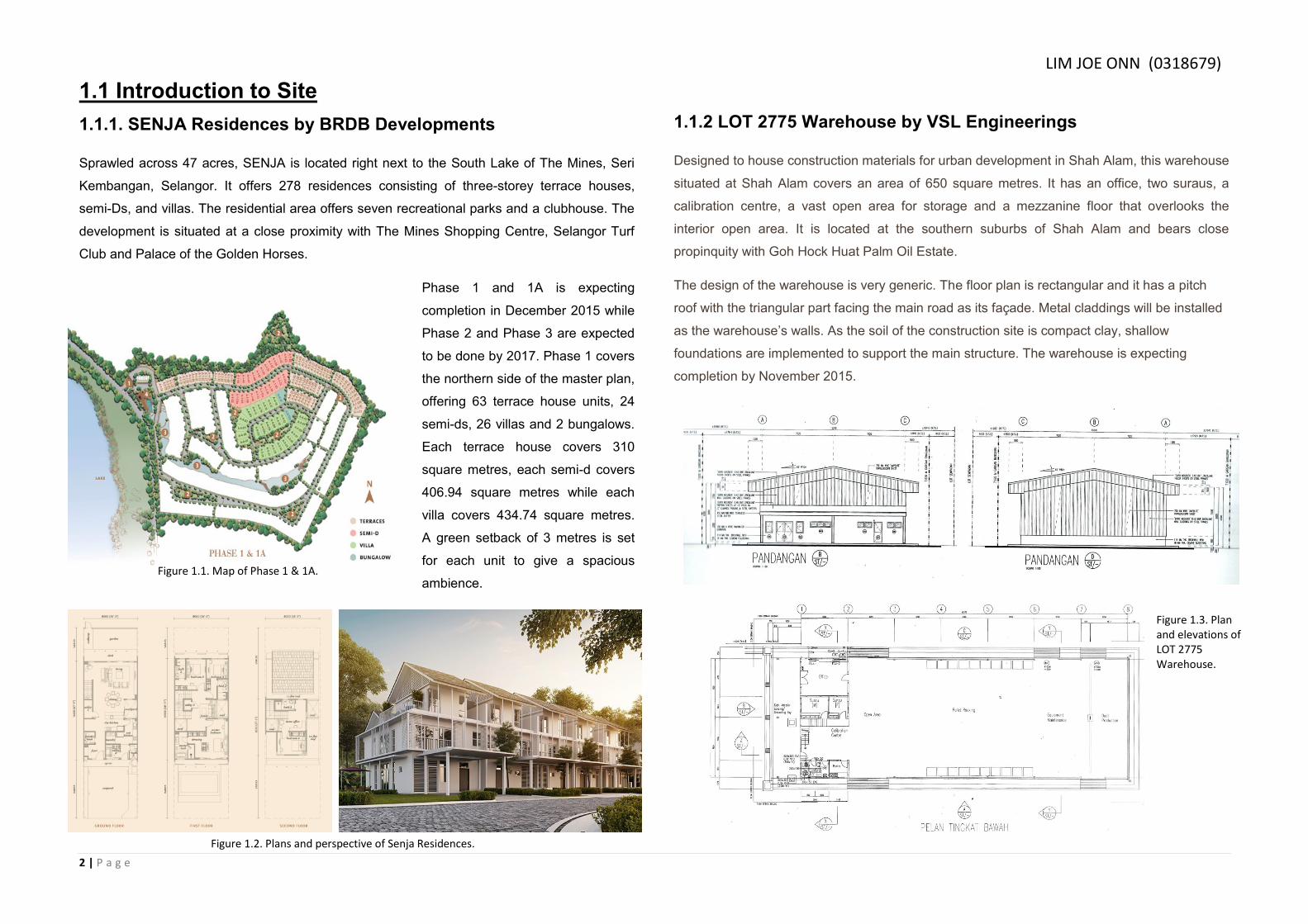
1.1 Introduction to Site
1.1.1. SENJA Residences by BRDB Developments
Sprawled across 47 acres, SENJA is located right next to the South Lake of The Mines, Seri
Kembangan, Selangor. It offers 278 residences consisting of three-storey terrace houses,
semi-Ds, and villas. The residential area offers seven recreational parks and a clubhouse. The
development is situated at a close proximity with The Mines Shopping Centre, Selangor Turf
Club and Palace of the Golden Horses.
Phase 1 and 1A is expecting
completion in December 2015 while
Phase 2 and Phase 3 are expected
to be done by 2017. Phase 1 covers
the northern side of the master plan,
offering 63 terrace house units, 24
semi-ds, 26 villas and 2 bungalows.
Each terrace house covers 310
square metres, each semi-d covers
406.94 square metres while each
villa covers 434.74 square metres.
A green setback of 3 metres is set
for each unit to give a spacious
ambience.
1.1.2 LOT 2775 Warehouse by VSL Engineerings
Designed to house construction materials for urban development in Shah Alam, this warehouse
situated at Shah Alam covers an area of 650 square metres. It has an office, two suraus, a
calibration centre, a vast open area for storage and a mezzanine floor that overlooks the
interior open area. It is located at the southern suburbs of Shah Alam and bears close
propinquity with Goh Hock Huat Palm Oil Estate.
The design of the warehouse is very generic. The floor plan is rectangular and it has a pitch
roof with the triangular part facing the main road as its façade. Metal claddings will be installed
as the warehouse’s walls. As the soil of the construction site is compact clay, shallow
foundations are implemented to support the main structure. The warehouse is expecting
completion by November 2015.
Figure 1.1. Map of Phase 1 & 1A.
Figure 1.2. Plans and perspective of Senja Residences.
Figure 1.3. Plan and elevations of LOT 2775 Warehouse.
LIM JOE ONN (0318679)
3 | P a g e
2.0 Site and Safety
2.0.1 Introduction
Safety in a construction site is always taken lightly. Every year, 1 in 10 construction workers
are injured. Between 2002 and 2012, 19.5% of all workplace deaths were from the construction
industry.
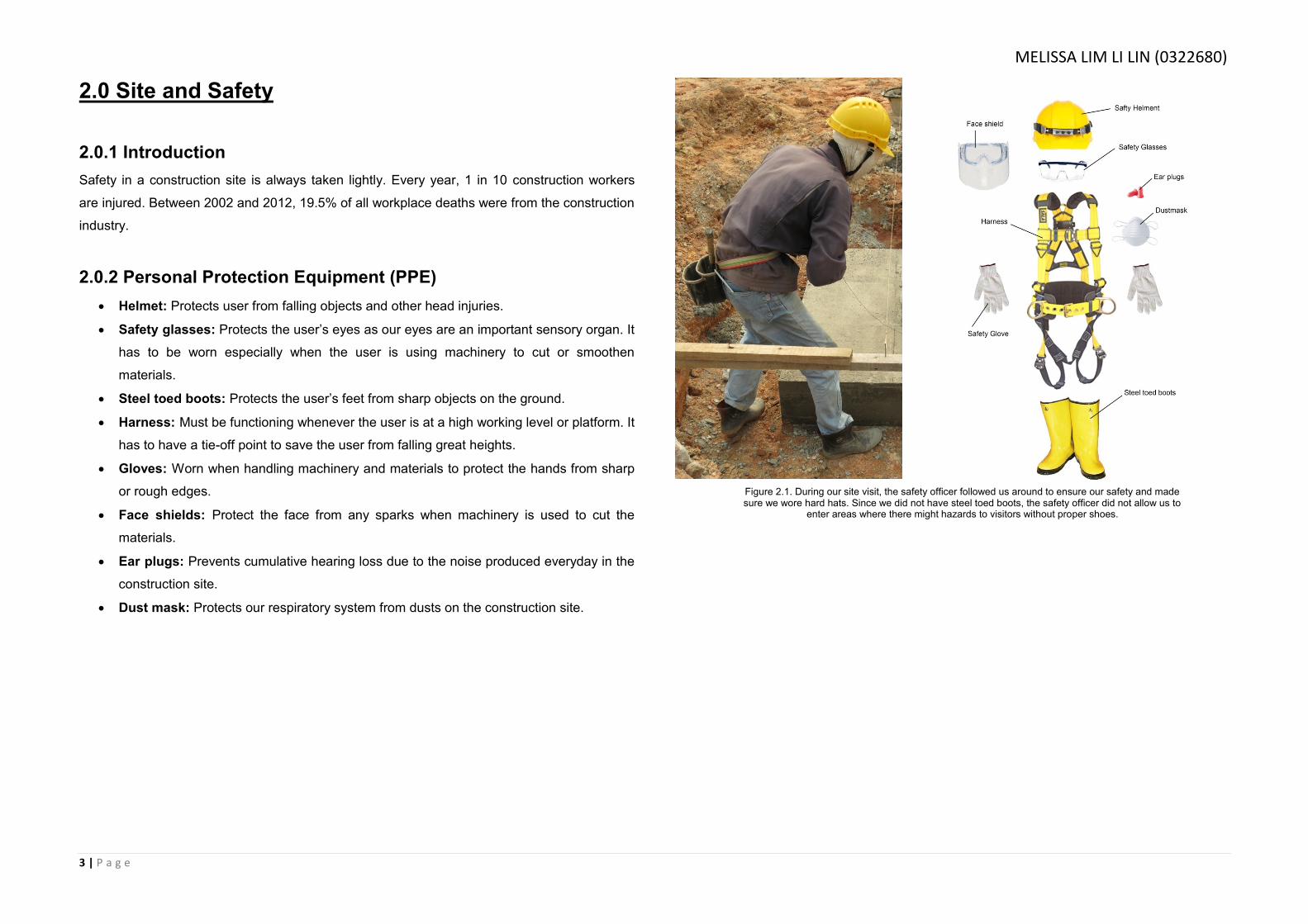
2.0.2 Personal Protection Equipment (PPE)
Helmet: Protects user from falling objects and other head injuries.
Safety glasses: Protects the user’s eyes as our eyes are an important sensory organ. It
has to be worn especially when the user is using machinery to cut or smoothen
materials.
Steel toed boots: Protects the user’s feet from sharp objects on the ground.
Harness: Must be functioning whenever the user is at a high working level or platform. It
has to have a tie-off point to save the user from falling great heights.
Gloves: Worn when handling machinery and materials to protect the hands from sharp
or rough edges.
Face shields: Protect the face from any sparks when machinery is used to cut the
materials.
Ear plugs: Prevents cumulative hearing loss due to the noise produced everyday in the
construction site.
Dust mask: Protects our respiratory system from dusts on the construction site.
Figure 2.1. During our site visit, the safety officer followed us around to ensure our safety and made sure we wore hard hats. Since we did not have steel toed boots, the safety officer did not allow us to
enter areas where there might hazards to visitors without proper shoes.
MELISSA LIM LI LIN (0322680)

4 | P a g e
2.0.3 Site Safety
Fire extinguisher: In case of any fire incidents, the fire extinguisher should be present
on site to prevent the fire from spreading. One of the fire hazards is the machinery and
wood on site.
First aid kits: Allows first hand treatment can be done on minor injuries on site.
Sign boards: To warn and remind workers and visitors of the hazards on site.
2.0.4 Machinery
Before handling or using any machinery, the worker has to check if the machine is in perfect
working condition. They have to make sure that the working horn and backup alarm are
working. Workers have to climb the machine properly and wear their seat belts before starting
the job. For smaller hand-use equipments, they have to also be checked before use. If any
equipment is faulty, it should be labelled out of use or kept away.
2.0.5 Sanitation and temporary structures
Every construction site has to have temporary structures to provide basic needs for the workers,
especially is the construction process is a long process.
Water storage tanks: Supply drinking water for workers and visitors.
Temporary toilets: Presence of one will provide sanitary services if there isn’t one
nearby as workers will be on site for almost the whole day.
Temporary canteen or resting area: Allows the workers to have their meals and breaks away
from the construction process
Figure 2.2. Fire extinguisher and warning signs seen on the construction site.
Figure 2.3. A temporary toilet found on site. It could cater 2 person at a time.
Figure 2.4. A temporary eating area that not only provides food but also shelter if it rains.
5 | P a g e
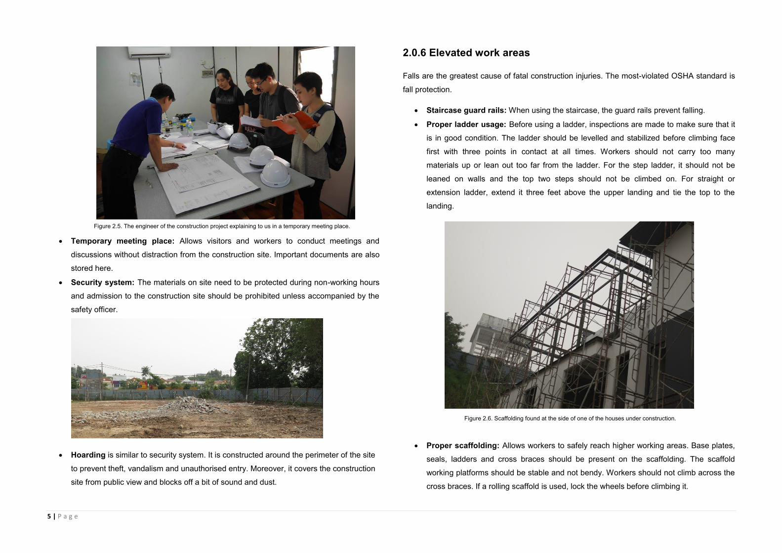
Temporary meeting place: Allows visitors and workers to conduct meetings and
discussions without distraction from the construction site. Important documents are also
stored here.
Security system: The materials on site need to be protected during non-working hours
and admission to the construction site should be prohibited unless accompanied by the
safety officer.
Hoarding is similar to security system. It is constructed around the perimeter of the site
to prevent theft, vandalism and unauthorised entry. Moreover, it covers the construction
site from public view and blocks off a bit of sound and dust.
2.0.6 Elevated work areas
Falls are the greatest cause of fatal construction injuries. The most-violated OSHA standard is
fall protection.
Staircase guard rails: When using the staircase, the guard rails prevent falling.
Proper ladder usage: Before using a ladder, inspections are made to make sure that it
is in good condition. The ladder should be levelled and stabilized before climbing face
first with three points in contact at all times. Workers should not carry too many
materials up or lean out too far from the ladder. For the step ladder, it should not be
leaned on walls and the top two steps should not be climbed on. For straight or
extension ladder, extend it three feet above the upper landing and tie the top to the
landing.
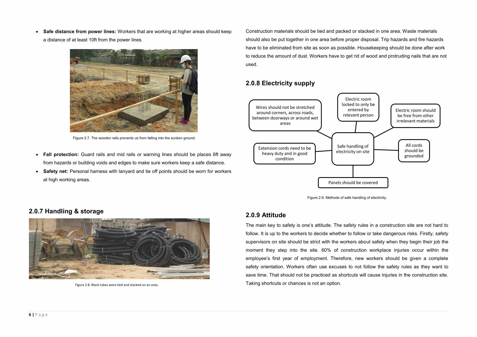
Proper scaffolding: Allows workers to safely reach higher working areas. Base plates,
seals, ladders and cross braces should be present on the scaffolding. The scaffold
working platforms should be stable and not bendy. Workers should not climb across the
cross braces. If a rolling scaffold is used, lock the wheels before climbing it.
Figure 2.5. The engineer of the construction project explaining to us in a temporary meeting place.
Figure 2.6. Scaffolding found at the side of one of the houses under construction.
6 | P a g e
Safe distance from power lines: Workers that are working at higher areas should keep
a distance of at least 10ft from the power lines.
Fall protection: Guard rails and mid rails or warning lines should be places 6ft away
from hazards or building voids and edges to make sure workers keep a safe distance.
Safety net: Personal harness with lanyard and tie off points should be worn for workers
at high working areas.
2.0.7 Handling & storage
Construction materials should be tied and packed or stacked in one area. Waste materials
should also be put together in one area before proper disposal. Trip hazards and fire hazards
have to be eliminated from site as soon as possible. Housekeeping should be done after work
to reduce the amount of dust. Workers have to get rid of wood and protruding nails that are not
used.
2.0.8 Electricity supply
2.0.9 Attitude
The main key to safety is one’s attitude. The safety rules in a construction site are not hard to
follow. It is up to the workers to decide whether to follow or take dangerous risks. Firstly, safety
supervisors on site should be strict with the workers about safety when they begin their job the
moment they step into the site. 60% of construction workplace injuries occur within the
employee’s first year of employment. Therefore, new workers should be given a complete
safety orientation. Workers often use excuses to not follow the safety rules as they want to
save time. That should not be practiced as shortcuts will cause injuries in the construction site.
Taking shortcuts or chances is not an option.
Safe handling of electricity on site
Electric room locked to only be
entered by relevant person
Electric room should be free from other irrelevant materials
All cords should be grounded
Panels should be covered
Extension cords need to be heavy duty and in good
condition
Wires should not be stretched around corners, across roads,
between doorways or around wet areas
Figure 2.7. The wooden rails prevents us from falling into the sunken ground.
Figure 2.8. Black tubes were tied and stacked on an area.
Figure 2.9. Methods of safe handling of electricity.

7 | P a g e
2.1 Plants & Machinery
2.1.1 Construction regulations for Plants & Machinery
Under the construction regulations;
On all construction sites on which transport vehicles, earth-moving or materials-handling
machinery or locomotives are used, the project supervisor for the construction stage shall
ensure that: (a) safe and suitable access ways are provided for them; (b) traffic and pedestrian
routes are so organized and controlled including, where appropriate, by the provision of a traffic
and pedestrian management plan, as to secure their safe operation.
2.1.2 Earth moving & excavating equipment
Earth moving equipment, also known as heavy equipment, refers to heavy-duty vehicles,
specially designed for executing construction tasks, most frequently ones involving earthwork
operations. They are also known as heavy machines, heavy trucks, construction equipment,
engineering equipment, heavy vehicles, or heavy hydraulics. They usually comprise five
equipment systems: implement, traction, structure, power train, control and information.[1]
Heavy equipment functions through the mechanical advantage of a simple machine, the ratio
between input force applied and force exerted is multiplied. Some equipment uses hydraulic
drives as a primary source of motion.
2.1.2.1 Examples of earth moving equipment
Loaders: Usually loaders are wheel loaders as wheels will
provide better mobility and speed and won’t damage paved
roads near as much as tracks. It has a wide square tilting
bucket on the end of movable arms to lift and move material
around. The bucket may be replaced with other tools like forks.
The function of loaders are loading materials into trucks, laying
pipe, clearing rubble, and also digging. Loaders aren’t the
most efficient machines for digging, as they can’t dig very
deep below the level of their wheels, like the backhoe can.
Bulldozer: Bulldozer is a tractor that is fitted with a dozer
blade, they are usually tracked for ground mobility through
rough terrain. Wide tracks help distribute the weight of the
dozer over large areas, preventing it from sinking into
sandy or muddy ground. The blade comes in 3 varieties: (a)
A straight blade that is short and has no lateral curve, no
side wings, and can be used only for fine grading; (b) A
universal blade, or U blade, which is tall and very curved,
and features large side wings to carry more material
around; (c) A combination blade that is shorter,offers less
curvature, and smaller side wings.
2.1.2.2 Types of earth moving equipment available on site
Backhoe loader: Backhoe loaders are common with small construction and excavation due to
its small size and versatility. It consists of a tractor, front shovel and bucket and a small
backhoe in the rear end. Besides construction, backhoe loaders are also used for light
transportation of materials, powering building equipment, digging holes and excavating,
breaking asphalt, and even paving roads. The general purpose buckets can be switched either
to retractable bottom bucket, rock bucket or many more for different tasks.
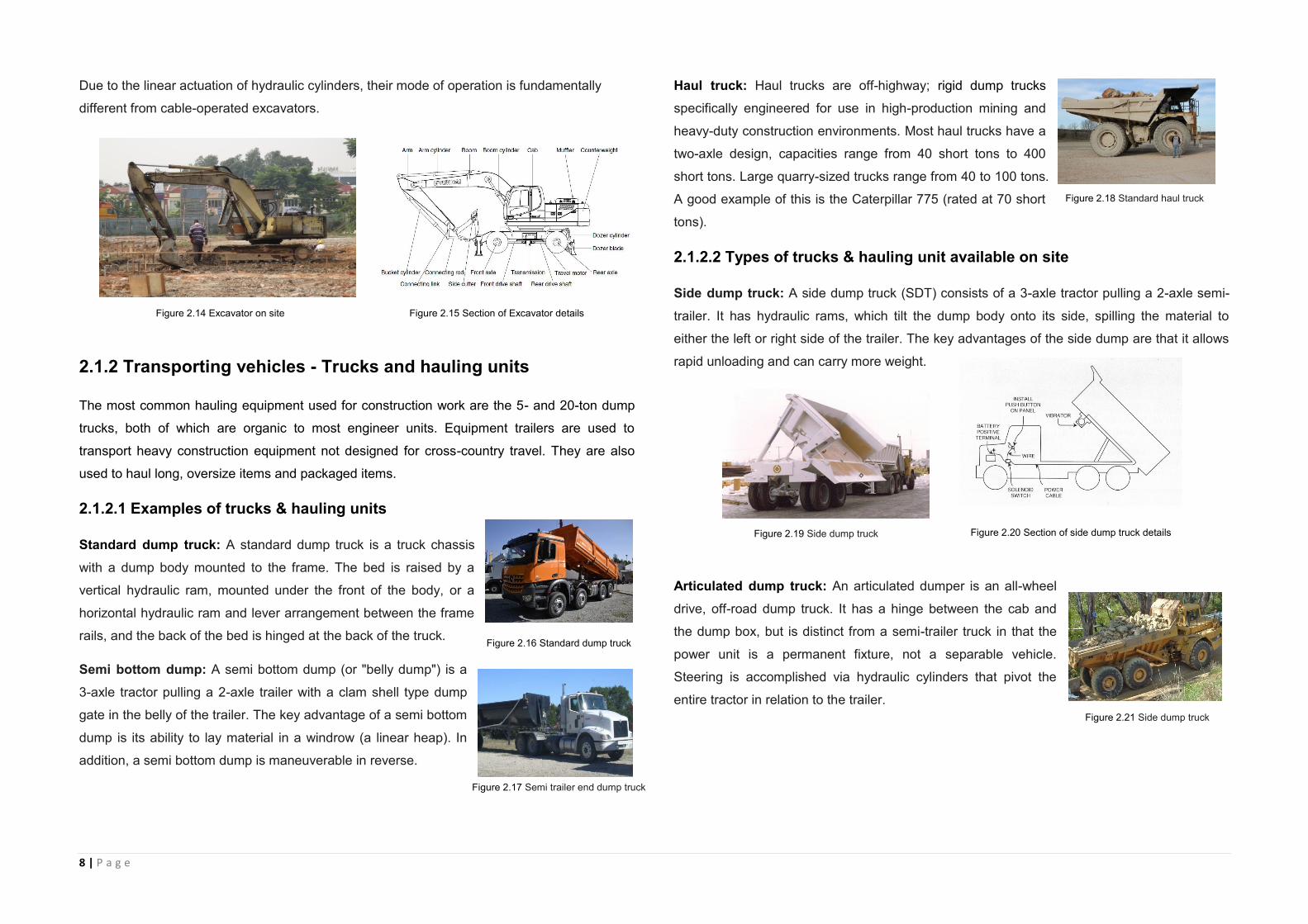
Excavator: Excavators are heavy construction equipment consisting of a boom, stick, bucket
and cab on a rotating platform known as the "house". The house sits atop an undercarriage
with tracks and wheels. A cable-operated excavator uses winches and steel ropes to
accomplish the movements. They are a natural progression from the steam shovels and often
mistakenly called power shovels. All movement and functions of a hydraulic excavator are
accomplished through the use of hydraulic fluid with hydraulic cylinder and hydraulic motor.
Figure 2.10 Wheel loader
Figure 2.12 Backhoe loader 580 Super L on site
Figure 2.13 Section of Backhoe Loader details
Figure 2.11 Wheel loader
MELISSA LIM LI LIN (0322680)
8 | P a g e
Due to the linear actuation of hydraulic cylinders, their mode of operation is fundamentally
different from cable-operated excavators.
2.1.2 Transporting vehicles - Trucks and hauling units
The most common hauling equipment used for construction work are the 5- and 20-ton dump
trucks, both of which are organic to most engineer units. Equipment trailers are used to
transport heavy construction equipment not designed for cross-country travel. They are also
used to haul long, oversize items and packaged items.
2.1.2.1 Examples of trucks & hauling units
Standard dump truck: A standard dump truck is a truck chassis
with a dump body mounted to the frame. The bed is raised by a
vertical hydraulic ram, mounted under the front of the body, or a
horizontal hydraulic ram and lever arrangement between the frame
rails, and the back of the bed is hinged at the back of the truck.
Semi bottom dump: A semi bottom dump (or "belly dump") is a
3-axle tractor pulling a 2-axle trailer with a clam shell type dump
gate in the belly of the trailer. The key advantage of a semi bottom
dump is its ability to lay material in a windrow (a linear heap). In
addition, a semi bottom dump is maneuverable in reverse.
Haul truck: Haul trucks are off-highway; rigid dump trucks
specifically engineered for use in high-production mining and
heavy-duty construction environments. Most haul trucks have a
two-axle design, capacities range from 40 short tons to 400
short tons. Large quarry-sized trucks range from 40 to 100 tons.
A good example of this is the Caterpillar 775 (rated at 70 short
tons).
2.1.2.2 Types of trucks & hauling unit available on site
Side dump truck: A side dump truck (SDT) consists of a 3-axle tractor pulling a 2-axle semi-
trailer. It has hydraulic rams, which tilt the dump body onto its side, spilling the material to
either the left or right side of the trailer. The key advantages of the side dump are that it allows
rapid unloading and can carry more weight.
Articulated dump truck: An articulated dumper is an all-wheel
drive, off-road dump truck. It has a hinge between the cab and
the dump box, but is distinct from a semi-trailer truck in that the
power unit is a permanent fixture, not a separable vehicle.
Steering is accomplished via hydraulic cylinders that pivot the
entire tractor in relation to the trailer.
Figure 2.14 Excavator on site Figure 2.15 Section of Excavator details
Figure 2.16 Standard dump truck
Figure 2.17 Semi trailer end dump truck
Figure 2.18 Standard haul truck
Figure 2.19 Side dump truck
Figure 2.21 Side dump truck
Figure 2.20 Section of side dump truck details
9 | P a g e
2.1.3 Material Handling Equipments
2.1.3.1 Cranes
In the excavation world, cranes are used to move equipment or machinery. Cranes can quickly
and easily move machinery into trenches or down steep hills, or even pipe. There are many
types of cranes available, serving everything from excavation to road work.
Examples of cranes
Mobile crane: A mobile crane is "a cable-controlled crane mounted
on crawlers or rubber-tired carriers" or "a hydraulic-powered crane
with a telescoping boom mounted on truck-type carriers or as self-
propelled models’. They are designed to easily transport to a site and
use with different types of load and cargo with little or no setup or
assembly.
Fixed crane: Exchanging mobility for the ability to carry greater
loads and reach greater heights due to increased stability, these
types of cranes are characterized by the fact that their main
structure does not move during the period of use. However, many
can still be assembled and disassembled. The structure is
basically fixed in one place.
Types of available cranes on site
Crawler crane: A crawler is a crane mounted on an
undercarriage with a set of Caterpillar track (also called
crawlers) that provide stability and mobility. Crawler
cranes range in lifting capacity from about 40 to 3,500
short tons (35.7 to 3,125.0 long tons; 36.3 to 3,175.1 t).
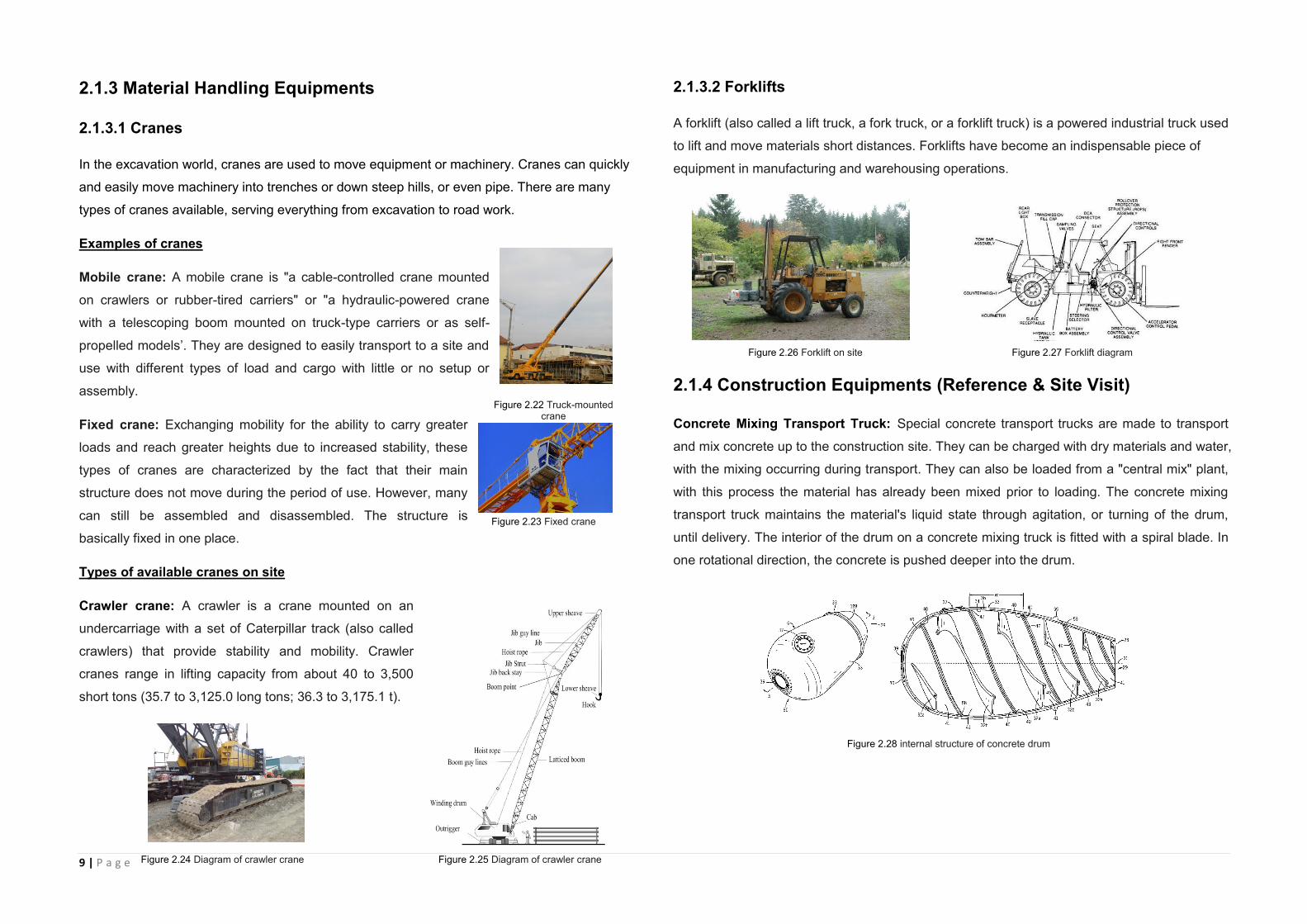
2.1.3.2 Forklifts
A forklift (also called a lift truck, a fork truck, or a forklift truck) is a powered industrial truck used
to lift and move materials short distances. Forklifts have become an indispensable piece of
equipment in manufacturing and warehousing operations.
2.1.4 Construction Equipments (Reference & Site Visit)
Concrete Mixing Transport Truck: Special concrete transport trucks are made to transport
and mix concrete up to the construction site. They can be charged with dry materials and water,
with the mixing occurring during transport. They can also be loaded from a "central mix" plant,
with this process the material has already been mixed prior to loading. The concrete mixing
transport truck maintains the material's liquid state through agitation, or turning of the drum,
until delivery. The interior of the drum on a concrete mixing truck is fitted with a spiral blade. In
one rotational direction, the concrete is pushed deeper into the drum.
Figure 2.22 Truck-mounted crane
Figure 2.23 Fixed crane
Figure 2.26 Forklift on site Figure 2.27 Forklift diagram
Figure 2.28 internal structure of concrete drum
Figure 2.25 Diagram of crawler crane Figure 2.24 Diagram of crawler crane

10 | P a g e
This is the direction the drum is rotated while the concrete is being transported to the building
site. This is known as "charging" the mixer. When the drum rotates in the other direction, the
Archimedes screw-type arrangement "discharges", or forces the concrete out of the drum.
From there it may go onto chutes to guide the viscous concrete directly to the job site. If the
truck cannot get close enough to the site to use the chutes, the concrete may be discharged
into a concrete truck, connected to a flexible hose, or onto a conveyor belt, which can be
extended some distance (typically ten or more meters). A pump provides the means to move
the material to precise locations, multi-floor buildings, and other distance prohibitive locations.
Buckets suspended from cranes are also used to place the concrete. The drum is traditionally
made of steel but on some newer trucks as a weight reduction measure, fiberglass is used.
Concrete Mixer: A concrete mixer (also commonly called a cement
mixer) is a device that homogeneously combines cement, aggregate
such as sand or gravel, and water to form concrete. A typical
concrete mixer uses a revolving drum to mix the components. For
smaller volume works portable concrete mixers are often used so
that the concrete can be made at the construction site, giving the
workers ample time to use the concrete before it hardens.
Pile Driver: A pile driver is a mechanical device used to
drive piles (poles) into soil to provide foundation support for
buildings or other structures. The term is also used in
reference to members of the construction crew that work
with pile-driving rigs.
Housing construction - Hydraulic pile driver
A hydraulic hammer is a modern type of piling hammer used in place of diesel and air
hammers for driving steel pipe, precast concrete, and timber piles. Hydraulic hammers are
more environmentally acceptable than the older, less efficient hammers as they generate less
noise and pollutants. However, in many cases the dominant noise is caused by the impact of
the hammer on the pile, or the impacts between components of the hammer, so that the
resulting noise level can be very similar to diesel hammers.
Figure 2.29 Standard concrete mixing transport truck Figure 2.30 Diagram oftruck details
Figure 2.32 Concrete Production Illustration
Figure 2.31 Concrete Mixer on site
Figure 2.33 Standard pile driver
Figure 2.34 Hydraulic pile driver on site
Figure 2.35 Pile driver diagram
11 | P a g e
3.0 External Work
The external work lays the foundation for the initial stage of construction. It determines the
working system within the construction area by building certain amount of compartments to
define the circulation, road and temporary structure for the long-term construction work.
External work ranges from clearance of site, excavating for pipes work to the finishing of road,
it serves to ensure the functionality of the building construction, and sometimes external work
can also enhance the aesthetic value of the building such as building of a fountain or park
around the construction site.
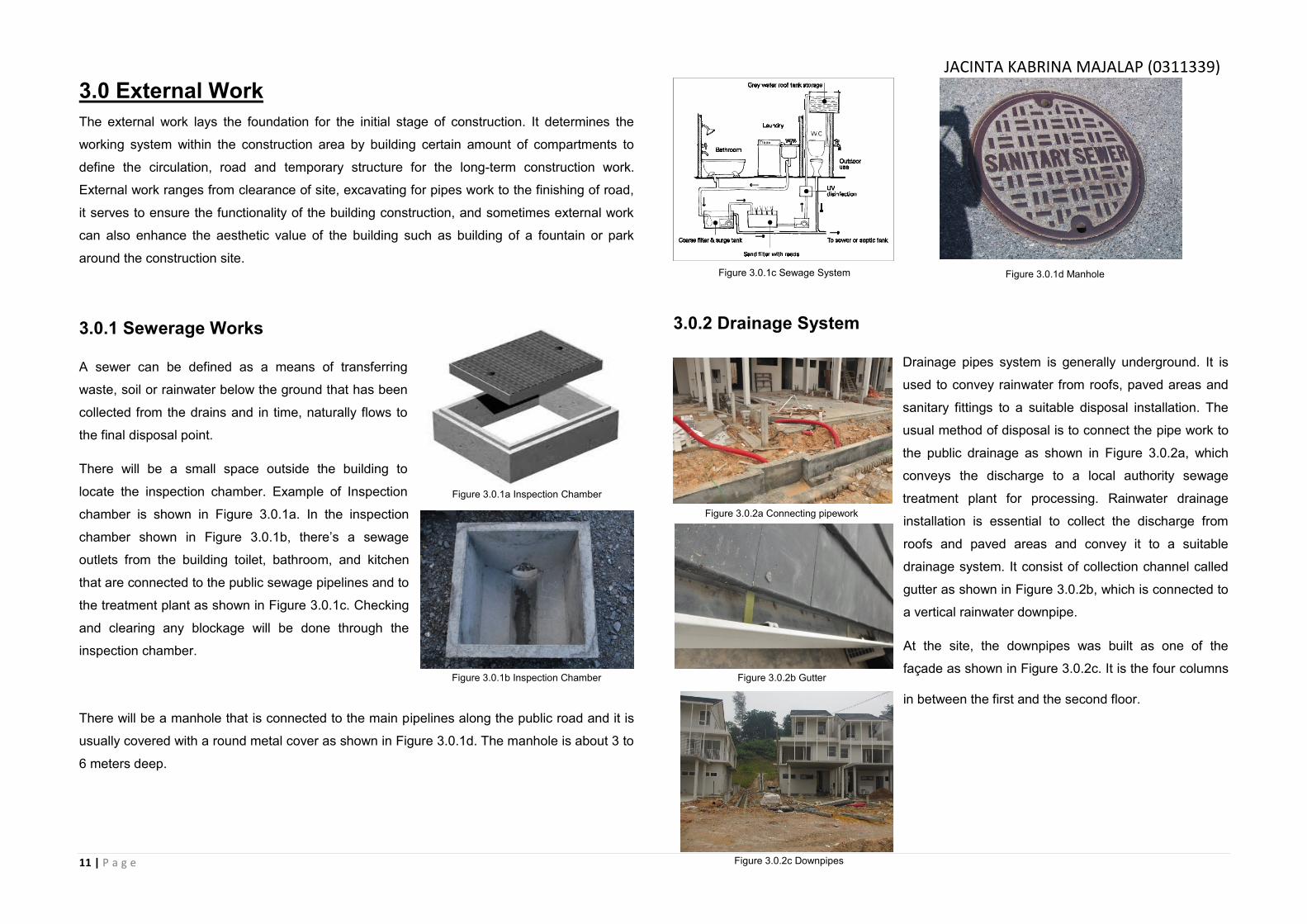
3.0.1 Sewerage Works
A sewer can be defined as a means of transferring
waste, soil or rainwater below the ground that has been
collected from the drains and in time, naturally flows to
the final disposal point.
There will be a small space outside the building to
locate the inspection chamber. Example of Inspection
chamber is shown in Figure 3.0.1a. In the inspection
chamber shown in Figure 3.0.1b, there’s a sewage
outlets from the building toilet, bathroom, and kitchen
that are connected to the public sewage pipelines and to
the treatment plant as shown in Figure 3.0.1c. Checking
and clearing any blockage will be done through the
inspection chamber.
There will be a manhole that is connected to the main pipelines along the public road and it is
usually covered with a round metal cover as shown in Figure 3.0.1d. The manhole is about 3 to
6 meters deep.
3.0.2 Drainage System
Drainage pipes system is generally underground. It is
used to convey rainwater from roofs, paved areas and
sanitary fittings to a suitable disposal installation. The
usual method of disposal is to connect the pipe work to
the public drainage as shown in Figure 3.0.2a, which
conveys the discharge to a local authority sewage
treatment plant for processing. Rainwater drainage
installation is essential to collect the discharge from
roofs and paved areas and convey it to a suitable
drainage system. It consist of collection channel called
gutter as shown in Figure 3.0.2b, which is connected to
a vertical rainwater downpipe.
At the site, the downpipes was built as one of the
façade as shown in Figure 3.0.2c. It is the four columns
in between the first and the second floor.
Figure 3.0.1a Inspection Chamber
Figure 3.0.1b Inspection Chamber
Figure 3.0.1c Sewage System Figure 3.0.1d Manhole
Figure 3.0.2a Connecting pipework
Figure 3.0.2b Gutter
Figure 3.0.2c Downpipes
JACINTA KABRINA MAJALAP (0311339)
12 | P a g e
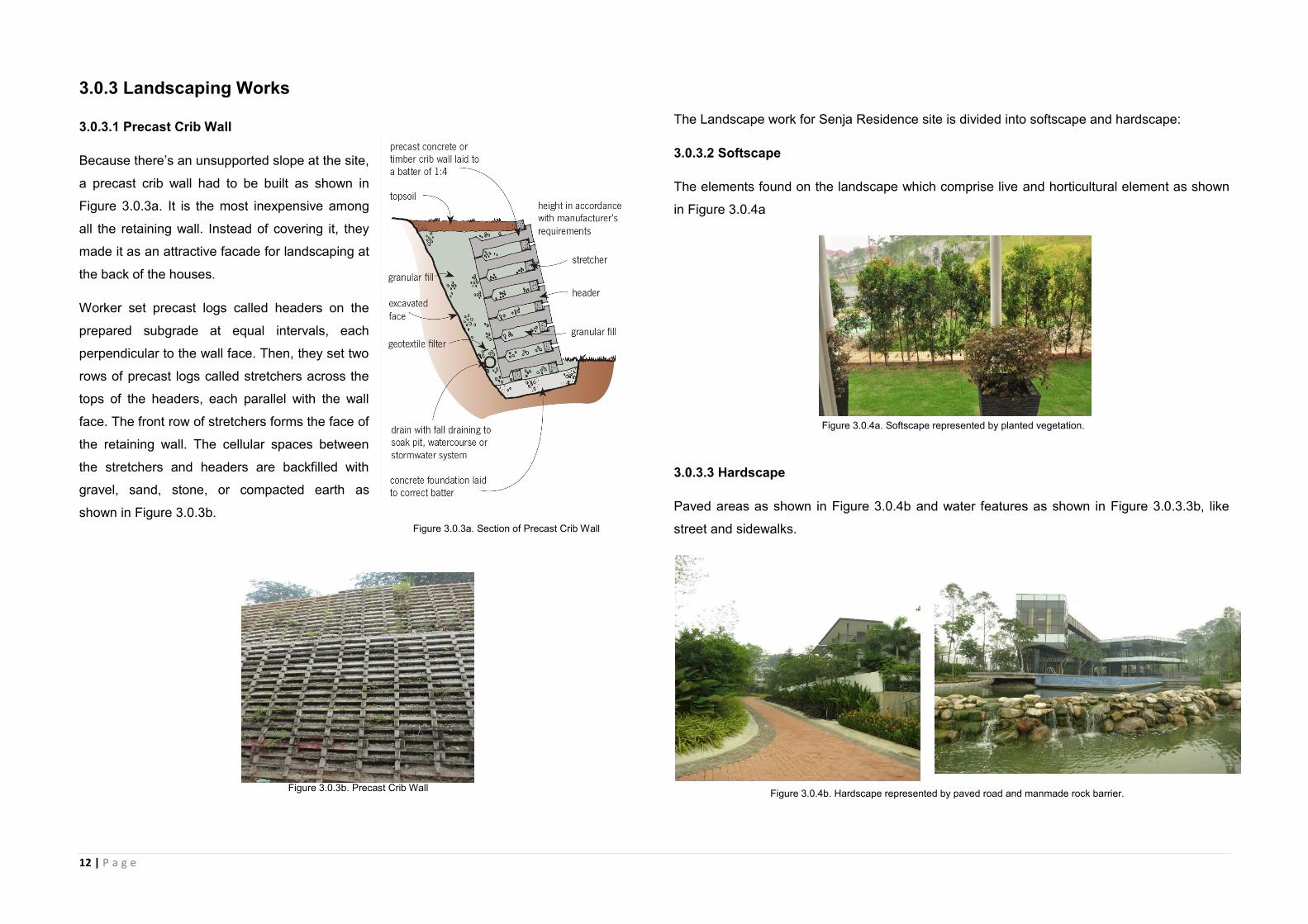
3.0.3 Landscaping Works
3.0.3.1 Precast Crib Wall
Because there’s an unsupported slope at the site,
a precast crib wall had to be built as shown in
Figure 3.0.3a. It is the most inexpensive among
all the retaining wall. Instead of covering it, they
made it as an attractive facade for landscaping at
the back of the houses.
Worker set precast logs called headers on the
prepared subgrade at equal intervals, each
perpendicular to the wall face. Then, they set two
rows of precast logs called stretchers across the
tops of the headers, each parallel with the wall
face. The front row of stretchers forms the face of
the retaining wall. The cellular spaces between
the stretchers and headers are backfilled with
gravel, sand, stone, or compacted earth as
shown in Figure 3.0.3b.
The Landscape work for Senja Residence site is divided into softscape and hardscape:
3.0.3.2 Softscape
The elements found on the landscape which comprise live and horticultural element as shown
in Figure 3.0.4a
3.0.3.3 Hardscape
Paved areas as shown in Figure 3.0.4b and water features as shown in Figure 3.0.3.3b, like
street and sidewalks.
Figure 3.0.3b. Precast Crib Wall
Figure 3.0.3a. Section of Precast Crib Wall
Figure 3.0.4a. Softscape represented by planted vegetation.
Figure 3.0.4b. Hardscape represented by paved road and manmade rock barrier.
13 | P a g e
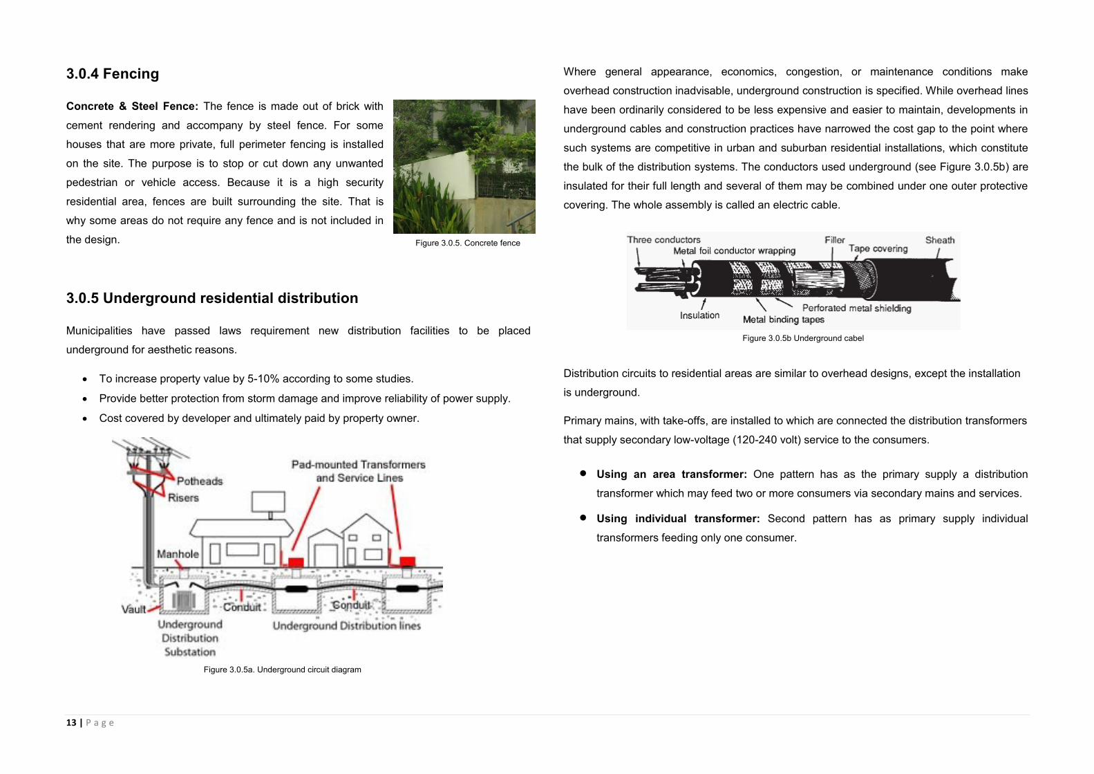
3.0.4 Fencing
Concrete & Steel Fence: The fence is made out of brick with
cement rendering and accompany by steel fence. For some
houses that are more private, full perimeter fencing is installed
on the site. The purpose is to stop or cut down any unwanted
pedestrian or vehicle access. Because it is a high security
residential area, fences are built surrounding the site. That is
why some areas do not require any fence and is not included in
the design.
3.0.5 Underground residential distribution
Municipalities have passed laws requirement new distribution facilities to be placed
underground for aesthetic reasons.
To increase property value by 5-10% according to some studies.
Provide better protection from storm damage and improve reliability of power supply.
Cost covered by developer and ultimately paid by property owner.
Where general appearance, economics, congestion, or maintenance conditions make
overhead construction inadvisable, underground construction is specified. While overhead lines
have been ordinarily considered to be less expensive and easier to maintain, developments in
underground cables and construction practices have narrowed the cost gap to the point where
such systems are competitive in urban and suburban residential installations, which constitute
the bulk of the distribution systems. The conductors used underground (see Figure 3.0.5b) are
insulated for their full length and several of them may be combined under one outer protective
covering. The whole assembly is called an electric cable.
Distribution circuits to residential areas are similar to overhead designs, except the installation
is underground.
Primary mains, with take-offs, are installed to which are connected the distribution transformers
that supply secondary low-voltage (120-240 volt) service to the consumers.
Using an area transformer: One pattern has as the primary supply a distribution
transformer which may feed two or more consumers via secondary mains and services.
Using individual transformer: Second pattern has as primary supply individual
transformers feeding only one consumer.
Figure 3.0.5. Concrete fence
Figure 3.0.5a. Underground circuit diagram
Figure 3.0.5b Underground cabel
14 | P a g e
3.1 Setting Out
3.1.1 Introduction
A definition of setting out, often used, is that it is the reverse of surveying. Whereas surveying
is a process for forming maps and plans of a particular site or area, setting out begins with
plans and ends with the various elements of a particular plan correctly positioned on site.
3.1.1.1 Stages in setting out
As the works proceed, the setting out falls into two broad stages.
First stage setting out
In practice, first stage setting out involves the use of many of the horizontal and vertical control
methods and positioning techniques. The purpose of this stage is to locate the boundaries of
the works in their correct position on the ground surface and to define the major elements. In
order to do this, horizontal and vertical control points must be established on or near the site.
Second stage setting out
Second stage setting out continues on from the first stage, beginning at the ground floor slab,
road sub-base level etc. Up to this point, all the control will be outside the main construction,
for example, the pegs defining building corners, centre lines and so on will have been knocked
out during the earth moving work and only the original control will be undisturbed.
This operation falls into the first category of setting out.
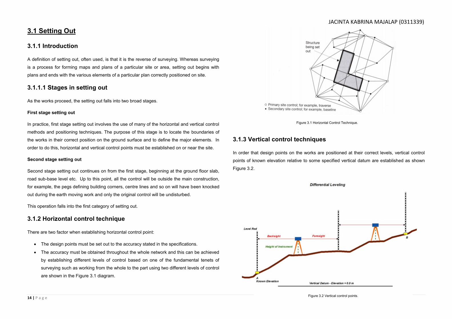
3.1.2 Horizontal control technique
There are two factor when establishing horizontal control point:
The design points must be set out to the accuracy stated in the specifications.
The accuracy must be obtained throughout the whole network and this can be achieved
by establishing different levels of control based on one of the fundamental tenets of
surveying such as working from the whole to the part using two different levels of control
are shown in the Figure 3.1 diagram.
3.1.3 Vertical control techniques
In order that design points on the works are positioned at their correct levels, vertical control
points of known elevation relative to some specified vertical datum are established as shown
Figure 3.2.
Figure 3.1 Horizontal Control Technique.
Figure 3.2 Vertical control points.
JACINTA KABRINA MAJALAP (0311339)

15 | P a g e
3.1.4 Baselines
A baseline is a line running between two points of a known position. Any baselines
required to set out a project should be specified on the setting out plan by the designer
and included in the contract.
Baselines can be used in a number of different ways:
Where a baseline is specified to run between two points, once the points have
been established on site, the design points can be set out from the baseline by
offsetting using tapes as seen in Figure 3.3.
Primary site control points, such as traverse stations E & F in Figure 3.4 can be
used to establish a baseline AB by angle α and distance values.
Design points can be set out by taping known as distances from each end of a
baseline as shown in Figure 3.5.
Figure 3.3 The baseline running between points A and B.
Figure 3.4 Primary site control points.
Figure 3.5. Setting out design points.
16 | P a g e
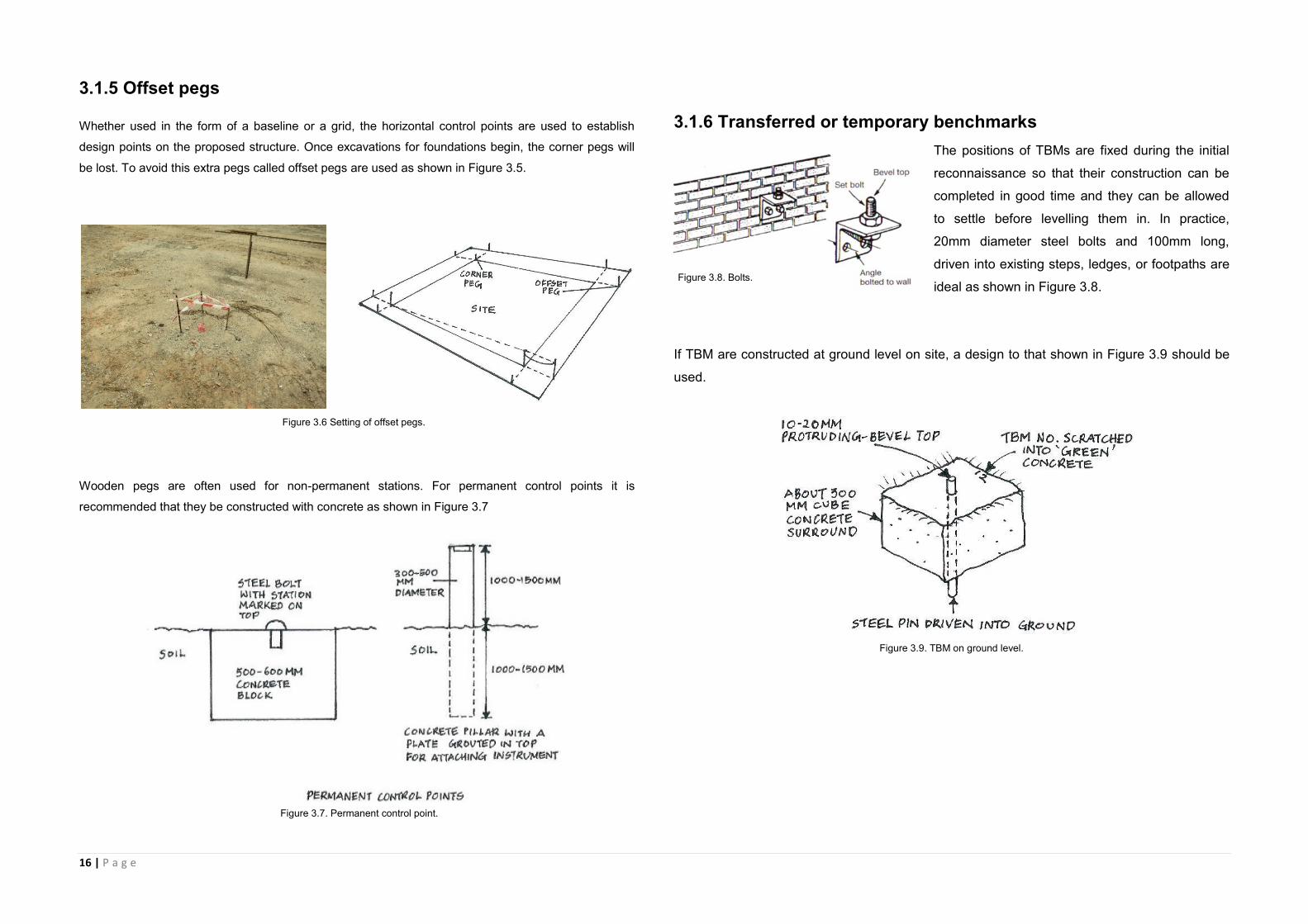
3.1.5 Offset pegs
Whether used in the form of a baseline or a grid, the horizontal control points are used to establish
design points on the proposed structure. Once excavations for foundations begin, the corner pegs will
be lost. To avoid this extra pegs called offset pegs are used as shown in Figure 3.5.
Wooden pegs are often used for non-permanent stations. For permanent control points it is
recommended that they be constructed with concrete as shown in Figure 3.7
3.1.6 Transferred or temporary benchmarks
The positions of TBMs are fixed during the initial
reconnaissance so that their construction can be
completed in good time and they can be allowed
to settle before levelling them in. In practice,
20mm diameter steel bolts and 100mm long,
driven into existing steps, ledges, or footpaths are
ideal as shown in Figure 3.8.
If TBM are constructed at ground level on site, a design to that shown in Figure 3.9 should be
used.
Figure 3.6 Setting of offset pegs.
Figure 3.7. Permanent control point.
Figure 3.8. Bolts.
Figure 3.9. TBM on ground level.
17 | P a g e
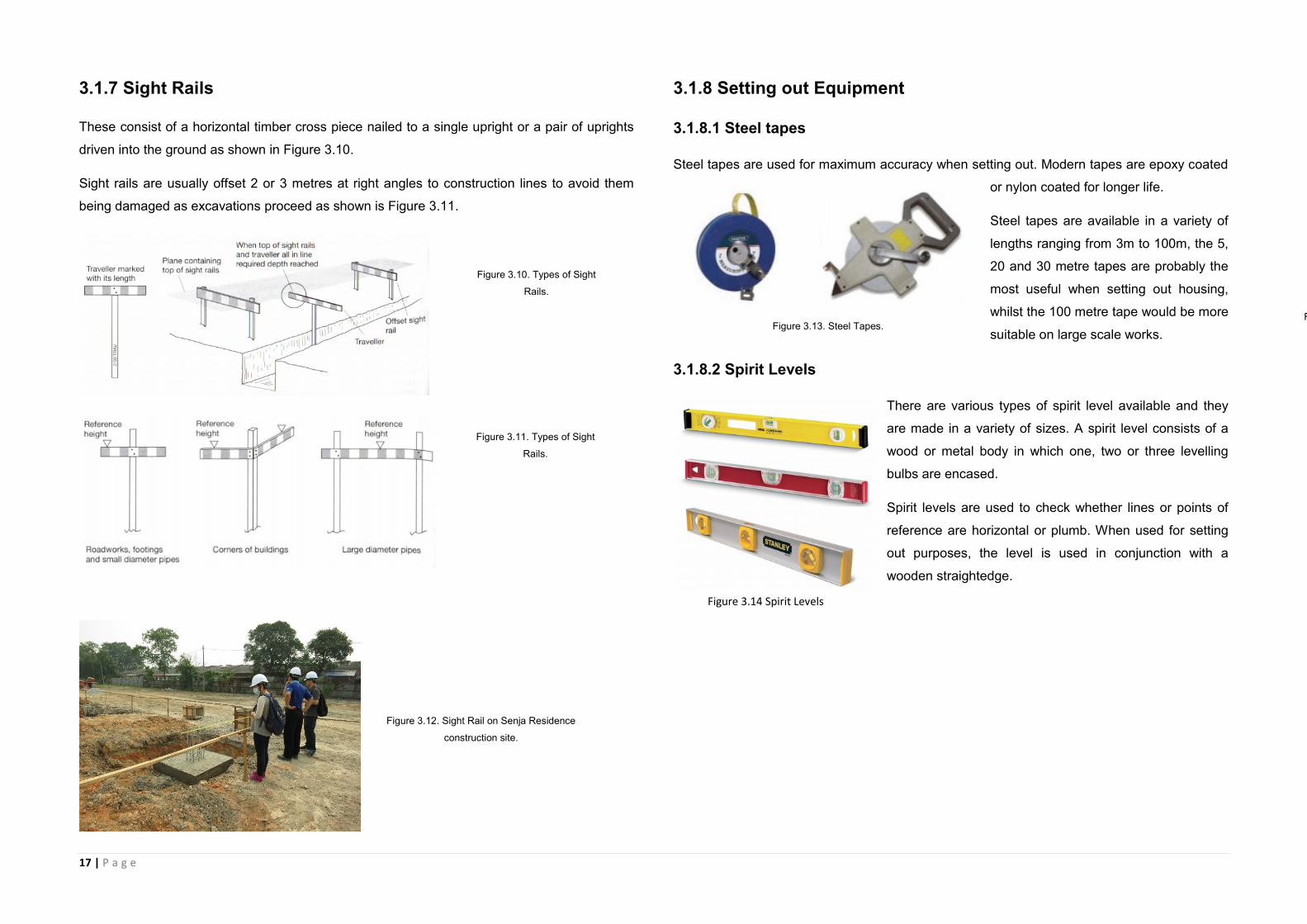
3.1.7 Sight Rails
These consist of a horizontal timber cross piece nailed to a single upright or a pair of uprights
driven into the ground as shown in Figure 3.10.
Sight rails are usually offset 2 or 3 metres at right angles to construction lines to avoid them
being damaged as excavations proceed as shown is Figure 3.11.
3.1.8 Setting out Equipment
3.1.8.1 Steel tapes
Steel tapes are used for maximum accuracy when setting out. Modern tapes are epoxy coated
or nylon coated for longer life.
Steel tapes are available in a variety of
lengths ranging from 3m to 100m, the 5,
20 and 30 metre tapes are probably the
most useful when setting out housing,
whilst the 100 metre tape would be more
suitable on large scale works.
3.1.8.2 Spirit Levels
There are various types of spirit level available and they
are made in a variety of sizes. A spirit level consists of a
wood or metal body in which one, two or three levelling
bulbs are encased.
Spirit levels are used to check whether lines or points of
reference are horizontal or plumb. When used for setting
out purposes, the level is used in conjunction with a
wooden straightedge.
Figure 3.12. Sight Rail on Senja Residence
construction site.
Figure 3.10. Types of Sight
Rails.
Figure 3.11. Types of Sight
Rails.
Figure 3.13. Steel Tapes. Figure 3.14. Various Spirit Levels.
Figure 3.14 Spirit Levels

18 | P a g e
3.1.8.3 Optical Levels, Optical Squares and Theodolite
When levels have to be transferred over a long distance, the method of straightedge and level
can be very time consuming and rather inaccurate. A more accurate method is to use a setting
out instrument called an optical level or theodolite.
The optical level is secured to a tripod which is positioned and levelled by means of levelling
screws. When the instrument is as level as possible it is aimed at a levelling staff which has
been placed at a designated position. The height or level is then read through the optical level
and noted or transferred to another position.
Setting out using a theodolite and tape
To set out using coordinates by theodolite and tape, one of the following procedures is used:
1. Angle and distance from two control points e.g. from point A below, can be set out from a
control point S using one of two methods:
Using the inverse calculation, determine the horizontal length l(SA) and the whole circle
bearings of ST and SA.
With the theodolite set up at S, sight T and set the horizontal circle to read zero along this
direction. Then the telescope is rotated through angle αto fix the direction to A and measure l
along this direction to fix the position of A. This is known as setting out by angle and distance.
Intersection with two theodolites
Intersection with two theodolites, from four control points using angles or bearings only.
Intersection is shown in Figure 3.18.
Figure 3.15. Securing optical level on site.
Figure 3.16. Types of optical level.
Figure 3.17e. Inverse calculation method.
Figure 3.18. Intersection with two theodolites

19 | P a g e
3.1.9 Setting out a pipeline
This operation falls into the first category of setting out.
General considerations: sewers normally follow the natural fall in the land and are laid at
gradients which induce self-cleansing velocity. The figure 3.19 shows a sight rail offset at right
angles to a pipe line laid in a granular bedding trench.
Horizontal control: The working drawings will show the directions of the sewer pipes and the
positions of the manholes. The line of the sewer is normally pegged at 20 to 30m intervals
using coordinate methods of positioning from reference points or in relation to existing detail.
The direction of the line can be sighted using a theodolite and pegs.
Vertical control: Involves the erection of sight rails some convenient height above the invert
level of the pipe.
Erection and use of sight rails: the sight rail uprights are hammered firmly into the ground,
usually offset from the line rather than straddling it. Using a nearby TBM and levelling
equipment, reduced levels of the tops of the uprights.
Where the natural slope of the ground is not approximately parallel to the proposed pipe
gradient, double sight rails can be used as shown in Figure 3.20. Often it is required to lay
storm water and foul water sewers in adjacent trenches. Since the storm water pipe is usually
at a higher level than the foul water pipe, it is common to dig one trench to two different levels –
as shown in Figure 3.21.
Both pipe runs are then controlled using different sight rails nailed to the same uprights.
Figure 3.19. Setting out pipeline.
Figure 3.20. Double sight rails.
Figure 3.21. Two different levels for pipes.
20 | P a g e
3.2 Earthwork
Earthwork is the first work performed on most construction projects. It encompasses a number
of activities, from clearing the site to excavating for structures or pipes. The earthwork done on
a project prepares the site for other construction work, such as building bridges and paving
roads. Problems with earthwork often do not become apparent until other construction work
has been done, at which point the effort to correct the problems is both time consuming and
expensive. Therefore, earthwork operations must be carefully inspected to ensure that the work
done is in accordance with the Specifications. The Inspector should closely observe all
earthwork operations and bring all problems to the attention of the Contractor and, when
necessary, the Engineer.
3.2.1 Importance of Earthwork
Earthwork, though broad by its many aspects, is a specific and important engineered phase of
construction. Engineered earthwork begins with a soils investigation and ends as a foundation
for all construction. The widest highway, the longest bridge, and the tallest building could not
exist were it not for a solid foundation; this foundation is earthwork.
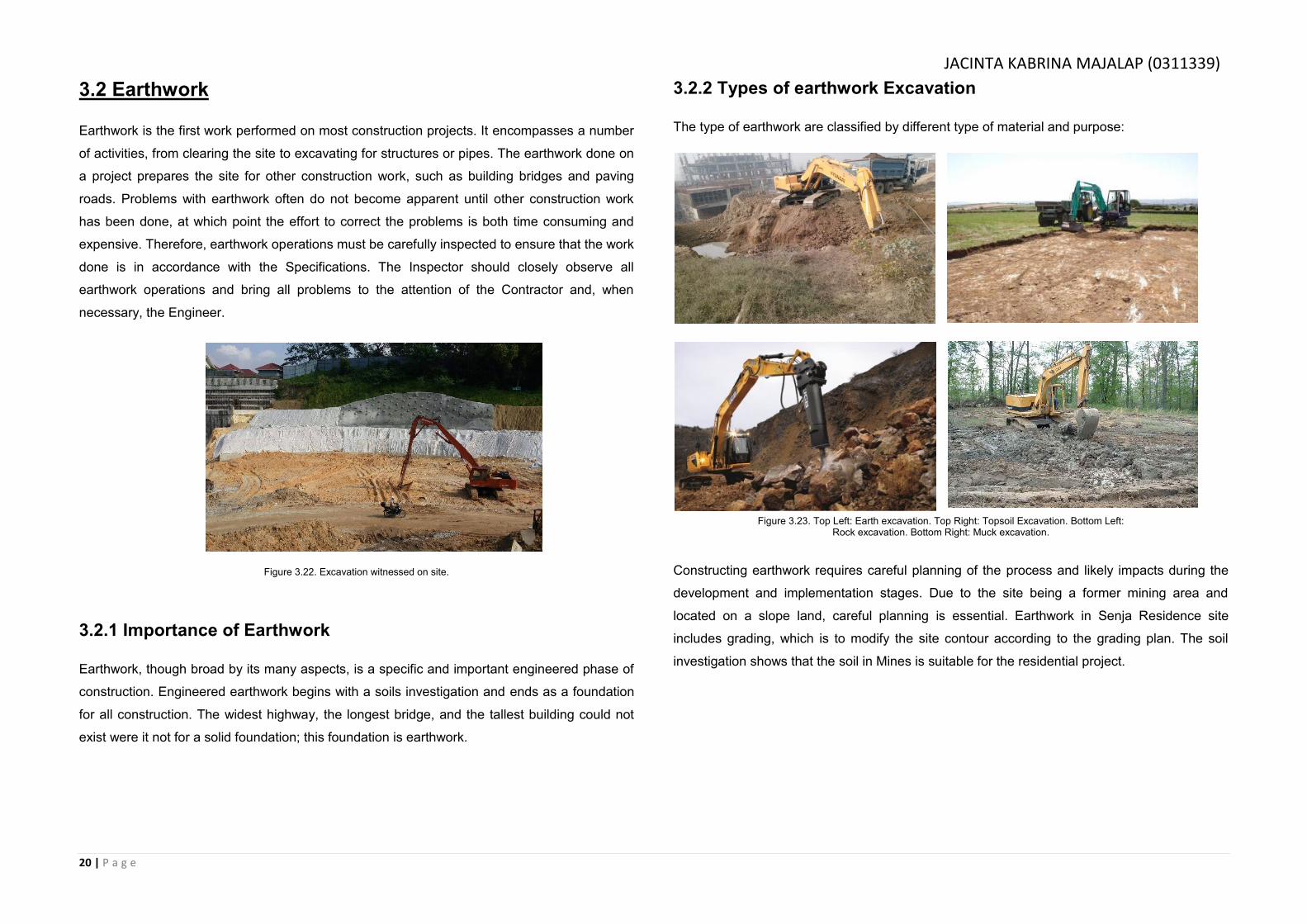
3.2.2 Types of earthwork Excavation
The type of earthwork are classified by different type of material and purpose:
Constructing earthwork requires careful planning of the process and likely impacts during the
development and implementation stages. Due to the site being a former mining area and
located on a slope land, careful planning is essential. Earthwork in Senja Residence site
includes grading, which is to modify the site contour according to the grading plan. The soil
investigation shows that the soil in Mines is suitable for the residential project.
Figure 3.22. Excavation witnessed on site.
Figure 3.23. Top Left: Earth excavation. Top Right: Topsoil Excavation. Bottom Left: Rock excavation. Bottom Right: Muck excavation.
JACINTA KABRINA MAJALAP (0311339)
21 | P a g e
3.2.3 Site Clearing
A proper procedure must be done for both site establishment and site clearance. Pre-entry
survey must be done before the work commences, preferably photographic survey
supplemented with a written record. Advance writing must be done before work begins on site
to make sure that if any parties who will be affected by the construction work would be notified.
Site clearance involves demolition of existing building, grubbing of bushes and trees, and the
removal of soil reducing or increasing the level of land. The removal of trees can be carried out
by manual or mechanical means while the removal of larger trees should be left to the
specialized contractor.
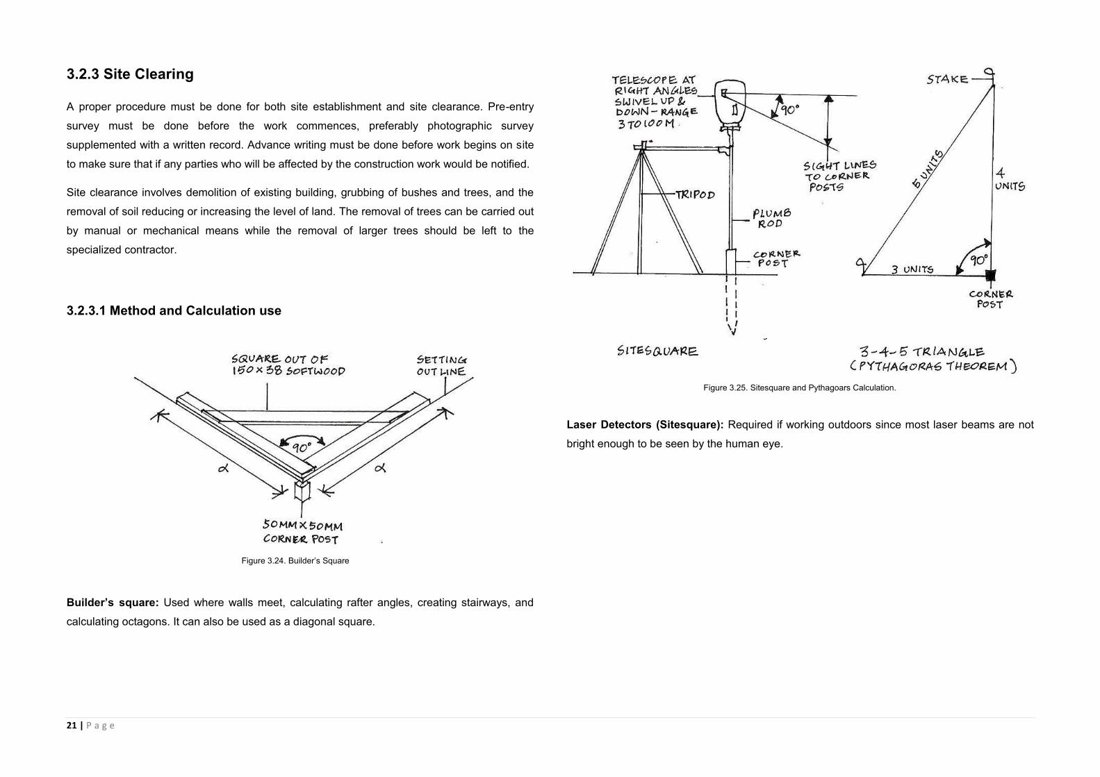
3.2.3.1 Method and Calculation use
Builder’s square: Used where walls meet, calculating rafter angles, creating stairways, and
calculating octagons. It can also be used as a diagonal square.
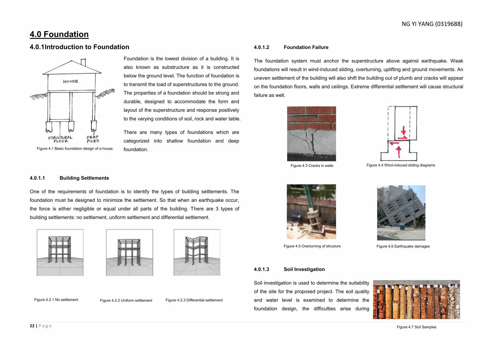
Laser Detectors (Sitesquare): Required if working outdoors since most laser beams are not
bright enough to be seen by the human eye.
Figure 3.24. Builder’s Square
Figure 3.25. Sitesquare and Pythagoars Calculation.
22 | P a g e
4.0 Foundation
4.0.1 Introduction to Foundation
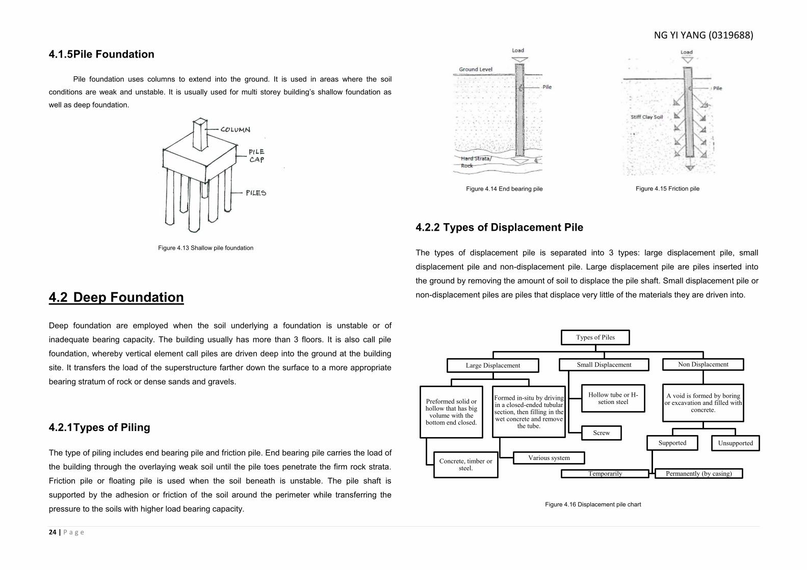
Foundation is the lowest division of a building. It is
also known as substructure as it is constructed
below the ground level. The function of foundation is
to transmit the load of superstructures to the ground.
The properties of a foundation should be strong and
durable, designed to accommodate the form and
layout of the superstructure and response positively
to the varying conditions of soil, rock and water table.
There are many types of foundations which are
categorized into shallow foundation and deep
foundation.
4.0.1.1 Building Settlements
One of the requirements of foundation is to identify the types of building settlements. The
foundation must be designed to minimize the settlement. So that when an earthquake occur,
the force is either negligible or equal under all parts of the building. There are 3 types of
building settlements: no settlement, uniform settlement and differential settlement.
4.0.1.2 Foundation Failure
The foundation system must anchor the superstructure above against earthquake. Weak
foundations will result in wind-induced sliding, overturning, uplifting and ground movements. An
uneven settlement of the building will also shift the building out of plumb and cracks will appear
on the foundation floors, walls and ceilings. Extreme differential settlement will cause structural
failure as well.
4.0.1.3 Soil Investigation
Soil investigation is used to determine the suitability
of the site for the proposed project. The soil quality
and water level is examined to determine the
foundation design, the difficulties arise during
Figure 4.7 Soil Samples
Figure 4.1 Basic foundation design of a house.
Figure 4.3 Cracks in walls Figure 4.4 Wind-induced sliding diagrams
Figure 4.5 Overturning of structure Figure 4.6 Earthquake damages
Figure 4.2.1 No settlement Figure 4.2.2 Uniform settlement Figure 4.2.3 Differential settlement
NG YI YANG (0319688)

23 | P a g e
construction process, and the changes in the subsoil conditions. Subsoil samples from different
positions of the site are taken to determine its physical, chemical and general characteristics in
labs. The depth of soil investigation is usually based on the proposed foundation type.
4.1 Shallow Foundation
Shallow or spread foundations are employed when stable soil of adequate bearing capacity
occurs relatively near to the ground surface. The building usually consist of 3 floors or less,
while the foundation is 3 meters deep below ground level and transfer loads directly to the
supporting soil by vertical pressure. It includes strip foundation, raft foundation, pad footing,
and piled foundation.
4.1.1 Strip Foundation
Strip footing is a strip of continuous concrete placed centrally below load bearing walls. It is used to
spread the load evenly along the entire structure or concentrated at individual points. It is usually
connected to beams or columns. I has two types which are uniform distribution load or point loads.
4.1.2 Raft Foundation
Raft footing is usually used on soft natural ground. Reinforced concrete slabs are used to cover
the whole base area of a building and extends beyond it. It acts as wall support and floor slabs.
Sometimes, it is reinforced with steel mesh to prevent soil erosion at its edge.
4.1.3 Pad Footing
Pad foundations are individual foundations that are usually connected to the columns or
structural frame of a building. It uses concrete pad at the base with steel columns held down by
bots.
4.1.4 Cantilever Foundation
Cantilever foundations can be used where it is
necessary to avoid imposing any pressure on an
adjacent foundation or an underground services.
Figure 4.8 Uniform distribution load strip foundation Figure 4.9 Point load strip foundation
Figure 4.10 Raft footing
Figure 4.11 Pad Footing
Figure 4.12 Cantilever foundation
NG YI YANG (0319688)
24 | P a g e
Figure 4.13 Shallow pile foundation
4.1.5 Pile Foundation
Pile foundation uses columns to extend into the ground. It is used in areas where the soil
conditions are weak and unstable. It is usually used for multi storey building’s shallow foundation as
well as deep foundation.
4.2 Deep Foundation
Deep foundation are employed when the soil underlying a foundation is unstable or of
inadequate bearing capacity. The building usually has more than 3 floors. It is also call pile
foundation, whereby vertical element call piles are driven deep into the ground at the building
site. It transfers the load of the superstructure farther down the surface to a more appropriate
bearing stratum of rock or dense sands and gravels.
4.2.1 Types of Piling
The type of piling includes end bearing pile and friction pile. End bearing pile carries the load of
the building through the overlaying weak soil until the pile toes penetrate the firm rock strata.
Friction pile or floating pile is used when the soil beneath is unstable. The pile shaft is
supported by the adhesion or friction of the soil around the perimeter while transferring the
pressure to the soils with higher load bearing capacity.
4.2.2 Types of Displacement Pile
The types of displacement pile is separated into 3 types: large displacement pile, small
displacement pile and non-displacement pile. Large displacement pile are piles inserted into
the ground by removing the amount of soil to displace the pile shaft. Small displacement pile or
non-displacement piles are piles that displace very little of the materials they are driven into.
Types of Piles
Large Displacement
Preformed solid or hollow that has big
volume with the bottom end closed.
Concrete, timber or steel.
Formed in-situ by driving in a closed-ended tubular section, then filling in the wet concrete and remove
the tube.
Various system
Small Displacement
Hollow tube or H-setion steel
Screw
Non Displacement
A void is formed by boring or excavation and filled with
concrete.
Supported
Permanently (by casing) Temporarily
Unsupported
Figure 4.14 End bearing pile Figure 4.15 Friction pile
Figure 4.16 Displacement pile chart
NG YI YANG (0319688)
25 | P a g e
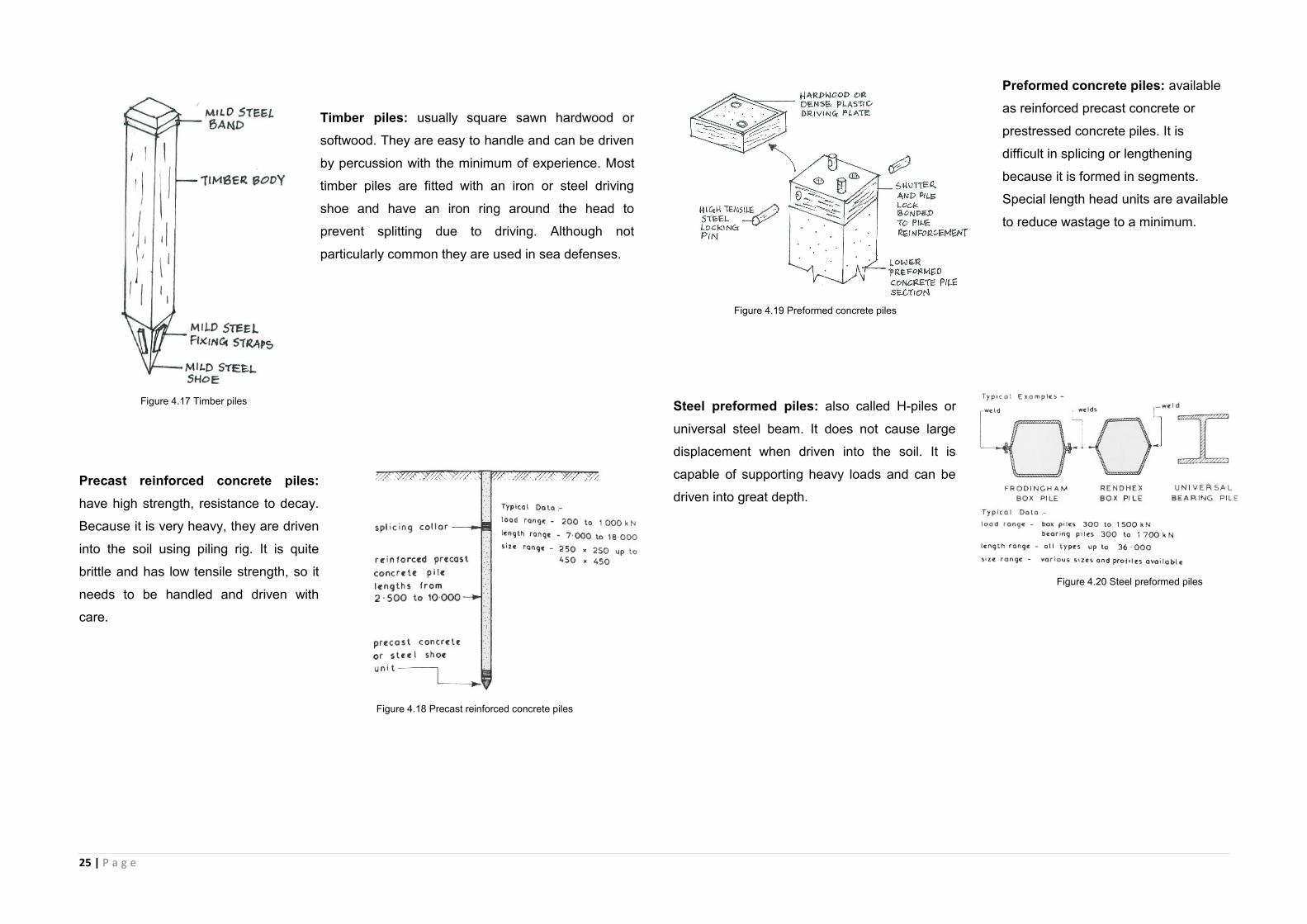
Timber piles: usually square sawn hardwood or
softwood. They are easy to handle and can be driven
by percussion with the minimum of experience. Most
timber piles are fitted with an iron or steel driving
shoe and have an iron ring around the head to
prevent splitting due to driving. Although not
particularly common they are used in sea defenses.
Precast reinforced concrete piles:
have high strength, resistance to decay.
Because it is very heavy, they are driven
into the soil using piling rig. It is quite
brittle and has low tensile strength, so it
needs to be handled and driven with
care.
Preformed concrete piles: available
as reinforced precast concrete or
prestressed concrete piles. It is
difficult in splicing or lengthening
because it is formed in segments.
Special length head units are available
to reduce wastage to a minimum.
Steel preformed piles: also called H-piles or
universal steel beam. It does not cause large
displacement when driven into the soil. It is
capable of supporting heavy loads and can be
driven into great depth.
Figure 4.17 Timber piles
Figure 4.19 Preformed concrete piles
Figure 4.18 Precast reinforced concrete piles
Figure 4.20 Steel preformed piles
26 | P a g e
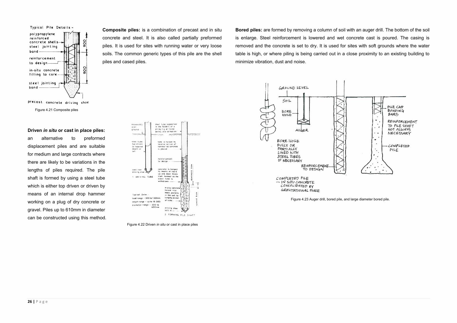
Composite piles: is a combination of precast and in situ
concrete and steel. It is also called partially preformed
piles. It is used for sites with running water or very loose
soils. The common generic types of this pile are the shell
piles and cased piles.
Driven in situ or cast in place piles:
an alternative to preformed
displacement piles and are suitable
for medium and large contracts where
there are likely to be variations in the
lengths of piles required. The pile
shaft is formed by using a steel tube
which is either top driven or driven by
means of an internal drop hammer
working on a plug of dry concrete or
gravel. Piles up to 610mm in diameter
can be constructed using this method.
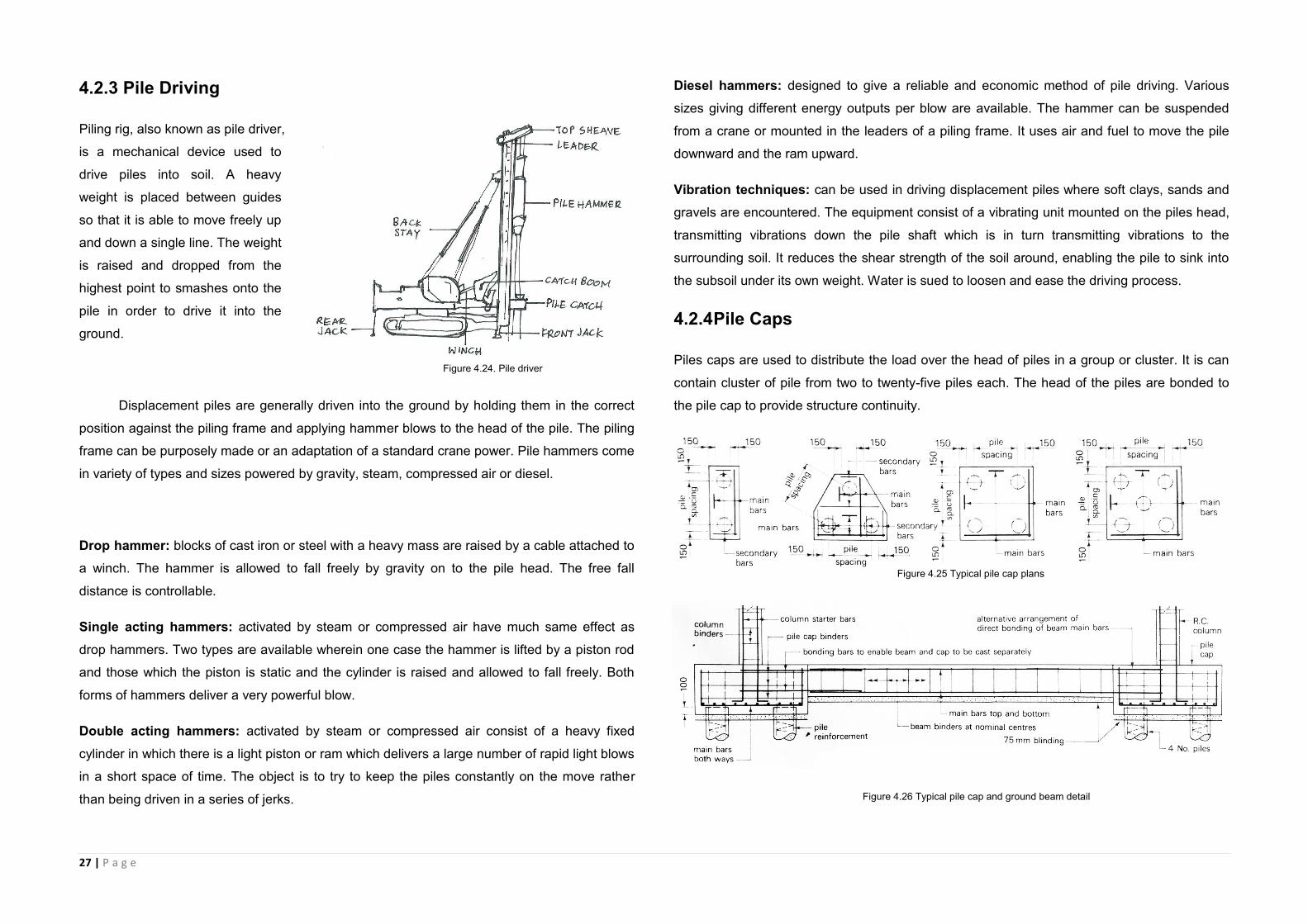
Bored piles: are formed by removing a column of soil with an auger drill. The bottom of the soil
is enlarge. Steel reinforcement is lowered and wet concrete cast is poured. The casing is
removed and the concrete is set to dry. It is used for sites with soft grounds where the water
table is high, or where piling is being carried out in a close proximity to an existing building to
minimize vibration, dust and noise.
Figure 4.21 Composite piles
Figure 4.22 Driven in situ or cast in place piles
Figure 4.23 Auger drill, bored pile, and large diameter bored pile.
27 | P a g e
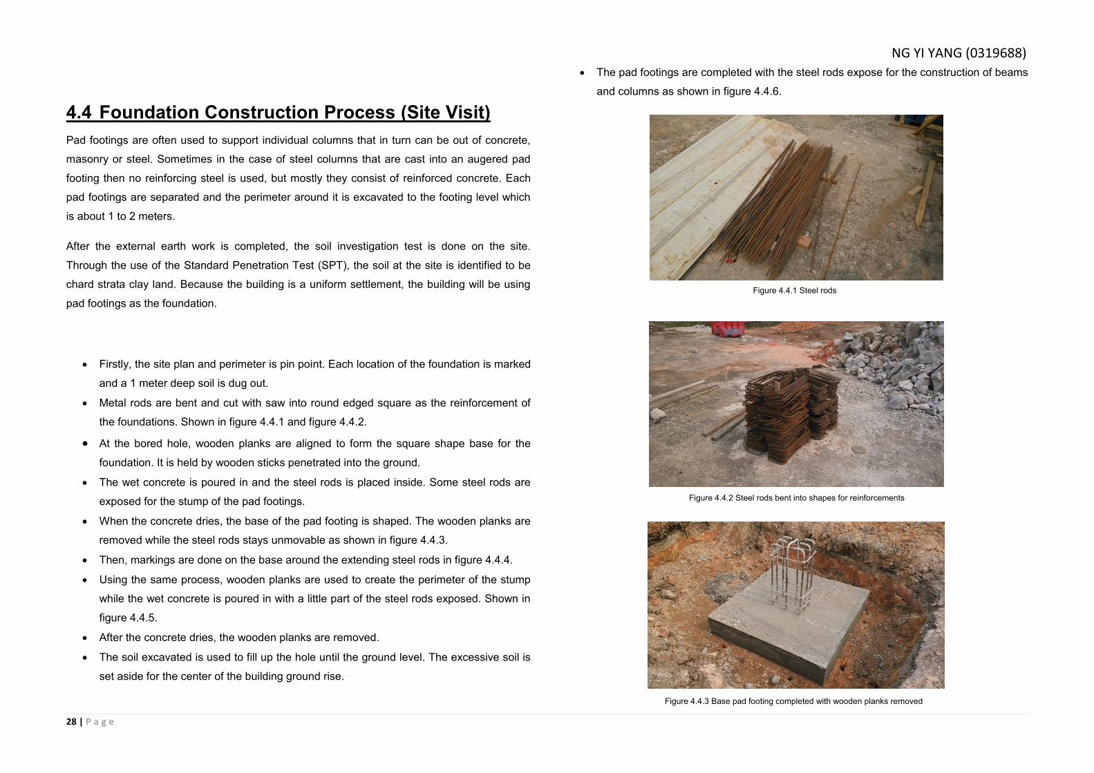
4.2.3 Pile Driving
Piling rig, also known as pile driver,
is a mechanical device used to
drive piles into soil. A heavy
weight is placed between guides
so that it is able to move freely up
and down a single line. The weight
is raised and dropped from the
highest point to smashes onto the
pile in order to drive it into the
ground.
Displacement piles are generally driven into the ground by holding them in the correct
position against the piling frame and applying hammer blows to the head of the pile. The piling
frame can be purposely made or an adaptation of a standard crane power. Pile hammers come
in variety of types and sizes powered by gravity, steam, compressed air or diesel.
Drop hammer: blocks of cast iron or steel with a heavy mass are raised by a cable attached to
a winch. The hammer is allowed to fall freely by gravity on to the pile head. The free fall
distance is controllable.
Single acting hammers: activated by steam or compressed air have much same effect as
drop hammers. Two types are available wherein one case the hammer is lifted by a piston rod
and those which the piston is static and the cylinder is raised and allowed to fall freely. Both
forms of hammers deliver a very powerful blow.
Double acting hammers: activated by steam or compressed air consist of a heavy fixed
cylinder in which there is a light piston or ram which delivers a large number of rapid light blows
in a short space of time. The object is to try to keep the piles constantly on the move rather
than being driven in a series of jerks.
Diesel hammers: designed to give a reliable and economic method of pile driving. Various
sizes giving different energy outputs per blow are available. The hammer can be suspended
from a crane or mounted in the leaders of a piling frame. It uses air and fuel to move the pile
downward and the ram upward.
Vibration techniques: can be used in driving displacement piles where soft clays, sands and
gravels are encountered. The equipment consist of a vibrating unit mounted on the piles head,
transmitting vibrations down the pile shaft which is in turn transmitting vibrations to the
surrounding soil. It reduces the shear strength of the soil around, enabling the pile to sink into
the subsoil under its own weight. Water is sued to loosen and ease the driving process.
4.2.4 Pile Caps
Piles caps are used to distribute the load over the head of piles in a group or cluster. It is can
contain cluster of pile from two to twenty-five piles each. The head of the piles are bonded to
the pile cap to provide structure continuity.
Figure 4.24. Pile driver
Figure 4.25 Typical pile cap plans
Figure 4.26 Typical pile cap and ground beam detail
28 | P a g e
4.4 Foundation Construction Process (Site Visit)
Pad footings are often used to support individual columns that in turn can be out of concrete,
masonry or steel. Sometimes in the case of steel columns that are cast into an augered pad
footing then no reinforcing steel is used, but mostly they consist of reinforced concrete. Each
pad footings are separated and the perimeter around it is excavated to the footing level which
is about 1 to 2 meters.
After the external earth work is completed, the soil investigation test is done on the site.
Through the use of the Standard Penetration Test (SPT), the soil at the site is identified to be
chard strata clay land. Because the building is a uniform settlement, the building will be using
pad footings as the foundation.
Firstly, the site plan and perimeter is pin point. Each location of the foundation is marked
and a 1 meter deep soil is dug out.
Metal rods are bent and cut with saw into round edged square as the reinforcement of
the foundations. Shown in figure 4.4.1 and figure 4.4.2.
At the bored hole, wooden planks are aligned to form the square shape base for the
foundation. It is held by wooden sticks penetrated into the ground.
The wet concrete is poured in and the steel rods is placed inside. Some steel rods are
exposed for the stump of the pad footings.
When the concrete dries, the base of the pad footing is shaped. The wooden planks are
removed while the steel rods stays unmovable as shown in figure 4.4.3.
Then, markings are done on the base around the extending steel rods in figure 4.4.4.
Using the same process, wooden planks are used to create the perimeter of the stump
while the wet concrete is poured in with a little part of the steel rods exposed. Shown in
figure 4.4.5.
After the concrete dries, the wooden planks are removed.
The soil excavated is used to fill up the hole until the ground level. The excessive soil is
set aside for the center of the building ground rise.
The pad footings are completed with the steel rods expose for the construction of beams
and columns as shown in figure 4.4.6.
Figure 4.4.1 Steel rods
Figure 4.4.2 Steel rods bent into shapes for reinforcements
Figure 4.4.3 Base pad footing completed with wooden planks removed
NG YI YANG (0319688)
29 | P a g e
Figure 4.4.4 Marking of stump size.
Figure 4.4.6 Pad footing completed with the steel rods exposed and the soil filled around it.
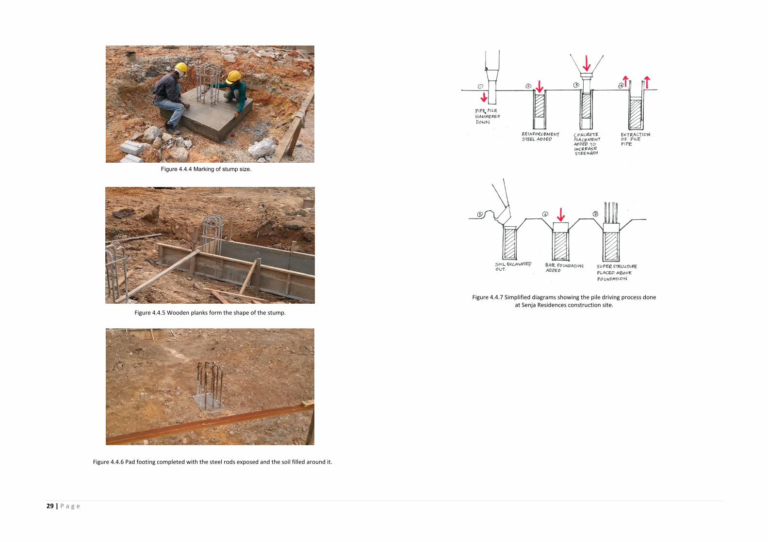
Figure 4.4.7 Simplified diagrams showing the pile driving process done at Senja Residences construction site.
Figure 4.4.5 Wooden planks form the shape of the stump.
30 | P a g e
5.0 Superstructure (from site visit and reference)
Superstructure is the building parts located above the ground level. It is the part where the
height of the building starts to rise up whether it serves for structural, enclosure, openings and
functional purpose.
5.1 Beam and Column
The beam and the column are the supporting system of a building during the early stage, while
both serve as the same purpose of supporting the building structure, they have different
characteristics.
Both of them work together to form a comprehensive supporting system in the early stage of
erecting the building.
5.1.1 Beams
The beam is the horizontal member of the structure, carrying transverse load from the upper
structures including its own weight towards the columns or the walls.
5.1.2 Types of Beam (general)
The beam can either sit on the ground right next to the floor slab or be supported both ends by
columns or walls. However depending on the design intention, there are several types of
beams used in the building construction:
Fixed Beam
This type of beam can be used ranging from a residence house to a grand building. It could
withstand strong loads from the upper structure as both ends of the beam are rigidly fixed in to
the support, giving extra durability. Therefore it serves as the primary beam in a beam structure.
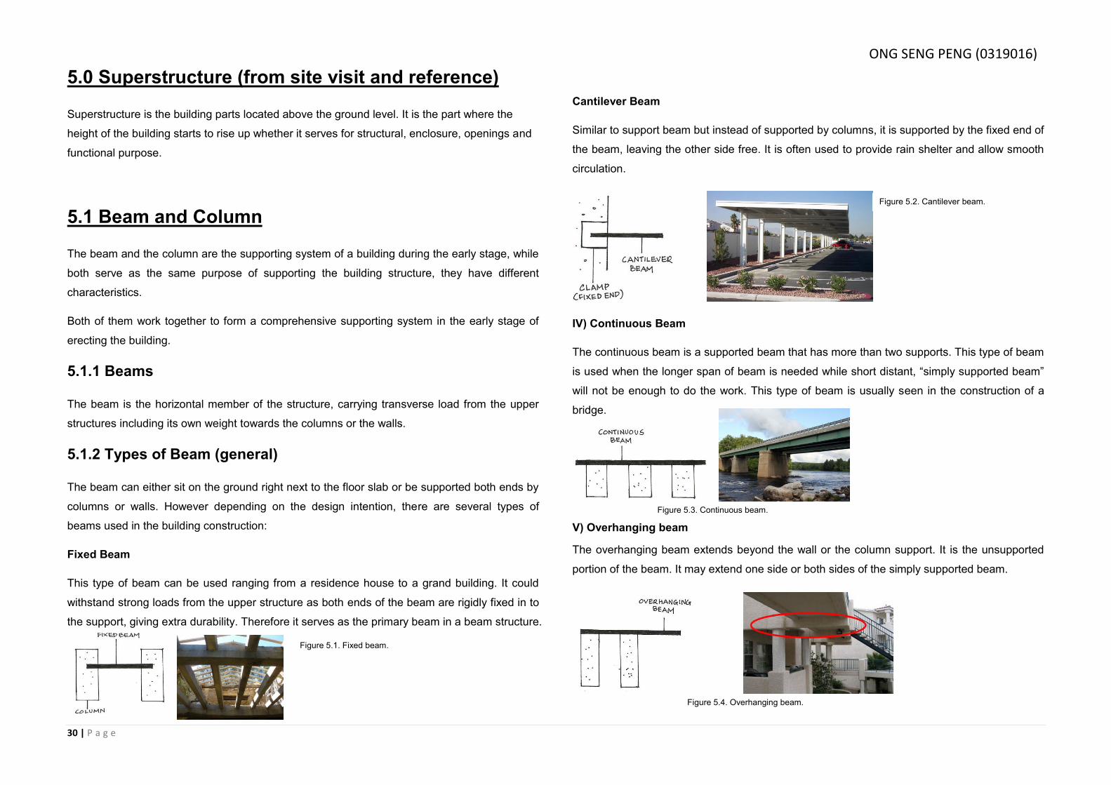
Cantilever Beam
Similar to support beam but instead of supported by columns, it is supported by the fixed end of
the beam, leaving the other side free. It is often used to provide rain shelter and allow smooth
circulation.
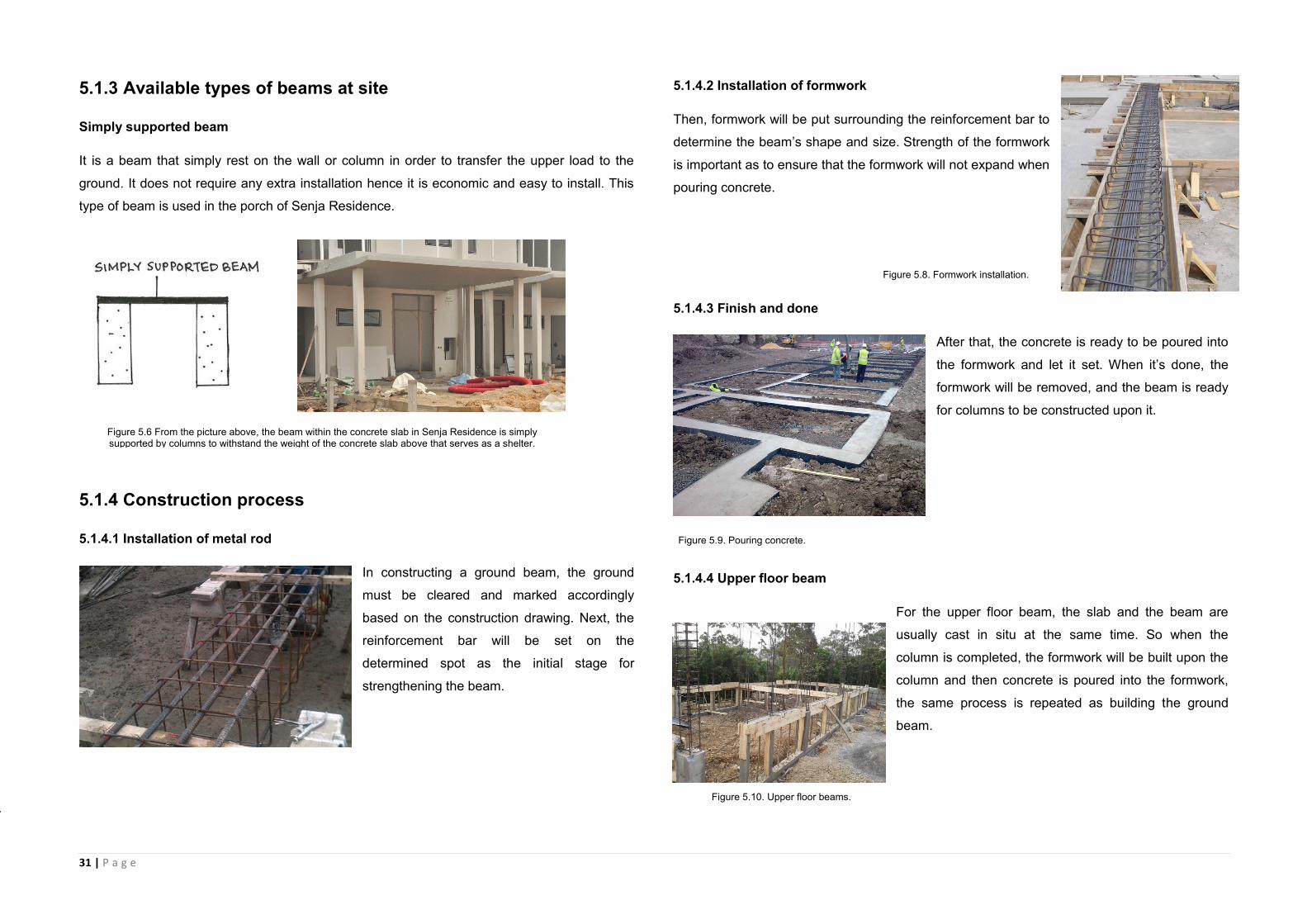
IV) Continuous Beam
The continuous beam is a supported beam that has more than two supports. This type of beam
is used when the longer span of beam is needed while short distant, “simply supported beam”
will not be enough to do the work. This type of beam is usually seen in the construction of a
bridge.
V) Overhanging beam
The overhanging beam extends beyond the wall or the column support. It is the unsupported
portion of the beam. It may extend one side or both sides of the simply supported beam.
Figure 5.1. Fixed beam.
Figure 5.2. Cantilever beam.
Figure 5.3. Continuous beam.
Figure 5.4. Overhanging beam.
Figure 5.4. Overhanging beam.
ONG SENG PENG (0319016)
31 | P a g e
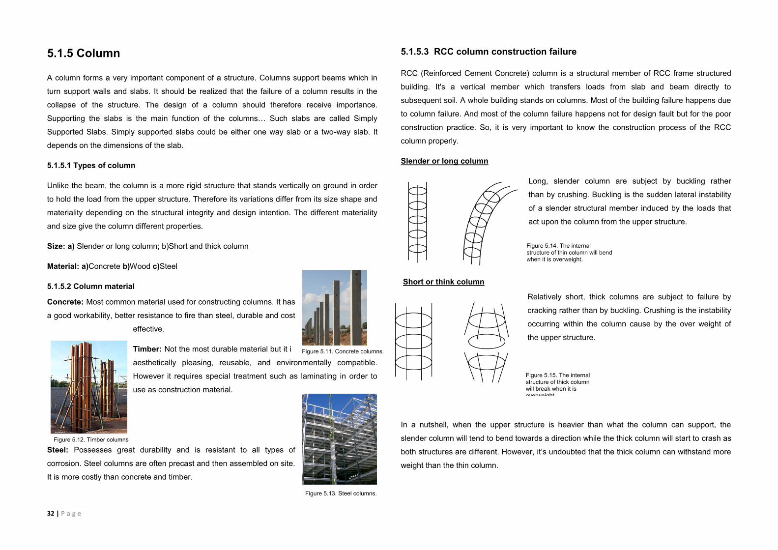
5.1.3 Available types of beams at site
Simply supported beam
It is a beam that simply rest on the wall or column in order to transfer the upper load to the
ground. It does not require any extra installation hence it is economic and easy to install. This
type of beam is used in the porch of Senja Residence.
5.1.4 Construction process
5.1.4.1 Installation of metal rod
In constructing a ground beam, the ground
must be cleared and marked accordingly
based on the construction drawing. Next, the
reinforcement bar will be set on the
determined spot as the initial stage for
strengthening the beam.
5.1.4.2 Installation of formwork
Then, formwork will be put surrounding the reinforcement bar to
determine the beam’s shape and size. Strength of the formwork
is important as to ensure that the formwork will not expand when
pouring concrete.
5.1.4.3 Finish and done
After that, the concrete is ready to be poured into
the formwork and let it set. When it’s done, the
formwork will be removed, and the beam is ready
for columns to be constructed upon it.
5.1.4.4 Upper floor beam
For the upper floor beam, the slab and the beam are
usually cast in situ at the same time. So when the
column is completed, the formwork will be built upon the
column and then concrete is poured into the formwork,
the same process is repeated as building the ground
beam.
Figure 5.6 From the picture above, the beam within the concrete slab in Senja Residence is simply supported by columns to withstand the weight of the concrete slab above that serves as a shelter.
Figure 5.7. Metal rod installation.
Figure 5.8. Formwork installation.
Figure 5.9. Pouring concrete.
Figure 5.10. Upper floor beams.
32 | P a g e
5.1.5 Column
A column forms a very important component of a structure. Columns support beams which in
turn support walls and slabs. It should be realized that the failure of a column results in the
collapse of the structure. The design of a column should therefore receive importance.
Supporting the slabs is the main function of the columns… Such slabs are called Simply
Supported Slabs. Simply supported slabs could be either one way slab or a two-way slab. It
depends on the dimensions of the slab.
5.1.5.1 Types of column
Unlike the beam, the column is a more rigid structure that stands vertically on ground in order
to hold the load from the upper structure. Therefore its variations differ from its size shape and
materiality depending on the structural integrity and design intention. The different materiality
and size give the column different properties.
Size: a) Slender or long column; b)Short and thick column
Material: a)Concrete b)Wood c)Steel
5.1.5.2 Column material
Concrete: Most common material used for constructing columns. It has
a good workability, better resistance to fire than steel, durable and cost
effective.
Timber: Not the most durable material but it is
aesthetically pleasing, reusable, and environmentally compatible.
However it requires special treatment such as laminating in order to
use as construction material.
Steel: Possesses great durability and is resistant to all types of
corrosion. Steel columns are often precast and then assembled on site.
It is more costly than concrete and timber.
5.1.5.3 RCC column construction failure
RCC (Reinforced Cement Concrete) column is a structural member of RCC frame structured
building. It's a vertical member which transfers loads from slab and beam directly to
subsequent soil. A whole building stands on columns. Most of the building failure happens due
to column failure. And most of the column failure happens not for design fault but for the poor
construction practice. So, it is very important to know the construction process of the RCC
column properly.
Slender or long column
Long, slender column are subject by buckling rather
than by crushing. Buckling is the sudden lateral instability
of a slender structural member induced by the loads that
act upon the column from the upper structure.
Short or think column
Relatively short, thick columns are subject to failure by
cracking rather than by buckling. Crushing is the instability
occurring within the column cause by the over weight of
the upper structure.
In a nutshell, when the upper structure is heavier than what the column can support, the
slender column will tend to bend towards a direction while the thick column will start to crash as
both structures are different. However, it’s undoubted that the thick column can withstand more
weight than the thin column.
Figure 5.15. The internal structure of thick column will break when it is overweight.
Figure 5.14. The internal structure of thin column will bend when it is overweight.
Figure 5.11. Concrete columns.
Figure 5.12. Timber columns
Figure 5.13. Steel columns.
33 | P a g e
5.1.7 Available types of beams at site
The type of columns that used in our site is the slender
square concrete column.
From the picture on the left, we can see that the slender
columns not only hold up the concrete slab but also
improve the beauty of the house and maximize the space
for the user.
5.1.8 Construction process (site visit – concrete column)
5.1.8.1 Installation of metal rod
After completing the foundation, with the beams or floor slabs is done, the construction of
columns begins. The reinforcement work will starts first, the metal bars will be set accordingly
to the construction drawing, and each bar is added with spacer block to prevent the steel bar
from touching the formwork.
5.1.8.2 Installation of formwork
Then, formwork will be put surrounding the reinforcement bar to determine the beam’s shape
and size. The formwork is assembled piece by piece surrounding the metal rods.
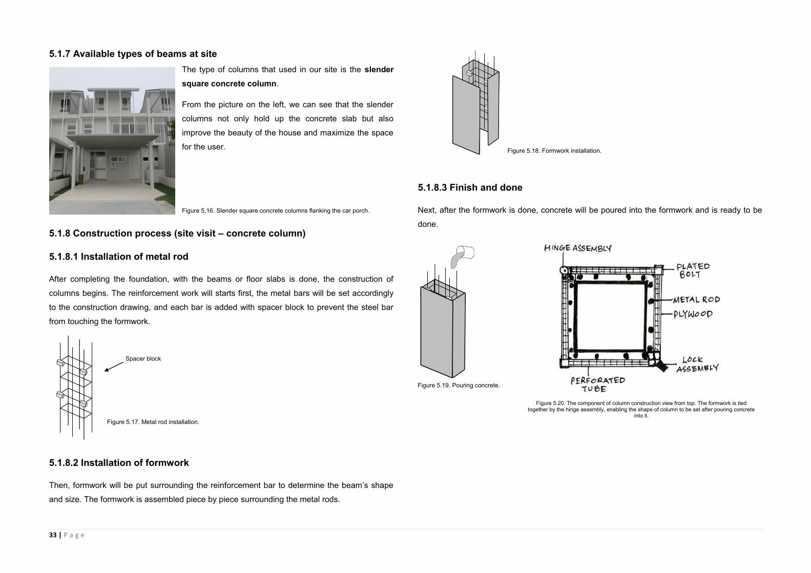
5.1.8.3 Finish and done
Next, after the formwork is done, concrete will be poured into the formwork and is ready to be
done.
Spacer block
Figure 5.20. The component of column construction view from top. The formwork is tied together by the hinge assembly, enabling the shape of column to be set after pouring concrete
into it.
Figure 5.16. Slender square concrete columns flanking the car porch.
Figure 5.19. Pouring concrete.
Figure 5.18. Formwork installation.
Figure 5.17. Metal rod installation.

34 | P a g e
5.2 Slab
A concrete slab is a common structural element of modern buildings. Horizontal slabs of
steel reinforced concrete, typically between 4 and 20 inches thick, are most often used to
construct floors and ceilings, while thinner slabs are also used for exterior paving. Concrete
slabs are just the foundation for floor and ceiling; it is still needed to have a floor finishing to
complete a floor. The failure of concrete slabs are often caused by the moisture as it will affect
the durability of the concrete slabs, therefore, a damp-proof membrane is necessary to be
installed underneath the concrete bed in order to keep the concrete dry.
5.2.1 Construction process (site visit – concrete slab)
The following pictures will illustrate the process of constructing the concrete slab in our site,
Senja Residence.
5.2.1.1 Clearance of site
The construction of concrete slab went through the
same process as the construction of beam and column
with some different procedures. First, the site will be
cleared for the beginning of construction work; after the
foundation is ready, concrete slab is ready to be built.
5.2.1.2 Installation of reinforcement
The installation of steel bar for slab is tied together with
beam. Welded Reinforcement Mesh (for construction) is
regularly used for concrete slab construction. The cost, time
and labour savings of welded wire fabric reinforcing offers
an advantage over traditional tied rebar.
5.2.1.3 Installation of formwork
Installation of formwork will begin after installation of
reinforcement, formwork is made used in our site is made
of wood and can be used over and over again for the
consequence floor slab hence is economic.
5.2.1.4 Setting phase
When the concrete is poured into the formwork, the worker
will make sure the surface is even.
5.2.1.4 Finish and done
The formwork will be removed when the concrete slab is set.
The concrete slab will ultimately be finished with titles when
the construction is come to the ending stage.
Figure 5.21. The components within concrete slab, the binder will be used to even off the hard-core if damp-proof membrane is needed. The damp-proof member will prevent water from entering the building and prevent the green growth inside the building thus ensure the safety of the building.
Figure 5.22. Site clearance.
Figure 5.23. Reinforcement installation.
Figure 5.24. Formwork installation.
Figure 5.25. Concrete setting.
Figure 5.26. Finish setting.
Figure 5.26 Concrete slab Is set
ONG SENG PENG (0319016)
35 | P a g e
5.3 Wall
Usually a thin vertical structure. The main function of an external wall is to provide
shelter against weather conditions and the daily and seasonal variations of outside
temperature.
To provide proper shelter, walls should have sufficient strength and stability to be self-
supporting and to support roofs and upper floors load.
The majority of walls for single, double or triple story buildings are either built using load
bearing masonry walls or are framed from concrete, steel or timber.
The type of wall used depends on factors like availability of supply of labour and
materials, economic issues and the design approach.
5.3.1 Function of walls
To provide protection from the weather and animals.
To divide the areas.
Act as sound barriers.
As fire walls to attenuate the spread of fire from one building unit to another.
Separate the interior spaces.
To improve the building appearance.
To provide privacy.
5.3.2 Materials for wall construction
Timber, brick, concrete block, reinforced concrete can be used for wall construction.
Cengal is suitable to be used at hot and cold climate area
Meranti can be used for all types of construction in the building.
Reinforced concrete used for precast concrete panel
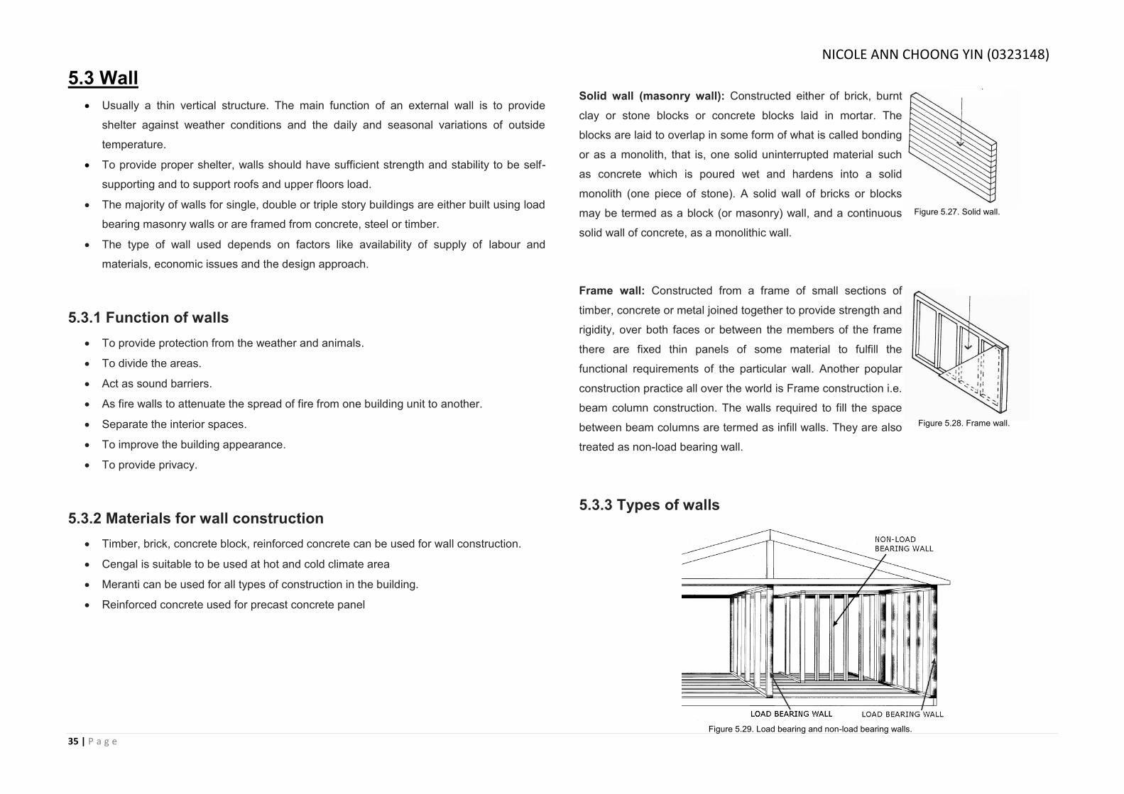
Solid wall (masonry wall): Constructed either of brick, burnt
clay or stone blocks or concrete blocks laid in mortar. The
blocks are laid to overlap in some form of what is called bonding
or as a monolith, that is, one solid uninterrupted material such
as concrete which is poured wet and hardens into a solid
monolith (one piece of stone). A solid wall of bricks or blocks
may be termed as a block (or masonry) wall, and a continuous
solid wall of concrete, as a monolithic wall.
Frame wall: Constructed from a frame of small sections of
timber, concrete or metal joined together to provide strength and
rigidity, over both faces or between the members of the frame
there are fixed thin panels of some material to fulfill the
functional requirements of the particular wall. Another popular
construction practice all over the world is Frame construction i.e.
beam column construction. The walls required to fill the space
between beam columns are termed as infill walls. They are also
treated as non-load bearing wall.
5.3.3 Types of walls
Figure 5.27. Solid wall.
Figure 5.28. Frame wall.
Figure 5.29. Load bearing and non-load bearing walls.
NICOLE ANN CHOONG YIN (0323148)
36 | P a g e
Load bearing walls are walls that bear a load resting upon it by distributing its weight to a
foundation structure. The materials most often used to construct load-bearing walls in large
buildings are concrete, block, or brick. The main purpose of this wall is to enclose or divide a
space of the building to make it more functional and useful. It provides privacy, security and
gives protection against weather conditions. Non load bearing walls however only carry their
own weight and are freestanding. They are mostly partitions or infill panels.
5.3.4 Masonry
Brick masonry units may be solid, hollow, or architectural terra cotta. All types can serve a
structural or decorative function or even a combination of both. The various types differ in their
formation and composition.
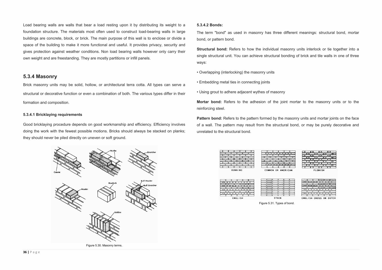
5.3.4.1 Bricklaying requirements
Good bricklaying procedure depends on good workmanship and efficiency. Efficiency involves
doing the work with the fewest possible motions. Bricks should always be stacked on planks;
they should never be piled directly on uneven or soft ground.
5.3.4.2 Bonds:
The term "bond" as used in masonry has three different meanings: structural bond, mortar
bond, or pattern bond.
Structural bond: Refers to how the individual masonry units interlock or tie together into a
single structural unit. You can achieve structural bonding of brick and tile walls in one of three
ways:
• Overlapping (interlocking) the masonry units
• Embedding metal ties in connecting joints
• Using grout to adhere adjacent wythes of masonry
Mortar bond: Refers to the adhesion of the joint mortar to the masonry units or to the
reinforcing steel.
Pattern bond: Refers to the pattern formed by the masonry units and mortar joints on the face
of a wall. The pattern may result from the structural bond, or may be purely decorative and
unrelated to the structural bond.
Figure 5.30. Masonry terms.
Figure 5.31. Types of bond.
37 | P a g e
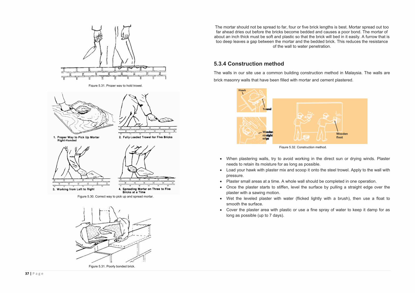
The mortar should not be spread to far, four or five brick lengths is best. Mortar spread out too far ahead dries out before the bricks become bedded and causes a poor bond. The mortar of
about an inch thick must be soft and plastic so that the brick will bed in it easily. A furrow that is too deep leaves a gap between the mortar and the bedded brick. This reduces the resistance
of the wall to water penetration.
5.3.4 Construction method
The walls in our site use a common building construction method in Malaysia. The walls are
brick masonry walls that have been filled with mortar and cement plastered.
When plastering walls, try to avoid working in the direct sun or drying winds. Plaster
needs to retain its moisture for as long as possible.
Load your hawk with plaster mix and scoop it onto the steel trowel. Apply to the wall with
pressure.
Plaster small areas at a time. A whole wall should be completed in one operation.
Once the plaster starts to stiffen, level the surface by pulling a straight edge over the
plaster with a sawing motion.
Wet the leveled plaster with water (flicked lightly with a brush), then use a float to
smooth the surface.
Cover the plaster area with plastic or use a fine spray of water to keep it damp for as
long as possible (up to 7 days).
Figure 5.31. Proper way to hold trowel.
Figure 5.32. Construction method.
Figure 5.31. Poorly bonded brick.
Figure 5.30. Correct way to pick up and spread mortar.

38 | P a g e
The masonry walls from our site used a running bond. Figure 5.33 was a picture taken before
the cement plastering begins.
5.4 Staircase
A staircase or stairway is one or more flights of stairs leading from one floor to another, and
includes landings, newel posts, handrails, balustrades and additional parts. A stairwell is a
compartment extending vertically through a building in which stairs are placed.
5.4.1 Function of Stairs
Provide circulation between floor levels
Establish a safe means of travel between floor levels
Provide an easy means of travel between floor levels
Provide a means of conveying fittings and furniture between floor levels.
5.4.2 Types of Stairs
There are several types of staircases. Although straight stairs are one of the most common
types of stairs found in commercial and residential properties, our site uses a winder staircase,
which is a variation of an L shaped stair but instead of a flat landing, they have pie triangular
shaped steps at the corner transition.
Figure 5.34(Types of staircases)
Figure 5.33. Masonry wall under construction.
Figure 5.33. After cement plaster.
NICOLE ANN CHOONG YIN (0323148)
39 | P a g e
5.4.3 Stairs Terminology
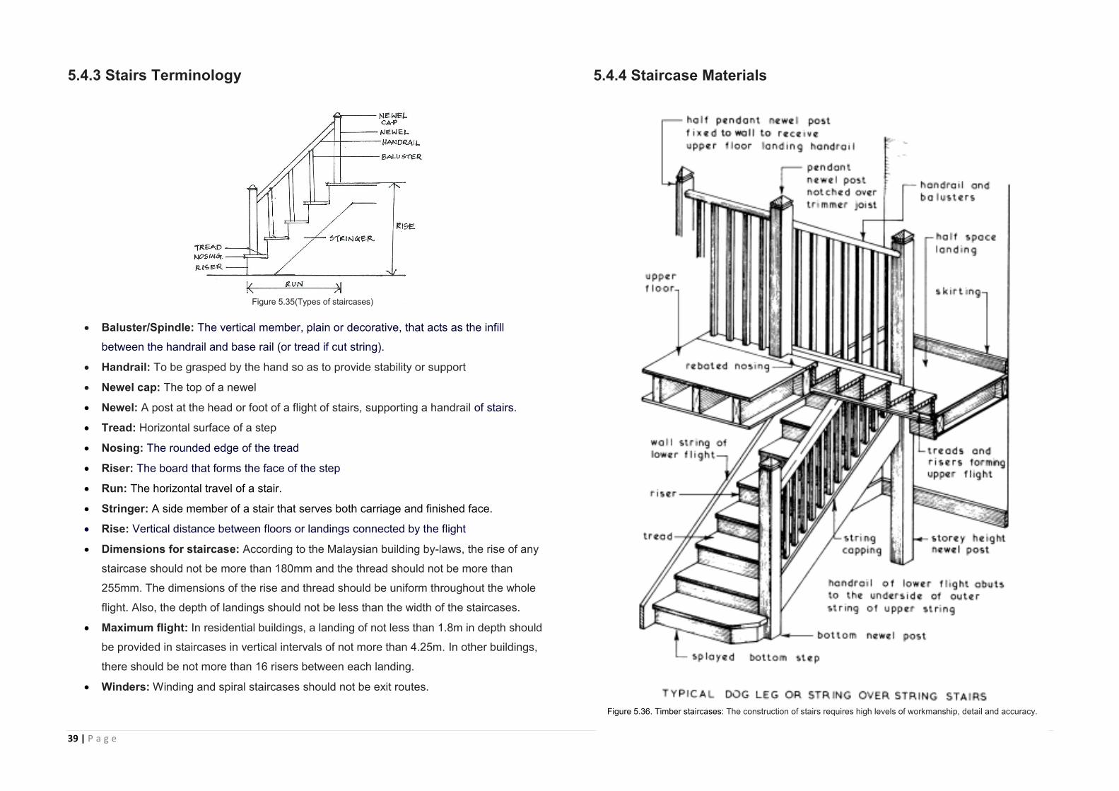
Baluster/Spindle: The vertical member, plain or decorative, that acts as the infill
between the handrail and base rail (or tread if cut string).
Handrail: To be grasped by the hand so as to provide stability or support
Newel cap: The top of a newel
Newel: A post at the head or foot of a flight of stairs, supporting a handrail of stairs.
Tread: Horizontal surface of a step
Nosing: The rounded edge of the tread
Riser: The board that forms the face of the step
Run: The horizontal travel of a stair.
Stringer: A side member of a stair that serves both carriage and finished face.
Rise: Vertical distance between floors or landings connected by the flight
Dimensions for staircase: According to the Malaysian building by-laws, the rise of any
staircase should not be more than 180mm and the thread should not be more than
255mm. The dimensions of the rise and thread should be uniform throughout the whole
flight. Also, the depth of landings should not be less than the width of the staircases.
Maximum flight: In residential buildings, a landing of not less than 1.8m in depth should
be provided in staircases in vertical intervals of not more than 4.25m. In other buildings,
there should be not more than 16 risers between each landing.
Winders: Winding and spiral staircases should not be exit routes.
5.4.4 Staircase Materials
Figure 5.35(Types of staircases)
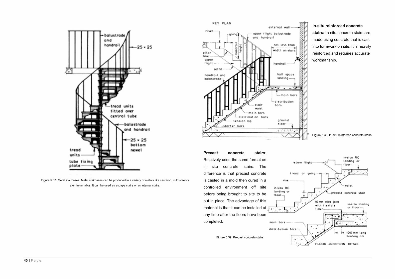
Figure 5.36. Timber staircases: The construction of stairs requires high levels of workmanship, detail and accuracy.
40 | P a g e
In-situ reinforced concrete
stairs: In-situ concrete stairs are
made using concrete that is cast
into formwork on site. It is heavily
reinforced and requires accurate
workmanship.
Precast concrete stairs:
Relatively used the same format as
in situ concrete stairs. The
difference is that precast concrete
is casted in a mold then cured in a
controlled environment off site
before being brought to site to be
put in place. The advantage of this
material is that it can be installed at
any time after the floors have been
completed.
Figure 5.37. Metal staircases: Metal staircases can be produced in a variety of metals like cast iron, mild steel or
aluminium alloy. It can be used as escape stairs or as internal stairs.
Figure 5.38. In-situ reinforced concrete stairs
Figure 5.39. Precast concrete stairs
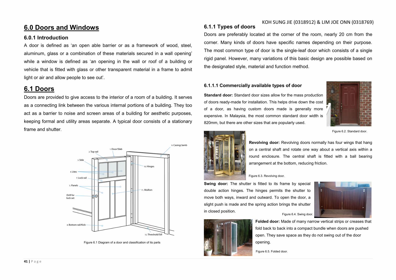
41 | P a g e
6.0 Doors and Windows
6.0.1 Introduction
A door is defined as ‘an open able barrier or as a framework of wood, steel,
aluminum, glass or a combination of these materials secured in a wall opening’
while a window is defined as ‘an opening in the wall or roof of a building or
vehicle that is fitted with glass or other transparent material in a frame to admit
light or air and allow people to see out’.
6.1 Doors Doors are provided to give access to the interior of a room of a building. It serves
as a connecting link between the various internal portions of a building. They too
act as a barrier to noise and screen areas of a building for aesthetic purposes,
keeping formal and utility areas separate. A typical door consists of a stationary
frame and shutter.
6.1.1 Types of doors
Doors are preferably located at the corner of the room, nearly 20 cm from the
corner. Many kinds of doors have specific names depending on their purpose.
The most common type of door is the single-leaf door which consists of a single
rigid panel. However, many variations of this basic design are possible based on
the designated style, material and function method.
6.1.1.1 Commercially available types of door
Standard door: Standard door sizes allow for the mass production
of doors ready-made for installation. This helps drive down the cost
of a door, as having custom doors made is generally more
expensive. In Malaysia, the most common standard door width is
820mm, but there are other sizes that are popularly used.
Revolving door: Revolving doors normally has four wings that hang
on a central shaft and rotate one way about a vertical axis within a
round enclosure. The central shaft is fitted with a ball bearing
arrangement at the bottom, reducing friction.
Swing door: The shutter is fitted to its frame by special
double action hinges. The hinges permits the shutter to
move both ways, inward and outward. To open the door, a
slight push is made and the spring action brings the shutter
in closed position.
Folded door: Made of many narrow vertical strips or creases that
fold back to back into a compact bundle when doors are pushed
open. They save space as they do not swing out of the door
opening. Figure 6.1 Diagram of a door and classification of its parts
Figure 6.2 uPVC patio door on site
Figure 6.2. Standard door.
Figure 6.3. Revolving door.
Figure 6.4. Swing door.
Figure 6.5. Folded door.
KOH SUNG JIE (0318912) & LIM JOE ONN (0318769)
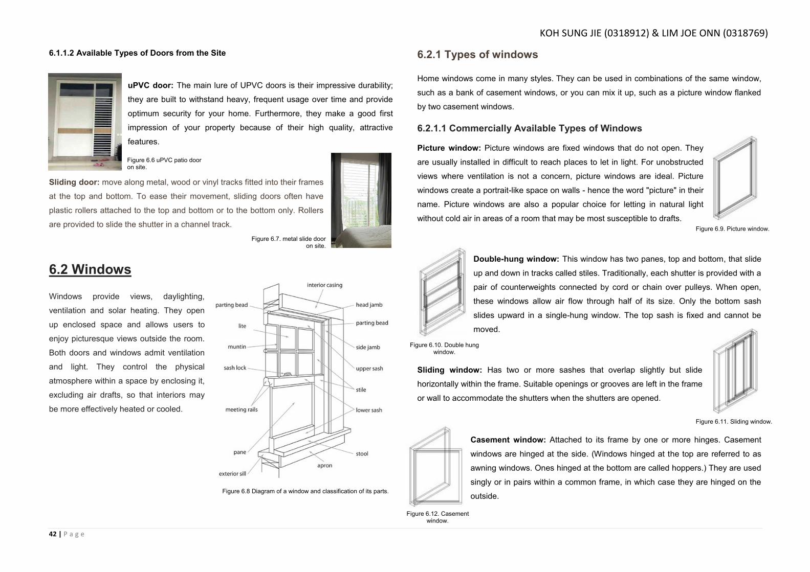
42 | P a g e
6.1.1.2 Available Types of Doors from the Site
uPVC door: The main lure of UPVC doors is their impressive durability;
they are built to withstand heavy, frequent usage over time and provide
optimum security for your home. Furthermore, they make a good first
impression of your property because of their high quality, attractive
features.
Sliding door: move along metal, wood or vinyl tracks fitted into their frames
at the top and bottom. To ease their movement, sliding doors often have
plastic rollers attached to the top and bottom or to the bottom only. Rollers
are provided to slide the shutter in a channel track.
6.2 Windows
Windows provide views, daylighting,
ventilation and solar heating. They open
up enclosed space and allows users to
enjoy picturesque views outside the room.
Both doors and windows admit ventilation
and light. They control the physical
atmosphere within a space by enclosing it,
excluding air drafts, so that interiors may
be more effectively heated or cooled.
6.2.1 Types of windows
Home windows come in many styles. They can be used in combinations of the same window,
such as a bank of casement windows, or you can mix it up, such as a picture window flanked
by two casement windows.
6.2.1.1 Commercially Available Types of Windows
Picture window: Picture windows are fixed windows that do not open. They
are usually installed in difficult to reach places to let in light. For unobstructed
views where ventilation is not a concern, picture windows are ideal. Picture
windows create a portrait-like space on walls - hence the word "picture" in their
name. Picture windows are also a popular choice for letting in natural light
without cold air in areas of a room that may be most susceptible to drafts.
Double-hung window: This window has two panes, top and bottom, that slide
up and down in tracks called stiles. Traditionally, each shutter is provided with a
pair of counterweights connected by cord or chain over pulleys. When open,
these windows allow air flow through half of its size. Only the bottom sash
slides upward in a single-hung window. The top sash is fixed and cannot be
moved.
Sliding window: Has two or more sashes that overlap slightly but slide
horizontally within the frame. Suitable openings or grooves are left in the frame
or wall to accommodate the shutters when the shutters are opened.
Casement window: Attached to its frame by one or more hinges. Casement
windows are hinged at the side. (Windows hinged at the top are referred to as
awning windows. Ones hinged at the bottom are called hoppers.) They are used
singly or in pairs within a common frame, in which case they are hinged on the
outside.
Figure 6.6 uPVC patio door on site.
Figure 6.8 Diagram of a window and classification of its parts.
Figure 6.7. metal slide door on site.
Figure 6.9. Picture window.
Figure 6.10. Double hung window.
Figure 6.11. Sliding window.
Figure 6.12. Casement window.
KOH SUNG JIE (0318912) & LIM JOE ONN (0318769)

43 | P a g e
6.2.1.2 Available Types of Windows from the Site
Pivoted window:
Pivot windows in which the window sash revolves within a window frame,
allows a wider opening than is common with other window types. The
design of a pivot window also allows for larger than standard window sizes.
The shutter is capable of rotating about a pivot fixed to window frame.
Louvered window: Louvered windows are provided for the
sole function of ventilation and not for the vision outside. The
styles are grooved to receive a series of louvers usually fixed
at a 450 inclination sloping downward to the outside to run-off
rain water. Such windows are recommended for rooms where
privacy is vital.
Fixed window: The glass pane is permanently fixed in the opening of
the wall. The shutter cannot be opened or closed and is fully glazed.
The function is limited to allowing light into the room.
6.3 Door and Window Materials
6.3.1 Material Selection
Material selection depends on multiple factors including climate, location in the building,
availability of cost, customer taste and also taking into account the advantages and
disadvantages of each material.
6.3.1.1 Window Frames
Wood (From site visit): For years, wood has been a readily available window substrate, and
the most common choice for homes. It could be painted a solid colour or stained and sealed to
display wood grain.
Wood is also strong and easy to work with, is a natural
insulator and complements many forms of architecture.
Compared to vinyl and fiberglass, wood frames require more
maintenance. If not maintained properly, it is susceptible to
termite attacks or rotting. Regular sealing, staining or
painting is needed to prolong the beauty and performance of
the window or door. Frequent touch-ups and the occasional
refurbishing, sanding and applying new coats is almost
always required.
Fiberglass: Fiberglass frames are composed of
glass fibers and resin. These materials expand and
contract very little with temperature changes in the
weather, making it highly durable. Fiberglass
windows and doors can replicate the look and feel of
wood with a veneer while helping to resist swelling,
rotting and warping. Fiberglass frames do not require
repainting for upkeep but the colour can be changed
by painting it.
Vinyl: a synthetic resin or plastic consisting of polyvinyl
chloride or a related polymer. It is exceptionally energy
efficient and durable. It is non-corroding and virtually
maintenance-free. Each additive to vinyl helps determine the
long-term characteristics of the final product, like its weather
and impact resistance. For example, titanium dioxide makes
the vinyl more heat resistant, thus suitable for tropical climates.
Figure 6.5 Vertical Pivot Window on site
Figure 6.13 Louvered window on site
Figure 6.14 Fixed window on site.
Figure 6.15 Choices of wood pattern for doors
Figure 6.17 Vinyl glss frame
Figure 6.16 Fiberglass window details
KOH SUNG JIE (0318912) & LIM JOE ONN (0318769)

44 | P a g e
Aluminium: Light yet strong, aluminium windows and doors
can be configured into a wide variety of combinations. The
narrowness of the frame places the focus on the glass and
subsequently, the view it offers. Aluminium is not
recommended in beach homes for while the material is water
resistant, it can suffer corrosion from salt water and salt air.
Compared with vinyl, fiberglass and wood frames, aluminium
conducts heat and cold the least well.
6.3.2 Window Panes
Laminated glass (From site visit): Used to increase the
sound insulation rating of a window, where it significantly
improves sound attenuation compared to unlaminated glass
panes of the same thickness. For this purpose a special
"acoustic PVB" compound is used for the interlayer.
6.4 Installation Process
6.4.1 Doors Installation (Site Visit)
6.4.1.1 uPVC Door Installation
Cut the sill supplied to the correct size and fit the end caps provided using superglue or
silicone sealant. Bed the sill onto a thin layer of mortar or silicone sealant before leveling
and fixing into the brickwork opening using frame fixings minimum 100mm long. 3 fixings
should be sufficient.
Fit the locking barrel and handles supplied using the screws provided.
Place the door and frame onto the sill, level and plumb the frame then pack into place
using plastic packers or wedges. Once you are happy with the position of the door fix
the frame to the sill using self-tapping screws minimum 65mm long. 2 fixings should be
sufficient but ensure that no fixings are closer than 150mm to the welded corners. Fix
the side jambs of the frame into the brickwork using frame fixings minimum 100mm long.
4 fixings should be sufficient but ensure that no fixings are closer than 150mm to the
welded corners. Re-check that the frame is still level and plumb, if it has moved then just
loosen the fixings and repack as appropriate.
Remove the beading from the inside of the door; remove the protective tape from both
sides of the infill panel. Place the infill panel or sealed units supplied into the door and
pack tight into place using plastic packers or wedges, the packers should only be
inserted as per the illustration. Re-fit the beads to secure the infill panel or sealed units
into place.
Remove all of the protective tapes and fit the hinge cover caps supplied.
Figure 6.18 Tilt and Turn aluminium window
Figure 6.19 Laminated glass on site
Figure 6.20 Sill is set under the door Figure 6.21 Head jamb & side jamb
Figure 6.22 infill panel is placed
KOH SUNG JIE (0318912) & LIM JOE ONN (0318769)
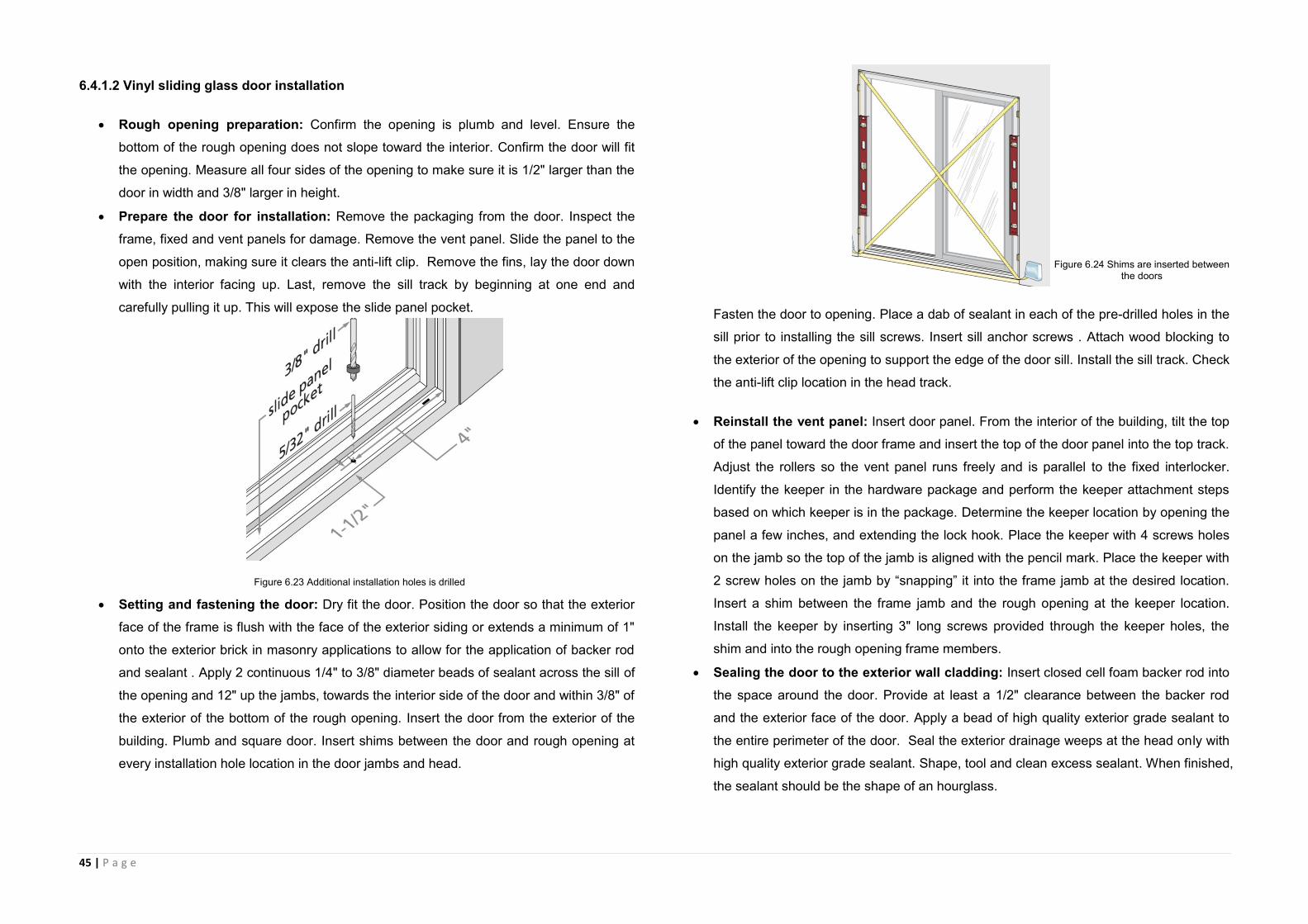
45 | P a g e
6.4.1.2 Vinyl sliding glass door installation
Rough opening preparation: Confirm the opening is plumb and level. Ensure the
bottom of the rough opening does not slope toward the interior. Confirm the door will fit
the opening. Measure all four sides of the opening to make sure it is 1/2" larger than the
door in width and 3/8" larger in height.
Prepare the door for installation: Remove the packaging from the door. Inspect the
frame, fixed and vent panels for damage. Remove the vent panel. Slide the panel to the
open position, making sure it clears the anti-lift clip. Remove the fins, lay the door down
with the interior facing up. Last, remove the sill track by beginning at one end and
carefully pulling it up. This will expose the slide panel pocket.
Setting and fastening the door: Dry fit the door. Position the door so that the exterior
face of the frame is flush with the face of the exterior siding or extends a minimum of 1"
onto the exterior brick in masonry applications to allow for the application of backer rod
and sealant . Apply 2 continuous 1/4" to 3/8" diameter beads of sealant across the sill of
the opening and 12" up the jambs, towards the interior side of the door and within 3/8" of
the exterior of the bottom of the rough opening. Insert the door from the exterior of the
building. Plumb and square door. Insert shims between the door and rough opening at
every installation hole location in the door jambs and head.
Fasten the door to opening. Place a dab of sealant in each of the pre-drilled holes in the
sill prior to installing the sill screws. Insert sill anchor screws . Attach wood blocking to
the exterior of the opening to support the edge of the door sill. Install the sill track. Check
the anti-lift clip location in the head track.
Reinstall the vent panel: Insert door panel. From the interior of the building, tilt the top
of the panel toward the door frame and insert the top of the door panel into the top track.
Adjust the rollers so the vent panel runs freely and is parallel to the fixed interlocker.
Identify the keeper in the hardware package and perform the keeper attachment steps
based on which keeper is in the package. Determine the keeper location by opening the
panel a few inches, and extending the lock hook. Place the keeper with 4 screws holes
on the jamb so the top of the jamb is aligned with the pencil mark. Place the keeper with
2 screw holes on the jamb by “snapping” it into the frame jamb at the desired location.
Insert a shim between the frame jamb and the rough opening at the keeper location.
Install the keeper by inserting 3" long screws provided through the keeper holes, the
shim and into the rough opening frame members.
Sealing the door to the exterior wall cladding: Insert closed cell foam backer rod into
the space around the door. Provide at least a 1/2" clearance between the backer rod
and the exterior face of the door. Apply a bead of high quality exterior grade sealant to
the entire perimeter of the door. Seal the exterior drainage weeps at the head only with
high quality exterior grade sealant. Shape, tool and clean excess sealant. When finished,
the sealant should be the shape of an hourglass.
Figure 6.23 Additional installation holes is drilled
Figure 6.24 Shims are inserted between the doors
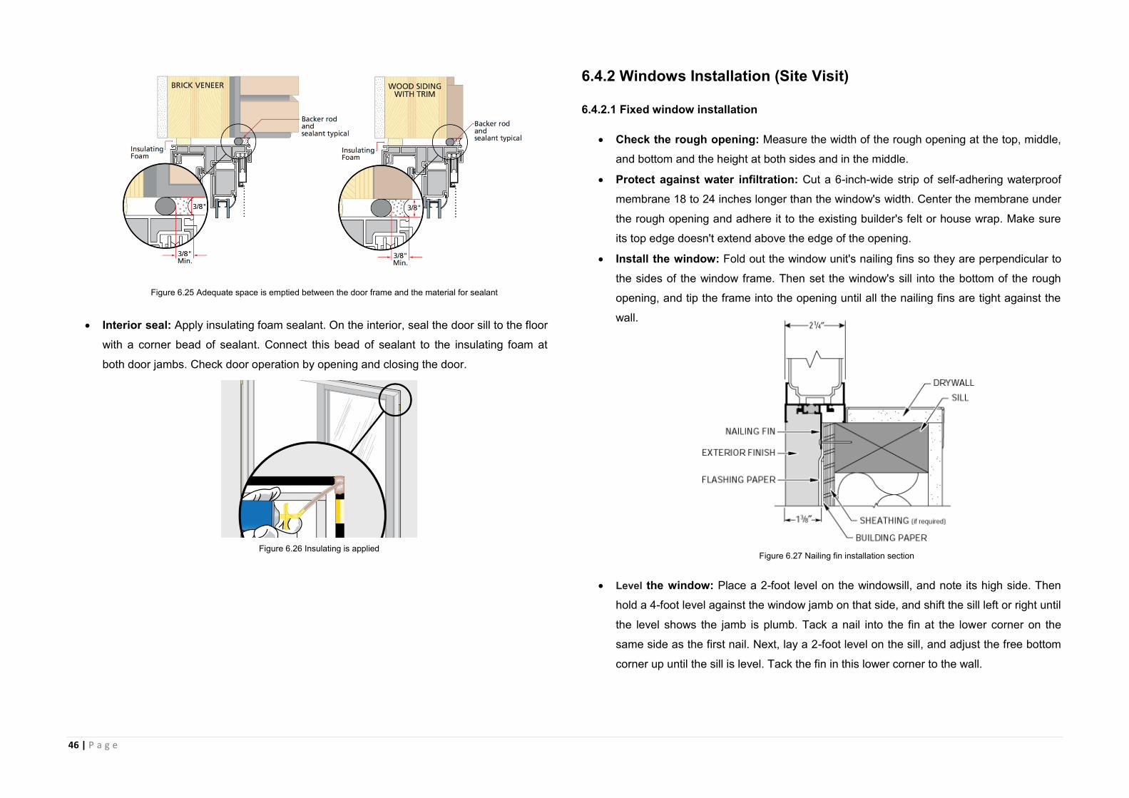
46 | P a g e
Interior seal: Apply insulating foam sealant. On the interior, seal the door sill to the floor
with a corner bead of sealant. Connect this bead of sealant to the insulating foam at
both door jambs. Check door operation by opening and closing the door.
6.4.2 Windows Installation (Site Visit)
6.4.2.1 Fixed window installation
Check the rough opening: Measure the width of the rough opening at the top, middle,
and bottom and the height at both sides and in the middle.
Protect against water infiltration: Cut a 6-inch-wide strip of self-adhering waterproof
membrane 18 to 24 inches longer than the window's width. Center the membrane under
the rough opening and adhere it to the existing builder's felt or house wrap. Make sure
its top edge doesn't extend above the edge of the opening.
Install the window: Fold out the window unit's nailing fins so they are perpendicular to
the sides of the window frame. Then set the window's sill into the bottom of the rough
opening, and tip the frame into the opening until all the nailing fins are tight against the
wall.
Level the window: Place a 2-foot level on the windowsill, and note its high side. Then
hold a 4-foot level against the window jamb on that side, and shift the sill left or right until
the level shows the jamb is plumb. Tack a nail into the fin at the lower corner on the
same side as the first nail. Next, lay a 2-foot level on the sill, and adjust the free bottom
corner up until the sill is level. Tack the fin in this lower corner to the wall.
Figure 6.25 Adequate space is emptied between the door frame and the material for sealant
Figure 6.26 Insulating is applied Figure 6.27 Nailing fin installation section
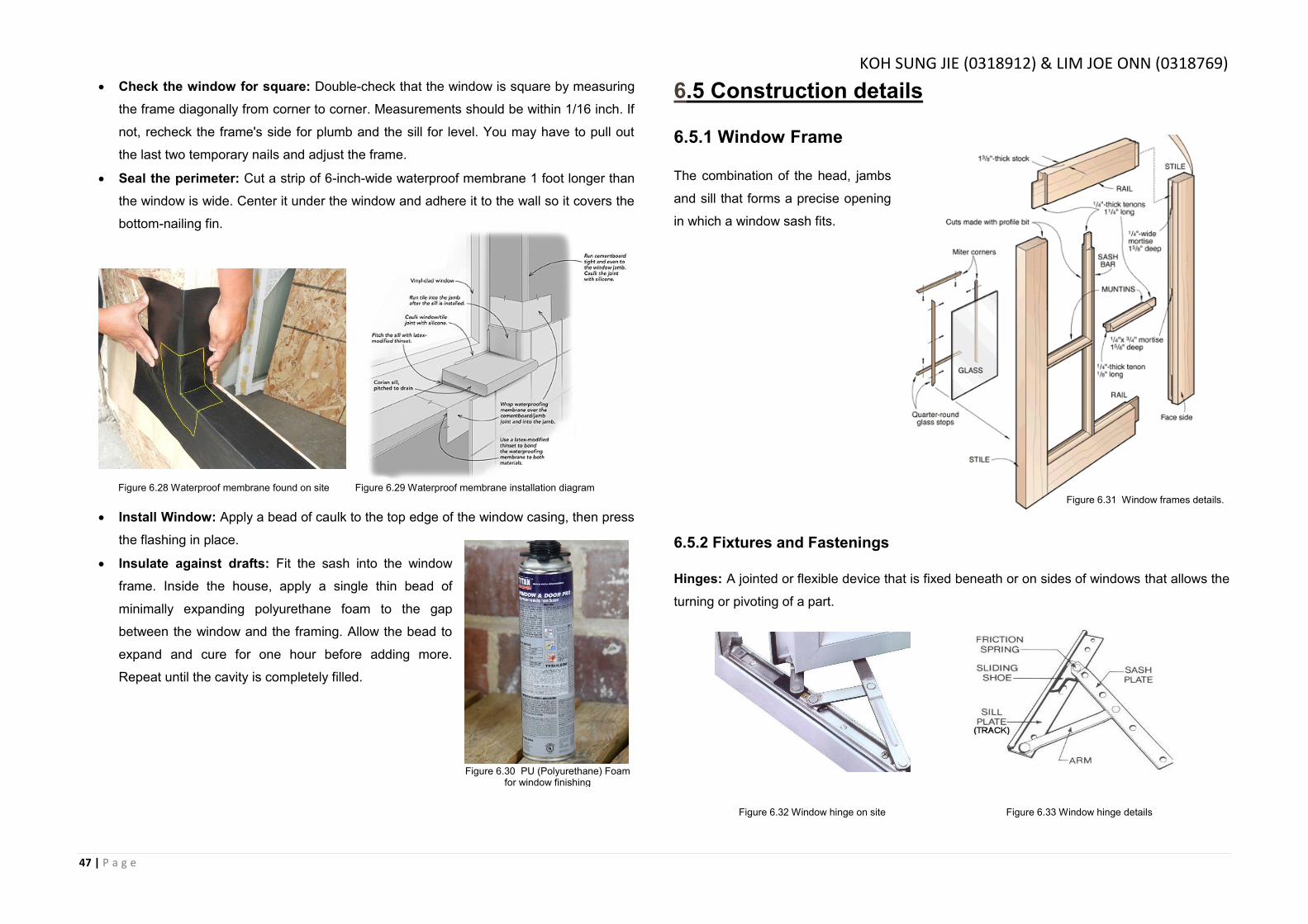
47 | P a g e
Check the window for square: Double-check that the window is square by measuring
the frame diagonally from corner to corner. Measurements should be within 1/16 inch. If
not, recheck the frame's side for plumb and the sill for level. You may have to pull out
the last two temporary nails and adjust the frame.
Seal the perimeter: Cut a strip of 6-inch-wide waterproof membrane 1 foot longer than
the window is wide. Center it under the window and adhere it to the wall so it covers the
bottom-nailing fin.
Install Window: Apply a bead of caulk to the top edge of the window casing, then press
the flashing in place.
Insulate against drafts: Fit the sash into the window
frame. Inside the house, apply a single thin bead of
minimally expanding polyurethane foam to the gap
between the window and the framing. Allow the bead to
expand and cure for one hour before adding more.
Repeat until the cavity is completely filled.
6.5 Construction details
6.5.1 Window Frame
The combination of the head, jambs
and sill that forms a precise opening
in which a window sash fits.
6.5.2 Fixtures and Fastenings
Hinges: A jointed or flexible device that is fixed beneath or on sides of windows that allows the
turning or pivoting of a part.
Figure 6.28 Waterproof membrane found on site Figure 6.29 Waterproof membrane installation diagram
Figure 6.31 Window frames details.
Figure 6.32 Window hinge on site Figure 6.33 Window hinge details
Figure 6.25 Standard door handle Figure 6.25 show that stardard distance between screw hole is 43mm.
Figure 6.30 PU (Polyurethane) Foam for window finishing
KOH SUNG JIE (0318912) & LIM JOE ONN (0318769)

48 | P a g e
Bolts: A metal bar on window that slides across to lock it closed, it provides a locking window
stop which secures the window in the closed position using a standard key.
Handles: An alternative method to lock a window rather than
using window latch, which is more expensive and assured
security. Most handles are ‘push-and-turn’ handles. Various
finishes are available.
Figure 6.34 Window bolts set
Figure 6.35 Push-and-turn window handle.

49 | P a g e
7.0 Roof
7.0.1 Introduction
Roofs can be classified as either: 1) Flat – pitch from 0’ to 10’ 2) Pitched – pitch over 10’. It is
worth nothing that for design purposes roof pitches over 70’ are classified as walls.
Roof can be designed in many different forms and in combinations of these forms some of
which would not be suitable and/or economic for domestic properties.
7.0.2 Types of roof shapes
Roof shapes differ greatly from region to region. The main factors which influence the shape of
roofs are the climate and the materials available for roof structure and the outer covering. Roof
terminology is also not rigidly defined. Usages vary slightly from region to region, or from one
builder or architect to another.Roof shapes vary from almost flat to steeply pitched. They can
be arched or domed; a single flat sheet or a complex arrangement of slopes, gables and hips;
or truncated (terraced, cut) to minimize the overall height.
7.0.2.1 Examples of roof types:
Gable Roof: Gable roof designs are one of the more simple styles when it comes to
roofs. The gable roof style looks like an inverted/upside down V. Gable roofs are not
ideal for areas with high wind because they easily can catch the wind much like a sail
would.
Flat Roof: Flat roofs are common especially with commercial buildings. Flat roofs are
definitely the most simple roof to build because they have little to no pitch. The most
common types of roofing systems used with flat roofs are rubber roofing systems.
Hip Roof: Hip roofs are a common residential style roof. This type of roof is more
difficult to construct when compared to flat roofs and gable roofs because they have
a more complicated truss and rafter structure.
Gambrel Roof: The best way to describe a gambrel roof is by saying barn roof. The
gambrel style roof is most commonly used on barns. However, it is also used in
residential construction. This type of roof has the benefit of providing a good amount
of space in the attic.
Butterfly Roof: The butterfly roof is not a roof style that is widely used. The style
provides plenty of light and ventilation but is not the effective when it comes to water
drainage.
7.0.2.2 Available Types of Roofs From The Site
Double-pitched slate roofs with eaves
Reinforced concrete flat roof
Figure 7.2 Top view of pitched roofs showing concrete tiles
Figure 7.3 Top view of concrete flat roof
A roof formed by joining two
parallel gable roofs, creating a
valley between them,
resembling the capital letter M
in section.
Roof platform, which is either
horizontal or inclined up to 10
degrees (to prevent ponding),
usually surrounded by
fascia/parapet wall
Figure 7.1 Composited diagram of Pitched-roof showing terminology
Roof type: Gable roof
Roof type: Flat roof
TAN WEN HAO (0319923)
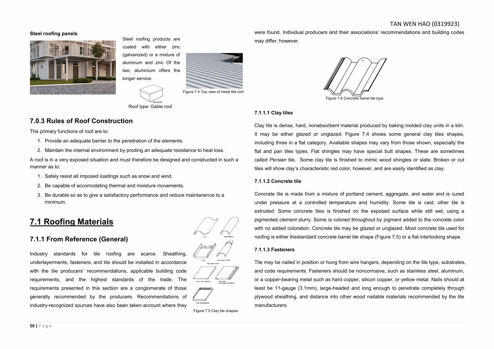
50 | P a g e
Steel roofing panels
7.0.3 Rules of Roof Construction
The primary functions of roof are to:
1. Provide an adequate barrier to the penetration of the elements.
2. Maintain the internal environment by proding an adequate resistance to heat loss.
A roof is in a very exposed situation and must therefore be designed and constructed in such a
manner as to:
1. Safely resist all imposed loadings such as snow and wind.
2. Be capable of accomodating thermal and moisture movements.
3. Be durable so as to give a satisfactory performance and reduce maintanence to a
minimum.
7.1 Roofing Materials
7.1.1 From Reference (General)
Industry standards for tile roofing are scarce. Sheathing,
underlayerments, fasteners, and tile should be installed in accordance
with the tile producers’ recommendations, applicable building code
requirements, and the highest standards of the trade. The
requirements presented in this section are a conglomerate of those
generally recommended by the producers. Recommendations of
industry-recognized sources have also been taken account where they
were found. Individual producers and their associations’ recommendations and building codes
may differ, however.
7.1.1.1 Clay tiles
Clay tile is dense, hard, nonabsorbent material produced by baking molded clay units in a kiln.
It may be either glazed or unglazed. Figure 7.4 shows some general clay tiles shapes,
including three in a flat category. Available shapes may vary from those shown, especially the
flat and pan tiles types. Flat shingles may have special butt shapes. These are sometimes
called Persian tile. Some clay tile is finished to mimic wood shingles or slate. Broken or cut
tiles will show clay’s characteristic red color, however, and are easily identified as clay.
7.1.1.2 Concrete tile
Concrete tile is made from a mixture of portland cement, aggregate, and water and is cured
under pressure at a controlled temperature and humidity. Some tile is cast; other tile is
extruded. Some concrete tiles is finished on the exposed surface while still wet, using a
pigmented clement slurry. Some is colored throughout by pigment added to the concrete color
with no added coloration. Concrete tile may be glazed or unglazed. Most concrete tile used for
roofing is either thestandard concrete barrel tile shape (Figure 7.5) or a flat interlocking shape.
7.1.1.3 Fasteners
Tile may be nailed in position or hung from wire hangers, depending on the tile type, substrates,
and code requirements. Fasteners should be noncorrosive, such as stainless steel, aluminum,
or a copper-bearing metal such as hard copper, silicon copper, or yellow metal. Nails should at
least be 11-gauge (3.1mm), large-headed and long enough to penetrate completely through
plywood sheathing, and distance into other wood nailable materials recommended by the tile
manufacturers.
Figure 7.4 Top view of metal flat roof
Figure 7.6 Concrete barrel tile type
Steel roofing products are
coated with either zinc
(galvanized) or a mixture of
aluminum and zinc Of the
two, aluminium offers the
longer service.
Roof type: Gable roof
Figure 7.5 Clay tile shapes
TAN WEN HAO (0319923)
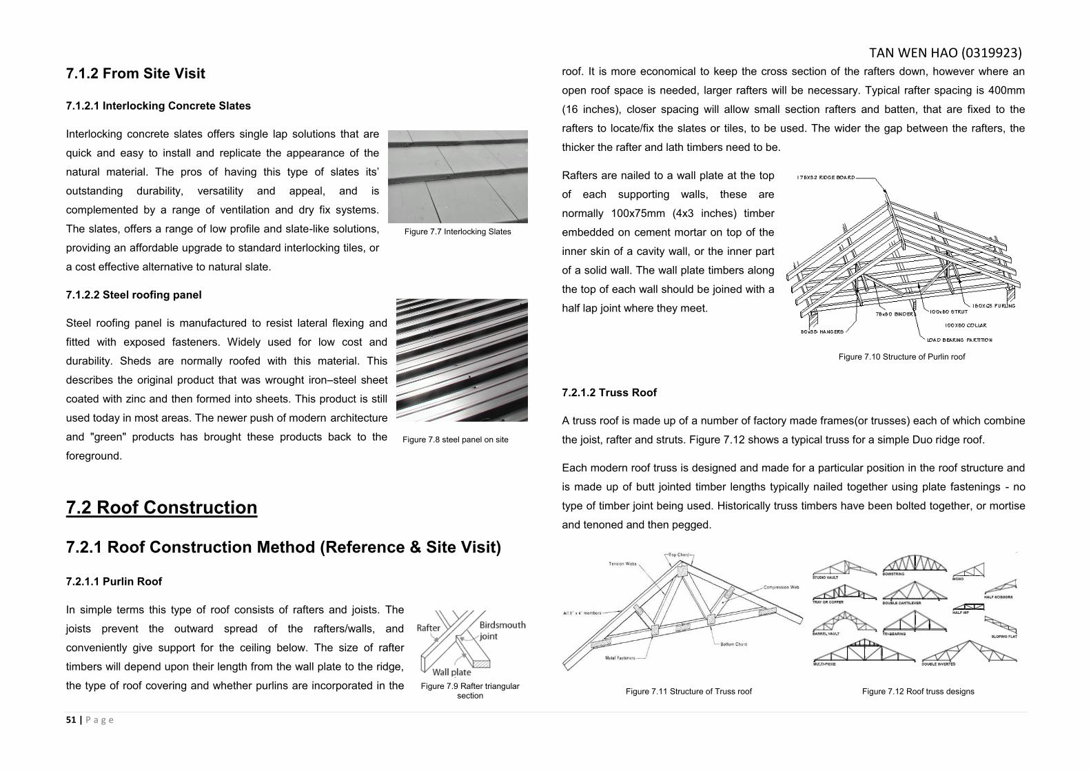
51 | P a g e
7.1.2 From Site Visit
7.1.2.1 Interlocking Concrete Slates
Interlocking concrete slates offers single lap solutions that are
quick and easy to install and replicate the appearance of the
natural material. The pros of having this type of slates its’
outstanding durability, versatility and appeal, and is
complemented by a range of ventilation and dry fix systems.
The slates, offers a range of low profile and slate-like solutions,
providing an affordable upgrade to standard interlocking tiles, or
a cost effective alternative to natural slate.
7.1.2.2 Steel roofing panel
Steel roofing panel is manufactured to resist lateral flexing and
fitted with exposed fasteners. Widely used for low cost and
durability. Sheds are normally roofed with this material. This
describes the original product that was wrought iron–steel sheet
coated with zinc and then formed into sheets. This product is still
used today in most areas. The newer push of modern architecture
and "green" products has brought these products back to the
foreground.
7.2 Roof Construction
7.2.1 Roof Construction Method (Reference & Site Visit)
7.2.1.1 Purlin Roof
In simple terms this type of roof consists of rafters and joists. The
joists prevent the outward spread of the rafters/walls, and
conveniently give support for the ceiling below. The size of rafter
timbers will depend upon their length from the wall plate to the ridge,
the type of roof covering and whether purlins are incorporated in the
roof. It is more economical to keep the cross section of the rafters down, however where an
open roof space is needed, larger rafters will be necessary. Typical rafter spacing is 400mm
(16 inches), closer spacing will allow small section rafters and batten, that are fixed to the
rafters to locate/fix the slates or tiles, to be used. The wider the gap between the rafters, the
thicker the rafter and lath timbers need to be.
Rafters are nailed to a wall plate at the top
of each supporting walls, these are
normally 100x75mm (4x3 inches) timber
embedded on cement mortar on top of the
inner skin of a cavity wall, or the inner part
of a solid wall. The wall plate timbers along
the top of each wall should be joined with a
half lap joint where they meet.
7.2.1.2 Truss Roof
A truss roof is made up of a number of factory made frames(or trusses) each of which combine
the joist, rafter and struts. Figure 7.12 shows a typical truss for a simple Duo ridge roof.
Each modern roof truss is designed and made for a particular position in the roof structure and
is made up of butt jointed timber lengths typically nailed together using plate fastenings - no
type of timber joint being used. Historically truss timbers have been bolted together, or mortise
and tenoned and then pegged.
Figure 7.7 Interlocking Slates
Figure 7.8 steel panel on site
Figure 7.9 Rafter triangular section
Figure 7.10 Structure of Purlin roof
Figure 7.11 Structure of Truss roof Figure 7.12 Roof truss designs
TAN WEN HAO (0319923)
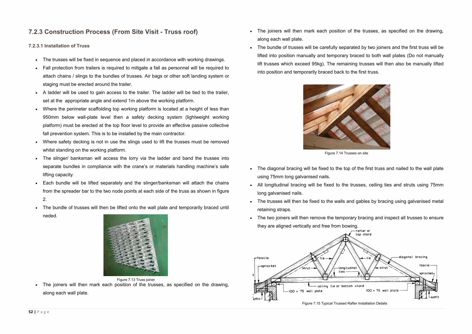
52 | P a g e
7.2.3 Construction Process (From Site Visit - Truss roof)
7.2.3.1 Installation of Truss
The trusses will be fixed in sequence and placed in accordance with working drawings.
Fall protection from trailers is required to mitigate a fall as personnel will be required to
attach chains / slings to the bundles of trusses. Air bags or other soft landing system or
staging must be erected around the trailer.
A ladder will be used to gain access to the trailer. The ladder will be tied to the trailer,
set at the appropriate angle and extend 1m above the working platform.
Where the perimeter scaffolding top working platform is located at a height of less than
950mm below wall-plate level then a safety decking system (lightweight working
platform) must be erected at the top floor level to provide an effective passive collective
fall prevention system. This is to be installed by the main contractor.
Where safety decking is not in use the slings used to lift the trusses must be removed
whilst standing on the working platform.
The slinger/ banksman will access the lorry via the ladder and band the trusses into
separate bundles in compliance with the crane’s or materials handling machine’s safe
lifting capacity.
Each bundle will be lifted separately and the slinger/banksman will attach the chains
from the spreader bar to the two node points at each side of the truss as shown in figure
2.
The bundle of trusses will then be lifted onto the wall plate and temporarily braced until
neded.
The joiners will then mark each position of the trusses, as specified on the drawing,
along each wall plate.
The joiners will then mark each position of the trusses, as specified on the drawing,
along each wall plate.
The bundle of trusses will be carefully separated by two joiners and the first truss will be
lifted into position manually and temporary braced to both wall plates (Do not manually
lift trusses which exceed 95kg). The remaining trusses will then also be manually lifted
into position and temporarily braced back to the first truss.
The diagonal bracing will be fixed to the top of the first truss and nailed to the wall plate
using 75mm long galvanised nails.
All longitudinal bracing will be fixed to the trusses, ceiling ties and struts using 75mm
long galvanised nails.
The trusses will then be fixed to the walls and gables by bracing using galvanised metal
retaining straps.
The two joiners will then remove the temporary bracing and inspect all trusses to ensure
they are aligned vertically and free from bowing.
Figure 7.14 Trusses on site
Figure 7.15 Typical Trussed Rafter Installation Details
Figure 7.13 Truss joiner
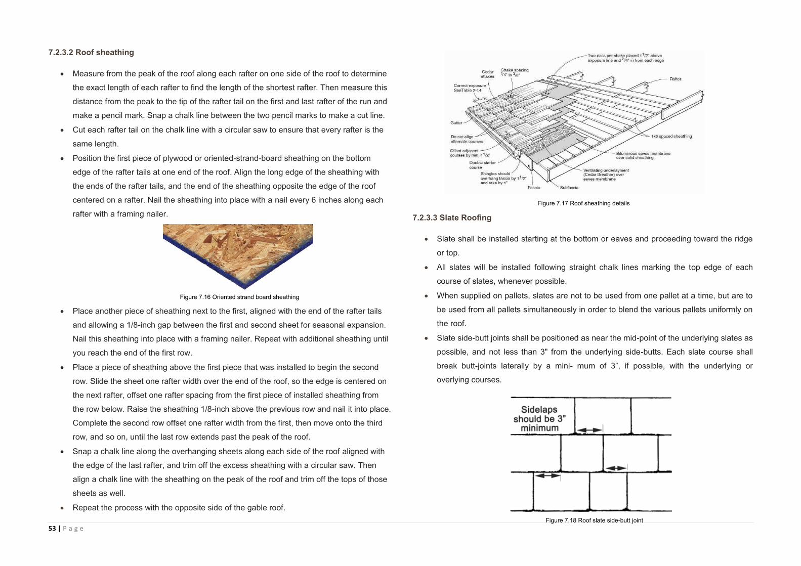
53 | P a g e
7.2.3.2 Roof sheathing
Measure from the peak of the roof along each rafter on one side of the roof to determine
the exact length of each rafter to find the length of the shortest rafter. Then measure this
distance from the peak to the tip of the rafter tail on the first and last rafter of the run and
make a pencil mark. Snap a chalk line between the two pencil marks to make a cut line.
Cut each rafter tail on the chalk line with a circular saw to ensure that every rafter is the
same length.
Position the first piece of plywood or oriented-strand-board sheathing on the bottom
edge of the rafter tails at one end of the roof. Align the long edge of the sheathing with
the ends of the rafter tails, and the end of the sheathing opposite the edge of the roof
centered on a rafter. Nail the sheathing into place with a nail every 6 inches along each
rafter with a framing nailer.
Place another piece of sheathing next to the first, aligned with the end of the rafter tails
and allowing a 1/8-inch gap between the first and second sheet for seasonal expansion.
Nail this sheathing into place with a framing nailer. Repeat with additional sheathing until
you reach the end of the first row.
Place a piece of sheathing above the first piece that was installed to begin the second
row. Slide the sheet one rafter width over the end of the roof, so the edge is centered on
the next rafter, offset one rafter spacing from the first piece of installed sheathing from
the row below. Raise the sheathing 1/8-inch above the previous row and nail it into place.
Complete the second row offset one rafter width from the first, then move onto the third
row, and so on, until the last row extends past the peak of the roof.
Snap a chalk line along the overhanging sheets along each side of the roof aligned with
the edge of the last rafter, and trim off the excess sheathing with a circular saw. Then
align a chalk line with the sheathing on the peak of the roof and trim off the tops of those
sheets as well.
Repeat the process with the opposite side of the gable roof.
7.2.3.3 Slate Roofing
Slate shall be installed starting at the bottom or eaves and proceeding toward the ridge
or top.
All slates will be installed following straight chalk lines marking the top edge of each
course of slates, whenever possible.
When supplied on pallets, slates are not to be used from one pallet at a time, but are to
be used from all pallets simultaneously in order to blend the various pallets uniformly on
the roof.
Slate side-butt joints shall be positioned as near the mid-point of the underlying slates as
possible, and not less than 3" from the underlying side-butts. Each slate course shall
break butt-joints laterally by a mini- mum of 3”, if possible, with the underlying or
overlying courses.
Figure 7.17 Roof sheathing details
Figure 7.16 Oriented strand board sheathing
Figure 7.18 Roof slate side-butt joint
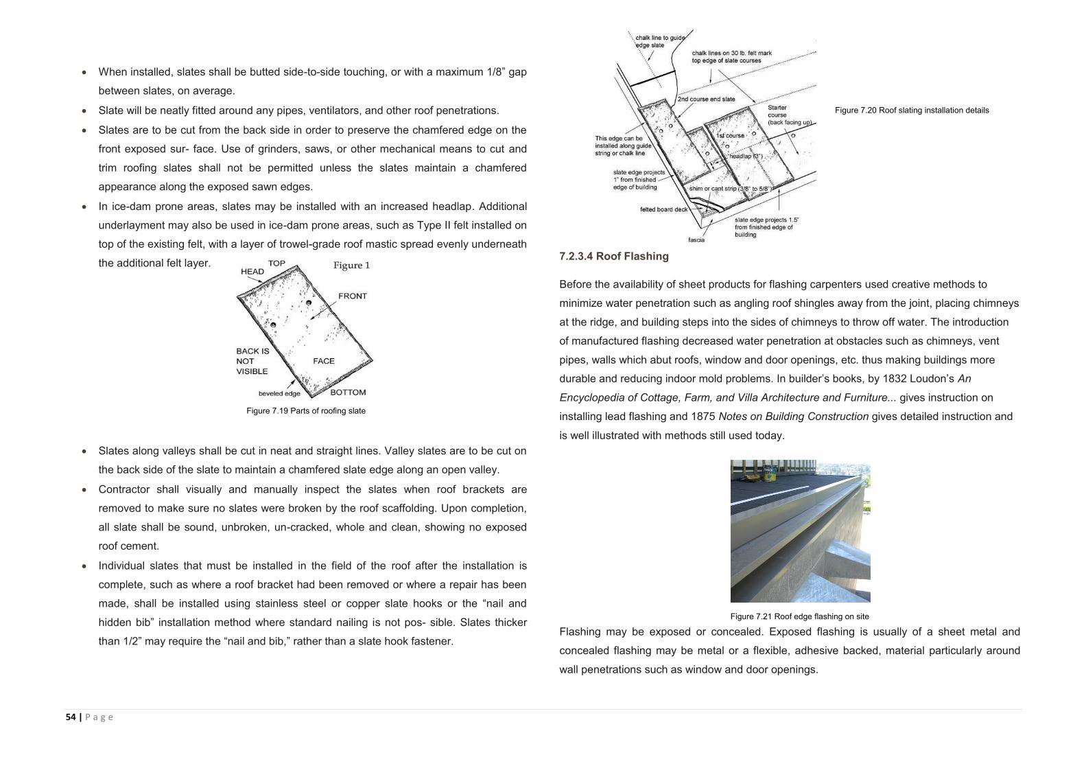
54 | P a g e
When installed, slates shall be butted side-to-side touching, or with a maximum 1/8” gap
between slates, on average.
Slate will be neatly fitted around any pipes, ventilators, and other roof penetrations.
Slates are to be cut from the back side in order to preserve the chamfered edge on the
front exposed sur- face. Use of grinders, saws, or other mechanical means to cut and
trim roofing slates shall not be permitted unless the slates maintain a chamfered
appearance along the exposed sawn edges.
In ice-dam prone areas, slates may be installed with an increased headlap. Additional
underlayment may also be used in ice-dam prone areas, such as Type II felt installed on
top of the existing felt, with a layer of trowel-grade roof mastic spread evenly underneath
the additional felt layer.
Slates along valleys shall be cut in neat and straight lines. Valley slates are to be cut on
the back side of the slate to maintain a chamfered slate edge along an open valley.
Contractor shall visually and manually inspect the slates when roof brackets are
removed to make sure no slates were broken by the roof scaffolding. Upon completion,
all slate shall be sound, unbroken, un-cracked, whole and clean, showing no exposed
roof cement.
Individual slates that must be installed in the field of the roof after the installation is
complete, such as where a roof bracket had been removed or where a repair has been
made, shall be installed using stainless steel or copper slate hooks or the “nail and
hidden bib” installation method where standard nailing is not pos- sible. Slates thicker
than 1/2” may require the “nail and bib,” rather than a slate hook fastener.
7.2.3.4 Roof Flashing
Before the availability of sheet products for flashing carpenters used creative methods to
minimize water penetration such as angling roof shingles away from the joint, placing chimneys
at the ridge, and building steps into the sides of chimneys to throw off water. The introduction
of manufactured flashing decreased water penetration at obstacles such as chimneys, vent
pipes, walls which abut roofs, window and door openings, etc. thus making buildings more
durable and reducing indoor mold problems. In builder’s books, by 1832 Loudon’s An
Encyclopedia of Cottage, Farm, and Villa Architecture and Furniture... gives instruction on
installing lead flashing and 1875 Notes on Building Construction gives detailed instruction and
is well illustrated with methods still used today.
Flashing may be exposed or concealed. Exposed flashing is usually of a sheet metal and
concealed flashing may be metal or a flexible, adhesive backed, material particularly around
wall penetrations such as window and door openings.
Figure 7.20 Roof slating installation details
Figure 7.19 Parts of roofing slate
Figure 7.21 Roof edge flashing on site
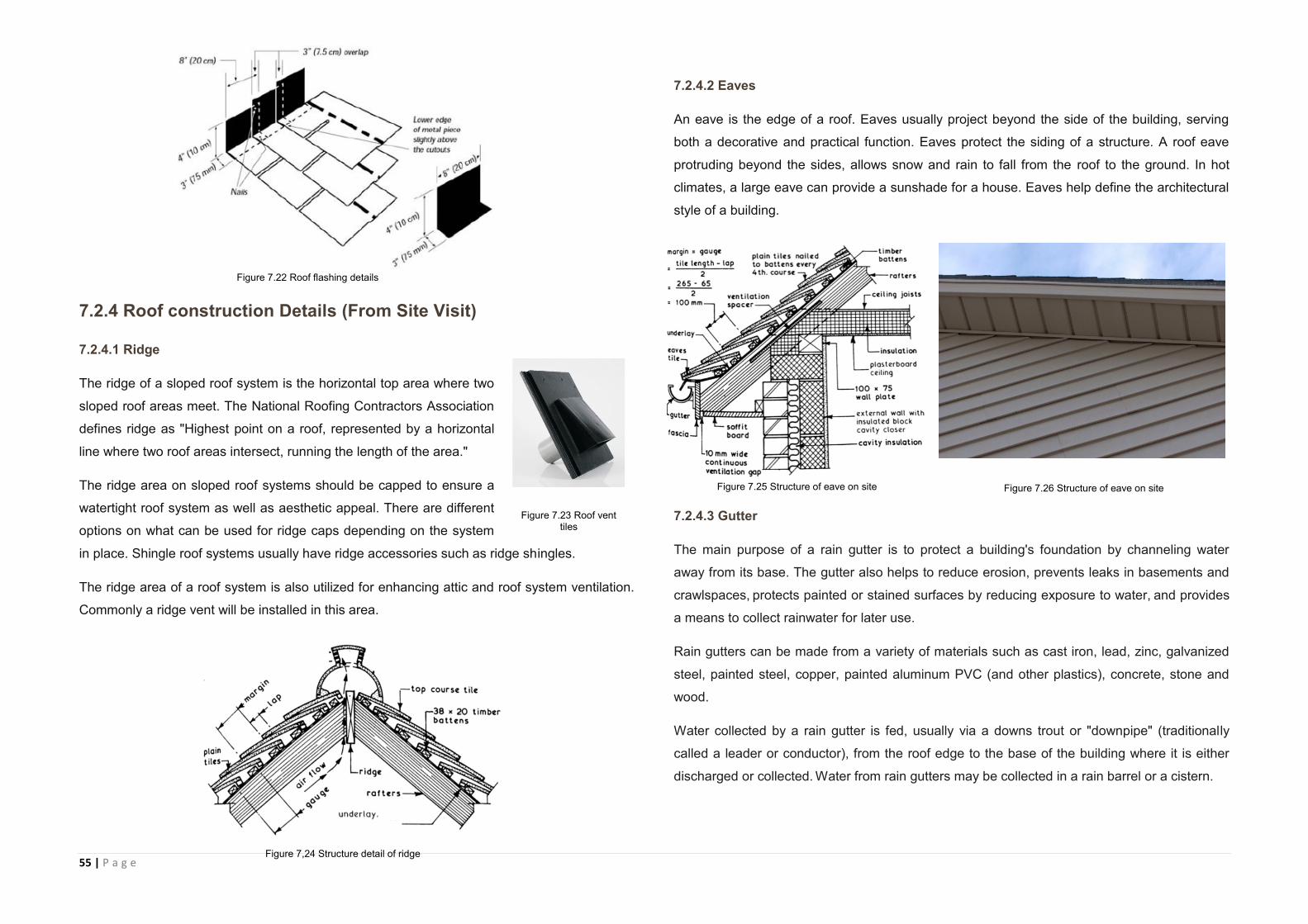
55 | P a g e
7.2.4 Roof construction Details (From Site Visit)
7.2.4.1 Ridge
The ridge of a sloped roof system is the horizontal top area where two
sloped roof areas meet. The National Roofing Contractors Association
defines ridge as "Highest point on a roof, represented by a horizontal
line where two roof areas intersect, running the length of the area."
The ridge area on sloped roof systems should be capped to ensure a
watertight roof system as well as aesthetic appeal. There are different
options on what can be used for ridge caps depending on the system
in place. Shingle roof systems usually have ridge accessories such as ridge shingles.
The ridge area of a roof system is also utilized for enhancing attic and roof system ventilation.
Commonly a ridge vent will be installed in this area.
7.2.4.2 Eaves
An eave is the edge of a roof. Eaves usually project beyond the side of the building, serving
both a decorative and practical function. Eaves protect the siding of a structure. A roof eave
protruding beyond the sides, allows snow and rain to fall from the roof to the ground. In hot
climates, a large eave can provide a sunshade for a house. Eaves help define the architectural
style of a building.
7.2.4.3 Gutter
The main purpose of a rain gutter is to protect a building's foundation by channeling water
away from its base. The gutter also helps to reduce erosion, prevents leaks in basements and
crawlspaces, protects painted or stained surfaces by reducing exposure to water, and provides
a means to collect rainwater for later use.
Rain gutters can be made from a variety of materials such as cast iron, lead, zinc, galvanized
steel, painted steel, copper, painted aluminum PVC (and other plastics), concrete, stone and
wood.
Water collected by a rain gutter is fed, usually via a downs trout or "downpipe" (traditionally
called a leader or conductor), from the roof edge to the base of the building where it is either
discharged or collected. Water from rain gutters may be collected in a rain barrel or a cistern.
Figure 7.22 Roof flashing details
Figure 7.23 Roof vent tiles
Figure 7,24 Structure detail of ridge
Figure 7.25 Structure of eave on site Figure 7.26 Structure of eave on site
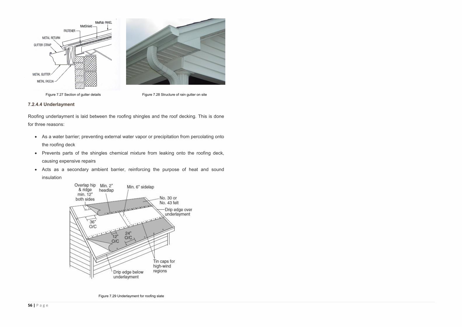
56 | P a g e
7.2.4.4 Underlayment
Roofing underlayment is laid between the roofing shingles and the roof decking. This is done
for three reasons:
As a water barrier; preventing external water vapor or precipitation from percolating onto
the roofing deck
Prevents parts of the shingles chemical mixture from leaking onto the roofing deck,
causing expensive repairs
Acts as a secondary ambient barrier, reinforcing the purpose of heat and sound
insulation
Figure 7.28 Structure of rain gutter on site Figure 7.27 Section of gutter details
Figure 7.29 Underlayment for roofing slate
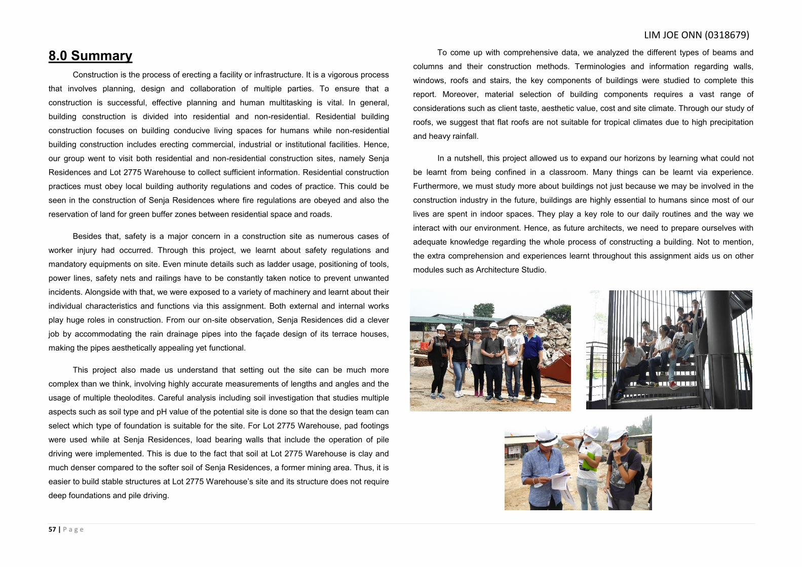
57 | P a g e
8.0 Summary
Construction is the process of erecting a facility or infrastructure. It is a vigorous process
that involves planning, design and collaboration of multiple parties. To ensure that a
construction is successful, effective planning and human multitasking is vital. In general,
building construction is divided into residential and non-residential. Residential building
construction focuses on building conducive living spaces for humans while non-residential
building construction includes erecting commercial, industrial or institutional facilities. Hence,
our group went to visit both residential and non-residential construction sites, namely Senja
Residences and Lot 2775 Warehouse to collect sufficient information. Residential construction
practices must obey local building authority regulations and codes of practice. This could be
seen in the construction of Senja Residences where fire regulations are obeyed and also the
reservation of land for green buffer zones between residential space and roads.
Besides that, safety is a major concern in a construction site as numerous cases of
worker injury had occurred. Through this project, we learnt about safety regulations and
mandatory equipments on site. Even minute details such as ladder usage, positioning of tools,
power lines, safety nets and railings have to be constantly taken notice to prevent unwanted
incidents. Alongside with that, we were exposed to a variety of machinery and learnt about their
individual characteristics and functions via this assignment. Both external and internal works
play huge roles in construction. From our on-site observation, Senja Residences did a clever
job by accommodating the rain drainage pipes into the façade design of its terrace houses,
making the pipes aesthetically appealing yet functional.
This project also made us understand that setting out the site can be much more
complex than we think, involving highly accurate measurements of lengths and angles and the
usage of multiple theolodites. Careful analysis including soil investigation that studies multiple
aspects such as soil type and pH value of the potential site is done so that the design team can
select which type of foundation is suitable for the site. For Lot 2775 Warehouse, pad footings
were used while at Senja Residences, load bearing walls that include the operation of pile
driving were implemented. This is due to the fact that soil at Lot 2775 Warehouse is clay and
much denser compared to the softer soil of Senja Residences, a former mining area. Thus, it is
easier to build stable structures at Lot 2775 Warehouse’s site and its structure does not require
deep foundations and pile driving.
To come up with comprehensive data, we analyzed the different types of beams and
columns and their construction methods. Terminologies and information regarding walls,
windows, roofs and stairs, the key components of buildings were studied to complete this
report. Moreover, material selection of building components requires a vast range of
considerations such as client taste, aesthetic value, cost and site climate. Through our study of
roofs, we suggest that flat roofs are not suitable for tropical climates due to high precipitation
and heavy rainfall.
In a nutshell, this project allowed us to expand our horizons by learning what could not
be learnt from being confined in a classroom. Many things can be learnt via experience.
Furthermore, we must study more about buildings not just because we may be involved in the
construction industry in the future, buildings are highly essential to humans since most of our
lives are spent in indoor spaces. They play a key role to our daily routines and the way we
interact with our environment. Hence, as future architects, we need to prepare ourselves with
adequate knowledge regarding the whole process of constructing a building. Not to mention,
the extra comprehension and experiences learnt throughout this assignment aids us on other
modules such as Architecture Studio.
LIM JOE ONN (0318679)
58 | P a g e
8.1 References
Books
Emmitt, S., & Gorse, C. (2005). Barry’s Introduction to Construction of Buildings (Vol.2). Wiley-Blackwell.
Ching, F. D. K., & Adams, C. (1943). Building Construction Illustrated. (3rd ed.) Canada: John Wiley & Sons.Inc.
Chudley, R. (1987). Construction Technology Vol. 3. (2nd ed.) Harlow: Addison Wesley
Longman Limited.
Chudley, R. & Greeno R. (2008) Building Construction Handbook. (7th ed) Burlington:
Butterworth-Heinemann Elsevier.
Levy, S. (1992). The construction superintendent's handbook. New York: Van Nostrand Reinhold.
Chudley, R., & Greeno, R. (2010). Building construction handbook (8th ed.). Amsterdam: Butterworth-Heinemann.
Grey, A. (2011, July 8). Types of Roof Trusses. Retrieved October 18, 2015
Websites
Civil Engineering Home (n.d.) Retrieved 13 October 2015 from http://theconstructor.org/
How To Install A Window (n.d.) Retrieved 26 September 2015 from http://www.thisoldhouse.com/toh/how-to/step/
Understand Building Construction. Foundations. (n.d.) Retrieved 14 October 2015 from
http://www.understandconstruction.com/introduction-to-foundations.html [Accessed 14th
October 2015]
Robertson, R. (2012, November 3). Roof Underlayment Installation & Detailing. Retrieved
October 18, 2015, from
http://inspectapedia.com/BestPractices/Best_Roofing_Underlayment.php
Home Building & Renovating. Foundations Explains. (n.d.) Retrieved 3 October 2015 from:
http://www.homebuilding.co.uk/2008/12/18/foundations-explained/
The Concrete Center. Foundations. (n.d.) Retrieved 7 October, 2015from:
http://www.concretecentre.com/technical_information/building_solutions/foundations.aspx
Setting Out (n.d.) Retrieved October 3, 2015 from http://bbstore.northbrook-online.ac.uk/store/CITB/BW/materials/Sec05-Setting%20Out/Sec05-M02.pdf
Smith, J. (2013, July 15). How to Choose a Roof for Your Home | Today's Homeowner.
Retrieved October 18, 2015, from http://www.todayshomeowner.com/choosing-a-roof/
Grey, A. (2011, July 8). Types of Roof Trusses. Retrieved October 18, 2015, from http://www.truswood.com/types of roof trusses.htm
Daniels, J. (n.d.). Guide To Design For RCC Columns. Retrieved October 16, 2015, from http://www.civilprojectsonline.com/building-construction/guide-to-design-of-rcc-columns/
Interviews
Lim, T. (personal communication, 12 September 2015)
Shahabuddin, F . (personal communication, 14 September 2015)
Omar, A. (personal communication, 14 September 2015)
LIM JOE ONN (0318679)