Embed Size (px)
Citation preview

Lab Manual OOAD
OOAD LAB MANUAL
Sukanya Roychowdhury
Lecturer
Pillai’s Institute Of Information Technology
Sukanya Roychowdhury

Lab Manual OOAD
Introduction
In late 1960‘s people were concentrating on Procedure Oriented Languages such as COBOL, FORTRAN, PASCAL…etc. Later on they preferred Object Oriented Languages. In the middle of 1970-80 three Scientists named as BOOCH, RUMBAUGH and JACOBSON found a new language named as U nified Mo deling L a n g u a g e . It encompasses the Designing of the System/Program. It is a Defacto language.
What is UML?
• Is a lang u age. It is not simply a notation for drawing diagrams, but a complete language for capturing knowledge (semantics) about a subject and expressing knowledge (syntax) regarding the subject for the purpose of communication.
• Applies to mo d e l i ng and systems. Modeling involves a focus on understanding a subject (system) and capturing and being able to communicate in this knowledge.
• It is the result of u nify i ng the information systems and technology industry‘s bestengineering practices (principals, techniques, methods and tools).
• used for both database and software modeling
O v e r view of the U ML
• The UML is a language for
– visualizing
– specifying
– constructing
– documenting
Sukanya Roychowdhury

Lab Manual OOADThe artifacts of a software-intensive system
Vis u al model i ng (visualizing)
• A picture is worth a thousand words!
- Uses standard graphical notations- Semi-formal- Captures Business Process from enterprise information systems to distributed
Web-based applications and even to hard real time embedded systems
S p e c ify i ng
• building models that are: Precise, Unambiguous, Complete
• UML symbols are based on well-defined syntax and semantics.
• UML addresses the specification of all important analysis, design, and implementation decisions.
Constructing
• Models are related to OO programming languages.
• Round-trip engineering requires tool and human intervention to avoid information loss
– Forward engineering — direct mapping of a UML model into code.
– Reverse engineering — reconstruction of a UML model from animplementation.
Documenting– Architecture, Requirements, Tests, Activities (Project planning, Release management)
Sukanya Roychowdhury

Lab Manual OOAD
Conce ptual Model of the UML
» To understand the UML, you need to form a conceptual model of the language, and this requires learning three major elements.
Elements:1. Basic building blocks2. Rules3. Common Mechanisms
Basic Building Blocks of the UML
The vocabulary of the UML encompasses three kinds of building blocks:» Things» Relationships» Diagrams
1 . S tru c t u r al Things
• These are the N o u n s and Static parts of the model.
• These are representing c on cep tu al or ph y sical elements.
There are seven kinds of structural things:
1. Class2. Interface3. Collaboration4. Use Case5. Active Class6. Component7. Node
1 .Clas s
Is a description of set of objects that share the same attributes, operations methods, relationships and semantics.
Sukanya Roychowdhury

Lab Manual OOAD
Window
OriginSize
Open ( ) Close ( ) Move ( )
Name
Attributes
Operations
A Simple Class
Sukanya Roychowdhury

2 .Interfa ce
A collection of operations that specify a service (for a resource or an action) of a class or component. It describes the externally visible behavior of that element
Nam<<interface>>
Iwindow
Iname
Operation Open () Close ()
A Simple Interface
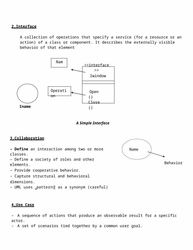
3 .Coll a b o r a tion
– Define an interaction among two or more classes.– Define a society of roles and other elements.– Provide cooperative behavior.– Capture structural and behavioral dimensions.– UML uses ‗pattern‖ as a synonym (careful)
4 .Use Cas e
Name
Behavior
– A sequence of actions that produce an observable result for a specific actor.– A set of scenarios tied together by a common user goal.– Provides a structure for behavioral things.– Realized through a collaboration (usually realized by a set of actors and the system to be built).
Place order
5 . Active Cla ss
– Special class whose objects own one or more processes or threads.
– Can initiate control activity.
Heavy borderEvent
ManagerName
ThreadAttributes
Operations
Time
Suspend () Flush ()
6 . C o m p o nent
• Replaceable part of a system.
• Components can be packaged logically.
• Conforms to a set of interfaces.
• Provides the realization of an interface.
• Represents a physical module of code
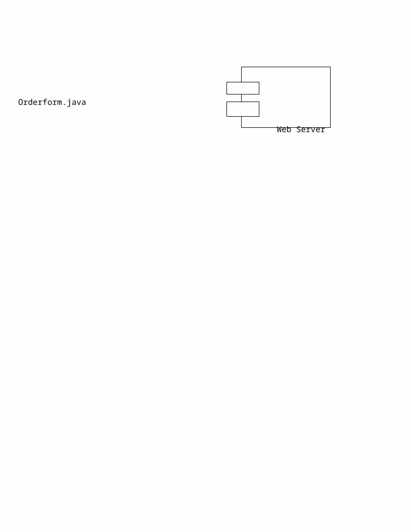
7. No d e
• Element that exists at run t ime .
• Represents a c o m p ut a ti o n a l res o urc e .
• Generally has memory and processing power.
Orderform.java
Web Server


1 .Interaction
• Is a behavior of a set of objects comprising of a set of messages exchanges within a particular context to accomplish a specific purpose.
Display
2 .Sta te Ma chine
• Is a behavior that specifies the sequences of states an object or an interaction goes through during its lifetime in response to events, together with its responses to those events.
Idle Waiting
3. Grouping Things
• These are the o rg a n izati on al parts of the UML models.● There is only one primary kind of group thing:
1 .Pa ckag es
- General purpose mechanism for organizing elements into groups.- Purely conceptual; only exists at development time.- Contains behavioral and structural things.- Can be nested.- Variations of packages are: Frameworks, models, & subsystems.
Business rules
4.Annotational Things
• These are Ex p la n a t o ry parts of UML models
• These are the C o m m e n ts regarding other UML elements (usually called adornments in UML)There is only one primary kind of annotational thing:
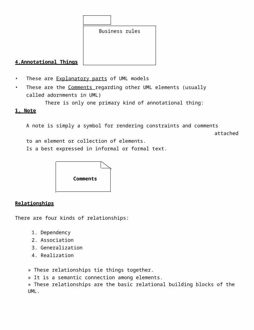
1 . No te
A note is simply a symbol for rendering constraints and comments attached to an element or collection of elements.Is a best expressed in informal or formal text.
Comments
Relat ion ships
There are four kinds of relationships:
1. Dependency2. Association3. Generalization4. Realization
» These relationships tie things together.» It is a semantic connection among elements.» These relationships are the basic relational building blocks of the UML.

1. D ependency Is a semantic relationship between two things in which a change to one thing (the independent thing) may affect the semantics of the other thing (the dependent thing).
2. Associati on
Is a structural relationship that describes a set of links, a link being a connection among objects.
employer employee
0...1 *
Agg regatio n
» Is a special kind of association. It represents a structural relationship between the whole and its parts.
» Represented by black diamond.
3. Ge neral ization
Is a specialization/generalization relationship in which objects of the specialized element (the child) are more specific than the objects of the generalized element.

Diag ra ms
• A diagram is the graphical presentation of a set of elements.
• Represented by a connected graph: Vertices are things; Arcs are behaviors.
UML includes nine diagrams:
• Class Diagram;
• Object Diagram
• Use case Diagram
• Sequence Diagram;
• Collaboration Diagram
• State chart Diagram
• Activity Diagram
• Component Diagram
• Deployment Diagram
Both Sequence and Collaboration diagrams are called Interaction Diagrams.
Experiment No:1:Aim: To implement Inheritance
Inheritance is the concept that when a class of object is defined, any subclass that isdefined can inherit the definitions of one or more general classes. This means for theprogrammer that an object in a subclass need not carry its own definition of data andmethods that are generic to the class (or classes) of which it is a part. This not onlyspeeds up program development; it also ensures an inherent validity to the definedsubclass object (what works and is consistent about the class will also work for thesubclass).The simple example in C++ is having a class that inherits a data member from its parentclass.class A{public:integer d;};class B : public A{public:};The class B in the example does not have any direct data member does it? Yes, it does. Itinherits the data member d from class A. When one class inherits from another, itacquires all of its methods and data. We can then instantiate an object of class B and callinto that data member.void func(){B b;b.d = 10;};

Experiment No. 2:Aim : To Implement Polymorphism
In object-oriented programming, polymorphism (from the Greek meaning "havingmultiple forms") is the characteristic of being able to assign a different meaning to aparticular symbol or "operator" in different contexts.The simple example is two classes that inherit from a common parent and implement thesame virtual method.class A{public:virtual void f()=0;};class B{public:virtual void f(){std::cout << "Hello from B" << std::endl;};};class C{public:virtual void f(){std::cout << "Hello from C" << std::endl;};};If I have an object A, then calling the method f() will produce different results dependingon the context, the real type of the object A.func(A & a){A.f();
};

Experiment No: 3
Aim: Class Diagram
• Class Diagrams describe the static structure of a system, or how it is structured rather than how it behaves.
• A class diagram shows the existence of classes and their relationships in the logical view of a systemThese diagrams contain the following elements.
– Classes and their structure and behavior– Association, aggregation, dependency, and inheritance relationships– Multiplicity and navigation indicators– Role names
These diagrams are the most common diagrams found in O-O modeling systems.
Ex a mples:
RegistrationStudent
Experiment No: 4Aim: Object Diagrams
• Shows a set of objects and their relationships.
• A static snapshot of instances.
• Object Diagrams describe the static structure of a system at a particular time.Whereas a class model describes all possible situations, an object model describesa particular situation.
Object diagrams contain the following elements:
O bj e cts which represent particular entities. These are instances of classes.Lin k s which represent particular relationships between objects. These are instances of
associations.

Harry(Student)
Name:” Harry Mat”Major: C.S
Experiment No: 5
Aim: Use case diagrams
Use Case Diagrams describe the func t i o n a li t y of a system and u s e r s of the system.
These diagrams contain the following elements:
A ct o r s : which represent users of a system, including human users and other systems.
Us e Ca ses: which represent functionality or services provided by a system to users.
Registrar Student
Maintain

Experiment No: 6
Aim: Sequence Diagrams
● Sequence Diagrams describe interactions among classes. These interactions are modeled as exchanges of messages.
● These diagrams focus on classes and the messages they exchange to accomplish
Some desired behavior.
● Sequence diagrams are a type of interaction diagrams. Sequence diagrams
contain the following elements:
C l a s s r o l e s : which represent roles that objects may play within the interaction.
L i f e li n es : which represent the existence of an object over a period of time.A ct i v a t i o ns : which represent the time during which an object is performing an operation.M e s sa g es : which represent communication between objects.
Experiment No: 7
Aim: Collaboration Diagram
Collaboration Diagrams describe i n te r a c t i o ns a m o ng c l as s es a nd a ss o c i a t i o n s . These interactions are modeled as exchanges of messages between classesThrough their associations. Collaboration diagrams are a type of interactionDiagram.
Collaboration diagrams contain the following elements.
C a s s r o l e s : which represent roles that objects may play within the interaction.
A s s o c i a t i o n r o l e s : which represent roles that links may play within the interaction.
M e s sa g e f l o w s : which represent messages sent between objects via links. Links transport or implement the delivery of the message.

Experiment No: 8
Aim: Statechart DiagramsState chart (or state) diagrams describe the states and responses of a class. Statechart
Diagrams describe the behavior of a class in response to external stimuli.
These diagrams contain the following elements:
St a t e s : which represent the situations during the life of an object in which it satisfies some condition, performs some activity, or waits for some occurrence.Tr a n si t i o ns : which represent relationships between the different states of an object.
Experiment No: 9
Aim: Activity Diagrams
Activity diagrams describe the a c t i v i t i e s o f a c la s s . These diagrams are similar to Statechart diagrams and use similar conventions, but activity diagrams describe the behavior of a class in response to internal processing rather than external events as in Statechart diagram.
S w i m l a n e s : which represent responsibilities of one or more objects for actions within an overall activity; that is, they divide the activity states into groups and assign these groups to object that must perform the activities.
A ct io n S t a t e s : which represent atomic, or noninterruptible, actions of entities or steps in the execution of an algorithm.
A ct io n f lo ws : which represent relationships between the different action states of an entity.
Object f l o w s : which represent the utilization of objects by action states and the influence of action states on objects.
Experiment No: 10
Aim: Component Diagram
Component diagrams describe the organizations and dependencies among software Implementation components. These diagrams contain components, which represent Distributable physical units, including source code, object code, and executable code. These are static implementation view of a system.
Experiment No: 11

Aim : Deployment Diagrams
Deployment diagrams describe the configuration of run-time processing resource elements and the mapping of software implementation components onto them. These Diagrams contain components and nodes, which represent processing or computational resources, including computers, printers, etc.