Embed Size (px)
Citation preview
Wave Propagation, Huygens’ Principle, and
Interference
Physics 101 LO
By Elaine Lee
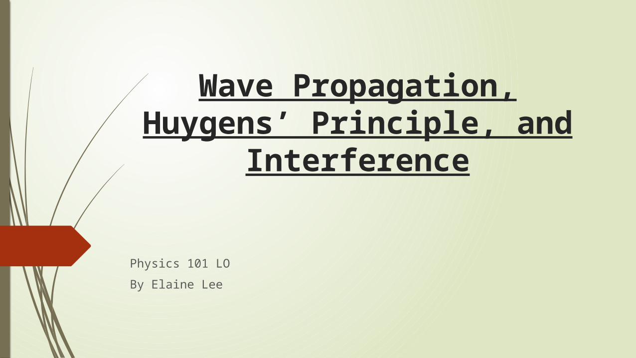
Huygens’s Principle
Any point on a wave front can be considered to be point
source producing spherical secondary wavelets. The tangential surface of the
secondary wavelets predict the new position of the wave
front over time.
Christiaan Huygens. Digital image. Molecular Expressions. N.p., n.d. Web. 12 Mar. 2015.
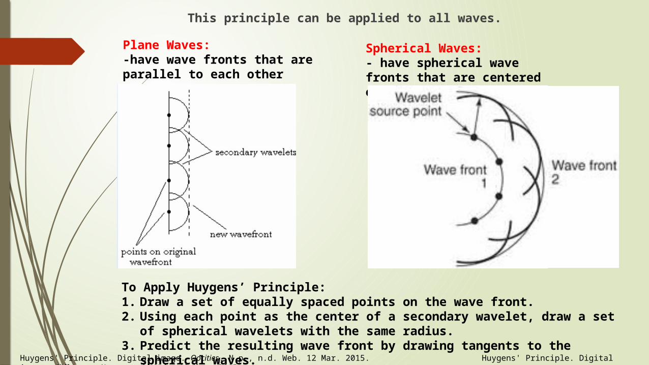
This principle can be applied to all waves.
Plane Waves: -have wave fronts that are parallel to each other
Spherical Waves:- have spherical wave fronts that are centered on the point source
To Apply Huygens’ Principle:1. Draw a set of equally spaced points on the wave front.2. Using each point as the center of a secondary wavelet, draw a set of
spherical wavelets with the same radius. 3. Predict the resulting wave front by drawing tangents to the
spherical waves. Huygens' Principle. Digital image. Oocities. N.p., n.d. Web. 12 Mar. 2015. Huygens' Principle. Digital image. Cliffsnotes. N.p., n.d. Web. 12 Mar. 2015.
INTERFERENCE-separated by intervals of space and time
INTERFERENCE- separated by intervals of space
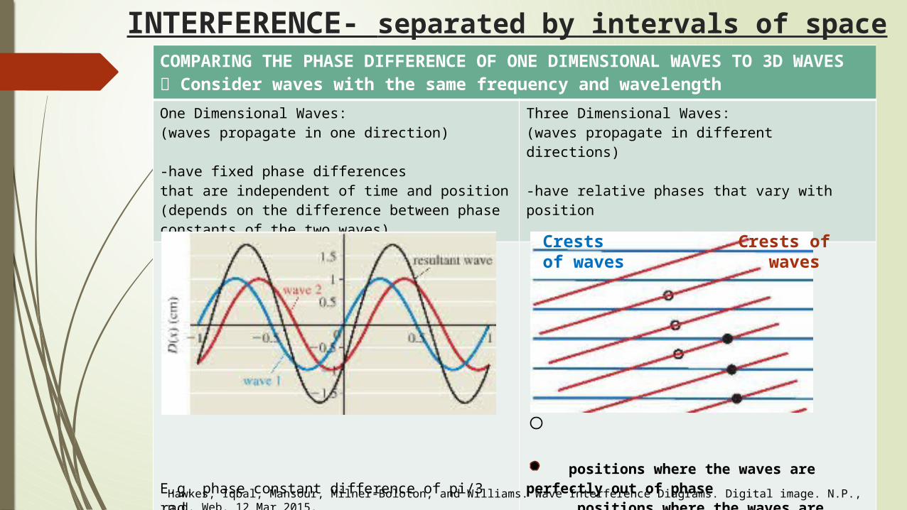
COMPARING THE PHASE DIFFERENCE OF ONE DIMENSIONAL WAVES TO 3D WAVES Consider waves with the same frequency and wavelengthOne Dimensional Waves:(waves propagate in one direction)
-have fixed phase differencesthat are independent of time and position(depends on the difference between phase constants of the two waves)
Three Dimensional Waves:(waves propagate in different directions)
-have relative phases that vary with position
E.g. phase constant difference of pi/3 rad
positions where the waves are perfectly out of phase positions where the waves are perfectly in phase
Crests of waves
Crests of waves
Hawkes, Iqbal, Mansour, Milner-Boloton, and Williams. Wave Interference Diagrams. Digital image. N.P., n.d. Web. 12 Mar 2015.
Interference is a phenomenon in which two waves superimpose to form a resultant wave of greater or lower amplitude
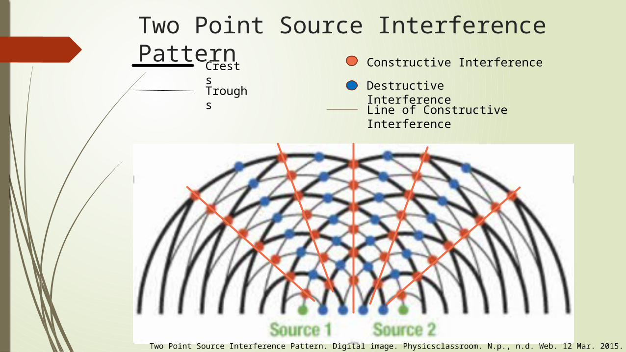
Two Point Source Interference Pattern
Crests
Troughs
Constructive Interference
Destructive Interference
Line of Constructive Interference
Two Point Source Interference Pattern. Digital image. Physicsclassroom. N.p., n.d. Web. 12 Mar. 2015.
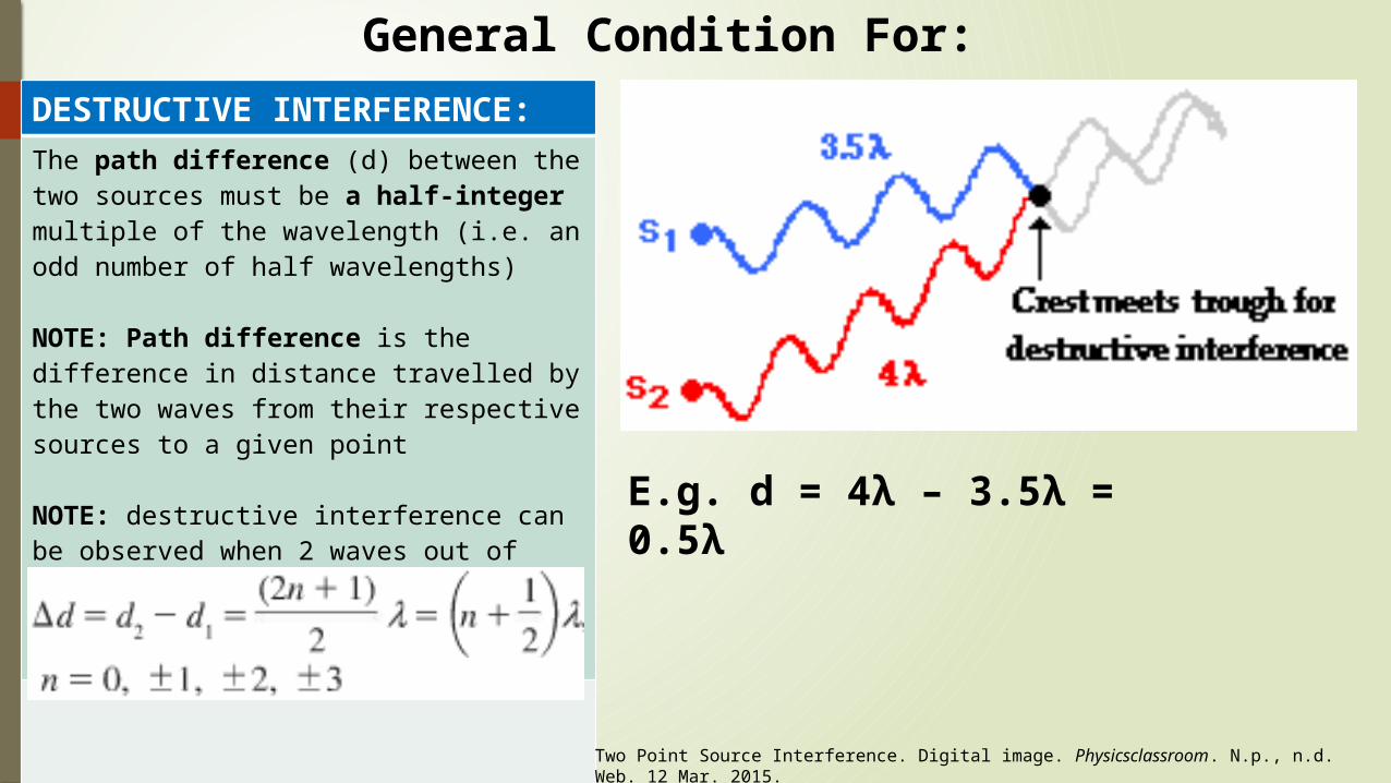
DESTRUCTIVE INTERFERENCE:The path difference (d) between the two sources must be a half-integer multiple of the wavelength (i.e. an odd number of half wavelengths)
NOTE: Path difference is the difference in distance travelled by the two waves from their respective sources to a given point
NOTE: destructive interference can be observed when 2 waves out of phase by pi
General Condition For:
E.g. d = 4λ – 3.5λ = 0.5λ
Two Point Source Interference. Digital image. Physicsclassroom. N.p., n.d. Web. 12 Mar. 2015.
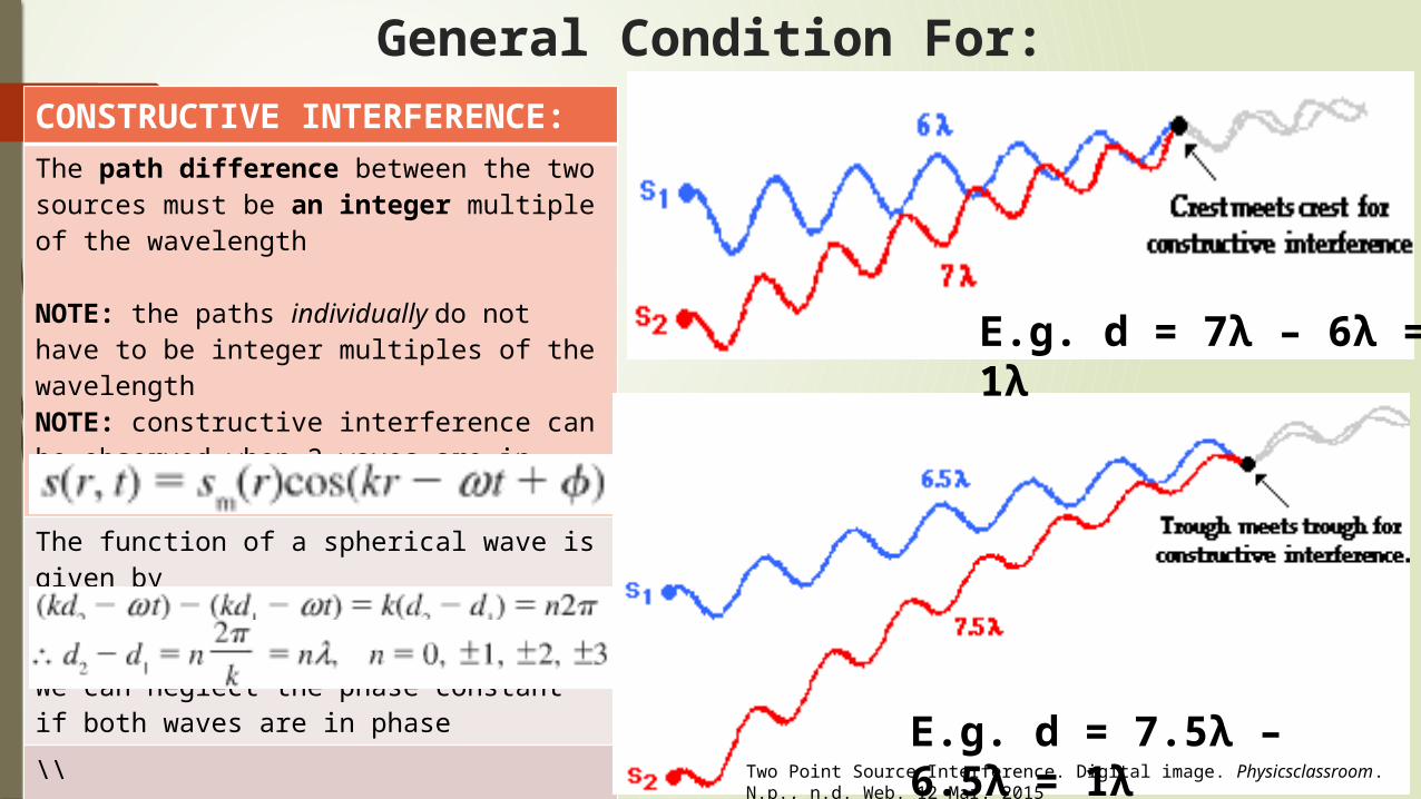
General Condition For:CONSTRUCTIVE INTERFERENCE:The path difference between the two sources must be an integer multiple of the wavelength
NOTE: the paths individually do not have to be integer multiples of the wavelengthNOTE: constructive interference can be observed when 2 waves are in phase
The function of a spherical wave is given by
We can neglect the phase constant if both waves are in phase
\\
NOTE: if d1 = d2 = d, simply add the two waves to find the resultant wave
E.g. d = 7λ – 6λ = 1λ
E.g. d = 7.5λ – 6.5λ = 1λ Two Point Source Interference. Digital image. Physicsclassroom. N.p., n.d.
Web. 12 Mar. 2015
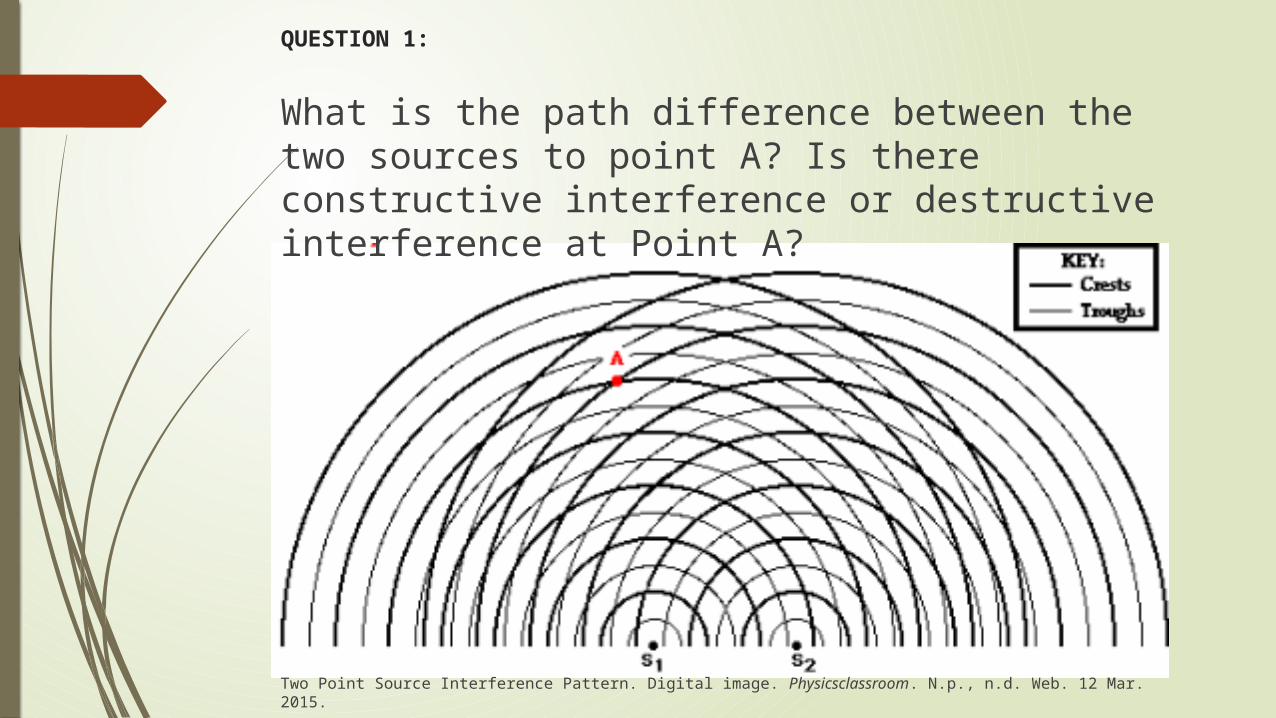
QUESTION 1:
What is the path difference between the two sources to point A? Is there constructive interference or destructive interference at Point A?
Two Point Source Interference Pattern. Digital image. Physicsclassroom. N.p., n.d. Web. 12 Mar. 2015.
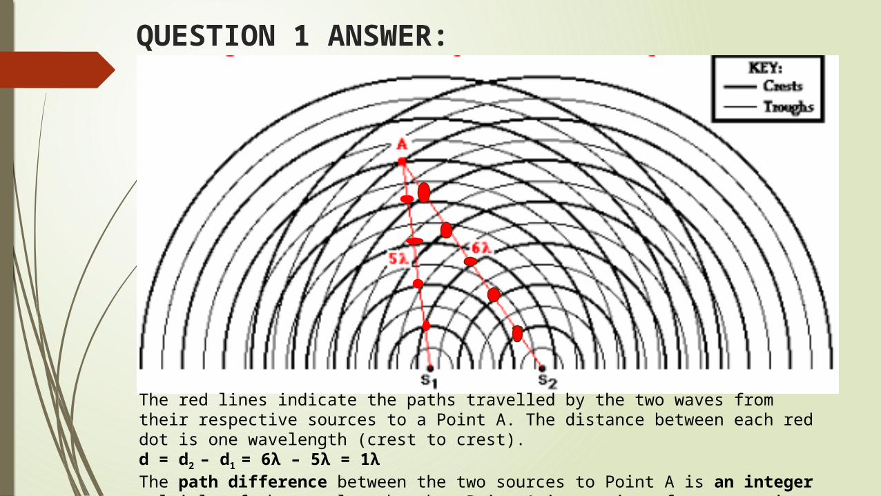
QUESTION 1 ANSWER:
The red lines indicate the paths travelled by the two waves from their respective sources to a Point A. The distance between each red dot is one wavelength (crest to crest). d = d2 – d1 = 6λ – 5λ = 1λThe path difference between the two sources to Point A is an integer multiple of the wavelength, thus Point A is a point of constructive interference.
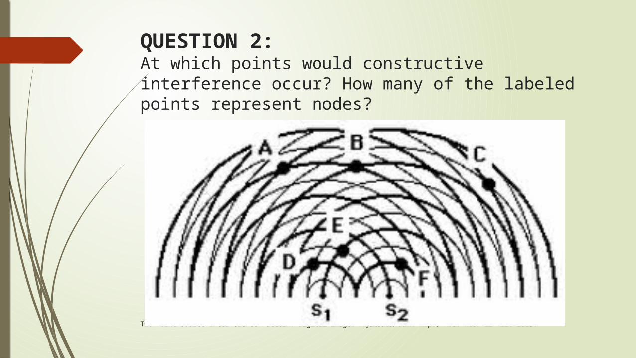
QUESTION 2:At which points would constructive interference occur? How many of the labeled points represent nodes?
Two Point Source Interference Pattern. Digital image. Physicsclassroom. N.p., n.d. Web. 12 Mar. 2015.
QUESTION 2 ANSWER: Constructive interference would occur at
Point A and Point B because both points are at locations where a crest meets a crest.
Four out of the six points represent nodes. Points C, D, E and F are points where crests and troughs meet.
Interference- separated by intervals of time Beats are periodic fluctuations heard in the
intensity of a sound when two sound waves of very similar frequencies interfere with one another
The rate at which amplitude increases and decreases as a function of time is proportional to the frequency difference
Beat Frequency: the rate at which the volume is heard to be
oscillating from high to low volume
E.g. If three complete cycles of high and low volumes are heard every second, the beat frequency is 3 Hz.
The beat frequency is equal to the difference in frequency of the two tones that interfere to produce beats.

QUESTION 3:A guitarist plays a 110 Hz tone while his friend simultaneously plays a tone with a frequency of 115 Hz. How many beats will be heard over a period of 15 seconds?
QUESTION 3 ANSWER:The beat frequency is equal to the difference in frequency of the two tones that interfere to produce beats.
The beat frequency will be 5 Hz. ( 115 Hz – 110 Hz = 5 Hz )
Thus, in 15 seconds, there should be 75 beats.( 5 Hz x 15s = 75 beats)