Embed Size (px)
Citation preview

Complementary Huygens principle for geometrical
and nongeometrical optics
Alfredo Luis
Departamento de Optica, Facultad de Ciencias Fısicas, Universidad Complutense,
28040 Madrid, Spain
Abstract. We develop a fundamental principle depicting the generalized ray
formulation of optics provided by the Wigner function. This principle is formally
identical to the Huygens-Fresnel principle but in terms of opposite concepts, rays
instead of waves, and incoherent superpositions instead of coherent ones. This ray
picture naturally includes diffraction and interference, and provides a geometrical
picture of the degree of coherence.
PACS numbers: 42.25.-p, 42.15.-i, 42.25.Fx, 42.25.Hz
Published in European Journal of Physics vol. 28, p. 231-240, (2007)
European Journal of Physics c°copyright (2007) IOP Publishing Ltd.
Complementary Huygens principle 2
1. Introduction
The description of light in terms of the Wigner function provides a ray picture of
optics which is exact, complete, and rigorous (at least within paraxial propagation in
homogeneous or weakly inhomogeneous media) covering most of undergraduate optics
[1, 2, 3, 4, 5, 6, 7, 8]. In particular, and in sharp contrast to standard geometrical optics,
this Wigner ray picture encompasses coherent wave phenomena, such as interference,
diffraction, and polarization [9, 10, 11, 12, 13, 14, 15, 16, 17, 18]. The price to be
paid is that the Wigner function can take negative values. This is rather disturbing,
since otherwise it would be a first-rate aspirant to represent the energy content of rays
(radiance or specific intensity).
In this work we elaborate the Wigner function approach to optics by formulating
it in terms of a simple and basic principle, formally analogous to the Huygens-
Fresnel principle but with inverted terms: Each point reached by the light becomes a
secondary source of rays, so that the disturbance evolves as the result of the incoherent
superposition of these secondary rays. Given the importance and insight of the Huygens-
Fresnel principle for the wave picture we may expect that this inverted version (let us
call it complementary Huygens principle) might well condensate and illustrate this ray
picture of optics.
Using this complementary Huygens principle as an starting point we derive typical
coherent phenomena such as interference and diffraction. In particular we show that
this approach provides a natural geometrical picture of coherence as an average value
of the phase difference.
This issue has interesting didactical applications in undergraduate optics as an
illustration of coexistence of different theories. On the one hand we have two partially
incompatible theories (standard geometrical optics versus Wigner ray optics) leading to
contradictory predictions in spite of using the same concept of light trajectories. On
the other hand, we have two equivalent theories (Wigner ray optics and wave optics)
providing different explanations for the same predictions using very different concepts.
2. Ray picture of wave optics
For the sake of simplicity we focus on harmonic, scalar, fully coherent waves where the
electric field E is expressed as
E(x, z, t) = Uz(x)ei(nkz−ωt), (1)
where k is the wave number k = 2π/λ, λ is the wavelength in vacuum, n is the refraction
index, ω is the frequency, and throughout we assume that the amplitude Uz(x) dependsexclusively on a single transversal coordinate x orthogonal to the main propagation
direction along axis z.
The associated Wigner function is defined as
Wz(x, p) =k
2π
Z ∞−∞dx0Uz(x− x0/2)U∗z (x+ x0/2)eikpx
0. (2)
Complementary Huygens principle 3
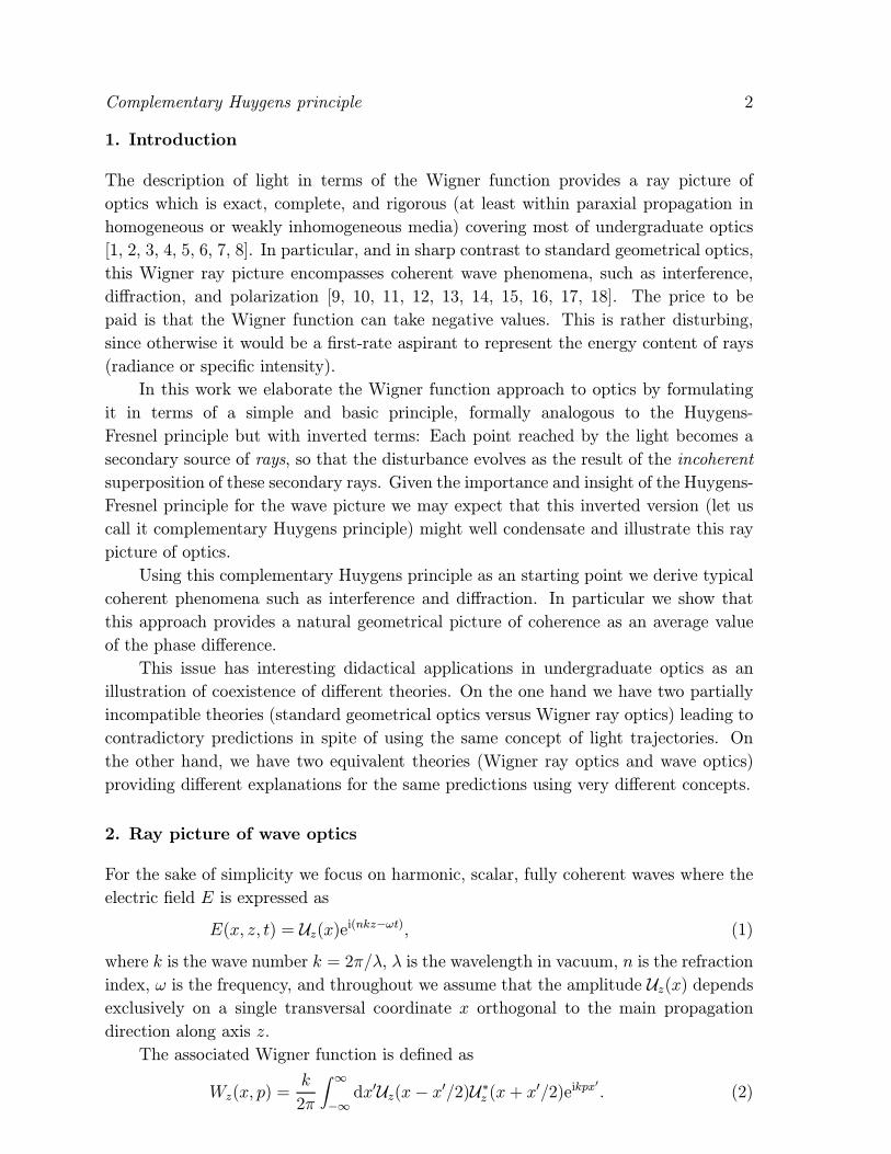
x
W (x,p)z
z
��p/n
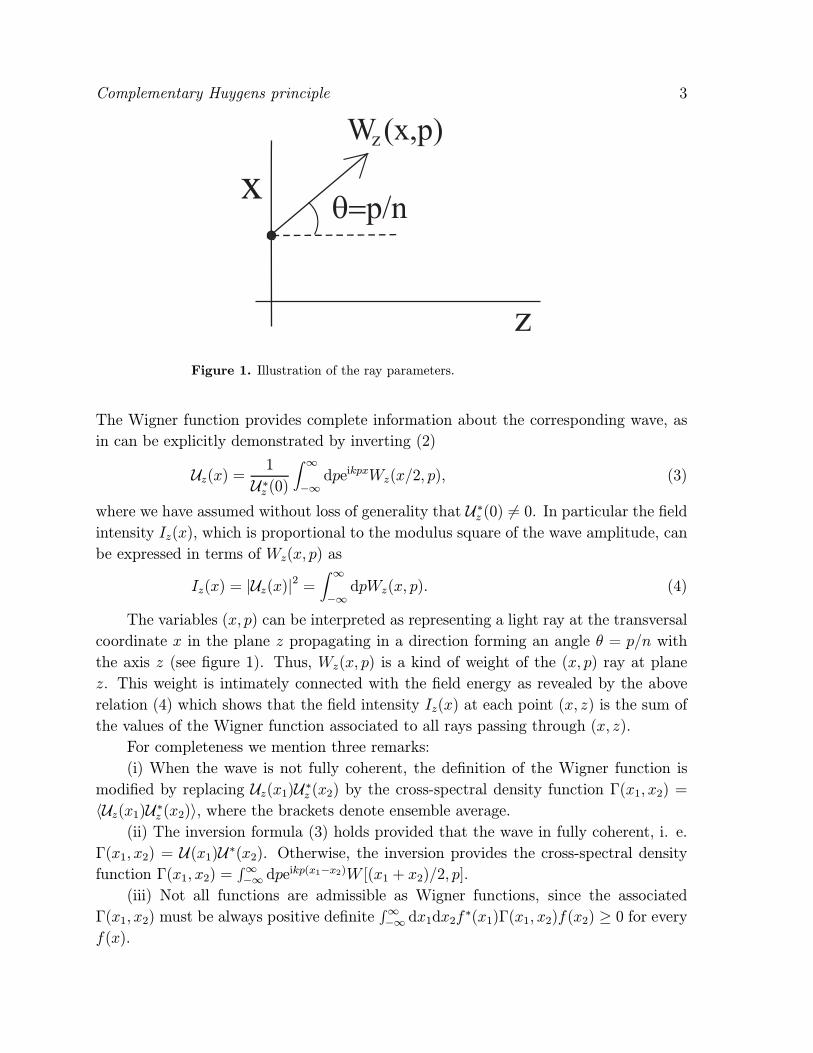
Figure 1. Illustration of the ray parameters.
The Wigner function provides complete information about the corresponding wave, as
in can be explicitly demonstrated by inverting (2)
Uz(x) = 1
U∗z (0)Z ∞−∞dpeikpxWz(x/2, p), (3)
where we have assumed without loss of generality that U∗z (0) 6= 0. In particular the fieldintensity Iz(x), which is proportional to the modulus square of the wave amplitude, can
be expressed in terms of Wz(x, p) as
Iz(x) = |Uz(x)|2 =Z ∞−∞dpWz(x, p). (4)
The variables (x, p) can be interpreted as representing a light ray at the transversal
coordinate x in the plane z propagating in a direction forming an angle θ = p/n with
the axis z (see figure 1). Thus, Wz(x, p) is a kind of weight of the (x, p) ray at plane
z. This weight is intimately connected with the field energy as revealed by the above
relation (4) which shows that the field intensity Iz(x) at each point (x, z) is the sum of
the values of the Wigner function associated to all rays passing through (x, z).
For completeness we mention three remarks:
(i) When the wave is not fully coherent, the definition of the Wigner function is
modified by replacing Uz(x1)U∗z (x2) by the cross-spectral density function Γ(x1, x2) =hUz(x1)U∗z (x2)i, where the brackets denote ensemble average.
(ii) The inversion formula (3) holds provided that the wave in fully coherent, i. e.
Γ(x1, x2) = U(x1)U∗(x2). Otherwise, the inversion provides the cross-spectral densityfunction Γ(x1, x2) =
R∞−∞ dpe
ikp(x1−x2)W [(x1 + x2)/2, p].(iii) Not all functions are admissible as Wigner functions, since the associated
Γ(x1, x2) must be always positive definiteR∞−∞ dx1dx2f
∗(x1)Γ(x1, x2)f(x2) ≥ 0 for everyf(x).
Complementary Huygens principle 4
2.1. Free wave propagation
Free propagation of an electromagnetic wave in an homogeneous medium is usually
described in undergraduate optics via the Huygens-Fresnel principle: (i) Each point
reached by the light becomes a secondary source of waves whose amplitudes are
proportional to the amplitude of the incoming wave at that point, (ii) The disturbance
evolves as the result of the coherent superposition of the secondary waves. The
mathematical expression of this principle is of the form
Uz(r) = nk
2πi
Z ∞−∞d2r0U0(r0) cos θe
inkR
R, (5)
where we have considered the most general case in which two transversal coordinates
are required to describe both the observation plane z > 0 with r = (x, y), and the
source plane z = 0 with r0 = (x0, y0). The angle θ is the one between the vector
R = (x− x0, y − y0, z) and the z axis, and R =q(r− r0)2 + z2 is the distance between
the source point r0 at z = 0 and the observation point r at z > 0.We appreciate in (5) that each secondary-source point at r0 produces a spherical
wave einkR/R with amplitude U0(r0). The integration represents the coherent
superposition of these secondary waves. We recall that coherent superposition occurs
when the complex amplitude of the superposition is the sum of the complex amplitudes
of the incoming waves. On the other hand, the superposition is incoherent when the
intensity of the superposition is the sum of the intensities of the incoming waves.
Within paraxial approximation |r − r0| << z the mathematical expression of the
Huygens-Fresnel principle becomes the Fresnel diffraction formula
Uz(r) = nk
2πizeinkz
Z ∞−∞d2r0U0(r0)eink(r−r0)2/(2z). (6)
Furthermore, for far enough observation planes (z → ∞) the Fraunhofer diffractionformula holds
Uz(r) = nk
2πizeinkzeinkr
2/(2z)Z ∞−∞d2r0U0(r0)e−inkr·r0/z. (7)
For the sake of simplicity we adapt the above expressions (6), (7) to the simpler
one-dimensional dependence of the transversal amplitude [19]. For Fresnel diffraction
we have
Uz(x) =snk
2πizeinkz
Z ∞−∞dx0U0(x0)eink(x−x0)2/(2z), (8)
while for Fraunhofer diffraction
Uz(x) =snk
2πizeinkzeinkx
2/(2z)Z ∞−∞dx0U0(x0)e−inkxx0/z, (9)
which is equivalent to
Uz(x) =rn
izeinkzeinkx
2/(2z)U0(nx/z), (10)
Complementary Huygens principle 5
= 0z z��p/n
x-zp/n
x
p
p
W (x-zp/n,p)0
W (x,p)z
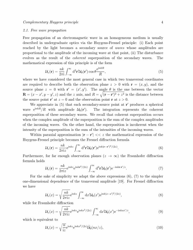
Figure 2. Transport of the value of the Wigner function along a ray.
where U(p) is the Fourier transform of U(x),
U(p) =sk
2π
Z ∞−∞dxU(x)e−ipkx. (11)
The modulus square of the Fourier transform |U(p)|2 is often referred to as angularspectrum (or angular distribution) and can be obtained directly as the spatial integration
of the Wigner function as¯U(p)
¯2=Z ∞−∞dxW (x, p). (12)
2.2. Free ray propagation
By combining (2) and (8) we can compute the Wigner functionWz(x, p) within paraxial
approximation at any plane z > 0, relating it to the Wigner function W0(x, p) at z = 0.
The result is
Wz(x, p) = W0(x− zp/n, p). (13)
Among other consequences this relation means that the Wigner function remains
constant along straight rays (see figure 2). As a matter of fact this constancy along
rays actually holds for every optical system within paraxial approximation.
2.3. Complementary Huygens principle
The propagation law (13) is the cornerstone of the ray picture of optics offered by the
Wigner function and can be taken as the basis of the complementary Huygens principle
encapsulating this picture of optics. We enunciate it in two steps: (i) Each point reached
by the light becomes a secondary source of rays, (ii) The disturbance evolves as the result
of the incoherent superposition of the secondary rays.
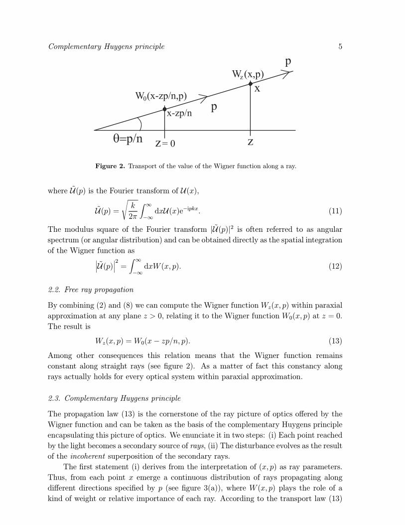
The first statement (i) derives from the interpretation of (x, p) as ray parameters.
Thus, from each point x emerge a continuous distribution of rays propagating along
different directions specified by p (see figure 3(a)), where W (x, p) plays the role of a
kind of weight or relative importance of each ray. According to the transport law (13)
Complementary Huygens principle 6
x
x
= 0z z
(a) (b)
= 0z
Figure 3. Illustration of the complementary Huygens principle.
this weight remains invariant along the ray. This is a clear departure from standard
geometrical optics, where rays are often defined as normal to the wavefronts, so that
for a fully coherent wave U(x) there would be single ray at each point (leaving asidecaustics and singularities).
The second statement (ii) derives from the formula (4) for the field intensity Iz(x)
at each point
Iz(x) =Z ∞−∞dpWz(x, p) =
Z ∞−∞dpW0(x− zp/n, p). (14)
This means that Iz(x) is the sum of the ray ”intensities” Wz(x, p) associated to all rays
p passing through the same point x. This superposition of rays is incoherent since it
deals with the addition of ”intensities” instead of complex amplitudes. The last equality
in (14) means that each observation point is reached by a ray from each point of the
source plane parametrized by the ray slope p (see figure 3(b)). We stress that the
waves U(x) we are considering are fully coherent, so that the incoherent character ofthe superposition is a universal key feature of the formalism, independent of the actual
coherence properties of the wave.
2.4. Spatial filtering
In order to complete the picture we can consider the effect of spatial filters such as the
pass of the wave through diffracting apertures. In the wave picture this is described by
amplitude-transmission coefficients t(x) (inhomogeneous in general) transforming the
input wave amplitude U(x) intoU(x)→ t(x)U(x). (15)
In the ray picture, the corresponding transformation of the Wigner function is
Wtu(x, p) =Z ∞−∞dp0Wt(x, p− p0)Wu(x, p
0), (16)
Complementary Huygens principle 7
where Wtu, Wu are the Wigner functions immediately after and before, respectively, of
the spatial filter, and
Wt(x, p) =k
2π
Z ∞−∞dx0t(x− x0/2)t∗(x+ x0/2)eikpx0, (17)
is the Wigner function of the filter. This is to say that the output Wigner function
arises from the convolution of the input Wigner function with the Wigner function of
the filter.
2.5. Negativity
As we have mentioned in the Introduction, a complete radiometric interpretation of W
is prevented by the fact that it can take negative values. This is the price to be paid
to include rigorously wave coherence phenomena within a ray picture. Addition of rays
with positive weights corresponds exclusively to incoherent wave mixing, so that the
inclusion of coherent wave phenomena demands the appearance of rays with negative
weights. More specifically, we may say that this formalism includes two classes of weird
rays, which might be termed fictitious and dark rays.
Fictitious rays are those emerging from regions where the wave amplitude vanishes
Uz(x) = 0. The paradigmatic example is the Young interferometer which be elaboratedin some detail below.
Dark rays are those associated with negative values of the Wigner function
[8, 9, 10, 15, 17, 18]. Waves with dark rays might be termed nongeometrical in the same
sense that quantum states with negative Wigner functions are considered as nonclassical.
The amount of negativity can be measured for example in terms of the distance between
W (x, p) and its modulus [18, 20]
D =Z ∞−∞dpZ ∞−∞dx [W (x, p)− |W (x, p)|]2 . (18)
3. Examples
Let us illustrate the general approach with some simple but meaningful examples. For a
proper comparison we will always consider normalized waves carrying the same intensityZ ∞−∞dx
Z ∞−∞dpW (x, p) =
Z ∞−∞dx |U(x)|2 = 1. (19)
3.1. Gaussian
The Gaussian
U0(x) = 1qσ√2πe−x
2/(4σ2), (20)
provides a paradigmatic example of geometrical wave with positive definite Wigner
function
W0(x, p) =k
πe−x
2/(2σ2)e−2k2σ2p2 , (21)

Complementary Huygens principle 8
so that D = 0 irrespectively of the its spatial width σ. Actually, this is the only coherent
wave with positive definite Wigner function [21].
3.2. Slit
The simplest example of diffraction is provided by a homogenous slit of width a
U0(x) =(
1√a, for |x| � a
2,
0, for |x| > a2,, (22)
leading to
W0(x, p) =
( sin[kp(a−2|x|)]πap
, for |x| � a2
0, for |x| > a2,, (23)
which takes negative values with
D ' 0.25
λ, (24)
that does not depend on the width of the slit a.
3.3. Exponential
For the exponential
U0(x) = 1√be−|x|/b, (25)
we have
W0(x, p) =k
πe−2|x|/b
(1
1 + (kbp)2[cos(2kp|x|)
− kpb sin(2kp|x|)] + sin(2kp|x|)kpb
), (26)
that takes negative values with
D ' 0.016
λ, (27)
which does not depend on b.
4. Coherence phenomena
As we have mentioned in the Introduction the geometrical ray picture provided by
the Wigner formalism is complete and properly includes coherence phenomena such as
diffraction and interference.
Complementary Huygens principle 9
4.1. Diffraction
The complementary Huygens principle developed above indicates the existence of
diffraction in much the same way the standard Huygens principle does. This is via
the superposition of the emissions of the secondary sources in directions different from
the input one. The only difference is the magnitude which is added. This is the coherent
superposition of amplitudes in the wave picture versus the incoherent addition of the
ray ”intensities” provided by the Wigner function.
We can show that diffraction is included within the Wigner ray formalism by
deriving the Fresnel propagation formula (8) from the ray propagation law (13). From
Eqs. (3) and (13) we can express the field amplitude Uz(x) at any plane z > 0 in termsof the Wigner function at z = 0 as
Uz(x) = 1
U∗z (0)Z ∞−∞dpeikpxW0(x/2− zp/n, p). (28)
Using (2), after a suitable change of integration variables we get
Uz(x) = kn
2πz
1
U∗z (0)Z ∞−∞dx00U∗0 (x00)e−iknx
002/(2z)
×Z ∞−∞dx0U0(x0)eink(x−x0)2/(2z). (29)
Evaluating this expression at x = 0 we get that the first integral is proportional to U∗z (0)Z ∞−∞dx00U∗0 (x00)e−inkx
002/(2z) =
s2πz
kneiϕU∗z (0), (30)
where ϕ is a global phase. Therefore, Eq. (29) reproduces the Fresnel diffraction formula
(8).
We can also show explicitly the complete quantitative equivalence of the Wigner
ray approach with Fraunhofer diffraction. To this end we derive the intensity of the
Fraunhofer diffraction at the far field z →∞ directly from the complementary Huygens
principle (13). Performing the p integration in (13) and after a suitable change of
integration variables we get
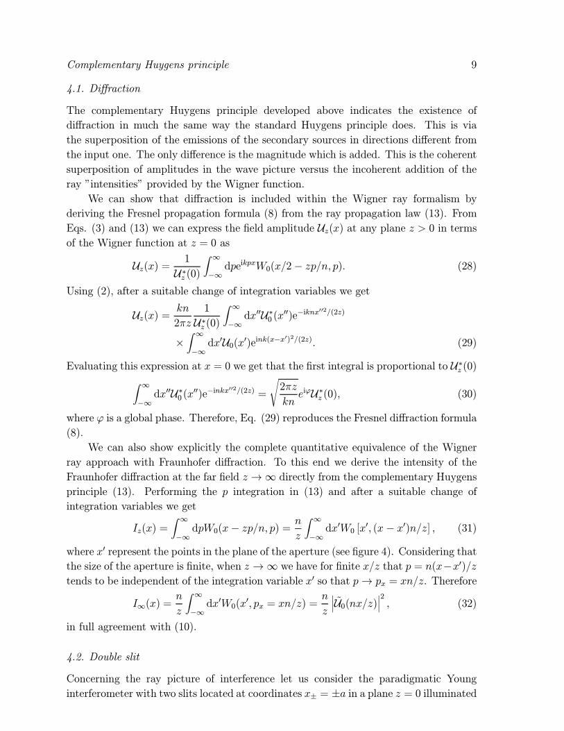
Iz(x) =Z ∞−∞dpW0(x− zp/n, p) = n
z
Z ∞−∞dx0W0 [x
0, (x− x0)n/z] , (31)
where x0 represent the points in the plane of the aperture (see figure 4). Considering thatthe size of the aperture is finite, when z →∞ we have for finite x/z that p = n(x−x0)/ztends to be independent of the integration variable x0 so that p→ px = xn/z. Therefore
I∞(x) =n
z
Z ∞−∞dx0W0(x
0, px = xn/z) =n
z
¯U0(nx/z)
¯2, (32)
in full agreement with (10).
4.2. Double slit
Concerning the ray picture of interference let us consider the paradigmatic Young
interferometer with two slits located at coordinates x± = ±a in a plane z = 0 illuminated

Complementary Huygens principle 10
x
z
�= (x-x )/z x/z
x
U (x )0U (x)Z
Figure 4. Fraunhofer diffraction.
by a light field of Wigner function Wu(x, p). For definiteness, the two apertures are
assumed to be narrow enough to be described by delta functions so that the amplitude
transmission coefficient is of the form
t(x) = δ(x− a) + δ(x+ a). (33)
From (17) the Wigner function associated to t(x) is
Wt(x, p) =k
2π[δ(x− a) + δ(x+ a) + 2 cos(2kpa)δ(x)] , (34)
and then, from (16), the field at z = 0 immediately after the slits is described by the
Wigner function
Wtu(x, p) =k
2π
h|U0(a)|2 δ(x− a) + |U0(−a)|2 δ(x+ a)
+³e−ikp2aµ+ eikp2aµ∗
´δ(x)
i, (35)
where
µ =Z ∞−∞dp0eikp
02aWu(0, p0) = U0(a)U∗0 (−a), (36)
and U0(±a) is the complex amplitude of the illuminating field at the slits. We canappreciate that Wtu(x, p) 6= 0 only at x = ±a, 0 so that the double slit produces threesecondary point sources of generalized rays, instead of the two sources at x = ±a ofthe Huygens principle (see figure 5). The third source of fictitious rays located at the
midpoint between the slits x = 0 contains all the coherence properties of the input field
required to reproduce exactly the complete interferometric pattern [8, 9, 6, 17].
To see this let us consider that the observation of the interference is performed at
the far plane z → ∞ so that the rays reaching a given observation point x propagate
parallel along a given direction p = xn/z. According to Eqs. (12) and (32) when z →∞the intensity distribution Iz(x = pz/n) is proportional to the angular distribution at
z = 0
I∞(x = pz/n) ∝Z ∞−∞dx0Wtu(x
0, p) ∝¯U0(a) + U0(−a)eiφ
¯2, (37)
where φ = kp2a is the phase difference acquired by the rays between the slits and the
observation plane (see figure 6).

Complementary Huygens principle 11
(a) ( b)
Figure 5. Secondary sources in the Young interferometer: (a) Wave picture (b) Ray
picture.
p
p
W (0,p )u
�=kp2a
�=p/n
�=p/n
�=kp2a
Figure 6. Sketch of the Young interferometer.
This is exactly the same result provided by the wave approach via the Huygens
principle, which leads to the right-hand side of Eq. (37) via the superposition of the
complex amplitudes of the field at the slits U0(±a) after acquiring the phase differenceφ during propagation from the slits to the observation point.
Moreover, the formula for the coherence or visibility factor µ in (36) has a very
simple geometrical meaning. The coherence factor µ turns out to be the average value
of the phase difference φ0 = kp02a at the slits illuminated by a set of plane waves specifiedby the propagation direction p0, where the weight of each plane wave is Wu(0, p
0)
µ = heiφ0iW =Z ∞−∞dp0eikp
02aWu(0, p0) = Γ(a,−a), (38)
where Γ(x1, x2) = hU(x1)U∗(x2)i is the cross-spectral density function.

Complementary Huygens principle 12
5. Conclusions
We have developed a complementary Huygens principle depicting the Wigner ray
formulation of optics. This principle is supported by the transport law satisfied by
the Wigner function and is formally identical to the Huygens-Fresnel principle but in
terms of opposite concepts, i. e., rays instead of waves, and incoherent superpositions
instead of coherent ones. A key feature is that this geometrical ray representation is
complete including all coherent phenomena, such as diffraction and interference, as far
as we admit negative Wigner functions.[1] Dragoman D 1997 Prog. Opt. 37 1
[2] Torre A 2005 Linear Ray and Wave Optics in Phase Space (Amsterdam: Elsevier)
[3] Bastiaans M J 1978 Opt. Commun. 25 26
[4] Bastiaans M J 1979 J. Opt. Soc. Am. 69 1710
[5] Bastiaans M J 1986 J. Opt. Soc. Am. A 3 1227
[6] Simon R and Mukunda M 2000 J. Opt. Soc. Am. A 17 2440
[7] Friberg A T 1979 J. Opt. Soc. Am. 69 192
[8] Sudarshan E C G 1979 Phys. Lett. A 73 269
[9] Sudarshan E C G 1979 Physica A 96 315
[10] Sudarshan E C G 1981 Phys. Rev. A 23 2802
[11] Simon R 1983 Pramana 20 105
[12] Milsom P K 2000 Appl. Phys. B 70 593
[13] Chzhu V D, Chzhun M S and Rodionov S A 1998 J. Opt. Technol. 65 770
[14] Luis A 2005 Opt. Commun. 246 437
[15] Luis A 2005 Opt. Commun. 251 243
[16] Luis A 2006 Opt. Commun. 263 141
[17] Luis A 2006 J. Opt. Soc. Am. A 23 2855
[18] Luis A 2006 Opt. Commun. 266 426
[19] Siegman A E 1986 Lasers (Sausalito: U. Science Books)
[20] Kenfack A Zyczkowski K 2004 J. Opt. B: Quantum Semiclassical Opt. 6 396
[21] Hudson R L 1974 Rep. Math. Phys. 6 249