Embed Size (px)
Citation preview
Farzin Piltan, Sajad Rahmdel, Saleh Mehrara & Reza Bayat
International Journal of Engineering (IJE), Volume (6) : Issue (3) : 2012 142
Sliding Mode Methodology Vs. Computed Torque Methodology Using MATLAB/SIMULINK and Their
Integration into Graduate Nonlinear Control Courses
Farzin Piltan [email protected] Industrial Electrical and Electronic Engineering SanatkadeheSabze Pasargad. CO (S.S.P. Co), NO:16 , PO.Code 71347-66773, Fourth floor Dena Apr , Seven Tir Ave , Shiraz , Iran
Sajad Rahmdel [email protected] Industrial Electrical and Electronic Engineering SanatkadeheSabze Pasargad. CO (S.S.P. Co), NO:16 ,PO.Code 71347-66773, Fourth floor Dena Apr , Seven Tir Ave , Shiraz , Iran
Saleh Mehrara [email protected] Industrial Electrical and Electronic Engineering SanatkadeheSabze Pasargad. CO (S.S.P. Co), NO:16 ,PO.Code 71347-66773, Fourth floor Dena Apr , Seven Tir Ave , Shiraz , Iran
Reza Bayat [email protected] Industrial Electrical and Electronic Engineering SanatkadeheSabze Pasargad. CO (S.S.P. Co), NO:16 ,PO.Code 71347-66773, Fourth floor Dena Apr , Seven Tir Ave , Shiraz , Iran
Abstract
Design a nonlinear controller for second order nonlinear uncertain dynamical systems is one of the most important challenging works. This paper focuses on the design, implementation and analysis of a chattering free sliding mode controller for highly nonlinear dynamic PUMA robot manipulator and compare to computed torque controller, in presence of uncertainties. In order to provide high performance nonlinear methodology, sliding mode controller and computed torque controller are selected. Pure sliding mode controller and computed torque controller can be used to control of partly known nonlinear dynamic parameters of robot manipulator. Conversely, pure sliding mode controller is used in many applications; it has an important drawback namely; chattering phenomenon which it can causes some problems such as saturation and heat the mechanical parts of robot manipulators or drivers. In order to reduce the chattering this research is used the linear saturation function boundary layer method instead of switching function method in pure sliding mode controller. These simulation models are developed as a part of a software laboratory to support and enhance graduate/undergraduate robotics courses, nonlinear control courses and MATLAB/SIMULINK courses at research and development company (SSP Co.) research center, Shiraz, Iran.
Keywords: MATLAB/SIMULINK, PUMA 560 Robot Manipulator, Nonlinear Position Control Method, Sliding Mode Control, Computed Torque Control, Chattering Free, and Nonlinear Control.
Farzin Piltan, Sajad Rahmdel, Saleh Mehrara & Reza Bayat
International Journal of Engineering (IJE), Volume (6) : Issue (3) : 2012 143
1. INTRODUCTION Computer modeling, simulation and implementation tools have been widely used to support and develop nonlinear control, robotics, and MATLAB/SIMULINK courses. MATLAB with its toolboxes such as SIMULINK [1] is one of the most accepted software packages used by researchers to enhance teaching the transient and steady-state characteristics of control and robotic courses [3_7]. In an effort to modeling and implement robotics, nonlinear control and advanced MATLAB/SIMULINK courses at research and development SSP Co., authors have developed MATLAB/SIMULINK models for learn the basic information in field of nonlinear control and industrial robot manipulator [8, 9].
Controller is a device which can sense information from linear or nonlinear system (e.g., robot manipulator) to improve the systems performance [3]. The main targets in designing control systems are stability, good disturbance rejection, and small tracking error[5]. Several industrial robot manipulators are controlled by linear methodologies (e.g., Proportional-Derivative (PD) controller, Proportional- Integral (PI) controller or Proportional- Integral-Derivative (PID) controller), but when robot manipulator works with various payloads and have uncertainty in dynamic models this technique has limitations. From the control point of view, uncertainty is divided into two main groups: uncertainty in unstructured inputs (e.g., noise, disturbance) and uncertainty in structure dynamics (e.g., payload, parameter variations). In some applications robot manipulators are used in an unknown and unstructured environment, therefore strong mathematical tools used in new control methodologies to design nonlinear robust controller with an acceptable performance (e.g., minimum error, good trajectory, disturbance rejection [10-18]. Sliding mode controller is a powerful nonlinear robust controller under condition of partly uncertain dynamic parameters of system [7]. This controller is used to control of highly nonlinear systems especially for robot manipulators. Chattering phenomenon and nonlinear equivalent dynamic formulation in uncertain dynamic parameter are two main drawbacks in pure sliding mode controller [20]. The main reason to opt for this controller is its acceptable control performance in wide range and solves two most important challenging topics in control which names, stability and robustness [7, 17-20]. Sliding mode controller is divided into two main sub controllers: discontinues controller and equivalent controller . Discontinues controller
causes an acceptable tracking performance at the expense of very fast switching. Conversely in this theory good trajectory following is based on fast switching, fast switching is caused to have system instability and chattering phenomenon. Fine tuning the sliding surface slope is based on nonlinear equivalent part [1, 6]. However, this controller is used in many applications but, pure sliding mode controller has two most important challenges: chattering phenomenon and nonlinear equivalent dynamic formulation in uncertain parameters[20]. Chattering phenomenon (Figure 1) can causes some problems such as saturation and heat the mechanical parts of robot manipulators or drivers. To reduce or eliminate the chattering, various papers have been reported by many researchers which classified into two most important methods: boundary layer saturation method and estimated uncertainties method [1]. In boundary layer saturation method, the basic idea is the discontinuous method replacement by saturation (linear) method with small neighborhood of the switching surface. This replacement caused to increase the error performance against with the considerable chattering reduction. Slotine and Sastry have introduced boundary layer method instead of discontinuous method to reduce the chattering[21]. Slotine has presented sliding mode with boundary layer to improve the industry application [22]. Palm has presented a fuzzy method to nonlinear approximation instead of linear approximation inside the boundary layer to improve the chattering and control the result performance[23]. Moreover, Weng and Yu improved the previous method by using a new method in fuzzy nonlinear approximation inside the boundary layer and adaptive method[24]. As mentioned [24]sliding mode fuzzy controller (SMFC) is fuzzy controller based on sliding mode technique to most exceptional stability and robustness. Sliding mode fuzzy controller has the two most important advantages: reduce the number of fuzzy rule base and increase robustness and stability.
Farzin Piltan, Sajad Rahmdel, Saleh Mehrara & Reza Bayat
International Journal of Engineering (IJE), Volume (6) : Issue (3) : 2012 144
Conversely sliding mode fuzzy controller has the above advantages, define the sliding surface slope coefficient very carefully is the main disadvantage of this controller. Estimated uncertainty method used in term of uncertainty estimator to compensation of the system uncertainties. It has been used to solve the chattering phenomenon and also nonlinear equivalent dynamic. If estimator has an acceptable performance to compensate the uncertainties, the chattering is reduced. Research on estimated uncertainty to reduce the chattering is significantly growing as their applications such as industrial automation and robot manipulator. For instance, the applications of artificial intelligence, neural networks and fuzzy logic on estimated uncertainty method have been reported in [25-28]. Wu et al. [30] have proposed a simple fuzzy estimator controller beside the discontinuous and equivalent control terms to reduce the chattering. Their design had three main parts i.e. equivalent, discontinuous and fuzzy estimator tuning part which has reduced the chattering very well. Elmali et al. [27]and Li and Xu [29] have addressed sliding mode control with perturbation estimation method (SMCPE) to reduce the classical sliding mode chattering. This method was tested for the tracking control of the first two links of a SCARA type HITACHI robot. In this technique, digital controller is used to increase the system’s response quality. However this controller’s response is very fast and robust but it has chattering phenomenon. Design a robust controller for robot manipulator is essential because robot manipulator has highly nonlinear dynamic parameters. Computed torque controller (CTC) is a powerful nonlinear controller which it widely used in control of robot manipulator. It is based on feedback linearization and computes the required arm torques using the nonlinear feedback control law. This controller works very well when all dynamic and physical parameters are known but when the robot manipulator has variation in dynamic parameters, in this situation the controller has no acceptable performance[14]. In practice, most of physical systems (e.g., robot manipulators) parameters are unknown or time variant, therefore, computed torque like controller used to compensate dynamic equation of robot manipulator[1, 6]. Research on computed torque controller is significantly growing on robot manipulator application which has been reported in [1, 6, 15-16]. Vivas and Mosquera [15]have proposed a predictive functional controller and compare to computed torque controller for tracking response in uncertain environment. However both controllers have been used in feedback linearization, but predictive strategy gives better result as a performance. A computed torque control with non parametric regression models have been presented for a robot arm[16]. This controller also has been problem in uncertain dynamic models. Based on [1, 6]and [15-16] computed torque controller is a significant nonlinear controller to certain systems which it is based on feedback linearization and computes the required arm torques using the nonlinear feedback control law. This paper is organized as follows: In section 2, dynamic formulation of robot manipulator is presented. Detail of classical SMC and MATLAB/SIMULINK implementation of this controller is presented in section 3. Detail of classical CTC and MATLAB/SIMULINK implementation of this controller is presented in section 4. In section 5, the simulation result is presented and finally in section 6, the conclusion is presented.
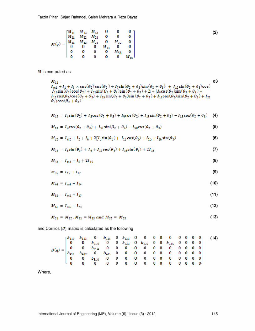
2. PUMA 560 ROBOT MANIPULATOR DYNAMIC FORMULATION Dynamics of PUMA560 Robot Manipulator To position control of robot manipulator, the second three axes are locked the dynamic equation of PUMA robot manipulator is given by [77-80];
(1)
Where
Farzin Piltan, Sajad Rahmdel, Saleh Mehrara & Reza Bayat
International Journal of Engineering (IJE), Volume (6) : Issue (3) : 2012 145
(2)
is computed as
o3
(4)
(5)
(6)
(7)
(8)
(9)
(10)
(11)
(12)
(13)
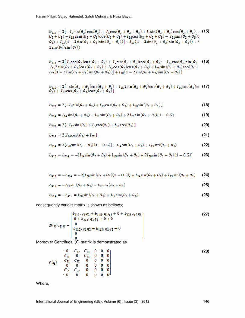
and Corilios ( ) matrix is calculated as the following
(14)
Where,
Farzin Piltan, Sajad Rahmdel, Saleh Mehrara & Reza Bayat
International Journal of Engineering (IJE), Volume (6) : Issue (3) : 2012 146
(15)
(16)
(17)
(18)
(19)
(20)
(21)
(22)
(23)
(24)
(25)
(26)
consequently coriolis matrix is shown as bellows;
(27)
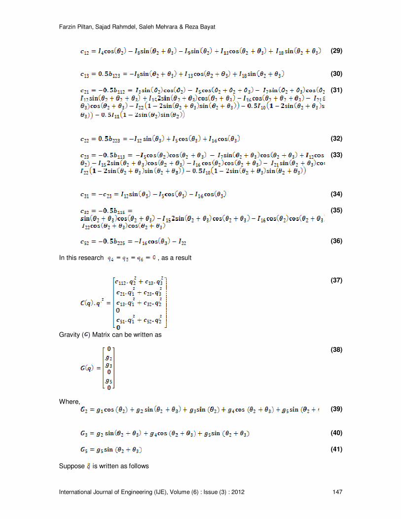
Moreover Centrifugal ( ) matrix is demonstrated as
(28)
Where,
Farzin Piltan, Sajad Rahmdel, Saleh Mehrara & Reza Bayat
International Journal of Engineering (IJE), Volume (6) : Issue (3) : 2012 147
(29)
(30)
(31)
(32)
(33)
(34)
(35)
(36)
In this research , as a result
(37)
Gravity ( ) Matrix can be written as
(38)
Where,
(39)
(40)
(41)
Suppose is written as follows
Farzin Piltan, Sajad Rahmdel, Saleh Mehrara & Reza Bayat
International Journal of Engineering (IJE), Volume (6) : Issue (3) : 2012 148
(42)
and is introduced as (43)
can be written as (44)
Therefore for PUMA robot manipulator is calculated by the following equations
(45)
(46)
(47)
(48)
(49)
(50)
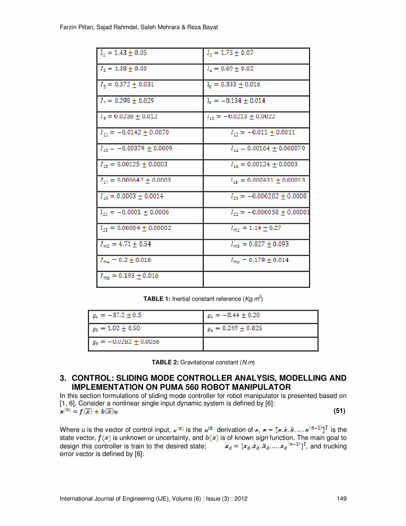
An information about inertial constant and gravitational constant are shown in Tables 1 and 2 based on the studies carried out by Armstrong [80] and Corke and Armstrong [81].
Farzin Piltan, Sajad Rahmdel, Saleh Mehrara & Reza Bayat
International Journal of Engineering (IJE), Volume (6) : Issue (3) : 2012 149
TABLE 1: Inertial constant reference (Kg.m
2)
TABLE 2: Gravitational constant (N.m)
3. CONTROL: SLIDING MODE CONTROLLER ANALYSIS, MODELLING AND IMPLEMENTATION ON PUMA 560 ROBOT MANIPULATOR
In this section formulations of sliding mode controller for robot manipulator is presented based on [1, 6]. Consider a nonlinear single input dynamic system is defined by [6]:
(51)
Where u is the vector of control input, is the derivation of , is the state vector, is unknown or uncertainty, and is of known sign function. The main goal to
design this controller is train to the desired state; , and trucking error vector is defined by [6]:
Farzin Piltan, Sajad Rahmdel, Saleh Mehrara & Reza Bayat
International Journal of Engineering (IJE), Volume (6) : Issue (3) : 2012 150
(52)
A time-varying sliding surface in the state space is given by [6]:
(53)
where λ is the positive constant. To further penalize tracking error, integral part can be used in sliding surface part as follows [6]:
(54)
The main target in this methodology is kept the sliding surface slope near to the zero. Therefore, one of the common strategies is to find input outside of [6].
(55)
where ζ is positive constant.
If S(0)>0 (56)
To eliminate the derivative term, it is used an integral term from t=0 to t=
(57)
Where is the time that trajectories reach to the sliding surface so, suppose S( defined as
(58)
and
(59)
Equation (81) guarantees time to reach the sliding surface is smaller than since the
trajectories are outside of .
(60)
suppose S is defined as
(61)
The derivation of S, namely, can be calculated as the following;
(62)
suppose the second order system is defined as;
(63)
Where is the dynamic uncertain, and also since , to have the best approximation , is defined as
(64)
A simple solution to get the sliding condition when the dynamic parameters have uncertainty is the switching control law:
(65)
where the switching function is defined as [1, 6]
Farzin Piltan, Sajad Rahmdel, Saleh Mehrara & Reza Bayat
International Journal of Engineering (IJE), Volume (6) : Issue (3) : 2012 151
(66)
and the is the positive constant. Suppose by (67) the following equation can be written as,
(67)
and if the equation (61) instead of (60) the sliding surface can be calculated as
(68)
in this method the approximation of is computed as [6]
(69)
Based on above discussion, the sliding mode control law for a multi degrees of freedom robot manipulator is written as [1, 6]:
(70)
Where, the model-based component is the nominal dynamics of systems and for first 3
DOF PUMA robot manipulator can be calculate as follows [1]:
(71)
and is computed as [1];
(72)
by replace the formulation (72) in (70) the control output can be written as;
(73)
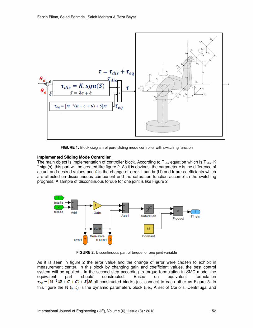
Figure 1 shows the position classical sliding mode control for PUMA 560 robot manipulator. By (73) and (71) the sliding mode control of PUMA 560 robot manipulator is calculated as;
(74)
where in PD-SMC and in PID-SMC.
Farzin Piltan, Sajad Rahmdel, Saleh Mehrara & Reza Bayat
International Journal of Engineering (IJE), Volume (6) : Issue (3) : 2012 152
FIGURE 1: Block diagram of pure sliding mode controller with switching function
Implemented Sliding Mode Controller The main object is implementation of controller block. According to T dis equation which is T dis=K * sign(s), this part will be created like figure 2. As it is obvious, the parameter e is the difference of actual and desired values and is the change of error. Luanda (l1) and k are coefficients which are affected on discontinuous component and the saturation function accomplish the switching progress. A sample of discontinuous torque for one joint is like Figure 2.
FIGURE 2: Discontinuous part of torque for one joint variable
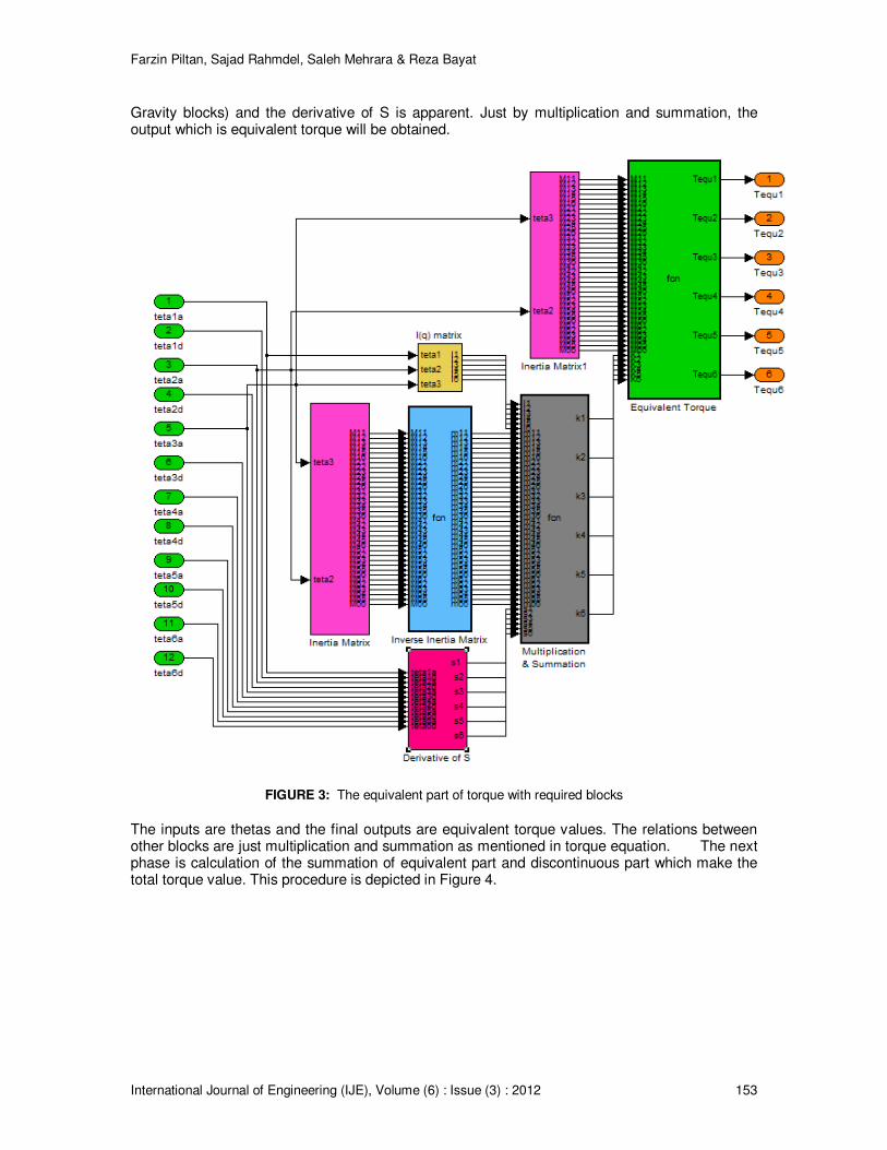
As it is seen in figure 2 the error value and the change of error were chosen to exhibit in measurement center. In this block by changing gain and coefficient values, the best control system will be applied. In the second step according to torque formulation in SMC mode, the equivalent part should constructed. Based on equivalent formulation
all constructed blocks just connect to each other as Figure 3. In
this figure the N ( ) is the dynamic parameters block (i.e., A set of Coriolis, Centrifugal and
Farzin Piltan, Sajad Rahmdel, Saleh Mehrara & Reza Bayat
International Journal of Engineering (IJE), Volume (6) : Issue (3) : 2012 153
Gravity blocks) and the derivative of S is apparent. Just by multiplication and summation, the output which is equivalent torque will be obtained.
FIGURE 3: The equivalent part of torque with required blocks
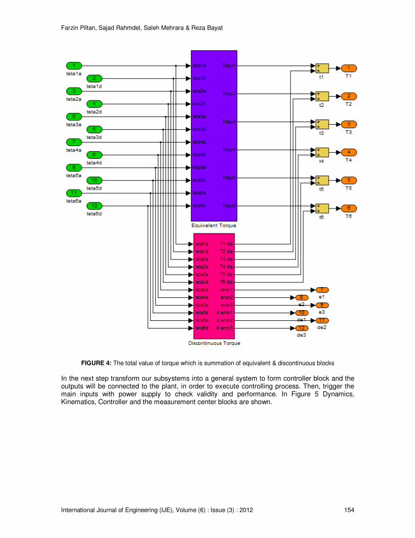
The inputs are thetas and the final outputs are equivalent torque values. The relations between other blocks are just multiplication and summation as mentioned in torque equation. The next phase is calculation of the summation of equivalent part and discontinuous part which make the total torque value. This procedure is depicted in Figure 4.
Farzin Piltan, Sajad Rahmdel, Saleh Mehrara & Reza Bayat
International Journal of Engineering (IJE), Volume (6) : Issue (3) : 2012 154
FIGURE 4: The total value of torque which is summation of equivalent & discontinuous blocks
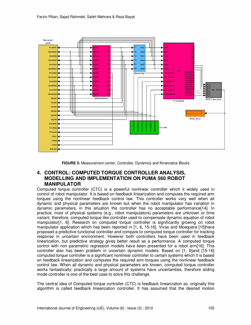
In the next step transform our subsystems into a general system to form controller block and the outputs will be connected to the plant, in order to execute controlling process. Then, trigger the main inputs with power supply to check validity and performance. In Figure 5 Dynamics, Kinematics, Controller and the measurement center blocks are shown.
Farzin Piltan, Sajad Rahmdel, Saleh Mehrara & Reza Bayat
International Journal of Engineering (IJE), Volume (6) : Issue (3) : 2012 155
FIGURE 5: Measurement center, Controller, Dynamics and Kinematics Blocks
4. CONTROL: COMPUTED TORQUE CONTROLLER ANALYSIS, MODELLING AND IMPLEMENTATION ON PUMA 560 ROBOT MANIPULATOR
Computed torque controller (CTC) is a powerful nonlinear controller which it widely used in control of robot manipulator. It is based on feedback linearization and computes the required arm torques using the nonlinear feedback control law. This controller works very well when all dynamic and physical parameters are known but when the robot manipulator has variation in dynamic parameters, in this situation the controller has no acceptable performance[14]. In practice, most of physical systems (e.g., robot manipulators) parameters are unknown or time variant, therefore, computed torque like controller used to compensate dynamic equation of robot manipulator[1, 6]. Research on computed torque controller is significantly growing on robot manipulator application which has been reported in [1, 6, 15-16]. Vivas and Mosquera [15]have proposed a predictive functional controller and compare to computed torque controller for tracking response in uncertain environment. However both controllers have been used in feedback linearization, but predictive strategy gives better result as a performance. A computed torque control with non parametric regression models have been presented for a robot arm[16]. This controller also has been problem in uncertain dynamic models. Based on [1, 6]and [15-16] computed torque controller is a significant nonlinear controller to certain systems which it is based on feedback linearization and computes the required arm torques using the nonlinear feedback control law. When all dynamic and physical parameters are known, computed torque controller works fantastically; practically a large amount of systems have uncertainties, therefore sliding mode controller is one of the best case to solve this challenge. The central idea of Computed torque controller (CTC) is feedback linearization so, originally this algorithm is called feedback linearization controller. It has assumed that the desired motion
Farzin Piltan, Sajad Rahmdel, Saleh Mehrara & Reza Bayat
International Journal of Engineering (IJE), Volume (6) : Issue (3) : 2012 156
trajectory for the manipulator , as determined, by a path planner. Defines the tracking error as:
(75)
Where e(t) is error of the plant, is desired input variable, that in our system is desired displacement, is actual displacement. If an alternative linear state-space equation in the form can be defined as
(76)
With and this is known as the Brunousky canonical form. By equation (76) and (77) the Brunousky canonical form can be written in terms of the state
as [1]:
(77)
With
(78)
Then compute the required arm torques using inverse of equation (79), is;
(79)
This is a nonlinear feedback control law that guarantees tracking of desired trajectory. Selecting proportional-plus-derivative (PD) feedback for U(t) results in the PD-computed torque controller [6];
(80)
and the resulting linear error dynamics are
(81)
According to the linear system theory, convergence of the tracking error to zero is guaranteed [6]. Where and are the controller gains. The result schemes is shown in Figure 6, in which two
feedback loops, namely, inner loop and outer loop, which an inner loop is a compensate loop and an outer loop is a tracking error loop.
Farzin Piltan, Sajad Rahmdel, Saleh Mehrara & Reza Bayat
International Journal of Engineering (IJE), Volume (6) : Issue (3) : 2012 157
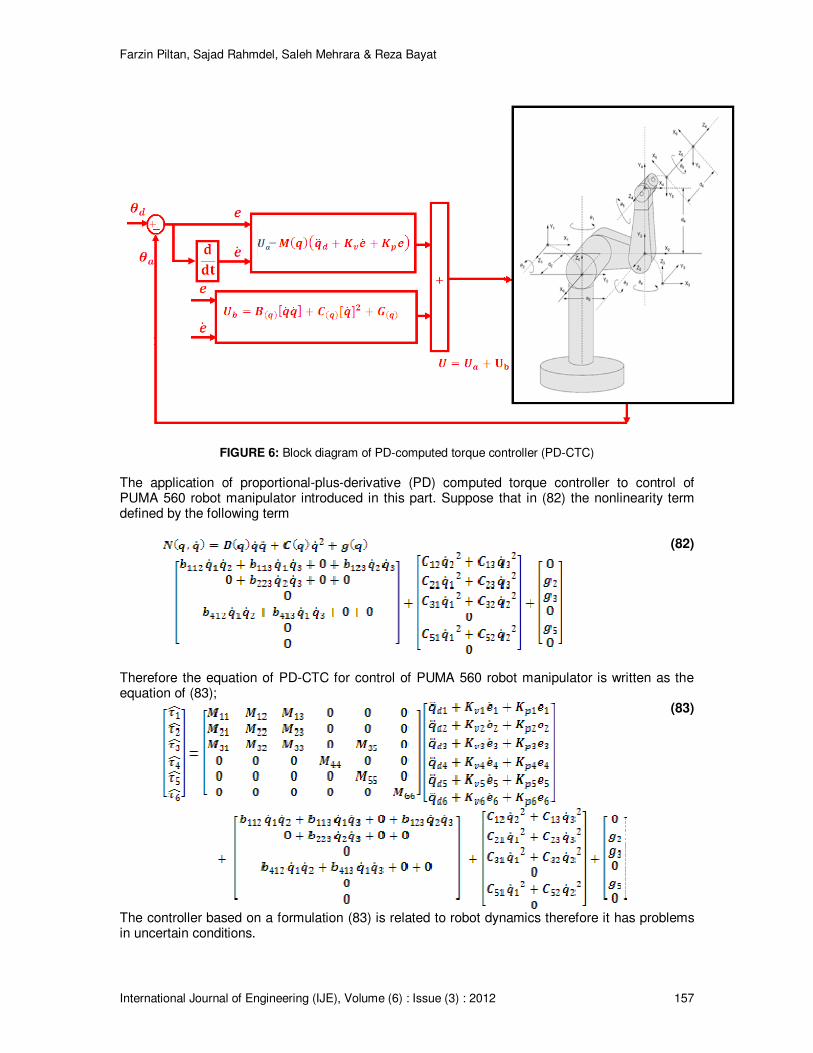
FIGURE 6: Block diagram of PD-computed torque controller (PD-CTC)
The application of proportional-plus-derivative (PD) computed torque controller to control of PUMA 560 robot manipulator introduced in this part. Suppose that in (82) the nonlinearity term defined by the following term
(82)
Therefore the equation of PD-CTC for control of PUMA 560 robot manipulator is written as the equation of (83);
(83)
The controller based on a formulation (83) is related to robot dynamics therefore it has problems in uncertain conditions.
Farzin Piltan, Sajad Rahmdel, Saleh Mehrara & Reza Bayat
International Journal of Engineering (IJE), Volume (6) : Issue (3) : 2012 158
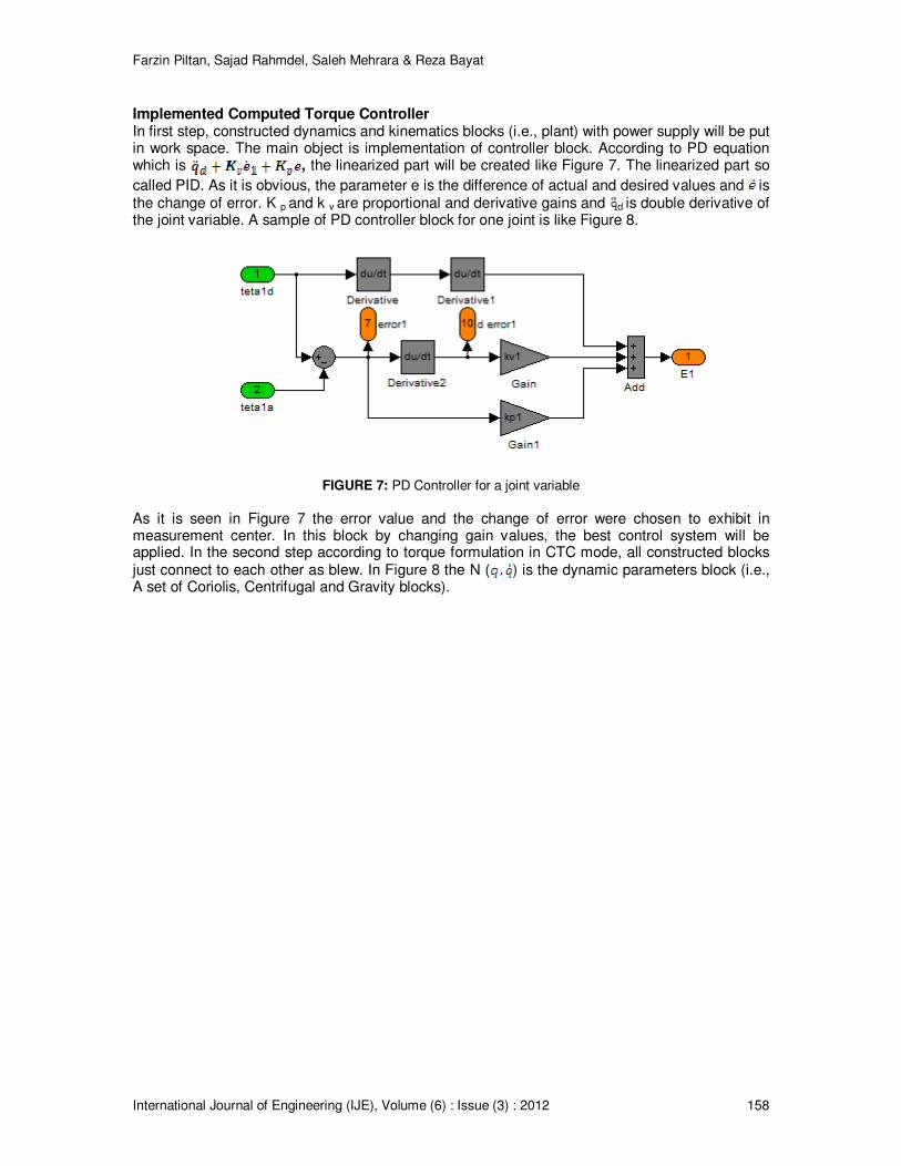
Implemented Computed Torque Controller In first step, constructed dynamics and kinematics blocks (i.e., plant) with power supply will be put in work space. The main object is implementation of controller block. According to PD equation which is , the linearized part will be created like Figure 7. The linearized part so
called PID. As it is obvious, the parameter e is the difference of actual and desired values and is the change of error. K p and k v are proportional and derivative gains and d is double derivative of the joint variable. A sample of PD controller block for one joint is like Figure 8.
FIGURE 7: PD Controller for a joint variable
As it is seen in Figure 7 the error value and the change of error were chosen to exhibit in measurement center. In this block by changing gain values, the best control system will be applied. In the second step according to torque formulation in CTC mode, all constructed blocks just connect to each other as blew. In Figure 8 the N ( ) is the dynamic parameters block (i.e., A set of Coriolis, Centrifugal and Gravity blocks).
Farzin Piltan, Sajad Rahmdel, Saleh Mehrara & Reza Bayat
International Journal of Engineering (IJE), Volume (6) : Issue (3) : 2012 159
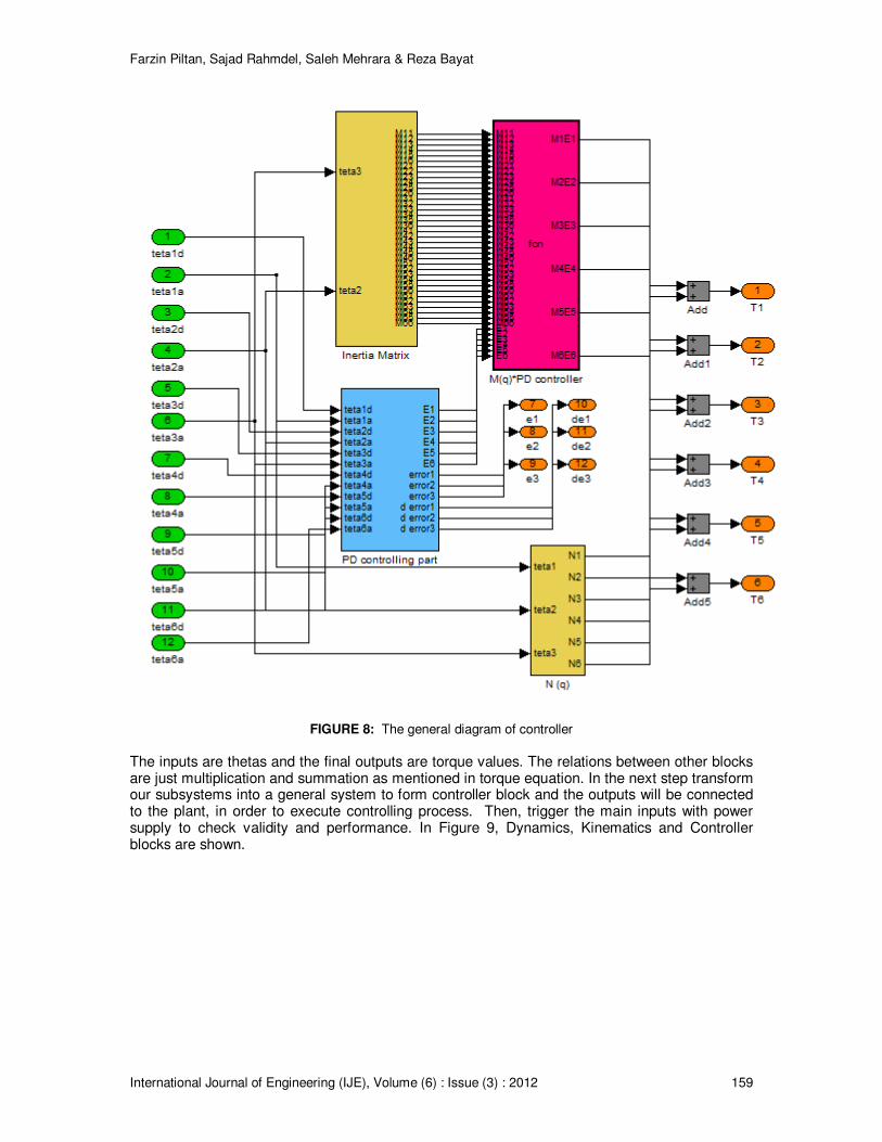
FIGURE 8: The general diagram of controller
The inputs are thetas and the final outputs are torque values. The relations between other blocks are just multiplication and summation as mentioned in torque equation. In the next step transform our subsystems into a general system to form controller block and the outputs will be connected to the plant, in order to execute controlling process. Then, trigger the main inputs with power supply to check validity and performance. In Figure 9, Dynamics, Kinematics and Controller blocks are shown.
Farzin Piltan, Sajad Rahmdel, Saleh Mehrara & Reza Bayat
International Journal of Engineering (IJE), Volume (6) : Issue (3) : 2012 160
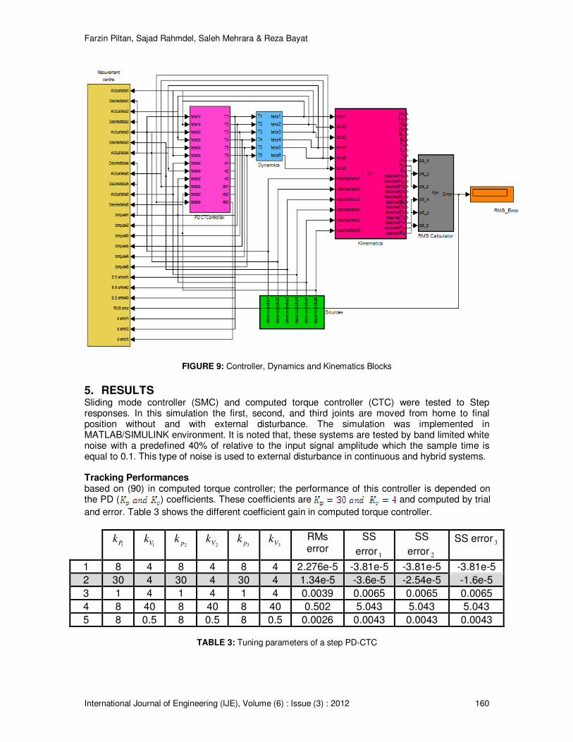
FIGURE 9: Controller, Dynamics and Kinematics Blocks
5. RESULTS Sliding mode controller (SMC) and computed torque controller (CTC) were tested to Step responses. In this simulation the first, second, and third joints are moved from home to final position without and with external disturbance. The simulation was implemented in MATLAB/SIMULINK environment. It is noted that, these systems are tested by band limited white noise with a predefined 40% of relative to the input signal amplitude which the sample time is equal to 0.1. This type of noise is used to external disturbance in continuous and hybrid systems. Tracking Performances based on (90) in computed torque controller; the performance of this controller is depended on the PD ( ) coefficients. These coefficients are and computed by trial
and error. Table 3 shows the different coefficient gain in computed torque controller.
1Pk
1Vk 2pk
2Vk 3pk
3Vk RMs error
SS
error1
SS
error2
SS error3
1 8 4 8 4 8 4 2.276e-5 -3.81e-5 -3.81e-5 -3.81e-5
2 30 4 30 4 30 4 1.34e-5 -3.6e-5 -2.54e-5 -1.6e-5
3 1 4 1 4 1 4 0.0039 0.0065 0.0065 0.0065
4 8 40 8 40 8 40 0.502 5.043 5.043 5.043
5 8 0.5 8 0.5 8 0.5 0.0026 0.0043 0.0043 0.0043
TABLE 3: Tuning parameters of a step PD-CTC
Farzin Piltan, Sajad Rahmdel, Saleh Mehrara & Reza Bayat
International Journal of Engineering (IJE), Volume (6) : Issue (3) : 2012 161
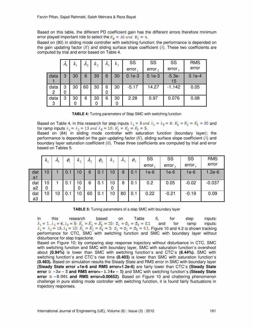
Based on this table, the different PD coefficient gain has the different errors therefore minimum error played important role to select the .
Based on (80) in sliding mode controller with switching function; the performance is depended on the gain updating factor ( ) and sliding surface slope coefficient ( ). These two coefficients are computed by trial and error based on Table 4.
1
λ
1k
2λ
2k 3
λ
3
k SS
error1
SS
error2
SS
error3
RMS error
data1
3 30 6 30 6 30 0.1e-3 0.1e-3 -5.3e-15
0.1e-4
data2
30
30 60 30 60
30 -5.17 14.27 -1.142 0.05
data3
3 300
6 300
6 300
2.28 0.97 0.076 0.08
TABLE 4: Tuning parameters of Step SMC with switching function
Based on Table 4, in this research for step inputs and for ramp inputs Based on (84) in sliding mode controller with saturation function (boundary layer); the performance is depended on the gain updating factor ( ), sliding surface slope coefficient ( ) and boundary layer saturation coefficient ( ). These three coefficients are computed by trial and error based on Tables 5.
1
k 1
λ 1
φ 2
k
2
λ 2
φ 3k
3λ
3
φ SS
error1
SS
error2
SS
error3
RMS error
data1
10 1 0.1 10 6 0.1 10 8 0.1 1e-6 1e-6 1e-6 1.2e-6
data2
100
1 0.1 100
6 0.1 100
8 0.1 0.2 0.05 -0.02 -0.037
data3
10 10 0.1 10 60 0.1 10 80 0.1 0.22 -0.21 -0.19 0.09
TABLE 5: Tuning parameters of a step SMC with boundary layer
In this research based on Table 5, for step inputs:
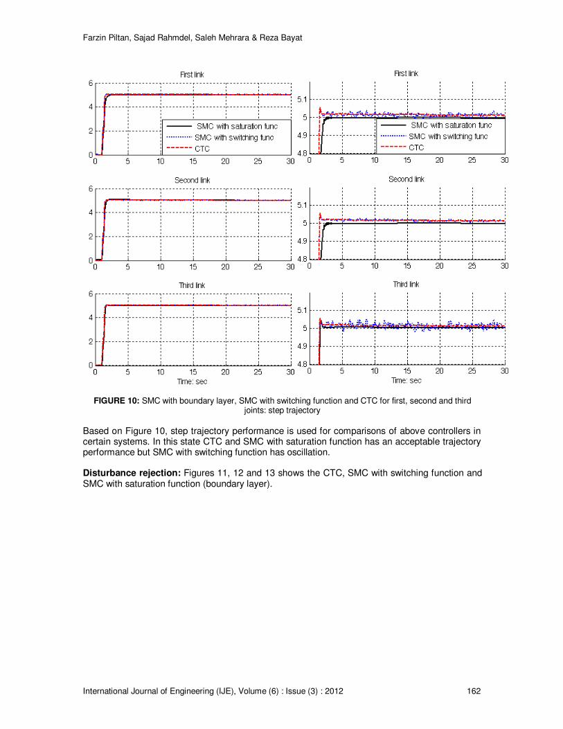
and for ramp inputs: . Figure 10 and 4.2 is shown tracking
performance for CTC, SMC with switching function and SMC with boundary layer without disturbance for step trajectorie. Based on Figure 10; by comparing step response trajectory without disturbance in CTC, SMC with switching function and SMC with boundary layer, SMC with saturation function’s overshoot about (0.94%) is lower than SMC with switching function’s and CTC’s (6.44%). SMC with switching function’s and CTC’s rise time (0.403) is lower than SMC with saturation function’s (0.483). Based on simulation results the Steady State and RMS error in SMC with boundary layer (Steady State error =1e-6 and RMS error=1.2e-6) are fairly lower than CTC’s (Steady State error and RMS error= ) and SMC with switching function’s (Steady State error and RMS error=0.00652). Based on Figure 10 and chattering phenomenon challenge in pure sliding mode controller with switching function, it is found fairly fluctuations in trajectory responses.
Farzin Piltan, Sajad Rahmdel, Saleh Mehrara & Reza Bayat
International Journal of Engineering (IJE), Volume (6) : Issue (3) : 2012 162
FIGURE 10: SMC with boundary layer, SMC with switching function and CTC for first, second and third joints: step trajectory
Based on Figure 10, step trajectory performance is used for comparisons of above controllers in certain systems. In this state CTC and SMC with saturation function has an acceptable trajectory performance but SMC with switching function has oscillation. Disturbance rejection: Figures 11, 12 and 13 shows the CTC, SMC with switching function and SMC with saturation function (boundary layer).
Farzin Piltan, Sajad Rahmdel, Saleh Mehrara & Reza Bayat
International Journal of Engineering (IJE), Volume (6) : Issue (3) : 2012 163
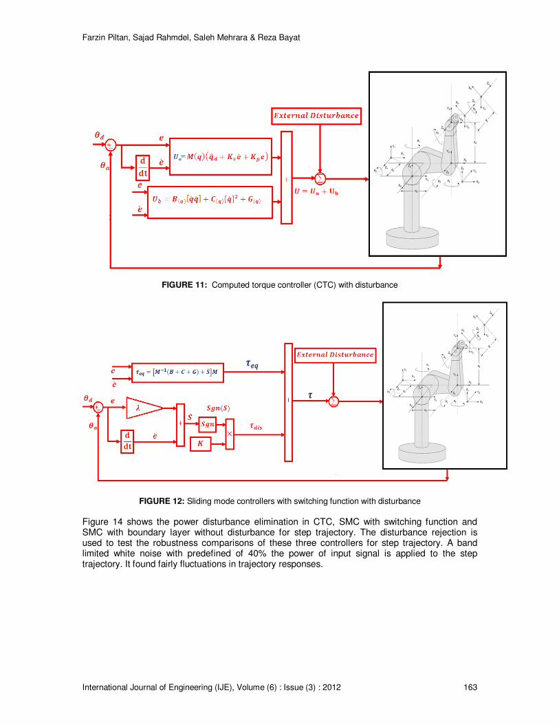
FIGURE 11: Computed torque controller (CTC) with disturbance
FIGURE 12: Sliding mode controllers with switching function with disturbance
Figure 14 shows the power disturbance elimination in CTC, SMC with switching function and SMC with boundary layer without disturbance for step trajectory. The disturbance rejection is used to test the robustness comparisons of these three controllers for step trajectory. A band limited white noise with predefined of 40% the power of input signal is applied to the step trajectory. It found fairly fluctuations in trajectory responses.
Farzin Piltan, Sajad Rahmdel, Saleh Mehrara & Reza Bayat
International Journal of Engineering (IJE), Volume (6) : Issue (3) : 2012 164
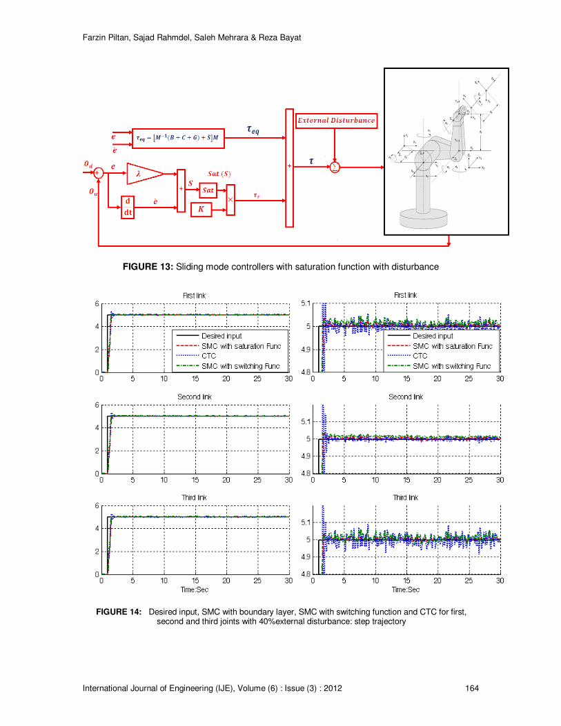
FIGURE 13: Sliding mode controllers with saturation function with disturbance
FIGURE 14: Desired input, SMC with boundary layer, SMC with switching function and CTC for first, second and third joints with 40%external disturbance: step trajectory
Farzin Piltan, Sajad Rahmdel, Saleh Mehrara & Reza Bayat
International Journal of Engineering (IJE), Volume (6) : Issue (3) : 2012 165
Based on Figure 14; by comparing step response trajectory with 40% disturbance of relative to the input signal amplitude in CTC, boundary layer (saturation) SMC and switching mode SMC, SMC with saturation function’s overshoot about (6%) is lower than SMC with switching function’s (13%)and CTC’s (14.8%). SMC with switching function’s and CTC’s rise time (0.5) is lower than SMC with saturation function’s (0.53). Besides the Steady State and RMS error in SMC with boundary layer (Steady State error =10e-4 and RMS error=11e-4) are fairly lower than CTC’s (Steady State error and RMS error= ) and SMC with switching function’s (Steady State error and RMS error=0.98). Based on Figure 14, all three controllers have oscillation in trajectory response with regard to 40% of the input signal amplitude disturbance. All these three controllers have fairly large oscillation with regard to the external disturbance. Based on Figure 14, a step trajectory performance is used for comparisons of above controllers in presence of uncertainties with 40% of input signal amplitude. In this state however boundary layer SMC has relatively moderate oscillations but it is more robust than CTC and SMC with switching function. From the disturbance rejection for boundary layer SMC, SMC with switching function and CTC in presence of disturbance, it was seen that however boundary layer SMC performance is better than SMC with switching function and CTC but it has a limitation against to highly external disturbance. Steady State and RMS Error Figures 15and 16 show the error performance without disturbance and in presence of disturbance in CTC, SMC with switching function and SMC with boundary layer without disturbance for two type trajectories. The error performance is used to test the disturbance effect comparisons of these three controllers for step trajectory. A band limited white noise with predefined of 40% the power of input signal is applied to the step trajectory. It found fairly fluctuations in error responses.
Farzin Piltan, Sajad Rahmdel, Saleh Mehrara & Reza Bayat
International Journal of Engineering (IJE), Volume (6) : Issue (3) : 2012 166
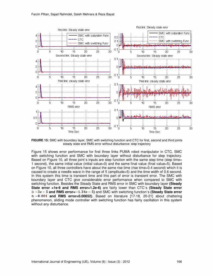
FIGURE 15: SMC with boundary layer, SMC with switching function and CTC for first, second and third joints
steady state and RMS error without disturbance: step trajectory
Figure 15 shows error performance for first three links PUMA robot manipulator in CTC, SMC with switching function and SMC with boundary layer without disturbance for step trajectory. Based on Figure 10, all three joint’s inputs are step function with the same step time (step time= 1 second), the same initial value (initial value=0) and the same final value (final value=5). Based on Figure 10, all three controllers have about the same rise time (rise time=0.4 second) which it is caused to create a needle wave in the range of 5 (amplitude=5) and the time width of 0.6 second. In this system this time is transient time and this part of error is transient error. The SMC with boundary layer and CTC give considerable error performance when compared to SMC with switching function. Besides the Steady State and RMS error in SMC with boundary layer (Steady State error =1e-6 and RMS error=1.2e-6) are fairly lower than CTC’s (Steady State error
and RMS error= ) and SMC with switching function’s (Steady State error and RMS error=0.00652). Based on literature [17-18, 20-21] about chattering
phenomenon, sliding mode controller with switching function has fairly oscillation in this system without any disturbance.
Farzin Piltan, Sajad Rahmdel, Saleh Mehrara & Reza Bayat
International Journal of Engineering (IJE), Volume (6) : Issue (3) : 2012 167
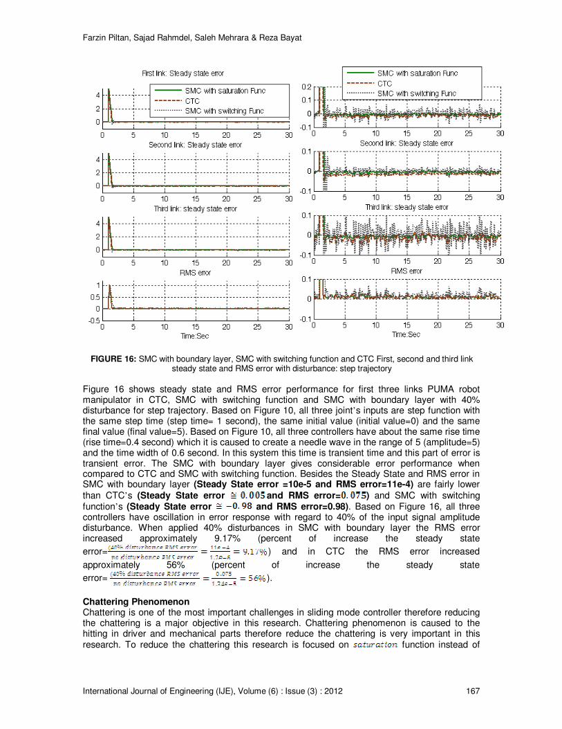
FIGURE 16: SMC with boundary layer, SMC with switching function and CTC First, second and third link steady state and RMS error with disturbance: step trajectory
Figure 16 shows steady state and RMS error performance for first three links PUMA robot manipulator in CTC, SMC with switching function and SMC with boundary layer with 40% disturbance for step trajectory. Based on Figure 10, all three joint’s inputs are step function with the same step time (step time= 1 second), the same initial value (initial value=0) and the same final value (final value=5). Based on Figure 10, all three controllers have about the same rise time (rise time=0.4 second) which it is caused to create a needle wave in the range of 5 (amplitude=5) and the time width of 0.6 second. In this system this time is transient time and this part of error is transient error. The SMC with boundary layer gives considerable error performance when compared to CTC and SMC with switching function. Besides the Steady State and RMS error in SMC with boundary layer (Steady State error =10e-5 and RMS error=11e-4) are fairly lower
than CTC’s (Steady State error and RMS error= ) and SMC with switching function’s (Steady State error and RMS error=0.98). Based on Figure 16, all three controllers have oscillation in error response with regard to 40% of the input signal amplitude disturbance. When applied 40% disturbances in SMC with boundary layer the RMS error increased approximately 9.17% (percent of increase the steady state
error= ) and in CTC the RMS error increased
approximately 56% (percent of increase the steady state
error= ).
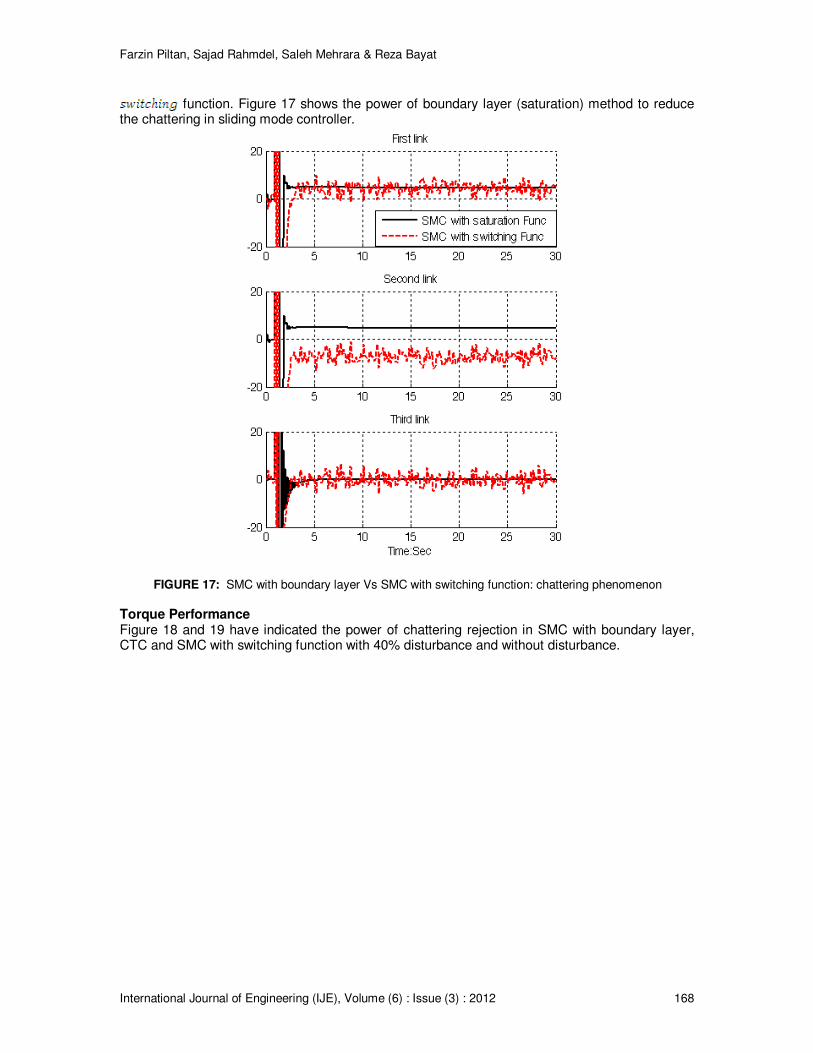
Chattering Phenomenon Chattering is one of the most important challenges in sliding mode controller therefore reducing the chattering is a major objective in this research. Chattering phenomenon is caused to the hitting in driver and mechanical parts therefore reduce the chattering is very important in this research. To reduce the chattering this research is focused on function instead of
Farzin Piltan, Sajad Rahmdel, Saleh Mehrara & Reza Bayat
International Journal of Engineering (IJE), Volume (6) : Issue (3) : 2012 168
function. Figure 17 shows the power of boundary layer (saturation) method to reduce the chattering in sliding mode controller.
FIGURE 17: SMC with boundary layer Vs SMC with switching function: chattering phenomenon
Torque Performance Figure 18 and 19 have indicated the power of chattering rejection in SMC with boundary layer, CTC and SMC with switching function with 40% disturbance and without disturbance.
Farzin Piltan, Sajad Rahmdel, Saleh Mehrara & Reza Bayat
International Journal of Engineering (IJE), Volume (6) : Issue (3) : 2012 169
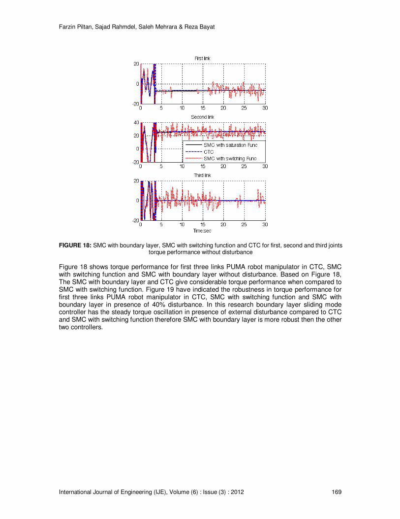
FIGURE 18: SMC with boundary layer, SMC with switching function and CTC for first, second and third joints
torque performance without disturbance
Figure 18 shows torque performance for first three links PUMA robot manipulator in CTC, SMC with switching function and SMC with boundary layer without disturbance. Based on Figure 18, The SMC with boundary layer and CTC give considerable torque performance when compared to SMC with switching function. Figure 19 have indicated the robustness in torque performance for first three links PUMA robot manipulator in CTC, SMC with switching function and SMC with boundary layer in presence of 40% disturbance. In this research boundary layer sliding mode controller has the steady torque oscillation in presence of external disturbance compared to CTC and SMC with switching function therefore SMC with boundary layer is more robust then the other two controllers.
Farzin Piltan, Sajad Rahmdel, Saleh Mehrara & Reza Bayat
International Journal of Engineering (IJE), Volume (6) : Issue (3) : 2012 170
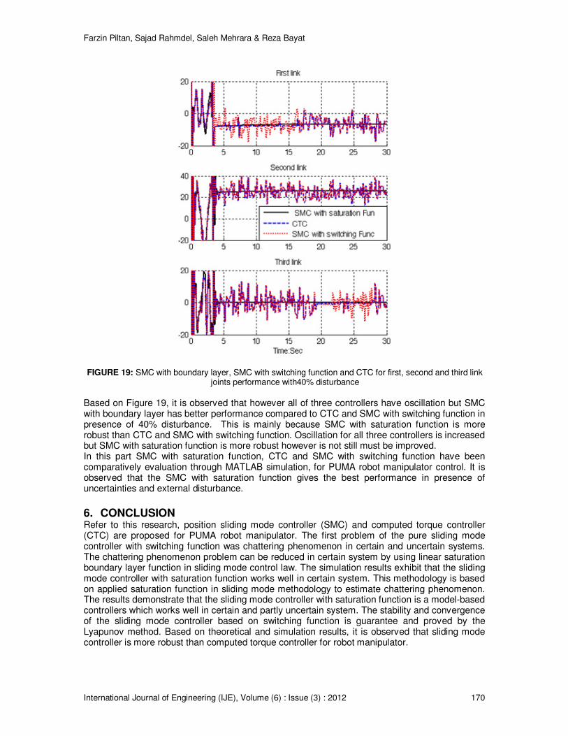
FIGURE 19: SMC with boundary layer, SMC with switching function and CTC for first, second and third link joints performance with40% disturbance
Based on Figure 19, it is observed that however all of three controllers have oscillation but SMC with boundary layer has better performance compared to CTC and SMC with switching function in presence of 40% disturbance. This is mainly because SMC with saturation function is more robust than CTC and SMC with switching function. Oscillation for all three controllers is increased but SMC with saturation function is more robust however is not still must be improved. In this part SMC with saturation function, CTC and SMC with switching function have been comparatively evaluation through MATLAB simulation, for PUMA robot manipulator control. It is observed that the SMC with saturation function gives the best performance in presence of uncertainties and external disturbance.
6. CONCLUSION Refer to this research, position sliding mode controller (SMC) and computed torque controller (CTC) are proposed for PUMA robot manipulator. The first problem of the pure sliding mode controller with switching function was chattering phenomenon in certain and uncertain systems. The chattering phenomenon problem can be reduced in certain system by using linear saturation boundary layer function in sliding mode control law. The simulation results exhibit that the sliding mode controller with saturation function works well in certain system. This methodology is based on applied saturation function in sliding mode methodology to estimate chattering phenomenon. The results demonstrate that the sliding mode controller with saturation function is a model-based controllers which works well in certain and partly uncertain system. The stability and convergence of the sliding mode controller based on switching function is guarantee and proved by the Lyapunov method. Based on theoretical and simulation results, it is observed that sliding mode controller is more robust than computed torque controller for robot manipulator.
Farzin Piltan, Sajad Rahmdel, Saleh Mehrara & Reza Bayat
International Journal of Engineering (IJE), Volume (6) : Issue (3) : 2012 171
REFERENCES [1] T. R. Kurfess, Robotics and automation handbook: CRC, 2005. [2] J. J. E. Slotine and W. Li, Applied nonlinear control vol. 461: Prentice hall Englewood Cliffs,
NJ, 1991. [3] K. Ogata, Modern control engineering: Prentice Hall, 2009. [4] L. Cheng, Z. G. Hou, M. Tan, D. Liu and A. M. Zou, "Multi-agent based adaptive consensus
control for multiple manipulators with kinematic uncertainties," 2008, pp. 189-194. [5] J. J. D'Azzo, C. H. Houpis and S. N. Sheldon, Linear control system analysis and design
with MATLAB: CRC, 2003. [6] B. Siciliano and O. Khatib, Springer handbook of robotics: Springer-Verlag New York Inc,
2008. [7] I. Boiko, L. Fridman, A. Pisano and E. Usai, "Analysis of chattering in systems with second-
order sliding modes," IEEE Transactions on Automatic Control, No. 11, vol. 52,pp. 2085-2102, 2007.
[8] J. Wang, A. Rad and P. Chan, "Indirect adaptive fuzzy sliding mode control: Part I: fuzzy
switching," Fuzzy Sets and Systems, No. 1, vol. 122,pp. 21-30, 2001. [9] C. Wu, "Robot accuracy analysis based on kinematics," IEEE Journal of Robotics and
Automation, No. 3, vol. 2, pp. 171-179, 1986. [10] H. Zhang and R. P. Paul, "A parallel solution to robot inverse kinematics," IEEE conference
proceeding, 2002, pp. 1140-1145. [11] J. Kieffer, "A path following algorithm for manipulator inverse kinematics," IEEE conference
proceeding, 2002, pp. 475-480. [12] Z. Ahmad and A. Guez, "On the solution to the inverse kinematic problem(of robot)," IEEE
conference proceeding, 1990, pp. 1692-1697. [13] F. T. Cheng, T. L. Hour, Y. Y. Sun and T. H. Chen, "Study and resolution of singularities for
a 6-DOF PUMA manipulator," Systems, Man, and Cybernetics, Part B: Cybernetics, IEEE Transactions on, No. 2, vol. 27, pp. 332-343, 2002.
[14] M. W. Spong and M. Vidyasagar, Robot dynamics and control: Wiley-India, 2009. [15] A. Vivas and V. Mosquera, "Predictive functional control of a PUMA robot," Conference
Proceedings, 2005. [16] D. Nguyen-Tuong, M. Seeger and J. Peters, "Computed torque control with nonparametric
regression models," IEEE conference proceeding, 2008, pp. 212-217. [17] V. Utkin, "Variable structure systems with sliding modes," Automatic Control, IEEE
Transactions on, No. 2, vol. 22, pp. 212-222, 2002. [18] R. A. DeCarlo, S. H. Zak and G. P. Matthews, "Variable structure control of nonlinear
multivariable systems: a tutorial," Proceedings of the IEEE, No. 3, vol. 76, pp. 212-232, 2002.
Farzin Piltan, Sajad Rahmdel, Saleh Mehrara & Reza Bayat
International Journal of Engineering (IJE), Volume (6) : Issue (3) : 2012 172
[19] K. D. Young, V. Utkin and U. Ozguner, "A control engineer's guide to sliding mode control," IEEE conference proceeding, 2002, pp. 1-14.
[20] O. Kaynak, "Guest editorial special section on computationally intelligent methodologies and
sliding-mode control," IEEE Transactions on Industrial Electronics, No. 1, vol. 48, pp. 2-3, 2001.
[21] J. J. Slotine and S. Sastry, "Tracking control of non-linear systems using sliding surfaces,
with application to robot manipulators†," International Journal of Control, No. 2, vol. 38, pp. 465-492, 1983.
[22] J. J. E. Slotine, "Sliding controller design for non-linear systems," International Journal of
Control, No. 2, vol. 40, pp. 421-434, 1984. [23] R. Palm, "Sliding mode fuzzy control," IEEE conference proceeding,2002, pp. 519-526. [24] C. C. Weng and W. S. Yu, "Adaptive fuzzy sliding mode control for linear time-varying
uncertain systems," IEEE conference proceeding, 2008, pp. 1483-1490. [25] M. Ertugrul and O. Kaynak, "Neuro sliding mode control of robotic manipulators,"
Mechatronics Journal, No. 1, vol. 10, pp. 239-263, 2000. [26] P. Kachroo and M. Tomizuka, "Chattering reduction and error convergence in the sliding-
mode control of a class of nonlinear systems," Automatic Control, IEEE Transactions on, No. 7, vol. 41, pp. 1063-1068, 2002.
[27] H. Elmali and N. Olgac, "Implementation of sliding mode control with perturbation estimation
(SMCPE)," Control Systems Technology, IEEE Transactions on, No. 1, vol. 4, pp. 79-85, 2002.
[28] J. Moura and N. Olgac, "A comparative study on simulations vs. experiments of SMCPE,"
IEEE conference proceeding, 2002, pp. 996-1000. [29] Y. Li and Q. Xu, "Adaptive Sliding Mode Control With Perturbation Estimation and PID
Sliding Surface for Motion Tracking of a Piezo-Driven Micromanipulator," Control Systems Technology, IEEE Transactions on, No. 4, vol. 18, pp. 798-810, 2010.
[30] B. Wu, Y. Dong, S. Wu, D. Xu and K. Zhao, "An integral variable structure controller with
fuzzy tuning design for electro-hydraulic driving Stewart platform," IEEE conference proceeding, 2006, pp. 5-945.
[31] Farzin Piltan , N. Sulaiman, Zahra Tajpaykar, Payman Ferdosali, Mehdi Rashidi, “Design
Artificial Nonlinear Robust Controller Based on CTLC and FSMC with Tunable Gain,” International Journal of Robotic and Automation, 2 (3): 205-220, 2011.
[32] Farzin Piltan, A. R. Salehi and Nasri B Sulaiman.,” Design artificial robust control of second
order system based on adaptive fuzzy gain scheduling,” world applied science journal (WASJ), 13 (5): 1085-1092, 2011.
[33] Farzin Piltan, N. Sulaiman, Atefeh Gavahian, Samira Soltani, Samaneh Roosta, “Design
Mathematical Tunable Gain PID-Like Sliding Mode Fuzzy Controller with Minimum Rule Base,” International Journal of Robotic and Automation, 2 (3): 146-156, 2011.
[34] Farzin Piltan , A. Zare, Nasri B. Sulaiman, M. H. Marhaban and R. Ramli, , “A Model Free
Robust Sliding Surface Slope Adjustment in Sliding Mode Control for Robot Manipulator,” World Applied Science Journal, 12 (12): 2330-2336, 2011.
Farzin Piltan, Sajad Rahmdel, Saleh Mehrara & Reza Bayat
International Journal of Engineering (IJE), Volume (6) : Issue (3) : 2012 173
[35] Farzin Piltan , A. H. Aryanfar, Nasri B. Sulaiman, M. H. Marhaban and R. Ramli “Design
Adaptive Fuzzy Robust Controllers for Robot Manipulator,” World Applied Science Journal, 12 (12): 2317-2329, 2011.
[36] Farzin Piltan, N. Sulaiman , Arash Zargari, Mohammad Keshavarz, Ali Badri , “Design PID-
Like Fuzzy Controller With Minimum Rule Base and Mathematical Proposed On-line Tunable Gain: Applied to Robot Manipulator,” International Journal of Artificial intelligence and expert system, 2 (4):184-195, 2011.
[37] Farzin Piltan, Nasri Sulaiman, M. H. Marhaban and R. Ramli, “Design On-Line Tunable Gain
Artificial Nonlinear Controller,” Journal of Advances In Computer Research, 2 (4): 75-83, 2011.
[38] Farzin Piltan, N. Sulaiman, Payman Ferdosali, Iraj Assadi Talooki, “ Design Model Free
Fuzzy Sliding Mode Control: Applied to Internal Combustion Engine,” International Journal of Engineering, 5 (4):302-312, 2011.
[39] Farzin Piltan, N. Sulaiman, Samaneh Roosta, M.H. Marhaban, R. Ramli, “Design a New
Sliding Mode Adaptive Hybrid Fuzzy Controller,” Journal of Advanced Science & Engineering Research , 1 (1): 115-123, 2011.
[40] Farzin Piltan, Atefe Gavahian, N. Sulaiman, M.H. Marhaban, R. Ramli, “Novel Sliding Mode
Controller for robot manipulator using FPGA,” Journal of Advanced Science & Engineering Research, 1 (1): 1-22, 2011.
[41] Farzin Piltan, N. Sulaiman, A. Jalali & F. Danesh Narouei, “Design of Model Free Adaptive
Fuzzy Computed Torque Controller: Applied to Nonlinear Second Order System,” International Journal of Robotics and Automation, 2 (4):232-244, 2011.
[42] Farzin Piltan, N. Sulaiman, Iraj Asadi Talooki, Payman Ferdosali, “Control of IC Engine:
Design a Novel MIMO Fuzzy Backstepping Adaptive Based Fuzzy Estimator Variable Structure Control ,” International Journal of Robotics and Automation, 2 (5):360-380, 2011.
[43] Farzin Piltan, N. Sulaiman, Payman Ferdosali, Mehdi Rashidi, Zahra Tajpeikar, “Adaptive
MIMO Fuzzy Compensate Fuzzy Sliding Mode Algorithm: Applied to Second Order Nonlinear System,” International Journal of Engineering, 5 (5): 380-398, 2011.
[44] Farzin Piltan, N. Sulaiman, Hajar Nasiri, Sadeq Allahdadi, Mohammad A. Bairami, “Novel
Robot Manipulator Adaptive Artificial Control: Design a Novel SISO Adaptive Fuzzy Sliding Algorithm Inverse Dynamic Like Method,” International Journal of Engineering, 5 (5): 399-418, 2011.
[45] Farzin Piltan, N. Sulaiman, Sadeq Allahdadi, Mohammadali Dialame, Abbas Zare, “Position
Control of Robot Manipulator: Design a Novel SISO Adaptive Sliding Mode Fuzzy PD Fuzzy Sliding Mode Control,” International Journal of Artificial intelligence and Expert System, 2 (5):208-228, 2011.
[46] Farzin Piltan, SH. Tayebi HAGHIGHI, N. Sulaiman, Iman Nazari, Sobhan Siamak, “Artificial
Control of PUMA Robot Manipulator: A-Review of Fuzzy Inference Engine And Application to Classical Controller ,” International Journal of Robotics and Automation, 2 (5):401-425, 2011.
[47] Farzin Piltan, N. Sulaiman, Abbas Zare, Sadeq Allahdadi, Mohammadali Dialame, “Design
Adaptive Fuzzy Inference Sliding Mode Algorithm: Applied to Robot Arm,” International Journal of Robotics and Automation , 2 (5): 283-297, 2011.
Farzin Piltan, Sajad Rahmdel, Saleh Mehrara & Reza Bayat
International Journal of Engineering (IJE), Volume (6) : Issue (3) : 2012 174
[48] Farzin Piltan, Amin Jalali, N. Sulaiman, Atefeh Gavahian, Sobhan Siamak, “Novel Artificial Control of Nonlinear Uncertain System: Design a Novel Modified PSO SISO Lyapunov Based Fuzzy Sliding Mode Algorithm ,” International Journal of Robotics and Automation, 2 (5): 298-316, 2011.
[49] Farzin Piltan, N. Sulaiman, Amin Jalali, Koorosh Aslansefat, “Evolutionary Design of
Mathematical tunable FPGA Based MIMO Fuzzy Estimator Sliding Mode Based Lyapunov Algorithm: Applied to Robot Manipulator,” International Journal of Robotics and Automation, 2 (5):317-343, 2011.
[50] Farzin Piltan, N. Sulaiman, Samaneh Roosta, Atefeh Gavahian, Samira Soltani,
“Evolutionary Design of Backstepping Artificial Sliding Mode Based Position Algorithm: Applied to Robot Manipulator,” International Journal of Engineering, 5 (5):419-434, 2011.
[51] Farzin Piltan, N. Sulaiman, S.Soltani, M. H. Marhaban & R. Ramli, “An Adaptive sliding
surface slope adjustment in PD Sliding Mode Fuzzy Control for Robot Manipulator,” International Journal of Control and Automation , 4 (3): 65-76, 2011.
[52] Farzin Piltan, N. Sulaiman, Mehdi Rashidi, Zahra Tajpaikar, Payman Ferdosali, “Design and
Implementation of Sliding Mode Algorithm: Applied to Robot Manipulator-A Review ,” International Journal of Robotics and Automation, 2 (5):265-282, 2011.
[53] Farzin Piltan, N. Sulaiman, Amin Jalali, Sobhan Siamak, and Iman Nazari, “Control of Robot
Manipulator: Design a Novel Tuning MIMO Fuzzy Backstepping Adaptive Based Fuzzy Estimator Variable Structure Control ,” International Journal of Control and Automation, 4 (4):91-110, 2011.
[54] Farzin Piltan, N. Sulaiman, Atefeh Gavahian, Samaneh Roosta, Samira Soltani, “On line
Tuning Premise and Consequence FIS: Design Fuzzy Adaptive Fuzzy Sliding Mode Controller Based on Lyaponuv Theory,” International Journal of Robotics and Automation, 2 (5):381-400, 2011.
[55] Farzin Piltan, N. Sulaiman, Samaneh Roosta, Atefeh Gavahian, Samira Soltani, “Artificial
Chattering Free on-line Fuzzy Sliding Mode Algorithm for Uncertain System: Applied in Robot Manipulator,” International Journal of Engineering, 5 (5):360-379, 2011.
[56] Farzin Piltan, N. Sulaiman and I.AsadiTalooki, “Evolutionary Design on-line Sliding Fuzzy
Gain Scheduling Sliding Mode Algorithm: Applied to Internal Combustion Engine,” International Journal of Engineering Science and Technology, 3 (10):7301-7308, 2011.
[57] Farzin Piltan, Nasri B Sulaiman, Iraj Asadi Talooki and Payman Ferdosali.,” Designing On-
Line Tunable Gain Fuzzy Sliding Mode Controller Using Sliding Mode Fuzzy Algorithm: Applied to Internal Combustion Engine,” world applied science journal (WASJ), 15 (3): 422-428, 2011.
[58] B. K. Yoo and W. C. Ham, "Adaptive control of robot manipulator using fuzzy compensator,"
Fuzzy Systems, IEEE Transactions on, No. 2, vol. 8, pp. 186-199, 2002. [59] H. Medhaffar, N. Derbel and T. Damak, "A decoupled fuzzy indirect adaptive sliding mode
controller with application to robot manipulator," International Journal of Modelling, Identification and Control, No. 1, vol. 1, pp. 23-29, 2006.
[60] Y. Guo and P. Y. Woo, "An adaptive fuzzy sliding mode controller for robotic manipulators,"
Systems, Man and Cybernetics, Part A: Systems and Humans, IEEE Transactions on, No. 2, vol. 33, pp. 149-159, 2003.
Farzin Piltan, Sajad Rahmdel, Saleh Mehrara & Reza Bayat
International Journal of Engineering (IJE), Volume (6) : Issue (3) : 2012 175
[61] C. M. Lin and C. F. Hsu, "Adaptive fuzzy sliding-mode control for induction servomotor systems," Energy Conversion, IEEE Transactions on, No. 2, vol. 19, pp. 362-368, 2004.
[62] N. Sulaiman, Z. A. Obaid, M. Marhaban and M. Hamidon , "Design and Implementation of
FPGA-Based Systems-A Review," Australian Journal of Basic and Applied Sciences, No. 4, vol. 3, pp. 3575-3596, 2009.
[63] X. Shao and D. Sun, "Development of an FPGA-based motion control ASIC for robotic
manipulators," IEEE Conference , 2006, pp. 8221-8225. [64] Y. S. Kung, K. Tseng, C. Chen, H. Sze and A. Wang, "FPGA-implementation of inverse
kinematics and servo controller for robot manipulator," Proc. IEEE Int. on Robotics and Biomimetics, pp. 1163–1168, 2006.
[65] X. Shao, D. Sun and J. K. Mills, "A new motion control hardware architecture with FPGA-
based IC design for robotic manipulators," IEEE Conference, 2006, pp. 3520-3525. [66] Y. S. Kung, C. S. Chen and G. S. Shu, "Design and Implementation of a Servo System for
Robotic Manipulator," CACS, 2005. [67] U. D. Meshram and R. Harkare, "FPGA Based Five Axis Robot Arm Controller," IEEE
Conference, 2005, pp. 3520-3525. [68] U. Meshram, P. Bande, P. Dwaramwar and R. Harkare, "Robot arm controller using FPGA,"
IEEE Conference, 2009, pp. 8-11. [69] Y. S. Kung and G. S. Shu, "Development of a FPGA-based motion control IC for robot arm,"
IEEE Conference, 2006, pp. 1397-1402. [70] Z. A. Obaid, N. Sulaiman and M. Hamidon, "Developed Method of FPGA-based Fuzzy Logic
Controller Design with the Aid of Conventional PID Algorithm," Australian Journal of Basic and Applied Sciences, No. 3, vol. 3, pp. 2724-2740, 2009.
[71] S. T. Karris, Digital circuit analysis and design with Simulink modeling and introduction to
CPLDs and FPGAs: Orchard Pubns, 2007. [72] K. D. Rogers, "Acceleration and implementation of a DSP phase-based frequency
estimation algorithm: MATLAB/SIMULINK to FPGA via XILINX system generator," Citeseer, 2004.
[73] F. J. Lin, D. H. Wang and P. K. Huang, "FPGA-based fuzzy sliding-mode control for a linear
induction motor drive," IEEE journal of electrical power application, No. 5, Vol. 152, 2005, pp. 1137-1148.
[74] R. R. Ramos, D. Biel, E. Fossas and F. Guinjoan, "A fixed-frequency quasi-sliding control
algorithm: application to power inverters design by means of FPGA implementation," Power Electronics, IEEE Transactions on, No. 1, vol. 18, pp. 344-355, 2003.
[75] Xiaosong. Lu, "An investigation of adaptive fuzzy sliding mode control for robot manipulator,"
Carleton university Ottawa,2007. [76] S. Lentijo, S. Pytel, A. Monti, J. Hudgins, E. Santi and G. Simin, "FPGA based sliding mode
control for high frequency power converters," IEEE Conference, 2004, pp. 3588-3592. [77] B. S. R. Armstrong, "Dynamics for robot control: friction modeling and ensuring excitation
during parameter identification," 1988.
Farzin Piltan, Sajad Rahmdel, Saleh Mehrara & Reza Bayat
International Journal of Engineering (IJE), Volume (6) : Issue (3) : 2012 176
[78] C. L. Clover, "Control system design for robots used in simulating dynamic force and
moment interaction in virtual reality applications," 1996. [79] K. R. Horspool, Cartesian-space Adaptive Control for Dual-arm Force Control Using
Industrial Robots: University of New Mexico, 2003. [80] B. Armstrong, O. Khatib and J. Burdick, "The explicit dynamic model and inertial parameters
of the PUMA 560 arm," IEEE Conference, 2002, pp. 510-518. [81] P. I. Corke and B. Armstrong-Helouvry, "A search for consensus among model parameters
reported for the PUMA 560 robot," IEEE Conference, 2002, pp. 1608-1613. [82] Farzin Piltan, N. Sulaiman, M. H. Marhaban, Adel Nowzary, Mostafa Tohidian,” “Design of
FPGA based sliding mode controller for robot manipulator,” International Journal of Robotic and Automation, 2 (3): 183-204, 2011.
[83] I. Eksin, M. Guzelkaya and S. Tokat, "Sliding surface slope adjustment in fuzzy sliding mode
controller," Mediterranean Conference, 2002, pp. 160-168. [84] Samira Soltani & Farzin Piltan, “Design Artificial Nonlinear Controller Based on Computed
Torque like Controller with Tunable Gain”. World Applied Science Journal,14 (9): 1306-1312, 2011.
[85] Farzin Piltan, H. Rezaie, B. Boroomand, Arman Jahed,” Design robust back stepping online
tuning feedback linearization control applied to IC engine,” International Journal of
Advance Science and Technology, 42: 183-204, 2012.
[86] Farzin Piltan, I. Nazari, S. Siamak, P. Ferdosali ,”Methodology of FPGA-based
mathematical error-based tuning sliding mode controller” International Journal of Control
and Automation, 5(1): 89-110, 2012.
[87] Farzin Piltan, M. A. Dialame, A. Zare, A. Badri ,”Design Novel Lookup table changed Auto
Tuning FSMC: Applied to Robot Manipulator” International Journal of Engineering, 6(1):
25-40, 2012.
[88] Farzin Piltan, B. Boroomand, A. Jahed, H. Rezaie ,”Methodology of Mathematical Error-
Based Tuning Sliding Mode Controller” International Journal of Engineering, 6(2): 96-112,
2012.
[89] Farzin Piltan, F. Aghayari, M. R. Rashidian, M. Shamsodini, ”A New Estimate Sliding Mode
Fuzzy Controller for Robotic Manipulator” International Journal of Robotics and
Automation, 3(1): 45-58, 2012.
[90] Farzin Piltan, M. Keshavarz, A. Badri, A. Zargari , ”Design novel nonlinear controller applied
to robot manipulator: design new feedback linearization fuzzy controller with minimum rule
base tuning method” International Journal of Robotics and Automation, 3(1): 1-18, 2012.
[91] Piltan, F., et al. "Design sliding mode controller for robot manipulator with artificial tunable
gain". Canaidian Journal of pure and applied science, 5 (2), 1573-1579, 2011.
Farzin Piltan, Sajad Rahmdel, Saleh Mehrara & Reza Bayat
International Journal of Engineering (IJE), Volume (6) : Issue (3) : 2012 177
[92] Farzin Piltan, A. Hosainpour, E. Mazlomian, M.Shamsodini, M.H Yarmahmoudi. ”Online Tuning Chattering Free Sliding Mode Fuzzy Control Design: Lyapunov Approach” International Journal of Robotics and Automation, 3(3): 2012.
[93] Farzin Piltan , M.H. Yarmahmoudi, M. Shamsodini, E.Mazlomian, A.Hosainpour. ” PUMA-
560 Robot Manipulator Position Computed Torque Control Methods Using MATLAB/SIMULINK and Their Integration into Graduate Nonlinear Control and MATLAB Courses” International Journal of Robotics and Automation, 3(3): 2012.
[94] Farzin Piltan, R. Bayat, F. Aghayari, B. Boroomand. “Design Error-Based Linear Model-
Free Evaluation Performance Computed Torque Controller” International Journal of Robotics and Automation, 3(3): 2012.
[95] Farzin Piltan, S. Emamzadeh, Z. Hivand, F. Shahriyari & Mina Mirazaei . ” PUMA-560 Robot
Manipulator Position Sliding Mode Control Methods Using MATLAB/SIMULINK and Their Integration into Graduate/Undergraduate Nonlinear Control, Robotics and MATLAB Courses” International Journal of Robotics and Automation, 3(3): 2012.
[96] Farzin Piltan, J. Meigolinedjad, S. Mehrara, S. Rahmdel. ” Evaluation Performance of 2
nd
Order Nonlinear System: Baseline Control Tunable Gain Sliding Mode Methodology” International Journal of Robotics and Automation, 3(3): 2012.
[97] Farzin Piltan, M. Mirzaie, F. Shahriyari, Iman Nazari & S. Emamzadeh.” Design Baseline Computed Torque Controller” International Journal of Engineering, 3(3): 2012.


![A novel code generation methodology for block diagram ... · such as Scicos [2], VisSim SIMULATE1 (VSS) and Simulink. This methodology takes advantage of the operator overloading](https://img.pdfslide.net/doc/110x75/5e8161a43803887c28694caf/a-novel-code-generation-methodology-for-block-diagram-such-as-scicos-2-vissim.jpg)