Embed Size (px)
Citation preview

Light and Optics
Form 4 Physics (SPM) – Chapter 5
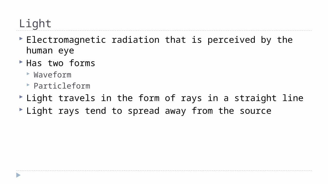
Light Electromagnetic radiation that is perceived by the human eye Has two forms
Waveform Particleform
Light travels in the form of rays in a straight line Light rays tend to spread away from the source
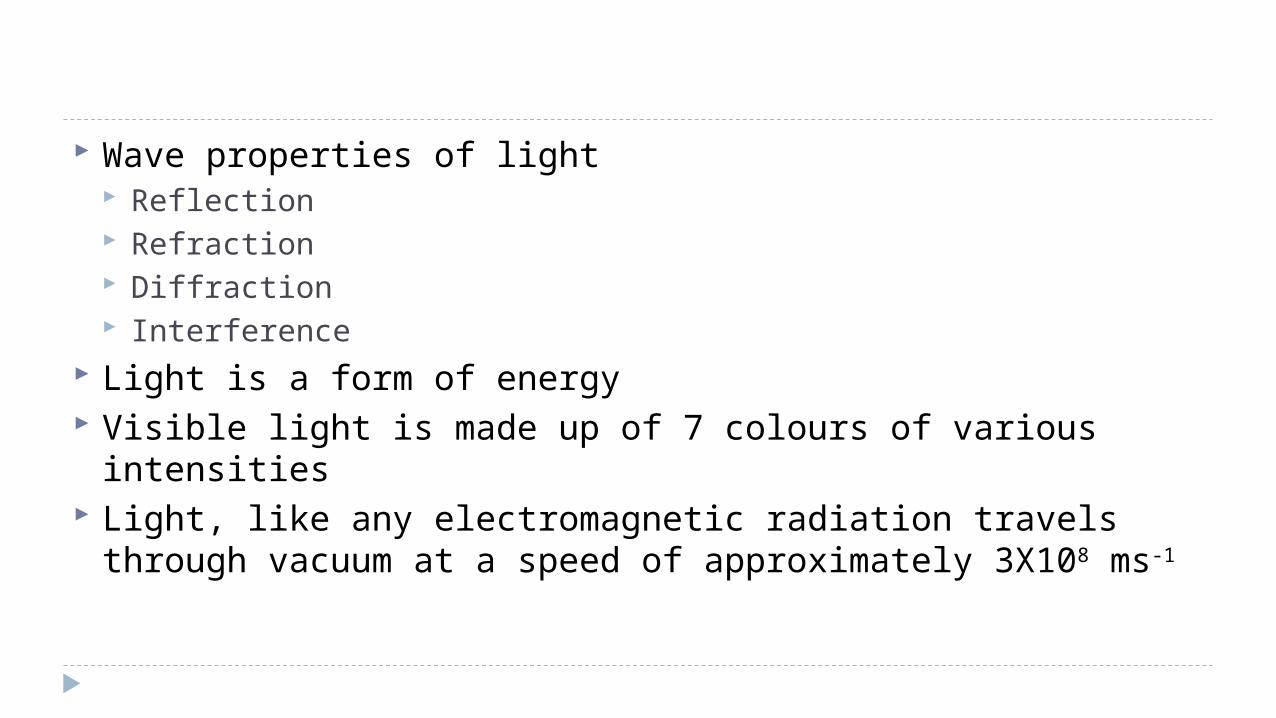
Wave properties of light Reflection Refraction Diffraction Interference
Light is a form of energy Visible light is made up of 7 colours of various intensities Light, like any electromagnetic radiation travels through
vacuum at a speed of approximately 3X10⁸ ms-1

Optics Study of interaction of light with objects that reflect or scatter
light Light is able to
Completely penetrate transparent objects Partially penetrate translucent objects Not penetrate opaque objects
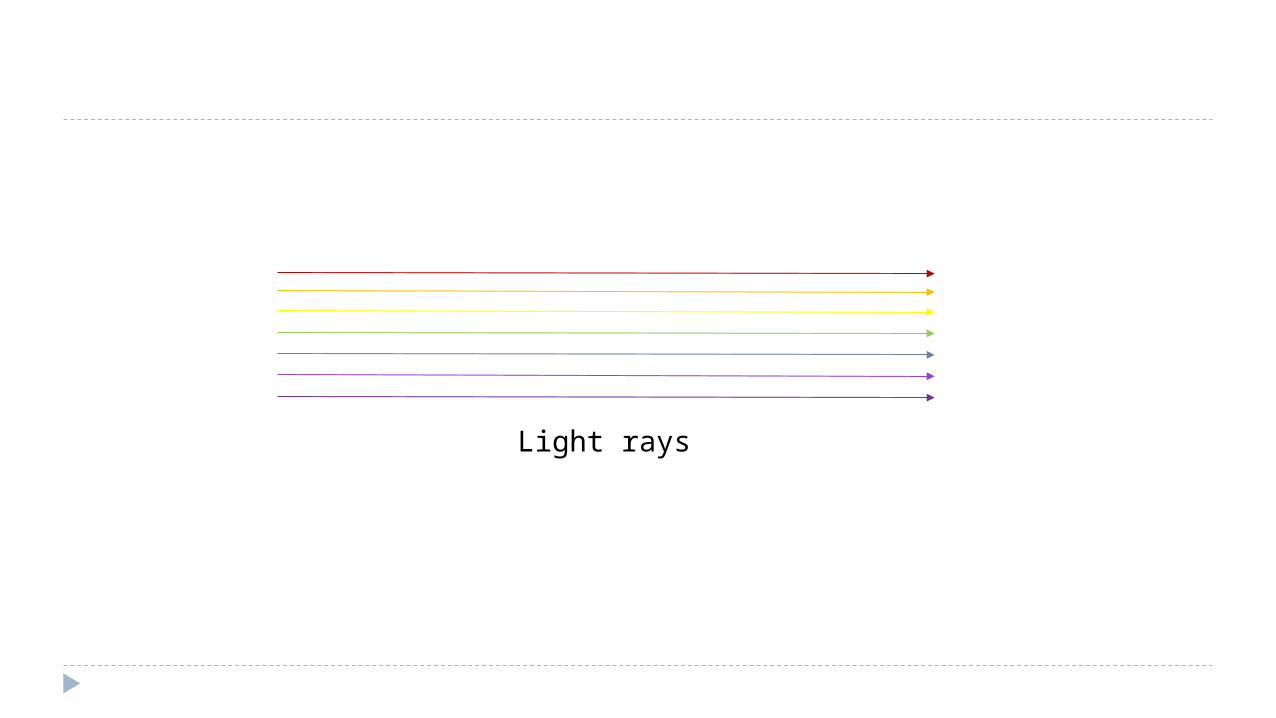
Light rays
Key notes Object – material that emits light rays Image – representation of object after light has reflected or
refracted Ray diagram – diagram showing path of light through reflection or
refraction Line of sight – order or position of the eye to view the image formed Solid lines – real light rays Dotted lines – virtual light rays Convergence – meeting of light rays at a point Divergence – spreading of light rays from a point Focus point – point where light rays are converged or diverged
Reflection Occurs when the direction of light changes when it strikes an
opaque material Light ray before reflection – incident ray Light ray after reflection – reflected ray Imaginary line that is perpendicular to surface – normal line Angle of incidence, i – angle between incident ray and normal
line Angled of reflection, r – angle between reflected ray and
normal line
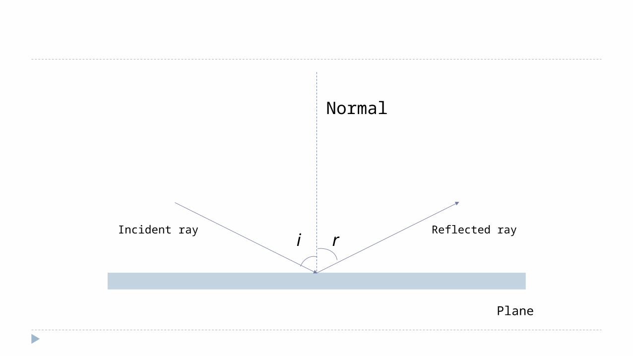
Incident ray Reflected ray
Normal
Plane
i r
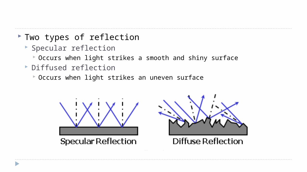
Two types of reflection Specular reflection
Occurs when light strikes a smooth and shiny surface Diffused reflection
Occurs when light strikes an uneven surface
Law of reflection Incident, reflected ray and normal line lies on the same plane i = r
Path of light reflection is represented in a ray diagram
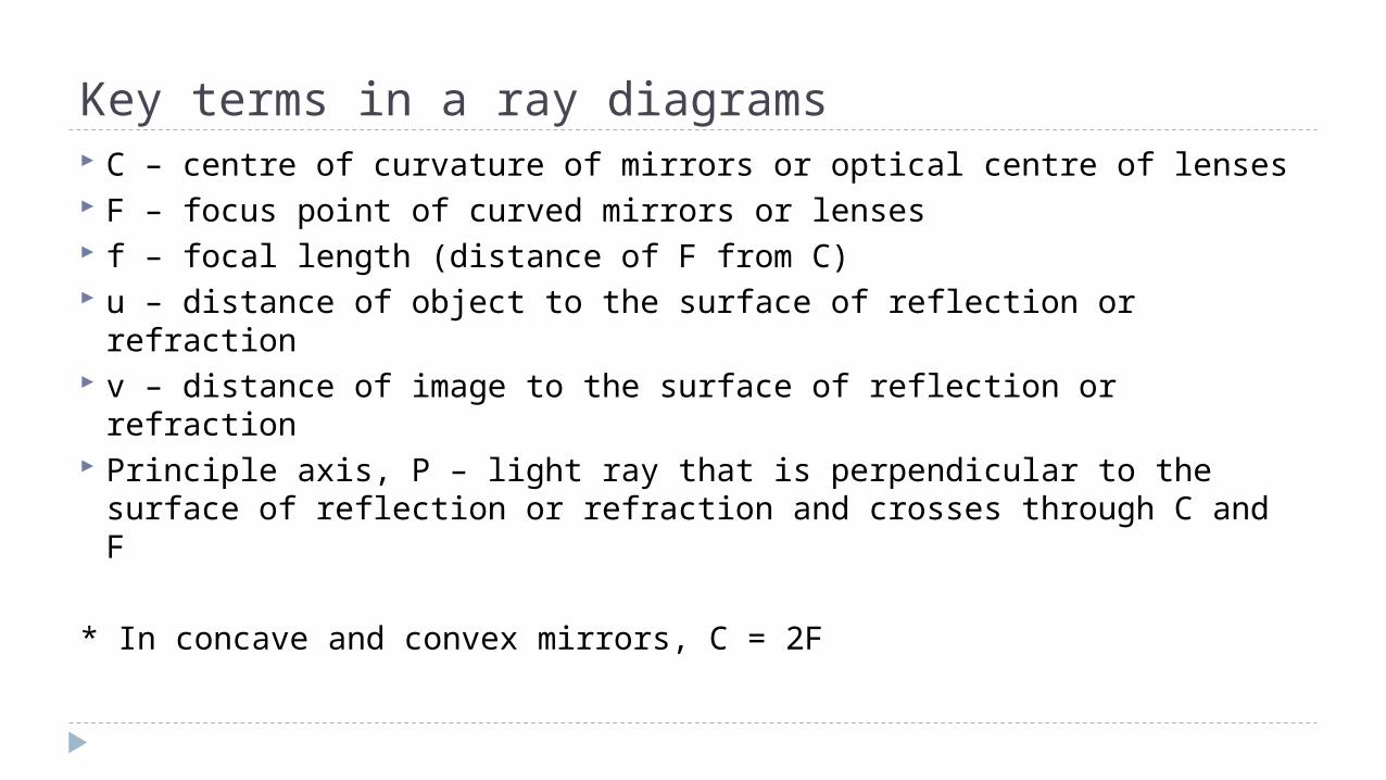
Key terms in a ray diagrams C – centre of curvature of mirrors or optical centre of lenses F – focus point of curved mirrors or lenses f – focal length (distance of F from C) u – distance of object to the surface of reflection or refraction v – distance of image to the surface of reflection or refraction Principle axis, P – light ray that is perpendicular to the surface
of reflection or refraction and crosses through C and F
* In concave and convex mirrors, C = 2F
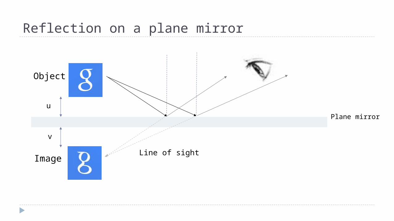
Reflection on a plane mirror
Image
Object
Line of sight
Plane mirroru
v
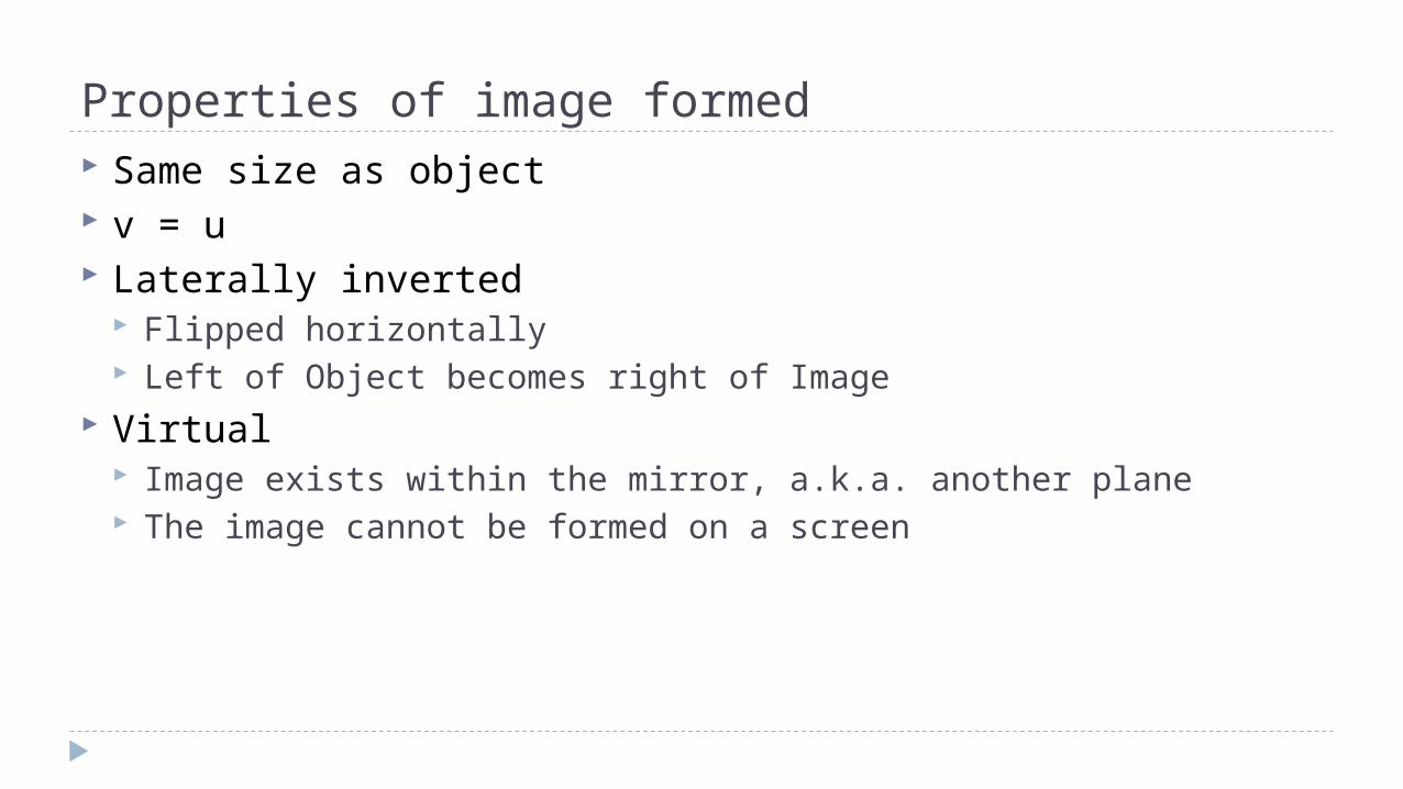
Properties of image formed Same size as object v = u Laterally inverted
Flipped horizontally Left of Object becomes right of Image
Virtual Image exists within the mirror, a.k.a. another plane The image cannot be formed on a screen
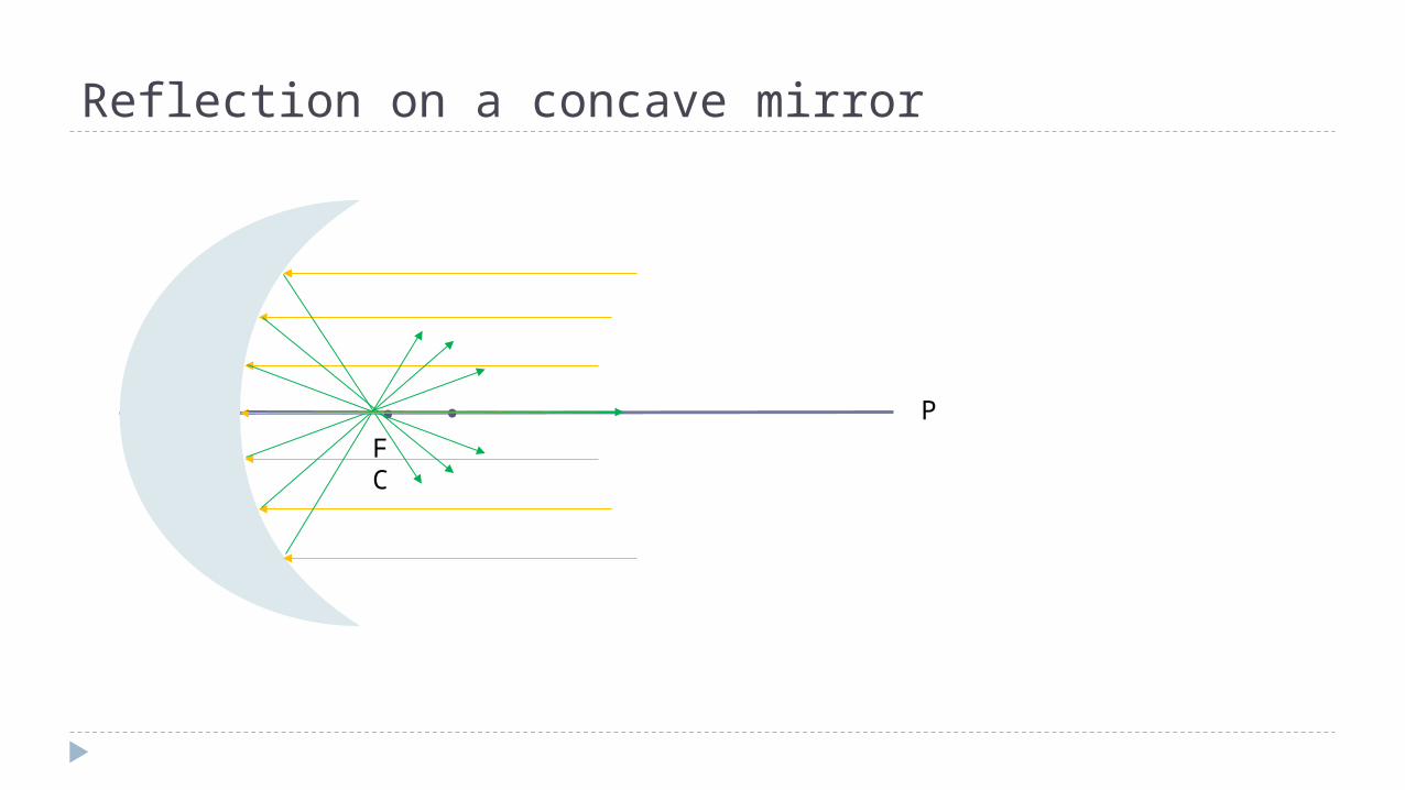
Reflection on a concave mirror
..F C
P
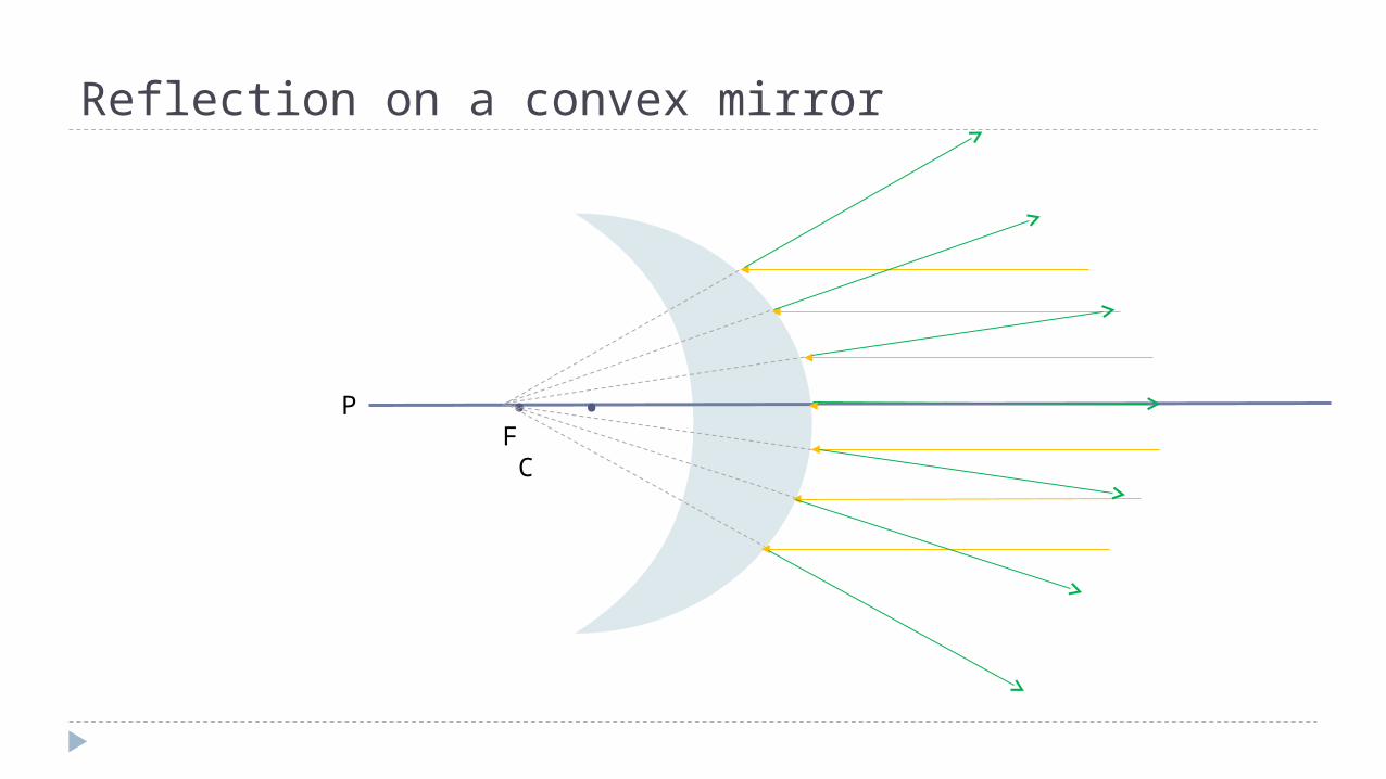
Reflection on a convex mirror
. .F C
P

A concave mirror is also called a converging mirror A convex mirror is also called a diverging mirror The curvier the mirror, the smaller the focal length When incident rays are parallel to P, then reflected rays will
pass through F When incident rays passes through F, then reflected rays will
be parallel to P When incident rays passes through C, then reflected rays will
pass through C in the opposite direction, parallel to the incident ray
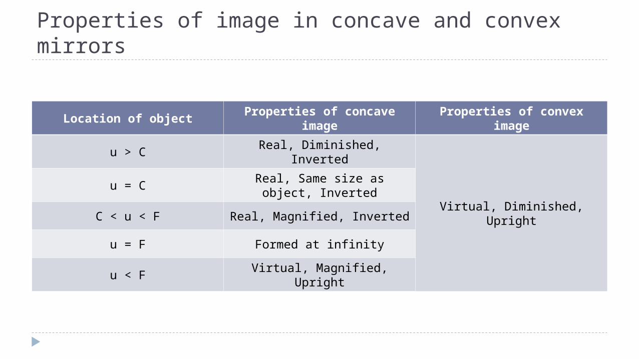
Properties of image in concave and convex mirrors
Location of objectProperties of concave
imageProperties of convex
image
u > C Real, Diminished, Inverted
Virtual, Diminished, Upright
u = CReal, Same size as object,
Inverted
C < u < F Real, Magnified, Inverted
u = F Formed at infinity
u < F Virtual, Magnified, Upright
Applications of reflection Parallax mirror in measuring instruments Wing and rear view mirrors Periscope Vanity mirror Satellite dish Headlights and torchlight reflectors
Refraction Phenomenon where the speed of light changes as it
propagates from one medium to another The change of speed causes a change in the direction of
propagation When light propagates from a medium of low density to a
medium of high density, its speed decreases, causing the direction of propagation to approach the normal
The opposite is true when light passes from a medium of high density to a medium of low density
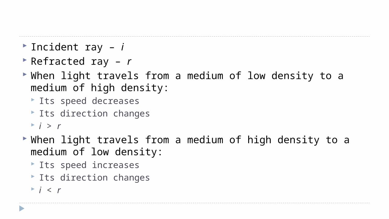
Incident ray – i Refracted ray – r When light travels from a medium of low density to a medium of
high density: Its speed decreases Its direction changes i > r
When light travels from a medium of high density to a medium of low density: Its speed increases Its direction changes i < r
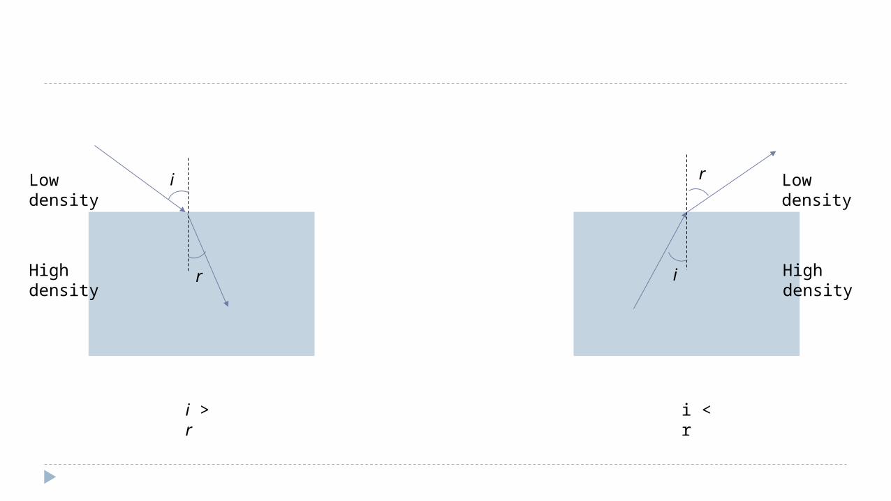
r
r i
i
i > r
High density
High density
Low density
Low density
i < r
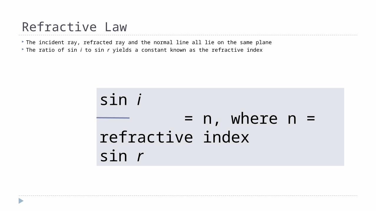
Refractive Law The incident ray, refracted ray and the normal line all lie on the same plane The ratio of sin i to sin r yields a constant known as the refractive index
sin i = n, where n = refractive index sin r
Refractive Index, n Has no units Indicates the light bending ability of a medium Value equals to the ratio of sin i to sin r Value also equals to ratio of speed of light in vacuum to
speed of light in medium Value also equals to ratio of real depth to apparent depth
Total internal reflection Is a form of light refraction. Occurs when light travels from a medium of high density to a
medium of low density, where i > r. Occurs when the i is very large causing the r to be more than
90˚. Critical angle, c is the value of i that results in r = 90˚. When i > c, total internal reflection occurs and the reflected
ray is present in the same medium as the incident ray.
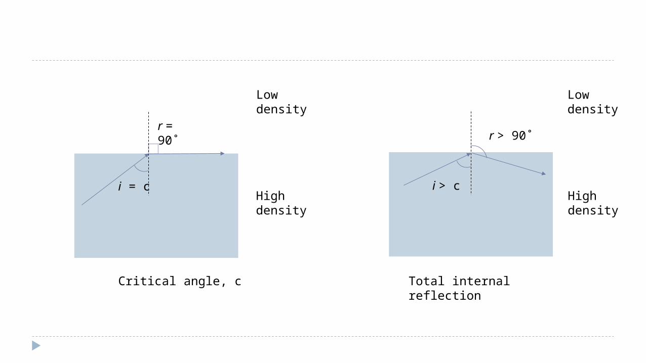
r > 90˚
i > cHigh density
Low density
Total internal reflection
r = 90˚
i = c
Critical angle, c
High density
Low density
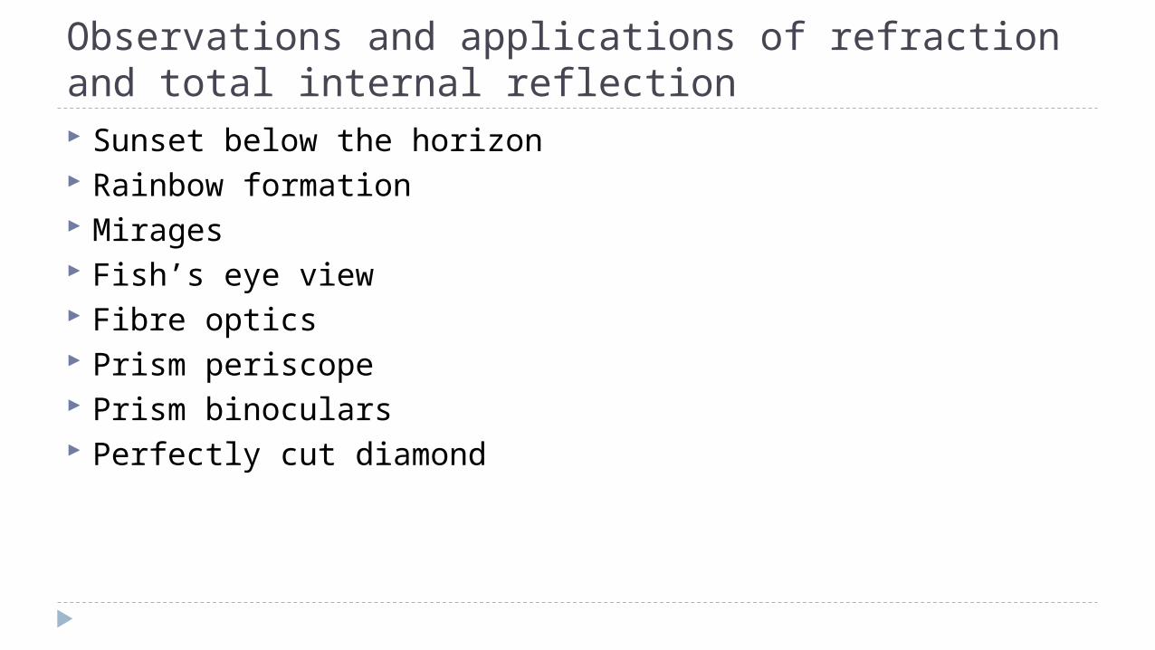
Observations and applications of refraction and total internal reflection Sunset below the horizon Rainbow formation Mirages Fish’s eye view Fibre optics Prism periscope Prism binoculars Perfectly cut diamond
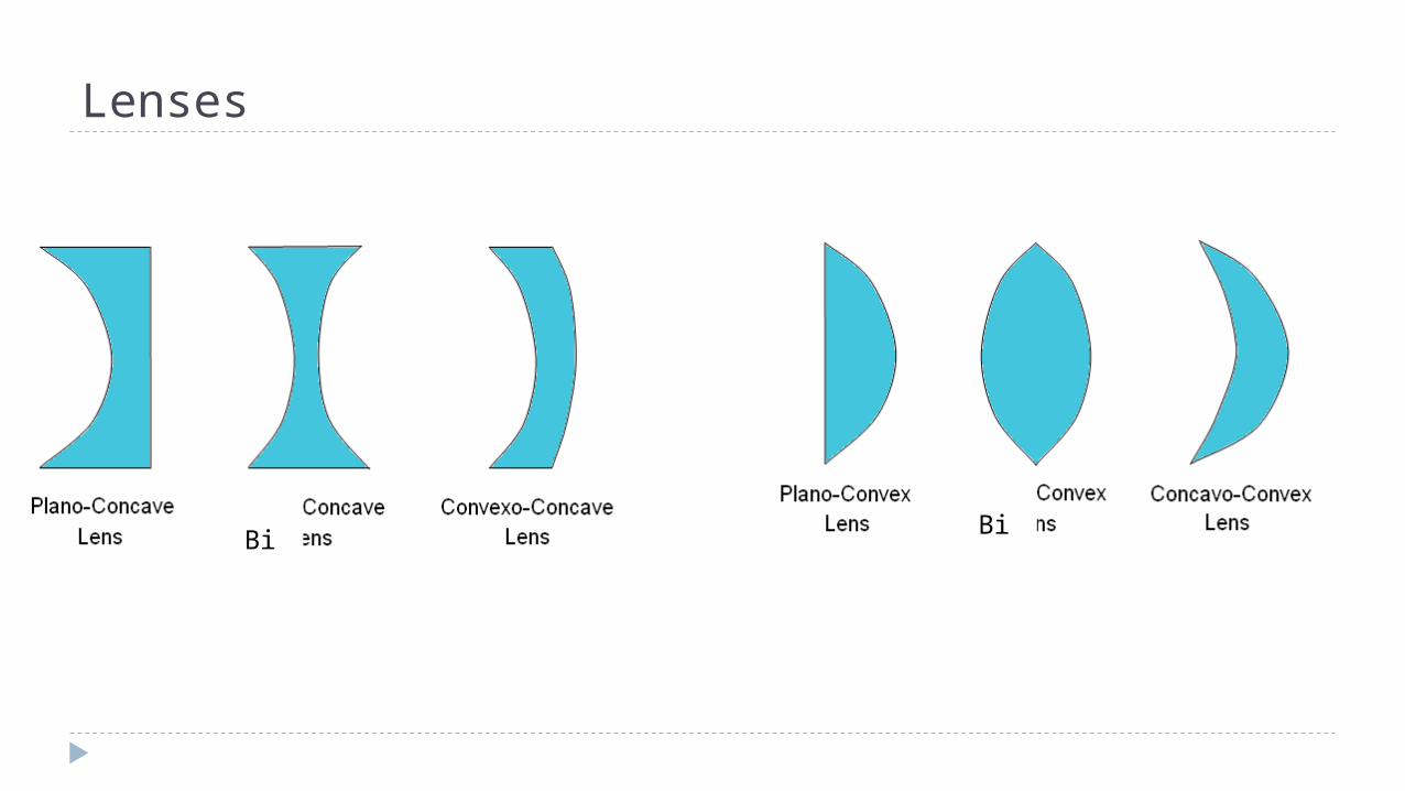
Lenses
Bi
Bi
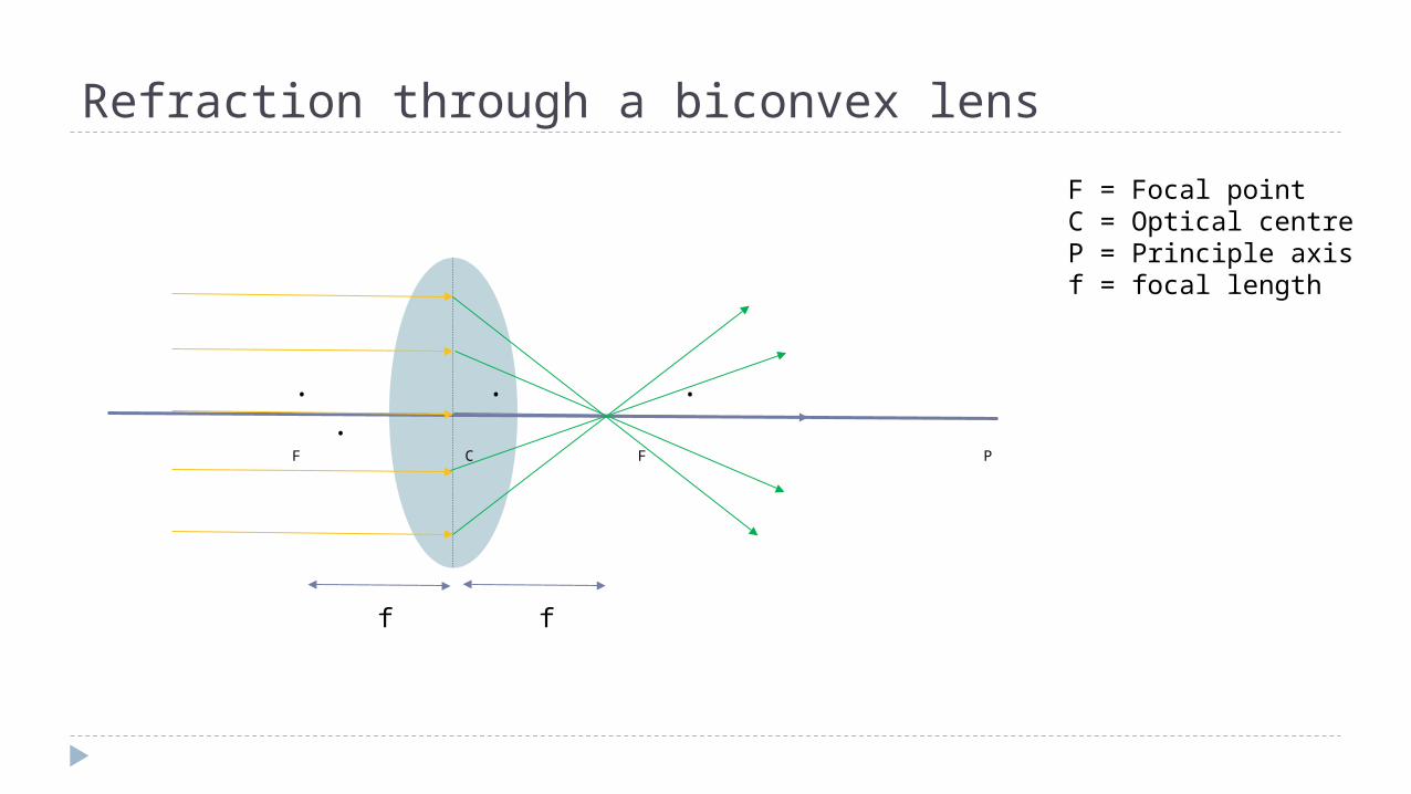
Refraction through a biconvex lens
. . . .F C F P
F = Focal pointC = Optical centreP = Principle axisf = focal length
ff
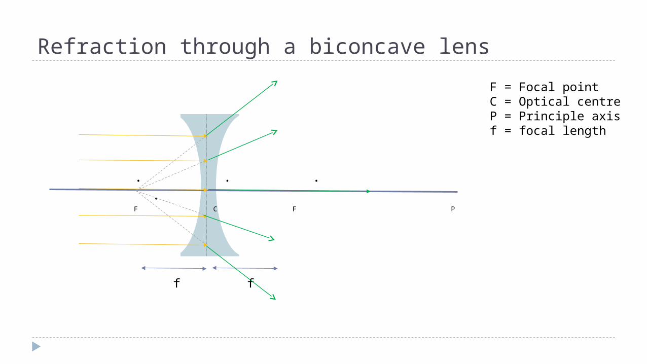
Refraction through a biconcave lens
. . . .F C F P
F = Focal pointC = Optical centreP = Principle axisf = focal length
ff
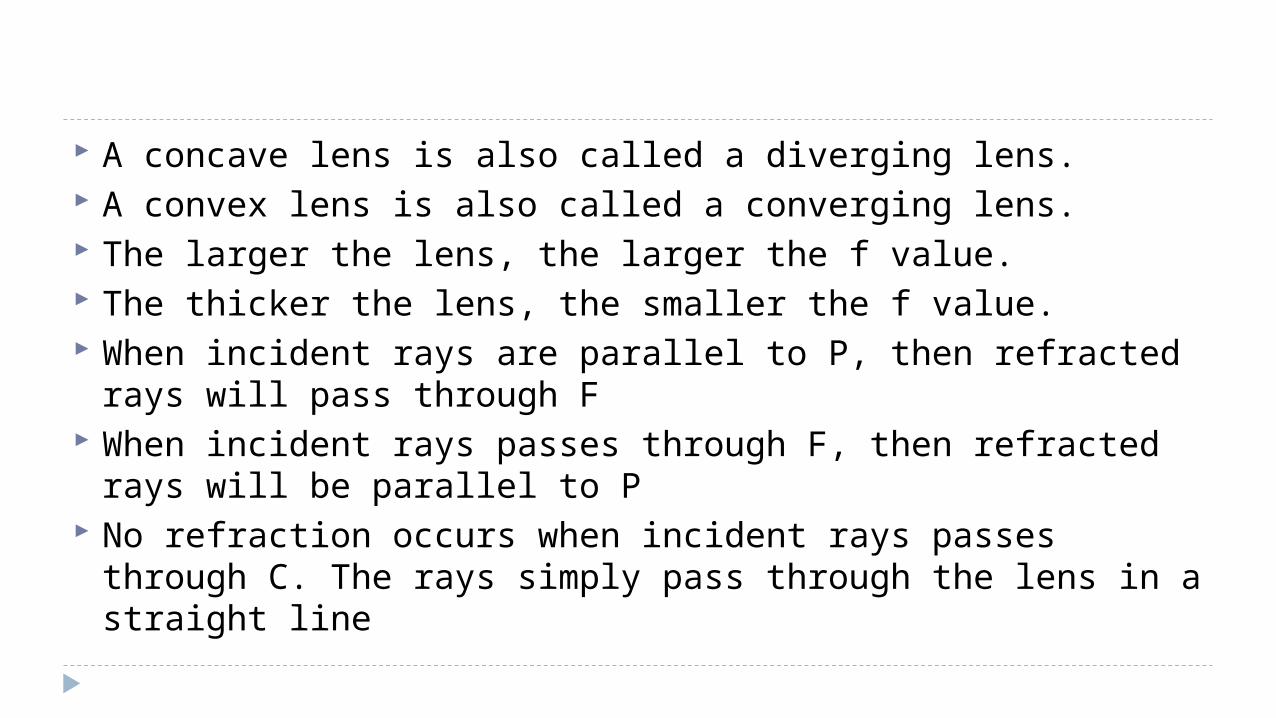
A concave lens is also called a diverging lens. A convex lens is also called a converging lens. The larger the lens, the larger the f value. The thicker the lens, the smaller the f value. When incident rays are parallel to P, then refracted rays will
pass through F When incident rays passes through F, then refracted rays will
be parallel to P No refraction occurs when incident rays passes through C. The
rays simply pass through the lens in a straight line
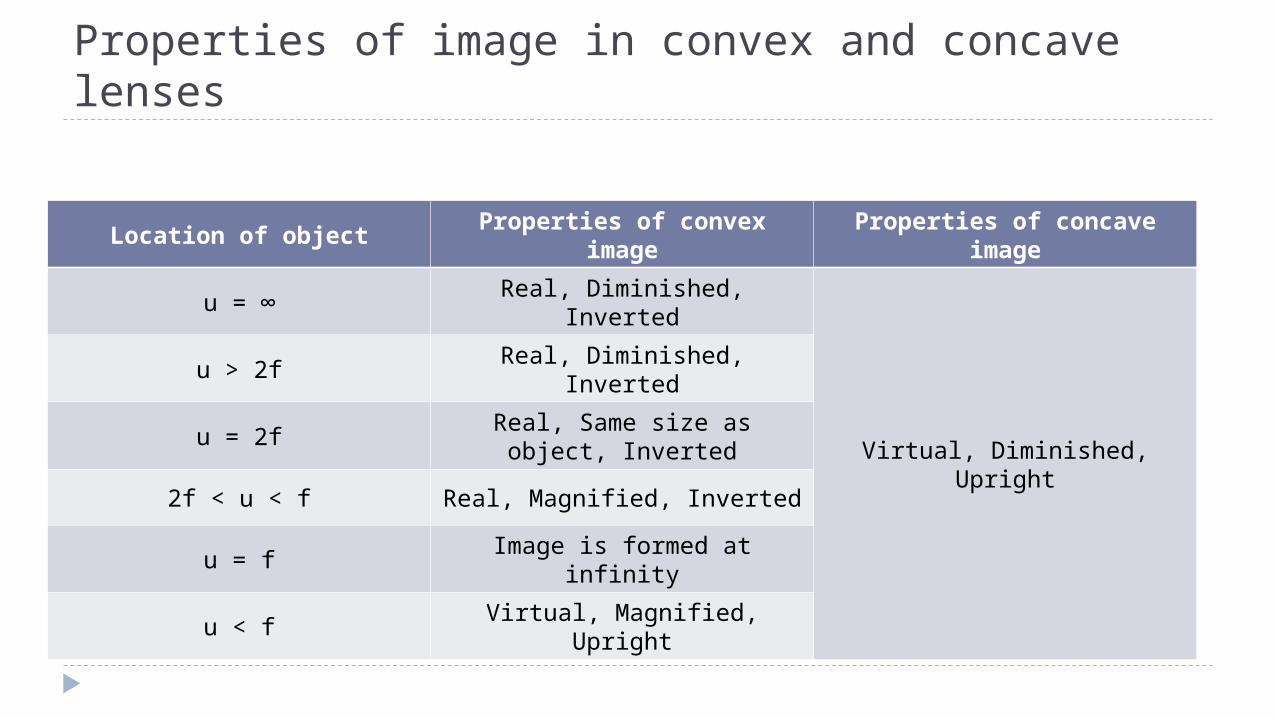
Properties of image in convex and concave lenses
Location of objectProperties of convex
imageProperties of concave
image
u = ∞ Real, Diminished, Inverted
Virtual, Diminished, Upright
u > 2f Real, Diminished, Inverted
u = 2fReal, Same size as object,
Inverted
2f < u < f Real, Magnified, Inverted
u = f Image is formed at infinity
u < f Virtual, Magnified, Upright
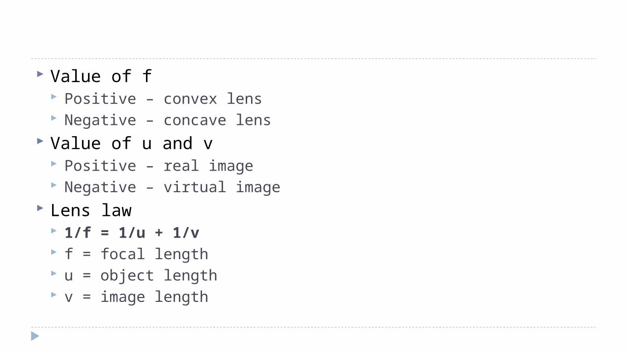
Value of f Positive – convex lens Negative – concave lens
Value of u and v Positive – real image Negative – virtual image
Lens law 1/f = 1/u + 1/v f = focal length u = object length v = image length
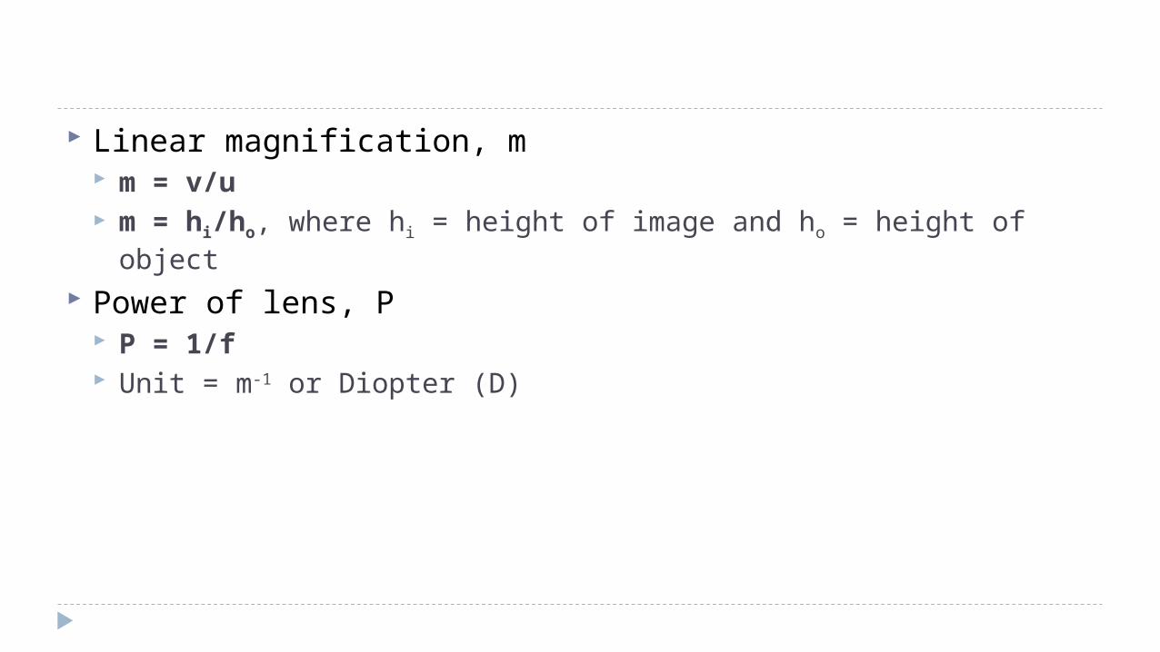
Linear magnification, m m = v/u m = hi/ho, where hi = height of image and ho = height of object
Power of lens, P P = 1/f Unit = m-1 or Diopter (D)
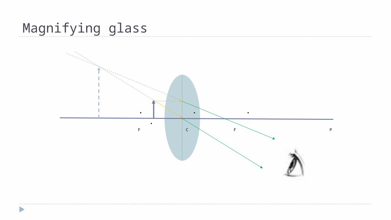
Magnifying glass
. . . .F C F P
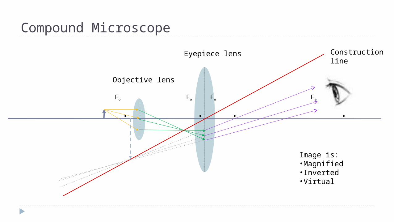
Compound Microscope
Fo Fo Fe Fe
. . . .
Objective lens
Eyepiece lens Construction line
Image is:•Magnified•Inverted•Virtual
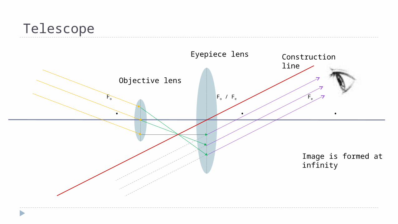
Telescope
Fo Fo / Fe Fe
. . .
Objective lens
Eyepiece lens Construction line
Image is formed at infinity

![Physics SPM 2018 Chapter 5: Light CHAPTER 5: LIGHT · Physics SPM 2018 Chapter 5: Light Hoo Sze Yen Page 6 of 8 5.1.4 Lens Equation u v f 1 1 1 where u = object distance [cm] v =](https://img.pdfslide.net/doc/110x75/603140011529ac2e665f1b6e/physics-spm-2018-chapter-5-light-chapter-5-light-physics-spm-2018-chapter-5-light.jpg)


![[Spm] Presentasi 2 Juknis Spm](https://img.pdfslide.net/doc/110x75/5571fe3f49795991699af645/spm-presentasi-2-juknis-spm.jpg)