Embed Size (px)
Citation preview
Department of Mechanical Engineering Mohammad Ali Jinnah University
Islamabad
Mechanical Vibrations ME 4253
Project Report
Name Registration No
Rasikh Tariq ME 113006
Structural and Vibration Analysis of an Airplane Wing
Page 2 of 15
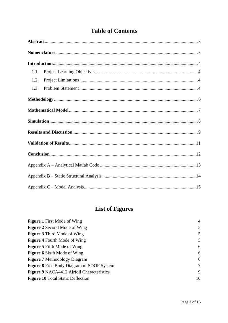
Table of Contents
Abstract ..................................................................................................................................... 3
Nomenclature ........................................................................................................................... 3
Introduction .............................................................................................................................. 4
1.1 Project Learning Objectives ......................................................................................... 4
1.2 Project Limitations ....................................................................................................... 4
1.3 Problem Statement ....................................................................................................... 4
Methodology ............................................................................................................................. 6
Mathematical Model ................................................................................................................ 7
Simulation ................................................................................................................................. 8
Results and Discussion ............................................................................................................. 9
Validation of Results .............................................................................................................. 11
Conclusion .............................................................................................................................. 12
Appendix A – Analytical Matlab Code ................................................................................... 13
Appendix B – Static Structural Analysis ................................................................................. 14
Appendix C – Modal Analysis ................................................................................................. 15
List of Figures
Figure 1 First Mode of Wing 4
Figure 2 Second Mode of Wing 5
Figure 3 Third Mode of Wing 5
Figure 4 Fourth Mode of Wing 5
Figure 5 Fifth Mode of Wing 6
Figure 6 Sixth Mode of Wing 6
Figure 7 Methodology Diagram 6
Figure 8 Free Body Diagram of SDOF System 7
Figure 9 NACA4412 Airfoil Characteristics 9
Figure 10 Total Static Deflection 10
Page 3 of 15
Structural and Vibration Analysis of an Airplane Wing
Rasikh Tariqa
a ME 113 006 Mechanical Engineering Department, Mohammad Ali Jinnah Univeristy, Pakistan
________________________________________________________________________________________________________________
Abstract This project is associated to the analysis of an airplane wing approximated using NACA 4412 airfoil. A
structural analysis using ANSYS Workbench is performed on the airplane wing by applying the static forces
and analyzing the total static deformation. A modal analysis using ANSYS Workbench is carried out for first
six modes and analyzed the behavior of wing upon resonance conditions. Then, a mathematical model is
developed assuming wing to be a single-degree-of-freedom damped system undergoing harmonic excitation.
The external harmonic excitation is calculated upon the maximum cruise speed of airplane (Mach number =
0.8), drag/lift characteristics of NACA 4412 and using classical fluid mechanics formula for drag and lift
force calculations. Based on the simulation of mathematical model on Matlab the system damping is
designed. At the end a comment is made on the airplane wing using vortex shedding principle of continuously
damped system as in actual/real life.
© 2015 All rights reserved. Reproduction in whole or in part in any form requires the prior written permission of Rasikh Tariq, Khuram
Yousaf, Zain Talib, Muhammad Ali, and Muhammad Ramzan.
Keywords: NACA4412, Vibration Analysis, modal analysis, wing.
Nomenclature
𝑋 Amplitude Caused by Forcing Function, m
𝜙 Phase Angle, degree
𝜔𝑛 Natural Frequency, rad/sec
𝜔𝑑 Damped Natural Frequency, rad/sec
𝜔 Forcing Frequency, rad/sec
𝑟 Frequency Ratio
𝜛𝑛(𝑖) Modal Frequency, rad/sec
𝑘 Spring Constant, N/m
𝑐 Damping, N-s/m
𝑐𝑐 Critical Damping
𝐶𝐿 Longitudinal Speed
𝛿𝑠𝑡 Static Deflection, m
Page 4 of 15
Introduction This project is related to analyze a problem applying mechanical vibration concepts. For this purpose, an
airplane wing is chosen. The problem statement starts with the identification of the structure modes when the
first six natural frequencies matches the forcing frequency – the amplitudes goes to maximum during those
conditions. A static structural, modal and vibration analysis is to be performed on the airplane wing. Airplane
wing is considered as single-degree-of-freedom damped system with external force. Finally, a damping
coefficient is calculated that will prevent the modal to go into resonance conditions.
1.1 Project Learning Objectives
Following includes the learning objectives of the project:
1. Formulate mathematical models of problems in vibrations using Newton`s second law or energy
principles.
2. Determine a complete solution to the modelled mechanical vibration problems.
3. Correlate results from the mathematical model to physical characteristics of the actual system.
4. Using modern engineering tools and techniques and their usage to understand physical problem of
mechanical vibration
1.2 Project Limitations
The project is accomplished under certain assumptions. They are mentioned here as:
1. Airplane wing is approximated using scaled-down model of NACA airfoil 4412 with a wall thickness
of 0.01m.
2. The wing model is solved analytically using single-degree-of-freedom damped vibration system.
3. The external forcing function is calculated by taking basic fluid mechanics concepts of drag and lift
force which are not accurate computations.
4. External forcing function is made harmonic by multiplying with cosθ for computation ease purpose.
1.3 Problem Statement
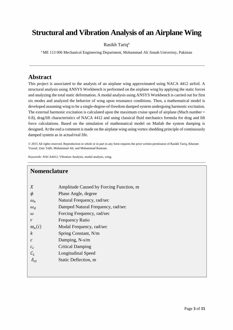
To explain the problem statement a modal analysis is carried out. The first six modes are computed using
ANSYS Workbench. The maximum amplitudes are found for resonance conditions for each of the mode. The
problem statement includes to design a value of damping ratio to avoid these resonance conditions.
Figure 1 First Mode of Wing
Page 5 of 15
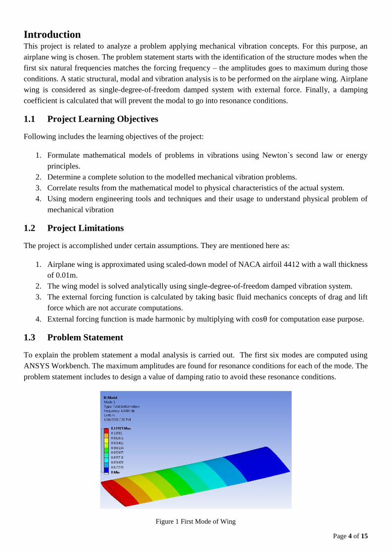
Figure 2 Second Mode of Wing
Figure 3 Third Mode of Wing
Figure 4 Fourth Mode of Wing
Page 6 of 15
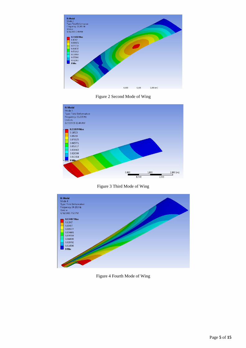
Figure 5 Fifth Mode of Wing
Figure 6 Sixth Mode of Wing
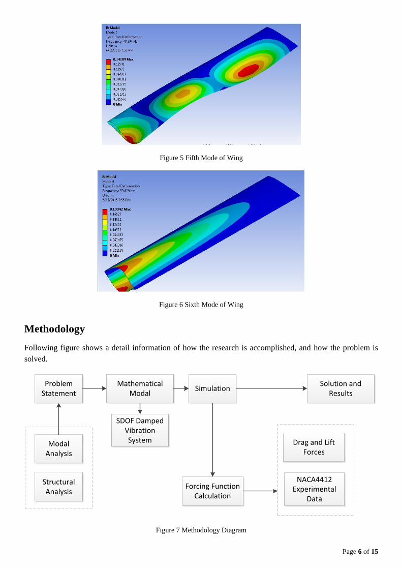
Methodology
Following figure shows a detail information of how the research is accomplished, and how the problem is
solved.
Problem Statement
Modal Analysis
Structural Analysis
Mathematical Modal
Solution and Results
SDOF Damped Vibration System
Simulation
Forcing Function Calculation
Drag and Lift Forces
NACA4412 Experimental
Data
Figure 7 Methodology Diagram
Page 7 of 15
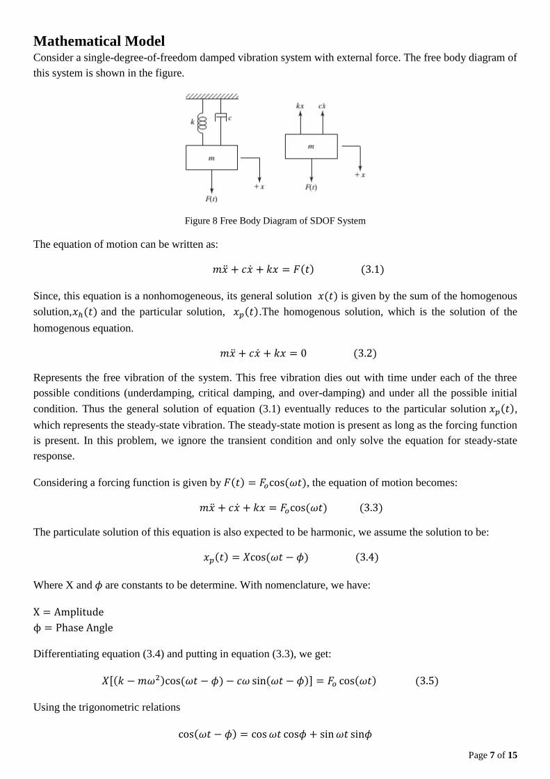
Mathematical Model Consider a single-degree-of-freedom damped vibration system with external force. The free body diagram of
this system is shown in the figure.
Figure 8 Free Body Diagram of SDOF System
The equation of motion can be written as:
𝑚�̈� + 𝑐�̇� + 𝑘𝑥 = 𝐹(𝑡) (3.1)
Since, this equation is a nonhomogeneous, its general solution 𝑥(𝑡) is given by the sum of the homogenous
solution,𝑥ℎ(𝑡) and the particular solution, 𝑥𝑝(𝑡).The homogenous solution, which is the solution of the
homogenous equation.
𝑚�̈� + 𝑐�̇� + 𝑘𝑥 = 0 (3.2)
Represents the free vibration of the system. This free vibration dies out with time under each of the three
possible conditions (underdamping, critical damping, and over-damping) and under all the possible initial
condition. Thus the general solution of equation (3.1) eventually reduces to the particular solution 𝑥𝑝(𝑡),
which represents the steady-state vibration. The steady-state motion is present as long as the forcing function
is present. In this problem, we ignore the transient condition and only solve the equation for steady-state
response.
Considering a forcing function is given by 𝐹(𝑡) = 𝐹𝑜cos (𝜔𝑡), the equation of motion becomes:
𝑚�̈� + 𝑐�̇� + 𝑘𝑥 = 𝐹𝑜cos (𝜔𝑡) (3.3)
The particulate solution of this equation is also expected to be harmonic, we assume the solution to be:
𝑥𝑝(𝑡) = 𝑋cos (𝜔𝑡 − 𝜙) (3.4)
Where X and 𝜙 are constants to be determine. With nomenclature, we have:
X = Amplitude
ϕ = Phase Angle
Differentiating equation (3.4) and putting in equation (3.3), we get:
𝑋[(𝑘 − 𝑚𝜔2)cos (𝜔𝑡 − 𝜙) − 𝑐𝜔 sin(𝜔𝑡 − 𝜙)] = 𝐹𝑜 cos(𝜔𝑡) (3.5)
Using the trigonometric relations
cos(𝜔𝑡 − 𝜙) = cos 𝜔𝑡 cos𝜙 + sin 𝜔𝑡 sin𝜙
Page 8 of 15
sin(𝜔𝑡 − 𝜙) = sin 𝜔𝑡 cos𝜙 − cos 𝜔𝑡 sin𝜙
Equating the coefficients of cos 𝜔𝑡 and sin 𝜔𝑡 on both sides of the resulting equation, we obtain:
𝑋[(𝑘 − 𝑚𝜔2) cos 𝜙 + 𝑐𝜔 sin 𝜙] = 𝐹𝑜
𝑋[(𝑘 − 𝑚𝜔2) sin 𝜙 − 𝑐𝜔 cos 𝜙] = 0
Solution of above equations gives:
𝑋 =𝐹𝑜
[(𝑘 − 𝑚𝜔2)2 + 𝑐2𝜔2]12
And
𝜙 = tan−1 (𝑐𝜔
𝑘 − 𝑚𝜔2)
Using the definitions of natural frequency 𝜔𝑛, damping ratio 𝜁, static deflection 𝛿𝑠𝑡, and frequency ratio r we
can redefine the above equations. Since,
𝜔𝑛 = √𝑘
𝑚
𝜁 =𝑐
𝑐𝑐
𝛿𝑠𝑡 =𝐹𝑜
𝑘
And
𝑟 =𝜔
𝜔𝑛
The modified equation becomes:
𝑿
𝜹𝒔𝒕=
𝟏
[(𝟏 − 𝒓𝟐)𝟐 + (𝟐𝜻𝒓)𝟐]𝟏𝟐
Similarly
𝝓 = 𝐭𝐚𝐧−𝟏 (𝟐𝜻𝒓
𝟏 − 𝒓𝟐)
Simulation
The simulation is carried out using Matlab and ANSYS Workbench. To carry out the simulation first we need
to calculate the forcing function. To calculate the forcing function following formula is used:
𝐹(𝑡) = √𝐹𝑑𝑟𝑎𝑔2 + 𝐹𝑙𝑖𝑓𝑡
2 𝑐𝑜𝑠 𝜔𝑡
Page 9 of 15
The drag and lift forces are calculated using following formula:
𝐹𝑑𝑟𝑎𝑔 =1
2𝐶𝐷𝜌𝑈2𝐴
𝐹𝑙𝑖𝑓𝑡 =1
2𝐶𝐿𝜌𝑈2𝐴
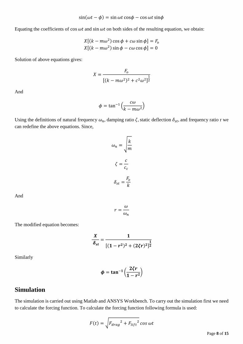
In the above equations 𝐶𝐷 , 𝐶𝐿 represents drag and lift Coefficient, respectively. These coefficients are
calculated using previous experimental results available for NACA4412. Following figure shows the drag and
lift coefficients.
Figure 9 NACA4412 Airfoil Characteristics1
Now, all the parameters that must be needed to simulate the wing on software program are available. The
details of the Matlab code is shown in Appendix A. The details of ANSYS Static Structural deformation is
shown in Appendix B. The details of modal analysis is shown in Appendix C.
Results and Discussion
Following are some of the technical results obtained from Matlab.
Physical Quantity Magnitude
Material Aluminum
Mass, kg 282.48
Span, m 5
Thickness, m 0.0020
Chord, m 1
Spring Constant, N/m 8.3286e+006
Natural Frequency, rad/sec 10,783
1 Dr. J.M Meyers, Dr. D. G. Fletcher, Dr. Y. Dubieft article on Lift and Drag on an airfoil.
Page 10 of 15
Forcing Function, N 9656
Forcing Frequency, rad/sec 8626
Damping Ratio 𝜁 0.707
Some of the other parameters are shown in following steps:
𝜔𝑛 = √𝑘
𝑚= √
8.3286 e006
282.48= 10,738 𝑟𝑎𝑑/𝑠𝑒𝑐
𝛿𝑠𝑡 =𝐹𝑜
𝑘=
9656
8.3286 e006= 0.00115𝑚
𝑐𝑐 = 2√𝑘𝑚 = 2√8.3286 e006 × 282.48 = 97008 𝑁 −𝑠
𝑚
𝑐 = 𝜁𝑐𝑐 = 0.707 × 97008 𝑁 −𝑠
𝑚= 68584 𝑁 − 𝑠/𝑚
𝜔𝑑 = √1 − 𝜁2𝜔𝑛 = √1 − 0.7072 × 10,738 = 7594 𝑟𝑎𝑑/𝑠𝑒𝑐
𝑟 =𝜔
𝜔𝑛=
8626
10,738= 0.8
𝑋 = 𝛿𝑠𝑡
[(1 − 𝑟2)2 + (2𝜁𝑟)2]12
=0.00115
[(1 − 0.82)2 + (2 × 0.707 × 0.8)2]12
= 9.6 × 10⁻⁴𝑚
𝜙 = tan−1 (2𝜁𝑟
1 − 𝑟2) = tan−1 (
2 × 0.707 × 0.8
1 − 0.82) = 72.34𝑜
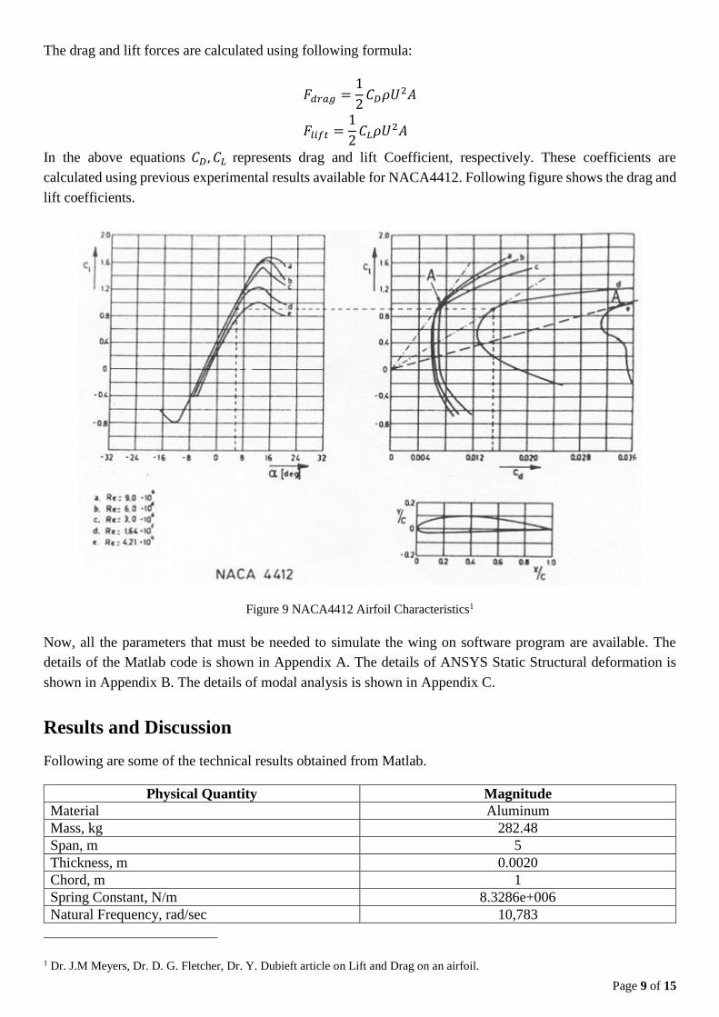
The static structural analysis is also performed using the action of this maximum force. The purpose is to find
out the maximum static deflection in the structure.
Figure 10 Total Static Deflection
Page 11 of 15
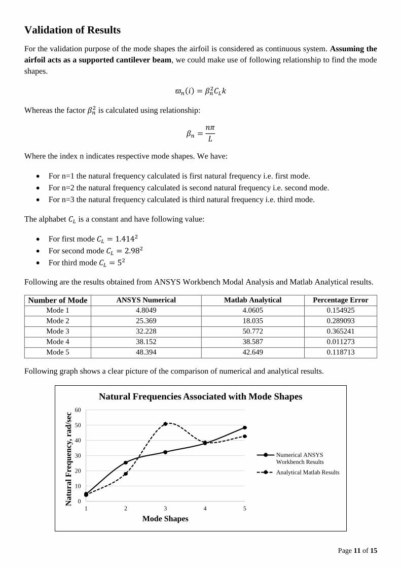
Validation of Results
For the validation purpose of the mode shapes the airfoil is considered as continuous system. Assuming the
airfoil acts as a supported cantilever beam, we could make use of following relationship to find the mode
shapes.
𝜛𝑛(𝑖) = 𝛽𝑛2𝐶𝐿𝑘
Whereas the factor 𝛽𝑛2 is calculated using relationship:
𝛽𝑛 =𝑛𝜋
𝐿
Where the index n indicates respective mode shapes. We have:
For n=1 the natural frequency calculated is first natural frequency i.e. first mode.
For n=2 the natural frequency calculated is second natural frequency i.e. second mode.
For n=3 the natural frequency calculated is third natural frequency i.e. third mode.
The alphabet 𝐶𝐿 is a constant and have following value:
For first mode 𝐶𝐿 = 1.4142
For second mode 𝐶𝐿 = 2.982
For third mode 𝐶𝐿 = 52
Following are the results obtained from ANSYS Workbench Modal Analysis and Matlab Analytical results.
Number of Mode ANSYS Numerical Matlab Analytical Percentage Error
Mode 1 4.8049 4.0605 0.154925
Mode 2 25.369 18.035 0.289093
Mode 3 32.228 50.772 0.365241
Mode 4 38.152 38.587 0.011273
Mode 5 48.394 42.649 0.118713
Following graph shows a clear picture of the comparison of numerical and analytical results.
0
10
20
30
40
50
60
1 2 3 4 5
Natu
ral
Fre
qu
ency
, ra
d/s
ec
Mode Shapes
Natural Frequencies Associated with Mode Shapes
Numerical ANSYS
Workbench Results
Analytical Matlab Results
Page 12 of 15
Conclusion
The project starts with the identification of the problem statement by analyzing the natural frequencies of the
different mode shapes obtained using ANSYS Workbench. To avoid those resonance conditions, we designed
a value of damping ratio and spring constant to avoid those resonance conditions. A mathematical model is
established using single-degree-of-freedom-system with external forced damped vibration system. In the
simulation phase Matlab is used to calculate all the parameters. And in the validation phase, the analytical and
numerical results of different mode shapes are compared by considering airplane wing to be continuous system.
Page 13 of 15
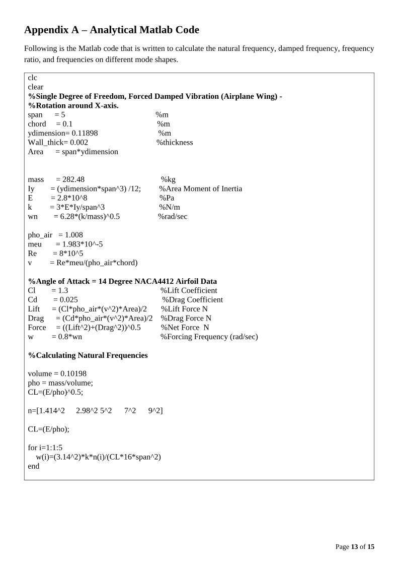
Appendix A – Analytical Matlab Code
Following is the Matlab code that is written to calculate the natural frequency, damped frequency, frequency
ratio, and frequencies on different mode shapes.
clc
clear
%Single Degree of Freedom, Forced Damped Vibration (Airplane Wing) -
%Rotation around X-axis.
span = 5 %m
chord = 0.1 %m
ydimension= 0.11898 %m
Wall_thick= 0.002 %thickness
Area = span*ydimension
mass = 282.48 %kg
Iy = (ydimension*span^3) /12; %Area Moment of Inertia
E = 2.8*10^8 %Pa
k = 3*E*Iy/span^3 %N/m
wn = 6.28*(k/mass)^0.5 %rad/sec
pho_air = 1.008
meu = 1.983*10^-5
Re = 8*10^5
v = Re*meu/(pho_air*chord)
%Angle of Attack = 14 Degree NACA4412 Airfoil Data
Cl = 1.3 %Lift Coefficient
Cd = 0.025 %Drag Coefficient
Lift = (Cl*pho_air*(v^2)*Area)/2 %Lift Force N
Drag = (Cd*pho_air*(v^2)*Area)/2 %Drag Force N
Force = ((Lift^2)+(Drag^2))^0.5 %Net Force N
w = 0.8*wn %Forcing Frequency (rad/sec)
%Calculating Natural Frequencies
volume = 0.10198
pho = mass/volume;
CL=(E/pho)^0.5;
n=[1.414^2 2.98^2 5^2 7^2 9^2]
CL=(E/pho);
for i=1:1:5
w(i)=(3.14^2)*k*n(i)/(CL*16*span^2)
end
Page 14 of 15
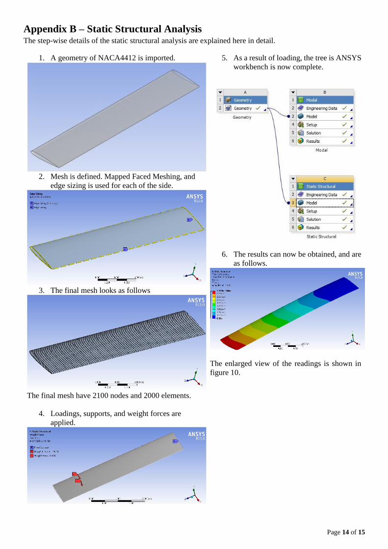
Appendix B – Static Structural Analysis The step-wise details of the static structural analysis are explained here in detail.
1. A geometry of NACA4412 is imported.
2. Mesh is defined. Mapped Faced Meshing, and
edge sizing is used for each of the side.
3. The final mesh looks as follows
The final mesh have 2100 nodes and 2000 elements.
4. Loadings, supports, and weight forces are
applied.
5. As a result of loading, the tree is ANSYS
workbench is now complete.
6. The results can now be obtained, and are
as follows.
The enlarged view of the readings is shown in
figure 10.
Page 15 of 15
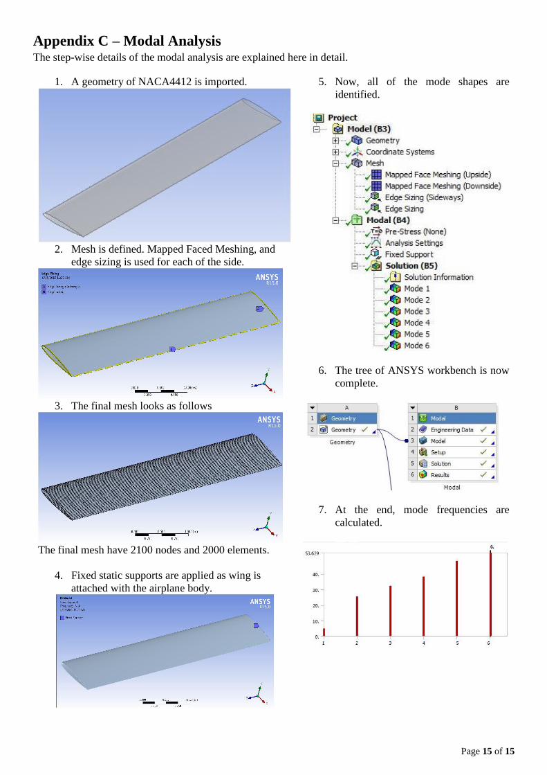
Appendix C – Modal Analysis The step-wise details of the modal analysis are explained here in detail.
1. A geometry of NACA4412 is imported.
2. Mesh is defined. Mapped Faced Meshing, and
edge sizing is used for each of the side.
3. The final mesh looks as follows
The final mesh have 2100 nodes and 2000 elements.
4. Fixed static supports are applied as wing is
attached with the airplane body.
5. Now, all of the mode shapes are
identified.
6. The tree of ANSYS workbench is now
complete.
7. At the end, mode frequencies are
calculated.