Embed Size (px)
Citation preview

Finite State MachineMobile Game Programming
[email protected] of Digital Contents, Dongseo Univ.
October 6, 2016

Action states
2
states of the mon-ster– Idle– Moving– Attack– Hurt– Dead

Simplification Step1: How to model the problem to find a solu-
tion. Step2: How to implement the model.
3

Step1: Model
4

Model: Object State Diagram The State Diagram is a well known data structure
in computer science. In compiler theory, we learn State Diagram which
is used in automata. In database, there is an entity-relation model
which is similar to the state diagram. In game programming, there is a state machine
which is based on the state diagram. We apply this data structure to an object in
game.– It is called ‘Object State Diagram’.
5

State DiagramState
A State is represented as a circle.
Start state has a incoming arrow.
Final state has a double circle.
6

State DiagramState Action A State can have action(s). An action is described in text after
slash symbol. An action describes the dynamic be-
havior of an object in that state.
Example:
7
State/Action

State DiagramTransition A transition is represented as a
directed solid arrow. A transition means the state
change between two different states.
8
A state transition between A and B.
It can be read, ‘State A goes to B’.

State DiagramTransition Input/Action A transition can have input(s)
and action(s). An input describes a condition
which trigger the state change. An action describes the dynamic
behavior of an object when it goes to other state.
Example:
9
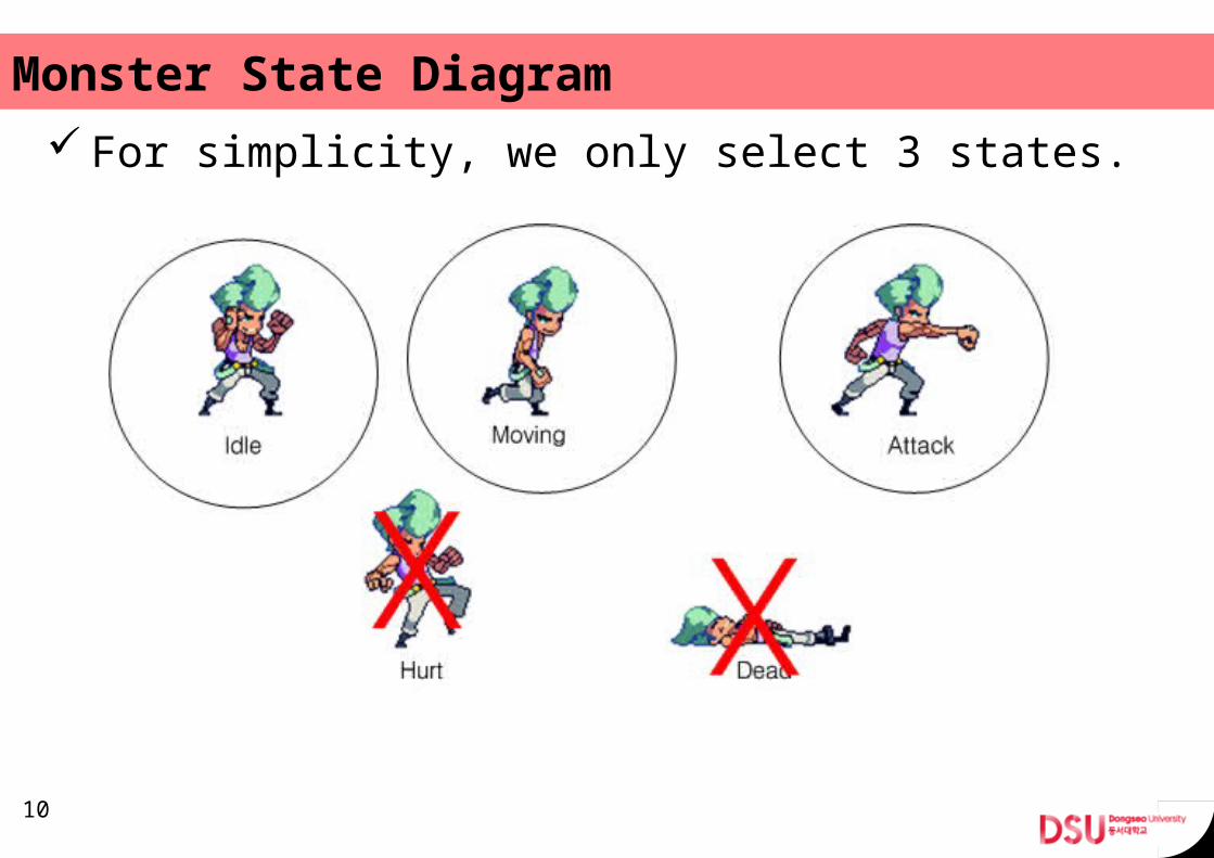
Monster State Diagram For simplicity, we only select 3 states.
10

Final Monster State Diagram
11

Question In Moving state, I want to add more detailed mo-
tions for the monster.– Crawl– Walk– Run
How to add this feature?
12

(Answer to Question) We can build the ‘Moving State Diagram’. Add this sub state diagram into inner state dia-
gram of Moving State.
13
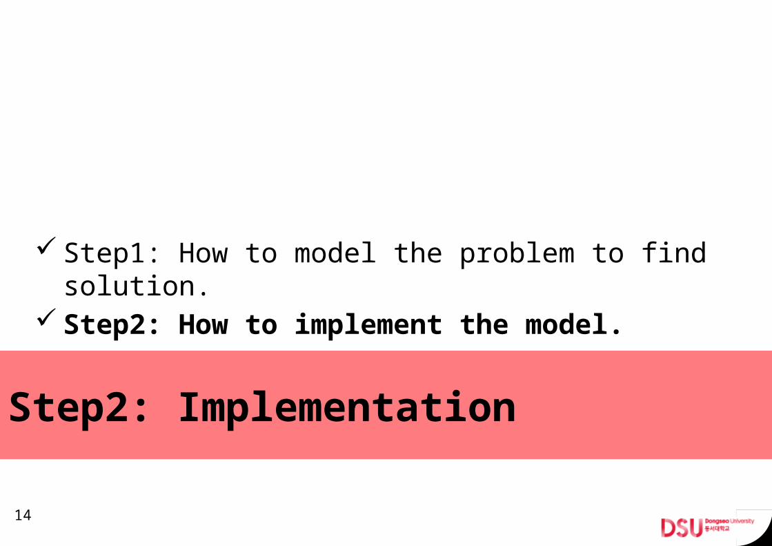
Step2: Implementation
Step1: How to model the problem to find solu-tion.
Step2: How to implement the model.
14

Simple Game Client
15
Coding Conventions

16
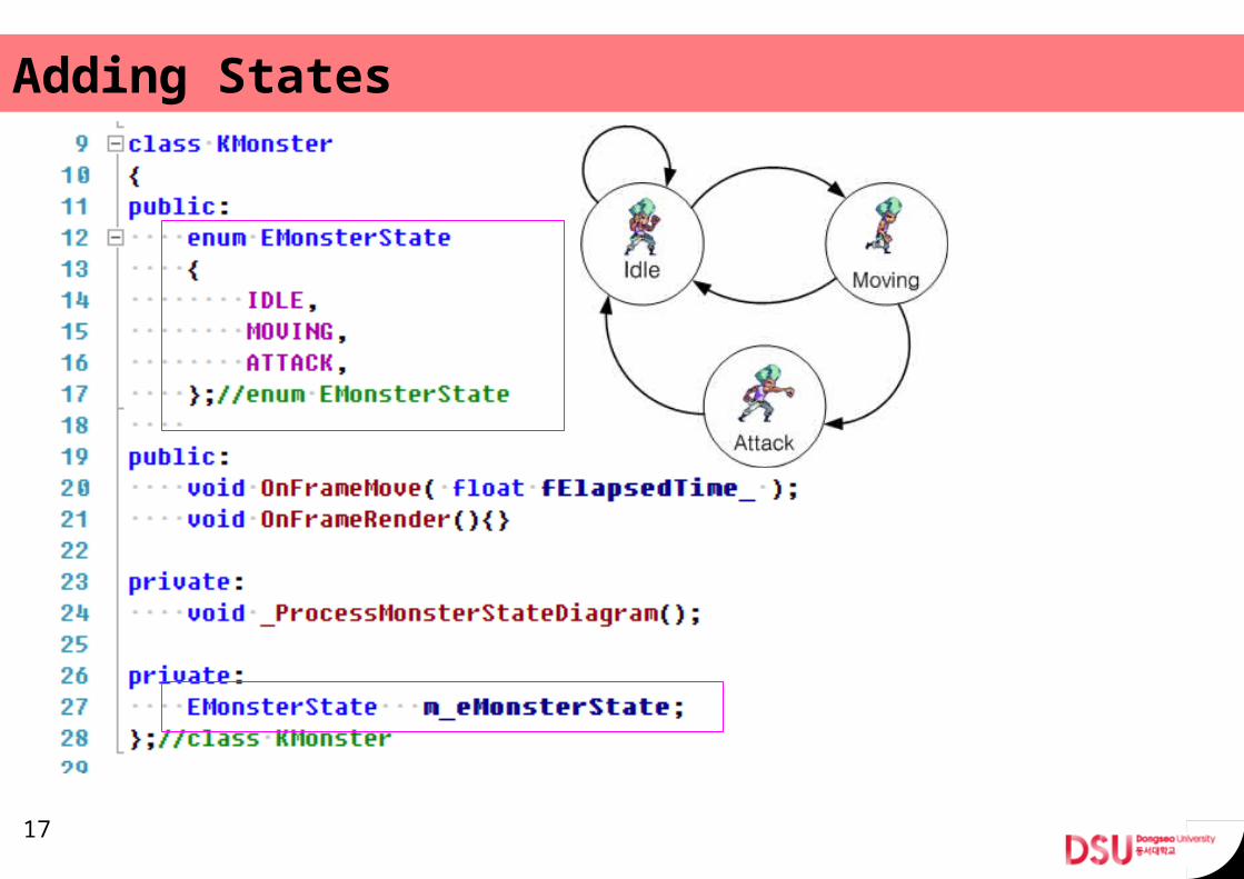
Adding States
17

Adding Properties
18
m_fIdleTimer
m_dwIdleMotion
m_dwDistanceToTarget
m_fSpellGauge
m_dwAttackMotion
m_dwTargetId
m_dwBboxId
m_fPrepareAttackTimer

19

Adding State Transitions
20

21

State transition: Idle state
22

State transition: Moving state
23

State transition: Attack state
24

Test routine
25

26

Demo The Simple Console application project using
Microsoft Visual Studio 2010.
27
User press a ‘1' key.
User press a 'Esc' key.
Question: There is an output sequence of 1 and 0 after first 1 is printed. Why?

(Answer to question)
In Moving state, the condition of first if-statement is always true. Because the string expression “target is out in range” always returns a non-zero value.
In C++, a non-zero value evaluated to true for a boolean expression.
28

(Implementation Optimization) Our C++ implementation can be structured to
more elegant form. We can use well-known design patterns. Use the pointer to member functions!
– I will show it in the next lecture.
29

More Complex Example
Most programmer are aware of this concept. But they cannot use it freely, why?
30

Implementing Simple Desktop Calculator.◇Input ◇Output• 1• +• 2• +• 13• =• +• 3• -• …
31
1
2
116
3
3
16
13
1
19

How to Find States? Let’s focus on number.
1 + 2 + 13 = + 3 -
32
first operand
second operandsecond operand

Can you find a hidden state?
1 + 2 + 13 = + 3 -
33
The result can be used as first operand, but also it can be dis-carded.

3 States for Calculator problem
34

Homework: Complete the Calculator State Model.
35

Q&A
36


![FSM [Autosaved]](https://img.pdfslide.net/doc/110x75/577cda6c1a28ab9e78a5a27e/fsm-autosaved.jpg)