Embed Size (px)
Citation preview

POTENTIAL AND PROSPECTIVE IMPLEMENTATION OF
CARBON NANOTUBESON NEXT GENERATION
AIRCRAFT AND SPACE VEHICLE
NASREEN HABEEB UR RAHIMANM140497NSNIT-C
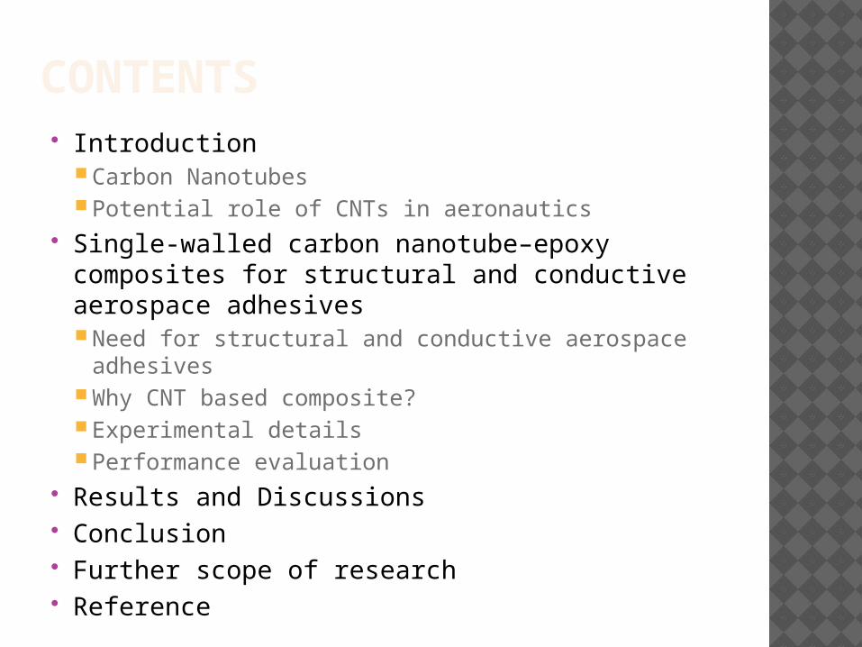
CONTENTS Introduction
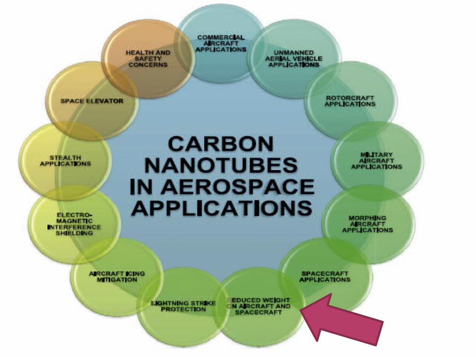
Carbon Nanotubes Potential role of CNTs in aeronautics
Single-walled carbon nanotube–epoxy composites for structural and conductive aerospace adhesives Need for structural and conductive aerospace
adhesives Why CNT based composite? Experimental details Performance evaluation
Results and Discussions Conclusion Further scope of research Reference
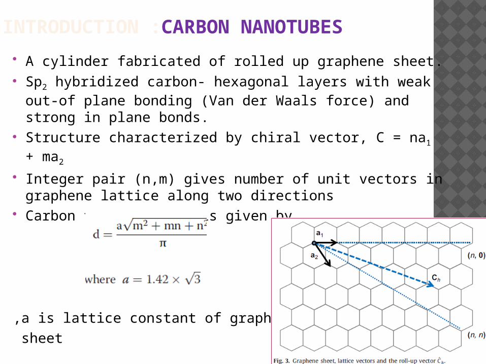
INTRODUCTION :CARBON NANOTUBES
A cylinder fabricated of rolled up graphene sheet. Sp2 hybridized carbon- hexagonal layers with weak out-
of plane bonding (Van der Waals force) and strong in plane bonds.
Structure characterized by chiral vector, C = na1 + ma2
Integer pair (n,m) gives number of unit vectors in graphene lattice along two directions
Carbon tube diameter is given by
,a is lattice constant of graphene sheet
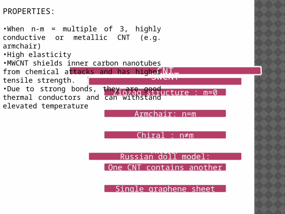
CNTSWCNT
(Single walled)Zigzag structure : m=0
Armchair: n=m
Chiral : n≠m
MWCNT(multi walled)Russian doll model:
One CNT contains another CNT inside itParchment model:
Single graphene sheet wrapped around itself
PROPERTIES:
•When n-m = multiple of 3, highly conductive or metallic CNT (e.g. armchair)•High elasticity•MWCNT shields inner carbon nanotubes from chemical attacks and has higher tensile strength.•Due to strong bonds, they are good thermal conductors and can withstand elevated temperature
SINGLE-WALLED CARBON NANOTUBE–EPOXY COMPOSITES FOR STRUCTURALAND CONDUCTIVE AEROSPACE ADHESIVES
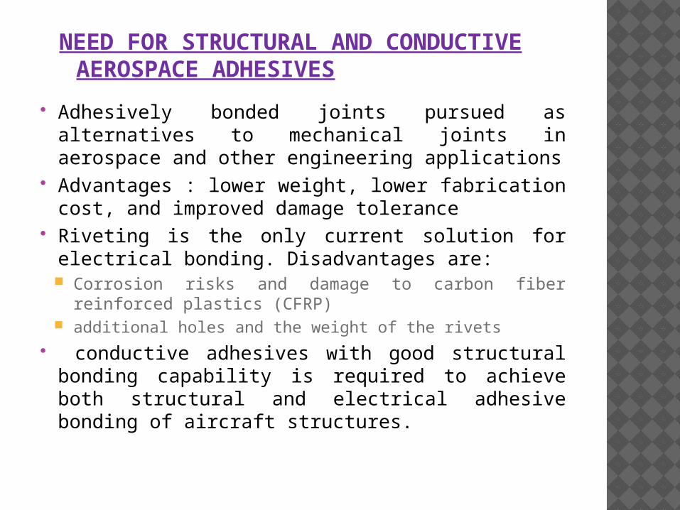
NEED FOR STRUCTURAL AND CONDUCTIVE AEROSPACE ADHESIVES
Adhesively bonded joints pursued as alternatives to mechanical joints in aerospace and other engineering applications
Advantages : lower weight, lower fabrication cost, and improved damage tolerance
Riveting is the only current solution for electrical bonding. Disadvantages are: Corrosion risks and damage to carbon fiber
reinforced plastics (CFRP) additional holes and the weight of the rivets
conductive adhesives with good structural bonding capability is required to achieve both structural and electrical adhesive bonding of aircraft structures.
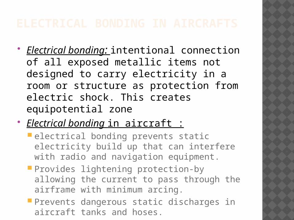
ELECTRICAL BONDING IN AIRCRAFTS
Electrical bonding: intentional connection of all exposed metallic items not designed to carry electricity in a room or structure as protection from electric shock. This creates equipotential zone
Electrical bonding in aircraft : electrical bonding prevents static electricity
build up that can interfere with radio and navigation equipment.
Provides lightening protection-by allowing the current to pass through the airframe with minimum arcing.
Prevents dangerous static discharges in aircraft tanks and hoses.
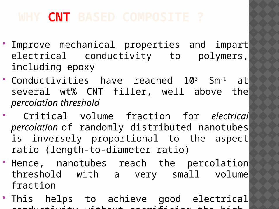
WHY CNT BASED COMPOSITE ?
Improve mechanical properties and impart electrical conductivity to polymers, including epoxy
Conductivities have reached 103 Sm-1 at several wt% CNT filler, well above the percolation threshold
Critical volume fraction for electrical percolation of randomly distributed nanotubes is inversely proportional to the aspect ratio (length-to-diameter ratio)
Hence, nanotubes reach the percolation threshold with a very small volume fraction
This helps to achieve good electrical conductivity without sacrificing the high-performance structural bonding requirements of an aerospace adhesive
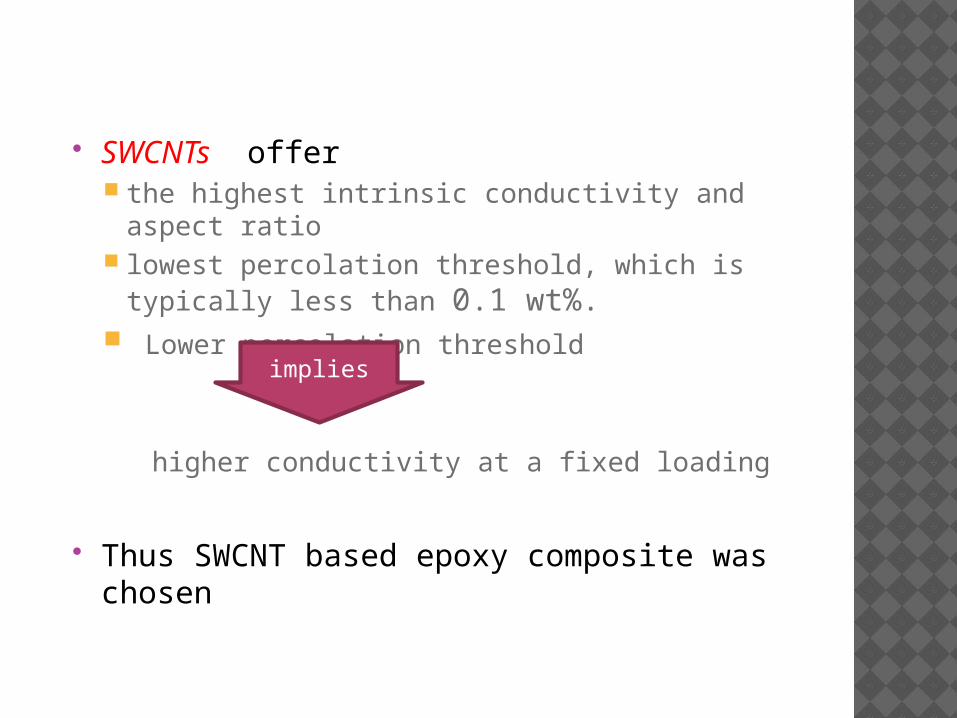
SWCNTs offer the highest intrinsic conductivity and aspect
ratio lowest percolation threshold, which is typically
less than 0.1 wt%. Lower percolation threshold
higher conductivity at a fixed loading
Thus SWCNT based epoxy composite was chosen
implies
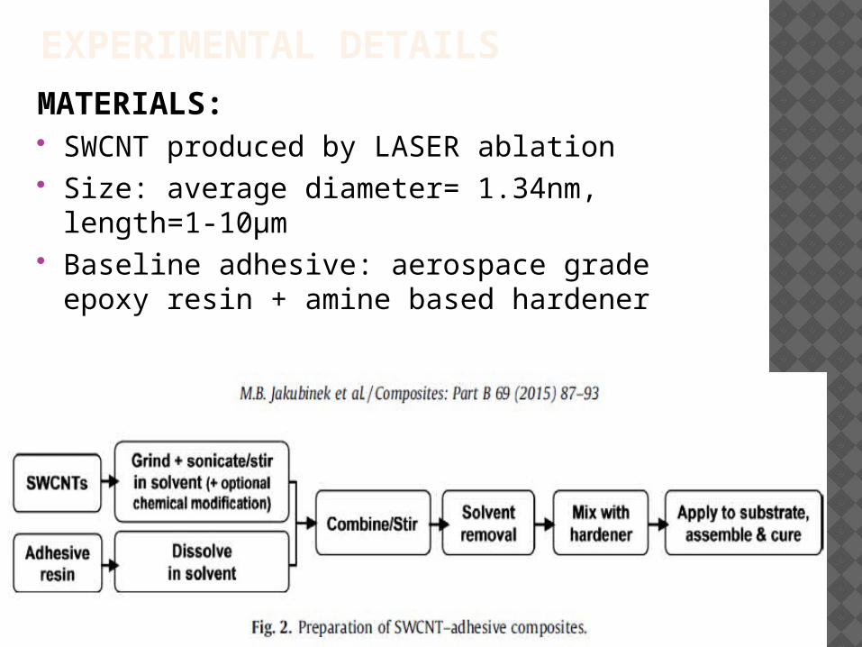
EXPERIMENTAL DETAILS
MATERIALS: SWCNT produced by LASER ablation Size: average diameter= 1.34nm, length=1-
10µm Baseline adhesive: aerospace grade epoxy
resin + amine based hardener
SYNTHESIS:
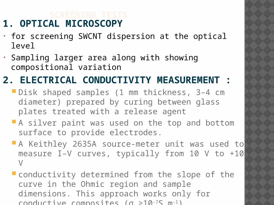
SCREENING TESTS1. OPTICAL MICROSCOPY• for screening SWCNT dispersion at the optical level• Sampling larger area along with showing compositional
variation
2. ELECTRICAL CONDUCTIVITY MEASUREMENT : Disk shaped samples (1 mm thickness, 3–4 cm
diameter) prepared by curing between glass plates treated with a release agent
A silver paint was used on the top and bottom surface to provide electrodes.
A Keithley 2635A source-meter unit was used to measure I–V curves, typically from 10 V to +10 V
conductivity determined from the slope of the curve in the Ohmic region and sample dimensions. This approach works only for conductive composites (σ >10-
7S m-1) for very low conductivity samples, i.e. conductivity (σ
~10-13 Sm-1) was estimated by applying a larger voltage (±100 V) and waiting (500 s) for the current to stabilize.
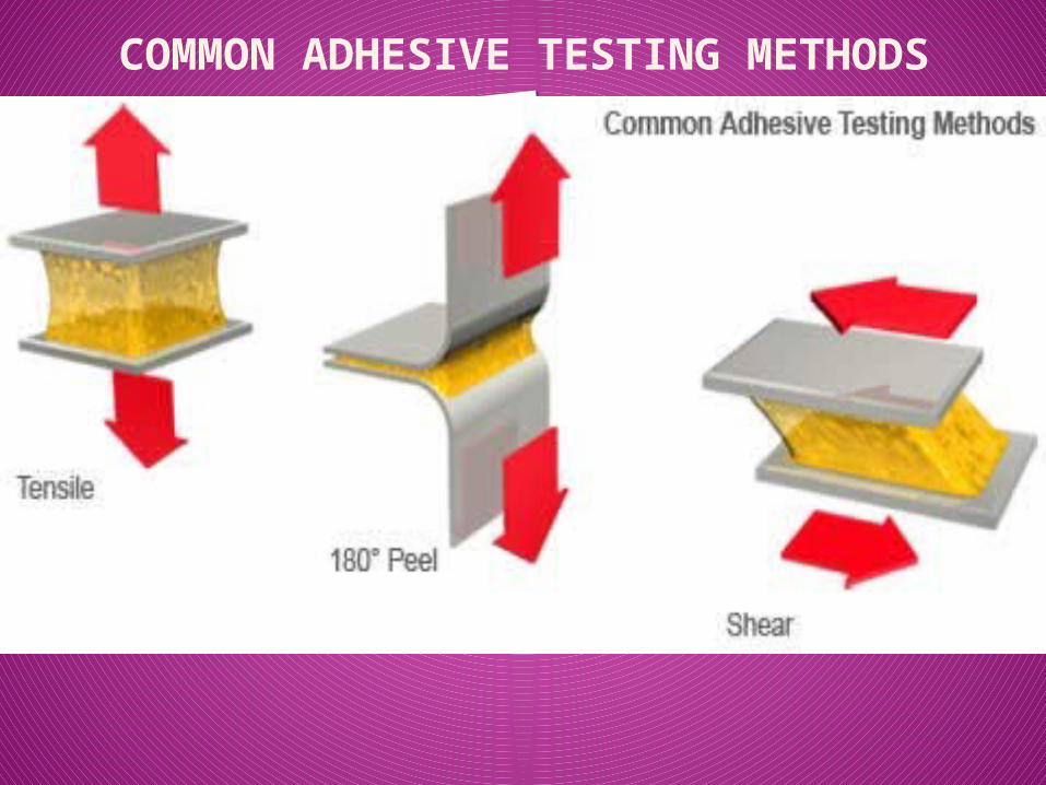
COMMON ADHESIVE TESTING METHODS
Click icon to add picture
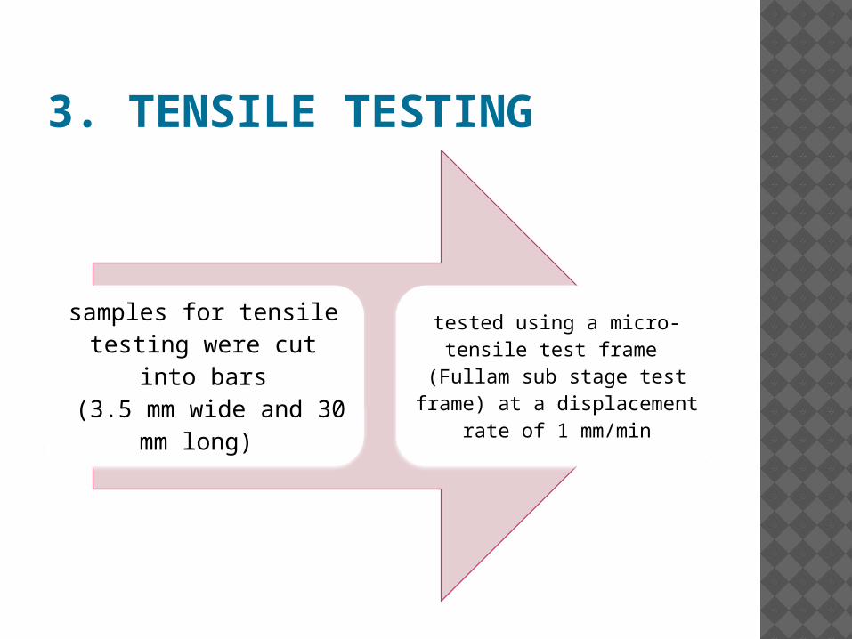
3. TENSILE TESTING
samples for tensile testing were cut into
bars (3.5 mm wide and 30
mm long)
tested using a micro-tensile test frame
(Fullam sub stage test frame) at a displacement
rate of 1 mm/min
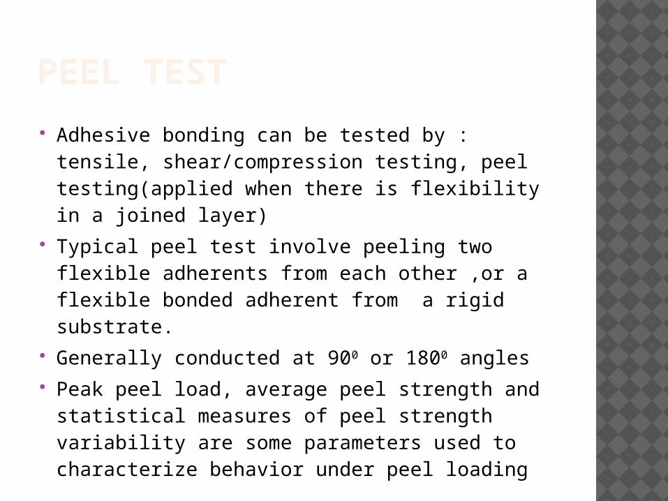
PEEL TEST
Adhesive bonding can be tested by : tensile, shear/compression testing, peel testing(applied when there is flexibility in a joined layer)
Typical peel test involve peeling two flexible adherents from each other ,or a flexible bonded adherent from a rigid substrate.
Generally conducted at 900 or 1800 angles Peak peel load, average peel strength and
statistical measures of peel strength variability are some parameters used to characterize behavior under peel loading
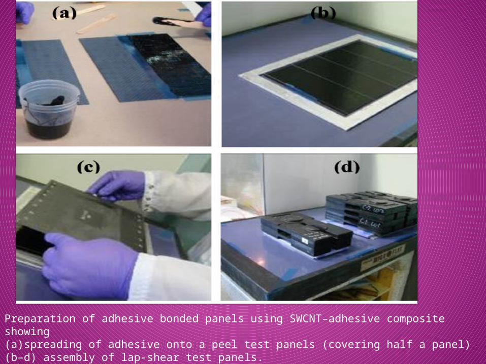
Preparation of adhesive bonded panels using SWCNT–adhesive composite showing (a)spreading of adhesive onto a peel test panels (covering half a panel) (b–d) assembly of lap-shear test panels.
LAP SHEAR STRENGTH TEST
Shear joints impose uniform stresses across bond area, which results in highest possible joint strength.
Generally uses a single lap joint specimen to determine the shear strength of specimens
Procedure : measure amount of shear area in square
centimeters load each end of specimen in the tensile grips apply force at controlled rate till the specimen breaks record the maximum force and type of joint failure.
Evaluating the SEM images give the type of joint failure

RESULTS AND DISCUSSIONS
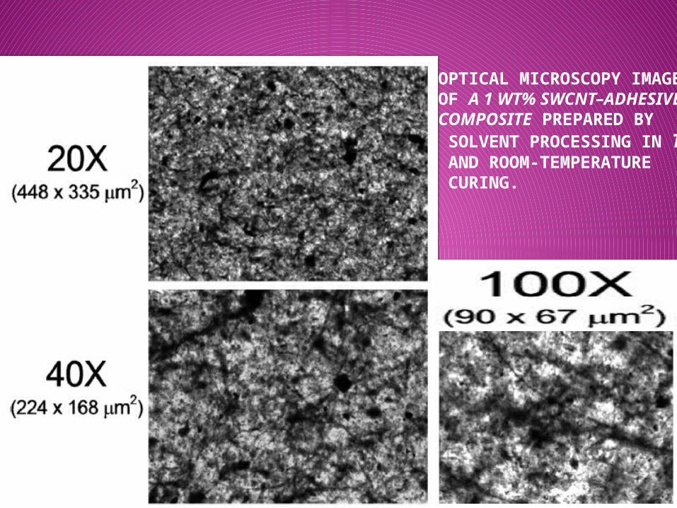
OPTICAL MICROSCOPY IMAGESOF A 1 WT% SWCNT–ADHESIVECOMPOSITE PREPARED BY SOLVENT PROCESSING IN THF AND ROOM-TEMPERATURE CURING.
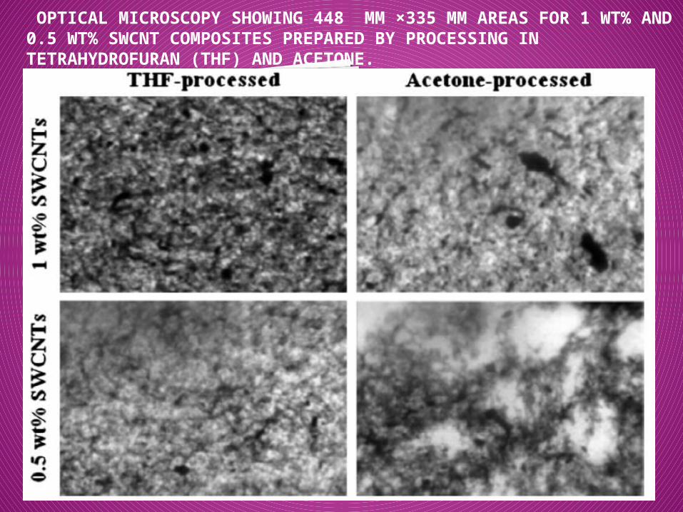
OPTICAL MICROSCOPY SHOWING 448 ΜM ×335 ΜM AREAS FOR 1 WT% AND 0.5 WT% SWCNT COMPOSITES PREPARED BY PROCESSING IN TETRAHYDROFURAN (THF) AND ACETONE.
Click icon to add picture
OPTICAL MICROSCOPY
Darker areas are indicative higher concentration of the SWCNT filler.
More uniform dispersion is observed for THF-dispersed SWCNTs in comparison to acetone-dispersed SWCNTs.THF is generally a better solvent for CNTs
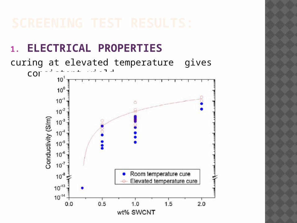
SCREENING TEST RESULTS:
1. ELECTRICAL PROPERTIEScuring at elevated temperature gives consistent
yield

2.TENSILE PROPERTIES
1. •Tensile tests conducted on samples with loadings of 0, 0.2, 0.5 and 1 wt% SWCNTs
2. •ultimate tensile strength (UTS), elastic modulus (E), and maximum strain (ε max) were maintained or improved with up to 1 wt% SWCNTs, regardless of the solvent
3. •UTS and εmax decreased significantly at 2 wt% SWCNTs
4. •Therefore, based on the electrical and tensile results, loadings of 0, 0.5 and 1 wt% SWCNTs were selected for study with joint tests.
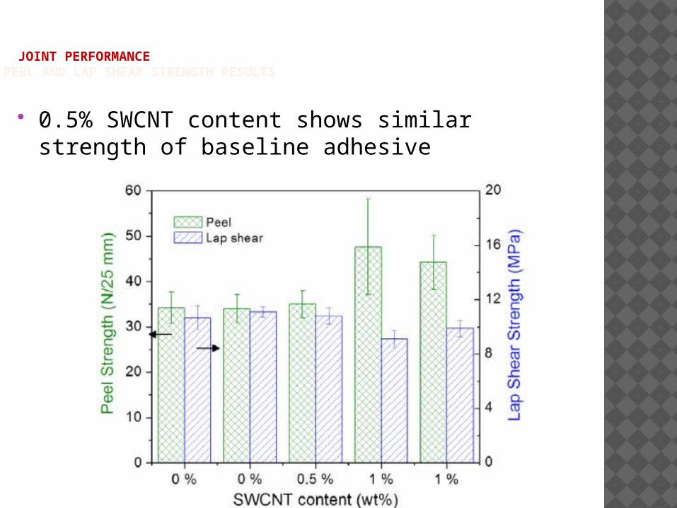
JOINT PERFORMANCEPEEL AND LAP SHEAR STRENGTH RESULTS
0.5% SWCNT content shows similar strength of baseline adhesive
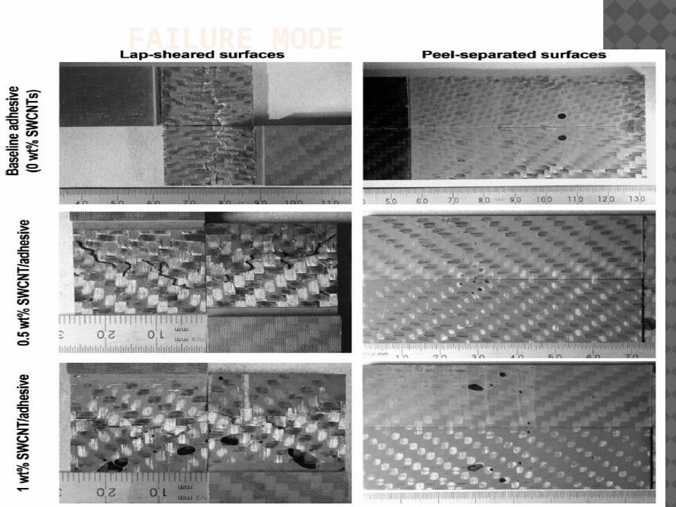
FAILURE MODE
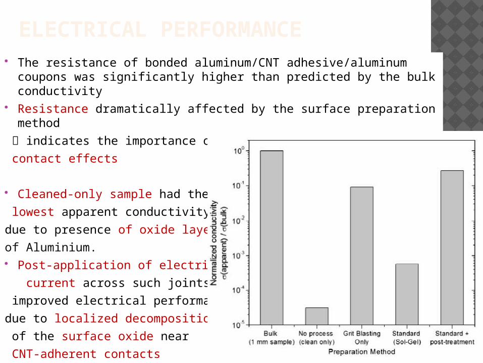
ELECTRICAL PERFORMANCE The resistance of bonded aluminum/CNT adhesive/aluminum
coupons was significantly higher than predicted by the bulk conductivity
Resistance dramatically affected by the surface preparation method
indicates the importance of
contact effects
Cleaned-only sample had the
lowest apparent conductivity
due to presence of oxide layer
of Aluminium. Post-application of electrical
current across such joints
improved electrical performance
due to localized decomposition
of the surface oxide near
CNT-adherent contacts
CONCLUSION
SWCNT–adhesive composite joints were prepared containing 0.5 wt% and 1 wt% SWCNT filler and performance was compared to that of the baseline, aerospace-grade adhesive
The composites are conductive, with a percolation threshold between 0.2 and 0.5 wt%.
The joint resistance of bonded metal/SWCNT–adhesive/metal samples was two-to-three orders of magnitude higher than expected from the bulk electrical conductivity; owing to surface-oxide-effects in metal bonds
The apparent conductivity of the bonded samples could be improved by a voltage post-treatment step such that the bonded samples reached roughly 30% of bulk conductivity.
Peel strength was improved with a SWCNT loading of 1 wt%.
Even the most conductive CNT–polymer composites, both in the present study and the wider literature, do not reach the 105S m-1 achieved in silver-filled ECAs (electrically conductive adhesives)
But they do achieve moderate conductivity with 1/100th the amount of conductive filler required in conventional ECAs for electronics applications, where the structural bonding requirements are low.
Whether some decrease in lap shear strength at 1 wt% SWCNTs is an acceptable trade-off to improve conductivity will depend on the detailed joint requirements and the effect of the CNTs on other parameters (e.g., shelf-life and viscosity).
The conductive adhesives in this study easily exceed the threshold cited for electrostatic discharge
FURTHER SCOPE OF RESEARCH
The best results in the present study (0.1 S m-1 for 1 wt% SWNCTs) show potential to reach other thresholds around 1–10 S m-1, including that to enable electromagnetic shielding, but further improvement is required to reach these targets.
REFERENCE
Potential and prospective implementation of carbon nanotubes on next generation aircraft and space vehicles: A review of current and expected applications in aerospace sciences Omid Gohardani, Maialen Chapartegui Elola, Cristina Elizetxea
Single-walled carbon nanotube–epoxy composites for structural and conductive aerospace adhesives :
Michael B. Jakubinek , Behnam Ashrafi , Yunfa Zhang,Yadienka Martinez-Rubi,Christopher T. Kingston a, Andrew Johnston b, Benoit Simard.

THANK YOU