Embed Size (px)
Citation preview
Chapter 3: Sensors and/or Transducers
1
Introduction to Different Types of Sensors
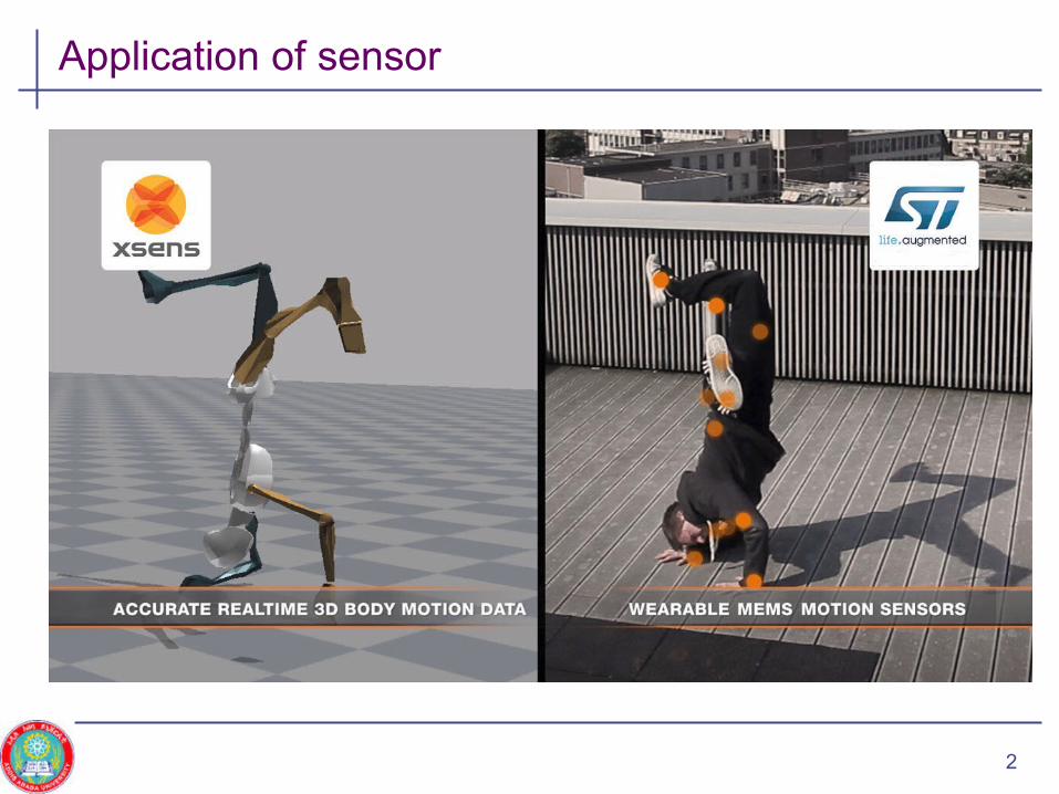
Application of sensor
2

Application off sensor
Grey code encoder reflection sensor 3
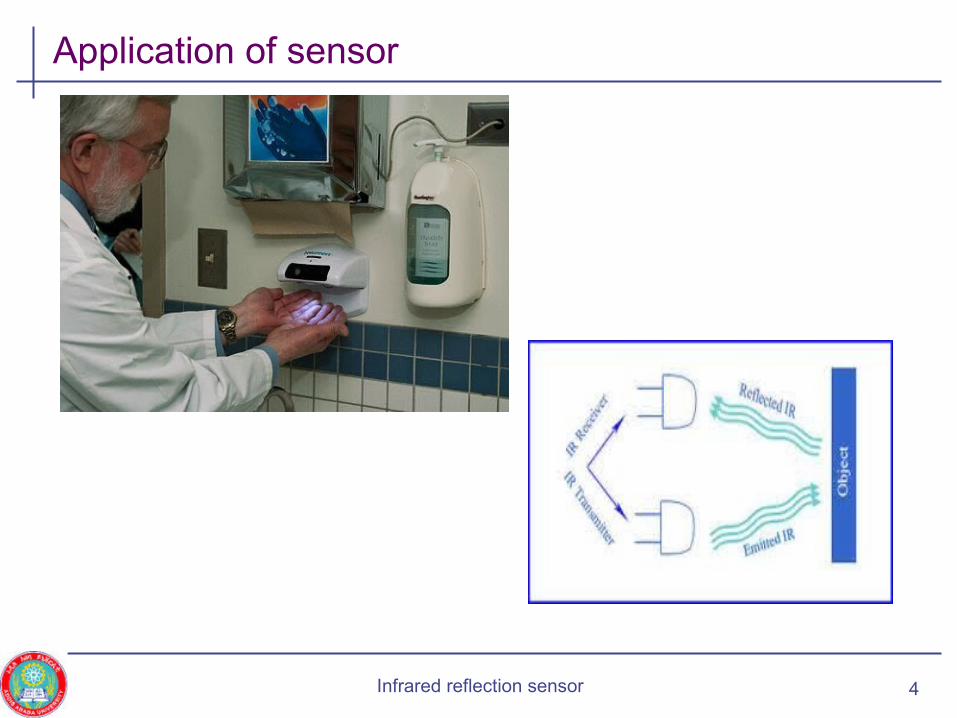
Application of sensor
Infrared reflection sensor 4
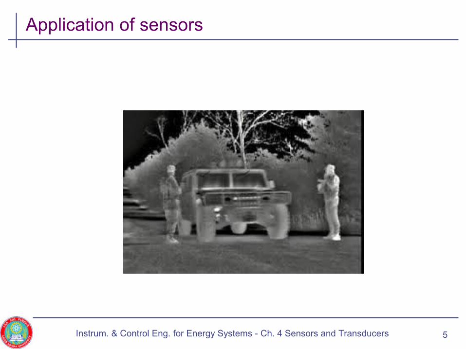
Application of sensors
Instrum. & Control Eng. for Energy Systems - Ch. 4 Sensors and Transducers 5
Goals of the Chapter
• Define classification of sensors and some terminologies
• Introduce various types of sensors for measurement purpose and their applications
• Example: Displacement, motion, level, pressure, temperature, …
6Introduction to Instrumntaion Eng‘g - Ch. 4 Sensors and Transducers
Overview
• Introduction
• Classification of sensors
• Passive sensors
• Active sensors
7Instrum. & Control Eng. for Energy Systems - Ch. 4 Sensors and Transducers

Introduction
• Sensors• Elements which generate variation of electrical quantities (EQ) in
response to variation of non-electrical quantities (NEQ)
• Examples of EQ• Temperature, displacement, humidity, fluid flow, speed, pressure,…
• Sensor are sometimes called transducers
8
Sensing element
Signal conditioning
element
Signal conversion/processing
element
Output presentation
Non-electrical quantity
Electricalsignal
Introduction to Instrumntaion Eng‘g - Ch. 4 Sensors and Transducers
Introduction …
• Advantages of using sensors include 1. Mechanical effects such as friction is reduced to the minimum
possibility
2. Very small power is required for controlling the electrical system
3. The electrical output can be amplified to any desired level
4. The electrical output can be detected and recorded remotely at a distance from the sensing medium and use modern digital computers
5. etc …
9Introduction to Instrumntaion Eng‘g - Ch. 4 Sensors and Transducers

Introduction - Use of Sensors
1. Information gathering: Provide data for display purpose• This gives an understanding of the current status of the system
parameters
• Example: Car speed sensor and speedometer, which records the speed of a car against time
1. System control: Signal from the sensor is an input to a controller
10
Controller
System under control Output signalDesires signal
Sensor
Introduction to Instrumntaion Eng‘g - Ch. 4 Sensors and Transducers

Introduction – Sensor Requirements
• The main function of a sensor is to respond only for the measurement under specified limits for which it is designed
• Sensors should meet the following basic requirements 1. Ruggedness: Capable of withstanding overload
• Some safety arrangements should be provided for overload protection
1. Linearity: Its input-output characteristics must be linear
2. Repeatability: It should reproduce the same output signal when the same input is applied again and again
3. High output signal quality
4. High reliability and stability
5. Good dynamic response
6. No hysteresis, …
11Introduction to Instrumntaion Eng‘g - Ch. 4 Sensors and Transducers
Overview
• Introduction
• Classification of sensors
• Passive sensors
• Active sensors
12Introduction to Instrumntaion Eng‘g - Ch. 4 Sensors and Transducers
Classification of Sensors
• Sensors can be divided on the basis of• Method of applications
• Method of energy conversion used
• Nature of output signals
• Electrical principle
• In general, the classification of sensors is given by• Primary and secondary sensors
• Active and passive sensors
• Analog and Digital sensors
13Introduction to Instrumntaion Eng‘g - Ch. 4 Sensors and Transducers
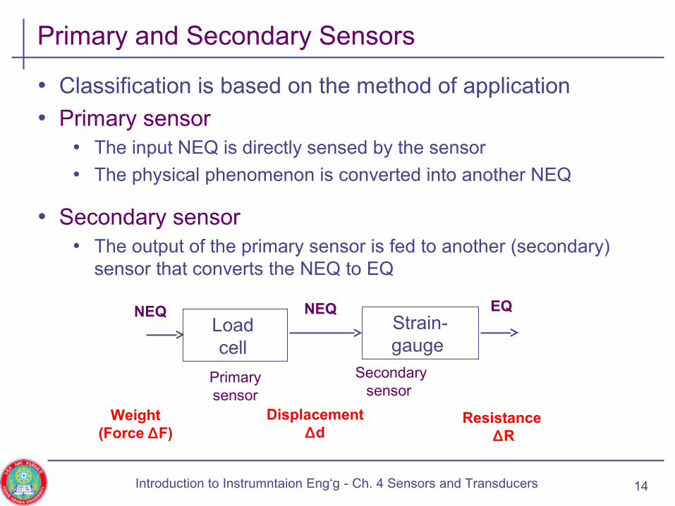
Primary and Secondary Sensors
• Classification is based on the method of application
• Primary sensor• The input NEQ is directly sensed by the sensor
• The physical phenomenon is converted into another NEQ
• Secondary sensor• The output of the primary sensor is fed to another (secondary)
sensor that converts the NEQ to EQ
14
Load cell
Strain- gauge
NEQ
Secondary sensor
Weight(Force ∆F)
Primary sensor
NEQ EQ
Displacement∆d
Resistance ∆R
Introduction to Instrumntaion Eng‘g - Ch. 4 Sensors and Transducers
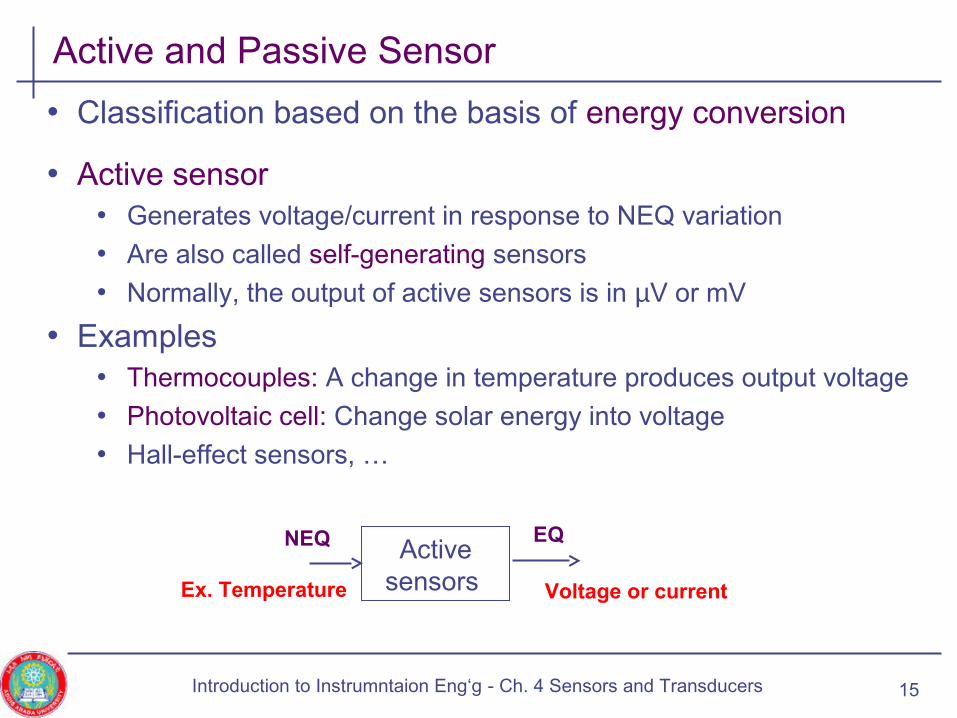
Active and Passive Sensor
• Classification based on the basis of energy conversion
• Active sensor• Generates voltage/current in response to NEQ variation
• Are also called self-generating sensors
• Normally, the output of active sensors is in µV or mV
• Examples• Thermocouples: A change in temperature produces output voltage
• Photovoltaic cell: Change solar energy into voltage
• Hall-effect sensors, …
15
Active sensors
NEQ
Ex. Temperature
EQ
Voltage or current
Introduction to Instrumntaion Eng‘g - Ch. 4 Sensors and Transducers

Active and Passive ….
• Passive sensors • Sensors that does not generate voltage or current, but produce
element variation in R, L, or C
• Need an additional circuit to produce voltage or current variation
• Examples• Thermistor: Change in temperature leads to change in resistance
• Photo resistor: Change in light leads to change in resistance
• Straingauge: Change in length or position into change in resistance)
• LVDT, Mic
16
Passive sensors
NEQ ∆R, ∆L, ∆C
Introduction to Instrumntaion Eng‘g - Ch. 4 Sensors and Transducers

Analog and Digital Sensors
• Classification based on the nature of the output signal
• Analog sensor• Gives an output that varies continuously as the input changes
• Output can have infinite number of values within the sensor’s range
• Digital sensor• Has an output that varies in discrete steps or pulses or sampled form
and so can have a finite number of values
• E.g., Revolution counter: A cam, attached to a revolving body whose motion is being measured, opens and closes a switch
• The switching operations are counted by an electronic counter
17Introduction to Instrumntaion Eng‘g - Ch. 4 Sensors and Transducers
Sensor Classification
• Sensors can also be classified according to the application
• Example• Measurement of displacement, motion, temperature, intensity,
sensors
18Introduction to Instrumntaion Eng‘g - Ch. 4 Sensors and Transducers
Overview
• Introduction
• Classification of sensors
• Passive sensors• Resistive sensors
• Potentiometers, temperature dependent resistors, strain gauge, photoconductors (photoresistors), Piezoresistive
• Capacitive sensors
• Inductive sensors
• Active sensors
19Introduction to Instrumntaion Eng‘g - Ch. 4 Sensors and Transducers

Resistive Sensors - Potentiometer
• Examples: Displacement, liquid level (in petrol-tank level indicator) using potentiometer or rheostat• Convert s linear (translatory) or angular (rotary) displacement
into a change of resistance in the resistive element provided with a movable contact
20
• Petrol-tank level indicator • Change in petrol level moves a
potentiometer arm
• Output signal is proportion to the external voltage source applied across the potentiometer
• The energy in the output signal comes from the external power source
Introduction to Instrumntaion Eng‘g - Ch. 4 Sensors and Transducers
Resistive Sensors – Potentiometer …
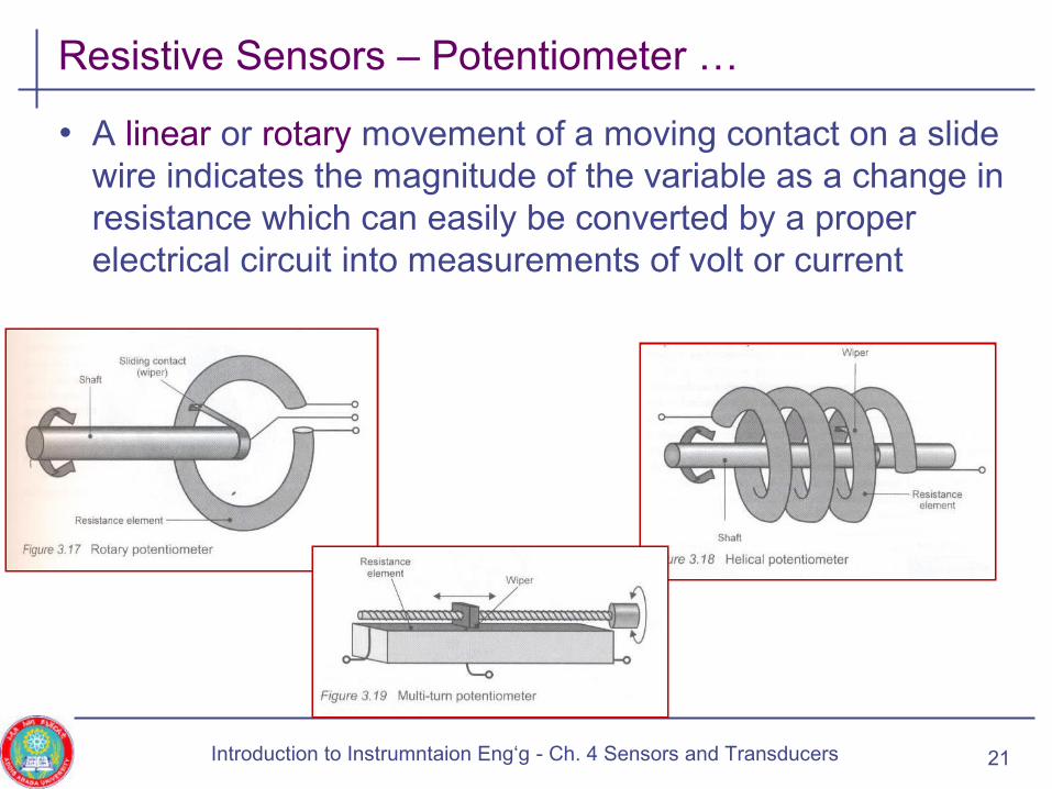
• A linear or rotary movement of a moving contact on a slide wire indicates the magnitude of the variable as a change in resistance which can easily be converted by a proper electrical circuit into measurements of volt or current
21Introduction to Instrumntaion Eng‘g - Ch. 4 Sensors and Transducers

Resistive Sensors – Temperature Dependent Resistors
• Two classes of thermal resistors are • Metallic element
• Semiconductor
• For most metals, the resistance increases with increase in temperature
• Where α is the temperature coefficient of resistance and given as
• Example: Platinum• Has a linear temperature-resistance characteristics
• Reproducible over a wide range of temperature
• Platinum Thermometers are used for temperature measurement22
]1[...]1[)(R 02
210 TRTTRT ααα +≈+++=
0
1
R
R
T
∆∆
=α
Introduction to Instrumntaion Eng‘g - Ch. 4 Sensors and Transducers

Resistive Sensors – Temperature Dependent…
• Semiconductor based resistance thermometers elements • The resistance of such elements decreases with increasing
temperature
• Example: Thermistor
• The resistance-temperature relationship is non-linear and governed by
• Where R0 is the resistance at absolute temp (in Kelvin) and β is material constant expressed in degree Kelvin
• Most semiconductor materials used for thermometry possess high resistivity and high negative temperature coefficients
23
KTeRT TT 00
)11
(
0 300;)(R 0 ==−β
Introduction to Instrumntaion Eng‘g - Ch. 4 Sensors and Transducers

Resistive Sensors – Temperature Dependent…
• The temperature coefficient of resistance is
• β is typically 4000 k and for T = 300k,
24
20
1
TR
R
T
βα −=∆∆
=
044.0300
400022
−=−=−=T
βα
Introduction to Instrumntaion Eng‘g - Ch. 4 Sensors and Transducers
Resistive Sensors – Strain Gauges
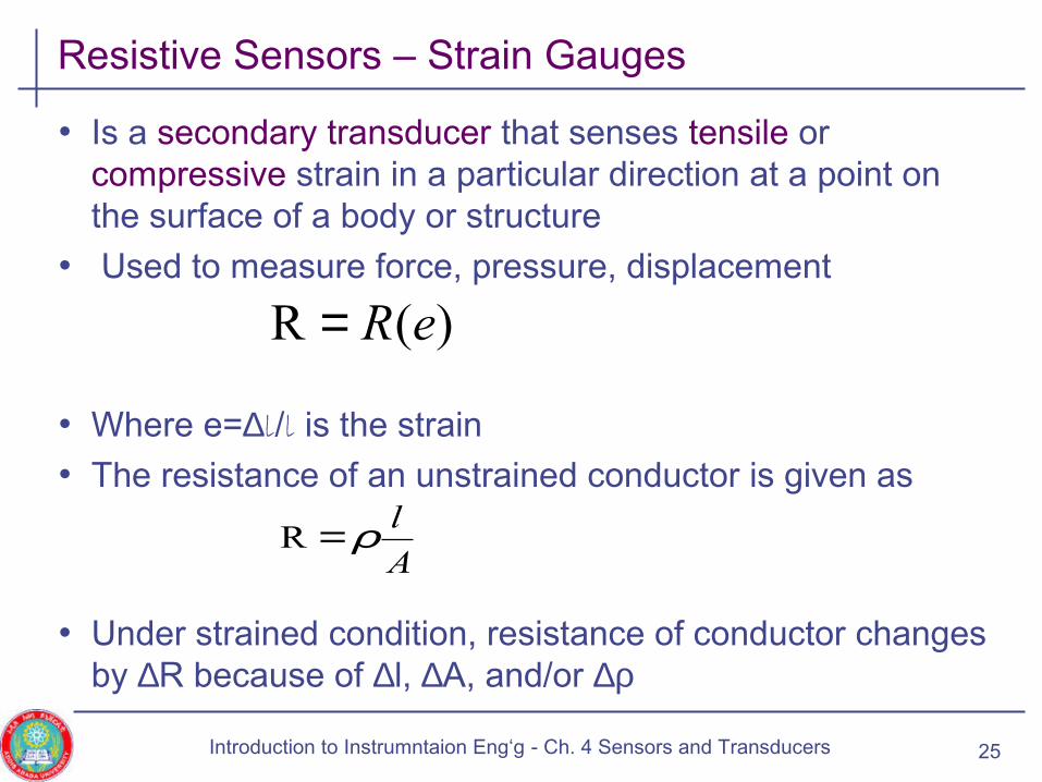
• Is a secondary transducer that senses tensile or compressive strain in a particular direction at a point on the surface of a body or structure
• Used to measure force, pressure, displacement
• Where e=∆l/l is the strain
• The resistance of an unstrained conductor is given as
• Under strained condition, resistance of conductor changes by ∆R because of ∆l, ∆A, and/or ∆ρ
25
)(R eR=
A
lρ=R
Introduction to Instrumntaion Eng‘g - Ch. 4 Sensors and Transducers

Resistive Sensors – Strain Gauges …
• To find the change in resistance ∆R,
• Dividing both sides by R, we get the fractional change as
• Let us define eL = ∆l/l as the longitudinal stain and eT as the transversal strain
• Also assume that eT = -νeL ,where ν is the Poisson’s Ratio
26
ρρρ
ρρ
∆+∆−∆=
∆∂∂+∆
∂∂+∆
∂∂=∆
A
lA
A
ll
A
RA
A
Rl
l
R
2
R
ρρ∆+∆−∆=∆
A
A
l
l
R
R
Introduction to Instrumntaion Eng‘g - Ch. 4 Sensors and Transducers
Resistive Sensors – Strain Gauges …
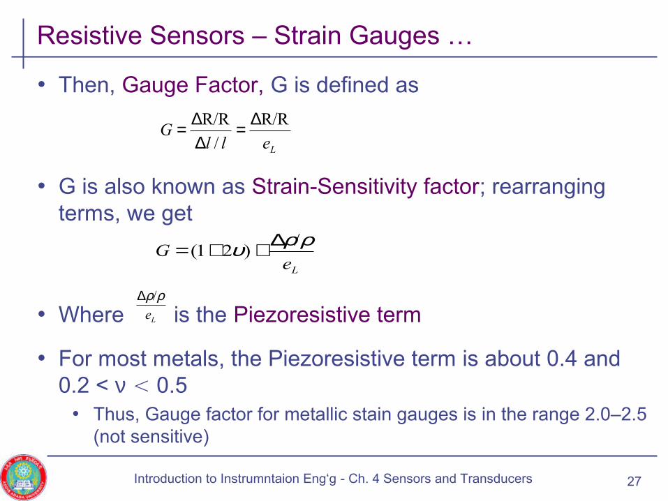
• Then, Gauge Factor, G is defined as
• G is also known as Strain-Sensitivity factor; rearranging terms, we get
• Where is the Piezoresistive term
• For most metals, the Piezoresistive term is about 0.4 and 0.2 < ν < 0.5
• Thus, Gauge factor for metallic stain gauges is in the range 2.0–2.5 (not sensitive)
27
LeG
ρρυ /)21(
∆++=
Le
ρρ/∆
LellG
R/R
/
R/R ∆=∆∆=
Introduction to Instrumntaion Eng‘g - Ch. 4 Sensors and Transducers
Resistive Sensors – Strain Gauges …
• Sensitive measurements require very high Gauge factors in the range of 100-300
• Such factor can be obtained from semiconductor strain gauges
• Due to the significant contribution from the Piezoresistive term
28Introduction to Instrumntaion Eng‘g - Ch. 4 Sensors and Transducers
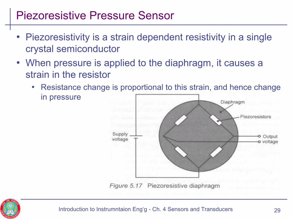
Piezoresistive Pressure Sensor
• Piezoresistivity is a strain dependent resistivity in a single crystal semiconductor
• When pressure is applied to the diaphragm, it causes a strain in the resistor
• Resistance change is proportional to this strain, and hence change in pressure
29Introduction to Instrumntaion Eng‘g - Ch. 4 Sensors and Transducers

Resistive Sensors – Photoconductor
• Are light sensitive resistors with non-linear negative temperature coefficient
• Are resistive optical radiation transducers
• Photoconductors have resistance variation that depends on illumination
• The resistance illumination characteristics is given by
• Where RD is Dark Resistance and E is illumination level in Lux
• Photoconductors are used in • Cameras, light sensors in spectrophotometer
• Counting systems where an object interrupts a light beam hitting the photoconductor, etc.
30
EDeR
α−=R
Introduction to Instrumntaion Eng‘g - Ch. 4 Sensors and Transducers
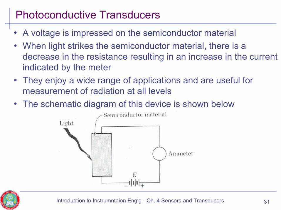
Photoconductive Transducers
• A voltage is impressed on the semiconductor material
• When light strikes the semiconductor material, there is a decrease in the resistance resulting in an increase in the current indicated by the meter
• They enjoy a wide range of applications and are useful for measurement of radiation at all levels
• The schematic diagram of this device is shown below
31Introduction to Instrumntaion Eng‘g - Ch. 4 Sensors and Transducers
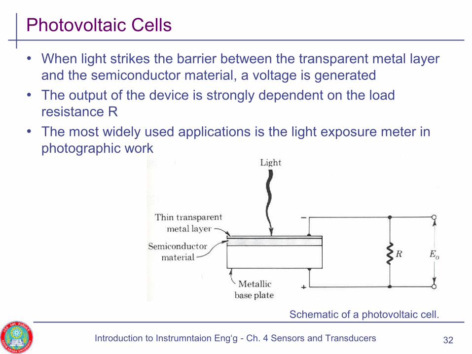
Photovoltaic Cells
• When light strikes the barrier between the transparent metal layer and the semiconductor material, a voltage is generated
• The output of the device is strongly dependent on the load resistance R
• The most widely used applications is the light exposure meter in photographic work
Schematic of a photovoltaic cell.
32Introduction to Instrumntaion Eng‘g - Ch. 4 Sensors and Transducers

Overview
• Introduction
• Classification of sensors
• Passive sensors• Resistive sensors
• Capacitive sensors
• Inductive sensors
• Active sensors
33Introduction to Instrumntaion Eng‘g - Ch. 4 Sensors and Transducers
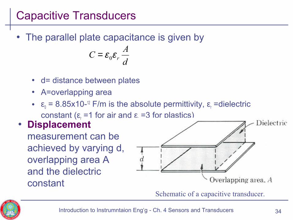
Capacitive Transducers
• The parallel plate capacitance is given by
• d= distance between plates
• A=overlapping area
• ε0 = 8.85x10⁻¹² F/m is the absolute permittivity, εr =dielectric constant (εr =1 for air and εr =3 for plastics)
d
AC rεε 0=
• Displacement measurement can be achieved by varying d, overlapping area A and the dielectric constant
Schematic of a capacitive transducer.
34Introduction to Instrumntaion Eng‘g - Ch. 4 Sensors and Transducers
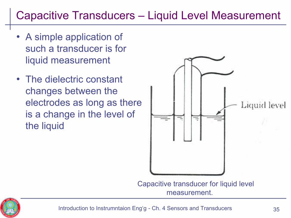
Capacitive Transducers – Liquid Level Measurement
• A simple application of such a transducer is for liquid measurement
• The dielectric constant changes between the electrodes as long as there is a change in the level of the liquid
Capacitive transducer for liquid level measurement.
35Introduction to Instrumntaion Eng‘g - Ch. 4 Sensors and Transducers

Capacitive Transducers – Liquid Level Measurement
• A simple application of such a transducer is for liquid measurement
• The dielectric constant changes between the electrodes as long as there is a change in the level of the liquid
Capacitive transducer for liquid level measurement.
36Introduction to Instrumntaion Eng‘g - Ch. 3 Sensors and Transducers
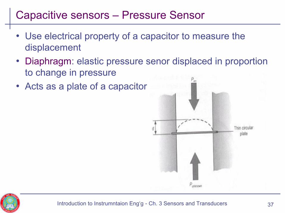
Capacitive sensors – Pressure Sensor
• Use electrical property of a capacitor to measure the displacement
• Diaphragm: elastic pressure senor displaced in proportion to change in pressure
• Acts as a plate of a capacitor
37Introduction to Instrumntaion Eng‘g - Ch. 3 Sensors and Transducers
Capacitive Sensor – Proximity Switch
• A capacitive sensor functions like a typical capacitor.
• The metal plate in the end of the sensor electrically connects to the oscillator, and the object to be sensed acts as the second plate.
• When this sensor receives power, the oscillator detects the external capacitance between the target and the internal sensor plate.
Instrum. & Control Eng. for Energy Systems - Ch. 3 Sensors and Transducers 38
Capacitive Sensor – Proximity Switch
39Introduction to Instrumntaion Eng‘g - Ch. 3 Sensors and Transducers
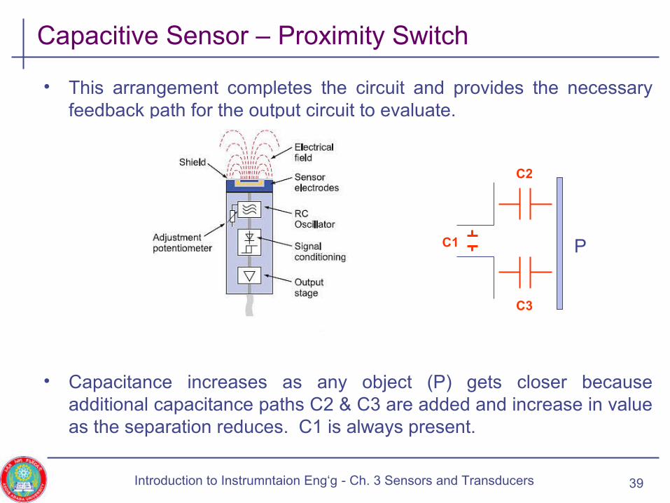
• This arrangement completes the circuit and provides the necessary feedback path for the output circuit to evaluate.
• Capacitance increases as any object (P) gets closer because additional capacitance paths C2 & C3 are added and increase in value as the separation reduces. C1 is always present.
C1
C3
C2
P
Capacitive Sensor – Proximity Switch
Instrum. & Control Eng. for Energy Systems - Ch. 3 Sensors and Transducers 40
Capacitive Transducers - Linear Displacement
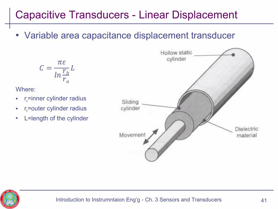
• Variable area capacitance displacement transducer
Where:
• ra=inner cylinder radius
• rb=outer cylinder radius
• L=length of the cylinder
41Introduction to Instrumntaion Eng‘g - Ch. 3 Sensors and Transducers

Capacitive sensors
• Application of capacitive sensors
Instrum. & Control Eng. for Energy Systems - Ch. 4 Sensors and Transducers 42
Overview
• Introduction
• Classification of sensors
• Passive sensors• Resistive sensors
• Capacitive sensors
• Inductive sensors
• Active sensors
43Introduction to Instrumntaion Eng‘g - Ch. 3Sensors and Transducers

Inductive Sensors
• For a coil of n turns, the inductance L is given by
• Where • n: Number of turns of the coil
• l: Mean length of the magnetic path
• A: Area of the magnetic path
• µ: Permeability of the magnetic material
• R: Magnetic reluctance of the circuit
• Application of inductive sensors• Force, displacement, pressure, …
• Inductance variation can be in the form of • Self inductance or
• Mutual inductance: e.g., differential transformer
44
R
n
l
nAL
22
== µ
Introduction to Instrumntaion Eng‘g - Ch. 4 Sensors and Transducers
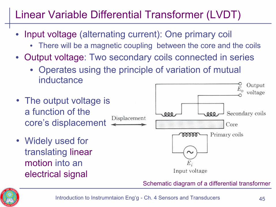
• Input voltage (alternating current): One primary coil• There will be a magnetic coupling between the core and the coils
• Output voltage: Two secondary coils connected in series• Operates using the principle of variation of mutual
inductance
Linear Variable Differential Transformer (LVDT)
Schematic diagram of a differential transformer
• The output voltage is a function of the core’s displacement
• Widely used for translating linear motion into an electrical signal
45Introduction to Instrumntaion Eng‘g - Ch. 4 Sensors and Transducers
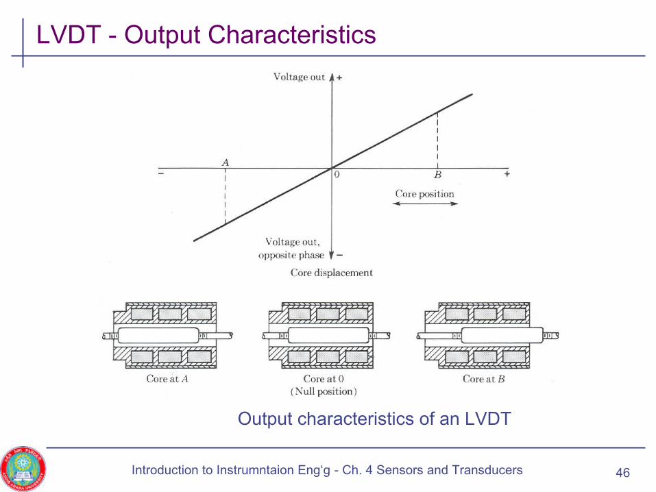
LVDT - Output Characteristics
Output characteristics of an LVDT
46Introduction to Instrumntaion Eng‘g - Ch. 4 Sensors and Transducers
LVDT – Applications
• Measure linear mechanical displacement• Provides resolution about 0.05mm, operating range from ± 0.1mm
to ± 300 mm, accuracy of ± 0.5% of full-scale reading
• The input ac excitation of LVDT can range in frequency from 50 Hz to 20kHz
• Used to measure position in control systems and precision manufacturing
• Can also be used to measure force, pressure, acceleration, etc..
47Introduction to Instrumntaion Eng‘g - Ch. 4 Sensors and Transducers
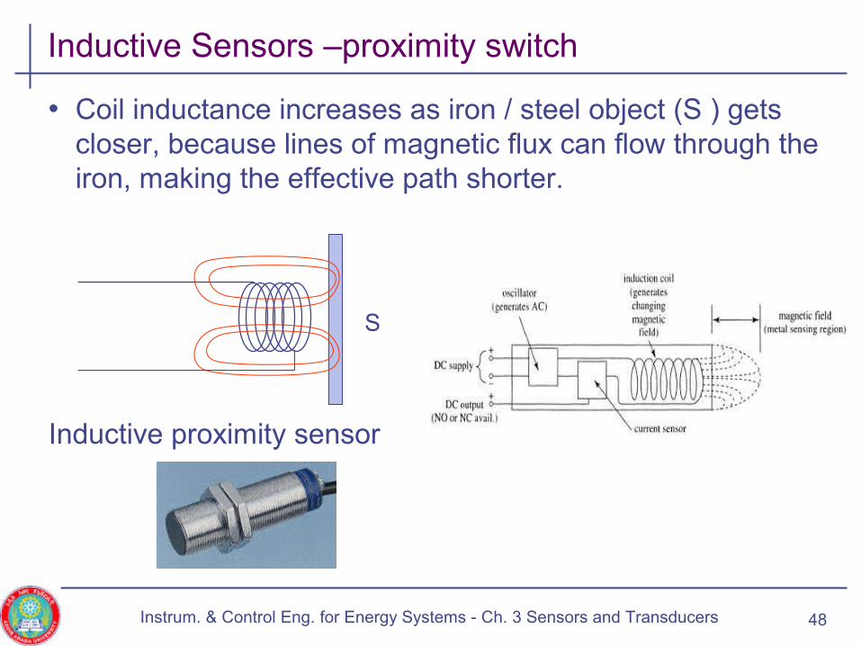
Inductive Sensors –proximity switch
• Coil inductance increases as iron / steel object (S ) gets closer, because lines of magnetic flux can flow through the iron, making the effective path shorter.
Inductive proximity sensor
Instrum. & Control Eng. for Energy Systems - Ch. 3 Sensors and Transducers 48
S
Inductive sensor-proximity switch
• An inductive proximity sensor has four components;
• The coil, oscillator, detection circuit and output circuit.
• The oscillator generates a fluctuating magnetic field the shape of a doughnut around the winding of the coil that locates in the device’s sensing face.
• When a metal object moves into the inductive proximity sensor’s field of detection, Eddy circuits build up in the metallic object, magnetically push back, and finally reduce the Inductive sensor’s own oscillation field.
Instrum. & Control Eng. for Energy Systems - Ch. 3 Sensors and Transducers 49

LVDT – Bourdon Tube Pressure Gauge
• LVDT can be combined with a Bourdon tube
• LVDT converts displacement into an electrical signal
• The signal can be displayed on an electrical device calibrated in terms of pressure
50Introduction to Instrumntaion Eng‘g - Ch. 3 Sensors and Transducers

LVDT and Bellow Combination
• Bellows produce small displacement
• Amplified by LVDT and potentiometer
51Introduction to Instrumntaion Eng‘g - Ch. 3 Sensors and Transducers

Overview
• Introduction
• Classification of sensors
• Passive sensors
• Active sensors • Thermoelectric transducers
• Photoelectric transducers
• Piezoelectric transducers
• Hall-effect transudes
• Tachometric generators
52Introduction to Instrumntaion Eng‘g - Ch. 4 Sensors and Transducers
Active Sensors - Thermocouple
• Thermoelectric transducers provide electrical signal in response to change in temperature
• Example: Thermocouple
• Thermocouple: Converts thermal energy into electrical energy
• Application: To measure temperature
• Contains a pair of dissimilar metal wires joined together at one end (sensing or hot junction) and terminated at the other end (reference or cold junction)
• When a temperature difference exists b/n the sensing junction and the reference, an emf is produced
53
)(....)()( 2122
2121 TTTTTTEemfInduced −≈+−+−== αβα
Introduction to Instrumntaion Eng‘g - Ch. 4 Sensors and Transducers
Active Sensors – Thermocouple …
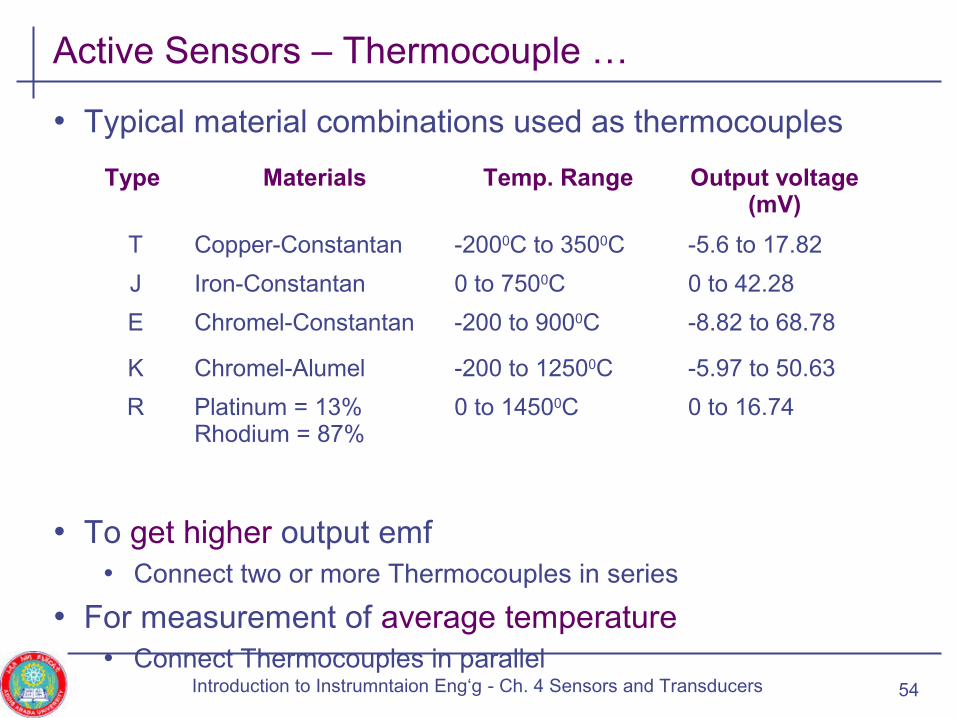
• Typical material combinations used as thermocouples
• To get higher output emf• Connect two or more Thermocouples in series
• For measurement of average temperature• Connect Thermocouples in parallel
54
Type Materials Temp. Range Output voltage (mV)
T Copper-Constantan -2000C to 3500C -5.6 to 17.82
J Iron-Constantan 0 to 7500C 0 to 42.28
E Chromel-Constantan -200 to 9000C -8.82 to 68.78
K Chromel-Alumel -200 to 12500C -5.97 to 50.63
R Platinum = 13%Rhodium = 87%
0 to 14500C 0 to 16.74
Introduction to Instrumntaion Eng‘g - Ch. 4 Sensors and Transducers
Active Sensors – Thermocouple …
• Applications• Temperature measurement
• Voltage measurement• Rectifier based rms indications are waveform dependent
• They are normally designed for sinusoidal signals• Hence, error for non-sinusoidal signals
• Use thermocouple based voltmeters• Here, temperature of a hot junction is proportional to the true rms
value of the current
55Introduction to Instrumntaion Eng‘g - Ch. 4 Sensors and Transducers

Active Sensors – Thermocouple Meter
• The measured a.c. voltage signal is applied to a heater element
• A thermocouple senses the temperature of the heater due to heat generated ( )
• The d.c. voltage generated in the thermocouple is applied to a moving-coil meter
• The thermocouple will be calibrated to read current (Irms)
• AC with frequencies up to 100 MHz may be measured with thermocouple meters
• One may also measure high frequency current by first rectifying the signal to DC and then measuring the DC
Schematic of a thermocouple meter.
2rmsI
56Introduction to Instrumntaion Eng‘g - Ch. 4 Sensors and Transducers

Overview
• Introduction
• Classification of sensors
• Passive sensors
• Active sensors • Thermoelectric transducers
• Photoelectric transducers
• Piezoelectric transducers
• Hall-effect transudes
• Tachometric generators
57Introduction to Instrumntaion Eng‘g - Ch. 4 Sensors and Transducers

Photoelectric Transducers
• Versatile tools for detecting radiant energy or light • Are extensively used in instrumentation
• Most known photosensitive devices include
1.Photovoltaic cells• Semiconductor junction devices used to convert radiation energy
into electrical energy
58Introduction to Instrumntaion Eng‘g - Ch. 4 Sensors and Transducers
Photoelectric Transducers …
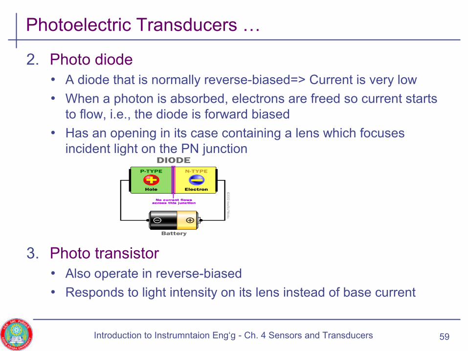
2. Photo diode• A diode that is normally reverse-biased=> Current is very low
• When a photon is absorbed, electrons are freed so current starts to flow, i.e., the diode is forward biased
• Has an opening in its case containing a lens which focuses incident light on the PN junction
3. Photo transistor• Also operate in reverse-biased
• Responds to light intensity on its lens instead of base current
59Introduction to Instrumntaion Eng‘g - Ch. 4 Sensors and Transducers
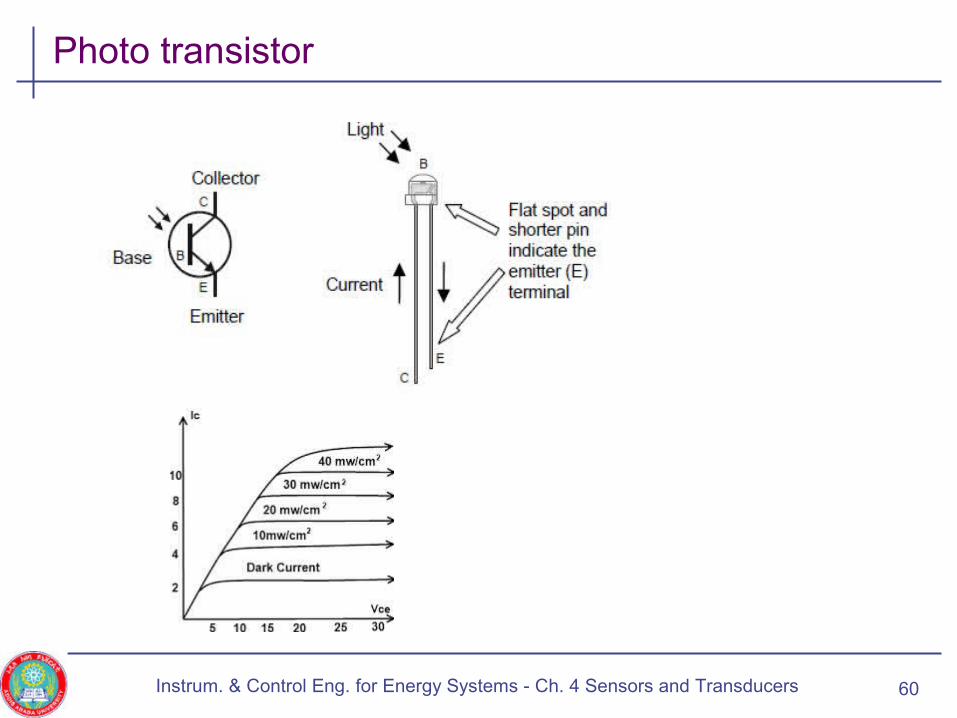
Photo transistor
Instrum. & Control Eng. for Energy Systems - Ch. 4 Sensors and Transducers 60
Overview
• Introduction
• Classification of sensors
• Passive sensors
• Active sensors • Thermoelectric sensors
• Photoelectric sensors
• Piezoelectric sensors
• Hall-effect sensors
• Tachometric sensors
61Introduction to Instrumntaion Eng‘g - Ch. 4 Sensors and Transducers
Piezoelelectric Transducers
• Convert mechanical energy into electrical energy
• If any crystal is subject to an external force F, there will be an atomic displacement, x
• The displacement is related to the applied force in exactly the same way as elastic sensor such as spring
• Asymmetric crystalline material such as Quartz, Rochelle Salt and Barium Tantalite produce an emf when they are placed under stress
• An externally force, entering the sensor through its pressure port, applies pressure to the top of a crystal
• This produces an emf across the crystal proportional to the magnitude of the applied pressure
62Introduction to Instrumntaion Eng‘g - Ch. 3 Sensors and Transducers
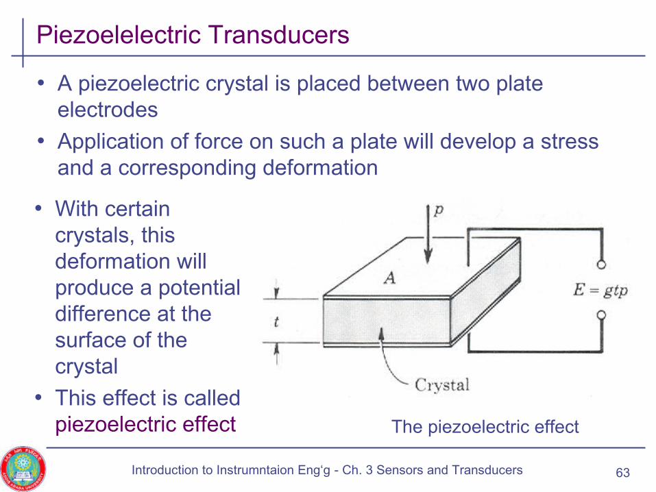
Piezoelelectric Transducers
• A piezoelectric crystal is placed between two plate electrodes
• Application of force on such a plate will develop a stress and a corresponding deformation
The piezoelectric effect
• With certain crystals, this deformation will produce a potential difference at the surface of the crystal
• This effect is called piezoelectric effect
63Introduction to Instrumntaion Eng‘g - Ch. 3 Sensors and Transducers

Piezoelelectric Transducers …
• Induced charge is proportional to the impressed force
Q = d F • d= charge sensitivity (C/m2)/(N/m2) = proportionality constant
• Output voltage E= g t P • t= crystal thickness
• P = impressed pressure
• g=voltage sensitivity (V/m)/(N/m2)
• Shear stress can also produce piezoelectric effect
• Widely used as inexpensive pressure transducers for dynamic measurements
64Introduction to Instrumntaion Eng‘g - Ch. 3 Sensors and Transducers
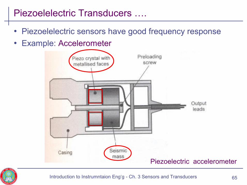
Piezoelelectric Transducers ….
• Piezoelelectric sensors have good frequency response
• Example: Accelerometer
65
Piezoelectric accelerometer
Introduction to Instrumntaion Eng‘g - Ch. 3 Sensors and Transducers
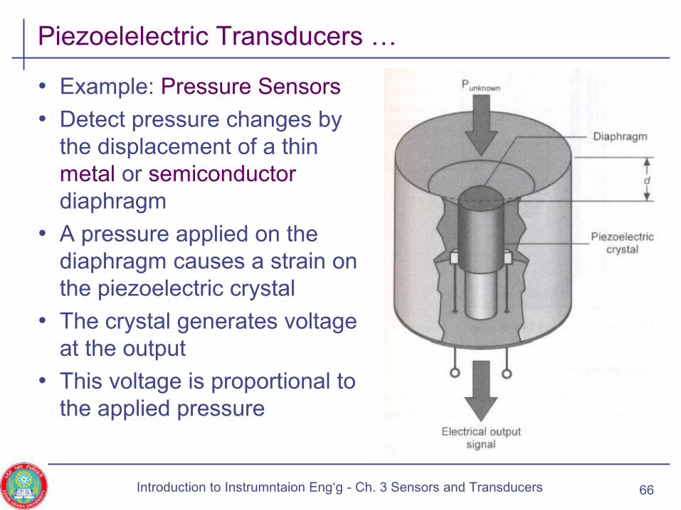
Piezoelelectric Transducers …
• Example: Pressure Sensors
• Detect pressure changes by the displacement of a thin metal or semiconductor diaphragm
• A pressure applied on the diaphragm causes a strain on the piezoelectric crystal
• The crystal generates voltage at the output
• This voltage is proportional to the applied pressure
66Introduction to Instrumntaion Eng‘g - Ch. 3 Sensors and Transducers
Overview
• Introduction
• Classification of sensors
• Passive sensors
• Active sensors • Thermoelectric transducers
• Photoelectric transducers
• Piezoelectric transducers
• Hall-effect transudes
• Tachometric generators
67Introduction to Instrumntaion Eng‘g - Ch. 4 Sensors and Transducers
Hall-effect Transducers
• Hall voltage is produced when a material is • Kept perpendicular to the magnetic field and
• A direct current is passed through it
• The Hall-voltage is expressed as
• Where • Ic: Control current flowing through the Hall-effect sensor, in Amps
• β: Flux density of the magnetic field applied, in Wb/m2
• t: Thickness of the Hall-effect sensor, in meters
• KH : Hall-effect coefficient
• Hall-effect sensors are used to measure flux density • Can detect very week magnetic fields or small change in magnetic
flux density
68
t
IKV CHH
β=
Introduction to Instrumntaion Eng‘g - Ch. 3 Sensors and Transducers
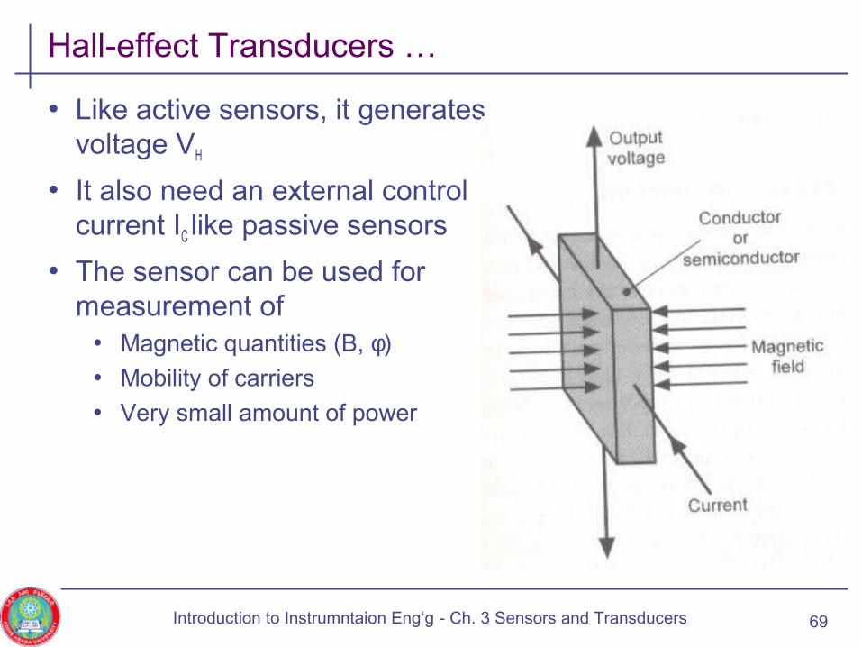
Hall-effect Transducers …
• Like active sensors, it generates voltage VH
• It also need an external control current IC like passive sensors
• The sensor can be used for measurement of
• Magnetic quantities (B, φ)
• Mobility of carriers
• Very small amount of power
69Introduction to Instrumntaion Eng‘g - Ch. 3 Sensors and Transducers
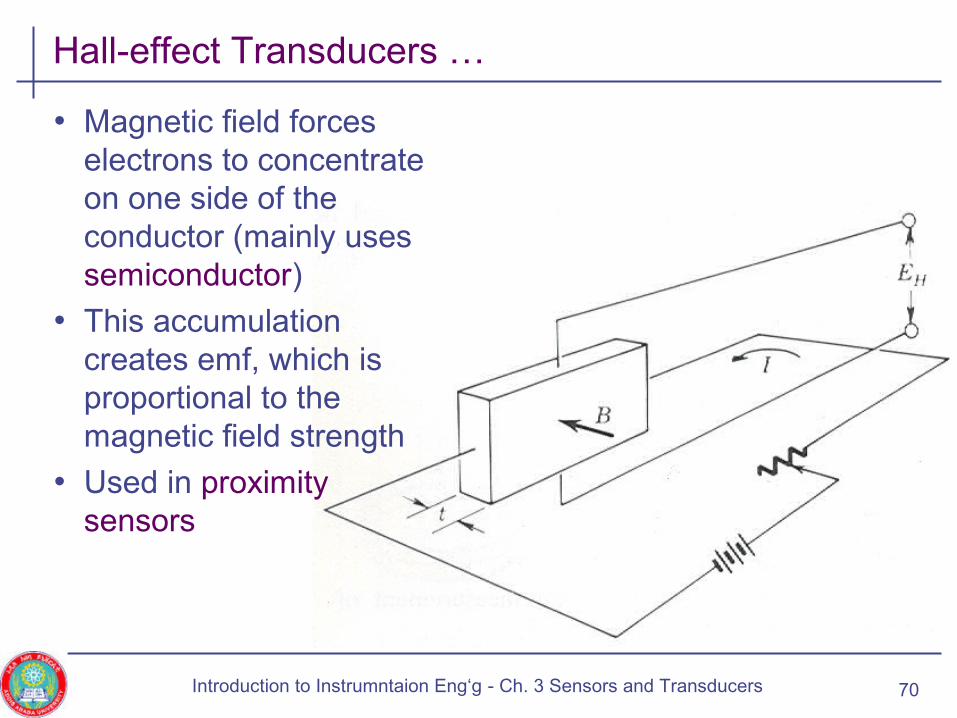
Hall-effect Transducers …
• Magnetic field forces electrons to concentrate on one side of the conductor (mainly uses semiconductor)
• This accumulation creates emf, which is proportional to the magnetic field strength
• Used in proximity sensors
70Introduction to Instrumntaion Eng‘g - Ch. 3 Sensors and Transducers

Overview
• Introduction
• Classification of sensors
• Passive sensors
• Active sensors • Thermoelectric transducers
• Photoelectric transducers
• Piezoelectric transducers
• Hall-effect transudes
• Tachometric generators
71Introduction to Instrumntaion Eng‘g - Ch. 3 Sensors and Transducers

Tachometric Generators
• Tachometer – any device used to measure shaft’s rotation
• Tachometric generator• A machine, when driven by a rotating mechanical force, produces
an electric output proportional to the speed of rotation
• Essentially a small generators
• Tachometric generators connect to the rotating shaft, whose displacement is to be measured, by, e.g.,
• Direct coupling or
• Means of belts or gears
• They produce an output which primarily relates to speed • Displacement can be obtained by integrating speed
• Types of Tachometric generators: Generally a.c. or d.c.
72Introduction to Instrumntaion Eng‘g - Ch. 3 Sensors and Transducers
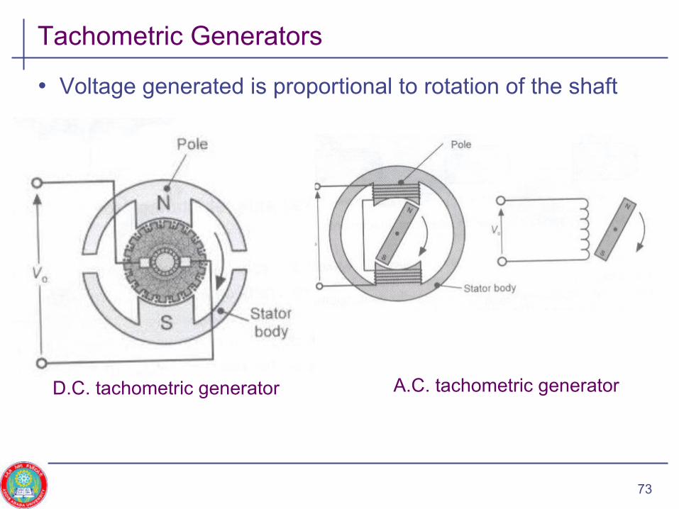
Tachometric Generators
• Voltage generated is proportional to rotation of the shaft
73
D.C. tachometric generator A.C. tachometric generator