Embed Size (px)
Citation preview
IOSR Journal of Mechanical and Civil Engineering (IOSR-JMCE)
e-ISSN: 2278-1684,p-ISSN: 2320-334X, Volume 8, Issue 5 (Sep. - Oct. 2013), PP 38-47 www.iosrjournals.org
www.iosrjournals.org 38 | Page
Cutting Parameters Optimization in Milling Of P – 20 Tool Steel
And EN31B
M. Yaswanth Kumar, Dr. G. Shankaraiah 1 ( Mechanical Engineerig,G.Pulla Reddy Engineerig College (Autonomous) /J Ntu Anantapur , India)
2 (Mechanical Engineerig,G.Pulla Reddy Engineerig College (Autonomous) /J Ntu Anantapur , India )
Abstract: The objective of the paper is to obtain an optimal setting of CNC machining process parameters,
cutting speed, feed rate resulting in optimal values of the feed and radial forces while machining P – 20 tool
steel and EN31B with TiN coated tungsten carbide inserts. The effects of the selected process parameters on the
chosen characteristics and the subsequent optimal settings of the parameters have been accomplished using
Taguchi’s parameter design approach.The process parameters considered are – Cutting speed 3000rpm,
2500rpm and 2000rpm. Feed rate 200mm/min, 300mm/min and 400mm/min and depth of cut is 0.2mm.The
effect of these parameters on the feed force, radial force are considered for analysis.The analysis of the results
shows that the optimal settings for low values of feed and radial forces are high cutting speed, low feed rate and
depth of cut.The thrust force and feed force are also taken experimentally using dynamometer for above Cutting
speeds, feed rate and depth of cut. The optimal values for speed, feed rate and depth of cut are taken using
Taguchi technique.Taguchi methods are statistical methods developed by Genichi Taguchi to improve the quality of manufactured goods, and more recently also applied to, engineering, biotechnology, marketing and
advertising.Process used in this project is milling process. Machine selected is Vertical milling center. Machine
model selected is BFW Agni 45. Modeling is done in Pro/Engineer and analysis is done in ANSYS.
Keywords: Cutting parameters, CNC machining process, feed force, Radial force, Taguchi approach, P – 20
Tool steel, Coated carbide inserts.
I. Introduction Milling is the process of cutting away material by feeding a work piece past a rotating multiple tooth
cutter. The cutting action of the many teeth around the milling cutter provides a fast method of machining. The
machined surface may be flat, angular, or curved. The surface may also be milled to any combination of shapes.
The machine for holding the work piece, rotating the cutter, and feeding it is known as the Milling machine.
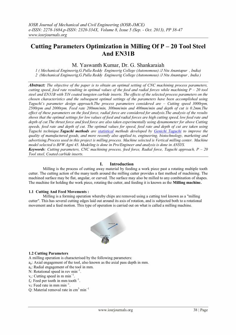
1.1 Cutting And Feed Movements :
Milling is a forming operation whereby chips are removed using a cutting tool known as a "milling
cutter". This has several cutting edges laid out around its axis of rotation, and is subjected both to a rotational
movement and a feed motion. This type of operation is carried out on what is called a milling machine.
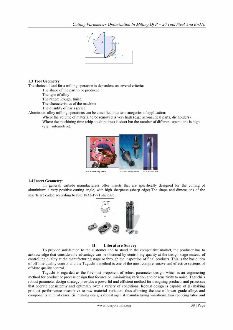
1.2 Cutting Parameters
A milling operation is characterised by the following parameters:
ap: Axial engagement of the tool, also known as the axial pass depth in mm.
ae: Radial engagement of the tool in mm. N: Rotational speed in rev min−1.
vc: Cutting speed in m min−1.
fz: Feed per tooth in mm tooth−1.
vf: Feed rate in mm min−1.
Q: Material removal rate in cm3 min−1
Cutting Parameters Optimization In Milling Of P – 20 Tool Steel And En31b
www.iosrjournals.org 39 | Page
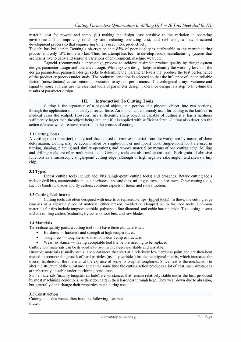
1.3 Tool Geometry
The choice of tool for a milling operation is dependent on several criteria:
The shape of the part to be produced
The type of alloy The range: Rough, finish
The characteristics of the machine
The quantity of parts (price)
Aluminium alloy milling operations can be classified into two categories of application:
Where the volume of material to be removed is very high (e.g.: aeronautical parts, die holders).
Where the machining time (chip-to-chip time) is short but the number of different operations is high
(e.g.: automotive).
1.4 Insert Geometry: In general, carbide manufacturers offer inserts that are specifically designed for the cutting of
aluminium: a very positive cutting angle, with high sharpness (sharp edge).The shape and dimensions of the
inserts are coded according to ISO 1832-1991 standard.
II. Literature Survey To provide satisfaction to the customer and to stand in the competitive market, the producer has to
acknowledge that considerable advantage can be obtained by controlling quality at the design stage instead of controlling quality at the manufacturing stage or through the inspection of final products. This is the basic idea
of off-line quality control and the Taguchi’s method is one of the most comprehensive and effective systems of
off-line quality control.
Taguchi is regarded as the foremost proponent of robust parameter design, which is an engineering
method for product or process design that focuses on minimizing variation and/or sensitivity to noise. Taguchi’s
robust parameter design strategy provides a powerful and efficient method for designing products and processes
that operate consistently and optimally over a variety of conditions. Robust design is capable of (i) making
product performance insensitive to raw material variation, thus allowing the use of lower grade alloys and
components in most cases; (ii) making designs robust against manufacturing variations, thus reducing labor and
Cutting Parameters Optimization In Milling Of P – 20 Tool Steel And En31b
www.iosrjournals.org 40 | Page
material cost for rework and scrap; (iii) making the design least sensitive to the variation in operating
environment, thus improving reliability and reducing operating cost; and (iv) using a new structured
development process so that engineering time is used more productively Taguchi has built upon Deming’s observation that 85% of poor quality is attributable to the manufacturing
process and only 15% to the worker. Thus, his attempt has been to develop robust manufacturing systems that
are insensitive to daily and seasonal variations of environment, machine wear, etc.
Taguchi recommends a three-stage process to achieve desirable product quality by design-system
design, parameter design and tolerance design. While system design helps to identify the working levels of the
design parameters, parameter design seeks to determine the parameter levels that produce the best performance
of the product or process under study. The optimum condition is selected so that the influence of uncontrollable
factors (noise factors) causes minimum variation to system performance. The orthogonal arrays, variance and
signal to noise analysis are the essential tools of parameter design. Tolerance design is a step to fine-tune the
results of parameter design.
III. Introduction To Cutting Tools Cutting is the separation of a physical object, or a portion of a physical object, into two portions,
through the application of an acutely directed force. An implement commonly used for cutting is the knife or in
medical cases the scalpel. However, any sufficiently sharp object is capable of cutting if it has a hardness
sufficiently larger than the object being cut, and if it is applied with sufficient force. Cutting also describes the
action of a saw which removes material in the process of cutting.
3.1 Cutting Tools
A cutting tool (or cutter) is any tool that is used to remove material from the workpiece by means of shear
deformation. Cutting may be accomplished by single-point or multipoint tools. Single-point tools are used in
turning, shaping, plaining and similar operations, and remove material by means of one cutting edge. Milling
and drilling tools are often multipoint tools. Grinding tools are also multipoint tools. Each grain of abrasive
functions as a microscopic single-point cutting edge (although of high negative rake angle), and shears a tiny
chip.
3.2 Types
Linear cutting tools include tool bits (single-point cutting tools) and broaches. Rotary cutting tools
include drill bits, countersinks and counterbores, taps and dies, milling cutters, and reamers. Other cutting tools, such as bandsaw blades and fly cutters, combine aspects of linear and rotary motion.
3.3 Cutting Tool Inserts
Cutting tools are often designed with inserts or replaceable tips (tipped tools). In these, the cutting edge
consists of a separate piece of material, either brazed, welded or clamped on to the tool body. Common
materials for tips include tungsten carbide, polycrystalline diamond, and cubic boron nitride. Tools using inserts
include milling cutters (endmills, fly cutters), tool bits, and saw blades.
3.4 Materials
To produce quality parts, a cutting tool must have three characteristics:
Hardness — hardness and strength at high temperatures.
Toughness — toughness, so that tools don’t chip or fracture.
Wear resistance — having acceptable tool life before needing to be replaced.
Cutting tool materials can be divided into two main categories: stable and unstable. Unstable materials (usually steels) are substances that start at a relatively low hardness point and are then heat
treated to promote the growth of hard particles (usually carbides) inside the original matrix, which increases the
overall hardness of the material at the expense of some its original toughness. Since heat is the mechanism to
alter the structure of the substance and at the same time the cutting action produces a lot of heat, such substances
are inherently unstable under machining conditions.
Stable materials (usually tungsten carbide) are substances that remain relatively stable under the heat produced
by most machining conditions, as they don't attain their hardness through heat. They wear down due to abrasion,
but generally don't change their properties much during use.
3.5 Construction
Cutting tools that rotate often have the following features:
Flute :
Cutting Parameters Optimization In Milling Of P – 20 Tool Steel And En31b
www.iosrjournals.org 41 | Page
A recessed portion of the tool's cross-section that conveys chips away from a cutting edge as the tool rotates. In
the common twist drill, two flutes are usually provided, one for each cutting edge. Taps and end mills may have
up to six or more cutting edges and flutes.
IV. Milling Cutter Milling cutters are cutting tools used in milling machines or machining centres. They remove material
by their movement within the machine (eg: a ball nose mill) or directly from the cutters shape (a form tool such
as a Hobbing cutter).
Types Of Milling Cutters:
End mill, Slot drill, Roughing end mill, Ball nose cutter, Slab mill, Side-and-face cutter, Involute gear cutter,
Hob Face mill, Fly cutter, Woodruff cutter, Hollow mill, Dovetail cutter, Bull nose end mill.
Introduction To P20 Hot Work Tool Steel
Tool steel refers to a variety of carbon and alloy steels that are particularly well-suited to be made into
tools. Their suitability comes from their distinctive hardness, resistance to abrasion, their ability to hold a cutting
edge, and/or their resistance to deformation at elevated temperatures (red-hardness). Tool steel is generally used
in a heat-treated state.Tool steels are also used for special applications like injection molding because the
resistance to abrasion is an important criterion for a mold that will be used to produce hundreds of thousands of
parts.
Physical Properties Metric
Density 7.81 g/cc
Mechanical Properties Metric
Hardness, Brinell 290 – 341
Tensile Strength, Ultimate 1010 MPa
Tensile Strength, Yield 800 MPa
Modulus of Elasticity 205 GPa
Compressive Yield Strength 850 - 1000 MPa
Charpy Impact 5.02 - 10.0 J
V. Introduction To Cad And Pro/Engineer Computer-aided design (CAD), also known as computer-aided design and drafting (CADD), is the use of
computer technology for the process of design and design-documentation. Computer Aided Drafting describes
the process of drafting with a computer. CADD software, or environments, provide the user with input-tools for
the purpose of streamlining design processes; drafting, documentation, and manufacturing processes. CADD
output is often in the form of electronic files for print or machining operations. The development of CADD-
based software is in direct correlation with the processes it seeks to economize; industry-based software
(construction, manufacturing, etc.) typically uses vector-based (linear) environments whereas graphic-based
software utilizes raster-based (pixelated) environments.
CADD environments often involve more than just shapes. As in the manual drafting of technical and engineering drawings, the output of CAD must convey information, such as materials, processes, dimensions,
and tolerances, according to application-specific conventions.
CAD may be used to design curves and figures in two-dimensional (2D) space; or curves, surfaces, and solids in
three-dimensional (3D) objects.
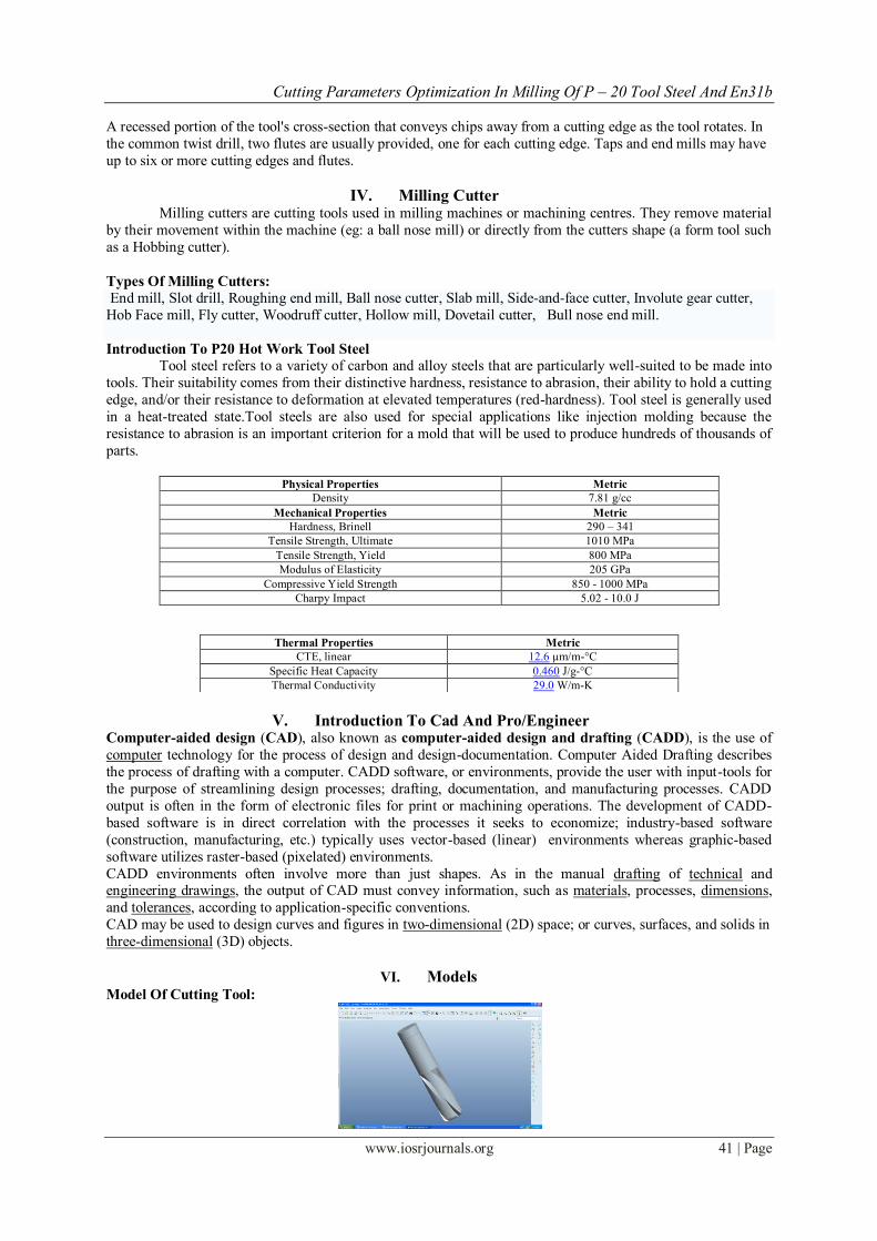
VI. Models
Model Of Cutting Tool:
Thermal Properties Metric
CTE, linear 12.6 µm/m-°C
Specific Heat Capacity 0.460 J/g-°C
Thermal Conductivity 29.0 W/m-K
Cutting Parameters Optimization In Milling Of P – 20 Tool Steel And En31b
www.iosrjournals.org 42 | Page
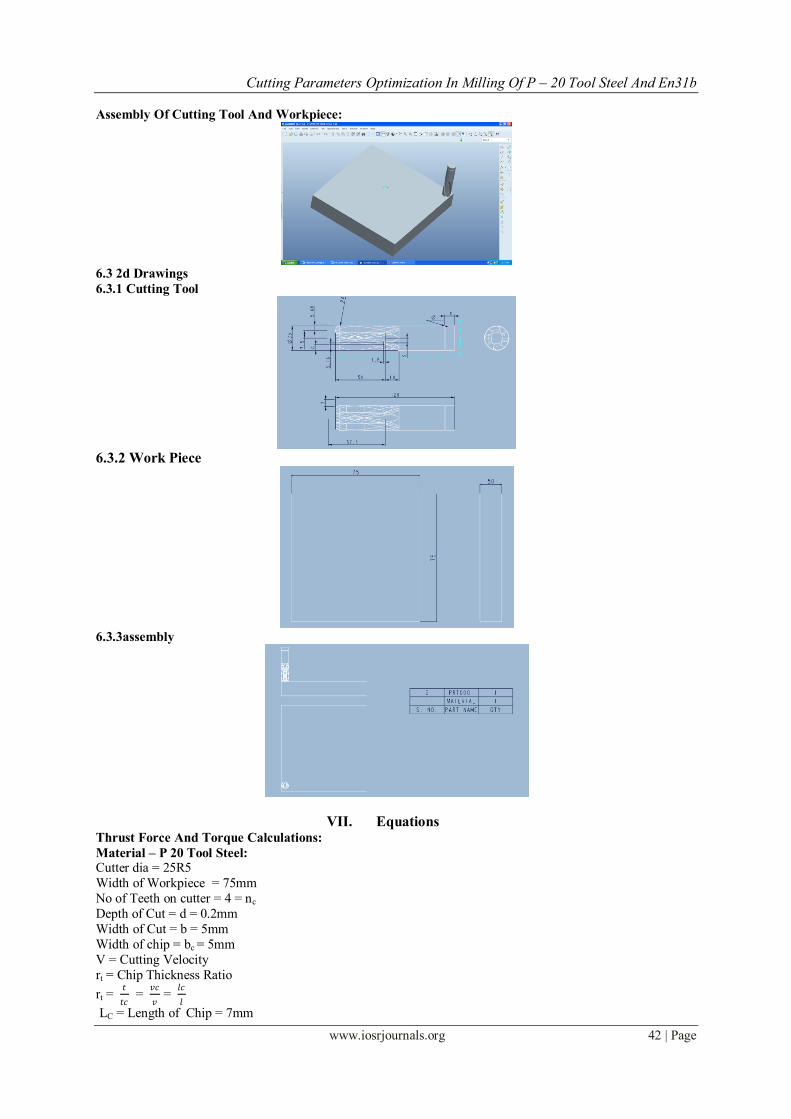
Assembly Of Cutting Tool And Workpiece:
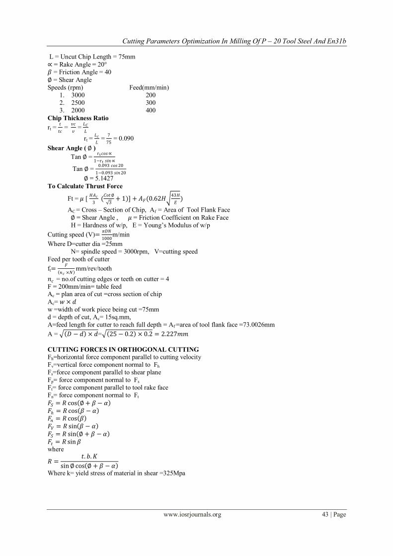
6.3 2d Drawings
6.3.1 Cutting Tool
6.3.2 Work Piece
6.3.3assembly
VII. Equations Thrust Force And Torque Calculations:
Material – P 20 Tool Steel: Cutter dia = 25R5
Width of Workpiece = 75mm
No of Teeth on cutter = 4 = nc
Depth of Cut = d = 0.2mm
Width of Cut = b = 5mm
Width of chip = bc = 5mm
V = Cutting Velocity
rt = Chip Thickness Ratio
rt = 𝑡
𝑡𝑐 =
𝑣𝑐
𝑣 =
𝑙𝑐
𝑙
LC = Length of Chip = 7mm
Cutting Parameters Optimization In Milling Of P – 20 Tool Steel And En31b
www.iosrjournals.org 43 | Page
L = Uncut Chip Length = 75mm
∝ = Rake Angle = 20°
𝛽 = Friction Angle = 40
∅ = Shear Angle
Speeds (rpm) Feed(mm/min)
1. 3000 200
2. 2500 300
3. 2000 400
Chip Thickness Ratio
rt = 𝑡
𝑡𝑐 =
𝑣𝑐
𝑣 =
𝐿𝐶
𝐿
rt = 𝐿𝑐
𝐿 =
7
75 = 0.090
Shear Angle ( ∅ )
Tan ∅ = rt𝑐𝑜𝑠∝
1−rt 𝑠𝑖𝑛 ∝
Tan ∅ = 0.093 𝑐𝑜𝑠20
1−0.093 𝑠𝑖𝑛20
∅ = 5.1427
To Calculate Thrust Force
Ft = 𝜇 [ 𝐻𝐴𝑐
3 (𝐶𝑜𝑡∅
3+ 1)] + 𝐴𝐹(0.62𝐻
43𝐻
𝐸)
AC = Cross – Section of Chip, Af = Area of Tool Flank Face
∅ = Shear Angle , 𝜇 = Friction Coefficient on Rake Face
H = Hardness of w/p, E = Young’s Modulus of w/p
Cutting speed (V)=𝜋𝐷𝑁
1000m/min
Where D=cutter dia =25mm
N= spindle speed = 3000rpm, V=cutting speed
Feed per tooth of cutter
ft=𝐹
𝑛𝑐 ×𝑁 mm/rev/tooth
𝑛𝑐 = no.of cutting edges or teeth on cutter = 4
F = 200mm/min= table feed Ac = plan area of cut =cross section of chip
Ac= 𝑤 × 𝑑
w =width of work piece being cut =75mm
d = depth of cut, Ac= 15sq.mm,
A=feed length for cutter to reach full depth = Af =area of tool flank face =73.0026mm
A = 𝐷 − 𝑑 × 𝑑= 25 − 0.2 × 0.2 = 2.227𝑚𝑚
CUTTING FORCES IN ORTHOGONAL CUTTING
Fh=horizontal force component parallel to cutting velocity
Fv=vertical force component normal to Fh
Fs=force component parallel to shear plane
Fp= force component normal to Fs
Ft= force component parallel to tool rake face
Fn= force component normal to Ft
𝐹𝑆 = 𝑅 cos ∅+ 𝛽 − 𝛼 𝐹 = 𝑅 cos 𝛽 − 𝛼 𝐹𝑛 = 𝑅 cos 𝛽 𝐹𝑉 = 𝑅 sin 𝛽 − 𝛼 𝐹𝑆 = 𝑅 sin ∅ + 𝛽 − 𝛼 𝐹𝑡 = 𝑅 sin𝛽 where
𝑅 =𝑡. 𝑏.𝐾
sin∅ cos ∅ + 𝛽 − 𝛼
Where k= yield stress of material in shear =325Mpa
Cutting Parameters Optimization In Milling Of P – 20 Tool Steel And En31b
www.iosrjournals.org 44 | Page
7.1.1 THRUST FORCE CALCULATION
Ft = μ HAc
3
cot∅
3+ 1 + Af 0.62H
43H
E
d=depth of cut=0.2
𝜇 = 𝑓𝑟𝑖𝑐𝑡𝑖𝑜𝑛 𝑎𝑛𝑔𝑙𝑒 = tan𝛽 = 0.8
Where 𝛽 = 90
H=hardness of the work piece = 70
Density = 0.000008 Kg/m3 E=young’s modulus of work piece =200000 Mpa
7.1.2 SHEAR PLANE TEMPERATURE
𝜃𝑠 =λEs
𝐽𝜌𝑤𝐶𝑤+ 𝜃𝑖
𝜃𝑖=initial temperature of work material =33°C
λ =factor representing the fraction of heat retained by the chip
assume λ = 1
J = heat equivalent of mechanical energy = 4200J
𝜌𝑤 =density of work material= 0.00000781 kg/mm3
𝐶𝑤=specific heat of work material = 0.46 J/g°C
𝐸𝑆 =𝐾 cos𝛼
sin∅ cos ∅ − 𝛼
7.1.3 TORQUE
Torque = Ft ×D
2
D= cutter diameter in mm
𝜃1 = 𝛽
𝜃2 = ∅+ 2𝛽 − 𝛼
𝜃3 = ∅+ 𝛽 − 𝛼 Tangential force
Ft = zs . ks . fc . w Zs = Number of teeth symmetrically engaged with work piece.
Specific cutting force:
Ks = 𝑇𝐶𝐶𝑜𝑠𝛼𝐴𝑐
𝐶𝑜𝑠 (∅−𝛼)+
𝑇𝐹𝐶𝑜𝑠𝛼𝑆𝑖𝑛𝛽𝐴𝑓
𝐶𝑜𝑠 ∅+𝛽−𝛼 𝐶𝑜𝑠 (∅−𝛼)
Specific Cutting Force:
𝑇𝐶 =
𝑇𝑟𝑢𝑠𝑡 𝐹𝑜𝑟𝑐𝑒
𝐴𝑟𝑒𝑎
fc =57.3
𝜃3 × ft × Sin A(Cos𝜃1− 𝐶𝑜𝑠𝜃2), A = Approach angle = 20°
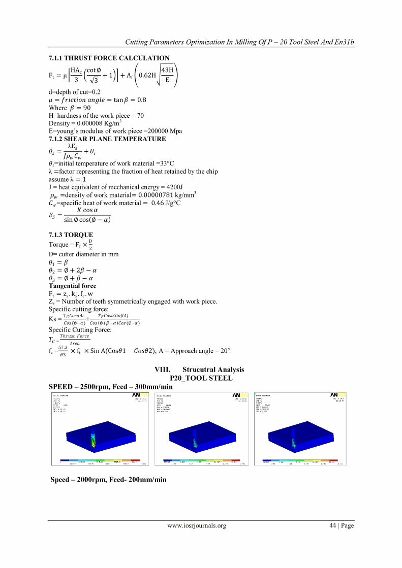
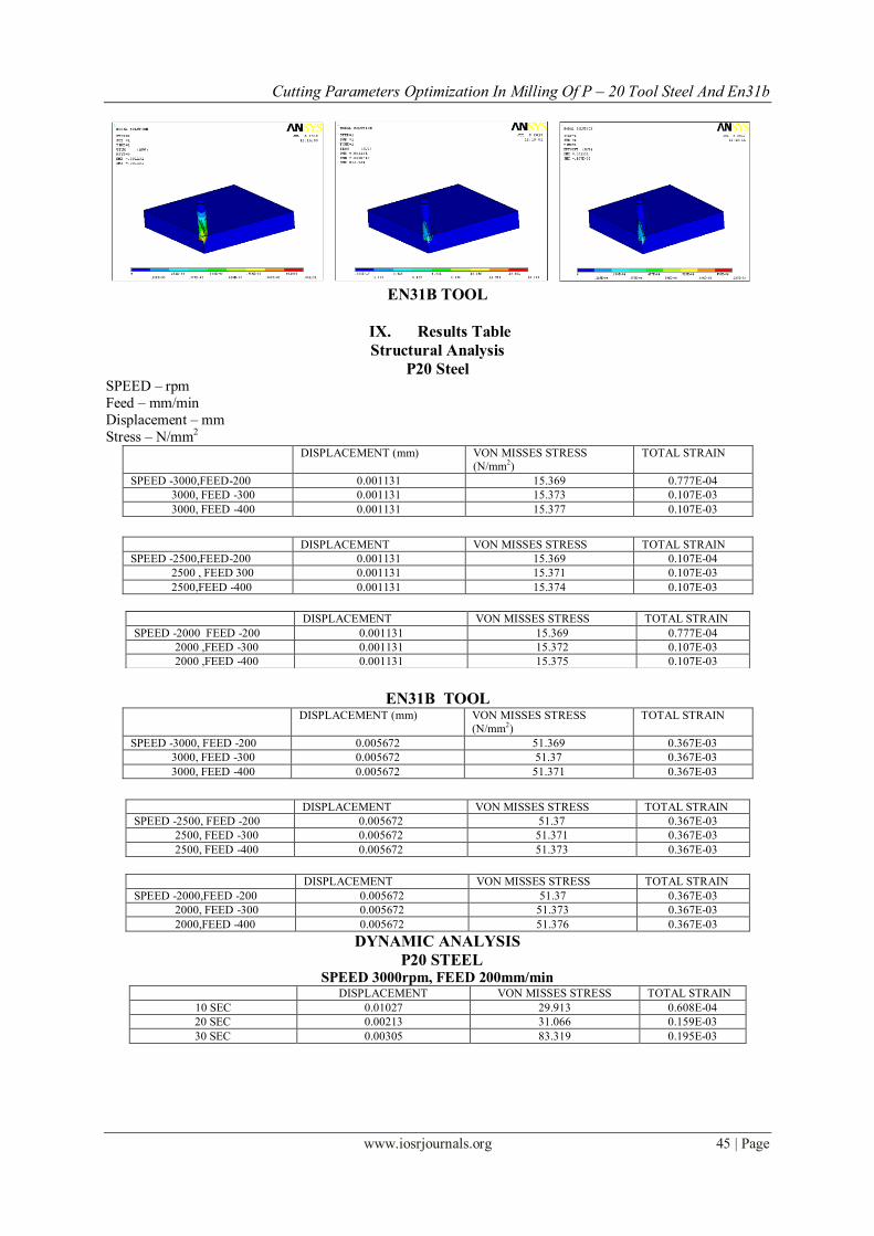
VIII. Strucutral Analysis
P20_TOOL STEEL
SPEED – 2500rpm, Feed – 300mm/min
Speed – 2000rpm, Feed- 200mm/min
Cutting Parameters Optimization In Milling Of P – 20 Tool Steel And En31b
www.iosrjournals.org 45 | Page
EN31B TOOL
IX. Results Table
Structural Analysis
P20 Steel SPEED – rpm
Feed – mm/min
Displacement – mm
Stress – N/mm2 DISPLACEMENT (mm) VON MISSES STRESS
(N/mm2)
TOTAL STRAIN
SPEED -3000,FEED-200 0.001131 15.369 0.777E-04
3000, FEED -300 0.001131 15.373 0.107E-03
3000, FEED -400 0.001131 15.377 0.107E-03
DISPLACEMENT VON MISSES STRESS TOTAL STRAIN
SPEED -2500,FEED-200 0.001131 15.369 0.107E-04
2500 , FEED 300 0.001131 15.371 0.107E-03
2500,FEED -400 0.001131 15.374 0.107E-03
EN31B TOOL
DISPLACEMENT (mm) VON MISSES STRESS
(N/mm2)
TOTAL STRAIN
SPEED -3000, FEED -200 0.005672 51.369 0.367E-03
3000, FEED -300 0.005672 51.37 0.367E-03
3000, FEED -400 0.005672 51.371 0.367E-03
DISPLACEMENT VON MISSES STRESS TOTAL STRAIN
SPEED -2500, FEED -200 0.005672 51.37 0.367E-03
2500, FEED -300 0.005672 51.371 0.367E-03
2500, FEED -400 0.005672 51.373 0.367E-03
DISPLACEMENT VON MISSES STRESS TOTAL STRAIN
SPEED -2000,FEED -200 0.005672 51.37 0.367E-03
2000, FEED -300 0.005672 51.373 0.367E-03
2000,FEED -400 0.005672 51.376 0.367E-03
DYNAMIC ANALYSIS
P20 STEEL SPEED 3000rpm, FEED 200mm/min
DISPLACEMENT VON MISSES STRESS TOTAL STRAIN
10 SEC 0.01027 29.913 0.608E-04
20 SEC 0.00213 31.066 0.159E-03
30 SEC 0.00305 83.319 0.195E-03
DISPLACEMENT VON MISSES STRESS TOTAL STRAIN
SPEED -2000 FEED -200 0.001131 15.369 0.777E-04
2000 ,FEED -300 0.001131 15.372 0.107E-03
2000 ,FEED -400 0.001131 15.375 0.107E-03
Cutting Parameters Optimization In Milling Of P – 20 Tool Steel And En31b
www.iosrjournals.org 46 | Page
EN31 B
SPEED 3000rpm, FEED 200 mm/min DISPLACEMENT VON MISSES STRESS TOTAL STRAIN
10 SEC 0.001878 26.053 0.177E-03
20 SEC 0.003574 49.556 0.353E-03
30 SEC 0.005322 75.93 0.535E-03
X. Introduction To Taguchi Technique • Taguchi defines Quality Level of a product as the Total Loss incurred by society due to failure of a product
to perform as desired when it deviates from the delivered target performance levels. • This includes costs associated with poor performance, operating costs (which changes as a product ages)
and any added expenses due to harmful side effects of the product in use
Taguchi Methods
Help companies to perform the Quality Fix!
Quality problems are due to Noises in the product or process system
Noise is any undesirable effect that increases variability
Conduct extensive Problem Analyses
Employ Inter-disciplinary Teams
Perform Designed Experimental Analyses
Evaluate Experiments using ANOVA and Signal-to noise techniques
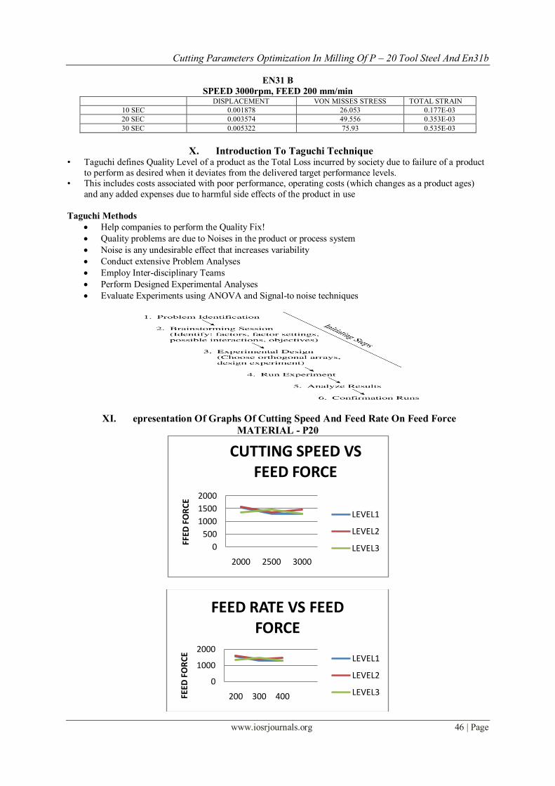
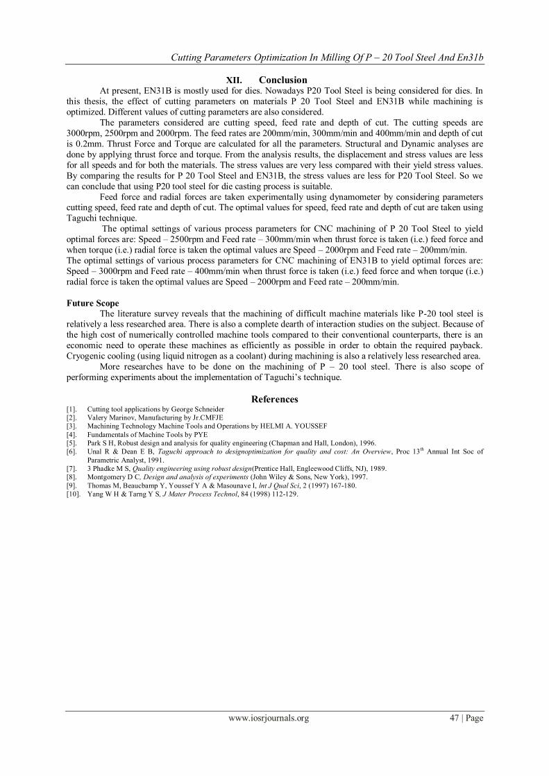
XI. epresentation Of Graphs Of Cutting Speed And Feed Rate On Feed Force
MATERIAL - P20
0
500
1000
1500
2000
2000 2500 3000
FFED
FO
RC
E
CUTTING SPEED VS FEED FORCE
LEVEL1
LEVEL2
LEVEL3
0
1000
2000
200 300 400FEED
FO
RC
E
FEED RATE VS FEED FORCE
LEVEL1
LEVEL2
LEVEL3
Cutting Parameters Optimization In Milling Of P – 20 Tool Steel And En31b
www.iosrjournals.org 47 | Page
XII. Conclusion
At present, EN31B is mostly used for dies. Nowadays P20 Tool Steel is being considered for dies. In
this thesis, the effect of cutting parameters on materials P 20 Tool Steel and EN31B while machining is
optimized. Different values of cutting parameters are also considered.
The parameters considered are cutting speed, feed rate and depth of cut. The cutting speeds are
3000rpm, 2500rpm and 2000rpm. The feed rates are 200mm/min, 300mm/min and 400mm/min and depth of cut
is 0.2mm. Thrust Force and Torque are calculated for all the parameters. Structural and Dynamic analyses are
done by applying thrust force and torque. From the analysis results, the displacement and stress values are less
for all speeds and for both the materials. The stress values are very less compared with their yield stress values.
By comparing the results for P 20 Tool Steel and EN31B, the stress values are less for P20 Tool Steel. So we
can conclude that using P20 tool steel for die casting process is suitable.
Feed force and radial forces are taken experimentally using dynamometer by considering parameters cutting speed, feed rate and depth of cut. The optimal values for speed, feed rate and depth of cut are taken using
Taguchi technique.
The optimal settings of various process parameters for CNC machining of P 20 Tool Steel to yield
optimal forces are: Speed – 2500rpm and Feed rate – 300mm/min when thrust force is taken (i.e.) feed force and
when torque (i.e.) radial force is taken the optimal values are Speed – 2000rpm and Feed rate – 200mm/min.
The optimal settings of various process parameters for CNC machining of EN31B to yield optimal forces are:
Speed – 3000rpm and Feed rate – 400mm/min when thrust force is taken (i.e.) feed force and when torque (i.e.)
radial force is taken the optimal values are Speed – 2000rpm and Feed rate – 200mm/min.
Future Scope
The literature survey reveals that the machining of difficult machine materials like P-20 tool steel is relatively a less researched area. There is also a complete dearth of interaction studies on the subject. Because of
the high cost of numerically controlled machine tools compared to their conventional counterparts, there is an
economic need to operate these machines as efficiently as possible in order to obtain the required payback.
Cryogenic cooling (using liquid nitrogen as a coolant) during machining is also a relatively less researched area.
More researches have to be done on the machining of P – 20 tool steel. There is also scope of
performing experiments about the implementation of Taguchi’s technique.
References [1]. Cutting tool applications by George Schneider
[2]. Valery Marinov, Manufacturing by Jr.CMFJE
[3]. Machining Technology Machine Tools and Operations by HELMI A. YOUSSEF
[4]. Fundamentals of Machine Tools by PYE
[5]. Park S H, Robust design and analysis for quality engineering (Chapman and Hall, London), 1996.
[6]. Unal R & Dean E B, Taguchi approach to designoptimization for quality and cost: An Overview, Proc 13th Annual Int Soc of
Parametric Analyst, 1991.
[7]. 3 Phadke M S, Quality engineering using robust design(Prentice Hall, Engleewood Cliffs, NJ), 1989.
[8]. Montgomery D C, Design and analysis of experiments (John Wiley & Sons, New York), 1997.
[9]. Thomas M, Beaucbamp Y, Youssef Y A & Masounave I, lnt J Qual Sci, 2 (1997) 167-180.
[10]. Yang W H & Tarng Y S, J Mater Process Technol, 84 (1998) 112-129.