Embed Size (px)
Citation preview

PROJECT REPORT (JUNE 2014 - DECEMBER 2014)
STUDY AND ANALYSIS OF THE
CONSTRUCTION OF DELHI METRO RAIL CORPORATION (CC- 27)
Submitted by
Sukhdarshan Singh - 101102073
Under the Guidance of
Mr. Tanuj Chopra
Assistant Professor
Thapar University
DEPARTMENT OF CIVIL ENGINEERING
THAPAR UNIVERSITY, PATIALA
(Declared as Deemed-to-be-University u/s 3 of the UGC Act, 1956)

1
DELHI METRO RAIL CORPORATION
The Delhi Metro is a mass-rapid transit system serving Delhi, Gurgaon, Noida and Ghaziabad in the
National Capital Region of India. Delhi Metro is a metro system serving Delhi, Gurgaon, Noida, and
Ghaziabad in the National Capital Region of India. Delhi Metro is the world's thirteenth largest
metro system in terms of length. Delhi Metro is India's second urban mass rapid transportation
system, after Kolkata Metro. As of June 2014, the network consists of five colour-coded lines (Red,
Blue, Green, Yellow, Violet), plus a sixth .Airport Express line, with a total length of 193.2
kilometres serving 139 stations, (including the 6 Airport Express stations), of which 38 are
underground, five are at-grade, and the rest are elevated.
It is also India’s first modern public transportation system, which has revolutionized travel by
providing a fast, reliable, safe and comfortable means of transport. The present network consists of
six lines with a total length of 189.63km with 142 stations. Delhi Metro was planned to be built in
phases spread over around 20 years as with each phase having a target of five years and end of one
phase marking the beginning of another. Phase I (65 km) and Phase II (125 km) were completed in
2006 and 2011, respectively, and Phase III and Phase IV are scheduled for completion in 2016 and
2021, respectively. Work on Phase III started in 2011 while planning for Phase IV has begun. Ex-
chief of DMRC hinted that by the time Phase IV is completed, the city will need Phase V to cope
with rising population and transport needs.

2
LARSEN & TOUBRO
Larsen & Toubro Limited (L&T) is amongst one of India’s largest technology, engineering
construction and manufacturing conglomerate. L&T is considered to be the "bellwether of India's
engineering sector”, and was recognized as the company of the year in 2010. Its business structure
has a dominant presence in India's infrastructure, power, hydrocarbon, machinery, shipbuilding and
railway sectors. L&T has an international presence. The company's businesses are supported by a
wide marketing and distribution network, and have established a reputation for strong customer
support. With more than a seven decades of dedicated customer focused service and continuous
quest for world class quality have established them as the leader of the Engineering and Construction
sector in India.

3
SHANGHAI URBAN CONSTRUCTION GROUP
SUCG Infrastructure India Pvt. Ltd. is an international company which integrates overseas
construction, design and management, investment, and sales of construction equipment. Shanghai
Urban Construction (Group) Corporation, established in October 1996 with the approval of Shanghai
Municipal Party Committee and the Government, is a comprehensive enterprise particularly
supported by the Ministry of Construction and Shanghai Municipal Government. It is authorized by
Shanghai State-owned Asset Management Committee to manage the state-owned assets within the
Group. Shanghai Urban Construction (Group) Corporation has the special class qualification for
municipal public works, the first-class general contracting qualifications for highway construction,
housing, etc.

4
L&T SUCG JV CC-27, New Delhi PROJECT FEATURES
INTRODUCTION
L&T in a joint venture with SUCG won an order worth 12.526 billion from DMRC.
CONTRACT FEATURES
Under the terms of the contract, the Heavy Infrastructure IC of L&T Construction and SUCG will
design and construct a tunnel between Shankar Vihar and Hauz Khas, as well as underground
stations at Vasant Vihar, Munirka, R.K. Puram, I.I.T. and Hauz Khas.
CONTRACT
Design and construction of tunnel from end of underground ramp (Near Shankar Vihar Metro
Station) to Hauz Khas Metro Station and an underground ramp near Shankar Vihar Metro Station
and underground Metro Stations at Vasant Vihar, Munirka, R.K. Puram, I.I.T. and Hauz Khas on
Janakpuri West-Botanical Garden corridor of Delhi Metro Project of Phase-III .
PROJECT FEATURES
-SUCG JOINT VENTURE
KS DESIGNER: Tandon Consultants Pvt. Ltd.
-PASSAGE DESIGNER: SUCDRI
ECT: 6.82KM
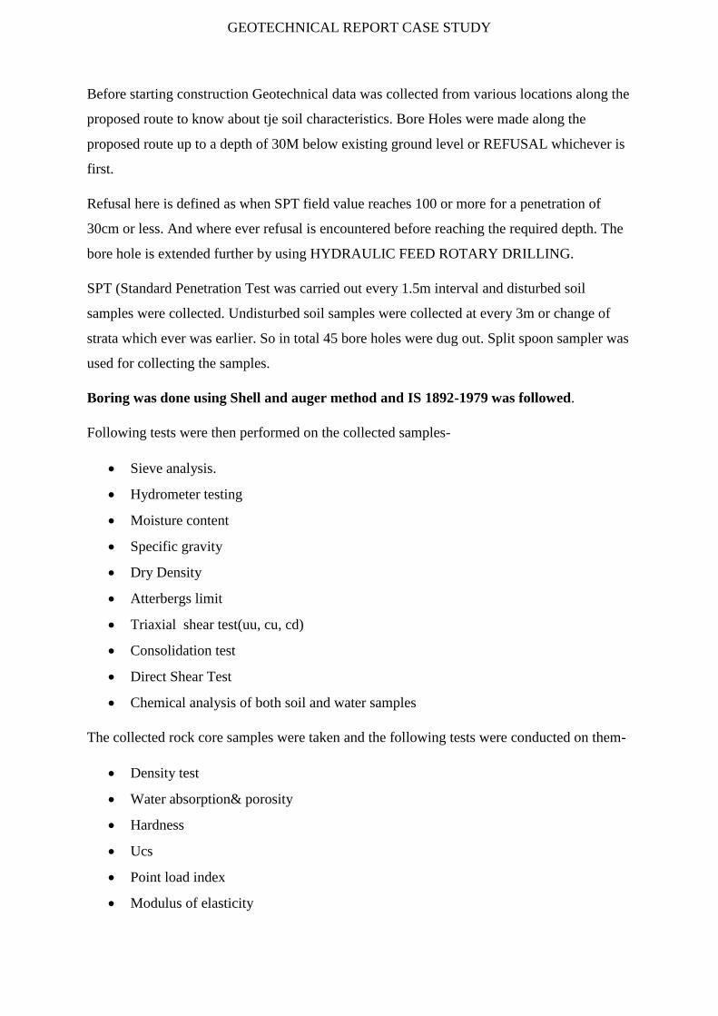
GEOTECHNICAL REPORT CASE STUDY
Before starting construction Geotechnical data was collected from various locations along the
proposed route to know about tje soil characteristics. Bore Holes were made along the
proposed route up to a depth of 30M below existing ground level or REFUSAL whichever is
first.
Refusal here is defined as when SPT field value reaches 100 or more for a penetration of
30cm or less. And where ever refusal is encountered before reaching the required depth. The
bore hole is extended further by using HYDRAULIC FEED ROTARY DRILLING.
SPT (Standard Penetration Test was carried out every 1.5m interval and disturbed soil
samples were collected. Undisturbed soil samples were collected at every 3m or change of
strata which ever was earlier. So in total 45 bore holes were dug out. Split spoon sampler was
used for collecting the samples.
Boring was done using Shell and auger method and IS 1892-1979 was followed.
Following tests were then performed on the collected samples-
Sieve analysis.
Hydrometer testing
Moisture content
Specific gravity
Dry Density
Atterbergs limit
Triaxial shear test(uu, cu, cd)
Consolidation test
Direct Shear Test
Chemical analysis of both soil and water samples
The collected rock core samples were taken and the following tests were conducted on them-
Density test
Water absorption& porosity
Hardness
Ucs
Point load index
Modulus of elasticity

GEOTECHNICAL REPORT CASE STUDY
Abrasion testing
Bore holes through all type of soils were bored using shell and auger method. Further
bore holes through rocky strata were drilled using hydraulic feed rotary drilling
machine with double tube core barrel . To retain the bore holes the casing pipe was
used up to the entire depth of bore holes .The details of various bore holes conducted
at site and the location is shown in the above figure.
ROCKY
STRATA SOIL/SOFT
STRATA
GEOTECHNICAL REPORT CASE STUDY
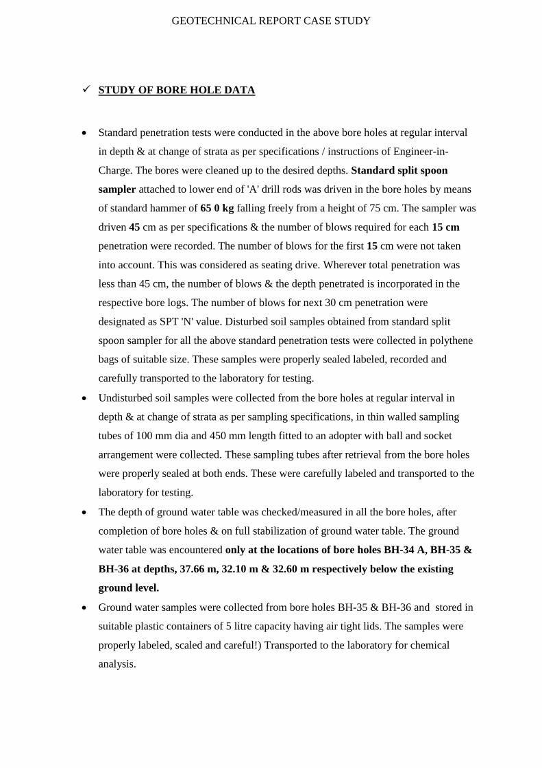
STUDY OF BORE HOLE DATA
Standard penetration tests were conducted in the above bore holes at regular interval
in depth & at change of strata as per specifications / instructions of Engineer-in-
Charge. The bores were cleaned up to the desired depths. Standard split spoon
sampler attached to lower end of 'A' drill rods was driven in the bore holes by means
of standard hammer of 65 0 kg falling freely from a height of 75 cm. The sampler was
driven 45 cm as per specifications & the number of blows required for each 15 cm
penetration were recorded. The number of blows for the first 15 cm were not taken
into account. This was considered as seating drive. Wherever total penetration was
less than 45 cm, the number of blows & the depth penetrated is incorporated in the
respective bore logs. The number of blows for next 30 cm penetration were
designated as SPT 'N' value. Disturbed soil samples obtained from standard split
spoon sampler for all the above standard penetration tests were collected in polythene
bags of suitable size. These samples were properly sealed labeled, recorded and
carefully transported to the laboratory for testing.
Undisturbed soil samples were collected from the bore holes at regular interval in
depth & at change of strata as per sampling specifications, in thin walled sampling
tubes of 100 mm dia and 450 mm length fitted to an adopter with ball and socket
arrangement were collected. These sampling tubes after retrieval from the bore holes
were properly sealed at both ends. These were carefully labeled and transported to the
laboratory for testing.
The depth of ground water table was checked/measured in all the bore holes, after
completion of bore holes & on full stabilization of ground water table. The ground
water table was encountered only at the locations of bore holes BH-34 A, BH-35 &
BH-36 at depths, 37.66 m, 32.10 m & 32.60 m respectively below the existing
ground level.
Ground water samples were collected from bore holes BH-35 & BH-36 and stored in
suitable plastic containers of 5 litre capacity having air tight lids. The samples were
properly labeled, scaled and careful!) Transported to the laboratory for chemical
analysis.

GEOTECHNICAL REPORT CASE STUDY
TEST RESULT COMARISON FOR BH-61,62 & BH -35,36
BH-61(VASANT VIHAR METRO STATION) LOCATION-AS SHOWN IN FIGURE BORING METHOD-ROTARY DRILLING
From existing ground surface to 2.00m depth consists of filled up soil.
From depth 2.00m to 22.50m depth consists of whitish brown medium to coarse
grained highly fractured partially decomposed micaceous quartzite.
Ground Water Table was not encountered.
Whitish Brown Medium to coarse grained Highly Fractured Partially Decomposed
Micaceos Quartzite(Physical Characteristic Of encountered rock)
RQD Stands for rock quality Designation- RQD is a modified core recovery
percentage in which all the pieces of sound core over 10 cm long are counted as
recovery, and are expressed as a percentage of the length drilled. The smaller pieces
resulting from closer jointing, faulting or weathering are discounted. The rock quality
designation (RQD), is a simple and practical method of describing the quality of core
from borings.
BORE HOLE NO COORDINATE E : N
REDUCED LEVEL(m)
DEPTH OF BORE HOLE(m)
DEPTH OF GROUND WATER TABLE (m)
BH-61 8641.464 -1193.61 -241.95 22.50 NIL

GEOTECHNICAL REPORT CASE STUDY
Sound rock usually furnishes high recoveries, often about 100 percent, seamy and or
jointed rock may furnish low recovery and badly broken cores.
From the study of the results of field work & laboratory tests carried out on selected
rock core samples collected from the locations of nine bore holes (BH-41, BH-44.
BH-50, BH-51, BH-54 to BH-58, BH-61 & B11-64 to BH-66) . It is revealed that the
core recovery & R.Q.D. values are very low at most of the places ranging from 6% to
47A. At the locations of bore hole BH-41. BH-44. BH-54 & BH-58 core recovery is
nil. Further at the locations of bore holes BH-41m BH-44, BH-54,BH-56,BH-58 &
BH-65. RQD. value is nil indicating moderate!) to highly weathered decomposed rock
formation. The unconfined compressive strength of the rock core samples (wherever
available) mostly ranged from 130 kg 'cm to 1039 kg/cm2.
Test Result
Density test 2.01 to 2.47(g/cc) Varying with depth
Abrasion test 28.0%
UCS

GEOTECHNICAL REPORT CASE STUDY
Hardness 7 to 7.5(Mohr Scale)
Porosity .83 to 7.14 Varying with depth
UCS 217kg/cm2
Pont Load Test Index 395.0 to 545.0 kg/cm2
Modulus of elasticity .36 to .52kg/cm2

GEOTECHNICAL REPORT CASE STUDY
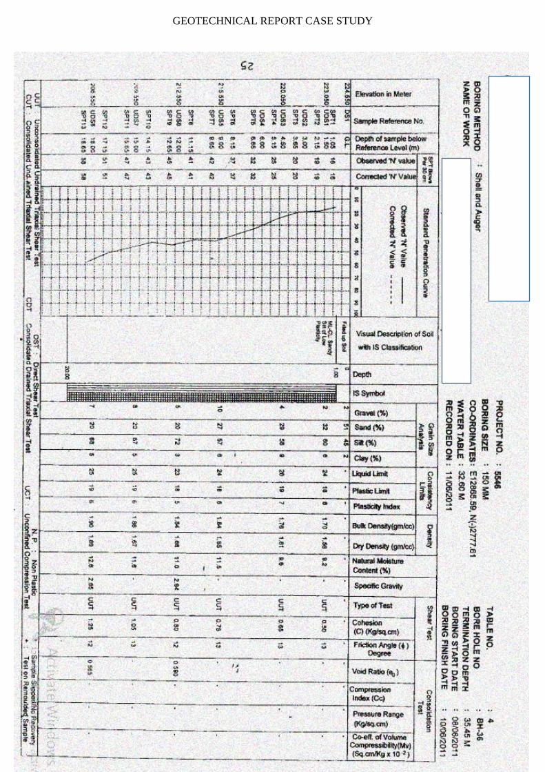
BH-35(Hauz Khaz Metro Station) LOCATION AS SHOWN IN FIGURE BORING METHOD-SHELL AND AUGER BORING
BH-35
From existing ground surface to 8.00 m depth consists predominantly of fine gained
soils i.e. sandy silt of low plasticity (CL/ML-CL) having SPT field ‘N’ values mostly
ranging from 11 to 29 showing stiff to very stiff consistency of the strata. From depth
8.00 m to 35.45 m depth consists predominantly of fine gained soils i.e. sandy silt of
low plasticity (CLJML-CL) having SPT field 'N’ values mostly ranging from 30 to
more than 100 showing hard consistency of the strata.
BH-36
At the location of bore hole BH-36. From existing ground surface to 1.00 m depth
consists of filled-up soil. From depth 1.00 m to 6.00 m depth consists predominantly
of fine grained soil i.e. 3,33, of low plasticity (ML-CL) having SPT field 'N' values
mostly ranging From 16 to 25 showing very stiff consistency of the strata. from depth
BORE HOLE NO COORDINATE E : N
REDUCED LEVEL(m)
DEPTH OF BORE HOLE(m)
DEPTH OF GROUND WATER TABLE (m)
BH-35 12977.800 -2802.410 224.200 35.45 32.10
BH-36 12865.590 -2777.610 224.500 35.45 32.60

GEOTECHNICAL REPORT CASE STUDY
6.00 m to 35.45 m depth consists predominantly of fine grained soils i.e. sandy silt of
low plasticity (CL/ML-CL) having SPT field `N' values mostly ranging from 32 to
more than 100 showing hard consistency of the strata.
The depth of ground water table was checked/measured in all the bore holes. After
completion of bore holes & on full stabilization of ground water table. The ground
water table was encountered only at the locations of bore holes BH-34A. BH-35 &
BH-36 at depths 10.90 m. 37.66 m. 32.10 m & 32.60 m respectively below the
existing ground level .
From the results of chemical analysis of two water samples from bore holes BH-35 &
BH-36.it is revealed that PH value ranged from 7.1 to 7.2. Chloride content (as CL)
from 40 ppm to 55 ppm & Sulphate content (as SO3) from 29 ppm to 37 ppm. From
the study of above results it is revealed that the various contents are within
permissible limits as per IS:456-2000 & no precautions are required due to this.
Above test results & interpretations are drawn based upon the field data collected
from the locations of various bore holes and results.
SHELL&AUGER DRILLING
GEOTECHNICAL REPORT CASE STUDY

GEOTECHNICAL REPORT CASE STUDY

GEOTECHNICAL REPORT CASE STUDY
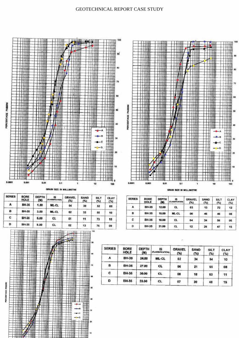
DEPTH(m) GRAVEL (%)
SAND (%)
SILT (%)
CLAY (%)
LL
PL PLASTICITY INDEX(IP )
COHESION (KG/CM2)
Refer To Graph
1.5 4 39 52 5 24 18 6 .35 3 2 33 55 10 27 20 7 .45 6 1 11 73 15 33 21 12 .65 9 2 13 76 9 30 20 10 .75 12 3 13 72 12 32 21 11 1.20 15 0 46 46 8 24 18 6 1.30 18 4 34 56 6 24 18 6 1.4 21 12 26 47 15 29 20 9 1.64 24 2 34 54 10 28 19 7 - 27 6 21 65 8 29 20 9 - 30 8 18 63 11 30 20 10 -
33 7 30 48 15 29 20 9 -
GEOTECHNICAL REPORT CASE STUDY
GEOTECHNICAL REPORT CASE STUDY
GRADATION CURVES OF THE SOIL SAMPLES OBTAINED FROM A SPT AND SUBJECTED TO
SIEVE ANALYSIS.
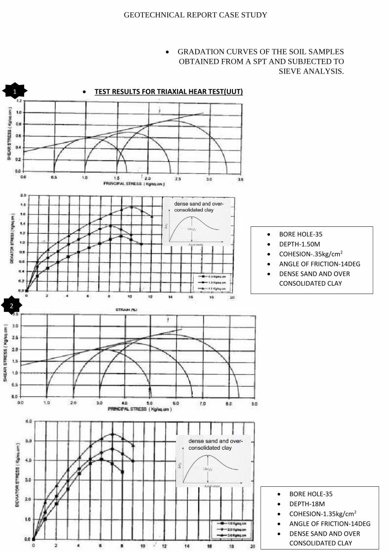
TEST RESULTS FOR TRIAXIAL HEAR TEST(UUT)
BORE HOLE-35
DEPTH-1.50M
COHESION-.35kg/cm2
ANGLE OF FRICTION-14DEG
DENSE SAND AND OVER
CONSOLIDATED CLAY
BORE HOLE-35
DEPTH-18M
COHESION-1.35kg/cm2
ANGLE OF FRICTION-14DEG
DENSE SAND AND OVER
CONSOLIDATED CLAY
1
2

GEOTECHNICAL REPORT CASE STUDY
CONSOLIDATION STUDIES FOR SOIL
DEPTH-1.5M
There are various methods for determining the pre consolidation pressure from
lab data. The data is usually arranged on a semi log plot of the effective stress
(frequently represented as σ'vc) versus the void ratio. This graph is commonly
called the e log p curve or the consolidation curve.
CONSOLIDATION
PRIMARY -Time Dependent
-Due To Expulsion of Pore Water
SECONDARY
-Time Dependent
-Very Slow
-Due To Plastic Readjustment of soil
CONVEX IN
SHAPE HENCE
THE SOIL IS
OCC OCS-OVER CONSOLIDATED SOIL
NCC-NORMALY CONSOLIDATED
Cr= (.2 to .1)CC
Cc= -(e2 – e1 )/log(0--- 1 – 0---
2 )
Cc=.156
1-2 VIRGIN COMP CURVE
2-3 SWELLING CURVE
SOIL TYPE-ML-CL
DEPTH-1.5M
NCC
STRAIGHT
LINE
1
2
3

GEOTECHNICAL REPORT CASE STUDY
TIME FAVTOR(Tv)
Time factor is a parameter which relates to DOC (Degree of compaction and time
required for that consolidation. It depends upon following
Degree of Consolidation
Length of Drainage Path
Time of Consolidation
Coeff of Consolidation(Cv)
We will determine Cv using Taylors Method (Square Root For Time fitting
Method).By making use of time required for 90% Consolidation.
3.4
90% Of
Consolidation
point
Di
D0
T90=3.42=11.56Min
Drainage Path Length=1cm
Cv=(.848*1)/(11.56*60) = .00124cm2/sec
Refer To side graph for steps of construction

GEOTECHNICAL REPORT CASE STUDY
SIMILAR PROCEDURE WERE ADOPTED TO FIND Cv And Cc With
Changing Depth.
Increment of .5kg/Cm2 of pressure for finding Cv through T90

GEOTECHNICAL REPORT CASE STUDY
Geotechnical report suggested using
1. Bottom-up Construction technique for construction at VASANT VIHAR SITE
2. Top To Bottom Construction for HAUZ KHAS SITE.
1.5, 0.353, 0.45
6, 0.659, 0.75
12, 1.215, 1.3
18, 1.4
21, 1.64
00.10.20.30.40.50.60.70.80.9
11.11.21.31.41.51.61.71.8
0 1 2 3 4 5 6 7 8 9 10 11 12 13 14 15 16 17 18 19 20 21 22 23
CO
HES
ION
DEPTH
COHESION VS DEPTH BORE HOLE-35
BOTTOM-UP CONSTRUCTION AND TOP TO BOTTOM CONSTRUCTION
As suggested by the testing and Geotechnical report Suitable methods are selected for
construction at sites according to the location and soil properties. Here we are going to
discuss about 2 such methods
Bottom Up construction
Top to Bottom construction
The choice of selection of method depends on a so many factors like-
Soil Profile- As suggested by the geotechnical investigation.
Site Location-The site is located in an isolated environment or urban dwellings.
Cost Incurred -Depends
Surrounding Environment-Weather the Surrounding environment consists of existing
structures and road networks.
Time Constrain-The total time available for completion of project.
Availability of Material-The availability of material for filling and construction
Activities to be carried out.
Both the methods have their own merits and demerits and we will study about the
methods one at a time.
BOTTOM-UP CONSTRUCTION
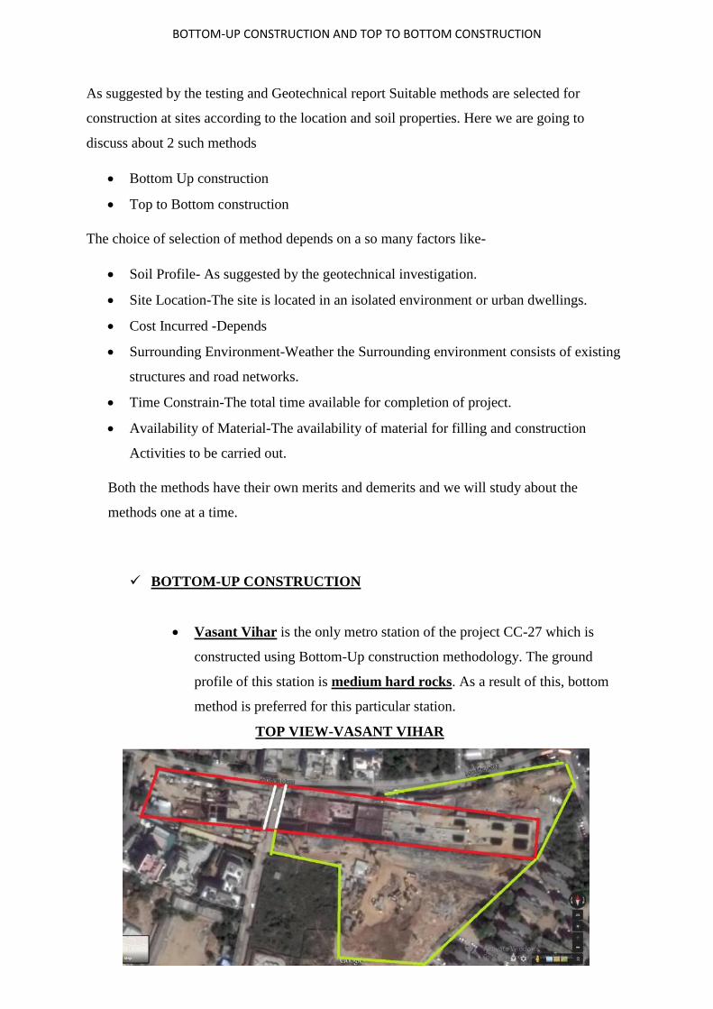
Vasant Vihar is the only metro station of the project CC-27 which is
constructed using Bottom-Up construction methodology. The ground
profile of this station is medium hard rocks. As a result of this, bottom
method is preferred for this particular station.
TOP VIEW-VASANT VIHAR

BOTTOM-UP CONSTRUCTION AND TOP TO BOTTOM CONSTRUCTION
In bottom-up construction, a trench is excavated more than the required
size of the station. Then the trench is backfilled and the surface is restored afterwards
Important components in bottom up approach are
Earthworks
Excavation and Temporary Retaining structures- Rock
anchoring/ Strut waler arrangement.
RCC Works- Columns, Beams, Slabs, External Wall.
Plunge in Column
1. EXCAVATION
Excavation should be carried out by
mechanized method up to the formation
level at stages. The activities for carrying
out excavation are mainly rock excavation,
shot Crete, rock bolting, disposal of
excavated materials and grout monitoring.
Excavation should be carried out in proper
sequence. Before excavating, a trial trench
is dug for a depth of 1.5m.
Also, the site should be checked for utility lines and proper diversions should be done
beforehand. Traffic divers on plans should be made and it should be diverted before
starting the excavation.
According to IS 3764:1992
All trenches in soil more than 1.5 m deep shallbe securely shored and timbered.
All trenches in friable or unstable rock exceeding2 m in depth shall be securely
shored and timbered.
Excavation of the soil can be done in two ways depending on the soil profile.
EXCAVATION BEING CARRIED OUT
BOTTOM-UP CONSTRUCTION AND TOP TO BOTTOM CONSTRUCTION
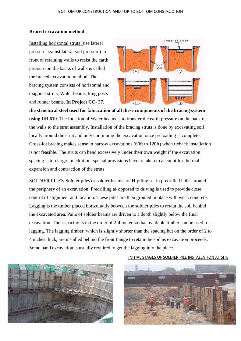
Braced excavation method-
Installing horizontal struts (use lateral
pressure against lateral soil pressure) in
front of retaining walls to resist the earth
pressure on the backs of walls is called
the braced excavation method. The
bracing system consists of horizontal and
diagonal struts, Waler beams, king posts
and runner beams. In Project CC- 27,
the structural steel used for fabrication of all these components of the bracing system
using UB 610. The function of Waler beams is to transfer the earth pressure on the back of
the walls to the strut assembly. Installation of the bracing struts is done by excavating soil
locally around the strut and only continuing the excavation once preloading is complete.
Cross-lot bracing makes sense in narrow excavations (60ft to 120ft) when tieback installation
is not feasible. The struts can bend excessively under their own weight if the excavation
spacing is too large. In addition, special provisions have to taken to account for thermal
expansion and contraction of the struts.
SOLDIER PILES-Soldier piles or soldier beams are H-piling set in predrilled holes around
the periphery of an excavation. Predrilling as opposed to driving is used to provide close
control of alignment and location. These piles are then grouted in place with weak concrete.
Lagging is the timber placed horizontally between the soldier piles to retain the soil behind
the excavated area. Pairs of soldier beams are driven to a depth slightly below the final
excavation. Their spacing is in the order of 2-4 meter so that available timber can be used for
lagging. The lagging timber, which is slightly shorter than the spacing but on the order of 2 to
4 inches thick, are installed behind the front flange to retain the soil as excavation proceeds.
Some hand excavation is usually required to get the lagging into the place.
INITIAL STAGES OF SOLDIER PILE INSTALLATION AT SITE

BOTTOM-UP CONSTRUCTION AND TOP TO BOTTOM CONSTRUCTION
Soldier piles are installed with conventional pile-driving equipment or in augured holes. The
horizontal sheeting or lagging is installed behind the flange closest to the excavation (inside
flange). The sheeting can be installed on the inside face of the front flange and held in place
by various methods such as clips, welded studs, or bars, etc. Figure 5 shows two photos of
excavation supports using soldier beam and lagging. The soldier pile and lagging method is
inappropriate for perfectly cohesionless soil. For cohesionless soils sheeting must be used.
PROCEDURE
A. Strike soldier piles into soil. In non-urban areas, it will be all right to strike them into
soil directly. In urban areas, however, static vibrating installation would be the better
way to have soldier piles penetrated into the soil. If encountering a hard soil layer,
pre-bore the soil (AS DONE ON SITE).
B. Place laggings as excavation proceeds. Then backfill the voids between soldier piles
and laggings.
C. Install horizontal struts in proper places during the excavation process once excavation
is completed, begin constructing the inner walls of the basement. Then remove struts
level by level and construct floor slabs.
ADVANTAGES DISADVANTAGES
I Easier and faster construction with lower cost.
2 Piles can be easily pulled out.
3 It is necessary that less ground disturbance is caused
when pulling out the piles, compared to pulling out sheet
piles.
4 The pile tip can be strengthened with special steel
materials for use in gravel soils.
5 Soldier piles are reusable.
I Sealing is difficult. In sandy soils with high
groundwater level some dewatering measures may be
necessary.
2 Installing soldier piles by striking will cause much
noise and vibration. The latter will render sandy soils
below the foundation denser in such a way that uneven
settlement of the adjacent buildings may occur.
3 Backfilling is necessary if soldier piles are driven
using pre-boring.
5 Removing piles will disturb the surrounding soil.
2-4 Meters

BOTTOM-UP CONSTRUCTION AND TOP TO BOTTOM CONSTRUCTION
Anchored Excavation Methods-
Anchored excavation methods substitute anchors force to counteract the lateral earth
pressure. The configuration of an anchor can be divided into
(a) The fixed section- which offers anchoring force
(b) The free section- which transfers the anchoring force to the anchor head.
(c) The anchor head- which locks the tendons and transfers the anchoring force to the
structure.
The anchored excavation counts solely on soil
strength to offer the anchoring strength. The higher the soil strength, the stronger the
anchoring force and vice-versa. Granular soils as sandy soils or gravel soils have high
strengths and thus offer strong anchoring force while clay has weak strength and creep will
further decrease the anchoring force. Therefore, the anchoring section should avoid being
installed in clay.
The anchorage process involves the following steps
o Drilling Processes
o Anchor installation and grouting
o Waler beam installation
o Pre Stressing
o De-Stressing
o Quality Assurance and quality control(Qa-Qc Procedures)

BOTTOM-UP CONSTRUCTION AND TOP TO BOTTOM CONSTRUCTION
DRILLING PROCESS-
-Drilling is carried out typically inclined at an angle of
(20+ -5deg) to the horizontal as required Using a
suitable anchor drilling rig with appropriate drill tools
to frill a hole of( 152mm Dia and length from 7m to
13m)
-It shall be ensured to have full length casing during
drilling process with due considerations to collapse in-
site soils, in order to stabilize the boreholes. However
casing is not required when drilling through rock mass
as it is not a collapsible stratum.
-During the drilling operation the sequence of strata in
the ground needs to be observed continuously. It must
be ensured that the fixed/bond length of the anchor
does not
Fall under a soil stratum that is significantly different from that of the idealized soil strata.
-Once the required depth of the borehole has been reached the hole is flushed out using air
and the drill tools are removed from the hole.
Anchor Installation and Grouting
-High tensile strength strands shall be used conforming to IS14268:1995 to achieve the
desired structural capacities and the prefabricated anchor shall be tied together with HDPE
grout pipe for grouting process (secondary Grouting)
-A shrink free grout mixture is used (typically water cement ratio shall be .35 to .4) with
approved OPC grade 53 shall be used with the admixture CEBEX 100.
-The prefabricated anchor assembly is then inserted into the borehole and grout is injected
either through HDPE grout pipe or gravity flow from top of the bore hole using grout station
(Consisting of a colloidal mixer, agitator and high pressure grout pump)
-During this process the casing shall be withdrawn in stages and the gap formed due to
retrieval of casing shall be filled-up with the grout. This procedure is repeated until the entire
casing is retrieved,

BOTTOM-UP CONSTRUCTION AND TOP TO BOTTOM CONSTRUCTION
-Following primary Grouting process a secondary grouting process shall be commenced after
a time lapse of about 24 Hours. During secondary grouting through the Pre-Installed HDPE
grout pipe, High grout pressure for effective bonding between the primary and secondary
grout.
GROUT MATERIAL& PROPERTIES
-The purpose of grouting is to provide is to provide permanent bond in the fixed length of the
tendon. This also helps in stabilizing drilled holes in the free length. Grout also fills up void
spaces, expelling the water collection if any
GROUT PROPRTIES
o The cement grout is prepared based on W/C of .35 to .4
o The admixture Cebex-100 shall be added as of 225grams per 50kg cement bag.
o 100mm cube samples shall be taken from the grout mix for strength checks
o The grout temperature is maintained at 25deg Celsius.
GROUT STATION
GROUT MIXTURE
BOTTOM-UP CONSTRUCTION AND TOP TO BOTTOM CONSTRUCTION
o The cube shall attain a minimum strength of 17N/mm2 in 7 days
INSTALLATION OF BRACKETS AND WALERS
-The brackets for each location shall be measure &Fabricated at site for fixing to the soldier
piles. Walters will be installed as H-Piles &Welded completely as specified in the drawing.
The gap between the waler beam and the soldier pile wall will be filled with concrete.
Bearing Plate shall be installed prior to stressing.
PRE-STRESSING
-The grouted anchors are allowed to cure for a minimum period of 7-10 days before the
anchor strands are subjected to pre-stressing. The Stressing, operations must not commence
until the grout has attained the required crushing strength of at least 17 MPa or 7days after
grouting whichever is earlier.
-As per BS 8081: 1989 (clause 11.4.3, table 18). While pre-stressing. each stage loading in
the first cycle should be held only for the time necessary to record the displacement (as
shown in table below).
- Each stage loading in the second Cycle should be held for at least 1 min and the
displacement recorded at the beginning and end of each period. For proof loads, this period is
extended to at least 15min. with an intermediate displacement reading at 5min.
- On completion of the second load cycle, reload in one operation to 110% and lock off.
Reread the load immediately after lock-Off to establish the initial residual load.
- The anchors will be locked at 110%of the Pre stressing load.
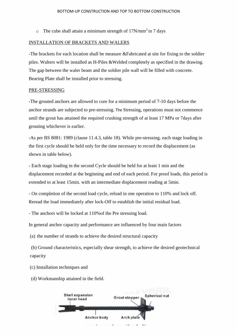
In general anchor capacity and performance are influenced by four main factors
(a) the number of strands to achieve the desired structural capacity
(b) Ground characteristics, especially shear strength, to achieve the desired geotechnical
capacity
(c) Installation techniques and
(d) Workmanship attained in the field.

BOTTOM-UP CONSTRUCTION AND TOP TO BOTTOM CONSTRUCTION
DESIGN CRITERIA FOR ANCHOR BOLTS
(example)
Structural Capacity
To achieve the desired structural capacity of the anchors i.e., say 80 tons, the anchors are
Fabricated using 6 Nos. of each 12.7mm diameter steel strands (7 ply) confirming to
IS: 14268-1995, clause-II, were used as per the following calculations:
Design capacity of the anchor = 80 T
Capacity of each strand of 12.7mm dia. = 18.74 T
(As per IS 14268:1995 For 7 ply, 12.7 mm nominal dia., clause II)
No. of strands = 6nos (say)
Total Structural capacity of the anchor = 18.74T x 6nos = 112.44T
Factor of safety against STRUCTURAL capacity of the anchor
= Theoretical capacity / design capacity
= 112.4 T / 80T
= 1.41 > 1.4 (as per BS 8081: 1989)
Geotechnical Capacity
The main components of the geotechnical capacity of the anchor are free and fixed length,
Which are arrived at based on the following calculations:
Design Capacity of the anchor = 80T
Length of anchor in the active wedge zone = 10.5m (as per to failure wedge analysis)
Free length of anchor = 12.5m (incl. 2m additional buffer length)
Fixed length of the anchor, L = 9.5m (say)
BOTTOM-UP CONSTRUCTION AND TOP TO BOTTOM CONSTRUCTION
Geotechnical capacity of the anchor = π x D x L x τf (Sandy silt)
D, Dia of drill hole = 0.152m
τf (Sandy silt) is theoretical skin friction (> 400 kN/sq.m) for Sandy Silts having Consistency
Index, Ic=1.25, according to BS 8081: 1989, clause 6.2.5.3, Fixed Length in Type C
Anchorages
Considering, theoretical skin friction τf (Sandy silt) = 400 kN/sq.m
The ultimate geotechnical capacity of anchor = (π x 0.152 x 9.5) x 400
= 1,815 kN ~ 182T
Factor of safety against geotechnical capacity of the anchor
= Theoretical capacity / design capacity
= 182 T / 80T
= 2.3 > 2 (as per BS 8081: 1989)
Total length of the anchor = Free length + Fixed length
= 12.5m + 9.5m = 22m
SHORTCRETE
Shortcrete is concrete conveyed through a hose and pneumatically projected at high velocity
onto the excavated surface, as a technique for stabilizing the excavated face. Shortcrete is
usually an all- inclusive term that can be used for both wet-mix and dry-mix versions.
Shortcrete undergoes placement and compaction at the same time due to the force with
which it is projected from the nozzle. Cement, sand, aggregates and water are the main
constituents of shotcrete. Prior to the application of shotcrete, all surfaces to receive
shotcrete shall be cleaned with compressed air.
o Admixtures: Admixtures for the improvement of performance, workability, etc.
o Water: Water free from solid suspended matter and organic particles confirming to
IS: 456-2000
o Flyash: Flash shall comply with Specification IS:3812.

BOTTOM-UP CONSTRUCTION AND TOP TO BOTTOM CONSTRUCTION
o Accelerator: Accelerator will be Alkali free, and dose will be max. 6% by wt. of
Cement.
-After the preparation of surfaces 4mm wire mesh is
fixed to the concrete surface with pin/8m dia and to the
earth surface with 25-32mm dia reinforcement bar 1500-
3000mm c/c
-The operation temperature for Shortcrete is 5 – 32deg
Celsius
-MIX DESIGN PROPORTION USUALLY ARE 1:3
to 1:5 depending upon the surface.
-Shortcrete is transported by transit mixer from the
batching plant to site and will be delivered into hopper of
concrete spraying machine.
-The designed thickness of the Shortcrete will be built up
in layers of about 75mm thick. The nozzle for spraying will be kept at a distance of 1 to 1.4m
away from surface and always perpendicular to the surface.
-Before a subsequent layer of shortcrete is applied the percentage layer will be checked for
defects. Defects like voids, dry or sandy patches will be cut and then re-Shortcrete.
-The area of spray should not be less than 300mm*300mm
-Initially fix the wire mesh then spray the Shortcrete up to 75mm, after the drill hole for
installation of rock bolt. So Shortcrete around rock bolt is not required
-To check the thickness of the Shortcrete coring will be done.
ON FIELD
1) Clean the surface off the loose material and then clean with air compressor.
2) Apply a layer of shortcrete to the surface and wait for it to cure.
3) Apply the wire mesh on the surface and bind it to the surface using reinforcements.
4) Now apply the second layer of the shortcrete on the surface.

BOTTOM-UP CONSTRUCTION AND TOP TO BOTTOM CONSTRUCTION
Following figures are used to provide structural visualization for VASANT VIHAR METRO STATION to help in subsequent topics.
BASE SLAB
CONCOURSE SLAB
ROOF SLAB
D
SECTIONAL FRONT VIEW

BOTTOM-UP CONSTRUCTION AND TOP TO BOTTOM CONSTRUCTION
After excavation we will further study about the bottom-up construction in the
sequence of slabs.
2. SLABS
BASE SLAB-
The major work of the base slab is to support the tracks and resist the vertical pressure
from the ground. The construction process to construct this slab is also the same as the
roof slab and the concourse slab. The base slab is placed 6.86 meters below the base of
concourse slab and it is 900mm thick. The base slab structure is not flat but in shape of a
bucket with leaves at the ends.
For the construction of the base slab this soil is then lined with 75mm (min) thick PCC
layer and 3mm thick ply. These ply act as a base support for the concrete layer; it also
gives a fine finish. As shown in the above figure
BUCKET-LEAF STRUCTURE OF BASE SLAB

BOTTOM-UP CONSTRUCTION AND TOP TO BOTTOM CONSTRUCTION
MATERIALS USED
-Concrete conforming to M40 grade shall be used for casting.
-Reinforcement conforming to FE500D shall be used on site.
-Water shall conform to IS456.
-Water Stops –PVC water stop will be used to arrest the water leakage as specified in the
drawing.
-Binding wire used for binding reinforcement has a core dia of 1.25mm
-Formwork panel would be made of film coated plywood.12mm thick and shall be placed
along the alignment and the verticality, fine and level shall be checked.
-Cover blocks should be used depending on clearance that needs to be provided to the
reinforcement.
-Minimum lift period for the formwork are as follows-
-Vibrator of 60mm dia 4NOS
Type of Formwork Minimum Period Before
Striking Formwork
a) Vertical formwork to columns, walls , beams 16-24 hours
b) Soffit formwork to slabs (Props to be refixed
immediately after removal of formwork)
3 days
c) Soffit formwork to beams (Props to be refixed
immediately after removal of formwork)
7 days
d) Props to slabs:
1. Spanning up to 4.5 m
2. Spanning over 4.5 m
7 days
14 days
e) Props to beams and arches:
1. Spanning up to 6m
14 days

BOTTOM-UP CONSTRUCTION AND TOP TO BOTTOM CONSTRUCTION
2. Spanning over 6m 21 days
CONCRETING
-Before concreting the pore are shall be
cleaned using a boom pressure with air or
water.
-M40 grade of concrete shall be used along
with waterproofing admixture of
crystalline type which would be mixed
with the concrete at the batching plant
during mixing.
-Concreting temperature shall be between 32 deg Celsius to 5deg Celsius and concrete shall
be placed using boom placer/bucket whoever serves the purpose.
-In order to avoid cold joints the concrete shall be placed in continuous layers not exceeding
300mm and it should be kept in mind to compact each layer efficiently and completely by
immersion of vibrators before second layer is laid down
-Reason for cold joints-Cold joints are formed primarily between two batches of concrete
where the delivery and placement of the second batch has been delayed and the initial placed
and compacted concrete has started to set. The full knitting together of the two batches of
concrete under vibration to form a homogeneous mass is therefore not possible, unlike the
compaction of two fresh workable batches of concrete. This could be a potential plane of
weakness.
Remedy for cold joints-Proper compaction of the layer beneath and subsequent poring of
second layer without any delay so that the layer below is still green (FRESH).
COLD JOINT BW 2 Layers
BOTTOM-UP CONSTRUCTION AND TOP TO BOTTOM CONSTRUCTION
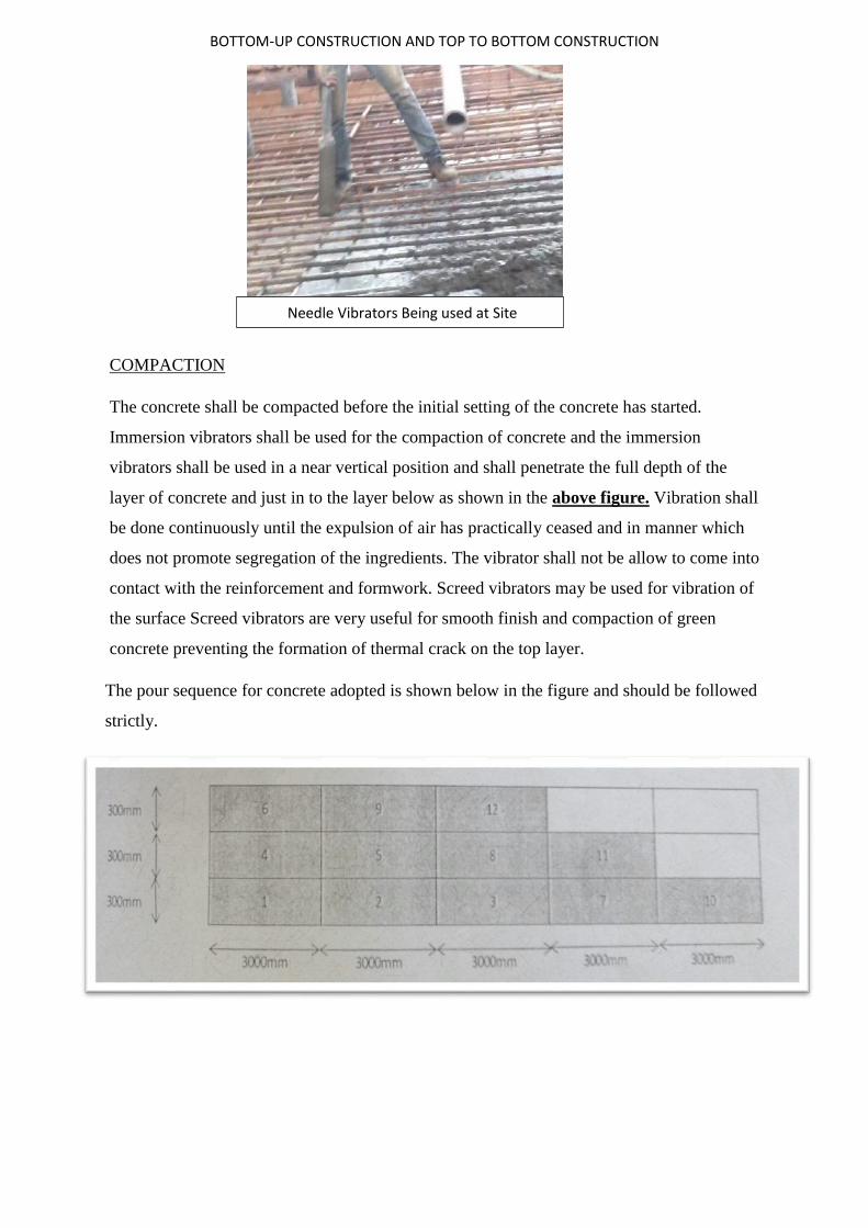
COMPACTION
The concrete shall be compacted before the initial setting of the concrete has started.
Immersion vibrators shall be used for the compaction of concrete and the immersion
vibrators shall be used in a near vertical position and shall penetrate the full depth of the
layer of concrete and just in to the layer below as shown in the above figure. Vibration shall
be done continuously until the expulsion of air has practically ceased and in manner which
does not promote segregation of the ingredients. The vibrator shall not be allow to come into
contact with the reinforcement and formwork. Screed vibrators may be used for vibration of
the surface Screed vibrators are very useful for smooth finish and compaction of green
concrete preventing the formation of thermal crack on the top layer.
The pour sequence for concrete adopted is shown below in the figure and should be followed
strictly.
Needle Vibrators Being used at Site
BOTTOM-UP CONSTRUCTION AND TOP TO BOTTOM CONSTRUCTION
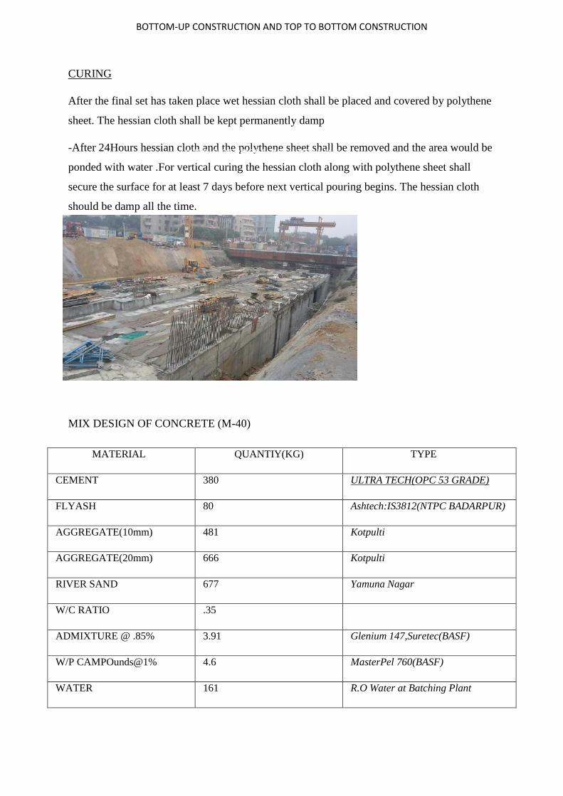
CURING
After the final set has taken place wet hessian cloth shall be placed and covered by polythene
sheet. The hessian cloth shall be kept permanently damp
-After 24Hours hessian cloth and the polythene sheet shall be removed and the area would be
ponded with water .For vertical curing the hessian cloth along with polythene sheet shall
secure the surface for at least 7 days before next vertical pouring begins. The hessian cloth
should be damp all the time.
MIX DESIGN OF CONCRETE (M-40)
MATERIAL QUANTIY(KG) TYPE
CEMENT 380 ULTRA TECH(OPC 53 GRADE)
FLYASH 80 Ashtech:IS3812(NTPC BADARPUR)
AGGREGATE(10mm) 481 Kotpulti
AGGREGATE(20mm) 666 Kotpulti
RIVER SAND 677 Yamuna Nagar
W/C RATIO .35
ADMIXTURE @ .85% 3.91 Glenium 147,Suretec(BASF)
W/P CAMPOunds@1% 4.6 MasterPel 760(BASF)
WATER 161 R.O Water at Batching Plant
CURING OF ROOF SLAB UNDER WAY

BOTTOM-UP CONSTRUCTION AND TOP TO BOTTOM CONSTRUCTION
CONCOURSE SLAB
Outlook of the station is said to be concourse slab. The activities at the station other than the
train tracks are all available on this slab. The slab serves as the gallery of the metro station. It
contains the entry and exit gates to the station, the ticket counters, and security and fire
escape provisions. The construction of the concourse slab is carried out in the same manner
as the roof slab. This slab contains larger temporary cut- outs than the roof slab. These cut-
out spaces help in the laying and development of the base slab and lowering of TBM for
tunneling. These cut-outs are closed during the final phase of the construction. These cutouts
are initially supported by beams to provide stability to the D-walls. These beams are
removed after the structure is stabilized by the construction of the base slab. The concourse
slab is placed 5.25m below the base of the roof slab. Its thickness is 550mm. The concourse
slab contains exhaust vents (Over Track Exhaust ducts) at the sides of the slab. The
concourse slab contains the cavity provided to place the service lines inside the station. The
concourse slab is connected to the base slab with the help of stair case, escalator and lift.
MATERIALS USED
-Concrete conforming to M40 grade shall be used for casting.
CONCOURSE SLAB/ INTERMEDIATE SLAB

BOTTOM-UP CONSTRUCTION AND TOP TO BOTTOM CONSTRUCTION
-Reinforcement conforming to FE500D shall be used on site.
-Water shall conform to IS456.
-Water Stops –PVC water stop will be used to arrest the water leakage as specified in the
drawing.
-Binding wire used for binding reinforcement has a core dia of 1.25mm
-Formwork panel would be made of film coated plywood.12mm thick and shall be placed
along the alignment and the verticality, fine and level shall be checked.
-Cover blocks should be used depending on clearance that needs to be provided to the
reinforcement.
-Minimum lift period for the formwork are as follows
Type of Formwork Minimum Period Before
Striking Formwork
f) Vertical formwork to columns, walls , beams 16-24 hours
g) Soffit formwork to slabs (Props to be re fixed
immediately after removal of formwork)
3 days
h) Soffit formwork to beams (Props to be re fixed
immediately after removal of formwork)
7 days
i) Props to slabs:
3. Spanning up to 4.5 m
4. Spanning over 4.5 m
7 days
14 days
j) Props to beams and arches:
3. Spanning up to 6m
4. Spanning over 6m
14 days
21 days

BOTTOM-UP CONSTRUCTION AND TOP TO BOTTOM CONSTRUCTION
FORMWORK & STAGING
Formwork shall provide concrete of the shape, lines and dimensions shown on the drawing.
L&T Formwork System would be used for staging & formwork preparation as per the
approved drawing
For staging purpose Heavy Duty Towers shall be erected and fixed at positions and spacing
as per the drawing with bracing as required to prevent lateral tilting. Such an arrangement
would provide sufficient strength, support and rigidity during placing and compacting of
concrete.
As per the drawing, the top tower spindle of the HDT would be attached to U-head. U-head
will provide a resting platform to the steel waler at 100mm back to back spacing, which
would run along the span of the slab. Over the steel waler, H-16 would be laid
perpendicularly at 300 mm c/c. The steel waler will act as the primary span member &
timber H-beams would act as secondary beam members. Over this, plywood of 12 mm
thickness shall be fixed. Slab will rest over this arrangement.
Formwork will be placed along the alignment and the verticality, line and level shall be
checked. Appropriate formwork arrangement shall be provided at the cut-out portions of the
slab as per the drawing.
Inserts, if any to be fixed within the shutter shall be fixed as per the design and drawing.
The verticality of side shutter shall be checked using Plumb bob.
The straight line of the shutters shall be checked with the help of line thread/ total station.
Starter shutter for RCC wall above concourse slab shall also be fixed.
TEMPORARY SUPPORT TO CONCOURSE SLAB
At per the locations mentioned in drawing composite steel structure would be provided to
give temporary support to the roof slab beam. As the locations of the permanent columns lie
in the cut-out portion of the station, hence for temporary support temporary columns would
be provided.
Three sections of UC 610 x 229 x 125.1 mm shall be butt welded & fabricated (as mentioned
in the drawing) as a single vertical member of length as mentioned in the drawing. Towards
BOTTOM-UP CONSTRUCTION AND TOP TO BOTTOM CONSTRUCTION
the bottom side of the fabricated column head plate of 32mm thickness MS plate of size 660
x 775 mm will be welded. Similarly, base plate will be welded on the bottom end.
This set up will be lowered through the cut-out portion of the slab above and then positioned
into its place. After positioning it, it will be erected as such the top of the column is pressed
up against the top sab and the gap created in the bottom will be then grouted by prepacked
high early strength non-shrink grout which will give strength of 40 Mpa at the end of 28
days.
Towards the shorter dimension of the column, diagonal lacing at 458 mm spacing c/c would
be provided using ISA 75 x 75 x 6 mm. It will be welded as mentioned in the drawing. 12
mm thick stiffeners will be provided and welded as shown in the drawing.
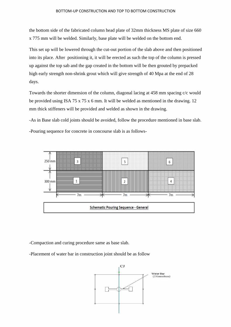
-As in Base slab cold joints should be avoided, follow the procedure mentioned in base slab.
-Pouring sequence for concrete in concourse slab is as follows-
-Compaction and curing procedure same as base slab.
-Placement of water bar in construction joint should be as follow

BOTTOM-UP CONSTRUCTION AND TOP TO BOTTOM CONSTRUCTION
ROOF SLAB
The base slab supports the whole weight of the station. The diaphragm walls of the station
sustain huge amounts of lateral pressure from the backfill. This makes the diaphragm wall
act as a cantilever and it tends to lean inwards, but to sustain the pressure the roof slab is
constructed. The roof slab provides the support at one point. The concourse slab built after
the roof slab provides extra support to the D-wall. When the roof slab is constructed, it
completes the box structure and provides additional support and gives stability to the
structure, the roof slab is designed to take the weight of filling and any subsequent structure
that may be built on it. At the time of making of roof slab, several cut-outs are left for further
excavation required for construction of concourse and base slab and for lowering of TBM for
tunneling. The thickness of roof slab is 1.8- 2 meters.
Material required- Same as above
And all other considerations are same as those of base slab and concourse slab. Except that
water proofing has to provide over roof slab, which has been discussed later in the project.
3) WALL
ROOF SLAB SATELLITE VIEW WITH CUT OUTS IN THE ROOF SLAB

CONCRETING ON SITE
CONCRETING ON SITE
DESIGN MIX M-40
M30 would have been suitable according to the load consideration but M40 was used to fulfill the
criteria of design life of 125 years and provide a more sustainable structure.
FOLLOWING ADMIXTURES WERE USED IN THE MIX
1) Masterglenium 147 provides
Description
Polycarboxylic Ether Based High Range Water Reducer / Versatile Super plasticizer Concrete
Admixture.
Masterglenium 147 provides
Extended workability
Providing the ultimate high strength, especially ready
Advantages
Highest quality available with or without pump on site.
MATERIAL QUANTIY(KG) TYPE CEMENT 380 ULTRA TECH(OPC 53 GRADE) FLYASH 80 Ashtech:IS3812(NTPC
BADARPUR) AGGREGATE(10mm) 481 Kotpulti AGGREGATE(20mm) 666 Kotpulti RIVER SAND 677 Yamuna Nagar W/C RATIO .35 ADMIXTURE @ .85% 3.91 Glenium 147,Suretec(BASF) W/P CAMPOunds@1% 4.6 MasterPel 760(BASF) WATER 161 R.O Water at Batching Plant

CONCRETING ON SITE
Favors reinforced concrete elements easy to place & has Self-Compacting Concrete properties.
Allows the provision of maintaining the quality of concrete without losing consistency,
affordable, low water / cement ratio concrete.
Using a single product for many applications.
Application Method
Add to the mixture 80% -90% of the calculated water for the concrete mix and then, with the
remaining water masterglenium 147 must be added to the mixture.
For the efficient dispersion of mastergenium 147 give 100sec or the calculated laboratory time
should be given to mixture with the constant stirring.
Dosage
The use ratio from 0.8 to 1.5 kg is recommended. Depending on the use of laboratory
experiments.
Shelf Life: 12 months from the production date
2) MasterPEL760
Description- MasterPel 760 is a crystalline powder admixture for concrete to achieve high resistance to
water ingression. Free Flowing grey powder with a bulk density of 1.350 ± 0.02 gm/cm3 and is
approved by IS:2645-2003. MasterPel 760 is available in 5 Kg & 25 kg pack.
HOW IT WORKS?

CONCRETING ON SITE
It is based on a blend of Portland cement, processed silica sand and special catalytic agents which
converts hydration by-products to solid crystalline formation in the water transporting capillary tracts
and hydration pores thus preventing water seepage.
Shelf Life: 6 months after date of production
Where it should be used?
MasterPel 760 should be used in all structural concrete that is constantly or intermittently in contact with
water such as
Sea walls
Tunnels
Basements
Structural and pre-cast concrete.
ADVNTAGES
Provides resistance to water penetration either under hydrostatic pressure or capillary absorption.
Imparts integral water tightness to structures
Protects from waterborne corrosive agents.
Permanently active - crystalline action is reactivated by contact with water.
Equally effective against both positive and negative water pressure or osmotic pressure.
Reduced sulfate attack.
Reduced efflorescence.
Do not reduce compressive strengths
Powder – easy to use in pre-batched renders.
Low dosage – Economical
Important points to remember
Ensure water / cement ratio is less than 0.5 .Addition of good plasticizer from the
MasterRheobuild or MasterGlenium range is advised to achieve minimum water/cement ratio.
Place concrete quickly and compact it well.
Ensure complete curing with a MasterKure curing compound.
CONCRETING ON SITE
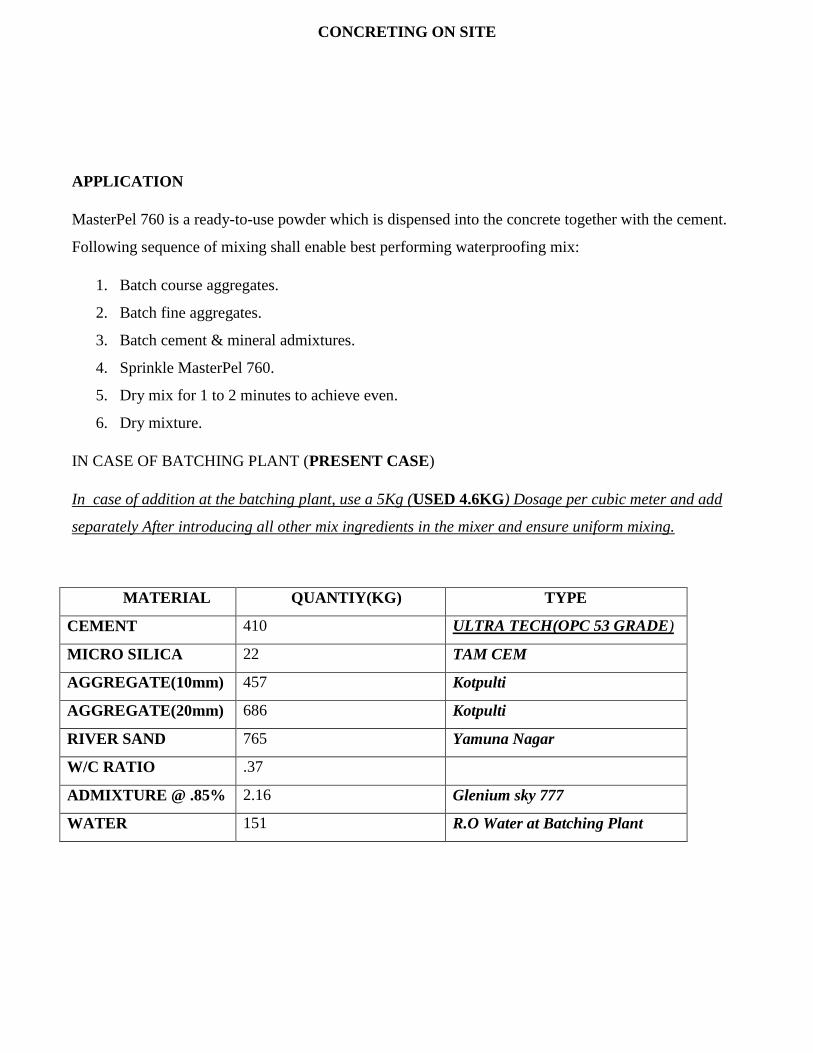
APPLICATION
MasterPel 760 is a ready-to-use powder which is dispensed into the concrete together with the cement.
Following sequence of mixing shall enable best performing waterproofing mix:
1. Batch course aggregates.
2. Batch fine aggregates.
3. Batch cement & mineral admixtures.
4. Sprinkle MasterPel 760.
5. Dry mix for 1 to 2 minutes to achieve even.
6. Dry mixture.
IN CASE OF BATCHING PLANT (PRESENT CASE)
In case of addition at the batching plant, use a 5Kg (USED 4.6KG) Dosage per cubic meter and add
separately After introducing all other mix ingredients in the mixer and ensure uniform mixing.
MATERIAL QUANTIY(KG) TYPE
CEMENT 410 ULTRA TECH(OPC 53 GRADE)
MICRO SILICA 22 TAM CEM
AGGREGATE(10mm) 457 Kotpulti
AGGREGATE(20mm) 686 Kotpulti
RIVER SAND 765 Yamuna Nagar
W/C RATIO .37
ADMIXTURE @ .85% 2.16 Glenium sky 777
WATER 151 R.O Water at Batching Plant

CONCRETING ON SITE
DESIGN MIX M50
IMPORTANT CONSTITUENTS
GLENIUM SKY 777
MasterGlenium SKY 8777 is the super plasticizer based on second generation polycarboxylic ether
polymers, developed using nano-technology. The product has been primarily developed for applications
in high performance ready-mix concrete to facilitate TOTAL CONCRETE PERFORMANCE. It helps
to produce high performance concrete with longer workability retention, and high early strength. Mostly
compatible with all OPC, PPC, PSC and can be used with high pozzolonic material.
TOTAL CONCRETE PERFORMANCE- Ensures that ready-mix producers, contractors and engineers
get a concrete that is of the same high quality as originally specified; starting from production at the
batching plant, to the delivery and application into place and followed by its hardening process.
Utilising. Rheodynamic Concrete technology, it provides a concrete mix with exceptional placing
characteristics and accelerated cement hydration for early strength development and high-quality
Concrete.
CONCRETING ON SITE
ADVANTAGES
Capability of delivering high quality concrete at any time to the job site in place.
Production of concrete with low w/c ratio that meets international guidelines for consistency
classes (EN 206-1) without loss of workability.
Single product for many application needs.
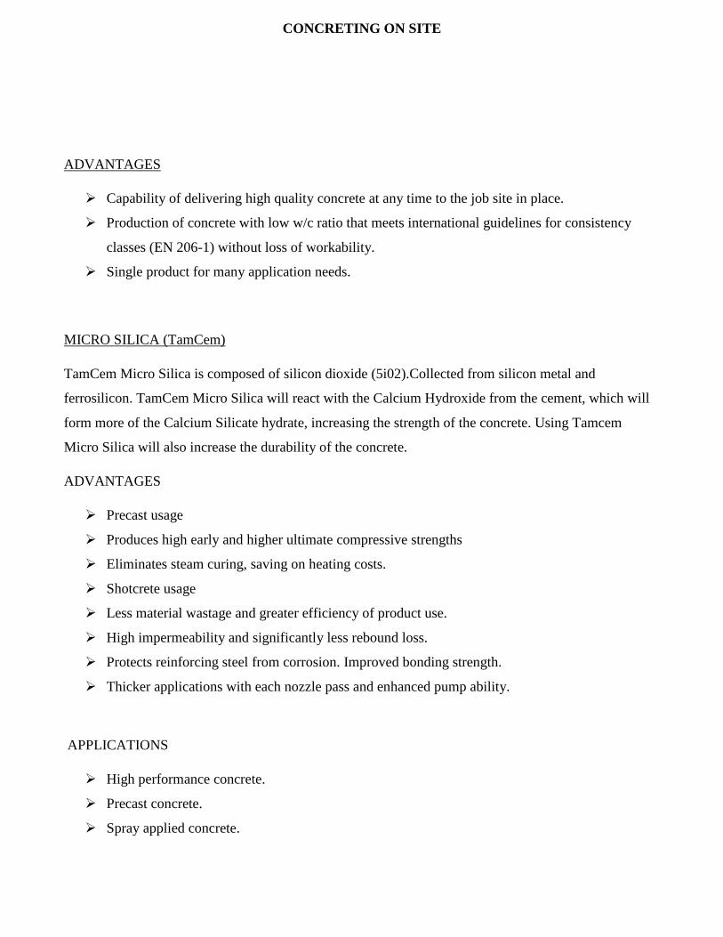
MICRO SILICA (TamCem)
TamCem Micro Silica is composed of silicon dioxide (5i02).Collected from silicon metal and
ferrosilicon. TamCem Micro Silica will react with the Calcium Hydroxide from the cement, which will
form more of the Calcium Silicate hydrate, increasing the strength of the concrete. Using Tamcem
Micro Silica will also increase the durability of the concrete.
ADVANTAGES
Precast usage
Produces high early and higher ultimate compressive strengths
Eliminates steam curing, saving on heating costs.
Shotcrete usage
Less material wastage and greater efficiency of product use.
High impermeability and significantly less rebound loss.
Protects reinforcing steel from corrosion. Improved bonding strength.
Thicker applications with each nozzle pass and enhanced pump ability.
APPLICATIONS
High performance concrete.
Precast concrete.
Spray applied concrete.

CONCRETING ON SITE
Concrete exposed to environmental and chemical attack.
Marine concrete.
Ready mix concrete for high strength concrete.
DESIGN PROCEDURE FOR M50
Design stipulations for proportioning
Grade designation : M50
Type of cement : OPC 53 grade confirming to IS 12269
Maximum nominal size of aggregates : 20 mm
Minimum cement content : 320 kg/m3
Maximum water cement ratio : 0.45
Workability : 90-130 after 30 to 120 Minutes
Exposure condition : MODERATE
Method of concrete placing : Pumping
Degree of supervision : Good
Type of aggregate : Crushed angular aggregate
Maximum cement content : 450 kg/m3
Chemical admixture type : Super plasticizer
TEST DATA FOR MATERIALS
COARSE AGGREGATES
1) LOCATION- KOTPUTLI(HARYANA).
2) SPECIFIC GRAVITY -2.74(20MM) & 2.74(10MM)
3) WATER ABSORPTION-.27%(20MM)&2.74(20MM)
4) SIEVE ANALYSIS
SIEVE SIZE(MM) PERCENTAGE PASSING
FRACTION 1 FRACTION 2
20MM 10MM
40 100 100

CONCRETING ON SITE
20 96.1 100
10 6.4 86.4
4.75 .7 11.1
2.36 - .3
FINE AGGREGATE
1) LOCATION-YAMUNA NAGAR
2) SPECIFIC GRAVITY-2.64
3) WATER ABSORPTION-1.02%
4) SIEVE ANALYSIS
TARGET STRENGTH FOR MIX PROPORTIONING
f’ck = fck + 1.65 s
Where
f’ck = Target average compressive strength at 28 days,
fck = Characteristic compressive strength at 28 days
s= Standard deviation
SIEVE SIZE(MM) PERCENTAGE PASSING
(%)
10 100
4.75 94.15
2.34 84.02
1.18 71.05
600 54.57
300 21.76
150 1.24

CONCRETING ON SITE
From Table 1 standard deviation, s = 5 N/mm
Therefore target strength = 50 + 1.65 x 5 = 58.25
N/mm2
2) SELECTION OF WATER CEMENT RATIO
From table 5 IS456:200 the max water content for M40
is =.40 so based on experience adopt a water content of
.35 and 0.35<.0.40
3) SELECTION OF WATER AND SAND CONTENT
Trials were conducted with 41% sand content and 59% coarse aggregate content to get the good
cohesive mix and water contents 151 lts/cum as we are using admixtures to get the required
workability.
4) DETERMINATION OF
CEMENT CONTENT
Water content ratio - 0.35
Water -151lts
Cement Content -410Kgs
M silica -22Kg
SG Cement-3.15

CONCRETING ON SITE
5) DETERMINATION OF COARSE AND FINE AGGREGATE CONTENT(IS:10262-2009)
Volume of concrete = 1 m3
Volume of cement= 410/3.15*1000= 0.135 m3 (a)
Volume of water= 151/1000= 0.151m3 (b)
Total volume of aggregates(CA+FA)= 1 - (a + b) = 1-(.135+.151)= 0.714m3
Volume of coarse aggregates= 0.714 * 0.59* 2.74 *1000= 1154kg.
Volume of Fine
aggregates=.714* 0.41*2.64*
1000= 773kg.
Slump Value for the MIX
CONCRETING ACTIVITIES ON SITE
Any concreting activity on site happens in the following sequence.
Pouring plan
Before proceeding with concrete pouring plan to be prepared which shows
How concrete is to be done?
In how many layers?
Where is the positioning of concrete equipment like boom placer, Concrete pump?
TIME
SLUMP
(MM)
INITIAL 180
60Min 150
90 MIN 125
120MIN 110
CONCRETING ON SITE
Standby arrangements?
Time Management is the key factor for a successful pouring operation. Pour cards are prepared for
effective and efficient pouring operation.
Compaction of concrete
Compaction is the process which expels entrapped air from freshly placed concrete and packs the
aggregate particles together so as to increase the density of concrete.
It increases significantly the ultimate strength of concrete and enhances the bond with reinforcement. It
also increases the abrasion resistance and general durability of the concrete, decreases the permeability
and helps to minimize its shrinkage-and-creep characteristics.
ON SITE-Vertical Vibration using needle vibrators was done.
The time of application of application of vibration at a location is from 5-10 sec.
Vibrator should be at least 150mm into the layer.
Over vibration can lead to segregation so sharp monitoring of workman is required.
When proper vibration is done he probability of getting a cold joint reduces and high strength
RCC is obtained.
Finishing
Concrete finishing should be done after concrete immediately but no need to smooth finishing
on surface to avoid minor cracks.
Curing Of Concrete
After final set has taken place wet hessian cloth shall be placed and covered by polythene sheet.
The hessian cloth shall be kept permanently damp.
After 24 hours hessian cloth and polythene sheet shall be removed.

CONCRETING ON SITE
The area shall be ponded for 7 days.
Defects encountered on site and repair techniques used
BULGED CONCRETE
Bulged Concrete – Bulging in concrete takes place due to displacement of formwork.
Surface preparation: The bulged area on concrete surface shall be hacked with chisel to required line, level. All dirt, dust shall be cleaned with brush and water.
Repairing: Hacked area will be patched up with cement: sand mortar of proportion 1:4. On the completion of patch up work, the exposed area shall be thoroughly cured.
Grout Loss Exposed aggregate surface created by exit of cement slurry/grout mortar from the gaps of formwork due to excessive vibration, unsealed joint of formwork during pouring of concrete. Repair
The concrete surface is cleaned and free from dust/oil/grease etc by using broom or wire mesh by scrubbing vigorously.
After removal of loose particles surface is washed with water.
Patch-up is done at cleaned surface with non-shrink Grout conbextra GP2 (Fosroc)/
Rendroc RG (Fosroc)/ Concressive 2200 (BASF)/Emaco S88CT. The material mixing shall be as per manufacturer recommendation. On the completion of patch up work exposed area shall be thoroughly cured.

CONCRETING ON SITE
Honey Combing It is due segregation of aggregates and mortar into the concrete. Honeycomb creates in structures due to mainly improper compaction in terms of excessive/insufficient vibration at the time of placing of concrete or several grout loss. Types
Minor Honeycombing Minor honeycomb is those which create small void within the cover of reinforcement.
Major Honey combing Major honeycomb is those defects which extend beyond the reinforcement bar and create big void on the surface.
Repair Surface Preparation The loose aggregate that are exposed shall be removed by gently tapping on it. After removal of all loose aggregate, dust, dirt etc. by wire/Soft brush then surface will be cleaned with Water. Patchup is done by using conbextra GP2/Rendroc RG/Concressive 2200/Emaco S46 T/Masterflow 918 or mix prepared at site as per site mix design on the cleaned surface with non-Shrink material. The material mixing shall be as per manufacturer recommendation. On completion of the patchup work, exposed area is thoroughly cured.
CONCRETING ON SITE
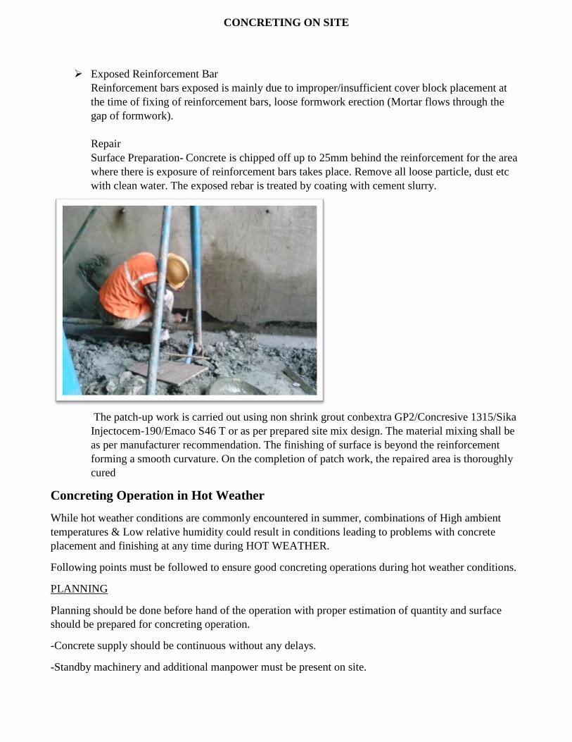
Exposed Reinforcement Bar Reinforcement bars exposed is mainly due to improper/insufficient cover block placement at the time of fixing of reinforcement bars, loose formwork erection (Mortar flows through the gap of formwork). Repair Surface Preparation- Concrete is chipped off up to 25mm behind the reinforcement for the area where there is exposure of reinforcement bars takes place. Remove all loose particle, dust etc with clean water. The exposed rebar is treated by coating with cement slurry.
The patch-up work is carried out using non shrink grout conbextra GP2/Concresive 1315/Sika Injectocem-190/Emaco S46 T or as per prepared site mix design. The material mixing shall be as per manufacturer recommendation. The finishing of surface is beyond the reinforcement forming a smooth curvature. On the completion of patch work, the repaired area is thoroughly cured
Concreting Operation in Hot Weather
While hot weather conditions are commonly encountered in summer, combinations of High ambient temperatures & Low relative humidity could result in conditions leading to problems with concrete placement and finishing at any time during HOT WEATHER.
Following points must be followed to ensure good concreting operations during hot weather conditions.
PLANNING
Planning should be done before hand of the operation with proper estimation of quantity and surface should be prepared for concreting operation.
-Concrete supply should be continuous without any delays.
-Standby machinery and additional manpower must be present on site.

CONCRETING ON SITE
-Slump of value of each batch of concrete should be checked before placing.
Concrete production also plays an important role in case of hot weather concreting and following points
should always be kept under consideration.
-Shade should be used over the stockpile of aggregates
-Paint the mixer and storage bins white to minimize absorption of heat from the sun.
-Use ice as part of the mix water or cool the concrete with liquid nitrogen
DELIVERY AND DISCHARGE
-Transportation time should be minimized and transportation should be preferred during the time period when the intensity of traffic is less.
-Avoid prolonged mixing. Transit mixer trucks should be discharged as soon as possible after the water has been added to the mix.
-Consider batching and mixing the materials using a job-site plant.
CONCRETE POUR CARD (A DOCUMENT USED FOR KEEPING A CHECK
ON QUANTITY AND PROPERTIES OF CONCRETE COMING ON SITE)

CONCRETING ON SITE
-Water should not be added to concrete at the job site unless it is part of the amount required initially for the specified maximum water-cement ratio and the specified slump.
PLACING AND FINISHING
-Schedule placement for the cool time of the day
-Equipment and workers ready to receive and handle concrete, especially the first delivery.
-Use sunshades and/or windbreaks.
-Keep all equipment that are in contact with the concrete cool ( pump lines, tremies, reinforcement and vehicles ).
-Use low temperature water or ice to reduce the temperature in TM(Transit Mixer).
-Use a thermometer to monitor the temperature.
-Shorten finishing time.
EVAPORATION CONTROL
-Be alert in eliminating the damaging practice of ‘wet wiping’ or spraying water onto the dry patches
during trowelling of the concrete Significantly reduces surface crusting.
-A dry surface layer may appear to indicate that the concrete has set, but can lead to a ‘spongy concrete’
effect, as the concrete below is still plastic. This may result in flaking and an uneven surface finish.
CURING AND PROTECTION
CONCRETE REQUEST SLIP (A DOCUMENT USED FOR PLACING A
REQUEST FOR CONCRETE TO A BATCHING PLANT)

CONCRETING ON SITE
-Curing should start immediately after the CONCTERE has been finished.
-Curing methods include PONDING WITH WATER, use of WET HESSIAN or COTTON MATS, continuous spray mist, covering with PLASTIC SHEETING or sprayed on CURING COMPOUNDS.

DESIGN SPECIFICATIONS FOR STRUCTURE
1
Design life of the structure
The design life of a structure is that period for which it is designed to fulfil its intended
function when inspected and maintained in accordance with agreed procedures. The
assumption of a design life for a structure or component does not necessarily mean that the
structure will no longer be fit for its purpose at the end of that period. Neither will it
necessarily continue to be serviceable for that length of time without adequate and regular
inspection nor shall routine maintenance. All Design Life criteria be confirmed.
Underground civil structures -120 yrs.
Above ground building structures -50 yrs.
Asphaltic pavements -15 yrs.
Concrete pavement -25 yrs.
Tunnel Walkways -20 yrs.
Steel Paintwork Systems -05 yrs.
Nonstructural components -30 yrs.
Waterproofing membrane -10 yrs.
Steps to be taken to ensure a design life of 12yrs for the structure are-
Use of Micro Silica conforming to Is15388:2003(or other suitable admixtures)
Water permeability should not exceed 10mm
Rcpt (RAPID CHLORIDE PERMEABILITY TEST)-Value should be less than
1000coulombs
Minimum Cement content for underwater structure per M3 should not be less than
400kg.
Contractor should further submit a report in context to design, construction &material
so as to achieve 120 years of design life.

DESIGN SPECIFICATIONS FOR STRUCTURE
2
RCPT TESTING
Corrosion of reinforcing steel due to chloride ingress is one of the most common
environmental attacks that lead to the deterioration of concrete structures. Corrosion related
damage to concrete structures is a major problem. This durability problem has received
widespread attention in recent years because of its frequent occurrence and the associated
high cost of repairs. Based on the charge that passes through the sample, a qualitative rating
is made of the concrete’s permeability.
Design Loads and Calculations
Railway Load
The railway loadings considered are as per “Modern Rolling Stock” type with following axle
configuration. However loading due to rolling stock can be modified after the proposed
rolling stock has been finalized.
For the purpose of computing stresses and deformations the following loads and
consequential effects shall be taken into account.
• Dead loads DL
• Live loads LL
• Dynamic effects Dl
• Forces due to curvature or eccentricity of track CF
• Temperature effects T
• Longitudinal forces LF
• Racking forces RE

DESIGN SPECIFICATIONS FOR STRUCTURE
3
• Forces on parapets
• Wind pressure effect WL
• Earth Pressure EP
• Water Pressure WP
• Forces and effect due to earthquake EQ
• Erection forces and effects DEL
• Buoyancy B
• Differential settlement DS
Modern Rolling Stock Loading
2A= 2250 + 2B= 2500 + C=12600 = 22100mm
Design load shall include the effect of
Static Loading These shall consist of loads due to:
Track: Load due to 60 Kg (UIC) rails and guard rail and fittings
Track bed: RCC blocks or concrete pour or precast slabs in RCC with inserts and
finings. In case of ballast less track (450 to 600 mm thick) or PSC sleepers over
250/300 mm thick for ballasted track.
Fatigue Loading
Those structures subjected to repeated fluctuations of stress. These fluctuations
may cause fatigue failure of members or connections at lower stresses than those
at which they would fail under static load. Such failures are primarily due to stress

DESIGN SPECIFICATIONS FOR STRUCTURE
4
concentrations introduced by the constructional details. To overcome such
problems the concept fatigue loading is employed.
The nominal loading for the design of members in accordance with BS 5400: Part
10 shall comprise trains with six individual cars each having four axles.
Dynamic Loading
When live loads are applied rapidly to a structure, they cause larger stresses than
those that would be produced if the same loads would have been applied gradually.
This dynamic effect of the load is referred to as impact. Live loads expected to cause
such a dynamic effect on structures are increased by impact factors.
Coefficient of Dynamic impact (CDA): Impact factor for longitudinal analysis shall
be 1.2 while for transverse analysis the same shall be 1.67. Dynamic loading shall not
be applied to piles, pile caps. Centrifugal loads or braking/traction loads.
Longitudinal Loading
It acts due to braking of large trucks or trains on bridges, ships entering a harbor or
cranes on a rail.
Longitudinal loads from braking and traction shall be 18% and 20% of live load per
track. When a structure carries two tracks, both tracks shall be considered to be
occupied simultaneously. Traction forces shall act on one track and braking forces
acting on the other, with both acting in the same direction simultaneously to produce
the worst loading condition
Centrifugal load
Train Derailment Load: For tracks on a curve, centrifugal force (CF) shall be considered as a
horizontal load applied toward the outside of the curve above top of rail. The centrifugal
force (CF) is a function of the train live load, impact (I), and horizontal radius of curvature:
As per latest Design Code ACI 358.1R-92, for derailment check, derailment load corresponds
to the application of 50% of one coach weight, applied horizontally as a 5m long uniform
Impact load.
Wind loading

DESIGN SPECIFICATIONS FOR STRUCTURE
5
WL will be applied to above ground structures. Calculation of Wind Load is based on IS-875
(Pad 3) - 1987.
The minimum design wind pressure to be used is: pz = 609 kN/m2
Temperature Loading – (Not Used).
Seismic Loading
Seismic effects shall be considered on all structures. Other details for seismic design shall
conform with IS 1893 and other guidelines obtained after soil testing and study.
DELHI is located in ZONE 4(HIGH RISK ZONE) according to Seismic studies.
IMPORTANCE
FACTOR (I):It is a
factor used to obtain the
design seismic force
depending on the
functional use of the
structure, characterized
by hazardous
consequences of its
failure, its post-
earthquake functional
need, historic value, or
economic importance.
STRUCTURAL RESPONSE FACTOR (Sa/g): It is a factor denoting the acceleration
response spectrum of the structure subjected to earthquake ground vibrations, and depends on
natural period of vibration and damping of the structure.

DESIGN SPECIFICATIONS FOR STRUCTURE
6
ZONE FACTOR Z: It is a factor to obtain the design spectrum depending on the perceived
maximum seismic risk characterized by Maximum Considered Earthquake (MCE) in the
zone in which the structure is located. The basic zone factors included in this standard are
reasonable estimate of effective peak ground acceleration.
Response Reduction Factor (R): It is the factor by which the actual base shear force that
would be generated if the structure were to remain elastic during its response to the Design
Basis Earthquake (DBE) shaking, shall be reduced to obtain the design lateral force. Taken as
4.
For all buried structures an incremental dynamic load should be applied. For the
purposes of implementing this method a design seismic coefficient of (Ah) 0.1125 shall be
adopted at ground Level linearly reducing to 0.056 at 30 m depth as permitted by.
These coefficients already include the Importance Factor of 1.5 required.
NOTE-Based on the performance record, it is undoubtedly fair to say that underground
structures are less vulnerable to earthquakes than surface structures
Temporary elements such as scaffolding, temporary excavations need not be designed for
earthquake forces.
EARTHQUAKE DEFINATIONS:
OPERATIONAL DESIGN EARTHQUAKE (ODE): The earthquake for which a structure is
designed to remain operational, with the damage being readily repairable following the event.
The ODE/OLE is likely to occur during the design life of the structure. Based on probabilistic
methods, and is generally the 50%/50 year earthquake motion.
Controlling Earthquake or Maximum Design Earthquake (MDE): The earthquake that is
expected to produce the strongest level of shaking at a site. Often used interchangeably with
MCE (above), but is based on ground motions, not earthquake size. The MDE can be based
on deterministic or probabilistic methods. For critical structures, the MDE may equal the
MCE from a specific fault or seismic source.
Effect of earthquake on above ground and underground structures.

DESIGN SPECIFICATIONS FOR STRUCTURE
7
Above Ground Under Ground
Above ground structures need to transmit the seismic forces towards the foundation since soil is not available on sides.
Design becomes uneconomical when approach is centered towards designing structure for MDE
Surface structures are not only directly subjected to the excitations of the ground.
Comparatively lower redundancy to earthquakes.
For aboveground structures, the seismic loads are largely expressed in terms of inertial forces
Underground structures, such as underground stations, subjected to seismic actions don´t need to transfer inertia forces to the foundations, since those forces are directly transferred to the surrounding soil.
Feasible though not recommended to design for MDE
Directly subjected to shaking of ground due to transfer from surrounding soil strata.
Shows greater redundancy towards earthquake
The design and analysis for underground structures should be based, however, on an approach that focuses on the displacement/deformation aspects of the ground and the structures
Operating Design Earthquake (ODE). For the ODE, the seismic design loading combination depends on the performance requirements of the structural members. Generally speaking, if the members are to experience little to no damage during the lower level event (ODE), the inelastic deformations in the structure members should be kept low.

GENERAL INSTRUMENTS USED ON CONSTRUCTION SITE
1
INSTRUMENTS USED ON SITE
Tiltmeter
A Tiltmeter is an instrument designed to measure very small changes from the vertical level, either on the ground or in structures
A similar term, in less common usage, is the inclinometer. A sensitive instrument can detect changes of as little as one arc second. It consists of
tilt plates, a portable tilt meter & a readout unit
USED AT SITE- Used on Buildings around Vasant Vihar Station.
Frequency of taking the readings
The frequency of taking the readings of instruments is twice a day.

GENERAL INSTRUMENTS USED ON CONSTRUCTION SITE
2
Building settlement, ground settlement & optical survey readings are taken by surveyors.
Inclinometer, Tiltmeter, Tape Extensometer, Crack meter, Load Cell & Piezometer readings are taken by Instrument-Rite Engineers.
CRACKMETER
It is used to monitor cracks in buildings affected due to construction or excavation activities.
It is installed by drilling 5mm diameter & 50mm deep holes.
USED AT SITE -VASANT VIHAR
ROOF SLAB

GENERAL INSTRUMENTS USED ON CONSTRUCTION SITE
3
Tape Extensometer It is used to measure small changes in distance between two reference points
in any orientation
To give deformation of underground openings, excavations, tunnels,
movement of unstable slopes etc.
The tape extensometer forms an
important part in investigations during tunnelling,
especially the New Austrian Tunnelling Method
(NATM) for effectiveness of the roof of a
underground cavity and monitor its behavior during
the excavation operation.
HOW IT WORKS??
o To obtain distance reading
between pair of reference anchor bolts grouted into
any structure, the operator is required to stretch the
tape between two anchors, adjust its tension and note the tape and
digital readings. This is not the true distance between the two reference
points. This is only used as an initial reading. The variation from the
initial reading, gives the change in distance (convergence or
divergence) between two anchorage points with a measurement
sensitivity of ± 0.01 mm (± 0.0005”)
USED AT SITE-
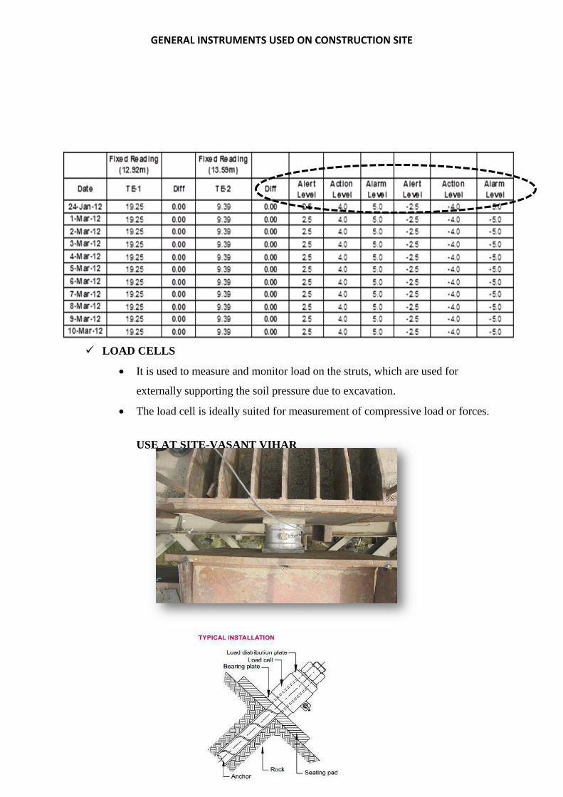
GENERAL INSTRUMENTS USED ON CONSTRUCTION SITE
4
LOAD CELLS
It is used to measure and monitor load on the struts, which are used for
externally supporting the soil pressure due to excavation.
The load cell is ideally suited for measurement of compressive load or forces.
USE AT SITE-VASANT VIHAR

GENERAL INSTRUMENTS USED ON CONSTRUCTION SITE
5
STAND PIPE PEIZOMETER It is used to measure depth of ground water level in standpipes, boreholes &
wells.
The stand pipe Piezometer consists of a pipe that is sealed along its entire
length and installed in a borehole such that it must be open to water flow at
bottom and open to atmosphere at the top.
Ideal for simple ground water monitoring.
HOW IT WORKS?
The stand pipe is set in a bore hole, which is drilled into the soil/foundation to
a pre-determined depth to intercept ground water. The perforated pipe is
connected by a socket to same diameter plastic stand pipe extending to the
surface. The borehole is filled with pea gravel. The top of borehole is
Sealed with cement bentonite plug the Ground water seeps into the stand pipe
Ground water level through the slotted end and attains a level equal to ground
water. This level is determined by an electrical sounding device.

GENERAL INSTRUMENTS USED ON CONSTRUCTION SITE
6
GROUND SETTLEMENT POINT It is used to monitor vertical settlement on the ground surface. It is installed by making a pit of 1000mm deep & 500mm square at the top & filled with soil & concrete. The steel bar is kept at the centre of GI pipe.
READINGS

Water Proofing Of Roof Surface
1
WATERPROOFING OF STRUCTURE
In the case of underground concrete structures which are usually surrounded by moisture the
need to keep the water out is critical. Therefore, waterproofing shall be done on roof slab to
ensure water tightness of the structure.
What is water proofing?
Waterproofing is the creation of a relatively impervious membrane, coating, or sealer used in
concealed locations to prevent water from entering or passing through either horizontal or
vertical building materials.
Chemicals used:
FOR PRIMING
Master Emaco 2525 is a solvent free, high-performance, versatile epoxy binder that can be
used to produce a range of epoxy resin based mortars. Master Emaco 2525 can be applied to
both dry and damp surfaces and adheres to most substrates after proper preparation.
Recommended use:
Structural bonding of new to old concrete
Production of epoxy resin mortars for floor toppings
Production of epoxy resin mortars to grout bolt holes
Steel bonding
Rapid structural repair of concrete
Grouting dowels
Priming of concrete floors prior to applying Master top Flooring Systems and
MasterSeal.
Membrane Systems to achieve structural bond

Water Proofing Of Roof Surface
2
Advantages:
Adheres to wet or damp surfaces – Wide application area
solvent free - Low VOC and non-shrink
Pre-proportioned packaging - No job site errors
Multi-purpose binder - Many uses
Low viscosity - Easy to apply as primer
High abrasion and chemical resistance
Can be used as wearing surface Approved to AS/NZS 4020:2002 – Suitable for contact
with Potable Water.
Cures hard at low temperatures – Wide application rang
0Properties of the chemical:
FOR WATER PROOFING
Master Seal M800
Description- A highly elastic, solvent free, ultra-fast curing, spray applied polyurethane
coating and it is used in waterproofing applications. MasterSeal M800 is a solvent free,
two component.
It is highly reactive and can only be applied by special two component spray equipment
Master Seal M800 is used in a variety of waterproofing applications including roofing,
balconies, podium and car park decks, cut and cover tunneling and basement
waterproofing.

Water Proofing Of Roof Surface
3
FEATURES AND BENEFITS
• Easy application to complicated details
• Fast installation
• Can be applied to a wide range of substrates with the appropriate primer
• Monolithic – no welds or seams
• No welding, no torches, no hot works
• High water vapor permeability – low risk of blistering
• Excellent mechanical properties
• Excellent crack bridging properties
• Root resistant
• Resistant to standing water
• Application to vertical surfaces without runs
SUBSTRATE CONDITION
The primer, or base layer to which Master Seal M800 is to be applied must be clean and dry and
free from oil, grease and loose material and any other contamination which might impair
adhesion.
STEP WISE PROCEDURE OF WATER-PROOFING.
SURFACE CONDITIONS
The RCC surface shall be dry before waterproofing.
Any ingress for water seepage shall be identified and treated.
Construction Joint shall be filled with high performance water stop grout of crystalline
growth.

Water Proofing Of Roof Surface
4
The gap between D-wall and slab shall be filled with micro concrete(As shown in
figure)
The concrete shall be fully cured before The surface
shall be cleaned with wire brush to remove all algae, fungus
and voids, pinholes, cracks shall be treated to level and
smoothen the surface are starting of waterproofing works.
MIXING:
Proportion part kits accurately mixing only what can be used in less than 30 minutes.
Thoroughly stir Part A, add Part B (3:1 parts by volume respectively) and blend thoroughly using
a slow speed mixer fitted with a suitable paddle.
MIXING OF COMPONENT A & B

Water Proofing Of Roof Surface
5
Primer Application
Thin coat of mixed primer (RESIN + HARDNER) on the surface shall be mechanically
& uniformly applied, ensuring continuous film soon after surface preparation is
complete.
Moisture content in the substrate shall be less than 5 %.
The drying period of primer depends on the ambient temperature and relative
humidity.
MOISTURE METER BASF AGGREGATES
BASF AGGREGATES are sprinkled over
the primer layer immediately after
application of the primer. Aggregates
help in roughening the surface of
primer for proper bonding between
the primer layer and the
waterproofing membrane layer.
APPLICATION OF PRIMER LAYER
Master seal M800 Being heated to a
temperature of 60 deg Celsius before being
applied using gun.

Water Proofing Of Roof Surface
6
APPLICATION OF WATER PROFFING MEMBRANE
Water proofing membrane shall be applied in double layers such that dry film thickness
of the membrane is minimum of 2.5 mm. The entire 2.5 mm layer shall be single
monolithic layer built in two applications.
MasterSeal M800 can only be applied by means of a suitable two component spray
machine. The choice of machine depends on the type and size of work and the ease of
access.
MasterSeal M800 is available with the Part A coloured white
and the Part B coloured black. This results in a uniform grey colour
of the sprayed material thus giving the sprayer a visual control of
the quality of the mixing, and machine faults become immediately
obvious. If the membrane colour changes, stop spraying and check
machine settings etc
MasterSeal M800 is normally applied at 1.5–2.0kg/SQM this
corresponds to a thickness of 1.5–2.0mm.
APPLICTION OF WATER PROOFING MEMBRANE ON PRIMER LAYER
SPECIAL TWO COMPONENT SPRAY GUN
FOR WATER PROOFING

Water Proofing Of Roof Surface
7
PACKAGING
MasterSeal M800 is supplied in drums.
Component A 210 kg
Component B 220 kg
Mixing ratio
By weight 100:73
By volume 100:70
Requirements on site
Dry Film Thickness – 2.5 mm
Tensile Strength- 4.0 Mpa min
Membrane Elongation at break- 130 % min
Peel Adhesion to concrete – 2 Mpa min
Static crack bridging – 2 mm min
Termination
The setting time for the arrangement is 2-3 seconds
and the surface becomes tack free in 45 Seconds.
Testing
The metallic thickness should not be less than 2.3mm
as shown above it should be checked per 10sqm
Holiday Testing
PONDING(DONE AT SITE)
2.6MM
THCIKNESS OF MEMBRANE

Water Proofing Of Roof Surface
8
Ponding of water shall be done over the roof slab for minimum 72 hours to access
leakage if any from the membrane.
Protective arrangement for waterproofing membrane
The membrane shall be protected with 25 mm thick extruded polystyrene boards, which
shall be spot bonded to the membrane.
A 6-mill polyethylene separating membrane shall then be laid before covering with
protective slab of lean mix of min 75 mm thickness.
Where the roof slab has been cast against a diaphragm or other face, the protective slab
shall be provided with an up stand at the perimeter to provide a min 75 mm concrete
protection.
75mm PCC COVER
6-mill polyethylene
separating membrane
Waterproofing Membrane
25 mm thick extruded
polystyrene boards

STUDY ON PREFABRICATED CONCRETE SEGMENTS & CASTING YARD (MUNDKA)
LOCATION- MUNDKA, New Delhi
Products
Segments for Rings (Tunnel)
OTE(over track extract duct)
List of major equipment’s at site
MATERIAL USED-
CONCRETE-Concrete of grade M50&M40 in accordance with code IS456:2000 shall be used.
S.No Equipment Nos Capacity
1 Batching Plant 1 30cum/hr
2 Transit Mixer 2 6cum
3 Steam Boiler 1 600kg/hr
4 Casting Yard 1
6 Rebar cutting 2 -
7 Gantry crane 2 5T
8 Vacuum lifter 1 -
9 EOT crane 4 10T
10 Office 1 -
11 Reinforcement yard 1
12 QA/QC LAB 1
13 Storage Yard -
1
13
11 10
4
12

STUDY ON PREFABRICATED CONCRETE SEGMENTS & CASTING YARD (MUNDKA)
REINFORCEMENT-Reinforcement of grade Fe500 shall be used
WATER –Clean water shall be used in preparing concrete. Water shall be free from solid suspended matter and organic matter and should comply with IS456
EMBEDMENT-All embedments should be prepared as per the drawings
CONSTRUCTION PROCEDURE
Rebar Cage Fabrication&Cage placement
All reinforcemnt bending,sutting and fixing activities shall take place within the reinforcement yard
and should be done according to the provided BBS.
The rebars shall then be placed in the jogs as per the spacing and then tack welding should be used at
intersections.
2.55mm welding bars conforming to IS6013 shall be used from the approved list of vendors.
Accepted reinforcement cages shall be tagged with BLUE TAG
Rejected reinforcement cages shall be tagged with RED Tag
Cage shall be placed in to the mould using the gantry crane and spacers should be provided as per the
drawings.
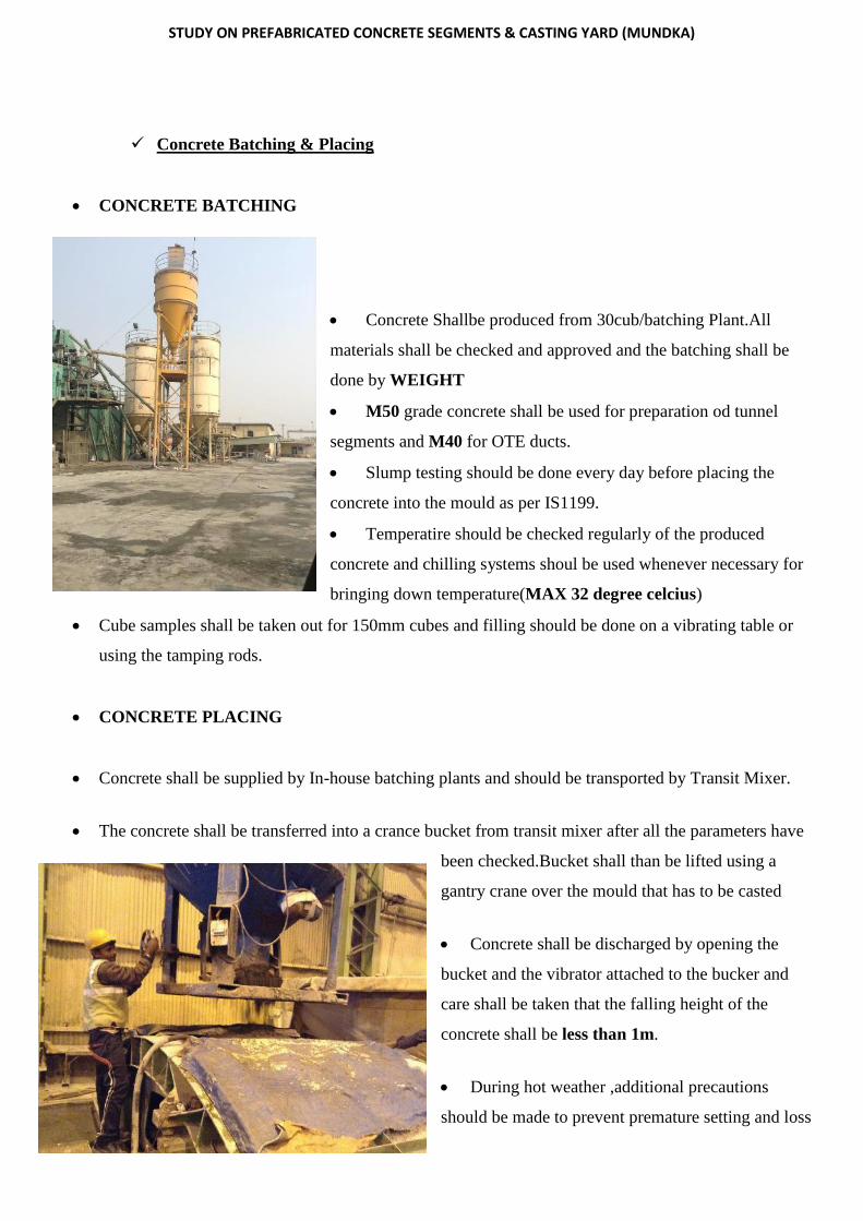
STUDY ON PREFABRICATED CONCRETE SEGMENTS & CASTING YARD (MUNDKA)
Concrete Batching & Placing
CONCRETE BATCHING
Concrete Shallbe produced from 30cub/batching Plant.All
materials shall be checked and approved and the batching shall be
done by WEIGHT
M50 grade concrete shall be used for preparation od tunnel
segments and M40 for OTE ducts.
Slump testing should be done every day before placing the
concrete into the mould as per IS1199.
Temperatire should be checked regularly of the produced
concrete and chilling systems shoul be used whenever necessary for
bringing down temperature(MAX 32 degree celcius)
Cube samples shall be taken out for 150mm cubes and filling should be done on a vibrating table or
using the tamping rods.
CONCRETE PLACING
Concrete shall be supplied by In-house batching plants and should be transported by Transit Mixer.
The concrete shall be transferred into a crance bucket from transit mixer after all the parameters have
been checked.Bucket shall than be lifted using a
gantry crane over the mould that has to be casted
Concrete shall be discharged by opening the
bucket and the vibrator attached to the bucker and
care shall be taken that the falling height of the
concrete shall be less than 1m.
During hot weather ,additional precautions
should be made to prevent premature setting and loss
ON SITE BATCHING PLANT

STUDY ON PREFABRICATED CONCRETE SEGMENTS & CASTING YARD (MUNDKA)
of water during the placing and compaction of concrete in the formwork.
Compaction of Concrete
The mould used for placement are equpped with a total of 5 motor operated vibrators
below the bottom (4 corners +1 Middle).These should be used during the time of
filling the concrete along witht the needle vibrators.
Surface Finishing
After the compaction of concrete ,The mould cover shall be opened.Top cover of the
segment shall be worked(PLANED) using a squoare plastic pipe whose width is
equal to the width of the segment.To get the accurate thickness.
EARLY FINISHING Within 30 Minutes of working with the Pipe trowel shall be
used on the surface to avoid the pinholes.
FINAL FINISHING After 2-3 hours of casting,top surface of segments shall be
finished by steel trowel to get very smooth surface.
BEFORE AFTER

STUDY ON PREFABRICATED CONCRETE SEGMENTS & CASTING YARD (MUNDKA)
Testing Of Concrete
Samples of concrete shall be taken regulary in starting for
7 DAYS-3
28 Days-3
12Hours-2
for every batch however the frequency can be reduced later.Sampls
shall be taken for for both M50 and M40 grade.
In case of failure the sement shall be tagged RED as Rejected.

STUDY ON PREFABRICATED CONCRETE SEGMENTS & CASTING YARD (MUNDKA)
Checking Of The Moulds
Checking of the mould shall be done using the
following precission tools
Micrometer Gauge-1500mm
Measuring Steel Tape- 30m
Set of shim for reading the gaps.
Angular templates and depth gauges
Application of Steel Mould
Side plates and end plates shall be kept in unfolded
position.
Aplly to coats of release agent(chemical) on the surface
of the mould REEBOL(Forsoc),Rheofinish249W on the surface of the mould .
Place the Prefabricated rebar Cage in the mould and then the side plates of both the sides shall be pushed
towards the base and then fasten them together using lock bolts.
Adjust the radial and longitudnal core rod.Care should be taken while installing the weight lifting arm in
the centre.
Adjust the cover and then pour the concrete.
Concrete shall be placed from farend to centre using bucket and crane.
After initial setting of concrete top cover is removed and extrados in finishing using steel float.
Dimensional checking for mould shall be done once a month and if necessary be re-adjusted
Demoulding procedure
After concrete attains strength of 12Mpa in normal condition,removal
of segment shall be taken up.However for attaining early strength of
concrete steam curing shall be done.
Dismantle the core rod of the side plate.
Dismatle the core rod of the end plate.
Lossen the lock bolt of the end plate and open the end plate by
switching device.
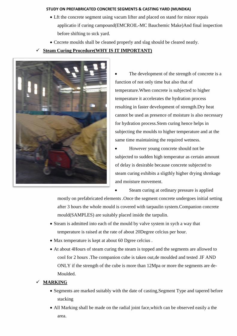
STUDY ON PREFABRICATED CONCRETE SEGMENTS & CASTING YARD (MUNDKA)
Lft the concrete segment using vacum lifter and placed on stand for minor repais
applicatio if curing campound(EMCROIL-MC Bauchemic Make)And final inspection
before shifting to stck yard.
Cncrete moulds shall be cleaned properly and slag should be cleared neatly.
Steam Curing Procedure(WHY IS IT IMPORTANT)
The development of the strength of concrete is a
function of not only time but also that of
temperature.When concrete is subjected to higher
temperature it accelerates the hydration process
resulting in faster development of strength.Dry heat
cannot be used as presence of moisture is also necessary
for hydration process.Stem curing hence helps in
subjecting the moulds to higher temperature and at the
same time maintaining the required wetness.
However young concrete should not be
subjected to sudden high temperatur as certain amount
of delay is desirable because concrete subjected to
steam curing exhibits a sligthly higher drying shrnkage
and moisture movement.
Steam curing at ordinary pressure is applied
mostly on prefabricated elements .Once the segment concrete undergoes initial setting
after 3 hours the whole mould is covered with tarpaulin system.Companion concrete
mould(SAMPLES) are suitably placed inside the tarpulin.
Steam is admitted into each of the mould by valve system in sych a way that
temperature is raised at the rate of about 20Degree celcius per hour.
Max temperature is kept at about 60 Dgree celcius .
At about 4Hours of steam curing the steam is topped and the segments are allowed to
cool for 2 hours .The companion cube is taken out,de moulded and tested .IF AND
ONLY if the strength of the cube is more than 12Mpa or more the segments are de-
Moulded.
MARKING
Segments are marked suitably with the date of casting,Segment Type and tapered before
stacking
All Marking shall be made on the radial joint face,which can be observed easily a the
area.
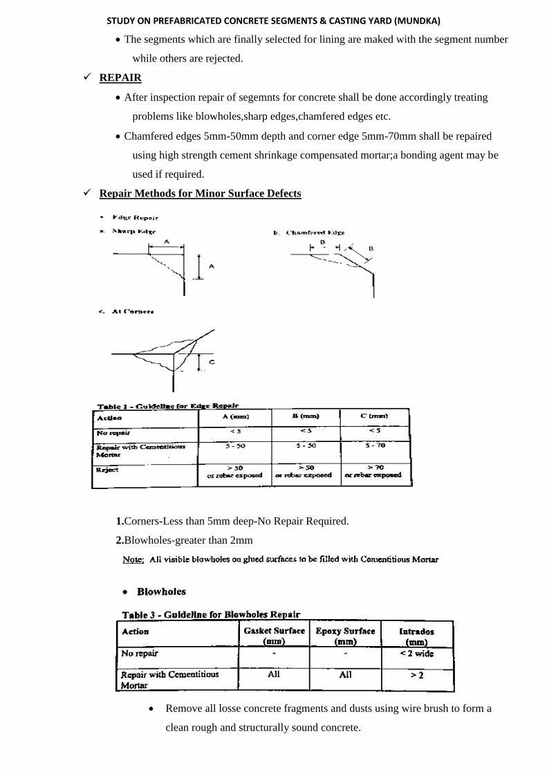
STUDY ON PREFABRICATED CONCRETE SEGMENTS & CASTING YARD (MUNDKA)
The segments which are finally selected for lining are maked with the segment number
while others are rejected.
REPAIR
After inspection repair of segemnts for concrete shall be done accordingly treating
problems like blowholes,sharp edges,chamfered edges etc.
Chamfered edges 5mm-50mm depth and corner edge 5mm-70mm shall be repaired
using high strength cement shrinkage compensated mortar;a bonding agent may be
used if required.
Repair Methods for Minor Surface Defects
1.Corners-Less than 5mm deep-No Repair Required.
2.Blowholes-greater than 2mm
Remove all losse concrete fragments and dusts using wire brush to form a
clean rough and structurally sound concrete.

STUDY ON PREFABRICATED CONCRETE SEGMENTS & CASTING YARD (MUNDKA)
Pre wet the substarte thoroughly to saturate the pores completely with water
Use sandpaper to smoothen the surface after the repair material has hardened.
3.Corner-5mm to 70mm Deep
Cut back damage periphery edge of spalled segment to a depth of not less than
10mm using disk cutter to form squqre edges on plan.in section,the edge
should be inclined away from the spalled are provide tail key at the repair join
edge.Remove all losse material fragments and apply repair in two layers.
Ring Recesses rapair is as shown in figure
Storage & Handling
After demolding using a vacum lifter the segment should be placed on a prepared surface for repair.
After repairing the segments shal be turned 180 degree with intrados facing upwards by turning device,transported to storage are and stored in a stack,one ring high by gantry crane with sling belt.
Delivery and Transportation
Upon unloading from site the segments shall be checked carefully and if they are damaged during the transportation responsible people shall be notified on site to do repair.
The Transportation is Adviced at NIGHT or at a suitable time when roads are on free run o accommodate the large vehicle.
Each lorry shall tranport 2 rings at a time. As shown in fig

STUDY ON PREFABRICATED CONCRETE SEGMENTS & CASTING YARD (MUNDKA)
Construction Tolerance Limits. Circumferential Length +3mm-0mm Thickness +5mm-0mm Width +1mm-1mm Internal Diameter of completed ring
+8mm-0mm
Bolt Hole size Position +1mm-0mm
Sketch of steel mould
Application of mould
Open the side plate and end plate of a steel mould to check whether its inner
surface and mating surface are free of rubbish slag. Note: before opening the
steel mould, first loosen the, lock bolts of the side plate and the end plate:
manually open the side plate to the end plate with the switching device km
the end plate
Apply several Coatings of the release agents.
Adjust The reinforcement cage
First of all, Pull the end plates of both sides and the base together by using
the switching device and then fasten them with lock bolts.
Afterwards push the side plates of both sides to the base and then fasten
them together with lock bolts
1 COVER
2 LOCK BOLT
4 POSITIONING PIN
5 GUIDING RAIL(SIDE PLATE)
6 SIDE PLATE
7 FIXED CLAMP INSERT
8 INSERT FOR FITTING
9 LONGITUDNAL MOULD CORE
10 LONGITUDNAL CORE ROD
11 RADIAL MOULD CORE
12 RADIAL CORE ROD
13 END PLATE
14 SWITCHING DEVICE END PLATE
15 LOCKING DEVICE CORE ROD

STUDY ON PREFABRICATED CONCRETE SEGMENTS & CASTING YARD (MUNDKA)
The lock bolts shall be fastened from the centre of the steel mould to both
sides symmetrically and smoothly.
Adjust the longitudinal core rod.
Adjust the radial core rod
Install the insert for lifting of the weight lifting arm
Adjust the cover
Pour the concrete into the mould.

108
TUNNELING
Tunnels are feasible alternatives to cross a water body or traverse through physical barriers such as
mountains, existing roadways, railroads, or facilities; or to satisfy environmental or ecological
requirements. The tunneling in CC-27 project is taken care by SUCG Infrastructure Pvt. Ltd. There are
different techniques of tunneling viz. drilling and blasting, NATM, hydraulic splitter, slurry shield
machine, etc. All the tunnels in project CC-27 are to be made using TBM. A Tunnel Boring Machine
(TBM), also known as a "mole", is a machine used to excavate tunnels with a circular cross section
through a variety of soil and rock strata. TBMs and associated back-up systems are used to highly
automate the entire tunneling process, reducing tunnelling costs. In certain predominantly urban
applications, tunnel boring is viewed as quick and cost effective alternative to laying surface rails and
roads. Expensive compulsory purchase of buildings and land, with potentially lengthy planning
inquiries, is eliminated.
USE OF TUNNELS BY DMRC
Tunnels & Underground stations were provided due to environmental & space constrains further tunnels
allow for estate developments over them. Underground structures have an added advantage of a longer
structure life as compared to those on ground.
TYPES OF TBM
SINGLE SHIELD TBM:
A single shield machine uses pre-fitted segments to exert the blast force on the working face. Digging
time represents approximately 80% of operating time, the remaining 20% corresponding to segment
fitting.
1) Cutter head
2) Shield 3) Belt conveyor 4)
Excavated material removal
trolley

109
DOUBLE SHIELD TBM (USED AT VASANT VIHAR)
Machines allow for faster tunnel excavation as the segments are fitted in concurrent operation time
during blasting (digging). In this case, digging time approaches 100% of operating time. The rear shield
is fitted with grippers.
Machine progress is a 3-step process:
Gripping of the rear shield onto the excavated surfaces,
Digging by the cutter head (front shield advance), and laying of the lining,
Rear shield advance (hence gripper advance) to the next digging position and
1. 1)Cutter head
2. 2)Shields
3. 2a - Front shield
4. 2b - Double shield
5. 2c - Rear shield and gripper
6. 3)Belt conveyor
7. 4)Excavated material removal
trolley
The TBMs operating in Project CC-27 are: DOUBLE SHIELD TBM HK (Herrenknecht) was used on site for tunnel towards Shankar Vihar

110
1. THI 1 TBM
2. THI 2 TBM
3. Okumura TBM
4. Herrenknecht TBM
5. Mitsubishi TBM
Selection of TBM depends on many factors of which the most important factor is the ground profile. These TBMs can also be broadly classified into Soil TBM, Mixed TBM and Rock TBM. A TBM typically consists of one or two shields (large metal cylinders) and trailing support mechanisms. At the front end of the shield is a rotating cutting wheel. Behind the cutting wheel is a chamber where, depending on the type of the TBM, the excavated soil is mixed with slurry. Systems for removal of the soil are also incorporated into the machine system. Behind the chamber there is a set of hydraulic jacks supported by the finished part of the tunnel which push the TBM forward.
The action here is much like an earthworm. The rear section of the TBM is braced against the tunnel
walls and used to push the TBM head forward. At maximum extension the
TUNNEL VASANT VIHAR TO SHANKAR VIHAR

111
The systems are mainly planted for the works such as dirt removal, slurry pipelines if applicable, control
rooms, and rails for transport of the precast segments. The cutting wheel cut the rock face into chips or
excavate soil (known as muck). Depending on the type of TBM, the muck will fall onto a conveyor belt
system and be carried out of the tunnel, or be mixed with slurry and pumped back to the tunnel entrance.
Depending on rock strata and tunnel requirements, the tunnel may be cased, lined, or left unlined. This
may be done by bringing in precast concrete sections that are jacked into place as the TBM moves
forward, by assembling concrete forms, or in some hard rock strata, leaving the tunnel unlined and
relying on the surrounding rock to handle and distribute the load.
TBM(TUNNEL BORING MACHINE) ASSEMBLY ORIGINAL ABOVE AND ANIMATED SHOWN BELOW

112
The segmental lining has been designed to withstand thegroundwater, soil pressure and permanent loads.
Design loads parameters include Earth Pressure, Groundwater pressure, Grouting Pressure, Jacking
forces, Short term & Long term handling force, Segment misalignment and Bolt & gasket forces. Initial
setups to be done before drive:
1. Ground Treatment
2. Installation of Cradle
3. TBM lifting & assembly
4. Installation of Reaction Frame
5. Installation of Temporary segments
6. Tunnel Eye breaking
Before starting the tunnelling activities, it is necessary to improve the soil characteristics at the head of
the launching shaft /retrieval
shaft and along the cross
passage. High Pressure Jet
grouting method to improve
the soil stabilization (350 to
400 bar pressure). Cradle is
fixed according to the tunnel
centre line before TBM
unloading. Reaction frames
are erected to guide to Initial
Push for TBM without any
Backup Gantry. Tunnel eye is
broken by hacking along the
Tunnel circumference
alignment.
COMPENSAION GROUTING