Embed Size (px)
Citation preview
Step by Step Guide
Hydro-Brake® Optimum within Causeway
Flow
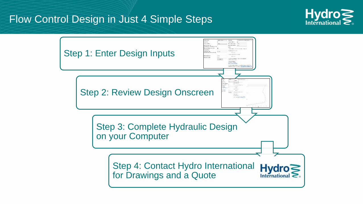
Step 1: Enter Design Inputs
Step 2: Review Design Onscreen
Step 3: Complete Hydraulic Design on your Computer
Step 4: Contact Hydro International for Drawings and a Quote
Flow Control Design in Just 4 Simple Steps
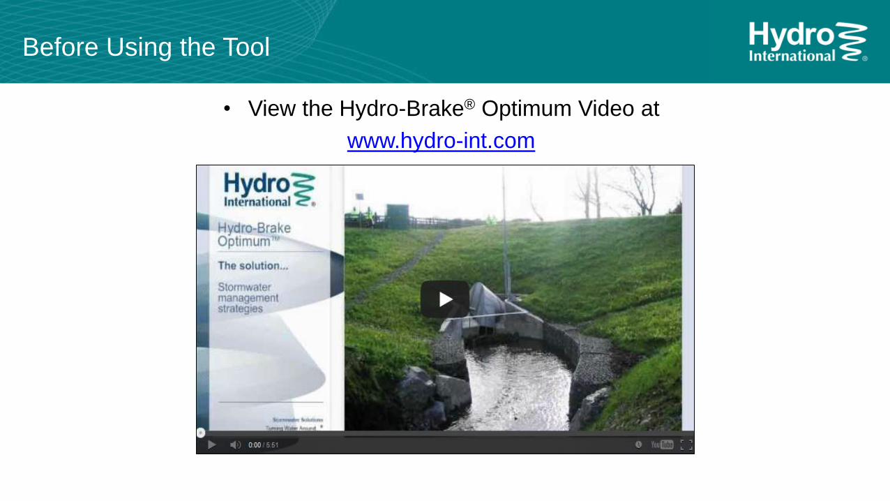
Before Using the Tool
• View the Hydro-Brake® Optimum Video at
www.hydro-int.com
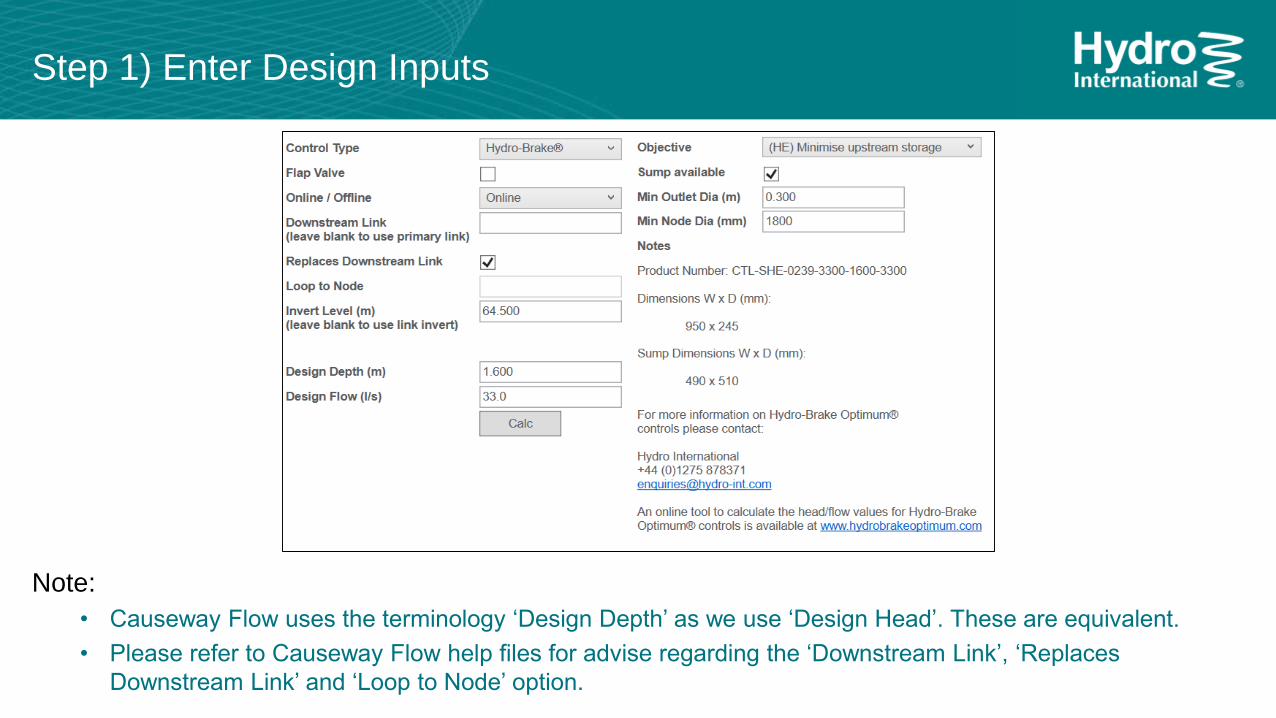
Step 1) Enter Design Inputs
Note:
• Causeway Flow uses the terminology ‘Design Depth’ as we use ‘Design Head’. These are equivalent.
• Please refer to Causeway Flow help files for advise regarding the ‘Downstream Link’, ‘Replaces
Downstream Link’ and ‘Loop to Node’ option.
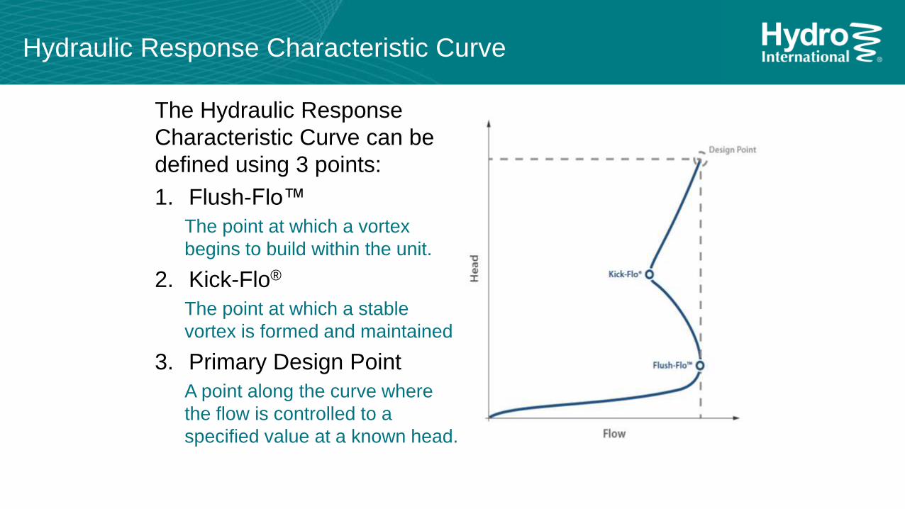
Hydraulic Response Characteristic Curve
The Hydraulic Response
Characteristic Curve can be
defined using 3 points:
1. Flush-Flo™
The point at which a vortex
begins to build within the unit.
2. Kick-Flo®
The point at which a stable
vortex is formed and maintained
3. Primary Design Point
A point along the curve where
the flow is controlled to a
specified value at a known head.
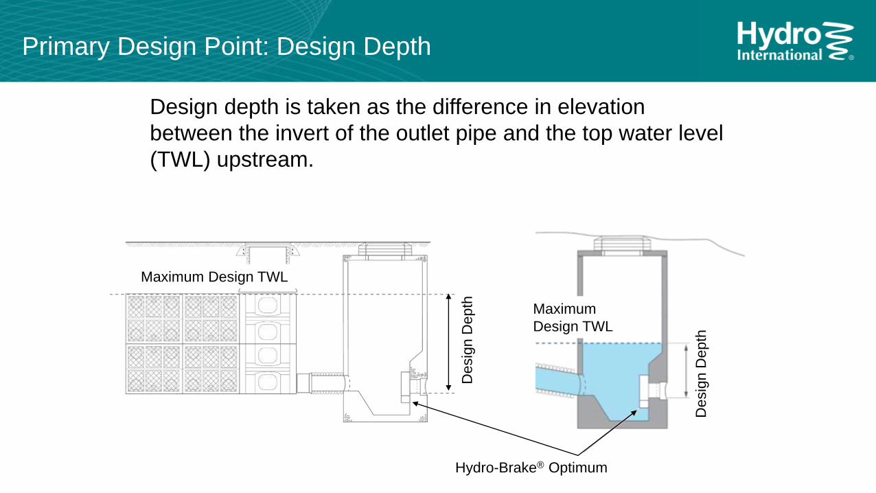
Design depth is taken as the difference in elevation
between the invert of the outlet pipe and the top water level
(TWL) upstream.
Desig
n D
epth
Primary Design Point: Design Depth
Hydro-Brake® Optimum
Maximum
Design TWL
Maximum Design TWL
Desig
n D
epth
Primary Design Point: Design Flow
The Design Flow should be set at the maximum permissible
discharge rate from the catchment or sub-catchment. This will
generally be specified by the authority responsible for the
downstream receiving waterbody or sewer.
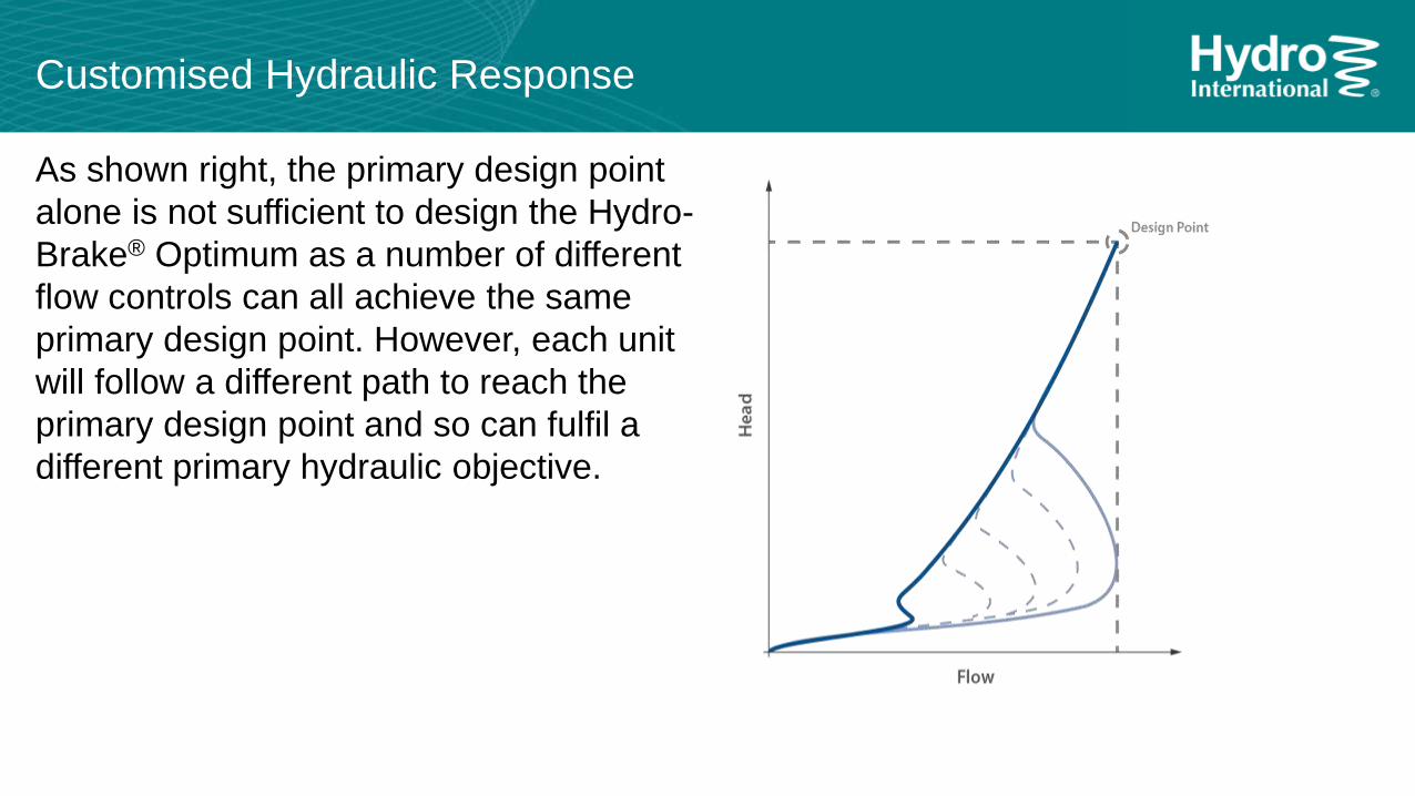
Customised Hydraulic Response
As shown right, the primary design point
alone is not sufficient to design the Hydro-
Brake® Optimum as a number of different
flow controls can all achieve the same
primary design point. However, each unit
will follow a different path to reach the
primary design point and so can fulfil a
different primary hydraulic objective.
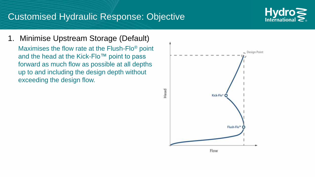
Customised Hydraulic Response: Objective
1. Minimise Upstream Storage (Default)
Maximises the flow rate at the Flush-Flo® point
and the head at the Kick-Flo™ point to pass
forward as much flow as possible at all depths
up to and including the design depth without
exceeding the design flow.
Customised Hydraulic Response: Objective
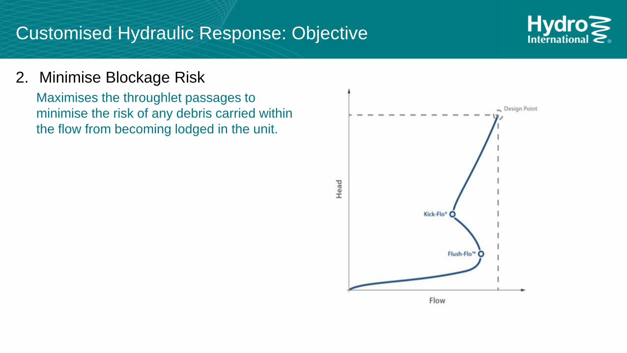
2. Minimise Blockage Risk
Maximises the throughlet passages to
minimise the risk of any debris carried within
the flow from becoming lodged in the unit.
Customised Hydraulic Response: Objective
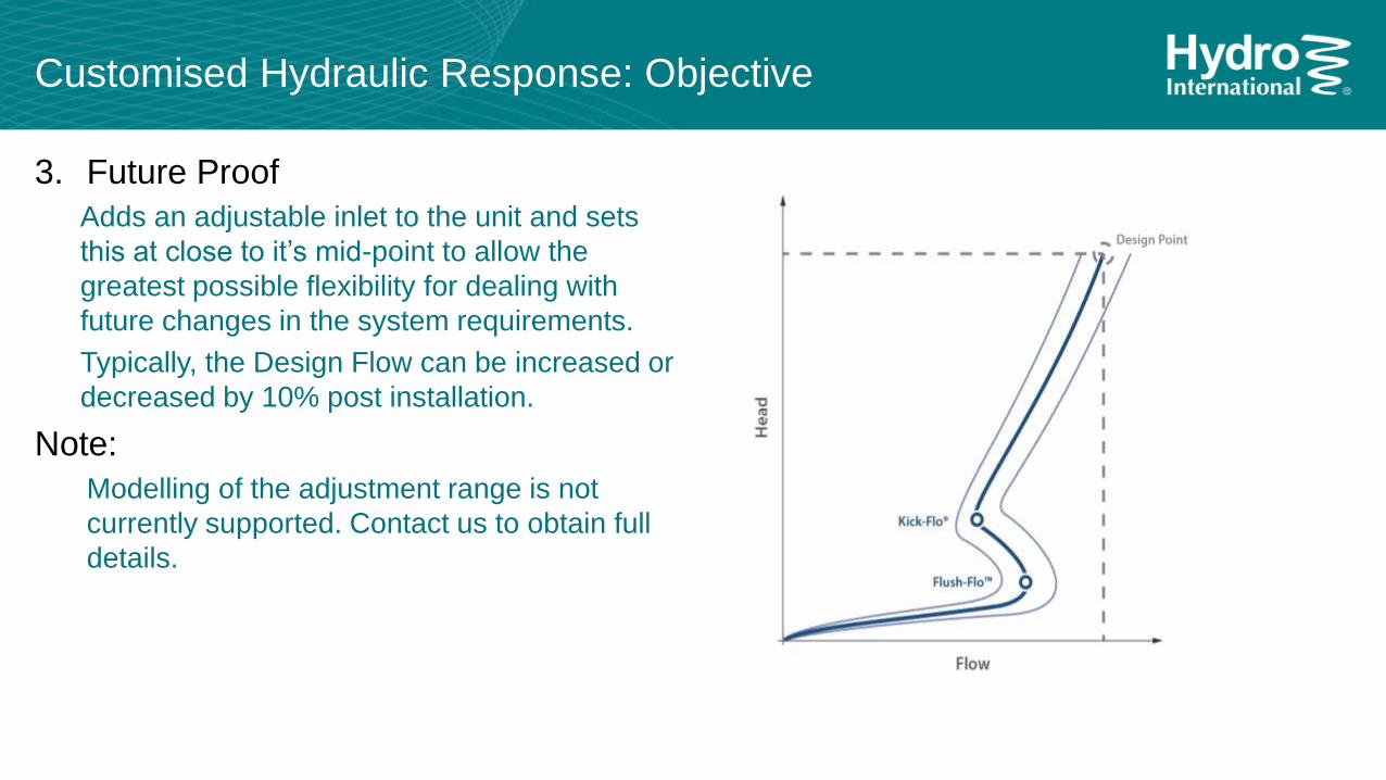
3. Future Proof
Adds an adjustable inlet to the unit and sets
this at close to it’s mid-point to allow the
greatest possible flexibility for dealing with
future changes in the system requirements.
Typically, the Design Flow can be increased or
decreased by 10% post installation.
Note:
Modelling of the adjustment range is not
currently supported. Contact us to obtain full
details.
Customised Hydraulic Response: Objective
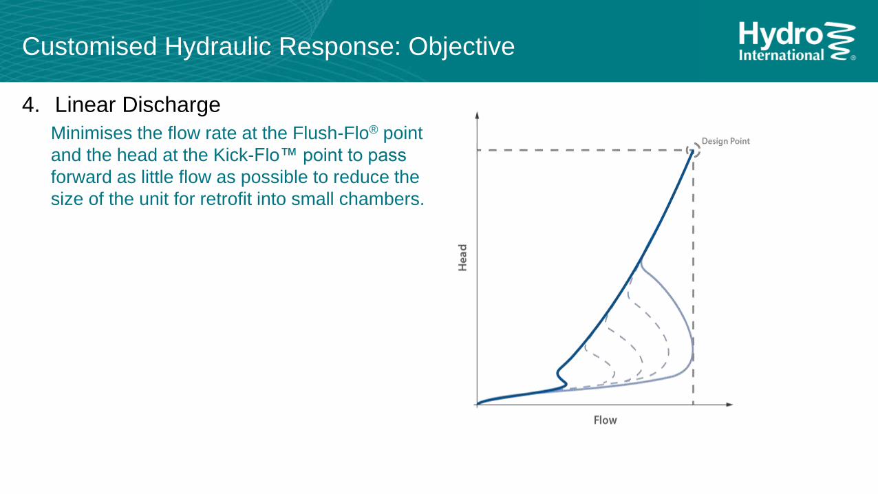
4. Linear Discharge
Minimises the flow rate at the Flush-Flo® point
and the head at the Kick-Flo™ point to pass
forward as little flow as possible to reduce the
size of the unit for retrofit into small chambers.
Customised Hydraulic Response:
Flush-Flo™
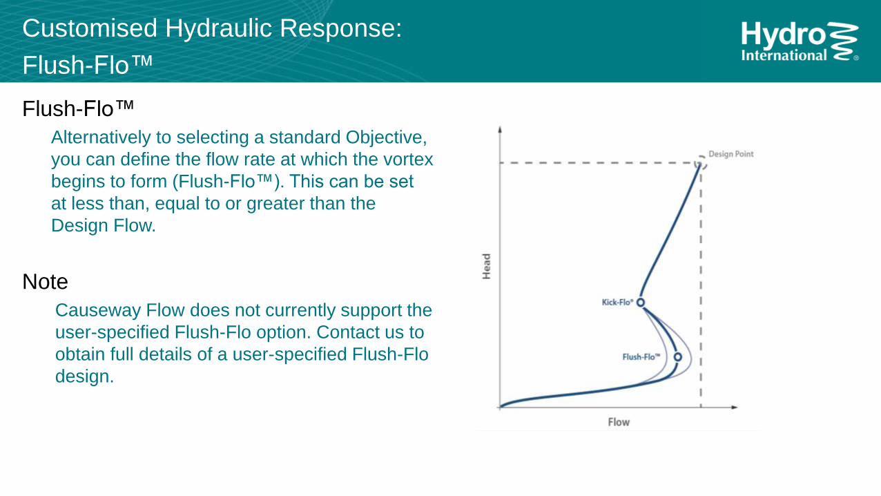
Flush-Flo™
Alternatively to selecting a standard Objective,
you can define the flow rate at which the vortex
begins to form (Flush-Flo™). This can be set
at less than, equal to or greater than the
Design Flow.
Note
Causeway Flow does not currently support the
user-specified Flush-Flo option. Contact us to
obtain full details of a user-specified Flush-Flo
design.
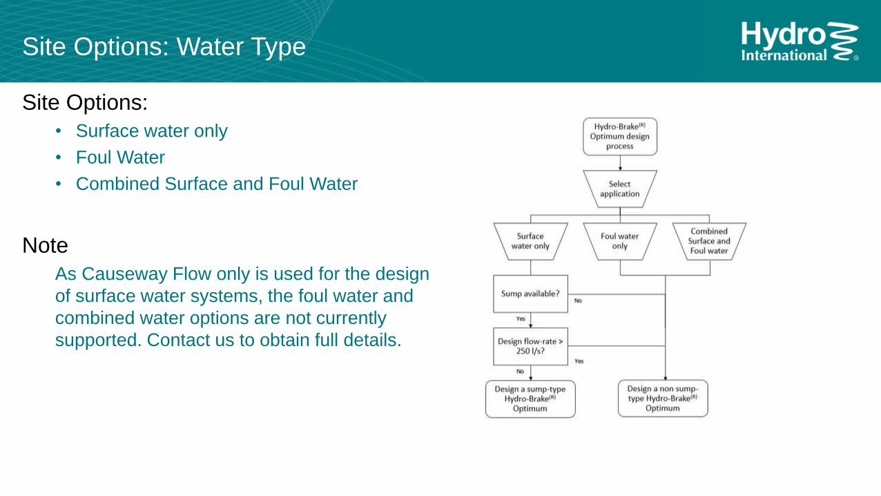
Site Options: Water Type
Site Options:
• Surface water only
• Foul Water
• Combined Surface and Foul Water
Note
As Causeway Flow only is used for the design
of surface water systems, the foul water and
combined water options are not currently
supported. Contact us to obtain full details.
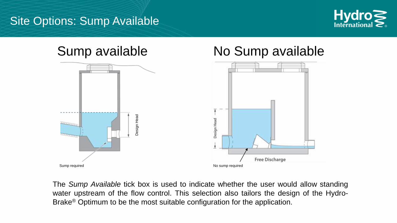
Site Options: Sump Available
Sump available No Sump available
Desig
n H
ea
d
Sump required No sump required
The Sump Available tick box is used to indicate whether the user would allow standing
water upstream of the flow control. This selection also tailors the design of the Hydro-
Brake® Optimum to be the most suitable configuration for the application.
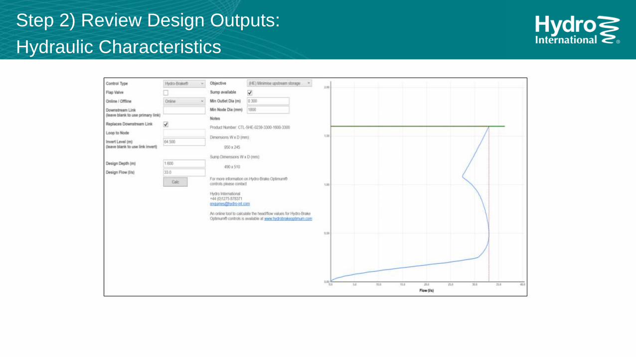
Step 2) Review Design Outputs:
Hydraulic Characteristics
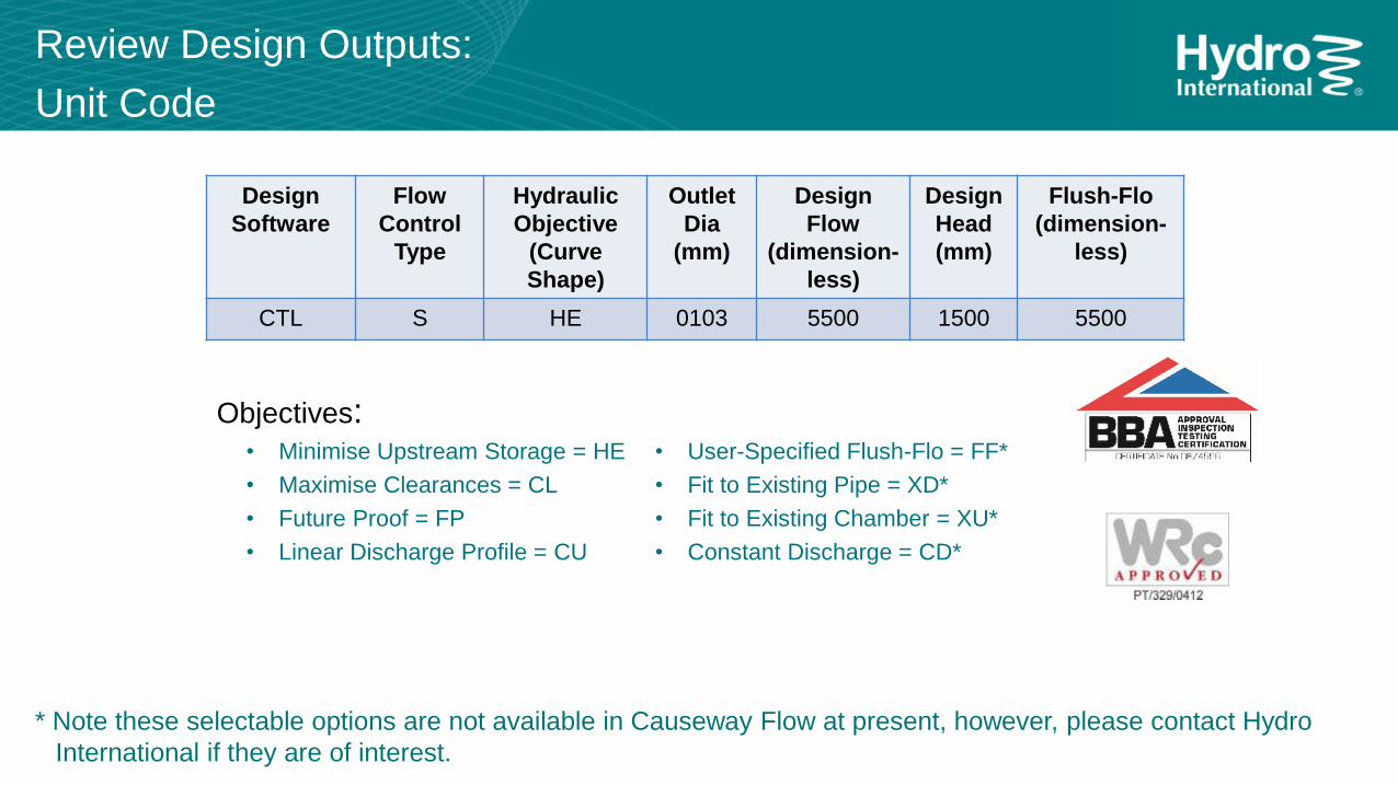
Review Design Outputs:
Unit Code
Objectives:• Minimise Upstream Storage = HE
• Maximise Clearances = CL
• Future Proof = FP
• Linear Discharge Profile = CU
• User-Specified Flush-Flo = FF*
• Fit to Existing Pipe = XD*
• Fit to Existing Chamber = XU*
• Constant Discharge = CD*
Design
Software
Flow
Control
Type
Hydraulic
Objective
(Curve
Shape)
Outlet
Dia
(mm)
Design
Flow
(dimension-
less)
Design
Head
(mm)
Flush-Flo
(dimension-
less)
CTL S HE 0103 5500 1500 5500
* Note these selectable options are not available in Causeway Flow at present, however, please contact Hydro
International if they are of interest.
Review Design Outputs:
Key Dimensions
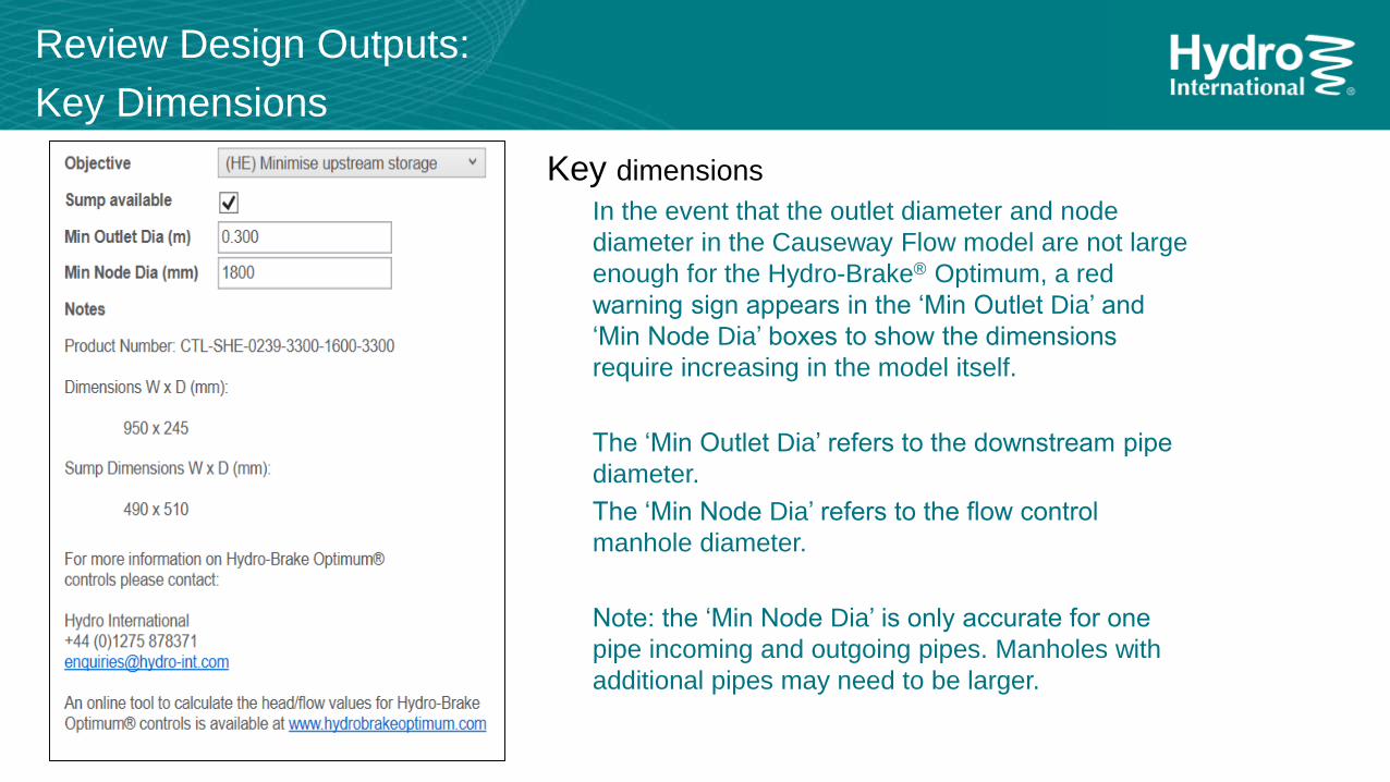
Key dimensions
In the event that the outlet diameter and node
diameter in the Causeway Flow model are not large
enough for the Hydro-Brake® Optimum, a red
warning sign appears in the ‘Min Outlet Dia’ and
‘Min Node Dia’ boxes to show the dimensions
require increasing in the model itself.
The ‘Min Outlet Dia’ refers to the downstream pipe
diameter.
The ‘Min Node Dia’ refers to the flow control
manhole diameter.
Note: the ‘Min Node Dia’ is only accurate for one
pipe incoming and outgoing pipes. Manholes with
additional pipes may need to be larger.
Step 3) Complete Hydraulic Design
Analyse the designed surface water system in Causeway
Flow to ensure the hydraulic profile is suitable; revise
Hydro-Brake® Optimum unit as required.
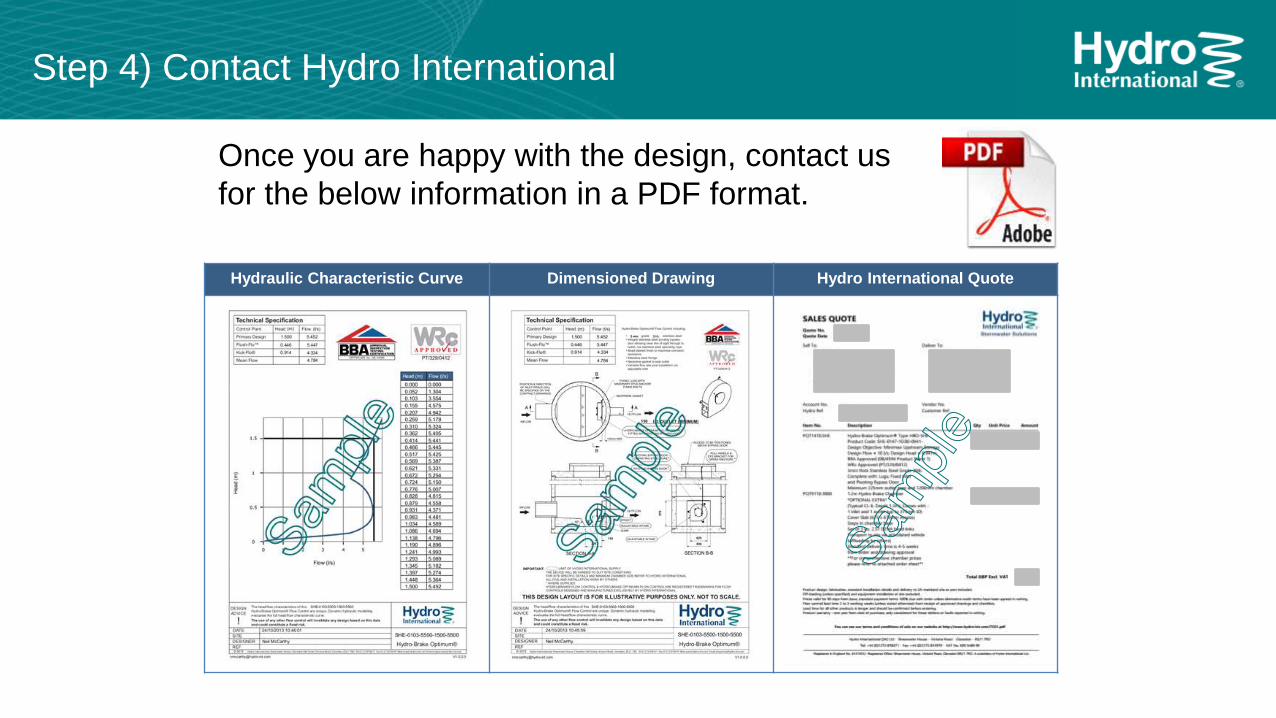
Step 4) Contact Hydro International
Once you are happy with the design, contact us
for the below information in a PDF format.
Hydraulic Characteristic Curve Dimensioned Drawing Hydro International Quote
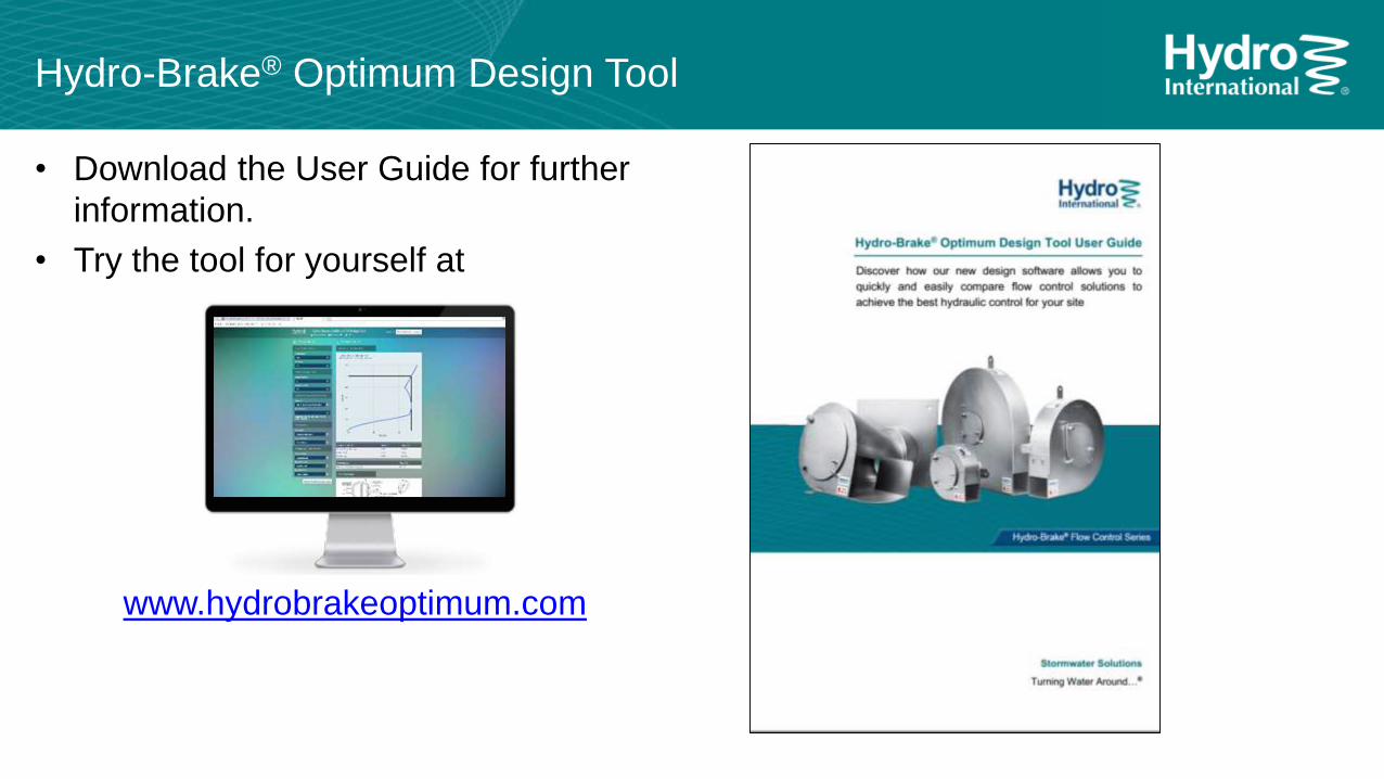
www.hydrobrakeoptimum.com
Hydro-Brake® Optimum Design Tool
• Download the User Guide for further
information.
• Try the tool for yourself at