Embed Size (px)
Citation preview

1
HELLO BIO!
launching digital biology
Mirela Alistar

2
Motivation for biochips
*This slide was created by prof. K. Chakrabarty, Duke University. Used with permission.
Automation Integration Miniaturization
Automation Integration Miniaturization
Automation Integration Miniaturization
✔
✔
✔
✔
✔

3
Biochips
disposable, the liquid can be transported between reservoirs.87
Alternatively, a weakly bonded connection to an adjacentreservoir can be disrupted, or the connection to a neighbouringcavity selectively blocked.88 Liquid reagent storage can easilybe implemented by integrating pouches into the cartridge.Mixing can also be realized on the linear actuated platformby moving liquids between neighbouring reservoirs.88
Application examples
One example of a linear actuated device is of coursethe previously mentioned i-STATs analyzer from AbbottPoint-of-Care.89 Using different disposable cartridges, severalblood parameters (blood gases, electrolytes, coagulation,cardiac markers, and hematology) can be determined withthe same portable hand-held analyzer for automated sampleprocessing and readout (Fig. 6(a)). Since only the disposablepolymer cartridge is contaminated with the blood sample andthus has to be disposed after performing the diagnostic assay,the analyzer device itself is reusable. Typical response times ofthe system are in the order of a few minutes.
The system features an integrated calibration solution thatis pre-stored in the disposable. The analysis process takes onlya few steps: As depicted in Fig. 6, the blood sample (a fewdrops) is filled into the cartridge by capillary forces (b), andplaced into the analyzer (c). First, the calibrant solution isreleased and provides the baseline for an array of thin-filmelectrodes integrated in the disposable. Then the sample ispushed into the measuring chamber and displaces the calibrant.Thereby, the blood parameters which can be determined bythe sensor array of the specific disposable are measured andpresented at the integrated display of the hand-held analyzer.Several studies showed good agreement between laboratoryresults and this POC-system.87,90,91
A second example is the lab-in-a-tube (Liatt) analyzer fromIQuum.92 This bench-top device with disposable test tubescontains all necessary reagents for amplification-based nucleicacid tests. It integrates sample preparation, amplification anddetection and is a fully integrated sample-to-result platformwith response times between 30 and 60 min. Handling of theplatform requires only a few steps: The sample (e.g. 10 mL ofwhole blood) is collected in the collection tube that is integratedinto the disposable, the barcode on the disposable is scanned,and the tube is then inserted into the analyzer. The disposablefeatures compartmentalized chambers in a tube which containdifferent reagents and can be connected via peelable seals(Fig. 7). Liquid control is performed by actuators that com-press the compartments, displacing the liquid into adjacentchambers.88 Sample preparation includes a nucleic acid puri-fication step: magnetic beads serve as solid nucleic acidbinding phase and are controlled by a built-in magnet. Fornucleic acid amplification, compartments can be heated andthe liquid is transferred between two different temperaturezones thus cycling the sample. The system is capable ofreal-time fluorescence readout.
Strengths and limitations
The presented commercially available examples show thatautomation and time-reduction by microfluidic systems withactive processing devices can indeed be achieved in a market-relevant context. The potential of the linear actuated deviceplatform certainly lies in its simplicity and the ability for long-term liquid reagent storage. The presented application exam-ples are portable and show a high degree of assay integration,requiring no external sample pre- or post-processing steps.Typical liquid (sample) volumes handled on the platform arein the range of 10–100 mL, which is adequate for point-of-carediagnostic applications (capillary blood from finger tip).While disposables can generally be mass-produced, thesecan become somewhat expensive due to the integration ofsensors (i-STATs) and liquid reagents (i-STATs and Liatt).
Fig. 6 Images and handling procedure of the i-STATs analyzer.
(a) Photograph depicting the portable i-STATs analyzer for clinical
blood tests.89 (b) Depending on the blood parameters to be measured,
a certain disposable cartridge is filled with blood by capillary forces
from the finger tip and (c) afterwards loaded into the analyzer for
assay processing and readout (images courtesy of Abbott Point of
Care Inc., NJ, USA).
Fig. 7 Functional principle and processing steps in a nucleic acid test
in the lab-in-a-tube analyzer according to Chen et al.88 The disposable
contains pouches with reagents (light blue) which are actuated by
plungers while clamps open and close fluidic connections to adjacent
pouches. (a) Sample is inserted (red). (b) Sample is mixed with pre-
stored chemicals containing magnetic capture-beads. (c) Unwanted
sample components are moved to a waste reservoir while the capture-
beads are held in place by a magnet. (d, e) Further processing steps
allow sequential release of additional (washing) buffers and heating
steps (red block) for lysis and thermocycling demands. The system
allows optical readout by a photometer (PM).
1162 | Chem. Soc. Rev., 2010, 39, 1153–1182 This journal is !c The Royal Society of Chemistry 2010
Dow
nloa
ded
on 1
7/04
/201
3 09
:33:
25. O
pen
Acc
ess A
rticl
e.Pu
blish
ed o
n 25
Janu
ary
2010
on
http
://pu
bs.rs
c.or
g | d
oi:1
0.10
39/B
8205
57B
A large number of microfluidically automated componentsfor batch-wise nucleic acid diagnostics based on pressuredriven laminar flow chips have been published and summedup in several reviews.32,112,113 However, a totally integratedsystem remains a challenge, since the integration of samplepreparation proved difficult,113 although it seems to be inreach, as the next two examples show.
Easley et al. showed integrated DNA purification, PCR,electrophoretic separation and detection of pathogens in lessthan 30 min.114 The assay was performed on a pressuredriven four layer glass/PDMS chip with elastomeric valves.Temperature cycling for PCR was achieved by IR radiation.Only the sample lysis step was not integrated in the micro-fluidic chip. Detection of Bacillus anthracis from infected miceand Bordetella pertussis from a clinical sample was successfullydemonstrated.
An integrated mTAS system for the detection of bacteriaincluding lysis, DNA purification, PCR and fluorescencereadout has also been published recently.111 A microfluidicplastic chip with integrated porous polymer monolithsand silica particles for lysis and nucleic acid isolationwas used for detection (Fig. 9). A custom-made base deviceprovided liquid actuation and off-chip valving by stoppingliquid flow from the exits of the chip, utilizing the incompressi-bility of liquids. Detection of 1.25 ! 106 cells of Bacillussubtilis was demonstrated with all assay steps performedon-chip.
Strengths and limitations
One strength of the platform lies in its potential for continuousprocessing of samples. Continuous sample processing is ofutmost importance for online monitoring of clinical para-meters, process control in fermentation, water quality controlor cell sorting. Typically one or a few parameters aremonitored. The application examples showed one systemcapable of continuous DNA extraction as well as otherimplementations that integrated complex batch-wise protocolssuch as nucleic acid analysis. The platform is in principlecompatible with polymer mass-production technologiessuch as injection molding, enabling inexpensive disposablemicrofluidic chips.
A difficulty of the platform is the necessity to connect thepressure source to the (disposable) chip, which decreases theportability and requires additional manual steps. Anotherchallenge is the Taylor dispersion115 of streamwise dispersedsamples which can make it hard to accurately track analyteconcentrations. Unit operations on the platform are optimizedfor mixing and separation processes and somewhat limited inother aspects such as aliquoting.
Microfluidic large scale integration
Characterization of microfluidic large scale integration
Microfluidic large scale integration describes a microfluidicchannel circuitry with chip-integrated microvalves based onflexible membranes between a liquid-guiding layer and apneumatic control-channel layer. The microvalves are closedor open corresponding to the pneumatic pressure applied tothe control-channels. Just by combining several microvalvesmore complex units like micropumps, mixers, multiplexers,etc. can be built up with hundreds of units on one singlechip.
General principle
The microfluidic large scale integration (LSI) platform arose in1993.116 At the same time, a novel fabrication technology formicrofluidic channels, called soft lithography made its appearance.Soft lithography is based on the use of elastomeric stamps,molds and conformable photomasks to fabricate and replicatemicrostructures.117 Using this technology, the monolithicfabrication of all necessary fluidic components within onesingle elastomer material (polydimethylsiloxane, PDMS)became possible, similar to the silicon-based technology inmicroelectronics. PDMS, also known as silicone elastomer, isan inexpensive material offering several advantages comparedto silicon or glass. It is a cheap, rubber-like elastomer withgood optical transparency and biocompatibility. A detailedreview on the use of PDMS for different fields of applicationscan be found in ref. 118.The strength of the technology became obvious, when
Stephen Quake’s group expanded the technology towards
Fig. 9 Chip for integrated detection of bacteria including lysis, DNA isolation and PCR published by Sauer-Budge et al.111
1164 | Chem. Soc. Rev., 2010, 39, 1153–1182 This journal is "c The Royal Society of Chemistry 2010
Dow
nloa
ded
on 1
7/04
/201
3 09
:33:
25. O
pen
Acc
ess A
rticl
e.Pu
blish
ed o
n 25
Janu
ary
2010
on
http
://pu
bs.rs
c.or
g | d
oi:1
0.10
39/B
8205
57B
according to charge with subsequent collection of the sampleband of interest.241 For this, an transverse electric fieldis applied in pressure driven flow within a broad and flatmicrochamber. While passing this extraction chamber, thespecies contained in the sample flow are deflected dependingon their charge and thus exit the chamber through one ofseveral outlets.
Another electrokinetic effect is based on polarization ofparticles within an oscillating electrical field or field gradient(dielectrophoresis), as depicted in Fig. 14(c). Dielectrophoresis isapplied in many fields, e.g. for the controlled separation andtrapping of submicron bioparticles,242 for the fusion and transportof cells,243 gene transfection244 or the separation of metallic fromsemiconducting carbon nanotubes.12,245,246 Other applications arecell sorting247,248 and apoptosis of cells.249,250
Application examples
Capillary electrophoresis systems were the first micro totalanalysis systems and emerged as single chip solutions from theanalytical chemistry field in the 1990s.251 Several companiesutilize microfluidic capillary electrophoretic chips for chemicalanalysis, with capillaries of typically 10 to 100 mm diameter.252
Today, Caliper Life Sciences, MA, USA252 and AgilentTechnologies, CA, USA253 offer microfluidic chips for DNAand protein analysis. Liquid propulsion is provided viaelectroosmosis and combined with capillary electrophoreticseparation. The sample is electroosmotically transported andmetered inside the chip, then separated via capillary electro-phoresis and analysed by fluorescence detection. (Fig. 15).The whole assay is performed within minutes, instead of hoursor days.
The first combinations of microfluidic integrated electro-phoresis with microarrays were published in 1998 by NanogenInc., CA, USA.254 This approach resulted in a 20-fold fasterhybridization and more specific binding of DNA onto the
microarray. This was the first step in the direction of aplatform for massively parallel analysis.
Strengths and limitations
Electroosmotic actuation of liquids enables pulse-free pumpingwithout any moving parts. Liquid manipulation at highprecision can be achieved by the existing unit operations.In addition, electroosmotic flow does not lead to Taylordispersion115 as in pressure driven systems and thus enableshigh efficiency separations. The seamless integration withelectrophoresis, an established technology in use for 100 years,255
is another obvious strength. In microfluidic systems, applicationscan benefit from faster heat dissipation, better resolution,and faster separation. Miniaturization of electrophoreticanalysis enables the automation and parallelization of tests withsmall dead volumes, thus reducing the required amount ofsample.A technical problem in capillary electrophoresis systems is
the changing pH-gradient due to electrolysis or electrophoresisitself. Also streaming currents which counteract the externalelectric field or gas bubbles as a result of electrolysis at theelectrodes are problematic. Also a massively parallel setup isproblematic due to the heat generated by the electrophoresisitself. In addition, the realization of hand-held devices ischallenging due to the necessity of high voltages in com-bination with high energy consumption. Overall, miniaturizedelectrophoresis is established as a fast and efficient method forthe separation and analysis of bio-molecules.
Electrowetting
Characterization of electrowetting
Electrowetting platforms use droplets immersed in a secondimmiscible continuous phase (gas or liquid) as stable micro-confinements. The droplets reside on a hydrophobic surfacethat contains a one- or two-dimensional array of individuallyaddressable electrodes. The voltage between a droplet and theelectrode underneath the droplet defines its wetting behavior.By changing voltages between neighboring electrodes, dropletscan be generated, transported, split, merged, and processed.These unit operations are freely programmable for eachindividual droplet by the end-user enabling online control ofan assay.
General principle
The electrowetting effect was first described by Lippmann in1875.256 Interest in this effect was spurred again in the 1990s,when researchers started placing thin insulating layers on themetallic electrodes to separate it from the often conductiveliquids in order to eliminate electrolysis.257 The basic electro-wetting effect is depicted in Fig. 16(a). The wettability of asolid surface increases due to polarization and electric fields assoon as a voltage is applied between the electrode and theliquid droplet above (separated by the dielectric insulatinglayer).257 This so-called ‘‘electrowetting-on-dielectric’’(EWOD)258 effect is therefore a tool to control the contactangle of liquids on surfaces.
Fig. 15 Microfluidic realization of capillary electrophoresis analysis
on the electrokinetic platform (adapted from ref. 121) (r Agilent
Technologies, Inc. 2007. Reproduced with permission, courtesy of
Agilent Technologies, Inc.). After the sample has been transported to
the junction area (a) it is metered by the activated horizontal flow and
injected into the separation channel (b). Therein, the sample components
are electrophoretically separated (c) and readout by their fluorescence
signal (d). The complete microfluidic CE-chip is depicted in the
center.
1172 | Chem. Soc. Rev., 2010, 39, 1153–1182 This journal is !c The Royal Society of Chemistry 2010
Dow
nloa
ded
on 1
7/04
/201
3 09
:33:
25. O
pen
Acc
ess A
rticl
e.Pu
blish
ed o
n 25
Janu
ary
2010
on
http
://pu
bs.rs
c.or
g | d
oi:1
0.10
39/B
8205
57B
This invention paved the way for the application of theelectrowetting effect as a liquid propulsion principle forlab-on-a-chip systems.259,260 To utilize the EWOD technologyfor programmable liquid actuation, a liquid droplet is placedbetween two electrodes covered with insulating, preferablyhydrophobic, dielectric layers (Fig. 16(b)). The liquid dropletis steered by the electrode array on one side and by a largeplanar ground electrode on the opposite side. Activatingselected electrodes allows programming of a path which thedroplet follows. The droplet needs to be large enough to coverparts of at least four addressable electrodes at all times,allowing two-dimensional movement. If a voltage is appliedto one of the control electrodes covered by the droplet, itmoves onto the activated electrode pad. Successive activationof one electrode after the other will drag the droplet along adefined path. This freedom to program the liquid movementenables the implementation of different assays on thesame chip.
The universal applicability of moving droplets by EWODwas shown with several media such as ionic liquids, aqueoussurfactant solutions,261 and also biological fluids like wholeblood, serum, plasma, urine, saliva, sweat, and tear fluid.262
Unit operations
The droplet formation, i.e. initial metering, is the elementaryunit operation of the platform. Metered droplets can beproduced from an on-chip reservoir in three steps.262 First, aliquid column is extruded from the reservoir by activating aseries of adjacent electrodes. Second, once the column over-laps the electrode on which the droplet is to be formed, all theremaining electrodes are turned off, forming a neck in thecolumn. The reservoir electrode is then activated duringthe third and last step, pulling back the liquid and breakingthe neck, leaving a droplet behind on the metering electrode.Using this droplet metering structure, droplets down to 20 nLvolume can be generated with a standard deviation of less than2%.262 A similar technology can be used for the splitting of adroplet into several smaller droplets.31 Since the dropletvolume is of great importance for the accuracy of all assays,additional volume control mechanisms such as on-chipcapacitance volume control263 or the use of numerical methodsfor the design of EWOD metering structures264 have beenproposed. Once the droplets are formed, their actuation isaccomplished by the EWOD effect as described above.Also the merging of droplets can be achieved easily with
the use of three electrodes. Two droplets are individuallyguided to electrodes separated from each other by a thirdone. Deactivating these two electrodes and activating the thirdseparation electrode pulls the droplets together.265 The mostbasic type of mixing within droplets on the EWOD platform isan oscillation, forwards and backwards, between at least twoelectrodes. Another mixing scheme is the repetitive movementof the droplet on a rectangular path. The shortest mixing timefor two 1.3 mL droplets in linear oscillation on 4 electrodes wasabout 4.6 s.266 In another work, the mixing times of 1.4 mLdroplets could be further reduced to less than 3 s usingtwo-dimensional arrays.267
Application examples
Applications based on EWOD are in the development phaseand quite close to market products. For example, an enzymaticcolorimetric assay for (point-of-care) diagnostic applicationshas been successfully implemented, and glucose concentrationin several biological liquids (serum, plasma, urine, and saliva)was determined with comparable results to standard methods.262
The microfluidic chip layout for the colorimetric glucose assayis depicted in Fig. 17. It features reservoirs, injection structures(metering) and a network of electrodes for droplet transport,splitting and detection.Also the use of an EWOD system for the automated sample
preparation of peptides and proteins for matrix-assisted laserdesorption-ionization mass spectrometry (MALDI-MS) wasreported. In that work, standard MALDI-MS reagents,analytes, concentrations, and recipes have been demonstratedto be compatible with the EWOD technology, and massspectra comparable to those collected by conventionalmethods were obtained.268 Also a PCR assay has been realizedon the platform by temperature cycling of a droplet at rest.269
Additional information about the EWOD platform can befound in a comprehensive review.270
Strengths and limitations
The strengths of the platform are the very small liquid volumesin the nanolitre range that can be handled with high precision,and the freedom to program the droplet movement. This cutsdown sample and reagent consumption and allows a maximumof flexibility for the implementation of different assay protocols.
Fig. 16 The electrowetting effect (according to Mugele and Baret257).
(a) If a voltage V is applied between a liquid and an electrode
separated by an insulating layer, the contact angle of the liquid–solid
interface is decreased and the droplet ‘‘flattens’’. (b) Hydrophobic
surfaces enhance the effect of electrowetting. For ‘‘electrowetting-
on-dielectrics’’ (EWOD) several individual addressable control
electrodes (here on the bottom) and a large counter-electrode are
used. The droplet is pulled to the charged electrodes.
Fig. 17 Electrowetting platform (EWOD). Implementation of a
colorimetric glucose assay in a single chip. Four reservoirs with
injection elements are connected to an electrode circuitry, where the
droplets are mixed, split and transported to detection sites for readout
(adapted from Srinivasan et al.262).
This journal is !c The Royal Society of Chemistry 2010 Chem. Soc. Rev., 2010, 39, 1153–1182 | 1173
Dow
nloa
ded
on 1
7/04
/201
3 09
:33:
25. O
pen
Acc
ess A
rticl
e.Pu
blish
ed o
n 25
Janu
ary
2010
on
http
://pu
bs.rs
c.or
g | d
oi:1
0.10
39/B
8205
57B
! Can run biochemical applications ! In-vitro diagnostics ! Drug discovery ! Biotech ! Ecology
Digital microfluidic biochip

4
Digital Microfluidic Biochip (DMB) example
More videos at http://microfluidics.ee.duke.edu/

5
Digital Microfluidic Biochip (DMB) example
Moving droplets -> Biochemical application

6
Electrowetting on dielectric
7
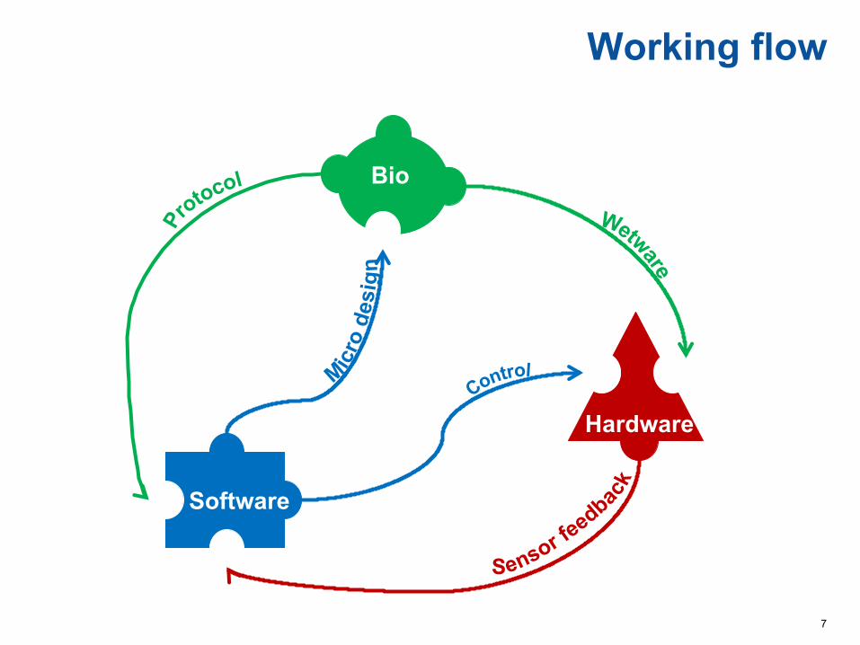
Working flow
Bio
Software
Hardware

8
Operational setup
Computer Controller Biochip

9
Design methodology
Architecture designThe architecture of the biochip is decided assuming maximum k permanent faults
The biochip is fabricated
The biochip is tested for permanent faults If more faults than k, then the biochip is discarded
If application does not complete within deadline, then the biochip is discarded
The application is executed on the biochip
The DMB is discarded or stored if the results are needed later
Biochip fabrication
Biochip testing
Application compilation
Operation
Disposal

10
Motivational Example
Application obtained by repeating 3 times the graph Rectangular architecture
Application-specific architecture
The application-specific architecture is cheaper
Cost: 168 units
Cost: 128 units
11
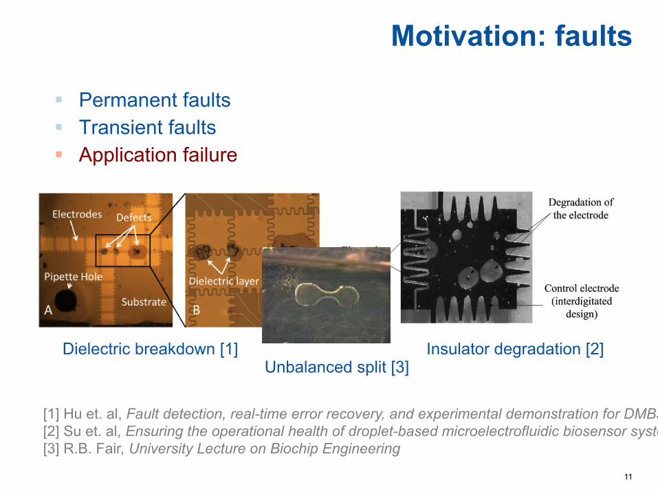
Motivation: faults
Dielectric breakdown [1] Insulator degradation [2] Unbalanced split [3]
• [1] Hu et. al, Fault detection, real-time error recovery, and experimental demonstration for DMBs • [2] Su et. al, Ensuring the operational health of droplet-based microelectrofluidic biosensor systems • [3] R.B. Fair, University Lecture on Biochip Engineering
! Permanent faults ! Transient faults ! Application failure

12
Design methodology
Architecture design
Biochip fabrication
Biochip testing
Application compilation
Operation
Disposal

13
Compilation tasks
Biochip architecture Placement of modules on biochip Application graph
Schedule of operations
Allocation of modules

14
Design methodology
Architecture design
Biochip fabrication
Biochip testing
Application compilation
Operation
Disposal

15
DropLab project
Amplification (copy DNA)
Cells growth
www.bioflux.eu

16
Bacteriophage therapy

17
Bio + Hacking

18
… March March March Feb Jan
Biohacking - What?
Oct

19
Biohacking - Who?
RüdigerTrojok Urs Gaudenz Pieter van Boheemen