Embed Size (px)
Citation preview


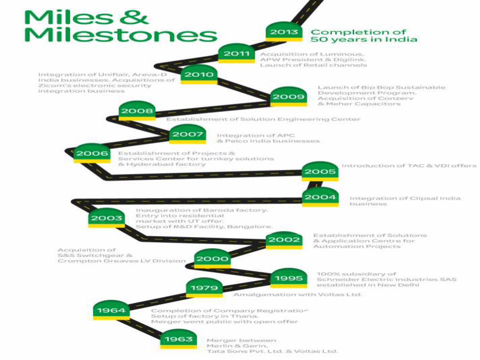
Schneider Electric is a
European multinational corporation that specializes in electricity distribution, automation management and produces installation components for energy management.
Industry -Electrical Equipment
Founded- 1836, incorporated 1981
Headquarters-Rueil-Malmaison, France
Key people-Jean Pascal Tricoire (Chairman and CEO)-Henri Lachmann (Vice-Chairman and Lead Director)
Products -Include programmable logic controllers, sensors, drives, uninterruptible, breakers, switchgear, switchboards, motor
Owner-Capital Group Companies(9.4%)
Number of employees-152,384 (2012)
Brief Overview of Schneider Electric
+
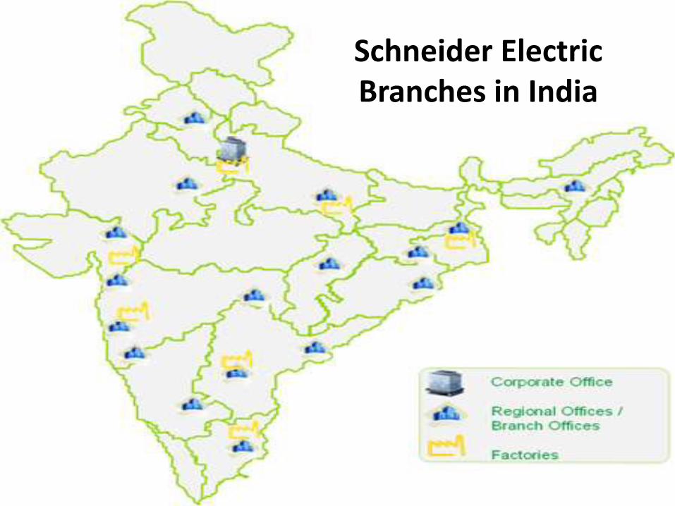
Schneider Electric Branches in India
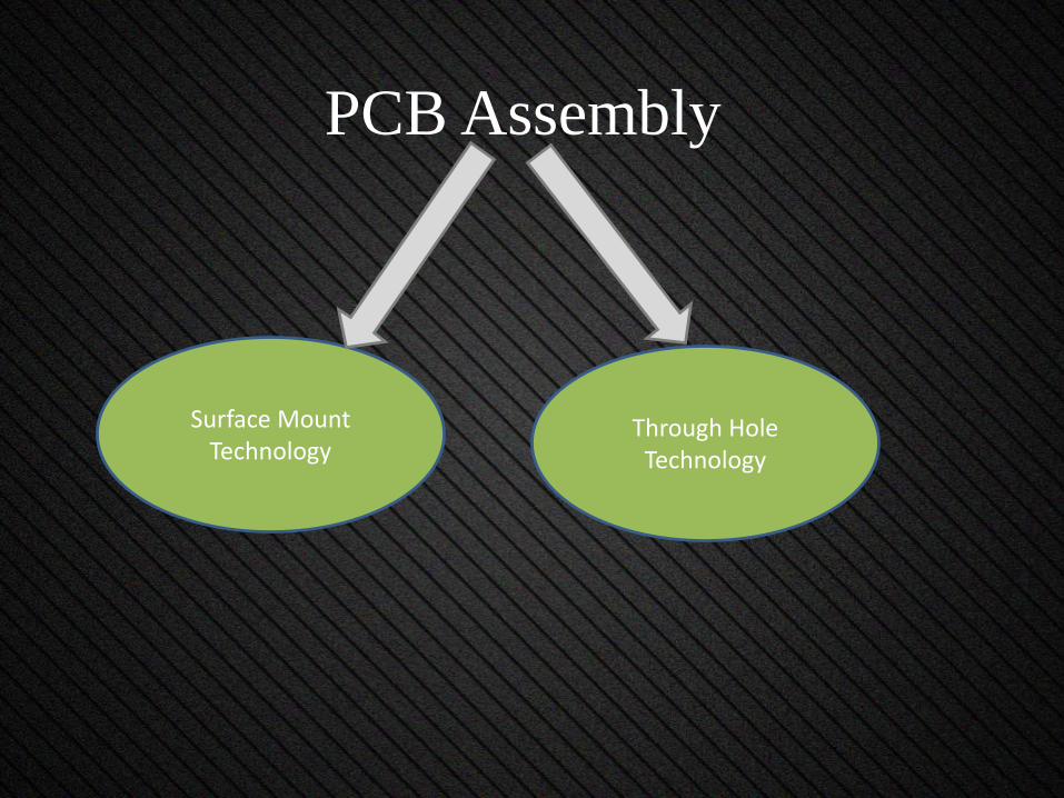
PCB Assembly
Through Hole Technology
Surface Mount Technology
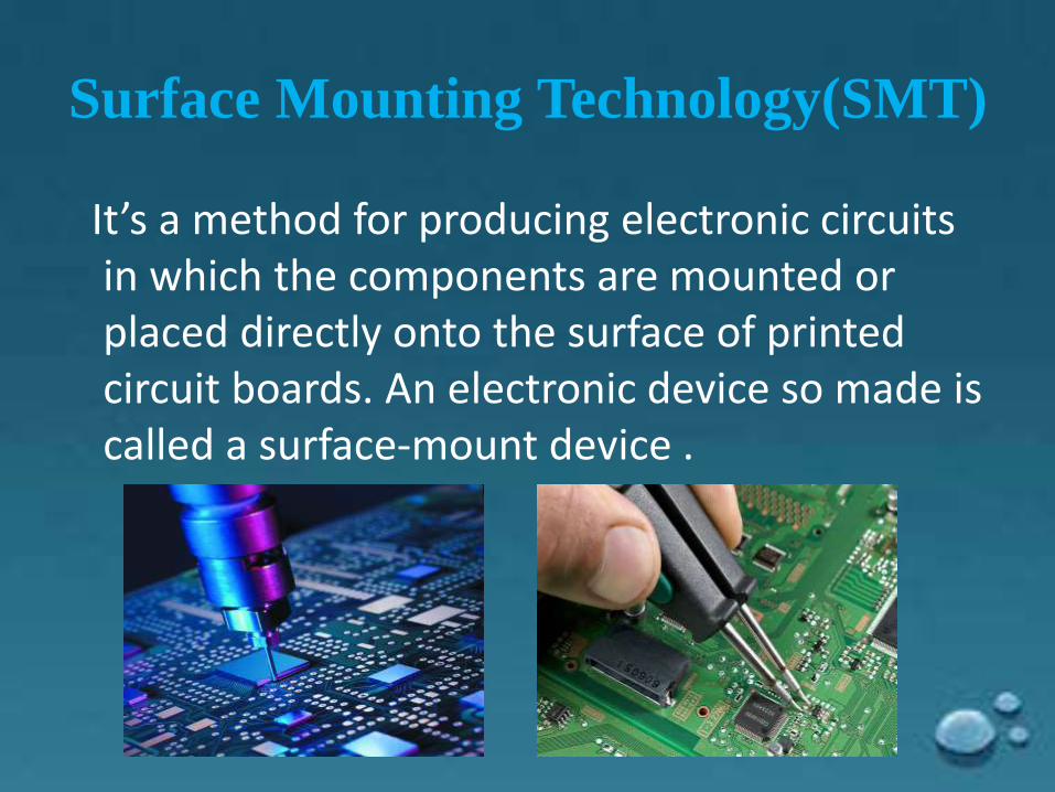
Surface Mounting Technology(SMT)
It’s a method for producing electronic circuits in which the components are mounted or placed directly onto the surface of printed circuit boards. An electronic device so made is called a surface-mount device .
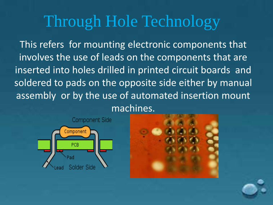
This refers for mounting electronic components that involves the use of leads on the components that are
inserted into holes drilled in printed circuit boards and soldered to pads on the opposite side either by manual assembly or by the use of automated insertion mount
machines.
Through Hole Technology
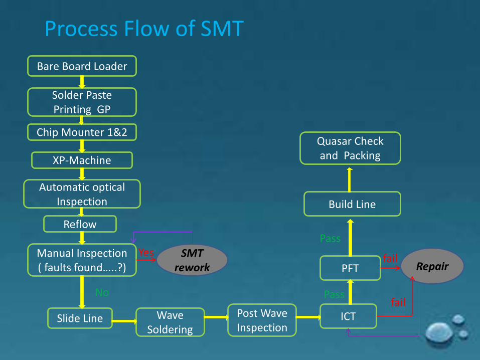
Process Flow of SMT
Bare Board Loader
Solder Paste Printing GP
Chip Mounter 1&2
XP-Machine
Automatic optical Inspection
Slide Line
Reflow
Wave Soldering
ICT
Manual Inspection ( faults found…..?)
Post Wave Inspection
PFT
Quasar Check and Packing
No
SMT rework
Yes
Pass
Repair
fail
fail
Pass
Build Line
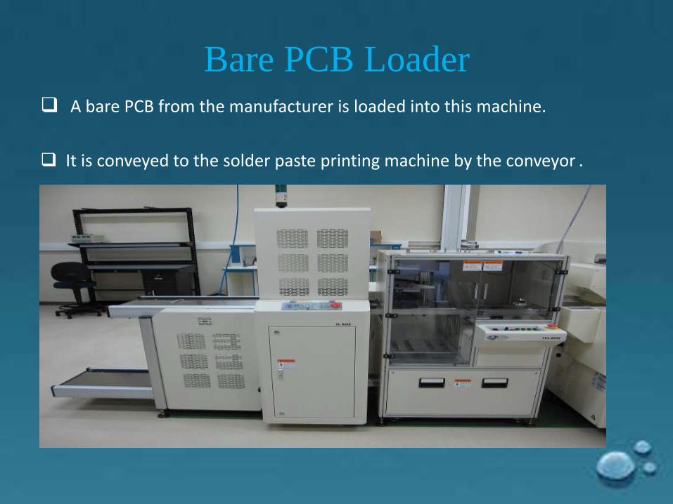
Bare PCB Loader A bare PCB from the manufacturer is loaded into this machine.
It is conveyed to the solder paste printing machine by the conveyor .
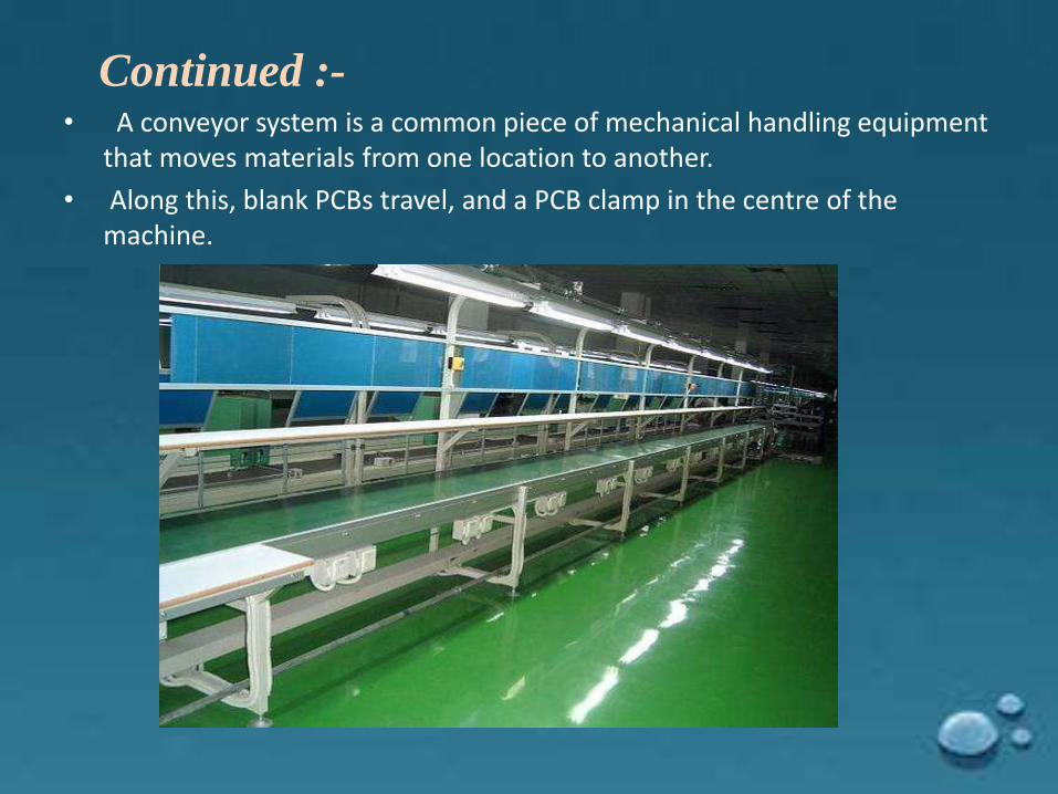
Continued :-• A conveyor system is a common piece of mechanical handling equipment
that moves materials from one location to another.
• Along this, blank PCBs travel, and a PCB clamp in the centre of the machine.
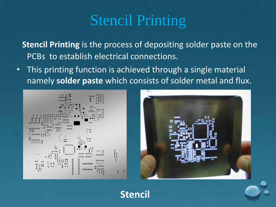
Stencil Printing
Stencil Printing is the process of depositing solder paste on the
PCBs to establish electrical connections.
• This printing function is achieved through a single material namely solder paste which consists of solder metal and flux.
Stencil
Continued :-
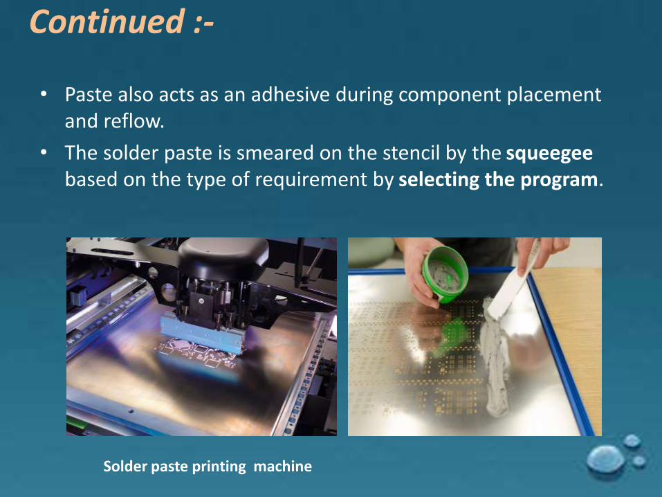
• Paste also acts as an adhesive during component placement and reflow.
• The solder paste is smeared on the stencil by the squeegeebased on the type of requirement by selecting the program.
Solder paste printing machine
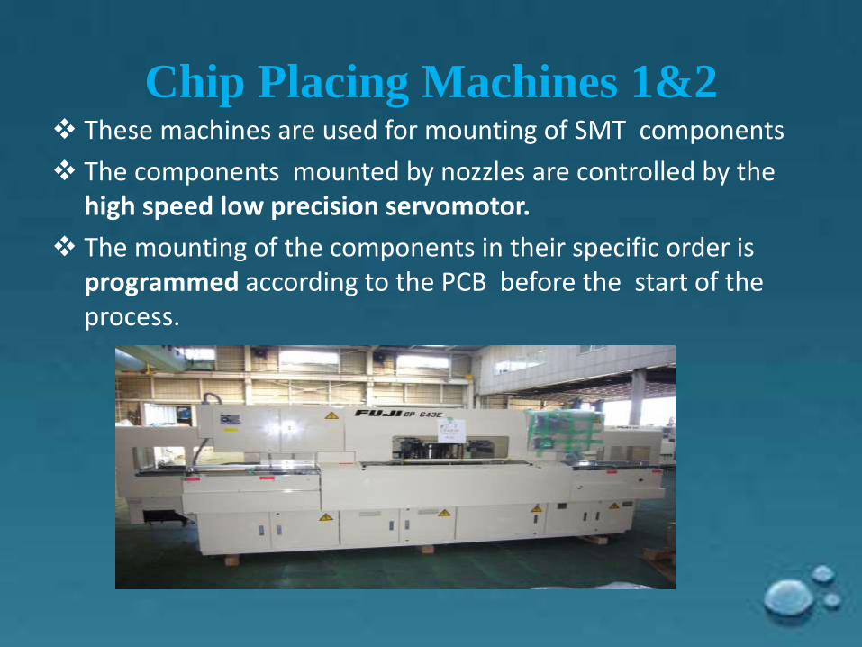
Chip Placing Machines 1&2 These machines are used for mounting of SMT components
The components mounted by nozzles are controlled by the high speed low precision servomotor.
The mounting of the components in their specific order is programmed according to the PCB before the start of the process.
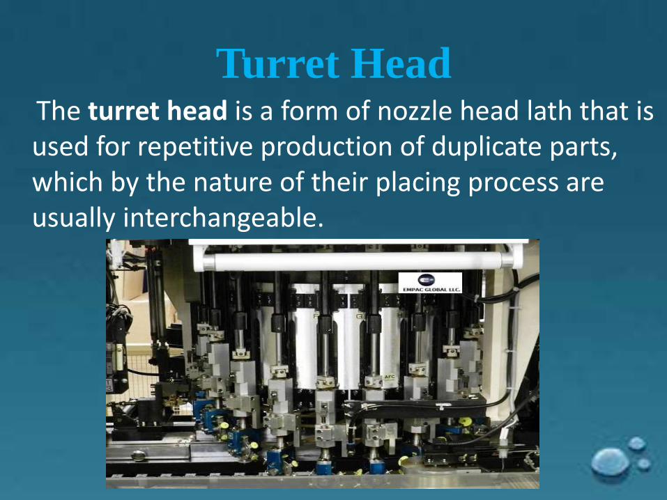
Turret HeadThe turret head is a form of nozzle head lath that is used for repetitive production of duplicate parts, which by the nature of their placing process are usually interchangeable.
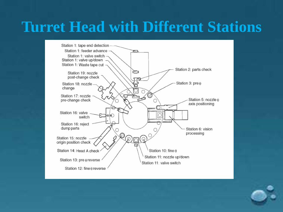
Turret Head with Different Stations
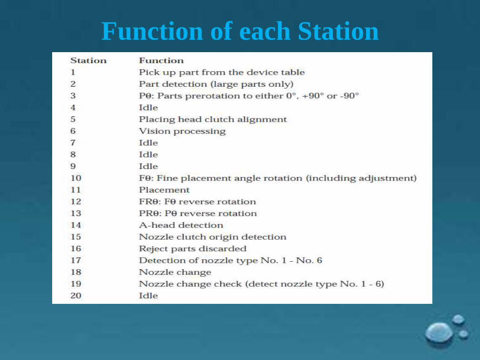
Function of each Station
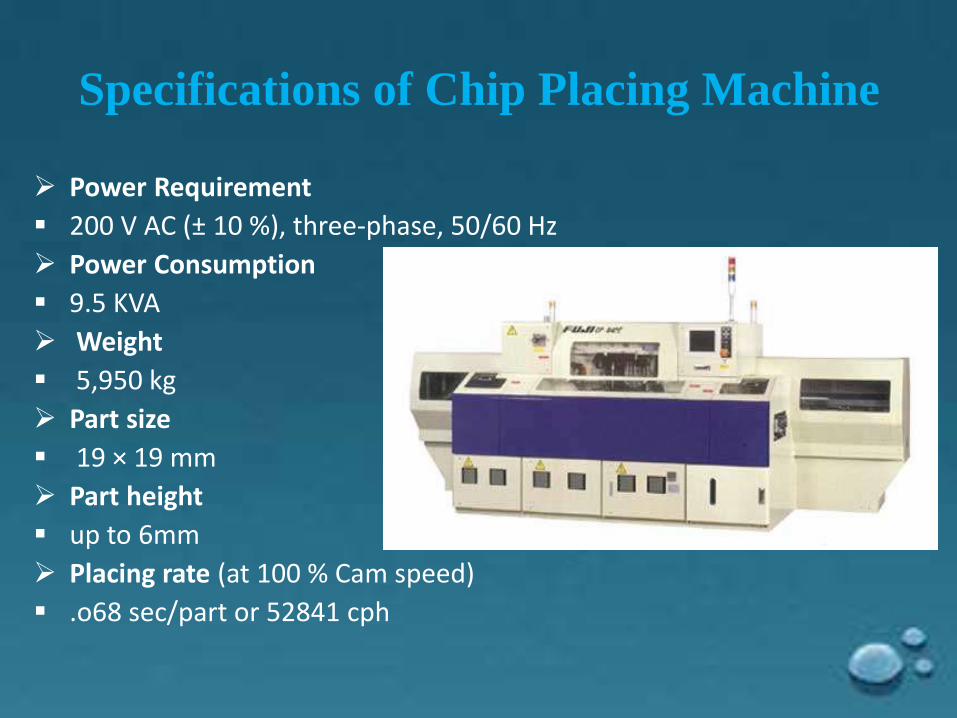
Specifications of Chip Placing Machine
Power Requirement
200 V AC (± 10 %), three-phase, 50/60 Hz
Power Consumption
9.5 KVA
Weight
5,950 kg
Part size
19 × 19 mm
Part height
up to 6mm
Placing rate (at 100 % Cam speed)
.o68 sec/part or 52841 cph
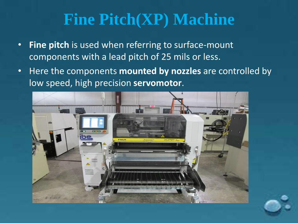
Fine Pitch(XP) Machine
• Fine pitch is used when referring to surface-mount components with a lead pitch of 25 mils or less.
• Here the components mounted by nozzles are controlled by low speed, high precision servomotor.
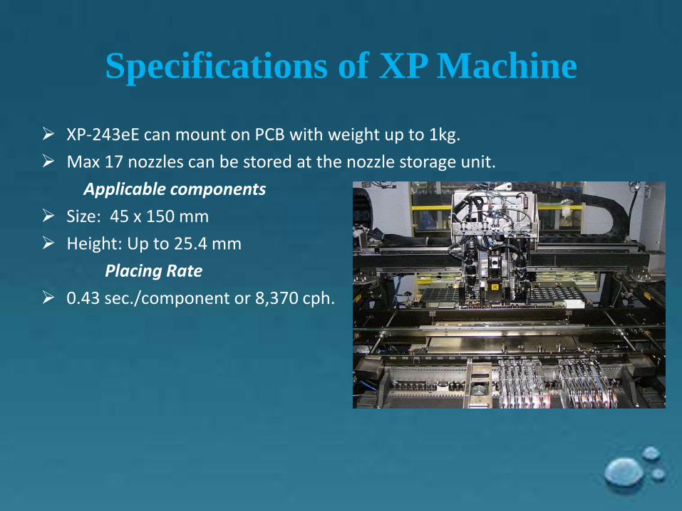
Specifications of XP Machine
XP-243eE can mount on PCB with weight up to 1kg.
Max 17 nozzles can be stored at the nozzle storage unit.
Applicable components
Size: 45 x 150 mm
Height: Up to 25.4 mm
Placing Rate
0.43 sec./component or 8,370 cph.
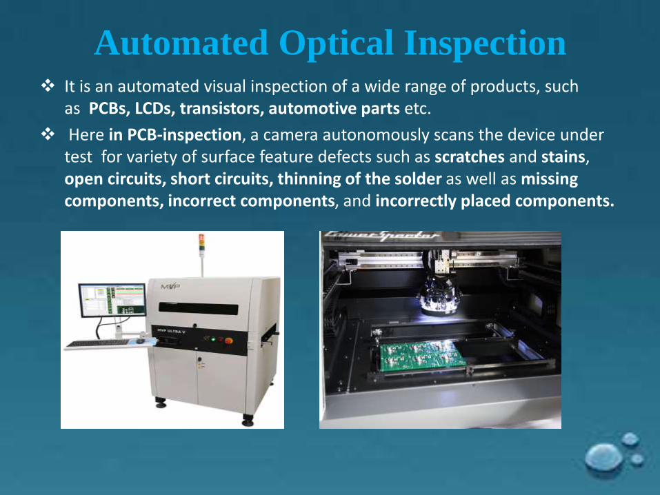
Automated Optical Inspection It is an automated visual inspection of a wide range of products, such
as PCBs, LCDs, transistors, automotive parts etc.
Here in PCB-inspection, a camera autonomously scans the device under test for variety of surface feature defects such as scratches and stains, open circuits, short circuits, thinning of the solder as well as missing components, incorrect components, and incorrectly placed components.
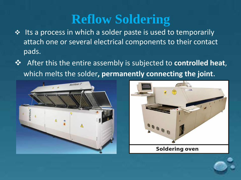
Reflow Soldering Its a process in which a solder paste is used to temporarily
attach one or several electrical components to their contact pads.
After this the entire assembly is subjected to controlled heat,
which melts the solder, permanently connecting the joint.
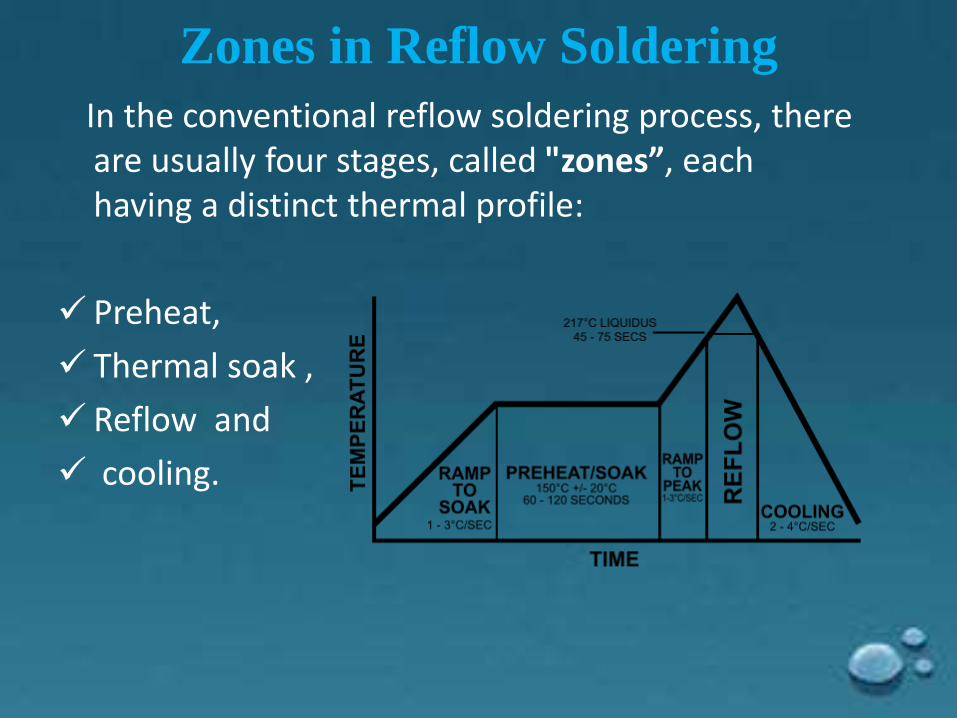
Zones in Reflow Soldering
In the conventional reflow soldering process, there are usually four stages, called "zones”, each having a distinct thermal profile:
Preheat,
Thermal soak ,
Reflow and
cooling.
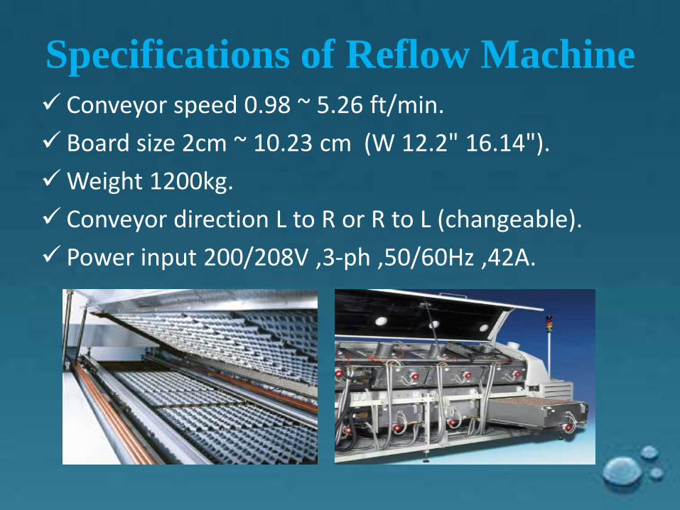
Specifications of Reflow Machine Conveyor speed 0.98 ~ 5.26 ft/min.
Board size 2cm ~ 10.23 cm (W 12.2" 16.14").
Weight 1200kg.
Conveyor direction L to R or R to L (changeable).
Power input 200/208V ,3-ph ,50/60Hz ,42A.
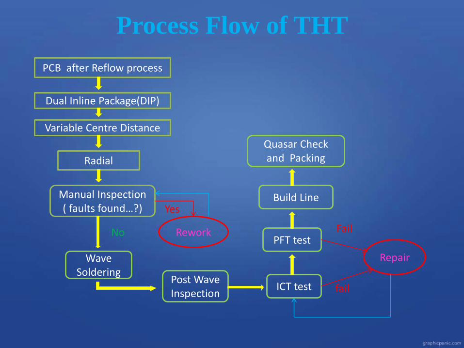
Process Flow of THT
PCB after Reflow process
Dual Inline Package(DIP)
Variable Centre Distance
Radial
Manual Inspection( faults found…?)
Rework
Wave Soldering
Post Wave Inspection
ICT test
PFT test
Repair
fail
Build Line
Quasar Check and Packing
Yes
No Fail
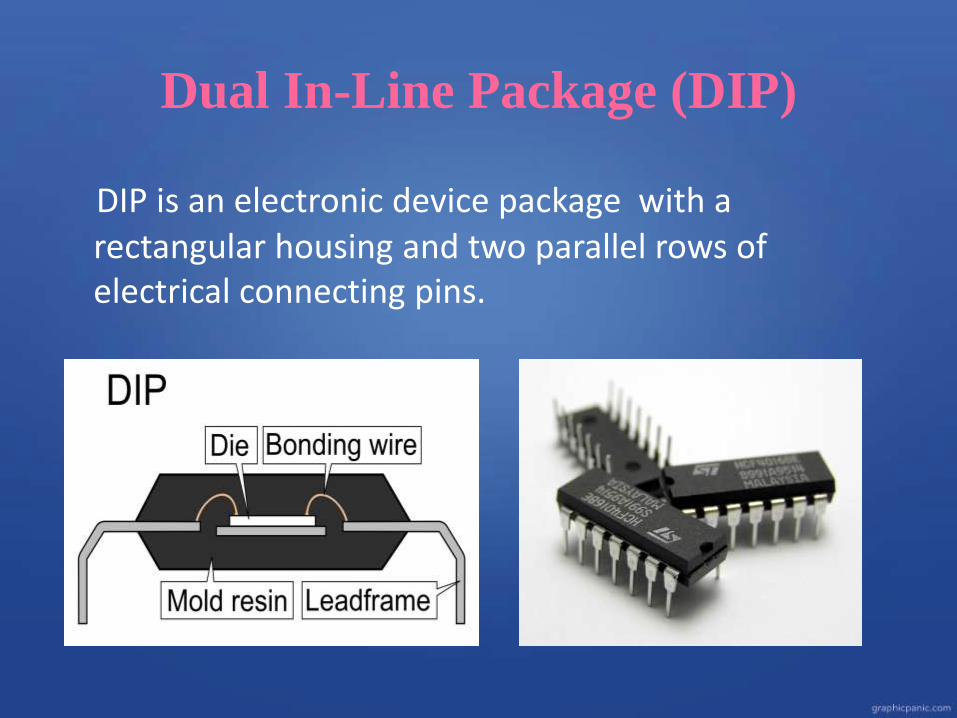
Dual In-Line Package (DIP)
DIP is an electronic device package with a rectangular housing and two parallel rows of electrical connecting pins.
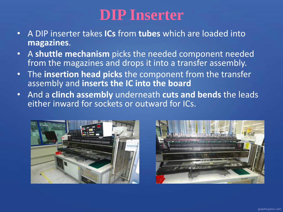
DIP Inserter• A DIP inserter takes ICs from tubes which are loaded into
magazines. • A shuttle mechanism picks the needed component needed
from the magazines and drops it into a transfer assembly. • The insertion head picks the component from the transfer
assembly and inserts the IC into the board • And a clinch assembly underneath cuts and bends the leads
either inward for sockets or outward for ICs.
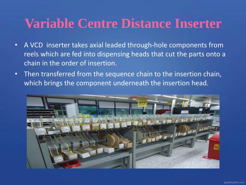
Variable Centre Distance Inserter
• A VCD inserter takes axial leaded through-hole components from reels which are fed into dispensing heads that cut the parts onto a chain in the order of insertion.
• Then transferred from the sequence chain to the insertion chain, which brings the component underneath the insertion head.
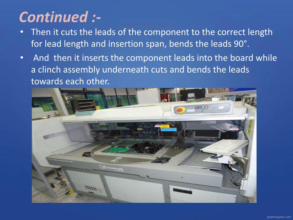
Continued :-• Then it cuts the leads of the component to the correct length
for lead length and insertion span, bends the leads 90°.
• And then it inserts the component leads into the board while a clinch assembly underneath cuts and bends the leads towards each other.
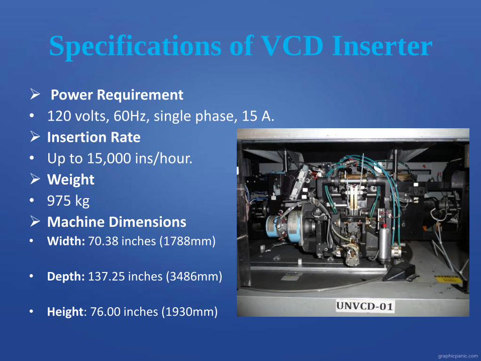
Power Requirement
• 120 volts, 60Hz, single phase, 15 A.
Insertion Rate
• Up to 15,000 ins/hour.
Weight
• 975 kg
Machine Dimensions• Width: 70.38 inches (1788mm)
• Depth: 137.25 inches (3486mm)
• Height: 76.00 inches (1930mm)
Specifications of VCD Inserter
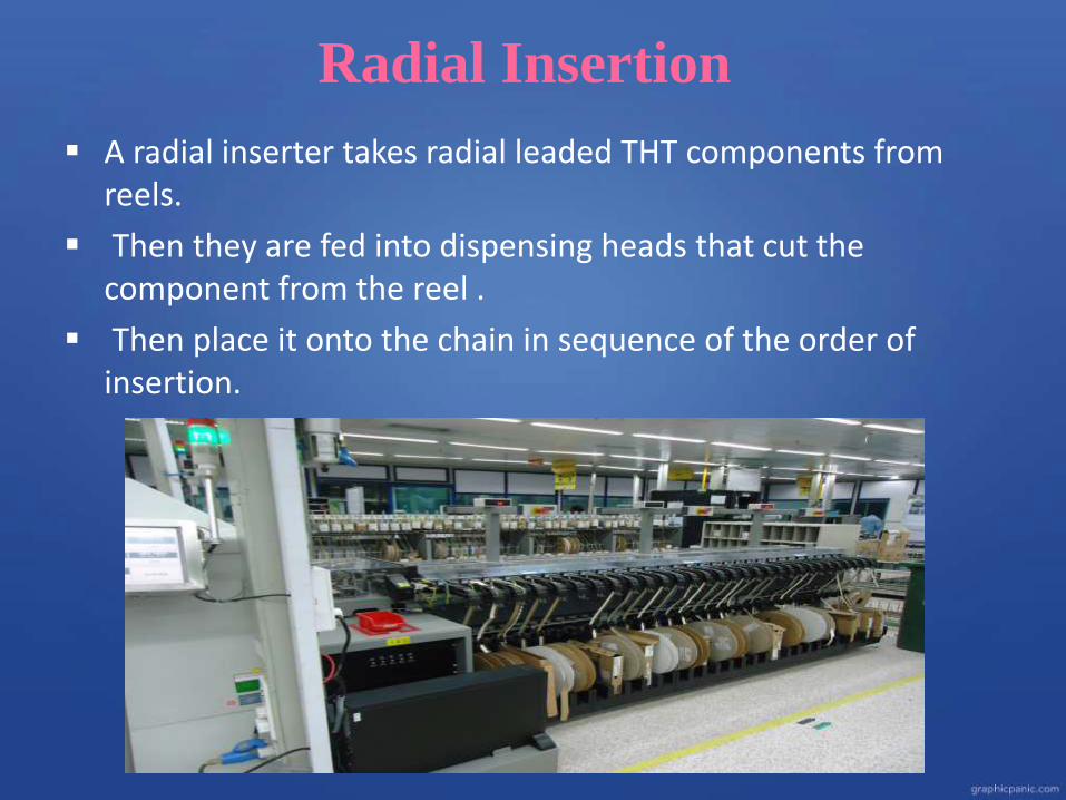
Radial Insertion
A radial inserter takes radial leaded THT components from reels.
Then they are fed into dispensing heads that cut the component from the reel .
Then place it onto the chain in sequence of the order of insertion.
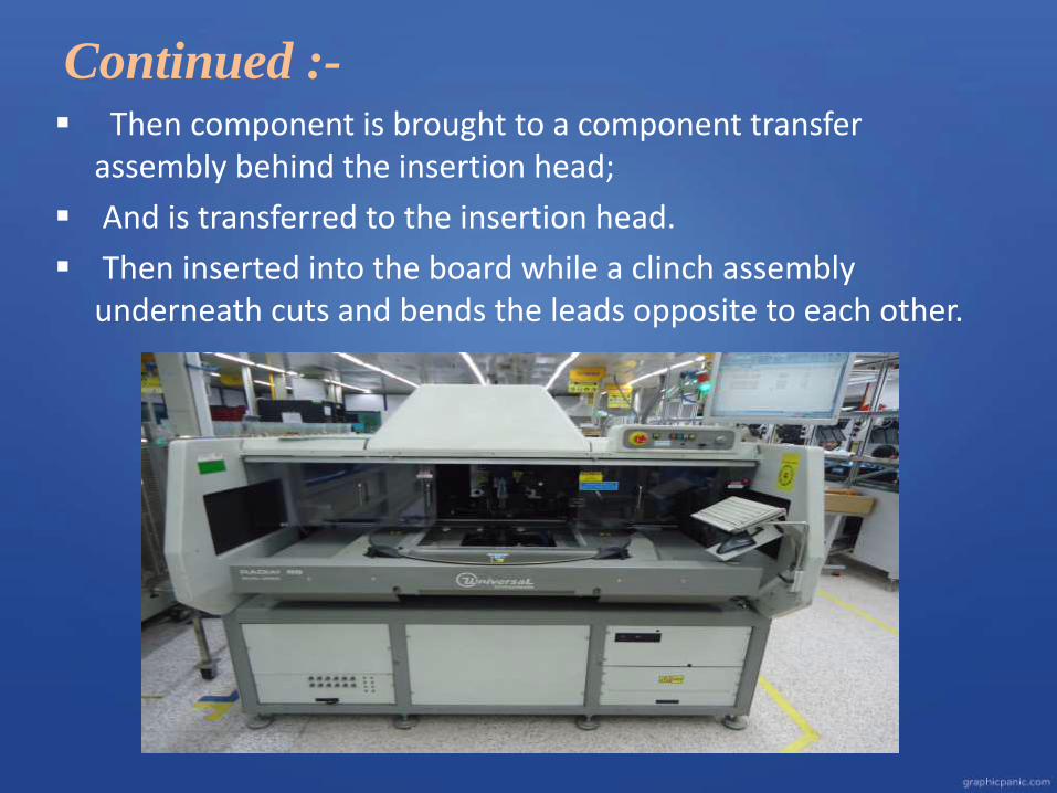
Continued :- Then component is brought to a component transfer
assembly behind the insertion head;
And is transferred to the insertion head.
Then inserted into the board while a clinch assembly underneath cuts and bends the leads opposite to each other.
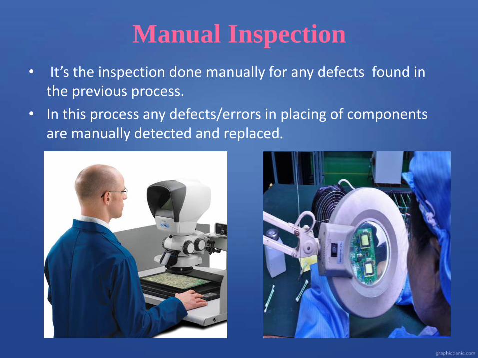
Manual Inspection
• It’s the inspection done manually for any defects found in the previous process.
• In this process any defects/errors in placing of components are manually detected and replaced.
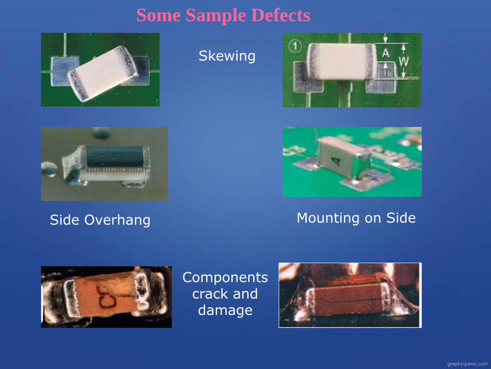
Skewing
Side Overhang Mounting on Side
Components crack and damage
Some Sample Defects
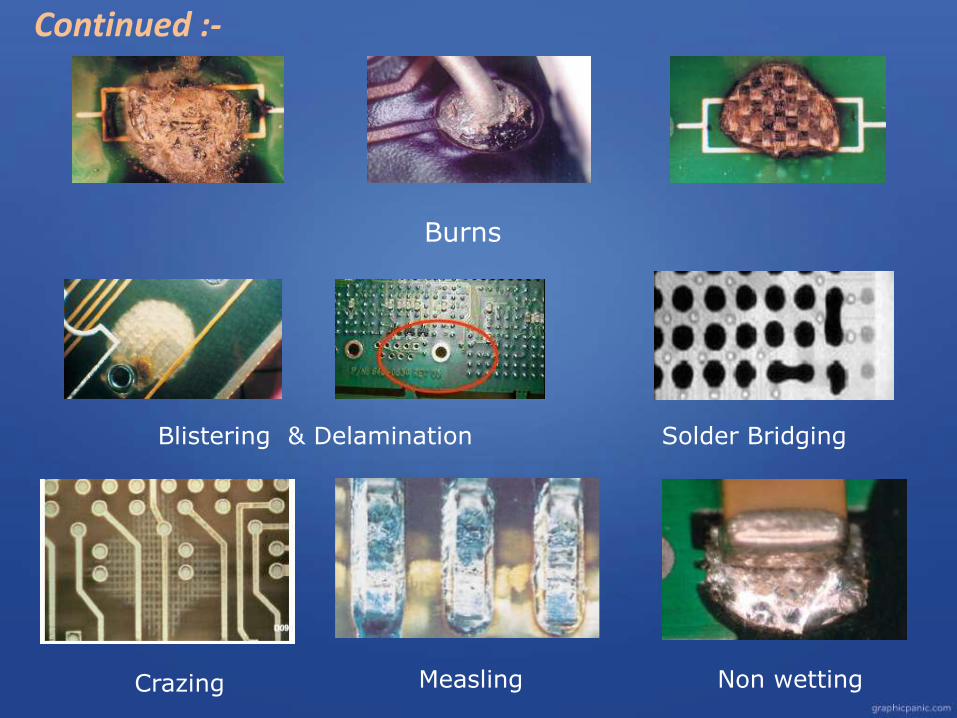
Burns
Blistering & Delamination
Crazing Measling Non wetting
Continued :-
Solder Bridging
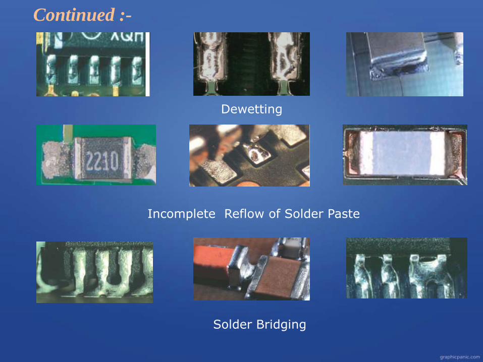
Dewetting
Incomplete Reflow of Solder Paste
Solder Bridging
Continued :-
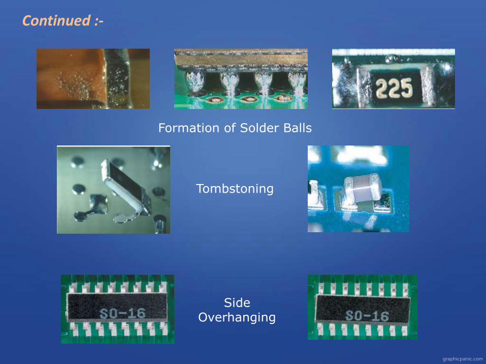
Formation of Solder Balls
Continued :-
Tombstoning
Side Overhanging
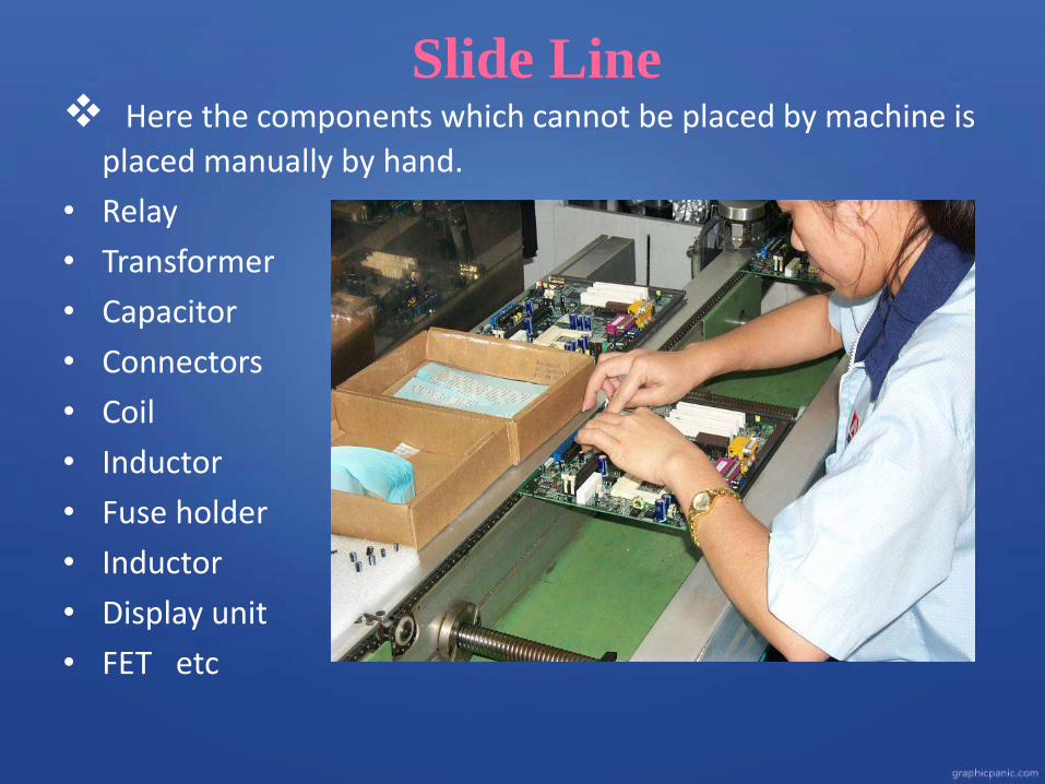
Slide Line Here the components which cannot be placed by machine is
placed manually by hand.
• Relay
• Transformer
• Capacitor
• Connectors
• Coil
• Inductor
• Fuse holder
• Inductor
• Display unit
• FET etc
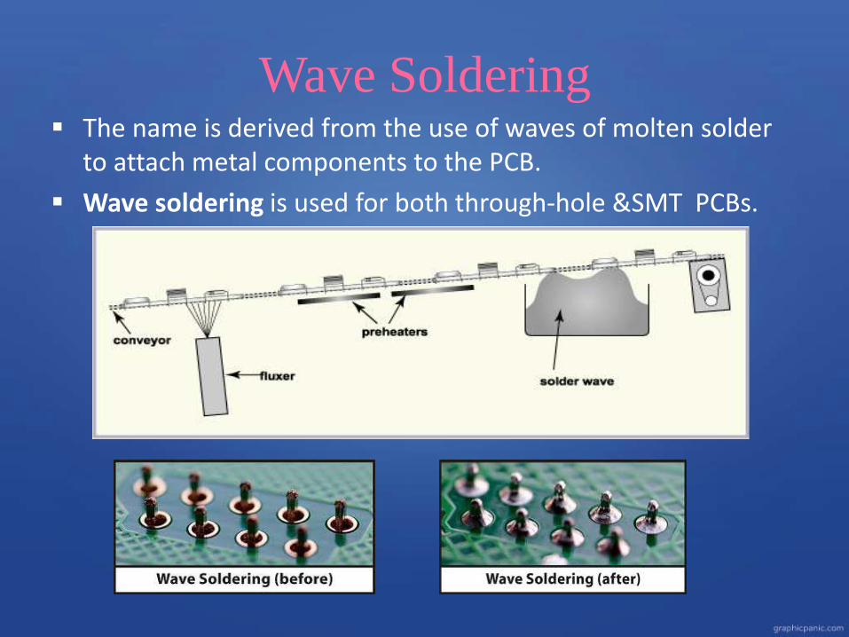
Wave Soldering The name is derived from the use of waves of molten solder
to attach metal components to the PCB.
Wave soldering is used for both through-hole &SMT PCBs.
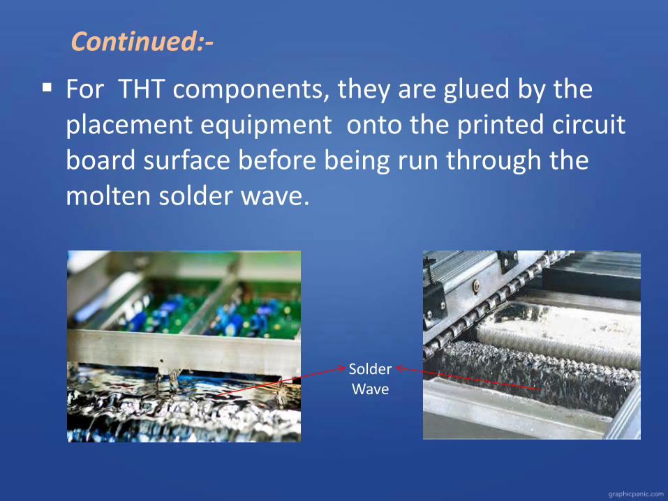
Continued:-
For THT components, they are glued by the placement equipment onto the printed circuit board surface before being run through the molten solder wave.
Solder Wave
Wave Solder Process
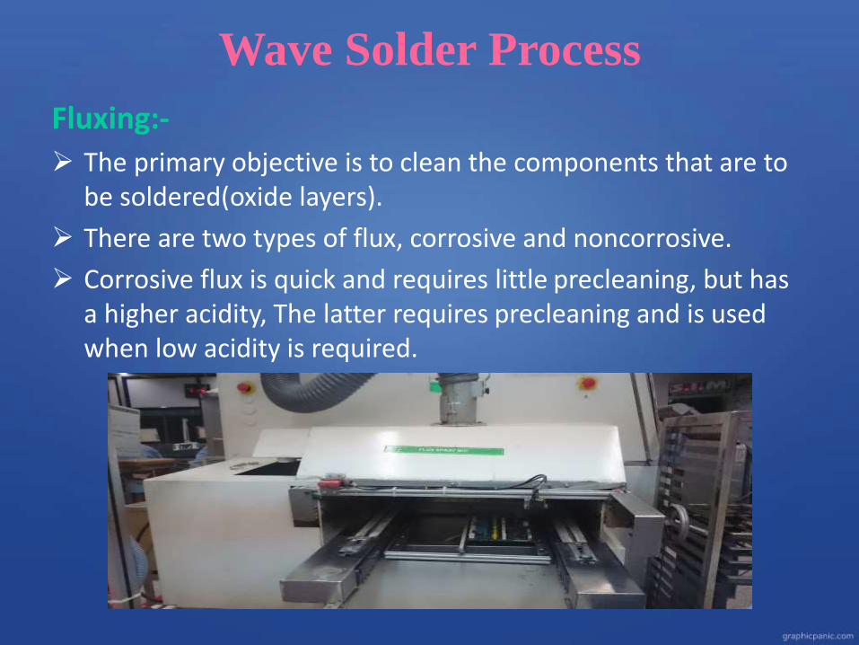
Fluxing:-
The primary objective is to clean the components that are to be soldered(oxide layers).
There are two types of flux, corrosive and noncorrosive.
Corrosive flux is quick and requires little precleaning, but has a higher acidity, The latter requires precleaning and is used when low acidity is required.

Continued :-
Preheating• The preheating zone consists of convection heaters which
blow hot air onto the PCB to increase its temperature.
• The upper preheater is usually an infrared heater.
• Preheating is necessary to activate the flux, and to remove any flux carrier solvents.
• Preheating is also necessary to prevent thermal shock.
Continued:-
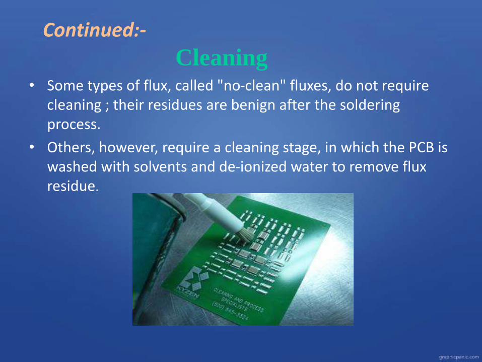
Cleaning• Some types of flux, called "no-clean" fluxes, do not require
cleaning ; their residues are benign after the soldering process.
• Others, however, require a cleaning stage, in which the PCB is washed with solvents and de-ionized water to remove flux residue.
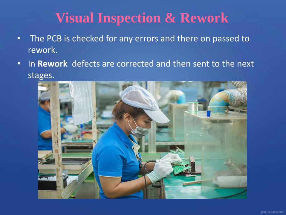
Visual Inspection & Rework
• The PCB is checked for any errors and there on passed to rework.
• In Rework defects are corrected and then sent to the next stages.
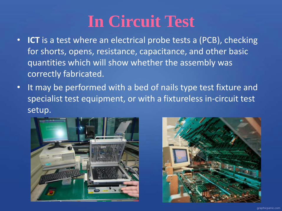
In Circuit Test• ICT is a test where an electrical probe tests a (PCB), checking
for shorts, opens, resistance, capacitance, and other basic quantities which will show whether the assembly was correctly fabricated.
• It may be performed with a bed of nails type test fixture and specialist test equipment, or with a fixtureless in-circuit test setup.
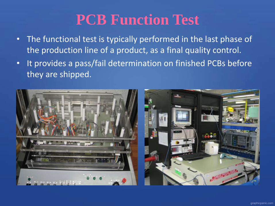
PCB Function Test
• The functional test is typically performed in the last phase of the production line of a product, as a final quality control.
• It provides a pass/fail determination on finished PCBs before they are shipped.
Continued:-
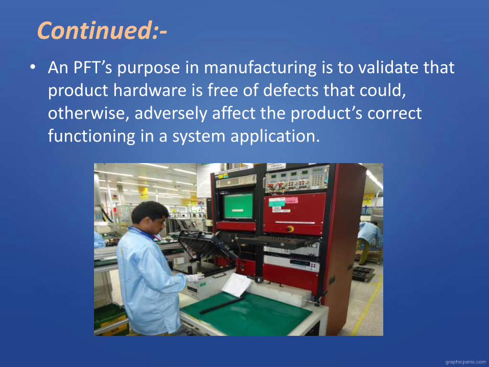
• An PFT’s purpose in manufacturing is to validate that product hardware is free of defects that could, otherwise, adversely affect the product’s correct functioning in a system application.
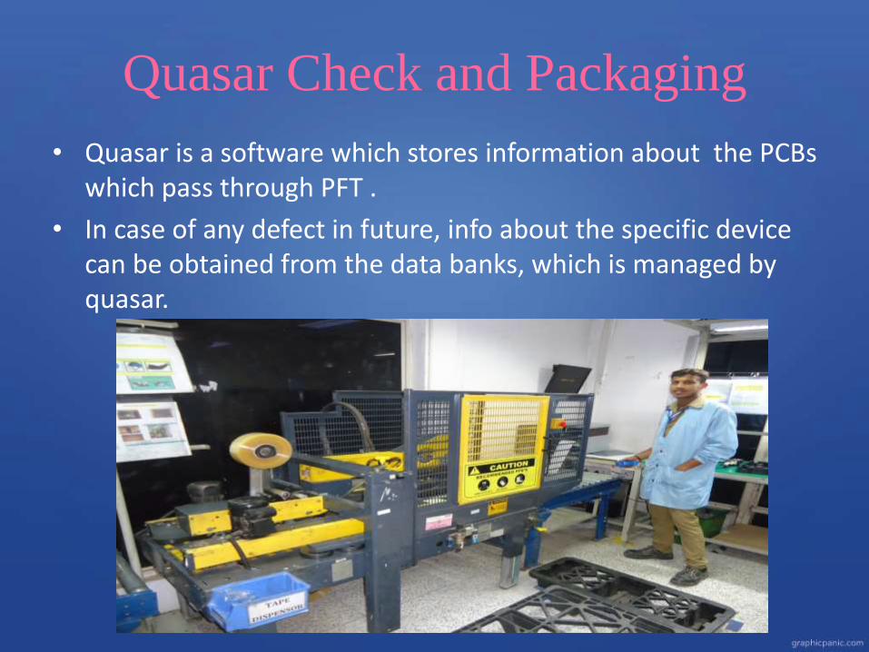
Quasar Check and Packaging
• Quasar is a software which stores information about the PCBs which pass through PFT .
• In case of any defect in future, info about the specific device can be obtained from the data banks, which is managed by quasar.
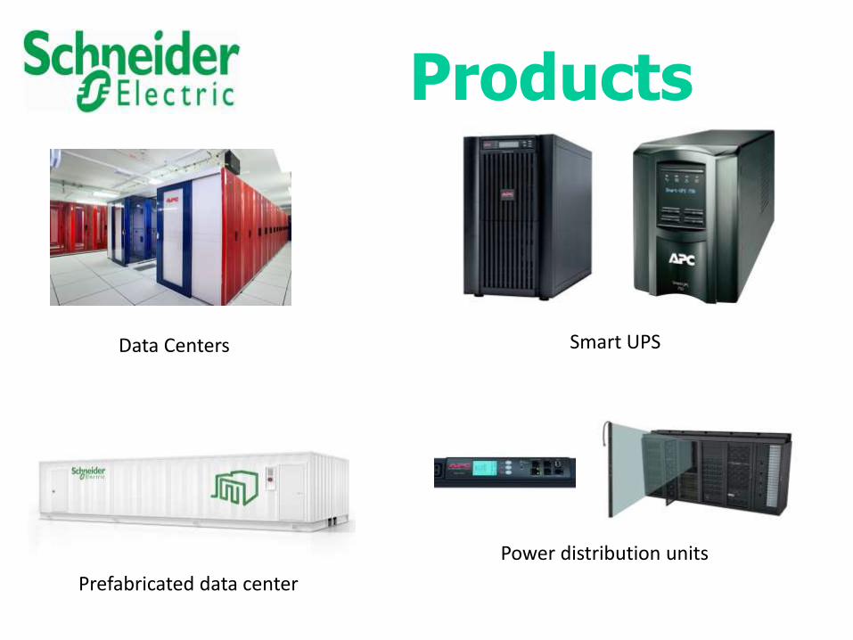
Data Centers Smart UPS
Prefabricated data center
Power distribution unitsunit
Products
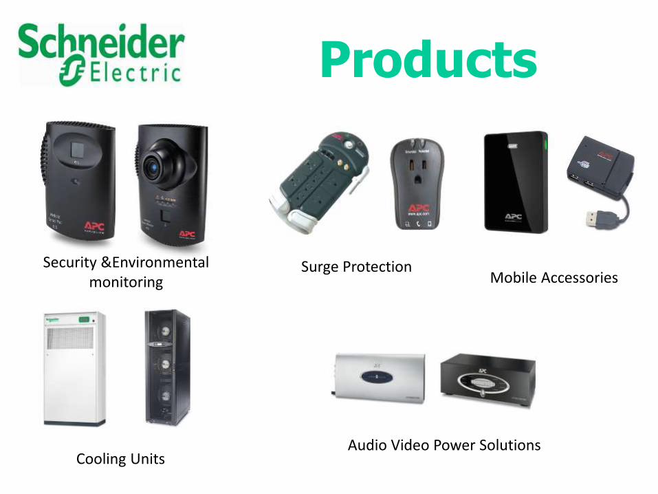
Products
Security &Environmental monitoring
Surge Protection
Cooling Units
Mobile Accessories
Audio Video Power Solutions


Our Sincere Gratitude to
Santosh P.NH.R Manager
K. Anand SharvanPlatform Team Leader MFG. Tech
Process Engineer

Sujith.J.SProject Trainee
Bangalore Institute Of Technology
V.V.Puram
8762985568
Presented by:-


![Pcb Manufacturing[1]](https://img.pdfslide.net/doc/110x75/577d2ab51a28ab4e1ea9dec2/pcb-manufacturing1.jpg)