Embed Size (px)
Citation preview
MEASUREMENTSAND
INSTRUMENTATION
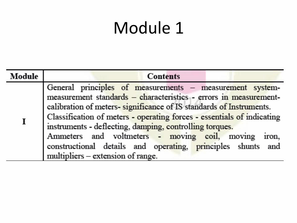
Module 1
• MEASUREMENT
• A Method To Obtain The Information Regarding The
Physical Values Of A Variable.
• INSTRUMENTATION
• Device used for measurement system
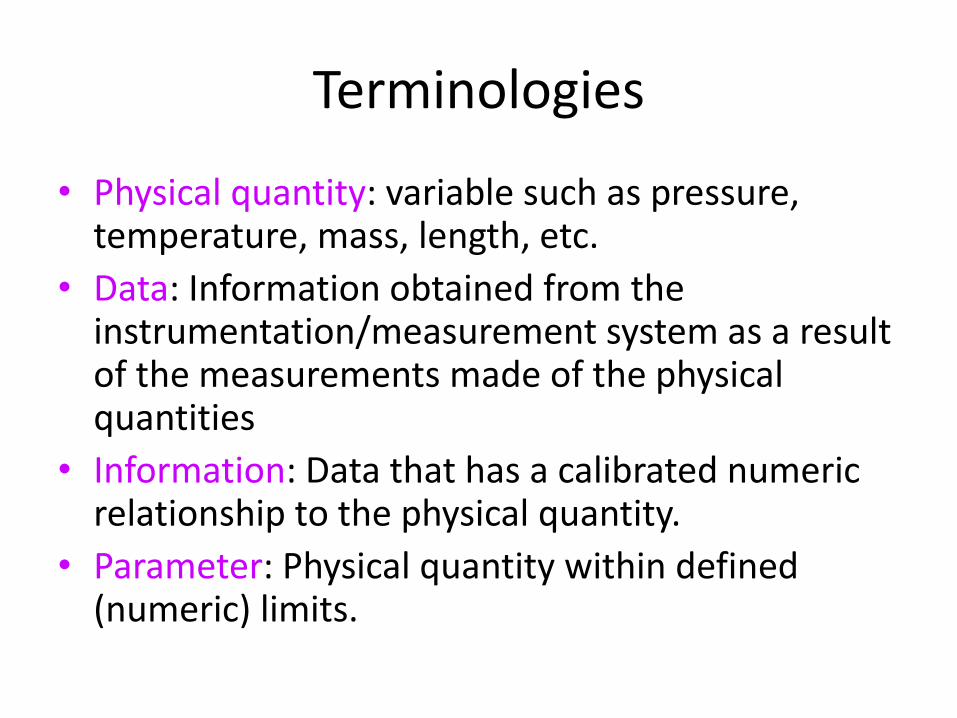
Terminologies
• Physical quantity: variable such as pressure, temperature, mass, length, etc.
• Data: Information obtained from the instrumentation/measurement system as a result of the measurements made of the physical quantities
• Information: Data that has a calibrated numeric relationship to the physical quantity.
• Parameter: Physical quantity within defined (numeric) limits.
5
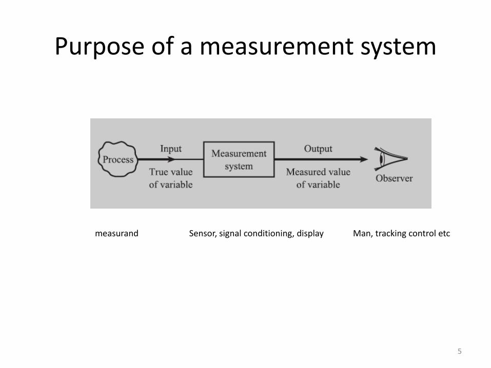
Purpose of a measurement system
measurand Sensor, signal conditioning, display Man, tracking control etc
• Measurand: Physical quantity being measured.
• Calibration: Implies that there is a numeric relationship throughout the whole instrumentation system and that it is directly related to an approved national or international standard.
• Test instrumentation: It is a branch of instrumentation and most closely associated with the task of gathering data during various development phases encountered in engineering, e.g.
flight test instrumentation for testing and approving aircraft.
6
Terminology
• Transducer: A device that converts one form of energy to another.
• Electronic transducer: It has an input or output that is electrical in nature (e.g., voltage, current or resistance).
• Sensor: Electronic transducer that converts physical quantity into an electrical signal.
• Actuator: Electronic transducer that converts electrical energy into mechanical energy.
7
Terminologies

• In the case of process industries and industrial manufacturing…
– To improve the quality of the product
– To improve the efficiency of production
– To maintain the proper operation.
8
Why measurement?
• To acquire data or information (hence data acquisition) about parameters, in terms of:– putting the numerical values to the physical quantities
– making measurements otherwise inaccessible.
– producing data agreeable to analysis (mostly in electrical form)
• Data Acquisition Software (DAS) – data is acquired by the instrumentation system.
9
Why instrumentation?
Requirement of measuring instrument
• With the introduction of the instrument in the circuit the circuit conditions should not alter
- Thus the quanity to be measured should not get affected due to the instrument used.
• Power consumed by the instrument for their operation should be small as possible.
• Direct comparison– Easy to do but… less accurate
• e.g. to measure a steel bar
• Indirect comparison– Calibrated system; consists of several devices to
convert, process (amplification or filtering) and display the output • e.g. to measure force from strain gages located in a
structure
11
Types of measurements
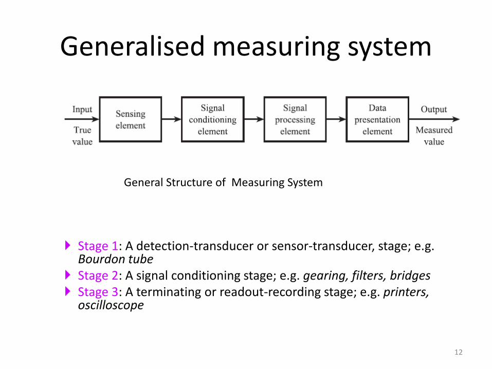
Stage 1: A detection-transducer or sensor-transducer, stage; e.g.Bourdon tube
Stage 2: A signal conditioning stage; e.g. gearing, filters, bridges Stage 3: A terminating or readout-recording stage; e.g. printers,
oscilloscope
12
Generalised measuring system
General Structure of Measuring System
• Active Instruments– the quantity being measured simply modulates (adapts to) the
magnitude of some external power source.
• Passive Instruments– the instrument output is entirely produced by the quantity being
measured
• Difference between active & passive instruments is the level of measurement resolution that can be obtained.
13
Types of instruments in measurements
MEASUREMENT
• The process of measuring is essentially that of comparing some unknown value with a value which is assumed to be known.
• 1) latter one in standard.
• 2) And measuring system is instrument.
• Characteristics of INSTRUMENTS
• Calibration: All the static characteristics are obtained in one form or another by a process called Calibration.
Calibration procedures involve a comparison of the particular instrument with either
a) a primary standard.b) a secondary standard with a higher accuracy than
the instruments be calibrated.c) an instrument of known accuracy.
• Accuracy: Accuracy may be defined as the ability of a device or a system to respond to a true value of a measured variable under reference conditions.
• Precision: Precision is defined by the degree of exactness for which an instrument is designed or intended to perform.
• Repeatability: It is the closeness of agreement among a number of consecutive measurements of the output for the same value of the input, under the same operating conditions.
• Reproducibility: It is the closeness of agreement among repeated measurements of the output for the same value of the input, made under the same operating conditions over a period of time.
• Drift: It is an undesired change or a gradual variation in output over a period of time that is unrelated to changes in input and operating conditions.
• Span: If in a measuring instrument the highest point of calibration is y units and the lowest point x units.Then the instrument range y unitsThe instrument span is given by Span=(x-y)units
• Sensitivity: Sensitivity can be defined as the ratio of a change in output to the change in input which causes it.
• Resolution: The smallest increment in input (the quantity being measured) which can be detected with certainty by an instrument is its resolution.
• Dead zone: Dead zone is the largest range of values of a measured variable to which the instrument does not respond.
• To define physical quantities in type and magnitude
• Units of measurement may be defined as the standard measure of each kind of physical quantity.
• Efforts were made to standardise systems of measurement so that instrument professionals and specialist in other
disciplines could communicate among themselves.
18
Units Of Measurement
• Foot-pound-second (F.P.S.) used for:
– Length
– Mass
– Time
19
English Systems Of Units
• As a physical representation of a unit of measurement
• It is used for obtaining the values of the physical properties of other equipment by comparison methods; e.g.
– The fundamental unit of mass in the SI system is the kilogram, defined as the mass of a cubic decimeter of water at its temperature of maximum density of 4C.
20
Standard Of Measurement

• International Organization for Standardization (ISO)
• International Electrotechnical Commission (IEC)
• American National Standards Institute (ANSI)
• Standards Council of Canada ( SCC)
• British Standards (BS)
21
Examples of Standard Bodies
22
CalibrationCalibration consists of comparing the output of the instrument or sensor under test against the output of an instrument of known accuracy (higher accuracy)when the same input (the measured quantity is applied to both instrument)
The procedure is carried out for a range of inputs coveringthe whole measurement range of the instrument or sensorEnsures that the measuring accuracy of all instruments andsensors used in a measurement system is known over the whole measurement range, provided that the calibrated instruments and sensors are used in environmental conditionsthat are the same as those under which they were calibrated
23
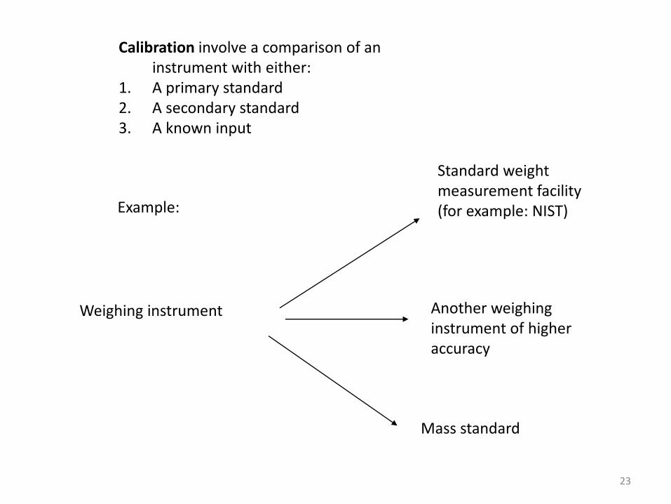
Calibration involve a comparison of an instrument with either:
1. A primary standard2. A secondary standard3. A known input
Example:
Weighing instrument
Standard weight measurement facility(for example: NIST)
Another weighing instrument of higher accuracy
Mass standard
• The method and apparatus for performing measurement instrumentation calibrations vary widely.
• A rule that should be followed is that the calibration standard should be at least 10 times as accurate as the instrument being calibrated.
• By holding some inputs constant, varying others and recording the output(s) develop the desired static input-output relations. Many trial and runs are needed.
24
Calibration
• Home – Thermometer
– Barometer
– Watch
• Road vehicles– speedometer
– fuel gauge
• Industry– Automation
– Process control
– Boiler control
25
Application
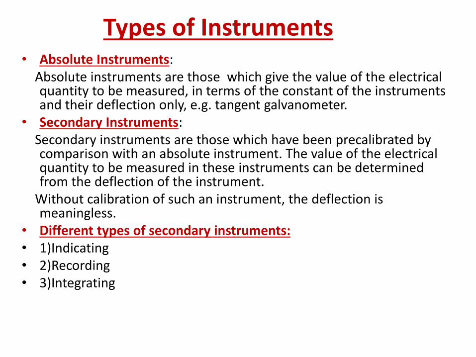
Types of Instruments• Absolute Instruments:
Absolute instruments are those which give the value of the electrical quantity to be measured, in terms of the constant of the instruments and their deflection only, e.g. tangent galvanometer.
• Secondary Instruments:Secondary instruments are those which have been precalibrated by comparison with an absolute instrument. The value of the electrical quantity to be measured in these instruments can be determined from the deflection of the instrument.
Without calibration of such an instrument, the deflection is meaningless.
• Different types of secondary instruments:• 1)Indicating• 2)Recording• 3)Integrating

• 1)Indicating:
Indicating instruments are those which indicate the instantaneous value of the electrical quantity being measured, at the time at which it is being measured. Their indications are given by pointers moving over calibrated dials(scale), e.g. ammeters,voltmeters and wattmeters.
• 2)Recording:
Recording instruments are those which give a continuous record of variations of the electrical quantity over a selected period of time. The moving system of the instrument carries an inked pen which rests tightly on a graph chart. E.g. recording voltmeters used in supply station.
• 3)Integrating:
Integrating instruments are those which measure and register the total quantity of electricity (in ampere-hour) or the total amount of electrical energy(in watt-hours or kilowatt-hours) supplied to a circuit over a period of time, e.g. ampere-hour meters, energy meters.
Essentials of Indicating Instruments
• Deflecting Torque(Td):
It is the torque which deflects the pointer on a calibrated scale according to the electrical quantity passing through the instrument. The deflecting torque causes the moving system and hence the pointer attached to it to move from zero position to indicate on a graduated scale the value of electrical quantity being measured.
• Controlling Torque(Tc):
It is the torque which controls the movement of the pointer on a particular scale according to the quantity of electricity passing through it. If deflecting torque were acting alone, the pointer would continue to move indefinitely and would swing over to the maximum deflected position irrespective of the magnitude of current (or voltage or power) to be measured.
1) Spring Control:In the spring control method, a hair-spring, usually of phosphor-bronze, attached to the moving system is used. With the deflection of the pointer, the spring is twisted in the opposite direction. This twist in the spring produces a restoring torque which is directly proportional to the angle of deflection of the moving system. The pointer comes to a position of rest (or equilibrium) when the deflecting torque (Td) and controlling torque (Tc) are equal.
Tc ∞ θ
To give a controlling torque which is directly proportional to the angle of deflection of the moving system, the number of turns of the spring should be fairly large so that the deformation per unit length is small. The stress in the spring must be limited to such a value that there is no permanent set. Springs are made of materials which are
Non magnetic
Not subject to much fatigue
Low in specific resistance
Have low temperature coefficient of resistance.
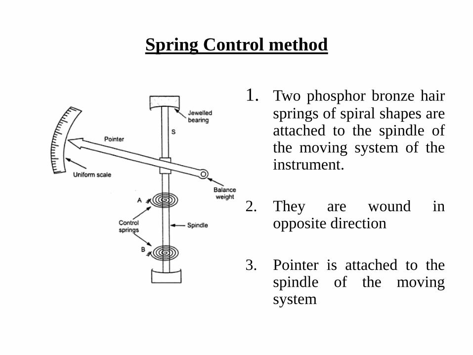
Spring Control method
1. Two phosphor bronze hairsprings of spiral shapes areattached to the spindle ofthe moving system of theinstrument.
2. They are wound inopposite direction
3. Pointer is attached to thespindle of the movingsystem
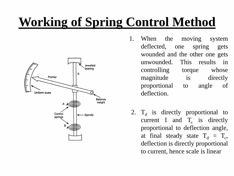
Working of Spring Control Method
1. When the moving system
deflected, one spring gets
wounded and the other one gets
unwounded. This results in
controlling torque whose
magnitude is directly
proportional to angle of
deflection.
2. Td is directly proportional to
current I and Tc is directly
proportional to deflection angle,
at final steady state Td = Tc,
deflection is directly proportional
to current, hence scale is linear
Gravity Control Method
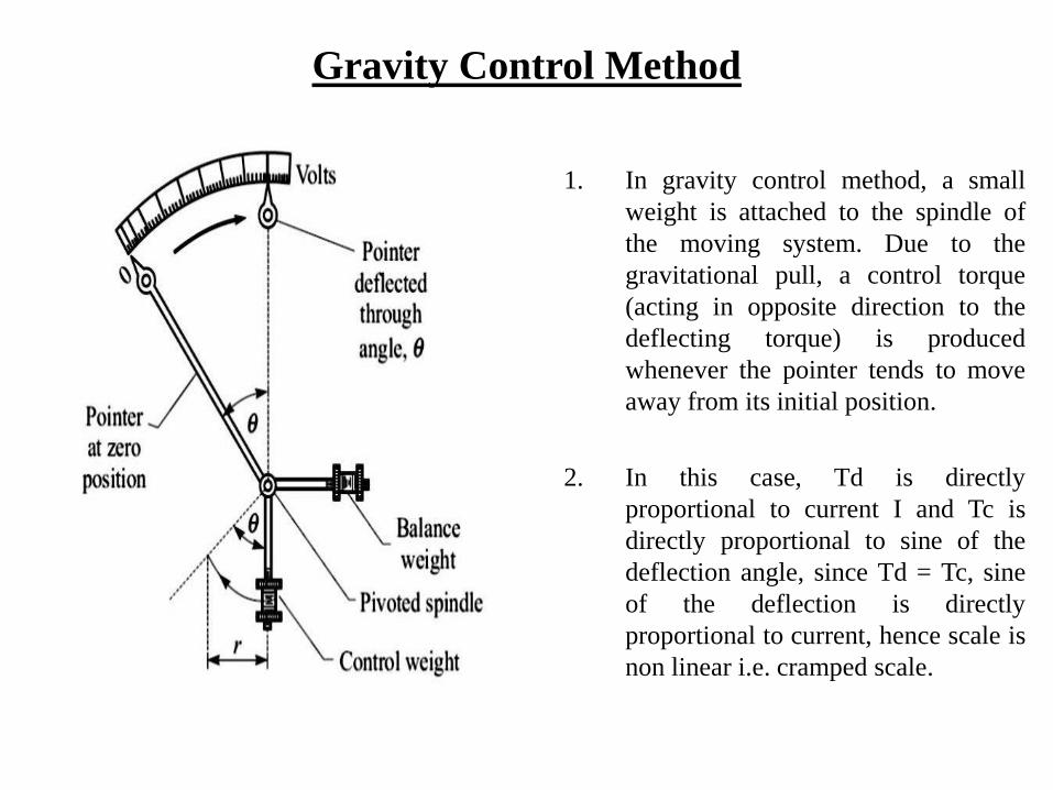
1. In gravity control method, a small
weight is attached to the spindle of
the moving system. Due to the
gravitational pull, a control torque
(acting in opposite direction to the
deflecting torque) is produced
whenever the pointer tends to move
away from its initial position.
2. In this case, Td is directly
proportional to current I and Tc is
directly proportional to sine of the
deflection angle, since Td = Tc, sine
of the deflection is directly
proportional to current, hence scale is
non linear i.e. cramped scale.
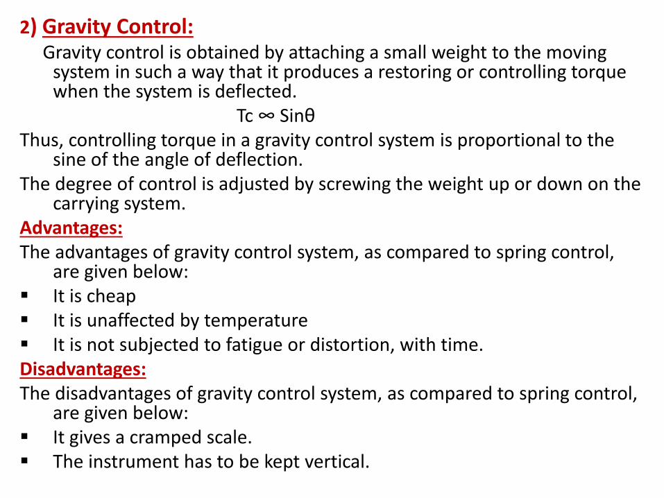
2) Gravity Control:Gravity control is obtained by attaching a small weight to the moving
system in such a way that it produces a restoring or controlling torque when the system is deflected.
Tc ∞ SinθThus, controlling torque in a gravity control system is proportional to the
sine of the angle of deflection.The degree of control is adjusted by screwing the weight up or down on the
carrying system.Advantages:The advantages of gravity control system, as compared to spring control,
are given below: It is cheap It is unaffected by temperature It is not subjected to fatigue or distortion, with time.Disadvantages:The disadvantages of gravity control system, as compared to spring control,
are given below: It gives a cramped scale. The instrument has to be kept vertical.
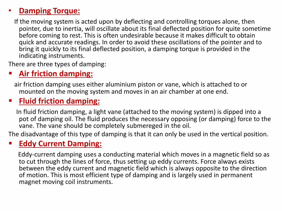
• Damping Torque:If the moving system is acted upon by deflecting and controlling torques alone, then
pointer, due to inertia, will oscillate about its final deflected position for quite sometime before coming to rest. This is often undesirable because it makes difficult to obtain quick and accurate readings. In order to avoid these oscillations of the pointer and to bring it quickly to its final deflected position, a damping torque is provided in the indicating instruments.
There are three types of damping:
Air friction damping:air friction damping uses either aluminium piston or vane, which is attached to or
mounted on the moving system and moves in an air chamber at one end.
Fluid friction damping:In fluid friction damping, a light vane (attached to the moving system) is dipped into a pot of damping oil. The fluid produces the necessary opposing (or damping) force to the vane. The vane should be completely submereged in the oil.
The disadvantage of this type of damping is that it can only be used in the vertical position.
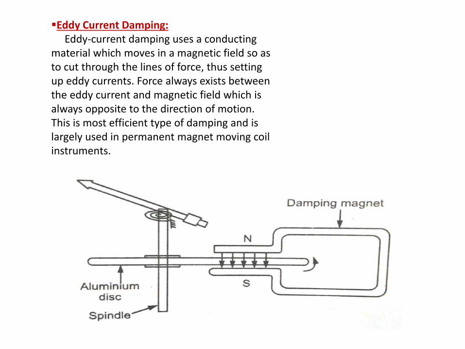
Eddy Current Damping:Eddy-current damping uses a conducting material which moves in a magnetic field so as to cut through the lines of force, thus setting up eddy currents. Force always exists between the eddy current and magnetic field which is always opposite to the direction of motion. This is most efficient type of damping and is largely used in permanent magnet moving coil instruments.
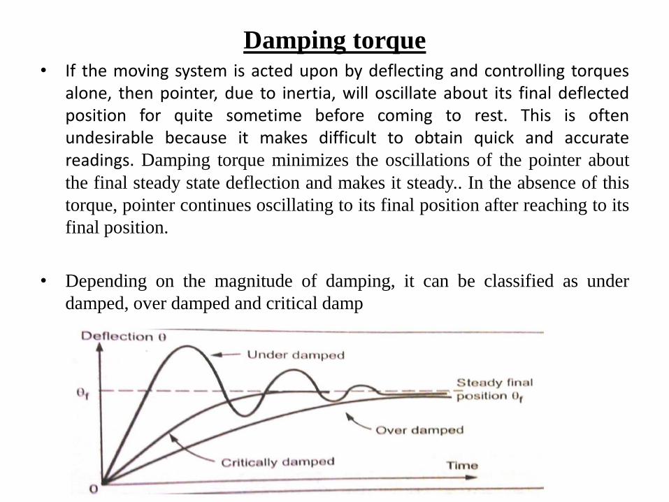
Damping torque• If the moving system is acted upon by deflecting and controlling torques
alone, then pointer, due to inertia, will oscillate about its final deflectedposition for quite sometime before coming to rest. This is oftenundesirable because it makes difficult to obtain quick and accuratereadings. Damping torque minimizes the oscillations of the pointer about
the final steady state deflection and makes it steady.. In the absence of this
torque, pointer continues oscillating to its final position after reaching to its
final position.
• Depending on the magnitude of damping, it can be classified as under
damped, over damped and critical damp
Damping Methods
Air Friction Damping
Eddy current Damping
Fluid Friction Damping
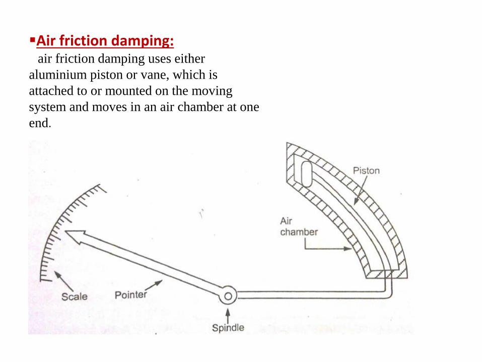
Air friction damping:air friction damping uses either
aluminium piston or vane, which is
attached to or mounted on the moving
system and moves in an air chamber at one
end.
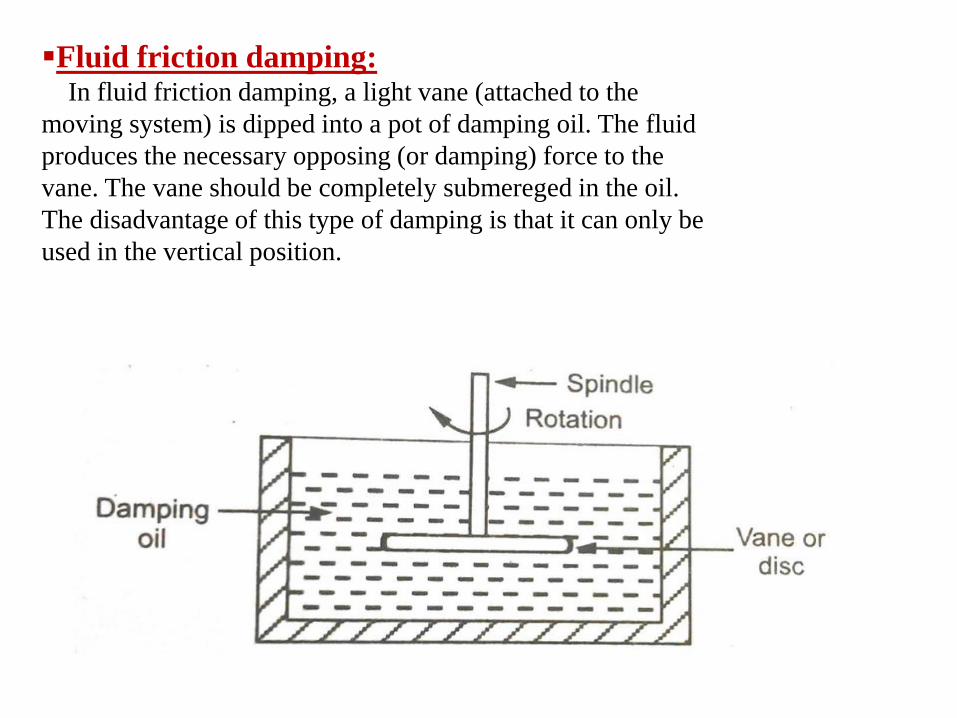
Fluid friction damping:In fluid friction damping, a light vane (attached to the
moving system) is dipped into a pot of damping oil. The fluid
produces the necessary opposing (or damping) force to the
vane. The vane should be completely submereged in the oil.
The disadvantage of this type of damping is that it can only be
used in the vertical position.
Eddy Current Damping:Eddy-current damping uses a conducting
material which moves in a magnetic field so as to cut through the lines of force, thus setting up eddy currents. Force always exists between the eddy current and magnetic field which is always opposite to the direction of motion. This is most efficient type of damping and is largely used in permanent magnet moving coil instruments.
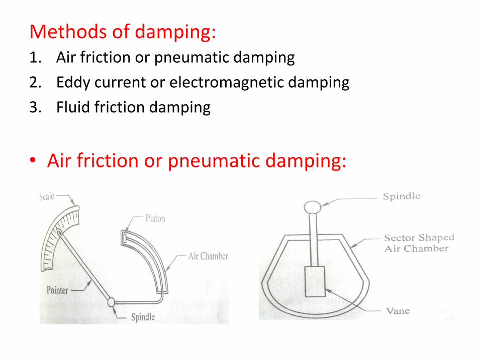
Methods of damping:1. Air friction or pneumatic damping
2. Eddy current or electromagnetic damping
3. Fluid friction damping
• Air friction or pneumatic damping:
Air Friction or Pneumatic Damping:
• In this system a light aluminium piston is attached to the spindle of the instrument and is arranged to move in a fix air chamber closed at one end. The cross section of the chamber may be either circular or rectangular and the clearance between the piston and the side of the chamber is small and uniform. Compression and suction action of the piston on the air in the chamber damp the possible oscillations of moving system, because the motion of the piston in either direction is oppose by the air.
• In second case a thin aluminium vane, mounted on the spindle, moves with very small clearance in a sector shaped box. Any tendency of the moving system to oscillate is damped by the action of the air on vane.
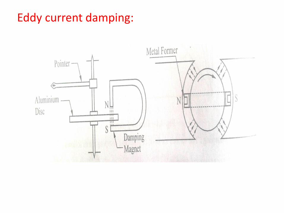
Eddy current damping:
Eddy current damping:
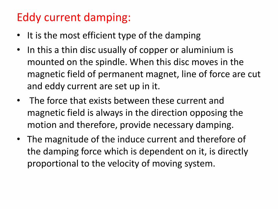
• It is the most efficient type of the damping
• In this a thin disc usually of copper or aluminium is mounted on the spindle. When this disc moves in the magnetic field of permanent magnet, line of force are cut and eddy current are set up in it.
• The force that exists between these current and magnetic field is always in the direction opposing the motion and therefore, provide necessary damping.
• The magnitude of the induce current and therefore of the damping force which is dependent on it, is directly proportional to the velocity of moving system.
Fluid friction damping:
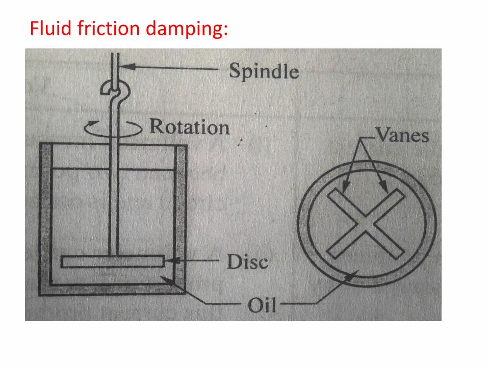
Fluid friction damping:• In this method of damping, a light disc is attached to the
spindle of the moving system and completely submerge in the damping oil in a pot.
• The motion of the disc is always opposed by a frictional drag on the disc. This frictional drag is zero when the disc is stationary and increases with the speed of the rotation of the disc.
• For increase damping, vanes in a vertical planes, carried on a spindle and immersed in oil are used.
• Fluid friction damping can only be used in the instruments which are use in the vertical position.
Error• Types of Error
• Static Error : the numerical difference between the true value of a quantity and its value as obtained by measurement.
• Mistakes: These are errors due to human mistakes such as careless reading, mistakes in observations, incorrect application of a correction, improper application of instruments and computational errors.
• Systematic Error: • 1)Instrumental Error: Instrumental errors are the errors inherent
in measuring instruments because of their mechanical structure, such as friction in bearings of various moving components, irregular spring tension.
• 2)Environmental Error: it is due to conditions external to the measuring device including conditions in the area surrounding the instrument such as the effect of change in temp , humidity, barometric pressure , or magnetic or electrostatic fields.
• Random Error: the cause of such error is unknown or not determinable in the ordinary process of making measurements. Such errors are normally small and follows the laws of chance.
Sources of error
• Insufficient knowledge of process parameters and design conditions.
• Poor design.
• Poor maintenance.
• Error caused by people who operate instrument equipment.
• Certain design limitations.
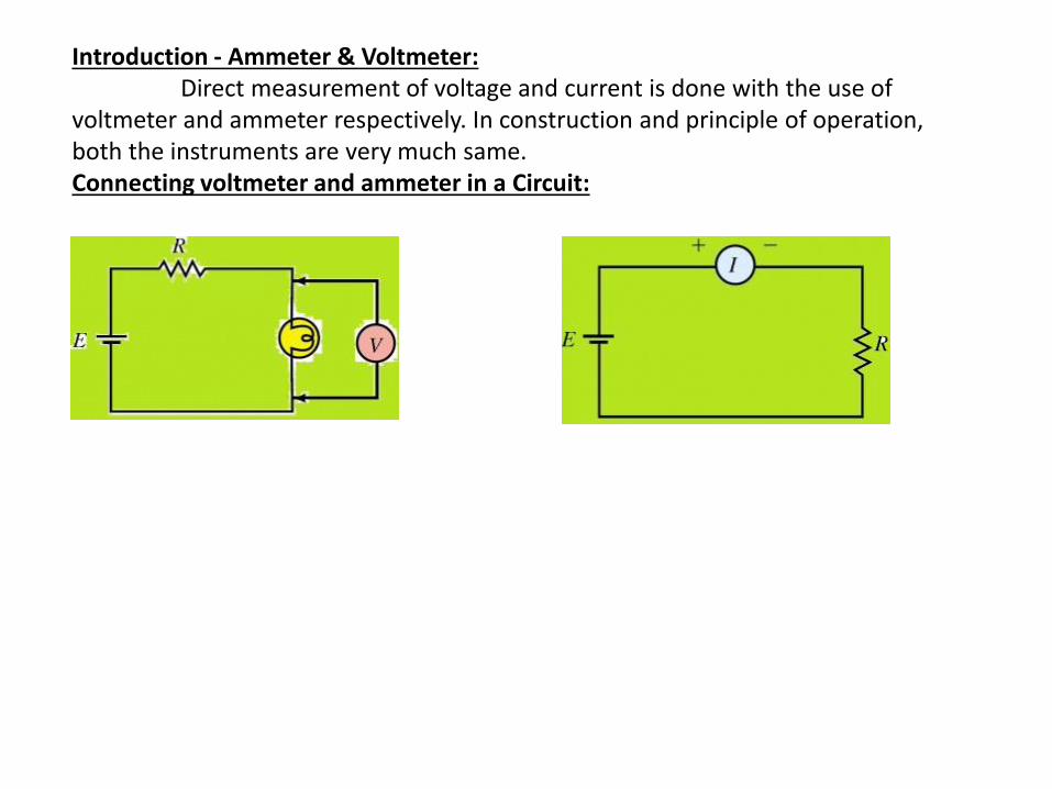
Introduction - Ammeter & Voltmeter:Direct measurement of voltage and current is done with the use of
voltmeter and ammeter respectively. In construction and principle of operation, both the instruments are very much same.Connecting voltmeter and ammeter in a Circuit:
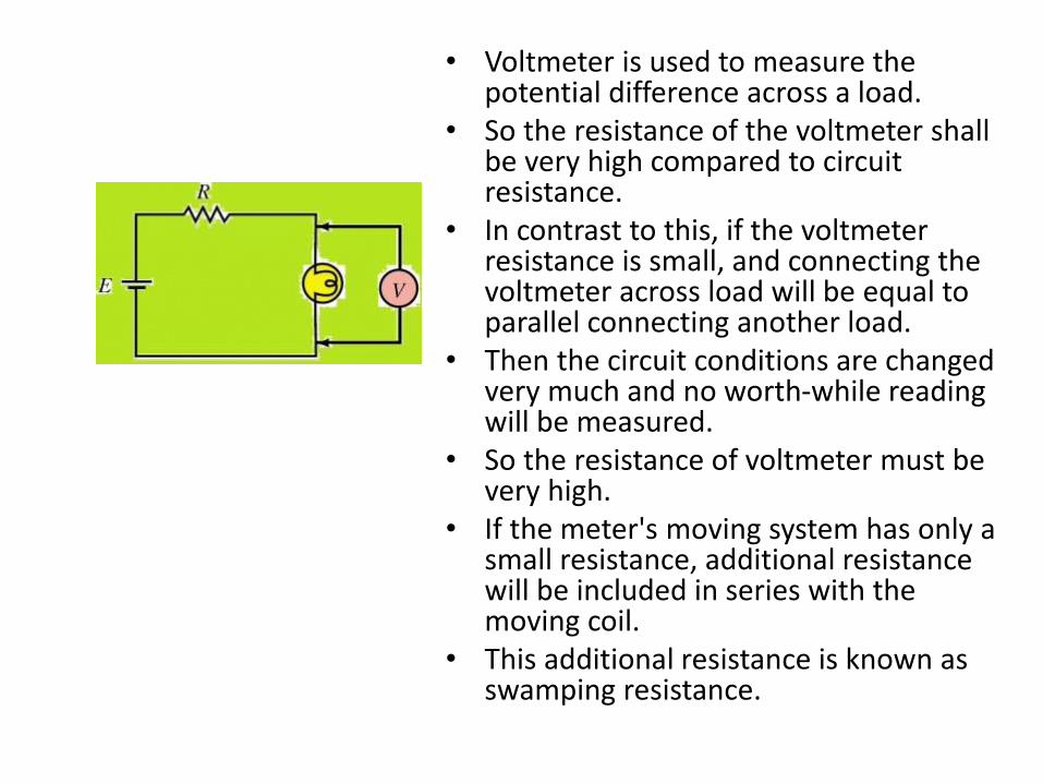
• Voltmeter is used to measure the potential difference across a load.
• So the resistance of the voltmeter shall be very high compared to circuit resistance.
• In contrast to this, if the voltmeter resistance is small, and connecting the voltmeter across load will be equal to parallel connecting another load.
• Then the circuit conditions are changed very much and no worth-while reading will be measured.
• So the resistance of voltmeter must be very high.
• If the meter's moving system has only a small resistance, additional resistance will be included in series with the moving coil.
• This additional resistance is known as swamping resistance.
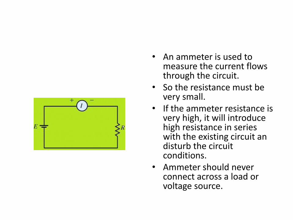
• An ammeter is used to measure the current flows through the circuit.
• So the resistance must be very small.
• If the ammeter resistance is very high, it will introduce high resistance in series with the existing circuit an disturb the circuit conditions.
• Ammeter should never connect across a load or voltage source.
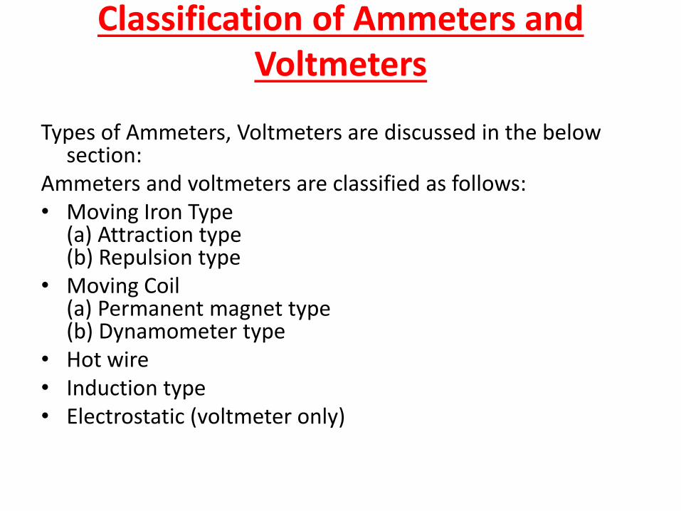
Classification of Ammeters and Voltmeters
Types of Ammeters, Voltmeters are discussed in the below section:
Ammeters and voltmeters are classified as follows:• Moving Iron Type
(a) Attraction type(b) Repulsion type
• Moving Coil(a) Permanent magnet type(b) Dynamometer type
• Hot wire• Induction type• Electrostatic (voltmeter only)
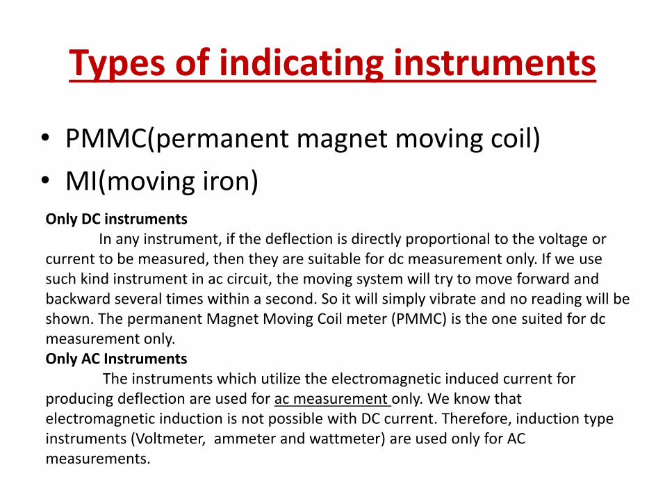
Types of indicating instruments
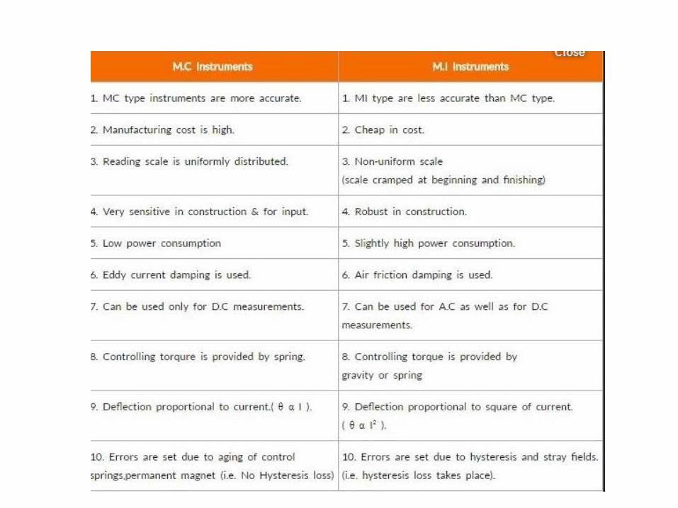
• PMMC(permanent magnet moving coil)
• MI(moving iron)Only DC instruments
In any instrument, if the deflection is directly proportional to the voltage or current to be measured, then they are suitable for dc measurement only. If we use such kind instrument in ac circuit, the moving system will try to move forward and backward several times within a second. So it will simply vibrate and no reading will be shown. The permanent Magnet Moving Coil meter (PMMC) is the one suited for dc measurement only.Only AC Instruments
The instruments which utilize the electromagnetic induced current for producing deflection are used for ac measurement only. We know that electromagnetic induction is not possible with DC current. Therefore, induction type instruments (Voltmeter, ammeter and wattmeter) are used only for AC measurements.
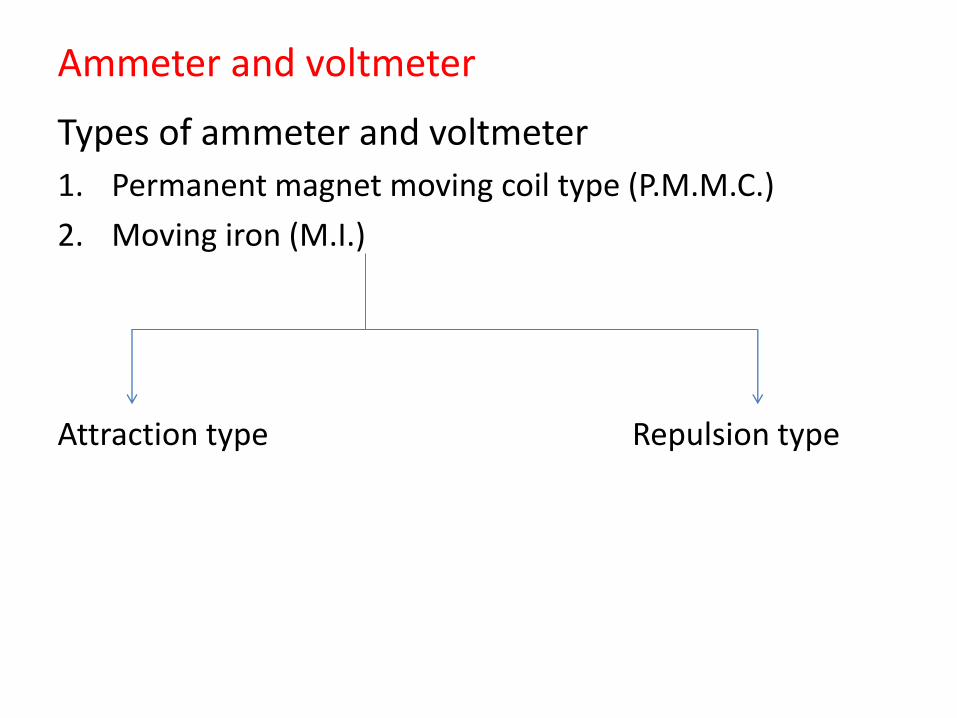
Ammeter and voltmeter
Types of ammeter and voltmeter
1. Permanent magnet moving coil type (P.M.M.C.)
2. Moving iron (M.I.)
Attraction type Repulsion type
Permanent magnet moving coil ammeter and voltmeter
PMMC………….
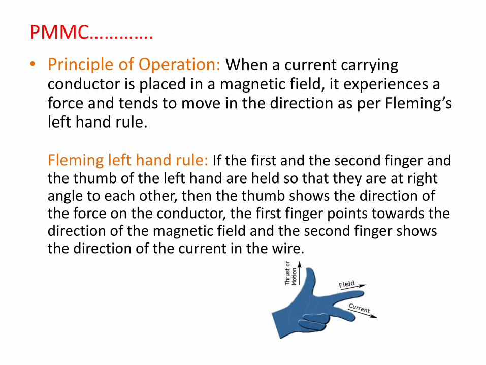
• Principle of Operation: When a current carrying conductor is placed in a magnetic field, it experiences a force and tends to move in the direction as per Fleming’s left hand rule.
Fleming left hand rule: If the first and the second finger and the thumb of the left hand are held so that they are at right angle to each other, then the thumb shows the direction of the force on the conductor, the first finger points towards the direction of the magnetic field and the second finger shows the direction of the current in the wire.
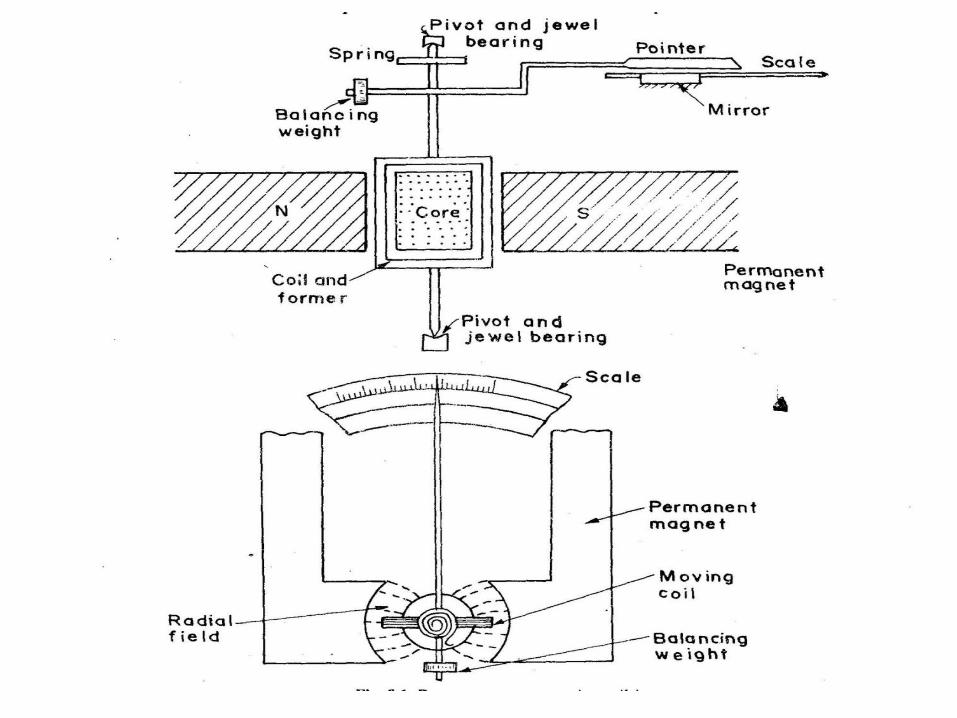
Construction:• A coil of thin wire is mounted on an aluminum frame
(spindle) positioned between the poles of a U shaped permanent magnet which is made up of magnetic alloys like alnico.
• The coil is pivoted on the jewelled bearing and thus the coil is free to rotate. The current is fed to the coil through spiral springs which are two in numbers. The coil which carries a current, which is to be measured, moves in a strong magnetic field produced by a permanent magnet and a pointer is attached to the spindle which shows the measured value.
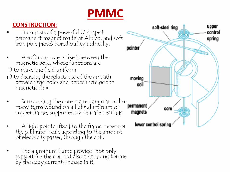
PMMCCONSTRUCTION:
• It consists of a powerful U-shaped permanent magnet made of Alnico, and soft iron pole pieces bored out cylindrically.
• A soft iron core is fixed between the magnetic poles whose functions are
i) to make the field uniformii) to decrease the reluctance of the air path
between the poles and hence increase the magnetic flux.
• Surrounding the core is a rectangular coil of many turns wound on a light aluminum or copper frame, supported by delicate bearings
• A light pointer fixed to the frame moves on the calibrated scale according to the amount of electricity passed through the coil.
• The aluminum frame provides not only support for the coil but also a damping torque by the eddy currents induce in it.
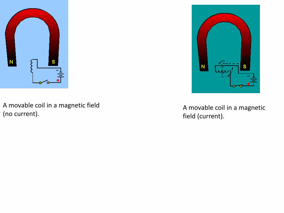
A movable coil in a magnetic field (no current).
A movable coil in a magnetic field (current).
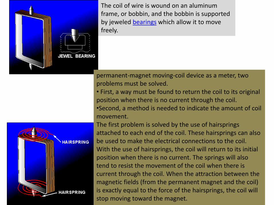
The coil of wire is wound on an aluminum frame, or bobbin, and the bobbin is supported by jeweled bearings which allow it to move freely.
permanent-magnet moving-coil device as a meter, two problems must be solved.• First, a way must be found to return the coil to its original position when there is no current through the coil. •Second, a method is needed to indicate the amount of coil movement. The first problem is solved by the use of hairsprings attached to each end of the coil. These hairsprings can also be used to make the electrical connections to the coil. With the use of hairsprings, the coil will return to its initial position when there is no current. The springs will also tend to resist the movement of the coil when there is current through the coil. When the attraction between the magnetic fields (from the permanent magnet and the coil) is exactly equal to the force of the hairsprings, the coil will stop moving toward the magnet.
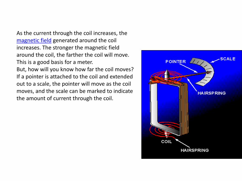
As the current through the coil increases, the magnetic field generated around the coil increases. The stronger the magnetic field around the coil, the farther the coil will move. This is a good basis for a meter. But, how will you know how far the coil moves? If a pointer is attached to the coil and extended out to a scale, the pointer will move as the coil moves, and the scale can be marked to indicate the amount of current through the coil.
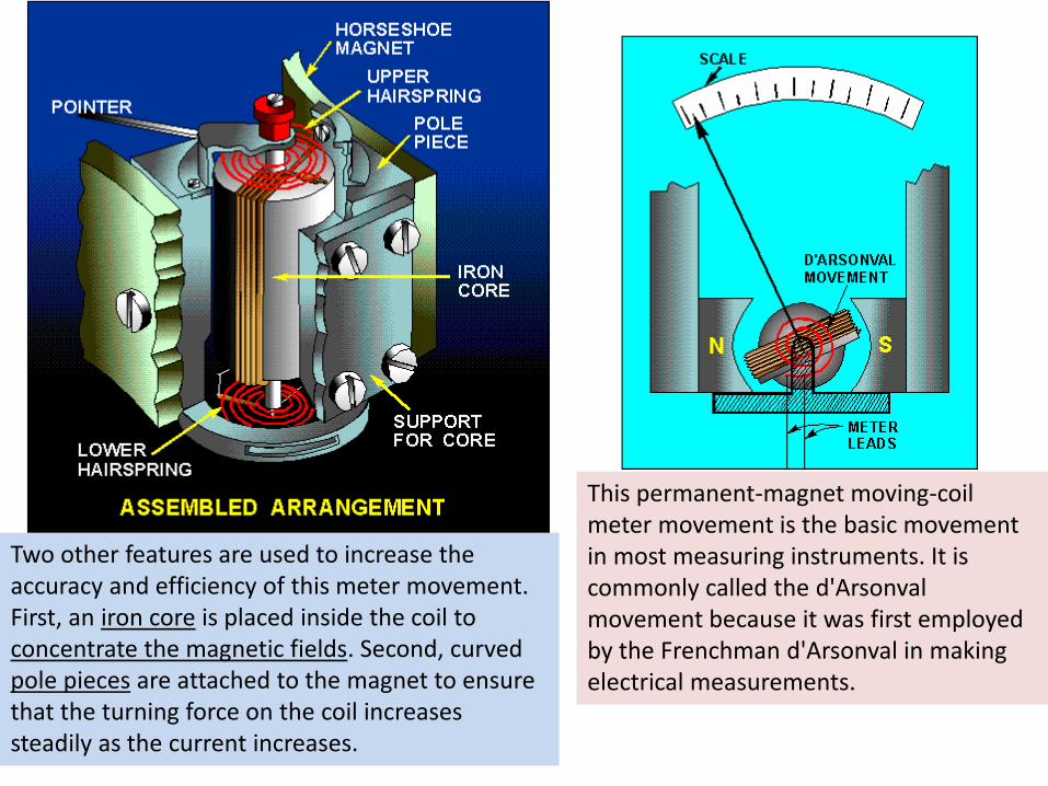
Two other features are used to increase the accuracy and efficiency of this meter movement. First, an iron core is placed inside the coil to concentrate the magnetic fields. Second, curved pole pieces are attached to the magnet to ensure that the turning force on the coil increases steadily as the current increases.
This permanent-magnet moving-coil meter movement is the basic movement in most measuring instruments. It is commonly called the d'Arsonvalmovement because it was first employed by the Frenchman d'Arsonval in making electrical measurements.
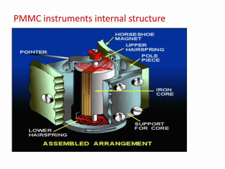
PMMC instruments internal structure
Working:
• When a current flow through the coil, it generates a magnetic field which is proportional to the current in case of an ammeter. The deflecting torque is produced by the electromagnetic action of the current in the coil and the magnetic field.
• The controlling torque is provided by two phosphorous bronze flat coiled helical springs. These springs serve as a flexible connection to the coil conductors.
• Damping is caused by the eddy current set up in the aluminum coil which prevents the oscillation of the coil.
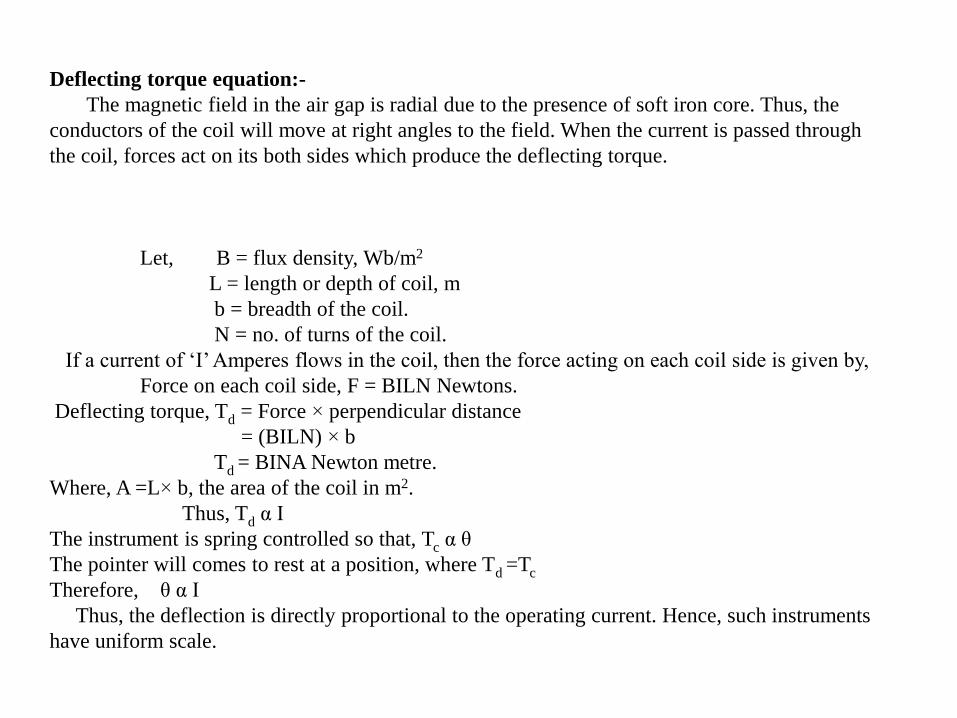
Deflecting torque equation:-
The magnetic field in the air gap is radial due to the presence of soft iron core. Thus, the
conductors of the coil will move at right angles to the field. When the current is passed through
the coil, forces act on its both sides which produce the deflecting torque.
Let, B = flux density, Wb/m2
L = length or depth of coil, m
b = breadth of the coil.
N = no. of turns of the coil.
If a current of ‘I’ Amperes flows in the coil, then the force acting on each coil side is given by,
Force on each coil side, F = BILN Newtons.
Deflecting torque, Td = Force × perpendicular distance
= (BILN) × b
Td = BINA Newton metre.
Where, A =L× b, the area of the coil in m2.
Thus, Td α I
The instrument is spring controlled so that, Tc α θ
The pointer will comes to rest at a position, where Td =Tc
Therefore, θ α I
Thus, the deflection is directly proportional to the operating current. Hence, such instruments
have uniform scale.
Applications:
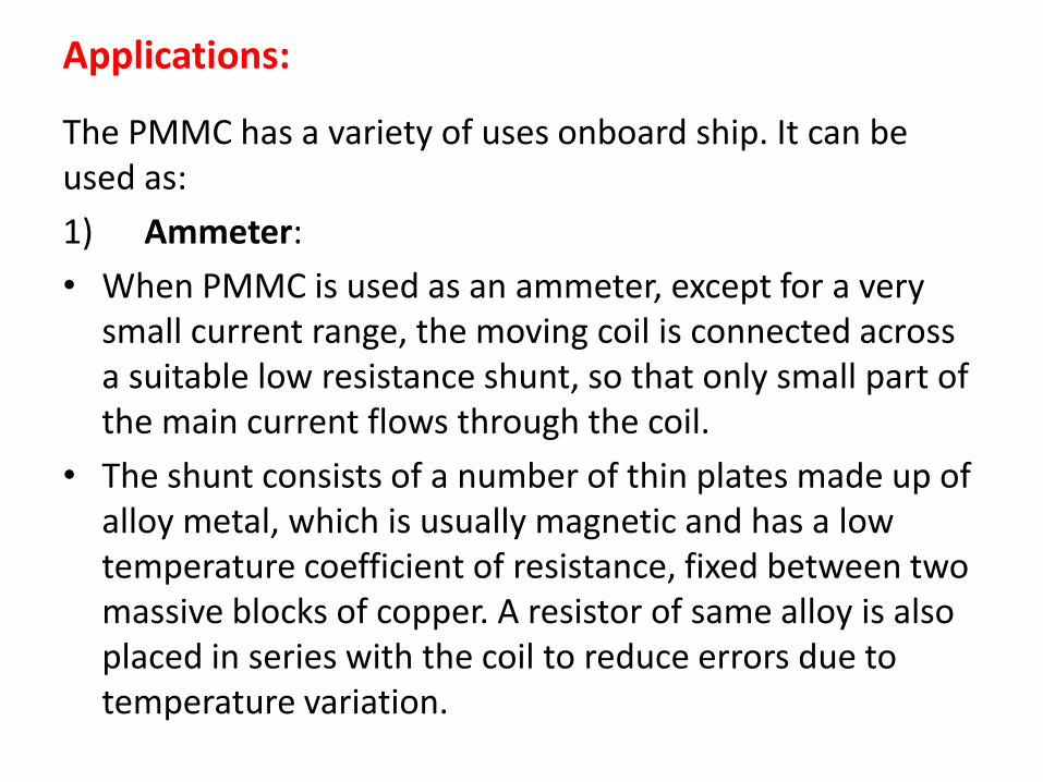
The PMMC has a variety of uses onboard ship. It can be used as:
1) Ammeter:
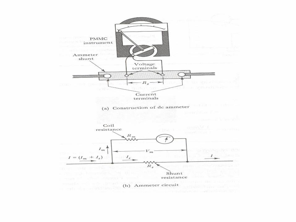
• When PMMC is used as an ammeter, except for a very small current range, the moving coil is connected across a suitable low resistance shunt, so that only small part of the main current flows through the coil.
• The shunt consists of a number of thin plates made up of alloy metal, which is usually magnetic and has a low temperature coefficient of resistance, fixed between two massive blocks of copper. A resistor of same alloy is also placed in series with the coil to reduce errors due to temperature variation.
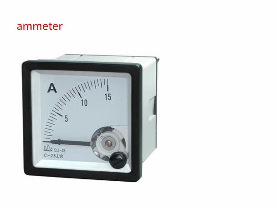
ammeter
Applications………..
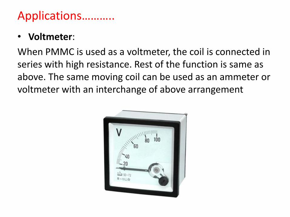
• Voltmeter:
When PMMC is used as a voltmeter, the coil is connected in series with high resistance. Rest of the function is same as above. The same moving coil can be used as an ammeter or voltmeter with an interchange of above arrangement
Applications………..
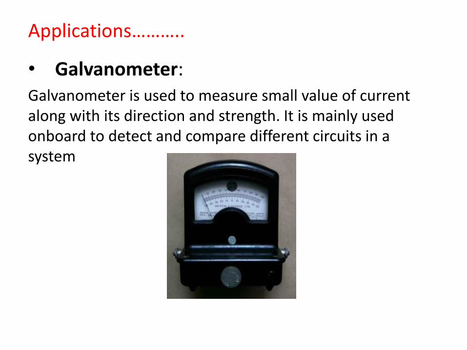
• Galvanometer:Galvanometer is used to measure small value of current along with its direction and strength. It is mainly used onboard to detect and compare different circuits in a system
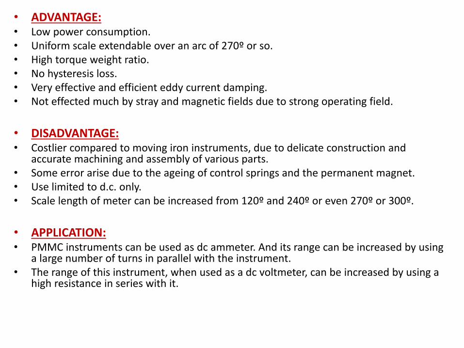
• ADVANTAGE:• Low power consumption.• Uniform scale extendable over an arc of 270º or so.• High torque weight ratio.• No hysteresis loss.• Very effective and efficient eddy current damping.• Not effected much by stray and magnetic fields due to strong operating field.
• DISADVANTAGE:• Costlier compared to moving iron instruments, due to delicate construction and
accurate machining and assembly of various parts.• Some error arise due to the ageing of control springs and the permanent magnet.• Use limited to d.c. only.• Scale length of meter can be increased from 120º and 240º or even 270º or 300º.
• APPLICATION:• PMMC instruments can be used as dc ammeter. And its range can be increased by using
a large number of turns in parallel with the instrument.• The range of this instrument, when used as a dc voltmeter, can be increased by using a
high resistance in series with it.
Moving Iron Instruments – Voltmeter and Ammeter
Construction and basic principle operation of moving-iron instrumentsMoving-iron instruments are generally used to measure alternating voltages and currents. In moving-iron instruments the movable system consists of one or more pieces of specially-shaped soft iron, which are so pivoted as to be acted upon by the magnetic field produced by the current in coil.There are two general types of moving-iron instruments namely:1. Repulsion (or double iron) type2. Attraction (or single-iron) type
The brief description of different components of a moving-iron instrument is given below:
• Moving element: a small piece of soft iron in the form of a vane or rod.
• Coil: to produce the magnetic field due to current flowing through it and also to magnetize the iron pieces.
• In repulsion type, a fixed vane or rod is also used and magnetized with the same polarity.
• Control torque is provided by spring or weight (gravity).
• Damping torque is normally pneumatic, the damping device consisting of an air chamber and a moving vane attached to the instrument spindle.
• Deflecting torque produces a movement on an aluminum pointer over a graduated scale.
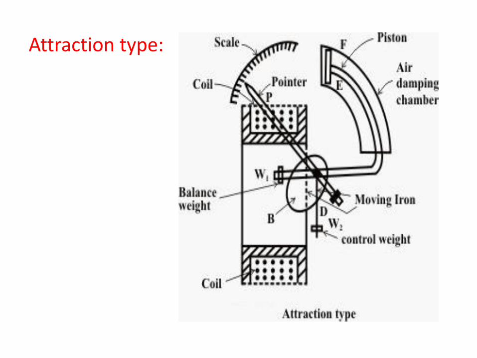
Attraction type:
Working:
Current in the coil induces both vanes to become magnetized and repulsion between the similarly magnetized vanes produces a proportional rotation. The deflecting torque is proportional to the square of the current in the coil, making the instrument reading is a true ‘RMS’ quantity Rotation is opposed by a hairspring that produces the restoring torque. Only the fixed coil carries load current, and it is constructed so as to withstand high transient current.
Moving iron instruments having scales that are nonlinear and somewhat crowded in the lower range of calibration
Application:
Measurement of Electric Voltage and Current• Moving iron instruments are used as Voltmeter and
Ammeter only.• Both can work on AC as well as on DC.
Ammeter:• Instrument used to measure current in the circuit.• Always connected in series with the circuit and carries
the current to be measured.• This current flowing through the coil produces the
desired deflecting torque.• It should have low resistance as it is to be connected in
series.
Application:
Voltmeter
• Instrument used to measure voltage between two points in a circuit.
• Always connected in parallel.
• Current flowing through the operating coil of the meter produces deflecting torque.
• It should have high resistance. Thus a high resistance of order of kilo ohms is connected in series with the coil of the instrument
Advantages:
• The instruments are suitable for use in AC and DC circuits.
• The instruments are robust, owing to the simple construction of the moving parts.
• The stationary parts of the instruments are also simple.
• Instrument is low cost compared to moving coil instrument.
• Torque/weight ratio is high, thus less frictional error.
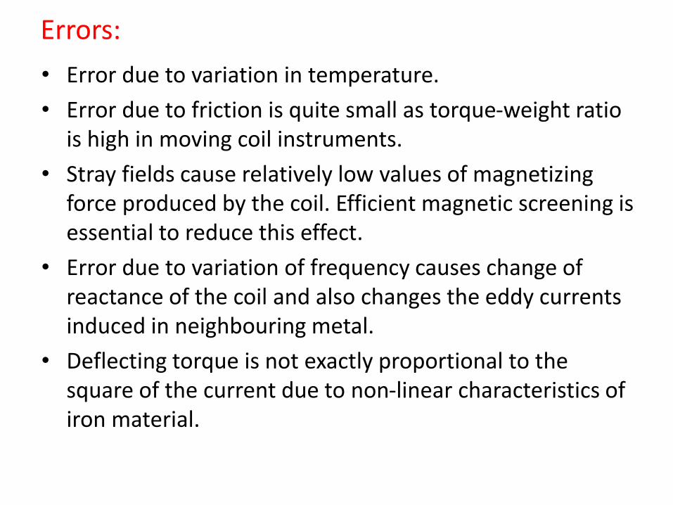
Errors:
• Error due to variation in temperature.
• Error due to friction is quite small as torque-weight ratio is high in moving coil instruments.
• Stray fields cause relatively low values of magnetizing force produced by the coil. Efficient magnetic screening is essential to reduce this effect.
• Error due to variation of frequency causes change of reactance of the coil and also changes the eddy currents induced in neighbouring metal.
• Deflecting torque is not exactly proportional to the square of the current due to non-linear characteristics of iron material.
MI
• The basic principle of operation is that when a current carrying conductor is brought in a magnetic field (they should not be parallel to each other) a torque on the conductor is produced.
• The Permanent Magnet Moving Coil instrument consists of a rectangular coil pivoted so that its sides lie in the air gap between the two poles of a permanent magnet and a soft-iron cylinder.
• The air gap between the magnet poles and iron core is small and the flux density is uniform and is in a radial direction, so that the flux lines are always at right angle to the current carrying conductor and hence when current passes through the coil, a deflecting torque is produced owing to the interaction between the two fluxes, one due to permanent magnet and the other due to the magnetic field of the coil.
Moving Iron instruments
Moving Iron instruments depend for their action upon the magnetic effect of current, and are widely used as indicating instruments. In this type of instrument , the coil is stationery and the deflection is caused by a soft-iron piece moving in the field produced by the coil.
There are two types of moving iron instruments:
i) Attraction type
ii) Repulsion type
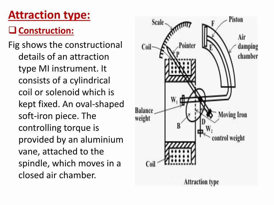
Attraction type:Construction:
Fig shows the constructional details of an attraction type MI instrument. It consists of a cylindrical coil or solenoid which is kept fixed. An oval-shaped soft-iron piece. The controlling torque is provided by an aluminiumvane, attached to the spindle, which moves in a closed air chamber.
Working:When the instrument is connected in the circuit to
measure current or voltage, the operating current flowing through the coil sets up a magnetic field. In other words, the coil behaves like a magnet and therefore it attracts the soft iron piece towards it. The result is that the pointer attached to the moving system moves from zero position. The pointer will come to rest at a position where deflecting torque is equal to the controlling torque. If current in the coil is reversed, the direction of magnetic field also reverses and so does the magnetism produce in the soft iron piece. Hence, the direction of the deflecting torque remains unchanged. For this reason, such instruments can be used for both d.c. and a.c. measurements.
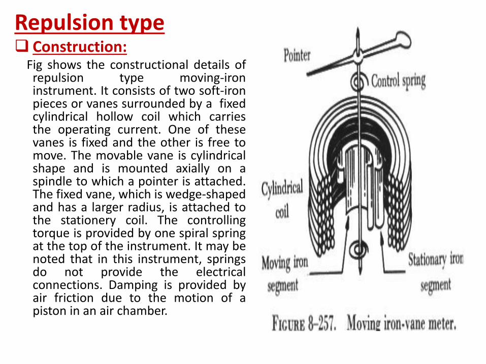
Repulsion type Construction:
Fig shows the constructional details ofrepulsion type moving-ironinstrument. It consists of two soft-ironpieces or vanes surrounded by a fixedcylindrical hollow coil which carriesthe operating current. One of thesevanes is fixed and the other is free tomove. The movable vane is cylindricalshape and is mounted axially on aspindle to which a pointer is attached.The fixed vane, which is wedge-shapedand has a larger radius, is attached tothe stationery coil. The controllingtorque is provided by one spiral springat the top of the instrument. It may benoted that in this instrument, springsdo not provide the electricalconnections. Damping is provided byair friction due to the motion of apiston in an air chamber.
Working:When current to be measured or current proportional tothe voltage to be measured flows through the coil, amagnetic field is set up by the coil. This magnetic fieldmagnetises the two vanes in the same direction i.e.similar polarities are developed at the same ends of thevanes. Since the adjacent edges of the vanes are of thesame polarity, the two vanes repel each other. As thefixed vane cannot move, the movable vane deflects andcauses the pointer to move from zero position. Thepointer will come to rest at a position where deflectingtorque is equal to controlling torque provided by thespring. If the current in the coil is reversed, the directionof deflection remains unchanged. It is because reversal ofthe field of the coil reverses the magnetisation of bothiron vanes so that they repel each other regardless whichway current flows through the coil. For this reason, suchinstruments can be used for both d.c. and a.c.applications.
o Advantages:
i) Cheap, robust and give reliable service.ii) Usable in both a.c. and d.c. circuits.o Disadvantages:
i) Have non-linear scale.ii) Cannot be calibrate with high degree of precision for d.c.
on account of the affect of hysteresis in the iron vanes.iii) Deflection up to 240º only may be obtained with this
instrument.iv) This instrument will always have to be put in the vertical
position if it uses gravity control.o Errors with MI instruments:
i) Due to hysteresis when used in a.c. and d.c.ii) Due to stray magnetic fields when used both in a.c. and
d.c.iii) Due to frequency variation when used in a.c.iv) Due to waveforms effect when used in a.c.
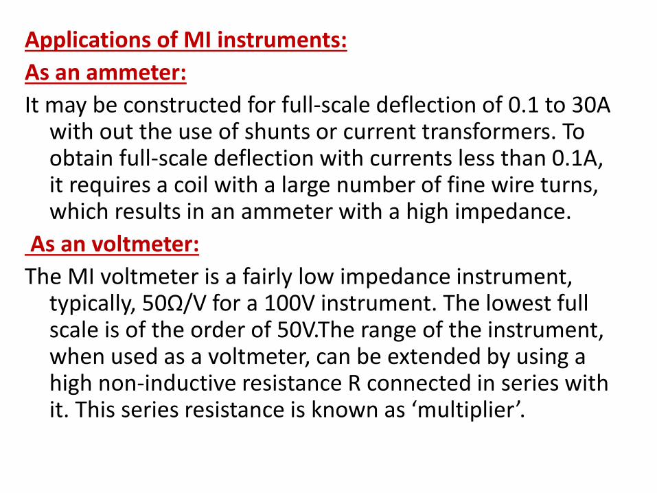
Applications of MI instruments:
As an ammeter:
It may be constructed for full-scale deflection of 0.1 to 30A with out the use of shunts or current transformers. To obtain full-scale deflection with currents less than 0.1A, it requires a coil with a large number of fine wire turns, which results in an ammeter with a high impedance.
As an voltmeter:
The MI voltmeter is a fairly low impedance instrument, typically, 50Ω/V for a 100V instrument. The lowest full scale is of the order of 50V.The range of the instrument, when used as a voltmeter, can be extended by using a high non-inductive resistance R connected in series with it. This series resistance is known as ‘multiplier’.
90
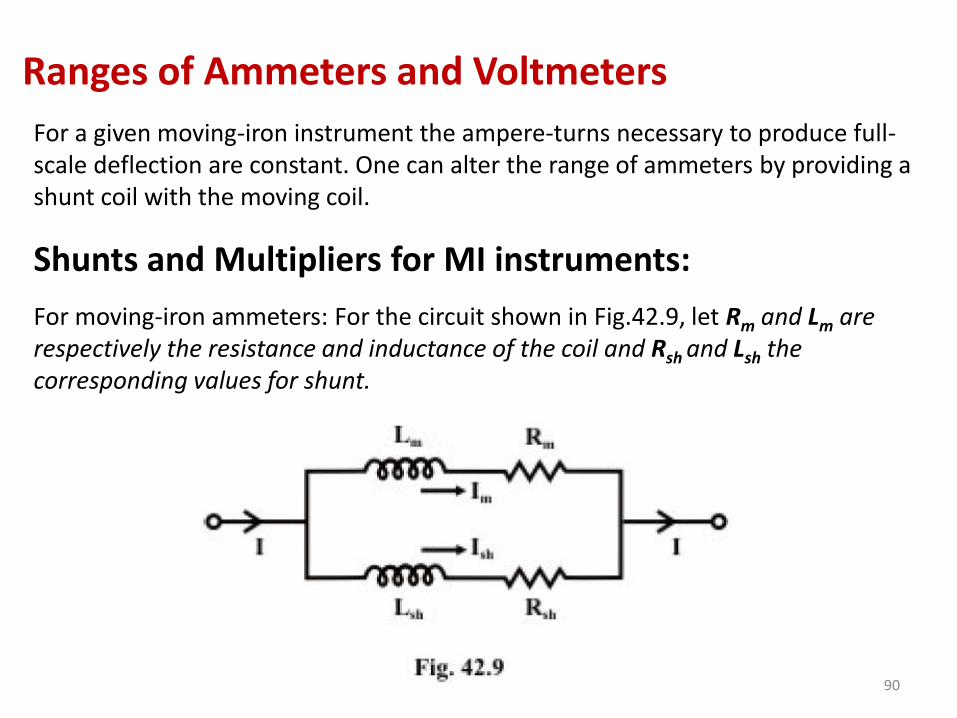
Ranges of Ammeters and Voltmeters
For a given moving-iron instrument the ampere-turns necessary to produce full-scale deflection are constant. One can alter the range of ammeters by providing a shunt coil with the moving coil.
Shunts and Multipliers for MI instruments:
For moving-iron ammeters: For the circuit shown in Fig.42.9, let Rm and Lm are respectively the resistance and inductance of the coil and Rsh and Lsh the corresponding values for shunt.
91
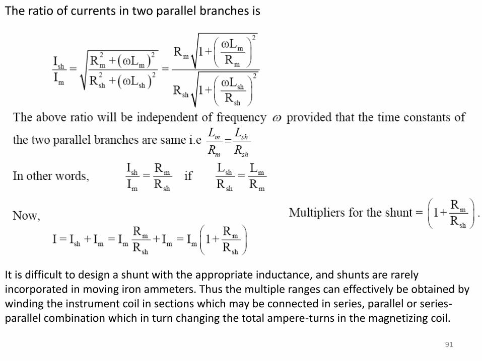
The ratio of currents in two parallel branches is
It is difficult to design a shunt with the appropriate inductance, and shunts are rarely incorporated in moving iron ammeters. Thus the multiple ranges can effectively be obtained by winding the instrument coil in sections which may be connected in series, parallel or series-parallel combination which in turn changing the total ampere-turns in the magnetizing coil.
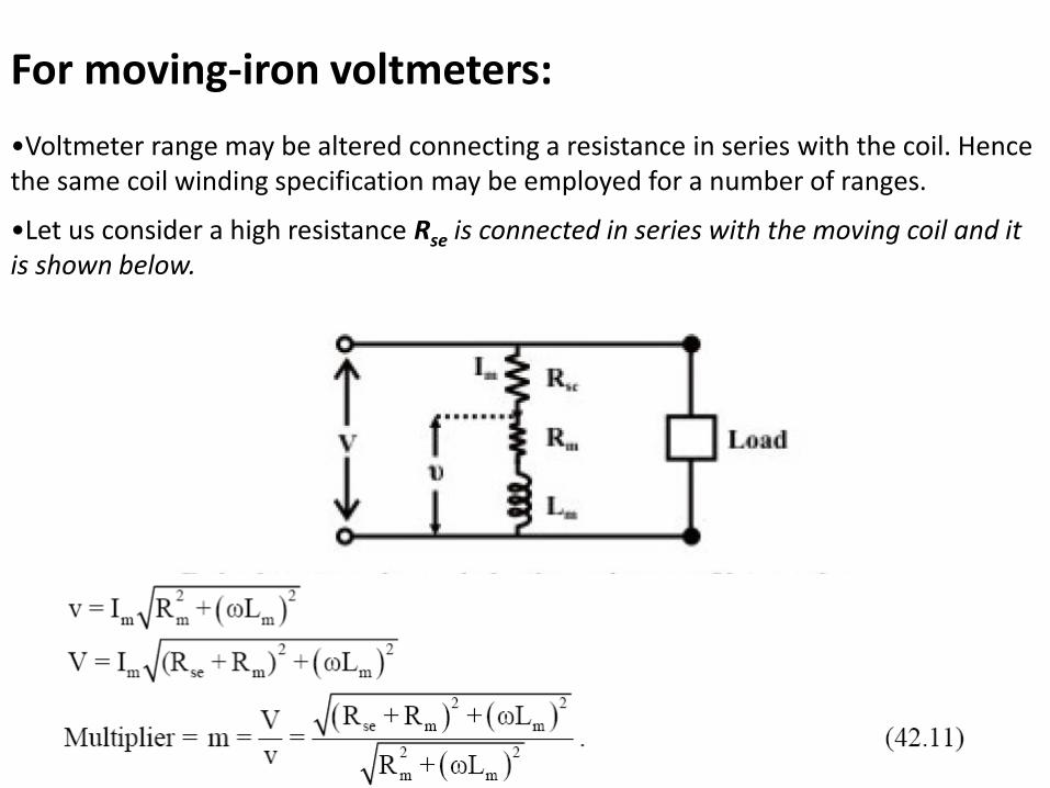
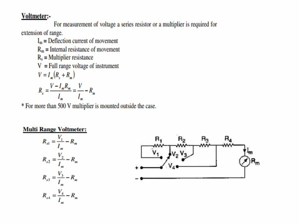
For moving-iron voltmeters:
•Voltmeter range may be altered connecting a resistance in series with the coil. Hence the same coil winding specification may be employed for a number of ranges.
•Let us consider a high resistance Rse is connected in series with the moving coil and it is shown below.
93
• DC Ammeter– is always connected in series
– low internal resistance
– maximum pointer deflection is produced by a very small current
– For a large currents, the instrument must be modified by connecting a very low shunt resister
– Extension of Ranges of Ammeter
• Single Shunt Type of Ammeter
94
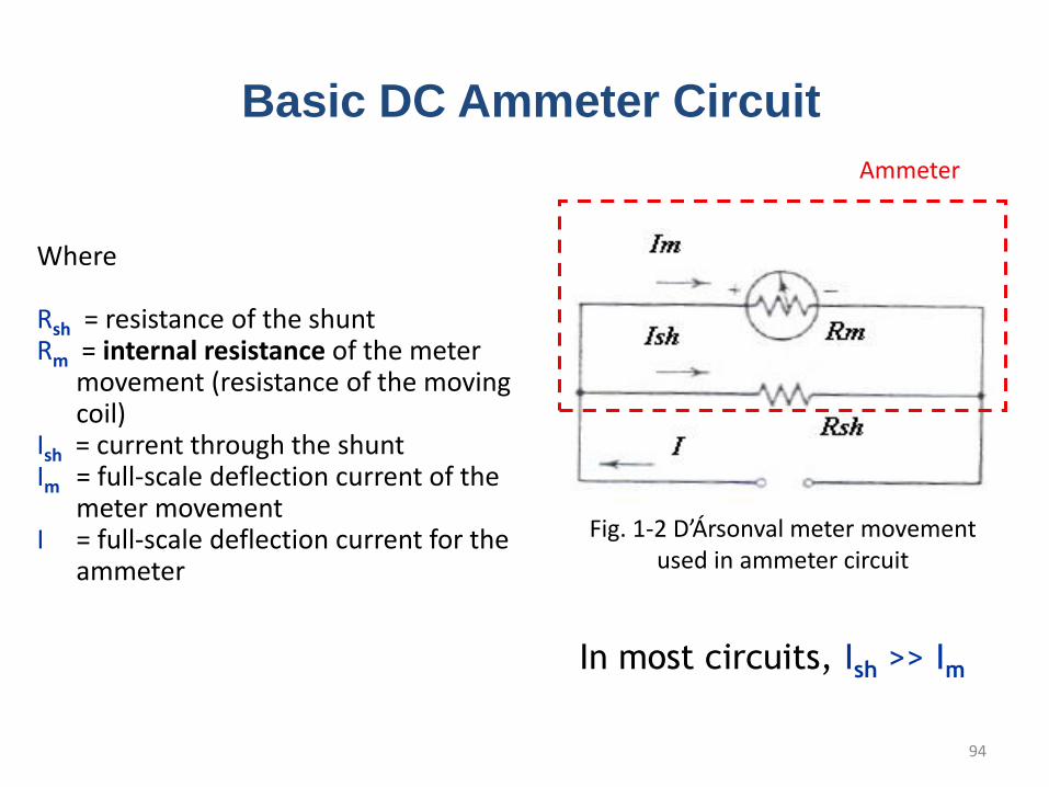
In most circuits, Ish >> Im
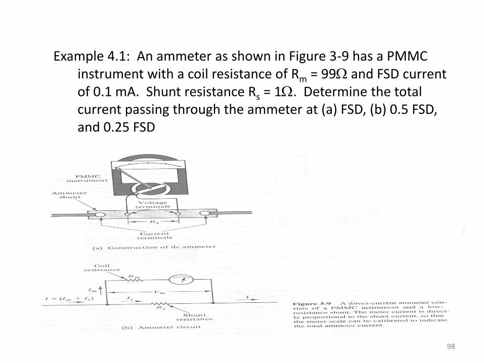
Fig. 1-2 D’Ársonval meter movement used in ammeter circuit
Basic DC Ammeter Circuit
Ammeter
Where
Rsh = resistance of the shuntRm = internal resistance of the meter
movement (resistance of the moving coil)
Ish = current through the shunt Im = full-scale deflection current of the
meter movementI = full-scale deflection current for the
ammeter
96
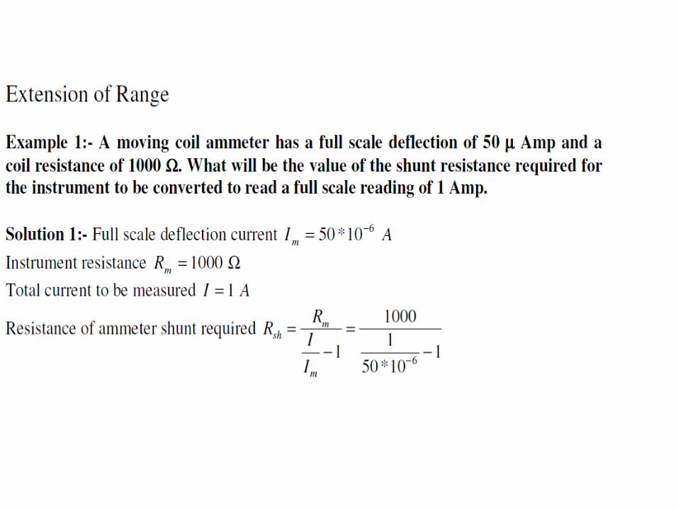
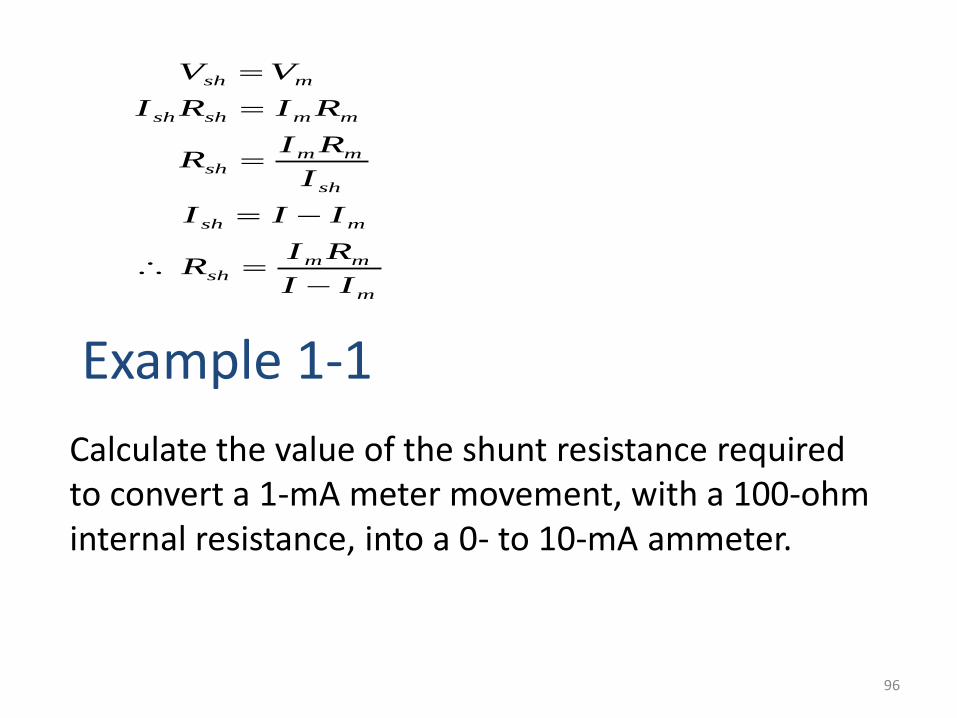
Example 1-1
Calculate the value of the shunt resistance required to convert a 1-mA meter movement, with a 100-ohm internal resistance, into a 0- to 10-mA ammeter.
m
mmsh
msh
sh
mmsh
mmshsh
msh
II
RIR
III
I
RIR
RIRI
VV
97
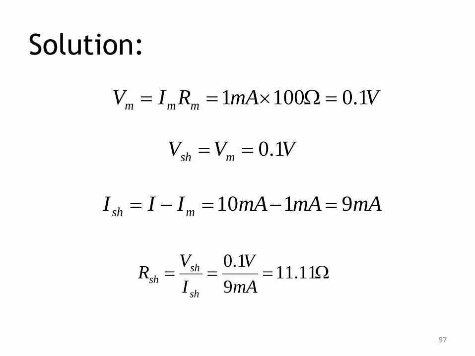
Solution:
VmARIV mmm 1.01001
VVV msh 1.0
mAmAmAIII msh 9110
11.119
1.0
mA
V
I
VR
sh
shsh
98
Example 4.1: An ammeter as shown in Figure 3-9 has a PMMC instrument with a coil resistance of Rm = 99 and FSD current of 0.1 mA. Shunt resistance Rs = 1. Determine the total current passing through the ammeter at (a) FSD, (b) 0.5 FSD, and 0.25 FSD
99
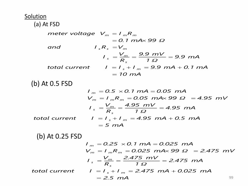
Solution(a) At FSD
mA10
mA0.1mA9.9IIIcurrenttotal
mA9.9Ω1
mV9.9
R
VI
VRIand
Ω99mA0.1
RIVvoltagemeter
ms
s
ms
mss
mmm
(b) At 0.5 FSD
mA5
mA0.5mA4.95IIIcurrenttotal
mA4.95Ω1
mV4.95
R
VI
mV4.95Ω99mA0.05RIV
mA0.05mA0.10.5I
ms
s
ms
mmm
m
(b) At 0.25 FSD
mA2.5
mA0.025mA2.475IIIcurrenttotal
mA2.475Ω1
mV2.475
R
VI
mV2.475Ω99mA0.025RIV
mA0.025mA0.10.25I
ms
s
ms
mmm
m
100
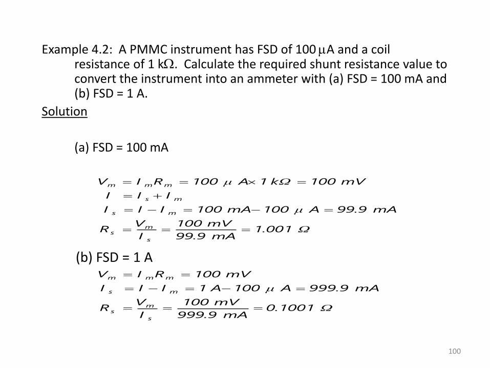
Example 4.2: A PMMC instrument has FSD of 100 A and a coil resistance of 1 k. Calculate the required shunt resistance value to convert the instrument into an ammeter with (a) FSD = 100 mA and (b) FSD = 1 A.
Solution
(a) FSD = 100 mA
Ω1.001mA99.9
mV100
I
VR
mA99.9Aμ100mA100III
III
mV100kΩ1Aμ100RIV
s
ms
ms
ms
mmm
(b) FSD = 1 A
Ω0.1001mA999.9
mV100
I
VR
mA999.9Aμ100A1III
mV100RIV
s
ms
ms
mmm