Embed Size (px)
DESCRIPTION
telecommunication sector training In Operation and maintenance
Citation preview

PREPARED BY-ISHA
11UEC045

INTRODUCTION TO COMPANY
WHAT IS GSM?
CDMA
PRI AND D CHANNEL
E1 CONCEPT
SIGNAL TRACE
ADD HUNDERED GROUP
CALL DATA RECORD BACKUPS
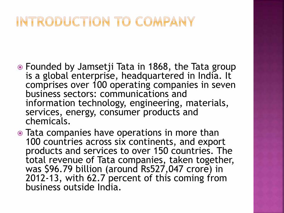
Founded by Jamsetji Tata in 1868, the Tata group is a global enterprise, headquartered in India. It comprises over 100 operating companies in seven business sectors: communications and information technology, engineering, materials, services, energy, consumer products and chemicals.
Tata companies have operations in more than 100 countries across six continents, and export products and services to over 150 countries. The total revenue of Tata companies, taken together, was $96.79 billion (around Rs527,047 crore) in 2012-13, with 62.7 percent of this coming from business outside India.
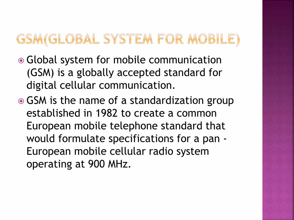
Global system for mobile communication
(GSM) is a globally accepted standard for
digital cellular communication.
GSM is the name of a standardization group
established in 1982 to create a common
European mobile telephone standard that
would formulate specifications for a pan -
European mobile cellular radio system
operating at 900 MHz.

Year Mobile System
1981 Nordic Mobile Telephone (NMT)
450
1983 American Mobile Phone System
(AMPS)
1985 Total Access Communication
System (TACS)
1986 Nordic Mobile Telephony (NMT)
900
1991 American Digital Cellular (ADC)
1991 Global System for Mobile
Communication (GSM)
1992 Digital Cellular System (DCS)
1800
1994 Personal Digital Cellular (PDC)
1995 PCS 1900—Canada
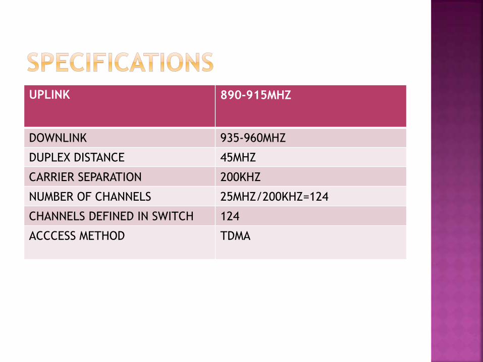
UPLINK 890-915MHZ
DOWNLINK 935-960MHZ
DUPLEX DISTANCE 45MHZ
CARRIER SEPARATION 200KHZ
NUMBER OF CHANNELS 25MHZ/200KHZ=124
CHANNELS DEFINED IN SWITCH 124
ACCCESS METHOD TDMA
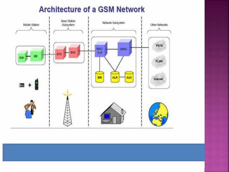

The switching system (SS) is responsible for
performing call processing and subscriber-
related functions. The switching system
includes the following functional units:
home location register (HLR)
mobile services switching center (MSC)
visitor location register (VLR)
authentication center (AUC)
equipment identity register (EIR)
The HLR is a database used for storage and
management of subscriptions. The HLR is
considered the most important database, as it
stores permanent data about subscribers,
including a subscriber's service profile, location
information, and activity status. When an
individual buys a subscription from one of the
PCS operators, he or she is registered in
the HLR of that operator.
The MSC performs the telephony switching
functions of the system. It controls calls to and
from other telephone and data systems. It also
performs such functions as toll ticketing,
network interfacing, common channel signaling
, and others.

The VLR is a database thatcontains temporary
information about subscribers that is needed by
the MSC in order to service visiting subscribers.
The VLR is always integrated with the MSC. When a
mobile station roams into a new MSC area, the VLR
connected to that MSC will request data about the
mobile station from the HLR. Later, if the mobile
station makes a call, the VLR will have the
information needed for call setup without having
to interrogate the HLR each time.
—A unit called the AUC provides authentication
and encryption parameters that verify the
user's identity and ensure the confidentiality of
each call. The AUC protects network
operators from different types of fraud found
in today's cellular world.
The EIR is a database that contains information
about the identity of mobile equipment that
prevents calls from stolen, unauthorized, or
defective mobile stations.
The AUC and EIR are implemented as stand-
alone nodes or as a combined AUC/EIR node.
Code Division Multiple Access (CDMA) is a digital technique for sharing the frequency spectrum. Multiple users are assigned radio resources using spread Spectrum techniques.
Although all users are transmitting in the same RF band, individual users are separated from each other via the use of orthogonal codes. CDMA is based on proven “Spread Spectrum communications technology”
There are several CDMA implementations that are currently deployed or under development. The first commercial and most widely deployed CDMA implementation is cdmaOne.

CDMA is an advance digital technology that can offer 7 to 10 times the capacity of analog technologies and up to 6 times the capacity of digital technologies such as TDMA. The speech quality provided by the CDMA systems is far superior to any other digital technology particularly in difficult radio environments such as dense urban areas and mountainous regions.
It provides the most cost effective solution for cellular operators. CDMA Technology is constantly evolving to offer customers new advanced services. The mobile data speeds offered through CDMA phones are increasing and new voice codecs provide speech quality close to wire line. Internet access is now available through CDMA terminals.
The CDMA systems and technology have been standardized under Interim standard-95 (IS-95 A&B).

MOBILE STATIONS ISDN NUMBER (MSISDN)
=> Is the mobile number used in a GSM PLMN (Public Land
Mobile Network)
MSISDN = Country Code + National Destination Code +
Subscriber number
e.g. 63 + 0918 + 8889999
Maximum length is 15 digits.
INTERNATIONAL MOBILE SUBSCRIBER IDENTITY (IMSI)
=> Is the subscriber number used over radio path for all
signaling in the GSM PLMN.
This number is stored in SIM (Subscriber Identity Module), HLR
(Home Location Register,
and VLR (Visitor Location Register).
IMSI = MCC + MNC + MSIN
= Mobile Country Code + Mobile Network Code + Mobile
Identification Number
[ 3 digit ] [ 2 digit ]
[ 11 digit ]
e.g. 502 + 19 + 2345451
TEMPORARY MOBILE SUBSCRIBER IDENTITY (TMSI)
=> Is used for the subscriber's confidentiality. Since the TMSI has only
local significance
(within MSC/VLR) the structure of the TMSI can be chosen by the
Vendor.
But the size must be 1/2 of the size of IMSI. Each time a mobile
request for location
updating or call setup, MSC/VLR allocates to the IMSI a new TMSI, so
the TMSI
is used on the signaling path, protecting the IMSI identity. Plus since
the TMSI is half
the size of IMSI, we can page twice the amount compared to IMSI.

SIM is used to provide storage on subscriber related information as following :
• IMSI (International Mobile Subscriber Identity).
• Temporary network data like TMSI, LAI, Location update status.
• Subscriber Authentication Key (Ki) and Ciphering Key (Kc) which are used for security purposes.
• BCCH information : List of carrier frequencies to be used for cell selection.
• Forbidden PLMN.
• Language preference.
• PIN number (Personal Identification Number) and PIN error counter.
• PUK number (Personal Unlock Key) and PUK error counter.
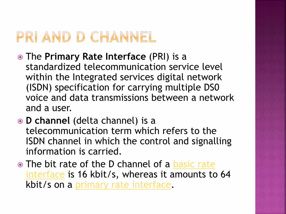
The Primary Rate Interface (PRI) is a standardized telecommunication service level within the Integrated services digital network (ISDN) specification for carrying multiple DS0 voice and data transmissions between a network and a user.
D channel (delta channel) is a telecommunication term which refers to the ISDN channel in which the control and signalling information is carried.
The bit rate of the D channel of a basic rate interface is 16 kbit/s, whereas it amounts to 64 kbit/s on a primary rate interface.

The E carrier system has been created by the
European Conference of Postal and
Telecommunications Administrations (CEPT) as a
digital telecommunications carrier scheme for
carrying multiple links.
The E-carrier system enables the transmission of
several (multiplexed) voice/data channels
simultaneously on the same transmission facility.
The E1 standard defines the physical
characteristics of a transmission path, and as
such it corresponds to the physical layer (layer
1) in the OSI model.

E1 is any medium that is capable for enabling
32 persons to make calls at a time.
There are 32 timeslots in an E1.
The timeslots are numbered from 0 to 31.
Each time slot has a rate of 64 kbit/s.
Total bit rate is 2.048 Mbits/s(ie:32*64=2048)
0th slot is used for Synchronization b/w A party & Bparty.
16th slot is for signaling (ie to establish call b/w A party & B party).
PHYSICAL CONCEPT
Basically there are 2 E1’s:
Electrical E1 &
Optical E1.

Physically an electrical E1 is any twisted pair
of cable having a Transmitter & a Receiver .
Optical E1’s are defined in terms of STM’s
(Synchronous Transport Module)
1 STM = 63 E1’s. It is basically an optical
fiber connectivity. In STM E1’s are identified
with the help of KLM’s & port numbers.
Total bit rate in 1 STM = 63*2.048= 155.52
Mbit/s.
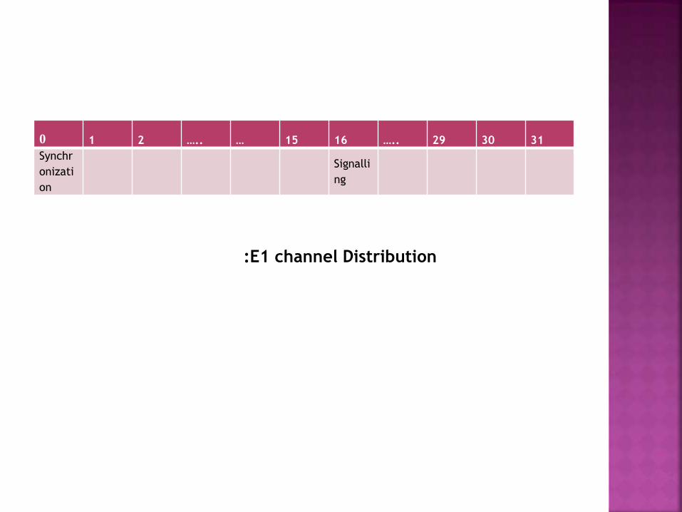
0 1 2 ….. … 15 16 ….. 29 30 31
Synchr
onizati
on
Signalli
ng
:E1 channel Distribution

Click on Database Interface Service
Manager User Configuration THEN
Local Office User Configuration (O)

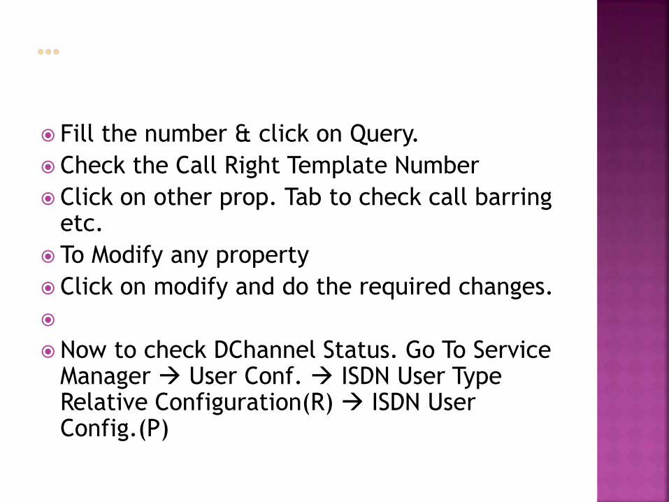
Fill the number & click on Query.
Check the Call Right Template Number
Click on other prop. Tab to check call barring etc.
To Modify any property
Click on modify and do the required changes.
Now to check DChannel Status. Go To Service Manager User Conf. ISDN User Type Relative Configuration(R) ISDN User Config.(P)
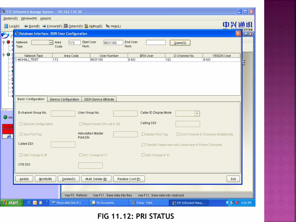
FIG 11.12: PRI STATUS

Here fill the number as shown & click on query. Note down the D Channel
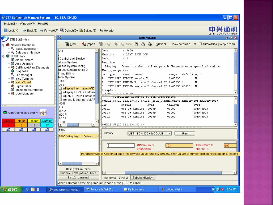
Now go to MML Wizard type 5600 & select 5600 (Display Information)
Fill Module Number 3 or 4 , Minimum D channel ID – (one less then the required Dchanneli.e. 102) , Maximum DChannel ID – (one more then the required Dchannel i.e. 102). Click on Run.
Check the Status of Required DChannel
i.e. 102. here its OOS (Out of Service)
Click on signal trace option.
Click on the type of trace you want to do.
Here Q 931 Trace Is being performed. It can
be done By Module Number, By Node, Or By
SDN Numbers as shown. Then Click Next.
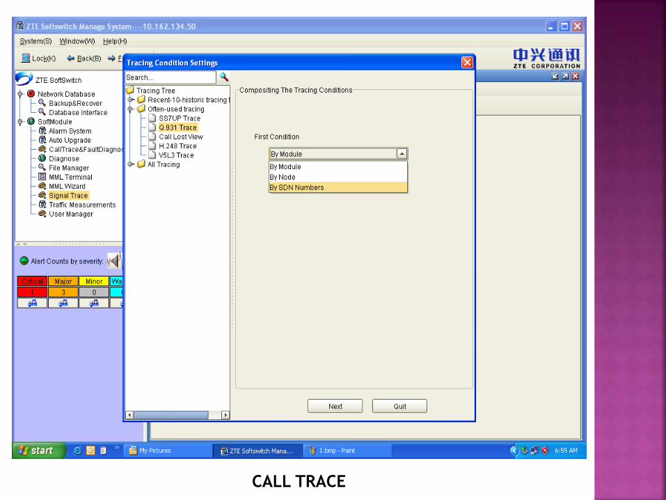
CALL TRACE
Centrex is a PBX-like service providing switching at the central office instead of at the customer's premises. Typically, the telephone company owns and manages all the communications equipment and software necessary to implement the Centrex service and then sells various services to the customer.
No switching equipment resides on the customer's premises, as the service is supplied and managed directly from the phone company's exchange site
With a PBX, stations inside the group can call each other with 3, 4 or 5 digits, depending on how large the group, instead of an entire telephone number (unit number).
Go to Service Manager User Config.
Local Office Code and DNHM
Configuration
Select the desired area code and office code
where the hundred group is
To be added. Click Add
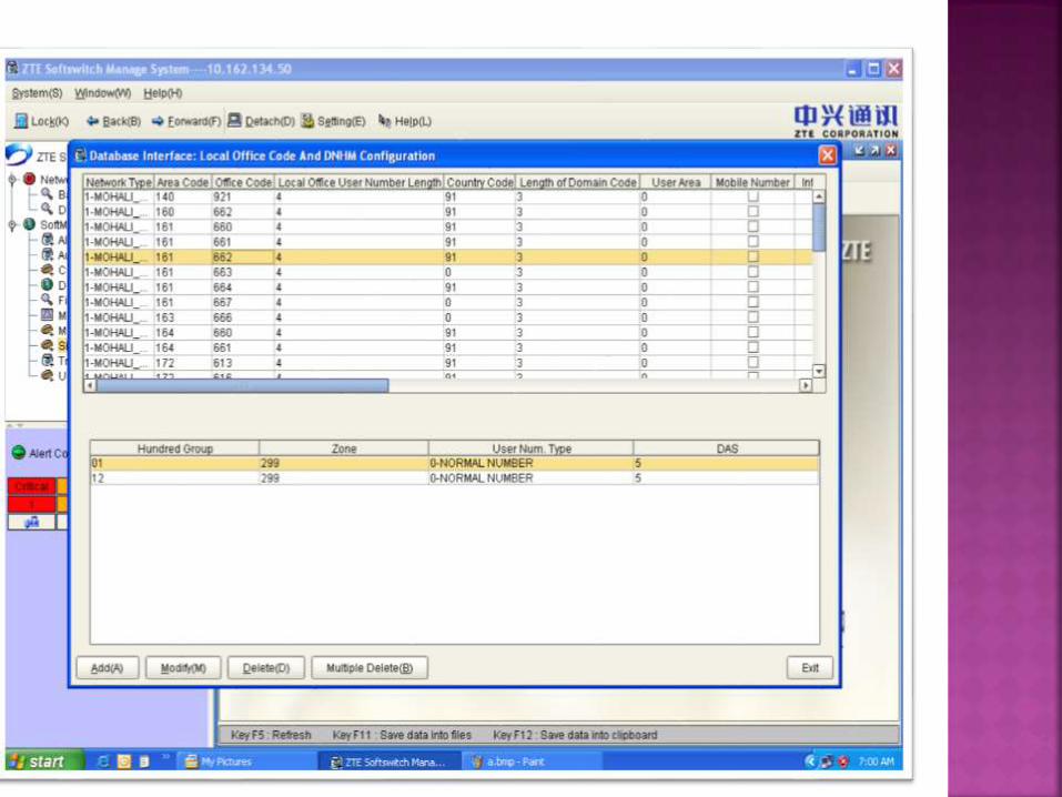
Fill the zone & das number (same as in other)
and add the hundred group.
Example: 02 added here. The hundred group
(02) is added.
It is important to take backups from time to time because in case of a sudden system failure all the data can be lost. So to ensure secure and data records backups are taken twice a week.
TYPES OF BACKUPSCDR
CP
APG
LOGFILE
The call detail record (CDR) feature creates text records of call related data. The data recorded includes calling and called numbers, call origination/connect time, the time the call was disconnected, the disconnect reason, the DLCI field to identify the originating PRI, and the bearer (B) channel used.
There are CDRs for normal calls, i.e., calls that were successfully completed and for failed calls.
All call-related operation failures will also be recorded in a CDR.
A call data record (CDR) is kept for billing Yield historical account of cell phone’s Locations.
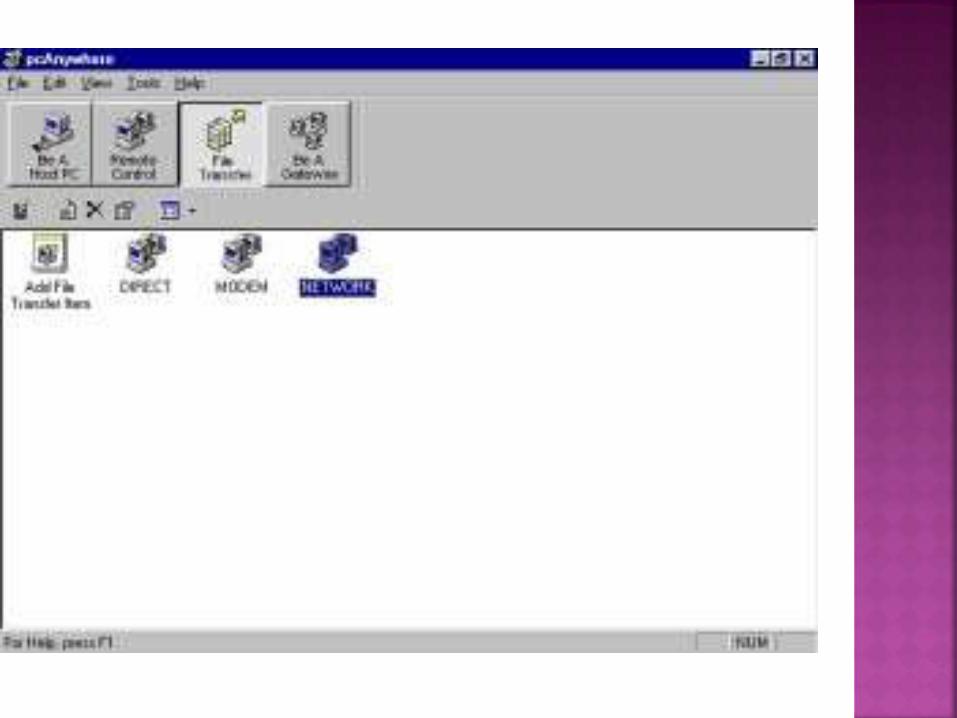
Pc Anywhere

A system is presented for logging and recording a call to a call network. The system comprises a voice print logic for generating a voice print of a caller who is making a call to a call network.
A telecom routing switch generates a correlated telecom router switch log file by appending the voice print of the caller to a telecom router switch log file for the call.
The voice print is utilized to retrieve and to consolidate the correlated telecom router switch log file, the correlated telecom software system log file, and the correlated contact center agent log file into a single correlated file for the call.

Fig.11.22:Log file generation
MGW(Media Gateway)
The maintenance terminal is used to interact
with the system software for configuration
changes and maintenance purposes. This is
achieved using a range of MMI (man/machine
interface) and SMI (System Maintenance
Interface) commands.

Proprietary unified packet gateway.
Can function as a gateway
Uses:
Hot swapping and redundancy backup, double power supplies, and overvoltage and overcurrent protection for key boards
Overload control, flow control, resource check, self fault detection, system software backup, and configure consistency check for stable and reliable system operation
CDR cache function for charging reliability
Hot patch technique for software operation reliability
Route backup and route load-sharing modes for preventing single-point failures and ensuring high network reliability