Embed Size (px)
Citation preview

SINGLE PHASE TRANSFORMER
3rd semester Electrical EngineeringSub :- DC Machine & Transformer
Professor name : Ashok D Pateliya
PREPARED BY 1 MAHENDRA RAJPUT 1406431090302 ANKUR SHAH 1406431090313 KAUSHAL RANA 140643109021 4 JAY PRAJAPATI 140643109018

-: Topic covered :-
• Construction and working principle of
single phase transformer.
• Types of Transformer.
• Emf Equation of Transformer.
• Transformer on NO LOAD.

-: Transformer :-

-: Construction and working principle of single phase transformer :-
• A Transformer is a static piece of apparatus by means of which electric power in one circuit is transformed into electric power of same frequency in another circuit.
• The physical basis of a transformer is mutual induction between two circuit linked by a common magnetic flux.

-:Transformer Construction:-

-:Core type transformer:-

-: Core-type Transformers :-
The coils used are form-wound and are of thecylindrical type. The general form of thesecoils may be circular or oval or rectangular. Insmall size core-type transformers, a simplerectangular core is used with cylindrical coilswhich are either circular or rectangular inform.

But for large-size core-type transformers,round or circular cylindrical coils are usedwhich are so wound as to fit over a cruciformcore section as shown in Fig. The circularcylindrical coils are used in most of the core-type transformers because of theirmechanical strength. Such cylindrical coils arewound in helical layers with the differentlayers insulated from each other by paper,cloth, micarta board or cooling ducts. Fig.shows the general arrangement of these coilswith respect to the core.

-:Shell type transformer:-

-:Shell-type Transformers:-In these case also, the coils are form-would but are multi-layer disc type usually wound in theform of pancakes. The different layers of such multi-layer discs are insulated from each other by paper. The complete winding consists of stacked discs with insulation space between the coils–the spaces forming horizontal cooling and insulating ducts. A shell-type transformer may have a simple rectangular form as shown in Fig.

A very commonly-used shell-type transformer is the one known as Berry Transformer–so calledafter the name of its designer and is cylindrical in form. The transformer core consists of laminations arranged in groups which radiate out from the centre. It may be pointed out that cores and coils of transformers must be provided with rigid mechanical bracing in order to prevent movement and possible insulation damage. Good bracing reduces vibration andthe objectionable noise–a humming sound–during operation.
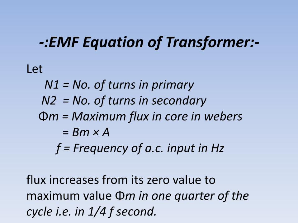
-:EMF Equation of Transformer:-
LetN1 = No. of turns in primaryN2 = No. of turns in secondaryΦm = Maximum flux in core in webers
= Bm × Af = Frequency of a.c. input in Hz
flux increases from its zero value to maximum value Φm in one quarter of the cycle i.e. in 1/4 f second.

∴ Average rate of change of flux =1/ 4fΦm= 4 f Φm Wb/s
or volt
Now, rate of change of flux per turn means induced e.m.f. in volts.∴ Average e.m.f./turn = 4 f Φm volt
If flux Φ varies sinusoidally, then r.m.s. value of induced e.m.f. is obtained by multiplying the averagevalue with form factor.
Form factor =r.m.s. value/ avg. value = 1.11

∴ r.m.s. value of e.m.f./turn = 1.11 × 4 f Φm = 4.44 f Φm volt
• Now, r.m.s. value of the induced e.m.f. in the whole of primary winding
= (induced e.m.f/turn) × No. of primary turns
•E1 = 4.44 f N1 Φm = 4.44 f N1 BmA.........(1)
Similarly, r.m.s. value of the e.m.f. induced in secondary is,•E2 = 4.44 f N2 Φm = 4.44 f N2 BmA..........(2)

-:Transformer on NO Load:-

When an actual transformer is put on load, there is iron loss in the core and copper loss in the windings (both primary and secondary) and these losses are not entirely negligible.Even when the transformer is on no-load, the primary input current is not wholly reactive. The primary input current under no-load conditions has to supply (i) iron losses in the core i.e. hysteresis loss and eddy current loss and (ii) a very small amount of copper loss in primary (there being no Cu loss in secondary as it is open)

Hence, the no-load primary input current I0 is not at 90° behind V1 but lags it by an angle φ0 <90°.
No-load input power W0 = V1I0 cos φ0
where cos φ0 is primary power factor under no-load conditions. No-loadcondition of an actual transformer is shown vectorially.
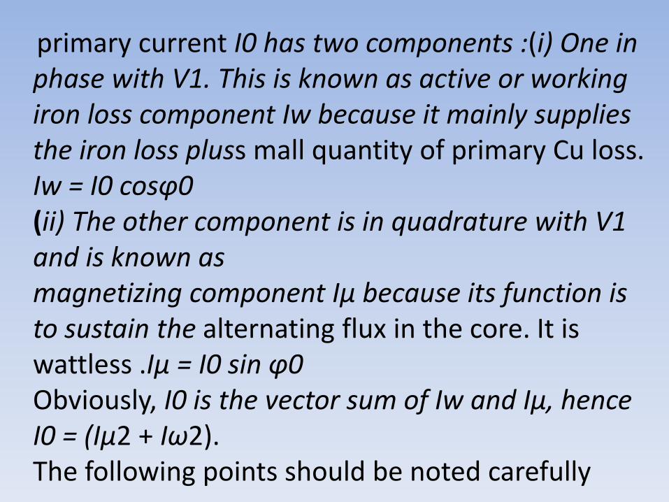
primary current I0 has two components :(i) One in phase with V1. This is known as active or working iron loss component Iw because it mainly supplies the iron loss pluss mall quantity of primary Cu loss. Iw = I0 cosφ0(ii) The other component is in quadrature with V1 and is known asmagnetizing component Iμ because its function is to sustain the alternating flux in the core. It is wattless .Iμ = I0 sin φ0Obviously, I0 is the vector sum of Iw and Iμ, hence I0 = (Iμ2 + Iω2).The following points should be noted carefully

1. The no-load primary current I0 is very small as compared to the full-load primary current. It isabout 1 per cent of the full-load current.
2. Owing to the fact that the permeability of thecore varies with the instantaneous value of the exciting current, the wave of the excitingor magnetizing current is not truly sinusoidal. As such it should not be represented by avector because only sinusoidally varyingquantities are represented by rotating vectors. But, in practice, it makes noappreciable difference.

3. As I0 is very small, the no-load primary.Cu loss is negligibly small which means that no-load primary input is practically equal to the iron loss in the transformer.
4. As it is principally the core-loss which is responsible for shift in the current vector,angle φ0 is known as hysteresis angle ofadvance.