Embed Size (px)
Citation preview
http://www.iaeme.com/IJCIET/index.asp 8 [email protected]
International Journal of Civil Engineering and Technology (IJCIET)
Volume 6, Issue 12, Dec 2015, pp. 08-21, Article ID: IJCIET_06_12_002
Available online at
http://www.iaeme.com/IJCIET/issues.asp?JType=IJCIET&VType=6&IType=12
ISSN Print: 0976-6308 and ISSN Online: 0976-6316
© IAEME Publication
___________________________________________________________________________
THEORETICAL BEHAVIOR OF
COMPOSITE CONSTRUCTION PRECAST
REACTIVE POWDER RC GIRDER AND
ORDINARY RC DECK SLAB
Dr. Nameer A. Alwash, and Ms. Dunia A. Abd Al-Radha
College of Engineering, Babylon University, Iraq
ABSTRACT
This study displays numerically (or theoretically) investigation by using
the finite element models for experimental work of composite behavior for
hybrid reinforced concrete slab on girder from locale material in Iraq,
ordinary concrete in slab and reactive powder concrete in girder, RPC, with
steel fibers of different types (straight, hook, and mix between its), tested as
simply supported span subjected under two point loading. Which ANSYS
version 15.0 is utilized. By studying the compatibility between the
experimental results and the theoretical results. As well as, parametric study
of many others variables are investigated by using ANSYS (version 15.0), such as: changing the compressive strength of the slab, changing the main
reinforcement of the girder, and changing thickness of resin bond layer
between girder and slab. The results showed that the increasing of the grade
of slab concrete from 25.8 MPa to (45, 55, 158)MPa the ultimate capacity
increases by (7.5, 14.2, and 24.5) % and the deflection decreases to (10.6,
16.4, and 24.8)% for reinforced hybrid RPC girder with NC slab.
Also, the results indicated that the increase of the area of tension
reinforcement in the girder of the considered section, by (33.3) %, improves
the stiffness behavior and the ultimate capacity by 19.7%. Which the results
confirmed that the degree of improvement of the both parameters :(grade of
slab concrete and area of tension reinforcement bars of the girder) on hybrid
reinforced girder is much larger than for same specimen without shear
reinforcement (using epoxy adhesive). Since the improvement in the ultimate
load of the considered specimen without shear reinforcement does not exceed
5%; however, the bond-slip decreases to 18.4%; and the deflection decreases
to 32.6%, when compressive strength of the slab increases from (25.8 to 158)
MPa. In addition, There is an optimum epoxy layer thickness that give the best
behavior and strength and it is 4mm for the considered specimens in the
present study.
Theoretical Behavior of Composite Construction Precast Reactive Powder RC Girder and
Ordinary RC Deck Slab
http://www.iaeme.com/IJCIET/index.asp 9 [email protected]
Key words: ANSYS Analysis, Area of Tension Reinforcement, Bond-Slip,
Compressive Strength, Reactive Powder Concrete, RPC, Resin Bond Layer,
Hybrid Concrete, Composite Section, RC Girder, RC Slab, Shear Connecters,
Inverted T Section.
Cite this Article: Dr. Nameer A. Alwash, and Ms. Dunia A. Abd Al-Radha.
Theoretical Behavior of Composite Construction Precast Reactive Powder RC
Girder and Ordinary RC Deck Slab. International Journal of Civil
Engineering and Technology, 6(12), 2015, pp. 08-21.
http://www.iaeme.com/IJCIET/issues.asp?JType=IJCIET&VType=6&IType=12
1. INTRODUCTION
Research over the past decade has yielded a new classification of concrete called
Reactive Powder Concrete, RPC, now labeled and classified as Ultra-High
Performance Concrete, UHPC. The term UHPC is used for defining concretes that are
produced by carefully selected high quality components, optimized blend designs,
which are batched, mixed, placed, consolidated and cured to the highest industry
standards.
Forster, 1994 [1] defined UHPC as "a concrete made with appropriate materials
combined according to a selected mix design and properly mixed, transported, placed,
consolidated, and cured so that the resulting concrete will give excellent performance
in the structure in which it will be exposed, and with the loads to which it will be
subjected for its design life". While American Concrete Institute had defined UHPC
as “Concrete meeting special combinations of performance and uniformity
requirements that cannot always be achieved routinely using conventional
constituents and normal mixing, placing and curing practices” [2]. These requirements
may involve enhancements of characteristics such as placement and compaction
without segregation, long-term mechanical properties, early-age strength, volume
stability, or service life in severe environments. UHPC (or RPC) technology
contributes significantly to the realization of sustainable development. The technology
carries an equation that sums up ‘sustainable construction’ in that it provides for a
minimum impact on the environment, maximizes structural performance and provides
a minimum total life-cycle cost solution. RPC is a cold cast cementitious material in
which the mechanical properties of the composite matrix are improved. This material
is very high strength and ductile. Its more isotropic nature and greater ductility make
it. All these improvements, however, result in a substantial cost increase over
conventional and even high-performance concrete. Because of its cost, RPC will not
replace concrete in applications where conventional mixes can economically meet the
performance criteria. However, with some of its performances nearing those of metals
and at a minor cost compared to steel, RPC becomes truly competitive in areas where
steel is predominant. To increase the load carrying requirement of steel sections, a
hybrid section is used. The concept of hybrid section in steel structures is not a new
idea. In 1990, Salmon, C. G., and Johnson, J. E. [3] defined a hybrid girder as one that
has either the tension flange or both flanges of steel section made with a higher
strength grade of steel than used for the web.
2. LITERATURE REVIEW
A brief of some research related to this study, are presented, as:
Aziz, 2006 [4] studied the experimental and theoretical flexure and shear behavior of
simply supported seventeen hybrid concrete I- beam under two-points load, with and
Dr. Nameer A. Alwash, and Ms. Dunia A. Abd Al-Radha
http://www.iaeme.com/IJCIET/index.asp 10 [email protected]
without construction joints by epoxy layer, the hybrid section was from conventional
and high strength concrete distributed on upper flange- web – lower flange for two
groups. Also, ANSYS program was used to test and compare with the experimental
results. The construction joints were modeled by using three dimensional surface-to-
surface contact (Interface) elements connected with concrete elements at shared nodes
represented the adhesion epoxy layer, and using a nonlinear spring element
(COMBIN-39) to represented the dowel action of the transversely crossing bars in
ANSYS program. The results indicated that for two-construction joint beams, no
interface slip was recorded at the joints between tension flanges and web. Also, the
tested beams that had one-construction joint had exhibited an increase in ductility
between (4% - 8%). While the tested beams that had two-construction joints had
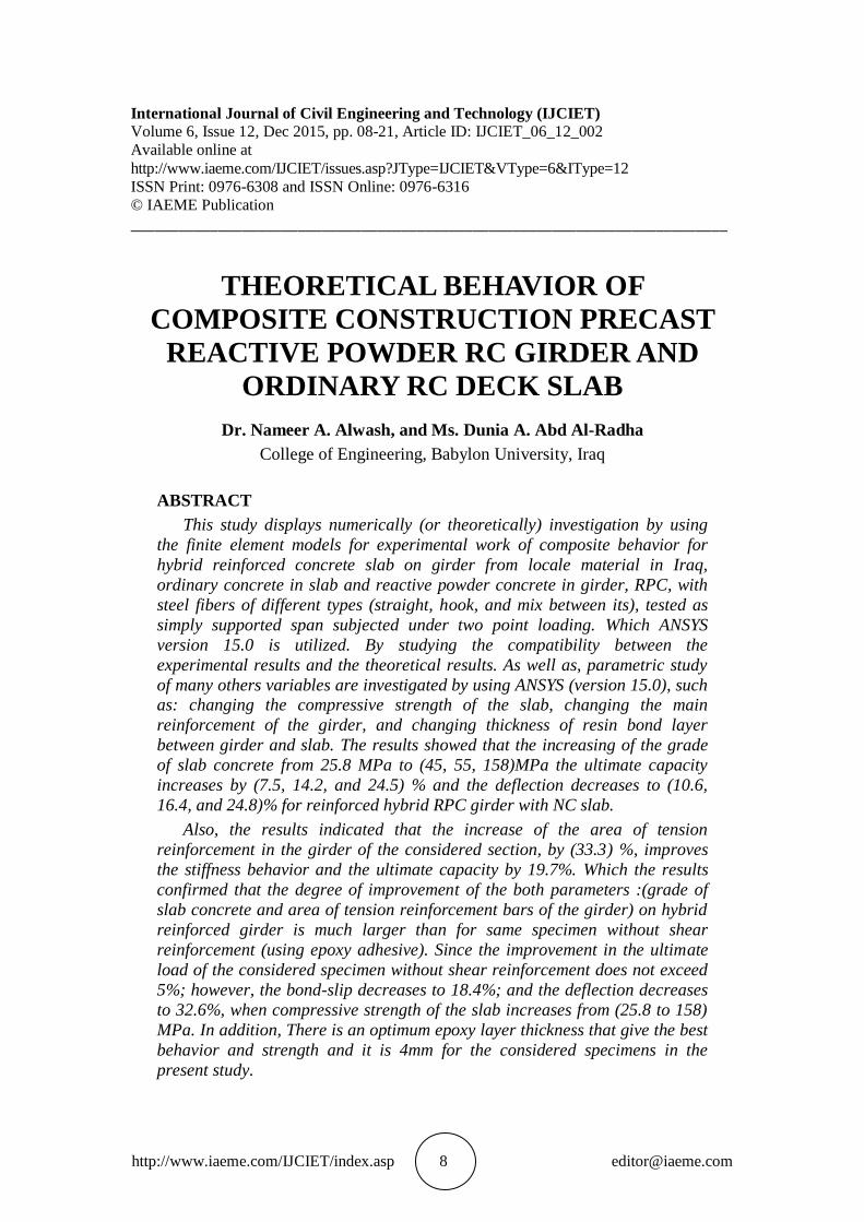
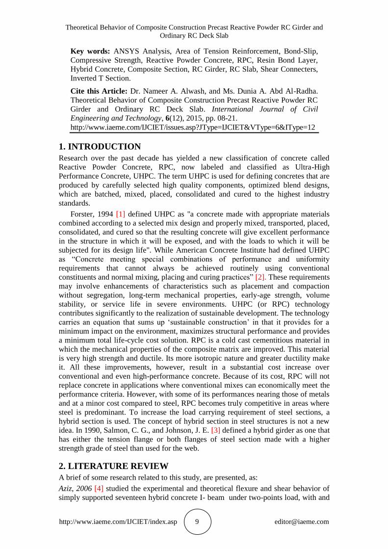
exhibited an increase in ductility between (6% - 62%). Resan, 2012 [5] investigated
the experimental and theoretical flexure behavior of simply supported sixteen
composite beams, from ferrocement slab and aluminum beam (I- section and box)
connected together by adhesive epoxy layer, under static load subjected to 3-point
loading, as described in fig. (1 and 2). ANSYS program was used to test and compare
with the experimental results. Different models with different interface element types
(linear spring element COMPIN14, nonlinear spring element COMPIN39, cohesive
zone interface element INTER205, and a solid shell element of SOLSH190) were
used to simulate the adhesive epoxy layer. Model COMPIN14 spring element gave
closer results to experimental ones as well as less solution iterations and so less
solution time in ANSYS program. The results reveal that the proposed beams have a
good loading capacity relative to their weight, by the assistance of using the epoxy
which was provided adequate bond that could be perfect as the slip between the slab
and beam remain very small during the test.
Figure 1 Details of the composite beams tested by Resan [5].
Figure 2 Aluminum sections details that used in the composite beams tested by Resan
[5].
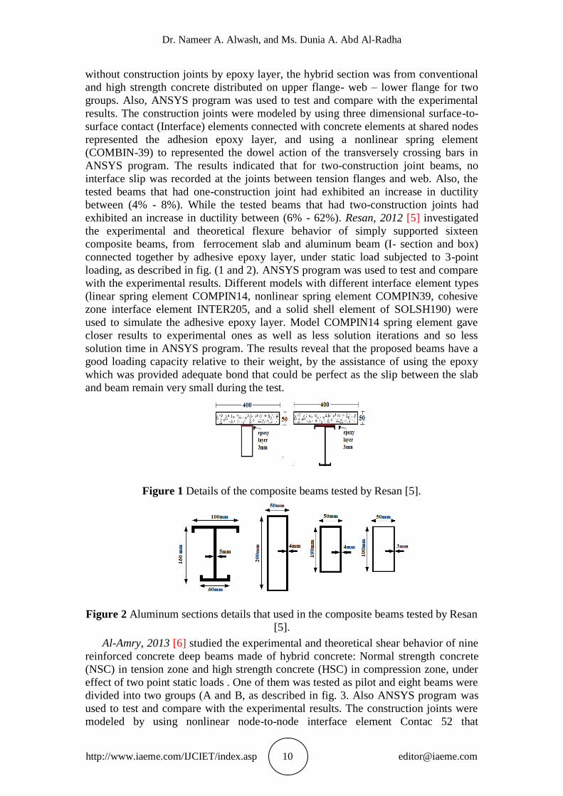
Al-Amry, 2013 [6] studied the experimental and theoretical shear behavior of nine
reinforced concrete deep beams made of hybrid concrete: Normal strength concrete
(NSC) in tension zone and high strength concrete (HSC) in compression zone, under
effect of two point static loads . One of them was tested as pilot and eight beams were
divided into two groups (A and B, as described in fig. 3. Also ANSYS program was
used to test and compare with the experimental results. The construction joints were
modeled by using nonlinear node-to-node interface element Contac 52 that
Theoretical Behavior of Composite Construction Precast Reactive Powder RC Girder and
Ordinary RC Deck Slab
http://www.iaeme.com/IJCIET/index.asp 11 [email protected]
represented for (with and without dowel action) in ANSYS program. The variables
parametric were: the effects of: (HSC) layer thickness, presence of web reinforcement
and method of casting (monolithically or at different times). The results were
indicated that the hybrid beams which cast monolithically, were exhibited an increase
in ductility about (13.3- 22.6) % and (17.3- 26.3) % for specimens without and with
web reinforcement, respectively. While, the hybrid beams with construction joint and
epoxy layer of thickness about (1 mm), exhibited larger increasing in ductility about
(28.7%) and (30.2%) for specimens with and without web reinforcement, respectively
when compared by control beam.
Group A) without web reinforcement
(Group B) with web reinforcement
Figure 3 Details of tested hybrid beams by Al-Amry [6].
Ismael, 2013 [7] investigated the experimental and theoretical flexural behavior of
fifteen monolithic RPC T-beams. The variables parametric were: the effects of steel
fiber volumetric ratio, silica fume ratio, tensile steel ratio, hybrid section and flange
width. And for hybrid section, no construction joint was submitted because there was
no time delayed between casting of the two materials. Also ANSYS program was
used to test and compare with the experimental results. No Interface element was
taken in ANSYS program, Its considered to be full bond between the material
changing. The results were indicated that using RPC in web and normal concrete in
flange effectively enhances the performance of T- beams in comparison with normal
concrete T-beams.
3. EXPERIMENTAL PREPARATIONS
3.1. Concrete Mix Design
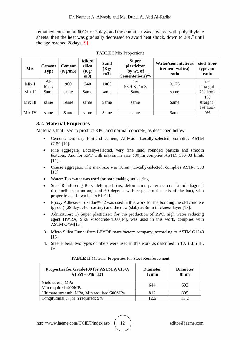
1. Reactive powder concrete: To product RPC with maximum strength by using local
materials, it have been experimented tried mixes and chosen, which mixed [8] as
shown in TABLE I. For 3 mixes that the only variable is (the type and ratio) of steel
fiber.
2. Conventional concrete, CC: Normal weight concrete was used to cast all slabs and
one girder. It was decided to choose a mix of 1:1.5:3 (by volume) cement, sand,
gravel respectively and 0. 48 water cement ratio.
All girders were cured by smearing in a container filled with tap water heated at
rate (20Co per hour) until reached 60C
o to avoid heat shock, and the temperature
Dr. Nameer A. Alwash, and Ms. Dunia A. Abd Al-Radha
http://www.iaeme.com/IJCIET/index.asp 12 [email protected]
remained constant at 60Cofor 2 days and the container was covered with polyethylene
sheets, then the heat was gradually decreased to avoid heat shock, down to 20Co until
the age reached 28days [9].
TABLE I Mix Proportions
Mix Cement
Type
Cement
(Kg/m3)
Micro
silica
(Kg/
m3)
Sand
(Kg/
m3)
Super
plasticizer
(by wt. of
Cementetious)%
Water/cementetious
(cement +silica)
ratio
steel fiber
type and
ratio
Mix I Al-
Mass 960 240 1000
5%
58.9 Kg/ m3 0.175
2%
straight
Mix II Same same Same same Same same 2% hook
Mix III same Same same Same same Same
1%
straight+
1% hook
Mix IV same Same same Same same Same 0%
3.2. Material Properties
Materials that used to product RPC and normal concrete, as described below:
Cement: Ordinary Portland cement, Al-Mass, Locally-selected, complies ASTM
C150 [10].
Fine aggregate: Locally-selected, very fine sand, rounded particle and smooth
textures. And for RPC with maximum size 600μm complies ASTM C33-03 limits
[11].
Coarse aggregate: The max size was 10mm, Locally-selected, complies ASTM C33
[12].
Water: Tap water was used for both making and curing.
Steel Reinforcing Bars: deformed bars, deformation pattern C consists of diagonal
ribs inclined at an angle of 60 degrees with respect to the axis of the bar), with
properties as shown in TABLE II.
Epoxy Adhesive: Sikadur®-32 was used in this work for the bonding the old concrete
(girder) (28 days after casting) and the new (slab) as 3mm thickness layer [13].
Admixtures: 1) Super plasticizer: for the production of RPC, high water reducing
agent HWRA, Sika Viscocrete-4100[14], was used in this work, complies with
ASTM C494[15].
3. Micro Silica Fume: from LEYDE manufactory company, according to ASTM C1240
[16].
4. Steel Fibers: two types of fibers were used in this work as described in TABLES III,
IV.
TABLE II Material Properties for Steel Reinforcement
Properties for Grade400 for ASTM A 615/A
615M – 04b [12]
Diameter
12mm
Diameter
8mm
Yield stress, MPa
Min required :400MPa 644 603
Ultimate strength, MPa, Min required:600MPa 812 895
Longitudinal,% ,Min required: 9% 12.6 13.2
Theoretical Behavior of Composite Construction Precast Reactive Powder RC Girder and
Ordinary RC Deck Slab
http://www.iaeme.com/IJCIET/index.asp 13 [email protected]
TABLE III Properties of the steel fibers,
with ACI 544.1R-96[17], ASTM A820[18]
Fiber type Hook ends
Density kg/m3 7800
Tensile strength,
MPa
1800
Length, mm 25
Diameter, mm 0.3 rounded section
Aspect ratio 83
The min tensile yield strength is (345 MPa)
TABLE IV Properties of the steel fibers manufactured by the Ganzhou
Daye Metallic Fibres Co., Ltd, China
Fiber type Straight, WSF 0213,
rounded section, Brass coated
Density kg/m3 7860
Tensile strength, MPa 2300
Length, mm 13
Diameter, mm 0.2mm±0.05mm
Aspect ratio 65
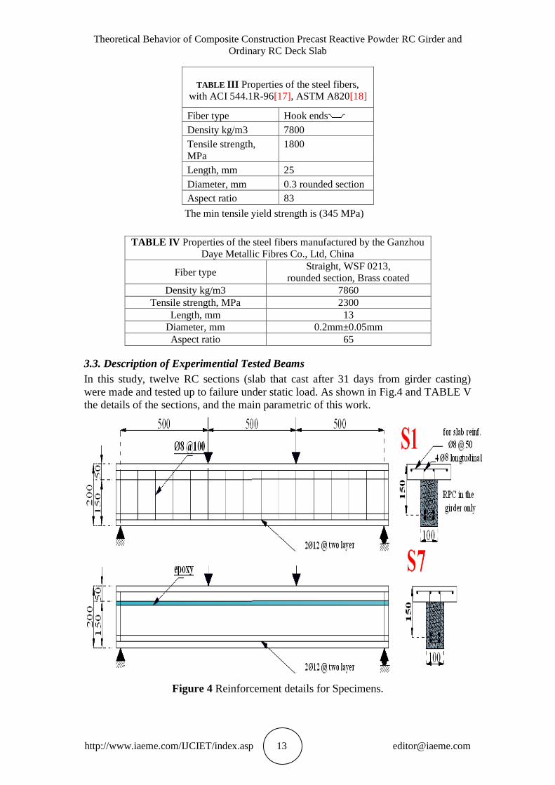
3.3. Description of Experimential Tested Beams
In this study, twelve RC sections (slab that cast after 31 days from girder casting)
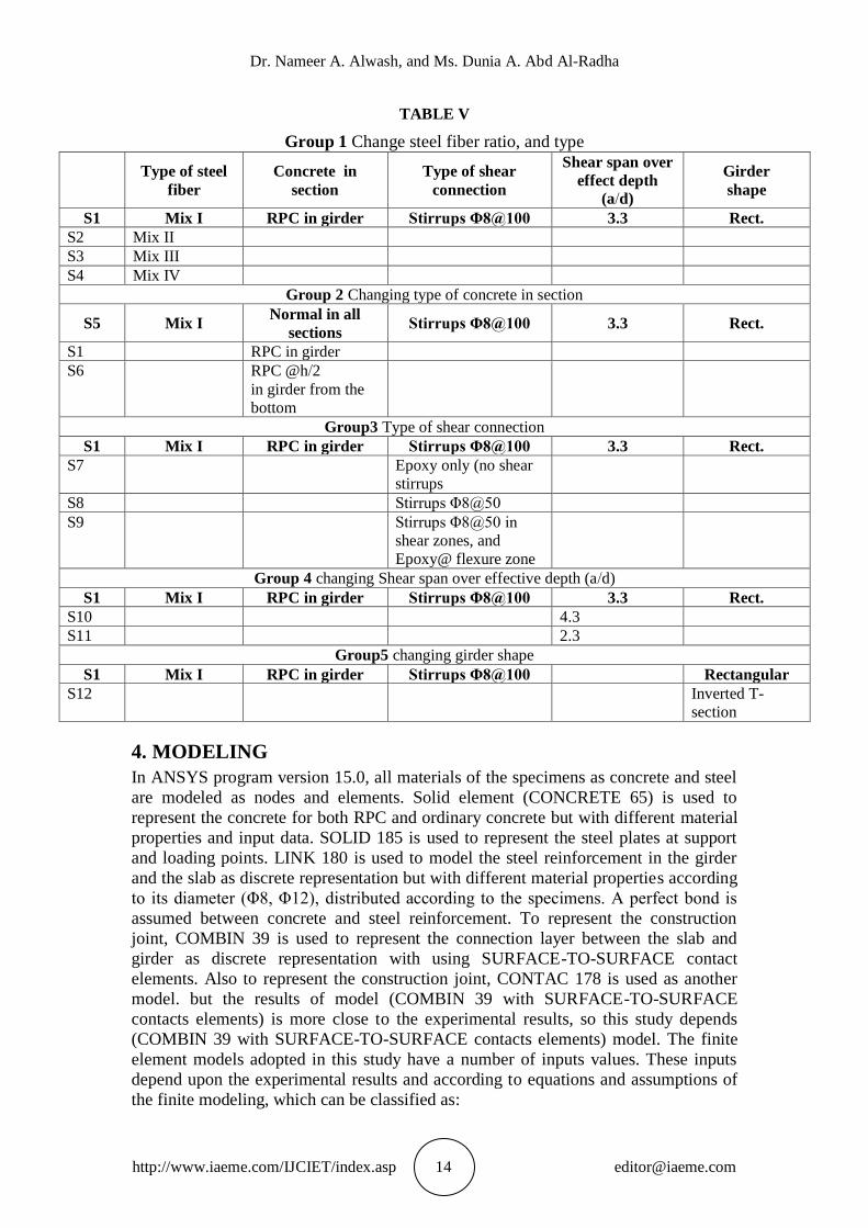
were made and tested up to failure under static load. As shown in Fig.4 and TABLE V
the details of the sections, and the main parametric of this work.
Figure 4 Reinforcement details for Specimens.
Dr. Nameer A. Alwash, and Ms. Dunia A. Abd Al-Radha
http://www.iaeme.com/IJCIET/index.asp 14 [email protected]
TABLE V
Group 1 Change steel fiber ratio, and type
Type of steel
fiber
Concrete in
section
Type of shear
connection
Shear span over
effect depth
(a/d)
Girder
shape
S1 Mix I RPC in girder Stirrups Φ8@100 3.3 Rect.
S2 Mix II
S3 Mix III
S4 Mix IV
Group 2 Changing type of concrete in section
S5 Mix I Normal in all
sections Stirrups Φ8@100 3.3 Rect.
S1 RPC in girder
S6 RPC @h/2
in girder from the
bottom
Group3 Type of shear connection
S1 Mix I RPC in girder Stirrups Φ8@100 3.3 Rect.
S7 Epoxy only (no shear
stirrups
S8 Stirrups Φ8@50
S9 Stirrups Φ8@50 in
shear zones, and
Epoxy@ flexure zone
Group 4 changing Shear span over effective depth (a/d)
S1 Mix I RPC in girder Stirrups Φ8@100 3.3 Rect.
S10 4.3
S11 2.3
Group5 changing girder shape
S1 Mix I RPC in girder Stirrups Φ8@100 Rectangular
S12 Inverted T-
section
4. MODELING
In ANSYS program version 15.0, all materials of the specimens as concrete and steel
are modeled as nodes and elements. Solid element (CONCRETE 65) is used to
represent the concrete for both RPC and ordinary concrete but with different material
properties and input data. SOLID 185 is used to represent the steel plates at support
and loading points. LINK 180 is used to model the steel reinforcement in the girder
and the slab as discrete representation but with different material properties according
to its diameter (Φ8, Φ12), distributed according to the specimens. A perfect bond is
assumed between concrete and steel reinforcement. To represent the construction
joint, COMBIN 39 is used to represent the connection layer between the slab and
girder as discrete representation with using SURFACE-TO-SURFACE contact
elements. Also to represent the construction joint, CONTAC 178 is used as another
model. but the results of model (COMBIN 39 with SURFACE-TO-SURFACE
contacts elements) is more close to the experimental results, so this study depends
(COMBIN 39 with SURFACE-TO-SURFACE contacts elements) model. The finite
element models adopted in this study have a number of inputs values. These inputs
depend upon the experimental results and according to equations and assumptions of
the finite modeling, which can be classified as:
Theoretical Behavior of Composite Construction Precast Reactive Powder RC Girder and
Ordinary RC Deck Slab
http://www.iaeme.com/IJCIET/index.asp 15 [email protected]
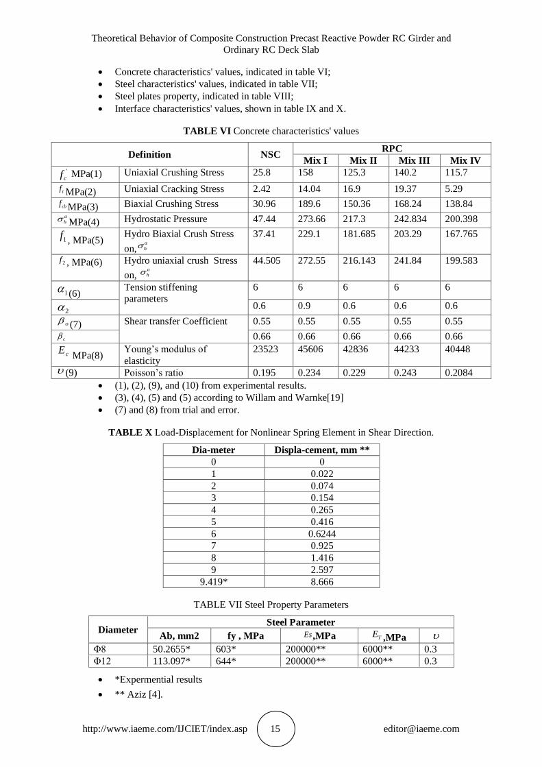
Concrete characteristics' values, indicated in table VI;
Steel characteristics' values, indicated in table VII;
Steel plates property, indicated in table VIII;
Interface characteristics' values, shown in table IX and X.
TABLE VI Concrete characteristics' values
Definition NSC RPC
Mix I Mix II Mix III Mix IV '
cf MPa(1) Uniaxial Crushing Stress 25.8 158 125.3 140.2 115.7
tf MPa(2) Uniaxial Cracking Stress 2.42 14.04 16.9 19.37 5.29
cbf MPa(3) Biaxial Crushing Stress 30.96 189.6 150.36 168.24 138.84 a
h MPa(4) Hydrostatic Pressure 47.44 273.66 217.3 242.834 200.398
1f , MPa(5) Hydro Biaxial Crush Stress
on,a
h
37.41 229.1 181.685 203.29 167.765
2f , MPa(6) Hydro uniaxial crush Stress
on, a
h
44.505 272.55 216.143 241.84 199.583
1 (6) Tension stiffening
parameters
6 6 6 6 6
0.6 0.9 0.6 0.6 0.6
o (7) Shear transfer Coefficient 0.55 0.55 0.55 0.55 0.55
c 0.66 0.66 0.66 0.66 0.66
cE MPa(8)
Young’s modulus of
elasticity
23523 45606 42836 44233 40448
(9) Poisson’s ratio 0.195 0.234 0.229 0.243 0.2084
(1), (2), (9), and (10) from experimental results.
(3), (4), (5) and (5) according to Willam and Warnke[19]
(7) and (8) from trial and error.
TABLE X Load-Displacement for Nonlinear Spring Element in Shear Direction.
Dia-meter Displa-cement, mm **
0 0
1 0.022
2 0.074
3 0.154
4 0.265
5 0.416
6 0.6244
7 0.925
8 1.416
9 2.597
9.419* 8.666
TABLE VII Steel Property Parameters
Diameter Steel Parameter
Ab, mm2 fy , MPa Es,MPa TE ,MPa Φ8 50.2655* 603* 200000** 6000** 0.3
Φ12 113.097* 644* 200000** 6000** 0.3
*Expermential results
** Aziz [4].
2
Dr. Nameer A. Alwash, and Ms. Dunia A. Abd Al-Radha
http://www.iaeme.com/IJCIET/index.asp 16 [email protected]
TABLE VIII Steel Plates Property
Steel Plate Parameter Value
Thickness of steel plates 15 mm
Modulus of elasticity, Es 200000 MPa
Tangent modulus of elasticity, ET 2000 MPa
Poisson’s ratio (υ) 0.3
Material behavior Linear elastic
TABLE IX Interface Property Parameters
Interface Parameter Definition value Note
μ Coefficient of friction 1.0 ACI-318 Code
τmax Maximum equivalent shear stress,
MPa
14.896 Xinzheng, and Jianjing
[20]
Target surface NSC as material 2
Contact surface RPC as material 1
FKN Contact compatibility factor 1.0 Assumed
Fdu Ultimate dowel force, kN 9.419 Aziz [4]
5. RESULTS OF FINITE ELEMENT ANALYSIS COMPARISON
WITH EXPERIMENTAL RESULT
The largest difference in the results is in the first cracking load of S4, about (16.67%).
The largest difference is in mid-span deflections at service load of S4 and S9 which is
about (19.2%) for both specimens.
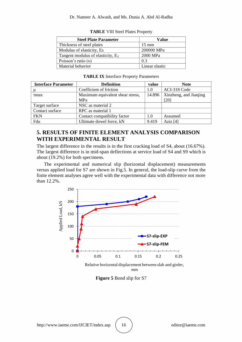
The experimental and numerical slip (horizontal displacement) measurements
versus applied load for S7 are shown in Fig.5. In general, the load-slip curve from the
finite element analyses agree well with the experimental data with difference not more
than 12.2%.
Figure 5 Bond slip for S7
0
50
100
150
200
250
0 0.05 0.1 0.15 0.2 0.25
Ap
pli
ed L
oad
, kN
Relative horizontal displacement between slab and girder, mm
S7-slip-EXP
S7-slip-FEM
Theoretical Behavior of Composite Construction Precast Reactive Powder RC Girder and
Ordinary RC Deck Slab
http://www.iaeme.com/IJCIET/index.asp 17 [email protected]
6. PARAMETRIC STUDY
The effect of some selected parameters on overall behavior of hybrid concrete,
reinforced RPC girder with reinforced NSC deck slab are decided herein, as follows:
6.1. Compressive strength for the slab
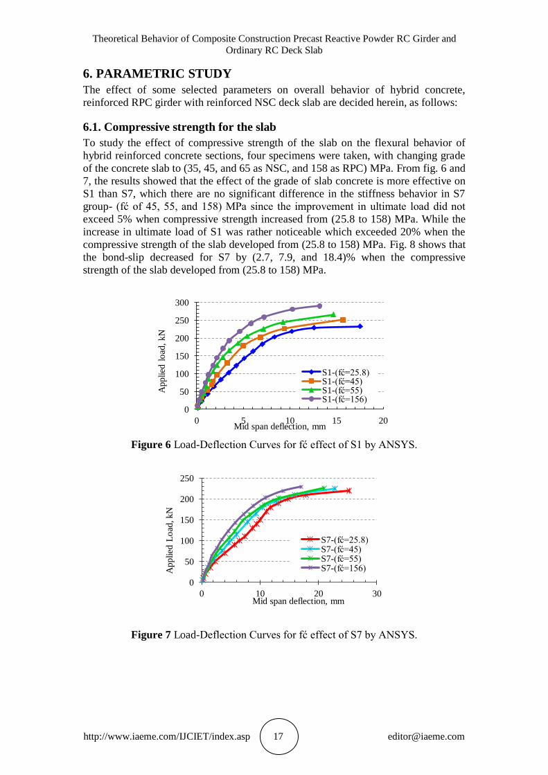
To study the effect of compressive strength of the slab on the flexural behavior of
hybrid reinforced concrete sections, four specimens were taken, with changing grade
of the concrete slab to (35, 45, and 65 as NSC, and 158 as RPC) MPa. From fig. 6 and
7, the results showed that the effect of the grade of slab concrete is more effective on
S1 than S7, which there are no significant difference in the stiffness behavior in S7
group- (fć of 45, 55, and 158) MPa since the improvement in ultimate load did not
exceed 5% when compressive strength increased from (25.8 to 158) MPa. While the
increase in ultimate load of S1 was rather noticeable which exceeded 20% when the
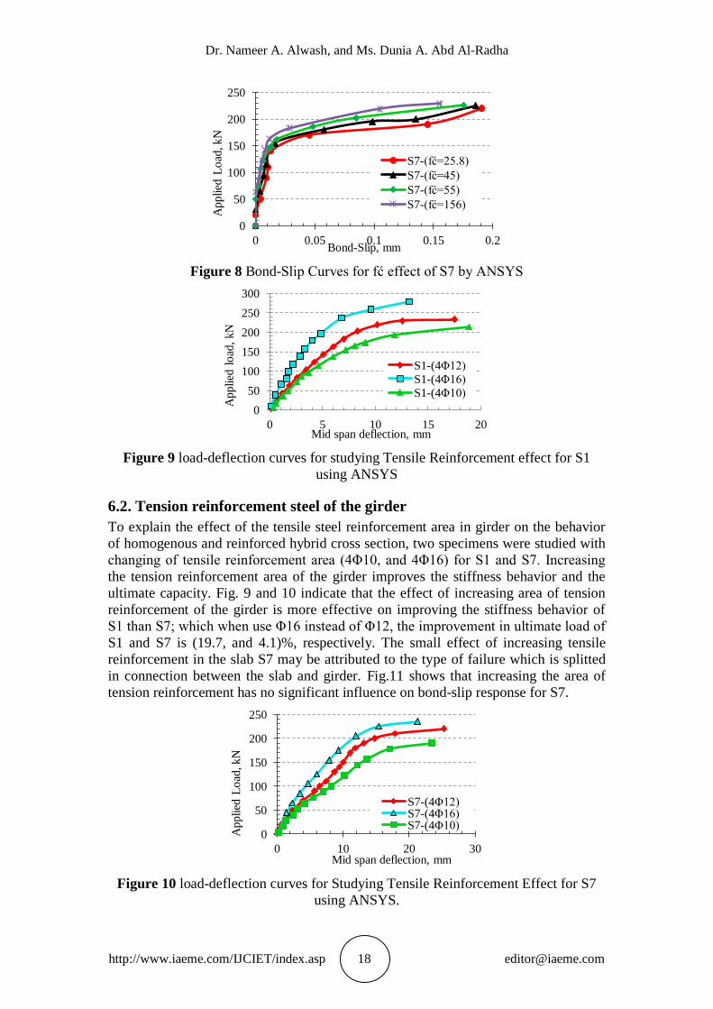
compressive strength of the slab developed from (25.8 to 158) MPa. Fig. 8 shows that
the bond-slip decreased for S7 by (2.7, 7.9, and 18.4)% when the compressive
strength of the slab developed from (25.8 to 158) MPa.
Figure 6 Load-Deflection Curves for fć effect of S1 by ANSYS.
Figure 7 Load-Deflection Curves for fć effect of S7 by ANSYS.
0
50
100
150
200
250
300
0 5 10 15 20
Applied
lo
ad,
kN
Mid span deflection, mm
S1-(fć=25.8) S1-(fć=45) S1-(fć=55) S1-(fć=156)
0
50
100
150
200
250
0 10 20 30
Applied
Lo
ad, kN
Mid span deflection, mm
S7-(fć=25.8) S7-(fć=45) S7-(fć=55) S7-(fć=156)
Dr. Nameer A. Alwash, and Ms. Dunia A. Abd Al-Radha
http://www.iaeme.com/IJCIET/index.asp 18 [email protected]
Figure 8 Bond-Slip Curves for fć effect of S7 by ANSYS
Figure 9 load-deflection curves for studying Tensile Reinforcement effect for S1
using ANSYS
6.2. Tension reinforcement steel of the girder
To explain the effect of the tensile steel reinforcement area in girder on the behavior
of homogenous and reinforced hybrid cross section, two specimens were studied with
changing of tensile reinforcement area (4Φ10, and 4Φ16) for S1 and S7. Increasing
the tension reinforcement area of the girder improves the stiffness behavior and the
ultimate capacity. Fig. 9 and 10 indicate that the effect of increasing area of tension
reinforcement of the girder is more effective on improving the stiffness behavior of
S1 than S7; which when use Φ16 instead of Φ12, the improvement in ultimate load of
S1 and S7 is (19.7, and 4.1)%, respectively. The small effect of increasing tensile
reinforcement in the slab S7 may be attributed to the type of failure which is splitted
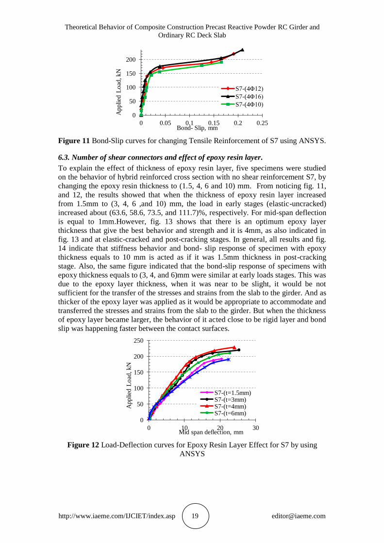
in connection between the slab and girder. Fig.11 shows that increasing the area of
tension reinforcement has no significant influence on bond-slip response for S7.
Figure 10 load-deflection curves for Studying Tensile Reinforcement Effect for S7
using ANSYS.
0
50
100
150
200
250
0 0.05 0.1 0.15 0.2
Applied
Lo
ad, kN
Bond-Slip, mm
S7-(fć=25.8)
S7-(fć=45)
S7-(fć=55)
S7-(fć=156)
0
50
100
150
200
250
300
0 5 10 15 20
Applied
lo
ad,
kN
Mid span deflection, mm
S1-(4Φ12)
S1-(4Φ16)
S1-(4Φ10)
0
50
100
150
200
250
0 10 20 30
Applied
Lo
ad, kN
Mid span deflection, mm
S7-(4Φ12) S7-(4Φ16) S7-(4Φ10)
Theoretical Behavior of Composite Construction Precast Reactive Powder RC Girder and
Ordinary RC Deck Slab
http://www.iaeme.com/IJCIET/index.asp 19 [email protected]
Figure 11 Bond-Slip curves for changing Tensile Reinforcement of S7 using ANSYS.
6.3. Number of shear connectors and effect of epoxy resin layer.
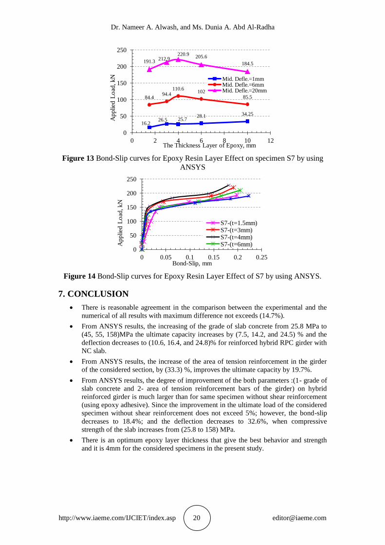
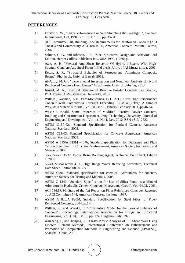
To explain the effect of thickness of epoxy resin layer, five specimens were studied
on the behavior of hybrid reinforced cross section with no shear reinforcement S7, by
changing the epoxy resin thickness to (1.5, 4, 6 and 10) mm. From noticing fig. 11,
and 12, the results showed that when the thickness of epoxy resin layer increased
from 1.5mm to (3, 4, 6 ,and 10) mm, the load in early stages (elastic-uncracked)
increased about (63.6, 58.6, 73.5, and 111.7)%, respectively. For mid-span deflection
is equal to 1mm.However, fig. 13 shows that there is an optimum epoxy layer
thickness that give the best behavior and strength and it is 4mm, as also indicated in
fig. 13 and at elastic-cracked and post-cracking stages. In general, all results and fig.
14 indicate that stiffness behavior and bond- slip response of specimen with epoxy
thickness equals to 10 mm is acted as if it was 1.5mm thickness in post-cracking
stage. Also, the same figure indicated that the bond-slip response of specimens with
epoxy thickness equals to (3, 4, and 6)mm were similar at early loads stages. This was
due to the epoxy layer thickness, when it was near to be slight, it would be not
sufficient for the transfer of the stresses and strains from the slab to the girder. And as
thicker of the epoxy layer was applied as it would be appropriate to accommodate and
transferred the stresses and strains from the slab to the girder. But when the thickness
of epoxy layer became larger, the behavior of it acted close to be rigid layer and bond
slip was happening faster between the contact surfaces.
Figure 12 Load-Deflection curves for Epoxy Resin Layer Effect for S7 by using
ANSYS
0
50
100
150
200
0 0.05 0.1 0.15 0.2 0.25 A
pplied
Lo
ad, kN
Bond- Slip, mm
S7-(4Φ12)
S7-(4Φ16)
S7-(4Φ10)
0
50
100
150
200
250
0 10 20 30
Applied
Lo
ad, kN
Mid span deflection, mm
S7-(t=1.5mm) S7-(t=3mm) S7-(t=4mm) S7-(t=6mm)
Dr. Nameer A. Alwash, and Ms. Dunia A. Abd Al-Radha
http://www.iaeme.com/IJCIET/index.asp 20 [email protected]
Figure 13 Bond-Slip curves for Epoxy Resin Layer Effect on specimen S7 by using
ANSYS
Figure 14 Bond-Slip curves for Epoxy Resin Layer Effect of S7 by using ANSYS.
7. CONCLUSION
There is reasonable agreement in the comparison between the experimental and the
numerical of all results with maximum difference not exceeds (14.7%).
From ANSYS results, the increasing of the grade of slab concrete from 25.8 MPa to
(45, 55, 158)MPa the ultimate capacity increases by (7.5, 14.2, and 24.5) % and the
deflection decreases to (10.6, 16.4, and 24.8)% for reinforced hybrid RPC girder with
NC slab.
From ANSYS results, the increase of the area of tension reinforcement in the girder
of the considered section, by (33.3) %, improves the ultimate capacity by 19.7%.
From ANSYS results, the degree of improvement of the both parameters :(1- grade of
slab concrete and 2- area of tension reinforcement bars of the girder) on hybrid
reinforced girder is much larger than for same specimen without shear reinforcement
(using epoxy adhesive). Since the improvement in the ultimate load of the considered
specimen without shear reinforcement does not exceed 5%; however, the bond-slip
decreases to 18.4%; and the deflection decreases to 32.6%, when compressive
strength of the slab increases from (25.8 to 158) MPa.
There is an optimum epoxy layer thickness that give the best behavior and strength
and it is 4mm for the considered specimens in the present study.
16.2 26.5 25.7
28.1 34.25
84.4 94.4
110.6 102
85.5
191.3 212.9
220.9 205.6
184.5
0
50
100
150
200
250
0 2 4 6 8 10 12
Applied
Lo
ad, kN
The Thickness Layer of Epoxy, mm
Mid. Defle.=1mm Mid. Defle.=6mm Mid. Defle.=20mm
0
50
100
150
200
250
0 0.05 0.1 0.15 0.2 0.25
Applied
Lo
ad, kN
Bond-Slip, mm
S7-(t=1.5mm) S7-(t=3mm) S7-(t=4mm) S7-(t=6mm)
Theoretical Behavior of Composite Construction Precast Reactive Powder RC Girder and
Ordinary RC Deck Slab
http://www.iaeme.com/IJCIET/index.asp 21 [email protected]
REFERENCES
[1] Forster, S. W., "High-Performance Concrete Stretching the Paradigm ", Concrete
International, Oct, 1994, Vol. 16, No. 10, pp. 33-34.
[2] ACI Committee 318, Building Code Requirements for Reinforced Concrete (ACI
318-06) and Commentary-ACI318RM-06, American Concrete Institute, Detroit,
2006.
[3] Salmon, C. G., and Johnson, J. E., "Steel Structures: Design and Behavior", 3rd
Edition, Harper Collins Publishers Inc., USA 1990, (1086) p.
[4] Aziz, A. H. "Flexural And Shear Behavior Of Hybrid I-Beams With High-
Strength Concrete And Steel Fibers", Phd thesis, Univ. of Al-Mustansiriya, 2006.
[5] Resan, S. F., "Structural Behavior of Ferrocement- Aluminum Composite
Beams", Phd thesis, Univ. of Basrah, 2013.
[6] Al-Amry, M. Gh, "Experimental Investigation and Nonlinear Analysis of Hybrid
Reinforced Concrete Deep Beams" M.SC thesis, Univ. of Babylon, 2013.
[7] Ismael, M. A.," Flexural Behavior of Reactive Powder Concrete Tee Beams",
PhD. Thesis, Al-Mustansiriya University, 2013.
[8] Wille,K., Naaman, A.E., Parr-Montesinos, G.J., 2011. Ultra-High Performance
Concrete with Compressive Strength Exceeding 150MPa (22ksi): A Simpler
Way, ACI Materials Journal, Vol.108, No.1, January-February 2011, pp.46-54.
[9] Wasan I. Khalil, Some Properties of Modified Reactive Powder Concrete,
Building and Construction Department, Iraq: Technology University, Journal of
Engineering and Development, Vol. 16, No.4, Dec. 2012 ISSN 1813- 7822
[10] ASTM C150-02a, Standard Specification for Portland Cement, American
National Standard, 2002.
[11] ASTM C33-03, Standard Specification for Concrete Aggregates, American
National Standard, 2003.
[12] ASTM A 615/A 615M – 04b, Standard specification for Deformed and Plain
Carbon Steel Bars for Concrete Reinforcement, American Society for Testing and
Materials, 2005.
[13] Sika, Sikadur®-32, Epoxy Resin Bonding Agent, Technical Data Sheet, Edition
1, 2005.
[14] Sika® ViscoCrete® 4100, High Range Water Reducing Admixture, Technical
Data Sheet, Edition 08.2012/v1
[15] ASTM C494, Standard specification for chemical Admixtures for concrete,
American Society for Testing and Materials, 2005.
[16] ASTM C 1240, "Standard Specification for Use of Silica Fume as a Mineral
Admixture in Hydraulic-Cement Concrete, Mortar, and Grout", Vol. 04.02, 2003.
[17] ACI 544.1R-96, State-of-the-Art Report on Fiber Reinforced Concrete. Reported
by ACI Committee 544, American Concrete Institute, 1997.
[18] ASTM A 820/A 820M, Standard Specification for Steel Fiber for Fiber-
Reinforced Concrete, 2004,pp.1-4.
[19] Willam, K., and Warnke, E, "Constitutive Model for the Triaxial Behavior of
Concrete", Proceedings, International Association for Bridge and Structural
Engineering, Vol. (19), ISMES, pp. 174, Bergamo, Italy, 1975.
[20] Xinzheng, L, and Jianjing, J., "Elasto-Plastic Analysis of RC Shear Wall Using
Discrete Element Method", International Conference on Enhancement and
Promotion of Computation Methods in Engineering and Science (EPMESC),
Shanghai, China, 2001.