Embed Size (px)
Citation preview

LOSSES ENERGY IN PIPELINES J3008/6/1
ENERGY LOSS IN PIPELINES
OBJECTIVES
General Objective : To know, understand and apply Bernoulli’s equation to pipeline systems
Specific Objectives : At the end of the unit, you should be able to :
sketch the velocity profile in circular pipe system
explain and calculate energy loss in pipeline system
calculate and apply energy loss equation from reservoir
solve problem related to the pipeline system
UNIT 6

LOSSES ENERGY IN PIPELINES J3008/6/2
6.0 INTRODUCTION
A pipe is defined as a closed conduit of circular section through which the fluid flows, filling the complete cross-section. The fluid in the pipe has no free surface. It will be at a pressure which may vary along the pipe. Losses of energy in a pipeline cannot be ignored. When the shock losses and friction loss have been determined, they are inserted in Bernoulli’s equation in the usual way.
Velocity profile in circular pipe system (refer Figure 6.1)
Losses of energy in pipe line are due to :a) shock loss at sudden enlargementb) shock loss at sudden contractionc) frictional resistance to flowd) loss at entrye) loss at rounded exit
INPUTINPUT
Figure 6.1
rough pipe wall
smooth pipe wall

Loss of head at enlargement, hL
LOSSES ENERGY IN PIPELINES J3008/6/3
6.1 SHOCK LOSS AT SUDDEN ENLARGEMENT
Figure 6.2 shows the loss of head when a pipe undergoes a sudden increase in diameter. To calculate the loss the following equation is given.
When, v1 = velocity in the smaller pipe upstream of the enlargementv2 = velocity in the larger pipe
If hL = head lost at the enlargement, then by Bernoulli’s theorem,
Special case: When a pipe discharges into a large reservoir through a sharp exit, conditions are equivalent to a sudden enlargement (refer Figure 6.2).
v1 = pipe velocity = vv2 = reservoir velocity = 0
Figure 6.2
Loss of head at sharp exit into reservoir, hL
LOSSES ENERGY IN PIPELINES J3008/6/4
If the exit is rounded, this loss is greatly reduced and is usually negligible
Example 6.1A pipe carrying 1800 l/min of water increases suddenly from 10 cm to 15 cm diameter. Find
a) the head loss due to the sudden enlargement b) the difference in pressure in kN/m2 in the two pipes
Solution to Example 6.1
a) 1 liter = 0.001 m3
1800 l = 1.8 m3
QA = AA vA = AB vB
So thatvA =Q/AA
Figure 6.3

LOSSES ENERGY IN PIPELINES J3008/6/5
vB =Q/AB
Head loss of enlargement, hL =
b) Difference in pressure;
zA=zB
6.2 SHOCK LOSS AT SUDDEN CONTRACTION
Loss of head at sudden contraction, hC
Loss of head at sharp entrance, hC
LOSSES ENERGY IN PIPELINES J3008/6/6
Figure 6.4
In a sudden contraction, the flow converges to form a vena contracta at section (3) in the smaller pipe. The loss of energy in the convergence from sections (1) to (3) is small and the main loss occurs in the enlargement from sections (3) to (2). It is usual to ignore the loss from sections (1) to (3) and treat the loss from (3) to (2) as if it was due to a sudden enlargement from the area of the vena contracta ac to the area a2 of the smaller pipe.( Figure 6.4 )
Loss of head =
For continuity of flow
If the coefficient of contraction =
Special case: if the entrance of a pipe line from a reservoir is sharp (no rounded or bell-mouthed) it is equivalent to a sudden contraction from a pipe of infinite size to that of the pipe line. The loss of head at sharp entrance is

LOSSES ENERGY IN PIPELINES J3008/6/7
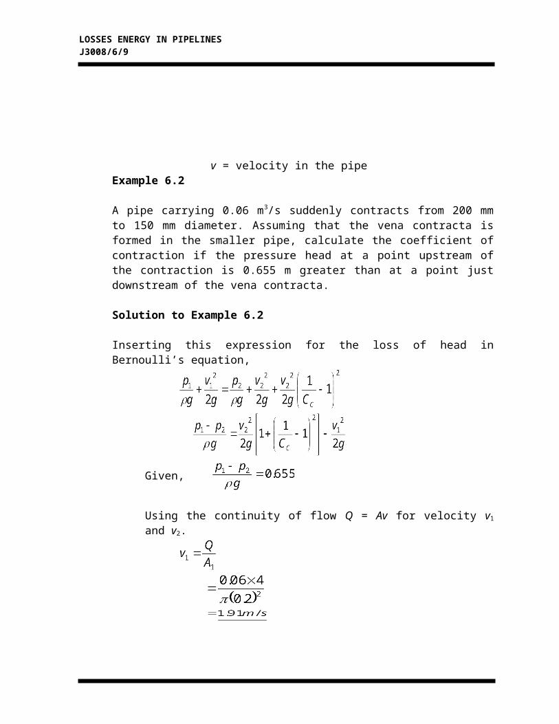
v = velocity in the pipeExample 6.2
A pipe carrying 0.06 m3/s suddenly contracts from 200 mm to 150 mm diameter. Assuming that the vena contracta is formed in the smaller pipe, calculate the coefficient of contraction if the pressure head at a point upstream of the contraction is 0.655 m greater than at a point just downstream of the vena contracta.
Solution to Example 6.2
Inserting this expression for the loss of head in Bernoulli’s equation,
Given,
Using the continuity of flow Q = Av for velocity v1 and v2.
Thus,

LOSSES ENERGY IN PIPELINES J3008/6/8
coefficient of contraction,
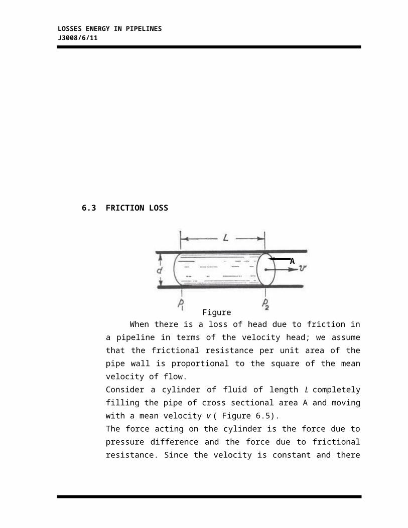
6.3 FRICTION LOSS
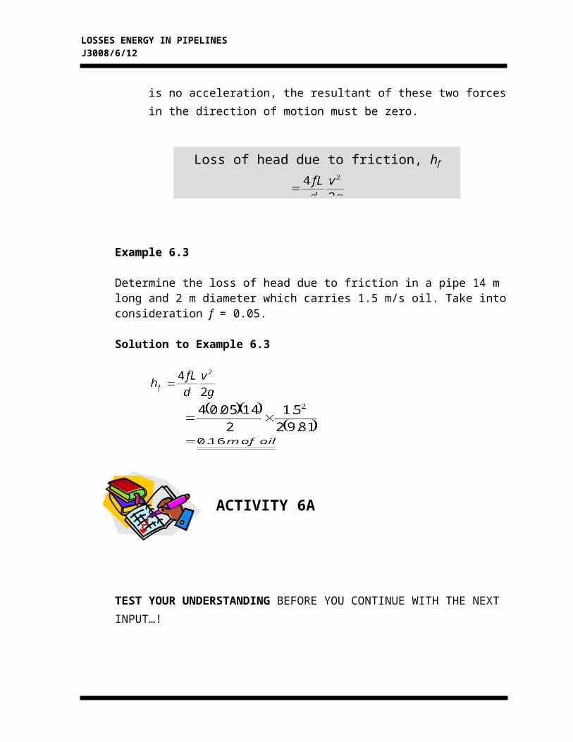
Loss of head due to friction, hf
LOSSES ENERGY IN PIPELINES J3008/6/9
When there is a loss of head due to friction in a pipeline in terms of the velocity head; we assume that the frictional resistance per unit area of the pipe wall is proportional to the square of the mean velocity of flow.Consider a cylinder of fluid of length L completely filling the pipe of cross sectional area A and moving with a mean velocity v ( Figure 6.5).The force acting on the cylinder is the force due to pressure difference and the force due to frictional resistance. Since the velocity is constant and there is no acceleration, the resultant of these two forces in the direction of motion must be zero.
Example 6.3
Determine the loss of head due to friction in a pipe 14 m long and 2 m diameter which carries 1.5 m/s oil. Take into consideration f = 0.05.
Solution to Example 6.3
ACTIVITY 6A
Figure 6.5
A

LOSSES ENERGY IN PIPELINES J3008/6/10
TEST YOUR UNDERSTANDING BEFORE YOU CONTINUE WITH THE NEXT INPUT…!
6.1 Water flows vertically downwards through a 150 mm diameter pipe with a velocity of 2.4 m/s. The pipe suddenly enlarges to 300 mm in diameter. Find the loss of head. If the flow is reversed, find the loss of head, assuming the coefficient of contraction now being 0.62.
FEEDBACK ON ACTIVITY 6A
LOSSES ENERGY IN PIPELINES J3008/6/11
6.1
loss of head at sudden enlargement, hL
using continuity of flow,Q1 = Q2
A1v1 = A2v2
loss of head at sudden contraction, hC
LOSSES ENERGY IN PIPELINES J3008/6/12
INPUTINPUT

LOSSES ENERGY IN PIPELINES J3008/6/13
6.4 PIPELINE PROBLEMS
All pipeline problems should be solved by applying Bernoulli’s theorem between points for which the total energy is known and including expressions for any loss of energy due to shock or to friction, thus
6.4.1 Discharge to atmosphere
To understand the discharge to atmosphere, let’s look at Example 6.4.
Example 6.4
Water from a large reservoir is discharged to atmosphere through a 100 mm diameter pipe 450 m long. The entry from the reservoir to the pipe is sharp and the outlet is 12 m below the surface level in the reservoir. Taking f = 0.01 in the Darcy formula, calculate the discharge.(refer to Figure 6.6)
Figure 6.6

LOSSES ENERGY IN PIPELINES J3008/6/14
Solution to Example 6.4
Apply Bernoulli’s theorem to A and B, assuming velocity at A is zero and that pA = pB = atmospheric pressure
Total energy at A = Total energy at B + loss at entry + frictional loss
Putting H = 12 m, f = 0.01, L = 450 m, d = 100 mm = 0.1 m
Discharge
6.4.2 Pipe in series

LOSSES ENERGY IN PIPELINES J3008/6/15
To understand the pipe in series, let’s look at Example 6.5.
Example 6.5
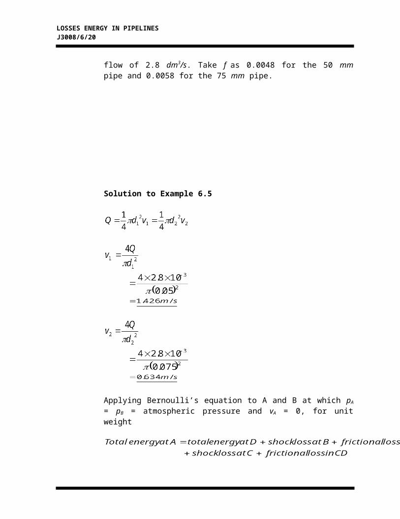
Water is discharged from a reservoir into the atmosphere through a pipe 39 m long. There is a sharp entrance to the pipe and the diameter is 50 mm for the first 15 m from the entrance. The pipe then enlarges suddenly to 75 mm in diameter for the remainder of its length. Taking into account the loss of head at entry and at the enlargement, calculate the difference of level between the surface of the reservoir and the pipe exit which will maintain a flow of 2.8 dm3/s. Take f as 0.0048 for the 50 mm pipe and 0.0058 for the 75 mm pipe.
Solution to Example 6.5
Figure 6.7

LOSSES ENERGY IN PIPELINES J3008/6/16
Applying Bernoulli’s equation to A and B at which pA = pB = atmospheric pressure and vA = 0, for unit weight
There is no shock loss at D as discharge is to atmosphere.

LOSSES ENERGY IN PIPELINES J3008/6/17
Difference of level = H = 0.02 + 0.052 + 0.597 + 0.032 + 0.152
= 0.853 m of water
6.4.3 Hydraulic Gradient

LOSSES ENERGY IN PIPELINES J3008/6/18
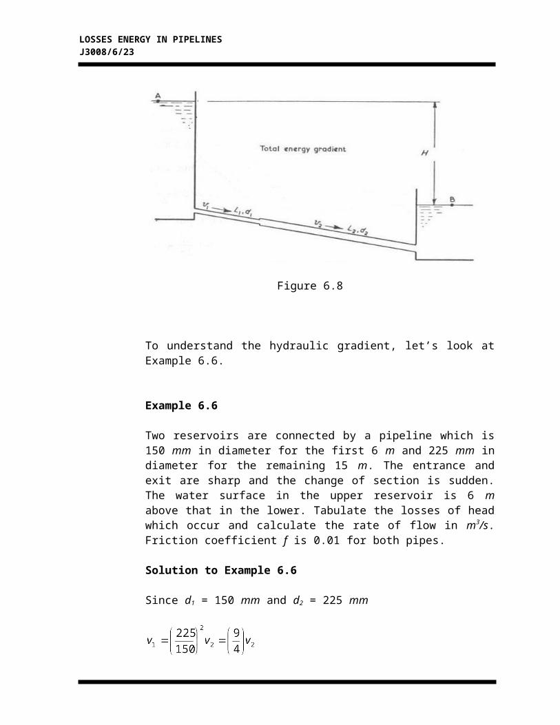
Figure 6.8
To understand the hydraulic gradient, let’s look at Example 6.6.
Example 6.6
Two reservoirs are connected by a pipeline which is 150 mm in diameter for the first 6 m and 225 mm in diameter for the remaining 15 m. The entrance and exit are sharp and the change of section is sudden. The water surface in the upper reservoir is 6 m above that in the lower. Tabulate the losses of head which occur and calculate the rate of flow in m3/s. Friction coefficient f is 0.01 for both pipes.
Solution to Example 6.6
Since d1 = 150 mm and d2 = 225 mm
The losses are

LOSSES ENERGY IN PIPELINES J3008/6/19
LOSSES ENERGY IN PIPELINES J3008/6/20
Total loss of head =
Applying Bernoulli’s Equation to A and B for unit weight
Pressures at A and B are equal and if the reservoirs are large the velocities will be zero. Taking datum level at B,
H = 0 + losses
so
Discharge

LOSSES ENERGY IN PIPELINES J3008/6/21
ACTIVITY 6B
LOSSES ENERGY IN PIPELINES J3008/6/22
TEST YOUR UNDERSTANDING BEFORE YOU CONTINUE WITH THE NEXT INPUT…!
6.2 According to the figure below, list out the losses of head which occur, giving an expression for each.
FEEDBACK ON ACTIVITY 6B
LOSSES ENERGY IN PIPELINES J3008/6/23
Answers:
6.1 The losses of head which will occur are as follows:
1. Loss at entry
2. Friction loss
3. Loss at sudden enlargement
4. Friction loss
5. Loss at exit
SELF-ASSESSMENT

LOSSES ENERGY IN PIPELINES J3008/6/24
You are approaching success. Try all the questions in this self-assessment section and check your answers with those given in the Feedback on Self-Assessment If you face any problems, discuss it with your lecturer. Good luck.
6.1 Water is discharged from a reservoir into the atmosphere through a pipe 80 m long. There is a sharp entrance to the pipe and the diameter is 250 mm for the first 50 m. The outlet is 35 m below the surface level in the reservoir. The pipe then enlarges suddenly to 450 mm in diameter for the reminder of its length. Take f = 0.004 for both pipes. Calculate the discharge.
6.2 Two reservoirs have a difference in level of 9 m and are connected by a pipe line, which is 38 mm in diameter for the first 13 m and 23 mm for the remaining 6 m. Take f = 0.01 for both pipes and CC = 0.66. Calculate the discharge.
6.3 A pipe carrying 0.056 m3/s suddenly changes diameter from;a) 200 mm to 150 mmb) 300 mm to 150 mmc) 450 mm to 150 mmFind the loss of head and the pressure difference across the contraction in each case, given CC = 0.62.
FEEDBACK ON SELF-ASSESSMENT
Answers:

LOSSES ENERGY IN PIPELINES J3008/6/25
6.1 Q = 0.623 m3/s
6.2 Q = 0.00345 m3/s
6.3 (a) 0.19 m, 0.54 m(b) 0.19 m, 0.673 m(c) 0.19 m, 0.699 m