Embed Size (px)
Citation preview

CHAPTER 1
Wireless Power Transmission
1.1 Introduction
Power is very important to modern systems. From the smallest sensors, bionic
implants, laptops, consumer products to satellites and oil platforms, it is important to
be able to deliver power means other than classical wires or transmission lines.
Wireless transmission is useful in cases where instantaneous or continuous energy
transfer is needed, but interconnecting wires are inconvenient, hazardous, or
impossible some times. In the case of biological implants, there must be a battery or
energy storage element present that can receive and hold energy. This element takes
up valuable space inside a person body. In the case of satellites, UAVs and oil
platforms, solar panels, fuel cells, or combustion engines are currently used to supply
power. Solar panels take up a great deal of weight and bulk in terms of energy density
and must have a tracking system to maximize exposure to the sun. Fuel cells and
combustion cells needs fuel and maintenance to be delivered on site.
Wireless Power Transmission (WPT) is the efficient transmission of electric
power from one point to another trough vacuum or an atmosphere without the use of
wire or any other substance. The power can be transmitted using Inductive coupling
for short range, resonant induction for mid-range electromagnetic wave power
transfer. WPT is a technology that can transport power to locations, which are
otherwise not possible or impractical to reach. The objective of this report is to design
and implement a method to transmit wireless electrical power through space. The
system will work by using resonant coils to transmit power from an AC line to a
resistive load. Investigation of various geometrical and physical form factors
evaluated in order to increase coupling between transmitter and receiver. [2]
1.2 Why Do We Go For WPT System
1.2.1 Losses in the Wired System
Professor Rauscher showed that the earth’s magnetosphere contains sufficient
potential energy (at least 3 billion kilowatts) so that the resonant excitation of the
earth-ionosphere cavity can reasonably be expected to increase the amplitude of
Page 1

natural “Schumann” frequencies, facilitating the capture of useful electrical power.
Tesla also knew that the earth could be treated as one big spherical conductor and the
ionosphere as another bigger spherical conductor, so that together they have parallel
plates and thus, comprise a “spherical capacitor.” Dr. Rauscher calculates the
capacitance to be about 15,000 microfarads for the complete earth-ionosphere cavity
capacitor. W.O. Schumann is credited for predicting the “self-oscillations” of the
conducting sphere of the earth, surrounded by an air layer and an ionosphere in 1952,
without knowing that Tesla had found the earth’s fundamental frequency fifty years
earlier. In comparison to the 3 billion kW available from the earth system, it is
possible to calculate what the U.S. consumed in electricity. In 2000, about 11 Quads
(quadrillion Btu) were actually used by consumers for electrical needs, which is equal
to 3.2 trillion kWh. Dividing by the 8760 hours in a year, we find that only 360
million kW are needed on site to power our entire country. This would still leave 2.6
billion kW for the rest of the world! The really shameful U.S. scandal, unknown to the
general public, is that out of the total electrical power generated using wire
transmission (about 31 Quads), a full 2/3 is totally wasted in “conversion losses.” .[2]
Fig 1.1: Losses in the Wired System
Page 2

No other energy production system of any kind in the world has so much
wastefulness. Instead of trying to build 2 power plants per week (at 300 MW each) for
the next 20 years (only to have a total of additional 6 trillion kWh available by 2020),
as some U.S. government officials want to do, we simply need to eliminate the 7
trillion kWh of conversion losses in our present electricity generation modality.
Tesla’s wireless transmission of power accomplishes this goal, better than any
distributed generation.
1.3 Historical Revolution Of Wireless Power Transmission
Fig 1.2 : Wireless Power Transmission
In 1864, James C. Maxwell predicted the existence of radio waves by means
of mathematical model. In 1884, John H. Poynting realized that the Poynting vector
would play an important role in quantifying the electromagnetic energy. In 1888,
bolstered by Maxwell's theory, Heinrich Hertz succeeded in showing experimental
evidence of radio waves by his spark gap radio transmitter. The prediction and
evidence of the radio wave in the end of 19th century was start of the wireless power
transmission.
During the same period of Marchese G. Marconi and Reginald Fessenden who
are pioneers of communication via radio waves, Nicola Tesla suggested an idea of the
wireless power transmission and carried out the first WPT experiment in 1899. He
said “This energy will be collected all over the globe preferably in small amounts,
ranging from a fraction of one to a few horse powers. One of its chief uses will be the
illumination of isolated homes”. He actually built a gigantic coil which was connected
Page 3

to a high mast of 200 ft. with a 3 ft. diameter ball at its top. He fed 300 Kw power to
the Tesla coil resonated at 150 kHz. The RF potential at the top sphere reached 100
MV. Unfortunately, he failed because the transmitted power was diffused to all
directions with 150 kHz radio waves whose wave length was 21 km.
To concentrate the transmitted power and to increase transmission efficiency,
we have to use higher frequency than that used by Tesla. In 1930s, much progress in
generating high power microwaves, namely 1-10 GHz radio waves, was achieved by
invention of the magnetron and the klystron. After World War II, high power and high
efficiency microwave tubes were advanced by development of radar Technology. We
can concentrate a power to receiver with microwaves. We call the wireless power
transmission with microwaves as microwave power transmission (MPT). Based on
the development of the microwave tubes during the World War II, W. C. Brown
started the First MPT research and development in 1960. First of all, he developed a
rectenna, rectifying antenna which he named, for receiving and rectifying
microwaves. The efficiency of the first rectenna developed in 1963 was 50 % at
output 4WDC and 40% at output 7WDC, respectively.[8]
Fig 1.3 : MPT Demonstration With Helicopter By W.C.Brown
With the rectenna, he succeeded in MPT experiments to wired helicopter in 1964 and
to free flied helicopter in 1968 (Fig. 1.3). In 1970s; he tried to increase DC RF
transmission RF DC total efficiency with 2.45 GHz microwave. In 1970, overall DC
total efficiency was only 26.5 % at 39WDC in Marshall Space Flight Centre.
Page 4

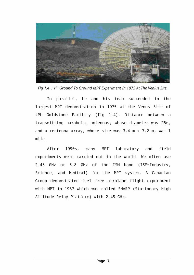
Fig 1.4 : 1st Ground To Ground MPT Experiment In 1975 At The Venius Site.
In parallel, he and his team succeeded in the largest MPT demonstration in
1975 at the Venus Site of JPL Goldstone Facility (fig 1.4). Distance between a
transmitting parabolic antennas, whose diameter was 26m, and a rectenna array,
whose size was 3.4 m x 7.2 m, was 1 mile.
After 1990s, many MPT laboratory and field experiments were carried out in
the world. We often use 2.45 GHz or 5.8 GHz of the ISM band (ISM=Industry,
Science, and Medical) for the MPT system. A Canadian Group demonstrated fuel free
airplane flight experiment with MPT in 1987 which was called SHARP (Stationary
High Altitude Relay Platform) with 2.45 GHz.
Fig 1.5 : Stationary High Altitude Relay Platform.
In USA, there were many MPT research and development projects after W. C.
Brown: for instance, retro directive microwave transmitters, rectenna , and microwave
circuit technologies.
Page 5

In Japan, there were many field MPT experiments such as fuel free airplane
flight experiment with MPT phased array with 2.411 GHz in 1992, ground to ground
MPT experiment with Power Company and universities in 1994-95.
Fig 1.6 : Ground To Ground MPT Experiment In Japan In 1994-95.
In the early 1970s, experiments with RFID tags began and by the early 2000’s
Professor She Yuen (Ron) Hui and S.C. Tang developed a charger to provide resonant
power transfer for small electronics. Today wireless power is used for everything
from industrial motors to charging smartphones and tablets.
Researchers predict that wireless power will be making a significant
contribution to energy supplies by the end of this decade [3].
1.4 What Is WPT? WPT is nothing but wireless electricity. Transmission of electrical energy
from one object to another without the use of wires is called as WPT. WPT will
ensure that the cell phones, laptops, iPods and other power hungry devices get
charged on their own, eliminating the need of plugging them in. WPT technology is
transferring electric energy or power over distance without wires. With the basics of
electricity and magnetism, and work our way up to the WPT technology. Even better,
because of WPT some of the devices won't enquire batteries to operate. No, this
concept of wireless electricity is not new. In fact Nikola Tesla used resonance
magnetic fields to transfer wireless power. [5]
Page 6
1.5 How Does Wireless Power Work? The basics of WPT involves the transmission of energy from a transmitter to a
receiver via an oscillating magnetic field. To achieve this, Direct Current (DC)
supplied by a power source, is converted into high frequency AC by specially
designed electronics built into the transmitter. The AC energizes a copper wire coil in
the transmitter, which generates a magnetic field. Once a second (receiver) coil is
placed within proximity of the magnetic field, the field can induce an alternating
current in the receiving coil.
Electronics in the receiving device then converts alternating current back into direct
current, which becomes usable power. The diagram FIG. 1.8 simplifies this process
into four key steps.
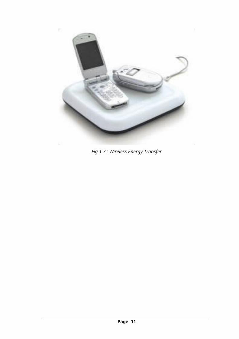
1.6 Need Of WPT Now a days there is a Rapid development of autonomous electronics like Laptops,
Cell phones, House hold robots and all those devices typically relay on chemical
energy storage(Battery) As they are becoming daily needs to present generation,
Wireless energy transfer would be useful for many applications and they need
midrange energy.
Fig 1.7 : Wireless Energy Transfer
Page 7

Fig. 1.8 : Simple Wireless Power Transmission Diagram
Page 8

CHAPTER 2
The Basic Idea of Transforming Electricity to WPT2.1 Electricity The flow of electrons (current) through a conductor (like a wire), or charges
through the atmosphere (like lightning). A convenient way for energy to get from one
place to another.
Fig 2.1 : An Illustration Representing The Earth's Magnetic Field
2.2 Magnetism A fundamental force of nature, which causes certain types of materials to attract or
repel each other. Permanent magnets, like the ones on your refrigerator and the earth‘s
magnetic field, are examples of objects having constant magnetic fields. Oscillating
magnetic fields vary with time, and can be generated by alternating current (AC)
flowing on a wire. The strength, direction, and extent of magnetic fields are often
represented and visualized by drawings of the magnetic field lines.[1]
2.3 Electromagnetism A term for the interdependence of time varying electric and magnetic fields. For
example, it turns out that an oscillating magnetic field produces an electric field and
an oscillating electric field produces a magnetic field.
Page 9

Fig 2.2: B RepresentsMagnetic Field When Current Flows Through A Coil.
As electric current, I, flows in a wire, it gives rise to a magnetic field, B,
which wraps around the wire. When the current reverses direction, the magnetic field
also reverses its direction.
2.4 Magnetic InductionA loop or coil of conductive material like copper, carrying an alternating
current (AC), is a Very efficient structure for generating or capturing a magnetic field.
If a conductive loop is connected to an AC power source, it will generate an
oscillating magnetic field in the vicinity of the loop. A second conducting loop,
brought close enough to the first, may capture some portion of that oscillating
magnetic field, which in turn, generates or induces an electric current in the second
coil. The current generated in the second coil may be used to power devices. This type
of electrical power transfer from one loop or coil to another is well known and
referred to as magnetic induction. Some common examples of devices based on
magnetic induction are electric transformers and electric generators. [1]
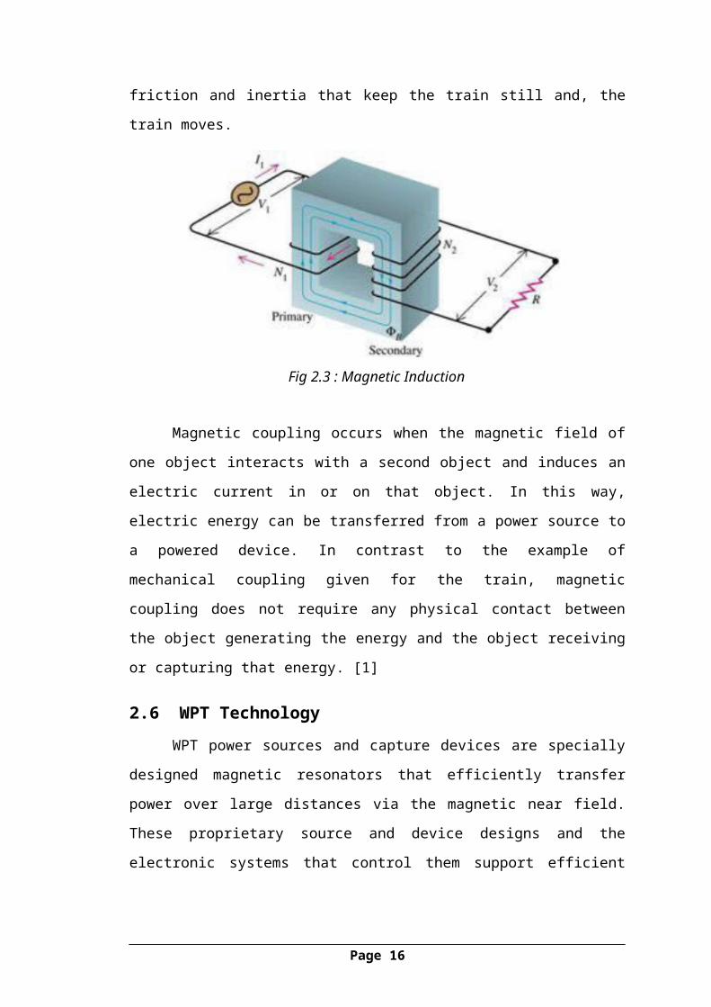
2.5 Energy/Power Coupling An electric transformer is a device that uses magnetic induction to transfer
energy from its primary winding to its secondary winding, without the windings being
connected to each other. It is used to transform AC current at one voltage to AC
current at a different voltage. Energy coupling occurs when an energy source has a
Page 10
means of transferring energy to another object. One simple example is a locomotive
pulling a train car the mechanical coupling between the two enables the locomotive to
pull the train, and overcome the forces of friction and inertia that keep the train still
and, the train moves.
Fig 2.3 : Magnetic Induction
Magnetic coupling occurs when the magnetic field of one object interacts with
a second object and induces an electric current in or on that object. In this way,
electric energy can be transferred from a power source to a powered device. In
contrast to the example of mechanical coupling given for the train, magnetic coupling
does not require any physical contact between the object generating the energy and
the object receiving or capturing that energy. [1]
2.6 WPT TechnologyWPT power sources and capture devices are specially designed magnetic
resonators that efficiently transfer power over large distances via the magnetic near
field. These proprietary source and device designs and the electronic systems that
control them support efficient energy transfer over distances that are many times the
size of the sources/devices themselves.
The WPT power source, left, is connected to AC power. The blue lines
represent the magnetic near field induced by the power source. The yellow lines
represent the flow of energy from the source to the WPT capture coil, which is shown
powering a light bulb. Note that this diagram also shows how the magnetic field (blue
lines) can wrap around a conductive obstacle between the power source and the
capture device.
Page 11

Fig 2.4 : WPT Power Source
Page 12

CHAPTER 3
Theories On WPT
3.1 Near Field TheoryNear field is wireless transmission techniques over distances comparable to, or
a few times the diameter of the device(s), and up to around a quarter of the
wavelengths used. Near field energy itself is non radiative, but some radiative losses
will occur. In addition there are usually resistive losses. Near field transfer is usually
magnetic (inductive), but electric (capacitive) energy transfer can also occur.
The magnetic near field has several properties that make it an excellent means
of transferring energy in a typical consumer, commercial, or industrial environment.
Most common building and furnishing Materials, such as wood, gypsum wall board,
plastics, textiles, glass, brick, and concrete are essentially transparent to magnetic
fields enabling WPT Technology to efficiently transfer power through them. In
addition, the magnetic near field has the ability to wrap around many metallic
obstacles that might otherwise block the magnetic fields.[9]
3.1.1 Electrical Conduction Principle
Electrical energy can be transmitted by means of electrical currents made to
flow through naturally existing conductors, specifically the earth, lakes and oceans,
and through the upper atmosphere starting at approximately 35,000 feet (11,000 m)
elevation — a natural medium that can be made conducting if the breakdown voltage
is exceeded and the constituent gas becomes ionized. For example, when a high
voltage is applied across a neon tube the gas becomes ionized and a current passes
between the two internal electrodes. In a wireless energy transmission system using
this principle, a high-power ultraviolet beam might be used to form vertical ionized
channels in the air directly above the transmitter-receiver stations. The same concept
is used in virtual lightning rods, the electro laser electroshock weapon and has been
proposed for disabling vehicles. A global system for "the transmission of electrical
energy without wires" dependent upon the high electrical conductivity of the earth
was proposed by Nikola Tesla as early as 1904.[6]
Page 13

"The earth is 4,000 miles radius. Around this conducting earth is an atmosphere.
The earth is a conductor; the atmosphere above is a conductor, only there is a little
stratum between the conducting atmosphere and the conducting earth which is
insulating. Now, you realize right away that if you set up differences of potential at
one point, say, you will create in the media corresponding fluctuations of potential.
But, since the distance from the earth's surface to the conducting atmosphere is
minute, as compared with the distance of the receiver at 4,000 miles, say, you can
readily see that the energy cannot travel along this curve and get there, but will be
immediately transformed into conduction currents, and these currents will travel like
currents over a wire with a return. The energy will be recovered in the circuit, not by a
beam that passes along this curve and is reflected and absorbed, but it will travel by
conduction and will be recovered in this way."
Researchers experimenting with Tesla's wireless energy transmission system
design have made observations that may be inconsistent with a basic tenet of physics
related to the scalar derivatives of the electromagnetic potentials, which are presently
considered to be nonphysical. The intention of the Tesla world wireless energy
transmission system is to combine electrical power transmission along with
broadcasting and point-to-point wireless telecommunications, and allow for the
elimination of many existing high-tension power transmission lines, facilitating the
interconnection of electrical generation plants on a global scale. One of Tesla's patents
suggests he may have misinterpreted 25–70 km nodal structures associated with
cloud-ground lightning observations made during the 1899 Colorado Springs
experiments in terms of circum globally propagating standing waves instead of a local
interference phenomenon of direct and reflected waves. Regarding the recent notion
of power transmission through the earth-ionosphere cavity, a consideration of the
earth-ionosphere or concentric spherical shell waveguide propagation parameters as
they are known today shows that wireless energy transfer by direct excitation of a
Schumann cavity resonance mode is not realizable. "The conceptual difficulty with
this model is that, at the very low frequencies that Tesla said that he employed (1-50
kHz), earth-ionosphere waveguide excitation, now well understood, would seem to be
impossible with the either the Colorado Springs or the Long Island apparatus (at least
with the apparatus that is visible in the photographs of these facilities)." [4]
Page 14

Fig 3.1 : Tesla Coil Transformer Wound In The Form Of A Flat Spiral. This Is The
Transmitter Form As Described In U.S. Patent 645,576.
On the other hand, Tesla's concept of a global wireless electrical power
transmission grid and telecommunications network based upon energy transmission
by means of a spherical conductor transmission line with an upper three-space model
return circuit, while apparently not practical for power transmission, is feasible,
defying no law of physics. Global wireless energy transmission by means of a
spherical conductor “single-wire” surface wave transmission line and a propagating
TM00 mode may also be possible.
3.1.2 Induction Principle (Non Resonant Energy Transfer)
The action of an electrical transformer is the simplest instance of wireless
energy transfer. The primary and secondary circuits of a transformer are not directly
connected. The transfer of energy takes place by electromagnetic coupling through a
process known as mutual induction. (An added benefit is the capability to step the
primary voltage either up or down.) The Battery chargers of a mobile phone or the
transformers on the street is examples of how this principle can be used. Induction
cookers and many electric toothbrushes are also powered by this technique. The main
Page 15
drawback to induction, however, is the short range. The receiver must be very close to
the transmitter or induction unit in order to inductively couple with it.[4]
3.1.3 Electrostatic Induction Principle
FIG 3.2 : (Tesla Illuminating Two Exhausted Tubes By Means Of A Powerful,
Rapidly Alternating Electrostatic Field Created Between Two Vertical Metal Sheets
Suspended From The Ceiling On Insulating Cords.)
The "electrostatic induction effect" or "capacitive coupling" is an electric field
gradient or differential capacitance between two elevated electrodes over a conducting
ground plane for wireless energy transmission involving high frequency alternating
current potential differences transmitted between two plates or nodes. The
electrostatic forces through natural media across a conductor situated in the changing
magnetic flux can transfer energy to a receiving device (such as Tesla's wireless
bulbs).Sometimes called "the Tesla effect" it is the application of a type of electrical
displacement, i.e., the passage of electrical energy through space and matter, other
than and in addition to the development of a potential across a conductor.
Tesla stated, "Instead of depending on [electrodynamic] induction at a distance to
light the tube . . . the ideal way of lighting a hall or room would . . . be to produce
such a condition in it that an illuminating device could be moved and put anywhere,
and that it is lighted, no matter where it is put and without being electrically
connected to anything. I have been able to produce such a condition by creating in the
room a powerful, rapidly alternating electrostatic field. For this purpose I suspend a
sheet of metal a distance from the ceiling on insulating cords and connect it to one
terminal of the induction coil, the other terminal being preferably connected to the
Page 16

ground. Or else I suspend two sheets .each sheet being connected with one of the
terminals of the coil, and their size being carefully determined. An exhausted tube
may then be carried in the hand anywhere between the sheets or placed anywhere,
even a certain distance beyond them; it remains always luminous.” And “In some
cases when small amounts of energy are required the high elevation of the terminals,
and more particularly of the receiving-terminal D' may not be necessary, since,
especially when the frequency of the currents is very high, a sufficient amount of
energy may be collected at that terminal by electrostatic induction from the upper air
strata, which are rendered conducting by the active terminal of the transmitter or
through which the currents from the same are conveyed."[2]
3.1.4 Electro-Dynamic Induction (Resonant Inductive Coupling Method/
Evanescent Coupling Method)
An inductive transformer is a device commonly used in power circuits and
electromechanical motors (for example electrical toothbrushes and chargers). A
transformer typically operates up to mid-kHz frequencies. It essentially transfers
electrical energy from one circuit to another via induction: the time-varying magnetic
flux produced by a primary coil crosses a secondary coil and induces in it a voltage.
The primary and the secondary coils are not physically connected, hence the method
is wireless. Transformers can be very efficient but the distance between the coils must
be very small (typically a few millimetres). For distances a few times the size of the
coils, the efficiency drops significantly. Part of the underlying physics for most of the
existing methods for the wireless transfer of electricity is the fundamental principle of
resonance: the property of certain physical systems to oscillate with maximum
amplitudes at certain frequencies. It follows that, for any type of excitation
(mechanical, acoustic, electro magnetic, nuclear) with a given frequency, a receiver
will pick up the transmitted energy efficiently only when designed to resonate at the
excitation frequency. Only then do successive excitations after each oscillation period
add coherently in phase and lead to a build up of energy within the receiver. To
illustrate, consider 100 glasses filled with wine at different levels so that they support
acoustic resonances at different frequencies. Now let an electric-guitar player produce
and sustain a very well-defined note. Only one of the glasses, the one resonant with
the frequency of this note, will respond to the excitation, to the extent that it may even
break, while the rest will remain unaffected. Similarly, we tune the electromagnetic
Page 17

antenna of a radio to be resonant with the frequency of the station we want to listen to.
Many transformers used in power circuitry and elsewhere are also designed to employ
resonance to enhance the power transmission.[1]
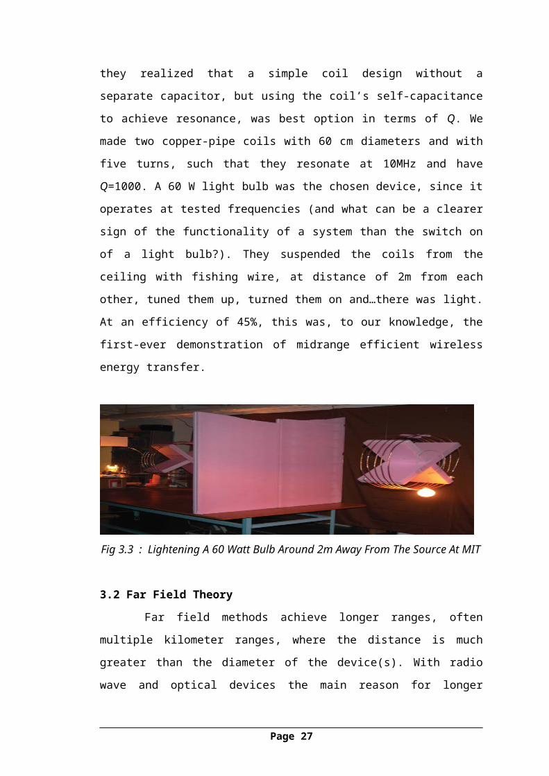
3.1.5 Experimental Demonstration Of Evanescent Coupling At MIT
Based on their theory, they started experiments in late 2006. The main
challenges consisted of designing a driving circuit that would operate in our desired
low-MHz regime and constructing coils that would resonate with high enough value
of Q. After a trial-and-error phase, they realized that a simple coil design without a
separate capacitor, but using the coil’s self-capacitance to achieve resonance, was best
option in terms of Q. We made two copper-pipe coils with 60 cm diameters and with
five turns, such that they resonate at 10MHz and have Q=1000. A 60 W light bulb
was the chosen device, since it operates at tested frequencies (and what can be a
clearer sign of the functionality of a system than the switch on of a light bulb?). They
suspended the coils from the ceiling with fishing wire, at distance of 2m from each
other, tuned them up, turned them on and…there was light. At an efficiency of 45%,
this was, to our knowledge, the first-ever demonstration of midrange efficient wireless
energy transfer.
Fig 3.3 : Lightening A 60 Watt Bulb Around 2m Away From The Source At MIT
3.2 Far Field Theory
Far field methods achieve longer ranges, often multiple kilometer ranges,
where the distance is much greater than the diameter of the device(s). With radio
wave and optical devices the main reason for longer ranges is the fact that
electromagnetic radiation in the far-field can be made to match the shape of the
Page 18
receiving area (using high directivity antennas or well-collimated Laser Beam)
thereby delivering almost all emitted power at long ranges. The maximum directivity
for antennas is physically limited by diffraction. The Raytheon Company did the first
successful WPT experiment in 1963. In this experiment energy was transmitted with a
DC-to-DC efficiency of 13%. This company also demonstrated a microwave-powered
helicopter in 1964. The Jet propulsion lab of NASA carried out an experiment and
demonstrated the transfer of 30 kW over a distance of 1 mile in 1975. They used an
antenna array erected at the Goldstone facility. This test demonstrated the possibilities
of wireless power outside the laboratory. Rockwell International and David Sarnoff
Laboratory operated in 1991 a microwave powered rover at 5.86 GHz. Three
kilowatts of power was transmitted and 500 watts was received.
3.2.1 Microwave Power Transmission (MPT)
In order to transport electricity is has to be transformed into a suitable energy
form. For wireless transmission, this has to be a form that can travel through air.
Microwave frequencies hold this ability. The microwave spectrum is defined as
electromagnetic energy ranging from approximately 1 GHz to 1000 GHz in
frequency, but older usage includes lower frequencies. Most common applications are
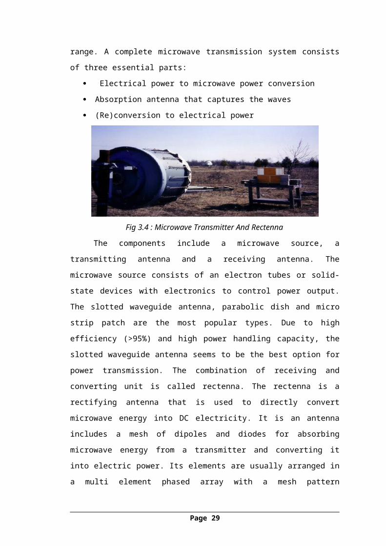
within the 1 to 40 GHz range. A complete microwave transmission system consists of
three essential parts:
Electrical power to microwave power conversion
Absorption antenna that captures the waves
(Re)conversion to electrical power
Fig 3.4 : Microwave Transmitter And Rectenna
The components include a microwave source, a transmitting antenna and a
receiving antenna. The microwave source consists of an electron tubes or solid-state
devices with electronics to control power output. The slotted waveguide antenna,
Page 19

parabolic dish and micro strip patch are the most popular types. Due to high
efficiency (>95%) and high power handling capacity, the slotted waveguide antenna
seems to be the best option for power transmission. The combination of receiving and
converting unit is called rectenna. The rectenna is a rectifying antenna that is used to
directly convert microwave energy into DC electricity. It is an antenna includes a
mesh of dipoles and diodes for absorbing microwave energy from a transmitter and
converting it into electric power. Its elements are usually arranged in a multi element
phased array with a mesh pattern reflector element to make it directional. The
Rayleigh criterion dictates that any beam will spread (microwave or laser), become
weaker, and diffuse over distance. The larger the transmitter antenna or laser aperture,
the tighter the beam and the less it will spread as a function of distance (and vice
versa). Therefore, the system requires large transmitters and receivers. The used
power density of the microwave beam is normally in the order of 100 W/m2. This is
relative low compared to the power density of solar radiation on earth (1000 W/m2)
and chosen this way for safety reasons.
3.2.2 Applications
3.2.2.1 WPT For Space Solar
The largest application for microwave power transmission is space solar
power satellites (SPS). In this application, solar power is captured in space and
converted into electricity. The electricity is converted into microwaves and
transmitted to the earth. The microwave power will be captured with antennas and
converted into electricity. NASA is still investigating the possibilities of SPS. One of
the problems is the high investment cost due to the space transport. The current rates
on the Space Shuttle run between $7,000 and $11,000 per kilogram of transported
material. Recently the idea of Space Solar Power caught again the public attention e.g.
by the Obama transition team and The Economist .
Page 20

Fig 3.5 : Space Solar Power Satellite
3.2.2.2 Power Transfer, Bridging Applications
Using a powerful focused beam in the microwave or laser range long distances
can be covered. There are two methods of wireless power transmission for bridging
application. First is the direct method, from transmitting array to rectenna. A line of
sight is needed and is therefore limited to short (< 40 km) distances. Above 40
kilometers, huge structures are needed to compensate for the curvature of the earth.
The second method is via a relay reflector between the transmitter and rectenna. This
reflector needs to be at an altitude that is visible for both transmitter and rectenna.
Next one bridging applications of WPT are discussed.
Alaska '21WPT can be an option for power supply to rural areas. In 1993 was a project
presented about wireless power supply in Alaska. Because of limited infrastructure,
hundreds of small rural communities in Alaska must provide their own electricity.
These systems can be expensive not standard or just not available. At the moment, the
small communities produce their own power with mainly diesel engines. These
produce noise and pollution. Also the needed fuel has to be transported over long
distances. All this results in an electricity price in excess of $40 /kWh .Cable
connections trough water is no option because of ice. With the help of WPT, the
needed power production of the communities can be combined. This can reduce noise,
pollution and transportation of fuel. WPT may be capable of transmitting electrical
energy to Alaska’s remote villages. To investigate these possibilities, a pilot project
was conducted named "Alaska'21”. The system used for the pilot project consisted of
a2.45 GHz phased array design. The distances that should be bridged are between 1
and 15 miles. The status of the project is unknown.
Page 21
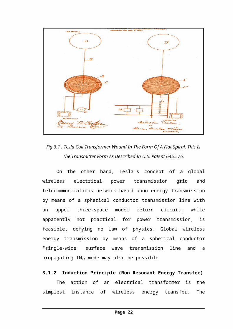
Fig 3.6 :(Alaska’21 ).
3.2.3 Safety Issues
Bio-Effects
A general public perception that microwaves are harmful has been a major
obstacle for the acceptance of power transmission with microwaves. A major concern
is that the long-term exposure to low levels of microwaves might be unsafe and even
could cause cancer. Since 1950, there have been thousands of papers published about
microwave bio-effects. The scientific research indicates that heating of humans
exposed to the radiation is the only known effect. There are also many claims of low-
level non thermal effects, but most of these are difficult to replicate or show
unsatisfying uncertainties. Large robust effects only occur well above exposure limits
existing anywhere in the world. The corresponding exposure limits listed in IEEE
standards at 2.45 or 5.8 GHz are 81.6 W/m2 and 100 W/m2 averaged over 6 minutes,
and 16.3 or 38.7 W/m2 averaged over 30 minutes .
Page 22

Fig 3.7 : Graph Showing Safety Level To Different Range Of Frequencies
This low compared to average solar radiation of 1000 W/m2. A clearly
relevant bio-effect is the effect of microwave radiation on birds, the so-called "fried
bird effect". Research is done on such effect at 2.45 GHz. The outcome showed slight
thermal effects that probably are welcome in the winter and to be avoided in the
summer . Larger birds tend to experience more heat stress then small birds . The
overall conclusion of bioeffects research is that microwave exposures are generally
harmless except for the case of penetrating exposure to intense fields far above
existing exposure limits .
Page 23

CHAPTER 4
Transmitters, Antennas And Receivers
4.1 Antennas For Microwave Power Transmission
All antennas can be applied for both the MPT system and communication
systems, for example, Yagi Uda antenna, horn antenna, parabolic antenna, micro strip
antenna, phased array antenna or any other type of antenna.
To fixed target of the MPT system, we usually select a large parabolic
antenna, for example, in MPT demonstration in 1975 at the Venus Site of JPL
Goldstone Facility and in ground to ground MPT experiment in 1994-95 in Japan. In
the fuel free airship light experiment with MPT in 1995 in Japan, they changed a
direction of the parabolic antenna to chase the moving airship. In some MPT
Page 24

experiments in Japan, the phased array antenna was adopted to steer a direction of the
microwave beam (FIG. 4.1).
All SPS is designed with the phased array antenna.
Fig 4.1 : Phased Array Used In Japanese Field MPT Experiment
4.2 Recent Technologies For Transmitters
The technology employed for generation of microwave Radiation is an
important subject for the MPT system. We need higher efficient generator/amplifier
for the MPT system than that for the wireless communication system. For highly
efficient beam collection on rectenna array, we need highly stabilized and accurate
phase and amplitude of microwaves for phased array system for the MPT .There are
two types of microwave generators/amplifiers. One is a microwave tube (magnetron)
and the other is semiconductor amplifier.
4.2.1 Magnetron
Magnetron is a crossed field tube in which electrons emitted from the cathode
take cyclical path to the anode. The magnetron is self-oscillatory device in which the
anode contains a resonant RF structure. The magnetron has long history from
invention by A. W. Hull in 1921.
The practical and efficient magnetron tube attracted worldwide interest only
after K. Okabe proposed divided anode type magnetron in 1928. Magnetron
technologies received a boost during the World War II, especially with the Japanese
Army. The magnetrons were also useful for microwave ovens. As a result, the
Page 25

magnetron of 500 – 1,000 W is widely in use for microwave ovens in 2.45 GHz, and
is a relatively inexpensive oscillator (below $5). There is a net global capacity of
45.5GW/year for all magnetrons used in microwave ovens whose production is 50–
55 millions. It was W. C. Brown who invented a voltage controlled oscillator with a
cooker type magnetron in PLL.
4.2.2 Semiconductor Amplifier
After 1980s, semiconductor devices became dominant in microwave world
instead of the microwave tubes. This was driven by advances in mobile phone
networks. The semiconductor device is expected to Expand microwave applications,
for example, phased array and active integrated antenna (AIA), because of its
manageability and mass productivity. After 1990s, some MPT experiments were
carried out in Japan with phased array of semiconductor amplifiers.
Typical semiconductor devices for microwave circuits are FET (Field Effect
Transistor), HBT (Hetero junction Bipolar Transistor), and HEMT (High Electron
Mobility Transistor). Present materials for the semiconductor devices are Si for lower
frequency below a few GHz and GaAs for higher frequency. It is easy to control
phase and amplitude through the microwave circuits with semiconductor devices, for
example, amplifiers, phase shifters, modulators, and so on. Currently, new materials
are under development to enable semiconductor devices yield increased output power
and efficiency.
4.3 Wireless Power Transmission – Receivers And Rectifiers
Point to point MPT system needs a large receiving area with a rectenna array
because one rectenna element receives and creates only a few W. Especially for the
SPS, we need a huge rectenna site and a power network connected to the existing
power networks on the ground. On contrary, there are some MPT applications with
one small rectenna element such as RF ID.
4.3.1 Recent Technologies Of Rectenna
The word “rectenna” is composed of “rectifying circuit” and “antenna”. The
rectenna can receive and rectify a microwave power to DC. The rectenna is passive
element with a rectifying diode, operated without any power source. The circuit,
especially diode, mainly determines the RF DC conversion efficiency. Silicon Scotty
barrier diodes were usually used for earlier rectenna. New devices like SiC and GaN
Page 26
are expected to increase the efficiency. The rectenna with FET or HEMT appeared
recently. The single shunt full wave rectifier is always used for the rectenna. It
consists of a diode inserted in the circuit in parallel, a λ/4 distributed line, and a
capacitor inserted in parallel. In an ideal situation, 100% of the received microwave
power should be converted into DC power.
4.3.2 Recent Technologies Of Rectenna Array
The rectenna will be used as an array for high power MPT because one
rectenna element rectifies a few W only. For usual phased array antenna, mutual
coupling and phase distribution are problems to solve. For the rectenna array, problem
is different from that of the array antenna because the rectenna array is connected not
in microwave phase but in DC phase. When we connect two rectenna in series or in
parallel, they will not operate at their optimum power output and their combined
power output will be less than that if operated independently. This is theoretical
prediction.
4.3.3 Efficiency
We classify the MPT efficiency roughly into three stages;
DC RF conversion efficiency which includes losses caused by beam forming.
Beam collection efficiency which means ratio of all radiated power to collected
power on a receiving antenna, and
RF DC conversion efficiency.
4.3.3.1 RF DC Conversion Efficiency
The RF DC conversion efficiency of the rectenna or the CWC is over 80 % of
experimental results as shown. Decline of the efficiency is caused by array connection
loss, change of optimum operation point of the rectenna array caused by change of
connected load, trouble of the rectenna, and any losses on the systems, for example,
DC/AC conversion, cables, etc. However, it is easier to realize higher efficiency than
that on the other two
4.3.3.2 Beam Collection Efficiency
The beam collection efficiency depends on the transmitter and receiver
aperture areas, the wavelength, and the separation distance between the two antennas.
Page 27

Fig 4.2: Efficiency Of Rectenna Element.
CHAPTER 5
Recent Technological Trends
There are several technological trends which are going to be concerned
for wireless power transmission which are as follows:
5.1 Retro Directive Beam Control
A microwave power transmission is suitable for a power transmission from/to
moving transmitters/targets. Therefore, accurate target detection and high efficient
beam forming are important. Retro directive system is always used for SPS.
Page 28
A corner reflector is most basic retro directive system. The corner reflectors
consist of perpendicular metal sheets, which meet at an apex. Incoming signals are
reflected back in the direction of arrival through multiple reflections off the wall of
the reflector. Van Atta array is also a basic technique of the retro directive system.
This array is made up of pairs of antennas spaced equidistant from the centre of the
array, and connected with equal length transmission lines. The signal received by an
antenna is re-radiated by its pair, thus the order of re-radiating elements are inverted
with respect to the centre of the array, achieving the proper phasing for retro
directivity.
Usual retro directive system have phase conjugate circuits in each
receiving/transmitting antenna, which play same role as pairs of antennas spaced
equidistant from the centre of the array in Van Atta array. The signal is called a pilot
signal. We do not need any phase shifters for beam forming. The retro directive
system is usually used for satellite communication, wireless LAN, military, and so on.
5.2 Environmental Issues
One of the characteristics of the MPT is to use more intense microwave than
that in wireless communication systems. Therefore, we have to consider MPT safety
for humans.
5.3 Interaction With Atmosphere
In general, effect of atmosphere on microwaves is quite small. There are
absorption and scatter by air, rain, and irregularity of air refraction ratio. In 2.45 GHz
and 5.8 GHz, the absorption by water vapour and oxygen Dominate the effect in the
air. Especially, it is enough to consider only absorption by the oxygen in the
microwave frequency. It is approximately 0.007 dB/km. In the SPS case, the amount
of total absorption through the air from space is approximately 0.035 dB.
5.4 Interaction With Space Plasmas
When microwaves from SPS propagate through ionospheric plasmas, some
interaction between microwaves and the ionospheric plasmas occurs. It is well known
that refraction, Faraday rotation, scintillation, and absorption occur between weak
microwave used for satellite communication and the plasmas. However, influence on
the MPT system is negligible. It is nonlinear interaction between intense microwave
Page 29

and the space plasmas that we have to investigate before the commercial SPS. We
theoretically predict that the following may occur: heating of the plasmas, plasma hall
effect, thermal self-focusing effect of the microwave beam, and three wave
interactions and excitation of electrostatic waves in MHz bands. These interactions
don’t occur in existent satellite communication systems because microwave power is
very weak.
Generating power by placing satellites with giant solar arrays in
Geosynchronous Earth Orbit and transmitting the power as microwaves on the earth
called Solar Power Satellites (SPS) will be the largest application of WPT .[8].
CHAPTER 6
Applications, Advantages And Future
6.1 Applications
WPT wireless power transfer technology can be applied in a wide variety of
applications and environments. The ability of our technology to transfer power safely,
efficiently, and over distance can improve products by making them more convenient,
reliable, and environmentally friendly. WPT technology can be used to provide:
Page 30

6.1.1 Automatic Wireless Power Charging
When all the power a device needs is provided wirelessly, and no batteries are
required. This mode is for a device that is always used within range of its WPT power
source. When a device with rechargeable batteries charges itself while still in use or at
rest, without requiring a power cord or battery replacement. This mode is for a mobile
device that may be used both in and out of range of its WPT power source.
6.1.2 Consumer Electronics
Automatic wireless charging of mobile electronics (phones, laptops, game
controllers, etc.) in home, car, office, Wi Fi hotspots, while devices are in use and
mobile.
Direct wireless powering of stationary devices (flat screen TV‘s, digital
picture frames, home theater accessories, wireless loud speakers, etc.) eliminating
expensive custom wiring, unsightly cables and wall wart power supplies.
Direct wireless powering of desktop PC peripherals: wireless mouse,
keyboard, printer, speakers, display, etc… eliminating disposable batteries and
awkward cabling.
6.1.3 Industrial
Direct wireless power and communication interconnections across rotating and
moving joints (robots, packaging machinery, assembly machinery, machine tools) …
eliminating costly and failure prone wiring. Direct wireless power and communication
interconnections at points of use in harsh environments (drilling, mining, underwater,
etc.) … where it is impractical or impossible to run wires. Direct wireless Power for
wireless sensors and actuators, eliminating the need for expensive power wiring or
battery replacement and disposal.
6.1.4 Transportation
Automatic wireless charging for existing electric vehicle classes: golf carts,
industrial vehicles. Automatic wireless charging for future hybrid and all electric
passenger and commercial vehicles, at home, in parking garages, at fleet depots, and
at remote kiosks.
Page 31

Direct wireless power interconnections to replace costly vehicle wiring
harnesses and slip rings.
6.2 Other Applications
a) Direct wireless power interconnections and automatic wireless charging for
implantable medical devices (ventricular assist devices, pacemaker,
defibrillator, etc.).
b) Automatic wireless charging and for high tech military systems (battery
powered mobile devices, covert sensors, unmanned mobile robots and aircraft,
etc.).
c) Direct wireless powering and automatic wireless charging of smart cards.
6.3 Advantages And Disadvantages
There are so many advantages with this WPT concept, some of those are:
a) Unaffected by the day night cycle, weather or seasons.
b) This is an ecofriendly.
c) It is a boon for the devices which use midrange power.
d) At places where economic competition is not the prime consideration, it can
be an option. Wireless power transmission can supply power to places that are
difficult to reach. Especially small communities in rural areas could be
supplied with power using WPT.
e) First of all the wireless electrical transmission of data removes the need for
physical infrastructure like grids and towers. In this way the cost associated
with deploying towers and cables can be saved.
f) During the rains and after natural disasters it is often hard to manage the
cables and towers .by using WPT technology this problem can be eliminated.
g) The transmission and distribution loss associated with traditional electricity
grids can be overcome.
h) Today two words are ruling the world “efficiency” and “speed”. These two
words have become the base for the development in the technology.
i) The electricity generation using microwaves is more environments friendly.
Moreover it does not involve any emission of carbon gases.
Page 32

j) The monthly electricity bills using conventional electricity supply can be cut
to very low.
k) Use of battery for charging electrical and electronics devices can totally be
eliminated.
Some of the disadvantages are as follows:
1. High capital cost for practical implementation of wireless power transmission.
2. Another potential disadvantage is the interference of the microwaves with the
present wireless communication system.
3. The effect of microwave radiations at high doses received is not suitable to
human health.
6.4 Safety And Future Scope 6.4.1 Is WPT Technology Safe?
WPT technology is a non radiative mode of energy transfer, relying instead on
the magnetic near field. Magnetic fields interact very weakly with biological
organism’s people and animals and are scientifically regarded to be safe. Professor Sir
John Pendry of Imperial College London, a world renowned physicist, explains: The
body really responds strongly to electric fields, which is why you can cook a chicken
in a microwave. But it doesn't respond to magnetic fields. As far as we know the body
has almost zero response to magnetic fields in terms of the amount of power it
absorbs." Evidence of the safety of magnetic fields is illustrated by the widespread
acceptance and safety of household magnetic induction cook tops. Through
proprietary design of the WPT source, electric fields are almost completely contained
within the source. Thus WPT technology doesn‘t give rise to radio frequency
emissions that interfere with other electronic devices, and is not a source of electric
and magnetic field levels that pose a risk to people or animals. Limits for human
exposure to magnetic fields are set by regulatory bodies such as the FCC, ICNIRP,
and are based on broad scientific and medical consensus.
6.4.2 Future Scope Of WPT
MIT's WPT is only 40 to 45% efficient and according to Soljacic, they have to
be twice as efficient to compete with the traditional chemical batteries. The team's
next aim is to get a robotic vacuum or a laptop working, charging devices placed
Page 33

anywhere in the room and even robots on factory floors. The researchers are also
currently working on the health issues related to this concept and have said that in
another three to five years’ time, they will come up with a WPT system for
commercial use.
WPT, if successful will definitely change the way we live. Imagine cell
phones, laptops, digital camera's getting self-charged! Wow! Let's hope the
researchers will be able to come up with the commercial system soon. Till then, we
wait in anticipation! Human beings or other objects placed between the transmitter
and receiver do not hinder the transmission of power. However, does magnetic
coupling or resonance coupling have any harmful effects on humans? MIT's
researchers are quite confident that WPT's 'coupling resonance' is safe for humans.
They say that the magnetic fields tend to interact very weakly with the biological
tissues of the body, and so are not prone to cause any damage to any living beings.
CONCLUSION
Today we do live in the “wireless age”, in which the air that we
breathe probably contains more information than oxygen. However, this
is also an age where mobile phones, MP3 players, laptop computers and
domestic robots exist alongside old-fashioned power wires and bulky
Page 34

batteries. Unlike information, electrical energy is still physically confined
to these borderline anachronistic appliances. Overcoming these last
obstacles would finally make this a truly wireless world.
Transfer of power via microwaves has long been the focus of study
and experimentation. In the early 1900s, Nikola Tesla experimented with
transmission of power wirelessly, through microwaves. His work,
however, was largely left unimplemented, as his experiments were vastly
ahead of their time and the technology did not yet exist to make WPT via
microwaves feasible. Advances in wireless technologies since Tesla,
however, have made possible that which was not in the early 20th
century. Described in this section are the details of those technologies
behind MPT as a mechanism for WPT.
REFERENCES
1. Tesla, N. “Apparatus for transmitting electrical energy.” U.S. patent number
1,119,732, issued in December 1914.
Page 35

2. Ka-Lai, L., Hay, J. W. and Beart, P. G. W. “Contact-less power transfer.”
U.S. patent number 7,042,196, issued in May 2006. (SplashPower Ltd.,
www.splashpower.com)
3. Hirai, J., Kim, T.-W. and Kawamura, A. “Wireless transmission of power and
information and information for cableless linear motor drive.” IEEE Trans.
on power electronics 15, 21 (2000).
4. G. Landis and R. Cull, “Integrated Solar Power Satellites: An Approach to
Low-Mass Space Power,”Space Power, Vol. 11, No. 3–4, 303–218 (1992);
presented at SPS-91: Power From Space, Aug. 27–30, 1991, Paris France, pp.
225–232
5. www.WPT.com
6. http://www.cse.wustl.edu/~jain/cse574-14/ftp/power.pdf }
7. Electricity Flow Chart 1999, which contains US DOE/EIA data, updating the
Toby Grotz article in this book.)
8. http://ijtir.hctl.org/vol8/IJTIR_Article_201403012.pdf
9. http://www.seminarreports.in/2014/09/wireless-electricity-or-witricity.html
10. http://www.collegelib.com/t-witricity-wireless-electricity-seminar-abstract-
report.html
Page 36


![[XLS] · Web viewAL3Z AU2Z WPT-1090 BL3Z F4AZ 15A416 9E5Z K WPT-1161 8L3Z F5SZ 9F479 UB WPT-992 8C2Z BHAB WPT-1147 F5TZ AU5Z WPT-1089 16611B08 16611B09 BC3Z F5CZ XF3Z WPT-1001 NUB](https://img.pdfslide.net/doc/110x75/5af9707e7f8b9aac248e66a3/xls-viewal3z-au2z-wpt-1090-bl3z-f4az-15a416-9e5z-k-wpt-1161-8l3z-f5sz-9f479-ub.jpg)