Embed Size (px)
Citation preview
Simulation of Ground Freezing around the Perimeter of the Fukushima Nuclear Power Plant for the Prevention of Radionuclide Diffusion via Groundwater
Source: http://simmakers.com/fukushima-radiation-ice-wall/
(Keywords: fukushima radiation, fukushima radiation leak, fukushima water, fukushima radioactive water,
artificial ground freezing, fukushima radiation simulation)
Following the accident at the Fukushima nuclear power plant, high concentrations of radiation seepage into the ocean through radionuclide transfer via groundwater has been observed. In order to prevent further radionuclide permeation into the groundwater, it was decided to delimit the area around the turbines and reactors with an ice wall several meters deep. This purpose of the wall is to restrict the influx of the groundwater into the radioactive zone, as well as the escape of groundwater from the same zone, inevitably contaminated with radionuclides. To this end, vertical cooling devices shall be situated around the perimeter of the nuclear power plant, as demonstrated in the figure below.
Plan of cooling device arrangement around the perimeter of the Fukushima power plant
Geological investigations of the area made it possible to determine the physicochemical properties of the ground and the speed of the groundwater displacement (see the section below).
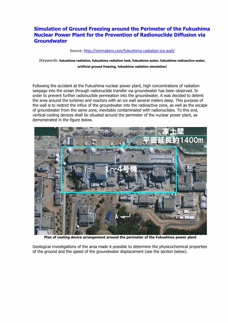
Geological section of the ground near the Fukushima
Water-proof rock layer is marked green. Landfill, where the movement of groundwater takes place, is marked yellow. R/B and T/B are reactor and turbine buildings respectively. Water flows are marked by blue arrows. Computer simulation of the artificial ground freezing in the specified area with the Frost 3D Universal specialized software can be employed to test the proposed design solutions and confirm or reject their viability on the basis of the derived data. For computer simulation on the basis of the geometric dimensions of the considered domain and geological and lithological structure of the grounds, the following dimensions for the computational domain were introduced: length – 450m, width – 210m, height – 30m. The geological and lithological structure of the ground in the considered domain was reproduced on the basis of the information obtained from the engineering and geological boreholes. When creating the 3D geometric model, the foundations and footings of the reactors and turbines were taken into account. The footings of the reactors and turbines are found at a depth of approximately 10 m and their temperature is assumed to correspond to the temperature inside the building for thermotechnical computation purposes.
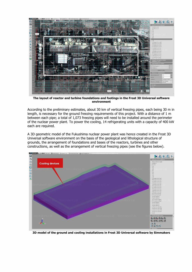
The layout of reactor and turbine foundations and footings in the Frost 3D Universal software
environment
According to the preliminary estimates, about 30 km of vertical freezing pipes, each being 30 m in length, is necessary for the ground freezing requirements of this project. With a distance of 1 m between each pipe; a total of 1,073 freezing pipes will need to be installed around the perimeter of the nuclear power plant. To power the cooling, 14 refrigerating units with a capacity of 400 kW each are required. A 3D geometric model of the Fukushima nuclear power plant was hence created in the Frost 3D Universal software environment on the basis of the geological and lithological structure of grounds, the arrangement of foundations and bases of the reactors, turbines and other constructions, as well as the arrangement of vertical freezing pipes (see the figures below).
3D model of the ground and cooling installations in Frost 3D Universal software by Simmakers
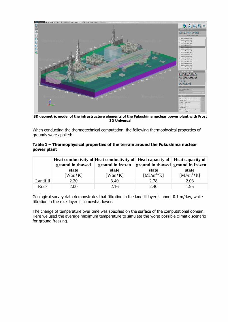
3D geometric model of the infrastructure elements of the Fukushima nuclear power plant with Frost
3D Universal
When conducting the thermotechnical computation, the following thermophysical properties of grounds were applied: Table 1 – Thermophysical properties of the terrain around the Fukushima nuclear power plant
Heat conductivity of
ground in thawed
state [Wtm*K]
Heat conductivity of
ground in frozen
state [Wtm*K]
Heat capacity of
ground in thawed
state [MJ/m
3*К]
Heat capacity of
ground in frozen
state [MJ/m
3*К]
Landfill 2.20 3.40 2.78 2.03
Rock 2.00 2.16 2.40 1.95
Geological survey data demonstrates that filtration in the landfill layer is about 0.1 m/day, while filtration in the rock layer is somewhat lower. The change of temperature over time was specified on the surface of the computational domain. Here we used the average maximum temperature to simulate the worst possible climatic scenario for ground freezing.
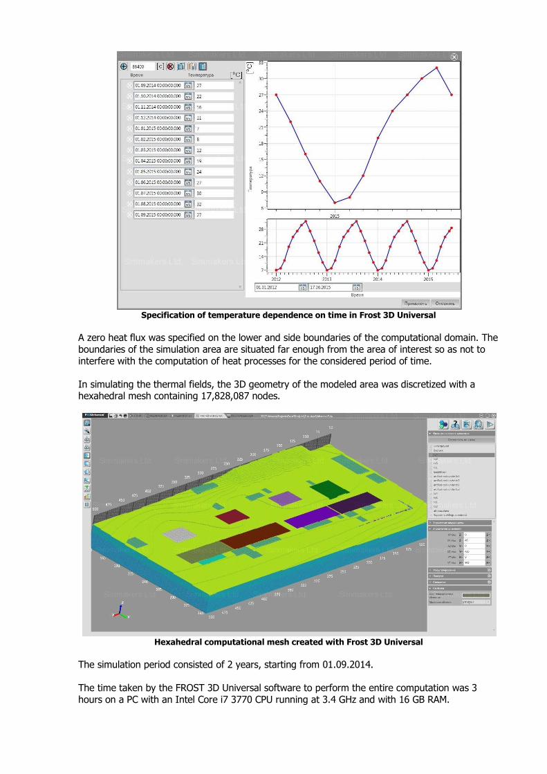
Specification of temperature dependence on time in Frost 3D Universal
A zero heat flux was specified on the lower and side boundaries of the computational domain. The boundaries of the simulation area are situated far enough from the area of interest so as not to interfere with the computation of heat processes for the considered period of time. In simulating the thermal fields, the 3D geometry of the modeled area was discretized with a hexahedral mesh containing 17,828,087 nodes.
Hexahedral computational mesh created with Frost 3D Universal
The simulation period consisted of 2 years, starting from 01.09.2014. The time taken by the FROST 3D Universal software to perform the entire computation was 3 hours on a PC with an Intel Core i7 3770 CPU running at 3.4 GHz and with 16 GB RAM.

Below are the results of the simulation of the temperature distribution in the considered area for various moments in time.
01.12.2014 – Temperature distribution after 3 months of cooling device operation
01.09.2016 – Temperature distribution after 2 years of cooling device operation
For a more detailed visualization of the simulation results, we considered the temperature distribution in a restricted section of the simulated area, marked by a red rectangle in the figure below.
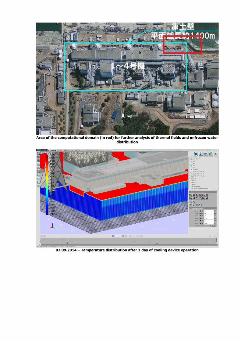
Area of the computational domain (in red) for further analysis of thermal fields and unfrozen water
distribution
02.09.2014 – Temperature distribution after 1 day of cooling device operation
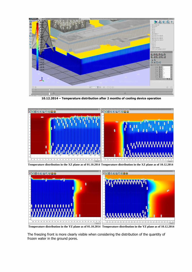
10.12.2014 – Temperature distribution after 2 months of cooling device operation
Temperature distribution in the XZ plane as of 01.10.2014 Temperature distribution in the XZ plane as of 10.12.2014
Temperature distribution in the YZ plane as of 01.10.2014 Temperature distribution in the YZ plane as of 10.12.2014
The freezing front is more clearly visible when considering the distribution of the quantity of frozen water in the ground pores.

Distribution of the quantity of frozen water in the XZ plane
as of 10.12.2014; unfrozen moisture is marked blue.
Distribution of the quantity of frozen water in the YZ plane
as of 10.12.2014; unfrozen moisture is marked blue.
The distribution of the quantity of frozen water in the sections after half a year demonstrates complete ground freezing in the vicinity of the cooling devices. Beyond this time, further operation of the cooling devices in maximum power mode is no longer necessary, and the cooling elements can be switched to temperature maintenance mode. Moreover, the distributions shown below of the quantity of frozen water after half a year of operation demonstrate that further cooling will not significantly influence the growth of the freezing front:
31.08.2016 – Temperature distribution after 2 years of cooling device operation
In conclusion, modern computer technologies render forecasting of temperature distributions and the quantity of unfrozen moisture around the Fukushima nuclear power plant feasible. This provides a crucial opportunity to verify the adequacy of the design solutions for the construction of an ice wall around the perimeter of the Fukushima nuclear power plant. Related topics: Artificial Ground Freezing. Problem Overview Thermosyphon Technology for Ground Freezing Computer Simulation of Artificial Ground Freezing