
ADEQ
DRAFT
OPERATING
AIR PERMIT
Pursuant to the Regulations of the Arkansas Operating Air Permit Program, Regulation 26:
Permit No. : 1860-AOP-R5
IS ISSUED TO:
Arkansas Electric Cooperative Corporation - Fulton CT1 Generating
Station
100 AECC Road
Fulton, AR 71838
Hempstead County
AFIN: 2900304
THIS PERMIT AUTHORIZES THE ABOVE REFERENCED PERMITTEE TO INSTALL,
OPERATE, AND MAINTAIN THE EQUIPMENT AND EMISSION UNITS DESCRIBED IN
THE PERMIT APPLICATION AND ON THE FOLLOWING PAGES. THIS PERMIT IS
VALID BETWEEN:
AND
THE PERMITTEE IS SUBJECT TO ALL LIMITS AND CONDITIONS CONTAINED
HEREIN.
Signed:
Stuart Spencer Date
Chief, Air Division

Arkansas Electric Cooperative Corporation - Fulton CT1 Generating Station
Permit #: 1860-AOP-R5
AFIN: 2900304
2
Table of Contents
SECTION I: FACILITY INFORMATION .............................................................................. 4 SECTION II: INTRODUCTION ............................................................................................... 5
Summary of Permit Activity .................................................................................................... 5
Regulations ................................................................................................................................ 5 Emission Summary ................................................................................................................... 6
SECTION III: PERMIT HISTORY .......................................................................................... 7 SECTION IV: SPECIFIC CONDITIONS ................................................................................ 8
SN-01 .......................................................................................................................................... 8
SN-02 ........................................................................................................................................ 12 40 CFR Part 63 - Subpart ZZZZ Conditions ............................................................................ 13
SECTION V: COMPLIANCE PLAN AND SCHEDULE ..................................................... 19 SECTION VI: PLANTWIDE CONDITIONS ........................................................................ 20
Acid Rain (Title IV) ................................................................................................................ 21 Title VI Provisions .................................................................................................................. 21
SECTION VII: INSIGNIFICANT ACTIVITIES................................................................... 23 SECTION VIII: GENERAL PROVISIONS ........................................................................... 24
APPENDIX A .............................................................................................................................. 30 ADEQ CEMS Conditions ......................................................................................................... 30
APPENDIX B .............................................................................................................................. 40
40 CFR Part 60, Subpart GG .................................................................................................... 40 APPENDIX C .............................................................................................................................. 57
Fuel Monitoring Protocol for Stationary Gas Turbines ............................................................ 57 APPENDIX D .............................................................................................................................. 59
40 CFR, Part 75, Continuous Emissions Monitoring ................................................................ 59 APPENDIX E ............................................................................................................................ 408
Acid Rain Permit Application ................................................................................................. 408

Arkansas Electric Cooperative Corporation - Fulton CT1 Generating Station
Permit #: 1860-AOP-R5
AFIN: 2900304
3
List of Acronyms and Abbreviations
Ark. Code Ann. Arkansas Code Annotated
AFIN ADEQ Facility Identification Number
C.F.R. Code of Federal Regulations
CO Carbon Monoxide
HAP Hazardous Air Pollutant
lb/hr Pound Per Hour
MVAC Motor Vehicle Air Conditioner
No. Number
NOx Nitrogen Oxide
PM Particulate Matter
PM10 Particulate Matter Smaller Than Ten Microns
SNAP Significant New Alternatives Program (SNAP)
SO2 Sulfur Dioxide
SSM Startup, Shutdown, and Malfunction Plan
Tpy Tons Per Year
UTM Universal Transverse Mercator
VOC Volatile Organic Compound

Arkansas Electric Cooperative Corporation - Fulton CT1 Generating Station
Permit #: 1860-AOP-R5
AFIN: 2900304
4
SECTION I: FACILITY INFORMATION
PERMITTEE: Arkansas Electric Cooperative Corporation - Fulton CT1
Generating Station
AFIN: 2900304
PERMIT NUMBER: 1860-AOP-R5
FACILITY ADDRESS: 100 AECC Road
Fulton, AR 71838
MAILING ADDRESS: P. O. Box 194208
Little Rock, AR 72219
COUNTY: Hempstead County
CONTACT NAME: Curtis Warner
CONTACT POSITION: Director-Compliance & Support
TELEPHONE NUMBER: (501) 570-2462
REVIEWING ENGINEER: John Mazurkiewicz
UTM North South (Y): Zone 15: 3719184.81 m
UTM East West (X): Zone 15: 426412.68 m

Arkansas Electric Cooperative Corporation - Fulton CT1 Generating Station
Permit #: 1860-AOP-R5
AFIN: 2900304
5
SECTION II: INTRODUCTION
Summary of Permit Activity
Arkansas Electric Cooperative Corporation (AECC) operates an electric power station in
Hempstead County near Fulton, Arkansas. The purpose of this revision is to renew the existing
Title V operating air permit. The following changes were requested with the Title V renewal
application:
1. Update the HAP emission rates in the Emission Rate Tables for the main turbine (SN-01)
to reflect calculations using updated emission factors.
2. Move the existing emergency diesel generator (EDG) from the insignificant activities list
to a permitted source in the permit (as SN-02).
3. Combine individual HAPs into one category titled, "Total HAPs."
4. Change the averaging time of NOX measured emissions to be more consistent with other
combustion turbine facilities in Arkansas.
The total permitted emission increases include 0.2 tpy SO2, 0.7 tpy CO, 3 tpy NOX, and 1.8 tpy
of total HAPs. The total permitted emission decreases include 84.7 tpy PM/PM10, 52.4 tpy VOC,
0.02 tpy Acrolein, and 1.72 tpy Formaldehyde.
Process Description
The Fulton CT1 Generating Station (CT1) consists of one Siemens V84.3A2 simple-cycle
combustion turbine (SCCT). The unit is designed to burn pipeline natural gas as its only fuel. The
CT1 facility can produce approximately 153 megawatts (MW) under summertime conditions (at 98
F). The unit is used primarily to generate electricity for peak load conditions (i.e. when the demand
for electricity is high). The unit is equipped with dry low NOx (DLN) burners designed to limit the
amount of NOx produced during the combustion process. These regulations require the source to
utilize a continuous emission monitoring system (CEMS). The CEMS is also used for compliance
with some permit limits.
Regulations
The following table contains the regulations applicable to this permit.
Regulations
Arkansas Air Pollution Control Code, Regulation 18, effective June 18, 2010
Regulations of the Arkansas Plan of Implementation for Air Pollution Control,
Regulation 19, effective September 13, 2014
Regulations of the Arkansas Operating Air Permit Program, Regulation 26, effective

Arkansas Electric Cooperative Corporation - Fulton CT1 Generating Station
Permit #: 1860-AOP-R5
AFIN: 2900304
6
November 18, 2012
40 CFR Part 60, Subpart GG, Standards of Performance for Stationary Gas Turbines
Acid Rain Program, 40 CFR Parts 72, 73, and 75
40 CFR Part 63, Subpart ZZZZ, National Emissions Standards for Hazardous Air
Pollutants for Stationary Reciprocating Internal Combustion Engines
Emission Summary
The following table is a summary of emissions from the facility. This table, in itself, is not an
enforceable condition of the permit.
EMISSION SUMMARY
Source
Number Description Pollutant
Emission Rates
lb/hr tpy
Total Allowable Emissions
PM 12.1 16.3
PM10 12.1 16.3
SO2 1.9 1.8
VOC 4.6 5.5
CO 44.6 60.6
NOX 183.8 248.0
HAPs Total HAPs* 1.24 1.78
01
Siemens V84.3A2 Simple
Cycle Combustion
Turbine
PM
PM10
SO2
VOC
CO
NOx
Total HAPs
11.2
11.2
1.1
3.6
42.0
172.0
1.23
16.0
16.0
1.6
5.2
59.9
245.0
1.76
02 Emergency Diesel
Generator
PM
PM10
SO2
VOC
CO
NOx
Total HAPs
0.9
0.9
0.8
1.0
2.6
11.8
0.01
0.3
0.3
0.2
0.3
0.7
3.0
0.01
*HAPs included in the VOC totals. Other HAPs are not included in any other totals unless
specifically stated.

Arkansas Electric Cooperative Corporation - Fulton CT1 Generating Station
Permit #: 1860-AOP-R5
AFIN: 2900304
7
SECTION III: PERMIT HISTORY
Permit #1860-AOP-R0, issued February 3, 2000, was the initial permit for a single combustion
turbine electric generating station.
Permit #1860-AOP-R1, issued January 23, 2001, implemented a minor modification to adjust
HAP emission rates. Administrative changes included the addition of a fuel pre-heater, an
emergency generator, and a diesel storage tank.
Permit #1860-AOP-R2, issued April 12, 2005, completed Title V renewal requirements. This
was the first renewal to the permit. No modifications took place. The first renewal permits
typically involve the inclusion of applicable requirements of 40 CFR, Part 64, Compliance
Assurance Monitoring (CAM) to affected units. However, this facility had no CAM affected
units; there is no control equipment with pre-control emissions greater than 100 tons per year.
Permit #1860-AOP-R3 was issued June 18, 2009. This permit modification was issued to
incorporate the facility’s Clean Air Interstate Rule (CAIR) permit application. There were no
permitted emission changes associated with this permitting action.
Permit #1860-AOP-R4 was issued August 4, 2010. The purpose of this modification was to
renew the facility’s Title V Operating Permit. No other changes are requested in this
modification.

Arkansas Electric Cooperative Corporation - Fulton CT1 Generating Station
Permit #: 1860-AOP-R5
AFIN: 2900304
8
SECTION IV: SPECIFIC CONDITIONS
SN-01
Siemens V84.3A2 Simple Cycle Combustion Turbine
Source Description
AECC operates one Siemens V84.3A2 simple cycle combustion turbine to drive electric
generating equipment. The overall generating capacity of the unit is estimated at 153 MW
during summer conditions (98 F).
The unit fires a mixture of compressed air and pipeline quality natural gas only. The unit is
equipped with dry low NOx (DLN) burners designed to limit the amount of NOx produced during
the combustion process. Hot, pressurized exhaust gases produced by the DLN burners expand
through a series of rotating turbine wheel and blade assemblies resulting in shaft power. Exhaust
gases are uncontrolled and exit through an 18-foot diameter, 90-foot tall stack (SN-01).
Specific Conditions
1. The permittee shall not exceed the emission rates set forth in the following table.
Compliance with this condition shall be demonstrated by the fuel limit of Specific
Condition 5 and the continuous emission monitoring system (CEMS) required by
Specific Condition 8. [Regulation 19, §19.501 et seq., and 40 CFR Part 52, Subpart E]
SN Description Pollutant lb/hr tpy
01
Siemens V84.3A2
Simple Cycle
Combustion Turbine
PM10 11.2 16.0
SO2 1.1 1.6
VOC 3.6 5.2
CO 42.0 59.9
NOx 172.0 245.0
2. The permittee shall not exceed the emission rates set forth in the following table. Initial
compliance has been determined through successful stack testing completed in May
2001. Ongoing compliance with this condition shall be demonstrated by the fuel limit of
Specific Condition 5. [Regulation 18, §18.801, and A.C.A. §8-4-203 as referenced by
A.C.A. §8-4-304 and §8-4-311]
SN Description Pollutant lb/hr tpy
01 Siemens V84.3A2 PM 11.2 16.0

Arkansas Electric Cooperative Corporation - Fulton CT1 Generating Station
Permit #: 1860-AOP-R5
AFIN: 2900304
9
SN Description Pollutant lb/hr tpy
Simple Cycle
Combustion
Turbine Total HAPs 1.23 1.76
3. Visible emissions may not exceed the limits specified in the following table of this permit
as measured by EPA Reference Method 9. Compliance shall be demonstrated by
compliance with Specific Condition 4. [§18.501 and A.C.A. §8-4-203 as referenced by
§8-4-304 and §8-4-311]
SN Limit Regulatory Citation
01 5% §18.501 and A.C.A. §8-4-
203
4. The permittee shall only burn pipeline quality natural gas at SN-01. [§18.501 and A.C.A.
§8-4-203 as referenced by §8-4-304 and §8-4-311]
5. The permittee shall not consume more than 5,832 million SCF of pipeline quality natural
gas per 12 consecutive months. [§19.705, A.C.A. §8-4-203 as referenced by §8-4-304
and §8-4-311, and 40 CFR §70.6]
6. The permittee shall maintain monthly records which demonstrate compliance with
Specific Condition 5. Records must contain a twelve month rolling total of monthly fuel
usage along with usage records from each individual month. Records must be updated by
the fifteenth day of the month following the month to which the records pertain. Records
must be kept on-site and made available to the Department upon request. Reports of the
twelve month rolling total shall be submitted to the Department in accordance with
General Provision 7 of this permit. [§19.705 and 40 CFR 52]
7. The permittee shall not exceed from SN-01 a NOx emission concentration of 25 ppmvd
corrected to 15% O2 at ISO conditions. Compliance with this limit shall be determined as
the 24-hour average volumetric concentration (arithmetic average of 24 continuous one-
hour periods) of NOx corrected to 15% O2 as measured by a CEMS. [§19.501 and 40
CFR Part 52, Subpart E]
8. The permittee shall install, operate, and maintain continuous emission monitoring
systems (CEMS) for NOx at SN-01 in accordance with the ADEQ CEMS Conditions
which are included in Appendix A of this permit. Compliance with the hourly NOx
emission limit set in Specific Condition 1 shall be determined as the 24-hour average
(arithmetic average of 24 contiguous one-hour periods) emissions of NOx as measured by
a CEMS. Compliance with the NOx concentration limit set in Specific Condition 10.a
shall be determined as the 4-hour average (arithmetic average of four contiguous one-
hour periods) concentration of NOx as measured by a CEMS. [§19.703, 40 CFR Part 52,

Arkansas Electric Cooperative Corporation - Fulton CT1 Generating Station
Permit #: 1860-AOP-R5
AFIN: 2900304
10
and A.C.A. §8-4-203 as referenced by §8-4-304 and §8-4-311] [§19.703, 40 CFR Part
52, and A.C.A. §8-4-203 as referenced by §8-4-304 and §8-4-311]
9. For the purposes of this permit, “upset condition” reports as required by §19.601 of
Regulation 19 shall not be required for periods of startup excess emissions from SN‑01
unless such periods of excess startup emissions exceed a two-hour period. Reports shall
not be required for exceedances that occur during a one-hour period that begins
immediately after shutdown is initiated. This shall only apply for “upset conditions”
which directly result from the start-up and/or shut down of the combustion turbine units
(SN‑01). All other “upset conditions” must be reported as required by Regulation 19.
Additionally, the following conditions must be met during start up and shut down
periods.
a. All CEM systems for SN-01 must be operating during start up and shut down.
The emissions recorded during these periods shall count toward the annual ton per
year permit limits.
b. The permittee shall maintain a log or equivalent electronic data storage which
shall indicate the date, start time, and duration of each start up and shut down
procedure. “Start up” shall be defined the period of time beginning with the first
fire within the combustion turbine firing chamber until the unit is in “premix”
mode or a maximum of two hours. “Shut down” shall be defined as the period of
time beginning when the unit drops below “premix” mode until no more
combustion in the combustion turbine firing chamber. This log or equivalent
electronic data storage shall be made available to Department personnel upon
request.
c. Opacity is not included. If any occurrences should ever occur, “upset condition”
reporting is required.
d. The permittee shall comply with all requirements of 40 CFR 60.7 and ADEQ
CEMS Conditions. [§19.601 and A.C.A. §8‑4‑203 as referenced by §8‑4‑304
and §8‑4‑311]
NSPS Requirements
10. The Combustion Turbine (SN-01) is subject to and shall comply with applicable
provisions of 40 CFR Part 60 Subpart A – General Provisions and 40 CFR Part 60
Subpart GG – Standards of Performance for Stationary Gas Turbines. A copy of Subpart
GG is provided in Appendix B. Applicable provisions of Subpart GG include, but are not
limited to, the following:
a. NOx emissions shall not exceed 109.4 ppmvd at 15% O2 at ISO conditions.
Compliance will be demonstrated by compliance with Specific Condition 8.
[§19.304 and 40 CFR §60.332(a)(1)]
b. The permittee shall not burn any fuel which contains sulfur in excess of 0.8
percent by weight. [§19.304 and 40 CFR §60.333(b)]

Arkansas Electric Cooperative Corporation - Fulton CT1 Generating Station
Permit #: 1860-AOP-R5
AFIN: 2900304
11
c. Natural gas sulfur and nitrogen content shall be determined as specified by the
fuel monitoring protocol outlined in Appendix C. Alternatively, the permittee
may provide sulfur certifications or representative data in accordance with 40
CFR §60.334(h)(3)(i or ii) to meet the sulfur monitoring requirements. Records
of fuel monitoring or alternative data shall be submitted to the Department
postmarked within 30 days of each calendar half and in accordance with General
Provision 7. [§19.304, 40 CFR §60.334, and 40 CFR §60.8]
d. The permittee shall file reports for periods of excess emissions for any period
during which the fuel bound sulfur is greater than 0.8% by weight. Reports shall
be submitted to the Department postmarked by the 30th
day following each
calendar half and in accordance with General Provision 7. [§19.304 and 40 CFR
§60.8]
e. Initial compliance testing for NOx is required within 180 days after start-up. The
NOx testing shall be conducted in accordance with tests methods in 40 CFR Part
60 Appendix A or alternative approved methods. The testing shall be conducted,
at four points in the normal operating range of the turbine. [§19.304 and 40 CFR
§60.8]
Acid Rain Requirements
11. The Combustion Turbine (SN-01) is subject to and shall comply with all applicable
provisions of the Acid Rain Program (40 CFR Parts 72, 73, and 75). A copy of 40 CFR
Part 75 is provided in Appendix D.
a. The submission of the NOx, SO2, and O2 or CO2 monitoring plans and notice of
CEMS certification testing is required at least 45 days prior to the CEMS
certification testing. [40 CFR Part 75 – Continuous Emission Monitoring Subpart
G]
b. A monitoring plan is required to be submitted for NOx, SO2, and O2 or CO2
monitoring. An SO2 CEM shall be required pending approval by the agency of an
optional SO2 emission data protocol. [40 CFR Part 75 – Continuous Emission
Monitoring Subpart G]
c. The initial NOx, SO2, and O2 or CO2 CEMS certification testing is to occur no
later than 90 days after the unit commences commercial operation except the
testing must occur prior to the date this unit is declared commercial in accordance
with DOE Form EIA-860. [40 CFR Part 75 Subpart A]
d. The permittee shall ensure that the continuous emissions monitoring systems are
in operation and monitoring all unit emissions at all times, except during periods
of calibration, quality assurance, preventative maintenance or repair. [40 CFR
§75.10]
[A.C.A. §8-4-203 as referenced by §8-4-304 and §8-4-311]

Arkansas Electric Cooperative Corporation - Fulton CT1 Generating Station
Permit #: 1860-AOP-R5
AFIN: 2900304
12
SN-02
Emergency Diesel Generator
Source Description
This is a diesel-fired, compression-ignited engine that is used for emergency power at the plant.
Specific Conditions
12. The permittee shall not exceed the emission rates set forth in the following table. The
permittee shall demonstrate compliance with this condition by compliance with Specific
Condition 16. [Reg.19.501 et seq. and 40 C.F.R. § 52 Subpart E]
SN Description Pollutant lb/hr tpy
02 Emergency Diesel
Generator
PM10 0.9 0.3
SO2 0.8 0.2
VOC 1.0 0.3
CO 2.6 0.7
NOx 11.8 3.0
13. The permittee shall not exceed the emission rates set forth in the following table. The
permittee shall demonstrate compliance with this condition by compliance with Specific
Condition 16. [Reg.18.801 and Ark. Code Ann. § 8-4-203 as referenced by Ark. Code
Ann. §§ 8-4-304 and 8-4-311]
SN Description Pollutant lb/hr tpy
02 Emergency Diesel
Generator
PM 0.9 0.3
Total HAPs 0.01 0.01
14. The permitteVisible emissions may not exceed the limits specified in the following table
of this permit as measured by EPA Reference Method 9.
SN Limit Regulatory Citation
02 20% §18.501
15. One annual observations of the opacity from the emergency diesel generator (SN-02)
shall be conducted by a person trained but not necessarily certified in EPA Reference
Method 9. If visible emissions in excess of the permitted levels are detected, the

Arkansas Electric Cooperative Corporation - Fulton CT1 Generating Station
Permit #: 1860-AOP-R5
AFIN: 2900304
13
permittee shall immediately take action to identify the cause of the visible emissions in
excess of the permit limit, implement corrective action, and document that visible
emissions did not appear to be in excess of the permitted opacity following the corrective
action. The permittee shall maintain records which contain the following items in order
to demonstrate compliance with this specific condition. These records shall be kept on
site, and made available to Department personnel upon request.
a. The date and time of the observation.
b. If visible emissions which appeared to be above the permitted limit were detected.
c. If visible emissions which appeared to be above the permitted limit were detected,
the cause of the exceedance of the opacity limit, the corrective action taken, and if
the visible emissions appeared to be below the permitted limit after the corrective
action was taken.
d. The name of the person conducting the opacity observations. [§18.501 and A.C.A.
§8-4-203 as referenced by §8-4-304 and §8-4-311]
16. The permittee shall not operate the emergency generator SN-02 in excess of 500 total
hours (emergency and non-emergency) per calendar year in order to demonstrate
compliance with the annual emission rate limits. Emergency operation in excess of these
hours may be allowable but shall be reported and will be evaluated in accordance with
Reg.19.602 and other applicable regulations. [Reg.19.705, Ark. Code Ann. § 8-4-203 as
referenced by Ark. Code Ann. §§ 8-4-304 and 8-4-311, and 40 C.F.R. § 70.6]
17. The permittee shall maintain monthly records to demonstrate compliance with Specific
Condition 16. The permittee shall update these records by the fifteenth day of the month
following the month to which the records pertain. The calendar year totals and each
individual month’s data shall be maintained on-site, made available to Department
personnel upon request, and submitted in accordance with General Provision #7.
[Reg.19.705 and 40 C.F.R. § 52 Subpart E]
40 CFR Part 63 - Subpart ZZZZ Conditions
18. The Emergency Diesel Generator (SN-02) is subject to 40 CFR Part 63, Subpart ZZZZ,
National Emission Standard for Hazardous Air Pollutants for Stationary Reciprocating
Internal Combustion Engines. The permittee shall comply with all applicable provisions
of 40 CFR Part 63, Subpart ZZZZ no later than May 3, 2013, and is subject, but not
limited to, Specific Conditions 19 through 33. [Regulation 19, §19.304 and 40 CFR Part
63, Subpart ZZZZ]
19. The permittee must comply with the requirements in this subpart and the operating
limitations in this subpart which apply to you. [Regulation 19, §19.304 and NESHAP 40
CFR Part §63.6603(a) & Table 2d]
Table 2d of NESHAP 40 CFR Part 63 Subpart ZZZZ

Arkansas Electric Cooperative Corporation - Fulton CT1 Generating Station
Permit #: 1860-AOP-R5
AFIN: 2900304
14
For You must meet the following requirement, except during
periods of startup
During periods of startup
you must
SN-021
a. Change oil and filter every 500 hours of operation or
annually, whichever comes first1
Minimize the engine's time
spent at idle and minimize
the engine's startup time at
startup to a period needed
for appropriate and safe
loading of the engine, not
to exceed 30 minutes, after
which time the non-startup
emission limitations apply.
b. Inspect air cleaner every 1,000 hours of operation or
annually, whichever comes first, and replace as necessary;
and
c. Inspect all hoses and belts every 500 hours of operation
or annually, whichever comes first, and replace as
necessary. 1Sources have the option to utilize an oil analysis program as described in §63.6625(i) or (j) in order to extend the specified oil
change requirement in Table 2d of this subpart. 2If an emergency engine is operating during an emergency and it is not possible to shut down the engine in order to perform the
management practice requirements on the schedule required in Table 2d of this subpart, or if performing the management
practice on the required schedule would otherwise pose an unacceptable risk under federal, state, or local law, the management
practice can be delayed until the emergency is over or the unacceptable risk under federal, state, or local law has abated. The
management practice should be performed as soon as practicable after the emergency has ended or the unacceptable risk under
federal, state, or local law has abated. Sources must report any failure to perform the management practice on the schedule
required and the federal, state or local law under which the risk was deemed unacceptable.
20. The permittee must operate and maintain the Emergency Diesel Generator (SN-02) and
after-treatment control device (if any) according to the manufacturer's emission-related
written instructions or develop a maintenance plan which must provide to the extent
practicable for the maintenance and operation of the engine in a manner consistent with
good air pollution control practice for minimizing emissions. [Regulation 19 §19.304 and
40 CFR Part §63.6625(e)]
21. The permittee must install a non-resettable hour meter at the Emergency Diesel Generator
(SN-02) if one is not already installed. [Regulation 19 §19.304 and 40 CFR Part
§63.6625(f)]
22. The permittee must minimize the engine's time spent at idle during startup and minimize
the engine's startup time to a period needed for appropriate and safe loading of the
engine, not to exceed 30 minutes, after which time the emission standards applicable to
all times other than startup in this subpart apply. [Regulation 19, §19.304 and NESHAP
40 CFR Part §63.6625(h)]
23. The permittee has the option of utilizing an oil analysis program in order to extend the
specified oil change requirement in Table 2d to 40 CFR Part 63, Subpart ZZZZ. The oil
analysis must be performed at the same frequency specified for changing the oil in Table
2d to 40 CFR Part 63, Subpart ZZZZ. The analysis program must at a minimum analyze
the following three parameters: Total Base Number, viscosity, and percent water content.
The condemning limits for these parameters are as follows: Total Base Number is less
than 30 percent of the Total Base Number of the oil when new; viscosity of the oil has
changed by more than 20 percent from the viscosity of the oil when new; or percent water

Arkansas Electric Cooperative Corporation - Fulton CT1 Generating Station
Permit #: 1860-AOP-R5
AFIN: 2900304
15
content (by volume) is greater than 0.5. If all of these condemning limits are not
exceeded, the engine owner or operator is not required to change the oil. If any of the
limits are exceeded, the engine owner or operator must change the oil within 2 business
days of receiving the results of the analysis; if the engine is not in operation when the
results of the analysis are received, the engine owner or operator must change the oil
within 2 business days or before commencing operation, whichever is later. The owner or
operator must keep records of the parameters that are analyzed as part of the program, the
results of the analysis, and the oil changes for the engine. The analysis program must be
part of the maintenance plan for the engine. [Regulation 19 §19.304 and 40 CFR Part
§63.6625(i)]
24. The permittee must be in compliance with the emission limitations, operating limitations,
and other requirements in this subpart that apply at all times. [Regulation 19 §19.304 and
40 CFR Part §63.6605(a)]
25. At all times the permittee must operate and maintain any affected source, including
associated air pollution control equipment and monitoring equipment, in a manner
consistent with safety and good air pollution control practices for minimizing emissions.
The general duty to minimize emissions does not require the permittee to make any
further efforts to reduce emissions if levels required by this standard have been achieved.
Determination of whether such operation and maintenance procedures are being used will
be based on information available to the Administrator which may include, but is not
limited to, monitoring results, review of operation and maintenance procedures, review of
operation and maintenance records, and inspection of the source. [Regulation 19 §19.304
and 40 CFR Part §63.6605(b)]
26. The permittee must demonstrate continuous compliance with each emission limitation,
operating limitation and other requirements in Table 2d to 40 CFR Part 63, Subpart
ZZZZ that apply to you according to methods specified in Table 6 to this subpart.
[Regulation 19 §19.304 and 40 CFR Part §63.6640(a)]
Table 6 of NESHAP 40 CFR Part 63 Subpart ZZZZ
For
each
Complying with
the requirement
to
You must demonstrate continuous compliance by
SN-02
Work or
Management
practices
i. Operating and maintaining the stationary RICE according to the
manufacturer's emission-related operation and maintenance
instructions; or
ii. Develop and follow your own maintenance plan which must provide
to the extent practicable for the maintenance and operation of the
engine in a manner consistent with good air pollution control practice
for minimizing emissions.

Arkansas Electric Cooperative Corporation - Fulton CT1 Generating Station
Permit #: 1860-AOP-R5
AFIN: 2900304
16
27. The permittee must report each instance in which you did not meet each emission
limitation or operating limitation in 40 CFR Part 63, Subpart ZZZZ that apply to you.
These instances are deviations from the emission and operating limitations in 40 CFR
Part 63, Subpart ZZZZ. These deviations must be reported according to the requirements
in §63.6650. If you change your catalyst, you must reestablish the values of the operating
parameters measured during the initial performance test. When you reestablish the values
of your operating parameters, you must also conduct a performance test to demonstrate
that you are meeting the required emission limitation applicable to your stationary RICE.
[Regulation 19 §19.304 and 40 CFR Part §63.6640(b)]
28. For new, reconstructed, and rebuilt stationary RICE, deviations from the emission or
operating limitations that occur during the first 200 hours of operation from engine
startup (engine burn-in period) are not violations. Rebuilt stationary RICE means a
stationary RICE that has been rebuilt as that term is defined in 40 CFR 94.11(a).
[Regulation 19, §19.304 and NESHAP 40 CFR Part §63.6640(d)]
29. The permittee must also report each instance in which you did not meet the requirements
in Table 8 to 40 CFR Part 63, Subpart ZZZZ that apply to you. [Regulation 19 §19.304
and 40 CFR Part §63.6640(e)]
30. The permittee must operate the Emergency Generator (SN-02) according to the
requirements in paragraphs (f)(1) through (4) of 40 CFR §63.6640. In order for the
engine to be considered an emergency stationary RICE under this subpart, any operation
other than emergency operation, maintenance and testing, emergency demand response,
and operation in non-emergency situations for 50 hours per year, as described in
paragraphs (f)(1) through (4) of 40 CFR §63.6640, is prohibited. If you do not operate the
engine according to the requirements in paragraphs (f)(1) through (4) of 40 CFR
§63.6640, the engine will not be considered an emergency engine under this subpart and
must meet all requirements for non-emergency engines.
a. There is no time limit on the use of emergency stationary RICE in emergency
situations.
b. You may operate your emergency stationary RICE for any combination of the
purposes specified in paragraphs (f)(2)(i) through (iii) of 40 CFR §63.6640 for a
maximum of 100 hours per calendar year. Any operation for non-emergency
situations as allowed by paragraphs (f)(3) and (4) of 40 CFR §63.6640 counts as
part of the 100 hours per calendar year allowed by this paragraph (f)(2).
i. Emergency stationary RICE may be operated for maintenance checks and
readiness testing, provided that the tests are recommended by federal, state
or local government, the manufacturer, the vendor, the regional
transmission organization or equivalent balancing authority and
transmission operator, or the insurance company associated with the
engine. The owner or operator may petition the Administrator for approval
of additional hours to be used for maintenance checks and readiness

Arkansas Electric Cooperative Corporation - Fulton CT1 Generating Station
Permit #: 1860-AOP-R5
AFIN: 2900304
17
testing, but a petition is not required if the owner or operator maintains
records indicating that federal, state, or local standards require
maintenance and testing of emergency RICE beyond 100 hours per
calendar year.
ii. Emergency stationary RICE may be operated for emergency demand
response for periods in which the Reliability Coordinator under the North
American Electric Reliability Corporation (NERC) Reliability Standard
EOP-002-3, Capacity and Energy Emergencies (incorporated by reference,
see §63.14), or other authorized entity as determined by the Reliability
Coordinator, has declared an Energy Emergency Alert Level 2 as defined
in the NERC Reliability Standard EOP-002-3.
iii. Emergency stationary RICE may be operated for periods where there is a
deviation of voltage or frequency of 5 percent or greater below standard
voltage or frequency.
c. Emergency stationary RICE located at area sources of HAP may be operated for
up to 50 hours per calendar year in non-emergency situations. The 50 hours of
operation in non-emergency situations are counted as part of the 100 hours per
calendar year for maintenance and testing and emergency demand response
provided in paragraph (f)(2) of 40 CFR §63.6640. Except as provided in
paragraphs (f)(4)(i) and (ii) of 40 CFR §63.6640, the 50 hours per year for non-
emergency situations cannot be used for peak shaving or non-emergency demand
response, or to generate income for a facility to an electric grid or otherwise
supply power as part of a financial arrangement with another entity.
i. The 50 hours per year for non-emergency situations can be used to supply
power as part of a financial arrangement with another entity if all of the
following conditions are met:
A. The engine is dispatched by the local balancing authority or local
transmission and distribution system operator.
B. The dispatch is intended to mitigate local transmission and/or
distribution limitations so as to avert potential voltage collapse or
line overloads that could lead to the interruption of power supply
in a local area or region.
C. The dispatch follows reliability, emergency operation or similar
protocols that follow specific NERC, regional, state, public utility
commission or local standards or guidelines.
D. The power is provided only to the facility itself or to support the
local transmission and distribution system.
E. The owner or operator identifies and records the entity that
dispatches the engine and the specific NERC, regional, state,
public utility commission or local standards or guidelines that are
being followed for dispatching the engine. The local balancing
authority or local transmission and distribution system operator

Arkansas Electric Cooperative Corporation - Fulton CT1 Generating Station
Permit #: 1860-AOP-R5
AFIN: 2900304
18
may keep these records on behalf of the engine owner or operator.
[Regulation 19 §19.304 and 40 CFR Part §63.6640(f)]
31. The permittee must keep the records described in paragraphs (a)(1) through (a)(5), (b)(1)
through (b)(3) and (c) of 40 CFR §63.6655. These include, but are not limited to the
following:
a. A copy of each notification and report that you submitted to comply with this
subpart, including all documentation supporting any Initial Notification or
Notification of Compliance Status that you submitted, according to the
requirement in §63.10(b)(2)(xiv).
b. Records of the occurrence and duration of each malfunction of operation (i.e.,
process equipment) or the air pollution control and monitoring equipment.
c. Records of performance tests and performance evaluations as required in
§63.10(b)(2)(viii).
d. Records of all required maintenance performed on the air pollution control and
monitoring equipment.
e. Records of actions taken during periods of malfunction to minimize emissions in
accordance with §63.6605(b), including corrective actions to restore
malfunctioning process and air pollution control and monitoring equipment to its
normal or usual manner of operation. [Regulation 19 §19.304 and 40 CFR Part
§63.6655(a)]
32. For each CEMS or CPMS, you must keep the records listed in paragraphs (b)(1) through
(3) of this section.
a. Records described in §63.10(b)(2)(vi) through (xi).
b. Previous (i.e., superseded) versions of the performance evaluation plan as
required in §63.8(d)(3).
c. Requests for alternatives to the relative accuracy test for CEMS or CPMS as
required in §63.8(f)(6)(i), if applicable. [Regulation 19 §19.304 and 40 CFR Part
§63.6655(b)]
33. The permittee must keep records of the maintenance conducted on the stationary RICE in
order to demonstrate that you operated and maintained the stationary RICE and after-
treatment control device (if any) according to your own maintenance plan if you own or
operate any of the following stationary RICE;
a. An existing stationary RICE with a site rating of less than 100 brake HP located at
a major source of HAP emissions.
b. An existing stationary emergency RICE.
c. An existing stationary RICE located at an area source of HAP emissions subject
to management practices as shown in Table 2d to this subpart. [Regulation 19
§19.304 and 40 CFR Part §63.6655(d)]

Arkansas Electric Cooperative Corporation - Fulton CT1 Generating Station
Permit #: 1860-AOP-R5
AFIN: 2900304
19
SECTION V: COMPLIANCE PLAN AND SCHEDULE
Arkansas Electric Cooperative Corporation - Fulton CT1 Generating Station will continue to
operate in compliance with those identified regulatory provisions. The facility will examine and
analyze future regulations that may apply and determine their applicability with any necessary
action taken on a timely basis.
Arkansas Electric Cooperative Corporation - Fulton CT1 Generating Station
Permit #: 1860-AOP-R5
AFIN: 2900304
20
SECTION VI: PLANTWIDE CONDITIONS
1. The permittee shall notify the Director in writing within thirty (30) days after
commencing construction, completing construction, first placing the equipment and/or
facility in operation, and reaching the equipment and/or facility target production rate.
[Regulation 19, §19.704, 40 CFR Part 52, Subpart E, and A.C.A. §8-4-203 as referenced
by A.C.A. §8-4-304 and §8-4-311]
2. If the permittee fails to start construction within eighteen months or suspends
construction for eighteen months or more, the Director may cancel all or part of this
permit. [Regulation 19, §19.410(B) and 40 CFR Part 52, Subpart E]
3. The permittee must test any equipment scheduled for testing, unless otherwise stated in
the Specific Conditions of this permit or by any federally regulated requirements, within
the following time frames: (1) new equipment or newly modified equipment within sixty
(60) days of achieving the maximum production rate, but no later than 180 days after
initial start up of the permitted source or (2) operating equipment according to the time
frames set forth by the Department or within 180 days of permit issuance if no date is
specified. The permittee must notify the Department of the scheduled date of compliance
testing at least fifteen (15) days in advance of such test. The permittee shall submit the
compliance test results to the Department within thirty (30) days after completing the
testing. [Regulation 19, §19.702 and/or Regulation 18 §18.1002 and A.C.A. §8-4-203 as
referenced by A.C.A. §8-4-304 and §8-4-311]
4. The permittee must provide:
a. Sampling ports adequate for applicable test methods;
b. Safe sampling platforms;
c. Safe access to sampling platforms; and
d. Utilities for sampling and testing equipment.
[Regulation 19, §19.702 and/or Regulation 18, §18.1002 and A.C.A. §8-4-203 as
referenced by A.C.A. §8-4-304 and §8-4-311]
5. The permittee must operate the equipment, control apparatus and emission monitoring
equipment within the design limitations. The permittee shall maintain the equipment in
good condition at all times. [Regulation 19, §19.303 and A.C.A. §8-4-203 as referenced
by A.C.A. §8-4-304 and §8-4-311]
6. This permit subsumes and incorporates all previously issued air permits for this facility.
[Regulation 26 and A.C.A. §8-4-203 as referenced by A.C.A. §8-4-304 and §8-4-311]

Arkansas Electric Cooperative Corporation - Fulton CT1 Generating Station
Permit #: 1860-AOP-R5
AFIN: 2900304
21
Acid Rain (Title IV)
7. The Director prohibits the permittee to cause any emissions exceeding any allowances the
source lawfully holds under Title IV of the Act or the regulations promulgated under the
Act. No permit revision is required for increases in emissions allowed by allowances
acquired pursuant to the acid rain program, if such increases do not require a permit
revision under any other applicable requirement. This permit establishes no limit on the
number of allowances held by the permittee. However, the source may not use
allowances as a defense for noncompliance with any other applicable requirement of this
permit or the Act. The permittee will account for any such allowance according to the
procedures established in regulations promulgated under Title IV of the Act. A copy of
the facility’s Acid Rain Permit is attached in an appendix to this Title V permit.
[Regulation 26, §26.701 and 40 CFR 70.6(a)(4)]
Title VI Provisions
8. The permittee must comply with the standards for labeling of products using ozone-
depleting substances. [40 CFR Part 82, Subpart E]
a. All containers containing a class I or class II substance stored or transported, all
products containing a class I substance, and all products directly manufactured
with a class I substance must bear the required warning statement if it is being
introduced to interstate commerce pursuant to §82.106.
b. The placement of the required warning statement must comply with the
requirements pursuant to §82.108.
c. The form of the label bearing the required warning must comply with the
requirements pursuant to §82.110.
d. No person may modify, remove, or interfere with the required warning statement
except as described in §82.112.
9. The permittee must comply with the standards for recycling and emissions reduction,
except as provided for MVACs in Subpart B. [40 CFR Part 82, Subpart F]
a. Persons opening appliances for maintenance, service, repair, or disposal must
comply with the required practices pursuant to §82.156.
b. Equipment used during the maintenance, service, repair, or disposal of appliances
must comply with the standards for recycling and recovery equipment pursuant to
§82.158.
c. Persons performing maintenance, service repair, or disposal of appliances must be
certified by an approved technician certification program pursuant to §82.161.
d. Persons disposing of small appliances, MVACs, and MVAC like appliances must
comply with record keeping requirements pursuant to §82.166. (“MVAC like
appliance” as defined at §82.152)
e. Persons owning commercial or industrial process refrigeration equipment must
comply with leak repair requirements pursuant to §82.156.

Arkansas Electric Cooperative Corporation - Fulton CT1 Generating Station
Permit #: 1860-AOP-R5
AFIN: 2900304
22
f. Owners/operators of appliances normally containing 50 or more pounds of
refrigerant must keep records of refrigerant purchased and added to such
appliances pursuant to §82.166.
10. If the permittee manufactures, transforms, destroys, imports, or exports a class I or class
II substance, the permittee is subject to all requirements as specified in 40 CFR Part 82,
Subpart A, Production and Consumption Controls.
11. If the permittee performs a service on motor (fleet) vehicles when this service involves
ozone depleting substance refrigerant (or regulated substitute substance) in the motor
vehicle air conditioner (MVAC), the permittee is subject to all the applicable
requirements as specified in 40 CFR part 82, Subpart B, Servicing of Motor Vehicle Air
Conditioners.
The term “motor vehicle” as used in Subpart B does not include a vehicle in which final
assembly of the vehicle has not been completed. The term “MVAC” as used in Subpart
B does not include the air tight sealed refrigeration system used as refrigerated cargo, or
the system used on passenger buses using HCFC 22 refrigerant.
12. The permittee can switch from any ozone depleting substance to any alternative listed in
the Significant New Alternatives Program (SNAP) promulgated pursuant to 40 CFR Part
82, Subpart G.

Arkansas Electric Cooperative Corporation - Fulton CT1 Generating Station
Permit #: 1860-AOP-R5
AFIN: 2900304
23
SECTION VII: INSIGNIFICANT ACTIVITIES
The following sources are insignificant activities. Any activity that has a state or federal
applicable requirement shall be considered a significant activity even if this activity meets the
criteria of Reg.26.304 or listed in the table below. Insignificant activity determinations rely upon
the information submitted by the permittee in an application dated February 3, 2015.
Description Category
500 Gallon Diesel Storage Tank A-3
3.75 MMBtu/hr Natural Gas Fired Fuel Heater A-1

Arkansas Electric Cooperative Corporation - Fulton CT1 Generating Station
Permit #: 1860-AOP-R5
AFIN: 2900304
24
SECTION VIII: GENERAL PROVISIONS
1. Any terms or conditions included in this permit which specify and reference Arkansas
Pollution Control & Ecology Commission Regulation 18 or the Arkansas Water and Air
Pollution Control Act (Ark. Code Ann. § 8-4-101 et seq.) as the sole origin of and
authority for the terms or conditions are not required under the Clean Air Act or any of its
applicable requirements, and are not federally enforceable under the Clean Air Act.
Arkansas Pollution Control & Ecology Commission Regulation 18 was adopted pursuant
to the Arkansas Water and Air Pollution Control Act (Ark. Code Ann. § 8-4-101 et seq.).
Any terms or conditions included in this permit which specify and reference Arkansas
Pollution Control & Ecology Commission Regulation 18 or the Arkansas Water and Air
Pollution Control Act (Ark. Code Ann. § 8-4-101 et seq.) as the origin of and authority
for the terms or conditions are enforceable under this Arkansas statute. [40 C.F.R. §
70.6(b)(2)]
2. This permit shall be valid for a period of five (5) years beginning on the date this permit
becomes effective and ending five (5) years later. [40 C.F.R. § 70.6(a)(2) and
Reg.26.701(B)]
3. The permittee must submit a complete application for permit renewal at least six (6)
months before permit expiration. Permit expiration terminates the permittee’s right to
operate unless the permittee submitted a complete renewal application at least six (6)
months before permit expiration. If the permittee submits a complete application, the
existing permit will remain in effect until the Department takes final action on the
renewal application. The Department will not necessarily notify the permittee when the
permit renewal application is due. [Reg.26.406]
4. Where an applicable requirement of the Clean Air Act, as amended, 42 U.S.C. 7401, et
seq. (Act) is more stringent than an applicable requirement of regulations promulgated
under Title IV of the Act, the permit incorporates both provisions into the permit, and the
Director or the Administrator can enforce both provisions. [40 C.F.R. § 70.6(a)(1)(ii) and
Reg.26.701(A)(2)]
5. The permittee must maintain the following records of monitoring information as required
by this permit.
a. The date, place as defined in this permit, and time of sampling or measurements;
b. The date(s) analyses performed;
c. The company or entity performing the analyses;
d. The analytical techniques or methods used;
e. The results of such analyses; and
f. The operating conditions existing at the time of sampling or measurement.
[40 C.F.R. § 70.6(a)(3)(ii)(A) and Reg.26.701(C)(2)]

Arkansas Electric Cooperative Corporation - Fulton CT1 Generating Station
Permit #: 1860-AOP-R5
AFIN: 2900304
25
6. The permittee must retain the records of all required monitoring data and support
information for at least five (5) years from the date of the monitoring sample,
measurement, report, or application. Support information includes all calibration and
maintenance records and all original strip chart recordings for continuous monitoring
instrumentation, and copies of all reports required by this permit. [40 C.F.R. §
70.6(a)(3)(ii)(B) and Reg.26.701(C)(2)(b)]
7. The permittee must submit reports of all required monitoring every six (6) months. If the
permit establishes no other reporting period, the reporting period shall end on the last day
of the month six months after the issuance of the initial Title V permit and every six
months thereafter. The report is due on the first day of the second month after the end of
the reporting period. The first report due after issuance of the initial Title V permit shall
contain six months of data and each report thereafter shall contain 12 months of data.
The report shall contain data for all monitoring requirements in effect during the
reporting period. If a monitoring requirement is not in effect for the entire reporting
period, only those months of data in which the monitoring requirement was in effect are
required to be reported. The report must clearly identify all instances of deviations from
permit requirements. A responsible official as defined in Reg.26.2 must certify all
required reports. The permittee will send the reports to the address below:
Arkansas Department of Environmental Quality
Air Division
ATTN: Compliance Inspector Supervisor
5301 Northshore Drive
North Little Rock, AR 72118-5317
[40 C.F.R. § 70.6(a)(3)(iii)(A) and Reg.26.701(C)(3)(a)]
8. The permittee shall report to the Department all deviations from permit requirements,
including those attributable to upset conditions as defined in the permit.
a. For all upset conditions (as defined in Reg.19.601), the permittee will make an
initial report to the Department by the next business day after the discovery of the
occurrence. The initial report may be made by telephone and shall include:
i. The facility name and location;
ii. The process unit or emission source deviating from the permit limit;
iii. The permit limit, including the identification of pollutants, from which
deviation occurs;
iv. The date and time the deviation started;
v. The duration of the deviation;
vi. The emissions during the deviation;
vii. The probable cause of such deviations;
viii. Any corrective actions or preventive measures taken or being taken to
prevent such deviations in the future; and

Arkansas Electric Cooperative Corporation - Fulton CT1 Generating Station
Permit #: 1860-AOP-R5
AFIN: 2900304
26
ix. The name of the person submitting the report.
The permittee shall make a full report in writing to the Department within five (5)
business days of discovery of the occurrence. The report must include, in addition to
the information required by the initial report, a schedule of actions taken or planned
to eliminate future occurrences and/or to minimize the amount the permit’s limits
were exceeded and to reduce the length of time the limits were exceeded. The
permittee may submit a full report in writing (by facsimile, overnight courier, or other
means) by the next business day after discovery of the occurrence, and the report will
serve as both the initial report and full report.
b. For all deviations, the permittee shall report such events in semi-annual reporting
and annual certifications required in this permit. This includes all upset
conditions reported in 8a above. The semi-annual report must include all the
information as required by the initial and full reports required in 8a.
[Reg.19.601, Reg.19.602, Reg.26.701(C)(3)(b), and 40 C.F.R. § 70.6(a)(3)(iii)(B)]
9. If any provision of the permit or the application thereof to any person or circumstance is
held invalid, such invalidity will not affect other provisions or applications hereof which
can be given effect without the invalid provision or application, and to this end,
provisions of this Regulation are declared to be separable and severable. [40 C.F.R. §
70.6(a)(5), Reg.26.701(E), and Ark. Code Ann. § 8-4-203 as referenced by Ark. Code
Ann. §§ 8-4-304 and 8-4-311]
10. The permittee must comply with all conditions of this Part 70 permit. Any permit
noncompliance with applicable requirements as defined in Regulation 26 constitutes a
violation of the Clean Air Act, as amended, 42 U.S.C. § 7401, et seq. and is grounds for
enforcement action; for permit termination, revocation and reissuance, for permit
modification; or for denial of a permit renewal application. [40 C.F.R. § 70.6(a)(6)(i) and
Reg.26.701(F)(1)]
11. It shall not be a defense for a permittee in an enforcement action that it would have been
necessary to halt or reduce the permitted activity to maintain compliance with the
conditions of this permit. [40 C.F.R. § 70.6(a)(6)(ii) and Reg.26.701(F)(2)]
12. The Department may modify, revoke, reopen and reissue the permit or terminate the
permit for cause. The filing of a request by the permittee for a permit modification,
revocation and reissuance, termination, or of a notification of planned changes or
anticipated noncompliance does not stay any permit condition. [40 C.F.R. §
70.6(a)(6)(iii) and Reg.26.701(F)(3)]
13. This permit does not convey any property rights of any sort, or any exclusive privilege.
[40 C.F.R. § 70.6(a)(6)(iv) and Reg.26.701(F)(4)]

Arkansas Electric Cooperative Corporation - Fulton CT1 Generating Station
Permit #: 1860-AOP-R5
AFIN: 2900304
27
14. The permittee must furnish to the Director, within the time specified by the Director, any
information that the Director may request in writing to determine whether cause exists for
modifying, revoking and reissuing, or terminating the permit or to determine compliance
with the permit. Upon request, the permittee must also furnish to the Director copies of
records required by the permit. For information the permittee claims confidentiality, the
Department may require the permittee to furnish such records directly to the Director
along with a claim of confidentiality. [40 C.F.R. § 70.6(a)(6)(v) and Reg.26.701(F)(5)]
15. The permittee must pay all permit fees in accordance with the procedures established in
Regulation 9. [40 C.F.R. § 70.6(a)(7) and Reg.26.701(G)]
16. No permit revision shall be required, under any approved economic incentives,
marketable permits, emissions trading and other similar programs or processes for
changes provided for elsewhere in this permit. [40 C.F.R. § 70.6(a)(8) and
Reg.26.701(H)]
17. If the permit allows different operating scenarios, the permittee shall, contemporaneously
with making a change from one operating scenario to another, record in a log at the
permitted facility a record of the operational scenario. [40 C.F.R. § 70.6(a)(9)(i) and
Reg.26.701(I)(1)]
18. The Administrator and citizens may enforce under the Act all terms and conditions in this
permit, including any provisions designed to limit a source’s potential to emit, unless the
Department specifically designates terms and conditions of the permit as being federally
unenforceable under the Act or under any of its applicable requirements. [40 C.F.R. §
70.6(b) and Reg.26.702(A) and (B)]
19. Any document (including reports) required by this permit must contain a certification by
a responsible official as defined in Reg.26.2. [40 C.F.R. § 70.6(c)(1) and Reg.26.703(A)]
20. The permittee must allow an authorized representative of the Department, upon
presentation of credentials, to perform the following: [40 C.F.R. § 70.6(c)(2) and
Reg.26.703(B)]
a. Enter upon the permittee’s premises where the permitted source is located or
emissions related activity is conducted, or where records must be kept under the
conditions of this permit;
b. Have access to and copy, at reasonable times, any records required under the
conditions of this permit;
c. Inspect at reasonable times any facilities, equipment (including monitoring and air
pollution control equipment), practices, or operations regulated or required under
this permit; and
d. As authorized by the Act, sample or monitor at reasonable times substances or
parameters for assuring compliance with this permit or applicable requirements.

Arkansas Electric Cooperative Corporation - Fulton CT1 Generating Station
Permit #: 1860-AOP-R5
AFIN: 2900304
28
21. The permittee shall submit a compliance certification with the terms and conditions
contained in the permit, including emission limitations, standards, or work practices. The
permittee must submit the compliance certification annually. If the permit establishes no
other reporting period, the reporting period shall end on the last day of the anniversary
month of the initial Title V permit. The report is due on the first day of the second month
after the end of the reporting period. The permittee must also submit the compliance
certification to the Administrator as well as to the Department. All compliance
certifications required by this permit must include the following: [40 C.F.R. § 70.6(c)(5)
and Reg.26.703(E)(3)]
a. The identification of each term or condition of the permit that is the basis of the
certification;
b. The compliance status;
c. Whether compliance was continuous or intermittent;
d. The method(s) used for determining the compliance status of the source, currently
and over the reporting period established by the monitoring requirements of this
permit; and
e. Such other facts as the Department may require elsewhere in this permit or by §
114(a)(3) and § 504(b) of the Act.
22. Nothing in this permit will alter or affect the following: [Reg.26.704(C)]
a. The provisions of Section 303 of the Act (emergency orders), including the
authority of the Administrator under that section;
b. The liability of the permittee for any violation of applicable requirements prior to
or at the time of permit issuance;
c. The applicable requirements of the acid rain program, consistent with § 408(a) of
the Act; or
d. The ability of EPA to obtain information from a source pursuant to § 114 of the
Act.
23. This permit authorizes only those pollutant emitting activities addressed in this permit.
[Ark. Code Ann. § 8-4-203 as referenced by Ark. Code Ann. §§ 8-4-304 and 8-4-311]
24. The permittee may request in writing and at least 15 days in advance of the deadline, an
extension to any testing, compliance or other dates in this permit. No such extensions are
authorized until the permittee receives written Department approval. The Department
may grant such a request, at its discretion in the following circumstances:
a. Such an extension does not violate a federal requirement;
b. The permittee demonstrates the need for the extension; and
c. The permittee documents that all reasonable measures have been taken to meet
the current deadline and documents reasons it cannot be met.

Arkansas Electric Cooperative Corporation - Fulton CT1 Generating Station
Permit #: 1860-AOP-R5
AFIN: 2900304
29
[Reg.18.314(A), Reg.19.416(A), Reg.26.1013(A), Ark. Code Ann. § 8-4-203 as
referenced by Ark. Code Ann. §§ 8-4-304 and 8-4-311, and 40 C.F.R. § 52 Subpart E]
25. The permittee may request in writing and at least 30 days in advance, temporary
emissions and/or testing that would otherwise exceed an emission rate, throughput
requirement, or other limit in this permit. No such activities are authorized until the
permittee receives written Department approval. Any such emissions shall be included in
the facility’s total emissions and reported as such. The Department may grant such a
request, at its discretion under the following conditions:
a. Such a request does not violate a federal requirement;
b. Such a request is temporary in nature;
c. Such a request will not result in a condition of air pollution;
d. The request contains such information necessary for the Department to evaluate
the request, including but not limited to, quantification of such emissions and the
date/time such emission will occur;
e. Such a request will result in increased emissions less than five tons of any
individual criteria pollutant, one ton of any single HAP and 2.5 tons of total
HAPs; and
f. The permittee maintains records of the dates and results of such temporary
emissions/testing.
[Reg.18.314(B), Reg.19.416(B), Reg.26.1013(B), Ark. Code Ann. § 8-4-203 as
referenced by Ark. Code Ann. §§ 8-4-304 and 8-4-311, and 40 C.F.R. § 52 Subpart E]
26. The permittee may request in writing and at least 30 days in advance, an alternative to the
specified monitoring in this permit. No such alternatives are authorized until the
permittee receives written Department approval. The Department may grant such a
request, at its discretion under the following conditions:
a. The request does not violate a federal requirement;
b. The request provides an equivalent or greater degree of actual monitoring to the
current requirements; and
c. Any such request, if approved, is incorporated in the next permit modification
application by the permittee.
[Reg.18.314(C), Reg.19.416(C), Reg.26.1013(C), Ark. Code Ann. § 8-4-203 as
referenced by Ark. Code Ann. §§ 8-4-304 and 8-4-311, and 40 C.F.R. § 52 Subpart E]

Arkansas Electric Cooperative Corporation - Fulton CT1 Generating Station
Permit #: 1860-AOP-R5
AFIN: 2900304
30
APPENDIX A
ADEQ CEMS Conditions

Arkansas Electric Cooperative Corporation - Fulton CT1 Generating Station
Permit #: 1860-AOP-R5
AFIN: 2900304
31
Arkansas Department of Environmental Quality
CONTINUOUS EMISSION MONITORING SYSTEMS
CONDITIONS
Revised September 2013

Arkansas Electric Cooperative Corporation - Fulton CT1 Generating Station
Permit #: 1860-AOP-R5
AFIN: 2900304
32
PREAMBLE
These conditions are intended to outline the requirements for facilities required to operate Continuous Emission
Monitoring Systems/Continuous Opacity Monitoring Systems (CEMS/COMS). Generally there are three types
of sources required to operate CEMS/COMS:
1. CEMS/COMS required by 40 CFR Part 60 or 63,
2. CEMS required by 40 CFR Part 75,
3. CEMS/COMS required by ADEQ permit for reasons other than Part 60, 63 or 75.
These CEMS/COMS conditions are not intended to supercede Part 60, 63 or 75 requirements.
Only CEMS/COMS in the third category (those required by ADEQ permit for reasons other than Part
60, 63, or 75) shall comply with SECTION II, MONITORING REQUIREMENTS and SECTION IV,
QUALITY ASSURANCE/QUALITY CONTROL.
All CEMS/COMS shall comply with Section III, NOTIFICATION AND RECORDKEEPING.

Arkansas Electric Cooperative Corporation - Fulton CT1 Generating Station
Permit #: 1860-AOP-R5
AFIN: 2900304
33
SECTION I
DEFINITIONS
Continuous Emission Monitoring System (CEMS) - The total equipment required for the determination of a
gas concentration and/or emission rate so as to include sampling, analysis and recording of emission data.
Continuous Opacity Monitoring System (COMS) - The total equipment required for the determination of
opacity as to include sampling, analysis and recording of emission data.
Calibration Drift (CD) - The difference in the CEMS output reading from the established reference value after
a stated period of operation during which no unscheduled maintenance, repair, or adjustments took place.
Back-up CEMS (Secondary CEMS) - A CEMS with the ability to sample, analyze and record stack pollutant to
determine gas concentration and/or emission rate. This CEMS is to serve as a back-up to the primary CEMS to
minimize monitor downtime.
Excess Emissions - Any period in which the emissions exceed the permit limits.
Monitor Downtime - Any period during which the CEMS/COMS is unable to sample, analyze and record a
minimum of four evenly spaced data points over an hour, except during one daily zero-span check during which
two data points per hour are sufficient.
Out-of-Control Period - Begins with the time corresponding to the completion of the fifth, consecutive, daily
CD check with a CD in excess of two times the allowable limit, or the time corresponding to the completion of
the daily CD check preceding the daily CD check that results in a CD in excess of four times the allowable limit
and the time corresponding to the completion of the sampling for the Relative Accuracy Test Audit (RATA),
Relative Accuracy Audit (RAA), or Cylinder Gas Audit (CGA) which exceeds the limits outlined in Section IV.
Out-of-Control Period ends with the time corresponding to the completion of the CD check following corrective
action with the results being within the allowable CD limit or the completion of the sampling of the subsequent
successful RATA, RAA, or CGA.
Primary CEMS - The main reporting CEMS with the ability to sample, analyze, and record stack pollutant to
determine gas concentration and/or emission rate.
Relative Accuracy (RA) - The absolute mean difference between the gas concentration or emission rate
determined by the CEMS and the value determined by the reference method plus the 2.5 percent error
confidence coefficient of a series of tests divided by the mean of the reference method tests of the applicable
emission limit.
Span Value – The upper limit of a gas concentration measurement range.

Arkansas Electric Cooperative Corporation - Fulton CT1 Generating Station
Permit #: 1860-AOP-R5
AFIN: 2900304
34
SECTION II
MONITORING REQUIREMENTS
** Only CEMS/COMS required by ADEQ permit for reasons other than Part 60, 63 or 75 shall comply with
this section.
A. For new sources, the installation date for the CEMS/COMS shall be no later than thirty (30) days from
the date of start-up of the source.
B. For existing sources, the installation date for the CEMS/COMS shall be no later than sixty (60) days
from the issuance of the permit unless the permit requires a specific date.
C. Within sixty (60) days of installation of a CEMS/COMS, a performance specification test (PST) must be
completed. PST's are defined in 40 CFR, Part 60, Appendix B, PS 1-9. The Department may accept
alternate PST's for pollutants not covered by Appendix B on a case-by-case basis. Alternate PST's shall
be approved, in writing, by the ADEQ CEM Coordinator prior to testing.
D. Each CEMS/COMS shall have, as a minimum, a daily zero-span check. The zero-span shall be adjusted
whenever the 24-hour zero or 24-hour span drift exceeds two times the limits in the applicable
performance specification in 40 CFR, Part 60, Appendix B. Before any adjustments are made to either
the zero or span drifts measured at the 24-hour interval, the excess zero and span drifts measured must
be quantified and recorded.
E. All CEMS/COMS shall be in continuous operation and shall meet minimum frequency of operation
requirements of 95% up-time for each quarter for each pollutant measured. Percent of monitor down-
time is calculated by dividing the total minutes the monitor is not in operation by the total time in the
calendar quarter and multiplying by one hundred. Failure to maintain operation time shall constitute a
violation of the CEMS conditions.
F. Percent of excess emissions are calculated by dividing the total minutes of excess emissions by the total
time the source operated and multiplying by one hundred. Failure to maintain compliance may
constitute a violation of the CEMS conditions.
G. All CEMS measuring emissions shall complete a minimum of one cycle of operation (sampling,
analyzing, and data recording) for each successive fifteen minute period unless more cycles are required
by the permit. For each CEMS, one-hour averages shall be computed from four or more data points
equally spaced over each one hour period unless more data points are required by the permit.
H. All COMS shall complete a minimum of one cycle of sampling and analyzing for each successive 10-
second period and one cycle of data recording for each successive 6-minute period.

Arkansas Electric Cooperative Corporation - Fulton CT1 Generating Station
Permit #: 1860-AOP-R5
AFIN: 2900304
35
I. When the pollutant from a single affected facility is released through more than one point, a
CEMS/COMS shall be installed on each point unless installation of fewer systems is approved, in
writing, by the ADEQ CEM Coordinator. When more than one CEM/COM is used to monitor
emissions from one affected facility the owner or operator shall report the results as required from each
CEMS/COMS.

Arkansas Electric Cooperative Corporation - Fulton CT1 Generating Station
Permit #: 1860-AOP-R5
AFIN: 2900304
36
SECTION III
NOTIFICATION AND RECORD KEEPING
** All CEMS/COMS shall comply with this section.
A. When requested to do so by an owner or operator, the ADEQ CEM Coordinator will review plans for
installation or modification for the purpose of providing technical advice to the owner or operator.
B. Each facility which operates a CEMS/COMS shall notify the ADEQ CEM Coordinator of the date for
which the demonstration of the CEMS/COMS performance will commence (i.e. PST, RATA, RAA,
CGA). Notification shall be received in writing no less than 15 business days prior to testing.
Performance test results shall be submitted to the Department within thirty days after completion of
testing.
C. Each facility which operates a CEMS/COMS shall maintain records of the occurrence and duration of
start up/shut down, cleaning/soot blowing, process problems, fuel problems, or other malfunction in the
operation of the affected facility which causes excess emissions. This includes any malfunction of the
air pollution control equipment or any period during which a continuous monitoring device/system is
inoperative.
D. Each facility required to install a CEMS/COMS shall submit an excess emission and monitoring system
performance report to the Department (Attention: Air Division, CEM Coordinator) at least quarterly,
unless more frequent submittals are warranted to assess the compliance status of the facility. Quarterly
reports shall be postmarked no later than the 30th day of the month following the end of each calendar
quarter.
E. All excess emissions shall be reported in terms of the applicable standard. Each report shall be
submitted on ADEQ Quarterly Excess Emission Report Forms. Alternate forms may be used with prior
written approval from the Department.
F. Each facility which operates a CEMS/COMS must maintain on site a file of CEMS/COMS data
including all raw data, corrected and adjusted, repair logs, calibration checks, adjustments, and test
audits. This file must be retained for a period of at least five years, and is required to be maintained in
such a condition that it can easily be audited by an inspector.
G. Quarterly reports shall be used by the Department to determine compliance with the permit.

SECTION IV
QUALITY ASSURANCE/QUALITY CONTROL
** Only CEMS/COMS required by ADEQ permit for reasons other than Part 60, 63 or 75 shall
comply with this section.
A. For each CEMS/COMS a Quality Assurance/Quality Control (QA/QC) plan shall be
submitted to the Department (Attn.: Air Division, CEM Coordinator). CEMS quality
assurance procedures are defined in 40 CFR, Part 60, Appendix F. This plan shall be
submitted within 180 days of the CEMS/COMS installation. A QA/QC plan shall consist
of procedure and practices which assures acceptable level of monitor data accuracy,
precision, representativeness, and availability.
B. The submitted QA/QC plan for each CEMS/COMS shall not be considered as accepted
until the facility receives a written notification of acceptance from the Department.
C. Facilities responsible for one, or more, CEMS/COMS used for compliance monitoring
shall meet these minimum requirements and are encouraged to develop and implement a
more extensive QA/QC program, or to continue such programs where they already exist.
Each QA/QC program must include written procedures which should describe in detail,
complete, step-by-step procedures and operations for each of the following activities:
1. Calibration of CEMS/COMS
a. Daily calibrations (including the approximate time(s) that the daily
zero and span drifts will be checked and the time required to
perform these checks and return to stable operation)
2. Calibration drift determination and adjustment of CEMS/COMS
a. Out-of-control period determination
b. Steps of corrective action
3. Preventive maintenance of CEMS/COMS
a. CEMS/COMS information
1) Manufacture
2) Model number
3) Serial number
b. Scheduled activities (check list)
c. Spare part inventory
4. Data recording, calculations, and reporting
5. Accuracy audit procedures including sampling and analysis methods
6. Program of corrective action for malfunctioning CEMS/COMS
D. A Relative Accuracy Test Audit (RATA), shall be conducted at least once every four
calendar quarters. A Relative Accuracy Audit (RAA), or a Cylinder Gas Audit (CGA),
may be conducted in the other three quarters but in no more than three quarters in
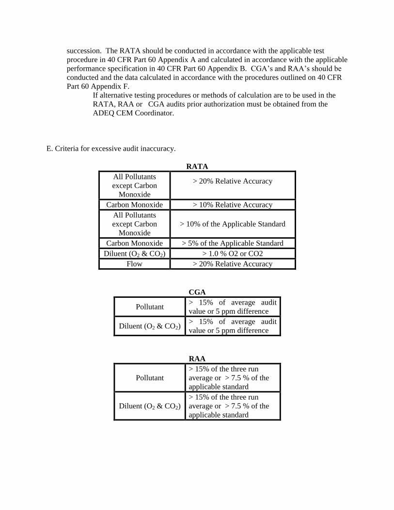
succession. The RATA should be conducted in accordance with the applicable test
procedure in 40 CFR Part 60 Appendix A and calculated in accordance with the applicable
performance specification in 40 CFR Part 60 Appendix B. CGA’s and RAA’s should be
conducted and the data calculated in accordance with the procedures outlined on 40 CFR
Part 60 Appendix F.
If alternative testing procedures or methods of calculation are to be used in the
RATA, RAA or CGA audits prior authorization must be obtained from the
ADEQ CEM Coordinator.
E. Criteria for excessive audit inaccuracy.
RATA
All Pollutants
except Carbon
Monoxide
> 20% Relative Accuracy
Carbon Monoxide > 10% Relative Accuracy
All Pollutants
except Carbon
Monoxide
> 10% of the Applicable Standard
Carbon Monoxide > 5% of the Applicable Standard
Diluent (O2 & CO2) > 1.0 % O2 or CO2
Flow > 20% Relative Accuracy
CGA
Pollutant > 15% of average audit
value or 5 ppm difference
Diluent (O2 & CO2) > 15% of average audit
value or 5 ppm difference
RAA
Pollutant
> 15% of the three run
average or > 7.5 % of the
applicable standard
Diluent (O2 & CO2)
> 15% of the three run
average or > 7.5 % of the
applicable standard

F. If either the zero or span drift results exceed two times the applicable drift specification
in 40 CFR, Part 60, Appendix B for five consecutive, daily periods, the CEMS is out-of-
control. If either the zero or span drift results exceed four times the applicable drift
specification in Appendix B during a calibration drift check, the CEMS is out-of-control.
If the CEMS exceeds the audit inaccuracies listed above, the CEMS is out-of-control. If
a CEMS is out-of-control, the data from that out-of-control period is not counted towards
meeting the minimum data availability as required and described in the applicable
subpart. The end of the out-of-control period is the time corresponding to the completion
of the successful daily zero or span drift or completion of the successful CGA, RAA or
RATA.
G. A back-up monitor may be placed on an emission source to minimize monitor downtime.
This back-up CEMS is subject to the same QA/QC procedure and practices as the
primary CEMS. The back-up CEMS shall be certified by a PST. Daily zero-span checks
must be performed and recorded in accordance with standard practices. When the
primary CEMS goes down, the back-up CEMS may then be engaged to sample, analyze
and record the emission source pollutant until repairs are made and the primary unit is
placed back in service. Records must be maintained on site when the back-up CEMS is
placed in service, these records shall include at a minimum the reason the primary CEMS
is out of service, the date and time the primary CEMS was out of service and the date and
time the primary CEMS was placed back in service.

APPENDIX B
40 CFR Part 60, Subpart GG

ELECTRONIC CODE OF FEDERAL REGULATIONS
View past updates to the e-CFR.
Click here to learn more.
e-CFR data is current as of September 1, 2015
Title 40 → Chapter I → Subchapter C → Part 60 → Subpart GG
Browse Previous | Browse Next
Title 40: Protection of Environment
PART 60—STANDARDS OF PERFORMANCE FOR NEW STATIONARY SOURCES
Subpart GG—Standards of Performance for Stationary Gas Turbines
Contents
§60.330 Applicability and designation of affected facility.
§60.331 Definitions.
§60.332 Standard for nitrogen oxides.
§60.333 Standard for sulfur dioxide.
§60.334 Monitoring of operations.
§60.335 Test methods and procedures.
Back to Top
§60.330 Applicability and designation of affected facility.
(a) The provisions of this subpart are applicable to the following affected facilities: All stationary gas turbines with a heat input at peak load equal to or greater than 10.7 gigajoules (10 million Btu) per hour, based on the lower heating value of the fuel fired.
(b) Any facility under paragraph (a) of this section which commences construction, modification, or reconstruction after October 3, 1977, is subject to the requirements of this part except as provided in paragraphs (e) and (j) of §60.332.
[44 FR 52798, Sept. 10, 1979, as amended at 52 FR 42434, Nov. 5, 1987; 65 FR 61759, Oct. 17, 2000]
Back to Top

§60.331 Definitions.
As used in this subpart, all terms not defined herein shall have the meaning given them in the Act and in subpart A of this part.
(a) Stationary gas turbine means any simple cycle gas turbine, regenerative cycle gas turbine or any gas turbine portion of a combined cycle steam/electric generating system that is not self propelled. It may, however, be mounted on a vehicle for portability.
(b) Simple cycle gas turbine means any stationary gas turbine which does not recover heat from the gas turbine exhaust gases to preheat the inlet combustion air to the gas turbine, or which does not recover heat from the gas turbine exhaust gases to heat water or generate steam.
(c) Regenerative cycle gas turbine means any stationary gas turbine which recovers heat from the gas turbine exhaust gases to preheat the inlet combustion air to the gas turbine.
(d) Combined cycle gas turbine means any stationary gas turbine which recovers heat from the gas turbine exhaust gases to heat water or generate steam.
(e) Emergency gas turbine means any stationary gas turbine which operates as a mechanical or electrical power source only when the primary power source for a facility has been rendered inoperable by an emergency situation.
(f) Ice fog means an atmospheric suspension of highly reflective ice crystals.
(g) ISO standard day conditions means 288 degrees Kelvin, 60 percent relative humidity and 101.3 kilopascals pressure.
(h) Efficiency means the gas turbine manufacturer's rated heat rate at peak load in terms of heat input per unit of power output based on the lower heating value of the fuel.
(i) Peak load means 100 percent of the manufacturer's design capacity of the gas turbine at ISO standard day conditions.
(j) Base load means the load level at which a gas turbine is normally operated.
(k) Fire-fighting turbine means any stationary gas turbine that is used solely to pump water for extinguishing fires.
(l) Turbines employed in oil/gas production or oil/gas transportation means any stationary gas turbine used to provide power to extract crude oil/natural gas from the earth or to move crude oil/natural gas, or products refined from these substances through pipelines.
(m) A Metropolitan Statistical Area or MSA as defined by the Department of Commerce.
(n) Offshore platform gas turbines means any stationary gas turbine located on a platform in an ocean.
(o) Garrison facility means any permanent military installation.

(p) Gas turbine model means a group of gas turbines having the same nominal air flow, combuster inlet pressure, combuster inlet temperature, firing temperature, turbine inlet temperature and turbine inlet pressure.
(q) Electric utility stationary gas turbine means any stationary gas turbine constructed for the purpose of supplying more than one-third of its potential electric output capacity to any utility power distribution system for sale.
(r) Emergency fuel is a fuel fired by a gas turbine only during circumstances, such as natural gas supply curtailment or breakdown of delivery system, that make it impossible to fire natural gas in the gas turbine.
(s) Unit operating hour means a clock hour during which any fuel is combusted in the affected unit. If the unit combusts fuel for the entire clock hour, it is considered to be a full unit operating hour. If the unit combusts fuel for only part of the clock hour, it is considered to be a partial unit operating hour.
(t) Excess emissions means a specified averaging period over which either:
(1) The NOX emissions are higher than the applicable emission limit in §60.332;
(2) The total sulfur content of the fuel being combusted in the affected facility exceeds the limit specified in §60.333; or
(3) The recorded value of a particular monitored parameter is outside the acceptable range specified in the parameter monitoring plan for the affected unit.
(u) Natural gas means a naturally occurring fluid mixture of hydrocarbons (e.g., methane, ethane, or propane) produced in geological formations beneath the Earth's surface that maintains a gaseous state at standard atmospheric temperature and pressure under ordinary conditions. Natural gas contains 20.0 grains or less of total sulfur per 100 standard cubic feet. Equivalents of this in other units are as follows: 0.068 weight percent total sulfur, 680 parts per million by weight (ppmw) total sulfur, and 338 parts per million by volume (ppmv) at 20 degrees Celsius total sulfur. Additionally, natural gas must either be composed of at least 70 percent methane by volume or have a gross calorific value between 950 and 1100 British thermal units (Btu) per standard cubic foot. Natural gas does not include the following gaseous fuels: landfill gas, digester gas, refinery gas, sour gas, blast furnace gas, coal-derived gas, producer gas, coke oven gas, or any gaseous fuel produced in a process which might result in highly variable sulfur content or heating value.
(v) Duct burner means a device that combusts fuel and that is placed in the exhaust duct from another source, such as a stationary gas turbine, internal combustion engine, kiln, etc., to allow the firing of additional fuel to heat the exhaust gases before the exhaust gases enter a heat recovery steam generating unit.
(w) Lean premix stationary combustion turbine means any stationary combustion turbine where the air and fuel are thoroughly mixed to form a lean mixture for combustion in the combustor. Mixing may occur before or in the combustion chamber. A unit which is capable of operating in both lean premix and diffusion flame modes is considered a lean premix stationary combustion turbine when it is in the lean premix mode, and it is considered a diffusion flame stationary combustion turbine when it is in the diffusion flame mode.
(x) Diffusion flame stationary combustion turbine means any stationary combustion turbine where fuel and air are injected at the combustor and are mixed only by diffusion prior to ignition. A unit which is capable of operating in both lean premix and diffusion flame modes is considered a lean premix

stationary combustion turbine when it is in the lean premix mode, and it is considered a diffusion flame stationary combustion turbine when it is in the diffusion flame mode.
(y) Unit operating day means a 24-hour period between 12:00 midnight and the following midnight during which any fuel is combusted at any time in the unit. It is not necessary for fuel to be combusted continuously for the entire 24-hour period.
[44 FR 52798, Sept. 10, 1979, as amended at 47 FR 3770, Jan. 27, 1982; 65 FR 61759, Oct. 17, 2000; 69 FR 41359, July 8, 2004]
Back to Top
§60.332 Standard for nitrogen oxides.
(a) On and after the date on which the performance test required by §60.8 is completed, every owner or operator subject to the provisions of this subpart as specified in paragraphs (b), (c), and (d) of this section shall comply with one of the following, except as provided in paragraphs (e), (f), (g), (h), (i), (j), (k), and (l) of this section.
(1) No owner or operator subject to the provisions of this subpart shall cause to be discharged into the atmosphere from any stationary gas turbine, any gases which contain nitrogen oxides in excess of:
View or download PDF
where:
STD = allowable ISO corrected (if required as given in §60.335(b)(1)) NOX emission concentration (percent by volume at 15 percent oxygen and on a dry basis),
Y = manufacturer's rated heat rate at manufacturer's rated load (kilojoules per watt hour) or, actual measured heat rate based on lower heating value of fuel as measured at actual peak load for the facility. The value of Y shall not exceed 14.4 kilojoules per watt hour, and
F = NOX emission allowance for fuel-bound nitrogen as defined in paragraph (a)(4) of this section.
(2) No owner or operator subject to the provisions of this subpart shall cause to be discharged into the atmosphere from any stationary gas turbine, any gases which contain nitrogen oxides in excess of:
View or download PDF
where:
STD = allowable ISO corrected (if required as given in §60.335(b)(1)) NOX emission concentration (percent by volume at 15 percent oxygen and on a dry basis),

Y = manufacturer's rated heat rate at manufacturer's rated peak load (kilojoules per watt hour), or actual measured heat rate based on lower heating value of fuel as measured at actual peak load for the facility. The value of Y shall not exceed 14.4 kilojoules per watt hour, and
F = NOX emission allowance for fuel-bound nitrogen as defined in paragraph (a)(4) of this section.
(3) The use of F in paragraphs (a)(1) and (2) of this section is optional. That is, the owner or operator may choose to apply a NOX allowance for fuel-bound nitrogen and determine the appropriate F-value in accordance with paragraph (a)(4) of this section or may accept an F-value of zero.
(4) If the owner or operator elects to apply a NOX emission allowance for fuel-bound nitrogen, F shall be defined according to the nitrogen content of the fuel during the most recent performance test required under §60.8 as follows:
Fuel-bound nitrogen (percent by weight) F (NOX percent by volume)
N .015 0
0.015 <N≤0.1 0.04 (N)
0.1<N≤0.25 0.004 + 0.0067(N-0.1)
N >0.25 0.005
Where:
N = the nitrogen content of the fuel (percent by weight).
or:
Manufacturers may develop and submit to EPA custom fuel-bound nitrogen allowances for each gas turbine model they manufacture. These fuel-bound nitrogen allowances shall be substantiated with data and must be approved for use by the Administrator before the initial performance test required by §60.8. Notices of approval of custom fuel-bound nitrogen allowances will be published in the FEDERAL REGISTER.
(b) Electric utility stationary gas turbines with a heat input at peak load greater than 107.2 gigajoules per hour (100 million Btu/hour) based on the lower heating value of the fuel fired shall comply with the provisions of paragraph (a)(1) of this section.
(c) Stationary gas turbines with a heat input at peak load equal to or greater than 10.7 gigajoules per hour (10 million Btu/hour) but less than or equal to 107.2 gigajoules per hour (100 million Btu/hour) based on the lower heating value of the fuel fired, shall comply with the provisions of paragraph (a)(2) of this section.
(d) Stationary gas turbines with a manufacturer's rated base load at ISO conditions of 30 megawatts or less except as provided in §60.332(b) shall comply with paragraph (a)(2) of this section.
(e) Stationary gas turbines with a heat input at peak load equal to or greater than 10.7 gigajoules per hour (10 million Btu/hour) but less than or equal to 107.2 gigajoules per hour (100 million Btu/hour) based on the lower heating value of the fuel fired and that have commenced construction prior to October 3, 1982 are exempt from paragraph (a) of this section.
(f) Stationary gas turbines using water or steam injection for control of NOX emissions are exempt from paragraph (a) when ice fog is deemed a traffic hazard by the owner or operator of the gas turbine.

(g) Emergency gas turbines, military gas turbines for use in other than a garrison facility, military gas turbines installed for use as military training facilities, and fire fighting gas turbines are exempt from paragraph (a) of this section.
(h) Stationary gas turbines engaged by manufacturers in research and development of equipment for both gas turbine emission control techniques and gas turbine efficiency improvements are exempt from paragraph (a) on a case-by-case basis as determined by the Administrator.
(i) Exemptions from the requirements of paragraph (a) of this section will be granted on a case-by-case basis as determined by the Administrator in specific geographical areas where mandatory water restrictions are required by governmental agencies because of drought conditions. These exemptions will be allowed only while the mandatory water restrictions are in effect.
(j) Stationary gas turbines with a heat input at peak load greater than 107.2 gigajoules per hour that commenced construction, modification, or reconstruction between the dates of October 3, 1977, and January 27, 1982, and were required in the September 10, 1979, FEDERAL REGISTER (44 FR 52792) to comply with paragraph (a)(1) of this section, except electric utility stationary gas turbines, are exempt from paragraph (a) of this section.
(k) Stationary gas turbines with a heat input greater than or equal to 10.7 gigajoules per hour (10 million Btu/hour) when fired with natural gas are exempt from paragraph (a)(2) of this section when being fired with an emergency fuel.
(l) Regenerative cycle gas turbines with a heat input less than or equal to 107.2 gigajoules per hour (100 million Btu/hour) are exempt from paragraph (a) of this section.
[44 FR 52798, Sept. 10, 1979, as amended at 47 FR 3770, Jan. 27, 1982; 65 FR 61759, Oct. 17, 2000; 69 FR 41359, July 8, 2004]
Back to Top
§60.333 Standard for sulfur dioxide.
On and after the date on which the performance test required to be conducted by §60.8 is completed, every owner or operator subject to the provision of this subpart shall comply with one or the other of the following conditions:
(a) No owner or operator subject to the provisions of this subpart shall cause to be discharged into the atmosphere from any stationary gas turbine any gases which contain sulfur dioxide in excess of 0.015 percent by volume at 15 percent oxygen and on a dry basis.
(b) No owner or operator subject to the provisions of this subpart shall burn in any stationary gas turbine any fuel which contains total sulfur in excess of 0.8 percent by weight (8000 ppmw).
[44 FR 52798, Sept. 10, 1979, as amended at 69 FR 41360, July 8, 2004]
Back to Top
§60.334 Monitoring of operations.
(a) Except as provided in paragraph (b) of this section, the owner or operator of any stationary gas turbine subject to the provisions of this subpart and using water or steam injection to control NOX
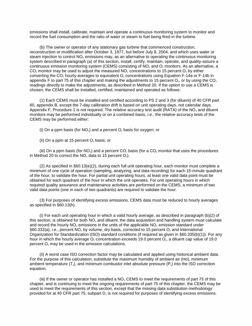
emissions shall install, calibrate, maintain and operate a continuous monitoring system to monitor and record the fuel consumption and the ratio of water or steam to fuel being fired in the turbine.
(b) The owner or operator of any stationary gas turbine that commenced construction, reconstruction or modification after October 3, 1977, but before July 8, 2004, and which uses water or steam injection to control NOX emissions may, as an alternative to operating the continuous monitoring system described in paragraph (a) of this section, install, certify, maintain, operate, and quality-assure a continuous emission monitoring system (CEMS) consisting of NOX and O2 monitors. As an alternative, a CO2 monitor may be used to adjust the measured NOX concentrations to 15 percent O2 by either converting the CO2 hourly averages to equivalent O2 concentrations using Equation F-14a or F-14b in appendix F to part 75 of this chapter and making the adjustments to 15 percent O2, or by using the CO2 readings directly to make the adjustments, as described in Method 20. If the option to use a CEMS is chosen, the CEMS shall be installed, certified, maintained and operated as follows:
(1) Each CEMS must be installed and certified according to PS 2 and 3 (for diluent) of 40 CFR part 60, appendix B, except the 7-day calibration drift is based on unit operating days, not calendar days. Appendix F, Procedure 1 is not required. The relative accuracy test audit (RATA) of the NOX and diluent monitors may be performed individually or on a combined basis, i.e., the relative accuracy tests of the CEMS may be performed either:
(i) On a ppm basis (for NOX) and a percent O2 basis for oxygen; or
(ii) On a ppm at 15 percent O2 basis; or
(iii) On a ppm basis (for NOX) and a percent CO2 basis (for a CO2 monitor that uses the procedures in Method 20 to correct the NOX data to 15 percent O2).
(2) As specified in §60.13(e)(2), during each full unit operating hour, each monitor must complete a minimum of one cycle of operation (sampling, analyzing, and data recording) for each 15-minute quadrant of the hour, to validate the hour. For partial unit operating hours, at least one valid data point must be obtained for each quadrant of the hour in which the unit operates. For unit operating hours in which required quality assurance and maintenance activities are performed on the CEMS, a minimum of two valid data points (one in each of two quadrants) are required to validate the hour.
(3) For purposes of identifying excess emissions, CEMS data must be reduced to hourly averages as specified in §60.13(h).
(i) For each unit operating hour in which a valid hourly average, as described in paragraph (b)(2) of this section, is obtained for both NOX and diluent, the data acquisition and handling system must calculate and record the hourly NOX emissions in the units of the applicable NOX emission standard under §60.332(a), i.e., percent NOX by volume, dry basis, corrected to 15 percent O2 and International Organization for Standardization (ISO) standard conditions (if required as given in §60.335(b)(1)). For any hour in which the hourly average O2 concentration exceeds 19.0 percent O2, a diluent cap value of 19.0 percent O2 may be used in the emission calculations.
(ii) A worst case ISO correction factor may be calculated and applied using historical ambient data. For the purpose of this calculation, substitute the maximum humidity of ambient air (Ho), minimum ambient temperature (Ta), and minimum combustor inlet absolute pressure (Po) into the ISO correction equation.
(iii) If the owner or operator has installed a NOX CEMS to meet the requirements of part 75 of this chapter, and is continuing to meet the ongoing requirements of part 75 of this chapter, the CEMS may be used to meet the requirements of this section, except that the missing data substitution methodology provided for at 40 CFR part 75, subpart D, is not required for purposes of identifying excess emissions.

Instead, periods of missing CEMS data are to be reported as monitor downtime in the excess emissions and monitoring performance report required in §60.7(c).
(c) For any turbine that commenced construction, reconstruction or modification after October 3, 1977, but before July 8, 2004, and which does not use steam or water injection to control NOX emissions, the owner or operator may, but is not required to, for purposes of determining excess emissions, use a CEMS that meets the requirements of paragraph (b) of this section. Also, if the owner or operator has previously submitted and received EPA, State, or local permitting authority approval of a procedure for monitoring compliance with the applicable NOX emission limit under §60.332, that approved procedure may continue to be used.
(d) The owner or operator of any new turbine constructed after July 8, 2004, and which uses water or steam injection to control NOX emissions may elect to use either the requirements in paragraph (a) of this section for continuous water or steam to fuel ratio monitoring or may use a NOX CEMS installed, certified, operated, maintained, and quality-assured as described in paragraph (b) of this section.
(e) The owner or operator of any new turbine that commences construction after July 8, 2004, and which does not use water or steam injection to control NOX emissions, may, but is not required to, elect to use a NOX CEMS installed, certified, operated, maintained, and quality-assured as described in paragraph (b) of this section. Other acceptable monitoring approaches include periodic testing approved by EPA or the State or local permitting authority or continuous parameter monitoring as described in paragraph (f) of this section.
(f) The owner or operator of a new turbine that commences construction after July 8, 2004, which does not use water or steam injection to control NOX emissions may, but is not required to, perform continuous parameter monitoring as follows:
(1) For a diffusion flame turbine without add-on selective catalytic reduction controls (SCR), the owner or operator shall define at least four parameters indicative of the unit's NOX formation characteristics and shall monitor these parameters continuously.
(2) For any lean premix stationary combustion turbine, the owner or operator shall continuously monitor the appropriate parameters to determine whether the unit is operating in low-NOX mode.
(3) For any turbine that uses SCR to reduce NOX emissions, the owner or operator shall continuously monitor appropriate parameters to verify the proper operation of the emission controls.
(4) For affected units that are also regulated under part 75 of this chapter, if the owner or operator elects to monitor NOX emission rate using the methodology in appendix E to part 75 of this chapter, or the low mass emissions methodology in §75.19 of this chapter, the requirements of this paragraph (f) may be met by performing the parametric monitoring described in section 2.3 of appendix E or in §75.19(c)(1)(iv)(H) of this chapter.
(g) The steam or water to fuel ratio or other parameters that are continuously monitored as described in paragraphs (a), (d) or (f) of this section shall be monitored during the performance test required under §60.8, to establish acceptable values and ranges. The owner or operator may supplement the performance test data with engineering analyses, design specifications, manufacturer's recommendations and other relevant information to define the acceptable parametric ranges more precisely. The owner or operator shall develop and keep on-site a parameter monitoring plan which explains the procedures used to document proper operation of the NOX emission controls. The plan shall include the parameter(s) monitored and the acceptable range(s) of the parameter(s) as well as the basis for designating the parameter(s) and acceptable range(s). Any supplemental data such as engineering analyses, design specifications, manufacturer's recommendations and other relevant information shall be included in the monitoring plan. For affected units that are also subject to part 75 of this chapter and that

use the low mass emissions methodology in §75.19 of this chapter or the NOX emission measurement methodology in appendix E to part 75, the owner or operator may meet the requirements of this paragraph by developing and keeping on-site (or at a central location for unmanned facilities) a quality-assurance plan, as described in §75.19 (e)(5) or in section 2.3 of appendix E and section 1.3.6 of appendix B to part 75 of this chapter.
(h) The owner or operator of any stationary gas turbine subject to the provisions of this subpart:
(1) Shall monitor the total sulfur content of the fuel being fired in the turbine, except as provided in paragraph (h)(3) of this section. The sulfur content of the fuel must be determined using total sulfur methods described in §60.335(b)(10). Alternatively, if the total sulfur content of the gaseous fuel during the most recent performance test was less than 0.4 weight percent (4000 ppmw), ASTM D4084-82, 94, D5504-01, D6228-98, or Gas Processors Association Standard 2377-86 (all of which are incorporated by reference-see §60.17), which measure the major sulfur compounds may be used; and
(2) Shall monitor the nitrogen content of the fuel combusted in the turbine, if the owner or operator claims an allowance for fuel bound nitrogen (i.e., if an F-value greater than zero is being or will be used by the owner or operator to calculate STD in §60.332). The nitrogen content of the fuel shall be determined using methods described in §60.335(b)(9) or an approved alternative.
(3) Notwithstanding the provisions of paragraph (h)(1) of this section, the owner or operator may elect not to monitor the total sulfur content of the gaseous fuel combusted in the turbine, if the gaseous fuel is demonstrated to meet the definition of natural gas in §60.331(u), regardless of whether an existing custom schedule approved by the administrator for subpart GG requires such monitoring. The owner or operator shall use one of the following sources of information to make the required demonstration:
(i) The gas quality characteristics in a current, valid purchase contract, tariff sheet or transportation contract for the gaseous fuel, specifying that the maximum total sulfur content of the fuel is 20.0 grains/100 scf or less; or
(ii) Representative fuel sampling data which show that the sulfur content of the gaseous fuel does not exceed 20 grains/100 scf. At a minimum, the amount of fuel sampling data specified in section 2.3.1.4 or 2.3.2.4 of appendix D to part 75 of this chapter is required.
(4) For any turbine that commenced construction, reconstruction or modification after October 3, 1977, but before July 8, 2004, and for which a custom fuel monitoring schedule has previously been approved, the owner or operator may, without submitting a special petition to the Administrator, continue monitoring on this schedule.
(i) The frequency of determining the sulfur and nitrogen content of the fuel shall be as follows:
(1) Fuel oil. For fuel oil, use one of the total sulfur sampling options and the associated sampling frequency described in sections 2.2.3, 2.2.4.1, 2.2.4.2, and 2.2.4.3 of appendix D to part 75 of this chapter (i.e., flow proportional sampling, daily sampling, sampling from the unit's storage tank after each addition of fuel to the tank, or sampling each delivery prior to combining it with fuel oil already in the intended storage tank). If an emission allowance is being claimed for fuel-bound nitrogen, the nitrogen content of the oil shall be determined and recorded once per unit operating day.
(2) Gaseous fuel. Any applicable nitrogen content value of the gaseous fuel shall be determined and recorded once per unit operating day. For owners and operators that elect not to demonstrate sulfur content using options in paragraph (h)(3) of this section, and for which the fuel is supplied without intermediate bulk storage, the sulfur content value of the gaseous fuel shall be determined and recorded once per unit operating day.

(3) Custom schedules. Notwithstanding the requirements of paragraph (i)(2) of this section, operators or fuel vendors may develop custom schedules for determination of the total sulfur content of gaseous fuels, based on the design and operation of the affected facility and the characteristics of the fuel supply. Except as provided in paragraphs (i)(3)(i) and (i)(3)(ii) of this section, custom schedules shall be substantiated with data and shall be approved by the Administrator before they can be used to comply with the standard in §60.333.
(i) The two custom sulfur monitoring schedules set forth in paragraphs (i)(3)(i)(A) through (D) and in paragraph (i)(3)(ii) of this section are acceptable, without prior Administrative approval:
(A) The owner or operator shall obtain daily total sulfur content measurements for 30 consecutive unit operating days, using the applicable methods specified in this subpart. Based on the results of the 30 daily samples, the required frequency for subsequent monitoring of the fuel's total sulfur content shall be as specified in paragraph (i)(3)(i)(B), (C), or (D) of this section, as applicable.
(B) If none of the 30 daily measurements of the fuel's total sulfur content exceeds 0.4 weight percent (4000 ppmw), subsequent sulfur content monitoring may be performed at 12 month intervals. If any of the samples taken at 12-month intervals has a total sulfur content between 0.4 and 0.8 weight percent (4000 and 8000 ppmw), follow the procedures in paragraph (i)(3)(i)(C) of this section. If any measurement exceeds 0.8 weight percent (8000 ppmw), follow the procedures in paragraph (i)(3)(i)(D) of this section.
(C) If at least one of the 30 daily measurements of the fuel's total sulfur content is between 0.4 and 0.8 weight percent (4000 and 8000 ppmw), but none exceeds 0.8 weight percent (8000 ppmw), then:
(1) Collect and analyze a sample every 30 days for three months. If any sulfur content measurement exceeds 0.8 weight percent (8000 ppmw), follow the procedures in paragraph (i)(3)(i)(D) of this section. Otherwise, follow the procedures in paragraph (i)(3)(i)(C)(2) of this section.
(2) Begin monitoring at 6-month intervals for 12 months. If any sulfur content measurement exceeds 0.8 weight percent (8000 ppmw), follow the procedures in paragraph (i)(3)(i)(D) of this section. Otherwise, follow the procedures in paragraph (i)(3)(i)(C)(3) of this section.
(3) Begin monitoring at 12-month intervals. If any sulfur content measurement exceeds 0.8 weight percent (8000 ppmw), follow the procedures in paragraph (i)(3)(i)(D) of this section. Otherwise, continue to monitor at this frequency.
(D) If a sulfur content measurement exceeds 0.8 weight percent (8000 ppmw), immediately begin daily monitoring according to paragraph (i)(3)(i)(A) of this section. Daily monitoring shall continue until 30 consecutive daily samples, each having a sulfur content no greater than 0.8 weight percent (8000 ppmw), are obtained. At that point, the applicable procedures of paragraph (i)(3)(i)(B) or (C) of this section shall be followed.
(ii) The owner or operator may use the data collected from the 720-hour sulfur sampling demonstration described in section 2.3.6 of appendix D to part 75 of this chapter to determine a custom sulfur sampling schedule, as follows:
(A) If the maximum fuel sulfur content obtained from the 720 hourly samples does not exceed 20 grains/100 scf (i.e., the maximum total sulfur content of natural gas as defined in §60.331(u)), no additional monitoring of the sulfur content of the gas is required, for the purposes of this subpart.
(B) If the maximum fuel sulfur content obtained from any of the 720 hourly samples exceeds 20 grains/100 scf, but none of the sulfur content values (when converted to weight percent sulfur) exceeds

0.4 weight percent (4000 ppmw), then the minimum required sampling frequency shall be one sample at 12 month intervals.
(C) If any sample result exceeds 0.4 weight percent sulfur (4000 ppmw), but none exceeds 0.8 weight percent sulfur (8000 ppmw), follow the provisions of paragraph (i)(3)(i)(C) of this section.
(D) If the sulfur content of any of the 720 hourly samples exceeds 0.8 weight percent (8000 ppmw), follow the provisions of paragraph (i)(3)(i)(D) of this section.
(j) For each affected unit that elects to continuously monitor parameters or emissions, or to periodically determine the fuel sulfur content or fuel nitrogen content under this subpart, the owner or operator shall submit reports of excess emissions and monitor downtime, in accordance with §60.7(c). Excess emissions shall be reported for all periods of unit operation, including startup, shutdown and malfunction. For the purpose of reports required under §60.7(c), periods of excess emissions and monitor downtime that shall be reported are defined as follows:
(1) Nitrogen oxides.
(i) For turbines using water or steam to fuel ratio monitoring:
(A) An excess emission shall be any unit operating hour for which the average steam or water to fuel ratio, as measured by the continuous monitoring system, falls below the acceptable steam or water to fuel ratio needed to demonstrate compliance with §60.332, as established during the performance test required in §60.8. Any unit operating hour in which no water or steam is injected into the turbine shall also be considered an excess emission.
(B) A period of monitor downtime shall be any unit operating hour in which water or steam is injected into the turbine, but the essential parametric data needed to determine the steam or water to fuel ratio are unavailable or invalid.
(C) Each report shall include the average steam or water to fuel ratio, average fuel consumption, ambient conditions (temperature, pressure, and humidity), gas turbine load, and (if applicable) the nitrogen content of the fuel during each excess emission. You do not have to report ambient conditions if you opt to use the worst case ISO correction factor as specified in §60.334(b)(3)(ii), or if you are not using the ISO correction equation under the provisions of §60.335(b)(1).
(ii) If the owner or operator elects to take an emission allowance for fuel bound nitrogen, then excess emissions and periods of monitor downtime are as described in paragraphs (j)(1)(ii)(A) and (B) of this section.
(A) An excess emission shall be the period of time during which the fuel-bound nitrogen (N) is greater than the value measured during the performance test required in §60.8 and used to determine the allowance. The excess emission begins on the date and hour of the sample which shows that N is greater than the performance test value, and ends with the date and hour of a subsequent sample which shows a fuel nitrogen content less than or equal to the performance test value.
(B) A period of monitor downtime begins when a required sample is not taken by its due date. A period of monitor downtime also begins on the date and hour that a required sample is taken, if invalid results are obtained. The period of monitor downtime ends on the date and hour of the next valid sample.
(iii) For turbines using NOX and diluent CEMS:

(A) An hour of excess emissions shall be any unit operating hour in which the 4-hour rolling average NOX concentration exceeds the applicable emission limit in §60.332(a)(1) or (2). For the purposes of this subpart, a “4-hour rolling average NOX concentration” is the arithmetic average of the average NOX concentration measured by the CEMS for a given hour (corrected to 15 percent O2 and, if required under §60.335(b)(1), to ISO standard conditions) and the three unit operating hour average NOX concentrations immediately preceding that unit operating hour.
(B) A period of monitor downtime shall be any unit operating hour in which sufficient data are not obtained to validate the hour, for either NOX concentration or diluent (or both).
(C) Each report shall include the ambient conditions (temperature, pressure, and humidity) at the time of the excess emission period and (if the owner or operator has claimed an emission allowance for fuel bound nitrogen) the nitrogen content of the fuel during the period of excess emissions. You do not have to report ambient conditions if you opt to use the worst case ISO correction factor as specified in §60.334(b)(3)(ii), or if you are not using the ISO correction equation under the provisions of §60.335(b)(1).
(iv) For owners or operators that elect, under paragraph (f) of this section, to monitor combustion parameters or parameters that document proper operation of the NOX emission controls:
(A) An excess emission shall be a 4-hour rolling unit operating hour average in which any monitored parameter does not achieve the target value or is outside the acceptable range defined in the parameter monitoring plan for the unit.
(B) A period of monitor downtime shall be a unit operating hour in which any of the required parametric data are either not recorded or are invalid.
(2) Sulfur dioxide. If the owner or operator is required to monitor the sulfur content of the fuel under paragraph (h) of this section:
(i) For samples of gaseous fuel and for oil samples obtained using daily sampling, flow proportional sampling, or sampling from the unit's storage tank, an excess emission occurs each unit operating hour included in the period beginning on the date and hour of any sample for which the sulfur content of the fuel being fired in the gas turbine exceeds 0.8 weight percent and ending on the date and hour that a subsequent sample is taken that demonstrates compliance with the sulfur limit.
(ii) If the option to sample each delivery of fuel oil has been selected, the owner or operator shall immediately switch to one of the other oil sampling options (i.e., daily sampling, flow proportional sampling, or sampling from the unit's storage tank) if the sulfur content of a delivery exceeds 0.8 weight percent. The owner or operator shall continue to use one of the other sampling options until all of the oil from the delivery has been combusted, and shall evaluate excess emissions according to paragraph (j)(2)(i) of this section. When all of the fuel from the delivery has been burned, the owner or operator may resume using the as-delivered sampling option.
(iii) A period of monitor downtime begins when a required sample is not taken by its due date. A period of monitor downtime also begins on the date and hour of a required sample, if invalid results are obtained. The period of monitor downtime shall include only unit operating hours, and ends on the date and hour of the next valid sample.
(3) Ice fog. Each period during which an exemption provided in §60.332(f) is in effect shall be reported in writing to the Administrator quarterly. For each period the ambient conditions existing during the period, the date and time the air pollution control system was deactivated, and the date and time the air pollution control system was reactivated shall be reported. All quarterly reports shall be postmarked by the 30th day following the end of each calendar quarter.

(4) Emergency fuel. Each period during which an exemption provided in §60.332(k) is in effect shall be included in the report required in §60.7(c). For each period, the type, reasons, and duration of the firing of the emergency fuel shall be reported.
(5) All reports required under §60.7(c) shall be postmarked by the 30th day following the end of each 6-month period.
[44 FR 52798, Sept. 10, 1979, as amended at 47 FR 3770, Jan. 27, 1982; 65 FR 61759, Oct. 17, 2000; 69 FR 41360, July 8, 2004; 71 FR 9457, Feb. 24, 2006]
Back to Top
§60.335 Test methods and procedures.
(a) The owner or operator shall conduct the performance tests required in §60.8, using either
(1) EPA Method 20,
(2) ASTM D6522-00 (incorporated by reference, see §60.17), or
(3) EPA Method 7E and either EPA Method 3 or 3A in appendix A to this part, to determine NOX and diluent concentration.
(4) Sampling traverse points are to be selected following Method 20 or Method 1, (non-particulate procedures) and sampled for equal time intervals. The sampling shall be performed with a traversing single-hole probe or, if feasible, with a stationary multi-hole probe that samples each of the points sequentially. Alternatively, a multi-hole probe designed and documented to sample equal volumes from each hole may be used to sample simultaneously at the required points.
(5) Notwithstanding paragraph (a)(4) of this section, the owner or operator may test at few points than are specified in Method 1 or Method 20 if the following conditions are met:
(i) You may perform a stratification test for NOX and diluent pursuant to
(A) [Reserved]
(B) The procedures specified in section 6.5.6.1(a) through (e) appendix A to part 75 of this chapter.
(ii) Once the stratification sampling is completed, the owner or operator may use the following alternative sample point selection criteria for the performance test:
(A) If each of the individual traverse point NOX concentrations, normalized to 15 percent O2, is within 10 percent of the mean normalized concentration for all traverse points, then you may use 3 points (located either 16.7, 50.0, and 83.3 percent of the way across the stack or duct, or, for circular stacks or ducts greater than 2.4 meters (7.8 feet) in diameter, at 0.4, 1.2, and 2.0 meters from the wall). The 3 points shall be located along the measurement line that exhibited the highest average normalized NOX concentration during the stratification test; or
(B) If each of the individual traverse point NOX concentrations, normalized to 15 percent O2, is within 5 percent of the mean normalized concentration for all traverse points, then you may sample at a single point, located at least 1 meter from the stack wall or at the stack centroid.

(6) Other acceptable alternative reference methods and procedures are given in paragraph (c) of this section.
(b) The owner or operator shall determine compliance with the applicable nitrogen oxides emission limitation in §60.332 and shall meet the performance test requirements of §60.8 as follows:
(1) For each run of the performance test, the mean nitrogen oxides emission concentration (NOXo) corrected to 15 percent O2 shall be corrected to ISO standard conditions using the following equation. Notwithstanding this requirement, use of the ISO correction equation is optional for: Lean premix stationary combustion turbines; units used in association with heat recovery steam generators (HRSG) equipped with duct burners; and units equipped with add-on emission control devices:
NOX = (NOXo)(Pr/Po)0.5 e19 (Ho−0.00633) (288 °K/Ta)1.53
Where:
NOX = emission concentration of NOX at 15 percent O2 and ISO standard ambient conditions, ppm by volume, dry basis,
NOXo = mean observed NOX concentration, ppm by volume, dry basis, at 15 percent O2,
Pr = reference combustor inlet absolute pressure at 101.3 kilopascals ambient pressure. Alternatively, you may use 760 mm Hg (29.92 in Hg),
Po = observed combustor inlet absolute pressure at test, mm Hg. Alternatively, you may use the barometric pressure for the date of the test,
Ho = observed humidity of ambient air, g H2O/g air,
e = transcendental constant, 2.718, and
Ta = ambient temperature, °K.
(2) The 3-run performance test required by §60.8 must be performed within 5 percent at 30, 50, 75, and 90-to-100 percent of peak load or at four evenly-spaced load points in the normal operating range of the gas turbine, including the minimum point in the operating range and 90-to-100 percent of peak load, or at the highest achievable load point if 90-to-100 percent of peak load cannot be physically achieved in practice. If the turbine combusts both oil and gas as primary or backup fuels, separate performance testing is required for each fuel. Notwithstanding these requirements, performance testing is not required for any emergency fuel (as defined in §60.331).
(3) For a combined cycle turbine system with supplemental heat (duct burner), the owner or operator may elect to measure the turbine NOX emissions after the duct burner rather than directly after the turbine. If the owner or operator elects to use this alternative sampling location, the applicable NOX emission limit in §60.332 for the combustion turbine must still be met.
(4) If water or steam injection is used to control NOX with no additional post-combustion NOX control and the owner or operator chooses to monitor the steam or water to fuel ratio in accordance with §60.334(a), then that monitoring system must be operated concurrently with each EPA Method 20, ASTM D6522-00 (incorporated by reference, see §60.17), or EPA Method 7E run and shall be used to determine the fuel consumption and the steam or water to fuel ratio necessary to comply with the applicable §60.332 NOX emission limit.
(5) If the owner operator elects to claim an emission allowance for fuel bound nitrogen as described in §60.332, then concurrently with each reference method run, a representative sample of the fuel used

shall be collected and analyzed, following the applicable procedures described in §60.335(b)(9). These data shall be used to determine the maximum fuel nitrogen content for which the established water (or steam) to fuel ratio will be valid.
(6) If the owner or operator elects to install a CEMS, the performance evaluation of the CEMS may either be conducted separately (as described in paragraph (b)(7) of this section) or as part of the initial performance test of the affected unit.
(7) If the owner or operator elects to install and certify a NOX CEMS under §60.334(e), then the initial performance test required under §60.8 may be done in the following alternative manner:
(i) Perform a minimum of 9 reference method runs, with a minimum time per run of 21 minutes, at a single load level, between 90 and 100 percent of peak (or the highest physically achievable) load.
(ii) Use the test data both to demonstrate compliance with the applicable NOX emission limit under §60.332 and to provide the required reference method data for the RATA of the CEMS described under §60.334(b).
(iii) The requirement to test at three additional load levels is waived.
(8) If the owner or operator elects under §60.334(f) to monitor combustion parameters or parameters indicative of proper operation of NOX emission controls, the appropriate parameters shall be continuously monitored and recorded during each run of the initial performance test, to establish acceptable operating ranges, for purposes of the parameter monitoring plan for the affected unit, as specified in §60.334(g).
(9) To determine the fuel bound nitrogen content of fuel being fired (if an emission allowance is claimed for fuel bound nitrogen), the owner or operator may use equipment and procedures meeting the requirements of:
(i) For liquid fuels, ASTM D2597-94 (Reapproved 1999), D6366-99, D4629-02, D5762-02 (all of which are incorporated by reference, see §60.17); or
(ii) For gaseous fuels, shall use analytical methods and procedures that are accurate to within 5 percent of the instrument range and are approved by the Administrator.
(10) If the owner or operator is required under §60.334(i)(1) or (3) to periodically determine the sulfur content of the fuel combusted in the turbine, a minimum of three fuel samples shall be collected during the performance test. Analyze the samples for the total sulfur content of the fuel using:
(i) For liquid fuels, ASTM D129-00, D2622-98, D4294-02, D1266-98, D5453-00 or D1552-01 (all of which are incorporated by reference, see §60.17); or
(ii) For gaseous fuels, ASTM D1072-80, 90 (Reapproved 1994); D3246-81, 92, 96; D4468-85 (Reapproved 2000); or D6667-01 (all of which are incorporated by reference, see §60.17). The applicable ranges of some ASTM methods mentioned above are not adequate to measure the levels of sulfur in some fuel gases. Dilution of samples before analysis (with verification of the dilution ratio) may be used, subject to the prior approval of the Administrator.
(11) The fuel analyses required under paragraphs (b)(9) and (b)(10) of this section may be performed by the owner or operator, a service contractor retained by the owner or operator, the fuel vendor, or any other qualified agency.
(c) The owner or operator may use the following as alternatives to the reference methods and procedures specified in this section:
(1) Instead of using the equation in paragraph (b)(1) of this section, manufacturers may develop ambient condition correction factors to adjust the nitrogen oxides emission level measured by the performance test as provided in §60.8 to ISO standard day conditions.
[69 FR 41363, July 8, 2004, as amended at 71 FR 9458, Feb. 24, 2006; 79 FR 11250, Feb. 27, 2014]
Back to Top

APPENDIX C
Fuel Monitoring Protocol for Stationary Gas Turbines

Fuel Monitoring Protocol for Stationary Turbines Subject to 40 CFR Part 60, Subpart GG
1. Monitoring of fuel nitrogen content shall not be required while natural gas is the only fuel
fired in the gas turbine.
2. Analysis for fuel sulfur content of the natural gas shall be conducted using one of the
approved ASTM reference methods for the measurement of sulfur in gaseous fuels, or an
approved alternative method. The approved reference methods are: ASTM Dl072-80;
ASTM D3031-81; ASTM D3246-81; and ASTM D4084-82 as referenced in 40 CFR
60.335(b)(2). The Gas Processors Association (GPA) test method entitled “Test for
Hydrogen Sulfide and Carbon Dioxide in Natural Gas Using Length of Stain Tubes”
(GPA Standard 2377-86) is an approved alternative method.
3. The fuel supply shall be initially sampled daily for a period of two weeks to establish that
the pipeline quality natural gas fuel supply is low in sulfur content.
4. After the monitoring required in item 3 above, sulfur monitoring shall be conducted twice
monthly for six months. If this monitoring shows little variability in the fuel sulfur
content, and indicates consistent compliance with 40 CFR 60.333, then sulfur monitoring
shall be conducted once per quarter for six quarters.
5. If after the monitoring required in item 4 above, or herein, the sulfur content of the fuel
shows little variability and, calculated as sulfur dioxide, represents consistent compliance
with the sulfur dioxide emission limits specified under 40 CFR 60.333, sample analysis
shall be conducted twice per annum. This monitoring shall be conducted during the first
and third quarters of each calendar year.
6. Should any sulfur analysis as required in items 4 or 5 above indicate noncompliance
with40 CFR 60.333, the owner or operator shall notify the ADEQ of such excess
emissions and the custom schedule shall be re-examined. Sulfur monitoring shall be
conducted weekly during the interim period when this custom schedule is being
re-examined.
7. If there is a change in fuel supply (supplier), the fuel shall be sampled daily for a period
of two weeks to re-establish for the record that the fuel supply is low in sulfur content. If
the fuel supply's low sulfur content is re-established, then the custom fuel monitoring
schedule can be resumed.
8. Stationary gas turbines that use the same supply of pipeline quality natural gas to fuel
multiple gas turbines may monitor the fuel sulfur content at a single common location.
9. Records of sample analysis and fuel supply pertinent to this custom schedule shall be
retained for a period of three years, and be available for inspection by personnel of
federal, state, and local air pollution control agencies.

APPENDIX D
40 CFR, Part 75, Continuous Emissions Monitoring

ELECTRONIC CODE OF FEDERAL REGULATIONS
View past updates to the e-CFR.
Click here to learn more.
e-CFR data is current as of September 1, 2015
Title 40 → Chapter I → Subchapter C → Part 75
Browse Previous | Browse Next
Title 40: Protection of Environment
PART 75—CONTINUOUS EMISSION MONITORING
Contents Subpart A—General
§75.1 Purpose and scope.
§75.2 Applicability.
§75.3 General Acid Rain Program provisions.
§75.4 Compliance dates.
§75.5 Prohibitions.
§75.6 Incorporation by reference.
§§75.7-75.8 [Reserved] Subpart B—Monitoring Provisions
§75.10 General operating requirements.
§75.11 Specific provisions for monitoring SO2 emissions.
§75.12 Specific provisions for monitoring NOX emission rate.
§75.13 Specific provisions for monitoring CO2 emissions.
§75.14 Specific provisions for monitoring opacity.
§75.15 [Reserved]
§75.16 Special provisions for monitoring emissions from common, bypass, and multiple stacks
for SO2 emissions and heat input determinations.
§75.17 Specific provisions for monitoring emissions from common, bypass, and multiple stacks
for NOX emission rate.
§75.18 Specific provisions for monitoring emissions from common and by-pass stacks for
opacity.
§75.19 Optional SO2, NOX, and CO2 emissions calculation for low mass emissions (LME) units. Subpart C—Operation and Maintenance Requirements

§75.20 Initial certification and recertification procedures.
§75.21 Quality assurance and quality control requirements.
§75.22 Reference test methods.
§75.23 Alternatives to standards incorporated by reference.
§75.24 Out-of-control periods and adjustment for system bias. Subpart D—Missing Data Substitution Procedures
§75.30 General provisions.
§75.31 Initial missing data procedures.
§75.32 Determination of monitor data availability for standard missing data procedures.
§75.33 Standard missing data procedures for SO2, NOX, and flow rate.
§75.34 Units with add-on emission controls.
§75.35 Missing data procedures for CO2.
§75.36 Missing data procedures for heat input rate determinations.
§75.37 Missing data procedures for moisture.
§§75.38-75.39 [Reserved] Subpart E—Alternative Monitoring Systems
§75.40 General demonstration requirements.
§75.41 Precision criteria.
§75.42 Reliability criteria.
§75.43 Accessibility criteria.
§75.44 Timeliness criteria.
§75.45 Daily quality assurance criteria.
§75.46 Missing data substitution criteria.
§75.47 Criteria for a class of affected units.
§75.48 Petition for an alternative monitoring system. Subpart F—Recordkeeping Requirements
§§75.50-75.52 [Reserved]
§75.53 Monitoring plan.
§§75.54-75.56 [Reserved]
§75.57 General recordkeeping provisions.
§75.58 General recordkeeping provisions for specific situations.
§75.59 Certification, quality assurance, and quality control record provisions. Subpart G—Reporting Requirements
§75.60 General provisions.
§75.61 Notifications.
§75.62 Monitoring plan submittals.
§75.63 Initial certification or recertification application.
§75.64 Quarterly reports.
§75.65 Opacity reports.
§75.66 Petitions to the Administrator.
§75.67 Retired units petitions. Subpart H—NOX Mass Emissions Provisions

§75.70 NOX mass emissions provisions.
§75.71 Specific provisions for monitoring NOX and heat input for the purpose of calculating
NOX mass emissions.
§75.72 Determination of NOX mass emissions for common stack and multiple stack
configurations.
§75.73 Recordkeeping and reporting.
§75.74 Annual and ozone season monitoring and reporting requirements.
§75.75 Additional ozone season calculation procedures for special circumstances.
Appendix A to Part 75—Specifications and Test Procedures
Appendix B to Part 75—Quality Assurance and Quality Control Procedures
Appendix C to Part 75—Missing Data Estimation Procedures
Appendix D to Part 75—Optional SO2 Emissions Data Protocol for Gas-Fired and Oil-Fired
Units
Appendix E to Part 75—Optional NOX Emissions Estimation Protocol for Gas-Fired Peaking
Units and Oil-Fired Peaking Units
Appendix F to Part 75—Conversion Procedures
Appendix G to Part 75—Determination of CO2 Emissions
Appendix H to Part 75—Revised Traceability Protocol No. 1 [Reserved]
Appendix I to Part 75—Optional F—Factor/Fuel Flow Method [Reserved]
Appendix J to Part 75—Compliance Dates for Revised Recordkeeping Requirements and
Missing Data Procedures [Reserved]
AUTHORITY: 42 U.S.C. 7601 and 7651K, and 7651K note.
SOURCE: 58 FR 3701, Jan. 11, 1993, unless otherwise noted.
EDITORIAL NOTE: Nomenclature changes to part 75 appear at 67 FR 40476, June 12, 2002.
Back to Top
Subpart A—General
Back to Top
§75.1 Purpose and scope.
(a) Purpose. The purpose of this part is to establish requirements for the monitoring, recordkeeping, and reporting of sulfur dioxide (SO2), nitrogen oxides (NOX), and carbon dioxide (CO2) emissions, volumetric flow, and opacity data from affected units under the Acid Rain Program pursuant to sections 412 and 821 of the CAA, 42 U.S.C. 7401-7671q as amended by Public Law 101-549 (November 15, 1990) [the Act]. In addition, this part sets forth provisions for the monitoring, recordkeeping, and reporting of NOX mass emissions with which EPA, individual States, or groups of States may require sources to comply in order to demonstrate compliance with a NOX mass emission reduction program, to the extent these provisions are adopted as requirements under such a program.
(b) Scope. (1) The regulations established under this part include general requirements for the installation, certification, operation, and maintenance of continuous emission or opacity monitoring systems and specific requirements for the monitoring of SO2 emissions, volumetric flow, NOX emissions,

opacity, CO2 emissions and SO2 emissions removal by qualifying Phase I technologies. Specifications for the installation and performance of continuous emission monitoring systems, certification tests and procedures, and quality assurance tests and procedures are included in appendices A and B to this part. Criteria for alternative monitoring systems and provisions to account for missing data from certified continuous emission monitoring systems or approved alternative monitoring systems are also included in the regulation.
(2) Statistical estimation procedures for missing data are included in appendix C to this part. Optional protocols for estimating SO2 mass emissions from gas-fired or oil-fired units and NOX emissions from gas-fired peaking or oil-fired peaking units are included in appendices D and E, respectively, to this part. Requirements for recording and recordkeeping of monitoring data and for quarterly electronic reporting also are specified. Procedures for conversion of monitoring data into units of the standard are included in appendix F to this part. Procedures for the monitoring and calculation of CO2 emissions are included in appendix G of this part.
[58 FR 3701, Jan. 11, 1993; 58 FR 34126, June 23, 1993; 58 FR 40747, July 30, 1993; 63 FR 57498, Oct. 27, 1999; 67 FR 40421, June 12, 2002]
Back to Top
§75.2 Applicability.
(a) Except as provided in paragraphs (b) and (c) of this section, the provisions of this part apply to each affected unit subject to Acid Rain emission limitations or reduction requirements for SO2 or NOX.
(b) The provisions of this part do not apply to:
(1) A new unit for which a written exemption has been issued under §72.7 of this chapter (any new unit that serves one or more generators with total nameplate capacity of 25 MWe or less and burns only fuels with a sulfur content of 0.05 percent or less by weight may apply to the Administrator for an exemption); or
(2) Any unit not subject to the requirements of the Acid Rain Program due to operation of any paragraph of §72.6(b) of this chapter; or
(3) An affected unit for which a written exemption has been issued under §72.8 of this chapter and an exception granted under §75.67 of this part.
(c) The provisions of this part apply to sources subject to a State or federal NOX mass emission reduction program, to the extent these provisions are adopted as requirements under such a program.
[58 FR 3701, Jan. 11, 1993, as amended at 58 FR 15716, Mar. 23, 1993; 60 FR 26516, May 17, 1995; 63 FR 57499, Oct. 27, 1998; 70 FR 28678, May 18, 2005; 76 FR 17306, Mar. 28, 2011]
Back to Top
§75.3 General Acid Rain Program provisions.
The provisions of part 72, including the following, shall apply to this part:
(a) §72.2 (Definitions);

(b) §72.3 (Measurements, Abbreviations, and Acronyms);
(c) §72.4 (Federal Authority);
(d) §72.5 (State Authority);
(e) §72.6 (Applicability);
(f) §72.7 (New Unit Exemption);
(g) §72.8 (Retired Units Exemption);
(h) §72.9 (Standard Requirements);
(i) §72.10 (Availability of Information); and
(j) §72.11 (Computation of Time).
In addition, the procedures for appeals of decisions of the Administrator under this part are contained in part 78 of this chapter.
Back to Top
§75.4 Compliance dates.
(a) The provisions of this part apply to each existing Phase I and Phase II unit on February 10, 1993. For substitution or compensating units that are so designated under the Acid Rain permit which governs that unit and contains the approved substitution or reduced utilization plan, pursuant to §72.41 or §72.43 of this chapter, the provisions of this part become applicable upon the issuance date of the Acid Rain permit. For combustion sources seeking to enter the Opt-in Program in accordance with part 74 of this chapter, the provisions of this part become applicable upon the submission of an opt-in permit application in accordance with §74.14 of this chapter. The provisions of this part for the monitoring, recording, and reporting of NOX mass emissions become applicable on the deadlines specified in the applicable State or federal NOX mass emission reduction program, to the extent these provisions are adopted as requirements under such a program. In accordance with §75.20, the owner or operator of each existing affected unit shall ensure that all monitoring systems required by this part for monitoring SO2, NOX, CO2, opacity, moisture and volumetric flow are installed and that all certification tests are completed no later than the following dates (except as provided in paragraphs (d) through (i) of this section):
(1) For a unit listed in table 1 of §73.10(a) of this chapter, November 15, 1993.
(2) For a substitution or a compensating unit that is designated under an approved substitution plan or reduced utilization plan pursuant to §72.41 or §72.43 of this chapter, or for a unit that is designated an early election unit under an approved NOX compliance plan pursuant to part 76 of this chapter, that is not conditionally approved and that is effective for 1995, the earlier of the following dates:
(i) January 1, 1995; or
(ii) 90 days after the issuance date of the Acid Rain permit (or date of approval of permit revision) that governs the unit and contains the approved substitution plan, reduced utilization plan, or NOX compliance plan.
(3) For either a Phase II unit, other than a gas-fired unit or an oil-fired unit, or a substitution or compensating unit that is not a substitution or compensating unit under paragraph (a)(2) of this section: January 1, 1995.
(4) For a gas-fired Phase II unit or an oil-fired Phase II unit, January 1, 1995, except that installation and certification tests for continuous emission monitoring systems for NOX and CO2 or excepted monitoring systems for NOX under appendix E or CO2 estimation under appendix G of this part shall be completed as follows:
(i) For an oil-fired Phase II unit or a gas-fired Phase II unit located in an ozone nonattainment area or the ozone transport region, not later than July 1, 1995; or
(ii) For an oil-fired Phase II unit or a gas-fired Phase II unit not located in an ozone nonattainment area or the ozone transport region, not later than January 1, 1996.
(5) For combustion sources seeking to enter the Opt-in Program in accordance with part 74 of this chapter, the expiration date of a combustion source's opt-in permit under §74.14(e) of this chapter.
(b) In accordance with §75.20, the owner or operator of each new affected unit shall ensure that all monitoring systems required under this part for monitoring of SO2, NOX, CO2, opacity, and volumetric flow are installed and all certification tests are completed on or before the later of the following dates:
(1) January 1, 1995, except that for a gas-fired unit or oil-fired unit located in an ozone nonattainment area or the ozone transport region, the date for installation and completion of all certification tests for NOX and CO2 monitoring systems shall be July 1, 1995 and for a gas-fired unit or an oil-fired unit not located in an ozone nonattainment area or the ozone transport region, the date for installation and completion of all certification tests for NOX and CO2 monitoring systems shall be January 1, 1996; or
(2) 180 calendar days after the date the unit commences commercial operation, notice of which date shall be provided under subpart G of this part.
(c) In accordance with §75.20, the owner or operator of any unit affected under any paragraph of §72.6(a)(3) (ii) through (vii) of this chapter shall ensure that all monitoring systems required under this part for monitoring of SO2, NOX, CO2, opacity, and volumetric flow are installed and all certification tests are completed on or before the later of the following dates:
(1) January 1, 1995, except that for a gas-fired unit or oil-fired unit located in an ozone nonattainment area or the ozone transport region, the date for installation and completion of all certification tests for NOX and CO2 monitoring systems shall be July 1, 1995 and for a gas-fired unit or an oil-fired unit not located in an ozone nonattainment area or the ozone transport region, the date for installation and completion of all certification tests for NOX and CO2 monitoring systems shall be January 1, 1996; or
(2) 180 calendar days after the date on which the unit becomes subject to the requirements of the Acid Rain Program, notice of which date shall be provided under subpart G of this part.
(d) This paragraph (d) applies to affected units under the Acid Rain Program and to units subject to a State or Federal pollutant mass emissions reduction program that adopts the emission monitoring and reporting provisions of this part. In accordance with §75.20, for an affected unit which, on the applicable compliance date, is either in long-term cold storage (as defined in §72.2 of this chapter) or is shut down as the result of a planned outage or a forced outage, thereby preventing the required continuous monitoring system certification tests from being completed by the compliance date, the owner or operator
shall provide notice of such unit storage or outage in accordance with §75.61(a)(3) or §75.61(a)(7), as applicable. For the planned and unplanned unit outages described in this paragraph (d), the owner or operator shall ensure that all of the continuous monitoring systems for SO2, NOX, CO2, opacity, and volumetric flow rate required under this part (or under the applicable State or Federal mass emissions reduction program) are installed and that all required certification tests are completed no later than 90 unit operating days or 180 calendar days (whichever occurs first) after the date that the unit recommences commercial operation, notice of which date shall be provided under §75.61(a)(3) or §75.61(a)(7), as applicable. The owner or operator shall determine and report SO2 concentration, NOX emission rate, CO2 concentration, and flow rate data (as applicable) for all unit operating hours after the applicable compliance date until all of the required certification tests are successfully completed, using either:
(1) The maximum potential concentration of SO2 (as defined in section 2.1.1.1 of appendix A to this part), the maximum potential NOX emission rate, as defined in §72.2 of this chapter, the maximum potential flow rate, as defined in section 2.1.4.1 of appendix A to this part, or the maximum potential CO2 concentration, as defined in section 2.1.3.1 of appendix A to this part; or
(2) The conditional data validation provisions of §75.20(b)(3); or
(3) Reference methods under §75.22(b); or
(4) Another procedure approved by the Administrator pursuant to a petition under §75.66.
(e) In accordance with §75.20, if the owner or operator of an affected unit completes construction of a new stack or flue, or a flue gas desulfurization system or add-on NOX emission controls, after the applicable deadline in paragraph (a), (b), or (c) of this section:
(1) Except as otherwise provided in paragraph (e)(3) of this section, the owner or operator shall ensure that all required certification and/or recertification and/or diagnostic tests of the monitoring systems required under this part (i.e., the SO2, NOX, CO2, O2, opacity, volumetric flow rate, and moisture monitoring systems, as applicable) are completed not later than 90 unit operating days or 180 calendar days (whichever occurs first) after:
(i) For the event of construction of a new stack or flue, the date that emissions first exit to the atmosphere through the new stack or flue, notice of which date shall be provided under subpart G of this part; or
(ii) For the event of installation of a flue gas desulfurization system or add-on NOX emission controls, the date that reagent is first injected into the flue gas desulfurization system or the add-on NOX emission controls, as applicable, notice of which date shall be provided under subpart G of this part.
(2) The owner or operator shall determine and report, as applicable, SO2 concentration, NOX concentration, NOX emission rate, CO2 concentration, O2 concentration, volumetric flow rate, and moisture data for all unit or stack operating hours after emissions first pass through the new stack or flue, or reagent is first injected into the flue gas desulfurization system or add-on NOX emission controls, as applicable, until all required certification and/or recertification and/or diagnostic tests are successfully completed, using:
(i) Quality-assured data recorded by a previously-certified monitoring system for which the event requires no additional testing;
(ii) The applicable missing data substitution procedures under §§75.31 through 75.37;

(iii) The conditional data validation procedures of §75.20(b)(3), except that conditional data validation may, if necessary, be used for the entire window of time provided under paragraph (e)(1) of this section in lieu of the periods specified in §75.20(b)(3)(iv);
(iv) Reference methods under §75.22(b);
(v) For the event of installation of a flue gas desulfurization system or add-on NOX emission controls, quality-assured data recorded on the high measurement scale of the monitor that measures the pollutant being removed by the add-on emission controls (i.e., SO2 or NOX, as applicable), if, pursuant to section 2 of appendix A to this part, two spans and ranges are required for that monitor and if the high measurement scale of the monitor has been certified according to §75.20(c), section 6 of appendix A to this part, and, if applicable, paragraph (e)(4)(i) of this section. Data recorded on the certified high scale that ordinarily would be required to be recorded on the low scale, pursuant to section 2.1.1.4(g) or 2.1.2.4(f) of appendix A to this part, may be reported as quality-assured for a period not to exceed 60 unit or stack operating days after the date and hour that reagent is first injected into the control device, after which one or more of the options provided in paragraphs (e)(2)(ii), (e)(2)(iii), (e)(2)(iv) and (e)(2)(vi) of this section must be used to report SO2 or NOX concentration data (as applicable) for each operating hour in which these low emissions occur, until certification testing of the low scale of the monitor is successfully completed; or
(vi) Another procedure approved by the Administrator pursuant to a petition under §75.66.
(3) If a particular project involves both the event of new stack or flue construction and the event of installation of a flue gas desulfurization system or add-on NOX emission controls, the owner or operator shall either:
(i) Complete all of the monitoring system certification and/or recertification and/or diagnostic testing requirements of both events within the window of time provided under paragraph (e)(1)(i) of this section; or
(ii) Complete all of the monitoring system certification and/or recertification and/or diagnostic testing requirements of each event within the separate window of time applicable to such event provided under paragraph (e)(1) of this section.
(4) For the project described in paragraph (e)(3) of this section, the emissions data from each CEMS installed on the new stack recorded in the interval of time starting on the date and hour on which emissions first exit to the atmosphere through the new stack and ending on the hour before the date and hour on which reagent is first injected into the control device may be reported as quality assured:
(i) For the CEMS that includes the monitor that measures the pollutant being removed by the add-on emission controls (i.e., SO2 or NOX, as applicable):
(A) Only if the relative accuracy test audit (RATA) of the high measurement scale of the monitor is successfully completed either prior to the date and hour of the first injection of reagent into the emission control device, or after that date and hour during a period when the control device is not operating, but still within the window of time provided under paragraph (e)(1)(i) of this section, and the rest of the certification tests required under §75.20(c) and section 6 of appendix A to this part for the high measurement scale of the monitor are successfully completed within the window of time provided under paragraph (e)(1)(i) of this section;
(B) Beginning with:

(1) The first unit or stack operating hour after successful completion of all of the certification tests in accordance with paragraph (e)(4)(i)(A) of this section; or
(2) The hour of the probationary calibration error test (see §75.20(b)(3)(ii)), if conditional data validation is used and all of the certification tests are successfully completed in accordance with paragraph (e)(4)(i)(A) of this section, with no test failures. If any required test is failed or aborted or is otherwise not in accordance with paragraph (e)(4)(i)(A) of this section, data validation shall be done according to §75.20(b)(3)(vii).
(ii) For a CEMS other than one addressed in paragraph (e)(4)(i) of this section:
(A) Only if the relative accuracy test audit (RATA) of the CEMS is successfully completed either prior to the date and hour of the first injection of reagent into the emission control device, or after that date and hour during a period when the control device is not operating, but still within the window of time provided under paragraph (e)(1)(i) of this section, and the rest of the certification tests required under §75.20(c) and section 6 of appendix A to this part for the CEMS are successfully completed within the window of time provided under paragraph (e)(1)(i) of this section;
(B) Beginning with:
(1) The first unit or stack operating hour after successful completion of all of the certification tests in accordance with paragraph (e)(4)(ii)(A) of this section; or
(2) The hour of the probationary calibration error test (see §75.20(b)(3)(ii)), if conditional data validation is used and all of the certification tests are successfully completed in accordance with paragraph (e)(4)(ii)(A) of this section, with no test failures. If any required test is failed or aborted or is otherwise not in accordance with paragraph (e)(4)(ii)(A) of this section, data validation shall be done according to §75.20(b)(3)(vii).
(f) In accordance with §75.20, the owner or operator of an affected gas-fired or oil-fired peaking unit, if planning to use appendix E of this part, shall ensure that the required certification tests for excepted monitoring systems under appendix E are completed for backup fuel, as defined in §72.2 of this chapter, no later than 90 unit operating days or 180 calendar days (whichever occurs first) after the date that the unit first combusts the backup fuel following the certification testing with the primary fuel. If the required testing is completed by this deadline, the appendix E correlation curve derived from the test results may be used for reporting data under this part beginning with the first date and hour that the backup fuel is combusted, provided that the fuel flowmeter for the backup fuel was certified as of that date and hour. If the required appendix E testing has not been successfully completed by the compliance date in this paragraph, then, until the testing is completed, the owner or operator shall report NOX emission rate data for all unit operating hours that the backup fuel is combusted using either:
(1) The fuel-specific maximum potential NOX emission rate, as defined in §72.2 of this chapter; or
(2) Reference methods under §75.22(b) of this part; or
(3) Another procedure approved by the Administrator pursuant to a petition under §75.66.
(g) The provisions of this paragraph shall apply unless an owner or operator is exempt from certifying a fuel flowmeter for use during combustion of emergency fuel under section 2.1.4.3 of appendix D to this part, in which circumstance the provisions of section 2.1.4.3 of appendix D shall apply. In accordance with §75.20, whenever the owner or operator of a gas-fired or oil-fired unit uses an excepted monitoring system under appendix D or E of this part and combusts emergency fuel as defined in §72.2 of this chapter, then the owner or operator shall ensure that a fuel flowmeter measuring emergency fuel is

installed and the required certification tests for excepted monitoring systems are completed by no later than 30 unit operating days after the first date after January 1, 1995 that the unit combusts emergency fuel. For all unit operating hours that the unit combusts emergency fuel after January 1, 1995 until the owner or operator installs a flowmeter for emergency fuel and successfully completes all required certification tests, the owner or operator shall determine and report SO2 mass emission data using either:
(1) The maximum potential fuel flow rate, as described in appendix D of this part, and the maximum sulfur content of the fuel, as described in section 2.1.1.1 of appendix A of this part;
(2) Reference methods under §75.22(b) of this part; or
(3) Another procedure approved by the Administrator pursuant to a petition under §75.66.
(h) [Reserved]
(i) In accordance with §75.20, the owner or operator of each affected unit at which SO2 concentration is measured on a dry basis or at which moisture corrections are required to account for CO2 emissions, NOX emission rate in lb/mmBtu, heat input, or NOX mass emissions for units in a NOX mass reduction program, shall ensure that the continuous moisture monitoring system required by this part is installed and that all applicable initial certification tests required under §75.20(c)(5), (c)(6), or (c)(7) for the continuous moisture monitoring system are completed no later than the following dates:
(1) April 1, 2000, for a unit that is existing and has commenced commercial operation by January 2, 2000;
(2) For a new affected unit which has not commenced commercial operation by January 2, 2000, 90 unit operating days or 180 calendar days (whichever occurs first) after the date the unit commences commercial operation; or
(3) For an existing unit that is shutdown and is not yet operating by April 1, 2000, 90 unit operating days or 180 calendar days (whichever occurs first) after the date that the unit recommences commercial operation.
(j) If the certification tests required under paragraph (b) or (c) of this section have not been completed by the applicable compliance date, the owner or operator shall determine and report SO2 concentration, NOX emission rate, CO2 concentration, and flow rate data for all unit operating hours after the applicable compliance date in this paragraph until all required certification tests are successfully completed using either:
(1) The maximum potential concentration of SO2, as defined in section 2.1.1.1 of appendix A to this part, the maximum potential NOX emission rate, as defined in §72.2 of this chapter, the maximum potential flow rate, as defined in section 2.1.4.1 of appendix A to this part, or the maximum potential CO2 concentration, as defined in section 2.1.3.1 of appendix A to this part;
(2) Reference methods under §75.22(b); or
(3) Another procedure approved by the Administrator pursuant to a petition under §75.66.
[60 FR 17131, Apr. 4, 1995, as amended at 60 FR 26516, May 17, 1995; 63 FR 57499, Oct. 27, 1998; 64 FR 28588, May 26, 1999; 67 FR 40421, June 12, 2002; 73 FR 4340, Jan. 24, 2008; 76 FR 17306, Mar. 28, 2011; 76 FR 50132, Aug. 12, 2011]
Back to Top

§75.5 Prohibitions.
(a) A violation of any applicable regulation in this part by the owners or operators or the designated representative of an affected source or an affected unit is a violation of the Act.
(b) No owner or operator of an affected unit shall operate the unit without complying with the requirements of §§75.2 through 75.75 and appendices A through G to this part.
(c) No owner or operator of an affected unit shall use any alternative monitoring system, alternative reference method, or any other alternative for the required continuous emission monitoring system without having obtained the Administrator's prior written approval in accordance with §§75.23, 75.48 and 75.66.
(d) No owner or operator of an affected unit shall operate the unit so as to discharge, or allow to be discharged, emissions of SO2, NOX or CO2 to the atmosphere without accounting for all such emissions in accordance with the provisions of §§75.10 through 75.19.
(e) No owner or operator of an affected unit shall disrupt the continuous emission monitoring system, any portion thereof, or any other approved emission monitoring method, and thereby avoid monitoring and recording SO2, NOX, or CO2 emissions discharged to the atmosphere, except for periods of recertification, or periods when calibration, quality assurance, or maintenance is performed pursuant to §75.21 and appendix B of this part.
(f) No owner or operator of an affected unit shall retire or permanently discontinue use of the continuous emission monitoring system, any component thereof, the continuous opacity monitoring system, or any other approved emission monitoring system under this part, except under any one of the following circumstances:
(1) During the period that the unit is covered by an approved retired unit exemption under §72.8 of this chapter that is in effect; or
(2) The owner or operator is monitoring emissions from the unit with another certified monitoring system or an excepted methodology approved by the Administrator for use at that unit that provides emissions data for the same pollutant or parameter as the retired or discontinued monitoring system; or
(3) The designated representative submits notification of the date of recertification testing of a replacement monitoring system in accordance with §§75.20 and 75.61, and the owner or operator recertifies thereafter a replacement monitoring system in accordance with §75.20.
[58 FR 3701, Jan. 11, 1993, as amended at 58 FR 40747, July 30, 1993; 60 FR 26517, May 17, 1995; 64 FR 28589, May 26, 1999]
Back to Top
§75.6 Incorporation by reference.
The materials listed in this section are incorporated by reference in the corresponding sections noted. These incorporations by reference were approved by the Director of the Federal Register in accordance with 5 U.S.C. 552(a) and 1 CFR part 51. These materials are incorporated as they existed on the date of approval, and a notice of any change in these materials will be published in the FEDERAL
REGISTER. The materials are available for purchase at the corresponding address noted below and are available for inspection at the Public Information Reference Unit of the U.S. EPA, 401 M St., SW.,

Washington, DC and at the Library (MD-35), U.S. EPA, Research Triangle Park, North Carolina or at the National Archives and Records Administration (NARA). For information on the availability of this material at NARA, call 202-741-6030, or go to: http://www.archives.gov/federal_register/code_of_federal_regulations/ibr_locations.html.
(a) The following materials are available for purchase from the following address: American Society for Testing and Material (ASTM) International, 100 Barr Harbor Drive, P.O. Box C700, West Conshohocken, Pennsylvania, 19428-2959, phone: 610-832-9585, http://www.astm.org/DIGITAL_LIBRARY/index.shtml.
(1) ASTM D129-00, Standard Test Method for Sulfur in Petroleum Products (General Bomb Method), for appendices A and D of this part.
(2) D240-00, Standard Test Method for Heat of Combustion of Liquid Hydrocarbon Fuels by Bomb Calorimeter, for appendices A, D and F of this part.
(3) ASTM D287-92 (Reapproved 2000), Standard Test Method for API Gravity of Crude Petroleum and Petroleum Products (Hydrometer Method), for appendix D of this part.
(4) ASTM D388-99, Standard Classification of Coals by Rank, incorporation by reference for appendix F of this part.
(5) [Reserved]
(6) ASTM D1072-06, Standard Test Method for Total Sulfur in Fuel Gases by Combustion and Barium Chloride Titration, for appendix D of this part.
(7) ASTM D1217-993 (Reapproved 1998), Standard Test Method for Density and Relative Density (Specific Gravity) of Liquids by Bingham Pycnometer, for appendix D of this part.
(8) ASTM D1250-07 , Standard Guide for Use of the Petroleum Measurement Tables, for appendix D of this part.
(9) ASTM D1298-99, Standard Test Method for Density, Relative Density (Specific Gravity) or API Gravity of Crude Petroleum and Liquid Petroleum Products by Hydrometer Method, for appendix D of this part.
(10) ASTM D1480-93 (Reapproved 1997), Standard Test Method for Density and Relative Density (Specific Gravity) of Viscous Materials by Bingham Pycnometer, for appendix D of this part.
(11) ASTM D1481-93 (Reapproved 1997), Standard Test Method for Density and Relative Density (Specific Gravity) of Viscous Materials by Lipkin Bicapillary Pycnometer, for appendix D of this part.
(12) ASTM D1552-01, Standard Test Method for Sulfur in Petroleum Products (High-Temperature Method), for appendices A and D of the part.
(13) ASTM D1826-94 (Reapproved 1998), Standard Test Method for Calorific (Heating) Value of Gases in Natural Gas Range by Continuous Recording Calorimeter, for appendices D and F to this part.
(14) ASTM D1945-96 (Reapproved 2001), Standard Test Method for Analysis of Natural Gas by Gas Chromatography, for appendices F and G of this part.

(15) ASTM D1946-90 (Reapproved 2006), Standard Practice for Analysis of Reformed Gas by Gas Chromatography, for appendices F and G of this part.
(16) [Reserved]
(17) ASTM D2013-01, Standard Practice for Preparing Coal Samples for Analysis, for appendix F of this part.
(18) [Reserved]
(19) ASTM D2234-00, Standard Practice for Collection of a Gross Sample of Coal, for appendix F of this part.
(20) [Reserved]
(21) ASTM D2502-92 (Reapproved 1996), Standard Test Method for Estimation of Molecular Weight (Relative Molecular Mass) of Petroleum Oils from Viscosity Measurements, for appendix G of this part.
(22) ASTM D2503-92 (Reapproved 1997), Standard Test Method for Relative Molecular Mass (Molecular Weight) of Hydrocarbons by Thermoelectric Measurement of Vapor Pressure, for appendix G of this part.
(23) ASTM D2622-98, Standard Test Method for Sulfur in Petroleum Products by Wavelength Dispersive X-ray Fluorescence Spectrometry, for appendices A and D of this part.
(24) ASTM D3174-00, Standard Test Method for Ash in the Analysis Sample of Coal and Coke from Coal, for appendix G of this part.
(25) ASTM D3176-89 (Reapproved 2002), Standard Practice for Ultimate Analysis of Coal and Coke, for appendices A and F of this part.
(26) ASTM D3177-02 (Reapproved 2007), Standard Test Methods for Total Sulfur in the Analysis Sample of Coal and Coke, for appendix A of this part.
(27) ASTM D5373-02 (Reapproved 2007) Standard Test Methods for Instrumental Determination of Carbon, Hydrogen, and Nitrogen in Laboratory Samples of Coal and Coke, for appendix G of this part.
(28) ASTM D3238-95 (Reapproved 2000), Standard Test Method for Calculation of Carbon Distribution and Structural Group Analysis of Petroleum Oils by the n-d-M Method, for appendix G of this part.
(29) ASTM D3246-96, Standard Test Method for Sulfur in Petroleum Gas by Oxidative Microcoulometry, for appendix D of this part.
(30) [Reserved]
(31) ASTM D3588-98, Standard Practice for Calculating Heat Value, Compressibility Factor, and Relative Density of Gaseous Fuels, for appendices D and F to this part.
(32) ASTM D4052-96 (Reapproved 2002), Standard Test Method for Density and Relative Density of Liquids by Digital Density Meter, for appendix D of this part.
(33) ASTM D4057-95 (Reapproved 2000), Standard Practice for Manual Sampling of Petroleum and Petroleum Products, for appendix D of this part.
(34) ASTM D4177-95 (Reapproved 2000), Standard Practice for Automatic Sampling of Petroleum and Petroleum Products, for appendix D of this part.
(35) ASTM D4239-02, Standard Test Methods for Sulfur in the Analysis Sample of Coal and Coke Using High-Temperature Tube Furnace Combustion Methods, for appendix A of this part.
(36) ASTM D4294-98, Standard Test Method for Sulfur in Petroleum and Petroleum Products by Energy-Dispersive X-ray Fluorescence Spectrometry, for appendices A and D of this part.
(37) ASTM D4468-85 (Reapproved 2006), Standard Test Method for Total Sulfur in Gaseous Fuels by Hydrogenolysis and Rateometric Colorimetry, for appendix D of this part.
(38) [Reserved]
(39) ASTM D4891-89 (Reapproved 2006), Standard Test Method for Heating Value of Gases in Natural Gas Range by Stoichiometric Combustion, for appendices D and F to this part.
(40) ASTM D5291-02, Standard Test Methods for Instrumental Determination of Carbon, Hydrogen, and Nitrogen in Petroleum Products and Lubricants, for appendices F and G to this part.
(41) ASTM D5373-02 (Reapproved 2007), “Standard Test Methods for Instrumental Determination of Carbon, Hydrogen, and Nitrogen in Laboratory Samples of Coal and Coke,” for appendix G to this part.
(42) ASTM D5504-01, Standard Test Method for Determination of Sulfur Compounds in Natural Gas and Gaseous Fuels by Gas Chromatography and Chemiluminescence, for appendix D of this part.
(43) [Reserved]
(44) [Reserved]
(45) ASTM D6667-04, Standard Test Method for Determination of Total Volatile Sulfur in Gaseous Hydrocarbons and Liquefied Petroleum Gases by Ultraviolet Fluorescence, for appendix D of this part.
(46) ASTM D4809-00, Standard Test Method for Heat of Combustion of Liquid Hydrocarbon Fuels by Bomb Calorimeter (Precision Method), for appendices D and F of this part.
(47) ASTM D5865-01a, Standard Test Method for Gross Calorific Value of Coal and Coke, for appendices A, D, and F of this part.
(48) ASTM D7036-04, Standard Practice for Competence of Air Emission Testing Bodies, for §75.21, §75.59, and appendix A to this part.
(49) ASTM D5453-06, Standard Test Method for Determination of Total Sulfur in Light Hydrocarbons, Spark Ignition Engine Fuel, Diesel Engine Fuel, and Engine Oil by Ultraviolet Fluorescence, for appendix D of this part.
(50) ASTM D5865-10 (Approved January 1, 2010), Standard Test Method for Gross Calorific Value of Coal and Coke, for appendices A, D, and F of this part.
(b) The following materials are available for purchase from the American Society of Mechanical Engineers (ASME), 22 Law Drive, P.O. Box 2900, Fairfield, New Jersey 07007-2900:
(1) ASME MFC-3M-2004 (Revision of ASME MFC-3M-1989 (R1995)), Measurement of Fluid Flow in Pipes Using Orifice, Nozzle, and Venturi, for appendix D of this part.
(2) ASME MFC-4M-1986 (Reaffirmed 1997), Measurement of Gas Flow by Turbine Meters, for appendix D of this part.
(3) ASME-MFC-5M-1985 (Reaffirmed 1994), Measurement of Liquid Flow in Closed Conduits Using Transit-Time Ultrasonic Flowmeters, for appendix D of this part.
(4) ASME MFC-6M-1998, Measurement of Fluid Flow in Pipes Using Vortex Flowmeters, for appendix D of this part.
(5) ASME MFC-7M-1987 (Reaffirmed 1992), Measurement of Gas Flow by Means of Critical Flow Venturi Nozzles, for appendix D of this part.
(6) ASME MFC-9M-1988 (Reaffirmed 2001), Measurement of Liquid Flow in Closed Conduits by Weighing Method, for appendix D of this part.
(c) The following materials are available for purchase from the American National Standards Institute (ANSI), 25 West 43rd Street, Fourth Floor, New York, New York 10036:
(1) ISO 8316: 1987(E) Measurement of Liquid Flow in closed Conduits-Method by Collection of the Liquid in a Volumetric Tank, for appendices D and E of this part.
(2) [Reserved]
(d) The following materials are available for purchase from the following address: Gas Processors Association (GPA), 6526 East 60th Street, Tulsa, Oklahoma 74143:
(1) GPA Standard 2172-96, Calculation of Gross Heating Value, Relative Density and Compressibility Factor for Natural Gas Mixtures from Compositional Analysis, for appendices D, E, and F of this part.
(2) GPA Standard 2261-00, Analysis for Natural Gas and Similar Gaseous Mixtures by Gas Chromatography, for appendices D, F, and G of this part.
(e) The following American Gas Association materials are available for purchase from the following address: ILI Infodisk, 610 Winters Avenue, Paramus, New Jersey 07652:
(1) American Gas Association Report No. 3: Orifice Metering of Natural Gas and Other Related Hydrocarbon Fluids, Part 1: General Equations and Uncertainty Guidelines (October 1990 Edition), Part 2: Specification and Installation Requirements (February 1991 Edition) and Part 3: Natural Gas Applications (August 1992 Edition), for appendices D and E of this part.
(2) American Gas Association Transmission Measurement Committee Report No. 7: Measurement of Gas by Turbine Meters (Second Revision, April, 1996), for appendix D to this part.
(f) The following materials are available for purchase from the following address: American Petroleum Institute, Publications Department, 1220 L Street NW, Washington, DC 20005-4070.

(1) American Petroleum Institute (API) Manual of Petroleum Measurement Standards, Chapter 3—Tank Gauging, Section 1A, Standard Practice for the Manual Gauging of Petroleum and Petroleum Products, Second Edition, August 2005; Section 1B—Standard Practice for Level Measurement of Liquid Hydrocarbons in Stationary Tanks by Automatic Tank Gauging, Second Edition June 2001; Section 2—Standard Practice for Gauging Petroleum and Petroleum Products in Tank Cars, First Edition, August 1995 (Reaffirmed March 2006); Section 3—Standard Practice for Level Measurement of Liquid Hydrocarbons in Stationary Pressurized Storage Tanks by Automatic Tank Gauging, First Edition June 1996; Section 4—Standard Practice for Level Measurement of Liquid Hydrocarbons on Marine Vessels by Automatic Tank Gauging, First Edition April 1995 (Reaffirmed, March 2006); and Section 5—Standard Practice for Level Measurement of Light Hydrocarbon Liquids Onboard Marine Vessels by Automatic Tank Gauging, First Edition March 1997 (Reaffirmed, March 2003); for §75.19.
(2) Shop Testing of Automatic Liquid Level Gages, Bulletin 2509 B, December 1961 (Reaffirmed August 1987, October 1992), for §75.19.
(3) American Petroleum Institute (API) Manual of Petroleum Measurement Standards, Chapter 4—Proving Systems, Section 2—Pipe Provers (Provers Accumulating at Least 10,000 Pulses), Second Edition, March 2001, Section 3—Small Volume Provers, First Edition, July 1988, Reaffirmed Oct 1993, and Section 5—Master-Meter Provers, Second Edition, May 2000, for appendix D to this part.
(4) American Petroleum Institute (API) Manual of Petroleum Measurement Standards, Chapter 22—Testing Protocol, Section 2—Differential Pressure Flow Measurement Devices (First Edition, August 2005), for appendix D to this part.
(g) A copy of the following material is available from http://www.epa.gov/ttn/emc/news.html (see postings for Sections 1, 2, 3, 4, Appendices, Spreadsheets, and the “Read before downloading Section 2” revision posted August 27, 1999): EPA-600/R-97/121, EPA Traceability Protocol for Assay and Certification of Gaseous Calibration Standards, September 1997, as amended August 25, 1999, U.S. Environmental Protection Agency, for §75.21, and appendix A to this part.
[58 FR 3701, Jan. 11, 1993, as amended at 60 FR 26517, May 17, 1995; 61 FR 59157, Nov. 20, 1996; 63 FR 57499, Oct. 27, 1998; 64 FR 28589, May 26, 1999; 67 FR 40422, June 12, 2002; 70 FR 28678, May 18, 2005; 70 FR 51269, Aug. 30, 2005; 73 FR 4341, Jan. 24, 2008; 76 FR 17307, Mar. 28, 2011; 77 FR 2460, Jan. 18, 2012]
EDITORIAL NOTE: At 70 FR 28678, May 18, 2005, §75.6 was amended, however, certain amendments could not be incorporated due to inaccurate amendatory instruction.
Back to Top
§§75.7-75.8 [Reserved]
Back to Top
Subpart B—Monitoring Provisions
Back to Top
§75.10 General operating requirements.
(a) Primary Measurement Requirement. The owner or operator shall measure opacity, and all SO2, NOX, and CO2 emissions for each affected unit as follows:

(1) To determine SO2 emissions, the owner or operator shall install, certify, operate, and maintain, in accordance with all the requirements of this part, a SO2 continuous emission monitoring system and a flow monitoring system with an automated data acquisition and handling system for measuring and recording SO2 concentration (in ppm), volumetric gas flow (in scfh), and SO2 mass emissions (in lb/hr) discharged to the atmosphere, except as provided in §§75.11 and 75.16 and subpart E of this part;
(2) To determine NOX emissions, the owner or operator shall install, certify, operate, and maintain, in accordance with all the requirements of this part, a NOX-diluent continuous emission monitoring system (consisting of a NOX pollutant concentration monitor and an O2 or CO2 diluent gas monitor) with an automated data acquisition and handling system for measuring and recording NOX concentration (in ppm), O2 or CO2 concentration (in percent O2 or CO2) and NOX emission rate (in lb/mmBtu) discharged to the atmosphere, except as provided in §§75.12 and 75.17 and subpart E of this part. The owner or operator shall account for total NOX emissions, both NO and NO2, either by monitoring for both NO and NO2 or by monitoring for NO only and adjusting the emissions data to account for NO2;
(3) The owner or operator shall determine CO2 emissions by using one of the following options, except as provided in §75.13 and subpart E of this part:
(i) The owner or operator shall install, certify, operate, and maintain, in accordance with all the requirements of this part, a CO2 continuous emission monitoring system and a flow monitoring system with an automated data acquisition and handling system for measuring and recording CO2 concentration (in ppm or percent), volumetric gas flow (in scfh), and CO2 mass emissions (in tons/hr) discharged to the atmosphere;
(ii) The owner or operator shall determine CO2 emissions based on the measured carbon content of the fuel and the procedures in appendix G of this part to estimate CO2 emissions (in ton/day) discharged to the atmosphere; or
(iii) The owner or operator shall install, certify, operate, and maintain, in accordance with all the requirements of this part, a flow monitoring system and a CO2 continuous emission monitoring system that uses an O2 concentration monitor to determine CO2 emissions (according to the procedures in appendix F of this part) with an automated data acquisition and handling system for measuring and recording O2 concentration (in percent), CO2 concentration (in percent), volumetric gas flow (in scfh), and CO2 mass emissions (in tons/hr) discharged to the atmosphere;
(4) The owner or operator shall install, certify, operate, and maintain, in accordance with all the requirements in this part, a continuous opacity monitoring system with the automated data acquisition and handling system for measuring and recording the opacity of emissions (in percent opacity) discharged to the atmosphere, except as provided in §§75.14 and 75.18; and
(5) A single certified flow monitoring system may be used to meet the requirements of paragraphs (a)(1) and (a)(3) of this section. A single certified diluent monitor may be used to meet the requirements of paragraphs (a)(2) and (a)(3) of this section. A single automated data acquisition and handling system may be used to meet the requirements of paragraphs (a)(1) through (a)(4) of this section.
(b) Primary Equipment Performance Requirements. The owner or operator shall ensure that each continuous emission monitoring system required by this part meets the equipment, installation, and performance specifications in appendix A to this part; and is maintained according to the quality assurance and quality control procedures in appendix B to this part; and shall record SO2 and NOX emissions in the appropriate units of measurement (i.e., lb/hr for SO2 and lb/mmBtu for NOX).
(c) Heat Input Rate Measurement Requirement. The owner or operator shall determine and record the heat input rate, in units of mmBtu/hr, to each affected unit for every hour or part of an hour any fuel is combusted following the procedures in appendix F to this part.

(d) Primary equipment hourly operating requirements. The owner or operator shall ensure that all continuous emission and opacity monitoring systems required by this part are in operation and monitoring unit emissions or opacity at all times that the affected unit combusts any fuel except as provided in §75.11(e) and during periods of calibration, quality assurance, or preventive maintenance, performed pursuant to §75.21 and appendix B of this part, periods of repair, periods of backups of data from the data acquisition and handling system, or recertification performed pursuant to §75.20. The owner or operator shall also ensure, subject to the exceptions above in this paragraph, that all continuous opacity monitoring systems required by this part are in operation and monitoring opacity during the time following combustion when fans are still operating, unless fan operation is not required to be included under any other applicable Federal, State, or local regulation, or permit. The owner or operator shall ensure that the following requirements are met:
(1) The owner or operator shall ensure that each continuous emission monitoring system is capable of completing a minimum of one cycle of operation (sampling, analyzing, and data recording) for each successive 15-min interval. The owner or operator shall reduce all SO2 concentrations, volumetric flow, SO2 mass emissions, CO2 concentration, O2 concentration, CO2 mass emissions (if applicable), NOX concentration, and NOX emission rate data collected by the monitors to hourly averages. Hourly averages shall be computed using at least one data point in each fifteen minute quadrant of an hour, where the unit combusted fuel during that quadrant of an hour. Notwithstanding this requirement, an hourly average may be computed from at least two data points separated by a minimum of 15 minutes (where the unit operates for more than one quadrant of an hour) if data are unavailable as a result of the performance of calibration, quality assurance, or preventive maintenance activities pursuant to §75.21 and appendix B of this part, or backups of data from the data acquisition and handling system, or recertification, pursuant to §75.20. The owner or operator shall use all valid measurements or data points collected during an hour to calculate the hourly averages. All data points collected during an hour shall be, to the extent practicable, evenly spaced over the hour.
(2) The owner or operator shall ensure that each continuous opacity monitoring system is capable of completing a minimum of one cycle of sampling and analyzing for each successive 10-sec period and one cycle of data recording for each successive 6-min period. The owner or operator shall reduce all opacity data to 6-min averages calculated in accordance with the provisions of part 51, appendix M of this chapter, except where the applicable State implementation plan or operating permit requires a different averaging period, in which case the State requirement shall satisfy this Acid Rain Program requirement.
(3) Failure of an SO2, CO2, or O2 emissions concentration monitor, NOX concentration monitor, flow monitor, moisture monitor, or NOX-diluent continuous emission monitoring system to acquire the minimum number of data points for calculation of an hourly average in paragraph (d)(1) of this section shall result in the failure to obtain a valid hour of data and the loss of such component data for the entire hour. For a NOX-diluent monitoring system, an hourly average NOX emission rate in lb/mmBtu is valid only if the minimum number of data points is acquired by both the NOX pollutant concentration monitor and the diluent monitor (O2 or CO2). For a moisture monitoring system consisting of one or more oxygen analyzers capable of measuring O2 on a wet-basis and a dry-basis, an hourly average percent moisture value is valid only if the minimum number of data points is acquired for both the wet-and dry-basis measurements. If a valid hour of data is not obtained, the owner or operator shall estimate and record emissions, moisture, or flow data for the missing hour by means of the automated data acquisition and handling system, in accordance with the applicable procedure for missing data substitution in subpart D of this part.
(e) Optional backup monitor requirements. If the owner or operator chooses to use two or more continuous emission monitoring systems, each of which is capable of monitoring the same stack or duct at a specific affected unit, or group of units using a common stack, then the owner or operator shall designate one monitoring system as the primary monitoring system, and shall record this information in the monitoring plan, as provided for in §75.53. The owner or operator shall designate the other monitoring system(s) as backup monitoring system(s) in the monitoring plan. The backup monitoring system(s) shall be designated as redundant backup monitoring system(s), non-redundant backup monitoring system(s),

or reference method backup system(s), as described in §75.20(d). When the certified primary monitoring system is operating and not out-of-control as defined in §75.24, only data from the certified primary monitoring system shall be reported as valid, quality-assured data. Thus, data from the backup monitoring system may be reported as valid, quality-assured data only when the backup is operating and not out-of-control as defined in §75.24 (or in the applicable reference method in appendix A of part 60 of this chapter) and when the certified primary monitoring system is not operating (or is operating but out-of-control). A particular monitor may be designated both as a certified primary monitor for one unit and as a certified redundant backup monitor for another unit.
(f) Minimum measurement capability requirement. The owner or operator shall ensure that each continuous emission monitoring system is capable of accurately measuring, recording, and reporting data, and shall not incur an exceedance of the full scale range, except as provided in sections 2.1.1.5, 2.1.2.5, and 2.1.4.3 of appendix A to this part.
(g) Minimum recording and recordkeeping requirements. The owner or operator shall record and the designated representative shall report the hourly, daily, quarterly, and annual information collected under the requirements of this part as specified in subparts F and G of this part.
[58 FR 3701, Jan. 11, 1993, as amended at 60 FR 26519, May 17, 1995; 64 FR 28590, May 26, 1999; 67 FR 40422, June 12, 2002; 70 FR 28678, May 18, 2005; 76 FR 17308, Mar. 28, 2011]
Back to Top
§75.11 Specific provisions for monitoring SO2 emissions.
(a) Coal-fired units. The owner or operator shall meet the general operating requirements in §75.10 for an SO2 continuous emission monitoring system and a flow monitoring system for each affected coal-fired unit while the unit is combusting coal and/or any other fuel, except as provided in paragraph (e) of this section, in §75.16, and in subpart E of this part. During hours in which only gaseous fuel is combusted in the unit, the owner or operator shall comply with the applicable provisions of paragraph (e)(1), (e)(2), or (e)(3) of this section.
(b) Moisture correction. Where SO2 concentration is measured on a dry basis, the owner or operator shall either:
(1) Report the appropriate fuel-specific default moisture value for each unit operating hour, selected from among the following: 3.0%, for anthracite coal; 6.0% for bituminous coal; 8.0% for sub-bituminous coal; 11.0% for lignite coal; 13.0% for wood and 14.0% for natural gas (boilers, only); or
(2) Install, operate, maintain, and quality assure a continuous moisture monitoring system for measuring and recording the moisture content of the flue gases, in order to correct the measured hourly volumetric flow rates for moisture when calculating SO2 mass emissions (in lb/hr) using the procedures in appendix F to this part. The following continuous moisture monitoring systems are acceptable: a continuous moisture sensor; an oxygen analyzer (or analyzers) capable of measuring O2 both on a wet basis and on a dry basis; or a stack temperature sensor and a moisture look-up table, i.e., a psychrometric chart (for saturated gas streams following wet scrubbers or other demonstrably saturated gas streams, only). The moisture monitoring system shall include as a component the automated data acquisition and handling system (DAHS) for recording and reporting both the raw data (e.g., hourly average wet-and dry-basis O2 values) and the hourly average values of the stack gas moisture content derived from those data. When a moisture look-up table is used, the moisture monitoring system shall be represented as a single component, the certified DAHS, in the monitoring plan for the unit or common stack.
(c) Unit with no location for a flow monitor meeting siting requirements. Where no location exists that satisfies the minimum physical siting criteria in appendix A to this part for installation of a flow monitor in either the stack or the ducts serving an affected unit or installation of a flow monitor in either the stack or ducts is demonstrated to the satisfaction of the Administrator to be technically infeasible, either:
(1) The designated representative shall petition the Administrator for an alternative method for monitoring volumetric flow in accordance with §75.66; or
(2) The owner or operator shall construct a new stack or modify existing ductwork to accommodate the installation of a flow monitor, and the designated representative shall petition the Administrator for an extension of the required certification date given in §75.4 and approval of an interim alternative flow monitoring methodology in accordance with §75.66. The Administrator may grant existing Phase I affected units an extension to January 1, 1995, and existing Phase II affected units an extension to January 1, 1996 for the submission of the certification application for the purpose of constructing a new stack or making substantial modifications to ductwork for installation of a flow monitor; or
(3) The owner or operator shall install a flow monitor in any existing location in the stack or ducts serving the affected unit at which the monitor can achieve the performance specifications of this part.
(d) Gas-fired and oil-fired units. The owner or operator of an affected unit that qualifies as a gas-fired or oil-fired unit, as defined in §72.2 of this chapter, based on information submitted by the designated representative in the monitoring plan, shall measure and record SO2 emissions:
(1) By meeting the general operating requirements in §75.10 for an SO2 continuous emission monitoring system and flow monitoring system. If this option is selected, the owner or operator shall comply with the applicable provisions in paragraph (e)(1), (e)(2), or (e)(3) of this section during hours in which the unit combusts only gaseous fuel;
(2) By providing other information satisfactory to the Administrator using the applicable procedures specified in appendix D to this part for estimating hourly SO2 mass emissions; or
(3) By using the low mass emissions excepted methodology in §75.19(c) for estimating hourly SO2 mass emissions if the affected unit qualifies as a low mass emissions unit under §75.19(a) and (b). If this option is selected for SO2, the LME methodology must also be used for NOX and CO2 when these parameters are required to be monitored by applicable program(s).
(e) Special considerations during the combustion of gaseous fuels. The owner or operator of an affected unit that uses a certified flow monitor and a certified diluent gas (O2 or CO2) monitor to measure the unit heat input rate shall, during any hours in which the unit combusts only gaseous fuel, determine SO2 emissions in accordance with paragraph (e)(1) or (e)(3) of this section, as applicable.
(1) If the gaseous fuel qualifies for a default SO2 emission rate under Section 2.3.1.1, 2.3.2.1.1, or 2.3.6(b) of appendix D to this part, the owner or operator may determine SO2 emissions by using Equation F-23 in appendix F to this part. Substitute into Equation F-23 the hourly heat input, calculated using the certified flow monitoring system and the certified diluent monitor (according to the applicable equation in section 5.2 of appendix F to this part), in conjunction with the appropriate default SO2 emission rate from section 2.3.1.1, 2.3.2.1.1, or 2.3.6(b) of appendix D to this part. When this option is chosen, the owner or operator shall perform the necessary data acquisition and handling system tests under §75.20(c), and shall meet all quality control and quality assurance requirements in appendix B to this part for the flow monitor and the diluent monitor; or
(2) [Reserved]

(3) The owner or operator may determine SO2 mass emissions by using a certified SO2 continuous monitoring system, in conjunction with the certified flow rate monitoring system. However, if the gaseous fuel is very low sulfur fuel (as defined in §72.2 of this chapter), the SO2 monitoring system shall meet the following quality assurance provisions when the very low sulfur fuel is combusted:
(i) When conducting the daily calibration error tests of the SO2 monitoring system, as required by section 2.1.1 in appendix B of this part, the zero-level calibration gas shall have an SO2 concentration of 0.0 percent of span. This restriction does not apply if gaseous fuel is burned in the affected unit only during unit startup.
(ii) EPA recommends that the calibration response of the SO2 monitoring system be adjusted, either automatically or manually, in accordance with the procedures for routine calibration adjustments in section 2.1.3 of appendix B to this part, whenever the zero-level calibration response during a required daily calibration error test exceeds the applicable performance specification of the instrument in section 3.1 of appendix A to this part (i.e., ±2.5 percent of the span value or ±5 ppm, whichever is less restrictive).
(iii) Any bias-adjusted hourly average SO2 concentration of less than 2.0 ppm recorded by the SO2 monitoring system shall be adjusted to a default value of 2.0 ppm, for reporting purposes. Such adjusted hourly averages shall be considered to be quality-assured data, provided that the monitoring system is operating and is not out-of-control with respect to any of the quality assurance tests required by appendix B of this part (i.e., daily calibration error, linearity and relative accuracy test audit).
(iv) In accordance with the requirements of section 2.1.1.2 of appendix A to this part, for units that sometimes burn gaseous fuel that is very low sulfur fuel (as defined in §72.2 of this chapter) and at other times burn higher sulfur fuel(s) such as coal or oil, a second low-scale SO2 measurement range is not required when the very low sulfur gaseous fuel is combusted. For units that burn only gaseous fuel that is very low sulfur fuel and burn no other type(s) of fuel(s), the owner or operator shall set the span of the SO2 monitoring system to a value no greater than 200 ppm.
(4) The provisions in paragraph (e)(1) of this section, may also be used for the combustion of a solid or liquid fuel that meets the definition of very low sulfur fuel in §72.2 of this chapter, mixtures of such fuels, or combinations of such fuels with gaseous fuel, if the owner or operator submits a petition under §75.66 for a default SO2 emission rate for each fuel, mixture or combination, and if the Administrator approves the petition.
(f) Other units. The owner or operator of an affected unit that combusts wood, refuse, or other material in addition to oil or gas shall comply with the monitoring provisions for coal-fired units specified in paragraph (a) of this section, except where the owner or operator has an approved petition to use the provisions of paragraph (e)(1) of this section.
[58 FR 3701, Jan. 11, 1993, as amended at 60 FR 26520, 26566, May 17, 1995; 61 FR 59157, Nov. 20, 1996; 63 FR 57499, Oct. 27, 1998; 64 FR 28590, May 26, 1999; 67 FR 40423, June 12, 2002; 73 FR 4342, Jan. 24, 2008]
Back to Top
§75.12 Specific provisions for monitoring NOX emission rate.
(a) Coal-fired units, gas-fired nonpeaking units or oil-fired nonpeaking units. The owner or operator shall meet the general operating requirements in §75.10 of this part for a NOX continuous emission monitoring system (CEMS) for each affected coal-fired unit, gas-fired nonpeaking unit, or oil-fired nonpeaking unit, except as provided in paragraph (d) of this section, §75.17, and subpart E of this part. The diluent gas monitor in the NOX-diluent CEMS may measure either O2 or CO2 concentration in the flue gases.
(b) Moisture correction. If a correction for the stack gas moisture content is needed to properly calculate the NOX emission rate in lb/mmBtu, e.g., if the NOX pollutant concentration monitor measures on a different moisture basis from the diluent monitor, the owner or operator shall either report a fuel-specific default moisture value for each unit operating hour, as provided in §75.11(b)(1), or shall install, operate, maintain, and quality assure a continuous moisture monitoring system, as defined in §75.11(b)(2). Notwithstanding this requirement, if Equation 19-3, 19-4 or 19-8 in Method 19 in appendix A to part 60 of this chapter is used to measure NOX emission rate, the following fuel-specific default moisture percentages shall be used in lieu of the default values specified in §75.11(b)(1): 5.0%, for anthracite coal; 8.0% for bituminous coal; 12.0% for sub-bituminous coal; 13.0% for lignite coal; 15.0% for wood and 18.0% for natural gas (boilers, only).
(c) Determination of NOX emission rate. The owner or operator shall calculate hourly, quarterly, and annual NOX emission rates (in lb/mmBtu) by combining the NOX concentration (in ppm), diluent concentration (in percent O2 or CO2), and percent moisture (if applicable) measurements according to the procedures in appendix F to this part.
(d) Gas-fired peaking units or oil-fired peaking units. The owner or operator of an affected unit that qualifies as a gas-fired peaking unit or oil-fired peaking unit, as defined in §72.2 of this chapter, based on information submitted by the designated representative in the monitoring plan shall comply with one of the following:
(1) Meet the general operating requirements in §75.10 for a NOX continuous emission monitoring system; or
(2) Provide information satisfactory to the Administrator using the procedure specified in appendix E of this part for estimating hourly NOX emission rate. However, if in the years after certification of an excepted monitoring system under appendix E of this part, a unit's operations exceed a capacity factor of 20 percent in any calendar year or exceed a capacity factor of 10.0 percent averaged over three years, the owner or operator shall install, certify, and operate a NOX-diluent continuous emission monitoring system no later than December 31 of the following calendar year. If the required CEMS has not been installed and certified by that date, the owner or operator shall report the maximum potential NOX emission rate (MER) (as defined in §72.2 of this chapter) for each unit operating hour, starting with the first unit operating hour after the deadline and continuing until the CEMS has been provisionally certified.
(e) Low mass emissions units. Notwithstanding the requirements of paragraphs (a) and (d) of this section, the owner or operator of an affected unit that qualifies as a low mass emissions unit under §75.19(a) and (b) shall comply with one of the following:
(1) Meet the general operating requirements in §75.10 for a NOX continuous emission monitoring system;
(2) Meet the requirements specified in paragraph (d)(2) of this section for using the excepted monitoring procedures in appendix E to this part, if applicable; or
(3) Use the low mass emissions excepted methodology in §75.19(c) for estimating hourly NOX emission rate and hourly NOX mass emissions, if applicable under §75.19(a) and (b). If this option is selected for NOX, the LME methodology must also be used for SO2 and CO2 when these parameters are required to be monitored by applicable program(s).
(f) Other units. The owner or operator of an affected unit that combusts wood, refuse, or other material in addition to oil or gas shall comply with the monitoring provisions specified in paragraph (a) of this section.

[58 FR 3701, Jan. 11, 1993, as amended at 60 FR 26520, May 17, 1995; 63 FR 57499, Oct. 27, 1998; 64 FR 28591, May 26, 1999; 67 FR 40423, June 12, 2002; 73 FR 4342, Jan. 24, 2008]
Back to Top
§75.13 Specific provisions for monitoring CO2 emissions.
(a) CO2 continuous emission monitoring system. If the owner or operator chooses to use the continuous emission monitoring method, then the owner or operator shall meet the general operating requirements in §75.10 for a CO2 continuous emission monitoring system and flow monitoring system for each affected unit. The owner or operator shall comply with the applicable provisions specified in §§75.11(a) through (e) or §75.16, except that the phrase “CO2 continuous emission monitoring system” shall apply rather than “SO2 continuous emission monitoring system,” the phrase “CO2 concentration” shall apply rather than “SO2 concentration,” the term “maximum potential concentration of CO2” shall apply rather than “maximum potential concentration of SO2,” and the phrase “CO2 mass emissions” shall apply rather than “SO2 mass emissions.”
(b) Determination of CO2 emissions using appendix G to this part. If the owner or operator chooses to use the appendix G method, then the owner or operator shall follow the procedures in appendix G to this part for estimating daily CO2 mass emissions based on the measured carbon content of the fuel and the amount of fuel combusted. For units with wet flue gas desulfurization systems or other add-on emissions controls generating CO2, the owner or operator shall use the procedures in appendix G to this part to estimate both combustion-related emissions based on the measured carbon content of the fuel and the amount of fuel combusted and sorbent-related emissions based on the amount of sorbent injected. The owner or operator shall calculate daily, quarterly, and annual CO2 mass emissions (in tons) in accordance with the procedures in appendix G to this part.
(c) Determination of CO2 mass emissions using an O2 monitor according to appendix F to this part. If the owner or operator chooses to use the appendix F method, then the owner or operator shall determine hourly CO2 concentration and mass emissions with a flow monitoring system; a continuous O2 concentration monitor; fuel F and Fc factors; and, where O2 concentration is measured on a dry basis (or where Equation F-14b in appendix F to this part is used to determine CO2 concentration), either, a continuous moisture monitoring system, as specified in §75.11(b)(2), or a fuel-specific default moisture percentage (if applicable), as defined in §75.11(b)(1); and by using the methods and procedures specified in appendix F to this part. For units using a common stack, multiple stack, or bypass stack, the owner or operator may use the provisions of §75.16, except that the phrase “CO2 continuous emission monitoring system” shall apply rather than “SO2 continuous emission monitoring system,” the term “maximum potential concentration of CO2” shall apply rather than “maximum potential concentration of SO2,” and the phrase “CO2 mass emissions” shall apply rather than “SO2 mass emissions.”
(d) Determination of CO2 mass emissions from low mass emissions units. The owner or operator of a unit that qualifies as a low mass emissions unit under §75.19(a) and (b) shall comply with one of the following:
(1) Meet the general operating requirements in §75.10 for a CO2 continuous emission monitoring system and flow monitoring system;
(2) Meet the requirements specified in paragraph (b) or (c) of this section for use of the methods in appendix G or F to this part, respectively; or
(3) Use the low mass emissions excepted methodology in §75.19(c) for estimating hourly CO2 mass emissions, if applicable under §75.19(a) and (b). If this option is selected for CO2, the LME methodology

must also be used for NOX and SO2 when these parameters are required to be monitored by applicable program(s).
[58 FR 3701, Jan. 11, 1993, as amended at 60 FR 26521, May 17, 1995; 63 FR 57499, Oct. 27, 1998; 64 FR 28591, May 26, 1999; 67 FR 40423, June 12, 2002; 73 FR 4343, Jan. 24, 2008]
Back to Top
§75.14 Specific provisions for monitoring opacity.
(a) Coal-fired units and oil-fired units. The owner or operator shall meet the general operating provisions in §75.10 of this part for a continuous opacity monitoring system for each affected coal-fired or oil-fired unit, except as provided in paragraphs (b), (c), and (d) of this section and in §75.18. Each continuous opacity monitoring system shall meet the design, installation, equipment, and performance specifications in Performance Specification 1 in appendix B to part 60 of this chapter. Any continuous opacity monitoring system previously certified to meet Performance Specification 1 shall be deemed certified for the purposes of this part.
(b) Unit with wet flue gas pollution control system. If the owner or operator can demonstrate that condensed water is present in the exhaust flue gas stream and would impede the accuracy of opacity measurements, then the owner or operator of an affected unit equipped with a wet flue gas pollution control system for SO2 emissions or particulates is exempt from the opacity monitoring requirements of this part.
(c) Gas-fired units. The owner or operator of an affected unit that qualifies as gas-fired, as defined in §72.2 of this chapter, based on information submitted by the designated representative in the monitoring plan is exempt from the opacity monitoring requirements of this part. Whenever a unit previously categorized as a gas-fired unit is recategorized as another type of unit by changing its fuel mix, the owner or operator shall install, operate, and certify a continuous opacity monitoring system as required by paragraph (a) of this section by December 31 of the following calendar year.
(d) Diesel-fired units and dual-fuel reciprocating engine units. The owner or operator of an affected diesel-fired unit or a dual-fuel reciprocating engine unit is exempt from the opacity monitoring requirements of this part.
(e) Unit with a certified particulate matter (PM) monitoring system. If, for a particular affected unit, the owner or operator installs, certifies, operates, maintains, and quality-assures a continuous particulate matter (PM) monitoring system in accordance with Procedure 2 in appendix F to part 60 of this chapter, the unit shall be exempt from the opacity monitoring requirement of this part.
[58 FR 3701, Jan. 11, 1993, as amended at 61 FR 25581, May 22, 1996; 73 FR 4343, Jan. 24, 2008]
Back to Top
§75.15 [Reserved]
Back to Top

§75.16 Special provisions for monitoring emissions from common, bypass, and multiple stacks for SO2 emissions and heat input determinations.
(a) [Reserved]
(b) Common stack procedures. The following procedures shall be used when more than one unit uses a common stack:
(1) Unit utilizing common stack with other affected unit(s). When a Phase I or Phase II affected unit utilizes a common stack with one or more other Phase I or Phase II affected units, but no nonaffected units, the owner or operator shall either:
(i) Install, certify, operate, and maintain an SO2 continuous emission monitoring system and flow monitoring system in the duct to the common stack from each affected unit; or
(ii) Install, certify, operate, and maintain an SO2 continuous emission monitoring system and flow monitoring system in the common stack and combine emissions for the affected units for recordkeeping and compliance purposes.
(A) Combine emissions for the affected units for recordkeeping and compliance purposes; or
(B) Provide information satisfactory to the Administrator on methods for apportioning SO2 mass emissions measured in the common stack to each of the Phase I and Phase II affected units. The designated representative shall provide the information to the Administrator through a petition submitted under §75.66. The Administrator may approve such substitute methods for apportioning SO2 mass emissions measured in a common stack whenever the method ensures complete and accurate accounting of all emissions regulated under this part.
(2) Unit utilizing common stack with nonaffected unit(s). When one or more Phase I or Phase II affected units utilizes a common stack with one or more nonaffected units, the owner or operator shall either:
(i) Install, certify, operate, and maintain an SO2 continuous emission monitoring system and flow monitoring system in the duct to the common stack from each Phase I and Phase II unit; or
(ii) Install, certify, operate, and maintain an SO2 continuous emission monitoring system and flow monitoring system in the common stack; and
(A) Designate the nonaffected units as opt-in units in accordance with part 74 of this chapter and combine emissions for recordkeeping and compliance purposes; or
(B) Install, certify, operate, and maintain an SO2 continuous emission monitoring system and flow monitoring system in the duct from each nonaffected unit; determine SO2 mass emissions from the affected units as the difference between SO2 mass emissions measured in the common stack and SO2 mass emissions measured in the ducts of the nonaffected units, not to be reported as an hourly average value less than zero; combine emissions for the Phase I and Phase II affected units for recordkeeping and compliance purposes; and calculate and report SO2 mass emissions from the Phase I and Phase II affected units, pursuant to an approach approved by the Administrator, such that these emissions are not underestimated; or

(C) Record the combined emissions from all units as the combined SO2 mass emissions for the Phase I and Phase II affected units for recordkeeping and compliance purposes; or
(D) Petition through the designated representative and provide information satisfactory to the Administrator on methods for apportioning SO2 mass emissions measured in the common stack to each of the units using the common stack and on reporting the SO2 mass emissions. The Administrator may approve such demonstrated substitute methods for apportioning and reporting SO2 mass emissions measured in a common stack whenever the demonstration ensures that there is a complete and accurate accounting of all emissions regulated under this part and, in particular, that the emissions from any affected unit are not underestimated.
(c) Unit with bypass stack. Whenever any portion of the flue gases from an affected unit can be routed through a bypass stack so as to avoid the installed SO2 continuous emission monitoring system and flow monitoring system, the owner or operator shall either:
(1) Install, certify, operate, and maintain separate SO2 continuous emission monitoring systems and flow monitoring systems on the main stack and the bypass stack and calculate SO2 mass emissions for the unit as the sum of the SO2 mass emissions measured at the two stacks; or
(2) Monitor SO2 mass emissions at the main stack using SO2 and flow rate monitoring systems and measure SO2 mass emissions at the bypass stack using the reference methods in §75.22(b) for SO2 and flow rate and calculate SO2 mass emissions for the unit as the sum of the emissions recorded by the installed monitoring systems on the main stack and the emissions measured by the reference method monitoring systems; or
(3) Install, certify, operate, and maintain SO2 and flow rate monitoring systems only on the main stack. If this option is chosen, report the following values for each hour during which emissions pass through the bypass stack: the maximum potential concentration of SO2 as determined under section 2.1.1.1 of appendix A to this part (or, if available, the SO2 concentration measured by a certified monitor located at the control device inlet may be reported instead), and the hourly volumetric flow rate value that would be substituted for the flow monitor installed on the main stack or flue under the missing data procedures in subpart D of this part if data from the flow monitor installed on the main stack or flue were missing for the hour. The maximum potential SO2 concentration may be specific to the type of fuel combusted in the unit during the bypass (see §75.33(b)(5)). The option in this paragraph, (c)(3), may only be used if use of the bypass stack is limited to unit startup, emergency situations (e.g., malfunction of a flue gas desulfurization system), and periods of routine maintenance of the flue gas desulfurization system or maintenance on the main stack. If this option is chosen, it is not necessary to designate the exhaust configuration as a multiple stack configuration in the monitoring plan required under §75.53, with respect to SO2 or any other parameter that is monitored only at the main stack. Calculate SO2 mass emissions for the unit as the sum of the emissions calculated with the substitute values and the emissions recorded by the SO2 and flow monitoring systems installed on the main stack.
(d) Unit with multiple stacks or ducts. When the flue gases from an affected unit utilize two or more ducts feeding into two or more stacks (that may include flue gases from other affected or nonaffected units), or when the flue gases utilize two or more ducts feeding into a single stack and the owner or operator chooses to monitor in the ducts rather than the stack, the owner or operator shall either:
(1) Install, certify, operate, and maintain an SO2 continuous emission monitoring system and flow monitoring system in each duct feeding into the stack or stacks and determine SO2 mass emissions from each affected unit as the sum of the SO2 mass emissions recorded for each duct; or
(2) Install, certify, operate, and maintain an SO2 continuous emission monitoring system and flow monitoring system in each stack. Determine SO2 mass emissions from each affected unit as the sum of the SO2 mass emissions recorded for each stack. Notwithstanding the prior sentence, if another unit also

exhausts flue gases to one or more of the stacks, the owner or operator shall also comply with the applicable common stack requirements of this section to determine and record SO2 mass emissions from the units using that stack and shall calculate and report SO2 mass emissions from the affected units and stacks, pursuant to an approach approved by the Administrator, such that these emissions are not underestimated.
(e) Heat input rate. The owner or operator of an affected unit using a common stack, bypass stack, or multiple stacks shall account for heat input rate according to the following:
(1) The owner or operator of an affected unit using a common stack, bypass stack, or multiple stack with a diluent monitor and a flow monitor on each stack may use the flow rate and diluent monitors to determine the heat input rate for the affected unit, using the procedures specified in paragraphs (b) through (d) of this section, except that the term “heat input rate” shall apply rather than “SO2 mass emissions” or “emissions” and the phrase “a diluent monitor and a flow monitor” shall apply rather than “SO2 continuous emission monitoring system and flow monitoring system.” The applicable equation in appendix F to this part shall be used to calculate the heat input rate from the hourly flow rate, diluent monitor measurements, and (if the equation in appendix F requires a correction for the stack gas moisture content) hourly moisture measurements. Notwithstanding the options for combining heat input rate in paragraph (b)(1)(ii) and (b)(2)(ii) of this section, the owner or operator of an affected unit with a diluent monitor and a flow monitor installed on a common stack to determine the combined heat input rate at the common stack shall also determine and report heat input rate to each individual unit, according to paragraph (e)(3) of this section.
(2) In the event that an owner or operator of a unit with a bypass stack does not install and certify a diluent monitor and flow monitoring system in a bypass stack, the owner or operator shall determine total heat input rate to the unit for each unit operating hour during which the bypass stack is used according to the missing data provisions for heat input rate under §75.36 or the procedures for calculating heat input rate from fuel sampling and analysis in section 5.5 of appendix F to this part.
(3) The owner or operator of an affected unit with a diluent monitor and a flow monitor installed on a common stack to determine heat input rate at the common stack may choose to apportion the heat input rate from the common stack to each affected unit utilizing the common stack by using either of the following two methods, provided that all of the units utilizing the common stack are combusting fuel with the same F-factor found in section 3 of appendix F of this part. The heat input rate may be apportioned either by using the ratio of load (in MWe) for each individual unit to the total load for all units utilizing the common stack or by using the ratio of steam load (in 1000 lb/hr or mmBtu/hr thermal output) for each individual unit to the total steam load for all units utilizing the common stack, in conjunction with the appropriate unit and stack operating times. If using either of these apportionment methods, the owner or operator shall apportion according to section 5.6 of appendix F to this part.
(4) Notwithstanding paragraph (e)(1) of this section, any affected unit that is using the procedures in this part to meet the monitoring and reporting requirements of a State or federal NOX mass emission reduction program must also meet the requirements for monitoring heat input rate in §§75.71, 75.72 and 75.75.
[60 FR 26522, May 17, 1995, as amended at 61 FR 25582, May 22, 1996; 61 FR 59158, Nov. 20, 1996; 64 FR 28591, May 26, 1999; 67 FR 40423, June 12, 2002; 67 FR 53504, Aug. 16, 2002; 73 FR 4343, Jan. 24, 2008]
Back to Top

§75.17 Specific provisions for monitoring emissions from common, bypass, and multiple stacks for NOX emission rate.
Notwithstanding the provisions of paragraphs (a), (b), (c), and (d) of this section, the owner or operator of an affected unit that is using the procedures in this part to meet the monitoring and reporting requirements of a State or federal NOX mass emission reduction program must also meet the provisions for monitoring NOX emission rate in §§75.71 and 75.72.
(a) Unit utilizing common stack with other affected unit(s). When an affected unit utilizes a common stack with one or more affected units, but no nonaffected units, the owner or operator shall either:
(1) Install, certify, operate, and maintain a NOX continuous emission monitoring system in the duct to the common stack from each affected unit; or
(2) Install, certify, operate, and maintain a NOX continuous emission monitoring system in the common stack and follow the appropriate procedure in paragraphs (a)(2) (i) through (iii) of this section, depending on whether or not the units are required to comply with a NOX emission limitation (in lb/mmBtu, annual average basis) pursuant to section 407(b) of the Act (referred to hereafter as “NOX emission limitation”).
(i) When each of the affected units has a NOX emission limitation, the designated representative shall submit a compliance plan to the Administrator that indicates:
(A) Each unit will comply with the most stringent NOX emission limitation of any unit utilizing the common stack; or
(B) Each unit will comply with the applicable NOX emission limitation by averaging its emissions with the other unit(s) utilizing the common stack, pursuant to the emissions averaging plan submitted under part 76 of this chapter; or
(C) Each unit's compliance with the applicable NOX emission limit will be determined by a method satisfactory to the Administrator for apportioning to each of the units the combined NOX emission rate (in lb/mmBtu) measured in the common stack and for reporting the NOX emission rate, as provided in a petition submitted by the designated representative. The Administrator may approve such demonstrated substitute methods for apportioning and reporting NOX emission rate measured in a common stack whenever the demonstration ensures that there is a complete and accurate estimation of all emissions regulated under this part and, in particular, that the emissions from any unit with a NOX emission limitation are not underestimated.
(ii) When none of the affected units has a NOX emission limitation, the owner or operator and the designated representative have no additional obligations pursuant to section 407 of the Act and may record and report a combined NOX emission rate (in lb/mmBtu) for the affected units utilizing the common stack.
(iii) When at least one of the affected units has a NOX emission limitation and at least one of the affected units does not have a NOX emission limitation, the owner or operator shall either:
(A) Install, certify, operate, and maintain NOX and diluent monitors in the ducts from the affected units; or
(B) Develop, demonstrate, and provide information satisfactory to the Administrator on methods for apportioning the combined NOX emission rate (in lb/mmBtu) measured in the common stack on each of

the units. The Administrator may approve such demonstrated substitute methods for apportioning the combined NOX emission rate measured in a common stack whenever the demonstration ensures complete and accurate estimation of all emissions regulated under this part.
(b) Unit utilizing common stack with nonaffected unit(s). When one or more affected units utilizes a common stack with one or more nonaffected units, the owner or operator shall either:
(1) Install, certify, operate, and maintain a NOX-diluent continuous emission monitoring system in the duct from each affected unit; or
(2) Develop, demonstrate, and provide information satisfactory to the Administrator on methods for apportioning the combined NOX emission rate (in lb/mmBtu) measured in the common stack for each of the units. The Administrator may approve such demonstrated substitute methods for apportioning the combined NOX emission rate measured in a common stack whenever the demonstration ensures complete and accurate estimation of all emissions regulated under this part.
(c) Unit with multiple stacks or ducts. When the flue gases from an affected unit discharge to the atmosphere through two or more stacks or when flue gases from an affected unit utilize two or more ducts feeding into a single stack and the owner or operator chooses to monitor in the ducts rather than the stack, the owner or operator shall monitor the NOX emission rate in a way that is representative of each affected unit. Where another unit also exhausts flue gases to one or more of the stacks where monitoring systems are installed, the owner or operator shall also comply with the applicable common stack monitoring requirements of this section. The owner or operator shall either:
(1) Install, certify, operate, and maintain a NOX-diluent continuous emission monitoring system and a flow monitoring system in each stack or duct and determine the NOX emission rate for the unit as the Btu-weighted average of the NOX emission rates measured in the stacks or ducts using the heat input estimation procedures in appendix F to this part. Alternatively, for units that are eligible to use the procedures of appendix D to this part, the owner or operator may monitor heat input and NOX emission rate at the unit level, in lieu of installing flow monitors on each stack or duct. If this alternative unit-level monitoring is performed, report, for each unit operating hour, the highest emission rate measured by any of the NOX-diluent monitoring systems installed on the individual stacks or ducts as the hourly NOX emission rate for the unit, and report the hourly unit heat input as determined under appendix D to this part. Also, when this alternative unit-level monitoring is performed, the applicable NOX missing data procedures in §§75.31 or 75.33 shall be used for each unit operating hour in which a quality-assured NOX emission rate is not obtained for one or more of the individual stacks or ducts; or
(2) Provided that the products of combustion are well-mixed, install, certify, operate, and maintain a NOX continuous emission monitoring system in one stack or duct from the affected unit and record the monitored value as the NOX emission rate for the unit. The owner or operator shall account for NOX emissions from the unit during all times when the unit combusts fuel. Therefore, this option shall not be used if the monitored stack or duct can be bypassed (e.g., by using dampers). Follow the procedure in §75.17(d) for units with bypass stacks. Further, this option shall not be used unless the monitored NOX emission rate truly represents the NOX emissions discharged to the atmosphere (e.g., the option is disallowed if there are any additional NOX emission controls downstream of the monitored location).
(d) Unit with a main stack and bypass stack configuration. For an affected unit with a discharge configuration consisting of a main stack and a bypass stack, the owner or operator shall either:
(1) Follow the procedures in paragraph (c)(1) of this section; or
(2) Install, certify, operate, and maintain a NOX-diluent CEMS only on the main stack. If this option is chosen, it is not necessary to designate the exhaust configuration as a multiple stack configuration in the monitoring plan required under §75.53, with respect to NOX or any other parameter that is monitored only

at the main stack. For each unit operating hour in which the bypass stack is used and the emissions are either uncontrolled (or the add-on controls are not documented to be operating properly), report the maximum potential NOX emission rate (as defined in §72.2 of this chapter). The maximum potential NOX emission rate may be specific to the type of fuel combusted in the unit during the bypass (see §75.33(c)(8)). Alternatively, for a unit with NOX add-on emission controls, for each unit operating hour in which the bypass stack is used and the add-on NOX emission controls are not bypassed, the owner or operator may report the maximum controlled NOX emission rate (MCR) instead of the maximum potential NOX emission rate provided that the add-on controls are documented to be operating properly, as described in the quality assurance/quality control program for the unit, required by section 1 in appendix B of this part. To provide the necessary documentation, the owner or operator shall record parametric data to verify the proper operation of the NOX add-on emission controls as described in §75.34(d). Furthermore, the owner or operator shall calculate the MCR using the procedure described in section 2.1.2.1(b) of appendix A to this part where the words “maximum potential NOX emission rate (MER)” shall apply instead of the words “maximum controlled NOX emission rate (MCR)” and by using the NOX MEC in the calculations instead of the NOX MPC.
[58 FR 3701, Jan. 11, 1993, as amended at 60 FR 26523, May 17, 1995; 63 FR 57499, Oct. 27, 1998; 64 FR 28592, May 26, 1999; 67 FR 40424, June 12, 2002; 73 FR 4343, Jan. 24, 2008]
Back to Top
§75.18 Specific provisions for monitoring emissions from common and by-pass stacks for opacity.
(a) Unit using common stack. When an affected unit utilizes a common stack with other affected units or nonaffected units, the owner or operator shall comply with the applicable monitoring provision in this paragraph, as determined by existing Federal, State, or local opacity regulations.
(1) Where another regulation requires the installation of a continuous opacity monitoring system upon each affected unit, the owner or operator shall install, certify, operate, and maintain a continuous opacity monitoring system meeting Performance Specification 1 in appendix B to part 60 of this chapter (referred to hereafter as a “certified continuous opacity monitoring system”) upon each unit.
(2) Where another regulation does not require the installation of a continuous opacity monitoring system upon each affected unit, and where the affected source is not subject to any existing Federal, State, or local opacity regulations, the owner or operator shall install, certify, operate, and maintain a certified continuous opacity monitoring system upon each common stack for the combined effluent.
(b) Unit using bypass stack. Where any portion of the flue gases from an affected unit can be routed so as to bypass the installed continuous opacity monitoring system, the owner or operator shall install, certify, operate, and maintain a certified continuous opacity monitoring system on each bypass stack flue, duct, or stack gas stream unless either:
(1) An applicable Federal, State, or local opacity regulation or permit exempts the unit from a requirement to install a continuous opacity monitoring system in the bypass stack; or
(2) A continuous opacity monitoring system is already installed and certified at the inlet of the add-on emissions controls.
(3) The owner or operator monitors opacity using method 9 of appendix A of part 60 of this chapter whenever emissions pass through the bypass stack. Method 9 shall be used in accordance with the applicable State regulations.

[58 FR 3701, Jan. 11, 1993, as amended at 60 FR 26524, May 17, 1995; 60 FR 40296, Aug. 8, 1995; 61 FR 59158, Nov. 20, 1996]
Back to Top
§75.19 Optional SO2, NOX, and CO2 emissions calculation for low mass emissions (LME) units.
(a) Applicability and qualification. (1) For units that meet the requirements of this paragraph (a)(1) and paragraphs (a)(2) and (b) of this section, the low mass emissions (LME) excepted methodology in paragraph (c) of this section may be used in lieu of continuous emission monitoring systems or, if applicable, in lieu of methods under appendices D, E, and G to this part, for the purpose of determining unit heat input, NOX, SO2, and CO2 mass emissions, and NOX emission rate under this part. If the owner or operator of a qualifying unit elects to use the LME methodology, it must be used for all parameters that are required to be monitored by the applicable program(s). For example, for an Acid Rain Program LME unit, the methodology must be used to estimate SO2, NOX, and CO2 mass emissions, NOX emission rate, and unit heat input.
(i) A low mass emissions unit is an affected unit that is gas-fired, or oil-fired (as defined in §72.2 of this chapter), and for which:
(A) An initial demonstration is provided, in accordance with paragraph (a)(2) of this section, which shows that the unit emits:
(1) No more than 25 tons of SO2 annually and less than 100 tons of NOX annually, for Acid Rain Program affected units. If the unit is also subject to the provisions of subpart H of this part, no more than 50 of the allowable annual tons of NOX may be emitted during the ozone season; or
(2) Less than 100 tons of NOX annually and no more than 50 tons of NOX during the ozone season, for non-Acid Rain Program units subject to the provisions of subpart H of this part, for which the owner or operator reports emissions data on a year-round basis, in accordance with §75.74(a) or §75.74(b); or
(3) No more than 50 tons of NOX per ozone season, for non-Acid Rain Program units subject to the provisions of subpart H of this part, for which the owner or operator reports emissions data only during the ozone season, in accordance with §75.74(b); and
(B) An annual demonstration is provided thereafter, using one of the allowable methodologies in paragraph (c) of this section, showing that the low mass emissions unit continues to emit no more than the applicable number of tons of SO2 and/or NOX specified in paragraph (a)(1)(i)(A) of this section.
(C) This paragraph, (a)(1)(i)(C), applies only to a unit that is subject to an SO2 emission limitation under the Acid Rain Program, and that combusts a gaseous fuel other than pipeline natural gas or natural gas (as defined in §72.2 of this chapter). The owner or operator of such a unit must quantify the sulfur content and variability of the gaseous fuel by performing the demonstration described in section 2.3.6 of appendix D to this part, in order for the unit to qualify for LME unit status. If the results of that demonstration show that the gaseous fuel qualifies under paragraph (b) of section 2.3.6 to use a default SO2 emission rate to report SO2 mass emissions under this part, the unit is eligible for LME unit status.
(ii) Each qualifying LME unit must start using the low mass emissions excepted methodology as follows:

(A) For a unit that reports emission data on a year-round basis, begin using the methodology in the first unit operating hour in the calendar year designated in the certification application as the first year that the methodology will be used; or
(B) For a unit that is subject to Subpart H of this part and that reports only during the ozone season according to §75.74(c), begin using the methodology in the first unit operating hour in the ozone season designated in the certification application as the first ozone season that the methodology will be used.
(C) For a new or newly-affected unit, see paragraph (b)(4) of this section for additional guidance.
(2) A unit may initially qualify as a low mass emissions unit if the designated representative submits a certification application to use the LME methodology (as described in §75.63(a)(1)(ii) and in this paragraph, (a)(2)) and the Administrator (or permitting authority, as applicable) certifies the use of such methodology. The certification application shall be submitted no later than 45 days prior to the date on which use of the low mass emissions methodology is expected to commence, and the application must contain:
(i) A statement identifying the projected date on which the LME methodology will first be used. The projected commencement date shall be consistent with paragraphs (a)(1)(ii) and (b)(4) of this section, as applicable; and
(ii) Either:
(A) Actual SO2 and/or NOX mass emissions data (as applicable) for each of the three calendar years (or ozone seasons) prior to the calendar year in which the certification application is submitted demonstrating to the satisfaction of the Administrator or (if applicable) the permitting authority, that the unit emitted less than the applicable number of tons of SO2 and/or NOX specified in paragraph (a)(1)(i)(A) of this section. For the purposes of this paragraph, (a)(2)(ii)(A), the required actual SO2 or NOX mass emissions for each qualifying year or ozone season shall be determined using the SO2, NOX and heat input data reported to the Administrator in the electronic quarterly reports required under §75.64 or under the Ozone Transport Commission (OTC) NOX Budget Trading Program. Notwithstanding this requirement, in the absence of such electronic reports, an estimate of the actual emissions for each of the previous three years (or ozone seasons) shall be provided, using either the maximum rated heat input methodology described in paragraph (c)(3)(i) of this section or procedures consistent with the long term fuel flow heat input methodology described in paragraph (c)(3)(ii) of this section, in conjunction with the appropriate SO2 or NOX emission rate from paragraph (c)(1)(i) of this section for SO2, and paragraph (c)(1)(ii) or (c)(1)(iv) of this section for NOX. Alternatively, the initial estimate of the NOX emission rate may be based on historical emission test data that is representative of operation at normal load or historical data from a CEMS certified under part 60 of this chapter or under a state CEM program; or
(B) When the three full years (or ozone seasons) of actual SO2 and NOX mass emissions data (or reliable estimates thereof) described under paragraph (a)(2)(ii)(A) of this section do not exist, the designated representative may submit an application to use the low mass emissions excepted methodology based upon a combination of actual historical SO2 and NOX mass emissions data and projected SO2 and NOX mass emissions, totaling three years (or ozone seasons). Except as provided in paragraph (a)(3) of this section, actual data must be used for any years (or ozone seasons) in which such data exists and projected data should be used for any remaining future years (or ozone seasons) needed to provide emissions data for three consecutive calendar years (or ozone seasons). For example, if a unit commenced operation two years ago, the designated representative may submit actual, historical data for the previous two years and one year of projected emissions for the current calendar year or, for a new unit, the designated representative may submit three years of projected emissions, beginning with the current calendar year. Any actual or projected annual emissions must demonstrate to the satisfaction of the Administrator that the unit will emit less than the applicable number of tons of SO2 and/or NOX specified in paragraph (a)(1)(i)(A) of this section. Projected emissions shall be calculated using either the

appropriate default emission rates from paragraphs (c)(1)(i) and (c)(1)(ii) of this section (or, alternatively for NOX, a conservative estimate of the NOX emission rate, as described in paragraph (a)(4) of this section), in conjunction with projections of unit operating hours or fuel type and fuel usage, according to one of the allowable calculation methodologies in paragraph (c) of this section; and
(iii) A description of the methodology from paragraph (c) of this section that will be used to demonstrate on-going compliance under paragraph (b) of this section; and
(iv) Appropriate documentation demonstrating that the unit is eligible to use projected emissions to qualify for LME status under paragraph (a)(3) of this section (if applicable).
(3) In the following circumstances, projected emissions for a future year (or years) may be used in lieu of the actual emissions data from one (or more) of the three years (or ozone seasons) preceding the year of the certification application:
(i) If the owner or operator takes an enforceable permit restriction on the number of annual or ozone season unit operating hours for the future year (or years), such that the unit will emit no more than the applicable number of tons of SO2 and/or NOX specified in paragraph (a)(1)(i)(A) of this section; or
(ii) If the actual emissions for one (or more) of the three years (or ozone seasons) prior to the year of the certification application is not representative of the present and expected future emissions from the unit, because the owner or operator has recently installed emission controls on the unit.
(4) When the owner or operator elects to demonstrate initial LME qualification and on-going compliance using a fuel-and-unit-specific NOX emission rate in accordance with paragraph (c)(1)(iv) of this section, there will be instances (e.g., for a new or newly-affected unit) where it is not possible to determine that NOX emission rate prior to submitting the certification application. In such cases, if the generic default NOX emission rates in Table LM-2 of this section are inappropriately high for the unit, the owner or operator may use a more representative, but conservatively high estimate of the expected NOX emission rate, for the purposes of the initial monitoring plan submittal and to calculate the unit's projected annual or ozone season emissions under paragraph (a)(2)(ii)(B) of this section. For example, the NOX emission rate could, as described in paragraph (a)(2)(ii)(A) of this section, be estimated using historical CEM data or historical emission test data that is representative of operation at normal load. The NOX emission limit specified in the operating permit for the unit could also be used to estimate the NOX emission rate (except for units equipped with SCR or SNCR), or, consistent with paragraph (c)(1)(iv)(C)(4) of this section, for a unit that uses SCR or SNCR to control NOX emissions, an estimated default NOX emission rate of 0.15 lb/mmBtu could be used. However, these estimated NOX emission rates may not be used for reporting purposes in the time period extending from the first hour in which the LME methodology is used to the date and hour on which the fuel-and-unit-specific NOX emission rate testing is completed. Rather, in that interval, the owner or operator shall either report the appropriate default NOX emission rate from Table LM-2, or shall report the maximum potential NOX emission rate, calculated in accordance with §72.2 of this chapter and section 2.1.2.1 of appendix A to this part. Then, beginning with the first unit operating hour after completion of the tests, the appropriate default NOX emission rate(s) obtained from the fuel-and-unit-specific testing shall be used for emissions reporting.
(b) On-going qualification and disqualification. (1) Once a low mass emissions unit has qualified for and has started using the low mass emissions excepted methodology, an annual demonstration is required, showing that the unit continues to emit no more than the applicable number of tons of SO2 and/or NOX specified in paragraph (a)(1)(i)(A) of this section. The calculation methodology used for the annual demonstration shall be the methodology described in the certification application under paragraph (a)(2)(iii) of this section.
(2) If any low mass emissions unit fails to provide the required annual demonstration under paragraph (b)(1) of this section, such that the calculated cumulative emissions for the unit exceed the

applicable number of tons of SO2 and/or NOX specified in paragraph (a)(1)(i)(A) of this section at the end of any calendar year or ozone season, then:
(i) The low mass emissions unit shall be disqualified from using the low mass emissions excepted methodology; and
(ii) The owner or operator of the low mass emissions unit shall install and certify monitoring systems that meet the requirements of §§75.11, 75.12, and 75.13, and shall report SO2 (Acid Rain Program units, only), NOX, and CO2 (Acid Rain Program units, only) emissions data and heat input data from such monitoring systems by December 31 of the calendar year following the year in which the unit exceeded the number of tons of SO2 and/or NOX specified in paragraph (a)(1)(i)(A) of this section; and
(iii) If the required monitoring systems have not been installed and certified by the applicable deadline in paragraph (b)(2)(ii) of this section, the owner or operator shall report the following values for each unit operating hour, beginning with the first operating hour after the deadline and continuing until the monitoring systems have been provisionally certified: the maximum potential hourly heat input for the unit, as defined in §72.2 of this chapter; the SO2 emissions, in lb/hr, calculated using the applicable default SO2 emission rate from paragraph (c)(1)(i) of this section and the maximum potential hourly unit heat input; the CO2 emissions, in tons/hr, calculated using the applicable default CO2 emission rate from paragraph (c)(1)(iii) of this section and the maximum potential hourly unit heat input; and the maximum potential NOX emission rate, as defined in §72.2 of this chapter.
(3) If a low mass emissions unit that initially qualifies to use the low mass emissions excepted methodology under this section changes fuels, such that a fuel other than those allowed for use in the low mass emissions methodology is combusted in the unit, the unit shall be disqualified from using the low mass emissions excepted methodology as of the first hour that the new fuel is combusted in the unit. The owner or operator shall install and certify SO2 (Acid Rain Program units, only), NOX, and CO2 (Acid Rain Program units, only) and flow (if necessary) monitoring systems that meet the requirements of §§75.11, 75.12, and 75.13 prior to a change to such fuel, and shall report emissions data from such monitoring systems beginning with the date and hour on which the new fuel is first combusted in the unit. If the required monitoring systems are not installed and certified prior to the fuel switch, the owner or operator shall report (as applicable) the maximum potential concentration of SO2, CO2 and NOX, the maximum potential NOX emission rate, the maximum potential flowrate, the maximum potential hourly heat input and the maximum (or minimum, if appropriate) potential moisture percentage, from the date and hour of the fuel switch until the monitoring systems are certified or until probationary calibration error tests of the monitors are passed and the conditional data validation procedures in §75.20(b)(3) begin to be used. All maximum and minimum potential values shall be specific to the new fuel and shall be determined in a manner consistent with section 2 of appendix A to this part and §72.2 of this chapter. The owner or operator must notify the Administrator (or the permitting authority) in the case where a unit switches fuels without previously having installed and certified a SO2, NOX and CO2 monitoring system meeting the requirements of §§75.11, 75.12, and 75.13.
(4) If a new of newly-affected unit initially qualifies to use the low mass emissions excepted methodology under this section and the owner or operator wants to use the low mass emissions methodology for the unit, he or she must:
(i) Keep the records specified in paragraph (c)(2) of this section, beginning with the date and hour of commencement of commercial operation, for a new unit subject to an Acid Rain emission limitation, and beginning with the date and hour of the commencement of operation, for a new unit subject to a NOX mass reduction program under subpart H of this part. For newly-affected units, the records in paragraph (c)(2) of this section shall be kept as follows:
(A) For Acid Rain Program units, begin keeping the records as of the first hour of commercial operation of the unit following the date on which the unit becomes affected; or
(B) For units subject to a NOX mass reduction program under subpart H of this part, begin keeping the records as of the first hour of unit operation following the date on which the unit becomes an affected unit;
(ii) Use these records to determine the cumulative heat input and SO2, CO2, and/or NOX mass emissions in order to continue to qualify as a low mass emissions unit; and
(iii) Determine the cumulative SO2 and/or NOX mass emissions according to paragraph (c) of this section using the same procedures used after the certification deadline for the unit, for purposes of demonstrating eligibility to use the excepted methodology set forth in this section. For example, use the default emission rates in Tables LM-1, LM-2, and LM-3 of this section or use the fuel-and-unit-specific NOX emission rate determined according to paragraph (c)(1)(iv) of this section. For Acid Rain Program LME units, the Administrator will not count SO2 mass emissions calculated for the period between commencement of commercial operation and the certification deadline for the unit under §75.4 against SO2 allowances to be held in the unit account.
(5) A low mass emissions unit that has been disqualified from using the low mass emissions excepted methodology may subsequently submit an application to qualify again to use the low mass emissions methodology under paragraph (a)(2) of this section only if, following the non-compliant year (or ozone season), at least three full years (or ozone seasons) of actual, monitored emissions data is obtained showing that the unit emitted no more than the applicable number of tons of SO2 and/or NOX specified in paragraph (a)(1)(i)(A) of this section. Further, the designated representative or authorized account representative must certify in the application that the unit operation for the years or ozone seasons for which the emissions were monitored are representative of the projected future operation of the unit.
(c) Low mass emissions excepted methodology, calculations, and values—(1) Determination of SO2, NOX, and CO2 emission rates.
(i) If the unit combusts only natural gas and/or fuel oil, use Table LM-1 of this section to determine the appropriate SO2 emission rate for use in calculating hourly SO2 mass emissions under this section. Alternatively, for fuel oil combustion, a lower, fuel-specific SO2 emission factor may be used in lieu of the applicable emission factor from Table LM-1, if a federally enforceable permit condition is in place that limits the sulfur content of the oil. If this alternative is chosen, the fuel-specific SO2 emission rate in lb/mmBtu shall be calculated by multiplying the fuel sulfur content limit (weight percent sulfur) by 1.01. In addition, the owner or operator shall periodically determine the sulfur content of the oil combusted in the unit, using one of the oil sampling and analysis options described in section 2.2 of appendix D to this part, and shall keep records of these fuel sampling results in a format suitable for inspection and auditing. Alternatively, the required oil sampling and associated recordkeeping may be performed using a consensus standard (e.g., ASTM, API, etc.) that is prescribed in the unit's Federally-enforceable operating permit, in an applicable State regulation, or in another applicable Federal regulation. If the unit combusts gaseous fuel(s) other than natural gas, the owner or operator shall use the procedures in section 2.3.6 of appendix D to this part to document the total sulfur content of each such fuel and to determine the appropriate default SO2 emission rate for each such fuel.
(ii) If the unit combusts only natural gas and/or fuel oil, use either the appropriate NOX emission factor from Table LM-2 of this section, or a fuel-and-unit-specific NOX emission rate determined according to paragraph (c)(1)(iv) of this section, to calculate hourly NOX mass emissions under this section. If the unit combusts a gaseous fuel other than pipeline natural gas or natural gas, the owner or operator shall determine a fuel-and-unit-specific NOX emission rate according to paragraph (c)(1)(iv) of this section.
(iii) If the unit combusts only natural gas and/or fuel oil, use Table LM-3 of this section to determine the appropriate CO2 emission rate for use in calculating hourly CO2 mass emissions under this section (Acid Rain Program units, only). If the unit combusts a gaseous fuel other than pipeline natural gas or
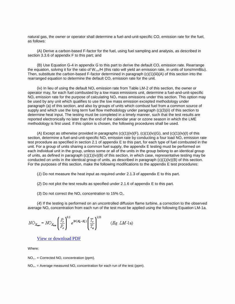
natural gas, the owner or operator shall determine a fuel-and-unit-specific CO2 emission rate for the fuel, as follows:
(A) Derive a carbon-based F-factor for the fuel, using fuel sampling and analysis, as described in section 3.3.6 of appendix F to this part; and
(B) Use Equation G-4 in appendix G to this part to derive the default CO2 emission rate. Rearrange the equation, solving it for the ratio of WCO2/H (this ratio will yield an emission rate, in units of tons/mmBtu). Then, substitute the carbon-based F-factor determined in paragraph (c)(1)(iii)(A) of this section into the rearranged equation to determine the default CO2 emission rate for the unit.
(iv) In lieu of using the default NOX emission rate from Table LM-2 of this section, the owner or operator may, for each fuel combusted by a low mass emissions unit, determine a fuel-and-unit-specific NOX emission rate for the purpose of calculating NOX mass emissions under this section. This option may be used by any unit which qualifies to use the low mass emission excepted methodology under paragraph (a) of this section, and also by groups of units which combust fuel from a common source of supply and which use the long term fuel flow methodology under paragraph (c)(3)(ii) of this section to determine heat input. The testing must be completed in a timely manner, such that the test results are reported electronically no later than the end of the calendar year or ozone season in which the LME methodology is first used. If this option is chosen, the following procedures shall be used.
(A) Except as otherwise provided in paragraphs (c)(1)(iv)(F), (c)(1)(iv)(G), and (c)(1)(iv)(I) of this section, determine a fuel-and-unit-specific NOX emission rate by conducting a four load NOX emission rate test procedure as specified in section 2.1 of appendix E to this part, for each type of fuel combusted in the unit. For a group of units sharing a common fuel supply, the appendix E testing must be performed on each individual unit in the group, unless some or all of the units in the group belong to an identical group of units, as defined in paragraph (c)(1)(iv)(B) of this section, in which case, representative testing may be conducted on units in the identical group of units, as described in paragraph (c)(1)(iv)(B) of this section. For the purposes of this section, make the following modifications to the appendix E test procedures:
(1) Do not measure the heat input as required under 2.1.3 of appendix E to this part.
(2) Do not plot the test results as specified under 2.1.6 of appendix E to this part.
(3) Do not correct the NOX concentration to 15% O2.
(4) If the testing is performed on an uncontrolled diffusion flame turbine, a correction to the observed average NOX concentration from each run of the test must be applied using the following Equation LM-1a.
View or download PDF
Where:
NOXcorr = Corrected NOX concentration (ppm).
NOXobs = Average measured NOX concentration for each run of the test (ppm).

Pr = Average annual atmospheric pressure (or average ozone season atmospheric pressure for a Subpart H unit that reports data only during the ozone season) at the nearest weather station (e.g., a standardized NOAA weather station located at the airport) for the year (or ozone season) prior to the year of the test (mm Hg).
Po = Observed atmospheric pressure during the test run (mm Hg).
Hr = Average annual atmospheric humidity ratio (or average ozone season humidity ratio for a Subpart H unit that reports data only during the ozone season) at the nearest weather station, for the year (or ozone season) prior to the year of the test (g H2O/g air).
Ho = Observed humidity ratio during the test run (g H2O/g air).
Tr = Average annual atmospheric temperature (or average ozone season atmospheric temperature for a Subpart H unit that reports data only during the ozone season) at the nearest weather station, for the year (or ozone season) prior to the year of the test (° K).
Ta = Observed atmospheric temperature during the test run (° K).
(B) Representative appendix E testing may be done on low mass emission units in a group of identical units. All of the units in a group of identical units must combust the same fuel type but do not have to share a common fuel supply.
(1) To be considered identical, all low mass emission units must be of the same size (based on maximum rated hourly heat input), manufacturer and model, and must have the same history of modifications (e.g., have the same controls installed, the same types of burners and have undergone major overhauls at the same frequency (based on hours of operation)). Also, under similar operating conditions, the stack or turbine outlet temperature of each unit must be within ±50 degrees Fahrenheit of the average stack or turbine outlet temperature for all of the units.
(2) If all of the low mass emission units in the group qualify as identical, then representative testing of the units in the group may be performed according to Table LM-4 of this section.
(3) [Reserved]
(4) If the acceptance criteria in paragraph (c)(1)(iv)(B)(1) of this section are not met then the group of low mass emission units is not considered an identical group of units and individual appendix E testing of each unit is required.
(5) Fuel and unit specific NOX emission rates determined according to paragraphs (c)(1)(iv)(F) and (c)(1)(iv)(G) of this section may be used in lieu of appendix E testing for one or more low mass emission units in a group of identical units.
(C) Based on the results of the part 75 appendix E testing, determine the fuel-and-unit-specific NOX emission rate as follows:
(1) Except for LME units that use selective catalytic reduction (SCR) or selective non-catalytic reduction (SNCR) to control NOX emissions, the highest three-run average NOX emission rate obtained at any load in the appendix E test for a particular type of fuel shall be the fuel-and-unit-specific NOX emission rate, for that type of fuel.
(2) [Reserved]
(3) For a group of identical low mass emissions units (except for units that use SCR or SNCR to control NOX emissions), the fuel-and-unit-specific NOX emission rate for all units in the group, for a particular type of fuel, shall be the highest three-run average NOX emission rate obtained at any tested load from any unit tested in the group, for that type of fuel.

(4) Except as provided in paragraphs (c)(1)(iv)(C)(7) and (c)(1)(iv)(C)(8) of this section, for an individual low mass emissions unit which uses SCR or SNCR to control NOX emissions, the fuel-and-unit-specific NOX emission rate for each type of fuel combusted in the unit shall be the higher of:
(i) The highest three-run average emission rate from any load of the appendix E test for that type of fuel; or
(ii) 0.15 lb/mmBtu.
(5) [Reserved]
(6) Except as provided in paragraphs (c)(1)(iv)(C)(7) and (c)(1)(iv)(C)(8) of this section, for a group of identical low mass emissions units that are all equipped with SCR or SNCR to control NOX emissions, the fuel-and-unit-specific NOX emission rate for each unit in the group of units, for a particular type of fuel, shall be the higher of:
(i) The highest three-run average NOX emission rate at any load from all appendix E tests of all tested units in the group, for that type of fuel; or
(ii) 0.15 lb/mmBtu.
(7) Notwithstanding the requirements of paragraphs (c)(1)(iv)(C)(4) and (c)(1)(iv)(C)(6) of this section, for a unit (or group of identical units) equipped with SCR (or SNCR) and water (or steam) injection to control NOX emissions:
(i) If the appendix E testing is performed when the water (or steam) injection is in use and either upstream of the SCR or SNCR or during a time period when the SCR or SNCR is out of service; then
(ii) The highest three-run average emission rate from the appendix E testing may be used as the fuel-and-unit-specific NOX emission rate for the unit (or, if applicable, for each unit in the group), for each unit operating hour in which the water-to-fuel ratio is within the acceptable range established during the appendix E testing.
(8) Notwithstanding the requirements of paragraphs (c)(1)(iv)(C)(4) and (c)(1)(iv)(C)(6) of this section, for a unit (or group of identical units) equipped with SCR (or SNCR) and uses dry low-NOX technology to control NOX emissions:
(i) If the appendix E testing is performed during a time period when the dry low-NOX controls are in use, but the SCR or SNCR is out of service; then
(ii) The highest three-run average emission rate from the appendix E testing may be used as the fuel-and-unit-specific NOX emission rate for the unit (or, if applicable, for each unit in the group), for each unit operating hour in which the parametric data described in paragraph (c)(1)(iv)(H)(2) of this section demonstrate that the dry low-NOX controls are operating in the premixed or low-NOX mode.
(9) For an individual combustion turbine (or a group of identical turbines) that operate principally at base load (or at a set point temperature), but are capable of operating at a higher peak load (or higher internal operating temperature), the fuel-and-unit-specific NOX emission rate for the unit (or for each unit in the group) shall be as follows:
(i) If the testing is done only at base load, use the three-run average NOX emission rate for base load operating hours and 1.15 times that emission rate for peak load operating hours; or

(ii) If the testing is done at both base load and peak load, use the three-run average NOX emission rate from the base load testing for base load operating hours and the three-run average NOX emission rate from the peak load testing for peak load operating hours.
(D) For each low mass emissions unit, or group of identical units for which the provisions of paragraph (c)(1)(iv) of this section are used to account for NOX emission rate, the owner or operator shall determine a new fuel-and-unit-specific NOX emission rate every five years (20 calendar quarters), unless changes in the fuel supply, physical changes to the unit, changes in the manner of unit operation, or changes to the emission controls occur which may cause a significant increase in the unit's actual NOX emission rate. If such changes occur, the fuel-and-unit-specific NOX emission rate(s) shall be re-determined according to paragraph (c)(1)(iv) of this section. Testing shall be done at the number of loads specified in paragraph (c)(1)(iv)(A) or (c)(1)(iv)(I) of this section, as applicable. If a low mass emissions unit belongs to a group of identical units and it is required to retest to determine a new fuel-and-unit-specific NOX emission rate because of changes in the fuel supply, physical changes to the unit, changes in the manner of unit operation or changes to the emission controls occur which may cause a significant increase in the unit's actual NOX emission rate, any other unit in that group of identical units is not required to re-determine the fuel-and-unit-specific NOX emission rate unless such unit also undergoes changes in the fuel supply, physical changes to the unit, changes in the manner of unit operation or changes to the emission controls occur which may cause a significant increase in the unit's actual NOX emission rates.
(E) Each low mass emissions unit or each low mass emissions unit in a group of identical units for which a fuel-and-unit-specific NOX emission rate(s) are determined shall meet the quality assurance and quality control provisions of paragraph (e) of this section.
(F) Low mass emission units may use the results of appendix E testing, if such test results are available from a test conducted no more than five years prior to the time of initial certification, to determine the appropriate fuel-and-unit-specific NOX emission rate(s). However, fuel-and-unit-specific NOX emission rates from historical testing may not be used longer than five years after the appendix E testing was conducted.
(G) Low mass emissions units for which at least 3 years of quality-assured NOX emission rate data from a NOX-diluent CEMS that meets the quality assurance requirements of either: this part, or appendix F to part 60 of this chapter, or a comparable State CEM program, and corresponding fuel usage data are available may determine fuel-and-unit-specific NOX emission rates from the actual data using the following procedure. Separate the actual NOX emission rate data into groups, according to the type of fuel combusted. Discard data from periods when multiple fuels were combusted. Each fuel-specific data set must contain at least 168 hours of data and must represent all normal operating ranges of the unit when combusting the fuel. Sort the data in each fuel-specific data set in ascending order according to NOX emission rate. Determine the 95th percentile NOX emission rate for each data set as defined in §72.2 of this chapter. Use the 95th percentile value for each data set as the fuel-and-unit-specific NOX emission rate, except that for a unit that uses SCR or SNCR for NOX emission control, if the 95th percentile value is less than 0.15 lb/mmBtu, a value of 0.15 lb/mmBtu shall be used as the fuel-and-unit-specific NOX emission rate.
(H) For low mass emission units with add-on NOX emission controls, and for units that use dry low-NOX technology, the owner or operator shall, during every hour of unit operation during the test period, monitor and record parameters, as required under paragraph (e)(5) of this section, which indicate that the NOX emission controls are operating properly. After the test period, these same parameters shall be monitored and recorded and kept for all operating hours in order to determine whether the NOX controls are operating properly and to allow the determination of the correct NOX emission rate as required under paragraph (c)(1)(iv) of this section.
(1) For low mass emission units with steam or water injection, the steam-to-fuel or water-to-fuel ratio used during the testing must be documented. The water-to-fuel or steam-to-fuel ratio must be maintained

during unit operations for a unit to use the fuel and unit specific NOX emission rate determined during the test. Owners or operators must include in the monitoring plan the acceptable range of the water-to-fuel or steam-to-fuel ratio, which will be used to indicate hourly, proper operation of the NOX controls for each unit. The water-to-fuel or steam-to-fuel ratio shall be monitored and recorded during each hour of unit operation. If the water-to-fuel or steam-to-fuel ratio is not within the acceptable range in a given hour the fuel and unit specific NOX emission rate may not be used for that hour, and the appropriate default NOX emission rate from Table LM-2 shall be reported instead.
(2) For a low mass emissions unit that uses dry low-NOX premix technology to control NOX emissions, proper operation of the emission controls means that the unit is in the low-NOX or premixed combustion mode, and fired with natural gas. Evidence of operation in the low-NOX or premixed mode shall be provided by monitoring the appropriate turbine operating parameters. These parameters may include percentage of full load, turbine exhaust temperature, combustion reference temperature, compressor discharge pressure, fuel and air valve positions, dynamic pressure pulsations, internal guide vane (IGV) position, and flame detection or flame scanner condition. The acceptable values and ranges for all parameters monitored shall be specified in the monitoring plan for the unit, and the parameters shall be monitored during each subsequent operating hour. If one or more of these parameters is not within the acceptable range or at an acceptable value in a given operating hour, the fuel-and-unit-specific NOX emission rate may not be used for that hour, and the appropriate default NOX emission rate from Table LM-2 shall be reported instead. When the unit is fired with oil the appropriate default value from Table LM-2 shall be reported.
(3) For low mass emission units with other types of add-on NOX controls, appropriate parameters and the acceptable range of the parameters which indicate hourly proper operation of the NOX controls must be specified in the monitoring plan. These parameters shall be monitored during each subsequent operating hour. If any of these parameters are not within the acceptable range in a given operating hour, the fuel and unit specific NOX emission rates may not be used in that hour, and the appropriate default NOX emission rate from Table LM-2 shall be reported instead.
(I) Notwithstanding the requirements in paragraph (c)(1)(iv)(A) of this section, the appendix E testing to determine (or re-determine) the fuel-specific, unit-specific NOX emission rate for a unit (or for each unit in a group of identical units) may be performed at fewer than four loads, under the following circumstances:
(1) Testing may be done at one load level if the data analysis described in paragraph (c)(1)(iv)(J) of this section is performed and the results show that the unit has operated (or all units in the group of identical units have operated) at a single load level for at least 85.0 percent of all operating hours in the previous three years (12 calendar quarters) prior to the calendar quarter of the appendix E testing. For combustion turbines that are operated to produce approximately constant output (in MW) but which use internal operating and exhaust temperatures and not the actual output in MW to control the operation of the turbine, the internal operating temperature set point may be used as a surrogate for load in demonstrating that the unit qualifies for single-load testing. If the data analysis shows that the unit does not qualify for single-load testing, testing may be done at two (or three) load levels if the unit has operated (or if all units in the group of identical units have operated) cumulatively at two (or three) load levels for at least 85.0 percent of all operating hours in the previous three years; or
(2) If a multiple-load appendix E test was initially performed for a unit (or group of identical units) to determine the fuel-and-unit specific NOX emission rate, then the periodic retests required under paragraph (c)(1)(iv)(D) of this section may be single-load tests, performed at the load level for which the highest average NOX emission rate was obtained in the initial test.
(3) The initial appendix E testing may be performed at a single load, between 75 and 100 percent of the maximum sustainable load defined in the monitoring plan for the unit, if the average annual capacity factor of the LME unit, when calculated according to the definition of “capacity factor” in §72.2 of this chapter, is 2.5 percent or less for the three calendar years immediately preceding the year of the testing,

and that the annual capacity factor does not exceed 4.0 percent in any of those three years. Similarly, for a LME unit that reports emissions data on an ozone season-only basis, the initial appendix E testing may be performed at a single load between 75 and 100 percent of the maximum sustainable load if the 2.5 and 4.0 percent capacity factor requirements are met for the three ozone seasons immediately preceding the date of the emission testing (see §75.74(c)(11)). For a group of identical LME units, any unit(s) in the group that meet the 2.5 and 4.0 percent capacity factor requirements may perform the initial appendix E testing at a single load between 75 and 100 percent of the maximum sustainable load.
(4) The retest of any LME unit may be performed at a single load between 75 and 100 percent of the maximum sustainable load if, for the three calendar years immediately preceding the year of the retest (or, if applicable, the three ozone seasons immediately preceding the date of the retest), the applicable capacity factor requirements described in paragraph (c)(1)(iv)(I)(3) of this section are met.
(5) Alternatively, for combustion turbines, the single-load testing described in paragraphs (c)(1)(iv)(I)(3) and (c)(1)(iv)(I)(4) of this section may be performed at the highest attainable load level corresponding to the season of the year in which the testing is conducted.
(6) In all cases where the alternative single-load testing option described in paragraphs (c)(1)(iv)(I)(3) through (c)(1)(iv)(I)(5) of this section is used, the owner or operator shall keep records documenting that the required capacity factor requirements were met.
(J) To determine whether a unit qualifies for testing at fewer than four loads under paragraph (c)(1)(iv)(I) of this section, follow the procedures in paragraph (c)(1)(iv)(J)(1) or (c)(1)(iv)(J)(2) of this section, as applicable.
(1) Determine the range of operation of the unit, according to section 6.5.2.1 of appendix A to this part. Divide the range of operation into four equal load bands. For example, if the range of operation extends from 20 MW to 100 MW, the four equal load bands would be: band #1: from 20 MW to 40 MW; band #2: from 41 MW to 60 MW; band #3: from 61 MW to 80 MW; and band #4: from 81 to 100 MW. Then, perform a historical load analysis for all unit operating hours in the 12 calendar quarters preceding the quarter of the test. Alternatively, for sources that report emissions data only during the ozone season, the historical load analysis may be based on unit operation in the previous three ozone seasons, rather than unit operation in the previous 12 calendar quarters. Determine the percentage of the data that fall into each load band. For a unit that is not part of a group of identical units, if 85.0% or more of the data fall into one load band, single-load testing may be performed at any point within that load band. For a group of identical units, if each unit in the group meets the 85.0% criterion, then representative single-load testing within the load band may be performed. If the 85.0% criterion cannot be met to qualify for single-load testing but this criterion can be met cumulatively for two (or three) load levels, then testing may be performed at two (or three) loads instead of four.
(2) For a combustion turbine that uses exhaust temperature and not the actual output in megawatts to control the operation of the turbine (or for a group of identical units of this type), the owner or operator must document that the unit (or each unit in the group) has operated within ±10% of the set point temperature for 85.0% of the operating hours in the previous 12 calendar quarters to qualify for single-load testing. Alternatively, for sources that report emissions data only during the ozone season, the historical set point temperature analysis may be based on unit operation in the previous three ozone seasons, rather than unit operation in the previous 12 calendar quarters. When the set point temperature is used rather than unit load to justify single-load testing, the designated representative shall certify in the monitoring plan for the unit that this is the normal manner of unit operation and shall document the setpoint temperature.
(2) Records of operating time, fuel usage, unit output and NOX emission control operating status. The owner or operator shall keep the following records on-site, for three years, in a form suitable for

inspection, except that for unmanned facilities, the records may be kept at a central location, rather than on-site:
(i) For each low mass emissions unit, the owner or operator shall keep hourly records which indicate whether or not the unit operated during each clock hour of each calendar year. The owner or operator may report partial operating hours or may assume that for each hour the unit operated the operating time is a whole hour. Units using partial operating hours and the maximum rated hourly heat input to calculate heat input for each hour must report partial operating hours.
(ii) For each low mass emissions unit, the owner or operator shall keep hourly records indicating the type(s) of fuel(s) combusted in the unit during each hour of unit operation.
(iii) For each low mass emissions unit using the long term fuel flow methodology under paragraph (c)(3)(ii) of this section to determine hourly heat input, the owner or operator shall keep hourly records of unit load (in megawatts or thousands of pounds of steam per hour), for the purpose of apportioning heat input to the individual unit operating hours.
(iv) For each low mass emissions unit with add-on NOX emission controls of any kind and each unit that uses dry low-NOX technology, the owner or operator shall keep hourly records of the hourly value of the parameter(s) specified in (c)(1)(iv)(H) of this section used to indicate proper operation of the unit's NOX controls.
(3) Heat input. Hourly, quarterly and annual heat input for a low mass emissions unit shall be determined using either the maximum rated hourly heat input method under paragraph (c)(3)(i) of this section or the long term fuel flow method under paragraph (c)(3)(ii) of this section.
(i) Maximum rated hourly heat input method. (A) For the purposes of the mass emission calculation methodology of paragraph (c)(3) of this section, HIhr, the hourly heat input (mmBtu) to a low mass emissions unit shall be deemed to equal the maximum rated hourly heat input, as defined in §72.2 of this chapter, multiplied by the operating time of the unit for each hour. The owner or operator may choose to record and report partial operating hours or may assume that a unit operated for a whole hour for each hour the unit operated. However, the owner or operator of a unit may petition the Administrator under §75.66 for a lower value for maximum rated hourly heat input than that defined in §72.2 of this chapter. The Administrator may approve such lower value if the owner or operator demonstrates that either the maximum hourly heat input specified by the manufacturer or the highest observed hourly heat input, or both, are not representative, and such a lower value is representative, of the unit's current capabilities because modifications have been made to the unit, limiting its capacity permanently.
(B) The quarterly heat input, HIqtr, in mmBtu, shall be determined using Equation LM-1:
View or download PDF
Where:
n = Number of unit operating hours in the quarter.
HIhr = Hourly heat input under paragraph (c)(3)(i)(A) of this section (mmBtu).
(C) The year-to-date cumulative heat input (mmBtu) shall be the sum of the quarterly heat input values for all of the calendar quarters in the year to date.

(D) For a unit subject to the provisions of subpart H of this part, which is not required to report emission data on a year-round basis and elects to report only during the ozone season, the quarterly heat input for the second calendar quarter of the year shall, for compliance purposes, include only the heat input for the months of May and June, and the cumulative ozone season heat input shall be the sum of the heat input values for May, June and the third calendar quarter of the year.
(ii) Long term fuel flow heat input method. The owner or operator may, for the purpose of demonstrating that a low mass emissions unit or group of low mass emission units sharing a common fuel supply meets the requirements of this section, use records of long-term fuel flow, to calculate hourly heat input to a low mass emissions unit.
(A) This option may be used for a group of low mass emission units only if:
(1) The low mass emission units combust fuel from a common source of supply; and
(2) Records are kept of the total amount of fuel combusted by the group of low mass emission units and the hourly output (in megawatts or pounds of steam) from each unit in the group; and
(3) All of the units in the group are low mass emission units.
(B) For each fuel used during the quarter, the volume in standard cubic feet (for gas) or gallons (for oil) may be determined using any of the following methods;
(1) Fuel billing records (for low mass emission units, or groups of low mass emission units, which purchase fuel from non-affiliated sources);
(2) American Petroleum Institute (API) Manual of Petroleum Measurement Standards, Chapter 3-Tank Gauging, Section 1A, Standard Practice for the Manual Gauging of Petroleum and Petroleum Products, Second Edition, August 2005; Section 1B-Standard Practice for Level Measurement of Liquid Hydrocarbons in Stationary Tanks by Automatic Tank Gauging, Second Edition June 2001; Section 2-Standard Practice for Gauging Petroleum and Petroleum Products in Tank Cars, First Edition, August 1995 (Reaffirmed March 2006); Section 3-Standard Practice for Level Measurement of Liquid Hydrocarbons in Stationary Pressurized Storage Tanks by Automatic Tank Gauging, First Edition June 1996 (Reaffirmed, March 2001); Section 4-Standard Practice for Level Measurement of Liquid Hydrocarbons on Marine Vessels by Automatic Tank Gauging, First Edition April 1995 (Reaffirmed, September 2000); and Section 5-Standard Practice for Level Measurement of Light Hydrocarbon Liquids Onboard Marine Vessels by Automatic Tank Gauging, First Edition March 1997 (Reaffirmed, March 2003); for §75.19; Shop Testing of Automatic Liquid Level Gages, Bulletin 2509 B, December 1961 (Reaffirmed August 1987, October 1992) (all incorporated by reference under §75.6 of this part); or
(3) A fuel flow meter certified and maintained according to appendix D to this part.
(C) Except as provided in paragraph (c)(3)(ii)(C)(3) of this section, for each fuel combusted during a quarter, the gross calorific value of the fuel shall be determined by either:
(1) Using the applicable procedures for gas and oil analysis in sections 2.2 and 2.3 of appendix D to this part. If this option is chosen the highest gross calorific value recorded during the previous calendar year shall be used (or, for a new or newly-affected unit, if there are no sample results from the previous year, use the highest GCV from the samples taken in the current year); or
(2) Using the appropriate default gross calorific value listed in Table LM-5 of this section.
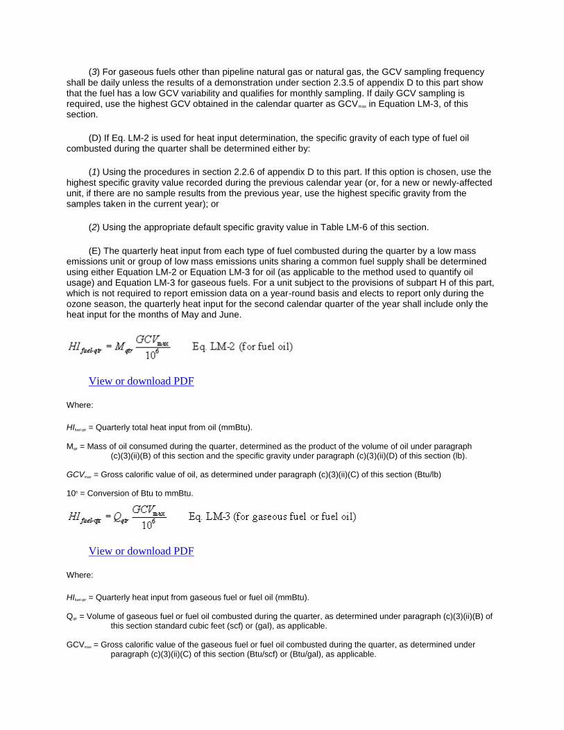
(3) For gaseous fuels other than pipeline natural gas or natural gas, the GCV sampling frequency shall be daily unless the results of a demonstration under section 2.3.5 of appendix D to this part show that the fuel has a low GCV variability and qualifies for monthly sampling. If daily GCV sampling is required, use the highest GCV obtained in the calendar quarter as GCVmax in Equation LM-3, of this section.
(D) If Eq. LM-2 is used for heat input determination, the specific gravity of each type of fuel oil combusted during the quarter shall be determined either by:
(1) Using the procedures in section 2.2.6 of appendix D to this part. If this option is chosen, use the highest specific gravity value recorded during the previous calendar year (or, for a new or newly-affected unit, if there are no sample results from the previous year, use the highest specific gravity from the samples taken in the current year); or
(2) Using the appropriate default specific gravity value in Table LM-6 of this section.
(E) The quarterly heat input from each type of fuel combusted during the quarter by a low mass emissions unit or group of low mass emissions units sharing a common fuel supply shall be determined using either Equation LM-2 or Equation LM-3 for oil (as applicable to the method used to quantify oil usage) and Equation LM-3 for gaseous fuels. For a unit subject to the provisions of subpart H of this part, which is not required to report emission data on a year-round basis and elects to report only during the ozone season, the quarterly heat input for the second calendar quarter of the year shall include only the heat input for the months of May and June.
View or download PDF
Where:
HIfuel-qtr = Quarterly total heat input from oil (mmBtu).
Mqtr = Mass of oil consumed during the quarter, determined as the product of the volume of oil under paragraph (c)(3)(ii)(B) of this section and the specific gravity under paragraph (c)(3)(ii)(D) of this section (lb).
GCVmax = Gross calorific value of oil, as determined under paragraph (c)(3)(ii)(C) of this section (Btu/lb)
106 = Conversion of Btu to mmBtu.
View or download PDF
Where:
HIfuel-qtr = Quarterly heat input from gaseous fuel or fuel oil (mmBtu).
Qqtr = Volume of gaseous fuel or fuel oil combusted during the quarter, as determined under paragraph (c)(3)(ii)(B) of this section standard cubic feet (scf) or (gal), as applicable.
GCVmax = Gross calorific value of the gaseous fuel or fuel oil combusted during the quarter, as determined under paragraph (c)(3)(ii)(C) of this section (Btu/scf) or (Btu/gal), as applicable.
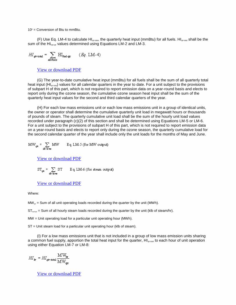
106 = Conversion of Btu to mmBtu.
(F) Use Eq. LM-4 to calculate HIqtr-total, the quarterly heat input (mmBtu) for all fuels. HIqtr-total shall be the sum of the HIfuel-qtr values determined using Equations LM-2 and LM-3.
View or download PDF
(G) The year-to-date cumulative heat input (mmBtu) for all fuels shall be the sum of all quarterly total heat input (HIqtr-total) values for all calendar quarters in the year to date. For a unit subject to the provisions of subpart H of this part, which is not required to report emission data on a year-round basis and elects to report only during the ozone season, the cumulative ozone season heat input shall be the sum of the quarterly heat input values for the second and third calendar quarters of the year.
(H) For each low mass emissions unit or each low mass emissions unit in a group of identical units, the owner or operator shall determine the cumulative quarterly unit load in megawatt hours or thousands of pounds of steam. The quarterly cumulative unit load shall be the sum of the hourly unit load values recorded under paragraph (c)(2) of this section and shall be determined using Equations LM-5 or LM-6. For a unit subject to the provisions of subpart H of this part, which is not required to report emission data on a year-round basis and elects to report only during the ozone season, the quarterly cumulative load for the second calendar quarter of the year shall include only the unit loads for the months of May and June.
View or download PDF
View or download PDF
Where:
MWqtr = Sum of all unit operating loads recorded during the quarter by the unit (MWh).
STfuel-qtr = Sum of all hourly steam loads recorded during the quarter by the unit (klb of steam/hr).
MW = Unit operating load for a particular unit operating hour (MWh).
ST = Unit steam load for a particular unit operating hour (klb of steam).
(I) For a low mass emissions unit that is not included in a group of low mass emission units sharing a common fuel supply, apportion the total heat input for the quarter, HIqtr-total to each hour of unit operation using either Equation LM-7 or LM-8:
View or download PDF

(Eq LM-7 for MW output)
View or download PDF
(Eq LM-8 for steam output)
Where:
HIhr = Hourly heat input to the unit (mmBtu).
MWhr = Hourly operating load for the unit (MW).
SThr = Hourly steam load for the unit (klb of steam/hr).
(J) For each low mass emissions unit that is included in a group of units sharing a common fuel supply, apportion the total heat input for the quarter, HIqtr-total to each hour of operation using either Equation LM-7a or LM-8a:
View or download PDF
(Eq LM-7a for MW output)
View or download PDF
(Eq LM-8a for steam output)
Where:
HIhr = Hourly heat input to the individual unit (mmBtu).
MWhr = Hourly operating load for the individual unit (MW).
SThr = Hourly steam load for the individual unit (klb of steam/hr).
ΣMWqtr = Sum of the quarterly operating
all-units loads (from Eq. LM-5) for all units in the group (MW).
ΣSTqtr = Sum of the quarterly steam

all-units loads (from Eq. LM-6) for all units in the group (klb of steam/hr)
(4) Calculation of SO2, NOX and CO2 mass emissions. The owner or operator shall, for the purpose of demonstrating that a low mass emissions unit meets the requirements of this section, calculate SO2, NOX and CO2 mass emissions in accordance with the following.
(i) SO2 mass emissions. (A) The hourly SO2 mass emissions (lbs) for a low mass emissions unit (Acid Rain Program units, only) shall be determined using Equation LM-9 and the appropriate fuel-based SO2 emission factor for the fuels combusted in that hour. If more than one fuel is combusted in the hour, use the highest emission factor for all of the fuels combusted in the hour. If records are missing as to which fuel was combusted in the hour, use the highest emission factor for all of the fuels capable of being combusted in the unit.
WSO2 = EFSO2 × HIhr (Eq. LM-9)
Where:
WSO2 = Hourly SO2 mass emissions (lbs.)
EFSO2 = Either the SO2 emission factor from Table LM-1 of this section or the fuel-and-unit-specific SO2 emission rate from paragraph (c)(1)(i) of this section (lb/mmBtu).
HIhr = Either the maximum rated hourly heat input under paragraph (c)(3)(i)(A) of this section or the hourly heat input under paragraph (c)(3)(ii) of this section (mmBtu).
(B) The quarterly SO2 mass emissions (tons) for the low mass emissions unit shall be the sum of all the hourly SO2 mass emissions in the quarter, as determined under paragraph (c)(4)(i)(A) of this section, divided by 2000 lb/ton.
(C) The year-to-date cumulative SO2 mass emissions (tons) for the low mass emissions unit shall be the sum of the quarterly SO2 mass emissions, as determined under paragraph (c)(4)(i)(B) of this section, for all of the calendar quarters in the year to date.
(ii)(A) The hourly NOX mass emissions for the low mass emissions unit (lbs) shall be determined using Equation LM-10. If more than one fuel is combusted in the hour, use the highest emission rate for all of the fuels combusted in the hour. If records are missing as to which fuel was combusted in the hour, use the highest emission factor for all of the fuels capable of being combusted in the unit. For low mass emission units with NOX emission controls of any kind and for which a fuel-and-unit-specific NOX emission rate is determined under paragraph (c)(1)(iv) of this section, for any hour in which the parameters under paragraph (c)(1)(iv)(A) of this section do not show that the NOX emission controls are operating properly, use the NOX emission rate from Table LM-2 of this section for the fuel combusted during the hour with the highest NOX emission rate.
WNOX = EFNOX × HIhr (Eq. LM-10)
Where:
WNOX = Hourly NOX mass emissions (lbs).
EFNOX = Either the NOX emission factor from Table LM-2 of this section or the fuel- and unit-specific NOX emission rate determined under paragraph (c)(1)(iv) of this section (lb/mmBtu).
HIhr = Either the maximum rated hourly heat input from paragraph (c)(3)(i)(A) of this section or the hourly heat input as determined under paragraph (c)(3)(ii) of this section (mmBtu).

(B) The quarterly NOX mass emissions (tons) for the low mass emissions unit shall be the sum of all of the hourly NOX mass emissions in the quarter, as determined under paragraph (c)(4)(ii)(A) of this section, divided by 2000 lb/ton.
(C) The year-to-date cumulative NOX mass emissions (tons) for the low mass emissions unit shall be the sum of the quarterly NOX mass emissions, as determined under paragraph (c)(4)(ii)(B) of this section, for all of the calendar quarters in the year to date. For a unit subject to the provisions of subpart H of this part, which is not required to report emission data on a year-round basis and elects to report only during the ozone season, the ozone season NOX mass emissions for the unit shall be the sum of the quarterly NOX mass emissions, as determined under paragraph (c)(4)(ii)(B) of this section, for the second and third calendar quarters of the year, and the second quarter report shall include emissions data only for May and June.
(D) The quarterly and cumulative NOX emission rate in lb/mmBtu (if required by the applicable program(s)) shall be determined as follows. Calculate the quarterly NOX emission rate by taking the arithmetic average of all of the hourly EFNOX values. Calculate the cumulative (year-to-date) NOX emission rate by taking the arithmetic average of the quarterly NOX emission rates.
(iii) CO2 Mass Emissions. (A) The hourly CO2 mass emissions (tons) for the affected low mass emissions unit (Acid Rain Program units, only) shall be determined using Equation LM-11 and the appropriate fuel-based CO2 emission factor from Table LM-3 of this section for the fuel being combusted in that hour. If more than one fuel is combusted in the hour, use the highest emission factor for all of the fuels combusted in the hour. If records are missing as to which fuel was combusted in the hour, use the highest emission factor for all of the fuels capable of being combusted in the unit.
WCO2 = EFCO2 × HIhr (Eq. LM-11)
Where:
WCO2 = Hourly CO2 mass emissions (tons).
EFCO2 = Either the fuel-based CO2 emission factor from Table LM-3 of this section or the fuel-and-unit-specific CO2 emission rate from paragraph (c)(1)(iii) of this section (tons/mmBtu).
HIhr = Either the maximum rated hourly heat input from paragraph (c)(3)(i)(A) of this section or the hourly heat input as determined under paragraph (c)(3)(ii) of this section (mmBtu).
(B) The quarterly CO2 mass emissions (tons) for the low mass emissions unit shall be the sum of all of the hourly CO2 mass emissions in the quarter, as determined under paragraph (c)(4)(iii)(A)of this section.
(C) The year-to-date cumulative CO2 mass emissions (tons) for the low mass emissions unit shall be the sum of all of the quarterly CO2 mass emissions, as determined under paragraph (c)(4)(iii)(B) of this section, for all of the calendar quarters in the year to date.
(d) Each unit that qualifies under this section to use the low mass emissions methodology must follow the recordkeeping and reporting requirements pertaining to low mass emissions units in subparts F and G of this part.
(e) The quality control and quality assurance requirements in §75.21 are not applicable to a low mass emissions unit for which the low mass emissions excepted methodology under paragraph (c) of this section is being used in lieu of a continuous emission monitoring system or an excepted monitoring system under appendix D or E to this part, except for fuel flowmeters used to meet the provisions in paragraph (c)(3)(ii) of this section. However, the owner or operator of a low mass emissions unit shall implement the following quality assurance and quality control provisions:

(1) For low mass emission units or groups of units which use the long term fuel flow methodology under paragraph (c)(3)(ii) of this section and which use fuel billing records to determine fuel usage, the owner or operator shall keep, at the facility, for three years, the records of the fuel billing statements used for long term fuel flow determinations.
(2) For low mass emissions units or groups of units which use the long term fuel flow methodology under paragraph (c)(3)(ii) of this section and which use one of the methods specified in paragraph (c)(3)(ii)(B)(2) of this section to determine fuel usage, the owner or operator shall keep, at the facility, a copy of the standard used and shall keep records, for three years, of all measurements obtained for each quarter using the methodology.
(3) For low mass emission units or groups of units which use the long term fuel flow methodology under paragraph (c)(3)(ii) of this section and which use a certified fuel flow meter to determine fuel usage, the owner or operator shall comply with the quality control quality assurance requirements for a fuel flow meter under section 2.1.6 of appendix D of this part.
(4) For each low mass emissions unit for which fuel-and-unit-specific NOX emission rates are determined in accordance with paragraph (c)(1)(iv) of this section, the owner or operator shall keep, at the facility, records which document the results of all NOX emission rate tests conducted according to appendix E to this part. If CEMS data are used to determine the fuel-and-unit-specific NOX emission rates under paragraph (c)(1)(iv)(G) of this section, the owner or operator shall keep, at the facility, records of the CEMS data and the data analysis performed to determine a fuel-and-unit-specific NOX emission rate. The appendix E test records and historical CEMS data records shall be kept until the fuel and unit specific NOX emission rates are re-determined.
(5) For each low mass emissions unit for which fuel-and-unit-specific NOX emission rates are determined in accordance with paragraph (c)(1)(iv) of this section and which has add-on NOX emission controls of any kind or uses dry low-NOX technology, the owner or operator shall develop and keep on-site a quality assurance plan which explains the procedures used to document proper operation of the NOX emission controls. The plan shall include the parameters monitored (e.g., water-to-fuel ratio) and the acceptable ranges for each parameter used to determine proper operation of the unit's NOX controls.
(6) For unmanned facilities, the records required by paragraphs (e)(1), (e)(2) and (e)(4) of this section may be kept at a central location, rather than at the facility.
TABLE LM-1—SO2 EMISSION FACTORS (LB/MMBTU) FOR VARIOUS FUEL TYPES
Fuel type SO2 emission factors
Pipeline Natural Gas 0.0006 lb/mmBtu.
Other Natural Gas 0.06 lb/mmBtu.
Residual Oil 2.1 lb/mmBtu.
Diesel Fuel 0.5 lb/mmBtu.
TABLE LM-2—NOX EMISSION RATES (LB/MMBTU) FOR VARIOUS BOILER/FUEL TYPES
Unit type Fuel type NOX emission rate
Turbine Gas 0.7
Turbine Oil 1.2
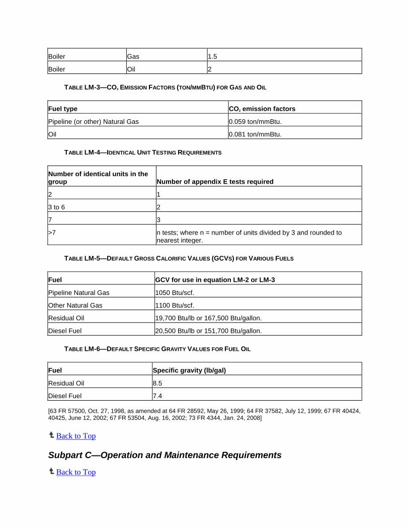
Boiler Gas 1.5
Boiler Oil 2
TABLE LM-3—CO2 EMISSION FACTORS (TON/MMBTU) FOR GAS AND OIL
Fuel type CO2 emission factors
Pipeline (or other) Natural Gas 0.059 ton/mmBtu.
Oil 0.081 ton/mmBtu.
TABLE LM-4—IDENTICAL UNIT TESTING REQUIREMENTS
Number of identical units in the group Number of appendix E tests required
2 1
3 to 6 2
7 3
>7 n tests; where n = number of units divided by 3 and rounded to nearest integer.
TABLE LM-5—DEFAULT GROSS CALORIFIC VALUES (GCVS) FOR VARIOUS FUELS
Fuel GCV for use in equation LM-2 or LM-3
Pipeline Natural Gas 1050 Btu/scf.
Other Natural Gas 1100 Btu/scf.
Residual Oil 19,700 Btu/lb or 167,500 Btu/gallon.
Diesel Fuel 20,500 Btu/lb or 151,700 Btu/gallon.
TABLE LM-6—DEFAULT SPECIFIC GRAVITY VALUES FOR FUEL OIL
Fuel Specific gravity (lb/gal)
Residual Oil 8.5
Diesel Fuel 7.4
[63 FR 57500, Oct. 27, 1998, as amended at 64 FR 28592, May 26, 1999; 64 FR 37582, July 12, 1999; 67 FR 40424, 40425, June 12, 2002; 67 FR 53504, Aug. 16, 2002; 73 FR 4344, Jan. 24, 2008]
Back to Top
Subpart C—Operation and Maintenance Requirements
Back to Top

§75.20 Initial certification and recertification procedures.
(a) Initial certification approval process. The owner or operator shall ensure that each continuous emission or opacity monitoring system required by this part meets the initial certification requirements of this section and shall ensure that all applicable initial certification tests under paragraph (c) of this section are completed by the deadlines specified in §75.4 and prior to use in the Acid Rain Program. In addition, whenever the owner or operator installs a continuous emission or opacity monitoring system in order to meet the requirements of §§75.11 through 75.18, where no continuous emission or opacity monitoring system was previously installed, initial certification is required.
(1) Notification of initial certification test dates. The owner or operator or designated representative shall submit a written notice of the dates of initial certification testing at the unit as specified in §75.61(a)(1).
(2) Certification application. The owner or operator shall apply for certification of each continuous emission or opacity monitoring system used under the Acid Rain Program. The owner or operator shall submit the certification application in accordance with §75.60 and each complete certification application shall include the information specified in §75.63.
(3) Provisional approval of certification (or recertification) applications. Upon the successful completion of the required certification (or recertification) procedures of this section, each continuous emission or opacity monitoring system shall be deemed provisionally certified (or recertified) for use under the Acid Rain Program for a period not to exceed 120 days following receipt by the Administrator of the complete certification (or recertification) application under paragraph (a)(4) of this section. Notwithstanding this paragraph, no continuous emission or opacity monitor systems for a combustion source seeking to enter the Opt-in Program in accordance with part 74 of this chapter shall be deemed provisionally certified (or recertified) for use under the Acid Rain Program. Data measured and recorded by a provisionally certified (or recertified) continuous emission or opacity monitoring system , operated in accordance with the requirements of appendix B to this part, will be considered valid quality-assured data (retroactive to the date and time of provisional certification or recertification), provided that the Administrator does not invalidate the provisional certification (or recertification) by issuing a notice of disapproval within 120 days of receipt by the Administrator of the complete certification (or recertification) application. Note that when the conditional data validation procedures of paragraph (b)(3) of this section are used for the initial certification (or recertification) of a continuous emissions monitoring system, the date and time of provisional certification (or recertification) of the CEMS may be earlier than the date and time of completion of the required certification (or recertification) tests.
(4) Certification (or recertification) application formal approval process. The Administrator will issue a notice of approval or disapproval of the certification (or recertification) application to the owner or operator within 120 days of receipt of the complete certification (or recertification) application. In the event the Administrator does not issue such a notice within 120 days of receipt, each continuous emission or opacity monitoring system which meets the performance requirements of this part and is included in the certification (or recertification) application will be deemed certified (or recertified) for use under the Acid Rain Program.
(i) Approval notice. If the certification (or recertification) application is complete and shows that each continuous emission or opacity monitoring system meets the performance requirements of this part, then the Administrator will issue a notice of approval of the certification (or recertification) application within 120 days of receipt.
(ii) Incomplete application notice. A certification (or recertification) application will be considered complete when all of the applicable information required to be submitted in §75.63 has been received by the Administrator, the EPA Regional Office, and the appropriate State and/or local air pollution control agency. If the certification (or recertification) application is not complete, then the Administrator will issue

a notice of incompleteness that provides a reasonable timeframe for the designated representative to submit the additional information required to complete the certification (or recertification) application. If the designated representative has not complied with the notice of incompleteness by a specified due date, then the Administrator may issue a notice of disapproval specified under paragraph (a)(4)(iii) of this section. The 120-day review period shall not begin prior to receipt of a complete application.
(iii) Disapproval notice. If the certification (or recertification) application shows that any continuous emission or opacity monitoring system does not meet the performance requirements of this part, or if the certification (or recertification) application is incomplete and the requirement for disapproval under paragraph (a)(4)(ii) of this section has been met, the Administrator shall issue a written notice of disapproval of the certification (or recertification) application within 120 days of receipt. By issuing the notice of disapproval, the provisional certification (or recertification) is invalidated by the Administrator, and the data measured and recorded by each uncertified continuous emission or opacity monitoring system shall not be considered valid quality-assured data as follows: from the hour of the probationary calibration error test that began the initial certification (or recertification) test period (if the conditional data validation procedures of paragraph (b)(3) of this section were used to retrospectively validate data); or from the date and time of completion of the invalid certification or recertification tests (if the conditional data validation procedures of paragraph (b)(3) of this section were not used). The owner or operator shall follow the procedures for loss of initial certification in paragraph (a)(5) of this section for each continuous emission or opacity monitoring system which is disapproved for initial certification. For each disapproved recertification, the owner or operator shall follow the procedures of paragraph (b)(5) of this section.
(iv) Audit decertification. The Administrator may issue a notice of disapproval of the certification status of a continuous emission or opacity monitoring system, in accordance with §75.21.
(5) Procedures for loss of certification. When the Administrator issues a notice of disapproval of a certification application or a notice of disapproval of certification status (as specified in paragraph (a)(4) of this section), then:
(i) Until such time, date, and hour as the continuous emission monitoring system can be adjusted, repaired, or replaced and certification tests successfully completed (or, if the conditional data validation procedures in paragraphs (b)(3)(ii) through (b)(3)(ix) of this section are used, until a probationary calibration error test is passed following corrective actions in accordance with paragraph (b)(3)(ii) of this section), the owner or operator shall substitute the following values, as applicable, for each hour of unit operation during the period of invalid data specified in paragraph (a)(4)(iii) of this section or in §75.21: the maximum potential concentration of SO2, as defined in section 2.1.1.1 of appendix A to this part, to report SO2 concentration; the maximum potential NOX emission rate, as defined in §72.2 of this chapter, to report NOX emissions in lb/mmBtu; the maximum potential concentration of NOX, as defined in section 2.1.2.1 of appendix A to this part, to report NOX emissions in ppm (when a NOX concentration monitoring system is used to determine NOX mass emissions, as defined under §75.71(a)(2)); the maximum potential flow rate, as defined in section 2.1.4.1 of appendix A to this part, to report volumetric flow; the maximum potential concentration of CO2, as defined in section 2.1.3.1 of appendix A to this part, to report CO2 concentration data; and either the minimum potential moisture percentage, as defined in section 2.1.5 of appendix A to this part or, if Equation 19-3, 19-4 or 19-8 in Method 19 in appendix A to part 60 of this chapter is used to determine NOX emission rate, the maximum potential moisture percentage, as defined in section 2.1.6 of appendix A to this part; and
(ii) The designated representative shall submit a notification of certification retest dates as specified in §75.61(a)(1)(ii) and a new certification application according to the procedures in paragraph (a)(2) of this section; and
(iii) The owner or operator shall repeat all certification tests or other requirements that were failed by the continuous emission or opacity monitoring system, as indicated in the Administrator's notice of disapproval, no later than 30 unit operating days after the date of issuance of the notice of disapproval.

(b) Recertification approval process. Whenever the owner or operator makes a replacement, modification, or change in a certified continuous emission monitoring system or continuous opacity monitoring system that may significantly affect the ability of the system to accurately measure or record the SO2 or CO2 concentration, stack gas volumetric flow rate, NOX emission rate, NOX concentration, percent moisture, or opacity, or to meet the requirements of §75.21 or appendix B to this part, the owner or operator shall recertify the continuous emission monitoring system or continuous opacity monitoring system, according to the procedures in this paragraph. Furthermore, whenever the owner or operator makes a replacement, modification, or change to the flue gas handling system or the unit operation that may significantly change the flow or concentration profile, the owner or operator shall recertify the monitoring system according to the procedures in this paragraph. Examples of changes which require recertification include: replacement of the analyzer; change in location or orientation of the sampling probe or site; and complete replacement of an existing continuous emission monitoring system or continuous opacity monitoring system. The owner or operator shall also recertify the continuous emission monitoring systems for a unit that has recommenced commercial operation following a period of long-term cold storage as defined in §72.2 of this chapter. The owner or operator shall recertify a continuous opacity monitoring system whenever the monitor path length changes or as required by an applicable State or local regulation or permit. Any change to a flow monitor or gas monitoring system for which a RATA is not necessary shall not be considered a recertification event. In addition, changing the polynomial coefficients or K factor(s) of a flow monitor shall require a 3-load RATA, but is not considered to be a recertification event; however, records of the polynomial coefficients or K factor (s) currently in use shall be maintained on-site in a format suitable for inspection. Changing the coefficient or K factor(s) of a moisture monitoring system shall require a RATA, but is not considered to be a recertification event; however, records of the coefficient or K factor (s) currently in use by the moisture monitoring system shall be maintained on-site in a format suitable for inspection. In such cases, any other tests that are necessary to ensure continued proper operation of the monitoring system (e.g., 3-load flow RATAs following changes to flow monitor polynomial coefficients, linearity checks, calibration error tests, DAHS verifications, etc.) shall be performed as diagnostic tests, rather than as recertification tests. The data validation procedures in paragraph (b)(3) of this section shall be applied to RATAs associated with changes to flow or moisture monitor coefficients, and to linearity checks, 7-day calibration error tests, and cycle time tests, when these are required as diagnostic tests. When the data validation procedures of paragraph (b)(3) of this section are applied in this manner, replace the word “recertification” with the word “diagnostic.”
(1) Tests required. For all recertification testing, the owner or operator shall complete all initial certification tests in paragraph (c) of this section that are applicable to the monitoring system, except as otherwise approved by the Administrator. For diagnostic testing after changing the flow rate monitor polynomial coefficients, the owner or operator shall complete a 3-level RATA. For diagnostic testing after changing the K factor or mathematical algorithm of a moisture monitoring system, the owner or operator shall complete a RATA.
(2) Notification of recertification test dates. The owner, operator, or designated representative shall submit notice of testing dates for recertification under this paragraph as specified in §75.61(a)(1)(ii), unless all of the tests in paragraph (c) of this section are required for recertification, in which case the owner or operator shall provide notice in accordance with the notice provisions for initial certification testing in §75.61(a)(1)(i).
(3) Recertification test period requirements and data validation. The data validation provisions in paragraphs (b)(3)(i) through (b)(3)(ix) of this section shall apply to all CEMS recertifications and diagnostic testing. The provisions in paragraphs (b)(3)(ii) through (b)(3)(ix) of this section may also be applied to initial certifications (see sections 6.2(a), 6.3.1(a), 6.3.2(a), 6.4(a) and 6.5(f) of appendix A to this part) and may be used to supplement the linearity check and RATA data validation procedures in sections 2.2.3(b) and 2.3.2(b) of appendix B to this part.
(i) The owner or operator shall use substitute data, according to the standard missing data procedures in §§75.33 through 75.37 (or shall report emission data using a reference method or another monitoring system that has been certified or approved for use under this part), in the period extending

from the hour of the replacement, modification or change made to a monitoring system that triggers the need to perform recertification testing, until either: the hour of successful completion of all of the required recertification tests; or the hour in which a probationary calibration error test (according to paragraph (b)(3)(ii) of this section) is performed and passed, following all necessary repairs, adjustments or reprogramming of the monitoring system. The first hour of quality-assured data for the recertified monitoring system shall either be the hour after all recertification tests have been completed or, if conditional data validation is used, the first quality-assured hour shall be determined in accordance with paragraphs (b)(3)(ii) through (b)(3)(ix) of this section. Notwithstanding these requirements, if the replacement, modification, or change requiring recertification of the CEMS is such that the historical data stream is no longer representative (e.g., where the SO2 concentration and stack flow rate change significantly after installation of a wet scrubber), the owner or operator shall substitute for missing data as follows, in lieu of using the standard missing data procedures in §§75.33 through 75.37: for a change that results in a significantly higher concentration or flow rate, substitute maximum potential values according to the procedures in paragraph (a)(5) of this section; or for a change that results in a significantly lower concentration or flow rate, substitute data using the standard missing data procedures. The owner or operator shall then use the initial missing data procedures in §75.31, beginning with the first hour of quality-assured data obtained with the recertified monitoring system, unless otherwise provided by §75.34 for units with add-on emission controls.
(ii) Once the modification or change to the CEMS has been completed and all of the associated repairs, component replacements, adjustments, linearization, and reprogramming of the CEMS have been completed, a probationary calibration error test is required to establish the beginning point of the recertification test period. In this instance, the first successful calibration error test of the monitoring system following completion of all necessary repairs, component replacements, adjustments, linearization and reprogramming shall be the probationary calibration error test. The probationary calibration error test must be passed before any of the required recertification tests are commenced.
(iii) Beginning with the hour of commencement of a recertification test period, emission data recorded by the CEMS are considered to be conditionally valid, contingent upon the results of the subsequent recertification tests.
(iv) Each required recertification test shall be completed no later than the following number of unit operating hours (or unit operating days) after the probationary calibration error test that initiates the test period:
(A) For a linearity check and/or cycle time test, 168 consecutive unit operating hours, as defined in §72.2 of this chapter or, for CEMS installed on common stacks or bypass stacks, 168 consecutive stack operating hours, as defined in §72.2 of this chapter;
(B) For a RATA (whether normal-load or multiple-load), 720 consecutive unit operating hours, as defined in §72.2 of this chapter or, for CEMS installed on common stacks or bypass stacks, 720 consecutive stack operating hours, as defined in §72.2 of this chapter; and
(C) For a 7-day calibration error test, 21 consecutive unit operating days, as defined in §72.2 of this chapter.
(v) All recertification tests shall be performed hands-off. No adjustments to the calibration of the CEMS, other than the routine calibration adjustments following daily calibration error tests as described in section 2.1.3 of appendix B to this part, are permitted during the recertification test period. Routine daily calibration error tests shall be performed throughout the recertification test period, in accordance with section 2.1.1 of appendix B to this part. The additional calibration error test requirements in section 2.1.3 of appendix B to this part shall also apply during the recertification test period.

(vi) If all of the required recertification tests and required daily calibration error tests are successfully completed in succession with no failures, and if each recertification test is completed within the time period specified in paragraph (b)(3)(iv)(A), (B), or (C) of this section, then all of the conditionally valid emission data recorded by the CEMS shall be considered quality-assured, from the hour of commencement of the recertification test period until the hour of completion of the required test(s).
(vii) If a required recertification test is failed or aborted due to a problem with the CEMS, or if a daily calibration error test is failed during a recertification test period, data validation shall be done as follows:
(A) If any required recertification test is failed, it shall be repeated. If any recertification test other than a 7-day calibration error test is failed or aborted due to a problem with the CEMS, the original recertification test period is ended, and a new recertification test period must be commenced with a probationary calibration error test. The tests that are required in the new recertification test period will include any tests that were required for the initial recertification event which were not successfully completed and any recertification or diagnostic tests that are required as a result of changes made to the monitoring system to correct the problems that caused the failure of the recertification test. For a 2- or 3-load flow RATA, if the relative accuracy test is passed at one or more load levels, but is failed at a subsequent load level, provided that the problem that caused the RATA failure is corrected without re-linearizing the instrument, the length of the new recertification test period shall be equal to the number of unit operating hours remaining in the original recertification test period, as of the hour of failure of the RATA. However, if re-linearization of the flow monitor is required after a flow RATA is failed at a particular load level, then a subsequent 3-load RATA is required, and the new recertification test period shall be 720 consecutive unit (or stack) operating hours. The new recertification test sequence shall not be commenced until all necessary maintenance activities, adjustments, linearizations, and reprogramming of the CEMS have been completed;
(B) If a linearity check, RATA, or cycle time test is failed or aborted due to a problem with the CEMS, all conditionally valid emission data recorded by the CEMS are invalidated, from the hour of commencement of the recertification test period to the hour in which the test is failed or aborted, except for the case in which a multiple-load flow RATA is passed at one or more load levels, failed at a subsequent load level, and the problem that caused the RATA failure is corrected without re-linearizing the instrument. In that case, data invalidation shall be prospective, from the hour of failure of the RATA until the commencement of the new recertification test period. Data from the CEMS remain invalid until the hour in which a new recertification test period is commenced, following corrective action, and a probationary calibration error test is passed, at which time the conditionally valid status of emission data from the CEMS begins again;
(C) If a 7-day calibration error test is failed within the recertification test period, previously-recorded conditionally valid emission data from the CEMS are not invalidated. The conditionally valid data status is unaffected, unless the calibration error on the day of the failed 7-day calibration error test exceeds twice the performance specification in section 3 of appendix A to this part, as described in paragraph (b)(3)(vii)(D) of this section; and
(D) If a daily calibration error test is failed during a recertification test period (i.e., the results of the test exceed twice the performance specification in section 3 of appendix A to this part), the CEMS is out-of-control as of the hour in which the calibration error test is failed. Emission data from the CEMS shall be invalidated prospectively from the hour of the failed calibration error test until the hour of completion of a subsequent successful calibration error test following corrective action, at which time the conditionally valid status of data from the monitoring system resumes. Failure to perform a required daily calibration error test during a recertification test period shall also cause data from the CEMS to be invalidated prospectively, from the hour in which the calibration error test was due until the hour of completion of a subsequent successful calibration error test. Whenever a calibration error test is failed or missed during a recertification test period, no further recertification tests shall be performed until the required subsequent calibration error test has been passed, re-establishing the conditionally valid status of data from the

monitoring system. If a calibration error test failure occurs while a linearity check or RATA is still in progress, the linearity check or RATA must be re-started.
(E) Trial gas injections and trial RATA runs are permissible during the recertification test period, prior to commencing a linearity check or RATA, for the purpose of optimizing the performance of the CEMS. The results of such gas injections and trial runs shall not affect the status of previously-recorded conditionally valid data or result in termination of the recertification test period, provided that the following specifications and conditions are met:
(1) For gas injections, the stable, ending monitor response is within ±5 percent or within 5 ppm of the tag value of the reference gas;
(2) For RATA trial runs, the average reference method reading and the average CEMS reading for the run differ by no more than ±10% of the average reference method value or ±15 ppm, or ±1.5% H2O, or ±0.02 lb/mmBtu from the average reference method value, as applicable;
(3) No adjustments to the calibration of the CEMS are made following the trial injection(s) or run(s), other than the adjustments permitted under section 2.1.3 of appendix B to this part; and
(4) The CEMS is not repaired, re-linearized or reprogrammed (e.g., changing flow monitor polynomial coefficients, linearity constants, or K-factors) after the trial injection(s) or run(s).
(F) If the results of any trial gas injection(s) or RATA run(s) are outside the limits in paragraphs (b)(3)(vii)(E)(1) or (2) of this section or if the CEMS is repaired, re-linearized or reprogrammed after the trial injection(s) or run(s), the trial injection(s) or run(s) shall be counted as a failed linearity check or RATA attempt. If this occurs, follow the procedures pertaining to failed and aborted recertification tests in paragraphs (b)(3)(vii)(A) and (b)(3)(vii)(B) of this section.
(viii) If any required recertification test is not completed within its allotted time period, data validation shall be done as follows. For a late linearity test, RATA, or cycle time test that is passed on the first attempt, data from the monitoring system shall be invalidated from the hour of expiration of the recertification test period until the hour of completion of the late test. For a late 7-day calibration error test, whether or not it is passed on the first attempt, data from the monitoring system shall also be invalidated from the hour of expiration of the recertification test period until the hour of completion of the late test. For a late linearity test, RATA, or cycle time test that is failed on the first attempt or aborted on the first attempt due to a problem with the monitor, all conditionally valid data from the monitoring system shall be considered invalid back to the hour of the first probationary calibration error test which initiated the recertification test period. Data from the monitoring system shall remain invalid until the hour of successful completion of the late recertification test and any additional recertification or diagnostic tests that are required as a result of changes made to the monitoring system to correct problems that caused failure of the late recertification test.
(ix) If any required recertification test of a monitoring system has not been completed by the end of a calendar quarter and if data contained in the quarterly report are conditionally valid pending the results of test(s) to be completed in a subsequent quarter, the owner or operator shall indicate this by means of a suitable conditionally valid data flag in the electronic quarterly report for that quarter. The owner or operator shall resubmit the report for that quarter if the required recertification test is subsequently failed. In the resubmitted report, the owner or operator shall use the appropriate missing data routine in §75.31 or §75.33 to replace with substitute data each hour of conditionally valid data that was invalidated by the failed recertification test. Alternatively, if any required recertification test is not completed by the end of a particular calendar quarter but is completed no later than 30 days after the end of that quarter (i.e., prior to the deadline for submitting the quarterly report under §75.64), the test data and results may be submitted with the earlier quarterly report even though the test date(s) are from the next calendar quarter. In such instances, if the recertification test(s) are passed in accordance with the provisions of paragraph

(b)(3) of this section, conditionally valid data may be reported as quality-assured, in lieu of reporting a conditional data flag. If the recertification test(s) is failed and if conditionally valid data are replaced, as appropriate, with substitute data, then neither the reporting of a conditional data flag nor resubmission is required. In addition, if the owner or operator uses a conditionally valid data flag in any of the four quarterly reports for a given year, the owner or operator shall indicate the final status of the conditionally valid data (i.e., resolved or unresolved) in the annual compliance certification report required under §72.90 of this chapter for that year. The Administrator may invalidate any conditionally valid data that remains unresolved at the end of a particular calendar year and may require the owner or operator to resubmit one or more of the quarterly reports for that calendar year, replacing the unresolved conditionally valid data with substitute data values determined in accordance with §75.31 or §75.33, as appropriate.
(4) Recertification application. The designated representative shall apply for recertification of each continuous emission or opacity monitoring system used under the Acid Rain Program. The owner or operator shall submit the recertification application in accordance with §75.60, and each complete recertification application shall include the information specified in §75.63.
(5) Approval or disapproval of request for recertification. The procedures for provisional certification in paragraph (a)(3) of this section shall apply to recertification applications. The Administrator will issue a notice of approval, disapproval, or incompleteness according to the procedures in paragraph (a)(4) of this section. In the event that a recertification application is disapproved, data from the monitoring system are invalidated and the applicable missing data procedures in §§75.31 or 75.33 shall be used from the date and hour of receipt of the disapproval notice back to the hour of the adjustment or change to the CEMS that triggered the need for recertification testing or, if the conditional data validation procedures in paragraphs (b)(3)(ii) through (b)(3)(ix) of this section were used, back to the hour of the probationary calibration error test that began the recertification test period. Data from the monitoring system remain invalid until all required recertification tests have been passed or until a subsequent probationary calibration error test is passed, beginning a new recertification test period. The owner or operator shall repeat all recertification tests or other requirements, as indicated in the Administrator's notice of disapproval, no later than 30 unit operating days after the date of issuance of the notice of disapproval. The designated representative shall submit a notification of the recertification retest dates, as specified in §75.61(a)(1)(ii), and shall submit a new recertification application according to the procedures in paragraph (b)(4) of this section.
(c) Initial certification and recertification procedures. Prior to the deadline in §75.4, the owner or operator shall conduct initial certification tests and in accordance with §75.63, the designated representative shall submit an application to demonstrate that the continuous emission or opacity monitoring system and components thereof meet the specifications in appendix A to this part. The owner or operator shall compare reference method values with output from the automated data acquisition and handling system that is part of the continuous emission monitoring system being tested. Except as otherwise specified in paragraphs (b)(1), (d), and (e) of this section, and in sections 6.3.1 and 6.3.2 of appendix A to this part, the owner or operator shall perform the following tests for initial certification or recertification of continuous emission or opacity monitoring systems or components according to the requirements of appendix A to this part:
(1) For each SO2 pollutant concentration monitor, each NOX concentration monitoring system used to determine NOX mass emissions, as defined under §75.71(a)(2), and each NOX-diluent continuous emission monitoring system:
(i) A 7-day calibration error test, where, for the NOX -diluent continuous emission monitoring system, the test is performed separately on the NOX pollutant concentration monitor and the diluent gas monitor;
(ii) A linearity check, where, for the NOX-diluent continuous emission monitoring system, the test is performed separately on the NOX pollutant concentration monitor and the diluent gas monitor;

(iii) A relative accuracy test audit. For the NOX-diluent continuous emission monitoring system, the RATA shall be done on a system basis, in units of lb/mmBtu. For the NOX concentration monitoring system, the RATA shall be done on a ppm basis;
(iv) A bias test;
(v) A cycle time test, (where, for the NOX-diluent continuous emission monitoring system, the test is performed separately on the NOX pollutant concentration monitor and the diluent gas monitor); and
(2) For each flow monitor:
(i) A 7-day calibration error test;
(ii) Relative accuracy test audits, as follows:
(A) A single-load (or single-level) RATA at the normal load (or level), as defined in section 6.5.2.1(d) of appendix A to this part, for a flow monitor installed on a peaking unit or bypass stack, or for a flow monitor exempted from multiple-level RATA testing under section 6.5.2(e) of appendix A to this part;
(B) For all other flow monitors, a RATA at each of the three load levels (or operating levels) corresponding to the three flue gas velocities described in section 6.5.2(a) of appendix A to this part;
(iii) A bias test for the single-load (or single-level) flow RATA described in paragraph (c)(2)(ii)(A) of this section; and
(iv) A bias test (or bias tests) for the 3-level flow RATA described in paragraph (c)(2)(ii)(B) of this section, at the following load or operational level(s):
(A) At each load level designated as normal under section 6.5.2.1(d) of appendix A to this part, for units that produce electrical or thermal output, or
(B) At the operational level identified as normal in section 6.5.2.1(d) of appendix A to this part, for units that do not produce electrical or thermal output.
(3) The initial certification test data from an O2 or a CO2 diluent gas monitor certified for use in a NOX continuous emission monitoring system may be submitted to meet the requirements of paragraph (c)(4) of this section. Also, for a diluent monitor that is used both as a CO2 monitoring system and to determine heat input, only one set of diluent monitor certification data need be submitted (under the component and system identification numbers of the CO2 monitoring system).
(4) For each CO2 pollutant concentration monitor, each CO2 monitoring system that uses an O2 monitor to determine CO2 concentration, and each diluent gas monitor used only to monitor heat input rate:
(i) A 7-day calibration error test;
(ii) A linearity check;
(iii) A relative accuracy test audit, where, for an O2 monitor used to determine CO2 concentration, the CO2 reference method shall be used for the RATA; and
(iv) A cycle-time test.

(5) For each continuous moisture monitoring system consisting of wet- and dry-basis O2 analyzers:
(i) A 7-day calibration error test of each O2 analyzer;
(ii) A cycle time test of each O2 analyzer;
(iii) A linearity test of each O2 analyzer; and
(iv) A RATA, directly comparing the percent moisture measured by the monitoring system to a reference method.
(6) For each continuous moisture sensor: A RATA, directly comparing the percent moisture measured by the monitor sensor to a reference method.
(7) For a continuous moisture monitoring system consisting of a temperature sensor and a data acquisition and handling system (DAHS) software component programmed with a moisture lookup table:
(i) A demonstration that the correct moisture value for each hour is being taken from the moisture lookup tables and applied to the emission calculations. At a minimum, the demonstration shall be made at three different temperatures covering the normal range of stack temperatures from low to high.
(ii) [Reserved]
(8) The owner or operator shall ensure that initial certification or recertification of a continuous opacity monitor for use under the Acid Rain Program is conducted according to one of the following procedures:
(i) Performance of the tests for initial certification or recertification, according to the requirements of Performance Specification 1 in appendix B to part 60 of this chapter; or
(ii) A continuous opacity monitoring system tested and certified previously under State or other Federal requirements to meet the requirements of Performance Specification 1 shall be deemed certified for the purposes of this part.
(9) [Reserved]
(10) For the automated data acquisition and handling system, tests designed to verify:
(i) Proper computation of hourly averages for pollutant concentrations, flow rate, pollutant emission rates, and pollutant mass emissions; and
(ii) Proper computation and application of the missing data substitution procedures in subpart D of this part and the bias adjustment factors in section 7 of appendix A to this part.
(11) The owner or operator shall provide adequate facilities for initial certification or recertification testing that include:
(i) Sampling ports adequate for test methods applicable to such facility, such that:
(A) Volumetric flow rate, pollutant concentration, and pollutant emission rates can be accurately determined by applicable test methods and procedures; and

(B) A stack or duct free of cyclonic flow during performance tests is available, as demonstrated by applicable test methods and procedures.
(ii) Basic facilities (e.g., electricity) for sampling and testing equipment.
(d) Initial certification and recertification and quality assurance procedures for optional backup continuous emission monitoring systems—(1) Redundant backups. The owner or operator of an optional redundant backup CEMS shall comply with all the requirements for initial certification and recertification according to the procedures specified in paragraphs (a), (b), and (c) of this section. The owner or operator shall operate the redundant backup CEMS during all periods of unit operation, except for periods of calibration, quality assurance, maintenance, or repair. The owner or operator shall perform upon the redundant backup CEMS all quality assurance and quality control procedures specified in appendix B to this part, except that the daily assessments in section 2.1 of appendix B to this part are optional for days on which the redundant backup CEMS is not used to report emission data under this part. For any day on which a redundant backup CEMS is used to report emission data, the system must meet all of the applicable daily assessment criteria in appendix B to this part.
(2) Non-redundant backups. The owner or operator of an optional non-redundant backup CEMS or like-kind replacement analyzer shall comply with all of the following requirements for initial certification, quality assurance, recertification, and data reporting:
(i) Except as provided in paragraph (d)(2)(v) of this section, for a regular non-redundant backup CEMS (i.e., a non-redundant backup CEMS that has its own separate probe, sample interface, and analyzer), or a non-redundant backup flow monitor, all of the tests in paragraph (c) of this section are required for initial certification of the system, except for the 7-day calibration error test.
(ii) For a like-kind replacement non-redundant backup analyzer (i.e., a non-redundant backup analyzer that uses the same probe and sample interface as a primary monitoring system), no initial certification of the analyzer is required. A non-redundant backup analyzer, connected to the same probe and interface as a primary CEMS in order to satisfy the dual span requirements of section 2.1.1.4 or 2.1.2.4 of appendix A to this part, shall be treated in the same manner as a like-kind replacement analyzer.
(iii) Each non-redundant backup CEMS or like-kind replacement analyzer shall comply with the daily and quarterly quality assurance and quality control requirements in appendix B to this part for each day and quarter that the non-redundant backup CEMS or like-kind replacement analyzer is used to report data, and shall meet the additional linearity and calibration error test requirements specified in this paragraph. The owner or operator shall ensure that each non-redundant backup CEMS or like-kind replacement analyzer passes a linearity check (for pollutant concentration and diluent gas monitors) or a calibration error test (for flow monitors) prior to each use for recording and reporting emissions. For a primary NOX-diluent CEMS consisting of the primary pollutant analyzer and a like-kind replacement diluent analyzer (or vice-versa), provided that the primary pollutant or diluent analyzer (as applicable) is operating and is not out-of-control with respect to any of its quality assurance requirements, only the like-kind replacement analyzer must pass a linearity check before the system is used for data reporting. When a non-redundant backup CEMS or like-kind replacement analyzer is brought into service, prior to conducting the linearity test, a probationary calibration error test (as described in paragraph (b)(3)(ii) of this section), which will begin a period of conditionally valid data, may be performed in order to allow the validation of data retrospectively, as follows. Conditionally valid data from the CEMS or like-kind replacement analyzer are validated back to the hour of completion of the probationary calibration error test if the following conditions are met: if no adjustments are made to the CEMS or like-kind replacement analyzer other than the allowable calibration adjustments specified in section 2.1.3 of appendix B to this part between the probationary calibration error test and the successful completion of the linearity test; and if the linearity test is passed within 168 unit (or stack) operating hours of the probationary calibration error test. However, if the linearity test is performed within 168 unit or stack operating hours but is either failed or aborted due to a problem with the CEMS or like-kind replacement analyzer, then all of the conditionally

valid data are invalidated back to the hour of the probationary calibration error test, and data from the non-redundant backup CEMS or from the primary monitoring system of which the like-kind replacement analyzer is a part remain invalid until the hour of completion of a successful linearity test. Notwithstanding this requirement, the conditionally valid data status may be re-established after a failed or aborted linearity check, if corrective action is taken and a calibration error test is subsequently passed. However, in no case shall the use of conditional data validation extend for more than 168 unit or stack operating hours beyond the date and time of the original probationary calibration error test when the analyzer was brought into service.
(iv) When data are reported from a non-redundant backup CEMS or like-kind replacement analyzer, the appropriate bias adjustment factor shall be determined as follows:
(A) For a regular non-redundant backup CEMS, as described in paragraph (d)(2)(i) of this section, apply the bias adjustment factor from the most recent RATA of the non-redundant backup system (even if that RATA was done more than 12 months previously); or
(B) When a like-kind replacement non-redundant backup analyzer is used as a component of a primary CEMS (as described in paragraph (d)(2)(ii) of this section), apply the primary monitoring system bias adjustment factor.
(v) For each parameter monitored (i.e., SO2, CO2, O2, NOX, Hg or flow rate) at each unit or stack, a regular non-redundant backup CEMS may not be used to report data at that affected unit or common stack for more than 720 hours in any one calendar year (or 720 hours in any ozone season, for sources that report emission data only during the ozone season, in accordance with §75.74(c)), unless the CEMS passes a RATA at that unit or stack. For each parameter monitored at each unit or stack, the use of a like-kind replacement non-redundant backup analyzer (or analyzers) is restricted to 720 cumulative hours per calendar year (or ozone season, as applicable), unless the owner or operator redesignates the like-kind replacement analyzer(s) as component(s) of regular non-redundant backup CEMS and each redesignated CEMS passes a RATA at that unit or stack.
(vi) For each regular non-redundant backup CEMS, no more than eight successive calendar quarters shall elapse following the quarter in which the last RATA of the CEMS was done at a particular unit or stack, without performing a subsequent RATA. Otherwise, the CEMS may not be used to report data from that unit or stack until the hour of completion of a passing RATA at that location.
(vii) Each regular non-redundant backup CEMS shall be represented in the monitoring plan required under §75.53 as a separate monitoring system, with unique system and component identification numbers. When like-kind replacement non-redundant backup analyzers are used, the owner or operator shall represent each like-kind replacement analyzer used during a particular calendar quarter in the monitoring plan required under §75.53 as a component of a primary monitoring system. The owner or operator shall also assign a unique component identification number to each like-kind replacement analyzer, beginning with the letters “LK” (e.g., “LK1,” “LK2,” etc.) and shall specify the manufacturer, model and serial number of the like-kind replacement analyzer. This information may be added, deleted or updated as necessary, from quarter to quarter. The owner or operator shall also report data from the like-kind replacement analyzer using the system identification number of the primary monitoring system and the assigned component identification number of the like-kind replacement analyzer. For the purposes of the electronic quarterly report required under §75.64, the owner or operator may manually enter the appropriate component identification number(s) of any like-kind replacement analyzer(s) used for data reporting during the quarter.
(viii) When reporting data from a certified regular non-redundant backup CEMS, use a method of determination (MODC) code of “02.” When reporting data from a like-kind replacement non-redundant backup analyzer, use a MODC of “17” (see Table 4a under §75.57). For the purposes of the electronic

quarterly report required under §75.64, the owner or operator may manually enter the required MODC of “17” for a like-kind replacement analyzer.
(3) Reference method backups. A monitoring system that is operated as a reference method backup system pursuant to the reference method requirements of methods 2, 6C, 7E, or 3A in appendix A of part 60 of this chapter need not perform and pass the certification tests required by paragraph (c) of this section prior to its use pursuant to this paragraph.
(e) Certification/recertification procedures for either peaking unit or by-pass stack/duct continuous emission monitoring systems. The owner or operator of either a peaking unit or by-pass stack/duct continuous emission monitoring system shall comply with all the requirements for certification or recertification according to the procedures specified in paragraphs (a), (b), and (c) of this section, except as follows: the owner or operator need only perform one nine-run relative accuracy test audit for certification or recertification of a flow monitor installed on the by-pass stack/duct or on the stack/duct used only by affected peaking unit(s). The relative accuracy test audit shall be performed during normal operation of the peaking unit(s) or the by-pass stack/duct.
(f) Certification/recertification procedures for alternative monitoring systems. The designated representative representing the owner or operator of each alternative monitoring system approved by the Administrator as equivalent to or better than a continuous emission monitoring system according to the criteria in subpart E of this part shall apply for certification to the Administrator prior to use of the system under the Acid Rain Program, and shall apply for recertification to the Administrator following a replacement, modification, or change according to the procedures in paragraph (c) of this section. The owner or operator of an alternative monitoring system shall comply with the notification and application requirements for certification or recertification according to the procedures specified in paragraphs (a) and (b) of this section.
(g) Initial certification and recertification procedures for excepted monitoring systems under appendices D and E. The owner or operator of a gas-fired unit, oil-fired unit, or diesel-fired unit using the optional protocol under appendix D or E to this part shall ensure that an excepted monitoring system under appendix D or E to this part meets the applicable general operating requirements of §75.10, the applicable requirements of appendices D and E to this part, and the initial certification or recertification requirements of this paragraph.
(1) Initial certification and recertification testing. The owner or operator shall use the following procedures for initial certification and recertification of an excepted monitoring system under appendix D or E to this part.
(i) When the optional SO2 mass emissions estimation procedure in appendix D to this part or the optional NOX emissions estimation protocol in appendix E to this part is used, the owner or operator shall provide data from a flowmeter accuracy test (or shall provide a statement of calibration if the flowmeter meets the accuracy standard by design) for each fuel flowmeter, according to section 2.1.5.1 of appendix D to this part. For orifice, nozzle, and venturi-type flowmeters, the results of primary element visual inspections and/or calibrations of the transmitters or transducers shall also be provided.
(ii) For the automated data acquisition and handling system used under either the optional SO2 mass emissions estimation procedure in appendix D of this part or the optional NOX emissions estimation protocol in appendix E of this part, the owner or operator shall perform tests designed to verify:
(A) The proper computation of hourly averages for pollutant concentrations, fuel flow rates, emission rates, heat input, and pollutant mass emissions; and
(B) Proper computation and application of the missing data substitution procedures in appendix D or E of this part.

(iii) When the optional NOX emissions protocol in appendix E is used, the owner or operator shall complete all initial performance testing under section 2.1 of appendix E.
(2) Initial certification, recertification, and QA testing notification. The designated representative shall provide initial certification testing notification, recertification testing notification, and routine periodic quality-assurance testing, as specified in §75.61. Initial certification testing notification, recertification testing notification, or periodic quality assurance testing notification is not required for an excepted monitoring system under appendix D to this part.
(3) Monitoring plan. The designated representative shall submit an initial monitoring plan in accordance with §75.62(a).
(4) Initial certification or recertification application. The designated representative shall submit an initial certification or recertification application in accordance with §§75.60 and 75.63.
(5) Provisional approval of initial certification and recertification applications. Upon the successful completion of the required initial certification or recertification procedures for each excepted monitoring system under appendix D or E to this part, each excepted monitoring system under appendix D or E to this part shall be deemed provisionally certified (or recertified) for use under the Acid Rain Program during the period for the Administrator's review. The provisions for the initial certification or recertification application formal approval process in paragraph (a)(4) of this section shall apply, except that the term “excepted monitoring system” shall apply rather than “continuous emission or opacity monitoring system” and except that the procedures for loss of certification or for disapproval of a recertification request in paragraph (g)(7) of this section shall apply rather than the procedures for loss of certification or denial of a recertification request in paragraph (a)(5) or (b)(5) of this section. Data measured and recorded by a provisionally certified (or recertified) excepted monitoring system under appendix D or E to this part will be considered quality-assured data from the date and time of completion of the last initial certification or recertification test, provided that the Administrator does not revoke the provisional certification or recertification by issuing a notice of disapproval in accordance with the provisions in paragraph (a)(4) or (b)(5) of this section.
(6) Recertification requirements. Recertification of an excepted monitoring system under appendix D or E to this part is required for any modification to the system or change in operation that could significantly affect the ability of the system to accurately account for emissions and for which the Administrator determines that an accuracy test of the fuel flowmeter or a retest under appendix E to this part to re-establish the NOX correlation curve is required. Examples of such changes or modifications include fuel flowmeter replacement, changes in unit configuration, or exceedance of operating parameters.
(7) Procedures for loss of certification or recertification for excepted monitoring systems under appendices D and E to this part. In the event that a certification or recertification application is disapproved for an excepted monitoring system, data from the monitoring system are invalidated, and the applicable missing data procedures in section 2.4 of appendix D or section 2.5 of appendix E to this part shall be used from the date and hour of receipt of such notice back to the hour of the provisional certification. Data from the excepted monitoring system remain invalid until all required tests are repeated and the excepted monitoring system is again provisionally certified. The owner or operator shall repeat all certification or recertification tests or other requirements, as indicated in the Administrator's notice of disapproval, no later than 30 unit operating days after the date of issuance of the notice of disapproval. The designated representative shall submit a notification of the certification or recertification retest dates if required under paragraph (g)(2) of this section and shall submit a new certification or recertification application according to the procedures in paragraph (g)(4) of this section.
(h) Initial certification and recertification procedures for low mass emission units using the excepted methodologies under §75.19. The owner or operator of a gas-fired or oil-fired unit using the low mass

emissions excepted methodology under §75.19 shall meet the applicable general operating requirements of §75.10, the applicable requirements of §75.19, and the applicable certification requirements of this paragraph.
(1) Monitoring plan. The designated representative shall submit a monitoring plan in accordance with §§75.53 and 75.62.
(2) Certification application. The designated representative shall submit a certification application in accordance with §75.63(a)(1)(ii).
(3) Approval of certification applications. The provisions for the certification application formal approval process in the introductory text of paragraph (a)(4) and in paragraphs (a)(4)(i), (ii), and (iv) of this section shall apply, except that “continuous emission or opacity monitoring system” shall be replaced with “low mass emissions excepted methodology.” Provisional certification status for the low mass emissions methodology begins on the date of submittal (consistent with the definition of “submit” in §72.2 of this chapter) of a complete certification application, and the methodology is considered to be certified either upon receipt of a written approval notice from the Administrator or, if such notice is not provided, at the end of the Administrator's 120-day review period. However, in contrast to CEM systems or appendix D and E monitoring systems, a provisionally certified or certified low mass emissions excepted methodology may not be used to report data under the Acid Rain Program or in a NOX mass emissions reduction program under subpart H of this part prior to the applicable commencement date specified in §75.19(a)(2)(i).
(4) Disapproval of low mass emissions unit certification applications. If the Administrator determines that the certification application for a low mass emissions unit does not demonstrate that the unit meets the requirements of §§75.19(a) and (b), the Administrator shall issue a written notice of disapproval of the certification application within 120 days of receipt. By issuing the notice of disapproval, the provisional certification is invalidated by the Administrator, and any emission data reported using the excepted methodology during the Administrator's 120-day review period shall be considered invalid. The owner or operator shall use the following procedures when a certification application is disapproved:
(i) The owner or operator shall substitute the following values, as applicable, for each hour of unit operation in which data were reported using the low mass emissions methodology until such time, date, and hour as continuous emission monitoring systems or excepted monitoring systems, where applicable, are installed and provisionally certified: the maximum potential concentration of SO2, as defined in section 2.1.1.1 of appendix A to this part; the maximum potential fuel flowrate, as defined in section 2.4.2 of appendix D to this part; the maximum potential values of fuel sulfur content, GCV, and density (if applicable) in Table D-6 of appendix D to this part; the maximum potential NOX emission rate, as defined in §72.2 of this chapter; the maximum potential flow rate, as defined in section 2.1.4.1 of appendix A to this part; or the maximum potential CO2 concentration as defined in section 2.1.3.1 of appendix A to this part. For a unit subject to a State or federal NOX mass reduction program where the owner or operator intends to monitor NOX mass emissions with a NOX pollutant concentration monitor and a flow monitoring system, substitute for NOX concentration using the maximum potential concentration of NOX, as defined in section 2.1.2.1 of appendix A to this part, and substitute for volumetric flow using the maximum potential flow rate, as defined in section 2.1.4.1 of appendix A to this part; and
(ii) The designated representative shall submit a notification of certification test dates for the required monitoring systems, as specified in §75.61(a)(1)(i), and shall submit a certification application according to the procedures in paragraph (a)(2) of this section.
(5) Recertification. Recertification of an approved low mass emissions excepted methodology is not required. Once the Administrator has approved the methodology for use, the owner or operator is subject to the on-going qualification and disqualification procedures in §75.19(b), on an annual or ozone season basis, as applicable.

[58 FR 3701, Jan. 11, 1993, as amended at 60 FR 26524, May 17, 1995; 60 FR 40296, Aug. 8, 1995; 61 FR 59158, Nov. 20, 1996; 63 FR 57506, Oct. 27, 1998; 64 FR 28592, May 26, 1999; 67 FR 40431, June 12, 2002; 70 FR 28678, May 18, 2005; 72 FR 51527, Sept. 7, 2007; 73 FR 4345, Jan. 24, 2008; 76 FR 17308, Mar. 28, 2011]
Back to Top
§75.21 Quality assurance and quality control requirements.
(a) Continuous emission monitoring systems. The owner or operator of an affected unit shall operate, calibrate and maintain each continuous emission monitoring system used to report emission data under the Acid Rain Program as follows:
(1) The owner or operator shall operate, calibrate and maintain each primary and redundant backup continuous emission monitoring system according to the quality assurance and quality control procedures in appendix B of this part.
(2) The owner or operator shall ensure that each non-redundant backup CEMS meets the quality assurance requirements of §75.20(d) for each day and quarter that the system is used to report data.
(3) The owner or operator shall perform quality assurance upon a reference method backup monitoring system according to the requirements of Method 2, 6C, 7E, or 3A in Appendices A-1, A-2 and A-4 to part 60 of this chapter (supplemented, as necessary, by guidance from the Administrator), instead of the procedures specified in appendix B to this part.
(4) The owner or operator of a unit with an SO2 continuous emission monitoring system is not required to perform the daily or quarterly assessments of the SO2 monitoring system under appendix B to this part on any day or in any calendar quarter in which only gaseous fuel is combusted in the unit if, during those days and calendar quarters, SO2 emissions are determined in accordance with §75.11(e)(1). However, such assessments are permissible, and if any daily calibration error test or linearity test of the SO2 monitoring system is failed while the unit is combusting only gaseous fuel, the SO2 monitoring system shall be considered out-of-control. The length of the out-of-control period shall be determined in accordance with the applicable procedures in section 2.1.4 or 2.2.3 of appendix B to this part.
(5) For a unit with an SO2 continuous monitoring system, in which gaseous fuel that is very low sulfur fuel (as defined in §72.2 of this chapter) is sometimes burned as a primary or backup fuel and in which higher-sulfur fuel(s) such as oil or coal are, at other times, burned as primary or backup fuel(s), the owner shall perform the relative accuracy test audits of the SO2 monitoring system (as required by section 6.5 of appendix A to this part and section 2.3.1 of appendix B to this part) only when the higher-sulfur fuel is combusted in the unit and shall not perform SO2 relative accuracy test audits when the very low sulfur gaseous fuel is the only fuel being combusted.
(6) If the designated representative certifies that a unit with an SO2 monitoring system burns only very low sulfur fuel (as defined in §72.2 of this chapter), the SO2 monitoring system is exempted from the relative accuracy test audit requirements in appendices A and B to this part.
(7) If the designated representative certifies that a particular unit with an SO2 monitoring system combusts primarily fuel(s) that are very low sulfur fuel(s) (as defined in §72.2 of this chapter) and combusts higher sulfur fuel(s) only for infrequent, non-routine operations (e.g., only as emergency backup fuel(s) or for short-term testing), the SO2 monitoring system shall be exempted from the RATA requirements of appendices A and B to this part in any calendar year that the unit combusts the higher sulfur fuel(s) for no more than 480 hours. If, in a particular calendar year, the higher-sulfur fuel usage exceeds 480 hours, the owner or operator shall perform a RATA of the SO2 monitor (while combusting the higher-sulfur fuel) either by the end of the calendar quarter in which the exceedance occurs or by the end

of a 720 unit (or stack) operating hour grace period (under section 2.3.3 of appendix B to this part) following the quarter in which the exceedance occurs.
(8) The quality assurance provisions of §§75.11(e)(3)(i) through 75.11(e)(3)(iv) shall apply to all units with SO2 monitoring systems during hours in which only very low sulfur fuel (as defined in §72.2 of this chapter) is combusted in the unit.
(9) Provided that a unit with an SO2 monitoring system is not exempted from the SO2 RATA requirements of this part under paragraphs (a)(6) or (a)(7) of this section, any calendar quarter during which a unit combusts only very low sulfur fuel (as defined in §72.2 of this chapter) shall be excluded in determining the quarter in which the next relative accuracy test audit must be performed for the SO2 monitoring system. However, no more than eight successive calendar quarters shall elapse after a relative accuracy test audit of an SO2 monitoring system, without a subsequent relative accuracy test audit having been performed. The owner or operator shall ensure that a relative accuracy test audit is performed, in accordance with paragraph (a)(5) of this section, either by the end of the eighth successive elapsed calendar quarter since the last RATA or by the end of a 720 unit (or stack) operating hour grace period, as provided in section 2.3.3 of appendix B to this part.
(10) The owner or operator who, in accordance with §75.11(e)(1), uses a certified flow monitor and a certified diluent monitor and Equation F-23 in appendix F to this part to calculate SO2 emissions during hours in which a unit combusts only natural gas or pipeline natural gas (as defined in §72.2 of this chapter) shall meet all quality control and quality assurance requirements in appendix B to this part for the flow monitor and the diluent monitor.
(b) Continuous opacity monitoring systems. The owner or operator of an affected unit shall operate, calibrate, and maintain each continuous opacity monitoring system used under the Acid Rain Program according to the procedures specified for State Implementation Plans, pursuant to part 51, appendix M of this chapter.
(c) Calibration gases. The owner or operator shall ensure that all calibration gases used to quality assure the operation of the instrumentation required by this part shall meet the definition in §72.2 of this chapter.
(d) Notification for periodic relative accuracy test audits. The owner or operator or the designated representative shall submit a written notice of the dates of relative accuracy testing as specified in §75.61.
(e) Consequences of audits. The owner or operator shall invalidate data from a continuous emission monitoring system or continuous opacity monitoring system upon failure of an audit under appendix B to this part or any other audit, beginning with the unit operating hour of completion of a failed audit as determined by the Administrator. The owner or operator shall not use invalidated data for reporting either emissions or heat input, nor for calculating monitor data availability.
(1) Audit decertification. Whenever both an audit of a continuous emission or opacity monitoring system (or component thereof, including the data acquisition and handling system), of any excepted monitoring system under appendix D or E to this part, or of any alternative monitoring system under subpart E of this part, and a review of the initial certification application or of a recertification application, reveal that any system or component should not have been certified or recertified because it did not meet a particular performance specification or other requirement of this part, both at the time of the initial certification or recertification application submission and at the time of the audit, the Administrator will issue a notice of disapproval of the certification status of such system or component. For the purposes of this paragraph, an audit shall be either a field audit of the facility or an audit of any information submitted to EPA or the State agency regarding the facility. By issuing the notice of disapproval, the certification status is revoked prospectively by the Administrator. The data measured and recorded by each system shall not be considered valid quality-assured data from the date of issuance of the notification of the

revoked certification status until the date and time that the owner or operator completes subsequently approved initial certification or recertification tests. The owner or operator shall follow the procedures in §75.20(a)(5) for initial certification or §75.20(b)(5) for recertification to replace, prospectively, all of the invalid, non-quality-assured data for each disapproved system.
(2) Out-of-control period. Whenever a continuous emission monitoring system or continuous opacity monitoring system fails a quality assurance audit or any other audit, the system is out-of-control. The owner or operator shall follow the procedures for out-of-control periods in §75.24.
(f) Requirements for Air Emission Testing. On and after March 27, 2012, relative accuracy testing under §75.74(c)(2)(ii), section 6.5 of appendix A to this part, and section 2.3.1 of appendix B to this part, and stack testing under §75.19 and section 2.1 of appendix E to this part shall be performed by an “Air Emission Testing Body”, as defined in §72.2 of this chapter. Conformance to the requirements of ASTM D7036-04 (incorporated by reference, see §75.6), referred to in section 6.1.2 of appendix A to this part, shall apply only to these tests. Section 1.1.4 of appendix B to this part, and section 2.1 of appendix E to this part require compliance with section 6.1.2 of appendix A to this part. Tests and activities under this part not required to be performed by an AETB as defined in §72.2 of this chapter include daily CEMS operation, daily calibration error checks, daily flow interference checks, quarterly linearity checks, routine maintenance of CEMS, voluntary emissions testing, or emissions testing required under other regulations.
(g) Requirements for EPA Protocol Gas Verification Program. Any EPA Protocol gas production site that chooses to participate in the EPA Protocol Gas Verification Program (PGVP) must notify the Administrator of its intent to participate. An EPA Protocol gas production site's participation shall commence immediately upon notification to EPA and shall extend through the end of the calendar year in which notification is provided. EPA will issue a vendor ID to each participating EPA Protocol gas production site. In each year of the PGVP, EPA may audit up to four EPA Protocol gas cylinders from each participating EPA Protocol gas production site.
(1) A production site participating in the PGVP shall provide the following information in its initial and ongoing notifications to EPA in an electronic format prescribed by the Administrator (see the CAMD Web site http://www.epa.gov/airmarkets/emissions/pgvp.html):
(i) The specialty gas company name which owns or operates the participating production site;
(ii) The name, e-mail address, and telephone number of a contact person for that specialty gas company;
(iii) The name and address of that participating EPA Protocol gas production site, owned or operated by the specialty gas company; and
(iv) The name, e-mail address, and telephone number of a contact person for that participating EPA Protocol gas production site.
(2) An EPA Protocol gas production site that elects to continue participating in the PGVP in the next calendar year must notify the Administrator of its intent to continue in the program by December 31 of the current year by submitting to EPA the information described in paragraph (g)(1) of this section.
(3) A list of the names, contact information, and vendor IDs of EPA Protocol gas production sites participating in the PGVP will be made publicly available by posting on EPA Web sites (see the CAMD Web site http://www.epa.gov/airmarkets/emissions/pgvp.html).
(4) EPA may remove an EPA Protocol gas production site from the list of PGVP participants and give notice to the production site for any of the following reasons:

(i) If the EPA Protocol gas production site fails to provide all of the information required by paragraph (g)(1) of this section in accordance with paragraph (g)(2) of this section;
(ii) If, after being notified that its EPA Protocol gas cylinders are being audited by EPA, the EPA Protocol gas production site fails to cancel its invoice or to credit the purchaser's account for the cylinders within 45 calendar days of such notification; or
(iii) If, after being notified that its EPA Protocol gas cylinders are being audited by EPA, the EPA Protocol gas production site cannot provide to EPA upon demand proof of payment to the National Institute of Standards and Technology (NIST) and a valid contract with NIST;
(5) EPA may relist an EPA Protocol gas production site as follows:
(i) An EPA Protocol gas production site may be relisted immediately after its failure is remedied if the only reason for removal from the list of PGVP participants is failure to provide all of the information required by paragraph (g)(1) of this section;
(ii) If EPA does not receive hardcopy or electronic proof of a credit receipt or of cancellation of the invoice for the cylinders from the EPA Protocol gas production site within 45 calendar days of notifying the EPA Protocol gas production site that its cylinders are being audited by EPA, the cylinders shall be returned to the EPA Protocol gas production site free of any demurrage, and that EPA Protocol gas production site shall not be eligible for relisting for 180 calendar days from the date of notice that it was removed from the list and until it submits to EPA the information required by paragraph (g)(1) of this section;
(iii) For any EPA Protocol gas production site which is notified by EPA that its cylinders are being audited and cannot provide to EPA upon demand proof of payment to NIST and a valid contract with NIST, the cylinders may either be kept by NIST or returned to the EPA Protocol gas production site free of any demurrage and at no cost to NIST, and that EPA Protocol gas production site shall not be eligible for relisting for 180 calendar days from the date of notice that it was removed from the list and until it submits to EPA the information required by paragraph (g)(1) of this section.
(6) On and after May 27, 2011 for each unit subject to this part that uses EPA Protocol gases, the owner or operator must obtain such gases from either an EPA Protocol gas production site that is on the EPA list of sites participating in the PGVP on the date the owner or operator procures such gases or from a reseller that sells to the owner or operator unaltered EPA Protocol gases produced by an EPA Protocol gas production site that was on the EPA list of participating sites on the date the reseller procured such gases.
(7) An EPA Protocol gas cylinder certified by or ordered from any non-participating EPA Protocol gas production site no later than May 27, 2011 may be used for the purposes of this part until the earlier of the cylinder's expiration date or the date on which the cylinder gas pressure reaches 150 psig. In the event that an EPA Protocol gas production site is removed from the list of PGVP participants on the same date as or after the date on which a particular cylinder has been certified or ordered, that gas cylinder may continue to be used for the purposes of this part until the earlier of the cylinder's expiration date or the date on which the cylinder gas pressure reaches 150 psig. However, in no case shall a cylinder described in this paragraph (g)(7) be recertified by a non-participating EPA Protocol gas production site to extend its useful life and be used by a source subject to this part.
(8) If EPA notifies a participating EPA Protocol gas production site that its EPA Protocol gas cylinders are being audited and identifies the purchaser as an EPA representative or contractor participating in the audit process, the production site shall:

(i) Either cancel that purchaser's invoice or credit that purchaser's account for the purchase of those EPA Protocol gas cylinders;
(ii) Not charge for demurrage for those EPA Protocol gas cylinders;
(iii) Arrange for and pay for the return shipment of its cylinders from NIST; and
(iv) Provide sufficient funding to NIST for:
(A) The analysis of those EPA Protocol gas cylinders by NIST;
(B) The production site's pro rata share of draft and final NIST electronic audit reports as specified in paragraphs (g)(9)(ii) through (g)(9)(v) of this section on all cylinders in the current audit; and
(C) The full cost of a draft redacted electronic audit report containing just that production site's results and the information as specified in paragraphs (g)(9)(ii) through (g)(9)(v) of this section;
(9) If EPA notifies a participating EPA Protocol gas production site that its EPA Protocol gas cylinders are being audited then:
(i) Each participating EPA Protocol gas production site must have NIST analyze its EPA Protocol gas cylinders provided for audit as soon after NIST receives the batch containing those cylinders as possible, preferably within two weeks of NIST's receipt, using analytical procedures consistent with metrology institute practices and at least as rigorous as the “EPA Traceability Protocol for Assay and Certification of Gaseous Calibration Standards” (Traceability Protocol), September 1997, as amended August 25, 1999, EPA-600/R-97/121, (incorporated by reference, see §75.6) or equivalent written cylinder analysis protocol that has been approved by EPA.
(ii) Each cylinder's concentration must be determined by NIST and the results compared to each cylinder's certification documentation and tag value to establish conformance with section 5.1 of appendix A to this part. After NIST analysis, each cylinder must be provided with a NIST analyzed concentration with an expanded uncertainty, as defined in §72.2, (coverage factor, as defined in §72.2, k = 2) of plus or minus 1.0 percent (calculated combined standard uncertainty of plus or minus 0.5%), inclusive, or better, unless otherwise approved by EPA.
(iii) The certification documentation accompanying each cylinder must be verified in the audit report as meeting the requirements of “EPA Traceability Protocol for Assay and Certification of Gaseous Calibration Standards,” September 1997, as amended August 25, 1999, EPA-600/R-97/121 (incorporated by reference, see §75.6) or a revised procedure approved by the Administrator.
(iv) Each participating EPA Protocol gas production site shall have NIST provide all of the information required by paragraphs (g)(9)(ii) through (g)(9)(v) of this section in draft and final electronic audit reports on all cylinders in the current audit, and in a draft redacted electronic audit report containing just that production site's information. The draft audit report on all cylinders in the current audit and each draft redacted version of the audit report shall be submitted electronically by NIST to [email protected], unless otherwise provided by the Administrator, within four weeks of completion of all cylinder analyses or as soon as possible thereafter. The draft and final audit report on all cylinders in the current audit shall only be sent to EPA. EPA will send the applicable draft redacted audit report to each participating production site for comment. To be considered in the final posted audit report, EPA must receive comments, and any cylinder re-analyses from participating EPA Protocol gas production sites within 60 days of the participating EPA Protocol gas production site's receipt of the draft redacted audit report. All comments from production sites, including any cylinder re-analyses, on the draft redacted versions of the audit report shall be submitted electronically to [email protected], unless otherwise provided by the

Administrator. The final audit report on all cylinders in the current audit shall be submitted electronically by NIST to [email protected], unless otherwise provided by the Administrator, within 90 days of the participating EPA Protocol gas production site's receipt of the draft redacted audit report sent by EPA or as soon as possible thereafter. EPA will post the final results of the NIST analyses on EPA Web sites (see the CAMD Web site http://www.epa.gov/airmarkets/emissions/pgvp.html). Each audit report shall include:
(A) A table with the information and in the format specified by Figure 3 (or the Note below Figure 3, as applicable) of appendix B to this part or such revised format as approved by the Administrator; and
(B) Complete documentation of the NIST procedures used to analyze the cylinders, including the analytical reference standards, analytical method, analytical method uncertainty, analytical instrumentation, and instrument calibration procedures.
(v) For EPA Protocol gas production sites that produce EPA Protocol gas cylinders claiming NIST traceability for both NO and NOX concentrations in the same cylinder, if analyzed by NIST for the PGVP, such cylinders must be analyzed by NIST for both the NO and NOX components (where total NOX is determined by NO plus NO2) and the results of the analyses shall be included in the audit report.
(10) An EPA Protocol gas production site shall continue to be on the EPA list of sites participating in the PGVP and may continue to sell EPA Protocol gases to sources subject to part 75 if it is not notified by EPA that its cylinders are being audited under the PGVP if it provides the information described in paragraph (g)(1) of this section in accordance with paragraph (g)(2) of this section.
(11) The data validation procedures under §§2.1.4, 2.2.3, and 2.3.2 of appendix B to this part apply.
[58 FR 3701, Jan. 11, 1993, as amended at 60 FR 26527, 26566, May 17, 1995; 61 FR 25582, May 22, 1996; 61 FR 59159, Nov. 20, 1996; 64 FR 28599, May 26, 1999; 67 FR 40433, June 12, 2002; 67 FR 53505, Aug. 16, 2002; 70 FR 28679, May 18, 2005; 73 FR 4345, Jan. 24, 2008; 76 FR 17308, Mar. 28, 2011]
Back to Top
§75.22 Reference test methods.
(a) The owner or operator shall use the following methods, which are found in appendices A-1 through A-4 to part 60 of this chapter, to conduct the following tests: Monitoring system tests for certification or recertification of continuous emission monitoring Systems; NOX emission tests of low mass emission units under §75.19(c)(1)(iv); NOX emission tests of excepted monitoring systems under appendix E to this part; and required quality assurance and quality control tests:
(1) Methods 1 or 1A are the reference methods for selection of sampling site and sample traverses.
(2) Method 2 or its allowable alternatives, as provided in appendix A to part 60 of this chapter, except for Methods 2B and 2E, are the reference methods for determination of volumetric flow.
(3) Methods 3, 3A, or 3B are the reference methods for the determination of the dry molecular weight O2 and CO2 concentrations in the emissions.
(4) Method 4 (either the standard procedure described in section 8.1 of the method or the moisture approximation procedure described in section 8.2 of the method) shall be used to correct pollutant concentrations from a dry basis to a wet basis (or from a wet basis to a dry basis) and shall be used when relative accuracy test audits of continuous moisture monitoring systems are conducted. For the purpose of determining the stack gas molecular weight, however, the alternative wet bulb-dry bulb technique for

approximating the stack gas moisture content described in section 2.2 of Method 4 may be used in lieu of the procedures in sections 8.1 and 8.2 of the method.
(5) Methods 6, 6A, 6B or 6C, and 7, 7A, 7C, 7D or 7E in appendix A-4 to part 60 of this chapter, as applicable, are the reference methods for determining SO2 and NOX pollutant concentrations. (Methods 6A and 6B in appendix A-4 to part 60 of this chapter may also be used to determine SO2 emission rate in lb/mmBtu.) Methods 7, 7A, 7C, 7D, or 7E in appendix A-4 to part 60 of this chapter must be used to measure total NOX emissions, both NO and NO2, for purposes of this part. The owner or operator shall not use the following sections, exceptions, and options of method 7E in appendix A-4 to part 60 of this chapter:
(i) Section 7.1 of the method allowing for use of prepared calibration gas mixtures that are produced in accordance with method 205 in Appendix M of 40 CFR Part 51;
(ii) The sampling point selection procedures in section 8.1 of the method, for the emission testing of boilers and combustion turbines under appendix E to this part. The number and location of the sampling points for those applications shall be as specified in sections 2.1.2.1 and 2.1.2.2 of appendix E to this part;
(iii) Paragraph (3) in section 8.4 of the method allowing for the use of a multi-hole probe to satisfy the multipoint traverse requirement of the method;
(iv) Section 8.6 of the method allowing for the use of “Dynamic Spiking” as an alternative to the interference and system bias checks of the method. Dynamic spiking may be conducted (optionally) as an additional quality assurance check; and
(v) That portion of Section 8.5 of the method allowing multiple sampling runs to be conducted before performing the post-run system bias check or system calibration error check.
(6) Method 3A in appendix A-2 and method 7E in appendix A-4 to part 60 of this chapter are the reference methods for determining NOX and diluent emissions from stationary gas turbines for testing under appendix E to this part.
(b) The owner or operator may use any of the following methods, which are found in appendices A-1 through A-4 to part 60 of this chapter, as a reference method backup monitoring system to provide quality-assured monitor data:
(1) Method 3A for determining O2 or CO2 concentration;
(2) Method 6C for determining SO2 concentration;
(3) Method 7E for determining total NOX concentration (both NO and NO2);
(4) Method 2, or its allowable alternatives, as provided in appendix A to part 60 of this chapter, except for Methods 2B and 2E, for determining volumetric flow. The sample point(s) for reference methods shall be located according to the provisions of section 6.5.5 of appendix A to this part.
(c)(1) Instrumental EPA Reference Methods 3A, 6C, and 7E in appendices A-2 and A-4 of part 60 of this chapter shall be conducted using calibration gases as defined in section 5 of appendix A to this part. Otherwise, performance tests shall be conducted and data reduced in accordance with the test methods and procedures of this part unless the Administrator:

(i) Specifies or approves, in specific cases, the use of a reference method with minor changes in methodology;
(ii) Approves the use of an equivalent method; or
(iii) Approves shorter sampling times and smaller sample volumes when necessitated by process variables or other factors.
(2) Nothing in this paragraph shall be construed to abrogate the Administrator's authority to require testing under Section 114 of the Act.
[58 FR 3701, Jan. 11, 1993, as amended at 60 FR 26528, May 17, 1995; 64 FR 28600, May 26, 1999; 67 FR 40433, June 12, 2002; 67 FR 53505, Aug. 16, 2002; 70 FR 28679, May 18, 2005; 73 FR 4345, Jan. 24, 2008; 76 FR 17310, Mar. 28, 2011]
Back to Top
§75.23 Alternatives to standards incorporated by reference.
(a) The designated representative of a unit may petition the Administrator for an alternative to any standard incorporated by reference and prescribed in this part in accordance with §75.66(c).
(b) [Reserved]
[60 FR 26528, May 17, 1995]
Back to Top
§75.24 Out-of-control periods and adjustment for system bias.
(a) If an out-of-control period occurs to a monitor or continuous emission monitoring system, the owner or operator shall take corrective action and repeat the tests applicable to the “out-of-control parameter” as described in appendix B of this part.
(1) For daily calibration error tests, an out-of-control period occurs when the calibration error of a pollutant concentration monitor exceeds the applicable specification in section 2.1.4 of appendix B to this part.
(2) For quarterly linearity checks, an out-of-control period occurs when the error in linearity at any of three gas concentrations (low, mid-range, and high) exceeds the applicable specification in appendix A to this part.
(3) For relative accuracy test audits, an out-of-control period occurs when the relative accuracy exceeds the applicable specification in appendix A to this part.
(b) When a monitor or continuous emission monitoring system is out-of-control, any data recorded by the monitor or monitoring system are not quality-assured and shall not be used in calculating monitor data availabilities pursuant to §75.32 of this part.

(c) When a monitor or continuous emission monitoring system is out-of-control, the owner or operator shall take one of the following actions until the monitor or monitoring system has successfully met the relevant criteria in appendices A and B of this part as demonstrated by subsequent tests:
(1) Apply the procedures for missing data substitution to emissions from affected unit(s); or
(2) Use a certified backup monitoring system or a reference method for measuring and recording emissions from the affected unit(s); or
(3) Adjust the gas discharge paths from the affected unit(s) with emissions normally observed by the out-of-control monitor or monitoring system so that all exhaust gases are monitored by a certified monitor or monitoring system meeting the requirements of appendices A and B of this part.
(d) When the bias test indicates that an SO2 monitor, a flow monitor, a NOX-diluent continuous emission monitoring system, or a NOX concentration monitoring system used to determine NOX mass emissions, as defined in §75.71(a)(2), is biased low (i.e., the arithmetic mean of the differences between the reference method value and the monitor or monitoring system measurements in a relative accuracy test audit exceed the bias statistic in section 7 of appendix A to this part), the owner or operator shall adjust the monitor or continuous emission monitoring system to eliminate the cause of bias such that it passes the bias test or calculate and use the bias adjustment factor as specified in section 2.3.4 of appendix B to this part.
(e) The owner or operator shall determine if a continuous opacity monitoring system is out-of-control and shall take appropriate corrective actions according to the procedures specified for State Implementation Plans, pursuant to appendix M of part 51 of this chapter. The owner or operator shall comply with the monitor data availability requirements of the State. If the State has no monitor data availability requirements for continuous opacity monitoring systems, then the owner or operator shall comply with the monitor data availability requirements as stated in the data capture provisions of appendix M, part 51 of this chapter.
[58 FR 3701, Jan. 11, 1993, as amended at 60 FR 26528, May 17, 1995; 64 FR 28600, May 26, 1999; 67 FR 40433, June 12, 2002; 70 FR 28680, May 18, 2005; 76 FR 17311, Mar. 28, 2011]
Back to Top
Subpart D—Missing Data Substitution Procedures
Back to Top
§75.30 General provisions.
(a) Except as provided in §75.34, the owner or operator shall provide substitute data for each affected unit using a continuous emission monitoring system according to the missing data procedures in this subpart whenever the unit combusts any fuel and:
(1) A valid, quality-assured hour of SO2 concentration data (in ppm) has not been measured and recorded for an affected unit by a certified SO2 pollutant concentration monitor, or by an approved alternative monitoring method under subpart E of this part, except as provided in paragraph (d) of this section; or

(2) A valid, quality-assured hour of flow data (in scfh) has not been measured and recorded for an affected unit from a certified flow monitor, or by an approved alternative monitoring system under subpart E of this part; or
(3) A valid, quality-assured hour of NOX emission rate data (in lb/mmBtu) has not been measured or recorded for an affected unit, either by a certified NOX-diluent continuous emission monitoring system or by an approved alternative monitoring system under subpart E of this part; or
(4) A valid, quality-assured hour of CO2 concentration data (in percent CO2, or percent O2 converted to percent CO2 using the procedures in appendix F to this part) has not been measured and recorded for an affected unit, either by a certified CO2 continuous emission monitoring system or by an approved alternative monitoring method under subpart E of this part; or
(5) A valid, quality-assured hour of NOX concentration data (in ppm) has not been measured or recorded for an affected unit, either by a certified NOX concentration monitoring system used to determine NOX mass emissions, as defined in §75.71(a)(2), or by an approved alternative monitoring system under subpart E of this part; or
(6) A valid, quality-assured hour of CO2 or O2 concentration data (in percent CO2, or percent O2) used for the determination of heat input has not been measured and recorded for an affected unit, either by a certified CO2 or O2 diluent monitor, or by an approved alternative monitoring method under subpart E of this part; or
(7) A valid, quality-assured hour of moisture data (in percent H2O) has not been measured or recorded for an affected unit, either by a certified moisture monitoring system or an approved alternative monitoring method under subpart E of this part. This requirement does not apply when a default percent moisture value, as provided in §§75.11(b) or 75.12(b), is used to account for the hourly moisture content of the stack gas; or
(8) A valid, quality-assured hour of heat input rate data (in mmBtu/hr) has not been measured and recorded for a unit from a certified flow monitor and a certified diluent (CO2 or O2) monitor or by an approved alternative monitoring system under subpart E of this part.
(b) However, the owner or operator shall have no need to provide substitute data according to the missing data procedures in this subpart if the owner or operator uses SO2, CO2, NOX, or O2 concentration, flow rate, percent moisture, or NOX emission rate data recorded from either a certified redundant or regular non-redundant backup CEMS, a like-kind replacement non-redundant backup analyzer, or a backup reference method monitoring system when the certified primary monitor is not operating or is out-of-control. A redundant or non-redundant backup continuous emission monitoring system must have been certified according to the procedures in §75.20 prior to the missing data period. Non-redundant backup continuous emission monitoring system must pass a linearity check (for pollutant concentration monitors) or a calibration error test (for flow monitors) prior to each period of use of the certified backup monitor for recording and reporting emissions. Use of a certified backup monitoring system or backup reference method monitoring system is optional and at the discretion of the owner or operator.
(c) When the certified primary monitor is not operating or out-of-control, then data recorded for an affected unit from a certified backup continuous emission monitor or backup reference method monitoring system are used, as if such data were from the certified primary monitor, to calculate monitor data availability in §75.32, and to provide the quality-assured data used in the missing data procedures in §§75.31 and 75.33, such as the “hour after” value.
(d) The owner or operator shall comply with the applicable provisions of this paragraph during hours in which a unit with an SO2 continuous emission monitoring system combusts only gaseous fuel.

(1) Whenever a unit with an SO2 CEMS combusts only natural gas or pipeline natural gas (as defined in §72.2 of this chapter) and the owner or operator is using the procedures in section 7 of appendix F to this part to determine SO2 mass emissions pursuant to §75.11(e)(1), the owner or operator shall, for purposes of reporting heat input data under §75.57(b)(5), and for the calculation of SO2 mass emissions using Equation F-23 in section 7 of appendix F to this part, substitute for missing data from a flow monitoring system, CO2 diluent monitor or O2 diluent monitor using the missing data substitution procedures in §75.36.
(2) Whenever a unit with an SO2 CEMS combusts gaseous fuel and the owner or operator uses the gas sampling and analysis and fuel flow procedures in appendix D to this part to determine SO2 mass emissions pursuant to §75.11(e)(2), the owner or operator shall substitute for missing total sulfur content, gross calorific value, and fuel flowmeter data using the missing data procedures in appendix D to this part and shall also, for purposes of reporting heat input data under §75.54(b)(5) or §75.57(b)(5), as applicable, substitute for missing data from a flow monitoring system, CO2 diluent monitor, or O2 diluent monitor using the missing data substitution procedures in §75.36.
(3) The owner or operator of a unit with an SO2 monitoring system shall not include hours when the unit combusts only gaseous fuel in the SO2 data availability calculations in §75.32 or in the calculations of substitute SO2 data using the procedures of either §75.31 or §75.33, for hours when SO2 emissions are determined in accordance with §75.11(e)(1) or (e)(2). For the purpose of the missing data and availability procedures for SO2 pollutant concentration monitors in §§75.31 and 75.33 only, all hours during which the unit combusts only gaseous fuel shall be excluded from the definition of “monitor operating hour,” “quality-assured monitor operating hour,” “unit operating hour,” and “unit operating day,” when SO2 emissions are determined in accordance with §75.11(e)(1) or (e)(2).
(4) During all hours in which a unit with an SO2 continuous emission monitoring system combusts only gaseous fuel and the owner or operator uses the SO2 monitoring system to determine SO2 mass emissions pursuant to §75.11(e)(3), the owner or operator shall determine the percent monitor data availability for SO2 in accordance with §75.32 and shall use the standard SO2 missing data procedures of §75.33.
[60 FR 26528, 26566, May 17, 1995, as amended at 61 FR 59160, Nov. 20, 1996; 64 FR 28600, May 26, 1999; 67 FR 40433, June 12, 2002]
Back to Top
§75.31 Initial missing data procedures.
(a) During the first 720 quality-assured monitor operating hours following initial certification of the required SO2, CO2, O2, or moisture monitoring system(s) at a particular unit or stack location (i.e., the date and time at which quality assured data begins to be recorded by CEMS(s) installed at that location), and during the first 2,160 quality assured monitor operating hours following initial certification of the required NOX-diluent, NOX concentration, or flow monitoring system(s) at the unit or stack location, the owner or operator shall provide substitute data required under this subpart according to the procedures in paragraphs (b) and (c) of this section. The owner or operator of a unit shall use these procedures for no longer than three years (26,280 clock hours) following initial certification.
(b) SO2, CO2, or O2 concentration data, and moisture data. For each hour of missing SO2 or CO2 emissions concentration data (including CO2 data converted from O2 data using the procedures in appendix F of this part), or missing O2 or CO2 diluent concentration data used to calculate heat input, or missing moisture data, the owner or operator shall calculate the substitute data as follows:

(1) Whenever prior quality-assured data exist, the owner or operator shall substitute, by means of the data acquisition and handling system, for each hour of missing data, the average of the hourly SO2, CO2, or O2 concentrations or moisture percentages recorded by a certified monitor for the unit operating hour immediately before and the unit operating hour immediately after the missing data period.
(2) Whenever no prior quality assured SO2, CO2, or O2 concentration data or moisture data exist, the owner or operator shall substitute, as applicable, for each hour of missing data, the maximum potential SO2 concentration or the maximum potential CO2 concentration or the minimum potential O2 concentration or (unless Equation 19-3, 19-4 or 19-8 in Method 19 in appendix A-7 to part 60 of this chapter is used to determine NOX emission rate) the minimum potential moisture percentage, as specified, respectively, in sections 2.1.1.1, 2.1.3.1, 2.1.3.2 and 2.1.5 of appendix A to this part. If Equation 19-3, 19-4 or 19-8 in Method 19 in appendix A-7 to part 60 of this chapter is used to determine NOX emission rate, substitute the maximum potential moisture percentage, as specified in section 2.1.6 of appendix A to this part.
(c) Volumetric flow and NOX emission rate or NOX concentration data (load ranges or operational bins used). The procedures in this paragraph apply to affected units for which load-based ranges or non-load-based operational bins, as defined, respectively, in sections 2 and 3 of appendix C to this part are used to provide substitute NOX and flow rate data. For each hour of missing volumetric flow rate data, NOX emission rate data, or NOX concentration data used to determine NOX mass emissions:
(1) Whenever prior quality-assured data exist in the load range (or operational bin) corresponding to the operating load (or operating conditions) at the time of the missing data period, the owner or operator shall substitute, by means of the automated data acquisition and handling system, for each hour of missing data, the arithmetic average of all of the prior quality-assured hourly flow rates, NOX emission rates, or NOX concentrations in the corresponding load range (or operational bin) as determined using the procedure in appendix C to this part. When non-load-based operational bins are used, if essential operating or parametric data are unavailable for any hour in the missing data period, such that the operational bin cannot be determined, the owner or operator shall, for that hour, substitute (as applicable) the maximum potential flow rate as specified in section 2.1.4.1 of appendix A to this part or the maximum potential NOX emission rate or the maximum potential NOX concentration as specified in section 2.1.2.1 of appendix A to this part.
(2) This paragraph (c)(2) does not apply to non-load-based units using operational bins. Whenever no prior quality-assured flow or NOX emission rate or NOX concentration data exist for the corresponding load range, the owner or operator shall substitute, for each hour of missing data, the average hourly flow rate or the average hourly NOX emission rate or NOX concentration at the next higher level load range for which quality-assured data are available.
(3) Whenever no prior quality-assured flow rate or NOX emission rate or NOX concentration data exist for the corresponding load range, or any higher load range (or for non-load-based units using operational bins, when no prior quality-assured data exist in the corresponding operational bin), the owner or operator shall, as applicable, substitute, for each hour of missing data, the maximum potential flow rate as specified in section 2.1.4.1 of appendix A to this part or shall substitute the maximum potential NOX emission rate or the maximum potential NOX concentration, as specified in section 2.1.2.1 of appendix A to this part. Alternatively, where a unit with add-on NOX emission controls can demonstrate that the controls are operating properly during the hour, as provided in §75.34(d), the owner or operator may substitute, as applicable, the maximum controlled NOX emission rate (MCR) or the maximum expected NOX concentration (MEC).
(d) Non-load-based volumetric flow and NOX emission rate or NOX concentration data (operational bins not used). The procedures in this paragraph, (d), apply only to affected units that do not produce electrical output (in megawatts) or thermal output (in klb/hr of steam) and for which operational bins are not used. For each hour of missing volumetric flow rate data, NOX emission rate data, or NOX concentration data used to determine NOX mass emissions:

(1) Whenever prior quality-assured data exist at the time of the missing data period, the owner or operator shall substitute, by means of the automated data acquisition and handling system, for each hour of missing data, the arithmetic average of all of the prior quality-assured hourly average flow rates or NOX emission rates or NOX concentrations.
(2) Whenever no prior quality-assured flow rate, NOX emission rate, or NOX concentration data exist, the owner or operator shall, as applicable, substitute for each hour of missing data, the maximum potential flow rate as specified in section 2.1.4.1 of appendix A to this part or the maximum potential NOX emission rate or the maximum potential NOX concentration as specified in section 2.1.2.1 of appendix A to this part.
[64 FR 28601, May 26, 1999, as amended at 67 FR 40433, June 12, 2002; 70 FR 28680, May 18, 2005; 73 FR 4346, Jan. 24, 2008; 76 FR 17311, Mar. 28, 2011]
Back to Top
§75.32 Determination of monitor data availability for standard missing data procedures.
(a) Following initial certification of the required SO2, CO2, O2, or moisture monitoring system(s) at a particular unit or stack location (i.e., the date and time at which quality assured data begins to be recorded by CEMS(s) at that location), the owner or operator shall begin calculating the percent monitor data availability as described in paragraph (a)(1) of this section, and shall, upon completion of the first 720 quality-assured monitor operating hours, record, by means of the automated data acquisition and handling system, the percent monitor data availability for each monitored parameter. Similarly, following initial certification of the required NOX-diluent, NOX concentration, or flow monitoring system(s) at a unit or stack location, the owner or operator shall begin calculating the percent monitor data availability as described in paragraph (a)(1) of this section, and shall, upon completion of the first 2,160 quality-assured monitor operating hours, record, by means of the automated data acquisition and handling system, the percent monitor data availability for each monitored parameter. Notwithstanding these requirements, if three years (26,280 clock hours) have elapsed since the date and hour of initial certification and fewer than 720 (or 2,160, as applicable) quality-assured monitor operating hours have been recorded, the owner or operator shall begin recording the percent monitor data availability. The percent monitor data availability shall be calculated for each monitored parameter at each unit or stack location, as follows:
(1) Prior to completion of 8,760 unit or stack operating hours following initial certification, the owner or operator shall, for the purpose of applying the standard missing data procedures of §75.33, use Equation 8 to calculate, hourly, percent monitor data availability.
View or download PDF
(2) Upon completion of 8,760 unit (or stack) operating hours following initial certification and thereafter, the owner or operator shall, for the purpose of applying the standard missing data procedures of §75.33, use Equation 9 to calculate hourly, percent monitor data availability. Notwithstanding this

requirement, if three years (26,280 clock hours) have elapsed since initial certification and fewer than 8,760 unit or stack operating hours have been accumulated, the owner or operator shall begin using a modified version of Equation 9, as described in paragraph (a)(3) of this section.
View or download PDF
(3) When calculating percent monitor data availability using Equation 8 or 9, the owner or operator shall include all unit operating hours, and all monitor operating hours for which quality-assured data were recorded by a certified primary monitor; a certified redundant or non-redundant backup monitor or a reference method for that unit; or by an approved alternative monitoring system under subpart E of this part. No hours from more than three years (26,280 clock hours) earlier shall be used in Equation 9. For a unit that has accumulated fewer than 8,760 unit operating hours in the previous three years (26,280 clock hours), replace the words “during previous 8,760 unit operating hours” in the numerator of Equation 9 with “in the previous three years” and replace “8,760” in the denominator of Equation 9 with “total unit operating hours in the previous three years.” The owner or operator of a unit with an SO2 monitoring system shall, when SO2 emissions are determined in accordance with §75.11(e)(1) or (e)(2), exclude hours in which a unit combusts only gaseous fuel from calculations of percent monitor data availability for SO2 pollutant concentration monitors, as provided in §75.30(d).
(b) The monitor data availability shall be calculated for each hour during each missing data period. The owner or operator shall record the percent monitor data availability for each hour of each missing data period to implement the missing data substitution procedures.
[58 FR 3701, Jan. 11, 1993, as amended at 60 FR 26529, 26567, May 17, 1995; 61 FR 59160, Nov. 20, 1996; 64 FR 28602, May 26, 1999; 67 FR 40434, June 12, 2002; 70 FR 28680, May 18, 2005; 73 FR 4346, Jan. 24, 2008; 76 FR 17311, Mar. 28, 2011]
Back to Top
§75.33 Standard missing data procedures for SO2, NOX, and flow rate.
(a) Following initial certification of the required SO2, NOX, and flow rate monitoring system(s) at a particular unit or stack location (i.e., the date and time at which quality-assured data begins to be recorded by CEMS(s) at that location) and upon completion of the first 720 quality-assured monitor operating hours (for SO2) or the first 2,160 quality-assured monitor operating hours (for flow, NOX emission rate, or NOX concentration), the owner or operator shall provide substitute data required under this subpart according to the procedures in paragraphs (b) and (c) of this section and depicted in Table 1 (SO2) and Table 2 of this section (NOX, flow). The owner or operator may either implement the provisions of paragraphs (b) and (c) of this section on a non-fuel-specific basis, or may, as described in paragraphs (b)(5), (b)(6), (c)(7) and (c)(8) of this section, provide fuel-specific substitute data values. Notwithstanding these requirements, if three years (26,280 clock hours) have elapsed since the date and hour of initial certification, and fewer than 720 (or 2,160, as applicable) quality-assured monitor operating hours have been recorded, the owner or operator shall begin using the missing data procedures of this section. The owner or operator of a unit shall substitute for missing data using quality-assured monitor operating hours

of data from no earlier than three years (26,280 clock hours) prior to the date and time of the missing data period.
(b) SO2 concentration data. For each hour of missing SO2 concentration data,
(1) If the monitor data availability is equal to or greater than 95.0 percent, the owner or operator shall calculate substitute data by means of the automated data acquisition and handling system for that hour of the missing data period according to the following procedures:
(i) For a missing data period less than or equal to 24 hours, substitute the average of the hourly SO2 concentrations recorded by an SO2 pollutant concentration monitor for the hour before and the hour after the missing data period.
(ii) For a missing data period greater than 24 hours, substitute the greater of:
(A) The 90th percentile hourly SO2 concentration recorded by an SO2 pollutant concentration monitor during the previous 720 quality-assured monitor operating hours; or
(B) The average of the hourly SO2 concentrations recorded by an SO2 pollutant concentration monitor for the hour before and the hour after the missing data period.
(2) If the monitor data availability is at least 90.0 percent but less than 95.0 percent, the owner or operator shall calculate substitute data by means of the automated data acquisition and handling system for that hour of the missing data period according to the following procedures:
(i) For a missing data period of less than or equal to 8 hours, substitute the average of the hourly SO2 concentrations recorded by an SO2 pollutant concentration monitor for the hour before and the hour after the missing data period.
(ii) For a missing data period of more than 8 hours, substitute the greater of:
(A) the 95th percentile hourly SO2 concentration recorded by an SO2 pollutant concentration monitor during the previous 720 quality-assured monitor operating hours; or
(B) The average of the hourly SO2 concentrations recorded by an SO2 pollutant concentration monitor for the hour before and the hour after the missing data period.
(3) If the monitor data availability is at least 80.0 percent but less than 90.0 percent, the owner or operator shall substitute for that hour of the missing data period the maximum hourly SO2 concentration recorded by an SO2 pollutant concentration monitor during the previous 720 quality-assured monitor operating hours.
(4) If the monitor data availability is less than 80.0 percent, the owner or operator shall substitute for that hour of the missing data period the maximum potential SO2 concentration, as defined in section 2.1.1.1 of appendix A to this part.
(5) For units that combust more than one type of fuel, the owner or operator may opt to implement the missing data routines in paragraphs (b)(1) through (b)(4) of this section on a fuel-specific basis. If this option is selected, the owner or operator shall document this in the monitoring plan required under §75.53.
(6) Use the following guidelines to implement paragraphs (b)(1) through (b)(4) of this section on a fuel-specific basis:

(i) Separate the historical, quality-assured SO2 concentration data according to the type of fuel combusted;
(ii) For units that co-fire different types of fuel, either group the co-fired hours with the historical data for the fuel with the highest SO2 emission rate (e.g., if diesel oil and pipeline natural gas are co-fired, count co-fired hours as oil-burning hours), or separate the co-fired hours from the single-fuel hours;
(iii) For the purposes of providing substitute data under paragraph (b)(4) of this section, determine a separate, fuel-specific maximum potential SO2 concentration (MPC) value for each type of fuel combusted in the unit, in a manner consistent with section 2.1.1.1 of appendix A to this part. For fuel that qualifies as pipeline natural gas or natural gas (as defined in §72.2 of this chapter), the owner or operator shall, for the purposes of determining the MPC, either determine the maximum total sulfur content and minimum gross calorific value (GCV) of the gas by fuel sampling and analysis or shall use a default total sulfur content of 0.05 percent by weight (dry basis) and a default GCV value of 950 Btu/scf. For co-firing, the MPC value shall be based on the fuel with the highest SO2 emission rate. The exact methodology used to determine each fuel-specific MPC value shall be documented in the monitoring plan for the unit or stack; and
(iv) For missing data periods that require 720-hour (or, if applicable, 3-year) lookbacks, use historical data for the type of fuel combusted during each hour of the missing data period to determine the appropriate substitute data value for that hour. For co-fired missing data hours, if the historical data are separated into single-fuel and co-fired hours, use co-fired data to provide the substitute data values. Otherwise, use data for the fuel with the highest SO2 emission rate to provide substitute data values for co-fired missing data hours.
(7) Table 1 summarizes the provisions of paragraphs (b)(1) through (b)(6) of this section.
(c) Volumetric flow rate, NOX emission rate and NOX concentration data. Use the procedures in this paragraph to provide substitute NOX and flow rate data for all affected units for which load-based ranges have been defined in accordance with section 2 of appendix C to this part. For units that do not produce electrical or thermal output (i.e., non-load-based units), use the procedures in this paragraph only to provide substitute data for volumetric flow rate, and only if operational bins have been defined for the unit, as described in section 3 of appendix C to this part. Otherwise, use the applicable missing data procedures in paragraph (d) or (e) of this section for non-load-based units. For each hour of missing volumetric flow rate data, NOX emission rate data, or NOX concentration data used to determine NOX mass emissions:
(1) If the monitor data availability is equal to or greater than 95.0 percent, the owner or operator shall calculate substitute data by means of the automated data acquisition and handling system for that hour of the missing data period according to the following procedures:
(i) For a missing data period less than or equal to 24 hours, substitute, as applicable, for each missing hour, the arithmetic average of the flow rates or NOX emission rates or NOX concentrations recorded by a monitoring system during the previous 2,160 quality-assured monitor operating hours at the corresponding unit load range or operational bin, as determined using the procedure in appendix C to this part.
(ii) For a missing data period greater than 24 hours, substitute, as applicable, for each missing hour, the greater of:
(A) The 90th percentile hourly flow rate or the 90th percentile NOX emission rate or the 90th percentile NOX concentration recorded by a monitoring system during the previous 2,160 quality-assured monitor operating hours at the corresponding unit load range or operational bin, as determined using the procedure in appendix C to this part; or

(B) The average of the recorded hourly flow rates, NOX emission rates or NOX concentrations recorded by a monitoring system for the hour before and the hour after the missing data period.
(2) If the monitor data availability is at least 90.0 percent but less than 95.0 percent, the owner or operator shall calculate substitute data by means of the automated data acquisition and handling system for that hour of the missing data period according to the following procedures:
(i) For a missing data period of less than or equal to 8 hours, substitute, as applicable, the arithmetic average hourly flow rate or NOX emission rate or NOX concentration recorded by a monitoring system during the previous 2,160 quality-assured monitor operating hours at the corresponding unit load range or operational bin, as determined using the procedure in appendix C to this part.
(ii) For a missing data period greater than 8 hours, substitute, as applicable, for each missing hour, the greater of:
(A) The 95th percentile hourly flow rate or the 95th percentile NOX emission rate or the 95th percentile NOX concentration recorded by a monitoring system during the previous 2,160 quality-assured monitor operating hours at the corresponding unit load range or operational bin, as determined using the procedure in appendix C to this part; or
(B) The average of the hourly flow rates, NOX emission rates or NOX concentrations recorded by a monitoring system for the hour before and the hour after the missing data period.
(3) If the monitor data availability is at least 80.0 percent but less than 90.0 percent, the owner or operator shall, by means of the automated data acquisition and handling system, substitute, as applicable, for that hour of the missing data period, the maximum hourly flow rate or the maximum hourly NOX emission rate or the maximum hourly NOX concentration recorded during the previous 2,160 quality-assured monitor operating hours at the corresponding unit load range or operational bin, as determined using the procedure in appendix C to this part.
(4) If the monitor data availability is less than 80.0 percent, the owner or operator shall substitute, as applicable, for that hour of the missing data period, the maximum potential flow rate, as defined in section 2.1.4.1 of appendix A to this part, or the maximum NOX emission rate, as defined in section 2.1.2.1 of appendix A to this part, or the maximum potential NOX concentration, as defined in section 2.1.2.1 of appendix A to this part. In addition, when non-load-based operational bins are used, the owner or operator shall substitute the maximum potential flow rate for any hour in the missing data period in which essential operating or parametric data are unavailable and the operational bin cannot be determined.
(5) This paragraph, (c)(5), does not apply to non-load-based, affected units using operational bins. Whenever no prior quality-assured flow rate data, NOX concentration data or NOX emission rate data exist for the corresponding load range, the owner or operator shall substitute, as applicable, for each hour of missing data, the maximum hourly flow rate or the maximum hourly NOX concentration or maximum hourly NOX emission rate at the next higher level load range for which quality-assured data are available.
(6) Whenever no prior quality-assured flow rate data, NOX concentration data or NOX emission rate data exist at either the corresponding load range (or a higher load range) or at the corresponding operational bin, the owner or operator shall substitute, as applicable, either the maximum potential NOX emission rate or the maximum potential NOX concentration, as defined in section 2.1.2.1 of appendix A to this part or the maximum potential flow rate, as defined in section 2.1.4.1 of appendix A to this part.
(7) This paragraph (c)(7) does not apply to affected units using non-load-based operational bins. For units that combust more than one type of fuel, the owner or operator may opt to implement the missing data routines in paragraphs (c)(1) through (c)(6) of this section on a fuel-specific basis. If this option is selected, the owner or operator shall document this in the monitoring plan required under §75.53.

(8) This paragraph, (c)(8), does not apply to affected units using non-load-based operational bins. Use the following guidelines to implement paragraphs (c)(1) through (c)(6) of this section on a fuel-specific basis:
(i) Separate the historical, quality-assured NOX emission rate, NOX concentration, or flow rate data according to the type of fuel combusted;
(ii) For units that co-fire different types of fuel, either group the co-fired hours with the historical data for the fuel with the highest NOX emission rate, NOX concentration or flow rate, or separate the co-fired hours from the single-fuel hours;
(iii) For the purposes of providing substitute data under paragraph (c)(4) of this section, a separate, fuel-specific maximum potential concentration (MPC), maximum potential NOX emission rate (MER), or maximum potential flow rate (MPF) value (as applicable) shall be determined for each type of fuel combusted in the unit, in a manner consistent with §72.2 of this chapter and with section 2.1.2.1 or 2.1.4.1 of appendix A to this part. For co-firing, the MPC, MER or MPF value shall be based on the fuel with the highest emission rate or flow rate (as applicable). Furthermore, for a unit with add-on NOX emission controls, a separate fuel-specific maximum controlled NOX emission rate (MCR) or maximum expected NOX concentration (MEC) value (as applicable) shall be determined for each type of fuel combusted in the unit. The exact methodology used to determine each fuel-specific MPC, MER, MEC, MCR or MPF value shall be documented in the monitoring plan for the unit or stack.
(iv) For missing data periods that require 2,160-hour (or, if applicable, 3-year) lookbacks, use historical data for the type of fuel combusted during each hour of the missing data period to determine the appropriate substitute data value for that hour. For co-fired missing data hours, if the historical data are separated into single-fuel and co-fired hours, use co-fired data to provide the substitute data values. Otherwise, use data for the fuel with the highest NOX emission rate, NOX concentration or flow rate (as applicable) to provide substitute data values for co-fired missing data hours. Tables 1 and 2 follow.
TABLE 1—MISSING DATA PROCEDURE FOR SO2 CEMS, CO2 CEMS, MOISTURE CEMS, AND DILUENT
(CO2 OR O2) MONITORS FOR HEAT INPUT DETERMINATION
Trigger conditions Calculation routines
Monitor data availability (percent)
Duration (N) of CEMS outage (hours)
2 Method
Lookback period
95 or more N ≤24 Average HB/HA.
N >24 For SO2, CO2, and H2O**, the greater of:
Average HB/HA.
90th percentile 720 hours.*
For O2 and H2OX, the lesser of: HB/HA.
10th percentile 720 hours.*
90 or more, but below 95 N ≤8 Average HB/HA.
N >8 For SO2, CO2, and H2O**, the greater of:
Average HB/HA.
95th percentile 720 hours.*

For O2 and H2OX, the lesser of:
Average HB/HA.
5th Percentile 720 hours.*
80 or more, but below 90 N >0 For SO2, CO2, and H2O**,
Maximum value1 720 hours.*
For O2 and H2OX:
Minimum value1 720 hours.*
Below 80 N >0 Maximum potential concentration3 or % (for
SO2, CO2, and H2O**) or
Minimum potential concentration or % (for O2 and H2O
X)
None.
HB/HA = hour before and hour after the CEMS outage.
*Quality-assured, monitor operating hours, during unit operation. May be either fuel-specific or non-fuel-specific. For units that report data only for the ozone season, include only quality assured monitor operating hours within the ozone season in the lookback period. Use data from no earlier than 3 years prior to the missing data period.
1Where a unit with add-on SO2 emission controls can demonstrate that the controls are operating
properly during the missing data period, as provided in §75.34, the unit may use the maximum controlled concentration from the previous 720 quality-assured monitor operating hours.
2During unit operating hours.
3Where a unit with add-on SO2 emission controls can demonstrate that the controls are operating
properly during the missing data period, the unit may report the greater of: (a) the maximum expected SO2 concentration or (b) 1.25 times the maximum controlled value from the previous 720 quality-assured monitor operating hours (see §75.34).
XUse this algorithm for moisture except when Equation 19-3, 19-4 or 19-8 in Method 19 in appendix
A-7 to part 60 of this chapter is used for NOX emission rate.
**Use this algorithm for moisture only when Equation 19-3, 19-4 or 19-8 in Method 19 in appendix A-7 to part 60 of this chapter is used for NOX emission rate.
TABLE 2—LOAD-BASED MISSING DATA PROCEDURE FOR NOX-DILUENT CEMS, NOX CONCENTRATION
CEMS AND FLOW RATE CEMS
Trigger conditions Calculation routines
Monitor data availability (percent)
Duration (N) of CEMS outage (hours)
2 Method
Lookback period
Load ranges
95 or more N ≤24 Average 2,160 hours* Yes.
N >24 The greater of:

Average HB/HA No.
90th percentile 2,160 hours* Yes.
90 or more, but below 95
N ≤8 Average 2,160 hours* Yes.
N >8 The greater of:
Average HB/HA No.
95th percentile 2,160 hours* Yes.
80 or more, but below 90
N >0 Maximum value1 2,160 hours* Yes.
Below 80 N >0 Maximum potential NOX emission rate3; or
maximum potential NOX concentration3; or
maximum potential flow rate
None No.
HB/HA = hour before and hour after the CEMS outage.
*Quality-assured, monitor operating hours, using data at the corresponding load range (“load bin”) for each hour of the missing data period. May be either fuel-specific or non-fuel-specific. For units that report data only for the ozone season, include only quality assured monitor operating hours within the ozone season in the lookback period. Use data from no earlier than three years prior to the missing data period.
1Where a unit with add-on NOX emission controls can demonstrate that the controls are operating
properly during the missing data period, as provided in §75.34, the unit may use the maximum controlled NOX concentration or emission rate from the previous 2,160 quality-assured monitor operating hours. Units with add-on controls that report NOX mass emissions on a year-round basis under subpart H of this part may use separate ozone season and non-ozone season data pools to provide substitute data values, as described in §75.34(a)(2).
2During unit operating hours.
3Alternatively, where a unit with add-on NOX emission controls can demonstrate that the controls are
operating properly during the missing data period, as provided in §75.34, the unit may report the greater of: (a) the maximum expected NOX concentration (or maximum controlled NOX emission rate, as applicable); or (b) 1.25 times the maximum controlled value at the corresponding load bin, from the previous 2,160 quality-assured monitor operating hours.
(9) The load-based provisions of paragraphs (c)(1) through (c)(8) of this section are summarized in Table 2 of this section. The non-load-based provisions for volumetric flow rate, found in paragraphs (c)(1) through (c)(4), and (c)(6) of this section, are presented in Table 4 of this section.
(d) Non-load-based NO X emission rate and NOX concentration data. Use the procedures in this paragraph to provide substitute NOX data for affected units that do not produce electrical output (in megawatts) or thermal output (in klb/hr of steam). For each hour of missing NOX emission rate data, or NOX concentration data used to determine NOX mass emissions:
(1) If the monitor data availability is equal to or greater than 95.0 percent, the owner or operator shall calculate substitute data by means of the automated data acquisition and handling system for that hour of the missing data period according to the following procedures:

(i) For a missing data period less than or equal to 24 hours, substitute, as applicable, for each missing hour, the arithmetic average of the NOX emission rates or NOX concentrations recorded by a monitoring system in a 2,160 hour lookback period. The lookback period may be comprised of either:
(A) The previous 2,160 quality-assured monitor operating hours, or
(B) The previous 2,160 quality-assured monitor operating hours at the corresponding operational bin, if operational bins, as defined in section 3 of appendix C to this part, are used.
(ii) For a missing data period greater than 24 hours, substitute, for each missing hour, the 90th percentile NOX emission rate or the 90th percentile NOX concentration recorded by a monitoring system during the previous 2,160 quality-assured monitor operating hours (or during the previous 2,160 quality-assured monitor operating hours at the corresponding operational bin, if operational bins are used).
(2) If the monitor data availability is at least 90.0 percent but less than 95.0 percent, the owner or operator shall calculate substitute data by means of the automated data acquisition and handling system for that hour of the missing data period according to the following procedures:
(i) For a missing data period of less than or equal to eight hours, substitute, as applicable, the arithmetic average of the hourly NOX emission rates or NOX concentrations recorded by a monitoring system during the previous 2,160 quality-assured monitor operating hours (or during the previous 2,160 quality-assured monitor operating hours at the corresponding operational bin, if operational bins are used).
(ii) For a missing data period greater than eight hours, substitute, for each missing hour, the 95th percentile hourly flow rate or the 95th percentile NOX emission rate or the 95th percentile NOX concentration recorded by a monitoring system during the previous 2,160 quality-assured monitor operating hours (or during the previous 2,160 quality-assured monitor operating hours at the corresponding operational bin, if operational bins are used).
(3) If the monitor data availability is at least 80.0 percent but less than 90.0 percent, the owner or operator shall, by means of the automated data acquisition and handling system, substitute, as applicable, for that hour of the missing data period, the maximum hourly NOX emission rate or the maximum hourly NOX concentration recorded during the previous 2,160 quality-assured monitor operating hours (or during the previous 2,160 quality-assured monitor operating hours at the corresponding operational bin, if operational bins are used).
(4) If the monitor data availability is less than 80.0 percent, the owner or operator shall substitute, as applicable, for that hour of the missing data period, the maximum NOX emission rate, as defined in §72.2 of this chapter, or the maximum potential NOX concentration, as defined in section 2.1.2.1 of appendix A to this part. In addition, when operational bins are used, the owner or operator shall substitute (as applicable) the maximum potential NOX emission rate or the maximum potential NOX concentration for any hour in the missing data period in which essential operating or parametric data are unavailable and the operational bin cannot be determined.
(5) If operational bins are used and no prior quality-assured NOX concentration data or NOX emission rate data exist for the corresponding operational bin, the owner or operator shall substitute, as applicable, either the maximum potential NOX emission rate, as defined in §72.2 of this chapter, or the maximum potential NOX concentration, as defined in section 2.1.2.1 of appendix A to this part.
(6) Table 3 of this section summarizes the provisions of paragraphs (d)(1) through (d)(5) of this section.

(e) Non-load-based volumetric flow rate data. (1) If operational bins, as defined in section 3 of appendix C to this part, are used for a unit that does not produce electrical or thermal output, use the missing data procedures in paragraph (c) of this section to provide substitute volumetric flow rate data for the unit.
(2) If operational bins are not used, modify the procedures in paragraph (c) of this section as follows:
(i) In paragraphs (c)(1) through (c)(3), the words “previous 2,160 quality-assured monitor operating hours” shall apply rather than “previous 2,160 quality-assured monitor operating hours at the corresponding unit load range or operational bin, as determined using the procedure in appendix C to this part;”
(ii) The last sentence in paragraph (c)(4) does not apply;
(iii) Paragraphs (c)(5), (c)(7), and (c)(8) are not applicable; and
(iv) In paragraph (c)(6), the words, “for either the corresponding load range (or a higher load range) or at the corresponding operational bin” do not apply.
(3) Table 4 of this section summarizes the provisions of paragraphs (e)(1) and (e)(2) of this section. Tables 3 and 4 follow:
TABLE 3—NON-LOAD-BASED MISSING DATA PROCEDURE FOR NOX-DILUENT CEMS AND NOX
CONCENTRATION CEMS
Trigger conditions Calculation routines
Monitor data availability (percent)
Duration (N) of CEMS outage (hours)
1 Method
Lookback period
95 or more N ≤24 Average 2,160 hours.*
N >24 90th percentile 2,160 hours.*
90 or more, but below 95 N ≤8 Average 2,160 hours.*
N >8 95th percentile 2,160 hours.*
80 or more, but below 90 N >0 Maximum value3 2,160 hours.*
Below 80, or operational bin indeterminable
N >0 Maximum potential NOX emission rate2 or
maximum potential NOX concentration2
None.
*If operational bins are used, the lookback period is 2,160 quality-assured, monitor operating hours, and data at the corresponding operational bin are used to provide substitute data values. If operational bins are not used, the lookback period is the previous 2,160 quality-assured monitor operating hours. For units that report data only for the ozone season, include only quality-assured monitor operating hours within the ozone season in the lookback period. Use data from no earlier than three years prior to the missing data period.
1During unit operation.
2Alternatively, where a unit with add-on NOX emission controls can demonstrate that the controls are
operating properly, as provided in §75.34, the unit may report the greater of: (a) the maximum expected

NOX concentration, (or maximum controlled NOX emission rate, as applicable); or (b) 1.25 times the maximum controlled value at the corresponding operational bin (if applicable), from the previous 2,160 quality-assured monitor operating hours.
3Where a unit with add-on NOX emission controls can demonstrate that the controls are operating
properly during the missing data period, as provided in §75.34, the unit may use the maximum controlled NOX concentration or emission rate from the previous 2,160 quality-assured monitor operating hours. Units with add-on controls that report NOX mass emissions on a year-round basis under subpart H of this part may use separate ozone season and non-ozone season data pools to provide substitute data values, as described in §75.34(a)(2).
TABLE 4—NON-LOAD-BASED MISSING DATA PROCEDURE FOR FLOW RATE CEMS
Trigger conditions Calculation routines
Monitor data availability (percent)
Duration (N) of CEMS outage (hours)
1 Method
Lookback period
95 or more N ≤24 Average 2160 hours*
N >24 The greater of: Average 90th percentile
HB/HA 2160 hours*
90 or more, but below 95 N ≤8 Average 2160 hours*
N >8 The greater of: Average 95th percentile HB/HA 2160 hours*
80 or more, but below 90 N >0 Maximum value 2160 hours*
Below 80, or operational bin indeterminable
N >0 Maximum potential flow rate
None
* If operational bins are used, the lookback period is the previous 2,160 quality-assured, monitor operating hours and data at the corresponding operational bin are used to provide substitute data values. If operational bins are not used, the lookback period is the previous 2,160 quality-assured, monitor operating hours. For units that report data only for the ozone season, include only quality-assured monitor operating hours within the ozone season in the lookback period. Use data from no earlier than three years prior to the missing data period.
1During unit operation.
[58 FR 3701, Jan. 11, 1993, as amended at 60 FR 26529, May 17, 1995; 61 FR 25582, May 22, 1996; 64 FR 28602, May 26, 1999; 67 FR 40434, June 12, 2002; 67 FR 53505, Aug. 16, 2002; 67 FR 57274, Sept. 9, 2002; 70 FR 28680, May 18, 2005; 73 FR 4346, Jan. 24, 2008; 76 FR 17311, Mar. 28, 2011]
Back to Top

§75.34 Units with add-on emission controls.
(a) The owner or operator of an affected unit equipped with add-on SO2 and/or NOX emission controls shall provide substitute data in accordance with paragraphs (a)(1), through (a)(5) of this section for each hour in which quality-assured data from the outlet SO2 and/or NOX monitoring system(s) are not obtained.
(1) The owner or operator may use the missing data substitution procedures specified in §§75.31 through 75.33 to provide substitute data for any missing data hour(s) in which the add-on emission controls are documented to be operating properly, as described in the quality assurance/quality control program for the unit, required by section 1 in appendix B of this part. To provide the necessary documentation, the owner or operator shall, for each missing data period, record parametric data to verify the proper operation of the SO2 or NOX add-on emission controls during each hour, as described in paragraph (d) of this section. For any missing data hour(s) in which such parametric data are either not provided or, if provided, do not demonstrate that proper operation of the SO2 or NOX add-on emission controls has been maintained, the owner or operator shall substitute (as applicable) the maximum potential NOX concentration (MPC) as defined in section 2.1.2.1 of appendix A to this part, the maximum potential NOX emission rate, as defined in §72.2 of this chapter, or the maximum potential concentration for SO2, as defined by section 2.1.1.1. Alternatively, for SO2 or NOX, the owner or operator may substitute, if available, the hourly SO2 or NOX concentration recorded by a certified inlet monitor, in lieu of the MPC. For each hour in which data from an inlet monitor are reported, the owner or operator shall use a method of determination code (MODC) of “22” (see Table 4a in §75.57). In addition, under §75.64(c), the designated representative shall submit as part of each electronic quarterly report, a certification statement, verifying the proper operation of the SO2 or NOX add-on emission control for each missing data period in which the missing data procedures of §§75.31 through 75.33 were applied; or
(2) This paragraph, (a)(2), applies only to a unit which, as provided in §75.74(a) or §75.74(b)(1), reports NOX mass emissions on a year-round basis under a state or Federal NOX mass emissions reduction program that adopts the emissions monitoring provisions of this part. If the add-on NOX emission controls installed on such a unit are operated only during the ozone season or are operated in a more efficient manner during the ozone season than outside the ozone season, the owner or operator may implement the missing data provisions of paragraph (a)(1) of this section in the following alternative manner:
(i) The historical, quality-assured NOX emission rate or NOX concentration data may be separated into two categories, i.e., data recorded inside the ozone season and data recorded outside the ozone season;
(ii) For the purposes of the missing data lookback periods described under §§75.33 (c)(1), (c)(2), (c)(3) and (c)(5) of this section, the substitute data values shall be taken from the appropriate database, depending on the date(s) and hour(s) of the missing data period. That is, if the missing data period occurs inside the ozone season, the ozone season data shall be used to provide substitute data. If the missing data period occurs outside the ozone season, data from outside the ozone season shall be used to provide substitute data.
(iii) A missing data period that begins outside the ozone season and continues into the ozone season shall be considered to be two separate missing data periods, one ending on April 30, hour 23, and the other beginning on May 1, hour 00;
(iv) For missing data hours outside the ozone season, the procedures of §75.33 may be applied unconditionally, i.e., documentation of the operational status of the emission controls is not required in order to apply the standard missing data routines.

(3) For each missing data hour in which the percent monitor data availability for SO2 or NOX, calculated in accordance with §75.32, is less than 90.0 percent and is greater than or equal to 80.0 percent; and parametric data establishes that the add-on emission controls were operating properly (i.e. within the range of operating parameters provided in the quality assurance/quality control program) during the hour, the owner or operator may:
(i) Replace the maximum SO2 concentration recorded in the 720 quality-assured monitor operating hours immediately preceding the missing data period, with the maximum controlled SO2 concentration recorded in the previous 720 quality-assured monitor operating hours; or
(ii) Replace the maximum NOX concentration(s) or NOX emission rate(s) from the appropriate load bin(s) (based on a lookback through the 2,160 quality-assured monitor operating hours immediately preceding the missing data period), with the maximum controlled NOX concentration(s) or emission rate(s) from the appropriate load bin(s) in the same 2,160 quality-assured monitor operating hour lookback period.
(4) The designated representative may petition the Administrator under §75.66 for approval of site-specific parametric monitoring procedure(s) for calculating substitute data for missing SO2 pollutant concentration, NOX pollutant concentration, and NOX emission rate data in accordance with the requirements of paragraphs (b) and (c) of this section and appendix C to this part. The owner or operator shall record the data required in appendix C to this part, pursuant to §75.58(b).
(5) For each missing data hour in which the percent monitor data availability for SO2 or NOX, calculated in accordance with §75.32, is below 80.0 percent and parametric data establish that the add-on emission controls were operating properly (i.e. within the range of operating parameters provided in the quality assurance/quality control program),in lieu of reporting the maximum potential value, the owner or operator may substitute, as applicable, the greater of:
(i) The maximum expected SO2 concentration or 1.25 times the maximum hourly controlled SO2 concentration recorded in the previous 720 quality-assured monitor operating hours;
(ii) The maximum expected NOX concentration or 1.25 times the maximum hourly controlled NOX concentration recorded in the previous 2,160 quality-assured monitor operating hours at the corresponding unit load range or operational bin;
(iii) The maximum controlled hourly NOX emission rate (MCR) or 1.25 times the maximum hourly controlled NOX emission rate recorded in the previous 2,160 quality-assured monitor operating hours at the corresponding unit load range or operational bin;
(iv) For the purposes of implementing the missing data options in paragraphs (a)(5)(i) through (a)(5)(iii) of this section, the maximum expected SO2 and NOX concentrations shall be determined, respectively, according to sections 2.1.1.2 and 2.1.2.2 of appendix A to this part. The MCR shall be calculated according to the basic procedure described in section 2.1.2.1(b) of appendix A to this part, except that the words “maximum potential NOX emission rate (MER)” shall be replaced with the words “maximum controlled NOX emission rate (MCR)” and the NOX MEC shall be used instead of the NOX MPC.
(b) For an affected unit equipped with add-on SO2 emission controls, the designated representative may petition the Administrator to approve a parametric monitoring procedure, as described in appendix C of this part, for calculating substitute SO2 concentration data for missing data periods. The owner or operator shall use the procedures in §§75.31, 75.33, or 75.34(a) for providing substitute data for missing SO2 concentration data unless a parametric monitoring procedure has been approved by the Administrator.
(1) Where the monitor data availability is 90.0 percent or more for an outlet SO2 pollutant concentration monitor, the owner or operator may calculate substitute data using an approved parametric monitoring procedure.
(2) Where the monitor data availability for an outlet SO2 pollutant concentration monitor is less than 90.0 percent, the owner or operator shall calculate substitute data using the procedures in §75.34(a) (1) or (2), even if the Administrator has approved a parametric monitoring procedure.
(c) For an affected unit with NOX add-on emission controls, the designated representative may petition the Administrator to approve a parametric monitoring procedure, as described in appendix C of this part, in order to calculate substitute NOX emission rate data for missing data periods. The owner or operator shall use the procedures in §75.31 or 75.33 for providing substitute data for missing NOX emission rate data prior to receiving the Administrator's approval for a parametric monitoring procedure.
(1) Where monitor data availability for a NOX continuous emission monitoring system is 90.0 percent or more, the owner or operator may calculate substitute data using an approved parametric monitoring procedure.
(2) Where monitor data availability for a NOX continuous emission monitoring system is less than 90.0 percent, the owner or operator shall calculate substitute data using the procedure in §75.34(a) (1) or (2), even if the Administrator has approved a parametric monitoring procedure.
(d) In order to implement the options in paragraphs (a)(1), (a)(3) and (a)(5) of this section; and §§75.31(c)(3) and 75.72(c)(3), the owner or operator shall keep records of information as described in §75.58(b)(3) to verify the proper operation of all add-on SO2 or NOX emission controls, during all periods of SO2 or NOX emission missing data. If the owner or operator elects to implement the missing data option in paragraph (a)(2) of this section, the records in §75.58(b)(3) are required to be kept only for the ozone season. The owner or operator shall document in the quality assurance/quality control (QA/QC) program required by section 1 of appendix B to this part, the parameters monitored and (as applicable) the ranges and combinations of parameters that indicate proper operation of the controls. The owner or operator shall provide the information recorded under §75.58(b)(3) and the related QA/QC program information to the Administrator, to the EPA Regional Office, or to the appropriate State or local agency, upon request.
[60 FR 26567, May 17, 1995, as amended at 61 FR 59160, Nov. 20, 1996; 64 FR 28604, May 26, 1999; 67 FR 40438, June 12, 2002; 73 FR 4348, Jan. 24, 2008; 76 FR 17312, Mar. 28, 2011]
Back to Top
§75.35 Missing data procedures for CO2.
(a) The owner or operator of a unit with a CO2 continuous emission monitoring system for determining CO2 mass emissions in accordance with §75.10 (or an O2 monitor that is used to determine CO2 concentration in accordance with appendix F to this part) shall substitute for missing CO2 pollutant concentration data using the procedures of paragraphs (b) and (d) of this section.
(b) During the first 720 quality-assured monitor operating hours following initial certification at a particular unit or stack location (i.e., the date and time at which quality-assured data begins to be recorded by a CEMS at that location), or (when implementing these procedures for a previously certified CO2 monitoring system) during the 720 quality-assured monitor operating hours preceding implementation of the standard missing data procedures in paragraph (d) of this section, the owner or operator shall provide substitute CO2 pollutant concentration data or substitute CO2 data for heat input determination, as applicable, according to the procedures in §75.31(b).

(c) [Reserved]
(d) Upon completion of 720 quality-assured monitor operating hours using the initial missing data procedures of §75.31(b), the owner or operator shall provide substitute data for CO2 concentration or substitute CO2 data for heat input determination, as applicable, in accordance with the procedures in §75.33(b) except that the term “CO2 concentration” shall apply rather than “SO2 concentration,” the term “CO2 pollutant concentration monitor” or “CO2 diluent monitor” shall apply rather than “SO2 pollutant concentration monitor,” and the term “maximum potential CO2 concentration, as defined in section 2.1.3.1 of appendix A to this part” shall apply, rather than “maximum potential SO2 concentration.”
[67 FR 40439, June 12, 2002]
Back to Top
§75.36 Missing data procedures for heat input rate determinations.
(a) When hourly heat input rate is determined using a flow monitoring system and a diluent gas (O2 or CO2) monitor, substitute data must be provided to calculate the heat input whenever quality-assured data are unavailable from the flow monitor, the diluent gas monitor, or both. When flow rate data are unavailable, substitute flow rate data for the heat input rate calculation shall be provided according to §75.31 or §75.33, as applicable. When diluent gas data are unavailable, the owner or operator shall provide substitute O2 or CO2 data for the heat input rate calculations in accordance with paragraphs (b) and (d) of this section.
(b) During the first 720 quality-assured monitor operating hours following initial certification at a particular unit or stack location (i.e., the date and time at which quality-assured data begins to be recorded by a CEMS at that location), or (when implementing these procedures for a previously certified CO2 or O2 monitor) during the 720 quality-assured monitor operating hours preceding implementation of the standard missing data procedures in paragraph (d) of this section, the owner or operator shall provide substitute CO2 or O2 data, as applicable, for the calculation of heat input (under section 5.2 of appendix F to this part) according to §75.31(b).
(c) [Reserved]
(d) Upon completion of 720 quality-assured monitor operating hours using the initial missing data procedures of §75.31(b), the owner or operator shall provide substitute data for CO2 or O2 concentration to calculate heat input rate, as follows. Substitute CO2 data for heat input rate determinations shall be provided according to §75.35(d). Substitute O2 data for the heat input rate determinations shall be provided in accordance with the procedures in §75.33(b), except that the term “O2 concentration” shall apply rather than the term “SO2 concentration” and the term “O2 diluent monitor” shall apply rather than the term “SO2 pollutant concentration monitor.” In addition, the term “substitute the lesser of” shall apply rather than “substitute the greater of;” the terms “minimum hourly O2 concentration” and “minimum potential O2 concentration, as determined under section 2.1.3.2 of appendix A to this part” shall apply rather than, respectively, the terms “maximum hourly SO2 concentration” and “maximum potential SO2 concentration, as determined under section 2.1.1.1 of appendix A to this part;” and the terms “10th percentile” and “5th percentile” shall apply rather than, respectively, the terms “90th percentile” and “95th percentile” (see Table 1 of §75.33).
[60 FR 26530, May 17, 1995, as amended at 64 FR 28604, May 26, 1999; 67 FR 40439, June 12, 2002]
Back to Top

§75.37 Missing data procedures for moisture.
(a) The owner or operator of a unit with a continuous moisture monitoring system shall substitute for missing moisture data using the procedures of this section.
(b) Where no prior quality-assured moisture data exist, substitute the minimum potential moisture percentage, from section 2.1.5 of appendix A to this part, except when Equation 19-3, 19-4 or 19-8 in Method 19 in appendix A to part 60 of this chapter is used to determine NOX emission rate. If Equation 19-3, 19-4 or 19-8 in Method 19 in appendix A to part 60 of this chapter is used to determine NOX emission rate, substitute the maximum potential moisture percentage, as specified in section 2.1.6 of appendix A to this part.
(c) During the first 720 quality-assured monitor operating hours following initial certification at a particular unit or stack location (i.e., the date and time at which quality-assured data begins to be recorded by a moisture monitoring system at that location), the owner or operator shall provide substitute data for moisture according to §75.31(b).
(d) Upon completion of the first 720 quality-assured monitor operating hours following initial certification, the owner or operator shall provide substitute data for moisture as follows:
(1) Unless Equation 19-3, 19-4 or 19-8 in Method 19 in appendix A to part 60 of this chapter is used to determine NOX emission rate, follow the missing data procedures in §75.33(b), except that the term “moisture percentage” shall apply rather than “SO2 concentration;” the term “moisture monitoring system” shall apply rather than the term “SO2 pollutant concentration monitor;” the term “substitute the lesser of” shall apply rather than “substitute the greater of;” the terms “minimum hourly moisture percentage” and “minimum potential moisture percentage, as determined under section 2.1.5 of appendix A to this part” shall apply rather than, respectively, the terms “maximum hourly SO2 concentration” and “maximum potential SO2 concentration, as determined under section 2.1.1.1 of appendix A to this part;” and the terms “10th percentile” and “5th percentile” shall apply rather than, respectively, the terms “90th percentile” and “95th percentile” (see Table 1 of §75.33).
(2) When Equation 19-3, 19-4 or 19-8 in Method 19 in appendix A to part 60 of this chapter is used to determine NOX emission rate:
(i) Provided that none of the following equations is used to determine SO2 emissions, CO2 emissions or heat input: Equation F-2, F-14b, F-16, F-17, or F-18 in appendix F to this part, or Equation 19-5 or 19-9 in Method 19 in appendix A to part 60 of this chapter, use the missing data procedures in §75.33(b), except that the term “moisture percentage” shall apply rather than “SO2 concentration,” the term “moisture monitoring system” shall apply rather than “SO2 pollutant concentration monitor,” and the term “maximum potential moisture percentage, as defined in section 2.1.6 of appendix A to this part” shall apply, rather than “maximum potential SO2 concentration;” or
(ii) If any of the following equations is used to determine SO2 emissions, CO2 emissions or heat input: Equation F-2, F-14b, F-16, F-17, or F-18 in appendix F to this part, or Equation 19-5 or 19-9 in Method 19 in appendix A to part 60 of this chapter, the owner or operator shall petition the Administrator under §75.66(l) for permission to use an alternative moisture missing data procedure.
[64 FR 28604, May 26, 1999, as amended at 67 FR 40439, June 12, 2002]
Back to Top

§§75.38-75.39 [Reserved]
Back to Top
Subpart E—Alternative Monitoring Systems
Back to Top
§75.40 General demonstration requirements.
(a) The owner or operator of an affected unit, or the owner or operator of an affected unit and representing a class of affected units which meet the criteria specified in §75.47, required to install a continuous emission monitoring system may apply to the Administrator for approval of an alternative monitoring system (or system component) to determine average hourly emission data for SO2, NOX, and/or volumetric flow by demonstrating that the alternative monitoring system has the same or better precision, reliability, accessibility, and timeliness as that provided by the continuous emission monitoring system.
(b) The requirements of this subpart shall be met by the alternative monitoring system when compared to a contemporaneously operating, fully certified continuous emission monitoring system or a contemporaneously operating reference method, where the appropriate reference methods are listed in §75.22.
Back to Top
§75.41 Precision criteria.
(a) Data collection and analysis. To demonstrate precision equal to or better than the continuous emission monitoring system, the owner or operator shall conduct an F-test, a correlation analysis, and a t-test for bias as described in this section. The t-test shall be performed only on sample data at the normal operating level and primary fuel supply, whereas the F-test and the correlation analysis must be performed on each of the data sets required under paragraphs (a)(4) and (a)(5) of this section. The owner or operator shall collect and analyze data according to the following requirements:
(1) Data from the alternative monitoring system and the continuous emission monitoring system shall be collected and paired in a manner that ensures each pair of values applies to hourly average emissions during the same hour.
(2) An alternative monitoring system that directly measures emissions shall have probes or other measuring devices in locations that are in proximity to the continuous emission monitoring system and shall provide data on the same parameters as those measured by the continuous emission monitoring system. Data from the alternative monitoring system shall meet the statistical tests for precision in paragraph (c) of this section and the t-test for bias in appendix A of this part.
(3) An alternative monitoring system that indirectly quantifies emission values by measuring inputs, operating characteristics, or outputs and then applying a regression or another quantitative technique to estimate emissions, shall meet the statistical tests for precision in paragraph (c) of this section and the t-test for bias in appendix A of this part.

(4) For flow monitor alternatives, the alternative monitoring system must provide sample data for each of three different exhaust gas velocities while the unit or units, if more than one unit exhausts into the stack or duct, is burning its primary fuel at:
(i) A frequently used low operating level, selected within the range between the minimum safe and stable operating level and 50 percent of the maximum operating level,
(ii) A frequently used high operating level, selected within the range between 80 percent of the maximum operating level and the maximum operating level, and
(iii) The normal operating level, or an evenly spaced intermediary level between low and high levels used if the normal operating level is within a specified range (10.0 percent of the maximum operating level), of either paragraphs (a)(4) (i) or (ii) of this section.
(5) For pollutant concentration monitor alternatives, the alternative monitoring system shall provide sample data for the primary fuel supply and for all alternative fuel supplies that have significantly different sulfur content.
(6) For the normal unit operating level and primary fuel supply, paired hourly sample data shall be provided for at least 90.0 percent of the hours during 720 unit operating hours. For each of the remaining two operating levels for flow monitor alternatives, and for each alternative fuel supply for pollutant concentration monitor alternatives, paired hourly sample data shall be provided for at least 24 successive unit operating hours.
(7) The owner or operator shall not use missing data substitution procedures to provide sample data.
(8) If the collected data meet the requirements of the F-test, the correlation test, and the t-test at one or more, but not all, of the operating levels or fuel supplies, the owner or operator may elect to continue collecting the paired data for up to 1,440 additional operating hours and repeat the statistical tests using the data for the entire 30- to 90-day period.
(9) The owner or operator shall provide two separate time series data plots for the data at each operating level or fuel supply described in paragraphs (a)(4) and (a)(5) of this section. Each data plot shall have a horizontal axis that represents the clock hour and calendar date of the readings and shall contain a separate data point for every hour for the duration of the performance evaluation. The data plots shall show the following:
(i) Percentage difference versus time where the vertical axis represents the percentage difference between each paired hourly reading generated by the continuous emission monitoring system (or reference method) and the alternative emission monitoring system as calculated using the following equation:
View or download PDF
(Eq. 10)
where,

Δ e = Percentage difference between the readings generated by the alternative monitoring system and the continuous emission monitoring system.
ep = Measured value from the alternative monitoring system.
ev = Measured value from the continuous emission monitoring system.
(ii) Alternative monitoring system readings and continuous emission monitoring system (or reference method) readings versus time where the vertical axis represents hourly pollutant concentrations or volumetric flow, as appropriate, and two different symbols are used to represent the readings from the alternative monitoring system and the continuous emission monitoring system (or reference method), respectively.
(b) Data screening and calculation adjustments. In preparation for conducting the statistical tests described in paragraph (c) of this section, the owner or operator may screen the data for lognormality and time dependency autocorrelation. If either is detected, the owner or operator shall make the following calculation adjustments:
(1) Lognormality. The owner or operator shall conduct any screening and adjustment for lognormality according to the following procedures.
(i) Apply the log transformation to each measured value of either the certified continuous emissions monitoring system or certified flow monitor, using the following equation:
lv = ln ev
(Eq. 11)
where,
ev = Hourly value generated by the certified continuous emissions monitoring system or certified flow monitoring system
lv = Hourly lognormalized data values for the certified monitoring system
and to each measured value, ep, of the proposed alternative monitoring system, using the following equation to obtain the lognormalized data values, lp:
lp = ln ep
(Eq. 12)
where,
ep = Hourly value generated by the proposed alternative monitoring system.
lp = Hourly lognormalized data values for the proposed alternative monitoring system.
(ii) Separately test each set of transformed data, lv and lp, for normality, using the following:
(A) Shapiro-Wilk test;
(B) Histogram of the transformed data; and
(C) Quantile-Quantile plot of the transformed data.

(iii) The transformed data in a data set will be considered normally distributed if all of the following conditions are satisfied:
(A) The Shapiro-Wilk test statistic, W, is greater than or equal to 0.75 or is not statistically significant at α = 0.05.
(B) The histogram of the data is unimodal and symmetric.
(C) The Quantile-Quantile plot is a diagonal straight line.
(iv) If both of the transformed data sets, lv and lp, meet the conditions for normality, specified in paragraphs (b)(1)(iii) (A) through (C) of this section, the owner or operator may use the transformed data, lv and lp, in place of the original measured data values in the statistical tests for alternative monitoring systems as described in paragraph (c) of this section and in appendix A of this part.
(v) If the transformed data are used in the statistical tests in paragraph (c) of this section and in appendix A of this part, the owner or operator shall provide the following:
(A) Copy of the original measured values and the corresponding transformed data in printed and electronic format.
(B) Printed copy of the test results and plots described in paragraphs (b)(1) (i) through (iii) of this section.
(2) Time dependency (autocorrelation). The screening and adjustment for time dependency are conducted according to the following procedures:
(i) Calculate the degree of autocorrelation of the data on their LAG1 values, where the degree of autocorrelation is represented by the Pearson autocorrelation coefficient, ρ, computed from an AR(1) autoregression model, such that:
View or download PDF
(Eq. 13)
where,
x′i = The original data value at hour i.
x″i = The LAG1 data value at hour i.
COV(x′i, x″i) = The autocovariance of x′i and defined by,
View or download PDF
(Eq. 14)

where,
n = The total number of observations in which both the original value, x′ i, and the lagged value, x″i, are available in the data set.
s′x i = The standard deviation of the original data values, x′i defined by,
View or download PDF
(Eq. 15)
where,
s″x i = The standard deviation of the LAG1 data values, x″i, defined by
View or download PDF
(Eq. 16)
where,
x′ = The mean of the original data values, x′i defined by
View or download PDF
(Eq. 17)
where,
x″ = The mean of the LAG1 data values, x″i, defined by
View or download PDF
(Eq. 18)
where,

(ii) The data in a data set will be considered autocorrelated if the autocorrelation coefficient, ρ, is significant at the 5 percent significance level. To determine if this condition is satisfied, calculate Z using the following equation:
View or download PDF
(Eq. 19)
If Z >1.96, then the autocorrelation coefficient, ρ, is significant at the 5 percent significance level (a = 0.05).
(iii) If the data in a data set satisfy the conditions for autocorrelation, specified in paragraph (b)(2)(ii) of this section, the variance of the data, S2, may be adjusted using the following equation:
S2ADJ = VIF × S2
(Eq. 20)
where,
S2 = The original, unadjusted variance of the data set.
VIF = The variance inflation factor, defined by
View or download PDF
(Eq. 21)
S2ADJ = The autocorrelation-adjusted variance for the data set.
(iv) The procedures described in paragraphs (b)(2)(i)-(iii) of this section may be separately applied to the following data sets in order to derive distinct autocorrelation coefficients and variance inflation factors for each data set:
(A) The set of measured hourly values, ev, generated by the certified continuous emissions monitoring system or certified flow monitoring system.
(B) The set of hourly values, ep, generated by the proposed alternative monitoring system,
(C) The set of hourly differences, ev-ep, between the hourly values, ev, generated by the certified continuous emissions monitoring system or certified flow monitoring system and the hourly values, ep, generated by the proposed alternative monitoring system.
(v) For any data set, listed in paragraph (b)(2)(iv) of this section, that satisfies the conditions for autocorrelation specified in paragraph (b)(2)(ii) of this section, the owner or operator may adjust the variance of that data set, using equation 20 of this section.

(A) The adjusted variance may be used in place of the corresponding original variance, as calculated using equation 23 of this section, in the F-test (Equation 24) of this section.
(B) In place of the standard error of the mean,
View or download PDF
in the bias test Equation A-9 of appendix A of this part the following adjusted standard error of the mean may be used:
View or download PDF
(Eq. 22)where
View or download PDF
(vi) For each data set in which a variance adjustment is used, the owner or operator shall provide the following:
(A) All values in the data set in printed and electronic format.
(B) Values of the autocorrelation coefficient, its level of significance, the variance inflation factor, and the unadjusted original and adjusted values found in equations 20 and 22 of this section.
(C) Equation and related statistics of the AR(1) autoregression model of the data set.
(D) Printed documentation of the intermediate calculations used to derive the autocorrelation coefficient and the Variance Inflation Factor.
(c) Statistical Tests. The owner or operator shall perform the F-test and correlation analysis as described in this paragraph and the t-test for bias described in appendix A of this part to demonstrate the precision of the alternative monitoring system.
(1) F-test. The owner or operator shall conduct the F-test according to the following procedures.
(i) Calculate the variance of the certified continuous emission monitoring system or certified flow monitor as applicable, Sv2, and the proposed method, Sp2, using the following equation.

View or download PDF
(Eq. 23)
where,
ei = Measured values of either the certified continuous emission monitoring system or certified flow monitor, as applicable, or proposed method.
em = Mean of either the certified continuous emission monitoring system or certified flow monitor, as applicable, or proposed method values.
n = Total number of paired samples.
(ii) Determine if the variance of the proposed method is significantly different from that of the certified continuous emission monitoring system or certified flow monitor, as applicable, by calculating the F-value using the following equation.
View or download PDF
(Eq. 24)
Compare the experimental F-value with the critical value of F at the 95-percent confidence level with n-1 degrees of freedom. The critical value is obtained from a table for F-distribution. If the calculated F-value is greater than the critical value, the proposed method is unacceptable.
(2) Correlation analysis. The owner or operator shall conduct the correlation analysis according to the following procedures.
(i) Plot each of the paired emissions readings as a separate point on a graph where the vertical axis represents the value (pollutant concentration or volumetric flow, as appropriate) generated by the alternative monitoring system and the horizontal axis represents the value (pollutant concentration or volumetric flow, as appropriate) generated by the continuous emission monitoring system (or reference method). On the graph, draw a horizontal line representing the mean value, ep, for the alternative monitoring system and a vertical line representing the mean value, ev, for the continuous emission monitoring system where,
View or download PDF
(Eq. 25)

View or download PDF
(Eq. 26)
where,
ep = Hourly value generated by the alternative monitoring system.
ev = Hourly value generated by the continuous emission monitoring system.
n = Total number of hours for which data were generated for the tests.
A separate graph shall be produced for the data generated at each of the operating levels or fuel supplies described in paragraphs (a)(4) and (a)(5) of this section.
(ii) Use the following equation to calculate the coefficient of correlation, r, between the emissions data from the alternative monitoring system and the continuous emission monitoring system using all hourly data for which paired values were available from both monitoring systems.
View or download PDF
(Eq. 27)
(iii) If the calculated r-value is less than 0.8, the proposed method is unacceptable.
[58 FR 3701, Jan. 11, 1993, as amended at 60 FR 26530, May 17, 1995; 60 FR 40296, Aug. 8, 1995; 67 FR 40440, June 12, 2002]
Back to Top
§75.42 Reliability criteria.
To demonstrate reliability equal to or better than the continuous emission monitoring system, the owner or operator shall demonstrate that the alternative monitoring system is capable of providing valid 1-hr averages for 95.0 percent or more of unit operating hours over a 1-yr period and that the system meets the applicable requirements of appendix B of this part.
Back to Top

§75.43 Accessibility criteria.
To demonstrate accessibility equal to or better than the continuous emission monitoring system, the owner or operator shall provide reports and onsite records of emission data to demonstrate that the alternative monitoring system provides data meeting the requirements of subparts F and G of this part.
Back to Top
§75.44 Timeliness criteria.
To demonstrate timeliness equal to or better than the continuous emission monitoring system, the owner or operator shall demonstrate that the alternative monitoring system can meet the requirements of subparts F and G of this part; can provide a continuous, quality-assured, permanent record of certified emissions data on an hourly basis; and can issue a record of data for the previous day within 24 hours.
Back to Top
§75.45 Daily quality assurance criteria.
The owner or operator shall either demonstrate that daily tests equivalent to those specified in appendix B of this part can be performed on the alternative monitoring system or demonstrate and document that such tests are unnecessary for providing quality-assured data.
Back to Top
§75.46 Missing data substitution criteria.
The owner or operator shall demonstrate that all missing data can be accounted for in a manner consistent with the applicable missing data procedures in subpart D of this part.
Back to Top
§75.47 Criteria for a class of affected units.
(a) The owner or operator of an affected unit may represent a class of affected units for the purpose of applying to the Administrator for a class-approved alternative monitoring system.
(b) The owner or operator of an affected unit representing a class of affected units shall provide the following information:
(1) A description of the affected unit and how it appropriately represents the class of affected units;
(2) A description of the class of affected units, including data describing all of the affected units that will comprise the class.
[60 FR 40297, Aug. 8, 1995, as amended at 76 FR 17312, Mar. 28, 2011]
Back to Top

§75.48 Petition for an alternative monitoring system.
(a) The designated representative shall submit the following information in the application for certification or recertification of an alternative monitoring system.
(1) Source identification information.
(2) A description of the alternative monitoring system.
(3) Data, calculations, and results of the statistical tests, specified in §75.41(c) of this part, including:
(i) Date and hour.
(ii) Hourly test data for the alternative monitoring system at each required operating level and fuel type. The fuel type, operating level and gross unit load shall be recorded.
(iii) Hourly test data for the continuous emissions monitoring system at each required operating level and fuel type. The fuel type, operating level and gross unit load shall be recorded.
(iv) Arithmetic mean of the alternative monitoring system measurement values, as specified in Equation 25 in §75.41(c) of this part, of the continuous emission monitoring system values, as specified in Equation 26 in §75.41(c) of this part, and of their differences.
(v) Standard deviation of the difference, as specified in equation A-8 in appendix A of this part.
(vi) Confidence coefficient, as specified in equation A-9 in appendix A of this part.
(vii) The bias test results as specified in §7.6.4 in appendix A of this part.
(viii) Variance of the measured values for the alternative monitoring system and of the measured values for the continuous emission monitoring system, as specified in Equation 23 in §75.41(c) of this part.
(ix) F-statistic, as specified in Equation 24 in §75.41(c) of this part.
(x) Critical value of F at the 95-percent confidence level with n-1 degrees of freedom.
(xi) Coefficient of correlation, r, as specified in Equation 27 in §75.41(c) of this part.
(4) Data plots, specified in §§75.41(a)(9) and 75.41(c)(2)(i) of this part.
(5) Results of monitor reliability analysis.
(6) Results of monitor accessibility analysis.
(7) Results of monitor timeliness analysis.
(8) A detailed description of the process used to collect data, including location and method of ensuring an accurate assessment of operating hourly conditions on a real-time basis.

(9) A detailed description of the operation, maintenance, and quality assurance procedures for the alternative monitoring system as required in appendix B of this part.
(10) A description of methods used to calculate heat input or diluent gas concentration, if applicable.
(11) Results of tests and measurements (including the results of all reference method field test sheets, charts, laboratory analyses, example calculations, or other data as appropriate) necessary to substantiate that the alternative monitoring system is equivalent in performance to an appropriate, certified operating continuous emission monitoring system.
(b) [Reserved]
[60 FR 40297, Aug. 8, 1995, as amended at 64 FR 28605, May 26, 1999]
Back to Top
Subpart F—Recordkeeping Requirements
Back to Top
§§75.50-75.52 [Reserved]
Back to Top
§75.53 Monitoring plan.
(a) General provisions. (1) The provisions of paragraphs (e) and (f) of this section shall be met through December 31, 2008. The owner or operator shall meet the requirements of paragraphs (a), (b), (e), and (f) of this section through December 31, 2008, except as otherwise provided in paragraph (g) of this section. On and after January 1, 2009, the owner or operator shall meet the requirements of paragraphs (a), (b), (g), and (h) of this section only. In addition, the provisions in paragraphs (g) and (h) of this section that support a regulatory option provided in another section of this part must be followed if the regulatory option is used prior to January 1, 2009.
(2) The owner or operator of an affected unit shall prepare and maintain a monitoring plan. Except as provided in paragraphs (f) or (h) of this section (as applicable), a monitoring plan shall contain sufficient information on the continuous emission or opacity monitoring systems, excepted methodology under §75.19, or excepted monitoring systems under appendix D or E to this part and the use of data derived from these systems to demonstrate that all unit SO2 emissions, NOX emissions, CO2 emissions, and opacity are monitored and reported.
(b) Whenever the owner or operator makes a replacement, modification, or change in the certified CEMS, continuous opacity monitoring system, excepted methodology under §75.19, excepted monitoring system under appendix D or E to this part, or alternative monitoring system under subpart E of this part, including a change in the automated data acquisition and handling system or in the flue gas handling system, that affects information reported in the monitoring plan (e.g., a change to a serial number for a component of a monitoring system), then the owner or operator shall update the monitoring plan, by the applicable deadline specified in §75.62 or elsewhere in this part.
(c)-(d) [Reserved]

(e) Contents of the monitoring plan. Each monitoring plan shall contain the information in paragraph (e)(1) of this section in electronic format and the information in paragraph (e)(2) of this section in hardcopy format. Electronic storage of all monitoring plan information, including the hardcopy portions, is permissible provided that a paper copy of the information can be furnished upon request for audit purposes.
(1) Electronic. (i) ORISPL numbers developed by the Department of Energy and used in the National Allowance Data Base (or equivalent facility ID number assigned by EPA, if the facility does not have an ORSPL number), for all affected units involved in the monitoring plan, with the following information for each unit:
(A) Short name;
(B) Classification of the unit as one of the following: Phase I (including substitution or compensating units), Phase II, new, or nonaffected;
(C) Type of boiler (or boilers for a group of units using a common stack);
(D) Type of fuel(s) fired by boiler, fuel type start and end dates, primary/secondary/emergency/startup fuel indicator, and, if more than one fuel, the fuel classification of the boiler;
(E) Type(s) of emission controls for SO2, NOX, and particulates installed or to be installed, including specifications of whether such controls are pre-combustion, post-combustion, or integral to the combustion process; control equipment code, installation date, and optimization date; control equipment retirement date (if applicable); primary/secondary controls indicator; and an indicator for whether the controls are an original installation;
(F) Maximum hourly heat input capacity;
(G) Date of first commercial operation;
(H) Unit retirement date (if applicable);
(I) Maximum hourly gross load (in MW, rounded to the nearest MW, or steam load in 1000 lb/hr, rounded to the nearest 100 lb/hr);
(J) Identification of all units using a common stack;
(K) Activation date for the stack/pipe;
(L) Retirement date of the stack/pipe (if applicable); and
(M) Indicator of whether the stack is a bypass stack.
(ii) For each unit and parameter required to be monitored, identification of monitoring methodology information, consisting of monitoring methodology, type of fuel associated with the methodology, primary/secondary methodology indicator, missing data approach for the methodology, methodology start date, and methodology end date (if applicable).
(iii) The following information:

(A) Program(s) for which the EDR is submitted;
(B) Unit classification;
(C) Reporting frequency;
(D) Program participation date;
(E) State regulation code (if applicable); and
(F) State or local regulatory agency code.
(iv) Identification and description of each monitoring system component (including each monitor and its identifiable components, such as analyzer and/or probe) in the CEMS (e.g., SO2 pollutant concentration monitor, flow monitor, moisture monitor; NOX pollutant concentration monitor, and diluent gas monitor), the continuous opacity monitoring system, or the excepted monitoring system (e.g., fuel flowmeter, data acquisition and handling system), including:
(A) Manufacturer, model number and serial number;
(B) Component/system identification code assigned by the utility to each identifiable monitoring component (such as the analyzer and/or probe). Each code shall use a three-digit format, unique to each monitoring component and unique to each monitoring system;
(C) Designation of the component type and method of sample acquisition or operation, (e.g., in situ pollutant concentration monitor or thermal flow monitor);
(D) Designation of the system as a primary, redundant backup, non-redundant backup, data backup, or reference method backup system, as provided in §75.10(e);
(E) First and last dates the system reported data;
(F) Status of the monitoring component; and
(G) Parameter monitored.
(v) Identification and description of all major hardware and software components of the automated data acquisition and handling system, including:
(A) Hardware components that perform emission calculations or store data for quarterly reporting purposes (provide the manufacturer and model number); and
(B) Software components (provide the identification of the provider and model/version number).
(vi) Explicit formulas for each measured emission parameter, using component/system identification codes for the primary system used to measure the parameter that links CEMS or excepted monitoring system observations with reported concentrations, mass emissions, or emission rates, according to the conversions listed in appendix D or E to this part. Formulas for backup monitoring systems are required only if different formulas for the same parameter are used for the primary and backup monitoring systems (e.g., if the primary system measures pollutant concentration on a different moisture basis from the backup system). The formulas must contain all constants and factors required to derive mass emissions or emission rates from component/system code observations and an indication of whether the formula is

being added, corrected, deleted, or is unchanged. Each emissions formula is identified with a unique three digit code. The owner or operator of a low mass emissions unit for which the owner or operator is using the optional low mass emissions excepted methodology in §75.19(c) is not required to report such formulas.
(vii) Inside cross-sectional area (ft2) at flue exit (for all units) and at flow monitoring location (for units with flow monitors, only).
(viii) Stack exit height (ft) above ground level and ground level elevation above sea level.
(ix) Monitoring location identification, facility identification code as assigned by the Administrator for use under the Acid Rain Program or this part, and the following information, as reported to the Energy Information Administration (EIA): facility identification number, flue identification number, boiler identification number, ARP/Subpart H facility ID number or ORISPL number (as applicable), reporting year, and 767 reporting indicator (or equivalent).
(x) For each parameter monitored: Scale, maximum potential concentration (and method of calculation), maximum expected concentration (if applicable) (and method of calculation), maximum potential flow rate (and method of calculation), maximum potential NOX emission rate, span value, full-scale range, daily calibration units of measure, span effective date/hour, span inactivation date/hour, indication of whether dual spans are required, default high range value, flow rate span, and flow rate span value and full scale value (in scfh) for each unit or stack using SO2, NOX, CO2, O2, or flow component monitors.
(xi) If the monitoring system or excepted methodology provides for the use of a constant, assumed, or default value for a parameter under specific circumstances, then include the following information for each such value for each parameter:
(A) Identification of the parameter;
(B) Default, maximum, minimum, or constant value, and units of measure for the value;
(C) Purpose of the value;
(D) Indicator of use during controlled/uncontrolled hours;
(E) Type of fuel;
(F) Source of the value;
(G) Value effective date and hour;
(H) Date and hour value is no longer effective (if applicable); and
(I) For units using the excepted methodology under §75.19, the applicable SO2 emission factor.
(xii) Uless otherwise specified in section 6.5.2.1 of appendix A to this part, for each unit of common stack on which hardware CEMS are installed:
(A) The upper and lower boundaries of the range of operation (as defined in section 6.5.2.1 of appendix A to this part), expressed in megawatts, or thousands of lb/hr of steam, or ft/sec (as applicable);

(B) The load or operating level(s) designated as normal in section 6.5.2.1 of appendix A to this part, expressed in megawatts, or thousands of lb/hr of steam, or ft/sec (as applicable);
(C) The two load or operating levels (i.e., low, mid, or high) identified in section 6.5.2.1 of appendix A to this part as the most frequently used;
(D) The date of the data analysis used to determine the normal load (or operating) level(s) and the two most frequently-used load (or operating) levels; and
(E) Activation and deactivation dates, when the normal load or operating level(s) or two most frequently-used load or operating levels change and are updated.
(xiii) For each unit for which the optional fuel flow-to-load test in section 2.1.7 of appendix D to this part is used:
(A) The upper and lower boundaries of the range of operation (as defined in section 6.5.2.1 of appendix A to this part), expressed in megawatts or thousands of lb/hr of steam;
(B) The load level designated as normal, pursuant to section 6.5.2.1 of appendix A to this part, expressed in megawatts or thousands of lb/hr of steam; and
(C) The date of the load analysis used to determine the normal load level.
(xiv) For each unit with a flow monitor installed on a rectangular stack or duct, if a wall effects adjustment factor (WAF) is determined and applied to the hourly flow rate data:
(A) Stack or duct width at the test location, ft;
(B) Stack or duct depth at the test location, ft;
(C) Wall effects adjustment factor (WAF), to the nearest 0.0001;
(D) Method of determining the WAF;
(E) WAF Effective date and hour;
(F) WAF no longer effective date and hour (if applicable);
(G) WAF determination date;
(H) Number of WAF test runs;
(I) Number of Method 1 traverse points in the WAF test;
(J) Number of test ports in the WAF test; and
(K) Number of Method 1 traverse points in the reference flow RATA.
(2) Hardcopy. (i) Information, including (as applicable): identification of the test strategy; protocol for the relative accuracy test audit; other relevant test information; calibration gas levels (percent of span) for the calibration error test and linearity check; calculations for determining maximum potential

concentration, maximum expected concentration (if applicable), maximum potential flow rate, maximum potential NOX emission rate, and span; and apportionment strategies under §§75.10 through 75.18.
(ii) Description of site locations for each monitoring component in the continuous emission or opacity monitoring systems, including schematic diagrams and engineering drawings specified in paragraphs (e)(2)(iv) and (e)(2)(v) of this section and any other documentation that demonstrates each monitor location meets the appropriate siting criteria.
(iii) A data flow diagram denoting the complete information handling path from output signals of CEMS components to final reports.
(iv) For units monitored by a continuous emission or opacity monitoring system, a schematic diagram identifying entire gas handling system from boiler to stack for all affected units, using identification numbers for units, monitor components, and stacks corresponding to the identification numbers provided in paragraphs (e)(1)(i), (e)(1)(iv), (e)(1)(vi), and (e)(1)(ix) of this section. The schematic diagram must depict stack height and the height of any monitor locations. Comprehensive and/or separate schematic diagrams shall be used to describe groups of units using a common stack.
(v) For units monitored by a continuous emission or opacity monitoring system, stack and duct engineering diagrams showing the dimensions and location of fans, turning vanes, air preheaters, monitor components, probes, reference method sampling ports, and other equipment that affects the monitoring system location, performance, or quality control checks.
(f) Contents of monitoring plan for specific situations. The following additional information shall be included in the monitoring plan for the specific situations described:
(1) For each gas-fired unit or oil-fired unit for which the owner or operator uses the optional protocol in appendix D to this part for estimating heat input and/or SO2 mass emissions, or for each gas-fired or oil-fired peaking unit for which the owner/operator uses the optional protocol in appendix E to this part for estimating NOX emission rate (using a fuel flowmeter), the designated representative shall include the following additional information in the monitoring plan:
(i) Electronic. (A) Parameter monitored;
(B) Type of fuel measured, maximum fuel flow rate, units of measure, and basis of maximum fuel flow rate (i.e., upper range value or unit maximum) for each fuel flowmeter;
(C) Test method used to check the accuracy of each fuel flowmeter;
(D) Submission status of the data;
(E) Monitoring system identification code; and
(F) The method used to demonstrate that the unit qualifies for monthly GCV sampling or for daily or annual fuel sampling for sulfur content, as applicable.
(ii) Hardcopy. (A) A schematic diagram identifying the relationship between the unit, all fuel supply lines, the fuel flowmeter(s), and the stack(s). The schematic diagram must depict the installation location of each fuel flowmeter and the fuel sampling location(s). Comprehensive and/or separate schematic diagrams shall be used to describe groups of units using a common pipe;

(B) For units using the optional default SO2 emission rate for “pipeline natural gas” or “natural gas” in appendix D to this part, the information on the sulfur content of the gaseous fuel used to demonstrate compliance with either section 2.3.1.4 or 2.3.2.4 of appendix D to this part;
(C) For units using the 720 hour test under 2.3.6 of Appendix D of this part to determine the required sulfur sampling requirements, report the procedures and results of the test; and
(D) For units using the 720 hour test under 2.3.5 of Appendix D of this part to determine the appropriate fuel GCV sampling frequency, report the procedures used and the results of the test;
(2) For each gas-fired peaking unit and oil-fired peaking unit for which the owner or operator uses the optional procedures in appendix E to this part for estimating NOX emission rate, the designated representative shall include in the monitoring plan:
(i) Electronic. Unit operating and capacity factor information demonstrating that the unit qualifies as a peaking unit or gas-fired unit, as defined in §72.2 of this chapter, and NOX correlation test information, including:
(A) Test date;
(B) Test number;
(C) Operating level;
(D) Segment ID of the NOX correlation curve;
(E) NOX monitoring system identification;
(F) Low and high heat input rate values and corresponding NOX emission rates;
(G) Type of fuel; and
(H) To document the unit qualifies as a peaking unit, current calendar year or ozone season, capacity factor data as specified in the definition of peaking unit in §72.2 of this chapter, and an indication of whether the data are actual or projected data.
(ii) Hardcopy. (A) A protocol containing methods used to perform the baseline or periodic NOX emission test; and
(B) Unit operating parameters related to NOX formation by the unit.
(3) For each gas-fired unit and diesel-fired unit or unit with a wet flue gas pollution control system for which the designated representative claims an opacity monitoring exemption under §75.14, the designated representative shall include in the hardcopy monitoring plan the information specified under §75.14(b), (c), or (d), demonstrating that the unit qualifies for the exemption.
(4) For each monitoring system recertification, maintenance, or other event, the designated representative shall include the following additional information in electronic format in the monitoring plan:
(i) Component/system identification code;
(ii) Event code or code for required test;

(iii) Event begin date and hour;
(iv) Conditionally valid data period begin date and hour (if applicable);
(v) Date and hour that last test is successfully completed; and
(vi) Indicator of whether conditionally valid data were reported at the end of the quarter.
(5) For each unit using the low mass emission excepted methodology under §75.19 the designated representative shall include the following additional information in the monitoring plan that accompanies the initial certification application:
(i) Electronic. For each low mass emissions unit, report the results of the analysis performed to qualify as a low mass emissions unit under §75.19(c). This report will include either the previous three years actual or projected emissions. The following items should be included:
(A) Current calendar year of application;
(B) Type of qualification;
(C) Years one, two, and three;
(D) Annual or ozone season measured, estimated or projected NOX mass emissions for years one, two, and three;
(E) Annual measured, estimated or projected SO2 mass emissions for years one, two, and three; and
(F) Annual or ozone season operating hours for years one, two, and three.
(ii) Hardcopy. (A) A schematic diagram identifying the relationship between the unit, all fuel supply lines and tanks, any fuel flowmeter(s), and the stack(s). Comprehensive and/or separate schematic diagrams shall be used to describe groups of units using a common pipe;
(B) For units which use the long term fuel flow methodology under §75.19(c)(3), the designated representative must provide a diagram of the fuel flow to each affected unit or group of units and describe in detail the procedures used to determine the long term fuel flow for a unit or group of units for each fuel combusted by the unit or group of units;
(C) A statement that the unit burns only gaseous fuel(s) and/or fuel oil and a list of the fuels that are burned or a statement that the unit is projected to burn only gaseous fuel(s) and/or fuel oil and a list of the fuels that are projected to be burned;
(D) A statement that the unit meets the applicability requirements in §§75.19(a) and (b); and
(E) Any unit historical actual, estimated and projected emissions data and calculated emissions data demonstrating that the affected unit qualifies as a low mass emissions unit under §§75.19(a) and 75.19(b).
(6) For each gas-fired unit the designated representative shall include in the monitoring plan, in electronic format, the following: current calendar year, fuel usage data as specified in the definition of gas-fired in §72.2 of this part, and an indication of whether the data are actual or projected data.

(g) Contents of the monitoring plan. The requirements of paragraphs (g) and (h) of this section shall be met on and after January 1, 2009. Notwithstanding this requirement, the provisions of paragraphs (g) and (h) of this section may be implemented prior to January 1, 2009, as follows. In 2008, the owner or operator may opt to record and report the monitoring plan information in paragraphs (g) and (h) of this section, in lieu of recording and reporting the information in paragraphs (e) and (f) of this section. Each monitoring plan shall contain the information in paragraph (g)(1) of this section in electronic format and the information in paragraph (g)(2) of this section in hardcopy format. Electronic storage of all monitoring plan information, including the hardcopy portions, is permissible provided that a paper copy of the information can be furnished upon request for audit purposes.
(1) Electronic. (i) The facility ORISPL number developed by the Department of Energy and used in the National Allowance Data Base (or equivalent facility ID number assigned by EPA, if the facility does not have an ORISPL number). Also provide the following information for each unit and (as applicable) for each common stack and/or pipe, and each multiple stack and/or pipe involved in the monitoring plan:
(A) A representation of the exhaust configuration for the units in the monitoring plan. On and after April 27, 2011, provide the activation date and deactivation date (if applicable) of the configuration. Provide the ID number of each unit and assign a unique ID number to each common stack, common pipe multiple stack and/or multiple pipe associated with the unit(s) represented in the monitoring plan. For common and multiple stacks and/or pipes, provide the activation date and deactivation date (if applicable) of each stack and/or pipe;
(B) Identification of the monitoring system location(s) (e.g., at the unit-level, on the common stack, at each multiple stack, etc.). Provide an indicator (“flag”) if the monitoring location is at a bypass stack or in the ductwork (breeching);
(C) The stack exit height (ft) above ground level and ground level elevation above sea level, and the inside cross-sectional area (ft2) at the flue exit and at the flow monitoring location (for units with flow monitors, only). Also use appropriate codes to indicate the material(s) of construction and the shape(s) of the stack or duct cross-section(s) at the flue exit and (if applicable) at the flow monitor location. On and after April 27, 2011, provide the activation date and deactivation date (if applicable) for the information in this paragraph (g)(1)(i)(C);
(D) The type(s) of fuel(s) fired by each unit. Indicate the start and (if applicable) end date of combustion for each type of fuel, and whether the fuel is the primary, secondary, emergency, or startup fuel;
(E) The type(s) of emission controls that are used to reduce SO2, NOX, and particulate emissions from each unit. Also provide the installation date, optimization date, and retirement date (if applicable) of the emission controls, and indicate whether the controls are an original installation;
(F) Maximum hourly heat input capacity of each unit. On and after April 27, 2011, provide the activation date and deactivation date (if applicable) for this parameter; and
(G) A non-load based unit indicator (if applicable) for units that do not produce electrical or thermal output.
(ii) For each monitored parameter (e.g., SO2, NOX, flow, etc.) at each monitoring location, specify the monitoring methodology and the missing data approach for the parameter. If the unmonitored bypass stack approach is used for a particular parameter, indicate this by means of an appropriate code. Provide the activation date/hour, and deactivation date/hour (if applicable) for each monitoring methodology and each missing data approach.

(iii) For each required continuous emission monitoring system, each fuel flowmeter system, and each continuous opacity monitoring system, identify and describe the major monitoring components in the monitoring system (e.g., gas analyzer, flow monitor, opacity monitor, moisture sensor, fuel flowmeter, DAHS software, etc.). Other important components in the system (e.g., sample probe, PLC, data logger, etc.) may also be represented in the monitoring plan, if necessary. Provide the following specific information about each component and monitoring system:
(A) For each required monitoring system:
(1) Assign a unique, 3-character alphanumeric identification code to the system;
(2) Indicate the parameter monitored by the system;
(3) Designate the system as a primary, redundant backup, non-redundant backup, data backup, or reference method backup system, as provided in §75.10(e); and
(4) Indicate the system activation date/hour and deactivation date/hour (as applicable).
(B) For each component of each monitoring system represented in the monitoring plan:
(1) Assign a unique, 3-character alphanumeric identification code to the component;
(2) Indicate the manufacturer, model and serial number;
(3) Designate the component type;
(4) For dual-span applications, indicate whether the analyzer component ID represents a high measurement scale, a low scale, or a dual range;
(5) For gas analyzers, indicate the moisture basis of measurement;
(6) Indicate the method of sample acquisition or operation, (e.g., extractive pollutant concentration monitor or thermal flow monitor); and
(7) Indicate the component activation date/hour and deactivation date/hour (as applicable).
(iv) Explicit formulas, using the component and system identification codes for the primary monitoring system, and containing all constants and factors required to derive the required mass emissions, emission rates, heat input rates, etc. from the hourly data recorded by the monitoring systems. Formulas using the system and component ID codes for backup monitoring systems are required only if different formulas for the same parameter are used for the primary and backup monitoring systems (e.g., if the primary system measures pollutant concentration on a different moisture basis from the backup system). Provide the equation number or other appropriate code for each emissions formula (e.g., use code F-1 if Equation F-1 in appendix F to this part is used to calculate SO2 mass emissions). Also identify each emissions formula with a unique three character alphanumeric code. The formula effective start date/hour and inactivation date/hour (as applicable) shall be included for each formula. The owner or operator of a unit for which the optional low mass emissions excepted methodology in §75.19 is being used is not required to report such formulas.
(v) For each parameter monitored with CEMS, provide the following information:
(A) Measurement scale (high or low);

(B) Maximum potential value (and method of calculation). If NOX emission rate in lb/mmBtu is monitored, calculate and provide the maximum potential NOX emission rate in addition to the maximum potential NOX concentration;
(C) Maximum expected value (if applicable) and method of calculation;
(D) Span value(s) and full-scale measurement range(s);
(E) Daily calibration units of measure;
(F) Effective date/hour, and (if applicable) inactivation date/hour of each span value. On and after April 27, 2011, provide the activation date and deactivation date (if applicable) for the measurement scale and dual span information in paragraphs (g)(1)(v)(A), (g)(1)(v)(G), and (g)(1)(v)(H) of this section;
(G) An indication of whether dual spans are required. If two span values are required, then, on and after April 27, 2011, indicate whether an autoranging analyzer is used to represent the two measurement scales; and
(H) The default high range value (if applicable) and the maximum allowable low-range value for this option.
(vi) If the monitoring system or excepted methodology provides for the use of a constant, assumed, or default value for a parameter under specific circumstances, then include the following information for each such value for each parameter:
(A) Identification of the parameter;
(B) Default, maximum, minimum, or constant value, and units of measure for the value;
(C) Purpose of the value;
(D) Indicator of use, i.e., during controlled hours, uncontrolled hours, or all operating hours;
(E) Type of fuel;
(F) Source of the value;
(G) Value effective date and hour;
(H) Date and hour that the value is no longer effective (if applicable);
(I) For units using the excepted methodology under §75.19, the applicable SO2 emission factor; and
(J) On and after April 27, 2011, group identification code.
(vii) Unless otherwise specified in section 6.5.2.1 of appendix A to this part, for each unit or common stack on which hardware CEMS are installed:
(A) Maximum hourly gross load (in MW, rounded to the nearest MW, or steam load in 1000 lb/hr (i.e., klb/hr), rounded to the nearest klb/hr, or thermal output in mmBtu/hr, rounded to the nearest mmBtu/hr), for units that produce electrical or thermal output;
(B) The upper and lower boundaries of the range of operation (as defined in section 6.5.2.1 of appendix A to this part), expressed in megawatts, thousands of lb/hr of steam, mmBtu/hr of thermal output, or ft/sec (as applicable);
(C) Except for peaking units, identify the most frequently and second most frequently used load (or operating) levels (i.e., low, mid, or high) in accordance with section 6.5.2.1 of appendix A to this part, expressed in megawatts, thousands of lb/hr of steam, mmBtu/hr of thermal output, or ft/sec (as applicable);
(D) Except for peaking units, an indicator of whether the second most frequently used load (or operating) level is designated as normal in section 6.5.2.1 of appendix A to this part;
(E) The date of the data analysis used to determine the normal load (or operating) level(s) and the two most frequently-used load (or operating) levels (as applicable); and
(F) Activation and deactivation dates and hours, when the maximum hourly gross load, boundaries of the range of operation, normal load (or operating) level(s) or two most frequently-used load (or operating) levels change and are updated.
(viii) For each unit for which CEMS are not installed:
(A) Maximum hourly gross load (in MW, rounded to the nearest MW, or steam load in klb/hr, rounded to the nearest klb/hr, or steam load in mmBtu/hr, rounded to the nearest mmBtu/hr);
(B) The upper and lower boundaries of the range of operation (as defined in section 6.5.2.1 of appendix A to this part), expressed in megawatts, mmBtu/hr of thermal output, or thousands of lb/hr of steam;
(C) Except for peaking units and units using the low mass emissions excepted methodology under §75.19, identify the load level designated as normal, pursuant to section 6.5.2.1 of appendix A to this part, expressed in megawatts, mmBtu/hr of thermal output, or thousands of lb/hr of steam;
(D) The date of the load analysis used to determine the normal load level (as applicable); and
(E) Activation and deactivation dates and hours, when the maximum hourly gross load, boundaries of the range of operation, or normal load level change and are updated.
(ix) For each unit with a flow monitor installed on a rectangular stack or duct, if a wall effects adjustment factor (WAF) is determined and applied to the hourly flow rate data:
(A) Stack or duct width at the test location, ft;
(B) Stack or duct depth at the test location, ft;
(C) Wall effects adjustment factor (WAF), to the nearest 0.0001;
(D) Method of determining the WAF;
(E) WAF Effective date and hour;
(F) WAF no longer effective date and hour (if applicable);

(G) WAF determination date;
(H) Number of WAF test runs;
(I) Number of Method 1 traverse points in the WAF test;
(J) Number of test ports in the WAF test; and
(K) Number of Method 1 traverse points in the reference flow RATA.
(2) Hardcopy. (i) Information, including (as applicable): Identification of the test strategy; protocol for the relative accuracy test audit; other relevant test information; calibration gas levels (percent of span) for the calibration error test and linearity check; calculations for determining maximum potential concentration, maximum expected concentration (if applicable), maximum potential flow rate, maximum potential NOX emission rate, and span; and apportionment strategies under §§75.10 through 75.18.
(ii) Description of site locations for each monitoring component in the continuous emission or opacity monitoring systems, including schematic diagrams and engineering drawings specified in paragraphs (e)(2)(iv) and (e)(2)(v) of this section and any other documentation that demonstrates each monitor location meets the appropriate siting criteria.
(iii) A data flow diagram denoting the complete information handling path from output signals of CEMS components to final reports.
(iv) For units monitored by a continuous emission or opacity monitoring system, a schematic diagram identifying entire gas handling system from boiler to stack for all affected units, using identification numbers for units, monitoring systems and components, and stacks corresponding to the identification numbers provided in paragraphs (g)(1)(i) and (g)(1)(iii) of this section. The schematic diagram must depict stack height and the height of any monitor locations. Comprehensive and/or separate schematic diagrams shall be used to describe groups of units using a common stack.
(v) For units monitored by a continuous emission or opacity monitoring system, stack and duct engineering diagrams showing the dimensions and location of fans, turning vanes, air preheaters, monitor components, probes, reference method sampling ports, and other equipment that affects the monitoring system location, performance, or quality control checks.
(h) Contents of monitoring plan for specific situations. The following additional information shall be included in the monitoring plan for the specific situations described:
(1) For each gas-fired unit or oil-fired unit for which the owner or operator uses the optional protocol in appendix D to this part for estimating heat input and/or SO2 mass emissions, or for each gas-fired or oil-fired peaking unit for which the owner/operator uses the optional protocol in appendix E to this part for estimating NOX emission rate (using a fuel flowmeter), the designated representative shall include the following additional information for each fuel flowmeter system in the monitoring plan:
(i) Electronic. (A) Parameter monitored;
(B) Type of fuel measured, maximum fuel flow rate, units of measure, and basis of maximum fuel flow rate (i.e., upper range value or unit maximum) for each fuel flowmeter;
(C) Test method used to check the accuracy of each fuel flowmeter;
(D) Monitoring system identification code;

(E) The method used to demonstrate that the unit qualifies for monthly GCV sampling or for daily or annual fuel sampling for sulfur content, as applicable; and
(F) Activation date/hour and (if applicable) inactivation date/hour for the fuel flowmeter system;
(ii) Hardcopy. (A) A schematic diagram identifying the relationship between the unit, all fuel supply lines, the fuel flowmeter(s), and the stack(s). The schematic diagram must depict the installation location of each fuel flowmeter and the fuel sampling location(s). Comprehensive and/or separate schematic diagrams shall be used to describe groups of units using a common pipe;
(B) For units using the optional default SO2 emission rate for “pipeline natural gas” or “natural gas” in appendix D to this part, the information on the sulfur content of the gaseous fuel used to demonstrate compliance with either section 2.3.1.4 or 2.3.2.4 of appendix D to this part;
(C) For units using the 720 hour test under 2.3.6 of Appendix D of this part to determine the required sulfur sampling requirements, report the procedures and results of the test; and
(D) For units using the 720 hour test under 2.3.5 of Appendix D of this part to determine the appropriate fuel GCV sampling frequency, report the procedures used and the results of the test.
(2) For each gas-fired peaking unit and oil-fired peaking unit for which the owner or operator uses the optional procedures in appendix E to this part for estimating NOX emission rate, the designated representative shall include in the monitoring plan:
(i) Electronic. Unit operating and capacity factor information demonstrating that the unit qualifies as a peaking unit, as defined in §72.2 of this chapter for the current calendar year or ozone season, including: capacity factor data for three calendar years (or ozone seasons) as specified in the definition of peaking unit in §72.2 of this chapter; the method of qualification used; and an indication of whether the data are actual or projected data. On and after April 27, 2011, provide the activation date and deactivation date (if applicable) for the peaking unit qualification information in this paragraph (h)(2)(i).
(ii) Hardcopy. (A) A protocol containing methods used to perform the baseline or periodic NOX emission test; and
(B) Unit operating parameters related to NOX formation by the unit.
(3) For each gas-fired unit and diesel-fired unit or unit with a wet flue gas pollution control system for which the designated representative claims an opacity monitoring exemption under §75.14, the designated representative shall include in the hardcopy monitoring plan the information specified under §75.14(b), (c), or (d), demonstrating that the unit qualifies for the exemption.
(4) For each unit using the low mass emissions excepted methodology under §75.19 the designated representative shall include the following additional information in the monitoring plan that accompanies the initial certification application:
(i) Electronic. For each low mass emissions unit, report the results of the analysis performed to qualify as a low mass emissions unit under §75.19(c). This report will include either the previous three years actual or projected emissions. The following items should be included:
(A) Current calendar year of application;
(B) Type of qualification;

(C) Years one, two, and three;
(D) Annual and/or ozone season measured, estimated or projected NOX mass emissions for years one, two, and three;
(E) Annual measured, estimated or projected SO2 mass emissions (if applicable) for years one, two, and three; and
(F) Annual or ozone season operating hours for years one, two, and three.
(ii) Hardcopy. (A) A schematic diagram identifying the relationship between the unit, all fuel supply lines and tanks, any fuel flowmeter(s), and the stack(s). Comprehensive and/or separate schematic diagrams shall be used to describe groups of units using a common pipe;
(B) For units which use the long term fuel flow methodology under §75.19(c)(3), the designated representative must provide a diagram of the fuel flow to each affected unit or group of units and describe in detail the procedures used to determine the long term fuel flow for a unit or group of units for each fuel combusted by the unit or group of units;
(C) A statement that the unit burns only gaseous fuel(s) and/or fuel oil and a list of the fuels that are burned or a statement that the unit is projected to burn only gaseous fuel(s) and/or fuel oil and a list of the fuels that are projected to be burned;
(D) A statement that the unit meets the applicability requirements in §75.19(a) and (b); and
(E) Any unit historical actual, estimated and projected emissions data and calculated emissions data demonstrating that the affected unit qualifies as a low mass emissions unit under §75.19(a) and 75.19(b).
(5) For qualification as a gas-fired unit, as defined in §72.2 of this part, the designated representative shall include in the monitoring plan, in electronic format, the following: current calendar year, fuel usage data for three calendar years (or ozone seasons) as specified in the definition of gas-fired in §72.2 of this chapter, the method of qualification used, and an indication of whether the data are actual or projected data. On and after April 27, 2011, provide the activation date and deactivation date (if applicable) for the gas-fired unit qualification information in this paragraph (h)(5).
(6) For each monitoring location with a stack flow monitor that is exempt from performing 3-load flow RATAs (peaking units, bypass stacks, or by petition) the designated representative shall include in the monitoring plan an indicator of exemption from 3-load flow RATA using the appropriate exemption code.
[58 FR 3701, Jan. 11, 1993, as amended at 60 FR 26532, 26568, May 17, 1995; 61 FR 59161, Nov. 20, 1996; 64 FR 28605, May 26, 1999; 67 FR 40440, June 12, 2002; 70 FR 28682, May 18, 2005; 73 FR 4350, Jan. 24, 2008; 76 FR 17312, Mar. 28, 2011]
Back to Top
§§75.54-75.56 [Reserved]
Back to Top
§75.57 General recordkeeping provisions.
The owner or operator shall meet all of the applicable recordkeeping requirements of this section.

(a) Recordkeeping requirements for affected sources. The owner or operator of any affected source subject to the requirements of this part shall maintain for each affected unit a file of all measurements, data, reports, and other information required by this part at the source in a form suitable for inspection for at least three (3) years from the date of each record. Unless otherwise provided, throughout this subpart the phrase “for each affected unit” also applies to each group of affected or nonaffected units utilizing a common stack and common monitoring systems, pursuant to §§75.16 through 75.18, or utilizing a common pipe header and common fuel flowmeter, pursuant to section 2.1.2 of appendix D to this part. The file shall contain the following information:
(1) The data and information required in paragraphs (b) through (h) of this section, beginning with the earlier of the date of provisional certification or the deadline in §75.4(a), (b), or (c);
(2) The supporting data and information used to calculate values required in paragraphs (b) through (g) of this section, excluding the subhourly data points used to compute hourly averages under §75.10(d), beginning with the earlier of the date of provisional certification or the deadline in §75.4(a), (b), or (c);
(3) The data and information required in §75.58 for specific situations, beginning with the earlier of the date of provisional certification or the deadline in §75.4(a), (b), or (c);
(4) The certification test data and information required in §75.59 for tests required under §75.20, beginning with the date of the first certification test performed, the quality assurance and quality control data and information required in §75.59 for tests, and the quality assurance/quality control plan required under §75.21 and appendix B to this part, beginning with the date of provisional certification;
(5) The current monitoring plan as specified in §75.53, beginning with the initial submission required by §75.62;
(6) The quality control plan as described in section 1 of appendix B to this part, beginning with the date of provisional certification; and
(7) The information required by sections 6.1.2(b) and (c) of appendix A to this part.
(b) Operating parameter record provisions. The owner or operator shall record for each hour the following information on unit operating time, heat input rate, and load, separately for each affected unit and also for each group of units utilizing a common stack and a common monitoring system or utilizing a common pipe header and common fuel flowmeter:
(1) Date and hour;
(2) Unit operating time (rounded up to the nearest fraction of an hour (in equal increments that can range from one hundredth to one quarter of an hour, at the option of the owner or operator));
(3) Hourly gross unit load (rounded to nearest MWge) (or steam load in 1000 lb/hr at stated temperature and pressure, rounded to the nearest 1000 lb/hr, or mmBtu/hr of thermal output, rounded to the nearest mmBtu/hr, if elected in the monitoring plan);
(4) Operating load range corresponding to hourly gross load of 1 to 10, except for units using a common stack or common pipe header, which may use up to 20 load ranges for stack or fuel flow, as specified in the monitoring plan;
(5) Hourly heat input rate (mmBtu/hr, rounded to the nearest tenth);
(6) Identification code for formula used for heat input, as provided in §75.53; and

(7) For CEMS units only, F-factor for heat input calculation and indication of whether the diluent cap was used for heat input calculations for the hour.
(c) SO2 emission record provisions. The owner or operator shall record for each hour the information required by this paragraph for each affected unit or group of units using a common stack and common monitoring systems, except as provided under §75.11(e) or for a gas-fired or oil-fired unit for which the owner or operator is using the optional protocol in appendix D to this part or for a low mass emissions unit for which the owner or operator is using the optional low mass emissions methodology in §75.19(c) for estimating SO2 mass emissions:
(1) For SO2 concentration during unit operation, as measured and reported from each certified primary monitor, certified back-up monitor, or other approved method of emissions determination:
(i) Component-system identification code, as provided in §75.53;
(ii) Date and hour;
(iii) Hourly average SO2 concentration (ppm, rounded to the nearest tenth);
(iv) Hourly average SO2 concentration (ppm, rounded to the nearest tenth), adjusted for bias if bias adjustment factor is required, as provided in §75.24(d);
(v) Percent monitor data availability (recorded to the nearest tenth of a percent), calculated pursuant to §75.32; and
(vi) Method of determination for hourly average SO2 concentration using Codes 1-55 in Table 4a of this section.
(2) For flow rate during unit operation, as measured and reported from each certified primary monitor, certified back-up monitor, or other approved method of emissions determination:
(i) Component-system identification code, as provided in §75.53;
(ii) Date and hour;
(iii) Hourly average volumetric flow rate (in scfh, rounded to the nearest thousand);
(iv) Hourly average volumetric flow rate (in scfh, rounded to the nearest thousand), adjusted for bias if bias adjustment factor required, as provided in §75.24(d);
(v) Percent monitor data availability (recorded to the nearest tenth of a percent) for the flow monitor, calculated pursuant to §75.32; and
(vi) Method of determination for hourly average flow rate using Codes 1-55 in Table 4a of this section.
(3) For flue gas moisture content during unit operation (where SO2 concentration is measured on a dry basis), as measured and reported from each certified primary monitor, certified back-up monitor, or other approved method of emissions determination:
(i) Component-system identification code, as provided in §75.53;

(ii) Date and hour;
(iii) Hourly average moisture content of flue gas (percent, rounded to the nearest tenth). If the continuous moisture monitoring system consists of wet- and dry-basis oxygen analyzers, also record both the wet- and dry-basis oxygen hourly averages (in percent O2, rounded to the nearest tenth);
(iv) Percent monitor data availability (recorded to the nearest tenth of a percent) for the moisture monitoring system, calculated pursuant to §75.32; and
(v) Method of determination for hourly average moisture percentage, using Codes 1-55 in Table 4a of this section.
(4) For SO2 mass emission rate during unit operation, as measured and reported from the certified primary monitoring system(s), certified redundant or non-redundant back-up monitoring system(s), or other approved method(s) of emissions determination:
(i) Date and hour;
(ii) Hourly SO2 mass emission rate (lb/hr, rounded to the nearest tenth);
(iii) Hourly SO2 mass emission rate (lb/hr, rounded to the nearest tenth), adjusted for bias if bias adjustment factor required, as provided in §75.24(d); and
(iv) Identification code for emissions formula used to derive hourly SO2 mass emission rate from SO2 concentration and flow and (if applicable) moisture data in paragraphs (c)(1), (c)(2), and (c)(3) of this section, as provided in §75.53.
TABLE 4A—CODES FOR METHOD OF EMISSIONS AND FLOW DETERMINATION
Code Hourly emissions/flow measurement or estimation method
1 Certified primary emission/flow monitoring system.
2 Certified backup emission/flow monitoring system.
3 Approved alternative monitoring system.
4 Reference method: SO2: Method 6C. Flow: Method 2 or its allowable alternatives under appendix A to part 60 of this chapter. NOX: Method 7E. CO2 or O2: Method 3A.
5 For units with add-on SO2 and/or NOX emission controls: SO2 concentration or NOX emission rate estimate from Agency preapproved parametric monitoring method.
6 Average of the hourly SO2 concentrations, CO2 concentrations, O2 concentrations, NOX concentrations, flow rates, moisture percentages or NOX emission rates for the hour before and the hour following a missing data period.
7 Initial missing data procedures used. Either: (a) the average of the hourly SO2 concentration, CO2 concentration, O2 concentration, or moisture percentage for the hour before and the hour following a missing data period; or (b) the arithmetic average of all NOX concentration, NOX emission rate, or flow rate values at the corresponding load range (or a higher load range), or at the corresponding operational bin (non-load-based units, only); or (c) the arithmetic average of all previous NOX

concentration, NOX emission rate, or flow rate values (non-load-based units, only).
8 90th percentile hourly SO2 concentration, CO2 concentration, NOX concentration, flow rate, moisture percentage, or NOX emission rate or 10th percentile hourly O2 concentration or moisture percentage in the applicable lookback period (moisture missing data algorithm depends on which equations are used for emissions and heat input).
9 95th percentile hourly SO2 concentration, CO2 concentration, NOX concentration, flow rate, moisture percentage, or NOX emission rate or 5th percentile hourly O2 concentration or moisture percentage in the applicable lookback period (moisture missing data algorithm depends on which equations are used for emissions and heat input).
10 Maximum hourly SO2 concentration, CO2 concentration, NOX concentration, flow rate, moisture percentage, or NOX emission rate or minimum hourly O2 concentration or moisture percentage in the applicable lookback period (moisture missing data algorithm depends on which equations are used for emissions and heat input).
11 Average of hourly flow rates, NOX concentrations or NOX emission rates in corresponding load range, for the applicable lookback period. For non-load-based units, report either the average flow rate, NOX concentration or NOX emission rate in the applicable lookback period, or the average flow rate or NOX value at the corresponding operational bin (if operational bins are used).
12 Maximum potential concentration of SO2, maximum potential concentration of CO2, maximum potential concentration of NOX maximum potential flow rate, maximum potential NOX emission rate, maximum potential moisture percentage, minimum potential O2 concentration or minimum potential moisture percentage, as determined using §72.2 of this chapter and section 2.1 of appendix A to this part (moisture missing data algorithm depends on which equations are used for emissions and heat input).
13 Maximum expected concentration of SO2, maximum expected concentration of NOX,, or maximum controlled NOX emission rate. (See §75.34(a)(5)).
14 Diluent cap value (if the cap is replacing a CO2 measurement, use 5.0 percent for boilers and 1.0 percent for turbines; if it is replacing an O2 measurement, use 14.0 percent for boilers and 19.0 percent for turbines).
15 1.25 times the maximum hourly controlled SO2 concentration, NOX concentration at the corresponding load or operational bin, or NOX emission rate at the corresponding load or operational bin, in the applicable lookback period (See §75.34(a)(5)).
16 SO2 concentration value of 2.0 ppm during hours when only “very low sulfur fuel“, as defined in §72.2 of this chapter, is combusted.
17 Like-kind replacement non-redundant backup analyzer.
19 200 percent of the MPC; default high range value.
20 200 percent of the full-scale range setting (full-scale exceedance of high range).
21 Negative hourly CO2 concentration, SO2 concentration, NOX concentration, percent moisture, or NOX emission rate replaced with zero.
22 Hourly average SO2 or NOX concentration, measured by a certified monitor at the control device inlet (units with add-on emission controls only).
23 Maximum potential SO2 concentration, NOX concentration, CO2 concentration, or NOX emission rate, or minimum potential O2 concentration or moisture percentage, for an hour in which flue gases are discharged through an unmonitored bypass stack.
24 Maximum expected NOX concentration, or maximum controlled NOX emission rate for an hour in which flue gases are discharged downstream of the NOX emission controls through an unmonitored

bypass stack, and the add-on NOX emission controls are confirmed to be operating properly.
25 Maximum potential NOX emission rate (MER). (Use only when a NOX concentration full-scale exceedance occurs and the diluent monitor is unavailable.)
26 1.0 mmBtu/hr substituted for Heat Input Rate for an operating hour in which the calculated Heat Input Rate is zero or negative.
40 Fuel specific default value (or prorated default value) used for the hour.
53 Other quality-assured data approved through petition. These are treated as available hours for percent monitor availability calculations and are included in missing data lookback.
54 Other quality assured methodologies approved through petition. These hours are included in missing data lookback and are treated as unavailable hours for percent monitor availability calculations.
55 Other substitute data approved through petition. These hours are not included in missing data lookback and are treated as unavailable hours for percent monitor availability calculations.
(d) NOX emission record provisions. The owner or operator shall record the applicable information required by this paragraph for each affected unit for each hour or partial hour during which the unit operates, except for a gas-fired peaking unit or oil-fired peaking unit for which the owner or operator is using the optional protocol in appendix E to this part or a low mass emissions unit for which the owner or operator is using the optional low mass emissions excepted methodology in §75.19(c) for estimating NOX emission rate. For each NOX emission rate (in lb/mmBtu) measured by a NOX-diluent monitoring system, or, if applicable, for each NOX concentration (in ppm) measured by a NOX concentration monitoring system used to calculate NOX mass emissions under §75.71(a)(2), record the following data as measured and reported from the certified primary monitor, certified back-up monitor, or other approved method of emissions determination:
(1) Component-system identification code, as provided in §75.53 (including identification code for the moisture monitoring system, if applicable);
(2) Date and hour;
(3) Hourly average NOX concentration (ppm, rounded to the nearest tenth) and hourly average NOX concentration (ppm, rounded to the nearest tenth) adjusted for bias if bias adjustment factor required, as provided in §75.24(d);
(4) Hourly average diluent gas concentration (for NOX-diluent monitoring systems, only, in units of percent O2 or percent CO2, rounded to the nearest tenth);
(5) If applicable, the hourly average moisture content of the stack gas (percent H2O, rounded to the nearest tenth). If the continuous moisture monitoring system consists of wet- and dry-basis oxygen analyzers, also record both the hourly wet- and dry-basis oxygen readings (in percent O2, rounded to the nearest tenth);
(6) Hourly average NOX emission rate (for NOX-diluent monitoring systems only, in units of lb/mmBtu, rounded to the nearest thousandth);
(7) Hourly average NOX emission rate (for NOX-diluent monitoring systems only, in units of lb/mmBtu, rounded to the nearest thousandth), adjusted for bias if bias adjustment factor is required, as provided in §75.24(d). The requirement to report hourly NOX emission rates to the nearest thousandth shall not affect

NOX compliance determinations under part 76 of this chapter; compliance with each applicable emission limit under part 76 shall be determined to the nearest hundredth pound per million Btu;
(8) Percent monitoring system data availability (recorded to the nearest tenth of a percent), for the NOX-diluent or NOX concentration monitoring system, and, if applicable, for the moisture monitoring system, calculated pursuant to §75.32;
(9) Method of determination for hourly average NOX emission rate or NOX concentration and (if applicable) for the hourly average moisture percentage, using Codes 1-55 in Table 4a of this section; and
(10) Identification codes for emissions formulas used to derive hourly average NOX emission rate and total NOX mass emissions, as provided in §75.53, and (if applicable) the F-factor used to convert NOX concentrations into emission rates.
(e) CO2 emission record provisions. Except for a low mass emissions unit for which the owner or operator is using the optional low mass emissions excepted methodology in §75.19(c) for estimating CO2 mass emissions, the owner or operator shall record or calculate CO2 emissions for each affected unit using one of the following methods specified in this section:
(1) If the owner or operator chooses to use a CO2 CEMS (including an O2 monitor and flow monitor, as specified in appendix F to this part), then the owner or operator shall record for each hour or partial hour during which the unit operates the following information for CO2 mass emissions, as measured and reported from the certified primary monitor, certified back-up monitor, or other approved method of emissions determination:
(i) Component-system identification code, as provided in §75.53 (including identification code for the moisture monitoring system, if applicable);
(ii) Date and hour;
(iii) Hourly average CO2 concentration (in percent, rounded to the nearest tenth);
(iv) Hourly average volumetric flow rate (scfh, rounded to the nearest thousand scfh);
(v) Hourly average moisture content of flue gas (percent, rounded to the nearest tenth), where CO2 concentration is measured on a dry basis. If the continuous moisture monitoring system consists of wet- and dry-basis oxygen analyzers, also record both the hourly wet- and dry-basis oxygen readings (in percent O2, rounded to the nearest tenth);
(vi) Hourly average CO2 mass emission rate (tons/hr, rounded to the nearest tenth);
(vii) Percent monitor data availability for both the CO2 monitoring system and, if applicable, the moisture monitoring system (recorded to the nearest tenth of a percent), calculated pursuant to §75.32;
(viii) Method of determination for hourly average CO2 mass emission rate and hourly average CO2 concentration, and, if applicable, for the hourly average moisture percentage, using Codes 1-55 in Table 4a of this section;
(ix) Identification code for emissions formula used to derive hourly average CO2 mass emission rate, as provided in §75.53; and
(x) Indication of whether the diluent cap was used for CO2 calculation for the hour.

(2) As an alternative to paragraph (e)(1) of this section, the owner or operator may use the procedures in §75.13 and in appendix G to this part, and shall record daily the following information for CO2 mass emissions:
(i) Date;
(ii) Daily combustion-formed CO2 mass emissions (tons/day, rounded to the nearest tenth);
(iii) For coal-fired units, flag indicating whether optional procedure to adjust combustion-formed CO2 mass emissions for carbon retained in flyash has been used and, if so, the adjustment;
(iv) For a unit with a wet flue gas desulfurization system or other controls generating CO2, daily sorbent-related CO2 mass emissions (tons/day, rounded to the nearest tenth); and
(v) For a unit with a wet flue gas desulfurization system or other controls generating CO2, total daily CO2 mass emissions (tons/day, rounded to the nearest tenth) as the sum of combustion-formed emissions and sorbent-related emissions.
(f) Opacity records. The owner or operator shall record opacity data as specified by the State or local air pollution control agency. If the State or local air pollution control agency does not specify recordkeeping requirements for opacity, then record the information required by paragraphs (f) (1) through (5) of this section for each affected unit, except as provided in §§75.14(b), (c), and (d). The owner or operator shall also keep records of all incidents of opacity monitor downtime during unit operation, including reason(s) for the monitor outage(s) and any corrective action(s) taken for opacity, as measured and reported by the continuous opacity monitoring system:
(1) Component/system identification code;
(2) Date, hour, and minute;
(3) Average opacity of emissions for each six minute averaging period (in percent opacity);
(4) If the average opacity of emissions exceeds the applicable standard, then a code indicating such an exceedance has occurred; and
(5) Percent monitor data availability (recorded to the nearest tenth of a percent), calculated according to the requirements of the procedure recommended for State Implementation Plans in appendix M to part 51 of this chapter.
(g) Diluent record provisions. The owner or operator of a unit using a flow monitor and an O2 diluent monitor to determine heat input, in accordance with Equation F-17 or F-18 of appendix F to this part, or a unit that accounts for heat input using a flow monitor and a CO2 diluent monitor (which is used only for heat input determination and is not used as a CO2 pollutant concentration monitor) shall keep the following records for the O2 or CO2 diluent monitor:
(1) Component-system identification code, as provided in §75.53;
(2) Date and hour;
(3) Hourly average diluent gas (O2 or CO2) concentration (in percent, rounded to the nearest tenth);

(4) Percent monitor data availability for the diluent monitor (recorded to the nearest tenth of a percent), calculated pursuant to §75.32; and
(5) Method of determination code for diluent gas (O2 or CO2) concentration data using Codes 1-55, in Table 4a of this section.
(h) Missing data records. The owner or operator shall record the causes of any missing data periods and the actions taken by the owner or operator to correct such causes.
[64 FR 28609, May 26, 1999; 64 FR 37582, July 12, 1999; 67 FR 40440, June 12, 2002; 70 FR 28682, May 18, 2005; 72 FR 51528, Sept. 7, 2007; 73 FR 4353, Jan. 24, 2008; 76 FR 17313, Mar. 28, 2011]
Back to Top
§75.58 General recordkeeping provisions for specific situations.
The owner or operator shall meet all of the applicable recordkeeping requirements of this section.
(a) [Reserved]
(b) Specific parametric data record provisions for calculating substitute emissions data for units with add-on emission controls. In accordance with §75.34, the owner or operator of an affected unit with add-on emission controls shall either record the applicable information in paragraph (b)(3) of this section for each hour of missing SO2 concentration data or NOX emission rate (in addition to other information), or shall record the information in paragraph (b)(1) of this section for SO2 or paragraph (b)(2) of this section for NOX through an automated data acquisition and handling system, as appropriate to the type of add-on emission controls:
(1) For units with add-on SO2 emission controls using the optional parametric monitoring procedures in appendix C to this part, for each hour of missing SO2 concentration or volumetric flow data:
(i) The information required in §75.57(c) for SO2 concentration and volumetric flow, if either one of these monitors is still operating;
(ii) Date and hour;
(iii) Number of operating scrubber modules;
(iv) Total feedrate of slurry to each operating scrubber module (gal/min);
(v) Pressure differential across each operating scrubber module (inches of water column);
(vi) For a unit with a wet flue gas desulfurization system, an in-line measure of absorber pH for each operating scrubber module;
(vii) For a unit with a dry flue gas desulfurization system, the inlet and outlet temperatures across each operating scrubber module;
(viii) For a unit with a wet flue gas desulfurization system, the percent solids in slurry for each scrubber module;

(ix) For a unit with a dry flue gas desulfurization system, the slurry feed rate (gal/min) to the atomizer nozzle;
(x) For a unit with SO2 add-on emission controls other than wet or dry limestone, corresponding parameters approved by the Administrator;
(xi) Method of determination of SO2 concentration and volumetric flow using Codes 1-55 in Table 4a of §75.57; and
(xii) Inlet and outlet SO2 concentration values, recorded by an SO2 continuous emission monitoring system, and the removal efficiency of the add-on emission controls.
(2) For units with add-on NOX emission controls using the optional parametric monitoring procedures in appendix C to this part, for each hour of missing NOX emission rate data:
(i) Date and hour;
(ii) Inlet air flow rate (scfh, rounded to the nearest thousand);
(iii) Excess O2 concentration of flue gas at stack outlet (percent, rounded to the nearest tenth of a percent);
(iv) Carbon monoxide concentration of flue gas at stack outlet (ppm, rounded to the nearest tenth);
(v) Temperature of flue gas at furnace exit or economizer outlet duct (°F);
(vi) Other parameters specific to NOX emission controls (e.g., average hourly reagent feedrate);
(vii) Method of determination of NOX emission rate using Codes 1-55 in Table 4a of §75.57; and
(viii) Inlet and outlet NOX emission rate values recorded by a NOX continuous emission monitoring system and the removal efficiency of the add-on emission controls.
(3) Except as otherwise provided in §75.34(d), for units with add-on SO2 or NOX emission controls following the provisions of §§75.34(a)(1), (a)(2), (a)(3) or (a)(5), the owner or operator shall record:
(i) Parametric data which demonstrate, for each hour of missing SO2 or NOX emission data, the proper operation of the add-on emission controls, as described in the quality assurance/quality control program for the unit. The parametric data shall be maintained on site and shall be submitted, upon request, to the Administrator, EPA Regional office, State, or local agency;
(ii) A flag indicating, for each hour of missing SO2 or NOX emission data, either that the add-on emission controls are operating properly, as evidenced by all parameters being within the ranges specified in the quality assurance/quality control program, or that the add-on emission controls are not operating properly.
(c) Specific SO2 emission record provisions for gas-fired or oil-fired units using optional protocol in appendix D to this part. In lieu of recording the information in §75.57(c), the owner or operator shall record the applicable information in this paragraph for each affected gas-fired or oil-fired unit for which the owner or operator is using the optional protocol in appendix D to this part for estimating SO2 mass emissions:

(1) For each hour when the unit is combusting oil:
(i) Date and hour;
(ii) Hourly average volumetric flow rate of oil, while the unit combusts oil, with the units in which oil flow is recorded (gal/hr, scf/hr, m3/hr, or bbl/hr, rounded to the nearest tenth) (flag value if derived from missing data procedures);
(iii) Sulfur content of oil sample used to determine SO2 mass emission rate (rounded to nearest hundredth for diesel fuel or to the nearest tenth of a percent for other fuel oil) (flag value if derived from missing data procedures);
(iv) [Reserved];
(v) Mass flow rate of oil combusted each hour and method of determination (lb/hr, rounded to the nearest tenth) (flag value if derived from missing data procedures);
(vi) SO2 mass emission rate from oil (lb/hr, rounded to the nearest tenth);
(vii) For units using volumetric oil flowmeters, density of oil with the units in which oil density is recorded and method of determination (flag value if derived from missing data procedures);
(viii) Gross calorific value of oil used to determine heat input and method of determination (Btu/lb) (flag value if derived from missing data procedures);
(ix) Hourly heat input rate from oil, according to procedures in appendix D to this part (mmBtu/hr, to the nearest tenth);
(x) Fuel usage time for combustion of oil during the hour (rounded up to the nearest fraction of an hour (in equal increments that can range from one hundredth to one quarter of an hour, at the option of the owner or operator)) (flag to indicate multiple/single fuel types combusted);
(xi) Monitoring system identification code;
(xii) Operating load range corresponding to gross unit load (01-20);
(xiii) Type of oil combusted; and
(xiv) Heat input formula ID and SO2 Formula ID (required beginning January 1, 2009).
(2) For gas-fired units or oil-fired units using the optional protocol in appendix D to this part for daily manual oil sampling, when the unit is combusting oil, the highest sulfur content recorded from the most recent 30 daily oil samples (rounded to the nearest tenth of a percent).
(3) For gas-fired units or oil-fired units using the optional protocol in appendix D to this part, when either an assumed oil sulfur content or density value is used, or when as-delivered oil sampling is performed:
(i) Record the measured sulfur content, gross calorific value, and, if applicable, density from each fuel sample; and

(ii) Record and report the assumed sulfur content, gross calorific value, and, if applicable, density used to calculate SO2 mass emission rate or heat input rate.
(4) For each hour when the unit is combusting gaseous fuel:
(i) Date and hour.
(ii) Hourly heat input rate from gaseous fuel, according to procedures in appendix F to this part (mmBtu/hr, rounded to the nearest tenth).
(iii) Sulfur content or SO2 emission rate, in one of the following formats, in accordance with the appropriate procedure from appendix D to this part:
(A) Sulfur content of gas sample and method of determination (rounded to the nearest 0.1 grains/100 scf) (flag value if derived from missing data procedures); or
(B) Default SO2 emission rate of 0.0006 lb/mmBtu for pipeline natural gas, or calculated SO2 emission rate for natural gas from section 2.3.2.1.1 of appendix D to this part.
(iv) Hourly flow rate of gaseous fuel, while the unit combusts gas (100 scfh) and source of data code for gas flow rate.
(v) Gross calorific value of gaseous fuel used to determine heat input rate (Btu/100 scf) (flag value if derived from missing data procedures).
(vi) SO2 mass emission rate due to the combustion of gaseous fuels (lb/hr).
(vii) Fuel usage time for combustion of gaseous fuel during the hour (rounded up to the nearest fraction of an hour (in equal increments that can range from one hundredth to one quarter of an hour, at the option of the owner or operator)) (flag to indicate multiple/single fuel types combusted).
(viii) Monitoring system identification code.
(ix) Operating load range corresponding to gross unit load (01-20).
(x) Type of gas combusted; and
(xi) Heat input formula ID and SO2 Formula ID (required beginning January 1, 2009).
(5) For each oil sample or sample of diesel fuel:
(i) Date of sampling;
(ii) Sulfur content (percent, rounded to either the nearest hundredth, or nearest ten-thousandth for diesel fuels and to the nearest tenth for other fuel oil);
(iii) Gross calorific value (Btu/lb); and
(iv) Density or specific gravity, if required to convert volume to mass.
(6) For each sample of gaseous fuel for sulfur content:

(i) Date of sampling; and
(ii) Sulfur content (grains/100 scf, rounded to the nearest tenth).
(7) For each sample of gaseous fuel for gross calorific value:
(i) Date of sampling; and
(ii) Gross calorific value (Btu/100 scf).
(8) For each oil sample or sample of gaseous fuel:
(i) Type of oil or gas; and
(ii) Type of sulfur sampling (using codes in tables D-4 and D-5 of appendix D to this part) and value used in calculations, and type of GCV or density sampling (using codes in tables D-4 and D-5 of appendix D to this part).
(d) Specific NOX emission record provisions for gas-fired peaking units or oil-fired peaking units using optional protocol in appendix E to this part. In lieu of recording the information in §75.57(d), the owner or operator shall record the applicable information in this paragraph for each affected gas-fired peaking unit or oil-fired peaking unit for which the owner or operator is using the optional protocol in appendix E to this part for estimating NOX emission rate. The owner or operator shall meet the requirements of this section, except that the requirements under paragraphs (d)(1)(vii) and (d)(2)(vii) of this section shall become applicable on the date on which the owner or operator is required to monitor, record, and report NOX mass emissions under an applicable State or federal NOX mass emission reduction program, if the provisions of subpart H of this part are adopted as requirements under such a program.
(1) For each hour when the unit is combusting oil:
(i) Date and hour;
(ii) Hourly average mass flow rate of oil while the unit combusts oil with the units in which oil flow is recorded (lb/hr);
(iii) Gross calorific value of oil used to determine heat input (Btu/lb);
(iv) Hourly average NOX emission rate from combustion of oil (lb/mmBtu, rounded to the nearest hundredth);
(v) Heat input rate of oil (mmBtu/hr, rounded to the nearest tenth);
(vi) Fuel usage time for combustion of oil during the hour (rounded up to the nearest fraction of an hour, in equal increments that can range from one hundredth to one quarter of an hour, at the option of the owner or operator);
(vii) NOX mass emissions, calculated in accordance with section 8.1 of appendix F to this part;
(viii) NOX monitoring system identification code;
(ix) Fuel flow monitoring system identification code;

(x) Segment identification of the correlation curve; and
(xi) Heat input rate formula ID (required beginning January 1, 2009).
(2) For each hour when the unit is combusting gaseous fuel:
(i) Date and hour;
(ii) Hourly average fuel flow rate of gaseous fuel, while the unit combusts gas (100 scfh);
(iii) Gross calorific value of gaseous fuel used to determine heat input (Btu/100 scf) (flag value if derived from missing data procedures);
(iv) Hourly average NOX emission rate from combustion of gaseous fuel (lb/mmBtu, rounded to nearest hundredth);
(v) Heat input rate from gaseous fuel, while the unit combusts gas (mmBtu/hr, rounded to the nearest tenth);
(vi) Fuel usage time for combustion of gaseous fuel during the hour (rounded up to the nearest fraction of an hour, in equal increments that can range from one hundredth to one quarter of an hour, at the option of the owner or operator);
(vii) NOX mass emissions, calculated in accordance with section 8.1 of appendix F to this part;
(viii) NOX monitoring system identification code;
(ix) Fuel flow monitoring system identification code;
(x) Segment identification of the correlation curve; and
(xi) Heat input rate formula ID (required beginning January 1, 2009).
(3) For each hour when the unit combusts multiple fuels:
(i) Date and hour;
(ii) Hourly average heat input rate from all fuels (mmBtu/hr, rounded to the nearest tenth); and
(iii) Hourly average NOX emission rate for the unit for all fuels (lb/mmBtu, rounded to the nearest hundredth).
(4) For each hour when the unit combusts any fuel(s):
(i) For stationary gas turbines and diesel or dual-fuel reciprocating engines, hourly averages of operating parameters under section 2.3 of appendix E to this part (flag if value is outside of manufacturer's recommended range); and
(ii) For boilers, hourly average boiler O2 reading (percent, rounded to the nearest tenth) (flag if value exceeds by more than 2 percentage points the O2 level recorded at the same heat input during the previous NOX emission rate test); and

(iii) On and after April 27, 2011, operating condition codes for the following:
(A) Unit operated on emergency fuel;
(B) Correlation curve for the fuel mixture has expired;
(C) Operating parameter is outside of normal limits;
(D) Uncontrolled hour;
(E) Operation above highest tested heat input rate point on the curve;
(F) Operating parameter data missing or invalid;
(G) Designated operational and control equipment parameters within normal limits; and
(H) Operation below lowest tested heat input rate point on the curve.
(5) For each fuel sample:
(i) Date of sampling;
(ii) Gross calorific value (Btu/lb for oil, Btu/100 scf for gaseous fuel); and
(iii) Density or specific gravity, if required to convert volume to mass.
(6) Flag to indicate multiple or single fuels combusted.
(e) Specific SO2 emission record provisions during the combustion of gaseous fuel. (1) If SO2 emissions are determined in accordance with the provisions in §75.11(e)(2) during hours in which only gaseous fuel is combusted in a unit with an SO2 CEMS, the owner or operator shall record the information in paragraph (c)(3) of this section in lieu of the information in §§75.57(c)(1), (c)(3), and (c)(4), for those hours.
(2) The provisions of this paragraph apply to a unit which, in accordance with the provisions of §75.11(e)(3), uses an SO2 CEMS to determine SO2 emissions during hours in which only gaseous fuel is combusted in the unit. If the unit sometimes burns only gaseous fuel that is very low sulfur fuel (as defined in §72.2 of this chapter) as a primary and/or backup fuel and at other times combusts higher sulfur fuels, such as coal or oil, as primary and/or backup fuel(s), then the owner or operator shall keep records on-site, in a form suitable for inspection, of the type(s) of fuel(s) burned during each period of missing SO2 data and the number of hours that each type of fuel was combusted in the unit during each missing data period. This recordkeeping requirement does not apply to an affected unit that burns very low sulfur fuel exclusively, nor does it apply to a unit that burns such gaseous fuel(s) only during unit startup.
(f) Specific SO2, NOX, and CO2 record provisions for gas-fired or oil-fired units using the optional low mass emissions excepted methodology in §75.19. In lieu of recording the information in §§75.57(b) through (e), the owner or operator shall record the following information for each affected low mass emissions unit for which the owner or operator is using the optional low mass emissions excepted methodology in §75.19(c):
(1) All low mass emission units shall report for each hour:

(i) Date and hour;
(ii) Unit operating time (units using the long term fuel flow methodology report operating time to be 1);
(iii) Fuel type (pipeline natural gas, natural gas, other gaseous fuel, residual oil, or diesel fuel). If more than one type of fuel is combusted in the hour, either:
(A) Indicate the fuel type which results in the highest emission factors for NOX (this option is in effect through December 31, 2008); or
(B) Indicate the fuel type resulting in the highest emission factor for each parameter (SO2, NOX emission rate, and CO2) separately (this option is required on and after January 1, 2009);
(iv) Average hourly NOX emission rate (lb/mmBtu, rounded to the nearest thousandth);
(v) Hourly NOX mass emissions (lbs, rounded to the nearest tenth);
(vi) Hourly SO2 mass emissions (lbs, rounded to the nearest tenth);
(vii) Hourly CO2 mass emissions (tons, rounded to the nearest tenth);
(viii) Hourly calculated unit heat input in mmBtu;
(ix) Hourly unit output in gross load or steam load;
(x) The method of determining hourly heat input: unit maximum rated heat input, unit long term fuel flow or group long term fuel flow;
(xi) The method of determining NOX emission rate used for the hour: default based on fuel combusted, unit specific default based on testing or historical data, group default based on representative testing of identical units, unit specific based on testing of a unit with NOX controls operating, or missing data value;
(xii) Control status of the unit; and
(xiii) Base or peak load indicator (as applicable); and
(xiv) Multiple fuel flag.
(2) Low mass emission units using the optional long term fuel flow methodology to determine unit heat input shall report for each quarter:
(i) Type of fuel;
(ii) Beginning date and hour of long term fuel flow measurement period;
(iii) End date and hour of long term fuel flow period;
(iv) Quantity of fuel measured;

(v) Units of measure;
(vi) Fuel GCV value used to calculate heat input;
(vii) Units of GCV;
(viii) Method of determining fuel GCV used;
(ix) Method of determining fuel flow over period;
(x) Monitoring-system identification code;
(xi) Quarter and year;
(xii) Total heat input (mmBtu); and
(xiii) Operating hours in period.
[64 FR 28612, May 26, 1999, as amended at 67 FR 40441, 40442, June 12, 2002; 70 FR 28683, May 18, 2005; 73 FR 4354, Jan. 24, 2008; 76 FR 17314, Mar. 28, 2011]
Back to Top
§75.59 Certification, quality assurance, and quality control record provisions.
The owner or operator shall meet all of the applicable recordkeeping requirements of this section.
(a) Continuous emission or opacity monitoring systems. The owner or operator shall record the applicable information in this section for each certified monitor or certified monitoring system (including certified backup monitors) measuring and recording emissions or flow from an affected unit.
(1) For each SO2 or NOX pollutant concentration monitor, flow monitor, CO2 emissions concentration monitor (including O2 monitors used to determine CO2 emissions), or diluent gas monitor (including wet- and dry-basis O2 monitors used to determine percent moisture), the owner or operator shall record the following for all daily and 7-day calibration error tests, and all off-line calibration demonstrations, including any follow-up tests after corrective action:
(i) Component-system identification code (on and after January 1, 2009, only the component identification code is required);
(ii) Instrument span and span scale;
(iii) On and after April 27, 2011, date, hour, and minute;
(iv) Reference value (i.e., calibration gas concentration or reference signal value, in ppm or other appropriate units);
(v) Observed value (monitor response during calibration, in ppm or other appropriate units);

(vi) Percent calibration error (rounded to the nearest tenth of a percent) (flag if using alternative performance specification for low emitters or differential pressure flow monitors);
(vii) Reference signal or calibration gas level;
(viii) For 7-day calibration error tests, a test number and reason for test;
(ix) For 7-day calibration tests for certification or recertification, a certification from the cylinder gas vendor or CEMS vendor that calibration gas, as defined in §72.2 of this chapter and appendix A to this part, was used to conduct calibration error testing;
(x) Description of any adjustments, corrective actions, or maintenance prior to a passed test or following a failed test; and
(xi) Indication of whether the unit is off-line or on-line.
(2) For each flow monitor, the owner or operator shall record the following for all daily interference checks, including any follow-up tests after corrective action.
(i) Component-system identification code (after January 1, 2009, only the component identification code is required);
(ii) Date and hour;
(iii) Code indicating whether monitor passes or fails the interference check; and
(iv) Description of any adjustments, corrective actions, or maintenance prior to a passed test or following a failed test.
(3) For each SO2 or NOX pollutant concentration monitor, CO2 emissions concentration monitor (including O2 monitors used to determine CO2 emissions), or diluent gas monitor (including wet- and dry-basis O2 monitors used to determine percent moisture), the owner or operator shall record the following for the initial and all subsequent linearity check(s), including any follow-up tests after corrective action.
(i) Component-system identification code (on and after January 1, 2009, only the component identification code is required);
(ii) Instrument span and span scale (only span scale is required on and after January 1, 2009);
(iii) Calibration gas level;
(iv) Date and time (hour and minute) of each gas injection at each calibration gas level;
(v) Reference value (i.e., reference gas concentration for each gas injection at each calibration gas level, in ppm or other appropriate units);
(vi) Observed value (monitor response to each reference gas injection at each calibration gas level, in ppm or other appropriate units);
(vii) Mean of reference values and mean of measured values at each calibration gas level;

(viii) Linearity error at each of the reference gas concentrations (rounded to nearest tenth of a percent) (flag if using alternative performance specification);
(ix) Test number and reason for test (flag if aborted test); and
(x) Description of any adjustments, corrective action, or maintenance prior to a passed test or following a failed test.
(4) For each differential pressure type flow monitor, the owner or operator shall record items in paragraphs (a)(4) (i) through (v) of this section, for all quarterly leak checks, including any follow-up tests after corrective action. For each flow monitor, the owner or operator shall record items in paragraphs (a)(4) (vi) and (vii) for all flow-to-load ratio and gross heat rate tests:
(i) Component-system identification code (on and after January 1, 2009, only the system identification code is required).
(ii) Date and hour.
(iii) Reason for test.
(iv) Code indicating whether monitor passes or fails the quarterly leak check.
(v) Description of any adjustments, corrective actions, or maintenance prior to a passed test or following a failed test.
(vi) Test data from the flow-to-load ratio or gross heat rate (GHR) evaluation, including:
(A) Monitoring system identification code;
(B) Calendar year and quarter;
(C) Indication of whether the test is a flow-to-load ratio or gross heat rate evaluation;
(D) Indication of whether bias adjusted flow rates were used;
(E) Average absolute percent difference between reference ratio (or GHR) and hourly ratios (or GHR values);
(F) Test result;
(G) Number of hours used in final quarterly average;
(H) Number of hours exempted for use of a different fuel type;
(I) Number of hours exempted for load ramping up or down;
(J) Number of hours exempted for scrubber bypass;
(K) Number of hours exempted for hours preceding a normal-load flow RATA;

(L) Number of hours exempted for hours preceding a successful diagnostic test, following a documented monitor repair or major component replacement;
(M) Number of hours excluded for flue gases discharging simultaneously thorough a main stack and a bypass stack; and
(N) Test number.
(vii) Reference data for the flow-to-load ratio or gross heat rate evaluation, including (as applicable):
(A) Reference flow RATA end date and time;
(B) Test number of the reference RATA;
(C) Reference RATA load and load level;
(D) Average reference method flow rate during reference flow RATA;
(E) Reference flow/load ratio;
(F) Average reference method diluent gas concentration during flow RATA and diluent gas units of measure;
(G) Fuel specific Fd -or Fc-factor during flow RATA and F-factor units of measure;
(H) Reference gross heat rate value;
(I) Monitoring system identification code;
(J) Average hourly heat input rate during RATA;
(K) Average gross unit load;
(L) Operating load level; and
(M) An indicator (“flag”) if separate reference ratios are calculated for each multiple stack.
(5) For each SO2 pollutant concentration monitor, flow monitor, each CO2 emissions concentration monitor (including any O2 concentration monitor used to determine CO2 mass emissions or heat input), each NOX-diluent continuous emission monitoring system, each NOX concentration monitoring system, each diluent gas (O2 or CO2) monitor used to determine heat input, each moisture monitoring system, and each approved alternative monitoring system, the owner or operator shall record the following information for the initial and all subsequent relative accuracy test audits:
(i) Reference method(s) used.
(ii) Individual test run data from the relative accuracy test audit for the SO2 concentration monitor, flow monitor, CO2 emissions concentration monitor, NOX-diluent continuous emission monitoring system, diluent gas (O2 or CO2) monitor used to determine heat input, NOX concentration monitoring system, moisture monitoring system, or approved alternative monitoring system, including:
(A) Date, hour, and minute of beginning of test run;

(B) Date, hour, and minute of end of test run;
(C) Monitoring system identification code;
(D) Test number and reason for test;
(E) Operating level (low, mid, high, or normal, as appropriate) and number of operating levels comprising test;
(F) Normal load (or operating level) indicator for flow RATAs (except for peaking units);
(G) Units of measure;
(H) Run number;
(I) Run value from CEMS being tested, in the appropriate units of measure;
(J) Run value from reference method, in the appropriate units of measure;
(K) Flag value (0, 1, or 9, as appropriate) indicating whether run has been used in calculating relative accuracy and bias values or whether the test was aborted prior to completion;
(L) Average gross unit load, expressed as a total gross unit load, rounded to the nearest MWe, or as steam load, rounded to the nearest thousand lb/hr; on and after April 27, 2011, for units that do not produce electrical or thermal output, record, instead, the average stack gas velocity at the operating level being tested; and
(M) Flag to indicate whether an alternative performance specification has been used.
(iii) Calculations and tabulated results, as follows:
(A) Arithmetic mean of the monitoring system measurement values, of the reference method values, and of their differences, as specified in Equation A-7 in appendix A to this part;
(B) Standard deviation, as specified in Equation A-8 in appendix A to this part;
(C) Confidence coefficient, as specified in Equation A-9 in appendix A to this part;
(D) Statistical “t” value used in calculations;
(E) Relative accuracy test results, as specified in Equation A-10 in appendix A to this part. For multi-level flow monitor tests the relative accuracy test results shall be recorded at each load (or operating) level tested. Each load (or operating) level shall be expressed as a total gross unit load, rounded to the nearest MWe, or as steam load, rounded to the nearest thousand lb/hr, or as otherwise specified by the Administrator, for units that do not produce electrical or thermal output;
(F) Bias test results as specified in section 7.6.4 of appendix A to this part;
(G) Bias adjustment factor from Equation A-12 in appendix A to this part for any monitoring system that failed the bias test (except as otherwise provided in section 7.6.5 of appendix A to this part) and 1.000 for any monitoring system that passed the bias test; and

(H) On and after April 27, 2011, RATA frequency code.
(iv) Description of any adjustment, corrective action, or maintenance prior to a passed test or following a failed or aborted test.
(v) F-factor value(s) used to convert NOX pollutant concentration and diluent gas (O2 or CO2) concentration measurements into NOX emission rates (in lb/mmBtu), heat input or CO2 emissions.
(vi) For flow monitors, the equation used to linearize the flow monitor and the numerical values of the polynomial coefficients or K factor(s) of that equation.
(vii) For moisture monitoring systems, the coefficient or “K” factor or other mathematical algorithm used to adjust the monitoring system with respect to the reference method.
(6) For each SO2, NOX, or CO2 pollutant concentration monitor, each component of a NOX-diluent continuous emission monitoring system, and each CO2 or O2 monitor used to determine heat input, the owner or operator shall record the following information for the cycle time test:
(i) Component-system identification code (on and after January 1, 2009, only the component identification code is required);
(ii) Date;
(iii) Start and end times;
(iv) Upscale and downscale cycle times for each component;
(v) Stable start monitor value;
(vi) Stable end monitor value;
(vii) Reference value of calibration gas(es);
(viii) Calibration gas level;
(ix) Total cycle time;
(x) Reason for test; and
(xi) Test number.
(7) In addition to the information in paragraph (a)(5) of this section, the owner or operator shall record, for each relative accuracy test audit, supporting information sufficient to substantiate compliance with all applicable sections and appendices in this part. Unless otherwise specified in this part or in an applicable test method, the information in paragraphs (a)(7)(i) through (a)(7)(vi) of this section may be recorded either in hard copy format, electronic format or a combination of the two, and the owner or operator shall maintain this information in a format suitable for inspection and audit purposes. This RATA supporting information shall include, but shall not be limited to, the following data elements:
(i) For each RATA using Reference Method 2 (or its allowable alternatives) in appendix A to part 60 of this chapter to determine volumetric flow rate:

(A) Information indicating whether or not the location meets requirements of Method 1 in appendix A to part 60 of this chapter; and
(B) Information indicating whether or not the equipment passed the required leak checks.
(ii) For each run of each RATA using Reference Method 2 (or its allowable alternatives in appendix A to part 60 of this chapter) to determine volumetric flow rate, record the following data elements (as applicable to the measurement method used):
(A) Operating level (low, mid, high, or normal, as appropriate);
(B) Number of reference method traverse points;
(C) Average stack gas temperature (°F);
(D) Barometric pressure at test port (inches of mercury);
(E) Stack static pressure (inches of H2O);
(F) Absolute stack gas pressure (inches of mercury);
(G) Percent CO2 and O2 in the stack gas, dry basis;
(H) CO2 and O2 reference method used;
(I) Moisture content of stack gas (percent H2O);
(J) Molecular weight of stack gas, dry basis (lb/lb-mole);
(K) Molecular weight of stack gas, wet basis (lb/lb-mole);
(L) Stack diameter (or equivalent diameter) at the test port (ft);
(M) Average square root of velocity head of stack gas (inches of H2O) for the run;
(N) Stack or duct cross-sectional area at test port (ft2);
(O) Average velocity (ft/sec);
(P) Average stack flow rate, adjusted, if applicable, for wall effects (scfh, wet basis);
(Q) Flow rate reference method used;
(R) Average velocity, adjusted for wall effects;
(S) Calculated (site-specific) wall effects adjustment factor determined during the run, and, if different, the wall effects adjustment factor used in the calculations; and
(T) Default wall effects adjustment factor used.

(iii) For each traverse point of each run of each RATA using Reference Method 2 (or its allowable alternatives in appendix A to part 60 of this chapter) to determine volumetric flow rate, record the following data elements (as applicable to the measurement method used):
(A) Reference method probe type;
(B) Pressure measurement device type;
(C) Traverse point ID;
(D) Probe or pitot tube calibration coefficient;
(E) Date of latest probe or pitot tube calibration;
(F) Average velocity differential pressure at traverse point (inches of H2O) or the average of the square roots of the velocity differential pressures at the traverse point ((inches of H2O)1/2);
(G) TS, stack temperature at the traverse point (°F);
(H) Composite (wall effects) traverse point identifier;
(I) Number of points included in composite traverse point;
(J) Yaw angle of flow at traverse point (degrees);
(K) Pitch angle of flow at traverse point (degrees);
(L) Calculated velocity at traverse point both accounting and not accounting for wall effects (ft/sec); and
(M) Probe identification number.
(iv) For each RATA using Method 6C, 7E, or 3A in appendix A to part 60 of this chapter to determine SO2, NOX, CO2, or O2 concentration:
(A) Pollutant or diluent gas being measured;
(B) Span of reference method analyzer;
(C) Type of reference method system (e.g., extractive or dilution type);
(D) Reference method dilution factor (dilution type systems, only);
(E) Reference gas concentrations (zero, mid, and high gas levels) used for the 3-point pre-test analyzer calibration error test (or, for dilution type reference method systems, for the 3-point pre-test system calibration error test) and for any subsequent recalibrations;
(F) Analyzer responses to the zero-, mid-, and high-level calibration gases during the 3-point pre-test analyzer (or system) calibration error test and during any subsequent recalibration(s);

(G) Analyzer calibration error at each gas level (zero, mid, and high) for the 3-point pre-test analyzer (or system) calibration error test and for any subsequent recalibration(s) (percent of span value);
(H) Upscale gas concentration (mid or high gas level) used for each pre-run or post-run system bias check or (for dilution type reference method systems) for each pre-run or post-run system calibration error check;
(I) Analyzer response to the calibration gas for each pre-run or post-run system bias (or system calibration error) check;
(J) The arithmetic average of the analyzer responses to the zero-level gas, for each pair of pre- and post-run system bias (or system calibration error) checks;
(K) The arithmetic average of the analyzer responses to the upscale calibration gas, for each pair of pre- and post-run system bias (or system calibration error) checks;
(L) The results of each pre-run and each post-run system bias (or system calibration error) check using the zero-level gas (percentage of span value);
(M) The results of each pre-run and each post-run system bias (or system calibration error) check using the upscale calibration gas (percentage of span value);
(N) Calibration drift and zero drift of analyzer during each RATA run (percentage of span value);
(O) Moisture basis of the reference method analysis;
(P) Moisture content of stack gas, in percent, during each test run (if needed to convert to moisture basis of CEMS being tested);
(Q) Unadjusted (raw) average pollutant or diluent gas concentration for each run;
(R) Average pollutant or diluent gas concentration for each run, corrected for calibration bias (or calibration error) and, if applicable, corrected for moisture;
(S) The F-factor used to convert reference method data to units of lb/mmBtu (if applicable);
(T) Date(s) of the latest analyzer interference test(s);
(U) Results of the latest analyzer interference test(s);
(V) Date of the latest NO2 to NO conversion test (Method 7E only);
(W) Results of the latest NO2 to NO conversion test (Method 7E only); and
(X) For each calibration gas cylinder used during each RATA, record the cylinder gas vendor, cylinder number, expiration date, pollutant(s) in the cylinder, and certified gas concentration(s).
(v) For each test run of each moisture determination using Method 4 in appendix A to part 60 of this chapter (or its allowable alternatives), whether the determination is made to support a gas RATA, to support a flow RATA, or to quality assure the data from a continuous moisture monitoring system, record the following data elements (as applicable to the moisture measurement method used):

(A) Test number;
(B) Run number;
(C) The beginning date, hour, and minute of the run;
(D) The ending date, hour, and minute of the run;
(E) Unit operating level (low, mid, high, or normal, as appropriate);
(F) Moisture measurement method;
(G) Volume of H2O collected in the impingers (ml);
(H) Mass of H2O collected in the silica gel (g);
(I) Dry gas meter calibration factor;
(J) Average dry gas meter temperature (°F);
(K) Barometric pressure (inches of mercury);
(L) Differential pressure across the orifice meter (inches of H2O);
(M) Initial and final dry gas meter readings (ft3);
(N) Total sample gas volume, corrected to standard conditions (dscf); and
(O) Percentage of moisture in the stack gas (percent H2O).
(vi) The raw data and calculated results for any stratification tests performed in accordance with sections 6.5.6.1 through 6.5.6.3 of appendix A to this part.
(vii) [Reserved]
(viii) [Reserved]
(ix) For a unit with a flow monitor installed on a rectangular stack or duct, if a site-specific default or measured wall effects adjustment factor (WAF) is used to correct the stack gas volumetric flow rate data to account for velocity decay near the stack or duct wall, the owner or operator shall keep records of the following for each flow RATA performed with EPA Method 2 in appendices A-1 and A-2 to part 60 of this chapter, subsequent to the WAF determination:
(A) Monitoring system ID;
(B) Test number;
(C) Operating level;
(D) RATA end date and time;

(E) Number of Method 1 traverse points; and
(F) Wall effects adjustment factor (WAF), to the nearest 0.0001.
(8) For each certified continuous emission monitoring system, continuous opacity monitoring system, excepted monitoring system, or alternative monitoring system, the date and description of each event which requires certification, recertification, or certain diagnostic testing of the system and the date and type of each test performed. If the conditional data validation procedures of §75.20(b)(3) are to be used to validate and report data prior to the completion of the required certification, recertification, or diagnostic testing, the date and hour of the probationary calibration error test shall be reported to mark the beginning of conditional data validation.
(9) When hardcopy relative accuracy test reports, certification reports, recertification reports, or semiannual or annual reports for gas or flow rate CEMS are required or requested under §75.60(b)(6) or §75.63, the reports shall include, at a minimum, the following elements (as applicable to the type(s) of test(s) performed):
(i) Summarized test results.
(ii) DAHS printouts of the CEMS data generated during the calibration error, linearity, cycle time, and relative accuracy tests.
(iii) For pollutant concentration monitor or diluent monitor relative accuracy tests at normal operating load:
(A) The raw reference method data from each run, i.e., the data under paragraph (a)(7)(iv)(Q) of this section (usually in the form of a computerized printout, showing a series of one-minute readings and the run average);
(B) The raw data and results for all required pre-test, post-test, pre-run and post-run quality assurance checks (i.e., calibration gas injections) of the reference method analyzers, i.e., the data under paragraphs (a)(7)(iv)(E) through (a)(7)(iv)(N) of this section;
(C) The raw data and results for any moisture measurements made during the relative accuracy testing, i.e., the data under paragraphs (a)(7)(v)(A) through (a)(7)(v)(O) of this section; and
(D) Tabulated, final, corrected reference method run data (i.e., the actual values used in the relative accuracy calculations), along with the equations used to convert the raw data to the final values and example calculations to demonstrate how the test data were reduced.
(iv) For relative accuracy tests for flow monitors:
(A) The raw flow rate reference method data, from Reference Method 2 (or its allowable alternatives) under appendix A to part 60 of this chapter, including auxiliary moisture data (often in the form of handwritten data sheets), i.e., the data under paragraphs (a)(7)(ii)(A) through (a)(7)(ii)(T), paragraphs (a)(7)(iii)(A) through (a)(7)(iii)(M), and, if applicable, paragraphs (a)(7)(v)(A) through (a)(7)(v)(O) of this section; and
(B) The tabulated, final volumetric flow rate values used in the relative accuracy calculations (determined from the flow rate reference method data and other necessary measurements, such as moisture, stack temperature and pressure), along with the equations used to convert the raw data to the final values and example calculations to demonstrate how the test data were reduced.

(v) Calibration gas certificates for the gases used in the linearity, calibration error, and cycle time tests and for the calibration gases used to quality assure the gas monitor reference method data during the relative accuracy test audit.
(vi) Laboratory calibrations of the source sampling equipment.
(vii) A copy of the test protocol used for the CEMS certifications or recertifications, including narrative that explains any testing abnormalities, problematic sampling, and analytical conditions that required a change to the test protocol, and/or solutions to technical problems encountered during the testing program.
(viii) Diagrams illustrating test locations and sample point locations (to verify that locations are consistent with information in the monitoring plan). Include a discussion of any special traversing or measurement scheme. The discussion shall also confirm that sample points satisfy applicable acceptance criteria.
(ix) Names of key personnel involved in the test program, including test team members, plant contacts, agency representatives and test observers on site.
(x) For testing involving use of EPA Protocol gases, the owner or operator shall record in electronic and hardcopy format the following information, as applicable:
(A) On and after September 26, 2011, for each gas monitor, for both low and high measurement ranges, record the following information for the mid-level or high-level EPA Protocol gas (as applicable) that is used for daily calibration error tests, and the low-, mid-, and high-level gases used for quarterly linearity checks. For O2, if purified air is used as the high-level gas for daily calibrations or linearity checks, record the following information for the low- and mid-level EPA Protocol gas used for linearity checks, instead:
(1) Gas level code;
(2) A code for the type of EPA Protocol gas used;
(3) The PGVP vendor ID issued by EPA for the EPA Protocol gas production site that supplied the EPA Protocol gas cylinder;
(4) The expiration date for the EPA Protocol gas cylinder; and
(5) The cylinder number.
(B) On and after September 26, 2011, for each usage of Reference Method 3A in appendix A-2 to part 60 of this chapter, or Method 6C or 7E in appendix A-4 to part 60 of this chapter performed using EPA Protocol gas for the certification, recertification, routine quality assurance or diagnostic testing (reportable diagnostics, only) of a Part 75 monitoring system, record the information required by paragraphs (a)(9)(x)(A)(1) through (5) of this section.
(xi) On and after March 27, 2012, for all RATAs performed pursuant to §75.74(c)(2)(ii), section 6.5 of appendix A to this part and section 2.3.1 of appendix B to this part, and for all NOX emission testing performed pursuant to section 2.1 of appendix E to this part, or §75.19(c)(1)(iv), the owner or operator shall record the following information as provided by the AETB:
(A) The name, telephone number and e-mail address of the Air Emission Testing Body;

(B) The name of each on-site Qualified Individual, as defined in §72.2 of this chapter;
(C) For the reference method(s) that were performed, the date(s) that each on-site Qualified Individual took and passed the relevant qualification exam(s) required by ASTM D7036-04 (incorporated by reference, see §75.6); and
(D) The name and e-mail address of each qualification exam provider.
(10) Whenever reference methods are used as backup monitoring systems pursuant to §75.20(d)(3), the owner or operator shall record the following information:
(i) For each test run using Reference Method 2 (or its allowable alternatives in appendix A to part 60 of this chapter) to determine volumetric flow rate, record the following data elements (as applicable to the measurement method used):
(A) Unit or stack identification number;
(B) Reference method system and component identification numbers;
(C) Run date and hour;
(D) The data in paragraph (a)(7)(ii) of this section, except for paragraphs (a)(7)(ii)(A), (F), (H), (L) and (Q) through (T); and
(E) The data in paragraph (a)(7)(iii), except on a run basis.
(ii) For each reference method test run using Method 6C, 7E, or 3A in appendix A to part 60 of this chapter to determine SO2, NOX, CO2, or O2 concentration:
(A) Unit or stack identification number;
(B) The reference method system and component identification numbers;
(C) Run number;
(D) Run start date and hour;
(E) Run end date and hour;
(F) The data in paragraphs (a)(7)(iv)(B) through (I) and (L) through (O); and (G) Stack gas density adjustment factor (if applicable).
(iii) For each hour of each reference method test run using Method 6C, 7E, or 3A in appendix A to part 60 of this chapter to determine SO2, NOX, CO2, or O2 concentration:
(A) Unit or stack identification number;
(B) The reference method system and component identification numbers;
(C) Run number;

(D) Run date and hour;
(E) Pollutant or diluent gas being measured;
(F) Unadjusted (raw) average pollutant or diluent gas concentration for the hour; and
(G) Average pollutant or diluent gas concentration for the hour, adjusted as appropriate for moisture, calibration bias (or calibration error) and stack gas density.
(11) For each other quality-assurance test or other quality assurance activity, the owner or operator shall record the following (as applicable):
(i) Component/system identification code;
(ii) Parameter;
(iii) Test or activity completion date and hour;
(iv) Test or activity description;
(v) Test result;
(vi) Reason for test; and
(vii) Test code.
(12) For each request for a quality assurance test extension or exemption, for any loss of exempt status, and for each single-load flow RATA claim pursuant to section 2.3.1.3(c)(3) of appendix B to this part, the owner or operator shall record the following (as applicable):
(i) For a RATA deadline extension or exemption request:
(A) Monitoring system identification code;
(B) Date of last RATA;
(C) RATA expiration date without extension;
(D) RATA expiration date with extension;
(E) Type of RATA extension of exemption claimed or lost;
(F) Year to date hours of usage of fuel other than very low sulfur fuel;
(G) Year to date hours of non-redundant back-up CEMS usage at the unit/stack; and
(H) Quarter and year.
(ii) For a linearity test or flow-to-load ratio test quarterly exemption:
(A) Component-system identification code;

(B) Type of test;
(C) Basis for exemption;
(D) Quarter and year; and
(E) Span scale.
(iii) [Reserved]
(iv) For a fuel flowmeter accuracy test extension:
(A) Component-system identification code;
(B) Date of last accuracy test;
(C) Accuracy test expiration date without extension;
(D) Accuracy test expiration date with extension;
(E) Type of extension;
(F) Quarter and year; and
(G) On and after April 27, 2011, fuel code for Ozone Season Only reporters under §75.74(c).
(v) For a single-load (or single-level) flow RATA claim:
(A) Monitoring system identification code;
(B) Ending date of last annual flow RATA;
(C) The relative frequency (percentage) of unit or stack operation at each load (or operating) level (low, mid, and high) since the previous annual flow RATA, to the nearest 0.1 percent;
(D) End date of the historical load (or operating level) data collection period; and
(E) Indication of the load (or operating) level (low, mid or high) claimed for the single-load flow RATA.
(13) An indication that data have been excluded from a periodic span and range evaluation of an SO2 or NOX monitor under section 2.1.1.5 or 2.1.2.5 of appendix A to this part and the reason(s) for excluding the data. For purposes of reporting under §75.64(a), this information shall be reported with the quarterly report as descriptive text consistent with §75.64(g).
(14) [Reserved]
(15) On and after March 27, 2012, for all RATAs performed pursuant to §75.74(c)(2)(ii), section 6.5 of appendix A to this part or section 2.3.1 of appendix B to this part, the owner or operator shall record in electronic format the following information as provided by the AETB:

(i) The name, telephone number and e-mail address of the Air Emission Testing Body;
(ii) The name of each on-site Qualified Individual, as defined in §72.2 of this chapter;
(iii) For the reference method(s) that were performed, the date(s) that each on-site Qualified Individual took and passed the relevant qualification exam(s) required by ASTM D7036-04 (incorporated by reference, see §75.6); and
(iv) The name and e-mail address of each qualification exam provider.
(b) Excepted monitoring systems for gas-fired and oil-fired units. The owner or operator shall record the applicable information in this section for each excepted monitoring system following the requirements of appendix D to this part or appendix E to this part for determining and recording emissions from an affected unit.
(1) For certification and quality assurance testing of fuel flowmeters tested against a reference fuel flow rate (i.e., flow rate from another fuel flowmeter under section 2.1.5.2 of appendix D to this part or flow rate from a procedure according to a standard incorporated by reference under section 2.1.5.1 of appendix D to this part):
(i) Unit or common pipe header identification code;
(ii) Component and system identification codes of the fuel flowmeter being tested (on and after January 1, 2009, only the component identification code is required);
(iii) Date and hour of test completion, for a test performed in-line at the unit;
(iv) Date and hour of flowmeter reinstallation, for laboratory tests;
(v) Test number;
(vi) Upper range value of the fuel flowmeter;
(vii) Flowmeter measurements during accuracy test (and mean of values), including units of measure;
(viii) Reference flow rates during accuracy test (and mean of values), including units of measure;
(ix) Level of fuel flowrate test during runs (low, mid or high);
(x) Average flowmeter accuracy for low and high fuel flowrates and highest flowmeter accuracy of any level designated as mid, expressed as a percent of upper range value;
(xi) Indicator of whether test method was a lab comparison to reference meter or an in-line comparison against a master meter;
(xii) Test result (aborted, pass, or fail); and
(xiii) Description of fuel flowmeter calibration specification or procedure (in the certification application, or periodically if a different method is used for annual quality assurance testing).
(2) For each transmitter or transducer accuracy test for an orifice-, nozzle-, or venturi-type flowmeter used under section 2.1.6 of appendix D to this part:
(i) Component and system identification codes of the fuel flowmeter being tested (on and after January 1, 2009, only the component identification code is required);
(ii) Completion date and hour of test;
(iii) For each transmitter or transducer: transmitter or transducer type (differential pressure, static pressure, or temperature); the full-scale value of the transmitter or transducer, transmitter input (pre-calibration) prior to accuracy test, including units of measure; and expected transmitter output during accuracy test (reference value from NIST-traceable equipment), including units of measure;
(iv) For each transmitter or transducer tested: output during accuracy test, including units of measure; transmitter or transducer accuracy as a percent of the full-scale value; and transmitter output level as a percent of the full-scale value;
(v) Average flowmeter accuracy at low and high level fuel flowrates and highest flowmeter accuracy of any level designated as mid fuel flowrate, expressed as a percent of upper range value;
(vi) Test result (pass, fail, or aborted);
(vii) Test number; and
(viii) Accuracy determination methodology.
(3) For each visual inspection of the primary element or transmitter or transducer accuracy test for an
orifice-, nozzle-, or venturi-type flowmeter under sections 2.1.6.1 through 2.1.6.4 of appendix D to this part:
(i) Date of inspection/test;
(ii) Hour of completion of inspection/test;
(iii) Component and system identification codes of the fuel flowmeter being inspected/tested; and
(iv) Results of inspection/test (pass or fail).
(4) For fuel flowmeters that are tested using the optional fuel flow-to-load ratio procedures of section 2.1.7 of appendix D to this part:
(i) Test data for the fuel flowmeter flow-to-load ratio or gross heat rate check, including:
(A) Component/system identification code (on and after January 1, 2009, only the monitoring system identification code is required);
(B) Calendar year and quarter;
(C) Indication of whether the test is for fuel flow-to-load ratio or gross heat rate;

(D) Quarterly average absolute percent difference between baseline for fuel flow-to-load ratio (or baseline gross heat rate and hourly quarterly fuel flow-to-load ratios (or gross heat rate value);
(E) Test result;
(F) Number of hours used in the analysis;
(G) Number of hours excluded due to co-firing;
(H) Number of hours excluded due to ramping;
(I) Number of hours excluded in lower 25.0 percent range of operation; and
(J) Test number.
(ii) Reference data for the fuel flowmeter flow-to-load ratio or gross heat rate evaluation, including:
(A) Completion date and hour of most recent primary element inspection or test number of the most recent primary element inspection (as applicable); (on and after January 1, 2009, the test number of the most recent primary element inspection is required in lieu of the completion date and hour for the most recent primary element inspection);
(B) Completion date and hour of most recent flow meter of transmitter accuracy test or test number of the most recent flowmeter or transmitter accuracy test (as applicable); (on and after January 1, 2009, the test number of the most recent flowmeter or transmitter accuracy test is required in lieu of the completion date and hour for the most recent flowmeter or transmitter accuracy test);
(C) Beginning date and hour of baseline period;
(D) Completion date and hour of baseline period;
(E) Average fuel flow rate, in 100 scfh for gas and lb/hr for oil;
(F) Average load, in megawatts, 1000 lb/hr of steam, or mmBtu/hr thermal output;
(G) Baseline fuel flow-to-load ratio, in the appropriate units of measure (if using fuel flow-to-load ratio);
(H) Baseline gross heat rate if using gross heat rate, in the appropriate units of measure (if using gross heat rate check);
(I) Number of hours excluded from baseline data due to ramping;
(J) Number of hours excluded from baseline data in lower 25.0 percent of range of operation;
(K) Average hourly heat input rate;
(L) Flag indicating baseline data collection is in progress and that fewer than four calendar quarters have elapsed since the quarter of the last flowmeter QA test;
(M) Number of hours excluded due to co-firing; and

(N) Monitoring system identification code.
(5) For gas-fired peaking units or oil-fired peaking units using the optional procedures of appendix E to this part, for each initial performance, periodic, or quality assurance/quality control-related test:
(i) For each run of emission data, record the following data:
(A) Unit or common pipe identification code;
(B) Monitoring system identification code for appendix E system (on and after January 1, 2009, component identification codes shall be reported in addition to the monitoring system identification code);
(C) Run start date and time;
(D) Run end date and time;
(E) Total heat input during the run (mmBtu);
(F) NOX emission rate (lb/mmBtu) from reference method;
(G) Response time of the O2 and NOX reference method analyzers;
(H) Type of fuel(s) combusted during the run. This requirement remains in effect through December 31, 2008;
(I) Heat input rate (mmBtu/hr) during the run;
(J) Test number;
(K) Run number;
(L) Operating level during the run;
(M) NOX concentration recorded by the reference method during the run;
(N) Diluent concentration recorded by the reference method during the run; and
(O) Moisture measurement for the run (if applicable).
(ii) For each run during which oil or mixed fuels are combusted record the following data:
(A) Unit or common pipe identification code;
(B) Monitoring system identification code for oil monitoring system (on and after January 1, 2009, component identification codes shall be reported in addition to the monitoring system identification code);
(C) Run start date and time;
(D) Run end date and time;
(E) Mass flow or volumetric flow of oil, in the units of measure for the type of fuel flowmeter;

(F) Gross calorific value of oil in the appropriate units of measure;
(G) Density of fuel oil in the appropriate units of measure (if density is used to convert oil volume to mass);
(H) Hourly heat input (mmBtu) during run from oil;
(I) Test number;
(J) Run number; and
(K) Operating level during the run.
(iii) For each run during which gas or mixed fuels are combusted record the following data:
(A) Unit or common pipe identification code;
(B) Monitoring system identification code for gas monitoring system (on and after January 1, 2009, component identification codes shall be reported in addition to the monitoring system identification code);
(C) Run start date and time;
(D) Run end date and time;
(E) Volumetric flow of gas (100 scf);
(F) Gross calorific value of gas (Btu/100 scf);
(G) Hourly heat input (mmBtu) during run from gas;
(H) Test number;
(I) Run number; and
(J) Operating level during the run.
(iv) For each operating level at which runs were performed:
(A) Completion date and time of last run for operating level (as applicable). This requirement remains in effect through December 31, 2008;
(B) Type of fuel(s) combusted during test;
(C) Average heat input rate at that operating level (mmBtu/hr);
(D) Arithmetic mean of NOX emission rates from reference method run at this level;
(E) F-factor used in calculations of NOX emission rate at that operating level;
(F) Unit operating parametric data related to NOX formation for that unit type (e.g., excess O2 level, water/fuel ratio);

(G) Test number;
(H) Operating level for runs; and
(I) Component identification code (required on and after January 1, 2009).
(6) On and after March 27, 2012, for all stack testing performed pursuant to section 2.1 of appendix E to this part, the owner or operator shall record in electronic format the following information as provided by the AETB:
(i) The name, telephone number and e-mail address of the Air Emission Testing Body;
(ii) The name of each on-site Qualified Individual, as defined in §72.2 of this chapter;
(iii) For the reference method(s) that were performed, the date(s) that each on-site Qualified Individual took and passed the relevant qualification exam(s) required by ASTM D7036-04 (incorporated by reference, see §75.6); and
(iv) The name and e-mail address of each qualification exam provider.
(c) Except as otherwise provided in §75.58(b)(3)(i), for units with add-on SO2 or NOX emission controls following the provisions of §75.34(a)(1) or (a)(2), the owner or operator shall keep the following records on-site in the quality assurance/quality control plan required by section 1 of appendix B to this part:
(1) A list of operating parameters for the add-on emission controls, including parameters in §75.58(b), appropriate to the particular installation of add-on emission controls; and
(2) The range of each operating parameter in the list that indicates the add-on emission controls are properly operating.
(d) Excepted monitoring for low mass emissions units under §75.19(c)(1)(iv). For oil-and gas-fired units using the optional SO2, NOX and CO2 emissions calculations for low mass emission units under §75.19, the owner or operator shall record the following information for tests performed to determine a fuel and unit-specific default as provided in §75.19(c)(1)(iv):
(1) For each run of each test performed using the procedures of section 2.1 of appendix E to this part, record the following data:
(i) Unit or common pipe identification code;
(ii) Run start date and time;
(iii) Run end date and time;
(iv) NOX emission rate (lb/mmBtu) from reference method;
(v) Response time of the O2 and NOX reference method analyzers;
(vi) Type of fuel(s) combusted during the run;
(vii) Test number;

(viii) Run number;
(ix) Operating level during the run;
(x) NOX concentration recorded by the reference method during the run;
(xi) Diluent concentration recorded by the reference method during the run;
(xii) Moisture measurement for the run (if applicable); and
(xiii) An indicator (“flag”) if the run is used to calculate the highest 3-run average NOX emission rate at any load level.
(2) For each single-load or multiple-load appendix E test, record the following:
(i) The three-run average NOX emission rate for each load level;
(ii) An indicator that the average NOX emission rate is the highest NOX average emission rate recorded at any load level of the test (if appropriate);
(iii) The default NOX emission rate (highest three-run average NOX emission rate at any load level);
(iv) An indicator that the add-on NOX emission controls were operating or not operating during each run of the test;
(v) Parameter data indicating the use and efficacy of control equipment during the test; and
(vi) Indicator of whether the testing was done at base load, peak load or both (if appropriate); and
(vii) The default NOX emission rate for peak load hours (if applicable).
(3) For each unit in a group of identical units qualifying for reduced testing under §75.19(c)(1)(iv)(B), record the following data:
(i) The unique group identification code assigned to the group. This code must include the ORIS code of one of the units in the group;
(ii) The ORIS code or facility identification code for the unit;
(iii) The plant name of the facility at which the unit is located, consistent with the facility's monitoring plan;
(iv) The identification code for the unit, consistent with the facility's monitoring plan;
(v) A record of whether or not the unit underwent fuel and unit-specific testing for purposes of establishing a fuel and unit-specific NOX emission rate for purposes of §75.19;
(vi) The completion date of the fuel and unit-specific test performed for purposes of establishing a fuel and unit-specific NOX emission rate for purposes of §75.19;

(vii) The fuel and unit-specific NOX default rate established for the group of identical units under §75.19;
(viii) The type of fuel combusted for the units during testing and represented by the resulting default NOX emission rate;
(ix) The control status for the units during testing and represented by the resulting default NOX emission rate;
(x) Documentation supporting the qualification of all units in the group for reduced testing, in accordance with the criteria established in §75.19(c)(1)(iv)(B)(1);
(xi) Purpose of group tests;
(xii) On and after April 27, 2011, the number of tests for group; and
(xiii) On and after April 27, 2011, the number of units in group.
(4) On and after March 27, 2012, for all NOX emission testing performed pursuant to §75.19(c)(1)(iv), the owner or operator shall record in electronic format the following information as provided by the AETB:
(i) The name, telephone number and e-mail address of the Air Emission Testing Body;
(ii) The name of each on-site Qualified Individual, as defined in §72.2 of this chapter;
(iii) For the reference method(s) that were performed, the date(s) that each on-site Qualified Individual took and passed the relevant qualification exam(s) required by ASTM D7036-04 (incorporated by reference, see §75.6); and
(iv) The name and e-mail address of each qualification exam provider.
(e) DAHS Verification. For each DAHS (missing data and formula) verification that is required for initial certification, recertification, or for certain diagnostic testing of a monitoring system, record the date and hour that the DAHS verification is successfully completed. (This requirement only applies to units that report monitoring plan data in accordance with §75.53(g) and (h).)
[64 FR 28614, May 26, 1999, as amended at 67 FR 40442, June 12, 2002; 70 FR 28683, May 18, 2005; 63 FR 4354, Jan. 24, 2008; 76 FR 17315, Mar. 28, 2011]
Back to Top
Subpart G—Reporting Requirements
Back to Top
§75.60 General provisions.
(a) The designated representative for any affected unit subject to the requirements of this part shall comply with all reporting requirements in this section and with the signatory requirements of §72.21 of this chapter for all submissions.

(b) Submissions. The designated representative shall submit all reports and petitions (except as provided in §75.61) as follows:
(1) Initial certifications. The designated representative shall submit initial certification applications according to §75.63.
(2) Recertifications. The designated representative shall submit recertification applications according to §75.63.
(3) Monitoring plans. The designated representative shall submit monitoring plans according to §75.62.
(4) Electronic quarterly reports. The designated representative shall submit electronic quarterly reports according to §75.64.
(5) Other petitions and communications. The designated representative shall submit petitions, correspondence, application forms, designated representative signature, and petition-related test results in hardcopy to the Administrator. Additional petition requirements are specified in §§75.66 and 75.67.
(6) Semiannual or annual RATA reports. If requested in writing (or by electronic mail) by the applicable EPA Regional Office, appropriate State, and/or appropriate local air pollution control agency, the designated representative shall submit a hardcopy RATA report within 45 days after completing a required semiannual or annual RATA according to section 2.3.1 of appendix B to this part, or within 15 days of receiving the request, whichever is later. The designated representative shall report the hardcopy information required by §75.59(a)(9) to the applicable EPA Regional Office, appropriate State, and/or appropriate local air pollution control agency that requested the RATA report.
(7) Routine appendix E retest reports. If requested in writing (or by electronic mail) by the applicable EPA Regional Office, appropriate State, and/or appropriate local air pollution control agency, the designated representative shall submit a hardcopy report within 45 days after completing a required periodic retest according to section 2.2 of appendix E to this part, or within 15 days of receiving the request, whichever is later. The designated representative shall report the hardcopy information required by §75.59(b)(5) to the applicable EPA Regional Office, appropriate State, and/or appropriate local air pollution control agency that requested the hardcopy report.
(c) Confidentiality of data. The following provisions shall govern the confidentiality of information submitted under this part.
(1) All emission data reported in quarterly reports under §75.64 shall remain public information.
(2) For information submitted under this part other than emission data submitted in quarterly reports, the designated representative must assert a claim of confidentiality at the time of submission for any information he or she wishes to have treated as confidential business information (CBI) under subpart B of part 2 of this chapter. Failure to assert a claim of confidentiality at the time of submission may result in disclosure of the information by EPA without further notice to the designated representative.
(3) Any claim of confidentiality for information submitted in quarterly reports under §75.64 must include substantiation of the claim. Failure to provide substantiation may result in disclosure of the information by EPA without further notice.
(4) As provided under subpart B of part 2 of this chapter, EPA may review information submitted to determine whether it is entitled to confidential treatment even when confidentiality claims are initially received. The EPA will contact the designated representative as part of such a review process.

[58 FR 3701, Jan. 11, 1993, as amended at 60 FR 26538, May 17, 1995; 64 FR 28620, May 26, 1999; 67 FR 40442, June 12, 2002; 73 FR 4356, Jan. 24, 2008; 76 FR 17316, Mar. 28, 2011]
Back to Top
§75.61 Notifications.
(a) Submission. The designated representative for an affected unit (or owner or operator, as specified) shall submit notice to the Administrator, to the appropriate EPA Regional Office, and to the applicable State and local air pollution control agencies for the following purposes, as required by this part.
(1) Initial certification and recertification test notifications. The owner or operator or designated representative for an affected unit shall submit written notification of initial certification tests and revised test dates as specified in §75.20 for continuous emission monitoring systems, for alternative monitoring systems under subpart E of this part, or for excepted monitoring systems under appendix E to this part, except as provided in paragraphs (a)(1)(iii), (a)(1)(iv) and (a)(4) of this section. The owner or operator shall also provide written notification of testing performed under §75.19(c)(1)(iv)(A) to establish fuel-and-unit-specific NOX emission rates for low mass emissions units. Such notifications are not required, however, for initial certifications and recertifications of excepted monitoring systems under appendix D to this part.
(i) Notification of initial certification testing and full recertification. Initial certification test notifications and notifications of full recertification testing under §75.20(b)(2) shall be submitted not later than 21 days prior to the first scheduled day of certification or recertification testing. In emergency situations when full recertification testing is required following an uncontrollable failure of equipment that results in lost data, notice shall be sufficient if provided within 2 business days following the date when testing is scheduled. Testing may be performed on a date other than that already provided in a notice under this subparagraph as long as notice of the new date is provided either in writing or by telephone or other means at least 7 days prior to the original scheduled test date or the revised test date, whichever is earlier.
(ii) Notification of certification retesting, and partial recertification testing. For retesting required following a loss of certification under §75.20(a)(5) or for partial recertification testing required under §75.20(b)(2), notice of the date of any required RATA testing or any requred retesting under section 2.3 in appendix E to this part shall be submitted either in writing or by telephone at least 7 days prior to the first scheduled day of testing; except that in emergency situations when testing is required following an uncontrollable failure of equipment that results in lost data, notice shall be sufficient if provided within 2 business days following the date when testing is scheduled. Testing may be performed on a date other than that already provided in a notice under this subparagraph as long as notice of the new date is provided by telephone or other means at least 2 business days prior to the original scheduled test date or the revised test date, whichever is earlier.
(iii) Repeat of testing without notice. Notwithstanding the above notice requirements, the owner or operator may elect to repeat a certification or recertification test immediately, without advance notification, whenever the owner or operator has determined during the certification or recertification testing that a test was failed or must be aborted, or that a second test is necessary in order to attain a reduced relative accuracy test frequency.
(iv) Waiver from notification requirements. The Administrator, the appropriate EPA Regional Office, or the applicable State or local air pollution control agency may issue a waiver from the notification requirement of paragraph (a)(1)(ii) of this section, for a unit or a group of units, for one or more recertification tests or other retests. The Administrator, the appropriate EPA Regional Office, or the applicable State or local air pollution control agency may also discontinue the waiver and reinstate the

notification requirement of paragraph (a)(1)(ii) of this section for future recertification tests (or other retests) of a unit or a group of units.
(2) New unit, newly affected unit, new stack, or new flue gas desulfurization system operation notification. The designated representative for an affected unit shall submit written notification: For a new unit or a newly affected unit, of the planned date when a new unit or newly affected unit will commence commercial operation, or becomes affected, or, for new stack or flue gas desulfurization system, of the planned date when a new stack or flue gas desulfurization system will be completed and emissions will first exit to the atmosphere.
(i) Notification of the planned date shall be submitted not later than 45 days prior to the date the unit commences commercial operation or becomes affected, or not later than 45 days prior to the date when a new stack or flue gas desulfurization system exhausts emissions to the atmosphere.
(ii) If the date when the unit commences commercial operation or becomes affected, or the date when the new stack or flue gas desulfurization system exhausts emissions to the atmosphere, whichever is applicable, changes from the planned date, a notification of the actual date shall be submitted not later than 7 days following: The date the unit commences commercial operation or becomes affected, or the date when a new stack or flue gas desulfurization system exhausts emissions to the atmosphere.
(3) Unit shutdown and recommencement of commercial operation. For an affected unit that will be shut down on the relevant compliance date specified in §75.4 or in a State or Federal pollutant mass emissions reduction program that adopts the monitoring and reporting requirements of this part, if the owner or operator is relying on the provisions in §75.4(d) to postpone certification testing, the designated representative for the unit shall submit notification of unit shutdown and recommencement of commercial operation as follows:
(i) For planned unit shutdowns (e.g., extended maintenance outages), written notification of the planned shutdown date shall be provided at least 21 days prior to the applicable compliance date, and written notification of the planned date of recommencement of commercial operation shall be provided at least 21 days in advance of unit restart. If the actual shutdown date or the actual date of recommencement of commercial operation differs from the planned date, written notice of the actual date shall be submitted no later than 7 days following the actual date of shutdown or of recommencement of commercial operation, as applicable;
(ii) For unplanned unit shutdowns (e.g., forced outages), written notification of the actual shutdown date shall be provided no more than 7 days after the shutdown, and written notification of the planned date of recommencement of commercial operation shall be provided at least 21 days in advance of unit restart. If the actual date of recommencement of commercial operation differs from the expected date, written notice of the actual date shall be submitted no later than 7 days following the actual date of recommencement of commercial operation.
(4) Use of backup fuels for appendix E procedures. The designated representative for an affected oil-fired or gas-fired peaking unit that is using an excepted monitoring system under appendix E of this part and that is relying on the provisions in §75.4(f) to postpone testing of a fuel shall submit written notification of that fact no later than 45 days prior to the deadline in §75.4. The designated representative shall also submit a notification that such a fuel has been combusted no later than 7 days after the first date of combustion of any fuel for which testing has not been performed under appendix E after the deadline in §75.4. Such notice shall also include notice that testing under appendix E either was performed during the initial combustion or notice of the date that testing will be performed.
(5) Periodic relative accuracy test audits, appendix E retests, and low mass emissions unit retests. The owner or operator or designated representative of an affected unit shall submit written notice of the date of periodic relative accuracy testing performed under section 2.3.1 of appendix B to this part, of

periodic retesting performed under section 2.2 of appendix E to this part, and of periodic retesting of low mass emissions units performed under §75.19(c)(1)(iv)(D), no later than 21 days prior to the first scheduled day of testing. Testing may be performed on a date other than that already provided in a notice under this subparagraph as long as notice of the new date is provided either in writing or by telephone or other means acceptable to the respective State agency or office of EPA, and the notice is provided as soon as practicable after the new testing date is known, but no later than twenty-four (24) hours in advance of the new date of testing.
(i) Written notification under paragraph (a) (5) of this section may be provided either by mail or by facsimile. In addition, written notification may be provided by electronic mail, provided that the respective State agency or office of EPA agrees that this is an acceptable form of notification.
(ii) Notwithstanding the notice requirements under paragraph (a)(5) of this section, the owner or operator may elect to repeat a periodic relative accuracy test, appendix E restest, or low mass emissions unit retest immediately, without additional notification whenever the owner or operator has determined that a test was failed, or that a second test is necessary in order to attain a reduced relative accuracy test frequency.
(iii) Waiver from notification requirements. The Administrator, the appropriate EPA Regional Office, or the applicable State air pollution control agency may issue a waiver from the requirement of paragraph (a)(5) of this section to provide notice to the respective State agency or office of EPA for a unit or a group of units for one or more tests. The Administrator, the appropriate EPA Regional Office, or the applicable State air pollution control agency may also discontinue the waiver and reinstate the requirement of paragraph (a)(5) of this section to provide notice to the respective State agency or office of EPA for future tests for a unit or a group of units. In addition, if an observer from a State agency or EPA is present when a test is rescheduled, the observer may waive all notification requirements under paragraph (a)(5) of this section for the rescheduled test.
(6) Notice of combustion of emergency fuel under appendix D or E. The designated representative of an oil-fired unit or gas-fired unit using appendix D or E of this part shall, for each calendar quarter in which emergency fuel is combusted, provide notice of the combustion of the emergency fuel in the cover letter (or electronic equivalent) which transmits the next quarterly report submitted under §75.64. The notice shall specify the exact dates and hours during which the emergency fuel was combusted.
(7) Long-term cold storage and recommencement of commercial operation. The designated representative for an affected unit that is placed into long-term cold storage that is relying on the provisions in §75.4(d) or §75.64(a), either to postpone certification testing or to discontinue the submittal of quarterly reports during the period of long-term cold storage, shall provide written notification of long-term cold storage status and recommencement of commercial operation as follows:
(i) Whenever an affected unit has been placed into long-term cold storage, written notification of the date and hour that the unit was shutdown and a statement from the designated representative stating that the shutdown is expected to last for at least two years from that date, in accordance with the definition for long-term cold storage of a unit as provided in §72.2 of this chapter.
(ii) Whenever an affected unit that has been placed into long-term cold storage is expected to resume operation, written notification shall be submitted 45 calendar days prior to the planned date of recommencement of commercial operation. If the actual date of recommencement of commercial operation differs from the expected date, written notice of the actual date shall be submitted no later than 7 days following the actual date of recommencement of commercial operation.
(8) Certification deadline date for new or newly affected units. The designated representative of a new or newly affected unit shall provide notification of the date on which the relevant deadline for initial certification is reached, either as provided in §75.4(b) or §75.4(c), or as specified in a State or Federal

SO2 or NOX mass emission reduction program that incorporates by reference, or otherwise adopts, the monitoring, recordkeeping, and reporting requirements of subpart F, G, or H of this part. The notification shall be submitted no later than 7 calendar days after the applicable certification deadline is reached.
(b) The owner or operator or designated representative shall submit notification of certification tests and recertification tests for continuous opacity monitoring systems as specified in §75.20(c)(8) to the State or local air pollution control agency.
(c) If the Administrator determines that notification substantially similar to that required in this section is required by any other State or local agency, the owner or operator or designated representative may send the Administrator a copy of that notification to satisfy the requirements of this section, provided the ORISPL unit identification number(s) is denoted.
[60 FR 26538, May 17, 1995, as amended at 61 FR 25582, May 22, 1996; 61 FR 59162, Nov. 22, 1996; 64 FR 28620, May 26, 1999; 67 FR 40442, 40443, June 12, 2002; 73 FR 4356, Jan. 24, 2008; 76 FR 17316, Mar. 28, 2011]
Back to Top
§75.62 Monitoring plan submittals.
(a) Submission—(1) Electronic. Using the format specified in paragraph (c) of this section, the designated representative for an affected unit shall submit a complete, electronic, up-to-date monitoring plan file (except for hardcopy portions identified in paragraph (a)(2) of this section) to the Administrator as follows: no later than 21 days prior to the initial certification tests; at the time of each certification or recertification application submission; and (prior to or concurrent with) the submittal of the electronic quarterly report for a reporting quarter where an update of the electronic monitoring plan information is required, either under §75.53(b) or elsewhere in this part.
(2) Hardcopy. The designated representative shall submit all of the hardcopy information required under §75.53 to the appropriate EPA Regional Office and the appropriate State and/or local air pollution control agency prior to initial certification. Thereafter, the designated representative shall submit hardcopy information only if that portion of the monitoring plan is revised. The designated representative shall submit the required hardcopy information as follows: no later than 21 days prior to the initial certification test; with any certification or recertification application, if a hardcopy monitoring plan change is associated with the certification or recertification event; and within 30 days of any other event with which a hardcopy monitoring plan change is associated, pursuant to §75.53(b). Electronic submittal of all monitoring plan information, including hardcopy portions, is permissible provided that a paper copy of the hardcopy portions can be furnished upon request.
(b) Contents. Monitoring plans shall contain the information specified in §75.53 of this part.
(c) Format. The designated representative shall submit each monitoring plan in a format specified by the Administrator.
(d) On and after April 27, 2011, consistent with §72.21 of this chapter, a hardcopy cover letter signed by the Designated Representative (DR) shall accompany each hardcopy monitoring plan submittal. The cover letter shall include the certification statement described in §72.21(b) of this chapter, and shall be submitted to the applicable EPA Regional Office and to the appropriate State or local air pollution control agency. For electronic monitoring plan submittals to the Administrator, a cover letter is not required. However, at his or her discretion, the DR may include important explanatory text or comments with an electronic monitoring plan submittal, so long as the information is provided in an electronic format that is compatible with the other data required to be reported under this section.

[58 FR 3701, Jan. 11, 1993, as amended at 60 FR 26539, May 17, 1995; 64 FR 28621, May 26, 1999; 67 FR 40443, June 12, 2002; 73 FR 4356, Jan. 24, 2008; 76 FR 17316, Mar. 28, 2011]
Back to Top
§75.63 Initial certification or recertification application.
(a) Submission. The designated representative for an affected unit or a combustion source shall submit applications and reports as follows:
(1) Initial certifications. (i) For CEM systems or excepted monitoring systems under appendix D or E to this part, within 45 days after completing all initial certification tests, submit:
(A) To the Administrator, the electronic information required by paragraph (b)(1) of this section. Except for subpart E applications for alternative monitoring systems or unless specifically requested by the Administrator, do not submit a hardcopy of the test data and results to the Administrator.
(B) To the applicable EPA Regional Office and the appropriate State and/or local air pollution control agency, the hardcopy information required by paragraph (b)(2) of this section.
(ii) For units for which the owner or operator is applying for certification approval of the optional excepted methodology under §75.19 for low mass emissions units, submit, no later than 45 days prior to commencing use of the methodology:
(A) To the Administrator, the electronic low mass emission qualification information required by §75.53(f)(5)(i) or §75.53(h)(4)(i) (as applicable) and paragraph (b)(1)(i) of this section; and
(B) To the applicable EPA Regional Office and appropriate State and/or local air pollution control agency, the hardcopy information required by §75.19(a)(2) and §75.53(f)(5)(ii) or §75.53(h)(4)(ii) (as applicable), the hardcopy results of any appendix E (of this part) tests or any CEMS data analysis used to derive a fuel-and-unit-specific default NOX emission rate.
(2) Recertifications and diagnostic testing. (i) Within 45 days after completing all recertification tests under §75.20(b), submit to the Administrator the electronic information required by paragraph (b)(1) of this section. Except for subpart E applications for alternative monitoring systems or unless specifically requested by the Administrator, do not submit a hardcopy of the test data and results to the Administrator.
(ii) Within 45 days after completing all recertification tests under §75.20(b), submit the hardcopy information required by paragraph (b)(2) of this section to the applicable EPA Regional Office and the appropriate State and/or local air pollution control agency. The applicable EPA Regional Office or appropriate State or local air pollution control agency may waive the requirement to provide hardcopy recertification test and data results. The applicable EPA Regional Office or the appropriate State or local air pollution control agency may also discontinue the waiver and reinstate the requirement of this paragraph to provide a hardcopy report of the recertification test data and results.
(iii) Notwithstanding the requirements of paragraphs (a)(2)(i) and (a)(2)(ii) of this section, for an event for which the Administrator determines that only diagnostic tests (see §75.20(b)) are required rather than recertification testing, no hardcopy submittal is required; however, the results of all diagnostic test(s) shall be submitted prior to or concurrent with the electronic quarterly report required under §75.64. Notwithstanding the requirement of §75.59(e), for DAHS (missing data and formula) verifications, no hardcopy submittal is required; the owner or operator shall keep these test results on-site in a format suitable for inspection.

(b) Contents. Each application for initial certification or recertification shall contain the following information, as applicable:
(1) Electronic. (i) A complete, up-to-date version of the electronic portion of the monitoring plan, according to §75.53(e) and (f), in the format specified in §75.62(c).
(ii) The results of the test(s) required by §75.20, including the type of test conducted, testing date, information required by §75.59, and the results of any failed tests that affect data validation.
(2) Hardcopy. (i) Any changed portions of the hardcopy monitoring plan information required under §75.53(e) and (f). Electronic submittal of all monitoring plan information, including the hardcopy portions, is permissible, provided that a paper copy can be furnished upon request.
(ii) The results of the test(s) required by §75.20, including the type of test conducted, testing date, information required by §75.59(a)(9), and the results of any failed tests that affect data validation.
(iii) [Reserved]
(iv) Designated representative signature certifying the accuracy of the submission.
(c) Format. The electronic portion of each certification or recertification application shall be submitted in a format to be specified by the Administrator. The hardcopy test results shall be submitted in a format suitable for review and shall include the information in §75.59(a)(9).
(d) Consistent with §72.21 of this chapter, a hardcopy cover letter signed by the Designated Representative (DR) shall accompany the hardcopy portion of each certification or recertification application. The cover letter shall include the certification statement described in §72.21(b) of this chapter, and shall be submitted to the applicable EPA Regional Office and to the appropriate State or local air pollution control agency. For the electronic portion of a certification or recertification application submitted to the Administrator, a cover letter is not required. However, at his or her discretion, the DR may include important explanatory text or comments with the electronic portion of a certification or recertification application, so long as the information is provided in an electronic format compatible with the other data required to be reported under this section.
[64 FR 28621, May 26, 1999, as amended at 67 FR 40443, June 12, 2002; 73 FR 4357, Jan. 24, 2008; 76 FR 17317, Mar. 28, 2011]
Back to Top
§75.64 Quarterly reports.
(a) Electronic submission. The designated representative for an affected unit shall electronically report the data and information in paragraphs (a), (b), and (c) of this section to the Administrator quarterly, beginning with the data from the earlier of the calendar quarter corresponding to the date of provisional certification or the calendar quarter corresponding to the relevant deadline for initial certification in §75.4(a), (b), or (c). The initial quarterly report shall contain hourly data beginning with the hour of provisional certification or the hour corresponding to the relevant certification deadline, whichever is earlier. For an affected unit subject to §75.4(d) that is shutdown on the relevant compliance date in §75.4(a) or has been placed in long-term cold storage (as defined in §72.2 of this chapter), quarterly reports are not required. In such cases, the owner or operator shall submit quarterly reports for the unit beginning with the data from the quarter in which the unit recommences commercial operation (where the initial quarterly report contains hourly data beginning with the first hour of recommenced commercial operation of the unit). For units placed into long-term cold storage during a reporting quarter, the

exemption from submitting quarterly reports begins with the calendar quarter following the date that the unit is placed into long-term cold storage. For any provisionally-certified monitoring system, §75.20(a)(3) shall apply for initial certifications, and §75.20(b)(5) shall apply for recertifications. Each electronic report must be submitted to the Administrator within 30 days following the end of each calendar quarter. Prior to January 1, 2008, each electronic report shall include for each affected unit (or group of units using a common stack), the information provided in paragraphs (a)(1), (a)(2), and (a)(8) through (a)(15) of this section. During the time period of January 1, 2008 to January 1, 2009, each electronic report shall include, either the information provided in paragraphs (a)(1), (a)(2), and (a)(8) through (a)(15) of this section or the information provided in paragraphs (a)(3) through (a)(15) of this section. On and after January 1, 2009, the owner or operator shall meet the requirements of paragraphs (a)(3) through (a)(15) of this section only. Each electronic report shall also include the date of report generation.
(1) Facility information:
(i) Identification, including:
(A) Facility/ORISPL number;
(B) Calendar quarter and year for the data contained in the report; and
(C) Version of the electronic data reporting format used for the report.
(ii) Location, including:
(A) Plant name and facility ID;
(B) EPA AIRS facility system ID;
(C) State facility ID;
(D) Source category/type;
(E) Primary SIC code;
(F) State postal abbreviation;
(G) County code; and
(H) Latitude and longitude.
(2) The information and hourly data required in §75.53 and §§75.57 through 75.59, excluding the following:
(i) Descriptions of adjustments, corrective action, and maintenance;
(ii) Information which is incompatible with electronic reporting (e.g., field data sheets, lab analyses, quality control plan);
(iii) Opacity data listed in or §75.57(f), and in §75.59(a)(8);

(iv) For units with SO2 or NOX add-on emission controls that do not elect to use the approved site-specific parametric monitoring procedures for calculation of substitute data, the information in §75.58(b)(3);
(v) [Reserved]
(vi) Information required by §75.57(h) concerning the causes of any missing data periods and the actions taken to cure such causes;
(vii) Hardcopy monitoring plan information required by §75.53 and hardcopy test data and results required by §75.59;
(viii) Records of flow monitor and moisture monitoring system polynomial equations, coefficients, or “K” factors required by §75.59(a)(5)(vi) or §75.59(a)(5)(vii);
(ix) Daily fuel sampling information required by §75.58(c)(3)(i) for units using assumed values under appendix D;
(x) Information required by §§75.59(b)(1)(vi), (vii), (viii), (ix), and (xiii), and (b)(2)(iii) and (iv) concerning fuel flowmeter accuracy tests and transmitter/transducer accuracy tests;
(xi) Stratification test results required as part of the RATA supplementary records under §75.59(a)(7);
(xii) Data and results of RATAs that are aborted or invalidated due to problems with the reference method or operational problems with the unit and data and results of linearity checks that are aborted or invalidated due to problems unrelated to monitor performance; and
(xiii) Supplementary RATA information required under §75.59(a)(7), except that:
(A) The applicable data elements under §75.59(a)(7)(ii)(A) through (T) and under §75.59(a)(7)(iii)(A) through (M) shall be reported for flow RATAs at circular or rectangular stacks (or ducts) in which angular compensation for yaw and/or pitch angles is used (i.e., Method 2F or 2G in appendices A-1 and A-2 to part 60 of this chapter), with or without wall effects adjustments;
(B) The applicable data elements under §75.59(a)(7)(ii)(A) through (T) and under §75.59(a)(7)(iii)(A) through (M) shall be reported for any flow RATA run at a circular stack in which Method 2 in appendices A-1 and A-2 to part 60 of this chapter is used and a wall effects adjustment factor is determined by direct measurement;
(C) The data under §75.59(a)(7)(ii)(T) shall be reported for all flow RATAs at circular stacks in which Method 2 in appendices A-1 and A-2 to part 60 of this chapter is used and a default wall effects adjustment factor is applied; and
(D) The data under §75.59(a)(7)(ix)(A) through (F) shall be reported for all flow RATAs at rectangular stacks or ducts in which Method 2 in appendices A-1 and A-2 to part 60 of this chapter is used and a wall effects adjustment factor is applied.
(3) Facility identification information, including:
(i) Facility/ORISPL number;

(ii) Calendar quarter and year for the data contained in the report; and
(iii) Version of the electronic data reporting format used for the report.
(4) In accordance with §75.62(a)(1), if any monitoring plan information required in §75.53 requires an update, either under §75.53(b) or elsewhere in this part, submission of the electronic monitoring plan update shall be completed prior to or concurrent with the submittal of the quarterly electronic data report for the appropriate quarter in which the update is required.
(5) The daily calibration error test and daily interference check information required in §75.59(a)(1) and (a)(2) must always be included in the electronic quarterly emissions report. All other certification, quality assurance, and quality control information in §75.59 that is not excluded from electronic reporting under paragraph (a)(2) or (a)(7) of this section shall be submitted separately, either prior to or concurrent with the submittal of the relevant electronic quarterly emissions report. However, reporting of the information in §75.59(a)(9)(x) is not required until September 26, 2011, and reporting of the information in §75.59(a)(15), (b)(6), and (d)(4) is not required until March 27, 2012.
(6) The information and hourly data required in §§75.57 through 75.59, and daily calibration error test data, daily interference check, and off-line calibration demonstration information required in §75.59(a)(1) and (2).
(7) Notwithstanding the requirements of paragraphs (a)(4) through (a)(6) of this section, the following information is excluded from electronic reporting:
(i) Descriptions of adjustments, corrective action, and maintenance;
(ii) Information which is incompatible with electronic reporting (e.g., field data sheets, lab analyses, quality control plan);
(iii) Opacity data listed in §75.57(f), and in §75.59(a)(8);
(iv) For units with SO2 or NOX add-on emission controls that do not elect to use the approved site-specific parametric monitoring procedures for calculation of substitute data, the information in §75.58(b)(3);
(v) Information required by §75.57(h) concerning the causes of any missing data periods and the actions taken to cure such causes;
(vi) Hardcopy monitoring plan information required by §75.53 and hardcopy test data and results required by §75.59;
(vii) Records of flow monitor and moisture monitoring system polynomial equations, coefficients, or “K” factors required by §75.59(a)(5)(vi) or §75.59(a)(5)(vii);
(viii) Daily fuel sampling information required by §75.58(c)(3)(i) for units using assumed values under appendix D of this part;
(ix) Information required by §§75.59(b)(1)(vi), (vii), (viii), (ix), and (xiii), and (b)(2)(iii) and (iv) concerning fuel flowmeter accuracy tests and transmitter/transducer accuracy tests;
(x) Stratification test results required as part of the RATA supplementary records under §75.59(a)(7);

(xi) Data and results of RATAs that are aborted or invalidated due to problems with the reference method or operational problems with the unit and data and results of linearity checks that are aborted or invalidated due to problems unrelated to monitor performance;
(xii) Supplementary RATA information required under §75.59(a)(7)(i) through §75.59(a)(7)(v), except that:
(A) The applicable data elements under §75.59(a)(7)(ii)(A) through (T) and under §75.59(a)(7)(iii)(A) through (M) shall be reported for flow RATAs at circular or rectangular stacks (or ducts) in which angular compensation for yaw and/or pitch angles is used (i.e., Method 2F or 2G in appendices A-1 and A-2 to part 60 of this chapter), with or without wall effects adjustments;
(B) The applicable data elements under §75.59(a)(7)(ii)(A) through (T) and under §75.59(a)(7)(iii)(A) through (M) shall be reported for any flow RATA run at a circular stack in which Method 2 in appendices A-1 and A-2 to part 60 of this chapter is used and a wall effects adjustment factor is determined by direct measurement;
(C) The data under §75.59(a)(7)(ii)(T) shall be reported for all flow RATAs at circular stacks in which Method 2 in appendices A-1 and A-2 to part 60 of this chapter is used and a default wall effects adjustment factor is applied; and
(D) The data under §75.59(a)(7)(ix)(A) through (F) shall be reported for all flow RATAs at rectangular stacks or ducts in which Method 2 in appendices A-1 and A-2 to part 60 of this chapter is used and a wall effects adjustment factor is applied; and
(xiii) The certification required by section 6.1.2(b) of appendix A to this part and recorded under §75.57(a)(7).
(8) Tons (rounded to the nearest tenth) of SO2 emitted during the quarter and cumulative SO2 emissions for the calendar year.
(9) Average NOX emission rate (lb/mmBtu, rounded to the nearest thousandth) during the quarter and cumulative NOX emission rate for the calendar year.
(10) Tons of CO2 emitted during quarter and cumulative CO2 emissions for calendar year.
(11) Total heat input (mmBtu) for quarter and cumulative heat input for calendar year.
(12) Unit or stack or common pipe header operating hours for quarter and cumulative unit or stack or common pipe header operating hours for calendar year.
(13) For low mass emissions units for which the owner or operator is using the optional low mass emissions methodology in §75.19(c) to calculate NOX mass emissions, the designated representative must also report tons (rounded to the nearest tenth) of NOX emitted during the quarter and cumulative NOX mass emissions for the calendar year.
(14) For low mass emissions units using the optional long term fuel flow methodology under §75.19(c), for each quarter report the long term fuel flow for each fuel according to §75.58(f)(2).
(15) For units using the optional fuel flow to load procedure in section 2.1.7 of appendix D to this part, report both the fuel flow-to-load baseline data and the results of the fuel flow-to-load test each quarter.
(b) The designated representative shall affirm that the component/system identification codes and formulas in the quarterly electronic reports, submitted to the Administrator pursuant to §75.53, represent current operating conditions.
(c) Compliance certification. The designated representative shall submit a certification in support of each quarterly emissions monitoring report based on reasonable inquiry of those persons with primary responsibility for ensuring that all of the unit's emissions are correctly and fully monitored. The certification shall indicate whether the monitoring data submitted were recorded in accordance with the applicable requirements of this part including the quality control and quality assurance procedures and specifications of this part and its appendices, and any such requirements, procedures and specifications of an applicable excepted or approved alternative monitoring method. For a unit with add-on emission controls, the designated representative shall also include a certification, for all hours where data are substituted following the provisions of §75.34(a)(1), that the add-on emission controls were operating within the range of parameters listed in the monitoring plan and that the substitute values recorded during the quarter do not systematically underestimate SO2 or NOX emissions, pursuant to §75.34.
(d) Electronic format. Each quarterly report shall be submitted in a format to be specified by the Administrator, including both electronic submission of data and (unless otherwise approved by the Administrator) electronic submission of compliance certifications.
(e) [Reserved]
(f) Method of submission. Beginning with the quarterly report for the first quarter of the year 2001, all quarterly reports shall be submitted to EPA by direct computer-to-computer electronic transfer via EPA-provided software, unless otherwise approved by the Administrator.
(g) At his or her discretion, the DR may include important explanatory text or comments with an electronic quarterly report submittal, so long as the information is provided in a format that is compatible with the other data required to be reported under this section.
[64 FR 28622, May 26, 1999, as amended at 67 FR 40444, June 12, 2002; 73 FR 4357, Jan. 24, 2008; 76 FR 17317, Mar. 28, 2011]
Back to Top
§75.65 Opacity reports.
The owner or operator or designated representative shall report excess emissions of opacity recorded under §75.57(f) to the applicable State or local air pollution control agency.
[64 FR 28623, May 26, 1999, as amended at 67 FR 40444, June 12, 2002]
Back to Top
§75.66 Petitions to the Administrator.
(a) General. The designated representative for an affected unit subject to the requirements of this part may submit a petition to the Administrator requesting that the Administrator exercise his or her discretion to approve an alternative to any requirement prescribed in this part or incorporated by reference in this part. Any such petition shall be submitted in accordance with the requirements of this section. The designated representative shall comply with the signatory requirements of §72.21 of this chapter for each submission.

(b) Alternative flow monitoring method petition. In cases where no location exists for installation of a flow monitor in either the stack or the ducts serving an affected unit that satisfies the minimum physical siting criteria in appendix A of this part or where installation of a flow monitor in either the stack or duct is demonstrated to the satisfaction of the Administrator to be technically infeasible, the designated representative for the affected unit may petition the Administrator for an alternative method for monitoring volumetric flow. The petition shall, at a minimum, contain the following information:
(1) Identification of the affected unit(s);
(2) Description of why the minimum siting criteria cannot be met within the existing ductwork or stack(s). This description shall include diagrams of the existing ductwork or stack, as well as documentation of any attempts to locate a flow monitor; and
(3) Description of proposed alternative method for monitoring flow.
(c) Alternative to standards incorporated by reference. The designated representative for an affected unit may apply to the Administrator for an alternative to any standard incorporated by reference and prescribed in this part. The designated representative shall include the following information in an application:
(1) A description of why the prescribed standard is not being used;
(2) A description and diagram(s) of any equipment and procedures used in the proposed alternative;
(3) Information demonstrating that the proposed alternative produces data acceptable for use in the Acid Rain Program, including accuracy and precision statements, NIST traceability certificates or protocols, or other supporting data, as applicable to the proposed alternative.
(d) Alternative monitoring system petitions. The designated representative for an affected unit may submit a petition to the Administrator for approval and certification of an alternative monitoring system or component according to the procedure in subpart E of this part. Each petition shall contain the information and data specified in subpart E, including the information specified in §75.48, in a format to be specified by the Administrator.
(e) Parametric monitoring procedure petitions. The designated representative for an affected unit may submit a petition to the Administrator, where each petition shall contain the information specified in §75.58(b) for the use of a parametric monitoring method. The Administrator will either:
(1) Publish a notice in the FEDERAL REGISTER indicating receipt of a parametric monitoring procedure petition;, or
(2) Notify interested parties of receipt of a parametric monitoring petition.
(f) [Reserved]
(g) Petitions for emissions or heat input apportionments. The designated representative of an affected unit shall provide information to describe a method for emissions or heat input apportionment under §§75.13, 75.16, 75.17, or appendix D of this part. This petition may be submitted as part of the monitoring plan. Such a petition shall contain, at a minimum, the following information:
(1) A description of the units, including their fuel type, their boiler type, and their categorization as Phase I units, substitution units, compensating units, Phase II units, new units, or non-affected units;

(2) A formula describing how the emissions or heat input are to be apportioned to which units;
(3) A description of the methods and parameters used to apportion the emissions or heat input; and
(4) Any other information necessary to demonstrate that the apportionment method accurately measures emissions or heat input and does not underestimate emissions or heat input from affected units.
(h) Partial recertification petition. The designated representative of an affected unit may provide information and petition the Administrator to specify which of the certification tests required by §75.20 apply for partial recertification of the affected unit. Such a petition shall include the following information:
(1) Identification of the monitoring system(s) being changed;
(2) A description of the changes being made to the system;
(3) An explanation of why the changes are being made; and
(4) A description of the possible effect upon the monitoring system's ability to measure, record, and report emissions.
(i) [Reserved]
(j) Petition for alternative method of accounting for emissions prior to completion of certification tests. The designated representative for an affected unit may submit a petition to the Administrator to use an alternative to the procedures in §75.4(d)(3), (e)(3), (f)(3) or (g)(3) to account for emissions during the period between the compliance date for a unit and the completion of certification testing for that unit. The designated representative shall include:
(1) Identification of the affected unit(s);
(2) A detailed explanation of the alternative method to account for emissions of the following parameters, as applicable: SO2 mass emissions (in lbs), NOX emission rate (in lbs/mmBtu), CO2 mass emissions (in lbs) and, if the unit is subject to the requirements of subpart H of this part, NOX mass emissions (in lbs); and
(3) A demonstration that the proposed alternative does not underestimate emissions.
(k) Petition for an alternative to the stabilization criteria for the cycle time test in section 6.4 of appendix A to this part. The designated representative for an affected unit may submit a petition to the Administrator to use an alternative stabilization criteria for the cycle time test in section 6.4 of appendix A to this part, if the installed monitoring system does not record data in 1-minute or 3-minute intervals. The designated representative shall provide a description of the alternative criteria.
(l) Any other petitions to the Administrator under this part. Except for petitions addressed in paragraphs (b) through (k) of this section, any petition submitted under this paragraph shall include sufficient information for the evaluation of the petition, including, at a minimum, the following information:
(1) Identification of the affected plant and unit(s);
(2) A detailed explanation of why the proposed alternative is being suggested in lieu of the requirement;

(3) A description and diagram of any equipment and procedures used in the proposed alternative, if applicable;
(4) A demonstration that the proposed alternative is consistent with the purposes of the requirement for which the alternative is proposed and is consistent with the purposes of this part and of section 412 of the Act and that any adverse effect of approving such alternative will be de minimis; and
(5) Any other relevant information that the Administrator may require.
[58 FR 3701, Jan. 11, 1993,as amended at 60 FR 26540, 26569, May 17, 1995; 61 FR 59162, Nov. 20, 1996; 64 FR 28623, May 26, 1999; 67 FR 40444, June 12, 2002; 73 FR 4358, Jan. 24, 2008]
Back to Top
§75.67 Retired units petitions.
(a) [Reserved]
(b) For combustion sources seeking to enter the Opt-in Program in accordance with part 74 of this chapter that will be permanently retired and governed upon entry into the Opt-in Program by a thermal energy plan in accordance with §74.47 of this chapter, an exemption from the requirements of this part, including the requirement to install and certify a continuous emissions monitoring system, may be obtained from the Administrator if the designated representative submits to the Administrator a petition for such an exemption prior to the deadline in §75.4 by which the continuous emission or opacity monitoring systems must complete the required certification tests.
[60 FR 17131, Apr. 4, 1995, as amended at 60 FR 26541, May 17, 1995; 62 FR 55487, Oct. 24, 1997]
Back to Top
Subpart H—NOX Mass Emissions Provisions
SOURCE: 63 FR 57507, Oct. 27, 1998, unless otherwise noted.
Back to Top
§75.70 NOX mass emissions provisions.
(a) Applicability. The owner or operator of a unit shall comply with the requirements of this subpart to the extent that compliance is required by an applicable State or federal NOX mass emission reduction program that incorporates by reference, or otherwise adopts the provisions of, this subpart.
(1) For purposes of this subpart, the term “affected unit” shall mean any unit that is subject to a State or federal NOX mass emission reduction program requiring compliance with this subpart, the term “non-affected unit” shall mean any unit that is not subject to such a program, the term “permitting authority” shall mean the permitting authority under an applicable State or federal NOX mass emission reduction program that adopts the requirements of this subpart, and the term “designated representative” shall mean the responsible party under the applicable State or federal NOX mass emission reduction program that adopts the requirements of this subpart.

(2) In addition, the provisions of subparts A, C, D, E, F, and G and appendices A through G of this part applicable to NOX concentration, flow rate, NOX emission rate and heat input, as set forth and referenced in this subpart, shall apply to the owner or operator of a unit required to meet the requirements of this subpart by a State or federal NOX mass emission reduction program. When applying these requirements, the term “affected unit” shall mean any unit that is subject to a State or federal NOX mass emission reduction program requiring compliance with this subpart, the term “permitting authority” shall mean the permitting authority under an applicable State or federal NOX mass emission reduction program that adopts the requirements of this subpart, and the term “designated representative” shall mean the responsible party under the applicable State or federal NOX mass emission reduction program that adopts the requirements of this subpart. The requirements of this part for SO2, CO2 and opacity monitoring, recordkeeping and reporting do not apply to units that are subject to a State or federal NOX mass emission reduction program only and are not affected units with an Acid Rain emission limitation.
(b) Compliance dates. The owner or operator of an affected unit shall meet the compliance deadlines established by an applicable State or federal NOX mass emission reduction program that adopts the requirements of this subpart.
(c) Prohibitions. (1) No owner or operator of an affected unit or a non-affected unit under §75.72(b)(2)(ii) shall use any alternative monitoring system, alternative reference method, or any other alternative for the required continuous emission monitoring system without having obtained prior written approval in accordance with paragraph (h) of this section.
(2) No owner or operator of an affected unit or a non-affected unit under §75.72(b)(2)(ii) shall operate the unit so as to discharge, or allow to be discharged emissions of NOX to the atmosphere without accounting for all such emissions in accordance with the applicable provisions of this part, except as provided in §75.74.
(3) No owner or operator of an affected unit or a non-affected unit under §75.72(b)(2)(ii) shall disrupt the continuous emission monitoring system, any portion thereof, or any other approved emission monitoring method, and thereby avoid monitoring and recording NOX mass emissions discharged into the atmosphere, except for periods of recertification or periods when calibration, quality assurance testing, or maintenance is performed in accordance with the provisions of this part applicable to monitoring systems under §75.71, except as provided in §75.74.
(4) No owner or operator of an affected unit or a non-affected unit under §75.72(b)(2)(ii) shall retire or permanently discontinue use of the continuous emission monitoring system, any component thereof, or any other approved emission monitoring system under this part, except under any one of the following circumstances:
(i) During the period that the unit is covered by a retired unit exemption that is in effect under the State or federal NOX mass emission reduction program that adopts the requirements of this subpart;
(ii) The owner or operator is monitoring NOX mass emissions from the affected unit with another certified monitoring system approved, in accordance with the provisions of paragraph (d) of this section; or
(iii) The designated representative submits notification of the date of certification testing of a replacement monitoring system in accordance with §75.61.
(d) Initial certification and recertification procedures. (1) The owner or operator of an affected unit that is subject to an Acid Rain emissions limitation shall comply with the initial certification and recertification procedures in §75.20 of this part, except that the owner or operator shall meet any additional requirements set forth in an applicable State or federal NOX mass emission reduction program that adopts the requirements of this subpart.

(2) The owner or operator of an affected unit that is not subject to an Acid Rain emissions limitation shall comply with the initial certification and recertification procedures established by an applicable State or federal NOX mass emission reduction program that adopts the requirements of this subpart. The owner or operator of an affected unit that is subject to an Acid Rain emissions limitation shall comply with the initial certification and recertification procedures established by an applicable State or federal NOX mass emission reduction program that adopts the requirements of this subpart for any additional NOX-diluent CEMS, flow monitors, diluent monitors or NOX concentration monitoring system required under the NOX mass emissions provisions of §75.71 or the common stack provisions in §75.72.
(e) Quality assurance and quality control requirements. For units that use continuous emission monitoring systems to account for NOX mass emissions, the owner or operator shall meet the applicable quality assurance and quality control requirements in §75.21, appendix B to this part, and §75.74(c) for the NOX-diluent continuous emission monitoring systems, flow monitoring systems, NOX concentration monitoring systems, moisture monitoring systems, and diluent monitors required under §75.71. Units using the low mass emissions excepted methodology under §75.19 shall meet the applicable quality assurance requirements of that section, except as otherwise provided in §75.74(c). Units using excepted monitoring methods under appendices D and E to this part shall meet the applicable quality assurance requirements of those appendices.
(f) Missing data procedures. Except as provided in §75.34, paragraph (g) of this section, and §75.74(c)(7), the owner or operator shall provide substitute data from monitoring systems required under §75.71 for each affected unit as follows:
(1) For an owner or operator using a continuous emissions monitoring system, substitute for missing data in accordance with the applicable missing data procedures in §§75.31 through 75.37 whenever the unit combusts fuel and:
(i) A valid, quality-assured hour of NOX emission rate data (in lb/mmBtu) has not been measured and recorded for a unit by a certified NOX-diluent continuous emission monitoring system or by an approved monitoring system under subpart E of this part;
(ii) A valid, quality-assured hour of flow data (in scfh) has not been measured and recorded for a unit from a certified flow monitor or by an approved alternative monitoring system under subpart E of this part;
(iii) A valid, quality-assured hour of heat input rate data (in mmBtu/hr) has not been measured and recorded for a unit from a certified flow monitor and a certified diluent (CO2 or O2) monitor or by an approved alternative monitoring system under subpart E of this part, where heat input is required either for calculating NOX mass or allocating allowances under the applicable State or federal NOX mass emission reduction program that adopts the requirements of this subpart;
(iv) A valid, quality-assured hour of NOX concentration data (in ppm) has not been measured and recorded by a certified NOX concentration monitoring system, or by an approved alternative monitoring method under subpart E of this part, where the owner or operator chooses to use a NOX concentration monitoring system with a flow monitor, to calculate NOX mass emissions. The initial missing data procedures for determining monitor data availability and the standard missing data procedures for a NOX concentration monitoring system shall be the same as the procedures specified for a NOX-diluent continuous emission monitoring system under §§75.31, 75.32, and 75.33; or
(v) A valid, quality-assured hour of moisture data (in percent H2O) has not been measured or recorded for an affected unit, either by a certified moisture monitoring system or an approved alternative monitoring method under subpart E of this part. This requirement does not apply when a default percent moisture value, as provided in §75.11(b) or §75.12(b), is used to account for the hourly moisture content of the stack gas.

(2) For an owner or operator using an excepted monitoring system under appendix D or E of this part, substitute for missing data in accordance with the missing data procedures in section 2.4 of appendix D to this part or in section 2.5 of appendix E to this part whenever the unit combusts fuel and:
(i) A valid, quality-assured hour of fuel flow rate data has not been measured and recorded by a certified fuel flowmeter that is part of an excepted monitoring system under appendix D or E of this part; or
(ii) A fuel sample value for gross calorific value, or if necessary, density or specific gravity, from a sample taken an analyzed in accordance with appendix D of this part is not available; or
(iii) A valid, quality-assured hour of NOX emission rate data has not been obtained according to the procedures and specifications of appendix E to this part.
(g) Reporting data prior to initial certification. If the owner or operator of an affected unit has not successfully completed all certification tests required by the State or federal NOX mass emission reduction program that adopts the requirements of this subpart by the applicable date required by that program, he or she shall determine, record and report hourly data prior to initial certification using one of the following procedures, consistent with the monitoring equipment to be certified:
(1) For units that the owner or operator intends to monitor for NOX mass emissions using NOX emission rate and heat input rate, the maximum potential NOX emission rate and the maximum potential hourly heat input of the unit, as defined in §72.2 of this chapter.
(2) For units that the owner or operator intends to monitor for NOX mass emissions using a NOX concentration monitoring system and a flow monitoring system, the maximum potential concentration of NOX and the maximum potential flow rate, as defined in section 2.1.4.1 of appendix A to this part;
(3) For any unit, the reference methods under §75.22 of this part.
(4) For any unit using the low mass emission excepted monitoring methodology under §75.19, the procedures in paragraphs (g)(1) or (2) of this section.
(5) Any unit using the procedures in paragraph (g)(2) of this section that is required to report heat input for purposes of allocating allowances shall also report the maximum potential hourly heat input of the unit, as defined in §72.2 of this chapter.
(6) For any unit using continuous emissions monitors, the conditional data validation procedures in §75.20(b)(3)(ii) through (b)(3)(ix).
(h) Petitions. (1) The designated representative of an affected unit that is subject to an Acid Rain emissions limitation may submit a petition to the Administrator requesting an alternative to any requirement of this subpart. Such a petition shall meet the requirements of §75.66 and any additional requirements established by an applicable State or federal NOX mass emission reduction program that adopts the requirements of this subpart. Use of an alternative to any requirement of this subpart is in accordance with this subpart and with such State or federal NOX mass emission reduction program only to the extent that the petition is approved by the Administrator, in consultation with the permitting authority.
(2) Notwithstanding paragraph (h)(1) of this section, petitions requesting an alternative to a requirement concerning any additional CEMS required solely to meet the common stack provisions of §75.72 shall be submitted to the permitting authority and the Administrator and shall be governed by paragraph (h)(3)(ii) of this section. Such a petition shall meet the requirements of §75.66 and any

additional requirements established by an applicable State or federal NOX mass emission reduction program that adopts the requirements of this subpart.
(3)(i) The designated representative of an affected unit that is not subject to an Acid Rain emissions limitation may submit a petition to the permitting authority and the Administrator requesting an alternative to any requirement of this subpart. Such a petition shall meet the requirements of §75.66 and any additional requirements established by an applicable State or federal NOX mass emission reduction program that adopts the requirements of this subpart.
(ii) Use of an alternative to any requirement of this subpart is in accordance with this subpart only to the extent that it is approved by the Administrator and by the permitting authority if required by an applicable State or federal NOX mass emission reduction program that adopts the requirements of this subpart.
[63 FR 57507, Oct. 27, 1998, as amended at 64 FR 28624, May 26, 1999; 67 FR 40444, June 12, 2002]
Back to Top
§75.71 Specific provisions for monitoring NOX and heat input for the purpose of calculating NOX mass emissions.
(a) Coal-fired units. The owner or operator of a coal-fired affected unit shall either:
(1) Meet the general operating requirements in §75.10 for a NOX-diluent continuous emission monitoring system (consisting of a NOX pollutant concentration monitor, an O2 or CO2 diluent gas monitor, and a data acquisition and handling system) to measure NOX emission rate and for a flow monitoring system and an O2 or CO2 diluent gas monitoring system to measure heat input rate, except as provided in accordance with subpart E of this part; or
(2) Meet the general operating requirements in §75.10 for a NOX concentration monitoring system (consisting of a NOX pollutant concentration monitor and a data acquisition and handling system) to measure NOX concentration and for a flow monitoring system. In addition, if heat input is required to be reported under the applicable State or federal NOX mass emission reduction program that adopts the requirements of this subpart, the owner or operator also must meet the general operating requirements for a flow monitoring system and an O2 or CO2 monitoring system to measure heat input rate. These requirements must be met, except as provided in accordance with subpart E of this part.
(b) Moisture correction. (1) If a correction for the stack gas moisture content is needed to properly calculate the NOX emission rate in lb/mmBtu (e.g., if the NOX pollutant concentration monitor in a NOX-diluent monitoring system measures on a different moisture basis from the diluent monitor), or to calculate the heat input rate, the owner or operator of an affected unit shall account for the moisture content of the flue gas on a continuous basis in accordance with §75.12(b).
(2) If a correction for the stack gas moisture content is needed to properly calculate NOX mass emissions in tons, in the case where a NOX concentration monitoring system which measures on a dry basis is used with a flow rate monitor to determine NOX mass emissions, the owner or operator of an affected unit shall account for the moisture content of the flue gas on a continuous basis in accordance with §75.11(b) except that the term “SO2” shall be replaced by the term “NOX.”
(3) If a correction for the stack gas moisture content is needed to properly calculate NOX mass emissions, in the case where a diluent monitor that measures on a dry basis is used with a flow rate monitor to determine heat input rate, which is then multiplied by the NOX emission rate, the owner or
operator shall install, operate, maintain, and quality assure a continuous moisture monitoring system, as described in §75.11(b).
(c) Gas-fired nonpeaking units or oil-fired nonpeaking units. The owner or operator of an affected unit that, based on information submitted by the designated representative in the monitoring plan, qualifies as a gas-fired or oil-fired unit but not as a peaking unit, as defined in §72.2 of this chapter, shall either:
(1) Meet the requirements of paragraph (a) of this section and, if applicable, paragraph (b) of this section; or
(2) Meet the general operating requirements in §75.10 for a NOX-diluent continuous emission monitoring system, except as provided in accordance with subpart E of this part, and use the procedures specified in appendix D to this part for determining hourly heat input rate. However, for a common pipe configuration, the heat input rate apportionment provisions in section 2.1.2 of appendix D to this part shall not be used to meet the NOX mass reporting provisions of this subpart, unless all of the units served by the common pipe are affected units and have similar efficiencies; or
(3) Meet the requirements of the low mass emission excepted methodology under paragraph (e)(2) of this section and under §75.19, if applicable.
(d) Gas-fired or oil-fired peaking units. The owner or operator of an affected unit that qualifies as a peaking unit and as either gas-fired or oil-fired, as defined in §72.2 of this chapter, based on information submitted by the designated representative in the monitoring plan, shall either:
(1) Meet the requirements of paragraph (c) of this section; or
(2) Use the procedures in appendix D to this part for determining hourly heat input and the procedure specified in appendix E to this part for estimating hourly NOX emission rate. However, for a common pipe configuration, the heat input apportionment provisions in section 2.1.2 of appendix D to this part shall not be used to meet the NOX mass reporting provisions of this subpart unless all of the units served by the common pipe are affected units and have similar efficiencies. In addition, if after certification of an excepted monitoring system under appendix E to this part, the operation of a unit that reports emissions on an annual basis under §75.74(a) of this part exceeds a capacity factor of 20.0 percent in any calendar year or exceeds an annual capacity factor of 10.0 percent averaged over three years, or the operation of a unit that reports emissions on an ozone season basis under §75.74(b) of this part exceeds a capacity factor of 20.0 percent in any ozone season or exceeds an ozone season capacity factor of 10.0 percent averaged over three years, the owner or operator shall meet the requirements of paragraph (c)(1) or (c)(2) of this section by no later than December 31 of the following calendar year. If the required CEMS are not installed and certified by that date, the owner or operator shall report hourly NOX mass emissions as the product of the maximum potential NOX emission rate (MER) and the maximum hourly heat input of the unit (as defined in §72.2 of this chapter), starting with the first unit operating hour after the deadline and continuing until the CEMS are provisionally certified.
(e) Low mass emissions units. Notwithstanding the requirements of paragraphs (c) and (d) of this section, for an affected unit using the low mass emissions (LME) unit under §75.19 to estimate hourly NOX emission rate, heat input and NOX mass emissions, the owner or operator shall calculate the ozone season NOX mass emissions by summing all of the estimated hourly NOX mass emissions in the ozone season, as determined under §75.19 (c)(4)(ii)(A), and dividing this sum by 2000 lb/ton.
(f) Other units. The owner or operator of an affected unit that combusts wood, refuse, or other materials shall comply with the monitoring provisions specified in paragraph (a) of this section and, where applicable, paragraph (b) of this section.

[63 FR 57508, Oct. 27, 1998, as amended at 64 FR 28624, May 26, 1999; 67 FR 40444, 40445, June 12, 2002; 67 FR 53505, Aug. 16, 2002; 73 FR 4358, Jan. 24, 2008]
Back to Top
§75.72 Determination of NOX mass emissions for common stack and multiple stack configurations.
The owner or operator of an affected unit shall either: calculate hourly NOX mass emissions (in lbs) by multiplying the hourly NOX emission rate (in lbs/mmBtu) by the hourly heat input rate (in mmBtu/hr) and the unit or stack operating time (as defined in §72.2), or, as provided in paragraph (e) of this section, calculate hourly NOX mass emissions from the hourly NOX concentration (in ppm) and the hourly stack flow rate (in scfh). Only one methodology for determining NOX mass emissions shall be identified in the monitoring plan for each monitoring location at any given time. The owner or operator shall also calculate quarterly and cumulative year-to-date NOX mass emissions and cumulative NOX mass emissions for the ozone season (in tons) by summing the hourly NOX mass emissions according to the procedures in section 8 of appendix F to this part.
(a) Unit utilizing common stack with other affected unit(s). When an affected unit utilizes a common stack with one or more affected units, but no nonaffected units, the owner or operator shall either:
(1) Install, certify, operate, and maintain a NOX-diluent continuous emissions monitoring system and a flow monitoring system in the common stack, record the combined NOX mass emissions for the units exhausting to the common stack, and, for purposes of determining the hourly unit heat input rates, either:
(i) Apportion the common stack heat input rate to the individual units according to the procedures in §75.16(e)(3); or
(ii) Install, certify, operate, and maintain a flow monitoring system and diluent monitor in the duct to the common stack from each unit; or
(iii) If any of the units using the common stack are eligible to use the procedures in appendix D to this part,
(A) Use the procedures in appendix D to this part to determine heat input rate for that unit; and
(B) Install, certify, operate, and maintain a flow monitoring system and a diluent monitor in the duct to the common stack for each remaining unit; or
(2) Install, certify, operate, and maintain a NOX-diluent continuous emissions monitoring system in the duct to the common stack from each unit and, for purposes of heat input determination, either:
(i) Install, certify, operate, and maintain a flow monitoring system in the duct to the common stack from each unit; or
(ii) For any unit using the common stack and eligible to use the procedures in appendix D to this part,
(A) Use the procedures in appendix D to determine heat input rate for that unit; and
(B) Install, certify, operate, and maintain a flow monitoring system in the duct to the common stack for each remaining unit.

(b) Unit utilizing common stack with nonaffected unit(s). When one or more affected units utilizes a common stack with one or more nonaffected units, the owner or operator shall either:
(1) Install, certify, operate, and maintain a NOX-diluent continuous emission monitoring system in the duct to the common stack from each affected unit and, for purposes of heat input determination,
(i) Install, certify, operate, and maintain a flow monitoring system in the duct to the common stack from each affected unit; or
(ii) For any affected unit using the common stack and eligible to use the procedures in appendix D to this part,
(A) Use the procedures in appendix D to determine heat input for that unit; however, for a common pipe configuration, the heat input apportionment provisions in section 2.1.2 of appendix D to this part shall not be used to meet the NOX mass reporting provisions of this subpart unless all of the units served by the common pipe are affected units and have similar efficiencies; and
(B) Install, certify, operate, and maintain a flow monitoring system in the duct to the common stack for each remaining affected unit that exhausts to the common stack; or
(2) Install, certify, operate, and maintain a NOX-diluent continuous emission monitoring system in the common stack; and
(i) Designate the nonaffected units as affected units in accordance with the applicable State or federal NOX mass emissions reduction program and meet the requirements of paragraph (a)(1) of this section; or
(ii) Install, certify, operate, and maintain a flow monitoring system in the common stack and a NOX-diluent continuous emission monitoring system in the duct to the common stack from each nonaffected unit. The designated representative shall submit a petition to the permitting authority and the Administrator to allow a method of calculating and reporting the NOX mass emissions from the affected units as the difference between NOX mass emissions measured in the common stack and NOX mass emissions measured in the ducts of the nonaffected units, not to be reported as an hourly value less than zero. The permitting authority and the Administrator may approve such a method whenever the designated representative demonstrates, to the satisfaction of the permitting authority and the Administrator, that the method ensures that the NOX mass emissions from the affected units are not underestimated. In addition, the owner or operator shall also either:
(A) Install, certify, operate, and maintain a flow monitoring system in the duct from each nonaffected unit or,
(B) For any nonaffected unit exhausting to the common stack and otherwise eligible to use the procedures in appendix D to this part, determine heat input rate using the procedures in appendix D for that unit. However, for a common pipe serving both affected and non-affected units, the heat input rate apportionment provisions in section 2.1.2 of appendix D to this part shall not be used to meet the NOX mass reporting provisions of this subpart. For any remaining nonaffected unit that exhausts to the common stack, install, certify, operate, and maintain a flow monitoring system in the duct to the common stack; or
(iii) Install a flow monitoring system in the common stack and record the combined emissions from all units as the combined NOX mass emissions for the affected units for recordkeeping and compliance purposes, in accordance with paragraph (a) of this section; or

(iv) Submit a petition to the permitting authority and the Administrator to allow use of a method for apportioning NOX mass emissions measured in the common stack to each of the units using the common stack and for reporting the NOX mass emissions. The permitting authority and the Administrator may approve such a method whenever the designated representative demonstrates, to the satisfaction of the permitting authority and the Administrator, that the method ensures that the NOX mass emissions from the affected units are not underestimated.
(c) Unit with a main stack and a bypass stack. Whenever any portion of the flue gases from an affected unit can be routed through a bypass stack to avoid the installed NOX-diluent continuous emissions monitoring system or NOX concentration monitoring system, the owner and operator shall either:
(1) Install, certify, operate, and maintain separate NOX-diluent continuous emissions monitoring systems and flow monitoring systems on the main stack and the bypass stack and calculate NOX mass emissions for the unit as the sum of the NOX mass emissions measured at the two stacks;
(2) Monitor NOX mass emissions at the main stack using a NOX-diluent CEMS and a flow monitoring system and measure NOX mass emissions at the bypass stack using the reference methods in §75.22(b) for NOX concentration, flow rate, and diluent gas concentration, or NOX concentration and flow rate, and calculate NOX mass emissions for the unit as the sum of the emissions recorded by the installed monitoring systems on the main stack and the emissions measured by the reference method monitoring systems; or
(3) Install, certify, operate, and maintain a NOX-diluent CEMS and a flow monitoring system only on the main stack. If this option is chosen, it is not necessary to designate the exhaust configuration as a multiple stack configuration in the monitoring plan required under §75.53, since only the main stack is monitored. For each unit operating hour in which the bypass stack is used and the emissions are either uncontrolled (or the add-on controls are not documented to be operating properly), report NOX mass emissions as follows. If the unit heat input is determined using a flow monitor and a diluent monitor, report NOX mass emissions using the maximum potential NOX emission rate, the maximum potential flow rate, and either the maximum potential CO2 concentration or the minimum potential O2 concentration (as applicable). The maximum potential NOX emission rate may be specific to the type of fuel combusted in the unit during the bypass (see §75.33(c)(8)). If the unit heat input is determined using a fuel flowmeter, in accordance with appendix D to this part, report NOX mass emissions as the product of the maximum potential NOX emission rate and the actual measured hourly heat input rate. Alternatively, for a unit with NOX add-on emission controls, for each unit operating hour in which the bypass stack is used but the add-on NOX emission controls are not bypassed, the owner or operator may report the maximum controlled NOX emission rate (MCR) instead of the maximum potential NOX emission rate provided that the add-on controls are documented to be operating properly, as described in the quality assurance/quality control program for the unit, required by section 1 in appendix B of this part. To provide the necessary documentation, the owner or operator shall record parametric data to verify the proper operation of the NOX add-on emission controls as described in §75.34(d). Furthermore, the owner or operator shall calculate the MCR using the procedure described in section 2.1.2.1(b) of appendix A to this part by replacing the words “maximum potential NOX emission rate (MER)” with the words “maximum controlled NOX emission rate (MCR)” and by using the NOX MEC in the calculations instead of the NOX MPC.
(d) Unit with multiple stack or duct configuration. When the flue gases from an affected unit discharge to the atmosphere through more than one stack, or when the flue gases from an affected unit utilize two or more ducts feeding into a single stack and the owner or operator chooses to monitor in the ducts rather than in the stack, the owner or operator shall either:
(1) Install, certify, operate, and maintain a NOX-diluent continuous emission monitoring system and a flow monitoring system in each of the multiple stacks and determine NOX mass emissions from the affected unit as the sum of the NOX mass emissions recorded for each stack. If another unit also exhausts flue gases into one of the monitored stacks, the owner or operator shall comply with the applicable

requirements of paragraphs (a) and (b) of this section, in order to properly determine the NOX mass emissions from the units using that stack;
(2) Install, certify, operate, and maintain a NOX-diluent continuous emissions monitoring system and a flow monitoring system in each of the ducts that feed into the stack, and determine NOX mass emissions from the affected unit using the sum of the NOX mass emissions measured at each duct; or
(3) If the unit is eligible to use the procedures in appendix D to this part and if the conditions and restrictions of §75.17(c)(2) are fully met, install, certify, operate, and maintain a NOX-diluent continuous emissions monitoring system in one of the ducts feeding into the stack or in one of the multiple stacks, (as applicable) in accordance with §75.17(c)(2), and use the procedures in appendix D to this part to determine heat input rate for the unit.
(e) Units using a NOX concentration monitoring system and a flow monitoring system to determine NOX mass. The owner or operator may use a NOX concentration monitoring system and a flow monitoring system to determine NOX mass emissions for the cases described in paragraphs (a) through (c) of this section and in paragraph (d)(1) or paragraph (d)(2) of this section (in place of a NOX-diluent continuous emissions monitoring system and a flow monitoring system). However, this option may not be used for the case described in paragraph (d)(3) of this section. When using this approach, calculate NOX mass according to sections 8.2 and 8.3 in appendix F to this part. In addition, if an applicable State or federal NOX mass reduction program requires determination of a unit's heat input, the owner or operator must either:
(1) Install, certify, operate, and maintain a CO2 or O2 diluent monitor in the same location as each flow monitoring system. In addition, the owner or operator must provide heat input rate values for each unit utilizing a common stack. The owner or operator may either:
(i) Apportion heat input rate from the common stack to each unit according to §75.16(e)(3), where all units utilizing the common stack are affected units, or
(ii) Measure heat input from each affected unit, using a flow monitor and a CO2 or O2 diluent monitor in the duct from each affected unit; or
(2) For units that are eligible to use appendix D to this part, use the procedures in appendix D to this part to determine heat input rate for the unit. However, the use of a fuel flowmeter in a common pipe header and the provisions of sections 2.1.2.1 and 2.1.2.2 of appendix D of this part are not applicable to any unit that is using the provisions of this subpart to monitor, record, and report NOX mass emissions under a State or federal NOX mass emission reduction program and that shares a common pipe with a nonaffected unit.
(f) [Reserved]
(g) Procedures for apportioning heat input to the unit level. If the owner or operator of a unit using the common stack monitoring provisions in paragraphs (a) or (b) of this section does not monitor and record heat input at the unit level and the owner or operator is required to do so under an applicable State or federal NOX mass emission reduction program, apportion heat input from the common stack to each unit according to §75.16(e)(3).
[63 FR 57507, Oct. 27, 1998, as amended at 67 FR 40445, June 12, 2002; 73 FR 4358, Jan. 24, 2008]
Back to Top

§75.73 Recordkeeping and reporting.
(a) General recordkeeping provisions. The owner or operator of any affected unit shall maintain for each affected unit and each non-affected unit under §75.72(b)(2)(ii) a file of all measurements, data, reports, and other information required by this part at the source in a form suitable for inspection for at least three (3) years from the date of each record. Except for the certification data required in §75.57(a)(4) and the initial submission of the monitoring plan required in §75.57(a)(5), the data shall be collected beginning with the earlier of the date of provisional certification or the compliance deadline in §75.70(b). The certification data required in §75.57(a)(4) shall be collected beginning with the date of the first certification test performed. The file shall contain the following information:
(1) The information required in §§75.57(a)(2), (a)(4), (a)(5), (a)(6), (b), (c)(2), (d), (g), and (h).
(2) The information required in §§75.58(b)(2) or (b)(3) (for units with add-on NOX emission controls), as applicable, (d) (as applicable for units using Appendix E to this part), and (f) (as applicable for units using the low mass emissions unit provisions of §75.19).
(3) For each hour when the unit is operating, NOX mass emissions, calculated in accordance with section 8.1 of appendix F to this part.
(4) During the second and third calendar quarters, cumulative ozone season heat input and cumulative ozone season operating hours.
(5) Heat input and NOX methodologies for the hour.
(6) Specific heat input record provisions for gas-fired or oil-fired units using the procedures in appendix D to this part. In lieu of the information required in §75.57(c)(2), the owner or operator shall record the information in §75.58(c) for each affected gas-fired or oil-fired unit and each non-affected gas- or oil-fired unit under §75.72(b)(2)(ii) for which the owner or operator is using the procedures in appendix D to this part for estimating heat input.
(7) Specific NOX record provisions for gas-fired or oil-fired units using the optional low mass emissions excepted methodology in §75.19. In lieu of recording the information in §§75.57(b), (c)(2), (d), and (g), the owner or operator shall record, for each hour when the unit is operating for any portion of the hour, the following information for each affected low mass emissions unit for which the owner or operator is using the low mass emissions excepted methodology in §75.19(c):
(i) Date and hour;
(ii) If one type of fuel is combusted in the hour, fuel type (pipeline natural gas, natural gas, residual oil, or diesel fuel) or, if more than one type of fuel is combusted in the hour, the fuel type which results in the highest emission factors for NOX;
(iii) Average hourly NOX emission rate (in lb/mmBtu, rounded to the nearest thousandth); and
(iv) Hourly NOX mass emissions (in lbs, rounded to the nearest tenth).
(8) Formulas from monitoring plan for total NOX mass.
(b) Certification, quality assurance and quality control record provisions. The owner or operator of any affected unit shall record the applicable information in §75.59 for each affected unit or group of units monitored at a common stack and each non-affected unit under §75.72(b)(2)(ii).

(c) Monitoring plan recordkeeping provisions—(1) General provisions. The owner or operator of an affected unit shall prepare and maintain a monitoring plan for each affected unit or group of units monitored at a common stack and each non-affected unit under §75.72(b)(2)(ii). Except as provided in paragraph (d) or (f) of this section, a monitoring plan shall contain sufficient information on the continuous emission monitoring systems, excepted methodology under §75.19, or excepted monitoring systems under appendix D or E to this part and the use of data derived from these systems to demonstrate that all the unit's NoX emissions are monitored and reported.
(2) Whenever the owner or operator makes a replacement, modification, or change in the certified continuous emission monitoring system, excepted methodology under §75.19, excepted monitoring system under appendix D or E to this part, or alternative monitoring system under subpart E of this part, including a change in the automated data acquisition and handling system or in the flue gas handling system, that affects information reported in the monitoring plan (e.g., a change to a serial number for a component of a monitoring system), then the owner or operator shall update the monitoring plan.
(3) Contents of the monitoring plan for units not subject to an Acid Rain emissions limitation. Prior to January 1, 2009, each monitoring plan shall contain the information in §75.53(e)(1) or §75.53(g)(1) in electronic format and the information in §75.53(e)(2) or §75.53(g)(2) in hardcopy format. On and after January 1, 2009, each monitoring plan shall contain the information in §75.53(g)(1) in electronic format and the information in §75.53(g)(2) in hardcopy format, only. In addition, to the extent applicable, prior to January 1, 2009, each monitoring plan shall contain the information in §75.53(f)(1)(i), (f)(2)(i), and (f)(4) or §75.53(h)(1)(i), and (h)(2)(i) in electronic format and the information in §75.53(f)(1)(ii) and (f)(2)(ii) or §75.53(h)(1)(ii) and (h)(2)(ii) in hardcopy format. On and after January 1, 2009, each monitoring plan shall contain the information in §75.53(h)(1)(i), and (h)(2)(i) in electronic format and the information in §75.53(h)(1)(ii) and (h)(2)(ii) in hardcopy format, only. For units using the low mass emissions excepted methodology under §75.19, prior to January 1, 2009, the monitoring plan shall include the additional information in §75.53(f)(5)(i) and (f)(5)(ii) or §75.53(h)(4)(i) and (h)(4)(ii). On and after January 1, 2009, for units using the low mass emissions excepted methodology under §75.19 the monitoring plan shall include the additional information in §75.53(h)(4)(i) and (h)(4)(ii), only. Prior to January 1, 2008, the monitoring plan shall also identify, in electronic format, the reporting schedule for the affected unit (ozone season or quarterly), and the beginning and end dates for the reporting schedule. The monitoring plan also shall include a seasonal controls indicator, and an ozone season fuel-switching flag.
(d) General reporting provisions. (1) The designated representative for an affected unit shall comply with all reporting requirements in this section and with any additional requirements set forth in an applicable State or federal NOX mass emission reduction program that adopts the requirements of this subpart.
(2) The designated representative for an affected unit shall submit the following for each affected unit or group of units monitored at a common stack and each non-affected unit under §75.72(b)(2)(ii):
(i) Initial certification and recertification applications in accordance with §75.70(d);
(ii) Monitoring plans in accordance with paragraph (e) of this section; and
(iii) Quarterly reports in accordance with paragraph (f) of this section.
(3) Other petitions and communications. The designated representative for an affected unit shall submit petitions, correspondence, application forms, and petition-related test results in accordance with the provisions in §75.70(h).
(4) Quality assurance RATA reports. If requested by the permitting authority, the designated representative of an affected unit shall submit the quality assurance RATA report for each affected unit or group of units monitored at a common stack and each non-affected unit under §75.72(b)(2)(ii) by the later

of 45 days after completing a quality assurance RATA according to section 2.3 of appendix B to this part or 15 days of receiving the request. The designated representative shall report the hardcopy information required by §75.59(a)(9) to the permitting authority.
(5) Notifications. The designated representative for an affected unit shall submit written notice to the permitting authority according to the provisions in §75.61 for each affected unit or group of units monitored at a common stack and each non-affected unit under §75.72(b)(2)(ii).
(6) Routine appendix E retest reports. If requested by the applicable EPA Regional Office, appropriate State, and/or appropriate local air pollution control agency, the designated representative shall submit a hardcopy report within 45 days after completing a required periodic retest according to section 2.2 of appendix E to this part, or within 15 days of receiving the request, whichever is later. The designated representative shall report the hardcopy information required by §75.59(b)(5) to the applicable EPA Regional Office, appropriate State, and/or appropriate local air pollution control agency that requested the hardcopy report.
(e) Monitoring plan reporting—(1) Electronic submission. The designated representative for an affected unit shall submit to the Administrator a complete, electronic, up-to-date monitoring plan file for each affected unit or group of units monitored at a common stack and each non-affected unit under §75.72(b)(2)(ii), no later than 21 days prior to the initial certification test; at the time of a certification or recertification application submission; and whenever an update of the electronic monitoring plan is required, either under §75.53 or elsewhere in this part.
(2) Hardcopy submission. The designated representative of an affected unit shall submit all of the hardcopy information required under §75.53, for each affected unit or group of units monitored at a common stack and each non-affected unit under §75.72(b)(2)(ii), to the permitting authority prior to initial certification. Thereafter, the designated representative shall submit hardcopy information only if that portion of the monitoring plan is revised. The designated representative shall submit the required hardcopy information as follows: no later than 21 days prior to the initial certification test; with any certification or recertification application, if a hardcopy monitoring plan change is associated with the recertification event; and within 30 days of any other event with which a hardcopy monitoring plan change is associated, pursuant to §75.53(b). Electronic submittal of all monitoring plan information, including hardcopy portions, is permissible provided that a paper copy of the hardcopy portions can be furnished upon request.
(f) Quarterly reports—(1) Electronic submission. The designated representative for an affected unit shall electronically report the data and information in this paragraph (f)(1) and in paragraphs (f)(2) and (3) of this section to the Administrator quarterly, unless the unit has been placed in long-term cold storage (as defined in §72.2 of this chapter). For units placed into long-term cold storage during a reporting quarter, the exemption from submitting quarterly reports begins with the calendar quarter following the date that the unit is placed into long-term cold storage. In such cases, the owner or operator shall submit quarterly reports for the unit beginning with the data from the quarter in which the unit recommences operation (where the initial quarterly report contains hourly data beginning with the first hour of recommenced operation of the unit). Each electronic report must be submitted to the Administrator within 30 days following the end of each calendar quarter. Except as otherwise provided in §75.64(a)(4) and (a)(5), each electronic report shall include the information provided in paragraphs (f)(1)(i) through (1)(vi) of this section, and shall also include the date of report generation. Prior to January 1, 2009, each report shall include the facility information provided in paragraphs (f)(1)(i)(A) and (B) of this section, for each affected unit or group of units monitored at a common stack. On and after January 1, 2009, only the facility identification information provided in paragraph (f)(1)(i)(A) of this section is required.
(i) Facility information:
(A) Identification, including:

(1) Facility/ORISPL number;
(2) Calendar quarter and year data contained in the report; and
(3) Electronic data reporting format version used for the report.
(B) Location of facility, including:
(1) Plant name and facility identification code;
(2) EPA AIRS facility system identification code;
(3) State facility identification code;
(4) Source category/type;
(5) Primary SIC code;
(6) State postal abbreviation;
(7) FIPS county code; and
(8) Latitude and longitude.
(ii) The information and hourly data required in paragraphs (a) and (b) of this section, except for:
(A) Descriptions of adjustments, corrective action, and maintenance;
(B) Information which is incompatible with electronic reporting (e.g., field data sheets, lab analyses, quality control plan);
(C) For units with NOX add-on emission controls that do not elect to use the approved site-specific parametric monitoring procedures for calculation of substitute data, the information in §75.58(b)(3);
(D) Information required by §75.57(h) concerning the causes of any missing data periods and the actions taken to cure such causes;
(E) Hardcopy monitoring plan information required by §75.53 and hardcopy test data and results required by §75.59;
(F) Records of flow polynomial equations and numerical values required by §75.59(a)(5)(vi);
(G) Daily fuel sampling information required by §75.58(c)(3)(i) for units using assumed values under appendix D;
(H) Information required by §75.59(b)(2) concerning transmitter or transducer accuracy tests;
(I) Stratification test results required as part of the RATA supplementary records under §75.59(a)(7);

(J) Data and results of RATAs that are aborted or invalidated due to problems with the reference method or operational problems with the unit and data and results of linearity checks that are aborted or invalidated due to operational problems with the unit; and
(K) Supplementary RATA information required under §75.59(a)(7), except that:
(1) The applicable data elements under §75.59(a)(7)(ii)(A) through (T) and under §75.59(a)(7)(iii)(A) through (M) shall be reported for flow RATAs at circular or rectangular stacks (or ducts) in which angular compensation for yaw and/or pitch angles is used (i.e., Method 2F or 2G in appendices A-1 and A-2 to part 60 of this chapter), with or without wall effects adjustments;
(2) The applicable data elements under §75.59(a)(7)(ii)(A) through (T) and under §75.59(a)(7)(iii)(A) through (M) shall be reported for any flow RATA run at a circular stack in which Method 2 in appendices A-1 and A-2 to part 60 of this chapter is used and a wall effects adjustment factor is determined by direct measurement;
(3) The data under §75.59(a)(7)(ii)(T) shall be reported for all flow RATAs at circular stacks in which Method 2 in appendices A-1 and A-2 to part 60 of this chapter is used and a default wall effects adjustment factor is applied; and
(4) The data under §75.59(a)(7)(ix)(A) through (F) shall be reported for all flow RATAs at rectangular stacks or ducts in which Method 2 in appendices A-1 and A-2 to part 60 of this chapter is used and a wall effects adjustment factor is applied.
(iii) Average NOX emission rate (lb/mmBtu, rounded to the nearest thousandth) during the quarter and cumulative NOX emission rate for the calendar year.
(iv) Tons of NOX emitted during quarter, cumulative tons of NOX emitted during the year, and, during the second and third calendar quarters, cumulative tons of NOX emitted during the ozone season.
(v) During the second and third calendar quarters, cumulative heat input for the ozone season.
(vi) Unit or stack or common pipe header operating hours for quarter, cumulative unit, stack or common pipe header operating hours for calendar year, and, during the second and third calendar quarters, cumulative operating hours during the ozone season.
(vii) Reporting period heat input.
(viii) New reporting frequency and begin date of the new reporting frequency (if applicable).
(2) The designated representative shall certify that the component and system identification codes and formulas in the quarterly electronic reports submitted to the Administrator pursuant to paragraph (e) of this section represent current operating conditions.
(3) Compliance certification. The designated representative shall submit and sign a compliance certification in support of each quarterly emissions monitoring report based on reasonable inquiry of those persons with primary responsibility for ensuring that all of the unit's emissions are correctly and fully monitored. The certification shall state that:
(i) The monitoring data submitted were recorded in accordance with the applicable requirements of this part, including the quality assurance procedures and specifications; and

(ii) With regard to a unit with add-on emission controls and for all hours where data are substituted in accordance with §75.34(a)(1), the add-on emission controls were operating within the range of parameters listed in the monitoring plan and the substitute values do not systematically underestimate NOX emissions.
(4) The designated representative shall comply with all of the quarterly reporting requirements in §§75.64(d), (f), and (g).
[64 FR 28624, May 26, 1999, as amended at 67 FR 40446, June 12, 2002; 73 FR 4359, Jan. 24, 2008]
Back to Top
§75.74 Annual and ozone season monitoring and reporting requirements.
(a) Annual monitoring requirement. (1) The owner or operator of an affected unit subject both to an Acid Rain emission limitation and to a State or federal NOX mass reduction program that adopts the provisions of this part must meet the requirements of this part during the entire calendar year.
(2) The owner or operator of an affected unit subject to a State or federal NOX mass reduction program that adopts the provisions of this part and that requires monitoring and reporting of hourly emissions on an annual basis must meet the requirements of this part during the entire calendar year.
(b) Ozone season monitoring requirements. The owner or operator of an affected unit that is not required to meet the requirements of this subpart on an annual basis under paragraph (a) of this section may either:
(1) Meet the requirements of this subpart on an annual basis; or
(2) Meet the requirements of this subpart during the ozone season, except as specified in paragraph (c) of this section.
(c) If the owner or operator of an affected unit chooses to meet the requirements of this subpart on less than an annual basis in accordance with paragraph (b)(2) of this section, then:
(1) The owner or operator of a unit that uses continuous emissions monitoring systems or a fuel flowmeter to meet any of the requirements of this subpart shall quality assure the hourly ozone season emission data required by this subpart. To achieve this, the owner or operator shall operate, maintain and calibrate each required CEMS and shall perform diagnostic testing and quality assurance testing of each required CEMS or fuel flowmeter according to the applicable provisions of paragraphs (c)(2) through (c)(5) of this section. Except where otherwise noted, the provisions of paragraphs (c)(2) and (c)(3) of this section apply instead of the quality assurance provisions in sections 2.1 through 2.3 of appendix B to this part, and shall be used in lieu of those appendix B provisions.
(2) Quality assurance requirements prior to the ozone season. The provisions of this paragraph apply to each ozone season. The owner or operator shall, at a minimum, perform the following diagnostic testing and quality assurance assessments, and shall maintain the following records, to ensure that the hourly emission data recorded at the beginning of the current ozone season are suitable for reporting as quality-assured data:
(i) For each required gas monitor (i.e., for each NOX pollutant concentration monitor and each diluent gas (CO2 or O2) monitor, including CO2 and O2 monitors used exclusively for heat input determination and

O2 monitors used for moisture determination), a linearity check shall be performed and passed in the second calendar quarter no later than April 30.
(A) Conduct each linearity check in accordance with the general procedures in section 6.2 of appendix A to this part, except that the data validation procedures in sections 6.2(a) through (f) of appendix A do not apply.
(B) Each linearity check shall be done “hands-off,” as described in section 2.2.3(c) of appendix B to this part.
(C) In the time period extending from the date and hour in which the linearity check is passed through April 30, the owner or operator shall operate and maintain the CEMS and shall perform daily calibration error tests of the CEMS in accordance with section 2.1 of appendix B to this part. When a calibration error test is failed, as described in section 2.1.4 of appendix B to this part, corrective actions shall be taken. The additional calibration error test provisions of section 2.1.3 of appendix B to this part shall be followed.
(D) If the linearity check is not completed by April 30, data validation shall be determined in accordance with paragraph (c)(3)(ii)(E) of this section.
(ii) For each required CEMS (i.e., for each NOX concentration monitoring system, each NOX-diluent monitoring system, each flow rate monitoring system, each moisture monitoring system and each diluent gas CEMS used exclusively for heat input determination), a relative accuracy test audit (RATA) shall be performed and passed in the first or second calendar quarter, but no later than April 30.
(A) Conduct each RATA in accordance with the applicable procedures in sections 6.5 through 6.5.10 of appendix A to this part, except that the data validation procedures in sections 6.5(f)(1) through (f)(6) do not apply, and, for flow rate monitoring systems, the required RATA load level(s) (or operating level(s)) shall be as specified in this paragraph.
(B) Each RATA shall be done “hands-off,” as described in section 2.3.2 (c) of appendix B to this part. The provisions in section 2.3.1.4 of appendix B to this part, pertaining to the number of allowable RATA attempts, shall apply.
(C) For flow rate monitoring systems installed on peaking units or bypass stacks and for flow monitors exempted from multiple-level RATA testing under section 6.5.2(e) of appendix A to this part, a single-load (or single-level) RATA is required. For all other flow rate monitoring systems, a 2-load (or 2-level) RATA is required at the two most frequently-used load or operating levels (as defined under section 6.5.2.1 of appendix A to this part), with the following exceptions. Except for flow monitors exempted from 3-level RATA testing under section 6.5.2(e) of appendix A to this part, a 3-load flow RATA is required at least once every five years and is also required if the flow monitor polynomial coefficients or K factor(s) are changed prior to conducting the flow RATA required under this paragraph.
(D) A bias test of each required NOX concentration monitoring system, each NOX-diluent monitoring system and each flow rate monitoring system shall be performed in accordance with section 7.6 of appendix A to this part. If the bias test is failed, a bias adjustment factor (BAF) shall be calculated for the monitoring system, as described in section 7.6.5 of appendix A to this part and shall be applied to the subsequent data recorded by the CEMS.
(E) In the time period extending from the hour of completion of the required RATA through April 30, the owner or operator shall operate and maintain the CEMS by performing, at a minimum, the following activities:

(1) The owner or operator shall perform daily calibration error tests and (if applicable) daily flow monitor interference checks, according to section 2.1 of appendix B to this part. When a daily calibration error test or interference check is failed, as described in section 2.1.4 of appendix B to this part, corrective actions shall be taken. The additional calibration error test provisions in section 2.1.3 of appendix B to this part shall be followed. Records of the required daily calibration error tests and interference checks shall be kept in a format suitable for inspection on a year-round basis.
(2) If the owner or operator makes a replacement, modification, or change in a certified monitoring system that significantly affects the ability of the system to accurately measure or record NOX mass emissions or heat input or to meet the requirements of §75.21 or appendix B to this part, the owner or operator shall recertify the monitoring system according to §75.20(b).
(F) Data validation. For each RATA that is performed by April 30, data validation shall be done according to sections 2.3.2(a)-(j) of appendix B to this part. However, if a required RATA is not completed by April 30, data from the monitoring system shall be invalid, beginning with the first unit operating hour on or after May 1. The owner or operator shall continue to invalidate all data from the CEMS until either:
(1) The required RATA of the CEMS has been performed and passed; or
(2) A probationary calibration error test of the CEMS is passed in accordance with §75.20(b)(3)(ii). Once the probationary calibration error test has been passed, the owner or operator shall perform the required RATA in accordance with the conditional data validation provisions and within the 720 unit or stack operating hour time frame specified in §75.20(b)(3) (subject to the restrictions in paragraph (c)(3)(xii) of this section), and the term “quality assurance” shall apply instead of the term “recertification.” However, in lieu of the provisions in §75.20(b)(3)(ix), the owner or operator shall follow the applicable provisions in paragraphs (c)(3)(xi) and (c)(3)(xii) of this section.
(3) Quality assurance requirements within the ozone season. The provisions of this paragraph apply to each ozone season. The owner or operator shall, at a minimum, perform the following quality assurance testing during the ozone season, i.e. in the time period extending from May 1 through September 30 of each calendar year:
(i) Daily calibration error tests and (if applicable) interference checks of each CEMS required by this subpart shall be performed in accordance with sections 2.1.1 and 2.1.2 of appendix B to this part. The applicable provisions in sections 2.1.3, 2.1.4 and 2.1.5 of appendix B to this part, pertaining, respectively, to additional calibration error tests and calibration adjustments, data validation, and quality assurance of data with respect to daily assessments, shall also apply.
(ii) For each gas monitor required by this subpart, linearity checks shall be performed in the second and third calendar quarters, as follows:
(A) For the second calendar quarter, the pre-ozone season linearity check required under paragraph (c)(2)(i) of this section shall be performed by April 30.
(B) For the third calendar quarter, a linearity check shall be performed and passed no later than July 30.
(C) Conduct each linearity check in accordance with the general procedures in section 6.2 of appendix A to this part, except that the data validation procedures in sections 6.2(a) through (f) of appendix A do not apply.
(D) Each linearity check shall be done “hands-off,” as described in section 2.2.3(c) of appendix B to this part.

(E) Data Validation. For second and third quarter linearity checks performed by the applicable deadline (i.e., April 30 or July 30), data validation shall be done in accordance with sections 2.2.3(a), (b), (c), (e), and (h) of Appendix B to this part. However, if a required linearity check for the second calendar quarter is not completed by April 30, or if a required linearity check for the third calendar quarter is not completed by July 30, data from the monitoring system (or range) shall be invalid, beginning with the first unit operating hour on or after May 1 or July 31, respectively. The owner or operator shall continue to invalidate all data from the CEMS until either:
(1) The required linearity check of the CEMS has been performed and passed; or
(2) A probationary calibration error test of the CEMS is passed in accordance with §75.20(b)(3)(ii). Once the probationary calibration error test has been passed, the owner or operator shall perform the required linearity check in accordance with the conditional data validation provisions and within the 168 unit or stack operating hour time frame specified in §75.20(b)(3) (subject to the restrictions in paragraph (c)(3)(xii) of this section), and the term “quality assurance” shall apply instead of the term “recertification.” However, in lieu of the provisions in §75.20(b)(3)(ix), the owner or operator shall follow the applicable provisions in paragraphs (c)(3)(xi) and (c)(3)(xii) of this section.
(F) A pre-season linearity check performed and passed in April satisfies the linearity check requirement for the second quarter.
(G) The third quarter linearity check requirement in paragraph (c)(3)(ii)(B) of this section is waived if:
(1) Due to infrequent unit operation, the 168 operating hour conditional data validation period associated with a pre-season linearity check extends into the third quarter; and
(2) A linearity check is performed and passed within that conditional data validation period.
(iii) For each flow monitoring system required by this subpart, except for flow monitors installed on non-load-based units that do not produce electrical or thermal output, flow-to-load ratio tests are required in the second and third calendar quarters, in accordance with section 2.2.5 of appendix B to this part. If the flow-to-load ratio test for the second calendar quarter is failed, the owner or operator shall follow the procedures in section 2.2.5(c)(8) of appendix B to this part. If the flow-to-load ratio test for the third calendar quarter is failed, data from the flow monitor shall be considered invalid at the beginning of the next ozone season unless, prior to May 1 of the next calendar year, the owner or operator has either successfully implemented Option 1 in section 2.2.5.1 of appendix B to this part or Option 2 in section 2.2.5.2 of appendix B to this part, or unless a flow RATA has been performed and passed in accordance with paragraph (c)(2)(ii) of this section.
(iv) For each differential pressure-type flow monitor used to meet the requirements of this subpart, quarterly leak checks are required in the second and third calendar quarters, in accordance with section 2.2.2 of appendix B to this part. For the second calendar quarter of the year, only the unit or stack operating hours in the months of May and June shall be used to determine whether the second calendar quarter is a QA operating quarter (as defined in §72.2 of this chapter). Data validation for quarterly flow monitor leak checks shall be done in accordance with section 2.2.3(g) of appendix B to this part. If the leak check for the third calendar quarter is failed and a subsequent leak check is not passed by the end of the ozone season, then data from the flow monitor shall be considered invalid at the beginning of the next ozone season unless a leak check is passed prior to May 1 of the next calendar year.
(v) A fuel flow-to-load ratio test in section 2.1.7 of appendix D to this part shall be performed in the second and third calendar quarters if, for a unit using a fuel flowmeter to determine heat input under this subpart, the owner or operator has elected to use the fuel flow-to-load ratio test to extend the deadline for the next fuel flowmeter accuracy test. Automatic deadline extensions may be claimed for the two calendar quarters outside the ozone season (the first and fourth calendar quarters), since a fuel flow-to-load ratio
test is not required in those quarters. If a fuel flow-to-load ratio test is failed, follow the applicable procedures and data validation provisions in section 2.1.7.4 of appendix D to this part. If the fuel flow-to-load ratio test for the third calendar quarter is failed, data from the fuel flowmeter shall be considered invalid at the beginning of the next ozone season unless the requirements of section 2.1.7.4 of appendix D to this part have been fully met prior to May 1 of the next calendar year.
(vi)-(viii)
(ix) If, for any required CEMS, diagnostic linearity checks or RATAs other than those required by this section are performed during the ozone season, use the applicable data validation procedures in section 2.2.3 (for linearity checks) or 2.3.2 (for RATAs) of appendix B to this part.
(x) If any required CEMS is recertified within the ozone season, use the data validation provisions in §75.20(b)(3) and, if applicable, paragraphs (c)(3)(xi) and (c)(3)(xii) of this section.
(xi) If, at the end of the second quarter of any calendar year, a required quality assurance, diagnostic, or recertification test of a monitoring system has not been completed, and if data contained in the quarterly report are conditionally valid pending the results of test(s) to be completed in a subsequent quarter, the owner or operator shall indicate this by means of a suitable conditionally valid data flag in the electronic quarterly report for the second calendar quarter. The owner or operator shall resubmit the report for the second quarter if the required quality assurance, diagnostic, or recertification test is subsequently failed. In the resubmitted report, the owner or operator shall use the appropriate missing data routine in §§75.31 through §75.37 to replace with substitute data each hour of conditionally valid data that was invalidated by the failed quality assurance, diagnostic, or recertification test. Alternatively, if any required quality assurance, diagnostic, or recertification test is not completed by the end of the second calendar quarter but is completed no later than 30 days after the end of that quarter (i.e., prior to the deadline for submitting the quarterly report under §75.73), the test data and results may be submitted with the second quarter report even though the test date(s) are from the third calendar quarter. In such instances, if the quality assurance, diagnostic, or recertification test(s) are passed in accordance with the conditional data validation provisions of §75.20(b)(3), conditionally valid data may be reported as quality-assured, in lieu of reporting a conditional data flag. If the tests are failed and if conditionally valid data are replaced, as appropriate, with substitute data, then neither the reporting of a conditional data flag nor resubmission is required.
(xii) If, at the end of the third quarter of any calendar year, a required quality assurance, diagnostic or recertification test of a monitoring system has not been completed, and if data contained in the quarterly report are conditionally valid pending the results of test(s) to be completed, the owner or operator shall do one of the following:
(A) If the results of the required tests are not available within 30 days of the end of the third calendar quarter and cannot be submitted with the quarterly report for the third calendar quarter, then the test results are considered to be missing and the owner or operator shall use the appropriate missing data routine in §§75.31 through §75.37 to replace with substitute data each hour of conditionally valid data in the third quarter report. In addition, if the data in the second quarterly report were flagged as conditionally valid at the end of the quarter, pending the results of the same missing tests, the owner or operator shall resubmit the report for the second quarter and shall use the appropriate missing data routine in §§75.31 through §75.37 to replace with substitute data each hour of conditionally valid data associated with the missing quality assurance, diagnostic, or recertification tests; or
(B) If the required quality assurance, diagnostic, or recertification tests are completed no later than 30 days after the end of the third calendar quarter, the test data and results may be submitted with the third quarter report even though the test date(s) are from the fourth calendar quarter. In this instance, if the required tests are passed in accordance with the conditional data validation provisions of §75.20(b)(3), all conditionally valid data associated with the tests shall be reported as quality-assured. If

the tests are failed, the owner or operator shall use the appropriate missing data routine in §§75.31 through §75.37 to replace with substitute data each hour of conditionally valid data associated with the failed test(s). In addition, if the data in the second quarterly report were flagged as conditionally valid at the end of the quarter, pending the results of the same failed test(s), the owner or operator shall resubmit the report for the second quarter and shall use the appropriate missing data routine in §§75.31 through §75.37 to replace with substitute data each hour of conditionally valid data associated with the failed test(s).
(4) The owner or operator of a unit using the procedures in appendix D of this part to determine heat input rate is required to maintain fuel flowmeters only during the ozone season, except that for purposes of determining the deadline for the next periodic quality assurance test on the fuel flowmeter, the owner or operator shall include all fuel flowmeter QA operating quarters (as defined in §72.2) for the entire calendar year, not just fuel flowmeter QA operating quarters in the ozone season. For each calendar year, the owner or operator shall record, for each fuel flowmeter, the number of fuel flowmeter QA operating quarters. The owner or operator shall include all calendar quarters in the year when determining the deadline for visual inspection of the primary fuel flowmeter element, as specified in section 2.1.6(c) of appendix D to this part.
(5) The owner or operator of a unit using the procedures in appendix D of this part to determine heat input rate is only required to sample fuel for the purposes of determining density and GCV during the ozone season, except that:
(i) The owner or operator of a unit that performs sampling from the fuel storage tank upon delivery must sample the tank between the date and hour of the most recent delivery before the first date and hour that the unit operates in the ozone season and the first date and hour that the unit operates in the ozone season.
(ii) The owner or operator of a unit that performs sampling upon delivery from the delivery vehicle must ensure that all shipments received during the calendar year are sampled.
(iii) The owner or operator of a unit that performs sampling on each day the unit combusts fuel or that performs fuel sampling continuously must sample the fuel starting on the first day the unit operates during the ozone season. The owner or operator then shall use that sampled value for all hours of combustion during the first day of unit operation, continuing until the date and hour of the next sample.
(6) The owner or operator shall, in accordance with §75.73, record and report the hourly data required by this subpart and shall record and report the results of all required quality assurance tests, as follows:
(i) All hourly emission data for the period of time from May 1 through September 30 of each calendar year shall be recorded and reported. For missing data purposes, only the data recorded in the time period from May 1 through September 30 shall be considered quality-assured;
(ii) The results of all daily calibration error tests and flow monitor interference checks performed in the time period from May 1 through September 30 shall be recorded and reported;
(iii) For the time periods described in paragraphs (c)(2)(i)(C) and (c)(2)(ii)(E) of this section, hourly emission data and the results of all daily calibration error tests and flow monitor interference checks shall be recorded. The owner or operator may opt to report unit operating data, daily calibration error test and flow monitor interference check results, and hourly emission data in the time period from April 1 through April 30. However, only the data recorded in the time period from May 1 through September 30 shall be used for NOX mass compliance determination;

(iv) The results of all required quality assurance tests (RATAs, linearity checks, flow-to-load ratio tests and leak checks) performed during the ozone season shall be reported in the appropriate ozone season quarterly report; and
(v) The results of RATAs (and any other quality assurance test(s) required under paragraph (c)(2) or (c)(3) of this section) which affect data validation for the current ozone season, but which were performed outside the ozone season (i.e., between January 1 and April 30 of the current calendar year), shall be reported in the quarterly report for the second quarter of the current calendar year (or in the report for the third calendar quarter of the current calendar year, if the unit or stack does not operate in the second quarter).
(7) The owner or operator shall use only quality-assured data from within ozone seasons in the substitute data procedures under subpart D of this part and section 2.4.2 of appendix D to this part.
(i) The lookback periods (e.g., 2160 quality-assured monitor operating hours for a NOX-diluent continuous emission monitoring system, a NOX concentration monitoring system, or a flow monitoring system) used to calculate missing data must include only quality-assured data from periods within ozone seasons.
(ii) The applicable missing data procedures of §§75.31 through 75.37 shall be used, with one exception. When a fuel which has a significantly higher NOX emission rate than any of the fuel(s) combusted in prior ozone seasons is combusted in the unit, and no quality-assured NOX data have been recorded in the current, or any previous, ozone season while combusting the new fuel, the owner or operator shall substitute the maximum potential NOX emission rate, as defined in §72.2 of this chapter, from a NOX-diluent continuous emission monitoring system, or the maximum potential concentration of NOX, as defined in section 2.1.2.1 of appendix A to this part, from a NOX concentration monitoring system. The maximum potential value used shall be specific to the new fuel. The owner or operator shall substitute the maximum potential value for each hour of missing NOX data until the first hour that quality-assured NOX data are obtained while combusting the new fuel, and then shall resume use of the missing data routines in §§75.31 through 75.37; and
(iii) In order to apply the missing data routines described in §§75.31 through 75.37 on an ozone season-only basis, the procedures in those sections shall be modified as follows:
(A) The use of the initial missing data procedures in §75.31 shall commence with the first unit operating hour in the first ozone season for which emissions data are required to be reported under §75.64.
(B) In §75.31(a), the phrases “During the first 720 quality-assured monitor operating hours within the ozone season” and “during the first 2,160 quality-assured monitor operating hours within the ozone season” apply respectively instead of the phrases “During the first 720 quality-assured monitor operating hours” and “during the first 2,160 quality-assured monitor operating hours”.
(C) In §75.32(a), the phrases “the first 720 quality-assured monitor operating hours within the ozone season” and “the first 2,160 quality-assured monitor operating hours within the ozone season” apply, respectively, instead of the phrases “the first 720 quality-assured monitor operating hours” and “the first 2,160 quality-assured monitor operating hours”.
(D) In §75.32(a)(1), the phrase “Following initial certification, prior to completion of 3,672 unit (or stack) operating hours within the ozone season” applies instead of the phrase “Prior to completion of 8,760 unit (or stack) operating hours following initial certification”.
(E) In Equation 8, the phrase “Total unit operating hours within the ozone season” applies instead of the phrase “Total unit operating hours”.
(F) In §75.32(a)(2), the phrase “3,672 unit (or stack) operating hours within the ozone season” applies instead of the phrase “8,760 unit (or stack) operating hours”.
(G) In the numerator of Equation 9, the phrase “Total unit operating hours within the ozone season” applies instead of the phrase “Total unit operating hours”, and the phrase “3,672 unit operating hours within the ozone season” applies instead of the phrase “8,760 unit operating hours”. In the denominator of Equation 9, the number “3,672” applies instead of “8,760”.
(H) Use the following instead of the first three sentences in §75.32(a)(3): “When calculating percent monitor data availability using Equation 8 or 9, the owner or operator shall include all unit or stack operating hours within the ozone season, and all monitor operating hours within the ozone season for which quality-assured data were recorded by a certified primary monitor; a certified redundant or non-redundant backup monitor or a reference method for that unit; or by an approved alternative monitoring system under subpart E of this part. No hours from more than three years (26,280 clock hours) earlier shall be used in Equation 9. For a unit that has accumulated fewer than 3,672 ozone season operating hours in the previous three years, use the following: in the numerator of Equation 9 use ‘Total unit operating hours within the ozone season for which quality-assured data were recorded in the previous three years’; and in the denominator of Equation 9 use ‘Total unit operating hours within the ozone season, in the previous three years’”
(I) In §75.33(a), the phrases “the first 720 quality-assured monitor operating hours within the ozone season” and “the first 2,160 quality-assured monitor operating hours within the ozone season” apply, respectively, instead of the phrases “the first 720 quality-assured monitor operating hours” and “the first 2,160 quality-assured monitor operating hours”.
(J) Instead of the last sentence of §75.33(a), use “For the purposes of missing data substitution, the owner or operator of a unit shall use only quality-assured monitor operating hours of data that were recorded within the ozone season and no more than three years (26,280 clock hours) prior to the date and time of the missing data period.”
(K) In §§75.33(b), 75.33(c), 75.35, 75.36, and 75.37, the phrases “720 quality-assured monitor operating hours within the ozone season” and “2,160 quality-assured monitor operating hours within the ozone season” apply, respectively, instead of the phrases “720 quality-assured monitor operating hours” and “2,160 quality-assured monitor operating hours”.
(L) In §75.34(a)(3) and (a)(5), the phrases “720 quality-assured monitor operating hours within the ozone season” and “2160 quality-assured monitor operating hours within the ozone season” apply instead of “720 quality-assured monitor operating hours” and “2160 quality-assured monitor operating hours”, respectively.
(8) The owner or operator of a unit with NOX add-on emission controls or a unit capable of combusting more than one fuel shall keep records during ozone season in a form suitable for inspection to demonstrate that the typical NOX emission rate or NOX concentration during the prior ozone season(s) included in the missing data lookback period is representative of the ozone season in which missing data are substituted and that use of the missing data procedures will not systematically underestimate NOX mass emissions. These records shall include:
(i) For units that can combust more than one fuel, the fuel or fuels combusted each hour; and
(ii) For units with add-on emission controls, using the missing data options in §§75.34(a)(1) through 75.34(a)(5), the range of operating parameters for add-on emission controls (as defined in the quality assurance/quality control program for the unit required by section 1 in appendix B to this part) and information for verifying proper operation of the add-on emission controls during missing data periods, as described in §75.34(d).

(9) The designated representative shall certify with each quarterly report that NOX emission rate values or NOX concentration values substituted for missing data under subpart D of this part are calculated using only values from an ozone season, that substitute values measured during the prior ozone season(s) included in the missing data lookback period are representative of the ozone season in which missing data are substituted, and that NOX emissions are not systematically underestimated.
(10) Units may qualify to use the low mass emissions excepted monitoring methodology in §75.19 on an ozone season basis. In order to be allowed to use this methodology, a unit may not emit more than 50 tons of NOX per ozone season, as provided in §75.19(a)(1)(i)(A)(3). If any low mass emissions unit fails to provide a demonstration that its ozone season NOX mass emissions are less than or equal to 50 tons, then the unit is disqualified from using the methodology. The owner or operator must install and certify any equipment needed to ensure that the unit is monitored using an acceptable methodology by December 31 of the following year.
(11) Units may qualify to use the optional NOX mass emissions estimation protocol for gas-fired and oil-fired peaking units in appendix E to this part on an ozone season basis. In order to be allowed to use this methodology, the unit must meet the definition of “peaking unit” in §72.2 of this chapter, except that the words “year”, “calendar year” and “calendar years” in that definition shall be replaced by the words “ozone season”, “ozone season”, and “ozone seasons”, respectively. In addition, in the definition of the term “capacity factor” in §72.2 of this chapter, the word “annual” shall be replaced by the words “ozone season” and the number “8,760” shall be replaced by the number “3,672”.
[63 FR 57507, Oct. 27, 1998, as amended at 64 FR 28627, May 26, 1999; 67 FR 40446, 40447, June 12, 2002; 67 FR 57274, Sept. 9, 2002; 73 FR 4360, Jan. 24, 2008]
Back to Top
§75.75 Additional ozone season calculation procedures for special circumstances.
(a) The owner or operator of a unit that is required to calculate ozone season heat input for purposes of providing data needed for determining allocations, shall do so by summing the unit's hourly heat input determined according to the procedures in this part for all hours in which the unit operated during the ozone season.
(b) The owner or operator of a unit that is required to determine ozone season NOX emission rate (in lbs/mmBtu) shall do so by dividing ozone season NOX mass emissions(in lbs) determined in accordance with this subpart, by heat input determined in accordance with paragraph (a) of this section.
Back to Top
Appendix A to Part 75—Specifications and Test Procedures
1. INSTALLATION AND MEASUREMENT LOCATION
1.1 Gas Monitors
(a) Following the procedures in section 8.1.1 of Performance Specification 2 in appendix B to part 60 of this chapter, install the pollutant concentration monitor or monitoring system at a location where the pollutant concentration and emission rate measurements are directly representative of the total emissions from the affected unit. Select a representative measurement point or path for the monitor probe(s) (or for

the path from the transmitter to the receiver) such that the SO2, CO2, O2, or NOX concentration monitoring system or NOX-diluent CEMS (NOX pollutant concentration monitor and diluent gas monitor) will pass the relative accuracy test (see section 6 of this appendix).
(b) It is recommended that monitor measurements be made at locations where the exhaust gas temperature is above the dew-point temperature. If the cause of failure to meet the relative accuracy tests is determined to be the measurement location, relocate the monitor probe(s).
1.1.1 Point Monitors
Locate the measurement point (1) within the centroidal area of the stack or duct cross section, or (2) no less than 1.0 meter from the stack or duct wall.
1.1.2 Path Monitors
Locate the measurement path (1) totally within the inner area bounded by a line 1.0 meter from the stack or duct wall, or (2) such that at least 70.0 percent of the path is within the inner 50.0 percent of the stack or duct cross-sectional area, or (3) such that the path is centrally located within any part of the centroidal area.
1.2 Flow Monitors
Install the flow monitor in a location that provides representative volumetric flow over all operating conditions. Such a location is one that provides an average velocity of the flue gas flow over the stack or duct cross section, provides a representative SO2 emission rate (in lb/hr), and is representative of the pollutant concentration monitor location. Where the moisture content of the flue gas affects volumetric flow measurements, use the procedures in both Reference Methods 1 and 4 of appendix A to part 60 of this chapter to establish a proper location for the flow monitor. The EPA recommends (but does not require) performing a flow profile study following the procedures in 40 CFR part 60, appendix A, method, 1, sections 11.5 or 11.4 for each of the three operating or load levels indicated in section 6.5.2.1 of this appendix to determine the acceptability of the potential flow monitor location and to determine the number and location of flow sampling points required to obtain a representative flow value. The procedure in 40 CFR part 60, appendix A, Test Method 1, section 11.5 may be used even if the flow measurement location is greater than or equal to 2 equivalent stack or duct diameters downstream or greater than or equal to 1⁄2 duct diameter upstream from a flow disturbance. If a flow profile study shows that cyclonic (or swirling) or stratified flow conditions exist at the potential flow monitor location that are likely to prevent the monitor from meeting the performance specifications of this part, then EPA recommends either (1) selecting another location where there is no cyclonic (or swirling) or stratified flow condition, or (2) eliminating the cyclonic (or swirling) or stratified flow condition by straightening the flow, e.g., by installing straightening vanes. EPA also recommends selecting flow monitor locations to minimize the effects of condensation, coating, erosion, or other conditions that could adversely affect flow monitor performance.
1.2.1 Acceptability of Monitor Location
The installation of a flow monitor is acceptable if either (1) the location satisfies the minimum siting criteria of method 1 in appendix A to part 60 of this chapter (i.e., the location is greater than or equal to eight stack or duct diameters downstream and two diameters upstream from a flow disturbance; or, if necessary, two stack or duct diameters downstream and one-half stack or duct diameter upstream from a flow disturbance), or (2) the results of a flow profile study, if performed, are acceptable (i.e., there are no cyclonic (or swirling) or stratified flow conditions), and the flow monitor also satisfies the performance specifications of this part. If the flow monitor is installed in a location that does not satisfy these physical criteria, but nevertheless the monitor achieves the performance specifications of this part, then the location is acceptable, notwithstanding the requirements of this section.

1.2.2 Alternative Monitoring Location
Whenever the owner or operator successfully demonstrates that modifications to the exhaust duct or stack (such as installation of straightening vanes, modifications of ductwork, and the like) are necessary for the flow monitor to meet the performance specifications, the Administrator may approve an interim alternative flow monitoring methodology and an extension to the required certification date for the flow monitor.
Where no location exists that satisfies the physical siting criteria in section 1.2.1, where the results of flow profile studies performed at two or more alternative flow monitor locations are unacceptable, or where installation of a flow monitor in either the stack or the ducts is demonstrated to be technically infeasible, the owner or operator may petition the Administrator for an alternative method for monitoring flow.
2. EQUIPMENT SPECIFICATIONS
2.1 Instrument Span and Range
In implementing sections 2.1.1 through 2.1.6 of this appendix, set the measurement range for each parameter (SO2, NOX, CO2, O2, or flow rate) high enough to prevent full-scale exceedances from occurring, yet low enough to ensure good measurement accuracy and to maintain a high signal-to-noise ratio. To meet these objectives, select the range such that the majority of the readings obtained during typical unit operation are kept, to the extent practicable, between 20.0 and 80.0 percent of the full-scale range of the instrument. These guidelines do not apply to: (1) SO2 readings obtained during the combustion of very low sulfur fuel (as defined in §72.2 of this chapter); (2) SO2 or NOX readings recorded on the high measurement range, for units with SO2 or NOX emission controls and two span values, unless the emission controls are operated seasonally (for example, only during the ozone season); or (3) SO2 or NOX readings less than 20.0 percent of full-scale on the low measurement range for a dual span unit, provided that the maximum expected concentration (MEC), low-scale span value, and low-scale range settings have been determined according to sections 2.1.1.2, 2.1.1.4(a), (b), and (g) of this appendix (for SO2), or according to sections 2.1.2.2, 2.1.2.4(a) and (f) of this appendix (for NOX).
2.1.1 SO2 Pollutant Concentration Monitors
Determine, as indicated in sections 2.1.1.1 through 2.1.1.5 of this appendix the span value(s) and range(s) for an SO2 pollutant concentration monitor so that all potential and expected concentrations can be accurately measured and recorded. Note that if a unit exclusively combusts fuels that are very low sulfur fuels (as defined in §72.2 of this chapter), the SO2 monitor span requirements in §75.11(e)(3)(iv) apply in lieu of the requirements of this section.
2.1.1.1 Maximum Potential Concentration
(a) Make an initial determination of the maximum potential concentration (MPC) of SO2 by using Equation A-1a or A-1b. Base the MPC calculation on the maximum percent sulfur and the minimum gross calorific value (GCV) for the highest-sulfur fuel to be burned. The maximum sulfur content and minimum GCV shall be determined from all available fuel sampling and analysis data for that fuel from the previous 12 months (minimum), excluding clearly anomalous fuel sampling values. If both the fuel sulfur content and the GCV are routinely determined from each fuel sample, the owner or operator may, as an alternative to using the highest individual percent sulfur and lowest individual GCV values in the MPC calculation, pair the sulfur content and GCV values from each sample analysis and calculate the ratio of percent sulfur to GCV (i.e., %S/GCV) for each pair of values. If this option is selected, the MPC shall be calculated using the highest %S/GCV ratio in Equation A-1a or A-1b. If the designated representative

certifies that the highest-sulfur fuel is never burned alone in the unit during normal operation but is always blended or co-fired with other fuel(s), the MPC may be calculated using a best estimate of the highest sulfur content and lowest gross calorific value expected for the blend or fuel mixture and inserting these values into Equation A-1a or A-1b. Derive the best estimate of the highest percent sulfur and lowest GCV for a blend or fuel mixture from weighted-average values based upon the historical composition of the blend or mixture in the previous 12 (or more) months. If insufficient representative fuel sampling data are available to determine the maximum sulfur content and minimum GCV, use values from contract(s) for the fuel(s) that will be combusted by the unit in the MPC calculation.
View or download PDF
or
View or download PDF
Where,
MPC = Maximum potential concentration (ppm, wet basis). (To convert to dry basis, divide the MPC by 0.9.)
MEC = Maximum expected concentration (ppm, wet basis). (To convert to dry basis, divide the MEC by 0.9).
%S = Maximum sulfur content of fuel to be fired, wet basis, weight percent, as determined according to the applicable method in paragraph (c) of section 2.1.1.1.
%O2w = Minimum oxygen concentration, percent wet basis, under typical operating conditions.
%CO2w = Maximum carbon dioxide concentration, percent wet basis, under typical operating conditions.
GCV = Minimum gross calorific value of the fuel or blend to be combusted, based on historical fuel sampling and analysis data or, if applicable, based on the fuel contract specifications (Btu/lb). If based on fuel sampling and analysis, the GCV shall be determined according to the applicable method in paragraph (c) of section 2.1.1.1.
11.32 × 106 = Oxygen-based conversion factor in Btu/lb (ppm)/%.
66.93 × 106 = Carbon dioxide-based conversion factor in Btu/lb (ppm)/%.
NOTE: All percent values to be inserted in the equations of this section are to be expressed as a percentage, not a fractional value (e.g., 3, not .03).
(b) Alternatively, if a certified SO2 CEMS is already installed, the owner or operator may make the initial MPC determination based upon quality-assured historical data recorded by the CEMS. For the purposes of this section, 2.1.1.1, a “certified” CEMS means a CEM system that has met the applicable certification requirements of either: This part, or part 60 of this chapter, or a State CEM program, or the source operating permit. If this option is chosen, the MPC shall be the maximum SO2 concentration observed during the previous 720 (or more) quality-assured monitor operating hours when combusting the highest-sulfur fuel (or highest-sulfur blend if fuels are always blended or co-fired) that is to be

combusted in the unit or units monitored by the SO2 monitor. For units with SO2 emission controls, the certified SO2 monitor used to determine the MPC must be located at or before the control device inlet. Report the MPC and the method of determination in the monitoring plan required under §75.53. Note that the initial MPC value is subject to periodic review under section 2.1.1.5 of this appendix. If an MPC value is found to be either inappropriately high or low, the MPC shall be adjusted in accordance with section 2.1.1.5, and corresponding span and range adjustments shall be made, if necessary.
(c) When performing fuel sampling to determine the MPC, use ASTM Methods: ASTM D129-00, ASTM D240-00, ASTM D1552-01, ASTM D2622-98, ASTM D3176-89 (Reapproved 2002), ASTM D3177-02 (Reapproved 2007), ASTM D4239-02, ASTM D4294-98, ASTM D5865-01a, or ASTM D5865-10 (all incorporated by reference under §75.6).
2.1.1.2 Maximum Expected Concentration
(a) Make an initial determination of the maximum expected concentration (MEC) of SO2 whenever: (a) SO2 emission controls are used; or (b) both high-sulfur and low-sulfur fuels (e.g., high-sulfur coal and low-sulfur coal or different grades of fuel oil) or high-sulfur and low-sulfur fuel blends are combusted as primary or backup fuels in a unit without SO2 emission controls. For units with SO2 emission controls, use Equation A-2 to make the initial MEC determination. When high-sulfur and low-sulfur fuels or blends are burned as primary or backup fuels in a unit without SO2 controls, use Equation A-1a or A-1b to calculate the initial MEC value for each fuel or blend, except for: (1) the highest-sulfur fuel or blend (for which the MPC was previously calculated in section 2.1.1.1 of this appendix); (2) fuels or blends that are very low sulfur fuels (as defined in §72.2 of this chapter); or (3) fuels or blends that are used only for unit startup. Each initial MEC value shall be documented in the monitoring plan required under §75.53. Note that each initial MEC value is subject to periodic review under section 2.1.1.5 of this appendix. If an MEC value is found to be either inappropriately high or low, the MEC shall be adjusted in accordance with section 2.1.1.5, and corresponding span and range adjustments shall be made, if necessary.
(b) For each MEC determination, substitute into Equation A-1a or A-1b the highest sulfur content and minimum GCV value for that fuel or blend, based upon all available fuel sampling and analysis results from the previous 12 months (or more), or, if fuel sampling data are unavailable, based upon fuel contract(s).
(c) Alternatively, if a certified SO2 CEMS is already installed, the owner or operator may make the initial MEC determination(s) based upon historical monitoring data. For the purposes of this section, 2.1.1.2, a “certified” CEMS means a CEM system that has met the applicable certification requirements of either: This part, or part 60 of this chapter, or a State CEM program, or the source operating permit. If this option is chosen for a unit with SO2 emission controls, the MEC shall be the maximum SO2 concentration measured downstream of the control device outlet by the CEMS over the previous 720 (or more) quality-assured monitor operating hours with the unit and the control device both operating normally. For units that burn high- and low-sulfur fuels or blends as primary and backup fuels and have no SO2 emission controls, the MEC for each fuel shall be the maximum SO2 concentration measured by the CEMS over the previous 720 (or more) quality-assured monitor operating hours in which that fuel or blend was the only fuel being burned in the unit.
View or download PDF
Where:
MEC = Maximum expected concentration (ppm).

MPC = Maximum potential concentration (ppm), as determined by Eq. A-1a or A-1b in section 2.1.1.1 of this appendix.
RE = Expected average design removal efficiency of control equipment (%).
2.1.1.3 Span Value(s) and Range(s)
Determine the high span value and the high full-scale range of the SO2 monitor as follows. (Note: For purposes of this part, the high span and range refer, respectively, either to the span and range of a single span unit or to the high span and range of a dual span unit.) The high span value shall be obtained by multiplying the MPC by a factor no less than 1.00 and no greater than 1.25. Round the span value upward to the next highest multiple of 100 ppm. If the SO2 span concentration is ≤500 ppm, the span value may either be rounded upward to the next highest multiple of 10 ppm, or to the next highest multiple of 100 ppm. The high span value shall be used to determine concentrations of the calibration gases required for daily calibration error checks and linearity tests. Select the full-scale range of the instrument to be consistent with section 2.1 of this appendix and to be greater than or equal to the span value. Report the full-scale range setting and calculations of the MPC and span in the monitoring plan for the unit. Note that for certain applications, a second (low) SO2 span and range may be required (see section 2.1.1.4 of this appendix). If an existing State, local, or federal requirement for span of an SO2 pollutant concentration monitor requires or allows the use of a span value lower than that required by this section or by section 2.1.1.4 of this appendix, the State, local, or federal span value may be used if a satisfactory explanation is included in the monitoring plan, unless span and/or range adjustments become necessary in accordance with section 2.1.1.5 of this appendix. Span values higher than those required by either this section or section 2.1.1.4 of this appendix must be approved by the Administrator.
2.1.1.4 Dual Span and Range Requirements
For most units, the high span value based on the MPC, as determined under section 2.1.1.3 of this appendix will suffice to measure and record SO2 concentrations (unless span and/or range adjustments become necessary in accordance with section 2.1.1.5 of this appendix). In some instances, however, a second (low) span value based on the MEC may be required to ensure accurate measurement of all possible or expected SO2 concentrations. To determine whether two SO2 span values are required, proceed as follows:
(a) For units with SO2 emission controls, compare the MEC from section 2.1.1.2 of this appendix to the high full-scale range value from section 2.1.1.3 of this appendix. If the MEC is ≥20.0 percent of the high range value, then the high span value and range determined under section 2.1.1.3 of this appendix are sufficient. If the MEC is <20.0 percent of the high range value, then a second (low) span value is required.
(b) For units that combust high- and low-sulfur primary and backup fuels (or blends) and have no SO2 controls, compare the high range value from section 2.1.1.3 of this appendix (for the highest-sulfur fuel or blend) to the MEC value for each of the other fuels or blends, as determined under section 2.1.1.2 of this appendix. If all of the MEC values are ≥20.0 percent of the high range value, the high span and range determined under section 2.1.1.3 of this appendix are sufficient, regardless of which fuel or blend is burned in the unit. If any MEC value is <20.0 percent of the high range value, then a second (low) span value must be used when that fuel or blend is combusted.
(c) When two SO2 spans are required, the owner or operator may either use a single SO2 analyzer with a dual range (i.e., low- and high-scales) or two separate SO2 analyzers connected to a common sample probe and sample interface. Alternatively, if RATAs are performed and passed on both measurement ranges, the owner or operator may use two separate SO2 analyzers connected to separate probes and sample interfaces. For units with SO2 emission controls, the owner or operator may use a low range analyzer and a default high range value, as described in paragraph (f) of this section, in lieu of

maintaining and quality assuring a high-scale range. Other monitor configurations are subject to the approval of the Administrator.
(d) The owner or operator shall designate the monitoring systems and components in the monitoring plan under §75.53 as follows: when a single probe and sample interface are used, either designate the low and high monitor ranges as separate SO2 components of a single, primary SO2 monitoring system; designate the low and high monitor ranges as the SO2 components of two separate, primary SO2 monitoring systems; designate the normal monitor range as a primary monitoring system and the other monitor range as a non-redundant backup monitoring system; or, when a single, dual-range SO2 analyzer is used, designate the low and high ranges as a single SO2 component of a primary SO2 monitoring system (if this option is selected, use a special dual-range component type code, as specified by the Administrator, to satisfy the requirements of §75.53(e)(1)(iv)(D)). When two SO2 analyzers are connected to separate probes and sample interfaces, designate the analyzers as the SO2 components of two separate, primary SO2 monitoring systems. For units with SO2 controls, if the default high range value is used, designate the low range analyzer as the SO2 component of a primary SO2 monitoring system. Do not designate the default high range as a monitoring system or component. Other component and system designations are subject to approval by the Administrator. Note that the component and system designations for redundant backup monitoring systems shall be the same as for primary monitoring systems.
(e) Each monitoring system designated as primary or redundant backup shall meet the initial certification and quality assurance requirements for primary monitoring systems in §75.20(c) or §75.20(d)(1), as applicable, and appendices A and B to this part, with one exception: relative accuracy test audits (RATAs) are required only on the normal range (for units with SO2 emission controls, the low range is considered normal). Each monitoring system designated as a non-redundant backup shall meet the applicable quality assurance requirements in §75.20(d)(2).
(f) For dual span units with SO2 emission controls, the owner or operator may, as an alternative to maintaining and quality assuring a high monitor range, use a default high range value. If this option is chosen, the owner or operator shall report a default SO2 concentration of 200 percent of the MPC for each unit operating hour in which the full-scale of the low range SO2 analyzer is exceeded.
(g) The high span value and range shall be determined in accordance with section 2.1.1.3 of this appendix. The low span value shall be obtained by multiplying the MEC by a factor no less than 1.00 and no greater than 1.25, and rounding the result upward to the next highest multiple of 10 ppm (or 100 ppm, as appropriate). For units that burn high- and low-sulfur primary and backup fuels or blends and have no SO2 emission controls, select, as the basis for calculating the appropriate low span value and range, the fuel-specific MEC value closest to 20.0 percent of the high full-scale range value (from paragraph (b) of this section). The low range must be greater than or equal to the low span value, and the required calibration gases must be selected based on the low span value. However, if the default high range option in paragraph (f) of this section is selected, the full-scale of the low measurement range shall not exceed five times the MEC value (where the MEC is rounded upward to the next highest multiple of 10 ppm). For units with two SO2 spans, use the low range whenever the SO2 concentrations are expected to be consistently below 20.0 percent of the high full-scale range value, i.e., when the MEC of the fuel or blend being combusted is less than 20.0 percent of the high full-scale range value. When the full-scale of the low range is exceeded, the high range shall be used to measure and record the SO2 concentrations; or, if applicable, the default high range value in paragraph (f) of this section shall be reported for each hour of the full-scale exceedance.
2.1.1.5 Adjustment of Span and Range
For each affected unit or common stack, the owner or operator shall make a periodic evaluation of the MPC, MEC, span, and range values for each SO2 monitor (at a minimum, an annual evaluation is required) and shall make any necessary span and range adjustments, with corresponding monitoring plan

updates, as described in paragraphs (a), (b), and (c) of this section. Span and range adjustments may be required, for example, as a result of changes in the fuel supply, changes in the manner of operation of the unit, or installation or removal of emission controls. In implementing the provisions in paragraphs (a) and (b) of this section, SO2 data recorded during short-term, non-representative process operating conditions (e.g., a trial burn of a different type of fuel) shall be excluded from consideration. The owner or operator shall keep the results of the most recent span and range evaluation on-site, in a format suitable for inspection. Make each required span or range adjustment no later than 45 days after the end of the quarter in which the need to adjust the span or range is identified, except that up to 90 days after the end of that quarter may be taken to implement a span adjustment if the calibration gases currently being used for daily calibration error tests and linearity checks are unsuitable for use with the new span value.
(a) If the fuel supply, the composition of the fuel blend(s), the emission controls, or the manner of operation change such that the maximum expected or potential concentration changes significantly, adjust the span and range setting to assure the continued accuracy of the monitoring system. A “significant” change in the MPC or MEC means that the guidelines in section 2.1 of this appendix can no longer be met, as determined by either a periodic evaluation by the owner or operator or from the results of an audit by the Administrator. The owner or operator should evaluate whether any planned changes in operation of the unit may affect the concentration of emissions being emitted from the unit or stack and should plan any necessary span and range changes needed to account for these changes, so that they are made in as timely a manner as practicable to coordinate with the operational changes. Determine the adjusted span(s) using the procedures in sections 2.1.1.3 and 2.1.1.4 of this appendix (as applicable). Select the full-scale range(s) of the instrument to be greater than or equal to the new span value(s) and to be consistent with the guidelines of section 2.1 of this appendix.
(b) Whenever a full-scale range is exceeded during a quarter and the exceedance is not caused by a monitor out-of-control period, proceed as follows:
(1) For exceedances of the high range, report 200.0 percent of the current full-scale range as the hourly SO2 concentration for each hour of the full-scale exceedance and make appropriate adjustments to the MPC, span, and range to prevent future full-scale exceedances.
(2) For units with two SO2 spans and ranges, if the low range is exceeded, no further action is required, provided that the high range is available and its most recent calibration error test and linearity check have not expired. However, if either of these quality assurance tests has expired and the high range is not able to provide quality assured data at the time of the low range exceedance or at any time during the continuation of the exceedance, report the MPC as the SO2 concentration until the readings return to the low range or until the high range is able to provide quality assured data (unless the reason that the high-scale range is not able to provide quality assured data is because the high-scale range has been exceeded; if the high-scale range is exceeded follow the procedures in paragraph (b)(1) of this section).
(c) Whenever changes are made to the MPC, MEC, full-scale range, or span value of the SO2 monitor, as described in paragraphs (a) or (b) of this section, record and report (as applicable) the new full-scale range setting, the new MPC or MEC and calculations of the adjusted span value in an updated monitoring plan. The monitoring plan update shall be made in the quarter in which the changes become effective. In addition, record and report the adjusted span as part of the records for the daily calibration error test and linearity check specified by appendix B to this part. Whenever the span value is adjusted, use calibration gas concentrations that meet the requirements of section 5.1 of this appendix, based on the adjusted span value. When a span adjustment is so significant that the calibration gases currently being used for daily calibration error tests and linearity checks are unsuitable for use with the new span value, then a diagnostic linearity test using the new calibration gases must be performed and passed. Use the data validation procedures in §75.20(b)(3), beginning with the hour in which the span is changed.

2.1.2 NOX Pollutant Concentration Monitors
Determine, as indicated in sections 2.1.2.1 through 2.1.2.5 of this appendix, the span and range value(s) for the NOX pollutant concentration monitor so that all expected NOX concentrations can be determined and recorded accurately.
2.1.2.1 Maximum Potential Concentration
(a) The maximum potential concentration (MPC) of NOX for each affected unit shall be based upon whichever fuel or blend combusted in the unit produces the highest level of NOX emissions. For the purposes of this section, 2.1.2.1, and section 2.1.2.2 of this appendix, a “blend” means a frequently-used fuel mixture having a consistent composition (e.g., an oil and gas mixture where the relative proportions of the two fuels vary by no more than 10%, on average). Make an initial determination of the MPC using the appropriate option as follows:
Option 1: Use 800 ppm for coal-fired and 400 ppm for oil- or gas-fired units as the maximum potential concentration of NOX (if an MPC of 1600 ppm for coal-fired units or 480 ppm for oil- or gas-fired units was previously selected under this section, that value may still be used, provided that the guidelines of section 2.1 of this appendix are met); For cement kilns, use 2000 ppm as the MPC. For process heaters, use 200 ppm if the unit burns only gaseous fuel and 500 ppm if the unit burns oil;
Option 2: Use the specific values based on boiler type and fuel combusted, listed in Table 2-1 or Table 2-2; For a new gas-fired or oil-fired combustion turbine, if a default MPC value of 50 ppm was previously selected from Table 2-2, that value may be used until March 31, 2003;
Option 3: Use NOX emission test results;
Option 4: Use historical CEM data over the previous 720 (or more) unit operating hours when combusting the fuel or blend with the highest NOX emission rate; or
Option 5: If a reliable estimate of the uncontrolled NOX emissions from the unit is available from the manufacturer, the estimated value may be used.
(b) For the purpose of providing substitute data during NOX missing data periods in accordance with §§75.31 and 75.33 and as required elsewhere under this part, the owner or operator shall also calculate the maximum potential NOX emission rate (MER), in lb/mmBtu, by substituting the MPC for NOX in conjunction with the minimum expected CO2 or maximum O2 concentration (under all unit operating conditions except for unit startup, shutdown, and upsets) and the appropriate F-factor into the applicable equation in appendix F to this part. The diluent cap value of 5.0 percent CO2 (or 14.0 percent O2) for boilers or 1.0 percent CO2 (or 19.0 percent O2) for combustion turbines may be used in the NOX MER calculation. As a second alternative, when the NOX MPC is determined from emission test results or from historical CEM data, as described in paragraphs (a), (d) and (e) of this section, quality-assured diluent gas (i.e., O2 or CO2) data recorded concurrently with the MPC may be used to calculate the MER.
(c) Report the method of determining the initial MPC and the calculation of the maximum potential NOX emission rate in the monitoring plan for the unit. Note that whichever MPC option in paragraph 2.1.2.1(a) of this appendix is selected, the initial MPC value is subject to periodic review under section 2.1.2.5 of this appendix. If an MPC value is found to be either inappropriately high or low, the MPC shall be adjusted in accordance with section 2.1.2.5, and corresponding span and range adjustments shall be made, if necessary.
(d) For units with add-on NOX controls (whether or not the unit is equipped with low-NOX burner technology), or for units equipped with dry low-NOX (DLN) technology, NOX emission testing may only be

used to determine the MPC if testing can be performed either upstream of the add-on controls or during a time or season when the add-on controls are not in operation or when the DLN controls are not in the premixed (low-NOX) mode. If NOX emission testing is performed, use the following guidelines. Use Method 7E from appendix A to part 60 of this chapter to measure total NOX concentration. (Note: Method 20 from appendix A to part 60 may be used for gas turbines, instead of Method 7E.) Operate the unit, or group of units sharing a common stack, at the minimum safe and stable load, the normal load, and the maximum load. If the normal load and maximum load are identical, an intermediate level need not be tested. Operate at the highest excess O2 level expected under normal operating conditions. Make at least three runs of 20 minutes (minimum) duration with three traverse points per run at each operating condition. Select the highest point NOX concentration from all test runs as the MPC for NOX.
(e) If historical CEM data are used to determine the MPC, the data must, for uncontrolled units or units equipped with low-NOX burner technology and no other NOX controls, represent a minimum of 720 quality-assured monitor operating hours from the NOX component of a certified monitoring system, obtained under various operating conditions including the minimum safe and stable load, normal load (including periods of high excess air at normal load), and maximum load. For the purposes of this section, 2.1.2.1, a “certified” CEMS means a CEM system that has met the applicable certification requirements of either: this part, or part 60 of this chapter, or a State CEM program, or the source operating permit. For a unit with add-on NOX controls (whether or not the unit is equipped with low-NOX burner technology), or for a unit equipped with dry low-NOX (DLN) technology, historical CEM data may only be used to determine the MPC if the 720 quality-assured monitor operating hours of CEM data are collected upstream of the add-on controls or if the 720 hours of data include periods when the add-on controls are not in operation or when the DLN controls are not in the premixed (low-NOX mode). For units that do not produce electrical or thermal output, the data must represent the full range of normal process operation. The highest hourly NOX concentration in ppm shall be the MPC.
TABLE 2-1—MAXIMUM POTENTIAL CONCENTRATION FOR NOX—COAL-FIRED UNITS
Unit type Maximum potential concentration for NOX (ppm)
Tangentially-fired dry bottom and fluidized bed 460
Wall-fired dry bottom, turbo-fired dry bottom, stokers 675
Roof-fired (vertically-fired) dry bottom, cell burners, arch-fired
975
Cyclone, wall-fired wet bottom, wet bottom turbo-fired 1200
Others (1)
1As approved by the Administrator.

View or download PDF
2.1.2.2 Maximum Expected Concentration
(a) Make an initial determination of the maximum expected concentration (MEC) of NOX during normal operation for affected units with add-on NOX controls of any kind (e.g., steam injection, water injection, SCR, or SNCR) and for turbines that use dry low-NOX technology. Determine a separate MEC value for each type of fuel (or blend) combusted in the unit, except for fuels that are only used for unit startup and/or flame stabilization. Calculate the MEC of NOX using Equation A-2, if applicable, inserting the maximum potential concentration, as determined using the procedures in section 2.1.2.1 of this appendix. Where Equation A-2 is not applicable, set the MEC either by: (1) measuring the NOX concentration using the testing procedures in this section; (2) using historical CEM data over the previous 720 (or more) quality-assured monitor operating hours; or (3) if the unit has add-on NOX controls or uses dry low NOX technology, and has a federally-enforceable permit limit for NOX concentration, the permit limit may be used as the MEC. Include in the monitoring plan for the unit each MEC value and the method by which the MEC was determined. Note that each initial MEC value is subject to periodic review under section 2.1.2.5 of this appendix. If an MEC value is found to be either inappropriately high or low, the MEC shall be adjusted in accordance with section 2.1.2.5, and corresponding span and range adjustments shall be made, if necessary.
(b) If NOX emission testing is used to determine the MEC value(s), the MEC for each type of fuel (or blend) shall be based upon testing at minimum load, normal load, and maximum load. At least three tests of 20 minutes (minimum) duration, using at least three traverse points, shall be performed at each load, using Method 7E from appendix A to part 60 of this chapter (Note: Method 20 from appendix A to part 60 may be used for gas turbines instead of Method 7E). The test must be performed at a time when all NOX control devices and methods used to reduce NOX emissions (if applicable) are operating properly. The testing shall be conducted downstream of all NOX controls. The highest point NOX concentration (e.g., the highest one-minute average) recorded during any of the test runs shall be the MEC.
(c)If historical CEM data are used to determine the MEC value(s), the MEC for each type of fuel shall be based upon 720 (or more) hours of quality-assured data from the NOX component of a certified monitoring system representing the entire load range under stable operating conditions. For the purposes of this section, 2.1.2.2, a “certified” CEMS means a CEM system that has met the applicable certification requirements of either: this part, or part 60 of this chapter, or a State CEM program, or the source operating permit. The data base for the MEC shall not include any CEM data recorded during unit startup, shutdown, or malfunction or (for units with add-on NOX controls or turbines using dry low NOX technology) during any NOX control device malfunctions or outages. All NOX control devices and methods used to reduce NOX emissions (if applicable) must be operating properly during each hour. The CEM data shall be

collected downstream of all NOX controls. For each type of fuel, the highest of the 720 (or more) quality-assured hourly average NOX concentrations recorded by the CEMS shall be the MEC.
2.1.2.3 Span Value(s) and Range(s)
(a) Determine the high span value of the NOX monitor as follows. The high span value shall be obtained by multiplying the MPC by a factor no less than 1.00 and no greater than 1.25. Round the span value upward to the next highest multiple of 100 ppm. If the NOX span concentration is ≤500 ppm, the span value may either be rounded upward to the next highest multiple of 10 ppm, or to the next highest multiple of 100 ppm. The high span value shall be used to determine the concentrations of the calibration gases required for daily calibration error checks and linearity tests. Note that for certain applications, a second (low) NOX span and range may be required (see section 2.1.2.4 of this appendix).
(b) If an existing State, local, or federal requirement for span of a NOX pollutant concentration monitor requires or allows the use of a span value lower than that required by this section or by section 2.1.2.4 of this appendix, the State, local, or federal span value may be used, where a satisfactory explanation is included in the monitoring plan, unless span and/or range adjustments become necessary in accordance with section 2.1.2.5 of this appendix. Span values higher than required by this section or by section 2.1.2.4 of this appendix must be approved by the Administrator.
(c) Select the full-scale range of the instrument to be consistent with section 2.1 of this appendix and to be greater than or equal to the high span value. Include the full-scale range setting and calculations of the MPC and span in the monitoring plan for the unit.
2.1.2.4 Dual Span and Range Requirements
For most units, the high span value based on the MPC, as determined under section 2.1.2.3 of this appendix will suffice to measure and record NOX concentrations (unless span and/or range adjustments must be made in accordance with section 2.1.2.5 of this appendix). In some instances, however, a second (low) span value based on the MEC may be required to ensure accurate measurement of all expected and potential NOX concentrations. To determine whether two NOX spans are required, proceed as follows:
(a) Compare the MEC value(s) determined in section 2.1.2.2 of this appendix to the high full-scale range value determined in section 2.1.2.3 of this appendix. If the MEC values for all fuels (or blends) are ≥20.0 percent of the high range value, the high span and range values determined under section 2.1.2.3 of this appendix are sufficient, irrespective of which fuel or blend is combusted in the unit. If any of the MEC values is <20.0 percent of the high range value, two spans (low and high) are required, one based on the MPC and the other based on the MEC.
(b) When two NOX spans are required, the owner or operator may either use a single NOX analyzer with a dual range (low-and high-scales) or two separate NOX analyzers connected to a common sample probe and sample interface. Two separate NOX analyzers connected to separate probes and sample interfaces may be used if RATAs are passed on both ranges. For units with add-on NOX emission controls (e.g., steam injection, water injection, SCR, or SNCR) or units equipped with dry low-NOX technology, the owner or operator may use a low range analyzer and a “default high range value,” as described in paragraph 2.1.2.4(e) of this section, in lieu of maintaining and quality assuring a high-scale range. Other monitor configurations are subject to the approval of the Administrator.
(c) The owner or operator shall designate the monitoring systems and components in the monitoring plan under §75.53 as follows: when a single probe and sample interface are used, either designate the low and high ranges as separate NOX components of a single, primary NOX monitoring system; designate the low and high ranges as the NOX components of two separate, primary NOX monitoring systems;

designate the normal range as a primary monitoring system and the other range as a non-redundant backup monitoring system; or, when a single, dual-range NOX analyzer is used, designate the low and high ranges as a single NOX component of a primary NOX monitoring system (if this option is selected, use a special dual-range component type code, as specified by the Administrator, to satisfy the requirements of §75.53(e)(1)(iv)(D)). When two NOX analyzers are connected to separate probes and sample interfaces, designate the analyzers as the NOX components of two separate, primary NOX monitoring systems. For units with add-on NOX controls or units equipped with dry low-NOX technology, if the default high range value is used, designate the low range analyzer as the NOX component of the primary NOX monitoring system. Do not designate the default high range as a monitoring system or component. Other component and system designations are subject to approval by the Administrator. Note that the component and system designations for redundant backup monitoring systems shall be the same as for primary monitoring systems.
(d) Each monitoring system designated as primary or redundant backup shall meet the initial certification and quality assurance requirements in §75.20(c) (for primary monitoring systems), in §75.20(d)(1) (for redundant backup monitoring systems) and appendices A and B to this part, with one exception: relative accuracy test audits (RATAs) are required only on the normal range (for dual span units with add-on NOX emission controls, the low range is considered normal). Each monitoring system designated as non-redundant backup shall meet the applicable quality assurance requirements in §75.20(d)(2).
(e) For dual span units with add-on NOX emission controls (e.g., steam injection, water injection, SCR, or SNCR), or, for units that use dry low NOX technology, the owner or operator may, as an alternative to maintaining and quality assuring a high monitor range, use a default high range value. If this option is chosen, the owner or operator shall report a default value of 200.0 percent of the MPC for each unit operating hour in which the full-scale of the low range NOX analyzer is exceeded.
(f) The high span and range shall be determined in accordance with section 2.1.2.3 of this appendix. The low span value shall be 100.0 to 125.0 percent of the MEC, rounded up to the next highest multiple of 10 ppm (or 100 ppm, if appropriate). If more than one MEC value (as determined in section 2.1.2.2 of this appendix) is <20.0 percent of the high full-scale range value, the low span value shall be based upon whichever MEC value is closest to 20.0 percent of the high range value. The low range must be greater than or equal to the low span value, and the required calibration gases for the low range must be selected based on the low span value. However, if the default high range option in paragraph (e) of this section is selected, the full-scale of the low measurement range shall not exceed five times the MEC value (where the MEC is rounded upward to the next highest multiple of 10 ppm). For units with two NOX spans, use the low range whenever NOX concentrations are expected to be consistently <20.0 percent of the high range value, i.e., when the MEC of the fuel being combusted is <20.0 percent of the high range value. When the full-scale of the low range is exceeded, the high range shall be used to measure and record the NOX concentrations; or, if applicable, the default high range value in paragraph (e) of this section shall be reported for each hour of the full-scale exceedance.
2.1.2.5 Adjustment of Span and Range
For each affected unit or common stack, the owner or operator shall make a periodic evaluation of the MPC, MEC, span, and range values for each NOX monitor (at a minimum, an annual evaluation is required) and shall make any necessary span and range adjustments, with corresponding monitoring plan updates, as described in paragraphs (a), (b), and (c) of this section. Span and range adjustments may be required, for example, as a result of changes in the fuel supply, changes in the manner of operation of the unit, or installation or removal of emission controls. In implementing the provisions in paragraphs (a) and (b) of this section, note that NOX data recorded during short-term, non-representative operating conditions (e.g., a trial burn of a different type of fuel) shall be excluded from consideration. The owner or operator shall keep the results of the most recent span and range evaluation on-site, in a format suitable for inspection. Make each required span or range adjustment no later than 45 days after the end of the
quarter in which the need to adjust the span or range is identified, except that up to 90 days after the end of that quarter may be taken to implement a span adjustment if the calibration gases currently being used for daily calibration error tests and linearity checks are unsuitable for use with the new span value.
(a) If the fuel supply, emission controls, or other process parameters change such that the maximum expected concentration or the maximum potential concentration changes significantly, adjust the NOX pollutant concentration span(s) and (if necessary) monitor range(s) to assure the continued accuracy of the monitoring system. A “significant” change in the MPC or MEC means that the guidelines in section 2.1 of this appendix can no longer be met, as determined by either a periodic evaluation by the owner or operator or from the results of an audit by the Administrator. The owner or operator should evaluate whether any planned changes in operation of the unit or stack may affect the concentration of emissions being emitted from the unit and should plan any necessary span and range changes needed to account for these changes, so that they are made in as timely a manner as practicable to coordinate with the operational changes. An example of a change that may require a span and range adjustment is the installation of low-NOX burner technology on a previously uncontrolled unit. Determine the adjusted span(s) using the procedures in section 2.1.2.3 or 2.1.2.4 of this appendix (as applicable). Select the full-scale range(s) of the instrument to be greater than or equal to the adjusted span value(s) and to be consistent with the guidelines of section 2.1 of this appendix.
(b) Whenever a full-scale range is exceeded during a quarter and the exceedance is not caused by a monitor out-of-control period, proceed as follows:
(1) For exceedances of the high range, report 200.0 percent of the current full-scale range as the hourly NOX concentration for each hour of the full-scale exceedance and make appropriate adjustments to the MPC, span, and range to prevent future full-scale exceedances.
(2) For units with two NOX spans and ranges, if the low range is exceeded, no further action is required, provided that the high range is available and its most recent calibration error test and linearity check have not expired. However, if either of these quality assurance tests has expired and the high range is not able to provide quality assured data at the time of the low range exceedance or at any time during the continuation of the exceedance, report the MPC as the NOX concentration until the readings return to the low range or until the high range is able to provide quality assured data (unless the reason that the high-scale range is not able to provide quality assured data is because the high-scale range has been exceeded; if the high-scale range is exceeded, follow the procedures in paragraph (b)(1) of this section).
(c) Whenever changes are made to the MPC, MEC, full-scale range, or span value of the NOX monitor as described in paragraphs (a) and (b) of this section, record and report (as applicable) the new full-scale range setting, the new MPC or MEC, maximum potential NOX emission rate, and the adjusted span value in an updated monitoring plan for the unit. The monitoring plan update shall be made in the quarter in which the changes become effective. In addition, record and report the adjusted span as part of the records for the daily calibration error test and linearity check required by appendix B to this part. Whenever the span value is adjusted, use calibration gas concentrations that meet the requirements of section 5.1 of this appendix, based on the adjusted span value. When a span adjustment is significant enough that the calibration gases currently being used for daily calibration error tests and linearity checks are unsuitable for use with the new span value, a diagnostic linearity test using the new calibration gases must be performed and passed. Use the data validation procedures in §75.20(b)(3), beginning with the hour in which the span is changed.
2.1.3 CO2 and O2 Monitors
* * * If a dual-range or autoranging diluent analyzer is installed, the analyzer may be represented in the monitoring plan as a single component, using a special component type code specified by the Administrator to satisfy the requirements of §75.53(e)(1)(iv)(D).
2.1.3 CO2 and O2 Monitors
For an O2 monitor (including O2 monitors used to measure CO2 emissions or percentage moisture), select a span value between 15.0 and 25.0 percent O2. For a CO2 monitor installed on a boiler, select a span value between 14.0 and 20.0 percent CO2. For a CO2 monitor installed on a combustion turbine, an alternative span value between 6.0 and 14.0 percent CO2 may be used. An alternative CO2 span value below 6.0 percent may be used if an appropriate technical justification is included in the hardcopy monitoring plan. An alternative O2 span value below 15.0 percent O2 may be used if an appropriate technical justification is included in the monitoring plan (e.g., O2 concentrations above a certain level create an unsafe operating condition). Select the full-scale range of the instrument to be consistent with section 2.1 of this appendix and to be greater than or equal to the span value. Select the calibration gas concentrations for the daily calibration error tests and linearity checks in accordance with section 5.1 of this appendix, as percentages of the span value. For O2 monitors with span values ≥21.0 percent O2, purified instrument air containing 20.9 percent O2 may be used as the high-level calibration material. If a dual-range or autoranging diluent analyzer is installed, the analyzer may be represented in the monitoring plan as a single component, using a special component type code specified by the Administrator to satisfy the requirements of §75.53(e)(1)(iv)(D).
2.1.3.1 Maximum Potential Concentration of CO2
The MPC and MEC values for diluent monitors are subject to the same periodic review as SO2 and NOX monitors (see sections 2.1.1.5 and 2.1.2.5 of this appendix). If an MPC or MEC value is found to be either inappropriately high or low, the MPC shall be adjusted and corresponding span and range adjustments shall be made, if necessary.
For CO2 pollutant concentration monitors, the maximum potential concentration shall be 14.0 percent CO2 for boilers and 6.0 percent CO2 for combustion turbines. Alternatively, the owner or operator may determine the MPC based on a minimum of 720 hours of quality-assured historical CEM data representing the full operating load range of the unit(s). Note that the MPC for CO2 monitors shall only be used for the purpose of providing substitute data under this part. The CO2 monitor span and range shall be determined according to section 2.1.3 of this appendix.
2.1.3.2 Minimum Potential Concentration of O2
The owner or operator of a unit that uses a flow monitor and an O2 diluent monitor to determine heat input in accordance with Equation F-17 or F-18 in appendix F to this part shall, for the purposes of providing substitute data under §75.36, determine the minimum potential O2 concentration. The minimum potential O2 concentration shall be based upon 720 hours or more of quality-assured CEM data, representing the full operating load range of the unit(s). The minimum potential O2 concentration shall be the lowest quality-assured hourly average O2 concentration recorded in the 720 (or more) hours of data used for the determination.
2.1.3.3 Adjustment of Span and Range
The MPC and MEC values for diluent monitors are subject to the same periodic review as SO2 and NOX monitors (see sections 2.1.1.5 and 2.1.2.5 of this appendix). If an MPC or MEC value is found to be either inappropriately high or low, the MPC shall be adjusted and corresponding span and range adjustments shall be made, if necessary. Adjust the span value and range of a CO2 or O2 monitor in accordance with section 2.1.1.5 of this appendix (insofar as those provisions are applicable), with the term “CO2 or O2” applying instead of the term “SO2”. Set the new span and range in accordance with section 2.1.3 of this appendix and report the new span value in the monitoring plan.

2.1.4 Flow Monitors
Select the full-scale range of the flow monitor so that it is consistent with section 2.1 of this appendix and can accurately measure all potential volumetric flow rates at the flow monitor installation site.
2.1.4.1 Maximum Potential Velocity and Flow Rate
For this purpose, determine the span value of the flow monitor using the following procedure. Calculate the maximum potential velocity (MPV) using Equation A-3a or A-3b or determine the MPV (wet basis) from velocity traverse testing using Reference Method 2 (or its allowable alternatives) in appendix A to part 60 of this chapter. If using test values, use the highest average velocity (determined from the Method 2 traverses) measured at or near the maximum unit operating load (or, for units that do not produce electrical or thermal output, at the normal process operating conditions corresponding to the maximum stack gas flow rate). Express the MPV in units of wet standard feet per minute (fpm). For the purpose of providing substitute data during periods of missing flow rate data in accordance with §§75.31 and 75.33 and as required elsewhere in this part, calculate the maximum potential stack gas flow rate (MPF) in units of standard cubic feet per hour (scfh), as the product of the MPV (in units of wet, standard fpm) times 60, times the cross-sectional area of the stack or duct (in ft2) at the flow monitor location.
View or download PDF
or
View or download PDF
Where:
MPV = maximum potential velocity (fpm, standard wet basis).
Fd = dry-basis F factor (dscf/mmBtu) from Table 1, Appendix F to this part.
Fc = carbon-based F factor (scf CO2/mmBtu) from Table 1, Appendix F to this part.
Hf = maximum heat input (mmBtu/minute) for all units, combined, exhausting to the stack or duct where the flow monitor is located.
A = inside cross sectional area (ft2) of the flue at the flow monitor location.
%O2d = maximum oxygen concentration, percent dry basis, under normal operating conditions.
%CO2d = minimum carbon dioxide concentration, percent dry basis, under normal operating conditions.
%H2O = maximum percent flue gas moisture content under normal operating conditions.
2.1.4.2 Span Values and Range
Determine the span and range of the flow monitor as follows. Convert the MPV, as determined in section 2.1.4.1 of this appendix, to the same measurement units of flow rate that are used for daily calibration error tests (e.g., scfh, kscfh, kacfm, or differential pressure (inches of water)). Next, determine the “calibration span value” by multiplying the MPV (converted to equivalent daily calibration error units) by a factor no less than 1.00 and no greater than 1.25, and rounding up the result to at least two significant figures. For calibration span values in inches of water, retain at least two decimal places. Select appropriate reference signals for the daily calibration error tests as percentages of the calibration span value, as specified in section 2.2.2.1 of this appendix. Finally, calculate the “flow rate span value” (in scfh) as the product of the MPF, as determined in section 2.1.4.1 of this appendix, times the same factor (between 1.00 and 1.25) that was used to calculate the calibration span value. Round off the flow rate span value to the nearest 1000 scfh. Select the full-scale range of the flow monitor so that it is greater than or equal to the span value and is consistent with section 2.1 of this appendix. Include in the monitoring plan for the unit: calculations of the MPV, MPF, calibration span value, flow rate span value, and full-scale range (expressed both in scfh and, if different, in the measurement units of calibration).
2.1.4.3 Adjustment of Span and Range
For each affected unit or common stack, the owner or operator shall make a periodic evaluation of the MPV, MPF, span, and range values for each flow rate monitor (at a minimum, an annual evaluation is required) and shall make any necessary span and range adjustments with corresponding monitoring plan updates, as described in paragraphs (a) through (c) of this section 2.1.4.3. Span and range adjustments may be required, for example, as a result of changes in the fuel supply, changes in the stack or ductwork configuration, changes in the manner of operation of the unit, or installation or removal of emission controls. In implementing the provisions in paragraphs (a) and (b) of this section 2.1.4.3, note that flow rate data recorded during short-term, non-representative operating conditions (e.g., a trial burn of a different type of fuel) shall be excluded from consideration. The owner or operator shall keep the results of the most recent span and range evaluation on-site, in a format suitable for inspection. Make each required span or range adjustment no later than 45 days after the end of the quarter in which the need to adjust the span or range is identified.
(a) If the fuel supply, stack or ductwork configuration, operating parameters, or other conditions change such that the maximum potential flow rate changes significantly, adjust the span and range to assure the continued accuracy of the flow monitor. A “significant” change in the MPV or MPF means that the guidelines of section 2.1 of this appendix can no longer be met, as determined by either a periodic evaluation by the owner or operator or from the results of an audit by the Administrator. The owner or operator should evaluate whether any planned changes in operation of the unit may affect the flow of the unit or stack and should plan any necessary span and range changes needed to account for these changes, so that they are made in as timely a manner as practicable to coordinate with the operational changes. Calculate the adjusted calibration span and flow rate span values using the procedures in section 2.1.4.2 of this appendix.
(b) Whenever the full-scale range is exceeded during a quarter, provided that the exceedance is not caused by a monitor out-of-control period, report 200.0 percent of the current full-scale range as the hourly flow rate for each hour of the full-scale exceedance. If the range is exceeded, make appropriate adjustments to the MPF, flow rate span, and range to prevent future full-scale exceedances. Calculate the new calibration span value by converting the new flow rate span value from units of scfh to units of daily calibration. A calibration error test must be performed and passed to validate data on the new range.
(c) Whenever changes are made to the MPV, MPF, full-scale range, or span value of the flow monitor, as described in paragraphs (a) and (b) of this section, record and report (as applicable) the new full-scale range setting, calculations of the flow rate span value, calibration span value, MPV, and MPF in an updated monitoring plan for the unit. The monitoring plan update shall be made in the quarter in which

the changes become effective. Record and report the adjusted calibration span and reference values as parts of the records for the calibration error test required by appendix B to this part. Whenever the calibration span value is adjusted, use reference values for the calibration error test that meet the requirements of section 2.2.2.1 of this appendix, based on the most recent adjusted calibration span value. Perform a calibration error test according to section 2.1.1 of appendix B to this part whenever making a change to the flow monitor span or range, unless the range change also triggers a recertification under §75.20(b).
2.1.5 Minimum Potential Moisture Percentage
Except as provided in section 2.1.6 of this appendix, the owner or operator of a unit that uses a continuous moisture monitoring system to correct emission rates and heat inputs from a dry basis to a wet basis (or vice-versa) shall, for the purpose of providing substitute data under §75.37, use a default value of 3.0 percent H2O as the minimum potential moisture percentage. Alternatively, the minimum potential moisture percentage may be based upon 720 hours or more of quality-assured CEM data, representing the full operating load range of the unit(s). If this option is chosen, the minimum potential moisture percentage shall be the lowest quality-assured hourly average H2O concentration recorded in the 720 (or more) hours of data used for the determination.
2.1.6 Maximum Potential Moisture Percentage
When Equation 19-3, 19-4 or 19-8 in Method 19 in appendix A to part 60 of this chapter is used to determine NOX emission rate, the owner or operator of a unit that uses a continuous moisture monitoring system shall, for the purpose of providing substitute data under §75.37, determine the maximum potential moisture percentage. The maximum potential moisture percentage shall be based upon 720 hours or more of quality-assured CEM data, representing the full operating load range of the unit(s). The maximum potential moisture percentage shall be the highest quality-assured hourly average H2O concentration recorded in the 720 (or more) hours of data used for the determination. Alternatively, a default maximum potential moisture value of 15.0 percent H2O may be used.
2.2 Design for Quality Control Testing
2.2.1 Pollutant Concentration and CO2 or O2 Monitors
(a) Design and equip each pollutant concentration and CO2 or O2 monitor with a calibration gas injection port that allows a check of the entire measurement system when calibration gases are introduced. For extractive and dilution type monitors, all monitoring components exposed to the sample gas, (e.g., sample lines, filters, scrubbers, conditioners, and as much of the probe as practicable) are included in the measurement system. For in situ type monitors, the calibration must check against the injected gas for the performance of all active electronic and optical components (e.g. transmitter, receiver, analyzer).
(b) Design and equip each pollutant concentration or CO2 or O2 monitor to allow daily determinations of calibration error (positive or negative) at the zero- and mid-or high-level concentrations specified in section 5.2 of this appendix.
2.2.2 Flow Monitors
Design all flow monitors to meet the applicable performance specifications.
2.2.2.1 Calibration Error Test
Design and equip each flow monitor to allow for a daily calibration error test consisting of at least two reference values: Zero to 20 percent of span or an equivalent reference value (e.g., pressure pulse or electronic signal) and 50 to 70 percent of span. Flow monitor response, both before and after any adjustment, must be capable of being recorded by the data acquisition and handling system. Design each flow monitor to allow a daily calibration error test of the entire flow monitoring system, from and including the probe tip (or equivalent) through and including the data acquisition and handling system, or the flow monitoring system from and including the transducer through and including the data acquisition and handling system.
2.2.2.2 Interference Check
(a) Design and equip each flow monitor with a means to ensure that the moisture expected to occur at the monitoring location does not interfere with the proper functioning of the flow monitoring system. Design and equip each flow monitor with a means to detect, on at least a daily basis, pluggage of each sample line and sensing port, and malfunction of each resistance temperature detector (RTD), transceiver or equivalent.
(b) Design and equip each differential pressure flow monitor to provide an automatic, periodic back purging (simultaneously on both sides of the probe) or equivalent method of sufficient force and frequency to keep the probe and lines sufficiently free of obstructions on at least a daily basis to prevent velocity sensing interference, and a means for detecting leaks in the system on at least a quarterly basis (manual check is acceptable).
(c) Design and equip each thermal flow monitor with a means to ensure on at least a daily basis that the probe remains sufficiently clean to prevent velocity sensing interference.
(d) Design and equip each ultrasonic flow monitor with a means to ensure on at least a daily basis that the transceivers remain sufficiently clean (e.g., backpurging system) to prevent velocity sensing interference.
3. PERFORMANCE SPECIFICATIONS
3.1 Calibration Error
(a) The calibration error performance specifications in this section apply only to 7-day calibration error tests under sections 6.3.1 and 6.3.2 of this appendix and to the offline calibration demonstration described in section 2.1.1.2 of appendix B to this part. The calibration error limits for daily operation of the continuous monitoring systems required under this part are found in section 2.1.4(a) of appendix B to this part.
(b) The calibration error of SO2 and NOX pollutant concentration monitors shall not deviate from the reference value of either the zero or upscale calibration gas by more than 2.5 percent of the span of the instrument, as calculated using Equation A-5 of this appendix. Alternatively, where the span value is less than 200 ppm, calibration error test results are also acceptable if the absolute value of the difference between the monitor response value and the reference value, |R−A| in Equation A-5 of this appendix, is ≤5 ppm. The calibration error of CO2 or O2 monitors (including O2 monitors used to measure CO2 emissions or percent moisture) shall not deviate from the reference value of the zero or upscale calibration gas by >0.5 percent O2 or CO2, as calculated using the term |R−A| in the numerator of Equation A-5 of this appendix. The calibration error of flow monitors shall not exceed 3.0 percent of the calibration span value of the instrument, as calculated using Equation A-6 of this appendix. For differential

pressure-type flow monitors, the calibration error test results are also acceptable if |R−A|, the absolute value of the difference between the monitor response and the reference value in Equation A-6, does not exceed 0.01 inches of water.
3.2 Linearity Check
For SO2 and NOX pollutant concentration monitors, the error in linearity for each calibration gas concentration (low-, mid-, and high-levels) shall not exceed or deviate from the reference value by more than 5.0 percent (as calculated using equation A-4 of this appendix). Linearity check results are also acceptable if the absolute value of the difference between the average of the monitor response values and the average of the reference values, | R-A | in equation A-4 of this appendix, is less than or equal to 5 ppm. For CO2 or O2 monitors (including O2 monitors used to measure CO2 emissions or percent moisture):
(1) The error in linearity for each calibration gas concentration (low-, mid-, and high-levels) shall not exceed or deviate from the reference value by more than 5.0 percent as calculated using equation A-4 of this appendix; or
(2) The absolute value of the difference between the average of the monitor response values and the average of the reference values, | R-A| in equation A-4 of this appendix, shall be less than or equal to 0.5 percent CO2 or O2, whichever is less restrictive.
3.3 Relative Accuracy
3.3.1 Relative Accuracy for SO2 Monitors
(a) The relative accuracy for SO2 pollutant concentration monitors shall not exceed 10.0 percent except as provided in this section.
(b) For affected units where the average of the reference method measurements of SO2 concentration during the relative accuracy test audit is less than or equal to 250.0 ppm, the difference between the mean value of the monitor measurements and the reference method mean value shall not exceed ±15.0 ppm, wherever the relative accuracy specification of 10.0 percent is not achieved.
3.3.2 Relative Accuracy for NOX-Diluent Continuous Emission Monitoring Systems
(a) The relative accuracy for NOX-diluent continuous emission monitoring systems shall not exceed 10.0 percent.
(b) For affected units where the average of the reference method measurements of NOX emission rate during the relative accuracy test audit is less than or equal to 0.200 lb/mmBtu, the difference between the mean value of the continuous emission monitoring system measurements and the reference method mean value shall not exceed ±0.020 lb/mmBtu, wherever the relative accuracy specification of 10.0 percent is not achieved.
3.3.3 Relative Accuracy for CO2 and O2 Monitors
The relative accuracy for CO2 and O2 monitors shall not exceed 10.0 percent. The relative accuracy test results are also acceptable if the difference between the mean value of the CO2 or O2 monitor measurements and the corresponding reference method measurement mean value, calculated using equation A-7 of this appendix, does not exceed ±1.0 percent CO2 or O2.
3.3.4 Relative Accuracy for Flow Monitors
(a) The relative accuracy of flow monitors shall not exceed 10.0 percent at any load (or operating) level at which a RATA is performed (i.e., the low, mid, or high level, as defined in section 6.5.2.1 of this appendix).
(b) For affected units where the average of the flow reference method measurements of gas velocity at a particular load (or operating) level of the relative accuracy test audit is less than or equal to 10.0 fps, the difference between the mean value of the flow monitor velocity measurements and the reference method mean value in fps at that level shall not exceed ±2.0 fps, wherever the 10.0 percent relative accuracy specification is not achieved.
3.3.5 Combined SO2/Flow Monitoring System [Reserved]
3.3.6 Relative Accuracy for Moisture Monitoring Systems
The relative accuracy of a moisture monitoring system shall not exceed 10.0 percent. The relative accuracy test results are also acceptable if the difference between the mean value of the reference method measurements (in percent H2O) and the corresponding mean value of the moisture monitoring system measurements (in percent H2O), calculated using Equation A-7 of this appendix does not exceed ±1.5 percent H2O.
3.3.7 Relative Accuracy for NOX Concentration Monitoring Systems
(a) The following requirement applies only to NOX concentration monitoring systems (i.e., NOX pollutant concentration monitors) that are used to determine NOX mass emissions, where the owner or operator elects to monitor and report NOX mass emissions using a NOX concentration monitoring system and a flow monitoring system.
(b) The relative accuracy for NOX concentration monitoring systems shall not exceed 10.0 percent. Alternatively, for affected units where the average of the reference method measurements of NOX concentration during the relative accuracy test audit is less than or equal to 250.0 ppm, the difference between the mean value of the continuous emission monitoring system measurements and the reference method mean value shall not exceed ±15.0 ppm, wherever the 10.0 percent relative accuracy specification is not achieved.
3.4 Bias
3.4.1 SO2 Pollutant Concentration Monitors, NOX Concentration Monitoring Systems and NOX-Diluent Continuous Emission Monitoring Systems
SO2 pollutant concentration monitors, NOX-diluent continuous emission monitoring systems and NOX concentration monitoring systems used to determine NOX mass emissions, as defined in §75.71(a)(2), shall not be biased low as determined by the test procedure in section 7.6 of this appendix. The bias specification applies to all SO2 pollutant concentration monitors and to all NOX concentration monitoring systems, including those measuring an average SO2 or NOX concentration of 250.0 ppm or less, and to all NOX-diluent continuous emission monitoring systems, including those measuring an average NOX emission rate of 0.200 lb/mmBtu or less.

3.4.2 Flow Monitors
Flow monitors shall not be biased low as determined by the test procedure in section 7.6 of this appendix. The bias specification applies to all flow monitors including those measuring an average gas velocity of 10.0 fps or less.
3.5 Cycle Time
The cycle time for pollutant concentration monitors, oxygen monitors used to determine percent moisture, and any other monitoring component of a continuous emission monitoring system that is required to perform a cycle time test shall not exceed 15 minutes.
4. DATA ACQUISITION AND HANDLING SYSTEMS
(a) Automated data acquisition and handling systems shall read and record the entire range of pollutant concentrations and volumetric flow from zero through full-scale and provide a continuous, permanent record of all measurements and required information in an electronic format. These systems also shall have the capability of interpreting and converting the individual output signals from an SO2 pollutant concentration monitor, a flow monitor, a CO2 monitor, an O2 monitor, a NOX pollutant concentration monitor, a NOX-diluent CEMS, and a moisture monitoring system to produce a continuous readout of pollutant emission rates or pollutant mass emissions (as applicable) in the appropriate units (e.g., lb/hr, lb/mmBtu, tons/hr).
(b) Data acquisition and handling systems shall also compute and record: Monitor calibration error; any bias adjustments to SO2, NOX, flow rate, or NOX emission rate data; and all missing data procedure statistics specified in subpart D of this part.
(c) For an excepted monitoring system under appendix D or E of this part, data acquisition and handling systems shall:
(1) Read and record the full range of fuel flowrate through the upper range value;
(2) Calculate and record intermediate values necessary to obtain emissions, such as mass fuel flowrate and heat input rate;
(3) Calculate and record emissions in the appropriate units (e.g., lb/hr of SO2, lb/mmBtu of NOX);
(4) Predict and record NOX emission rate using the heat input rate and the NOX/heat input correlation developed under appendix E of this part;
(5) Calculate and record all missing data substitution values specified in appendix D or E of this part; and
(6) Provide a continuous, permanent record of all measurements and required information in an electronic format.

5. CALIBRATION GAS
5.1 Reference Gases
For the purposes of part 75, calibration gases include the following:
5.1.1 Standard Reference Materials (SRM)
These calibration gases may be obtained from the National Institute of Standards and Technology (NIST) at the following address: Quince Orchard and Cloppers Road, Gaithersburg, MD 20899-0001.
5.1.2 SRM-Equivalent Compressed Gas Primary Reference Material (PRM)
Contact the Gas Metrology Team, Analytical Chemistry Division, Chemical Science and Technology Laboratory of NIST, at the address in section 5.1.1, for a list of vendors and cylinder gases.
5.1.3 NIST Traceable Reference Materials
Contact the Gas Metrology Team, Analytical Chemistry Division, Chemical Science and Technology Laboratory of NIST, at the address in section 5.1.1, for a list of vendors and cylinder gases that meet the definition for a NIST Traceable Reference Material (NTRM) provided in §72.2.
5.1.4 EPA Protocol Gases
(a) An EPA Protocol gas is a calibration gas mixture prepared and analyzed according to Section 2 of the “EPA Traceability Protocol for Assay and Certification of Gaseous Calibration Standards,” September 1997, as amended on August 25, 1999, EPA-600/R-97/121 (incorporated by reference, see §75.6) or such revised procedure as approved by the Administrator.
(b) EPA Protocol gas concentrations must be certified by an EPA Protocol gas production site to have an analytical uncertainty (95-percent confidence interval) to be not more than plus or minus 2.0 percent (inclusive) of the certified concentration (tag value) of the gas mixture. The uncertainty must be calculated using the statistical procedures (or equivalent statistical techniques) that are listed in Section 2.1.8 of the “EPA Traceability Protocol for Assay and Certification of Gaseous Calibration Standards,” September 1997, as amended on August 25, 1999, EPA-600/R-97/121 (incorporated by reference, see §75.6).
5.1.5 Research Gas Mixtures
Concentrations of research gas mixtures, as defined in §72.2 of this chapter, must be certified by the National Institute of Standards and Technology to have an analytical uncertainty (95-percent confidence interval) calculated using the statistical procedures (or equivalent statistical techniques) that are listed in Section 2.1.8 of the “EPA Traceability Protocol for Assay and Certification of Gaseous Calibration Standards,” September 1997, as amended on August 25, 1999, EPA-600/R-97/121 (incorporated by reference, see §75.6) to be not more than plus or minus 2.0 percent (inclusive) of the concentration specified on the cylinder label (i.e., the tag value) in order to be used as calibration gas under this part. Inquiries about the RGM program should be directed to: National Institute of Standards and Technology, Analytical Chemistry Division, Chemical Science and Technology Laboratory, B-324 Chemistry, Gaithersburg, MD 20899.
5.1.6 Zero Air Material
Zero air material is defined in §72.2 of this chapter.
5.1.7 NIST/EPA-Approved Certified Reference Materials
Existing certified reference materials (CRMs) that are still within their certification period may be used as calibration gas.
5.1.8 Gas Manufacturer's Intermediate Standards
Gas manufacturer's intermediate standards is defined in §72.2 of this chapter.
5.2 Concentrations
Four concentration levels are required as follows.
5.2.1 Zero-level Concentration
0.0 to 20.0 percent of span, including span for high-scale or both low- and high-scale for SO2, NOX, CO2, and O2 monitors, as appropriate.
5.2.2 Low-level Concentration
20.0 to 30.0 percent of span, including span for high-scale or both low- and high-scale for SO2, NOX, CO2, and O2 monitors, as appropriate.
5.2.3 Mid-level Concentration
50.0 to 60.0 percent of span, including span for high-scale or both low- and high-scale for SO2, NOX, CO2, and O2 monitors, as appropriate.
5.2.4 High-level Concentration
80.0 to 100.0 percent of span, including span for high-scale or both low-and high-scale for SO2, NOX, CO2, and O2 monitors, as appropriate.
6. CERTIFICATION TESTS AND PROCEDURES
6.1 General Requirements
6.1.1 Pretest Preparation
Install the components of the continuous emission monitoring system (i.e., pollutant concentration monitors, CO2 or O2 monitor, and flow monitor) as specified in sections 1, 2, and 3 of this appendix, and prepare each system component and the combined system for operation in accordance with the manufacturer's written instructions. Operate the unit(s) during each period when measurements are

made. Units may be tested on non-consecutive days. To the extent practicable, test the DAHS software prior to testing the monitoring hardware.
6.1.2 Requirements for Air Emission Testing
(a) On and after March 27, 2012, all relative accuracy test audits (RATAs) of CEMS under this part, and stack testing under §75.19 and Appendix E to this part shall be conducted by an Air Emission Testing Body (AETB) which has provided to the owner or operator of a unit subject to this part the documentation required in paragraph (b) of this section, demonstrating its conformance to ASTM D7036-04 (incorporated by reference, see §75.6).
(b) The owner or operator shall obtain from the AETB a certification that as of the time of testing the AETB is operating in conformance with ASTM D7036-04 (incorporated by reference, see §75.6). The AETB's certification may be limited in scope to the tests identified under paragraph (a). The AETB's certification need not extend to other work it may perform. This certification shall be provided in the form of either:
(1) A certificate of accreditation or interim accreditation for the relevant test methods issued by a recognized, national accreditation body; or
(2) A letter of certification for the relevant test methods signed by a member of the senior management staff of the AETB.
(c) The owner or operator shall obtain from the AETB the information required under §§75.59(a)(15), (b)(6), and (d)(4), as applicable.
(d) While under no obligation to request the following information from an AETB, to review the information provided by the AETB in response to such a request, or to take any other action related to the response, the owner or operator may find it useful to request that AETBs complying with paragraph (b)(2) of this section provide a copy of the following:
(1) The AETB's quality manual. For the purpose of application of 40 CFR part 2, subpart B, AETB's concerned about the potential for public access to confidential business information (CBI) may identify any information subject to such a claim in the copy provided;
(2) The results of any internal audits performed by the AETB and any external audits of the AETB during the 12 month period through the previous calendar quarter;
(3) Performance data (as defined in ASTM D7036-04 (incorporated by reference, see §75.6)) collected by the AETB, including corrective actions implemented, during the 12 month period through the previous calendar quarter; and
(4) Training records for all on-site technical personnel, including any Qualified Individuals, for the 12 month period through the previous calendar quarter.
(e) All relative accuracy testing performed pursuant to §75.74(c)(2)(ii), section 6.5 of appendix A to this part or section 2.3.1 of appendix B to this part, and stack testing under §75.19 and Appendix E to this part shall be overseen and supervised on site by at least one Qualified Individual, as defined in §72.2 of this chapter with respect to the methods employed in the test project. If the source owner or operator, or a State, local, or EPA observer, discovers while the test team is still on site, that at least one QI did not oversee and supervise the entire test (as qualified by this paragraph (e)), only those portions of the test that were overseen and supervised by at least one QI as described above may be used under this part.

However, allowance is made for normal activities of a QI who is overseeing and supervising a test, e.g., bathroom breaks, meal breaks, and emergencies that may arise during a test.
(f) Except as provided in paragraph (e), no RATA performed pursuant to §75.74(c)(2)(ii), section 6.5 of appendix A to this part or section 2.3.1 of appendix B to this part, and no stack test under §75.19 or Appendix E to this part (or portion of such a RATA or stack test) conducted by an AETB (as defined in §72.2) shall be invalidated under this part as a result of the failure of the AETB to conform to ASTM D7036-04 (incorporated by reference, see §75.6). Validation of such tests is determined based on the other part 75 testing requirements. EPA recommends that proper observation of tests and review of test results continue, regardless of whether an AETB fully conforms to ASTM D7036-04.
(g) An owner or operator who has requested information from an AETB under paragraph (d) of this part who believes that the information provided by the AETB was either incomplete or inaccurate may request the Administrator's assistance in remedying the alleged deficiencies. Upon such a request, if the Administrator concurs that the information submitted to a source subject to part 75 by an AETB under this section is either incomplete or inaccurate, the Administrator will provide the AETB a description of the deficiencies to be remedied. The Administrator's determination of completeness and accuracy of information will be solely based on the provisions of ASTM D7036-04 (incorporated by reference, see §75.6) and this part. The Administrator may post the name of the offending AETB on Agency Web sites (including the CAMD Web site http://www.epa.gov/airmarkets/emissions/aetb.html) if within 30 days of the Administrator having provided the AETB a description of the deficiencies to be remedied, the AETB does not satisfactorily respond to the source and notify the Administrator of the response by submitting the notification to [email protected], unless otherwise provided by the Administrator. The AETB need not submit the information it provides to the owner or operator to the Administrator, unless specifically requested by the Administrator. If after the AETB's name is posted, the Administrator, in consultation with the source, determines that the AETB's response is sufficient, the AETB's name will be removed from the EPA Web sites.
6.2 Linearity Check (General Procedures)
Check the linearity of each SO2, NOX, CO2, and O2 monitor while the unit, or group of units for a common stack, is combusting fuel at conditions of typical stack temperature and pressure; it is not necessary for the unit to be generating electricity during this test. Notwithstanding these requirements, if the SO2 or NOX span value for a particular monitor range is ≤30 ppm, that range is exempted from the linearity check requirements of this part, for initial certification, recertification, and for on-going quality-assurance. For units with two measurement ranges (high and low) for a particular parameter, perform a linearity check on both the low scale (except for SO2 or NOX span values ≤30 ppm) and the high scale. Note that for a NOX-diluent monitoring system with two NOX measurement ranges, if the low NOX scale has a span value ≤30 ppm and is exempt from linearity checks, this does not exempt either the diluent monitor or the high NOX scale (if the span is >30 ppm) from linearity check requirements. For on-going quality assurance of the CEMS, perform linearity checks, using the procedures in this section, on the range(s) and at the frequency specified in section 2.2.1 of appendix B to this part. Challenge each monitor with calibration gas, as defined in section 5.1 of this appendix, at the low-, mid-, and high-range concentrations specified in section 5.2 of this appendix. Introduce the calibration gas at the gas injection port, as specified in section 2.2.1 of this appendix. Operate each monitor at its normal operating temperature and conditions. For extractive and dilution type monitors, pass the calibration gas through all filters, scrubbers, conditioners, and other monitor components used during normal sampling and through as much of the sampling probe as is practical. For in-situ type monitors, perform calibration checking all active electronic and optical components, including the transmitter, receiver, and analyzer. Challenge the monitor three times with each reference gas (see example data sheet in Figure 1). Do not use the same gas twice in succession. To the extent practicable, the duration of each linearity test, from the hour of the first injection to the hour of the last injection, shall not exceed 24 unit operating hours. Record the monitor response from the data acquisition and handling system. For each concentration, use the average of the responses to determine the error in linearity using Equation A-4 in this appendix. Linearity checks are acceptable for monitor or monitoring system certification, recertification, or quality assurance if none of
the test results exceed the applicable performance specifications in section 3.2 of this appendix. The status of emission data from a CEMS prior to and during a linearity test period shall be determined as follows:
(a) For the initial certification of a CEMS, data from the monitoring system are considered invalid until all certification tests, including the linearity test, have been successfully completed, unless the conditional data validation procedures in §75.20(b)(3) are used. When the procedures in §75.20(b)(3) are followed, the words “initial certification” apply instead of “recertification,” and complete all of the initial certification tests by the applicable deadline in §75.4, rather than within the time periods specified in §75.20(b)(3)(iv) for the individual tests.
(b) For the routine quality assurance linearity checks required by section 2.2.1 of appendix B to this part, use the data validation procedures in section 2.2.3 of appendix B to this part.
(c) When a linearity test is required as a diagnostic test or for recertification, use the data validation procedures in §75.20(b)(3).
(d) For linearity tests of non-redundant backup monitoring systems, use the data validation procedures in §75.20(d)(2)(iii).
(e) For linearity tests performed during a grace period and after the expiration of a grace period, use the data validation procedures in sections 2.2.3 and 2.2.4, respectively, of appendix B to this part.
(f) For all other linearity checks, use the data validation procedures in section 2.2.3 of appendix B to this part.
6.3 7-Day Calibration Error Test
6.3.1 Gas Monitor 7-Day Calibration Error Test
The following monitors and ranges are exempted from the 7-day calibration error test requirements of this part: the SO2, NOX, CO2 and O2 monitors installed on peaking units (as defined in §72.2 of this chapter); and any SO2 or NOX measurement range with a span value of 50 ppm or less. In all other cases, measure the calibration error of each SO2 monitor, each NOX monitor, and each CO2 or O2 monitor while the unit is combusting fuel (but not necessarily generating electricity) once each day for 7 consecutive operating days according to the following procedures. (In the event that unit outages occur after the commencement of the test, the 7 consecutive unit operating days need not be 7 consecutive calendar days). Units using dual span monitors must perform the calibration error test on both high- and low-scales of the pollutant concentration monitor. The calibration error test procedures in this section and in section 6.3.2 of this appendix shall also be used to perform the daily assessments and additional calibration error tests required under sections 2.1.1 and 2.1.3 of appendix B to this part. Do not make manual or automatic adjustments to the monitor settings until after taking measurements at both zero and high concentration levels for that day during the 7-day test. If automatic adjustments are made following both injections, conduct the calibration error test such that the magnitude of the adjustments can be determined and recorded. Record and report test results for each day using the unadjusted concentration measured in the calibration error test prior to making any manual or automatic adjustments (i.e., resetting the calibration). The calibration error tests should be approximately 24 hours apart, (unless the 7-day test is performed over nonconsecutive days). Perform calibration error tests at both the zero-level concentration and high-level concentration, as specified in section 5.2 of this appendix. Alternatively, a mid-level concentration gas (50.0 to 60.0 percent of the span value) may be used in lieu of the high-level gas, provided that the mid-level gas is more representative of the actual stack gas concentrations. A calibration gas blend may be used as both a zero-level gas and an upscale (mid- or high-level) gas, where appropriate. In addition, repeat the procedure for SO2 and NOX pollutant concentration monitors using the low-scale for units

equipped with emission controls or other units with dual span monitors. Use only calibration gas, as specified in section 5.1 of this appendix. Introduce the calibration gas at the gas injection port, as specified in section 2.2.1 of this appendix. Operate each monitor in its normal sampling mode. For extractive and dilution type monitors, pass the calibration gas through all filters, scrubbers, conditioners, and other monitor components used during normal sampling and through as much of the sampling probe as is practical. For in-situ type monitors, perform calibration, checking all active electronic and optical components, including the transmitter, receiver, and analyzer. Challenge the pollutant concentration monitors and CO2 or O2 monitors once with each calibration gas. Record the monitor response from the data acquisition and handling system. Using Equation A-5 of this appendix, determine the calibration error at each concentration once each day (at approximately 24-hour intervals) for 7 consecutive days according to the procedures given in this section. The results of a 7-day calibration error test are acceptable for monitor or monitoring system certification, recertification or diagnostic testing if none of these daily calibration error test results exceed the applicable performance specifications in section 3.1 of this appendix. The status of emission data from a gas monitor prior to and during a 7-day calibration error test period shall be determined as follows:
(a) For initial certification, data from the monitor are considered invalid until all certification tests, including the 7-day calibration error test, have been successfully completed, unless the conditional data validation procedures in §75.20(b)(3) are used. When the procedures in §75.20(b)(3) are followed, the words “initial certification” apply instead of “recertification,” and complete all of the initial certification tests by the applicable deadline in §75.4, rather than within the time periods specified in §75.20(b)(3)(iv) for the individual tests.
(b) When a 7-day calibration error test is required as a diagnostic test or for recertification, use the data validation procedures in §75.20(b)(3).
6.3.2 Flow Monitor 7-day Calibration Error Test
Flow monitors installed on peaking units (as defined in §72.2 of this chapter) are exempted from the 7-day calibration error test requirements of this part. In all other cases, perform the 7-day calibration error test of a flow monitor, when required for certification, recertification or diagnostic testing, according to the following procedures. Introduce the reference signal corresponding to the values specified in section 2.2.2.1 of this appendix to the probe tip (or equivalent), or to the transducer. During the 7-day certification test period, conduct the calibration error test while the unit is operating once each unit operating day (as close to 24-hour intervals as practicable). In the event that unit outages occur after the commencement of the test, the 7 consecutive operating days need not be 7 consecutive calendar days. Record the flow monitor responses by means of the data acquisition and handling system. Calculate the calibration error using Equation A-6 of this appendix. Do not perform any corrective maintenance, repair, or replacement upon the flow monitor during the 7-day test period other than that required in the quality assurance/quality control plan required by appendix B to this part. Do not make adjustments between the zero and high reference level measurements on any day during the 7-day test. If the flow monitor operates within the calibration error performance specification (i.e., less than or equal to 3.0 percent error each day and requiring no corrective maintenance, repair, or replacement during the 7-day test period), the flow monitor passes the calibration error test. Record all maintenance activities and the magnitude of any adjustments. Record output readings from the data acquisition and handling system before and after all adjustments. Record and report all calibration error test results using the unadjusted flow rate measured in the calibration error test prior to resetting the calibration. Record all adjustments made during the 7-day period at the time the adjustment is made, and report them in the certification or recertification application. The status of emissions data from a flow monitor prior to and during a 7-day calibration error test period shall be determined as follows:
(a) For initial certification, data from the monitor are considered invalid until all certification tests, including the 7-day calibration error test, have been successfully completed, unless the conditional data validation procedures in §75.20(b)(3) are used. When the procedures in §75.20(b)(3) are followed, the

words “initial certification” apply instead of “recertification,” and complete all of the initial certification tests by the applicable deadline in §75.4, rather than within the time periods specified in §75.20(b)(3)(iv) for the individual tests.
(b) When a 7-day calibration error test is required as a diagnostic test or for recertification, use the data validation procedures in §75.20(b)(3).
6.3.3 For gas or flow monitors installed on peaking units, the exemption from performing the 7-day calibration error test applies as long as the unit continues to meet the definition of a peaking unit in §72.2 of this chapter. However, if at the end of a particular calendar year or ozone season, it is determined that peaking unit status has been lost, the owner or operator shall perform a diagnostic 7-day calibration error test of each monitor installed on the unit, by no later than December 31 of the following calendar year.
6.4 Cycle Time Test
Perform cycle time tests for each pollutant concentration monitor and continuous emission monitoring system while the unit is operating, according to the following procedures. Use a zero-level and a high-level calibration gas (as defined in section 5.2 of this appendix) alternately. To determine the downscale cycle time, measure the concentration of the flue gas emissions until the response stabilizes. Record the stable emissions value. Inject a zero-level concentration calibration gas into the probe tip (or injection port leading to the calibration cell, for in situ systems with no probe). Record the time of the zero gas injection, using the data acquisition and handling system (DAHS). Next, allow the monitor to measure the concentration of the zero gas until the response stabilizes. Record the stable ending calibration gas reading. Determine the downscale cycle time as the time it takes for 95.0 percent of the step change to be achieved between the stable stack emissions value and the stable ending zero gas reading. Then repeat the procedure, starting with stable stack emissions and injecting the high-level gas, to determine the upscale cycle time, which is the time it takes for 95.0 percent of the step change to be achieved between the stable stack emissions value and the stable ending high-level gas reading. Use the following criteria to assess when a stable reading of stack emissions or calibration gas concentration has been attained. A stable value is equivalent to a reading with a change of less than 2.0 percent of the span value for 2 minutes, or a reading with a change of less than 6.0 percent from the measured average concentration over 6 minutes. Alternatively, the reading is considered stable if it changes by no more than 0.5 ppm or 0.2% CO2 or O2 (as applicable) for two minutes. (Owners or operators of systems which do not record data in 1-minute or 3-minute intervals may petition the Administrator under §75.66 for alternative stabilization criteria). For monitors or monitoring systems that perform a series of operations (such as purge, sample, and analyze), time the injections of the calibration gases so they will produce the longest possible cycle time. Refer to Figures 6a and 6b in this appendix for example calculations of upscale and downscale cycle times. Report the slower of the two cycle times (upscale or downscale) as the cycle time for the analyzer. Prior to January 1, 2009 for the NOX-diluent continuous emission monitoring system test, either record and report the longer cycle time of the two component analyzers as the system cycle time or record the cycle time for each component analyzer separately (as applicable). On and after January 1, 2009, record the cycle time for each component analyzer separately. For time-shared systems, perform the cycle time tests at each probe locations that will be polled within the same 15-minute period during monitoring system operations. To determine the cycle time for time-shared systems, at each monitoring location, report the sum of the cycle time observed at that monitoring location plus the sum of the time required for all purge cycles (as determined by the continuous emission monitoring system manufacturer) at each of the probe locations of the time-shared systems. For monitors with dual ranges, report the test results for each range separately. Cycle time test results are acceptable for monitor or monitoring system certification, recertification or diagnostic testing if none of the cycle times exceed 15 minutes. The status of emissions data from a monitor prior to and during a cycle time test period shall be determined as follows:
(a) For initial certification, data from the monitor are considered invalid until all certification tests, including the cycle time test, have been successfully completed, unless the conditional data validation

procedures in §75.20(b)(3) are used. When the procedures in §75.20(b)(3) are followed, the words “initial certification” apply instead of “recertification,” and complete all of the initial certification tests by the applicable deadline in §75.4, rather than within the time periods specified in §75.20(b)(3)(iv) for the individual tests.
(b) When a cycle time test is required as a diagnostic test or for recertification, use the data validation procedures in §75.20(b)(3).
6.5 Relative Accuracy and Bias Tests (General Procedures)
Perform the required relative accuracy test audits (RATAs) as follows for each CO2 emissions concentration monitor (including O2 monitors used to determine CO2 emissions concentration), each SO2 pollutant concentration monitor, each NOX concentration monitoring system used to determine NOX mass emissions, each flow monitor, each NOX-diluent CEMS, each O2 or CO2 diluent monitor used to calculate heat input, and each moisture monitoring system. For NOX concentration monitoring systems used to determine NOX mass emissions, as defined in §75.71(a)(2), use the same general RATA procedures as for SO2 pollutant concentration monitors; however, use the reference methods for NOX concentration specified in section 6.5.10 of this appendix:
(a) Except as otherwise provided in this paragraph or in §75.21(a)(5), perform each RATA while the unit (or units, if more than one unit exhausts into the flue) is combusting the fuel that is a normal primary or backup fuel for that unit (for some units, more than one type of fuel may be considered normal, e.g., a unit that combusts gas or oil on a seasonal basis). For units that co-fire fuels as the predominant mode of operation, perform the RATAs while co-firing. For Hg monitoring systems, perform the RATAs while the unit is combusting coal. When relative accuracy test audits are performed on CEMS installed on bypass stacks/ducts, use the fuel normally combusted by the unit (or units, if more than one unit exhausts into the flue) when emissions exhaust through the bypass stack/ducts.
(b) Perform each RATA at the load (or operating) level(s) specified in section 6.5.1 or 6.5.2 of this appendix or in section 2.3.1.3 of appendix B to this part, as applicable.
(c) For monitoring systems with dual ranges, perform the relative accuracy test on the range normally used for measuring emissions. For units with add-on SO2 or NOX controls that operate continuously rather than seasonally, or for units that need a dual range to record high concentration “spikes” during startup conditions, the low range is considered normal. However, for some dual span units (e.g., for units that use fuel switching or for which the emission controls are operated seasonally), provided that both monitor ranges are connected to a common probe and sample interface, either of the two measurement ranges may be considered normal; in such cases, perform the RATA on the range that is in use at the time of the scheduled test. If the low and high measurement ranges are connected to separate sample probes and interfaces, RATA testing on both ranges is required.
(d) Record monitor or monitoring system output from the data acquisition and handling system.
(e) Complete each single-load relative accuracy test audit within a period of 168 consecutive unit operating hours, as defined in §72.2 of this chapter (or, for CEMS installed on common stacks or bypass stacks, 168 consecutive stack operating hours, as defined in §72.2 of this chapter). For 2-level and 3-level flow monitor RATAs, complete all of the RATAs at all levels, to the extent practicable, within a period of 168 consecutive unit (or stack) operating hours; however, if this is not possible, up to 720 consecutive unit (or stack) operating hours may be taken to complete a multiple-load flow RATA.
(f) The status of emission data from the CEMS prior to and during the RATA test period shall be determined as follows:

(1) For the initial certification of a CEMS, data from the monitoring system are considered invalid until all certification tests, including the RATA, have been successfully completed, unless the conditional data validation procedures in §75.20(b)(3) are used. When the procedures in §75.20(b)(3) are followed, the words “initial certification” apply instead of “recertification,” and complete all of the initial certification tests by the applicable deadline in §75.4, rather than within the time periods specified in §75.20(b)(3)(iv) for the individual tests.
(2) For the routine quality assurance RATAs required by section 2.3.1 of appendix B to this part, use the data validation procedures in section 2.3.2 of appendix B to this part.
(3) For recertification RATAs, use the data validation procedures in §75.20(b)(3).
(4) For quality assurance RATAs of non-redundant backup monitoring systems, use the data validation procedures in §§75.20(d)(2)(v) and (vi).
(5) For RATAs performed during and after the expiration of a grace period, use the data validation procedures in sections 2.3.2 and 2.3.3, respectively, of appendix B to this part.
(6) For all other RATAs, use the data validation procedures in section 2.3.2 of appendix B to this part.
(g) For each SO2 or CO2 emissions concentration monitor, each flow monitor, each CO2 or O2 diluent monitor used to determine heat input, each NOX concentration monitoring system used to determine NOX mass emissions, as defined in §75.71(a)(2), each moisture monitoring system, and each NOX-diluent CEMS, calculate the relative accuracy, in accordance with section 7.3 or 7.4 of this appendix, as applicable. In addition (except for CO2, O2, or moisture monitors), test for bias and determine the appropriate bias adjustment factor, in accordance with sections 7.6.4 and 7.6.5 of this appendix, using the data from the relative accuracy test audits.
6.5.1 Gas Monitoring System RATAs (Special Considerations)
(a) Perform the required relative accuracy test audits for each SO2 or CO2 emissions concentration monitor, each CO2 or O2 diluent monitor used to determine heat input, each NOX-diluent CEMS, and each NOX concentration monitoring system used to determine NOX mass emissions, as defined in §75.71(a)(2), at the normal load level or normal operating level for the unit (or combined units, if common stack), as defined in section 6.5.2.1 of this appendix. If two load levels or operating levels have been designated as normal, the RATAs may be done at either load (or operating) level.
(b) For the initial certification of a gas monitoring system and for recertifications in which, in addition to a RATA, one or more other tests are required (i.e., a linearity test, cycle time test, or 7-day calibration error test), EPA recommends that the RATA not be commenced until the other required tests of the CEMS have been passed.
6.5.2 Flow Monitor RATAs (Special Considerations)
(a) Except as otherwise provided in paragraph (b) or (e) of this section, perform relative accuracy test audits for the initial certification of each flow monitor at three different exhaust gas velocities (low, mid, and high), corresponding to three different load levels or operating levels within the range of operation, as defined in section 6.5.2.1 of this appendix. For a common stack/duct, the three different exhaust gas velocities may be obtained from frequently used unit/load or operating level combinations for the units exhausting to the common stack. Select the three exhaust gas velocities such that the audit points at adjacent load or operating levels (i.e., low and mid or mid and high), in megawatts (or in

thousands of lb/hr of steam production or in ft/sec, as applicable), are separated by no less than 25.0 percent of the range of operation, as defined in section 6.5.2.1 of this appendix.
(b) For flow monitors on bypass stacks/ducts and peaking units, the flow monitor relative accuracy test audits for initial certification and recertification shall be single-load tests, performed at the normal load, as defined in section 6.5.2.1(d) of this appendix.
(c) Flow monitor recertification RATAs shall be done at three load level(s) (or three operating levels), unless otherwise specified in paragraph (b) or (e) of this section or unless otherwise specified or approved by the Administrator.
(d) The semiannual and annual quality assurance flow monitor RATAs required under appendix B to this part shall be done at the load level(s) (or operating levels) specified in section 2.3.1.3 of appendix B to this part.
(e) For flow monitors installed on units that do not produce electrical or thermal output, the flow RATAs for initial certification or recertification may be done at fewer than three operating levels, if:
(1) The owner or operator provides a technical justification in the hardcopy portion of the monitoring plan for the unit required under §75.53(e)(2), demonstrating that the unit operates at only one level or two levels during normal operation (excluding unit startup and shutdown). Appropriate documentation and data must be provided to support the claim of single-level or two-level operation; and
(2) The justification provided in paragraph (e)(1) of this section is deemed to be acceptable by the permitting authority.
6.5.2.1 Range of Operation and Normal Load (or Operating) Level(s)
(a) The owner or operator shall determine the upper and lower boundaries of the “range of operation” as follows for each unit (or combination of units, for common stack configurations):
(1) For affected units that produce electrical output (in megawatts) or thermal output (in klb/hr of steam production or mmBtu/hr), the lower boundary of the range of operation of a unit shall be the minimum safe, stable loads for any of the units discharging through the stack. Alternatively, for a group of frequently-operated units that serve a common stack, the sum of the minimum safe, stable loads for the individual units may be used as the lower boundary of the range of operation. The upper boundary of the range of operation of a unit shall be the maximum sustainable load. The “maximum sustainable load” is the higher of either: the nameplate or rated capacity of the unit, less any physical or regulatory limitations or other deratings; or the highest sustainable load, based on at least four quarters of representative historical operating data. For common stacks, the maximum sustainable load is the sum of all of the maximum sustainable loads of the individual units discharging through the stack, unless this load is unattainable in practice, in which case use the highest sustainable combined load for the units that discharge through the stack. Based on at least four quarters of representative historical operating data. The load values for the unit(s) shall be expressed either in units of megawatts of thousands of lb/hr of steam load or mmBtu/hr of thermal output; or
(2) For affected units that do not produce electrical or thermal output, the lower boundary of the range of operation shall be the minimum expected flue gas velocity (in ft/sec) during normal, stable operation of the unit. The upper boundary of the range of operation shall be the maximum potential flue gas velocity (in ft/sec) as defined in section 2.1.4.1 of this appendix. The minimum expected and maximum potential velocities may be derived from the results of reference method testing or by using Equation A-3a or A-3b (as applicable) in section 2.1.4.1 of this appendix. If Equation A-3a or A-3b is used to determine the minimum expected velocity, replace the word “maximum” with the word “minimum” in the

definitions of “MPV,” “Hf,” “% O2d,” and “% H2O,” and replace the word “minimum” with the word “maximum” in the definition of “CO2d.” Alternatively, 0.0 ft/sec may be used as the lower boundary of the range of operation.
(b) The operating levels for relative accuracy test audits shall, except for peaking units, be defined as follows: the “low” operating level shall be the first 30.0 percent of the range of operation; the “mid” operating level shall be the middle portion (>30.0 percent, but ≤60.0 percent) of the range of operation; and the “high” operating level shall be the upper end (>60.0 percent) of the range of operation. For example, if the upper and lower boundaries of the range of operation are 100 and 1100 megawatts, respectively, then the low, mid, and high operating levels would be 100 to 400 megawatts, 400 to 700 megawatts, and 700 to 1100 megawatts, respectively.
(c) Units that do not produce electrical or thermal output are exempted from the requirements of this paragraph, (c). The owner or operator shall identify, for each affected unit or common stack (except for peaking units and units using the low mass emissions (LME) excepted methodology under §75.19), the “normal” load level or levels (low, mid or high), based on the operating history of the unit(s). To identify the normal load level(s), the owner or operator shall, at a minimum, determine the relative number of operating hours at each of the three load levels, low, mid and high over the past four representative operating quarters. The owner or operator shall determine, to the nearest 0.1 percent, the percentage of the time that each load level (low, mid, high) has been used during that time period. A summary of the data used for this determination and the calculated results shall be kept on-site in a format suitable for inspection. For new units or newly-affected units, the data analysis in this paragraph may be based on fewer than four quarters of data if fewer than four representative quarters of historical load data are available. Or, if no historical load data are available, the owner or operator may designate the normal load based on the expected or projected manner of operating the unit. However, in either case, once four quarters of representative data become available, the historical load analysis shall be repeated.
(d) Determination of normal load (or operating level)
(1) Based on the analysis of the historical load data described in paragraph (c) of this section, the owner or operator shall, for units that produce electrical or thermal output, designate the most frequently used load level as the normal load level for the unit (or combination of units, for common stacks). The owner or operator may also designate the second most frequently used load level as an additional normal load level for the unit or stack. For peaking units and LME units, normal load designations are unnecessary; the entire operating load range shall be considered normal. If the manner of operation of the unit changes significantly, such that the designated normal load(s) or the two most frequently used load levels change, the owner or operator shall repeat the historical load analysis and shall redesignate the normal load(s) and the two most frequently used load levels, as appropriate. A minimum of two representative quarters of historical load data are required to document that a change in the manner of unit operation has occurred. Update the electronic monitoring plan whenever the normal load level(s) and the two most frequently-used load levels are redesignated.
(2) For units that do not produce electrical or thermal output, the normal operating level(s) shall be determined using sound engineering judgment, based on knowledge of the unit and operating experience with the industrial process.
(e) The owner or operator shall report the upper and lower boundaries of the range of operation for each unit (or combination of units, for common stacks), in units of megawatts or thousands of lb/hr or mmBtu/hr of steam production or ft/sec (as applicable), in the electronic monitoring plan required under §75.53. Except for peaking units and LME units, the owner or operator shall indicate, in the electronic monitoring plan, the load level (or levels) designated as normal under this section and shall also indicate the two most frequently used load levels.

6.5.2.2 Multi-Load (or Multi-Level) Flow RATA Results
For each multi-load (or multi-level) flow RATA, calculate the flow monitor relative accuracy at each operating level. If a flow monitor relative accuracy test is failed or aborted due to a problem with the monitor on any level of a 2-level (or 3-level) relative accuracy test audit, the RATA must be repeated at that load (or operating) level. However, the entire 2-level (or 3-level) relative accuracy test audit does not have to be repeated unless the flow monitor polynomial coefficients or K-factor(s) are changed, in which case a 3-level RATA is required (or, a 2-level RATA, for units demonstrated to operate at only two levels, under section 6.5.2(e) of this appendix).
6.5.3 [Reserved]
6.5.4 Calculations
Using the data from the relative accuracy test audits, calculate relative accuracy and bias in accordance with the procedures and equations specified in section 7 of this appendix.
6.5.5 Reference Method Measurement Location
Select a location for reference method measurements that is (1) accessible; (2) in the same proximity as the monitor or monitoring system location; and (3) meets the requirements of Performance Specification 2 in appendix B of part 60 of this chapter for SO2 and NOX continuous emission monitoring systems, Performance Specification 3 in appendix B of part 60 of this chapter for CO2 or O2 monitors, or method 1 (or 1A) in appendix A of part 60 of this chapter for volumetric flow, except as otherwise indicated in this section or as approved by the Administrator.
6.5.6 Reference Method Traverse Point Selection
Select traverse points that ensure acquisition of representative samples of pollutant and diluent concentrations, moisture content, temperature, and flue gas flow rate over the flue cross section. To achieve this, the reference method traverse points shall meet the requirements of section 8.1.3 of Performance Specification 2 (“PS No. 2”) in appendix B to part 60 of this chapter (for SO2, NOX, and moisture monitoring system RATAs), Performance Specification 3 in appendix B to part 60 of this chapter (for O2 and CO2 monitor RATAs), Method 1 (or 1A) (for volumetric flow rate monitor RATAs), Method 3 (for molecular weight), and Method 4 (for moisture determination) in appendix A to part 60 of this chapter. The following alternative reference method traverse point locations are permitted for moisture and gas monitor RATAs:
(a) For moisture determinations where the moisture data are used only to determine stack gas molecular weight, a single reference method point, located at least 1.0 meter from the stack wall, may be used. For moisture monitoring system RATAs and for gas monitor RATAs in which moisture data are used to correct pollutant or diluent concentrations from a dry basis to a wet basis (or vice-versa), single-point moisture sampling may only be used if the 12-point stratification test described in section 6.5.6.1 of this appendix is performed prior to the RATA for at least one pollutant or diluent gas, and if the test is passed according to the acceptance criteria in section 6.5.6.3(b) of this appendix.
(b) For gas monitoring system RATAs, the owner or operator may use any of the following options:
(1) At any location (including locations where stratification is expected), use a minimum of six traverse points along a diameter, in the direction of any expected stratification. The points shall be located in accordance with Method 1 in appendix A to part 60 of this chapter.

(2) At locations where section 8.1.3 of PS No. 2 allows the use of a short reference method measurement line (with three points located at 0.4, 1.2, and 2.0 meters from the stack wall), the owner or operator may use an alternative 3-point measurement line, locating the three points at 4.4, 14.6, and 29.6 percent of the way across the stack, in accordance with Method 1 in appendix A to part 60 of this chapter.
(3) At locations where stratification is likely to occur (e.g., following a wet scrubber or when dissimilar gas streams are combined), the short measurement line from section 8.1.3 of PS No. 2 (or the alternative line described in paragraph (b)(2) of this section) may be used in lieu of the prescribed “long” measurement line in section 8.1.3 of PS No. 2, provided that the 12-point stratification test described in section 6.5.6.1 of this appendix is performed and passed one time at the location (according to the acceptance criteria of section 6.5.6.3(a) of this appendix) and provided that either the 12-point stratification test or the alternative (abbreviated) stratification test in section 6.5.6.2 of this appendix is performed and passed prior to each subsequent RATA at the location (according to the acceptance criteria of section 6.5.6.3(a) of this appendix).
(4) A single reference method measurement point, located no less than 1.0 meter from the stack wall and situated along one of the measurement lines used for the stratification test, may be used at any sampling location if the 12-point stratification test described in section 6.5.6.1 of this appendix is performed and passed prior to each RATA at the location (according to the acceptance criteria of section 6.5.6.3(b) of this appendix).
(5) If Method 7E is used as the reference method for the RATA of a NOX CEMS installed on a combustion turbine, the reference method measurements may be made at the sampling points specified in section 6.1.2 of Method 20 in appendix A to part 60 of this chapter.
6.5.6.1 Stratification Test
(a) With the unit(s) operating under steady-state conditions at the normal load level (or normal operating level), as defined in section 6.5.2.1 of this appendix, use a traversing gas sampling probe to measure the pollutant (SO2 or NOX) and diluent (CO2 or O2) concentrations at a minimum of twelve (12) points, located according to Method 1 in appendix A to part 60 of this chapter.
(b) Use Methods 6C, 7E, and 3A in appendix A to part 60 of this chapter to make the measurements. Data from the reference method analyzers must be quality-assured by performing analyzer calibration error and system bias checks before the series of measurements and by conducting system bias and calibration drift checks after the measurements, in accordance with the procedures of Methods 6C, 7E, and 3A.
(c) Measure for a minimum of 2 minutes at each traverse point. To the extent practicable, complete the traverse within a 2-hour period.
(d) If the load has remained constant (±3.0 percent) during the traverse and if the reference method analyzers have passed all of the required quality assurance checks, proceed with the data analysis.
(e) Calculate the average NOX, SO2, and CO2 (or O2) concentrations at each of the individual traverse points. Then, calculate the arithmetic average NOX, SO2, and CO2 (or O2) concentrations for all traverse points.
6.5.6.2 Alternative (Abbreviated) Stratification Test
(a) With the unit(s) operating under steady-state conditions at normal load level (or normal operating level), as defined in section 6.5.2.1 of this appendix, use a traversing gas sampling probe to measure the pollutant (SO2 or NOX) and diluent (CO2 or O2) concentrations at three points. The points shall be located

according to the specifications for the long measurement line in section 8.1.3 of PS No. 2 (i.e., locate the points 16.7 percent, 50.0 percent, and 83.3 percent of the way across the stack). Alternatively, the concentration measurements may be made at six traverse points along a diameter. The six points shall be located in accordance with Method 1 in appendix A to part 60 of this chapter.
(b) Use Methods 6C, 7E, and 3A in appendix A to part 60 of this chapter to make the measurements. Data from the reference method analyzers must be quality-assured by performing analyzer calibration error and system bias checks before the series of measurements and by conducting system bias and calibration drift checks after the measurements, in accordance with the procedures of Methods 6C, 7E, and 3A.
(c) Measure for a minimum of 2 minutes at each traverse point. To the extent practicable, complete the traverse within a 1-hour period.
(d) If the load has remained constant (±3.0 percent) during the traverse and if the reference method analyzers have passed all of the required quality assurance checks, proceed with the data analysis.
(e) Calculate the average NOX, SO2, and CO2 (or O2) concentrations at each of the individual traverse points. Then, calculate the arithmetic average NOX, SO2, and CO2 (or O2) concentrations for all traverse points.
6.5.6.3 Stratification Test Results and Acceptance Criteria
(a) For each pollutant or diluent gas, the short reference method measurement line described in section 8.1.3 of PS No. 2 may be used in lieu of the long measurement line prescribed in section 8.1.3 of PS No. 2 if the results of a stratification test, conducted in accordance with section 6.5.6.1 or 6.5.6.2 of this appendix (as appropriate; see section 6.5.6(b)(3) of this appendix), show that the concentration at each individual traverse point differs by no more than ±10.0 percent from the arithmetic average concentration for all traverse points. The results are also acceptable if the concentration at each individual traverse point differs by no more than ±5ppm or ±0.5 percent CO2 (or O2) from the arithmetic average concentration for all traverse points.
(b) For each pollutant or diluent gas, a single reference method measurement point, located at least 1.0 meter from the stack wall and situated along one of the measurement lines used for the stratification test, may be used for that pollutant or diluent gas if the results of a stratification test, conducted in accordance with section 6.5.6.1 of this appendix, show that the concentration at each individual traverse point differs by no more than ±5.0 percent from the arithmetic average concentration for all traverse points. The results are also acceptable if the concentration at each individual traverse point differs by no more than ±3 ppm or ±0.3 percent CO2 (or O2) from the arithmetic average concentration for all traverse points.
(c) The owner or operator shall keep the results of all stratification tests on-site, in a format suitable for inspection, as part of the supplementary RATA records required under §75.59(a)(7).
6.5.7 Sampling Strategy
(a) Conduct the reference method tests allowed in section 6.5.10 of this appendix so they will yield results representative of the pollutant concentration, emission rate, moisture, temperature, and flue gas flow rate from the unit and can be correlated with the pollutant concentration monitor, CO2 or O2 monitor, flow monitor, and SO2 or NOX CEMS measurements. The minimum acceptable time for a gas monitoring system RATA run or for a moisture monitoring system RATA run is 21 minutes. For each run of a gas monitoring system RATA, all necessary pollutant concentration measurements, diluent concentration measurements, and moisture measurements (if applicable) must, to the extent practicable, be made

within a 60-minute period. For NOX-diluent monitoring system RATAs, the pollutant and diluent concentration measurements must be made simultaneously. For flow monitor RATAs, the minimum time per run shall be 5 minutes. Flow rate reference method measurements allowed in section 6.5.10 of this appendix may be made either sequentially from port-to-port or simultaneously at two or more sample ports. The velocity measurement probe may be moved from traverse point to traverse point either manually or automatically. If, during a flow RATA, significant pulsations in the reference method readings are observed, be sure to allow enough measurement time at each traverse point to obtain an accurate average reading when a manual readout method is used (e.g., a “sight-weighted” average from a manometer). Also, allow sufficient measurement time to ensure that stable temperature readings are obtained at each traverse point, particularly at the first measurement point at each sample port, when a probe is moved sequentially from port-to-port. A minimum of one set of auxiliary measurements for stack gas molecular weight determination (i.e., diluent gas data and moisture data) is required for every clock hour of a flow RATA or for every three test runs (whichever is less restrictive). Alternatively, moisture measurements for molecular weight determination may be performed before and after a series of flow RATA runs at a particular load level (low, mid, or high), provided that the time interval between the two moisture measurements does not exceed three hours. If this option is selected, the results of the two moisture determinations shall be averaged arithmetically and applied to all RATA runs in the series. Successive flow RATA runs may be performed without waiting in between runs. If an O2 diluent monitor is used as a CO2 continuous emission monitoring system, perform a CO2 system RATA (i.e., measure CO2, rather than O2, with the applicable reference method allowed in section 6.5.10 of this appendix). For moisture monitoring systems, an appropriate coefficient, “K” factor or other suitable mathematical algorithm may be developed prior to the RATA, to adjust the monitoring system readings with respect to the applicable reference method allowed in section 6.5.10 of this appendix. If such a coefficient, K-factor or algorithm is developed, it shall be applied to the CEMS readings during the RATA and (if the RATA is passed), to the subsequent CEMS data, by means of the automated data acquisition and handling system. The owner or operator shall keep records of the current coefficient, K factor or algorithm, as specified in §75.59(a)(5)(vii). Whenever the coefficient, K factor or algorithm is changed, a RATA of the moisture monitoring system is required.
(b) To properly correlate individual SO2 or NOX CEMS data (in lb/mmBtu) and volumetric flow rate data with the applicable reference method data, annotate the beginning and end of each reference method test run (including the exact time of day) on the individual chart recorder(s) or other permanent recording device(s).
6.5.8 Correlation of Reference Method and Continuous Emission Monitoring System
Confirm that the monitor or monitoring system and reference method test results are on consistent moisture, pressure, temperature, and diluent concentration basis (e.g., since the flow monitor measures flow rate on a wet basis, method 2 test results must also be on a wet basis). Compare flow-monitor and reference method results on a scfh basis. Also, consider the response times of the pollutant concentration monitor, the continuous emission monitoring system, and the flow monitoring system to ensure comparison of simultaneous measurements.
For each relative accuracy test audit run, compare the measurements obtained from the monitor or continuous emission monitoring system (in ppm, percent CO2, lb/mmBtu, or other units) against the corresponding reference method values. Tabulate the paired data in a table such as the one shown in Figure 2.
6.5.9 Number of Reference Method Tests
Perform a minimum of nine sets of paired monitor (or monitoring system) and reference method test data for every required (i.e., certification, recertification, diagnostic, semiannual, or annual) relative
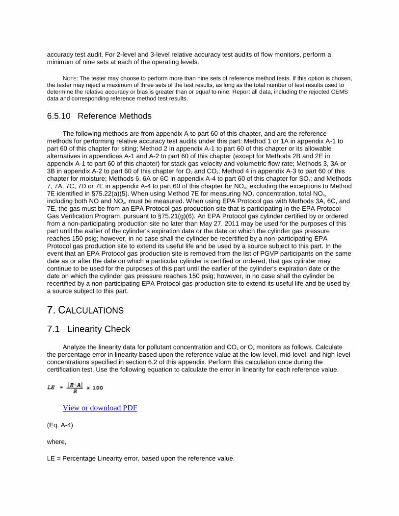
accuracy test audit. For 2-level and 3-level relative accuracy test audits of flow monitors, perform a minimum of nine sets at each of the operating levels.
NOTE: The tester may choose to perform more than nine sets of reference method tests. If this option is chosen, the tester may reject a maximum of three sets of the test results, as long as the total number of test results used to determine the relative accuracy or bias is greater than or equal to nine. Report all data, including the rejected CEMS data and corresponding reference method test results.
6.5.10 Reference Methods
The following methods are from appendix A to part 60 of this chapter, and are the reference methods for performing relative accuracy test audits under this part: Method 1 or 1A in appendix A-1 to part 60 of this chapter for siting; Method 2 in appendix A-1 to part 60 of this chapter or its allowable alternatives in appendices A-1 and A-2 to part 60 of this chapter (except for Methods 2B and 2E in appendix A-1 to part 60 of this chapter) for stack gas velocity and volumetric flow rate; Methods 3, 3A or 3B in appendix A-2 to part 60 of this chapter for O2 and CO2; Method 4 in appendix A-3 to part 60 of this chapter for moisture; Methods 6, 6A or 6C in appendix A-4 to part 60 of this chapter for SO2; and Methods 7, 7A, 7C, 7D or 7E in appendix A-4 to part 60 of this chapter for NOX, excluding the exceptions to Method 7E identified in §75.22(a)(5). When using Method 7E for measuring NOX concentration, total NOX, including both NO and NO2, must be measured. When using EPA Protocol gas with Methods 3A, 6C, and 7E, the gas must be from an EPA Protocol gas production site that is participating in the EPA Protocol Gas Verification Program, pursuant to §75.21(g)(6). An EPA Protocol gas cylinder certified by or ordered from a non-participating production site no later than May 27, 2011 may be used for the purposes of this part until the earlier of the cylinder's expiration date or the date on which the cylinder gas pressure reaches 150 psig; however, in no case shall the cylinder be recertified by a non-participating EPA Protocol gas production site to extend its useful life and be used by a source subject to this part. In the event that an EPA Protocol gas production site is removed from the list of PGVP participants on the same date as or after the date on which a particular cylinder is certified or ordered, that gas cylinder may continue to be used for the purposes of this part until the earlier of the cylinder's expiration date or the date on which the cylinder gas pressure reaches 150 psig; however, in no case shall the cylinder be recertified by a non-participating EPA Protocol gas production site to extend its useful life and be used by a source subject to this part.
7. CALCULATIONS
7.1 Linearity Check
Analyze the linearity data for pollutant concentration and CO2 or O2 monitors as follows. Calculate the percentage error in linearity based upon the reference value at the low-level, mid-level, and high-level concentrations specified in section 6.2 of this appendix. Perform this calculation once during the certification test. Use the following equation to calculate the error in linearity for each reference value.
View or download PDF
(Eq. A-4)
where,
LE = Percentage Linearity error, based upon the reference value.

R = Reference value of Low-, mid-, or high-level calibration gas introduced into the monitoring system.
A = Average of the monitoring system responses.
7.2 Calibration Error
7.2.1 Pollutant Concentration and Diluent Monitors
For each reference value, calculate the percentage calibration error based upon instrument span for daily calibration error tests using the following equation:
View or download PDF
(Eq. A-5)
where,
CE = Calibration error as a percentage of the span of the instrument.
R = Reference value of zero or upscale (high-level or mid-level, as applicable) calibration gas introduced into the monitoring system.
A = Actual monitoring system response to the calibration gas.
S = Span of the instrument, as specified in section 2 of this appendix.
7.2.2 Flow Monitor Calibration Error
For each reference value, calculate the percentage calibration error based upon span using the following equation:
View or download PDF
where:
CE = Calibration error as a percentage of span.
R = Low or high level reference value specified in section 2.2.2.1 of this appendix.
A = Actual flow monitor response to the reference value.
S = Flow monitor calibration span value as determined under section 2.1.4.2 of this appendix.

7.3 Relative Accuracy for SO2 and CO2 Emissions Concentration Monitors, O2 Monitors, NOX Concentration Monitoring Systems, and Flow Monitors
Analyze the relative accuracy test audit data from the reference method tests for SO2 and CO2 emissions concentration monitors, CO2 or O2 monitors used for heat input rate determination, NOX concentration monitoring systems used to determine NOX mass emissions under subpart H of this part, and flow monitors using the following procedures. Summarize the results on a data sheet. An example is shown in Figure 2. Calculate the mean of the monitor or monitoring system measurement values. Calculate the mean of the reference method values. Using data from the automated data acquisition and handling system, calculate the arithmetic differences between the reference method and monitor measurement data sets. Then calculate the arithmetic mean of the difference, the standard deviation, the confidence coefficient, and the monitor or monitoring system relative accuracy using the following procedures and equations.
7.3.1 Arithmetic Mean
Calculate the arithmetic mean of the differences of a data set as follows:
View or download PDF
7.3.2 Standard Deviation
Calculate the standard deviation, Sd, of a data set as follows:
View or download PDF
(Eq. A-8)
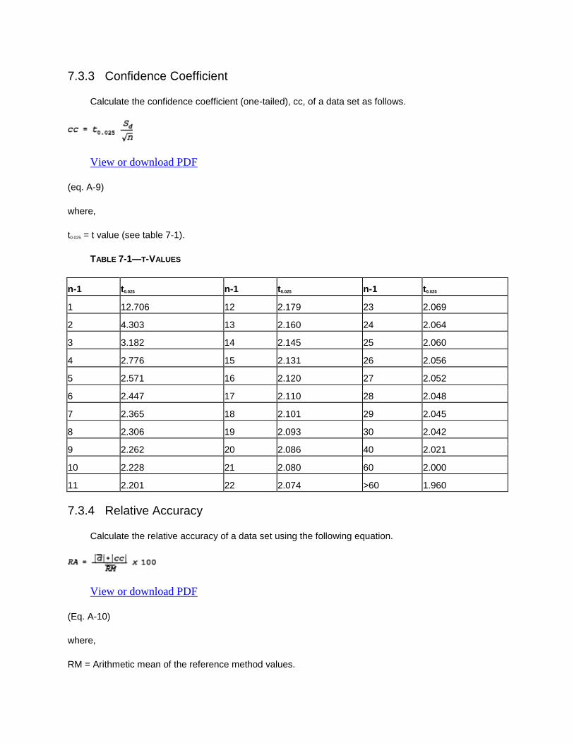
7.3.3 Confidence Coefficient
Calculate the confidence coefficient (one-tailed), cc, of a data set as follows.
View or download PDF
(eq. A-9)
where,
t0.025 = t value (see table 7-1).
TABLE 7-1—T-VALUES
n-1 t0.025 n-1 t0.025 n-1 t0.025
1 12.706 12 2.179 23 2.069
2 4.303 13 2.160 24 2.064
3 3.182 14 2.145 25 2.060
4 2.776 15 2.131 26 2.056
5 2.571 16 2.120 27 2.052
6 2.447 17 2.110 28 2.048
7 2.365 18 2.101 29 2.045
8 2.306 19 2.093 30 2.042
9 2.262 20 2.086 40 2.021
10 2.228 21 2.080 60 2.000
11 2.201 22 2.074 >60 1.960
7.3.4 Relative Accuracy
Calculate the relative accuracy of a data set using the following equation.
View or download PDF
(Eq. A-10)
where,
RM = Arithmetic mean of the reference method values.
|d̅| = The absolute value of the mean difference between the reference method values and the corresponding continuous emission monitoring system values.
|cc| = The absolute value of the confidence coefficient.
7.4 Relative Accuracy for NOX-diluent Continuous Emission Monitoring Systems
Analyze the relative accuracy test audit data from the reference method tests for NOX-diluent continuous emissions monitoring system as follows.
7.4.1 Data Preparation
If CNOx, the NOX concentration, is in ppm, multiply it by 1.194 × 10⁻⁷ (lb/dscf)/ppm to convert it to units of lb/dscf. If CNOx is in mg/dscm, multiply it by 6.24 × 10⁻⁸ (lb/dscf)/(mg/dscm) to convert it to lb/dscf. Then, use the diluent (O2 or CO2) reference method results for the run and the appropriate F or Fc factor from table 1 in appendix F of this part to convert CNOx from lb/dscf to lb/mmBtu units. Use the equations and procedure in section 3 of appendix F to this part, as appropriate.
7.4.2 NOX Emission Rate
For each test run in a data set, calculate the average NOX emission rate (in lb/mmBtu), by means of the data acquisition and handling system, during the time period of the test run. Tabulate the results as shown in example Figure 4.
7.4.3 Relative Accuracy
Use the equations and procedures in section 7.3 above to calculate the relative accuracy for the NOX continuous emission monitoring system. In using equation A-7, “d” is, for each run, the difference between the NOX emission rate values (in lb/mmBtu) obtained from the reference method data and the NOX continuous emission monitoring system.
7.5 Relative Accuracy for Combined SO2/Flow [Reserved]
7.6 Bias Test and Adjustment Factor
Test the following relative accuracy test audit data sets for bias: SO2 pollutant concentration monitors; flow monitors; NOX concentration monitoring systems used to determine NOX mass emissions, as defined in 75.71(a)(2); and NOX-diluent CEMS using the procedures outlined in sections 7.6.1 through 7.6.5 of this appendix. For multiple-load flow RATAs, perform a bias test at each load level designated as normal under section 6.5.2.1 of this appendix.
7.6.1 Arithmetic Mean
Calculate the arithmetic mean of the differences of the data set using Equation A-7 of this appendix. To calculate bias for an SO2 or NOX pollutant concentration monitor, “di” is, for each paired data point, the difference between the SO2 or NOX concentration value (in ppm) obtained from the reference method and the monitor. To calculate bias for a flow monitor, “di” is, for each paired data point, the difference between the flow rate values (in scfh) obtained from the reference method and the monitor. To calculate bias for a NOX-diluent continuous emission monitoring system, “di” is, for each paired data point, the difference

between the NOX emission rate values (in lb/mmBtu) obtained from the reference method and the monitoring system.
7.6.2 Standard Deviation
Calculate the standard deviation, Sd, of the data set using equation A-8.
7.6.3 CONFIDENCE COEFFICIENT
Calculate the confidence coefficient, cc, of the data set using equation A-9.
7.6.4 Bias Test
If, for the relative accuracy test audit data set being tested, the mean difference, d̅, is less than or equal to the absolute value of the confidence coefficient, | cc |, the monitor or monitoring system has passed the bias test. If the mean difference, d̅, is greater than the absolute value of the confidence coefficient, √ cc √, the monitor or monitoring system has failed to meet the bias test requirement.
7.6.5 Bias Adjustment
(a) If the monitor or monitoring system fails to meet the bias test requirement, adjust the value obtained from the monitor using the following equation:
View or download PDF
Where:
CEMiMonitor = Data (measurement) provided by the monitor at time i.
CEMiAdjusted = Data value, adjusted for bias, at time i.
BAF = Bias adjustment factor, defined by:
View or download PDF
Where:
BAF = Bias adjustment factor, calculated to the nearest thousandth.
d̅= Arithmetic mean of the difference obtained during the failed bias test using Equation A-7.
CEMavg = Mean of the data values provided by the monitor during the failed bias test.
(b) For single-load RATAs of SO2 pollutant concentration monitors, NOX concentration monitoring systems, and NOX-diluent monitoring systems, and for the single-load flow RATAs required or allowed

under section 6.5.2 of this appendix and sections 2.3.1.3(b) and 2.3.1.3(c) of appendix B to this part, the appropriate BAF is determined directly from the RATA results at normal load, using Equation A-12. Notwithstanding, when a NOX concentration CEMS or an SO2 CEMS or a NOX-diluent CEMS installed on a low-emitting affected unit (i.e., average SO2 or NOX concentration during the RATA ≤250 ppm or average NOX emission rate ≤0.200 lb/mmBtu) meets the normal 10.0 percent relative accuracy specification (as calculated using Equation A-10) or the alternate relative accuracy specification in section 3.3 of this appendix for low-emitters, but fails the bias test, the BAF may either be determined using Equation A-12, or a default BAF of 1.111 may be used.
(c) For 2-load or 3-load flow RATAs, when only one load level (low, mid or high) has been designated as normal under section 6.5.2.1 of this appendix and the bias test is passed at the normal load level, apply a BAF of 1.000 to the subsequent flow rate data. If the bias test is failed at the normal load level, use Equation A-12 to calculate the normal load BAF and then perform an additional bias test at the second most frequently-used load level, as determined under section 6.5.2.1 of this appendix. If the bias test is passed at this second load level, apply the normal load BAF to the subsequent flow rate data. If the bias test is failed at this second load level, use Equation A-12 to calculate the BAF at the second load level and apply the higher of the two BAFs (either from the normal load level or from the second load level) to the subsequent flow rate data.
(d) For 2-load or 3-load flow RATAs, when two load levels have been designated as normal under section 6.5.2.1 of this appendix and the bias test is passed at both normal load levels, apply a BAF of 1.000 to the subsequent flow rate data. If the bias test is failed at one of the normal load levels but not at the other, use Equation A-12 to calculate the BAF for the normal load level at which the bias test was failed and apply that BAF to the subsequent flow rate data. If the bias test is failed at both designated normal load levels, use Equation A-12 to calculate the BAF at each normal load level and apply the higher of the two BAFs to the subsequent flow rate data.
(e) Each time a RATA is passed and the appropriate bias adjustment factor has been determined, apply the BAF prospectively to all monitoring system data, beginning with the first clock hour following the hour in which the RATA was completed. For a 2-load flow RATA, the “hour in which the RATA was completed” refers to the hour in which the testing at both loads was completed; for a 3-load RATA, it refers to the hour in which the testing at all three loads was completed.
(f) Use the bias-adjusted values in computing substitution values in the missing data procedure, as specified in subpart D of this part, and in reporting the concentration of SO2, the flow rate, the average NOX emission rate, the unit heat input, and the calculated mass emissions of SO2 and CO2 during the quarter and calendar year, as specified in subpart G of this part. In addition, when using a NOX concentration monitoring system and a flow monitor to calculate NOX mass emissions under subpart H of this part, use bias-adjusted values for NOX concentration and flow rate in the mass emission calculations and use bias-adjusted NOX concentrations to compute the appropriate substitution values for NOX concentration in the missing data routines under subpart D of this part.
(g) For units that do not produce electrical or thermal output, the provisions of paragraphs (a) through (f) of this section apply, except that the terms, “single-load”, “2-load”, “3-load”, and “load level” shall be replaced, respectively, with the terms, “single-level”, “2-level”, “3-level”, and “operating level”.
7.7 Reference Flow-to-Load Ratio or Gross Heat Rate
(a) Except as provided in section 7.8 of this appendix, the owner or operator shall determine Rref, the reference value of the ratio of flow rate to unit load, each time that a passing flow RATA is performed at a load level designated as normal in section 6.5.2.1 of this appendix. The owner or operator shall report the current value of Rref in the electronic quarterly report required under §75.64 and shall also report the completion date of the associated RATA. If two load levels have been designated as normal under

section 6.5.2.1 of this appendix, the owner or operator shall determine a separate Rref value for each of the normal load levels. The reference flow-to-load ratio shall be calculated as follows:
View or download PDF
Where:
Rref = Reference value of the flow-to-load ratio, from the most recent normal-load flow RATA, scfh/megawatts, scfh/1000 lb/hr of steam, or scfh/(mmBtu/hr of steam output).
Qref = Average stack gas volumetric flow rate measured by the reference method during the normal-load RATA, scfh.
Lavg = Average unit load during the normal-load flow RATA, megawatts, 1000 lb/hr of steam, or mmBtu/hr of thermal output.
(b) In Equation A-13, for a common stack, determine Lavg by summing, for each RATA run, the operating loads of all units discharging through the common stack, and then taking the arithmetic average of the summed loads. For a unit that discharges its emissions through multiple stacks, either determine a single value of Qref for the unit or a separate value of Qref for each stack. In the former case, calculate Qref by summing, for each RATA run, the volumetric flow rates through the individual stacks and then taking the arithmetic average of the summed RATA run flow rates. In the latter case, calculate the value of Qref for each stack by taking the arithmetic average, for all RATA runs, of the flow rates through the stack. For a unit with a multiple stack discharge configuration consisting of a main stack and a bypass stack (e.g., a unit with a wet SO2 scrubber), determine Qref separately for each stack at the time of the normal load flow RATA. Round off the value of Rref to two decimal places.
(c) In addition to determining Rref or as an alternative to determining Rref, a reference value of the gross heat rate (GHR) may be determined. In order to use this option, quality-assured diluent gas (CO2 or O2) must be available for each hour of the most recent normal-load flow RATA. The reference value of the GHR shall be determined as follows:
View or download PDF
Where:
(GHR)ref = Reference value of the gross heat rate at the time of the most recent normal-load flow RATA, Btu/kwh, Btu/lb steam load, or Btu heat input/mmBtu steam output.
(Heat Input)avg = Average hourly heat input during the normal-load flow RATA, as determined using the applicable equation in appendix F to this part, mmBtu/hr. For multiple stack configurations, if the reference GHR value is determined separately for each stack, use the hourly heat input measured at each stack. If the reference GHR is determined at the unit level, sum the hourly heat inputs measured at the individual stacks.
Lavg = Average unit load during the normal-load flow RATA, megawatts, 1000 lb/hr of steam, or mmBtu/hr thermal output.

(d) In the calculation of (Heat Input)avg, use Qref, the average volumetric flow rate measured by the reference method during the RATA, and use the average diluent gas concentration measured during the flow RATA (i.e., the arithmetic average of the diluent gas concentrations for all clock hours in which a RATA run was performed).
7.8 Flow-to-Load Test Exemptions
(a) For complex stack configuations (e.g., when the effluent from a unit is divided and discharges through multiple stacks in such a manner that the flow rate in the individual stacks cannot be correlated with unit load), the owner or operator may petition the Administrator under §75.66 for an exemption from the requirements of section 7.7 of this appendix and section 2.2.5 fo appendix B to this part. The petition must include sufficient information and data to demonstrate that a flow-to-load or gross heat rate evaluation is infeasible for the complex stack configuration.
(b) Units that do not produce electrical output (in megawatts) or thermal output (in klb of steam per hour) are exempted from the flow-to-load ratio test requirements of section 7.7 of this appendix and section 2.2.5 of appendix B to this part.
FIGURE 1 TO APPENDIX A—LINEARITY ERROR DETERMINATION
Day Date and time Reference value Monitor value Difference Percent of reference value
Low-level:
Mid-level:
High-level:

FIGURE 2 TO APPENDIX A—RELATIVE ACCURACY DETERMINATION (POLLUTANT CONCENTRATION
MONITORS)
Run No. Date and time
SO2 (ppmc)
Date and time
CO2 (Pollutant) (ppm
c)
RMa M
b Diff RM
a M
b Diff
1
2
3
4
5
6
7
8
9
10
11
12
Arithmetic Mean Difference (Eq. A-7). Confidence Coefficient (Eq. A-9). Relative Accuracy (Eq. A-10).
aRM means “reference method data.”
bM means “monitor data.”
cMake sure the RM and M data are on a consistent basis, either wet or dry.
FIGURE 3 TO APPENDIX A—RELATIVE ACCURACY DETERMINATION (FLOW MONITORS)
Run No.
Date and time
Flow rate (Low) (scf/hr)*
Date and time
Flow rate (Normal) (scf/hr)*
Date and time
Flow rate (High) (scf/hr)*
RM M Diff RM M Diff RM M Diff
1
2
3
4
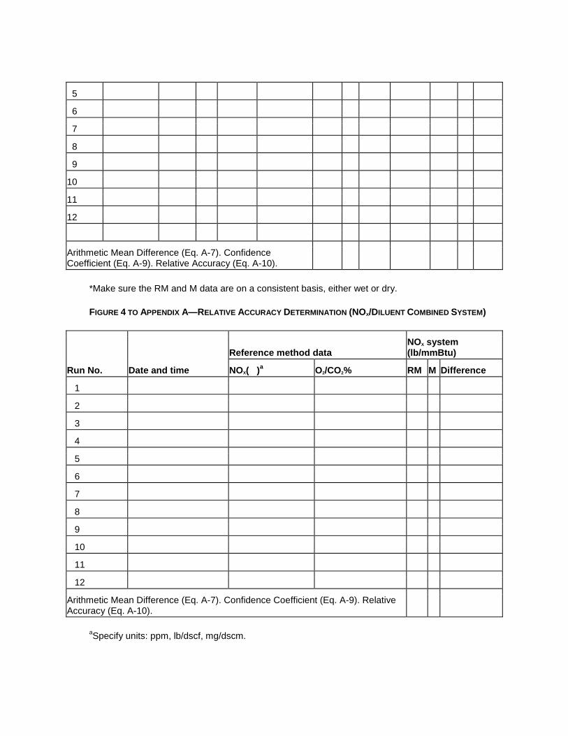
5
6
7
8
9
10
11
12
Arithmetic Mean Difference (Eq. A-7). Confidence Coefficient (Eq. A-9). Relative Accuracy (Eq. A-10).
*Make sure the RM and M data are on a consistent basis, either wet or dry.
FIGURE 4 TO APPENDIX A—RELATIVE ACCURACY DETERMINATION (NOX/DILUENT COMBINED SYSTEM)
Run No. Date and time
Reference method data NOX system (lb/mmBtu)
NOX( )a O2/CO2% RM M Difference
1
2
3
4
5
6
7
8
9
10
11
12
Arithmetic Mean Difference (Eq. A-7). Confidence Coefficient (Eq. A-9). Relative Accuracy (Eq. A-10).
aSpecify units: ppm, lb/dscf, mg/dscm.
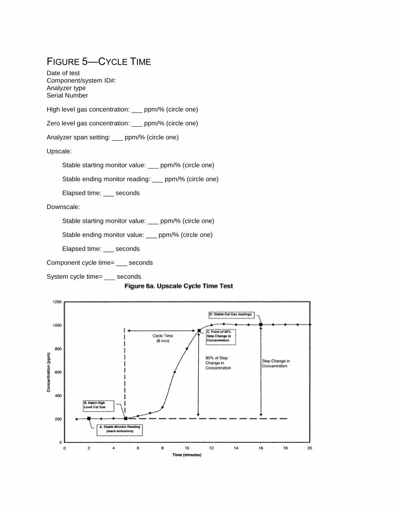
FIGURE 5—CYCLE TIME
Date of test Component/system ID#: Analyzer type Serial Number
High level gas concentration: ___ ppm/% (circle one)
Zero level gas concentration: ___ ppm/% (circle one)
Analyzer span setting: ___ ppm/% (circle one)
Upscale:
Stable starting monitor value: ___ ppm/% (circle one)
Stable ending monitor reading: ___ ppm/% (circle one)
Elapsed time: ___ seconds
Downscale:
Stable starting monitor value: ___ ppm/% (circle one)
Stable ending monitor value: ___ ppm/% (circle one)
Elapsed time: ___ seconds
Component cycle time= ___ seconds
System cycle time= ___ seconds

View or download PDF
View or download PDF
A. To determine the upscale cycle time (Figure 6a), measure the flue gas emissions until the response stabilizes. Record the stabilized value (see section 6.4 of this appendix for the stability criteria).
B. Inject a high-level calibration gas into the port leading to the calibration cell or thimble (Point B). Allow the analyzer to stabilize. Record the stabilized value.
C. Determine the step change. The step change is equal to the difference between the final stable calibration gas value (Point D) and the stabilized stack emissions value (Point A).
D. Take 95% of the step change value and add the result to the stabilized stack emissions value (Point A). Determine the time at which 95% of the step change occurred (Point C).
E. Calculate the upscale cycle time by subtracting the time at which the calibration gas was injected (Point B) from the time at which 95% of the step change occurred (Point C). In this example, upscale cycle time = (11−5) = 6 minutes.
F. To determine the downscale cycle time (Figure 6b) repeat the procedures above, except that a zero gas is injected when the flue gas emissions have stabilized, and 95% of the step change in concentration is subtracted from the stabilized stack emissions value.
G. Compare the upscale and downscale cycle time values. The longer of these two times is the cycle time for the analyzer.
EDITORIAL NOTE: For FEDERAL REGISTER citations affecting part 75, Appendix A, see the List of CFR Sections Affected, which appears in the Finding Aids section of the printed volume and at www.fdsys.gov.

EFFECTIVE DATE NOTE: At 73 FR 65556, Nov. 4, 2008, the effectiveness of Section 6.1.2(a) through (c) was stayed indefinitely.
Back to Top
Appendix B to Part 75—Quality Assurance and Quality Control Procedures
1. QUALITY ASSURANCE/QUALITY CONTROL PROGRAM
Develop and implement a quality assurance/quality control (QA/QC) program for the continuous emission monitoring systems, excepted monitoring systems approved under appendix D or E to this part, and alternative monitoring systems under subpart E of this part, and their components. At a minimum, include in each QA/QC program a written plan that describes in detail (or that refers to separate documents containing) complete, step-by-step procedures and operations for each of the following activities. Upon request from regulatory authorities, the source shall make all procedures, maintenance records, and ancillary supporting documentation from the manufacturer (e.g., software coefficients and troubleshooting diagrams) available for review during an audit. Electronic storage of the information in the QA/QC plan is permissible, provided that the information can be made available in hardcopy upon request during an audit.
1.1 Requirements for All Monitoring Systems
1.1.1 Preventive Maintenance
Keep a written record of procedures needed to maintain the monitoring system in proper operating condition and a schedule for those procedures. This shall, at a minimum, include procedures specified by the manufacturers of the equipment and, if applicable, additional or alternate procedures developed for the equipment.
1.1.2 Recordkeeping and Reporting
Keep a written record describing procedures that will be used to implement the recordkeeping and reporting requirements in subparts E, F, and G and appendices D and E to this part, as applicable.
1.1.3 Maintenance Records
Keep a record of all testing, maintenance, or repair activities performed on any monitoring system or component in a location and format suitable for inspection. A maintenance log may be used for this purpose. The following records should be maintained: date, time, and description of any testing, adjustment, repair, replacement, or preventive maintenance action performed on any monitoring system and records of any corrective actions associated with a monitor's outage period. Additionally, any adjustment that recharacterizes a system's ability to record and report emissions data must be recorded (e.g., changing of flow monitor or moisture monitoring system polynomial coefficients, K factors or mathematical algorithms, changing of temperature and pressure coefficients and dilution ratio settings), and a written explanation of the procedures used to make the adjustment(s) shall be kept.
1.1.4 The provisions in section 6.1.2 of appendix A to this part shall apply to the annual RATAs described in §75.74(c)(2)(ii) and to the semiannual and annual RATAs described in section 2.3 of this appendix.
1.2 Specific Requirements for Continuous Emissions Monitoring Systems
1.2.1 Calibration Error Test and Linearity Check Procedures
Keep a written record of the procedures used for daily calibration error tests and linearity checks (e.g., how gases are to be injected, adjustments of flow rates and pressure, introduction of reference values, length of time for injection of calibration gases, steps for obtaining calibration error or error in linearity, determination of interferences, and when calibration adjustments should be made). Identify any calibration error test and linearity check procedures specific to the continuous emission monitoring system that vary from the procedures in appendix A to this part.
1.2.2 Calibration and Linearity Adjustments
Explain how each component of the continuous emission monitoring system will be adjusted to provide correct responses to calibration gases, reference values, and/or indications of interference both initially and after repairs or corrective action. Identify equations, conversion factors and other factors affecting calibration of each continuous emission monitoring system.
1.2.3 Relative Accuracy Test Audit Procedures
Keep a written record of procedures and details peculiar to the installed continuous emission monitoring systems that are to be used for relative accuracy test audits, such as sampling and analysis methods.
1.2.4 Parametric Monitoring for Units With Add-on Emission Controls
The owner or operator shall keep a written (or electronic) record including a list of operating parameters for the add-on SO2 or NOX emission controls, including parameters in §75.55(b) or §75.58(b), as applicable, and the range of each operating parameter that indicates the add-on emission controls are operating properly. The owner or operator shall keep a written (or electronic) record of the parametric monitoring data during each SO2 or NOX missing data period.
1.3 Specific Requirements for Excepted Systems Approved Under Appendices D and E
1.3.1 Fuel Flowmeter Accuracy Test Procedures
Keep a written record of the specific fuel flowmeter accuracy test procedures. These may include: standard methods or specifications listed in and of appendix D to this part and incorporated by reference under §75.6; the procedures of sections 2.1.5.2 or 2.1.7 of appendix D to this part; or other methods approved by the Administrator through the petition process of §75.66(c).
1.3.2 Transducer or Transmitter Accuracy Test Procedures
Keep a written record of the procedures for testing the accuracy of transducers or transmitters of an orifice-, nozzle-, or venturi-type fuel flowmeter under section 2.1.6 of appendix D to this part. These procedures should include a description of equipment used, steps in testing, and frequency of testing.

1.3.3 Fuel Flowmeter, Transducer, or Transmitter Calibration and Maintenance Records
Keep a record of adjustments, maintenance, or repairs performed on the fuel flowmeter monitoring system. Keep records of the data and results for fuel flowmeter accuracy tests and transducer accuracy tests, consistent with appendix D to this part.
1.3.4 Primary Element Inspection Procedures
Keep a written record of the standard operating procedures for inspection of the primary element (i.e., orifice, venturi, or nozzle) of an orifice-, venturi-, or nozzle-type fuel flowmeter. Examples of the types of information to be included are: what to examine on the primary element; how to identify if there is corrosion sufficient to affect the accuracy of the primary element; and what inspection tools (e.g., baroscope), if any, are used.
1.3.5 Fuel Sampling Method and Sample Retention
Keep a written record of the standard procedures used to perform fuel sampling, either by utility personnel or by fuel supply company personnel. These procedures should specify the portion of the ASTM method used, as incorporated by reference under §75.6, or other methods approved by the Administrator through the petition process of §75.66(c). These procedures should describe safeguards for ensuring the availability of an oil sample (e.g., procedure and location for splitting samples, procedure for maintaining sample splits on site, and procedure for transmitting samples to an analytical laboratory). These procedures should identify the ASTM analytical methods used to analyze sulfur content, gross calorific value, and density, as incorporated by reference under §75.6, or other methods approved by the Administrator through the petition process of §75.66(c).
1.3.6 Appendix E Monitoring System Quality Assurance Information
Identify the recommended range of quality assurance- and quality control-related operating parameters. Keep records of these operating parameters for each hour of unit operation (i.e., fuel combustion). Keep a written record of the procedures used to perform NOX emission rate testing. Keep a copy of all data and results from the initial and from the most recent NOX emission rate testing, including the values of quality assurance parameters specified in section 2.3 of appendix E to this part.
1.4 Requirements for Alternative Systems Approved Under Subpart E
1.4.1 Daily Quality Assurance Tests
Explain how the daily assessment procedures specific to the alternative monitoring system are to be performed.
1.4.2 Daily Quality Assurance Test Adjustments
Explain how each component of the alternative monitoring system will be adjusted in response to the results of the daily assessments.

1.4.3 Relative Accuracy Test Audit Procedures
Keep a written record of procedures and details peculiar to the installed alternative monitoring system that are to be used for relative accuracy test audits, such as sampling and analysis methods.
2. FREQUENCY OF TESTING
A summary chart showing each quality assurance test and the frequency at which each test is required is located at the end of this appendix in Figure 1.
2.1 Daily Assessments
Perform the following daily assessments to quality-assure the hourly data recorded by the monitoring systems during each period of unit operation, or, for a bypass stack or duct, each period in which emissions pass through the bypass stack or duct. These requirements are effective as of the date when the monitor or continuous emission monitoring system completes certification testing.
2.1.1 Calibration Error Test
Except as provided in section 2.1.1.2 of this appendix, perform the daily calibration error test of each gas monitoring system (including moisture monitoring systems consisting of wet- and dry-basis O2 analyzers) according to the procedures in section 6.3.1 of appendix A to this part, and perform the daily calibration error test of each flow monitoring system according to the procedure in section 6.3.2 of appendix A to this part. When two measurement ranges (low and high) are required for a particular parameter, perform sufficient calibration error tests on each range to validate the data recorded on that range, according to the criteria in section 2.1.5 of this appendix.
2.1.1.1 On-line Daily Calibration Error Tests. Except as provided in section 2.1.1.2 of this appendix, all daily calibration error tests must be performed while the unit is in operation at normal, stable conditions (i.e. “on-line”).
2.1.1.2 Off-line Daily Calibration Error Tests. Daily calibrations may be performed while the unit is not operating (i.e., “off-line”) and may be used to validate data for a monitoring system that meets the following conditions:
(1) An initial demonstration test of the monitoring system is successfully completed and the results are reported in the quarterly report required under §75.64 of this part. The initial demonstration test, hereafter called the “off-line calibration demonstration”, consists of an off-line calibration error test followed by an on-line calibration error test. Both the off-line and on-line portions of the off-line calibration demonstration must meet the calibration error performance specification in section 3.1 of appendix A of this part. Upon completion of the off-line portion of the demonstration, the zero and upscale monitor responses may be adjusted, but only toward the true values of the calibration gases or reference signals used to perform the test and only in accordance with the routine calibration adjustment procedures specified in the quality control program required under section 1 of appendix B to this part. Once these adjustments are made, no further adjustments may be made to the monitoring system until after completion of the on-line portion of the off-line calibration demonstration. Within 26 clock hours of the completion hour of the off-line portion of the demonstration, the monitoring system must successfully complete the first attempted calibration error test, i.e., the on-line portion of the demonstration.
(2) For each monitoring system that has passed the off-line calibration demonstration, off-line calibration error tests may be used on a limited basis to validate data, in accordance with paragraph (2) in section 2.1.5.1 of this appendix.

2.1.2 Daily Flow Interference Check
Perform the daily flow monitor interference checks specified in section 2.2.2.2 of appendix A of this part while the unit is in operation at normal, stable conditions.
2.1.3 Additional Calibration Error Tests and Calibration Adjustments
(a) In addition to the daily calibration error tests required under section 2.1.1 of this appendix, a calibration error test of a monitor shall be performed in accordance with section 2.1.1 of this appendix, as follows: whenever a daily calibration error test is failed; whenever a monitoring system is returned to service following repair or corrective maintenance that could affect the monitor's ability to accurately measure and record emissions data; or after making certain calibration adjustments, as described in this section. Except in the case of the routine calibration adjustments described in this section, data from the monitor are considered invalid until the required additional calibration error test has been successfully completed.
(b) Routine calibration adjustments of a monitor are permitted after any successful calibration error test. These routine adjustments shall be made so as to bring the monitor readings as close as practicable to the known tag values of the calibration gases or to the actual value of the flow monitor reference signals. An additional calibration error test is required following routine calibration adjustments where the monitor's calibration has been physically adjusted (e.g., by turning a potentiometer) to verify that the adjustments have been made properly. An additional calibration error test is not required, however, if the routine calibration adjustments are made by means of a mathematical algorithm programmed into the data acquisition and handling system. The EPA recommends that routine calibration adjustments be made, at a minimum, whenever the daily calibration error exceeds the limits of the applicable performance specification in appendix A to this part for the pollutant concentration monitor, CO2 or O2 monitor, or flow monitor.
(c) Additional (non-routine) calibration adjustments of a monitor are permitted prior to (but not during) linearity checks and RATAs and at other times, provided that an appropriate technical justification is included in the quality control program required under section 1 of this appendix. The allowable non-routine adjustments are as follows. The owner or operator may physically adjust the calibration of a monitor (e.g., by means of a potentiometer), provided that the post-adjustment zero and upscale responses of the monitor are within the performance specifications of the instrument given in section 3.1 of appendix A to this part. An additional calibration error test is required following such adjustments to verify that the monitor is operating within the performance specifications at both the zero and upscale calibration levels.
2.1.4 Data Validation
(a) An out-of-control period occurs when the calibration error of an SO2 or NOX pollutant concentration monitor exceeds 5.0 percent of the span value, when the calibration error of a CO2 or O2 monitor (including O2 monitors used to measure CO2 emissions or percent moisture) exceeds 1.0 percent O2 or CO2, or when the calibration error of a flow monitor exceeds 6.0 percent of the span value, which is twice the applicable specification of appendix A to this part. Notwithstanding, a differential pressure-type flow monitor for which the calibration error exceeds 6.0 percent of the span value shall not be considered out-of-control if |R-A|, the absolute value of the difference between the monitor response and the reference value in Equation A-6 of appendix A to this part, is <0.02 inches of water. In addition, an SO2 or NOX monitor for which the calibration error exceeds 5.0 percent of the span value shall not be considered out-of-control if |R-A| in Equation A-6 does not exceed 5.0 ppm (for span values ≤50 ppm), or if |R-A|; does not exceed 10.0 ppm (for span values >50 ppm, but ≤200 ppm). The out-of-control period begins upon failure of the calibration error test and ends upon completion of a successful calibration error test. Note, that if a failed calibration, corrective action, and successful calibration error test occur within the

same hour, emission data for that hour recorded by the monitor after the successful calibration error test may be used for reporting purposes, provided that two or more valid readings are obtained as required by §75.10. A NOX-diluent CEMS is considered out-of-control if the calibration error of either component monitor exceeds twice the applicable performance specification in appendix A to this part. Emission data shall not be reported from an out-of-control monitor.
(b) An out-of-control period also occurs whenever interference of a flow monitor is identified. The out-of-control period begins with the hour of completion of the failed interference check and ends with the hour of completion of an interference check that is passed.
(c) The results of any certification, recertification, diagnostic, or quality assurance test required under this part may not be used to validate the emissions data required under this part, if the test is performed using EPA Protocol gas from a production site that is not participating in the PGVP, except as provided in §75.21(g)(7) or if the cylinder(s) are analyzed by an independent laboratory and shown to meet the requirements of section 5.1.4(b) of appendix A to this part.
2.1.5 Quality Assurance of Data With Respect to Daily Assessments
When a monitoring system passes a daily assessment (i.e., daily calibration error test or daily flow interference check), data from that monitoring system are prospectively validated for 26 clock hours (i.e., 24 hours plus a 2-hour grace period) beginning with the hour in which the test is passed, unless another assessment (i.e. a daily calibration error test, an interference check of a flow monitor, a quarterly linearity check, a quarterly leak check, or a relative accuracy test audit) is failed within the 26-hour period.
2.1.5.1 Data Invalidation with Respect to Daily Assessments. The following specific rules apply to the invalidation of data with respect to daily assessments:
(1) Data from a monitoring system are invalid, beginning with the first hour following the expiration of a 26-hour data validation period or beginning with the first hour following the expiration of an 8-hour start-up grace period (as provided under section 2.1.5.2 of this appendix), if the required subsequent daily assessment has not been conducted.
(2) For a monitor that has passed the off-line calibration demonstration, a combination of on-line and off-line calibration error tests may be used to validate data from the monitor, as follows. For a particular unit (or stack) operating hour, data from a monitor may be validated using a successful off-line calibration error test if: (a) An on-line calibration error test has been passed within the previous 26 unit (or stack) operating hours; and (b) the 26 clock hour data validation window for the off-line calibration error test has not expired. If either of these conditions is not met, then the data from the monitor are invalid with respect to the daily calibration error test requirement. Data from the monitor shall remain invalid until the appropriate on-line or off-line calibration error test is successfully completed so that both conditions (a) and (b) are met.
(3) For units with two measurement ranges (low and high) for a particular parameter, when separate analyzers are used for the low and high ranges, a failed or expired calibration on one of the ranges does not affect the quality-assured data status on the other range. For a dual-range analyzer (i.e., a single analyzer with two measurement scales), a failed calibration error test on either the low or high scale results in an out-of-control period for the monitor. Data from the monitor remain invalid until corrective actions are taken and “hands-off” calibration error tests have been passed on both ranges. However, if the most recent calibration error test on the high scale was passed but has expired, while the low scale is up-to-date on its calibration error test requirements (or vice-versa), the expired calibration error test does not affect the quality-assured status of the data recorded on the other scale.
2.1.5.2 Daily Assessment Start-Up Grace Period. For the purpose of quality assuring data with respect to a daily assessment (i.e. a daily calibration error test or a flow interference check), a start-up

grace period may apply when a unit begins to operate after a period of non-operation. The start-up grace period for a daily calibration error test is independent of the start-up grace period for a daily flow interference check. To qualify for a start-up grace period for a daily assessment, there are two requirements:
(1) The unit must have resumed operation after being in outage for 1 or more hours (i.e., the unit must be in a start-up condition) as evidenced by a change in unit operating time from zero in one clock hour to an operating time greater than zero in the next clock hour.
(2) For the monitoring system to be used to validate data during the grace period, the previous daily assessment of the same kind must have been passed on-line within 26 clock hours prior to the last hour in which the unit operated before the outage. In addition, the monitoring system must be in-control with respect to quarterly and semi-annual or annual assessments.
If both of the above conditions are met, then a start-up grace period of up to 8 clock hours applies, beginning with the first hour of unit operation following the outage. During the start-up grace period, data generated by the monitoring system are considered quality-assured. For each monitoring system, a start-up grace period for a calibration error test or flow interference check ends when either: (1) a daily assessment of the same kind (i.e., calibration error test or flow interference check) is performed; or (2) 8 clock hours have elapsed (starting with the first hour of unit operation following the outage), whichever occurs first.
2.1.6 Data Recording
Record and tabulate all calibration error test data according to month, day, clock-hour, and magnitude in either ppm, percent volume, or scfh. Program monitors that automatically adjust data to the corrected calibration values (e.g., microprocessor control) to record either: (1) The unadjusted concentration or flow rate measured in the calibration error test prior to resetting the calibration, or (2) the magnitude of any adjustment. Record the following applicable flow monitor interference check data: (1) Sample line/sensing port pluggage, and (2) malfunction of each RTD, transceiver, or equivalent.
2.2 Quarterly Assessments
For each primary and redundant backup monitor or monitoring system, perform the following quarterly assessments. This requirement is applies as of the calendar quarter following the calendar quarter in which the monitor or continuous emission monitoring system is provisionally certified.
2.2.1 Linearity Check
Unless a particular monitor (or monitoring range) is exempted under this paragraph or under section 6.2 of appendix A to this part, perform a linearity check, in accordance with the procedures in section 6.2 of appendix A to this part, for each primary and redundant backup SO2, and NOx pollutant concentration monitor and each primary and redundant backup CO2 or O2 monitor (including O2 monitors used to measure CO2 emissions or to continuously monitor moisture) at least once during each QA operating quarter, as defined in §72.2 of this chapter. For units using both a low and high span value, a linearity check is required only on the range(s) used to record and report emission data during the QA operating quarter. Conduct the linearity checks no less than 30 days apart, to the extent practicable. The data validation procedures in section 2.2.3(e) of this appendix shall be followed.

2.2.2 Leak Check
For differential pressure flow monitors, perform a leak check of all sample lines (a manual check is acceptable) at least once during each QA operating quarter. For this test, the unit does not have to be in operation. Conduct the leak checks no less than 30 days apart, to the extent practicable. If a leak check is failed, follow the applicable data validation procedures in section 2.2.3(g) of this appendix.
2.2.3 Data Validation
(a) A linearity check shall not be commenced if the monitoring system is operating out-of-control with respect to any of the daily or semiannual quality assurance assessments required by sections 2.1 and 2.3 of this appendix or with respect to the additional calibration error test requirements in section 2.1.3 of this appendix.
(b) Each required linearity check shall be done according to paragraph (b)(1), (b)(2) or (b)(3) of this section:
(1) The linearity check may be done “cold,” i.e., with no corrective maintenance, repair, calibration adjustments, re-linearization or reprogramming of the monitor prior to the test.
(2) The linearity check may be done after performing only the routine or non-routine calibration adjustments described in section 2.1.3 of this appendix at the various calibration gas levels (zero, low, mid or high), but no other corrective maintenance, repair, re-linearization or reprogramming of the monitor. Trial gas injection runs may be performed after the calibration adjustments and additional adjustments within the allowable limits in section 2.1.3 of this appendix may be made prior to the linearity check, as necessary, to optimize the performance of the monitor. The trial gas injections need not be reported, provided that they meet the specification for trial gas injections in §75.20(b)(3)(vii)(E)(1). However, if, for any trial injection, the specification in §75.20(b)(3)(vii)(E)(1) is not met, the trial injection shall be counted as an aborted linearity check.
(3) The linearity check may be done after repair, corrective maintenance or reprogramming of the monitor. In this case, the monitor shall be considered out-of-control from the hour in which the repair, corrective maintenance or reprogramming is commenced until the linearity check has been passed. Alternatively, the data validation procedures and associated timelines in §§75.20(b)(3)(ii) through (ix) may be followed upon completion of the necessary repair, corrective maintenance, or reprogramming. If the procedures in §75.20(b)(3) are used, the words “quality assurance” apply instead of the word “recertification”.
(c) Once a linearity check has been commenced, the test shall be done hands-off. That is, no adjustments of the monitor are permitted during the linearity test period, other than the routine calibration adjustments following daily calibration error tests, as described in section 2.1.3 of this appendix. If a routine daily calibration error test is performed and passed just prior to a linearity test (or during a linearity test period) and a mathematical correction factor is automatically applied by the DAHS, the correction factor shall be applied to all subsequent data recorded by the monitor, including the linearity test data.
(d) If a daily calibration error test is failed during a linearity test period, prior to completing the test, the linearity test must be repeated. Data from the monitor are invalidated prospectively from the hour of the failed calibration error test until the hour of completion of a subsequent successful calibration error test. The linearity test shall not be commenced until the monitor has successfully completed a calibration error test.
(e) An out-of-control period occurs when a linearity test is failed (i.e., when the error in linearity at any of the three concentrations in the quarterly linearity check (or any of the six concentrations, when

both ranges of a single analyzer with a dual range are tested) exceeds the applicable specification in section 3.2 of appendix A to this part) or when a linearity test is aborted due to a problem with the monitor or monitoring system. For a NOX-diluent continuous emission monitoring system, the system is considered out-of-control if either of the component monitors exceeds the applicable specification in section 3.2 of appendix A to this part or if the linearity test of either component is aborted due to a problem with the monitor. The out-of-control period begins with the hour of the failed or aborted linearity check and ends with the hour of completion of a satisfactory linearity check following corrective action and/or monitor repair, unless the option in paragraph (b)(3) of this section to use the data validation procedures and associated timelines in §75.20(b)(3)(ii) through (ix) has been selected, in which case the beginning and end of the out-of-control period shall be determined in accordance with §§75.20(b)(3)(vii)(A) and (B). For a dual-range analyzer, “hands-off” linearity checks must be passed on both measurement scales to end the out-of-control period. Note that a monitor shall not be considered out-of-control when a linearity test is aborted for a reason unrelated to the monitor's performance (e.g., a forced unit outage).
(f) No more than four successive calendar quarters shall elapse after the quarter in which a linearity check of a monitor or monitoring system (or range of a monitor or monitoring system) was last performed without a subsequent linearity test having been conducted. If a linearity test has not been completed by the end of the fourth calendar quarter since the last linearity test, then the linearity test must be completed within a 168 unit operating hour or stack operating hour “grace period” (as provided in section 2.2.4 of this appendix) following the end of the fourth successive elapsed calendar quarter, or data from the CEMS (or range) will become invalid.
(g) An out-of-control period also occurs when a flow monitor sample line leak is detected. The out-of-control period begins with the hour of the failed leak check and ends with the hour of a satisfactory leak check following corrective action.
(h) For each monitoring system, report the results of all completed and partial linearity tests that affect data validation (i.e., all completed, passed linearity checks; all completed, failed linearity checks; and all linearity checks aborted due to a problem with the monitor, including trial gas injections counted as failed test attempts under paragraph (b)(2) of this section or under §75.20(b)(3)(vii)(F)), in the quarterly report required under §75.64. Note that linearity attempts which are aborted or invalidated due to problems with the reference calibration gases or due to operational problems with the affected unit(s) need not be reported. Such partial tests do not affect the validation status of emission data recorded by the monitor. A record of all linearity tests, trial gas injections and test attempts (whether reported or not) must be kept on-site as part of the official test log for each monitoring system.
(i) The results of any certification, recertification, diagnostic, or quality assurance test required under this part may not be used to validate the emissions data required under this part, if the test is performed using EPA Protocol gas that was not from an EPA Protocol gas production site participating in the PGVP on the date the gas was procured either by the tester or by a reseller that sold to the tester the unaltered EPA Protocol gas, except as provided in §75.21(g)(7) or if the cylinder(s) are analyzed by an independent laboratory and shown to meet the requirements of section 5.1.4(b) of appendix A to this part.
2.2.4 Linearity and Leak Check Grace Period
(a) When a required linearity test or flow monitor leak check has not been completed by the end of the QA operating quarter in which it is due or if, due to infrequent operation of a unit or infrequent use of a required high range of a monitor or monitoring system, four successive calendar quarters have elapsed after the quarter in which a linearity check of a monitor or monitoring system (or range) was last performed without a subsequent linearity test having been done, the owner or operator has a grace period of 168 consecutive unit operating hours, as defined in §72.2 of this chapter (or, for monitors installed on common stacks or bypass stacks, 168 consecutive stack operating hours, as defined in §72.2 of this chapter) in which to perform a linearity test or leak check of that monitor or monitoring system (or

range). The grace period begins with the first unit or stack operating hour following the calendar quarter in which the linearity test was due. Data validation during a linearity or leak check grace period shall be done in accordance with the applicable provisions in section 2.2.3 of this appendix.
(b) If, at the end of the 168 unit (or stack) operating hour grace period, the required linearity test or leak check has not been completed, data from the monitoring system (or range) shall be invalid, beginning with the first unit operating hour following the expiration of the grace period. Data from the monitoring system (or range) remain invalid until the hour of completion of a subsequent successful hands-off linearity test or leak check of the monitor or monitoring system (or range). Note that when a linearity test or a leak check is conducted within a grace period for the purpose of satisfying the linearity test or leak check requirement from a previous QA operating quarter, the results of that linearity test or leak check may only be used to meet the linearity check or leak check requirement of the previous quarter, not the quarter in which the missed linearity test or leak check is completed.
2.2.5 Flow-to-Load Ratio or Gross Heat Rate Evaluation
(a) Applicability and methodology. Unless exempted from the flow-to-load ratio test under section 7.8 of appendix A to this part, the owner or operator shall, for each flow rate monitoring system installed on each unit, common stack or multiple stack, evaluate the flow-to-load ratio quarterly, i.e., for each QA operating quarter (as defined in §72.2 of this chapter). At the end of each QA operating quarter, the owner or operator shall use Equation B-1 to calculate the flow-to-load ratio for every hour during the quarter in which: the unit (or combination of units, for a common stack) operated within ±10.0 percent of Lavg, the average load during the most recent normal-load flow RATA; and a quality-assured hourly average flow rate was obtained with a certified flow rate monitor. Alternatively, for the reasons stated in paragraphs (c)(1) through (c)(6) of this section, the owner or operator may exclude from the data analysis certain hours within ±10.0 percent of Lavg and may calculate Rh values for only the remaining hours.
View or download PDF
Where:
Rh = Hourly value of the flow-to-load ratio, scfh/megawatts, scfh/1000 lb/hr of steam, or scfh/(mmBtu/hr thermal output).
Qh = Hourly stack gas volumetric flow rate, as measured by the flow rate monitor, scfh.
Lh = Hourly unit load, megawatts, 1000 lb/hr of steam, or mmBtu/hr thermal output; must be within + 10.0 percent of Lavg during the most recent normal-load flow RATA.
(1) In Equation B-1, the owner or operator may use either bias-adjusted flow rates or unadjusted flow rates, provided that all of the ratios are calculated the same way. For a common stack, Lh shall be the sum of the hourly operating loads of all units that discharge through the stack. For a unit that discharges its emissions through multiple stacks or that monitors its emissions in multiple breechings, Qh will be either the combined hourly volumetric flow rate for all of the stacks or ducts (if the test is done on a unit basis) or the hourly flow rate through each stack individually (if the test is performed separately for each stack). For a unit with a multiple stack discharge configuration consisting of a main stack and a bypass stack, each of which has a certified flow monitor (e.g., a unit with a wet SO2 scrubber), calculate the hourly flow-to-load ratios separately for each stack. Round off each value of Rh to two decimal places.

(2) Alternatively, the owner or operator may calculate the hourly gross heat rates (GHR) in lieu of the hourly flow-to-load ratios. The hourly GHR shall be determined only for those hours in which quality-assured flow rate data and diluent gas (CO2 or O2) concentration data are both available from a certified monitor or monitoring system or reference method. If this option is selected, calculate each hourly GHR value as follows:
View or download PDF
where:
(GHR)h = Hourly value of the gross heat rate, Btu/kwh, Btu/lb steam load, or 1000 mmBtu heat input/mmBtu thermal output.
(Heat Input)h = Hourly heat input, as determined from the quality-assured flow rate and diluent data, using the applicable equation in appendix F to this part, mmBtu/hr.
Lh = Hourly unit load, megawatts, 1000 lb/hr of steam, or mmBtu/hr thermal output; must be within + 10.0 percent of Lavg during the most recent normal-load flow RATA.
(3) In Equation B-1a, the owner or operator may either use bias-adjusted flow rates or unadjusted flow rates in the calculation of (Heat Input)h, provided that all of the heat input rate values are determined in the same manner.
(4) The owner or operator shall evaluate the calculated hourly flow-to-load ratios (or gross heat rates) as follows. A separate data analysis shall be performed for each primary and each redundant backup flow rate monitor used to record and report data during the quarter. Each analysis shall be based on a minimum of 168 acceptable recorded hourly average flow rates (i.e., at loads within ±10 percent of Lavg). When two RATA load levels are designated as normal, the analysis shall be performed at the higher load level, unless there are fewer than 168 acceptable data points available at that load level, in which case the analysis shall be performed at the lower load level. If, for a particular flow monitor, fewer than 168 acceptable hourly flow-to-load ratios (or GHR values) are available at any of the load levels designated as normal, a flow-to-load (or GHR) evaluation is not required for that monitor for that calendar quarter.
(5) For each flow monitor, use Equation B-2 in this appendix to calculate Eh, the absolute percentage difference between each hourly Rh value and Rref, the reference value of the flow-to-load ratio, as determined in accordance with section 7.7 of appendix A to this part. Note that Rref shall always be based upon the most recent normal-load RATA, even if that RATA was performed in the calendar quarter being evaluated.
View or download PDF
where:
Eh = Absolute percentage difference between the hourly average flow-to-load ratio and the reference value of the flow-to-load ratio at normal load.

Rh = The hourly average flow-to-load ratio, for each flow rate recorded at a load level within ±10.0 percent of Lavg.
Rref = The reference value of the flow-to-load ratio from the most recent normal-load flow RATA, determined in accordance with section 7.7 of appendix A to this part.
(6) Equation B-2 shall be used in a consistent manner. That is, use Rref and Rh if the flow-to-load ratio is being evaluated, and use (GHR)ref and (GHR)h if the gross heat rate is being evaluated. Finally, calculate Ef, the arithmetic average of all of the hourly Eh values. The owner or operator shall report the results of each quarterly flow-to-load (or gross heat rate) evaluation, as determined from Equation B-2, in the electronic quarterly report required under §75.64.
(b) Acceptable results. The results of a quarterly flow-to-load (or gross heat rate) evaluation are acceptable, and no further action is required, if the calculated value of Ef is less than or equal to: (1) 15.0 percent, if Lavg for the most recent normal-load flow RATA is ≥60 megawatts (or ≥500 klb/hr of steam) and if unadjusted flow rates were used in the calculations; or (2) 10.0 percent, if Lavg for the most recent normal-load flow RATA is ≥60 megawatts (or ≥500 klb/hr of steam) and if bias-adjusted flow rates were used in the calculations; or (3) 20.0 percent, if Lavg for the most recent normal-load flow RATA is <60 megawatts (or <500 klb/hr of steam) and if unadjusted flow rates were used in the calculations; or (4) 15.0 percent, if Lavg for the most recent normal-load flow RATA is <60 megawatts (or <500 klb/hr of steam) and if bias-adjusted flow rates were used in the calculations. If Ef is above these limits, the owner or operator shall either: implement Option 1 in section 2.2.5.1 of this appendix; or perform a RATA in accordance with Option 2 in section 2.2.5.2 of this appendix; or re-examine the hourly data used for the flow-to-load or GHR analysis and recalculate Ef, after excluding all non-representative hourly flow rates. If Ef is above these limits, the owner or operator shall either: implement Option 1 in section 2.2.5.1 of this appendix; perform a RATA in accordance with Option 2 in section 2.2.5.2 of this appendix; or (if applicable) re-examine the hourly data used for the flow-to-load or GHR analysis and recalculate Ef, after excluding all non-representative hourly flow rates, as provided in paragraph (c) of this section.
(c) Recalculation of Ef. If the owner or operator did not exclude any hours within ±10 percent of Lavg from the original data analysis and chooses to recalculate Ef, the flow rates for the following hours are considered non-representative and may be excluded from the data analysis:
(1) Any hour in which the type of fuel combusted was different from the fuel burned during the most recent normal-load RATA. For purposes of this determination, the type of fuel is different if the fuel is in a different state of matter (i.e., solid, liquid, or gas) than is the fuel burned during the RATA or if the fuel is a different classification of coal (e.g., bituminous versus sub-bituminous). Also, for units that co-fire different types of fuels, if the reference RATA was done while co-firing, then hours in which a single fuel was combusted may be excluded from the data analysis as different fuel hours (and vice-versa for co-fired hours, if the reference RATA was done while combusting only one type of fuel);
(2) For a unit that is equipped with an SO2 scrubber and which always discharges its flue gases to the atmosphere through a single stack, any hour in which the SO2 scrubber was bypassed;
(3) Any hour in which “ramping” occurred, i.e., the hourly load differed by more than ±15.0 percent from the load during the preceding hour or the subsequent hour;
(4) For a unit with a multiple stack discharge configuration consisting of a main stack and a bypass stack, any hour in which the flue gases were discharged through both stacks;
(5) If a normal-load flow RATA was performed and passed during the quarter being analyzed, any hour prior to completion of that RATA; and

(6) If a problem with the accuracy of the flow monitor was discovered during the quarter and was corrected (as evidenced by passing the abbreviated flow-to-load test in section 2.2.5.3 of this appendix), any hour prior to completion of the abbreviated flow-to-load test.
(7) After identifying and excluding all non-representative hourly data in accordance with paragraphs (c)(1) through (6) of this section, the owner or operator may analyze the remaining data a second time. At least 168 representative hourly ratios or GHR values must be available to perform the analysis; otherwise, the flow-to-load (or GHR) analysis is not required for that monitor for that calendar quarter.
(8) If, after re-analyzing the data, Ef meets the applicable limit in paragraph (b)(1), (b)(2), (b)(3), or (b)(4) of this section, no further action is required. If, however, Ef is still above the applicable limit, data from the monitor shall be declared out-of-control, beginning with the first unit operating hour following the quarter in which Ef exceeded the applicable limit. Alternatively, if a probationary calibration error test is performed and passed according to §75.20(b)(3)(ii), data from the monitor may be declared conditionally valid following the quarter in which Ef exceeded the applicable limit. The owner or operator shall then either implement Option 1 in section 2.2.5.1 of this appendix or Option 2 in section 2.2.5.2 of this appendix.
2.2.5.1 Option 1
Within 14 unit operating days of the end of the calendar quarter for which the Ef value is above the applicable limit, investigate and troubleshoot the applicable flow monitor(s). Evaluate the results of each investigation as follows:
(a) If the investigation fails to uncover a problem with the flow monitor, a RATA shall be performed in accordance with Option 2 in section 2.2.5.2 of this appendix.
(b) If a problem with the flow monitor is identified through the investigation (including the need to re-linearize the monitor by changing the polynomial coefficients or K factor(s)), data from the monitor are considered invalid back to the first unit operating hour after the end of the calendar quarter for which E f was above the applicable limit. If the option to use conditional data validation was selected under section 2.2.5(c)(8) of this appendix, all conditionally valid data shall be invalidated, back to the first unit operating hour after the end of the calendar quarter for which Ef was above the applicable limit. Corrective actions shall be taken. All corrective actions (e.g., non-routine maintenance, repairs, major component replacements, re-linearization of the monitor, etc.) shall be documented in the operation and maintenance records for the monitor. The owner or operator then shall either complete the abbreviated flow-to-load test in section 2.2.5.3 of this appendix, or, if the corrective action taken has required relinearization of the flow monitor, shall perform a 3-load RATA. The conditional data validation procedures in §75.20(b)(3) may be applied to the 3-load RATA.
2.2.5.2 Option 2
Perform a single-load RATA (at a load designated as normal under section 6.5.2.1 of appendix A to this part) of each flow monitor for which Ef is outside of the applicable limit. If the RATA is passed hands-off, in accordance with section 2.3.2(c) of this appendix, no further action is required and the out-of-control period for the monitor ends at the date and hour of completion of a successful RATA, unless the option to use conditional data validation was selected under section 2.2.5(c)(8) of this appendix. In that case, all conditionally valid data from the monitor are considered to be quality-assured, back to the first unit operating hour following the end of the calendar quarter for which the Ef value was above the applicable limit. If the RATA is failed, all data from the monitor shall be invalidated, back to the first unit operating hour following the end of the calendar quarter for which the Ef value was above the applicable limit. Data from the monitor remain invalid until the required RATA has been passed. Alternatively, following a failed RATA and corrective actions, the conditional data validation procedures of §75.20(b)(3) may be used until the RATA has been passed. If the corrective actions taken following the failed RATA

included adjustment of the polynomial coefficients or K-factor(s) of the flow monitor, a 3-level RATA is required, except as otherwise specified in section 2.3.1.3 of this appendix.
2.2.5.3 Abbreviated Flow-to-Load Test
(a) The following abbreviated flow-to-load test may be performed after any documented repair, component replacement, or other corrective maintenance to a flow monitor (except for changes affecting the linearity of the flow monitor, such as adjusting the flow monitor coefficients or K factor(s)) to demonstrate that the repair, replacement, or other maintenance has not significantly affected the monitor's ability to accurately measure the stack gas volumetric flow rate. Data from the monitoring system are considered invalid from the hour of commencement of the repair, replacement, or maintenance until either the hour in which the abbraviated flow-to-load test is passed, or the hour in which a probationary calibration error test is passed following completion of the repair, replacement, or maintenance and any associated adjustments to the monitor. If the latter option is selected, the abbreviated flow-to-load test shall be completed within 168 unit operating hours of the probationary calibration error test (or, for peaking units, within 30 unit operating days, if that is less restrictive). Data from the monitor are considered to be conditionally valid (as defined in §72.2 of this chapter), beginning with the hour of the probationary calibration error test.
(b) Operate the unit(s) in such a way as to reproduce, as closely as practicable, the exact conditions at the time of the most recent normal-load flow RATA. To achieve this, it is recommended that the load be held constant to within ±10.0 percent of the average load during the RATA and that the diluent gas (CO2 or O2) concentration be maintained within ±0.5 percent CO2 or O2 of the average diluent concentration during the RATA. For common stacks, to the extent practicable, use the same combination of units and load levels that were used during the RATA. When the process parameters have been set, record a minimum of six and a maximum of 12 consecutive hourly average flow rates, using the flow monitor(s) for which Ef was outside the applicable limit. For peaking units, a minimum of three and a maximum of 12 consecutive hourly average flow rates are required. Also record the corresponding hourly load values and, if applicable, the hourly diluent gas concentrations. Calculate the flow-to-load ratio (or GHR) for each hour in the test hour period, using Equation B-1 or B-1a. Determine Eh for each hourly flow-to-load ratio (or GHR), using Equation B-2 of this appendix and then calculate Ef, the arithmetic average of the Eh values.
(c) The results of the abbreviated flow-to-load test shall be considered acceptable, and no further action is required if the value of Ef does not exceed the applicable limit specified in section 2.2.5 of this appendix. All conditionally valid data recorded by the flow monitor shall be considered quality-assured, beginning with the hour of the probationary calibration error test that preceded the abbreviated flow-to-load test (if applicable). However, if Ef is outside the applicable limit, all conditionally valid data recorded by the flow monitor (if applicable) shall be considered invalid back to the hour of the probationary calibration error test that preceded the abbreviated flow-to-load test, and a single-load RATA is required in accordance with section 2.2.5.2 of this appendix. If the flow monitor must be re-linearized, however, a 3-load RATA is required.
2.3 Semiannual and Annual Assessments
For each primary and redundant backup monitoring system, perform relative accuracy assessments either semiannually or annually, as specified in section 2.3.1.1 or 2.3.1.2 of this appendix, for the type of test and the performance achieved. This requirement applies as of the calendar quarter following the calendar quarter in which the monitoring system is provisionally certified. A summary chart showing the frequency with which a relative accuracy test audit must be performed, depending on the accuracy achieved, is located at the end of this appendix in Figure 2.

2.3.1 Relative Accuracy Test Audit (RATA)
2.3.1.1 Standard RATA Frequencies
(a) Except as otherwise specified in §75.21(a)(6) or (a)(7) or in section 2.3.1.2 of this appendix, perform relative accuracy test audits semiannually, i.e., once every two successive QA operating quarters (as defined in §72.2 of this chapter) for each primary and redundant backup SO2 pollutant concentration monitor, flow monitor, CO2 emissions concentration monitor (including O2 monitors used to determine CO2 emissions), CO2 or O2 diluent monitor used to determine heat input, moisture monitoring system, NOX concentration monitoring system, or NOX-diluent CEMS. A calendar quarter that does not qualify as a QA operating quarter shall be excluded in determining the deadline for the next RATA. No more than eight successive calendar quarters shall elapse after the quarter in which a RATA was last performed without a subsequent RATA having been conducted. If a RATA has not been completed by the end of the eighth calendar quarter since the quarter of the last RATA, then the RATA must be completed within a 720 unit (or stack) operating hour grace period (as provided in section 2.3.3 of this appendix) following the end of the eighth successive elapsed calendar quarter, or data from the CEMS will become invalid.
(b) The relative accuracy test audit frequency of a CEMS may be reduced, as specified in section 2.3.1.2 of this appendix, for primary or redundant backup monitoring systems which qualify for less frequent testing. Perform all required RATAs in accordance with the applicable procedures and provisions in sections 6.5 through 6.5.2.2 of appendix A to this part and sections 2.3.1.3 and 2.3.1.4 of this appendix.
2.3.1.2 Reduced RATA Frequencies
Relative accuracy test audits of primary and redundant backup SO2 pollutant concentration monitors, CO2 pollutant concentration monitors (including O2 monitors used to determine CO2 emissions), CO2 or O2 diluent monitors used to determine heat input, moisture monitoring systems, NOX concentration monitoring systems, flow monitors, NOX-diluent monitoring systems or SO2-diluent monitoring systems may be performed annually (i.e., once every four successive QA operating quarters, rather than once every two successive QA operating quarters) if any of the following conditions are met for the specific monitoring system involved:
(a) The relative accuracy during the audit of an SO2 or CO2 pollutant concentration monitor (including an O2 pollutant monitor used to measure CO2 using the procedures in appendix F to this part), or of a CO2 or O2 diluent monitor used to determine heat input, or of a NOX concentration monitoring system, or of a NOX-diluent monitoring system, or of an SO2-diluent continuous emissions monitoring system is ≤7.5 percent;
(b) [Reserved]
(c) The relative accuracy during the audit of a flow monitor is ≤7.5 percent at each operating level tested;
(d) For low flow (≤10.0 fps, as measured by the reference method during the RATA) stacks/ducts, when the flow monitor fails to achieve a relative accuracy ≤7.5 percent during the audit, but the monitor mean value, calculated using Equation A-7 in appendix A to this part and converted back to an equivalent velocity in standard feet per second (fps), is within ±1.5 fps of the reference method mean value, converted to an equivalent velocity in fps;
(e) For low SO2 or NOX emitting units (average SO2 or NOX reference method concentrations ≤250 ppm) during the RATA, when an SO2 pollutant concentration monitor or NOX concentration monitoring

system fails to achieve a relative accuracy ≤7.5 percent during the audit, but the monitor mean value from the RATA is within ±12 ppm of the reference method mean value;
(f) For units with low NOX emission rates (average NOX emission rate measured by the reference method during the RATA ≤0.200 lb/mmBtu), when a NOX-diluent continuous emission monitoring system fails to achieve a relative accuracy ≤7.5 percent, but the monitoring system mean value from the RATA, calculated using Equation A-7 in appendix A to this part, is within ±0.015 lb/mmBtu of the reference method mean value;
(g) [Reserved]
(h) For a CO2 or O2 monitor, when the mean difference between the reference method values from the RATA and the corresponding monitor values is within ±0.7 percent CO2 or O2; and
(i) When the relative accuracy of a continuous moisture monitoring system is ≤7.5 percent or when the mean difference between the reference method values from the RATA and the corresponding monitoring system values is within ±1.0 percent H2O.
2.3.1.3 RATA Load (or Operating) Levels and Additional RATA Requirements
(a) For SO2 pollutant concentration monitors, CO2 emissions concentration monitors (including O2 monitors used to determine CO2 emissions), CO2 or O2 diluent monitors used to determine heat input, NOX concentration monitoring systems, and NOX-diluent monitoring systems, the required semiannual or annual RATA tests shall be done at the load level (or operating level) designated as normal under section 6.5.2.1(d) of appendix A to this part. If two load levels (or operating levels) are designated as normal, the required RATA(s) may be done at either load level (or operating level).
(b) For flow monitors installed on peaking units and bypass stacks, and for flow monitors that qualify to perform only single-level RATAs under section 6.5.2(e) of appendix A to this part, all required semiannual or annual relative accuracy test audits shall be single-load (or single-level) audits at the normal load (or operating level), as defined in section 6.5.2.1(d) of appendix A to this part.
(c) For all other flow monitors, the RATAs shall be performed as follows:
(1) An annual 2-load (or 2-level) flow RATA shall be done at the two most frequently used load levels (or operating levels), as determined under section 6.5.2.1(d) of appendix A to this part, or (if applicable) at the operating levels determined under section 6.5.2(e) of appendix A to this part. Alternatively, a 3-load (or 3-level) flow RATA at the low, mid, and high load levels (or operating levels), as defined under section 6.5.2.1(b) of appendix A to this part, may be performed in lieu of the 2-load (or 2-level) annual RATA.
(2) If the flow monitor is on a semiannual RATA frequency, 2-load (or 2-level) flow RATAs and single-load (or single-level) flow RATAs at the normal load level (or normal operating level) may be performed alternately.
(3) A single-load (or single-level) annual flow RATA may be performed in lieu of the 2-load (or 2-level) RATA if the results of an historical load data analysis show that in the time period extending from the ending date of the last annual flow RATA to a date that is no more than 21 days prior to the date of the current annual flow RATA, the unit (or combination of units, for a common stack) has operated at a single load level (or operating level) (low, mid, or high), for ≥85.0 percent of the time. Alternatively, a flow monitor may qualify for a single-load (or single-level) RATA if the 85.0 percent criterion is met in the time period extending from the beginning of the quarter in which the last annual flow RATA was performed through the end of the calendar quarter preceding the quarter of current annual flow RATA.

(4) A 3-load (or 3-level) RATA, at the low-, mid-, and high-load levels (or operating levels), as determined under section 6.5.2.1 of appendix A to this part, shall be performed at least once every twenty consecutive calendar quarters, except for flow monitors that are exempted from 3-load (or 3-level) RATA testing under section 6.5.2(b) or 6.5.2(e) of appendix A to this part.
(5) A 3-load (or 3-level) RATA is required whenever a flow monitor is re-linearized, i.e., when its polynomial coefficients or K factor(s) are changed, except for flow monitors that are exempted from 3-load (or 3-level) RATA testing under section 6.5.2(b) or 6.5.2(e) of appendix A to this part. For monitors so exempted under section 6.5.2(b), a single-load flow RATA is required. For monitors so exempted under section 6.5.2(e), either a single-level RATA or a 2-level RATA is required, depending on the number of operating levels documented in the monitoring plan for the unit.
(6) For all multi-level flow audits, the audit points at adjacent load levels or at adjacent operating levels (e.g., mid and high) shall be separated by no less than 25.0 percent of the “range of operation,” as defined in section 6.5.2.1 of appendix A to this part.
(d) A RATA of a moisture monitoring system shall be performed whenever the coefficient, K factor or mathematical algorithm determined under section 6.5.7 of appendix A to this part is changed.
2.3.1.4 Number of RATA Attempts
The owner or operator may perform as many RATA attempts as are necessary to achieve the desired relative accuracy test audit frequencies and/or bias adjustment factors. However, the data validation procedures in section 2.3.2 of this appendix must be followed.
2.3.2 Data Validation
(a) A RATA shall not commence if the monitoring system is operating out-of-control with respect to any of the daily and quarterly quality assurance assessments required by sections 2.1 and 2.2 of this appendix or with respect to the additional calibration error test requirements in section 2.1.3 of this appendix.
(b) Each required RATA shall be done according to paragraphs (b)(1), (b)(2) or (b)(3) of this section:
(1) The RATA may be done “cold,” i.e., with no corrective maintenance, repair, calibration adjustments, re-linearization or reprogramming of the monitoring system prior to the test.
(2) The RATA may be done after performing only the routine or non-routine calibration adjustments described in section 2.1.3 of this appendix at the zero and/or upscale calibration gas levels, but no other corrective maintenance, repair, re-linearization or reprogramming of the monitoring system. Trial RATA runs may be performed after the calibration adjustments and additional adjustments within the allowable limits in section 2.1.3 of this appendix may be made prior to the RATA, as necessary, to optimize the performance of the CEMS. The trial RATA runs need not be reported, provided that they meet the specification for trial RATA runs in §75.20(b)(3)(vii)(E)(2). However, if, for any trial run, the specification in §75.20(b)(3)(vii)(E)(2) is not met, the trial run shall be counted as an aborted RATA attempt.
(3) The RATA may be done after repair, corrective maintenance, re-linearization or reprogramming of the monitoring system. In this case, the monitoring system shall be considered out-of-control from the hour in which the repair, corrective maintenance, re-linearization or reprogramming is commenced until the RATA has been passed. Alternatively, the data validation procedures and associated timelines in §§75.20(b)(3)(ii) through (ix) may be followed upon completion of the necessary repair, corrective maintenance, re-linearization or reprogramming. If the procedures in §75.20(b)(3) are used, the words “quality assurance” apply instead of the word “recertification.”
(c) Once a RATA is commenced, the test must be done hands-off. No adjustment of the monitor's calibration is permitted during the RATA test period, other than the routine calibration adjustments following daily calibration error tests, as described in section 2.1.3 of this appendix. If a routine daily calibration error test is performed and passed just prior to a RATA (or during a RATA test period) and a mathematical correction factor is automatically applied by the DAHS, the correction factor shall be applied to all subsequent data recorded by the monitor, including the RATA test data. For 2-level and 3-level flow monitor audits, no linearization or reprogramming of the monitor is permitted in between load levels.
(d) For single-load (or single-level) RATAs, if a daily calibration error test is failed during a RATA test period, prior to completing the test, the RATA must be repeated. Data from the monitor are invalidated prospectively from the hour of the failed calibration error test until the hour of completion of a subsequent successful calibration error test. The subsequent RATA shall not be commenced until the monitor has successfully passed a calibration error test in accordance with section 2.1.3 of this appendix. For multiple-load (or multiple-level) flow RATAs, each load level (or operating level) is treated as a separate RATA (i.e., when a calibration error test is failed prior to completing the RATA at a particular load level (or operating level), only the RATA at that load level (or operating level) must be repeated; the results of any previously-passed RATA(s) at the other load level(s) (or operating level(s)) are unaffected, unless the monitor's polynomial coefficients or K-factor(s) must be changed to correct the problem that caused the calibration failure, in which case a subsequent 3-load (or 3-level) RATA is required), except as otherwise provided in section 2.3.1.3 (c)(5) of this appendix.
(e) For a RATA performed using the option in paragraph (b)(1) or (b)(2) of this section, if the RATA is failed (that is, if the relative accuracy exceeds the applicable specification in section 3.3 of appendix A to this part) or if the RATA is aborted prior to completion due to a problem with the CEMS, then the CEMS is out-of-control and all emission data from the CEMS are invalidated prospectively from the hour in which the RATA is failed or aborted. Data from the CEMS remain invalid until the hour of completion of a subsequent RATA that meets the applicable specification in section 3.3 of appendix A to this part. If the option in paragraph (b)(3) of this section to use the data validation procedures and associated timelines in §§75.20(b)(3)(ii) through(b)(3)(ix) has been selected, the beginning and end of the out-of-control period shall be determined in accordance with §75.20(b)(3)(vii)(A) and (B). Note that when a RATA is aborted for a reason other than monitoring system malfunction (see paragraph (h) of this section), this does not trigger an out-of-control period for the monitoring system.
(f) For a 2-level or 3-level flow RATA, if, at any load level (or operating level), a RATA is failed or aborted due to a problem with the flow monitor, the RATA at that load level (or operating level) must be repeated. The flow monitor is considered out-of-control and data from the monitor are invalidated from the hour in which the test is failed or aborted and remain invalid until the passing of a RATA at the failed load level (or operating level), unless the option in paragraph (b)(3) of this section to use the data validation procedures and associated timelines in §75.20(b)(3)(ii) through (b)(3)(ix) has been selected, in which case the beginning and end of the out-of-control period shall be determined in accordance with §75.20(b)(3)(vii)(A) and (B). Flow RATA(s) that were previously passed at the other load level(s) (or operating level(s)) do not have to be repeated unless the flow monitor must be re-linearized following the failed or aborted test. If the flow monitor is re-linearized, a subsequent 3-load (or 3-level) RATA is required, except as otherwise provided in section 2.3.1.3(c)(5) of this appendix.
(g) Data validation for failed RATAs for a CO2 pollutant concentration monitor (or an O2 monitor used to measure CO2 emissions), a NOX pollutant concentration monitor, and a NOX-diluent monitoring system shall be done according to paragraphs (g)(1) and (g)(2) of this section:
(1) For a CO2 pollutant concentration monitor (or an O2 monitor used to measure CO2 emissions) which also serves as the diluent component in a NOX-diluent monitoring system, if the CO2 (or O2) RATA is failed, then both the CO2 (or O2) monitor and the associated NOX-diluent system are considered out-of-control, beginning with the hour of completion of the failed CO2 (or O2) monitor RATA, and continuing until the hour of completion of subsequent hands-off RATAs which demonstrate that both systems have met the applicable relative accuracy specifications in sections 3.3.2 and 3.3.3 of appendix A to this part,

unless the option in paragraph (b)(3) of this section to use the data validation procedures and associated timelines in §75.20(b)(3)(ii) through (b)(3)(ix) has been selected, in which case the beginning and end of the out-of-control period shall be determined in accordance with §75.20(b)(3)(vii)(A) and (B).
(2) This paragraph (g)(2) applies only to a NOX pollutant concentration monitor that serves both as the NOX component of a NOX concentration monitoring system (to measure NOX mass emissions) and as the NOX component in a NOX-diluent monitoring system (to measure NOX emission rate in lb/mmBtu). If the RATA of the NOX concentration monitoring system is failed, then both the NOX concentration monitoring system and the associated NOX-diluent monitoring system are considered out-of-control, beginning with the hour of completion of the failed NOX concentration RATA, and continuing until the hour of completion of subsequent hands-off RATAs which demonstrate that both systems have met the applicable relative accuracy specifications in sections 3.3.2 and 3.3.7 of appendix A to this part, unless the option in paragraph (b)(3) of this section to use the data validation procedures and associated timelines in §75.20(b)(3)(ii) through (b)(3)(ix) has been selected, in which case the beginning and end of the out-of-control period shall be determined in accordance with §75.20(b)(3)(vii)(A) and (B).
(h) For each monitoring system, report the results of all completed and partial RATAs that affect data validation (i.e., all completed, passed RATAs; all completed, failed RATAs; and all RATAs aborted due to a problem with the CEMS, including trial RATA runs counted as failed test attempts under paragraph (b)(2) of this section or under §75.20(b)(3)(vii)(F)) in the quarterly report required under §75.64. Note that RATA attempts that are aborted or invalidated due to problems with the reference method or due to operational problems with the affected unit(s) need not be reported. Such runs do not affect the validation status of emission data recorded by the CEMS. However, a record of all RATAs, trial RATA runs and RATA attempts (whether reported or not) must be kept on-site as part of the official test log for each monitoring system.
(i) Each time that a hands-off RATA of an SO2 pollutant concentration monitor, a NOx-diluent monitoring system, a NOX concentration monitoring system, or a flow monitor is passed, perform a bias test in accordance with section 7.6.4 of appendix A to this part. Apply the appropriate bias adjustment factor to the reported SO2, NOX, or flow rate data, in accordance with section 7.6.5 of appendix A to this part.
(j) Failure of the bias test does not result in the monitoring system being out-of-control.
(k) The results of any certification, recertification, diagnostic, or quality assurance test required under this part may not be used to validate the emissions data required under this part, if the test is performed using EPA Protocol gas from a production site that is not participating in the PGVP, except as provided in §75.21(g)(7) or if the cylinder(s) are analyzed by an independent laboratory and shown to meet the requirements of section 5.1.4(b) of appendix A to this part.
2.3.3 RATA Grace Period
(a) The owner or operator has a grace period of 720 consecutive unit operating hours, as defined in §72.2 of this chapter (or, for CEMS installed on common stacks or bypass stacks, 720 consecutive stack operating hours, as defined in §72.2 of this chapter), in which to complete the required RATA for a particular CEMS whenever:
(1) A required RATA has not been performed by the end of the QA operating quarter in which it is due; or
(2) A required 3-load flow RATA has not been performed by the end of the calendar quarter in which it is due; or

(3) For a unit which is conditionally exempted under §75.21(a)(7) from the SO2 RATA requirements of this part, an SO2 RATA has not been completed by the end of the calendar quarter in which the annual usage of fuel(s) with a sulfur content higher than very low sulfur fuel (as defined in §72.2 of this chapter) exceeds 480 hours; or
(4) Eight successive calendar quarters have elapsed, following the quarter in which a RATA was last performed, without a subsequent RATA having been done, due either to infrequent operation of the unit(s) or frequent combustion of very low sulfur fuel, as defined in §72.2 of this chapter (SO2 monitors, only), or a combination of these factors.
(b) Except for SO2 monitoring system RATAs, the grace period shall begin with the first unit (or stack) operating hour following the calendar quarter in which the required RATA was due. For SO2 monitor RATAs, the grace period shall begin with the first unit (or stack) operating hour in which fuel with a total sulfur content higher than that of very low sulfur fuel (as defined in §72.2 of this chapter) is burned in the unit(s), following the quarter in which the required RATA is due. Data validation during a RATA grace period shall be done in accordance with the applicable provisions in section 2.3.2 of this appendix.
(c) If, at the end of the 720 unit (or stack) operating hour grace period, the RATA has not been completed, data from the monitoring system shall be invalid, beginning with the first unit operating hour following the expiration of the grace period. Data from the CEMS remain invalid until the hour of completion of a subsequent hands-off RATA. The deadline for the next test shall be either two QA operating quarters (if a semiannual RATA frequency is obtained) or four QA operating quarters (if an annual RATA frequency is obtained) after the quarter in which the RATA is completed, not to exceed eight calendar quarters.
(d) When a RATA is done during a grace period in order to satisfy a RATA requirement from a previous quarter, the deadline for the next RATA shall determined as follows:
(1) If the grace period RATA qualifies for a reduced, (i.e., annual), RATA frequency the deadline for the next RATA shall be set at three QA operating quarters after the quarter in which the grace period test is completed.
(2) If the grace period RATA qualifies for the standard, (i.e., semiannual), RATA frequency the deadline for the next RATA shall be set at two QA operating quarters after the quarter in which the grace period test is completed.
(3) Notwithstanding these requirements, no more than eight successive calendar quarters shall elapse after the quarter in which the grace period test is completed, without a subsequent RATA having been conducted.
2.3.4 Bias Adjustment Factor
Except as otherwise specified in section 7.6.5 of appendix A to this part, if an SO2 pollutant concentration monitor, a flow monitor, a NOX-diluent CEMS, or a NOX concentration monitoring system used to calculate NOX mass emissions fails the bias test specified in section 7.6 of appendix A to this part, use the bias adjustment factor given in Equations A-11 and A-12 of appendix A to this part or the allowable alternative BAF specified in section 7.6.5(b) of appendix A of this part, to adjust the monitored data.

2.4 Recertification, Quality Assurance, RATA Frequency and Bias Adjustment Factors (Special Considerations)
(a) When a significant change is made to a monitoring system such that recertification of the monitoring system is required in accordance with §75.20(b), a recertification test (or tests) must be performed to ensure that the CEMS continues to generate valid data. In all recertifications, a RATA will be one of the required tests; for some recertifications, other tests will also be required. A recertification test may be used to satisfy the quality assurance test requirement of this appendix. For example, if, for a particular change made to a CEMS, one of the required recertification tests is a linearity check and the linearity check is successful, then, unless another such recertification event occurs in that same QA operating quarter, it would not be necessary to perform an additional linearity test of the CEMS in that quarter to meet the quality assurance requirement of section 2.2.1 of this appendix. For this reason, EPA recommends that owners or operators coordinate component replacements, system upgrades, and other events that may require recertification, to the extent practicable, with the periodic quality assurance testing required by this appendix. When a quality assurance test is done for the dual purpose of recertification and routine quality assurance, the applicable data validation procedures in §75.20(b)(3) shall be followed.
(b) Except as provided in section 2.3.3 of this appendix, whenever a passing RATA of a gas monitor is performed, or a passing 2-load (or 2-level) RATA or a passing 3-load (or 3-level) RATA of a flow monitor is performed (irrespective of whether the RATA is done to satisfy a recertification requirement or to meet the quality assurance requirements of this appendix, or both), the RATA frequency (semi-annual or annual) shall be established based upon the date and time of completion of the RATA and the relative accuracy percentage obtained. For 2-load (or 2-level) and 3-load (or 3-level) flow RATAs, use the highest percentage relative accuracy at any of the loads (or levels) to determine the RATA frequency. The results of a single-load (or single-level) flow RATA may be used to establish the RATA frequency when the single-load (or single-level) flow RATA is specifically required under section 2.3.1.3(b) of this appendix or when the single-load (or single-level) RATA is allowed under section 2.3.1.3(c) of this appendix for a unit that has operated at one load level (or operating level) for ≥85.0 percent of the time since the last annual flow RATA. No other single-load (or single-level) flow RATA may be used to establish an annual RATA frequency; however, a 2-load or 3-load (or a 2-level or 3-level) flow RATA may be performed at any time or in place of any required single-load (or single-level) RATA, in order to establish an annual RATA frequency.
2.5 Other Audits
Affected units may be subject to relative accuracy test audits at any time. If a monitor or continuous emission monitoring system fails the relative accuracy test during the audit, the monitor or continuous emission monitoring system shall be considered to be out-of-control beginning with the date and time of completion of the audit, and continuing until a successful audit test is completed following corrective action. If a monitor or monitoring system fails the bias test during an audit, use the bias adjustment factor given by equations A-11 and A-12 in appendix A to this part to adjust the monitored data. Apply this adjustment factor from the date and time of completion of the audit until the date and time of completion of a relative accuracy test audit that does not show bias.
FIGURE 1 TO APPENDIX B OF PART 75—QUALITY ASSURANCE TEST REQUIREMENTS
Test
Basic QA test frequency requirements
Daily* Quarterly* Semiannual or annual*
Calibration Error Test (2 pt.) X
Interference Check (flow) X

Flow-to-Load Ratio X
Leak Check (DP flow monitors) X
Linearity Check*(3 pt.) X
RATA (SO2, NOX, CO2, O2, H2O)1 X
RATA (flow)12
X
*“Daily” means operating days, only. “Quarterly” means once every QA operating quarter. “Semiannual” means once every two QA operating quarters. “Annual” means once every four QA operating quarters.
1Conduct RATA annually (i.e., once every four QA operating quarters) rather than semiannually, if
monitor meets accuracy requirements to qualify for less frequent testing.
2For flow monitors installed on peaking units, bypass stacks, or units that qualify for single-level
RATA testing under section 6.5.2(e) of this part, conduct all RATAs at a single, normal load (or operating level). For other flow monitors, conduct annual RATAs at two load levels (or operating levels). Alternating single-load and 2-load (or single-level and 2-level) RATAs may be done if a monitor is on a semiannual frequency. A single-load (or single-level) RATA may be done in lieu of a 2-load (or 2-level) RATA if, since the last annual flow RATA, the unit has operated at one load level (or operating level) for ≥85.0 percent of the time. A 3-level RATA is required at least once every five years (20 calendar quarters) and whenever a flow monitor is re-characterized, except for flow monitors exempted from 3-level RATA testing under section 6.5.2(b) or 6.5.2(e) of appendix A to this part.
FIGURE 2 TO APPENDIX B OF PART 75—RELATIVE ACCURACY TEST FREQUENCY INCENTIVE SYSTEM
RATA SemiannualW
AnnualW
SO2 or NOX
Y 7.5% <RA ≤10.0% or ±15.0 ppm
X RA ≤7.5% or ±12.0 ppm
X.
NOX-diluent 7.5% <RA ≤10.0% or ±0.020 lb/mmBtuX RA ≤7.5% or ±0. 015 lb/mmBtu
X.
Flow 7.5% <RA ≤10.0% or ±2.0 fpsX RA ≤7.5% or ±1.5 fps
X.
CO2 or O2 7.5% <RA ≤10.0% or ±1.0% CO2/O2
X RA ≤7.5% or ±0.7% CO2/O2
X.
Moisture 7.5% <RA ≤10.0% or ±1.5% H2OX RA ≤7.5% or ±1.0% H2O
X.
WThe deadline for the next RATA is the end of the second (if semiannual) or fourth (if annual)
successive QA operating quarter following the quarter in which the CEMS was last tested. Exclude calendar quarters with fewer than 168 unit operating hours (or, for common stacks and bypass stacks, exclude quarters with fewer than 168 stack operating hours) in determining the RATA deadline. For SO2 monitors, QA operating quarters in which only very low sulfur fuel as defined in §72.2 of this chapter, is combusted may also be excluded. However, the exclusion of calendar quarters is limited as follows: the deadline for the next RATA shall be no more than 8 calendar quarters after the quarter in which a RATA was last performed. A 720 operating hour grace period is available if the RATA cannot be completed by the deadline.
XThe difference between monitor and reference method mean values applies to moisture monitors,
CO2, and O2 monitors, low emitters of SO2, NOX, and low flow, only.
YA NOX concentration monitoring system used to determine NOX mass emissions under §75.71.

View or download PDF
[58 FR 3701, Jan. 11, 1993, as amended at 60 FR 26546, 26571, May 17, 1995; 61 FR 59165, Nov. 20, 1996; 64 FR 28644, May 26, 1999; 64 FR 37582, July 12, 1999; 67 FR 40456, 40457, June 12, 2002; 67 FR 53505, Aug. 16, 2002; 67 FR 57274, Sept. 9, 2002; 70 FR 28693, May 18, 2005; 72 FR 51528, Sept. 7, 2007; 73 FR 4367, Jan. 24, 2008; 76 FR 17321, Mar. 28, 2011]
Back to Top

Appendix C to Part 75—Missing Data Estimation Procedures
1. PARAMETRIC MONITORING PROCEDURE FOR MISSING SO2
CONCENTRATION OR NOX EMISSION RATE DATA
1.1 Applicability
The owner or operator of any affected unit equipped with post-combustion SO2 or NOX emission controls and SO2 pollutant concentration monitors and/or NOX continuous emission monitoring systems at the inlet and outlet of the emission control system may apply to the Administrator for approval and certification of a parametric, empirical, or process simulation method or model for calculating substitute data for missing data periods. Such methods may be used to parametrically estimate the removal efficiency of the SO2 of postcombustion NOX emission controls which, with the monitored inlet concentration or emission rate data, may be used to estimate the average concentration of SO2 emissions or average emission rate of NOX discharged to the atmosphere. After approval by the Administrator, such method or model may be used for filling in missing SO2 concentration or NOX emission rate data when data from the outlet SO2 pollutant concentration monitor or outlet NOX continuous emission monitoring system have been reported with an annual monitor data availability of 90.0 percent or more.
Base the empirical and process simulation methods or models on the fundamental chemistry and engineering principles involved in the treatment of pollutant gas. On a case-by-case basis, the Administrator may pre-certify commercially available process simulation methods and models.
1.2 Petition Requirements
Continuously monitor, determine, and record hourly averages of the estimated SO2 or NOX removal efficiency and of the parameters specified below, at a minimum. The affected facility shall supply additional parametric information where appropriate. Measure the SO2 concentration or NOX emission rate, removal efficiency of the add-on emission controls, and the parameters for at least 2160 unit operating hours. Provide information for all expected operating conditions and removal efficiencies. At least 4 evenly spaced data points are required for a valid hourly average, except during periods of calibration, maintenance, or quality assurance activities, during which 2 data points per hour are sufficient. The Administrator will review all applications on a case-by-case basis.
1.2.1 Parameters for Wet Flue Gas Desulfurization System
1.2.1.1 Number of scrubber modules in operation.
1.2.1.2 Total slurry rate to each scrubber module (gal per min).
1.2.1.3 In-line absorber pH of each scrubber module.
1.2.1.4 Pressure differential across each scrubber module (inches of water column).
1.2.1.5 Unit load (MWe).
1.2.1.6 Inlet and outlet SO2 concentration as determined by the monitor or missing data substitution procedures.
1.2.1.7 Percent solids in slurry for each scrubber module.

1.2.1.8 Any other parameters necessary to verify scrubber removal efficiency, if the Administrator determines the parameters above are not sufficient.
1.2.2 Parameters for Dry Flue Gas Desulfurization System
1.2.2.1 Number of scrubber modules in operation.
1.2.2.2 Atomizer slurry flow rate to each scrubber module (gal per min).
1.2.2.3 Inlet and outlet temperature for each scrubber module (°F).
1.2.2.4 Pressure differential across each scrubber module (inches of water column).
1.2.2.5 Unit load (MWe).
1.2.2.6 Inlet and outlet SO2 concentration as determined by the monitor or missing data substitution procedures.
1.2.2.7 Any other parameters necessary to verify scrubber removal efficiency, if the Administrator determines the parameters above are not sufficient.
1.2.3 Parameters for Other Flue Gas Desulfurization Systems
If SO2 control technologies other than wet or dry lime or limestone scrubbing are selected for flue gas desulfurization, a corresponding empirical correlation or process simulation parametric method using appropriate parameters may be developed by the owner or operator of the affected unit, and then reviewed and approved or modified by the Administrator on a case-by-case basis.
1.2.4 Parameters for Post-Combustion NOX Emission Controls
1.2.4.1 Inlet air flow rate to the unit (boiler) (mcf/hr).
1.2.4.2 Excess oxygen concentration of flue gas at stack outlet (percent).
1.2.4.3 Carbon monoxide concentration of flue gas at stack outlet (ppm).
1.2.4.4 Temperature of flue gas at outlet of the unit (°F).
1.2.4.5 Inlet and outlet NOX emission rate as determined by the NOX continuous emission monitoring system or missing data substitution procedures.
1.2.4.6 Any other parameters specific to the emission reduction process necessary to verify the NOX control removal efficiency, (e.g., reagent feedrate in gal/mi).
1.3 Correlation of Emissions With Parameters
Establish a method for correlating hourly averages of the parameters identified above with the percent removal efficiency of the SO2 or post-combustion NOX emission controls under varying unit operating loads. Equations 1-7 in §75.15 may be used to estimate the percent removal efficiency of the SO2 emission controls on an hourly basis.

Each parametric data substitution procedure should develop a data correlation procedure to verify the performance of the SO2 emission controls or post-combustion NOX emission controls, along with the SO2 pollutant concentration monitor and NOX continuous emission monitoring system values for varying unit load ranges.
For NOX emission rate data, and wherever the performance of the emission controls varies with the load, use the load range procedure provided in section 2.2 of this appendix.
1.4 Calculations
1.4.1 Use the following equation to calculate substitute data for filling in missing (outlet) SO2 pollutant concentration monitor data.
Mo = Ic (1-E)
(Eq. C-1)
where,
Mo = Substitute data for outlet SO2 concentration, ppm.
Ic = Recorded inlet SO2 concentration, ppm.
E = Removal efficiency of SO2 emission controls as determined by the correlation procedure described in section 1.3 of this appendix.
1.4.2 Use the following equation to calculate substitute data for filling in missing (outlet) NOX emission rate data.
Mo = Ic (1-E)
(Eq. C-2)
where,
Mo = Substitute data for outlet NOX emission rate, lb/mmBtu.
Ic = Recorded inlet NOX emission rate, lb/mmBtu.
E = Removal efficiency of post-combustion NOX emission controls determined by the correlation procedure described in section 1.3 of this appendix.
1.5 Missing Data
1.5.1 If both the inlet and the outlet SO2 pollutant concentration monitors are unavailable simultaneously, use the maximum inlet SO2 concentration recorded by the inlet SO2 pollutant concentration monitor during the previous 720 quality-assured monitor operating hours to substitute for the inlet SO2 concentration in equation C-1 of this appendix.
1.5.2 If both the inlet and outlet NOX continuous emission monitoring systems are unavailable simultaneously, use the maximum inlet NOX emission rate for the corresponding unit load recorded by the NOX continuous emission monitoring system at the inlet during the previous 2160 quality-assured monitor operating hours to substitute for the inlet NOX emission rate in equation C-2 of this appendix.

1.6 Application
Apply to the Administrator for approval and certification of the parametric substitution procedure for filling in missing SO2 concentration or NOX emission rate data using the established criteria and information identified above. DO not use this procedure until approved by the Administrator.
2. LOAD-BASED PROCEDURE FOR MISSING FLOW RATE, NOX
CONCENTRATION, AND NOX EMISSION RATE DATA
2.1 Applicability
This procedure is applicable for data from all affected units for use in accordance with the provisions of this part to provide substitute data for volumetric flow rate (scfh), NOX emission rate (in lb/mmBtu) from NOX-diluent continuous emission monitoring systems, and NOX concentration data (in ppm) from NOx concentration monitoring systems used to determine NOX mass emissions.
2.2 Procedure
2.2.1 For a single unit, establish ten operating load ranges defined in terms of percent of the maximum hourly average gross load of the unit, in gross megawatts (MWge), as shown in Table C-1. (Do not use integrated hourly gross load in MW-hr.) For units sharing a common stack monitored with a single flow monitor, the load ranges for flow (but not for NOX) may be broken down into 20 operating load ranges in increments of 5.0 percent of the combined maximum hourly average gross load of all units utilizing the common stack. If this option is selected, the twentieth (uppermost) operating load range shall include all values greater than 95.0 percent of the maximum hourly average gross load. For a cogenerating unit or other unit at which some portion of the heat input is not used to produce electricity or for a unit for which hourly average gross load in MWge is not recorded separately, use the hourly gross steam load of the unit, in pounds of steam per hour at the measured temperature (°F) and pressure (psia) instead of MWge. Indicate a change in the number of load ranges or the units of loads to be used in the precertification section of the monitoring plan.
TABLE C-1—DEFINITION OF OPERATING LOAD RANGES FOR LOAD-BASED SUBSTITUTION DATA
PROCEDURES
Operating load range
Percent of maximum hourly gross load or maximum hourly gross steam load (percent)
1 0-10
2 >10-20
3 >20-30
4 >30-40
5 >40-50
6 >50-60
7 >60-70
8 >70-80
9 >80-90

10 >90
2.2.2 Beginning with the first hour of unit operation after installation and certification of the flow monitor or the NOX-diluent continuous emission monitoring system (or a NOX concentration monitoring system used to determine NOX mass emissions, as defined in §75.71(a)(2)), for each hour of unit operation record a number, 1 through 10, (or 1 through 20 for flow at common stacks) that identifies the operating load range corresponding to the integrated hourly gross load of the unit(s) recorded for each unit operating hour.
2.2.3 Beginning with the first hour of unit operation after installation and certification of the flow monitor or the NOX-diluent continuous emission monitoring system (or a NOX concentration monitoring system used to determine NOX mass emissions, as defined in §75.71(a)(2)) and continuing thereafter, the data acquisition and handling system must be capable of calculating and recording the following information for each unit operating hour of missing flow or NOX data within each identified load range during the shorter of: (a) the previous 2,160 quality-assured monitor operating hours (on a rolling basis), or (b) all previous quality-assured monitor operating hours.
2.2.3.1 Average of the hourly flow rates reported by a flow monitor, in scfh.
2.2.3.2 The 90th percentile value of hourly flow rates, in scfh.
2.2.3.3 The 95th percentile value of hourly flow rates, in scfh.
2.2.3.4 The maximum value of hourly flow rates, in scfh.
2.2.3.5 Average of the hourly NOX emission rate, in lb/mmBtu, reported by a NOX continuous emission monitoring system.
2.2.3.6 The 90th percentile value of hourly NOX emission rates, in lb/mmBtu.
2.2.3.7 The 95th percentile value of hourly NOX emission rates, in lb/mmBtu.
2.2.3.8 The maximum value of hourly NOX emission rates, in lb/mmBtu.
2.2.3.9 Average of the hourly NOX pollutant concentrations, in ppm, reported by a NOX concentration monitoring system used to determine NOX mass emissions, as defined in §75.71(a)(2).
2.2.3.10 The 90th percentile value of hourly NOX pollutant concentration, in ppm.
2.2.3.11 The 95th percentile value of hourly NOX pollutant concentration, in ppm.
2.2.3.12 The maximum value of hourly NOX pollutant concentration, in ppm.
2.2.4 Calculate all monitor or continuous emission monitoring system data averages, maximum values, and percentile values determined by this procedure using bias adjusted values in the load ranges.
2.2.5 When a bias adjustment is necessary for the flow monitor and/or the NOX-diluent continuous emission monitoring system (and/or the NOX concentration monitoring system used to determine NOX mass emissions, as defined in §75.71(a)(2)), apply the adjustment factor to all monitor or continuous emission monitoring system data values placed in the load ranges.

2.2.6 Use the calculated monitor or monitoring system data averages, maximum values, and percentile values to substitute for missing flow rate and NOX emission rate data (and where applicable, NOX concentration data) according to the procedures in subpart D of this part.
3. NON-LOAD-BASED PROCEDURE FOR MISSING FLOW RATE, NOX
CONCENTRATION, AND NOX EMISSION RATE DATA (OPTIONAL)
3.1 Applicability
For affected units that do not produce electrical output in megawatts or thermal output in klb/hr of steam, this procedure may be used in accordance with the provisions of this part to provide substitute data for volumetric flow rate (scfh), NOX emission rate (in lb/mmBtu) from NOX-diluent continuous emission monitoring systems, and NOX concentration data (in ppm) from NOX concentration monitoring systems used to determine NOX mass emissions.
3.2 Procedure
3.2.1 For each monitored parameter (flow rate, NOX emission rate, or NOX concentration), establish at least two, but no more than ten operational bins, corresponding to various operating conditions and parameters (or combinations of these) that affect volumetric flow rate or NOX emissions. Include a complete description of each operational bin in the hardcopy portion of the monitoring plan required under §75.53(e)(2), identifying the unique combination of parameters and operating conditions associated with the bin and explaining the relationship between these parameters and conditions and the magnitude of the stack gas flow rate or NOX emissions. Assign a unique number, 1 through 10, to each operational bin. Examples of conditions and parameters that may be used to define operational bins include unit heat input, type of fuel combusted, specific stages of an industrial process, or (for common stacks), the particular combination of units that are in operation.
3.2.2 In the electronic quarterly report required under §75.64, indicate for each hour of unit operation the operational bin associated with the NOX or flow rate data, by recording the number assigned to the bin under section 3.2.1 of this appendix.
3.2.3 The data acquisition and handling system must be capable of properly identifying and recording the operational bin number for each unit operating hour. The DAHS must also be capable of calculating and recording the following information (as applicable) for each unit operating hour of missing flow or NOX data within each identified operational bin during the shorter of:
(a) The previous 2,160 quality-assured monitor operating hours (on a rolling basis), or
(b) All previous quality-assured monitor operating hours in the previous 3 years:
3.2.3.1 Average of the hourly flow rates reported by a flow monitor (scfh).
3.2.3.2 The 90th percentile value of hourly flow rates (scfh).
3.2.3.3 The 95th percentile value of hourly flow rates (scfh).
3.2.3.4 The maximum value of hourly flow rates (scfh).
3.2.3.5 Average of the hourly NOX emission rates, in lb/mmBtu, reported by a NOX-diluent continuous emission monitoring system.

3.2.3.6 The 90th percentile value of hourly NOX emission rates (lb/mmBtu).
3.2.3.7 The 95th percentile value of hourly NOX emission rates (lb/mmBtu).
3.2.3.8 The maximum value of hourly NOX emission rates, in (lb/mmBtu).
3.2.3.9 Average of the hourly NOX pollutant concentrations (ppm), reported by a NOX concentration monitoring system used to determine NOX mass emissions, as defined in §75.71(a)(2).
3.2.3.10 The 90th percentile value of hourly NOX pollutant concentration (ppm).
3.2.3.11 The 95th percentile value of hourly NOX pollutant concentration (ppm).
3.2.3.12 The maximum value of hourly NOX pollutant concentration (ppm).
3.2.4 When a bias adjustment is necessary for the flow monitor and/or the NOX-diluent continuous emission monitoring system (and/or the NOX concentration monitoring system), apply the bias adjustment factor to all data values placed in the operational bins.
3.2.5 Calculate all CEMS data averages, maximum values, and percentile values determined by this procedure using bias-adjusted values.
3.2.6 Use the calculated monitor or monitoring system data averages, maximum values, and percentile values to substitute for missing flow rate and NOX emission rate data (and where applicable, NOX concentration data) according to the procedures in subpart D of this part.
[58 FR 3701, Jan. 11, 1993, as amended at 60 FR 26547, 26548, May 17, 1995; 63 FR 57313, Oct. 27, 1998; 64 FR 28652, May 26, 1999; 67 FR 40459, June 12, 2002]
Back to Top
Appendix D to Part 75—Optional SO2 Emissions Data Protocol for Gas-Fired and Oil-Fired Units
1. APPLICABILITY
1.1 This protocol may be used in lieu of continuous SO2 pollutant concentration and flow monitors for the purpose of determining hourly SO2 mass emissions and heat input from: gas-fired units, as defined in §72.2 of this chapter, or oil-fired units, as defined in §72.2 of this chapter. Section 2.1 of this appendix provides procedures for measuring oil or gaseous fuel flow using a fuel flowmeter, section 2.2 of this appendix provides procedures for conducting oil sampling and analysis to determine sulfur content and gross calorific value (GCV) of fuel oil, and section 2.3 of this appendix provides procedures for determining the sulfur content and GCV of gaseous fuels.
1.2 Pursuant to the procedures in §75.20, complete all testing requirements to certify use of this protocol in lieu of a flow monitor and an SO2 continuous emission monitoring system. Complete all testing requirements no later than the applicable deadline specified in §75.4. Apply to the Administrator for initial certification to use this protocol no later than 45 days after the completion of all certification tests.

2. PROCEDURE
2.1 Fuel Flowmeter Measurements
For each hour when the unit is combusting fuel, measure and record the flow rate of fuel combusted by the unit, except as provided in section 2.1.4 of this appendix. Measure the flow rate of fuel with an in-line fuel flowmeter, and automatically record the data with a data acquisition and handling system, except as provided in section 2.1.4 of this appendix.
2.1.1 Measure the flow rate of each fuel entering and being combusted by the unit. If, on an annual basis, more than 5.0 percent of the fuel from the main pipe is diverted from the unit without being burned and that diversion occurs downstream of the fuel flowmeter, an additional in-line fuel flowmeter is required to account for the unburned fuel. In this case, record the flow rate of each fuel combusted by the unit as the difference between the flow measured in the pipe leading to the unit and the flow in the pipe diverting fuel away from the unit. However, the additional fuel flowmeter is not required if, on an annual basis, the total amount of fuel diverted away from the unit, expressed as a percentage of the total annual fuel usage by the unit is demonstrated to be less than or equal to 5.0 percent. The owner or operator may make this demonstration in the following manner:
2.1.1.1 For existing units with fuel usage data from fuel flowmeters, if data are submitted from a previous year demonstrating that the total diverted yearly fuel does not exceed 5% of the total fuel used; or
2.1.1.2 For new units which do not have historical data, if a letter is submitted signed by the designated representative certifying that, in the future, the diverted fuel will not exceed 5.0% of the total annual fuel usage; or
2.1.1.3 By using a method approved by the Administrator under §75.66(d).
2.1.2 Install and use fuel flowmeters meeting the requirements of this appendix in a pipe going to each unit, or install and use a fuel flowmeter in a common pipe header (as defined in §72.2). However, the use of a fuel flowmeter in a common pipe header and the provisions of sections 2.1.2.1 and 2.1.2.2 of this appendix shall not apply to any unit that is using the provisions of subpart H of this part to monitor, record, and report NOX mass emissions under a State or federal NOX mass emission reduction program, unless both of the following are true: all of the units served by the common pipe are affected units, and all of the units have similar efficiencies. When a fuel flowmeter is installed in a common pipe header, proceed as follows:
2.1.2.1 Measure the fuel flow rate in the common pipe, and combine SO2 mass emissions (Acid Rain Program units only) for the affected units for recordkeeping and compliance purposes; and
2.1.2.2 Apportion the heat input rate measured at the common pipe to the individual units, using Equation F-21a, F-21b, or F-21d in appendix F to this part.
2.1.3 For a gas-fired unit or an oil-fired unit that continuously or frequently combusts a supplemental fuel for flame stabilization or safety purposes, measure the flow rate of the supplemental fuel with a fuel flowmeter meeting the requirements of this appendix.

2.1.4 Situations in Which Certified Flowmeter is Not Required
2.1.4.1 Start-up or Ignition Fuel
For an oil-fired unit that uses gas solely for start-up or burner ignition, a gas-fired unit that uses oil solely for start-up or burner ignition, or an oil-fired unit that uses a different grade of oil solely for start-up or burner ignition, a fuel flowmeter for the start-up fuel is permitted but not required. Estimate the volume of oil combusted for each start-up or ignition either by using a fuel flowmeter or by using the dimensions of the storage container and measuring the depth of the fuel in the storage container before and after each start-up or ignition. A fuel flowmeter used solely for start-up or ignition fuel is not subject to the calibration requirements of sections 2.1.5 and 2.1.6 of this appendix. Gas combusted solely for start-up or burner ignition does not need to be measured separately.
2.1.4.2 Gas or Oil Flowmeter Used for Commercial Billing
A gas or oil flowmeter used for commercial billing of natural gas or oil may be used to measure, record, and report hourly fuel flow rate. A gas or oil flowmeter used for commercial billing of natural gas or oil is not required to meet the certification requirements of section 2.1.5 of this appendix or the quality assurance requirements of section 2.1.6 of this appendix under the following circumstances:
(a) The gas or oil flowmeter is used for commercial billing under a contract, provided that the company providing the gas or oil under the contract and each unit combusting the gas or oil do not have any common owners and are not owned by subsidiaries or affiliates of the same company;
(b) The designated representative reports hourly records of gas or oil flow rate, heat input rate, and emissions due to combustion of natural gas or oil;
(c) The designated representative also reports hourly records of heat input rate for each unit, if the gas or oil flowmeter is on a common pipe header, consistent with section 2.1.2 of this appendix;
(d) The designated representative reports hourly records directly from the gas or oil flowmeter used for commercial billing if these records are the values used, without adjustment, for commercial billing, or reports hourly records using the missing data procedures of section 2.4 of this appendix if these records are not the values used, without adjustment, for commercial billing; and
(e) The designated representative identifies the gas or oil flowmeter in the unit's monitoring plan.
2.1.4.3 Emergency Fuel
The designated representative of a unit that is restricted by its Federal, State or local permit to combusting a particular fuel only during emergencies where the primary fuel is not available is exempt from certifying a fuel flowmeter for use during combustion of the emergency fuel. During any hour in which the emergency fuel is combusted, report the hourly heat input to be the maximum rated heat input of the unit for the fuel. Use the maximum potential sulfur content for the fuel (from Table D-6 of this appendix) and the fuel flow rate corresponding to the maximum hourly heat input to calculate the hourly SO2 mass emission rate, using Equations D-2 through D-4 (as applicable). Alternatively, if a certified fuel flowmeter is available for the emergency fuel, you may use the measured hourly fuel flow rates in the calculations. Also, if daily samples or weekly composite samples (fuel oil, only) of the fuel's total sulfur content, GCV, and (if applicable) density are taken during the combustion of the emergency fuel, as described in section 2.2 or 2.3 of this appendix, the sample results may be used to calculate the hourly SO2 emissions and heat input rates, in lieu of using maximum potential values. The designated

representative shall also provide notice under §75.61(a)(6) for each period when the emergency fuel is combusted.
2.1.5 Initial Certification Requirement for all Fuel Flowmeters
For the purposes of initial certification, each fuel flowmeter used to meet the requirements of this protocol shall meet a flowmeter accuracy of 2.0 percent of the upper range value (i.e. maximum fuel flow rate measurable by the flowmeter) across the range of fuel flow rate to be measured at the unit. Flowmeter accuracy may be determined under section 2.1.5.1 of this appendix for initial certification in any of the following ways (as applicable): by design (orifice, nozzle, and venturi-type flowmeters, only) or by measurement under laboratory conditions; by the manufacturer; by an independent laboratory; or by the owner or operator. Flowmeter accuracy may also be determined under section 2.1.5.2 of this appendix by in-line comparison against a reference flowmeter.
2.1.5.1 Use the procedures in the following standards to verify flowmeter accuracy or design, as appropriate to the type of flowmeter: ASME MFC-3M-2004, Measurement of Fluid Flow in Pipes Using Orifice, Nozzle, and Venturi; ASME MFC-4M-1986 (Reaffirmed 1997), Measurement of Gas Flow by Turbine Meters; American Gas Association Report No. 3, Orifice Metering of Natural Gas and Other Related Hydrocarbon Fluids Part 1: General Equations and Uncertainty Guidelines (October 1990 Edition), Part 2: Specification and Installation Requirements (February 1991 Edition), and Part 3: Natural Gas Applications (August 1992 edition) (excluding the modified flow-calculation method in part 3); Section 8, Calibration from American Gas Association Transmission Measurement Committee Report No. 7: Measurement of Gas by Turbine Meters (Second Revision, April 1996); ASME-MFC-5M-1985 (Reaffirmed 1994), Measurement of Liquid Flow in Closed Conduits Using Transit-Time Ultrasonic Flowmeters; ASME MFC-6M-1998, Measurement of Fluid Flow in Pipes Using Vortex Flowmeters; ASME MFC-7M-1987 (Reaffirmed 1992), Measurement of Gas Flow by Means of Critical Flow Venturi Nozzles; ISO 8316: 1987(E) Measurement of Liquid Flow in Closed Conduits—Method by Collection of the Liquid in a Volumetric Tank; American Petroleum Institute (API) Manual of Petroleum Measurement Standards, Chapter 4—Proving Systems, Section 2—Pipe Provers (Provers Accumulating at Least 10,000 Pulses), Second Edition, March 2001, Section 3—Small Volume Provers, First Edition, July 1988, Reaffirmed October 1993, and Section 5—Master-Meter Provers, Second Edition, May 2000; American Petroleum Institute (API) Manual of Petroleum Measurement Standards, Chapter 22—Testing Protocol, Section 2—Differential Pressure Flow Measurement Devices, First Edition, August 2005; or ASME MFC-9M-1988 (Reaffirmed 2001), Measurement of Liquid Flow in Closed Conduits by Weighing Method, for all other flowmeter types (all incorporated by reference under §75.6 of this part). The Administrator may also approve other procedures that use equipment traceable to National Institute of Standards and Technology standards. Document such procedures, the equipment used, and the accuracy of the procedures in the monitoring plan for the unit, and submit a petition signed by the designated representative under §75.66(c). If the flowmeter accuracy exceeds 2.0 percent of the upper range value, the flowmeter does not qualify for use under this part.
2.1.5.2 (a) Alternatively, determine the flowmeter accuracy of a fuel flowmeter used for the purposes of this part by comparing it to the measured flow from a reference flowmeter which has been either designed according to the specifications of American Gas Association Report No. 3 or ASME MFC-3M-1989, as cited in section 2.1.5.1 of this appendix, or tested for accuracy during the previous 365 days, using a standard listed in section 2.1.5.1 of this appendix or other procedure approved by the Administrator under §75.66 (all standards incorporated by reference under §75.6). Any secondary elements, such as pressure and temperature transmitters, must be calibrated immediately prior to the comparison. Perform the comparison over a period of no more than seven consecutive unit operating days. Compare the average of three fuel flow rate readings over 20 minutes or longer for each meter at each of three different flow rate levels. The three flow rate levels shall correspond to:
(1) Normal full unit operating load,

(2) Normal minimum unit operating load,
(3) A load point approximately equally spaced between the full and minimum unit operating loads, and
(b) Calculate the flowmeter accuracy at each of the three flow levels using the following equation:
View or download PDF
Where:
ACC = Flowmeter accuracy at a particular load level, as a percentage of the upper range value.
R = Average of the three flow measurements of the reference flowmeter.
A = Average of the three measurements of the flowmeter being tested.
URV = Upper range value of fuel flowmeter being tested (i.e. maximum measurable flow).
(c) Notwithstanding the requirement for calibration of the reference flowmeter within 365 days prior to an accuracy test, when an in-place reference meter or prover is used for quality assurance under section 2.1.6 of this appendix, the reference meter calibration requirement may be waived if, during the previous in-place accuracy test with that reference meter, the reference flowmeter and the flowmeter being tested agreed to within ±1.0 percent of each other at all levels tested. This exception to calibration and flowmeter accuracy testing requirements for the reference flowmeter shall apply for periods of no longer than five consecutive years (i.e., 20 consecutive calendar quarters).
2.1.5.3 If the flowmeter accuracy exceeds the specification in section 2.1.5 of this appendix, the flowmeter does not qualify for use for this appendix. Either recalibrate the flowmeter until the flowmeter accuracy is within the performance specification, or replace the flowmeter with another one that is demonstrated to meet the performance specification. Substitute for fuel flow rate using the missing data procedures in section 2.4.2 of this appendix until quality-assured fuel flow data become available.
2.1.5.4 For purposes of initial certification, when a flowmeter is tested against a reference fuel flow rate (i.e., fuel flow rate from another fuel flowmeter under section 2.1.5.2 of this appendix or flow rate from a procedure performed according to a standard incorporated by reference under section 2.1.5.1 of this appendix), report the results of flowmeter accuracy tests in a manner consistent with Table D-1.
TABLE D-1—TABLE OF FLOWMETER ACCURACY RESULTS
Test number:____ Test completion date1:__________ Test completion time
1:______
Reinstallation date2 (for testing under 2.1.5.1 only):__________ Reinstallation time
2:______
Unit or pipe ID: Component/System ID:
Flowmeter serial number: Upper range value:
Units of measure for flowmeter and reference flow readings:
Measurement level Run Time of run Candidate Reference flow Percent

(percent of URV) No. (HHMM) flowmeter reading reading accuracy (percent of URV)
Low (Minimum) level 1
__ percent3 of URV 2
3
Average
Mid-level 1
__ percent3 of URV 2
3
Average
High (Maximum) level 1
__ percent3 of URV 2
3
Average
1Report the date, hour, and minute that all test runs were completed.
2For laboratory tests not performed inline, report the date and hour that the fuel flowmeter was
reinstalled following the test.
3It is required to test at least at three different levels: (1) normal full unit operating load, (2) normal
minimum unit operating load, and (3) a load point approximately equally spaced between the full and minimum unit operating loads.
2.1.6 Quality Assurance
(a) Test the accuracy of each fuel flowmeter prior to use under this part and at least once every four fuel flowmeter QA operating quarters, as defined in §72.2 of this chapter, thereafter. Notwithstanding these requirements, no more than 20 successive calendar quarters shall elapse after the quarter in which a fuel flowmeter was last tested for accuracy without a subsequent flowmeter accuracy test having been conducted. Test the flowmeter accuracy more frequently if required by manufacturer specifications.
(b) Except for orifice-, nozzle-, and venturi-type flowmeters, perform the required flowmeter accuracy testing using the procedures in either section 2.1.5.1 or section 2.1.5.2 of this appendix. Each fuel flowmeter must meet the accuracy specification in section 2.1.5 of this appendix.
(c) For orifice-, nozzle-, and venturi-type flowmeters, either perform the required flowmeter accuracy testing using the procedures in section 2.1.5.2 of this appendix or perform a transmitter accuracy test for the initial certification and once every four fuel flowmeter QA operating quarters thereafter. Perform a primary element visual inspection for the initial certification and once every 12 calendar quarters thereafter, according to the procedures in sections 2.1.6.1 through 2.1.6.4 of this appendix for periodic quality assurance.

(d) Notwithstanding the requirements of this section, if the procedures of section 2.1.7 (fuel flow-to-load test) of this appendix are performed during each fuel flowmeter QA operating quarter, subsequent to a required flowmeter accuracy test or (if applicable) transmitter accuracy test and primary element inspection, those procedures may be used to meet the requirement for periodic quality assurance testing for a period of up to 20 calendar quarters from the previous accuracy test or (if applicable) transmitter accuracy test and primary element inspection.
(e) When accuracy testing of the orifice, nozzle, or venturi meter is performed according to section 2.1.5.2 of this appendix, record the information displayed in Table D-1 in this section. At a minimum, record the overall accuracy results for the fuel flowmeter at the three flow rate levels specified in section 2.1.5.2 of this appendix.
(f) Report the results of all fuel flowmeter accuracy tests, transmitter or transducer accuracy tests, and primary element inspections, as applicable, in the emissions report for the quarter in which the quality assurance tests are performed, using the electronic format specified by the Administrator under §75.64.
2.1.6.1 Transmitter or Transducer Accuracy Test for Orifice-, Nozzle-, and Venturi-Type Flowmeters
(a) Calibrate the differential pressure transmitter or transducer, static pressure transmitter or transducer, and temperature transmitter or transducer, as applicable, using equipment that has a current certificate of traceability to NIST standards. Check the calibration of each transmitter or transducer by comparing its readings to that of the NIST traceable equipment at least once at each of the following levels: the zero-level and at least two other upscale levels (e.g., “mid” and “high”), such that the full range of transmitter or transducer readings corresponding to normal unit operation is represented. For temperature transmitters, the zero and upscale levels may correspond to fixed reference points, such as the freezing point or boiling point of water.
(b) Calculate the accuracy of each transmitter or transducer at each level tested, using the following equation:
View or download PDF
Where:
ACC = Accuracy of the transmitter or transducer as a percentage of full-scale.
R = Reading of the NIST traceable reference value (in milliamperes, inches of water, psi, or degrees).
T = Reading of the transmitter or transducer being tested (in milliamperes, inches of water, psi, or degrees, consistent with the units of measure of the NIST traceable reference value).
FS = Full-scale range of the transmitter or transducer being tested (in milliamperes, inches of water, psi, or degrees, consistent with the units of measure of the NIST traceable reference value).
(c) If each transmitter or transducer meets an accuracy of 1.0 percent of its full-scale range at each level tested, the fuel flowmeter accuracy of 2.0 percent is considered to be met at all levels. If, however, one or more of the transmitters or transducers does not meet an accuracy of 1.0 percent of full-scale at a particular level, then the owner or operator may demonstrate that the fuel flowmeter meets the total accuracy specification of 2.0 percent at that level by using one of the following alternative methods. If, at

a particular level, the sum of the individual accuracies of the three transducers is less than or equal to 4.0 percent, the fuel flowmeter accuracy specification of 2.0 percent is considered to be met for that level. Or, if at a particular level, the total fuel flowmeter accuracy is 2.0 percent or less, when calculated in accordance with Part 1 of American Gas Association Report No. 3, General Equations and Uncertainty Guidelines, the flowmeter accuracy requirement is considered to be met for that level.
2.1.6.2 Recordkeeping for Transmitter or Transducer Accuracy Results
(a) Record the accuracy of the orifice, nozzle, or venturi meter or its individual transmitters or transducers and keep this information in a file at the site or other location suitable for inspection.
TABLE D-2—TABLE OF FLOWMETER TRANSMITTER OR TRANSDUCER ACCURACY RESULTS
Test number:____ Test completion date: __________ Unit or pipe ID: ______
Flowmeter serial number: Component/System ID:
Full-scale value: Units of measure:3
Transducer/Transmitter Type (check one):
__ Differential Pressure
__ Static Pressure
__ Temperature
Measurement level (percent of full-scale)
Run number (if multiple runs)
2
Run time (HHMM)
Transmitter/transducer input (pre-calibration)
Expected transmitter/transducer output (reference)
Actual transmitter/transducer output
3
Percent accuracy (percent of full-scale)
Low (Minimum) level
__ percent1 of
full-scale
Mid-level
__ percent1 of
full-scale
(If tested at more than 3 levels)
2nd Mid-level
__ percent1 of

full-scale
(If tested at more than 3 levels)
3rd Mid-level
__ percent1 of
full-scale
High (Maximum) level
__ percent1 of
full-scale
1At a minimum, it is required to test at zero-level and at least two other levels across the range of the
transmitter or transducer readings corresponding to normal unit operation.
2It is required to test at least once at each level.
3Use the same units of measure for all readings (e.g., use degrees (°), inches of water (in H2O),
pounds per square inch (psi), or milliamperes (ma) for both transmitter or transducer readings and reference readings).
(b)-(c) [Reserved]
2.1.6.3 Failure of Transducer(s) or Transmitter(s)
If, during a transmitter or transducer accuracy test conducted according to section 2.1.6.1 of this appendix, the flowmeter accuracy specification of 2.0 percent is not met at any of the levels tested, repair or replace transmitter(s) or transducer(s) as necessary until the flowmeter accuracy specification has been achieved at all levels. (Note that only transmitters or transducers which are repaired or replaced need to be re-tested; however, the re-testing is required at all three measurement levels, to ensure that the flowmeter accuracy specification is met at each level). The fuel flowmeter is “out-of-control” and data from the flowmeter are considered invalid, beginning with the date and hour of the failed accuracy test and continuing until the date and hour of completion of a successful transmitter or transducer accuracy test at all levels. In addition, if, during normal operation of the fuel flowmeter, one or more transmitters or transducers malfunction, data from the fuel flowmeter shall be considered invalid from the hour of the transmitter or transducer failure until the hour of completion of a successful 3-level transmitter or transducer accuracy test. During fuel flowmeter out-of-control periods, provide data from another fuel flowmeter that meets the requirements of §75.20(d) and section 2.1.5 of this appendix, or substitute for fuel flow rate using the missing data procedures in section 2.4.2 of this appendix. Record and report test data and results, consistent with sections 2.1.6.1 and 2.1.6.2 of this appendix and §75.59.

2.1.6.4 Primary Element Inspection
(a) Conduct a visual inspection of the orifice, nozzle, or venturi meter at least once every twelve calendar quarters. Notwithstanding this requirement, the procedures of section 2.1.7 of this appendix may be used to reduce the inspection frequency of the orifice, nozzle, or venturi meter to at least once every twenty calendar quarters. The inspection may be performed using a baroscope. If the visual inspection is failed (if the orifice, nozzle, or venturi meter has become damaged or corroded), then:
(1) Replace the primary element with another primary element meeting the requirements of American Gas Association Report No. 3 or ASME MFC-3M-1989, as cited in section 2.1.5.1 of this appendix (both standards incorporated by reference under §75.6). If the primary element size is changed, also calibrate the transmitters or transducers, consistent with the new primary element size;
(2) Replace the primary element with another primary element, and demonstrate that the overall flowmeter accuracy meets the accuracy specification in section 2.1.5 of this appendix, using the procedures of section 2.1.5.2 of this appendix; or
(3) Restore the damaged or corroded primary element to “as new” condition; determine the overall accuracy of the flowmeter, using either the specifications of American Gas Association Report No. 3 or ASME MFC-3M-1989, as cited in section 2.1.5.1 of this appendix (both standards incorporated by reference under §75.6); and retest the transmitters or transducers prior to providing quality-assured data from the flowmeter.
(b) Data from the fuel flowmeter are considered invalid, beginning with the date and hour of a failed visual inspection and continuing until the date and hour when:
(1) The damaged or corroded primary element is replaced with another primary element meeting the requirements of American Gas Association Report No. 3 or ASME MFC-3M-1989, as cited in section 2.1.5.1 of this appendix (both standards incorporated by reference under §75.6) and, if applicable, the transmitters have been successfully recalibrated;
(2) The damaged or corroded primary element is replaced, and the overall accuracy of the flowmeter is demonstrated to meet the accuracy specification in section 2.1.5 of this appendix, using the procedures of section 2.1.5.2 of this appendix; or
(3) The restored primary element is installed to meet the requirements of American Gas Association Report No. 3 or ASME MFC-3M-1989, as cited in section 2.1.5.1 of this appendix (both standards incorporated by reference under §75.6) and its transmitters or transducers are retested to meet the accuracy specification in section 2.1.6.1 of this appendix.
(c) During each period of invalid fuel flowmeter data described in paragraph (b) of this section, provide data from another fuel flowmeter that meets the requirements of §75.20(d) and section 2.1.5 of this appendix, or substitute for fuel flow rate using the missing data procedures in section 2.4.2 of this appendix.
2.1.7 Fuel Flow-to-Load Quality Assurance Testing for Certified Fuel Flowmeters
The procedures of this section may be used as an optional supplement to the quality assurance procedures in section 2.1.5.1, 2.1.5.2, 2.1.6.1, or 2.1.6.4 of this appendix when conducting periodic quality assurance testing of a certified fuel flowmeter. Note, however, that these procedures may not be used unless the 168-hour baseline data requirement of section 2.1.7.1 of this appendix has been met. If, following a flowmeter accuracy test or (if applicable) a flowmeter transmitter test and primary element

inspection, the procedures of this section are performed during each subsequent fuel flowmeter QA operating quarter, as defined in §72.2 of this chapter (excluding the quarter(s) in which the baseline data are collected), then these procedures may be used to meet the requirement for periodic quality assurance for a period of up to 20 calendar quarters from the previous periodic quality assurance procedure(s) performed according to sections 2.1.5.1, 2.1.5.2, or 2.1.6.1 through 2.1.6.4 of this appendix. The procedures of this section are not required for any quarter in which a flowmeter accuracy test or (if applicable) a transmitter accuracy test and a primary element inspection, are conducted. Notwithstanding the requirements of §75.57(a), when using the procedures of this section, keep records of the test data and results from the previous flowmeter accuracy test under section 2.1.5.1 or 2.1.5.2 of this appendix, records of the test data and results from the previous transmitter or transducer accuracy test under section 2.1.6.1 of this appendix for orifice-, nozzle-, and venturi-type fuel flowmeters, and records of the previous visual inspection of the primary element required under section 2.1.6.4 of this appendix for orifice-, nozzle-, and venturi-type fuel flowmeters until the next flowmeter accuracy test, transmitter accuracy test, or visual inspection is performed, even if the previous flowmeter accuracy test, transmitter accuracy test, or visual inspection was performed more than three years previously.
2.1.7.1 Baseline Flow Rate-to-Load Ratio or Heat Input-to-Load Ratio
(a) Determine Rbase, the baseline value of the ratio of fuel flow rate to unit load, following each successful periodic quality assurance procedure performed according to sections 2.1.5.1, 2.1.5.2, or 2.1.6.1 and 2.1.6.4 of this appendix. Establish a baseline period of data consisting, at a minimum, of 168 hours of quality-assured fuel flowmeter data. Baseline data collection shall begin with the first hour of fuel flowmeter operation following completion of the most recent quality assurance procedure(s), during which only the fuel measured by the fuel flowmeter is combusted (e.g., only gas, only residual oil, or only diesel fuel is combusted by the unit). During the baseline data collection period, the owner or operator may exclude as non-representative any hour in which the unit is “ramping” up or down, (i.e., the load during the hour differs by more than 15.0 percent from the load in the previous or subsequent hour) and may exclude any hour in which the unit load is in the lower 25.0 percent of the range of operation, as defined in section 6.5.2.1 of appendix A to this part (unless operation in this lower 25.0 percent of the range is considered normal for the unit). The baseline data must be obtained no later than the end of the fourth calendar quarter following the calendar quarter of the most recent quality assurance procedure for that fuel flowmeter. For orifice-, nozzle-, and venturi-type fuel flowmeters, if the fuel flow-to-load ratio is to be used as a supplement both to the transmitter accuracy test under section 2.1.6.1 of this appendix and to primary element inspections under section 2.1.6.4 of this appendix, then the baseline data must be obtained after both procedures are completed and no later than the end of the fourth calendar quarter following the calendar quarter in which both procedures were completed. From these 168 (or more) hours of baseline data, calculate the baseline fuel flow rate-to-load ratio as follows:
View or download PDF
where:
Rbase = Value of the fuel flow rate-to-load ratio during the baseline period; 100 scfh/MWe, 100 scfh/klb per hour steam load, or 100 scfh/mmBtu per hour thermal output for gas-firing; (lb/hr)/MWe, (lb/hr)/klb per hour steam load, or (lb/hr)/mmBtu per hour thermal output for oil-firing.
Qbase = Arithmetic average fuel flow rate measured by the fuel flowmeter during the baseline period, 100 scfh for gas-firing and lb/hr for oil-firing.
Lavg = Arithmetic average unit load during the baseline period, megawatts, 1000 lb/hr of steam, or mmBtu/hr thermal output.

(b) In Equation D-1b, for a fuel flowmeter installed on a common pipe header, Lavg is the sum of the operating loads of all units that received fuel through the common pipe header during the baseline period, divided by the total number of hours of fuel flow rate data collected during the baseline period. For a unit that receives the same type of fuel through multiple pipes, Qbase is the sum of the fuel flow rates during the baseline period from all of the pipes, divided by the total number of hours of fuel flow rate data collected during the baseline period. Round off the value of Rbase to the nearest tenth.
(c) Alternatively, a baseline value of the gross heat rate (GHR) may be determined in lieu of Rbase. The baseline value of the GHR, GHRbase, shall be determined as follows:
View or download PDF
Where:
(GHR)base = Baseline value of the gross heat rate during the baseline period, Btu/kwh, Btu/lb steam load, or 1000mmBtu heat input/mmBtu thermal output.
(Heat Input)avg = Average (mean) hourly heat input rate recorded by the fuel flowmeter during the baseline period, as determined using the average fuel flow rate and the fuel GCV in the applicable equation in appendix F to this part, mmBtu/hr.
Lavg = Average (mean) unit load during the baseline period, megawatts, 1000 lb/hr of steam, or mmBtu/hr thermal output.
(d) Report the current value of Rbase (or GHRbase) and the completion date of the associated quality assurance procedure in each electronic quarterly report required under §75.64.
(e) If a unit co-fires different fuels (e.g., oil and natural gas) as its normal mode of operation, the gross heat rate option in paragraph (c) of this section may be used to determine a value of (GHR)base, as follows. Derive the baseline data during co-fired hours. Then, use Equation D-1c to calculate (GHR)base, making sure that each hourly unit heat input rate used to calculate (Heat Input)avg includes the contribution of each type of fuel.
2.1.7.2 Data Preparation and Analysis
(a) Evaluate the fuel flow rate-to-load ratio (or GHR) for each fuel flowmeter QA operating quarter, as defined in §72.2 of this chapter. At the end of each fuel flowmeter QA operating quarter, use Equation D-1d in this appendix to calculate Rh, the hourly fuel flow-to-load ratio, for every quality-assured hourly average fuel flow rate obtained with a certified fuel flowmeter. Alternatively, the owner or operator may exclude non-representative hours from the data analysis, as described in section 2.1.7.3 of this appendix, prior to calculating the values of Rh.
View or download PDF
where:

Rh = Hourly value of the fuel flow rate-to-load ratio; 100 scfh/MWe, (lb/hr)/MWe, 100 scfh/1000 lb/hr of steam load, (lb/hr)/1000 lb/hr of steam load, 100 scfh/(mmBtu/hr of steam load), or (lb/hr)/(mmBtu/hr thermal output).
Qh = Hourly fuel flow rate, as measured by the fuel flowmeter, 100 scfh for gas-firing or lb/hr for oil-firing.
Lh = Hourly unit load, megawatts, 1000 lb/hr of steam, or mmBtu/hr thermal output.
(b) For a fuel flowmeter installed on a common pipe header, Lh shall be the sum of the hourly operating loads of all units that receive fuel through the common pipe header. For a unit that receives the same type of fuel through multiple pipes, Qh will be the sum of the fuel flow rates from all of the pipes. Round off each value of Rh to the nearest tenth.
(c) Alternatively, calculate the hourly gross heat rates (GHR) in lieu of the hourly flow-to-load ratios. If this option is selected, calculate each hourly GHR value as follows:
View or download PDF
Where:
(GHR)h = Hourly value of the gross heat rate, Btu/kwh, Btu/lb steam load, or mmBtu heat input/mmBtu thermal output.
(Heat Input)h = Hourly heat input rate, as determined using the hourly fuel flow rate and the fuel GCV in the applicable equation in appendix F to this part, mmBtu/hr.
Lh = Hourly unit load, megawatts, 1000 lb/hr of steam, or mmBtu/hr thermal output.
(d) Evaluate the calculated flow rate-to-load ratios (or gross heat rates) as follows.
(1) Perform a separate data analysis for each fuel flowmeter system following the procedures of this section. Base each analysis on a minimum of 168 hours of data. If, for a particular fuel flowmeter system, fewer than 168 hourly flow-to-load ratios (or GHR values) are available, or, if the baseline data collection period is still in progress at the end of the quarter and fewer than four calendar quarters have elapsed since the quarter in which the last successful fuel flowmeter system accuracy test was performed, a flow-to-load (or GHR) evaluation is not required for that flowmeter system for that calendar quarter. A one-quarter extension of the deadline for the next fuel flowmeter system accuracy test may be claimed for a quarter in which there is insufficient hourly data available to analyze or a quarter that ends with the baseline data collection period still in progress.
(2) For a unit that normally co-fires different types of fuel (e.g., oil and natural gas), include the contribution of each type of fuel in the value of (Heat Input)h, when using Equation D-1e.
(e) For each hourly flow-to-load ratio or GHR value, calculate the percentage difference (percent Dh) from the baseline fuel flow-to-load ratio using Equation D-1f.
View or download PDF
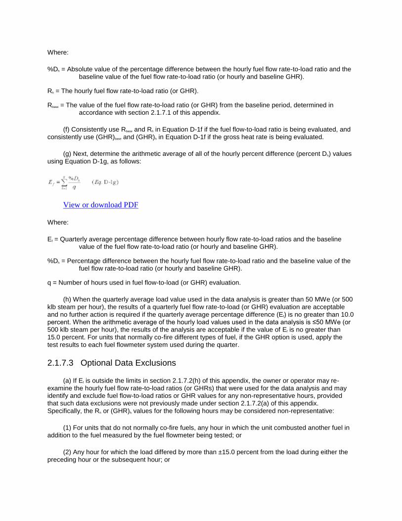
Where:
%Dh = Absolute value of the percentage difference between the hourly fuel flow rate-to-load ratio and the baseline value of the fuel flow rate-to-load ratio (or hourly and baseline GHR).
Rh = The hourly fuel flow rate-to-load ratio (or GHR).
Rbase = The value of the fuel flow rate-to-load ratio (or GHR) from the baseline period, determined in accordance with section 2.1.7.1 of this appendix.
(f) Consistently use Rbase and Rh in Equation D-1f if the fuel flow-to-load ratio is being evaluated, and consistently use (GHR)base and (GHR)h in Equation D-1f if the gross heat rate is being evaluated.
(g) Next, determine the arithmetic average of all of the hourly percent difference (percent Dh) values using Equation D-1g, as follows:
View or download PDF
Where:
Ef = Quarterly average percentage difference between hourly flow rate-to-load ratios and the baseline value of the fuel flow rate-to-load ratio (or hourly and baseline GHR).
%Dh = Percentage difference between the hourly fuel flow rate-to-load ratio and the baseline value of the fuel flow rate-to-load ratio (or hourly and baseline GHR).
q = Number of hours used in fuel flow-to-load (or GHR) evaluation.
(h) When the quarterly average load value used in the data analysis is greater than 50 MWe (or 500 klb steam per hour), the results of a quarterly fuel flow rate-to-load (or GHR) evaluation are acceptable and no further action is required if the quarterly average percentage difference (Ef) is no greater than 10.0 percent. When the arithmetic average of the hourly load values used in the data analysis is ≤50 MWe (or 500 klb steam per hour), the results of the analysis are acceptable if the value of Ef is no greater than 15.0 percent. For units that normally co-fire different types of fuel, if the GHR option is used, apply the test results to each fuel flowmeter system used during the quarter.
2.1.7.3 Optional Data Exclusions
(a) If Ef is outside the limits in section 2.1.7.2(h) of this appendix, the owner or operator may re-examine the hourly fuel flow rate-to-load ratios (or GHRs) that were used for the data analysis and may identify and exclude fuel flow-to-load ratios or GHR values for any non-representative hours, provided that such data exclusions were not previously made under section 2.1.7.2(a) of this appendix. Specifically, the Rh or (GHR)h values for the following hours may be considered non-representative:
(1) For units that do not normally co-fire fuels, any hour in which the unit combusted another fuel in addition to the fuel measured by the fuel flowmeter being tested; or
(2) Any hour for which the load differed by more than ±15.0 percent from the load during either the preceding hour or the subsequent hour; or

(3) For units that normally co-fire different fuels, any hour in which the unit burned only one type of fuel; or
(4) Any hour for which the unit load was in the lower 25.0 percent of the range of operation, as defined in section 6.5.2.1 of appendix A to this part (unless operation in the lower 25.0 percent of the range is considered normal for the unit).
(b) After identifying and excluding all non-representative hourly fuel flow-to-load ratios or GHR values, analyze the quarterly fuel flow rate-to-load data a second time. If fewer than 168 hourly fuel flow-to-load ratio or GHR values remain after the allowable data exclusions, a fuel flow-to-load ratio or GHR analysis is not required for that quarter, and a one-quarter extension of the fuel flowmeter accuracy test deadline may be claimed.
2.1.7.4 Consequences of Failed Fuel Flow-to-Load Ratio Test
(a) If Ef is outside the applicable limit in section 2.1.7.2(h) of this appendix (after analysis using any optional data exclusions under section 2.1.7.3 of this appendix), perform transmitter accuracy tests according to section 2.1.6.1 of this appendix for orifice-, nozzle-, and venturi-type flowmeters, or perform a fuel flowmeter accuracy test, in accordance with section 2.1.5.1 or 2.1.5.2 of this appendix, for each fuel flowmeter for which Ef is outside of the applicable limit. In addition, for an orifice-, nozzle-, or venturi-type fuel flowmeter, repeat the fuel flow-to-load ratio comparison of section 2.1.7.2 of this appendix using six to twelve hours of data following a passed transmitter accuracy test in order to verify that no significant corrosion has affected the primary element. If, for the abbreviated 6-to-12 hour test, the orifice-, nozzle-, or venturi-type fuel flowmeter is not able to meet the limit in section 2.1.7.2 of this appendix, then perform a visual inspection of the primary element according to section 2.1.6.4 of this appendix, and repair or replace the primary element, as necessary.
(b) Substitute for fuel flow rate, for any hour when that fuel is combusted, using the missing data procedures in section 2.4.2 of this appendix, beginning with the first hour of the calendar quarter following the quarter for which Ef was found to be outside the applicable limit and continuing until quality-assured fuel flow data become available. Following a failed flow rate-to-load or GHR evaluation, data from the flowmeter shall not be considered quality-assured until the hour in which all required flowmeter accuracy tests, transmitter accuracy tests, visual inspections and diagnostic tests have been passed. Additionally, a new value of Rbase or (GHR)base shall be established no later than two fuel flowmeter QA operating quarters (as defined in §72.2 of this chapter) after the quarter in which the required quality assurance tests are completed (note that for orifice-, nozzle-, or venturi-type fuel flowmeters, establish a new value of Rbase or (GHR)base only if both a transmitter accuracy test and a primary element inspection have been performed).
2.1.7.5 Test Results
Report the results of each quarterly flow rate-to-load (or GHR) evaluation, as determined from Equation D-1g, in the electronic quarterly report required under §75.64. Table D-3 is provided as a reference on the type of information to be recorded under §75.59 and reported under §75.64.

TABLE D-3—BASELINE INFORMATION AND TEST RESULTS FOR FUEL
FLOW-TO-LOAD TEST
View or download PDF
2.2 Oil Sampling and Analysis
Perform sampling and analysis of oil to determine the following fuel properties for each type of oil combusted by a unit: percentage of sulfur by weight in the oil; gross calorific value (GCV) of the oil; and, if necessary, the density of the oil. Use the sulfur content, density, and gross calorific value, determined under the provisions of this section, to calculate SO2 mass emission rate and heat input rate for each fuel using the applicable procedures of section 3 of this appendix. The designated representative may petition for reduced GCV and or density sampling under §75.66 if the fuel combusted has a consistent and relatively non-variable GCV or density.

View or download PDF
2.2.1 When combusting oil, use one of the following methods to sample the oil (see Table D-4): sample from the storage tank for the unit after each addition of oil to the storage tank, in accordance with section 2.2.4.2 of this appendix; or sample from the fuel lot in the shipment tank or container upon receipt of each oil delivery or from the fuel lot in the oil supplier's storage container, in accordance with section 2.2.4.3 of this appendix; or use the flow proportional sampling methodology in section 2.2.3 of this appendix; or use the daily manual sampling methodology in section 2.2.4.1 of this appendix. For purposes of this appendix, a fuel lot of oil is the mass or volume of product oil from one source (supplier or pretreatment facility), intended as one shipment or delivery (e.g., ship load, barge load, group of trucks,

discrete purchase of diesel fuel through pipeline, etc.). A storage tank is a container at a plant holding oil that is actually combusted by the unit, such that no blending of any other fuel with the fuel in the storage tank occurs from the time that the fuel lot is transferred to the storage tank to the time when the fuel is combusted in the unit.
2.2.2 [Reserved]
2.2.3 Flow Proportional Sampling
Conduct flow proportional oil sampling or continuous drip oil sampling in accordance with ASTM D4177-95 (Reapproved 2000), “Standard Practice for Automatic Sampling of Petroleum and Petroleum Products” (incorporated by reference under §75.6), every day the unit is combusting oil. Extract oil at least once every hour and blend into a composite sample. The sample compositing period may not exceed 7 calendar days (168 hrs). Use the actual sulfur content (and where density data are required, the actual density) from the composite sample to calculate the hourly SO2 mass emission rates for each operating day represented by the composite sample. Calculate the hourly heat input rates for each operating day represented by the composite sample, using the actual gross calorific value from the composite sample.
2.2.4 Manual Sampling
2.2.4.1 Daily Samples
Representative oil samples may be taken from the storage tank or fuel flow line manually every day that the unit combusts oil according to ASTM ASTM D4057-95 (Reapproved 2000), Standard Practice for Manual Sampling of Petroleum and Petroleum Products (incorporated by reference under §75.6 of this part). Use either the actual daily sulfur content or the highest fuel sulfur content recorded at that unit from the most recent 30 daily samples for the purpose of calculating SO2 emissions under section 3 of this appendix. Use either the gross calorific value measured from that day's sample or the highest GCV from the previous 30 days' samples to calculate heat input. If oil supplies with different sulfur contents are combusted on the same day, sample the highest sulfur fuel combusted that day.
2.2.4.2 Sampling From a Unit's Storage Tank
Take a manual sample after each addition of oil to the storage tank. Do not blend additional fuel with the sampled fuel prior to combustion. Sample according to the single tank composite sampling procedure or all-levels sampling procedure in ASTM ASTM D4057-95 (Reapproved 2000), Standard Practice for Manual Sampling of Petroleum and Petroleum Products (incorporated by reference under §75.6 of this part). Use the sulfur content and GCV value (and where required, the density) of either the most recent sample or one of the conservative assumed values described in section 2.2.4.3(c) of this appendix to calculate SO2 mass emission rate. Calculate heat input rate using the gross calorific value from either:
(a) The most recent oil sample taken or
(b) One of the conservative assumed values described in section 2.2.4.3(c) of this appendix. Follow the applicable provisions in section 2.2.4.3(d) of this appendix, regarding the use of assumed values.
2.2.4.3 Sampling From Each Delivery
(a) Alternatively, an oil sample may be taken from—
(1) The shipment tank or container upon receipt of each lot of fuel oil or

(2) The supplier's storage container which holds the lot of fuel oil. (Note: a supplier need only sample the storage container once for sulfur content, GCV and, where required, the density so long as the fuel sulfur content and GCV do not change and no fuel is added to the supplier's storage container.)
(b) For the purpose of this section, a lot is defined as a shipment or delivery (e.g., ship load, barge load, group of trucks, discrete purchase of diesel fuel through a pipeline, etc.) of a single fuel.
(c) Oil sampling may be performed either by the owner or operator of an affected unit, an outside laboratory, or a fuel supplier, provided that samples are representative and that sampling is performed according to either the single tank composite sampling procedure or the all-levels sampling procedure in ASTM ASTM D4057-95 (Reapproved 2000), Standard Practice for Manual Sampling of Petroleum and Petroleum Products (incorporated by reference under §75.6 of this part). Except as otherwise provided in this section, calculate SO2 mass emission rate using the sulfur content (and where required, the density) from one of the two following conservative assumed values, and calculate heat input using the gross calorific value from one of the assumed values:
(1) The highest value sampled during the previous calendar year (this option is allowed for any consistent fuel which comes from a single source whether or not the fuel is supplied under a contractual agreement) or
(2) The maximum value indicated in the contract with the fuel supplier. Continue to use this assumed contract value unless and until the actual sampled sulfur content, density, or gross calorific value of a delivery exceeds the assumed value.
(d) Continue using the assumed value(s), so long as the sample results do not exceed the assumed value(s). However, if the actual sampled sulfur content, gross calorific value, or density of an oil sample is greater than the assumed value for that parameter, then, consistent with section 2.3.7 of this appendix, begin to use the actual sampled value for sulfur content, gross calorific value, or density of fuel to calculate SO2 mass emission rate or heat input rate. Consider the sampled value to be the new assumed sulfur content, gross calorific value, or density. Continue using this new assumed value to calculate SO2 mass emission rate or heat input rate unless and until: it is superseded by a higher value from an oil sample; or (if applicable) it is superseded by a new contract in which case the new contract value becomes the assumed value at the time the fuel specified under the new contract begins to be combusted in the unit; or (if applicable) both the calendar year in which the sampled value exceeded the assumed value and the subsequent calendar year have elapsed.
2.2.5 For each oil sample that is taken on-site at the affected facility, split and label the sample and maintain a portion (at least 200 cc) of it throughout the calendar year and in all cases for not less than 90 calendar days after the end of the calendar year allowance accounting period. This requirement does not apply to oil samples taken from the fuel supplier's storage container, as described in section 2.2.4.3 of this appendix. Analyze oil samples for percent sulfur content by weight in accordance with ASTM D129-00, Standard Test Method for Sulfur in Petroleum Products (General Bomb Method), ASTM D1552-01, Standard Test Method for Sulfur in Petroleum Products (High-Temperature Method), ASTM D2622-98, Standard Test Method for Sulfur in Petroleum Products by Wavelength Dispersive X-ray Fluorescence Spectrometry, ASTM D4294-98, Standard Test Method for Sulfur in Petroleum and Petroleum Products by Energy-Dispersive X-ray Fluorescence Spectrometry, or ASTM D5453-06, Standard Test Method for Determination of Total Sulfur in Light Hydrocarbons, Spark Ignition Engine Fuel, Diesel Engine Fuel, and Engine Oil by Ultraviolet Fluorescence (all incorporated by reference under §75.6 of this part). Alternatively, the oil samples may be analyzed for percent sulfur by any consensus standard method prescribed for the affected unit under part 60 of this chapter.
2.2.6 Where the flowmeter records volumetric flow rate rather than mass flow rate, analyze oil samples to determine the density or specific gravity of the oil. Determine the density or specific gravity of the oil sample in accordance with ASTM D287-92 (Reapproved 2000), Standard Test Method for API

Gravity of Crude Petroleum and Petroleum Products (Hydrometer Method), ASTM D1217-93 (Reapproved 1998), Standard Test Method for Density and Relative Density (Specific Gravity) of Liquids by Bingham Pycnometer, ASTM D1481-93 (Reapproved 1997), Standard Test Method for Density and Relative Density (Specific Gravity) of Viscous Materials by Lipkin Bicapillary Pycnometer, ASTM D1480-93 (Reapproved 1997), Standard Test Method for Density and Relative Density (Specific Gravity) of Viscous Materials by Bingham Pycnometer, ASTM D1298-99, Standard Test Method for Density, Relative Density (Specific Gravity), or API Gravity of Crude Petroleum and Liquid Petroleum Products by Hydrometer Method, or ASTM D4052-96 (Reapproved 2002), Standard Test Method for Density and Relative Density of Liquids by Digital Density Meter (all incorporated by reference under §75.6 of this part). Alternatively, the oil samples may be analyzed for density or specific gravity by any consensus standard method prescribed for the affected unit under part 60 of this chapter.
2.2.7 Analyze oil samples to determine the heat content of the fuel. Determine oil heat content in accordance with ASTM D240-00, ASTM D4809-00, ASTM D5865-01a, or D5865-10 (all incorporated by reference under §75.6) or any other procedures listed in section 5.5 of appendix F of this part. Alternatively, the oil samples may be analyzed for heat content by any consensus standard method prescribed for the affected unit under part 60 of this chapter.
2.2.8 Results from the oil sample analysis must be available no later than thirty calendar days after the sample is composited or taken. However, during an audit, the Administrator may require that the results of the analysis be available as soon as practicable, and no later than 5 business days after receipt of a request from the Administrator.
2.3 SO2 Emissions From Combustion of Gaseous Fuels
(a) Account for the hourly SO2 mass emissions due to combustion of gaseous fuels for each hour when gaseous fuels are combusted by the unit using the procedures in this section.
(b) The procedures in sections 2.3.1 and 2.3.2 of this appendix, respectively, may be used to determine SO2 mass emissions from combustion of pipeline natural gas and natural gas, as defined in §72.2 of this chapter. The procedures in section 2.3.3 of this appendix may be used to account for SO2 mass emissions from any gaseous fuel combusted by a unit. For each type of gaseous fuel, the appropriate sampling frequency and the sulfur content and GCV values used for calculations of SO2 mass emission rates are summarized in the following Table D-5.

View or download PDF
2.3.1 Pipeline Natural Gas Combustion
The owner or operator may determine the SO2 mass emissions from the combustion of a fuel that meets the definition of pipeline natural gas, in §72.2 of this chapter, using the procedures of this section.
2.3.1.1 SO2 Emission Rate
For a fuel that meets the definition of pipeline natural gas under §72.2 of this chapter, the owner or operator may determine the SO2 mass emissions using either a default SO2 emission rate of 0.0006 lb/mmBtu and the procedures of this section, the procedures in section 2.3.2 for natural gas, or the procedures of section 2.3.3 for any gaseous fuel. For each affected unit using the default rate of 0.0006 lb/mmBtu, the owner or operator must document that the fuel combusted is actually pipeline natural gas, using the procedures in section 2.3.1.4 of this appendix.
2.3.1.2 Hourly Heat Input Rate
Calculate hourly heat input rate, in mmBtu/hr, for a unit combusting pipeline natural gas, using the procedures of section 3.4.1 of this appendix. Use the measured fuel flow rate from section 2.1 of this appendix and the gross calorific value from section 2.3.4.1 of this appendix in the calculations.
2.3.1.3 SO2 Hourly Mass Emission Rate and Hourly Mass Emissions
For pipeline natural gas combustion, calculate the SO2 mass emission rate, in lb/hr, using Equation D-5 in section 3.3.2 of this appendix (when the default SO2 emission rate is used) or Equation D-4 (if daily or hourly fuel sampling is used). Then, use the calculated SO2 mass emission rate and the unit operating time to determine the hourly SO2 mass emissions from pipeline natural gas combustion, in lb, using Equation D-12 in section 3.5.1 of this appendix.

2.3.1.4 Documentation that a Fuel is Pipeline Natural Gas
(a) A fuel may initially qualify as pipeline natural gas, if information is provided in the monitoring plan required under §75.53, demonstrating that the definition of pipeline natural gas in §72.2 of this chapter has been met. The information must demonstrate that the fuel meets either the percent methane or GCV requirement and has a total sulfur content of 0.5 grains/100scf or less. The demonstration must be made using one of the following sources of information:
(1) The gas quality characteristics specified by a purchase contract, tariff sheet, or by a pipeline transportation contract; or
(2) Historical fuel sampling data for the previous 12 months, documenting the total sulfur content of the fuel and the GCV and/or percentage by volume of methane. The results of all sample analyses obtained by or provided to the owner or operator in the previous 12 months shall be used in the demonstration, and each sample result must meet the definition of pipeline natural gas in §72.2 of this chapter, except where the results of at least 100 daily (or more frequent) total sulfur samples are provided by the fuel supplier. In that case you may opt to convert these data to monthly averages and then if, for each month, the average total sulfur content is 0.5 grains/100 scf or less, and if the GCV or percent methane requirement is also met, the fuel qualifies as pipeline natural gas. Alternatively, the fuel qualifies
as pipeline natural gas if ≥98 percent of the 100 (or more) samples have a total sulfur content of 0.5
grains/100 scf or less and if the GCV or percent methane requirement is also met; or
(3) If the requirements of paragraphs (a)(1) and (a)(2) of this section cannot be met, a fuel may initially qualify as pipeline natural gas if at least one representative sample of the fuel is obtained and analyzed for total sulfur content and for either the gross calorific value (GCV) or percent methane, and the results of the sample analysis show that the fuel meets the definition of pipeline natural gas in §72.2 of this chapter. Use the sampling methods specified in sections 2.3.3.1.2 and 2.3.4 of this appendix. The required fuel sample may be obtained and analyzed by the owner or operator, by an independent laboratory, or by the fuel supplier. If multiple samples are taken, each sample must meet the definition of pipeline natural gas in §72.2 of this chapter.
(b) If the results of the fuel sampling under paragraph (a)(2) or (a)(3) of this section show that the fuel does not meet the definition of pipeline natural gas in §72.2 of this chapter, but those results are believed to be anomalous, the owner or operator may document the reasons for believing this in the monitoring plan for the unit, and may immediately perform additional sampling. In such cases, a minimum of three additional samples must be obtained and analyzed, and the results of each sample analysis must meet the definition of pipeline natural gas.
(c) If several affected units are supplied by a common source of gaseous fuel, a single sampling result may be applied to all of the units and it is not necessary to obtain a separate sample for each unit, provided that the composition of the fuel is not altered by blending or mixing it with other gaseous fuel(s) when it is transported from the sampling location to the affected units. For the purposes of this paragraph, the term “other gaseous fuel(s)” excludes compounds such as mercaptans when they are added in trace quantities for safety reasons.
(d) If the results of fuel sampling and analysis under paragraph (a)(2), (a)(3), or (b) of this section show that the fuel does not qualify as pipeline natural gas, proceed as follows:
(1) If the fuel still qualifies as natural gas under section 2.3.2.4 of this appendix, re-classify the fuel as natural gas and determine the appropriate default SO2 emission rate for the fuel, according to section 2.3.2.1.1 of this appendix; or

(2) If the fuel does not qualify either as pipeline natural gas or natural gas, re-classify the fuel as “other gaseous fuel” and implement the procedures of section 2.3.3 of this appendix, within 180 days of the end of the quarter in which the disqualifying sample was taken. In addition, the owner or operator shall use Equation D-1h in this appendix to calculate a default SO2 emission rate for the fuel, based on the results of the sample analysis that exceeded 20 grains/100 scf of total sulfur, and shall use that default emission rate to report SO2 mass emissions under this part until section 2.3.3 of this appendix has been fully implemented.
(e) If a fuel qualifies as pipeline natural gas based on the specifications in a fuel contract or tariff sheet, no additional, on-going sampling of the fuel's total sulfur content is required, provided that the contract or tariff sheet is current, valid and representative of the fuel combusted in the unit. If the fuel qualifies as pipeline natural gas based on fuel sampling and analysis, on-going sampling of the fuel's sulfur content is required annually and whenever the fuel supply source changes. For the purposes of this paragraph (e), sampling “annually” means that at least one sample is taken in each calendar year. If the results of at least 100 daily (or more frequent) total sulfur samples have been provided by the fuel supplier since the last annual assessment of the fuel's sulfur content, the data may be used as follows to satisfy the annual sampling requirement for the current year. If this option is chosen, all of the data provided by the fuel supplier shall be used. First, convert the data to monthly averages. Then, if, for each month, the average total sulfur content is 0.5 grains/100 scf or less, and if the GCV or percent methane requirement is also met, the fuel qualifies as pipeline natural gas. Alternatively, the fuel qualifies as pipeline natural gas if the analysis of the 100 (or more) total sulfur samples since the last annual
assessment shows that ≥98 percent of the samples have a total sulfur content of 0.5 grains/100 scf or
less and if the GCV or percent methane requirement is also met. The effective date of the annual total sulfur sampling requirement is January 1, 2003.
(f) On-going sampling of the GCV of the pipeline natural gas is required under section 2.3.4.1 of this appendix.
(g) For units that are required to monitor and report NOX mass emissions and heat input under subpart H of this part, but which are not affected units under the Acid Rain Program, the owner or operator is exempted from the requirements in paragraphs (a) and (e) of this section to document the total sulfur content of the pipeline natural gas.
2.3.2 Natural Gas Combustion
The owner or operator may determine the SO2 mass emissions from the combustion of a fuel that meets the definition of natural gas, in §72.2 of this chapter, using the procedures of this section.
2.3.2.1 SO2 Emission Rate
The owner or operator may account for SO2 emissions either by using a default SO2 emission rate, as determined under section 2.3.2.1.1 of this appendix, or by daily sampling of the gas sulfur content using the procedures of section 2.3.3 of this appendix. For each affected unit using a default SO2 emission rate, the owner or operator must provide documentation that the fuel combusted is actually natural gas according to the procedures in section 2.3.2.4 of this appendix.
2.3.2.1.1 In lieu of daily sampling of the sulfur content of the natural gas, the owner or operator may either use the total sulfur content specified in a contract or tariff sheet as the SO2 default emission rate or may calculate the default SO2 emission rate based on fuel sampling results, using Equation D-1h. In Equation D-1h, the total sulfur content and GCV values shall be determined in accordance with Table D-5 of this appendix. Round off the calculated SO2 default emission rate to the nearest 0.0001 lb/mmBtu.

View or download PDF
Where:
ER = Default SO2 emission rate for natural gas combustion, lb/mmBtu.
Stotal = Total sulfur content of the natural gas, gr/100scf.
GCV = Gross calorific value of the natural gas, Btu/100scf.
7000 = Conversion of grains/100scf to lb/100scf.
2.0 = Ratio of lb SO2/lb S.
106 = Conversion factor (Btu/mmBtu).
2.3.2.1.2 [Reserved]
2.3.2.2 Hourly Heat Input Rate
Calculate hourly heat input rate for natural gas combustion, in mmBtu/hr, using the procedures in section 3.4.1 of this appendix. Use the measured fuel flow rate from section 2.1 of this appendix and the gross calorific value from section 2.3.4.2 of this appendix in the calculations.
2.3.2.3 SO2 Mass Emission Rate and Hourly Mass Emissions
For natural gas combustion, calculate the SO2 mass emission rate, in lb/hr, using Equation D-5 in section 3.3.2 of this appendix, when the default SO2 emission rate is used. Then, use the calculated SO2 mass emission rate and the unit operating time to determine the hourly SO2 mass emissions from natural gas combustion, in lb, using Equation D-12 in section 3.5.1 of this appendix.
2.3.2.4 Documentation that a Fuel Is Natural Gas
(a) A fuel may initially qualify as natural gas, if information is provided in the monitoring plan required under §75.53, demonstrating that the definition of natural gas in §72.2 of this chapter has been met. The information must demonstrate that the fuel meets either the percent methane or GCV requirement and has a total sulfur content of 20.0 grains/100 scf or less. This demonstration must be made using one of the following sources of information:
(1) The gas quality characteristics specified by a purchase contract, tariff sheet, or by a transportation contract; or
(2) Historical fuel sampling data for the previous 12 months, documenting the total sulfur content of the fuel and the GCV and/or percentage by volume of methane. The results of all sample analyses obtained by or provided to the owner or operator in the previous 12 months shall be used in the demonstration, and each sample result must meet the definition of natural gas in §72.2 of this chapter; or
(3) If the requirements of paragraphs (a)(1) and (a)(2) of this section cannot be met, a fuel may initially qualify as natural gas if at least one representative sample of the fuel is obtained and analyzed for

total sulfur content and for either the gross calorific value (GCV) or percent methane, and the results of the sample analysis show that the fuel meets the definition of natural gas in §72.2 of this chapter. Use the sampling methods specified in sections 2.3.3.1.2 and 2.3.4 of this appendix. The required fuel sample may be obtained and analyzed by the owner or operator, by an independent laboratory, or by the fuel supplier. If multiple samples are taken, each sample must meet the definition of natural gas in §72.2 of this chapter.
(b) If the results of the fuel sampling under paragraph (a)(2) or (a)(3) of this section show that the fuel does not meet the definition of natural gas in §72.2 of this chapter, but those results are believed to be anomalous, the owner or operator may document the reasons for believing this in the monitoring plan for the unit, and may immediately perform additional sampling. In such cases, a minimum of three additional samples must be obtained and analyzed, and the results of each sample analysis must meet the definition of natural gas.
(c) If several affected units are supplied by a common source of gaseous fuel, a single sampling result may be applied to all of the units and it is not necessary to obtain a separate sample for each unit, provided that the composition of the fuel is not altered by blending or mixing it with other gaseous fuel(s) when it is transported from the sampling location to the affected units. For the purposes of this paragraph, the term “other gaseous fuel(s)” excludes compounds such as mercaptans when they are added in trace quantities for safety reasons.
(d) If the results of fuel sampling and analysis under paragraph (a)(2), (a)(3), or (b) of this section show that the fuel does not qualify as natural gas, the owner or operator shall re-classify the fuel as “other gaseous fuel” and shall implement the procedures of section 2.3.3 of this appendix, within 180 days of the end of the quarter in which the disqualifying sample was taken. In addition, the owner or operator shall use Equation D-1h in this appendix to calculate a default SO2 emission rate for the fuel, based on the results of the sample analysis that exceeded 20 grains/100 scf of total sulfur, and shall use that default emission rate to report SO2 mass emissions under this part until section 2.3.3 of this appendix has been fully implemented.
(e) If a fuel qualifies as natural gas based on the specifications in a fuel contract or tariff sheet, no additional, on-going sampling of the fuel's total sulfur content is required, provided that the contract or tariff sheet is current, valid and representative of the fuel combusted in the unit. If the fuel qualifies as natural gas based on fuel sampling and analysis, the owner or operator shall sample the fuel for total sulfur content at least annually and when the fuel supply source changes. For the purposes of this paragraph, (e), sampling “annually” means that at least one sample is taken in each calendar year. The effective date of the annual total sulfur sampling requirement is January 1, 2003.
(f) On-going sampling of the GCV of the natural gas is required under section 2.3.4.2 of this appendix.
(g) For units that are required to monitor and report NOX mass emissions and heat input under subpart H of this part, but which are not affected units under the Acid Rain Program, the owner or operator is exempted from the requirements in paragraphs (a) and (e) of this section to document the total sulfur content of the natural gas.
2.3.3 SO2 Mass Emissions From Any Gaseous Fuel
The owner or operator of a unit may determine SO2 mass emissions using this section for any gaseous fuel (including fuels such as refinery gas, landfill gas, digester gas, coke oven gas, blast furnace gas, coal-derived gas, producer gas or any other gas which may have a variable sulfur content).

2.3.3.1 Sulfur Content Determination
2.3.3.1.1 Analyze the total sulfur content of the gaseous fuel in grains/100 scf, at the frequency specified in Table D-5 of this appendix. That is: for fuel delivered in discrete shipments or lots, sample each shipment or lot. For fuel transmitted by pipeline, sample hourly unless a demonstration is provided under section 2.3.6 of this appendix showing that the gaseous fuel qualifies for less frequent (i.e., daily or annual) sampling. If daily sampling is required, determine the sulfur content using either manual sampling or a gas chromatograph. If hourly sampling is required, determine the sulfur content using a gas chromatograph. For units that are required to monitor and report NOX mass emissions and heat input under subpart H of this part, but which are not affected units under the Acid Rain Program, the owner or operator is exempted from the requirements of this section to document the total sulfur content of the gaseous fuel.
2.3.3.1.2 Use one of the following methods when using manual sampling (as applicable to the type of gas combusted) to determine the sulfur content of the fuel: ASTM D1072-06, Standard Test Method for Total Sulfur in Fuel Gases by Combustion and Barium Chloride Titration, ASTM D4468-85 (Reapproved 2006), Standard Test Method for Total Sulfur in Gaseous Fuels by Hydrogenolysis and Rateometric Colorimetry, ASTM D5504-01, Standard Test Method for Determination of Sulfur Compounds in Natural Gas and Gaseous Fuels by Gas Chromatography and Chemiluminescence, ASTM D6667-04, Standard Test Method for Determination of Total Volatile Sulfur in Gaseous Hydrocarbons and Liquefied Petroleum Gases by Ultraviolet Fluorescence, or ASTM D3246-96, Standard Test Method for Sulfur in Petroleum Gas by Oxidative Microcoulometry, (all incorporated by reference under §75.6 of this part). Alternatively, the gas samples may be analyzed for percent sulfur by any consensus standard method prescribed for the affected unit under part 60 of this chapter.
2.3.3.1.3 The sampling and analysis of daily manual samples may be performed by the owner or operator, an outside laboratory, or the gas supplier. If hourly sampling with a gas chromatograph is required, or a source chooses to use an online gas chromatograph to determine daily fuel sulfur content, the owner or operator shall develop and implement a program to quality assure the data from the gas chromatograph, in accordance with the manufacturer's recommended procedures. The quality assurance procedures shall be kept on-site, in a form suitable for inspection.
2.3.3.1.4 Results of all sample analyses must be available no later than thirty calendar days after the sample is taken.
2.3.3.2 SO2 Mass Emission Rate
Calculate the SO2 mass emission rate for the gaseous fuel, in lb/hr, using Equation D-4 or D-5 (as applicable) in section 3.3.1 of this appendix. Equation D-5 may only be used if a demonstration is performed under section 2.3.6 of this appendix, showing that the fuel qualifies to use a default SO2 emission rate to account for SO2 mass emissions under this part. Use the appropriate sulfur content or default SO2 emission rate in Equation D-4 or D-5, as specified in Table D-5 of this appendix. If the fuel qualifies to use Equation D-5, the default SO2 emission rate shall be calculated using Equation D-1h in section 2.3.2.1.1 of this appendix, replacing the words “natural gas” in the equation nomenclature with the words, “gaseous fuel”. In all cases, for reporting purposes, apply the results of the required periodic total sulfur samples in accordance with the provisions of section 2.3.7 of this appendix.
2.3.3.3 Hourly Heat Input Rate
Calculate the hourly heat input rate for combustion of the gaseous fuel, using the provisions in section 3.4.1 of this appendix. Use the measured fuel flow rate from section 2.1 of this appendix and the gross calorific value from section 2.3.4.3 of this appendix in the calculations.

2.3.4 Gross Calorific Values for Gaseous Fuels
Determine the GCV of each gaseous fuel at the frequency specified in this section, using one of the following methods: ASTM D1826-94 (Reapproved 1998), ASTM D3588-98, ASTM D4891-89 (Reapproved 2006), GPA Standard 2172-96, Calculation of Gross Heating Value, Relative Density and Compressibility Factor for Natural Gas Mixtures from Compositional Analysis, or GPA Standard 2261-00, Analysis for Natural Gas and Similar Gaseous Mixtures by Gas Chromatography (all incorporated by reference under §75.6 of this part). Use the appropriate GCV value, as specified in section 2.3.4.1, 2.3.4.2, or 2.3.4.3 of this appendix, in the calculation of unit hourly heat input rates. Alternatively, the gas samples may be analyzed for heat content by any consensus standard method prescribed for the affected unit under part 60 of this chapter.
2.3.4.1 GCV of Pipeline Natural Gas
Determine the GCV of fuel that is pipeline natural gas, as defined in §72.2 of this chapter, at least once per calendar month. For GCV used in calculations use the specifications in Table D-5: either the value from the most recent monthly sample, the highest value specified in a contract or tariff sheet, or the highest value from the previous year. The fuel GCV value from the most recent monthly sample shall be used for any month in which that value is higher than a contract limit. If a unit combusts pipeline natural gas for less than 48 hours during a calendar month, the sampling and analysis requirement for GCV is waived for that calendar month. The preceding waiver is limited by the condition that at least one analysis for GCV must be performed for each quarter the unit operates for any amount of time. If multiple GCV samples are taken and analyzed in a particular month, the GCV values from all samples shall be averaged arithmetically to obtain the monthly GCV. Then, apply the monthly average GCV value as described in paragraph (c) in section 2.3.7 of this appendix.
2.3.4.2 GCV of Natural Gas
Determine the GCV of fuel that is natural gas, as defined in §72.2 of this chapter, on a monthly basis, in the same manner as described for pipeline natural gas in section 2.3.4.1 of this appendix.
2.3.4.3 GCV of Other Gaseous Fuels
For gaseous fuels other than natural gas or pipeline natural gas, determine the GCV as specified in section 2.3.4.3.1, 2.3.4.3.2 or 2.3.4.3.3, as applicable. For reporting purposes, apply the results of the required periodic GCV samples in accordance with the provisions of section 2.3.7 of this appendix.
2.3.4.3.1 For a gaseous fuel that is delivered in discrete shipments or lots, determine the GCV for each shipment or lot. The determination may be made by sampling each delivery or by sampling the supply tank after each delivery. For sampling of each delivery, use the highest GCV in the previous year's samples. For sampling from the tank after each delivery, use either the most recent GCV sample, the maximum GCV specified in the fuel contract or tariff sheet, or the highest GCV from the previous year's samples.
2.3.4.3.2 For any gaseous fuel that does not qualify as pipeline natural gas or natural gas, which is not delivered in shipments or lots, and for which the owner or operator performs the 720 hour test under section 2.3.5 of this appendix, if the results of the test demonstrate that the gaseous fuel has a low GCV variability, determine the GCV at least monthly (as described in section 2.3.4.1 of this appendix). In calculations of hourly heat input for a unit, use either the most recent monthly sample, the maximum GCV specified in the fuel contract or tariff sheet, or the highest fuel GCV from the previous year's samples.

2.3.4.3.3 For any other gaseous fuel, determine the GCV at least daily and use the actual fuel GCV in calculations of unit hourly heat input. If an online gas chromatograph or on-line calorimeter is used to determine fuel GCV each day, the owner or operator shall develop and implement a program to quality assure the data from the gas chromatograph or on-line calorimeter, in accordance with the manufacturer's recommended procedures. The quality assurance procedures shall be kept on-site, in a form suitable for inspection.
2.3.5 Demonstration of Fuel GCV Variability
(a) This optional demonstration may be made for any fuel which does not qualify as pipeline natural gas or natural gas, and is not delivered only in shipments or lots. The demonstration data may be used to show that monthly sampling of the GCV of the gaseous fuel or blend is sufficient, in lieu of daily GCV sampling.
(b) To make this demonstration, proceed as follows. Provide a minimum of 720 hours of data, indicating the GCV of the gaseous fuel or blend (in Btu/100 scf). The demonstration data shall be obtained using either: hourly sampling and analysis using the methods in section 2.3.4 to determine GCV of the fuel; an on-line gas chromatograph capable of determining fuel GCV on an hourly basis; or an on-line calorimeter. For gaseous fuel produced by a variable process, the data shall be representative of and include all process operating conditions including seasonal and yearly variations in process which may affect fuel GCV.
(c) The data shall be reduced to hourly averages. The mean GCV value and the standard deviation from the mean shall be calculated from the hourly averages. Specifically, the gaseous fuel is considered to have a low GCV variability, and monthly gas sampling for GCV may be used, if the mean value of the GCV multiplied by 1.075 is greater than the sum of the mean value and one standard deviation. If the gaseous fuel or blend does not meet this requirement, then daily fuel sampling and analysis for GCV, using manual sampling, a gas chromatograph or an on-line calorimeter is required.
2.3.6 Demonstration of Fuel Sulfur Variability
(a) This demonstration may be made for any fuel which does not qualify as pipeline natural gas or natural gas, and is not delivered only in shipments or lots. The results of the demonstration may be used to show that daily sampling for sulfur in the fuel is sufficient, rather than hourly sampling. The procedures in this section may also be used to demonstrate that a particular gaseous fuel qualifies to use a default SO2 emission rate (calculated using Equation D-1h in section 2.3.2.1.1 of this appendix) for the purpose of reporting hourly SO2 mass emissions under this part. To make this demonstration, proceed as follows. Provide a minimum of 720 hours of data, indicating the total sulfur content of the gaseous fuel (in gr/100 scf). The demonstration data shall be obtained using either manual hourly sampling or an on-line gas chromatograph (GC) capable of determining fuel total sulfur content on an hourly basis. For gaseous fuel produced by a variable process, the data shall be representative of all process operating conditions including seasonal or annual variations which may affect fuel sulfur content.
(b) If the data are collected with an on-line GC, reduce the data to hourly average values of the total sulfur content of the fuel. If manual hourly sampling is used, the results of each hourly sample analysis shall be the total sulfur value for that hour. Express all hourly average values of total sulfur content in units of grains/100 scf. Use all of the hourly average values of total sulfur content in grains/100 scf to calculate the mean value and the standard deviation. Also determine the 90th percentile and maximum hourly values of the total sulfur content for the data set. If the standard deviation of the hourly values from the mean does not exceed 5.0 grains/100 scf, the fuel has a low sulfur variability. If the standard deviation exceeds 5.0 grains/100 scf, the fuel has a high sulfur variability. Based on the results of this determination, establish the required sampling frequency and SO2 mass emissions methodology for the gaseous fuel, as follows:

(1) If the gaseous fuel has a low sulfur variability (irrespective of the total sulfur content), the owner or operator may either perform daily sampling of the fuel's total sulfur content using manual sampling or a GC, or may report hourly SO2 mass emissions data using a default SO2 emission rate calculated by substituting the 90th percentile value of the total sulfur content in Equation D-1h.
(2) If the gaseous fuel has a high sulfur variability, but the maximum hourly value of the total sulfur content does not exceed 20 grains/100 scf, the owner or operator may either perform hourly sampling of the fuel's total sulfur content using an on-line GC, or may report hourly SO2 mass emissions data using a default SO2 emission rate calculated by substituting the maximum value of the total sulfur content in Equation D-1h.
(3) If the gaseous fuel has a high sulfur variability and the maximum hourly value of the total sulfur content exceeds 20 grains/100 scf, the owner or operator shall perform hourly sampling of the fuel's total sulfur content, using an on-line GC.
(4) Any gaseous fuel under paragraph (b)(1) or (b)(2) of this section, for which the owner or operator elects to use a default SO2 emission rate for reporting purposes is subject to the annual total sulfur sampling requirement under section 2.3.2.4(e) of this appendix.
2.3.7 Application of Fuel Sampling Results
For reporting purposes, apply the results of the required periodic fuel samples described in Tables D-4 and D-5 of this appendix as follows. Use Equation D-1h to recalculate the SO2 emission rate, as necessary.
(a) For daily samples of total sulfur content or GCV:
(1) If the actual value is to be used in the calculations, apply the results of each daily sample to all hours in the day on which the sample is taken; or
(2) If the highest value in the previous 30 daily samples is to be used in the calculations, apply that value to all hours in the current day. If, for a particular unit, fewer than 30 daily samples have been collected, use the highest value from all available samples until 30 days of historical sampling results have been obtained.
(b) For annual samples of total sulfur content:
(1) For pipeline natural gas, use the results of annual sample analyses in the calculations only if the results exceed 0.5 grains/100 scf. In that case, if the fuel still qualifies as natural gas, follow the procedures in paragraph (b)(2) of this section. If the fuel does not qualify as natural gas, the owner or operator shall implement the procedures in section 2.3.3 of this appendix, in the time frame specified in sections 2.3.1.4(d) and 2.3.2.4(d) of this appendix;
(2) For natural gas, if only one sample is taken, apply the results beginning at the date on which the sample was taken. If multiple samples are taken and averaged, apply the results beginning at the date on which the last sample used in the annual assessment was taken;
(3) For other gaseous fuels with an annual sampling requirement under section 2.3.6(b)(4) of this appendix, use the sample results in the calculations only if the results exceed the 90th percentile value or maximum value (as applicable) from the 720-hour demonstration of fuel sulfur content and variability under section 2.3.6 of this appendix.
(c) For monthly samples of the fuel GCV:

(1) If the actual monthly value is to be used in the calculations and only one sample is taken, apply the results starting from the date on which the sample was taken. If multiple samples are taken and averaged, apply the monthly average GCV value to the entire month; or
(2) If an assumed value (contract maximum or highest value from previous year's samples) is to be used in the calculations, apply the assumed value to all hours in each month of the quarter unless a higher value is obtained in a monthly GCV sample (or, if multiple samples are taken and averaged, if the monthly average exceeds the assumed value). In that case, if only one monthly sample is taken, use the sampled value, starting from the date on which the sample was taken. If multiple samples are taken and averaged, use the average value for the entire month in which the assumed value was exceeded. Consider the sample (or, if applicable, monthly average) results to be the new assumed value. Continue using the new assumed value unless and until one of the following occurs (as applicable to the reporting option selected): The assumed value is superseded by a higher value from a subsequent monthly sample (or by a higher monthly average); or the assumed value is superseded by a new contract in which case the new contract value becomes the assumed value at the time the fuel specified under the new contract begins to be combusted in the unit; or both the calendar year in which the new sampled value (or monthly average) exceeded the assumed value and the subsequent calendar year have elapsed.
(d) For samples of gaseous fuel delivered in shipments or lots:
(1) If the actual value for the most recent shipment is to be used in the calculations, apply the results of the most recent sample, from the date on which the sample was taken until the date on which the next sample is taken; or
(2) If an assumed value (contract maximum or highest value from previous year's samples) is to be used in the calculations, apply the assumed value unless a higher value is obtained in a sample of a shipment. In that case, use the sampled value, starting from the date on which the sample was taken. Consider the sample results to be the new assumed value. Continue using the new assumed value unless and until: it is superseded by a higher value from a sample of a subsequent shipment; or (if applicable) it is superseded by a new contract in which case the new contract value becomes the assumed value at the time the fuel specified under the new contract begins to be combusted in the unit; or (if applicable) both the calendar year in which the sampled value exceeded the assumed value and the subsequent calendar year have elapsed.
(e) When the owner or operator elects to use assumed values in the calculations, the results of periodic samples of sulfur content and GCV which show that the assumed value has not been exceeded need not be reported. Keep these sample results on file, in a format suitable for inspection.
(f) Notwithstanding the requirements of paragraphs (b) through (d) of this section, in cases where the sample results are provided to the owner or operator by the supplier of the fuel, the owner or operator shall begin using the sampling results on the date of receipt of those results, rather than on the date that the sample was taken.
2.4 Missing Data Procedures.
When data from the procedures of this part are not available, provide substitute data using the following procedures.
2.4.1 Missing Data for Oil and Gas Samples
When fuel sulfur content, gross calorific value or, when necessary, density data are missing or invalid for an oil or gas sample taken according to the procedures in section 2.2.3, 2.2.4.1, 2.2.4.2, 2.2.4.3, 2.2.5, 2.2.6, 2.2.7, 2.3.3.1.2, or 2.3.4 of this appendix, then substitute the maximum potential

sulfur content, density, or gross calorific value of that fuel from Table D-6 of this appendix. Except for the annual samples of fuel sulfur content required under sections 2.3.1.4(e), 2.3.2.4(e) and 2.3.6(b)(5) of this appendix, the missing data values in Table D-6 shall be reported whenever the results of a required sample of sulfur content, GCV or density is missing or invalid in the current calendar year, irrespective of which reporting option is selected (i.e., actual value, contract value or highest value from the previous year). For the annual samples of fuel sulfur content required under sections 2.3.1.4(e), 2.3.2.4(e) and 2.3.6(b)(5) of this appendix, if a valid annual sample has not been obtained by the end of a particular calendar year, the appropriate missing data value in Table D-6 shall be reported, beginning with the first unit operating hour in the next calendar year. The substitute data value(s) shall be used until the next valid sample for the missing parameter(s) is obtained. Note that only actual sample results shall be used to determine the “highest value from the previous year” when that reporting option is used; missing data values shall not be used in the determination.
View or download PDF
2.4.2 Missing Data Procedures for Fuel Flow Rate
Whenever data are missing from any primary fuel flowmeter system (as defined in §72.2 of this chapter) and there is no backup system available to record the fuel flow rate, use the procedures in sections 2.4.2.2 and 2.4.2.3 of this appendix to account for the flow rate of fuel combusted at the unit for each hour during the missing data period. Alternatively, for a fuel flowmeter system used to measure the fuel combusted by a peaking unit, the simplified fuel flow missing data procedure in section 2.4.2.1 of this appendix may be used. Before using the procedures in sections 2.4.2.2 and 2.4.2.3 of this appendix, establish load ranges for the unit using the procedures of section 2 in appendix C to this part, except for units that do not produce electrical output (i.e., megawatts) or thermal output (e.g., klb of steam per hour). The owner or operator of a unit that does not produce electrical or thermal output shall either perform missing data substitution without segregating the fuel flow rate data into bins, or may petition the Administrator under §75.66 for permission to segregate the data into operational bins. When load ranges are used for fuel flow rate missing data purposes, separate, fuel-specific databases shall be created and maintained. A database shall be kept for each type of fuel combusted in the unit, for the hours in which

the fuel is combusted alone in the unit. An additional database shall be kept for each type of fuel, for the hours in which it is co-fired with any other type(s) of fuel(s).
2.4.2.1 Simplified Fuel Flow Rate Missing Data Procedure for Peaking Units
If no fuel flow rate data are available for a fuel flowmeter system installed on a peaking unit (as defined in §72.2 of this chapter), then substitute for each hour of missing data using the maximum potential fuel flow rate. The maximum potential fuel flow rate is the lesser of the following:
(a) The maximum fuel flow rate the unit is capable of combusting or
(b) The maximum flow rate that the fuel flowmeter can measure (i.e., the upper range value of the flowmeter).
2.4.2.2 Standard Missing Data Procedures—Single Fuel Hours
For missing data periods that occur when only one type of fuel is being combusted, provide substitute data for each hour in the missing data period as follows.
2.4.2.2.1 If load-based missing data procedures are used, substitute the arithmetic average of the hourly fuel flow rate(s) measured and recorded by a certified fuel flowmeter system at the corresponding operating unit load range during the previous 720 operating hours in which the unit combusted only that same fuel. If no fuel flow rate data are available at the corresponding load range, use data from the next higher load range, if such data are available. If no quality-assured fuel flow rate data are available at either the corresponding load range or a higher load range, substitute the maximum potential fuel flow rate (as defined in section 2.4.2.1 of this appendix) for each hour of the missing data period.
2.4.2.2.2 For units that do not produce electrical or thermal output and therefore cannot use load-based missing data procedures, provide substitute data for each hour of the missing data period as follows. Substitute the arithmetic average of the hourly fuel flow rates measured and recorded by a certified fuel flowmeter system during the previous 720 operating hours in which the unit combusted only that same fuel. If no quality-assured fuel flow rate data are available, substitute the maximum potential fuel flow rate (as defined in section 2.4.2.1 of this appendix) for each hour of the missing data period.
2.4.2.3 Standard Missing Data Procedures—Multiple Fuel Hours
For missing data periods that occur when two or more different types of fuel are being co-fired, provide substitute fuel flow rate data for each hour of the missing data period as follows.
2.4.2.3.1 If load-based missing data procedures are used, substitute the maximum hourly fuel flow rate measured and recorded by a certified fuel flowmeter system at the corresponding load range during the previous 720 operating hours when the fuel for which the flow rate data are missing was co-fired with any other type of fuel. If no such quality-assured fuel flow rate data are available at the corresponding load range, use data from the next higher load range (if available). If no quality-assured fuel flow rate data are available for co-fired hours, either at the corresponding load range or a higher load range, substitute the maximum potential fuel flow rate (as defined in section 2.4.2.1 of this appendix) for each hour of the missing data period.
2.4.2.3.2 For units that do not produce electrical or thermal output and therefore cannot use load-based missing data procedures, provide substitute fuel flow rate data for each hour of the missing data period as follows. Substitute the maximum hourly fuel flow rate measured and recorded by a certified fuel flowmeter system during the previous 720 operating hours in which the fuel for which the flow rate data

are missing was co-fired with any other type of fuel. If no quality-assured fuel flow rate data for co-fired hours are available, substitute the maximum potential fuel flow rate (as defined in section 2.4.2.1 of this appendix) for each hour of the missing data period.
2.4.2.3.3 If, during an hour in which different types of fuel are co-fired, quality-assured fuel flow rate data are missing for two or more of the fuels being combusted, apply the procedures in section 2.4.2.3.1 or 2.4.2.3.2 of this appendix (as applicable) separately for each type of fuel.
2.4.2.3.4 If the missing data substitution required in section 2.4.2.3.1 or 2.4.2.3.2 causes the reported hourly heat input rate based on the combined fuel usage to exceed the maximum rated hourly heat input of the unit, adjust the substitute fuel flow rate value(s) so that the reported heat input rate equals the unit's maximum rated hourly heat input. Manual entry of the adjusted substitute data values is permitted.
2.4.3. In any case where the missing data provisions of this section require substitution of data measured and recorded more than three years (26,280 clock hours) prior to the date and time of the missing data period, use three years (26,280 clock hours) in place of the prescribed lookback period. In addition, for a new or newly-affected unit, until 720 hours of quality-assured fuel flowmeter data are available for the lookback periods described in sections 2.4.2.2 and 2.4.2.3 of this appendix, use all of the available fuel flowmeter data to determine the appropriate substitute data values.
3. CALCULATIONS
Calculate hourly SO2 mass emission rate from combustion of oil fuel using the procedures in section 3.1 of this appendix. Calculate hourly SO2 mass emission rate from combustion of gaseous fuel using the procedures in section 3.3 of this appendix. (Note: the SO2 mass emission rates in sections 3.1 and 3.3 are calculated such that the rate, when multiplied by unit operating time, yields the hourly SO2 mass emissions for a particular fuel for the unit.) Calculate hourly heat input rate for both oil and gaseous fuels using the procedures in section 3.4 of this appendix. Calculate total SO2 mass emissions and heat input for each hour, each quarter and the year to date using the procedures under section 3.5 of this appendix. Where an oil flowmeter records volumetric flow rate, use the calculation procedures in section 3.2 of this appendix to calculate the mass flow rate of oil.
3.1 SO2 Mass Emission Rate Calculation for Oil
3.1.1 Use Equation D-2 to calculate SO2 mass emission rate per hour (lb/hr):
View or download PDF
Where:
SO2rate-oil = Hourly mass emission rate of SO2 emitted from combustion of oil, lb/hr.
OILrate = Mass rate of oil consumed per hr during combustion, lb/hr.
%Soil = Percentage of sulfur by weight in the oil.
2.0 = Ratio of lb SO2/lb S.

3.1.2 Record the SO2 mass emission rate from oil for each hour that oil is combusted.
3.2 Mass Flow Rate Calculation for Volumetric Oil Flowmeters
3.2.1 Where the oil flowmeter records volumetric flow rate rather than mass flow rate, calculate and record the oil mass flow rate for each hourly period using hourly oil flow rate measurements and the density or specific gravity of the oil sample.
3.2.2 Convert density, specific gravity, or API gravity of the oil sample to density of the oil sample at the sampling location's temperature using ASTM D1250-07, Standard Guide for Use of the Petroleum Measurement Tables (incorporated by reference under (§75.6 of this part).
3.2.3 Where density of the oil is determined by the applicable ASTM procedures from section 2.2.6 of this appendix, use Equation D-3 to calculate the rate of the mass of oil consumed (in lb/hr):
View or download PDF
Where:
OILrate = Mass rate of oil consumed per hr, lb/hr.
Voil-rate = Volume rate of oil consumed per hr, measured in scf/hr, gal/hr, barrels/hr, or m3/hr.
Doil = Density of oil, measured in lb/scf, lb/gal, lb/barrel, or lb/m3.
3.3 SO2 Mass Emission Rate Calculation for Gaseous Fuels
3.3.1 Use Equation D-4 to calculate the SO2 mass emission rate when using the optional gas sampling and analysis procedures in sections 2.3.1 and 2.3.2 of this appendix, or the required gas sampling and analysis procedures in section 2.3.3 of this appendix. Total sulfur content of a fuel must be determined using the procedures of 2.3.3.1.2 of this appendix:
View or download PDF
Where:
SO2rate-gas = Hourly mass rate of SO2 emitted due to combustion of gaseous fuel, lb/hr.
GASrate = Hourly metered flow rate of gaseous fuel combusted, 100 scf/hr.
Sgas = Sulfur content of gaseous fuel, in grain/100 scf.
2.0 = Ratio of lb SO2/lb S.
7000 = Conversion of grains/100 scf to lb/100 scf.

3.3.2 Use Equation D-5 to calculate the SO2 mass emission rate when using a default emission rate from section 2.3.1.1 or 2.3.2.1.1 of this appendix:
View or download PDF
where:
SO2rate = Hourly mass emission rate of SO2 from combustion of a gaseous fuel, lb/hr.
ER = SO2 emission rate from section 2.3.1.1 or 2.3.2.1.1, of this appendix, lb/mmBtu.
HIrate = Hourly heat input rate of a gaseous fuel, calculated using procedures in section 3.4.1 of this appendix, in mmBtu/hr.
3.3.3 Record the SO2 mass emission rate for each hour when the unit combusts a gaseous fuel.
3.4 Calculation of Heat Input Rate
3.4.1 Heat Input Rate for Gaseous Fuels
(a) Determine total hourly gas flow or average hourly gas flow rate with a fuel flowmeter in accordance with the requirements of section 2.1 of this appendix and the fuel GCV in accordance with the requirements of section 2.3.4 of this appendix. If necessary perform the 720-hour test under section 2.3.5 to determine the appropriate fuel GCV sampling frequency.
(b) Then, use Equation D-6 to calculate heat input rate from gaseous fuels for each hour.
View or download PDF
Where:
HIrate-gas = Hourly heat input rate from combustion of the gaseous fuel, mmBtu/hr.
GASrate = Average volumetric flow rate of fuel, for the portion of the hour in which the unit operated, 100 scf/hr.
GCVgas = Gross calorific value of gaseous fuel, Btu/100 scf.
106 = Conversion of Btu to mmBtu.
(c) Note that when fuel flow is measured on an hourly totalized basis (e.g. a fuel flowmeter reports totalized fuel flow for each hour), before Equation D-6 can be used, the total hourly fuel usage must be converted from units of 100 scf to units of 100 scf/hr using Equation D-7:

View or download PDF
Where:
GASrate = Average volumetric flow rate of fuel for the portion of the hour in which the unit operated, 100 scf/hr.
GASunit = Total fuel combusted during the hour, 100 scf.
t = Unit operating time, hour or fraction of an hour (in equal increments that can range from one hundredth to one quarter of an hour, at the option of the owner or operator).
3.4.2 Heat Input Rate From the Combustion of Oil
(a) Determine total hourly oil flow or average hourly oil flow rate with a fuel flowmeter, in accordance with the requirements of section 2.1 of this appendix. Determine oil GCV according to the requirements of section 2.2 of this appendix.
Then, use Equation D-8 to calculate hourly heat input rate from oil for each hour:
View or download PDF
Where:
HIrate-oil = Hourly heat input rate from combustion of oil, mmBtu/hr.
OILrate = Mass rate of oil consumed per hour, as determined using procedures in section 3.2.3 of this appendix, in lb/hr, tons/hr, or kg/hr.
GCVoil = Gross calorific value of oil, Btu/lb, Btu/ton, or Btu/kg.
106 = Conversion of Btu to mmBtu.
(b) Note that when fuel flow is measured on an hourly totalized basis (e.g., a fuel flowmeter reports totalized fuel flow for each hour), before equation D-8 can be used, the total hourly fuel usage must be converted from units of lb to units of lb/hr, using equation D-9:
View or download PDF
Where:
OILrate = Average fuel flow rate for the portion of the hour which the unit operated in lb/hr.
OILunit = Total fuel combusted during the hour, lb.
t = Unit operating time, hour or fraction of an hour (in equal increments that can range from one hundredth to one quarter of an hour, at the option of the owner or operator).
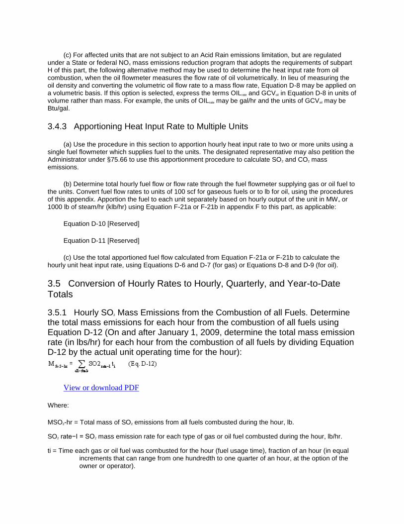
(c) For affected units that are not subject to an Acid Rain emissions limitation, but are regulated under a State or federal NOX mass emissions reduction program that adopts the requirements of subpart H of this part, the following alternative method may be used to determine the heat input rate from oil combustion, when the oil flowmeter measures the flow rate of oil volumetrically. In lieu of measuring the oil density and converting the volumetric oil flow rate to a mass flow rate, Equation D-8 may be applied on a volumetric basis. If this option is selected, express the terms OILrate and GCVoil in Equation D-8 in units of volume rather than mass. For example, the units of OILrate may be gal/hr and the units of GCVoil may be Btu/gal.
3.4.3 Apportioning Heat Input Rate to Multiple Units
(a) Use the procedure in this section to apportion hourly heat input rate to two or more units using a single fuel flowmeter which supplies fuel to the units. The designated representative may also petition the Administrator under §75.66 to use this apportionment procedure to calculate SO2 and CO2 mass emissions.
(b) Determine total hourly fuel flow or flow rate through the fuel flowmeter supplying gas or oil fuel to the units. Convert fuel flow rates to units of 100 scf for gaseous fuels or to lb for oil, using the procedures of this appendix. Apportion the fuel to each unit separately based on hourly output of the unit in MW e or 1000 lb of steam/hr (klb/hr) using Equation F-21a or F-21b in appendix F to this part, as applicable:
Equation D-10 [Reserved]
Equation D-11 [Reserved]
(c) Use the total apportioned fuel flow calculated from Equation F-21a or F-21b to calculate the hourly unit heat input rate, using Equations D-6 and D-7 (for gas) or Equations D-8 and D-9 (for oil).
3.5 Conversion of Hourly Rates to Hourly, Quarterly, and Year-to-Date Totals
3.5.1 Hourly SO2 Mass Emissions from the Combustion of all Fuels. Determine the total mass emissions for each hour from the combustion of all fuels using Equation D-12 (On and after January 1, 2009, determine the total mass emission rate (in lbs/hr) for each hour from the combustion of all fuels by dividing Equation D-12 by the actual unit operating time for the hour):
View or download PDF
Where:
MSO2-hr = Total mass of SO2 emissions from all fuels combusted during the hour, lb.
SO2 rate−I = SO2 mass emission rate for each type of gas or oil fuel combusted during the hour, lb/hr.
ti = Time each gas or oil fuel was combusted for the hour (fuel usage time), fraction of an hour (in equal increments that can range from one hundredth to one quarter of an hour, at the option of the owner or operator).

3.5.2 Quarterly Total SO2 Mass Emissions
Sum the hourly SO2 mass emissions in lb as determined from Equation D-12 for all hours in a quarter using Equation D-13:
View or download PDF
Where:
MSO2-qtr = Total mass of SO2 emissions from all fuels combusted during the quarter, tons.
MSO2-hr = Hourly SO2 mass emissions determined using Equation D-12, lb.
2000= Conversion factor from lb to tons.
3.5.3 Year to Date SO2 Mass Emissions
Calculate and record SO2 mass emissions in the year to date using Equation D-14:
View or download PDF
Where:
MSO2-YTD = Total SO2 mass emissions for the year to date, tons.
MSO2-qtr = Total SO2 mass emissions for the quarter, tons.
3.5.4 Hourly Total Heat Input Rate and Heat Input from the Combustion of all Fuels
3.5.4.1 Determine the total heat input in mmBtu for each hour from the combustion of all fuels using Equation D-15:
View or download PDF
Where:
HIhr = Total heat input from all fuels combusted during the hour, mmBtu.
HIrate-i = Heat input rate for each type of gas or oil combusted during the hour, mmBtu/hr.

ti = Time each gas or oil fuel was combusted for the hour (fuel usage time), fraction of an hour (in equal increments that can range from one hundredth to one quarter of an hour, at the option of the owner or operator).
3.5.4.2 For reporting purposes, determine the heat input rate to each unit, in mmBtu/hr, for each hour from the combustion of all fuels using Equation D-15a:
View or download PDF
Where:
HIrate-hr = Total heat input rate from all fuels combusted during the hour, mmBtu/hr.
HIrate-i = Heat input rate for each type of gas or oil combusted during the hour, mmBtu/hr.
ti = Time each gas or oil fuel was combusted for the hour (fuel usage time), fraction of an hour (in equal increments that can range from one hundredth to one quarter of an hour, at the option of the owner or operator).
tu = Unit operating time
3.5.5 Quarterly Heat Input
Sum the hourly heat input values determined from equation D-15 for all hours in a quarter using Equation D-16:
View or download PDF
Where:
HIqtr = Total heat input from all fuels combusted during the quarter, mmBtu.
HIqtr = Hourly heat input determined using Equation D-15, mmBtu.
3.5.6 Year-to-Date Heat Input
Calculate and record the total heat input in the year to date using Equation D-17.
View or download PDF
HIYTD = Total heat input for the year to date, mmBtu.

HIqtr = Total heat input for the quarter, mmBtu.
3.6 Records and Reports
Calculate and record quarterly and cumulative SO2 mass emissions and heat input for each calendar quarter using the procedures and equations of section 3.5 of this appendix. Calculate and record SO2 emissions and heat input data using a data acquisition and handling system. Report these data in a standard electronic format specified by the Administrator.
[58 FR 3701, Jan. 11, 1993, as amended at 60 FR 26548, 26551, May 17, 1995; 61 FR 25585, May 22, 1996; 61 FR 59166, Nov. 20, 1996; 63 FR 57513, Oct. 27, 1998; 64 FR 28652-28663, May 26, 1999; 64 FR 37582, July 12, 1999; 67 FR 40460, 40472, June 12, 2002; 67 FR 53505, Aug. 16, 2002; 73 FR 4369, Jan. 24, 2008; 76 FR 17324, Mar. 28, 2011; 76 FR 20536, Apr. 13, 2011; 77 FR 2460, Jan. 18, 2012]
EDITORIAL NOTE: At 67 FR 53505, Aug. 16, 2002, section 2.4.1 Table D-6 was amended. However, this table is a photographed graphic and the amendments could not be incorporated.
Back to Top
Appendix E to Part 75—Optional NOX Emissions Estimation Protocol for Gas-Fired Peaking Units and Oil-Fired Peaking Units
1. APPLICABILITY
1.1 Unit Operation Requirements
This NOX emissions estimation procedure may be used in lieu of a continuous NOX emission monitoring system (lb/mmBtu) for determining the average NOX emission rate and hourly NOX rate from gas-fired peaking units and oil-fired peaking units as defined in §72.2 of this chapter. If a unit's operations exceed the levels required to be a peaking unit, the owner or operator shall install and certify a NOX-diluent continuous emission monitoring system no later than December 31 of the following calendar year. If the required CEMS has not been installed and certified by that date, the owner or operator shall report the maximum potential NOX emission rate (MER) (as defined in §72.2 of this chapter) for each unit operating hour, starting with the first unit operating hour after the deadline and continuing until the CEMS has been provisionally certified. The provision of §75.12 apply to excepted monitoring systems under this appendix.
1.2 Certification
1.2.1 Pursuant to the procedures in §75.20, complete all testing requirements to certify use of this protocol in lieu of a NOX continuous emission monitoring system no later than the applicable deadline specified in §75.4. Apply to the Administrator for certification to use this method no later than 45 days after the completion of all certification testing. Whenever the monitoring method is to be changed, reapply to the Administrator for certification of the new monitoring method.
1.2.2 [Reserved]
2. PROCEDURE
2.1 Initial Performance Testing
Use the following procedures for: measuring NOX emission rates at heat input rate levels corresponding to different load levels; measuring heat input rate; and plotting the correlation between heat input rate and NOX emission rate, in order to determine the emission rate of the unit(s). The requirements in section 6.1.2 of appendix A to this part shall apply to any stack testing performed to obtain O2 and NOX concentration measurements under this appendix, either for units using the excepted methodology in this appendix or for units using the low mass emissions excepted methodology in §75.19.
2.1.1 Load Selection
Establish at least four approximately equally spaced operating load points, ranging from the maximum operating load to the minimum operating load. Select the maximum and minimum operating load from the operating history of the unit during the most recent two years. (If projections indicate that the unit's maximum or minimum operating load during the next five years will be significantly different from the most recent two years, select the maximum and minimum operating load based on the projected dispatched load of the unit.) For new gas-fired peaking units or new oil-fired peaking units, select the maximum and minimum operating load from the expected maximum and minimum load to be dispatched to the unit in the first five calendar years of operation.
2.1.2 NOX and O2 Concentration Measurements
Use the following procedures to measure NOX and O2 concentration in order to determine NOX emission rate.
2.1.2.1 For boilers, select an excess O2 level for each fuel (and, optionally, for each combination of fuels) to be combusted that is representative for each of the four or more load levels. If a boiler operates using a single, consistent combination of fuels only, the testing may be performed using the combination rather than each fuel. If a fuel is combusted only for the purpose of testing ignition of the burners for a period of five minutes or less per ignition test or for start-up, then the boiler NOX emission rate does not need to be tested separately for that fuel. Operate the boiler at a normal or conservatively high excess oxygen level in conjunction with these tests. Measure the NOX and O2 at each load point for each fuel or consistent fuel combination (and, optionally, for each combination of fuels) to be combusted. Measure the NOX and O2 concentrations according to method 7E and 3A in appendix A of part 60 of this chapter. Use a minimum of 12 sample points, located according to Method 1 in appendix A-1 to part 60 of this chapter. The designated representative for the unit may also petition the Administrator under §75.66 to use fewer sampling points. Such a petition shall include the proposed alternative sampling procedure and information demonstrating that there is no concentration stratification at the sampling location.
2.1.2.2 For stationary gas turbines, sample at a minimum of 12 points per run at each load level. Locate the sample points according to Method 1 in appendix A-1 to part 60 of this chapter. For each fuel or consistent combination of fuels (and, optionally, for each combination of fuels), measure the NOX and O2 concentrations at each sampling point using methods 7E and 3A in appendices A-4 and A-2 to part 60 of this chapter. For diesel or dual fuel reciprocating engines, select the sampling site to be as close as practicable to the exhaust of the engine.
2.1.2.3 Allow the unit to stabilize for a minimum of 15 minutes (or longer if needed for the NOX and O2 readings to stabilize) prior to commencing NOX, O2, and heat input measurements. Determine the measurement system response time according to sections 8.2.5 and 8.2.6 of method 7E in appendix A-4 to part 60 of this chapter. When inserting the probe into the flue gas for the first sampling point in each

traverse, sample for at least one minute plus twice the measurement system response time (or longer, if necessary to obtain a stable reading). For all other sampling points in each traverse, sample for at least one minute plus the measurement system response time (or longer, if necessary to obtain a stable reading). Perform three test runs at each load condition and obtain an arithmetic average of the runs for each load condition. During each test run on a boiler, record the boiler excess oxygen level at 5 minute intervals.
2.1.3 Heat Input
Measure the total heat input (mmBtu) and heat input rate during testing (mmBtu/hr) as follows:
2.1.3.1 When the unit is combusting fuel, measure and record the flow of fuel consumed. Measure the flow of fuel with an in-line flowmeter(s) and automatically record the data. If a portion of the flow is diverted from the unit without being burned, and that diversion occurs downstream of the fuel flowmeter, an in-line flowmeter is required to account for the unburned fuel. Install and calibrate in-line flow meters using the procedures and specifications contained in sections 2.1.2, 2.1.3, 2.1.4, and 2.1.5 of appendix D of this part. Correct any gaseous fuel flow rate measured at actual temperature and pressure to standard conditions of 68 °F and 29.92 inches of mercury.
2.1.3.2 For liquid fuels, analyze fuel samples taken according to the requirements of section 2.2 of appendix D of this part to determine the heat content of the fuel. Determine heat content of liquid or gaseous fuel in accordance with the procedures in appendix F of this part. Calculate the heat input rate during testing (mmBtu/hr) associated with each load condition in accordance with equations F-19 or F-20 in appendix F of this part and total heat input using equation E-1 of this appendix. Record the heat input rate at each heat input/load point.
2.1.4 Emergency Fuel
The designated representative of a unit that is restricted by its federal, State or local permit to combusting a particular fuel only during emergencies where the primary fuel is not available may claim an exemption from the requirements of this appendix for testing the NOX emission rate during combustion of the emergency fuel. To claim this exemption, the designated representative shall include in the monitoring plan for the unit documentation that the permit restricts use of the fuel to emergencies only. When emergency fuel is combusted, report the maximum potential NOX emission rate for the emergency fuel, in accordance with section 2.5.2.3 of this appendix. The designated representative shall also provide notice under §75.61(a)(6) for each period when the emergency fuel is combusted.
2.1.5 Tabulation of Results
Tabulate the results of each baseline correlation test for each fuel or, as applicable, combination of fuels, listing: time of test, duration, operating loads, heat input rate (mmBtu/hr), F-factors, excess oxygen levels, and NOX concentrations (ppm) on a dry basis (at actual excess oxygen level). Convert the NOX concentrations (ppm) to NOX emission rates (to the nearest 0.001 lb/mm/Btu) according to equation F-5 of appendix F of this part or 19-3 in method 19 of appendix A of part 60 of this chapter, as appropriate. Calculate the NOX emission rate in lb/mmBtu for each sampling point and determine the arithmetic average NOX emission rate of each test run. Calculate the arithmetic average of the boiler excess oxygen readings for each test run. Record the arithmetic average of the three test runs as the NOX emission rate and the boiler excess oxygen level for the heat input/load condition.
2.1.6 Plotting of Results
Plot the tabulated results as an x-y graph for each fuel and (as applicable) combination of fuels combusted according to the following procedures.
2.1.6.1 Plot the heat input rate (mmBtu/hr) as the independent (or x) variable and the NOX emission rates (lb/mmBtu) as the dependent (or y) variable for each load point. Construct the graph by drawing straight line segments between each load point. Draw a horizontal line to the y-axis from the minimum heat input (load) point.
2.1.6.2 Units that co-fire gas and oil may be tested while firing gas only and oil only instead of testing with each combination of fuels. In this case, construct a graph for each fuel.
2.2 Periodic NOX Emission Rate Testing
Retest the NOX emission rate of the gas-fired peaking unit or the oil-fired peaking unit while combusting each type of fuel (or fuel mixture) for which a NOX emission rate versus heat input rate correlation curve was derived, at least once every 20 calendar quarters. If a required retest is not completed by the end of the 20th calendar quarter following the quarter of the last test, use the missing data substitution procedures in section 2.5 of this appendix, beginning with the first unit operating hour after the end of the 20th calendar quarter. Continue using the missing data procedures until the required retest has been passed. Note that missing data substitution is fuel-specific (i.e., the use of substitute data is required only when combusting a fuel (or fuel mixture) for which the retesting deadline has not been met). Each time that a new fuel-specific correlation curve is derived from retesting, the new curve shall be used to report NOX emission rate, beginning with the first operating hour in which the fuel is combusted, following the completion of the retest. Notwithstanding this requirement, for non-Acid Rain Program units that report NOX mass emissions and heat input data only during the ozone season under §75.74(c), if the NOX emission rate testing is performed outside the ozone season, the new correlation curve may be used beginning with the first unit operating hour in the ozone season immediately following the testing.
2.3 Other Quality Assurance/Quality Control-Related NOx Emission Rate Testing
When the operating levels of certain parameters exceed the limits specified below, or where the Administrator issues a notice requesting retesting because the NOX emission rate data availability for when the unit operates within all quality assurance/quality control parameters in this section since the last test is less than 90.0 percent, as calculated by the Administrator, complete retesting of the NOX emission rate by the earlier of: (1) 30 unit operating days (as defined in §72.2 of this chapter) or (2) 180 calendar days after exceeding the limits or after the date of issuance of a notice from the Administrator to re-verify the unit's NOX emission rate. Submit test results in accordance with §75.60 within 45 days of completing the retesting.
2.3.1 For a stationary gas turbine, select at least four operating parameters indicative of the turbine's NOX formation characteristics, and define in the QA plan for the unit the acceptable ranges for these parameters at each tested load-heat input point. The acceptable parametric ranges should be based upon the turbine manufacturer's recommendations. Alternatively, the owner or operator may use sound engineering judgment and operating experience with the unit to establish the acceptable parametric ranges, provided that the rationale for selecting these ranges is included as part of the quality-assurance plan for the unit. If the gas turbine uses water or steam injection for NOX control, the water/fuel or steam/fuel ratio shall be one of these parameters. During the NOx-heat input correlation tests, record the average value of each parameter for each load-heat input to ensure that the parameters are within the acceptable range. Redetermine the NOX emission rate-heat input correlation for each fuel and (optional)

combination of fuels after continuously exceeding the acceptable range of any of these parameters for one or more successive operating periods totaling more than 16 unit operating hours.
2.3.2 For a diesel or dual-fuel reciprocating engine, select at least four operating parameters indicative of the engine's NOX formation characteristics, and define in the QA plan for the unit the acceptable ranges for these parameters at each tested load-heat input point. The acceptable parametric ranges should be based upon the engine manufacturer's recommendations. Alternatively, the owner or operator may use sound engineering judgment and operating experience with the unit to establish the acceptable parametric ranges, provided that the rationale for selecting these ranges is included as part of the quality-assurance plan for the unit. Any operating parameter critical for NOX control shall be included. During the NOX heat-input correlation tests, record the average value of each parameter for each load-heat input to ensure that the parameters are within the acceptable range. Redetermine the NOX emission rate-heat input correlation for each fuel and (optional) combination or fuels after continuously exceeding the acceptable range of any of these parameters for one or more successive operating periods totaling more than 16 unit operating hours.
2.3.3 For boilers using the procedures in this appendix, the NOX emission rate heat input correlation for each fuel and (optional) combination of fuels shall be redetermined if the excess oxygen level at any heat input rate (or unit operating load) continuously exceeds by more than 2 percentage points O2 from the boiler excess oxygen level recorded at the same operating heat input rate during the previous NOX emission rate test for one or more successive operating periods totaling more than 16 unit operating hours.
2.4 Procedures for Determining Hourly NOX Emission Rate
2.4.1 Record the time (hr. and min.), load (MWge or steam load in 1000 lb/hr, or mmBtu/hr thermal output), fuel flow rate and heat input rate (using the procedures in section 2.1.3 of this appendix) for each hour during which the unit combusts fuel. Calculate the total hourly heat input using equation E-1 of this appendix. Record the heat input rate for each fuel to the nearest 0.1 mmBtu/hr. During partial unit operating hours or during hours where more than one fuel is combusted, heat input must be represented as an hourly rate in mmBtu/hr, as if the fuel were combusted for the entire hour at that rate (and not as the actual, total heat input during that partial hour or hour) in order to ensure proper correlation with the NOX emission rate graph.
2.4.2 Use the graph of the baseline correlation results (appropriate for the fuel or fuel combination) to determine the NOX emissions rate (lb/mmBtu) corresponding to the heat input rate (mmBtu/hr). Input this correlation into the data acquisition and handling system for the unit. Linearly interpolate to 0.1 mmBtu/hr heat input rate and 0.001 lb/mmBtu NOX. For each type of fuel, calculate NOX emission rate using the baseline correlation results from the most recent test with that fuel, beginning with the date and hour of the completion of the most recent test.
2.4.3 To determine the NOX emission rate for a unit co-firing fuels that has not been tested for that combination of fuels, interpolate between the NOX emission rate for each fuel as follows. Determine the heat input rate for the hour (in mmBtu/hr) for each fuel and select the corresponding NOX emission rate for each fuel on the appropriate graph. (When a fuel is combusted for a partial hour, determine the fuel usage time for each fuel and determine the heat input rate from each fuel as if that fuel were combusted at that rate for the entire hour in order to select the corresponding NOX emission rate.) Calculate the total heat input to the unit in mmBtu for the hour from all fuel combusted using Equation E-1. Calculate a Btu-weighted average of the emission rates for all fuels using Equation E-2 of this appendix. For each type of fuel, calculate NOX emission rate using the baseline correlation results from the most recent test with that fuel, beginning with the date and hour of the completion of the most recent test.

2.4.4 For each hour, record the critical quality assurance parameters, as identified in the monitoring plan, and as required by section 2.3 of this appendix from the date and hour of the completion of the most recent test for each type of fuel.
2.5 Missing Data Procedures
Provide substitute data for each unit electing to use this alternative procedure whenever a valid quality-assured hour of NOX emission rate data has not been obtained according to the procedures and specifications of this appendix. For the purpose of providing substitute data, calculate the maximum potential NOX emission rate (as defined in §72.2 of this chapter) for each type of fuel combusted in the unit.
2.5.1 Use the procedures of this section whenever any of the quality assurance/quality control parameters exceeds the limits in section 2.3 of this appendix or whenever any of the quality assurance/quality control parameters are not available.
2.5.2 Substitute missing NOX emission rate data using the highest NOX emission rate tabulated during the most recent set of baseline correlation tests for the same fuel or, if applicable, combination of fuels, except as provided in sections 2.5.2.1, 2.5.2.2, 2.5.2.3, and 2.5.2.4 of this appendix.
2.5.2.1 If the measured heat input rate during any unit operating hour is higher than the highest heat input rate from the baseline correlation tests, the NOX emission rate for the hour is considered to be missing. Provide substitute data for each such hour, according to section 2.5.2.1.1 or 2.5.2.1.2 of this appendix, as applicable. Either:
2.5.2.1.1 Substitute the higher of: the NOX emission rate obtained by linear extrapolation of the correlation curve, or the maximum potential NOX emission rate (MER) (as defined in §72.2 of this chapter), specific to the type of fuel being combusted. (For fuel mixtures, substitute the highest NOX MER value for any fuel in the mixture.) For units with NOX emission controls, the extrapolated NOX emission rate may only be used if the controls are documented (e.g., by parametric data) to be operating properly during the missing data period (see section 2.5.2.2 of this appendix); or
2.5.2.1.2 Substitute 1.25 times the highest NOX emission rate from the baseline correlation tests for the fuel (or fuel mixture) being combusted in the unit, not to exceed the MER for that fuel (or mixture). For units with NOX emission controls, the option to report 1.25 times the highest emission rate from the correlation curve may only be used if the controls are documented (e.g., by parametric data) to be operating properly during the missing data period (see section 2.5.2.2 of this appendix).
2.5.2.2 For a unit with add-on NOX emission controls (e.g., steam or water injection, selective catalytic reduction), if, for any unit operating hour, the emission controls are either not in operation or if appropriate parametric data are unavailable to ensure proper operation of the controls, the NOX emission rate for the hour is considered to be missing. Substitute the fuel-specific MER (as defined in §72.2 of this chapter) for each such hour.
2.5.2.3 When emergency fuel (as defined in §72.2) is combusted in the unit, report the fuel-specific NOX MER for each hour that the fuel is combusted, unless a NOX correlation curve has been derived for the fuel.
2.5.2.4 Whenever 20 full calendar quarters have elapsed following the quarter of the last baseline correlation test for a particular type of fuel (or fuel mixture), without a subsequent baseline correlation test being done for that type of fuel (or fuel mixture), substitute the fuel-specific NOX MER (as defined in §72.2 of this chapter) for each hour in which that fuel (or mixture) is combusted until a new baseline correlation

test for that fuel (or mixture) has been successfully completed. For fuel mixtures, report the highest of the individual MER values for the components of the mixture.
2.5.3 Maintain a record indicating which data are substitute data and the reasons for the failure to provide a valid quality-assured hour of NOX emission rate data according to the procedures and specifications of this appendix.
2.5.4 Substitute missing data from a fuel flowmeter using the procedures in section 2.4.2 of appendix D to this part.
2.5.5 Substitute missing data for gross calorific value of fuel using the procedures in sections 2.4.1 of appendix D to this part.
3. CALCULATIONS
3.1 Heat Input
Calculate the total heat input by summing the product of heat input rate and fuel usage time of each fuel, as in the following equation:
View or download PDF
Where:
HT = Total heat input of fuel flow or a combination of fuel flows to a unit, mmBtu.
HIfuel 1,2,3,...last = Heat input rate from each fuel, in mmBtu/hr as determined using Equation F-19 or F-20 in section 5.5 of appendix F to this part, mmBtu/hr.
t1,2,3....last = Fuel usage time for each fuel (rounded up to the nearest fraction of an hour (in equal increments that can range from one hundredth to one quarter of an hour, at the option of the owner or operator)).
3.2 F-factors
Determine the F-factors for each fuel or combination of fuels to be combusted according to section 3.3 of appendix F of this part.
3.3 NOX Emission Rate
3.3.1 Conversion from Concentration to Emission Rate
Convert the NOX concentrations (ppm) and O2 concentrations to NOX emission rates (to the nearest 0.01 lb/mmBtu for tests performed prior to April 1, 2000, or to the nearest 0.001 lb/mmBtu for tests performed on and after April 1, 2000), according to the appropriate one of the following equations: F-5 in appendix F to this part for dry basis concentration measurements or 19-3 in Method 19 of appendix A to part 60 of this chapter for wet basis concentration measurements.

3.3.2 Quarterly Average NOX Emission Rate
Report the quarterly average emission rate (lb/mmBtu) as required in subpart G of this part. Calculate the quarterly average NOX emission rate according to equation F-9 in appendix F of this part.
3.3.3 Annual Average NOX Emission Rate
Report the average emission rate (lb/mmBtu) for the calendar year as required in subpart G of this part. Calculate the average NOX emission rate according to equation F-10 in appendix F of this part.
3.3.4 Average NOX Emission Rate During Co-firing of Fuels
View or download PDF
Where:
Eh = NOX emission rate for the unit for the hour, lb/mmBtu.
Ef = NOX emission rate for the unit for a given fuel at heat input rate HIf, lb/mmBtu.
HIf = Heat input rate for the hour for a given fuel, during the fuel usage time, as determined using Equation F-19 or F-20 in section 5.5 of appendix F to this part, mmBtu/hr.
HT = Total heat input for all fuels for the hour from Equation E-1.
tf = Fuel usage time for each fuel (rounded up to the nearest fraction of an hour (in equal increments that can range from one hundredth to one quarter of an hour, at the option of the owner or operator)).
NOTE: For hours where a fuel is combusted for only part of the hour, use the fuel flow rate or mass flow rate during the fuel usage time, instead of the total fuel flow or mass flow during the hour, when calculating heat input rate using Equation F-19 or F-20.
4. QUALITY ASSURANCE/QUALITY CONTROL PLAN
Include a section on the NOX emission rate determination as part of the monitoring quality assurance/quality control plan required under §75.21 and appendix B of this part for each gas-fired peaking unit and each oil-fired peaking unit. In this section present information including, but not limited to, the following: (1) a copy of all data and results from the initial NOX emission rate testing, including the values of quality assurance parameters specified in section 2.3 of this appendix; (2) a copy of all data and results from the most recent NOX emission rate load correlation testing; (3) a copy of the recommended range of quality assurance- and quality control-related operating parameters.
4.1 Submit a copy of the recommended range of operating parameter values, and the range of operating parameter values recorded during the previous NOX emission rate test that determined the unit's NOX emission rate, along with the unit's revised monitoring plan submitted with the certification application.

4.2 Keep records of these operating parameters for each hour of operation in order to demonstrate that a unit is remaining within the recommended operating range.
[58 FR 3701, Jan. 11, 1993, as amended at 60 FR 26551-26553, May 17, 1995; 64 FR 28665, May 26, 1999; 67 FR 40473, 40474, June 12, 2002; 67 FR 53505, Aug. 16, 2002; 73 FR 4372, Jan. 24, 2008; 76 FR 17325, Mar. 28, 2011]
Back to Top
Appendix F to Part 75—Conversion Procedures
1. APPLICABILITY
Use the procedures in this appendix to convert measured data from a monitor or continuous emission monitoring system into the appropriate units of the standard.
2. PROCEDURES FOR SO2 EMISSIONS
Use the following procedures to compute hourly SO2 mass emission rate (in lb/hr) and quarterly and annual SO2 total mass emissions (in tons).
2.1 When measurements of SO2 concentration and flow rate are on a wet basis, use the following equation to compute hourly SO2 mass emission rate (in lb/hr):
View or download PDF
Where:
Eh = Hourly SO2 mass emission rate during unit operation, lb/hr.
K = 1.660 × 10⁻⁷ for SO2, (lb/scf)/ppm.
Ch = Hourly average SO2 concentration during unit operation, stack moisture basis, ppm.
Qh = Hourly average volumetric flow rate during unit operation, stack moisture basis, scfh.
2.2 When measurements by the SO2 pollutant concentration monitor are on a dry basis and the flow rate monitor measurements are on a wet basis, use the following equation to compute hourly SO2 mass emission rate (in lb/hr):
View or download PDF
where:
Eh = Hourly SO2 mass emission rate during unit operation, lb/hr.
K = 1.660 × 10⁻⁷ for SO2, (lb/scf)/ppm.

Chp = Hourly average SO2 concentration during unit operation, ppm (dry).
Qhs = Hourly average volumetric flow rate during unit operation, scfh as measured (wet).
%H2O = Hourly average stack moisture content during unit operation, percent by volume.
2.3 Use the following equations to calculate total SO2 mass emissions for each calendar quarter (Equation F-3) and for each calendar year (Equation F-4), in tons:
View or download PDF
(Eq. F-3)
Where:
Eq = Quarterly total SO2 mass emissions, tons.
Eh = Hourly SO2 mass emission rate, lb/hr.
th = Unit operating time, hour or fraction of an hour (in equal increments that can range from one hundredth to one quarter of an hour, at the option of the owner or operator).
n = Number of hourly SO2 emissions values during calendar quarter.
2000 = Conversion of 2000 lb per ton.
View or download PDF
Where:
Ea = Annual total SO2 mass emissions, tons.
Eq = Quarterly SO2 mass emissions, tons.
q = Quarters for which Eq are available during calendar year.
2.4 Round all SO2 mass emission rates and totals to the nearest tenth.
3. PROCEDURES FOR NOX EMISSION RATE
Use the following procedures to convert continuous emission monitoring system measurements of NOX concentration (ppm) and diluent concentration (percentage) into NOX emission rates (in lb/mmBtu). Perform measurements of NOX and diluent (O2 or CO2) concentrations on the same moisture (wet or dry) basis.

3.1 When the NOX continuous emission monitoring system uses O2 as the diluent, and measurements are performed on a dry basis, use the following conversion procedure:
View or download PDF
(Eq. F-5)
where,
K, E, Ch, F, and %O2 are defined in section 3.3 of this appendix. When measurements are performed on a wet basis, use the equations in Method 19 in appendix A-7 to part 60 of this chapter.
3.2 When the NOX continuous emission monitoring system uses CO2 as the diluent, use the following conversion procedure:
View or download PDF
(Eq. F-6)
where:
K, E, Ch, Fc, and %CO2 are defined in section 3.3 of this appendix.
When CO2 and NOX measurements are performed on a different moisture basis, use the equations in Method 19 in appendix A-7 to part 60 of this chapter.
3.3 Use the definitions listed below to derive values for the parameters in equations F-5 and F-6 of this appendix, or (if applicable) in the equations in Method 19 in appendix A-7 to part 60 of this chapter.
3.3.1 K = 1.194 × 10⁻⁷ (lb/dscf)/ppm NOX.
3.3.2 E = Pollutant emissions during unit operation, lb/mmBtu.
3.3.3 Ch = Hourly average pollutant concentration during unit operation, ppm.
3.3.4 %O2, %CO2 = Oxygen or carbon dioxide volume during unit operation (expressed as percent O2 or CO2).
3.3.4.1 For boilers, a minimum concentration of 5.0 percent CO2 or a maximum concentration of 14.0 percent O2 may be substituted for the measured diluent gas concentration value for any operating hour in which the hourly average CO2 concentration is <5.0 percent CO2 or the hourly average O2 concentration is >14.0 percent O2. For stationary gas turbines, a minimum concentration of 1.0 percent CO2 or a maximum concentration of 19.0 percent O2 may be substituted for measured diluent gas concentration values for any operating hour in which the hourly average CO2 concentration is <1.0 percent CO2 or the hourly average O2 concentration is >19.0 percent O2.

3.3.4.2 If NOX emission rate is calculated using either Equation 19-3 or 19-5 in Method 19 in appendix A-7 to part 60 of this chapter, a variant of the equation shall be used whenever the diluent cap is applied. The modified equations shall be designated as Equations 19-3D and 19-5D, respectively. Equation 19-3D is structurally the same as Equation 19-3, except that the term “%O2w” in the denominator is replaced with the term “%O2dc × [(100−% H2O)/100]”, where %O2dc is the diluent cap value. The numerator of Equation 19-5D is the same as Equation 19-5; however, the denominator of Equation 19-5D is simply “20.9−%O2dc”, where %O2dc is the diluent cap value.
3.3.5 F, Fc = a factor representing a ratio of the volume of dry flue gases generated to the caloric value of the fuel combusted (F), and a factor representing a ratio of the volume of CO2 generated to the calorific value of the fuel combusted (Fc), respectively. Table 1 lists the values of F and Fc for different fuels.
TABLE 1—F- AND FC-FACTORS1
Fuel F-factor (dscf/mmBtu)
FC-factor (scf CO2/mmBtu)
Coal (as defined by ASTM D388-992):
Anthracite 10,100 1,970
Bituminous 9,780 1,800
Subbituminous 9,820 1,840
Lignite 9,860 1,910
Petroleum Coke 9,830 1,850
Tire Derived Fuel 10,260 1,800
Oil 9,190 1,420
Gas:
Natural gas 8,710 1,040
Propane 8,710 1,190
Butane 8,710 1,250
Wood:
Bark 9,600 1,920
Wood residue 9,240 1,830
1Determined at standard conditions: 20 °C (68 °F) and 29.92 inches of mercury.
2Incorporated by reference under §75.6 of this part.
3.3.6 Equations F-7a and F-7b may be used in lieu of the F or Fc factors specified in Section 3.3.5 of this appendix to calculate a site-specific dry-basis F factor (dscf/mmBtu) or a site-specific Fc factor (scf CO2/mmBtu), on either a dry or wet basis. At a minimum, the site-specific F or Fc factor must be based on 9 samples of the fuel. Fuel samples taken during each run of a RATA are acceptable for this purpose. The site-specific F or Fc factor must be re-determined at least annually, and the value from the most recent determination must be used in the emission calculations. Alternatively, the previous F or Fc value may continue to be used if it is higher than the value obtained in the most recent determination. The

owner or operator shall keep records of all site-specific F or Fc determinations, active for at least 3 years. (Calculate all F- and Fc factors at standard conditions of 20 °C (68 °F) and 29.92 inches of mercury).
View or download PDF
(Eq. F-7a)
View or download PDF
(Eq. F-7b)
3.3.6.1 H, C, S, N, and O are content by weight of hydrogen, carbon, sulfur, nitrogen, and oxygen (expressed as percent), respectively, as determined on the same basis as the gross calorific value (GCV) by ultimate analysis of the fuel combusted using ASTM D3176-89 (Reapproved 2002), Standard Practice for Ultimate Analysis of Coal and Coke, (solid fuels), ASTM D5291-02, Standard Test Methods for Instrumental Determination of Carbon, Hydrogen, and Nitrogen in Petroleum Products and Lubricants, (liquid fuels) or computed from results using ASTM D1945-96 (Reapproved 2001), Standard Test Method for Analysis of Natural Gas by Gas Chromatography, or ASTM D1946-90 (Reapproved 2006), Standard Practice for Analysis of Reformed Gas by Gas Chromatography, (gaseous fuels) as applicable. (All of these methods are incorporated by reference under §75.6 of this part.)
3.3.6.2 GCV is the gross calorific value (Btu/lb) of the fuel combusted determined by ASTM D5865-01a or ASTM D5865-10, ASTM D240-00 or ASTM D4809-00, and ASTM D3588-98, ASTM D4891-89 (Reapproved 2006), GPA Standard 2172-96, GPA Standard 2261-00, or ASTM D1826-94 (Reapproved 1998), as applicable. (All of these methods are incorporated by reference under §75.6.)
3.3.6.3 For affected units that combust a combination of a fuel (or fuels) listed in Table 1 in section 3.3.5 of this appendix with any fuel(s) not listed in Table 1, the F or Fc value is subject to the Administrator's approval under §75.66.
3.3.6.4 For affected units that combust combinations of fuels listed in Table 1 in section 3.3.5 of this appendix, prorate the F or Fc factors determined by section 3.3.5 or 3.3.6 of this appendix in accordance with the applicable formula as follows:
View or download PDF
Where,
Xi = Fraction of total heat input derived from each type of fuel (e.g., natural gas, bituminous coal, wood). Each Xi value shall be determined from the best available information on the quantity of fuel combusted and the GCV value, over a specified time period. The owner or operator shall explain the method used to calculate Xi in the hardcopy portion of the monitoring plan for the unit. The Xi values may be determined and updated either hourly, daily, weekly, or monthly. In

all cases, the prorated F-factor used in the emission calculations shall be determined using the Xi values from the most recent update.
Fi or (Fc)i = Applicable F or Fc factor for each fuel type determined in accordance with Section 3.3.5 or 3.3.6 of this appendix.
n = Number of fuels being combusted in combination.
3.3.6.5 As an alternative to prorating the F or Fc factor as described in section 3.3.6.4 of this appendix, a “worst-case” F or Fc factor may be reported for any unit operating hour. The worst-case F or Fc factor shall be the highest F or Fc value for any of the fuels combusted in the unit.
3.4 Use the following equations to calculate the average NOX emission rate for each calendar quarter (Equation F-9) and the average emission rate for the calendar year (Equation F-10), in lb/mmBtu:
View or download PDF
Where:
Eq = Quarterly average NOX emission rate, lb/mmBtu.
Ei = Hourly average NOX emission rate during unit operation, lb/mmBtu.
n = Number of hourly rates during calendar quarter.
View or download PDF
Where:
Ea = Average NOX emission rate for the calendar year, lb/mmBtu.
Ei = Hourly average NOX emission rate during unit operation, lb/mmBtu.
m = Number of hourly rates for which Ei is available in the calendar year.
3.5 Round all NOX emission rates to the nearest 0.001 lb/mmBtu.
4. PROCEDURES FOR CO2 MASS EMISSIONS
Use the following procedures to convert continuous emission monitoring system measurements of CO2 concentration (percentage) and volumetric flow rate (scfh) into CO2 mass emissions (in tons/day) when the owner or operator uses a CO2 continuous emission monitoring system (consisting of a CO2 or O2 pollutant monitor) and a flow monitoring system to monitor CO2 emissions from an affected unit.
4.1 When CO2 concentration is measured on a wet basis, use the following equation to calculate hourly CO2 mass emissions rates (in tons/hr):

View or download PDF
Where:
Eh = Hourly CO2 mass emission rate during unit operation, tons/hr.
K = 5.7 × 10⁻⁷ for CO2, (tons/scf) /%CO2.
Ch = Hourly average CO2 concentration during unit operation, wet basis, either measured directly with a CO2 monitor or calculated from wet-basis O2 data using Equation F-14b, percent CO2.
Qh = Hourly average volumetric flow rate during unit operation, wet basis, scfh.
4.2 When CO2 concentration is measured on a dry basis, use Equation F-2 to calculate the hourly CO2 mass emission rate (in tons/hr) with a K-value of 5.7 × 10⁻⁷ (tons/scf) percent CO2, where Eh = hourly CO2 mass emission rate, tons/hr and Chp = hourly average CO2 concentration in flue, dry basis, percent CO2.
4.3 Use the following equations to calculate total CO2 mass emissions for each calendar quarter (Equation F-12) and for each calendar year (Equation F-13):
View or download PDF
Where:
ECO2q = Quarterly total CO2 mass emissions, tons.
Eh = Hourly CO2 mass emission rate, tons/hr.
th = Unit operating time, in hours or fraction of an hour (in equal increments that can range from one hundredth to one quarter of an hour, at the option of the owner or operator).
HR = Number of hourly CO2 mass emission rates available during calendar quarter.
View or download PDF
Where:
ECO2a = Annual total CO2 mass emissions, tons.
ECO2q = Quarterly total CO2 mass emissions, tons.
q = Quarters for which ECO2q are available during calendar year.

4.4 For an affected unit, when the owner or operator is continuously monitoring O2 concentration (in percent by volume) of flue gases using an O2 monitor, use the equations and procedures in section 4.4.1 and 4.4.2 of this appendix to determine hourly CO2 mass emissions (in tons).
4.4.1 If the owner or operator elects to use data from an O2 monitor to calculate CO2 concentration, the appropriate F and FC factors from section 3.3.5 of this appendix shall be used in one of the following equations (as applicable) to determine hourly average CO2 concentration of flue gases (in percent by volume) from the measured hourly average O2 concentration:
View or download PDF
Where:
CO2d = Hourly average CO2 concentration during unit operation, percent by volume, dry basis.
F, FC = F-factor or carbon-based Fc-factor from section 3.3.5 of this appendix.
20.9 = Percentage of O2 in ambient air.
O2d = Hourly average O2 concentration during unit operation, percent by volume, dry basis.
View or download PDF
Where:
CO2w = Hourly average CO2 concentration during unit operation, percent by volume, wet basis.
O2w = Hourly average O2 concentration during unit operation, percent by volume, wet basis.
F, Fc = F-factor or carbon-based FC-factor from section 3.3.5 of this appendix.
20.9 = Percentage of O2 in ambient air.
%H2O = Moisture content of gas in the stack, percent.
For any hour where Equation F-14a or F-14b results in a negative hourly average CO2 value, 0.0% CO2w shall be recorded as the average CO2 value for that hour.
4.4.2 Determine CO2 mass emissions (in tons) from hourly average CO2 concentration (percent by volume) using equation F-11 and the procedure in section 4.1, where O2 measurements are on a wet basis, or using the procedures in section 4.2 of this appendix, where O2 measurements are on a dry basis.
5. PROCEDURES FOR HEAT INPUT
Use the following procedures to compute heat input rate to an affected unit (in mmBtu/hr or mmBtu/day):

5.1 Calculate and record heat input rate to an affected unit on an hourly basis, except as provided in sections 5.5 through 5.5.7. The owner or operator may choose to use the provisions specified in §75.16(e) or in section 2.1.2 of appendix D to this part in conjunction with the procedures provided in sections 5.6 through 5.6.2 to apportion heat input among each unit using the common stack or common pipe header.
5.2 For an affected unit that has a flow monitor (or approved alternate monitoring system under subpart E of this part for measuring volumetric flow rate) and a diluent gas (O2 or CO2) monitor, use the recorded data from these monitors and one of the following equations to calculate hourly heat input rate (in mmBtu/hr).
5.2.1 When measurements of CO2 concentration are on a wet basis, use the following equation:
View or download PDF
Where:
HI = Hourly heat input rate during unit operation, mmBtu/hr.
Qw = Hourly average volumetric flow rate during unit operation, wet basis, scfh.
Fc = Carbon-based F-factor, listed in section 3.3.5 of this appendix for each fuel, scf/mmBtu.
%CO2w = Hourly concentration of CO2 during unit operation, percent CO2 wet basis.
5.2.2 When measurements of CO2 concentration are on a dry basis, use the following equation:
View or download PDF
Where:
HI = Hourly heat input rate during unit operation, mmBtu/hr.
Qh = Hourly average volumetric flow rate during unit operation, wet basis, scfh.
Fc = Carbon-based F-Factor, listed in section 3.3.5 of this appendix for each fuel, scf/mmBtu.
%CO2d = Hourly concentration of CO2 during unit operation, percent CO2 dry basis.
%H2O = Moisture content of gas in the stack, percent.
5.2.3 When measurements of O2 concentration are on a wet basis, use the following equation:

View or download PDF
Where:
HI = Hourly heat input rate during unit operation, mmBtu/hr.
Qw = Hourly average volumetric flow rate during unit operation, wet basis, scfh.
F = Dry basis F-factor, listed in section 3.3.5 of this appendix for each fuel, dscf/mmBtu.
%O2w = Hourly concentration of O2 during unit operation, percent O2 wet basis. For any operating hour where Equation F-17 results in an hourly heat input rate that is ≤0.0 mmBtu/hr, 1.0 mmBtu/hr shall be recorded and reported as the heat input rate for that hour.
%H2O = Hourly average stack moisture content, percent by volume.
5.2.4 When measurements of O2 concentration are on a dry basis, use the following equation:
View or download PDF
Where:
HI = Hourly heat input rate during unit operation, mmBtu/hr.
Qw = Hourly average volumetric flow during unit operation, wet basis, scfh.
F = Dry basis F-factor, listed in section 3.3.5 of this appendix for each fuel, dscf/mmBtu.
%H2O = Moisture content of the stack gas, percent.
%O2d = Hourly concentration of O2 during unit operation, percent O2 dry basis.
5.3 Heat Input Summation (for Heat Input Determined Using a Flow Monitor and Diluent Monitor)
5.3.1 Calculate total quarterly heat input for a unit or common stack using a flow monitor and diluent monitor to calculate heat input, using the following equation:
View or download PDF
Where:
HIq = Total heat input for the quarter, mmBtu.
HIi = Hourly heat input rate during unit operation, using Equation F-15, F-16, F-17, or F-18, mmBtu/hr.

ti = Hourly operating time for the unit or common stack, hour or fraction of an hour (in equal increments that can range from one hundredth to one quarter of an hour, at the option of the owner or operator).
5.3.2 Calculate total cumulative heat input for a unit or common stack using a flow monitor and diluent monitor to calculate heat input, using the following equation:
View or download PDF
Where:
HIc = Total heat input for the year to date, mmBtu.
HIq = Total heat input for the quarter, mmBtu.
5.4 [Reserved]
5.5 For a gas-fired or oil-fired unit that does not have a flow monitor and is using the procedures specified in appendix D to this part to monitor SO2 emissions or for any unit using a common stack for which the owner or operator chooses to determine heat input by fuel sampling and analysis, use the following procedures to calculate hourly heat input rate in mmBtu/hr. The procedures of section 5.5.3 of this appendix shall not be used to determine heat input from a coal unit that is required to comply with the provisions of this part for monitoring, recording, and reporting NOX mass emissions under a State or federal NOX mass emission reduction program.
5.5.1 (a) When the unit is combusting oil, use the following equation to calculate hourly heat input rate:
View or download PDF
Where:
HIo = Hourly heat input rate from oil, mmBtu/hr.
Mo = Mass rate of oil consumed per hour, as determined using procedures in appendix D to this part, in lb/hr, tons/hr, or kg/hr.
GCVO = Gross calorific value of oil, as measured by ASTM D240-00, ASTM D5865-01a, ASTM D5865-10, or ASTM D4809-00 for each oil sample under section 2.2 of appendix D to this part, Btu/unit mass (all incorporated by reference under §75.6).
106 = Conversion of Btu to mmBtu.
(b) When performing oil sampling and analysis solely for the purpose of the missing data procedures in §75.36, oil samples for measuring GCV may be taken weekly, and the procedures specified in appendix D to this part for determining the mass rate of oil consumed per hour are optional.

5.5.2 When the unit is combusting gaseous fuels, use the following equation to calculate heat input rate from gaseous fuels for each hour:
View or download PDF
Where:
HIg = Hourly heat input rate from gaseous fuel, mmBtu/hour.
Qg = Metered flow rate of gaseous fuel combusted during unit operation, hundred standard cubic feet per hour.
GCVg = Gross calorific value of gaseous fuel, as determined by sampling (for each delivery for gaseous fuel in lots, for each daily gas sample for gaseous fuel delivered by pipeline, for each hourly average for gas measured hourly with a gas chromatograph, or for each monthly sample of pipeline natural gas, or as verified by the contractual supplier at least once every month pipeline natural gas is combusted, as specified in section 2.3 of appendix D to this part) using ASTM D1826-94 (Reapproved 1998), ASTM D3588-98, ASTM D4891-89 (Reapproved 2006), GPA Standard 2172-96 Calculation of Gross Heating Value, Relative Density and Compressibility Factor for Natural Gas Mixtures from Compositional Analysis, or GPA Standard 2261-00 Analysis for Natural Gas and Similar Gaseous Mixtures by Gas Chromatography, Btu/100 scf (all incorporated by reference under §75.6 of this part).
106 = Conversion of Btu to mmBtu.
5.5.3 When the unit is combusting coal, use the procedures, methods, and equations in sections 5.5.3.1-5.5.3.3 of this appendix to determine the heat input from coal for each 24-hour period. (All ASTM methods are incorporated by reference under §75.6 of this part.)
5.5.3.1 Perform coal sampling daily according to section 5.3.2.2 in Method 19 in appendix A to part 60 of this chapter and use ASTM D2234-00, Standard Practice for Collection of a Gross Sample of Coal, (incorporated by reference under §75.6 of this part) Type I, Conditions A, B, or C and systematic spacing for sampling. (When performing coal sampling solely for the purposes of the missing data procedures in §75.36, use of ASTM D2234-00 is optional, and coal samples may be taken weekly.)
5.5.3.2 All ASTM methods are incorporated by reference under §75.6. Use ASTM D2013-01 for preparation of a daily coal sample and analyze each daily coal sample for gross calorific value using ASTM D5865-01a or ASTM D5865-10. On-line coal analysis may also be used if the on-line analytical instrument has been demonstrated to be equivalent to the applicable ASTM methods under §§75.23 and 75.66.
5.5.3.3 Calculate the heat input from coal using the following equation:
View or download PDF
(Eq. F-21)

where:
HIc = Daily heat input from coal, mmBtu/day.
Mc = Mass of coal consumed per day, as measured and recorded in company records, tons.
GCVC = Gross calorific value of coal sample, as measured by ASTM D3176-89 (Reapproved 2002), ASTM D5865-01a, or ASTM D5865-10, Btu/lb (incorporated by reference under §75.6).
500 = Conversion of Btu/lb to mmBtu/ton.
5.5.4 For units obtaining heat input values daily instead of hourly, apportion the daily heat input using the fraction of the daily steam load or daily unit operating load used each hour in order to obtain HI i for use in the above equations. Alternatively, use the hourly mass of coal consumed in equation F-21.
5.5.5 If a daily fuel sampling value for gross calorific value is not available, substitute the maximum gross calorific value measured from the previous 30 daily samples. If a monthly fuel sampling value for gross calorific value is not available, substitute the maximum gross calorific value measured from the previous 3 monthly samples.
5.5.6 If a fuel flow value is not available, use the fuel flowmeter missing data procedures in section 2.4 of appendix D of this part. If a daily coal consumption value is not available, substitute the maximum fuel feed rate during the previous thirty days when the unit burned coal.
5.5.7 Results for samples must be available no later than thirty calendar days after the sample is composited or taken. However, during an audit, the Administrator may require that the results be available in five business days, or sooner if practicable.
5.6 Heat Input Rate Apportionment for Units Sharing a Common Stack or Pipe
5.6.1 Where applicable, the owner or operator of an affected unit that determines heat input rate at the unit level by apportioning the heat input monitored at a common stack or common pipe using megawatts shall apportion the heat input rate using the following equation:
View or download PDF
Where:
HIi = Heat input rate for a unit, mmBtu/hr.
HIcs = Heat input rate at the common stack or pipe, mmBtu/hr.
MW i = Gross electrical output, MWe.
ti = Unit operating time, hour or fraction of an hour (in equal increments that can range from one hundredth to one quarter of an hour, at the option of the owner or operator).

tCS = Common stack or common pipe operating time, hour or fraction of an hour (in equal increments that can range from one hundredth to one quarter of an hour, at the option of the owner or operator).
n = Total number of units using the common stack or pipe.
i = Designation of a particular unit.
5.6.2 Where applicable, the owner or operator of an affected unit that determines the heat input rate at the unit level by apportioning the heat input rate monitored at a common stack or common pipe using steam load shall apportion the heat input rate using the following equation:
View or download PDF
Where:
HIi = Heat input rate for a unit, mmBtu/hr.
HICS = Heat input rate at the common stack or pipe, mmBtu/hr.
SF = Gross steam load, lb/hr, or mmBtu/hr.
ti = Unit operating time, hour or fraction of an hour (in equal increments that can range from one hundredth to one quarter of an hour, at the option of the owner or operator).
tCS = Common stack or common pipe operating time, hour or fraction of an hour (in equal increments that can range from one hundredth to one quarter of an hour, at the option of the owner or operator).
n = Total number of units using the common stack or pipe.
i = Designation of a particular unit.
5.7 Heat Input Rate Summation for Units with Multiple Stacks or Pipes
The owner or operator of an affected unit that determines the heat input rate at the unit level by summing the heat input rates monitored at multiple stacks or multiple pipes shall sum the heat input rates using the following equation:
View or download PDF
Where:
HIUnit = Heat input rate for a unit, mmBtu/hr.

HIs = Heat input rate for the individual stack, duct, or pipe, mmBtu/hr.
tUnit = Unit operating time, hour or fraction of the hour (in equal increments that can range from one hundredth to one quarter of an hour, at the option of the owner or operator).
ts = Operating time for the individual stack or pipe, hour or fraction of the hour (in equal increments that can range from one hundredth to one quarter of an hour, at the option of the owner or operator).
s = Designation for a particular stack, duct, or pipe.
5.8 Alternate Heat Input Apportionment for Common Pipes
As an alternative to using Equation F-21a or F-21b in section 5.6 of this appendix, the owner or operator may apportion the heat input rate at a common pipe to the individual units served by the common pipe based on the fuel flow rate to the individual units, as measured by uncertified fuel flowmeters. This option may only be used if a fuel flowmeter system that meets the requirements of appendix D to this part is installed on the common pipe. If this option is used, determine the unit heat input rates using the following equation:
View or download PDF
Where:
HIi = Heat input rate for a unit, mmBtu/hr.
HICP = Heat input rate at the common pipe, mmBtu/hr.
FFi = Fuel flow rate to a unit, gal/min, 100 scfh, or other appropriate units.
ti = Unit operating time, hour or fraction of an hour (in equal increments that can range from one hundredth to one quarter of an hour, at the option of the owner or operator).
tCP = Common pipe operating time, hour or fraction of an hour (in equal increments that can range from one hundredth to one quarter of an hour, at the option of the owner or operator).
n = Total number of units using the common pipe.
i = Designation of a particular unit.
6. PROCEDURE FOR CONVERTING VOLUMETRIC FLOW TO STP
Use the following equation to convert volumetric flow at actual temperature and pressure to standard temperature and pressure.
FSTP = FActual(TStd/TStack)(PStack/PStd)

where:
FSTP = Flue gas volumetric flow rate at standard temperature and pressure, scfh.
FActual = Flue gas volumetric flow rate at actual temperature and pressure, acfh.
TStd = Standard temperature = 528 °R.
TStack = Flue gas temperature at flow monitor location, °R, where °R = 460 + °F.
PStack = The absolute flue gas pressure = barometric pressure at the flow monitor location + flue gas static pressure, inches of mercury.
PStd = Standard pressure = 29.92 inches of mercury.
7. PROCEDURES FOR SO2 MASS EMISSIONS, USING DEFAULT SO2
EMISSION RATES AND HEAT INPUT MEASURED BY CEMS
The owner or operator shall use Equation F-23 to calculate hourly SO2 mass emissions in accordance with §75.11(e)(1) during the combustion of gaseous fuel, for a unit that uses a flow monitor and a diluent gas monitor to measure heat input, and that qualifies to use a default SO2 emission rate under section 2.3.1.1, 2.3.2.1.1, or 2.3.6(b) of appendix D to this part. Equation F-23 may also be applied to the combustion of solid or liquid fuel that meets the definition of very low sulfur fuel in §72.2 of this chapter, combinations of such fuels, or mixtures of such fuels with gaseous fuel, if the owner or operator has received approval from the Administrator under §75.66 to use a site-specific default SO2 emission rate for the fuel or mixture of fuels.
View or download PDF
Where:
Eh = Hourly SO2 mass emission rate, lb/hr.
ER = Applicable SO2 default emission rate for gaseous fuel combustion, from section 2.3.1.1, 2.3.2.1.1, or 2.3.6(b) of appendix D to this part, or other default SO2 emission rate for the combustion of very low sulfur liquid or solid fuel, combinations of such fuels, or mixtures of such fuels with gaseous fuel, as approved by the Administrator under §75.66, lb/mmBtu.
HI = Hourly heat input rate, determined using the procedures in section 5.2 of this appendix, mmBtu/hr.
8. PROCEDURES FOR NOX MASS EMISSIONS
The owner or operator of a unit that is required to monitor, record, and report NOX mass emissions under a State or federal NOX mass emission reduction program must use the procedures in section 8.1, 8.2, or 8.3 of this appendix, as applicable, to account for hourly NOX mass emissions, and the procedures in section 8.4 of this appendix to account for quarterly, seasonal, and annual NOX mass emissions to the extent that the provisions of subpart H of this part are adopted as requirements under such a program.

8.1 The owner or operator may use the hourly NOX emission rate and the hourly heat input rate to calculate the NOX mass emissions in pounds or the NOX mass emission rate in pounds per hour, (as required by the applicable reporting format), for each unit or stack operating hour, as follows:
8.1.1 If both NOX emission rate and heat input rate are monitored at the same unit or stack level (e.g., the NOX emission rate value and the heat input rate value both represent all of the units exhausting to the common stack), then (as required by the applicable reporting format) either:
(a) Use Equation F-24 to calculate the hourly NOX mass emissions (lb).
View or download PDF
Where:
M(NOX)h = NOX mass emissions in lbs for the hour.
ER(NOX)h = Hourly average NOX emission rate for hour h, lb/mmBtu, from section 3 of this appendix, from Method 19 in appendix A-7 to part 60 of this chapter, or from section 3.3 of appendix E to this part. (Include bias-adjusted NOX emission rate values, where the bias-test procedures in appendix A to this part shows a bias-adjustment factor is necessary.)
HIh = Hourly average heat input rate for hour h, mmBtu/hr. (Include bias-adjusted flow rate values, where the bias-test procedures in appendix A to this part shows a bias-adjustment factor is necessary.)
th = Monitoring location operating time for hour h, in hours or fraction of an hour (in equal increments that can range from one hundredth to one quarter of an hour, at the option of the owner or operator). If the combined NOX emission rate and heat input are monitored for all of the units in a common stack, the monitoring location operating time is equal to the total time when any of those units was exhausting through the common stack; or
(b) Use Equation F-24a to calculate the hourly NOX mass emission rate (lb/hr).
View or download PDF
Where:
E(NOX)h = NOX mass emissions rate in lbs/hr for the hour.
ER(NOX)h = Hourly average NOX emission rate for hour h, lb/mmBtu, from section 3 of this appendix, from Method 19 in appendix A-7 to part 60 of this chapter, or from section 3.3 of appendix E to this part. (Include bias-adjusted NOX emission rate values, where the bias-test procedures in appendix A to this part shows a bias-adjustment factor is necessary.)
HIh = Hourly average heat input rate for hour h, mmBtu/hr. (Include bias-adjusted flow rate values, where the bias-test procedures in appendix A to this part shows a bias-adjustment factor is necessary.)

8.1.2 If NOX emission rate is measured at a common stack and heat input is measured at the unit level, sum the hourly heat inputs at the unit level according to the following formula:
View or download PDF
where:
HICS = Hourly average heat input rate for hour h for the units at the common stack, mmBtu/hr.
tCS = Common stack operating time for hour h, in hours or fraction of an hour (in equal increments that can range from one hundredth to one quarter of an hour, at the option of the owner or operator). (For each hour, tcs is the total time during which one or more of the units which exhaust through the common stack operate.).
HIu = Hourly average heat input rate for hour h for the unit, mmBtu/hr.
tu = Unit operating time for hour h, in hours or fraction of an hour (in equal increments that can range from one hundredth to one quarter of an hour, at the option of the owner or operator).
p = Number of units that exhaust through the common stack.
u = Designation of a particular unit.
Use the hourly heat input rate at the common stack level and the hourly average NOX emission rate at the common stack level and the procedures in section 8.1.1 of this appendix to determine the hourly NOX mass emissions at the common stack.
8.1.3 If a unit has multiple ducts and NOX emission rate is only measured at one duct, use the NOX emission rate measured at the duct, the heat input measured for the unit, and the procedures in section 8.1.1 of this appendix to determine NOX mass emissions.
8.1.4 If a unit has multiple ducts and NOX emission rate is measured in each duct, heat input shall also be measured in each duct and the procedures in section 8.1.1 of this appendix shall be used to determine NOX mass emissions.
8.2 Alternatively, the owner or operator may use the hourly NOX concentration (as measured by a NOX concentration monitoring system) and the hourly stack gas volumetric flow rate to calculate the NOX mass emission rate (lb/hr) for each unit or stack operating hour, in accordance with section 8.2.1 or 8.2.2 of this appendix (as applicable). If the hourly NOX mass emissions are to be reported in lb, Equation F-26c in section 8.3 of this appendix shall be used to convert the hourly NOX mass emission rates to hourly NOX mass emissions (lb).
8.2.1 When the NOX concentration monitoring system measures on a wet basis, first calculate the hourly NOX mass emission rate (in lb/hr) during unit (or stack) operation, using Equation F-26a. (Include bias-adjusted flow rate or NOX concentration values, where the bias-test procedures in appendix A to this part shows a bias-adjustment factor is necessary.)

View or download PDF
Where:
E(NOX)h = NOX mass emissions rate in lb/hr.
K = 1.194 × 10⁻⁷ for NOX, (lb/scf)/ppm.
Chw = Hourly average NOX concentration during unit operation, wet basis, ppm.
Qh = Hourly average volumetric flow rate during unit operation, wet basis, scfh.
8.2.2 When NOX mass emissions are determined using a dry basis NOX concentration monitoring system and a wet basis flow monitoring system, first calculate hourly NOX mass emission rate (in lb/hr) during unit (or stack) operation, using Equation F-26b. (Include bias-adjusted flow rate or NOX concentration values, where the bias-test procedures in appendix A to this part shows a bias-adjustment factor is necessary.)
View or download PDF
Where:
E(NOX)h = NOX mass emissions rate, lb/hr.
K = 1.194 × 10⁻⁷ for NOX, (lb/scf)/ppm.
Chd = Hourly average NOX concentration during unit operation, dry basis, ppm.
Qh = Hourly average volumetric flow rate during unit operation, wet basis, scfh.
%H2O = Hourly average stack moisture content during unit operation, percent by volume.
8.3 When hourly NOX mass emissions are reported in pounds and are determined using a NOX concentration monitoring system and a flow monitoring system, calculate NOX mass emissions (lb) for each unit or stack operating hour by multiplying the hourly NOX mass emission rate (lb/hr) by the unit operating time for the hour, as follows:
View or download PDF
Where:
M(NOX)h = NOX mass emissions for the hour, lb.
Eh = Hourly NOX mass emission rate during unit (or stack) operation from Equation F-26a in section 8.2.1 of this appendix or Equation F-26b in section 8.2.2 of this appendix (as applicable), lb/hr.
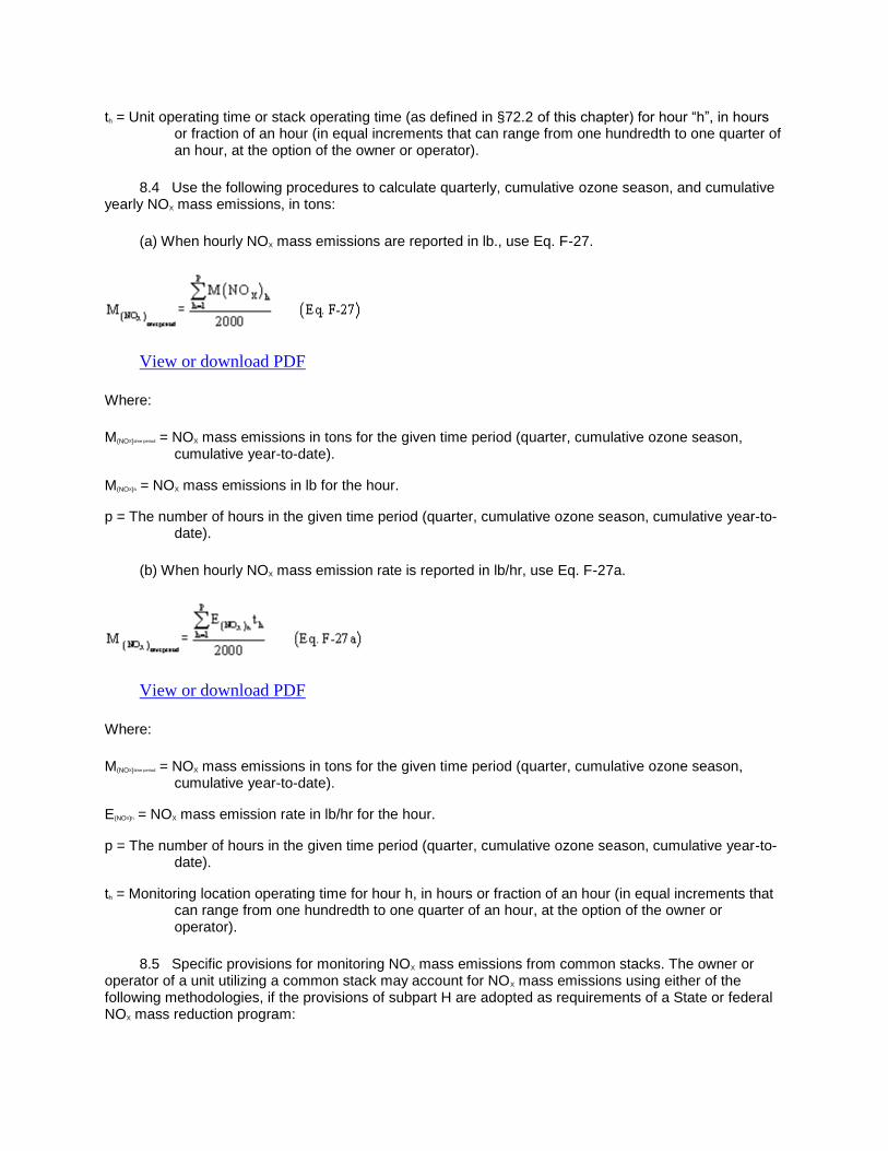
th = Unit operating time or stack operating time (as defined in §72.2 of this chapter) for hour “h”, in hours or fraction of an hour (in equal increments that can range from one hundredth to one quarter of an hour, at the option of the owner or operator).
8.4 Use the following procedures to calculate quarterly, cumulative ozone season, and cumulative yearly NOX mass emissions, in tons:
(a) When hourly NOX mass emissions are reported in lb., use Eq. F-27.
View or download PDF
Where:
M(NOX)time period = NOX mass emissions in tons for the given time period (quarter, cumulative ozone season, cumulative year-to-date).
M(NOX)h = NOX mass emissions in lb for the hour.
p = The number of hours in the given time period (quarter, cumulative ozone season, cumulative year-to-date).
(b) When hourly NOX mass emission rate is reported in lb/hr, use Eq. F-27a.
View or download PDF
Where:
M(NOX)time period = NOX mass emissions in tons for the given time period (quarter, cumulative ozone season, cumulative year-to-date).
E(NOX)h = NOX mass emission rate in lb/hr for the hour.
p = The number of hours in the given time period (quarter, cumulative ozone season, cumulative year-to-date).
th = Monitoring location operating time for hour h, in hours or fraction of an hour (in equal increments that can range from one hundredth to one quarter of an hour, at the option of the owner or operator).
8.5 Specific provisions for monitoring NOX mass emissions from common stacks. The owner or operator of a unit utilizing a common stack may account for NOX mass emissions using either of the following methodologies, if the provisions of subpart H are adopted as requirements of a State or federal NOX mass reduction program:

8.5.1 The owner or operator may determine both NOX emission rate and heat input at the common stack and use the procedures in section 8.1.1 of this appendix to determine hourly NOX mass emissions at the common stack.
8.5.2 The owner or operator may determine the NOX emission rate at the common stack and the heat input at each of the units and use the procedures in section 8.1.2 of this appendix to determine the hourly NOX mass emissions at each unit.
9. [RESERVED]
10. MOISTURE DETERMINATION FROM WET AND DRY O2 READINGS
If a correction for the stack gas moisture content is required in any of the emissions or heat input calculations described in this appendix, and if the hourly moisture content is determined from wet- and dry-basis O2 readings, use Equation F-31 to calculate the percent moisture, unless a “K” factor or other mathematical algorithm is developed as described in section 6.5.7(a) of appendix A to this part:
View or download PDF
Where:
% H2O = Hourly average stack gas moisture content, percent H2O
O2d = Dry-basis hourly average oxygen concentration, percent O2
O2w = Wet-basis hourly average oxygen concentration, percent O2
[58 FR 3701, Jan. 11, 1993; Redesignated and amended at 60 FR 26553, 26571, May 17, 1995; 61 FR 25585, May 22, 1996; 61 FR 59166, Nov. 20, 1996; 63 FR 57513, Oct. 27, 1998; 64 FR 28666-28671, May 26, 1999; 64 FR 37582, July 12, 1999; 67 FR 40474, 40475, June 12, 2002; 67 FR 53505, Aug. 16, 2002; 70 FR 28695, May 18, 2005; 73 FR 4372, Jan. 24, 2008; 76 FR 17325, Mar. 28, 2011; 77 FR 2460, Jan. 18, 2012]
Back to Top
Appendix G to Part 75—Determination of CO2 Emissions
1. APPLICABILITY
The procedures in this appendix may be used to estimate CO2 mass emissions discharged to the atmosphere (in tons/day) as the sum of CO2 emissions from combustion and, if applicable, CO2 emissions from sorbent used in a wet flue gas desulfurization control system, fluidized bed boiler, or other emission controls.

2. PROCEDURES FOR ESTIMATING CO2 EMISSIONS FROM
COMBUSTION
Use the following procedures to estimate daily CO2 mass emissions from the combustion of fossil fuels. The optional procedure in section 2.3 of this appendix may also be used for an affected gas-fired unit. For an affected unit that combusts any nonfossil fuels (e.g., bark, wood, residue, or refuse), either use a CO2 continuous emission monitoring system or apply to the Administrator for approval of a unit-specific method for determining CO2 emissions.
2.1 Use the following equation to calculate daily CO2 mass emissions (in tons/day) from the combustion of fossil fuels. Where fuel flow is measured in a common pipe header (i.e., a pipe carrying fuel for multiple units), the owner or operator may use the procedures in section 2.1.2 of appendix D of this part for combining or apportioning emissions, except that the term “SO2 mass emissions” is replaced with the term “CO2 mass emissions.”
View or download PDF
Where:
Wco2 = CO2 emitted from combustion, tons/day.
MWc = Molecular weight of carbon (12.0).
MWo2 = Molecular weight of oxygen (32.0)
Wc = Carbon burned, lb/day, determined using fuel sampling and analysis and fuel feed rates.
2.1.1 Collect at least one fuel sample during each week that the unit combusts coal, one sample per each shipment or delivery for oil and diesel fuel, one fuel sample for each delivery for gaseous fuel in lots, one sample per day or per hour (as applicable) for each gaseous fuel that is required to be sampled daily or hourly for gross calorific value under section 2.3.5.6 of appendix D to this part, and one sample per month for each gaseous fuel that is required to be sampled monthly for gross calorific value under section 2.3.4.1 or 2.3.4.2 of appendix D to this part. Collect coal samples from a location in the fuel handling system that provides a sample representative of the fuel bunkered or consumed during the week.
2.1.2 Determine the carbon content of each fuel sample using one of the following methods: ASTM D3178-89 (Reapproved 2002) or ASTM D5373-02 (Reapproved 2007) for coal; ASTM D5291-02, Standard Test Methods for Instrumental Determination of Carbon, Hydrogen, and Nitrogen in Petroleum Products and Lubricants, ultimate analysis of oil, or computations based upon ASTM D3238-95 (Reapproved 2000) and either ASTM D2502-92 (Reapproved 1996) or ASTM D2503-92 (Reapproved 1997) for oil; and computations based on ASTM D1945-96 (Reapproved 2001) or ASTM D1946-90 (Reapproved 2006) for gas (all incorporated by reference under §75.6 of this part).
2.1.3 Use daily fuel feed rates from company records for all fuels and the carbon content of the most recent fuel sample under this section to determine tons of carbon per day from combustion of each fuel. (All ASTM methods are incorporated by reference under §75.6.) Where more than one fuel is combusted during a calendar day, calculate total tons of carbon for the day from all fuels.

2.2 For an affected coal-fired unit, the estimate of daily CO2 mass emissions given by equation G-1 may be adjusted to account for carbon retained in the ash using the procedures in either section 2.2.1 through 2.2.3 or section 2.2.4 of this appendix.
2.2.1 Determine the ash content of the weekly sample of coal using ASTM D3174-00, “Standard Test Method for Ash in the Analysis Sample of Coal and Coke from Coal” (incorporated by reference under §75.6 of this part).
2.2.2 Sample and analyze the carbon content of the fly-ash according to ASTM D5373-02 (Reapproved 2007), Standard Test Methods for Instrumental Determination of Carbon, Hydrogen, and Nitrogen in Laboratory Samples of Coal and Coke” (incorporated by reference under §75.6 of this part).
2.2.3 Discount the estimate of daily CO2 mass emissions from the combustion of coal given by equation G-1 by the percent carbon retained in the ash using the following equation:
View or download PDF
(Eq. G-2)
where,
WNCO2 = Net CO2 mass emissions discharged to the atmosphere, tons/day.
WCO2 = Daily CO2 mass emissions calculated by equation G-1, tons/day.
MWC02 = Molecular weight of carbon dioxide (44.0).
MWc = Molecular weight of carbon (12.0).
A% = Ash content of the coal sample, percent by weight.
C% = Carbon content of ash, percent by weight.
WCOAL = Feed rate of coal from company records, tons/day.
2.2.4 The daily CO2 mass emissions from combusting coal may be adjusted to account for carbon retained in the ash using the following equation:
WNCO2 = .99 WCO2
(Eq. G-3)
where,
WNCO2 = Net CO2 mass emissions from the combustion of coal discharged to the atmosphere, tons/day.
.99 = Average fraction of coal converted into CO2 upon combustion.
WCO2 = Daily CO2 mass emissions from the combustion of coal calculated by equation G-1, tons/day.

2.3 In lieu of using the procedures, methods, and equations in section 2.1 of this appendix, the owner or operator of an affected gas-fired or oil-fired unit (as defined under §72.2 of this chapter) may use the following equation and records of hourly heat input to estimate hourly CO2 mass emissions (in tons).
View or download PDF
(Eq. G-4)
Where:
WCO2 = CO2 emitted from combustion, tons/hr.
MW CO2 = Molecular weight of carbon dioxide, 44.0 lb/lb-mole.
Fc = Carbon based F-factor, 1040 scf/mmBtu for natural gas; 1,420 scf/mmBtu for crude, residual, or distillate oil; and calculated according to the procedures in section 3.3.5 of appendix F to this part for other gaseous fuels.
H = Hourly heat input in mmBtu, as calculated using the procedures in section 5 of appendix F of this part.
Uf = 1/385 scf CO2/lb-mole at 14.7 psia and 68 °F.
3. PROCEDURES FOR ESTIMATING CO2 EMISSIONS FROM SORBENT
When the affected unit has a wet flue gas desulfurization system, is a fluidized bed boiler, or uses other emission controls with sorbent injection, use either a CO2 continuous emission monitoring system or an O2 monitor and a flow monitor, or use the procedures, methods, and equations in sections 3.1 through 3.2 of this appendix to determine daily CO2 mass emissions from the sorbent (in tons).
3.1 When limestone is the sorbent material, use the equations and procedures in either section 3.1.1 or 3.1.2 of this appendix.
3.1.1 Use the following equation to estimate daily CO2 mass emissions from sorbent (in tons).
View or download PDF
(Eq. G-5)
where,
SECO2 = CO2 emitted from sorbent, tons/day.
WCaCO3 = CaCO3 used, tons/day.

Fu = 1.00, the calcium to sulfur stoichiometric ratio.
MWCO2 = Molecular weight of carbon dioxide (44).
MWCaCO3 = Molecular weight of calcium carbonate (100).
3.1.2 In lieu of using Equation G-5, any owner or operator who operates and maintains a certified SO2-diluent continuous emission monitoring system (consisting of an SO2 pollutant concentration monitor and an O2 or CO2 diluent gas monitor), for measuring and recording SO2 emission rate (in lb/mmBtu) at the outlet to the emission controls and who uses the applicable procedures, methods, and equations such as those in EPA Method 19 in appendix A to part 60 of this chapter to estimate the SO2 emissions removal efficiency of the emission controls, may use the following equations to estimate daily CO2 mass emissions from sorbent (in tons).
View or download PDF
(Eq. G-6)
where,
SECO2 = CO2 emitted from sorbent, tons/day.
MWCO2 = Molecular weight of carbon dioxide (44).
MWSO2 = Molecular weight of sulfur dioxide (64).
WSO2 = Sulfur dioxide removed, lb/day, as calculated below using Eq. G-7.
Fu = 1.0, the calcium to sulfur stoichiometric ratio.
and
View or download PDF
(Eq. G-7)
where:
WSO2 = Weight of sulfur dioxide removed, lb/day.
SO20 = SO2 mass emissions monitored at the outlet, lb/day, as calculated using the equations and procedures in section 2 of appendix F of this part.
%R = Overall percentage SO2 emissions removal efficiency, calculated using equations such as those in EPA Method 19 in appendix A to part 60 of this chapter, and using daily instead of annual average emission rates.

3.2 When a sorbent material other than limestone is used, modify the equations, methods, and procedures in section 3.1 of this appendix as follows to estimate daily CO2 mass emissions from sorbent (in tons).
3.2.1 Determine a site-specific value for Fu, defined as the ratio of the number of moles of CO2 released upon capture of one mole of SO2, using methods and procedures satisfactory to the Administrator. Use this value of Fu (instead of 1.0) in either equation G-5 or equation G-6.
3.2.2 When using equation G-5, replace MWCaCO3, the molecular weight of calcium carbonate, with the molecular weight of the sorbent material that participates in the reaction to capture SO2 and that releases CO2, and replace WCaCO3, the amount of calcium carbonate used (in tons/day), with the amount of sorbent material used (in tons/day).
4. PROCEDURES FOR ESTIMATING TOTAL CO2 EMISSIONS
When the affected unit has a wet flue gas desulfurization system, is a fluidized bed boiler, or uses other emission controls with sorbent injection, use the following equation to obtain total daily CO2 mass emissions (in tons) as the sum of combustion-related emissions and sorbent-related emissions.
Wt = WCO2 + SECO2
(Eq. G-8)
where,
Wt = Estimated total CO2 mass emissions, tons/day.
WCO2 = CO2 emitted from fuel combustion, tons/day.
SECO2 = CO2 emitted from sorbent, tons/day.
5. MISSING DATA SUBSTITUTION PROCEDURES FOR FUEL ANALYTICAL
DATA
Use the following procedures to substitute for missing fuel analytical data used to calculate CO2 mass emissions under this appendix.
5.1-5.1.2 [Reserved]
5.2 Missing Carbon Content Data
Use the following procedures to substitute for missing carbon content data.
5.2.1 In all cases (i.e., for weekly coal samples or composite oil samples from continuous sampling, for oil samples taken from the storage tank after transfer of a new delivery of fuel, for as-delivered samples of oil, diesel fuel, or gaseous fuel delivered in lots, and for gaseous fuel that is supplied by a pipeline and sampled monthly, daily or hourly for gross calorific value) when carbon content data is missing, report the appropriate default value from Table G-1.

5.2.2 The missing data values in Table G-1 shall be reported whenever the results of a required sample of fuel carbon content are either missing or invalid. The substitute data value shall be used until the next valid carbon content sample is obtained.
View or download PDF
5.3 Gross Calorific Value Data
For a gas-fired unit using the procedures of section 2.3 of this appendix to determine CO2 emissions, substitute for missing gross calorific value data used to calculate heat input by following the missing data procedures for gross calorific value in section 2.4 of appendix D to this part.
[58 FR 3701, Jan. 11, 1993, as amended at 60 FR 26556-26557, May 17, 1995; 61 FR 25585, May 22, 1996; 64 FR 28671, May 26, 1999; 67 FR 40475, June 12, 2002; 67 FR 57274, Sept. 9, 2002; 73 FR 4376, Jan. 24, 2008]
Back to Top
Appendix H to Part 75—Revised Traceability Protocol No. 1 [Reserved]
Back to Top
Appendix I to Part 75—Optional F—Factor/Fuel Flow Method [Reserved]
Back to Top
Appendix J to Part 75—Compliance Dates for Revised Recordkeeping Requirements and Missing Data Procedures [Reserved]
Back to Top

APPENDIX E
Acid Rain Permit Application

&EPA
STEP 1
Identify the facility name, State, and plant (ORIS) code.
STEP2
Enter the unit ID# for every affected unit at the affected source in column "a."
AFIN 2 9-00304
United States En.Vironrilerltal ·protection Agency Acid Rain Program
OMB No. 2060-0258 Approval expires 11130/2012
Acid Rain Permit Application For more information, see instructions and 40 CFR 72.30 and 72.31.
This submission is: ,..., new ,..., revised li1for Acid Rain permit renewal
Facilitv !Source) Name Fulton State AR Plant Code 7825
a b
Unit ID# Uni!Will Hold Allowances in Accordance with 40 CFR 72.9(c)(1)
01 Yes
Yes
Yes
Yes
Yes
Yes
Yes
Yes
Yes
Yes
Yes
Yes
Yes
Yes
Yes
Facility Fulton CTI Permit# 1860-AOP-R4 Date 2/2/2015 Page 35

STEP3
Fulton
Facility.(Source) Name (from STEP 1)
Permit Requirements
(I) The designated representative of each affected source and each affected unit at the source shall:
Read the (i) Submit a complete Acid Rain permit application (including a compliance plan) under 40 standard CFR part 72 in accordance with the deadlines specified in 40 CFR 72.30; and requirement (ii) Submit in a timely manner any supplemental information that the permitting authority s. determines is necessary in order to review an Acid Rain permit application and issue or deny an
Acid Rain permit; (2) The owners and operators of each affected source and each affected unit at the source shall: (i) Operate the unit in compliance with a complete Acid Rain permit application or a superseding Acid Rain permit issued by the permitting authority; and (ii) Have an Acid Rain Permit
Monitoring Requirements
(1) The owners and operators and, to the extent applicable, designated representative of each affected source and each affected unit at the source shall comply with the monitoring requirements as provided in 40 CFR part 75. (2) The emissions measurements recorded and reported in accordance with 40 CFR part 75 shall be used to determine compliance by the source or unit, as appropriate, with the Acid Rain emissions limitations and emissions reduction requirements for sulfur dioxide and nitrogen oxides under the Acid Rain Program. (3) The requirements of 40 CFR part 75 shall not affect the responsibility of the owners and operators to monitor emissions of other pollutants or other emissions characteristics at the unit under other applicable requirements of the Act and other provisions of the operating penni! tor the source.
Sulfur Dioxide Requirements
(I) The owners and operators of each source and each affected unit at the source shall: (i) Hold allowances, as of the allowance transfer deadline, in the source's compliance account (after deductions under 40 CFR 73.34(c)), not less than the total annual emissions of sulfur dioxide for the previous calendar year from the affected units at the source; and (ii) Comply with the applicable Acid Rain emissions limitations for sulfur dioxide. (2) Each ton of sulfur dioxide emitted in excess of the Acid Rain emissions limitations for sulfur dioxide shall constitute a separate violation of the Act. (3) An affected unit shall be subject to the requirements under paragraph (I) of the sulfur dioxide requirements as follows: (i) Starting January I, 2000, an affected unit under 40 CFR 72.6(a)(2); or (ii) Starting on the later of January I, 2000 or the deadline for monitor certification under 40 CFR part 75, an affected unit under 40 CFR 72.6(a)(3).
AFIN 29-00304 Facility Fulton CTI Permit# I860-AOP-R4 Date 212/2015 Page 36

STEP 3, Con!' d.
Fulton
Facility (Source) Name (from STEP 1)
Sulfur Dioxide Requirements. Cont'd.
(4) Allowances shall be held in, deducted from, or transferred among Allowance Tracking System accounts in accordance with the Acid Rain Program. (5) An allowance shall not be deducted in order to comply with the requirements under paragraph (I) of the sulfur dioxide requirements prior to the calendar year for which the allowance was allocated. (6) An allowance allocated by the Administrator under the Acid Rain Program is a limited authorization to emit sulfur dioxide in accordance with the Acid Rain Program. No provision ofthe Acid Rain Program, the Acid Rain permit application, the Acid Rain permit, or an exemption under 40 CFR 72.7 or 72.8 and no provision of law shall be construed to limit the authority of the United States to terminate or limit such authorization. (7) An allowance allocated by the Administrator under the Acid Rain Program does not constitute a property right.
Nitrogen Oxides Requirements
The owners and operators of the source and each affected·unit at the source shall comply with the applicable Acid Rain emissions limitation for nitrogen oxides.
Excess Emissions Requirements
(I) The designated representative of an affected source that has excess emissions in any calendar year shall submit a proposed offset plan, as required under 40 CFR part 77. (2) The owners and operators of an affected source that has excess emissions in any calendar year shall: (i) Pay without demand the penalty required, and pay upon demand the interest on that penalty, as required by 40 CFR part 77; and (ii) Comply with the tenns of an approved offset plan, as required by 40 CFR part 77.
Recordkeeping and Reporting Requirements
(!}Unless otherwise provided, the owners and operators of the source and each affected unit at the source.shall keep on site,at the source each of the following documents for a period of 5 years from the date the document is created. This period may be extended for cause, at any time prior to the end of 5 years, in writing by the Administrator or permitting authority: (i) The certificate of representation for the designated representative for the source and each affected unit at the source and. all documents that demonstrate the. truth of the statements in the certificate of representation, in accordance with 40 CFR 72.24; provided that the certificate and documents shall be retained on site at the source beyond such 5-year period until such documents are superseded because of the submission of a new certificate of representation changing the designated representative;
AFIN 29-00304 Facility Fulton CTI Permit# 1860-AOP-R4 Date 2/2/2015 Page 37

STEP3, Cont'd.
Fulton
Facility (Source) Name cirom STEP 1)
Recordkeeping and Reporting Requirements, Cont'd.
(ii) All emissions monitoring infonnation, in accordance with 40 CFR part 75, provided that to the extent that 40 CFR part 75 provides for a 3-year period for record keeping, the 3-year period shall apply. (iii) Copies of all reports, compliance certifications, and other submissions and all records made or required under the Acid Rain Program; and, (iv) Copies of all documents used to complete an Acid Rain permit application and any other submission under the Acid Rain Program or to demonstrate compliance with the requirements of the Acid" Rain Program. (2) The designated representative of an affected source and each affected unit at the source shall submitthe reports and compliance certifications required under the Acid Rain Program, including those under 40 CPR part 72 subpart I and 40 CPR part 75.
Liability
(1) Any person who knowingly violates any requirement or prohibition of the Acid Rain Program, a complete Acid Rain permit application, an Acid Rain permit, or an exemption under 40 CPR 72.7 or 72.8, including any requirement for the payment of any penalty owed to the United States, shall be subject to enforcement pursuant to section 113(c) of the Act. (2) Any person who knowingly makes a false, material statement in any record, submission, or report under the Acid Rain Program shall be subject to criminal enforcement pursuant to section 1!3(c) of the Act and 18 U.S.C. 1001. (3) No permit revision shall excuse any violation of the requirements of the Acid Rain Program that occurs prior to the date that the revision takes effect. ( 4) Each affected source and each affected unit shall meet the requirements of the Acid Rain Program. (5) Any provision of the Acid Rain Program that applies to an affected source (including a provision applicable to the designated representative of an affected source) shall also apply to the owners and operators of such source and of the affected units at the source. (6) Any provision of the Acid Rain Program that applies to an affected unit (including a provision applicable to the designated representative of an affected unit) shall also apply to the owners and operators of such unit. (7) Each violation of a provision of 40 CFR parts 72, 73, 74, 75, 76, 77, and 78 by an affected source or·affected unit, or by an owner or operator or designated representative of such source or unit, shall be a separate violation of the Act.
AFIN 29-00304 Facility Fulton CTl Permit# 1860-AOP-R4 Date 2/2/2015 Page 38

STEP 3, Cant' d.
STEP4 Read the certification statement. sign, and date.
Fulton
Facilitv (Source l Name (from STEP 1 l
Effect on Other Authorities
No provision of the Acid Rain Program, an Acid Rain permit application, an Acid Rain permit, or an exemption under 40 CFR 72.7 or 72.8 shall be construed as: (1) Except as expressly provided in title IV of the Act, exempting or excluding the owners and operators and, to the extent applicable, the designated representative of an affected source or affected unit fi'om compliance with any other provision of the Act, including the provisions of title I of the Act relating to applicable National Ambient Air Quality Standards or State Implementation Plans; (2) Limiting the number of allowances a source can hold; provided, that the number of allowances held by the source shall not affect the source's obligation to comply with any other provisions of the Act; (3) Requiring a change of any kind in any State law regulating electric utility rates and charges, affecting any State law regarding such State regulation, or limiting such State regulation, including any prudence review requirements under such State law; (4) Modifying the Federal Power Act or affecting the authority of the Federal Energy Regulatory Commission under the Federal Power Act; or, (5) Interfering with or impairing any program for competitive bidding for power supply in a State in which such program is established.
Certification
I am authorized to make this submission on behalf of the owners and operators of the affected source or affected units for which the submission is made. l certify under penalty oflaw that I have personally examined, and am familiar with, the statements and information submitted in this document and all its attachments. Based on my inquiry of those individuals with primary responsibility for obtaining the infonnation, I certify that the statements and information are to the best of my knowledge and belief true, accurate,and complete. lam aware that there arc significant penalties for submitting talse statements and information or omitting required statements and information, including the possibility of fine or imprisonment.
Name Curtis Q. Warner
Siqnature c~ ld /J I" L.A "_,__/ Date 2./2-/Z-c:? 1) I '\:.
AFIN 29-00304 Facility Fulton CTJ Permit# 1860-AOP-R4 Date 2/2/2015 Page 39 -----
Recommended


