© Carrier Corporation 2018 Form 30XW-11PD
Product Data
AquaForce® Water-Cooled Liquid Screw Chillers150 to 400 Nominal Tons (528 to 1407 kW)
30XW325-400
30XW150-300
30XW150-400Water-Cooled Liquid Screw Chillers
2
Quality design and construction make the AquaForce® 30XW chillers an excellent choice for modern, efficient chilled water plants.Carrier's AquaForce 30XW chillers provide a great combination of perfor-mance and compact footprint for cool-ing and heat recovery applications. These chillers provide excellent reliabil-ity and efficiency at true operating con-ditions without compromising the environment.• Chlorine-free R-134a HFC refriger-
ant• Positive displacement, twin screw
compressors• AHRI (Air-Conditioning, Heating,
and Refrigeration Institute) certifiedefficiencies to 0.472 kW per tonIPLV (integrated part load value)
• Dual independent refrigerant circuits(sizes 325-400)
• Compact footprint, less than 48 in.(1219 mm) wide
• Easy to use controls
Small footprintThe 30XW chillers feature a compact footprint and are delivered as a single complete package less than 48 in. (1219 mm) wide for easy installation and minimal indoor space. The 30XW chiller footprints may be up to 30% smaller when compared to other chillers and may require less mechani-cal room floor space and smaller con-crete pads.
Easy installationThe AquaForce® 30XW screw chillers are shipped with starter and unit mounted flow switch installed and can
be shipped with a full R-134a refriger-ant charge to minimize installation time. The unit provides single point power connection (using optional con-trol power transformer) and quick, easy piping connections (using Victaulic-type clamp on couplings). The 30XW 200-v, 230-v, 460-v, and 575-v units are designed in accordance with UL (Underwriters Laboratories) and UL Canada standards to minimize electri-cal inspection time.
Dual circuits (sizes 325-400)Dual independent refrigerant circuits provide reliable, dependable cooling, excellent part load operation, and redundancy. Each circuit includes its own compressor, electronic expansion valve, filter drier, and sight glass to assure operation.
High efficiencyThe Aquaforce 30XW screw chiller efficiency levels meet or exceed energy efficiency requirements of ASHRAE (American Society of Heating, Refrig-erating and Air-Conditioning Engi-neers) 90.1 2010 and CSA (Canadian Standards Association) for both full load and part load operation. The chiller is certified to AHRI standards. Per AHRI 550/590, chillers operate at design conditions less than one per-cent of the time. As a result, superior part load efficiency is required for today's chilled water applications. The 30XW chillers deliver integrated part load values (IPLV) as low as 0.472 kW per ton at AHRI conditions while offer-ing the ability to operate in a broad range of applications and climates. This exceptional performance has a significant impact on energy savings and cost of ownership.
Heat recoveryThe Aquaforce 30XW screw chillers provide up to 140°F (60°C) leaving condenser water (requires heat machine option) when applied in heat recovery applications. Further, the 30XW unit heat control mode can be used to maintain a constant leaving condenser water temperature. Low source controls provide evaporator suction protection to prevent nuisance trips when operating in heat recovery applications. This flexible capability allows a chiller to meet both cooling and heating requirements providing a high level of interchangeability within a chilled water plant.
Environmental leadershipCarrier has long been committed to the environment and its sustainability. The Aquaforce 30XW screw chiller pro-vides customers with a high-efficiency, chlorine free, long-term solution unaf-fected by refrigerant phase outs. Carrier's decision to use non-ozone depleting R-134a refrigerant provides customers with a safe and environmen-tally balanced choice without compro-mising efficiency. In addition, R-134a refrigerant was given an A1 safety rat-ing by ASHRAE, meaning that it is among the safest refrigerants available.
Positive displacement screw compressionPositive displacement compression ensures stable operation under all load conditions without the possibility of compressor surge. High-efficiency rotary twin screw with slide valve allows the chillers to exactly match actual load conditions, delivering excellent part load performance.
Factory testingA quick start-up is assured once instal-lation is complete, since each 30XW unit is manufactured at an ISO (Interna-tional Organization for Standardiza-tion) 9001 listed manufacturing facility to ensure quality. In addition, all 30XW units that are shipped with a full charge of R-134a refrigerant are tested under load at the factory to provide reliable start-up.
Low starting current (inrush)Dual circuit units (sizes 325-400) stage the start-up of the compressors, thereby reducing the overall current draw by up to 40%.
Features/Benefits
Table of contentsPage
Features/Benefits . . . . . . . . . . . . . . . . . . . . . . . . . . . . . . . . . . . . . . . . . 2Model Number Nomenclature . . . . . . . . . . . . . . . . . . . . . . . . . . . . . . . . . 5Capacity Ratings . . . . . . . . . . . . . . . . . . . . . . . . . . . . . . . . . . . . . . . . . . 6Physical Data . . . . . . . . . . . . . . . . . . . . . . . . . . . . . . . . . . . . . . . . . . . . 7Options and Accessories . . . . . . . . . . . . . . . . . . . . . . . . . . . . . . . . . . . 11Dimensions. . . . . . . . . . . . . . . . . . . . . . . . . . . . . . . . . . . . . . . . . . . . . 15Selection Procedure. . . . . . . . . . . . . . . . . . . . . . . . . . . . . . . . . . . . . . . 30Performance Data . . . . . . . . . . . . . . . . . . . . . . . . . . . . . . . . . . . . . . . . 31Controls . . . . . . . . . . . . . . . . . . . . . . . . . . . . . . . . . . . . . . . . . . . . . . . 41Typical Control Wiring Schematic . . . . . . . . . . . . . . . . . . . . . . . . . . . . . 43Application Data . . . . . . . . . . . . . . . . . . . . . . . . . . . . . . . . . . . . . . . . . 44Typical Piping and Wiring . . . . . . . . . . . . . . . . . . . . . . . . . . . . . . . . . . 47Electrical Data . . . . . . . . . . . . . . . . . . . . . . . . . . . . . . . . . . . . . . . . . . . 49Guide Specifications . . . . . . . . . . . . . . . . . . . . . . . . . . . . . . . . . . . . . . 54
3
Constant or variable evapora-tor flowAquaforce 30XW screw chillers are suitable for constant or variable evapo-rator flow.
Semi-hermetic motorThe Aquaforce 30XW chiller uses motors that are semi-hermetically sealed from the machine room. Refrig-erant is used to cool the motor windings.Carrier's semi-hermetic design eliminates:• Compressor shaft seals that require
maintenance and increase the likeli-hood of refrigerant leaks.
• Machine room cooling requirements associated with air-cooled motors, which dissipate heat to the mechan-ical room.
• High noise levels common with air-cooled motors, which radiate noise to the machine room and adjacent areas.
• Shaft alignment problems that occur with open-drive designs during start-up and operation, when equipment temperature variations cause ther-mal expansion.
Positive pressure designPositive pressure designs eliminate the need for costly low pressure containment devices, reducing the initial cost of the system. The Aqua-Force® 30XW chiller's positive pres-sure design ensures that air, moisture and other performance degrading con-taminants are not sucked inside the chiller. Purge units and their associated maintenance are no longer necessary.
Optional refrigerant isolation valvesThe optional refrigerant isolation valves enable service personnel to store the refrigerant charge in the evapora-tor or condenser during servicing. During servicing, the in-chiller storage reduces refrigerant loss and eliminates time-consuming transfer procedures. As a self-contained unit, the AquaForce 30XW chiller does not require addi-tional remote storage systems.
Optional suction service valve(s)The optional suction service valve(s) allow for further isolation of the com-pressor from the evaporator vessel.
Marine container shipmentThe compact design allows for con-tainer shipment to export destinations,
ensuring quality while reducing ship-ping cost.
Heat exchangersThe Aquaforce 30XW chillers use mechanically cleanable shell and tube evaporators and condensers available with a complete line of waterbox options to meet project specific requirements. One, two, and three pass arrangements are available to meet a wide variety of flow conditions. Nozzle-in-head and marine waterboxes are available to meet 150 psig (1034 kPa) and 300 psig (2068 kPa) piping requirements.Heat exchanger features include:ASME certified construction — An independent agency certifies the design, manufacture, and testing of all heat exchangers to American Society of Mechanical Engineers (ASME) stan-dards, ensuring heat exchanger safety, reliability and long life. The ASME stamp is applied to the refrigerant side of the evaporator and condenser. Electronic thermal-dispersion flow switch — An electronic thermal- dispersion flow switch switch is included with the evaporator. The switch is factory installed and tested and contains no moving parts for high reliability.High performance tubing — Carrier's AquaForce chillers use advances in heat transfer technology providing compact, high-efficiency heat exchangers. Tubing with advanced internally and externally enhanced geometry improves chiller performance by reducing overall resis-tance to heat transfer while reducing fouling.Evaporator tube expansion — Evaporator tube expansion at center support sheets prevents unwanted tube movement and vibration, thereby reducing the possibility of premature tube failure. Tube wall thickness is greater at the expansion location, sup-port sheets, and end tube sheets, to provide maximum strength and long tube life.Closely spaced intermediate sup-port sheets — Support sheets pre-vent tube sagging and vibration, thereby increasing heat exchanger life.Refrigerant filter isolation valves — These valves allow filter replacement without pumping down the chiller, reducing service time and expense.
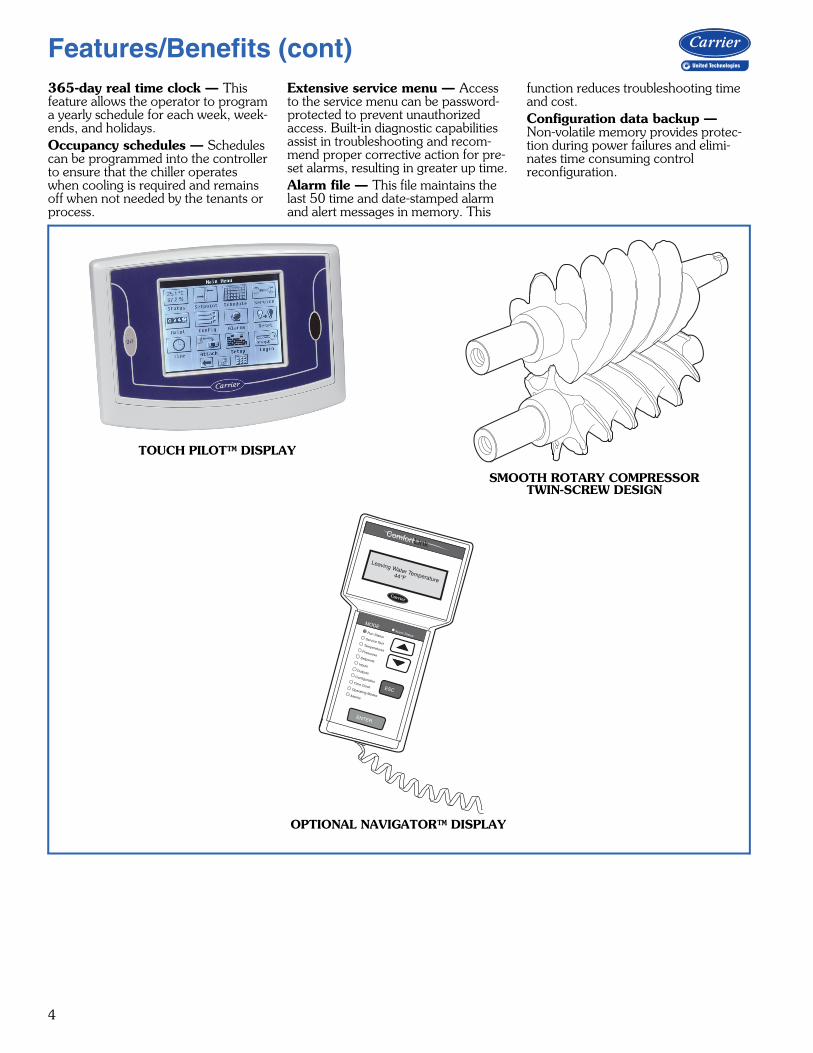
Microprocessor controlsThe AquaForce 30XW screw chiller controls communicate in easy to under-stand English, making it as easy as pos-sible to monitor and control each chiller while maintaining fluid tempera-tures. Controls are also available with French, Portuguese and Spanish as standard configuration options. These controls result in higher chiller reliabil-ity, simplified training and correspond-ingly lower operational and maintenance costs.Two user interface options are avail-able, the Touch Pilot™ display and the Navigator™ module.The Touch Pilot display is an easy to use touch screen display that provides simple navigation for configuration and control of the 30XW units.Carrier’s exclusive handheld Navigator display provides convenience and pow-erful information in the palm of your hand. The Navigator display helps technicians to quickly diagnose prob-lems and even prevent them from occurring.All 30XW units are ready to be used with Carrier Comfort Network® (CCN) devices.Controls features include:Automatic capacity override — This function unloads the compressor whenever key safety limits are approached, increasing unit life.Chilled liquid reset — Reset can be accomplished manually or automati-cally from the building management system. For a given capacity, reset allows operation at reduced lift, saving energy when warmer chilled liquid can be used. Demand limiting — This feature lim-its the power draw of the chiller during peak loading conditions. When incor-porated into the CCN building automa-tion system, a red line command holds chillers at their present capacity and prevents any other chillers from start-ing. If a load shed signal is received, the compressors are unloaded to avoid demand charges whenever possible.Ramp loading — Ramp loading ensures smooth pulldown of liquid loop temperature and prevents a rapid increase in compressor power con-sumption during the pulldown period.Automated controls test — The test can be executed prior to start-up to verify that the entire control system is functioning properly.
4
365-day real time clock — This feature allows the operator to program a yearly schedule for each week, week-ends, and holidays.Occupancy schedules — Schedules can be programmed into the controller to ensure that the chiller operates when cooling is required and remains off when not needed by the tenants or process.
Extensive service menu — Access to the service menu can be password-protected to prevent unauthorized access. Built-in diagnostic capabilities assist in troubleshooting and recom-mend proper corrective action for pre-set alarms, resulting in greater up time.Alarm file — This file maintains the last 50 time and date-stamped alarm and alert messages in memory. This
function reduces troubleshooting time and cost.Configuration data backup — Non-volatile memory provides protec-tion during power failures and elimi-nates time consuming control reconfiguration.
TOUCH PILOT™ DISPLAY
OPTIONAL NAVIGATOR™ DISPLAY
SMOOTH ROTARY COMPRESSORTWIN-SCREW DESIGN
Run StatusService TestTemperaturesPressures
SetpointsInputs
OutputsConfigurationTime Clock
Operating ModesAlarms
ENTER
ESC
MODEAlarm Status
ComfortLink
Features/Benefits (cont)
5
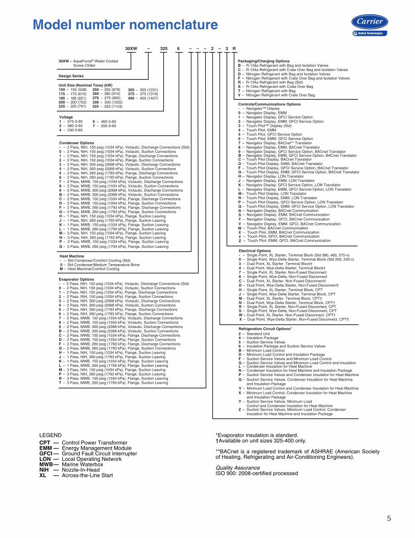
30XW – 325 6 – – – 2 – 3 R
30XW – AquaForce® Water-Cooled Screw Chiller
Design Series
Unit Size (Nominal Tons) (kW)150 – 150 (528)175 – 175 (615)
200 – 200 (703)
Voltage1 – 575-3-602 – 380-3-604 – 230-3-60
6 – 460-3-607 – 200-3-60
Condenser Options- – 2 Pass, NIH, 150 psig (1034 kPa), Victaulic, Discharge Connections (Std)0 – 2 Pass, NIH, 150 psig (1034 kPa), Victaulic, Suction Connections1 – 2 Pass, NIH, 150 psig (1034 kPa), Flange, Discharge Connections2 – 2 Pass, NIH, 150 psig (1034 kPa), Flange, Suction Connections3 – 2 Pass, NIH, 300 psig (2068 kPa), Victaulic, Discharge Connections4 – 2 Pass, NIH, 300 psig (2068 kPa), Victaulic, Suction Connections5 – 2 Pass, NIH, 260 psig (1793 kPa), Flange, Discharge Connections6 – 2 Pass, NIH, 260 psig (1793 kPa), Flange, Suction Connections7 – 2 Pass, MWB, 150 psig (1034 kPa), Victaulic, Discharge Connections8 – 2 Pass, MWB, 150 psig (1034 kPa), Victaulic, Suction Connections9 – 2 Pass, MWB, 300 psig (2068 kPa), Victaulic, Discharge ConnectionsB – 2 Pass, MWB, 300 psig (2068 kPa), Victaulic, Suction ConnectionsC – 2 Pass, MWB, 150 psig (1034 kPa), Flange, Discharge ConnectionsD – 2 Pass, MWB, 150 psig (1034 kPa), Flange, Suction ConnectionsF – 2 Pass, MWB, 260 psig (1793 kPa), Flange, Discharge ConnectionsG – 2 Pass, MWB, 260 psig (1793 kPa), Flange, Suction ConnectionsH – 1 Pass, NIH, 150 psig (1034 kPa), Flange, Suction LeavingJ – 1 Pass, NIH, 260 psig (1793 kPa), Flange, Suction LeavingK – 1 Pass, MWB, 150 psig (1034 kPa), Flange, Suction LeavingL – 1 Pass, MWB, 260 psig (1793 kPa), Flange, Suction Leaving
Heat Machine- – Std Condenser/Comfort Cooling (Std)
M – Heat Machine/Comfort Cooling
Evaporator Options- – 2 Pass, NIH, 150 psig (1034 kPa), Victaulic, Discharge Connections (Std)0 – 2 Pass, NIH, 150 psig (1034 kPa), Victaulic, Suction Connections1 – 2 Pass, NIH, 150 psig (1034 kPa), Flange, Discharge Connections2 – 2 Pass, NIH, 150 psig (1034 kPa), Flange, Suction Connections3 – 2 Pass, NIH, 300 psig (2068 kPa), Victaulic, Discharge Connections4 – 2 Pass, NIH, 300 psig (2068 kPa), Victaulic, Suction Connections5 – 2 Pass, NIH, 260 psig (1793 kPa), Flange, Discharge Connections6 – 2 Pass, NIH, 260 psig (1793 kPa), Flange, Suction Connections7 – 2 Pass, MWB, 150 psig (1034 kPa), Victaulic, Discharge Connections8 – 2 Pass, MWB, 150 psig (1034 kPa), Victaulic, Suction Connections9 – 2 Pass, MWB, 300 psig (2068 kPa), Victaulic, Discharge ConnectionsB – 2 Pass, MWB, 300 psig (2068 kPa), Victaulic, Suction ConnectionsC – 2 Pass, MWB, 150 psig (1034 kPa), Flange, Discharge ConnectionsD – 2 Pass, MWB, 150 psig (1034 kPa), Flange, Suction ConnectionsF – 2 Pass, MWB, 260 psig (1793 kPa), Flange, Discharge ConnectionsG – 2 Pass, MWB, 260 psig (1793 kPa), Flange, Suction ConnectionsH – 1 Pass, NIH, 150 psig (1034 kPa), Flange, Suction LeavingJ – 1 Pass, NIH, 260 psig (1793 kPa), Flange, Suction LeavingK – 1 Pass, MWB, 150 psig (1034 kPa), Flange, Suction LeavingL – 1 Pass, MWB, 260 psig (1793 kPa), Flange, Suction LeavingM – 3 Pass, NIH, 150 psig (1034 kPa), Flange, Suction LeavingP – 3 Pass, NIH, 260 psig (1793 kPa), Flange, Suction LeavingR – 3 Pass, MWB, 150 psig (1034 kPa), Flange, Suction LeavingT – 3 Pass, MWB, 260 psig (1793 kPa), Flange, Suction Leaving
Packaging/Charging OptionsB – R-134a Refrigerant with Bag and Isolation ValvesC – R-134a Refrigerant with Crate Over Bag and Isolation Valves D – Nitrogen Refrigerant with Bag and Isolation ValvesF – Nitrogen Refrigerant with Crate Over Bag and Isolation Valves
Controls/Communications Options- – Navigator™ Display0 – Navigator Display, EMM1 – Navigator Display, GFCI Service Option2 – Navigator Display, EMM, GFCI Service Option3 – Touch Pilot™ Display (Std)4 – Touch Pilot, EMM5 – Touch Pilot, GFCI Service Option6 – Touch Pilot, EMM, GFCI Service Option7 – Navigator Display, BACnet** Translator8 – Navigator Display, EMM, BACnet Translator9 – Navigator Display, GFCI Service Option, BACnet TranslatorB – Navigator Display, EMM, GFCI Service Option, BACnet TranslatorC – Touch Pilot Display, BACnet TranslatorD – Touch Pilot Display, EMM, BACnet TranslatorF – Touch Pilot Display, GFCI Service Option, BACnet TranslatorG – Touch Pilot Display, EMM, GFCI Service Option, BACnet TranslatorH – Navigator Display, LON TranslatorJ – Navigator Display, EMM, LON TranslatorK – Navigator Display, GFCI Service Option, LON TranslatorL – Navigator Display, EMM, GFCI Service Option, LON TranslatorM – Touch Pilot Display, LON TranslatorN – Touch Pilot Display, EMM, LON TranslatorP – Touch Pilot Display, GFCI Service Option, LON TranslatorQ – Touch Pilot Display, EMM, GFCI Service Option, LON Translator
Electrical Options- – Single Point, XL Starter, Terminal Block (Std 380, 460, 575-v) 0 – Single Point, Wye-Delta Starter, Terminal Block (Std 200, 230-v) 3 – Dual Point, XL Starter, Terminal Block†4 – Dual Point, Wye-Delta Starter, Terminal Block†7 – Single Point, XL Starter, Non-Fused Disconnect8 – Single Point, Wye-Delta, Non-Fused DisconnectC – Dual Point, XL Starter, Non-Fused Disconnect†D – Dual Point, Wye-Delta Starter, Non-Fused Disconnect† H – Single Point, XL Starter, Terminal Block, CPTJ – Single Point, Wye-Delta Starter, Terminal Block, CPT M – Dual Point, XL Starter, Terminal Block, CPT†N – Dual Point, Wye-Delta Starter, Terminal Block, CPT† R – Single Point, XL Starter, Non-Fused Disconnect, CPT S – Single Point, Wye-Delta, Non-Fused Disconnect, CPT W – Dual Point, XL Starter, Non-Fused Disconnect, CPT† X – Dual Point, Wye-Delta Starter, Non-Fused Disconnect, CPT†
Refrigeration Circuit Options*
4 – Insulation Package5 – Suction Service Valves
B – Minimum Load Control
G – Suction Service Valves and Minimum Load Control and InsulationL – Condenser Insulation for Heat Machine
Q – Suction Service Valves, Condenser Insulation for Heat Machine and Insulation Package
X – Minimum Load Control, Condenser Insulation for Heat Machine and Insulation Package
Y – Suction Service Valves, Minimum Load Control and Condenser Insulation for Heat Machine
250 – 250 (878)
275 – 275 (965)300 – 300 (1055)325 – 325 (1143)
350 – 350 (1231)
400 – 400 (1407)
2 – Standard Unit
6 – Insulation Package and Suction Service Valves
D – Minimum Load Control and Insulation Package F – Suction Service Valves and Minimum Load Control
N – Condenser Insulation for Heat Machine and Insulation PackageP – Suction Service Valves and Condenser Insulation for Heat Machine
V – Minimum Load Control and Condenser Insulation for Heat Machine
Z – Suction Service Valves, Minimum Load Control, Condenser Insulation for Heat Machine and Insulation Package
R – R-134a Refrigerant with Bag (Std)S – R-134a Refrigerant with Crate Over Bag T – Nitrogen Refrigerant with BagV – Nitrogen Refrigerant with Crate Over Bag
185 – 185 (651)
225 – 225 (791)
260 – 260 (914) 375 – 375 (1319)
– Std Condenser/Medium Temperature Brine0
M – 3 Pass, NIH, 150 psig (1034 kPa), Flange, Suction LeavingN – 3 Pass, NIH, 260 psig (1793 kPa), Flange, Suction LeavingP – 3 Pass, MWB, 150 psig (1034 kPa), Flange, Suction LeavingQ – 3 Pass, MWB, 260 psig (1793 kPa), Flange, Suction Leaving
RSTVWXYZ
– Navigator Display, BACnet Communication – Navigator Display, EMM, BACnet Communication – Navigator Display, GFCI, BACnet Communication – Navigator Display, EMM, GFCI, BACnet Communication – Touch Pilot, BACnet Communication – Touch Pilot, EMM, BACnet Communication – Touch Pilot, GFCI, BACnet Communication – Touch Pilot, EMM, GFCI, BACnet Communication
a30-6046
LEGEND *Evaporator insulation is standard.†Available on unit sizes 325-400 only.
**BACnet is a registered trademark of ASHRAE (American Societyof Heating, Refrigerating and Air-Conditioning Engineers).
Quality AssuranceISO 900: 2008-certified processed
CPT — Control Power TransformerEMM — Energy Management ModuleGFCI — Ground Fault Circuit InterrupterLON — Local Operating NetworkMWB— Marine WaterboxNIH — Nozzle-In-HeadXL — Across-the-Line Start
Model number nomenclature
6
LEGEND
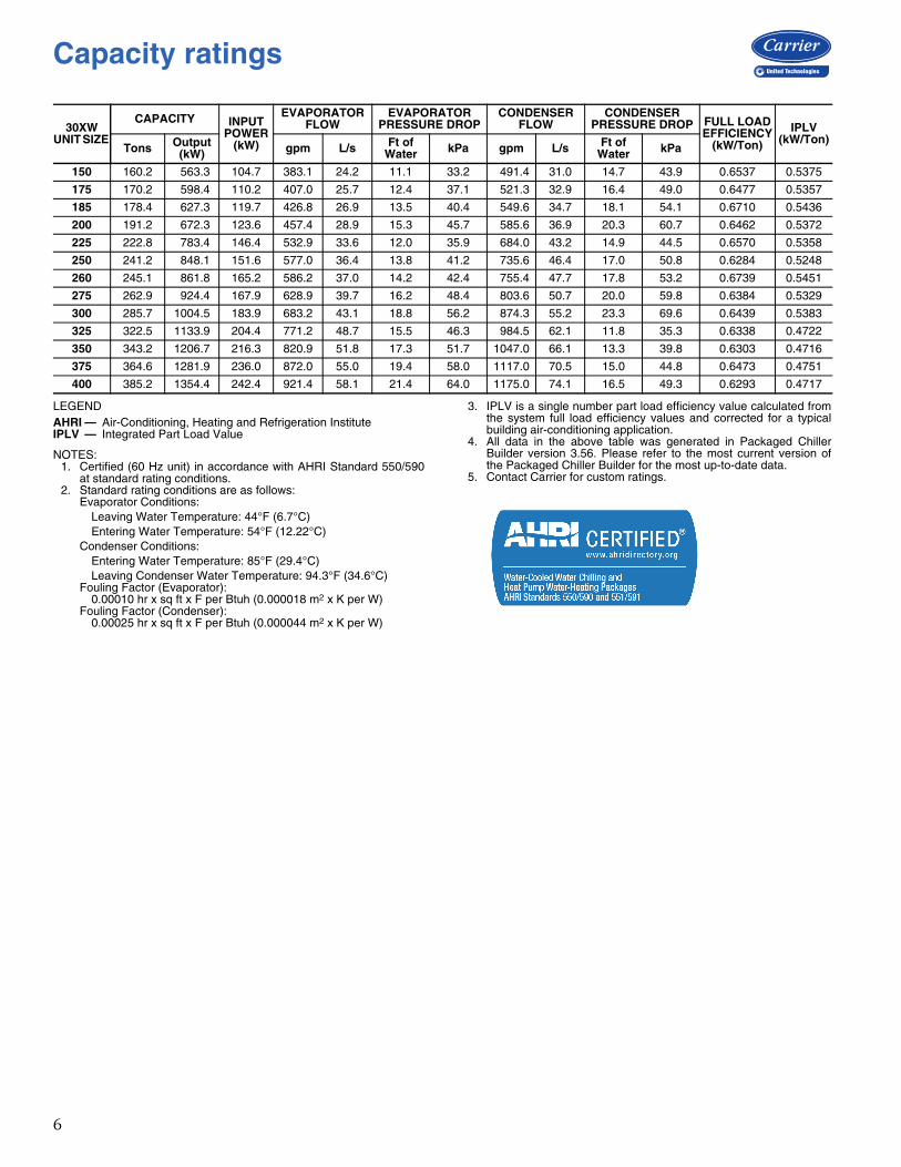
NOTES:1. Certified (60 Hz unit) in accordance with AHRI Standard 550/590
at standard rating conditions.2. Standard rating conditions are as follows:
Evaporator Conditions:Leaving Water Temperature: 44°F (6.7°C)Entering Water Temperature: 54°F (12.22°C)
Condenser Conditions:Entering Water Temperature: 85°F (29.4°C)Leaving Condenser Water Temperature: 94.3°F (34.6°C)
Fouling Factor (Evaporator):0.00010 hr x sq ft x F per Btuh (0.000018 m2 x K per W)
Fouling Factor (Condenser):0.00025 hr x sq ft x F per Btuh (0.000044 m2 x K per W)
3. IPLV is a single number part load efficiency value calculated fromthe system full load efficiency values and corrected for a typicalbuilding air-conditioning application.
4. All data in the above table was generated in Packaged ChillerBuilder version 3.56. Please refer to the most current version ofthe Packaged Chiller Builder for the most up-to-date data.
5. Contact Carrier for custom ratings.
30XW UNIT SIZE
CAPACITY INPUT POWER
(kW)
EVAPORATOR FLOW
EVAPORATOR PRESSURE DROP
CONDENSER FLOW
CONDENSER PRESSURE DROP FULL LOAD
EFFICIENCY (kW/Ton)
IPLV(kW/Ton)
Tons Output (kW) gpm L/s Ft of
Water kPa gpm L/s Ft of Water kPa
150 160.2 563.3 104.7 383.1 24.2 11.1 33.2 491.4 31.0 14.7 43.9 0.6537 0.5375
175 170.2 598.4 110.2 407.0 25.7 12.4 37.1 521.3 32.9 16.4 49.0 0.6477 0.5357
185 178.4 627.3 119.7 426.8 26.9 13.5 40.4 549.6 34.7 18.1 54.1 0.6710 0.5436
200 191.2 672.3 123.6 457.4 28.9 15.3 45.7 585.6 36.9 20.3 60.7 0.6462 0.5372
225 222.8 783.4 146.4 532.9 33.6 12.0 35.9 684.0 43.2 14.9 44.5 0.6570 0.5358
250 241.2 848.1 151.6 577.0 36.4 13.8 41.2 735.6 46.4 17.0 50.8 0.6284 0.5248
260 245.1 861.8 165.2 586.2 37.0 14.2 42.4 755.4 47.7 17.8 53.2 0.6739 0.5451
275 262.9 924.4 167.9 628.9 39.7 16.2 48.4 803.6 50.7 20.0 59.8 0.6384 0.5329
300 285.7 1004.5 183.9 683.2 43.1 18.8 56.2 874.3 55.2 23.3 69.6 0.6439 0.5383
325 322.5 1133.9 204.4 771.2 48.7 15.5 46.3 984.5 62.1 11.8 35.3 0.6338 0.4722
350 343.2 1206.7 216.3 820.9 51.8 17.3 51.7 1047.0 66.1 13.3 39.8 0.6303 0.4716
375 364.6 1281.9 236.0 872.0 55.0 19.4 58.0 1117.0 70.5 15.0 44.8 0.6473 0.4751
400 385.2 1354.4 242.4 921.4 58.1 21.4 64.0 1175.0 74.1 16.5 49.3 0.6293 0.4717
AHRI — Air-Conditioning, Heating and Refrigeration InstituteIPLV — Integrated Part Load Value
Capacity ratings
7
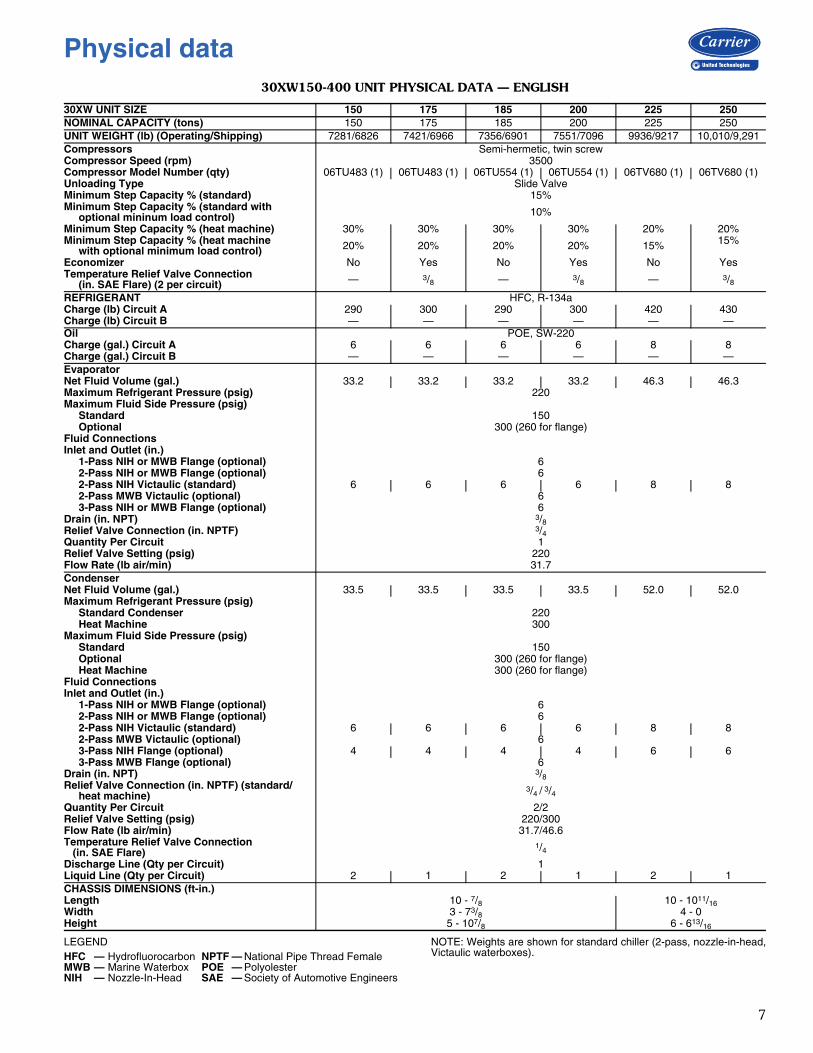
30XW150-400 UNIT PHYSICAL DATA — ENGLISH
LEGEND NOTE: Weights are shown for standard chiller (2-pass, nozzle-in-head,Victaulic waterboxes).
30XW UNIT SIZE 150 175 185 200 225 250NOMINAL CAPACITY (tons) 150 175 185 200 225 250UNIT WEIGHT (lb) (Operating/Shipping) 7281/6826 7421/6966 7356/6901 7551/7096 9936/9217 10,010/9,291Compressors Semi-hermetic, twin screwCompressor Speed (rpm) 3500Compressor Model Number (qty) 06TU483 (1) 06TU483 (1) 06TU554 (1) 06TU554 (1) 06TV680 (1) 06TV680 (1)Unloading Type Slide ValveMinimum Step Capacity % (standard) 15%Minimum Step Capacity % (standard with optional mininum load control) 10%
Minimum Step Capacity % (heat machine) 30% 30% 30% 30% 20% 20%Minimum Step Capacity % (heat machine with optional minimum load control) 20% 20% 20% 20% 15% 15%
Economizer No Yes No Yes No YesTemperature Relief Valve Connection (in. SAE Flare) (2 per circuit) — 3/8 — 3/8 — 3/8
REFRIGERANT HFC, R-134aCharge (lb) Circuit A 290 300 290 300 420 430Charge (lb) Circuit B — — — — — —Oil POE, SW-220Charge (gal.) Circuit A 6 6 6 6 8 8Charge (gal.) Circuit B — — — — — —EvaporatorNet Fluid Volume (gal.) 33.2 33.2 33.2 33.2 46.3 46.3Maximum Refrigerant Pressure (psig) 220Maximum Fluid Side Pressure (psig) Standard 150 Optional 300 (260 for flange)Fluid ConnectionsInlet and Outlet (in.) 1-Pass NIH or MWB Flange (optional) 6 2-Pass NIH or MWB Flange (optional) 6 2-Pass NIH Victaulic (standard) 6 6 6 6 8 8 2-Pass MWB Victaulic (optional) 6 3-Pass NIH or MWB Flange (optional) 6Drain (in. NPT) 3/8Relief Valve Connection (in. NPTF) 3/4Quantity Per Circuit 1Relief Valve Setting (psig) 220Flow Rate (lb air/min) 31.7CondenserNet Fluid Volume (gal.) 33.5 33.5 33.5 33.5 52.0 52.0Maximum Refrigerant Pressure (psig) Standard Condenser 220 Heat Machine 300Maximum Fluid Side Pressure (psig) Standard 150 Optional 300 (260 for flange) Heat Machine 300 (260 for flange)Fluid ConnectionsInlet and Outlet (in.) 1-Pass NIH or MWB Flange (optional) 6 2-Pass NIH or MWB Flange (optional) 6 2-Pass NIH Victaulic (standard) 6 6 6 6 8 8 2-Pass MWB Victaulic (optional) 6 3-Pass NIH Flange (optional) 4 4 4 4 6 6 3-Pass MWB Flange (optional) 6Drain (in. NPT) 3/8Relief Valve Connection (in. NPTF) (standard/ heat machine)
3/4 / 3/4Quantity Per Circuit 2/2Relief Valve Setting (psig) 220/300Flow Rate (lb air/min) 31.7/46.6Temperature Relief Valve Connection (in. SAE Flare)
1/4Discharge Line (Qty per Circuit) 1Liquid Line (Qty per Circuit) 2 1 2 1 2 1CHASSIS DIMENSIONS (ft-in.)Length 10 - 7/8 10 - 1011/16Width 3 - 73/8 4 - 0Height 5 - 107/8 6 - 613/16
HFC — Hydrofluorocarbon NPTF — National Pipe Thread FemaleMWB — Marine Waterbox POE — PolyolesterNIH — Nozzle-In-Head SAE — Society of Automotive Engineers
Physical data
8
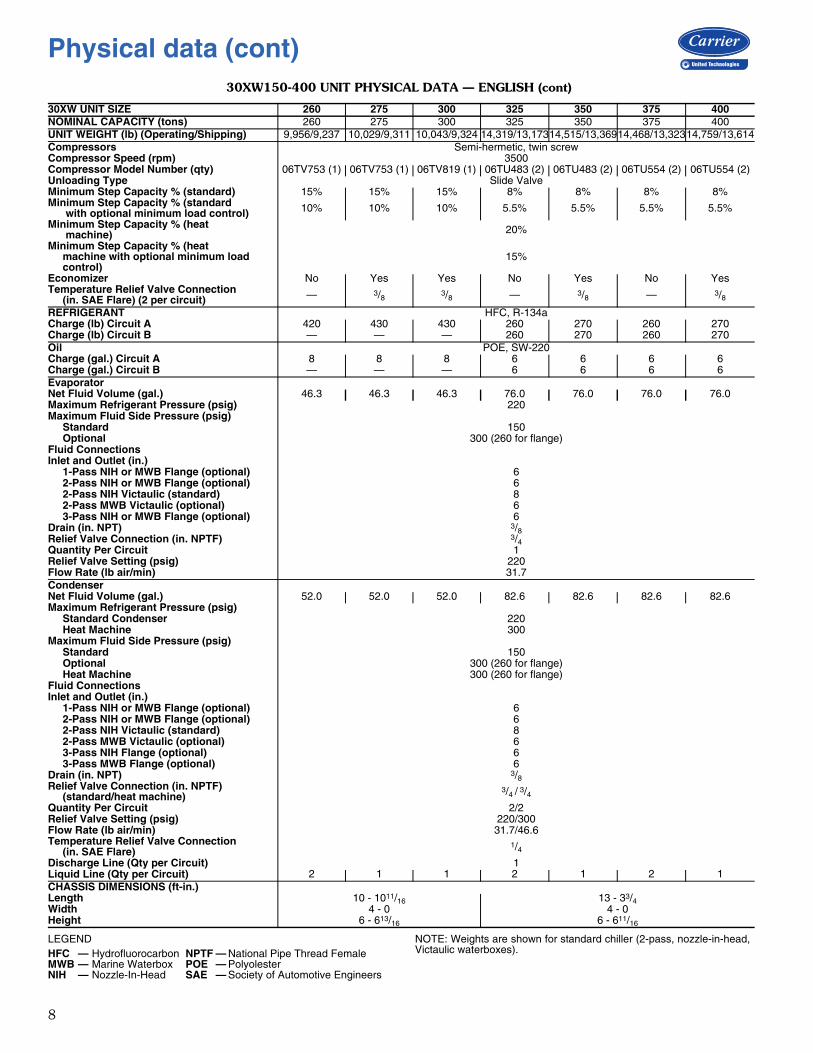
30XW150-400 UNIT PHYSICAL DATA — ENGLISH (cont)
LEGEND NOTE: Weights are shown for standard chiller (2-pass, nozzle-in-head,Victaulic waterboxes).
30XW UNIT SIZE 260 275 300 325 350 375 400NOMINAL CAPACITY (tons) 260 275 300 325 350 375 400UNIT WEIGHT (lb) (Operating/Shipping) 9,956/9,237 10,029/9,311 10,043/9,324 14,319/13,17314,515/13,36914,468/13,32314,759/13,614Compressors Semi-hermetic, twin screwCompressor Speed (rpm) 3500Compressor Model Number (qty) 06TV753 (1) 06TV753 (1) 06TV819 (1) 06TU483 (2) 06TU483 (2) 06TU554 (2) 06TU554 (2)Unloading Type Slide ValveMinimum Step Capacity % (standard) 15% 15% 15% 8% 8% 8% 8%Minimum Step Capacity % (standard with optional minimum load control) 10% 10% 10% 5.5% 5.5% 5.5% 5.5%
Minimum Step Capacity % (heat machine) 20%
Minimum Step Capacity % (heat machine with optional minimum load control)
15%
Economizer No Yes Yes No Yes No YesTemperature Relief Valve Connection (in. SAE Flare) (2 per circuit) — 3/8 3/8 — 3/8 — 3/8
REFRIGERANT HFC, R-134aCharge (lb) Circuit A 420 430 430 260 270 260 270Charge (lb) Circuit B — — — 260 270 260 270Oil POE, SW-220Charge (gal.) Circuit A 8 8 8 6 6 6 6Charge (gal.) Circuit B — — — 6 6 6 6EvaporatorNet Fluid Volume (gal.) 46.3 46.3 46.3 76.0 76.0 76.0 76.0Maximum Refrigerant Pressure (psig) 220Maximum Fluid Side Pressure (psig) Standard 150 Optional 300 (260 for flange)Fluid ConnectionsInlet and Outlet (in.) 1-Pass NIH or MWB Flange (optional) 6 2-Pass NIH or MWB Flange (optional) 6 2-Pass NIH Victaulic (standard) 8 2-Pass MWB Victaulic (optional) 6 3-Pass NIH or MWB Flange (optional) 6Drain (in. NPT) 3/8Relief Valve Connection (in. NPTF) 3/4Quantity Per Circuit 1Relief Valve Setting (psig) 220Flow Rate (lb air/min) 31.7CondenserNet Fluid Volume (gal.) 52.0 52.0 52.0 82.6 82.6 82.6 82.6Maximum Refrigerant Pressure (psig) Standard Condenser 220 Heat Machine 300Maximum Fluid Side Pressure (psig) Standard 150 Optional 300 (260 for flange) Heat Machine 300 (260 for flange)Fluid ConnectionsInlet and Outlet (in.) 1-Pass NIH or MWB Flange (optional) 6 2-Pass NIH or MWB Flange (optional) 6 2-Pass NIH Victaulic (standard) 8 2-Pass MWB Victaulic (optional) 6 3-Pass NIH Flange (optional) 6 3-Pass MWB Flange (optional) 6Drain (in. NPT) 3/8Relief Valve Connection (in. NPTF) (standard/heat machine)
3/4 / 3/4Quantity Per Circuit 2/2Relief Valve Setting (psig) 220/300Flow Rate (lb air/min) 31.7/46.6Temperature Relief Valve Connection (in. SAE Flare)
1/4Discharge Line (Qty per Circuit) 1Liquid Line (Qty per Circuit) 2 1 1 2 1 2 1CHASSIS DIMENSIONS (ft-in.)Length 10 - 1011/16 13 - 33/4Width 4 - 0 4 - 0Height 6 - 613/16 6 - 611/16
HFC — Hydrofluorocarbon NPTF — National Pipe Thread FemaleMWB — Marine Waterbox POE — PolyolesterNIH — Nozzle-In-Head SAE — Society of Automotive Engineers
Physical data (cont)
9
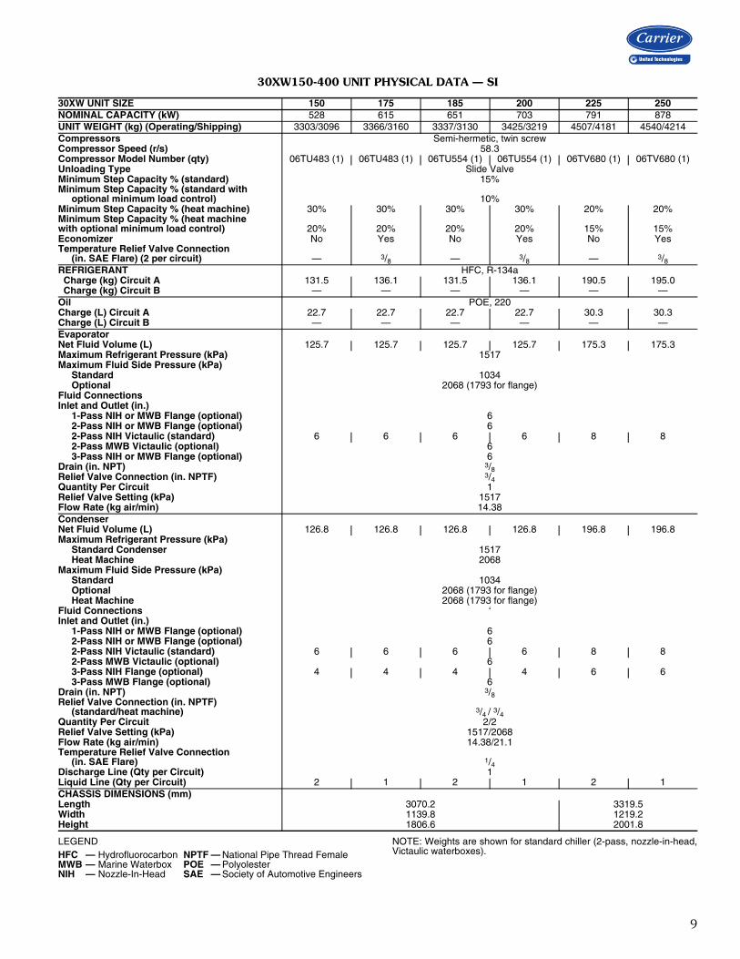
30XW150-400 UNIT PHYSICAL DATA — SI
LEGEND NOTE: Weights are shown for standard chiller (2-pass, nozzle-in-head,Victaulic waterboxes).
30XW UNIT SIZE 150 175 185 200 225 250NOMINAL CAPACITY (kW) 528 615 651 703 791 878UNIT WEIGHT (kg) (Operating/Shipping) 3303/3096 3366/3160 3337/3130 3425/3219 4507/4181 4540/4214Compressors Semi-hermetic, twin screwCompressor Speed (r/s) 58.3Compressor Model Number (qty) 06TU483 (1) 06TU483 (1) 06TU554 (1) 06TU554 (1) 06TV680 (1) 06TV680 (1)Unloading Type Slide ValveMinimum Step Capacity % (standard) 15%Minimum Step Capacity % (standard with optional minimum load control) 10%Minimum Step Capacity % (heat machine) 30% 30% 30% 30% 20% 20%Minimum Step Capacity % (heat machinewith optional minimum load control) 20% 20% 20% 20% 15% 15%Economizer No Yes No Yes No YesTemperature Relief Valve Connection (in. SAE Flare) (2 per circuit) — 3/8 — 3/8 — 3/8REFRIGERANT HFC, R-134a Charge (kg) Circuit A 131.5 136.1 131.5 136.1 190.5 195.0 Charge (kg) Circuit B — — — — — —Oil POE, 220Charge (L) Circuit A 22.7 22.7 22.7 22.7 30.3 30.3Charge (L) Circuit B — — — — — —EvaporatorNet Fluid Volume (L) 125.7 125.7 125.7 125.7 175.3 175.3Maximum Refrigerant Pressure (kPa) 1517Maximum Fluid Side Pressure (kPa) Standard 1034 Optional 2068 (1793 for flange)Fluid ConnectionsInlet and Outlet (in.) 1-Pass NIH or MWB Flange (optional) 6 2-Pass NIH or MWB Flange (optional) 6 2-Pass NIH Victaulic (standard) 6 6 6 6 8 8 2-Pass MWB Victaulic (optional) 6 3-Pass NIH or MWB Flange (optional) 6Drain (in. NPT) 3/8Relief Valve Connection (in. NPTF) 3/4Quantity Per Circuit 1Relief Valve Setting (kPa) 1517Flow Rate (kg air/min) 14.38CondenserNet Fluid Volume (L) 126.8 126.8 126.8 126.8 196.8 196.8Maximum Refrigerant Pressure (kPa) Standard Condenser 1517 Heat Machine 2068Maximum Fluid Side Pressure (kPa) Standard 1034 Optional 2068 (1793 for flange) Heat Machine 2068 (1793 for flange)Fluid Connections ‘Inlet and Outlet (in.) 1-Pass NIH or MWB Flange (optional) 6 2-Pass NIH or MWB Flange (optional) 6 2-Pass NIH Victaulic (standard) 6 6 6 6 8 8 2-Pass MWB Victaulic (optional) 6 3-Pass NIH Flange (optional) 4 4 4 4 6 6 3-Pass MWB Flange (optional) 6Drain (in. NPT) 3/8Relief Valve Connection (in. NPTF) (standard/heat machine) 3/4 / 3/4Quantity Per Circuit 2/2Relief Valve Setting (kPa) 1517/2068Flow Rate (kg air/min) 14.38/21.1Temperature Relief Valve Connection (in. SAE Flare) 1/4Discharge Line (Qty per Circuit) 1Liquid Line (Qty per Circuit) 2 1 2 1 2 1CHASSIS DIMENSIONS (mm)Length 3070.2 3319.5Width 1139.8 1219.2Height 1806.6 2001.8
HFC — Hydrofluorocarbon NPTF — National Pipe Thread FemaleMWB — Marine Waterbox POE — PolyolesterNIH — Nozzle-In-Head SAE — Society of Automotive Engineers
10
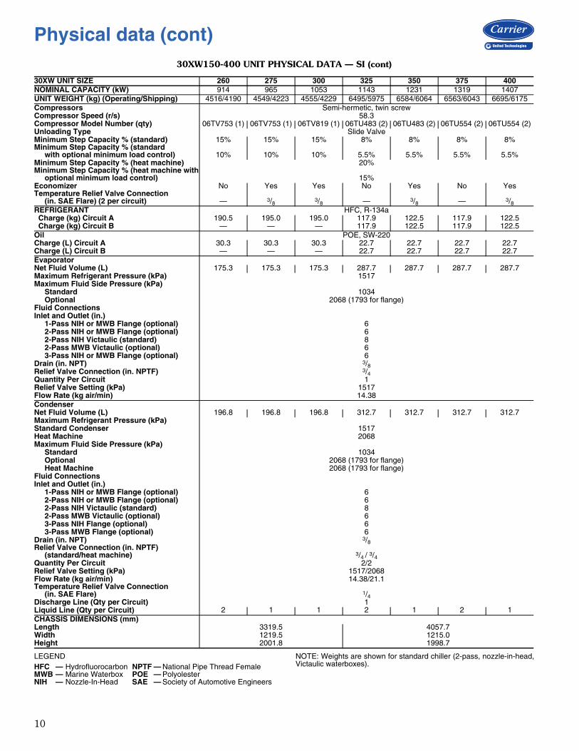
30XW150-400 UNIT PHYSICAL DATA — SI (cont)
LEGEND NOTE: Weights are shown for standard chiller (2-pass, nozzle-in-head,Victaulic waterboxes).
30XW UNIT SIZE 260 275 300 325 350 375 400NOMINAL CAPACITY (kW) 914 965 1053 1143 1231 1319 1407UNIT WEIGHT (kg) (Operating/Shipping) 4516/4190 4549/4223 4555/4229 6495/5975 6584/6064 6563/6043 6695/6175Compressors Semi-hermetic, twin screwCompressor Speed (r/s) 58.3Compressor Model Number (qty) 06TV753 (1) 06TV753 (1) 06TV819 (1) 06TU483 (2) 06TU483 (2) 06TU554 (2) 06TU554 (2)Unloading Type Slide ValveMinimum Step Capacity % (standard) 15% 15% 15% 8% 8% 8% 8%Minimum Step Capacity % (standard with optional minimum load control) 10% 10% 10% 5.5% 5.5% 5.5% 5.5%Minimum Step Capacity % (heat machine) 20%Minimum Step Capacity % (heat machine with optional minimum load control) 15%Economizer No Yes Yes No Yes No YesTemperature Relief Valve Connection (in. SAE Flare) (2 per circuit) — 3/8 3/8 — 3/8 — 3/8REFRIGERANT HFC, R-134a Charge (kg) Circuit A 190.5 195.0 195.0 117.9 122.5 117.9 122.5 Charge (kg) Circuit B — — — 117.9 122.5 117.9 122.5Oil POE, SW-220Charge (L) Circuit A 30.3 30.3 30.3 22.7 22.7 22.7 22.7Charge (L) Circuit B — — — 22.7 22.7 22.7 22.7EvaporatorNet Fluid Volume (L) 175.3 175.3 175.3 287.7 287.7 287.7 287.7Maximum Refrigerant Pressure (kPa) 1517Maximum Fluid Side Pressure (kPa) Standard 1034 Optional 2068 (1793 for flange)Fluid ConnectionsInlet and Outlet (in.) 1-Pass NIH or MWB Flange (optional) 6 2-Pass NIH or MWB Flange (optional) 6 2-Pass NIH Victaulic (standard) 8 2-Pass MWB Victaulic (optional) 6 3-Pass NIH or MWB Flange (optional) 6Drain (in. NPT) 3/8Relief Valve Connection (in. NPTF) 3/4Quantity Per Circuit 1Relief Valve Setting (kPa) 1517Flow Rate (kg air/min) 14.38CondenserNet Fluid Volume (L) 196.8 196.8 196.8 312.7 312.7 312.7 312.7Maximum Refrigerant Pressure (kPa)Standard Condenser 1517Heat Machine 2068Maximum Fluid Side Pressure (kPa) Standard 1034 Optional 2068 (1793 for flange) Heat Machine 2068 (1793 for flange)Fluid ConnectionsInlet and Outlet (in.) 1-Pass NIH or MWB Flange (optional) 6 2-Pass NIH or MWB Flange (optional) 6 2-Pass NIH Victaulic (standard) 8 2-Pass MWB Victaulic (optional) 6 3-Pass NIH Flange (optional) 6 3-Pass MWB Flange (optional) 6Drain (in. NPT) 3/8Relief Valve Connection (in. NPTF) (standard/heat machine) 3/4 / 3/4Quantity Per Circuit 2/2Relief Valve Setting (kPa) 1517/2068Flow Rate (kg air/min) 14.38/21.1Temperature Relief Valve Connection (in. SAE Flare) 1/4Discharge Line (Qty per Circuit) 1Liquid Line (Qty per Circuit) 2 1 1 2 1 2 1CHASSIS DIMENSIONS (mm)Length 3319.5 4057.7Width 1219.5 1215.0Height 2001.8 1998.7
HFC — Hydrofluorocarbon NPTF — National Pipe Thread FemaleMWB — Marine Waterbox POE — PolyolesterNIH — Nozzle-In-Head SAE — Society of Automotive Engineers
Physical data (cont)
11
*The following units are not available with the brine option: sizes 150,185, 225, 260, 325 and 375.
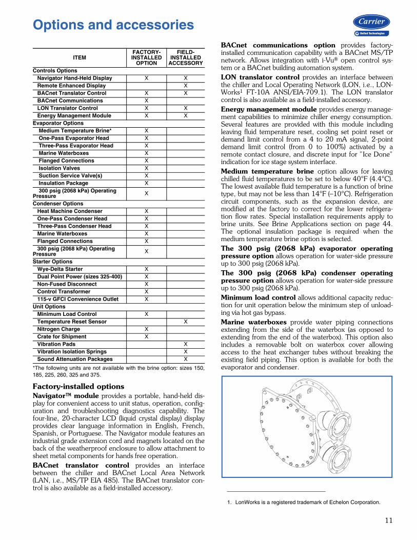
Factory-installed optionsNavigator™ module provides a portable, hand-held dis-play for convenient access to unit status, operation, config-uration and troubleshooting diagnostics capability. Thefour-line, 20-character LCD (liquid crystal display) displayprovides clear language information in English, French,Spanish, or Portuguese. The Navigator module features anindustrial grade extension cord and magnets located on theback of the weatherproof enclosure to allow attachment tosheet metal components for hands free operation.BACnet translator control provides an interfacebetween the chiller and BACnet Local Area Network(LAN, i.e., MS/TP EIA 485). The BACnet translator con-trol is also available as a field-installed accessory.
BACnet communications option provides factory-installed communication capability with a BACnet MS/TPnetwork. Allows integration with i-Vu® open control sys-tem or a BACnet building automation system.LON translator control provides an interface betweenthe chiller and Local Operating Network (LON, i.e., LON-Works1 FT-10A ANSI/EIA-709.1). The LON translatorcontrol is also available as a field-installed accessory.Energy management module provides energy manage-ment capabilities to minimize chiller energy consumption.Several features are provided with this module includingleaving fluid temperature reset, cooling set point reset ordemand limit control from a 4 to 20 mA signal, 2-pointdemand limit control (from 0 to 100%) activated by aremote contact closure, and discrete input for " Ice Done"indication for ice stage system interface.Medium temperature brine option allows for leavingchilled fluid temperatures to be set to below 40°F (4.4°C).The lowest available fluid temperature is a function of brinetype, but may not be less than 14°F (–10°C). Refrigerationcircuit components, such as the expansion device, aremodified at the factory to correct for the lower refrigera-tion flow rates. Special installation requirements apply tobrine units. See Brine Applications section on page 44.The optional insulation package is required when themedium temperature brine option is selected.The 300 psig (2068 kPa) evaporator operatingpressure option allows operation for water-side pressureup to 300 psig (2068 kPa).The 300 psig (2068 kPa) condenser operatingpressure option allows operation for water-side pressureup to 300 psig (2068 kPa).Minimum load control allows additional capacity reduc-tion for unit operation below the minimum step of unload-ing via hot gas bypass.Marine waterboxes provide water piping connectionsextending from the side of the waterbox (as opposed toextending from the end of the waterbox). This option alsoincludes a removable bolt on waterbox cover allowingaccess to the heat exchanger tubes without breaking theexisting field piping. This option is available for both theevaporator and condenser.
ITEMFACTORY-INSTALLED
OPTION
FIELD-INSTALLED
ACCESSORYControls Options Navigator Hand-Held Display X X Remote Enhanced Display X BACnet Translator Control X X BACnet Communications X LON Translator Control X X Energy Management Module X XEvaporator Options Medium Temperature Brine* X One-Pass Evaporator Head X Three-Pass Evaporator Head X Marine Waterboxes X Flanged Connections X Isolation Valves X Suction Service Valve(s) X Insulation Package X 300 psig (2068 kPa) Operating Pressure X
Condenser Options Heat Machine Condenser X One-Pass Condenser Head X Three-Pass Condenser Head X Marine Waterboxes X Flanged Connections X 300 psig (2068 kPa) Operating Pressure X
Starter Options Wye-Delta Starter X Dual Point Power (sizes 325-400) X Non-Fused Disconnect X Control Transformer X 115-v GFCI Convenience Outlet XUnit Options Minimum Load Control X Temperature Reset Sensor X Nitrogen Charge X Crate for Shipment X Vibration Pads X Vibration Isolation Springs X Sound Attenuation Packages X
1. LonWorks is a registered trademark of Echelon Corporation.
Options and accessories
12
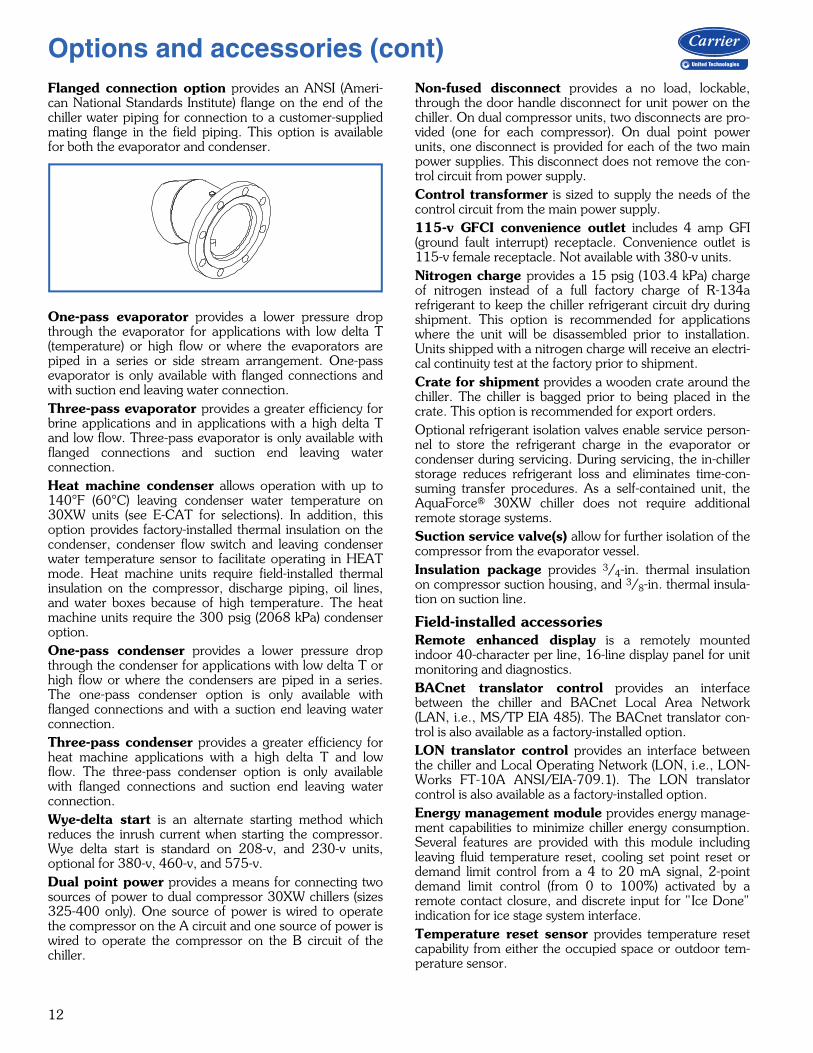
Flanged connection option provides an ANSI (Ameri-can National Standards Institute) flange on the end of thechiller water piping for connection to a customer-suppliedmating flange in the field piping. This option is availablefor both the evaporator and condenser.
One-pass evaporator provides a lower pressure dropthrough the evaporator for applications with low delta T(temperature) or high flow or where the evaporators arepiped in a series or side stream arrangement. One-passevaporator is only available with flanged connections andwith suction end leaving water connection.Three-pass evaporator provides a greater efficiency forbrine applications and in applications with a high delta Tand low flow. Three-pass evaporator is only available withflanged connections and suction end leaving waterconnection.Heat machine condenser allows operation with up to140°F (60°C) leaving condenser water temperature on30XW units (see E-CAT for selections). In addition, thisoption provides factory-installed thermal insulation on thecondenser, condenser flow switch and leaving condenserwater temperature sensor to facilitate operating in HEATmode. Heat machine units require field-installed thermalinsulation on the compressor, discharge piping, oil lines,and water boxes because of high temperature. The heatmachine units require the 300 psig (2068 kPa) condenseroption.One-pass condenser provides a lower pressure dropthrough the condenser for applications with low delta T orhigh flow or where the condensers are piped in a series.The one-pass condenser option is only available withflanged connections and with a suction end leaving waterconnection.Three-pass condenser provides a greater efficiency forheat machine applications with a high delta T and lowflow. The three-pass condenser option is only availablewith flanged connections and suction end leaving waterconnection.Wye-delta start is an alternate starting method whichreduces the inrush current when starting the compressor.Wye delta start is standard on 208-v, and 230-v units,optional for 380-v, 460-v, and 575-v. Dual point power provides a means for connecting twosources of power to dual compressor 30XW chillers (sizes325-400 only). One source of power is wired to operatethe compressor on the A circuit and one source of power iswired to operate the compressor on the B circuit of thechiller.
Non-fused disconnect provides a no load, lockable,through the door handle disconnect for unit power on thechiller. On dual compressor units, two disconnects are pro-vided (one for each compressor). On dual point powerunits, one disconnect is provided for each of the two mainpower supplies. This disconnect does not remove the con-trol circuit from power supply.Control transformer is sized to supply the needs of thecontrol circuit from the main power supply.115-v GFCI convenience outlet includes 4 amp GFI(ground fault interrupt) receptacle. Convenience outlet is115-v female receptacle. Not available with 380-v units.Nitrogen charge provides a 15 psig (103.4 kPa) chargeof nitrogen instead of a full factory charge of R-134arefrigerant to keep the chiller refrigerant circuit dry duringshipment. This option is recommended for applicationswhere the unit will be disassembled prior to installation.Units shipped with a nitrogen charge will receive an electri-cal continuity test at the factory prior to shipment.Crate for shipment provides a wooden crate around thechiller. The chiller is bagged prior to being placed in thecrate. This option is recommended for export orders.Optional refrigerant isolation valves enable service person-nel to store the refrigerant charge in the evaporator orcondenser during servicing. During servicing, the in-chillerstorage reduces refrigerant loss and eliminates time-con-suming transfer procedures. As a self-contained unit, theAquaForce® 30XW chiller does not require additionalremote storage systems.Suction service valve(s) allow for further isolation of thecompressor from the evaporator vessel.Insulation package provides 3/4-in. thermal insulationon compressor suction housing, and 3/8-in. thermal insula-tion on suction line.
Field-installed accessoriesRemote enhanced display is a remotely mountedindoor 40-character per line, 16-line display panel for unitmonitoring and diagnostics.BACnet translator control provides an interfacebetween the chiller and BACnet Local Area Network(LAN, i.e., MS/TP EIA 485). The BACnet translator con-trol is also available as a factory-installed option.LON translator control provides an interface betweenthe chiller and Local Operating Network (LON, i.e., LON-Works FT-10A ANSI/EIA-709.1). The LON translatorcontrol is also available as a factory-installed option.Energy management module provides energy manage-ment capabilities to minimize chiller energy consumption.Several features are provided with this module includingleaving fluid temperature reset, cooling set point reset ordemand limit control from a 4 to 20 mA signal, 2-pointdemand limit control (from 0 to 100%) activated by aremote contact closure, and discrete input for " Ice Done"indication for ice stage system interface.Temperature reset sensor provides temperature resetcapability from either the occupied space or outdoor tem-perature sensor.
a30-4685
Options and accessories (cont)
13
NOTE: Temperature reset capability using return tempera-ture is standard.Vibration isolation pads are neoprene pads for installa-tion under the chiller feet at the jobsite.Vibration springs provide a set of non-seismic springisolators for installation at the jobsite.
Navigator™ module provides a portable, hand-held dis-play for convenient access to unit status, operation, config-uration and troubleshooting diagnostics capability. Thefour-line, 20-character LCD (liquid crystal display) displayprovides clear language information in English, French,Spanish, or Portuguese. The Navigator module features anindustrial grade extension chord and magnets located onthe back of the weatherproof enclosure to allow attach-ment to sheet metal components for hands free operation.
Field-supplied and field-installed insulationEvaporator waterbox insulation must be field suppliedand field installed. When insulating waterbox and tubesheets, allow for service access and removal of covers. Toestimate waterbox and tube sheet cover areas, refer to theField-Supplied and Field-Installed Insulation figure on thenext page and certified drawings.Insulation for discharge piping between the compres-sor and condenser must be field installed on heat machineunits. Refer to the figure on the next page.
Condenser waterbox insulation must be field suppliedand field installed on heat machine units. When insulatingwaterbox and tube sheets, allow for service access andremoval of covers. To estimate waterbox and tube sheetcover areas, refer to certified drawings and the Field-Sup-plied and Field-Installed Insulation figure on the next page.Additional compressor insulation may be required toprevent condensation if the unit is installed in an uncondi-tioned mechanical space with high temperature and rela-tive humidity. Field-Supplied and Field-Installed Insulationshould be applied to the remainder of the compressormotor housing, as necessary. Refer to the figure on thenext page for insulation details.Factory insulation provides excellent protectionagainst condensation under most operating conditions asindicated in the Condensation vs Relative Humidity table. Iftemperatures in the equipment area exceed the maximumdesign conditions, extra insulation is recommended.
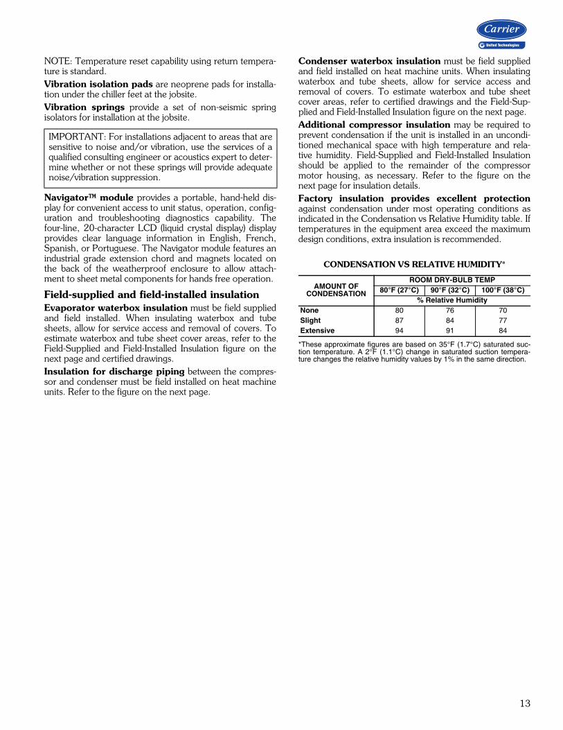
CONDENSATION VS RELATIVE HUMIDITY*
*These approximate figures are based on 35°F (1.7°C) saturated suc-tion temperature. A 2°F (1.1°C) change in saturated suction tempera-ture changes the relative humidity values by 1% in the same direction.
IMPORTANT: For installations adjacent to areas that aresensitive to noise and/or vibration, use the services of aqualified consulting engineer or acoustics expert to deter-mine whether or not these springs will provide adequatenoise/vibration suppression.
AMOUNT OFCONDENSATION
ROOM DRY-BULB TEMP80°F (27°C) 90°F (32°C) 100°F (38°C)
% Relative HumidityNone 80 76 70Slight 87 84 77Extensive 94 91 84
14
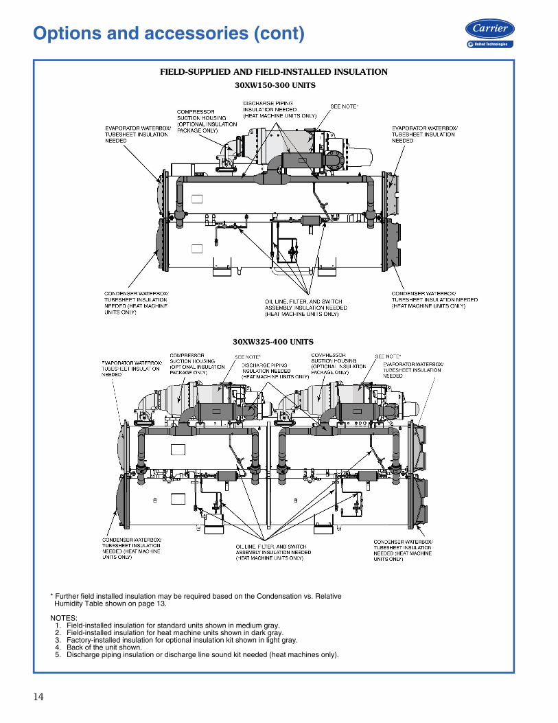
30XW150-300 UNITS
FIELD-SUPPLIED AND FIELD-INSTALLED INSULATION
30XW325-400 UNITS
* Further field installed insulation may be required based on the Condensation vs. Relative Humidity Table shown on page 13.
NOTES:1. Field-installed insulation for standard units shown in medium gray.2. Field-installed insulation for heat machine units shown in dark gray.3. Factory-installed insulation for optional insulation kit shown in light gray.4. Back of the unit shown.5. Discharge piping insulation or discharge line sound kit needed (heat machines only).
Options and accessories (cont)
15
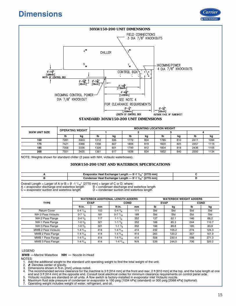
30XW150-200 UNIT DIMENSIONS
30XW150-200 UNIT AND WATERBOX SPECIFICATIONS
Overall Length = Larger of A or B + 9' -1 1/16" [2770 mm] + larger of C or D, where:A = evaporator discharge end waterbox length B = condenser discharge end waterbox lengthC = evaporator suction end waterbox length D = condenser suction end waterbox length
A Evaporator Heat Exchanger Length — 9'-1 1/16" [2770 mm] CB Condenser Heat Exchanger Length — 9'-1 1/16" [2770 mm] D
TYPEWATERBOX ADDITIONAL LENGTH ADDERS WATERBOX WEIGHT ADDERS
EVAP COND EVAP CONDft-in. mm ft-in. mm lb kg lb kg
Return Cover 0-4 1/16 103 0-4 3/8 111 Std Std Std StdNIH 2 Pass Victaulic 0-7 1/8 181 0-7 7/16 189 Std Std Std StdNIH 2 Pass Flange 0-4 5/8 117 1-1 7/8 352 137 62.1 146 66.2NIH 1 Pass Flange 1-0 5/8 321 1-1 7/8 352 188 85.3 244 110.7NIH 3 Pass Flange 1-0 5/8 321 1-1 7/8 352 198 89.8 185 83.9
MWB 2 Pass Victaulic 1-4 5/16 414 1-4 5/16 414 232 105.2 274 124.3MWB 2 Pass Flange 1-4 5/16 414 1-4 5/16 414 265 120.2 357 161.9MWB 1 Pass Flange 1-4 5/16 414 1-4 5/16 414 508 230.4 598 271.3MWB 3 Pass Flange 1-4 5/16 414 1-4 5/16 N/A 539 244.5 706 320.2
STANDARD 30XW150-200 UNIT DIMENSIONS
NOTE: Weights shown for standard chiller (2 pass with NIH, victaulic waterboxes).
30XW UNIT SIZEOPERATING WEIGHT
MOUNTING LOCATION WEIGHT1 2 3 4
lb kg lb kg lb kg lb kg lb kg150 7281 3303 1312 595 1772 804 1785 810 2411 1094175 7421 3366 1338 607 1806 819 1820 825 2457 1115185 7356 3336 1326 601 1790 812 1804 818 2436 1105200 7551 3425 1361 617 1838 834 1852 840 2500 1134
a30-5269
NOTES:1. Add the additional weight to the standard unit operating weight to find the total weight of the unit.2. Denotes center of gravity.3. Dimensions shown in ft-in. [mm] unless noted.4. The recommended service clearance for the machine is 3 ft [914 mm] at the front and rear, 2 ft [610 mm] at the top, and the tube length at one
end and 3 ft [914 mm] at the opposite end. Consult local electrical codes for minimum clearance requirements on control panel side.5. Victaulic nozzles are standard on all units. A flow switch is factory-installed in evaporator inlet Victaulic nozzle.6. Maximum fluid side pressure of condenser or evaporator is 150 psig [1034 kPa] (standard) or 300 psig [2068 kPa] (optional).7. Operating weight includes weight of water, refrigerant, and oil.
LEGENDMWB —Marine Waterbox NIH — Nozzle-In-Head
Dimensions
16
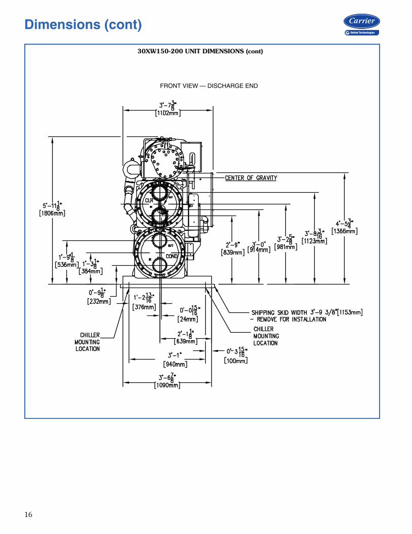
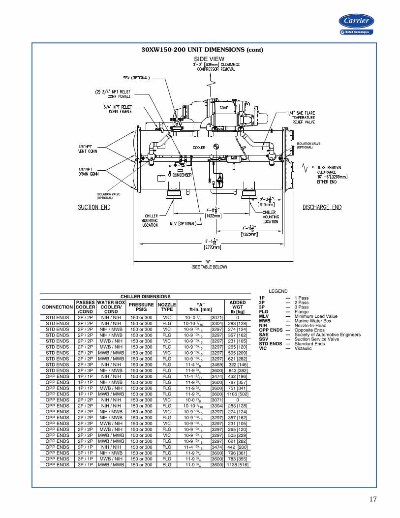
30XW150-200 UNIT DIMENSIONS (cont)
WIDTH
aa30-5266FRONT VIEW — DISCHARGE END
Dimensions (cont)
17
30XW150-200 UNIT DIMENSIONS (cont)
3/8”3/8”
3/8”3/8”
619 mm
“A” “A” (SEE TABLE BELOW) (SEE TABLE BELOW)
ISOLATION VALVE(OPTIONAL)
ISOLATION VALVE(OPTIONAL)
a30-5267
SIDE VIEW
CHILLER DIMENSIONS
CONNECTIONPASSESCOOLER/COND
WATER BOXCOOLER/
COND
PRESSUREPSIG
NOZZLETYPE
“A”ft-in. [mm]
ADDEDWGT
lb [kg]STD ENDS 2P / 2P NIH / NIH 150 or 300 VIC 10- 0 7/8 [3071] 0STD ENDS 2P / 2P NIH / NIH 150 or 300 FLG 10-10 1/16 [3304] 283 [128]STD ENDS 2P / 2P NIH / MWB 150 or 300 VIC 10-9 13/16 [3297] 274 [124]STD ENDS 2P / 2P NIH / MWB 150 or 300 FLG 10-9 13/16 [3297] 357 [162]STD ENDS 2P / 2P MWB / NIH 150 or 300 VIC 10-9 13/16 [3297] 231 [105]STD ENDS 2P / 2P MWB / NIH 150 or 300 FLG 10-9 13/16 [3297] 265 [120]STD ENDS 2P / 2P MWB / MWB 150 or 300 VIC 10-9 13/16 [3297] 505 [209]STD ENDS 2P / 2P MWB / MWB 150 or 300 FLG 10-9 13/16 [3297] 621 [282]STD ENDS 2P / 3P NIH / NIH 150 or 300 FLG 11-4 5/8 [3469] 322 [146]STD ENDS 2P / 3P NIH / MWB 150 or 300 FLG 11-9 3/4 [3600] 843 [382]OPP ENDS 1P / 1P NIH / NIH 150 or 300 FLG 11-4 13/16 [3474] 432 [196]OPP ENDS 1P / 1P NIH / MWB 150 or 300 FLG 11-9 3/4 [3600] 787 [357]OPP ENDS 1P / 1P MWB / NIH 150 or 300 FLG 11-9 3/4 [3600] 751 [341]OPP ENDS 1P / 1P MWB / MWB 150 or 300 FLG 11-9 3/4 [3600] 1106 [502]OPP ENDS 2P / 2P NIH / NIH 150 or 300 VIC 10-0 7/8 [3071] 0OPP ENDS 2P / 2P NIH / NIH 150 or 300 FLG 10-10 1/16 [3304] 283 [128]OPP ENDS 2P / 2P NIH / MWB 150 or 300 VIC 10-9 13/16 [3297] 274 [124]OPP ENDS 2P / 2P NIH / MWB 150 or 300 FLG 10-9 13/16 [3297] 357 [162]OPP ENDS 2P / 2P MWB / NIH 150 or 300 VIC 10-9 13/16 [3297] 231 [105]OPP ENDS 2P / 2P MWB / NIH 150 or 300 FLG 10-9 13/16 [3297] 265 [120]OPP ENDS 2P / 2P MWB / MWB 150 or 300 VIC 10-9 13/16 [3297] 505 [229]OPP ENDS 2P / 2P MWB / MWB 150 or 300 FLG 10-9 13/16 [3297] 621 [282]OPP ENDS 3P / 1P NIH / NIH 150 or 300 FLG 11-4 13/16 [3474] 442 [200]OPP ENDS 3P / 1P NIH / MWB 150 or 300 FLG 11-9 3/4 [3600] 796 [361]OPP ENDS 3P / 1P MWB / NIH 150 or 300 FLG 11-9 3/4 [3600] 783 [355]OPP ENDS 3P / 1P MWB / MWB 150 or 300 FLG 11-9 3/4 [3600] 1138 [516]
LEGEND
1P — 1 Pass2P — 2 Pass3P — 3 PassFLG — FlangeMLV — Minimum Load ValueMWB — Marine Water BoxNIH — Nozzle-In-HeadOPP ENDS — Opposite EndsSAE — Society of Automotive EngineersSSV — Suction Service ValveSTD ENDS — Standard EndsVIC — Victaulic
SIDE VIEW
18
COMPRESSORDISCHARGE END
COMPRESSORDISCHARGE END
COMPRESSORSUCTION END
COMPRESSORSUCTION END
COMPRESSORDISCHARGE END
COMPRESSORDISCHARGE END
COMPRESSORSUCTION END
COMPRESSORSUCTION END
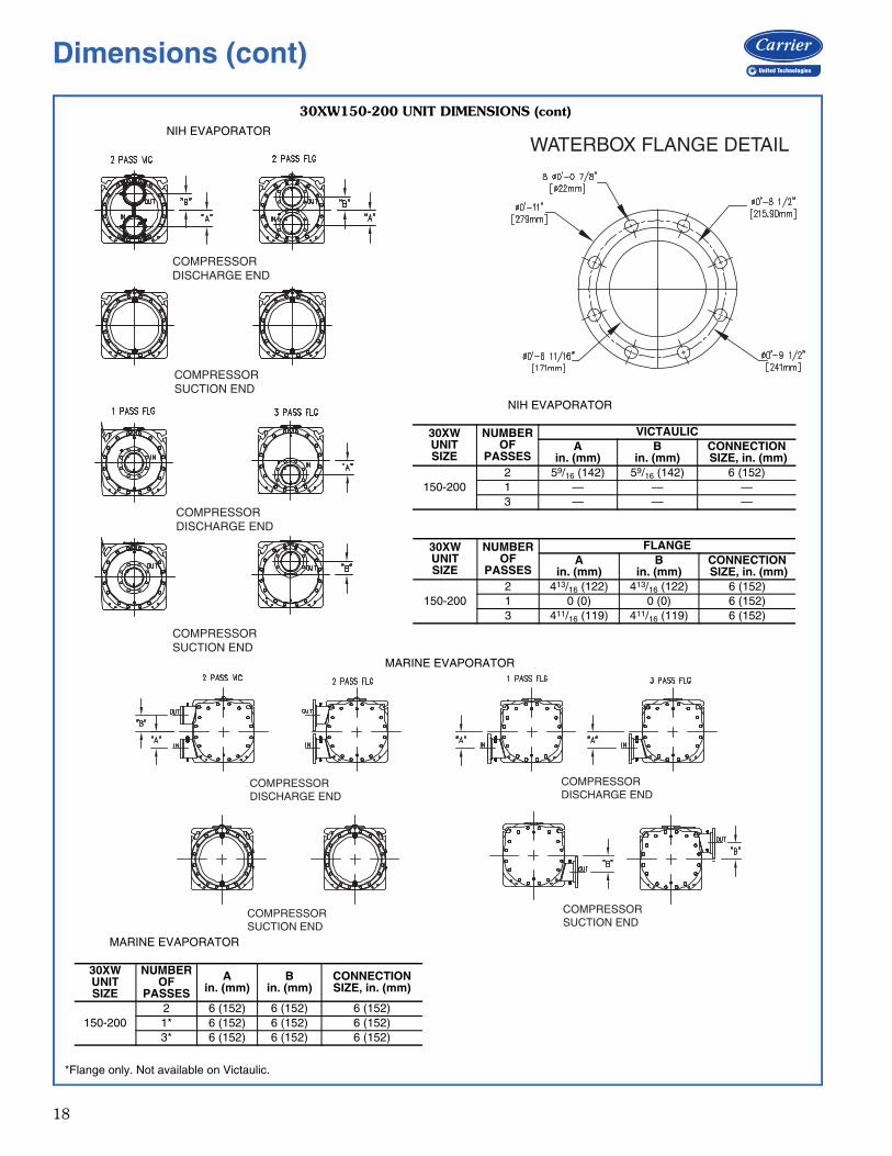
30XW150-200 UNIT DIMENSIONS (cont)
30XW UNITSIZE
NUMBER OF
PASSES
Ain. (mm)
Bin. (mm)
CONNECTION SIZE, in. (mm)
150-2002 6 (152) 6 (152) 6 (152)1* 6 (152) 6 (152) 6 (152)3* 6 (152) 6 (152) 6 (152)
A30-5516
A30-5517
MARINE EVAPORATOR
WATERBOX FLANGE DETAIL
30XW UNITSIZE
NUMBER OF
PASSES
VICTAULICA
in. (mm)B
in. (mm)CONNECTION SIZE, in. (mm)
150-2002 59/16 (142) 59/16 (142) 6 (152)1 — — —3 — — —
30XW UNITSIZE
NUMBER OF
PASSES
FLANGEA
in. (mm)B
in. (mm)CONNECTION SIZE, in. (mm)
150-2002 413/16 (122) 413/16 (122) 6 (152)1 0 (0) 0 (0) 6 (152)3 411/16 (119) 411/16 (119) 6 (152)
NIH EVAPORATOR
a30-4725
*Flange only. Not available on Victaulic.
COMPRESSORDISCHARGE END
COMPRESSORDISCHARGE END
COMPRESSORSUCTION END
COMPRESSORSUCTION END
NIH EVAPORATOR
MARINE EVAPORATOR
Dimensions (cont)
19
COMPRESSORDISCHARGE END
COMPRESSORDISCHARGE END
COMPRESSORDISCHARGE END
COMPRESSORDISCHARGE END
COMPRESSORSUCTION END
COMPRESSORSUCTION END
COMPRESSORSUCTION END
COMPRESSORSUCTION END
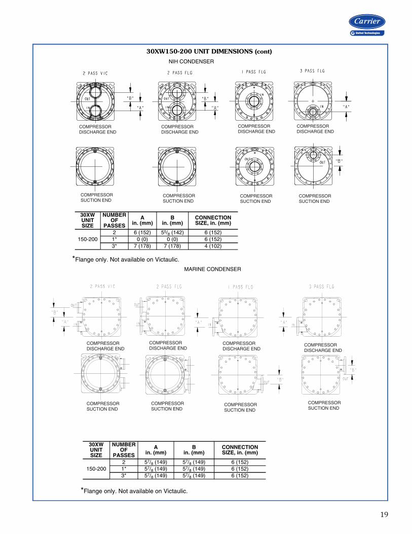
30XW150-200 UNIT DIMENSIONS (cont)
30XW UNITSIZE
NUMBER OF
PASSES
Ain. (mm)
Bin. (mm)
CONNECTION SIZE, in. (mm)
150-2002 6 (152) 55/8 (142) 6 (152)1* 0 (0) 0 (0) 6 (152)3* 7 (178) 7 (178) 4 (102)
A30-5508
A30-5509
30XW UNITSIZE
NUMBER OF
PASSES
Ain. (mm)
Bin. (mm)
CONNECTION SIZE, in. (mm)
150-2002 57/8 (149) 57/8 (149) 6 (152)1* 57/8 (149) 57/8 (149) 6 (152)3* 57/8 (149) 57/8 (149) 6 (152)
MARINE CONDENSER
NIH CONDENSER
*Flange only. Not available on Victaulic.
*Flange only. Not available on Victaulic.
COMPRESSORDISCHARGE END
COMPRESSORDISCHARGE END
COMPRESSORDISCHARGE END
COMPRESSORDISCHARGE END
COMPRESSORSUCTION END
COMPRESSORSUCTION END
COMPRESSORSUCTION END
COMPRESSORSUCTION END
20
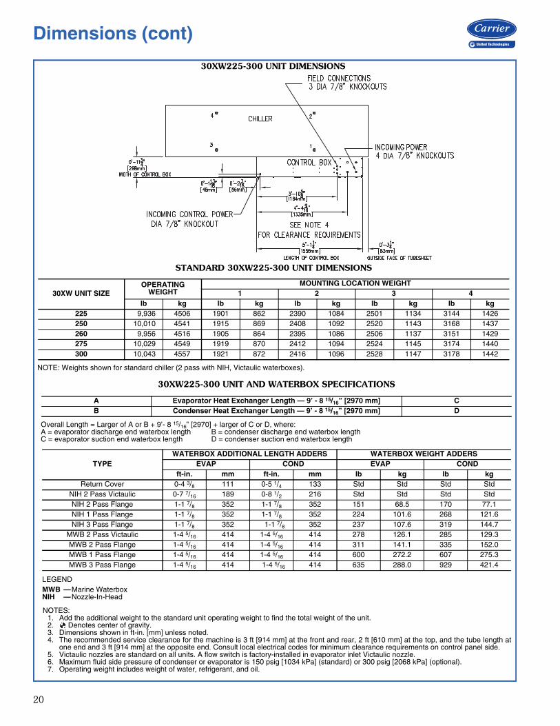
30XW225-300 UNIT DIMENSIONS
STANDARD 30XW225-300 UNIT DIMENSIONS
NOTE: Weights shown for standard chiller (2 pass with NIH, Victaulic waterboxes).
30XW UNIT SIZEOPERATING
WEIGHTMOUNTING LOCATION WEIGHT
1 2 3 4lb kg lb kg lb kg lb kg lb kg
225 9,936 4506 1901 862 2390 1084 2501 1134 3144 1426250 10,010 4541 1915 869 2408 1092 2520 1143 3168 1437260 9,956 4516 1905 864 2395 1086 2506 1137 3151 1429275 10,029 4549 1919 870 2412 1094 2524 1145 3174 1440300 10,043 4557 1921 872 2416 1096 2528 1147 3178 1442
NOTES:1. Add the additional weight to the standard unit operating weight to find the total weight of the unit.2. Denotes center of gravity.3. Dimensions shown in ft-in. [mm] unless noted.4. The recommended service clearance for the machine is 3 ft [914 mm] at the front and rear, 2 ft [610 mm] at the top, and the tube length at
one end and 3 ft [914 mm] at the opposite end. Consult local electrical codes for minimum clearance requirements on control panel side.5. Victaulic nozzles are standard on all units. A flow switch is factory-installed in evaporator inlet Victaulic nozzle.6. Maximum fluid side pressure of condenser or evaporator is 150 psig [1034 kPa] (standard) or 300 psig [2068 kPa] (optional).7. Operating weight includes weight of water, refrigerant, and oil.
LEGENDMWB —Marine WaterboxNIH —Nozzle-In-Head
A30-5269
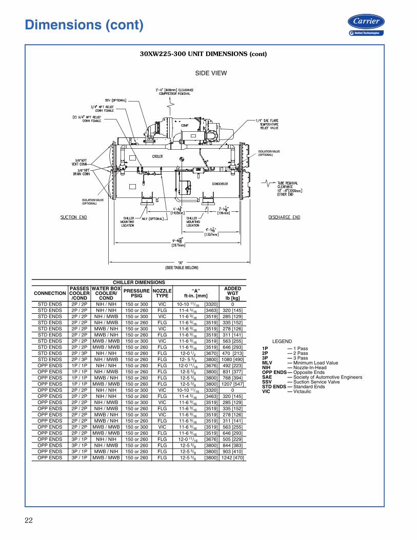
30XW225-300 UNIT AND WATERBOX SPECIFICATIONS
Overall Length = Larger of A or B + 9’- 8 15/16” [2970] + larger of C or D, where:A = evaporator discharge end waterbox length B = condenser discharge end waterbox lengthC = evaporator suction end waterbox length D = condenser suction end waterbox length
A Evaporator Heat Exchanger Length — 9’ - 8 15/16” [2970 mm] CB Condenser Heat Exchanger Length — 9’ - 8 15/16” [2970 mm] D
TYPEWATERBOX ADDITIONAL LENGTH ADDERS WATERBOX WEIGHT ADDERS
EVAP COND EVAP CONDft-in. mm ft-in. mm lb kg lb kg
Return Cover 0-4 3/8 111 0-5 1/4 133 Std Std Std StdNIH 2 Pass Victaulic 0-7 7/16 189 0-8 1/2 216 Std Std Std StdNIH 2 Pass Flange 1-1 7/8 352 1-1 7/8 352 151 68.5 170 77.1NIH 1 Pass Flange 1-1 7/8 352 1-1 7/8 352 224 101.6 268 121.6NIH 3 Pass Flange 1-1 7/8 352 1-1 7/8 352 237 107.6 319 144.7
MWB 2 Pass Victaulic 1-4 5/16 414 1-4 5/16 414 278 126.1 285 129.3MWB 2 Pass Flange 1-4 5/16 414 1-4 5/16 414 311 141.1 335 152.0MWB 1 Pass Flange 1-4 5/16 414 1-4 5/16 414 600 272.2 607 275.3MWB 3 Pass Flange 1-4 5/16 414 1-4 5/16 414 635 288.0 929 421.4
Dimensions (cont)
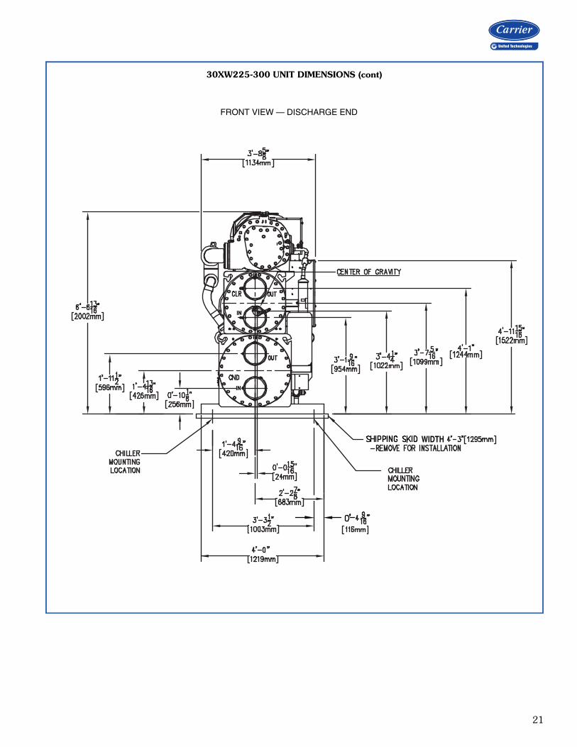
21
30XW225-300 UNIT DIMENSIONS (cont)
WIDTH
a30-5270
FRONT VIEW — DISCHARGE END
22
30XW225-300 UNIT DIMENSIONS (cont)
3/8”3/8”
3/8”3/8”
“A” “A” (SEE TABLE BELOW) (SEE TABLE BELOW)
ISOLATION VALVE(OPTIONAL)
ISOLATION VALVE(OPTIONAL)
a30-5271
SIDE VIEW
LEGEND
1P — 1 Pass2P — 2 Pass3P — 3 PassMLV — Minimum Load ValueNIH — Nozzle-In-HeadOPP ENDS — Opposite EndsSAE — Society of Automotive EngineersSSV — Suction Service ValveSTD ENDS — Standard EndsVIC — Victaulic
CHILLER DIMENSIONS
CONNECTIONPASSESCOOLER/COND
WATER BOXCOOLER/
COND
PRESSUREPSIG
NOZZLETYPE
“A”ft-in. [mm]
ADDEDWGT
lb [kg]STD ENDS 2P / 2P NIH / NIH 150 or 300 VIC 10-10 11/16 [3320] 0STD ENDS 2P / 2P NIH / NIH 150 or 260 FLG 11-4 5/16 [3463] 320 [145]STD ENDS 2P / 2P NIH / MWB 150 or 300 VIC 11-6 9/16 [3519] 285 [129]STD ENDS 2P / 2P NIH / MWB 150 or 260 FLG 11-6 9/16 [3519] 335 [152]STD ENDS 2P / 2P MWB / NIH 150 or 300 VIC 11-6 9/16 [3519] 278 [126]STD ENDS 2P / 2P MWB / NIH 150 or 260 FLG 11-6 9/16 [3519] 311 [141]STD ENDS 2P / 2P MWB / MWB 150 or 300 VIC 11-6 9/16 [3519] 563 [255]STD ENDS 2P / 2P MWB / MWB 150 or 260 FLG 11-6 9/16 [3519] 646 [293]STD ENDS 2P / 3P NIH / NIH 150 or 260 FLG 12-0 1/2 [3670] 470 [213]STD ENDS 2P / 3P NIH / MWB 150 or 260 FLG 12- 5 5/8 [3800] 1080 [490]OPP ENDS 1P / 1P NIH / NIH 150 or 260 FLG 12-0 11/16 [3676] 492 [223]OPP ENDS 1P / 1P NIH / MWB 150 or 260 FLG 12-5 5/8 [3800] 831 [377]OPP ENDS 1P / 1P MWB / NIH 150 or 260 FLG 12-5 5/8 [3800] 768 [394]OPP ENDS 1P / 1P MWB / MWB 150 or 260 FLG 12-5 5/8 [3800] 1207 [547]OPP ENDS 2P / 2P NIH / NIH 150 or 300 VIC 10-10 11/16 [3320] 0OPP ENDS 2P / 2P NIH / NIH 150 or 260 FLG 11-4 5/16 [3463] 320 [145]OPP ENDS 2P / 2P NIH / MWB 150 or 300 VIC 11-6 9/16 [3519] 285 [129]OPP ENDS 2P / 2P NIH / MWB 150 or 260 FLG 11-6 9/16 [3519] 335 [152]OPP ENDS 2P / 2P MWB / NIH 150 or 300 VIC 11-6 9/16 [3519] 278 [126]OPP ENDS 2P / 2P MWB / NIH 150 or 260 FLG 11-6 9/16 [3519] 311 [141]OPP ENDS 2P / 2P MWB / MWB 150 or 300 VIC 11-6 9/16 [3519] 563 [255]OPP ENDS 2P / 2P MWB / MWB 150 or 260 FLG 11-6 9/16 [3519] 646 [293]OPP ENDS 3P / 1P NIH / NIH 150 or 260 FLG 12-0 11/16 [3676] 505 [229]OPP ENDS 3P / 1P NIH / MWB 150 or 260 FLG 12-5 5/8 [3800] 844 [383]OPP ENDS 3P / 1P MWB / NIH 150 or 260 FLG 12-5 5/8 [3800] 903 [410]OPP ENDS 3P / 1P MWB / MWB 150 or 260 FLG 12-5 5/8 [3800] 1242 [470]
Dimensions (cont)
23
COMPRESSORDISCHARGE END
COMPRESSORDISCHARGE END
COMPRESSORSUCTION END
COMPRESSORSUCTION END
COMPRESSORDISCHARGE END
COMPRESSORDISCHARGE END
COMPRESSORSUCTION END
COMPRESSORSUCTION END
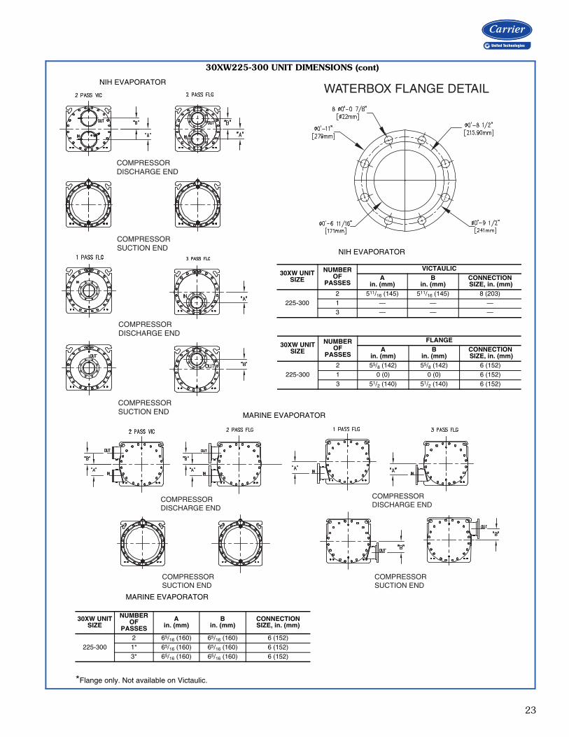
30XW225-300 UNIT DIMENSIONS (cont)
A30-5518
NIH EVAPORATOR
30XW UNITSIZE
NUMBER OF
PASSES
VICTAULICA
in. (mm)B
in. (mm)CONNECTION SIZE, in. (mm)
225-3002 511/16 (145) 511/16 (145) 8 (203)1 — — —3 — — —
30XW UNITSIZE
NUMBER OF
PASSES
FLANGEA
in. (mm)B
in. (mm)CONNECTION SIZE, in. (mm)
225-3002 55/8 (142) 55/8 (142) 6 (152)1 0 (0) 0 (0) 6 (152)3 51/2 (140) 51/2 (140) 6 (152)
A30-5519
MARINE EVAPORATOR
30XW UNITSIZE
NUMBER OF
PASSES
Ain. (mm)
Bin. (mm)
CONNECTION SIZE, in. (mm)
225-3002 65/16 (160) 65/16 (160) 6 (152)1* 65/16 (160) 65/16 (160) 6 (152)3* 65/16 (160) 65/16 (160) 6 (152)
a30-4725
*Flange only. Not available on Victaulic.
WATERBOX FLANGE DETAIL
MARINE EVAPORATOR
NIH EVAPORATOR
24
COMPRESSORDISCHARGE END
COMPRESSORDISCHARGE END
COMPRESSORDISCHARGE END
COMPRESSORSUCTION END
COMPRESSORSUCTION END
COMPRESSORSUCTION END
COMPRESSORSUCTION END
COMPRESSORDISCHARGE END
COMPRESSORDISCHARGE END
COMPRESSORSUCTION END
COMPRESSORDISCHARGE END
COMPRESSORDISCHARGE END
COMPRESSORDISCHARGE END
COMPRESSORSUCTION END
COMPRESSORSUCTION END
COMPRESSORSUCTION END
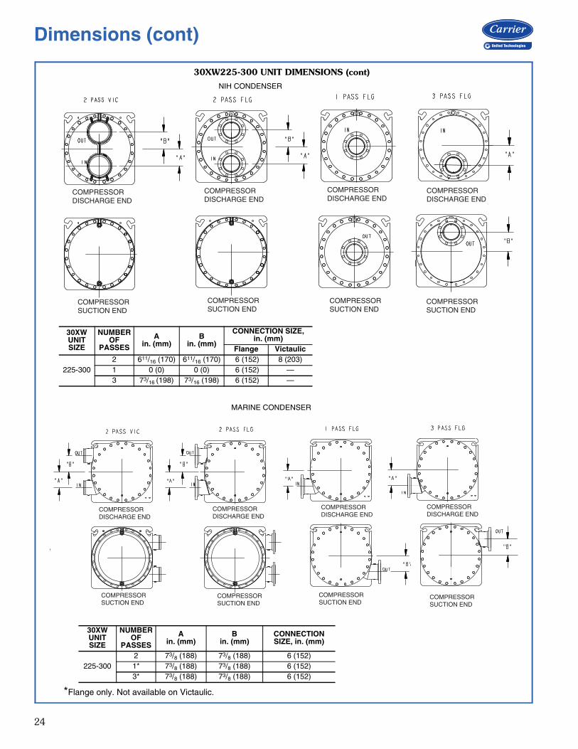
30XW225-300 UNIT DIMENSIONS (cont)
A30-5510
A30-5511
MARINE CONDENSER
NIH CONDENSER
30XW UNITSIZE
NUMBER OF
PASSES
Ain. (mm)
Bin. (mm)
CONNECTION SIZE, in. (mm)
225-3002 73/8 (188) 73/8 (188) 6 (152)1* 73/8 (188) 73/8 (188) 6 (152)3* 73/8 (188) 73/8 (188) 6 (152)
30XW UNITSIZE
NUMBER OF
PASSES
Ain. (mm)
Bin. (mm)
CONNECTION SIZE,in. (mm)
Flange Victaulic
225-3002 611/16 (170) 611/16 (170) 6 (152) 8 (203)1 0 (0) 0 (0) 6 (152) —3 73/16 (198) 73/16 (198) 6 (152) —
*Flange only. Not available on Victaulic.
Dimensions (cont)
25
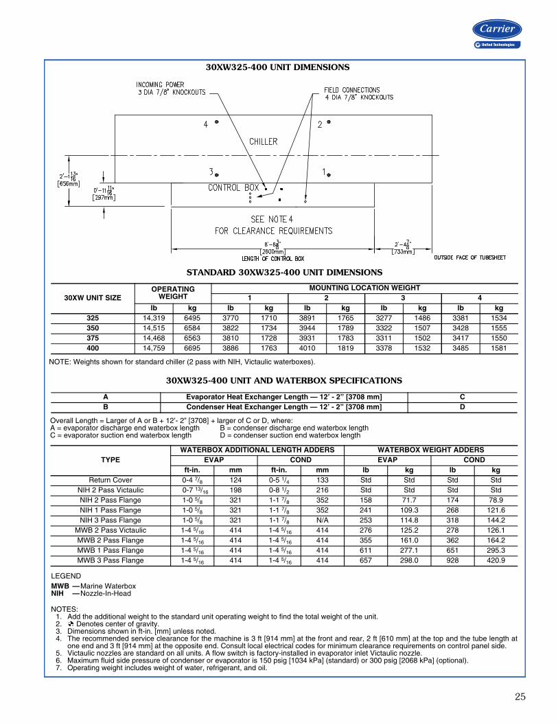
30XW325-400 UNIT DIMENSIONS
LEGENDMWB —Marine WaterboxNIH —Nozzle-In-Head
a30-5273
NOTES:1. Add the additional weight to the standard unit operating weight to find the total weight of the unit.2. Denotes center of gravity.3. Dimensions shown in ft-in. [mm] unless noted.4. The recommended service clearance for the machine is 3 ft [914 mm] at the front and rear, 2 ft [610 mm] at the top and the tube length at
one end and 3 ft [914 mm] at the opposite end. Consult local electrical codes for minimum clearance requirements on control panel side.5. Victaulic nozzles are standard on all units. A flow switch is factory-installed in evaporator inlet Victaulic nozzle.6. Maximum fluid side pressure of condenser or evaporator is 150 psig [1034 kPa] (standard) or 300 psig [2068 kPa] (optional).7. Operating weight includes weight of water, refrigerant, and oil.
30XW325-400 UNIT AND WATERBOX SPECIFICATIONS
Overall Length = Larger of A or B + 12’- 2” [3708] + larger of C or D, where:A = evaporator discharge end waterbox length B = condenser discharge end waterbox lengthC = evaporator suction end waterbox length D = condenser suction end waterbox length
A Evaporator Heat Exchanger Length — 12’ - 2” [3708 mm] CB Condenser Heat Exchanger Length — 12’ - 2” [3708 mm] D
TYPEWATERBOX ADDITIONAL LENGTH ADDERS WATERBOX WEIGHT ADDERS
EVAP COND EVAP CONDft-in. mm ft-in. mm lb kg lb kg
Return Cover 0-4 7/8 124 0-5 1/4 133 Std Std Std StdNIH 2 Pass Victaulic 0-7 13/16 198 0-8 1/2 216 Std Std Std StdNIH 2 Pass Flange 1-0 5/8 321 1-1 7/8 352 158 71.7 174 78.9NIH 1 Pass Flange 1-0 5/8 321 1-1 7/8 352 241 109.3 268 121.6NIH 3 Pass Flange 1-0 5/8 321 1-1 7/8 N/A 253 114.8 318 144.2
MWB 2 Pass Victaulic 1-4 5/16 414 1-4 5/16 414 276 125.2 278 126.1MWB 2 Pass Flange 1-4 5/16 414 1-4 5/16 414 355 161.0 362 164.2MWB 1 Pass Flange 1-4 5/16 414 1-4 5/16 414 611 277.1 651 295.3MWB 3 Pass Flange 1-4 5/16 414 1-4 5/16 414 657 298.0 928 420.9
STANDARD 30XW325-400 UNIT DIMENSIONS
NOTE: Weights shown for standard chiller (2 pass with NIH, Victaulic waterboxes).
30XW UNIT SIZEOPERATING
WEIGHTMOUNTING LOCATION WEIGHT
1 2 3 4lb kg lb kg lb kg lb kg lb kg
325 14,319 6495 3770 1710 3891 1765 3277 1486 3381 1534350 14,515 6584 3822 1734 3944 1789 3322 1507 3428 1555375 14,468 6563 3810 1728 3931 1783 3311 1502 3417 1550400 14,759 6695 3886 1763 4010 1819 3378 1532 3485 1581
26
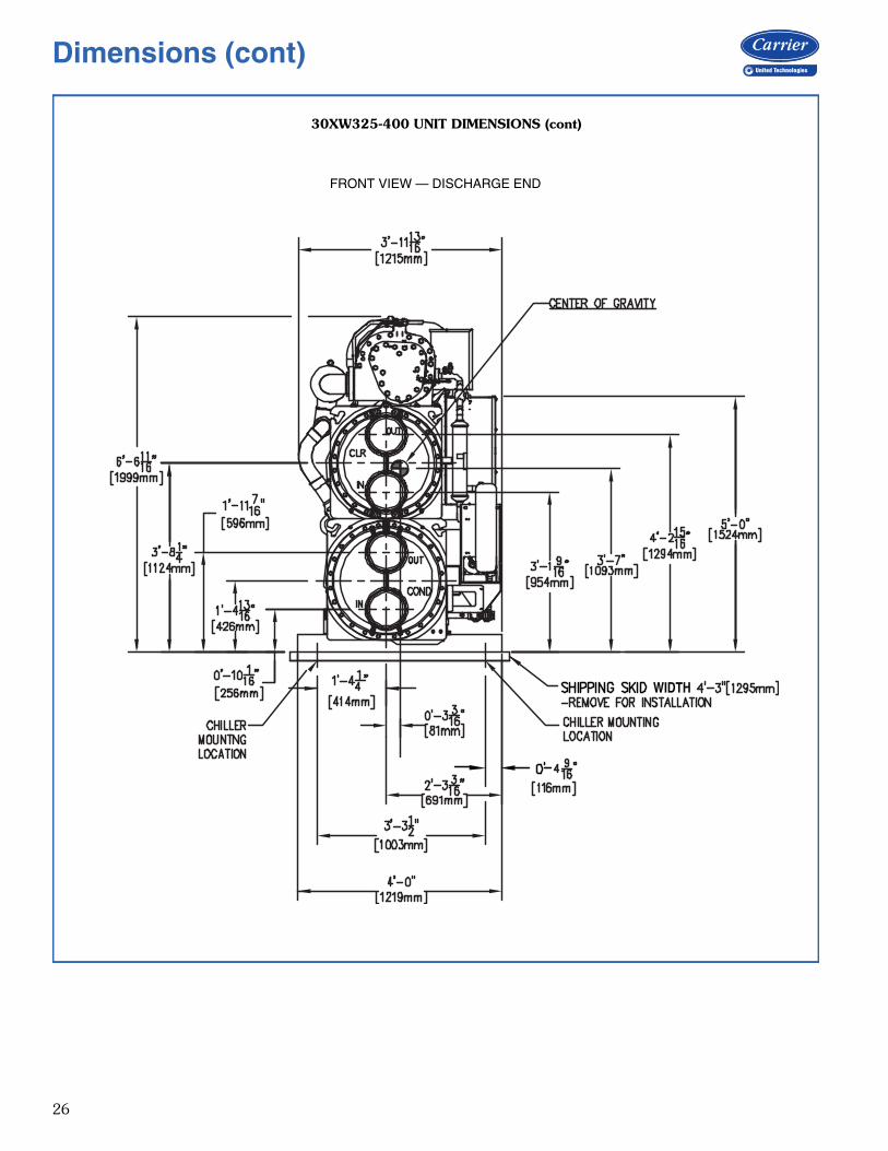
30XW325-400 UNIT DIMENSIONS (cont)
WIDTH
a30-5274
FRONT VIEW — DISCHARGE END
Dimensions (cont)
27
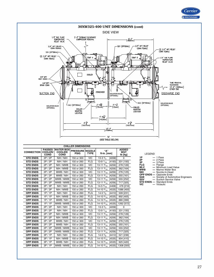
30XW325-400 UNIT DIMENSIONS (cont)
ISOLATION VALVE(OPTIONAL)
3/8”3/8”
3/8”3/8”
6’- 6’-[1837mm][1837mm]
6’- 6’-[1837mm][1837mm]
ISOLATION VALVES(OPTIONAL)
ISOLATION VALVE(OPTIONAL)
“A” “A” (SEE TABLE BELOW) (SEE TABLE BELOW)
a30-5275
SIDE VIEW
CHILLER DIMENSIONS
CONNECTIONPASSESCOOLER/
COND
WATER BOXCOOLER/
COND
PRESSUREPSIG
NOZZLETYPE
“A”ft-in. [mm]
ADDEDWGT
lb [kg]STD ENDS 2P / 2P NIH / NIH 150 or 300 VIC 13-3 3/4 [4058] 0STD ENDS 2P / 2P NIH / NIH 150 or 260 FLG 13-9 1/16 [4193] 331 [150]STD ENDS 2P / 2P NIH / MWB 150 or 300 VIC 13-11 9/16 [4256] 278 [126]STD ENDS 2P / 2P NIH / MWB 150 or 260 FLG 13-11 9/16 [4256] 362 [164]STD ENDS 2P / 2P MWB / NIH 150 or 300 VIC 13-11 9/16 [4256] 276 [125]STD ENDS 2P / 2P MWB / NIH 150 or 260 FLG 13-11 9/16 [4256] 355 [161]STD ENDS 2P / 2P MWB / MWB 150 or 300 VIC 13-11 9/16 [4256] 555 [252]STD ENDS 2P / 2P MWB / MWB 150 or 260 FLG 13-11 9/16 [4256] 717 [325]STD ENDS 2P / 3P NIH / NIH 150 or 260 FLG 14-5 9/16 [4406] 476 [216]STD ENDS 2P / 3P NIH / MWB 150 or 260 FLG 14-10 9/16 [4535] 1086 [493]OPP ENDS 1P / 1P NIH / NIH 150 or 260 FLG 14-5 5/8 [4410] 509 [231]OPP ENDS 1P / 1P NIH / MWB 150 or 260 FLG 14-10 9/16 [4535] 892 [405]OPP ENDS 1P / 1P MWB / NIH 150 or 260 FLG 14-10 9/16 [4535] 880 [399]OPP ENDS 1P / 1P MWB / MWB 150 or 260 FLG 14-10 9/16 [4535] 1262 [572]OPP ENDS 2P / 2P NIH / NIH 150 or 300 VIC 13-3 3/4 [4058] 0OPP ENDS 2P / 2P NIH / NIH 150 or 260 FLG 13-9 1/16 [4193] 331 [150]OPP ENDS 2P / 2P NIH / MWB 150 or 300 VIC 13-11 9/16 [4256] 278 [126]OPP ENDS 2P / 2P NIH / MWB 150 or 260 FLG 13-11 9/16 [4256] 362 [164]OPP ENDS 2P / 2P MWB / NIH 150 or 300 VIC 13-11 9/16 [4256] 276 [125]OPP ENDS 2P / 2P MWB / NIH 150 or 260 FLG 13-11 9/16 [4256] 355 [161]OPP ENDS 2P / 2P MWB / MWB 150 or 300 VIC 13-11 9/16 [4256] 555 [252]OPP ENDS 2P / 2P NWB / MWB 150 or 260 FLG 13-11 9/16 [4256] 717 [325]OPP ENDS 3P / 1P NIH / NIH 150 or 260 FLG 14-5 5/8 [4410] 521 [236]OPP ENDS 3P / 1P NIH / MWB 150 or 260 FLG 14-10 9/16 [4535] 904 [410]OPP ENDS 3P / 1P MWB / NIH 150 or 260 FLG 14-10 9/16 [4535] 925 [420]OPP ENDS 3P / 1P MWB / MWB 150 or 260 FLG 14-10 9/16 [4535] 1308 [593]
LEGEND
1P — 1 Pass2P — 2 Pass3P — 3 PassFLG — FlangeMLV — Minimum Load ValueMWB — Marine Water BoxNIH — Nozzle-In-HeadOPP ENDS — Opposite EndsSAE — Society of Automotive EngineersSSV — Suction Service ValveSTD ENDS — Standard EndsVIC — Victaulic
28
COMPRESSORDISCHARGE END
COMPRESSORSUCTION END
COMPRESSORDISCHARGE END
COMPRESSORSUCTION END
COMPRESSORDISCHARGE END
COMPRESSORSUCTION END
COMPRESSORSUCTION END
COMPRESSORDISCHARGE END
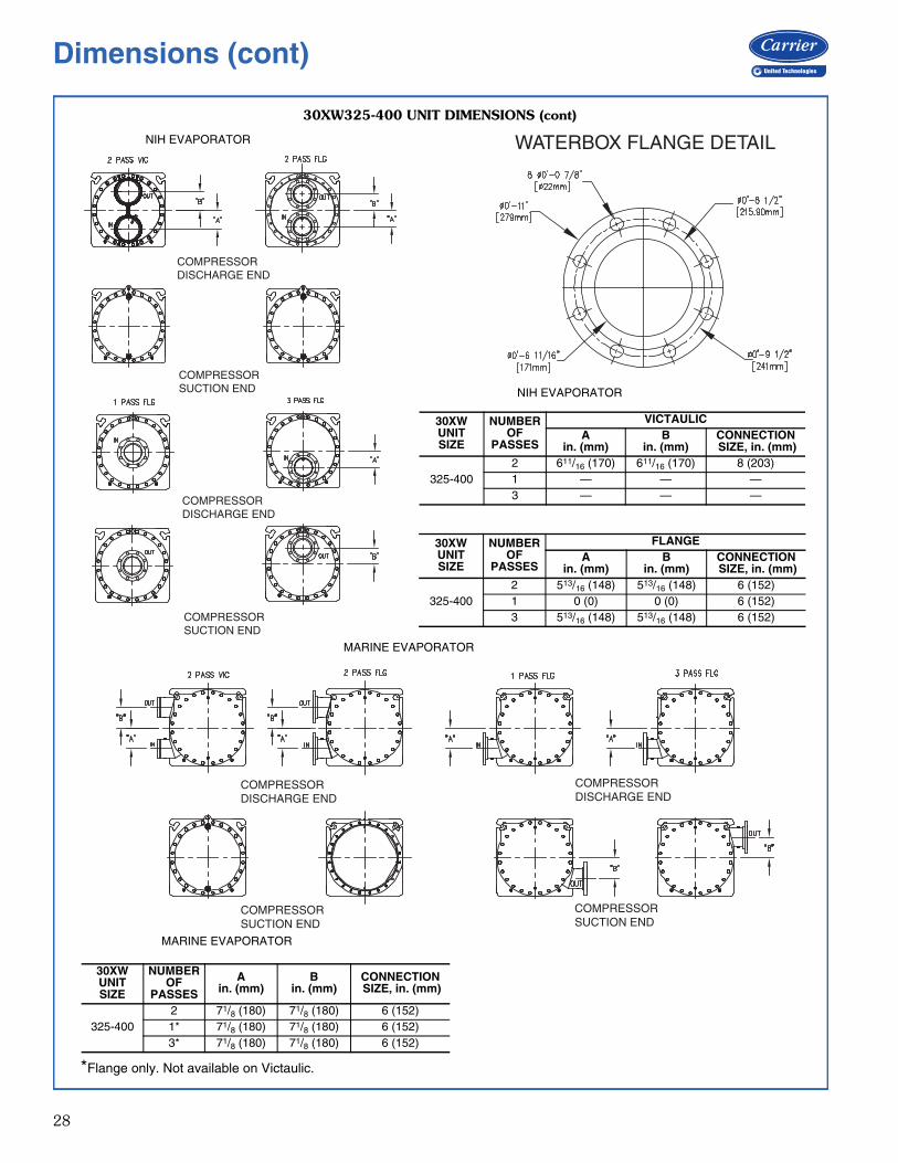
30XW325-400 UNIT DIMENSIONS (cont)
A30-5520
NIH EVAPORATOR
30XW UNITSIZE
NUMBER OF
PASSES
VICTAULICA
in. (mm)B
in. (mm)CONNECTION SIZE, in. (mm)
325-4002 611/16 (170) 611/16 (170) 8 (203)1 — — —3 — — —
30XW UNITSIZE
NUMBER OF
PASSES
FLANGEA
in. (mm)B
in. (mm)CONNECTION SIZE, in. (mm)
325-4002 513/16 (148) 513/16 (148) 6 (152)1 0 (0) 0 (0) 6 (152)3 513/16 (148) 513/16 (148) 6 (152)
A30-5521
MARINE EVAPORATOR
a30-4725
*Flange only. Not available on Victaulic.
30XW UNITSIZE
NUMBER OF
PASSES
Ain. (mm)
Bin. (mm)
CONNECTION SIZE, in. (mm)
325-4002 71/8 (180) 71/8 (180) 6 (152)1* 71/8 (180) 71/8 (180) 6 (152)3* 71/8 (180) 71/8 (180) 6 (152)
WATERBOX FLANGE DETAIL
NIH EVAPORATOR
MARINE EVAPORATOR
Dimensions (cont)
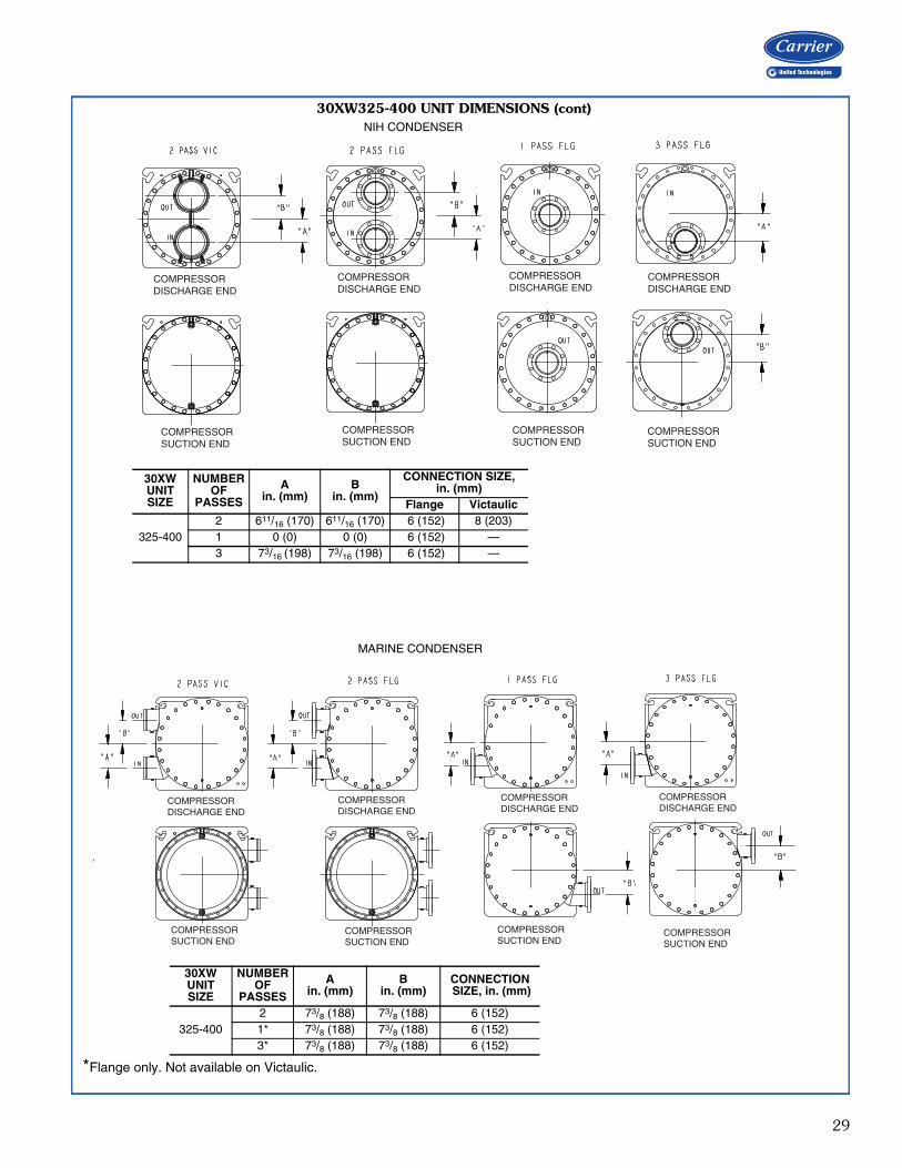
29
COMPRESSORDISCHARGE END
COMPRESSORDISCHARGE END
COMPRESSORDISCHARGE END
COMPRESSORSUCTION END
COMPRESSORSUCTION END
COMPRESSORSUCTION END
COMPRESSORSUCTION END
COMPRESSORDISCHARGE END
30XW325-400 UNIT DIMENSIONS (cont)
A30-5512
A30-5513
NIH CONDENSER
30XW UNITSIZE
NUMBER OF
PASSES
Ain. (mm)
Bin. (mm)
CONNECTION SIZE,in. (mm)
Flange Victaulic
325-4002 611/16 (170) 611/16 (170) 6 (152) 8 (203)1 0 (0) 0 (0) 6 (152) —3 73/16 (198) 73/16 (198) 6 (152) —
COMPRESSORDISCHARGE END
COMPRESSORSUCTION END
COMPRESSORDISCHARGE END
COMPRESSORDISCHARGE END
COMPRESSORDISCHARGE END
COMPRESSORSUCTION END
COMPRESSORSUCTION END
COMPRESSORSUCTION END
MARINE CONDENSER
30XW UNITSIZE
NUMBER OF
PASSES
Ain. (mm)
Bin. (mm)
CONNECTION SIZE, in. (mm)
325-4002 73/8 (188) 73/8 (188) 6 (152)1* 73/8 (188) 73/8 (188) 6 (152)3* 73/8 (188) 73/8 (188) 6 (152)
*Flange only. Not available on Victaulic.
30
Carrier’s packaged selection program provides a quick,easy selection of Carrier’s water-cooled chillers. The pro-gram considers specific temperature, fluid and flowrequirements among other factors such as fouling and alti-tude corrections.
Before selecting a chiller, consider the following points:Leaving water (fluid) temperature (LWT)• The LWT must be at least 40°F (4.4°C) or greater.• If the LWT is less than 40°F (4.4°C), loop freeze protec-
tion to a minimum of 15°F (8.3°C) below the LWT setpoint is required. The medium temperature brine optionis also required.
• If the LWT requirement is greater than 60°F (15.5°C), amixing loop is required.
Entering water (fluid) temperature (EWT)• If the EWT requirement is greater than 70°F (21.1°C), a
mixing loop is required. The EWT should not exceed70°F (21.1°C) for extended operation. Pulldown can beaccomplished from 95°F (35°C).
Evaporator flow rate or evaporator delta-T:• The evaporator delta-T (EWT – LWT) must fall between
5 and 20°F (2.8 and 11.1°C) while still meeting themaximum entering requirements.
• For larger or smaller delta-T applications, a mixing loopis required. If the evaporator flow is variable, the rate ofchange of flow should not exceed 10% per minute. Theloop volume in circulation must equal or exceed 3 gal-lons per nominal ton (3.2 L per kW) of cooling for tem-perature stability and accuracy in normal airconditioning applications. In process cooling applica-tions, there should be 6 to 10 gallons per ton (6.5 to10.8 L per kW). To achieve this loop volume, it is oftennecessary to install a tank in the loop. The tank shouldbe baffled to ensure there is no stratification, and thatwater (or brine) entering the tank is adequately mixed
with liquid in the tank. See Water Loop Volume in theApplication Data section on page 45.
Evaporator pressure drop:• A high evaporator pressure drop can be expected when
the evaporator delta-T is low. A mixing loop can help toalleviate this situation.
• The three-pass evaporator option is recommended toincrease performance when the evaporator delta T ishigh. This is particularly helpful with brine applications.
Condenser pressure drop:• A high condenser pressure drop can be expected when
the condenser delta-T is low. A one-pass condenser canhelp lower pressure drop.
Series chillers:• One-pass heat exchangers can help lower pressure
drop when heat exchangers are placed in series.Water quality, fouling factor:• Poor water quality can increase the required evaporator
fouling factor.• Higher than standard fouling factors lead to lower
capacity and higher input kW from a given chiller sizecompared to running the same application with betterwater quality (and lower fouling factors).
Temperature reset:• Return water (standard)• Outside air temperature (accessory sensor required)• Space temperature (accessory sensor required)• 4 to 20 mA (requires an energy management module)Demand limit:• 2-step (requires an energy management module)• 4 to 20 mA (requires an energy management module)• CCN Loadshed
Selection procedure
31
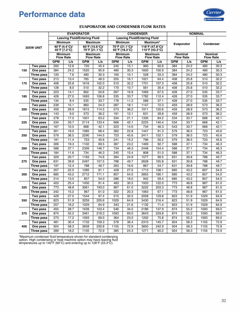
EVAPORATOR AND CONDENSER FLOW RATES
*Maximum condenser fluid temperature shown for standard condensingoption. High condensing or heat machine option may have leaving fluidtemperatures up to 140°F (60°C) and entering up to 128°F (53.3°C).
30XW UNIT
EVAPORATOR CONDENSER NOMINALLeaving Fluid/Entering Fluid Leaving Fluid/Entering Fluid
Evaporator CondenserMinimum Maximum Minimum Maximum*40°F (4.4°C)/45°F (7.2°C)
60°F (15.6°C)/70°F (21.1°C)
70°F (21.1°C)/65°F (18.3°C)
118°F (47.8°C)/110°F (43.3°C)
MinimumFlow Rate
MaximumFlow Rate
MinimumFlow Rate
MaximumFlow Rate
NominalFlow Rate
NominalFlow Rate
GPM L/s GPM L/s GPM L/s GPM L/s GPM L/s GPM L/s
150Two pass 200 12.6 720 45.4 240 15.1 960 60.6 384 24.2 480 30.3One pass 384 24.2 1520 95.9 480 30.3 1600 100.9 384 24.2 480 30.3
Three pass 120 7.6 480 30.3 160 10.1 528 33.3 384 24.2 480 30.3
175Two pass 213 13.4 765 48.3 255 16.1 1021 64.4 408 25.8 510 32.2One pass 408 25.8 1616 102.0 510 32.2 1701 107.3 408 25.8 510 32.2
Three pass 128 8.0 510 32.2 170 10.7 561 35.4 408 25.8 510 32.2
185Two pass 223 14.1 802 50.6 267 16.9 1069 67.5 428 27.0 535 33.7One pass 428 27.0 1693 106.8 535 33.7 1782 112.4 428 27.0 535 33.7
Three pass 134 8.4 535 33.7 178 11.2 588 37.1 428 27.0 535 33.7
200Two pass 239 15.1 860 54.3 287 18.1 1147 72.3 459 28.9 573 36.2One pass 459 28.9 1815 114.5 573 36.2 1911 120.6 459 28.9 573 36.2
Three pass 143 9.0 573 36.2 191 12.1 631 39.8 459 28.9 573 36.2
225Two pass 278 17.5 1001 63.2 334 21.1 1335 84.2 534 33.7 668 42.1One pass 534 33.7 2114 133.4 668 42.1 2225 140.4 534 33.7 668 42.1
Three pass 167 10.5 668 42.1 223 14.0 734 46.3 543 33.7 668 42.1
250Two pass 301 19.0 1085 68.4 362 22.8 1447 91.3 579 36.5 723 45.6One pass 579 36.5 2290 144.5 723 45.6 2411 152.1 579 36.5 723 45.6
Three pass 181 11.4 723 45.6 241 15.2 796 50.2 579 36.5 723 45.6
260Two pass 306 19.3 1102 69.5 367 23.2 1469 92.7 588 37.1 734 46.3One pass 588 37.1 2326 146.7 734 46.3 2448 154.4 588 37.1 734 46.3
Three pass 184 11.6 734 46.3 245 15.4 808 51.0 588 37.1 734 46.3
275Two pass 329 20.7 1183 74.6 394 24.9 1577 99.5 631 39.8 788 49.7One pass 631 39.8 2497 157.5 788 49.7 2628 165.8 631 39.8 788 49.7
Three pass 197 12.4 788 49.7 263 16.6 867 54.7 631 39.8 788 49.7
300Two pass 357 22.5 1285 81.1 428 27.0 1713 108.1 685 43.2 857 54.0One pass 685 43.2 2712 171.1 857 54.0 2855 180.1 685 43.2 857 54.0
Three pass 214 13.5 857 54.0 286 18.0 942 59.4 685 43.2 857 54.0
325Two pass 403 25.4 1450 91.4 483 30.5 1933 122.0 773 48.8 967 61.0One pass 773 48.8 3061 193.0 967 61.0 3222 203.3 773 48.8 967 61.0
Three pass 242 15.2 967 61.0 322 20.3 1063 67.1 773 48.8 967 61.0
350Two pass 429 27.0 1544 97.4 515 32.5 2058 129.8 823 51.9 1029 64.9One pass 823 51.9 3259 205.6 1029 64.9 3430 216.4 823 51.9 1029 64.9
Three pass 257 16.2 1029 64.9 343 21.6 1132 71.4 823 51.9 1029 64.9
375Two pass 455 28.7 1639 103.4 546 34.5 2186 137.9 874 55.2 1093 69.0One pass 874 55.2 3461 218.3 1093 69.0 3643 229.8 874 55.2 1093 69.0
Three pass 273 17.2 1093 69.0 364 23.0 1202 75.8 874 55.2 1093 69.0
400Two pass 481 30.4 1733 109.3 578 36.4 2310 145.7 924 58.3 1155 72.9One pass 924 58.3 3658 230.8 1155 72.9 3850 242.9 924 58.3 1155 72.9
Three pass 289 18.2 1155 72.9 385 24.3 1271 80.2 924 58.3 1155 72.9
Performance data
32
0.00
5.00
10.00
15.00
20.00
25.00
30.00
35.00
(0)
(14.9)
(29.8)
(44.8)
(59.7)
(74.6)
(89.5)
(104.4)
ft wg(kPa)
0 250 500 750 1000 gpm (0) (15.8) (31.5) (47.3) (63.1) (L/s)
Evaporator Flow Rate
Pres
sure
Dro
p
3 pass
2 pass
1 pass
a30-5555
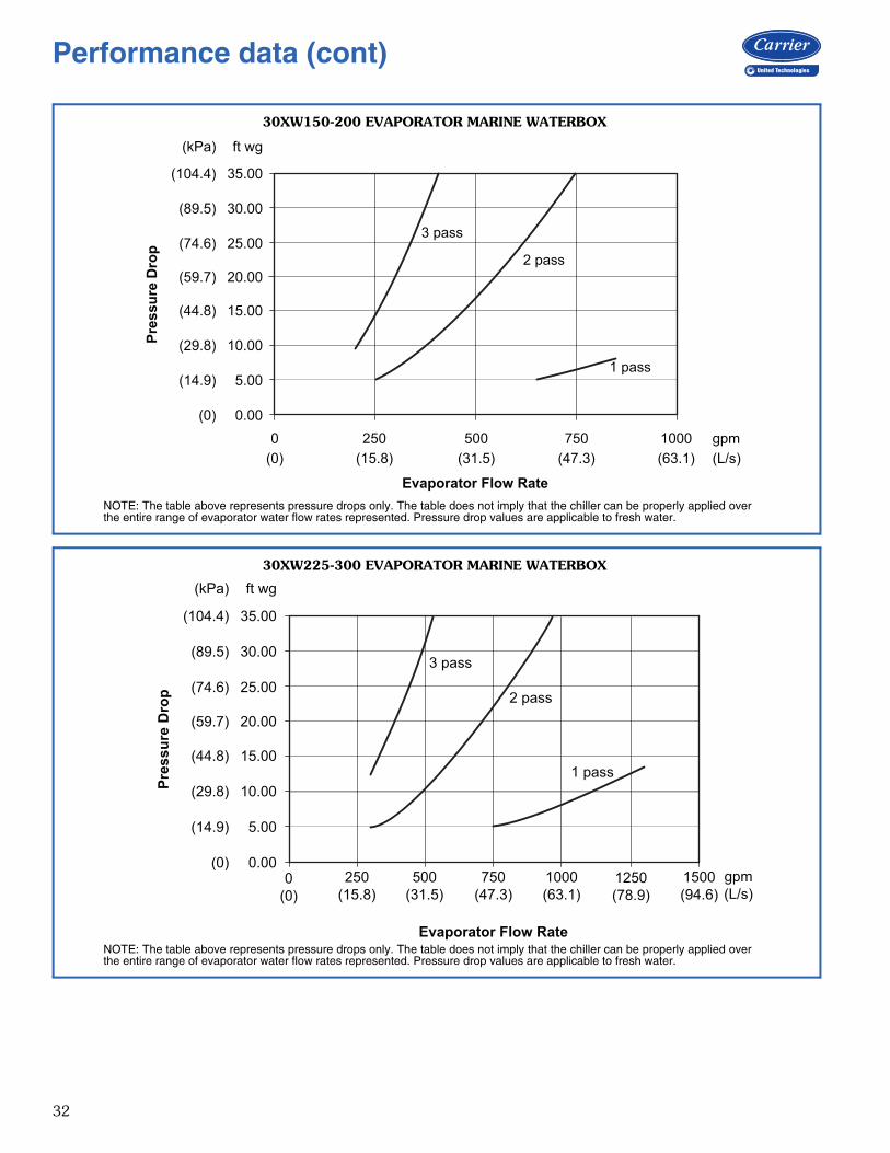
30XW150-200 EVAPORATOR MARINE WATERBOX
NOTE: The table above represents pressure drops only. The table does not imply that the chiller can be properly applied overthe entire range of evaporator water flow rates represented. Pressure drop values are applicable to fresh water.
0.00
5.00
10.00
15.00
20.00
25.00
30.00
35.00
(0)
(14.9)
(29.8)
(44.8)
(59.7)
(74.6)
(89.5)
(104.4)
ft wg(kPa)
Evaporator Flow Rate
Pres
sure
Dro
p
0(0)
250(15.8)
500(31.5)
750(47.3)
1000(63.1)
1250(78.9)
1500(94.6)
gpm(L/s)
3 pass
2 pass
1 pass
30XW225-300 EVAPORATOR MARINE WATERBOX
NOTE: The table above represents pressure drops only. The table does not imply that the chiller can be properly applied overthe entire range of evaporator water flow rates represented. Pressure drop values are applicable to fresh water.
a30-5556
Performance data (cont)
33
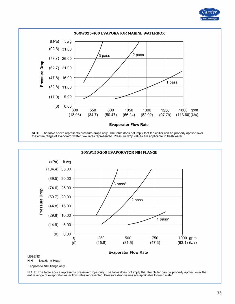
0.00
6.00
11.00
16.00
21.00
26.00
31.00
(0)
(17.9)
(32.8)
(47.8)
(62.7)
(77.7)
(92.6)
ft wg(kPa)
Evaporator Flow Rate
Pres
sure
Dro
p
300(18.93)
550(34.7)
800(50.47)
1050(66.24)
1300(82.02)
1550(97.79)
1800(113.60)
gpm(L/s)
3 pass 2 pass
1 pass
30XW325-400 EVAPORATOR MARINE WATERBOX
NOTE: The table above represents pressure drops only. The table does not imply that the chiller can be properly applied overthe entire range of evaporator water flow rates represented. Pressure drop values are applicable to fresh water.
a30-5557
0.00
5.00
10.00
15.00
20.00
25.00
30.00
35.00
(0)
(14.9)
(29.8)
(44.8)
(59.7)
(74.6)
(89.5)
(104.4)
ft wg(kPa)
Evaporator Flow Rate
Pres
sure
Dro
p
0(0)
250(15.8)
500(31.5)
750(47.3)
1000(63.1)
gpm(L/s)
3 pass*
2 pass
1 pass*
LEGEND
* Applies to NIH flange only.
NOTE: The table above represents pressure drops only. The table does not imply that the chiller can be properly applied over theentire range of evaporator water flow rates represented. Pressure drop values are applicable to fresh water.
NIH — Nozzle-In-Head
30XW150-200 EVAPORATOR NIH FLANGE
a30-5558
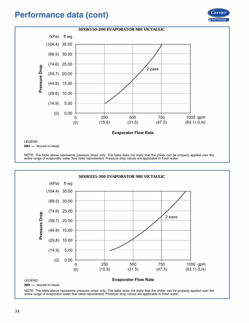
34
0.00
5.00
10.00
15.00
20.00
25.00
30.00
35.00
(0)
(14.9)
(29.8)
(44.8)
(59.7)
(74.6)
(89.5)
(104.4)
ft wg(kPa)
Evaporator Flow Rate
Pres
sure
Dro
p
0(0)
250(15.8)
500(31.5)
750(47.3)
1000(63.1)
gpm(L/s)
2 pass
LEGEND
NOTE: The table above represents pressure drops only. The table does not imply that the chiller can be properly applied over theentire range of evaporator water flow rates represented. Pressure drop values are applicable to fresh water.
NIH — Nozzle-In-Head
30XW150-200 EVAPORATOR NIH VICTAULIC
a30-5559
0.00
5.00
10.00
15.00
20.00
25.00
30.00
35.00
(0)
(14.9)
(29.8)
(44.8)
(59.7)
(74.6)
(89.5)
(104.4)
ft wg(kPa)
Evaporator Flow Rate
Pres
sure
Dro
p
0(0)
250(15.8)
500(31.5)
750(47.3)
1000(63.1)
gpm(L/s)
2 pass
LEGEND
NOTE: The table above represents pressure drops only. The table does not imply that the chiller can be properly applied over theentire range of evaporator water flow rates represented. Pressure drop values are applicable to fresh water.
NIH — Nozzle-In-Head
30XW225-300 EVAPORATOR NIH VICTAULIC
a30-5560
Performance data (cont)
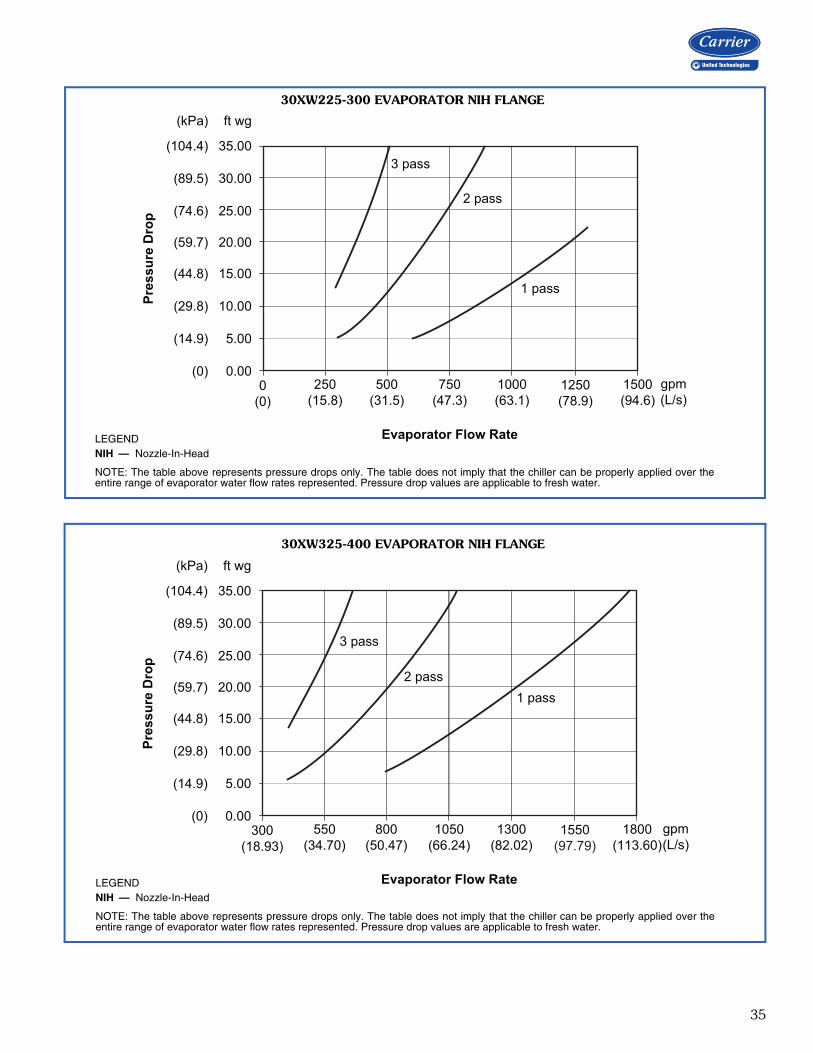
35
0.00
5.00
10.00
15.00
20.00
25.00
30.00
35.00
(0)
(14.9)
(29.8)
(44.8)
(59.7)
(74.6)
(89.5)
(104.4)
ft wg(kPa)
Evaporator Flow Rate
Pres
sure
Dro
p
0(0)
250(15.8)
500(31.5)
750(47.3)
1000(63.1)
1250(78.9)
1500(94.6)
gpm(L/s)
3 pass
2 pass
1 pass
LEGEND
NOTE: The table above represents pressure drops only. The table does not imply that the chiller can be properly applied over theentire range of evaporator water flow rates represented. Pressure drop values are applicable to fresh water.
NIH — Nozzle-In-Head
30XW225-300 EVAPORATOR NIH FLANGE
a30-5561
0.00
5.00
10.00
15.00
20.00
25.00
30.00
35.00
(0)
(14.9)
(29.8)
(44.8)
(59.7)
(74.6)
(89.5)
(104.4)
ft wg(kPa)
Evaporator Flow Rate
Pres
sure
Dro
p
300(18.93)
550(34.70)
800(50.47)
1050(66.24)
1300(82.02)
1550(97.79)
1800(113.60)
gpm(L/s)
3 pass
2 pass1 pass
LEGEND
NOTE: The table above represents pressure drops only. The table does not imply that the chiller can be properly applied over theentire range of evaporator water flow rates represented. Pressure drop values are applicable to fresh water.
NIH — Nozzle-In-Head
30XW325-400 EVAPORATOR NIH FLANGE
A30-5562
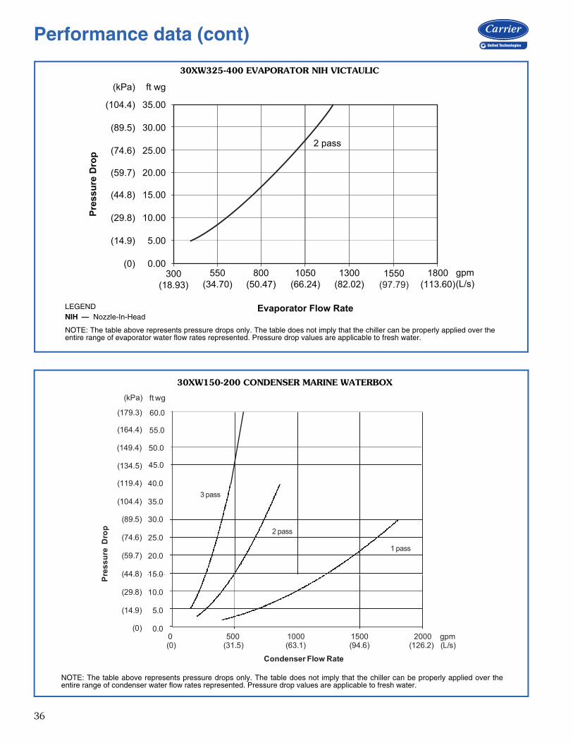
36
0.00
5.00
10.00
15.00
20.00
25.00
30.00
35.00
(0)
(14.9)
(29.8)
(44.8)
(59.7)
(74.6)
(89.5)
(104.4)
ft wg(kPa)
Evaporator Flow Rate
Pres
sure
Dro
p
300(18.93)
550(34.70)
800(50.47)
1050(66.24)
1300(82.02)
1550(97.79)
1800(113.60)
gpm(L/s)
2 pass
LEGEND
NOTE: The table above represents pressure drops only. The table does not imply that the chiller can be properly applied over theentire range of evaporator water flow rates represented. Pressure drop values are applicable to fresh water.
NIH — Nozzle-In-Head A30-5563
30XW325-400 EVAPORATOR NIH VICTAULIC
15 00
20.00
25.00
30.00
35.00
40.00
ress
ure
Dro
p
1 pass
2 pass
3 pass
ft wg
40.0
35.0
30.0
25.0
20.0
15 0
(kPa)
(119.4)
(104.4)
(89.5)
(74.6)
(59.7)
(44 8)
0.00
5.00
10.00
15.00
0 500 1000 1500 2000
Pr
Condenser Flow Rate
0 500 1000 1500 2000 gpm(0) (31.5) (63.1) (94.6) (126.2) (L/s)
15.0
10.0
5.0
0.0
(44.8)
(29.8)
(14.9)
(0)
45.0
50.0
55.0
60.0
(134.5)
(149.4)
(164.4)
(179.3)
NOTE: The table above represents pressure drops only. The table does not imply that the chiller can be properly applied over theentire range of condenser water flow rates represented. Pressure drop values are applicable to fresh water.
30XW150-200 CONDENSER MARINE WATERBOX
A30-5499
Performance data (cont)
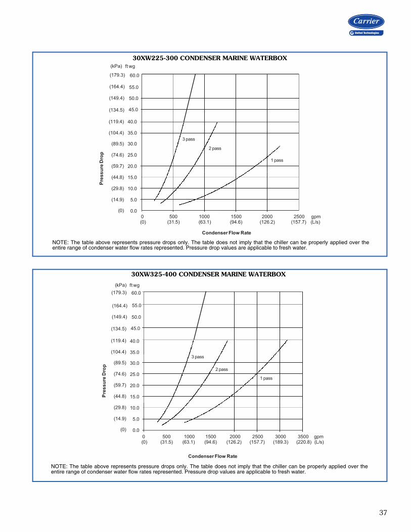
37
20.00
25.00
30.00
35.00
40.00
ure
Dro
p
3 pass
2 pass
1 pass
ft wg
40.0
35.0
30.0
25.0
20.0
(kPa)
(119.4)
(104.4)
(89.5)
(74.6)
(59.7)
0.00
5.00
10.00
15.00
0 500 1000 1500 2000 2500
Pres
s
Condenser Flow Rate
0 500 1000 1500 2000 2500 gpm(0) (31.5) (63.1) (94.6) (126.2) (157.7) (L/s)
15.0
10.0
5.0
0.0
(44.8)
(29.8)
(14.9)
(0)
45.0
50.0
60.0
(164.4)
(179.3)
(134.5)
(149.4)
55.0
NOTE: The table above represents pressure drops only. The table does not imply that the chiller can be properly applied over theentire range of condenser water flow rates represented. Pressure drop values are applicable to fresh water.
30XW225-300 CONDENSER MARINE WATERBOX
A30-5501
15.00
20.00
25.00
30.00
35.00
40.00
Pres
sure
Dro
p
40.0
35.0
30.0
25.0
20.0
15.0
(119.4)
(104.4)
(89.5)
(74.6)
(59.7)
(44.8)
3 pass
2 pass
1 pass
0.00
5.00
10.00
0 500 1000 1500 2000 2500 3000 3500
Condenser Flow Rate
0 500 1000 1500 2000 2500 3000 3500 gpm(0) (31.5) (63.1) (94.6) (126.2) (157.7) (189.3) (220.8) (L/s)
10.0
5.0
0.0
(29.8)
(14.9)
(0)
ft wg(kPa)
45.0
50.0
60.0
(164.4)
(179.3)
(134.5)
(149.4)
55.0
NOTE: The table above represents pressure drops only. The table does not imply that the chiller can be properly applied over theentire range of condenser water flow rates represented. Pressure drop values are applicable to fresh water.
30XW325-400 CONDENSER MARINE WATERBOX
a30-5503
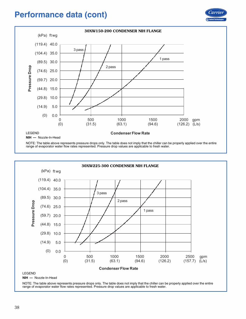
38
15 00
20.00
25.00
30.00
35.00
40.00
ress
ure
Dro
p
3 pass
2 pass
1 pass
ft wg
40.0
35.0
30.0
25.0
20.0
15 0
(kPa)
(119.4)
(104.4)
(89.5)
(74.6)
(59.7)
(44 8)
0.00
5.00
10.00
15.00
0 500 1000 1500 2000
Pr
Condenser Flow Rate
15.0
10.0
5.0
0.0
(44.8)
(29.8)
(14.9)
(0)0 500 1000 1500 2000 gpm(0) (31.5) (63.1) (94.6) (126.2) (L/s)
30XW150-200 CONDENSER NIH FLANGE
a30-5500
LEGEND
NOTE: The table above represents pressure drops only. The table does not imply that the chiller can be properly applied over the entirerange of evaporator water flow rates represented. Pressure drop values are applicable to fresh water.
NIH — Nozzle-In-Head
20.00
25.00
30.00
35.00
40.00
s sur
eD
rop
3 pass
2 pass
1 pass
ft wg
40.0
35.0
30.0
25.0
20.0
(kPa)
(119.4)
(104.4)
(89.5)
(74.6)
(59.7)
0.00
5.00
10.00
15.00
0 500 1000 1500 2000 2500
Pres
Condenser Flow Rate
0 500 1000 1500 2000 2500 gpm(0) (31.5) (63.1) (94.6) (126.2) (157.7) (L/s)
15.0
10.0
5.0
0.0
(44.8)
(29.8)
(14.9)
(0)
30XW225-300 CONDENSER NIH FLANGE
a30-5502
LEGEND
NOTE: The table above represents pressure drops only. The table does not imply that the chiller can be properly applied over the entirerange of evaporator water flow rates represented. Pressure drop values are applicable to fresh water.
NIH — Nozzle-In-Head
Performance data (cont)
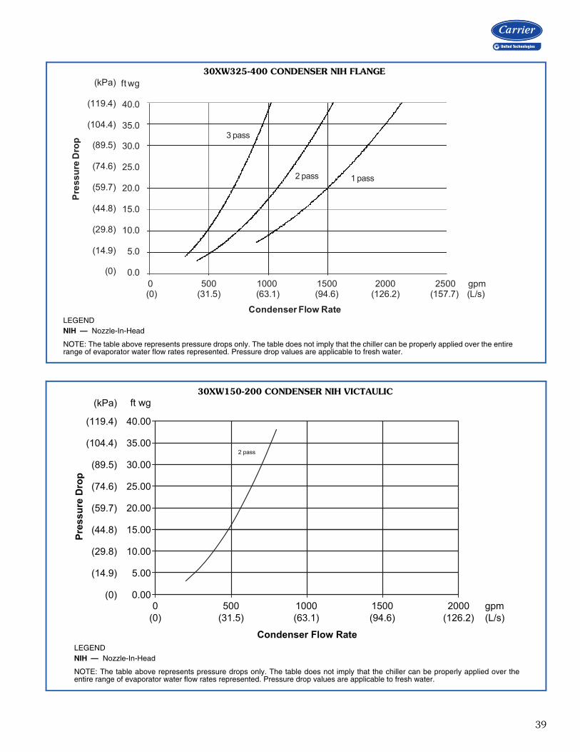
39
20.00
25.00
30.00
35.00
40.00
ress
ure
Dro
pft wg
40.0
35.0
30.0
25.0
20.0
(kPa)
(119.4)
(104.4)
(89.5)
(74.6)
(59.7)
3 pass
2 pass 1 pass
0.00
5.00
10.00
15.00
0 500 1000 1500 2000 2500
P
Condenser Flow Rate
15.0
10.0
5.0
0.0
(44.8)
(29.8)
(14.9)
(0)0 500 1000 1500 2000 2500 gpm(0) (31.5) (63.1) (94.6) (126.2) (157.7) (L/s)
30XW325-400 CONDENSER NIH FLANGE
LEGEND
NOTE: The table above represents pressure drops only. The table does not imply that the chiller can be properly applied over the entirerange of evaporator water flow rates represented. Pressure drop values are applicable to fresh water.
NIH — Nozzle-In-Head
a30-5504
0 500 1000 1500 2000 gpm (0) (31.5) (63.1) (94.6) (126.2) (L/s)
2 pass
0.00
5.00
10.00
15.00
20.00
25.00
30.00
35.00
40.00
Condenser Flow Rate
(0)
(14.9)
(29.8)
(44.8)
(59.7)
(74.6)
(89.5)
(104.4)
(119.4)
ft wg(kPa)
Pres
sure
Dro
p
30XW150-200 CONDENSER NIH VICTAULIC
LEGEND
NOTE: The table above represents pressure drops only. The table does not imply that the chiller can be properly applied over theentire range of evaporator water flow rates represented. Pressure drop values are applicable to fresh water.
NIH — Nozzle-In-Head a30-4837
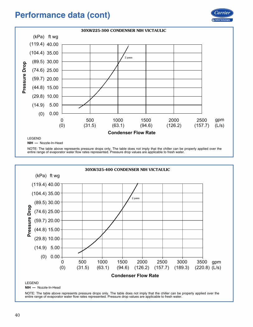
40
0.00
5.00
10.00
15.00
20.00
25.00
30.00
35.00
40.00
0 500 1000 1500 2000 2500
2 pass
(0)
(14.9)
(29.8)
(44.8)
(59.7)
(74.6)
(89.5)
(104.4)
(119.4)(kPa)
Pres
sure
Dro
p
ft wg
Condenser Flow Rate(0) (31.5) (63.1) (94.6) (126.2) (157.7) (L/s)
gpm
30XW225-300 CONDENSER NIH VICTAULIC
LEGEND
NOTE: The table above represents pressure drops only. The table does not imply that the chiller can be properly applied over theentire range of evaporator water flow rates represented. Pressure drop values are applicable to fresh water.
NIH — Nozzle-In-Head a30-5118
2 pass
0.00
5.00
10.00
15.00
20.00
25.00
30.00
35.00
40.00
ft wg
gpm(L/s)
(0)
(14.9)
(29.8)
(44.8)
(59.7)
(74.6)
(89.5)
(104.4)
(119.4)
(kPa)
0 500 1000 1500 2000 2500 3000 3500(0) (31.5) (63.1) (94.6) (126.2) (157.7) (189.3) (220.8)
Condenser Flow Rate
Pres
sure
Dro
p
30XW325-400 CONDENSER NIH VICTAULIC
LEGEND
NOTE: The table above represents pressure drops only. The table does not imply that the chiller can be properly applied over theentire range of evaporator water flow rates represented. Pressure drop values are applicable to fresh water.
NIH — Nozzle-In-Heada30-4696
Performance data (cont)
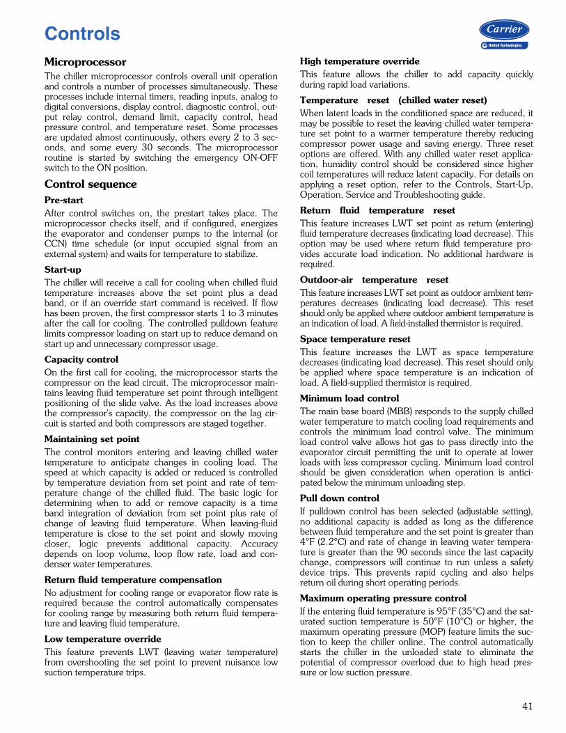
41
MicroprocessorThe chiller microprocessor controls overall unit operationand controls a number of processes simultaneously. Theseprocesses include internal timers, reading inputs, analog todigital conversions, display control, diagnostic control, out-put relay control, demand limit, capacity control, headpressure control, and temperature reset. Some processesare updated almost continuously, others every 2 to 3 sec-onds, and some every 30 seconds. The microprocessorroutine is started by switching the emergency ON-OFFswitch to the ON position.
Control sequencePre-startAfter control switches on, the prestart takes place. Themicroprocessor checks itself, and if configured, energizesthe evaporator and condenser pumps to the internal (orCCN) time schedule (or input occupied signal from anexternal system) and waits for temperature to stabilize.
Start-upThe chiller will receive a call for cooling when chilled fluidtemperature increases above the set point plus a deadband, or if an override start command is received. If flowhas been proven, the first compressor starts 1 to 3 minutesafter the call for cooling. The controlled pulldown featurelimits compressor loading on start up to reduce demand onstart up and unnecessary compressor usage.
Capacity controlOn the first call for cooling, the microprocessor starts thecompressor on the lead circuit. The microprocessor main-tains leaving fluid temperature set point through intelligentpositioning of the slide valve. As the load increases abovethe compressor's capacity, the compressor on the lag cir-cuit is started and both compressors are staged together.
Maintaining set pointThe control monitors entering and leaving chilled watertemperature to anticipate changes in cooling load. Thespeed at which capacity is added or reduced is controlledby temperature deviation from set point and rate of tem-perature change of the chilled fluid. The basic logic fordetermining when to add or remove capacity is a timeband integration of deviation from set point plus rate ofchange of leaving fluid temperature. When leaving-fluidtemperature is close to the set point and slowly movingcloser, logic prevents additional capacity. Accuracydepends on loop volume, loop flow rate, load and con-denser water temperatures.
Return fluid temperature compensationNo adjustment for cooling range or evaporator flow rate isrequired because the control automatically compensatesfor cooling range by measuring both return fluid tempera-ture and leaving fluid temperature.
Low temperature overrideThis feature prevents LWT (leaving water temperature)from overshooting the set point to prevent nuisance lowsuction temperature trips.
High temperature overrideThis feature allows the chiller to add capacity quicklyduring rapid load variations.
Temperature reset (chilled water reset) When latent loads in the conditioned space are reduced, itmay be possible to reset the leaving chilled water tempera-ture set point to a warmer temperature thereby reducingcompressor power usage and saving energy. Three resetoptions are offered. With any chilled water reset applica-tion, humidity control should be considered since highercoil temperatures will reduce latent capacity. For details onapplying a reset option, refer to the Controls, Start-Up,Operation, Service and Troubleshooting guide.
Return fluid temperature reset This feature increases LWT set point as return (entering)fluid temperature decreases (indicating load decrease). Thisoption may be used where return fluid temperature pro-vides accurate load indication. No additional hardware isrequired.
Outdoor-air temperature reset This feature increases LWT set point as outdoor ambient tem-peratures decreases (indicating load decrease). This resetshould only be applied where outdoor ambient temperature isan indication of load. A field-installed thermistor is required.
Space temperature resetThis feature increases the LWT as space temperaturedecreases (indicating load decrease). This reset should onlybe applied where space temperature is an indication ofload. A field-supplied thermistor is required.
Minimum load controlThe main base board (MBB) responds to the supply chilledwater temperature to match cooling load requirements andcontrols the minimum load control valve. The minimumload control valve allows hot gas to pass directly into theevaporator circuit permitting the unit to operate at lowerloads with less compressor cycling. Minimum load controlshould be given consideration when operation is antici-pated below the minimum unloading step.
Pull down controlIf pulldown control has been selected (adjustable setting),no additional capacity is added as long as the differencebetween fluid temperature and the set point is greater than4°F (2.2°C) and rate of change in leaving water tempera-ture is greater than the 90 seconds since the last capacitychange, compressors will continue to run unless a safetydevice trips. This prevents rapid cycling and also helpsreturn oil during short operating periods.
Maximum operating pressure controlIf the entering fluid temperature is 95°F (35°C) and the sat-urated suction temperature is 50°F (10°C) or higher, themaximum operating pressure (MOP) feature limits the suc-tion to keep the chiller online. The control automaticallystarts the chiller in the unloaded state to eliminate thepotential of compressor overload due to high head pres-sure or low suction pressure.
Controls
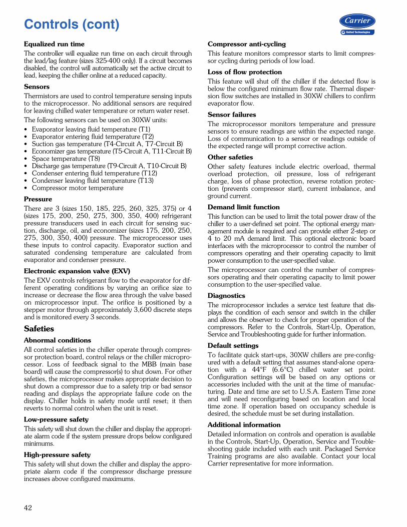
42
Equalized run timeThe controller will equalize run time on each circuit throughthe lead/lag feature (sizes 325-400 only). If a circuit becomesdisabled, the control will automatically set the active circuit tolead, keeping the chiller online at a reduced capacity.
SensorsThermistors are used to control temperature sensing inputsto the microprocessor. No additional sensors are requiredfor leaving chilled water temperature or return water reset.The following sensors can be used on 30XW units:• Evaporator leaving fluid temperature (T1)• Evaporator entering fluid temperature (T2)• Suction gas temperature (T4-Circuit A, T7-Circuit B)• Economizer gas temperature (T5-Circuit A, T11-Circuit B)• Space temperature (T8)• Discharge gas temperature (T9-Circuit A, T10-Circuit B)• Condenser entering fluid temperature (T12)• Condenser leaving fluid temperature (T13)• Compressor motor temperature
PressureThere are 3 (sizes 150, 185, 225, 260, 325, 375) or 4(sizes 175, 200, 250, 275, 300, 350, 400) refrigerantpressure transducers used in each circuit for sensing suc-tion, discharge, oil, and economizer (sizes 175, 200, 250,275, 300, 350, 400) pressure. The microprocessor usesthese inputs to control capacity. Evaporator suction andsaturated condensing temperature are calculated fromevaporator and condenser pressure.
Electronic expansion valve (EXV)The EXV controls refrigerant flow to the evaporator for dif-ferent operating conditions by varying an orifice size toincrease or decrease the flow area through the valve basedon microprocessor input. The orifice is positioned by astepper motor through approximately 3,600 discrete stepsand is monitored every 3 seconds.
SafetiesAbnormal conditionsAll control safeties in the chiller operate through compres-sor protection board, control relays or the chiller micropro-cessor. Loss of feedback signal to the MBB (main baseboard) will cause the compressor(s) to shut down. For othersafeties, the microprocessor makes appropriate decision toshut down a compressor due to a safety trip or bad sensorreading and displays the appropriate failure code on thedisplay. Chiller holds in safety mode until reset; it thenreverts to normal control when the unit is reset.
Low-pressure safetyThis safety will shut down the chiller and display the appropri-ate alarm code if the system pressure drops below configuredminimums.
High-pressure safetyThis safety will shut down the chiller and display the appro-priate alarm code if the compressor discharge pressureincreases above configured maximums.
Compressor anti-cyclingThis feature monitors compressor starts to limit compres-sor cycling during periods of low load.
Loss of flow protectionThis feature will shut off the chiller if the detected flow isbelow the configured minimum flow rate. Thermal disper-sion flow switches are installed in 30XW chillers to confirmevaporator flow.
Sensor failuresThe microprocessor monitors temperature and pressuresensors to ensure readings are within the expected range.Loss of communication to a sensor or readings outside ofthe expected range will prompt corrective action.
Other safetiesOther safety features include electric overload, thermaloverload protection, oil pressure, loss of refrigerantcharge, loss of phase protection, reverse rotation protec-tion (prevents compressor start), current imbalance, andground current.
Demand limit functionThis function can be used to limit the total power draw of thechiller to a user-defined set point. The optional energy man-agement module is required and can provide either 2-step or4 to 20 mA demand limit. This optional electronic boardinterfaces with the microprocessor to control the number ofcompressors operating and their operating capacity to limitpower consumption to the user-specified value. The microprocessor can control the number of compres-sors operating and their operating capacity to limit powerconsumption to the user-specified value.
DiagnosticsThe microprocessor includes a service test feature that dis-plays the condition of each sensor and switch in the chillerand allows the observer to check for proper operation of thecompressors. Refer to the Controls, Start-Up, Operation,Service and Troubleshooting guide for further information.
Default settingsTo facilitate quick start-ups, 30XW chillers are pre-config-ured with a default setting that assumes stand-alone opera-tion with a 44°F (6.6°C) chilled water set point.Configuration settings will be based on any options oraccessories included with the unit at the time of manufac-turing. Date and time are set to U.S.A. Eastern Time zoneand will need reconfiguring based on location and localtime zone. If operation based on occupancy schedule isdesired, the schedule must be set during installation.
Additional informationDetailed information on controls and operation is availablein the Controls, Start-Up, Operation, Service and Trouble-shooting guide included with each unit. Packaged ServiceTraining programs are also available. Contact your localCarrier representative for more information.
Controls (cont)
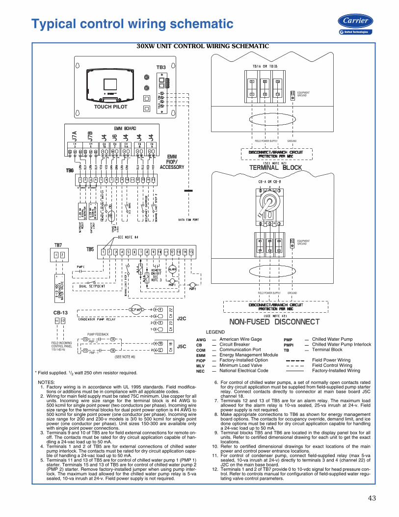
43
* *
J2C
J5C
PUMP FEEDBACK
PMP - 1
PMP - 2
(SEE NOTE #6)
CB-13
FIELD INCOMINGCONTROL PANEL115-1-60 Hz
TB3
TOUCH PILOT
EQUIPMENTGROUND
FIELD POWER SUPPLY GROUND
EQUIPMENTGROUND
FIELD POWER SUPPLY GROUND
NOTES:1. Factory wiring is in accordance with UL 1995 standards. Field modifica-
tions or additions must be in compliance with all applicable codes.2. Wiring for main field supply must be rated 75C minimum. Use copper for all
units. Incoming wire size range for the terminal block is #4 AWG to500 kcmil for single point power (two conductors per phase). Incoming wiresize range for the terminal blocks for dual point power option is #4 AWG to500 kcmil for single point power (one conductor per phase). Incoming wiresize range for 200 and 230-v models is 3/0 to 500 kcmil for single pointpower (one conductor per phase). Unit sizes 150-300 are available onlywith single point power connections.
3. Terminals 9 and 10 of TB5 are for field external connections for remote on-off. The contacts must be rated for dry circuit application capable of han-dling a 24-vac load up to 50 mA.
4. Terminals 1 and 2 of TB5 are for external connections of chilled waterpump interlock. The contacts must be rated for dry circuit application capa-ble of handling a 24-vac load up to 50 mA.
5. Terminals 11 and 13 of TB5 are for control of chilled water pump 1 (PMP 1)starter. Terminals 15 and 13 of TB5 are for control of chilled water pump 2(PMP 2) starter. Remove factory-installed jumper when using pump inter-lock. The maximum load allowed for the chilled water pump relay is 5-vasealed, 10-va inrush at 24-v. Field power supply is not required.
6. For control of chilled water pumps, a set of normally open contacts ratedfor dry circuit application must be supplied from field-supplied pump starterrelay. Connect contacts directly to connector at main base board J5Cchannel 18.
7. Terminals 12 and 13 of TB5 are for an alarm relay. The maximum loadallowed for the alarm relay is 10-va sealed, 25-va inrush at 24-v. Fieldpower supply is not required.
8. Make appropriate connections to TB6 as shown for energy managementboard options. The contacts for occupancy override, demand limit, and icedone options must be rated for dry circuit application capable for handlinga 24-vac load up to 50 mA.
9. Terminal blocks TB5 and TB6 are located in the display panel box for allunits. Refer to certified dimensional drawing for each unit to get the exactlocations.
10. Refer to certified dimensional drawings for exact locations of the mainpower and control power entrance locations.
11. For control of condenser pump, connect field-supplied relay (max 5-vasealed, 10-va inrush at 24-v) directly to terminals 3 and 4 (channel 22) ofJ2C on the main base board.
12. Terminals 1 and 2 of TB7 provide 0 to 10-vdc signal for head pressure con-trol. Refer to controls manual for configuration of field-supplied water regu-lating valve control parameters.
LEGEND
AWG — American Wire Gage PMP — Chilled Water PumpCB — Circuit Breaker PMPI — Chilled Water Pump InterlockCOM — Communication Port TB — Terminal BlockEMM — Energy Management ModuleFIOP — Factory-Installed Option Field Power WiringMLV — Minimum Load Valve Field Control WiringNEC — National Electrical Code Factory-Installed Wiring
a30-5320
* Field supplied. 1/2 watt 250 ohm resistor required.
30XW UNIT CONTROL WIRING SCHEMATIC
Typical control wiring schematic
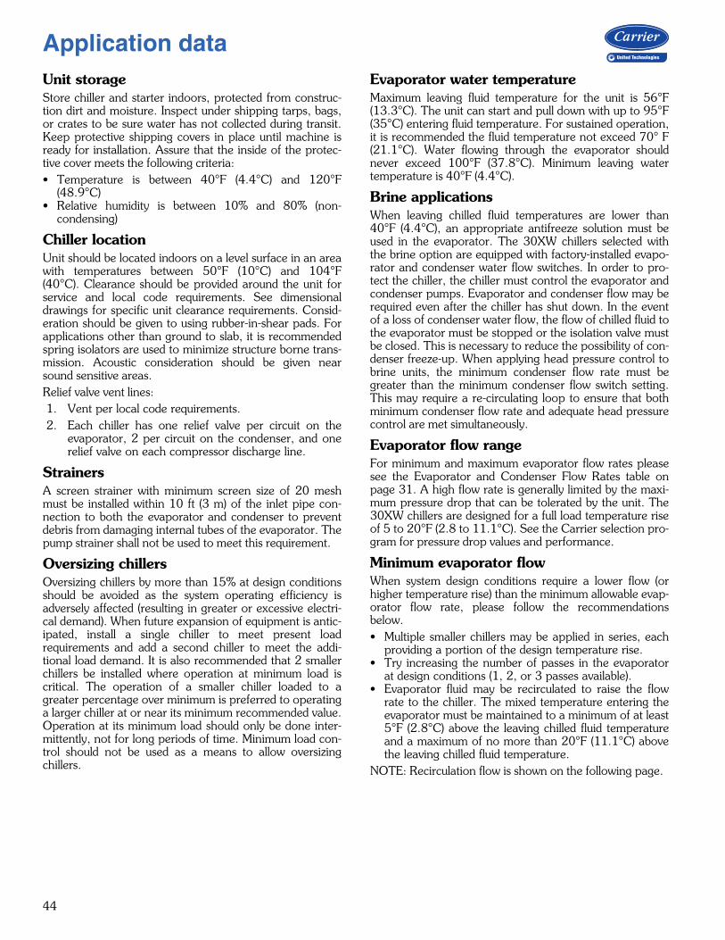
44
Unit storageStore chiller and starter indoors, protected from construc-tion dirt and moisture. Inspect under shipping tarps, bags,or crates to be sure water has not collected during transit.Keep protective shipping covers in place until machine isready for installation. Assure that the inside of the protec-tive cover meets the following criteria:• Temperature is between 40°F (4.4°C) and 120°F
(48.9°C)• Relative humidity is between 10% and 80% (non-
condensing)
Chiller locationUnit should be located indoors on a level surface in an areawith temperatures between 50°F (10°C) and 104°F(40°C). Clearance should be provided around the unit forservice and local code requirements. See dimensionaldrawings for specific unit clearance requirements. Consid-eration should be given to using rubber-in-shear pads. Forapplications other than ground to slab, it is recommendedspring isolators are used to minimize structure borne trans-mission. Acoustic consideration should be given nearsound sensitive areas.Relief valve vent lines:1. Vent per local code requirements.2. Each chiller has one relief valve per circuit on the
evaporator, 2 per circuit on the condenser, and onerelief valve on each compressor discharge line.
StrainersA screen strainer with minimum screen size of 20 meshmust be installed within 10 ft (3 m) of the inlet pipe con-nection to both the evaporator and condenser to preventdebris from damaging internal tubes of the evaporator. Thepump strainer shall not be used to meet this requirement.
Oversizing chillersOversizing chillers by more than 15% at design conditionsshould be avoided as the system operating efficiency isadversely affected (resulting in greater or excessive electri-cal demand). When future expansion of equipment is antic-ipated, install a single chiller to meet present loadrequirements and add a second chiller to meet the addi-tional load demand. It is also recommended that 2 smallerchillers be installed where operation at minimum load iscritical. The operation of a smaller chiller loaded to agreater percentage over minimum is preferred to operatinga larger chiller at or near its minimum recommended value.Operation at its minimum load should only be done inter-mittently, not for long periods of time. Minimum load con-trol should not be used as a means to allow oversizingchillers.
Evaporator water temperatureMaximum leaving fluid temperature for the unit is 56°F(13.3°C). The unit can start and pull down with up to 95°F(35°C) entering fluid temperature. For sustained operation,it is recommended the fluid temperature not exceed 70° F(21.1°C). Water flowing through the evaporator shouldnever exceed 100°F (37.8°C). Minimum leaving watertemperature is 40°F (4.4°C).
Brine applicationsWhen leaving chilled fluid temperatures are lower than40°F (4.4°C), an appropriate antifreeze solution must beused in the evaporator. The 30XW chillers selected withthe brine option are equipped with factory-installed evapo-rator and condenser water flow switches. In order to pro-tect the chiller, the chiller must control the evaporator andcondenser pumps. Evaporator and condenser flow may berequired even after the chiller has shut down. In the eventof a loss of condenser water flow, the flow of chilled fluid tothe evaporator must be stopped or the isolation valve mustbe closed. This is necessary to reduce the possibility of con-denser freeze-up. When applying head pressure control tobrine units, the minimum condenser flow rate must begreater than the minimum condenser flow switch setting.This may require a re-circulating loop to ensure that bothminimum condenser flow rate and adequate head pressurecontrol are met simultaneously.
Evaporator flow rangeFor minimum and maximum evaporator flow rates pleasesee the Evaporator and Condenser Flow Rates table onpage 31. A high flow rate is generally limited by the maxi-mum pressure drop that can be tolerated by the unit. The30XW chillers are designed for a full load temperature riseof 5 to 20°F (2.8 to 11.1°C). See the Carrier selection pro-gram for pressure drop values and performance.
Minimum evaporator flowWhen system design conditions require a lower flow (orhigher temperature rise) than the minimum allowable evap-orator flow rate, please follow the recommendationsbelow.• Multiple smaller chillers may be applied in series, each
providing a portion of the design temperature rise.• Try increasing the number of passes in the evaporator
at design conditions (1, 2, or 3 passes available).• Evaporator fluid may be recirculated to raise the flow
rate to the chiller. The mixed temperature entering theevaporator must be maintained to a minimum of at least5°F (2.8°C) above the leaving chilled fluid temperatureand a maximum of no more than 20°F (11.1°C) abovethe leaving chilled fluid temperature.
NOTE: Recirculation flow is shown on the following page.
Application data
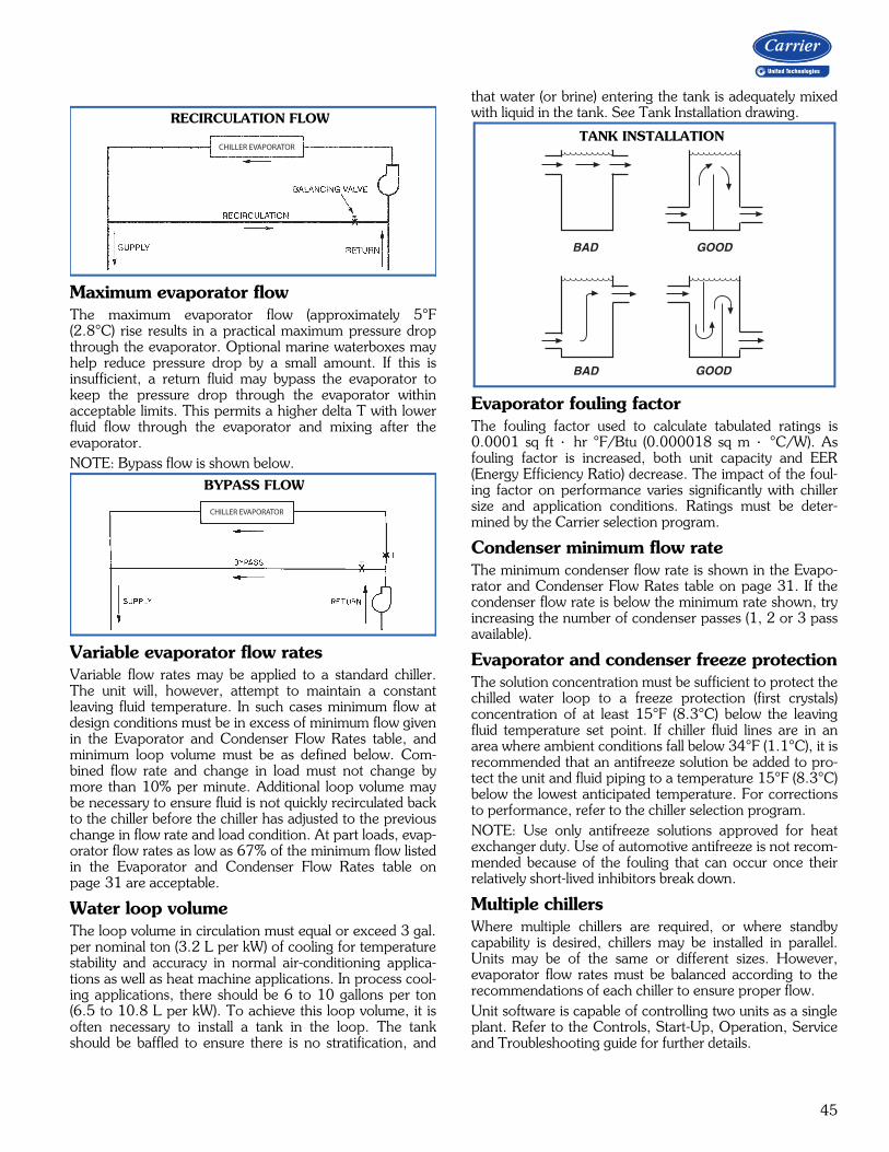
45
Maximum evaporator flowThe maximum evaporator flow (approximately 5°F(2.8°C) rise results in a practical maximum pressure dropthrough the evaporator. Optional marine waterboxes mayhelp reduce pressure drop by a small amount. If this isinsufficient, a return fluid may bypass the evaporator tokeep the pressure drop through the evaporator withinacceptable limits. This permits a higher delta T with lowerfluid flow through the evaporator and mixing after theevaporator.NOTE: Bypass flow is shown below.
Variable evaporator flow ratesVariable flow rates may be applied to a standard chiller.The unit will, however, attempt to maintain a constantleaving fluid temperature. In such cases minimum flow atdesign conditions must be in excess of minimum flow givenin the Evaporator and Condenser Flow Rates table, andminimum loop volume must be as defined below. Com-bined flow rate and change in load must not change bymore than 10% per minute. Additional loop volume maybe necessary to ensure fluid is not quickly recirculated backto the chiller before the chiller has adjusted to the previouschange in flow rate and load condition. At part loads, evap-orator flow rates as low as 67% of the minimum flow listedin the Evaporator and Condenser Flow Rates table onpage 31 are acceptable.
Water loop volumeThe loop volume in circulation must equal or exceed 3 gal.per nominal ton (3.2 L per kW) of cooling for temperaturestability and accuracy in normal air-conditioning applica-tions as well as heat machine applications. In process cool-ing applications, there should be 6 to 10 gallons per ton(6.5 to 10.8 L per kW). To achieve this loop volume, it isoften necessary to install a tank in the loop. The tankshould be baffled to ensure there is no stratification, and
that water (or brine) entering the tank is adequately mixedwith liquid in the tank. See Tank Installation drawing.
Evaporator fouling factor The fouling factor used to calculate tabulated ratings is0.0001 sq ft hr °F/Btu (0.000018 sq m °C/W). Asfouling factor is increased, both unit capacity and EER(Energy Efficiency Ratio) decrease. The impact of the foul-ing factor on performance varies significantly with chillersize and application conditions. Ratings must be deter-mined by the Carrier selection program.
Condenser minimum flow rateThe minimum condenser flow rate is shown in the Evapo-rator and Condenser Flow Rates table on page 31. If thecondenser flow rate is below the minimum rate shown, tryincreasing the number of condenser passes (1, 2 or 3 passavailable).
Evaporator and condenser freeze protectionThe solution concentration must be sufficient to protect thechilled water loop to a freeze protection (first crystals)concentration of at least 15°F (8.3°C) below the leavingfluid temperature set point. If chiller fluid lines are in anarea where ambient conditions fall below 34°F (1.1°C), it isrecommended that an antifreeze solution be added to pro-tect the unit and fluid piping to a temperature 15°F (8.3°C)below the lowest anticipated temperature. For correctionsto performance, refer to the chiller selection program. NOTE: Use only antifreeze solutions approved for heatexchanger duty. Use of automotive antifreeze is not recom-mended because of the fouling that can occur once theirrelatively short-lived inhibitors break down.
Multiple chillersWhere multiple chillers are required, or where standbycapability is desired, chillers may be installed in parallel.Units may be of the same or different sizes. However,evaporator flow rates must be balanced according to therecommendations of each chiller to ensure proper flow.Unit software is capable of controlling two units as a singleplant. Refer to the Controls, Start-Up, Operation, Serviceand Troubleshooting guide for further details.
RECIRCULATION FLOW
CHILLER EVAPORATOR
a30-4698
BYPASS FLOW
CHILLER EVAPORATOR
a30-4699
BAD
BAD
GOOD
GOOD
TANK INSTALLATION
a30-3185
46
Dual chiller controlThe chiller on board controller allows 2 chillers (piped inparallel or series) to operate as a single chilled water plantwith standard control functions coordinated through themaster chiller controller. This feature requires a communi-cation link between the 2 chillers. There are several advan-tages to this type of control:• Redundancy (multiple circuits)• Better low load control (lower tonnage capability)• Lower rigging lift weights (2 machines rather than one
large machine)• Chiller lead-lag operation (evens the wear between the
two machines)
Condenser fluid temperatureStandard 30XW units will start at entering condenser fluidtemperatures above 55°F (12.8°C). In general, however,continuous machine operation with entering condenser flu-id temperatures below 65°F (18.3°C) is not recommended.When the entering condenser fluid temperature is expect-ed to drop below 65°F (18.3°C), it is recommended thatsome form of condenser flow control be used to optimizeperformance. Tower pump, bypass valves, or flow regulat-ing valves may be controlled by a 4 to 20 mA output fromthe 30XW controller (60-second open to close time recom-mended for actuator).
Parallel chiller operationParallel chiller operation is the recommended option fordual chiller control. In this case, each chiller must controlits own dedicated pumps or isolation valves. Balancingvalves are recommended to ensure the proper flow to eachchiller. Two field-supplied and installed dual chiller leavingwater temperature sensors are required (one for each mod-ule) for this function to operate properly.Consider adding additional isolation valves to isolate eachchiller to allow for service on the machine, and still allowfor partial capacity from the other chiller.
Series chiller operationSeries chiller operation is an alternate control method sup-ported by the chiller control system. Certain applicationsmight require that two chillers be connected in series. Fornominal 10°F (5.6°C) evaporator ranges, use the one-passheat exchanger options to reduce fluid side pressure drop.Use the standard pass arrangement for low flow, high tem-perature rise applications. Two field-supplied and installed
dual chiller leaving water temperature sensors are required(one for each module) for this function to operate properly.Consider adding additional piping and isolation valves toisolate each chiller to allow for service on the machine, andstill allow for partial capacity from the other chiller.Even if evaporators are piped in series, parallel condenserpiping should be considered on constant speed chillers tomaximize capacity and efficiency while minimizing con-denser pressure drop and saturated condensing tempera-tures. If the condensers are piped in series, ensure that theleaving fluid temperature does not exceed 118°F (47.8°C)for standard units, or 140°F (60°C) for high condensing orheat machine condensers.
Electric utility interestsEnergy management Use of energy management practices can significantlyreduce operating costs, especially during off-peak modesof operation. Demand limiting and temperature reset aretwo techniques for accomplishing efficient energy manage-ment. See Demand Limiting (also called load shedding) sec-tion below for further details.
Demand limiting (load shedding)When a utility's demand for electricity exceeds a certainlevel, loads are shed to keep electricity demand below aprescribed maximum level. The energy management mod-ule (EMM) option can be added to accomplish this reduc-tion. Demand may be limited on the unit by resetting watertemperature, or by unloading the chiller to a given prede-termined percentage of the load. Demand limit may alsobe driven by an external 4 to 20 mA signal. These featuresrequire a signal from an intelligent central control.
Duty cyclingDuty cycling will cycle an electrical load at regular intervalsregardless of need. This reduces the electrical demand by“fooling” demand measuring devices. Duty cycling of theentire compressor is NOT recommended since motorwindings and bearing life will suffer from constant cycling.
Remote on-off controlRemote on-off control may be applied by hard-wired con-nection (see the Controls, Start-Up, Operation, Serviceand Troubleshooting guide) or by connection to the CarrierComfort Network® (CCN) system.
Application data (cont)
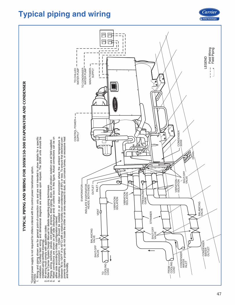
47
CO
NT
RO
L P
OW
ER
SU
PP
LY*
TO
CH
ILLE
DW
ATE
R P
UM
P
TO
CO
ND
EN
SE
RW
ATE
R P
UM
PE
VA
PO
RAT
OR
OU
TLE
T
INS
ULA
TE
EV
AP
OR
ATO
RH
EA
DS
, BO
TH
EN
DS
INLE
T
MA
IN P
OW
ER
SU
PP
LYS
HU
T-O
FF
VA
LVE
BA
LAN
CIN
GV
ALV
E
TO
CO
OLI
NG
LOA
D
FR
OM
CO
OLI
NG
LOA
D CO
ND
EN
SE
RW
ATE
RIN
LET
CO
ND
EN
SE
RW
ATE
RO
UT
LET
VIB
RAT
ION
ISO
LAT
ION
VIB
RAT
ION
ISO
LAT
ION V
IBR
ATIO
NIS
OLA
TIO
N
PR
ES
SU
RE
GA
GE
SH
UT-
OF
FV
ALV
E
DR
AIN
BA
LAN
CIN
GV
ALV
E
SH
UT-
OF
FV
ALV
E
ST
RA
INE
R
VE
NT
CO
ND
EN
SE
R30
XW
TY
PIC
AL
PIP
ING
AN
D W
IRIN
G F
OR
30X
W150-3
00 E
VA
PO
RA
TO
R A
ND
CO
ND
EN
SER
LEG
EN
DF
ield
Wiri
ngF
ield
Pip
ing
a30-4901*C
ontr
ol p
ower
sup
ply
is n
ot r
equi
red
for
chill
ers
orde
red
with
the
cont
rol p
ower
tran
sfor
mer
opt
ion.
NO
TE
S:
1.W
iring
and
pip
ing
show
n ar
e fo
r ge
nera
l po
int-
of-c
onne
ctio
n on
ly a
nd a
re n
ot i
nten
ded
to s
how
det
ails
for
a s
peci
ficin
stal
latio
n. C
ertif
ied
field
wiri
ng a
nd d
imen
sion
al d
iagr
ams
are
avai
labl
e up
on r
eque
st.
The
30X
W u
nits
sho
uld
bein
stal
led
usin
g ce
rtifi
ed d
raw
ings
.2.
All
wiri
ng m
ust c
ompl
y w
ith a
pplic
able
cod
es.
3.R
efer
to C
arrie
r S
yste
m D
esig
n M
anua
l for
det
ails
reg
ardi
ng p
ipin
g te
chni
ques
.4.
Pip
ing,
wiri
ng, s
witc
hes,
val
ves,
ven
t gag
es, s
trai
ners
, dra
in p
ipin
g, d
rain
, and
vib
ratio
n is
olat
ion
are
all f
ield
sup
plie
d.5.
Wat
er c
onne
ctio
ns a
re s
how
n on
lef
t si
de (
disc
harg
e en
d) o
f co
ntro
l box
in t
his
figur
e. A
ctua
l co
nnec
tions
can
be
onei
ther
sid
e ac
cord
ing
to c
hille
r co
nfig
urat
ion
orde
red.
6.O
pera
ting
envi
ronm
ent
— C
hille
r sh
ould
be
inst
alle
d in
an
indo
or e
nviro
nmen
t w
here
the
am
bien
t te
mpe
ratu
re i
sbe
twee
n 40
to 1
04°F
(4
to 4
0°C
) w
ith a
rel
ativ
e hu
mid
ity (
non-
cond
ensi
ng)
of 9
5% o
r le
ss. T
o en
sure
that
ele
ctric
al c
om-
pone
nts
oper
ate
prop
erly
, do
not
loca
te t
he c
hille
r in
an
area
exp
osed
to
dust
, di
rt,
corr
osiv
e fu
mes
, or
exc
essi
ve h
eat
and
hum
idity
.
Typical piping and wiring
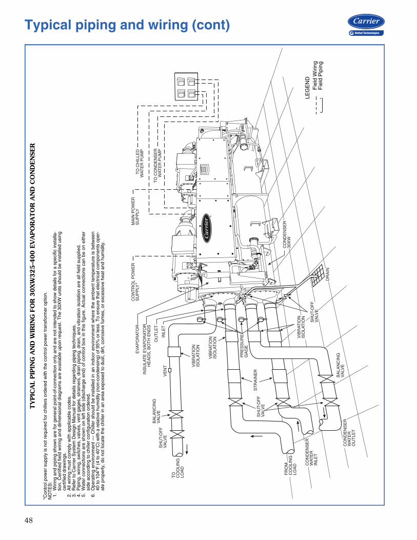
48
EV
AP
OR
ATO
R
SH
UT-
OF
FV
ALV
E
BA
LAN
CIN
GV
ALV
E
TO
CO
OLI
NG
LOA
D
FR
OM
CO
OLI
NG
LOA
D CO
ND
EN
SE
RW
ATE
RIN
LET
CO
ND
EN
SE
RW
ATE
RO
UT
LET
VIB
RAT
ION
ISO
LAT
ION
VIB
RAT
ION
ISO
LAT
ION V
IBR
ATIO
NIS
OLA
TIO
N
PR
ES
SU
RE
GA
GE
SH
UT-
OF
FV
ALV
E
CO
ND
EN
SE
R30
XW
DR
AIN
OU
TLE
T
BA
LAN
CIN
GV
ALV
E
SH
UT-
OF
FV
ALV
E
ST
RA
INE
RINS
ULA
TE
EV
AP
OR
ATO
RH
EA
DS
, BO
TH
EN
DS
VE
NT
INLE
T
CO
NT
RO
L P
OW
ER
SU
PP
LY*
TO
CH
ILLE
DW
ATE
R P
UM
P
TO
CO
ND
EN
SE
RW
ATE
R P
UM
P
MA
IN P
OW
ER
SU
PP
LY
TY
PIC
AL
PIP
ING
AN
D W
IRIN
G F
OR
30X
W325-4
00 E
VA
PO
RA
TO
R A
ND
CO
ND
EN
SER
a30-4700
LEG
EN
DF
ield
Wiri
ngF
ield
Pip
ing
*Con
trol
pow
er s
uppl
y is
not
req
uire
d fo
r ch
iller
s or
dere
d w
ith th
e co
ntro
l pow
er tr
ansf
orm
er o
ptio
n.N
OT
ES
:1.
Wiri
ng a
nd p
ipin
g sh
own
are
for
gene
ral p
oint
-of-
conn
ectio
n on
ly a
nd a
re n
ot in
tend
ed to
sho
w d
etai
ls fo
r a
spec
ific
inst
alla
-tio
n. C
ertif
ied
field
wiri
ng a
nd d
imen
sion
al d
iagr
ams
are
avai
labl
e up
on r
eque
st.
The
30X
W u
nits
sho
uld
be in
stal
led
usin
gce
rtifi
ed d
raw
ings
.2.
All
wiri
ng m
ust c
ompl
y w
ith a
pplic
able
cod
es.
3.R
efer
to C
arrie
r S
yste
m D
esig
n M
anua
l for
det
ails
reg
ardi
ng p
ipin
g te
chni
ques
.4.
Pip
ing,
wiri
ng, s
witc
hes,
val
ves,
ven
t gag
es, s
trai
ners
, dra
in p
ipin
g, d
rain
, and
vib
ratio
n is
olat
ion
are
all f
ield
sup
plie
d.5.
Wat
er c
onne
ctio
ns a
re s
how
n on
left
side
(di
scha
rge
end)
of c
ontr
ol b
ox in
this
fig
ure.
Act
ual c
onne
ctio
ns c
an b
e on
eith
ersi
de a
ccor
ding
to c
hille
r co
nfig
urat
ion
orde
red.
6.O
pera
ting
envi
ronm
ent
— C
hille
r sh
ould
be
inst
alle
d in
an
indo
or e
nviro
nmen
t w
here
the
am
bien
t te
mpe
ratu
re is
bet
wee
n40
to 1
04°F
(4
to 4
0°C
) w
ith a
rela
tive
hum
idity
(non
-con
dens
ing)
of 9
5% o
r le
ss. T
o en
sure
that
ele
ctric
al c
ompo
nent
s op
er-
ate
prop
erly
, do
not l
ocat
e th
e ch
iller
in a
n ar
ea e
xpos
ed to
dus
t, di
rt, c
orro
sive
fum
es, o
r ex
cess
ive
heat
and
hum
idity
.
Typical piping and wiring (cont)
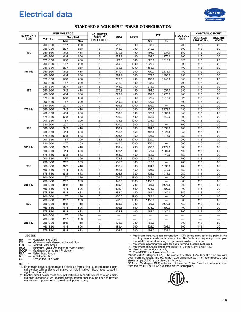
49
STANDARD SINGLE INPUT POWER CONFIGURATION
LEGEND
NOTES:1. Each main power source must be supplied from a field-supplied fused electri-
cal service with a (factory-installed or field-installed) disconnect located insight from the unit.
2. Control circuit power must be supplied from a separate source through a field-supplied disconnect. An optional control transformer may be used to providecontrol circuit power from the main unit power supply.
3. Maximum instantaneous current flow (ICF) during start-up is the point in thestarting sequence where the sum of the LRA for the start-up compressor, plusthe total RLA for all running compressors is at a maximum.
4. Maximum incoming wire size for each terminal block is 500 kcmil.5. Maximum allowable phase imbalance is: voltage, 2%; amps, 5%.6. Use copper conductors only.7. The MOCP is calculated as follows:
MOCP = (2.25) (largest RLA) + the sum of the other RLAs. Size the fuse one sizedown from the result. The RLAs are listed on nameplate. The recommended fusesize in amps (RFA) is calculated as follows:RFA = (1.50) (largest RLA) + the sum of the other RLAs. Size the fuse one size upfrom the result. The RLAs are listed on the nameplate.
30XW UNIT SIZE
UNIT VOLTAGE NO. POWER SUPPLY
CONDUCTORSMCA MOCP
ICF REC FUSESIZE
CONTROL CIRCUIT
V-Ph-HzSupplied VOLTAGE
1 PH, 60 HzMCA and
MOCPMin Max WD XL
150
200-3-60 187 220 6 511.3 800 938.0 — 700 115 20230-3-60 207 253 6 443.9 700 816.0 — 600 115 20380-3-60 342 418 3 270.9 450 494.0 1537.0 350 115 20460-3-60 414 506 3 222.8 400 408.0 1270.0 300 115 20575-3-60 518 633 3 176.3 300 326.0 1016.0 225 115 20
150 HM
200-3-60 187 220 6 649.0 1000 1329.0 — 800 115 20230-3-60 207 253 6 565.8 1000 1156.0 — 700 115 20380-3-60 342 418 3 341.4 600 700.0 2179.0 450 115 20460-3-60 414 506 3 283.8 500 578.0 1800.0 350 115 20575-3-60 518 633 3 226.0 400 462.0 1440.0 300 115 20
175
200-3-60 187 220 6 511.3 800 938.0 — 700 115 20230-3-60 207 253 6 443.9 700 816.0 — 600 115 20380-3-60 342 418 3 270.9 450 494.0 1537.0 350 115 20460-3-60 414 506 3 222.8 400 408.0 1270.0 300 115 20575-3-60 518 633 3 176.3 300 326.0 1016.0 225 115 20
175 HM
200-3-60 187 220 6 649.0 1000 1329.0 — 800 115 20230-3-60 207 253 6 565.8 1000 1156.0 — 700 115 20380-3-60 342 418 3 341.4 600 700.0 2179.0 450 115 20460-3-60 414 506 3 283.8 500 578.0 1800.0 350 115 20575-3-60 518 633 3 226.0 400 462.0 1440.0 300 115 20
185
200-3-60 187 220 6 578.5 1000 938.0 — 700 115 20230-3-60 207 253 6 501.6 800 816.0 — 700 115 20380-3-60 342 418 3 302.9 500 494.0 1537.0 400 115 20460-3-60 414 506 3 251.6 450 408.0 1270.0 350 115 20575-3-60 518 633 3 203.5 350 326.0 1016.0 250 115 20
185 HM
200-3-60 187 220 6 738.8 1200 1329.0 — 1000 115 20230-3-60 207 253 6 642.6 1000 1156.0 — 800 115 20380-3-60 342 418 6 389.4 700 700.0 2179.0 500 115 20460-3-60 414 506 3 322.1 500 578.0 1800.0 400 115 20575-3-60 518 633 3 258.0 450 462.0 1440.0 350 115 20
200
200-3-60 187 220 6 578.5 1000 938.0 — 700 115 20230-3-60 207 253 6 501.6 800 816.0 — 700 115 20380-3-60 342 418 3 302.9 500 494.0 1537.0 400 115 20460-3-60 414 506 3 251.6 450 408.0 1270.0 350 115 20575-3-60 518 633 3 203.5 350 326.0 1016.0 250 115 20
200 HM
200-3-60 187 220 6 738.8 1200 1329.0 — 1000 115 20230-3-60 207 253 6 642.6 1000 1156.0 — 800 115 20380-3-60 342 418 6 389.4 700 700.0 2179.0 500 115 20460-3-60 414 506 3 322.1 500 578.0 1800.0 400 115 20575-3-60 518 633 3 258.0 450 462.0 1440.0 350 115 20
225
200-3-60 187 220 6 687.5 1200 1329.0 — 1000 115 20230-3-60 207 253 6 597.8 1000 1156.0 — 800 115 20380-3-60 342 418 3 360.6 600 700.0 2179.0 450 115 20460-3-60 414 506 3 299.6 500 578.0 1800.0 400 115 20575-3-60 518 633 3 238.8 400 462.0 1440.0 300 115 20
225 HM
200-3-60 187 220 — — — — — — — —230-3-60 207 253 — — — — — — — —380-3-60 342 418 3 472.8 800 758.0 — 600 115 20460-3-60 414 506 3 389.4 700 625.0 1906.0 500 115 20575-3-60 518 633 3 309.3 500 498.0 1521.0 400 115 20
HM — Heat Machine UnitsICF — Maximum Instantaneous Current FlowLRA — Locked Rotor AmpsMCA — Minimum Circuit Ampacity (for wire sizing)MOCP — Maximum Overcurrent ProtectionRLA — Rated Load AmpsWD — Wye-Delta StartXL — Across-the-Line Start
Electrical data
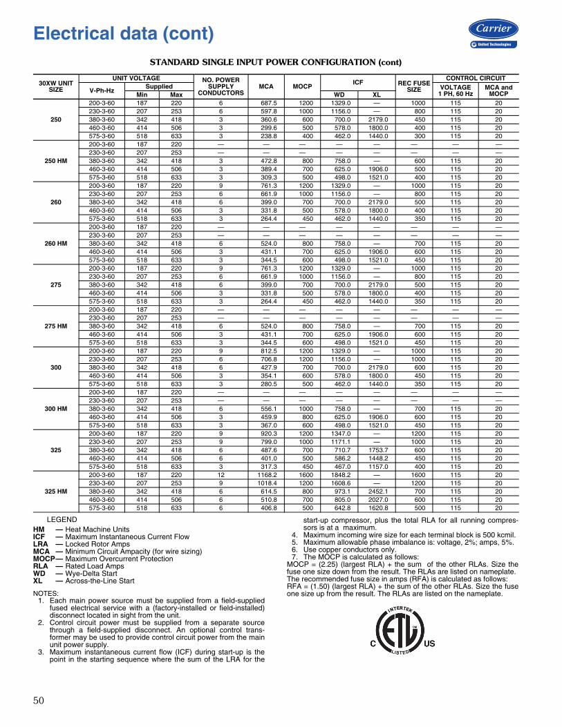
50
STANDARD SINGLE INPUT POWER CONFIGURATION (cont)
LEGEND
NOTES:1. Each main power source must be supplied from a field-supplied
fused electrical service with a (factory-installed or field-installed)disconnect located in sight from the unit.
2. Control circuit power must be supplied from a separate sourcethrough a field-supplied disconnect. An optional control trans-former may be used to provide control circuit power from the mainunit power supply.
3. Maximum instantaneous current flow (ICF) during start-up is thepoint in the starting sequence where the sum of the LRA for the
start-up compressor, plus the total RLA for all running compres-sors is at a maximum.
4. Maximum incoming wire size for each terminal block is 500 kcmil.5. Maximum allowable phase imbalance is: voltage, 2%; amps, 5%.6. Use copper conductors only.7. The MOCP is calculated as follows:
MOCP = (2.25) (largest RLA) + the sum of the other RLAs. Size thefuse one size down from the result. The RLAs are listed on nameplate.The recommended fuse size in amps (RFA) is calculated as follows:RFA = (1.50) (largest RLA) + the sum of the other RLAs. Size the fuseone size up from the result. The RLAs are listed on the nameplate.
30XW UNIT SIZE
UNIT VOLTAGE NO. POWER SUPPLY
CONDUCTORSMCA MOCP
ICF REC FUSESIZE
CONTROL CIRCUIT
V-Ph-HzSupplied VOLTAGE
1 PH, 60 HzMCA and
MOCPMin Max WD XL
250
200-3-60 187 220 6 687.5 1200 1329.0 — 1000 115 20230-3-60 207 253 6 597.8 1000 1156.0 — 800 115 20380-3-60 342 418 3 360.6 600 700.0 2179.0 450 115 20460-3-60 414 506 3 299.6 500 578.0 1800.0 400 115 20575-3-60 518 633 3 238.8 400 462.0 1440.0 300 115 20
250 HM
200-3-60 187 220 — — — — — — — —230-3-60 207 253 — — — — — — — —380-3-60 342 418 3 472.8 800 758.0 — 600 115 20460-3-60 414 506 3 389.4 700 625.0 1906.0 500 115 20575-3-60 518 633 3 309.3 500 498.0 1521.0 400 115 20
260
200-3-60 187 220 9 761.3 1200 1329.0 — 1000 115 20230-3-60 207 253 6 661.9 1000 1156.0 — 800 115 20380-3-60 342 418 6 399.0 700 700.0 2179.0 500 115 20460-3-60 414 506 3 331.8 500 578.0 1800.0 400 115 20575-3-60 518 633 3 264.4 450 462.0 1440.0 350 115 20
260 HM
200-3-60 187 220 — — — — — — — —230-3-60 207 253 — — — — — — — —380-3-60 342 418 6 524.0 800 758.0 — 700 115 20460-3-60 414 506 3 431.1 700 625.0 1906.0 600 115 20575-3-60 518 633 3 344.5 600 498.0 1521.0 450 115 20
275
200-3-60 187 220 9 761.3 1200 1329.0 — 1000 115 20230-3-60 207 253 6 661.9 1000 1156.0 — 800 115 20380-3-60 342 418 6 399.0 700 700.0 2179.0 500 115 20460-3-60 414 506 3 331.8 500 578.0 1800.0 400 115 20575-3-60 518 633 3 264.4 450 462.0 1440.0 350 115 20
275 HM
200-3-60 187 220 — — — — — — — —230-3-60 207 253 — — — — — — — —380-3-60 342 418 6 524.0 800 758.0 — 700 115 20460-3-60 414 506 3 431.1 700 625.0 1906.0 600 115 20575-3-60 518 633 3 344.5 600 498.0 1521.0 450 115 20
300
200-3-60 187 220 9 812.5 1200 1329.0 — 1000 115 20230-3-60 207 253 6 706.8 1200 1156.0 — 1000 115 20380-3-60 342 418 6 427.9 700 700.0 2179.0 600 115 20460-3-60 414 506 3 354.1 600 578.0 1800.0 450 115 20575-3-60 518 633 3 280.5 500 462.0 1440.0 350 115 20
300 HM
200-3-60 187 220 — — — — — — — —230-3-60 207 253 — — — — — — — —380-3-60 342 418 6 556.1 1000 758.0 — 700 115 20460-3-60 414 506 3 459.9 800 625.0 1906.0 600 115 20575-3-60 518 633 3 367.0 600 498.0 1521.0 450 115 20
325
200-3-60 187 220 9 920.3 1200 1347.0 — 1200 115 20230-3-60 207 253 9 799.0 1000 1171.1 — 1000 115 20380-3-60 342 418 6 487.6 700 710.7 1753.7 600 115 20460-3-60 414 506 6 401.0 500 586.2 1448.2 450 115 20575-3-60 518 633 3 317.3 450 467.0 1157.0 400 115 20
325 HM
200-3-60 187 220 12 1168.2 1600 1848.2 — 1600 115 20230-3-60 207 253 9 1018.4 1200 1608.6 — 1200 115 20380-3-60 342 418 6 614.5 800 973.1 2452.1 700 115 20460-3-60 414 506 6 510.8 700 805.0 2027.0 600 115 20575-3-60 518 633 6 406.8 500 642.8 1620.8 500 115 20
HM — Heat Machine UnitsICF — Maximum Instantaneous Current FlowLRA — Locked Rotor AmpsMCA — Minimum Circuit Ampacity (for wire sizing)MOCP— Maximum Overcurrent ProtectionRLA — Rated Load AmpsWD — Wye-Delta StartXL — Across-the-Line Start
Electrical data (cont)
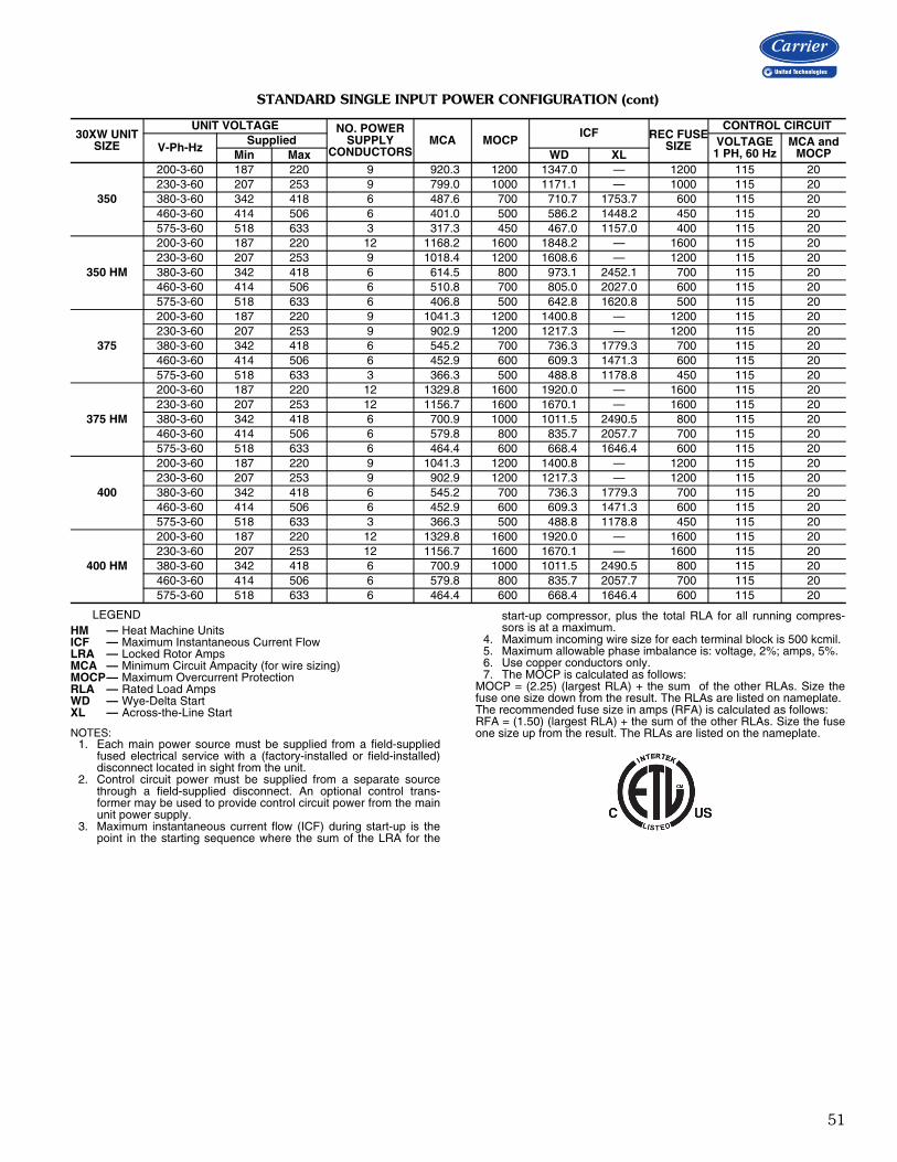
51
STANDARD SINGLE INPUT POWER CONFIGURATION (cont)
LEGEND
NOTES:1. Each main power source must be supplied from a field-supplied
fused electrical service with a (factory-installed or field-installed)disconnect located in sight from the unit.
2. Control circuit power must be supplied from a separate sourcethrough a field-supplied disconnect. An optional control trans-former may be used to provide control circuit power from the mainunit power supply.
3. Maximum instantaneous current flow (ICF) during start-up is thepoint in the starting sequence where the sum of the LRA for the
start-up compressor, plus the total RLA for all running compres-sors is at a maximum.
4. Maximum incoming wire size for each terminal block is 500 kcmil.5. Maximum allowable phase imbalance is: voltage, 2%; amps, 5%.6. Use copper conductors only.7. The MOCP is calculated as follows:
MOCP = (2.25) (largest RLA) + the sum of the other RLAs. Size thefuse one size down from the result. The RLAs are listed on nameplate.The recommended fuse size in amps (RFA) is calculated as follows:RFA = (1.50) (largest RLA) + the sum of the other RLAs. Size the fuseone size up from the result. The RLAs are listed on the nameplate.
30XW UNIT SIZE
UNIT VOLTAGE NO. POWER SUPPLY
CONDUCTORSMCA MOCP
ICF REC FUSESIZE
CONTROL CIRCUIT
V-Ph-HzSupplied VOLTAGE
1 PH, 60 HzMCA and
MOCPMin Max WD XL
350
200-3-60 187 220 9 920.3 1200 1347.0 — 1200 115 20230-3-60 207 253 9 799.0 1000 1171.1 — 1000 115 20380-3-60 342 418 6 487.6 700 710.7 1753.7 600 115 20460-3-60 414 506 6 401.0 500 586.2 1448.2 450 115 20575-3-60 518 633 3 317.3 450 467.0 1157.0 400 115 20
350 HM
200-3-60 187 220 12 1168.2 1600 1848.2 — 1600 115 20230-3-60 207 253 9 1018.4 1200 1608.6 — 1200 115 20380-3-60 342 418 6 614.5 800 973.1 2452.1 700 115 20460-3-60 414 506 6 510.8 700 805.0 2027.0 600 115 20575-3-60 518 633 6 406.8 500 642.8 1620.8 500 115 20
375
200-3-60 187 220 9 1041.3 1200 1400.8 — 1200 115 20230-3-60 207 253 9 902.9 1200 1217.3 — 1200 115 20380-3-60 342 418 6 545.2 700 736.3 1779.3 700 115 20460-3-60 414 506 6 452.9 600 609.3 1471.3 600 115 20575-3-60 518 633 3 366.3 500 488.8 1178.8 450 115 20
375 HM
200-3-60 187 220 12 1329.8 1600 1920.0 — 1600 115 20230-3-60 207 253 12 1156.7 1600 1670.1 — 1600 115 20380-3-60 342 418 6 700.9 1000 1011.5 2490.5 800 115 20460-3-60 414 506 6 579.8 800 835.7 2057.7 700 115 20575-3-60 518 633 6 464.4 600 668.4 1646.4 600 115 20
400
200-3-60 187 220 9 1041.3 1200 1400.8 — 1200 115 20230-3-60 207 253 9 902.9 1200 1217.3 — 1200 115 20380-3-60 342 418 6 545.2 700 736.3 1779.3 700 115 20460-3-60 414 506 6 452.9 600 609.3 1471.3 600 115 20575-3-60 518 633 3 366.3 500 488.8 1178.8 450 115 20
400 HM
200-3-60 187 220 12 1329.8 1600 1920.0 — 1600 115 20230-3-60 207 253 12 1156.7 1600 1670.1 — 1600 115 20380-3-60 342 418 6 700.9 1000 1011.5 2490.5 800 115 20460-3-60 414 506 6 579.8 800 835.7 2057.7 700 115 20575-3-60 518 633 6 464.4 600 668.4 1646.4 600 115 20
HM — Heat Machine UnitsICF — Maximum Instantaneous Current FlowLRA — Locked Rotor AmpsMCA — Minimum Circuit Ampacity (for wire sizing)MOCP— Maximum Overcurrent ProtectionRLA — Rated Load AmpsWD — Wye-Delta StartXL — Across-the-Line Start
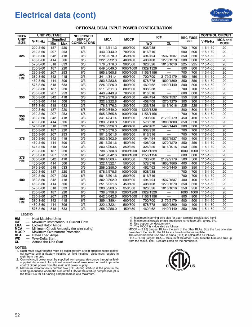
52
OPTIONAL DUAL INPUT POWER CONFIGURATION
LEGEND
NOTES:1. Each main power source must be supplied from a field-supplied fused electri-
cal service with a (factory-installed or field-installed) disconnect located insight from the unit.
2. Control circuit power must be supplied from a separate source through a field-supplied disconnect. An optional control transformer may be used to providecontrol circuit power from the main unit power supply.
3. Maximum instantaneous current flow (ICF) during start-up is the point in thestarting sequence where the sum of the LRA for the start-up compressor, plusthe total RLA for all running compressors is at a maximum.
4. Maximum incoming wire size for each terminal block is 500 kcmil.5. Maximum allowable phase imbalance is: voltage, 2%; amps, 5%.6. Use copper conductors only.7. The MOCP is calculated as follows:
MOCP = (2.25) (largest RLA) + the sum of the other RLAs. Size the fuse one size down from the result. The RLAs are listed on the nameplate.The recommended fuse size in amps (RFA) is calculated as follows:RFA = (1.50) (largest RLA) + the sum of the other RLAs. Size the fuse one size up from the result. The RLAs are listed on the nameplate.
30XW UNITSIZE
UNIT VOLTAGE NO. POWER SUPPLY
CONDUCTORSMCA MOCP
ICF REC FUSE SIZE
CONTROL CIRCUIT
V-Ph-HzSupplied
V-Ph-Hz MCA and MOCPMin Max WD XL
325
200-3-60 187 220 6/6 511.3/511.3 800/800 938/938 — 700 700 115-1-60 20230-3-60 207 253 6/6 443.9/443.9 700/700 816/816 — 600 600 115-1-60 20380-3-60 342 418 3/3 270.9/270.9 450/450 494/494 1537/1537 350 350 115-1-60 20460-3-60 414 506 3/3 222.8/222.8 400/400 408/408 1270/1270 300 300 115-1-60 20575-3-60 518 633 3/3 176.3/176.3 300/300 326/326 1016/1016 225 225 115-1-60 20
325HM
200-3-60 187 220 6/6 649.0/649.0 1000/1000 1329/1329 — 800 800 115-1-60 20230-3-60 207 253 6/6 565.8/565.8 1000/1000 1156/1156 — 700 700 115-1-60 20380-3-60 342 418 3/3 341.4/341.4 600/600 700/700 2179/2179 450 450 115-1-60 20460-3-60 414 506 3/3 283.8/283.8 500/500 578/578 1800/1800 350 350 115-1-60 20575-3-60 518 633 3/3 226.0/226.0 400/400 462/462 1440/1440 300 300 115-1-60 20
350
200-3-60 187 220 6/6 511.3/511.3 800/800 938/938 — 700 700 115-1-60 20230-3-60 207 253 6/6 443.9/443.9 700/700 816/816 — 600 600 115-1-60 20380-3-60 342 418 3/3 270.9/270.9 450/450 494/494 1537/1537 350 350 115-1-60 20460-3-60 414 506 3/3 222.8/222.8 400/400 408/408 1270/1270 300 300 115-1-60 20575-3-60 518 633 3/3 176.3/176.3 300/300 326/326 1016/1016 225 225 115-1-60 20
350HM
200-3-60 187 220 6/6 649.0/649.0 1000/1000 1329/1329 — 800 800 115-1-60 20230-3-60 207 253 6/6 565.8/565.8 1000/1000 1156/1156 — 700 700 115-1-60 20380-3-60 342 418 3/3 341.4/341.4 600/600 700/700 2179/2179 450 450 115-1-60 20460-3-60 414 506 3/3 283.8/283.8 500/500 578/578 1800/1800 350 350 115-1-60 20575-3-60 518 633 3/3 226.0/226.0 400/400 462/462 1440/1440 300 300 115-1-60 20
375
200-3-60 187 220 6/6 578.5/578.5 1000/1000 938/938 — 700 700 115-1-60 20230-3-60 207 253 6/6 501.6/501.6 800/800 816/816 — 700 700 115-1-60 20380-3-60 342 418 3/3 302.9/302.9 500/500 494/494 1537/1537 400 400 115-1-60 20460-3-60 414 506 3/3 251.6/251.6 450/450 408/408 1270/1270 350 350 115-1-60 20575-3-60 518 633 3/3 203.5/203.5 350/350 326/326 1016/1016 250 250 115-1-60 20
375HM
200-3-60 187 220 6/6 738.8/738.8 1200/1200 1329/1329 — 1000 1000 115-1-60 20230-3-60 207 253 6/6 642.6/642.6 1000/1000 1156/1156 — 800 800 115-1-60 20380-3-60 342 418 6/6 389.4/389.4 600/600 700/700 2179/2179 500 500 115-1-60 20460-3-60 414 506 3/3 322.1/322.1 500/500 578/578 1800/1800 400 400 115-1-60 20575-3-60 518 633 3/3 258.0/258.0 450/450 462/462 1440/1440 350 350 115-1-60 20
400
200-3-60 187 220 6/6 578.5/578.5 1000/1000 938/938 — 700 700 115-1-60 20230-3-60 207 253 6/6 501.6/501.6 800/800 816/816 — 700 700 115-1-60 20380-3-60 342 418 3/3 302.9/302.9 500/500 494/494 1537/1537 400 400 115-1-60 20460-3-60 414 506 3/3 251.6/251.6 450/450 408/408 1270/1270 350 350 115-1-60 20575-3-60 518 633 3/3 203.5/203.5 350/350 326/326 1016/1016 250 250 115-1-60 20
400HM
200-3-60 187 220 6/6 738.8/738.8 1200/1200 1329/1329 — 1000 1000 115-1-60 20230-3-60 207 253 6/6 642.6/642.6 1000/1000 1156/1156 — 800 800 115-1-60 20380-3-60 342 418 6/6 389.4/389.4 600/600 700/700 2179/2179 500 500 115-1-60 20460-3-60 414 506 3/3 322.1/322.1 500/500 578/578 1800/1800 400 400 115-1-60 20575-3-60 518 633 3/3 258.0/258.0 450/450 462/462 1440/1440 350 350 115-1-60 20
HM — Heat Machine UnitsICF — Maximum Instantaneous Current FlowLRA — Locked Rotor AmpsMCA — Minimum Circuit Ampacity (for wire sizing)MOCP — Maximum Overcurrent ProtectionRLA — Rated Load AmpsWD — Wye-Delta StartXL — Across-the-Line Start
Electrical data (cont)
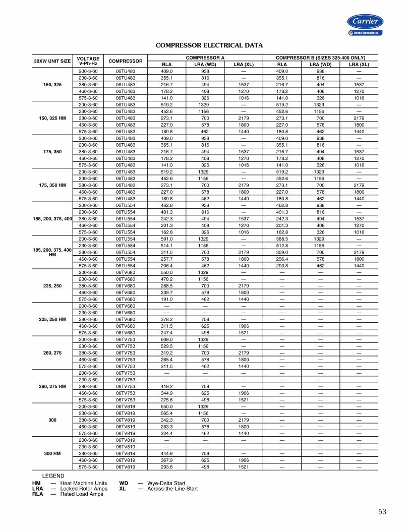
53
COMPRESSOR ELECTRICAL DATA
LEGEND
30XW UNIT SIZE VOLTAGEV-Ph-Hz COMPRESSOR
COMPRESSOR A COMPRESSOR B (SIZES 325-400 ONLY)RLA LRA (WD) LRA (XL) RLA LRA (WD) LRA (XL)
150, 325
200-3-60 06TU483 409.0 938 — 409.0 938 —230-3-60 06TU483 355.1 816 — 355.1 816 —380-3-60 06TU483 216.7 494 1537 216.7 494 1537460-3-60 06TU483 178.2 408 1270 178.2 408 1270575-3-60 06TU483 141.0 326 1016 141.0 326 1016
150, 325 HM
200-3-60 06TU483 519.2 1329 — 519.2 1329 —230-3-60 06TU483 452.6 1156 — 452.6 1156 —380-3-60 06TU483 273.1 700 2179 273.1 700 2179460-3-60 06TU483 227.0 578 1800 227.0 578 1800575-3-60 06TU483 180.8 462‘ 1440 180.8 462 1440
175, 350
200-3-60 06TU483 409.0 938 — 409.0 938 —230-3-60 06TU483 355.1 816 — 355.1 816 —380-3-60 06TU483 216.7 494 1537 216.7 494 1537460-3-60 06TU483 178.2 408 1270 178.2 408 1270575-3-60 06TU483 141.0 326 1016 141.0 326 1016
175, 350 HM
200-3-60 06TU483 519.2 1329 — 519.2 1329 —230-3-60 06TU483 452.6 1156 — 452.6 1156 —380-3-60 06TU483 273.1 700 2179 273.1 700 2179460-3-60 06TU483 227.0 578 1800 227.0 578 1800575-3-60 06TU483 180.8 462 1440 180.8 462 1440
185, 200, 375, 400
200-3-60 06TU554 462.8 938 — 462.8 938 —230-3-60 06TU554 401.3 816 — 401.3 816 —380-3-60 06TU554 242.3 494 1537 242.3 494 1537460-3-60 06TU554 201.3 408 1270 201.3 408 1270575-3-60 06TU554 162.8 326 1016 162.8 326 1016
185, 200, 375, 400 HM
200-3-60 06TU554 591.0 1329 — 588.5 1329 —230-3-60 06TU554 514.1 1156 — 512.8 1156 —380-3-60 06TU554 311.5 700 2179 309.0 700 2179460-3-60 06TU554 257.7 578 1800 256.4 578 1800575-3-60 06TU554 206.4 462 1440 203.8 462 1440
225, 250
200-3-60 06TV680 550.0 1329 — — — —230-3-60 06TV680 478.2 1156 — — — —380-3-60 06TV680 288.5 700 2179 — — —460-3-60 06TV680 239.7 578 1800 — — —575-3-60 06TV680 191.0 462 1440 — — —
225, 250 HM
200-3-60 06TV680 — — — — — —230-3-60 06TV680 — — — — — —380-3-60 06TV680 378.2 758 — — — —460-3-60 06TV680 311.5 625 1906 — — —575-3-60 06TV680 247.4 498 1521 — — —
260, 275
200-3-60 06TV753 609.0 1329 — — — —230-3-60 06TV753 529.5 1156 — — — —380-3-60 06TV753 319.2 700 2179 — — —460-3-60 06TV753 265.4 578 1800 — — —575-3-60 06TV753 211.5 462 1440 — — —
260, 275 HM
200-3-60 06TV753 — — — — — —230-3-60 06TV753 — — — — — —380-3-60 06TV753 419.2 758 — — — —460-3-60 06TV753 344.9 625 1906 — — —575-3-60 06TV753 275.6 498 1521 — — —
300
200-3-60 06TV819 650.0 1329 — — — —230-3-60 06TV819 565.4 1156 — — — —380-3-60 06TV819 342.3 700 2179 — — —460-3-60 06TV819 283.3 578 1800 — — —575-3-60 06TV819 224.4 462 1440 — — —
300 HM
200-3-60 06TV819 — — — — — —230-3-60 06TV819 — — — — — —380-3-60 06TV819 444.9 758 — — — —460-3-60 06TV819 367.9 625 1906 — — —575-3-60 06TV819 293.6 498 1521 — — —
HM — Heat Machine Units WD — Wye-Delta StartLRA — Locked Rotor Amps XL — Across-the-Line StartRLA — Rated Load Amps
54
Water-Cooled ChillerHVAC Guide SpecificationsSize Range: 150 to 400 Nominal Tons(528 to 1407 kW)Carrier Model Number: 30XWPart 1 — General1.01 SYSTEM DESCRIPTION
Microprocessor controlled water-cooled liquid chillerutilizing screw compressor(s) and electronic expan-sion valves.
1.02 QUALITY ASSURANCEA. Unit shall be rated in accordance with AHRI (Air-
Conditioning, Heating, and Refrigeration Institute)Standard 550/590 (U.S.A.), latest edition.
B. Unit construction shall comply with ASHRAE(American Society of Heating, Refrigerating, andAir-Conditioning Engineers) 90.1 2010 15 SafetyCode, NEC (National Electrical Code), and ASME(American Society of Mechanical Engineers) applica-ble codes (U.S.A. codes).
C. Unit shall be manufactured in a facility registered toISO (International Organization for Standardization)9001 Manufacturing Quality Standard.
D. 200-v, 230-v, 460-v, 575-v, 60 Hz units shall beconstructed in accordance with UL (UnderwritersLaboratories) or UL Canada standards and shall betested and listed by ETL or ETL, Canada, as con-forming to those standards. Units shall carry theETL and ETL, Canada, labels.
1.03 DELIVERY, STORAGE, AND HANDLINGA. Unit controls shall be capable of withstanding 150°F
(65.5°C) storage temperatures in the controlcompartment.
B. Chiller and starter should be stored indoors, pro-tected from construction dirt and moisture. Aninspection should be conducted under shippingtarps, bags, or crates to be sure water has not col-lected during transit. Protective shipping coversshould be kept in place until machine is ready forinstallation. The inside of the protective covershould meet the following criteria:
1. Temperature is between 40°F (4.4°C) and120°F (48.9°C).
2. Relative humidity is between 10% and 80%(non-condensing).
Part 2 — Products2.01 EQUIPMENT
A. General:Factory assembled, single-piece, water-cooled liquidchiller. Unit sizes 325-400 shall have dual (2) inde-pendent refrigerant circuits. Contained within theunit cabinet shall be all factory wiring, piping, con-trols, refrigerant charge (HFC-134a) and special fea-tures required prior to field start-up.
B. Compressor(s):1. Semi-hermetic twin-screw compressor(s) with
internal muffler and check valve.2. Each compressor shall be equipped with a dis-
charge shutoff valve.C. Evaporator:
1. Shall be tested and stamped in accordancewith ASME Code (U.S.A.) for a refrigerantworking-side pressure of 220 psig (1408 kPa).Water-side pressure rating shall be 150 psig(1034 kPa). In Canada, maximum water-sidepressure shall be 250 psig (1725 kPa), per theCanadian National Registry.
2. Shall be mechanically cleanable shell-and-tubetype with removable heads.
3. Tubes shall be internally enhanced, seamless-copper type, and shall be rolled into tubesheets.
4. Shall be equipped with Victaulic fluidconnections (2 pass) or flanged fluid connec-tions (1, 2 or 3 pass).
5. Shell shall be insulated with 3/4-in. (19-mm)closed-cell, polyvinyl chloride foam with a maxi-mum K factor of 0.28. Heads may require fieldinsulation.
6. Shall have an evaporator drain and vent.7. Design shall incorporate 2 independent refrig-
erant circuits (sizes 325-400 only).8. Shall be equipped with factory-installed thermal
dispersion chilled fluid flow switch.D. Condenser:
1. Shall be tested and stamped in accordancewith ASME code (U.S.A.) for a refrigerantworking-side pressure of 220 psig (1408 kPa).Water-side pressure rating shall be 150 psig(1034 kPa). In Canada, maximum water-sidepressure shall be 250 psig (1725 kPa), per theCanadian National Registry.
2. Shall be mechanically cleanable shell-and-tubetype with removable heads.
3. Tubes shall be internally enhanced, seamless-copper type, and shall be rolled into tubesheets.
4. Shall be equipped with Victaulic waterconnections.
5. Unit sizes 325-400 shall have dual (2) indepen-dent refrigerant circuits.
E. Heat Machines:1. Condenser shall be tested and stamped in
accordance with ASME Code (U.S.A.) for arefrigerant working-side pressure of 300 psig(2068 kPa).
2. Unit sizes 325-400 shall have dual (2) indepen-dent refrigerant circuits.
3. Heat machine condensers shall include factory-installed thermal insulation on the condenser,
Guide specifications
55
condenser flow switch and leaving watertemperature sensor. Heat machine unitsrequire field-installed thermal insulation on thecompressor discharge piping and waterboxheads because of high temperature.
F. Refrigeration Components:Refrigerant circuit components shall include oil sep-arator, high and low side pressure relief devices, liq-uid line shutoff valves, filter drier, moisture indicatingsight glass, expansion valve, refrigerant economizer(unit sizes 175, 200, 250, 275, 300, 350, 400),and complete charge of compressor oil. The unitsshall have a complete operating charge of refriger-ant HFC-134a.
G. Controls:1. Unit controls shall include the following mini-
mum components: a. Microprocessor with non-volatile memory.
Battery backup system shall not be accepted.b. Separate terminal block for power and
controls.c. Separate 115-v power supply to serve all
controllers, relays, and control components.d. ON/OFF control switch.e. Replaceable solid-state controllers.f. Pressure sensors installed to measure
suction, oil, economizer (unit sizes 175,200, 250, 275, 300, 350, 400), and dis-charge pressure. Thermistors installed tomeasure evaporator entering and leavingfluid temperatures.
2. Unit controls shall include the followingfunctions:a. Automatic circuit lead/lag.b. Capacity control based on leaving chilled
fluid temperature and compensated by rateof change of return-fluid temperature withtemperature set point accuracy to 0.1°F(0.05°C).
c. Limiting the chilled fluid temperaturepulldown rate at start-up to an adjustablerange of 0.2°F to 2°F (0.1 to 1.1°C) perminute to prevent excessive demand spikesat start-up.
d. Seven-day time schedule.e. Leaving chilled fluid temperature reset from
return fluid.f. Chilled water and condenser water pump
start/stop control.g. Chiller control for parallel chiller applications
without addition of hardware modules andcontrol panels (requires thermistors).
h. Single step demand limit control activated byremote contact closure.
H. Safeties:Unit shall be equipped with thermistors and all nec-essary components in conjunction with the controlsystem to provide the unit with the followingprotections:
1. Loss of refrigerant charge.2. Reverse rotation.3. Low chilled fluid temperature.4. Motor overtemperature.5. High pressure.6. Electrical overload.7. Loss of phase.8. Loss of chilled water flow.
I. Diagnostics:1. The control panel shall include, as standard, a
display:a. Touch screen display consisting of ¼ VGA
LCD (liquid crystal display) with adjustablecontrast and backlighting.
b. Display shall allow a user to navigatethrough menus, select desired options andmodify data.
2. Features of the display shall include:a. Display shall be customizable and allow up to
72 data points.b. Display shall support both local equipment
or network made for remote mount.c. Display shall allow access to configuration,
maintenance, service, set point, time sched-ules, alarm history and status data.
d. Display shall have one button for chiller on/off.
e. Display shall include three levels of passwordprotection against unauthorized access toconfiguration and maintenance informa-tion, and display set up parameters.
f. Display shall allow for easy connection of aportable hand held technician tool to accessinformation and upload and/or downloadchiller settings.
g. Display shall be compatible with the CarrierComfort Network® (CCN) system and pro-vide network alarm acknowledgment or indi-cation and provide capability to fully monitorand control chiller.
h. Display alarms and parameters shall becapable of being displayed in full text.
i. Display shall be capable of displaying the last50 alarms and will store a snapshot of aminimum of 20 status data parameters foreach alarm.
j. Compressor run hours.k. Compressor number of starts.l. Compressor current.
56
m. Time of day:1) Display module, in conjunction with the
microprocessor, must also be capable ofdisplaying the output (results) of a ser-vice test. Service test shall verify opera-tion of every switch, thermistor, andcompressor before chiller is started.
2) Diagnostics shall include the ability toreview a list of the 30 most recentalarms with clear language descriptionsof the alarm event. Display of alarmcodes without the ability for clear lan-guage descriptions shall be prohibited.
3) An alarm history buffer shall allow theuser to store no less than 30 alarmevents with clear language descriptions,time and date stamp event entry.
4) The chiller controller shall include multi-ple connection ports for communicat-ing with the local equipment networkand the Carrier Comfort Network®
(CCN) system.5) The control system shall allow software
upgrade without the need for new hard-ware modules.
J. Operating Characteristics:Unit shall be capable of starting up with 95°F (35°C)entering fluid temperature to the evaporator.
K. Electrical Requirements:1. Unit primary electrical power supply shall enter
the unit at a single location.2. Unit shall operate on 3-phase power at the volt-
age shown in the equipment schedule.3. Control voltage shall be 115-v (60 Hz), single-
phase, separate power supply.L. Special Features:
Certain standard features are not applicable whenthe features designated by * are specified. For assis-tance in amending the specifications, contact yourlocal Carrier Sales office.
* 1. Wye-Delta Starter:Unit shall have a factory-installed, wye-deltastarter to minimize electrical inrush current.
2. Vibration Isolation:Unit shall be supplied with rubber-in-shearvibration isolators for field installation.
3. Control Power Transformer:Unit shall be supplied with a factory-installedcontrols transformer that will supply 115-v con-trol circuit power from the main unit powersupply.
4. Temperature Reset Sensor:Unit shall reset leaving chilled fluid temperaturebased on outdoor ambient temperature orspace temperature when this sensor is installed.
* 5. Minimum Load Control:Unit shall be equipped with factory-installed,microprocessor-controlled, minimum load con-trol that shall permit unit operation down to10% of full capacity.
6. One-Pass Evaporator:Factory-installed option shall reduce pressuredrop for high flow applications.
7. Three-Pass Evaporator:Factory-installed option shall enhance perfor-mance for low flow applications.
8. Energy Management Module:A factory or field installed module shall providethe following energy management capabilities:4 to 20 mA signals for leaving fluid temperaturereset, cooling set point reset or demand limitcontrol; 2-point demand limit control (from 0 to100%) activated by a remote contact closure;and discrete input for " Ice Done" indication forice storage system interface.
9. BACnet Translator Control:Unit shall be supplied with factory or field-installed interface between the chiller and aBACnet Local Area Network (LAN, i.e., MS/TP EIA-485).
10. LON Translator Control:Unit shall be supplied with factory or field-installed interface between the chiller and aLocal Operating Network (LON, i.e., LonWorksFT-10A ANSI/EIA-709.1).
11. Navigator™ Hand Held Portable Display:a. Portable hand held display module with a
minimum of 4 lines and 20 characters perline, or clear English, Spanish, Portugueseor French language.
b. Display menus shall provide clear languagedescriptions of all menu items, operatingmodes, configuration points and alarm diag-nostics. Reference to factory codes shall notbe accepted.
c. RJ-14 connection plug shall allow displaymodule to be connected to factory-installedreceptacle.
d. Industrial grade coiled extension cord shallallow the display module to be movedaround the chiller.
e. Magnets shall hold the display module toany sheet metal panel to allow hands-freeoperation.
f. Display module shall have NEMA 4xhousing.
g. Display shall have back light and contrastadjustment for easy viewing in bright sun-light or night conditions.
h. Raised surface buttons with positive tactileresponse.
Guide specifications (cont)
57
12. Compressor Suction Service Valve:Optional refrigerant discharge isolation and liq-uid valves enable service personnel to store therefrigerant charge in the evaporator or con-denser during servicing. This factory-installedoption allows for further isolation of the com-pressor from the evaporator vessel.
13. Refrigerant Isolation Valves:Valves shall enable service personnel to storethe refrigerant charge in the evaporator or con-denser during servicing. During servicing, thein-chiller storage shall reduce refrigerant lossand eliminate time-consuming transfer proce-dures. As a self-contained unit, the chiller shallnot require additional remote storage systems.
14. GFCI Convenience Outlet:Shall be factory or field-installed and mountedwith easily accessible 115-v female receptacle.Shall include 4 amp GFI (ground fault interrupt)receptacle.
15. Medium Temperature Brine:Unit shall be factory modified to start and oper-ate at leaving chilled fluid temperatures below40°F (4.4°C). Chiller shall be equipped withcondenser water flow switch. The optional insu-lation package is required when the mediumtemperature brine option is selected.
16. 300 psig (2068 kPa) Evaporator OperatingPressure:This option shall provide for water-side pres-sure operation up to 300 psig (2068 kPa).
17. 300 psig (2068 kPa) Condenser OperatingPressure:This option shall provide for water-side pres-sure operation up to 300 psig (2068 kPa).
18. Marine Waterboxes:Marine waterboxes shall provide water pipingconnections extending from the side of thewaterbox (as opposed to extending from theend of the waterbox). This option also includesa removable bolt on waterbox cover allowingaccess to the heat exchanger tubes withoutbreaking the existing field piping. This optionis available for both the evaporator andcondenser.
19. Flanged Connection:The flanged connection option shall provide anANSI flange on the end of the chiller waterpiping for connection to a customer suppliedmating flange in the field piping. This optionis available for both the evaporator andcondenser.
20. One-Pass Condenser:This option shall provide a lower pressure dropthrough the condenser for applications with lowdelta T (temperature) or high flow or where thecondensers are piped in a series. The one-pass
condenser option is only available with flangedconnections and with a suction end leavingwater connection.
21. Three-Pass Condenser:This option shall provide a greater efficiency forheat machine applications with a high delta Tand low flow. The three-pass condenser optionis only available with flanged connections andsuction end leaving water connection.
22. Insulation Package:Package shall provide 3/4-in. (19-mm) thermalinsulation on compressor suction housing, andsuction line.
23. Dual Point Power:The dual point power option shall provide ameans for connecting two sources of power todual compressor chillers (sizes 325-400 only).One source of power is wired to operate thecompressor on the A circuit and one source ofpower is wired to operate the compressor onthe B circuit of the chiller.
24. Non-Fused Disconnect:This option shall provide a no load, lockable,through the door handle disconnect for unitpower on the chiller. On dual compressor units,two disconnects are provided (one for eachcompressor). On units with dual point power,one disconnect is provided for each of the twomain power supplies. This disconnect does notremove the control circuit from power supply.
25. Nitrogen Charge:A nitrogen charge option is available to providea 15 psig (103.4 kPa) charge of nitrogeninstead of a full factory charge of R-134a refrig-erant to keep the chiller refrigerant circuit dryduring shipment. This option is recommendedfor applications where the unit will be disassem-bled prior to installation. Units shipped with anitrogen charge will receive an electrical conti-nuity test at the factory prior to shipment.
26. Crate for Shipment:This option is recommended for export orders.The chiller will be bagged prior to being placedin a wooden crate.
27. Remote Enhanced Display:This option is a remotely mounted indoor40-character per line, 16-line display panel forunit monitoring and diagnostics.
28. Vibration Springs:A set of non-seismic spring isolators can beprovided for installation at the jobsite.
29. BACnet1 Communication Option:Shall provide factory-installed communicationcapability with a BACnet MS/TP network.Allows integration with i-Vu® Open control sys-tem or a BACnet building automation system.
1BACnet is a registered trademark of ASHRAE (American Society of Heating, Refrigerating and Air-Conditioning Engineers).


Manufacturer reserves the right to discontinue, or change at any time, specifications or designs without notice and without incurring obligations.Pg 60 Catalog No. 04-52300102-01 Printed in U.S.A. Form 30XW-11PD
Replaces: 30XW-10PD
Carrier Corporation • Syracuse, New York 13221 8-18
Recommended


