
1
Cover
Command Line Interface
DP612 Industrial 12G Layer 3 Managed PoE Switch
DS612 Industrial 12G Layer 3 Managed Switch
Feb.07.2018 V.1

2
WoMaster
DP612 Industrial 12G L3 Managed PoE Switch
DS612 Industrial 12G L3 Managed Switch
WoMaster Command Line Interface
User Manual
Copyright Notice
© WoMaster. All rights reserved.
About This Manual
This user manual is intended to guide a professional installer to configure the device through Command Line Interface. It includes procedures to assist you in avoiding unforeseen problems.
NOTE:
Only qualified and trained personnel should be involved with installation, inspection, and repairs of this switch.
Disclaimer
WoMaster reserves the right to make changes to this Manual or to the product hardware at any time without notice. Information provided here is intended to be accurate and reliable. However, it might not cover all details and variations in the equipment and does not claim to provide for every possible contingency met in the process of installation, operation, or maintenance. Should further information be required or should particular problem arise which are not covered sufficiently for the user’s purposes, the matter should be referred to WoMaster. Users must be aware that updates and amendments will be made from time to time to add new information and/or correct possible unintentional technical or typographical mistakes. It is the user’s responsibility to determine whether there have been any such updates or amendments of the Manual. WoMaster assumes no responsibility for its use by the third parties.
WoMaster Online Technical Services At WoMaster, you can use the online service forms to request the support. The submitted forms are stored in server for WoMaster team member to assign tasks and monitor the status of your service. Please feel free to write to [email protected] if you encounter any problems.

3
TABLE OF CONTENTS
COVER ...................................................................................................................................................................... 1
TABLE OF CONTENTS ............................................................................................................................................. 3
1. COMMAND LINE INTERFACE (CLI) INTRODUCTION ........................................................................ 4
1.1 PREPARATION FOR SERIAL CONSOLE ............................................................................ 4
1.2 PREPARATION FOR TELNET CONSOLE ........................................................................... 5
2. UNDERSTANDING ALL COMMANDS................................................................................................... 7
3. COMMANDS ......................................................................................................................................... 12
3.1 CLI COMMANDS FOR SYSTEM CONFIGURATION ......................................................... 12
3.2 CLI COMMANDS FOR PORT CONFIGURATION ............................................................ 17
3.3 CLI COMMANDS FOR PoE CONFIGURATION (PoE Model Only) .................................... 22
3.4 CLI COMMANDS FOR REDUNDANCY CONFIGURATION ............................................... 27
3.5 CLI COMMANDS FOR VLAN CONFIGURATION ............................................................ 36
3.6 CLI COMMANDS FOR QOS CONFIGURATION .............................................................. 44
3.7 CLI COMMANDS FOR MULTICAST FILTERING CONFIGURATION .................................... 48
3.8 CLI COMMANDS FOR SNMP CONFIGURATION ........................................................... 50
3.9 CLI COMMANDS FOR SECURITY CONFIGURATION ...................................................... 63
3.10 CLI COMMANDS FOR WARNING CONFIGURATION ..................................................... 66
3.11 CLI COMMANDS FOR DIAGNOSTICS CONFIGURATION ................................................ 70
3.12 CLI COMMANDS FOR BACKUP RESTORE ....................................................... 73
3.13 CLI COMMANDS FOR FIRMWARE UPGRADE .................................................. 74
3.14 CLI COMMANDS FOR RESET ............................................................................. 74
3.15 CLI COMMANDS FOR SAVE & LOAD ................................................................ 74
3.16 CLI COMMANDS FOR LOGOUT ......................................................................... 75
3.17 CLI COMMANDS FOR REBOOT ......................................................................... 75

4
1. COMMAND LINE INTERFACE (CLI) INTRODUCTION
The Command Line Interface (CLI) is the user interface to the switch’s embedded software system. The CLI in
WoMaster switches can be accessed through either the serial console or Telnet console. The explanation for Serial
and Telnet console preparation would be explained below:
1.1 PREPARATION FOR SERIAL CONSOLE
Attach RJ-45 to RS-232 DB-9 console cable to PC’s COM port; connect RJ45 connector to the Console port of the
WoMaster Managed Switch.
1. Go to Start -> Program -> Accessories -> Communication -> Hyper Terminal
2. Give a name to the new console connection.
3. Choose the COM name
4. Select correct serial settings. The serial settings of WoMaster Managed switches are as below:
Baud Rate: 115200 / Parity: None / Data Bit: 8 / Stop Bit: 1
5. After connected, switch login screen can be seen.
6. Login the switch. The default username: admin; password: admin.

5
1.2 PREPARATION FOR TELNET CONSOLE
WoMaster managed switch supports Telnet console. User can connect to the switch by Telnet and the command
lines are the same as what user sees by RS232 console port. Below are the steps to open Telnet connection to the
switch.
1. Start -> Run -> cmd. ->Enter
2. Type the Telnet 192.168.10.1 (or the IP address of the switch). And then press Enter, user will directly
enter the Telnet console.
3. Type the Login Name and its Password. The default Login Name and Password are admin / admin.
SSH (Secure Shell)
WoMaster managed SWITCH also supports SSH console. User can remotely connect to the switch by command line
interface. The SSH connection can secure all the configuration commands user sent to the switch.
SSH is a client/server architecture while the switch is the SSH server. When user wants to make SSH connection with
the switch, user should download the SSH client tool first.
SSH Client
There are many free, sharewares, trials or charged SSH clients user can find on the internet, e.g., PuTTY is a free and
popular Telnet/SSH client. We’ll use this tool to demonstrate how to login by SSH. (PuTTY copyright 1997-2016
Simon Tatham).

6
Download PuTTY: http://www.chiark.greenend.org.uk/~sgtatham/putty/download.html
1. Open SSH Client/PuTTY
In the Session configuration, choose the Serial protocol then enter the Serial line and Speed. For the serial
line, please check the device manager to make sure the serial line name. The speed should be 115200. Then
click on Open to start the SSH session console.
2. After it user can see the CLI command screen is pop-up
3. Type the Switch Login name and its Password. The default setting are admin / admin.
4. All the commands user sees in Putty are the same as the CLI commands user sees via RS232 console.
The next chapter will introduce in detail how to use command line to configure some features in the switch.
7
2. UNDERSTANDING ALL COMMANDS
For either type of connection, access to the command line interface is generally referred to as an EXEC session. There
are some different command modes. Each command mode has its own access ability, available command lines and
uses different command lines to enter and exit.
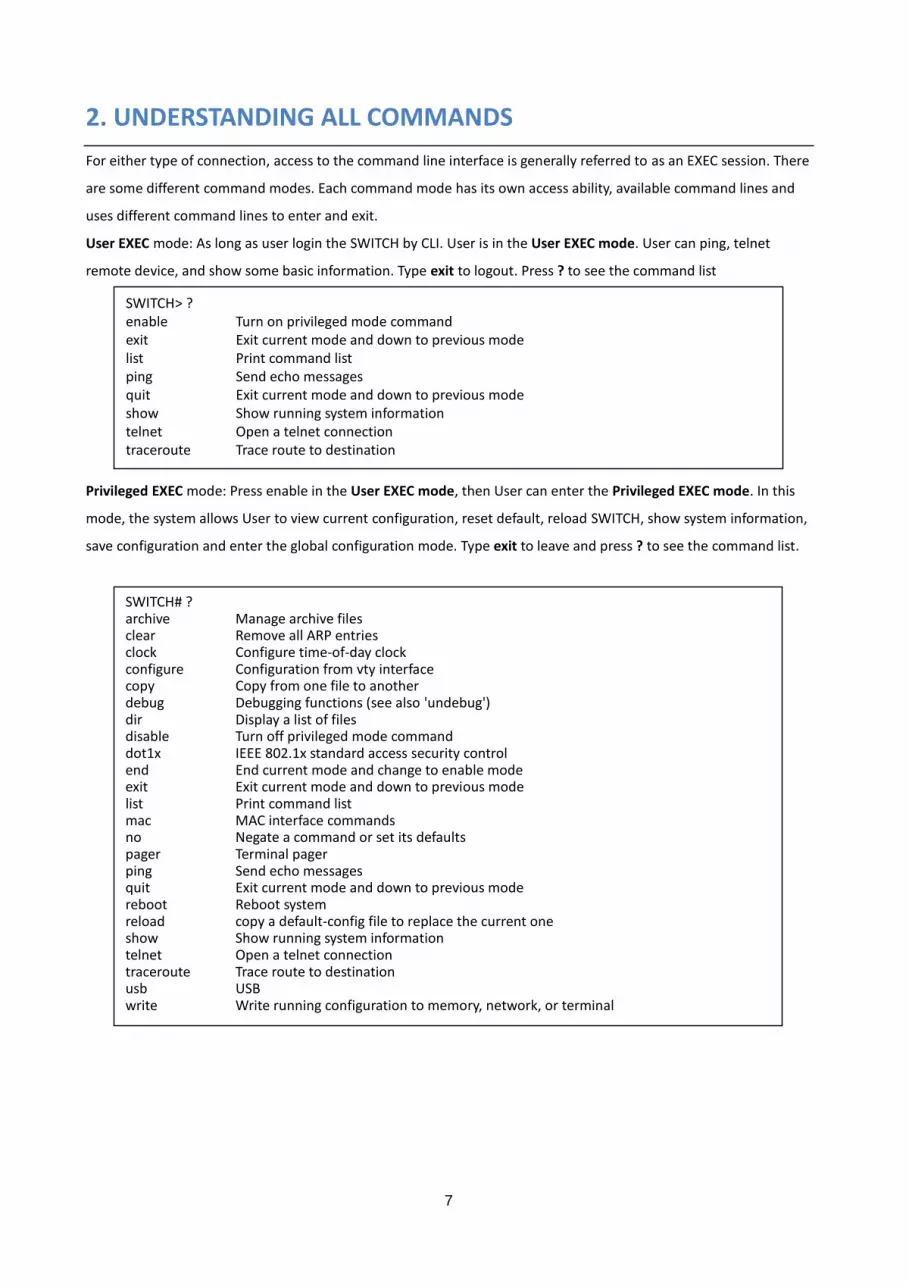
User EXEC mode: As long as user login the SWITCH by CLI. User is in the User EXEC mode. User can ping, telnet
remote device, and show some basic information. Type exit to logout. Press ? to see the command list
Privileged EXEC mode: Press enable in the User EXEC mode, then User can enter the Privileged EXEC mode. In this
mode, the system allows User to view current configuration, reset default, reload SWITCH, show system information,
save configuration and enter the global configuration mode. Type exit to leave and press ? to see the command list.
SWITCH> ? enable Turn on privileged mode command exit Exit current mode and down to previous mode list Print command list ping Send echo messages quit Exit current mode and down to previous mode show Show running system information telnet Open a telnet connection traceroute Trace route to destination
SWITCH# ? archive Manage archive files clear Remove all ARP entries clock Configure time-of-day clock configure Configuration from vty interface copy Copy from one file to another debug Debugging functions (see also 'undebug') dir Display a list of files disable Turn off privileged mode command dot1x IEEE 802.1x standard access security control end End current mode and change to enable mode exit Exit current mode and down to previous mode list Print command list mac MAC interface commands no Negate a command or set its defaults pager Terminal pager ping Send echo messages quit Exit current mode and down to previous mode reboot Reboot system reload copy a default-config file to replace the current one show Show running system information telnet Open a telnet connection traceroute Trace route to destination usb USB write Write running configuration to memory, network, or terminal

8
Global Configuration Mode: Type configure terminal in privileged EXEC mode. Then User can enter the Global
Configuration mode. In Global Configuration mode, User can configure all the features that the system provides. Type
exit to leave and press ? to see the command list.
The command lists of global configuration mode.
SWITCH(config)# ? access-list Add an access list entry administrator Administrator account setting arp Set a static ARP entry auth Authentication cfm IEEE 802.1ag - Connectivity Fault Management clock Configure time-of-day clock default Set a command to its defaults dot1x IEEE 802.1x standard access security control end End current mode and change to enable mode erps Ethernet Ring Protection Switching (ITU-T G.8032) exit Exit current mode and down to previous mode gmrp GMRP protocol gvrp GARP VLAN Registration Protocol hostname Set system's network name interface Select an interface to configure ip Global IP configuration subcommands ipv6 IP information key Authentication key management lacp Link Aggregation Control Protocol list Print command list lldp Link Layer Discovery Protocol log Logging control mac Global MAC configuration subcommands mac-address-table mac address table mirror Port mirroring nameserver DNS Server no Negate a command or set its defaults ntp Configure NTP poe Configure power over ethernet ptp IEEE1588 PTPv2 qos Quality of Service (QoS) relay relay output type information route-map Create route-map or enter route-map command mode router Enable a routing process service enable service sfp Small form-factor pluggable smtp-server SMTP server configuration snmp-server the SNMP server spanning-tree the spanning tree algorithm trunk Trunk group configuration vlan Virtual LAN warning-event Warning event selection write-config Specify config files to write to

9
Interface Configuration: Many features are enabled for a particular interface. The Interface commands enable or
modify the operation of an interface. In this mode, a physical port is set up for a specific logical connection operation.
The Interface Configuration mode provides access to the router interface configuration commands.
This section has two interface configuration, Port interface and VLAN interface. For Port interface, type interface
IFNAME in global configuration mode. Then User can enter the interface configuration mode. In this mode, User can
configure port settings. In port interface, the name of Giga Ethernet port 1 is ge1, Giga Ethernet 2 is ge2, and so on.
Type exit to leave current level and press ? to see the command list
The command lists of the global configuration mode.
SWITCH(config)# interface ge1 SWITCH(config-if)# ? acceptable Configures the 802.1Q acceptable frame types of a port. auto-negotiation Enables auto-negotiation state of a given port description Interface specific description dot1x IEEE 802.1x standard access security control duplex Specifies the duplex mode of operation for a port end End current mode and change to enable mode ethertype Ethertype exit Exit current mode and down to previous mode flowcontrol Sets the flow-control value for an interface garp General Attribute Registration Protocol ingress 802.1Q ingress filtering features ip Interface Internet Protocol config commands lacp Link Aggregation Control Protocol list Print command list loopback Specifies the loopback mode of operation for a port mac MAC interface commands media-type Specify media type mtu Specifies the MTU on a port. no Negate a command or set its defaults poe Configure power over ethernet qos Quality of Service (QoS) quit Exit current mode and down to previous mode rate-limit Rate limit configuration sfp Small form-factor pluggable shutdown Shutdown the selected interface spanning-tree the spanning-tree protocol speed Specifies the speed of a Fast Ethernet port or a Gigabit Ethernet port. storm-control Enables packets flooding rate limiting features switchport Set switching mode characteristics

10
The second section is VLAN interface, press interface VLAN (VLAN-ID) in global configuration mode. User can then
enter VLAN interface configuration mode. In this mode, User can configure the settings for the specific VLAN. In
VLAN interface, the name of VLAN 1 is VLAN 1, VLAN 2 is VLAN 2, and so on. To leave VLAN interface mode type exit.
Press ? to see the available command list.
The command lists of the VLAN interface configuration mode.
The table below presents the summary of the 5 command modes:
COMMAND MODE MAIN FUNCTION PROMPT
User EXEC This is the first level of access. User can ping, telnet
remote device, and show some basic information
SWITCH>
Privileged EXEC In this mode, the system allows User to view current
configuration, reset default, reload switch, show
system information, save configuration…and enter
global configuration mode.
SWITCH#
Global Configuration In global configuration mode, User can configure all
the features that the system provides User
SWITCH(config)#
Port Interface Configuration In this mode, User can configure port related settings. SWITCH(config-if)#
VLAN Interface Configuration In this mode, User can configure settings for specific
VLAN.
SWITCH(config-if)#
Here are some useful commands for User to see these available commands. Save User time in typing and avoid
typing error. Press ? to see all the available commands in this mode. It helps User to see the next command User
can/should type as well.
(Character)? To see all the available commands starts from this character.
SWITCH(config)# interface vlan 1 SWITCH(config-if)# ? description Interface specific description end End current mode and change to enable mode exit Exit current mode and down to previous mode ip Interface Internet Protocol config commands ipv6 Interface Internet Protocol config commands list Print command list no Negate a command or set its defaults quit Exit current mode and down to previous mode shutdown Shutdown the selected interface vrrp Virtual Router Redundancy Protocol (VRRP)
SWITCH(config)# a? administrator Administrator account setting arp Set a static ARP entry auth Authentication
SWITCH(config)# interface (?) IFNAME Interface's name Vlan Select a vlan to configure
11
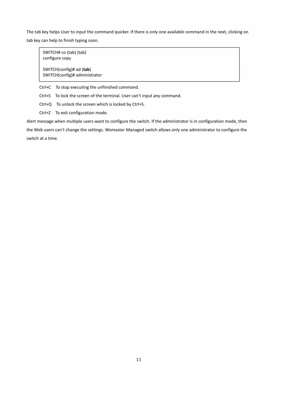
The tab key helps User to input the command quicker. If there is only one available command in the next, clicking on
tab key can help to finish typing soon.
Ctrl+C To stop executing the unfinished command.
Ctrl+S To lock the screen of the terminal. User can’t input any command.
Ctrl+Q To unlock the screen which is locked by Ctrl+S.
Ctrl+Z To exit configuration mode.
Alert message when multiple users want to configure the switch. If the administrator is in configuration mode, then
the Web users can’t change the settings. Womaster Managed switch allows only one administrator to configure the
switch at a time.
SWITCH# co (tab) (tab) configure copy SWITCH(config)# ad (tab) SWITCH(config)# administrator

12
3. COMMANDS
3.1 CLI COMMANDS FOR SYSTEM CONFIGURATION
This chapter will show the CLI Command for System Features, and this chapter covers the information, User Account,
Ip Setting, Date and Time and DHCP Server section. And the Show commands are used to display device settings,
statistics and other information.
Feature Command Line
SWITCH Setting
System Name SWITCH(config)# hostname
DWORD This system's network name
SWITCH(config)# hostname SWITCH
SWITCH(config)#
System Location SWITCH(config)# snmp-server location Taipei
DWORD string that describes the system location information
System Contact SWITCH(config)# snmp-server contact [email protected]
DWORD string that describes the system contact information
Display SWITCH# show snmp-server name
SWITCH
SWITCH# show snmp-server location
Taipei
SWITCH# show snmp-server contact
SWITCH# show version
Model Name : DP612
Bootloader : 2.1.0.0
Software : 1.0-1516254524
MAC Address : 94:66:E7:7F:A9:23
Admin Password
User Name and
Password
SWITCH(config)# administrator NAME PASSWORD
NAME Administrator account name
PASSWORD Administrator account password
SWITCH(config)# administrator admin admin
Administrator account name and password is unchanged

13
Display SWITCH# show administrator
Administrator account information
name: admin
password: admin
IP Configuration
IP Address/Mask
(192.168.10.8,
255.255.255.0
SWITCH(config)# int vlan 1
SWITCH(config-if)# ip address
address dhcp igmp
SWITCH(config-if)# ip address 192.168.10.8/24
SWITCH(config-if)# ip dhcp client
SWITCH(config-if)# ip dhcp client renew
SWITCH(config-if)# ipv6 address ; IPv6 configuration
X:X::X:X/M IPv6 address (e.g. 3ffe:506::1/48)
SWITCH(config-if)# ipv6 address 3ffe:506::1/48
Gateway SWITCH(config)# ip route 0.0.0.0/0 192.168.10.254/24
A.B.C.D IP destination prefix
A.B.C.D/M IP destination prefix (e.g. 10.0.0.0/8)
Remove Gateway SWITCH(config)# no ip route 0.0.0.0/0 192.168.10.254/24
Display SWITCH# show running-config
………
!
interface vlan1
ip address 192.168.10.8/24
no shutdown
!
ip route 0.0.0.0/0 192.168.10.254
!
Time Setting
NTP Server SWITCH(config)# ntp peer
enable
disable
primary
secondary
SWITCH(config)# ntp peer primary
IPADDR
SWITCH(config)# ntp peer primary 192.168.10.120
Clock Setting SWITCH# clock set
TIME hh:mm:ss Current Time

14
MONTH <1-12> Month of the year
DAY <1-31> Day of the month
YEAR <1993-2037> Year
SWITCH# clock set 11:20:30 7 21 2017
Fri Jul 21 11:20:30 2017 (GMT) Greenwich Mean Time: Dublin, Edinburgh,
Lisbon, London
Time Zone SWITCH(config)# clock timezone 26
Sun Jan 1 04:13:24 2006 (GMT) Greenwich Mean Time: Dublin, Edinburgh,
Lisbon, London
Note: By typing clock timezone ?, User can see the timezone list. Then choose
the number of the timezone User want to select.
Daylight Saving SWITCH(config)# clock summer-time 4 0 2 12:00 4 0 3 12:00
Clock summer-time<start week of month ><start weekday>
<start month><start Hour:Min><end week of month><end weekday><end
month><end Hour:Min>
Start / End week of month: 1~5 (5 means the last week)
Start / End weekday: 0 (Sunday) ~6 (Saturday)
Start / End Month: 1 (Jan) ~12 (Dec)
START_TIME Start time, format hh:mm
IEEE 1588 SWITCH(config)# ptp run
preferred-clock Preferred Clock
slave Run as slave
Display SWITCH# sh ntp associations
Network time protocol
Status : Disabled
Primary peer : N/A
Secondary peer : N/A
SWITCH# show clock
Fri Jul 21 06:10:53 2017 (GMT) Greenwich Mean Time: Dublin, Edinburgh,
Lisbon, London
SWITCH# show clock timezone
clock timezone (26) (GMT) Greenwich Mean Time: Dublin, Edinburgh, Lisbon,
London
DHCP Server
DHCP Server
configuration
Enable DHCP Server on DP310 switch
SWITCH#

15
SWITCH# configure terminal
SWITCH(config)# router dhcp
SWITCH(config-dhcp)# service dhcp
Configure DHCP network address pool
SWITCH(config-dhcp)#network 50.50.50.0/4 -(network/mask)
SWITCH(config-dhcp)#default-router 50.50.50.1
Lease time configure SWITCH(config-dhcp)#lease 300 (300 sec)
DHCP Relay Agent Enable DHCP Relay Agent
SWITCH#
SWITCH# configure terminal
SWITCH(config)# router dhcp
SWITCH(config-dhcp)# service dhcp
SWITCH(config-dhcp)# ip dhcp relay information option
Enable DHCP Relay policy
SWITCH(config-dhcp)# ip dhcp relay information policy replace
drop Relay Policy
keep Drop/Keep/Replace option82 field
replace
Show DHCP Relay
Agent
SWITCH# show ip dhcp relay
DHCP Relay Agent ON
----------------------------------------
Re-forwarding policy: Replace
Port Circuit-ID Hex Display
-------- --------------------------------
1 00010001 00010001
2 00010002 00010002
3 00010003 00010003
4 00010004 00010004
5 00010005 00010005
6 00010006 00010006
7 00010007 00010007
8 00010008 00010008
9 00010009 00010009
10 0001000a 0001000a
11 0001000b 0001000b
12 0001000c 0001000c
Remote-ID: 94:66:e7:7f:a9:23 (9466e77fa923)

16
Show DHCP server
information
SWITCH# show ip dhcp server statistics
SWITCH# show ip dhcp server statistics
DHCP Server OFF
[Address Pool 1]
network:0.0.0.0/0
default-router:0.0.0.0
lease time:604800
Excluded Address List
IP Address
---------------
Manual Binding List (Port/IP)
PortIP Address
--------- ---------------
Manual Binding List (IP/MAC)
IP Address MAC Address
--------------- --------------
Option82 Binding List
IP Address Circuit-ID Remote-ID
--------------- ------------------- ------------------
Leased Address List
IP Address MAC Address Leased Time Remains
--------------- -------------- --------------------

17
3.2 CLI COMMANDS FOR PORT CONFIGURATION
This chapter provides the Port Configuration CLI Commands, all of the features is covered in this chapter
Feature Command Line
Port Control
Port Control – State
SWITCH(config-if)# shutdown -> Disable port state Port1 Link Change to DOWN interface gigabitethernet1 is shutdown now. SWITCH(config-if)# no shutdown -> Enable port state interface gigabitethernet1 is up now.
Port Control – Auto Negotiation
SWITCH(config)# interface ge1 SWITCH(config-if)# auto-negotiation Auto-negotiation of port 1 is enabled!
Port Control – Force Speed/Duplex
SWITCH(config-if)# speed 100 set the speed mode ok! SWITCH(config-if)# duplex full set the duplex mode ok!
Port Control – Flow Control
SWITCH(config-if)# flowcontrol on Flowcontrol on for port 1 set ok! SWITCH(config-if)# flowcontrol off Flowcontrol off for port 1 set ok!
Port Status
Port Status SWITCH# show interface ge1 Interface gigabitethernet1 Description : N/A Administrative Status : Enable Operating Status : Connected Duplex : Auto (Full) Speed : Auto (1000) MTU : 1518 Flow Control : off Default Port VLAN ID: 1 Ingress Filtering : Disabled Acceptable Frame Type : All Auto Negotiation : Enable Loopback Mode : None STP Status: Blocking Default CoS Value for untagged packets is 0. Medium mode is Copper. Note: Administrative Status -> Port state of the port. Operating status -> Current status of the port. Duplex -> Duplex mode of the port. Speed -> Speed mode of the port. Flow control -> Flow Control status of the port.
Rate Control
Rate Control – Ingress or Egress
SWITCH(config-if)# rate-limit egress Outgoing packets ingress Incoming packets Note: To enable rate control, User should select the Ingress or Egress rule first; then assign the packet type and bandwidth.
Rate Control - Bandwidth
SWITCH(config-if)# rate-limit ingress bandwidth <0-100> Limit in megabits per second (0 is no limit) SWITCH(config-if)# rate-limit ingress bandwidth 8 Set the ingress rate limit 8Mbps for Port 1.
Port Trunking
LACP SWITCH(config)# lacp group 1 ge9-10

18
Group 1 based on LACP (802.3ad) is enabled! Note: different speed port can’t be aggregated together.
Static Trunk SWITCH(config)# trunk group 2 ge6-7 Trunk group 2 enable ok!
Display - LACP SWITCH# show lacp internal LACP group 1 internal information: LACP Port Admin Oper Port Port Priority Key Key State ----- ----------- -------- -------- ------- 8 1 8 8 0x45 9 1 9 9 0x45 10 1 10 10 0x45 LACP group 2 is inactive LACP group 3 is inactive LACP group 4 is inactive
Display - Trunk SWITCH# show trunk group 1 FLAGS: I -> Individual P -> In channel D -> Port Down Trunk Group GroupID Protocol Ports --------+---------+------------------------------------ 1 LACP 8(D) 9(D) 10(D) SWITCH# show trunk group 2 FLAGS: I -> Individual P -> In channel D -> Port Down Trunk Group GroupID Protocol Ports --------+---------+------------------------------------ 2 Static 6(D) 7(P) SWITCH#
CFM
Create SWITCH(config)# cfm create domain IEEE 802.1ag Maintenance Domain SWITCH(config)# cfm create domain string Name Format: General string SWITCH(config)# cfm create domain string NAME Domain name, maximum of 43 characters SWITCH(config)# cfm create domain string test md-level IEEE 802.1ag Maintenance Domain Level SWITCH(config)# cfm create domain string test md-level <0-7> MD-Level 0~7 SWITCH(config)# cfm create domain string test md-level 2
Delete SWITCH(config)# snmp-server community private rw community string add ok
Domain SWITCH(config)# cfm domain NAME IEEE 802.1ag Domain name SWITCH(config)# cfm domain test add Add configuration item to Domain association IEEE 802.1ag Maintenance Association delete Delete configuration item from Domain SWITCH(config)# cfm domain test add association IEEE 802.1ag Maintenance Association

19
SWITCH(config)# cfm domain test add association string Name Format: General string SWITCH(config)# cfm domain test add association string NAME Association name, maximum of 45 characters SWITCH(config)# cfm domain test add association string test1 vlan 1
Group SWITCH (config)# cfm group <0-255> Group ID 0~255 SWITCH (config)# cfm group 2 rmep IEEE 802.1ag Remote Maintenance End Point SWITCH (config)# cfm group 2 rmep <1-8191> MEP-ID 1~8191 SWITCH (config)# cfm group 2 rmep 30
Display CFM
Database SWITCH# show cfm database Domain/ Port MP Remote End-Point MEP Life CCM Flags Association MAC Address ID time Age Timeout ============================================================================== 1 1 1 DE -- 1 -- -- Timeout SA ============================================================================== Maintenance Point: (UE) Up End-Point, (DE) Down End-Point Flags: (S) Static Entry, (D) Dynamic Entry Status: (A) Active, (I) Inactive NOTE: The Domain and Association names are truncated to 13 characters, Lifetime and Age are in milliseconds. ==============================================================================
Domain SWITCH# show cfm domain Domain: test, MD Level: 2
JumboFrame
Jumbo Frame Type the maximum MTU to enable for specific port Jumbo Frame: SWITCH(config-if)# mtu <64-9216> bytes
SWITCH(config-if)# mtu 9216 Disable Jumbo Frame: Switch(config)# no system mtu

20
Display SWITCH# show int ge8 Interface gigabitethernet8 Description : N/A Administrative Status : Disable Operating Status : Not Connected Duplex : Auto Speed : Auto MTU : 9216 Flow Control : off Default Port VLAN ID: 2 Ingress Filtering : Enabled Acceptable Frame Type : All Auto Negotiation : Enable Loopback Mode : None STP Status: Disabled Default CoS Value for untagged packets is 0. Medium mode is Copper.
Storm Control
Strom Control Configuration
SWITCH(config-if)# storm-control broadcast Broadcast packets
dlf Destination Lookup Failure multicast Multicast packets
SWITCH(config-if)# storm-control broadcast ?
<0-262142> Rate limit value 0~262142 packet/sec
SWITCH(config-if)# storm-control broadcast 1000
Enables rate limit for Broadcast packets for Port 8
SWITCH(config-if)# storm-control multicast 1000
Enables rate limit for Multicast packetsfor Port 8
SWITCH(config-if)# storm-control dlf 1000
Enables rate limit for Destination Lookup Failue packets for Port8.

21
Display
Storm
Control
switch# show storm-control
Storm-control for Port 1
Broadcast packets : Disabled Rate : N/A (packets/s)
Destination Lookup Failure packets : Disabled Rate : N/A (packets/s)
Multicast packets : Disabled Rate : N/A (packets/s)
Storm-control for Port 2
Broadcast packets : Disabled Rate : N/A (packets/s)
Destination Lookup Failure packets : Disabled Rate : N/A (packets/s)
Multicast packets : Disabled Rate : N/A (packets/s)
Storm-control for Port 3
Broadcast packets : Disabled Rate : N/A (packets/s)
Destination Lookup Failure packets : Disabled Rate : N/A (packets/s)
Multicast packets : Disabled Rate : N/A (packets/s)
Storm-control for Port 4
Broadcast packets : Disabled Rate : N/A (packets/s)
Destination Lookup Failure packets : Disabled Rate : N/A (packets/s)
Multicast packets : Disabled Rate : N/A (packets/s)
Storm-control for Port 5
Broadcast packets : Disabled Rate : N/A (packets/s)
Destination Lookup Failure packets : Disabled Rate : N/A (packets/s)
Multicast packets : Disabled Rate : N/A (packets/s)
Storm-control for Port 6
Broadcast packets : Disabled Rate : N/A (packets/s)
Destination Lookup Failure packets : Disabled Rate : N/A (packets/s)
Multicast packets : Disabled Rate : N/A (packets/s)
Storm-control for Port 7
Broadcast packets : Disabled Rate : N/A (packets/s)
Destination Lookup Failure packets : Disabled Rate : N/A (packets/s)
Multicast packets : Disabled Rate : N/A (packets/s)
Storm-control for Port 8
Broadcast packets : Enabled Rate : 1000 (packets/s)
Destination Lookup Failure packets : Enabled Rate : 1000 (packets/s)
Multicast packets : Enabled Rate : 1000 (packets/s)
………………..

22
3.3 CLI COMMANDS FOR PoE CONFIGURATION (PoE Model Only)
This chapter is about the PoE Configuration CLI Command.
Syntax show poe system
Command Mode Enable mode
Description Display the status of the PoE system.
Examples SWITCH> enable
SWITCH# s show poe system
PoE System
PoE Admin : Enable
PoE Hardware : Normal
Output power : 3.05 Watts
Power Budget :
Budget : 240 Watts
Utilization : 1 %
Event : Normal
Syntax show poe interface IFNAME
Parameters IFNAME : interface name
Command Mode Enable mode
Description Display the PoE status of interface.
Examples SWITCH> enable
SWITCH# show poe interface ge7
Interface gigabitethernet7 (POE Port 7)
Control Mode : User (Enable)
Powering Mode : 802.3af
Operation Status : Powering
Detection Status : Valid
Classification : Class2
Output Power : 2.10 Watts, Voltage : 47.8 V, Current : 44.9 mA
Power Budget :
Budget Mode : Auto
Budget : 35.00 Watts, Effective 7.70 Watts
Utilization : 27 %
Event : Normal
Syntax show poe alive
Command Mode Enable mode
Description Display the status of pd status detection.

23
Examples SWITCH# show poe alive-check
PD Status Detection
Status : Enabled
Host 1 :
Target IP : 192.168.10.10
Cycle Time : 10
Host 2 :
Target IP : 192.168.10.11
Cycle Time : 20
Host 3 :
Target IP : 192.168.10.12
Cycle Time : 30
Syntax show poe schedule IFNAME
Parameters IFNAME : interface name
Command Mode Enable mode
Description Display the status of schedule of interface.
Examples SWITCH# show poe schedule ge1
Interface gigabitethernet1
POE Schedule
Status : Disable
Weekly Schedule :
Sunday : 0,1,2,3,4,5,6,7,8,19,20,21,22,23
Monday : 0,1,2,3,4,5,6,7,8,19,20,21,22,23
Tuesday : 0,1,2,3,4,5,6,7,8,19,20,21,22,23
Wednesday : 0,1,2,3,4,5,6,7,8,19,20,21,22,23
Thursday : 0,1,2,3,4,5,6,7,8,19,20,21,22,23
Friday : 0,1,2,3,4,5,6,7,8,19,20,21,22,23
Saturday :0,1,2,3,4,5,6,7,8,9,10,11,12,13,14,15,16,17,18,19,20
Syntax poe powering-mode 802.3af/forced/802.3at
Parameters 802.3af: deliver power if and only if the attached PD comply with IEEE 802.3af
forced: deliver power no matter what PD attached
Command Mode Interface mode
Description Set the Powering mode of PoE
Examples EX 1:Set 802.3af powering mode
SWITCH(config-if)# poe powering-mode 802.3af
EX 2:Set forced powering mode
SWITCH(config-if)# poe powering-mode forced
Syntax poe powering-mode 802.3at 2-event/lldp

24
Parameters 2-event: deliver power if and only if the attached PD comply with IEEE 802.3at
physical layer classification
lldp: deliver power if and only if the attached PD comply with IEEE 802.3at data
link layer classification
Command Mode Interface mode8
Description Set the Powering mode of PoE
Examples EX 1:Set 802.3at 2-event powering mode
SWITCH(config-if)# poe powering-mode 802.3at 2-event
EX 2:Set 802.3at lldp powering mode
SWITCH(config-if)# poe powering-mode 802.3at lldp
Syntax poe control-mode user/schedule
Parameters user: user mode
schedule: schedule mode
Command Mode Interface mode
Description Set the control mode of port
Examples Set PoE port 2 to user mode.
EX 1:
SWITCH(config)# interface ge2
SWITCH(config-if)# poe control-mode user
Set PoE port 2 to schedule mode.
EX 2:
SWITCH(config-if)# poe control-mode schedule
Syntax poe user enable/disable
Parameters enable: enable port in user mode
disable: disable port in user mode
Command Mode Interface mode
Description Enable/Disable the PoE of the port in user mode.
If in schedule mode, it will come into effect when the control mode changes to
user mode.
Examples To enable the PoE function in user mode
SWITCH(config-if)# poe user enable
To disable the PoE function in user mode
SWITCH(config-if)# poe user disable
Syntax poe type TYPE
Parameters TYPE : port type string with max 20 characters
Command Mode Interface mode
Description Set the port type string.

25
Examples Set the type string to “IPCam-1.
SWITCH(config-if)# poe type IPCam-1
Syntax poe budget [POWER]
Parameters POWER : 0.4 – 30
Command Mode Interface mode
Description Set the port budget.
The max budget is different between 802.3af, 802,3at and forced powering mode.
The max budget of 802.3af powering mode is 15.4.
The max budget of 802.3at powering mode is 30
The max budget of force powering mode is 30.
Examples Set the max value of power consumption to 12 W with manual mode.
SWITCH(config-if)# poe budget 12
Syntax poe priority critical/high/low
Parameters Critical : Highest priority level
High : High priority level
Low : Low priority level
Command Mode Interface mode
Description Set the powering priority. The port with higher priority will have the privilege to
delivery power under limited power situation.
Examples Set the priority to critical
SWITCH(config-if)# poe priority critical
Syntax poe schedule weekday hour
Parameters Weekday : Valid range 0-6 (0=Sunday, 1=Monday, …, 6=Saturday)
Hour : Valid range 0-23, Valid format a,b,c-d
Command Mode Interface mode
Description Add a day schedule to an interface.
Examples Add a schedule which enables PoE function at hour 1, 3, 5 and 10 to 23 on Sunday.
SWITCH(config-if)# poe schedule 0 1,3,5,10-23
Syntax no poe schedule weekday
Parameters Weekday : Valid range 0-6 (0=Sunday, 1=Monday, …, 6=Saturday)
Command Mode Interface mode
Description Remove a day schedule
Examples Remove the Sunday schedule.
SWITCH(config-if)# no poe schedule 0
Syntax Poe budget; system command for DP612 is 240Watts under 75C operating
temperature.
Parameters POWER : 0~200

26
Command Mode Configuration mode
Description Set the power budget of DC1
Examples Set the power budget of DC1 to 200W
SWITCH(config)# poe budget DC1 200w
Syntax poe alive-check enable/disable
Parameters enable: enable PD Status Detection function
disable: disable PD Status Detection function
Command Mode Configuration mode
Description Enable/Disable the PD Status Detection function
Examples To enable the function of pd status detect function
SWITCH(config)# poe alive-check enable
To disable the function of pd status detect function
SWITCH(configf)# poe alive-check disable
Syntax poe alive-check ip_address ping interval
Parameters IP address : A.B.C.D
Ping Interval : Valid range is 10 to 3600 in multiple of 10
Command Mode Configuration mode
Description Apply a rule of PD Status Detection.
Examples Apply a rule which ping 192.160.10.2 per 20 seconds. And if 192.160.1.2 is
timeout, pd status detection will re-enable the PoE.
SWITCH(config)# poe alive-check 192.160.10.2 20

27
3.4 CLI COMMANDS FOR REDUNDANCY CONFIGURATION
Feature Command Line
Global (STP, RSTP, MSTP)
Enable SWITCH(config)# spanning-tree enable
Disable SWITCH(config)# spanning-tree disable
Mode (Choose the
Spanning Tree mode)
SWITCH(config)# spanning-tree mode
rst the rapid spanning-tree protocol (802.1w)
stp the spanning-tree prtotcol (802.1d)
mst the multiple spanning-tree protocol (802.1s)
Priority SWITCH(config)# spanning-tree priority
<0-61440> valid range is 0 to 61440 in multiple of 4096
SWITCH(config)# spanning-tree priority 4096
Bridge Times SWITCH(config)# spanning-tree bridge-times (forward Delay) (max-age) (Hello
Time)
SWITCH(config)# spanning-tree bridge-times 15 20 2
<4-30> the value of forward delay time in seconds
This command allows you configure all the timing in one time.
Forward Time SWITCH(config)# spanning-tree forward-time
<4-30> the value of forward delay time in seconds
SWITCH(config)# spanning-tree forward-time 15
Max Age SWITCH(config)# spanning-tree max-age
<6-40> the value of message maximum age time in seconds
SWITCH(config)# spanning-tree max-age 20
Hello Time SWITCH(config)# spanning-tree hello-time
<1-10> the value of hello time in seconds
SWITCH(config)# spanning-tree hello-time 2
Pathcost SWITCH(config)# spanning-tree pathcost method
long specifies 32-bit based values that range from 1-200,000,000
short specifies 16-bit based values that range from 1-65535
transmission-limit SWITCH(config)# spanning-tree transmission-limit
<1-10> valid range from 1-10
MSTP
Enter the MSTP
Configuration Tree
SWITCH(config)# spanning-tree mst
MSTMAP the mst instance number or range
configuration enter mst configuration mode
forward-time the forward dleay time
hello-time the hello time
28
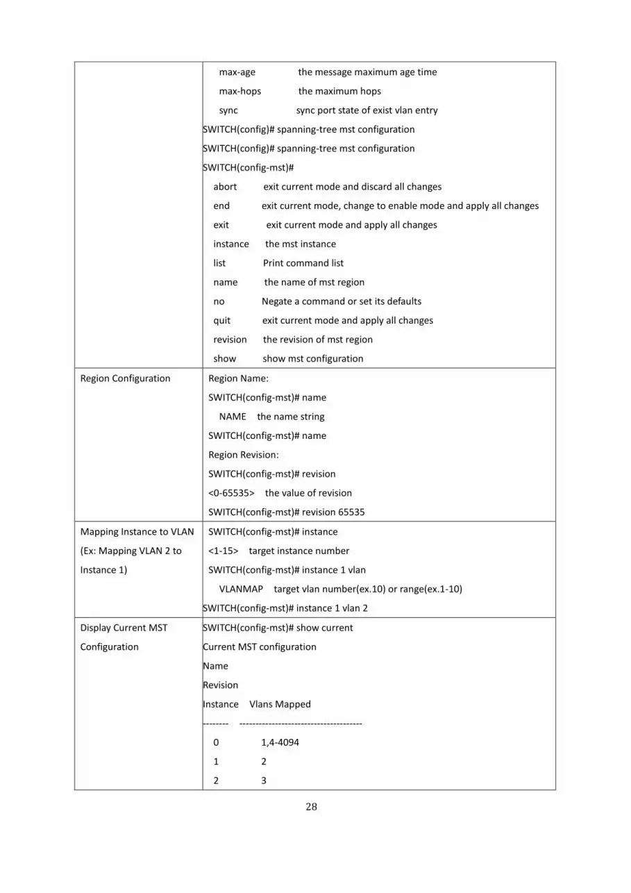
max-age the message maximum age time
max-hops the maximum hops
sync sync port state of exist vlan entry
SWITCH(config)# spanning-tree mst configuration
SWITCH(config)# spanning-tree mst configuration
SWITCH(config-mst)#
abort exit current mode and discard all changes
end exit current mode, change to enable mode and apply all changes
exit exit current mode and apply all changes
instance the mst instance
list Print command list
name the name of mst region
no Negate a command or set its defaults
quit exit current mode and apply all changes
revision the revision of mst region
show show mst configuration
Region Configuration Region Name:
SWITCH(config-mst)# name
NAME the name string
SWITCH(config-mst)# name
Region Revision:
SWITCH(config-mst)# revision
<0-65535> the value of revision
SWITCH(config-mst)# revision 65535
Mapping Instance to VLAN
(Ex: Mapping VLAN 2 to
Instance 1)
SWITCH(config-mst)# instance
<1-15> target instance number
SWITCH(config-mst)# instance 1 vlan
VLANMAP target vlan number(ex.10) or range(ex.1-10)
SWITCH(config-mst)# instance 1 vlan 2
Display Current MST
Configuration
SWITCH(config-mst)# show current
Current MST configuration
Name
Revision
Instance Vlans Mapped
-------- --------------------------------------
0 1,4-4094
1 2
2 3

29
------------------------------------------------
Config HMAC-MD5 Digest:
0xB41829F9030A054FB74EF7A8587FF58D
------------------------------------------------
Remove Region Name SWITCH(config-mst)# no
name name configure
revision revision configure
instance the mst instance
SWITCH(config-mst)# no name
Remove Instance example SWITCH(config-mst)# no instance
<1-15> target instance number
SWITCH(config-mst)# no instance 2
Show Pending MST
Configuration
SWITCH(config-mst)# show pending
Pending MST configuration
Name [](->The name is removed by no name)
Revision
Instance Vlans Mapped
-------- --------------------------------------
0 1,3-4094
1 2 (->Instance 2 is removed by no instance 2)
------------------------------------------------
Config HMAC-MD5 Digest:
0x3AB68794D602FDF43B21C0B37AC3BCA8
------------------------------------------------
Apply the setting and go to
the configuration mode
SWITCH(config-mst)# quit
apply all mst configuration changes
SWITCH(config)#
Apply the setting and go to
the global mode
SWITCH(config-mst)# end
apply all mst configuration changes
SWITCH#
Abort the Setting and go
to the configuration mode.
Show Pending to see the
new settings are not
applied.
SWITCH(config-mst)# abort
discard all mst configuration changes
SWITCH(config)# spanning-tree mst configuration
SWITCH(config-mst)# show pending
Pending MST configuration
Name (->The name is not applied after Abort settings.)
Revision
Instance Vlans Mapped

30
-------- --------------------------------------
0 1,4-4094
1 2
2 3(-> The instance is not applied after Abort settings.)
------------------------------------------------
Config HMAC-MD5 Digest:
0xB41829F9030A054FB74EF7A8587FF58D
------------------------------------------------
Port Configuration Mode
Port Configuration SWITCH(config)# int ge2
SWITCH(config-if)# spanning-tree
bpdufilter a secure BPDU process on edge-port interfcae
bpduguard a secure response to invalid configurations(received BPDU
sent by self)
cost change an interafce's spanning-tree port path cost
edge-port interface attached to a LAN segment that is at the end of a
bridged LAN or to an end node
link-type the link type for the Rapid Spanning Tree
mst the multiple spanning-tree
port-priority the spanning tree port priority
stp-state the bridge port STP state
Port Path Cost SWITCH(config-if)# spanning-tree cost
<1-200000000> 16-bit based value range from 1-65535, 32-bit based value
range
from 1-200,000,000
SWITCH(config-if)# spanning-tree cost 200000
Port Priority SWITCH(config-if)# spanning-tree port-priority
<0-240> the value of bridge port priority in multiple of 16
SWITCH(config-if)# spanning-tree port-priority 128
Link Type - Auto spanning-tree link-type
auto automatically determines if IF is attached to a point-to-pointlink or
shared media
point-to-point a connection to exactly one other bridge
shared a connection to two or more bridges
SWITCH(config-if)# spanning-tree link-type auto
Link Type - P2P SWITCH(config-if)# spanning-tree link-type point-to-point
Link Type - Share SWITCH(config-if)# spanning-tree link-type shared
Edge Port SWITCH(config-if)# spanning-tree edge-port

31
MSTP Port Configuration SWITCH(config-if)# spanning-tree mst
MSTMAP the mst instance number or range
cost the mst instance port cost
port-priority the mst instance port priority
SWITCH(config-if)# spanning-tree mst MSTMAP cost
<1-200000000> the value of mst instance port cost
SWITCH(config-if)# spanning-tree mst MSTMAP port-priority
<0-240> the value of mst instance port priority in multiple of 16
Global Information
Active Information SWITCH# show spanning-tree active
Spanning-Tree : Enabled Protocol : RSTP
Root Address : 9466.e79f.9834 Priority : 4096
Root Path Cost : 0 Root Port : N/A
Root Times : max-age 20, hello-time 2, forward-delay 15
Bridge Address : 9466.e79f.9834 Priority : 4096
Bridge Times : max-age 20, hello-time 2, forward-delay 15
BPDU transmission-limit : 3
Port Role State Cost Prio.Nbr Type
Aggregated
------ ---------- ---------- -------- ---------- ------------ ------------
ge1 Designated Forwarding 200000 128.1 P2P(RSTP) N/A
ge5 Designated Forwarding 200000 128.5 P2P(RSTP) N/A
ge7 Designated Forwarding 200000 128.7 P2P(RSTP) N/A
ge10 Designated Forwarding 20000 128.10 P2P(RSTP) N/A
RSTP Summary SWITCH# show spanning-tree summary
Spanning-Tree : Enabled Protocol : RSTP
Root Address : 9466.e79f.9834 Priority : 4096
Root Path Cost : 0 Root Port : N/A
Root Times : max-age 20, hello-time 2, forward-delay 15
Bridge Address 9466.e79f.9834 Priority : 4096
Bridge Times : max-age 20, hello-time 2, forward-delay 15
BPDU transmission-limit : 3
BPDU Skewing Detection : Disabled
Backbonefast : Disabled
Topology Change Flag : False Topology Change Detected Flag : False
Topology Change Count : 7 Last Topology Change from : 0000.0000.0000

32
Timers: hello 1, topology change 0
Summary of connected spanning tree ports :
Port-State Summary
Blocking Listening Learning Forwarding Disabled
-------- --------- -------- ---------- --------
0 0 0 4 6
Port Link-Type Summary
AutoDetected PointToPoint SharedLink EdgePort
------------ ------------ ---------- --------
10 0 0 8
Port Info SWITCH# show spanning-tree interface ge7
Interface fastethernet7 of Bridge is Enabled
Port Role : Designated Port State : Forwarding
Edge Port : Edge (Non-Edge) BPDU Filter : Disabled
Link Type : Auto (Point-to-point) BPDU Guard : Disabled
Timers : message-age 0, forward-delay 0
BPDUs : sent 368, received 1541
TCNs : sent 0, received 0
Message Expired Count : 0 Forward Transition Count : 2
Aggregation Group: N/A Type: N/A Aggregated with : N/A
Port information port id 128.7 priority 128 cost 200000
Designated root address 9466.e79f.9834 priority 4096 cost 200000
Designated bridge address 9466.e79f.9834 priority 4096 port id 128.7
MSTP Information
MSTP Configuration SWITCH# show spanning-tree mst configuration
Current MST configuration (MSTP is Running)
Name
Revision
Instance Vlans Mapped
-------- --------------------------------------
0 1,4-4094
1 2
2 3
------------------------------------------------
Config HMAC-MD5 Digest:
0xB41829F9030A054FB74EF7A8587FF58D

33
------------------------------------------------
Display all MST
Information
SWITCH# show spanning-tree mst
###### MST00 vlans mapped: 1,4-4094
Bridge address 9466.e77f.a923 priority 32768 (sysid 0)
Root this SWITCH for CST and IST
Configured max-age 2, hello-time 15, forward-delay 20, max-hops 20
Port Role State Cost Prio.Nbr Type
------ ---------- ---------- -------- ---------- ------------------------------
ge1 Designated Forwarding 200000 128.1 P2P Internal(MSTP)
ge2 Designated Forwarding 200000 128.2 P2P Internal(MSTP)
###### MST01 vlans mapped: 2
Bridge address 9466.e77f.a923 priority 32768 (sysid 1)
Root this SWITCH for MST01
Port Role State Cost Prio.Nbr Type
------ ---------- ---------- -------- ---------- ------------------
ge1 Designated Forwarding 200000 128.1 P2P Internal(MSTP)
ge2 Designated Forwarding 200000 128.2 P2P Internal(MSTP)
MSTP Root Information SWITCH# show spanning-tree mst root
MST Root Root Root Root Max Hello Fwd
Instance Address Priority Cost Port age dly
-------- -------------- -------- ----------- ------ ----- ----- -----
MST00 9466.e77f.a923 32768 0 N/A 20 2 15
MST01 9466.e77f.a923 32768 0 N/A 20 2 15
MST02 9466.e77f.a923 32768 0 N/A 20 2 15
MSTP Instance Information SWITCH# show spanning-tree mst 1
###### MST01 vlans mapped: 2
Bridge address 9466.e77f.a923 priority 32768 (sysid 1)
Root this SWITCH for MST01
Port Role State Cost Prio.Nbr Type
------ ---------- ---------- -------- ---------- ------------------
ge1 Designated Forwarding 200000 128.1 P2P Internal(MSTP)
ge2 Designated Forwarding 200000 128.2 P2P Internal(MSTP)
MSTP Port Information SWITCH# show spanning-tree mst interface ge1
Interface fastethernet1 of MST00 is Designated Forwarding

34
Edge Port : Edge (Edge) BPDU Filter : Disabled
Link Type : Auto (Point-to-point) BPDU Guard : Disabled
Boundary : Internal(MSTP)
BPDUs : sent 6352, received 0
Instance Role State Cost Prio.Nbr Vlans mapped
-------- ---------- ---------- -------- ---------- ---------------------
0 Designated Forwarding 200000 128.1 1,4-4094
1 Designated Forwarding 200000 128.1 2
2 Designated Forwarding 200000 128.1 3
ERPS
Instance SWITCH(config)#erps
<0-31> Ring identifier, valid range from 0 to 31 in decimal
instance ERPS Instance
SWITCH(config)# erps instance
disable Disable ERPS Instance function
enable Enable ERPS Instance function
<0-15> ERPS Instance, valid range from 0 to 15
SWITCH(config)# erps instance 1 vlan
vlan the vlan
SWITCH(config)# erps instance 1 vlan 1
VLANMAP target vlan number(ex.10) or range(ex.1-10)
Display SWITCH# show erps
Ethernet Ring Protection Switching (ITU-T G.8032)
Ring ID : 1
Version : v2
Ring State : Enabled
Node State : Idle
Node Role : Ring Node
Control Channel : VLAN 1
Sub Ring without VC : False
VC of Sub Ring : VLAN 1
ERPS Instance : Instance 1
Ring Port 0 : ge2 is Link Up and Forwarding
Ring Port 1 : ge3 is Link Up and Forwarding

35
RPL Port : Ring Port 1
Revertive Mode : Revertive
Manual Switch :
Forced Switch :
Timers
WTR Timer : period is 5 minutes, timer is not running, remains 0 ms
WTB Timer : period is 5100 ms, timer is not running, remains 0 ms
Guard Timer : period is 100 ms, timer is not running, remains 0 ms
Statistics
R-APS(FS) : sent 0, received 0
R-APS(SF) : sent 5, received 4

36
3.5 CLI COMMANDS FOR VLAN CONFIGURATION
This chapter provides a detailed explanation of the Virtual LAN CLI commands. The commands are divided by
functionality into the following different groups:
VLAN Port Configuration is used to set the port VLAN ID, port accept frame type, Ingress and Egress rule and
display switch settings, statistics and other information.
VLAN Configuration is used to configure and create VLAN setting, and also display the setting and some
information
GVRP Configuration Commands are used to configure the GVRP feature.
Management VLAN is used to set the VLAN management and display some information from the management
VLAN.
Feature Command Line
VLAN Port Configuration
VLAN Port PVID SWITCH(config-if)# switchport trunk native vlan 2
Set port default vlan id to 2 success
Port Accept Frame Type SWITCH(config)# inter ge1
SWITCH(config-if)# acceptable frame type all
any kind of frame type is accepted!
SWITCH(config-if)# acceptable frame type vlantaggedonly
only vlan-tag frame is accepted!
Ingress Filtering (for fast
Ethernet port 1)
SWITCH(config)# interface ge1
SWITCH(config-if)# ingress filtering enable
ingress filtering enable
SWITCH(config-if)# ingress filtering disable
ingress filtering disable
Egress rule – Untagged
(for VLAN 2)
SWITCH(config-if)# switchport access vlan 2
SWITCHport access vlan - success
Egress rule – Tagged (for
VLAN 2)
SWITCH(config-if)# switchport trunk allowed vlan add 2
Display – Port Ingress
Rule (PVID, Ingress
Filtering, Acceptable
Frame Type)
SWITCH# show interface ge1
Interface fastethernet1
Administrative Status : Enable
Operating Status : Not Connected
Duplex : Auto
Speed : Auto
Flow Control :off
Default Port VLAN ID: 2

37
Ingress Filtering : Disabled
Acceptable Frame Type : All
Port Security : Disabled
Auto Negotiation : Enable
Loopback Mode : None
STP Status: disabled
Default CoS Value for untagged packets is 0.
Medium mode is Copper.
Display – Port Egress Rule
(Egress rule, IP address,
status)
SWITCH# show running-config
……
!
interface ge1
SWITCHport access vlan 1
SWITCHport access vlan 3
SWITCHport trunk native vlan 2
…….
interface vlan1
ip address 192.168.10.8/24
no shutdown
VLAN Configuration
Create VLAN (2) SWITCH(config)# vlan 2
vlan 2 success
SWITCH(config)# interface vlan 2
SWITCH(config-if)#
Note: In CLI configuration, User should create a VLAN interface first. Then User
can start to add/remove ports. Default status of the created VLAN is unused
until User add member ports to it.
Remove VLAN SWITCH(config)# no vlan 2
no vlan success
Note: User can only remove the VLAN when the VLAN is in unused mode.
VLAN Name SWITCH(config)# vlan 2
vlan 2 has exists
SWITCH(config-vlan)# name v2

38
SWITCH(config-vlan)# no name
Note: Use no name to change the name to default name, VLAN VID.
VLAN description SWITCH(config)# interface vlan 2
SWITCH(config-if)#
SWITCH(config-if)# description this is the VLAN 2
SWITCH(config-if)# no description ->Delete the description.
IP address of the VLAN SWITCH(config)# interface vlan 2
SWITCH(config-if)#
SWITCH(config-if)# ip address 192.168.10.18/24
SWITCH(config-if)# no ip address 192.168.10.8/24 ->Delete the IP address
Create multiple VLANs
(VLAN 5-10)
SWITCH(config)# interface vlan 5-10
Shut down VLAN SWITCH(config)# interface vlan 2
SWITCH(config-if)# shutdown
SWITCH(config-if)# no shutdown ->Turn on the VLAN
Display – VLAN table SWITCH# sh vlan
VLAN Name Status Trunk Ports Access Ports
---- ------------ ------- -------------------------- --------------------------
1 VLAN1 Static - ge1-10
2 VLAN2 Unused - -
3 test Static ge4-7,ge8-10 ge1-3,ge7,ge9-10
GVRP configuration
GVRP enable/disable SWITCH(config)# gvrp mode
disable Disable GVRP feature globally on the SWITCH
enable Enable GVRP feature globally on the SWITCH
SWITCH(config)# gvrp mode enable
Gvrp is enabled on the SWITCH!
Configure GVRP timer
Join timer /Leave timer/
LeaveAll timer
SWITCH(config)# inter ge1
SWITCH(config-if)# garp timer
<10-10000>
SWITCH(config-if)# garp join-timer 20
Garp join timer value is set to 20 centiseconds on port 2!
Note: The unit of these timer is centisecond
Management VLAN
Management VLAN SWITCH(config)# int vlan 1 (Go to management VLAN)
39
SWITCH(config-if)# no shutdown
Display SWITCH# show running-config
….
!
interface vlan1
ip address 192.168.10.17/24
ip igmp
no shutdown
!
….
The section below is the CLI command for PVLAN Configuration that divided by functionality into the following
different groups:
PVLAN Configuration is used to configure and create VLAN setting, and also display the setting and some
information
PVLAN Port Configuration is used to set the port VLAN ID, port accept frame type, Ingress and Egress rule and
display switch settings, statistics and other information.
PVLAN Information Commands are used to display the information in PVLAN Configuration.
Feature Command Line
Private VLAN Configuration
Create VLAN SWITCH(config)# vlan 2
vlan 2 success
SWITCH(config-vlan)#
end End current mode and change to enable mode
exit Exit current mode and down to previous mode
list Print command list
name Assign a name to vlan
no no
private-vlan Configure a private VLAN
Private VLAN Type
Choose the Types
Go to the VLAN User want configure first.
SWITCH(config)# vlan (VID)
SWITCH(config-vlan)# private-vlan
community
Configure the VLAN as an community private VLAN
isolated

40
Primary Type
Isolated Type
Community Type
Configure the VLAN as an isolated private VLAN
primary
Configure the VLAN as a primary private VLAN
SWITCH(config-vlan)# private-vlan primary
<cr>
SWITCH(config-vlan)# private-vlan isolated
<cr>
SWITCH(config-vlan)# private-vlan community
<cr>
Private VLAN Port Configuration
Go to the port
configuration
SWITCH(config)# interface (port_number, ex: gi9)
SWITCH(config-if)# SWITCHport private-vlan
host-association Set the private VLAN host association
mapping map primary VLAN to secondary VLAN
Private VLAN Port Type
Promiscuous Port Type
Host Port Type
SWITCH(config-if)# SWITCHport mode
private-vlan Set private-vlan mode
SWITCH(config-if)# SWITCHport mode private-vlan
host Set the mode to private-vlan host
promiscuous Set the mode to private-vlan promiscuous
SWITCH(config-if)# SWITCHport mode private-vlan promiscuous
<cr>
SWITCH(config-if)# SWITCHport mode private-vlan host
<cr>
Private VLAN Port
Configuration
PVLAN Port Type
Host Association primary
to secondary
(The command is only
available for host port.)
SWITCH(config)# interface ge9
SWITCH(config-if)# SWITCHport mode private-vlan host
SWITCH(config-if)# SWITCHport private-vlan host-association
<2-4094> Primary range VLAN ID of the private VLAN port association
SWITCH(config-if)# SWITCHport private-vlan host-association 2
<2-4094> Secondary range VLAN ID of the private VLAN port association
SWITCH(config-if)# SWITCHport private-vlan host-association 2 3
41
Mapping primary to
secondary VLANs
(This command is only
available for promiscuous
port)
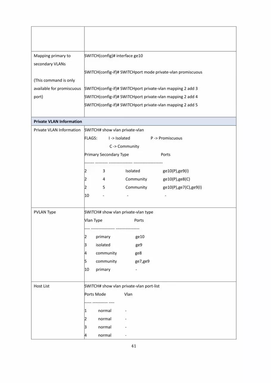
SWITCH(config)# interface ge10
SWITCH(config-if)# SWITCHport mode private-vlan promiscuous
SWITCH(config-if)# SWITCHport private-vlan mapping 2 add 3
SWITCH(config-if)# SWITCHport private-vlan mapping 2 add 4
SWITCH(config-if)# SWITCHport private-vlan mapping 2 add 5
Private VLAN Information
Private VLAN Information SWITCH# show vlan private-vlan
FLAGS: I -> Isolated P -> Promiscuous
C -> Community
Primary Secondary Type Ports
------- --------- ----------------- ---------------------
2 3 Isolated ge10(P),ge9(I)
2 4 Community ge10(P),ge8(C)
2 5 Community ge10(P),ge7(C),ge9(I)
10 - - -
PVLAN Type SWITCH# show vlan private-vlan type
Vlan Type Ports
---- ----------------- -----------------
2 primary ge10
3 isolated ge9
4 community ge8
5 community ge7,ge9
10 primary -
Host List SWITCH# show vlan private-vlan port-list
Ports Mode Vlan
----- ----------- ----
1 normal -
2 normal -
3 normal -
4 normal -

42
5 normal -
6 normal -
7 host 5
8 host 4
9 host 3
10 promiscuous 2
Running Config
Information
Private VLAN Type
Private VLAN Port
Information
SWITCH# show run
Building configuration...
Current configuration:
hostname SWITCH
vlan learning independent
!
vlan 1
!
vlan 2
private-vlan primary
!
vlan 3
private-vlan isolated
!
vlan 4
private-vlan community
!
vlan 5
private-vlan community
!
………..
………..
interface ge7
SWITCHport access vlan add 2,5
SWITCHport trunk native vlan 5
SWITCHport mode private-vlan host
SWITCHport private-vlan host-association 2 5
!
interface ge8
SWITCHport access vlan add 2,4
SWITCHport trunk native vlan 4

43
SWITCHport mode private-vlan host
SWITCHport private-vlan host-association 2 4
!
interface ge9
SWITCHport access vlan add 2,5
SWITCHport trunk native vlan 5
SWITCHport mode private-vlan host
SWITCHport private-vlan host-association 2 3
!
interface ge10
SWITCHport access vlan add 2,5
SWITCHport trunk native vlan 2
SWITCHport mode private-vlan promiscuous
SWITCHport private-vlan mapping 2 add 3-5
………
……..

44
3.6 CLI COMMANDS FOR QOS CONFIGURATION
This chapter provides a detailed explanation of the QoS commands. The following commands are available.
The commands are divided into these different groups:
Configuration Commands are used to configure features and options of the switch. For every configuration
command there is a show command that will display the configuration setting.
Show commands are used to display device settings, statistics and other information.
This chapter covered some sections such as, QoS Setting, CoS-Queue Mapping and DSCP-Queue Mapping.
Feature Command Line
QoS Setting
Queue Scheduling – Strict
Priority
SWITCH(config)# qos queue-sched
rr Round Robin
sp Strict Priority
wrr Weighted Round Robin
SWITCH(config)# qos queue-sched sp
<cr>
Queue Scheduling –
Round Robin
SWITCH(config)# qos queue-sched rr
Queue Scheduling - WRR SWITCH(config)# qos queue-sched wrr
Port Setting – CoS
(Default Port Priority)
SWITCH(config)# int ge8
SWITCH(config-if)# qos
priority Configure the port default priority value
SWITCH(config-if)# qos priority
<0-7> Assign an priority (7 highest)
Note: When change the port setting, User should Select the specific port first.
Trust Mode- CoS Only SWITCH (config)# qos trust-mode
cos 802.1p priority tag
dscp TOS/DSCP field
SWITCH (config)# qos trust-mode cos
Trust Mode- DSCP Only SWITCH (config)# qos trust-mode
cos 802.1p priority tag
dscp TOS/DSCP field
SWITCH (config)# qos trust-mode dscp
Display – Queue
Scheduling
SWITCH# show qos queue-sched
QoS queue scheduling scheme : Weighted Round Robin
COS queue 0 = 1

45
COS queue 1 = 1
COS queue 2 = 1
COS queue 3 = 1
COS queue 4 = 1
COS queue 5 = 1
COS queue 6 = 1
COS queue 7 = 1
Display –Trust Mode SWITCH# show qos trust-mode
QoS Trust Mode: 802.1p priority tag
Display –CoS (Port
Priority)
SWITCH# show qos port-priority
Port Default Priority :
Port Priority
-----+----
1 0
2 0
3 0
4 0
5 0
6 0
7 0
8 0
9 0
10 0
11 0
12 0
CoS-Queue Mapping
Format SWITCH(config)# qos cos-map
PRIORITY Assign an priority (7 highest)
SWITCH(config)# qos cos-map 1
QUEUE Assign an queue (0-3)
Note: Format: qos cos-map priority_value queue_value
Map CoS 0 to Queue 1 SWITCH(config)# qos cos-map 0 1
The CoS to queue mapping is set ok.
Map CoS 1 to Queue 0 SWITCH(config)# qos cos-map 1 0
The CoS to queue mapping is set ok.
Map CoS 2 to Queue 0 SWITCH(config)# qos cos-map 2 0
The CoS to queue mapping is set ok.

46
Map CoS 3 to Queue 1 SWITCH(config)# qos cos-map 3 1
The CoS to queue mapping is set ok.
Map CoS 4 to Queue 2 SWITCH(config)# qos cos-map 4 2
The CoS to queue mapping is set ok.
Map CoS 5 to Queue 2 SWITCH(config)# qos cos-map 5 2
The CoS to queue mapping is set ok.
Map CoS 6 to Queue 3 SWITCH(config)# qos cos-map 6 3
The CoS to queue mapping is set ok.
Map CoS 7 to Queue 3 SWITCH(config)# qos cos-map 7 3
The CoS to queue mapping is set ok.
Display – CoS-Queue
mapping
SWITCH# sh qos cos-map
CoS to Queue Mapping :
CoS Queue
---- + ------
0 1
1 0
2 0
3 1
4 2
5 2
6 3
7 3
DSCP-Queue Mapping
Format SWITCH(config)# qos dscp-map
PRIORITY Assign an priority (63 highest)
SWITCH(config)# qos dscp-map 0
QUEUE Assign an queue (0-3)
Format: qos dscp-map priority_value queue_value
Map DSCP 0 to Queue 1 SWITCH(config)# qos dscp-map 0 1
The TOS/DSCP to queue mapping is set ok.
Display – DSCO-Queue
mapping
SWITCH# show qos dscp-map
DSCP to Queue Mapping : (dscp = d1 d2)
d2| 0 1 2 3 4 5 6 7 8 9
d1 |
-----+----------------------
0 | 1 1 1 1 1 1 1 1 0 0

47
1 | 0 0 0 0 0 0 0 0 0 0
2 | 0 0 0 0 1 1 1 1 1 1
3 | 1 1 2 2 2 2 2 2 2 2
4 | 2 2 2 2 2 2 2 2 3 3
5 | 3 3 3 3 3 3 3 3 3 3
6 | 3 3 3 3
48
3.7 CLI COMMANDS FOR MULTICAST FILTERING CONFIGURATION
IGMP Snooping is used to monitor IGMP messages between host and routers, and process these IGMP messages.
IGMP Snooping make switch be able to track all network group members which are physically connected with switch
that running between host and multicast routers to manage the member relationships. This chapter will cover the
Multicast features CLI Command about configure and display the settings.
Feature Command Line
IGMP Snooping
IGMP Snooping - Global SWITCH(config)# ip igmp snooping
IGMP snooping is enabled globally. Please specify on which vlans IGMP snooping
enables
IGMP Snooping - VLAN SWITCH(config)# ip igmp snooping vlan
VLANLIST allowed vlan list
all all existed vlan
SWITCH(config)# ip igmp snooping vlan 1-2
IGMP snooping is enabled on vlan 1
IGMP snooping is enabled on vlan 2
Disable IGMP Snooping -
Global
SWITCH(config)# no ip igmp snoopin
IGMP snooping is disabled globally ok.
Disable IGMP Snooping -
VLAN
SWITCH(config)# no ip igmp snooping vlan 3
IGMP snooping is disabled on VLAN 3.
Display – IGMP Snooping
Setting
SWITCH# show ip igmp
interface vlan1
enabled: Yes
version: IGMPv1
query-interval; 125s
query-max-response-time: 10s
SWITCH# show ip igmp snooping
IGMP snooping is globally disabled
Static Router Port: N/A
Vlan1 is IGMP snooping enabled
immediate-leave is disabled
last-member-query-interval is 100 centiseconds
source-only-learning is disabled
Display – IGMP Table SWITCH# sh ip igmp snooping multicast all

49
VLAN IP Address Type Ports
---- --------------- ------- ------------------------
1 239.192.8.0 IGMP ge6,
1 239.255.255.250 IGMP ge6,
IGMP Query
IGMP Query V1 SWITCH(config)# int vlan 1 (Go to management VLAN)
SWITCH(config-if)# ip igmp v1
IGMP Query V2 SWITCH(config)# int vlan 1 (Go to management VLAN)
SWITCH(config-if)# ip igmp
IGMP Query version SWITCH(config-if)# ip igmp version 1
SWITCH(config-if)# ip igmp version 2
Disable SWITCH(config)# int vlan 1
SWITCH(config-if)# no ip igmp
Display SWITCH# sh ip igmp
interface vlan1
enabled: Yes
version: IGMPv2
query-interval: 125s
query-max-response-time: 10s
SWITCH# show running-config
….
!
interface vlan1
ip address 192.168.10.17/24
ip igmp
no shutdown
!
…….
Filtering Mode
Enable Force filtering SWITCH(config)# mac-address-table multicast filtering
flood flood to all ports
discard discard
vlan Virtual LAN
SWITCH(config)# mac-address-table multicast filtering discard vlan all
Set VLAN all multicast filtering to discard mode.

50
3.8 CLI COMMANDS FOR ROUTING CONFIGURATION
This chapter is about the Routing Configuration CLI Command.
Feature Command Line
ARP
Age Time SWITCH (config)# arp aging-time
<10-21600> seconds (10-21600)
SWITCH (config)# arp aging-time 14400
Static ARP Entry SWITCH (config)# arp
A.B.C.D IP address of ARP entry aging-time
Aging Time
SWITCH (config)# arp 192.168.10.90
MACADDR 48-bit hardware address xxxx.xxxx.xxxx of ARP entry
SWITCH (config)# arp 192.168.10.90
SWITCH (config)# arp 192.168.10.90 9466.e79f.5678
vlan L3 vlan interface
SWITCH (config)# arp 192.168.10.90 9466.e79f.5678 vlan 1
interface L2 interface
SWITCH (config)# arp 192.168.10.90 9466.e79f.5678 vlan 1 interface
IFNAME Interface name, ex: gigabitethernet1 or g4
SWITCH (config)# arp 192.168.10.90 9466.e79f.5678 vlan 1 interface ge8
=> The MAC address 9466.e79f.5678 with IP 192.168.10.90 is bind to the port 8 of
VLAN 1.
ARP Table SWITCH# show arp
IP address Mac Address Port Vlan Age(min) Type
---------------- -------------- ---- ---- -------- -------
192.168.10.80 708b.cd03.b567 ge5 1 233 Dynamic
192.168.10.90 9466.e79f.5678 ge8 1 0 Static
ARP Table Status SWITCH # show arp status
Aging time (secs) : 14400
ARP entry count : 2
ARP static entry count : 1
ARP dynamic entry count : 1

51
IP
Global IP Routing
Configuration
SWITCH (config)# ip route
A.B.C.D IP destination prefix
A.B.C.D/M IP destination prefix (e.g. 10.0.0.0/8)
Stop IP Routing SWITCH (config)#no ip route
A.B.C.D IP destination prefix
A.B.C.D/M IP destination prefix (e.g. 10.0.0.0/8)
IP Interface Configuration
Go to the VLAN
Interface
SWITCH (config)# interface vlan 1
SWITCH (config-if)#
Create IP Address SWITCH (config-if)# ip address
A.B.C.D/M IP address (e.g. 10.0.0.1/8)
Switch(config-if)# ip address 192.168.10.30/24
Create Secondary IP
Address
SWITCH (config-if)# ip address 192.168.101.30/24 secondary
Change Interface to
DOWN
SWITCH (config-if)# shutdown
Interface vlan1 Change to DOWN
Activate the IP Interface SWITCH (config-if)# no shutdown
Interface vlan1 Change to UP
Show ip routing status SWITCH # show ip route
Codes: K - kernel route, C - connected, S - static, R - RIP, O - OSPF,
IA - OSPF inter area, E1 - OSPF external type 1,
E2 - OSPF external type 2,
B - BGP, > - selected route, * - FIB route
C>* 192.168.10.0/24 is directly connected, vlan1

52
Route
Default Route SWITCH(config)# ip route
A.B.C.D IP destination prefix
A.B.C.D/M IP destination prefix (e.g. 10.0.0.0/8)
SWITCH (config)# ip route 0.0.0.0
A.B.C.D IP destination prefix mask
SWITCH (config)# ip route 0.0.0.0 192.168.10.3
% Command incomplete.
SWITCH (config)# ip route 0.0.0.0 192.168.10.3
A.B.C.D IP gateway address
INTERFACE IP gateway interface name
null0 Null interface
blackhole Silently discard pkts when matched
reject Emit an ICMP unreachable when matched
SWITCH (config)# ip route 0.0.0.0 192.168.10.90 192.168.10.70 5
Static Route SWITCH # show ip route 0.0.0.0
Routing entry for 0.0.0.0/2
Known via "static", distance 5, metric 0, best
* 192.168.10.70, via vlan1
Show Static/Dynamic
Route
SWITCH # show running-config
……
!
ip route 0.0.0.0/2 192.168.10.70 5
!
Routing Table Display SWITCH # show ip route
Codes: K - kernel route, C - connected, S - static, R - RIP, O - OSPF,
IA - OSPF inter area, E1 - OSPF external type 1,
E2 - OSPF external type 2,
B - BGP, > - selected route, * - FIB route
S>* 0.0.0.0/2 [5/0] via 192.168.10.70, vlan1
C>* 192.168.10.0/24 is directly connected, vlan1

53
RIP
(Before enable RIP, the IP Interfaces’ setting should be configured and activated
first.) Enable RIP protocol SWITCH (config)# router rip
SWITCH (config-router)#
default-information Control distribution of default route
default-metric Set a metric of redistribute routes
distance Administrative distance
distribute-list Filter networks in routing updates
end End current mode and change to enable mode
exit Exit current mode and down to previous mode
list Print command list
neighbor Specify a neighbor router
network Enable routing on an IP network
no Negate a command or set its defaults
offset-list Modify RIP metric
passive-interface Suppress routing updates on an interface
quit Exit current mode and down to previous mode
redistribute Redistribute information from another routing
protocol
route RIP static route configuration
route-map Route map set
timers Adjust routing timers
version Set routing protocol version
RIP Version SWITCH (config-router)# version
<1-2> version
SWITCH (config-router)# version 2
RIP Network SWITCH (config-router)# network 192.168.10.0/24
A.B.C.D/M IP prefix <network>/<length>, e.g., 35.0.0.0/8
WORD L3 Interface name
RIP Timer SWITCH (config-router)# timers basic
<5-2147483647> Routing table update timer value in second.
Default is 30.
RIP Split Horizon SWITCH (config-router)# passive-interface
IFNAME Interface name
default default for all interfaces
SWITCH (config-router)# passive-interface default

54
RIP default Metric
(usually = 1)
SWITCH (config-router)# default-metric
<1-16> Default metric
RIP Setting SWITCH # show ip rip status
Routing Protocol is "rip"
Sending updates every 30 seconds with +/-50%, next due in 18 seconds
Timeout after 180 seconds, garbage collect after 120 seconds
Outgoing update filter list for all interface is not set
Incoming update filter list for all interface is not set
Default redistribution metric is 1
Redistributing:
Default version control: send version 2, receive version 2
Interface Send Recv Key-chain
Routing for Networks:
Routing Information Sources:
Gateway BadPackets BadRoutes Distance Last Update
Distance: (default is 120)
RIP Table SWITCH # show ip rip
Codes: R - RIP, C - connected, S - Static, O - OSPF, B - BGP
Sub-codes:
(n) - normal, (s) - static, (d) - default, (r) - redistribute, (i) - interface
Network Next Hop Metric From Tag Time
C(i) 192.168.10.0/24 0.0.0.0 1 self 0

55
OSPF
(Before enable OSPF, the IP Interfaces’ setting should be configured and activated first.)
Go to the OSPF
command line
SWITCH (config)# router ospf
SWITCH (config-router)#
area OSPF area parameters
auto-cost Calculate OSPF interface cost according to bandwidth
compatible OSPF compatibility list
default-information Control distribution of default information
default-metric Set metric of redistributed routes
distance Define an administrative distance
distribute-list Filter networks in routing updates
end End current mode and change to enable mode
exit Exit current mode and down to previous mode
list Print command list
neighbor Specify neighbor router
network Enable routing on an IP network
no Negate a command or set its defaults
passive-interface Suppress routing updates on an interface
quit Exit current mode and down to previous mode
redistribute Redistribute information from another routing protocol
refresh Adjust refresh parameters
router-id router-id for the OSPF process
timers Adjust routing timers
Router ID for OSPF SWITCH (config-router)# router-id 192.168.5.251
OSPF Network and its Area ID
(0.0.0.0 for example)
SWITCH (config-router)# network
<0-4294967295> OSPF area ID as a decimal value
A.B.C.D OSPF area ID in IP address format
SWITCH (config-router)# network 192.168.5.0/24 area 0.0.0.0
Interface Configuration
Hello Interval SWITCH(config-if)# ip ospf hello-interval
<1-65535> Seconds
SWITCH (config-if)# ip ospf hello-interval 10
Dead Interval SWITCH(config-if)# ip ospf dead-interval 10
<1-65535> Seconds

56
Link Cost Change SWITCH (config-if)# ip ospf cost
<1-65535> Cost
Link Priority SWITCH (config-if)# ip ospf priority
<0-255> Priority
Authentication switch(config-if)# ip ospf authentication
<cr>
message-digest Use message-digest authentication
null Use null authentication
Authentication-key switch(config-if)# ip ospf authentication-key
AUTH_KEY The OSPF password (key)
Message-digest-key switch(config-if)# ip ospf message-digest-key
<1-255> Key ID
Retransmit-interval switch(config-if)# ip ospf retransmit-interval 10
<3-65535> Seconds
Transmit-delay switch(config-if)# ip ospf transmit-delay 10
<1-65535> Seconds
network switch(config-if)# ip ospf network
broadcast Specify OSPF broadcast multi-access network

57
Display
IP OSPF Information SWITCH # show ip ospf
OSPF Routing Process, Router ID: 192.168.5.251
Supports only single TOS (TOS0) routes
This implementation conforms to RFC2328
RFC1583Compatibility flag is disabled
Initial SPF scheduling delay 200 millisec(s)
Minimum hold time between consecutive SPFs 1000 millisec(s)
Maximum hold time between consecutive SPFs 10000 millisec(s)
Hold time multiplier is currently 1
SPF algorithm has not been run
SPF timer is inactive
Refresh timer 10 secs
Number of external LSA 0. Checksum Sum 0x00000000
Number of areas attached to this router: 1
Area ID: 0.0.0.0 (Backbone)
Number of interfaces in this area: Total: 0, Active: 0
Number of fully adjacent neighbors in this area: 0
Area has no authentication
SPF algorithm executed 0 times
Number of LSA 0
Number of router LSA 0. Checksum Sum 0x00000000
Number of network LSA 0. Checksum Sum 0x00000000
Number of summary LSA 0. Checksum Sum 0x00000000
Number of ASBR summary LSA 0. Checksum Sum 0x00000000
Number of NSSA LSA 0. Checksum Sum 0x00000000

58
IP OSPF Datasheet Switch# show ip ospf database
OSPF Router with ID (192.168.3.254) Router Link States (Area 0.0.0.0)
Link ID ADV Router Age Seq# CkSum Link count
192.168.3.253 192.168.3.253 928 0x80000009 0xf3b2 2
192.168.3.254 192.168.3.254 927 0x8000000a 0xd4aa
3
192.168.5.254 192.168.5.254 230 0x80000006 0xc248
2
Net Link States (Area 0.0.0.0)
Link ID ADV Router Age Seq# CkSum
192.168.3.254 192.168.3.254 927 0x80000003
0x7437
192.168.4.253 192.168.5.254 235 0x80000003
0x7334
IP OSPF Interface
Information
Switch# show ip ospf interface
vlan1 is up
ifindex 16, MTU 1500 bytes, BW 0 Kbit
<UP,BROADCAST,RUNNING,MULTICAST>
OSPF not enabled on this interface
vlan2 is up
ifindex 17, MTU 1500 bytes, BW 0 Kbit
<UP,BROADCAST,RUNNING,MULTICAST>
OSPF not enabled on this interface
vlan5 is down
ifindex 18, MTU 1500 bytes, BW 0 Kbit <BROADCAST,MULTICAST>
OSPF not enabled on this interface
IP OSPF Neighbor
Table
Switch# show ip ospf neighbor
Neighbor ID Pri State Dead Time Address Interface
RXmtL RqstL DBsmL
--------------- --- --------------- --------- --------------- -------------------- ----- ----- -----

59
IP OSPF Networking
Routing Table
Switch# show ip ospf route
============ OSPF network routing table ============ N 192.168.2.0/24
[10] area: 0.0.0.0
directly attached to vlan2
N 192.168.3.0/24 [10] area: 0.0.0.0
directly attached to vlan3
N 192.168.11.0/24 [10] area: 0.0.0.0
directly attached to vlan1
OSPF Setting in
Configuration file
Switch# show running-config
……
router ospf
router-id 192.168.3.253
network 192.168.2.0/24 area 0.0.0.0
network 192.168.3.0/24 area 0.0.0.0 network 192.168.11.0/24 area 0.0.0.0
!
ip routing
……..
Multicast Routing
(Before enable MRoute, the IP Interfaces’ setting should be configured and activated first.)
Enable the MRoute &
Configure the static entry
SWITCH(config)# ip multicast 224.0.1.10
vlan specify the ingress VLAN
switch(config)# ip multicast 224.0.1.10 vlan
VLANID valid range is 1 to 4094
switch(config)# ip multicast 224.0.1.10 vlan 1
egress-vlan specify the egress VLAN
switch(config)# ip multicast 224.0.1.10 vlan 1 egress-vlan
VLANID valid range is 1 to 4094
switch(config)# ip multicast 224.0.1.10 vlan 1 egress-vlan 5
interface specify an interface list to add to
switch(config)# ip multicast 224.0.1.10 vlan 1 egress-vlan 5 interface ge6
VRRP
(Go to the Interface mode) IP of VRRP Switch(config-if)# vrrp 1 ip 192.168.10.1
The virtual router of vlan1 count is 1. Create virtual router 1 success.

60
Priority of the interface SWITCH(config-if)# vrrp 1 priority
<1-254> virtual router's priority value in range 1-254, 255 for virtual IP
owner and 100 for backup by default
Preempt of the
interface
SWITCH(config-if)# vrrp 1 preempt
Set virtual router preemption mode to enabled success. VRRP Information SWITCH# show vrrp
[1-255] virtual router identifier in the range 1-255 (decimal)
brief display a summary view of the virtual router information
Switch# show vrrp
vlan1 - Virtual Router ID 1
State is Master
Virtual IP address is 192.168.10.1
Virtual MAC address is 0000.5e00.0101
Priority is 100
Advertisement interval is 1 sec
Preemption is enabled
Master Router is 192.168.10.1 (local), priority is 100
Master Advertisement interval is 1.000 sec
Master Down interval is 3.609 sec
VRRP Brief Information Switch# show vrrp brief
Interface VRID Prio Time Owner Pre
State Master IP addr
Virtual IP addr
vlan1 1 100 3.609 - enabled
Master 192.168.10.1
192.168.10.1

61
3.9 CLI COMMANDS FOR SNMP CONFIGURATION
SNMP is the most widely used network management protocol in TCP/IP that offers a method for monitoring and
managing computer network. For this reason, SNMP has been widely used and became de facto standard of network
management. SNMPv2c provides several advantages over SNMPv1. SNMPv2c have expanded data types of 64-bit
counter. It calls for improved efficiency and performance by introducing the GETBULK operation. Confirmed event
notification is sought by the introduction of the Inform operator. Enhanced error handling approach, improved sets,
and a fine tuned Data Definition Language are some of the advantages of SNMPv2c over the SNMPv1.
This chapter covers SNMP Community and SNMP Trap section. Through this function of reading or writing
community name, the access control of the device is realized and the communication security is enhanced because
the device will only accept the message with a qualified community name. Show commands are used to display
device settings and other information.
Feature Command Line
SNMP Community
Read Only Community SWITCH(config)# snmp-server community public ro
community string add ok
Read Write Community SWITCH(config)# snmp-server community private rw
community string add ok
SNMP Trap
Enable Trap SWITCH(config)# snmp-server enable trap
Set SNMP trap enable ok.
SNMP Trap Server IP
without specific
community name
SWITCH(config)# snmp-server host 192.168.10.33
SNMP trap host add OK, total host number = 1.
SNMP Trap Server IP with
version 1 and community
SWITCH(config)# snmp-server host 192.168.10.33 version 1 private
SNMP trap host add OK.con t
Note: private is the community name, version 1 is the SNMP version
SNMP Trap Server IP with
version 2 and community
SWITCH(config)# snmp-server host 192.168.10.33 version 2 private
SNMP trap host add OK.
Disable SNMP Trap SWITCH(config)# no snmp-server enable trap
Set SNMP trap disable ok.
Display SWITCH# sh snmp-server trap
SNMP trap: Enabled
SNMP trap community: public

62
SWITCH# show running-config
.......
snmp-server community public ro
snmp-server community private rw
snmp-server enable trap
snmp-server host 192.168.10.33 version 2 admin
snmp-server host 192.168.10.33 version 1 admin
……..

63
3.10 CLI COMMANDS FOR SECURITY CONFIGURATION
This chapter covers the Security configuration setting by CLI Command.
Feature Command Line
Filter
Add MAC access list SWITCH(config)# mac access-list extended
NAME access-list name
SWITCH (config)# mac access-list extended server1
SWITCH (config-ext-macl)#
permit Specify packets to forward
deny Specify packets to reject
end End current mode and change to enable mode
exit Exit current mode and down to previous mode
list Print command list
no Negate a command or set its defaults
quit Exit current mode and down to previous mode
Add IP Standard access
list
Switch(config)# ip access-list extended
Extended access-list standard
Standard access-list
Switch(config)# ip access-list extended
<100-199> Extended IP access-list number
<2000-2699> Extended IP access-list number (expanded range)
WORD access-list name Switch
(config)# ip access-list standard 1
SWITCH(config-std-acl)#
deny Specify packets to reject
permit Specify packets to forward
end End current mode and change to enable mode
exit Exit current mode and down to previous mode
list Print command list
no Negate a command or set its defaults
quit Exit current mode and down to previous mode
remark Access list entry comment

64
Add IP Extended access
list
Switch(config)# ip access-list extended
<100-199> Extended IP access-list number
<2000-2699> Extended IP access-list number (expanded range)
WORD access-list name
Switch(config)# ip access-list extended 100
Switch(config-ext-acl)#
Add MAC SWITCH(config)# mac-address-table static 9466.e79f.5678 vlan 1 interface ge1
mac-address-table unicast static set ok!
Display SWITCH# show mac-address-table static
Destination Address Address Type Vlan Destination Port
------------------- --------------- ------- ------------------------
9466.e79f.5678 Static 1 ge1
802.1x
enable
disable
SWITCH(config)# dot1x system-auth-control
SWITCH(config)#
SWITCH(config)# no dot1x system-auth-control
SWITCH(config)#
authentic-method SWITCH(config)# dot1x authentic-method
local Use the local username database for authentication
radius Use the Remote Authentication Dial-In User Service (RADIUS) servers
for authentication
SWITCH(config)# dot1x authentic-method radius
SWITCH(config)#
radius server-ip SWITCH(config)# dot1x radius
SWITCH(config)# dot1x radius server-ip 192.168.10.120 key 1234
RADIUS Server Port number NOT given. (default=1812)
RADIUS Accounting Port number NOT given. (default=1813)
RADIUS Server IP : 192.168.10.120
RADIUS Server Key : 1234
RADIUS Server Port : 1812
RADIUS Accounting Port : 1813
SWITCH(config)#
radius server-ip SWITCH(config)# dot1x radius
SWITCH(config)# dot1x radius server-ip 192.168.10.120key 1234

65
RADIUS Server Port number NOT given. (default=1812)
RADIUS Accounting Port number NOT given. (default=1813)
RADIUS Server IP : 192.168.10.120
RADIUS Server Key : 1234
RADIUS Server Port : 1812
RADIUS Accounting Port : 1813
SWITCH(config)#
radius secondary-server-ip SWITCH(config)# dot1x radius secondary-server-ip 192.168.10.250 key 5678
Port number NOT given. (default=1812)
RADIUS Accounting Port number NOT given. (default=1813)
Secondary RADIUS Server IP : 192.168.10.250
Secondary RADIUS Server Key : 5678
Secondary RADIUS Server Port : 1812
Secondary RADIUS Accounting Port : 1813
User name/password for
authentication
SWITCH(config)# dot1x username ………passwd ….. vlan 1

66
3.11 CLI COMMANDS FOR WARNING CONFIGURATION
This chapter is about the Warning Configuration by using CLI Command. Womaster Switch supports device alarm and
related alarm report, alarm enable/disable, and alarm searching. It assures that the alarm will be reported to the
customer timely and accurately
Feature Command Line
Relay Output
Relay Output SWITCH(config)# relay 1
di DI state
dry dry output
ping ping failure
port port link failure
power power failure
ring ring failure
Note: Select Relay 1 or 2 first, then select the event types.
DI State SWITCH(config)# relay 1 di
<1-2> DI number
SWITCH(config)# relay 1 di 1
high high is abnormal
low low is abnormal
SWITCH(config)# relay 1 di 1 high
Dry Output SWITCH(config)# relay 1 dry
<0-65535> turn on period in second
SWITCH(config)# relay 1 dry 5
<0-65535> turn on period in second
SWITCH(config)# relay 1 dry 5 5
Ping Failure SWITCH(config)# relay 1 ping 192.168.10.33
<cr>
reset reset a device
SWITCH(config)# relay 1 ping 192.168.10.33 reset
<1-65535> reset time
SWITCH(config)# relay 1 ping 192.168.10.33 reset 60
<0-65535> hold time to retry
SWITCH(config)# relay 1 ping 192.168.10.33 reset 60 60
Port Link Failure SWITCH(config)# relay 1 port
PORTLIST port list

67
SWITCH(config)# relay 1 port ge1-5
Power Failure SWITCH(config)# relay 1 power
<1-2> power id
SWITCH(config)# relay 1 power 1
SWITCH(config)# relay 1 power 2
Ring Failure SWITCH(config)# relay 1 ring
Disable Relay SWITCH(config)# no relay
<1-2> relay id
SWITCH(config)# no relay 1 (Relay_ID: 1 or 2)
<cr>
Display SWITCH# show relay 1
Relay 1
Event :
Power : Disabled
Port Link : Disabled
Ring : Enabled
Ping : Disabled
Ping Reset : Disabled
Dry Output : Disabled
DI : Disabled
Event Selection
Event Selection SWITCH(config)# warning-event
coldstart Switch cold start event
warmstart Switch warm start event
linkdown Switch link down event
linkup Switch link up event
authentication Authentication failure event
di Switch di event
loop-protect Switch loop protection event
poe-powering Switch PoE powering or unpowering event
power Switch power failure event
relay-output Switch relay output event
ring Switch ring event
sfp Switch SFP event
time-sync Switch time synchronize event
Ex: Cold Start event SWITCH(config)# warning-event coldstart
Set cold start event enable ok.
Ex: Link Up event SWITCH(config)# warning-event linkup

68
[IFNAME] Interface name, ex: ge1 or ge8
SWITCH(config)# warning-event linkup ge5
Set ge5 link up event enable ok.
Display SWITCH# show warning-event
Warning Event:
Cold Start: Disabled
Warm Start: Disabled
Authentication Failure: Disabled
Link Down: Disabled
Link Up: Disabled
Power Failure: Disabled
Ring: Disabled
Relay Output: Disabled
Time Synchronize Failure: Disabled
PoE Powering: Disabled
SFP: Disabled
DI: Disabled
Loop Protection: Disabled
Syslog Setting
Local Mode SWITCH(config)# log syslog local
Server Mode SWITCH(config)# log syslog remote 192.168.10.4
Both SWITCH(config)# log syslog local
SWITCH(config)# log syslog remote 192.168.10.4
Disable SWITCH(config)# no log syslog local
Email Alert
SMTP Enable SWITCH(config)# smtp-server enable email-alert
SMTP Email Alert set enable ok.
Sender mail SWITCH(config)# smtp-server server 192.168.10.100
ACCOUNT SMTP server mail account, ex: [email protected]
SWITCH(config)# smtp-server server 192.168.10.100 [email protected]
SMTP Email Alert set Server: 192.168.10.100, Account: [email protected] ok.
Receiver mail SWITCH(config)# smtp-server receipt 1 [email protected]
SMTP Email Alert set receipt 1: [email protected] ok.
Authentication with
username and password
SWITCH(config)# smtp-server authentication username admin password admin
SMTP Email Alert set authentication Username: admin, Password: admin
Note: User can assign string to username and password.

69
Disable SMTP SWITCH(config)# no smtp-server enable email-alert
SMTP Email Alert set disable ok.
Disable Authentication SWITCH(config)# no smtp-server authentication
SMTP Email Alert set Authentication disable ok.
Display SWITCH# sh smtp-server
SMTP Email Alert is Enabled
Server: 192.168.10.100, Account: [email protected]
Authentication: Enabled
Username: admin, Password: admin
SMTP Email Alert Receipt:
Receipt 1: [email protected]
Receipt 2:
Receipt 3:
Receipt 4:

70
3.12 CLI COMMANDS FOR DIAGNOSTICS CONFIGURATION
This chapter is about Diagnostics feature, the features that include in Diagnostics are LLDP, MAC Address Table, Port
Statistics, Port Mirroring, Event Log, and Ping.
Feature Command Line
LLDP
Enable LLDP SWITCH(config)# lldp
holdtime Specify the holdtime of LLDP in seconds
<10-255> Valid range is 10~255
run Enable LLDP
timer Set the transmission frequency of LLDP in seconds
<5-254> Valid range is 5~254
MAC Address Table
Aging Time SWITCH(config)# mac-address-table aging-time 350
mac-address-table aging-time set ok!
TIMEVALUE aging time in seconds, the range is 15 to 3825 seconds
Note: 350 is the new ageing timeout value.
Add Static Unicast MAC
address
SWITCH(config)# mac-address-table static 9466.e79f.5678 vlan 1 interface
ge7
mac-address-table ucast static set ok!
Note: rule: mac-address-table static MAC_address VLAN VID interface
interface_name
Add Multicast MAC
address
SWITCH(config)# mac-address-table multicast 0100.5e01.0101 vlan 1
interface ge6-7
Adds an entry in the multicast table ok!
MACADDR destination mac address xxxx.xxxx.xxxx (multicast) to add to
the address table
Note: rule: mac-address-table multicast MAC_address VLAN VID
interface_list interface_name/range
SWITCH(config)# mac-address-table multicast filtering
filtering filtering of unknown multicast addresses
flood flood to all ports
discard discard
vlan Virtual LAN
Show MAC Address Table SWITCH# show mac-address-table

71
– All types
***** UNICAST MAC ADDRESS *****
Destination Address Address Type Vlan Destination Port
------------------- --------------- ------- ------------------------
000f.b079.ca3b Dynamic 1 ge4
9466.e79f.5678 Dynamic 1 ge7
9466.e700.00e7 Static 1 ge7
9466.e75f.05b9 Static 1 ge7
9466.e79d.0069 Management 1
***** MULTICAST MAC ADDRESS *****
Vlan Mac Address COS Status Ports
---- --------------- ---- ------- --------------------------
1 9466.e79d.0069 0 ge6
1 9466.e79f.06d9 0 ge4,ge6
Show MAC Address Table
– Dynamic Learnt MAC
addresses
SWITCH# show mac-address-table dynamic
Destination Address Address Type Vlan Destination Port
------------------- --------------- ------- ------------------------
9466.e700.00e7 Dynamic 1 ge4
9466.e79f.06d9 Dynamic 1 ge7
Show MAC Address Table
– Multicast MAC
addresses
SWITCH# show mac-address-table multicast
Vlan Mac Address COS Status Ports
---- --------------- ---- ------- --------------------------
1 9466.e79f.06d9 0 ge6-7
1 9466.e700.00e7 0 ge4,ge6-7
Show MAC Address Table
– Static MAC addresses
SWITCH# show mac-address-table static
Destination Address Address Type Vlan Destination Port
------------------- --------------- ------- ------------------------
9466.e700.00e7 Static 1 ge7
9466.e75f.05b9 Static 1 ge7
Show Aging timeout time SWITCH# show mac-address-table aging-time
the mac-address-table aging-time is 345 sec.
Port Statistics
Port Statistics SWITCH# show rmon statistics ge4 (select interface)
Interface fastethernet4 is enable connected, which has
Inbound:
Good Octets: 178792, Bad Octets: 0
Unicast: 598, Broadcast: 1764, Multicast: 160

72
Pause: 0, Undersize: 0, Fragments: 0
Oversize: 0, Jabbers: 0, Disacrds: 0
Filtered: 0, RxError: 0, FCSError: 0
Outbound:
Good Octets: 330500
Unicast: 602, Broadcast: 1, Multicast: 2261
Pause: 0, Deferred: 0, Collisions: 0
SingleCollision: 0, MultipleCollision: 0
ExcessiveCollision: 0, LateCollision: 0
Filtered: 0, FCSError: 0
Number of frames received and transmitted with a length of:
64: 2388, 65to127: 142, 128to255: 11
256to511: 64, 512to1023: 10, 1024toMaxSize: 42
Port Mirroring
Enable Port Mirror SWITCH(config)# mirror en
Mirror set enable ok.
Disable Port Mirror SWITCH(config)# mirror disable
Mirror set disable ok.
Select Source Port SWITCH(config)# mirror source ge1-2
both Received and transmitted traffic
rx Received traffic
tx Transmitted traffic
SWITCH(config)# mirror source ge1-2 both
Mirror source ge1-2 both set ok.
Note: Select source port list and TX/RX/Both mode.
Select Destination Port SWITCH(config)# mirror destination ge6
Mirror destination ge6 both set ok
Display SWITCH# show mirror
Mirror Status : Enabled
Monitor Destination Port : ge6
Ingress Source Ports :ge1,ge2,
Egress Source Ports :ge1,ge2,
Event Log
Display SWITCH# show event-log
Jan 1 00:06:56 switch Event: Link 2 Down.
Jan 1 00:06:56 switch Event: Ring11 Become Protection state.
Jan 1 00:06:56 switch Event: Ring11, Port 2 Link Change to DOWN.

73
Jan 1 00:06:57 switch Event: Link 2 Up.
Jan 1 00:06:58 switch Event: Ring11 Become Non Protection state.
Jan 1 00:06:58 switch Event: Ring11, Port 2 Link Change to UP.
Ping
Ping IP SWITCH# ping 192.168.10.4
PING 192.168.10.4 (192.168.10.4): 56 data bytes
64 bytes from 192.168.10.4: seq=0 ttl=64 time=5.6 ms
64 bytes from 192.168.10.4: seq=1 ttl=64 time=0.8 ms
64 bytes from 192.168.10.4: seq=2 ttl=64 time=1.0 ms
64 bytes from 192.168.10.4: seq=3 ttl=64 time=1.0 ms
64 bytes from 192.168.10.4: seq=4 ttl=64 time=0.8 ms
--- 192.168.10.4 ping statistics ---
5 packets transmitted, 5 packets received, 0% packet loss
round-trip min/avg/max = 0.8/1.8/5.6 ms
3.13 CLI COMMANDS FOR BACKUP RESTORE
This chapter provides a detailed explanation of the Backup and Restore the configuration by using CLI commands.
Feature Command Line
Backup Startup
Configuration file
SWITCH# copy startup-config tftp: 192.168.10.33/default.conf
Writing Configuration [OK]
Note: 192.168.10.33 is the TFTP server’s IP and default.conf is name of the
configuration file. User environment may use different IP addresses or different
file name. Please type target TFTP server IP or file name in this command.
Restore Configuration SWITCH# copy tftp: /default.conf startup-config
Show Startup
Configuration
SWITCH# show startup-config
Show Running
Configuration
SWITCH# show running-config
74
3.14 CLI COMMANDS FOR FIRMWARE UPGRADE
This chapter covers the CLI Command for upgrading the switch firmware.
Feature Command line
Firmware Upgrade SWITCH# archive download-sw /overwrite tftp “ip address”
“firmwarefile”.bin binary code file name
Firmware upgrading, don't turn off the SWITCH!
Tftping file “firmwarefile”.bin binary code file name
Firmware upgrading
................................................................................
................................................................................
...........................
Firmware upgrade success!!
Rebooting.......
3.15 CLI COMMANDS FOR RESET
This chapter is about CLI command to reset to factory default configuration.
Feature Command Line
Factory Default SWITCH# reload default-config file
Reload OK!
SWITCH# reboot
3.16 CLI COMMANDS FOR SAVE & LOAD
This chapter is cover two function from the switch, Save and Load the configuration CLI command.
Feature Command Line
Save
Load
SWITCH# write
Building Configuration… --- save configuration
[OK]
SWITCH# copy running-config startup-config --- load configuration
Building Configuration...
[OK]
75
3.17 CLI COMMANDS FOR LOGOUT
This chapter is about the CLI Command for log out from the switch CLI interface.
Feature Command Line
Logout SWITCH> exit
SWITCH# exit
SWITCH login: admin
Password:
3.18 CLI COMMANDS FOR REBOOT
This chapter is about restart the device using CLI Command.
Feature Command Line
Reboot SWITCH# reboot
Recommended


