Chemical Engineering and Processing 38 (1999) 517–523
Design of a photo-bioreactor for modelling purposes�
Zsuzsa Csogor *, Michael Herrenbauer, Iris Perner, Karsten Schmidt, Clemens PostenInstitute for Mechanical Engineering and Mechanics, Uni6ersity of Karlsruhe (TH), D-76128 Karlsruhe, Germany
Received 1 April 1999; accepted 1 April 1999
Abstract
Microalgae have been recently recognized as tools for high value products like polyunsaturated fatty acids, pigments orpolysaccharides. So far however, only little modelling work has been done. Modelling of kinetics in standard photo-bioreactorsis difficult because of strong light gradients and the lack of control of light flux. For the study of microalgae kinetics and formodelling purposes a new kind of photo-bioreactor has been designed. Model based approaches are used to optimize illuminationand to achieve higher light intensities and a more uniform illumination. With the aid of the new reactor, kinetics of microalgaegrowth and product formation can be investigated under controlled conditions. © 1999 Elsevier Science S.A. All rights reserved.
Keywords: Photobioreactor; Light; Microalgal biotechnology; Modelling; Fermentation processes
www.elsevier.com/locate/cep
1. Introduction
Microalgae have an interesting and yet not fullyrealized potential for biotechnological exploitation.They produce products like natural dyes, polyunsatu-rated fatty acids, polysaccharides, and vitamins [1] [2].Also antiviral activities of pharmaceutical interest havebeen shown in some microalgae [3]. As the biggestprimary producers of oxygen worldwide, they are eco-logically important and play an important role in cli-mate modelling.
Biomass composition, growth rate, and product spec-tra depend strongly on the cultivation conditions. Im-portant factors are composition of the medium,temperature, pH, carbon dioxide and oxygen supply,and most important of all: illumination.
As photosynthetic organisms, microalgae need car-bon dioxide as carbon source and light within thephotosynthetically active radiation (PAR) to obtainenergy. The wavelength range of the PAR is between400 and 700 nm, which is equal to visible light. Theirradiation can be quantified adequately by the photonflux density (quantum of photons per area and time).
Because of the complex interactions between theseparameters there is a big demand to develop a modelwhich predicts the behavior of the whole system.
2. Requirements for photo-bioreactors for modellingpurposes
Usually stirred tank reactors (STR) are used for thegeneration of datasets which build the basis for modelsin biotechnology. The advantages of this type of reactorare that the culture is a homogeneous mixture (mediumand biomass, respectively), the reactor can be fullysterilized, and sufficient gas supply is guaranteed. Fur-ther, it is possible to perform batch, fed-batch, andcontinuous experiments.
For data acquisition and reactor control parameterslike temperature, pH, dissolved oxygen, biomass/ opti-cal density, composition of exhaust gas, and the con-centration of the different products have to bemeasured on-line, if possible. The measurement of suchparameters is most accessible in homogenous systemslike stirred tank reactors.
To examine the influences of light on growth andproduct formation of microalgae it is necessary to haveflexible illumination throughout the whole reactor.Thelighting should provide:� Enough light for growth in the range demanded.
� Dedicated to Professor Em. Dr-Ing. Dr h.c. mult. E.-U. Schlun-der on the occasion of his 70th birthday.
* Corresponding author. Tel.: +49-721-608-6171; fax: +49 721-608-6171.
E-mail address: [email protected] (Z. Csogor)
0255-2701/99/$ - see front matter © 1999 Elsevier Science S.A. All rights reserved.
PII: S 0255 -2701 (99 )00048 -3
Z. Csogor et al. / Chemical Engineering and Processing 38 (1999) 517–523518
� Adjustable light intensity.� Variable wavelength composition (light quality).� The possibility of generating light fluctuations in a
wide frequency range (from day/night rhythm toseveral Hz, in nature caused by clouds or choppyseas).
� Small gradient of light intensity throughout thereactor.In contrast to common chemical nutrients it is not
possible to distribute the light homogeneously in thewhole reactor volume. This is mainly caused by thealgae themselves, as the cells absorb and scatter thelight. This leads to decreasing light intensity with pene-tration depth of the light beam. To achieve the bestapproach to a homogeneous light distribution it isnecessary that the path length, which the light has topass through within the culture media, is short. Thisdemand is not met by common photobioreactors. For areview about different types of photo-bioreactors see[4].
3. Novel stirred draught tube reactor
The aim of the new development was to combine theadvantages of a stirred reactor (homogeneity) and aplate reactor (short path length). The idea was to builda curved plate reactor as a stirred reactor. The con-struction is realized in the following way.
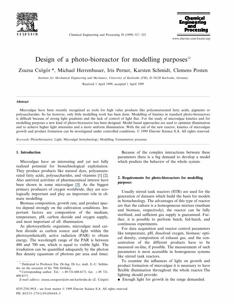
A stainless steel vessel with a double jacket is used.This arrangement avoids uncontrolled light input fromthe surroundings and it allows to temper the culturemedium. A propeller stirrer is used to homogenize theculture medium and for aeration. In order to avoidshadowing by the stirrer shaft the stirrer is mounted atthe bottom. The culture medium is recycled axially,streaming downward inside the coaxially mounteddraught tube and upwards in the gap between the vesselwall and the outer area of the tube. This tube is alsoused to illuminate the culture medium (about 3 l).
The heart of the reactor is the light input system thatconsists of an external light source, a fiber optical ringlight and a light emitting tube.
Light is generated in a light source arranged exter-nally and directed into the reactor using optical fibers.At the present time a 150 and a 250 W cold lightreflector lamps are used to obtain high light intensity,but any focusable light source can be applied. By usinga shutter module it is possible to generate light fluctua-tions in a wide range of frequencies. In order to changethe light quality, spectral filters are used, placed be-tween the lamp and the optical fiber.
The fibers are spread in a ring light to provide auniform illumination in the concentrically arrangedcylinder which illuminates the reactor uniformly. Ascheme of the reactor is given in Fig. 1.
The material of the emitting tube has to fulfill highdemands: it has to be fully transparent in the visiblerange of light, be non toxic, be inert with respect to thealgae and to the medium, and it has to withstand steamsterilization (121°C). While glass is an inert materialoften used in biotechnology, acrylic glass is not fullystable at sterilization. Other synthetic materials thatwould fit are polycarbonate (PC) and poly-methylpenthene (PMP).
Glass and acrylic glass have been used successfullyfor the light emitting tube. The surfaces of the tubes aremade rough to diffuse the light into the reactor in auniform way.
For other reactor components only high-grade steelis used to avoid any kind of interaction between thereactor and the medium (that may be of extreme pHand contain high salt concentrations).
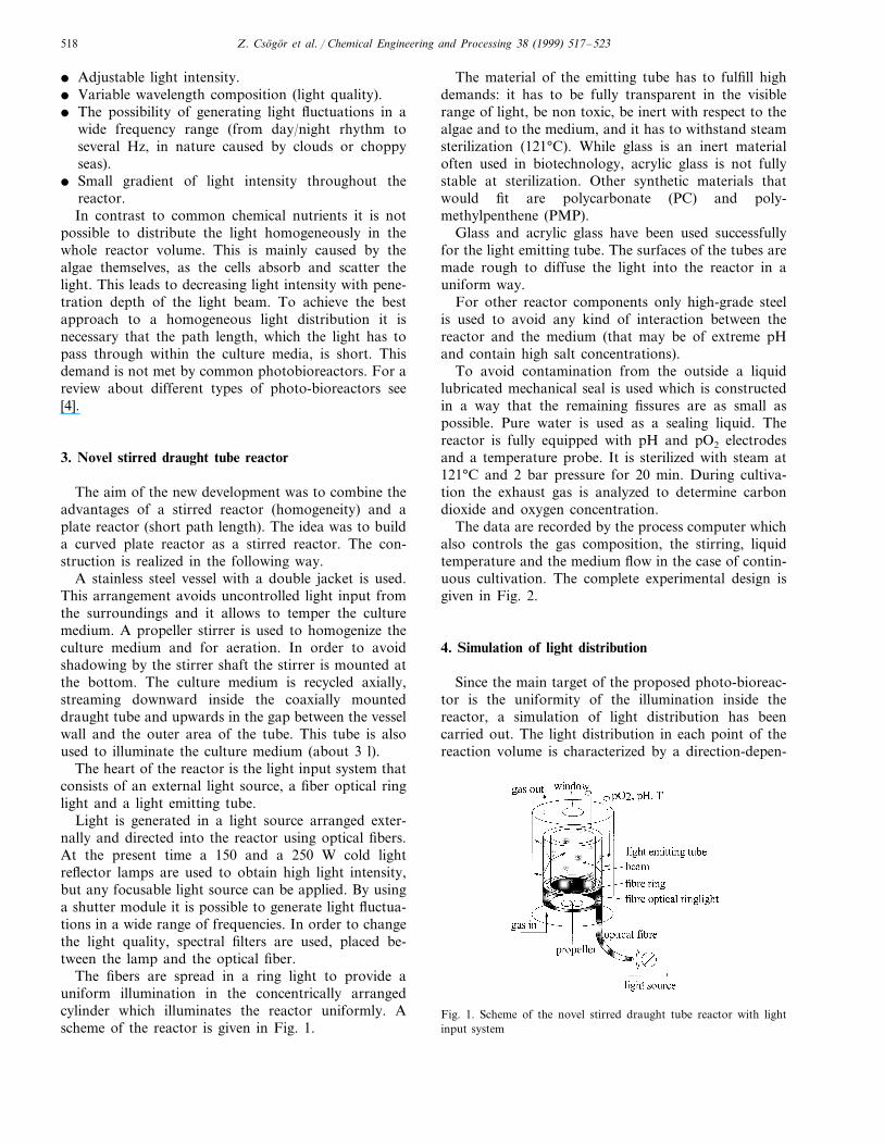
To avoid contamination from the outside a liquidlubricated mechanical seal is used which is constructedin a way that the remaining fissures are as small aspossible. Pure water is used as a sealing liquid. Thereactor is fully equipped with pH and pO2 electrodesand a temperature probe. It is sterilized with steam at121°C and 2 bar pressure for 20 min. During cultiva-tion the exhaust gas is analyzed to determine carbondioxide and oxygen concentration.
The data are recorded by the process computer whichalso controls the gas composition, the stirring, liquidtemperature and the medium flow in the case of contin-uous cultivation. The complete experimental design isgiven in Fig. 2.
4. Simulation of light distribution
Since the main target of the proposed photo-bioreac-tor is the uniformity of the illumination inside thereactor, a simulation of light distribution has beencarried out. The light distribution in each point of thereaction volume is characterized by a direction-depen-
Fig. 1. Scheme of the novel stirred draught tube reactor with lightinput system
Z. Csogor et al. / Chemical Engineering and Processing 38 (1999) 517–523 519
Fig. 2. Experimental design of the photobioreactor containing the reactor itself, measuring peripherie, and the process computer. Medium andinformation fluxes are shown.
dent intensity distribution. Therefore, a tensor problemhas to be solved, what can be done in principal bysolving the electromagnetic field equations. However, inpractice Monte-Carlo simulations have been shown tobe much more convenient in cases of complexboundary geometries. So many simulations of lightdistribution in biological systems, e.g. tissues or leaves[5], have been carried out employing Monte-Carlosimulation.
The basic idea is, to generate single ‘virtual photons’and calculate their propagation through the systemunder investigation. Beside precisely defined steps likereflection or refraction random events like scattering insuspensions or on rough surfaces can be modelled usingrandom numbers. A high number of simulated ‘pho-tons’ per volume element finally yields a good approxi-mation of the light density in the e.g. reactor.
4.1. Elements of simulation
4.1.1. The light sourceThe light is fed into the reactor via a fiber-optical
ring-light. So the starting point of each photon is givenby the radius rf= (rr,i−rr,o)/2 and a uniform distribu-tion between +/−p for the azimuth angle around themain axis of the reactor. Each fiber releases photonswith a deviation d from its main axes. This deviation isinfluenced by the geometry of the light source, whichsupplies the fiber with light, and the total reflectionangle of the fiber material. Measurements have shownthat for the light intensity a triangular distribution canbe assumed, here given as the probability:
pf(df)=p0−p0/df,max · df, df,max=p/3. (1)
for the emission angle of a single photon. The accumu-lated probability (p0 · dmax)/2 is normalized to unity byp0=2/df,max.
To obtain a random number generator ry,set for avariable y with a given distribution p(y) from a uniformdistributed generator rn, which is usually available insimulation programs, the transformation:
rn=P−1(y) (2)
holds [6], where P−1(y) is the inverse function of theprimitive of p(y). This equation can be solved in thisexample (Eq. (1)) with a computer algebra system,yielding:
df(rn)=1−1−rn · df,max (3)
which has to be accounted in polar coordinates for theelevation angle p/2−d, while the azimuth is normallydistributed between +/−p.
4.1.2. Propagation and absorption in transparent mediaFor characterization of a photon the coordinates in
each simulation step and the direction of the propaga-tion has to be defined. Both, the location xP and thevector of propagation vP has been calculated in Carte-sian coordinates. While basically only two values arenecessary to specify a direction in a three-dimensionalspace, an over determination is avoided by choosing�vP�=1, where the components of vP are the projectionon the axis of the coordinate system.
For the new location after a simulation step:
Z. Csogor et al. / Chemical Engineering and Processing 38 (1999) 517–523520
xp(tk+1)=xp(tk)+hsim · 6p (4)
easily obtained.The step size hsim is the minimum of the pathlength
of the light habs until the photon is absorbed in themedium and the pathlength hint until the photon hitsthe next interface.
To calculate the probability function p(habs) the Lam-bert–Beer law:
p(h)=1−e−a · h (5)
is employed, which is already the primitive according toEq. (2). Again solving with computer algebra:
habs(rn)= −1a
· ln(1−rn) (6)
is obtained. So the propagation of a single photon froman interface to the point of absorption can be calcu-lated in one random step.
4.1.3. Reflection and refraction at surfacesTo calculate the relevant angles a transformation into
a polar coordinate system has been carried out, wherethe transformation is given by:
8=arctanyx
(7a)
for the azimuth and:
U=arctanx2+y2
z(7b)
for the elevation angle. The back transformation isgiven as:
x=r sin U cos 8 (8a)
y=r sin U sin 8 (8b)
z=r cos U (8c)
with r=1.Let vN be the direction of the unit normal vector to
the surface in the point hit by the photon, then theangle between the normal vector and the propagationvector is given by:
cos dr=6n · 6p
�6n � · �6p �=6n · 6n (9)
nin
nout
· sin dr\1 (10)
In case: total reflection occurs or otherwise refractionwith the angles:
sin(8n−8in)=nout
nin
· sin(8n−8out) (11a)
sin(Un−Uin)=nout
nin
· sin(Un−Uout) (11b)
An ideal roughness of a surface is considered as asphere emitter, where the probability for the emissionof a photon is equal in all spatial directions. Forsimulation of the rough surface of the tube, a preferreddirection of the emitted photons was observed experi-mentally. Therefore, the normal vector given in polarcoordinates was subjected to random changes
Un(tk+1)=Un(tk)+dn,max · rn(tK) (12a)
Un(tK+1)=Un(tK)+dn,max · rn(tK) (12b)
mimicking the random angles of incidence (heredn,s,max=p/2) of the photon on the local surface point.
5. Scattering in random media
Since the micro-algae, which are going to be culti-vated in the bioreactor, are particles, the light is scat-tered randomly. While light propagation in randommedia is in principal a complex problem [7], in somegeometrical cases a monodimensional approach [8] canbe employed with the advantage of closed formula,while absorption was handled according to Eq. (6). Thesimulation of absorption and scattering is still a prob-lem [9]. In this paper scattering is considered in polarcoordinates in analogy to (Eqs. (12a) and (12b)), herewith dn,s,max=p/6.
To be as close as possible to the real situation insidethe reactor, here a constant step size hscat was used,what can be interpreted as the thickness of the cuvette,in which the measurement of the scattering propertiesof the algae suspension has been carried out. Fordetails see, e.g. [10]. For simplicity, here a uniformdistribution of the scattering angles was assumed.
5.1. Comparison of simulation and experimental results
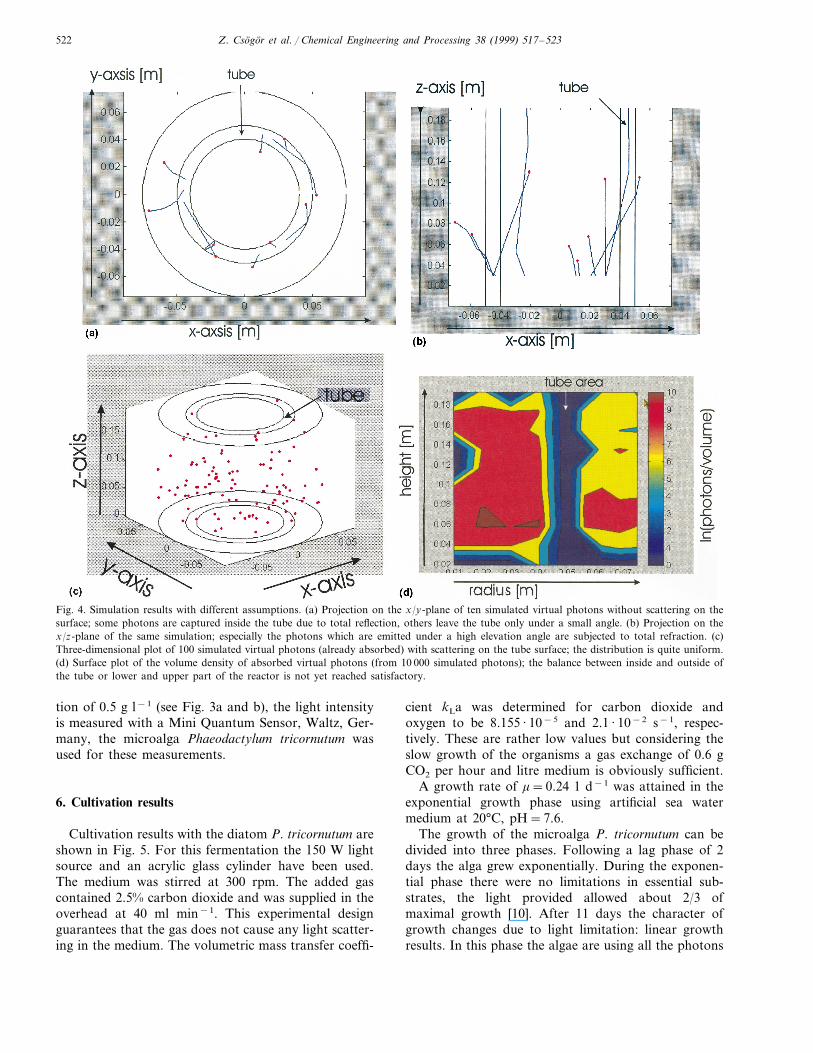
The simulation proofs that it is definitely necessaryfor understanding of the light distribution to simulate athree-dimensional problem, see Fig. 4a,b. The tube actsas a transparent light path which allows the photons toreach the upper part of the reactor without beingabsorbed. A second mechanism for light distributioninside the tube is total reflection. This helps the photonsto reach high positions inside the reactor. But unfortu-nately this has another effect. Many photons, especiallythe ones emitted under a high elevation angle, aretotally reflected several times thus moving on a helicaltrajectory until they hit the upper face of the tube andare therefore lost. Especially in the upper half of thetube none of the photons can penetrate the surface.Others leave the transparent tube under a nearly paral-lel direction to the surface and increase the radialgradient.
Z. Csogor et al. / Chemical Engineering and Processing 38 (1999) 517–523 521
One way to overcome this drawback is to roughenthe surface. So on the one hand total reflection can bepartially avoided and more photons can leave the tubein radial direction what decreases the radial gradient ascan be seen in Fig. 4c,d under the assumption of arough surface. In case, all photons would leave the tubein radial direction, a maximum peak of photon fluxdensity would be expected in the middle axis of thereactor due to the geometrical focus effect. However,this is not the case here, because there is still a big ratioof the photons with a more tangential pathway.
As shown in Fig. 4d the uniformity of light distribu-tion is better comparing a usual glass reactor withillumination via the reactor wall. However, it can befurther improved by an optimal harmonizing of the
design parameters namely refraction indices, inner andouter radius of the tube and the reactor as well as theroughness of the surface, where it is moreover possibleto chose a spatial pattern.
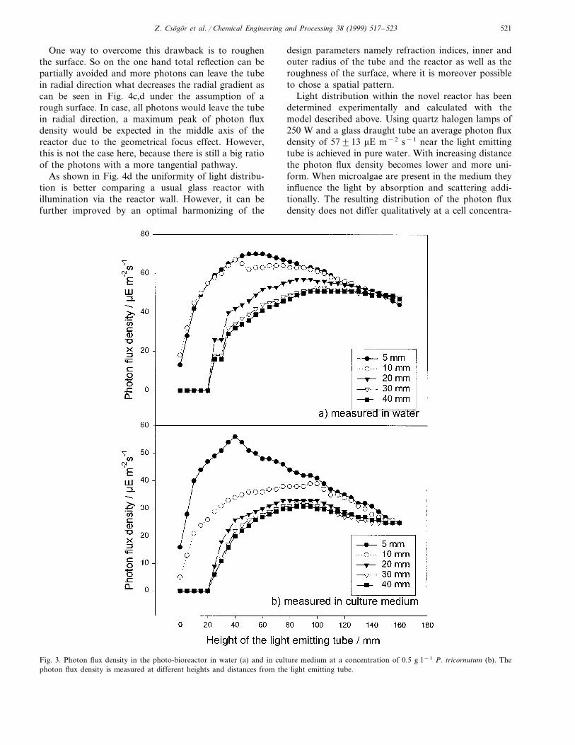
Light distribution within the novel reactor has beendetermined experimentally and calculated with themodel described above. Using quartz halogen lamps of250 W and a glass draught tube an average photon fluxdensity of 57913 mE m−2 s−1 near the light emittingtube is achieved in pure water. With increasing distancethe photon flux density becomes lower and more uni-form. When microalgae are present in the medium theyinfluence the light by absorption and scattering addi-tionally. The resulting distribution of the photon fluxdensity does not differ qualitatively at a cell concentra-
Fig. 3. Photon flux density in the photo-bioreactor in water (a) and in culture medium at a concentration of 0.5 g l−1 P. tricornutum (b). Thephoton flux density is measured at different heights and distances from the light emitting tube.
Z. Csogor et al. / Chemical Engineering and Processing 38 (1999) 517–523522
Fig. 4. Simulation results with different assumptions. (a) Projection on the x/y-plane of ten simulated virtual photons without scattering on thesurface; some photons are captured inside the tube due to total reflection, others leave the tube only under a small angle. (b) Projection on thex/z-plane of the same simulation; especially the photons which are emitted under a high elevation angle are subjected to total refraction. (c)Three-dimensional plot of 100 simulated virtual photons (already absorbed) with scattering on the tube surface; the distribution is quite uniform.(d) Surface plot of the volume density of absorbed virtual photons (from 10 000 simulated photons); the balance between inside and outside ofthe tube or lower and upper part of the reactor is not yet reached satisfactory.
tion of 0.5 g l−1 (see Fig. 3a and b), the light intensityis measured with a Mini Quantum Sensor, Waltz, Ger-many, the microalga Phaeodactylum tricornutum wasused for these measurements.
6. Cultivation results
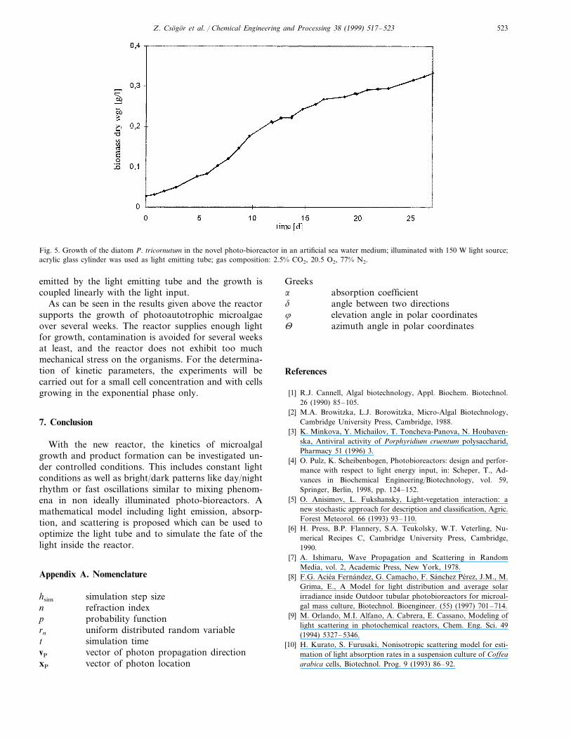
Cultivation results with the diatom P. tricornutum areshown in Fig. 5. For this fermentation the 150 W lightsource and an acrylic glass cylinder have been used.The medium was stirred at 300 rpm. The added gascontained 2.5% carbon dioxide and was supplied in theoverhead at 40 ml min−1. This experimental designguarantees that the gas does not cause any light scatter-ing in the medium. The volumetric mass transfer coeffi-
cient kLa was determined for carbon dioxide andoxygen to be 8.155 · 10−5 and 2.1 · 10−2 s−1, respec-tively. These are rather low values but considering theslow growth of the organisms a gas exchange of 0.6 gCO2 per hour and litre medium is obviously sufficient.
A growth rate of m=0.24 1 d−1 was attained in theexponential growth phase using artificial sea watermedium at 20°C, pH=7.6.
The growth of the microalga P. tricornutum can bedivided into three phases. Following a lag phase of 2days the alga grew exponentially. During the exponen-tial phase there were no limitations in essential sub-strates, the light provided allowed about 2/3 ofmaximal growth [10]. After 11 days the character ofgrowth changes due to light limitation: linear growthresults. In this phase the algae are using all the photons
Z. Csogor et al. / Chemical Engineering and Processing 38 (1999) 517–523 523
Fig. 5. Growth of the diatom P. tricornutum in the novel photo-bioreactor in an artificial sea water medium; illuminated with 150 W light source;acrylic glass cylinder was used as light emitting tube; gas composition: 2.5% CO2, 20.5 O2, 77% N2.
emitted by the light emitting tube and the growth iscoupled linearly with the light input.
As can be seen in the results given above the reactorsupports the growth of photoautotrophic microalgaeover several weeks. The reactor supplies enough lightfor growth, contamination is avoided for several weeksat least, and the reactor does not exhibit too muchmechanical stress on the organisms. For the determina-tion of kinetic parameters, the experiments will becarried out for a small cell concentration and with cellsgrowing in the exponential phase only.
7. Conclusion
With the new reactor, the kinetics of microalgalgrowth and product formation can be investigated un-der controlled conditions. This includes constant lightconditions as well as bright/dark patterns like day/nightrhythm or fast oscillations similar to mixing phenom-ena in non ideally illuminated photo-bioreactors. Amathematical model including light emission, absorp-tion, and scattering is proposed which can be used tooptimize the light tube and to simulate the fate of thelight inside the reactor.
Appendix A. Nomenclature
hsim simulation step sizen refraction index
probability functionprn uniform distributed random variable
simulation timetvector of photon propagation directionvP
vector of photon locationxP
Greeksabsorption coefficienta
angle between two directionsd
8 elevation angle in polar coordinatesazimuth angle in polar coordinatesU
References
[1] R.J. Cannell, Algal biotechnology, Appl. Biochem. Biotechnol.26 (1990) 85–105.
[2] M.A. Browitzka, L.J. Borowitzka, Micro-Algal Biotechnology,Cambridge University Press, Cambridge, 1988.
[3] K. Minkova, Y. Michailov, T. Toncheva-Panova, N. Houbaven-ska, Antiviral activity of Porphyridium cruentum polysaccharid,Pharmacy 51 (1996) 3.
[4] O. Pulz, K. Scheibenbogen, Photobioreactors: design and perfor-mance with respect to light energy input, in: Scheper, T., Ad-vances in Biochemical Engineering/Biotechnology, vol. 59,Springer, Berlin, 1998, pp. 124–152.
[5] O. Anisimov, L. Fukshansky, Light-vegetation interaction: anew stochastic approach for description and classification, Agric.Forest Meteorol. 66 (1993) 93–110.
[6] H. Press, B.P. Flannery, S.A. Teukolsky, W.T. Veterling, Nu-merical Recipes C, Cambridge University Press, Cambridge,1990.
[7] A. Ishimaru, Wave Propagation and Scattering in RandomMedia, vol. 2, Academic Press, New York, 1978.
[8] F.G. Aciea Fernandez, G. Camacho, F. Sanchez Perez, J.M., M.Grima, E., A Model for light distribution and average solarirradiance inside Outdoor tubular photobioreactors for microal-gal mass culture, Biotechnol. Bioengineer. (55) (1997) 701–714.
[9] M. Orlando, M.I. Alfano, A. Cabrera, E. Cassano, Modeling oflight scattering in photochemical reactors, Chem. Eng. Sci. 49(1994) 5327–5346.
[10] H. Kurato, S. Furusaki, Nonisotropic scattering model for esti-mation of light absorption rates in a suspension culture of Coffeaarabica cells, Biotechnol. Prog. 9 (1993) 86–92.
Recommended