EUROPEAN TRANSACTIONS ON TELECOMMUNICATIONSEur. Trans. Telecomms. 2009; 20:139–157Published online 7 August 2007 in Wiley InterScience(www.interscience.wiley.com) DOI: 10.1002/ett.1246
Communication Networks
Flexible routing in a distributed K-ary tree: the K-Umbrella
Athanasios-Dimitrios Sotiriou*, Panagiotis Kalliaras and Nikolas Mitrou
School of Electrical and Computer Engineering, Computer Network Laboratory, National Technical University of Athens, 9 Heroon PolytechneiouStreet, Zographou 15773, Athens, Greece
SUMMARY
As peer-to-peer (P2P) applications become more mature and demanding, there is a need for the underlyingtechnologies to provide more adaptive characteristics, according to the application’s requirements. In thispaper, we present K-Umbrella, a K-ary distributed hash table (DHT), which allows us to efficiently routethrough the use of a fixed-size routing table. By controlling a number of parameters, our algorithm is able totrade-off between efficiency, fault-tolerance and decentralisation according to the application’srequirements. Through a detailed analysis of our algorithms and an extensive set of simulations, we willshow that our protocol is able to offer an improved alternative to current DHT algorithms. Copyright #2007 John Wiley & Sons, Ltd.
1. INTRODUCTION
The introduction of peer-to-peer (P2P) systems was con-
ceived by some as a disruptive technology, mainly sup-
ported by the hacker community as an attempt to
promote the illegal sharing of content and undermine intel-
lectual property. One can easily compare this kind of reac-
tions with the ones received at the start of the open source
community. But as has open source matured during the last
decade, so did P2P technologies, passing from hype to
maturity and allowing for more sophisticated solutions
and wider usage. While file sharing has been the driving
force behind P2P technology’s popularity, the decentra-
lised, autonomous characteristics of P2P architectures
have thrived research in the development of more
advanced routing schemes, capable of outperforming clas-
sical centralised structures.
This paper provides insight in our work, trying to bridge
the best of both sides, by introducing a novel distributed
hash table (DHT) protocol, the K-Umbrella, which emu-
lates the form of a K-ary tree. While a strict definition of
a K-ary topology indicates a centralised point of control
that of the head of the tree, a number of relaxations on
the rules of our tree along with variable restrictions and
additional links allow for the construction of a scalable,
fault-tolerant, parameterised system that can efficiently
route queries on top of an overlay network.
The rest of the paper is organised as follows. Section 2
presents related work on the field of P2P networks, with
emphasis on DHT architectures. In Section 3, we present
the basic logic behind our work, followed by the algo-
rithms for the main operations in the next section. In
Section 5, we present some interesting extensions to our
algorithm and in the next section we provide a number
of results obtained by simulating our proposed work.
Finally, in Section 7 we offer some useful conclusions
and insight to future steps.
2. RELATED WORK
Our proposed algorithm is based on a semantic-free index,
and more particularly on a DHT implementation. The firsts
to introduce routing algorithms that could be applied to
Received 30 November 2006
Copyright # 2007 John Wiley & Sons, Ltd. Revised 23 April 2007
Accepted 19 June 2007
*Correspondence to: Athanasios-Dimitrios Sotiriou, School of Electrical and Computer Engineering, Computer Network Laboratory, National Tech-nical University of Athens, 9 Heroon Polytechneiou Street, Zographou 15773, Athens, Greece. E-mail: [email protected]
DHT systems were Plaxton, Rajaraman and Richa, with
the Plaxton Trees [1]. The algorithm was not developed
for P2P systems, and thus every node had a neighbourhood
of O(log N) and inquires resulted in O(log N) steps. It was
based on the ground rule of comparing one byte at a time
until all (or best compromise) were met. Following the
Plaxton Tree, a number of different DHT algorithms were
developed, which differentiated mainly on the geometry
adopted. The most common and interesting ones are Plax-
ton Trees, rings, toris, butterflies, de Brujin Graphs and
Skip Graphs.
Tapestry [2] was based on the ideas set by Plaxton but
adopted properly for P2P systems. Unlike Plaxton, it
allowed nodes to be inserted and deleted and used surro-
gate routing to incrementally choose root nodes and put
object copies close to nodes generating high query loads.
Pastry [3] is another variation that used Plaxton-like prefix
routing, where Pastry nodes maintain O(log N) neighbours
and route to a target in O(log N) hops. Pastry differs from
Tapestry only in the method by which it handles network
locality and replication. Each Pastry node maintains a ‘leaf
set’ and a ‘routing table’. More recently, Maymounkov and
Mazieres introduced Kademlia [4] which, like Pastry,
repeatedly finds nodes about half way to the target node.
Kademlia uses a bitwise exclusive or (XOR) metric for
the ‘distance’ between 160 bit node identifiers. Each node
keeps a list of contact nodes for each section of the node
space that is between 2i and 2iþ1 from itself (0_i< 160).
Willow [5] also uses the XOR metric in implementing a
Tree Maintenance Protocol to ‘zipper’ together broken
segments of a tree. Where other schemes use DHT routing
to inefficiently add new peers, Willow can merge disjoint
or broken trees in O(log N) parallel operations.
Chord [6] was the first to introduce the idea of the DHT
ring, mapping nodes and keys to an identifier ring. It uses
Consistent Hashing to minimise disruption of keys when
nodes join and leave the network and requires peers to only
track O(log N) other peers. Each Chord peer tracks its pre-
decessor, a list of successors and a finger table. Using the
finger table, each hop is at least half the remaining distance
around the ring to the target node, giving an average
lookup hop count of (1/2)log2 N. Alima et al. [7] tried to
minimise the communication costs of Chord by introdu-
cing the Distributed K-ary Search (DKS) design, which
is similar to Chord. They argued that the total system
should evolve for an optimum balance between the number
of peers, the lookup hop count and the size of the routing
table.
Ratnasamy et al. [8] developed the Content-Addressa-
ble Network (CAN), which is arranged as a virtual
d-dimensional Cartesian coordinate space on a d-torus. Each
node is responsible for a zone in this coordinate space.
This allowed the system to keep the number of neighbours
independent of the node population. While all other major
algorithms (Pastry, Tapestry, Chord) have O(log N) neigh-
bours per node and O(log N) hops per lookup, CAN has
O(d) neighbours and O(dN1/d) hop-count.
Viceroy [9] approximates a butterfly network which is
based on a constant degree, like CAN, but has logarithmic
diameter. As with most DHTs, it utilises Consistent Hash-
ing. When a peer joins the Viceroy network, it takes a ran-
dom but permanent ‘identity’ and selects its ‘level’ within
the network. Each peer maintains general ring pointers
(‘predecessor’ and ‘successor’), level ring pointers (‘nex-
tonlevel’ and ‘prevonlevel’) and butterfly pointers. Vice-
roy’ s expected degree may be constant but its high
probability bound is O(log N).
While most DHTalgorithms are ‘greedy’, as each time a
query is forwarded it moves closer to the destination, de
Bruijn graphs of degree k achieve an asymptotically opti-
mal diameter logk N, where N is the number of nodes in the
system and k can be varied to improve resilience. For
O(log N) neighbours per node, the de Bruijn graph can
route in O(log N/log log N). There have been numerous
proposals of de Bruijn graphs, such as D2B [10] and
Koorde [11].
Skip Graphs [12, 13] unlike balanced trees, are prob-
abilistic and are based on the Skip Lists. Their insert and
delete operations do not require tree rearrangements and so
are faster by a constant factor. In Skip Lists all nodes par-
ticipate in the bottom layer list while some of them also
participate in an upper layer with a given probability, of
which some participate on the layer on top of that and so
on. A lookup can proceed quickly through the list by tra-
versing the sparse upper layers until it is close to, or at, the
target. Unfortunately, nodes on the upper layers can prove
a single point of failure. Skip Graphs on the other hand
provide multiple lists at each level for redundancy, with
every node participating in one of the lists at each level.
Skip Graphs have O(log N) neighbours on an average, like
most DHTs but can support prefix and proximity searches.
However, Skip Graph nodes require many more pointers
than their DHT counterparts and this implies increased
maintenance traffic.
Our algorithm is based on a combination of some of the
above approaches, aiming to resolve open issues and pro-
vide additional features. Our protocol relates to the Plax-
ton Trees, as it is based on the fundamentals of prefix
routing and uses the concepts of ‘leaf set’ and ‘routing
table’, however, with major differences in the way these
140 A.D. SOTIRIOU, P. KALLIARAS AND N. MITROU
Copyright # 2007 John Wiley & Sons, Ltd. Eur. Trans. Telecomms. 2009; 20:139–157DOI:10.1002/ett
are created. As opposed to Plaxton, Tapestry and Pastry,
our algorithm is more similar to Kademlia sharing the tree
fundamental but extending it in order to bypass the short-
comings of using just a binary tree, which is sub-optimal.
In relation to ring topologies, our protocol shares the
concept of DKS for balancing the number of peers, the
lookup hop count and the size of the routing table. How-
ever, our protocol aims for a more diverse structuring, tak-
ing into consideration nodes that show stable behaviour
and promoting them in the topology.
Our K-Umbrella resembles the constant degree of
neighbours as in toris and butterflies networks (CAN,
Viceroy), however, it is able to route in logarithmic steps
as opposed to toris and with no high probability bound as
in butterflies. Also, the tree K-ary tree structure is much
simpler in operation as opposed to these algorithms.
Finally, as opposed to Skip and de Brujin Graphs, we pro-
vide a constant degree table in order to minimise mainte-
nance traffic and improve scalability.
In Reference [14], we firstly introduced the concept of
the K-ary tree and highlighted its benefits as opposed to
other DHT structures. This paper furthers our previous
work in a number of ways, by generalising the previous
concept from a constant 16-ary tree to a parameterised
K-ary tree. It also introduces the concept of sub-tree edges
for quick horizontal traversal of our structure and the
unique ability to change the degree of distribution of traffic
amongst stable and non-stable peers through these two
parameters, as will be shown in the course of this paper.
3. THE K-UMBRELLA
In this section we describe the main structure of the K-
Umbrella along with the fundamentals of our DHT. Our
implementation is based on top of an overlay network, in
which we assign identifiers for each node and provide
operations for inserting nodes, publishing and searching
keywords in the context of our proposed topology. Our
main focus is to define the entities stored in our fixed-size
routing table, which will allow our routing protocol to
guide messages, as described in the subsequent chapter.
In the rest of the paper we will assume the following:
� Node connectivity is both symmetric and transitive, a
direct consequence of our overlay topology on top of
an IP network.
� All inserting nodes are identified by a unique code,
asserted by applying the SHA-1 [15] hash-function on
the combination of IP and computer name, returning a
160-bit identifier.
� The hash-function distributes keys uniformly [16] in the
160-bit space and thus provides the desired load balan-
cing for both the user space and the content space.
3.1. Main model
K-ary trees are considered a generalisation of binary trees,
where each node has a maximum of k leafs, where k is
known as the branching factor. While a number of DHT
algorithms have been proposed for binary trees [7], K-
ary trees have not been investigated extensively. In this
paper, we present an enhanced K-ary tree, the K-Umbrella,
where each node has a maximum of k leafs, with some
additional connections that ensure that the tree can be dis-
tributed in a P2P environment. The main objective of the
K-Umbrella architecture is to insert and retain nodes in a
simple and well structured manner, thus querying and
fetching of content is both efficient and fault-tolerant. In
addition, each node only needs to retain up-to-date infor-
mation of a limited, constant number of neighbouring
nodes, thus increasing the scalability of the system in
population of both users and content.
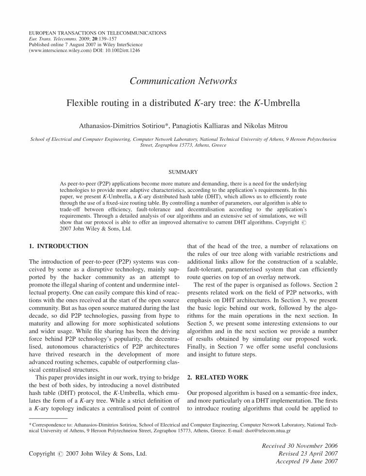
Our K-Umbrella, shown in Figure 1, constitutes a K-ary
tree where each node n is located at level l and has a max-
imum of k leafs (also called children). A child nk shares the
same prefix prel(nk) with its parent n for all l first digits,
thus prel(nk)¼ prel(n), and its lth digit is k. In addition,
each node holds a number of additional connections,
which ensure its scalability and fault tolerance. As such,
each node nk keeps two sets of pointers, one set towards
each non-empty neighbour to the left and to the right of
it, which do not necessarily belong to the same sub-tree.
Also, each node residing at the edge of each sub-tree keeps
a pointer towards the node residing on the other end at the
same level, with higher level sub-trees holding additional
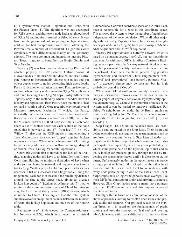
edge pointers at the same level. We call these nodes sub-
tree edges, sdgl(n), and extend them in a bottom-up
approach, as shown in Figure 2.
A simple rule for obtaining sub-tree edges is to move
horizontally (left or right) across the tree until the last child
of the sub-tree is found. For example, according to
Figure 2, sdg1(n) is calculated by moving towards the right
and finding the last child that resides on the same sub-tree
of depth 2. In our implementation, since acquiring the sub-
tree edges of high order can result in an extensive amount
of messages (klþ 1), we constrain the level of sub-tree
edges known to each node to an upper limit of m.
K-UMBRELLA 141
Copyright # 2007 John Wiley & Sons, Ltd. Eur. Trans. Telecomms. 2009; 20:139–157DOI:10.1002/ett
Each node is inserted in the system through an existing
node, which announces the new entrance. The inserting
nodes are always placed as leaf nodes in the K-ary tree,
since they must find an arbitrary node with free leafs. As
new nodes are inserted, these leaf nodes can become arbi-
trary nodes themselves. As a result, the K-ary tree structure
of two K-Umbrella networks comprising of the exact
nodes can differentiate depending on the order and the
entree point of the nodes. When this procedure has ended
successfully, the new node can, having acquired and
informed all neighbouring nodes, continue to publish all
of its content. The publishing procedure is similar to the
insertion mechanism, as content is characterised by a num-
ber of keys, which after being hashed can be forwarded in
the same manner. All keys are published in an existing
node that its identifier is the closest match to the key iden-
tifier. As closest match we consider the one having the
maximum same bits, read from left to right, and smallest
numerical match in the case of two nodes having the same
number of exact bits. In a similar fashion, querying is per-
formed by routing the request to the node with identifier
closest to the desired key. If no such node exists, it is
assumed that the desired content is not available.
3.2. Key mapping
Each level l of the structure is capable of withholding klþ 1
nodes. Each node has a unique parent node, which is
always one level higher, and a maximum of k children at
a lower level. Let f denote the function that returns the digit
of an identifier at position x. Then the explicit relation
between nodes A and B of the same parent p, which resides
on level l, is:
fAðxÞ ¼ fBðxÞ; 14x4lþ 1
fAðxÞ 6¼ fBðxÞ; x ¼ lþ 2ð1Þ
Also, the relation of parent and child requires that
fpðxÞ ¼ fAðxÞ ¼ fBðxÞ; 14x4lþ 1 ð2ÞThe above simple rules are obeyed by all nodes entering
the K-Umbrella overlay network. As already stated, the
Figure 1. The K-Umbrella structure.
Figure 2. Sub-tree edges.
142 A.D. SOTIRIOU, P. KALLIARAS AND N. MITROU
Copyright # 2007 John Wiley & Sons, Ltd. Eur. Trans. Telecomms. 2009; 20:139–157DOI:10.1002/ett
SHA-1 hash function is used to assign identifiers to both
nodes and content, offering a uniform distribution in the
160-bit space along with non-voluntary placement anon-
ymity [17] of the published content. In order to apply
the routing algorithms which will be described later on,
we define a comparing function for identifiers as comp,
which compares two identifiers and calculates their differ-
ence as a long integer. The returned function is calculated
as such:
compðid1; id2Þ ¼Xi¼160=k
i¼1
gðiÞ
gðiÞ ¼ kð160=kÞ�i; if fid1ðiÞ ¼ fid1ðiÞ0; if fid1ðiÞ 6¼ fid1ðiÞ
( ð3Þ
The use of a consistent hash function to distribute iden-
tifiers in our node and content space allows the construc-
tion of a well-balanced K-ary tree. The structure becomes
even more balanced as the node population increases
and nodes fill empty spaces. The consistent hash function
also balances key distribution among nodes as stated in
Reference [18] in the form of the following theorem:
Theorem 1. Given a set of nodes N and keys R, then with
high probability each node is responsible for an average of
R/N keys, with a maximum of ð1þ aÞR=N, whereas a a
parameter with bound of OðlogNÞ.
In the rest of the paper we will not elaborate further on
consistent hash function characteristics as these have been
examined and validated by Karger et al. [18] and are out of
the scope of this paper.
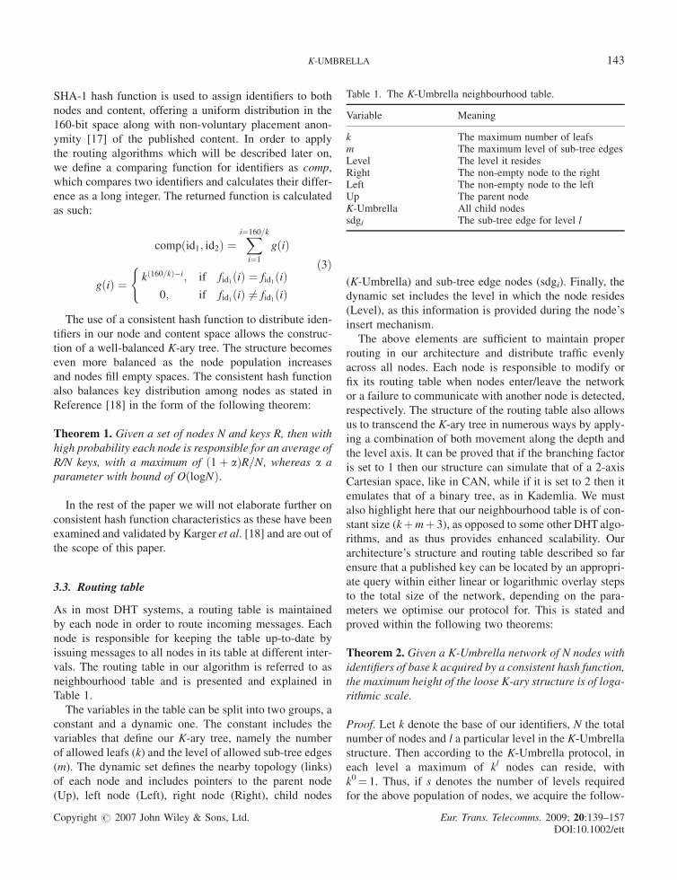
3.3. Routing table
As in most DHT systems, a routing table is maintained
by each node in order to route incoming messages. Each
node is responsible for keeping the table up-to-date by
issuing messages to all nodes in its table at different inter-
vals. The routing table in our algorithm is referred to as
neighbourhood table and is presented and explained in
Table 1.
The variables in the table can be split into two groups, a
constant and a dynamic one. The constant includes the
variables that define our K-ary tree, namely the number
of allowed leafs (k) and the level of allowed sub-tree edges
(m). The dynamic set defines the nearby topology (links)
of each node and includes pointers to the parent node
(Up), left node (Left), right node (Right), child nodes
(K-Umbrella) and sub-tree edge nodes (sdgi). Finally, the
dynamic set includes the level in which the node resides
(Level), as this information is provided during the node’s
insert mechanism.
The above elements are sufficient to maintain proper
routing in our architecture and distribute traffic evenly
across all nodes. Each node is responsible to modify or
fix its routing table when nodes enter/leave the network
or a failure to communicate with another node is detected,
respectively. The structure of the routing table also allows
us to transcend the K-ary tree in numerous ways by apply-
ing a combination of both movement along the depth and
the level axis. It can be proved that if the branching factor
is set to 1 then our structure can simulate that of a 2-axis
Cartesian space, like in CAN, while if it is set to 2 then it
emulates that of a binary tree, as in Kademlia. We must
also highlight here that our neighbourhood table is of con-
stant size (kþmþ 3), as opposed to some other DHTalgo-
rithms, and as thus provides enhanced scalability. Our
architecture’s structure and routing table described so far
ensure that a published key can be located by an appropri-
ate query within either linear or logarithmic overlay steps
to the total size of the network, depending on the para-
meters we optimise our protocol for. This is stated and
proved within the following two theorems:
Theorem 2. Given a K-Umbrella network of N nodes with
identifiers of base k acquired by a consistent hash function,
the maximum height of the loose K-ary structure is of loga-
rithmic scale.
Proof. Let k denote the base of our identifiers, N the total
number of nodes and l a particular level in the K-Umbrella
structure. Then according to the K-Umbrella protocol, in
each level a maximum of kl nodes can reside, with
k0¼ 1. Thus, if s denotes the number of levels required
for the above population of nodes, we acquire the follow-
Table 1. The K-Umbrella neighbourhood table.
Variable Meaning
k The maximum number of leafsm The maximum level of sub-tree edgesLevel The level it residesRight The non-empty node to the rightLeft The non-empty node to the leftUp The parent nodeK-Umbrella All child nodessdgl The sub-tree edge for level l
K-UMBRELLA 143
Copyright # 2007 John Wiley & Sons, Ltd. Eur. Trans. Telecomms. 2009; 20:139–157DOI:10.1002/ett
ing relation, in respect to Theorem 1 that provides, with
high probability, a uniform distribution of identifiers to
our space:
N ¼Xs�1
z¼0
kz ¼ k0 � ks�1þ1
1� k¼ 1� ks
1� k, s
¼ logk Nðk � 1Þ þ 1½ �ð4Þ
Thus the maximum height m of our structure is of
O(logk N). &
Theorem 3. A successful lookup in a K-Umbrella network
requires, with high probability, either linear or logarithmic
overlay steps to the total size of the network, depending on
the parameters of our protocol.
Proof. Suppose that a node p that resides at level lp is seek-
ing for a specific key z that resides within our network in
another node f at level lf. If s denotes the number of levels
of the current network, N the node population, k the
branching factor and H the required number of hops, then
we could argue that the worst case scenario would require
both nodes to reside at level s and with maximum distance
between them (thus node p is an s-depth child of the first
child at level 1 and on-forth and node f is the m-depth child
of the k child at level 0 and so on). According to our pro-
tocol, we can conduct a query based on two different
approaches.
The first would be to move completely horizontally
across the K-ary structure without using any sub-tree
edges. This would require a linear number of steps, as sta-
ted below:
H ¼ ks ) OðksÞ ) Oðklogk ½Nðk�1Þþ1�Þ )OðNðk � 1Þ þ 1Þ ) OðNkÞ ) OðNÞ ð5Þ
The second approach would be to move vertically upon
the K-ary topology, ascending and descending the K-ary
tree before moving horizontally. If u denotes the times
we move vertically, then each such move shortens the
required number of hops by a factor of k, with the addition
of 2 steps, for ascending and then descending back to the
previous level. As thus, a successful lookup would require
logarithmic number of hops, as stated below:
H ¼ ks�u þ 2u )u¼sOðks�s þ 2sÞ )
Oð1þ 2flogk½Nðk � 1Þ þ 1�gÞ )Oðlogk½Nðk � 1Þ þ 1�Þ ) OðlogkNðk � 1ÞÞ )OðlogkNkÞ ) OðlogkNÞ
ð6Þ
From the above we conclude that the required number of
steps can be varied between logarithmic or linear overlay
steps to the total size of the network. &The logarithmic degree requires that we transcend the
K-ary topology and as thus introduces more traffic to nodes
residing on the top of our topology as opposed to those
residing on lower levels, producing an uneven distribution
of traffic. On the other end, the linear degree is of course
not desirable. However, as will be proven later on through
our simulations, a combination of these two approaches
has been applied, providing an optimisation between
maintenance traffic and degree of steps. This parameterisa-
tion characteristic of our protocol allows us to change the
protocol’s behaviour in order to meet the specific require-
ments of the application build on top of it.
4. ALGORITHMS FOR K-UMBRELLA
In this section, we will present the basic routing algorithms
developed for our architecture, which include the network
construction, insert, publish, lookup and voluntary depar-
ture procedures and finally a repair mechanism.
During the creation of the overlay network, the first
node to enter creates the new network by placing itself
on the top level. As new nodes arrive, they are placed
according to their identifier, as described in the previous
section. A node only needs to contact an existing node in
the system in order to be inserted (special mechanisms for
fetching existing nodes by outside contacts are not in the
scope of this paper as our architecture can embody any of
numerous such techniques already proposed, such as
building a bootstrap ring [19] or using a distributed anycast
system [20]). Only the first node is automatically inserted
regardless of its identifier; all subsequent nodes are placed
within the system according to the insertion algorithm.
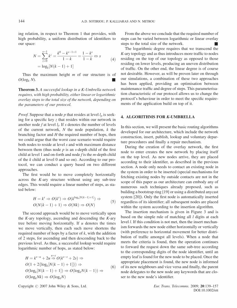
The insertion mechanism is given in Figure 3 and is
based on the simple rule of matching all l digits at each
level l. If this condition is not met, then the insert mechan-
ism forwards the new node either horizontally or vertically
(with preference to horizontal movement for better distri-
bution of traffic amongst all levels). When a node that
meets the criteria is found, then the operation continues
to forward the request down the same sub-tree according
to the corresponding digits of the node identifier, until an
empty leaf is found for the new node to be placed. Once the
appropriate placement is found, the new node is informed
of its new neighbours and vice versa and finally, the parent
node delegates to the new node any keywords that are clo-
ser to the new node’s identifier.
144 A.D. SOTIRIOU, P. KALLIARAS AND N. MITROU
Copyright # 2007 John Wiley & Sons, Ltd. Eur. Trans. Telecomms. 2009; 20:139–157DOI:10.1002/ett
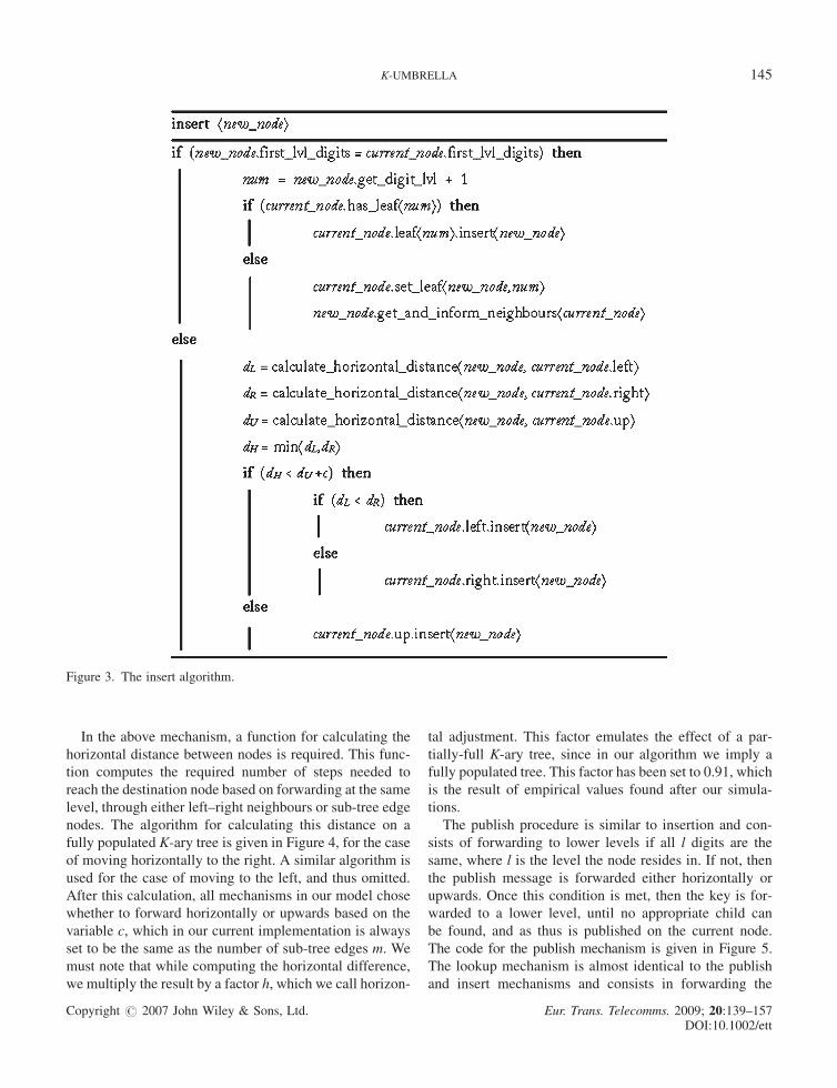
In the above mechanism, a function for calculating the
horizontal distance between nodes is required. This func-
tion computes the required number of steps needed to
reach the destination node based on forwarding at the same
level, through either left–right neighbours or sub-tree edge
nodes. The algorithm for calculating this distance on a
fully populated K-ary tree is given in Figure 4, for the case
of moving horizontally to the right. A similar algorithm is
used for the case of moving to the left, and thus omitted.
After this calculation, all mechanisms in our model chose
whether to forward horizontally or upwards based on the
variable c, which in our current implementation is always
set to be the same as the number of sub-tree edges m. We
must note that while computing the horizontal difference,
we multiply the result by a factor h, which we call horizon-
tal adjustment. This factor emulates the effect of a par-
tially-full K-ary tree, since in our algorithm we imply a
fully populated tree. This factor has been set to 0.91, which
is the result of empirical values found after our simula-
tions.
The publish procedure is similar to insertion and con-
sists of forwarding to lower levels if all l digits are the
same, where l is the level the node resides in. If not, then
the publish message is forwarded either horizontally or
upwards. Once this condition is met, then the key is for-
warded to a lower level, until no appropriate child can
be found, and as thus is published on the current node.
The code for the publish mechanism is given in Figure 5.
The lookup mechanism is almost identical to the publish
and insert mechanisms and consists in forwarding the
Figure 3. The insert algorithm.
K-UMBRELLA 145
Copyright # 2007 John Wiley & Sons, Ltd. Eur. Trans. Telecomms. 2009; 20:139–157DOI:10.1002/ett
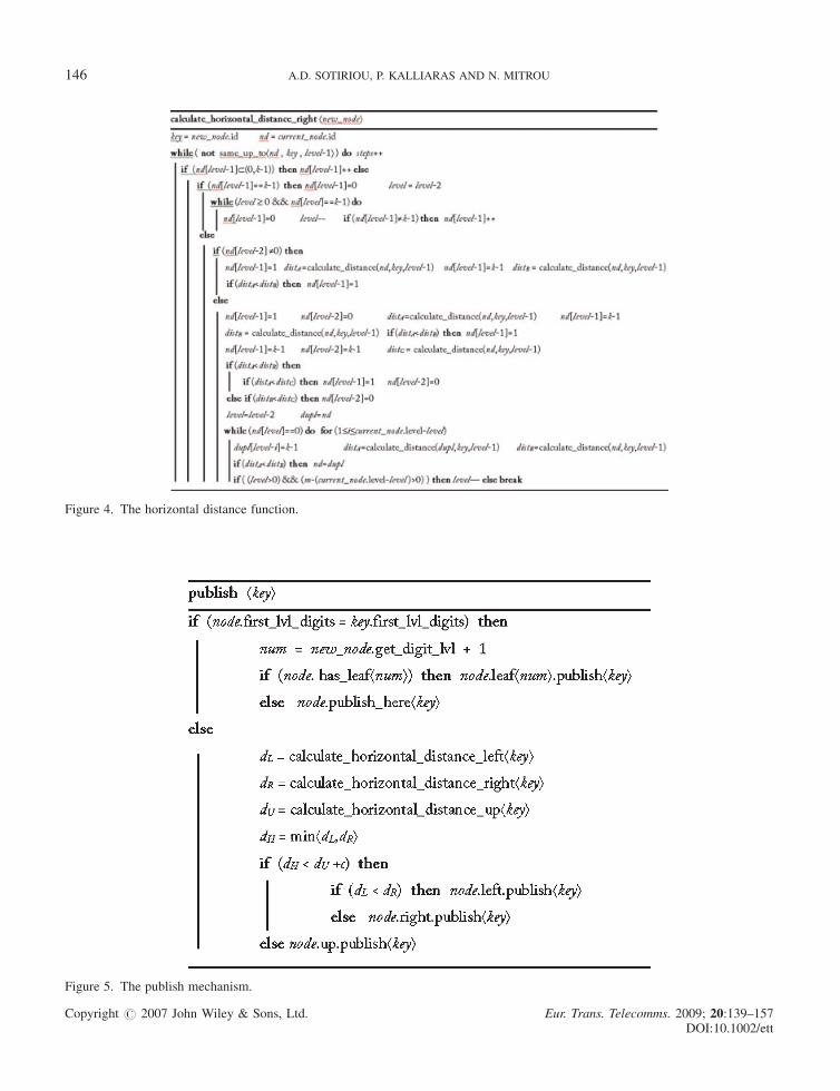
Figure 4. The horizontal distance function.
Figure 5. The publish mechanism.
146 A.D. SOTIRIOU, P. KALLIARAS AND N. MITROU
Copyright # 2007 John Wiley & Sons, Ltd. Eur. Trans. Telecomms. 2009; 20:139–157DOI:10.1002/ett
lookup messages either horizontally or vertically until the
key is found.
The final mechanism provided by our protocol is that of
voluntary node departure. When a node issues a departure
the following steps are followed:
Step 1: If the node has no children then all of its key-
words are forwarded to its parent and it informs all its
neighbours of the departure.
Step 2: If it has any child, then it randomly picks one and
copies all of its neighbourhood and keyword informa-
tion to it before departing. The chosen child moves up
a level and substitutes the departing node.
Step 3: The new node is informed of its neighbours and
updates all its sub-tree edge nodes.
Step 4: The process continues from Step 2 until a node
with no children is reached.
The algorithms presented so far are capable of maintain-
ing the system stable and fully functional under normal
conditions, as has been validated by our simulation results
given in subsequent sections. The system is, however,
liable to node departures, either intentional or due to net-
work disconnections. Intentional departures are handled
through the departure mechanism and as such we concen-
trate on sudden departures of nodes, which we call ‘node
failures’. The existence of the sub-tree edges and the cap-
ability of moving both horizontally and vertically allow
our system to bypass node failures to a given extent. How-
ever, in order to address the problem of node failures even
further, we have designed a repair mechanism, which is
invoked whenever such a failure is detected. The algorithm
utilises the voluntary departure algorithm in order to repair
a failure to a child node. It can be proved that all other fail-
ures can be transformed into a child failure through con-
tacting nodes in the neighbouring table and forwarding a
repair message to higher or lower levels until the parent
node of the failing node is reached. Once the appropriate
node is found and informed of the child failure, the repair
mechanism is evoked and restores the failure by substitut-
ing the failed node with one of its children or by deleting it
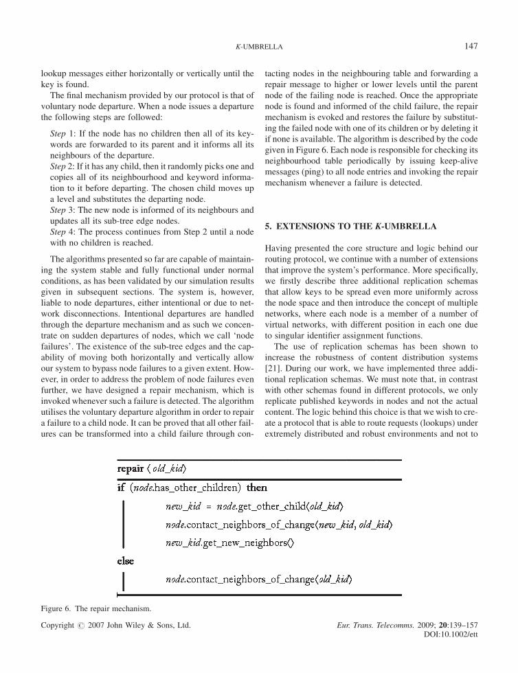
if none is available. The algorithm is described by the code
given in Figure 6. Each node is responsible for checking its
neighbourhood table periodically by issuing keep-alive
messages (ping) to all node entries and invoking the repair
mechanism whenever a failure is detected.
5. EXTENSIONS TO THE K-UMBRELLA
Having presented the core structure and logic behind our
routing protocol, we continue with a number of extensions
that improve the system’s performance. More specifically,
we firstly describe three additional replication schemas
that allow keys to be spread even more uniformly across
the node space and then introduce the concept of multiple
networks, where each node is a member of a number of
virtual networks, with different position in each one due
to singular identifier assignment functions.
The use of replication schemas has been shown to
increase the robustness of content distribution systems
[21]. During our work, we have implemented three addi-
tional replication schemas. We must note that, in contrast
with other schemas found in different protocols, we only
replicate published keywords in nodes and not the actual
content. The logic behind this choice is that we wish to cre-
ate a protocol that is able to route requests (lookups) under
extremely distributed and robust environments and not to
Figure 6. The repair mechanism.
K-UMBRELLA 147
Copyright # 2007 John Wiley & Sons, Ltd. Eur. Trans. Telecomms. 2009; 20:139–157DOI:10.1002/ett
ensure replication of rare content as in the case of Freenet
[22]. Our three variations are the following:
Local Spread Replication (LSR): In this schema, once
the proper node is found, through the publish mechan-
ism, the keyword is also published in all nodes residing
in its neighbouring table.
Inverse Replication (IR): This mechanism publishes
keywords in two nodes. The first is the closest match
as in our original routing protocol, while the second is
the one with inverse identifier to that of the keyword.
Local Spread Inverse Replication (LSIR): This mechan-
ism is a combination of the two previous schemas, and
implements a local spread in both the closest match and
the inverse closest match.
As already stated, the identifier obtained for each node
by the use of the SHA-1 hash function determines each
node’s position in our K-Umbrella. This defines its relation
to neighbouring nodes and, even though not explicitly,
bounds it to a constrained number of nodes. This can be
avoided to an extent by allowing each node to participate
in a number of virtual networks, with a different identifier
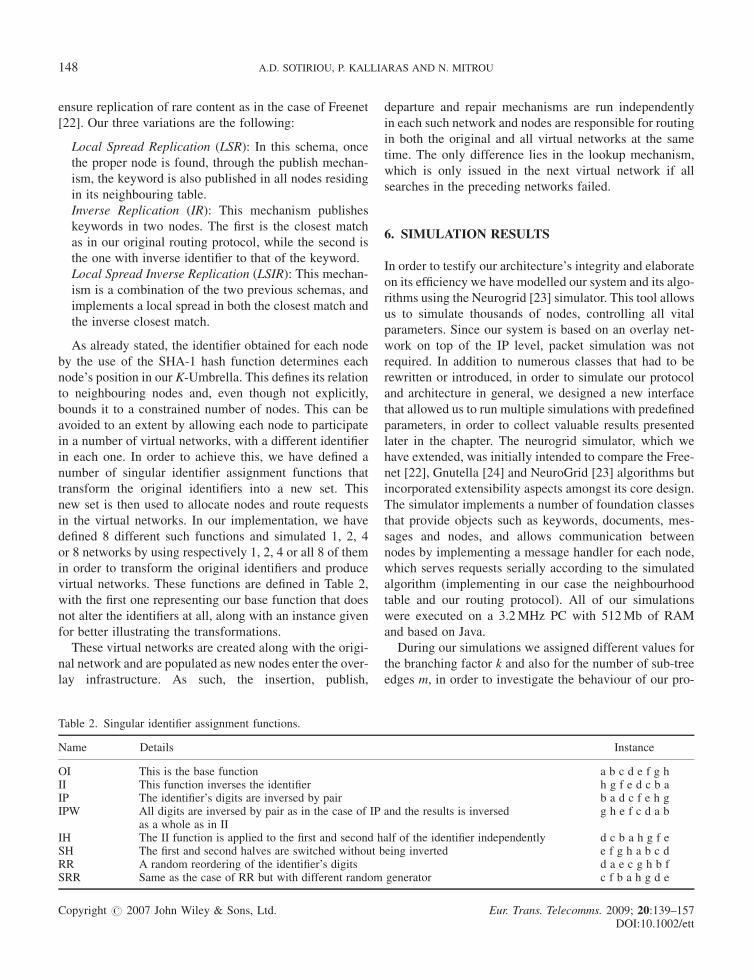
in each one. In order to achieve this, we have defined a
number of singular identifier assignment functions that
transform the original identifiers into a new set. This
new set is then used to allocate nodes and route requests
in the virtual networks. In our implementation, we have
defined 8 different such functions and simulated 1, 2, 4
or 8 networks by using respectively 1, 2, 4 or all 8 of them
in order to transform the original identifiers and produce
virtual networks. These functions are defined in Table 2,
with the first one representing our base function that does
not alter the identifiers at all, along with an instance given
for better illustrating the transformations.
These virtual networks are created along with the origi-
nal network and are populated as new nodes enter the over-
lay infrastructure. As such, the insertion, publish,
departure and repair mechanisms are run independently
in each such network and nodes are responsible for routing
in both the original and all virtual networks at the same
time. The only difference lies in the lookup mechanism,
which is only issued in the next virtual network if all
searches in the preceding networks failed.
6. SIMULATION RESULTS
In order to testify our architecture’s integrity and elaborate
on its efficiency we have modelled our system and its algo-
rithms using the Neurogrid [23] simulator. This tool allows
us to simulate thousands of nodes, controlling all vital
parameters. Since our system is based on an overlay net-
work on top of the IP level, packet simulation was not
required. In addition to numerous classes that had to be
rewritten or introduced, in order to simulate our protocol
and architecture in general, we designed a new interface
that allowed us to run multiple simulations with predefined
parameters, in order to collect valuable results presented
later in the chapter. The neurogrid simulator, which we
have extended, was initially intended to compare the Free-
net [22], Gnutella [24] and NeuroGrid [23] algorithms but
incorporated extensibility aspects amongst its core design.
The simulator implements a number of foundation classes
that provide objects such as keywords, documents, mes-
sages and nodes, and allows communication between
nodes by implementing a message handler for each node,
which serves requests serially according to the simulated
algorithm (implementing in our case the neighbourhood
table and our routing protocol). All of our simulations
were executed on a 3.2MHz PC with 512Mb of RAM
and based on Java.
During our simulations we assigned different values for
the branching factor k and also for the number of sub-tree
edges m, in order to investigate the behaviour of our pro-
Table 2. Singular identifier assignment functions.
Name Details Instance
OI This is the base function a b c d e f g hII This function inverses the identifier h g f e d c b aIP The identifier’s digits are inversed by pair b a d c f e h gIPW All digits are inversed by pair as in the case of IP and the results is inversed g h e f c d a b
as a whole as in IIIH The II function is applied to the first and second half of the identifier independently d c b a h g f eSH The first and second halves are switched without being inverted e f g h a b c dRR A random reordering of the identifier’s digits d a e c g h b fSRR Same as the case of RR but with different random generator c f b a h g d e
148 A.D. SOTIRIOU, P. KALLIARAS AND N. MITROU
Copyright # 2007 John Wiley & Sons, Ltd. Eur. Trans. Telecomms. 2009; 20:139–157DOI:10.1002/ett
tocol. We have split the simulation process into three dis-
tinct set of experiments, in order to investigate different
characteristics of our system. In the first one, we vary
the number of children and sub-tree edges and analyse
their impact on the performance of the protocol. In this
section, we mainly focus on the number of hops required
for each successful operation and also the overhead traffic
produced. During the second set, we simulate the network
using the distribution for content, arrival and duration of
P2P sessions described by Klemm et al. [25], in order to
validate the benefits of having a protocol that promotes
stable users. The main aim of this set is to provide a metric
for promoting stable users, that is peers that remain in the
overlay network are placed in more central points. Finally,
in the third set of simulations we observe the protocol’s
behaviour under node failures, utilising the extended
mechanisms of replication schemas and virtual networks
presented in the previous section. During this set, we look
at the success rate of the search algorithm under different
settings and increasing the number of failures.
Prior to our simulation analysis on the efficiency of our
protocol and its performance in general, we present the K-
Umbrella topology, as this derives from the architectural
design. For this purpose, we have used the JUNG [26]
library, which allows the visual representation of networks.
Once our overlay network has been created and fully popu-
lated, we produce an instance of the overlay topology by
representing each node (peer) along with the parent-
children pairs of connections. In addition, we colour each
node according to the level it resides, providing an in-sight
view of our protocol.
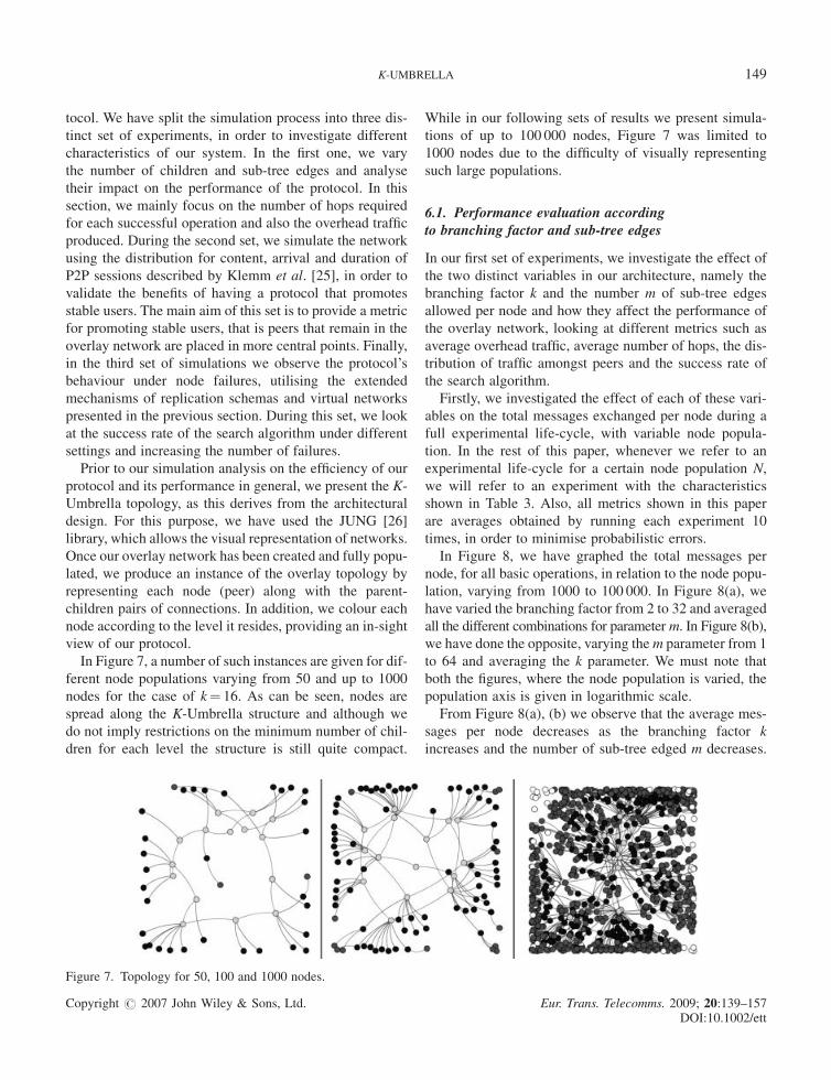
In Figure 7, a number of such instances are given for dif-
ferent node populations varying from 50 and up to 1000
nodes for the case of k¼ 16. As can be seen, nodes are
spread along the K-Umbrella structure and although we
do not imply restrictions on the minimum number of chil-
dren for each level the structure is still quite compact.
While in our following sets of results we present simula-
tions of up to 100 000 nodes, Figure 7 was limited to
1000 nodes due to the difficulty of visually representing
such large populations.
6.1. Performance evaluation accordingto branching factor and sub-tree edges
In our first set of experiments, we investigate the effect of
the two distinct variables in our architecture, namely the
branching factor k and the number m of sub-tree edges
allowed per node and how they affect the performance of
the overlay network, looking at different metrics such as
average overhead traffic, average number of hops, the dis-
tribution of traffic amongst peers and the success rate of
the search algorithm.
Firstly, we investigated the effect of each of these vari-
ables on the total messages exchanged per node during a
full experimental life-cycle, with variable node popula-
tion. In the rest of this paper, whenever we refer to an
experimental life-cycle for a certain node population N,
we will refer to an experiment with the characteristics
shown in Table 3. Also, all metrics shown in this paper
are averages obtained by running each experiment 10
times, in order to minimise probabilistic errors.
In Figure 8, we have graphed the total messages per
node, for all basic operations, in relation to the node popu-
lation, varying from 1000 to 100 000. In Figure 8(a), we
have varied the branching factor from 2 to 32 and averaged
all the different combinations for parameterm. In Figure 8(b),
we have done the opposite, varying them parameter from 1
to 64 and averaging the k parameter. We must note that
both the figures, where the node population is varied, the
population axis is given in logarithmic scale.
From Figure 8(a), (b) we observe that the average mes-
sages per node decreases as the branching factor k
increases and the number of sub-tree edged m decreases.
Figure 7. Topology for 50, 100 and 1000 nodes.
K-UMBRELLA 149
Copyright # 2007 John Wiley & Sons, Ltd. Eur. Trans. Telecomms. 2009; 20:139–157DOI:10.1002/ett
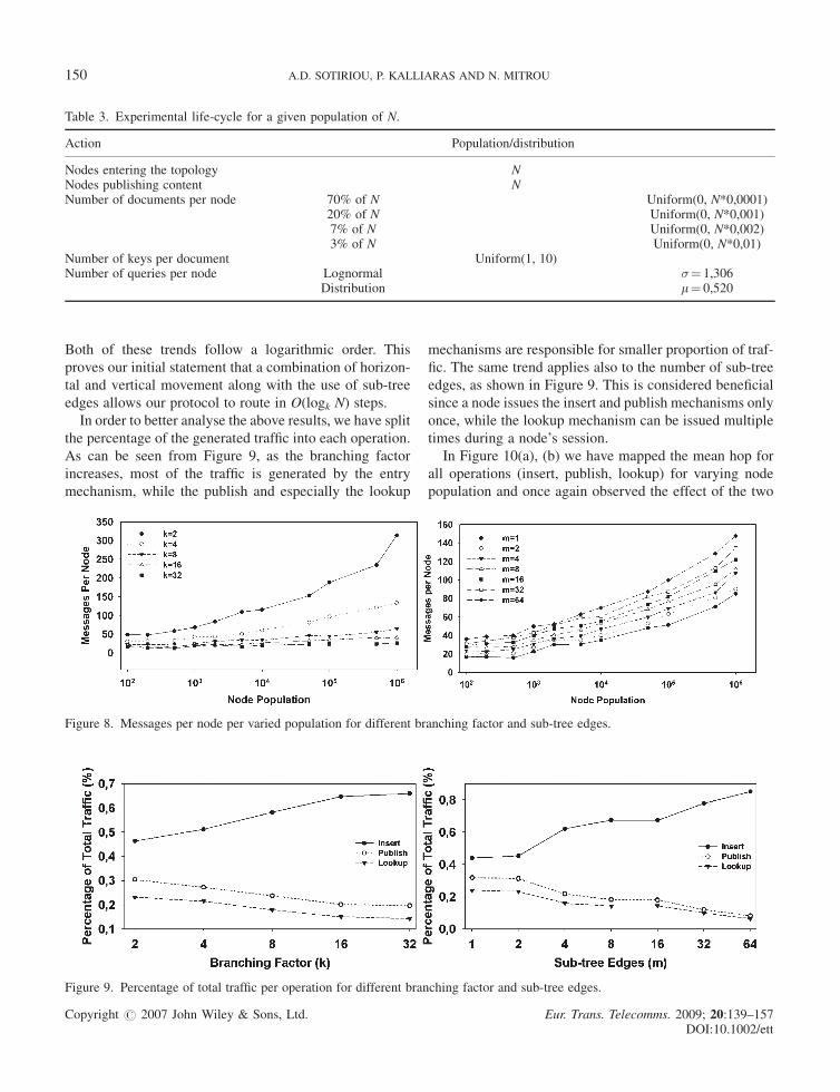
Both of these trends follow a logarithmic order. This
proves our initial statement that a combination of horizon-
tal and vertical movement along with the use of sub-tree
edges allows our protocol to route in O(logk N) steps.
In order to better analyse the above results, we have split
the percentage of the generated traffic into each operation.
As can be seen from Figure 9, as the branching factor
increases, most of the traffic is generated by the entry
mechanism, while the publish and especially the lookup
mechanisms are responsible for smaller proportion of traf-
fic. The same trend applies also to the number of sub-tree
edges, as shown in Figure 9. This is considered beneficial
since a node issues the insert and publish mechanisms only
once, while the lookup mechanism can be issued multiple
times during a node’s session.
In Figure 10(a), (b) we have mapped the mean hop for
all operations (insert, publish, lookup) for varying node
population and once again observed the effect of the two
Table 3. Experimental life-cycle for a given population of N.
Action Population/distribution
Nodes entering the topology NNodes publishing content NNumber of documents per node 70% of N Uniform(0, N*0,0001)
20% of N Uniform(0, N*0,001)7% of N Uniform(0, N*0,002)3% of N Uniform(0, N*0,01)
Number of keys per document Uniform(1, 10)Number of queries per node Lognormal �¼ 1,306
Distribution m¼ 0,520
Figure 8. Messages per node per varied population for different branching factor and sub-tree edges.
Figure 9. Percentage of total traffic per operation for different branching factor and sub-tree edges.
150 A.D. SOTIRIOU, P. KALLIARAS AND N. MITROU
Copyright # 2007 John Wiley & Sons, Ltd. Eur. Trans. Telecomms. 2009; 20:139–157DOI:10.1002/ett
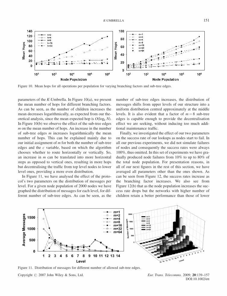
parameters of the K-Umbrella. In Figure 10(a), we present
the mean number of hops for different branching factors.
As can be seen, as the number of children increases the
mean decreases logarithmically, as expected from our the-
oretical analysis, since the mean expected hop is O(logk N).
In Figure 10(b) we observe the effect of the sub-tree edges
m on the mean number of hops. An increase in the number
of sub-tree edges m increases logarithmically the mean
number of hops. This can be explained mainly due to
our initial assignment of m for both the number of sub-tree
edges and the c variable, based on which the algorithm
chooses whether to route horizontally or vertically. So,
an increase in m can be translated into more horizontal
steps as opposed to vertical ones, resulting in more hops
but decentralising the traffic from top level nodes to lower
level ones, providing a more even distribution.
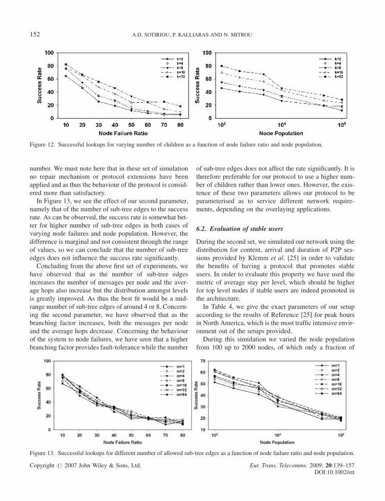
In Figure 11, we have analysed the effect of the proto-
col’s two parameters on the distribution of messages per
level. For a given node population of 2000 nodes we have
graphed the distribution of messages for each level, for dif-
ferent number of sub-tree edges. As can be seen, as the
number of sub-tree edges increases, the distribution of
messages shifts from upper levels of our structure into a
uniform distribution centred approximately at the middle
levels. It is also evident that a factor of m¼ 8 sub-tree
edges is capable enough to provide the decentralisation
effect we are seeking, without inducing too much addi-
tional maintenance traffic.
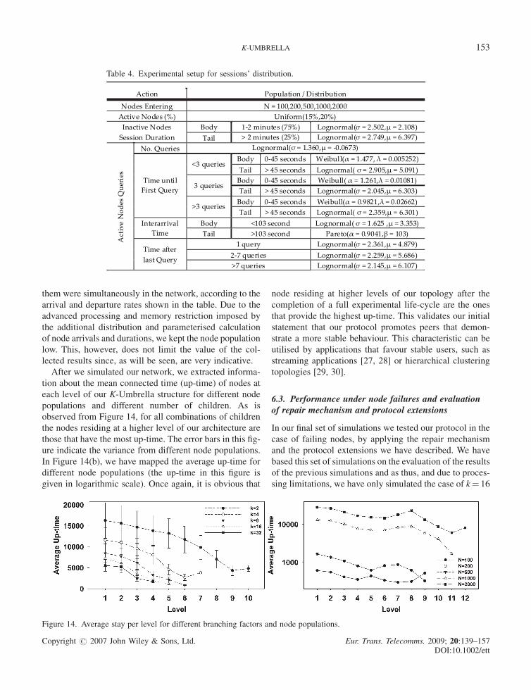
Finally, we investigated the effect of our two parameters
on the success rate of our lookups as nodes start to fail. In
all our previous experiments, we did not simulate failures
of nodes and consequently the success rates were always
100%, thus omitted. In this set of experiments we have gra-
dually produced node failures from 10% to up to 80% of
the total node population. For presentation reasons, in
all of our next figures in the rest of this section, we have
averaged all parameters other than the ones shown. As
can be seen from Figure 12, the success rates increase as
the branching factor increases. We also see from
Figure 12(b) that as the node population increases the suc-
cess rate drops but the networks with higher number of
children retain a better performance than those of lower
Figure 10. Mean hops for all operations per population for varying branching factors and sub-tree edges.
Figure 11. Distribution of messages for different number of allowed sub-tree edges.
K-UMBRELLA 151
Copyright # 2007 John Wiley & Sons, Ltd. Eur. Trans. Telecomms. 2009; 20:139–157DOI:10.1002/ett
number. We must note here that in these set of simulation
no repair mechanism or protocol extensions have been
applied and as thus the behaviour of the protocol is consid-
ered more than satisfactory.
In Figure 13, we see the effect of our second parameter,
namely that of the number of sub-tree edges to the success
rate. As can be observed, the success rate is somewhat bet-
ter for higher number of sub-tree edges in both cases of
varying node failures and node population. However, the
difference is marginal and not consistent through the range
of values, so we can conclude that the number of sub-tree
edges does not influence the success rate significantly.
Concluding from the above first set of experiments, we
have observed that as the number of sub-tree edges
increases the number of messages per node and the aver-
age hops also increase but the distribution amongst levels
is greatly improved. As thus the best fit would be a mid-
range number of sub-tree edges of around 4 or 8. Concern-
ing the second parameter, we have observed that as the
branching factor increases, both the messages per node
and the average hops decrease. Concerning the behaviour
of the system to node failures, we have seen that a higher
branching factor provides fault-tolerance while the number
of sub-tree edges does not affect the rate significantly. It is
therefore preferable for our protocol to use a higher num-
ber of children rather than lower ones. However, the exis-
tence of these two parameters allows our protocol to be
parameterised as to service different network require-
ments, depending on the overlaying applications.
6.2. Evaluation of stable users
During the second set, we simulated our network using the
distribution for content, arrival and duration of P2P ses-
sions provided by Klemm et al. [25] in order to validate
the benefits of having a protocol that promotes stable
users. In order to evaluate this property we have used the
metric of average stay per level, which should be higher
for top level nodes if stable users are indeed promoted in
the architecture.
In Table 4, we give the exact parameters of our setup
according to the results of Reference [25] for peak hours
in North America, which is the most traffic intensive envir-
onment out of the setups provided.
During this simulation we varied the node population
from 100 up to 2000 nodes, of which only a fraction of
Figure 12. Successful lookups for varying number of children as a function of node failure ratio and node population.
Figure 13. Successful lookups for different number of allowed sub-tree edges as a function of node failure ratio and node population.
152 A.D. SOTIRIOU, P. KALLIARAS AND N. MITROU
Copyright # 2007 John Wiley & Sons, Ltd. Eur. Trans. Telecomms. 2009; 20:139–157DOI:10.1002/ett
them were simultaneously in the network, according to the
arrival and departure rates shown in the table. Due to the
advanced processing and memory restriction imposed by
the additional distribution and parameterised calculation
of node arrivals and durations, we kept the node population
low. This, however, does not limit the value of the col-
lected results since, as will be seen, are very indicative.
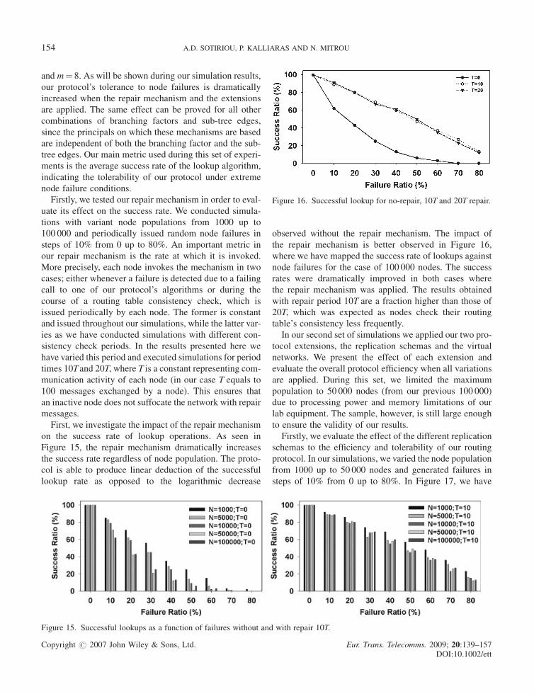
After we simulated our network, we extracted informa-
tion about the mean connected time (up-time) of nodes at
each level of our K-Umbrella structure for different node
populations and different number of children. As is
observed from Figure 14, for all combinations of children
the nodes residing at a higher level of our architecture are
those that have the most up-time. The error bars in this fig-
ure indicate the variance from different node populations.
In Figure 14(b), we have mapped the average up-time for
different node populations (the up-time in this figure is
given in logarithmic scale). Once again, it is obvious that
node residing at higher levels of our topology after the
completion of a full experimental life-cycle are the ones
that provide the highest up-time. This validates our initial
statement that our protocol promotes peers that demon-
strate a more stable behaviour. This characteristic can be
utilised by applications that favour stable users, such as
streaming applications [27, 28] or hierarchical clustering
topologies [29, 30].
6.3. Performance under node failures and evaluationof repair mechanism and protocol extensions
In our final set of simulations we tested our protocol in the
case of failing nodes, by applying the repair mechanism
and the protocol extensions we have described. We have
based this set of simulations on the evaluation of the results
of the previous simulations and as thus, and due to proces-
sing limitations, we have only simulated the case of k¼ 16
Table 4. Experimental setup for sessions’ distribution.
Action Population / Distribution
Nodes Entering N = 100,200,500,1000,2000 Active Nodes (%) Uniform(15%,20%)
Body 1-2 minutes (75%) Lognormal(σ = 2.502,µ = 2.108) Inactive Nodes Session Duration Tail > 2 minutes (25%) Lognormal(σ = 2.749,µ = 6.397)
No. Queries Lognormal(σ = 1.360,µ = -0.0673) Body 0-45 seconds Weibull(α = 1.477, λ = 0.005252)
<3 queries Tail > 45 seconds Lognormal( σ = 2.905,µ = 5.091)
Body 0-45 seconds Weibull( α = 1.261,λ = 0.01081) 3 queries
Tail > 45 seconds Lognormal(σ = 2.045,µ = 6.303) Body 0-45 seconds Weibull(α = 0.9821,λ = 0.02662)
Time until First Query
>3 queries Tail > 45 seconds Lognormal( σ = 2.359,µ = 6.301)
Body <103 second Lognormal( σ = 1.625 ,µ = 3.353) Interarrival Time Tail >103 second Pareto(α = 0.9041,β = 103)
1 query Lognormal(σ = 2.361,µ = 4.879) 2-7 queries Lognormal(σ = 2.259,µ = 5.686)
Act
ive
Nod
es Q
ueri
es
Time a�er last Query
>7 queries Lognormal(σ = 2.145,µ = 6.107)
Figure 14. Average stay per level for different branching factors and node populations.
K-UMBRELLA 153
Copyright # 2007 John Wiley & Sons, Ltd. Eur. Trans. Telecomms. 2009; 20:139–157DOI:10.1002/ett
and m¼ 8. As will be shown during our simulation results,
our protocol’s tolerance to node failures is dramatically
increased when the repair mechanism and the extensions
are applied. The same effect can be proved for all other
combinations of branching factors and sub-tree edges,
since the principals on which these mechanisms are based
are independent of both the branching factor and the sub-
tree edges. Our main metric used during this set of experi-
ments is the average success rate of the lookup algorithm,
indicating the tolerability of our protocol under extreme
node failure conditions.
Firstly, we tested our repair mechanism in order to eval-
uate its effect on the success rate. We conducted simula-
tions with variant node populations from 1000 up to
100 000 and periodically issued random node failures in
steps of 10% from 0 up to 80%. An important metric in
our repair mechanism is the rate at which it is invoked.
More precisely, each node invokes the mechanism in two
cases; either whenever a failure is detected due to a failing
call to one of our protocol’s algorithms or during the
course of a routing table consistency check, which is
issued periodically by each node. The former is constant
and issued throughout our simulations, while the latter var-
ies as we have conducted simulations with different con-
sistency check periods. In the results presented here we
have varied this period and executed simulations for period
times 10T and 20T, where T is a constant representing com-
munication activity of each node (in our case T equals to
100 messages exchanged by a node). This ensures that
an inactive node does not suffocate the network with repair
messages.
First, we investigate the impact of the repair mechanism
on the success rate of lookup operations. As seen in
Figure 15, the repair mechanism dramatically increases
the success rate regardless of node population. The proto-
col is able to produce linear deduction of the successful
lookup rate as opposed to the logarithmic decrease
observed without the repair mechanism. The impact of
the repair mechanism is better observed in Figure 16,
where we have mapped the success rate of lookups against
node failures for the case of 100 000 nodes. The success
rates were dramatically improved in both cases where
the repair mechanism was applied. The results obtained
with repair period 10T are a fraction higher than those of
20T, which was expected as nodes check their routing
table’s consistency less frequently.
In our second set of simulations we applied our two pro-
tocol extensions, the replication schemas and the virtual
networks. We present the effect of each extension and
evaluate the overall protocol efficiency when all variations
are applied. During this set, we limited the maximum
population to 50 000 nodes (from our previous 100 000)
due to processing power and memory limitations of our
lab equipment. The sample, however, is still large enough
to ensure the validity of our results.
Firstly, we evaluate the effect of the different replication
schemas to the efficiency and tolerability of our routing
protocol. In our simulations, we varied the node population
from 1000 up to 50 000 nodes and generated failures in
steps of 10% from 0 up to 80%. In Figure 17, we have
Figure 15. Successful lookups as a function of failures without and with repair 10T.
Figure 16. Successful lookup for no-repair, 10T and 20T repair.
154 A.D. SOTIRIOU, P. KALLIARAS AND N. MITROU
Copyright # 2007 John Wiley & Sons, Ltd. Eur. Trans. Telecomms. 2009; 20:139–157DOI:10.1002/ett
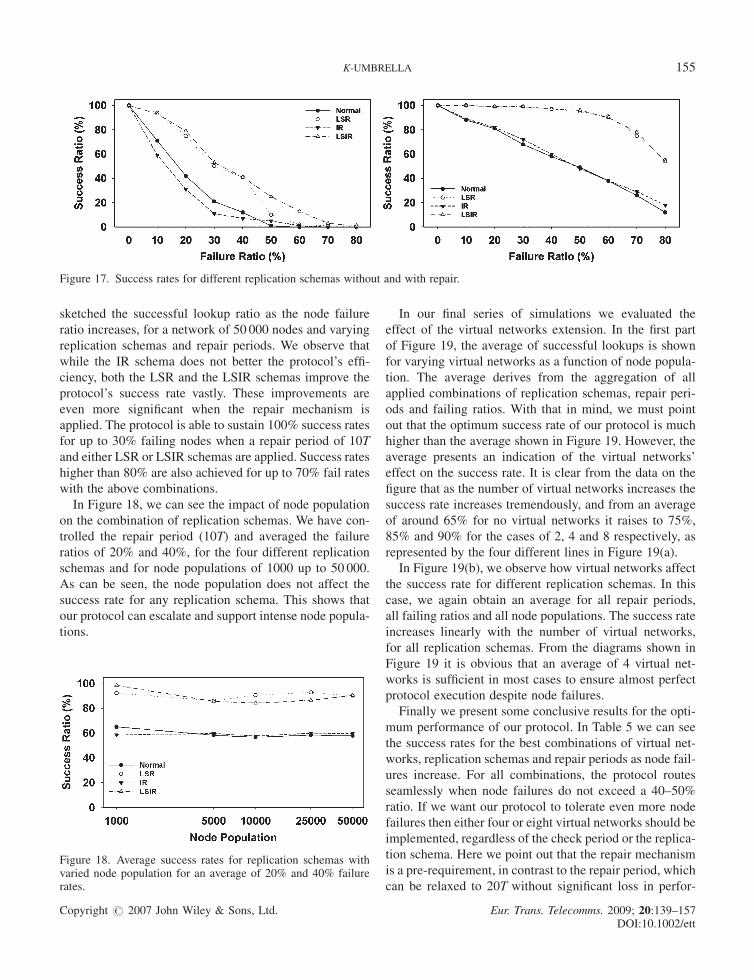
sketched the successful lookup ratio as the node failure
ratio increases, for a network of 50 000 nodes and varying
replication schemas and repair periods. We observe that
while the IR schema does not better the protocol’s effi-
ciency, both the LSR and the LSIR schemas improve the
protocol’s success rate vastly. These improvements are
even more significant when the repair mechanism is
applied. The protocol is able to sustain 100% success rates
for up to 30% failing nodes when a repair period of 10T
and either LSR or LSIR schemas are applied. Success rates
higher than 80% are also achieved for up to 70% fail rates
with the above combinations.
In Figure 18, we can see the impact of node population
on the combination of replication schemas. We have con-
trolled the repair period (10T) and averaged the failure
ratios of 20% and 40%, for the four different replication
schemas and for node populations of 1000 up to 50 000.
As can be seen, the node population does not affect the
success rate for any replication schema. This shows that
our protocol can escalate and support intense node popula-
tions.
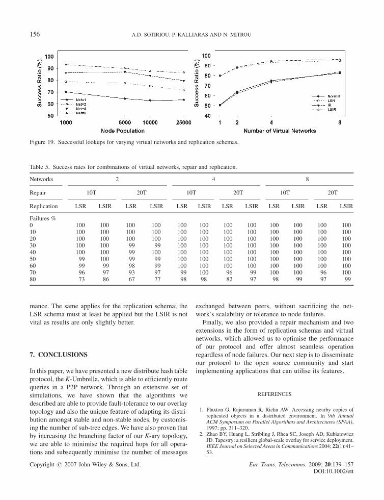
In our final series of simulations we evaluated the
effect of the virtual networks extension. In the first part
of Figure 19, the average of successful lookups is shown
for varying virtual networks as a function of node popula-
tion. The average derives from the aggregation of all
applied combinations of replication schemas, repair peri-
ods and failing ratios. With that in mind, we must point
out that the optimum success rate of our protocol is much
higher than the average shown in Figure 19. However, the
average presents an indication of the virtual networks’
effect on the success rate. It is clear from the data on the
figure that as the number of virtual networks increases the
success rate increases tremendously, and from an average
of around 65% for no virtual networks it raises to 75%,
85% and 90% for the cases of 2, 4 and 8 respectively, as
represented by the four different lines in Figure 19(a).
In Figure 19(b), we observe how virtual networks affect
the success rate for different replication schemas. In this
case, we again obtain an average for all repair periods,
all failing ratios and all node populations. The success rate
increases linearly with the number of virtual networks,
for all replication schemas. From the diagrams shown in
Figure 19 it is obvious that an average of 4 virtual net-
works is sufficient in most cases to ensure almost perfect
protocol execution despite node failures.
Finally we present some conclusive results for the opti-
mum performance of our protocol. In Table 5 we can see
the success rates for the best combinations of virtual net-
works, replication schemas and repair periods as node fail-
ures increase. For all combinations, the protocol routes
seamlessly when node failures do not exceed a 40–50%
ratio. If we want our protocol to tolerate even more node
failures then either four or eight virtual networks should be
implemented, regardless of the check period or the replica-
tion schema. Here we point out that the repair mechanism
is a pre-requirement, in contrast to the repair period, which
can be relaxed to 20T without significant loss in perfor-
Figure 17. Success rates for different replication schemas without and with repair.
Figure 18. Average success rates for replication schemas withvaried node population for an average of 20% and 40% failurerates.
K-UMBRELLA 155
Copyright # 2007 John Wiley & Sons, Ltd. Eur. Trans. Telecomms. 2009; 20:139–157DOI:10.1002/ett
mance. The same applies for the replication schema; the
LSR schema must at least be applied but the LSIR is not
vital as results are only slightly better.
7. CONCLUSIONS
In this paper, we have presented a new distribute hash table
protocol, the K-Umbrella, which is able to efficiently route
queries in a P2P network. Through an extensive set of
simulations, we have shown that the algorithms we
described are able to provide fault-tolerance to our overlay
topology and also the unique feature of adapting its distri-
bution amongst stable and non-stable nodes, by customis-
ing the number of sub-tree edges. We have also proven that
by increasing the branching factor of our K-ary topology,
we are able to minimise the required hops for all opera-
tions and subsequently minimise the number of messages
exchanged between peers, without sacrificing the net-
work’s scalability or tolerance to node failures.
Finally, we also provided a repair mechanism and two
extensions in the form of replication schemas and virtual
networks, which allowed us to optimise the performance
of our protocol and offer almost seamless operation
regardless of node failures. Our next step is to disseminate
our protocol to the open source community and start
implementing applications that can utilise its features.
REFERENCES
1. Plaxton G, Rajaraman R, Richa AW. Accessing nearby copies ofreplicated objects in a distributed environment. In 9th AnnualACM Symposium on Parallel Algorithms and Architectures (SPAA),1997; pp. 311–320.
2. Zhao BY, Huang L, Stribling J, Rhea SC, Joseph AD, KubiatowiczJD. Tapestry: a resilient global-scale overlay for service deployment.IEEE Journal on Selected Areas in Communications 2004; 22(1):41–53.
Figure 19. Successful lookups for varying virtual networks and replication schemas.
Table 5. Success rates for combinations of virtual networks, repair and replication.
Networks 2 4 8
Repair 10T 20T 10T 20T 10T 20T
Replication LSR LSIR LSR LSIR LSR LSIR LSR LSIR LSR LSIR LSR LSIR
Failures %0 100 100 100 100 100 100 100 100 100 100 100 10010 100 100 100 100 100 100 100 100 100 100 100 10020 100 100 100 100 100 100 100 100 100 100 100 10030 100 100 99 99 100 100 100 100 100 100 100 10040 100 100 99 100 100 100 100 100 100 100 100 10050 99 100 99 99 100 100 100 100 100 100 100 10060 99 99 98 99 100 100 100 100 100 100 100 10070 96 97 93 97 99 100 96 99 100 100 96 10080 73 86 67 77 98 98 82 97 98 99 97 99
156 A.D. SOTIRIOU, P. KALLIARAS AND N. MITROU
Copyright # 2007 John Wiley & Sons, Ltd. Eur. Trans. Telecomms. 2009; 20:139–157DOI:10.1002/ett
3. Rowstron A, Druschel P. Pastry: scalable, decentralized object loca-tion, and routing for large-scale peer-to-peer systems. Middleware2001; 2001.
4. Maymounkov P, Mazieres D. Kademlia: a peer-to-peer informaticsystem based on the XOR metric. In IPTPS’02. Cambridge, MA,2002; pp. 53–56.
5. Renesse RV, Bozdog A. Willow: DHT, aggregation and publish/sub-scribe in one protocol. In 3rd International Workshop on Peer-to-Peer System, San Diego, CA, USA, 2004.
6. Stoica I, Morris R, Karger D, Kaashoek F, Balakrishnan H. Chord: apeer-to-peer lookup service for internet applications. In SIGCOMM2001, San Diego, CA, 2001; pp. 149–160.
7. Alima L, El-Ansary S, Brand P, Haridi S. DKS(N, k, f): a family oflow communication, scalable and fault-tolerant infrastructures forP2P applications. In 3rd IEEE/ACM International Symposium onCluster Computing and the Grid, 2003; pp. 344–350.
8. Ratsanamy S, Francis P, Handley M, Karp R. A scalable content-addressable network. ACM SIGCOMM Conference, ACM Press:San Diego, CA, New York, 2001.
9. Malkhi D, Naor M, Ratajczak D. Viceroy: a scalable and dynamicemulation of the butterfly. In 21st Annual Symposium on Principlesof Distributed Computing, 2002; pp. 183–192.
10. Fraigniaud P, Gauron P. The content-addressable networks D2B:laboratoire de recherche en informatique, Universite de Paris Sud,2003 January. Report nr Technical Report 1349.
11. Kaashoek F, Karger D. Koorde: a simple degreeoptimal hash table.In 2nd International Workshop on Peer-to-Peer Systems (IPTPS 03),Berkeley, CA, USA, 2003.
12. Aspens J, Shah G. Skip Graphs. January 2003; pp. 384–193.13. Harvey N, Jones MB, Saroiu S, Theimer M, Wolman A. SkipNet: a
scalable overlay network with practical locality properties. Seattle,WA, March 2003.
14. Sotiriou AD, Kalliaras P, Mitrou N. Umbrella: a novel fixed-sizeDHT protocol. In 5th International Symposium on CommunicationSystems, Networks and Digital Signal Processing (CSNDSP’06).Patras, Greece, July 2006.
15. (NIST) NIoSaT. FIPS Pub 180-1: Secure Hash Standard (SHA-1).In: Publication FIPS, editor; 1995.
16. Soto J. Statistical testing of random number generators. In 22nd NationalInformation Systems Security Conference. Crystal City, Virginia, 1999.
17. Milojicic D, Kalogeraki V, Lukose R, Nagaraja K, Pruyne J, RichardB, Rollins S, Xu Z. Peer-to-Peer Computing, 2002. Report nr HPL-2002-57R1.
18. Karger D, Lehman E, Leighton F, Levine M, Lewin D, Panigrahy R.Consistent hashing and random trees: distributed caching protocols forrelieving hot spots on the world wide web. In 29th Annual ACMSymposium on Theory of Computing, El Paso, TX, 1997; pp. 654–663.
19. Castro M, Druschel P, Kermarrec AM, Rowsron A. One ring to rulethem all: service discovery and binding in structured peer-to-peeroverlay networks. September 2002.
20. Freedman MJ, Lakshminarayanan K, Mazieres D. Oasis: anycast forany service, 2006.
21. Ghodsi A, Alima LO, Haridi S. Symmetric replication for structuredpeer-to-peer systems. In The 3rd International Workshop on Data-bases, Information Systems and Peer-to-Peer Computing. Trond-heim, Norway, 2005.
22. Clarke I, Hong TW, Miller SG, Sandberg O, Wile B. Protecting freeexpression online with freenet. IEEE Internet Computing 2002;6(1):40–49.
23. Joseph S. An extendible open source P2P simulator. P2P Journal2003; 1–15.
24. Gnutella. http://www.gnutella.com/25. Klemm A, Lindemann C, Vernon M, Waldhorst O. Characterizing
the query behavior in peer-to-peer file sharing systems. In ACMInternet Measurement Conference (IMC). Taormina, Italy, 2004;pp. 55–67.
26. Madadhain J, Fisher D, Smyth P, White S, Boey Y. Analysis andvisualization of network data using JUNG, 2005.
27. Hefeeda M, Habib A, Xu D, Bhargava B, Botev B. Collectcast: apeer-to-peer service for media streaming. ACM/Springer MultimediaSystems 2003.
28. Liao X, Jin H, Liu Y, Ni L, Deng D. AnySee: peer-to-peer livestreaming. In proceedings of IEEE INFOCOM, Barcelona, Spain,April 2006.
29. Hsiao R, Wang S. Jelly: a dynamic hierarchical P2P overlay networkwith load balance and locality. IEEE ICDCS 2004, 2004; pp. 534–540.
30. Chung T, Chang Y, Liu C, Chen Y. Architecture and implementationof cluster-based peer-to-peer topology and its application in search.Journal of Internet Technology (JIT) 2006; 7(1):23–34.
AUTHORS’ BIOGRAPHIES
Athanasios-Dimitrios Sotiriou received his diploma in Electrical and Computer Engineering in 2000 from the National TechnicalUniversity of Athens (NTUA). In 2001, he received his Master’s degree in Telecommunications and DSP from Imperial College and ayear later his MBA in Business Administration from the Economic University of Athens. Since 2002, he has been a Research Associ-ate at the Computer Network Laboratory of the School of Electrical and Computer Engineering of NTUA as part of his PhD in the areaof P2P networks. Since 2006, he has been working as a Project Manager for Athens Technology Center and is currently involved in ISTprojects of the EU.
Panagiotis Kalliaras received his diploma in Electrical and Computer Engineering from the National Technical University of Athens(NTUA) and is currently a Ph.D. student there. His major areas of interests include highly-interactive multimedia services, internettechnologies, real-time applications, broadband communication networks and location based services. He has been involved in ISTprojects of the European Community and is also a member of the Technical Chamber of Greece.
Nikolas Mitrou received the diploma in Electrical Engineering from the National Technical University of Athens (NTUA) in 1980,the M.Sc. degree in systems and control from the UMIST, Manchester, in 1982, and the Ph.D. degree in Electrical Engineering fromthe NTUA in 1986. He is now a Professor in the School of Electrical and Computer Engineering of NTUA. His research interests are inthe areas of digital communications, communication networks and networked multimedia in all range of studies: design, implementa-tion, modelling, performance evaluation and optimisation, applications. He is a member of the IEEE and member of the IFIP (TC6).
K-UMBRELLA 157
Copyright # 2007 John Wiley & Sons, Ltd. Eur. Trans. Telecomms. 2009; 20:139–157DOI:10.1002/ett
Recommended


