
Mapping of the prostate in endorectal coil-based MRI/MRSI and CT: A deformableregistration and validation studyJ. Lian, L. Xing, S. Hunjan, C. Dumoulin, J. Levin, A. Lo, R. Watkins, K. Rohling, R. Giaquinto, D. Kim, D.
Spielman, and B. Daniel
Citation: Medical Physics 31, 3087 (2004); doi: 10.1118/1.1806292 View online: http://dx.doi.org/10.1118/1.1806292 View Table of Contents: http://scitation.aip.org/content/aapm/journal/medphys/31/11?ver=pdfcov Published by the American Association of Physicists in Medicine Articles you may be interested in Inter-slice bidirectional registration-based segmentation of the prostate gland in MR and CT image sequences Med. Phys. 40, 123503 (2013); 10.1118/1.4829511 A method to acquire CT organ dose map using OSL dosimeters and ATOM anthropomorphic phantoms Med. Phys. 40, 081918 (2013); 10.1118/1.4816299 Site-specific deformable imaging registration algorithm selection using patient-based simulated deformations Med. Phys. 40, 041911 (2013); 10.1118/1.4793723 A realistic deformable prostate phantom for multimodal imaging and needle-insertion procedures Med. Phys. 39, 2031 (2012); 10.1118/1.3692179 A CT based correction method for speed of sound aberration for ultrasound based image guided radiotherapy Med. Phys. 38, 2665 (2011); 10.1118/1.3583475

Mapping of the prostate in endorectal coil-based MRI/MRSI and CT:A deformable registration and validation study
J. Lian,a) L. Xing,b) and S. HunjanDepartment of Radiation Oncology, Stanford University School of Medicine, 875 Blake Wilbur Drive,Stanford, California 94305
C. DumoulinGE Corporate Research and Development Center, Schenectady, New York 12309
J. LevinDepartment of Radiology, Stanford University School of Medicine, 875 Blake Wilbur Drive, Stanford,California 94305
A. LoDepartment of Radiation Oncology, Stanford University School of Medicine, 875 Blake Wilbur Drive,Stanford, California 94305
R. Watkins, K. Rohling, and R. GiaquintoGE Corporate Research and Development Center, Schenectady, New York 12309
D. Kim, D. Spielman, and B. DanielDepartment of Radiology, Stanford University School of Medicine, 875 Blake Wilbur Drive, Stanford,California 94305
(Received 1 June 2004; revised 26 July 2004; accepted for publication 24 August 2004;published 28 October 2004)
The endorectal coil is being increasingly used in magnetic resonance imaging(MRI) and MRspectroscopic imaging(MRSI) to obtain anatomic and metabolic images of the prostate with highsignal-to-noise ratio(SNR). In practice, however, the use of endorectal probe inevitably distorts theprostate and other soft tissue organs, making the analysis and the use of the acquired image data intreatment planning difficult. The purpose of this work is to develop a deformable image registrationalgorithm to map the MRI/MRSI information obtained using an endorectal probe onto CT imagesand to verify the accuracy of the registration by phantom and patient studies. A mapping procedureinvolved using a thin plate spline(TPS) transformation was implemented to establish voxel-to-voxel correspondence between areferenceimage and afloating image with deformation. An elasticphantom with a number of implanted fiducial markers was designed for the validation of the qualityof the registration. Radiographic images of the phantom were obtained before and after a series ofintentionally introduced distortions. After mapping the distorted phantom to the original one, thedisplacements of the implanted markers were measured with respect to their ideal positions and themean error was calculated. In patient studies, CT images of three prostate patients were acquired,followed by 3 Teslas3 Td MR images with a rigid endorectal coil. Registration quality was esti-mated by the centroid position displacement and image coincidence index(CI). Phantom andpatient studies show that TPS-based registration has achieved significantly higher accuracy than thepreviously reported method based on a rigid-body transformation and scaling. The technique shouldbe useful to map the MR spectroscopic dataset acquired with ER probe onto the treatment planningCT dataset to guide radiotherapy planning. ©2004 American Association of Physicists in Medi-cine. [DOI: 10.1118/1.1806292]
-e ra.ans
en-ina
dia-rdin
or-nninghasden-or-
tmentthend-iegis-CT
I. INTRODUCTION
The introduction of endorectal(ER) surface coils significantly improves the spatial resolution and signal-to-noistio (SNR) of prostate MR and MR spectroscopic imaging1–8
The new MRI/MRSI tool provides an unprecedented mefor us to characterize the location(s) and volume(s) of intra-prostatic lesion(s) and to evaluate the possible capsular petration, invasion of neurovascular bundle, and semvesicle involvement.2–4,9–13 The information derived fromthe new imaging modality is also valuable for guiding ration treatment planning to escalate radiation doses acco
14–18
to the regional tumor burden. In practice, the use of an3087 Med. Phys. 31 (11), November 2004 0094-2405/2004/31
-
l
g
ER coil severely distorts the prostate and surroundinggans. On the other hand, current radiation treatment plais performed on the CT images without distortion. CThigh geometric accuracy and provides valuable electronsity information needed for accurate dose calculation. Inder to use ER-based image data to guide radiation treaplanning, it is imperative to develop a method to mapinformation in the ER-based MRI/MRSI to the correspoing location in CT images.19,20 Zaideret al.17 and Mizowaket al.21 have reported a translation and scaling based rtration method to map MRS positive volumes onto the
and ultrasound images. In their approach, the coordinates of3087(11)/3087/8/$22.00 © 2004 Am. Assoc. Phys. Med.

earlh a
er disrtion
tionef-
se-rtedt thsureathous
con-tollyem
oRImo
hehaletion
founs.pube
CT
t thtienascialtom
m toion
in-s,chcia
atosed
hingctalally-
istor-R
ualityspinOV:
can--1/T2
hecolo-
ativeMRd CTf thepair
tours andwastion-ce,
s the
n be
-ing
in a
3088 Lian et al. : Registration of ER-based MRI/MRSI and CT 3088
the boundary and the center of mass were used to lininterpolate the positions of the mapped voxels. Althougclinically acceptable mean differences2.4 mmd between thpredicted and measured positions was reported, largecrepancy was found for regions with more severe distosù4 mmd.
In order to fully use the functional data to guide radiatreatment planning, a mapping method with computationficiency and acceptable accuracy is needed. The purpothis paper is to present a thin plate spline(TPS)-based deformable registration to improve the previously reponondeformable MRS and CT mapping technique and tesregistration accuracy using a series of phantom meaments. The TPS transformation is a well-established mematical method and its central idea is to find a continutransformation to minimize the difference between thetrol points in two images. Since its first introduction inmedical image analysis,26 the TPS has been successfuused on several applications. A two step registration sch(rigid body registration and TPS warping) was employed tmake comparisons of MR images in interventional Mguided radiofrequency ablation to determine whether a tuis adequately treated.22,23 In order to map changes in tshape and position of the liver between inhale and exbreath held CT models of a patient, a mutual informa(MI ) based alignment with TPS warping was proposed.24 ATPS transformation based technique has also beenuseful to correct image distortion in fluoroscopic image25
We believe this method is a good tradeoff between comtation complexity and registration accuracy and shouldwell suited in mapping deformed voxels of MRS ontoimage.
II. METHODS AND MATERIALS
A. Phantom construction and imaging
Tissue equivalent bolus material was used to construc2D phantoms which simulate the axial sections of the padataset. The bolus, made of vinyl gel, is elastic and hdensity close to that of water. Ten to fifteen metal fidulandmarks were embedded into each phantom. The phanwere held in a custom made plastic holder, allowing thebe constricted and deformed in specifically chosen reg(Fig. 1). The radiographic images were then acquiredanterior-posterior(AP) and lateral(LT) direction using a Ximatron Radiotherapy Simulator(Varian Medical SystemPalo Alto, CA). An analysis of the AP/LT images for eaphantom revealed the geometric locations of the fidumarkers before and after the distortion.
B. Patient image acquisition
Patient MRI was acquired on a 3-Tesla MR scanner(Si-gna; GE Medical Systems, Milwaukee, WI). RF excitationwas achieved by using the whole body birdcage resonand the MR signal was received using a 4-element phaarray antenna(G.E. Medical Systems, Milwaukee, WI) com-
bined with a rigid single loop receiver-only surface coil withMedical Physics, Vol. 31, No. 11, November 2004
y
-
of
e--
e
r
d
-
eta
s
s
l
r,-
a fixed geometry that enables optimal tuning and matcfor use at 3 T. The coil dimensions are similar to transreultrasound transducers used for routine sonographicguided prostate imaging and biopsy. The ER-induced dtion of MRSI is very close to that of MRI. We show Mimages in this study because they have higher image qthan MRSI. MR images were acquired using axial fastecho TR/TE:6000/80.5 ms, echo train length: 48 ms, F10 cm, Matrix: 5123256 and Resolution: 1953390 mm.Patient CT images were acquired using a PQ5000 CT Sner (Philips Medical Systems, Cleveland, OH). Three patients were recruited for the scanning. They have stage Tdisease and pretreatment prostate specific antigen(PSA)level wasø10 ng/ml.
C. Image mapping method
After the acquisition of CT and MRS/MR image, tprostate volumes were contoured by an experienced ongist. The rotation operator was applied to adjust the reltilt between two volumes. The axial slices of CT anddata set were resampled using 1 mm interval. We aligneand MR slices with reference to the apex and base oglands. Four to eight control points were placed in eachof slices. The control points were only put along the conof the gland and they are featured points such as cornerintersections of edges. Lastly the TPS transformationapplied on each pair of slices to establish a mapping relaship between voxels of MRI and CT. For convenienhenceforth, the nondistorted CT volume is referred to areferenceand the distorted MRI thefloating dataset.
The detailed description of the TPS transformation cafound in Bookstein’s paper.26 In brief, weighting vectorW=sw1,w2, . . . ,wnd and the coefficientsa1, au, av are computed from a series of matrices which are constructed usn
FIG. 1. A photo of the deformable phantom with implanted landmarksholder. The landmarks are used to calculate the registration error.
pairs of selected control points in thereferenceimagesxi ,yid

a
inthen isom-
a
non
ceas
ectsely,of
ands
nd
htth
ant
only
e thconput-
torker
thTh
a
ho-pro-
ationdis-
and
-ox-at of
an
ternalln theject.atedage.trans-ix-
3089 Lian et al. : Registration of ER-based MRI/MRSI and CT 3089
and in thefloating imagesui ,vid. The function transformingvoxel in thefloating volume to a new coordinate in theref-erencevolume is defined as
fsu8,v8d = a1 + auu + avv + oi=0
n
wiUsuPi − su,vdud,
whereP is the matrix of the coordinates of control pointsthe reference image andU is a basis function to measuredistance. The computation of the TPS transformatiorather efficient. In our experiment, it took around 5 s to cpute a 5203520-pixel, 8-control point transformation onPersonal Computer(PC) with Intel Pentium® II 400 MHzCPU (Intel Corporation, Sunnyvale, CA) and 256 MBmemory.
For comparison purposes, we also implemented thedeformable registration method reported by Zaideret al.17
and Mizowakiet al.21 For a particular voxel in the MR spa(coordinatez1), the z coordinate in the US/CT space wobtained from
z1 − zC1
zT1− zB1
=z2 − zC2
zT2− zB2
,
wherezT1andzT2
are the coordinates of the superior aspof the prostate in the MR and US/CT volume, respectivzB1
andzB2refer to thez coordinates of the inferior aspects
the prostate, respectively, andzC1and zC2
represent thezcoordinates of the prostate centroid in the MR spaceUS/CT space, respectively. Similarly, thesx,yd coordinatewere mapped as follows:
yA1− yP1
yA1− y1
=yA2
− yP2
yA2− y2
,
xL1− xR1
xL1− x1
=xL2
− xR2
xL2− x2
.
Here,yA andyP are they coordinates of the anterior aposterior aspects of the prostate, respectively, andxL andxR
refer to, respectively, thex coordinates of the left and rigaspects of the prostate. The results obtained by usingmethod and the newly developed TPS method were qutatively compared in the phantom and patient studies.
D. Validation of the image registration
For phantom studies, the control points were chosenin the periphery for the registration of thefloatingandrefer-enceimages. The inserted landmarks were used to tracdisplacement and verify the registration accuracy. Thetrol points used in the registration were excluded in coming registration error. After mapping the distorted phantomthe original one, the displacements of the implanted mawere measured with respect to their ideal positions andmean discrepancy was calculated for each phantom.mean landmark displacement error(MLDE) was used as
metric for evaluating the quality of the registration.Medical Physics, Vol. 31, No. 11, November 2004
-
isi-
e-
see
For patient studies, typically 6–8 control points were csen along the contour of the prostate based on thenounced feature in geometry. Patient MR and CT registraccuracy was estimated by using the centroid positionplacement of the prostate and the coincidence index(CI)defined by
CIsR,DFd =DF ù R
DF ø R,
where CI is unity when two structures overlap exactlyzero when they are completely disjoined.27 The deformedfloating (DF) image and thereferencesRd images were converted to binary for the calculation. The intensity of the vels inside the contour of the prostate was set 1 and thother voxels was set 0. The use of CI provided us with
FIG. 2. A registration study using a square phantom deformed by exforce. (A) The phantom under the influence of a force(left) and its originashape(right). The distorted phantom is shown in a smaller scale thaoriginal phantom in order to include part of the holder and external ob(B) The position of four control points on the distorted phantom is indicby pink plus signs(left). The middle shows the computed deformed imThe right column shows the difference image between the computerformed image and original one.(C) and(D) are similar to B except that sand eight control points are used, respectively.(E) The landmark displacement of the three groups.
effective measure of the similarity between the warped
og
racithm
ob-s
uaten th
thees.andratio
therdis-
ndion.tionr opro-ix togis
e
tedce-dis-d ahe
hm
nlsD.
Differ-
PSmean, fors-de-to
toaxi-thanuleof
totalstra-hesem.and
and
g a
mted
3090 Lian et al. : Registration of ER-based MRI/MRSI and CT 3090
floating sFd image and thereferencesRd image. In bothevaluations the tissue density was assumed to be homneous.
III. RESULTS
A. Phantom studies
We first studied the dependence of registration accuon the number of control points. An elastic phantom wdimension 5.535.531 cm3 was used here. The phantowas distorted by the insertion of an object in the holder[Fig.2(A) left] and it restored to the original shape when theject was removed[Fig. 2(A) right]. When four control pointwere selected along the margin[Fig. 2(B) left], we obtainedthe warped image shown in the middle column. To evalthe TPS algorithm, we computed the difference betweeTPS predicted and the true image[Fig. 2(B) right panel]. TheMLDE was found to be 1.51±0.49 mm. It is seen thatimplanted landmarks do not coincide well in the two imagNext we added two more control points in the peripherythe corresponding mapped image shows reduced registerror with MLDE down to 0.76±0.54 mm[Fig. 2(C)]. Wheneight control points were selected, the MLDE was furreduced to 0.46±0.34 mm and no significant landmarkplacement was found in the difference image[Fig. 2(D)]. InFig. 2(E) we summarized the MLDEs when four, six aeight control points were used in the warping calculatThe use of more control points resulted in higher registraaccuracy. In practice, however, increasing the numbecontrol points requires additional manual interaction andlongs the registration process. In the following studies, seight pairs of control points were selected for the TPS retration. We also mapped the distorted phantoms onto thref-
erence images using a rigid-body registration and scalingMedical Physics, Vol. 31, No. 11, November 2004
e-
y
e
n
f
-
based method.17,21 The nondeformable registration resulin a 2.50±0.83 mm MLDE when the maximum displament was 4.2 mm. Hence, in the situation of a 4.2 mmtortions, the TPS method with eight control points yieldeMLDE that was only 18.4% of the MLDE obtained with tnondeformable model(0.46 vs 2.50 mm).
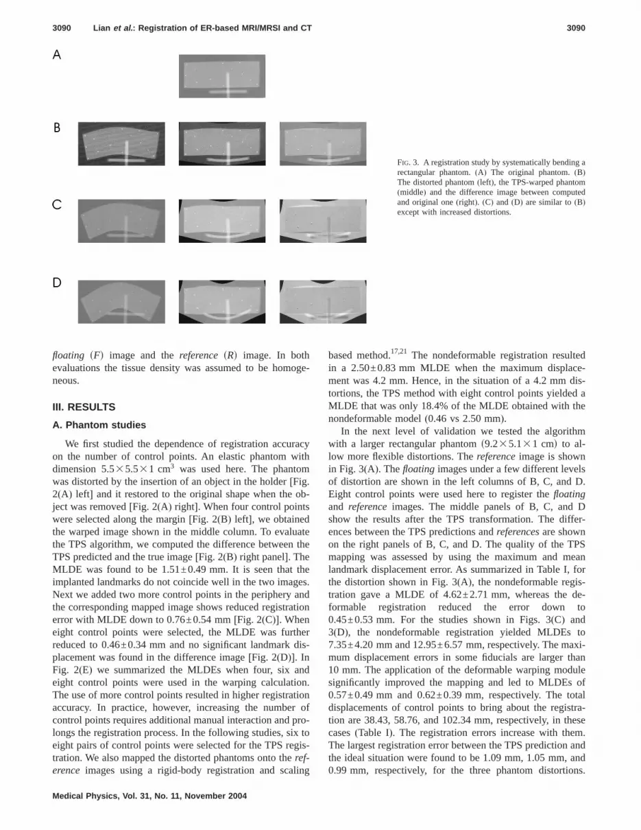
In the next level of validation we tested the algoritwith a larger rectangular phantoms9.235.131 cmd to al-low more flexible distortions. Thereferenceimage is showin Fig. 3(A). Thefloating images under a few different leveof distortion are shown in the left columns of B, C, andEight control points were used here to register thefloatingand referenceimages. The middle panels of B, C, andshow the results after the TPS transformation. The dences between the TPS predictions andreferencesare shownon the right panels of B, C, and D. The quality of the Tmapping was assessed by using the maximum andlandmark displacement error. As summarized in Table Ithe distortion shown in Fig. 3(A), the nondeformable regitration gave a MLDE of 4.62±2.71 mm, whereas theformable registration reduced the error down0.45±0.53 mm. For the studies shown in Figs. 3(C) and3(D), the nondeformable registration yielded MLDEs7.35±4.20 mm and 12.95±6.57 mm, respectively. The mmum displacement errors in some fiducials are larger10 mm. The application of the deformable warping modsignificantly improved the mapping and led to MLDEs0.57±0.49 mm and 0.62±0.39 mm, respectively. Thedisplacements of control points to bring about the regition are 38.43, 58.76, and 102.34 mm, respectively, in tcases(Table I). The registration errors increase with theThe largest registration error between the TPS predictionthe ideal situation were found to be 1.09 mm, 1.05 mm,
FIG. 3. A registration study by systematically bendinrectangular phantom.(A) The original phantom.(B)The distorted phantom(left), the TPS-warped phanto(middle) and the difference image between compuand original one(right). (C) and (D) are similar to(B)except with increased distortions.
0.99 mm, respectively, for the three phantom distortions.

andPSl da
, weorm
lts
nels.all
g con-ges.08,um
0.35,
ensand
pros-pros-samehe
ior–We
iddlee ine
ros-stlygeststhe
tionenta-
ctan-
pos-e of
enges.aged al-
con-inandere
f Figse-
ageactua
3091 Lian et al. : Registration of ER-based MRI/MRSI and CT 3091
Considering the severity of the distortion in this examplethe voxel size of MRSI is of 5 mm in dimension, the Tbased method seems adequate to correlate the functionaonto the corresponding voxels in CT.
In order to examine the consistency of the registrationinverted the previous transformation procedure by transfing the TPS-warped images[Figs. 3(B)–3(D) middle panels]back to the distortedfloating images. The calculation resuare shown in the left columns of Figs. 4(A)–4(C). The origi-nal deformed phantom images(the left columns of Fig. 3)
TABLE I. Deformable and nondeformable registratTotal displacements of control points(CPs) to bring amaximum landmark displacement error and thecase.
Distortion(mm)
Totaldisplacements
of CPs
Nondefor
Maximum
Fig. 3(B) 38.43 9.83Fig. 3(C) 58.76 14.74Fig. 3(D) 102.34 23.07
FIG. 4. Registration consistency test. Left panels of(A), (B), and (C) rep-resent the computer-warped images with the middle panel images o3(B)–3(D) as input. Right panels of(A), (B), and (C) represent the corrsponding difference images between the mapped and the original im(D), Landmark displacement between the model prediction and the
position for the three groups.Medical Physics, Vol. 31, No. 11, November 2004
ta
-
are subtracted from them and are shown in the right paThe resultant overlap of fiducial points was excellent inthree cases, suggesting the TPS is capable of generatinsistent good mapping independent of the starting imaThe MLDEs for the three groups were 0.23±0.0.23±0.18, and 0.20±0.11 mm, respectively. Maximlandmark registration discrepancies were found to be0.50, and 0.31 mm, respectively[Fig. 4(D)].
B. Patient studies
We first studied where the distortion most likely happin the ER-based MR images. After target segmentationrotation operation, we compared the dimensions of thetate in the datasets of three patients. The height of thetate along superior-posterior axis was found almost the(3.1% discrepancy) in CT and ER based-MR images. Twidth along left-right axis and the length along anterposterior axis differ a lot between CT and MR images.measured the width and length of the prostate in the maxial slices of three patients. The width of the prostatMRI is s115.0±1.7d% of that of the prostate in CT. Thlength of the prostate in MRI iss83.3±1.5d% of that of theprostate in CT. After further comparing the shape of the ptates in CT and ER-MRI, we conclude that distortion mohappens in the transverse plane. This observation sugthat, to a reasonable approximation, we could performmapping procedure in a slice by slice fashion.
The TPS transformation was applied to the coregistraof the CT and ER-based MR images. We show a represtive axial slice of a patient’s CT images in Fig. 5(A). To havea better view of the volume of interest, we selected a regular region encompassing the prostate[Fig. 5(A) right]. TheMR images were acquired with high resolution and theterior portion of the image was distorted by the presencthe ER coil[Fig. 5(B) left]. Eight control points were chosalong the contour of the corresponding MR and CT imaTPS transformation was applied to the distorted MR imand the mapped MRI contour of the prostate overlappemost completely with that from the CT scan[Fig. 5(B) right].Difference between TPS-derived MR contour and CTtour is shown in Fig. 5(C). Most prostate regions weregood agreement including the seriously contorted leftright posterior regions of the image. Similar results w
rror of the distorted phantoms shown in Figs. 3(B)–3(D).the registration are listed. The maximum refers to therefers to the mean landmark displacement error in each
e registration Deformable registration
Mean Maximum Mean
4.62±2.71 1.09 0.45±0.537.35±4.20 1.05 0.57±0.49
12.95±6.57 0.99 0.62±0.39
.
s.l
ion ebout
mean
mabl
obtained from the other patient.

enceim-setwasrm-
tsue
Thisandthe
laceten-een
eateen
I in-erafivecombe
were.cant
rcialsys-,idestualal-H
bothis-
er aathe
odatestateatientr en-
d in
-
dlus
ped
3092 Lian et al. : Registration of ER-based MRI/MRSI and CT 3092
We used centroid position displacement and coincidindex (CI) between the mapped MR images and the CTages to quantify the registration accuracy for three dataUsing the TPS method, the centroid displacement0.56±0.09 mm, significantly less than that of the nondefoable registration[2.03±0.38 mm, Fig. 6(A)]. The CI indiceswere found to be close to unitys93.1±5.0d%, indicating thathe TPS algorithm is able to model the nonrigid soft tisdeformation caused by the endorectal coil placement[Fig.6(B)]. On the other hand, a much lower CI,s49.5±8.9d%,was found when using the nondeformable registration.suggests that fusion with a rigid-body transformationscaling is inadequate to deal with the system involvingimages acquired with the ER coils.
The registration error depends on the appropriate pment of control points. We studied registration inconsiscies between different trials of one operator and betwthree operators. The intraoperator experiment was repfive times on one patient’s data. The centroid displacemwas found to be in the range of 0.31–0.65 mm. The Cdices were found to be from 91.7% to 93.5%. Three optors were asked to repeat the control point placementtimes and the mean results between the operators werepared. The centroid displacements were found to
0.55±0.30, 0.47±0.17, and 0.54±0.25 mm, respectively.Medical Physics, Vol. 31, No. 11, November 2004
s.
-
dt
-
-
The CI indices, corresponding to three operators,s92.7±0.9d%, s93.5±0.7d%, ands92.5±1.2d%, respectivelyThe centroid displacement and CI index show no signifidifference between trials and operators.
IV. DISCUSSION AND CONCLUSION
Registration has been implemented in several commemedical image analysis and radiation treatment planningtems. For example, Radionics(Radionics™, BurlingtonMA ) has developed ImageFusion software which provthe ability to fuse multiple image sets based on the muinformation. AcQSim Oncodiagnostic Simulation/Locization System(Philips Medical Systems, Cleveland, O)provides two registration methods: point matching(a mini-mum of three common points need to be selected onsets of images registered) and interactive image-based regtration (a color wash of one image set is displayed ovgray scale image of the other). At this point, they all userigid-body transformation and scaling, which maintainstraightness of lines, and hence cannot accommcontour/shape distortion. In reality, the shape of the progland can be easily changed by many factors such as pposition change, invasive brachytherapy procedures o
FIG. 5. Deformable registration of the prostate glana patient.(A) A transverse CT study(left) and a regionof interest encompassing the prostate(right). The control points are denoted with plus signs.(B) The MRIstudy(left) and transformed image(right) by TPS baseregistration. The control points are denoted with psigns.(C) Difference between the CT and the mapMR image.
dorectal coil placement during high resolution MR/MRS im-

tateting
ningcom
toTPSwithgespli-
-by-sultsedthisthet of
nsigwiththeentedsatu-3Draw
olo-ndear
eth--fluiquen otpro
ntify sorganta-allyk opro-Moatc
preea
thodnlycienpu-r usal iss in
in-
ndly,ilartrolng adieseffi-racy
anualan
re-
ancest de-nifi-
rma-ros-rm-thed bef thet stud-
thefor-
ual
e-
3093 Lian et al. : Registration of ER-based MRI/MRSI and CT 3093
ages acquisition.28 To help physicians to segment the prosgland and possible intraprostatic lesions by incorporaMRI/MRSI metabolic data on a CT-based treatment plansystem, there is an indisputable need for developing aputationally efficient deformable registration techniqueachieve voxel to voxel mapping. In this work, we used amethod to register the endorectal coil-based MR dataCT images. The data presented in the last section sugthat the TPS technique is well suited for this type of apcation.
The warping process was carried out in a 2D sliceslice and is worthy of further investigation. This may rein the registration error in the longitudinal direction. Baon our observations for the three patients involved instudy, it seems that the distortion occurs mainly alongright–left and the anterior–posterior directions. The heighthe prostate along the superior–inferior axis changes inificantly in the MR and CT datasets. This is consistentthe finding by another group in 1.5 T MR imaging ofprostate.28 In actuality, it is possible to extend the currquasi-3D model to a fully 3D one. The current study shuseful insight into this type of extension and provides a nral starting point for the implementation of a completeTPS mapping. We are aware that the prostate volume dfrom CT may be different from that in MR.29 Currently wesimply rely on the expert opinions from the radiation oncgist. Hopefully, with the common efforts from physicists aphysicians, this difficult issue will be resolved in the nfuture.
A few more sophisticated deformable registration mods have been investigated by several groups. A viscoustransformation and fluid-landmark registration technihave been proposed to model the nonrigid deformatioorgans in intracavitary brachytherapy.27,30 A finite-elemenmethod has been used to model the tissue mechanicalerty and to register brain and prostate images.31,32A biome-chanical model of an elastic body has been used to quapatient organ motion in the process of radiation therapthat the dose delivered on the volume of a deforming ocan be accumulated.33 These methods are usually computionally intensive. Moreover, the model parameters normneed to be determined empirically because of the lactissue biomechanical data in the literature, which commises the advantages of these physics-based models.recently, some registration schemes are designed to mboth control point and intensity information.34–36 In additionto guaranteeing a one to one correspondence of thescribed control points, they minimize an intensity based msure for the remaining parts of the images. The meshould yield higher accuracy than the control point obased method and should be more computationally effithan the intensity only based method. In addition to comtation efficiency, there are another two considerations foto use the TPS based registration. Firstly, our ultimate goto map the metabolic data of MRSI to the correct voxelCT. The voxel size of MRSI is generally very coarse(cur-rently ,5 mm) compared to the anatomic images. The
creased registration accuracy by more advanced methodMedical Physics, Vol. 31, No. 11, November 2004
-
ts
-
n
d
f
p-
y
f
reh
--
t
may be not necessary for this mapping purpose. Secoour registration target is the prostate only which is of simintensity. The linear interpolation after matching conpoints in TPS should be sufficiently accurate for registeriuniform small structure. The phantom and patient stuhave shown that the TPS approach is computationallycient and can yield clinically acceptable registration accufor our purpose.
It is noted that the TPS based registration needs mplacement of control points, which requires the input fromexperienced clinician. This is similar to the previouslyported rigid body-based registration method.17,21 The intra-and interoperator experiments have shown that the variof results are small and registration accuracy does nopend on the different operators or different trials sigcantly.
In conclusion, we have implemented a TPS transfotion algorithm to map voxels in endorectal coil-based ptate MR/MRS images with those in CT images. The defoable mapping technique significantly improvedpreviously reported nondeformable method and shouladequate for routine clinical application. The accuracy oapproach has been tested by using phantom and patienies. The registration scheme should be useful to mapfunctional MRSI data onto CT to guide the design of conmal radiation treatment plans.
ACKNOWLEDGMENTS
This work was presented in the 45th ASTRO ann
FIG. 6. Centroid position displacement(A) and coincidence index of dformable and nondeformable registration in patient studies(B).
smeeting in 2003. We would like to thank the assistance of A.

fromdis
y ofer-re-m
ity o99-:
n-carci
ski,rface
el,
andte,”
Lu-for
el-ce ocopic
andhel-
M.R
P.Rectal
en-g by
way,im-rol.
. Ruig be
.M.n en-eci-
ardntialstate
M.Jance
can
D.
G.lan-imag-
J.A.
iol.,
, R.te-ros-
ofing,”
rat-tion:im-
ncol.,
aticate,”
inges,”
er,sing
d onn to
po-
, K.J.F.
rapy:tem-
or-an-e and
eb-dy,”
tion
, E.inis,finiteostate
arf-ng a
ion-.
h aedicalicine,
iven
EEE
3094 Lian et al. : Registration of ER-based MRI/MRSI and CT 3094
Boyer, C. Cardenas, F. van den Haak, and Y. YangStanford University. We also appreciate the enlighteningcussions with S. Chang and L. Goyal from The UniversitNorth Carolina at Chapel Hill, and W. Du from The Univsity of Chicago. This work was in part supported by asearch grant from the prostate cancer research prograU.S. Department of Defense(DAMD17-03-1-0023).
a)Present address: Department of Radiation Oncology, The UniversNorth Carolina, 101 Manning Dr., Chapel Hill, North Carolina 2757512. E-mail: [email protected]; Phone:(919) 966 1101; Fax(919) 966 7681.
b)Author to whom correspondence should be addressed. [email protected]; Phone:(650) 498 7896; Fax:(650) 498 4015.
1C. Bartolozzi, L. Crocetti, I. Menchi, S. Ortori, and R. Lencioni, “Edorectal magnetic resonance imaging in local staging of prostatenoma,” Abdom. Imaging26, 111–122(2001).
2M.D. Schnall, Y. Imai, J. Tomaszewski, H.M. Pollack, R.E. Lenkinand H.Y. Kressel, “Prostate cancer: Local staging with endorectal sucoil MR imaging,” Radiology178, 797–802(1991).
3M.D. Schnall, R.E. Lenkinski, H.M. Pollack, Y. Imai, and H.Y. Kress“Prostate: MR imaging with an endorectal surface coil,” Radiology172,570–574(1989).
4J.F. Martin, P. Hajek, L. Baker, V. Gylys-Morin, R. Fitzmorris-Glass,R.R. Mattrey, “Inflatable surface coil for MR imaging of the prostaRadiology 167, 268–270(1988).
5R.A. Huch Boni, C. Meyenberger, J. Pok Lundquist, F. Trinkler, U.tolf, and G.P. Krestin, “Value of endorectal coil versus body coil MRIdiagnosis of recurrent pelvic malignancies,” Abdom. Imaging21, 345–352 (1996).
6Y. Kaji, J. Kurhanewicz, H. Hricak, D.L. Sokolov, L.R. Huang, S.J. Nson, and D.B. Vigneron, “Localizing prostate cancer in the presenpostbiopsy changes on MR images: Role of proton MR spectrosimaging,” Radiology206, 785–790(1998).
7J. Kurhanewicz, D.B. Vigneron, H. Hricak, P. Narayan, P. Carroll,S.J. Nelson, “Three-dimensional H-1 MR spectroscopic imaging of tinsitu human prostate with highs0.24-0.7-cm3d spatial resolution,” Radioogy 198, 795–805(1996).
8L. Kwock, J.K. Smith, M. Castillo, M.G. Ewend, S. Cush, T. Hensing,Varia, D. Morris, and T.W. Bouldin, “Clinical applications of proton Mspectroscopy in oncology,” Technol. Cancer Res. Treatment1, 17–28(2002).
9J.C. Presti, Jr., H. Hricak, P.A. Narayan, K. Shinohara, S. White, andCarroll, “Local staging of prostatic carcinoma: comparison of transrsonography and endorectal MR imaging,” AJR, Am. J. Roentgenol.166,103–108(1996).
10H. Hricak, G.C. Dooms, R.B. Jeffrey, A. Avallone, D. Jacobs, W.K. Bton, P. Narayan, and E.A. Tanagho, “Prostatic carcinoma: Staginclinical assessment, CT, and MR imaging,” Radiology162, 331–336(1987).
11M. Perrotti, R.P. Kaufman, Jr., T.A. Jennings, H.T. Thaler, S.M. SoloM.D. Rifkin, and H.A. Fisher, “Endo-rectal coil magnetic resonanceaging in clinically localized prostate cancer: Is it accurate?,” J. U(Baltimore) 156, 106–109(1996).
12G.J. Jager, J.L. Severens, J.R. Thornbury, J.J. de La Rosette, S.Hand J.O. Barentsz, “Prostate cancer staging: Should MR imaginused?—A decision analytic approach,” Radiology215, 445–451(2000).
13S.F. Quinn, D.A. Franzini, T.A. Demlow, D.R. Rosencrantz, J. Kim, RHanna, and J. Szumowski, “MR imaging of prostate cancer with adorectal surface coil technique: correlation with whole-mount spmens,” Radiology190, 323–327(1994).
14P. Xia, B. Pickett, E. Vigneault, L.J. Verhey, and M. Roach, 3rd, “Forwor inversely planned segmental multileaf collimator IMRT and sequetomotherapy to treat multiple dominant intraprostatic lesions of procancer to 90 Gy,” Int. J. Radiat. Oncol., Biol., Phys.51, 244–254(2001).
15S.J. DiBiase, K. Hosseinzadeh, R.P. Gullapalli, S.C. Jacobs,Naslund, G.N. Sklar, R.B. Alexander, and C. Yu, “Magnetic resonspectroscopic imaging-guided brachytherapy for localized prostatecer,” Int. J. Radiat. Oncol., Biol., Phys.52, 429–438(2002).
16L. Xing, C. Cotrutz, S. Hunjan, A.L. Boyer, E. Adalsteinsson, and
Spielman, “Inverse planning for functional image-guided intensity-Medical Physics, Vol. 31, No. 11, November 2004
-
of
f
:
-
f
.
js,
.
-
modulated radiation therapy,” Phys. Med. Biol.47, 3567–3578(2002).17M. Zaider, M.J. Zelefsky, E.K. Lee, K.L. Zakian, H.I. Amols, J. Dyke,
Cohen, Y. Hu, A.K. Endi, C. Chui, and J.A. Koutcher, “Treatment pning for prostate implants using magnetic-resonance spectroscopying,” Int. J. Radiat. Oncol., Biol., Phys.47, 1085–1096(2000).
18C.C. Ling, J. Humm, S. Larson, H. Amols, Z. Fuks, S. Leibel, andKoutcher, “Towards multidimensional radiotherapy(MD-CRT): Biologi-cal imaging and biological conformality,” Int. J. Radiat. Oncol., BPhys. 47, 551–560(2000).
19J. Lian, S. Hunjan, C. Dumoulin, J. Levin, R. Watkins, K. RohlingGiaquinto, D. Kim, A. Lo, D. Spielman, B. Daniel, and L. Xing, “Ingrating deformable MRI/MRSI and CT image registration into the ptate IMRT treatment planning,” Int. J. Radiat. Oncol., Biol., Phys.57,S207(2003).
20X. Wu, C.X. Yu, S.J. DiBiasea, and R. Gullapallib, “The applicationdeformable image registration for MRS in prostate treatment plannInt. J. Radiat. Oncol., Biol., Phys.57, S207–S208(2003).
21T. Mizowaki, G.N. Cohen, A.Y. Fung, and M. Zaider, “Towards integing functional imaging in the treatment of prostate cancer with radiaThe registration of the MR spectroscopy imaging to ultrasound/CTages and its implementation in treatment planning,” Int. J. Radiat. OBiol., Phys. 54, 1558–1564(2002).
22B. Fei, A. Wheaton, Z. Lee, J.L. Duerk, and D.L. Wilson, “AutomMR volume registration and its evaluation for the pelvis and prostPhys. Med. Biol.47, 823–838(2002).
23B. Fei, C. Kemper, and D.L. Wilson, “A comparative study of warpand rigid body registration for the prostate and pelvic MR volumComput. Med. Imaging Graph.27, 267–281(2003).
24K.M. Brock, J.M. Balter, L.A. Dawson, M.L. Kessler, and C.R. Mey“Automated generation of a four-dimensional model of the liver uwarping and mutual information,” Med. Phys.30, 1128–1133(2003).
25S. Fantozzi, A. Cappello, and A. Leardini, “A global method basethin-plate splines for correction of geometric distortion: An applicatiofluoroscopic images,” Med. Phys.30, 124–131(2003).
26F.L. Bookstein, “Principal Warps: Thin Plate Splines and the Decomsition of Deformations,” IEEE Trans. Pattern Anal. Mach. Intell.11, 567–585 (1989).
27G.E. Christensen, B. Carlson, K.S. Chao, P. Yin, P.W. GrigsbyNguyen, J.F. Dempsey, F.A. Lerma, K.T. Bae, M.W. Vannier, andWilliamson, “Image-based dose planning of intracavitary brachytheRegistration of serial-imaging studies using deformable anatomicplates,” Int. J. Radiat. Oncol., Biol., Phys.51, 227–243(2001).
28M. Hirose, A. Bharatha, N. Hata, K.H. Zou, S.K. Warfield, R.A. Cmack, A. D’Amico, R. Kikinis, F.A. Jolesz, and C.M. Tempany, “Qutitative MR imaging assessment of prostate gland deformation beforduring MR imaging-guided brachytherapy,” Acad. Radiol.9, 906–912(2002).
29C. Rasch, I. Barillot, P. Remeijer, A. Touw, M. van Herk, and J.V. Lesque, “Definition of the prostate in CT and MRI: A multiobserver stuInt. J. Radiat. Oncol., Biol., Phys.43, 57–66(1999).
30S.C. Joshi and M.I. Miller, “Landmark matching via large deforemadiffeomorphisms,” IEEE Trans. Image Process.9, 1357–1370(2000).
31A. Bharatha, M. Hirose, N. Hata, S.K. Warfield, M. Ferrant, K.H. ZouSuarez-Santana, J. Ruiz-Alzola, A. D’Amico, R.A. Cormack, R. KikF.A. Jolesz, and C.M. Tempany, “Evaluation of three-dimensionalelement-based deformable registration of pre- and intraoperative primaging,” Med. Phys.28, 2551–2560(2001).
32M. Ferrant, A. Nabavi, B. Macq, F.A. Jolesz, R. Kikinis, and S.K. Wield, “Registration of 3-D intraoperative MR images of the brain usifinite-element biomechanical model,” IEEE Trans. Med. Imaging20,1384–1397(2001).
33D. Yan, D.A. Jaffray, and J.W. Wong, “A model to accumulate fractated dose in a deforming organ,” Int. J. Radiat. Oncol., Biol., Phys44,665–675(1999).
34B. Fischer and J. Modersitzki,Intensity Based Image Registration WitGuaranteed One-to-One Point Match, Advances in Biomedical ImagAnalysis, Selected Papers from the German BVM-Workshop on MeImage Processing, Special Issue, Methods of Information in Mededited by T. Tolxdorff(Schattauer Verlag, Stuttgart, 2003).
35A. Fischer and J. Modersitzki, “Combining landmark and intensity drregistrations,” PAMM 3, 32–35(2003).
36J. Kybic and M. Unser, “Fast parametric elastic image registration,” I
Trans. Image Process.12, 1427–1442(2003).Recommended


