A STUDY OF RESIDUAL STRESSES IN
VACUUM PLASMA SPRAYED TUNGSTEN COATINGS
T-S. Jun1, S.Y. Zhang2, G. Appleby-Thomas3,4, P.S. Grant3 and A.M. Korsunsky1 1Dept of Engineering Science, University of Oxford, Parks Rd, Oxford, OX1 3PJ
2ISIS, RAL, Chilton, Didcot, OX11 0QX 3Dept of Materials, University of Oxford, Parks Rd, Oxford, OX1 3PH
4Defence College of Management and Technology, Cranfield University, Shrivenham SN6 8LA
Abstract. Thick tungsten (W) coatings are potential plasma facing materials in fusion reactors,
but the coefficient of thermal expansion (CTE) mismatch between W and Cu or steel substrates
leads to large thermally induced stresses and premature failure. While inter-layers can be used to
grade and distribute stresses away from a discrete planar W-steel interface, in the present study
an alternative approach was used based on patterning of the interface with repeating millimetre-
scale 3D features or �sculptures�. Up to 2mm thick W coatings were manufactured directly on
water-cooled patterned substrates using vacuum plasma spraying (VPS), without any inter-layers.
Synchrotron-based white beam, high energy X-ray diffraction measurements of lattice parameters
was used to obtain maps of residual strains and stresses in slices through the VPS W coatings.
Residual elastic lattice strains were deduced from energy-dispersive diffraction profiles collected
by two detectors mounted in the horizontal and vertical diffraction planes, providing information
about lattice strains in two nearly perpendicular directions lying in the plane of the coating. On
the basis of these data, maps of residual stresses in the VPS coatings were constructed. The
findings are discussed in the context of the geometry of the substrate-coating interface and any
inelastic processes operating to relieve and manage successfully the stresses induced by the
thermal expansion mismatch.
Keywords: residual stress, synchrotron X-ray diffraction, vacuum plasma spraying
Introduction
Application of coatings and layered composite structures on metal parts allows components to
withstand intense heat and abrasion. However the process of manufacturing coatings and layered
519Copyright ©JCPDS-International Centre for Diffraction Data 2009 ISSN 1097-0002

composites most commonly involves high temperature gradients and intensive heat transfer
between the different components of the system. The process therefore produces significant
residual stresses which can lead to distortion, cracking, and coating delamination. It is the
combination of temperature gradients and different thermo-physical properties of the materials
involved that leads to the formation of thermal stresses in the composite at different stages of the
manufacturing process. The final state of residual stresses affects the structural and functional
properties of the coating as well as the component reliability during operation. Therefore, residual
stress analysis is an important tool for the optimisation of coatings and layer composite
manufacturing processes [1-4].
It is well known in the fusion community that thick tungsten (W) coatings on steel
substrates are a promising material for plasma-facing components (PFCs) because they offer a
combination of good thermal conductivity and high sputtering thresholds, therefore manifesting
very low erosion rates during ion bombardment. Nevertheless, difficulties remain in the
processing or machining of W for engineering components because generally W is too brittle and
too dense to form structural components on its own [5-6]. In addition, the mismatch in CTE
between W and steel, typically 4.5 and 12.5 x 10⁻⁶K-1 respectively, leads to the generation of
large thermally induced stresses near the interface during thermal cycling. Producing a through
thickness graded coating involving mixed W/Steel inter-layers can successfully re-distribute
thermal stresses away from a single planar interface to a number of convoluted W/steel interfaces,
increasing lifetimes [5,6].
W coatings
In this study, two vacuum plasma sprayed (VPS) coating types with different W morphologies
were used; further manufacturing and microstructure details can be found elsewhere [5-6]. Firstly,
a W/steel graded coating of about 0.5-0.6mm overall thickness comprising five distinct layers on
a 5mm-thick mild steel substrate was considered. The graded coatings were produced in the
following way: mild steel substrates were first coated with a Diamalloy 1008 (Sulzer Metco, Fe-
17Cr-11Mo-3Ni-3Si-3Cu-4B) bondcoat. Then, different W/Diamalloy fractions were applied as
intermediate layers onto the bondcoat, increasing the W fraction from 0% to 100% in a step-wise
fashion, with a top coat of 100% W. This was achieved using separate Diamalloy and W mass
controlled powder injectors in the VPS torch [5,6]. From bondcoat to top coat, the intermediate
layers were 75% Diamalloy 25% W, 50% Diamalloy 50% W, and 25% Diamalloy 75% W.
520Copyright ©JCPDS-International Centre for Diffraction Data 2009 ISSN 1097-0002

Secondly, thick (~2mm) VPS W coatings were produced directly on a 5mm thick surfi-
sculpted 316L stainless steel substrate. Surfi-sculpt is an e-beam based surface manipulation
technique developed by TWI, UK that allows a regular pattern of millimetre scale, complex 3D
surface �sculptures� to be manufactured [5,6]. A schematic drawing and magnified
microstructure of both samples are shown in Figures 1(a) and (b) respectively.
Residual stresses
High energy dispersive synchrotron X-ray diffraction was used to characterise the residual stress
states in the VPS W coatings. The specimens were cut through thickness to produce �slices� about
1mm thick for transmission diffraction investigation. Residual elastic lattice strains were deduced
from the diffraction profiles collected by two detectors mounted in the horizontal and vertical
diffraction planes, providing information about lattice strains in two nearly perpendicular
directions lying in the plane of the slice, i.e. parallel and normal to the coating surface. On the
basis of these data, maps of residual stresses in the VPS coating slices were constructed.
Fig 1. Microstructure and schematic representation of graded (VPS 128b) and surfi-sculpt (VPS164b) W coatings and substrate
Synchrotron X-ray diffraction occupies a special place in the field of residual stress measurement
because it can provide information relevant at all structural length scales, and is non-destructive.
521Copyright ©JCPDS-International Centre for Diffraction Data 2009 ISSN 1097-0002

It utilises the simple relationship provided by Bragg�s law, sin2 hkldn , where n is an
integer, is the wavelength of the radiation, hkld is the interplanar distance between planes of
Miller indices ( hkl ), and is the angle that the incident beam makes with the lattice planes
(called the Bragg angle). Bragg�s law provides the relation between the spacing of atomic planes
in crystals and the angles of incidence at which these planes produce the most intense reflections.
Diffraction measurements were performed in the white beam energy dispersive mode with
twin-detector setup in the high energy synchrotron beamline ID15 at ESRF, Grenoble, France.
The white beam mode provides a very high counting efficiency as a broad bandwidth is used to
collect multiple reflections simultaneously.
The strain directions, which are parallel ( x ) and perpendicular ( y ) to the coating
surface, were measured simultaneously. Both detectors were mounted at fixed scattering angle of
52 . The beam spot size was 0.2mm (x direction) × 0.5mm (y direction) for the graded
coating and 0.2mm × 0.2mm for the surfi-sculpt coating. A line scan through the top coat to the
bottom edge of the mild steel was collected for the graded coating. A 2D strain mapping (mapped
area: 2.4mm×3mm, corresponding to 13points×16points) around the interface was collected for
the surfi-sculpt coating.
The obtained data were analysed by single peak fitting [7] and GSAS (General Structure
Analysis System) Pawley refinement [8]. In both cases strain error was lower than 10-4 which is
consistent with the results presented in literature [9-10]. The lattice parameter values obtained in
this way were used to calculate residual strain/stress according to procedures described
previously [11]. The single peak fitting used a custom written Matlab routine to approximate the
experimental data using the either Gaussian or Pseudo-Voigt peak profiles. Each peak is
characterised by position, amplitude and peak width FWHM (Full Width Half Maximum); there
is no need to input the instrumental parameters and crystal structure information into the program.
The results then provide information about the so-called grain group average lattice strain. The
grains that belong to this group share the same orientation of hkl lattice plane normal that
coincides with the bisector of the incident and scattered beams. However, the interpretation of
macroscopic strain on the basis of a single diffraction peak position is susceptible to errors
associated with the inhomogeneity of elasto-plastic deformation between grains. Therefore, in
addition to fitting individual single peaks, it is possible to perform a Rietveld or Pawley
refinement on the entire diffraction pattern collected. If the crystal structure of the material is
522Copyright ©JCPDS-International Centre for Diffraction Data 2009 ISSN 1097-0002

known, then the positions of the observed lattice reflections can be predicted. Pawley refinement
is a similar approach to Rietveld refinement that accommodates the variation in peak intensities
by allowing the intensity of individual reflections to vary freely, while the peak positions are
determined in the usual manner from the unit cell dimensions. This approach provides an
empirical average of the different reflections and has shown to be particularly convenient for the
description of the overall deformation of the polycrystal.
Results and discussion
Graded coatings
Figure 2 shows the XRD analysis of an intermediate layer, which has the composition of 50%
Diamalloy and 50% W, along the y direction. It indicates the peaks belonging to the W phase and
iron phase from Diamalloy and other phases were found. The unknown peaks are likely to come
from other minority phases present within Diamalloy or oxides formed during the plasma-spray
process. As the cumulative volume fraction of these phases is unlikely to exceed 5%, the effect of
minority phases on the overall macroscopic stresses was neglected.
Fig 2. Diffraction pattern of the 50% Diamalloy and 50% W intermediate layer in the graded coating
Fig 3. Diffraction patterns from the graded coating
Figure 3 shows the XRD patterns for the cross section scan from the top coat down to the
substrate. The intensity of -Fe peaks reduced proportionally with reducing nominal Diamalloy
fraction, whereas the W intensities increased initially and then decreased at the bond coat, and not
in agreement with expected monotonic increase with W fraction. Likely reasons include variation
523Copyright ©JCPDS-International Centre for Diffraction Data 2009 ISSN 1097-0002

in the grain size of W, as shown in the plot of W peak width (related to grain size) in Figure 4,
and/or the development/preponderance of a more distinct texture in the rapidly solidified W
droplets [5].
1
1.3
1.6
1.9
2.2
2.5
2.8
3.1
3.4
0 0.1 0.2 0.3 0.4 0.5 0.6Distance from top coat (mm)
Rel
ativ
e F
WH
M
Fig 4. Distribution of peak width from the coating to the substrate of VPS128b
Figure 5 shows the W BCC lattice parameter through the thickness of the graded W coating,
corresponding to the strain distribution in the direction parallel to the surface. The strain
decreased between the surface and the 50% Diamalloy 50% W intermediate layer, and then
stayed relatively constant closer to the bondcoat. Because the fraction of W decreased in this
region, the fitting error increased slightly.
3.176
3.177
3.178
3.179
3.18
3.181
0 0.1 0.2 0.3 0.4 0.5
Distance from top coat (mm)
Latti
ce p
aram
eter
(Å)
2.872
2.874
2.876
2.878
2.88
2.882
2.884
2.886
0 0.1 0.2 0.3 0.4 0.5
Distance from top coat (mm)
Latti
ce p
aram
eter
(Å)
Fig 5. Distribution of the W lattice parameter for the graded W coating
Fig 6. Distribution of -Fe lattice parameter the graded W coating
Figure 6 shows the -Fe BCC lattice parameter. Because there was no Diamalloy in the top coat,
results are plotted from the 25% Diamalloy 75% W intermediate layer. There was a slightly
different slope of lattice parameter with distance beyond the 50% Diamalloy 50% W intermediate
layer.
524Copyright ©JCPDS-International Centre for Diffraction Data 2009 ISSN 1097-0002

-600
-400
-200
0
200
400
600
800
0 0.1 0.2 0.3 0.4 0.5
Distance from top coat (mm)
Mic
rost
rain
W110W200W211GSAS
Fig 7. Distribution of residual elastic strains for the graded W coating
-2500
-2000
-1500
-1000
-500
0
500
1000
1500
2000
2500
0 0.2 0.4 0.6 0.8 1 1.2 1.4 1.6 1.8 2 2.2 2.4 2.6 2.8
Distance from top coat (mm)
Mic
rost
rain
GSAS (Diamalloy)GSAS (Mild Steel)
Fig 8. Distribution of residual elastic strains for Diamalloy and mild steel in the graded W coating
The same data are replotted in Figures 7 and 8 in the form of strain-depth profiles for W and
Diamalloy components of the coating (as well as the mild steel substrate). The results in Figure 7
show that the strains between single peak fitting data for 110, 200, and 211 reflection of tungsten
and GSAS refined data are well agreed. Figure 8 shows the strain distributions of Diamalloy and
mild steel, both of which are based on Iron. It is seen that compressive strains exist in the vicinity
of the interface, turning to tension out of the region.
The broad conclusion from these plots is that the grading of the steel/W in inter-layers
was successful in accommodating material property mismatch, giving a relatively smooth strain
variation from the top coat to the substrate, without sharp discontinuities. The experimental
results demonstrate that the magnitudes of residual stress in the substrate and the W layer are
reduced by about 30% compared to those found in a single layer W coating [5].
Surfisculpt W coatings
The calculated strain data were analysed with the assumption of plane stress, and then the
residual stresses (nominal) were calculated using Hooke�s law based in the two strain
525Copyright ©JCPDS-International Centre for Diffraction Data 2009 ISSN 1097-0002

components x and y . Due to the absence of reference strain-free samples, the unstrained lattice
parameters for each material were obtained from average values collected along 2 lines at
traction-free edges for each material, which were assumed to carry no or little residual
macroscopic elastic strain (and hence stress). The Young�s modulus used was 411GPa for W and
193GPa for Fe, with Poisson�s ratio of 0.28 for W and 0.3 for Fe respectively. The obtained
stresses are shown in Figure 9 in the form of contour maps. In the substrate/coating region,
transverse stresses were localised at specific regions associated with the surface sculptures, while
stresses in the longitudinal direction were distributed more homogeneously along the entire
boundary regions.
Fig 9. Distribution of mapped area and 2D mapping of residual elastic stresses in the surfisculpt W coating: (a) transverse residual stress in W; (b) longitudinal residual stress in W; (c) transverse residual stress in Fe; (d) longitudinal residual stress in Fe; (e) transverse residual stress in whole sample; (f) longitudinal residual stress in whole sample
Figure 10 shows the distribution of von Mises stress in the surfisculpt W coating, obtained by
combining the information on phase-specific strains from Figure 9. It is of importance to study
526Copyright ©JCPDS-International Centre for Diffraction Data 2009 ISSN 1097-0002
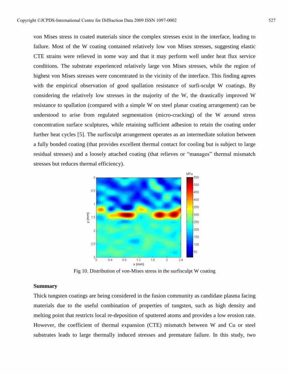
von Mises stress in coated materials since the complex stresses exist in the interface, leading to
failure. Most of the W coating contained relatively low von Mises stresses, suggesting elastic
CTE strains were relieved in some way and that it may perform well under heat flux service
conditions. The substrate experienced relatively large von Mises stresses, while the region of
highest von Mises stresses were concentrated in the vicinity of the interface. This finding agrees
with the empirical observation of good spallation resistance of surfi-sculpt W coatings. By
considering the relatively low stresses in the majority of the W, the drastically improved W
resistance to spallation (compared with a simple W on steel planar coating arrangement) can be
understood to arise from regulated segmentation (micro-cracking) of the W around stress
concentration surface sculptures, while retaining sufficient adhesion to retain the coating under
further heat cycles [5]. The surfisculpt arrangement operates as an intermediate solution between
a fully bonded coating (that provides excellent thermal contact for cooling but is subject to large
residual stresses) and a loosely attached coating (that relieves or �manages� thermal mismatch
stresses but reduces thermal efficiency).
Fig 10. Distribution of von-Mises stress in the surfisculpt W coating
Summary
Thick tungsten coatings are being considered in the fusion community as candidate plasma facing
materials due to the useful combination of properties of tungsten, such as high density and
melting point that restricts local re-deposition of sputtered atoms and provides a low erosion rate.
However, the coefficient of thermal expansion (CTE) mismatch between W and Cu or steel
substrates leads to large thermally induced stresses and premature failure. In this study, two
527Copyright ©JCPDS-International Centre for Diffraction Data 2009 ISSN 1097-0002

different approaches were investigated for manufacturing thick tungsten coatings on steel
substrate via vacuum plasma spraying (VPS): graded W/steel inter-layers and a steel substrate
surface with regular millimetre-scale sculptures. Residual stress measurements were conducted
using the white beam energy dispersive mode with twin-detector setup at the high energy
synchrotron beamline ID15 at ESRF, Grenoble. The graded coating produced a relatively smooth
residual strain variation across the W/steel inter-layers and successful re-distribution of thermal
stresses. The surfisculpt coatings showed that most of the tungsten coating was subject to
relatively low von Mises stresses, while the substrate experienced higher von Mises stresses.
Residual elastic stresses were concentrated in the vicinity of the material interface and this is
suggested to indicate local micro-cracking and segmentation of the W, but there was no evidence
of macroscopic coating failure/spallation. The use of surface sculptures or patterns to deliberately
regulate segmentation as a way of relieving thermally induced stresses is suggested.
Acknowledgements
The authors would like to thanks the UK Engineering and Physical Science Research Council and
UKAEA for financial support, and TWI, UK for the supply of surfi-sculpt substrates.
References
[1] X.C. Zhang, B.S. Xu, H.D. Wang, Y. Jiang and Y.X. Wu, Surface & Coatings Technology 201 (2007) 5716-5719
[2] M. Wenzelburger, D. López and R. Gadow, Surface & Coatings Technology 201 (2006) 1995-2001
[3] H. Cetinel, B. Uyulgan, C. Tekmen, I. Ozdemir and E. Celik, Surface & Coatings Technology 174-175 (2003) 1089-1094
[4] R. Ghafouri-Azar, J. Mostanghimi and S. Chandra, Computational Materials Science 35 (2006) 13-26
[5] G. Thomas, R. Vincent, G. Matthews, B. Dance and P.S. Grant, Materials Science and Engineering A 477 (2008) 35-42
[6] G. Thomas, R.G. Castro, G. Matthews, P. Coad and P.S. Grant, Proc. Int. Thermal Spray Conf. 2006 (on CD), ASM Intl., Ohio, USA (2006)
[7] B. Clausen, T. Leffers and T. Lorentzen, Acta Materialia. 51 (2003) 6181-6188 [8] A.C. Larson and R.B. Von Dreele, Los Alamos National Laboratory, New Mexico, USA
(1994) [9] S.Y. Zhang, High energy white beam X-ray diffraction studies of strains in engineering
materials and components, D.Phil thesis, Oxford University (2008) [10] A.M. Korsunsky, K.E. James and M.R. Daymond, Engineering Fracture Mechanics 71
(2004) 805-812 [11] T-S. Jun, S.Y. Zhang, M. Golshan, M. Peel, D. Richards and A.M. Korsunsky, Materials
Science Forum 571-572 (2008) 407-412
528Copyright ©JCPDS-International Centre for Diffraction Data 2009 ISSN 1097-0002
Recommended


![Spatial solitons supported by localized gain [Invited]](https://img.pdfslide.net/doc/110x75/635fb0aaac0cd8fcb10e4da0/spatial-solitons-supported-by-localized-gain-invited.jpg)


