Sp
SS
a
ARRAA
KAPEC
1
lcmadcacnn
rtvvac[Fv
0d
Journal of Power Sources 185 (2008) 676–684
Contents lists available at ScienceDirect
Journal of Power Sources
journa l homepage: www.e lsev ier .com/ locate / jpowsour
tructure and electrochemical properties of activatedolyacrylonitrile based carbon fibers containing carbon nanotubes
udhakar Jagannathan, Han Gi Chae, Rahul Jain, Satish Kumar ∗
chool of Polymer, Textile and Fiber Engineering, Georgia Institute of Technology, Atlanta, GA 30332, United States
r t i c l e i n f o
rticle history:eceived 3 July 2008eceived in revised form 27 August 2008ccepted 28 August 2008vailable online 7 September 2008
a b s t r a c t
Solution spun polyacrylonitrile (PAN), PAN/multi-wall carbon nanotube (MWCNT), and PAN/single-wallcarbon nanotube (SWCNT) fibers containing 5 wt.% carbon nanotubes were stabilized in air and activatedusing CO2 and KOH. The surface area as determined by nitrogen gas adsorption was an order of magnitudehigher for KOH activated fibers as compared to the CO2 activated fibers. The specific capacitance of KOH
−1
eywords:ctivated carbonolyacrylonitrilelectrochemical capacitorarbon nanotubes
activated PAN/SWCNT samples was as high as 250 F g in 6 M KOH electrolyte. Under the comparable KOHactivation conditions, PAN and PAN/SWCNT fibers had comparable surface areas (BET surface area about2200 m2 g−1) with pore size predominantly in the range of 1–5 nm, while surface area of PAN/MWCNTsamples was significantly lower (BET surface area 970 m2 g−1). The highest capacitance and energy densitywas obtained for PAN/SWCNT samples, suggesting SWCNT advantage in charge storage. The capacitancebehavior of these electrodes has also been tested in ionic liquids, and the energy density in ionic liquid is
ained
ld
trb[bwacaocktss
about twice the value obt
. Introduction
The activated carbons have wide range of applications such asiquid/gas phase adsorptions [1–4], gas, water or element purifi-ation [5–7], catalyst support [8–11], energy storage [12–18] andany other applications due to high surface area, pore structure and
dsorption capacity [19–21]. The pore structure of activated carbonepends on the precursor, activating agent as well as on processonditions. The precursors for activated carbons include poly-crylonitrile (PAN) [17,22–25], phenolic resin [18,22], petroleumoke [5,26], anthracite [27,28], pitch [29], coal [30–33], carbonanotube(CNT)/carbon nanofiber (CNF) [13,34], and a number ofatural fibers/shells [6,15,35,36].
There are two general approaches to modify carbon mate-ials to increase its adsorption capacity. The first approach iso make use of gasifying agents like CO2 [37–40] or waterapour [14,39–41] and is known as thermal or physical acti-ation. The chemical activation using hydroxides, halides andcids is another approach for producing porous carbon. The
hemical activating agents include KOH [5,23,26–28,34,42], NaOH7,27,29,34,43], ZnCl2 [22,36,44–46], H3PO4 [6,35,46], NH4Cl,eCl3, and AlCl3 [19,20,35,47]. The advantages of chemical acti-ation over physical activation include higher carbon yield,∗ Corresponding author. Tel.: +1 404 894 2490; fax: +1 404 894 8780.E-mail address: [email protected] (S. Kumar).
2
tpnai
378-7753/$ – see front matter © 2008 Elsevier B.V. All rights reserved.oi:10.1016/j.jpowsour.2008.08.093
using KOH electrolyte.© 2008 Elsevier B.V. All rights reserved.
ower activation time and temperature, and controlled pore sizeistribution.
Polyacrylonitrile, a carbonizing polymer, exhibits good interac-ion with carbon nanotubes [48–51]. A number of studies have beeneported on PAN/CNT films and fibers [37,48–50,52–59]. Fibers haveeen spun by conventional solution spinning [48,49], gel spinning50], as well as by electrospinning [53–55,57]. PAN/CNT based car-on fiber containing 1 wt.% carbon nanotube with respect to theeight of the polymer, can have 50% higher tensile strength thancarbon fiber processed without carbon nanotube [60]. Specific
apacitance of a PAN/SWCNT film containing 40 wt.% SWCNT wass high as 380 F g−1 [37]. These studies clearly suggest the potentialf PAN/CNT system for making both structural as well as porousarbon materials for a variety of applications. To the best of ournowledge, to date, there are no activation studies in the litera-ure on solution spun PAN/CNT fibers. In this paper we report thetructure, morphology, and electrochemical capacitor behavior oftabilized and CO2 and KOH activated PAN and PAN/CNT fibers.
. Experimental
The PAN and PAN/CNT fibers containing 5 wt.% CNT were solu-
ion spun by dry-jet-wet spinning using the previously describedrocedure [48,49]. SWCNTs were obtained from Carbon Nanotech-ologies, Inc. (Houston, TX) (Grade P0247, 2.4% catalytic impurity)nd MWCNTs were from Iljin Nanotech, Co. (Korea) (2.5% catalyticmpurity). Diameter of the solution spun fibers was in the range of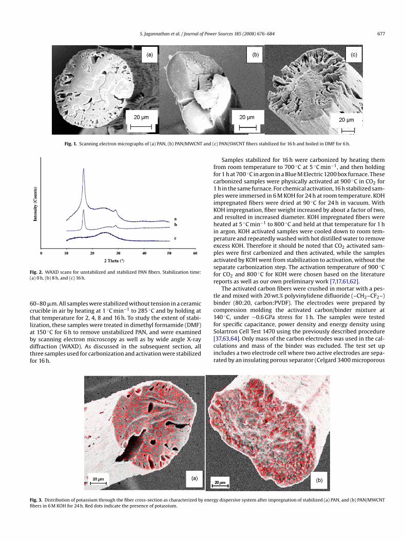
S. Jagannathan et al. / Journal of Power Sources 185 (2008) 676–684 677
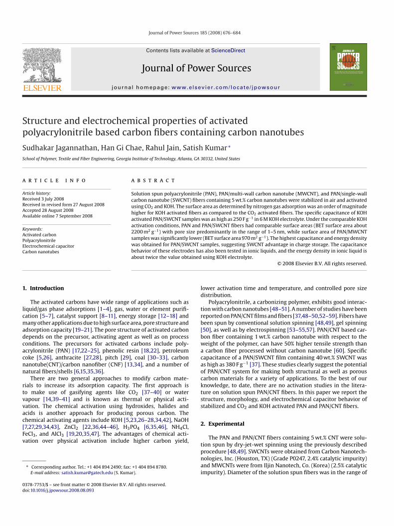
Fig. 1. Scanning electron micrographs of (a) PAN, (b) PAN/MWCNT and (
F(
6ctlabdtf
ffc1piKahipepasfr
tbc1fSolartron Cell Test 1470 using the previously described procedure[37,63,64]. Only mass of the carbon electrodes was used in the cal-
Ffi
ig. 2. WAXD scans for unstabilized and stabilized PAN fibers. Stabilization time:a) 0 h, (b) 8 h, and (c) 16 h.
0–80 �m. All samples were stabilized without tension in a ceramicrucible in air by heating at 1 ◦C min−1 to 285 ◦C and by holding athat temperature for 2, 4, 8 and 16 h. To study the extent of stabi-ization, these samples were treated in dimethyl formamide (DMF)t 150 ◦C for 6 h to remove unstabilized PAN, and were examinedy scanning electron microscopy as well as by wide angle X-ray
iffraction (WAXD). As discussed in the subsequent section, allhree samples used for carbonization and activation were stabilizedor 16 h.cir
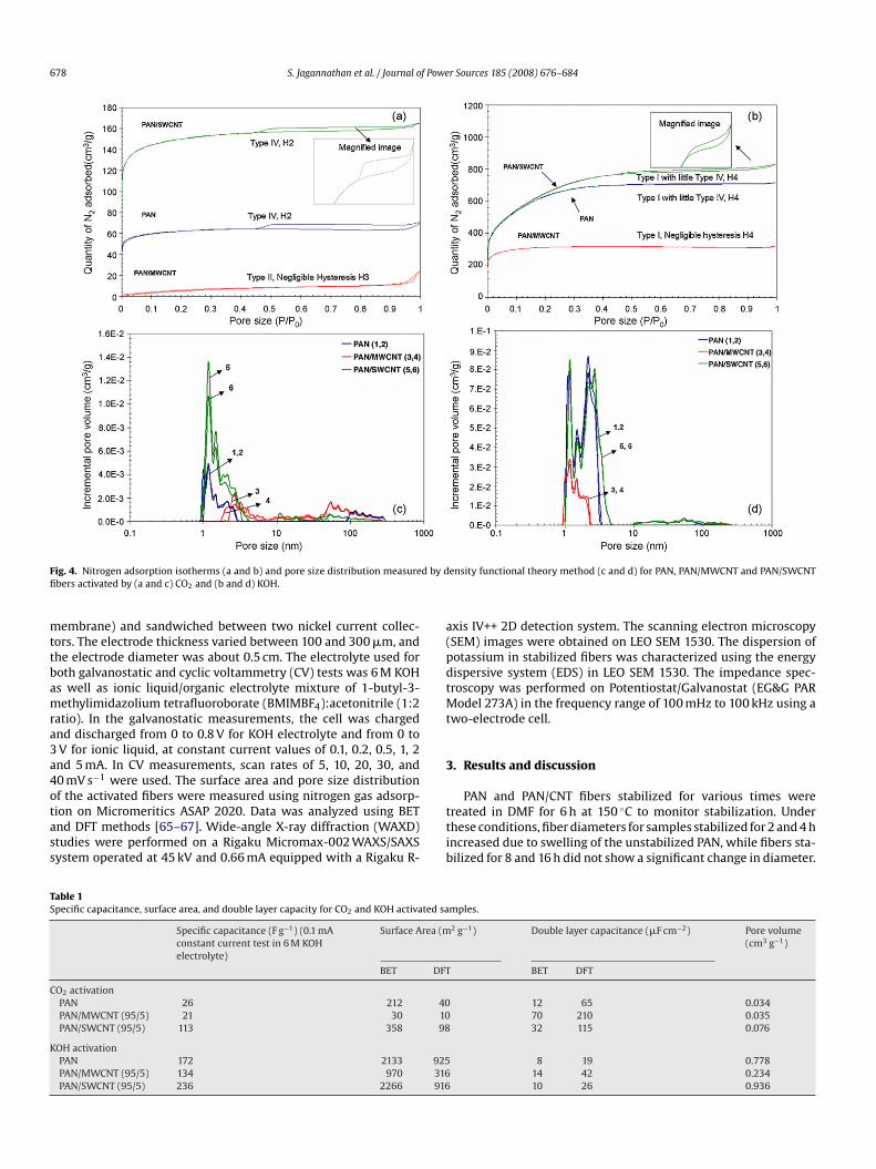
ig. 3. Distribution of potassium through the fiber cross-section as characterized by energbers in 6 M KOH for 24 h. Red dots indicate the presence of potassium.
c) PAN/SWCNT fibers stabilized for 16 h and boiled in DMF for 6 h.
Samples stabilized for 16 h were carbonized by heating themrom room temperature to 700 ◦C at 5 ◦C min−1, and then holdingor 1 h at 700 ◦C in argon in a Blue M Electric 1200 box furnace. Thesearbonized samples were physically activated at 900 ◦C in CO2 forh in the same furnace. For chemical activation, 16 h stabilized sam-les were immersed in 6 M KOH for 24 h at room temperature. KOH
mpregnated fibers were dried at 90 ◦C for 24 h in vacuum. WithOH impregnation, fiber weight increased by about a factor of two,nd resulted in increased diameter. KOH impregnated fibers wereeated at 5 ◦C min−1 to 800 ◦C and held at that temperature for 1 h
n argon. KOH activated samples were cooled down to room tem-erature and repeatedly washed with hot distilled water to removexcess KOH. Therefore it should be noted that CO2 activated sam-les were first carbonized and then activated, while the samplesctivated by KOH went from stabilization to activation, without theeparate carbonization step. The activation temperature of 900 ◦Cor CO2 and 800 ◦C for KOH were chosen based on the literatureeports as well as our own preliminary work [7,17,61,62].
The activated carbon fibers were crushed in mortar with a pes-le and mixed with 20 wt.% polyvinylidene difluoride (–CH2–CF2–)inder (80:20, carbon:PVDF). The electrodes were prepared byompression molding the activated carbon/binder mixture at40 ◦C, under ∼0.6 GPa stress for 1 h. The samples were testedor specific capacitance, power density and energy density using
ulations and mass of the binder was excluded. The test set upncludes a two electrode cell where two active electrodes are sepa-ated by an insulating porous separator (Celgard 3400 microporous
y dispersive system after impregnation of stabilized (a) PAN, and (b) PAN/MWCNT
678 S. Jagannathan et al. / Journal of Power Sources 185 (2008) 676–684
F d by dfi
mttbamra3a4otass
a(pdtMt
3
TS
C
K
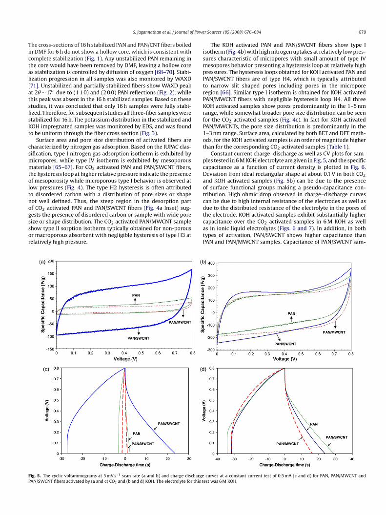
ig. 4. Nitrogen adsorption isotherms (a and b) and pore size distribution measurebers activated by (a and c) CO2 and (b and d) KOH.
embrane) and sandwiched between two nickel current collec-ors. The electrode thickness varied between 100 and 300 �m, andhe electrode diameter was about 0.5 cm. The electrolyte used foroth galvanostatic and cyclic voltammetry (CV) tests was 6 M KOHs well as ionic liquid/organic electrolyte mixture of 1-butyl-3-ethylimidazolium tetrafluoroborate (BMIMBF4):acetonitrile (1:2
atio). In the galvanostatic measurements, the cell was chargednd discharged from 0 to 0.8 V for KOH electrolyte and from 0 toV for ionic liquid, at constant current values of 0.1, 0.2, 0.5, 1, 2nd 5 mA. In CV measurements, scan rates of 5, 10, 20, 30, and0 mV s−1 were used. The surface area and pore size distribution
f the activated fibers were measured using nitrogen gas adsorp-ion on Micromeritics ASAP 2020. Data was analyzed using BETnd DFT methods [65–67]. Wide-angle X-ray diffraction (WAXD)tudies were performed on a Rigaku Micromax-002 WAXS/SAXSystem operated at 45 kV and 0.66 mA equipped with a Rigaku R-ttib
able 1pecific capacitance, surface area, and double layer capacity for CO2 and KOH activated sa
Specific capacitance (F g−1) (0.1 mAconstant current test in 6 M KOHelectrolyte)
Surface Area (m
BET DFT
O2 activationPAN 26 212 40PAN/MWCNT (95/5) 21 30 10PAN/SWCNT (95/5) 113 358 98
OH activationPAN 172 2133 925PAN/MWCNT (95/5) 134 970 316PAN/SWCNT (95/5) 236 2266 916
ensity functional theory method (c and d) for PAN, PAN/MWCNT and PAN/SWCNT
xis IV++ 2D detection system. The scanning electron microscopySEM) images were obtained on LEO SEM 1530. The dispersion ofotassium in stabilized fibers was characterized using the energyispersive system (EDS) in LEO SEM 1530. The impedance spec-roscopy was performed on Potentiostat/Galvanostat (EG&G PAR
odel 273A) in the frequency range of 100 mHz to 100 kHz using awo-electrode cell.
. Results and discussion
PAN and PAN/CNT fibers stabilized for various times werereated in DMF for 6 h at 150 ◦C to monitor stabilization. Underhese conditions, fiber diameters for samples stabilized for 2 and 4 hncreased due to swelling of the unstabilized PAN, while fibers sta-ilized for 8 and 16 h did not show a significant change in diameter.
mples.
2 g−1) Double layer capacitance (�F cm−2) Pore volume(cm3 g−1)
BET DFT
12 65 0.03470 210 0.03532 115 0.076
8 19 0.77814 42 0.23410 26 0.936
f Powe
Tictal[atslsKt
csmmtoltnogssor
ismpPtrPKrfP1ot
pcDaotcdt
FP
S. Jagannathan et al. / Journal o
he cross-sections of 16 h stabilized PAN and PAN/CNT fibers boiledn DMF for 6 h do not show a hollow core, which is consistent withomplete stabilization (Fig. 1). Any unstabilized PAN remaining inhe core would have been removed by DMF, leaving a hollow cores stabilization is controlled by diffusion of oxygen [68–70]. Stabi-ization progression in all samples was also monitored by WAXD71]. Unstabilized and partially stabilized fibers show WAXD peakt 2� ∼ 17◦ due to (1 1 0) and (2 0 0) PAN reflections (Fig. 2), whilehis peak was absent in the 16 h stabilized samples. Based on thesetudies, it was concluded that only 16 h samples were fully stabi-ized. Therefore, for subsequent studies all three-fiber samples weretabilized for 16 h. The potassium distribution in the stabilized andOH impregnated samples was monitored by EDS, and was foundo be uniform through the fiber cross section (Fig. 3).
Surface area and pore size distribution of activated fibers areharacterized by nitrogen gas adsorption. Based on the IUPAC clas-ification, type I nitrogen gas adsorption isotherm is exhibited byicropores, while type IV isotherm is exhibited by mesoporousaterials [65–67]. For CO2 activated PAN and PAN/SWCNT fibers,
he hysteresis loop at higher relative pressure indicate the presencef mesoporosity while microporous type I behavior is observed atow pressures (Fig. 4). The type H2 hysteresis is often attributedo disordered carbon with a distribution of pore sizes or shapeot well defined. Thus, the steep region in the desorption partf CO2 activated PAN and PAN/SWCNT fibers (Fig. 4a Inset) sug-ests the presence of disordered carbon or sample with wide pore
ize or shape distribution. The CO2 activated PAN/MWCNT samplehow type II sorption isotherm typically obtained for non-porousr macroporous absorbent with negligible hysteresis of type H3 atelatively high pressure.catP
ig. 5. The cyclic voltammograms at 5 mV s−1 scan rate (a and b) and charge dischargeAN/SWCNT fibers activated by (a and c) CO2 and (b and d) KOH. The electrolyte for this t
r Sources 185 (2008) 676–684 679
The KOH activated PAN and PAN/SWCNT fibers show type Isotherm (Fig. 4b) with high nitrogen uptakes at relatively low pres-ures characteristic of micropores with small amount of type IVesopores behavior presenting a hysteresis loop at relatively high
ressures. The hysteresis loops obtained for KOH activated PAN andAN/SWCNT fibers are of type H4, which is typically attributedo narrow slit shaped pores including pores in the microporeegion [66]. Similar type I isotherm is obtained for KOH activatedAN/MWCNT fibers with negligible hysteresis loop H4. All threeOH activated samples show pores predominantly in the 1–5 nmange, while somewhat broader pore size distribution can be seenor the CO2 activated samples (Fig. 4c). In fact for KOH activatedAN/MWCNTs, the pore size distribution is predominantly in the–3 nm range. Surface area, calculated by both BET and DFT meth-ds, for the KOH activated samples is an order of magnitude higherhan for the corresponding CO2 activated samples (Table 1).
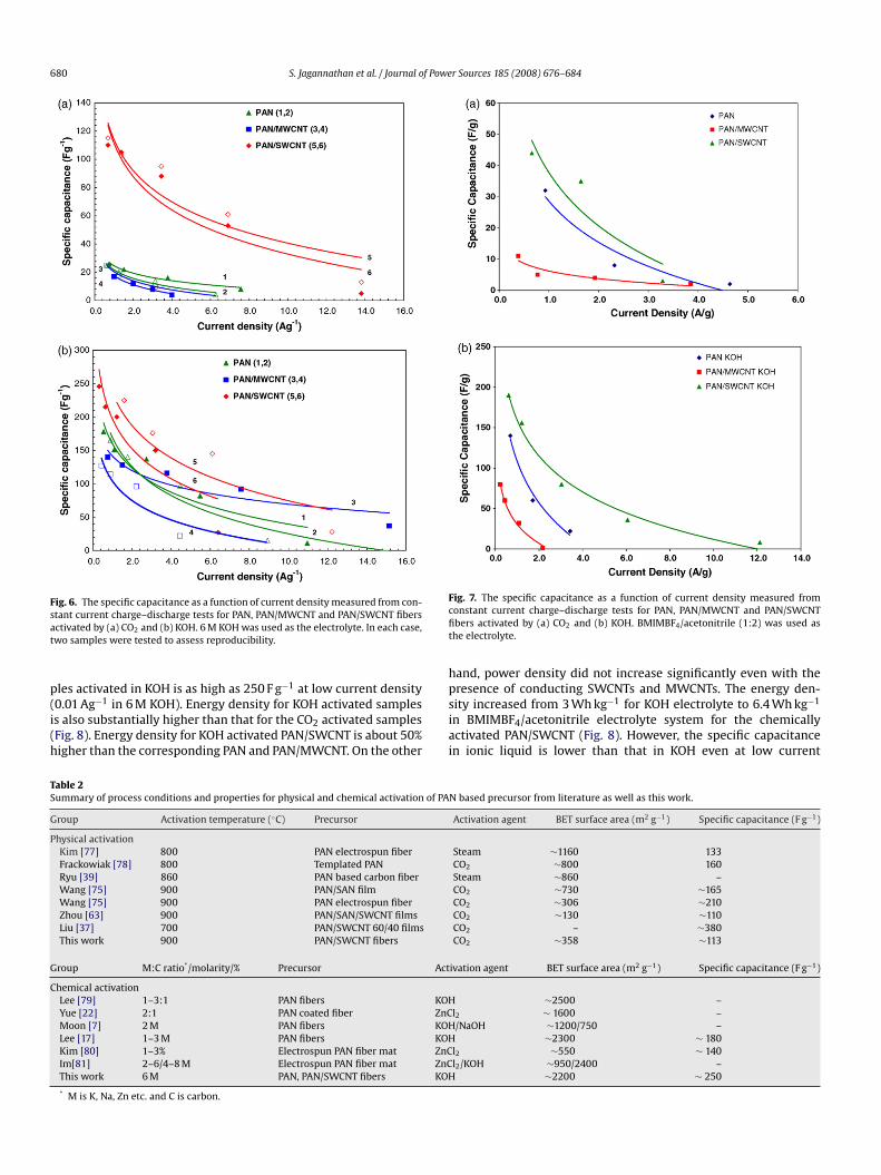
Constant current charge–discharge as well as CV plots for sam-les tested in 6 M KOH electrolyte are given in Fig. 5, and the specificapacitance as a function of current density is plotted in Fig. 6.eviation from ideal rectangular shape at about 0.1 V in both CO2nd KOH activated samples (Fig. 5b) can be due to the presencef surface functional groups making a pseudo-capacitance con-ribution. High ohmic drop observed in charge–discharge curvesan be due to high internal resistance of the electrodes as well asue to the distributed resistance of the electrolyte in the pores ofhe electrode. KOH activated samples exhibit substantially higher
apacitance over the CO2 activated samples in 6 M KOH as wells in ionic liquid electrolytes (Figs. 6 and 7). In addition, in bothypes of activation, PAN/SWCNT shows higher capacitance thanAN and PAN/MWCNT samples. Capacitance of PAN/SWCNT sam-curves at a constant current test of 0.5 mA (c and d) for PAN, PAN/MWCNT andest was 6 M KOH.
680 S. Jagannathan et al. / Journal of Power Sources 185 (2008) 676–684
Fig. 6. The specific capacitance as a function of current density measured from con-sat
p(i(h
Fcfit
hpresence of conducting SWCNTs and MWCNTs. The energy den-
TS
G
P
G
C
tant current charge–discharge tests for PAN, PAN/MWCNT and PAN/SWCNT fibersctivated by (a) CO2 and (b) KOH. 6 M KOH was used as the electrolyte. In each case,wo samples were tested to assess reproducibility.
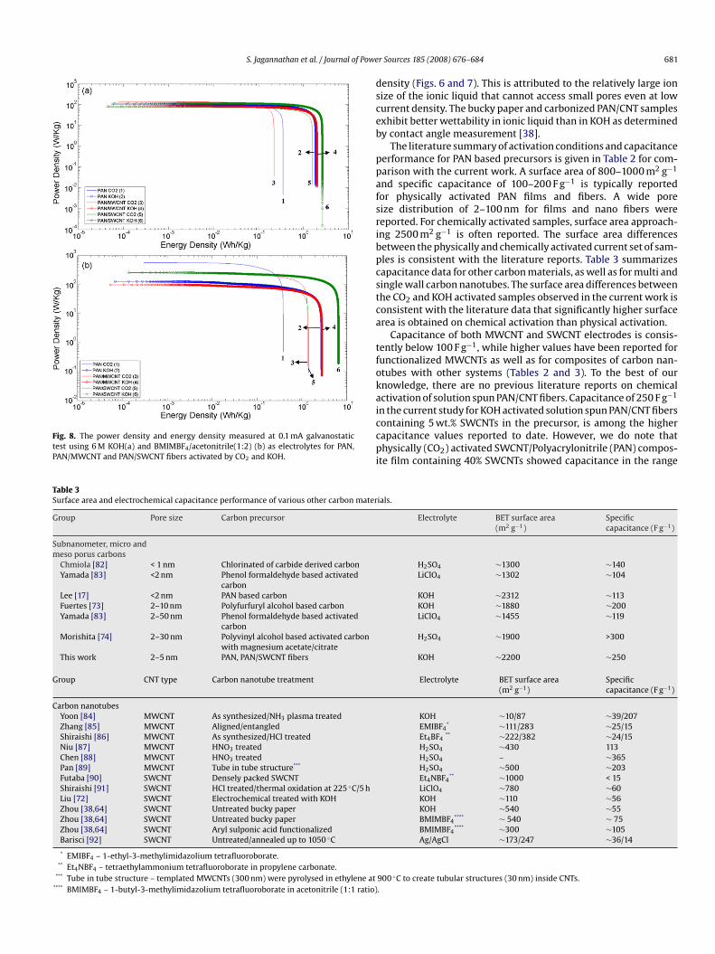
les activated in KOH is as high as 250 F g−1 at low current density
0.01 Ag−1 in 6 M KOH). Energy density for KOH activated sampless also substantially higher than that for the CO2 activated samplesFig. 8). Energy density for KOH activated PAN/SWCNT is about 50%igher than the corresponding PAN and PAN/MWCNT. On the othersiai
able 2ummary of process conditions and properties for physical and chemical activation of PA
roup Activation temperature (◦C) Precursor
hysical activationKim [77] 800 PAN electrospun fiberFrackowiak [78] 800 Templated PANRyu [39] 860 PAN based carbon fiberWang [75] 900 PAN/SAN filmWang [75] 900 PAN electrospun fiberZhou [63] 900 PAN/SAN/SWCNT filmsLiu [37] 700 PAN/SWCNT 60/40 filmsThis work 900 PAN/SWCNT fibers
roup M:C ratio*/molarity/% Precursor Act
hemical activationLee [79] 1–3:1 PAN fibers KOHYue [22] 2:1 PAN coated fiber ZnCMoon [7] 2 M PAN fibers KOHLee [17] 1–3 M PAN fibers KOHKim [80] 1–3% Electrospun PAN fiber mat ZnCIm[81] 2–6/4–8 M Electrospun PAN fiber mat ZnCThis work 6 M PAN, PAN/SWCNT fibers KOH
* M is K, Na, Zn etc. and C is carbon.
ig. 7. The specific capacitance as a function of current density measured fromonstant current charge–discharge tests for PAN, PAN/MWCNT and PAN/SWCNTbers activated by (a) CO2 and (b) KOH. BMIMBF4/acetonitrile (1:2) was used ashe electrolyte.
and, power density did not increase significantly even with the
ity increased from 3 Wh kg−1 for KOH electrolyte to 6.4 Wh kg−1
n BMIMBF4/acetonitrile electrolyte system for the chemicallyctivated PAN/SWCNT (Fig. 8). However, the specific capacitancen ionic liquid is lower than that in KOH even at low current
N based precursor from literature as well as this work.
Activation agent BET surface area (m2 g−1) Specific capacitance (F g−1)
Steam ∼1160 133CO2 ∼800 160Steam ∼860 –CO2 ∼730 ∼165CO2 ∼306 ∼210CO2 ∼130 ∼110CO2 – ∼380CO2 ∼358 ∼113
ivation agent BET surface area (m2 g−1) Specific capacitance (F g−1)
∼2500 –l2 ∼ 1600 –/NaOH ∼1200/750 –
∼2300 ∼ 180l2 ∼550 ∼ 140l2/KOH ∼950/2400 –
∼2200 ∼ 250
S. Jagannathan et al. / Journal of Powe
Fig. 8. The power density and energy density measured at 0.1 mA galvanostatictest using 6 M KOH(a) and BMIMBF4/acetonitrile(1:2) (b) as electrolytes for PAN,PAN/MWCNT and PAN/SWCNT fibers activated by CO2 and KOH.
dsceb
ppafsribpcstca
tfokaiccpi
Table 3Surface area and electrochemical capacitance performance of various other carbon mater
Group Pore size Carbon precursor
Subnanometer, micro andmeso porus carbons
Chmiola [82] < 1 nm Chlorinated of carbide derived carbonYamada [83] <2 nm Phenol formaldehyde based activated
carbonLee [17] <2 nm PAN based carbonFuertes [73] 2–10 nm Polyfurfuryl alcohol based carbonYamada [83] 2–50 nm Phenol formaldehyde based activated
carbonMorishita [74] 2–30 nm Polyvinyl alcohol based activated carbon
with magnesium acetate/citrateThis work 2–5 nm PAN, PAN/SWCNT fibers
Group CNT type Carbon nanotube treatment
Carbon nanotubesYoon [84] MWCNT As synthesized/NH3 plasma treatedZhang [85] MWCNT Aligned/entangledShiraishi [86] MWCNT As synthesized/HCl treatedNiu [87] MWCNT HNO3 treatedChen [88] MWCNT HNO3 treatedPan [89] MWCNT Tube in tube structure***
Futaba [90] SWCNT Densely packed SWCNTShiraishi [91] SWCNT HCl treated/thermal oxidation at 225 ◦C/5 hLiu [72] SWCNT Electrochemical treated with KOHZhou [38,64] SWCNT Untreated bucky paperZhou [38,64] SWCNT Untreated bucky paperZhou [38,64] SWCNT Aryl sulponic acid functionalizedBarisci [92] SWCNT Untreated/annealed up to 1050 ◦C
* EMIBF4 – 1-ethyl-3-methylimidazolium tetrafluoroborate.** Et4NBF4 – tetraethylammonium tetrafluoroborate in propylene carbonate.
*** Tube in tube structure – templated MWCNTs (300 nm) were pyrolysed in ethylene at**** BMIMBF4 – 1-butyl-3-methylimidazolium tetrafluoroborate in acetonitrile (1:1 ratio)
r Sources 185 (2008) 676–684 681
ensity (Figs. 6 and 7). This is attributed to the relatively large ionize of the ionic liquid that cannot access small pores even at lowurrent density. The bucky paper and carbonized PAN/CNT samplesxhibit better wettability in ionic liquid than in KOH as determinedy contact angle measurement [38].
The literature summary of activation conditions and capacitanceerformance for PAN based precursors is given in Table 2 for com-arison with the current work. A surface area of 800–1000 m2 g−1
nd specific capacitance of 100–200 F g−1 is typically reportedor physically activated PAN films and fibers. A wide poreize distribution of 2–100 nm for films and nano fibers wereeported. For chemically activated samples, surface area approach-ng 2500 m2 g−1 is often reported. The surface area differencesetween the physically and chemically activated current set of sam-les is consistent with the literature reports. Table 3 summarizesapacitance data for other carbon materials, as well as for multi andingle wall carbon nanotubes. The surface area differences betweenhe CO2 and KOH activated samples observed in the current work isonsistent with the literature data that significantly higher surfacerea is obtained on chemical activation than physical activation.
Capacitance of both MWCNT and SWCNT electrodes is consis-ently below 100 F g−1, while higher values have been reported forunctionalized MWCNTs as well as for composites of carbon nan-tubes with other systems (Tables 2 and 3). To the best of ournowledge, there are no previous literature reports on chemicalctivation of solution spun PAN/CNT fibers. Capacitance of 250 F g−1
n the current study for KOH activated solution spun PAN/CNT fibersontaining 5 wt.% SWCNTs in the precursor, is among the higherapacitance values reported to date. However, we do note thathysically (CO2) activated SWCNT/Polyacrylonitrile (PAN) compos-
te film containing 40% SWCNTs showed capacitance in the range
ials.
Electrolyte BET surface area(m2 g−1)
Specificcapacitance (F g−1)
H2SO4 ∼1300 ∼140LiClO4 ∼1302 ∼104
KOH ∼2312 ∼113KOH ∼1880 ∼200LiClO4 ∼1455 ∼119
H2SO4 ∼1900 >300
KOH ∼2200 ∼250
Electrolyte BET surface area(m2 g−1)
Specificcapacitance (F g−1)
KOH ∼10/87 ∼39/207EMIBF4
* ∼111/283 ∼25/15Et4BF4
** ∼222/382 ∼24/15H2SO4 ∼430 113H2SO4 – ∼365H2SO4 ∼500 ∼203Et4NBF4
** ∼1000 < 15LiClO4 ∼780 ∼60KOH ∼110 ∼56KOH ∼540 ∼55BMIMBF4
**** ∼ 540 ∼ 75BMIMBF4
**** ∼300 ∼105Ag/AgCl ∼173/247 ∼36/14
900 ◦C to create tubular structures (30 nm) inside CNTs..
682 S. Jagannathan et al. / Journal of Power Sources 185 (2008) 676–684
F mplef impe
o[aSam
bwscopmpscd
scldfstfK
amCcpaciawr
oimftwwMuwp
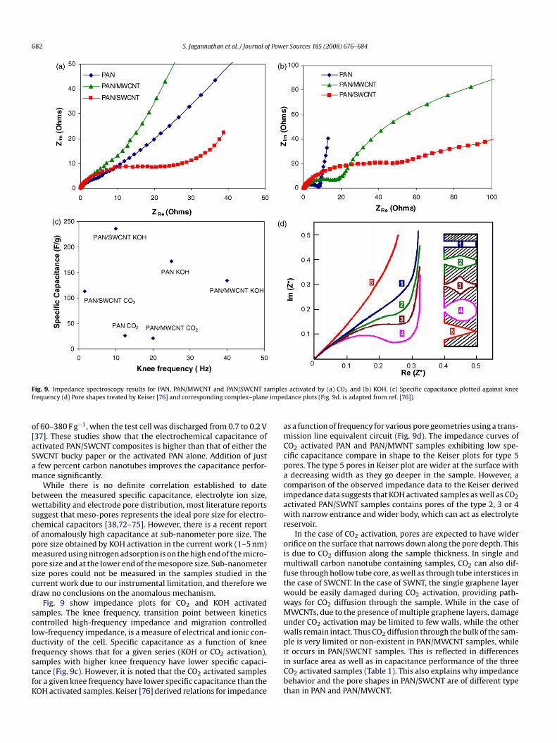
ig. 9. Impedance spectroscopy results for PAN, PAN/MWCNT and PAN/SWCNT sarequency (d) Pore shapes treated by Keiser [76] and corresponding complex–plane
f 60–380 F g−1, when the test cell was discharged from 0.7 to 0.2 V37]. These studies show that the electrochemical capacitance ofctivated PAN/SWCNT composites is higher than that of either theWCNT bucky paper or the activated PAN alone. Addition of justfew percent carbon nanotubes improves the capacitance perfor-ance significantly.While there is no definite correlation established to date
etween the measured specific capacitance, electrolyte ion size,ettability and electrode pore distribution, most literature reports
uggest that meso-pores represents the ideal pore size for electro-hemical capacitors [38,72–75]. However, there is a recent reportf anomalously high capacitance at sub-nanometer pore size. Theore size obtained by KOH activation in the current work (1–5 nm)easured using nitrogen adsorption is on the high end of the micro-
ore size and at the lower end of the mesopore size. Sub-nanometerize pores could not be measured in the samples studied in theurrent work due to our instrumental limitation, and therefore weraw no conclusions on the anomalous mechanism.
Fig. 9 show impedance plots for CO2 and KOH activatedamples. The knee frequency, transition point between kineticsontrolled high-frequency impedance and migration controlledow-frequency impedance, is a measure of electrical and ionic con-uctivity of the cell. Specific capacitance as a function of knee
requency shows that for a given series (KOH or CO2 activation),amples with higher knee frequency have lower specific capaci-ance (Fig. 9c). However, it is noted that the CO2 activated samplesor a given knee frequency have lower specific capacitance than theOH activated samples. Keiser [76] derived relations for impedanceiiCbt
s activated by (a) CO2 and (b) KOH. (c) Specific capacitance plotted against kneedance plots (Fig. 9d. is adapted from ref. [76]).
s a function of frequency for various pore geometries using a trans-ission line equivalent circuit (Fig. 9d). The impedance curves of
O2 activated PAN and PAN/MWNT samples exhibiting low spe-ific capacitance compare in shape to the Keiser plots for type 5ores. The type 5 pores in Keiser plot are wider at the surface withdecreasing width as they go deeper in the sample. However, a
omparison of the observed impedance data to the Keiser derivedmpedance data suggests that KOH activated samples as well as CO2ctivated PAN/SWNT samples contains pores of the type 2, 3 or 4ith narrow entrance and wider body, which can act as electrolyte
eservoir.In the case of CO2 activation, pores are expected to have wider
rifice on the surface that narrows down along the pore depth. Thiss due to CO2 diffusion along the sample thickness. In single and
ultiwall carbon nanotube containing samples, CO2 can also dif-use through hollow tube core, as well as through tube interstices inhe case of SWCNT. In the case of SWNT, the single graphene layerould be easily damaged during CO2 activation, providing path-ays for CO2 diffusion through the sample. While in the case ofWCNTs, due to the presence of multiple graphene layers, damage
nder CO2 activation may be limited to few walls, while the otheralls remain intact. Thus CO2 diffusion through the bulk of the sam-le is very limited or non-existent in PAN/MWCNT samples, while
t occurs in PAN/SWCNT samples. This is reflected in differencesn surface area as well as in capacitance performance of the threeO2 activated samples (Table 1). This also explains why impedanceehavior and the pore shapes in PAN/SWCNT are of different typehan in PAN and PAN/MWCNT.
f Powe
tPslCeitbftbbpptItwNatPte
4
P(cdTwrcwaaa
A
Rfc
R
[[[
[
[[
[[[[[[
[[[[[
[
[
[
[[[
[[
[[[
[[[[[[
[[
[
[[
[[[[[
[[[[
[[
[[[[[[
[
[
[[[
S. Jagannathan et al. / Journal o
Another question is why MWCNT contribute in a negative wayo the capacitance behavior, as under both types of activation,AN/MWCNT samples exhibit lower capacitance than the corre-ponding PAN. This can also be understood by multiple grapheneayer stacking in MWCNTs, which is not always penetrated byO2 activation than the surrounding matrix. Hence, we hypoth-size that the presence of MWCNTs limits activation, resultingn relatively low surface area and hence relatively low capaci-ance as compared to PAN and PAN/SWCNT. Interaction differencesetween PAN-SWCNT and PAN-MWCNT may also be responsibleor some of the observed differences. Based on the tempera-ure dependence of dynamic mechanical tan ı plots, differencesetween PAN/SWCNT and PAN/MWCNT interactions have indeedeen reported previously [49]. Width of the tan ı vs temperaturelot for the PAN/MWCNT fibers is significantly reduced as com-ared to that of the control PAN due to polymer interaction withhe nanotubes resulting in narrower spectrum of relaxation times.n the case of SWCNT containing fibers, tan ı peak is broadenedowards high temperature. We conjecture that PAN interactionsith SWCNT are stronger than with other larger diameter MWC-Ts and that PAN segments closer to the SWCNT exhibit tan ı losst higher temperature than the segments farther from it, leadingo the broadening in the high temperature region. Intercalation ofAN in the SWCNT bundle may also be partially responsible for thean ı broadening behavior. Intercalated PAN on activation wouldnhance surface area leading to higher capacitance.
. Conclusions
The structure, and electrochemical properties of PAN,AN/SWCNT, and PAN/MWCNT fibers activated by physicalCO2) and chemical (KOH) methods are compared. High specificapacitance, surface area, and pore volume with narrow pore sizeistribution are achieved in PAN/SWCNT with chemical activation.he specific capacitance of KOH activated PAN/SWCNT samplesas as high as 250 F g−1 in 6 M KOH electrolyte. Under the compa-
able KOH activation conditions, PAN and PAN/SWCNT fibers hadomparable surface areas (BET surface area about 2200 m2 g−1)ith pore size predominantly in the range of 1–5 nm, while surface
rea of PAN/MWCNT samples was significantly lower (BET surfacerea 970 m2 g−1). The highest energy density was obtained for KOHctivated PAN/SWCNT in ionic liquid.
cknowledgement
This work is supported by the Air Force Office of Scientificesearch. We are grateful to Professor Meilin Liu for the use ofrequency response analyzer and to Beom-Jin Yoon for useful dis-ussions.
eferences
[1] A. Ahmadpour, B.A. King, D.D. Do, Ind. Eng. Chem. Res. 37 (1998) 1329.[2] Z. Hu, M.P. Srinivasan, Y. Ni, Carbon 39 (2001) 877.[3] Y. Hattori, N. Noguchi, F. Okino, H. Touhara, Y. Nakahigashi, S. Utsumi, H. Tanaka,
H. Kanoh, K. Kaneko, Carbon 45 (2007) 1391.[4] D. Lozano-Castello, D. Cazorla-Amoros, A. Linares-Solano, D.F. Quinn, Carbon
40 (2002) 989.[5] T. Otowa, Y. Nojima, T. Miyazaki, Carbon 35 (1997) 1315.[6] N.H. Phan, S. Rio, C. Faur, L. Le Coq, P. Le Cloirec, T.H. Nguyen, Carbon 44 (2006)
2569.[7] S.Y. Moon, M.-s. Kim, H.-S. Hahm, Y.-S. Lim, Mater. Sci. Forum 510–511 (2006)
750.[8] M. Fan, P. Zhang, Energy Fuels 21 (2007) 633.[9] A. Guha, W. Lu, T.A. Zawodzinski Jr., D.A. Schiraldi, Carbon 45 (2007) 1506.10] P.D. Tien, T. Satoh, M. Miura, M. Nomura, Energy Fuels 19 (2005) 2110.11] D.R. Rolison, Science 299 (2003) 1698.12] B.E. Conway, Plenum Press, New York, 1999, xxviii.
[[[
[[
r Sources 185 (2008) 676–684 683
13] S.-H. Yoon, S. Lim, Y. Song, Y. Ota, W. Qiao, A. Tanaka, I. Mochida, Carbon 42(2004) 1723.
14] F.-C. Wu, R.-L. Tseng, C.-C. Hu, C.-C. Wang, J. Power Sources 144 (2005) 302.15] V. Subramanian, C. Luo, A.M. Stephan, K.S. Nahm, S. Thomas, B. Wei, J. Phys.
Chem. C 111 (2007) 7527.16] F.-C. Wu, R.-L. Tseng, C.-C. Hu, C.-C. Wang, J. Power Sources 159 (2006) 1532.17] J.-G. Lee, J.-Y. Kim, S.-H. Kim, J. Power Sources 160 (2006) 1495.18] H. Teng, Y.-J. Chang, C.-T. Hsieh, Carbon 39 (2001) 1981.19] R.C. Bansal, J.-B. Donnet, F. Stoeckli, Marcel Dekker, Inc. New York, 1988.20] J.-B. Donnet, R.C. Bansal, Marcel Dekker, Inc. New York, 1984.21] H. Marsh, F. 2006. Rodriguez-Reinoso, Activated Carbon, Elsevier Science Ltd.,
Oxford, 322.22] Z. Yue, C.L. Mangun, J. Econ. Carbon 40 (2002) 1181.23] M. Wu, Q. Zha, J. Qiu, Y. Guo, H. Shang, A. Yuan, Carbon 42 (2004) 205.24] M.S.A. Rahaman, A.F. Ismail, A. Mustafa, Polym. Degrad. Stab. 92 (2007) 1421.25] E. Fitzer, D.J. Muller, Carbon 13 (1975) 63.26] L. Chunlan, X. Shaoping, G. Yixiong, L. Shuqin, L. Changhou, Carbon 43 (2005)
2295.27] M.A. Lillo-Rodenas, D. Cazorla-Amoros, A. Linares-Solano, Carbon 41 (2003)
267.28] D. Lozano-Castello, M.A. Lillo-Rodenas, D. Cazorla-Amoros, A. Linares-Solano,
Carbon 39 (2001) 741.29] J.A. Macia-Agullo, B.C. Moore, D. Cazorla-Amoros, A. Linares-Solano, Carbon 42
(2004) 1367.30] A. Ahmadpour, D.D. Do, Carbon 34 (1996) 471.31] P. Ehrburger, A. Addoun, F. Addoun, J.-B. Donnet, Fuel 65 (1986) 1447.32] M.J. Illan-Gomez, A. Garcia-Garcia, C. Salinas-Martinez de Lecea, A. Linares-
Solano, Energy Fuels 10 (1996) 1108.33] H. Teng, L.Y. Hsu, Ind. Eng. Chem. Res. 38 (1999) 2947.34] E. Raymundo-Pinero, P. Azais, T. Cacciaguerra, D. Cazorla-Amoros, A. Linares-
Solano, F. Beguin, Carbon 43 (2005) 786.35] A. Huidobro, A.C. Pastor, F. Rodriguez-Reinoso, Carbon 39 (2001) 389.36] T. Yang, A.C. Lua, Mater. Chem. Phys. 100 (2006) 438.37] T. Liu, T.V. Sreekumar, S. Kumar, R.H. Hauge, R.E. Smalley, Carbon 41 (2003)
2440.38] C. Zhou, PhD Thesis, Georgia Institute of Technology, 2006, 42.39] Z. Ryu, H. Rong, J. Zheng, M. Wang, B. Zhang, Carbon 40 (2002) 1144.40] Tse-Hao Ko, W.-S. Kuo, C.-H. Hu, J. Appl. Polym. Sci. 81 (2001) 1090.41] P.H. Wang, Z.R. Yue, J. Liu, J. Appl. Polym. Sci. 60 (1996) 923.42] R. Xue, Z. Shen, Carbon 41 (2003) 1862.43] D. Lozano-Castello, J.A. Macia-Agullo, D. Cazorla-Amoros, A. Linares-Solano, M.
Muller, M. Burghammer, C. Riekel, Carbon 44 (2006) 1121.44] F. Caturla, M. Molina-Sabio, F. Rodriguez-Reinoso, Carbon 29 (1991) 999.45] J. Ganan-Gomez, A. Macias-Garcia, M.A. Diaz-Diez, C. Gonzalez-Garcia, E. Sabio-
Rey, Appl. Surf. Sci. 252 (2006) 5976.46] Y. Nakagawa, M. Molina-Sabio, F. Rodriguez-Reinoso, Microporous Mesoporous
Mater. 103 (2007) 29.47] H. Marsh, F. Rodriguez-Reinoso, 2006.48] T.V. Sreekumar, T. Liu, B.G. Min, H. Guo, S. Kumar, R.H. Hauge, R.E. Smalley, Adv.
Mater. 16 (2004) 58.49] H.G. Chae, T.V. Sreekumar, T. Uchida, S. Kumar, Polymer 46 (2005) 10925.50] H.G. Chae, M.L. Minus, S. Kumar, Polymer 47 (2006) 3494.51] T. Uchida, S. Kumar, J. Appl. Polym. Sci. 98 (2005) 985.52] T.V. Sreekumar, S. Kumar, US Patent 6,852,410, 2005.53] F. Ko, Y. Gogotsi, A. Ali, N. Naguib, H. Ye, G.L. Yang, C. Li, P. Willis, Adv. Mater. 15
(2003) 1161.54] H. Ye, H. Lam, N. Titchenal, Y. Gogotsi, F. Ko, Appl. Phys. Lett. 85 (2004) 1775.55] S. Prilutsky, E. Zussman, Y. Cohen, Nanotechnology 19 (2008) 165603.56] L. Vaisman, E. Wachtel, H.D. Wagner, G. Marom, Polymer 48 (2007) 6843.57] D.-K. Kim, S.H. Park, B.C. Kim, B.D. Chin, S.M. Jo, D.Y. Kim, Macromol. Res. 13
(2005) 521.58] F. Béguin, K. Szostak, G. Lota, E. Frackowiak, Adv. Mater. 17 (2005) 2380.59] H. Hou, J.J. Ge, J. Zeng, Q. Li, D.H. Reneker, A. Greiner, S.Z.D. Cheng, Chem. Mater.
17 (2005) 967.60] H.G. Chae, M.L. Minus, A. Rasheed, S. Kumar, Polymer 48 (2007) 3781.61] S. Jagannathan, PhD Thesis (in progress), Georgia Institute of Technology.62] J. Lee, J. Kim, S. Kim, J. Mater. Sci. 42 (2007) 2486.63] C. Zhou, T. Liu, T. Wang, S. Kumar, Polymer 47 (2006) 5831.64] C. Zhou, S. Kumar, C.D. Doyle, J.M. Tour, Chem. Mater. 17 (2005) 1997.65] S. Lowell, J.E. Shields, M.A. Thomas, M. Thommes, Characterization of Porous
Solids and Powders: Surface Area, Pore Size and Density, Kluwer AcademicPublishers, Dordrecht/Boston/London, 2004.
66] K.S.W. Sing, D.H. Everett, R.A.W. Haul, L. Moscou, R.A. Pierotti, J. Rouquerol, T.Siemieniewska, Pure Appl. Chem. 57 (1985) 603.
67] P.A. Webb, C. Orr, Analytical Methods in Fine Particle Technology, MicromeriticsInstruments Corp., Norcross, Georgia, 1997.
68] M.-J. Yu, C.-G. Wang, Y.-J. Bai, M.-X. Ji, Y. Xu, Polym. Bull. 58 (2007) 933.69] G.K. Layden, Carbon 10 (1972) 59.70] F.R. Barnet, M.K. Norr, Composites 7 (1976) 93.
71] M.-J. Yu, Y.-J. Bai, C.-G. Wang, Y. Xu, P.-Z. Guo, Mater. Lett. 61 (2007) 2292.72] C.G. Liu, H.T. Fang, F. Li, M. Liu, H.M. Cheng, J. Power Sources 160 (2006) 758.73] A.B. Fuertes, G. Lota, T.A. Centeno, E. Frackowiak, Electrochim. Acta 50 (2005)2799.74] T. Morishita, Y. Soneda, T. Tsumura, M. Inagaki, Carbon 44 (2006) 2360.75] T. Wang, PhD Thesis, Georgia Institute of Technology, 2007.

6 f Powe
[[[
[
[
[[
[[
[[
[
[
[
84 S. Jagannathan et al. / Journal o
76] H. Keiser, K.D. Beccu, M.A. Gutjahr, Electrochim. Acta 21 (1976) 539.77] C. Kim, Y. Kap-Seung, L. Wan-Jin, Electrochem. Solid-State Lett. 7 (2004) A397.78] E. Frackowiak, G. Lota, J. Machnikowski, C. Vix-Guterl, F. Beguin, Electrochim.
Acta 51 (2006) 2209.79] Y.-J. Lee, J.-H. Kim, J. Kim, D.B. Lee, J.-C. Lee, Y.-J. Chung, Y.-S. Lim, Mater. Sci.
Forum 449–452 (2004) 217.80] C. Kim, B.T.N. Ngoc, K.S. Yang, M. Kojima, Y.A. Kim, Y.J. Kim, M. Endo, S.C. Yang,
Adv. Mater. 19 (2007) 2341.
81] J.S. Im, S.-J. Park, Y.-S. Lee, J. Colloid Interface Sci. 314 (2007) 32.82] J. Chmiola, G. Yushin, Y. Gogotsi, C. Portet, P. Simon, P.L. Taberna, Science 313(2006) 1760.83] H. Yamada, I. Moriguchi, T. Kudo, J. Power Sources 175 (2008) 651.84] B.-J. Yoon, S.-H. Jeong, K.-H. Lee, H. Seok Kim, C. Gyung Park, J. Hun Han, Chem.
Phys. Lett. 388 (2004) 170.
[
[
[
r Sources 185 (2008) 676–684
85] H. Zhang, G. Cao, Y. Yang, Z. Gu, J. Electrochem. Soc. 155 (2008) K19.86] S. Shiraishi, M. Kibe, T. Yokoyama, H. Kurihara, N. Patel, A. Oya, Y. Kaburagi, Y.
Hishiyama, Appl. Phys. A: Mater. Sci. Process. 82 (2006) 585.87] C. Niu, E.K. Sichel, R. Hoch, D. Moy, H. Tennent, Appl. Phys. Lett. 70 (1997)
1480.88] Q.-L. Chen, K.-H. Xue, W. Shen, F.-F. Tao, S.-Y. Yin, W. Xu, Electrochim. Acta 49
(2004) 4157.89] H. Pan, C.K. Poh, Y.P. Feng, J. Lin, Chem. Mater. 19 (2007) 6120.
90] D.N. Futaba, K. Hata, T. Yamada, T. Hiraoka, Y. Hayamizu, Y. Kakudate, O. Tanaike,H. Hatori, M. Yumura, S. Iijima, Nat. Mater. 5 (2006) 987.91] S. Shiraishi, H. Kurihara, K. Okabe, D. Hulicova, A. Oya, Electrochem. Commun.
4 (2002) 593.92] J.N. Barisci, G.G. Wallace, D. Chattopadhyay, F. Papadimitrakopoulos, R.H.
Baughman, J. Electrochem. Soc. 150 (2003) E409.
Recommended


