SkyView HDX
System Installation Manual
AML STC SA02594SE
Document 103261-000, Revision E
April 28, 2020
Copyright © 2020 by Dynon Avionics, Inc.
Permission to print this manual is granted to third parties.

Contact Information
Dynon Avionics, Inc. 19825 141st Place NE Woodinville, WA 98072 Phone: 425-402-0433 - 8:00 AM – 5:00 PM (Pacific Time) Monday – Friday Technical Support: 7:00 AM–4:00 PM (Pacific Time) Monday – Friday Email: [email protected] Fax: 425-984-1751
Dynon Avionics offers a number of Internet sites for support: Primary website: http://www.dynonavionics.com – Dynon Avionics primary website; including: Current and archival documentation: http://docs.dynonavionics.com Software downloads: http://downloads.dynonavionics.com License redemption for SV-MAP-270, SV-SYNVIS-280, and SV-VPX-290: http://license.dynonavionics.com Secure store for purchasing avionics products: http://store.dynonavionics.com Register your product: http://register.dynonavionics.com Product support: http://support.dynonavionics.com Video library, including training: http://www.dynonavionics.com/videos Class-length training videos: http://www.dynonavionics.com/training
Stay in touch with Dynon Avionics: Sign up for email notifications for our blog: http://preflight.dynonavionics.com Like us on Facebook: https://www.facebook.com/dynonavionics Join our forum of SkyView pilots: http://forum.dynonavionics.com Sign up for our newsletter or read the archives: http://newsletter.dynonavionics.com Follow us on Twitter: https://twitter.com/dynon Follow us on Instagram: https://www.instagram.com/dynonavionics
Copyright
©2020 Dynon Avionics, Inc. All rights reserved. No part of this manual may be reproduced, copied, transmitted, disseminated or stored in any storage medium, for any purpose without the express written permission of Dynon Avionics. Dynon Avionics hereby grants permission to download a single copy of this manual and of any revision to this manual onto a hard drive or other electronic storage medium to be viewed for personal use, provided that such electronic or printed copy of this manual or revision must contain the complete text of this copyright notice and provided further that any unauthorized commercial distribution of this manual or any revision hereto is strictly prohibited.
Information in this document is subject to change without notice. Dynon Avionics reserves the right to change or improve its products and to make changes in the content without obligation to notify any person or organization of such changes. Visit the Dynon Avionics website (www.dynonavionics.com) for current updates and supplemental information concerning the use and operation of this and other Dynon Avionics products.

SkyView HDX System Installation Manual - Revision E i
Record of Revision
REV DATE ECO DESCRIPTION
A 3/5/2018 Initial Release
B 9/31/2018 312857 Added Second Display, VHF COM, AP Panel, Knob Panel. Also added more specific instructions on mounting SkyView HDX per STC02594SE
C 4/4/2019 326312 • Created Section 8.5.22 Landing Gear Position Indication
• Revised Landing Gear information in Section 8.6 Contacts to address logic change for landing gear to include GEAR 1, GEAR 2, GEAR 3, and GEAR 4
• Adjusted formatting on title page
• Updated references table
D 7/2/2019 327067 • Revision Bars indicate new information or significant changes to existing information
• Revised Table 64 - SV-COM-PANEL D15M Pinout to meet SV-COM-X83 Transciever wiring requirements
• Added Section 2.0: Instrument Panel Design
• Added Section 2.1: Regulatory Considerations
• Added Section 2.2: Volumetric Requirements
• Section 1 (old) moved to forematter content
• Section 1.10 (old) removed because content outdated
• Section 2.1-5 (old) moved to Section 1 (new)
• Section 2.6 (old) removed because content outdated
• Section 2.7 (old) renamed and moved to Section 1.15 (new)
• Added Section 3.1 (new): Avionics Tray Installation
• Sections 3, 6, 8-19 re-organized to better match typical order of assembly
• Sections 4.10-13 (old) removed because content outdated
• Section 5 (old) moved to Section 21 (new)
ii SkyView HDX System Installation Manual - Revision E
REV DATE ECO DESCRIPTION
• Section 7 (old) moved to Section 22 (new)
• Section 8.5.18 (old) removed because outdated
• Section 11.1.1 (old) moved to Section 20 and updated.
• Section 11.1.2 (old) moved to Section 19 and updated.
• Section 27 (old) removed because no longer applicable.
• Section 23.3.2 (old) renamed.
• Section 23.3.3 (old) removed because no longer applicable
• Tables 6, 35, 39 (old) removed because outdated
• Figure 59 (old) removed because outdated
• Replaced all component mounting dimension figures with updated drawings.
• All subsequent sections, figures, tables renumbered
• Edited new content, fixed headers/footers, fixed cross-references
• Incorporated internal review feedback.
• Updated doc in response to FAA review feedback, specifically Sections 2.3.1, 2.3.2, 3.1.2, 10.8.3.2, 12.1.2, 12.4, 14.3, 21.7, 22.2, 25.4.1, 25.4.2, 25.6.7.
E 4/24/2020 339966 • Change Bars indicate new information or significant changes to existing information.
• Created new Section 10.2.4 for Certified Sensors table. Subsequent Section 10 headings renumbered.
• Updated 10.2.11, and 10.2.12 with new fluid sensors sold by Dynon.
• Added new Section 3.2: Instrument Panel Material Requirements. Subsequent Section 3 headings renumbered.
SkyView HDX System Installation Manual - Revision E iii
References
Title
103272-000 SkyView HDX Airplane Flight Manual Supplement
102949-003 SkyView HDX Pilot’s User Guide
103488-000 WIRING DIAGRAM TYPICAL HDX DUAL DISPLAY
43.13-1B Acceptable Methods, Techniques and Practices- Aircraft Inspection and Repair
43.13-2B Acceptable Methods, Techniques and Practices- Aircraft Alterations
iv SkyView HDX System Installation Manual - Revision E
Table of Contents
1 Introduction 1-1
1.1 Product Registration ................................................................................................................... 1-1 1.2 Printing this Manual ................................................................................................................... 1-2 1.3 Installation Compliance ............................................................................................................... 1-2 1.4 Installation Record ...................................................................................................................... 1-3
2 System Overview 2-1
2.1 Required Equipment ................................................................................................................... 2-1 2.2 Optional Equipment .................................................................................................................... 2-1 2.3 Instrument Panel Mounted Equipment ........................................................................................ 2-2 2.3.1 SkyView HDX Displays .................................................................................................................. 2-2 2.3.2 Standby Display ........................................................................................................................... 2-2 2.3.3 Optional Avionics Trays ................................................................................................................ 2-2 2.4 Systems and Sub Systems ............................................................................................................ 2-8 2.5 SkyView Network ..................................................................................................................... 2-12 2.6 External Switches and Indicators ............................................................................................... 2-13 2.7 Display Resolution .................................................................................................................... 2-13 2.8 Maximum Number of Displays .................................................................................................. 2-13 2.9 Specifications ........................................................................................................................... 2-14 2.10 Power Protection ...................................................................................................................... 2-17 2.11 Connecting to the Network ....................................................................................................... 2-17 2.11.1 SV-NET-SERVO Servo Harness .................................................................................................... 2-17 2.11.2 SV-NET-SPL Network Splitter Harness ........................................................................................ 2-17 2.11.3 SV-NET-HUB ............................................................................................................................... 2-18 2.11.4 Test SkyView Network Cable ...................................................................................................... 2-19 2.11.5 Ethernet Connection .................................................................................................................. 2-19 2.11.6 Available Cables and Harnesses ................................................................................................. 2-19 2.12 Quick Start ............................................................................................................................... 2-20
3 Instrument Panel Design 3-1
3.1 Regulatory Considerations .......................................................................................................... 3-1 3.2 Instrument Panel Material Requirements .................................................................................... 3-2 3.3 Primary Flight Information ................................................................. Error! Bookmark not defined. 3.3.1 Quantitative Considerations ........................................................................................................ 3-3 3.3.2 Primary Field-of-View .................................................................................................................. 3-4 3.3.3 Primary Maximum Field-of-View ................................................................................................. 3-6 3.3.4 Qualitative Considerations ........................................................................................................... 3-7 3.3.5 Qualitative Assesment ................................................................................................................. 3-2 3.4 Volumetric Requirements ........................................................................................................... 3-2
4 SkyView HDX Display Installation and Configuration 4-1
4.1 Avionics Tray Installation ............................................................................................................ 4-3 4.2 SkyView HDX Display Mechanical Installation .............................................................................. 4-6 4.3 Electrical Installation ................................................................................................................... 4-9 4.3.1 Power Input ................................................................................................................................. 4-9 4.3.2 Grounding .................................................................................................................................... 4-9 4.3.3 Airplane Master Contactor / Relay Considerations ...................................................................... 4-9 4.3.4 SV-BAT-320 Connection and Operation Rules .............................................................................. 4-9 4.3.5 SkyView Network Connectors .................................................................................................... 4-10 4.3.6 Network Setup and Status ......................................................................................................... 4-10 4.3.7 Ethernet Connection .................................................................................................................. 4-13
SkyView HDX System Installation Manual - Revision E v
4.3.8 Internal Time Keeping ................................................................................................................ 4-13 4.3.9 RS-232 Serial Devices ................................................................................................................. 4-13 4.3.10 USB Usage and Accessibility ....................................................................................................... 4-24 4.3.11 External Dim Control (Dimming) Connections ............................................................................ 4-24 4.3.12 Contact Inputs ............................................................................................................................ 4-26 4.3.13 Reserved Connections for Future Use ........................................................................................ 4-26 4.4 Display Setup ............................................................................................................................ 4-27 4.4.1 How to Access Display Hardware Information ........................................................................... 4-27 4.4.2 Serial Port Configuration ............................................................................................................ 4-27 4.4.3 Brightness Setup ........................................................................................................................ 4-29 4.4.4 Top Bar Setup ............................................................................................................................ 4-30 4.4.5 Aircraft Information ................................................................................................................... 4-30 4.4.6 SkyView HDX Display Setup / Layout ......................................................................................... 4-31 4.4.7 SkyView HDX Touch Setup ......................................................................................................... 4-31 4.4.8 Glide Ring Setup ......................................................................................................................... 4-31 4.4.9 Weight and Balance Setup ......................................................................................................... 4-31 4.4.10 Maintenance Log Setup.............................................................................................................. 4-32
5 SV-KNOB-PANEL Panel Installation 5-1
5.1 Mechanical Installation ............................................................................................................... 5-1 5.2 Electrical Installation ................................................................................................................... 5-3 5.2.1 Network Setup ............................................................................................................................. 5-3 5.3 Post Installation Checks .............................................................................................................. 5-3
6 SV-BAT-320 Backup Battery Installation 6-1
6.1 Mechanical Installation ............................................................................................................... 6-1 6.1.1 SV-BAT-320 Location .................................................................................................................... 6-3 6.2 Electrical Connection .................................................................................................................. 6-3 6.3 Charging the SV-BAT-320 ............................................................................................................. 6-4 6.3.1 SV-BAT-320 is Automatically Charged in Flight ............................................................................. 6-4 6.3.2 Charging the SV-BAT-320 on Ground or During Aircraft Construction .......................................... 6-4 6.4 Battery Status Icon ..................................................................................................................... 6-5 6.4.1 No Battery Icon Displayed ............................................................................................................ 6-5 6.5 Detailed Battery Status Check ..................................................................................................... 6-6 6.6 Initial SV-BAT-320 Test ................................................................................................................ 6-7 6.6.1 In the Event of Initial SV-BAT-320 Test Failure ............................................................................. 6-8 6.7 SV-BAT-320 Specifications ........................................................................................................... 6-8 6.8 Returning an SV-BAT-320 to Dynon Avionics for Exchange (Warranty Replacement) ...................... 6-8
7 SV-ADAHRS-200 ADAHRS Installation and Configuration 7-1
7.1 Mechanical Installation ............................................................................................................... 7-1 7.2 Electrical Installation ................................................................................................................... 7-6 7.3 Compass Calibration ................................................................................................................... 7-6 7.3.1 On-ground Compass Calibration Procedure: ................................................................................ 7-7 7.3.2 In-flight Compass Calibration Procedure: ..................................................................................... 7-8 7.4 PFD-Related Settings ................................................................................................................. 7-10 7.4.1 Aircraft Icon ............................................................................................................................... 7-10 7.4.2 Measurement Units ................................................................................................................... 7-10 7.4.3 Airspeed Limitations .................................................................................................................. 7-10 7.4.4 Vertical Speed Scale ................................................................................................................... 7-10 7.4.5 G Meter ..................................................................................................................................... 7-10 7.5 Other ADAHRS Calibrations ....................................................................................................... 7-11 7.5.1 Altitude Offest ........................................................................................................................... 7-11
vi SkyView HDX System Installation Manual - Revision E
7.5.2 Zero Pressure IAS / AoA Calibration ........................................................................................... 7-11 7.6 Pitot / Static Checks .................................................................................................................. 7-11
8 SV-MAG-236 Remote Magnetometer Installation 8-1
8.1 Mechanical Installation ............................................................................................................... 8-1 8.2 SV-OAT-340 Connected to SV-MAG-236 ....................................................................................... 8-4 8.3 Electrical Installation ................................................................................................................... 8-5 8.4 Compass Calibration ................................................................................................................... 8-5 8.4.1 On-ground Compass Calibration Procedure: ................................................................................ 8-6 8.4.2 In-flight Compass Calibration Procedure: ..................................................................................... 8-7
9 SV-OAT-340 OAT Sensor Installation 9-1
9.1 Mechanical Installation ............................................................................................................... 9-1 9.2 Electrical Installation ................................................................................................................... 9-3
10 SV-EMS-220 Engine Monitoring System Installation and Configuration 10-1
10.1 Mechanical Installation ............................................................................................................. 10-1 10.2 Electrical Installation ................................................................................................................. 10-3 10.2.1 SkyView EMS Sensor Definition and Configuration Files ............................................................ 10-3 10.2.2 SV-EMS-220 Wire Harnesses ...................................................................................................... 10-3 10.2.3 Sensors Powered by SV-EMS-220 ............................................................................................... 10-4 10.2.4 Certified Sensors ........................................................................................................................ 10-5 10.2.5 Tools and Equipment Required .................................................................................................. 10-5 10.2.6 Voltmeter Inputs ........................................................................................................................ 10-6 10.2.7 Exhaust Gas Temperature (EGT) Sensors .................................................................................... 10-6 10.2.8 Cylinder Head Temperature (CHT) Sensors................................................................................. 10-7 10.2.9 Tachometer ................................................................................................................................ 10-8 10.2.10 Manifold Pressure Sensor .......................................................................................................... 10-9 10.2.11 Oil Pressure Sensor .................................................................................................................. 10-10 10.2.12 Oil Temperature Sensors .......................................................................................................... 10-11 10.2.13 Fuel Pressure Sensor ................................................................................................................ 10-12 10.2.14 Fuel Flow Sensor ...................................................................................................................... 10-13 10.2.15 Fuel Level Sensor ..................................................................................................................... 10-14 10.2.16 Ammeter Shunt........................................................................................................................ 10-17 10.2.17 Carburetor Temperature Sensor .............................................................................................. 10-18 10.2.18 Trim and Flaps Position Potentiometers .................................................................................. 10-19 10.2.19 General Purpose Temperature Sensor ..................................................................................... 10-19 10.2.20 Landing Gear Position Indication.............................................................................................. 10-20 10.3 Contacts ................................................................................................................................. 10-20 10.4 General Purpose Thermocouple .............................................................................................. 10-21 10.5 External EMS Warning Light .................................................................................................... 10-22 10.6 Engine Information ................................................................................................................. 10-22 10.7 EMS Sensor Definitions, Mapping, and Settings ........................................................................ 10-23 10.7.1 EMS Sensor Definitions ............................................................................................................ 10-23 10.7.2 EMS Sensor Input Mapping ...................................................................................................... 10-24 10.7.3 EMS Sensor Settings ................................................................................................................. 10-25 10.8 EMS Screen Layout Editor ........................................................................................................ 10-35 10.8.1 Example widget configuration ................................................................................................. 10-36 10.8.2 Specific Widget and Info Item Data Requirements ................................................................... 10-37 10.9 EMS Sensor Calibration ........................................................................................................... 10-37 10.10 SkyView HDX Engine Bottom Band .......................................................................................... 10-38
11 SV-GPS-2020 GPS Antenna/Receiver Installation 11-1
11.1 WAAS Data Reception ............................................................................................................... 11-1
SkyView HDX System Installation Manual - Revision E vii
11.2 Mechanical Installation ............................................................................................................. 11-2 11.3 Electrical Installation ................................................................................................................. 11-4 11.4 Serial Port 5 Configuration (SV-GPS-2020 only) ........................................................................... 11-5 11.5 Testing / Troubleshooting SV-GPS-2020 Installation ................................................................... 11-5 11.5.1 Basic Serial Port Functionality .................................................................................................... 11-5 11.5.2 GPS Receive Performance .......................................................................................................... 11-6 11.6 Additional Configuration Required for Compliance with FAA 2020 ADS-B Out Mandate ............... 11-9
12 SV-XPNDR-261 Transponder Installation and Configuration 12-1
12.1 Mechanical Installation ............................................................................................................. 12-2 12.1.1 Cooling Requirements ................................................................................................................ 12-4 12.1.2 Additional Items Required ......................................................................................................... 12-4 12.2 Electrical Installation ................................................................................................................. 12-5 12.2.1 SV-XPNDR-261 Harness Construction ......................................................................................... 12-5 12.2.2 Power / Ground Input ................................................................................................................ 12-9 12.2.3 Pin 1/2 and 12/13 Loopbacks ..................................................................................................... 12-9 12.2.4 Serial RX (Pin 5) and Serial TX (Pin 7).......................................................................................... 12-9 12.2.5 Mutual Suppression (Pin 18) (optional) .................................................................................... 12-10 12.2.6 Ident Switch Input (Pin 20) (optional) ...................................................................................... 12-10 12.2.7 Squat Switch Input (Pin 19) (optional) ...................................................................................... 12-10 12.2.8 External Standby Input (Pin 17) (optional) ............................................................................... 12-11 12.2.9 Direct Serial GPS Position Input (Pin 3) .................................................................................... 12-11 12.2.10 Antenna Cable ......................................................................................................................... 12-11 12.2.11 Antenna TNC Female Connector .............................................................................................. 12-12 12.2.12 TNC to BNC Adapter ................................................................................................................. 12-13 12.3 Transponder-Related SkyView Display Settings ........................................................................ 12-14 12.3.1 Serial Port Setup ...................................................................................................................... 12-14 12.3.2 SV-XPNDR-261 Settings ............................................................................................................ 12-14 12.4 Equipping for FAA 2020 ADS-B Out Mandate Compliance (U.S. Only) ........................................ 12-20 12.4.1 Installation of SV-GPS-2020 for FAA 2020 ADS-B Out Mandate Compliance............................. 12-21 12.4.2 Altitude Encoder Calibration .................................................................................................... 12-22 12.5 SV-XPNDR-261 Software Updates ............................................................................................ 12-23 12.6 SV-XPNDR-261 Post Installation Checks ................................................................................... 12-28 12.7 Transponder Warnings (Transponder Self Diagnostics) ............................................................. 12-29 12.8 Performing Transponder Checks .............................................................................................. 12-30 Dynon Avionics SV- SV-GPS-2020 Compliance Statements ................................................................... 12-31
13 SV-ARINC-429 Module Installation and Configuration 13-1
13.1 Mechanical Installation ............................................................................................................. 13-1 13.2 Electrical Installation ................................................................................................................. 13-3 13.2.1 ARINC-429 SkyView Connection ................................................................................................. 13-3 13.2.2 ARINC-429 Third-Party Connection ............................................................................................ 13-5 13.3 SV-ARINC-429 Related Settings ................................................................................................ 13-10
14 SV-ADSB-472 ADS-B IN Receiver Installation and Configuration 14-1
14.1 Mechanical Installation ............................................................................................................. 14-1 14.1.1 Installation Instructions ............................................................................................................. 14-3 14.2 Electrical Installation ................................................................................................................. 14-4 14.2.1 SV-HARNESS-ADSB – Pinout (D9F on module / D9M on harness) ............................................... 14-4 14.2.2 Power/Ground Input .................................................................................................................. 14-5 14.2.3 Serial RX/TX ............................................................................................................................... 14-5 14.3 Antenna Selection and Installation ............................................................................................ 14-6 14.3.1 Antenna Ground Plane ............................................................................................................... 14-8
viii SkyView HDX System Installation Manual - Revision E
14.3.2 Antenna Cable ........................................................................................................................... 14-8 14.3.3 Antenna BNC Female Connector ................................................................................................ 14-9 14.4 SV-ADSB-472 Related SkyView Display Settings ........................................................................ 14-10 14.5 Post Installation Checks .......................................................................................................... 14-10
15 SV-COM-X83 Transceiver and Panel Installation and Configuration 15-1
15.1 Mechanical Installation ............................................................................................................. 15-1 15.2 Electrical Installation ................................................................................................................. 15-5 15.2.1 Power Input ............................................................................................................................... 15-5 15.2.2 Audio Signal Grounding ............................................................................................................. 15-5 15.2.3 Audio Shielding .......................................................................................................................... 15-5 15.2.4 SkyView Network Connectors .................................................................................................... 15-5 15.2.5 Electrical Connections ................................................................................................................ 15-5 15.2.6 Antenna Installation .................................................................................................................. 15-8 15.3 SkyView System Settings for SV-COM-X83 ............................................................................... 15-10 15.4 Post Installation Checks .......................................................................................................... 15-11
16 AP Servo Installation and Configuration 16-1
16.1 Overview .................................................................................................................................. 16-1 16.1.1 Wire Sizing ................................................................................................................................. 16-1 16.1.2 Wiring Installation ..................................................................................................................... 16-1 16.2 Autopilot Servo Initial Setup...................................................................................................... 16-1 16.2.1 Autopilot Setup Options ............................................................................................................ 16-1 16.2.2 Roll Axis Configuration ............................................................................................................... 16-3 16.2.3 Pitch Axis Configuration ............................................................................................................. 16-3 16.2.4 Disengage Button Options ......................................................................................................... 16-6
17 SV-AP-PANEL Autopilot Panel Installation 17-1
17.1 Mechanical Installation ............................................................................................................. 17-2 17.2 Electrical Installation ................................................................................................................. 17-3
18 SV-BUTTON-LEVEL Autopilot Level Button Installation 18-1
18.1 Mechanical Installation ............................................................................................................. 18-2 18.2 Electrical Installation ................................................................................................................. 18-2 18.3 Considerations for SkyView Systems with Multiple SkyView Displays .......................................... 18-3 18.4 Installation Options on Multiple SkyView Displays ..................................................................... 18-3 18.5 Troubleshooting ....................................................................................................................... 18-3
19 Autopilot Disconnect Button Installation 19-1
19.1 Yoke-mounted Button............................................................................................................... 19-1 19.2 SV-BUTTON-APDISC .................................................................................................................. 19-1
20 EFIS-D10A Standby Display Installation and Configuration 20-1
20.1 Installation Checklist ................................................................................................................. 20-1 20.2 Power Requirements ................................................................................................................ 20-1 20.3 Weight Specifications ................................................................................................................ 20-1 20.4 Enviromental Requirements ...................................................................................................... 20-1 20.5 Power Inputs ............................................................................................................................ 20-1 20.6 EFIS-D10A Battery Installation ................................................................................................... 20-2 20.7 Mechanical Installation ............................................................................................................. 20-3 20.7.1 Attaching to Instrument Panel ................................................................................................... 20-5 20.7.2 Connecting Static and Pitot Lines to EFIS-D10A .......................................................................... 20-5 20.8 Post-Installation Configuration and Checkout Procedure ............................................................ 20-5 20.8.1 Initial Verification ...................................................................................................................... 20-5
SkyView HDX System Installation Manual - Revision E ix
21 Display Operation 21-1
21.1 Screen Synchronization ............................................................................................................. 21-1 21.2 Display Bezel Layout ................................................................................................................. 21-2 21.3 Joystick and Button Operation .................................................................................................. 21-3 21.3.1 Operation Basics ........................................................................................................................ 21-3 21.3.2 SkyView HDX Knob and Button Operation Example ................................................................... 21-3 21.4 Menu Navigation ...................................................................................................................... 21-4 21.5 Display Operation Procedures ................................................................................................... 21-5 21.5.1 How to Turn the System On or Off ............................................................................................. 21-5 21.5.2 Loss of Aircraft Power with SV-BAT-320 Connected ................................................................... 21-5 21.5.3 How to Reboot the Display ........................................................................................................ 21-6 21.5.4 How to Manually Adjust the Screen Brightness .......................................................................... 21-6 21.5.5 How to Enter the Joystick / Knob Function Menu ...................................................................... 21-6 21.5.6 How to Enter the Setup Menus .................................................................................................. 21-7 21.5.7 How to Adjust Time Zone Offset ................................................................................................ 21-7 21.5.8 How to Configure Units of Measure ........................................................................................... 21-7 21.6 In Flight Setup Menu ................................................................................................................. 21-7 21.6.1 SETUP MENU.............................................................................................................................. 21-8 21.6.2 SYSTEM EVENT Menu ................................................................................................................. 21-8 21.6.3 SYSTEM SOFTWARE Menu ......................................................................................................... 21-9 21.6.4 SYSTEM SETUP Menu ............................................................................................................... 21-10 21.6.5 LOCAL DISPLAY SETUP Menu.................................................................................................... 21-11 21.6.6 PFD SETUP Menu ..................................................................................................................... 21-12 21.6.7 EMS SETUP Menu ..................................................................................................................... 21-13 21.6.8 MAP SETUP Menu .................................................................................................................... 21-14 21.6.9 AUTOPILOT SETUP Menu ......................................................................................................... 21-14 21.6.10 TRANSPONDER SETUP Menu ................................................................................................... 21-15 21.6.11 HARDWARE CALIBRATION Menu ............................................................................................. 21-15 21.7 Software Updates and File Operations ..................................................................................... 21-15 21.7.1 How to Update Software ......................................................................................................... 21-16 21.7.2 How to Export System Settings ................................................................................................ 21-17 21.7.3 How to Load and Delete Files ................................................................................................... 21-18 21.7.4 How to Export Data Logs and Waypoints ................................................................................. 21-18
22 Navigation Mapping Setup 22-1
22.1 Features Overview .................................................................................................................... 22-1 22.2 Databases ................................................................................................................................ 22-1 22.2.1 Viewing Information about Installed Databases ........................................................................ 22-2 22.2.2 Terrain Database ........................................................................................................................ 22-4 22.2.3 Aviation/Obstacle Databases ..................................................................................................... 22-5 22.2.4 Stadium TFR Database (U.S. Only) .............................................................................................. 22-6 22.2.5 Charts and Airport Diagrams ...................................................................................................... 22-6 22.2.6 Base Map (Cultural Data) ........................................................................................................... 22-7 22.2.7 Loading Databases ..................................................................................................................... 22-7 22.2.8 Removing Databases .................................................................................................................. 22-8
23 Appendix A: Maintenance and Troubleshooting 23-1
23.1 Cleaning a SkyView Display ....................................................................................................... 23-1 23.2 Saving a Screenshot of a Specific Screen .................................................................................... 23-2 23.3 Savings a Settings File (Configuration of your SkyView system) ................................................... 23-2 23.4 Saving a Dynon Diagnostic File .................................................................................................. 23-2 23.5 SkyView Displays Error: SYS EVENT 5: SEE SETUP ........................................................................ 23-3 23.6 Returning SkyView Components to Service after Repair ............................................................. 23-4
x SkyView HDX System Installation Manual - Revision E
23.6.1 SkyView Display Scenario 1 ........................................................................................................ 23-4 23.6.2 SkyView Display Scenario 2 ........................................................................................................ 23-4 23.6.3 SkyView Display Scenario 3 ........................................................................................................ 23-5 23.7 Multi-display SkyView System, Continuing to Fly with a Missing Display ..................................... 23-6 23.7.1 SV-ADAHRS-200 Module ............................................................................................................ 23-7 23.7.2 Autopilot Servos ........................................................................................................................ 23-7 23.7.3 All other SkyView Network Components ................................................................................... 23-8 23.8 Operational Status .................................................................................................................... 23-8 23.8.1 Display Serial Number ................................................................................................................ 23-8 23.8.2 Display Software Version ........................................................................................................... 23-9 23.8.3 Display Input Voltage ................................................................................................................. 23-9 23.8.4 SV-BAT-320 Charge State ........................................................................................................... 23-9 23.8.5 Operational State of the Internal Battery Management Circuitry............................................... 23-9 23.8.6 Operational State of the Internal Voltages ................................................................................. 23-9 23.8.7 Screen Brightness Level .............................................................................................................. 23-9 23.8.8 Local Light Sensor Output .......................................................................................................... 23-9 23.8.9 External Light Control Signal Output ........................................................................................ 23-10 23.8.10 Brightness Level Output ........................................................................................................... 23-10 23.8.11 Contact Input Status ................................................................................................................ 23-10 23.8.12 Serial Port Status and Current Baud Rate ................................................................................. 23-10 23.8.13 Button and Joystick States ....................................................................................................... 23-10 23.8.14 Operational Hours.................................................................................................................... 23-10 23.9 Instructions for Continued Airworthiness ................................................................................. 23-10 23.9.1 Annual SV-BAT-320 Test ........................................................................................................... 23-11 23.10 Troubleshooting ..................................................................................................................... 23-13 23.10.1 Network Configuration or SkyView Network Module Does Not Work Properly ....................... 23-13 23.10.2 SkyView Reports STANDBY NETWORK ERROR ......................................................................... 23-14 23.10.3 Compass Calibration Fails ........................................................................................................ 23-14 23.10.4 Display does not Turn On ......................................................................................................... 23-15 23.10.5 No GPS ..................................................................................................................................... 23-15 23.10.6 Engine Sensor Does Not Show Up Onscreen ............................................................................ 23-16
24 Appendix B: Specifications 24-1
24.1 Minor Unit Physical Specifications ............................................................................................. 24-1 24.2 SkyView Compatible Engine Sensors (sold by Dynon Avionics) .................................................... 24-1 24.3 SV-BAT-320 Specifications ......................................................................................................... 24-3 24.4 SV-XPNDR-261 Specifications .................................................................................................... 24-4 24.5 SV-XPNDR-261 ADS-B Information ............................................................................................. 24-5 24.6 ADS-B Parameters Supported .................................................................................................... 24-5 24.6.1 14 CFR § 91.227 Compliance ...................................................................................................... 24-6 24.6.2 AMC 20-24 Compliance .............................................................................................................. 24-6 24.6.3 Automatic Air/Ground Determination ....................................................................................... 24-6 24.7 SV-COM-X83 Specifications ....................................................................................................... 24-6 24.8 SV-COM-T8 Environmental Qualification Form ........................................................................... 24-8 24.9 SV-GPS-2020 Specifications ....................................................................................................... 24-9
25 Appendix C: Wiring and Electrical Connections 25-1
25.1 Wire Gauge .............................................................................................................................. 25-1 25.2 Grounding ................................................................................................................................ 25-1 25.3 DSUB Crimp Contacts and Tools ................................................................................................. 25-2 25.4 Non-Dynon Avionics Wire Harness Considerations ..................................................................... 25-2 25.5 SkyView Equipment Electrical Connections ................................................................................ 25-4 25.6 SkyView Equipment Electrical Connector Pinout Tables .............................................................. 25-5
SkyView HDX System Installation Manual - Revision E xi
25.6.1 Servo Pinout (SV-NET-SERVO) .................................................................................................... 25-6 25.6.2 SkyView Display D37 Pinout (SV-HARNESS-D37) ........................................................................ 25-7 25.6.3 SkyView D37M Block Diagram ................................................................................................... 25-9 25.6.4 SV-EMS-220 Pinouts (EMS Harnesses) ...................................................................................... 25-11 25.6.5 SV-ARINC-429 Pinout ............................................................................................................... 25-14 25.6.7 SV-XPNDR-261 Pinout (SV-HARNESS-XPNDR) ........................................................................... 25-15 25.6.8 SV-AP-PANEL Pinout (D15M connector) ................................................................................... 25-16 25.6.9 SV-COM-PANEL Pinout (D15M) ................................................................................................ 25-17 25.6.10 SV-COM-T8 Pinout ................................................................................................................... 25-18
26 Appendix D: SV-EMS-220 Sensor Input Mapping Worksheet 26-1
27 Appendix E: Serial Data Output 27-1
27.1 DYNON ADAHRS Serial Data Format .......................................................................................... 27-2 27.2 DYNON SYSTEM Serial Data Format ........................................................................................... 27-3 27.3 DYNON EMS Serial Data Format ................................................................................................ 27-6 27.4 DYNON ADAHRS / SYSTEM / EMS Serial Data Output Combinations .......................................... 27-10 27.5 NMEA OUT Serial Data Formats ............................................................................................... 27-11
28 Appendix F: User Data Logs 28-1
28.1.1 User Data Log ............................................................................................................................. 28-1 28.1.2 Recent Flight Data Log ............................................................................................................... 28-2 28.1.3 Alert Data Log ............................................................................................................................ 28-2 28.1.4 History Data Log ......................................................................................................................... 28-3 28.1.5 Data Logging Recording Options ................................................................................................ 28-3 28.1.6 Exporting Data Logs ................................................................................................................... 28-4
29 Appendix G: Sensor Debug Data 29-5
30 Appendix H: Checklists 30-1
30.1 Saving Your Checklist with “UTF-8 Character Encoding” .............................................................. 30-2 30.2 Example Checklist ..................................................................................................................... 30-4 30.3 Example Checklist Formatting Notes: ......................................................................................... 30-5 30.4 Excel Checklist Generation Tool ................................................................................................. 30-6 30.5 Loading a Checklist ................................................................................................................... 30-7 30.6 Displaying Your Checklist on your SkyView Display ..................................................................... 30-9
31 Appendix I: Switches, Controls, Etc. External to SkyView Units 31-1


Introduction
SkyView HDX System Installation Manual - Revision E 1-1
1 Introduction
Upon receipt of your airplane’s LRUs, mouting brackets, cable harnesses, and any other accessories, visually inspect shipping containers and (after unpacking) all components for evidence of damage that may have occurred during shipping. If damage has occured, contact Dynon Support.
This manual provides information about the mechanical, electrical, and pneumatic installation and configuration of the following SkyView major system components into aircraft listed in STC SA02594SE for approved models listed in AML SA02594SE_AML. Autopilot installation and SkyView screen configurations are model(s) specific and are documented in a separate documents. Not all functionality is approved for all models. The AML specifies what aspects of the SkyView HDX System, which includes the D10A, can be installed into a particular model of airplane.
In addition to the information provided in this installation manual, it is the installer’s responsibility to conform to industry standards, as applicable.
This manual deals with setting up installation-dependent software options. If you have not purchased all of the components mentioned above, you only need to read through the sections of this manual relevant to your setup.
When a SkyView system is connected to products not manufactured or provided by Dynon Avionics (such as NAV radios and GPS receivers), it is often necessary to refer to those product’s technical/installation manuals/guides to configure their settings and their wiring to be compatible with your SkyView system. While this manual provides some information about some popular products not manufactured by Dynon Avionics, the information provided in this manual is not comprehensive. For any third-party products that are intend to be connect to the SkyView system, the installer should obtain the full technical/installation manuals/guides available, for reference.
Dynon Avionics’ products incorporate a variety of precise, sensitive electronics. SkyView products do not contain any field/user-serviceable parts such as fuses. Units found to have been taken apart may not be eligible for repair under warranty. Additionally, once a Dynon Avionics unit has been opened, it is not considered airworthy and must be serviced at the factory.
1.1 Product Registration
Please take a moment to register your Dynon Avionics SkyView HDX system at http://register.dynonavionics.com. Registering your product with Dynon Avionics ensures that your contact information is up-to-date. This helps verify product ownership, can expedite warranty claims, and allows us to notify you in the event a Service Bulletin is published for your product. You can also sign up to receive other Dynon Avionics news and product announcements. Dynon Avionics will not share your contact information with third parties or send you announcements without your explicit consent.
Introduction
1-2 SkyView HDX System Installation Manual - Revision E
1.2 Printing this Manual
To reduce waste and confusion resulting from outdated information in print, Dynon Avionics does not provide this manual in printed form. We recommend that you download the most recent version and print out sections as necessary for your build. If you prefer to print out the entire manual, rather than printing it out on a home printer (typically, with relatively expensive inkjet printing) we recommend that you take the PDF file of this manual to be printed at a large office supply retailer that provides printing services. The statement on the cover of this manual: Permission to print this manual is granted to third parties should be sufficient permission to do so.
It is also handy to have the electronic version on your tablet computer for reference as you can perform keyword searches, and the electronic version includes figures and diagrams that contain important color information. We have found that the free “iBooks” application that can be installed on Apple iPad tablet computers can import this manual’s PDF file for easy reference.
In the electronic (.PDF) version of this manual, page and section references in the Table of Contents, and elsewhere, act as hyperlinks, taking you to the relevant location in the manual.
This icon denotes information that merits special attention.
This icon denotes a helpful installation tip.
If your aircraft was built using components not provided by Dynon Avionics (such as harnesses), some information provided in this manual may not be applicable. For example, some manufacturers prefer to build harnesses that do not adhere to the wire color codes of harnesses manufactured by Dynon Avionics. Some configuration menus described in this manual may not be accessible, as a manufacturer may have restricted access to certain menus.
1.3 Installation Compliance
Airplanes identified on the Supplemental Type Certificate (STC) Approved Model List (AML) have been determined to meet a minimum required configuration for applicability of the STC. However, as some airplanes may have been modified over the years, it may be difficult to use the information in this manual to completely substantiate the installation in compliance with the STC. It is the installer's responsibility to make the final determination of applicability for each individual aircraft.
Prior to completing the installation, and before returning the aircraft to service, the installer must complete and submit a completed FAA form 337 "Major Repair and Alteration Airframe, Powerplant, Propeller, or Appliance" to the appropriate FAA Flight Standards District Office. The form should describe the SkyView installation and the equipment and
Introduction
SkyView HDX System Installation Manual - Revision E 1-3
systems to which the Skyview systems interface, along with the appropriately approved or acceptable data demonstrating compliance.
Refer to AC 43.9-1E for insructions on completing an FAA form 337.
1.4 Installation Record
It is the responsibility of the mechanic or facility performing the installation to record where each component of the SkyView system has been installed in the airplane. This record should be entered into airplane’s permanent record. Dynon Avionics provides a document template (103777-000 SkyView HDX System Equipment Installation Record) to complete the record.

System Overview
SkyView HDX System Installation Manual - Revision E 2-1
2 System Overview
2.1 Required Equipment
The SkyView HDX System STC SA02594SE requires that the following equipment be installed:
• HDX1100 or HDX800
• EFIS-D10A Standby Display
• SV-ADAHRS-200 ADAHRS
• SV-OAT-340 Outside Air Temperature sensor
• SV-GPS-2020 GPS Antenna/Reciever
• SV-MAG-236 Remote Magnetometer
• SV-BAT-320 Backup Battery
2.2 Optional Equipment
The following optional equipment may also be installed if available for your airplane:
NOTE: Not all options may be available for your aircraft. Check SA02594SE_AML for the system options available for your aircraft’s make and model.
• HDX1100 or HDX800 Secondary Display(s) (maximum of two Secondary displays)
• SV-BAT-320 Backup Battery (one required for each secondary display)
• SV-XPNDR-261 Transponder Mode-S, Class 1 (ADS-B OUT)
• SV-ADSB-472 ADS-B Receiver (Traffic and Weather)
• SV-EMS-220 Engine Monitoring System (and related sensors)
• SV-COM-X83 COM Radio.
• SV-ARINC-429 ARINC 429 Interface Module
• SV-KNOB-Panel Knob Control PanelAutopilot System:
Roll and pitch servos are required autopilot equipment.The following are optional autopilot equipment:
Yaw Damper Servo
SV-AP-PANEL Autopilot Control Panel
SV-BUTTON-APDISC Autopilot Disconect Button
SV-BUTTON-LEVEL Autopilot Level Button
System Overview
2-2 SkyView HDX System Installation Manual - Revision E
2.3 Instrument Panel Mounted Equipment
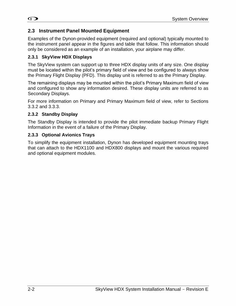
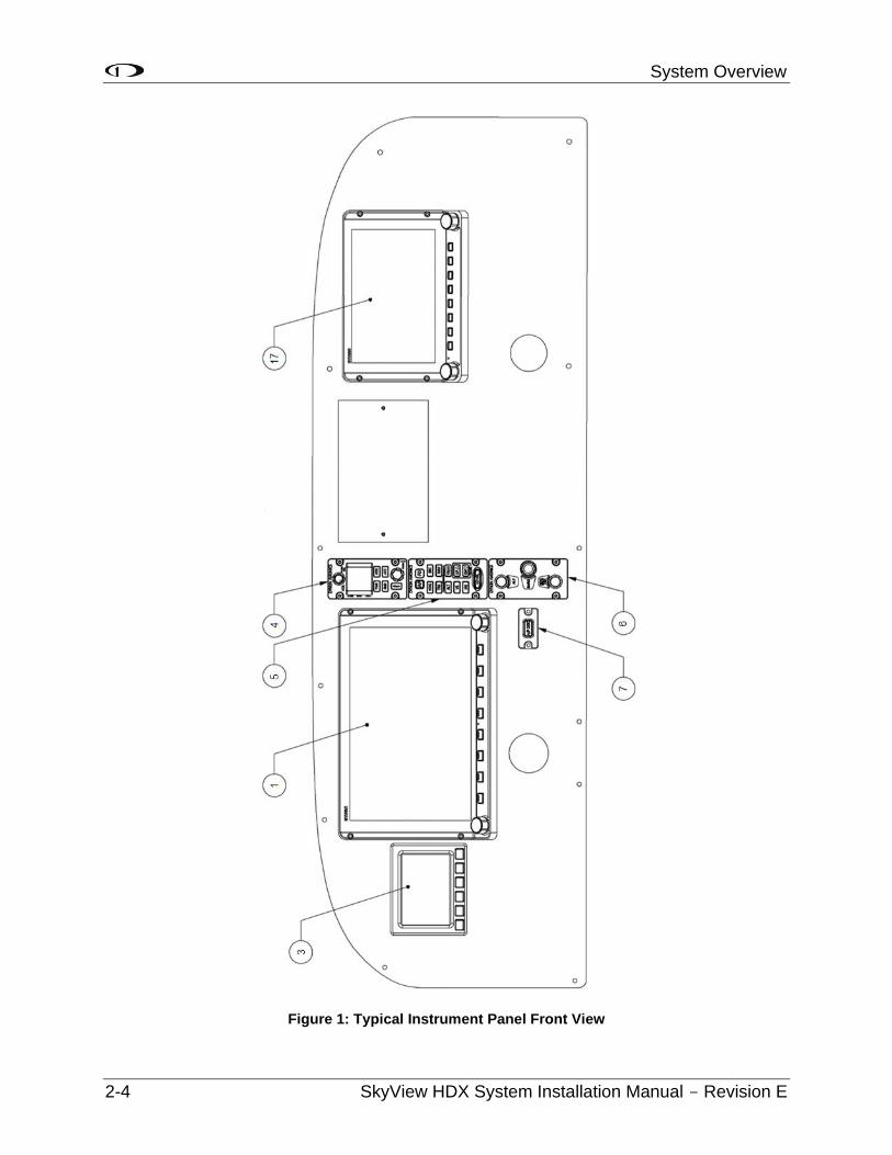
Examples of the Dynon-provided equipment (required and optional) typically mounted to the instrument panel appear in the figures and table that follow. This information should only be considered as an example of an installation, your airplane may differ.
2.3.1 SkyView HDX Displays
The SkyView system can support up to three HDX display units of any size. One display must be located within the pilot’s primary field of view and be configured to always show the Primary Flight Display (PFD). This display unit is referred to as the Primary Display.
The remaining displays may be mounted within the pilot’s Primary Maximum field of view and configured to show any information desired. These display units are referred to as Secondary Displays.
For more information on Primary and Primary Maximum field of view, refer to Sections 3.3.2 and 3.3.3.
2.3.2 Standby Display
The Standby Display is intended to provide the pilot immediate backup Primary Flight Information in the event of a failure of the Primary Display.
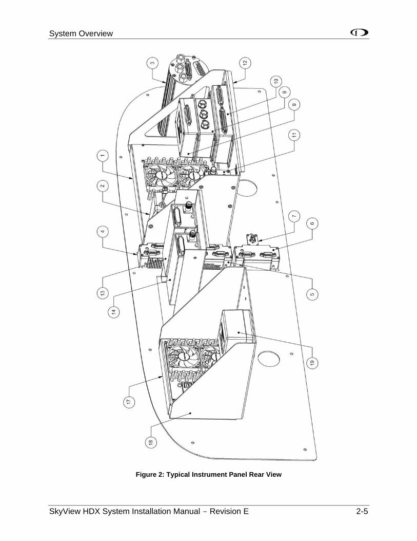
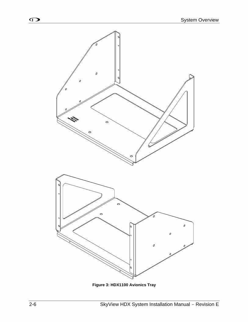
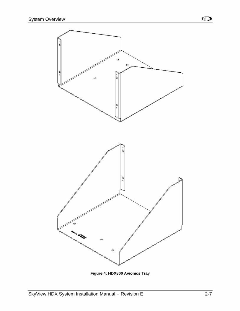
2.3.3 Optional Avionics Trays
To simplify the equipment installation, Dynon has developed equipment mounting trays that can attach to the HDX1100 and HDX800 displays and mount the various required and optional equipment modules.

System Overview
SkyView HDX System Installation Manual - Revision E 2-3
Table 1: Typical Instrument Panel Mounted Equipment
Item Description
1 HDX1100 Primary Display
2 SV-BAT-320 Backup Battery
3 EFIS-D10A Standby Display
4 SV-COM-X83 COM Radio Control Panel
5 SV-AP-PANEL Autopilot Control Panel
6 SV-KNOB-Panel Knob Control Panel
7 SV-BUTTON-APDISC Autopilot Disconnect Button
8 SV-ARINC-429 ARINC 429 Interface Module
9 SV-ADAHRS-200 ADAHRS
10 SV-EMS-220 Engine Monitoring System
11 SV-ADSB-472 ADS-B Receiver
12 HDX1100 Avionics Tray
13 SV-COM-X83 COM Radio Transceiver
14 SV-XPNDR-261 Transponder Mode-S
17 HDX800 Secondary Display
18 HDX800 Secondary Display Avionics Tray
19 SV-BAT-320 Backup Battery
System Overview
2-4 SkyView HDX System Installation Manual - Revision E
Figure 1: Typical Instrument Panel Front View
System Overview
SkyView HDX System Installation Manual - Revision E 2-5
Figure 2: Typical Instrument Panel Rear View
System Overview
2-6 SkyView HDX System Installation Manual - Revision E
Figure 3: HDX1100 Avionics Tray
System Overview
SkyView HDX System Installation Manual - Revision E 2-7
Figure 4: HDX800 Avionics Tray
System Overview
2-8 SkyView HDX System Installation Manual - Revision E
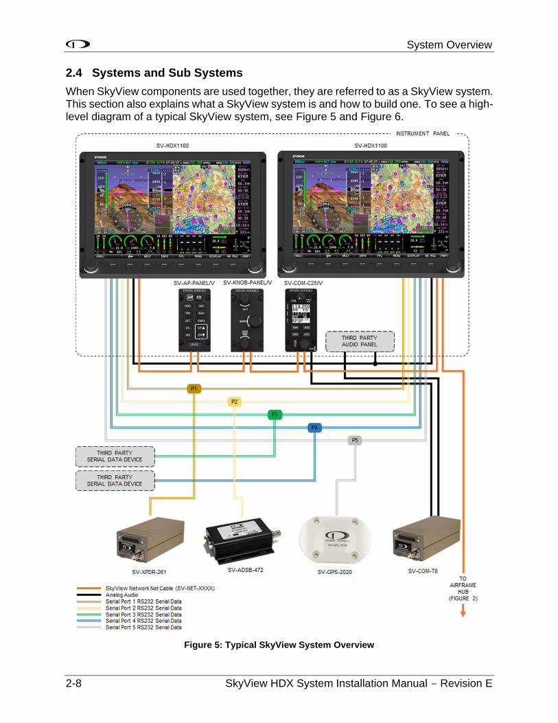
2.4 Systems and Sub Systems
When SkyView components are used together, they are referred to as a SkyView system. This section also explains what a SkyView system is and how to build one. To see a high-level diagram of a typical SkyView system, see Figure 5 and Figure 6.
Figure 5: Typical SkyView System Overview
System Overview
SkyView HDX System Installation Manual - Revision E 2-9
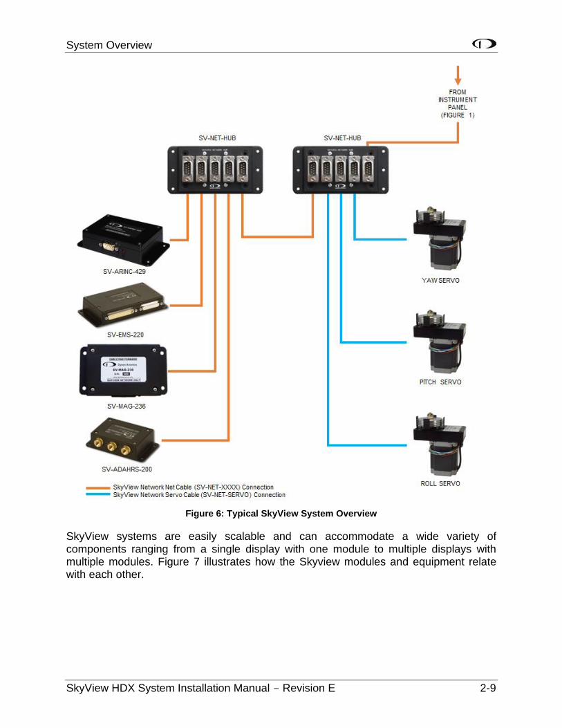
Figure 6: Typical SkyView System Overview
SkyView systems are easily scalable and can accommodate a wide variety of components ranging from a single display with one module to multiple displays with multiple modules. Figure 7 illustrates how the Skyview modules and equipment relate with each other.

System Overview
2-10 SkyView HDX System Installation Manual - Revision E
Figure 7: SkyView System Diagram with Required and Optional Equipment
System Overview
SkyView HDX System Installation Manual - Revision E 2-11
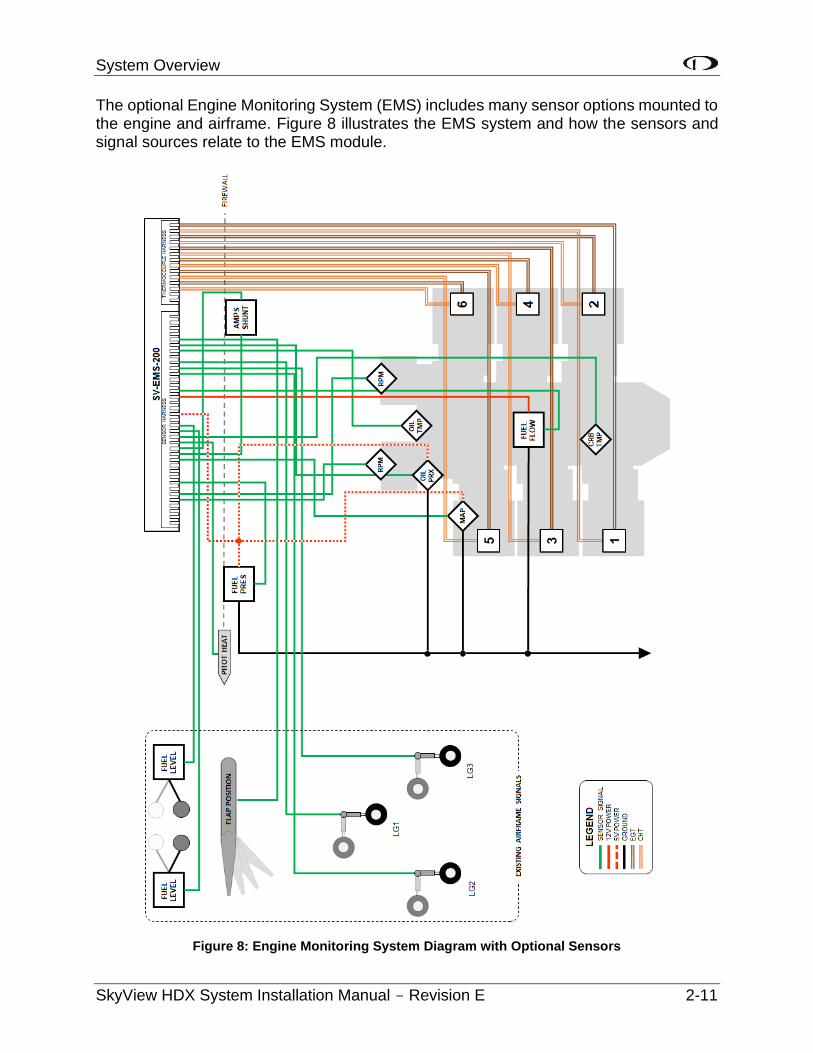
The optional Engine Monitoring System (EMS) includes many sensor options mounted to the engine and airframe. Figure 8 illustrates the EMS system and how the sensors and signal sources relate to the EMS module.
Figure 8: Engine Monitoring System Diagram with Optional Sensors
System Overview
2-12 SkyView HDX System Installation Manual - Revision E
2.5 SkyView Network
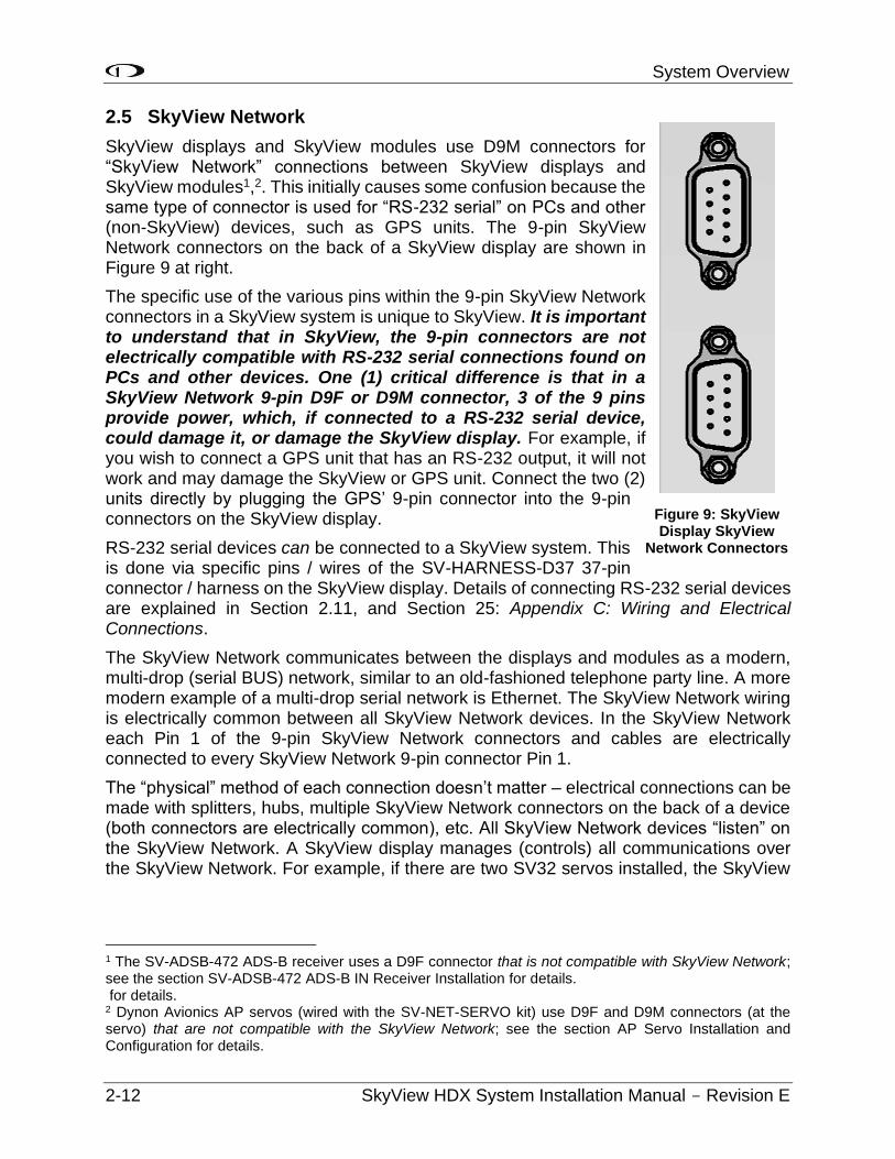
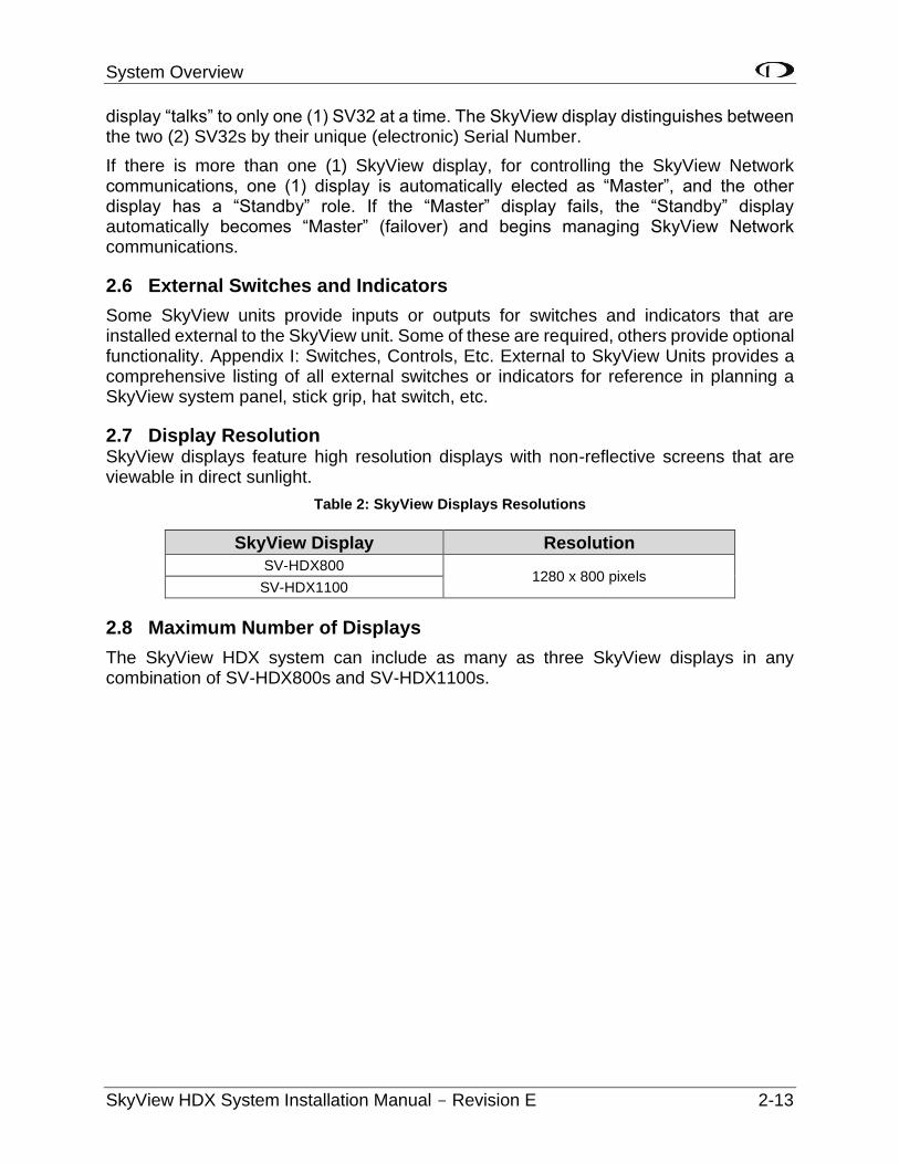
SkyView displays and SkyView modules use D9M connectors for “SkyView Network” connections between SkyView displays and SkyView modules1,2. This initially causes some confusion because the same type of connector is used for “RS-232 serial” on PCs and other (non-SkyView) devices, such as GPS units. The 9-pin SkyView Network connectors on the back of a SkyView display are shown in Figure 9 at right.
The specific use of the various pins within the 9-pin SkyView Network connectors in a SkyView system is unique to SkyView. It is important to understand that in SkyView, the 9-pin connectors are not electrically compatible with RS-232 serial connections found on PCs and other devices. One (1) critical difference is that in a SkyView Network 9-pin D9F or D9M connector, 3 of the 9 pins provide power, which, if connected to a RS-232 serial device, could damage it, or damage the SkyView display. For example, if you wish to connect a GPS unit that has an RS-232 output, it will not work and may damage the SkyView or GPS unit. Connect the two (2) units directly by plugging the GPS’ 9-pin connector into the 9-pin connectors on the SkyView display.
RS-232 serial devices can be connected to a SkyView system. This is done via specific pins / wires of the SV-HARNESS-D37 37-pin connector / harness on the SkyView display. Details of connecting RS-232 serial devices are explained in Section 2.11, and Section 25: Appendix C: Wiring and Electrical Connections.
The SkyView Network communicates between the displays and modules as a modern, multi-drop (serial BUS) network, similar to an old-fashioned telephone party line. A more modern example of a multi-drop serial network is Ethernet. The SkyView Network wiring is electrically common between all SkyView Network devices. In the SkyView Network each Pin 1 of the 9-pin SkyView Network connectors and cables are electrically connected to every SkyView Network 9-pin connector Pin 1.
The “physical” method of each connection doesn’t matter – electrical connections can be made with splitters, hubs, multiple SkyView Network connectors on the back of a device (both connectors are electrically common), etc. All SkyView Network devices “listen” on the SkyView Network. A SkyView display manages (controls) all communications over the SkyView Network. For example, if there are two SV32 servos installed, the SkyView
1 The SV-ADSB-472 ADS-B receiver uses a D9F connector that is not compatible with SkyView Network; see the section SV-ADSB-472 ADS-B IN Receiver Installation for details. for details. 2 Dynon Avionics AP servos (wired with the SV-NET-SERVO kit) use D9F and D9M connectors (at the servo) that are not compatible with the SkyView Network; see the section AP Servo Installation and Configuration for details.
Figure 9: SkyView Display SkyView
Network Connectors
System Overview
SkyView HDX System Installation Manual - Revision E 2-13
display “talks” to only one (1) SV32 at a time. The SkyView display distinguishes between the two (2) SV32s by their unique (electronic) Serial Number.
If there is more than one (1) SkyView display, for controlling the SkyView Network communications, one (1) display is automatically elected as “Master”, and the other display has a “Standby” role. If the “Master” display fails, the “Standby” display automatically becomes “Master” (failover) and begins managing SkyView Network communications.
2.6 External Switches and Indicators
Some SkyView units provide inputs or outputs for switches and indicators that are installed external to the SkyView unit. Some of these are required, others provide optional functionality. Appendix I: Switches, Controls, Etc. External to SkyView Units provides a comprehensive listing of all external switches or indicators for reference in planning a SkyView system panel, stick grip, hat switch, etc.
2.7 Display Resolution SkyView displays feature high resolution displays with non-reflective screens that are viewable in direct sunlight.
Table 2: SkyView Displays Resolutions
SkyView Display Resolution
SV-HDX800 1280 x 800 pixels
SV-HDX1100
2.8 Maximum Number of Displays
The SkyView HDX system can include as many as three SkyView displays in any combination of SV-HDX800s and SV-HDX1100s.
System Overview
2-14 SkyView HDX System Installation Manual - Revision E
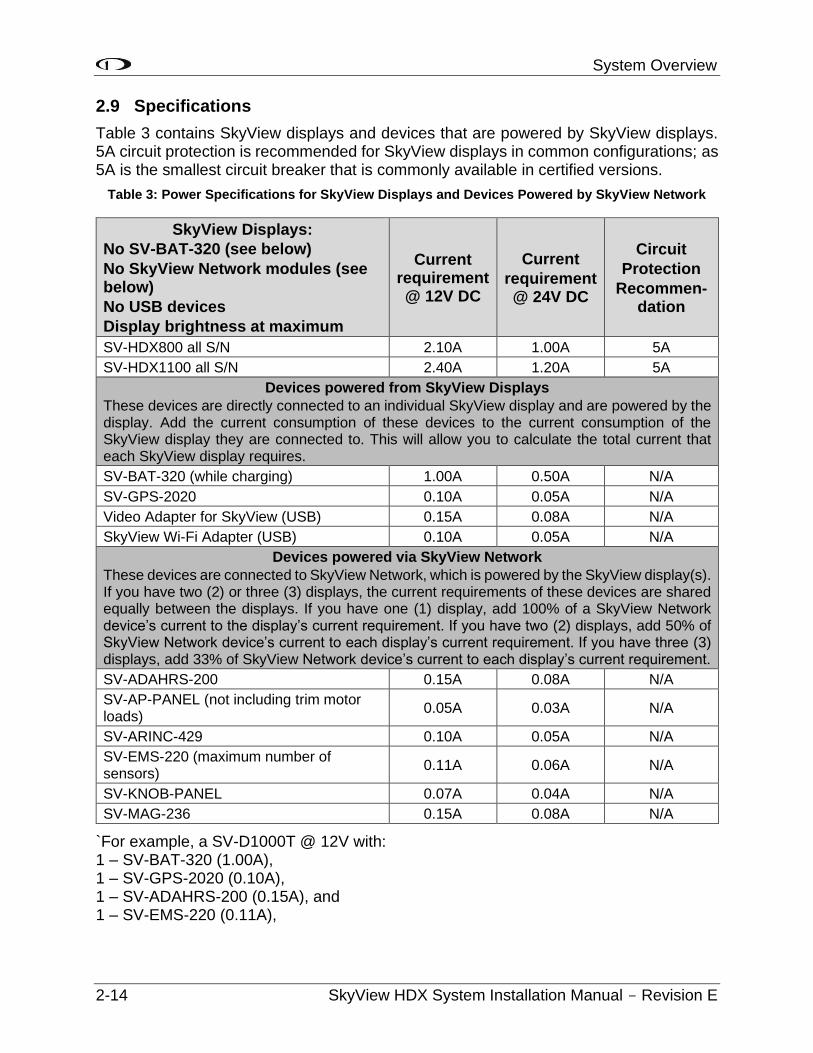
2.9 Specifications
Table 3 contains SkyView displays and devices that are powered by SkyView displays. 5A circuit protection is recommended for SkyView displays in common configurations; as 5A is the smallest circuit breaker that is commonly available in certified versions.
Table 3: Power Specifications for SkyView Displays and Devices Powered by SkyView Network
SkyView Displays:
No SV-BAT-320 (see below)
No SkyView Network modules (see below)
No USB devices
Display brightness at maximum
Current requirement @ 12V DC
Current
requirement @ 24V DC
Circuit
Protection
Recommen- dation
SV-HDX800 all S/N 2.10A 1.00A 5A
SV-HDX1100 all S/N 2.40A 1.20A 5A
Devices powered from SkyView Displays
These devices are directly connected to an individual SkyView display and are powered by the display. Add the current consumption of these devices to the current consumption of the SkyView display they are connected to. This will allow you to calculate the total current that each SkyView display requires.
SV-BAT-320 (while charging) 1.00A 0.50A N/A
SV-GPS-2020 0.10A 0.05A N/A
Video Adapter for SkyView (USB) 0.15A 0.08A N/A
SkyView Wi-Fi Adapter (USB) 0.10A 0.05A N/A
Devices powered via SkyView Network
These devices are connected to SkyView Network, which is powered by the SkyView display(s). If you have two (2) or three (3) displays, the current requirements of these devices are shared equally between the displays. If you have one (1) display, add 100% of a SkyView Network device’s current to the display’s current requirement. If you have two (2) displays, add 50% of SkyView Network device’s current to each display’s current requirement. If you have three (3) displays, add 33% of SkyView Network device’s current to each display’s current requirement.
SV-ADAHRS-200 0.15A 0.08A N/A
SV-AP-PANEL (not including trim motor loads)
0.05A 0.03A N/A
SV-ARINC-429 0.10A 0.05A N/A
SV-EMS-220 (maximum number of sensors)
0.11A 0.06A N/A
SV-KNOB-PANEL 0.07A 0.04A N/A
SV-MAG-236 0.15A 0.08A N/A
`For example, a SV-D1000T @ 12V with: 1 – SV-BAT-320 (1.00A), 1 – SV-GPS-2020 (0.10A), 1 – SV-ADAHRS-200 (0.15A), and 1 – SV-EMS-220 (0.11A),
System Overview
SkyView HDX System Installation Manual - Revision E 2-15
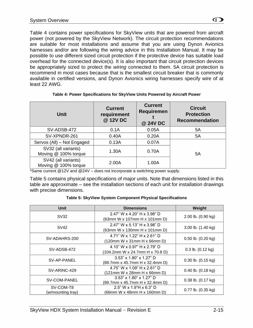
Table 4 contains power specifications for SkyView units that are powered from aircraft power (not powered by the SkyView Network). The circuit protection recommendations are suitable for most installations and assume that you are using Dynon Avionics harnesses and/or are following the wiring advice in this Installation Manual. It may be possible to use different sized circuit protection if the protective device has suitable load overhead for the connected device(s). It is also important that circuit protection devices be appropriately sized to protect the wiring connected to them. 5A circuit protection is recommend in most cases because that is the smallest circuit breaker that is commonly available in certified versions, and Dynon Avionics wiring harnesses specify wire of at least 22 AWG.
Table 4: Power Specifications for SkyView Units Powered by Aircraft Power
Unit
Current
requirement @ 12V DC
Current
Requirement
@ 24V DC
Circuit
Protection
Recommendation
SV-ADSB-472 0.1A 0.05A 5A
SV-XPNDR-261 0.40A 0.20A 5A
Servos (All) – Not Engaged 0.13A 0.07A
5A SV32 (all variants)
Moving @ 100% torque 1.30A 0.70A
SV42 (all variants) Moving @ 100% torque
2.00A 1.00A
*Same current @12V and @24V – does not incorporate a switching power supply.
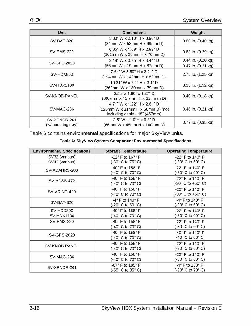
Table 5 contains physical specifications of major units. Note that dimensions listed in this table are approximate – see the installation sections of each unit for installation drawings with precise dimensions.
Table 5: SkyView System Component Physical Specifications
Unit Dimensions Weight
SV32 2.47” W x 4.20” H x 3.98” D
(63mm W x 107mm H x 101mm D) 2.00 lb. (0.90 kg)
SV42 2.47” W x 5.13” H x 3.98” D
(63mm W x 130mm H x 101mm D) 3.00 lb. (1.40 kg)
SV-ADAHRS-200 4.71” W x 1.22” H x 2.61” D
(120mm W x 31mm H x 66mm D) 0.50 lb. (0.20 kg)
SV-ADSB-472 4.10” W x 0.97” H x 2.79” D
(104.2mm W x 24.7mm H x 70.8 D) 0.3 lb. (0.12 kg)
SV-AP-PANEL 3.53” x 1.80” x 1.27” D
(89.7mm x 45.7mm H x 32.4mm D) 0.30 lb. (0.15 kg)
SV-ARINC-429 4.75” W x 1.09” H x 2.61” D
(121mm W x 28mm H x 66mm D) 0.40 lb. (0.18 kg)
SV-COM-PANEL 3.53” x 1.80” x 1.27” D
(89.7mm x 45.7mm H x 32.4mm D) 0.38 lb. (0.17 kg)
SV-COM-T8 (w/mounting tray)
2.5” W x 1.9”H x 6.3” D (66mm W x 48mm H x 160mm D)
0.77 lb. (0.35 kg)
System Overview
2-16 SkyView HDX System Installation Manual - Revision E
Unit Dimensions Weight
SV-BAT-320 3.30” W x 2.10” H x 3.90” D
(84mm W x 53mm H x 99mm D) 0.80 lb. (0.40 kg)
SV-EMS-220 6.35” W x 1.09” H x 2.99” D
(161mm W x 28mm H x 76mm D) 0.63 lb. (0.29 kg)
SV-GPS-2020 2.19” W x 0.75” H x 3.44” D
(56mm W x 19mm H x 87mm D)
0.44 lb. (0.20 kg)
0.47 lb. (0.21 kg)
SV-HDX800 7.64” W 5.59” H x 3.21” D
(194mm W x 142mm H x 82mm D) 2.75 lb. (1.25 kg)
SV-HDX1100 10.31” W x 7.1” H x 3.1” D
(262mm W x 180mm x 79mm D) 3.35 lb. (1.52 kg)
SV-KNOB-PANEL 3.53” x 1.80” x 1.27” D
(89.7mm x 45.7mm H x 32.4mm D) 0.40 lb. (0.18 kg)
SV-MAG-236
4.71” W x 1.22” H x 2.61” D
(120mm W x 31mm H x 66mm D) (not including cable - 18” (457mm)
0.46 lb. (0.21 kg)
SV-XPNDR-261 (w/mounting tray)
2.5” W x 1.9”H x 6.3” D
(66mm W x 48mm H x 160mm D) 0.77 lb. (0.35 kg)
Table 6 contains environmental specifications for major SkyView units.
Table 6: SkyView System Component Environmental Specifications
Environmental Specifications Storage Temperature Operating Temperature
SV32 (various)
SV42 (various)
-22° F to 167° F (-30° C to 75° C)
-22° F to 140° F (-30° C to 60° C)
SV-ADAHRS-200 -40° F to 158° F (-40° C to 70° C)
-22° F to 140° F (-30° C to 60° C)
SV-ADSB-472 -40° F to 158° F
(-40° C to 70° C)
-22° F to 140° F (-30° C to +60° C)
SV-ARINC-429 -40° F to 158° F
(-40° C to 70° C)
-22° F to 140° F (-30° C to +60° C)
SV-BAT-320 -4° F to 140° F
(-20° C to 60 °C) -4° F to 140° F
(-20° C to 60° C)
SV-HDX800
SV-HDX1100
-40° F to 158° F
(-40° C to 70° C)
-22° F to 140° F (-30° C to 60° C)
SV-EMS-220
-40° F to 158° F
(-40° C to 70° C)
-22° F to 140° F (-30° C to 60° C)
SV-GPS-2020 -40° F to 158° F
(-40° C to 70° C)
-40° F to 140° F -40° C to 60° C
SV-KNOB-PANEL -40° F to 158° F
(-40° C to 70° C)
-22° F to 140° F (-30° C to 60° C)
SV-MAG-236 -40° F to 158° F
(-40° C to 70° C)
-22° F to 140° F (-30° C to 60° C)
SV-XPNDR-261 -67° F to 185° F (-55° C to 85° C)
-4° F to 158° F (-20° C to 70° C)

System Overview
SkyView HDX System Installation Manual - Revision E 2-17
2.10 Power Protection
All Dynon Avionics units in a SkyView system incorporate robust power protection that allows them to be powered on during engine start for full engine monitoring. SkyView displays require a minimum of 10V, and during engine start, it’s common for the electrical system to temporarily drop below 10V. If an SV-BAT-320 Backup Battery is not installed, SkyView may shut off / reboot. If you wish to monitor your engine prior to engine start, an SV-BAT-320 should be installed so that the SkyView display can switch to the SV-BAT-320 when its power inputs are not receiving at least 10V. The SkyView display will switch from SV-BAT-320 to aircraft power when its power inputs receive voltage above 10V.
2.11 Connecting to the Network
Dynon Avionics SkyView harnesses and Skyview Network cables use aircraft-grade Tefzel® wiring. The SV-HARNESS-D37 breaks out power, serial, USB and other important pins from the back of the display. SkyView Network cables are available in a variety of lengths. The three (3) and six (6) foot cables have D9F connectors on both ends. The longer cables have a D9F connector on one (1) end and open pins on the other end. The open end allows installers to run the cable in and through areas that would not be possible if a connector was present. The connector is installed after the cable has been run.
2.11.1 SV-NET-SERVO Servo Harness
The SV-NET-SERVO (one kit per servo) makes it easy to connect the SkyView system to Dynon Avionics servos and includes 20 feet of pre-twisted wire (twisted pair 22 AWG wire for data; 20 AWG wire for power), D9 connectors, connector shells, crimp contacts, an insertion tool, heat shrink, and zip ties. It is recommended that you read and understand before working with this kit.
2.11.2 SV-NET-SPL Network Splitter Harness
The SV-NET-SPL uses aircraft-grade Tefzel® wiring, consisting of a D9M input connector and two D9F output connectors, with a length of one foot. The SV-NET-SPL may be used to connect an additional device to the SkyView network in lieu of using the network hub. For connecting multiple SkyView modules from a SkyView Network cable, using the SkyView Network Hub (SV-NET-HUB) is recommended.
Figure 10: SV-NET-SPL
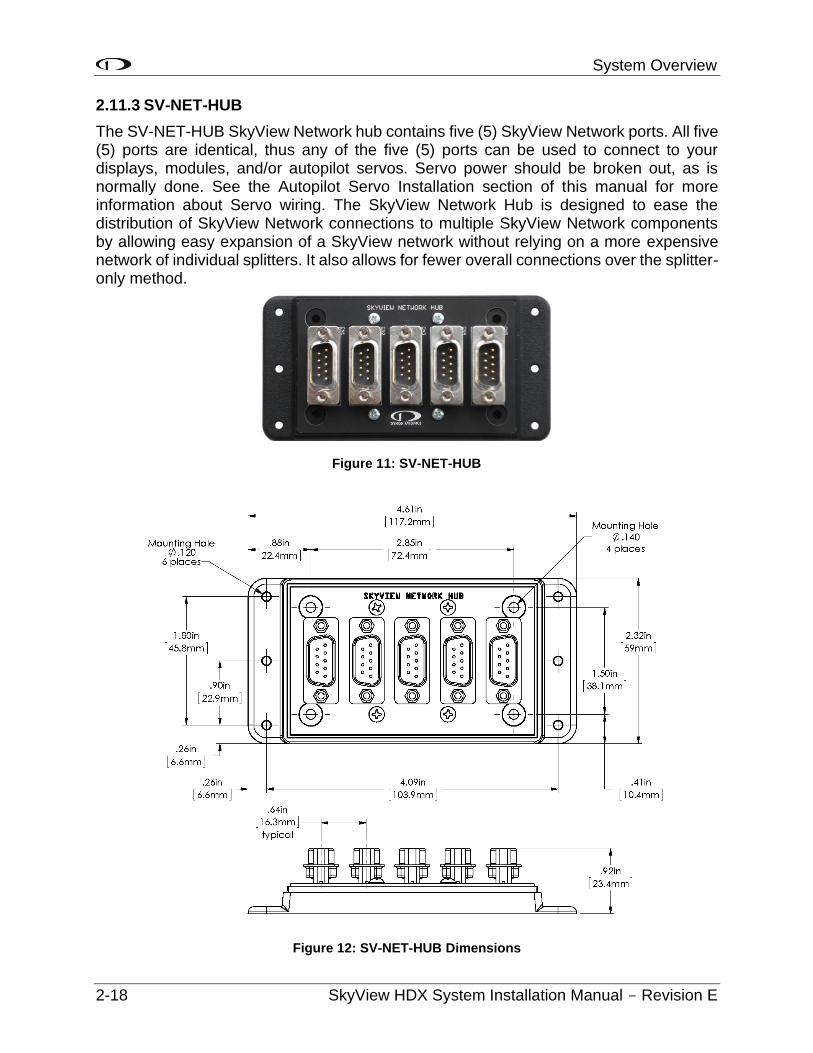
System Overview
2-18 SkyView HDX System Installation Manual - Revision E
2.11.3 SV-NET-HUB
The SV-NET-HUB SkyView Network hub contains five (5) SkyView Network ports. All five (5) ports are identical, thus any of the five (5) ports can be used to connect to your displays, modules, and/or autopilot servos. Servo power should be broken out, as is normally done. See the Autopilot Servo Installation section of this manual for more information about Servo wiring. The SkyView Network Hub is designed to ease the distribution of SkyView Network connections to multiple SkyView Network components by allowing easy expansion of a SkyView network without relying on a more expensive network of individual splitters. It also allows for fewer overall connections over the splitter-only method.
Figure 12: SV-NET-HUB Dimensions
Figure 11: SV-NET-HUB
System Overview
SkyView HDX System Installation Manual - Revision E 2-19
2.11.4 Test SkyView Network Cable
SkyView displays are supplied with a test SkyView network cable that is intended for bench top testing only. The test network cable is not built with aircraft-grade Tefzel® wiring and should not be permanently installed in an aircraft.
2.11.5 Ethernet Connection
SkyView systems that have more than one display should have their Ethernet ports permanently connected together. Though not a required connection, it allows aviation and obstacle databases to be transferred to all displays in a SkyView system when they are loaded on any one of them. If Ethernet is not connected, aviation and obstacle databases will need to be loaded on each display in the system individually.
Future SkyView functionality may require Ethernet to be connected as described in this section. Dynon Avionics strongly recommends connecting all Ethernet ports together at this time.
The Ethernet connection between SkyView displays is in addition to the SkyView Network connections, and should be connected on a permanent basis like other SkyView wiring. Dynon Avionics requires “Low Smoke Zero Halogen” Ethernet cables for use in aircraft. Low Smoke Zero Halogen Ethernet cables are available from Dynon Avionics (SV-ETHERNET-3CC). Aircraft containing more than two SkyView displays will need an Ethernet switch with enough ports to connect all SkyView displays together. Contact Dynon Avionics for Ethernet switch recommendations if your aircraft has more than two displays.
Lights on the Ethernet port usually indicate data transfer on traditional Ethernet devices. In SkyView, they are used instead for display troubleshooting purposes. See the Maintenance and Troubleshooting section for more information about what these lights indicate.
2.11.6 Available Cables and Harnesses
Table 7 contains Dynon Avionics part numbers and descriptions for the components that will typically be used to test and build a SkyView system. Note: network cables with the “CP” suffix include the second connector – it just is not installed on the cable to facilitate easy routing through tight areas of an aircraft.
Table 7 - Dynon Avionics SkyView Harnesses and SkyView Network Cables
Dynon Avionics P/N Description
SV-NET-TEST
SkyView Network Test Cable – 10 ft. (3.05 m)
One (1) SV-NET-TEST is shipped with each SkyView display.
Not Aircraft-Grade Wiring – used for test only!
All harnesses and SkyView Network Cables below made with Aircraft-Grade Tefzel® Wiring
SV-HARNESS-ADSB Wiring harness for SV-ADSB-472 – 15 ft. (4.6 m)
SV-HARNESS-D37 Primary Harness for SV-D600/SV-D700/SV-D900/SV-D1000/SV-D1000T
SV-HARNESS-XPNDR
Wiring Harness for SV-XPNDR-261 – 15 ft. (4.6 m)
SV-NET-1.5CC SkyView Network Cable, both ends with connectors – 1.5 ft. (0.46 m)
System Overview
2-20 SkyView HDX System Installation Manual - Revision E
Dynon Avionics P/N Description
SV-NET-3CC SkyView Network Cable, both ends with connectors – 3 ft. (0.91 m)
SV-NET-6CC SkyView Network Cable, both ends with connectors – 6 ft. (1.82 m)
SV-NET-10CP SkyView Network Cable, 1 end connector, 1 end pins only – 10 ft. (3.05 m)
SV-NET-15CP SkyView Network Cable, 1 end connector, 1 end pins only – 15 ft. (4.60 m)
SV-NET-20CP SkyView Network Cable, 1 end connector, 1 end pins only – 20 ft. (6.10 m)
SV-NET-25CP SkyView Network Cable, 1 end connector, 1 end pins only – 25 ft. (7.62 m)
SV-NET-30CP SkyView Network Cable, 1 end connector, 1 end pins only – 30 ft. (9.10 m)
SV-NET-HUB SkyView Network Hub (5 SkyView Network connections)
(Does not include a SkyView Network Cable – purchase separately)
SV-NET-SERVO SkyView Network Cabling Kit for Autopilot Servos – 20 ft. (6.10 m)
One (1) SV-NET-SERVO is used for each servo in most installations.
SV-NET-SPL SkyView Network Splitter – 1 ft. (30.5 cm)
Note that in Table 7 the SV-GPS-2020’s power, ground, and output wires are connected to both displays.
2.12 Quick Start
This section contains information that can be used to check out your SkyView system on the bench, or immediately after SkyView has been installed in the plane. This section is not a substitute for reading this entire manual, which provides instructions for wiring and configuring SkyView to the unique requirements of your particular airplane.
1. A SkyView display requires 10-30 VDC. You must connect BOTH of the (long) red wires to POWER and BOTH of the (long) black wires to Ground. Current for each display can be up to 3.5A @ 12V (add 1.5A if the SV-BAT-320 battery is connected and being charged); so, use a big battery or power supply.
2. To power on or power off a SkyView display manually, push and hold Button #1 (the leftmost button).
3. Any devices connected to SkyView that do not receive their power from the SkyView Network (such as SV-XPNDR-261 and Dynon Avionics Autopilot servos) must also be powered ON to communicate with SkyView.
4. To finish the installation of the SV-NET-10CP (10 foot) and longer cables, the diagram you need to insert the pins is of the SkyView Network found in Section 25: Appendix C: Wiring and Electrical Connections.
5. The EMS 37-pin Main Sensor Harness includes a 9-pin connector that is wired to pins 11 (Orange wire), 12 (Yellow wire), and 30 (Black wire). This connector is used for other Dynon Avionics products, but is not used in SkyView installations. Thus, the 9-pin connector should be removed to use these wires for connecting sensors to the SV-EMS-220. Remove the connector by cutting the three (3) wires close to the 9-pin connector.
6. The SkyView SETUP MENU is accessed by pushing and holding Buttons 7+8 together for 2-3 seconds.
System Overview
SkyView HDX System Installation Manual - Revision E 2-21
7. Setting the Tail Number is required before you can configure your SkyView Network (described below): SETUP > AIRCRAFT INFORMATION > TAIL NUMBER. If the Tail Number has not yet been issued for your plane, set the TAIL NUMBER to something other than DYNON AVIONICS. Note that for US planes, the leading N is a required part of the TAIL NUMBER. The TAIL NUMBER should not include dashes (-) or spaces.
Examples: Correct: N120AB Incorrect: N-120AB, N12OAB, 120AB, or N 12AB
8. SkyView displays and modules communicate over a common set of wires – the SkyView Network that terminates at the D9 connectors on the back of your SkyView display(s). Getting all modules and displays “talking” on SkyView Network is done by going to SETUP MENU > SYSTEM SETUP > SKYVIEW NETWORK SETUP > CONFIGURE > (right click one (1) more time). If a module is noted as “requires update”, press the UPDATE button. Otherwise, press the FINISH button. Note that you will not see any flight instruments or engine instruments before a network configuration is performed, even if the SV-ADAHRS-200/201 and SV-EMS-220 have been wired properly and are connected.
9. Devices that do not utilize the SkyView Network are connected via RS-232 serial port connections. Dynon Avionics devices that use RS-232 serial ports include the SV-ADSB-472, SV-GPS-2020, SV-XPNDR-261, and various third-party devices. As RS-232 serial devices are not part of the SkyView Network, they will not be seen on the list of devices seen as you configure the SkyView Network above. Instead, configuring SkyView to communicate with SV-GPS-2020 and SV-XPNDR-261 is done via a more manual process in SETUP MENU > SYSTEM SETUP > SERIAL PORT SETUP.
10. If you have installed an SV-GPS-2020, its SERIAL IN FUNCTION must be set to POS 1.
11. After you have configured the SkyView Network, and have properly configured any serial devices, exit SETUP MENU. Your SkyView display should now display EMS, PFD, and. Map will not display without a GPS fix (the airplane symbol on the Map page will also flash with “?” if it does not have a GPS fix.
12. Your SkyView System may require various updates, such as system Software, databases, and Sensor Definitions. See http://downloads.dynonavionics.com for certified products for more details on the updates available for the SkyView HDX System.
13. Common issues for setting up SkyView engine monitoring:
a. The configuration of sensors installed on SkyView at the factory is generic; therefore, “Red X’s” on the EMS for various sensors are normal until sensor configuration for your particular engine sensor configuration is complete.
b. The layout of which sensor “widgets” are shown on the screen: sizes; styles; etc., is completely configurable: SETUP > EMS SETUP > SCREEN LAYOUT EDITOR.
System Overview
2-22 SkyView HDX System Installation Manual - Revision E
14. Common issues for setting up SV-XPNDR-261:
a. Ensure that a valid tail number has been set (see above).
b. Ensure that a valid HEX CODE has been set: SETUP > TRANSPONDER SETUP > TRANSPONDER HEX CODE. A caution message – XPNDR HEX CODE NOT SET will appear if a transponder is configured in SkyView, but the HEX CODE is not set to a valid number.
c. Traffic will not be displayed unless you are in an area covered by an TIS radar site (US only).
15. Common issues for setting up Dynon Avionics Autopilot:
a. Servos must be powered ON.
b. Servos must be recognized on the SkyView Network (above).
c. AIRSPEED LIMITATIONS must be set (at least one (1) must be actively adjusted from the defaults) before the Autopilot can be configured: SETUP > PFD SETUP > AIRSPEED.
d. AP SERVO CALIBRATION must be performed: SETUP > HARDWARE CALIBRATION > AP SERVO CALIBRATION > CALIBRATION.
e. After the AP SERVO CALIBRATION has successfully completed, the AP status will be displayed on the SkyView display top bar.
Instrument Panel Design
SkyView HDX System Installation Manual - Revision E 3-1
3 Instrument Panel Design
Installing SkyView HDX necessitates the design and fabrication of a new instrument panel to mount the SkyView panel-mounted equipment. This section provides quantified and qualified regulatory guidance, as well as volumetric requirements for the SkyView panel-mounted equipment to help you decide where to locate equipment on the instrument panel. Sections 3-19 in this manual provide panel cut-out and mounting hole dimensions for each SkyView component.
3.1 Regulatory Considerations
Part 23 of the Code of Federal Regulations describes locations for displaying information which, for the most part, is information presented on SkyView HDX Display screen. Exceptions to this are the information that may be presented in the COM control panel or a third-party GPS Navigator. All system information must be evaluated and considered when determining the best equipment locations for your instrument panel.
Before beginning a SkyView HDX system installation, it is highly recommended that the Certified Mechanic with Inspection Authority (IA) that is approving your airplane’s return to service agrees with the proposed equipment location and installation methods, wire harness routing, and the location of mounted equipment on the instrument panel.
Doing so reduces the likelihood that the installation will not be found compliant with regulatory requirements and airworthy standards.
Refer to the guidance and approved engineering provided by the following FAA documents:
• AC 23.1311-1C - Installation of Electronic Display in Part 23 Airplanes
• AC 43.13-1B Acceptable Methods, Techniques, and Practices - Aircraft Inspection
• AC 43.13-2B Acceptable Methods, Techniques, and Practices - Aircraft Alterations
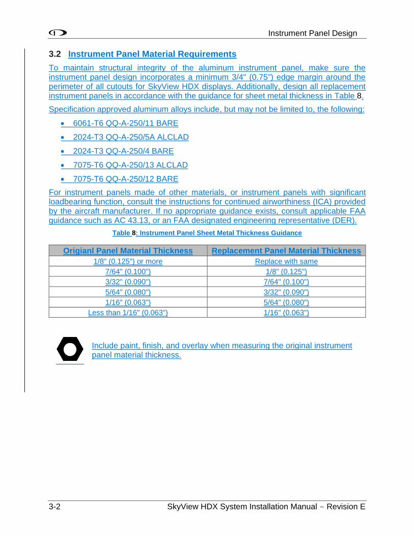
Instrument Panel Design
3-2 SkyView HDX System Installation Manual - Revision E
3.2 Instrument Panel Material Requirements
To maintain structural integrity of the aluminum instrument panel, make sure the instrument panel design incorporates a minimum 3/4" (0.75") edge margin around the perimeter of all cutouts for SkyView HDX displays. Additionally, design all replacement instrument panels in accordance with the guidance for sheet metal thickness in Table 8.
Specification approved aluminum alloys include, but may not be limited to, the following:
• 6061-T6 QQ-A-250/11 BARE
• 2024-T3 QQ-A-250/5A ALCLAD
• 2024-T3 QQ-A-250/4 BARE
• 7075-T6 QQ-A-250/13 ALCLAD
• 7075-T6 QQ-A-250/12 BARE
For instrument panels made of other materials, or instrument panels with significant loadbearing function, consult the instructions for continued airworthiness (ICA) provided by the aircraft manufacturer. If no appropriate guidance exists, consult applicable FAA guidance such as AC 43.13, or an FAA designated engineering representative (DER).
Table 8: Instrument Panel Sheet Metal Thickness Guidance
Origianl Panel Material Thickness Replacement Panel Material Thickness
1/8" (0.125") or more Replace with same
7/64" (0.100") 1/8" (0.125")
3/32" (0.090") 7/64" (0.100")
5/64" (0.080") 3/32" (0.090")
1/16" (0.063") 5/64" (0.080")
Less than 1/16" (0.063") 1/16" (0.063")
Include paint, finish, and overlay when measuring the original instrument panel material thickness.
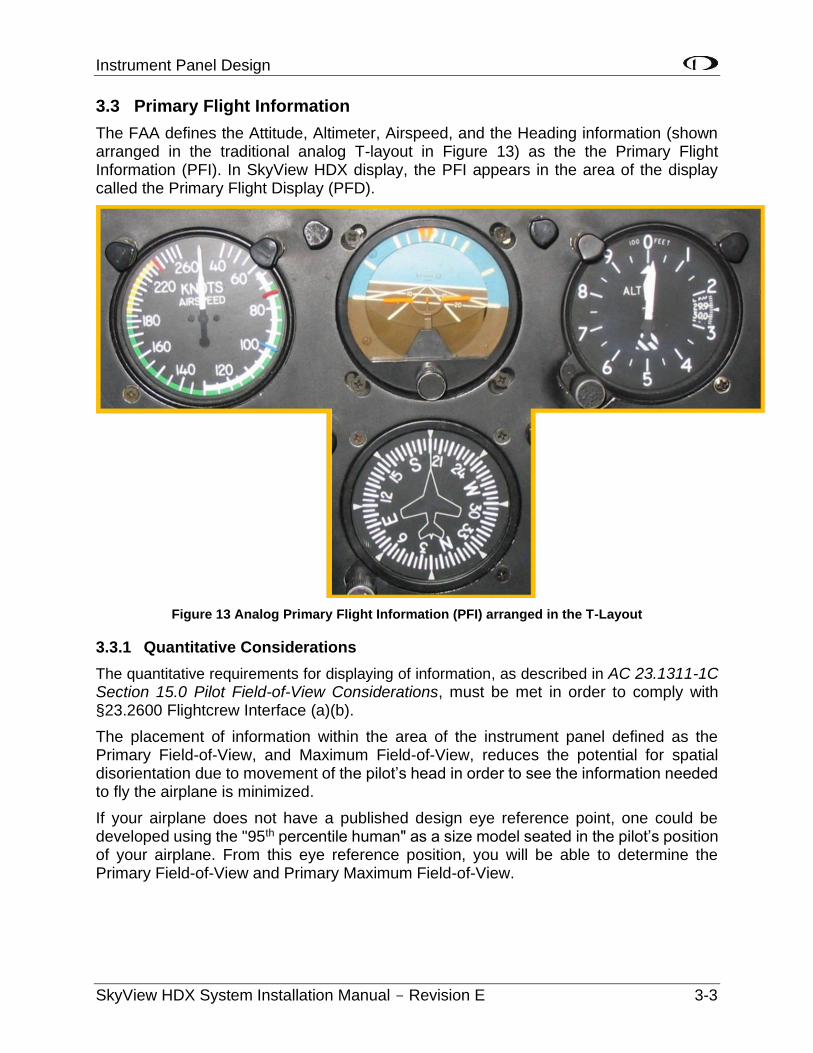
Instrument Panel Design
SkyView HDX System Installation Manual - Revision E 3-3
3.3 Primary Flight Information
The FAA defines the Attitude, Altimeter, Airspeed, and the Heading information (shown arranged in the traditional analog T-layout in Figure 13) as the the Primary Flight Information (PFI). In SkyView HDX display, the PFI appears in the area of the display called the Primary Flight Display (PFD).
Figure 13 Analog Primary Flight Information (PFI) arranged in the T-Layout
3.3.1 Quantitative Considerations
The quantitative requirements for displaying of information, as described in AC 23.1311-1C Section 15.0 Pilot Field-of-View Considerations, must be met in order to comply with §23.2600 Flightcrew Interface (a)(b).
The placement of information within the area of the instrument panel defined as the Primary Field-of-View, and Maximum Field-of-View, reduces the potential for spatial disorientation due to movement of the pilot’s head in order to see the information needed to fly the airplane is minimized.
If your airplane does not have a published design eye reference point, one could be developed using the "95th percentile human" as a size model seated in the pilot’s position of your airplane. From this eye reference position, you will be able to determine the Primary Field-of-View and Primary Maximum Field-of-View.
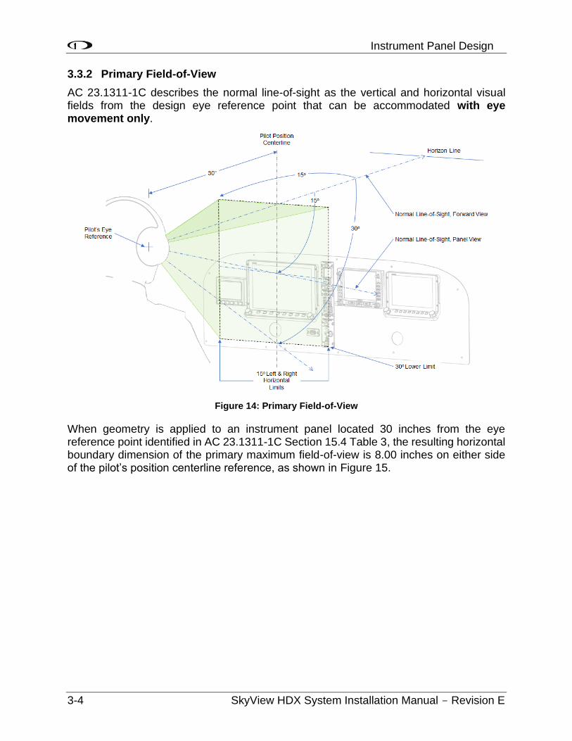
Instrument Panel Design
3-4 SkyView HDX System Installation Manual - Revision E
3.3.2 Primary Field-of-View
AC 23.1311-1C describes the normal line-of-sight as the vertical and horizontal visual fields from the design eye reference point that can be accommodated with eye movement only.
Figure 14: Primary Field-of-View
When geometry is applied to an instrument panel located 30 inches from the eye reference point identified in AC 23.1311-1C Section 15.4 Table 3, the resulting horizontal boundary dimension of the primary maximum field-of-view is 8.00 inches on either side of the pilot’s position centerline reference, as shown in Figure 15.
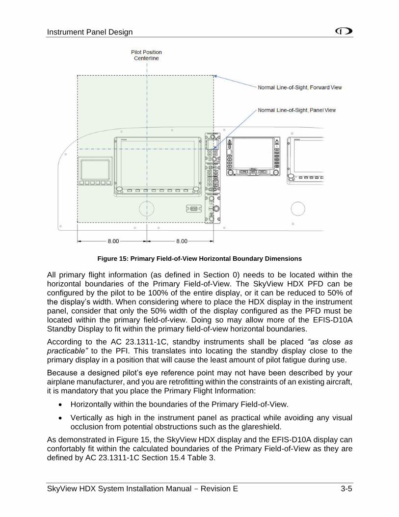
Instrument Panel Design
SkyView HDX System Installation Manual - Revision E 3-5
Figure 15: Primary Field-of-View Horizontal Boundary Dimensions
All primary flight information (as defined in Section 0) needs to be located within the horizontal boundaries of the Primary Field-of-View. The SkyView HDX PFD can be configured by the pilot to be 100% of the entire display, or it can be reduced to 50% of the display’s width. When considering where to place the HDX display in the instrument panel, consider that only the 50% width of the display configured as the PFD must be located within the primary field-of-view. Doing so may allow more of the EFIS-D10A Standby Display to fit within the primary field-of-view horizontal boundaries.
According to the AC 23.1311-1C, standby instruments shall be placed “as close as practicable” to the PFI. This translates into locating the standby display close to the primary display in a position that will cause the least amount of pilot fatigue during use.
Because a designed pilot’s eye reference point may not have been described by your airplane manufacturer, and you are retrofitting within the constraints of an existing aircraft, it is mandatory that you place the Primary Flight Information:
• Horizontally within the boundaries of the Primary Field-of-View.
• Vertically as high in the instrument panel as practical while avoiding any visual occlusion from potential obstructions such as the glareshield.
As demonstrated in Figure 15, the SkyView HDX display and the EFIS-D10A display can confortably fit within the calculated boundaries of the Primary Field-of-View as they are defined by AC 23.1311-1C Section 15.4 Table 3.
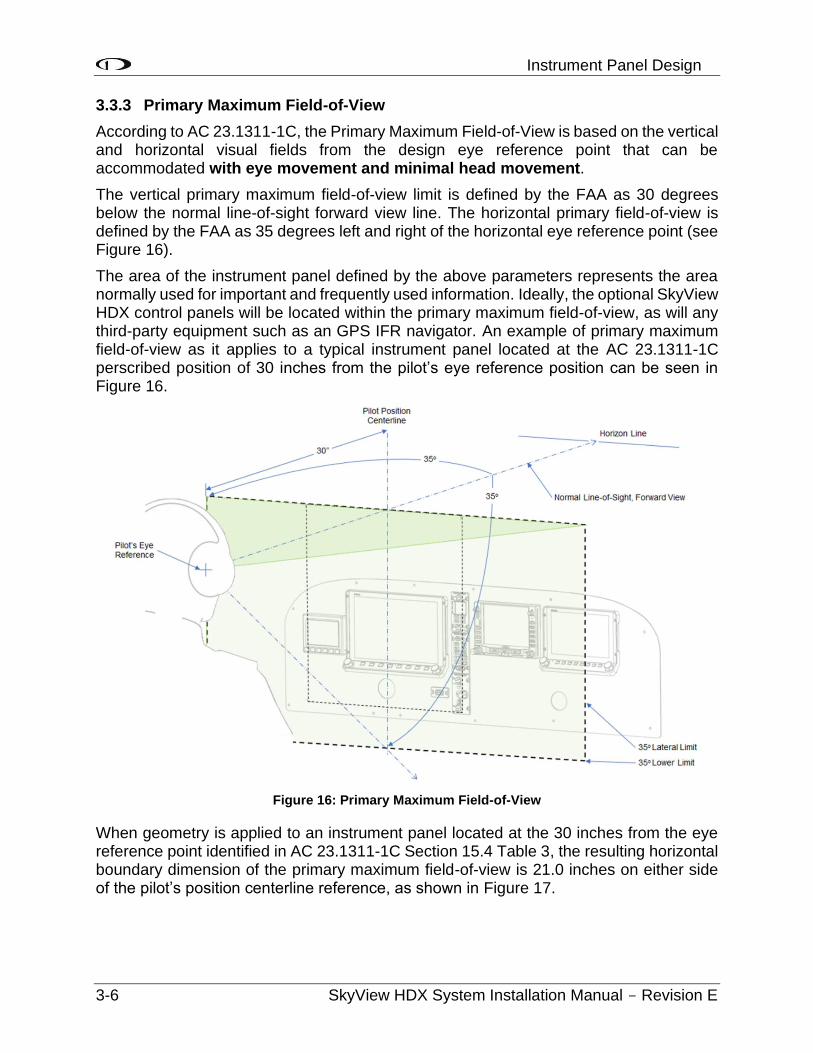
Instrument Panel Design
3-6 SkyView HDX System Installation Manual - Revision E
3.3.3 Primary Maximum Field-of-View
According to AC 23.1311-1C, the Primary Maximum Field-of-View is based on the vertical and horizontal visual fields from the design eye reference point that can be accommodated with eye movement and minimal head movement.
The vertical primary maximum field-of-view limit is defined by the FAA as 30 degrees below the normal line-of-sight forward view line. The horizontal primary field-of-view is defined by the FAA as 35 degrees left and right of the horizontal eye reference point (see Figure 16).
The area of the instrument panel defined by the above parameters represents the area normally used for important and frequently used information. Ideally, the optional SkyView HDX control panels will be located within the primary maximum field-of-view, as will any third-party equipment such as an GPS IFR navigator. An example of primary maximum field-of-view as it applies to a typical instrument panel located at the AC 23.1311-1C perscribed position of 30 inches from the pilot’s eye reference position can be seen in Figure 16.
Figure 16: Primary Maximum Field-of-View
When geometry is applied to an instrument panel located at the 30 inches from the eye reference point identified in AC 23.1311-1C Section 15.4 Table 3, the resulting horizontal boundary dimension of the primary maximum field-of-view is 21.0 inches on either side of the pilot’s position centerline reference, as shown in Figure 17.
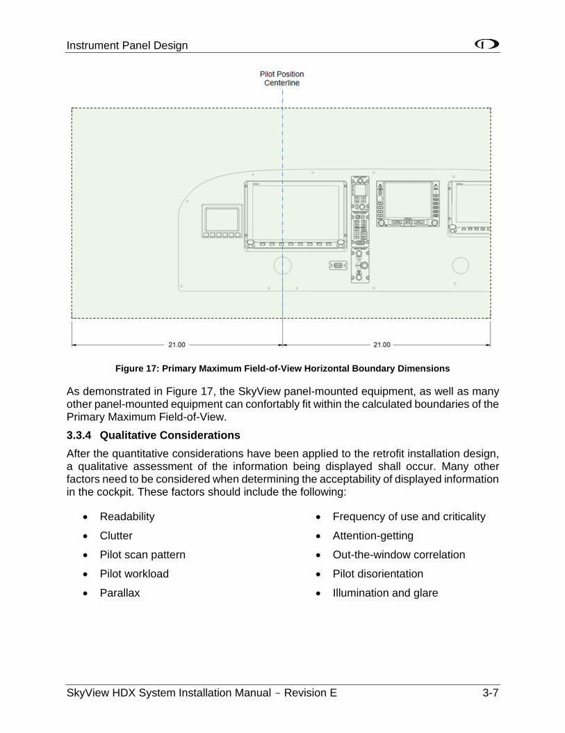
Instrument Panel Design
SkyView HDX System Installation Manual - Revision E 3-7
Figure 17: Primary Maximum Field-of-View Horizontal Boundary Dimensions
As demonstrated in Figure 17, the SkyView panel-mounted equipment, as well as many other panel-mounted equipment can confortably fit within the calculated boundaries of the Primary Maximum Field-of-View.
3.3.4 Qualitative Considerations
After the quantitative considerations have been applied to the retrofit installation design, a qualitative assessment of the information being displayed shall occur. Many other factors need to be considered when determining the acceptability of displayed information in the cockpit. These factors should include the following:
• Readability
• Clutter
• Pilot scan pattern
• Pilot workload
• Parallax
• Frequency of use and criticality
• Attention-getting
• Out-the-window correlation
• Pilot disorientation
• Illumination and glare
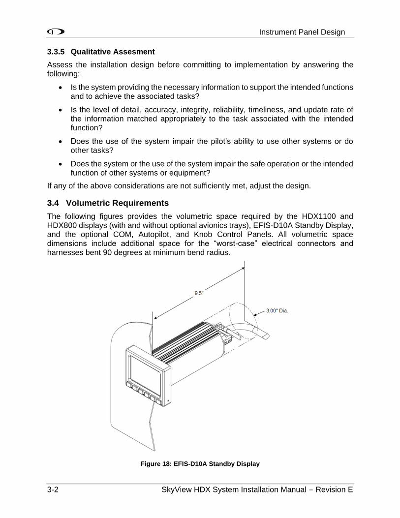
Instrument Panel Design
3-2 SkyView HDX System Installation Manual - Revision E
3.3.5 Qualitative Assesment
Assess the installation design before committing to implementation by answering the following:
• Is the system providing the necessary information to support the intended functions and to achieve the associated tasks?
• Is the level of detail, accuracy, integrity, reliability, timeliness, and update rate of the information matched appropriately to the task associated with the intended function?
• Does the use of the system impair the pilot’s ability to use other systems or do other tasks?
• Does the system or the use of the system impair the safe operation or the intended function of other systems or equipment?
If any of the above considerations are not sufficiently met, adjust the design.
3.4 Volumetric Requirements
The following figures provides the volumetric space required by the HDX1100 and HDX800 displays (with and without optional avionics trays), EFIS-D10A Standby Display, and the optional COM, Autopilot, and Knob Control Panels. All volumetric space dimensions include additional space for the “worst-case” electrical connectors and harnesses bent 90 degrees at minimum bend radius.
Figure 18: EFIS-D10A Standby Display
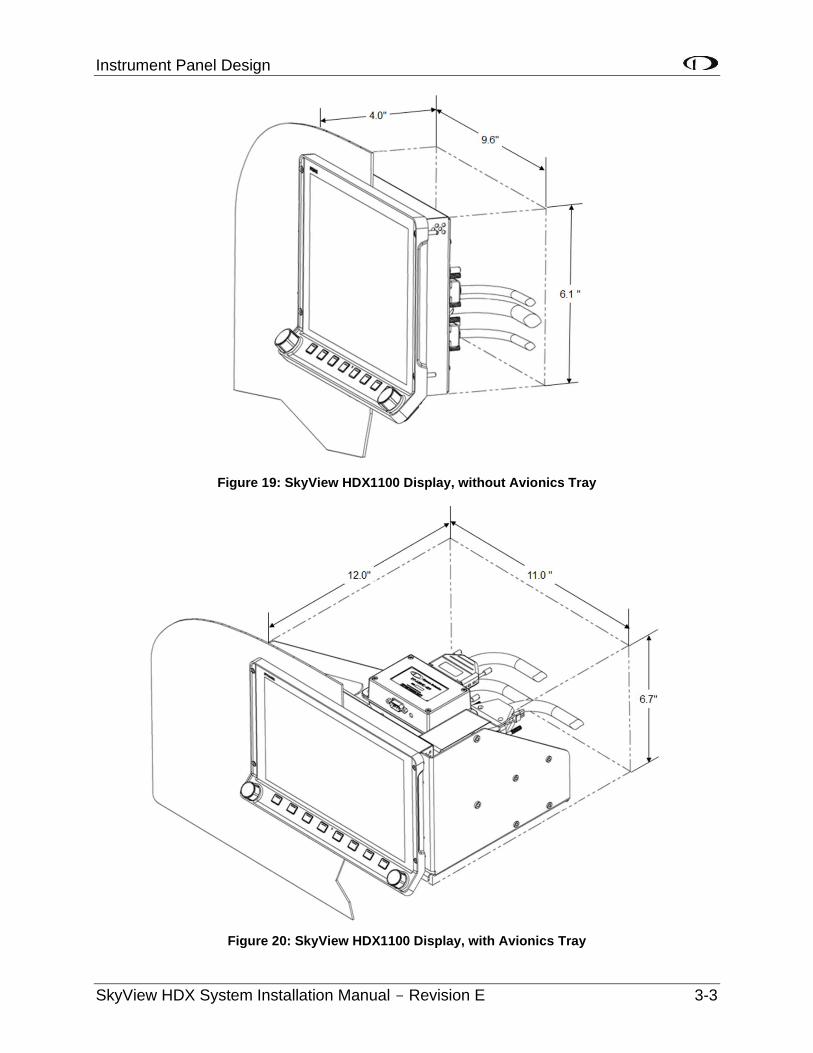
Instrument Panel Design
SkyView HDX System Installation Manual - Revision E 3-3
Figure 19: SkyView HDX1100 Display, without Avionics Tray
Figure 20: SkyView HDX1100 Display, with Avionics Tray
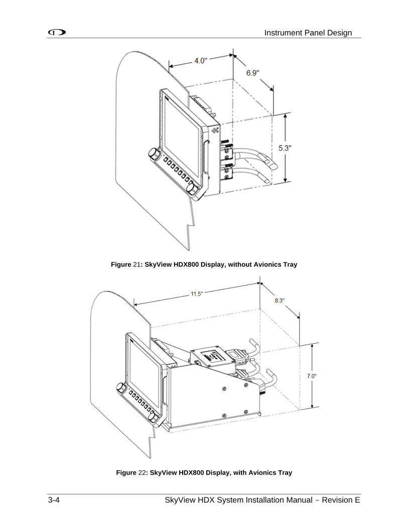
Instrument Panel Design
3-4 SkyView HDX System Installation Manual - Revision E
Figure 21: SkyView HDX800 Display, without Avionics Tray
Figure 22: SkyView HDX800 Display, with Avionics Tray
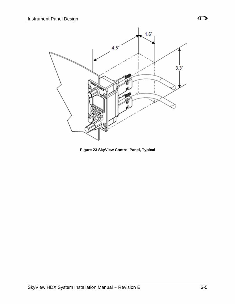
Instrument Panel Design
SkyView HDX System Installation Manual - Revision E 3-5
Figure 23 SkyView Control Panel, Typical

SkyView HDX Display Installation and Configuration
SkyView HDX System Installation Manual - Revision E 4-1
4 SkyView HDX Display Installation and Configuration
This section contains information and diagrams that specifically apply to the installation of SkyView HDX System per STC SA02594SE. After reading this section, you should be able to determine how to prepare a panel for display installation, how to mount a display, how to make all necessary electrical connections, and how to generally configure the display. Airplane specific configuration will be described in the SkyView System Configuration Manual for your airplane.
• Consider the ease, or difficulty of disconnecting multiple connectors when removing a SkyView display from the panel. Plan for either:
o Providing sufficient slack in the cables so that the SkyView display can be removed from the panel and then the cables disconnected, or
o Disconnecting (and reconnecting) the cables from behind the panel prior to removing the SkyView display from the panel.
• The SkyView Display Harness (SV-HARNESS-D37) extends about 3” (76mm) from the back of the display.
• Add a 1.0” (25.4 mm), minimum, beyond the physically required volume for the SkyView display’s heat sinks and fans to operate.
• Avoid placing the display near heater vents or any source of extremely hot air.
While SkyView displays do not normally require a forced cooling air, if the aircraft is to be operated in hot climates, the builder should ensure that the stated operating temperature range for SkyView displays is not exceeded.
• The display should be easily viewable without any obstructions.
• SkyView displays have no internal inertial sensors and do not need to be mounted in the same orientation as the ADAHRS or other modules.
• Displays only support a landscape viewing orientation; do not mount in portrait orientation.
Figure 27 and Figure 28 show the mechanical dimensions of the SkyView displays. Use the dimensions (in inches) in the diagrams to plan for the space required by the display.
To mount a SkyView display, cut an appropriately sized rectangular opening in your panel, drill out the mounting holes, and use the included mounting screws to fasten the display to the panel.
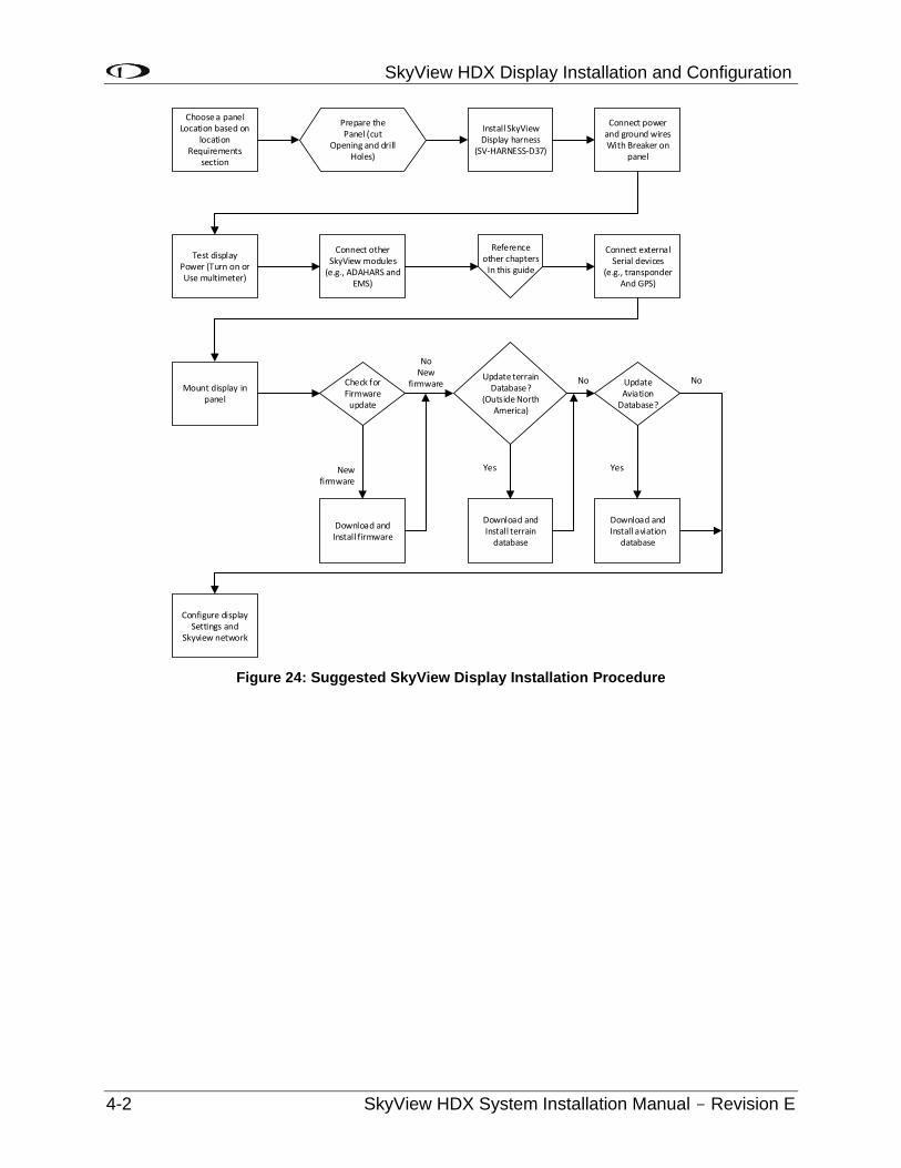
SkyView HDX Display Installation and Configuration
4-2 SkyView HDX System Installation Manual - Revision E
Choose a panelLocation based on
locationRequirements
section
Prepare thePanel (cut
Opening and drillHoles)
Install SkyViewDisplay harness
(SV-HARNESS-D37)
Connect powerand ground wiresWith Breaker on
panel
Test displayPower (Turn on orUse multimeter)
Connect otherSkyView modules
(e.g., ADAHARS andEMS)
Reference other chapters
In this guide
Connect externalSerial devices
(e.g., transponderAnd GPS)
Mount display in panel
Check for Firmware
update
Update terrainDatabase?
(Outside North America)
UpdateAviation
Database?
Download andInstall firmware
Download andInstall terrain
database
Download andInstall aviation
database
Configure displaySettings and
Skyview network
NoNew
firmware No No
Yes YesNewfirmware
Figure 24: Suggested SkyView Display Installation Procedure
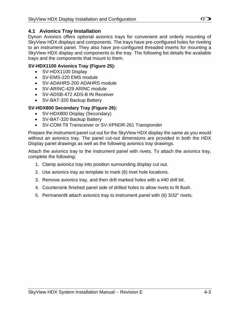
SkyView HDX Display Installation and Configuration
SkyView HDX System Installation Manual - Revision E 4-3
4.1 Avionics Tray Installation Dynon Avionics offers optional avionics trays for convenient and orderly mounting of SkyView HDX displays and components. The trays have pre-configured holes for riveting to an instrument panel. They also have pre-configured threaded inserts for mounting a SkyView HDX display and components to the tray. The following list details the available trays and the components that mount to them.
SV-HDX1100 Avionics Tray (Figure 25):
• SV-HDX1100 Display
• SV-EMS-220 EMS module
• SV-ADAHRS-200 ADAHRS module
• SV-ARINC-429 ARINC module
• SV-ADSB-472 ADS-B IN Receiver
• SV-BAT-320 Backup Battery
SV-HDX800 Secondary Tray (Figure 26):
• SV-HDX800 Display (Secondary)
• SV-BAT-320 Backup Battery
• SV-COM-T8 Transceiver or SV-XPNDR-261 Transponder
Prepare the instrument panel cut out for the SkyView HDX display the same as you would without an avionics tray. The panel cut-out dimensions are provided in both the HDX Display panel drawings as well as the following avionics tray drawings.
Attach the avionics tray to the instrument panel with rivets. To attach the avionics tray, complete the following:
1. Clamp avionics tray into position surrounding display cut out.
2. Use avionics tray as template to mark (6) rivet hole locations.
3. Remove avionics tray, and then drill marked holes with a #40 drill bit.
4. Countersink finished panel side of drilled holes to allow rivets to fit flush.
5. Permanentlt attach avionics tray to instrument panel with (6) 3/32" rivets.
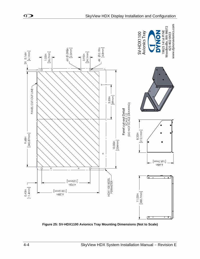
SkyView HDX Display Installation and Configuration
4-4 SkyView HDX System Installation Manual - Revision E
Figure 25: SV-HDX1100 Avionics Tray Mounting Dimensions (Not to Scale)
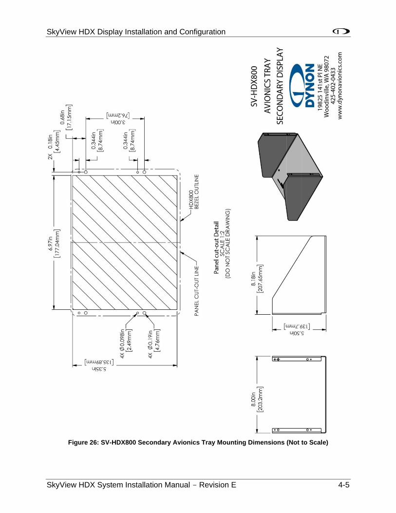
SkyView HDX Display Installation and Configuration
SkyView HDX System Installation Manual - Revision E 4-5
Figure 26: SV-HDX800 Secondary Avionics Tray Mounting Dimensions (Not to Scale)
SkyView HDX Display Installation and Configuration
4-6 SkyView HDX System Installation Manual - Revision E
4.2 SkyView HDX Display Mechanical Installation
Consider the ease, or difficulty of disconnecting multiple connectors when removing a SkyView display from the panel.
The following pages show the mechanical dimensions of the SkyView displays. Use the dimensions (in inches) found in the appropriate diagram to plan for the space required by the display.
To mount a SkyView display, cut an appropriately sized rectangular opening in your panel, drill out the mounting holes, and use the included mounting screws to fasten the display to the panel. See Figure 27 and Figure 28 for guidance.
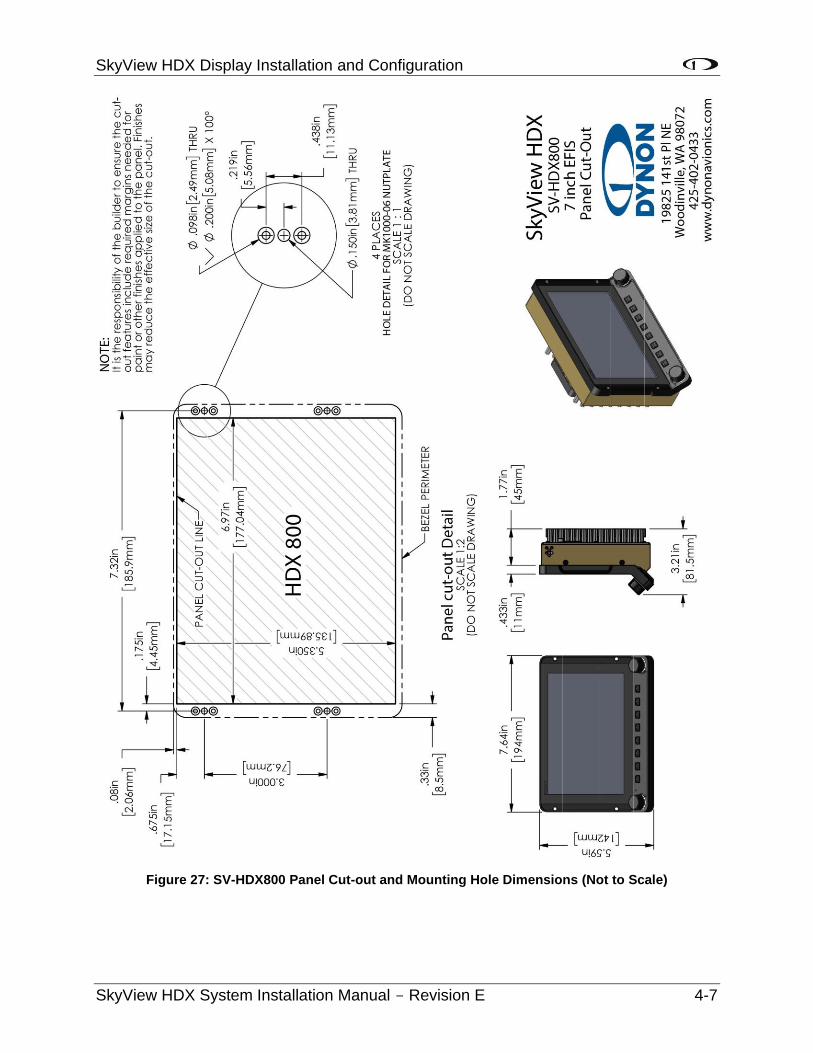
SkyView HDX Display Installation and Configuration
SkyView HDX System Installation Manual - Revision E 4-7
Figure 27: SV-HDX800 Panel Cut-out and Mounting Hole Dimensions (Not to Scale)
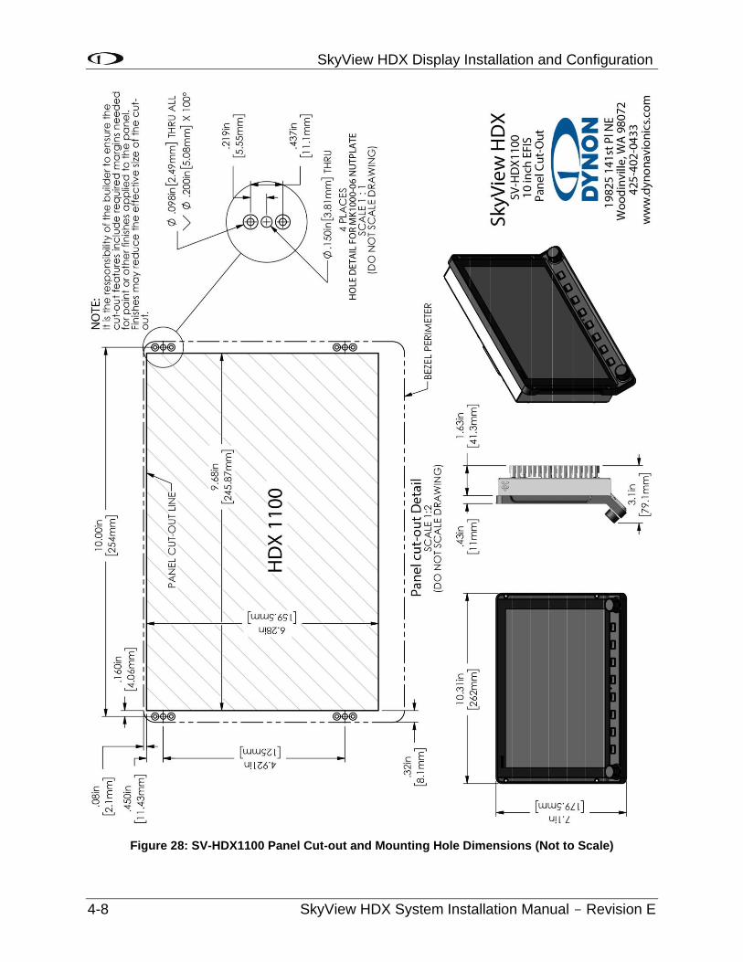
SkyView HDX Display Installation and Configuration
4-8 SkyView HDX System Installation Manual - Revision E
Figure 28: SV-HDX1100 Panel Cut-out and Mounting Hole Dimensions (Not to Scale)
SkyView HDX Display Installation and Configuration
SkyView HDX System Installation Manual - Revision E 4-9
4.3 Electrical Installation
Use this section in conjunction with the information contained in Section 25 Appendix C: Wiring and Electrical Connections (notably Figure 141 on page 25-9). The wires and wire colors in this section refer to the wires on the included SkyView Display Harness (SV-HARNESS-D37).
Some wires that are used in SkyView harnesses are identified with secondary color stripes. Exposing these striped wires to solvents or abrasives can cause the stripe color to wear off. Handle these wires with care.
4.3.1 Power Input
SkyView displays have a primary power input that is compatible with 12 volt and 24 volt electrical systems (10 to 30 volts DC). There are two unterminated solid red primary power input wires (to reduce current loading in each wire - these are not for redundancy and both must be connected to the same power source) and two unterminated solid black primary ground wires.
Ensure that there is an appropriately rated circuit breaker or replaceable fuse on the primary power input.
4.3.2 Grounding
Ensure that all external devices that interface with SkyView have a common ground with SkyView. If a device does not share ground with SkyView, it may not communicate properly.
4.3.3 Airplane Master Contactor / Relay Considerations
If your aircraft is equipped with a master contactor or a relay that is operated by the master switch, it is imperative that the coil of the contactor or relay is protected by a diode to reduce the voltage spike seen when the contactor is turned off. Without this diode, the aircraft system can see spikes above 100V, which can damage Dynon Avionics equipment and other avionics.
While some contactors have this diode internally, many do not. Please verify the existence of this diode before operating your Dynon Avionics equipment. Any diode that is rated for more than 1A, and more than 50V, is suitable.
4.3.4 SV-BAT-320 Connection and Operation Rules
SkyView displays have an external backup battery - SV-BAT-320. The SV-HARNESS-D37 harness has a connector that mates with the connector on the SV-BAT-320. Simply connecting the display to the battery enables the use of the SV-BAT-320; no additional configuration is required.
In the event of an electrical failure that causes SkyView to run on the SV-BAT-320, the SV-BAT-320 supplies power to the SkyView display it is connected to, along with any devices powered by the SkyView. A fully charged SV-BAT-320 can keep most SkyView systems operating for at least 60 minutes. The SV-BAT-320 does not supply (backup) power to the following SkyView system devices:
SkyView HDX Display Installation and Configuration
4-10 SkyView HDX System Installation Manual - Revision E
• Autopilot servos.
• SV-ADSB-472.
• SV-COM-X83.
• SV-XPNDR-261.
• Any non-Dynon Avionics device.
SkyView displays are only compatible with a Dynon Avionics SV-BAT-320 Backup Battery. Do not connect a lead-acid battery or any other battery to the connection reserved for the SV-BAT-320, as the charging algorithm and charging circuitry, voltages, etc., are optimized for the SV-BAT-320. Connecting any other battery may have detrimental consequences. Damage caused by connecting such a battery will not be repaired under warranty.
See the Non-Dynon Avionics Wire Harness Considerations, section 25.4, for important specifications that must be adhered to for the SV-BAT-320 to charge properly when used with a non-Dynon Avionics harness.
4.3.5 SkyView Network Connectors
The two D9 connectors on the back of a SkyView display are SkyView network connectors. They have identical pinouts and are electrically connected inside the display (i.e., they are completely interchangeable). Installers may use either connector or both connectors in SkyView installations. See Page 25-10 for SkyView Network Connector pinout information.
Note that these connectors are not “RS-232” Serial Port connectors.
4.3.6 Network Setup and Status
Once all SkyView modules are connected in a network, either in a benchtop test or permanent installation, turn the display(s) on. You will see the display boot up and the status LEDs on the modules light up.
A tail number on the Aircraft Information Page (SETUP MENU > SYSTEM SETUP > AIRCRAFT INFORMATION) is required for network configuration.
If you have more than one (1) display in your SkyView system, the tail number only needs to be set on the display that you initially perform the Network Configuration on. At network configuration time, all other displays that are set to the default tail number of DYNON will automatically have their settings and tail number synchronized with the display the configuration is performed from. After configuration, all displays’ tail numbers and settings will be synchronized, and further setup tasks can be performed from any display.
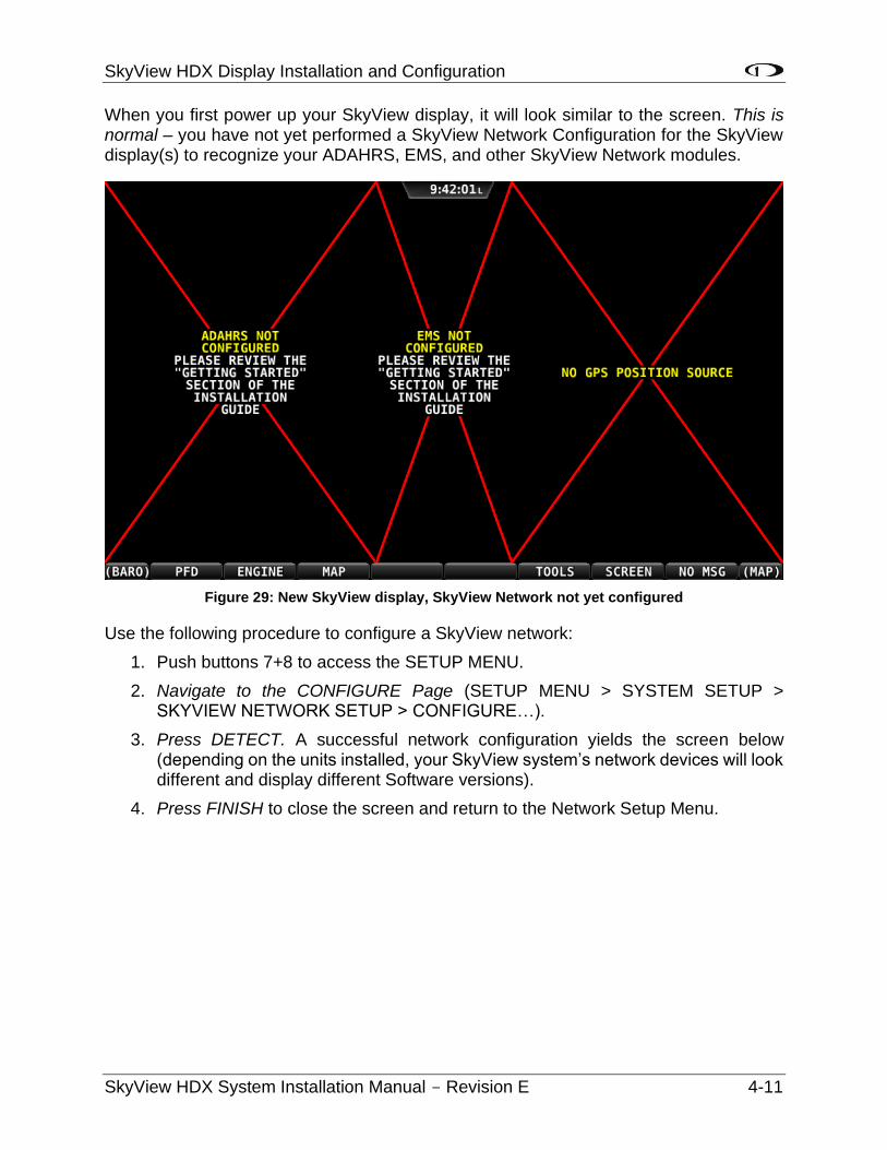
SkyView HDX Display Installation and Configuration
SkyView HDX System Installation Manual - Revision E 4-11
When you first power up your SkyView display, it will look similar to the screen. This is normal – you have not yet performed a SkyView Network Configuration for the SkyView display(s) to recognize your ADAHRS, EMS, and other SkyView Network modules.
Figure 29: New SkyView display, SkyView Network not yet configured
Use the following procedure to configure a SkyView network:
1. Push buttons 7+8 to access the SETUP MENU.
2. Navigate to the CONFIGURE Page (SETUP MENU > SYSTEM SETUP > SKYVIEW NETWORK SETUP > CONFIGURE…).
3. Press DETECT. A successful network configuration yields the screen below (depending on the units installed, your SkyView system’s network devices will look different and display different Software versions).
4. Press FINISH to close the screen and return to the Network Setup Menu.
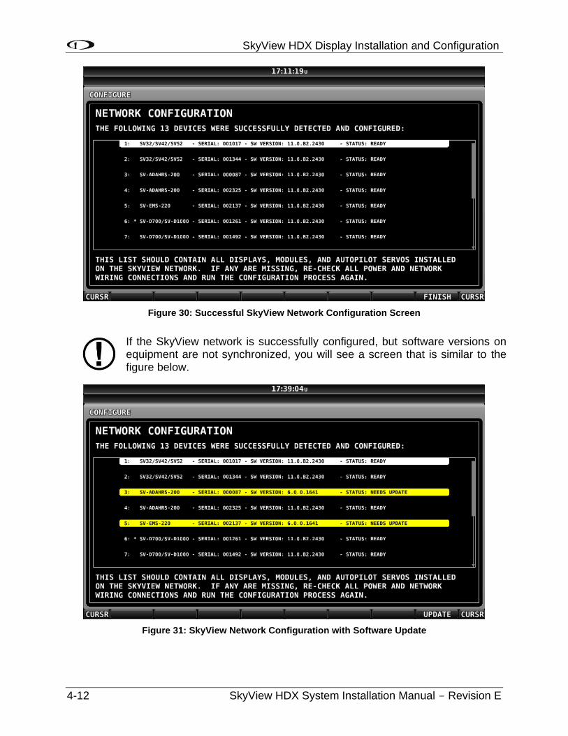
SkyView HDX Display Installation and Configuration
4-12 SkyView HDX System Installation Manual - Revision E
Figure 30: Successful SkyView Network Configuration Screen
If the SkyView network is successfully configured, but software versions on equipment are not synchronized, you will see a screen that is similar to the figure below.
Figure 31: SkyView Network Configuration with Software Update
SkyView HDX Display Installation and Configuration
SkyView HDX System Installation Manual - Revision E 4-13
If you see a screen similar to the one above, simply press the button labeled UPDATE to update the software running on the equipment in the SkyView network.
To check on SkyView network status, enter the NETWORK STATUS… Menu in the Network Setup Menu (SETUP MENU > SYSTEM SETUP > SKYVIEW NETWORK SETUP > NETWORK STATUS…).
The Network Status Page shows all displays, modules, servos, and other Dynon Avionics products installed on the SkyView network via the D9 SkyView Network connectors. This includes the following devices: SV-HDX 800, SV-HDX1100, SV-ADAHRS-200/201 modules, SV-EMS-220 modules, SV-ARINC-429 modules, SV-COM-PANEL for SV-COM-X83 COM radios, SV-AP-PANEL / SV-KNOB-PANEL control panels, and Dynon Avionics Autopilot Servos. It does NOT include any non-Dynon Avionics devices or any of the following Dynon Avionics devices that connect via a method other than SkyView Network: SV-XPNDR-261 transponders, SV-ADSB-472 ADS-B receiver, SV-GPS-2020 GPS receiver, OAT(s), or individual engine sensors.
SkyView Network has redundancy and error detection features which allow it to detect and annunciate module and SkyView Network wiring faults. In the event that SkyView reports a problem with an ADAHRS, EMS module, autopilot servo, or a problem with the “standby network”, this NETWORK STATUS page will provide more information about the nature of the problem.
4.3.7 Ethernet Connection
SkyView systems containing more than one (1) display should ideally have their Ethernet ports connected together for best operation. See Section 25 Appendix C: Wiring and Electrical Connections for further information about Ethernet.
4.3.8 Internal Time Keeping
Zulu/GMT time is initially obtained from a GPS source. Time is displayed as “--:--:--“until a GPS fix is received. When a display is turned off, a connected SV-BAT-320 backup battery enables the display to retain accurate time. To display time, a SkyView display that is not connected to a SV-BAT-320 must obtain a GPS fix each time it is powered on.
4.3.9 RS-232 Serial Devices
RS-232 serial communication to non–Dynon Avionics devices and interfacing of other devices in general can be involved and detailed. This installation manual is intended to provide general installation advice for the most common devices and situations.
A SkyView display includes five (5) general purpose RS-232 serial ports available for use with compatible equipment. Serial port transmit (TX) and receive (RX) wire sets are twisted together. Connected RS-232 serial devices must share a common power ground with the SkyView display(s).
Dynon Avionics devices that use RS-232 serial ports for communication include the SV-GPS-2020, SV-XPNDR-261, and SV-ADSB-472. Devices from other manufacturers that are commonly used with SkyView include transponders (with serial port inputs), NAV radios (such as Garmin SL30), COM radios (such as Garmin SL40), GPS devices (such as the Garmin X96 series), Vertical Power (VP-X), and Emergency Location Transmitters (ELTs). Reference the appropriate sections of this manual for detailed instructions for
SkyView HDX Display Installation and Configuration
4-14 SkyView HDX System Installation Manual - Revision E
installing the SV-GPS-2020, SV-XPNDR-261, SV-ADSB-472, and Vertical Power VP-X. Additionally, an external serial device (such as a PC or external serial data logger) can be connected and used to record real-time ADAHRS and EMS data that can be output by SkyView.
Serial Port 5 is recommended for the SV-GPS-2020 connection. Its wire bundle includes serial transmit, receive, ground, and power, and its wires are color-matched to the wire colors on the SV-GPS-2020.
If you have more than one (1) SkyView display, each external serial device’s serial TX wire needs to be connected to each screen so that it can send information to each display individually. Information that is received via serial connection is not automatically shared between multiple SkyView displays in an aircraft. Additionally, if the serial device you are connecting to your SkyView system can receive information from SkyView, that device’s RX wire must be connected to all SkyView displays as well. SkyView has special hardware to allow multiple TX lines to be connected together for redundancy. It is required that all connections to/from a particular serial device be connected to the same SkyView display serial port on every display in the SkyView system.
It is the installer’s responsibility to determine how to connect external serial devices to the display using the included wire harness. Installers should reference serial device documentation for serial port specifications. The basic order for installing an external serial device is as follows.
1. Specify a serial port for the device.
2. Make the serial port electrical connection. If you have more than one (1) SkyView display, make the same connection to all SkyView displays.
3. Configure the serial port (under SETUP MENU > SYSTEM SETUP > SERIAL PORT SETUP) according to the device’s documentation.
4. When the serial port configuration is complete, perform a final check by doing the following:
a. Power down all displays except #1. Verify all serial port devices are working - transponder, GPS, radios, etc.
b. Power down all displays except #2. Verify all serial port devices are working - transponder, GPS, radios, etc.
c. Power down all displays except #3. Verify all serial port devices are working - transponder, GPS, radios, etc.
A SkyView Display serial port can be configured to communicate with one (1) device on its TX and a different device on its RX, but when doing so, the TX and RX speeds must be the same.
SkyView HDX Display Installation and Configuration
SkyView HDX System Installation Manual - Revision E 4-15
Table 9: SkyView Serial Port Connections
Serial Port
Wire Function SkyView Display
Harness Wire Colors
1 TX Brown with Orange stripe
RX Brown with Violet stripe
2 TX Yellow with Orange stripe
RX Yellow with Violet stripe
3 TX Green with Orange stripe
RX Green with Violet stripe
4 TX Blue with Orange stripe
RX Blue with Violet stripe
5
TX Gray with Orange stripe
RX Gray with Violet stripe
SV-GPS-2020 Power
Solid Orange
SV-GPS-2020 Ground
Solid Black
4.3.9.1 Traffic Devices
SkyView has the ability to receive and display aircraft traffic data from:
• Dynon Avionics SV-XPNDR-261 (from TIS).
• Dynon Avionics SV-ADSB-472 (from ADS-B).
• Garmin GTX 330 / 330ES (from TIS).
• Other devices that output traffic data that emulates “Garmin TIS format” including Garrecht / AIR Avionics TRX-1500 (set to TIS output), NavWorx ADS-B receiver, and Zaon XRX (set to “Garmin” output). For such devices, configure the SkyView serial port connected to these devices in SERIAL PORT x SETUP, SERIAL IN DEVICE to GARMIN TIS TRAFFIC (which will automatically set the associated parameters).
If a device that can provide traffic data is connected to SkyView and configured (usually as a TIS serial traffic device under SETUP MENU > SYSTEM SETUP > SERIAL PORT SETUP), further traffic display options can be configured in SETUP MENU > TRAFFIC SETUP. Display of traffic on the MAP page and the PFD page can be set to:
• NONE (Do not display traffic).
• TA ONLY (Display only Traffic Advisories (TAs)).
• ALL (Display ALL traffic).
Only one (1) device can provide traffic information to SkyView at any moment. If you have more than one (1) device connected to SkyView that is capable of providing traffic (such as, but not limited to, SV-XPNDR-261 (TIS), SV-ADSB-472/472, Zaon XRX, etc.), the devices provide traffic information with
SkyView HDX Display Installation and Configuration
4-16 SkyView HDX System Installation Manual - Revision E
the following priority, based on the completeness of the traffic portrait they provide:
1. SV-ADSB-472 with full traffic (ADS-B ground station reporting with radar coverage).
2. TIS transponder from SV-XPNDR-261 or Garmin GTX 330 / ES (when in an active TIS coverage area).
3. FLARM.
4. Zaon.
5. SV-ADSB-472 with No RADAR (ADS-B reception, but without ground ADS-B station coverage or radar target inclusion).
4.3.9.2 Dynon Avionics SV-XPNDR-261 Transponder
See the SV-XPNDR-261 Transponder Installation and Configuration section for detailed instructions on how to set up the serial connection to the SV-XPNDR-261.
Note that if you are using a Dynon Avionics SV-XPNDR-261 Transponder, none of the encoder options in the below sections should to be set for the Dynon Avionics SV-XPNDR-261 module to receive pressure altitude. Instead, when the SV-XPNDR-261 is set up as described in the SV-XPNDR-261 Transponder Installation and Configuration section, it is automatically configured to receive pressure altitude from SkyView. Alternatively, systems that require the use of an external altitude encoder can be configured per the following section to have SkyView pass along an external pressure altitude source.
4.3.9.3 Dynon Avionics SV-ADSB-472
See Section 14 -SV-ADSB-472 ADS-B IN Receiver Installation for detailed instructions on how to set up the serial connection to the SV-ADSB-472.
4.3.9.4 Garmin GTX 330ES
To enable ADS-B traffic with a Garmin GTX 330ES, both the serial ports transmit and serial ports receive between SkyView and the GTX 330ES must be connected and configured. The GTX 330ES must be fully configured to output ADS-B Out, which requires a TSO’d GPS position. Contact Garmin for correctly configuring the GTX 330ES ADS-B Out capability. Also see SV-ADSB-472 ADS-B IN Receiver Installation, for additional configuration.
• SETUP MENU > SYSTEM SETUP > SERIAL PORT SETUP > SERIAL PORT x SETUP > SERIAL IN DEVICE > GARMIN GTX 330ES.
• SETUP MENU > SYSTEM SETUP > SERIAL PORT SETUP > SERIAL PORT x SETUP > SERIAL OUT DEVICE > ICARUS ALTITUDE 100ft OR ICARUS ALTITUDE 10ft.
• SETUP MENU > SYSTEM SETUP > AIRCRAFT INFORMATION > TRANSPONDER HEX CODE > (set to same HEX CODE as configured in the Garmin 330 ES) > ACCEPT (button).
SkyView HDX Display Installation and Configuration
SkyView HDX System Installation Manual - Revision E 4-17
4.3.9.5 External Serial Altitude Encoder Support
Some locales may require the use of a certified altitude encoder with the Dynon Avionics SV-XPNDR-261 Transponder. SkyView supports external serial altitude encoders that use Icarus/Garmin format. When one (1) is connected, the SV-XPNDR-261 uses the external altitude encoder data source instead of SkyView’s own ADAHRS-generated pressure altitude. However, the altitude displayed by SkyView on the PFD page is ALWAYS sourced from SkyView ADAHRS data.
To have SkyView use an external altitude serial encoder as the pressure altitude source for the SV-XPNDR-261:
• Wire a SkyView serial receive line to the respective serial transmit connection from the serial altitude encoder. If you have more than one (1) SkyView display, make the same connection to all SkyView displays.
• Ensure there is a shared ground between the SkyView display and the serial altitude encoder. If you have more than one (1) SkyView display, make the same connection to all SkyView displays.
• Configure this serial port on each display under SETUP MENU > SYSTEM SETUP > SERIAL PORT SETUP. The SERIAL IN device for this serial port should be set to ICARUS/GARMIN ALTITUDE.
4.3.9.6 Non-Dynon Avionics Transponder Serial Altitude Encoder Output
To use SkyView’s altitude output functionality with your transponder that can receive serial altitude input:
• Wire a SkyView serial transmit line to the respective receive connection on the transponder. If you have more than one (1) SkyView display, make the same connection to all SkyView displays.
• Ensure there is a shared ground between the SkyView display and the transponder. If you have more than one (1) SkyView display, make the same connection to all SkyView displays.
• Configure the serial port on each display appropriately. There is an example serial port configuration on Page 4-29.
4.3.9.7 SkyView Altitude Encoder Output Formats
There must be a SkyView ADAHRS installed for the altitude encoder output to function.
SkyView outputs its altitude measurements in two different formats. You can use either format on any of the serial ports. These formats are described in Table 10: Icarus Format.
Table 10: Icarus Format
ICARUS
Used by Garmin GTX330/ES (Garmin serial port must be set to Icarus input), Garmin GTX327 (Garmin serial port must be set to Icarus input),
SkyView HDX Display Installation and Configuration
4-18 SkyView HDX System Installation Manual - Revision E
ICARUS
Garmin GTX328 (Garmin serial port must be set to Icarus input), Icarus, Trimble
Baud rate 9600
Format ALT, space, five (5) altitude bytes, carriage return
Example message ALT 05200[CR]
4.3.9.8 Non-Dynon Avionics Transponder
SkyView can display the status of the Garmin GTX 327 and Garmin GTX 330 / 330ES transponders. To use this functionality with SkyView:
• Wire a serial receive line to the respective transmit line on the transponder. If you have more than one (1) SkyView display, make the same connection to all SkyView displays.
• Ensure there is a shared ground between the SkyView display and the transponder. If you have more than one (1) SkyView display, make the same connection to all SkyView displays.
• Configure the serial port on each display appropriately under SETUP MENU > SYSTEM SETUP > SERIAL PORT SETUP.
• Configure the serial port on the transponder appropriately. For a Garmin GTX 327, 330 / ES, the RS-232 output of the appropriate serial port on the transponder should be set to REMOTE+TIS.
4.3.9.9 Garmin SL30 COM / NAV Radio
In addition to the NAV radio functions of the SL30, SkyView can display COM radio information from the SL30 on the top bar of the SkyView display(s) and send COM frequencies to the SL30 (TUNE COM).
• Connect SL30 serial RX pin 4 (RxD1) to a SkyView serial TX. If you have more than one (1) SkyView display, make the same connection to all SkyView displays.
• Connect SL30 serial TX pin 5 (TxD1) to a SkyView serial RX. If you have more than one (1) SkyView display, make the same connection to all SkyView displays.
• Ensure there is a shared ground between the SkyView display and the SL30. If you have more than one (1) SkyView display, make the same connection to all SkyView displays.
• Configure the serial port on the SL30 appropriately. On the SL30, the Indicator Head Type should be set to NONE.
SkyView HDX Display Installation and Configuration
SkyView HDX System Installation Manual - Revision E 4-19
On SkyView
• SETUP MENU > SYSTEM SETUP > SERIAL PORT SETUP > SERIAL PORT x SETUP > SERIAL IN DEVICE > GARMIN / APOLLO SL30. This will automatically set the SERIAL IN/OUT BAUD RATE and SERIAL OUT DEVICE.
• Set SERIAL IN FUNCTION TO NAV 1, 2, 3, or 4. If the SL30 is the only NAV device, select NAV 1.
• Set NAVIGATION SOURCE DISPLAY NAME: (user selectable, 7 characters, suggest SL30). The name entered here is displayed as the HSI source and the Flight Plan Source (if this device outputs a flight plan).
• If you wish the SL30 frequency and status to be displayed on the top bar: SETUP MENU > SYSTEM SETUP > DISPLAYED COM > GARMIN / APOLLO SL30 (PORT x) and SETUP MENU > SYSTEM SETUP > DISPLAY COM IN TOP BAR: YES
4.3.9.10 Val Avionics NAV 2000
• To work with SkyView, the NAV 2000 must have v1.10 Software (minimum). The Software version is displayed during the NAV 2000 startup.
• Connect NAV 2000 serial RX Pin 4 (Connector P1) to a SkyView serial TX. If you have more than one (1) SkyView display, make the same connection to all SkyView displays.
• Connect NAV 2000 serial TX Pin 5 (Connector P1) to a SkyView serial RX. If you have more than one (1) SkyView display, make the same connection to all SkyView displays.
• Ensure there is a shared ground between the SkyView display and the NAV 2000 – Serial Ground Pin 3 (Connector P1). If you have more than one (1) SkyView display, make the same connection to all SkyView displays.
• Configure the NAV 2000:
• Enter the config page by pressing and holding both the left and right knobs while the unit is starting up until the display shows the last used active frequency and the first config page:
o *A108.00 Rs I:xxx (the *x*'s are a placeholder for the resolver setting).
• Rotate the left inner (small) encoder to show *Non* in the section following *Rs I:
• Push and hold both encoder buttons to exit from the configuration pages.
On SkyView
• SETUP MENU > SYSTEM SETUP > SERIAL PORT SETUP > SERIAL PORT x SETUP > SERIAL IN DEVICE > VAL AVIONICS NAV 2000. This will automatically set the SERIAL IN/OUT BAUD RATE and SERIAL OUT DEVICE.
• Set SERIAL IN FUNCTION TO NAV 1, 2, 3, or 4. If the NAV 2000 is the only NAV device, select NAV 1.
SkyView HDX Display Installation and Configuration
4-20 SkyView HDX System Installation Manual - Revision E
• Set NAVIGATION SOURCE DISPLAY NAME: (user selectable, 7 characters – suggest NAV2000). The name entered here is displayed as the HSI source and the Flight Plan Source (if this device outputs a flight plan).
• SETUP MENU > SYSTEM SETUP > DISPLAYED COM: NONE (If a SkyView compatible COM radio such as the SV-COM-X83 is installed, refer to those instructions for this setting) and SETUP MENU > SYSTEM SETUP > DISPLAY COM IN TOP BAR: NO (If a SkyView compatible COM radio such as the SV-COM-X83 is installed, refer to those instructions for this setting).
4.3.9.11 Garmin SL40 COM Radio
SkyView can display COM radio information from the SL40 on the SkyView top bar and send COM frequencies to the SL40 (TUNE COM).
• Connect SL40 serial RX pin 10 (RxD1) to a SkyView serial TX. If you have more than one (1) SkyView display, make the same connection to all SkyView displays.
• Connect SL40 serial TX pin 3 (TxD1) to one (1) of the SkyView serial RX pins on each display. If you have more than one (1) SkyView display, make the same connection to all SkyView displays.
• Ensure there is a shared ground between the SkyView display, and the SL40. If you have more than one (1) SkyView display, make the same connection to all SkyView displays.
• Configure the serial port on the SL40 appropriately.
• Configure the serial port: SETUP MENU > SYSTEM SETUP > SERIAL PORT SETUP > SERIAL PORT x SETUP > SERIAL IN DEVICE > GARMIN / APOLLO SL40. This will automatically set the SERIAL IN FUNCTION, SERIAL IN/OUT BAUD RATE, and SERIAL OUT DEVICE.
• Set the SL40 status to be displayed on the top bar: SETUP > SYSTEM SETUP > DISPLAYED COM > GARMIN / APOLLO SL40 (PORT x) and SETUP MENU > SYSTEM SETUP > DISPLAY COM IN TOP BAR: YES.
4.3.9.12 Trig TY91 COM Radio
SkyView can display COM radio information from the TY91 on the top bar of the SkyView display(s) and “push” COM frequencies to the TY91 (TUNE COM).
• Connect TY91 RS232 In (TC90 Pin 6) to a SkyView serial TX. If you have more than one (1) SkyView display, make the same connection to all SkyView displays.
• Connect TY91 RS232 Out (TC90 Pin 5) to a SkyView serial RX. If you have more than one (1) SkyView display, make the same connection to all SkyView displays.
• Ensure there is a shared ground between the SkyView display and the TY91. If you have more than one (1) SkyView display, make the same connection to all SkyView displays.
SkyView HDX Display Installation and Configuration
SkyView HDX System Installation Manual - Revision E 4-21
• On the TY91, configure the serial port appropriately (per Trig’s documentation).
On SkyView
• SETUP MENU > SYSTEM SETUP > SERIAL PORT SETUP > SERIAL PORT x SETUP > SERIAL IN DEVICE > TRIG TY91. This will automatically set the SERIAL IN FUNCTION, SERIAL IN/OUT BAUD RATE, and SERIAL OUT DEVICE.
• SETUP MENU > SYSTEM SETUP > PRIMARY COM > TRIG TY91 (PORT x).
• SETUP MENU > SYSTEM SETUP > DISPLAY COM IN TOP BAR > YES.
4.3.9.13 Icom IC-A210 TSO COM Radio
The IC-A210 does not transmit status or frequencies via serial port, so IC-A210 information cannot be displayed on the top bar of the SkyView display(s). SkyView can send COM radio frequencies to the IC-A210 (TUNE COM).
• Confirm that your A210 is running Software version 1.53 or newer. This feature will not work with old Software. Contact Icom for details on upgrading your radio Software.
• Connect IC-A210 serial RX (Molex Pin 2 / D15 Pin 10) to a SkyView serial TX. If you have more than one (1) SkyView display, make the same connection to all SkyView displays.
• Ensure there is a shared ground between the SkyView display and the IC-A210. If you have more than one (1) SkyView display, make the same connection to all SkyView displays.
• On the IC-A210, configure the serial port appropriately (per Icom documentation).
On SkyView
• SETUP MENU > SYSTEM SETUP > SERIAL PORT SETUP > SERIAL PORT x SETUP > SERIAL IN DEVICE > ICOM A210. This will automatically set the SERIAL IN FUNCTION, SERIAL IN/OUT BAUD RATE, and SERIAL OUT DEVICE. (Although there is no IC-A210 serial TX to SkyView serial RX connection, SERIAL IN DEVICE must be configured as described.).
• SETUP MENU > SYSTEM SETUP > PRIMARY COM > ICOM A210 (PORT x) and SETUP MENU > SYSTEM SETUP > DISPLAY COM IN TOP BAR > NO.
4.3.9.14 Garmin GTR 200, GTR 225 COM Radio, GNC 255 COM Radio / NAV
Receiver
SkyView can send frequencies to the GNC 255’s standby frequency.
On the GNC 255:
• Connect GNC 255 P2001 Pin 16 to a SkyView serial TX. If you have more than one (1) SkyView display, make the same connection to all SkyView displays.
• Connect GNC 255 P2001 Pin 1 to a SkyView serial RX. If you have more than one (1) SkyView display, make the same connection to all SkyView displays.
SkyView HDX Display Installation and Configuration
4-22 SkyView HDX System Installation Manual - Revision E
• Ensure there is a shared ground between the SkyView display and the GNC 255. If you have more than one (1) SkyView display, make the same connection to all SkyView displays.
• On the GNC 255, configure the serial port:
o Set “I/O Mode” to “NMEA.”
o Set “CDI Indicator” to “NONE.”
On SkyView:
• SETUP MENU > SYSTEM SETUP > SERIAL PORT SETUP > SERIAL PORT x SETUP > SERIAL IN DEVICE > GARMIN GNC 255 A/B. This will automatically set the SERIAL IN/OUT BAUD RATE, and SERIAL OUT DEVICE.
• SETUP MENU > SYSTEM SETUP > SERIAL PORT SETUP > SERIAL PORT x SETUP > SERIAL IN FUNCTION > NAV 1.
4.3.9.15 Trig Avionics TY91 and TY92 COM Radio
SkyView can display COM radio information from the ATR833, GTR 200, GTR 225, GNC 255, and TY91/923 on the SkyView top bar and send COM frequencies to them (TUNE COM).
Note that SkyView does not send database information for the GTR 200 to enable the GTR 200’s “Nearest or Flight Plan Airports” feature.
• Connect the radio’s serial RX to a SkyView serial TX. If you have more than one (1) SkyView display, make the same connection to all SkyView displays.
• Connect the radio’s serial TX to one (1) of the SkyView serial RX pins on each display. If you have more than one (1) SkyView display, make the same connection to all SkyView displays.
• Ensure there is a shared ground between the SkyView display, and the radio. If you have more than one (1) SkyView display, make the same connection to all SkyView displays.
• Configure the serial port on the radio appropriately.
• Configure the serial port: SETUP MENU > SYSTEM SETUP > SERIAL PORT SETUP > SERIAL PORT x SETUP > SERIAL IN DEVICE > FUNKE ATR833 or GARMIN GTR 200 or GARMIN GNC 255 A/B or GARMIN GTR 225 A/B or TRIG TY9X 25KHz ONLY TRIG TY9X 8.33/25KHz
3 Full TY91/92 8.33 kHz support depends on a future software update from Trig.
SkyView HDX Display Installation and Configuration
SkyView HDX System Installation Manual - Revision E 4-23
o This configuration will automatically set the SERIAL IN FUNCTION, SERIAL IN/OUT BAUD RATE, and SERIAL OUT DEVICE.
Set the radio status to be displayed on the top bar: SETUP > SYSTEM SETUP > DISPLAYED COM > (device you chose above) (PORT x) and SETUP MENU > SYSTEM SETUP > DISPLAY COM IN TOP BAR: YES
4.3.9.16 Emergency Location Transmitter (ELT)
SkyView can provide a GPS data stream to ELTs that accept GPS data in NMEA format.
• Wire a serial transmit (TX) line from one (1) display to the receive (RX) line on the ELT. If you have more than one (1) SkyView display, make the same connection to all SkyView displays.
• Ensure there is a shared ground between the SkyView display and the ELT. If you have more than one (1) SkyView display, make the same connection to all SkyView displays.
• Configure the SkyView display serial port: SETUP MENU > SYSTEM SETUP > SERIAL PORT SETUP > SERIAL PORT x SETUP. SERIAL IN DEVICE: (don’t care, does not affect ELT). SERIAL IN/OUT BAUD RATE: (set to match speed of ELT; typically 4800 or 9600).
• SERIAL OUT DEVICE: NMEA OUT (BASIC).
4.3.9.17 Dynon Avionics ADAHRS / EMS / SYSTEM / NMEA (GPS) Data Outputs
To output real-time data to an external serial device, such as a serial data logger or other device that accepts NMEA or Dynon Avionics formats:
• Wire a serial transmit line from one (1) display to the receive line on the external serial device. If you have more than one (1) SkyView display, make the same connection to all SkyView displays.
• Ensure there is a shared ground between the SkyView display and the external serial device. If you have more than one (1) SkyView display, make the same connection to all SkyView displays.
• Configure the serial port on the display appropriately under SETUP MENU > SYSTEM SETUP > SERIAL PORT SETUP, SERIAL PORT x SETUP > selecting the desired output data format.
4.3.9.18 TIS Format Traffic Output
SkyView can be configured to output TIS format traffic information for external display on other avionics that can receive traffic in TIS format. When this option is selected, only the actual TIS traffic from a SV-XPNDR-261 is included in this serial data stream. This stream does not include ADS-B, FLARM, Zaon, or other traffic sources that may be available to SkyView.
SkyView HDX Display Installation and Configuration
4-24 SkyView HDX System Installation Manual - Revision E
• Wire a serial transmit line from one (1) display to the receive line on the external serial device. If you have more than one (1) SkyView display, make the same connection to all SkyView displays.
• Ensure there is a shared ground between the SkyView display and the external serial device. If you have more than one (1) SkyView display, make the same connection to all SkyView displays.
• Configure the serial port on the display appropriately under SETUP MENU > SYSTEM SETUP > SERIAL PORT SETUP, SERIAL PORT X SETUP > TIS OUT (330 FORMAT).
4.3.10 USB Usage and Accessibility
It is useful to have the USB socket on the display’s wire harness accessible after installation for file uploads and downloads.
The USB connector is used during the following operations:
• System Software updates.
• Configuration file uploads and downloads.
• Database updates.
4.3.11 External Dim Control (Dimming) Connections
DIM INPUT (Pin 25) The backlight level on a SkyView display can be increased or decreased using a varying DC voltage of 0 to 36 volts DC. See External Brightness Management later in this section to configure brightness levels for specific voltages.
DIM OUTPUT (Pin 26) The DIM OUTPUT signal is an approx. 120 Hz (this may change in future Software revisions) Pulse Width Modulation (PWM) signal directly proportional to the screen brightness – 100% to 0.02%. This output is designed to directly control the dim level of devices such as LEDs; a common use is for the back-lighting of switches in a panel so that they dim at night in conjunction with SkyView’s automatic dim levels.
The DIM OUTPUT (Pin 26) signal is an open collector to ground – it acts as a switch to ground, and does not source any power itself. Pin 26 can sink a maximum current of 120mA and a maximum voltage of 40V. The DIM OUTPUT signal is not analog and cannot be used to control the dim level of devices that expect 0-5V, 0-12V, or a resistance as their dimming input.
Do not connect the DIM OUTPUT (Pin 26) signal from multiple SkyView screens in parallel. The DIM OUTPUT signals from each display is not synchronous, and this will lead to inconsistent behavior.
4.3.11.1 Audio Output Electrical Connections
Dynon Avionics recommends that SkyView’s audio outputs be connected to an unmuted input on your audio panel or intercom. When connected this way, critical audio alerts generated by SkyView are not muted by ATC
SkyView HDX Display Installation and Configuration
SkyView HDX System Installation Manual - Revision E 4-25
transmissions or other audio events that could cause SkyView’s audio to be suppressed if it were connected to a muting input.
SkyView’s audio output cannot be connected in parallel with a radio to a headset. Doing so will significantly reduce the volume of the radio output, possibly to the level that it is not usable. An intercom such as the SV-INTERCOM-2S, audio mixer, or audio panel is required to utilize this output.
If you are converting a Dynon Avionics D10/D100 product installation to a SkyView installation, you should remove the variable resistor that is connected to the existing audio output wiring: SkyView’s audio output (volume) is adjustable.
The audio outputs on pins 13 and 31 (left and right, respectively) of the display’s D37 connector can drive audio panel or intercom auxiliary inputs. When interfaced with such devices, they can generally be used with any input designated as an auxiliary input without any external resistors or other components needed between the SkyView and the intercom.
Use left and right audio outputs for stereo mode. If the audio panel or intercom only supports mono input, short the left and right audio outputs together and connect them to the mono input on the device. To minimize noise, ensure that your SkyView audio ground and intercom or audio panel ground are directly connected together, even though they nominally share a common ground via other aircraft wiring (audio ground is pin 30 on the D37).
If there is more than one display on a SkyView network, you MUST connect all displays’ audio outputs to the same audio panel input to ensure that audio is always heard. Electrically short the respective left and right outputs together for stereo mode (i.e., left-to-left and right-to-right) or connect all audio outputs together for mono mode. The same rule applies for audio grounds.
To minimize the possibility of audio “humming”, a 16 AWG wire may optionally be connected between the ground point for the intercom/audio panel/radio(s) and SkyView display case(s). To attach the wire to the rear of the SkyView display, a 4-40 x 3/16” long screw may be screwed into the threaded boss above the USB ports on the back of the SkyView display.
Audio output volume will be controlled via the interface on a SkyView display, so no external hardware components are required. The audio output from SkyView has a maximum output of 10V p-p with 50 Ω (50 ohms) of source impedance.
SkyView systems with more than one display normally only output audio alerts from one display to minimize audio distortion. In a SkyView system that has more than one display and dual SV-EMS-220s to monitor dual engines, EMS audio alerts are enabled from two displays. At moments when two displays are outputting EMS audio alerts, there may be minor “doubling” of audio alerts heard in the audio system.
SkyView HDX Display Installation and Configuration
4-26 SkyView HDX System Installation Manual - Revision E
4.3.11.2 SkyView Audio Output Settings
Go to SETUP MENU > SYSTEM SETUP > AUDIO SETUP to configure audio output settings. Most of the items in this menu control whether the audio output for a particular alert or alert category is played or not. The settings that can be adjusted here that are not voice alert toggles are:
• VOLUME CONTROL / TEST – Sets the volume level. While in this menu, sound is played continuously so that proper audio connectivity and volume levels can be confirmed.
o In this menu only, audio is only outputted from the actual display that is in the setup menu. This allows one (1) to troubleshoot the physical audio connections. In actual operation, only one (1) of the displays transmits audio at a time. Which display happens to be transmitting is automatically managed by SkyView. Since all displays’ audio outputs are connected together (and to the intercom or audio panel), this is transparent in actual use.
• BOOT SOUND – When set to ON, the system will say “Dynon Avionics SkyView” when it first starts up.
• ANGLE OF ATTACK – This sets a pulsing, progressive tone that increases in frequency, similar in nature to a conventional reed type aircraft stall warning sound to a reed-type stall warning sound, although it is much more predictable in its progression. It can be set to start its pulsing tones at either the border of the yellow/green marks on the AOA bars, the middle of the yellow, or the yellow/red border. The pulsing tones start at the level selected and get progressively quicker and closer together until a solid tone is played at critical AOA (in the red).
o INHIBIT AOA BELOW AIRSPEED – Allows you to set an airspeed below which no AOA tones are played. This helps prevent nuisance alarms while on the ground and taxiing, especially in taildraggers.
4.3.12 Contact Inputs
Contact Input #1 – (Optional) External LEVEL Button. See the Autopilot section for detailed explanation.
Contact Input #2 – (Optional) External GO AROUND Button. See the Autopilot section for detailed explanation.
Contact Input #3 and #4 are currently not supported. A future Software update may enable this functionality. Do not connect anything to these pins at this time.
4.3.13 Reserved Connections for Future Use
Do not connect anything to unspecified D37 connector pins (directly or using the display harness). These pins are reserved for future use.
SkyView HDX Display Installation and Configuration
SkyView HDX System Installation Manual - Revision E 4-27
4.4 Display Setup
You can access important information about a SkyView display, as well as configure serial ports, characterize your display backlight behavior, and specify other display-specific settings.
4.4.1 How to Access Display Hardware Information
Enter the Display Hardware Information Page (SETUP MENU > LOCAL DISPLAY SETUP > DISPLAY HARDWARE INFORMATION) to access important display hardware information. This menu contains status information only – nothing on it is configurable. Reference the Operation Section of this manual for more information about this menu.
4.4.2 Serial Port Configuration
Reference serial device documentation for serial communication specifications.
SkyView serial ports are configured in the Serial Port Setup Menu (SETUP MENU > SYSTEM SETUP > SERIAL PORT SETUP). SkyView serial ports have four (4) parameters that must be defined:
• Input Device.
• Input Function.
• Baud Rate.
• Output Device.
Note that sometimes a parameter will be defined as NONE on the screen. For example, when a serial port is configured as only an output, the input device and input function will both be set to NONE.
4.4.2.1 Input Device
Set the input device to the data format the SkyView display should expect from an input device. The configurable options list contains equipment by brand and model and also generic data formats such as NMEA and aviation. NMEA is the standard format for most GPS units the SV-GPS-2020). Aviation is used by some Garmin and Bendix/King panel mount equipment. If your specific equipment is listed by brand and model, we recommend you configure SkyView to use this option instead of a generic data format.
If you have any ARINC-429 devices, these are configured separately. See Section 13 SV-ARINC-429 Module Installation and Configuration for more information.
4.4.2.2 Input Function
SkyView has several options for input functions: NONE, GPS, NAV, or POS. Set the device’s input function to NONE if it does not have an input function.
SkyView HDX Display Installation and Configuration
4-28 SkyView HDX System Installation Manual - Revision E
• GPS devices provide GPS position and navigational information. These devices are generally "moving maps" that depict airports, airspaces, etc., and can generate flight plans. They provide source data for the moving map, HSI, autopilot, synthetic vision, and the clock in the Top Bar. An example GPS device is a Garmin X96.
• NAV devices provide radio-based navigational information from a VOR or ILS. They provide source data for the HSI and autopilot. SkyView currently supports the Garmin SL30 NAV Radio only.
• POS devices provide positional information only. These are generally simple GPS receivers that cannot do flight planning. They provide source data for the moving map, synthetic vision, and the clock in the Top Bar. Note that a POS device does not provide any data for the HSI and will not appear in the HSI NAVSRC rotation. An example of a POS device is the Dynon Avionics SV-GPS-2020.
4.4.2.3 Input Function Considerations and Priorities
SkyView’s Moving Map Page uses POS and GPS sources for its data. Regardless of the number of data sources in your system, this page prioritizes these sources and fails over to them as follows:
POS 1 GPS 1GPS 2GPS 3GPS 4POS 2POS 3POS 4
For example, if your system has one (1) SV-GPS-2020 configured as POS 1 and a Garmin 396 configured as GPS 1, the Moving Map will always use the SV-GPS-2020 as its primary data source. If the SV-GPS-2020 fails or you configure its input function to NONE, the Moving Map Page will use the Garmin 396 (or other GPS source) configured as GPS 1 as its primary data source.
The SkyView HSI uses GPS and NAV sources for its overlays and the user must choose the source during operation.
SkyView’s internal Navigation Mapping System can generate navigation information which can be displayed on the HSI. The Navigation Mapping System requires GPS data, which is sourced from the active (highest priority in the above list) POS or GPS source. Regardless of what source is being used for position information, the navigation provided by the Navigation Mapping System is always the SKYVIEW source on the HSI.
4.4.2.4 Baud Rate
Set this to match the baud rate of the serial device that is connected to the serial port. SkyView supports the following baud rates: 1200, 2400, 4800, 9600, 19200, 38400, 57600, and 115,200.
Note that if you use a serial port for a split function (e.g., GPS in and altitude encoder out), the input and output devices must use the same baud rate.
SkyView HDX Display Installation and Configuration
SkyView HDX System Installation Manual - Revision E 4-29
4.4.2.5 Output Device
Set output device to the data format the serial device should expect from the SkyView display (e.g., ICARUS (10ft)).
4.4.2.6 Example SkyView Serial Port Configuration for Icarus-Compatible
Transponder
This example assumes that an Icarus format compatible transponder has been installed on serial port 1.
1. Enter the Serial Port 1 Setup Menu (SETUP MENU > SYSTEM SETUP > SERIAL PORT SETUP > SERIAL PORT 1 SETUP).
2. Set serial 1 input device to NONE (SERIAL 1 IN DEVICE: NONE).
3. Set serial 1 in function to NONE (SERIAL 1 IN FUNCTION: NONE).
4. Set serial 1 baud rate to 9600 (SERIAL 1 IN/OUT BAUD RATE: 9600)
5. Set serial 1 output device to ICARUS (100ft) or ICARUS (10ft) (SERIAL 1 OUT DEVICE: ICARUS (100ft) or ICARUS (10ft).
6. Press BACK or EXIT to save the settings.
4.4.3 Brightness Setup
Enter the Brightness Setup Page (SETUP MENU > LOCAL DISPLAY SETUP > BRIGHTNESS SETUP) to characterize the display’s backlight behavior. The backlight level can be adjusted manually by the user automatically by the display based on ambient light conditions, or by an external control signal while on the Brightness Setup Page and in normal flight. Regardless of the specified control method, users always have the option to manually adjust the backlight level in the Dim Menu.
4.4.3.1 Automatic Brightness Management
To set the backlight level so that it automatically adjusts, set BRIGHTNESS SOURCE to INTERNAL (ZERO OFFSET) or INTERNAL (LAST) depending on whether you want the brightness setting to reset when SkyView is started, or you want the brightness setting from SkyView’s last use to be used when SkyView is started. When this option is selected, dimming is normally controlled automatically via ambient light detection, but it can also be controlled manually by using the DIM Menu. Dynon Avionics has created a default dimming profile that should work well in most aircraft. If you find that this profile does not work well in your installation, it can be customized to suit your preferences using the tools on the BRIGHTNESS SETUP Menu. This menu displays several parameters; which are listed and briefly explained below:
• LOCAL BRIGHTNESS SENSOR – This is an integer value ranging from 0 to 999 that represents the amount of light sensed by the display’s integrated light sensor. Use this value to characterize the ambient light levels in your installation during characterization.
SkyView HDX Display Installation and Configuration
4-30 SkyView HDX System Installation Manual - Revision E
• BRIGHTNESS TARGET – This is a percentage ranging from 0% to 100% that represents the calculated target backlight level based on the sensed ambient light level and the percent brightness sensor value map. The actual brightness never drops below 20% when the Brightness Setup Page is displayed, even though the target value may be below 20%.
• XX% Brightness Sensor Value – There are four (4) brightness sensor values: 25%, 50%, 75% and 100%. These values are correlated to a user-specified brightness sensor value, which are to the right of the percent value. These percentages along with the minimum brightness sensor value (explained below) form the calibration points for the backlight management profile. When the current brightness sensor value matches one (1) of these points, the target backlight level is adjusted to its matching percentage. When the current brightness sensor value is in between these points, the display interpolates between the points and calculates an appropriate target backlight level. These values must be set by the user.
• MINIMUM BRIGHTNESS SENSOR VALUE – This is an integer value ranging from 0 to 999 that represents the smallest amount of light that is expected to be sensed by the integrated light sensor. This must be set by the user.
• RESET TO DYNON AVIONICS DEFAULTS – (If needed) Use this option to start over.
Press the ACCEPT button to save any changes you make.
4.4.3.2 External Brightness Management
The brightness level of SkyView and Dynon Avionics panel units can be increased or decreased by applying 0 to 36 volts DC to a SkyView display’s DIM INPUT (Pin 25). Dynon Avionics offers the SV-KNOB-DIMMER (P/N 102801-000) as a convenient way to use this feature.
4.4.4 Top Bar Setup
The top bar is the strip across the top of the screen. It displays textual information such as the clock, autopilot status, transponder, and COM radio status.
Enter the Top Bar Setup Page to configure the top bar (SETUP MENU > LOCAL DISPLAY SETUP > TOP BAR SETUP).
4.4.5 Aircraft Information
Use the Aircraft Information Page (SETUP MENU > SYSTEM SETUP > AIRCRAFT INFORMATION) to record important information about your aircraft.
The tail number must be present for SkyView network configuration and operation.
If you have more than one display in your SkyView system, the tail number only needs to be set on the display that you initially perform the Network Configuration on. At network configuration time, all other displays that are set
SkyView HDX Display Installation and Configuration
SkyView HDX System Installation Manual - Revision E 4-31
to the default tail number of DYNON will automatically have their settings and tail number synchronized with the display the configuration is performed from. After configuration, all displays’ tail numbers and settings will be synchronized, and further setup tasks can be performed from any display.
For US registered aircraft with a conventional (pattern) N-number, when the tail number is entered, the HEX CODE will be set automatically (computed based on the aircraft N-number). If the TRANSPONDER HEX CODE cannot be computed, the TRANSPONDER HEX CODE remains set to 000000.
4.4.6 SkyView HDX Display Setup / Layout
For SkyView HDX, setup / layout of the display / screen is performed as an operational function by pushing the DISPLAY key in the Main Menu.
Reference for the SkyView HDX Pilot’s User Guide for more detail about setting up your SkyView HDX display’s layout.
4.4.7 SkyView HDX Touch Setup
SkyView HDX displays SV-HDX800 and SV-HDX1100 have settings that are specific to the touch interface: SETUP MENU > LOCAL DISPLAY SETUP > TOUCH SETUP.
• SHOW TOUCHES – YES/NO – Enables / disables a small circle to appear on the touch screen showing where the touch screen is sensing finger(s). SHOW TOUCHES is primarily used for diagnostics / troubleshooting and is not normally enabled.
• HARDWARE STATUS, EVENT COUNTER, POINT #1, POINT #2, and TOUCH TEST… are used for diagnostics / troubleshooting of the touch system of the display.
4.4.8 Glide Ring Setup
SkyView HDX, can display a Glide Ring . For instructions on how to use the Glide Ring feature, see the SkyView HDX Pilot’s User Guide.
There are two (2) settings that need to be adjusted for your specific aircraft for Glide Ring to be accurately displayed:
• SETUP MENU > AIRCRAFT INFORMATION > SINK RATE DURING GLIDE
• SETUP MENU > PFD SETUP > AIRSPEED LIMITATIONS > Vg – BEST GLIDE (under PERFORMANCE)
4.4.9 Weight and Balance Setup
SkyView HDX can assist you in computing Weight and Balance for your aircraft.
At least two (2) weight / moment points are required to define the quadrilateral that defines your Center of Gravity (CG) operating limits and the weight / moment points of the stations (which you define).
SkyView HDX Display Installation and Configuration
4-32 SkyView HDX System Installation Manual - Revision E
After setup is complete, Weight and Balance is accessed from the MENU > WEIGHT BAL icon (SkyView HDX). For instructions on how to use the Weight and Balance feature, see the SkyView HDX Pilot’s User Guide.
For Weight and Balance calculations to be displayed, several settings must be entered for your specific aircraft:
• SETUP MENU > AIRCRAFT INFORMATION > WEIGHT & BALANCE
o > MAX GROSS WEIGHT
o > EMPTY WEIGHT
o > EMPTY ARM
o > EMPTY MOMENT
o > STATIONS
At least one (1) Station is required. Up to nine (9) Stations can be defined.
Typically, Stations would be defined for Fuel, Pilot, Co-pilot, and Baggage
Each Station entry consists of:
> NAME
> MAX Weight
> ARM
> ENTER AS FUEL (Y/N)
o > CG LIMITS
A minimum of two (2) CG Limits is required. Typically, enter a CG limit for the forward maximum CG points and a CG limit for the aft maximum CG point. More complicated limits for different weights (such as with a C172) can be accommodated.
> WEIGHT
> ARM
4.4.10 Maintenance Log Setup
SkyView HDX can provide up to 10 maintenance reminders based on date, elapsed tach time, or elapsed Hobbs Time. A maintenance reminder can also be displayed with no time basis (display text only).
After setup is complete, the Maintenance Log is accessed from the MENU > MAINT LOG icon. For instructions on how to use the Maintenance Log feature, see the SkyView HDX Pilot’s User Guide.
Each item in the maintenance log requires entry of the time basis (or NONE) to determine whether the item is not yet due, due, or overdue.
SkyView HDX Display Installation and Configuration
SkyView HDX System Installation Manual - Revision E 4-33
• SETUP MENU > AIRCRAFT INFORMATION > MAINTENANCE LOG
o > LOG ITEM x
> NAME (user-defined text, up to 14 characters)
> TIME BASIS (NONE | DATE | TACH | HOBBS)
> END TIME, HRS (if TACH or HOBBS was selected)
or…
> END DAY, END MONTH, END YE
AR (if DATE was selected)

SV-KNOB-PANEL Panel Installation
SkyView HDX System Installation Manual - Revision E 5-1
5 SV-KNOB-PANEL Panel Installation
This section contains pre-installation considerations and installation instructions and details to install the SV-KNOB-PANEL/H (Horizontal orientation) and SV-KNOB-PANEL/V (Vertical orientation). Physically, electronically, and operationally, the two (2) versions are identical, and hereafter referred to SV-KNOB-PANEL.
SV-KNOB-PANEL is an optional control panel for a SkyView system that provides dedicated function knobs for:
• ALT
• BARO
• HDG/TRK
that are otherwise operated from the multifunction knobs on a SkyView display(s). Each SV-KNOB-PANEL knob can be pressed to sync each bug/setting, the same as using the knobs on the SkyView display. When an SV-KNOB-PANEL is installed in a SkyView system, the knobs on a SkyView display can still be set to ALT, BARO, and HDG/TRK if desired. Up to two (2) SV-KNOB-PANELs can be installed in a SkyView system.
5.1 Mechanical Installation
The following diagrams as printed are NOT to scale, NOT actual size. 1:1 template drawings and CAD models are available for download at: http://docs.dynonavionics.com (use SV-COM-PANEL drawings, which have the same dimensions as SV-AP-PANEL).
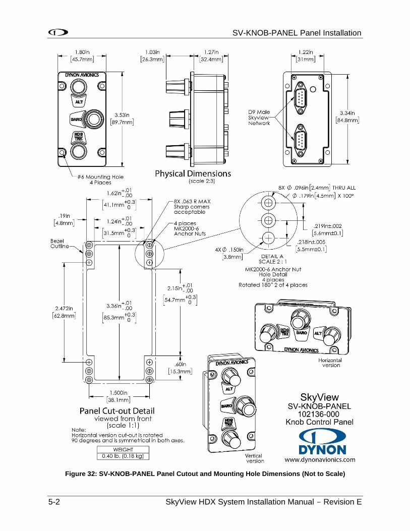
SV-KNOB-PANEL Panel Installation
5-2 SkyView HDX System Installation Manual - Revision E
Figure 32: SV-KNOB-PANEL Panel Cutout and Mounting Hole Dimensions (Not to Scale)
SV-KNOB-PANEL Panel Installation
SkyView HDX System Installation Manual - Revision E 5-3
5.2 Electrical Installation
SkyView Network
The SV-KNOB-PANEL has two (2) SkyView Network connections (D9 connectors). Both connectors are electrically identical and are internally connected. Thus, the SV-KNOB-PANEL can be installed in the SkyView Network as a “pass-through” device, or “daisy chained” from one (1) SkyView Network device, through the SV-KNOB-PANEL, to the next SkyView Network device. The SV-NET-1.5CC is an 18-inch (45.72 cm) SkyView Network cable that is ideal for such situations. The SV-AP-PANEL receives power (for operation of the buttons) from SkyView Network. Backlighting of the SV-KNOB-PANEL is controlled by the SkyView display(s).
5.2.1 Network Setup
As with all other SkyView Network devices, the SV-KNOB-PANEL must be configured into the SkyView Network:
• Go to SETUP MENU > SYSTEM SETUP > SKYVIEW NETWORK SETUP > CONFIGURE > (right click) > DETECT (button).
• The SV-KNOB-PANEL(s) will be listed.
• FINISH (button) > EXIT (button).
5.3 Post Installation Checks
• Verify the knobs work as expected.
• Verify dim commands from SkyView display dim the backlighting of the SV-KNOB-PANEL.

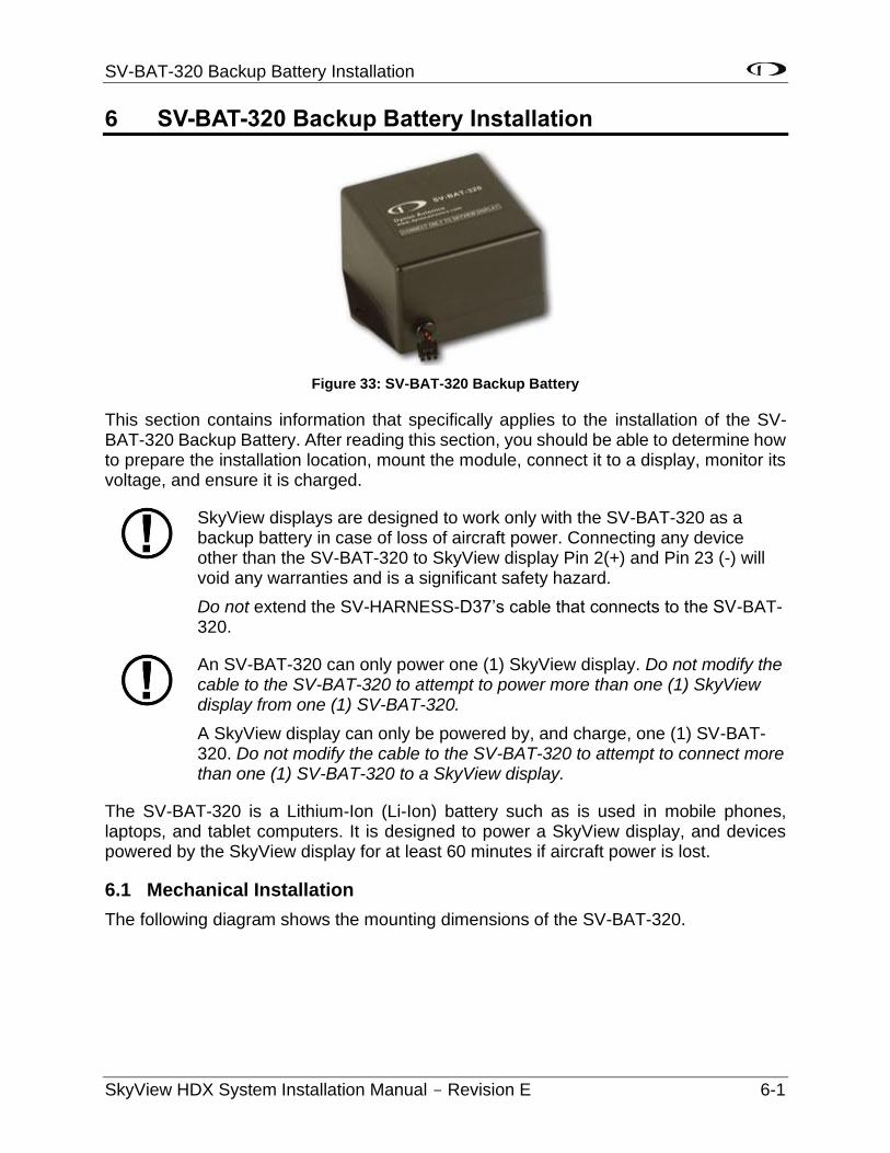
SV-BAT-320 Backup Battery Installation
SkyView HDX System Installation Manual - Revision E 6-1
6 SV-BAT-320 Backup Battery Installation
Figure 33: SV-BAT-320 Backup Battery
This section contains information that specifically applies to the installation of the SV-BAT-320 Backup Battery. After reading this section, you should be able to determine how to prepare the installation location, mount the module, connect it to a display, monitor its voltage, and ensure it is charged.
SkyView displays are designed to work only with the SV-BAT-320 as a backup battery in case of loss of aircraft power. Connecting any device other than the SV-BAT-320 to SkyView display Pin 2(+) and Pin 23 (-) will void any warranties and is a significant safety hazard.
Do not extend the SV-HARNESS-D37’s cable that connects to the SV-BAT-320.
An SV-BAT-320 can only power one (1) SkyView display. Do not modify the cable to the SV-BAT-320 to attempt to power more than one (1) SkyView display from one (1) SV-BAT-320.
A SkyView display can only be powered by, and charge, one (1) SV-BAT-320. Do not modify the cable to the SV-BAT-320 to attempt to connect more than one (1) SV-BAT-320 to a SkyView display.
The SV-BAT-320 is a Lithium-Ion (Li-Ion) battery such as is used in mobile phones, laptops, and tablet computers. It is designed to power a SkyView display, and devices powered by the SkyView display for at least 60 minutes if aircraft power is lost.
6.1 Mechanical Installation
The following diagram shows the mounting dimensions of the SV-BAT-320.
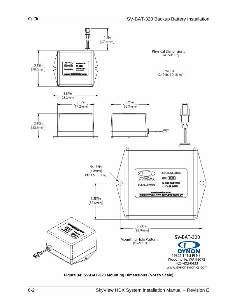
SV-BAT-320 Backup Battery Installation
6-2 SkyView HDX System Installation Manual - Revision E
Figure 34: SV-BAT-320 Mounting Dimensions (Not to Scale)
SV-BAT-320 Backup Battery Installation
SkyView HDX System Installation Manual - Revision E 6-3
6.1.1 SV-BAT-320 Location
The normal location is on the avionics tray behind the display. If the battery can not be mounted there, observe the following guidelines when choosing a location for an SV-BAT-320:
• Location should be near the rear of the SkyView display. A 24” cable is included on the SV-HARNESS-D37 for connecting the SV-BAT-320. This cable should not be extended.
• Avoid locations that are subject to severe vibration.
• Avoid locations that are subject to extended temperature ranges. The SV-BAT-320 has a narrower operating temperature range than other SkyView modules.
• Avoid locations that are subject to extreme humidity.
• Leave room for electrical connections.
Mounting hardware is not included with the SV-BAT-320. The mounting tabs on each side of the module have holes sized for #8 fasteners. Button head style AN hardware is recommended as spacing between the holes in the tabs and the body of the enclosure limits what style tool can be used to tighten certain fasteners. Follow recommended torque practices when tightening the mounting hardware (see Caution below).
The SV-BAT-320 enclosure is made of plastic that may crack if too much torque is applied to the fasteners and the mounting tabs of the SV-BAT-320. The appropriate amount of torque that should be applied is a combination of the mounting base material, its thickness, the fastener, the presence or absence of thread lock compound on the fastener, and the tolerance stack up of the diameters of the mounting hole and the fastener. Apply sufficient torque that the fasteners will not self-release, but not so much that the mounting tabs will eventually break from too much stress.
Use of ferrous fasteners in this location is acceptable. Do not rivet the SV-BAT-320 to the aircraft as this will hinder future removal if necessary.
6.2 Electrical Connection
For warranty replacement, an SV-BAT-320 that is received at Dynon Avionics with a different connector than the factory-installed connector is not eligible for warranty replacement.
Connect the SV-BAT-320 module’s connector to the mating connector on the SV-HARNESS-D37.
If you are constructing your own SkyView display harness (equivalent to the Dynon Avionics SV-HARNESS-D37), do not cut off the connector on the SV-BAT-320 to install a different connector. See Section 25 Appendix C: Wiring and Electrical Connections, Non-Dynon Avionics Wire Harness Considerations for details on the mating connector for the SV-BAT-320.
SV-BAT-320 Backup Battery Installation
6-4 SkyView HDX System Installation Manual - Revision E
6.3 Charging the SV-BAT-320
Do not attempt to charge the SV-BAT-320 using any other charging unit. Doing so may risk damaging the SV-BAT-320. The only safe method of charging an SV-BAT-320 is to connect it to a SkyView HDX display.
6.3.1 SV-BAT-320 is Automatically Charged in Flight
An SV-BAT-320 connected to a SkyView display is automatically charged by the SkyView display when there is adequate power applied to the SkyView display. If the SV-BAT-320 becomes discharged, on the next flight the SkyView display will automatically charge the SV-BAT-320. Charging, when necessary, required a minimum input voltage of 12.25 Volts supplied to the SkyView display. To prevent discharging the aircraft battery excessively (when not in flight), the SkyView display will not attempt to charge the SV-BAT-320 when the input voltage to the SkyView display is lower than 12.25 volts.
6.3.2 Charging the SV-BAT-320 on Ground or During Aircraft Construction
As with all new lithium-ion batteries, the SV-BAT-320 is manufactured, stored in inventory (Dynon Avionics, dealers, and aircraft manufacturers), and shipped in a partially-charged state. Occasionally, typically after a year or more with no charging, the SV-BAT-320 may appear to be fully discharged – the SkyView display may not be able to detect that a battery is installed.
To prevent becoming totally discharged, all lithium-ion batteries, including the SV-BAT-320, incorporate internal safety circuitry (protection mode) that will disconnect the load (SkyView display) when the lithium-ion battery’s state of charge is very low.
Prior to Software v15.0, SkyView displays could not detect when an SV-BAT-320 was in this state (protection mode due to low state of charge) and thus the SkyView display would not attempt to charge the SV-BAT-320. Software v15.0 and later incorporates an improvement to the charging algorithm; the SkyView display is able to detect this state and charge an SV-BAT-320 that is in protection mode.
As explained above, to prevent discharging the aircraft battery excessively (when not in flight), the SkyView display will not attempt to charge the SV-BAT-320 when the input voltage is lower than 12.25 volts. During aircraft construction, or if the aircraft will not be flown for an extended period, the SkyView display can charge the SV-BAT-320 if the following conditions are met:
• For each SkyView display that will be charging an SV-BAT-320, the aircraft’s battery charger must be able to supply at least 5 amps (5A) (for a 12 volt electrical system; 2.5A for a 24 volt electrical system). If you have two (2) SkyView displays with SV-BAT-320s, and you wish to charge them simultaneously, the battery charger must be capable of supplying 10A.
• Under full load (5A), the aircraft battery charger must be capable of supplying 13 volts (13V) to the SkyView display. Supplying 13V to the aircraft electrical
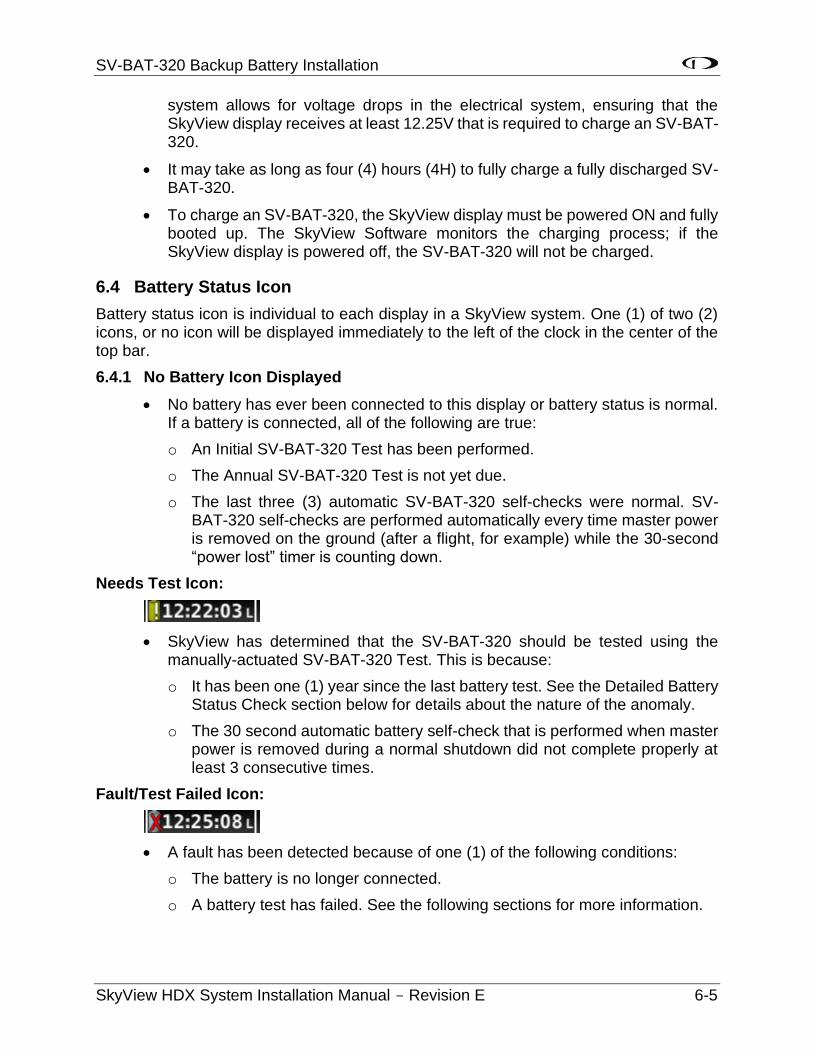
SV-BAT-320 Backup Battery Installation
SkyView HDX System Installation Manual - Revision E 6-5
system allows for voltage drops in the electrical system, ensuring that the SkyView display receives at least 12.25V that is required to charge an SV-BAT-320.
• It may take as long as four (4) hours (4H) to fully charge a fully discharged SV-BAT-320.
• To charge an SV-BAT-320, the SkyView display must be powered ON and fully booted up. The SkyView Software monitors the charging process; if the SkyView display is powered off, the SV-BAT-320 will not be charged.
6.4 Battery Status Icon
Battery status icon is individual to each display in a SkyView system. One (1) of two (2) icons, or no icon will be displayed immediately to the left of the clock in the center of the top bar.
6.4.1 No Battery Icon Displayed
• No battery has ever been connected to this display or battery status is normal. If a battery is connected, all of the following are true:
o An Initial SV-BAT-320 Test has been performed.
o The Annual SV-BAT-320 Test is not yet due.
o The last three (3) automatic SV-BAT-320 self-checks were normal. SV-BAT-320 self-checks are performed automatically every time master power is removed on the ground (after a flight, for example) while the 30-second “power lost” timer is counting down.
Needs Test Icon:
• SkyView has determined that the SV-BAT-320 should be tested using the manually-actuated SV-BAT-320 Test. This is because:
o It has been one (1) year since the last battery test. See the Detailed Battery Status Check section below for details about the nature of the anomaly.
o The 30 second automatic battery self-check that is performed when master power is removed during a normal shutdown did not complete properly at least 3 consecutive times.
Fault/Test Failed Icon:
• A fault has been detected because of one (1) of the following conditions:
o The battery is no longer connected.
o A battery test has failed. See the following sections for more information.
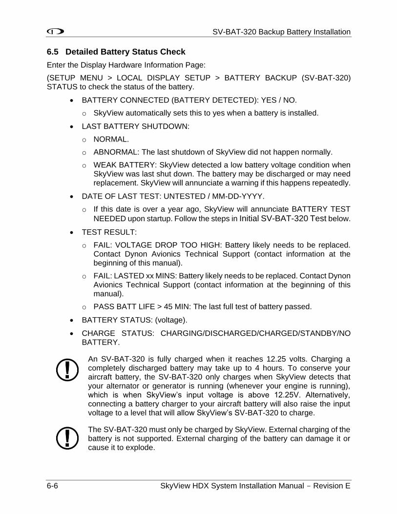
SV-BAT-320 Backup Battery Installation
6-6 SkyView HDX System Installation Manual - Revision E
6.5 Detailed Battery Status Check
Enter the Display Hardware Information Page:
(SETUP MENU > LOCAL DISPLAY SETUP > BATTERY BACKUP (SV-BAT-320) STATUS to check the status of the battery.
• BATTERY CONNECTED (BATTERY DETECTED): YES / NO.
o SkyView automatically sets this to yes when a battery is installed.
• LAST BATTERY SHUTDOWN:
o NORMAL.
o ABNORMAL: The last shutdown of SkyView did not happen normally.
o WEAK BATTERY: SkyView detected a low battery voltage condition when SkyView was last shut down. The battery may be discharged or may need replacement. SkyView will annunciate a warning if this happens repeatedly.
• DATE OF LAST TEST: UNTESTED / MM-DD-YYYY.
o If this date is over a year ago, SkyView will annunciate BATTERY TEST
NEEDED upon startup. Follow the steps in Initial SV-BAT-320 Test below.
• TEST RESULT:
o FAIL: VOLTAGE DROP TOO HIGH: Battery likely needs to be replaced. Contact Dynon Avionics Technical Support (contact information at the beginning of this manual).
o FAIL: LASTED xx MINS: Battery likely needs to be replaced. Contact Dynon Avionics Technical Support (contact information at the beginning of this manual).
o PASS BATT LIFE > 45 MIN: The last full test of battery passed.
• BATTERY STATUS: (voltage).
• CHARGE STATUS: CHARGING/DISCHARGED/CHARGED/STANDBY/NO BATTERY.
An SV-BAT-320 is fully charged when it reaches 12.25 volts. Charging a completely discharged battery may take up to 4 hours. To conserve your aircraft battery, the SV-BAT-320 only charges when SkyView detects that your alternator or generator is running (whenever your engine is running), which is when SkyView’s input voltage is above 12.25V. Alternatively, connecting a battery charger to your aircraft battery will also raise the input voltage to a level that will allow SkyView’s SV-BAT-320 to charge.
The SV-BAT-320 must only be charged by SkyView. External charging of the battery is not supported. External charging of the battery can damage it or cause it to explode.
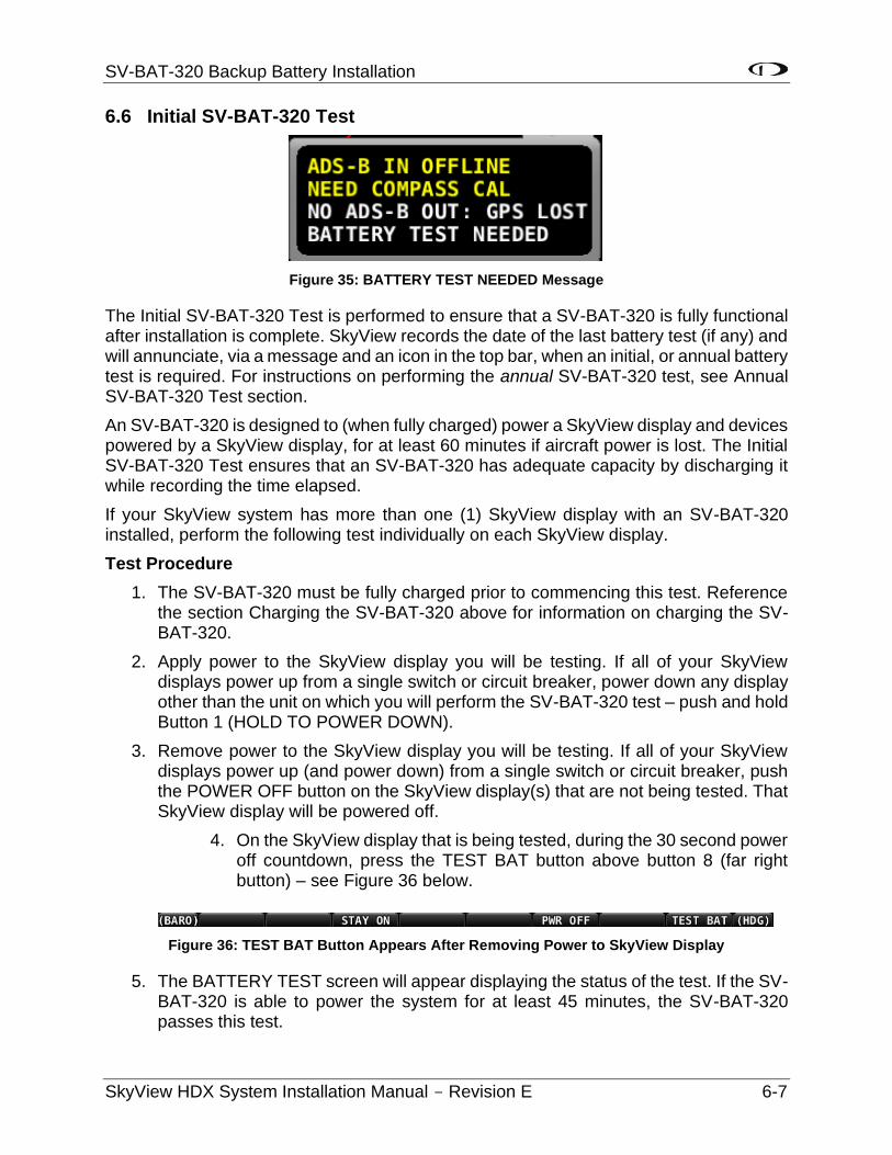
SV-BAT-320 Backup Battery Installation
SkyView HDX System Installation Manual - Revision E 6-7
6.6 Initial SV-BAT-320 Test
Figure 35: BATTERY TEST NEEDED Message
The Initial SV-BAT-320 Test is performed to ensure that a SV-BAT-320 is fully functional after installation is complete. SkyView records the date of the last battery test (if any) and will annunciate, via a message and an icon in the top bar, when an initial, or annual battery test is required. For instructions on performing the annual SV-BAT-320 test, see Annual SV-BAT-320 Test section.
An SV-BAT-320 is designed to (when fully charged) power a SkyView display and devices powered by a SkyView display, for at least 60 minutes if aircraft power is lost. The Initial SV-BAT-320 Test ensures that an SV-BAT-320 has adequate capacity by discharging it while recording the time elapsed.
If your SkyView system has more than one (1) SkyView display with an SV-BAT-320 installed, perform the following test individually on each SkyView display.
Test Procedure
1. The SV-BAT-320 must be fully charged prior to commencing this test. Reference the section Charging the SV-BAT-320 above for information on charging the SV-BAT-320.
2. Apply power to the SkyView display you will be testing. If all of your SkyView displays power up from a single switch or circuit breaker, power down any display other than the unit on which you will perform the SV-BAT-320 test – push and hold Button 1 (HOLD TO POWER DOWN).
3. Remove power to the SkyView display you will be testing. If all of your SkyView displays power up (and power down) from a single switch or circuit breaker, push the POWER OFF button on the SkyView display(s) that are not being tested. That SkyView display will be powered off.
4. On the SkyView display that is being tested, during the 30 second power off countdown, press the TEST BAT button above button 8 (far right button) – see Figure 36 below.
Figure 36: TEST BAT Button Appears After Removing Power to SkyView Display
5. The BATTERY TEST screen will appear displaying the status of the test. If the SV-BAT-320 is able to power the system for at least 45 minutes, the SV-BAT-320 passes this test.
SV-BAT-320 Backup Battery Installation
6-8 SkyView HDX System Installation Manual - Revision E
6. After the test completes (successfully, or unsuccessfully), the SkyView display will automatically power off.
7. To see the results of the test, enter the SETUP MENU > LOCAL DISPLAY SETUP > BATTERY BACKUP (SV-BAT-320) STATUS>TEST RESULTS. Make sure the TEST RESULT says PASS.
8. The BATTERY TEST can be aborted by pressing the PWR OFF button.
Repeat the test procedure for each SkyView display that has an SV-BAT-320 installed.
This test discharges the SV-BAT-320. Recharging the SV-BAT-320 after the test is recommended, either by flying for approximately four (4) hours, or using the procedure above to charge the SV-BAT-320 on the ground.
6.6.1 In the Event of Initial SV-BAT-320 Test Failure
See http://dynonavionics.com/docs/support_returns.html for the most current information on Dynon Avionics warranty terms and conditions.
Note that if an SV-BAT-320 is replaced under warranty, the defective SV-BAT-320 must be returned (at customer’s expense) to Dynon Avionics to avoid being charged full purchase price of a new SV-BAT-320.
If a new SV-BAT-320 does not pass the Initial SV-BAT-320 Test, contact Dynon Avionics Technical Support (contact information at the beginning of this manual) for further assistance. Please have the S/N of the SV-BAT-320 (printed on the SV-BAT-320 product label) available when you call. Note that warranty terms and conditions apply to a new SV-BAT-320.
6.7 SV-BAT-320 Specifications
Specifications for the SV-BAT-320 can be found in Appendix B: Specifications.
6.8 Returning an SV-BAT-320 to Dynon Avionics for Exchange (Warranty Replacement)
If it is necessary to return an SV-BAT-320 to Dynon Avionics for warranty replacement, consult with your shipping company, in your country, in advance of shipment regarding the regulations to ship a Lithium-Ion battery such as the SV-BAT-320. Regulations to ship a Lithium-Ion battery vary widely, depending on the shipping company, country, type of shipping (air, ship, ground, etc.), thus Dynon Avionics cannot offer definitive advice on shipping an SV-BAT-320, only this general guidance:
All packages containing lithium batteries are classified as Class 9 — Miscellaneous Dangerous Goods. However, packages containing small amounts of lithium may be exempted from most of the IATA and ICAO requirements if they comply with the requirements in Section II IATA (which matches Section II ICAO) Packing Instructions (PI) 965, 966, and 967 for lithium ion batteries and 968, 969 and 970 for lithium metal batteries as appropriate.
SV-BAT-320 Backup Battery Installation
SkyView HDX System Installation Manual - Revision E 6-9
For purposes of shipping, Lithium-Ion batteries manufactured for Dynon Avionics are deemed to contain minimal lithium, below thresholds that require special arrangements.
To support returning an SV-BAT-320 to Dynon Avionics for warranty replacement, a Material Safety Data Sheet (MSDS) for the SV-BAT-320 is available upon request – contact Dynon Avionics Technical Support (contact information at the beginning of this manual). Packages containing a lithium-ion battery require an associated warning labeled.

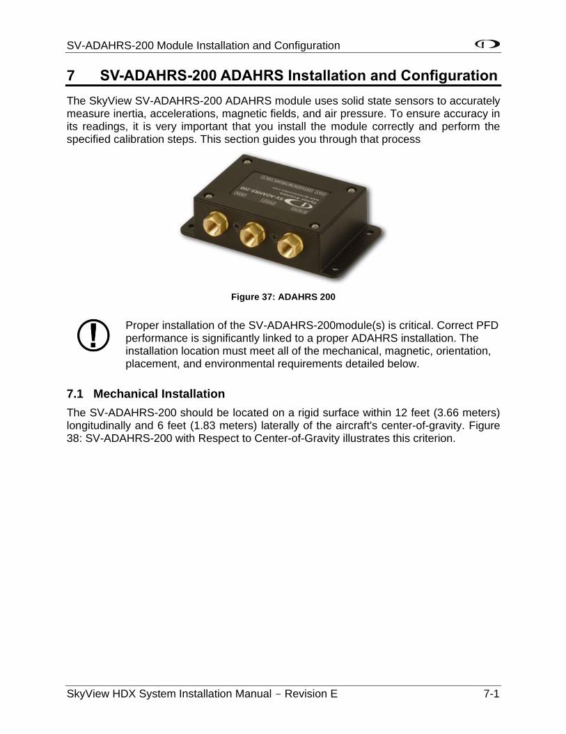
SV-ADAHRS-200 Module Installation and Configuration
SkyView HDX System Installation Manual - Revision E 7-1
7 SV-ADAHRS-200 ADAHRS Installation and Configuration
The SkyView SV-ADAHRS-200 ADAHRS module uses solid state sensors to accurately measure inertia, accelerations, magnetic fields, and air pressure. To ensure accuracy in its readings, it is very important that you install the module correctly and perform the specified calibration steps. This section guides you through that process
Figure 37: ADAHRS 200
Proper installation of the SV-ADAHRS-200module(s) is critical. Correct PFD performance is significantly linked to a proper ADAHRS installation. The installation location must meet all of the mechanical, magnetic, orientation, placement, and environmental requirements detailed below.
7.1 Mechanical Installation
The SV-ADAHRS-200 should be located on a rigid surface within 12 feet (3.66 meters) longitudinally and 6 feet (1.83 meters) laterally of the aircraft's center-of-gravity. Figure 38: SV-ADAHRS-200 with Respect to Center-of-Gravity illustrates this criterion.
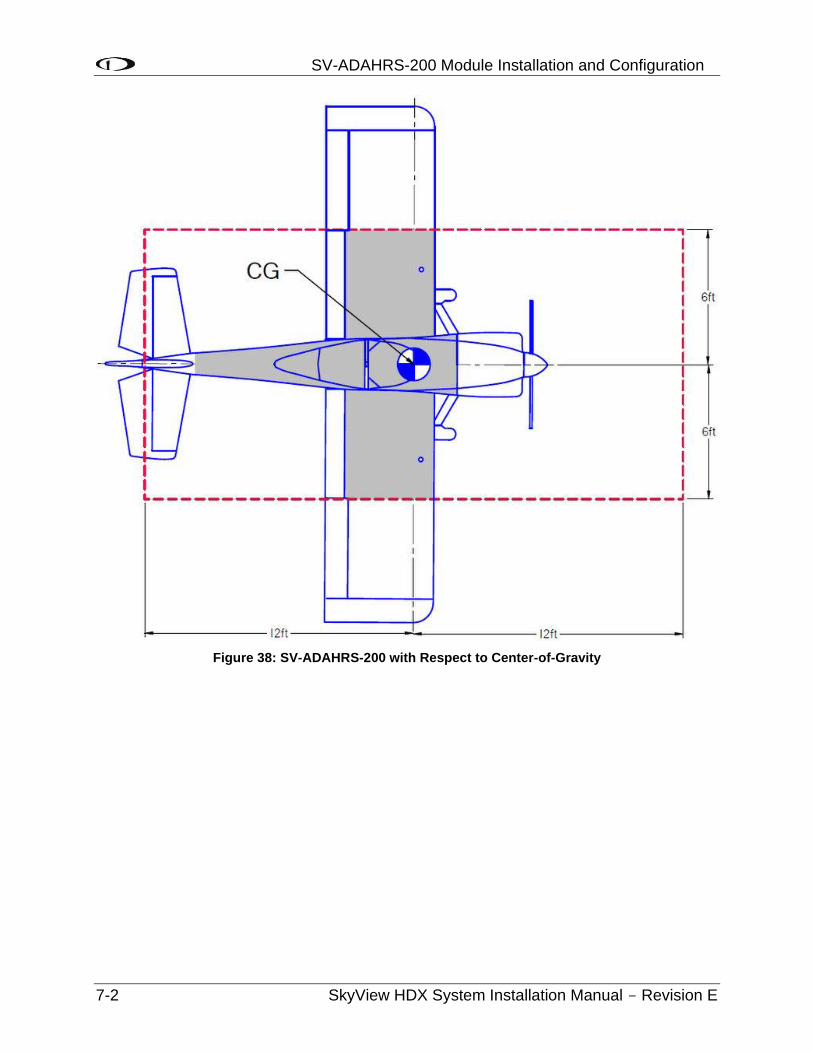
SV-ADAHRS-200 Module Installation and Configuration
7-2 SkyView HDX System Installation Manual - Revision E
Figure 38: SV-ADAHRS-200 with Respect to Center-of-Gravity
SV-ADAHRS-200 Module Installation and Configuration
SkyView HDX System Installation Manual - Revision E 7-3
Mounting requirements for the SV-ADAHRS-200:
• Must be mounted within one (1) degree of parallel to all three (3) aircraft axes,
• The pneumatic fittings must face toward the front of the aircraft,
• The mounting tabs must be towards the bottom of the aircraft, with the label towards the top of the aircraft.
Figure 39 shows the correct orientation of the ADAHRS as it would appear if you were above the aircraft, looking down at it. The module will not operate properly if it is rotated, or inverted, or in any other orientation.
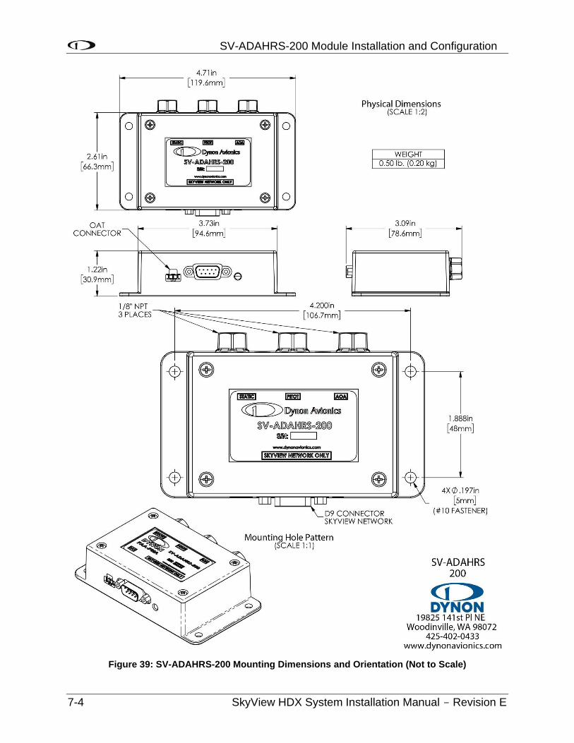
SV-ADAHRS-200 Module Installation and Configuration
7-4 SkyView HDX System Installation Manual - Revision E
Figure 39: SV-ADAHRS-200 Mounting Dimensions and Orientation (Not to Scale)
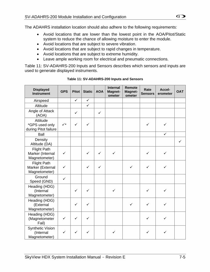
SV-ADAHRS-200 Module Installation and Configuration
SkyView HDX System Installation Manual - Revision E 7-5
The ADAHRS installation location should also adhere to the following requirements:
• Avoid locations that are lower than the lowest point in the AOA/Pitot/Static system to reduce the chance of allowing moisture to enter the module.
• Avoid locations that are subject to severe vibration.
• Avoid locations that are subject to rapid changes in temperature.
• Avoid locations that are subject to extreme humidity.
• Leave ample working room for electrical and pneumatic connections.
Table 11: SV-ADAHRS-200 Inputs and Sensors describes which sensors and inputs are used to generate displayed instruments.
Table 11: SV-ADAHRS-200 Inputs and Sensors
Displayed Instrument
GPS Pitot Static AOA Internal Magnet- ometer
Remote Magnet- ometer
Rate Sensors
Accel- erometer
OAT
Airspeed
Altitude
Angle of Attack (AOA)
Attitude *GPS used only
during Pitot failure *
Ball
Density Altitude (DA)
Flight Path Marker (Internal Magnetometer)
Flight Path Marker (External Magnetometer)
Ground Speed (GND)
Heading (HDG) (Internal
Magnetometer)
Heading (HDG) (External
Magnetometer)
Heading (HDG) (Magnetometer
Fail)
Synthetic Vision (Internal
Magnetometer)

SV-ADAHRS-200 Module Installation and Configuration
7-6 SkyView HDX System Installation Manual - Revision E
Displayed Instrument
GPS Pitot Static AOA Internal Magnet- ometer
Remote Magnet- ometer
Rate Sensors
Accel- erometer
OAT
Synthetic Vision (External
Magnetometer)
True Airspeed (TAS)
Turn Rate
Winds (Internal Magnetometer)
Winds (External Magnetometer)
To ensure that the Slip/Skid Ball will be displayed as centered during flight, the SV-ADAHRS-200 must be installed to 0° (absolute level). There is no adjustment in SkyView to electronically level the SV-ADAHRS-200. If, after installation, the Slip/Skid Ball is not centered, you will need to shim the SV-ADAHRS-200 to be 0° (absolute level). During installation, it may be necessary to use an electronic level as a “spirit” or “bubble” level may not be able to display an accurate enough degree of level.
7.2 Electrical Installation
Connect the SV-ADAHRS-200 to the SkyView network using the hardware mentioned in Section 2.11 or using equivalent hardware.
If you have to install a connector on the end of a network cable, insert all pins into the D9 connector. Refer to Section 25 Appendix C: Wiring and Electrical Connections for details on connector pinouts and wire colors.
7.3 Compass Calibration
Dynon Avionics calibrates every SV-ADAHRS-200 during manufacture. After the aircraft build is complete, an in-aircraft compass calibration must be performed. Until the on-ground or the in-flight compass calibration is performed, SkyView will display a Caution message: NEED COMPASS CAL.
Performing an In-flight Compass Calibration after the On-ground Compass Calibration can increase the accuracy of the compass’ magnetic heading. The best compass performance will be achieved by perform the on-ground compass calibration, then performing the in-flight compass calibration. It is not required that the in-flight compass calibration be performed immediately after the on-ground compass calibration.
The on-ground compass calibration requires pointing the aircraft in four (4) directions and acquiring data at each direction. An accurate method of aligning the aircraft with magnetic
SV-ADAHRS-200 Module Installation and Configuration
SkyView HDX System Installation Manual - Revision E 7-7
North, East, South, and West, such as an airport’s compass rose, is required. During the compass calibration, the aircraft’s configuration and major systems should be in a state that resembles flight conditions (i.e., the canopy should be closed, the aircraft’s pitch attitude matches SkyView’s attitude depiction, the engine should be running, and all electronic devices used in flight should be on).
Tail wheel equipped aircraft can be calibrated in their normal nose up ground attitude as long as the SkyView attitude display shows the correct corresponding nose up attitude.
A working GPS receiver with a view of the sky to acquire GPS data must be connected to the SkyView system in order to perform a compass calibration. SkyView uses GPS-derived position information to calculate magnetic intensity, declination, and variation.
During the on-ground compass calibration it is important to perform the compass calibration in an area that has been verified to be magnetically neutral. The presence of steel reinforcement (rebar), electrical power lines under the tarmac, or other natural deposits of ferrous metals can result in an inaccurate compass calibration. Airport compass roses are usually verified to be magnetically neutral and thus are often a good location for performing a compass calibration.
For more information on this issue see FAA Notice Number: NOTC4031: https://www.faasafety.gov/files/notices/2012/Aug/CAUTION_TLP_031612_Rev10.pdf
7.3.1 On-ground Compass Calibration Procedure:
1. Turn on the SkyView system and allow it to warm up for a minimum of 5 minutes.
2. Move the aircraft into position so that it is convenient to orient it in the four (4) cardinal directions.
3. Enter the Setup Menu on the SkyView display and go to the Compass Calibration Wizard (SETUP MENU > HARDWARE CALIBRATION > ADAHRS CALIBRATION > COMPASS CALIBRATION). Note - GPS data on the Compass Calibration Page must be green. If it is red, GPS data is not valid.
4. Orient the aircraft to North, South, East, or West.
5. When the aircraft is stable at the chosen orientation, push the button indicating the direction the aircraft is oriented in. Example – when the aircraft is pointed North, push the NORTH button.
6. Wait for data collection to reach 100%.
7. Rotate to the next cardinal direction and repeat steps 4, 5, and 6 for any remaining headings.
SV-ADAHRS-200 Module Installation and Configuration
7-8 SkyView HDX System Installation Manual - Revision E
8. If there is a SV-ADAHRS-200 installed, the Compass Calibration is performed simultaneously. If the Compass Calibration fails on only one (1) of the units, a message will appear: CALIBRATION FAILED – S/N xxxx
9. CALIBRATION COMPLETE appears when calibration is complete. Press FINISH to return to menu navigation mode.
7.3.2 In-flight Compass Calibration Procedure:
The in-flight compass calibration should be conducted on a clear, VFR day. Before commencing the compass calibration, ensure that you have adequate altitude, clear weather, no traffic, no obstructions in the flight path, great visibility, no airspace conflicts, etc. It is recommended that clearing turns be performed before executing each procedure.
It is recommended that you bring someone along for the in-flight compass calibration procedure. At times the pilot’s attention will be divided between documentation, configuring SkyView, and maintaining situational awareness.
Confine the flying for the in-flight compass calibration to a specific area to minimize variations in the earth’s magnetic field during the calibration process (IE, don’t combine the in-flight compass calibration with a cross-country flight).
While the in-flight compass calibration is optional, it will likely improve the dynamic performance of the heading indications in many aircraft. It is especially recommended in aircraft where the SV-ADAHRS-200 was, by necessity, installed in an area of the plane that was not entirely clear of magnetic interference. This is particularly true in steel framed aircraft.
The best compass performance will be achieved by performing the in-flight compass calibration after the on-ground compass calibration has been performed.
1. If you have two (2) SkyView displays, the in-flight compass calibration can be performed from either display.
2. After observing the cautions above, push buttons 7+8 to enter the IN FLIGHT SETUP MENU. Note – this menu is not accessible while on the ground.
3. Select COMPASS CALIBRATION.
4. Right-click the knob to enter the in-flight COMPASS CALIBRATION menu. You will see a screen similar to this:
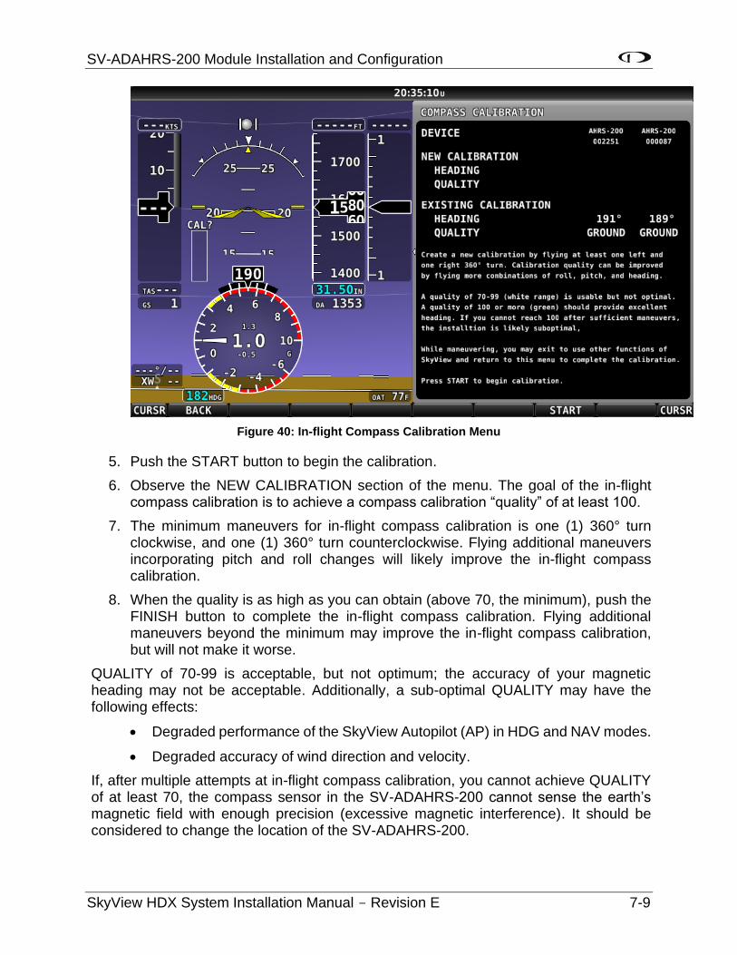
SV-ADAHRS-200 Module Installation and Configuration
SkyView HDX System Installation Manual - Revision E 7-9
Figure 40: In-flight Compass Calibration Menu
5. Push the START button to begin the calibration.
6. Observe the NEW CALIBRATION section of the menu. The goal of the in-flight compass calibration is to achieve a compass calibration “quality” of at least 100.
7. The minimum maneuvers for in-flight compass calibration is one (1) 360° turn clockwise, and one (1) 360° turn counterclockwise. Flying additional maneuvers incorporating pitch and roll changes will likely improve the in-flight compass calibration.
8. When the quality is as high as you can obtain (above 70, the minimum), push the FINISH button to complete the in-flight compass calibration. Flying additional maneuvers beyond the minimum may improve the in-flight compass calibration, but will not make it worse.
QUALITY of 70-99 is acceptable, but not optimum; the accuracy of your magnetic heading may not be acceptable. Additionally, a sub-optimal QUALITY may have the following effects:
• Degraded performance of the SkyView Autopilot (AP) in HDG and NAV modes.
• Degraded accuracy of wind direction and velocity.
If, after multiple attempts at in-flight compass calibration, you cannot achieve QUALITY of at least 70, the compass sensor in the SV-ADAHRS-200 cannot sense the earth’s magnetic field with enough precision (excessive magnetic interference). It should be considered to change the location of the SV-ADAHRS-200.
SV-ADAHRS-200 Module Installation and Configuration
7-10 SkyView HDX System Installation Manual - Revision E
7.4 PFD-Related Settings
Once the physical ADAHRS installation is complete, it may be necessary to configure PFD-related ADAHRS settings for the SkyView system. All ADAHRS settings are automatically shared between displays in multi-display systems.
7.4.1 Aircraft Icon
The airplane symbol at the center of the compass rose on the PFD Page, and the center of MAP Page can be changed. There are a variety of airplane types available, including “Fighter”, “Jumbo”, and “Twin”, and more. The symbol can be set in SYSTEM SETUP > AIRCRAFT INFORMATION > AIRCRAFT ICON. There is no “preview” of the symbol – change it and see how you like it in the PFD and the MAP.
7.4.2 Measurement Units
Set altitude, distance and speed, temperature, barometer, and pressure measurement units as detailed in Section 21.5.8: How to Configure Units of Measure.
7.4.3 Airspeed Limitations
Use the values on this page to set IAS tape colors. Set V-speed (e.g., stall speed in landing configuration) thresholds on the Airspeed Limitations Page (SETUP MENU > PFD SETUP > AIRSPEED LIMITATIONS). If your aircraft limitations are expressed in TAS rather than IAS, set Vne EXPRESSED AS: TAS.
If you do set Vne EXPRESSED AS: TAS, this will affect the Autopilot Pitch Axis MAXIMUM AIRSPEED.
The values on this page are default values that act as placeholders. You must adjust these values to work with your aircraft for any colors to show up on the IAS tape and also to be able to calibrate the autopilot servos.
7.4.4 Vertical Speed Scale
Set the vertical speed scale on the Vertical Speed Scale Page (SETUP MENU > PFD SETUP > VERTICAL SPEED SCALE).
7.4.5 G Meter
Go to this page (SETUP MENU > PFD SETUP > G METER) to configure the G meter.
The pop-up thresholds are G values that, when exceeded, will cause the G meter to display automatically. The G meter replaces the HSI when it is displayed. In addition to popping up automatically, the G meter can be manually toggled on and off using the PFD > G METER button. If you do not want the G meter to ever be displayed automatically, set the positive pop-up threshold value very high and the negative pop-up threshold value very low.
You can also set yellow and red cautionary ranges of the G meter here, and whether or not the max/min recorded G’s are reset at each SkyView boot-up.
SV-ADAHRS-200 Module Installation and Configuration
SkyView HDX System Installation Manual - Revision E 7-11
7.5 Other ADAHRS Calibrations
7.5.1 Altitude Offest
There is a single point altitude adjustment, located in SETUP MENU > HARDWARE CALIBRATION > ADAHRS CALIBRATION > ALTITUDE OFFSET that adjusts SkyView’s barometric altimeter. This adjustment affects both the displayed altitude and the encoded altitude that is sent to other devices. It should only be adjusted if altitude is found to be incorrect (by comparing it against a known source or field elevation, after the BARO setting has been set to correctly to known atmospheric conditions) after SkyView has fully warmed up.
7.5.2 Zero Pressure IAS / AoA Calibration
This calibration is located in SETUP MENU > HARDWARE CALIBRATION > ADAHRS CALIBRATION > ZERO PRESSURE / AOA CALIBRATION.
NOTE: Perform this calibration even if airplane is not equipped with an AoA Probe to properly set zero IAS.
This calibration routine samples Pitot, Static, and AOA pressures in a windless environment to allow SkyView to provide the best possible Indicated Airspeed (IAS) readings at very low airspeeds, and the best possible Angle of Attack (AOA). Ideally, perform this calibration before performing an (in-air) AOA calibration. After performing these two (2) steps, in the future, performing a ZERO PRESSURE IAS/AOA CALIBRATION should restore both airspeed and AOA performance without requiring a full AOA calibration.
It is important that this calibration is done in an absolutely windless environment, such as a closed hangar. Additionally, before performing this calibration, cover the Pitot, Static, and AOA ports with a sock or cloth to minimize airflow WITHOUT putting any air pressure on the Pitot, Static, or AOA ports.
7.6 Pitot / Static Checks
Dynon Avionics SV-ADAHRS-200 use airspeed in the calculation of attitude (or GPS ground speed when airspeed is unavailable). The internal rate sensors are monitored and calibrated in flight using feedback from the accelerometers and from airspeed to achieve a highly accurate attitude solution.
When a pitot or static test is performed the sensors in the SV-ADAHRS-200 are being exposed to dynamics that are impossible to achieve in a real aircraft flight environment, namely, large airspeed changes without the accompanying accelerations and rotations. This false condition will cause a well-calibrated unit to incorrectly adjust its calibration. Furthermore, when a unit is in a test situation a change in applied pitot or static pressure will cause the attitude to pitch up or down. This is expected.
Performing the following pitot and static test procedure to a Dynon Avionics SV-ADAHRS-200 will prevent problems with the unit’s performance in flight.
7.6.1.1 Test Instructions
• Ensure SkyView is warmed up during each test reading.
• SkyView should be powered off when changing pressures.
SV-ADAHRS-200 Module Installation and Configuration
7-12 SkyView HDX System Installation Manual - Revision E
• Keep aircraft still (do not move) when pressure is applied.
Steps:
1. The aircraft itself should be temperature stable. For example, if the aircraft is moved from outside in the sun to a hangar for testing, tests should not be started until the airplane has stabilized at the hangar temperature.
2. Turn SkyView on and let it warm up until the altitude reading is stabilized. This period should be at least 5 minutes, but may take longer depending on environmental conditions.
3. Turn SkyView off.
4. While SkyView is off, apply the pressure required by your test to pitot and/or static port via your test equipment.
5. Turn on SkyView (external or internal battery power is acceptable). Keep aircraft still while SkyView is powered on. Do not adjust the pitot or static pressures being applied to the ADAHRS while it is powered on.
6. Verify airspeed and/or altitude reading.
7. Turn SkyView off (using button 1 is a good option for this operation).
8. Repeat steps 4-7 for each required pressure point in the test.
See related procedure:
SV-XPNDR-261 Transponder Installation and Configuration, Performing Transponder Checks.

SV-MAG-236 Remote Magnetometer Installation and Configuration
SkyView HDX System Installation Manual - Revision E 8-1
8 SV-MAG-236 Remote Magnetometer Installation
The SV-MAG-236 provides SkyView with the magnetic heading data. To minimize the possibility of magnetic interference from the connector assembly, the SV-MAG-236 uses an 18-inch integral cable, so that metal connector is removed from the magnetometer sensor.
Figure 41: SV-MAG-236 (Photo)
8.1 Mechanical Installation
The most critical factor in the SV-MAG-236 being able to accurately sense magnetic heading is for it to be installed in an area of the plane that is magnetically benign.
Given that it may be difficult or impossible to avoid all sources of magnetic interference, it is possible to characterize and compensate for small, static magnetic fields with calibration. Calibration cannot, however, compensate for dynamic magnetic fields (e.g., AC currents, non-constant DC currents, and non-stationary ferrous material such as electric turn coordinators and control surfaces). Thus, you must avoid mounting the module close to sources of dynamic magnetic fields, avoid wires that carry large amounts of current, and use non-magnetic fasteners for installation (see caution below). Dynon Avionics’ general rule of thumb is that 1 to 2 feet (30.5 cm and 61 cm) between the module and sources of magnetic fields is generally good enough, but 2 (61 cm) or more feet is better.
Stainless steel mounting hardware is not always non-magnetic, and thus is not recommended. The best type of mounting hardware (screws, bolts, washers, AND nuts) to install the SV-MAG-236 is brass.
If you use a magnet to test whether possible interfering materials are non-magnetic, do not actually touch the magnet to the material you are testing, as this contact can cause the material you are testing to become magnetized.
SV-MAG-236 Remote Magnetometer Installation and Configuration
8-2 SkyView HDX System Installation Manual - Revision E
Move a handheld compass throughout the space surrounding your intended location to get a rough idea of the suitability of the area. Note that this test should be done with major aircraft systems operating (e.g., strobe lights and radios on) because some systems can cause magnetic interference. If the compass needle deviates significantly from magnetic North or cycles back and forth, the location is not ideal for SV-MAG-236 installation.
The following diagram shows the important mounting dimensions of the SV-MAG-236.
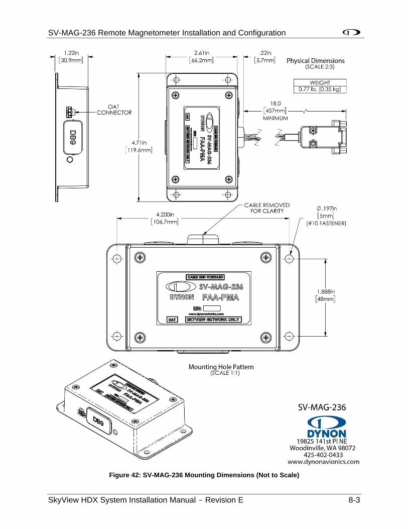
SV-MAG-236 Remote Magnetometer Installation and Configuration
SkyView HDX System Installation Manual - Revision E 8-3
Figure 42: SV-MAG-236 Mounting Dimensions (Not to Scale)
SV-MAG-236 Remote Magnetometer Installation and Configuration
8-4 SkyView HDX System Installation Manual - Revision E
As with the SV-ADAHRS-200, an SV-MAG-236 should be mounted within one (1) degree of parallel to all three (3) aircraft axes. The SV-MAG-236 should be oriented such that:
• The SV-MAG-236’s mounting tabs must be oriented towards the bottom of the aircraft.
• The label on the SV-MAG-236’s must be oriented towards the top of the aircraft.
• The side of the SV-MAG-236 where the cable exists must be oriented towards the nose of the aircraft (as noted on the label of the unit – CABLE END FORWARD).
• The side of the SV-MAG-236 with the LED indicator must be oriented towards the rear of the aircraft.
The SV-MAG-236 will not be able to indicate correct heading if it is rotated or inverted in any other orientation.
The SV-MAG-236 must be installed in the same orientation as the SV-ADAHRS-200. The SV-ADAHRS-200 is required to be level, and the SV-MAG-236 is also. If the SV-ADAHRS-200 is installed with a pitch other than 0°, the SV-MAG-236 must be installed with the same pitch. As with the SV-ADAHRS-200, it may be necessary to use an electronic level as a “spirit” or “bubble” level may not be able to display an accurate enough degree of level.
Dynon Avionics does not provide mounting hardware with SV-MAG-236. The mounting tabs on each side of the module have holes sized for #10 fasteners, but it is up to the installer to decide how the SV-MAG-236 will be secured to the aircraft.
For best performance, it is recommended that button-head style non-ferrous (brass recommended) fasteners be used to install the SV-MAG-236 in this location. Follow recommended torque practices when tightening the mounting hardware. Do not rivet the SV-MAG-236 to the aircraft as this will hinder future removal if necessary.
Do not use a magnetic driver when installing the SV-MAG-236. Doing so has the potential to affect the factory magnetic calibration.
8.2 SV-OAT-340 Connected to SV-MAG-236
The SV-ADAHRS-200 includes an SV-OAT-340 and can be used with the SV-MAG-236.
Only one (1) SV-OAT-340 is required in a SkyView system. The SV-OAT-340 can be connected to an SV-ADAHRS-200, or an SV-MAG-236. In a SkyView System which has an SV-ADAHRS-200, and an SV-MAG-236, it is possible to have a total of three (2) SV-OAT-340s, but only one (1) SV-OAT-340 is used by the system at one (1) time. If more than one (1) SV-OAT-340 is installed, the system “chooses” which of the three (2) to use for OAT.
SV-MAG-236 Remote Magnetometer Installation and Configuration
SkyView HDX System Installation Manual - Revision E 8-5
For example, if the SV-ADAHRS-200 is installed in an area of the plane where it is inconvenient to route the SV-OAT-340 wiring, and the SV-MAG-236 is more accessible to the SV-OAT-340, just connect the SV-OAT-340 to the SV-MAG-236 (instead of to the SV-ADAHRS-200).
• Because the SV-OAT-340 is optional for the SV-MAG-236, installation instructions are not included in this section (see Section 9 SV-OAT-340 OAT Sensor Installation).
8.3 Electrical Installation
Connect the SV-MAG-236 to the SkyView network using a SkyView Network Cable. To minimize any potential magnetic interference from the connector, it is recommended to not locate the connector near the SV-MAG-236. SkyView Network cables made by Dynon Avionics are available in various lengths, including 6 feet (1.83 m), 10 feet (3.05 m), 15 feet (4.57 m), 20 feet (6.1 m), 25 feet (7.62 m), and 30 feet (9.14 m).
If you have to install a connector on the end of a network cable, insert all pins into the D9 connector. Refer to Section 25 Appendix C: Wiring and Electrical Connections. for details on connector pinouts and wire colors.
Remember to configure the network as described in the Network Setup and Status section after connecting all modules to a display.
When a NETWORK CONFIGURATION is performed, the internal magnetometer of the SV-ADAHRS-200 (and SV-ADAHRS-201, if installed) is disabled.
When an SV-MAG-236 is installed in a SkyView system, if the SV-MAG-236 fails or is disconnected, GPS Ground Track (GND TRK) is substituted for magnetic heading throughout the system.
8.4 Compass Calibration
Dynon Avionics calibrates every SV-MAG-236 during manufacture. After the aircraft build is complete, an in-aircraft compass calibration must be performed. Until the on-ground or the in-flight compass calibration is performed, SkyView will display a Caution message: NEED COMPASS CAL.
Performing the in-flight compass calibration after the on-ground compass calibration can increase the accuracy of the compass’ magnetic heading. The best compass performance will be achieved by performing the on-ground compass calibration, then performing the in-flight compass calibration. It is not required that the in-flight compass calibration be performed immediately after the on-ground compass calibration.
The on-ground compass calibration requires pointing the aircraft in four (4) directions and acquiring data at each direction. An accurate method of aligning the aircraft with magnetic North, East, South, and West, such as an airport’s compass rose, is required. During the compass calibration, the aircraft’s configuration and major systems should be in a state
SV-MAG-236 Remote Magnetometer Installation and Configuration
8-6 SkyView HDX System Installation Manual - Revision E
that resembles flight conditions (i.e., the canopy should be closed, the aircraft’s pitch attitude matches SkyView’s attitude depiction, the engine should be running, and all electronic devices used in flight should be on).
Tail wheel equipped aircraft can be calibrated in their normal nose up ground attitude as long as the SkyView attitude display shows the correct corresponding nose up attitude.
A working GPS receiver with a view of the sky to acquire GPS data must be connected to the SkyView system in order to perform a compass calibration. SkyView uses GPS-derived position information to calculate magnetic intensity, declination, and variation.
During the on-ground compass calibration it is important to perform the compass calibration in an area that has been verified to be magnetically neutral. The presence of steel reinforcement (rebar), electrical power lines under the tarmac, or other natural deposits of ferrous metals can result in an inaccurate compass calibration. Airport compass roses are usually verified to be magnetically neutral and thus are often a good location for performing a compass calibration.
For more information on this issue see FAA Notice Number: NOTC4031: https://www.faasafety.gov/files/notices/2012/Aug/CAUTION_TLP_031612_Rev10.pdf
8.4.1 On-ground Compass Calibration Procedure:
1. If you have two (2) SkyView displays, the in-flight compass calibration can be performed from either display.
2. Turn on the SkyView system and allow it to warm up for a minimum of 5 minutes.
3. Move the aircraft into position so that it is convenient to orient it in the four (4) cardinal directions.
4. Enter the Setup Menu on the SkyView display and go to the Compass Calibration Wizard (SETUP MENU > HARDWARE CALIBRATION > ADAHRS CALIBRATION > COMPASS CALIBRATION). Note - GPS data on the Compass Calibration Page must be green. If it is red, GPS data is not valid. You will see a screen similar to this:
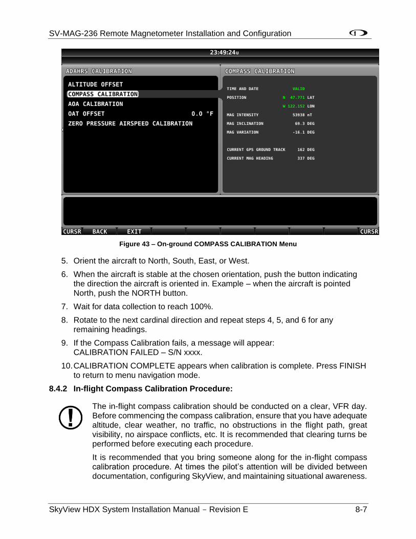
SV-MAG-236 Remote Magnetometer Installation and Configuration
SkyView HDX System Installation Manual - Revision E 8-7
Figure 43 – On-ground COMPASS CALIBRATION Menu
5. Orient the aircraft to North, South, East, or West.
6. When the aircraft is stable at the chosen orientation, push the button indicating the direction the aircraft is oriented in. Example – when the aircraft is pointed North, push the NORTH button.
7. Wait for data collection to reach 100%.
8. Rotate to the next cardinal direction and repeat steps 4, 5, and 6 for any remaining headings.
9. If the Compass Calibration fails, a message will appear: CALIBRATION FAILED – S/N xxxx.
10. CALIBRATION COMPLETE appears when calibration is complete. Press FINISH to return to menu navigation mode.
8.4.2 In-flight Compass Calibration Procedure:
The in-flight compass calibration should be conducted on a clear, VFR day. Before commencing the compass calibration, ensure that you have adequate altitude, clear weather, no traffic, no obstructions in the flight path, great visibility, no airspace conflicts, etc. It is recommended that clearing turns be performed before executing each procedure.
It is recommended that you bring someone along for the in-flight compass calibration procedure. At times the pilot’s attention will be divided between documentation, configuring SkyView, and maintaining situational awareness.
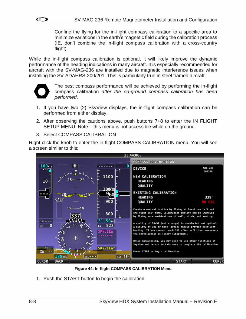
SV-MAG-236 Remote Magnetometer Installation and Configuration
8-8 SkyView HDX System Installation Manual - Revision E
Confine the flying for the in-flight compass calibration to a specific area to minimize variations in the earth’s magnetic field during the calibration process (IE, don’t combine the in-flight compass calibration with a cross-country flight).
While the in-flight compass calibration is optional, it will likely improve the dynamic performance of the heading indications in many aircraft. It is especially recommended for aircraft with the SV-MAG-236 are installed due to magnetic interference issues when installing the SV-ADAHRS-200/201. This is particularly true in steel framed aircraft.
The best compass performance will be achieved by performing the in-flight compass calibration after the on-ground compass calibration has been performed.
1. If you have two (2) SkyView displays, the in-flight compass calibration can be performed from either display.
2. After observing the cautions above, push buttons 7+8 to enter the IN FLIGHT SETUP MENU. Note – this menu is not accessible while on the ground.
3. Select COMPASS CALIBRATION
Right-click the knob to enter the in-flight COMPASS CALIBRATION menu. You will see a screen similar to this:
Figure 44: In-flight COMPASS CALIBRATION Menu
1. Push the START button to begin the calibration.

SV-MAG-236 Remote Magnetometer Installation and Configuration
SkyView HDX System Installation Manual - Revision E 8-9
2. Observe the NEW CALIBRATION section of the menu. The goal of the in-flight compass calibration is to achieve a compass calibration “quality” of at least 100.
3. The minimum maneuvers for in-flight compass calibration is one (1) 360° turn clockwise, and one (1) 360° turn counterclockwise. Flying additional maneuvers incorporating pitch and roll changes will likely improve the in-flight compass calibration.
4. When the quality is as high as you can obtain (above 70, the minimum), push the FINISH button to complete the in-flight compass calibration. Flying additional maneuvers beyond the minimum may improve the in-flight compass calibration, but will not make it worse.
QUALITY of 70-99 is acceptable, but not optimum; the accuracy of your magnetic heading may not be acceptable. Additionally, a sub-optimal QUALITY may have the following effects:
• Degraded performance of the SkyView Autopilot (AP) in HDG and NAV modes.
• Degraded accuracy of wind direction and velocity.
If, after multiple attempts at in-flight compass calibration, you cannot achieve QUALITY of at least 70, the SV-MAG-236 cannot sense the earth’s magnetic field with enough precision (excessive magnetic interference). It should be considered to change the location of the SV-MAG-236.

SV-OAT-340 OAT Sensor Installation
SkyView HDX System Installation Manual - Revision E 9-1
9 SV-OAT-340 OAT Sensor Installation
The SV-OAT -340 Sesnor measures the Outside Air Temperature, and provides this data to SkyView by connecting to either the SV-ADAHRS-200 ADAHRS module or the SV-MAG-320 Remote Magnetometer.
9.1 Mechanical Installation
The SV-OAT-340 is an outside air temperature sensor. In order for it work properly, it must be able to measure air temperature accurately. Avoid exposing the sensor to sources of heat that would interfere with outside air temperature readings such as:
• Direct sunlight.
• Engine heat and exhaust.
• Aircraft interior (back side of sensor).
• Heated air from the cabin exiting from an open window or cabin air exhaust port.
The installation area should have space for a nut and wires on the back side of the sensor. It is acceptable to extend or reduce the wire length if necessary. Reduce the wire length by cutting out the desired length from the middle of the wires and splicing together the remaining ends.

SV-MAG-236 Remote Magnetometer Installation
9-2 SkyView HDX System Installation Manual - Revision E
Figure 45: SV-OAT-340 Mounting Dimensions (Not to Scale)
If there is a backup ADAHRS in the SkyView system, it is acceptable to install a backup OAT sensor a few inches away from the primary sensor. Consider running primary and
SV-OAT-340 OAT Sensor Installation
SkyView HDX System Installation Manual - Revision E 9-3
backup OAT sensor wiring together. Tape sensor wire pairs together to avoid confusion later.
Do not insert the pins on the ends of the OAT sensor wires into the included connector housing until you are done running sensor wiring through the aircraft.
The SV-OAT-340 connector is small and easily lost. One (1) technique to avoid losing this connector is to temporarily tape it to the top of the SV-ADAHRS-200 until it’s time to insert the wires into the connector.
On the outside of the fuselage:
1. Drill a 3/8” hole at the installation location.
2. Feed the wires of the sensor through the hole.
3. Feed the body of the sensor through the hole.
On the inside of the fuselage (consider getting assistance for some of the steps below because it may be difficult to be simultaneously on the inside and outside of the fuselage):
1. Feed the nylon washer over the cable.
2. Feed the nylon nut over the cable.
3. Feed the nylon washer over the body of the sensor.
4. Hand-thread the nylon nut onto the threaded body of the sensor. At this point, the nylon washer should be sandwiched between the nylon nut and the inside of the fuselage.
5. Carefully tighten the nut using the 9/16” wrench.
9.2 Electrical Installation
Route and secure the sensor wires to the location of the either the SV-ADAHRS-200 ADAHRS module or the SV-MAG-320 Remote Magnetometer. Keep wires away from radios, ignition, and other noisy electronics.
Carefully insert the pins on the wires into the connector housing. Pins are not polarized and lock into place when inserted correctly.
Connect the sensor to the SV-ADAHRS-200 ADAHRS module or the SV-MAG-320 Remote Magnetometer as appropriate.

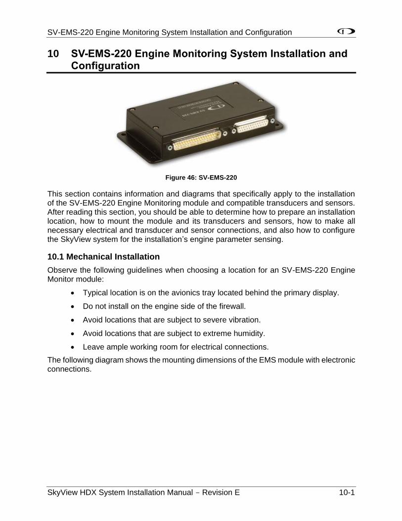
SV-EMS-220 Engine Monitoring System Installation and Configuration
SkyView HDX System Installation Manual - Revision E 10-1
10 SV-EMS-220 Engine Monitoring System Installation and Configuration
Figure 46: SV-EMS-220
This section contains information and diagrams that specifically apply to the installation of the SV-EMS-220 Engine Monitoring module and compatible transducers and sensors. After reading this section, you should be able to determine how to prepare an installation location, how to mount the module and its transducers and sensors, how to make all necessary electrical and transducer and sensor connections, and also how to configure the SkyView system for the installation’s engine parameter sensing.
10.1 Mechanical Installation
Observe the following guidelines when choosing a location for an SV-EMS-220 Engine Monitor module:
• Typical location is on the avionics tray located behind the primary display.
• Do not install on the engine side of the firewall.
• Avoid locations that are subject to severe vibration.
• Avoid locations that are subject to extreme humidity.
• Leave ample working room for electrical connections.
The following diagram shows the mounting dimensions of the EMS module with electronic connections.
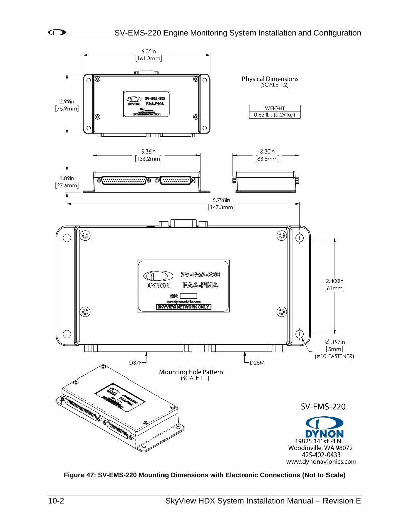
SV-EMS-220 Engine Monitoring System Installation and Configuration
10-2 SkyView HDX System Installation Manual - Revision E
Figure 47: SV-EMS-220 Mounting Dimensions with Electronic Connections (Not to Scale)
SV-EMS-220 Engine Monitoring System Installation and Configuration
SkyView HDX System Installation Manual - Revision E 10-3
Dynon Avionics does not include mounting hardware for use with the SV-EMS-220. The mounting tabs on each side of the module have holes sized for #10 fasteners, but it is up to the installer to decide how the EMS will be secured to the aircraft. Use of ferrous fasteners in this location is acceptable as the EMS is not adversely affected by small magnetic fields. We recommend button head style AN hardware as spacing between the holes in the tabs and the body of the enclosure will limit what style tool can be used to tighten certain fasteners. If you will be installing dual SV-EMS-220, it is acceptable to stack the two units. Follow recommended torque practices when tightening the mounting hardware. Do not rivet the SV-EMS-220 to the aircraft as this will hinder future removal if necessary.
10.2 Electrical Installation
Connect the EMS module to the SkyView network using the hardware mentioned in Section 2.11 or using equivalent hardware.
Refer to Section 25 Appendix C: Wiring and Electrical Connections for details on connector pinouts and wire colors.
Wire the EMS Systems and Sensors according to 103488-000 Wiring Diagram Typical HDX Dual Display document.
10.2.1 SkyView EMS Sensor Definition and Configuration Files
The SkyView EMS utilizes a file to define sensor behavior and a file to map those sensors to pins on the SV-EMS-220 and configure the sensors’ onscreen visual representations or widgets. The sensor definition file is preloaded onto all SkyView displays during manufacture and may need to be updated. The sensor mapping, and configuration file is not preloaded onto displays and must be downloaded and installed by the user. Reference the EMS Sensor Definitions, Mapping, and Settings Section for more information.
10.2.2 SV-EMS-220 Wire Harnesses
Engine and environmental sensors and transducers are connected to the SV-EMS-220 via two (2) connectors on the module: one (1) D37M and D25F. Dynon Avionics offers premade wire harnesses which break out the pins on these connectors and it is highly recommended that installers use these wire harnesses. Table 12 below lists these wire harnesses and their respective connections to the SV-EMS-220.
Table 12: Dynon Avionics EMS Wire Harnesses
Dynon Avionics P/N Description Mates with…
503424-000 EMS D37F Main Sensor Harness SV-EMS-220 D37M
503528-000 EMS D25M EGT/CHT 4-cylinder
Thermocouple Wire Harness SV-EMS-220 D25F
A typical SV-EMS-220 installation will utilize one (1) EMS 37-pin Main Sensor Harness and one (1) of thermocouple wire harness. Choose a thermocouple wire harness based on the number of EGTs and/or CHTs that need to be monitored.
SV-EMS-220 Engine Monitoring System Installation and Configuration
10-4 SkyView HDX System Installation Manual - Revision E
The EMS 37-pin Main Sensor Harness includes a 9-pin connector that is wired to pins 11 (Orange wire), 12 (Yellow wire), and 30 (Black wire). This connector is used for other Dynon Avionics products, but is not used in SkyView installations. Thus, the 9-pin connector should be removed to use these wires for connecting sensors to the SV-EMS-220. Remove the connector by cutting the three (3) wires close to the 9-pin connector.
The EMS 37-pin Main Sensor Harness (Dynon Avionics P/N 100399-000) may be wired with blue and green wires on pins 36 and 37, respectively. If you are going to use pins 36 and 37 for a thermocouple input such as a CHT or EGT (this is not possible on the SV-EMS-221 that is used with the Rotax 912 iS, as these wires are reserved for CAN communications), the blue and green wires should be removed and replaced with the appropriate type of thermocouple wire for thermocouple functionality on pins 36 and 37. If you are not going to use these pins for a thermocoduple input, the blue and green wires do not need to be removed.
All of the ground wires on the SV-EMS-220 D37 are interchangeable, and can be used for any sensor that requires grounding. Additionally, one (1) of these wires needs to be grounded to the aircraft locally to provide a good ground reference for the engine sensors. Use the black ground wire connected to D37 pin 3 for this purpose.
10.2.3 Sensors Powered by SV-EMS-220
Some sensors use a 5V (pin 18; white/red wire) or 12V (pin 15; red wire) power supply provided by the SV-EMS-220 module. These outputs are designed to handle a limited amount of current. The typical Lycoming/Continental/Rotax/Jabiru installations as described in the rest of this section are designed to not exceed these current limitations. However, more complex and installations that differ significantly from these standard installations should be designed to not exceed the following current limitations:
Table 13: EMS Module Current Draw Limits for 12V (Pin 15) and 5V (Pin 18) Outputs
EMS Module Output
Pin Output Current
Limit
Wire Color Current Draw of Sensors that Use This Output
12V 15 80mA Red EI Fuel Flow Sensor P/N 503380-000: 15mA
UMA Differential Fuel Pressure: 10mA
5V 18 300mA
(Limited by
internal self-
resetting fuse)
White/Red Kavlico pressure sensors: 5mA
3rd party trim and flaps position: 5mA
Manifold pressure sensor P/N 503387-000: 10mA
SV-EMS-220 Engine Monitoring System Installation and Configuration
SkyView HDX System Installation Manual - Revision E 10-5
10.2.4 Certified Sensors
See Table 14 for a list and description of the Certified sensors available through Dynon.
Table 14: Certified Sensors
Sensor Type Qty Dynon
Avionics P/N Description
Amps Shunt 1 503101-000 0–100 Amps, 1mV=1A
Pressure – Fuel 1
503389-000* 1/8-27 NPT, Kavlico 0–50 PSI Fluid Pressure
503850-000 1/8-27 NPT, Kavlico 15 PSI Fluid Pressure
503983-000 1/8-27 NPT, Kavlico 50 PSI Fluid Pressure
503851-000 1/8-27 NPT, Kavlico 150 PSI Fluid Pressure
Pressure – Manifold 1 503387-000 0"–60" hg, 1/8" hose
Pressure – Oil 1
503388-000* 1/8-27 NPT, Kavlico 0–150 PSI Fluid Pressure
503851-000 1/8-27 NPT, Kavlico 150 PSI Fluid Pressure
Temp – CHT 4 503382-000 Type J (CHT) Thermocouple, Adjustable Bayonet
3/8-24 UNF
Temp – EGT 4 503384-000 Type K (EGT) Thermocouple, 1.00"–2.25" Hose
Clamp
Temp – Oil 1 503385-000 5/8-18 UNF, 100°F – 240°F
Temp – Carb Air 1 503416-000 1/4-28 UNF, -50°F – 150°F
* As of 2020, Dynon Avionics no longer supplies the 0-50 PSI Kavlico sensor (P/N 503389-000) and 0-150 PSI Kavlico sensor (P/N 503388-000). See Section 10.2.11 and Section 10.2.13 for more information.
10.2.5 Tools and Equipment Required
The following list contains commonly used tools and equipment, however some of the tools or equipment listed below may not apply to your installation:
• Wire strippers.
• 22 AWG wire.
• DSUB pin crimper.
• Faston/ring terminal crimp tool.
o Available – http://bandcspecialty.com – (316) 283-8000 – part number RCT-1.
• Weather Pack crimp tool (common slip joint pliers will also work).
SV-EMS-220 Engine Monitoring System Installation and Configuration
10-6 SkyView HDX System Installation Manual - Revision E
o Available from http://www.whiteproducts.com/tools.shtml.
• #2 Phillips screwdriver.
• Flathead screwdriver.
• ¼” ID tubes, any necessary adapters, and clamps for routing manifold pressure to the sensor.
• Drill and 1/8” bit.
10.2.6 Voltmeter Inputs
Pins 1 and/or Pin 2 of the EMS D37 connector can be used to monitor voltage in your electrical system (or any other DC voltage source) from 10-30V DC. Connect either of the pins to a point in your electrical system that you wish to monitor.
10.2.7 Exhaust Gas Temperature (EGT) Sensors
Wire length of CHT/EGT harnesses supplied by Dynon Avionics is not critical. It is acceptable to cut the thermocouple (brown) wire of the CHT/EGT harness to shorten the appropriate length for your installation. It is recommended to not cut the “armored” portion of the cable near the sensor end of the CHT or EGT sensors.
The EGT wire may be extended provided that:
1. Type K thermocouple is used for the extension wire. (This is different than CHT wire.)
2. There is no temperature change across the connection between the junction that is created. For example, do not create a junction across the firewall.
If either of the above guidelines are not followed, your EGT readings will be incorrect.
Correct placement of EGT sensors on the exhaust manifold - per the engine manufacturer’s guidance - is critical to obtaining accurate readings. Placement differs between engine types and even specific models. All thermocouple harnesses supplied by Dynon Avionics have each function (e.g., CHT1, EGT1) labeled on each thermocouple pair.
Consult the specific engine’s manual for proper EGT locations.
10.2.7.1 Mechancical Installation
Once you have determined the appropriate EGT locations for your engine, drill 1/8” diameter holes at the specified positions in the exhaust manifold. Usually, this spot is 2 to 8 inches (50mm to 200 mm) from the cylinder. This spot should be on a straight portion of the exhaust manifold, as this provides a better fit for the hose clamps. For best results, mount all sensors the same distance from each cylinder.
SV-EMS-220 Engine Monitoring System Installation and Configuration
SkyView HDX System Installation Manual - Revision E 10-7
• Make sure the hole is placed to ensure that the sensor does not interfere with the cowl or spark plug. Also, when making holes, keep in mind that the sensor could inhibit the ability to perform routine maintenance if placed incorrectly.
• Place sensor in exhaust manifold, and secure it by tightening the clamp with a flathead screwdriver. Make sure the clamp is tight and provides a secure fit, but do not over-tighten such that visible stress is put on the pipe.
Now, plug each thermocouple wire into its corresponding wire on the thermocouple harness. Ensure that you match the wire color pairs on the harness to those on the thermocouple. All thermocouple harnesses supplied by Dynon Avionics have each function (e.g., CHT1, EGT1) labeled on each thermocouple pair.
A loose sensor could allow exhaust to leak. This can lead to carbon monoxide poisoning in the cabin and/or a potential fire. Have a knowledgeable mechanic inspect the installation.
The sensor can come loose during flight, and could potentially come in contact with rotating engine parts or the propeller. We suggest a safety wire to keep the sensor in place.
10.2.8 Cylinder Head Temperature (CHT) Sensors
Wire length of CHT/EGT harnesses supplied by Dynon Avionics is not critical. It is acceptable to cut the thermocouple (brown) wire of the CHT/EGT harness to shorten the appropriate length for your installation. It is recommended to not cut the “armored” portion of the cable near the sensor end of the CHT or EGT sensors.
1. CHT wire may be extended as well, provided that: Type J thermocouple is used for the extension wire. (This is different than EGT wire).
2. There is no temperature change across the connection between the junction that is created. For example, do not create a junction across the firewall. If either of the above guidelines are not followed, your CHT readings will be incorrect.
Dynon Avionics sells bayonet style CHT sensors used in Lycoming and Continental engines. With each sensor we sell, a bayonet adapter is included. Your specific engine manual should describe where to mount these bayonet adapters, but normally, there is a threaded hole (CHT well) near the bottom of the cylinder close to the lower spark plug. Screw the bayonet adapter into this hole. Screw the locking collar up or down the spring surrounding the sensor such that the tip of the sensor is pressed against the bottom of the CHT well when the collar is attached to the adapter. Insert the CHT sensor into the well and lock the collar to the adapter. Now, plug each thermocouple wire into its corresponding wire on the thermocouple harness. Ensure that you match the wire color pairs on the harness to those on the thermocouples.
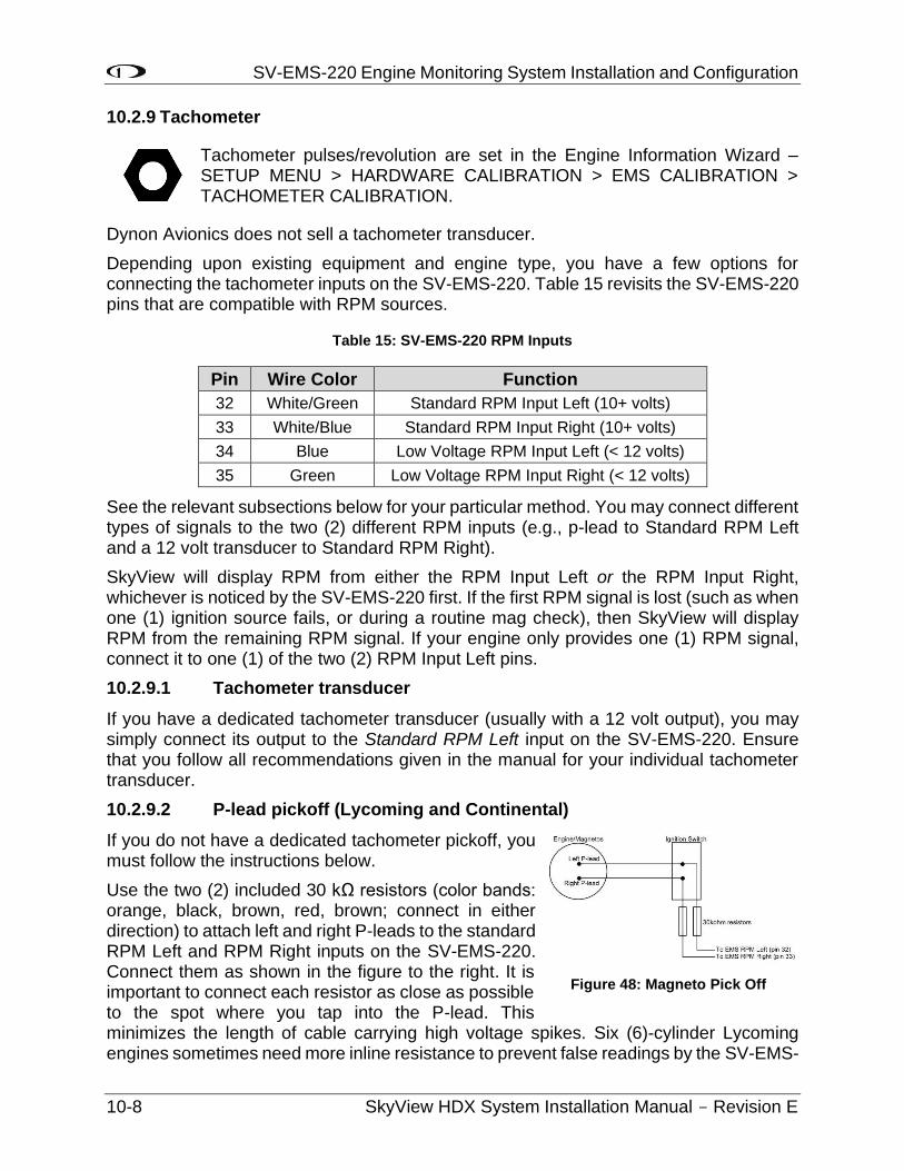
SV-EMS-220 Engine Monitoring System Installation and Configuration
10-8 SkyView HDX System Installation Manual - Revision E
10.2.9 Tachometer
Tachometer pulses/revolution are set in the Engine Information Wizard – SETUP MENU > HARDWARE CALIBRATION > EMS CALIBRATION > TACHOMETER CALIBRATION.
Dynon Avionics does not sell a tachometer transducer.
Depending upon existing equipment and engine type, you have a few options for connecting the tachometer inputs on the SV-EMS-220. Table 15 revisits the SV-EMS-220 pins that are compatible with RPM sources.
Table 15: SV-EMS-220 RPM Inputs
Pin Wire Color Function
32 White/Green Standard RPM Input Left (10+ volts)
33 White/Blue Standard RPM Input Right (10+ volts)
34 Blue Low Voltage RPM Input Left (< 12 volts)
35 Green Low Voltage RPM Input Right (< 12 volts)
See the relevant subsections below for your particular method. You may connect different types of signals to the two (2) different RPM inputs (e.g., p-lead to Standard RPM Left and a 12 volt transducer to Standard RPM Right).
SkyView will display RPM from either the RPM Input Left or the RPM Input Right, whichever is noticed by the SV-EMS-220 first. If the first RPM signal is lost (such as when one (1) ignition source fails, or during a routine mag check), then SkyView will display RPM from the remaining RPM signal. If your engine only provides one (1) RPM signal, connect it to one (1) of the two (2) RPM Input Left pins.
10.2.9.1 Tachometer transducer
If you have a dedicated tachometer transducer (usually with a 12 volt output), you may simply connect its output to the Standard RPM Left input on the SV-EMS-220. Ensure that you follow all recommendations given in the manual for your individual tachometer transducer.
10.2.9.2 P-lead pickoff (Lycoming and Continental)
If you do not have a dedicated tachometer pickoff, you must follow the instructions below.
Use the two (2) included 30 kΩ resistors (color bands: orange, black, brown, red, brown; connect in either direction) to attach left and right P-leads to the standard RPM Left and RPM Right inputs on the SV-EMS-220. Connect them as shown in the figure to the right. It is important to connect each resistor as close as possible to the spot where you tap into the P-lead. This minimizes the length of cable carrying high voltage spikes. Six (6)-cylinder Lycoming engines sometimes need more inline resistance to prevent false readings by the SV-EMS-
Figure 48: Magneto Pick Off
SV-EMS-220 Engine Monitoring System Installation and Configuration
SkyView HDX System Installation Manual - Revision E 10-9
220. If you supply your own resistors, they need not be exactly 30 kΩ. Additionally, both 1/4W and 1/2W resistors are acceptable to use.
If, after setting the PULS/REV R and L values as described in the Engine Information Section, you see unstable RPM, you may need to increase the series resistance. We recommend increasing the resistance in increments of approximately 30 kΩ – approx. 30 kΩ, approx. 60 kΩ, approx. 90 kΩ, approx. 120 kΩ, and approx. 150 kΩ. Try each value in sequence. A higher resistance value is not necessarily “better”, as too high a resistance can reduce the amplitude of the RPM signal to the point where you may see no, or low, RPM.
10.2.9.3 Other Ignition Systems
The SV-EMS-220’s Standard Voltage RPM inputs can read frequency-based RPM signals, provided the peak voltages goes at least 5.1 volts above ground, and crosses back down below 2.0V relative to ground. If the peak voltage exceeds 50 volts, use the included 30 kΩ resistors as described in the P-lead pickoff (Lycoming and Continental) Section above.
For signals that have a peak voltage of 12V or lower —such as Light Speed ignition outputs—use the low voltage RPM inputs. These inputs require that the peak voltage goes at least 2.1 volts above ground, and crosses back down below 0.8V relative to ground to be counted as a pulse.
For signals that have a peak voltage of 10-12V, either the Standard or Low Voltage RPM inputs can be used.
Like the other methods above, you must know the number of pulses per revolution for your RPM transducer.
10.2.10 Manifold Pressure Sensor
The Dynon Avionics Manifold Pressure Sensor (P/N 503387-000) is an integral assembly consisting of three (3) pins, a rubber seal, and a connector housing. Strip 3/16” (4.7625 mm) of insulation off the ends of the three (3) wires listed at right. Slide the three (3) rubber seals onto the three (3) wires and the pins onto the ends of the wires. Crimp the 3 included pins onto the ends of the wires, ensuring that the long tabs that cradle the rubber seal wrap around the seal (see picture at right for example). For more details on preparing and crimping the Weather Pack pins, see http://www.whiteproducts.net/faqs.shtml.
Table 16: Manifold Pressure Sensor Pins
SV-EMS-220 Pin Weather Pack Pin Color Function 18 C White/red +5 Volts Auxiliary
It is acceptable to share this pin / wire with other sensors; see table
above.
26 B Green/red Manifold pressure
17 A Black Ground
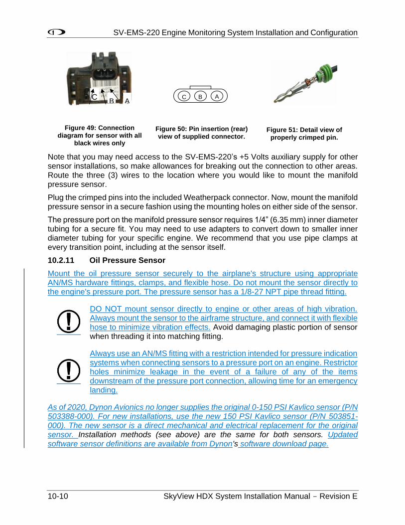
SV-EMS-220 Engine Monitoring System Installation and Configuration
10-10 SkyView HDX System Installation Manual - Revision E
Note that you may need access to the SV-EMS-220’s +5 Volts auxiliary supply for other sensor installations, so make allowances for breaking out the connection to other areas. Route the three (3) wires to the location where you would like to mount the manifold pressure sensor.
Plug the crimped pins into the included Weatherpack connector. Now, mount the manifold pressure sensor in a secure fashion using the mounting holes on either side of the sensor.
The pressure port on the manifold pressure sensor requires 1/4” (6.35 mm) inner diameter tubing for a secure fit. You may need to use adapters to convert down to smaller inner diameter tubing for your specific engine. We recommend that you use pipe clamps at every transition point, including at the sensor itself.
10.2.11 Oil Pressure Sensor
Mount the oil pressure sensor securely to the airplane's structure using appropriate AN/MS hardware fittings, clamps, and flexible hose. Do not mount the sensor directly to the engine's pressure port. The pressure sensor has a 1/8-27 NPT pipe thread fitting.
DO NOT mount sensor directly to engine or other areas of high vibration. Always mount the sensor to the airframe structure, and connect it with flexible hose to minimize vibration effects. Avoid damaging plastic portion of sensor when threading it into matching fitting.
Always use an AN/MS fitting with a restriction intended for pressure indication systems when connecting sensors to a pressure port on an engine. Restrictor holes minimize leakage in the event of a failure of any of the items downstream of the pressure port connection, allowing time for an emergency landing.
As of 2020, Dynon Avionics no longer supplies the original 0-150 PSI Kavlico sensor (P/N 503388-000). For new installations, use the new 150 PSI Kavlico sensor (P/N 503851-000). The new sensor is a direct mechanical and electrical replacement for the original sensor. Installation methods (see above) are the same for both sensors. Updated software sensor definitions are available from Dynon's software download page.
Figure 49: Connection diagram for sensor with all
black wires only
Figure 50: Pin insertion (rear) view of supplied connector.
Figure 51: Detail view of properly crimped pin.
C B A C A B
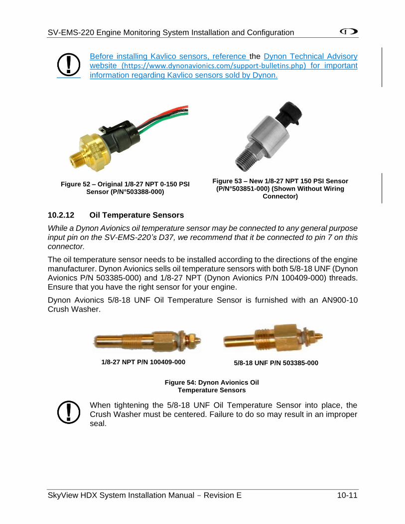
SV-EMS-220 Engine Monitoring System Installation and Configuration
SkyView HDX System Installation Manual - Revision E 10-11
Before installing Kavlico sensors, reference the Dynon Technical Advisory website (https://www.dynonavionics.com/support-bulletins.php) for important
information regarding Kavlico sensors sold by Dynon.
10.2.12 Oil Temperature Sensors
While a Dynon Avionics oil temperature sensor may be connected to any general purpose input pin on the SV-EMS-220’s D37, we recommend that it be connected to pin 7 on this connector.
The oil temperature sensor needs to be installed according to the directions of the engine manufacturer. Dynon Avionics sells oil temperature sensors with both 5/8-18 UNF (Dynon Avionics P/N 503385-000) and 1/8-27 NPT (Dynon Avionics P/N 100409-000) threads. Ensure that you have the right sensor for your engine.
Dynon Avionics 5/8-18 UNF Oil Temperature Sensor is furnished with an AN900-10 Crush Washer.
When tightening the 5/8-18 UNF Oil Temperature Sensor into place, the Crush Washer must be centered. Failure to do so may result in an improper seal.
1/8-27 NPT P/N 100409-000
Figure 54: Dynon Avionics Oil Temperature Sensors
5/8-18 UNF P/N 503385-000
Figure 52 – Original 1/8-27 NPT 0-150 PSI Sensor (P/N°503388-000)
Figure 53 – New 1/8-27 NPT 150 PSI Sensor (P/N°503851-000) (Shown Without Wiring
Connector)
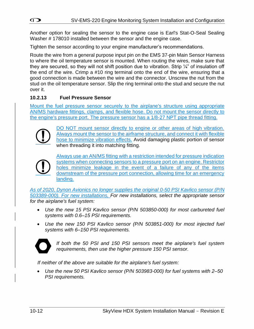
SV-EMS-220 Engine Monitoring System Installation and Configuration
10-12 SkyView HDX System Installation Manual - Revision E
Another option for sealing the sensor to the engine case is Earl's Stat-O-Seal Sealing Washer # 178010 installed between the sensor and the engine case.
Tighten the sensor according to your engine manufacturer’s recommendations.
Route the wire from a general purpose input pin on the EMS 37-pin Main Sensor Harness to where the oil temperature sensor is mounted. When routing the wires, make sure that they are secured, so they will not shift position due to vibration. Strip ¼” of insulation off the end of the wire. Crimp a #10 ring terminal onto the end of the wire, ensuring that a good connection is made between the wire and the connector. Unscrew the nut from the stud on the oil temperature sensor. Slip the ring terminal onto the stud and secure the nut over it.
10.2.13 Fuel Pressure Sensor
Mount the fuel pressure sensor securely to the airplane's structure using appropriate AN/MS hardware fittings, clamps, and flexible hose. Do not mount the sensor directly to the engine's pressure port. The pressure sensor has a 1/8-27 NPT pipe thread fitting.
DO NOT mount sensor directly to engine or other areas of high vibration. Always mount the sensor to the airframe structure, and connect it with flexible hose to minimize vibration effects. Avoid damaging plastic portion of sensor when threading it into matching fitting.
Always use an AN/MS fitting with a restriction intended for pressure indication systems when connecting sensors to a pressure port on an engine. Restrictor holes minimize leakage in the event of a failure of any of the items downstream of the pressure port connection, allowing time for an emergency landing.
As of 2020, Dynon Avionics no longer supplies the original 0-50 PSI Kavlico sensor (P/N 503389-000). For new installations, For new installations, select the appropriate sensor for the airplane's fuel system:
• Use the new 15 PSI Kavlico sensor (P/N 503850-000) for most carbureted fuel systems with 0.6–15 PSI requirements.
• Use the new 150 PSI Kavlico sensor (P/N 503851-000) for most injected fuel systems with 6–150 PSI requirements.
If both the 50 PSI and 150 PSI sensors meet the airplane's fuel system requirements, then use the higher pressure 150 PSI sensor.
If neither of the above are suitable for the airplane's fuel system:
• Use the new 50 PSI Kavlico sensor (P/N 503983-000) for fuel systems with 2–50 PSI requirements.
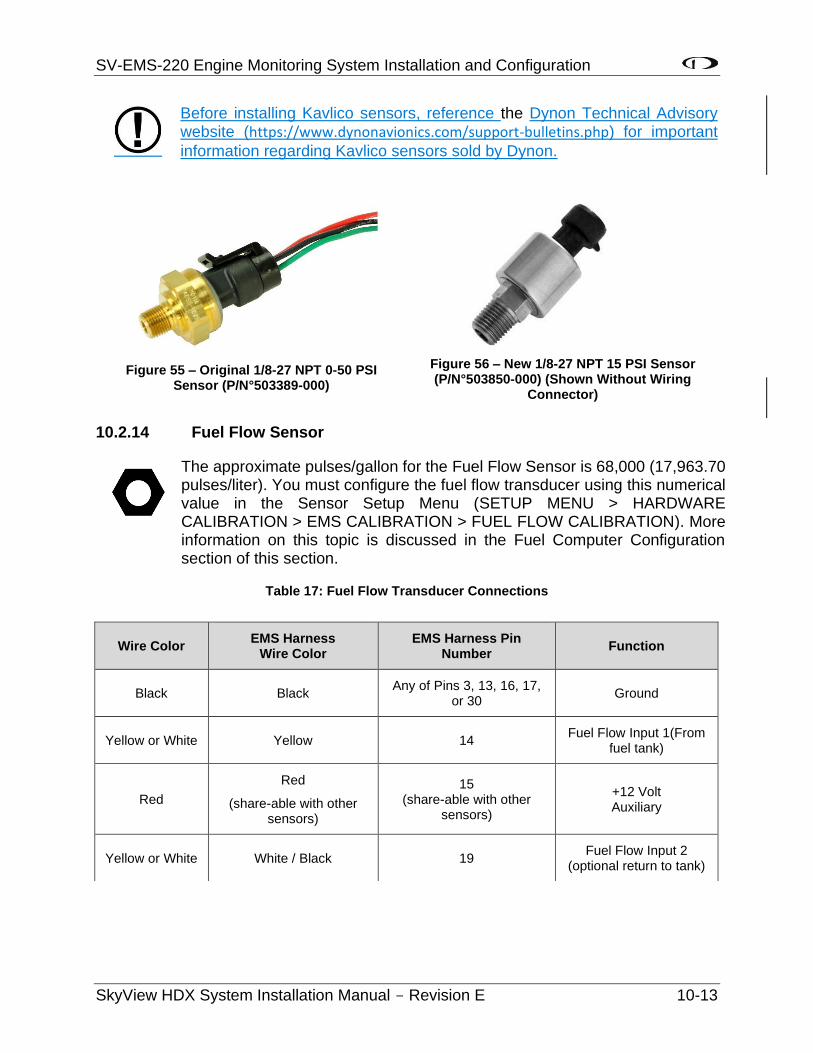
SV-EMS-220 Engine Monitoring System Installation and Configuration
SkyView HDX System Installation Manual - Revision E 10-13
Before installing Kavlico sensors, reference the Dynon Technical Advisory website (https://www.dynonavionics.com/support-bulletins.php) for important
information regarding Kavlico sensors sold by Dynon.
10.2.14 Fuel Flow Sensor
The approximate pulses/gallon for the Fuel Flow Sensor is 68,000 (17,963.70 pulses/liter). You must configure the fuel flow transducer using this numerical value in the Sensor Setup Menu (SETUP MENU > HARDWARE CALIBRATION > EMS CALIBRATION > FUEL FLOW CALIBRATION). More information on this topic is discussed in the Fuel Computer Configuration section of this section.
Table 17: Fuel Flow Transducer Connections
Wire Color EMS Harness
Wire Color EMS Harness Pin
Number Function
Black Black Any of Pins 3, 13, 16, 17,
or 30 Ground
Yellow or White Yellow 14 Fuel Flow Input 1(From
fuel tank)
Red
Red
(share-able with other sensors)
15 (share-able with other
sensors)
+12 Volt Auxiliary
Yellow or White White / Black 19 Fuel Flow Input 2
(optional return to tank)
Figure 55 – Original 1/8-27 NPT 0-50 PSI Sensor (P/N°503389-000)
Figure 56 – New 1/8-27 NPT 15 PSI Sensor (P/N°503850-000) (Shown Without Wiring
Connector)
SV-EMS-220 Engine Monitoring System Installation and Configuration
10-14 SkyView HDX System Installation Manual - Revision E
10.2.14.1 General Placement Recommendations for Fuel Flow Transducer
• Do not install the fuel flow transducer, hoses and fittings near exhaust system or turbocharger. Excessive heat can damage fuel system components.
• Do not install 90 degree fittings (elbows) on the input or output of the fuel flow transducer. Doing so will cause turbulence in the fuel flow which causes inaccurate fuel flow data.
• Install the fuel flow transducer with the three (3) wires pointed UP.
• Install a fuel filter UPSTREAM of the fuel flow transducer to screen out debris.
• For best measuring performance, the fuel should travel uphill by one (1) to two (2) inches (2.54-5.08 cm) after leaving the fuel flow transducer.
• Placement of the fuel flow transducer relative to other items in the fuel system like fuel pumps is left to the builder. It is common to place the sensor downstream of any auxiliary electric boost pumps but upstream of the engine driven fuel pump.
Due to vibration issues, never connect the fuel flow transducer directly to the engine.
When sealing the fittings on the fuel flow transducer, do not use Teflon tape! Instead, use a sealant such as “United EZ-Turn Fuel Resistant Lubricant” or “Permatex Thread Sealant.”
10.2.14.2 Mechanical Installation
The fuel flow sensor has ¼” (6.35 mm) female NPT ports. Do not exceed a torque of 300 inch-lbs. (.112 Nm) when installing fittings into the transducer. The sensor should NOT be installed with its wires pointing DOWN (the best situation is with the wires pointing UP). The fuel line on the outlet port should not drop down after exiting the transducer - this configuration can trap bubbles in the transducer, causing jumpy readings. The inlet port, outlet port, and flow direction are marked on the top of the sensor.
10.2.15 Fuel Level Sensor
Dynon Avionics does not sell fuel level sensors.
10.2.15.1 Resistive Fuel Level Sensors
You may connect as many resistive fuel level sensors to the SV-EMS-220 to General Purpose (GP) input – any of Pins 4, 7, 9, 10, 11, 12, 20, 21 (that are not already in use). We recommend not using Pins 6, 8, 22, and 23, and 31 for fuel level sensors as these pins are used for some specialized functions. We recommend that Pins 20 and 21 of the SV-EMS-220 D37 be used for fuel level sensors before using other general purpose inputs.
If you use a General Purpose Input other than Pins 20 and 21, you must configure the pin you use: SETUP MENU > EMS SETUP > SENSOR INPUT MAPPING > C37 Pxx.
SV-EMS-220 Engine Monitoring System Installation and Configuration
SkyView HDX System Installation Manual - Revision E 10-15
• FUEL LEVEL (RESISTIVE) – averages changes in fuel level over 1.5 minutes, with most of the change occurring within the first minute). This is a change from previous versions of this setting, and is the default setting.
• FUEL LEVEL (RESISTIVE FASTER RESPONSE) – averages changes in fuel level over 15 seconds, with most of the change occurring within the first seven (7) seconds.
• FUEL LEVEL (RESISTIVE SLOWER RESPONSE) – averages changes in fuel level over seven (7) minutes, with approximately 2/3 of the change occurring within the first three (3) minutes.
Choose the option which provides your preferred responsiveness to actual fuel level changes. For example, FUEL LEVEL (RESISTIVE SLOWER RESPONSE) might be preferred for an acrobatic aircraft where the (measured) fuel level changes rapidly in maneuvers that would otherwise trigger a low fuel level alert.
10.2.15.2 Capacitive Fuel Level Sensors
Capacitive fuel level sensors such as those made by Princeton Electronics are only supported on pins 8, 22, 23, and 31 on the SV-EMS-220 D37. Capacitive sensors must output a variable voltage within the ranges of 0-5 volts DC.
First, connect the sensor with power according to the manufacturer’s instructions. If the capacitive fuel level sensor requires its own calibration, perform that calibration before performing the SkyView fuel level calibration.
Configure the pin you use:
SETUP MENU > EMS SETUP > SENSOR INPUT MAPPING > C37 Pxx (8, 22, 23, or 31).
You can choose the following options under SENSOR:
• FUEL LEVEL (CAPACITIVE) – averages changes in fuel level over a few minutes. This is a change from previous versions of this setting.
• FUEL LEVEL (CAPACITIVE SLOWER RESPONSE) – averages changes in fuel level over approximately 3x the time of FUEL LEVEL (CAPACITIVE).
Choose the option which provides your preferred responsiveness to actual fuel level changes. For example, FUEL LEVEL (CAPACITIVE SLOWER RESPONSE) might be preferred for an acrobatic aircraft where the (measured) fuel level changes rapidly in maneuvers that would otherwise trigger a low fuel level alert.
SV-EMS-220 Engine Monitoring System Installation and Configuration
10-16 SkyView HDX System Installation Manual - Revision E
If your electrical system / startup procedure applies power to SkyView before applying power to the capacitive fuel level sensors, when first powered up, SkyView will “sense” a fuel level of 0. If the FUEL LEVEL (CAPACITIVE SLOWER RESPONSE) is selected, the fuel level will not display the actual fuel level for as long as 7 minutes after applying power. You can either change your startup procedure to apply power to the capacitive fuel level sensors before applying power to SkyView, or select FUEL LEVEL (CAPACITIVE).
Note that default fuel level sensor type is resistive fuel level sensors. To use capacitive fuel level sensors instead of resistive fuel level sensors requires changes to EMS settings in a few places. First, change the pins used for fuel quantity via the SETUP MENU > EMS SETUP > SENSOR INPUT MAPPING… menu. Then, in SETUP MENU > EMS SETUP > SCREEN LAYOUT EDITOR, delete the default fuel quantity widgets from the 20%, 50%, and 100% layouts. Finally, add the new fuel level widget(s) that will be available for the capacitive fuel level sensors.
After installation, prior to use, fuel level sensors must be calibrated before they can display accurate fuel levels. Until you have performed a fuel level calibration, the fuel level sensor widget will not display fuel levels, and will display CAL ?
If you have installed capacitive fuel level sensors, and these sensors require their own calibration, perform that calibration before performing the SkyView fuel level calibration.
To perform a fuel level calibration, go to SETUP MENU > HARDWARE CALIBRATION > EMS CALIBRATION > FUEL TANK xxx CALIBRATION > (one (1) more right click) and follow the on-screen instructions to perform the fuel level calibration. Generally, you will be prompted to perform up to ten (10) fuel level pours of equal volume; the volume of each pour will be determined by the size of the tank that you input.
For an accurate fuel level calibration, it is important to follow the on-screen instructions exactly. For example, pushing the NEXT button before a fuel pour is completed, or pushing it twice for one (1) fuel pour, will result in an inaccurate calibration, and the fuel level calibration procedure will likely have to be repeated.
Once a capacitive fuel level sensing system is calibrated for a certain type fuel, only that fuel should be used, and the aircraft should be placarded for such. For example, ethanol has a dielectric constant much different than 100LL or Auto Fuel. If your capacitive fuel level sensor has been calibrated for 100LL, and you then use Auto 10% Ethanol in the tanks, the fuel level indications could be off significantly.
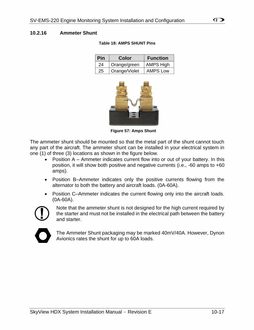
SV-EMS-220 Engine Monitoring System Installation and Configuration
SkyView HDX System Installation Manual - Revision E 10-17
10.2.16 Ammeter Shunt
Table 18: AMPS SHUNT Pins
The ammeter shunt should be mounted so that the metal part of the shunt cannot touch any part of the aircraft. The ammeter shunt can be installed in your electrical system in one (1) of three (3) locations as shown in the figure below.
• Position A – Ammeter indicates current flow into or out of your battery. In this position, it will show both positive and negative currents (i.e., -60 amps to +60 amps).
• Position B–Ammeter indicates only the positive currents flowing from the alternator to both the battery and aircraft loads. (0A-60A).
• Position C–Ammeter indicates the current flowing only into the aircraft loads. (0A-60A).
Note that the ammeter shunt is not designed for the high current required by the starter and must not be installed in the electrical path between the battery and starter.
The Ammeter Shunt packaging may be marked 40mV/40A. However, Dynon Avionics rates the shunt for up to 60A loads.
Pin Color Function
24 Orange/green AMPS High
25 Orange/Violet AMPS Low
Figure 57: Amps Shunt
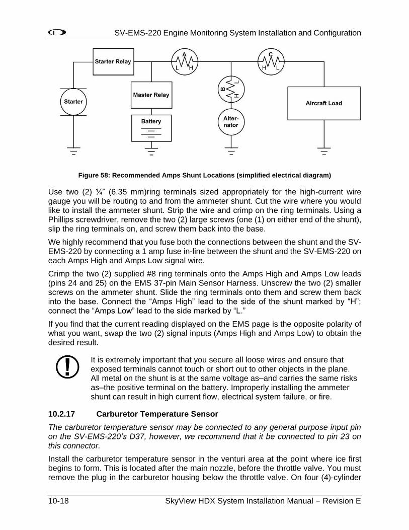
SV-EMS-220 Engine Monitoring System Installation and Configuration
10-18 SkyView HDX System Installation Manual - Revision E
Figure 58: Recommended Amps Shunt Locations (simplified electrical diagram)
Use two (2) ¼” (6.35 mm)ring terminals sized appropriately for the high-current wire gauge you will be routing to and from the ammeter shunt. Cut the wire where you would like to install the ammeter shunt. Strip the wire and crimp on the ring terminals. Using a Phillips screwdriver, remove the two (2) large screws (one (1) on either end of the shunt), slip the ring terminals on, and screw them back into the base.
We highly recommend that you fuse both the connections between the shunt and the SV-EMS-220 by connecting a 1 amp fuse in-line between the shunt and the SV-EMS-220 on each Amps High and Amps Low signal wire.
Crimp the two (2) supplied #8 ring terminals onto the Amps High and Amps Low leads (pins 24 and 25) on the EMS 37-pin Main Sensor Harness. Unscrew the two (2) smaller screws on the ammeter shunt. Slide the ring terminals onto them and screw them back into the base. Connect the “Amps High” lead to the side of the shunt marked by “H”; connect the “Amps Low” lead to the side marked by “L.”
If you find that the current reading displayed on the EMS page is the opposite polarity of what you want, swap the two (2) signal inputs (Amps High and Amps Low) to obtain the desired result.
It is extremely important that you secure all loose wires and ensure that exposed terminals cannot touch or short out to other objects in the plane. All metal on the shunt is at the same voltage as–and carries the same risks as–the positive terminal on the battery. Improperly installing the ammeter shunt can result in high current flow, electrical system failure, or fire.
10.2.17 Carburetor Temperature Sensor
The carburetor temperature sensor may be connected to any general purpose input pin on the SV-EMS-220’s D37, however, we recommend that it be connected to pin 23 on this connector.
Install the carburetor temperature sensor in the venturi area at the point where ice first begins to form. This is located after the main nozzle, before the throttle valve. You must remove the plug in the carburetor housing below the throttle valve. On four (4)-cylinder
SV-EMS-220 Engine Monitoring System Installation and Configuration
SkyView HDX System Installation Manual - Revision E 10-19
engines which use the Marvel Schebler MA-3 carburetors, this plug is located on the forward side. On six (6)-cylinder engines using the MA-4 carburetor, the plug is located on the rear. If your carburetor is not drilled and tapped for the plug, you must remove the carburetor from the engine and drill out the lead plug in the appropriate spot. Tap the hole with a ¼-28 tap. Remove all chips and burrs before reinstalling.
Route either of the two (2) wires to an electrical ground on the SV-EMS-22X D37 connector. Route the other wire to the general purpose input of your choice.
10.2.18 Trim and Flaps Position Potentiometers
Trim and flap indicators may not be available on all airplanes. Only airplanes equipped with flap and trim position sesnors can display these positions on EMS
Position potentiometers may be connected to any general purpose input pin on the SV-EMS-220’s D37 and must be calibrated according to the instructions found in Section 10.9: EMS Sensor Calibration. The number of position potentiometers in any installation is limited by the number of unused general purpose input pins on the SV-EMS-220’s D37 connector. The tables in the Example Engine Sensor and Transducer Installations Section contain recommended input pins for position potentiometers.
Dynon Avionics does not sell trim or flaps position sensors. These are normally included with, or added onto, their respective servos.
Most flap and trim sensors are potentiometers (variable resistors) which require power and ground inputs, and supply an output that is a function of position. These potentiometers come in a variety of resistance ranges, but are typically 1 kΩ, 5 kΩ, 10 kΩ, and 20 kΩ. All of these values will work properly with the SV-EMS-22, as there is a calibration required. Connect Pin 18 (+5 Volts Auxiliary) from the SV-EMS-220 to the +5 Volts input on your trim/flap position sensor. Connect the ground input on the sensor to a ground common to the SV-EMS-220’s signal ground. Connect the output of the sensor to the desired general purpose input. For physical installation, refer to the instructions that came with your position sensor.
Trim and flaps position potentiometers must be calibrated. Your SkyView display utilizes onscreen wizards that help you do this. Go to the EMS Calibration Menu to access these wizards (SETUP MENU > HARDWARE CALIBRATION > EMS CALIBRATION).
The take-off position will be shown as a green line on the trim widget. If you do not want this marking on your trim widget, press NONE during the take-off position portion of the trim calibration.
10.2.19 General Purpose Temperature Sensor
Any temperature sensor provided by Dynon Avionics may be utilized as a general purpose temperature sensor on any of Pins 4, 6, 7, 8, 9, 10, 11, 12, 20, 21, 22, 23, or 31 on the SV-EMS-220.
For example, you may connect an SV-OAT-340 sensor and configure it as a general purpose thermometer (e.g., for cabin temperature). Connect one (1) of the wires to the
SV-EMS-220 Engine Monitoring System Installation and Configuration
10-20 SkyView HDX System Installation Manual - Revision E
input pin, and the other wire to any available EMS Ground, any of Pins 3, 5, 13, 16, 17, or 30.
10.2.20 Landing Gear Position Indication
See Section 10.3 Contacts.
10.3 Contacts
Contacts may be connected to any general purpose input pin on the SV-EMS-220’s D37. The number of contacts in your SkyView system is only limited to the number of unused general purpose input pins on the connector.
Dynon Avionics does not sell contacts or switches.
Contacts are used for a variety of purposes, such as monitoring canopy closure. The EMS Software reads the voltage state of general purpose inputs. To configure them as contacts, use two (2) voltage ranges in your sensor setup. Set one (1) to 0-2V, and the other from 2-5V. SkyView will then report whether each input is open (no connection to ground, which is the 2-5V state) or closed (connection to ground, which is the 0-2V state). You must ensure that when closed, the contact connects to a ground common to the SV-EMS-220. Generally, the voltage on the general purpose inputs should not exceed 15 volts, but the inputs are protected against spikes up to 30V. Generally, it is safe to connect a general purpose input up to any 12V electrical signal (such as monitoring whether power is connected to a 12V fuel pump), but the same is not true for a 24V aircraft – connecting 24V (continuous) to a general purpose input will damage the input.
General purpose input pins are 0 to 5 volt inputs. While higher voltages are tolerated, the voltage will not read higher than 5 volts. Therefore, only use voltages between 0 and 5 volts in your sensor setup.
Contacts Used for Retractable / Amphibious Landing Gear and Related Alerts
The simplest method to monitor landing gear state is to use a contact as there are only two (2) states to monitor and it is mechanically and electrically easiest to install. To enable audio alerts related to landing gear status, the contact used for monitoring the status of landing gear must be named GEAR 1, GEAR 2, GEAR 3, or GEAR 4:
SETUP MENU > EMS SETUP > SENSOR INPUT MAPPING > C37 Pxx >
> FUNCTION: CONTACT
> SENSOR: CONTACT
> NAME: GEAR 1
To configure the GEAR contact alert for retractable landing gear:
• Install the GEAR contact that when the landing gear is up, the state of the contact is “UP” and when the landing gear is down, the state of the contact is “DOWN”.
• SETUP MENU > AIRCRAFT INFORMATION:
> LANDING GEAR TYPE: RETRACT
SV-EMS-220 Engine Monitoring System Installation and Configuration
SkyView HDX System Installation Manual - Revision E 10-21
> LANDING GEAR CHECK SPEED: (set as appropriate for your plane)
> LANDING GEAR OVERSPEED: (set as appropriate for your plane)
To configure the GEAR contact alert for amphibious landing gear:
• Install the GEAR contact that when the amphibious landing gear is configured for landing on water, the state of the contact is WATR and when the amphibious landing gear is configured for landing on land, the state of the contact is LAND.
• SETUP MENU > AIRCRAFT INFORMATION:
> LANDING GEAR TYPE: AMPHIB
> LANDING GEAR CHECK SPEED: (set as appropriate for your plane)
> LANDING GEAR OVERSPEED: (set as appropriate for your plane)
• SETUP MENU > SYSTEM SETUP > AUDIO SETUP > LANDING GEAR > VOICE
10.4 General Purpose Thermocouple
You may configure the SV-EMS-220 to monitor two (2) J or K type thermocouples in addition to the twelve thermocouples available on the SV-EMS-220’s D25 connector. Note that the SV-EMS-221 uses these four (4) pins for Rotax 912 is communication, and, therefore, these pins are not available for thermocouple use on the SV-EMS-221. Dynon Avionics does not supply a specific general purpose thermocouple sensor for this purpose. However, our standard EGT and CHT sensors will work, as will any other J or K type thermocouple.
The following table revisits which SV-EMS-220 pins are compatible with general purpose thermocouples.
Table 19: SV-EMS-220 D37 General Purpose Thermocouple Pins
Pin Wire Color Function
27 Not supplied General Purpose TC Input 1+
28 Not supplied General Purpose TC Input 1-
36 Blue General Purpose TC Input 2+
37 Green General Purpose TC Input 2-
If you use the second general purpose thermocouple input on pins 36 and 37, it is necessary to remove the blue and green wires from these pins on the EMS 37-pin Main Sensor Harness.
Dynon Avionics sells both J and K type thermocouple wire which may be used to connect the desired thermocouple to the SkyView. Ensure you order the correct wire type for the thermocouple you intend to use. Crimp a Female DSUB pin on the end of each wire, and plug them into the SV-EMS-220’s EMS 37-pin Main Sensor Harness D37. Polarity is

SV-EMS-220 Engine Monitoring System Installation and Configuration
10-22 SkyView HDX System Installation Manual - Revision E
important, so ensure that you are routing the positive side (yellow for K-type; white for J-type) of the thermocouple to pin 27 or pin 36 on the 37-pin harness, and the negative side to pin 28 or pin 37.
10.5 External EMS Warning Light
SV-EMS-220 D37 pin 29 can be wired and configured as an External Alarm Light.
To wire EMS D37 pin 29 as an External Alarm Light, you may connect any standard LED or incandescent lamp (1.5 Watt maximum), used during EMS-related “red” warning alarm conditions. Ensure that the LED or lamp is designed for the voltage of your system. Mount it to your panel according to its recommendations. Connect one (1) of the lamp’s leads to your plane’s power. Connect the other lead to pin 29 on the SV-EMS-220 37-pin wiring harness. During an alarm condition, this pin is connected to ground, causing current to flow through the lamp.
Aircraft Spruce P/N 17-410 is an example of a light that will work for this application. An LED and resistor in series will also suffice. If you use an LED as the indicator, you must choose a resistor that delivers the appropriate current to the LED, and can accommodate the power required for its current and voltage drop. Also note that the power and ground connections on LEDs are not reversible.
After installation, you can test the External EMS Warning Light:
SETUP MENU > HARDWARE CALIBRATION > EMS CALIBRATION > EXTERNAL EMS WARNING LIGHT TEST > (one (1) more right click to enter the menu and temporarily illuminate the External EMS Warning Light).
10.6 Engine Information
Use the Engine Information Wizard (SETUP MENU > EMS SETUP > ENGINE INFORMATION) to specify engine type, horsepower rating, redline and cruise RPM, and set HOBBS and TACH time (if installation is in a non-zero-time engine).
If you have an engine type that is in the list, please choose the appropriate engine. This will allow the system to perform some calculations that are specific to that engine, such as % power (Lycoming / Continental only) and special operating limitations (Rotax only). If your engine is not listed, choose "Other."
Horsepower is used to do some of the % power calculations (Lycoming/Continental engines only) and the auto Rich-of-Peak and Lean-of-Peak detection. Set it to the engine manufacturer's rated HP for initial usage. You may need to adjust this number in order to get all calculations working correctly.
If you are getting an auto Lean-of-Peak indication that is coming on too early, before the engine actually peaks while leaning, lower this number. It is not meant to be a measure of actual horsepower produced, as engines that are more efficient will act as if they are lower horsepower in the calculation. This will be particularly true if you are running a higher compression ratio than the stock charts are based upon.
Cruise RPM is used when calculating tach time. Tach time is a measure of engine time normalized to a cruise RPM. If you spend one (1) hour at your cruise RPM, tach time will
SV-EMS-220 Engine Monitoring System Installation and Configuration
SkyView HDX System Installation Manual - Revision E 10-23
increment one (1) hour. If you spend one (1) hour at 1/2 your cruise RPM, tach time will only increase by 1/2 hour. Tach time is defined as TIME x (CURRENT RPM / CRUISE RPM).
Hobbs time is a simple timer that runs whenever the oil pressure is above 15 PSI or the engine is above 0 RPM.
INHIBIT ENGINE ALERTS AT BOOT: NO | YES
When set to YES, all engine alerts, both audio and visual, will occurs until after the first engine start, or 5 minutes, whichever comes first. This option can help inhibit nuisance alarms before the engine is started. When set to NO, engine alerts are always active.
ALARM LIGHT: SOLID AFTER ACK | OFF AFTER ACK
If you have connected an External Alarm Light to SV-EMS-220 pin 29, the Alarm Light setting determines how the light behaves after alarm acknowledgement. It can be set to either SOLID AFTER ACK, which leaves the light lit continuously after acknowledgement (until the alarm condition ceases) or OFF AFTER ACK, which turns the light off after an alarm has been acknowledged.
10.7 EMS Sensor Definitions, Mapping, and Settings
All sensors must be defined, mapped to SV-EMS-220 pins, and have their settings configured. This section describes how sensors are defined, mapped, and set in SkyView.
10.7.1 EMS Sensor Definitions
All EMS sensor installations require a SkyView Sensor Definitions file. This file provides characterizations of all sensors that SkyView supports, and is occasionally updated to add additional supported sensors and correct issues with existing sensors. The most current version of the SkyView Sensor Definitions file is preloaded onto each display prior to shipment. The most current version of the SkyView Sensor Definitions file can be downloaded from www.dynoncertified.com/software-updates.php. If you have more than one (1) SkyView display, and the SkyView Sensor Definitions file on each display is different from one (1) another, a Warning message will be displayed: EMS SFG FILE MISMATCH.
If you need to update the SkyView Sensor Definitions file, download the file and use the instructions found in the How to Load and Delete Files Section.
The SkyView Sensor Definitions file has a .sfg file extension. This file is not automatically shared between displays. It must be loaded onto each display in the system.
SV-EMS-220 Engine Monitoring System Installation and Configuration
10-24 SkyView HDX System Installation Manual - Revision E
10.7.2 EMS Sensor Input Mapping
In order to save installers time, Dynon Avionics provides preconfigured sensor mapping and settings files which support four- and six-cylinder engine installations, providing the airplane has been wired according to 103488-000 WIRING DIAGRAM TYPICAL HDX DUAL DISPLAY available for download at www.dynon.aero/stcdocs.
Settings for SV-EMS-220 pin mapping, ranges, widget graphical properties, etc. are automatically shared between multiple SkyView displays.
Dynon recommends that you install the correct sensor mapping and settings file for your engine onto the SkyView display using the instructions found in the How to Load and Delete Files Section. Then update or modify the sensor settings according to the Airplane Flight Manual for your airplane..
Note that it is critical that you should check every setting before operating your engine with them as these files are only a starting point. While efforts were made to set up temperature, pressure, and other ranges to reasonable starting points, Dynon Avionics makes no claim that they are correct for your engine, as slightly different engines may have different limits.
Use this section as a guide when you review and update the sensor map and settings that were sourced from the preconfigured file. Also use this section if you are creating a sensor map and settings from scratch.
10.7.2.1 EMS Sensor Mapping Explanation
The SkyView system must be configured to map SV-EMS-220 pin numbers to physical sensors. This section contains an explanation of what it means to define a sensor for mapping purposes and also contains instructions on how to map sensors mentioned in this section to pins on the SV-EMS-220. Mapping can be accomplished using two (2) methods: you can use a premade file as mentioned above or you can manually map engine sensors to EMS module pins.
All sensors and transducers are mapped in the Sensor Input Mapping Wizard. As mentioned earlier, some pins are compatible with a variety of sensors, while other pins have fixed functionality. A sensor is defined in the Sensor Input Mapping Wizard by the following parameters:
• Pin #–the pin or set of pins the sensor is connected to.
• Function–the phenomenon the sensor measures (e.g., pressure and temperature).
• Sensor–the physical part used, for example 150 PSI Fluid Pressure (503388-000).
• Name–a six (6)-character field that names the sensor for use by the pilot in flight.
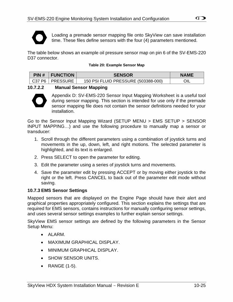
SV-EMS-220 Engine Monitoring System Installation and Configuration
SkyView HDX System Installation Manual - Revision E 10-25
Loading a premade sensor mapping file onto SkyView can save installation time. These files define sensors with the four (4) parameters mentioned.
The table below shows an example oil pressure sensor map on pin 6 of the SV-EMS-220 D37 connector.
Table 20: Example Sensor Map
PIN # FUNCTION SENSOR NAME
C37 P6 PRESSURE 150 PSI FLUID PRESSURE (503388-000) OIL
10.7.2.2 Manual Sensor Mapping
Appendix D: SV-EMS-220 Sensor Input Mapping Worksheet is a useful tool during sensor mapping. This section is intended for use only if the premade sensor mapping file does not contain the sensor definitions needed for your installation.
Go to the Sensor Input Mapping Wizard (SETUP MENU > EMS SETUP > SENSOR INPUT MAPPING…) and use the following procedure to manually map a sensor or transducer:
1. Scroll through the different parameters using a combination of joystick turns and movements in the up, down, left, and right motions. The selected parameter is highlighted, and its text is enlarged.
2. Press SELECT to open the parameter for editing.
3. Edit the parameter using a series of joystick turns and movements.
4. Save the parameter edit by pressing ACCEPT or by moving either joystick to the right or the left. Press CANCEL to back out of the parameter edit mode without saving.
10.7.3 EMS Sensor Settings
Mapped sensors that are displayed on the Engine Page should have their alert and graphical properties appropriately configured. This section explains the settings that are required for EMS sensors, contains instructions for manually configuring sensor settings, and uses several sensor settings examples to further explain sensor settings.
SkyView EMS sensor settings are defined by the following parameters in the Sensor Setup Menu:
• ALARM.
• MAXIMUM GRAPHICAL DISPLAY.
• MINIMUM GRAPHICAL DISPLAY.
• SHOW SENSOR UNITS.
• RANGE (1-5).
SV-EMS-220 Engine Monitoring System Installation and Configuration
10-26 SkyView HDX System Installation Manual - Revision E
10.7.3.1 EMS Sensor Alarms
EMS alerts (audio, EMS indicator light) are triggered when a sensor goes into a RED range, and set to SELF-CLEAR or LATCHING below. There are three (3) alarm options for EMS sensors:
• OFF – no alarm for the sensor.
• SELF-CLEAR – When an alert is triggered, it is annunciated both on the engine page and in the messaging system. When the alert condition ceases, all of these annunciations cease, even if the precise alert message was not acknowledged by pressing the rightmost button on the display to bring up the message window.
• LATCHING – When an alert is triggered, it is annunciated both on the engine page and in the messaging system. However, when the alert condition ceases, the message notification area above the rightmost button will continue to show the unacknowledged alert state until the alert message is viewed in the message window, even though the offending parameter has returned to within limits. This behavior ensures that the pilot is aware that an alert was triggered, even though the condition no longer exists.
Reference the SkyView Pilot’s User Guide for information regarding how sensor alarms show up onscreen during operation.
10.7.3.2 EMS Sensor Graphical Display Limits
These settings define the minimum and maximum values that will be shown graphically on the sensor’s gauge. Effectively, this is the start and stop point of the gauge. If the indicator you choose for this value shows digital numbers for the value, they will not be limited by this setting. The system will not allow you to set these numbers higher or lower than the sensor can support.
To increase the width of the red line indications, set the graphical display limit slightly lower or higher than the limits defined in the airplane manufacturer's documentation.
10.7.3.3 SHOW SENSOR UNITS (YES | NO)
Some custom developed sensors may warrant a graphical widget that is not expressed in any of the units that SkyView’s EMS supports. In such cases, you can suppress the display of the widget’s actual unit of measurement (volts, degrees, etc.) by setting SHOW SENSOR UNITS to NO.
10.7.3.4 EMS Sensor Ranges
According to AC 20-88A Guidelines on the Marking of Powerplant Instruments the following colors have very specific meanings, and therefore shall only be used as stipulated by the airplane manufacturer's documentation:
• The color red indicates an operating condition beyond authorized limits and requires a specific action on the part of the flightcrew. The specific action to be taken should be described in the airplane manufacturer's documentation.
SV-EMS-220 Engine Monitoring System Installation and Configuration
SkyView HDX System Installation Manual - Revision E 10-27
• The color yellow is used to indicate either a cautionary range where limited operation is permissible as directed by the airplane manufacturer's documentation. An example of compliance with the precautionary range requirement is the yellow arc marking on the carburetor air temperature gauge to indicate the range of temperature where carburetor icing may occur.
• The color green is used to indicate a normal condition for operation, both ground and flight. Where applicable, the high value end of the green arc should indicate the maximum limit for normal operation, and the low value end of the green arc should indicate the minimum limit for normal operation. Where appropriate, there may be blank gaps, or other colors, inserted into the green arc. Either the upper or lower end of the green arc may extend to the red radial or stop short of it as appropriate to the measurement being marked. A wide green arc and a narrow green arc may be used to denote a normal all-engine range and a normal engine-out range, if appropriate.
Apply the colors and values exactly as defined in airplane manufacturer's documentation. In some case, gaps may appear between the red colored limit, and the green colored normal operating range. These gap ranges, when they occur, can be colored any color you choose, except Red, Yellow, or Green.
The order that ranges are configured has no effect on the functionality or display of the gauge. Ranges are defined with the following properties: enable, color, top, and bottom. Enable is used to tell SkyView if that range is on or off. If it is off, it will not be considered or displayed.
Each gauge can consist of up to five (5) ranges. If fewer ranges are desired (such as a contact), set the unneeded ranges ENABLE: NO. Each range has an associated color: Black, Red, Orange, Yellow, Green, Blue, Violet, White, or Cyan. If a range is not defined, it is considered black, so there is not generally a reason to configure black ranges. If ranges overlap, the following rules apply:
• Red trumps Yellow.
• Yellow trumps Green.
• Green trumps Blue / Cyan / Orange / Violet / White / Yellow (these are equal priority).
• Blue / Cyan / Orange / Violet / White / Yellow (these are equal priority) trumps Black.
For example, you could set up two (2) ranges for the same gauge, each 0-10, one (1) Red, and one (1) Green, and that range would be Red. To further illustrate this behavior, if another range for that same gauge was configured from 5-15 and set to Yellow, only 10-15 would be Yellow.
The two (2) edge ranges are considered to go on "forever," so if a gauge is set up as Yellow from 10 to 20 and Red from 20 to 30, and the sensor reads 35, it will still be considered Red since that is above the highest range. It will be considered Yellow below 10. If you wish for this not to occur, you must make your edge ranges Black.
SV-EMS-220 Engine Monitoring System Installation and Configuration
10-28 SkyView HDX System Installation Manual - Revision E
Alarms are only triggered when ALARM: SELF-CLEAR or LATCHING and the value enters a Red range on a gauge. When values enter into a Yellow range, their numerical value is highlighted in Yellow to annunciate the caution condition.
10.7.3.5 Fuel Computer Configuration
Setting Pulses/Gallon
To find and configure the pulses/gallon value associated with your fuel flow sensor:
The fuel flow sensor requires a starting K-VALUE of 68000 under SETUP MENU > HARDWARE CALIBRATION > EMS CALIBRATION > FUEL FLOW CALIBRATION.
Over time, you may notice that the instrument’s computation of gallons or liters remaining (based on fuel flow) is either high or low. This is a result of many factors, including individual installation. To correct for this, follow this procedure:
Over several fill-ups keep a running total of the amount of fuel added. Keep a running total of the GALS (or LTRS) USED parameter over this same time span.
Perform the following calculation: )(
)(
actualFuelFilled
computedFuelUsed . You should obtain a number that
is close to 1. We’ll call this number, FuelFlowRatio.
Now perform this calculation: CurrentPulsesPerGallon*FuelFlowRatio. Enter this number as your new pulses/gallon value.
Observe the results over your next tank for accuracy. Repeat the above if necessary.
The general rule of thumb: if your GALS (or LTRS) USED reads higher than you expect, increase the pulses/gallon; if it reads lower than you expect, decrease the pulses/gallon.
If your engine has a return fuel flow sensor, note that there is a second pulses/gallon setting that is mapped to a second set of input pins. When a second fuel flow sensor is connected, and the pulses/gallon is adequately set, the fuel seen returning through the second fuel flow sensor is automatically subtracted from the flow that is seen through the primary sensor. If you do not have a second fuel flow sensor, you may ignore this setting entirely.
In SETUP MENU > HARDWARE CALIBRATION > EMS CALIBRATION > FUEL FLOW CALIBRATION, if you change PULS/GAL (C37 P14) or PULS/GAL (C37 P19), for the new value to be active, you must push the ACCEPT button, then the EXIT button. Until you EXIT the menu, the changed value is not used by SkyView (despite the value being changed in the menu).
Fuel Computer Presets
Fuel Computer computations are based on measured fuel flow and the pilot’s input of the aircraft’s starting fuel state. SkyView offers a few settings that allow the pilot to pre-program full fuel and an optional second “preset” fuel quantity. Once programmed, typical aircraft fuel loads are then quickly recalled under in the EMS > FUEL menu as described in the Pilots User Guide.
SV-EMS-220 Engine Monitoring System Installation and Configuration
SkyView HDX System Installation Manual - Revision E 10-29
There are three (3) fuel computer options, found under SYSTEM SETUP > SYSTEM SETUP > AIRCRAFT INFORMATION. They are only applicable if you have a fuel flow sensor installed:
• TOTAL FUEL CAPACITY – set this to the total usable fuel on board when the tanks are full. Once this is set, the pilot is prevented from accidentally setting more than this amount of fuel on board.
• PRESET FUEL CAPACITY – this can be used to quickly recall a second, non-full starting fuel state. For example, if your tanks have tabs so that you can easily fill to ¾ of your normal full fuel load, you would enter this number here so that you can quickly set your fuel computer to this second preset when you fill to the tabs.
• FUEL ADDED DETECT – When set to yes, SkyView will check for discrepancies between the physical fuel quantity sensors and the fuel computer’s calculated fuel load on boot-up. If one (1) is found, SkyView will prompt the user to adjust the fuel computer’s fuel state.
• FUEL TANK REMINDER – SkyView can be configured to alert the pilot to switch their fuel tanks at a set time or fuel usage interval (based on the fuel computer’s fuel calculations). When enabled, it will periodically annunciate a “Switch Fuel Tank” alert message and audio alert. There is no visible counter for this timer. To configure this feature, set FUEL TANK REMINDER to either TIME or QUANTITY. Then, set the resulting FUEL REMINDER TIME or FUEL REMINDER AMOUNT setting to the desired reminder interval.
10.7.3.6 Manual EMS Sensor Settings Configuration
Go to the Sensor Setup Menu (SETUP MENU > EMS SETUP > SENSOR SETUP) to manually configure the settings of an EMS sensor. Once there, a list of every mapped sensor is displayed.
Follow this basic procedure to configure sensor settings:
1. Choose a sensor. Scroll through the menu to a sensor and move the joystick right to enter to the sensor configuration menu.
2. Set the alarm. Scroll to the ALARM configuration line, move the joystick right to enter the Alarm Adjust Menu, choose the appropriate alarm for the sensor, and then press ACCEPT. Press BACK to return to the sensor configuration menu.
3. Set the graphical display limits. Scroll to the MAXIMUM and MINIMUM GRAPHICAL DISPLAY lines, move the joystick right to enter the respective menus, adjust the values appropriately - and then press ACCEPT. Press BACK to return to the sensor configuration menu.
4. Set the ranges. Scroll the menu and configure enable, color, and top and bottom.
5. Save the settings. Press BACK to return to the Sensor Setup Menu. Press EXIT to return to the Main Menu.
The examples on the following pages show four (4) configured sensors: a voltmeter, a contact, RPM, and an oil temperature sensor.
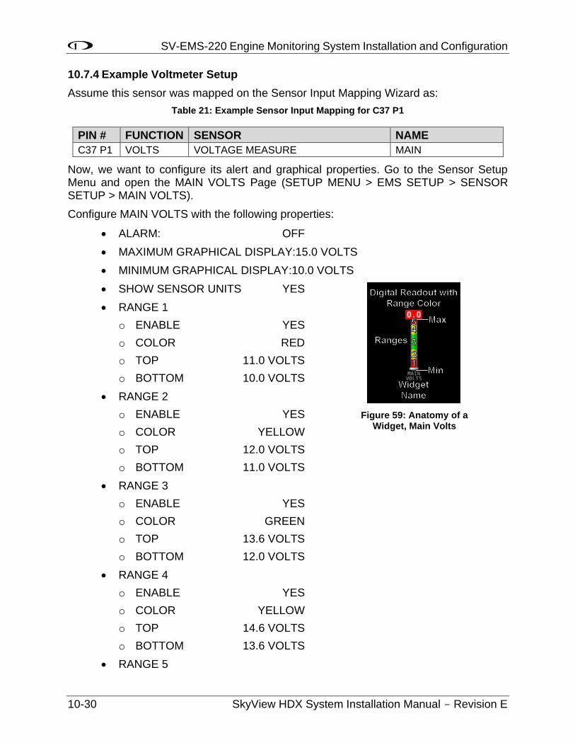
SV-EMS-220 Engine Monitoring System Installation and Configuration
10-30 SkyView HDX System Installation Manual - Revision E
10.7.4 Example Voltmeter Setup
Assume this sensor was mapped on the Sensor Input Mapping Wizard as:
Table 21: Example Sensor Input Mapping for C37 P1
PIN # FUNCTION SENSOR NAME
C37 P1 VOLTS VOLTAGE MEASURE MAIN
Now, we want to configure its alert and graphical properties. Go to the Sensor Setup Menu and open the MAIN VOLTS Page (SETUP MENU > EMS SETUP > SENSOR SETUP > MAIN VOLTS).
Configure MAIN VOLTS with the following properties:
• ALARM: OFF
• MAXIMUM GRAPHICAL DISPLAY:15.0 VOLTS
• MINIMUM GRAPHICAL DISPLAY:10.0 VOLTS
• SHOW SENSOR UNITS YES
• RANGE 1
o ENABLE YES
o COLOR RED
o TOP 11.0 VOLTS
o BOTTOM 10.0 VOLTS
• RANGE 2
o ENABLE YES
o COLOR YELLOW
o TOP 12.0 VOLTS
o BOTTOM 11.0 VOLTS
• RANGE 3
o ENABLE YES
o COLOR GREEN
o TOP 13.6 VOLTS
o BOTTOM 12.0 VOLTS
• RANGE 4
o ENABLE YES
o COLOR YELLOW
o TOP 14.6 VOLTS
o BOTTOM 13.6 VOLTS
• RANGE 5
Figure 59: Anatomy of a Widget, Main Volts
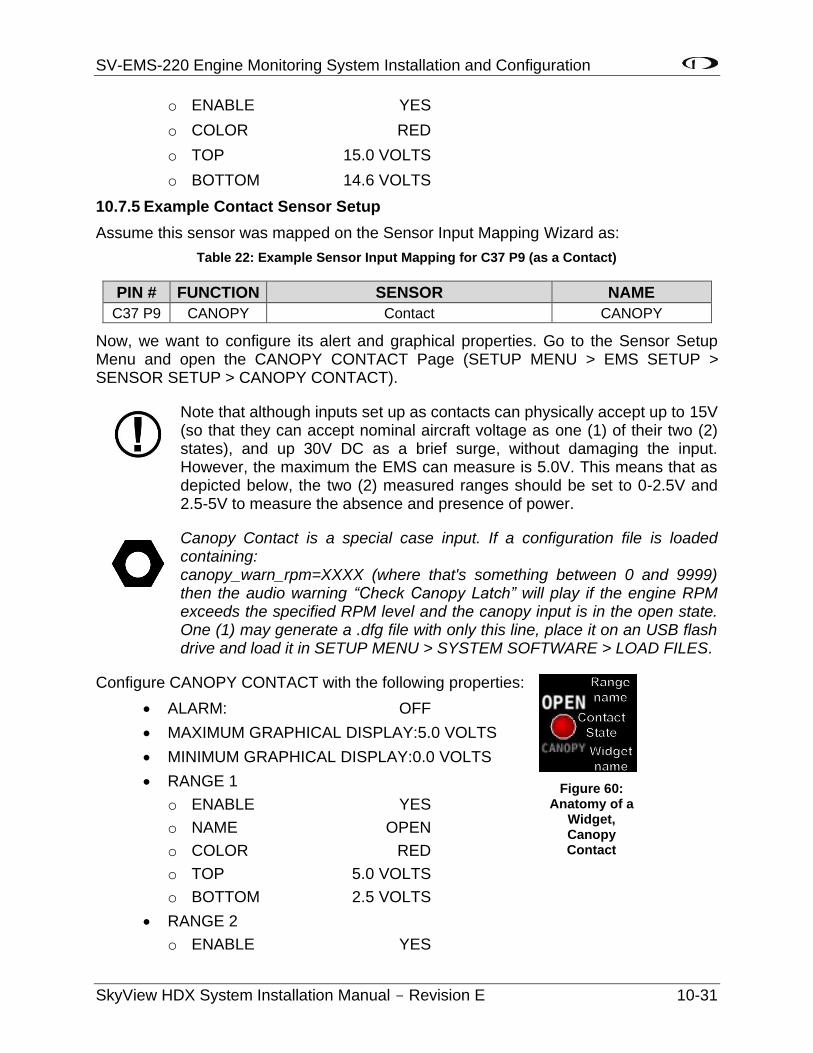
SV-EMS-220 Engine Monitoring System Installation and Configuration
SkyView HDX System Installation Manual - Revision E 10-31
o ENABLE YES
o COLOR RED
o TOP 15.0 VOLTS
o BOTTOM 14.6 VOLTS
10.7.5 Example Contact Sensor Setup
Assume this sensor was mapped on the Sensor Input Mapping Wizard as:
Table 22: Example Sensor Input Mapping for C37 P9 (as a Contact)
PIN # FUNCTION SENSOR NAME
C37 P9 CANOPY Contact CANOPY
Now, we want to configure its alert and graphical properties. Go to the Sensor Setup Menu and open the CANOPY CONTACT Page (SETUP MENU > EMS SETUP > SENSOR SETUP > CANOPY CONTACT).
Note that although inputs set up as contacts can physically accept up to 15V (so that they can accept nominal aircraft voltage as one (1) of their two (2) states), and up 30V DC as a brief surge, without damaging the input. However, the maximum the EMS can measure is 5.0V. This means that as depicted below, the two (2) measured ranges should be set to 0-2.5V and 2.5-5V to measure the absence and presence of power.
Canopy Contact is a special case input. If a configuration file is loaded containing: canopy_warn_rpm=XXXX (where that's something between 0 and 9999) then the audio warning “Check Canopy Latch” will play if the engine RPM exceeds the specified RPM level and the canopy input is in the open state. One (1) may generate a .dfg file with only this line, place it on an USB flash drive and load it in SETUP MENU > SYSTEM SOFTWARE > LOAD FILES.
Configure CANOPY CONTACT with the following properties:
• ALARM: OFF
• MAXIMUM GRAPHICAL DISPLAY:5.0 VOLTS
• MINIMUM GRAPHICAL DISPLAY:0.0 VOLTS
• RANGE 1
o ENABLE YES
o NAME OPEN
o COLOR RED
o TOP 5.0 VOLTS
o BOTTOM 2.5 VOLTS
• RANGE 2
o ENABLE YES
Figure 60: Anatomy of a
Widget, Canopy Contact
SV-EMS-220 Engine Monitoring System Installation and Configuration
10-32 SkyView HDX System Installation Manual - Revision E
o NAME CLOSED
o COLOR GREEN
o TOP 2.5 VOLTS
o BOTTOM 0.0 VOLTS
• RANGE 3
o ENABLE NO
o NAME R3
o COLOR GREEN
o TOP 20.0 VOLTS
o BOTTOM 10.0 VOLTS
• RANGE 4
o ENABLE NO
o NAME R4
o COLOR YELLOW
o TOP 10.0 VOLTS
o BOTTOM 5.0 VOLTS
• RANGE 5
o ENABLE NO
10.7.6 Example RPM Setup
Assume this sensor was mapped on the Sensor Input Mapping Wizard as:
Table 23: Example Sensor Input Mapping for C37 P32/34 (RPM / Tachometer)
PIN # FUNCTION SENSOR NAME
C37 P32/34
RPM RPM
RPM
Now, we want to configure its alert and graphical properties. Go to the Sensor Setup Menu and open the RPM Page (SETUP MENU > EMS SETUP > SENSOR SETUP > RPM RPM).
Configure RPM with the following properties:
• ALARM: OFF
• MAXIMUM GRAPHICAL DISPLAY:3000 RPM
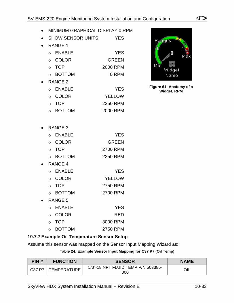
SV-EMS-220 Engine Monitoring System Installation and Configuration
SkyView HDX System Installation Manual - Revision E 10-33
• MINIMUM GRAPHICAL DISPLAY:0 RPM
• SHOW SENSOR UNITS YES
• RANGE 1
o ENABLE YES
o COLOR GREEN
o TOP 2000 RPM
o BOTTOM 0 RPM
• RANGE 2
o ENABLE YES
o COLOR YELLOW
o TOP 2250 RPM
o BOTTOM 2000 RPM
• RANGE 3
o ENABLE YES
o COLOR GREEN
o TOP 2700 RPM
o BOTTOM 2250 RPM
• RANGE 4
o ENABLE YES
o COLOR YELLOW
o TOP 2750 RPM
o BOTTOM 2700 RPM
• RANGE 5
o ENABLE YES
o COLOR RED
o TOP 3000 RPM
o BOTTOM 2750 RPM
10.7.7 Example Oil Temperature Sensor Setup
Assume this sensor was mapped on the Sensor Input Mapping Wizard as:
Table 24: Example Sensor Input Mapping for C37 P7 (Oil Temp)
PIN # FUNCTION SENSOR NAME
C37 P7 TEMPERATURE 5/8”-18 NPT FLUID TEMP P/N 503385-
000 OIL
Figure 61: Anatomy of a Widget, RPM
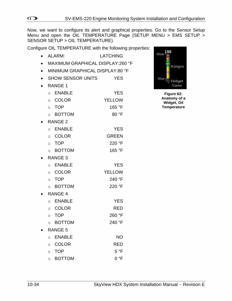
SV-EMS-220 Engine Monitoring System Installation and Configuration
10-34 SkyView HDX System Installation Manual - Revision E
Now, we want to configure its alert and graphical properties. Go to the Sensor Setup Menu and open the OIL TEMPERATURE Page (SETUP MENU > EMS SETUP > SENSOR SETUP > OIL TEMPERATURE).
Configure OIL TEMPERATURE with the following properties:
• ALARM: LATCHING
• MAXIMUM GRAPHICAL DISPLAY:260 °F
• MINIMUM GRAPHICAL DISPLAY:80 °F
• SHOW SENSOR UNITS YES
• RANGE 1
o ENABLE YES
o COLOR YELLOW
o TOP 165 °F
o BOTTOM 80 °F
• RANGE 2
o ENABLE YES
o COLOR GREEN
o TOP 220 °F
o BOTTOM 165 °F
• RANGE 3
o ENABLE YES
o COLOR YELLOW
o TOP 240 °F
o BOTTOM 220 °F
• RANGE 4
o ENABLE YES
o COLOR RED
o TOP 260 °F
o BOTTOM 240 °F
• RANGE 5
o ENABLE NO
o COLOR RED
o TOP 5 °F
o BOTTOM 0 °F
Figure 62: Anatomy of a Widget, Oil
Temperature
SV-EMS-220 Engine Monitoring System Installation and Configuration
SkyView HDX System Installation Manual - Revision E 10-35
Note that oil temperature is configured with a latching alarm in this example. If oil temperature ever reaches a range configured as red, an alarm will trigger, and a message will show up in the message box on the Main Menu.
10.8 EMS Screen Layout Editor
All sensor mapping, settings, and widget graphical properties are automatically shared between displays. Installers do not need to transfer files between displays.
Use this wizard to configure the style and layout of the engine and environmental sensor gauges and calculated parameters (e.g., % power) on the 100%, 50%, 20%, and ENGINE BOTTOM BAND Engine Pages.
SkyView HDX can display 100%, 50%, and ENGINE BOTTOM BAND pages.
Note that sensors must be defined, mapped, and configured in order to show up on an Engine Page (reference the EMS Sensor Definitions, Mapping, and Settings Section of this manual for instructions on how to do this).
To use this tool, enter the wizard (SETUP MENU > EMS SETUP > SCREEN LAYOUT EDITOR), then choose the page size to edit. Once in the Screen Layout Editor, follow this procedure:
1. Add a sensor or info widget to the screen. Press either SENSOR or INFO to show their respective menus and scroll through available sensors or info parameters, highlight one (1), and then press ACCEPT or move either joystick to the right to add it to the screen.
2. Change the style of the widget. Press STYLE or turn the joystick until the widget’s style is acceptable.
3. Change the size of the widget. Press SIZE until the widget’s size is acceptable.
4. Change the location of the widget on the screen.
a. In SkyView HDX, use the Left knob for movement of the widget to Left (Counterclockwise) and Right (Clockwise). Use the Right knob for movement of the widget Up (Counterclockwise), and Down (Clockwise).
5. Repeat the above steps for all sensors that you want displayed on the Engine Page.
6. Save the page by pressing SAVE.
Press REMOVE to remove the chosen widget from the screen. Press CANCEL to return to the EMS Setup Menu without saving any changes.
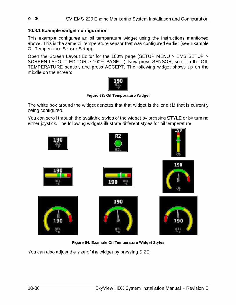
SV-EMS-220 Engine Monitoring System Installation and Configuration
10-36 SkyView HDX System Installation Manual - Revision E
10.8.1 Example widget configuration
This example configures an oil temperature widget using the instructions mentioned above. This is the same oil temperature sensor that was configured earlier (see Example Oil Temperature Sensor Setup).
Open the Screen Layout Editor for the 100% page (SETUP MENU > EMS SETUP > SCREEN LAYOUT EDITOR > 100% PAGE…). Now press SENSOR, scroll to the OIL TEMPERATURE sensor, and press ACCEPT. The following widget shows up on the middle on the screen:
Figure 63: Oil Temperature Widget
The white box around the widget denotes that that widget is the one (1) that is currently being configured.
You can scroll through the available styles of the widget by pressing STYLE or by turning either joystick. The following widgets illustrate different styles for oil temperature:
Figure 64: Example Oil Temperature Widget Styles
You can also adjust the size of the widget by pressing SIZE.
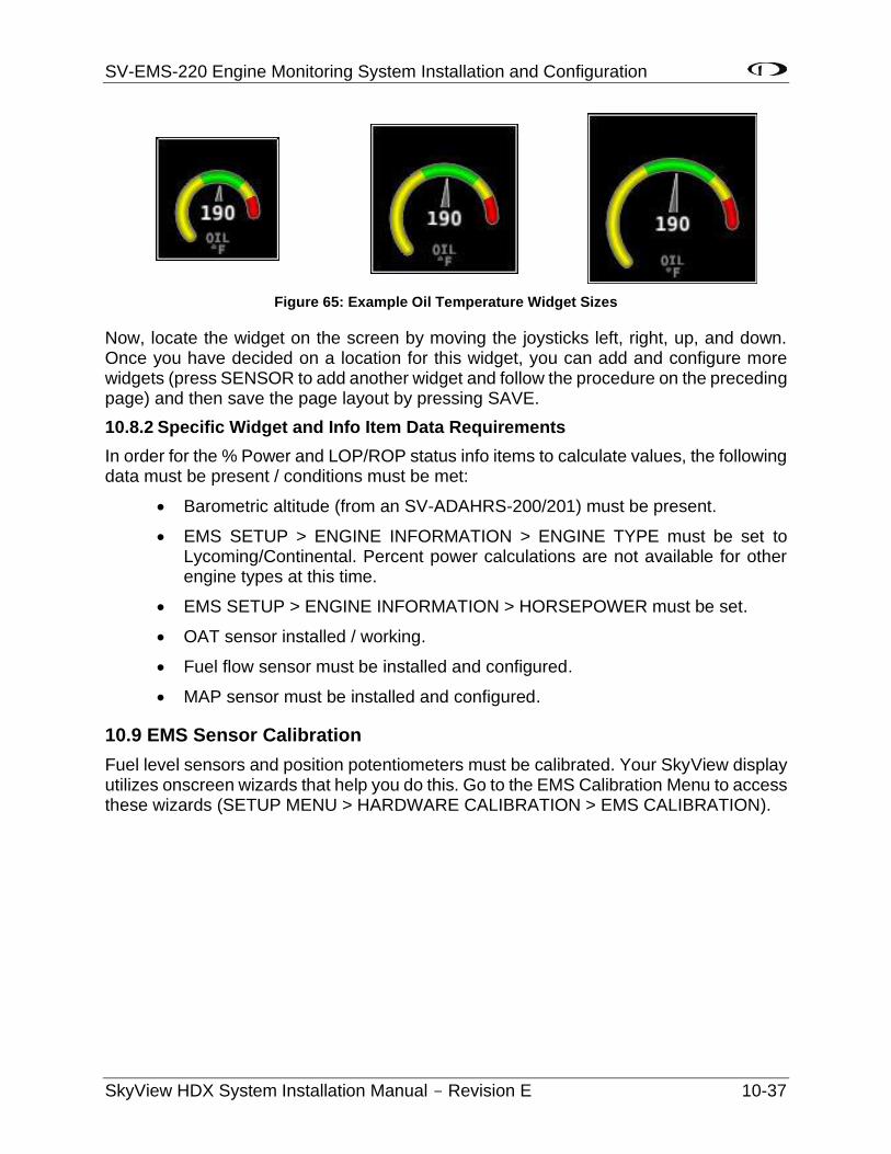
SV-EMS-220 Engine Monitoring System Installation and Configuration
SkyView HDX System Installation Manual - Revision E 10-37
Figure 65: Example Oil Temperature Widget Sizes
Now, locate the widget on the screen by moving the joysticks left, right, up, and down. Once you have decided on a location for this widget, you can add and configure more widgets (press SENSOR to add another widget and follow the procedure on the preceding page) and then save the page layout by pressing SAVE.
10.8.2 Specific Widget and Info Item Data Requirements
In order for the % Power and LOP/ROP status info items to calculate values, the following data must be present / conditions must be met:
• Barometric altitude (from an SV-ADAHRS-200/201) must be present.
• EMS SETUP > ENGINE INFORMATION > ENGINE TYPE must be set to Lycoming/Continental. Percent power calculations are not available for other engine types at this time.
• EMS SETUP > ENGINE INFORMATION > HORSEPOWER must be set.
• OAT sensor installed / working.
• Fuel flow sensor must be installed and configured.
• MAP sensor must be installed and configured.
10.9 EMS Sensor Calibration
Fuel level sensors and position potentiometers must be calibrated. Your SkyView display utilizes onscreen wizards that help you do this. Go to the EMS Calibration Menu to access these wizards (SETUP MENU > HARDWARE CALIBRATION > EMS CALIBRATION).
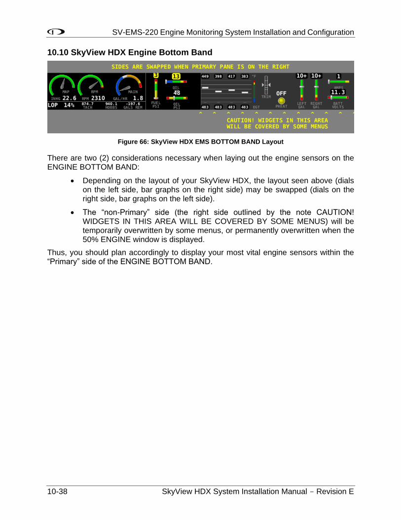
SV-EMS-220 Engine Monitoring System Installation and Configuration
10-38 SkyView HDX System Installation Manual - Revision E
10.10 SkyView HDX Engine Bottom Band
Figure 66: SkyView HDX EMS BOTTOM BAND Layout
There are two (2) considerations necessary when laying out the engine sensors on the ENGINE BOTTOM BAND:
• Depending on the layout of your SkyView HDX, the layout seen above (dials on the left side, bar graphs on the right side) may be swapped (dials on the right side, bar graphs on the left side).
• The “non-Primary” side (the right side outlined by the note CAUTION! WIDGETS IN THIS AREA WILL BE COVERED BY SOME MENUS) will be temporarily overwritten by some menus, or permanently overwritten when the 50% ENGINE window is displayed.
Thus, you should plan accordingly to display your most vital engine sensors within the “Primary” side of the ENGINE BOTTOM BAND.
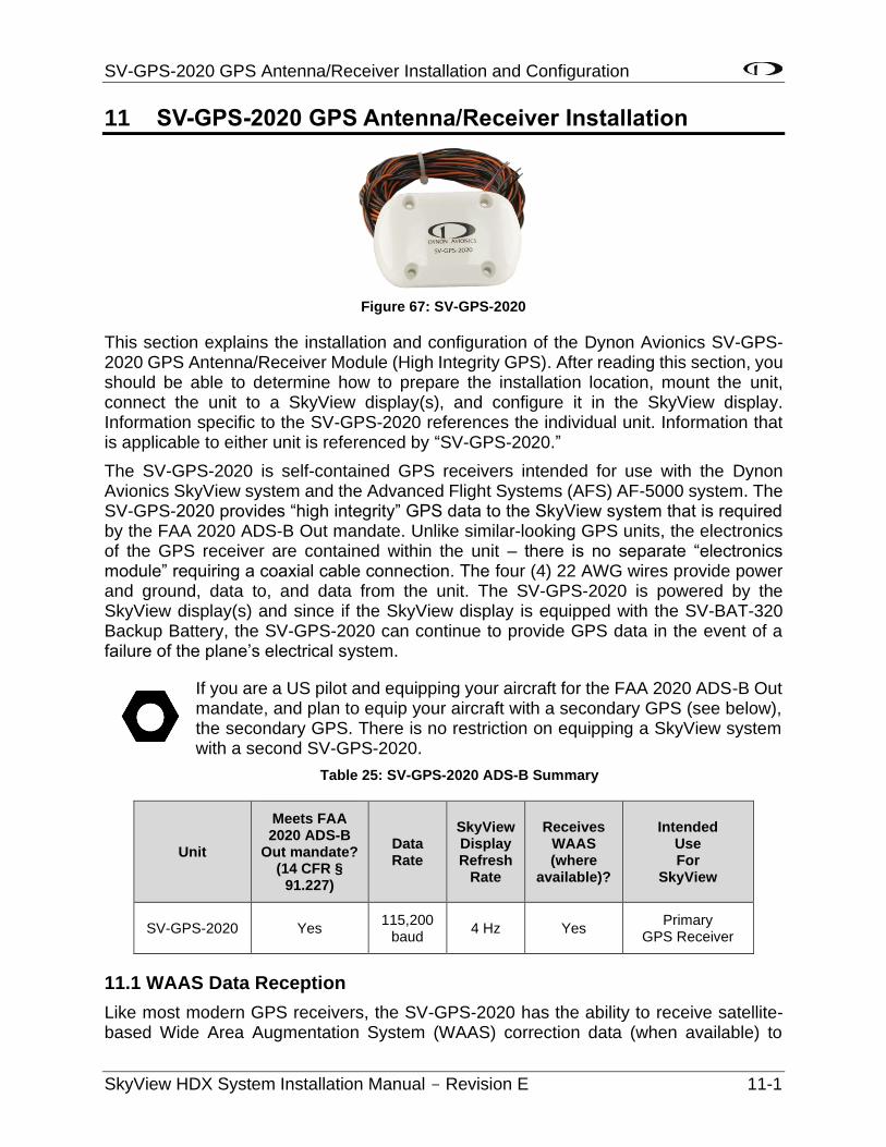
SV-GPS-2020 GPS Antenna/Receiver Installation and Configuration
SkyView HDX System Installation Manual - Revision E 11-1
11 SV-GPS-2020 GPS Antenna/Receiver Installation
Figure 67: SV-GPS-2020
This section explains the installation and configuration of the Dynon Avionics SV-GPS-2020 GPS Antenna/Receiver Module (High Integrity GPS). After reading this section, you should be able to determine how to prepare the installation location, mount the unit, connect the unit to a SkyView display(s), and configure it in the SkyView display. Information specific to the SV-GPS-2020 references the individual unit. Information that is applicable to either unit is referenced by “SV-GPS-2020.”
The SV-GPS-2020 is self-contained GPS receivers intended for use with the Dynon Avionics SkyView system and the Advanced Flight Systems (AFS) AF-5000 system. The SV-GPS-2020 provides “high integrity” GPS data to the SkyView system that is required by the FAA 2020 ADS-B Out mandate. Unlike similar-looking GPS units, the electronics of the GPS receiver are contained within the unit – there is no separate “electronics module” requiring a coaxial cable connection. The four (4) 22 AWG wires provide power and ground, data to, and data from the unit. The SV-GPS-2020 is powered by the SkyView display(s) and since if the SkyView display is equipped with the SV-BAT-320 Backup Battery, the SV-GPS-2020 can continue to provide GPS data in the event of a failure of the plane’s electrical system.
If you are a US pilot and equipping your aircraft for the FAA 2020 ADS-B Out mandate, and plan to equip your aircraft with a secondary GPS (see below), the secondary GPS. There is no restriction on equipping a SkyView system with a second SV-GPS-2020.
Table 25: SV-GPS-2020 ADS-B Summary
Unit
Meets FAA 2020 ADS-B
Out mandate? (14 CFR §
91.227)
Data Rate
SkyView Display Refresh
Rate
Receives WAAS (where
available)?
Intended Use For
SkyView
SV-GPS-2020 Yes 115,200
baud 4 Hz Yes
Primary GPS Receiver
11.1 WAAS Data Reception
Like most modern GPS receivers, the SV-GPS-2020 has the ability to receive satellite-based Wide Area Augmentation System (WAAS) correction data (when available) to
SV-GPS-2020 GPS Antenna/Receiver Installation and Configuration
11-2 SkyView HDX System Installation Manual - Revision E
improve positional accuracy. Many pilots confuse a GPS unit that receives WAAS data with a GPS Navigator unit that is certified for flight in Instrument Flight Rules (IFR) conditions. To be clear, the SV-GPS-2020, connected to a SkyView system, do receive WAAS data (when available), but having a SV-GPS-2020 (but not an IFR or “certified” GPS) does not mean that your aircraft is properly equipped for legal flight under IFR.
Only the SV-GPS-2020 or equivalent “high integrity” GPS unit meets the (GPS portion of the) requirements of the FAA 2020 ADS-B Out mandate. If you are equipping your plane for use in the US, to be compliant with the FAA 2020 ADS-B Out mandate, we recommend that you install the SV-GPS-2020.
Valid GPS data is required for time, compass calibration, moving map functionality, ADS-B IN, and ADS-B OUT, data logging, and other internal functions of the SkyView system. If your plane is already equipped with a GPS unit and it can output GPS data, SkyView can use that GPS data for its operations (other than FAA 2020 ADS-B Out mandate). However, if you decide to do so, be advised that other GPS units typically provide GPS data updates only once per second (1 Hz); this can cause position updates for the Synthetic Vision (SynVis) and the map position to appear “jerky.” In contrast, the SV-GPS-2020 provide positional updates much faster – four (4) times per second (4 Hz) for the SV-GPS-2020, which provides a superior display for SynVis and map position updates.
11.2 Mechanical Installation
Like all GPS devices, for most reliable performance, the SV-GPS-2020 requires a clear, unobstructed “view” of the sky. The -GPS-2020 is designed to be mounted on the upper fuselage of the aircraft for an unobstructed (360° view) of the sky during maneuvers.
Observe the following guidelines when choosing a location for an SV-GPS-2020:
• The optimal location for the SV-GPS-2020 is a rigid surface on the upper fuselage of the aircraft.
• Mounting location should be relatively level (the base of the SV-GPS-2020 is flat).
• Do not locate the receiver within 3 feet (91.44 cm)of transmitting antennas.
• Avoid antenna shadows (i.e., obstructions that block the antenna’s view of the sky).
• All four (4) of the SV-GPS-2020’s wires should all be connected to each SkyView system display for redundancy.
The following diagram shows the mounting dimensions of the SV-GPS-2020. Note that it utilizes a common bolt pattern found in much of general aviation.
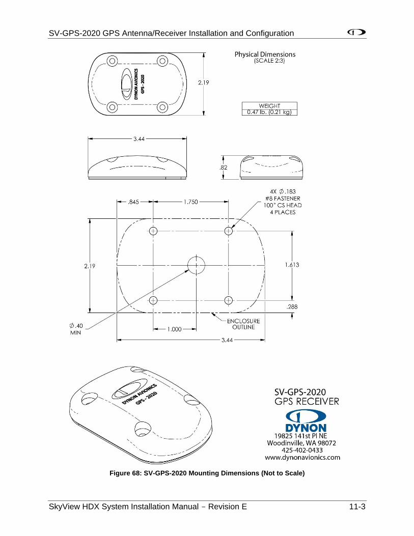
SV-GPS-2020 GPS Antenna/Receiver Installation and Configuration
SkyView HDX System Installation Manual - Revision E 11-3
Figure 68: SV-GPS-2020 Mounting Dimensions (Not to Scale)
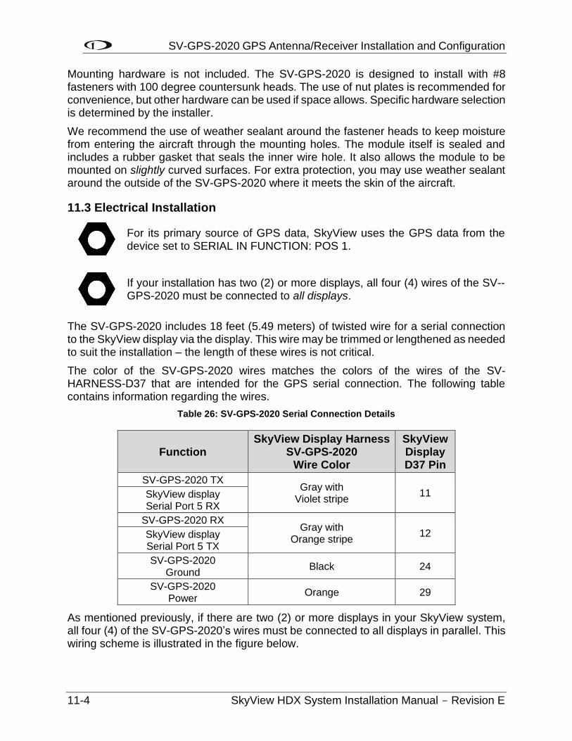
SV-GPS-2020 GPS Antenna/Receiver Installation and Configuration
11-4 SkyView HDX System Installation Manual - Revision E
Mounting hardware is not included. The SV-GPS-2020 is designed to install with #8 fasteners with 100 degree countersunk heads. The use of nut plates is recommended for convenience, but other hardware can be used if space allows. Specific hardware selection is determined by the installer.
We recommend the use of weather sealant around the fastener heads to keep moisture from entering the aircraft through the mounting holes. The module itself is sealed and includes a rubber gasket that seals the inner wire hole. It also allows the module to be mounted on slightly curved surfaces. For extra protection, you may use weather sealant around the outside of the SV-GPS-2020 where it meets the skin of the aircraft.
11.3 Electrical Installation
For its primary source of GPS data, SkyView uses the GPS data from the device set to SERIAL IN FUNCTION: POS 1.
If your installation has two (2) or more displays, all four (4) wires of the SV--GPS-2020 must be connected to all displays.
The SV-GPS-2020 includes 18 feet (5.49 meters) of twisted wire for a serial connection to the SkyView display via the display. This wire may be trimmed or lengthened as needed to suit the installation – the length of these wires is not critical.
The color of the SV-GPS-2020 wires matches the colors of the wires of the SV-HARNESS-D37 that are intended for the GPS serial connection. The following table contains information regarding the wires.
Table 26: SV-GPS-2020 Serial Connection Details
Function SkyView Display Harness
SV-GPS-2020 Wire Color
SkyView Display D37 Pin
SV-GPS-2020 TX Gray with
Violet stripe 11 SkyView display
Serial Port 5 RX
SV-GPS-2020 RX Gray with
Orange stripe 12 SkyView display
Serial Port 5 TX
SV-GPS-2020 Ground
Black 24
SV-GPS-2020 Power
Orange 29
As mentioned previously, if there are two (2) or more displays in your SkyView system, all four (4) of the SV-GPS-2020’s wires must be connected to all displays in parallel. This wiring scheme is illustrated in the figure below.
SV-GPS-2020 GPS Antenna/Receiver Installation and Configuration
SkyView HDX System Installation Manual - Revision E 11-5
SV-GPS-2020
SkyView Display 1
SkyView Display 2
GPS Power
GPS Power
SkyView RX
SkyView RX
Ground
Ground
SkyView TX
SkyView TX
GPS Power
GPS TX
Ground
GPS RX
Figure 69: SV-GPS-2020 Connected to Multiple SkyView Displays
11.4 Serial Port 5 Configuration (SV-GPS-2020 only)
Go to the Serial Port Setup Menu (SETUP MENU > SYSTEM SETUP > SERIAL PORT SETUP > SERIAL PORT 5 SETUP) and then configure serial port 5 as follows:
SERIAL IN DEVICE: DYNON SV-GPS-2020 SERIAL IN FUNCTION: POS 1 NAVIGATION SOURCE DISPLAY NAME:(NOT SET) SERIAL IN/OUT BAUD RATE: 115,200 SERIAL OUT DEVICE: DYNON SV-GPS-2020 (Highlighted settings are changed automatically from SERIAL IN DEVICE.)
11.5 Testing / Troubleshooting SV-GPS-2020 Installation
The SV-GPS-2020 are connected to the SkyView system via “serial port”, and thus will not appear on the list of SkyView Network Devices during a SkyView Network configuration.
11.5.1 Basic Serial Port Functionality
Go to Serial Port Setup for the serial port you chose to use for the SV-GPS-2020 (typically Serial Port 5):
SETUP MENU > SYSTEM SETUP > SERIAL PORT SETUP > SERIAL PORT 5 SETUP
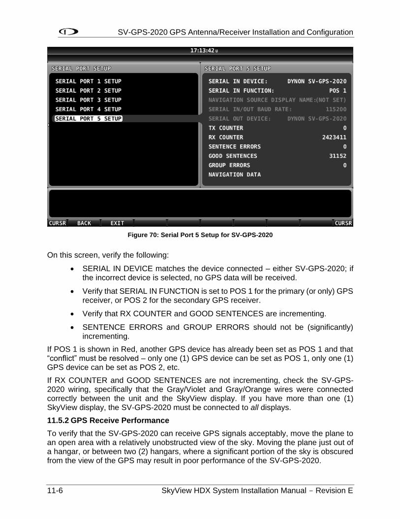
SV-GPS-2020 GPS Antenna/Receiver Installation and Configuration
11-6 SkyView HDX System Installation Manual - Revision E
Figure 70: Serial Port 5 Setup for SV-GPS-2020
On this screen, verify the following:
• SERIAL IN DEVICE matches the device connected – either SV-GPS-2020; if the incorrect device is selected, no GPS data will be received.
• Verify that SERIAL IN FUNCTION is set to POS 1 for the primary (or only) GPS receiver, or POS 2 for the secondary GPS receiver.
• Verify that RX COUNTER and GOOD SENTENCES are incrementing.
• SENTENCE ERRORS and GROUP ERRORS should not be (significantly) incrementing.
If POS 1 is shown in Red, another GPS device has already been set as POS 1 and that “conflict” must be resolved – only one (1) GPS device can be set as POS 1, only one (1) GPS device can be set as POS 2, etc.
If RX COUNTER and GOOD SENTENCES are not incrementing, check the SV-GPS-2020 wiring, specifically that the Gray/Violet and Gray/Orange wires were connected correctly between the unit and the SkyView display. If you have more than one (1) SkyView display, the SV-GPS-2020 must be connected to all displays.
11.5.2 GPS Receive Performance
To verify that the SV-GPS-2020 can receive GPS signals acceptably, move the plane to an open area with a relatively unobstructed view of the sky. Moving the plane just out of a hangar, or between two (2) hangars, where a significant portion of the sky is obscured from the view of the GPS may result in poor performance of the SV-GPS-2020.
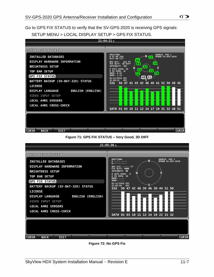
SV-GPS-2020 GPS Antenna/Receiver Installation and Configuration
SkyView HDX System Installation Manual - Revision E 11-7
Go to GPS FIX STATUS to verify that the SV-GPS-2020 is receiving GPS signals:
SETUP MENU > LOCAL DISPLAY SETUP > GPS FIX STATUS.
Figure 71: GPS FIX STATUS – Very Good, 3D DIFF
Figure 72: No GPS Fix
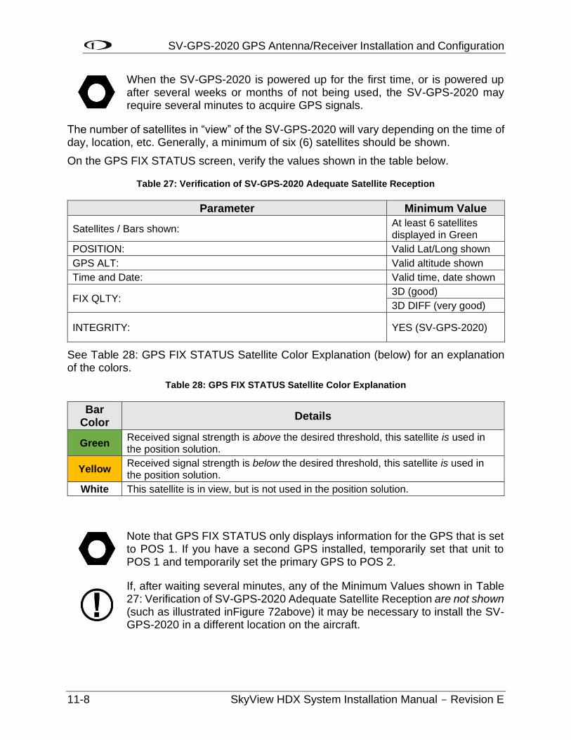
SV-GPS-2020 GPS Antenna/Receiver Installation and Configuration
11-8 SkyView HDX System Installation Manual - Revision E
When the SV-GPS-2020 is powered up for the first time, or is powered up after several weeks or months of not being used, the SV-GPS-2020 may require several minutes to acquire GPS signals.
The number of satellites in “view” of the SV-GPS-2020 will vary depending on the time of day, location, etc. Generally, a minimum of six (6) satellites should be shown.
On the GPS FIX STATUS screen, verify the values shown in the table below.
Table 27: Verification of SV-GPS-2020 Adequate Satellite Reception
Parameter Minimum Value
Satellites / Bars shown: At least 6 satellites displayed in Green
POSITION: Valid Lat/Long shown
GPS ALT: Valid altitude shown
Time and Date: Valid time, date shown
FIX QLTY: 3D (good)
3D DIFF (very good)
INTEGRITY: YES (SV-GPS-2020)
See Table 28: GPS FIX STATUS Satellite Color Explanation (below) for an explanation of the colors.
Table 28: GPS FIX STATUS Satellite Color Explanation
Bar Color
Details
Green Received signal strength is above the desired threshold, this satellite is used in the position solution.
Yellow Received signal strength is below the desired threshold, this satellite is used in the position solution.
White This satellite is in view, but is not used in the position solution.
Note that GPS FIX STATUS only displays information for the GPS that is set to POS 1. If you have a second GPS installed, temporarily set that unit to POS 1 and temporarily set the primary GPS to POS 2.
If, after waiting several minutes, any of the Minimum Values shown in Table 27: Verification of SV-GPS-2020 Adequate Satellite Reception are not shown (such as illustrated inFigure 72above) it may be necessary to install the SV-GPS-2020 in a different location on the aircraft.
SV-GPS-2020 GPS Antenna/Receiver Installation and Configuration
SkyView HDX System Installation Manual - Revision E 11-9
11.6 Additional Configuration Required for Compliance with FAA 2020 ADS-B Out Mandate
The section (above) deals with installation and configuration of the SV-GPS-2020 only. However, installing the SV-GPS-2020 is only part of what is required to be compliant with the FAA 2020 ADS-B Out mandate. Specifically, next steps include:
• Update your SkyView system to Software v14.0 (or later).
• Change the SV-XPNDR-261’s source of GPS data to the SV-GPS-2020.
For the details on the transponder changes, and explanation of overall compliance with the FAA 2020 ADS-B Out mandate, see the SV-XPNDR-261 Transponder Installation and Configuration section.

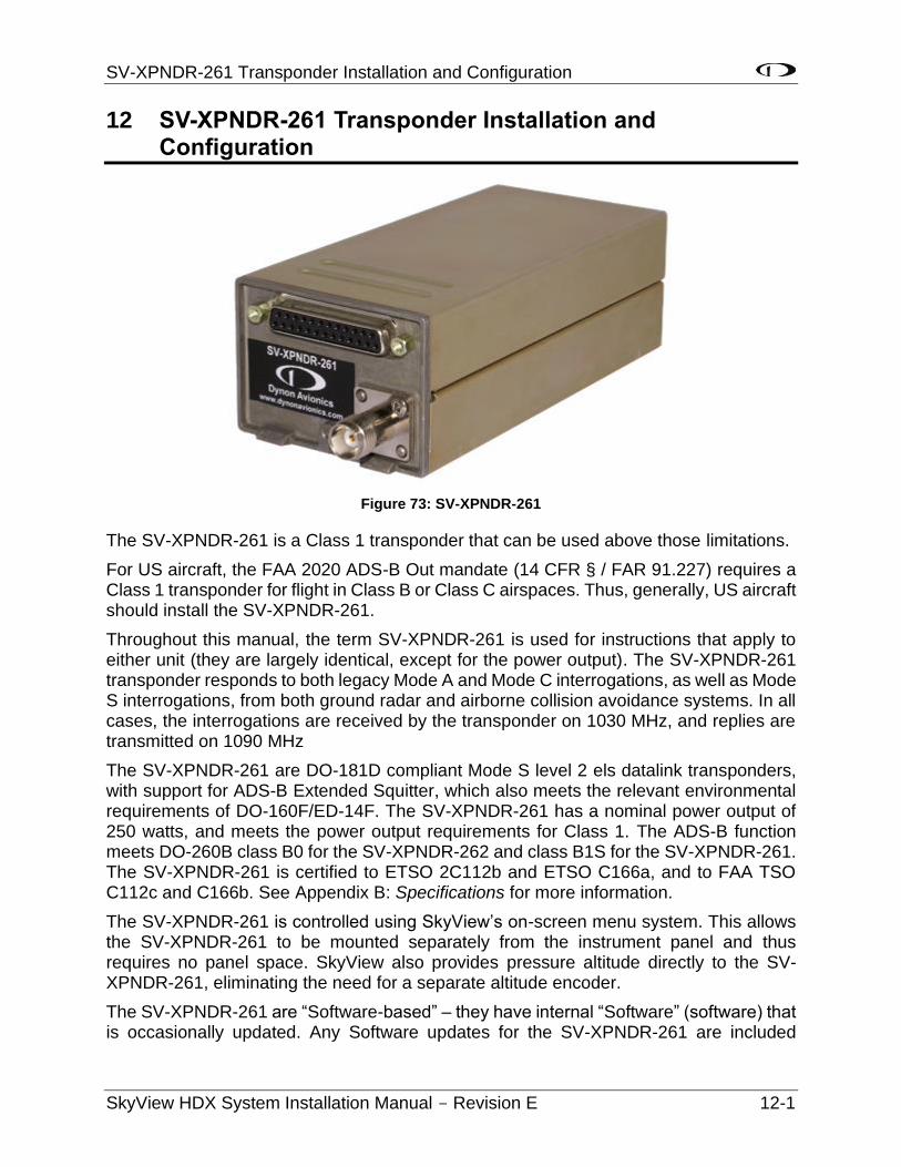
SV-XPNDR-261 Transponder Installation and Configuration
SkyView HDX System Installation Manual - Revision E 12-1
12 SV-XPNDR-261 Transponder Installation and Configuration
Figure 73: SV-XPNDR-261
The SV-XPNDR-261 is a Class 1 transponder that can be used above those limitations.
For US aircraft, the FAA 2020 ADS-B Out mandate (14 CFR § / FAR 91.227) requires a Class 1 transponder for flight in Class B or Class C airspaces. Thus, generally, US aircraft should install the SV-XPNDR-261.
Throughout this manual, the term SV-XPNDR-261 is used for instructions that apply to either unit (they are largely identical, except for the power output). The SV-XPNDR-261 transponder responds to both legacy Mode A and Mode C interrogations, as well as Mode S interrogations, from both ground radar and airborne collision avoidance systems. In all cases, the interrogations are received by the transponder on 1030 MHz, and replies are transmitted on 1090 MHz
The SV-XPNDR-261 are DO-181D compliant Mode S level 2 els datalink transponders, with support for ADS-B Extended Squitter, which also meets the relevant environmental requirements of DO-160F/ED-14F. The SV-XPNDR-261 has a nominal power output of 250 watts, and meets the power output requirements for Class 1. The ADS-B function meets DO-260B class B0 for the SV-XPNDR-262 and class B1S for the SV-XPNDR-261. The SV-XPNDR-261 is certified to ETSO 2C112b and ETSO C166a, and to FAA TSO C112c and C166b. See Appendix B: Specifications for more information.
The SV-XPNDR-261 is controlled using SkyView’s on-screen menu system. This allows the SV-XPNDR-261 to be mounted separately from the instrument panel and thus requires no panel space. SkyView also provides pressure altitude directly to the SV-XPNDR-261, eliminating the need for a separate altitude encoder.
The SV-XPNDR-261 are “Software-based” – they have internal “Software” (software) that is occasionally updated. Any Software updates for the SV-XPNDR-261 are included
SV-XPNDR-261 Transponder Installation and Configuration
12-2 SkyView HDX System Installation Manual - Revision E
within SkyView system Software. See SV-XPNDR-261 Software Updates later in this section for details on SV-XPNDR-261 Software updates.
The SV-XPNDR-261 operates at either 14-volt nominal or 28-volt nominal DC power supply; no configuration changes are required.
12.1 Mechanical Installation
The SV-XPNDR-261 is designed to be mounted in any convenient location in the cockpit, the cabin, or an avionics bay.
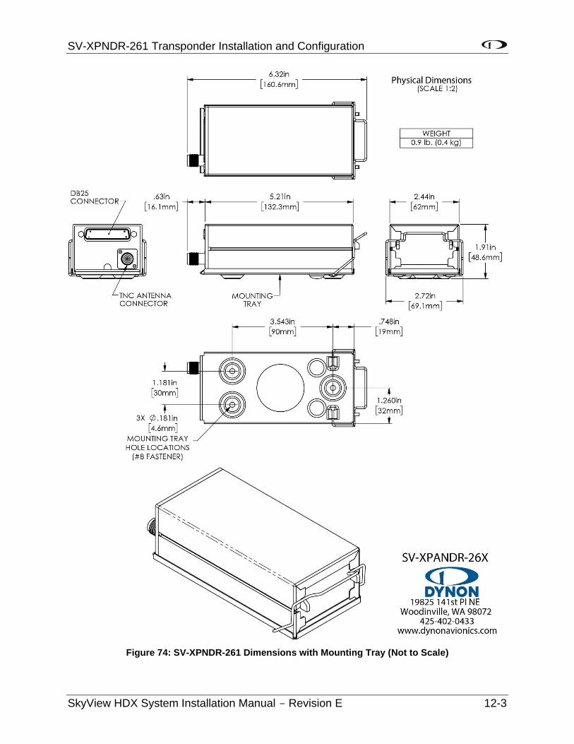
SV-XPNDR-261 Transponder Installation and Configuration
SkyView HDX System Installation Manual - Revision E 12-3
Figure 74: SV-XPNDR-261 Dimensions with Mounting Tray (Not to Scale)
SV-XPNDR-261 Transponder Installation and Configuration
12-4 SkyView HDX System Installation Manual - Revision E
The following installation procedure should be followed, remembering to allow adequate space for installation of cables and connectors:
• The SV-XPNDR-261 should be located in an area that is accessible, should the SV-XPNDR-261 require service.
• Select a position in the aircraft that is not too close to any high external heat source. (The SV-XPNDR-261 is not a significant heat source itself and does not need to be kept away from other devices for this reason).
• It is acceptable to locate the SV-XPNDR-261 remotely from the panel, such as in the aft fuselage, to minimize the length of coaxial cable between the SV-XPNDR-261 and the transponder antenna.
• Orientation of the SV-XPNDR-261 is not critical – it can be mounted horizontally, or vertically.
• Secure the mounting tray to the aircraft via the three (3) mounting holes in the tray. The tray should be mounted to a flat surface - it is important that the tray is supported at the dimples as well as the three (3) mounting points.
• Put the SV-XPNDR-261 transponder into the secured mounting tray by hooking the connector end under the lip on the tray.
• Lock the SV-XPNDR-261 into the mounting tray by clipping the retaining wire over the lugs on the opposite end.
• Avoid sharp bends and placing the cables too near to the aircraft control cables.
12.1.1 Cooling Requirements
The SV-XPNDR-261 meets all applicable TSO requirements without forced air-cooling; therefore, no additional cooling is required for the SV-XPNDR-261.
12.1.2 Additional Items Required
Additional items you will require, but which are not in the SV-XPNDR-261 package, include:
• Antenna and fixing hardware. The SV-XPNDR-261 is compatible with any transponder antenna conforming to TSO-C74.
• Cables and TNC Female connector (or TNC Female to BNC Male adapter). You need to supply and fabricate all required cables (or cable and connector is included with your transponder antenna). Guidance on cable types is given below.
• Mounting hardware: To secure the SV-XPNDR-261 tray to the airframe you will need at least three (3) flat head screws and three (3) self-locking nuts. If the aircraft does not have existing mounting provisions you may need to fabricate additional brackets to support the SV-XPNDR-261 tray.
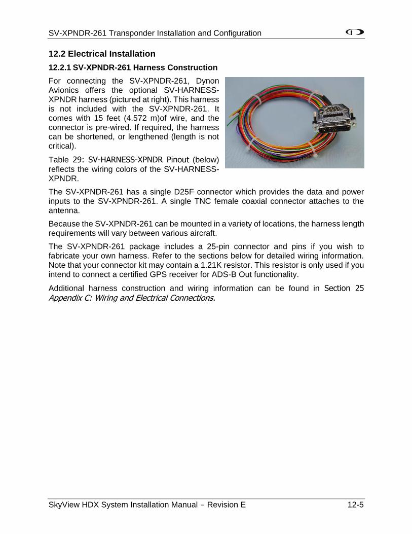
SV-XPNDR-261 Transponder Installation and Configuration
SkyView HDX System Installation Manual - Revision E 12-5
12.2 Electrical Installation
12.2.1 SV-XPNDR-261 Harness Construction
For connecting the SV-XPNDR-261, Dynon Avionics offers the optional SV-HARNESS-XPNDR harness (pictured at right). This harness is not included with the SV-XPNDR-261. It comes with 15 feet (4.572 m)of wire, and the connector is pre-wired. If required, the harness can be shortened, or lengthened (length is not critical).
Table 29: SV-HARNESS-XPNDR Pinout (below) reflects the wiring colors of the SV-HARNESS-XPNDR.
The SV-XPNDR-261 has a single D25F connector which provides the data and power inputs to the SV-XPNDR-261. A single TNC female coaxial connector attaches to the antenna.
Because the SV-XPNDR-261 can be mounted in a variety of locations, the harness length requirements will vary between various aircraft.
The SV-XPNDR-261 package includes a 25-pin connector and pins if you wish to fabricate your own harness. Refer to the sections below for detailed wiring information. Note that your connector kit may contain a 1.21K resistor. This resistor is only used if you intend to connect a certified GPS receiver for ADS-B Out functionality.
Additional harness construction and wiring information can be found in Section 25 Appendix C: Wiring and Electrical Connections.
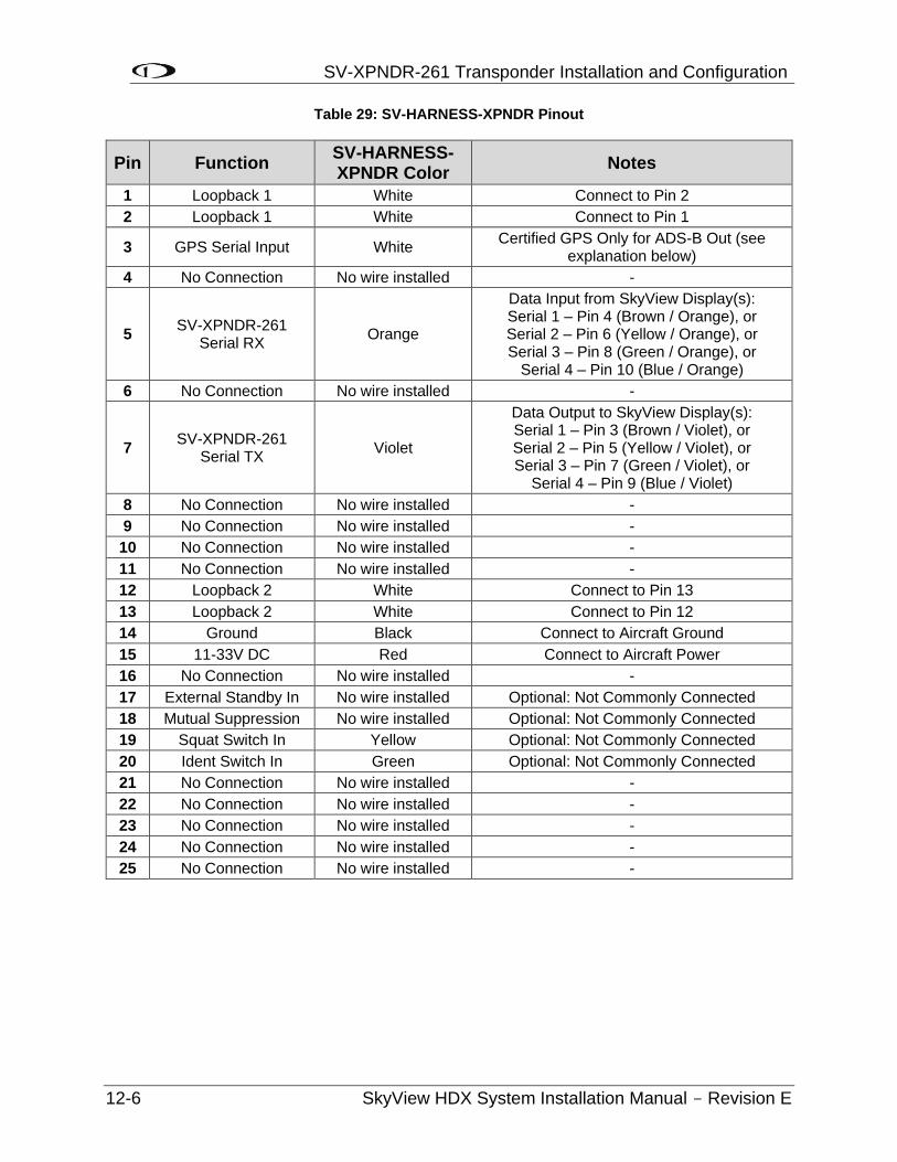
SV-XPNDR-261 Transponder Installation and Configuration
12-6 SkyView HDX System Installation Manual - Revision E
Table 29: SV-HARNESS-XPNDR Pinout
Pin Function SV-HARNESS-XPNDR Color
Notes
1 Loopback 1 White Connect to Pin 2
2 Loopback 1 White Connect to Pin 1
3 GPS Serial Input White Certified GPS Only for ADS-B Out (see
explanation below)
4 No Connection No wire installed -
5 SV-XPNDR-261
Serial RX Orange
Data Input from SkyView Display(s): Serial 1 – Pin 4 (Brown / Orange), or Serial 2 – Pin 6 (Yellow / Orange), or Serial 3 – Pin 8 (Green / Orange), or
Serial 4 – Pin 10 (Blue / Orange)
6 No Connection No wire installed -
7 SV-XPNDR-261
Serial TX Violet
Data Output to SkyView Display(s): Serial 1 – Pin 3 (Brown / Violet), or Serial 2 – Pin 5 (Yellow / Violet), or Serial 3 – Pin 7 (Green / Violet), or
Serial 4 – Pin 9 (Blue / Violet)
8 No Connection No wire installed -
9 No Connection No wire installed -
10 No Connection No wire installed -
11 No Connection No wire installed -
12 Loopback 2 White Connect to Pin 13
13 Loopback 2 White Connect to Pin 12
14 Ground Black Connect to Aircraft Ground
15 11-33V DC Red Connect to Aircraft Power
16 No Connection No wire installed -
17 External Standby In No wire installed Optional: Not Commonly Connected
18 Mutual Suppression No wire installed Optional: Not Commonly Connected
19 Squat Switch In Yellow Optional: Not Commonly Connected
20 Ident Switch In Green Optional: Not Commonly Connected
21 No Connection No wire installed -
22 No Connection No wire installed -
23 No Connection No wire installed -
24 No Connection No wire installed -
25 No Connection No wire installed -
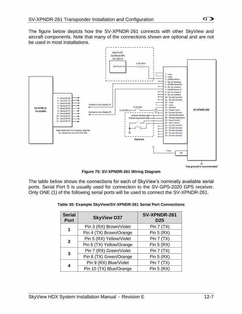
SV-XPNDR-261 Transponder Installation and Configuration
SkyView HDX System Installation Manual - Revision E 12-7
The figure below depicts how the SV-XPNDR-261 connects with other SkyView and aircraft components. Note that many of the connections shown are optional and are not be used in most installations.
Figure 75: SV-XPNDR-261 Wiring Diagram
The table below shows the connections for each of SkyView’s nominally available serial ports. Serial Port 5 is usually used for connection to the SV-GPS-2020 GPS receiver. Only ONE (1) of the following serial ports will be used to connect the SV-XPNDR-261.
Table 30: Example SkyView/SV-XPNDR-261 Serial Port Connections
Serial Port
SkyView D37 SV-XPNDR-261
D25
1 Pin 3 (RX) Brown/Violet Pin 7 (TX)
Pin 4 (TX) Brown/Orange Pin 5 (RX)
2 Pin 5 (RX) Yellow/Violet Pin 7 (TX)
Pin 6 (TX) Yellow/Orange Pin 5 (RX)
3 Pin 7 (RX) Green/Violet Pin 7 (TX)
Pin 8 (TX) Green/Orange Pin 5 (RX)
4 Pin 9 (RX) Blue/Violet Pin 7 (TX)
Pin 10 (TX) Blue/Orange Pin 5 (RX)
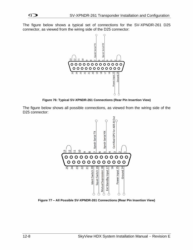
SV-XPNDR-261 Transponder Installation and Configuration
12-8 SkyView HDX System Installation Manual - Revision E
The figure below shows a typical set of connections for the SV-XPNDR-261 D25 connector, as viewed from the wiring side of the D25 connector:
Figure 76: Typical SV-XPNDR-261 Connections (Rear Pin Insertion View)
The figure below shows all possible connections, as viewed from the wiring side of the D25 connector:
Figure 77 – All Possible SV-XPNDR-261 Connections (Rear Pin Insertion View)
SV-XPNDR-261 Transponder Installation and Configuration
SkyView HDX System Installation Manual - Revision E 12-9
12.2.2 Power / Ground Input
The power supply can be 11-33 Volts DC; no voltage adjustment is required. 20 AWG wire is sufficient for wire runs up to 50’ for this application. Note that the SV-XPNDR-261 must be connected to aircraft power – none of SkyView’s voltage outputs can provide a sufficient amount of power to power the SV-XPNDR-261.
It is always good practice to use more than one (1) ground path in an installation. With only one (1) wire there may be only a single grounding path for the SV-XPNDR-261, controller and antenna. This can allow static electricity to build up and damage your SkyView display(s). Ensuring that the mounting tray is grounded provides an adequate alternative ground path to protect against such events. This is particularly important when the SV-XPNDR-261 is mounted on a non-conducting surface, such as a composite structure, where the mounting tray is often not grounded. Therefore, make sure that the mounting tray is grounded in addition to having the ground wire connected as depicted above.
Note: The SV-XPNDR-261 power input is not protected against reversed power connections. If the power and ground inputs to the SV-XPNDR-261 are reversed, and power is applied to the Ground input, and Ground is applied to the Power input, the SV-XPNDR-261 will be destroyed and this repair will not be covered under warranty. Check wiring before applying power!
12.2.3 Pin 1/2 and 12/13 Loopbacks
Pins 1 and 2 must be connected together (as shown in Figure 75, Figure 76, and Figure 77 above). Pins 12 and 13 must be connected together (as shown in Figure 75, Figure 76, and Figure 77 above).
12.2.4 Serial RX (Pin 5) and Serial TX (Pin 7)
All communication between the SV-XPNDR-261 module and SkyView is accomplished via a single bidirectional serial connection. To accomplish this:
• Choose an unused serial port on each display to connect the SV-XPNDR-261. Note that both the TX and RX sides of the serial port are needed, and both the RX and TX lines must be connected to all displays in parallel. It is required that the same numerical serial port on each display be used.
• Connect the SV-XPNDR-261 TX wire (pin 7) to the SkyView serial RX of your choosing. If you have multiple displays, the SV-XPNDR-261’s TX wire must be connected to a serial RX wire on each display.
Note that Pin 1 and Pin 2 must be connected to each other as depicted above as part of the wiring harness (they are not connected together inside the SV-XPNDR-261).
Note that Pin 12 and Pin 13 must be connected to each other as depicted above as part of the wiring harness (they are not connected together inside the SV-XPNDR-261).
SV-XPNDR-261 Transponder Installation and Configuration
12-10 SkyView HDX System Installation Manual - Revision E
• Connect the SV-XPNDR-261 RX wire (pin 5) to the SkyView serial TX of your choosing. If you have multiple displays, the SV-XPNDR-261’s RX wire must be connected to a serial TX wire on each display.
• Record the SkyView serial port that you have chosen on each display as you will need to configure it later for use with the SV-XPNDR-261.
12.2.5 Mutual Suppression (Pin 18) (optional)
Mutual Suppression allows two (2) or more transmitters on adjacent frequencies to inhibit the other transmitters when one (1) is active to limit the interference effects. It is commonly used between transponders and DME systems, and between transponders and collision avoidance systems. Most installations will not make use of this feature, since most SkyView-equipped aircraft have only one (1) transponder and often do not have DME equipment or other active traffic system that interrogate other aircraft.
The Mutual Suppression pin, Pin 18, is an ARINC compatible suppression bus interface, which acts as both an input and an output. The SV-XPNDR-261 will assert this signal when it is transmitting, and can be suppressed by other equipment that asserts the signal. The SV-XPNDR-261 will drive approximately twenty-four (24) Volts on the output (independently of supply voltage), and will treat the input as active whenever the bus has greater than ten (10) Volts.
If you are using the Mutual Suppression feature, simply connect all the Mutual Suppression wires from devices that use them together.
12.2.6 Ident Switch Input (Pin 20) (optional)
SkyView has an IDENT button in its TRANSPONDER menu that is normally used to ident when requested by ATC. However, the ident switch input allows the IDENT function to be selected using a remote switch. The input is active low, and will be asserted when the voltage to ground is pulled below approximately four (4) Volts. Therefore, a momentary switch to ground should be installed on this output if a remote ident switch is desired.
12.2.7 Squat Switch Input (Pin 19) (optional)
In a SkyView system, a Squat Switch is not required because SkyView can automatically detect whether ALT or GND mode is appropriate, and switch modes as necessary. Thus, the Squat Switch Input should be left unconnected. See the AUTO ALT/GND setting in the SV-XPNDR-261 Settings section of later in this section.
The Squat switch input allows the SV-XPNDR-261 to automatically switch between Airborne and Ground modes, and affects both the Mode S reply behavior and the ADS-B reporting behavior. The input will be asserted when the voltage to ground is pulled below approximately 4 Volts. The logical sense of the input can be programmed to be either active low or active high in the SkyView Setup Menu.
If connected, this must be a mechanical switch that accurately reflects the aircraft’s on-ground status. Mode-S certification requirements state that this cannot be a simple airspeed switch.
SV-XPNDR-261 Transponder Installation and Configuration
SkyView HDX System Installation Manual - Revision E 12-11
12.2.8 External Standby Input (Pin 17) (optional)
This input, when connected to Ground, places the SV-XPNDR-261 in Standby mode. It should be used to switch between transponders in an installation with two (2) transponders. The input is active low, and will be asserted when the voltage to ground is pulled below approximately four (4) Volts.
12.2.9 Direct Serial GPS Position Input (Pin 3)
This input is typically used if the aircraft is already equipped with a certified GPS unit (typically for qualification for IFR flight). This input is connected to a serial port output of the certified GPS. See SV-XPNDR-261 Settings, GPS Data later in this section for information on how to configure SkyView to use this capability.
If you connect a certified GPS to this input, you must install a 1.21k resistor (included with the SV-XPNDR-261) between the certified GPS and the SV-XPNDR-261 as shown in Figure 75: SV-XPNDR-261 Wiring Diagram.
12.2.10 Antenna Cable
The SV-XPNDR-261 is designed to meet Class 1 requirements with the same 2 dB allowance. Excessive loss will degrade both transmitter output power and receiver sensitivity.
Allowing 0.25 dB loss for the connector at each end of the antenna cable assembly leaves an allowance of 1.5 dB maximum loss for the cable itself.
An acceptable cable:
• Has less than 1.5 dB loss for the run length needed.
• Has a characteristic impedance of 50Ω (50 Ohms).
• Has double braid screens or has a foil and braid screen.
Once the cable run length is known, a cable type with low enough loss per metre that meets the above requirements can be chosen. Longer runs require lower loss cable. Consider moving the SV-XPNDR-261 closer to the antenna to minimize the losses in the antenna cable – subject to the limits identified above, the SV-XPNDR-261 can be at any distance from the SkyView display(s) without affecting performance in any way.
Note: Low loss cable typically uses foamed or cellular dielectrics and foil screens. These make such cables especially prone to damage from too-tight bends or from momentary kinking during installation. Once kinked, these cables do not return to full performance when straightened.
Table 31 below is a guide to the maximum usable lengths of some common coaxial cable types. Actual cable loss varies between manufacturers, there are many variants, and the table is therefore based on typical data. Use it as a guide only and refer to the manufacturer’s data sheet for your specific chosen cable for accurate values.
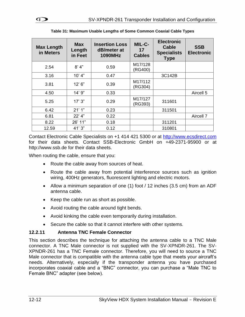
SV-XPNDR-261 Transponder Installation and Configuration
12-12 SkyView HDX System Installation Manual - Revision E
Table 31: Maximum Usable Lengths of Some Common Coaxial Cable Types
Max Length in Meters
Max Length in Feet
Insertion Loss dB/meter at
1090MHz
MIL-C-17
Cables
Electronic Cable
Specialists Type
SSB Electronic
2.54 8’ 4” 0.59 M17/128 (RG400)
3.16 10’ 4” 0.47 3C142B
3.81 12’ 6” 0.39 M17/112 (RG304)
4.50 14’ 9” 0.33 Aircell 5
5.25 17’ 3” 0.29 M17/127 (RG393)
311601
6.42 21’ 1” 0.23 311501
6.81 22’ 4” 0.22 Aircell 7
8.22 26’ 11” 0.18 311201
12.59 41’ 3” 0.12 310801
Contact Electronic Cable Specialists on +1 414 421 5300 or at http://www.ecsdirect.com for their data sheets. Contact SSB-Electronic GmbH on +49-2371-95900 or at http://www.ssb.de for their data sheets.
When routing the cable, ensure that you:
• Route the cable away from sources of heat.
• Route the cable away from potential interference sources such as ignition wiring, 400Hz generators, fluorescent lighting and electric motors.
• Allow a minimum separation of one (1) foot / 12 inches (3.5 cm) from an ADF antenna cable.
• Keep the cable run as short as possible.
• Avoid routing the cable around tight bends.
• Avoid kinking the cable even temporarily during installation.
• Secure the cable so that it cannot interfere with other systems.
12.2.11 Antenna TNC Female Connector
This section describes the technique for attaching the antenna cable to a TNC Male connector. A TNC Male connector is not supplied with the SV-XPNDR-261. The SV-XPNDR-261 has a TNC Female connector. Therefore, you will need to source a TNC Male connector that is compatible with the antenna cable type that meets your aircraft’s needs. Alternatively, especially if the transponder antenna you have purchased incorporates coaxial cable and a “BNC” connector, you can purchase a “Male TNC to Female BNC” adapter (see below).
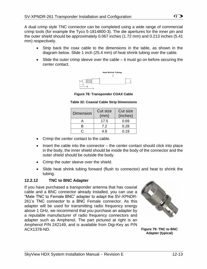
SV-XPNDR-261 Transponder Installation and Configuration
SkyView HDX System Installation Manual - Revision E 12-13
A dual crimp style TNC connector can be completed using a wide range of commercial crimp tools (for example the Tyco 5-1814800-3). The die apertures for the inner pin and the outer shield should be approximately 0.067 inches (1.72 mm) and 0.213 inches (5.41 mm) respectively.
• Strip back the coax cable to the dimensions in the table, as shown in the diagram below. Slide 1 inch (25.4 mm) of heat shrink tubing over the cable.
• Slide the outer crimp sleeve over the cable – it must go on before securing the center contact.
Figure 78: Transponder COAX Cable
Table 32: Coaxial Cable Strip Dimensions
Dimension Cut size
(mm) Cut size (inches)
A 17.5 0.69
B 7.2 0.28
C 4.8 0.19
• Crimp the center contact to the cable.
• Insert the cable into the connector – the center contact should click into place in the body, the inner shield should be inside the body of the connector and the outer shield should be outside the body.
• Crimp the outer sleeve over the shield.
• Slide heat shrink tubing forward (flush to connector) and heat to shrink the tubing.
12.2.12 TNC to BNC Adapter
If you have purchased a transponder antenna that has coaxial cable and a BNC connector already installed, you can use a “Male TNC to Female BNC” adapter to adapt the SV-XPNDR-261’s TNC connector to a BNC Female connector. As this adapter will be used for transmitting radio frequency energy above 1 GHz, we recommend that you purchase an adapter by a reputable manufacturer of radio frequency connectors and adapter such as Amphenol. The part pictured at right is an Amphenol P/N 242149, and is available from Digi-Key as P/N ACX1378-ND. Figure 79: TNC to BNC
Adapter (typical)
SV-XPNDR-261 Transponder Installation and Configuration
12-14 SkyView HDX System Installation Manual - Revision E
12.3 Transponder-Related SkyView Display Settings
12.3.1 Serial Port Setup
Before the TRANSPONDER SETUP menu can be accessed, the SV-XPNDR-261 needs to be set up as a serial device in the SkyView system. To accomplish this:
• SETUP MENU > SYSTEM SETUP > SERIAL PORT SETUP
• Select the serial port to which you connected (physically – the wires) the SV-XPNDR-261 – SERIAL PORT 1, SERIAL PORT 2, SERIAL PORT 3, or SERIAL PORT 4.
• Select either DYNON SV-XPNDR-261 or DYNON SV-XPNDR-262 as appropriate. Note that other fields are automatically configured and cannot be changed. Press ACCEPT.
The data transmitted between the SkyView display and the SV-XPNDR-261 nominally includes encoded altitude data from SkyView’s ADAHRS. Therefore, no other altitude encoder hardware is required. However, some locales may require the use of a certified altitude encoder with the Dynon Avionics SV-XPNDR-261. SkyView supports external serial altitude encoders that use Icarus/Garmin format (connected via serial port to one (1) of the SkyView display’s serial ports). When an external serial is connected, the SV-XPNDR-261 uses the external altitude encoder data source instead of SkyView’s pressure altitude (from the SV-ADAHRS-200/201). However, the pressure altitude displayed by SkyView on the PFD page is ALWAYS sourced from the SV-ADAHRS-200/201.
To have SkyView use an external altitude serial encoder as the pressure altitude source for the SV-XPNDR-261:
1. Connect a SkyView display serial RX to the respective serial TX connection from the serial altitude encoder. If your SkyView system has multiple displays, this connection must be made to all SkyView displays in parallel.
2. Ensure there is a shared ground between the SkyView display and the serial altitude encoder.
3. Configure the SkyView display serial port RX: SETUP MENU > SYSTEM SETUP > SERIAL PORT SETUP > SERIAL PORT x SETUP > SERIAL IN DEVICE > ICARUS/GARMIN ALTITUDE. (The other parameters are set automatically).
12.3.2 SV-XPNDR-261 Settings
The aircraft tail number must be set in SETUP > SYSTEM SETUP > AIRCRAFT INFORMATION > TAIL NUMBER prior to configuring the transponder.
The following settings need to be configured before testing and using the SV-XPNDR-261. They are all accessed under SETUP MENU > TRANSPONDER SETUP:
• STATUS: Displays online/offline status, displays hardware, Software, and Software versions of the SV-XPNDR-261. If shown in YELLOW, a Software
SV-XPNDR-261 Transponder Installation and Configuration
SkyView HDX System Installation Manual - Revision E 12-15
update for the SV-XPNDR-261 is available for the SkyView display – see SV-XPNDR-261 Software Updates later in this section for details on performing Software updates.
• USA PART 91.227 COMPLIANT: YES | NO Displays whether the combination of the selected GPS, the SV-XPNDR-261 model, and the GPS data being received is compliant with 14 CFR § 91.227 (YES is displayed) or not (NO is displayed).
When this field is highlighted, additional information about the status (YES | NO) is displayed, such as no data is being received from the GPS, thus NO is displayed. NO could be displayed when the GPS is not powered on or does not yet have a full “lock” on the GPS constellation (such as when you are in a hangar). Error Messages include:
o TRANSPONDER SOFTWARE NEEDS TO BE UPDATED – The SV-XPNDR-261’s Software has not been updated to v2.6 (minimum for compliance with 14 CFR § 91.227).
o NO COMPLIANT GPS PRESENT – The type of GPS selected is not compliant.
o NO GPS DATA (GPS OFFLINE OR MISCONFIGURED) – GPS data of the format selected is not being received by the SV-XPNDR-261.
o GPS PROTOCOL MISCONFIGURED, CHANGE TO ADS-B – PROTOCOL – The Garmin GPS is transmitting the older ADS-B format rather than the (now) required ADS-B PLUS (+) format.
See also Determining SkyView System’s with FAA 2020 ADS-B Out Mandate Compliance later in this section.
• TRANSPONDER WARNINGS: If a message other than NONE appears for TRANSPONDER WARNINGS, see Transponder Warnings (Transponder Self Diagnostics) later in this section for detailed explanation of the various transponder warnings.
• GPS DATA: Displays status of the GPS input to the SV-XPNDR-261: GPS DATA (OK) – GPS data is being received by the SV-XPNDR-261 or GPS DATA (OFFLINE) – GPS data is not being received by the SV-XPNDR-261.
Also select the source of GPS input to the SV-XPNDR-261 (explained below):
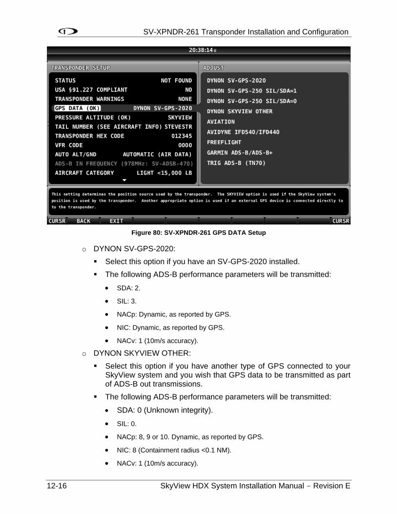
SV-XPNDR-261 Transponder Installation and Configuration
12-16 SkyView HDX System Installation Manual - Revision E
Figure 80: SV-XPNDR-261 GPS DATA Setup
o DYNON SV-GPS-2020:
Select this option if you have an SV-GPS-2020 installed.
The following ADS-B performance parameters will be transmitted:
• SDA: 2.
• SIL: 3.
• NACp: Dynamic, as reported by GPS.
• NIC: Dynamic, as reported by GPS.
• NACv: 1 (10m/s accuracy).
o DYNON SKYVIEW OTHER:
Select this option if you have another type of GPS connected to your SkyView system and you wish that GPS data to be transmitted as part of ADS-B out transmissions.
The following ADS-B performance parameters will be transmitted:
• SDA: 0 (Unknown integrity).
• SIL: 0.
• NACp: 8, 9 or 10. Dynamic, as reported by GPS.
• NIC: 8 (Containment radius <0.1 NM).
• NACv: 1 (10m/s accuracy).
SV-XPNDR-261 Transponder Installation and Configuration
SkyView HDX System Installation Manual - Revision E 12-17
Use of any of the DIRECT GPS-to-transponder position reporting methods below require that the GPS that is connected to the SV-XPNDR-261 be TSO’d when used in the US. Additionally, only specific models are supported via these connections. Other counties may have different regulatory requirements for GPS position indicators that are connected directly to the SV-XPNDR-261’s direct serial input.
o AVIDYNE IFD540/IFD440: Must be connected directly to SV-XPNDR-261 pin 3, transmitting at 9600 baud. This device is only supported in SV-XPNDR-261 version 2.06 or later; see SV-XPNDR-261 Software Updates below for more information about updating the SV-XPNDR-261 Software. Using this setting causes the SV-XPNDR-261 to transmit the following ADS-B performance parameters:
SDA: 2 (Level C integrity).
SIL: 3.
NACp: Sent from GPS to transponder. Refer to GPS documentation.
NIC: Sent from GPS to transponder. Refer to GPS documentation.
NACv: 1 (10m/s accuracy).
o FREEFLIGHT: FreeFlight 1201 or 1204 GPS, connected directly to SV-XPNDR-261 pin 3, transmitting at 19200 baud. Using this setting causes the SV-XPNDR-261 to transmit the following ADS-B performance parameters:
SDA: 2 (Level C integrity).
SIL: 3.
NACp: Sent from GPS to transponder. Refer to GPS documentation.
NIC: Sent from GPS to transponder. Refer to GPS documentation.
NACv: 1 (10m/s accuracy).
o GARMIN ADS-B/ADS-B+: Garmin GNS 400W/500W series (WAAS) or Garmin GTN series, both with appropriate Software updates as designated by Garmin, connected directly to SV-XPNDR-261 pin 3, transmitting at 9600 baud in “ADS-B+ OUT” or "ADS-B" format. "ADS-B" format only works with SV-XPNDR-261 Software 2.02 and above. "ADS-B+" format requires SV-XPNDR-261 version 2.06 or later. With 2.06 or later Software the format in use will be auto-detected. The original Garmin ADS-B format is not compliant for use after 2020, and may cause compliance failures in the FAA's ADS-B monitoring system, but is acceptable to use until 2020. See SV-XPNDR-261 Software Updates below for more information about updating the SV-XPNDR-261 Software. Using this setting causes the SV-XPNDR-261 to transmit the following ADS-B performance parameters:
SDA: 2 (Level C integrity) SIL: 3 NACp: Sent from GPS to transponder. Refer to GPS documentation.
SV-XPNDR-261 Transponder Installation and Configuration
12-18 SkyView HDX System Installation Manual - Revision E
NIC: Sent from GPS to transponder. Refer to GPS documentation.
NACv: 1 (10 m/s accuracy).
o TRIG ADS-B (TN70): Must be connected directly to SV-XPNDR-261 pin 3, transmitting at 19200 baud. This device is only supported in SV-XPNDR-261 version 2.06 or later. See SV-XPNDR-261 Software Updates below for more information about updating the SV-XPNDR-261 Software. Using this setting causes the SV-XPNDR-261 to transmit the following ADS-B performance parameters:
SDA: 2 (Level C integrity) SIL: 3 NACp: Sent from GPS to transponder. Refer to GPS documentation.
NIC: Sent from GPS to transponder. Refer to GPS documentation.
NACv: 1 (10 m/s accuracy).
• PRESSURE ALTITUDE: Displays status of pressure altitude input for the SV-XPNDR-261.
• TAIL NUMBER (SEE AIRCRAFT INFO): Displays tail number (set in SYSTEM SETUP > AIRCRAFT INFORMATION).
• TRANSPONDER HEX CODE: A Mode-S transponder’s HEX code is more precisely called a 24-bit ICAO code. All aircraft that fly with a Mode S transponder must have the correct ICAO code that is assigned to the specific aircraft, configured in the aircraft’s Mode-S transponder. The ICAO / HEX code uniquely identifies the aircraft and the country in which it is licensed. All ICAO / HEX codes are assigned by the aircraft licensing authority in the country in which the aircraft is registered/licensed.
The SV-XPNDR-261 setup requires the hexadecimal number (base 16) format; SkyView cannot accept the Octal (base 8) or Decimal (base 10) format.
For US registered aircraft with a conventional (pattern) N-number, when the tail number is entered, the HEX CODE will be set automatically (computed based on the aircraft N-number). If the TRANSPONDER HEX CODE cannot be computed, the TRANSPONDER HEX CODE remains set to 000000.
The HEX CODE needs to be set to the aircraft’s assigned code for the SV-XPNDR-261 to function properly. The default code of 000000 is not a valid code. If the code is left at 000000, the SV-XPNDR-261 will only work in SBY mode. A caution message – XPNDR HEX CODE NOT SET will appear if a SV-XPNDR-261 is configured in SkyView, but the HEX CODE is not set to a valid number.
There is no “special” HEX CODE that can be input to the SV-XPNDR-261 that will enable it to operate as a Mode A and/or Mode C transponder only.
o For US aircraft can be found at the FAA aircraft registry at http://registry.faa.gov/aircraftinquiry/nnum_inquiry.aspx. The FAA aircraft register shows both the octal number and the hexadecimal value.
SV-XPNDR-261 Transponder Installation and Configuration
SkyView HDX System Installation Manual - Revision E 12-19
o The website http://www.airframes.org provides HEX CODEs for most countries’ aircraft that can be input into SkyView. The HEX CODE is the value shown in the ICA024 result field.
o If you only have the octal number, you must convert it to hexadecimal. There is an Octal to Hexadecimal converter tool available in the Support section of http://www.trig-avionics.com/.
• VFR CODE: When the pilot presses the VFR button, a pre-programmed code will replace the current squawk code. The pre-programmed code is set here; the choice of code will depend on the normal location of the aircraft.
o In the USA, the VFR squawk code is 1200.
o In most parts of Europe, the VFR squawk code should be set to 7000.
• AUTO ALT/GND: Allows the SV-XPNDR-261 to automatically switch between Airborne and Ground modes. Available options include:
o NONE: Automatic switching disabled
o SQUAT SWITCH LOW ON GND: Utilizes a physical squat switch connected the SV-XPNDR-261 per the above instructions. When this option is selected, the SV-XPNDR-261 will consider the aircraft to be on the ground when this switch is low (electrically grounded).
o SQUAT SWITCH LOW IN AIR: Utilizes a physical squat switch connected the SV-XPNDR-261 per the above instructions. When this option is selected, the SV-XPNDR-261 will consider the aircraft to in flight when this switch is low (electrically grounded).
o AUTOMATIC (AIR DATA): The SV-XPNDR-261 automatically determines whether the aircraft is in flight or not by using a combination of GPS and air data changes from SkyView. Note that this option only works with SV-XPNDR-261 Software 2.02 or above. See SV-XPNDR-261 Software Updates below for more information about updating the SV-XPNDR-261 Software. This is the option that most SkyView systems should use unless they are required to use a Squat Switch. If a Squat Switch is installed and connected, this option will cause the Squat Switch to be ignored.
• ADS-B IN FREQUENCY:
If an SV-ADSB-472/472 is installed and configured under SETUP MENU > SYSTEM SETUP > SERIAL PORT SETUP, this option will be unavailable: The SV-ADSB-472/472 automatically receives ADS-B In traffic and weather via the 978 MHz UAT frequency band. The SV-ADSB-472 also uses the 1090 MHz band to receive traffic.
Note that the options in the ADS-B IN FREQUENCY only have an effect with SV-XPNDR-261 Software 2.02 or above. See SV-XPNDR-261 Software Updates below for more information about updating the SV-XPNDR-261 Software.
SV-XPNDR-261 Transponder Installation and Configuration
12-20 SkyView HDX System Installation Manual - Revision E
• If an SV-ADSB-472 is not installed and configured, the following settings are accessible:
o NONE – Set to NONE if there is no ADS-B IN equipment on board the aircraft.
o 1090 MHz ES – Select this option if there is ADS-B IN equipment on board that receives only on 1090 MHz.
o 978 MHz UAT – Select this option if there is ADS-B IN equipment on board that receives on 978 MHz (other than the Dynon Avionics SV-ADSB-472). Select this option if the ADS-B IN equipment on board is dual-band (receives on both 1090 MHz and 978 MHz).
• AIRCRAFT CATEGORY: To assist ATC tracking of aircraft, an aircraft category can be transmitted by Mode S transponders. Set as appropriate for your aircraft.
• AIRCRAFT LENGTH and AIRCRAFT WIDTH: On the ground, ADS-B transmits encoded aircraft size information which is used by ATC to identify taxiing routes and potential conflicts. Using the aircraft length and width (wingspan), in your current distance/speed units (meters or feet), the SV-XPNDR-26 will calculate the appropriate size code for transmission.
• MAXIMUM CRUISE SPEED: Mode S transponders can transmit their maximum airspeed characteristics to aircraft equipped with TCAS. This information is used to help identify threats and to plan avoiding action by the TCAS equipped aircraft. The airspeeds are grouped in ranges. Set as appropriate for your aircraft.
• TIS TRAFFIC: Enables the display of TIS traffic on the SkyView Map page when in an area served by a TIS-enabled RADAR. Note that TIS is a Mode S uplink service that is provided by some US approach RADARs. TIS coverage is limited to the coverage areas of those radars; there is no TIS provision outside the USA. If another traffic device is connected to SkyView and is set up correctly, its traffic information will trump the TIS traffic from the SV-XPNDR-261, regardless of this setting.
12.4 Equipping for FAA 2020 ADS-B Out Mandate Compliance (U.S. Only)
It is important to note that in the U.S., the ADS-B Out “mandate” and the associated GPS requirements do not go into effect until January 1, 2020, and the mandate only requires
The FAA’s ADS-B rule currently permits class A1, A1S, A2, A3, B1S, or B1 transponder-based 1090ES ADS-B transmissions for compliance once the FAA 2020 ADS-B Out rules mandate goes into effect January 1, 2020. Therefore, only the higher power class B1S SV-XPNDR-261 will be able to meet the 2020 ADS-B Out requirement. If your aircraft is equipped with an SV-XPNDR-262, it must be replaced with an SV-XPNDR-261 (or other Class 1 Mode-S transponder) to be compliant with the FAA 2020 ADS-B Out mandate.
SV-XPNDR-261 Transponder Installation and Configuration
SkyView HDX System Installation Manual - Revision E 12-21
compliance in specific airspaces. If you do not have an SV-GPS-2020 (or an appropriately TSO’d WAAS IFR GPS navigator - such as the Garmin GTN or GNS (WAAS only) series) installed, SkyView will send data from the SV-GPS-2020 to the SV-XPNDR-261.
The FAA 2020 ADS-B Out mandate is codified in 14 CFR § 91.225 and 14 CFR § 91.227. In general, these regulations require that as of January 1, 2020, if you operate an aircraft in, below, or above Class B or Class C airspace, or above 10,000 feet in Class E airspace, an airplane plane must be equipped with:
• A Class 1 Mode S transponder with 1090ES ADS-B Extended Squitter that meets the performance required in 14 CFR § 91.227 (or UAT; Dynon Avionics’ solution uses the former).
• The GPS supplying position data to the above transponder must meet the specific performance requirements as defined in 14 CFR § 91.227.
The Dynon Avionics SV-XPNDR-261, as a TSO C166B device, meets the transponder and ADS-B transmission requirements for 14 CFR § 91.225 and 14 CFR § 91.227.
The Dynon Avionics SV-GPS-2020, as a high integrity GPS receiver, meets the specific performance requirements as defined in 14 CFR § 91.227.
Additional options for a GPS receiver that meets the specific performance requirements as defined in 14 CFR § 91.227 include (that are supported by direct input to the SV-XPNDR-261):
• Avidyne IFD440 and IFD540.
• FreeFlight 1201 and 1203.
• Garmin GNS (WAAS only).
• Garmin GTN.
• Trig Avionics TN70.
12.4.1 Installation of SV-GPS-2020 for FAA 2020 ADS-B Out Mandate Compliance
The most common GPS position source for compliance for performance requirements for GPS data for FAA 2020 ADS-B Out mandate is the SV-GPS-2020 GPS Antenna/Receiver Module (High Integrity GPS - meets FAA 2020 ADS-B Out requirements). Installation is described in SV-GPS-2020 GPS Antenna/Receiver Installation earlier in this manual. For compliance, the SV-GPS-2020 must be installed in conjunction with an installed SV-XPNDR-261 with up-to-date Software (see SV-XPNDR-261 Software Updates later in this section), and SkyView Software v14.0 (or later).
If you have already installed and configured the serial port setup for an SV-GPS-2020, perform the following steps to complete the SV-GPS-2020 installation:
SETUP MENU > TRANSPONDER SETUP > GPS DATA (OK) and select DYNON SV-GPS-2020.
SV-XPNDR-261 Transponder Installation and Configuration
12-22 SkyView HDX System Installation Manual - Revision E
12.4.1.1 Determining SkyView System’s with FAA 2020 ADS-B Out Mandate
Compliance
SkyView can provide guidance as to whether your ADS-B Out installation and configuration is compliant with the FAA ADS-B Out 2020 Mandate (SkyView Software v12.2 or later is required): SETUP MENU > TRANSPONDER SETUP – Note the second line.
12.4.1.2 FAA Report for FAA ADS-B OUT 2020 Mandate Compliance
After you have updated your SkyView system with a SV-GPS-2020 (or other IFR GPS connected directly to the SV-XPNDR-261), and updated your SV-XPNDR-261’s Software to SW02.08 or later, you should fly within an ADS-B coverage area(s) for at least several hours (minimum), or days (optimum), before requesting the report below. This will give the ADS-B system some reasonable amount of data with your aircraft’s new ADS-B configuration on which to assess your compliance with the FAA 2020 ADS-B mandate.
Go to https://www.faa.gov/nextgen/programs/adsb/
See the first highlighted section entitled:
ADS-B Out Equipped?
E-mail us with your N-number, ADS-B transmitter and GPS make/model numbers to find out if your equipment is working properly.
The email address is:
Include the following in the email message:
• (your N-number).
• ADS-B transmitter: Dynon Avionics SkyView SV-XPNDR-261 transponder.
• GPS: Dynon Avionics SV-GPS-2020.
The FAA will email you back a report showing whether you comply, or not, with the FAA 2020 ADS-B mandate. If you do not comply, there will be detailed information about your aircraft’s issues in complying with the FAA 2020 ADS-B Out mandate.
12.4.2 Altitude Encoder Calibration
In most transponder systems, a calibration is normally carried out every 24 months, as part of the altimeter checks on the aircraft. The maximum allowed difference between the primary altimeter and the altitude encoder is 125 feet (38 meters) in ETSO C88a and TSO C88b. The primary altimeter in SkyView and the altitude encoder are the same device (SV-ADAHRS-200). It is therefore impossible for the encoder and the primary altimeter to exceed 125 feet (38 meters) of altitude difference. They will always be exactly the same as each other, thereby meeting the TSO requirements. Therefore, no altitude encoder calibration is possible or necessary.
At times it may be useful to know the altitude that is being reported to the transponder. Since SkyView sends pressure altitude to the SV-XPNDR-261, setting BARO to 29.92
SV-XPNDR-261 Transponder Installation and Configuration
SkyView HDX System Installation Manual - Revision E 12-23
will display the pressure altitude being transmitted to the transponder in the normal SkyView altitude display on the right side of the PFD page.
However, note that there is a single point altitude adjustment, located in SETUP MENU > HARDWARE CALIBRATION > ADAHRS CALIBRATION > ALTITUDE OFFSET that adjusts SkyView’s barometric altimeter. This adjustment affects both the displayed altitude and the encoded altitude that is sent to other devices.
12.5 SV-XPNDR-261 Software Updates
If your SkyView system has more than one (1) SkyView display, before you commence with the SV-XPNDR-261 Software update, it is recommended to power off all but one (1) SkyView display. Doing so will reduce the power drain on your aircraft electrical system during the SV-XPNDR-261 Software update, and minimize the chances of any interruptions to the update process while it is underway.
You can power off an individual display by pushing and holding Button 1 on the display to be powered off.
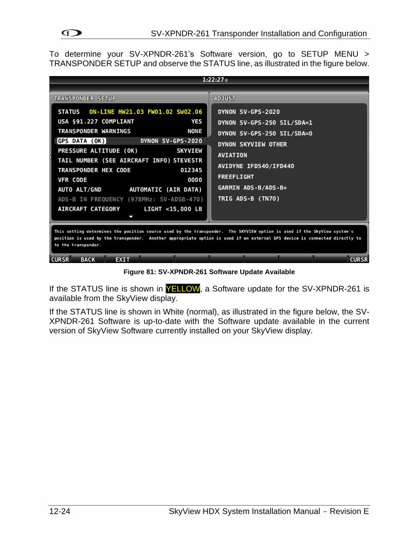
SV-XPNDR-261 Transponder Installation and Configuration
12-24 SkyView HDX System Installation Manual - Revision E
To determine your SV-XPNDR-261’s Software version, go to SETUP MENU > TRANSPONDER SETUP and observe the STATUS line, as illustrated in the figure below.
Figure 81: SV-XPNDR-261 Software Update Available
If the STATUS line is shown in YELLOW, a Software update for the SV-XPNDR-261 is available from the SkyView display.
If the STATUS line is shown in White (normal), as illustrated in the figure below, the SV-XPNDR-261 Software is up-to-date with the Software update available in the current version of SkyView Software currently installed on your SkyView display.
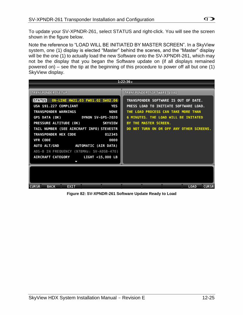
SV-XPNDR-261 Transponder Installation and Configuration
SkyView HDX System Installation Manual - Revision E 12-25
To update your SV-XPNDR-261, select STATUS and right-click. You will see the screen shown in the figure below.
Note the reference to “LOAD WILL BE INITIATED BY MASTER SCREEN”. In a SkyView system, one (1) display is elected “Master” behind the scenes, and the “Master” display will be the one (1) to actually load the new Software onto the SV-XPNDR-261, which may not be the display that you began the Software update on (if all displays remained powered on) – see the tip at the beginning of this procedure to power off all but one (1) SkyView display.
Figure 82: SV-XPNDR-261 Software Update Ready to Load
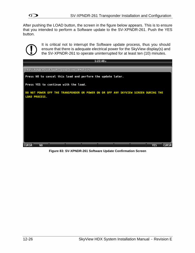
SV-XPNDR-261 Transponder Installation and Configuration
12-26 SkyView HDX System Installation Manual - Revision E
After pushing the LOAD button, the screen in the figure below appears. This is to ensure that you intended to perform a Software update to the SV-XPNDR-261. Push the YES button.
Figure 83: SV-XPNDR-261 Software Update Confirmation Screen
It is critical not to interrupt the Software update process, thus you should ensure that there is adequate electrical power for the SkyView display(s) and the SV-XPNDR-261 to operate uninterrupted for at least ten (10) minutes.
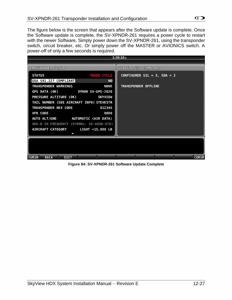
SV-XPNDR-261 Transponder Installation and Configuration
SkyView HDX System Installation Manual - Revision E 12-27
The figure below is the screen that appears after the Software update is complete. Once the Software update is complete, the SV-XPNDR-261 requires a power cycle to restart with the newer Software. Simply power down the SV-XPNDR-261, using the transponder switch, circuit breaker, etc. Or simply power off the MASTER or AVIONICS switch. A power-off of only a few seconds is required.
Figure 84: SV-XPNDR-261 Software Update Complete
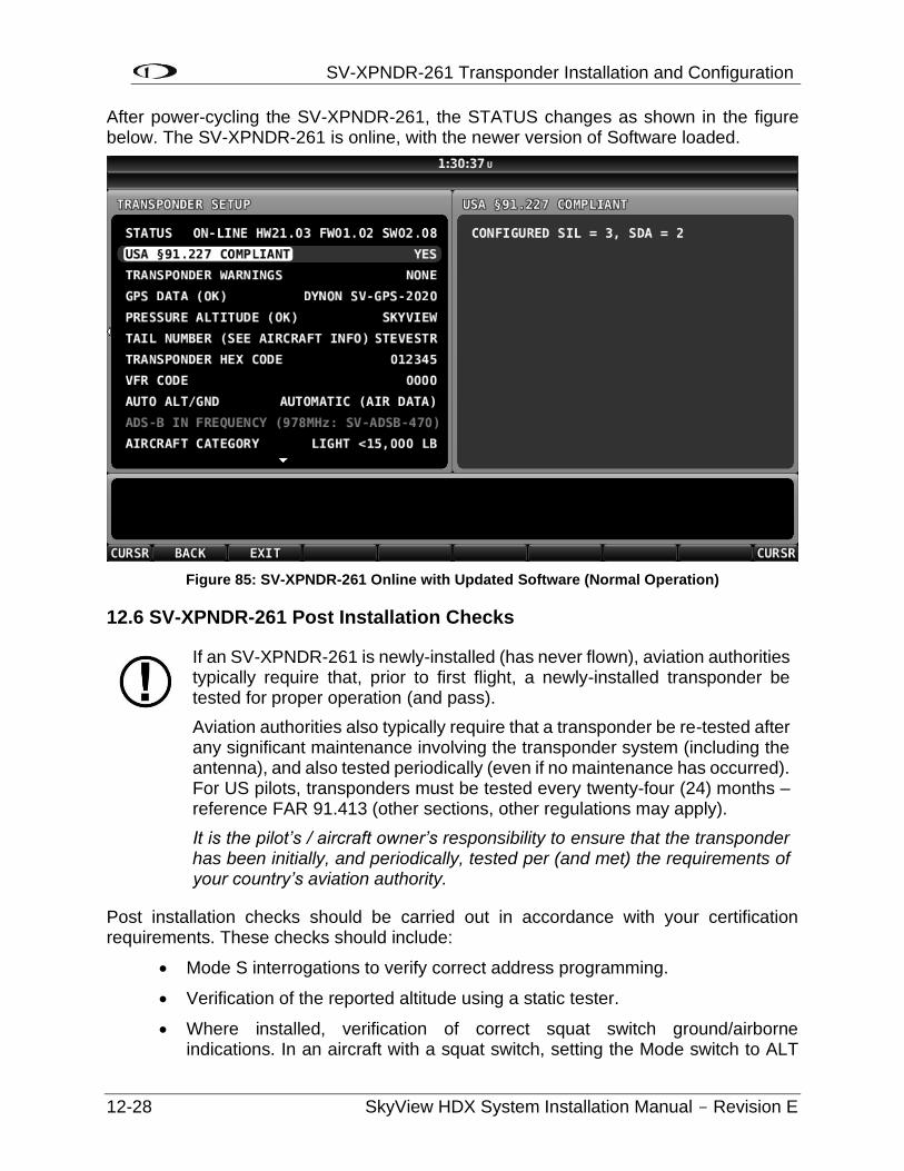
SV-XPNDR-261 Transponder Installation and Configuration
12-28 SkyView HDX System Installation Manual - Revision E
After power-cycling the SV-XPNDR-261, the STATUS changes as shown in the figure below. The SV-XPNDR-261 is online, with the newer version of Software loaded.
Figure 85: SV-XPNDR-261 Online with Updated Software (Normal Operation)
12.6 SV-XPNDR-261 Post Installation Checks
Post installation checks should be carried out in accordance with your certification requirements. These checks should include:
• Mode S interrogations to verify correct address programming.
• Verification of the reported altitude using a static tester.
• Where installed, verification of correct squat switch ground/airborne indications. In an aircraft with a squat switch, setting the Mode switch to ALT
If an SV-XPNDR-261 is newly-installed (has never flown), aviation authorities typically require that, prior to first flight, a newly-installed transponder be tested for proper operation (and pass).
Aviation authorities also typically require that a transponder be re-tested after any significant maintenance involving the transponder system (including the antenna), and also tested periodically (even if no maintenance has occurred). For US pilots, transponders must be tested every twenty-four (24) months – reference FAR 91.413 (other sections, other regulations may apply).
It is the pilot’s / aircraft owner’s responsibility to ensure that the transponder has been initially, and periodically, tested per (and met) the requirements of your country’s aviation authority.
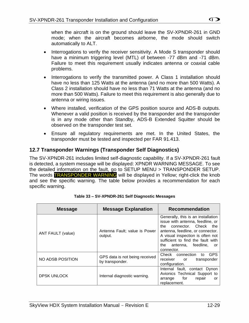
SV-XPNDR-261 Transponder Installation and Configuration
SkyView HDX System Installation Manual - Revision E 12-29
when the aircraft is on the ground should leave the SV-XPNDR-261 in GND mode; when the aircraft becomes airborne, the mode should switch automatically to ALT.
• Interrogations to verify the receiver sensitivity. A Mode S transponder should have a minimum triggering level (MTL) of between -77 dBm and -71 dBm. Failure to meet this requirement usually indicates antenna or coaxial cable problems.
• Interrogations to verify the transmitted power. A Class 1 installation should have no less than 125 Watts at the antenna (and no more than 500 Watts). A Class 2 installation should have no less than 71 Watts at the antenna (and no more than 500 Watts). Failure to meet this requirement is also generally due to antenna or wiring issues.
• Where installed, verification of the GPS position source and ADS-B outputs. Whenever a valid position is received by the transponder and the transponder is in any mode other than Standby, ADS-B Extended Squitter should be observed on the transponder test set.
• Ensure all regulatory requirements are met. In the United States, the transponder must be tested and inspected per FAR 91.413.
12.7 Transponder Warnings (Transponder Self Diagnostics)
The SV-XPNDR-261 includes limited self-diagnostic capability. If a SV-XPNDR-261 fault is detected, a system message will be displayed: XPNDR WARNING MESSAGE. To see the detailed information on the fault, go to SETUP MENU > TRANSPONDER SETUP. The words TRANSPONDER WARNING will be displayed in Yellow; right-click the knob and see the specific warning. The table below provides a recommendation for each specific warning.
Table 33 – SV-XPNDR-261 Self Diagnostic Messages
Message Message Explanation Recommendation
ANT FAULT (value) Antenna Fault; value is Power output.
Generally, this is an installation issue with antenna, feedline, or the connector. Check the antenna, feedline, or connector. A visual inspection is often not sufficient to find the fault with the antenna, feedline, or connector.
NO ADSB POSITION GPS data is not being received by transponder.
Check connection to GPS receiver or transponder configuration.
DPSK UNLOCK Internal diagnostic warning.
Internal fault, contact Dynon Avionics Technical Support to arrange for repair or replacement.
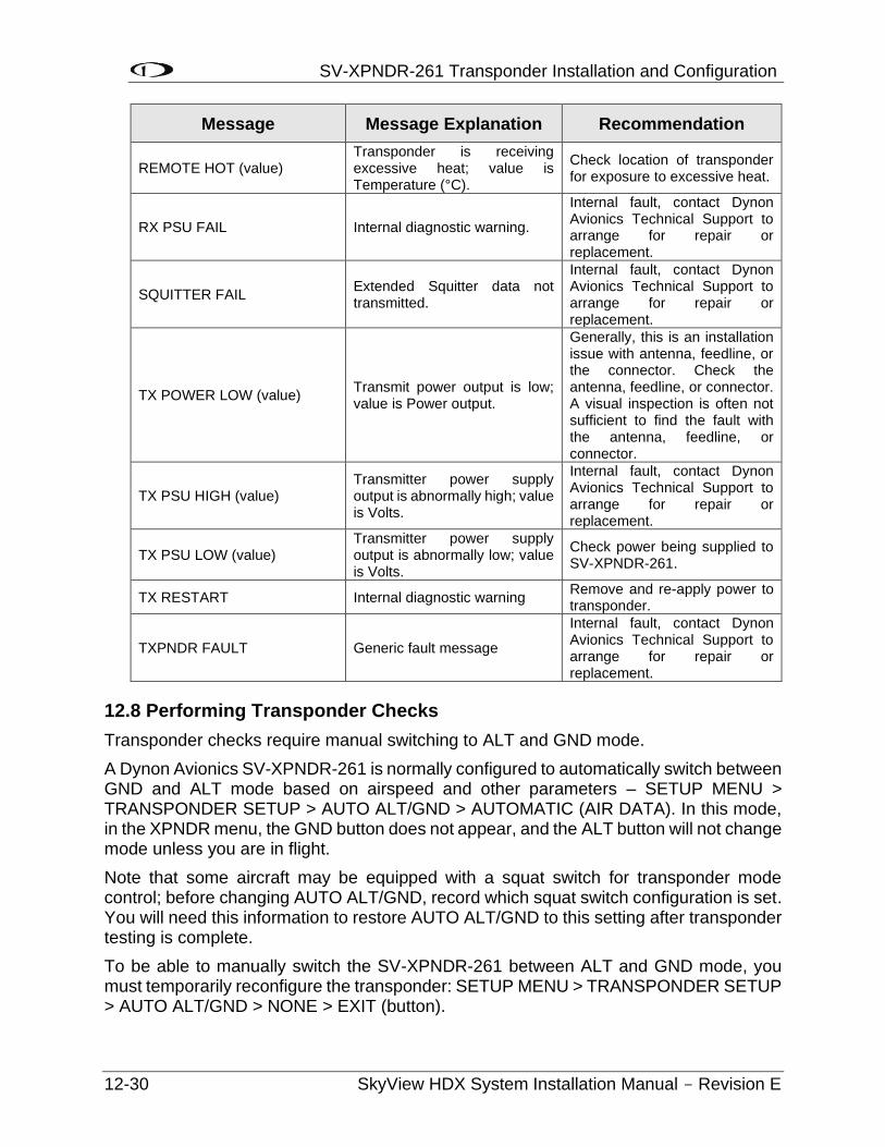
SV-XPNDR-261 Transponder Installation and Configuration
12-30 SkyView HDX System Installation Manual - Revision E
Message Message Explanation Recommendation
REMOTE HOT (value) Transponder is receiving excessive heat; value is Temperature (°C).
Check location of transponder for exposure to excessive heat.
RX PSU FAIL Internal diagnostic warning.
Internal fault, contact Dynon Avionics Technical Support to arrange for repair or replacement.
SQUITTER FAIL Extended Squitter data not transmitted.
Internal fault, contact Dynon Avionics Technical Support to arrange for repair or replacement.
TX POWER LOW (value) Transmit power output is low; value is Power output.
Generally, this is an installation issue with antenna, feedline, or the connector. Check the antenna, feedline, or connector. A visual inspection is often not sufficient to find the fault with the antenna, feedline, or connector.
TX PSU HIGH (value) Transmitter power supply output is abnormally high; value is Volts.
Internal fault, contact Dynon Avionics Technical Support to arrange for repair or replacement.
TX PSU LOW (value) Transmitter power supply output is abnormally low; value is Volts.
Check power being supplied to SV-XPNDR-261.
TX RESTART Internal diagnostic warning Remove and re-apply power to transponder.
TXPNDR FAULT Generic fault message
Internal fault, contact Dynon Avionics Technical Support to arrange for repair or replacement.
12.8 Performing Transponder Checks
Transponder checks require manual switching to ALT and GND mode.
A Dynon Avionics SV-XPNDR-261 is normally configured to automatically switch between GND and ALT mode based on airspeed and other parameters – SETUP MENU > TRANSPONDER SETUP > AUTO ALT/GND > AUTOMATIC (AIR DATA). In this mode, in the XPNDR menu, the GND button does not appear, and the ALT button will not change mode unless you are in flight.
Note that some aircraft may be equipped with a squat switch for transponder mode control; before changing AUTO ALT/GND, record which squat switch configuration is set. You will need this information to restore AUTO ALT/GND to this setting after transponder testing is complete.
To be able to manually switch the SV-XPNDR-261 between ALT and GND mode, you must temporarily reconfigure the transponder: SETUP MENU > TRANSPONDER SETUP > AUTO ALT/GND > NONE > EXIT (button).
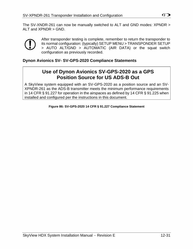
SV-XPNDR-261 Transponder Installation and Configuration
SkyView HDX System Installation Manual - Revision E 12-31
The SV-XNDR-261 can now be manually switched to ALT and GND modes: XPNDR > ALT and XPNDR > GND.
After transponder testing is complete, remember to return the transponder to its normal configuration: (typically) SETUP MENU > TRANSPONDER SETUP > AUTO ALT/GND > AUTOMATIC (AIR DATA) or the squat switch configuration as previously recorded.
Dynon Avionics SV- SV-GPS-2020 Compliance Statements
Use of Dynon Avionics SV-GPS-2020 as a GPS Position Source for US ADS-B Out
A SkyView system equipped with an SV-GPS-2020 as a position source and an SV-XPNDR-261 as the ADS-B transmitter meets the minimum performance requirements in 14 CFR § 91.227 for operation in the airspaces as defined by 14 CFR § 91.225 when installed and configured per the instructions in this document.
Figure 86: SV-GPS-2020 14 CFR § 91.227 Compliance Statement

SV-ARINC-429 Module Installation and Configuration
SkyView HDX System Installation Manual - Revision E 13-1
13 SV-ARINC-429 Module Installation and Configuration
SkyView can connect to advanced GPS/NAV devices like the Garmin GNS 430/530 and similar Via the SV-ARINC-429 module.
13.1 Mechanical Installation
Observe the following guidelines when choosing a location for the SV-ARINC-429 module:
• Avoid locations that are subject to severe vibration.
• Avoid locations that are subject to extreme humidity.
• Leave ample working room for electrical connections.
• SkyView systems support one (1) or two (2) SV-ARINC-429 per network.
• A common location for the SV-ARINC-429 is behind the instrument panel, keeping it close to the display and associated ARINC-429 capable device.
The diagram below shows the important mounting dimensions of the SV-ARINC-429 module with electronic connections.
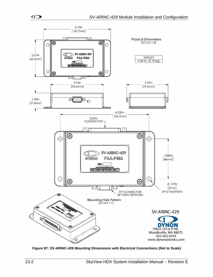
SV-ARINC-429 Module Installation and Configuration
13-2 SkyView HDX System Installation Manual - Revision E
Figure 87: SV-ARINC-429 Mounting Dimensions with Electrical Connections (Not to Scale)
SV-ARINC-429 Module Installation and Configuration
SkyView HDX System Installation Manual - Revision E 13-3
The SV-ARINC-429 does not provide mounting hardware. The mounting tabs on each side of the module have holes sized for #10 fasteners, but it is up to the installer to decide how the SV-ARINC-429 will be secured to the aircraft.
Follow recommended torque practices when tightening the mounting hardware. Do not rivet the SV-ARINC-429 to the aircraft as this will hinder future removal if necessary.
13.2 Electrical Installation
Connect the SV-ARINC-429 module to the SkyView network using the hardware mentioned in Section 2.11, or using equivalent hardware.
If you have to install a connector on the end of a network cable, insert all pins into the D9 connector. Refer to Section 25 Appendix C: Wiring and Electrical Connections for details on connector pinouts and wire colors.
13.2.1 ARINC-429 SkyView Connection
13.2.1.1 Harness Construction
Because the SV-ARINC-429 can be connected to a variety of devices, the harness requirements will vary from airplane to airplane. Therefore, Dynon Avionics does not supply pre-manufactured harnesses for the SV-ARINC-429 module. Instead, your SV-ARINC-429 shipped with enough connectors and pins to generate a wide variety of harness configurations. Refer to the sections below for detailed wiring information.
If you do not own a DSUB machined-pin crimping tool, they can be obtained from many electronics or avionics dealers. You may also find it helpful to own a pin insertion/extraction tool as well.
Additional harness construction and wiring information can be found in Section 25 Appendix C: Wiring and Electrical Connections.
The SV-ARINC-429 has a single D25F connector which is used for all data connections to your compatible ARINC-429 device. The pin out depicted in Figure 88 below depicts the view from the rear of your D25M connector – the view you will have of your harness connector as you are inserting pins into the harness. Note that the pin numbers are labelled on the face of both the female and male connector.
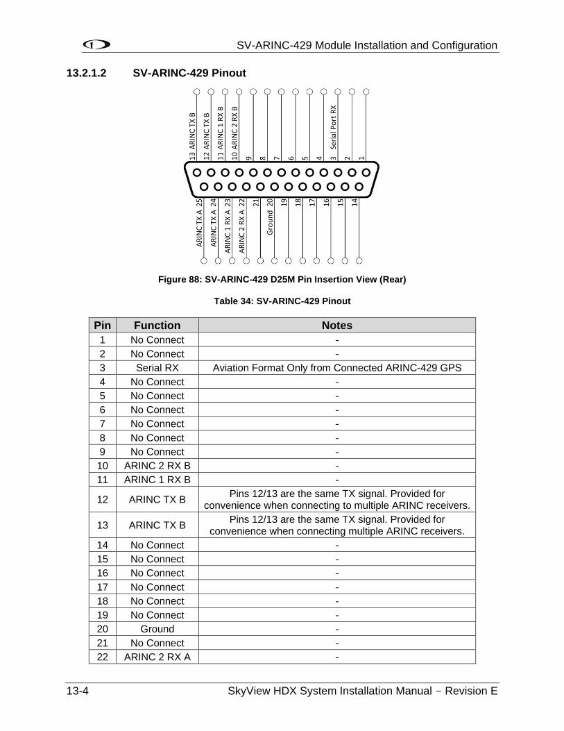
SV-ARINC-429 Module Installation and Configuration
13-4 SkyView HDX System Installation Manual - Revision E
13.2.1.2 SV-ARINC-429 Pinout
Figure 88: SV-ARINC-429 D25M Pin Insertion View (Rear)
Table 34: SV-ARINC-429 Pinout
Pin Function Notes
1 No Connect -
2 No Connect -
3 Serial RX Aviation Format Only from Connected ARINC-429 GPS
4 No Connect -
5 No Connect -
6 No Connect -
7 No Connect -
8 No Connect -
9 No Connect -
10 ARINC 2 RX B -
11 ARINC 1 RX B -
12 ARINC TX B Pins 12/13 are the same TX signal. Provided for
convenience when connecting to multiple ARINC receivers.
13 ARINC TX B Pins 12/13 are the same TX signal. Provided for
convenience when connecting multiple ARINC receivers.
14 No Connect -
15 No Connect -
16 No Connect -
17 No Connect -
18 No Connect -
19 No Connect -
20 Ground -
21 No Connect -
22 ARINC 2 RX A -
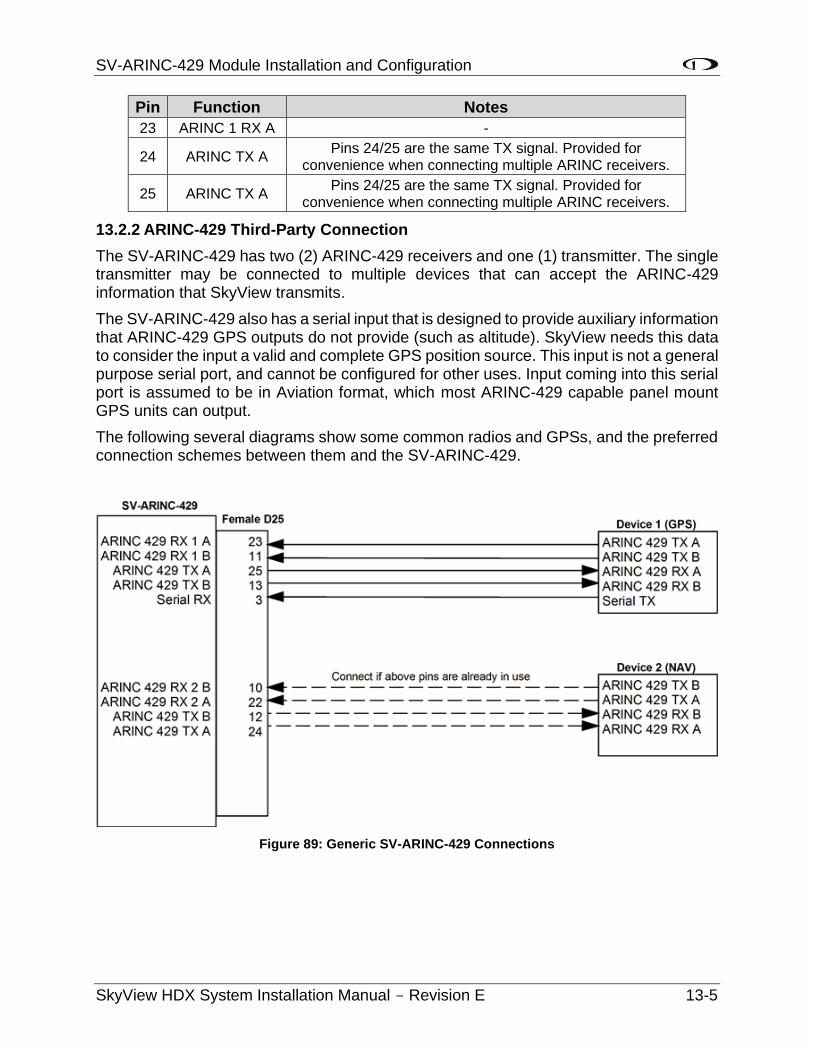
SV-ARINC-429 Module Installation and Configuration
SkyView HDX System Installation Manual - Revision E 13-5
Pin Function Notes
23 ARINC 1 RX A -
24 ARINC TX A Pins 24/25 are the same TX signal. Provided for
convenience when connecting multiple ARINC receivers.
25 ARINC TX A Pins 24/25 are the same TX signal. Provided for
convenience when connecting multiple ARINC receivers.
13.2.2 ARINC-429 Third-Party Connection
The SV-ARINC-429 has two (2) ARINC-429 receivers and one (1) transmitter. The single transmitter may be connected to multiple devices that can accept the ARINC-429 information that SkyView transmits.
The SV-ARINC-429 also has a serial input that is designed to provide auxiliary information that ARINC-429 GPS outputs do not provide (such as altitude). SkyView needs this data to consider the input a valid and complete GPS position source. This input is not a general purpose serial port, and cannot be configured for other uses. Input coming into this serial port is assumed to be in Aviation format, which most ARINC-429 capable panel mount GPS units can output.
The following several diagrams show some common radios and GPSs, and the preferred connection schemes between them and the SV-ARINC-429.
Figure 89: Generic SV-ARINC-429 Connections
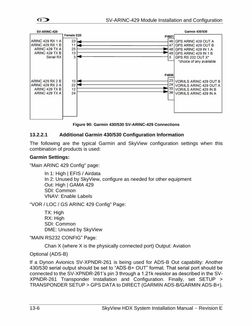
SV-ARINC-429 Module Installation and Configuration
13-6 SkyView HDX System Installation Manual - Revision E
Figure 90: Garmin 430/530 SV-ARINC-429 Connections
13.2.2.1 Additional Garmin 430/530 Configuration Information
The following are the typical Garmin and SkyView configuration settings when this combination of products is used:
Garmin Settings:
"Main ARINC 429 Config" page:
In 1: High | EFIS / Airdata In 2: Unused by SkyView, configure as needed for other equipment Out: High | GAMA 429 SDI: Common VNAV: Enable Labels
"VOR / LOC / GS ARINC 429 Config" Page:
TX: High RX: High SDI: Common DME: Unused by SkyView
“MAIN RS232 CONFIG” Page:
Chan X (where X is the physically connected port) Output: Aviation
Optional (ADS-B)
If a Dynon Avionics SV-XPNDR-261 is being used for ADS-B Out capability: Another 430/530 serial output should be set to “ADS-B+ OUT” format. That serial port should be connected to the SV-XPNDR-261’s pin 3 through a 1.21k resistor as described in the SV-XPNDR-261 Transponder Installation and Configuration. Finally, set SETUP > TRANSPONDER SETUP > GPS DATA to DIRECT (GARMIN ADS-B/GARMIN ADS-B+).
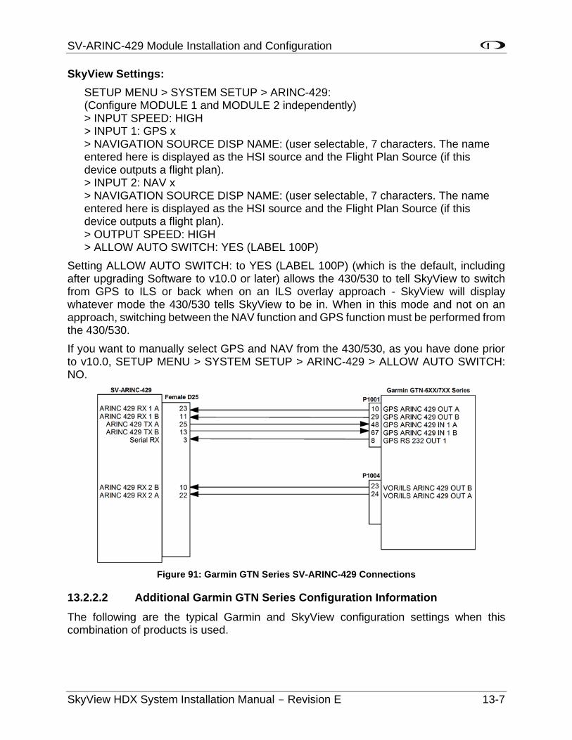
SV-ARINC-429 Module Installation and Configuration
SkyView HDX System Installation Manual - Revision E 13-7
SkyView Settings:
SETUP MENU > SYSTEM SETUP > ARINC-429: (Configure MODULE 1 and MODULE 2 independently) > INPUT SPEED: HIGH > INPUT 1: GPS x > NAVIGATION SOURCE DISP NAME: (user selectable, 7 characters. The name entered here is displayed as the HSI source and the Flight Plan Source (if this device outputs a flight plan). > INPUT 2: NAV x > NAVIGATION SOURCE DISP NAME: (user selectable, 7 characters. The name entered here is displayed as the HSI source and the Flight Plan Source (if this device outputs a flight plan). > OUTPUT SPEED: HIGH > ALLOW AUTO SWITCH: YES (LABEL 100P)
Setting ALLOW AUTO SWITCH: to YES (LABEL 100P) (which is the default, including after upgrading Software to v10.0 or later) allows the 430/530 to tell SkyView to switch from GPS to ILS or back when on an ILS overlay approach - SkyView will display whatever mode the 430/530 tells SkyView to be in. When in this mode and not on an approach, switching between the NAV function and GPS function must be performed from the 430/530.
If you want to manually select GPS and NAV from the 430/530, as you have done prior to v10.0, SETUP MENU > SYSTEM SETUP > ARINC-429 > ALLOW AUTO SWITCH: NO.
Figure 91: Garmin GTN Series SV-ARINC-429 Connections
13.2.2.2 Additional Garmin GTN Series Configuration Information
The following are the typical Garmin and SkyView configuration settings when this combination of products is used.
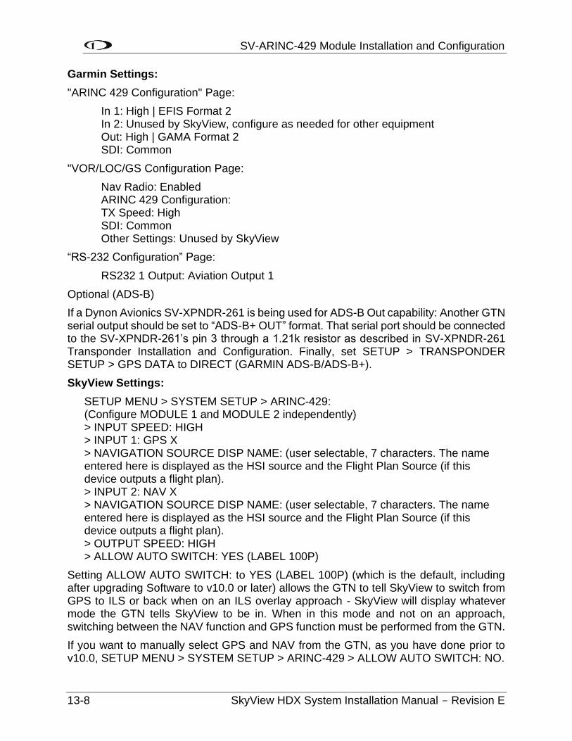
SV-ARINC-429 Module Installation and Configuration
13-8 SkyView HDX System Installation Manual - Revision E
Garmin Settings:
"ARINC 429 Configuration" Page:
In 1: High | EFIS Format 2 In 2: Unused by SkyView, configure as needed for other equipment Out: High | GAMA Format 2 SDI: Common
"VOR/LOC/GS Configuration Page:
Nav Radio: Enabled ARINC 429 Configuration: TX Speed: High SDI: Common Other Settings: Unused by SkyView
“RS-232 Configuration” Page:
RS232 1 Output: Aviation Output 1
Optional (ADS-B)
If a Dynon Avionics SV-XPNDR-261 is being used for ADS-B Out capability: Another GTN serial output should be set to “ADS-B+ OUT” format. That serial port should be connected to the SV-XPNDR-261’s pin 3 through a 1.21k resistor as described in SV-XPNDR-261 Transponder Installation and Configuration. Finally, set SETUP > TRANSPONDER SETUP > GPS DATA to DIRECT (GARMIN ADS-B/ADS-B+).
SkyView Settings:
SETUP MENU > SYSTEM SETUP > ARINC-429: (Configure MODULE 1 and MODULE 2 independently) > INPUT SPEED: HIGH > INPUT 1: GPS X > NAVIGATION SOURCE DISP NAME: (user selectable, 7 characters. The name entered here is displayed as the HSI source and the Flight Plan Source (if this device outputs a flight plan). > INPUT 2: NAV X > NAVIGATION SOURCE DISP NAME: (user selectable, 7 characters. The name entered here is displayed as the HSI source and the Flight Plan Source (if this device outputs a flight plan). > OUTPUT SPEED: HIGH > ALLOW AUTO SWITCH: YES (LABEL 100P)
Setting ALLOW AUTO SWITCH: to YES (LABEL 100P) (which is the default, including after upgrading Software to v10.0 or later) allows the GTN to tell SkyView to switch from GPS to ILS or back when on an ILS overlay approach - SkyView will display whatever mode the GTN tells SkyView to be in. When in this mode and not on an approach, switching between the NAV function and GPS function must be performed from the GTN.
If you want to manually select GPS and NAV from the GTN, as you have done prior to v10.0, SETUP MENU > SYSTEM SETUP > ARINC-429 > ALLOW AUTO SWITCH: NO.
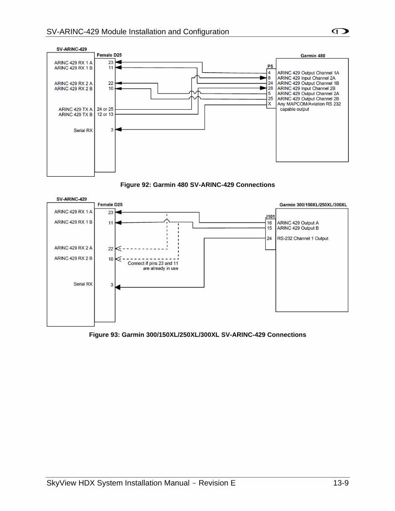
SV-ARINC-429 Module Installation and Configuration
SkyView HDX System Installation Manual - Revision E 13-9
Figure 92: Garmin 480 SV-ARINC-429 Connections
Figure 93: Garmin 300/150XL/250XL/300XL SV-ARINC-429 Connections
SV-ARINC-429 Module Installation and Configuration
13-10 SkyView HDX System Installation Manual - Revision E
13.3 SV-ARINC-429 Related Settings
Go to the ARINC-429 SETUP under SETUP MENU > SYSTEM SETUP > ARINC-429.
SkyView supports up to two (2) SV-ARINC-429 modules, but since most aircraft will only have one (1) installed, the “MODULE 2” section is normally disabled. If your aircraft does actually have two (2) SV-ARINC-429 modules, note that the serial numbers of each module are provided so you can determine which module is which.
For each module, Set INPUT1 to the type of device connected to the SV-ARINC-429’s ARINC-429 RX 1 A and B inputs, any of GPS 1, 2, 3, 4 or NAV 1, 2, 3, 4. Optionally, you can specify a “friendly” name for each navigation source using the NAVIGATION SOURCE DISP NAME and specifying up to 7 characters. Examples include “430NAV”, and “430GPS”. If a NAVIGATION SOURCE DISP NAME is specified, that will be displayed on the HSI. If NAVIGATION SOURCE DISP NAME is not specified, GPS 1,2,3,4 / NAV 1, 2, 3, 4 will be displayed in the info item next to the HSI. For IFR GPS navigators, particularly the Garmin GNS and GTN series, it is also used to describe the device at the top of the Flight Plan window. Note that any GPS/NAV slots that are highlighted in red are already being used for other devices. Also note that though POS X is a possible setting, it should generally not be used for ARINC devices.
Next set the INPUT SPEED parameter (HIGH or LOW), based on the output speed of your two (2) ARINC devices.
The SV-ARINC-429 has one (1) ARINC output channel with 2 sets of pins on the connector for wiring convenience. If one (1) or both of your ARINC devices can accept commands, configure OUTPUT SPEED appropriately.
If you have connected a device to ARINC-429 RX 2 A and B, repeat the above configuration for the INPUT2 parameter; otherwise, leave it set to NONE.
ALLOW AUTO SWITCH: YES (LABEL 100P) / NO: If set to YES (LABEL 100P), SkyView will automatically change whether data from INPUT1 or INPUT2 will be displayed.
• If the source transmits the “100P” label (such as Garmin 430/530/GTN series), SkyView will automatically switch inputs per the label. This allows the inputs to be remotely switched by data from the source, either when the CDI is changed, or automatic transition on approach.
• If data is being transmitted to INPUT1, but no data is being transmitted to INPUT2, INPUT1 will be displayed.
• If data is being transmitted to INPUT2, but no data is being transmitted to INPUT1, INPUT2 will be displayed.
Your ARINC-429 capable GPS and/or NAV will need to be configured appropriately as well.
SV-ADSB-472 ADS-B IN Receiver Installation and Configuration
SkyView HDX System Installation Manual - Revision E 14-1
14 SV-ADSB-472 ADS-B IN Receiver Installation and Configuration
SkyView can receive traffic and weather via the SV-ADSB-472 UAT Dual Band ADS-B Traffic and Weather Receiver. The SV-ADSB-472 is a remote mounted module that connects to SkyView via a serial port on your SkyView display(s). It also requires the installation of a dedicated antenna for ADS-B signal reception.
A map license is required to display ADS-B traffic and weather data received from the SV-ADSB-472.
The SV-ADSB-472 receives weather via the 978 MHz UAT ADS-B frequencies, which are only utilized in the US. Therefore, weather is only available in the US. Dynon Avionics does not recommend the use of the SV-ADSB-470 outside the US. However, the SV-ADSB-472 does show 1090 MHz ADS-B traffic from other ADS-B equipped aircraft outside the US.
Although weather and TFR information (FIS-B services) available any time the SV-ADSB-472 is in an ADS-B ground station coverage area, ADS-R TIS-B traffic is only available if a SV-XPNDR-261 with ADS-B OUT capability is installed and is providing ADS-B OUT position reports into the ADS-B system.
To enable ADS-B Traffic information on the SV-ADSB-472 with an ADS-B OUT device other than the Dynon Avionics SV-XPNDR-261:
1. SETUP MENU > SYSTEM SETUP > AIRCRAFT INFORMATION > TRANSPONDER HEX CODE > (enter the HEX Code assigned to your aircraft) > ACCEPT (button)
2. SETUP MENU > SYSTEM SETUP > TRAFFIC SETUP > NON-DYNON ADS-B OUT ONBOARD > YES
Only ADS-B OUT devices that comply with TSO C166b or later of the ADS-B spec will allow traffic to be displayed properly. The ADS-B OUT device must be set up to tell the ADS-B system that the aircraft is receiving on 978 MHz.
14.1 Mechanical Installation
The SV-ADSB-472 is designed to be mounted on the avionics tray. If it’s not possible to mount on avionics tray, any convenient location in the cockpit, the cabin, or an avionics bay.
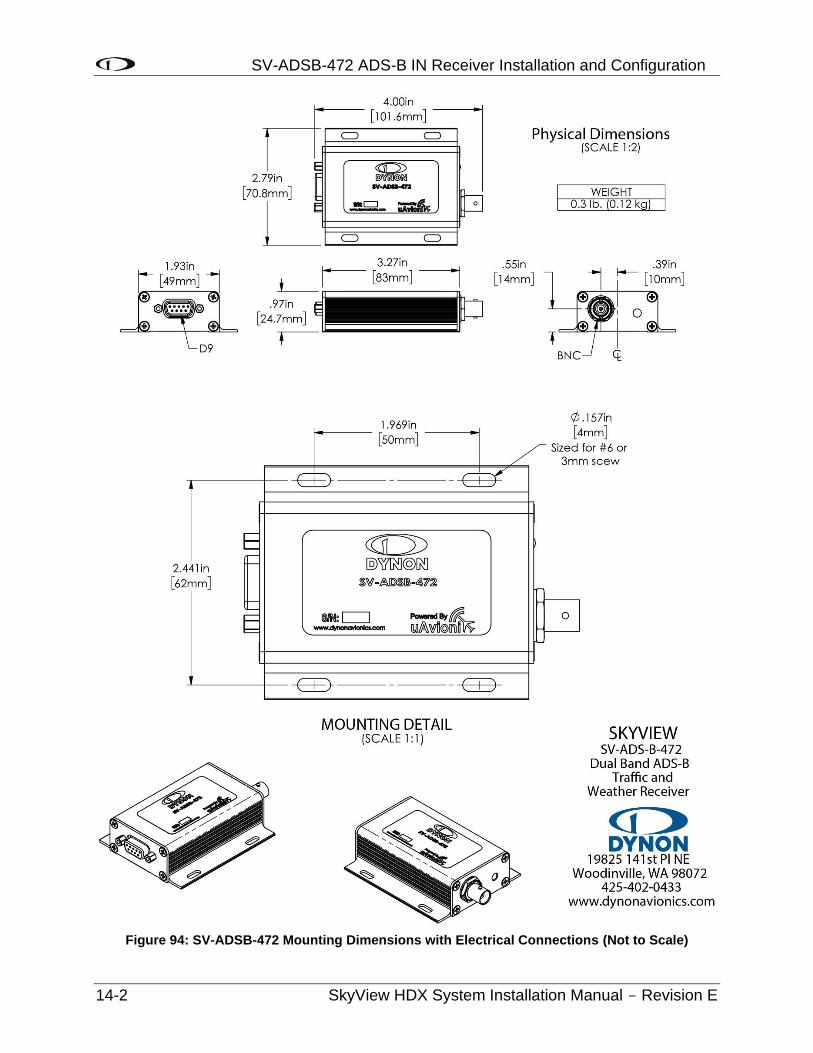
SV-ADSB-472 ADS-B IN Receiver Installation and Configuration
14-2 SkyView HDX System Installation Manual - Revision E
Figure 94: SV-ADSB-472 Mounting Dimensions with Electrical Connections (Not to Scale)
SV-ADSB-472 ADS-B IN Receiver Installation and Configuration
SkyView HDX System Installation Manual - Revision E 14-3
The following guidelines should be followed, remembering to allow adequate space for installation of cables and connectors:
• Select a position in the aircraft that is not too close to any high external heat source. (The SV-ADSB-472 is not a significant heat source itself and does not need to be kept away from other devices for this reason).
• Avoid sharp bends and placing the cables too near to the aircraft control cables.
• Avoid locations that are subject to severe vibration.
• Avoid locations that are subject to extreme humidity.
• Leave ample working room for electrical connections.
14.1.1 Installation Instructions
The SV-ADSB-472 is designed to be mounted in any convenient location in the cockpit, the cabin, or an avionics bay.
The following installation procedure should be followed, remembering to allow adequate space for installation of cables and connectors:
• Select a position in the aircraft that is not too close to any high external heat source. (The SV-ADSB-472 is not a significant heat source itself and does not need to be kept away from other devices for this reason).
• Avoid sharp bends and placing the cables too near to the aircraft control cables.
• Secure the SV-ADSB-472 to the aircraft using its four (4) mounting holes. The device should be mounted to a flat surface. The mounting tabs on each side of the module have holes sized for #8-32 fasteners. It is up to the installer to decide how the module will be secured to the aircraft.
Additional items you will require, but which are not in the SV-ADSB-472 package, include:
• SV-HARNESS-ADSB (or equivalent harness assembled by installer)
• Antenna and fixing hardware. Antenna selection suggestions are available in the following section.
• Antenna cable and BNC Male connector. You need to supply and fabricate all required antenna cables (or provided as part of your ADS-B antenna). Guidance on cable types is given below.
• Mounting hardware: To secure the SV-ADSB-472 to the aircraft.
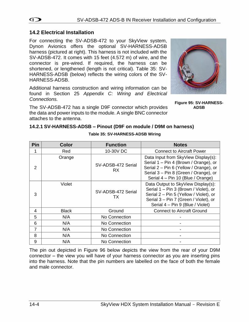
SV-ADSB-472 ADS-B IN Receiver Installation and Configuration
14-4 SkyView HDX System Installation Manual - Revision E
14.2 Electrical Installation
For connecting the SV-ADSB-472 to your SkyView system, Dynon Avionics offers the optional SV-HARNESS-ADSB harness (pictured at right). This harness is not included with the SV-ADSB-472. It comes with 15 feet (4.572 m) of wire, and the connector is pre-wired. If required, the harness can be shortened, or lengthened (length is not critical). Table 35: SV-HARNESS-ADSB (below) reflects the wiring colors of the SV-HARNESS-ADSB.
Additional harness construction and wiring information can be found in Section 25 Appendix C: Wiring and Electrical Connections.
The SV-ADSB-472 has a single D9F connector which provides the data and power inputs to the module. A single BNC connector attaches to the antenna.
14.2.1 SV-HARNESS-ADSB – Pinout (D9F on module / D9M on harness)
Table 35: SV-HARNESS-ADSB Wiring
Pin Color Function Notes
1 Red 10-30V DC Connect to Aircraft Power
2
Orange
SV-ADSB-472 Serial RX
Data Input from SkyView Display(s): Serial 1 – Pin 4 (Brown / Orange), or Serial 2 – Pin 6 (Yellow / Orange), or Serial 3 – Pin 8 (Green / Orange), or
Serial 4 – Pin 10 (Blue / Orange)
3
Violet
SV-ADSB-472 Serial TX
Data Output to SkyView Display(s): Serial 1 – Pin 3 (Brown / Violet), or Serial 2 – Pin 5 (Yellow / Violet), or Serial 3 – Pin 7 (Green / Violet), or
Serial 4 – Pin 9 (Blue / Violet)
4 Black Ground Connect to Aircraft Ground
5 N/A No Connection -
6 N/A No Connection -
7 N/A No Connection -
8 N/A No Connection -
9 N/A No Connection -
The pin out depicted in Figure 96 below depicts the view from the rear of your D9M connector – the view you will have of your harness connector as you are inserting pins into the harness. Note that the pin numbers are labelled on the face of both the female and male connector.
Figure 95: SV-HARNESS-ADSB
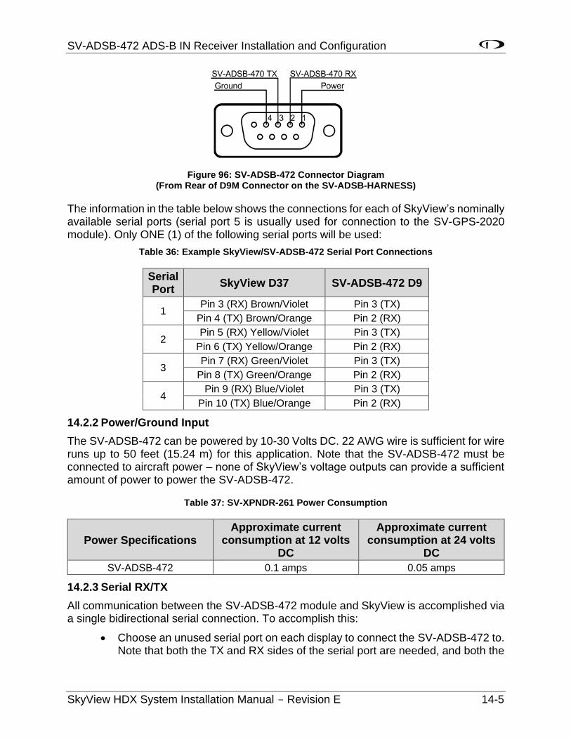
SV-ADSB-472 ADS-B IN Receiver Installation and Configuration
SkyView HDX System Installation Manual - Revision E 14-5
Figure 96: SV-ADSB-472 Connector Diagram (From Rear of D9M Connector on the SV-ADSB-HARNESS)
The information in the table below shows the connections for each of SkyView’s nominally available serial ports (serial port 5 is usually used for connection to the SV-GPS-2020 module). Only ONE (1) of the following serial ports will be used:
Table 36: Example SkyView/SV-ADSB-472 Serial Port Connections
Serial Port
SkyView D37 SV-ADSB-472 D9
1 Pin 3 (RX) Brown/Violet Pin 3 (TX)
Pin 4 (TX) Brown/Orange Pin 2 (RX)
2 Pin 5 (RX) Yellow/Violet Pin 3 (TX)
Pin 6 (TX) Yellow/Orange Pin 2 (RX)
3 Pin 7 (RX) Green/Violet Pin 3 (TX)
Pin 8 (TX) Green/Orange Pin 2 (RX)
4 Pin 9 (RX) Blue/Violet Pin 3 (TX)
Pin 10 (TX) Blue/Orange Pin 2 (RX)
14.2.2 Power/Ground Input
The SV-ADSB-472 can be powered by 10-30 Volts DC. 22 AWG wire is sufficient for wire runs up to 50 feet (15.24 m) for this application. Note that the SV-ADSB-472 must be connected to aircraft power – none of SkyView’s voltage outputs can provide a sufficient amount of power to power the SV-ADSB-472.
Table 37: SV-XPNDR-261 Power Consumption
Power Specifications Approximate current
consumption at 12 volts DC
Approximate current consumption at 24 volts
DC
SV-ADSB-472 0.1 amps 0.05 amps
14.2.3 Serial RX/TX
All communication between the SV-ADSB-472 module and SkyView is accomplished via a single bidirectional serial connection. To accomplish this:
• Choose an unused serial port on each display to connect the SV-ADSB-472 to. Note that both the TX and RX sides of the serial port are needed, and both the
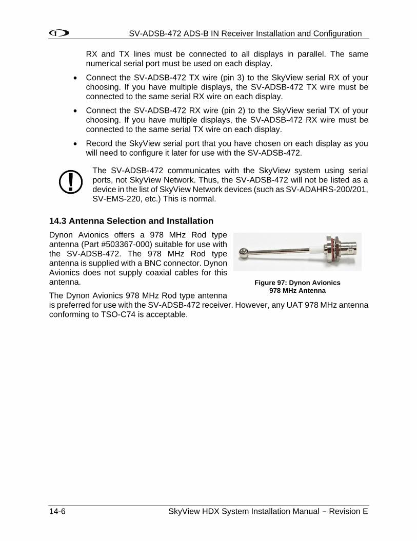
SV-ADSB-472 ADS-B IN Receiver Installation and Configuration
14-6 SkyView HDX System Installation Manual - Revision E
RX and TX lines must be connected to all displays in parallel. The same numerical serial port must be used on each display.
• Connect the SV-ADSB-472 TX wire (pin 3) to the SkyView serial RX of your choosing. If you have multiple displays, the SV-ADSB-472 TX wire must be connected to the same serial RX wire on each display.
• Connect the SV-ADSB-472 RX wire (pin 2) to the SkyView serial TX of your choosing. If you have multiple displays, the SV-ADSB-472 RX wire must be connected to the same serial TX wire on each display.
• Record the SkyView serial port that you have chosen on each display as you will need to configure it later for use with the SV-ADSB-472.
The SV-ADSB-472 communicates with the SkyView system using serial ports, not SkyView Network. Thus, the SV-ADSB-472 will not be listed as a device in the list of SkyView Network devices (such as SV-ADAHRS-200/201, SV-EMS-220, etc.) This is normal.
14.3 Antenna Selection and Installation
Dynon Avionics offers a 978 MHz Rod type antenna (Part #503367-000) suitable for use with the SV-ADSB-472. The 978 MHz Rod type antenna is supplied with a BNC connector. Dynon Avionics does not supply coaxial cables for this antenna.
The Dynon Avionics 978 MHz Rod type antenna is preferred for use with the SV-ADSB-472 receiver. However, any UAT 978 MHz antenna conforming to TSO-C74 is acceptable.
Figure 97: Dynon Avionics 978 MHz Antenna
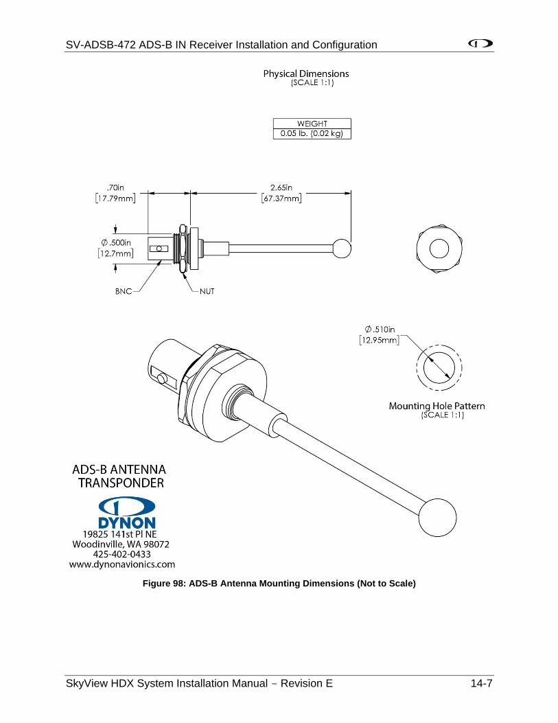
SV-ADSB-472 ADS-B IN Receiver Installation and Configuration
SkyView HDX System Installation Manual - Revision E 14-7
Figure 98: ADS-B Antenna Mounting Dimensions (Not to Scale)
SV-ADSB-472 ADS-B IN Receiver Installation and Configuration
14-8 SkyView HDX System Installation Manual - Revision E
The following considerations should be considered when siting the antenna:
• The antenna should be well removed from any projections, the engine(s) and propeller(s). It should also be well removed from landing gear doors, access doors or other openings which will break the ground plane for the antenna.
• The antenna should be mounted on the bottom surface of the aircraft and in a vertical position when the aircraft is in level flight.
• Where practical, plan the antenna location to keep the cable lengths as short as possible and avoid sharp bends in the cable to minimize the VSWR (voltage standing wave ratio).
• The SV-ADSB-472 antenna should not be installed within two (2) feet (60.96 cm) of a 1090 MHz transponder (including the SV-XPNDR-261) antenna.
14.3.1 Antenna Ground Plane
When a conventional aircraft monopole antenna is used it relies on a ground plane for correct behaviour. For ideal performance, the ground plane should be very large compared to the wavelength of reception, which is 12.01 inches (305 mm). In a metal skinned aircraft this is usually easy to accomplish, but is more difficult in a composite or fabric skinned aircraft. In such cases, a metallic ground plane should be fabricated and fitted under the antenna.
As the ground plane is made smaller, the actual dimensions of the ground plane become more critical, and small multiples of the wavelength should be avoided, as should circles. Rectangles or squares are much less likely to create a critical dimension that resonates with the transmissions. The smallest practical ground plane is a square about 5.12 inches (13.0 cm) per side; as the size increases the performance may actually get worse, but will be better by the time the ground plane is 30.71 inches (78.0 cm) on each side. Anything much larger than that size is unlikely to show significant further improvement.
The thickness of the material used to construct the ground plane is not critical, providing it is sufficiently conductive. A variety of proprietary mesh and grid solutions are available. Heavyweight cooking foil meets the technical requirements, but obviously needs to be properly supported.
14.3.2 Antenna Cable
An acceptable cable:
• Has less than 3.0 dB loss for the run length needed. For runs less than 17 feet (5.18 m), RG58 is acceptable.
• Has a characteristic impedance of 50 Ω (50 Ohms).
• If running the antenna cable in a bundle with or in close proximity to the SV-XPNDR-261 antenna cable:
o Has double braid screens or has a foil and braid screen. For runs less than 17 feet (5.18 m), RG400 is acceptable.
When routing the cable, ensure that you:
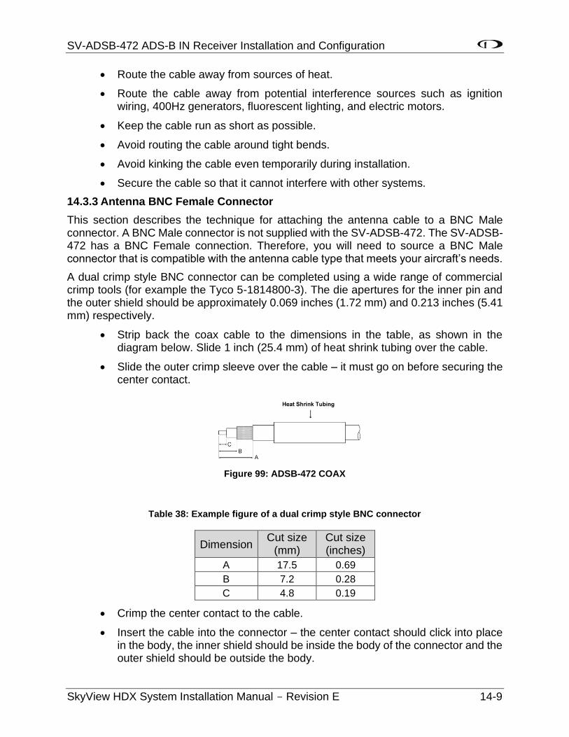
SV-ADSB-472 ADS-B IN Receiver Installation and Configuration
SkyView HDX System Installation Manual - Revision E 14-9
• Route the cable away from sources of heat.
• Route the cable away from potential interference sources such as ignition wiring, 400Hz generators, fluorescent lighting, and electric motors.
• Keep the cable run as short as possible.
• Avoid routing the cable around tight bends.
• Avoid kinking the cable even temporarily during installation.
• Secure the cable so that it cannot interfere with other systems.
14.3.3 Antenna BNC Female Connector
This section describes the technique for attaching the antenna cable to a BNC Male connector. A BNC Male connector is not supplied with the SV-ADSB-472. The SV-ADSB-472 has a BNC Female connection. Therefore, you will need to source a BNC Male connector that is compatible with the antenna cable type that meets your aircraft’s needs.
A dual crimp style BNC connector can be completed using a wide range of commercial crimp tools (for example the Tyco 5-1814800-3). The die apertures for the inner pin and the outer shield should be approximately 0.069 inches (1.72 mm) and 0.213 inches (5.41 mm) respectively.
• Strip back the coax cable to the dimensions in the table, as shown in the diagram below. Slide 1 inch (25.4 mm) of heat shrink tubing over the cable.
• Slide the outer crimp sleeve over the cable – it must go on before securing the center contact.
Figure 99: ADSB-472 COAX
Table 38: Example figure of a dual crimp style BNC connector
Dimension Cut size
(mm) Cut size (inches)
A 17.5 0.69
B 7.2 0.28
C 4.8 0.19
• Crimp the center contact to the cable.
• Insert the cable into the connector – the center contact should click into place in the body, the inner shield should be inside the body of the connector and the outer shield should be outside the body.
SV-ADSB-472 ADS-B IN Receiver Installation and Configuration
14-10 SkyView HDX System Installation Manual - Revision E
• Crimp the outer sleeve over the shield.
Slide heat shrink tubing forward (flush to connector) and heat to shrink the tubing.
14.4 SV-ADSB-472 Related SkyView Display Settings
Before the ADS-B STATUS menu can be accessed, the SV-ADSB-472 needs to be configured on the SkyView system:
SETUP MENU > SYSTEM SETUP > SERIAL PORT SETUP > SERIAL PORT x SETUP (the serial port you wired the SV-ADSB-472 to) > SERIAL IN DEVICE > SV-ADSB-472 > ACCEPT (button).
SETUP MENU > TRAFFIC SETUP > SHOW TAIL NUMBERS > YES > ACCEPT (button).
14.5 Post Installation Checks
After the SV-ADSB-472 has been configured, confirmation that communication has been established with the module by performing the following procedure:
• Go to SETUP MENU > ADS-B STATUS.
• Confirm that the DEVICE line reads SV-ADSB-472.
• Use the STATUS line to determine whether the SV-ADSB-472 is successfully communicating with SkyView. It can also be used to determine whether the as well as if it is able to see any ADS-B ground stations. The status line can display any of the following states:
o NOT FOUND: The device is not communicating with SkyView. This usually implies a connectivity/wiring problem between the SV-ADSB-472 and SkyView, or that the SV-ADSB-472 is not receiving power.
o NO SIGNAL: The device is communicating with SkyView, but data is not being received from an ADS-B ground station. This may occur when you are on the ground and do not have line-of-sight reception of an ADS-B ground station, or if you are in the air and are out of range of all ADS-B ground stations. If there is an ADS-B ground station in range, and NO SIGNAL is persistently displayed, it may imply a connectivity problem with your ADS-B antenna or an installation issue that is preventing the ADS-B antenna from receiving ADS-B ground station broadcasts. Note that when in flight, the Map Page displays a status widget in its lower left corner that contains the same information as this menu status item. That widget will be more useful for ascertaining proper operation once you are in the air and are most likely to be receiving data from ADS-B ground stations.
o RECEIVING: The device is communicating with SkyView AND data is being received from an ADS-B ground station.
If SkyView is not (yet) receiving a valid GPS fix, ADS-B data that is received will not be processed / updated until SkyView does have a valid GPS fix.
SV-ADSB-472 ADS-B IN Receiver Installation and Configuration
SkyView HDX System Installation Manual - Revision E 14-11
• You may also observe the red LED indicator on the SV-ADSB-472 module to confirm proper hardware operation:
o Flashing Fast: The SV-ADSB-472 is operating normally, is configured and communicating with SkyView over a correctly-configured serial port, and is receiving GPS data from SkyView.
o Flashing Slowly: The SV-ADSB-472 is receiving power and operating normally, but is not fully communicating with SkyView.
o Off: The SV-ADSB-472 is not receiving power.
o On: The SV-ADSB-472 is receiving power, but is not operating normally. Cycle power on the SV-ADSB-472 to try to clear this condition. If the indicator remains On (solid, no blinking), after cycling power, contact Dynon Avionics Technical Support (contact information can be found at the beginning of this manual).

SV-COM-X83 Transceiver and Panel Installation and Configuration
SkyView HDX System Installation Manual - Revision E 15-1
15 SV-COM-X83 Transceiver and Panel Installation and Configuration
Note: SV-COM-X83 is the complete radio system, consisting of the SV-COM-PANEL and the SV-COM-T8 transceiver installed elsewhere.
Do not transmit without an antenna connected. Doing so will damage your SV-COM-X83.
15.1 Mechanical Installation
The figures on the following pages show recommended panel cutouts, mounting hole patterns, and mechanical dimension for the SV-COM-PANEL/V (vertical) and SV-COM-PANEL/H (horizontal). Use these diagrams to plan for the space required by the display.
To mount an SV-COM-PANEL, cut the opening in your panel, drill out the mounting holes, install nutplates, and use the included mounting screws to fasten the display to the panel.
Your SV-COM-X83 is shipped with #6-32 hex-drive round head fasteners. Fasteners are 5/8” long and require a 5/64” hex drive tool. Dynon Avionics recommends fastening the included mounting screws to nut plates installed behind the panel. If access behind the panel allows, standard #6-32 lock nuts or nuts with lock washers can be used. Do not rivet the SV-COM-PANEL to the panel as this will hinder future removal if necessary.
The following installation procedure should be followed to install the remote transceiver module, remembering to allow adequate space for installation of cables and connectors.
• If you are installing two COM radios, it is acceptable to co-locate the two transceiver modules.
• Select a position in the aircraft for the transceiver that is not too close to any external external high-heat source and where reasonable airflow is available. The transceiver is not a significant heat source itself and does not need to be kept away from other devices for this reason.
• Avoid sharp bends and placing the cables too near to the aircraft control cables.
• Secure the transceiver to the aircraft via the four (4) mounting holes. The unit should be mounted to a flat surface.
Additional items you will require for installation of SV-COM-X83, but which are not in the SV-COM-X83 package, include:
• Nutplates for mounting SV-COM-PANEL to the panel
• To secure the SV-COM-X83 tray to the airframe you will need least 3 flat head screws and three self-locking nuts. If the aircraft does not have existing mounting provisions you may need to fabricate additional brackets to support the SV-COM-X83 tray.
• Circuit breaker or fuse for power to SV-COM-T8 and SV-COM-PANEL
SV-COM-X83 Transceiver and Panel Installation and Configuration
15-2 SkyView HDX System Installation Manual - Revision E
• Power wires to SV-COM-T8
• SV-COM-T8 to SV-COM-PANEL wiring
• SkyView Network cables to connect the SV-COM-PANEL to SkyView Network
• COM Antenna, coaxial cable, terminated to TNC Male connector or cable and TNC Male connector is included with your COM antenna. The SV-COM-X83 is compatible with aircraft COM antennas commonly available (may require a TNC Male to BNC Female adapter).
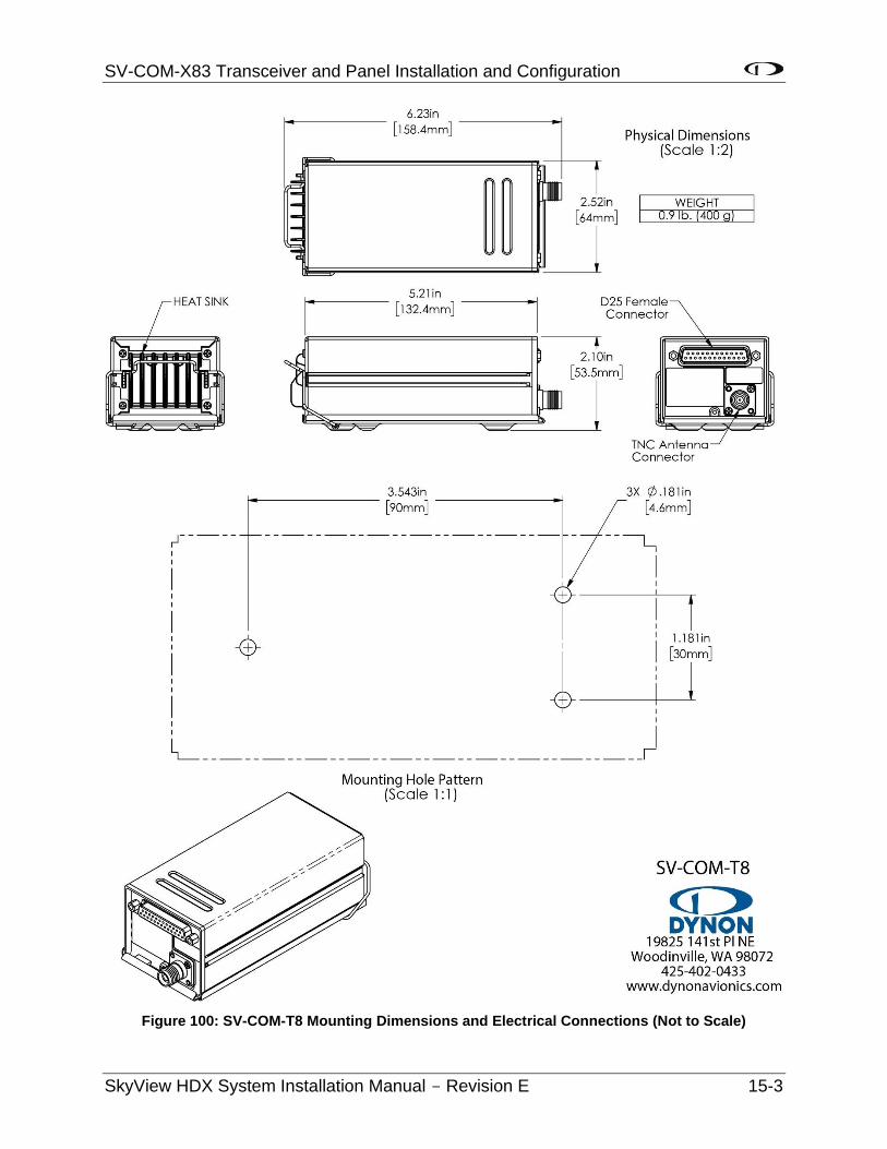
SV-COM-X83 Transceiver and Panel Installation and Configuration
SkyView HDX System Installation Manual - Revision E 15-3
Figure 100: SV-COM-T8 Mounting Dimensions and Electrical Connections (Not to Scale)

SV-COM-X83 Transceiver and Panel Installation and Configuration
15-4 SkyView HDX System Installation Manual - Revision E
Figure 101: SV-COM-PANEL Mounting Dimensions (Not to Scale)
SV-COM-X83 Transceiver and Panel Installation and Configuration
SkyView HDX System Installation Manual - Revision E 15-5
15.2 Electrical Installation
Use this section in conjunction with the information contained in Section 25 Appendix C: Wiring and Electrical Connections.
15.2.1 Power Input
SV-COM-X83 is compatible with 12-volt and 24-volt systems (10 to 30 volts DC). Power input is connected to the transceiver and the SV-COM-PANEL. See wiring diagrams and pinouts for details. Note that the transceiver has two pins for POWER input (Pins 24 and 25) and two pins for GROUND (Pins 19 and 22). Use both Pins 24 and 25 for POWER input to the transceiver and use both Pins 19 and 22 for GROUND to the transceiver.
15.2.2 Audio Signal Grounding
Ensure that audio input and output grounds terminate at a single point—typically the intercom or audio panel. Do not connect an audio input or output ground to aircraft frame ground or a power or data ground. You should run dedicated wires from audio devices to the single point audio input and output ground.
15.2.3 Audio Shielding
Shielded cable must be used for all audio connections. The shield should be connected to ground only at the single point audio ground.
15.2.4 SkyView Network Connectors
The two (2) D9 connectors on the back of a SV-COM-PANEL display are SkyView network connectors. They have identical pinouts and are electrically connected inside the SV-COM-PANEL (i.e., they are completely interchangeable). Installers may use either connector or both connectors in SkyView installations. Using both of these connectors allows installers to daisy-chain another SkyView Network module (such as the SV-EMS-22X) that may be co-located behind the panel. Reference
Table 67 on Page 25-10 for SkyView Network Connector pinout information.
Note that these connectors are not serial port connectors.
15.2.5 Electrical Connections
15.2.5.1 Harness Construction
Because the SV-COM-X83 (SV-COM-PANEL connected to the transceiver) can be mounted in a variety of locations, the harness length requirements will vary from airplane to airplane. Thus, Dynon Avionics does not supply pre-manufactured harnesses for the SV-COM-X83. Instead, your SV-COM-X83 includes connectors and pins to generate a wide variety of harness configurations. Refer to the sections below for detailed wiring information.
Additional harness construction and wiring information can be found in Section 25 Appendix C: Wiring and Electrical Connections.
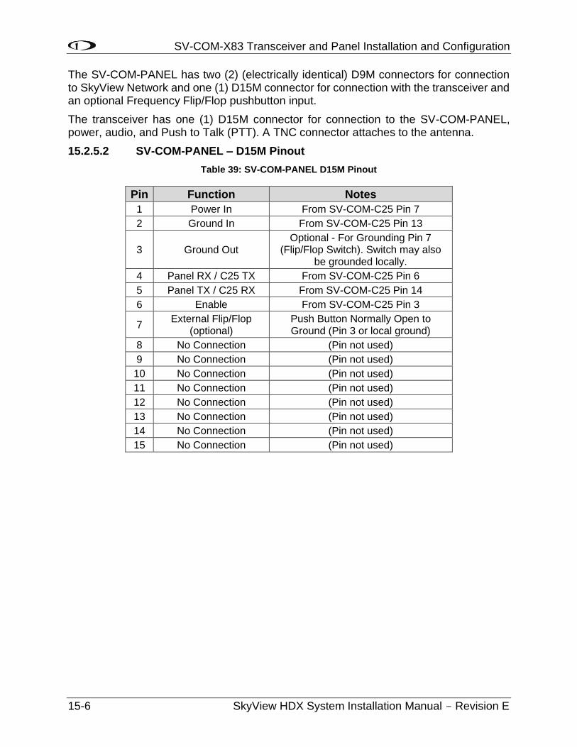
SV-COM-X83 Transceiver and Panel Installation and Configuration
15-6 SkyView HDX System Installation Manual - Revision E
The SV-COM-PANEL has two (2) (electrically identical) D9M connectors for connection to SkyView Network and one (1) D15M connector for connection with the transceiver and an optional Frequency Flip/Flop pushbutton input.
The transceiver has one (1) D15M connector for connection to the SV-COM-PANEL, power, audio, and Push to Talk (PTT). A TNC connector attaches to the antenna.
15.2.5.2 SV-COM-PANEL – D15M Pinout
Table 39: SV-COM-PANEL D15M Pinout
Pin Function Notes
1 Power In From SV-COM-C25 Pin 7
2 Ground In From SV-COM-C25 Pin 13
3 Ground Out Optional - For Grounding Pin 7
(Flip/Flop Switch). Switch may also be grounded locally.
4 Panel RX / C25 TX From SV-COM-C25 Pin 6
5 Panel TX / C25 RX From SV-COM-C25 Pin 14
6 Enable From SV-COM-C25 Pin 3
7 External Flip/Flop
(optional) Push Button Normally Open to Ground (Pin 3 or local ground)
8 No Connection (Pin not used)
9 No Connection (Pin not used)
10 No Connection (Pin not used)
11 No Connection (Pin not used)
12 No Connection (Pin not used)
13 No Connection (Pin not used)
14 No Connection (Pin not used)
15 No Connection (Pin not used)
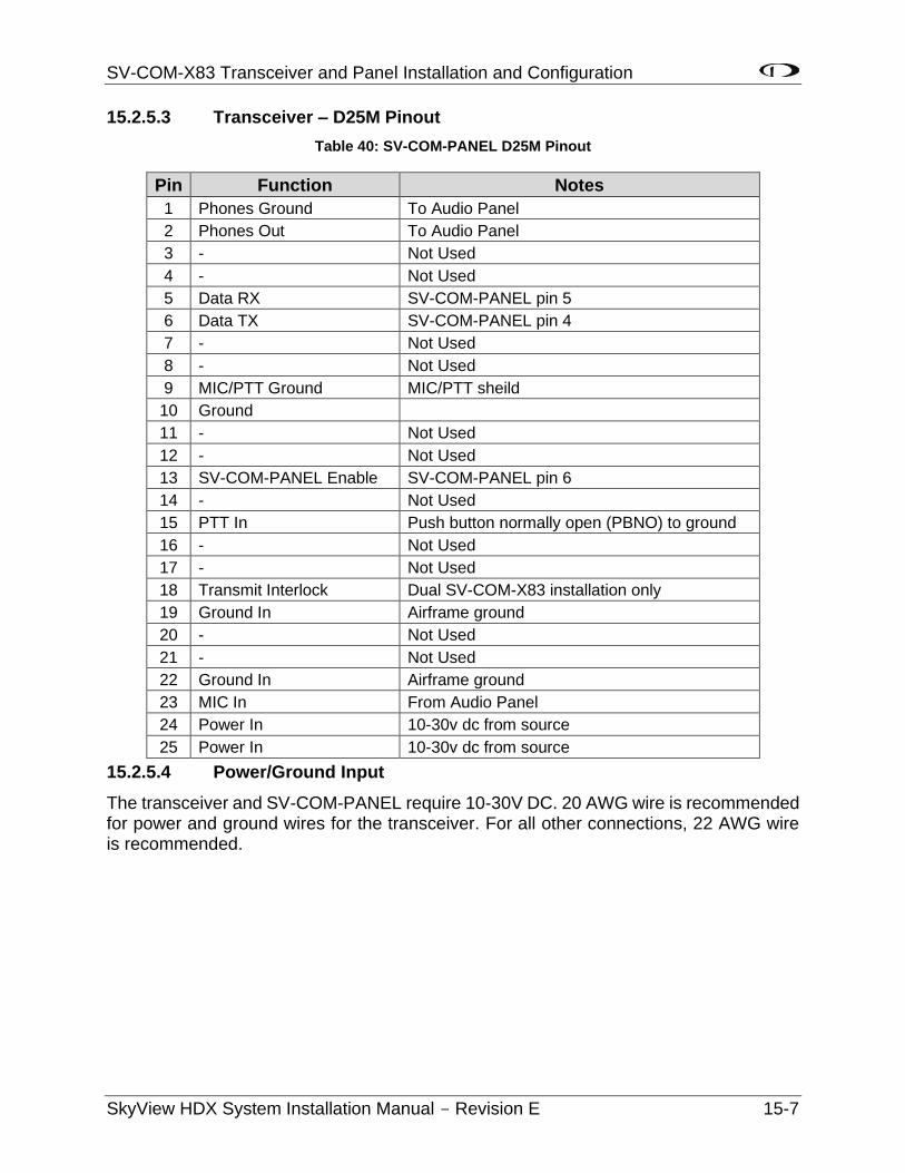
SV-COM-X83 Transceiver and Panel Installation and Configuration
SkyView HDX System Installation Manual - Revision E 15-7
15.2.5.3 Transceiver – D25M Pinout
Table 40: SV-COM-PANEL D25M Pinout
Pin Function Notes
1 Phones Ground To Audio Panel
2 Phones Out To Audio Panel
3 - Not Used
4 - Not Used
5 Data RX SV-COM-PANEL pin 5
6 Data TX SV-COM-PANEL pin 4
7 - Not Used
8 - Not Used
9 MIC/PTT Ground MIC/PTT sheild
10 Ground
11 - Not Used
12 - Not Used
13 SV-COM-PANEL Enable SV-COM-PANEL pin 6
14 - Not Used
15 PTT In Push button normally open (PBNO) to ground
16 - Not Used
17 - Not Used
18 Transmit Interlock Dual SV-COM-X83 installation only
19 Ground In Airframe ground
20 - Not Used
21 - Not Used
22 Ground In Airframe ground
23 MIC In From Audio Panel
24 Power In 10-30v dc from source
25 Power In 10-30v dc from source
15.2.5.4 Power/Ground Input
The transceiver and SV-COM-PANEL require 10-30V DC. 20 AWG wire is recommended for power and ground wires for the transceiver. For all other connections, 22 AWG wire is recommended.
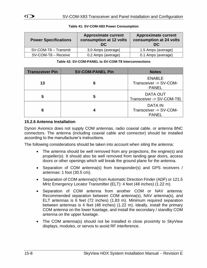
SV-COM-X83 Transceiver and Panel Installation and Configuration
15-8 SkyView HDX System Installation Manual - Revision E
Table 41: SV-COM-X83 Power Consumption
Power Specifications Approximate current
consumption at 12 volts DC
Approximate current consumption at 24 volts
DC
SV-COM-T8 – Transmit 3.0 Amps (average) 1.5 Amps (average)
SV-COM-T8 – Receive 0.2 Amps (average) 0.1 Amps (average)
Table 42: SV-COM-PANEL to SV-COM-T8 Interconnections
Transceiver Pin SV-COM-PANEL Pin Notes
13 6 ENABLE
Transceiver -> SV-COM-PANEL
5 5 DATA OUT
Transceiver -> SV-COM-T8)
6 4 DATA IN
Transceiver -> SV-COM-PANEL
15.2.6 Antenna Installation
Dynon Avionics does not supply COM antennas, radio coaxial cable, or antenna BNC connectors. The antenna (including coaxial cable and connector) should be installed according to the manufacturer’s instructions.
The following considerations should be taken into account when siting the antenna:
• The antenna should be well removed from any projections, the engine(s) and propeller(s). It should also be well removed from landing gear doors, access doors or other openings which will break the ground plane for the antenna.
• Separation of COM antenna(s) from transponder(s) and GPS receivers / antennas: 1 foot (30.5 cm).
• Separation of COM antenna(s) from Automatic Direction Finder (ADF) or 121.5 MHz Emergency Locator Transmitter (ELT): 4 feet (48 inches) (1.22 m).
• Separation of COM antenna from another COM or NAV antenna: Recommended separation between COM antenna(s), NAV antenna(s), and ELT antennas is 6 feet (72 inches) (1.83 m). Minimum required separation between antennas is 4 feet (48 inches) (1.22 m). Ideally, install the primary COM antenna on the lower fuselage, and install the secondary / standby COM antenna on the upper fuselage.
• The COM antenna(s) should not be installed in close proximity to SkyView displays, modules, or servos to avoid RF interference.
SV-COM-X83 Transceiver and Panel Installation and Configuration
SkyView HDX System Installation Manual - Revision E 15-9
• Where practical, plan the antenna location to keep the cable lengths as short as possible and avoid sharp bends in the cable to minimize the VSWR (voltage standing wave ratio).
• Double-shielded coaxial cable is superior to single shield coax – more of the transmit power will be coupled to the antenna, and less received signal will be lost.
• Electrical connection to the antenna should be protected to avoid loss of efficiency as a result of the presence of liquids or moisture. All antenna feeders shall be installed in such a way that a minimum of RF energy is radiated inside the aircraft.
15.2.6.1 Antenna Ground Plane
When a conventional aircraft monopole antenna is used it relies on a ground plane for correct behaviour. For ideal performance the ground plane should be very large compared to the wavelength of the transmission, which is approx. 7.5 feet (2.29 m). In a metal skinned aircraft this is usually easy to accomplish, but is more difficult in a composite or fabric skinned aircraft. In such cases, a metallic ground plane should be fabricated and fitted under the antenna.
As the ground plane is made smaller, the actual dimensions of the ground plane become more critical, and small multiples of the wavelength should be avoided, as should circles. Rectangles or squares are much less likely to create a critical dimension that resonates with the transmissions. The thickness of the material used to construct the ground plane is not critical, providing it is sufficiently conductive. A variety of proprietary mesh and grid solutions are available. Heavyweight cooking foil meets the technical requirements, but obviously needs to be properly supported.
15.2.6.2 Antenna Cable
When routing the cable, ensure that you:
• Route the cable away from sources of heat.
• Avoid routing antenna cables together.
• Route the cable away from potential interference sources such as ignition wiring, 400Hz generators, fluorescent lighting and electric motors.
• Allow a minimum separation of 1 foot / 12 inches (30.5 cm) from an ADF antenna cable.
• Keep the cable run as short as possible.
• Avoid routing the cable around tight bends.
• Avoid kinking the cable even temporarily during installation.
• Secure the cable so that it cannot interfere with other systems.
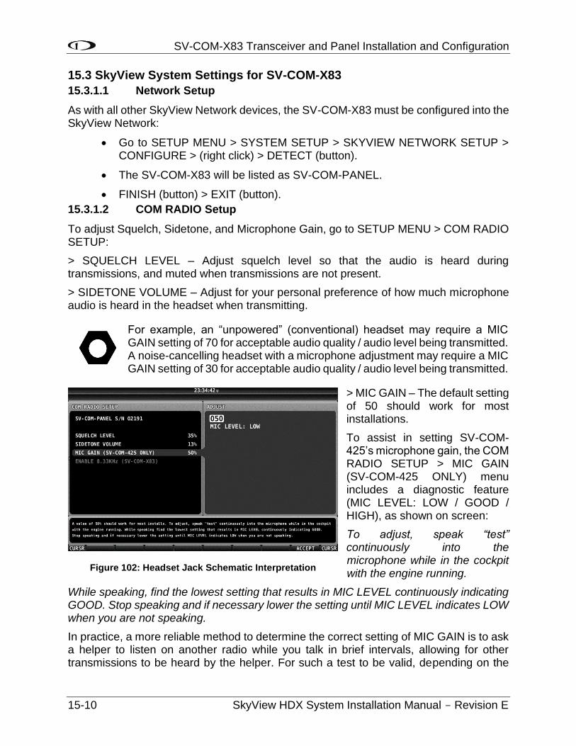
SV-COM-X83 Transceiver and Panel Installation and Configuration
15-10 SkyView HDX System Installation Manual - Revision E
15.3 SkyView System Settings for SV-COM-X83
15.3.1.1 Network Setup
As with all other SkyView Network devices, the SV-COM-X83 must be configured into the SkyView Network:
• Go to SETUP MENU > SYSTEM SETUP > SKYVIEW NETWORK SETUP > CONFIGURE > (right click) > DETECT (button).
• The SV-COM-X83 will be listed as SV-COM-PANEL.
• FINISH (button) > EXIT (button).
15.3.1.2 COM RADIO Setup
To adjust Squelch, Sidetone, and Microphone Gain, go to SETUP MENU > COM RADIO SETUP:
> SQUELCH LEVEL – Adjust squelch level so that the audio is heard during transmissions, and muted when transmissions are not present.
> SIDETONE VOLUME – Adjust for your personal preference of how much microphone audio is heard in the headset when transmitting.
For example, an “unpowered” (conventional) headset may require a MIC GAIN setting of 70 for acceptable audio quality / audio level being transmitted. A noise-cancelling headset with a microphone adjustment may require a MIC GAIN setting of 30 for acceptable audio quality / audio level being transmitted.
> MIC GAIN – The default setting of 50 should work for most installations.
To assist in setting SV-COM-425’s microphone gain, the COM RADIO SETUP > MIC GAIN (SV-COM-425 ONLY) menu includes a diagnostic feature (MIC LEVEL: LOW / GOOD / HIGH), as shown on screen:
To adjust, speak “test” continuously into the microphone while in the cockpit with the engine running.
While speaking, find the lowest setting that results in MIC LEVEL continuously indicating GOOD. Stop speaking and if necessary lower the setting until MIC LEVEL indicates LOW when you are not speaking.
In practice, a more reliable method to determine the correct setting of MIC GAIN is to ask a helper to listen on another radio while you talk in brief intervals, allowing for other transmissions to be heard by the helper. For such a test to be valid, depending on the
Figure 102: Headset Jack Schematic Interpretation
SV-COM-X83 Transceiver and Panel Installation and Configuration
SkyView HDX System Installation Manual - Revision E 15-11
particular radio, aircraft, antennas, and terrain (buildings), it may be necessary to have some distance between you and the helper (being right next to each other will not be a valid test). With the helper listening on your (not heavily in use) test frequency, adjust MIC GAIN slowly up or down, pausing between transmissions.
For example, set MIC GAIN to 55, speak “Test1, Test2, Test3, Test4, Test5”, then pause a minute or so for other transmissions to be heard. The helper should reply whether your transmission was weaker, or stronger than the other transmissions. If the helper indicated your transmission was stronger than the other transmissions, adjust MIC GAIN lower, and do another set of transmissions. When the helper hears your audio to be about the same volume as the other transmissions, MIC GAIN is set correctly.
If other people report that your transmissions fade off at the end or can't be heard at all, you may need increase MIC GAIN. If your transmissions are reported to sound "hollow", "robotic" or if they have a lot of background noise, you may need to decrease MIC GAIN. Also note these issues can only be heard on real transmissions by third parties.
The audio you hear in your headset (Sidetone) when you transmit is unaffected by the MIC GAIN setting. As explained above, the best method to set MIC GAIN correctly is to work with a helper who is listening to your transmissions on a different radio.
15.3.1.3 Displayed COM (Top Bar)
The status of one (1) COM radio can be displayed on the top bar. The radio that is selected here is also the radio that you can send airports and frequencies to via SkyView’s Map Menu APT>COM and TUNE COM buttons. See the SkyView Pilot’s User Guide for additional details.
• Go to SETUP MENU > SYSTEM SETUP > DISPLAYED COM and select which COM radio status to display on the Top Bar (or NONE). (To display status of a non-Dynon Avionics radio, a serial port connection must be installed FROM the radio TO the SkyView display(s).
15.4 Post Installation Checks
On ground:
• Do all SV-COM-PANEL buttons and knobs function normally?
• Verify dim commands from SkyView display dim the backlighting of the SV-COM-PANEL.
• Does the (optional) FLIP/FLOP pushbutton swap the STBY and COM frequencies?
• Does pushing the PTT switch cause the SV-COM-X83 to transmit (only) when pushed?
Do not transmit without an antenna connected. Doing so will damage your SV-COM-X83.
SV-COM-X83 Transceiver and Panel Installation and Configuration
15-12 SkyView HDX System Installation Manual - Revision E
• (Optional, if two (2) SV-COM-X83s installed) Does the PTT Select Switch cause only the selected radio to transmit when PTT switch is pushed?
• Temporarily install a VSWR meter between the SV-COM-X83 and the antenna. Using brief test transmissions, is the VSWR 3:1 or below? A good installation should have VSWR of 2:1 or even 1:1. The maximum acceptable VSWR for SV-COM-X83 is 3:1.
• When transmitting on SV-COM-X83, is there any interference to other aircraft systems?
• Power off the SkyView display(s) by pushing and holding Button #1 on the display. The SV-COM-X83 should continue to operate normally, with the exception that auto-population of the buttons frequencies will not occur, and a NO SV error message will appear approx. three (3) seconds after SV is not operating.
In Flight
• Does the SV-COM-X83 receive other aircraft and ground transmissions at reasonable ranges?
• Does the SV-COM-X83 receive other aircraft and ground transmissions equally well at the low end, middle, and high end of the Aviation band?
• Is received audio clear at most volume levels on the SV-COM-X83? (Distortion at high volume levels is normal.)
• Are transmissions from the SV-COM-X83 heard by others at reasonable ranges? (Keep in mind that the power output of the SV-COM-X83 is 6 watts.)
• Are transmissions from the SV-COM-X83 clear (when received by others)?
AP Servo Installation and Configuration
SkyView HDX System Installation Manual - Revision E 16-1
16 AP Servo Installation and Configuration
16.1 Overview
The installation of autopilot servos is aircraft-model specific. Not every airplane can receive a Dynon SkyView autopilot. Refer to the AML associated with STC SA02594SE to see if your make and model airplane is eligible for an autopilot installation.
If your airplane is eligible for an autopilot installation, refer the Servo Installation Manual specific to your make and model of airplane for instructions.
16.1.1 Wire Sizing
While it is beyond the scope of this installation manual to advise on specific types of wiring for a particular aircraft, choice of wiring should be sized to 1) minimize voltage drop over the length of the particular wiring run, and 2) conduct the amount of current required by the subsystem without the wiring becoming warm to the touch. Section 25 Appendix C: Wiring and Electrical Connections contains information and suggested resources for wiring and electrical connections. Generally, 20 AWG wire is a suitable gauge for the servo power / ground wires for lengths up to 20’ (6.10 m) of wire.
16.1.2 Wiring Installation
Care should be taken such that aircraft wiring is not subjected to chafing, excessive flexing, or connections/junctions subjected to excessive vibration which may cause the connection/junction to fail or short-circuit.
16.2 Autopilot Servo Initial Setup
There are several parameters in the Autopilot Setup Menu (SETUP MENU > AUTOPILOT SETUP) that allow you to tune the behavior of the SkyView autopilot system. This section describes these adjustable parameters. Note that the Autopilot Setup Menu is only accessible after a successful servo test procedure.
16.2.1 Autopilot Setup Options
16.2.1.1 Autopilot Controls
SkyView’s autopilot can be operated using one (1) of two (2) very distinct control schemes:
SIMPLIFIED: Two (2) button streamlined autopilot controls: TRK+ALT for flying in the direction and at the altitude you choose, HSI+ALT for following navigation sources like GPS flight plans.
EXPERT: Autopilot controls containing the features that IFR pilots need. Includes VNAV, IAS hold, TRK mode, fully-coupled approaches, mode sequencing, and a flight director.
Setting the SkyView AP to EXPERT mode requires that two (2) SkyView AP servos (Roll and Pitch) are installed. If only one (1) servo (either Roll only, or Pitch only) is installed, the SkyView AP can only be set to SIMPLIFIED mode.
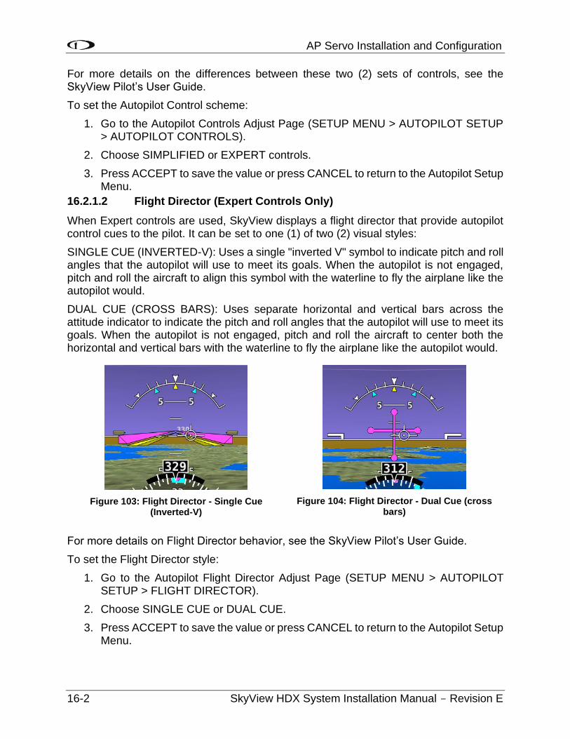
AP Servo Installation and Configuration
16-2 SkyView HDX System Installation Manual - Revision E
For more details on the differences between these two (2) sets of controls, see the SkyView Pilot’s User Guide.
To set the Autopilot Control scheme:
1. Go to the Autopilot Controls Adjust Page (SETUP MENU > AUTOPILOT SETUP > AUTOPILOT CONTROLS).
2. Choose SIMPLIFIED or EXPERT controls.
3. Press ACCEPT to save the value or press CANCEL to return to the Autopilot Setup Menu.
16.2.1.2 Flight Director (Expert Controls Only)
When Expert controls are used, SkyView displays a flight director that provide autopilot control cues to the pilot. It can be set to one (1) of two (2) visual styles:
SINGLE CUE (INVERTED-V): Uses a single "inverted V" symbol to indicate pitch and roll angles that the autopilot will use to meet its goals. When the autopilot is not engaged, pitch and roll the aircraft to align this symbol with the waterline to fly the airplane like the autopilot would.
DUAL CUE (CROSS BARS): Uses separate horizontal and vertical bars across the attitude indicator to indicate the pitch and roll angles that the autopilot will use to meet its goals. When the autopilot is not engaged, pitch and roll the aircraft to center both the horizontal and vertical bars with the waterline to fly the airplane like the autopilot would.
Figure 103: Flight Director - Single Cue (Inverted-V)
Figure 104: Flight Director - Dual Cue (cross bars)
For more details on Flight Director behavior, see the SkyView Pilot’s User Guide.
To set the Flight Director style:
1. Go to the Autopilot Flight Director Adjust Page (SETUP MENU > AUTOPILOT SETUP > FLIGHT DIRECTOR).
2. Choose SINGLE CUE or DUAL CUE.
3. Press ACCEPT to save the value or press CANCEL to return to the Autopilot Setup Menu.
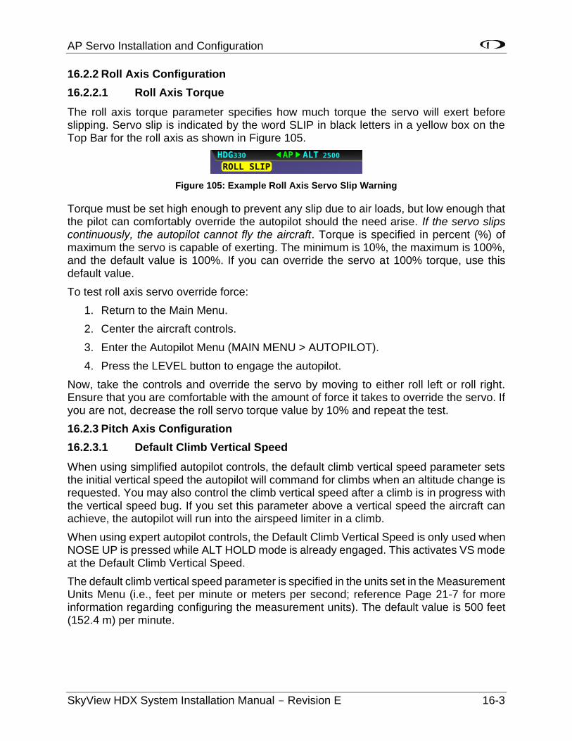
AP Servo Installation and Configuration
SkyView HDX System Installation Manual - Revision E 16-3
16.2.2 Roll Axis Configuration
16.2.2.1 Roll Axis Torque
The roll axis torque parameter specifies how much torque the servo will exert before slipping. Servo slip is indicated by the word SLIP in black letters in a yellow box on the Top Bar for the roll axis as shown in Figure 105.
Figure 105: Example Roll Axis Servo Slip Warning
Torque must be set high enough to prevent any slip due to air loads, but low enough that the pilot can comfortably override the autopilot should the need arise. If the servo slips continuously, the autopilot cannot fly the aircraft. Torque is specified in percent (%) of maximum the servo is capable of exerting. The minimum is 10%, the maximum is 100%, and the default value is 100%. If you can override the servo at 100% torque, use this default value.
To test roll axis servo override force:
1. Return to the Main Menu.
2. Center the aircraft controls.
3. Enter the Autopilot Menu (MAIN MENU > AUTOPILOT).
4. Press the LEVEL button to engage the autopilot.
Now, take the controls and override the servo by moving to either roll left or roll right. Ensure that you are comfortable with the amount of force it takes to override the servo. If you are not, decrease the roll servo torque value by 10% and repeat the test.
16.2.3 Pitch Axis Configuration
16.2.3.1 Default Climb Vertical Speed
When using simplified autopilot controls, the default climb vertical speed parameter sets the initial vertical speed the autopilot will command for climbs when an altitude change is requested. You may also control the climb vertical speed after a climb is in progress with the vertical speed bug. If you set this parameter above a vertical speed the aircraft can achieve, the autopilot will run into the airspeed limiter in a climb.
When using expert autopilot controls, the Default Climb Vertical Speed is only used when NOSE UP is pressed while ALT HOLD mode is already engaged. This activates VS mode at the Default Climb Vertical Speed.
The default climb vertical speed parameter is specified in the units set in the Measurement Units Menu (i.e., feet per minute or meters per second; reference Page 21-7 for more information regarding configuring the measurement units). The default value is 500 feet (152.4 m) per minute.
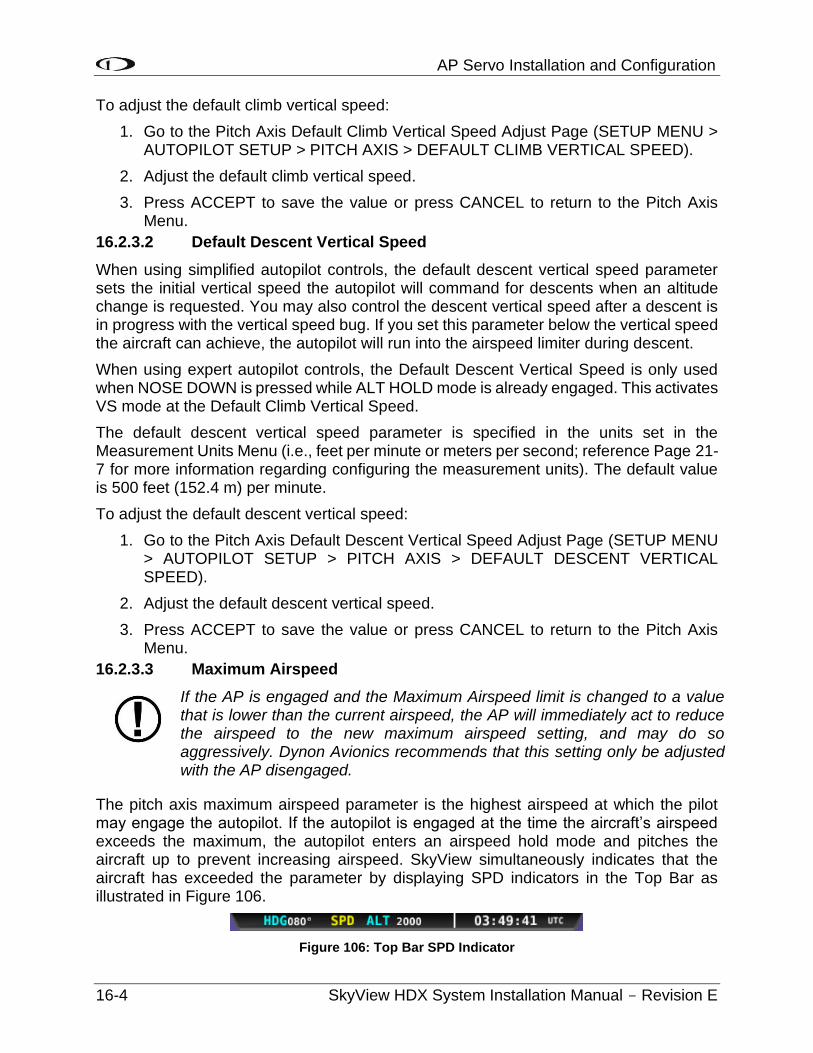
AP Servo Installation and Configuration
16-4 SkyView HDX System Installation Manual - Revision E
To adjust the default climb vertical speed:
1. Go to the Pitch Axis Default Climb Vertical Speed Adjust Page (SETUP MENU > AUTOPILOT SETUP > PITCH AXIS > DEFAULT CLIMB VERTICAL SPEED).
2. Adjust the default climb vertical speed.
3. Press ACCEPT to save the value or press CANCEL to return to the Pitch Axis Menu.
16.2.3.2 Default Descent Vertical Speed
When using simplified autopilot controls, the default descent vertical speed parameter sets the initial vertical speed the autopilot will command for descents when an altitude change is requested. You may also control the descent vertical speed after a descent is in progress with the vertical speed bug. If you set this parameter below the vertical speed the aircraft can achieve, the autopilot will run into the airspeed limiter during descent.
When using expert autopilot controls, the Default Descent Vertical Speed is only used when NOSE DOWN is pressed while ALT HOLD mode is already engaged. This activates VS mode at the Default Climb Vertical Speed.
The default descent vertical speed parameter is specified in the units set in the Measurement Units Menu (i.e., feet per minute or meters per second; reference Page 21-7 for more information regarding configuring the measurement units). The default value is 500 feet (152.4 m) per minute.
To adjust the default descent vertical speed:
1. Go to the Pitch Axis Default Descent Vertical Speed Adjust Page (SETUP MENU > AUTOPILOT SETUP > PITCH AXIS > DEFAULT DESCENT VERTICAL SPEED).
2. Adjust the default descent vertical speed.
3. Press ACCEPT to save the value or press CANCEL to return to the Pitch Axis Menu.
16.2.3.3 Maximum Airspeed
If the AP is engaged and the Maximum Airspeed limit is changed to a value that is lower than the current airspeed, the AP will immediately act to reduce the airspeed to the new maximum airspeed setting, and may do so aggressively. Dynon Avionics recommends that this setting only be adjusted with the AP disengaged.
The pitch axis maximum airspeed parameter is the highest airspeed at which the pilot may engage the autopilot. If the autopilot is engaged at the time the aircraft’s airspeed exceeds the maximum, the autopilot enters an airspeed hold mode and pitches the aircraft up to prevent increasing airspeed. SkyView simultaneously indicates that the aircraft has exceeded the parameter by displaying SPD indicators in the Top Bar as illustrated in Figure 106.
Figure 106: Top Bar SPD Indicator
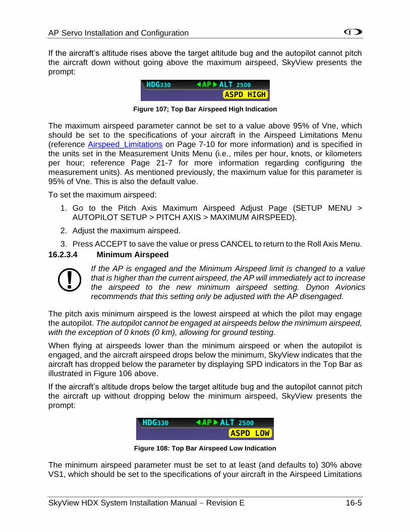
AP Servo Installation and Configuration
SkyView HDX System Installation Manual - Revision E 16-5
If the aircraft’s altitude rises above the target altitude bug and the autopilot cannot pitch the aircraft down without going above the maximum airspeed, SkyView presents the prompt:
Figure 107; Top Bar Airspeed High Indication
The maximum airspeed parameter cannot be set to a value above 95% of Vne, which should be set to the specifications of your aircraft in the Airspeed Limitations Menu (reference Airspeed_Limitations on Page 7-10 for more information) and is specified in the units set in the Measurement Units Menu (i.e., miles per hour, knots, or kilometers per hour; reference Page 21-7 for more information regarding configuring the measurement units). As mentioned previously, the maximum value for this parameter is 95% of Vne. This is also the default value.
To set the maximum airspeed:
1. Go to the Pitch Axis Maximum Airspeed Adjust Page (SETUP MENU > AUTOPILOT SETUP > PITCH AXIS > MAXIMUM AIRSPEED).
2. Adjust the maximum airspeed.
3. Press ACCEPT to save the value or press CANCEL to return to the Roll Axis Menu.
16.2.3.4 Minimum Airspeed
If the AP is engaged and the Minimum Airspeed limit is changed to a value that is higher than the current airspeed, the AP will immediately act to increase the airspeed to the new minimum airspeed setting. Dynon Avionics recommends that this setting only be adjusted with the AP disengaged.
The pitch axis minimum airspeed is the lowest airspeed at which the pilot may engage the autopilot. The autopilot cannot be engaged at airspeeds below the minimum airspeed, with the exception of 0 knots (0 km), allowing for ground testing.
When flying at airspeeds lower than the minimum airspeed or when the autopilot is engaged, and the aircraft airspeed drops below the minimum, SkyView indicates that the aircraft has dropped below the parameter by displaying SPD indicators in the Top Bar as illustrated in Figure 106 above.
If the aircraft’s altitude drops below the target altitude bug and the autopilot cannot pitch the aircraft up without dropping below the minimum airspeed, SkyView presents the prompt:
Figure 108: Top Bar Airspeed Low Indication
The minimum airspeed parameter must be set to at least (and defaults to) 30% above VS1, which should be set to the specifications of your aircraft in the Airspeed Limitations
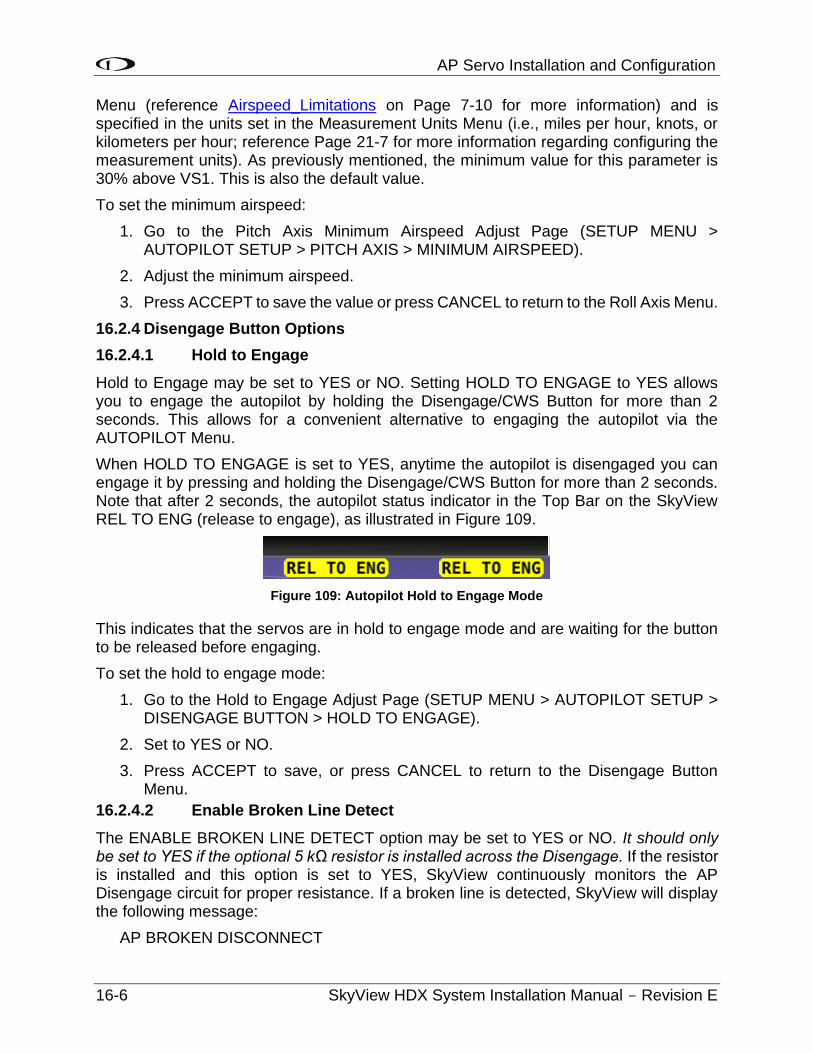
AP Servo Installation and Configuration
16-6 SkyView HDX System Installation Manual - Revision E
Menu (reference Airspeed_Limitations on Page 7-10 for more information) and is specified in the units set in the Measurement Units Menu (i.e., miles per hour, knots, or kilometers per hour; reference Page 21-7 for more information regarding configuring the measurement units). As previously mentioned, the minimum value for this parameter is 30% above VS1. This is also the default value.
To set the minimum airspeed:
1. Go to the Pitch Axis Minimum Airspeed Adjust Page (SETUP MENU > AUTOPILOT SETUP > PITCH AXIS > MINIMUM AIRSPEED).
2. Adjust the minimum airspeed.
3. Press ACCEPT to save the value or press CANCEL to return to the Roll Axis Menu.
16.2.4 Disengage Button Options
16.2.4.1 Hold to Engage
Hold to Engage may be set to YES or NO. Setting HOLD TO ENGAGE to YES allows you to engage the autopilot by holding the Disengage/CWS Button for more than 2 seconds. This allows for a convenient alternative to engaging the autopilot via the AUTOPILOT Menu.
When HOLD TO ENGAGE is set to YES, anytime the autopilot is disengaged you can engage it by pressing and holding the Disengage/CWS Button for more than 2 seconds. Note that after 2 seconds, the autopilot status indicator in the Top Bar on the SkyView REL TO ENG (release to engage), as illustrated in Figure 109.
Figure 109: Autopilot Hold to Engage Mode
This indicates that the servos are in hold to engage mode and are waiting for the button to be released before engaging.
To set the hold to engage mode:
1. Go to the Hold to Engage Adjust Page (SETUP MENU > AUTOPILOT SETUP > DISENGAGE BUTTON > HOLD TO ENGAGE).
2. Set to YES or NO.
3. Press ACCEPT to save, or press CANCEL to return to the Disengage Button Menu.
16.2.4.2 Enable Broken Line Detect
The ENABLE BROKEN LINE DETECT option may be set to YES or NO. It should only be set to YES if the optional 5 kΩ resistor is installed across the Disengage. If the resistor is installed and this option is set to YES, SkyView continuously monitors the AP Disengage circuit for proper resistance. If a broken line is detected, SkyView will display the following message:
AP BROKEN DISCONNECT
AP Servo Installation and Configuration
SkyView HDX System Installation Manual - Revision E 16-7
If the autopilot is engaged when this condition is detected, it will remain engaged.
Set to YES if the optional 5 kΩ resistor is installed across the two (2) terminals of the Disengage/CWS Button. Set to NO if the resistor is not installed. Default is NO.
To set the broken line detection mode:
1. Go to the Enable Broken Line Detect Adjust Page (SETUP MENU > AUTOPILOT SETUP > DISENGAGE BUTTON > ENABLE BROKEN LINE DETECT).
2. Set to YES or NO.
3. Press ACCEPT to save, or press CANCEL to return to the Disengage Button Menu.

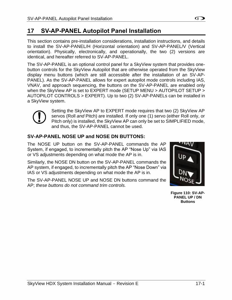
SV-AP-PANEL Autopilot Panel Installation
SkyView HDX System Installation Manual - Revision E 17-1
17 SV-AP-PANEL Autopilot Panel Installation
This section contains pre-installation considerations, installation instructions, and details to install the SV-AP-PANEL/H (Horizontal orientation) and SV-AP-PANEL/V (Vertical orientation). Physically, electronically, and operationally, the two (2) versions are identical, and hereafter referred to SV-AP-PANEL.
The SV-AP-PANEL is an optional control panel for a SkyView system that provides one-button controls for the SkyView Autopilot that are otherwise operated from the SkyView display menu buttons (which are still accessible after the installation of an SV-AP-PANEL). As the SV-AP-PANEL allows for expert autopilot mode controls including IAS, VNAV, and approach sequencing, the buttons on the SV-AP-PANEL are enabled only when the SkyView AP is set to EXPERT mode (SETUP MENU > AUTOPILOT SETUP > AUTOPILOT CONTROLS > EXPERT). Up to two (2) SV-AP-PANELs can be installed in a SkyView system.
Setting the SkyView AP to EXPERT mode requires that two (2) SkyView AP servos (Roll and Pitch) are installed. If only one (1) servo (either Roll only, or Pitch only) is installed, the SkyView AP can only be set to SIMPLIFIED mode, and thus, the SV-AP-PANEL cannot be used.
SV-AP-PANEL NOSE UP and NOSE DN BUTTONS:
The NOSE UP button on the SV-AP-PANEL commands the AP System, if engaged, to incrementally pitch the AP “Nose Up” via IAS or VS adjustments depending on what mode the AP is in.
Similarly, the NOSE DN button on the SV-AP-PANEL commands the AP system, if engaged, to incrementally pitch the AP “Nose Down” via IAS or VS adjustments depending on what mode the AP is in.
The SV-AP-PANEL NOSE UP and NOSE DN buttons command the AP; these buttons do not command trim controls.
Figure 110: SV-AP-PANEL UP / DN
Buttons

SV-AP-PANEL Autopilot Panel Installation
17-2 SkyView HDX System Installation Manual - Revision E
17.1 Mechanical Installation
Figure 111: SV-AP-PANEL Panel Cutout and Mounting Hole Dimensions (Not to Scale)
SV-AP-PANEL Autopilot Panel Installation
SkyView HDX System Installation Manual - Revision E 17-3
17.2 Electrical Installation
The SV-AP-PANEL has two (2) SkyView Network connections (D9M connectors). Both connectors are electrically identical and are internally connected. Thus, the SV-AP-PANEL can be installed in the SkyView Network as a “pass-through” device, or “daisy chained” from one (1) SkyView Network device, through the SV-AP-PANEL, to the next SkyView Network device. The SV-NET-1.5CC is an 18-inch (45.72 cm) SkyView Network cable that is ideal for such situations. The SV-AP-PANEL receives power (for operation of the buttons) from SkyView Network. Dimming of the SV-AP-PANEL is controlled by the SkyView display(s).


SV-BUTTON-LEVEL Autopilot Level Button Installation
SkyView HDX System Installation Manual - Revision E 18-1
18 SV-BUTTON-LEVEL Autopilot Level Button Installation
To provide a prominent LEVEL button on the panel the SV-BUTTON-LEVEL kit. Like most other Dynon Avionics panel units, the SV-BUTTON-LEVEL is backlit, and the degree of backlighting is controlled by SkyView. The SV-BUTTON-LEVEL is the same width, and similar appearance, as Dynon Avionics panel units such as SV-AP-PANEL, SV-COM-PANEL, and SV-KNOB-PANEL.
Pressing an External LEVEL Button such as the SV-BUTTON-LEVEL, the SkyView’s AP LEVEL mode is engaged.
In SkyView, this is equivalent to pressing MAIN MENU > AUTOPILOT > LEVEL and the LEVEL button on the (optional) SV-AP-PANEL.
Figure 112: Level Button
SV-LEVEL-BUTTON
Figure 113: SV-BUTTON-LEVEL Kit
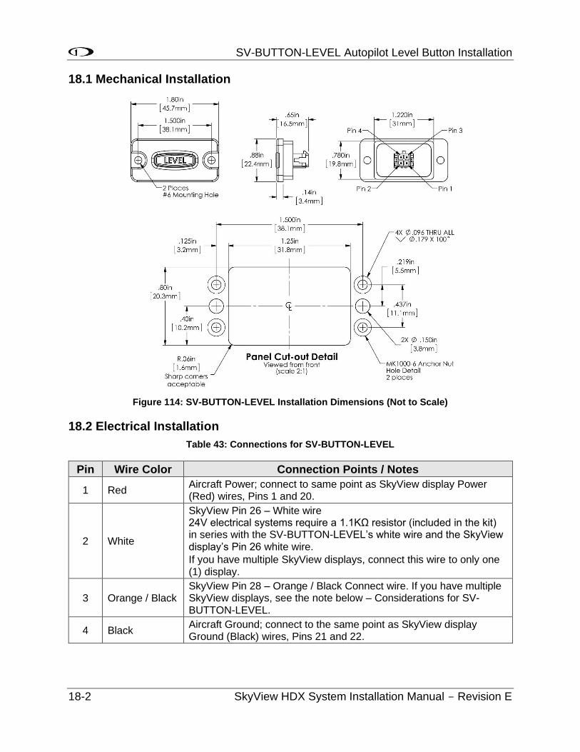
SV-BUTTON-LEVEL Autopilot Level Button Installation
18-2 SkyView HDX System Installation Manual - Revision E
18.1 Mechanical Installation
Figure 114: SV-BUTTON-LEVEL Installation Dimensions (Not to Scale)
18.2 Electrical Installation
Table 43: Connections for SV-BUTTON-LEVEL
Pin Wire Color Connection Points / Notes
1 Red Aircraft Power; connect to same point as SkyView display Power (Red) wires, Pins 1 and 20.
2 White
SkyView Pin 26 – White wire 24V electrical systems require a 1.1KΩ resistor (included in the kit) in series with the SV-BUTTON-LEVEL’s white wire and the SkyView display’s Pin 26 white wire.
If you have multiple SkyView displays, connect this wire to only one (1) display.
3 Orange / Black SkyView Pin 28 – Orange / Black Connect wire. If you have multiple SkyView displays, see the note below – Considerations for SV-BUTTON-LEVEL.
4 Black Aircraft Ground; connect to the same point as SkyView display Ground (Black) wires, Pins 21 and 22.
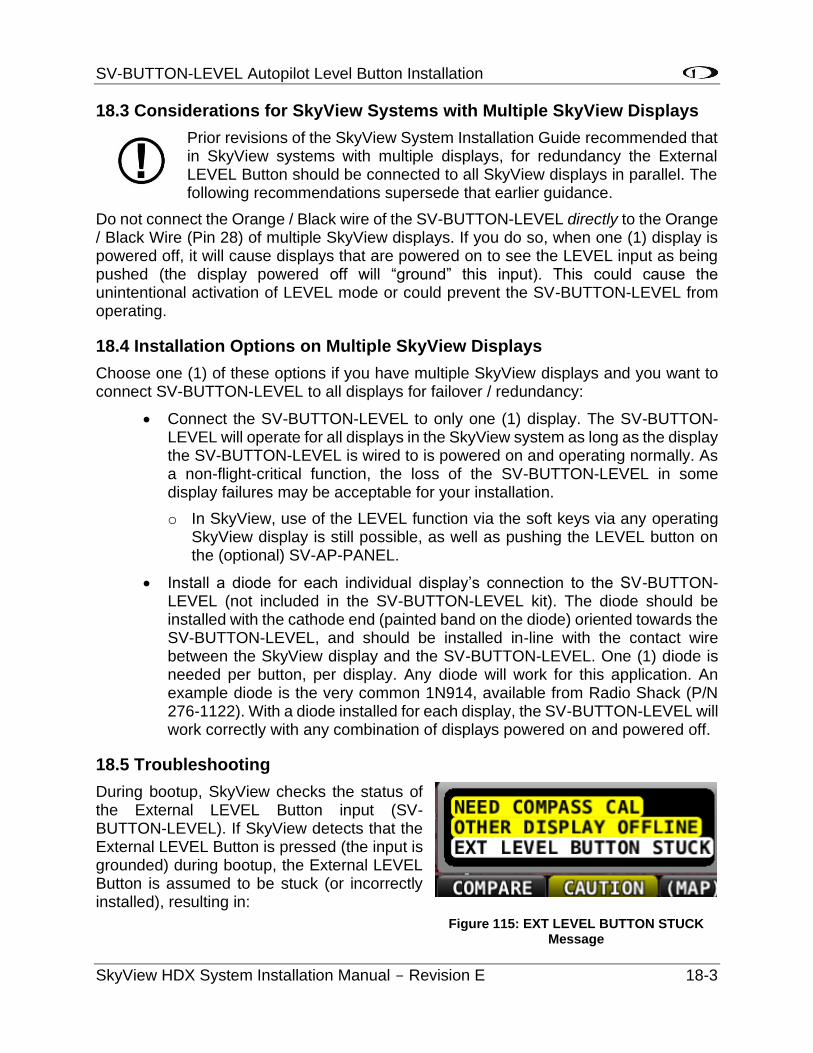
SV-BUTTON-LEVEL Autopilot Level Button Installation
SkyView HDX System Installation Manual - Revision E 18-3
18.3 Considerations for SkyView Systems with Multiple SkyView Displays
Prior revisions of the SkyView System Installation Guide recommended that in SkyView systems with multiple displays, for redundancy the External LEVEL Button should be connected to all SkyView displays in parallel. The following recommendations supersede that earlier guidance.
Do not connect the Orange / Black wire of the SV-BUTTON-LEVEL directly to the Orange / Black Wire (Pin 28) of multiple SkyView displays. If you do so, when one (1) display is powered off, it will cause displays that are powered on to see the LEVEL input as being pushed (the display powered off will “ground” this input). This could cause the unintentional activation of LEVEL mode or could prevent the SV-BUTTON-LEVEL from operating.
18.4 Installation Options on Multiple SkyView Displays
Choose one (1) of these options if you have multiple SkyView displays and you want to connect SV-BUTTON-LEVEL to all displays for failover / redundancy:
• Connect the SV-BUTTON-LEVEL to only one (1) display. The SV-BUTTON-LEVEL will operate for all displays in the SkyView system as long as the display the SV-BUTTON-LEVEL is wired to is powered on and operating normally. As a non-flight-critical function, the loss of the SV-BUTTON-LEVEL in some display failures may be acceptable for your installation.
o In SkyView, use of the LEVEL function via the soft keys via any operating SkyView display is still possible, as well as pushing the LEVEL button on the (optional) SV-AP-PANEL.
• Install a diode for each individual display’s connection to the SV-BUTTON-LEVEL (not included in the SV-BUTTON-LEVEL kit). The diode should be installed with the cathode end (painted band on the diode) oriented towards the SV-BUTTON-LEVEL, and should be installed in-line with the contact wire between the SkyView display and the SV-BUTTON-LEVEL. One (1) diode is needed per button, per display. Any diode will work for this application. An example diode is the very common 1N914, available from Radio Shack (P/N 276-1122). With a diode installed for each display, the SV-BUTTON-LEVEL will work correctly with any combination of displays powered on and powered off.
18.5 Troubleshooting
During bootup, SkyView checks the status of the External LEVEL Button input (SV-BUTTON-LEVEL). If SkyView detects that the External LEVEL Button is pressed (the input is grounded) during bootup, the External LEVEL Button is assumed to be stuck (or incorrectly installed), resulting in:
Figure 115: EXT LEVEL BUTTON STUCK Message
SV-BUTTON-LEVEL Autopilot Level Button Installation
18-4 SkyView HDX System Installation Manual - Revision E
• A Message is displayed: EXT LEVEL BUTTON STUCK.
• The External LEVEL Button input is ignored for the remainder of the time SkyView is operational (will be checked again at next bootup).
Autopilot Disconnect Button Installation
SkyView HDX System Installation Manual - Revision E 19-1
19 Autopilot Disconnect Button Installation
Installation of an autopilot disconnect button is required.
The Autopilot disconnect button should be in a very accessible location, usually mounted to the stick or yoke. The panel mounted version is mounted on the panel and should be located toward center of aircraft. This button’s primary purpose is to immediately disengage the autopilot. It is also required for autopilot calibration, control wheel steering functionality, and can be used to engage the autopilot.
19.1 Yoke-mounted Button
This button should be a red single pole, normally open, momentary button with a positive click when closed. Verify that two (2) terminals of the button are shorted when the button is pressed and open (no-connect) when the button is released. One (1) terminal of the button should connect to the servos’ yellow wires, and the other should connect to ground.
A 4.7 - 5.3k ohm resistor across the yoke-mounted A/P DISC is required. This allows SkyView to detect a break in this circuitry and alert the pilot if this resistor is present in the installation. Set SETUP MENU > AUTOPILOT SETUP > DISENGAGE BUTTON > ENABLE BROKEN LINE DETECT to “YES.”
During bootup, SkyView checks the status of the A/P DISC button. If SkyView detects that the button is pressed (the input is grounded) during bootup, the A/P DISC button is assumed to be stuck (or incorrectly installed), resulting in:
1. A CAUTION message is displayed: AP DISCONNECT STUCK, and
2. The Autopilot (AP) cannot be engaged for the remainder of the time SkyView is operational (The system will be checked again at next bootup).
19.2 SV-BUTTON-APDISC
The SV-BUTTON-APDISC Autopilot Disconect Button can be installed in the instrument panel and wired to SkyView.
This button is backlit, and the degree of backlighting is controlled by SkyView. It is the same width, and similar appearance, as Dynon Avionics panel units such as SV-AP-PANEL, SV-COM-PANEL, SV-KNOB-PANEL.
The Autopilot Disconect button will disengage the autopilot when depressed.
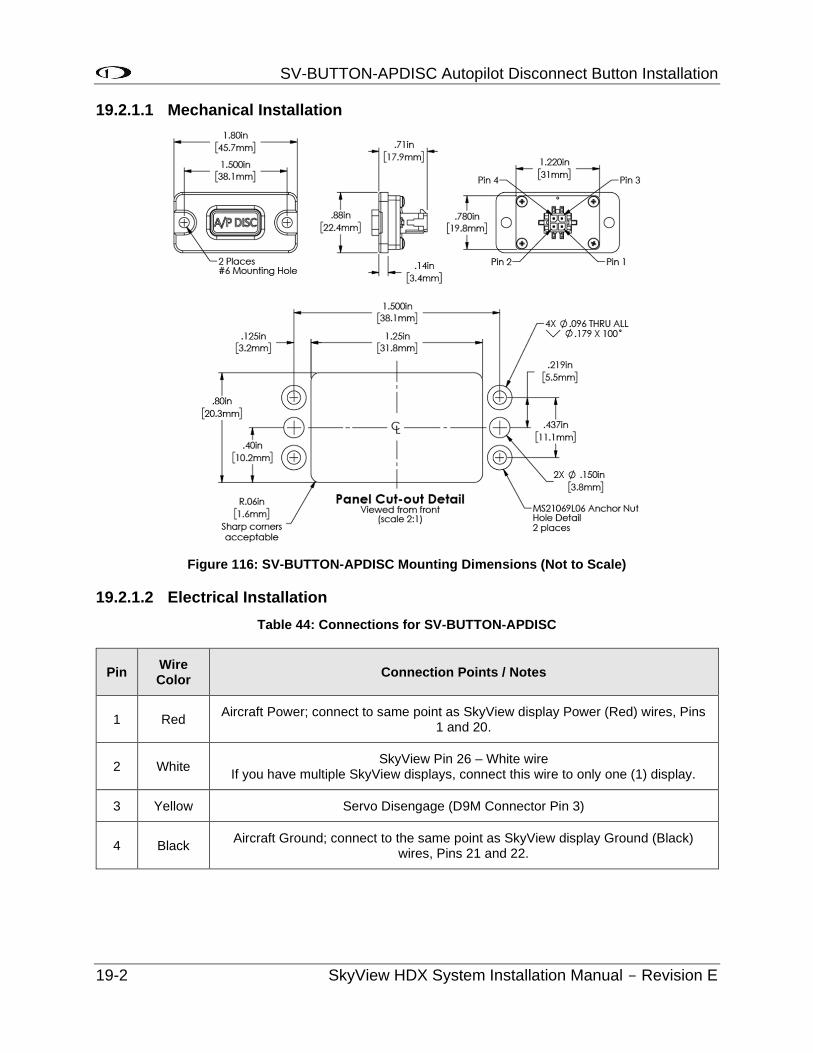
SV-BUTTON-APDISC Autopilot Disconnect Button Installation
19-2 SkyView HDX System Installation Manual - Revision E
19.2.1.1 Mechanical Installation
Figure 116: SV-BUTTON-APDISC Mounting Dimensions (Not to Scale)
19.2.1.2 Electrical Installation
Table 44: Connections for SV-BUTTON-APDISC
Pin Wire Color
Connection Points / Notes
1 Red Aircraft Power; connect to same point as SkyView display Power (Red) wires, Pins
1 and 20.
2 White SkyView Pin 26 – White wire
If you have multiple SkyView displays, connect this wire to only one (1) display.
3 Yellow Servo Disengage (D9M Connector Pin 3)
4 Black Aircraft Ground; connect to the same point as SkyView display Ground (Black)
wires, Pins 21 and 22.
EFIS-D10A Standby Display Installation and Configuration
SkyView HDX System Installation Manual - Revision E 20-1
20 EFIS-D10A Standby Display Installation and Configuration
20.1 Installation Checklist
To install a Dynon EFIS-D10A in an aircraft, the following steps must be completed:
1. Connect to properly current protected source of switched aircraft power using purchased or created wire harness
2. Install backup battery
3. Connect pitot and static ports to aircraft system
4. Install optional mounting tray/flush mount bracket
5. Install Dynon EFIS-D10A in panel
For the STC installation the D10A is only connected to power. See D10A electrical wiring section.
20.2 Power Requirements
Table 45: Electrical Connection
Device Current
requirement @ 12V DC
Current
requirement @ 24V DC
Circuit
Protection
Recommendation
D10A 1.5A .75A 3A
20.3 Weight Specifications
Adding any new instrument to an aircraft requires the installer to be aware of its weight and how that affects the overall weight and balance of the plane. The following are the weights of the EFIS-D10A and associated Dynon-supplied sensors.
EFIS-D10A + battery....................................................................................1 lb 13.8 oz (0.879 kg)
20.4 Enviromental Requirements
Operating Temperature -22° to 122° F (-30° to 50° C)
20.5 Power Inputs
The EFIS-D10A has a single power input, located on the DB25 connector.
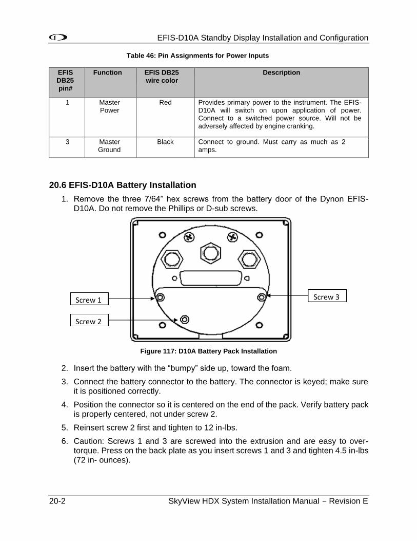
EFIS-D10A Standby Display Installation and Configuration
20-2 SkyView HDX System Installation Manual - Revision E
Table 46: Pin Assignments for Power Inputs
EFIS DB25 pin#
Function EFIS DB25 wire color
Description
1 Master Power
Red Provides primary power to the instrument. The EFIS-D10A will switch on upon application of power. Connect to a switched power source. Will not be adversely affected by engine cranking.
3 Master Ground
Black Connect to ground. Must carry as much as 2 amps.
20.6 EFIS-D10A Battery Installation
1. Remove the three 7/64” hex screws from the battery door of the Dynon EFIS-D10A. Do not remove the Phillips or D-sub screws.
Figure 117: D10A Battery Pack Installation
2. Insert the battery with the “bumpy” side up, toward the foam.
3. Connect the battery connector to the battery. The connector is keyed; make sure it is positioned correctly.
4. Position the connector so it is centered on the end of the pack. Verify battery pack is properly centered, not under screw 2.
5. Reinsert screw 2 first and tighten to 12 in-lbs.
6. Caution: Screws 1 and 3 are screwed into the extrusion and are easy to over-torque. Press on the back plate as you insert screws 1 and 3 and tighten 4.5 in-lbs (72 in- ounces).
Screw 1 Screw 3
Screw 2
EFIS-D10A Standby Display Installation and Configuration
SkyView HDX System Installation Manual - Revision E 20-3
20.7 Mechanical Installation
The following diagram shows the outside dimensions of the front bezel of the EFIS- D10A. Note that the instrument is about seven inches deep and the Dynon-made harness extends three inches more. Use the dimensions (in inches) found on the diagram to plan for the space required by the instrument. Take the following considerations into account when selecting a mounting location for the EFIS-D10A.
Avoid placing the instrument near heater vents or any source of extremely hot or cold air. The air surrounding the EFIS-D10A during operation may be no warmer than 50 C to ensure accurate operation. Plan a panel location that allows convenient viewing of the instrument with no obstruction. When flying straight and level, the panel angle from vertical may not be greater than +/- 30 degrees. The unit must also be parallel to the roll axis of the aircraft (although not necessarily located along it), and have no significant roll angle in the panel. The firmware supports an adjustment for panel tilt, but not for mounting errors in yaw or roll. Correct attitude performance depends on mounting the EFIS-D10A square with the direction of flight.
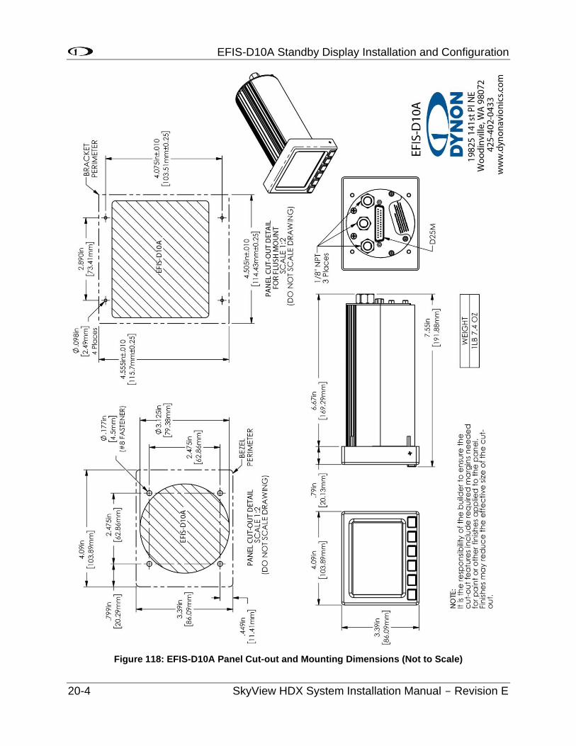
EFIS-D10A Standby Display Installation and Configuration
20-4 SkyView HDX System Installation Manual - Revision E
Figure 118: EFIS-D10A Panel Cut-out and Mounting Dimensions (Not to Scale)
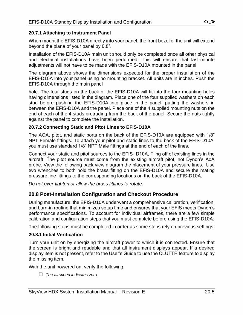
EFIS-D10A Standby Display Installation and Configuration
SkyView HDX System Installation Manual - Revision E 20-5
20.7.1 Attaching to Instrument Panel
When mount the EFIS-D10A directly into your panel, the front bezel of the unit will extend beyond the plane of your panel by 0.8”.
Installation of the EFIS-D10A main unit should only be completed once all other physical and electrical installations have been performed. This will ensure that last-minute adjustments will not have to be made with the EFIS-D10A mounted in the panel.
The diagram above shows the dimensions expected for the proper installation of the EFIS-D10A into your panel using no mounting bracket. All units are in inches. Push the EFIS-D10A through the main panel
hole. The four studs on the back of the EFIS-D10A will fit into the four mounting holes having dimensions listed in the diagram. Place one of the four supplied washers on each stud before pushing the EFIS-D10A into place in the panel, putting the washers in between the EFIS-D10A and the panel. Place one of the 4 supplied mounting nuts on the end of each of the 4 studs protruding from the back of the panel. Secure the nuts tightly against the panel to complete the installation.
20.7.2 Connecting Static and Pitot Lines to EFIS-D10A
The AOA, pitot, and static ports on the back of the EFIS-D10A are equipped with 1/8” NPT Female fittings. To attach your pitot and static lines to the back of the EFIS-D10A, you must use standard 1/8” NPT Male fittings at the end of each of the lines.
Connect your static and pitot sources to the EFIS- D10A, T’ing off of existing lines in the aircraft. The pitot source must come from the existing aircraft pitot, not Dynon’s AoA probe. View the following back view diagram the placement of your pressure lines. Use two wrenches to both hold the brass fitting on the EFIS-D10A and secure the mating pressure line fittings to the corresponding locations on the back of the EFIS-D10A.
Do not over-tighten or allow the brass fittings to rotate.
20.8 Post-Installation Configuration and Checkout Procedure
During manufacture, the EFIS-D10A underwent a comprehensive calibration, verification, and burn-in routine that minimizes setup time and ensures that your EFIS meets Dynon’s performance specifications. To account for individual airframes, there are a few simple calibration and configuration steps that you must complete before using the EFIS-D10A.
The following steps must be completed in order as some steps rely on previous settings.
20.8.1 Initial Verification
Turn your unit on by energizing the aircraft power to which it is connected. Ensure that the screen is bright and readable and that all instrument displays appear. If a desired display item is not present, refer to the User’s Guide to use the CLUTTR feature to display the missing item.
With the unit powered on, verify the following:
The airspeed indicates zero
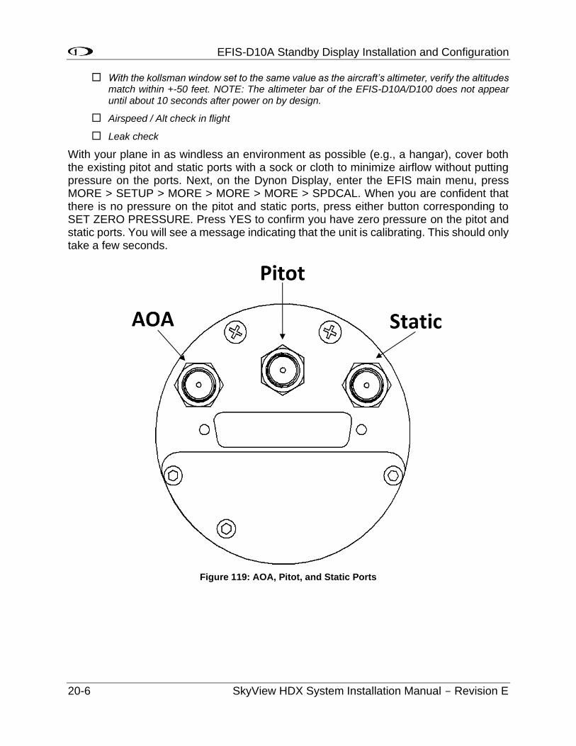
EFIS-D10A Standby Display Installation and Configuration
20-6 SkyView HDX System Installation Manual - Revision E
With the kollsman window set to the same value as the aircraft’s altimeter, verify the altitudes match within +-50 feet. NOTE: The altimeter bar of the EFIS-D10A/D100 does not appear until about 10 seconds after power on by design.
Airspeed / Alt check in flight
Leak check
With your plane in as windless an environment as possible (e.g., a hangar), cover both the existing pitot and static ports with a sock or cloth to minimize airflow without putting pressure on the ports. Next, on the Dynon Display, enter the EFIS main menu, press MORE > SETUP > MORE > MORE > MORE > SPDCAL. When you are confident that there is no pressure on the pitot and static ports, press either button corresponding to SET ZERO PRESSURE. Press YES to confirm you have zero pressure on the pitot and static ports. You will see a message indicating that the unit is calibrating. This should only take a few seconds.
Figure 119: AOA, Pitot, and Static Ports
Display Operation
SkyView HDX System Installation Manual - Revision E 21-1
21 Display Operation
After reading this section, you should be familiar with basic SkyView display operation including how to use joysticks, knobs, and buttons, how to turn displays on and off, how to access and navigate menus, how to configure the SkyView network, and how to perform Software updates and other file operations.
The SkyView SV-HDX800 and SV-HDX1100 displays are identical in functionality and presentation. The only difference is in the size of the screen.
21.1 Screen Synchronization
SkyView is designed to operate as an integrated system. SkyView configurations with more than one (1) display automatically share and synchronize settings on all displays. In-flight settings such as baro and bugs are synchronized in real time as they are adjusted. Setup menu items are synchronized when the user exits the setup menu and also at boot up. Aviation and obstacle databases are synchronized when they are loaded on any screen if Ethernet is connected.
It is not possible to have displays on the same network that do not share configurations, settings, and real-time items. Even if a unit is off when settings are adjusted, they will be synchronized when they boot up.
For displays to properly synchronize settings their tail numbers must be the same and SkyView Network must be configured correctly. See the Network Setup and Status Section of this manual for information about these required setup steps.
Only one (1) setup menu in the network may be open at once. If you try to open a setup menu on a display while it is open on another display, you will see OTHER SCREEN IN SETUP on the screen and thus cannot open the setup menu. There is no "master" in the system; changes made on any screen in the system will be automatically reflected on all other screens.
Some things are purposefully not synchronized on displays: Software, sensor configuration files (.sfg), and local display settings. You must ensure that each display is running the appropriate Software, up-to-date databases, and sensor configuration file. All of these files are available for download at http://downloads.dynonavionics.com. Also ensure that each display’s local settings are appropriately configured.
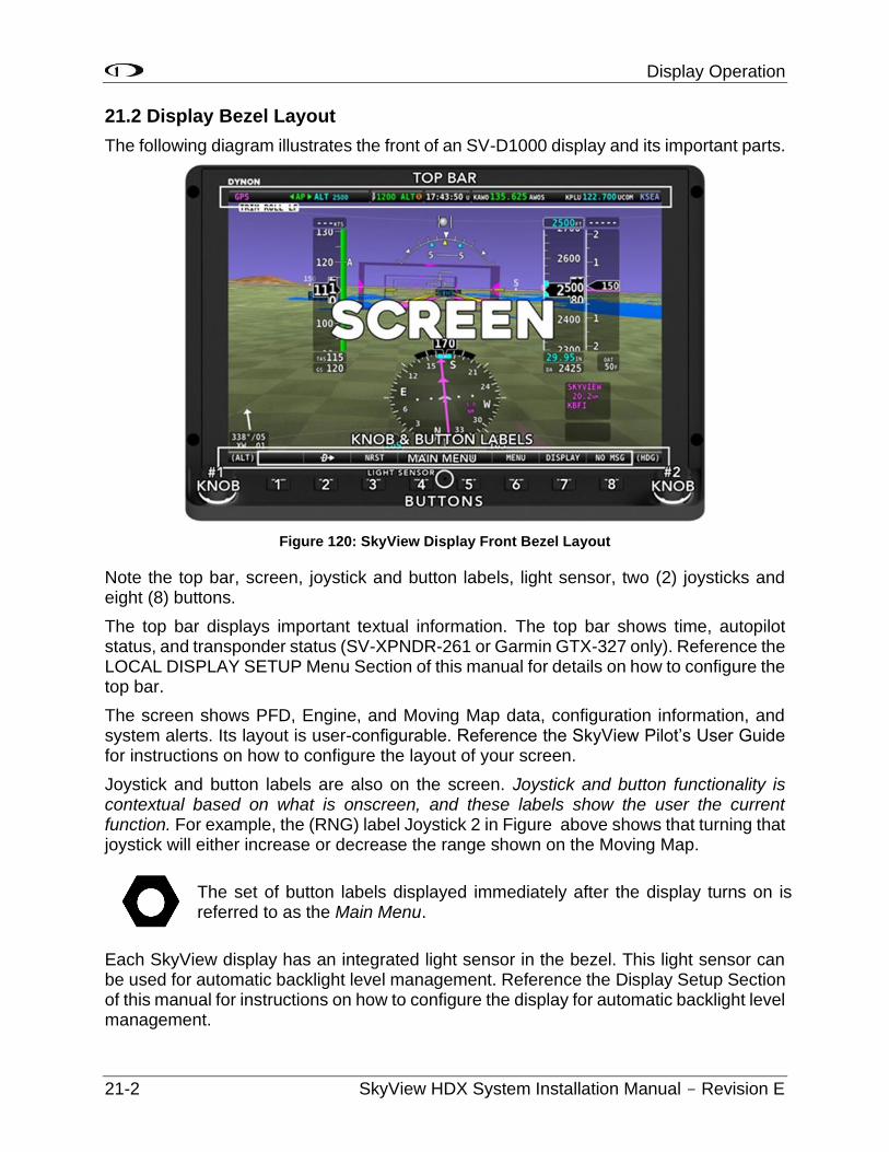
Display Operation
21-2 SkyView HDX System Installation Manual - Revision E
21.2 Display Bezel Layout
The following diagram illustrates the front of an SV-D1000 display and its important parts.
Figure 120: SkyView Display Front Bezel Layout
Note the top bar, screen, joystick and button labels, light sensor, two (2) joysticks and eight (8) buttons.
The top bar displays important textual information. The top bar shows time, autopilot status, and transponder status (SV-XPNDR-261 or Garmin GTX-327 only). Reference the LOCAL DISPLAY SETUP Menu Section of this manual for details on how to configure the top bar.
The screen shows PFD, Engine, and Moving Map data, configuration information, and system alerts. Its layout is user-configurable. Reference the SkyView Pilot’s User Guide for instructions on how to configure the layout of your screen.
Joystick and button labels are also on the screen. Joystick and button functionality is contextual based on what is onscreen, and these labels show the user the current function. For example, the (RNG) label Joystick 2 in Figure above shows that turning that joystick will either increase or decrease the range shown on the Moving Map.
The set of button labels displayed immediately after the display turns on is referred to as the Main Menu.
Each SkyView display has an integrated light sensor in the bezel. This light sensor can be used for automatic backlight level management. Reference the Display Setup Section of this manual for instructions on how to configure the display for automatic backlight level management.
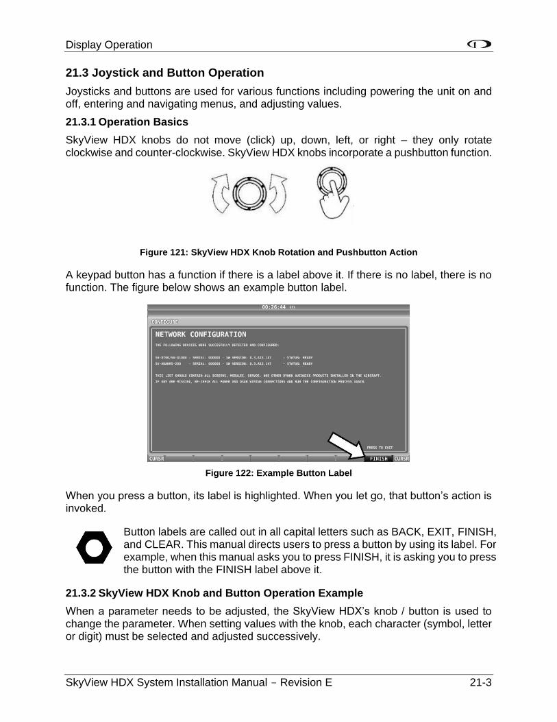
Display Operation
SkyView HDX System Installation Manual - Revision E 21-3
21.3 Joystick and Button Operation
Joysticks and buttons are used for various functions including powering the unit on and off, entering and navigating menus, and adjusting values.
21.3.1 Operation Basics
SkyView HDX knobs do not move (click) up, down, left, or right – they only rotate clockwise and counter-clockwise. SkyView HDX knobs incorporate a pushbutton function.
Figure 121: SkyView HDX Knob Rotation and Pushbutton Action
A keypad button has a function if there is a label above it. If there is no label, there is no function. The figure below shows an example button label.
Figure 122: Example Button Label
When you press a button, its label is highlighted. When you let go, that button’s action is invoked.
Button labels are called out in all capital letters such as BACK, EXIT, FINISH, and CLEAR. This manual directs users to press a button by using its label. For example, when this manual asks you to press FINISH, it is asking you to press the button with the FINISH label above it.
21.3.2 SkyView HDX Knob and Button Operation Example
When a parameter needs to be adjusted, the SkyView HDX’s knob / button is used to change the parameter. When setting values with the knob, each character (symbol, letter or digit) must be selected and adjusted successively.
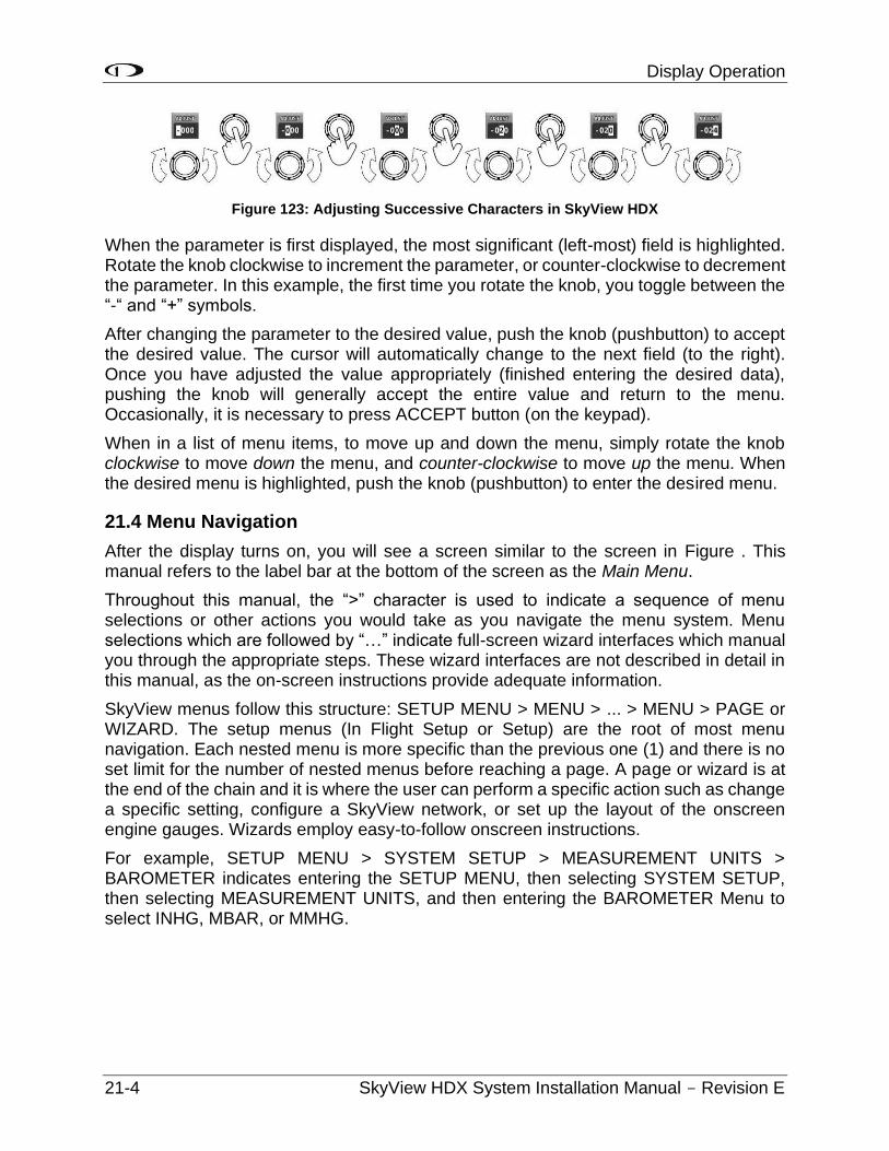
Display Operation
21-4 SkyView HDX System Installation Manual - Revision E
Figure 123: Adjusting Successive Characters in SkyView HDX
When the parameter is first displayed, the most significant (left-most) field is highlighted. Rotate the knob clockwise to increment the parameter, or counter-clockwise to decrement the parameter. In this example, the first time you rotate the knob, you toggle between the “-“ and “+” symbols.
After changing the parameter to the desired value, push the knob (pushbutton) to accept the desired value. The cursor will automatically change to the next field (to the right). Once you have adjusted the value appropriately (finished entering the desired data), pushing the knob will generally accept the entire value and return to the menu. Occasionally, it is necessary to press ACCEPT button (on the keypad).
When in a list of menu items, to move up and down the menu, simply rotate the knob clockwise to move down the menu, and counter-clockwise to move up the menu. When the desired menu is highlighted, push the knob (pushbutton) to enter the desired menu.
21.4 Menu Navigation
After the display turns on, you will see a screen similar to the screen in Figure . This manual refers to the label bar at the bottom of the screen as the Main Menu.
Throughout this manual, the “>” character is used to indicate a sequence of menu selections or other actions you would take as you navigate the menu system. Menu selections which are followed by “…” indicate full-screen wizard interfaces which manual you through the appropriate steps. These wizard interfaces are not described in detail in this manual, as the on-screen instructions provide adequate information.
SkyView menus follow this structure: SETUP MENU > MENU > ... > MENU > PAGE or WIZARD. The setup menus (In Flight Setup or Setup) are the root of most menu navigation. Each nested menu is more specific than the previous one (1) and there is no set limit for the number of nested menus before reaching a page. A page or wizard is at the end of the chain and it is where the user can perform a specific action such as change a specific setting, configure a SkyView network, or set up the layout of the onscreen engine gauges. Wizards employ easy-to-follow onscreen instructions.
For example, SETUP MENU > SYSTEM SETUP > MEASUREMENT UNITS > BAROMETER indicates entering the SETUP MENU, then selecting SYSTEM SETUP, then selecting MEASUREMENT UNITS, and then entering the BAROMETER Menu to select INHG, MBAR, or MMHG.
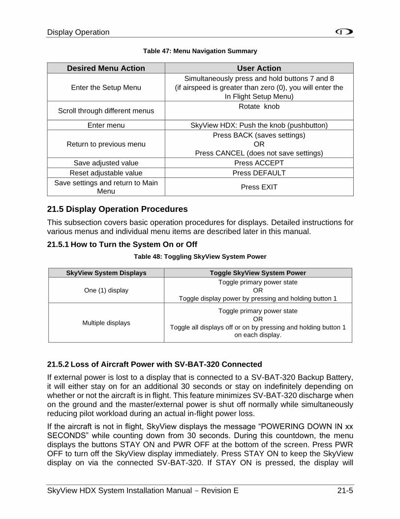
Display Operation
SkyView HDX System Installation Manual - Revision E 21-5
Table 47: Menu Navigation Summary
Desired Menu Action User Action
Enter the Setup Menu
Simultaneously press and hold buttons 7 and 8
(if airspeed is greater than zero (0), you will enter the
In Flight Setup Menu)
Scroll through different menus Rotate knob
Enter menu SkyView HDX: Push the knob (pushbutton)
Return to previous menu
Press BACK (saves settings)
OR
Press CANCEL (does not save settings)
Save adjusted value Press ACCEPT
Reset adjustable value Press DEFAULT
Save settings and return to Main Menu
Press EXIT
21.5 Display Operation Procedures
This subsection covers basic operation procedures for displays. Detailed instructions for various menus and individual menu items are described later in this manual.
21.5.1 How to Turn the System On or Off
Table 48: Toggling SkyView System Power
SkyView System Displays Toggle SkyView System Power
One (1) display
Toggle primary power state
OR
Toggle display power by pressing and holding button 1
Multiple displays
Toggle primary power state
OR
Toggle all displays off or on by pressing and holding button 1 on each display.
21.5.2 Loss of Aircraft Power with SV-BAT-320 Connected
If external power is lost to a display that is connected to a SV-BAT-320 Backup Battery, it will either stay on for an additional 30 seconds or stay on indefinitely depending on whether or not the aircraft is in flight. This feature minimizes SV-BAT-320 discharge when on the ground and the master/external power is shut off normally while simultaneously reducing pilot workload during an actual in-flight power loss.
If the aircraft is not in flight, SkyView displays the message “POWERING DOWN IN xx SECONDS” while counting down from 30 seconds. During this countdown, the menu displays the buttons STAY ON and PWR OFF at the bottom of the screen. Press PWR OFF to turn off the SkyView display immediately. Press STAY ON to keep the SkyView display on via the connected SV-BAT-320. If STAY ON is pressed, the display will
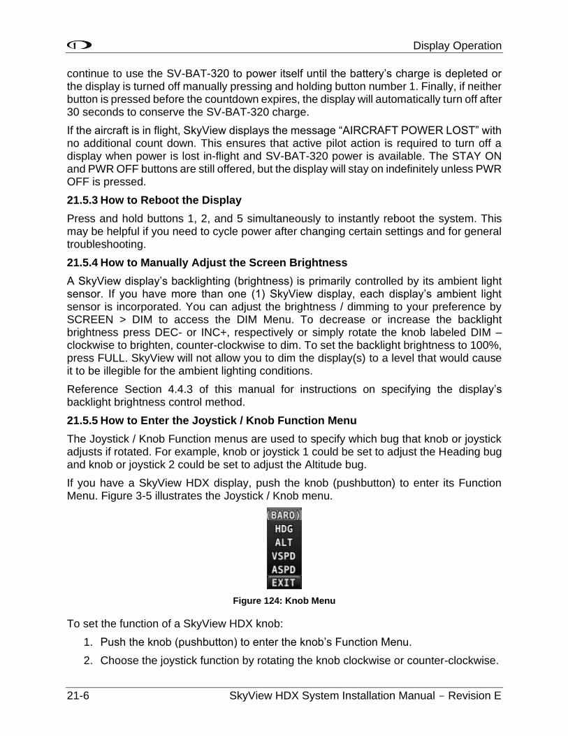
Display Operation
21-6 SkyView HDX System Installation Manual - Revision E
continue to use the SV-BAT-320 to power itself until the battery’s charge is depleted or the display is turned off manually pressing and holding button number 1. Finally, if neither button is pressed before the countdown expires, the display will automatically turn off after 30 seconds to conserve the SV-BAT-320 charge.
If the aircraft is in flight, SkyView displays the message “AIRCRAFT POWER LOST” with no additional count down. This ensures that active pilot action is required to turn off a display when power is lost in-flight and SV-BAT-320 power is available. The STAY ON and PWR OFF buttons are still offered, but the display will stay on indefinitely unless PWR OFF is pressed.
21.5.3 How to Reboot the Display
Press and hold buttons 1, 2, and 5 simultaneously to instantly reboot the system. This may be helpful if you need to cycle power after changing certain settings and for general troubleshooting.
21.5.4 How to Manually Adjust the Screen Brightness
A SkyView display’s backlighting (brightness) is primarily controlled by its ambient light sensor. If you have more than one (1) SkyView display, each display’s ambient light sensor is incorporated. You can adjust the brightness / dimming to your preference by SCREEN > DIM to access the DIM Menu. To decrease or increase the backlight brightness press DEC- or INC+, respectively or simply rotate the knob labeled DIM – clockwise to brighten, counter-clockwise to dim. To set the backlight brightness to 100%, press FULL. SkyView will not allow you to dim the display(s) to a level that would cause it to be illegible for the ambient lighting conditions.
Reference Section 4.4.3 of this manual for instructions on specifying the display’s backlight brightness control method.
21.5.5 How to Enter the Joystick / Knob Function Menu
The Joystick / Knob Function menus are used to specify which bug that knob or joystick adjusts if rotated. For example, knob or joystick 1 could be set to adjust the Heading bug and knob or joystick 2 could be set to adjust the Altitude bug.
If you have a SkyView HDX display, push the knob (pushbutton) to enter its Function Menu. Figure 3-5 illustrates the Joystick / Knob menu.
Figure 124: Knob Menu
To set the function of a SkyView HDX knob:
1. Push the knob (pushbutton) to enter the knob’s Function Menu.
2. Choose the joystick function by rotating the knob clockwise or counter-clockwise.
Display Operation
SkyView HDX System Installation Manual - Revision E 21-7
3. Confirm the highlighted function by pushing the knob (pushbutton),
OR
Wait approximately seven (7) seconds; the Function Menu will close, and the highlighted function will be selected.
If the Map Page is onscreen, the joystick or knob closest to the Moving Map is labeled (RNG) and is used to adjust the map’s range. It cannot be assigned a different function.
If the Knob Function menu does not display all of the Bugs that you wish to select from, it means some of the Bugs are disabled. To enable the desired Bugs, go to the PFD menu and select BUGS. In the BUGS menu, enable the desired bugs. Then the desired Bugs will be selectable in Knob menu.
21.5.6 How to Enter the Setup Menus
There are two (2) setup menus: The Setup Menu and the In-Flight Setup Menu. Simultaneously pressing and holding buttons 7 and 8 will open one (1) of these menus. If the airspeed is zero, the Setup Menu will open. If the airspeed is greater than zero (0), the In-Flight Setup Menu will open.
You may also access the Setup Menu from the In-Flight Setup Menu by using the ENTER FULL SCREEN SETUP MENU option.
21.5.7 How to Adjust Time Zone Offset
First, configure the Top Bar to display time in SETUP MENU > LOCAL DISPLAY SETUP > TOP BAR SETUP > TIME: ZULU | LOCAL.
Then, adjust your preferred offset from the time currently displayed on the Top Bar – SETUP MENU > SYSTEM SETUP > TIME.
21.5.8 How to Configure Units of Measure
Displayed units can be configured for altitude, distance, speed, temperature, barometer, pressure, and volume. Displayed units are configured on the Measurement Units Page (SETUP MENU > SYSTEM SETUP > MEASUREMENT UNITS).
21.6 In Flight Setup Menu
This menu contains links that may be useful during flight:
• ADAHRS SOURCE SELECTION.
• FLIGHT ANGLE PITCH ADJUST.
• COMPASS CALIBRATION.
• AOA CALIBRATION.
• AUTOPILOT SETUP.
• ENTER FULL SCREEN SETUP MENU.
Note that this menu occupies only half of the screen and that all the links in the In-Flight Setup Menu are accessible via the SETUP MENU.
Display Operation
21-8 SkyView HDX System Installation Manual - Revision E
21.6.1 SETUP MENU
This menu contains links to system configuration options:
• SYSTEM EVENT.
• SYSTEM SOFTWARE.
• SYSTEM SETUP.
• LOCAL DISPLAY SETUP.
• PFD SETUP.
• EMS SETUP.
• MAP SETUP.
• AUTOPILOT SETUP.
• TRANSPONDER SETUP.
• TRAFFIC SETUP.
• ADS-B STATUS.
• COM RADIO SETUP.
• HARDWARE CALIBRATION.
Note that this menu occupies the entire screen. The menus above have menus of their own. The information in this section contains information on the purposes of each of the above menus, as well as a list of each menu's respective menus and their functions.
Pages and wizards that require users to do something have explicit onscreen instructions. Most actions are simple enough and onscreen instructions are more than adequate. In these cases, explicit instructions are not contained in this manual. In cases where onscreen instructions are not present, instructions are included in this manual.
The menu options descriptions in this section are intended to be introductory / overview, not comprehensive. Comprehensive explanations of menu options can be found onscreen, in the SkyView system, in the installation instructions in the specific section of this manual for each subsystem, such as SV-EMS-220 or SV-XPNDR-261.
21.6.2 SYSTEM EVENT Menu
The SYSTEM EVENT menu will only appear if the SkyView display detects that a “system event” has occurred on (one (1) of your) SkyView display(s).
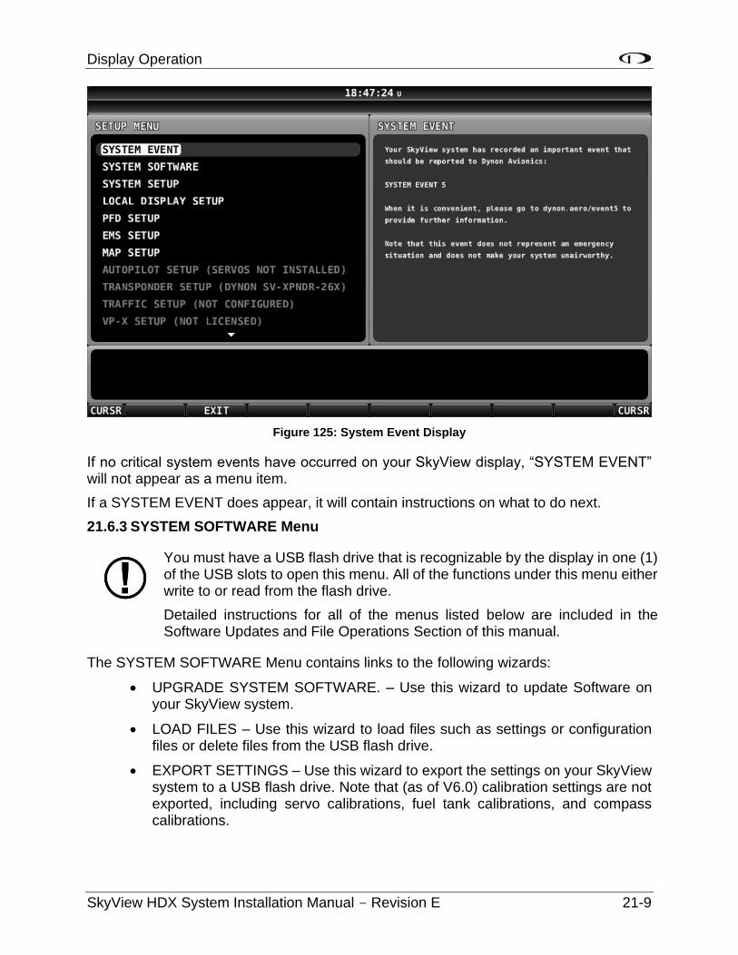
Display Operation
SkyView HDX System Installation Manual - Revision E 21-9
Figure 125: System Event Display
If no critical system events have occurred on your SkyView display, “SYSTEM EVENT” will not appear as a menu item.
If a SYSTEM EVENT does appear, it will contain instructions on what to do next.
21.6.3 SYSTEM SOFTWARE Menu
You must have a USB flash drive that is recognizable by the display in one (1) of the USB slots to open this menu. All of the functions under this menu either write to or read from the flash drive.
Detailed instructions for all of the menus listed below are included in the Software Updates and File Operations Section of this manual.
The SYSTEM SOFTWARE Menu contains links to the following wizards:
• UPGRADE SYSTEM SOFTWARE. – Use this wizard to update Software on your SkyView system.
• LOAD FILES – Use this wizard to load files such as settings or configuration files or delete files from the USB flash drive.
• EXPORT SETTINGS – Use this wizard to export the settings on your SkyView system to a USB flash drive. Note that (as of V6.0) calibration settings are not exported, including servo calibrations, fuel tank calibrations, and compass calibrations.
Display Operation
21-10 SkyView HDX System Installation Manual - Revision E
• EXPORT USER DATA LOGS – Use this wizard to export user data logs in human-readable CSV format. See Appendix F: User Data Logs for further information about user data logs.
• EXPORT USER WAYPOINTS – Use this wizard to export all of the User Waypoints that are currently stored in your SkyView system.
• EXPORT DYNON DIAGNOSTIC FILE – This specialized data log can only be interpreted by Dynon Avionics personnel; there is no data in it that can be interpreted by SkyView pilots. Dynon Avionics Technical Support may request this log during troubleshooting, especially for issues related to AP performance. Note that this log is very big – over 500 MB – and takes minutes to save to a USB flash drive. Unless directed to export this log by Dynon Avionics, there is no reason to do so.
If you have more than one (1) SkyView display in your system, you may be requested to save the Dynon Avionics Diagnostic File from each of your SkyView displays, as each display can sometimes contain different diagnostic data. If you save the Dynon Avionics Diagnostic File from multiple displays onto the same USB flash drive, use the 33-character name field to distinguish the two (2) files, such as naming one file “LEFT” and the other file “RIGHT.”
21.6.4 SYSTEM SETUP Menu
This menu contains menus and pages related to the entire SkyView system. When a setting is changed in one (1) of these menus, it is synchronized to other SkyView displays.
• SKYVIEW NETWORK SETUP – Enter this menu to configure your SkyView network or to check on network status (i.e., display important SkyView module information).
• WI-FI SETUP – Enter this menu to configure the Wi-Fi system – password, etc.
• SERIAL PORT SETUP – Enter this menu to configure the five (5) general purpose serial ports on all displays.
• AUDIO SETUP – Enter this menu to configure the options and volume for SkyView’s audio output capability.
AIRCRAFT INFORMATION – Enter this page to record important information regarding your aircraft. Specifically, enter the tail number of your aircraft – it is used to create unique SkyView configuration files. It is also used for other purposes. Note that for US planes, the leading N is a required part of the TAIL NUMBER. The TAIL NUMBER should not include dashes (-) or spaces.
Examples: Correct: N12AB Incorrect: N-42SV or N 42SV
• MEASUREMENT UNITS – Enter this page to configure displayed units (e.g., feet or meters).
Display Operation
SkyView HDX System Installation Manual - Revision E 21-11
• TIME – First, configure the Top Bar to display time in SETUP MENU > LOCAL DISPLAY SETUP > TOP BAR SETUP > TIME: ZULU | LOCAL. Then, in this menu, adjust your preferred offset from the time currently displayed on the Top Bar.
• ARINC-429 – Enter this page to set up ARINC-429 devices connected to SV-ARINC-429 modules.
• SCREEN LAYOUT SETUP – Enter this page to configure the availability of the PDF Page, Engine Page, and Map Page on this display and throughout the system (when more than one (1) display is installed).
• PRIMARY COM – Select the COM radio to be displayed on the Top Bar and receive a frequency setting when the APT→COM button is pushed in the MAP MENU. If only one (1) COM radio is installed, this must be set. If two (2) COM radios are installed, only one (1) can be displayed on the Top Bar and receive a frequency setting when the APT→COM button is pushed in the MAP MENU.
• DISPLAY COM IN TOP BAR – Selects whether, or not, frequencies, PTT status, etc. from the COM radio (selected in PRIMARY COM, above) is displayed.
• DATA LOG SETUP – Enter this page to configure the recording frequency of SkyView’s internal data logging feature, or to clear recorded data. See the User Data Logs Appendix for further information about user data logs.
21.6.5 LOCAL DISPLAY SETUP Menu
This menu contains menus and pages related to the individual SkyView display on which this menu is displayed. These settings can be different on one display from another display.
• INSTALLED DATABASES – Shows the various databases that are installed on this display and their respective versions.
• DISPLAY HARDWARE INFORMATION – Shows important hardware status information, such as the “Edition” of your SkyView display he serial number of your display, and the voltage of the attached SV-BAT-320. Reference the Returning SkyView Components to Service after Repair Section of this manual for more information about the Display Hardware Information Page.
• BRIGHTNESS SETUP – Choose between manual, automatic, or external screen backlight control. Manual screen backlight control is managed by the user in the DIM Menu with the DEC-, INC+, and FULL buttons. Automatic screen backlight control is managed by a default dimming profile in the display. A compatible external control signal is required for external backlight control. Refer to the Brightness Setup Section for more information.
• TOP BAR SETUP – Configures the top bar on the SkyView display's screen.
Display Operation
21-12 SkyView HDX System Installation Manual - Revision E
• GPS FIX STATUS – Shows fix quality information for the GPS source that is being used as the active position source for SkyView’s moving map and synthetic vision. Note that this does not show information about other GPS sources that may be available for HSI and backup position use.
• BATTERY BACKUP (SV-BAT-320) STATUS – Shows the status of automated tests of the SV-BAT-320.
• LICENSE – Shows the status of Software products that can be purchased and licensed to add features to SkyView. This page is also the place where license codes can be redeemed to activate features on your SkyView System.
• VIDEO INPUT SETUP – If a SkyView Video Input Adapter (USB) is connected to this display, options such as video input format and orientation can be selected. If a SkyView Video Input Adapter (USB) is not installed, this selection is grayed out and not accessible.
21.6.6 PFD SETUP Menu
This menu contains menus and pages related to Primary Flight Display page and data source (ADAHRS module).
• ADAHRS SOURCE SELECTION–This page has a list of all configured SkyView ADAHRS modules and their respective status. The ADAHRS module used as the PFD’s source of data can be selected.
• FLIGHT ANGLE PITCH ADJUST – This page allows you to adjust the displayed pitch of the waterline symbol (aircraft reference on the attitude indicator) to compensate for the aircraft’s attitude in level flight. That attitude can change depending on aircraft loading. This setting is not intended to compensate for an ADAHRS module that is not installed correctly.
• AIRSPEED LIMITATIONS – Enter this menu to configure the V-speeds and specify optimal flight parameters, such as the best angle of climb speed, the best rate of climb speed, and the optimum maneuvering speed.
• VERTICAL SPEED SCALE – Enter this page to configure the vertical speed tape's scale.
• G METER – Enter this page to configure G values that will cause the G Meter to be automatically displayed when exceeded; to set the yellow/red cautionary color ranges of the G meter; and whether or not the max/min recorded G’s are reset at each SkyView boot-up.
• FLIGHT PATH MARKER – Enter this page to enable/disable display of the flight path marker.
• EXTREME PITCH WARNING – Enter this page to enable/disable display of the extreme pitch warning indicators.
• ANGLE OF ATTACK – Enter this page to enable/disable display of the Angle of Attack indicator.
Display Operation
SkyView HDX System Installation Manual - Revision E 21-13
• ALTITUDE BUG ALERTER – Enter this page to configure the altitude alerter, an audible alert when you are approaching or departing the altitude set in the ALT bug.
o CAPTURE BAND: When the altitude of the aircraft flies within this range of feet/meters of the altitude bug (when displayed), SkyView will announce “approaching altitude” aurally (if audio output is configured).
o DEVIATION BAND: When the altitude of the aircraft climbs above or descends below the altitude bug by the range of feet or meters set here, SkyView will announce “departing altitude” aurally (if audio output is configured).
• PFD MODE
o LAYOUT
ALWAYS EFIS – The EFIS layout will always be displayed. The EFIS / SIX-PACK button is not present in the PFD > MODE menu.
SELECTABLE – the EFIS / SIX-PACK button is present in the PFD > MODE menu, allowing either EFIS or SIX-PACK layout on PFD.
o WIDE ANGLE VIEW
ALWAYS NORMAL – The NORMAL view of the horizon on the PFD will always be displayed. The WIDE ON / OFF button is not present in the PFD > MODE menu.
ALWAYS WIDE – The WIDE view of the horizon on the PFD will always be displayed. The WIDE ON / OFF button is not present in the PFD > MODE menu.
SELECTABLE – The WIDE ON / OFF button is present in the PFD > MODE menu, allowing either WIDE or NORMAL views of the horizon on the PFD.
• BARO MISMATCH WARNING – Enables / disables a warning message when the current SkyView BARO setting and nearest valid ADS-B METARS report barometric pressure are significantly different.
21.6.7 EMS SETUP Menu
This menu is not accessible if a SV-EMS-220 is not installed. Reference the Section 8 of this manual for more information.
This menu contains menus and pages related to Engine Monitoring System page and data source (EMS module).
• ENGINE INFORMATION – Set important information regarding the engine in your aircraft such as engine type and horsepower. The user-entered information here is used to calculate quantities such as % power and special operating limitations.
Display Operation
21-14 SkyView HDX System Installation Manual - Revision E
• SENSOR INPUT MAPPING... – This wizard configures the individual multipurpose pins of the SV-EMS-220(s) to specific engine and environmental sensors. Reference the EMS Sensor Input Mapping Section of this manual for instructions on how to navigate and use this menu to map sensors.
• SCREEN LAYOUT EDITOR – This wizard configures the placement and style of the onscreen EMS gauges on EMS pages. Reference the EMS Screen Layout Editor Section of this manual for instructions on how to use this wizard.
• SENSOR SETUP – Configures the ranges, alarm conditions, and graphical display properties of sensors. Reference the EMS Sensor Setting Section of this manual for more information regarding sensor setup.
• SENSOR DEBUG DATA – Displays diagnostic / troubleshooting data for engine sensors. Also displays the version of the EMS Sensor Definitions file loaded on this SkyView display. See Appendix G: Sensor Debug Data for how to interpret the information displayed on this page.
21.6.8 MAP SETUP Menu
This menu contains menus and pages related to MAP page and data sources.
• TERRAIN WARNING COLORS – Sets whether Red and Yellow terrain warning are provided on the Map Page.
• RED AND YELLOW START – When the above setting is set to “YES”, these settings how far above or below the aircraft’s current altitude the red and yellow colors persist.
21.6.9 AUTOPILOT SETUP Menu
This menu is not accessible until the autopilot servos in the system have been successfully calibrated and tested. Reference Section 16 of this manual for more information.
This menu configures various aspects of the Dynon Avionics Autopilot system:
• STATUS – Displays diagnostic / troubleshooting information for the AP system.
• AUTOPILOT CONTROLS – Chooses the EXPERT or SIMPLIFIED mode. Note that the EXPERT mode must be selected for the Dynon Avionics SV-AP-PANEL to be active.
• ROLL AXIS – Roll axis setup and tuning parameters.
• PITCH AXIS – Pitch axis setup and tuning parameters.
• DISENGAGE BUTTON – Configure disengage button options such as ‘hold to engage,’ ‘enable broken line detect,’ and ‘control wheel steering mode.’
• FLIGHT DIRECTOR – Chooses the SINGLE CUE (INVERTED V) or DUAL CUE (CROSS BARS) mode of flight director to be displayed on the PFD.
Display Operation
SkyView HDX System Installation Manual - Revision E 21-15
21.6.10 TRANSPONDER SETUP Menu
This menu is not accessible unless a SV-XPNDR-261 is setup and configured. Reference the SV-XPNDR-261 Transponder Installation and Configuration Section of this manual for more information.
This menu contains options that are used to set up and configure the SV-XPNDR-261 module.
21.6.11 HARDWARE CALIBRATION Menu
This menu contains links to the following menus:
• ADAHRS CALIBRATION – Enter this menu to make altitude adjustments (e.g., baro and altitude offset) and access the compass and AOA calibration wizards.
• EMS CALIBRATION – Enter this menu for EMS sensor calibration. You will have options to calibrate fuel tanks and position potentiometers that have been mapped in the Sensor Input Mapping Wizard. Calibration wizards contain onscreen instructions.
• AP SERVO CALIBRATION – Enter this menu for autopilot servo calibration. Reference the Section of this manual for more details.
• TRIM MOTOR CONFIGURATION – Enter this menu to configure one (1) or two (2) trim motors (connected to / powered by the Dynon Avionics SV-AP-PANEL 15-pin connector) for automatic trim control (Autopilot Auto-trim) during AP operation. Reference Section 16 of this manual for more details.
Note that if ADAHRS, EMS, or Servos are not present on the SkyView network, this menu will note the absence by displaying “(EMS NOT DETECTED)”, “(ADAHRS NOT DETECTED)”, or “(SERVOS NOT INSTALLED).”
21.7 Software Updates and File Operations
Dynon Avionics continually provides new functionality and capabilities to your SkyView system via Software updates. Use the resources mentioned in the Contact Information Section of this document to stay current on Software availability for SkyView.
The airplane owner/operater can install preventative software updates, but only an FAA-credentialed mechanic or facility can install non-preventitive software updates. Software updates are installed using a USB flash drive. See www.dynoncertified.com/software-updates.php for more information.
USB Flash Drive Considerations
A 4 GB or 8 GB USB flash drive is shipped with each SkyView display. There is nothing unique about this USB flash drive, including the data included on it. Dynon Avionics recommends that you have a variety of USB flash drives available for various purposes, to dedicate to a specific task. For example, maintain a separate USB flash drive for EXPORT SETTINGS files; another for
Display Operation
21-16 SkyView HDX System Installation Manual - Revision E
updating Software, and another for updating Aviation / Obstacle databases, etc. While a high-resolution terrain database may require as much as 4 GB, a SkyView Software update may require only 50 MB. To display Seattle Avionics charts, a 16 GB USB flash drive is required. For most purposes, such as saving data logs and typical updates, A 1 GB or 2 GB USB flash drive will be adequate.
Dynon Avionics recommends the use of “name brand” USB flash drives – “house brand” USB flash drives can sometimes fail prematurely, causing corrupted files or lost data. If it is ever necessary to reformat a USB flash drive, the format that is compatible with SkyView is “FAT32.”
In order to open the SYSTEM SOFTWARE Menu, you must have a USB flash drive plugged in to your SkyView display.
Updating the Software on a SkyView display automatically updates all the modules connected on the same SkyView network, except for other SkyView displays. Each display must be updated individually.
Prior to updating Software, all SkyView Network devices must be powered on and online. If all previously configured SkyView Network devices are not detected, a warning screen will appear. The most common cause for this error is that power is off to the autopilot servos (AP switch not ON). As soon as the offline module(s) resume(s) communicating with SkyView, the Software update will automatically proceed. (SkyView Network devices do not include SV-ADSB-472/472 and SV-XPNDR-261 – those devices are connected via serial ports).
21.7.1 How to Update Software
1. Download the latest SkyView Software file from www.dynoncertified.com/software-updates.php.
2. Copy the Software file onto your USB flash drive. The Software file must be in the root directory of the drive in order to be recognizable by the SkyView display.
3. Insert the USB flash drive into one (1) of the SkyView display’s USB ports.
4. SETUP MENU > SYSTEM SOFTWARE > UPGRADE SYSTEM SOFTWARE…) > (one (1) more right click).
If some SkyView Network modules (or other displays) are not powered on or connected to the SkyView network, you will see a screen that is similar to below.
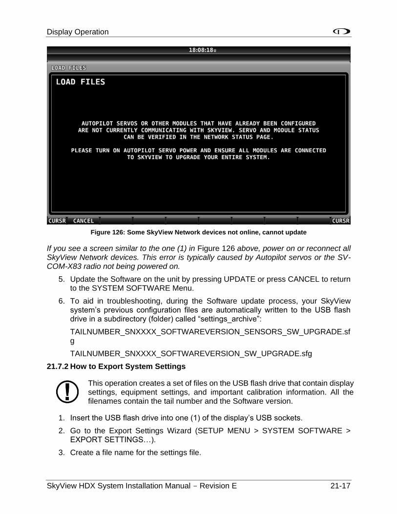
Display Operation
SkyView HDX System Installation Manual - Revision E 21-17
Figure 126: Some SkyView Network devices not online, cannot update
If you see a screen similar to the one (1) in Figure 126 above, power on or reconnect all SkyView Network devices. This error is typically caused by Autopilot servos or the SV-COM-X83 radio not being powered on.
5. Update the Software on the unit by pressing UPDATE or press CANCEL to return to the SYSTEM SOFTWARE Menu.
6. To aid in troubleshooting, during the Software update process, your SkyView system’s previous configuration files are automatically written to the USB flash drive in a subdirectory (folder) called “settings_archive”:
TAILNUMBER_SNXXXX_SOFTWAREVERSION_SENSORS_SW_UPGRADE.sfg
TAILNUMBER_SNXXXX_SOFTWAREVERSION_SW_UPGRADE.sfg
21.7.2 How to Export System Settings
This operation creates a set of files on the USB flash drive that contain display settings, equipment settings, and important calibration information. All the filenames contain the tail number and the Software version.
1. Insert the USB flash drive into one (1) of the display’s USB sockets.
2. Go to the Export Settings Wizard (SETUP MENU > SYSTEM SOFTWARE > EXPORT SETTINGS…).
3. Create a file name for the settings file.
Display Operation
21-18 SkyView HDX System Installation Manual - Revision E
4. Save the settings file onto the flash drive by pressing EXPORT or press CANCEL to return* to the SYSTEM SOFTWARE menu.
21.7.3 How to Load and Delete Files
1. Download file from www.dynoncertified.com/software-updates.php such as terrain or EMS files or use another source for the SkyView file.
2. Copy the file onto your USB flash drive. The file must be in the root directory of the drive in order to be recognizable by the display.
3. Insert the USB flash drive into one (1) of the display’s USB sockets.
4. Go to the Load Files Wizard (SETUP MENU > SYSTEM SOFTWARE > LOAD FILES…).
5. Select a file and press:
a. LOAD to load the file onto the system.
b. CANCEL to return to the SYSTEM SOFTWARE menu.
c. REMOVE to delete the file from the USB flash drive.
21.7.4 How to Export Data Logs and Waypoints
EXPORT DATA LOGS
Data logging, and how to export data logs is discussed in depth in Appendix F: User Data Logs.
EXPORT USER WAYPOINTS
This option exports all the User Waypoints that are currently stored in your SkyView system.
EXPORT DYNON DIAGNOSTIC FILE
This specialized data log can only be interpreted by Dynon Avionics Engineers; there is no data in it that can be interpreted by SkyView pilots. Dynon Avionics Technical Support may request this log during troubleshooting, especially for issues related to AP performance. Note that this log is very big – over 500 MB – and takes minutes to save to a USB flash drive. Unless directed to export this log by Dynon Avionics, there is no reason to do so. This file is too large to send in an email message.
If you have more than one (1) SkyView display in your system, you may be requested to save the Dynon Avionics Diagnostic File from each of your SkyView displays as each display can sometimes contain different diagnostic data. If you save the Dynon Avionics Diagnostic File from multiple displays onto the same USB flash drive, use the 33-character name field to distinguish the two (2) files, such as naming one (1) “LEFT” and the other one (1) “RIGHT.”
If Dynon Avionics Technical Support has requested that you send a Dynon Diagnostic File, go to http://www.dynonavionics.com/docs/upload.html to transmit the file to Dynon Avionics. Please reference any previous communications with Dynon Avionics Technical Support such as Case number, RMA number, etc.
Navigation Mapping Setup
SkyView HDX System Installation Manual - Revision E 22-1
22 Navigation Mapping Setup
22.1 Features Overview
The following features are enabled as long as SkyView has a valid GPS position signal, the appropriate high resolution terrain database installed for the region of the world that you are flying in, and aviation database installed.
• Use of MAP menu and features, including:
o Display of airport, airspace, obstacles, traffic, and other aviation data that is available (capabilities depend on available databases and other installed equipment).
o Display of procedure charts, airport diagrams, enroute charts (sectionals), and other layers that can be overlaid on the map.
o Display of base map features, including roads, city names, railroads, rivers, and political boundaries.
o All Navigation Mapping features available via the MAP menu.
o Display of obstacles and runways on Synthetic Vision (if Synthetic Vision is licensed).
o All future updates to the SV-MAP-270 Navigation Mapping License.
22.2 Databases
SkyView utilizes a variety of databases to display information on the moving map and present options for navigation. These include:
• Charts: Scanned or electronic versions of procedure charts, airport diagrams, and enroute charts. Seattle Avionics data available for US SkyView pilots. PocketFMS, OzRunways, and AvPlan EFB data available for other worldwide SkyView pilots.
• Aviation data: Airports, navigation aids, airspace, airport information, etc. Available for free for US SkyView pilots from Dynon Avionics. Jeppesen and PocketFMS data available for all other SkyView pilots worldwide.
• Obstacles data: Available for free for US SkyView pilots from Dynon Avionics. Jeppesen and PocketFMS data available for all other SkyView pilots worldwide.
• Terrain data: A high resolution terrain database is used to display the topographic map. Available worldwide for free from Dynon Avionics.
• Base map (Cultural) data: Base map is available for free for all SkyView pilots from Dynon Avionics worldwide.
• Stadium TFR data: Available for free for US SkyView pilots from Dynon Avionics.
Navigation Mapping Setup
22-2 SkyView HDX System Installation Manual - Revision E
The airplane owner/operater or an FAA-credentialed mechanic or facility can install databases, charts, and diagrams. Data updates are installed using a USB flash drive. See www.dynoncertified.com/software-updates.php for more information.
22.2.1 Viewing Information about Installed Databases
The Installed Databases Page (SETUP MENU > LOCAL DISPLAY SETUP > INSTALLED DATABASES) allows users to see the databases installed on their equipment as well as their respective versions and expiration dates. The sections below outline the various databases that are installed in SkyView.
When viewing INSTALLED DATABASES, the sections:
• PROCEDURE CHARTS AND AIRPORT DIAGRAMS,
• FLIGHT GUIDE AIRPORT DIAGRAMS, and
• ENROUTE CHARTS,
can only display information about these databases if the USB flash drive (with the PocketFMS / Seattle Avionics chart data) is plugged in. When the USB flash drive with this data is not plugged in, these sections are blank.
For any database which has an expiration date, if the expiration date has passed,
• On a SkyView display, a popup message will appear on the MAP page as shown in Figure 127. This message can be cleared by pushing the MAP button and then the ACCEPT button. The popup message is then cleared for the remainder of the time SkyView is powered on. Until the database whose expiration date has passed is updated, this popup message will continue to appear each time SkyView is powered on. The initial appearance of this popup message cannot be suppressed. Note that in the popup message, only the first database that is past its expiration date is listed.
• The presence, and status (including expiration dates) of all databases can be checked in the INSTALLED DATABASES page: SETUP MENU > LOCAL DISPLAY SETUP > INSTALLED DATABASES. Any database that has expired will be shown in YELLOW and appended with (EXPIRED), as shown in Figure 128. Note that in a SkyView system with multiple displays, it is possible for each display to have different, and different versions (expiration dates) of various databases. Thus, when verifying the presence, and expiration dates, of databases, check them on each SkyView display.
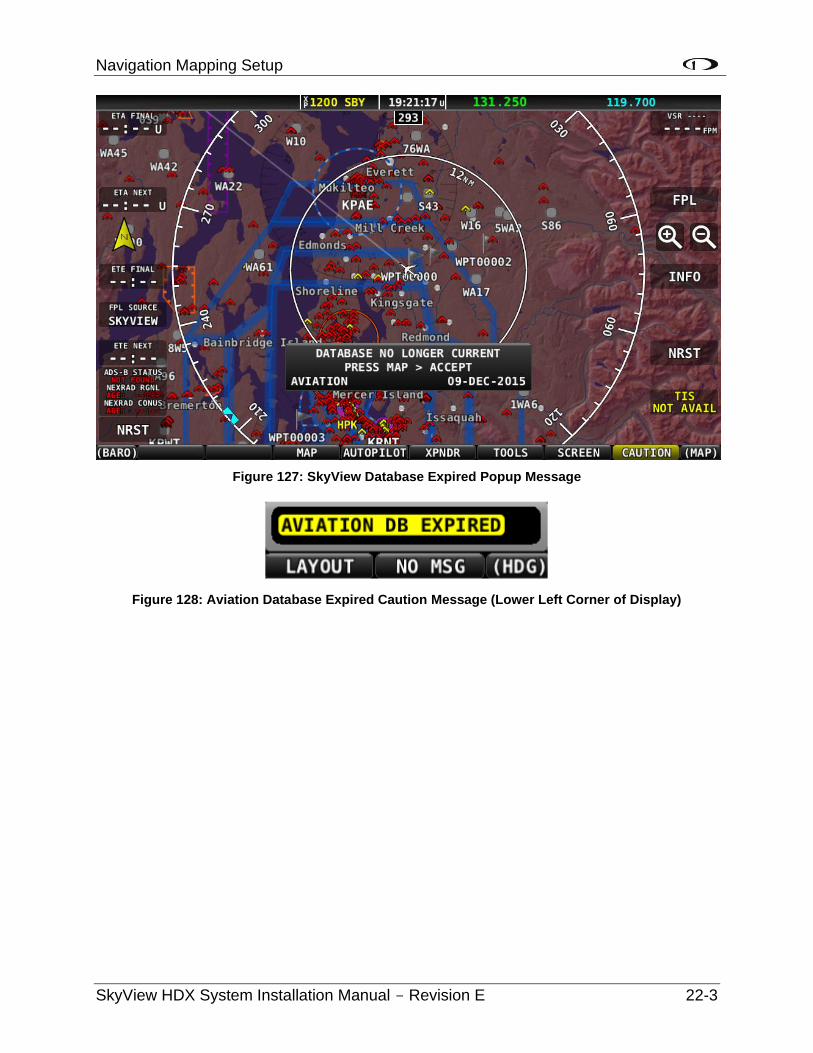
Navigation Mapping Setup
SkyView HDX System Installation Manual - Revision E 22-3
Figure 127: SkyView Database Expired Popup Message
Figure 128: Aviation Database Expired Caution Message (Lower Left Corner of Display)
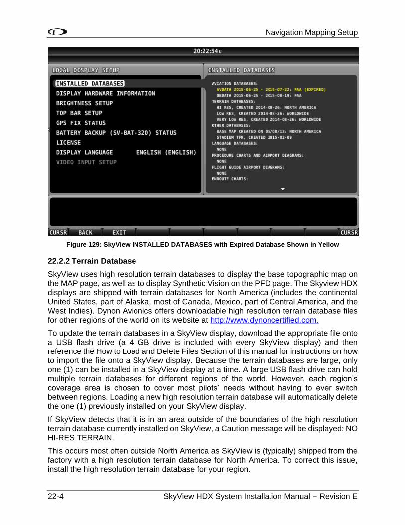
Navigation Mapping Setup
22-4 SkyView HDX System Installation Manual - Revision E
Figure 129: SkyView INSTALLED DATABASES with Expired Database Shown in Yellow
22.2.2 Terrain Database
SkyView uses high resolution terrain databases to display the base topographic map on the MAP page, as well as to display Synthetic Vision on the PFD page. The Skyview HDX displays are shipped with terrain databases for North America (includes the continental United States, part of Alaska, most of Canada, Mexico, part of Central America, and the West Indies). Dynon Avionics offers downloadable high resolution terrain database files for other regions of the world on its website at http://www.dynoncertified.com.
To update the terrain databases in a SkyView display, download the appropriate file onto a USB flash drive (a 4 GB drive is included with every SkyView display) and then reference the How to Load and Delete Files Section of this manual for instructions on how to import the file onto a SkyView display. Because the terrain databases are large, only one (1) can be installed in a SkyView display at a time. A large USB flash drive can hold multiple terrain databases for different regions of the world. However, each region’s coverage area is chosen to cover most pilots’ needs without having to ever switch between regions. Loading a new high resolution terrain database will automatically delete the one (1) previously installed on your SkyView display.
If SkyView detects that it is in an area outside of the boundaries of the high resolution terrain database currently installed on SkyView, a Caution message will be displayed: NO HI-RES TERRAIN.
This occurs most often outside North America as SkyView is (typically) shipped from the factory with a high resolution terrain database for North America. To correct this issue, install the high resolution terrain database for your region.
Navigation Mapping Setup
SkyView HDX System Installation Manual - Revision E 22-5
If you have difficulty downloading the very large regional high-resolution terrain databases using a web browser, particularly using a slow Internet connection, alternatively, you may use an “FTP” client, such as FileZilla, available at https://filezilla-project.org.
Host: dynonavionics.com Username: anonymous Password: (blank)
22.2.3 Aviation/Obstacle Databases
Aviation and obstacle databases are used to display airports, runways, navigation aids, airspace, obstacles, and other aviation data on the moving map. It also makes allows SkyView to provide detailed information about aviation features. SkyView can also provide navigation to these aviation features.
22.2.3.1 Free Dynon Avionics Aviation and Obstacle Data (U.S. Only)
Aviation and Obstacle data is available free-of-charge for US SkyView pilots. Go to http://www.dynoncertified.com/us-aviation-obstacle-data.php to download these databases to a USB flash drive. Reference the Loading Databases section of this manual below for instructions on how to import the file onto a SkyView display. Aviation data is updated every 28 days. Obstacle data is updated every 56 days.
22.2.3.2 PocketFMS AeroData Subscriptions with Obstacles and Visual
Reporting Points (Worldwide)
AeroData is professionally maintained and updated for SkyView every 28 days, and is available as a yearly subscription including obstacles for €119. Coverage encompasses Europe, North America (including Canada), Australia, and New Zealand. It includes Aviation data (including visual reporting points) and obstacle data. As of August 2015, enroute charts are also available from PocketFMS. To order and download PocketFMS AeroData, visit their website at http://www.pocketfms.com/Dynon Avionics
22.2.3.3 Jeppesen NavData® and Obstacle Data Services (Worldwide)
Aviation and Obstacle for SkyView pilots outside the US is available from Jeppesen. To purchase Jeppesen data:
• Visit http://www.JeppDirect.com/viewavionics for data subscription information from Jeppesen for your SkyView display.
• To order service, please call Jeppesen at a number below.

Navigation Mapping Setup
22-6 SkyView HDX System Installation Manual - Revision E
Table 49: Jeppesen Telephone Numbers
U.S. & Canada United Kingdom Europe (except
UK), Middle East, Africa and Asia
Australia
Toll-Free: 1-866-498-0213
Direct: 1-303-328-4030
Toll-Free: 0 (800) 085 5377
Direct: +44 129 384 2400
Toll-Free: 0 800 5377 3736
Direct: +49 6102 5070
Direct: +61 261 202 999
• Reference the Loading Databases section below of this manual for instructions on how to import the file onto a SkyView display.
Additional technical support from Jeppesen can be found online at http://www.jeppesen.com/support/technical-support.jsp.
22.2.4 Stadium TFR Database (U.S. Only)
Dynon Avionics includes a Stadium TFR database as part of its “Quick Packages” for US pilots. In loading any “Quick Package” since then, the Stadium TFR database will be loaded onto a SkyView system. After the Stadium TFR database is loaded, a TFR will be displayed on the MAP PG as if it was being received via ADS-B. The default opacity of the Stadium TFR database (as displayed on the MAP PG) is 100% (solid Red) but can be adjusted: MAP MENU > MAP ITEMS > TFR OPACITY.
If the Stadium TFR database is accidentally deleted from a SkyView display, contact Dynon Avionics Technical Support to obtain a replacement Stadium TFR database.
22.2.5 Charts and Airport Diagrams
SkyView’s charting capabilities allow pilots to quickly find and display the procedures they need during flight, all while showing the aircraft’s position and track right on the chart itself. With the touch of a button, SkyView automatically loads the available airport diagram while on the ground.
22.2.5.1 Geo-Referenced Charts and Airport Diagrams, Geo-referenced US
sectionals, and IFR HI and LO Charts (U.S. Only)
SkyView HDX can display geo-referenced charts and airport diagrams provided by Seattle Avionics, including over 5,000 FlightGuide diagrams and all approach plates and procedures. SkyView supports Seattle Avionics geo-referenced US sectionals and IFR HI and LO charts. Subscriptions for all Seattle Avionics data listed above for SkyView pilots are available at a special price. To order and download Seattle Avionics’ SkyView ChartData, contact Seattle Avionics – call 425-806-0249 or see http://www.seattleavionics.com/ChartData/Default.aspx?TargetDevice=Dynon Avionics
Navigation Mapping Setup
SkyView HDX System Installation Manual - Revision E 22-7
22.2.5.2 European Charts and Airport Diagrams (Europe)
PocketFMS’ Frequent Flyer membership includes AeroData, charts (including Pooleys in the UK), airport diagrams, visual approach, landing, and area charts, costs €150 per year. This is only €31 more than the existing SkyView AeroData-only subscription (which remains available). As of August 2015, enroute charts are also available from PocketFMS. To become a PocketFMS Member (Frequent Flyer membership), see http://www.pocketfms.com/Dynon/.
22.2.5.3 Australia and New Zealand Charts (Austraila, New Zealand)
SkyView supports Australia and New Zealand charts from OzRunways (https://www.ozrunways.com) and AvPlan EFB (http://www.avplan-efb.com). Please contact these companies directly for more information about the specific data they provide, pricing, purchase / subscription options, and support on saving their data onto a USB flash drive for use with SkyView.
22.2.6 Base Map (Cultural Data)
Base Map (Cultural Data) is available free-of-charge for all SkyView pilots for SkyView pilots worldwide. The Base Map contains roads, city names, railroads, rivers, and political boundaries. Like the terrain database, it is partitioned into different regions. Download the base map database for your region from http://www.dynoncertified.com/basemap-terrain-data.php to a USB flash drive. Reference the section below for instructions on how to import the file onto a SkyView display.
22.2.7 Loading Databases
1. Download database file(s) from http://www.dynoncertified.com/us-aviation-obstacle-data.php, Jeppesen, or PocketFMS.
a. If you’ve downloaded data from the Dynon Avionics website or PocketFMS: Copy the file onto your USB flash drive. The file must be in the root directory of the drive in order to be recognizable by the display
b. If you’ve purchased data from Jeppesen: It is important that the Jeppesen JSUM program is used to place the Jeppesen data on the USB flash drive that will be used to load the data onto SkyView. If you manually copy Jeppesen data onto a USB flash drive, it will not load onto your SkyView system.
2. Insert the USB flash drive into one (1) of the display’s USB sockets.
Navigation Mapping Setup
22-8 SkyView HDX System Installation Manual - Revision E
3. Go to the Load Files Wizard (SETUP MENU > SYSTEM SOFTWARE > LOAD FILES…).
4. Select a file and press:
a. LOAD to load the file onto the system.
5. Exit Setup.
6. In SkyView systems that have more than one (1) display, databases are automatically synchronized to other connected displays provided that those displays are connected via Ethernet. If they are, and you have the MAP page up on other displays, you may see a SYNCHRONIZING DATABASES message appear as this process occurs, followed by a display reboot. If you do not have your displays connected via Ethernet, simply load the database to each screen individually.
22.2.8 Removing Databases
SkyView automatically removes old databases when new databases are installed. Databases can also be removed manually by going to SETUP MENU > LOCAL DISPLAY SETUP > INSTALLED DATABASES. Highlight the database you wish to remove, and then press the REMOVE button.
Aviation Data updates are published periodically by Dynon Avionics, PocketFMS, and Jeppesen. It is the user’s responsibility stay current with these updates and keep their equipment up to date.
Appendix A: Maintenance and Troubleshooting
SkyView HDX System Installation Manual - Revision E 23-1
23 Appendix A: Maintenance and Troubleshooting
This appendix provides builders, installers and technicians basic information regarding SkyView maintenance and troubleshooting.
Dynon Avionics’ Internet sites may provide more up-to-date information on maintenance and troubleshooting than this document. The following sites should be used a reference:
• www.dynon.aero/stcdocs – Dynon Avionics' documentation download area allows SkyView pilots (and prospective SkyView pilots) to download the most up-to-date versions of all Dynon Avionics documentation. Older versions of Dynon Avionics documentation may be shipped with OEM and dealer-provided units, so it is a good idea to periodically check for new versions of documentation.
• http://forum.dynonavionics.com Dynon Avionics’ Online Customer Forum is a resource for Dynon Avionics SkyView pilots to discuss installation and operational issues relating to Dynon Avionics products. The Forum is especially useful for pilots with uncommon aircraft or unusual installation issues. For SkyView pilots that cannot call Dynon Avionics Technical Support during our normal business hours, the Forum is a convenient way to interact with Dynon Avionics Technical Support. The Forum allows online sharing of wiring diagrams, photos, and other types of electronic files.
Dynon Avionics Technical Support is available 7:00 AM–4:00 PM (Pacific Time) Monday – Friday. For phone support, call +1(425) 402-0433. Email our tech support staff at [email protected].
There are no user-serviceable parts (such as replaceable fuses) inside any SkyView system unit. Refer all servicing to Dynon Avionics.
23.1 Cleaning a SkyView Display
Do not clean SkyView displays or panel units with solvents such as alcohol. If solvents are used, the silk screen lettering on the bezel can be removed, and the display’s anti-glare coating can be damaged. Damage from the use of solvents is not covered by warranty.
Dynon Avionics recommends the use of iCloth Avionics wipes for cleaning SkyView displays and panel units. In our testing, this product was found to clean SkyView displays and panel units satisfactorily, without damage. Several sample iCloth Avionics wipes are included with every new SkyView display. Additional iCloth Avionics are available for purchase at http://iclothavionics.com.
Figure 130: iCloth Avionics Wipe
Appendix A: Maintenance and Troubleshooting
23-2 SkyView HDX System Installation Manual - Revision E
23.2 Saving a Screenshot of a Specific Screen
It is sometimes helpful to have a screenshot of a behavior to share with Dynon Avionics Technical Support. Screenshots recorded with this method are far superior to photos because they are always “in focus” and they include all of the detain on screen. Screenshots are also useful to have for your records for how your SkyView display was configured, especially detailed menus such as Serial Port Setup, Sensor Input Mapping, etc. To accomplish this:
• Insert a USB flash drive into your SkyView USB port.
• When you want to save a screenshot of the display, press buttons 2 and 7 on that display simultaneously. SkyView will display a message indicating that a screenshot has been saved.
• The screenshot can be found in the “screenshots” folder on the USB flash drive when the USB flash drive is connected to a computer.
• If a Language Pack is installed, two (2) screen shot files will be saved to the USB flash drive – one (1) in English, and one (1) in the language of the Language Pack.
• If requested by Dynon Avionics Technical Support, email the screenshot files to: [email protected].
23.3 Savings a Settings File (Configuration of your SkyView system)
It is sometimes helpful to send your system configuration settings to Dynon Avionics Technical Support. A settings file is also useful to have for your records for how your SkyView display was configured. With a Settings File, a new SkyView display can be mostly restored by loading this file. To accomplish this:
• Insert a USB flash drive into your SkyView USB port.
• SETUP MENU > SYSTEM SOFTWARE > EXPORT SETTINGS… > (one (1) more right click).
• For your records, put the USB flash drive (or at least the files) in a safe place.
• If requested by Dynon Avionics Technical Support, email the settings files to: [email protected].
23.4 Saving a Dynon Diagnostic File
In rare cases, Technical Support will request you to send a Dynon Avionics Diagnostic File. To accomplish this:
• Insert a USB flash drive into your SkyView USB port.
• SETUP MENU > SYSTEM SOFTWARE > EXPORT DYNON DIAGNOSTIC FILE… > (one (1) more right click).
Appendix A: Maintenance and Troubleshooting
SkyView HDX System Installation Manual - Revision E 23-3
• This file is too large to send in an email message. If Dynon Avionics Technical Support has requested that you send a Dynon Diagnostic File, go to http://www.dynonavionics.com/docs/upload.html to transmit the file to Dynon Avionics. Please reference any previous communications with Dynon Avionics Technical Support such as Case number, RMA number, etc.
23.5 SkyView Displays Error: SYS EVENT 5: SEE SETUP
System Event 5 indicates that the SkyView display's internal Solid State Disk (SSD) is experiencing an abnormal number of errors, and thus should be replaced. This feature was added to help detect units that may have potential problems with rebooting in flight or possible screen freezes.
The repair of the internal SSD can only be performed at the Dynon Avionics factory. Repair of SkyView displays for System Event 5 is considered a Warranty Repair, regardless of whether your SkyView display’s warranty is still in effect, or has expired. To arrange for a Return Material Authorization (RMA) for repair of your SkyView display for System Event 5, contact Dynon Avionics Technical Support (contact information at the beginning of this manual).
Before removing your SkyView display to ship to Dynon Avionics, please perform the following procedure to save a backup of your most important settings. You will need a USB flash drive (memory stick) - capacity of 1 GB is adequate, available inexpensively at most office supply and grocery stores. We recommend that you save these files to a USB flash drive not used for anything else.
1. Manually record your HOBBS and TACH time, as these two (2) pieces of information are not saved in the backup file.
2. Power up the SkyView display / system.
3. If you have another USB flash drive inserted into this SkyView display, temporarily remove it (SkyView can only "see" one (1) USB flash drive at a time).
4. Insert the "backup" USB flash drive on the SkyView display you will be sending in for trade-in.
5. Push buttons 7+8 together to enter the SETUP MENU.
6. SETUP MENU > SYSTEM SOFTWARE > EXPORT SETTINGS > (fill in the blank - suggest FINAL BACKUP) > EXPORT (button). The settings files will be saved to the USB flash drive.
7. After the export is complete, remove the USB flash drive.
8. Power down the SkyView display.
9. Put the USB flash drive in a safe place.
If the worst happens - your SkyView display is damaged or lost in transit, this will allow you to restore MOST settings of your SkyView system.
Appendix A: Maintenance and Troubleshooting
23-4 SkyView HDX System Installation Manual - Revision E
23.6 Returning SkyView Components to Service after Repair
SkyView Network enabled components such as modules and servos are shipped in a “like new” state after repair. To return a SkyView Network component to SkyView Network, follow the following directions. Note that there are three (3) different procedures for returning SkyView displays to service, depending on how the display is returned:
23.6.1 SkyView Display Scenario 1
When the documentation furnished with the repaired display indicates that is being returned to you with the exact same settings/configuration as it was sent to Dynon Avionics with
1. In this case, the display contains EXACTLY the same configuration as it did when you sent it in. If your system was working properly before the display failed and was sent in for repair:
a. Reinstall the display, reconnecting all harnesses and connections as originally installed.
2. Power up the entire SkyView System (all displays, modules, servos, etc.)
3. If this is the only display installed:
a. Reconfigure SkyView Network under SETUP MENU > SYSTEM SETUP > SKYVIEW NETWORK SETUP > CONFIGURE…
b. Confirm all SkyView Network components are found, including ALL displays that are in the aircraft.
4. If there is another display installed in the aircraft:
a. Using a display that never left the aircraft (and is presumably configured and working correctly):
i. Reconfigure SkyView Network under SETUP MENU > SYSTEM SETUP > SKYVIEW NETWORK SETUP > CONFIGURE…
ii. Confirm all SkyView Network components are found.
5. Confirm that all settings, behavior, and configuration are normal.
6. If your SkyView system is not working normally, contact Dynon Avionics Technical Support (contact information at the beginning of this manual) for further assistance.
23.6.2 SkyView Display Scenario 2
When repaired display is the ONLY display in the aircraft, and the documentation furnished with the repaired unit indicates that the display was shipped “like new:”
1. Reinstall the display, reconnecting all harnesses and connections as originally installed.
2. Power up the entire SkyView System (all displays, modules, servos, etc.).
3. If you have an EXPORT SETTINGS file on a USB flash drive:
Appendix A: Maintenance and Troubleshooting
SkyView HDX System Installation Manual - Revision E 23-5
a. Load the EXPORT SETTINGS file via SETUP MENU > SYSTEM SOFTWARE > LOAD FILES.
b. Confirm that the tail number under SYSTEM SETUP > AIRCRAFT INFORMATION is now set to the actual aircraft tail number, not DYNON. TAIL NUMBER should not include dashes (-) or spaces. Examples:
Correct: N12AB
Incorrect: N-12AB or N 12AB
c. Reconfigure SkyView Network under SETUP MENU > SYSTEM SETUP > SKYVIEW NETWORK SETUP > CONFIGURE.
d. Confirm all SkyView Network components are found.
e. Confirm all settings, calibrations, and behaviors are as expected. Dynon Avionics recommends using the Installation Manual to walk through each set up section to confirm proper system operation.
4. If you do not have an EXPORT SETTINGS file, use the SkyView Installation Manual to perform ALL setup and configuration steps as if the entire system is being installed for the first time.
23.6.3 SkyView Display Scenario 3
When other display is part of a multi-display system in the aircraft, and the documentation furnished with the repaired unit indicates that the display was shipped “like new”
1. Your repaired display will have the latest version of SkyView Software on it. All displays in the aircraft must be on the same SkyView Software version. Therefore, before doing anything with the repaired display, confirm that your OTHER (still installed) SkyView displays are running the latest system Software by comparing the version available at http://www.dynoncertified.com/software-updates.php with the version that is listed in SETUP MENU > LOCAL DISPLAY SETUP > DISPLAY HARDWARE INFORMATION. If the version displayed here does not match what is available on the web site, update these displays to the most current version of Software before proceeding further. Instructions for updating your displays can be found in the Software Updates and File Operations section of this manual.
a. If you have to updated SkyView Software, look through all the settings in the SETUP MENU after the update, as there may be some new options. Use the Revision History at the beginning of the SkyView System Installation Manual to help determine what has changed between versions.
2. Reinstall the repaired display, reconnecting all harnesses and connections as originally installed.
3. Power up the entire SkyView System (all displays, modules, servos, etc.).
4. From the display that never left the airplane, save your settings files to a USB flash drive by using SETUP MENU > EXPORT SETTINGS …
Appendix A: Maintenance and Troubleshooting
23-6 SkyView HDX System Installation Manual - Revision E
5. Move this USB flash drive to the repaired display, and load both the .dfg and .sfg files that were created on the USB flash drive by using SETUP MENU > SYSTEM SOFTWARE > LOAD FILES…
6. Set the tail number of the repaired display (SYSTEM SETUP > AIRCRAFT INFORMATION) to DYNON AVIONICS.
7. Going back to a display that never left the aircraft, which is configured properly and working correctly:
It is important that the following steps are done from a display which has remained in the aircraft, and NEVER the newly repaired display. If network configuration is done from the repaired display, it is possible for it to overwrite the correct settings that are stored in your good display with the Dynon Avionics default factory settings.
a. On the display that stayed in the plane, confirm that the tail number under SYSTEM SETUP > AIRCRAFT INFORMATION is set to the actual aircraft tail number, not DYNON.
b. On the display that stayed in the plane, reconfigure SkyView Network under SETUP MENU > SYSTEM SETUP > SKYVIEW NETWORK SETUP > CONFIGURE.
c. Confirm all SkyView Network components are found, including ALL displays that are in the aircraft.
d. Exit Setup mode.
8. On the recently repaired display, confirm that the tail number under SYSTEM SETUP > AICRAFT INFORMATION is now set to the actual aircraft tail number, not DYNON. This implies that all settings and configurations have been synchronized from the other display.
23.7 Multi-display SkyView System, Continuing to Fly with a Missing Display
In a multi-display SkyView system, the system can continue to operate with only one (1) SkyView display. However, this capability depends on all SkyView Network connections being intact so that the remaining SkyView display is electrically connected to all SkyView Network devices.
Each SkyView display has two (2) SkyView Network connections on the back. In the event of a failure of a SkyView display, the two (2) SkyView Network connectors are “electrically common”; even if the SkyView display is failed or powered off, all pins of the upper connector are electrically connected to all pins of the lower connector.
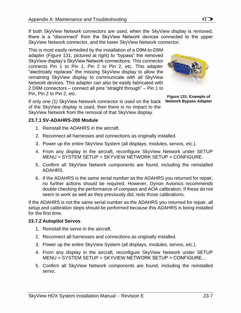
Appendix A: Maintenance and Troubleshooting
SkyView HDX System Installation Manual - Revision E 23-7
If both SkyView Network connectors are used, when the SkyView display is removed, there is a “disconnect” from the SkyView Network devices connected to the upper SkyView Network connector, and the lower SkyView Network connector.
This is most easily remedied by the installation of a D9M-to-D9M adapter (Figure 131, pictured at right) to “bypass” the removed SkyView display’s SkyView Network connections. This connector connects Pin 1 to Pin 1, Pin 2 to Pin 2, etc. This adapter “electrically replaces” the missing SkyView display to allow the remaining SkyView display to communicate with all SkyView Network devices. This adapter can also be easily fabricated with 2 D9M connectors – connect all pins “straight through” – Pin 1 to Pin, Pin 2 to Pin 2, etc.
If only one (1) SkyView Network connector is used on the back of the SkyView display is used, then there is no impact to the SkyView Network from the removal of that SkyView display.
23.7.1 SV-ADAHRS-200 Module
1. Reinstall the ADAHRS in the aircraft.
2. Reconnect all harnesses and connections as originally installed.
3. Power up the entire SkyView System (all displays, modules, servos, etc.).
4. From any display in the aircraft, reconfigure SkyView Network under SETUP MENU > SYSTEM SETUP > SKYVIEW NETWORK SETUP > CONFIGURE.
5. Confirm all SkyView Network components are found, including the reinstalled ADAHRS.
6. If the ADAHRS is the same serial number as the ADAHRS you returned for repair, no further actions should be required. However, Dynon Avionics recommends double checking the performance of compass and AOA calibration. If these do not seem to work as well as they previously did, redo those calibrations.
If the ADAHRS is not the same serial number as the ADAHRS you returned for repair, all setup and calibration steps should be performed because this ADAHRS is being installed for the first time.
23.7.2 Autopilot Servos
1. Reinstall the servo in the aircraft.
2. Reconnect all harnesses and connections as originally installed.
3. Power up the entire SkyView System (all displays, modules, servos, etc.).
4. From any display in the aircraft, reconfigure SkyView Network under SETUP MENU > SYSTEM SETUP > SKYVIEW NETWORK SETUP > CONFIGURE…
5. Confirm all SkyView Network components are found, including the reinstalled servo.
Figure 131: Example of Network Bypass Adapter
Appendix A: Maintenance and Troubleshooting
23-8 SkyView HDX System Installation Manual - Revision E
6. Assuming the Autopilot was previously set up and working correctly, you only need to recalibrate the servos by going to SETUP MENU > HARDWARE CALIBRATION > AP SERVO CALIBRATION > CALIBRATION and following the on-screen instructions.
23.7.3 All other SkyView Network Components
1. Reinstall the SkyView Network component in the aircraft.
2. Reconnect all harnesses and connections as originally installed.
3. Power up the entire SkyView System (all displays, modules, servos, etc.).
4. From any display in the aircraft, reconfigure SkyView Network under SETUP MENU > SYSTEM SETUP > SKYVIEW NETWORK SETUP > CONFIGURE.
5. No further action should be required.
23.8 Operational Status
SkyView displays give users access to vital operational information in the Display Hardware Information Page (SETUP MENU > LOCAL DISPLAY SETUP > DISPLAY HARDWARE INFORMATION). Note that the information in this menu may be useful during troubleshooting. The information here cannot be edited on this screen; however, some parameters are editable by the user on other screens.
This menu contains the following information:
• Display serial number.
• Software version.
• Display input voltage.
• SV-BAT-320 charge state.
• Operational state of the internal battery management circuitry.
• Operational state of the internal voltage rails.
• Screen brightness level.
• Local light sensor output.
• External light sensor output.
• Brightness level output.
• Contact input status.
• Serial port status and current baud rate.
• Button and joystick states.
• Operational hours.
23.8.1 Display Serial Number
The serial number of the display is noted here as SERIAL NUMBER: XXXXXX.
Appendix A: Maintenance and Troubleshooting
SkyView HDX System Installation Manual - Revision E 23-9
23.8.2 Display Software Version
The Software version of the display is noted here as SOFTWARE VERSION: X.X.XX.XXX.
23.8.3 Display Input Voltage
The display's input voltage is list here as VOLTAGE: XX.XXV.
23.8.4 SV-BAT-320 Charge State
If there is an SV-BAT-320 connected to the display, its voltage level is shown here as BATTERY STATUS: XX.XXV. The battery is fully charged at 12.25V. Charging a completely discharged battery may take up to 4 hours. To conserve your aircraft battery, the SV-BAT-320 is only charged with SkyView detects your alternator/generator to be online.
23.8.5 Operational State of the Internal Battery Management Circuitry
The operational state of the display's internal battery management circuitry is listed here. If there is an SV-BAT-320 connected to the display, you will see one (1) of the following states:
• CHARGING: SkyView system voltage is above 12.25V. SkyView is running on master power and is charging the SV-BAT-320.
• DISCHARGING: SkyView system voltage is below 10V. SkyView runs on the SV-BAT-320. The SV-BAT-320 discharges.
• CHARGED: SkyView system voltage is above 12.25V, and the SV-BAT-320 is fully charged.
• STANDBY: SkyView system voltage is above 10V, but below 12.25V: SkyView runs on master power but does not charge the SV-BAT-320. To conserve your aircraft battery, the SV-BAT-320 is only charged with SkyView detects your alternator/generator to be online.
• NO BATTERY: No SV-BAT-320 is connected.
23.8.6 Operational State of the Internal Voltages
There are several important voltages in the display. You will find their statuses here. If they are all operating at specified levels, then you will see OK. If any voltage is operating out of specification, you will see X.XV FAIL for that voltage.
23.8.7 Screen Brightness Level
The screen's brightness level is shown here as a percent. For example, 100.0 means 100% and 50.0 means 50%.
23.8.8 Local Light Sensor Output
Each SkyView display has an integrated light sensor on the front bezel and its output is shown here.
Appendix A: Maintenance and Troubleshooting
23-10 SkyView HDX System Installation Manual - Revision E
23.8.9 External Light Control Signal Output
SkyView displays are compatible with external light control signals. The state of the external light control signal is shown here.
23.8.10 Brightness Level Output
SkyView displays can output a brightness level signal to control the brightness of compatible external equipment screens. The level of the output is shown here.
23.8.11 Contact Input Status
Each SkyView display has four (4) contact inputs. The status of each contact input is shown here as either HIGH or LOW. CONTACT INPUT 1 is implemented as EXTERNAL LEVEL button. CONTACT INPUT 2 is implemented as EXTERNAL GO AROUND button. CONTACT INPUT 3 and CONTACT INPUT 4 have not been implemented.
23.8.12 Serial Port Status and Current Baud Rate
Each SkyView display has five (5) general purpose serial ports. The status of each serial port is shown with transmit (TX) and receive (RX) character counters and the ports current baud rate. The character counters show any outgoing or incoming character and roll over at 9999.
23.8.13 Button and Joystick States
The state of each button is shown on the BUTTON STATE line. You will see 1 2 3 4 5 6 7 8 on the line. When you press a button, its respective number on the button state line is replaced with an asterisk (*). For example, if you press and hold button 3, you will see 1 2 * 4 5 6 7 8.
The state of each joystick is shown on the JOYSTICK STATE line. Each joystick is denoted with an L or R (left or right, respectively), a counter to show joystick turns, and the letters UDLRC to denote moving the joystick Up, Down, Left, Right, and Center (when pressed like a button).
23.8.14 Operational Hours
This is a running count of the hours a screen has been on since was initially manufactured.
23.9 Instructions for Continued Airworthiness
Follow these steps for continued airworthiness:
• Conduct any periodic checks that are mandated by local regulations (IE, FAA for US Aircraft), such as (but not limited to):
o Transponder test
o Pitot / Static system test - refer to “Performing Pitot/Static Checks” near the end of the SV-ADAHRS-200 Installation and Configuration section.
• Annually test the SV-BAT-320 Backup Battery.
• Annually perform a ZERO PRESSURE IAS/AOA CALIBRATION.
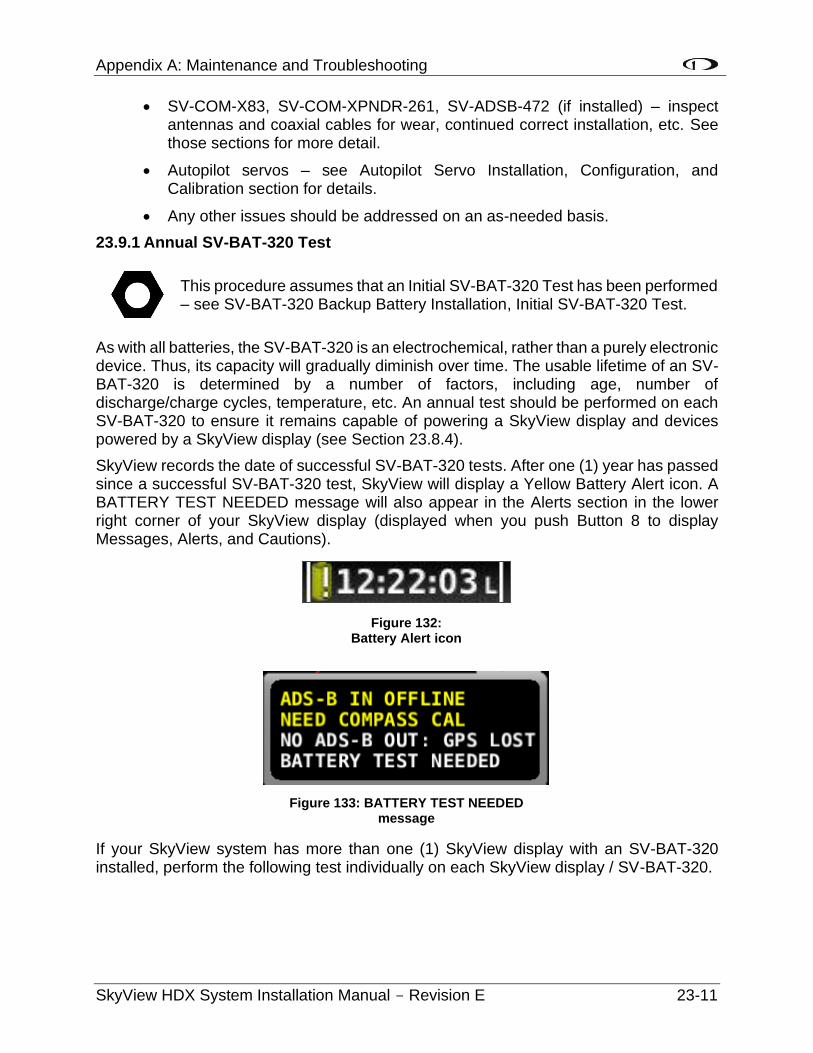
Appendix A: Maintenance and Troubleshooting
SkyView HDX System Installation Manual - Revision E 23-11
• SV-COM-X83, SV-COM-XPNDR-261, SV-ADSB-472 (if installed) – inspect antennas and coaxial cables for wear, continued correct installation, etc. See those sections for more detail.
• Autopilot servos – see Autopilot Servo Installation, Configuration, and Calibration section for details.
• Any other issues should be addressed on an as-needed basis.
23.9.1 Annual SV-BAT-320 Test
This procedure assumes that an Initial SV-BAT-320 Test has been performed – see SV-BAT-320 Backup Battery Installation, Initial SV-BAT-320 Test.
As with all batteries, the SV-BAT-320 is an electrochemical, rather than a purely electronic device. Thus, its capacity will gradually diminish over time. The usable lifetime of an SV-BAT-320 is determined by a number of factors, including age, number of discharge/charge cycles, temperature, etc. An annual test should be performed on each SV-BAT-320 to ensure it remains capable of powering a SkyView display and devices powered by a SkyView display (see Section 23.8.4).
SkyView records the date of successful SV-BAT-320 tests. After one (1) year has passed since a successful SV-BAT-320 test, SkyView will display a Yellow Battery Alert icon. A BATTERY TEST NEEDED message will also appear in the Alerts section in the lower right corner of your SkyView display (displayed when you push Button 8 to display Messages, Alerts, and Cautions).
If your SkyView system has more than one (1) SkyView display with an SV-BAT-320 installed, perform the following test individually on each SkyView display / SV-BAT-320.
Figure 132: Battery Alert icon
Figure 133: BATTERY TEST NEEDED message
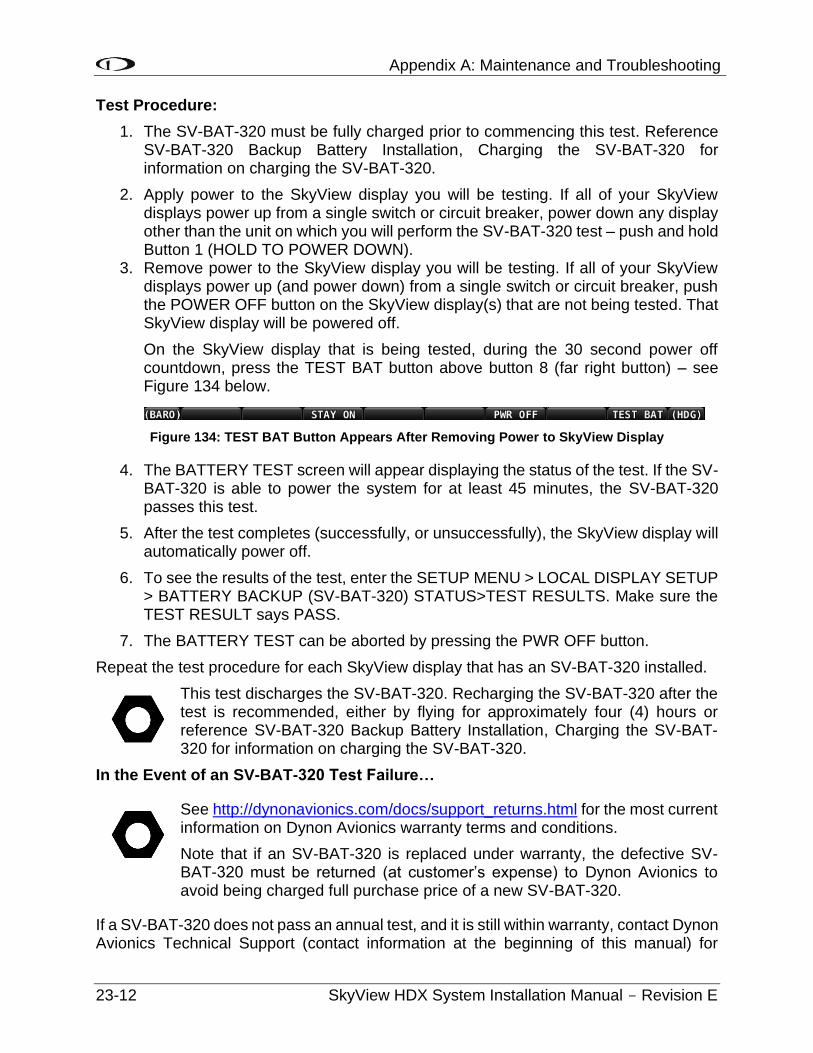
Appendix A: Maintenance and Troubleshooting
23-12 SkyView HDX System Installation Manual - Revision E
Test Procedure:
1. The SV-BAT-320 must be fully charged prior to commencing this test. Reference SV-BAT-320 Backup Battery Installation, Charging the SV-BAT-320 for information on charging the SV-BAT-320.
2. Apply power to the SkyView display you will be testing. If all of your SkyView displays power up from a single switch or circuit breaker, power down any display other than the unit on which you will perform the SV-BAT-320 test – push and hold Button 1 (HOLD TO POWER DOWN).
3. Remove power to the SkyView display you will be testing. If all of your SkyView displays power up (and power down) from a single switch or circuit breaker, push the POWER OFF button on the SkyView display(s) that are not being tested. That SkyView display will be powered off.
On the SkyView display that is being tested, during the 30 second power off countdown, press the TEST BAT button above button 8 (far right button) – see Figure 134 below.
Figure 134: TEST BAT Button Appears After Removing Power to SkyView Display
4. The BATTERY TEST screen will appear displaying the status of the test. If the SV-BAT-320 is able to power the system for at least 45 minutes, the SV-BAT-320 passes this test.
5. After the test completes (successfully, or unsuccessfully), the SkyView display will automatically power off.
6. To see the results of the test, enter the SETUP MENU > LOCAL DISPLAY SETUP > BATTERY BACKUP (SV-BAT-320) STATUS>TEST RESULTS. Make sure the TEST RESULT says PASS.
7. The BATTERY TEST can be aborted by pressing the PWR OFF button.
Repeat the test procedure for each SkyView display that has an SV-BAT-320 installed.
This test discharges the SV-BAT-320. Recharging the SV-BAT-320 after the test is recommended, either by flying for approximately four (4) hours or reference SV-BAT-320 Backup Battery Installation, Charging the SV-BAT-320 for information on charging the SV-BAT-320.
In the Event of an SV-BAT-320 Test Failure…
See http://dynonavionics.com/docs/support_returns.html for the most current information on Dynon Avionics warranty terms and conditions.
Note that if an SV-BAT-320 is replaced under warranty, the defective SV-BAT-320 must be returned (at customer’s expense) to Dynon Avionics to avoid being charged full purchase price of a new SV-BAT-320.
If a SV-BAT-320 does not pass an annual test, and it is still within warranty, contact Dynon Avionics Technical Support (contact information at the beginning of this manual) for
Appendix A: Maintenance and Troubleshooting
SkyView HDX System Installation Manual - Revision E 23-13
further assistance. Please have the S/N of the SV-BAT-320 (printed on the SV-BAT-320 product label) available when you contact Technical Support. See also SV-BAT-320 Backup Battery Installation, Returning an SV-BAT-320 to Dynon Avionics for Exchange (Warranty Replacement) for additional information.
If a SV-BAT-320 does not pass an annual test, and is no longer within warranty, dispose of the used SV-BAT-320 (see below) and purchase a new SV-BAT-320 from Dynon Avionics or a Dynon Avionics dealer. An SV-BAT-320 cannot be repaired or rebuilt.
Please dispose of a non‐functional SV-BAT-320 in a responsible manner. The SV-BAT-320 is a Lithium-Ion battery, similar in construction to cordless tool or laptop computer batteries and thus can be disposed of (recycled) wherever cordless tool or laptop computer battery recycling is available. For a list of recycling locations in the USA, call 1-800-8-BATTERY or see the Call 2 Recycle website at http://www.rbrc.org.
23.10 Troubleshooting
The Display Hardware Information Page (SETUP MENU > LOCAL DISPLAY SETUP > DISPLAY HARDWARE INFORMATION) can be a valuable resource when troubleshooting SkyView and is described in the previous section.
If the suggestions below do not help, or your issue is not listed below, please contact Dynon Avionics Technical Support (contact information at the beginning of this manual).
23.10.1 Network Configuration or SkyView Network Module Does Not Work Properly
If you try to configure a SkyView network and it does not work, try the following:
• Check network wiring and try again. There may be a short or an open somewhere.
• Unplug network modules one (1) by one (1) and try again. It is possible that one (1) of the modules could cause the network to stop functioning.
• Try again.
• For modules such as the SV-ADAHRS-200, the SV-EMS-220, and SV-ARINC-429, observe the red LED light near the SkyView Network connector:
o Flashing Fast: The module is operating normally and is configured and communicating on a SkyView Network.
o Flashing Slowly: The module is operating normally, but is not active on SkyView Network.
o Off: The module is not receiving power (from a SkyView Network / Display)
o On Solid - the module is receiving power, but is not operating normally.
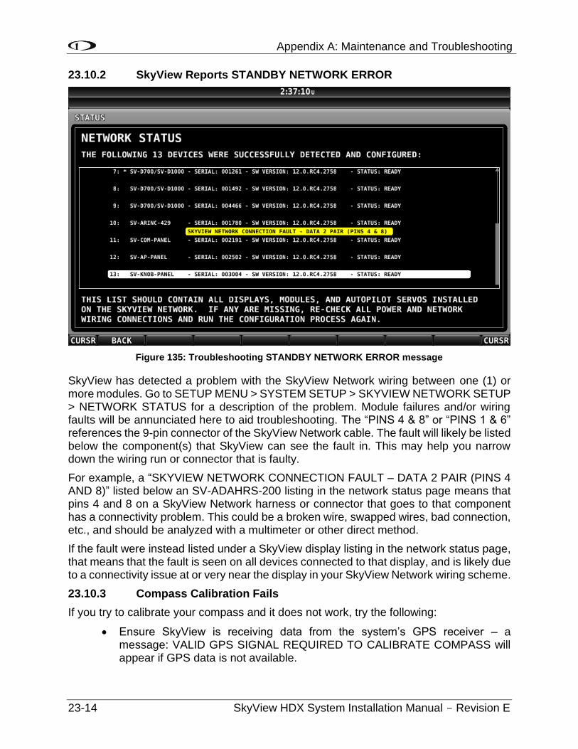
Appendix A: Maintenance and Troubleshooting
23-14 SkyView HDX System Installation Manual - Revision E
23.10.2 SkyView Reports STANDBY NETWORK ERROR
Figure 135: Troubleshooting STANDBY NETWORK ERROR message
SkyView has detected a problem with the SkyView Network wiring between one (1) or more modules. Go to SETUP MENU > SYSTEM SETUP > SKYVIEW NETWORK SETUP > NETWORK STATUS for a description of the problem. Module failures and/or wiring faults will be annunciated here to aid troubleshooting. The “PINS 4 & 8” or “PINS 1 & 6” references the 9-pin connector of the SkyView Network cable. The fault will likely be listed below the component(s) that SkyView can see the fault in. This may help you narrow down the wiring run or connector that is faulty.
For example, a “SKYVIEW NETWORK CONNECTION FAULT – DATA 2 PAIR (PINS 4 AND 8)” listed below an SV-ADAHRS-200 listing in the network status page means that pins 4 and 8 on a SkyView Network harness or connector that goes to that component has a connectivity problem. This could be a broken wire, swapped wires, bad connection, etc., and should be analyzed with a multimeter or other direct method.
If the fault were instead listed under a SkyView display listing in the network status page, that means that the fault is seen on all devices connected to that display, and is likely due to a connectivity issue at or very near the display in your SkyView Network wiring scheme.
23.10.3 Compass Calibration Fails
If you try to calibrate your compass and it does not work, try the following:
• Ensure SkyView is receiving data from the system’s GPS receiver – a message: VALID GPS SIGNAL REQUIRED TO CALIBRATE COMPASS will appear if GPS data is not available.
Appendix A: Maintenance and Troubleshooting
SkyView HDX System Installation Manual - Revision E 23-15
• Ensure the SkyView network status includes the ADAHRS you’re trying to calibrate. Use the Network Status Wizard and confirm that the ADAHRS is present in the system.
• Ensure the ADAHRS location is compatible with the requirements outlined in Section 7 SV-ADAHRS-200 ADAHRS Installation and Configuration of this manual, especially the discussion of external magnetic interference.
23.10.4 Display does not Turn On
If your SkyView display does not turn on, try the following:
• Check power wiring and fuses and try again. There may be a short or an open somewhere.
• Observe the lights on the Ethernet port. Unlike other Ethernet ports, these lights are used for display status:
o Yellow light on: Power on pins 1/20 (power/ground).
o Yellow light off: Display not receiving power.
o Green light flashing: Normal when display is turned on, or turned off with a SV-BAT-320 connected.
o Green light solid on or off: Something is wrong with the SkyView display. Contact Dynon Avionics Technical Support (contact information at the beginning of this manual) for further support.
23.10.5 No GPS
GPS is an essential part of a SkyView system. If you do not have a working GPS, you cannot set the system time, calibrate the compass, or use the moving map. If you are experiencing these symptoms, try the following:
• If you have installed an SV-GPS-2020, its SERIAL IN FUNCTION must be set to POS 1.
• Check wiring and connections. Make sure all wiring runs are complete, that connections are solid, and that transmit (TX) and receive (RX) are not swapped. If you have more than one (1) SkyView display, make the same serial port connections to ALL SkyView displays. If you are using the SV-GPS-2020 GPS Receiver, make sure that power and ground wires are also installed correctly.
Appendix A: Maintenance and Troubleshooting
23-16 SkyView HDX System Installation Manual - Revision E
• Ensure that the GPS serial port’s parameters are configured correctly. Go to the Serial Port Setup Menu (SETUP MENU > SYSTEM SETUP > SERIAL PORT SETUP > SERIAL PORT # SETUP) and check the input device, function, baud rate, and output device properties of the port. This menu also contains serial transmit (TX) and receive (RX) counters. These counters show activity on the transmit and receive lines of that serial port and can indicate if the GPS is active on that port. Reference the SV-GPS-2020 Electrical Installation Section for SV-GPS-2020 serial port settings. Also reference the RS-232 Serial Devices Section on page 4-13 of this manual if a comprehensive explanation of SkyView serial connections is necessary.
23.10.6 Engine Sensor Does Not Show Up Onscreen
Make sure the sensor is installed, defined, mapped, and configured according to the instructions found in Section 10 SV-EMS-220 Engine Monitoring System Installation and Configuration.
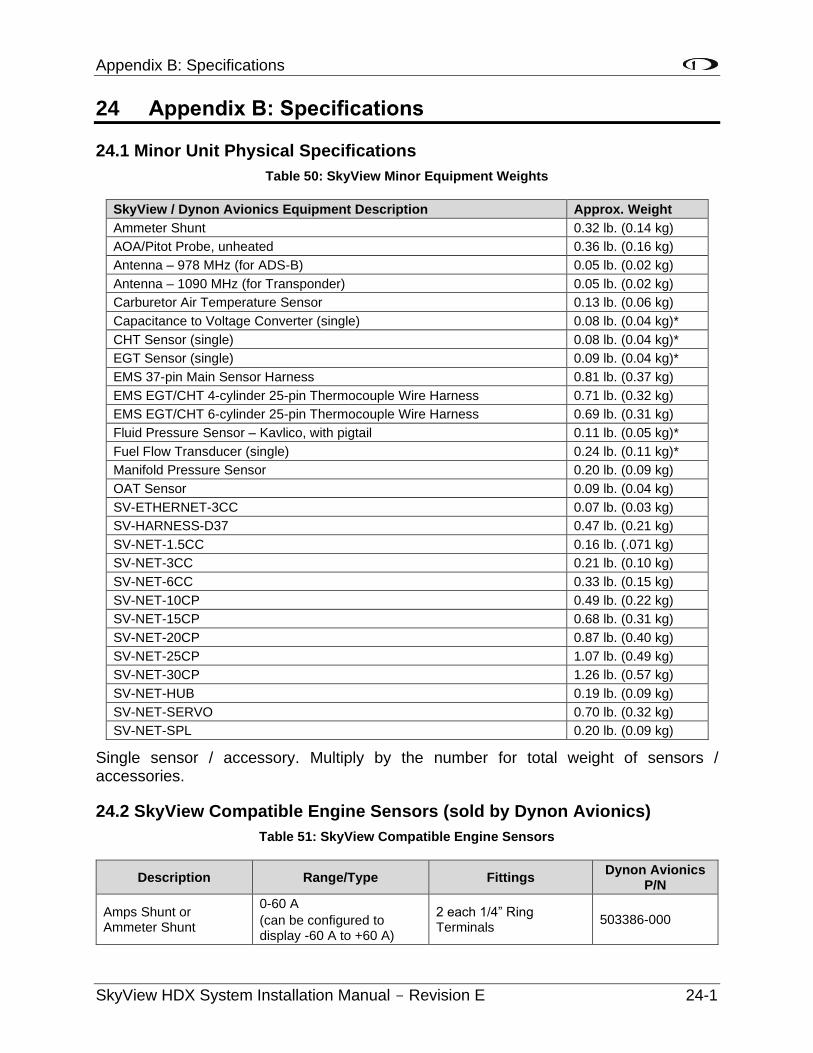
Appendix B: Specifications
SkyView HDX System Installation Manual - Revision E 24-1
24 Appendix B: Specifications
24.1 Minor Unit Physical Specifications
Table 50: SkyView Minor Equipment Weights
SkyView / Dynon Avionics Equipment Description Approx. Weight
Ammeter Shunt 0.32 lb. (0.14 kg)
AOA/Pitot Probe, unheated 0.36 lb. (0.16 kg)
Antenna – 978 MHz (for ADS-B) 0.05 lb. (0.02 kg)
Antenna – 1090 MHz (for Transponder) 0.05 lb. (0.02 kg)
Carburetor Air Temperature Sensor 0.13 lb. (0.06 kg)
Capacitance to Voltage Converter (single) 0.08 lb. (0.04 kg)*
CHT Sensor (single) 0.08 lb. (0.04 kg)*
EGT Sensor (single) 0.09 lb. (0.04 kg)*
EMS 37-pin Main Sensor Harness 0.81 lb. (0.37 kg)
EMS EGT/CHT 4-cylinder 25-pin Thermocouple Wire Harness 0.71 lb. (0.32 kg)
EMS EGT/CHT 6-cylinder 25-pin Thermocouple Wire Harness 0.69 lb. (0.31 kg)
Fluid Pressure Sensor – Kavlico, with pigtail 0.11 lb. (0.05 kg)*
Fuel Flow Transducer (single) 0.24 lb. (0.11 kg)*
Manifold Pressure Sensor 0.20 lb. (0.09 kg)
OAT Sensor 0.09 lb. (0.04 kg)
SV-ETHERNET-3CC 0.07 lb. (0.03 kg)
SV-HARNESS-D37 0.47 lb. (0.21 kg)
SV-NET-1.5CC 0.16 lb. (.071 kg)
SV-NET-3CC 0.21 lb. (0.10 kg)
SV-NET-6CC 0.33 lb. (0.15 kg)
SV-NET-10CP 0.49 lb. (0.22 kg)
SV-NET-15CP 0.68 lb. (0.31 kg)
SV-NET-20CP 0.87 lb. (0.40 kg)
SV-NET-25CP 1.07 lb. (0.49 kg)
SV-NET-30CP 1.26 lb. (0.57 kg)
SV-NET-HUB 0.19 lb. (0.09 kg)
SV-NET-SERVO 0.70 lb. (0.32 kg)
SV-NET-SPL 0.20 lb. (0.09 kg)
Single sensor / accessory. Multiply by the number for total weight of sensors / accessories.
24.2 SkyView Compatible Engine Sensors (sold by Dynon Avionics)
Table 51: SkyView Compatible Engine Sensors
Description Range/Type Fittings Dynon Avionics
P/N
Amps Shunt or Ammeter Shunt
0-60 A
(can be configured to display -60 A to +60 A)
2 each 1/4” Ring Terminals
503386-000
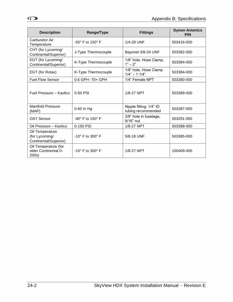
Appendix B: Specifications
24-2 SkyView HDX System Installation Manual - Revision E
Description Range/Type Fittings Dynon Avionics
P/N
Carburetor Air Temperature
-50° F to 150° F 1/4-28 UNF 503416-000
CHT (for Lycoming/
Continental/Superior) J-Type Thermocouple Bayonet 3/8-24 UNF 503382-000
EGT (for Lycoming/
Continental/Superior) K-Type Thermocouple
1/8” hole, Hose Clamp, 1” – 2”
503384-000
EGT (for Rotax) K-Type Thermocouple 1/8” hole, Hose Clamp 1/4” – 1 1/4”
503384-000
Fuel Flow Sensor 0.6 GPH -70+ GPH 1/4” Female NPT 503380-000
Fuel Pressure – Kavlico 0-50 PSI 1/8-27 NPT 503389-000
Manifold Pressure
(MAP) 0-60 In Hg
Nipple fitting: 1/4” ID tubing recommended
503387-000
OAT Sensor -40° F to 150° F 3/8” hole in fuselage, 9/16” nut
503291-000
Oil Pressure – Kavlico 0-150 PSI 1/8-27 NPT 503388-000
Oil Temperature
(for Lycoming/
Continental/Superior)
-10° F to 300° F 5/8-18 UNF 503385-000
Oil Temperature (for older Continental 0-200s)
-10° F to 300° F 1/8-27 NPT 100409-000
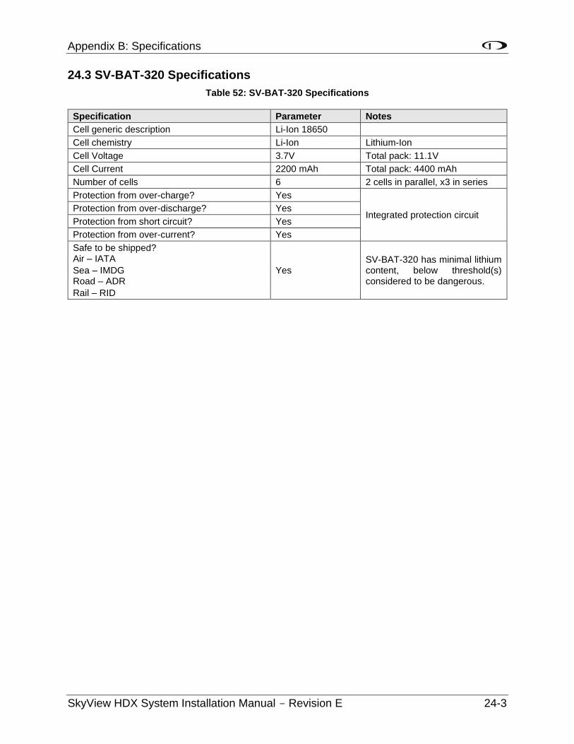
Appendix B: Specifications
SkyView HDX System Installation Manual - Revision E 24-3
24.3 SV-BAT-320 Specifications
Table 52: SV-BAT-320 Specifications
Specification Parameter Notes
Cell generic description Li-Ion 18650
Cell chemistry Li-Ion Lithium-Ion
Cell Voltage 3.7V Total pack: 11.1V
Cell Current 2200 mAh Total pack: 4400 mAh
Number of cells 6 2 cells in parallel, x3 in series
Protection from over-charge? Yes
Integrated protection circuit Protection from over-discharge? Yes
Protection from short circuit? Yes
Protection from over-current? Yes
Safe to be shipped? Air – IATA
Sea – IMDG Road – ADR
Rail – RID
Yes SV-BAT-320 has minimal lithium content, below threshold(s) considered to be dangerous.
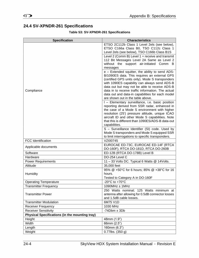
Appendix B: Specifications
24-4 SkyView HDX System Installation Manual - Revision E
24.4 SV-XPNDR-261 Specifications
Table 53: SV-XPNDR-261 Specifications
Specification Characteristics
Compliance
ETSO 2C112b Class 1 Level 2els (see below), ETSO C166a Class B0, TSO C112c Class 1 Level 2els (see below), TSO C166b Class B1S
Level 2 (Comm B) Level 1 + receive and transmit 112 Bit Messages Level 2A Same as Level 2 without the support air-initiated Comm B messages
e – Extended squitter, the ability to send ADS-B/1090ES data. This requires an external GPS (certified GPS units only). Mode S transponders with 1090ES capability can always send ADS-B data out but may not be able to receive ADS-B data in to receive traffic information. The actual data out and data-in capabilities for each model are shown out in the table above.
l – Elementary surveillance, i.e. basic position reporting derived from SSR radar, enhanced in the case of a Mode S environment with higher resolution (25') pressure altitude, unique ICAO aircraft ID and other Mode S capabilities. Note that this is different than 1090ES/ADS-B data-out capabilities.
S – Surveillance Identifier (SI) code. Used by Mode S transponders and Mode S equipped SSR to limit interrogations to specific transponders.
FCC Identification VZI00745
Applicable documents EUROCAE ED-73C, EUROCAE ED-14F (RTCA DO-160F), RTCA DO-181D, RTCA DO-260B
Software ED-12B (RTCA DO-178B) Level B
Hardware DO-254 Level C
Power Requirements 11 – 33 Volts DC. Typical 6 Watts @ 14Volts.
Altitude 35,000 feet
Humidity
95% @ +50°C for 6 hours; 85% @ +38°C for 16 hours.
Tested to Category A in DO-160F
Operating Temperature -20°C to +70°C
Transmitter Frequency 1090MHz ± 1MHz
Transmitter Power 250 Watts nominal; 125 Watts minimum at antenna after allowing for 0.5dB connector losses and 1.5dB cable losses.
Transmitter Modulation 6M75 V1D
Receiver Frequency 1030 MHz
Receiver Sensitivity -74Dbm ± 3Db
Physical Specifications (in the mounting tray)
Height 48mm (1.9”)
Width 66mm (2.5”)
Length 160mm (6.3”)
Weight 0.77lbs. (350 g)
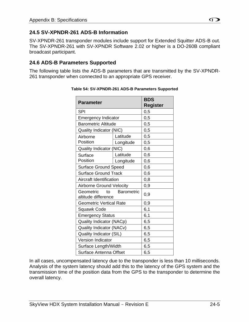
Appendix B: Specifications
SkyView HDX System Installation Manual - Revision E 24-5
24.5 SV-XPNDR-261 ADS-B Information
SV-XPNDR-261 transponder modules include support for Extended Squitter ADS-B out. The SV-XPNDR-261 with SV-XPNDR Software 2.02 or higher is a DO-260B compliant broadcast participant.
24.6 ADS-B Parameters Supported
The following table lists the ADS-B parameters that are transmitted by the SV-XPNDR-261 transponder when connected to an appropriate GPS receiver.
Table 54: SV-XPNDR-261 ADS-B Parameters Supported
Parameter BDS Register
SPI 0,5
Emergency Indicator 0,5
Barometric Altitude 0,5
Quality Indicator (NIC) 0,5
Airborne Position
Latitude 0,5
Longitude 0,5
Quality Indicator (NIC) 0,6
Surface Position
Latitude 0,6
Longitude 0,6
Surface Ground Speed 0,6
Surface Ground Track 0,6
Aircraft Identification 0,8
Airborne Ground Velocity 0,9
Geometric to Barometric altitude difference
0,9
Geometric Vertical Rate 0,9
Squawk Code 6,1
Emergency Status 6,1
Quality Indicator (NACp) 6,5
Quality Indicator (NACv) 6,5
Quality Indicator (SIL) 6,5
Version Indicator 6,5
Surface Length/Width 6,5
Surface Antenna Offset 6,5
In all cases, uncompensated latency due to the transponder is less than 10 milliseconds. Analysis of the system latency should add this to the latency of the GPS system and the transmission time of the position data from the GPS to the transponder to determine the overall latency.
Appendix B: Specifications
24-6 SkyView HDX System Installation Manual - Revision E
24.6.1 14 CFR § 91.227 Compliance
The Dynon Avionics SV-XPNDR-261 transponder can be connected to the following GPS units to form the basis of a 14 CFR § 91.227 compliant ADS-B Out installation:
• Dynon Avionics SV-GPS-2020 (connected to SkyView display).
• Avidyne IFD440/IFD540 (connected directly).
• FreeFlight 1201/1204 (connected directly).
• Garmin GNS 400W/500W series (connected directly).
• Trig Avionics TN70 (connected directly).
For installations seeking certification to 14 CFR § 91.227 or other applicable standards, additional compliance information may be available on request from Dynon Avionics or Trig Avionics Limited.
24.6.2 AMC 20-24 Compliance
The Dynon Avionics SV-XPNDR-261 or Dynon Avionics SV-XPNDR-262 transponder can be connected to the following GPS units to form the basis of an AMC20-24 compliant ADS-B installation:
• Avidyne IFD440/IFD540 (connected directly).
• FreeFlight 1201/1204 (connected directly).
• Garmin GNS 400W/500W series (connected directly).
• Trig Avionics TN70 (connected directly).
For installations seeking certification to AMC 20-24 or other applicable standards, additional compliance information is available on request from Trig Avionics Limited.
24.6.3 Automatic Air/Ground Determination
The SV-XPNDR-261 can report ADS-B surface and airborne messages. This can be accomplished via a squat switch input that is designed to be used with an automatic air/ground switching device, or via automatic detection. These options are fully explained in section SV-XPNDR-261 Transponder Installation and Configuration of this manual.
24.7 SV-COM-X83 Specifications
Table 55: SV-COM-X83 Specifications
Specification Characteristics
Compliance
ETSO 2C169a Class C, E, H1, H2, 4, 6
ETSO 2C128
TSO C169a Class C, E, 4, 6, TSO C128a
FCC Identification VZI00882
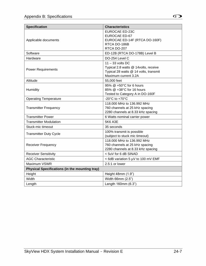
Appendix B: Specifications
SkyView HDX System Installation Manual - Revision E 24-7
Specification Characteristics
Applicable documents
EUROCAE ED-23C
EUROCAE ED-67
EUROCAE ED-14F (RTCA DO-160F)
RTCA DO-186B
RTCA DO-207
Software ED-12B (RTCA DO-178B) Level B
Hardware DO-254 Level C
Power Requirements
11 – 33 volts DC
Typical 2.8 watts @ 14volts, receive
Typical 28 watts @ 14 volts, transmit
Maximum current 3.2A
Altitude 55,000 feet
Humidity
95% @ +50°C for 6 hours
85% @ +38°C for 16 hours
Tested to Category A in DO-160F
Operating Temperature -20°C to +70°C
Transmitter Frequency
118.000 MHz to 136.992 MHz
760 channels at 25 kHz spacing
2280 channels at 8.33 kHz spacing
Transmitter Power 6 Watts nominal carrier power
Transmitter Modulation 5K6 A3E
Stuck-mic timeout 35 seconds
Transmitter Duty Cycle 100% transmit is possible
(subject to stuck mic timeout)
Receiver Frequency
118.000 MHz to 136.992 MHz
760 channels at 25 kHz spacing
2280 channels at 8.33 kHz spacing
Receiver Sensitivity < 5uV for 6 dB SINAD
AGC Characteristic < 6dB variation 5 µV to 100 mV EMF
Maximum VSWR 2.5:1 or lower
Physical Specifications (in the mounting tray)
Height Height 48mm (1.9”)
Width Width 66mm (2.5”)
Length Length 160mm (6.3”)
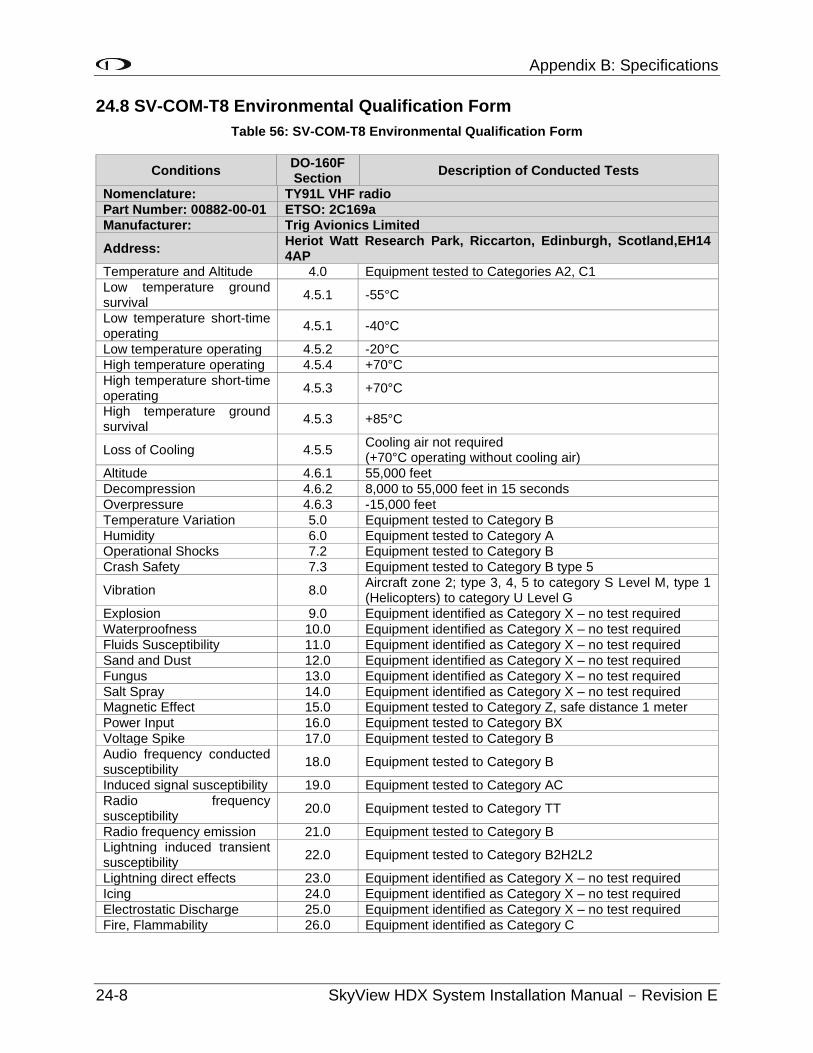
Appendix B: Specifications
24-8 SkyView HDX System Installation Manual - Revision E
24.8 SV-COM-T8 Environmental Qualification Form
Table 56: SV-COM-T8 Environmental Qualification Form
Conditions DO-160F Section
Description of Conducted Tests
Nomenclature: TY91L VHF radio
Part Number: 00882-00-01 ETSO: 2C169a
Manufacturer: Trig Avionics Limited
Address: Heriot Watt Research Park, Riccarton, Edinburgh, Scotland,EH14 4AP
Temperature and Altitude 4.0 Equipment tested to Categories A2, C1
Low temperature ground survival
4.5.1 -55°C
Low temperature short-time operating
4.5.1 -40°C
Low temperature operating 4.5.2 -20°C
High temperature operating 4.5.4 +70°C
High temperature short-time operating
4.5.3 +70°C
High temperature ground survival
4.5.3 +85°C
Loss of Cooling 4.5.5 Cooling air not required (+70°C operating without cooling air)
Altitude 4.6.1 55,000 feet
Decompression 4.6.2 8,000 to 55,000 feet in 15 seconds
Overpressure 4.6.3 -15,000 feet
Temperature Variation 5.0 Equipment tested to Category B
Humidity 6.0 Equipment tested to Category A Operational Shocks 7.2 Equipment tested to Category B
Crash Safety 7.3 Equipment tested to Category B type 5
Vibration 8.0 Aircraft zone 2; type 3, 4, 5 to category S Level M, type 1 (Helicopters) to category U Level G
Explosion 9.0 Equipment identified as Category X – no test required
Waterproofness 10.0 Equipment identified as Category X – no test required
Fluids Susceptibility 11.0 Equipment identified as Category X – no test required
Sand and Dust 12.0 Equipment identified as Category X – no test required
Fungus 13.0 Equipment identified as Category X – no test required
Salt Spray 14.0 Equipment identified as Category X – no test required Magnetic Effect 15.0 Equipment tested to Category Z, safe distance 1 meter
Power Input 16.0 Equipment tested to Category BX
Voltage Spike 17.0 Equipment tested to Category B
Audio frequency conducted susceptibility
18.0 Equipment tested to Category B
Induced signal susceptibility 19.0 Equipment tested to Category AC
Radio frequency susceptibility
20.0 Equipment tested to Category TT
Radio frequency emission 21.0 Equipment tested to Category B Lightning induced transient susceptibility
22.0 Equipment tested to Category B2H2L2
Lightning direct effects 23.0 Equipment identified as Category X – no test required
Icing 24.0 Equipment identified as Category X – no test required
Electrostatic Discharge 25.0 Equipment identified as Category X – no test required
Fire, Flammability 26.0 Equipment identified as Category C
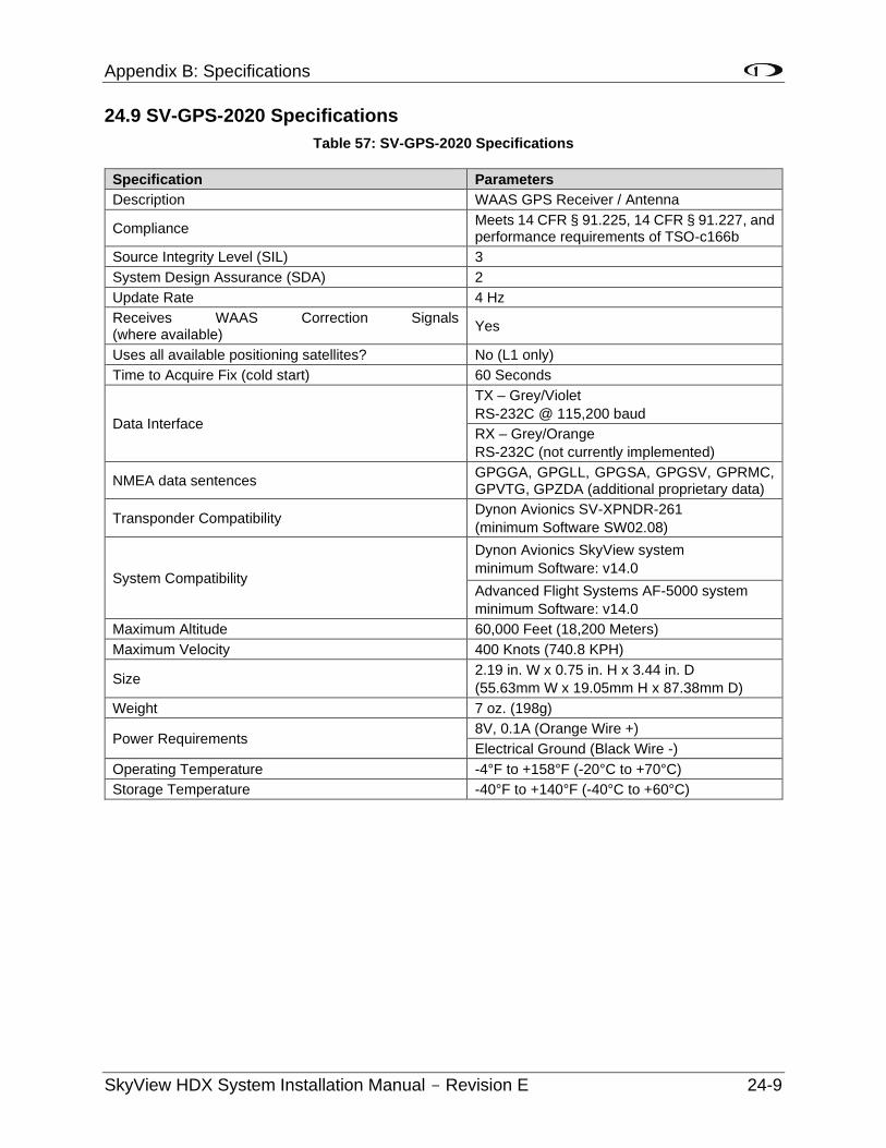
Appendix B: Specifications
SkyView HDX System Installation Manual - Revision E 24-9
24.9 SV-GPS-2020 Specifications
Table 57: SV-GPS-2020 Specifications
Specification Parameters
Description WAAS GPS Receiver / Antenna
Compliance Meets 14 CFR § 91.225, 14 CFR § 91.227, and performance requirements of TSO-c166b
Source Integrity Level (SIL) 3
System Design Assurance (SDA) 2
Update Rate 4 Hz
Receives WAAS Correction Signals (where available)
Yes
Uses all available positioning satellites? No (L1 only)
Time to Acquire Fix (cold start) 60 Seconds
Data Interface
TX – Grey/Violet
RS-232C @ 115,200 baud
RX – Grey/Orange
RS-232C (not currently implemented)
NMEA data sentences GPGGA, GPGLL, GPGSA, GPGSV, GPRMC, GPVTG, GPZDA (additional proprietary data)
Transponder Compatibility Dynon Avionics SV-XPNDR-261
(minimum Software SW02.08)
System Compatibility
Dynon Avionics SkyView system
minimum Software: v14.0
Advanced Flight Systems AF-5000 system
minimum Software: v14.0
Maximum Altitude 60,000 Feet (18,200 Meters)
Maximum Velocity 400 Knots (740.8 KPH)
Size 2.19 in. W x 0.75 in. H x 3.44 in. D
(55.63mm W x 19.05mm H x 87.38mm D)
Weight 7 oz. (198g)
Power Requirements 8V, 0.1A (Orange Wire +)
Electrical Ground (Black Wire -)
Operating Temperature -4°F to +158°F (-20°C to +70°C)
Storage Temperature -40°F to +140°F (-40°C to +60°C)

Appendix C: Wiring and Electrical Connections
SkyView HDX System Installation Manual - Revision E 25-1
25 Appendix C: Wiring and Electrical Connections
SkyView utilizes standardized network connectors and wire harnesses for equipment-to-equipment connections as well as other connections. Installers should rarely have to build custom wire harnesses. This appendix is included as a reference for those rare times when custom wiring is required.
Improper wiring can result in permanent damage to your instrument and/or the accompanying sensors.
Make all connections to your harness before plugging it into any of the components of the system. Do not make connections while power is applied at any point in the system.
25.1 Wire Gauge
Unless otherwise specified, 22 AWG wire is normally sufficient for the power supply and ground lines, but we recommend that you consult a wire sizing chart to determine the size required for the wire routing in your particular aircraft. Ensure that the power lines include a circuit breaker or an appropriately sized fuse for the wire you select.
Smaller gauge wire is sufficient for lines that only carry data.
FAA Advisory Circular AC 43.13-1B is an excellent resource for wire sizing requirements as well as other acceptable methods, techniques, and practices in aircraft inspection and repair.
25.2 Grounding
Many of the engine sensors require a connection to a ground on the SV-EMS-220. There are many places on an aircraft where you could connect these sensors. However, the ideal location to ground these sensors is to one (1) of the SV-EMS-220 ground pins. Connecting the sensor’s ground pin directly to the SV-EMS-220 minimizes any voltage difference between sensor ground and SV-EMS-220 ground.
You can measure the voltage difference between grounds to check if the connection has a minimal voltage drop. Set a multimeter to the DC voltages setting and place one (1) sensor tip on one (1) ground and place the other sensor tip on the other. Measurements close to 0 mV (within 5 mV) are, in most cases, acceptable.
Other grounding recommendations include:
• Ensure that solid, thick electrical connections exist between engine and battery ground.
• Do not paint over surfaces that are ground connection points.
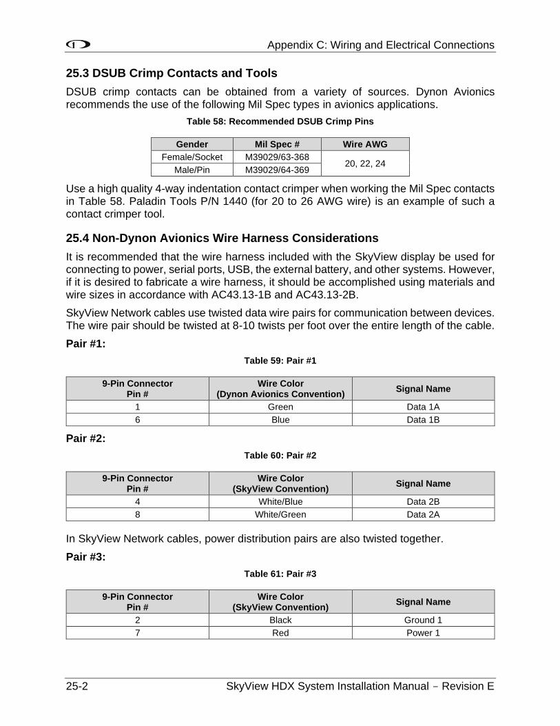
Appendix C: Wiring and Electrical Connections
25-2 SkyView HDX System Installation Manual - Revision E
25.3 DSUB Crimp Contacts and Tools
DSUB crimp contacts can be obtained from a variety of sources. Dynon Avionics recommends the use of the following Mil Spec types in avionics applications.
Table 58: Recommended DSUB Crimp Pins
Gender Mil Spec # Wire AWG
Female/Socket M39029/63-368 20, 22, 24
Male/Pin M39029/64-369
Use a high quality 4-way indentation contact crimper when working the Mil Spec contacts in Table 58. Paladin Tools P/N 1440 (for 20 to 26 AWG wire) is an example of such a contact crimper tool.
25.4 Non-Dynon Avionics Wire Harness Considerations
It is recommended that the wire harness included with the SkyView display be used for connecting to power, serial ports, USB, the external battery, and other systems. However, if it is desired to fabricate a wire harness, it should be accomplished using materials and wire sizes in accordance with AC43.13-1B and AC43.13-2B.
SkyView Network cables use twisted data wire pairs for communication between devices. The wire pair should be twisted at 8-10 twists per foot over the entire length of the cable.
Pair #1:
Table 59: Pair #1
9-Pin Connector Pin #
Wire Color (Dynon Avionics Convention)
Signal Name
1 Green Data 1A
6 Blue Data 1B
Pair #2:
Table 60: Pair #2
9-Pin Connector Pin #
Wire Color (SkyView Convention)
Signal Name
4 White/Blue Data 2B
8 White/Green Data 2A
In SkyView Network cables, power distribution pairs are also twisted together.
Pair #3:
Table 61: Pair #3
9-Pin Connector Pin #
Wire Color (SkyView Convention)
Signal Name
2 Black Ground 1
7 Red Power 1
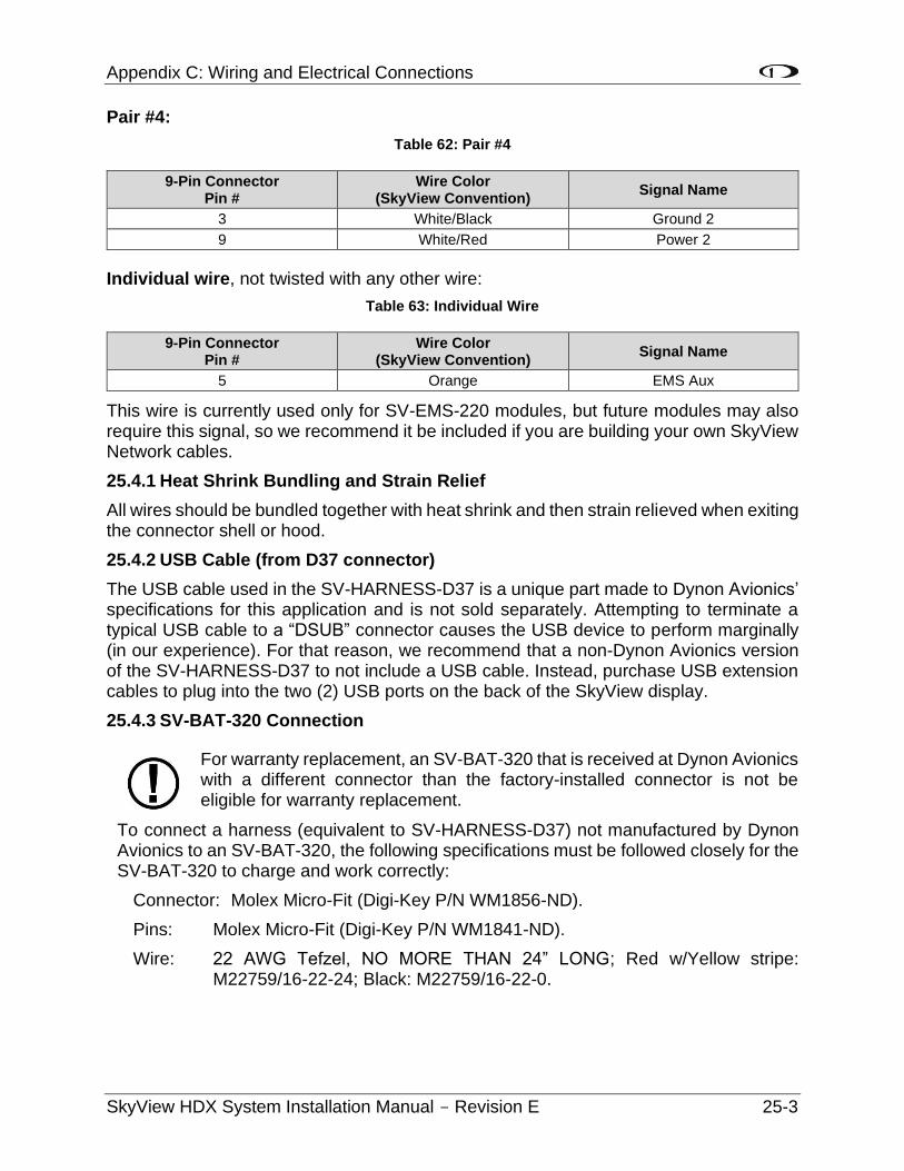
Appendix C: Wiring and Electrical Connections
SkyView HDX System Installation Manual - Revision E 25-3
Pair #4:
Table 62: Pair #4
9-Pin Connector Pin #
Wire Color (SkyView Convention)
Signal Name
3 White/Black Ground 2
9 White/Red Power 2
Individual wire, not twisted with any other wire:
Table 63: Individual Wire
9-Pin Connector Pin #
Wire Color (SkyView Convention)
Signal Name
5 Orange EMS Aux
This wire is currently used only for SV-EMS-220 modules, but future modules may also require this signal, so we recommend it be included if you are building your own SkyView Network cables.
25.4.1 Heat Shrink Bundling and Strain Relief
All wires should be bundled together with heat shrink and then strain relieved when exiting the connector shell or hood.
25.4.2 USB Cable (from D37 connector)
The USB cable used in the SV-HARNESS-D37 is a unique part made to Dynon Avionics’ specifications for this application and is not sold separately. Attempting to terminate a typical USB cable to a “DSUB” connector causes the USB device to perform marginally (in our experience). For that reason, we recommend that a non-Dynon Avionics version of the SV-HARNESS-D37 to not include a USB cable. Instead, purchase USB extension cables to plug into the two (2) USB ports on the back of the SkyView display.
25.4.3 SV-BAT-320 Connection
For warranty replacement, an SV-BAT-320 that is received at Dynon Avionics with a different connector than the factory-installed connector is not be eligible for warranty replacement.
To connect a harness (equivalent to SV-HARNESS-D37) not manufactured by Dynon Avionics to an SV-BAT-320, the following specifications must be followed closely for the SV-BAT-320 to charge and work correctly:
Connector: Molex Micro-Fit (Digi-Key P/N WM1856-ND).
Pins: Molex Micro-Fit (Digi-Key P/N WM1841-ND).
Wire: 22 AWG Tefzel, NO MORE THAN 24” LONG; Red w/Yellow stripe: M22759/16-22-24; Black: M22759/16-22-0.
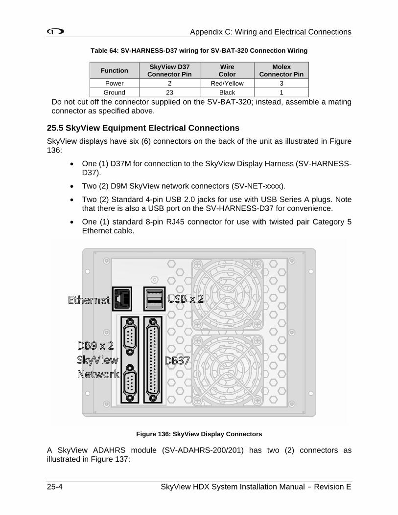
Appendix C: Wiring and Electrical Connections
25-4 SkyView HDX System Installation Manual - Revision E
Table 64: SV-HARNESS-D37 wiring for SV-BAT-320 Connection Wiring
Function SkyView D37
Connector Pin Wire Color
Molex Connector Pin
Power 2 Red/Yellow 3
Ground 23 Black 1
Do not cut off the connector supplied on the SV-BAT-320; instead, assemble a mating connector as specified above.
25.5 SkyView Equipment Electrical Connections
SkyView displays have six (6) connectors on the back of the unit as illustrated in Figure 136:
• One (1) D37M for connection to the SkyView Display Harness (SV-HARNESS-D37).
• Two (2) D9M SkyView network connectors (SV-NET-xxxx).
• Two (2) Standard 4-pin USB 2.0 jacks for use with USB Series A plugs. Note that there is also a USB port on the SV-HARNESS-D37 for convenience.
• One (1) standard 8-pin RJ45 connector for use with twisted pair Category 5 Ethernet cable.
Figure 136: SkyView Display Connectors
A SkyView ADAHRS module (SV-ADAHRS-200/201) has two (2) connectors as illustrated in Figure 137:
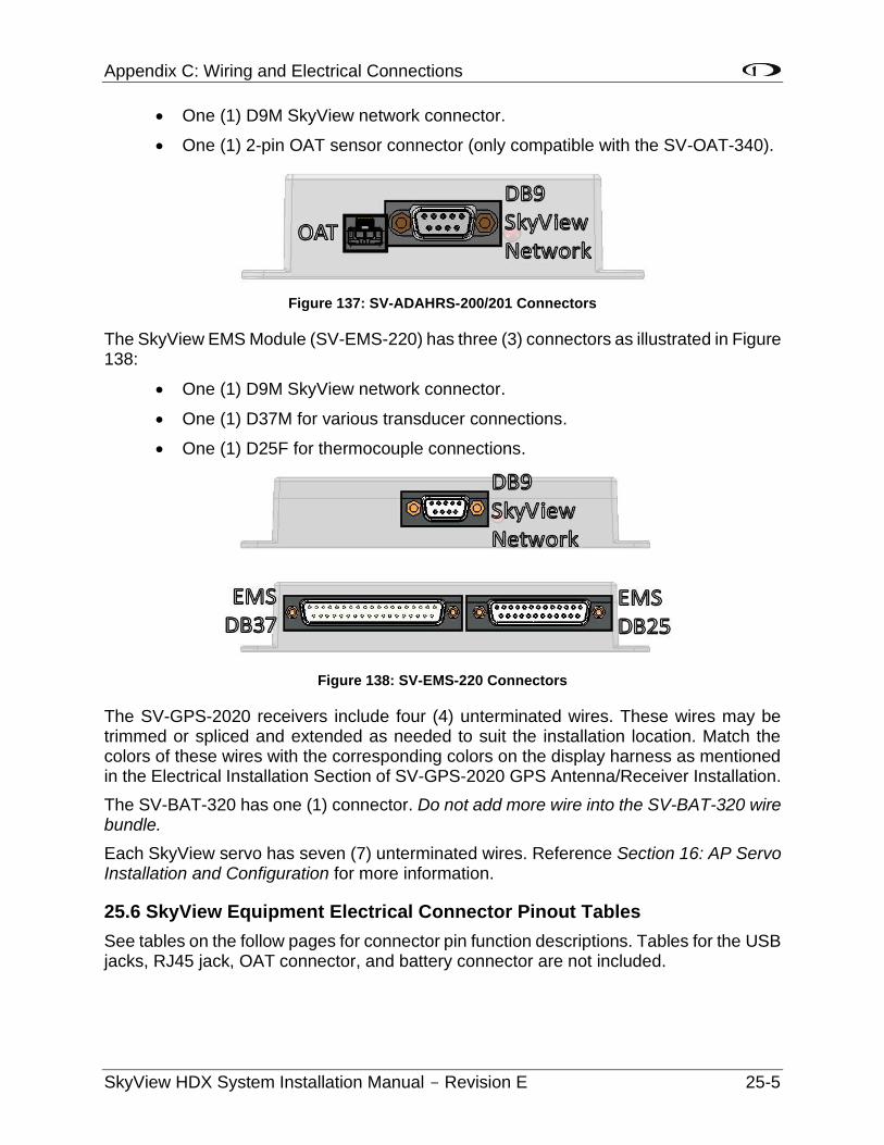
Appendix C: Wiring and Electrical Connections
SkyView HDX System Installation Manual - Revision E 25-5
• One (1) D9M SkyView network connector.
• One (1) 2-pin OAT sensor connector (only compatible with the SV-OAT-340).
Figure 137: SV-ADAHRS-200/201 Connectors
The SkyView EMS Module (SV-EMS-220) has three (3) connectors as illustrated in Figure 138:
• One (1) D9M SkyView network connector.
• One (1) D37M for various transducer connections.
• One (1) D25F for thermocouple connections.
Figure 138: SV-EMS-220 Connectors
The SV-GPS-2020 receivers include four (4) unterminated wires. These wires may be trimmed or spliced and extended as needed to suit the installation location. Match the colors of these wires with the corresponding colors on the display harness as mentioned in the Electrical Installation Section of SV-GPS-2020 GPS Antenna/Receiver Installation.
The SV-BAT-320 has one (1) connector. Do not add more wire into the SV-BAT-320 wire bundle.
Each SkyView servo has seven (7) unterminated wires. Reference Section 16: AP Servo Installation and Configuration for more information.
25.6 SkyView Equipment Electrical Connector Pinout Tables
See tables on the follow pages for connector pin function descriptions. Tables for the USB jacks, RJ45 jack, OAT connector, and battery connector are not included.
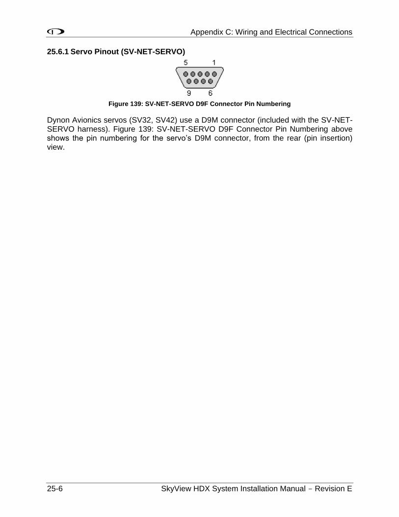
Appendix C: Wiring and Electrical Connections
25-6 SkyView HDX System Installation Manual - Revision E
25.6.1 Servo Pinout (SV-NET-SERVO)
Figure 139: SV-NET-SERVO D9F Connector Pin Numbering
Dynon Avionics servos (SV32, SV42) use a D9M connector (included with the SV-NET-SERVO harness). Figure 139: SV-NET-SERVO D9F Connector Pin Numbering above shows the pin numbering for the servo’s D9M connector, from the rear (pin insertion) view.
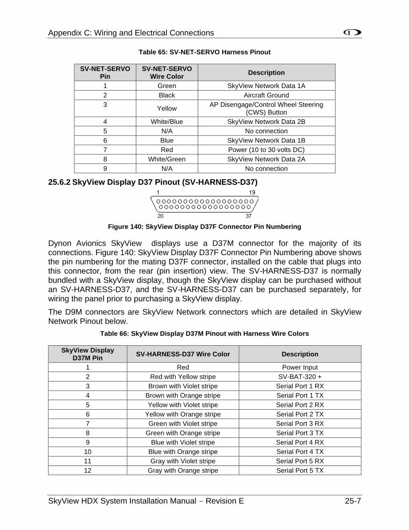
Appendix C: Wiring and Electrical Connections
SkyView HDX System Installation Manual - Revision E 25-7
Table 65: SV-NET-SERVO Harness Pinout
SV-NET-SERVO Pin
SV-NET-SERVO Wire Color
Description
1 Green SkyView Network Data 1A
2 Black Aircraft Ground
3 Yellow
AP Disengage/Control Wheel Steering (CWS) Button
4 White/Blue SkyView Network Data 2B
5 N/A No connection
6 Blue SkyView Network Data 1B
7 Red Power (10 to 30 volts DC)
8 White/Green SkyView Network Data 2A
9 N/A No connection
25.6.2 SkyView Display D37 Pinout (SV-HARNESS-D37)
Figure 140: SkyView Display D37F Connector Pin Numbering
Dynon Avionics SkyView displays use a D37M connector for the majority of its connections. Figure 140: SkyView Display D37F Connector Pin Numbering above shows the pin numbering for the mating D37F connector, installed on the cable that plugs into this connector, from the rear (pin insertion) view. The SV-HARNESS-D37 is normally bundled with a SkyView display, though the SkyView display can be purchased without an SV-HARNESS-D37, and the SV-HARNESS-D37 can be purchased separately, for wiring the panel prior to purchasing a SkyView display.
The D9M connectors are SkyView Network connectors which are detailed in SkyView Network Pinout below.
Table 66: SkyView Display D37M Pinout with Harness Wire Colors
SkyView Display D37M Pin
SV-HARNESS-D37 Wire Color Description
1 Red Power Input
2 Red with Yellow stripe SV-BAT-320 +
3 Brown with Violet stripe Serial Port 1 RX
4 Brown with Orange stripe Serial Port 1 TX
5 Yellow with Violet stripe Serial Port 2 RX
6 Yellow with Orange stripe Serial Port 2 TX
7 Green with Violet stripe Serial Port 3 RX
8 Green with Orange stripe Serial Port 3 TX
9 Blue with Violet stripe Serial Port 4 RX
10 Blue with Orange stripe Serial Port 4 TX
11 Gray with Violet stripe Serial Port 5 RX
12 Gray with Orange stripe Serial Port 5 TX
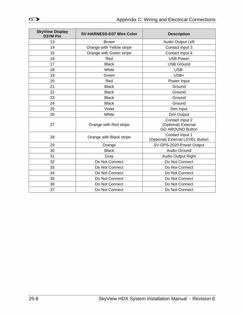
Appendix C: Wiring and Electrical Connections
25-8 SkyView HDX System Installation Manual - Revision E
SkyView Display D37M Pin
SV-HARNESS-D37 Wire Color Description
13 Brown Audio Output Left
14 Orange with Yellow stripe Contact Input 3
15 Orange with Green stripe Contact Input 4
16 Red USB Power
17 Black USB Ground
18 White USB-
19 Green USB+
20 Red Power Input
21 Black Ground
22 Black Ground
23 Black Ground
24 Black Ground
25 Violet Dim Input
26 White Dim Output
27 Orange with Red stripe Contact Input 2
(Optional) External GO AROUND Button
28 Orange with Black stripe Contact Input 1
(Optional) External LEVEL Button
29 Orange SV-GPS-2020 Power Output
30 Black Audio Ground
31 Gray Audio Output Right
32 Do Not Connect Do Not Connect
33 Do Not Connect Do Not Connect
34 Do Not Connect Do Not Connect
35 Do Not Connect Do Not Connect
36 Do Not Connect Do Not Connect
37 Do Not Connect Do Not Connect
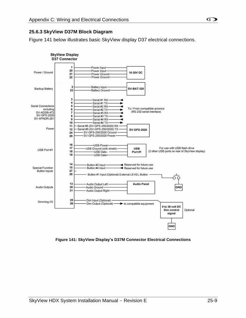
Appendix C: Wiring and Electrical Connections
SkyView HDX System Installation Manual - Revision E 25-9
25.6.3 SkyView D37M Block Diagram
Figure 141 below illustrates basic SkyView display D37 electrical connections.
Figure 141: SkyView Display’s D37M Connector Electrical Connections
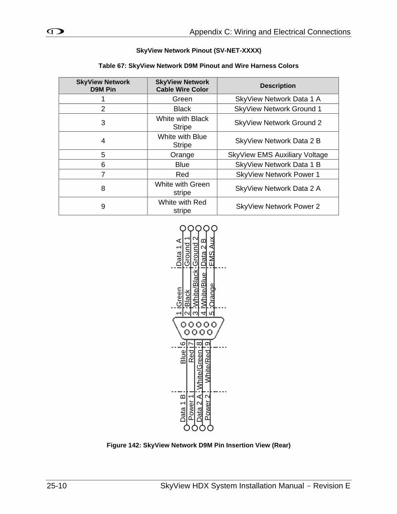
Appendix C: Wiring and Electrical Connections
25-10 SkyView HDX System Installation Manual - Revision E
SkyView Network Pinout (SV-NET-XXXX)
Table 67: SkyView Network D9M Pinout and Wire Harness Colors
SkyView Network D9M Pin
SkyView Network Cable Wire Color
Description
1 Green SkyView Network Data 1 A
2 Black SkyView Network Ground 1
3 White with Black
Stripe SkyView Network Ground 2
4 White with Blue
Stripe SkyView Network Data 2 B
5 Orange SkyView EMS Auxiliary Voltage
6 Blue SkyView Network Data 1 B
7 Red SkyView Network Power 1
8 White with Green
stripe SkyView Network Data 2 A
9 White with Red
stripe SkyView Network Power 2
Figure 142: SkyView Network D9M Pin Insertion View (Rear)
1 2 3 4 5
6 7 8 9
Blu
e
Re
d
Wh
ite
/Gre
en
Wh
ite
/Re
d
Gre
en
Bla
ck
Wh
ite
/Bla
ck
Wh
ite
/Blu
e
Ora
ng
e
Da
ta 1
A
Gro
un
d 1
Gro
un
d 2
Da
ta 2
B
EM
S A
ux
Da
ta 1
B
Po
we
r 1
Da
ta 2
A
Po
we
r 2
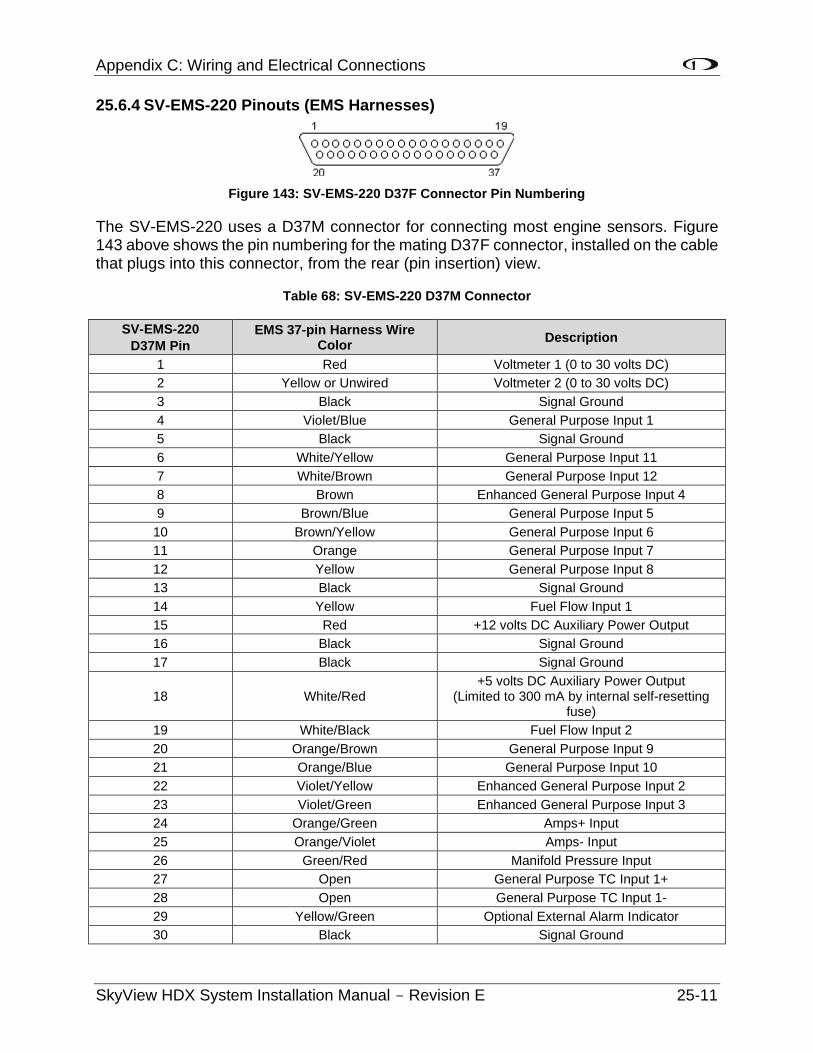
Appendix C: Wiring and Electrical Connections
SkyView HDX System Installation Manual - Revision E 25-11
25.6.4 SV-EMS-220 Pinouts (EMS Harnesses)
Figure 143: SV-EMS-220 D37F Connector Pin Numbering
The SV-EMS-220 uses a D37M connector for connecting most engine sensors. Figure 143 above shows the pin numbering for the mating D37F connector, installed on the cable that plugs into this connector, from the rear (pin insertion) view.
Table 68: SV-EMS-220 D37M Connector
SV-EMS-220
D37M Pin
EMS 37-pin Harness Wire Color
Description
1 Red Voltmeter 1 (0 to 30 volts DC)
2 Yellow or Unwired Voltmeter 2 (0 to 30 volts DC)
3 Black Signal Ground
4 Violet/Blue General Purpose Input 1
5 Black Signal Ground
6 White/Yellow General Purpose Input 11
7 White/Brown General Purpose Input 12
8 Brown Enhanced General Purpose Input 4
9 Brown/Blue General Purpose Input 5
10 Brown/Yellow General Purpose Input 6
11 Orange General Purpose Input 7
12 Yellow General Purpose Input 8
13 Black Signal Ground
14 Yellow Fuel Flow Input 1
15 Red +12 volts DC Auxiliary Power Output
16 Black Signal Ground
17 Black Signal Ground
18 White/Red +5 volts DC Auxiliary Power Output
(Limited to 300 mA by internal self-resetting fuse)
19 White/Black Fuel Flow Input 2
20 Orange/Brown General Purpose Input 9
21 Orange/Blue General Purpose Input 10
22 Violet/Yellow Enhanced General Purpose Input 2
23 Violet/Green Enhanced General Purpose Input 3
24 Orange/Green Amps+ Input
25 Orange/Violet Amps- Input
26 Green/Red Manifold Pressure Input
27 Open General Purpose TC Input 1+
28 Open General Purpose TC Input 1-
29 Yellow/Green Optional External Alarm Indicator
30 Black Signal Ground
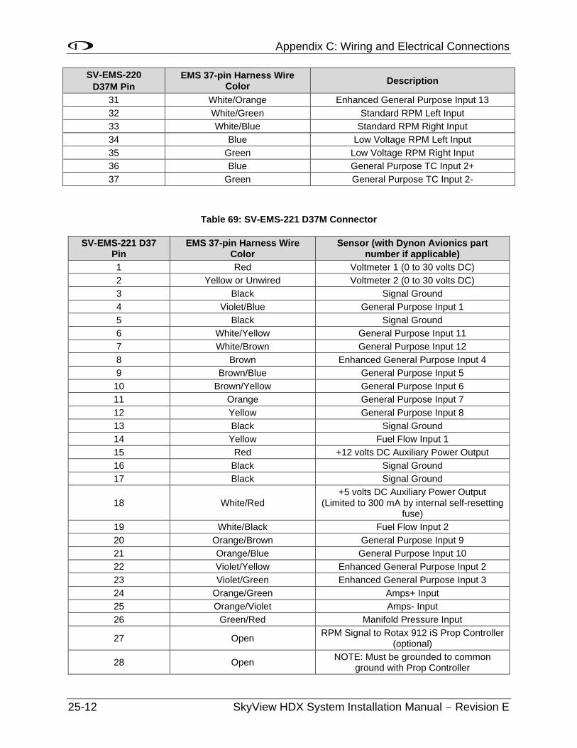
Appendix C: Wiring and Electrical Connections
25-12 SkyView HDX System Installation Manual - Revision E
SV-EMS-220
D37M Pin
EMS 37-pin Harness Wire Color
Description
31 White/Orange Enhanced General Purpose Input 13
32 White/Green Standard RPM Left Input
33 White/Blue Standard RPM Right Input
34 Blue Low Voltage RPM Left Input
35 Green Low Voltage RPM Right Input
36 Blue General Purpose TC Input 2+
37 Green General Purpose TC Input 2-
Table 69: SV-EMS-221 D37M Connector
SV-EMS-221 D37 Pin
EMS 37-pin Harness Wire Color
Sensor (with Dynon Avionics part number if applicable)
1 Red Voltmeter 1 (0 to 30 volts DC)
2 Yellow or Unwired Voltmeter 2 (0 to 30 volts DC)
3 Black Signal Ground
4 Violet/Blue General Purpose Input 1
5 Black Signal Ground
6 White/Yellow General Purpose Input 11
7 White/Brown General Purpose Input 12
8 Brown Enhanced General Purpose Input 4
9 Brown/Blue General Purpose Input 5
10 Brown/Yellow General Purpose Input 6
11 Orange General Purpose Input 7
12 Yellow General Purpose Input 8
13 Black Signal Ground
14 Yellow Fuel Flow Input 1
15 Red +12 volts DC Auxiliary Power Output
16 Black Signal Ground
17 Black Signal Ground
18 White/Red +5 volts DC Auxiliary Power Output
(Limited to 300 mA by internal self-resetting fuse)
19 White/Black Fuel Flow Input 2
20 Orange/Brown General Purpose Input 9
21 Orange/Blue General Purpose Input 10
22 Violet/Yellow Enhanced General Purpose Input 2
23 Violet/Green Enhanced General Purpose Input 3
24 Orange/Green Amps+ Input
25 Orange/Violet Amps- Input
26 Green/Red Manifold Pressure Input
27 Open RPM Signal to Rotax 912 iS Prop Controller
(optional)
28 Open NOTE: Must be grounded to common
ground with Prop Controller
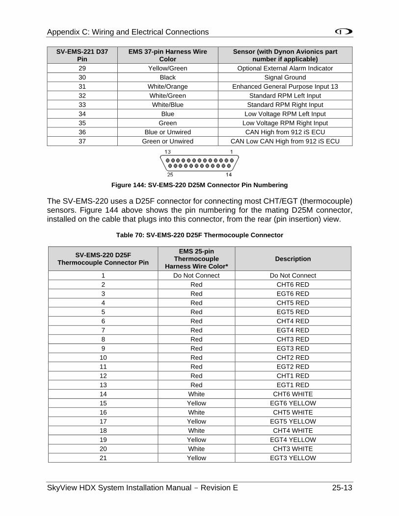
Appendix C: Wiring and Electrical Connections
SkyView HDX System Installation Manual - Revision E 25-13
SV-EMS-221 D37 Pin
EMS 37-pin Harness Wire Color
Sensor (with Dynon Avionics part number if applicable)
29 Yellow/Green Optional External Alarm Indicator
30 Black Signal Ground
31 White/Orange Enhanced General Purpose Input 13
32 White/Green Standard RPM Left Input
33 White/Blue Standard RPM Right Input
34 Blue Low Voltage RPM Left Input
35 Green Low Voltage RPM Right Input
36 Blue or Unwired CAN High from 912 iS ECU
37 Green or Unwired CAN Low CAN High from 912 iS ECU
Figure 144: SV-EMS-220 D25M Connector Pin Numbering
The SV-EMS-220 uses a D25F connector for connecting most CHT/EGT (thermocouple) sensors. Figure 144 above shows the pin numbering for the mating D25M connector, installed on the cable that plugs into this connector, from the rear (pin insertion) view.
Table 70: SV-EMS-220 D25F Thermocouple Connector
SV-EMS-220 D25F Thermocouple Connector Pin
EMS 25-pin Thermocouple
Harness Wire Color* Description
1 Do Not Connect Do Not Connect
2 Red CHT6 RED
3 Red EGT6 RED
4 Red CHT5 RED
5 Red EGT5 RED
6 Red CHT4 RED
7 Red EGT4 RED
8 Red CHT3 RED
9 Red EGT3 RED
10 Red CHT2 RED
11 Red EGT2 RED
12 Red CHT1 RED
13 Red EGT1 RED
14 White CHT6 WHITE
15 Yellow EGT6 YELLOW
16 White CHT5 WHITE
17 Yellow EGT5 YELLOW
18 White CHT4 WHITE
19 Yellow EGT4 YELLOW
20 White CHT3 WHITE
21 Yellow EGT3 YELLOW
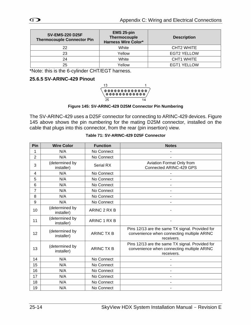
Appendix C: Wiring and Electrical Connections
25-14 SkyView HDX System Installation Manual - Revision E
SV-EMS-220 D25F Thermocouple Connector Pin
EMS 25-pin Thermocouple
Harness Wire Color* Description
22 White CHT2 WHITE
23 Yellow EGT2 YELLOW
24 White CHT1 WHITE
25 Yellow EGT1 YELLOW
*Note: this is the 6-cylinder CHT/EGT harness.
25.6.5 SV-ARINC-429 Pinout
Figure 145: SV-ARINC-429 D25M Connector Pin Numbering
The SV-ARINC-429 uses a D25F connector for connecting to ARINC-429 devices. Figure 145 above shows the pin numbering for the mating D25M connector, installed on the cable that plugs into this connector, from the rear (pin insertion) view.
Table 71: SV-ARINC-429 D25F Connector
Pin Wire Color Function Notes
1 N/A No Connect -
2 N/A No Connect -
3 (determined by
installer) Serial RX
Aviation Format Only from Connected ARINC-429 GPS
4 N/A No Connect -
5 N/A No Connect -
6 N/A No Connect -
7 N/A No Connect -
8 N/A No Connect -
9 N/A No Connect -
10 (determined by
installer) ARINC 2 RX B -
11 (determined by
installer) ARINC 1 RX B -
12 (determined by
installer) ARINC TX B
Pins 12/13 are the same TX signal. Provided for convenience when connecting multiple ARINC
receivers.
13 (determined by
installer) ARINC TX B
Pins 12/13 are the same TX signal. Provided for convenience when connecting multiple ARINC
receivers.
14 N/A No Connect -
15 N/A No Connect -
16 N/A No Connect -
17 N/A No Connect -
18 N/A No Connect -
19 N/A No Connect -
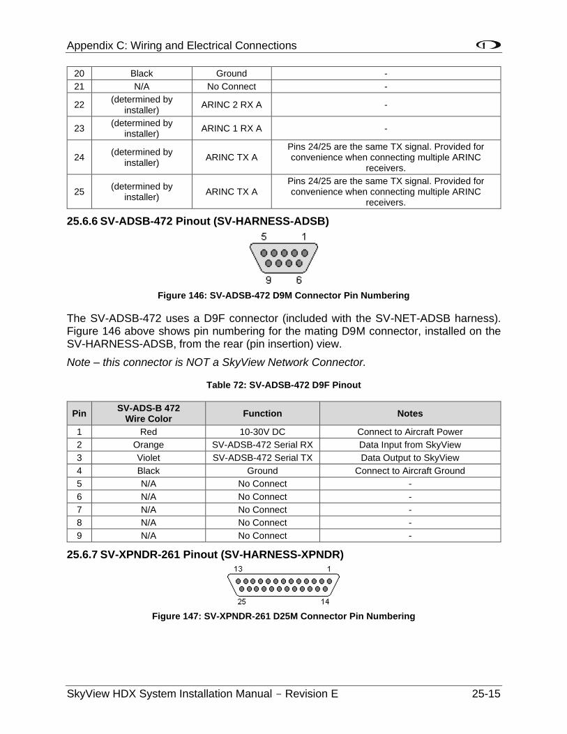
Appendix C: Wiring and Electrical Connections
SkyView HDX System Installation Manual - Revision E 25-15
20 Black Ground -
21 N/A No Connect -
22 (determined by
installer) ARINC 2 RX A -
23 (determined by
installer) ARINC 1 RX A -
24 (determined by
installer) ARINC TX A
Pins 24/25 are the same TX signal. Provided for convenience when connecting multiple ARINC
receivers.
25 (determined by
installer) ARINC TX A
Pins 24/25 are the same TX signal. Provided for convenience when connecting multiple ARINC
receivers.
25.6.6 SV-ADSB-472 Pinout (SV-HARNESS-ADSB)
Figure 146: SV-ADSB-472 D9M Connector Pin Numbering
The SV-ADSB-472 uses a D9F connector (included with the SV-NET-ADSB harness). Figure 146 above shows pin numbering for the mating D9M connector, installed on the SV-HARNESS-ADSB, from the rear (pin insertion) view.
Note – this connector is NOT a SkyView Network Connector.
Table 72: SV-ADSB-472 D9F Pinout
Pin SV-ADS-B 472
Wire Color Function Notes
1 Red 10-30V DC Connect to Aircraft Power
2 Orange SV-ADSB-472 Serial RX Data Input from SkyView
3 Violet SV-ADSB-472 Serial TX Data Output to SkyView
4 Black Ground Connect to Aircraft Ground
5 N/A No Connect -
6 N/A No Connect -
7 N/A No Connect -
8 N/A No Connect -
9 N/A No Connect -
25.6.7 SV-XPNDR-261 Pinout (SV-HARNESS-XPNDR)
Figure 147: SV-XPNDR-261 D25M Connector Pin Numbering
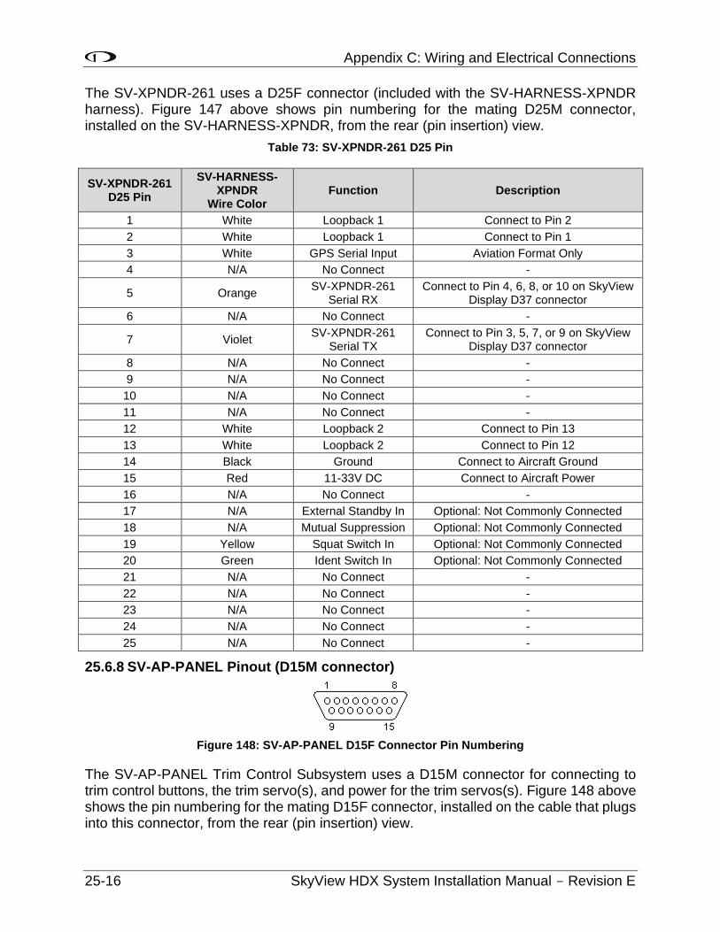
Appendix C: Wiring and Electrical Connections
25-16 SkyView HDX System Installation Manual - Revision E
The SV-XPNDR-261 uses a D25F connector (included with the SV-HARNESS-XPNDR harness). Figure 147 above shows pin numbering for the mating D25M connector, installed on the SV-HARNESS-XPNDR, from the rear (pin insertion) view.
Table 73: SV-XPNDR-261 D25 Pin
SV-XPNDR-261 D25 Pin
SV-HARNESS-XPNDR
Wire Color Function Description
1 White Loopback 1 Connect to Pin 2
2 White Loopback 1 Connect to Pin 1
3 White GPS Serial Input Aviation Format Only
4 N/A No Connect -
5 Orange SV-XPNDR-261
Serial RX Connect to Pin 4, 6, 8, or 10 on SkyView
Display D37 connector
6 N/A No Connect -
7 Violet SV-XPNDR-261
Serial TX Connect to Pin 3, 5, 7, or 9 on SkyView
Display D37 connector
8 N/A No Connect -
9 N/A No Connect -
10 N/A No Connect -
11 N/A No Connect -
12 White Loopback 2 Connect to Pin 13
13 White Loopback 2 Connect to Pin 12
14 Black Ground Connect to Aircraft Ground
15 Red 11-33V DC Connect to Aircraft Power
16 N/A No Connect -
17 N/A External Standby In Optional: Not Commonly Connected
18 N/A Mutual Suppression Optional: Not Commonly Connected
19 Yellow Squat Switch In Optional: Not Commonly Connected
20 Green Ident Switch In Optional: Not Commonly Connected
21 N/A No Connect -
22 N/A No Connect -
23 N/A No Connect -
24 N/A No Connect -
25 N/A No Connect -
25.6.8 SV-AP-PANEL Pinout (D15M connector)
Figure 148: SV-AP-PANEL D15F Connector Pin Numbering
The SV-AP-PANEL Trim Control Subsystem uses a D15M connector for connecting to trim control buttons, the trim servo(s), and power for the trim servos(s). Figure 148 above shows the pin numbering for the mating D15F connector, installed on the cable that plugs into this connector, from the rear (pin insertion) view.
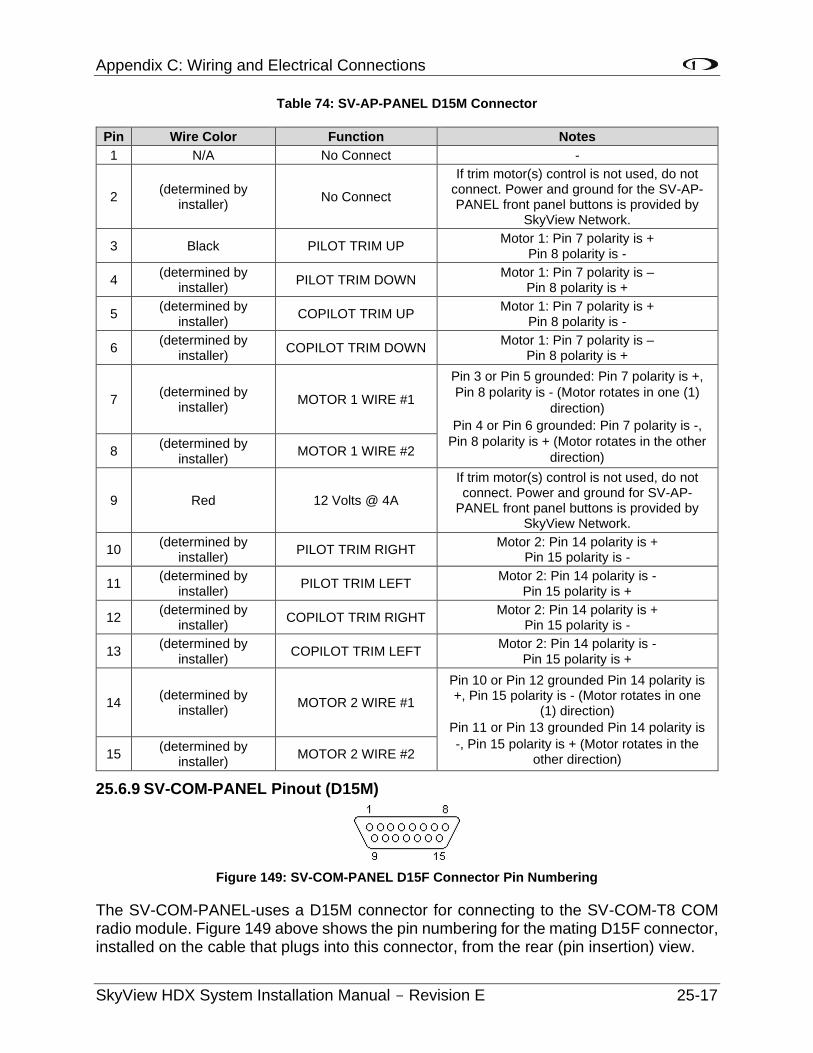
Appendix C: Wiring and Electrical Connections
SkyView HDX System Installation Manual - Revision E 25-17
Table 74: SV-AP-PANEL D15M Connector
Pin Wire Color Function Notes
1 N/A No Connect -
2 (determined by
installer) No Connect
If trim motor(s) control is not used, do not connect. Power and ground for the SV-AP-PANEL front panel buttons is provided by
SkyView Network.
3 Black PILOT TRIM UP Motor 1: Pin 7 polarity is +
Pin 8 polarity is -
4 (determined by
installer) PILOT TRIM DOWN
Motor 1: Pin 7 polarity is – Pin 8 polarity is +
5 (determined by
installer) COPILOT TRIM UP
Motor 1: Pin 7 polarity is + Pin 8 polarity is -
6 (determined by
installer) COPILOT TRIM DOWN
Motor 1: Pin 7 polarity is – Pin 8 polarity is +
7 (determined by
installer) MOTOR 1 WIRE #1
Pin 3 or Pin 5 grounded: Pin 7 polarity is +,
Pin 8 polarity is - (Motor rotates in one (1)
direction)
Pin 4 or Pin 6 grounded: Pin 7 polarity is -,
Pin 8 polarity is + (Motor rotates in the other
direction) 8
(determined by installer)
MOTOR 1 WIRE #2
9 Red 12 Volts @ 4A
If trim motor(s) control is not used, do not connect. Power and ground for SV-AP-
PANEL front panel buttons is provided by SkyView Network.
10 (determined by
installer) PILOT TRIM RIGHT
Motor 2: Pin 14 polarity is + Pin 15 polarity is -
11 (determined by
installer) PILOT TRIM LEFT
Motor 2: Pin 14 polarity is - Pin 15 polarity is +
12 (determined by
installer) COPILOT TRIM RIGHT
Motor 2: Pin 14 polarity is + Pin 15 polarity is -
13 (determined by
installer) COPILOT TRIM LEFT
Motor 2: Pin 14 polarity is - Pin 15 polarity is +
14 (determined by
installer) MOTOR 2 WIRE #1
Pin 10 or Pin 12 grounded Pin 14 polarity is +, Pin 15 polarity is - (Motor rotates in one
(1) direction)
Pin 11 or Pin 13 grounded Pin 14 polarity is
-, Pin 15 polarity is + (Motor rotates in the other direction) 15
(determined by installer)
MOTOR 2 WIRE #2
25.6.9 SV-COM-PANEL Pinout (D15M)
Figure 149: SV-COM-PANEL D15F Connector Pin Numbering
The SV-COM-PANEL-uses a D15M connector for connecting to the SV-COM-T8 COM radio module. Figure 149 above shows the pin numbering for the mating D15F connector, installed on the cable that plugs into this connector, from the rear (pin insertion) view.
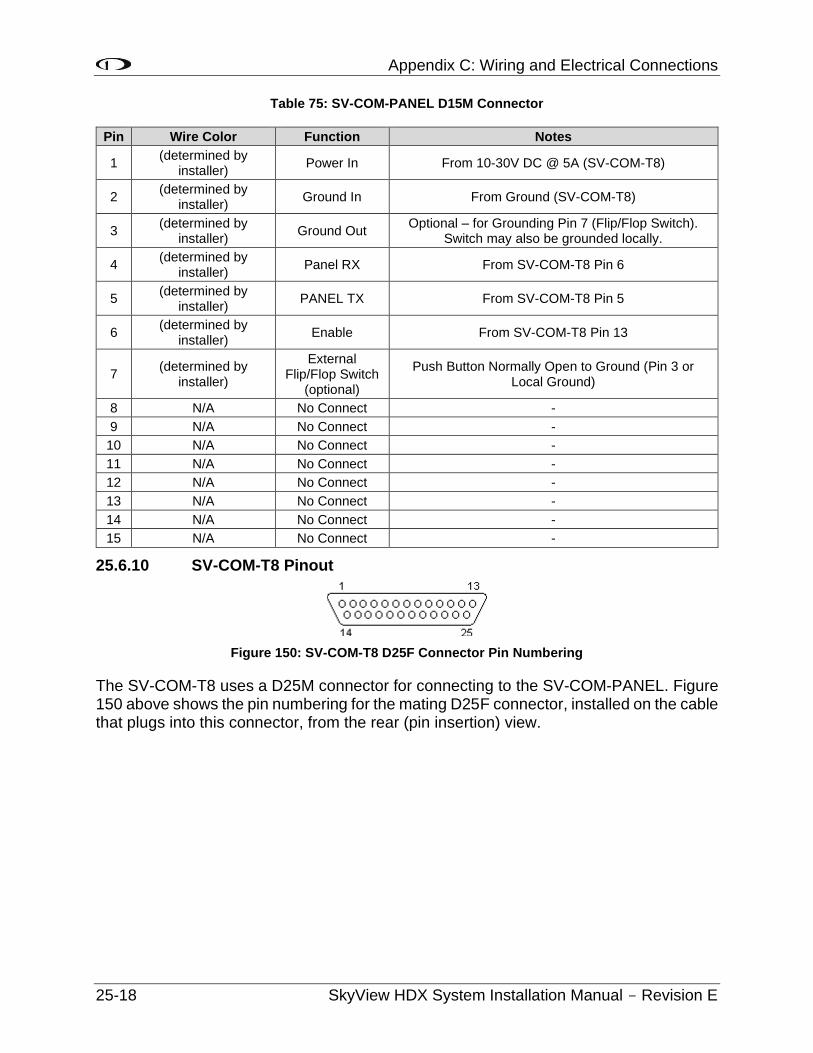
Appendix C: Wiring and Electrical Connections
25-18 SkyView HDX System Installation Manual - Revision E
Table 75: SV-COM-PANEL D15M Connector
Pin Wire Color Function Notes
1 (determined by
installer) Power In From 10-30V DC @ 5A (SV-COM-T8)
2 (determined by
installer) Ground In From Ground (SV-COM-T8)
3 (determined by
installer) Ground Out
Optional – for Grounding Pin 7 (Flip/Flop Switch). Switch may also be grounded locally.
4 (determined by
installer) Panel RX From SV-COM-T8 Pin 6
5 (determined by
installer) PANEL TX From SV-COM-T8 Pin 5
6 (determined by
installer) Enable From SV-COM-T8 Pin 13
7 (determined by
installer)
External Flip/Flop Switch
(optional)
Push Button Normally Open to Ground (Pin 3 or Local Ground)
8 N/A No Connect -
9 N/A No Connect -
10 N/A No Connect -
11 N/A No Connect -
12 N/A No Connect -
13 N/A No Connect -
14 N/A No Connect -
15 N/A No Connect -
25.6.10 SV-COM-T8 Pinout
Figure 150: SV-COM-T8 D25F Connector Pin Numbering
The SV-COM-T8 uses a D25M connector for connecting to the SV-COM-PANEL. Figure 150 above shows the pin numbering for the mating D25F connector, installed on the cable that plugs into this connector, from the rear (pin insertion) view.
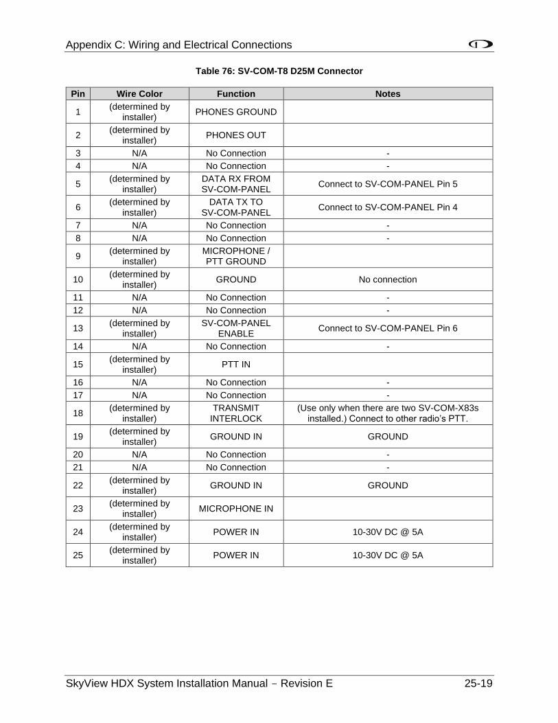
Appendix C: Wiring and Electrical Connections
SkyView HDX System Installation Manual - Revision E 25-19
Table 76: SV-COM-T8 D25M Connector
Pin Wire Color Function Notes
1 (determined by
installer) PHONES GROUND
2 (determined by
installer) PHONES OUT
3 N/A No Connection -
4 N/A No Connection -
5 (determined by
installer) DATA RX FROM SV-COM-PANEL
Connect to SV-COM-PANEL Pin 5
6 (determined by
installer) DATA TX TO
SV-COM-PANEL Connect to SV-COM-PANEL Pin 4
7 N/A No Connection -
8 N/A No Connection -
9 (determined by
installer) MICROPHONE / PTT GROUND
10 (determined by
installer) GROUND No connection
11 N/A No Connection -
12 N/A No Connection -
13 (determined by
installer) SV-COM-PANEL
ENABLE Connect to SV-COM-PANEL Pin 6
14 N/A No Connection -
15 (determined by
installer) PTT IN
16 N/A No Connection -
17 N/A No Connection -
18 (determined by
installer) TRANSMIT
INTERLOCK (Use only when there are two SV-COM-X83s
installed.) Connect to other radio’s PTT.
19 (determined by
installer) GROUND IN GROUND
20 N/A No Connection -
21 N/A No Connection -
22 (determined by
installer) GROUND IN GROUND
23 (determined by
installer) MICROPHONE IN
24 (determined by
installer) POWER IN 10-30V DC @ 5A
25 (determined by
installer) POWER IN 10-30V DC @ 5A

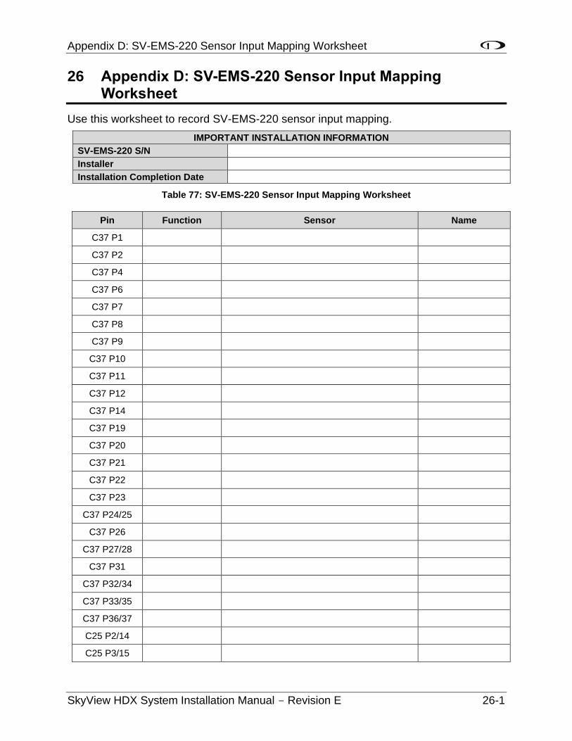
Appendix D: SV-EMS-220 Sensor Input Mapping Worksheet
SkyView HDX System Installation Manual - Revision E 26-1
26 Appendix D: SV-EMS-220 Sensor Input Mapping Worksheet
Use this worksheet to record SV-EMS-220 sensor input mapping.
IMPORTANT INSTALLATION INFORMATION
SV-EMS-220 S/N
Installer
Installation Completion Date
Table 77: SV-EMS-220 Sensor Input Mapping Worksheet
Pin Function Sensor Name
C37 P1
C37 P2
C37 P4
C37 P6
C37 P7
C37 P8
C37 P9
C37 P10
C37 P11
C37 P12
C37 P14
C37 P19
C37 P20
C37 P21
C37 P22
C37 P23
C37 P24/25
C37 P26
C37 P27/28
C37 P31
C37 P32/34
C37 P33/35
C37 P36/37
C25 P2/14
C25 P3/15
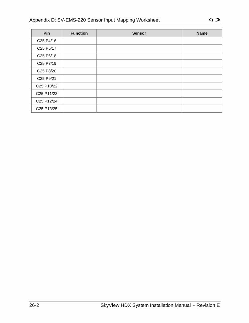
Appendix D: SV-EMS-220 Sensor Input Mapping Worksheet
26-2 SkyView HDX System Installation Manual - Revision E
Pin Function Sensor Name
C25 P4/16
C25 P5/17
C25 P6/18
C25 P7/19
C25 P8/20
C25 P9/21
C25 P10/22
C25 P11/23
C25 P12/24
C25 P13/25
Appendix E: Serial Data Output
SkyView HDX System Installation Manual - Revision E 27-1
27 Appendix E: Serial Data Output
Any of SkyView’s five (5) RS232 serial ports can be configured to output various types of serial data via SETUP MENU > SYSTEM SETUP > SERIAL PORT SETUP. Technical information on the installation and connection to the serial ports can be found in the Serial Devices section of the SkyView Installation Manual. To output serial data, you must select either DYNON EMS, ADAHRS, DYNON SYSTEM, DYNON ADAHRS + SYSTEM, DYNON ADAHRS + EMS, or DYNON ADAHRS + SYS + EMS, NMEA OUT (BASIC), or NMEA OUT (FULL) as a Serial Out device, select a baud rate, and connect the serial port to an external serial device such as a PC. The serial data can be logged using any standard serial terminal program, a data logger program, or dedicated data logger device. All numbers are output in decimal except where noted and are standard ASCII. To view the data using a terminal program, that program should be configured to receive data in the following format:
• Baud rate: Set baud rate to match the baud rate selected on SkyView’s serial port.
• Data: 8 bit.
• Parity: none.
• Stop: 1 bit.
• Flow control: none.
Multiple SkyView display systems: SkyView’s serial ports are designed in a way that allows serial transmission to continue, uninterrupted, as long as at least one (1) SkyView display is operational. SkyView accomplishes this by transmitting from only one (1) display’s serial ports in a multi-display system. SkyView manages which display is the “actual transmitter” automatically to avoid serial port conflicts. However, the display that transmits is not user-selectable. Therefore, for reliable serial reception in multi-display systems, a SkyView serial data output wire must be wired from each display, in parallel, to the external serial device that is being used to capture SkyView’s serial data.
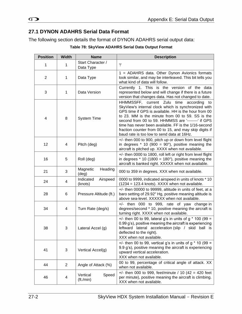
Appendix E: Serial Data Output
27-2 SkyView HDX System Installation Manual - Revision E
27.1 DYNON ADAHRS Serial Data Format
The following section details the format of DYNON ADAHRS serial output data:
Table 78: SkyView ADAHRS Serial Data Output Format
Position Width Name Description
1 1 Start Character /
Data Type '!'
2 1 Data Type 1 = ADAHRS data. Other Dynon Avionics formats look similar, and may be interleaved. This bit tells you what kind of data will follow.
3 1 Data Version Currently 1. This is the version of the data represented below and will change if there is a future version that changes data. Has not changed to date.
4 8 System Time
HHMMSSFF, current Zulu time according to SkyView's internal clock which is synchronized with GPS time if GPS is available. HH is the hour from 00 to 23. MM is the minute from 00 to 59. SS is the second from 00 to 59. HHMMSS are '--------' if GPS time has never been available. FF is the 1/16-second fraction counter from 00 to 15, and may skip digits if baud rate is too low to send data at 16Hz.
12 4 Pitch (deg) +/- then 000 to 900, pitch up or down from level flight in degrees * 10 (900 = 90°), positive meaning the aircraft is pitched up. XXXX when not available.
16 5 Roll (deg) +/- then 0000 to 1800, roll left or right from level flight in degrees * 10 (1800 = 180°), positive meaning the aircraft is banked right. XXXXX when not available.
21 3 Magnetic Heading (deg)
000 to 359 in degrees. XXX when not available.
24 4 Indicated Airspeed (knots)
0000 to 9999, indicated airspeed in units of knots * 10 (1234 = 123.4 knots). XXXX when not available.
28 6 Pressure Altitude (ft.) +/- then 00000 to 99999, altitude in units of feet, at a baro setting of 29.92" Hg, positive meaning altitude is above sea-level. XXXXXX when not available.
34 4 Turn Rate (deg/s) +/- then 000 to 999, rate of yaw change in degrees/second * 10, positive meaning the aircraft is turning right. XXXX when not available.
38 3 Lateral Accel (g)
+/- then 00 to 99, lateral g’s in units of g * 100 (99 = 0.99 g’s), positive meaning the aircraft is experiencing leftward lateral acceleration (slip / skid ball is deflected to the right).
XXX when not available.
41 3 Vertical Accel(g)
+/- then 00 to 99, vertical g’s in units of g * 10 (99 = 9.9 g’s), positive meaning the aircraft is experiencing upward vertical acceleration.
XXX when not available.
44 2 Angle of Attack (%) 00 to 99, percentage of critical angle of attack. XX when not available.
46 4 Vertical Speed (ft./min)
+/- then 000 to 999, feet/minute / 10 (42 = 420 feet per minute), positive meaning the aircraft is climbing. XXX when not available.
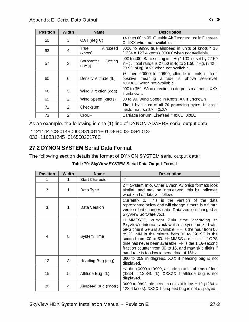
Appendix E: Serial Data Output
SkyView HDX System Installation Manual - Revision E 27-3
Position Width Name Description
50 3 OAT (deg C) +/- then 00 to 99. Outside Air Temperature in Degrees C. XXX when not available.
53 4 True Airspeed (knots)
0000 to 9999, true airspeed in units of knots * 10 (1234 = 123.4 knots). XXXX when not available.
57 3 Barometer Setting (inHg)
000 to 400. Baro setting in inHg * 100, offset by 27.50 inHg. Total range is 27.50 inHg to 31.50 inHg. (242 = 29.92 inHg). XXX when not available.
60 6 Density Altitude (ft.) +/- then 00000 to 99999, altitude in units of feet, positive meaning altitude is above sea-level. XXXXXX when not available.
66 3 Wind Direction (deg) 000 to 359. Wind direction in degrees magnetic. XXX if unknown.
69 2 Wind Speed (knots) 00 to 99. Wind Speed in Knots. XX if unknown.
71 2 Checksum The 1 byte sum of all 70 preceding bytes. In ascii-hexformat, so 3A = 0x3A
73 2 CR/LF Carriage Return, Linefeed = 0x0D, 0x0A.
As an example, the following is one (1) line of DYNON ADAHRS serial output data:
!1121144703-014+00003310811+01736+003-03+1013-033+110831245+01650023176C
27.2 DYNON SYSTEM Serial Data Format
The following section details the format of DYNON SYSTEM serial output data:
Table 79: SkyView SYSTEM Serial Data Output Format
Position Width Name Description
1 1 Start Character ‘!’
2 1 Data Type 2 = System Info. Other Dynon Avionics formats look similar, and may be interleaved, this bit indicates what kind of data will follow.
3 1 Data Version
Currently 2. This is the version of the data represented below and will change if there is a future version that changes data. Data version changed at SkyView Software v5.1.
4 8 System Time
HHMMSSFF, current Zulu time according to SkyView’s internal clock which is synchronized with GPS time if GPS is available. HH is the hour from 00 to 23. MM is the minute from 00 to 59. SS is the second from 00 to 59. HHMMSS are ‘--------‘ if GPS time has never been available. FF is the 1/16-second fraction counter from 00 to 15, and may skip digits if baud rate is too low to send data at 16Hz.
12 3 Heading Bug (deg) 000 to 359 in degrees. XXX if heading bug is not displayed.
15 5 Altitude Bug (ft.) +/- then 0000 to 9999, altitude in units of tens of feet (1234 = 12,340 ft.). XXXXX if altitude bug is not displayed.
20 4 Airspeed Bug (knots) 0000 to 9999, airspeed in units of knots * 10 (1234 = 123.4 knots). XXXX if airspeed bug is not displayed.
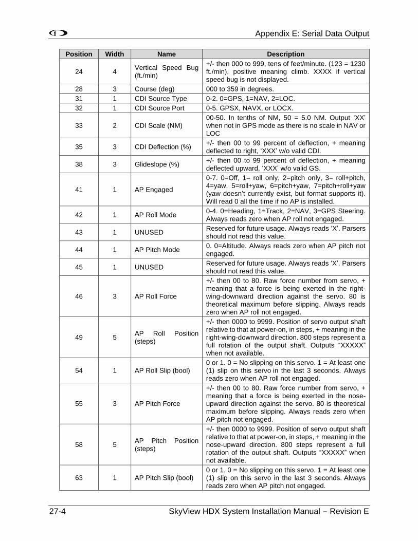
Appendix E: Serial Data Output
27-4 SkyView HDX System Installation Manual - Revision E
Position Width Name Description
24 4 Vertical Speed Bug (ft./min)
+/- then 000 to 999, tens of feet/minute. (123 = 1230 ft./min), positive meaning climb. XXXX if vertical speed bug is not displayed.
28 3 Course (deg) 000 to 359 in degrees.
31 1 CDI Source Type 0-2. 0=GPS, 1=NAV, 2=LOC.
32 1 CDI Source Port 0-5. GPSX, NAVX, or LOCX.
33 2 CDI Scale (NM) 00-50. In tenths of NM, 50 = 5.0 NM. Output ‘XX’ when not in GPS mode as there is no scale in NAV or LOC
35 3 CDI Deflection (%) +/- then 00 to 99 percent of deflection, + meaning deflected to right, ‘XXX’ w/o valid CDI.
38 3 Glideslope (%) +/- then 00 to 99 percent of deflection, + meaning deflected upward, ‘XXX’ w/o valid GS.
41 1 AP Engaged
0-7. 0=Off, 1= roll only, 2=pitch only, 3= roll+pitch, 4=yaw, 5=roll+yaw, 6=pitch+yaw, 7=pitch+roll+yaw (yaw doesn’t currently exist, but format supports it). Will read 0 all the time if no AP is installed.
42 1 AP Roll Mode 0-4. 0=Heading, 1=Track, 2=NAV, 3=GPS Steering. Always reads zero when AP roll not engaged.
43 1 UNUSED Reserved for future usage. Always reads ‘X’. Parsers should not read this value.
44 1 AP Pitch Mode 0. 0=Altitude. Always reads zero when AP pitch not engaged.
45 1 UNUSED Reserved for future usage. Always reads ‘X’. Parsers should not read this value.
46 3 AP Roll Force
+/- then 00 to 80. Raw force number from servo, + meaning that a force is being exerted in the right-wing-downward direction against the servo. 80 is theoretical maximum before slipping. Always reads zero when AP roll not engaged.
49 5 AP Roll Position (steps)
+/- then 0000 to 9999. Position of servo output shaft relative to that at power-on, in steps, + meaning in the right-wing-downward direction. 800 steps represent a full rotation of the output shaft. Outputs “XXXXX” when not available.
54 1 AP Roll Slip (bool) 0 or 1. 0 = No slipping on this servo. 1 = At least one (1) slip on this servo in the last 3 seconds. Always reads zero when AP roll not engaged.
55 3 AP Pitch Force
+/- then 00 to 80. Raw force number from servo, + meaning that a force is being exerted in the nose-upward direction against the servo. 80 is theoretical maximum before slipping. Always reads zero when AP pitch not engaged.
58 5 AP Pitch Position (steps)
+/- then 0000 to 9999. Position of servo output shaft relative to that at power-on, in steps, + meaning in the nose-upward direction. 800 steps represent a full rotation of the output shaft. Outputs “XXXXX” when not available.
63 1 AP Pitch Slip (bool) 0 or 1. 0 = No slipping on this servo. 1 = At least one (1) slip on this servo in the last 3 seconds. Always reads zero when AP pitch not engaged.
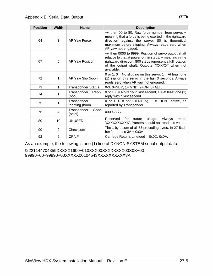
Appendix E: Serial Data Output
SkyView HDX System Installation Manual - Revision E 27-5
Position Width Name Description
64 3 AP Yaw Force
+/- then 00 to 80. Raw force number from servo, + meaning that a force is being exerted in the rightward direction against the servo. 80 is theoretical maximum before slipping. Always reads zero when AP yaw not engaged.
67 5 AP Yaw Position
+/- then 0000 to 9999. Position of servo output shaft relative to that at power-on, in steps, + meaning in the rightward direction. 800 steps represent a full rotation of the output shaft. Outputs “XXXXX” when not available.
72 1 AP Yaw Slip (bool) 0 or 1. 0 = No slipping on this servo. 1 = At least one (1) slip on this servo in the last 3 seconds. Always reads zero when AP yaw not engaged.
73 1 Transponder Status 0-3. 0=SBY, 1= GND, 2=ON, 3=ALT.
74 1 Transponder Reply (bool)
0 or 1. 0 = No reply in last second, 1 = at least one (1) reply within last second.
75 1 Transponder Identing (bool)
0 or 1. 0 = not IDENT’ing, 1 = IDENT active, as reported by Transponder.
76 4 Transponder Code (octal)
0000-7777
80 10 UNUSED Reserved for future usage. Always reads ‘XXXXXXXXXX’. Parsers should not read this value.
90 2 Checksum The 1 byte sum of all 73 preceding bytes. In 27-5sci-hexformat, so 3A = 0x3A
92 2 CR/LF Carriage Return, Linefeed = 0x0D, 0x0A.
As an example, the following is one (1) line of DYNON SYSTEM serial output data:
!2221144704359XXXXX1600+010XXX00XXXXXXXX00X0X+00-99990+00+99990+00XXXXX00104543XXXXXXXXXX3A
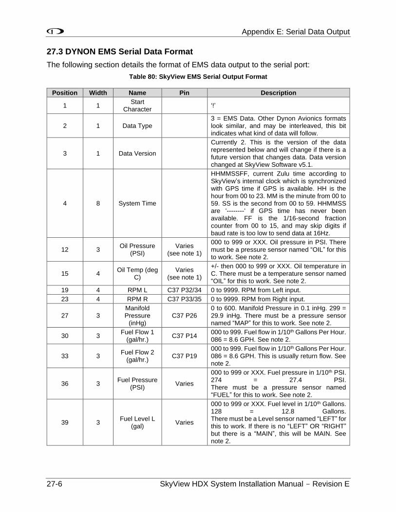
Appendix E: Serial Data Output
27-6 SkyView HDX System Installation Manual - Revision E
27.3 DYNON EMS Serial Data Format
The following section details the format of EMS data output to the serial port:
Table 80: SkyView EMS Serial Output Format
Position Width Name Pin Description
1 1 Start
Character ‘!’
2 1 Data Type 3 = EMS Data. Other Dynon Avionics formats look similar, and may be interleaved, this bit indicates what kind of data will follow.
3 1 Data Version
Currently 2. This is the version of the data represented below and will change if there is a future version that changes data. Data version changed at SkyView Software v5.1.
4 8 System Time
HHMMSSFF, current Zulu time according to SkyView’s internal clock which is synchronized with GPS time if GPS is available. HH is the hour from 00 to 23. MM is the minute from 00 to 59. SS is the second from 00 to 59. HHMMSS are ‘--------‘ if GPS time has never been available. FF is the 1/16-second fraction counter from 00 to 15, and may skip digits if baud rate is too low to send data at 16Hz.
12 3 Oil Pressure
(PSI) Varies
(see note 1)
000 to 999 or XXX. Oil pressure in PSI. There must be a pressure sensor named “OIL” for this to work. See note 2.
15 4 Oil Temp (deg
C) Varies
(see note 1)
+/- then 000 to 999 or XXX. Oil temperature in C. There must be a temperature sensor named “OIL” for this to work. See note 2.
19 4 RPM L C37 P32/34 0 to 9999. RPM from Left input.
23 4 RPM R C37 P33/35 0 to 9999. RPM from Right input.
27 3 Manifold Pressure
(inHg) C37 P26
0 to 600. Manifold Pressure in 0.1 inHg. 299 = 29.9 inHg. There must be a pressure sensor named “MAP” for this to work. See note 2.
30 3 Fuel Flow 1
(gal/hr.) C37 P14
000 to 999. Fuel flow in 1/10th Gallons Per Hour. 086 = 8.6 GPH. See note 2.
33 3 Fuel Flow 2
(gal/hr.) C37 P19
000 to 999. Fuel flow in 1/10th Gallons Per Hour. 086 = 8.6 GPH. This is usually return flow. See note 2.
36 3 Fuel Pressure
(PSI) Varies
000 to 999 or XXX. Fuel pressure in 1/10th PSI. 274 = 27.4 PSI. There must be a pressure sensor named “FUEL” for this to work. See note 2.
39 3 Fuel Level L
(gal) Varies
000 to 999 or XXX. Fuel level in 1/10th Gallons. 128 = 12.8 Gallons. There must be a Level sensor named “LEFT” for this to work. If there is no “LEFT” OR “RIGHT” but there is a “MAIN”, this will be MAIN. See note 2.
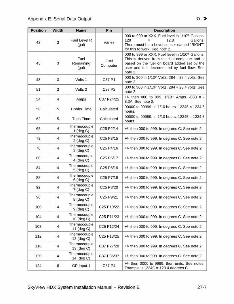
Appendix E: Serial Data Output
SkyView HDX System Installation Manual - Revision E 27-7
Position Width Name Pin Description
42 3 Fuel Level R
(gal) Varies
000 to 999 or XXX. Fuel level in 1/10th Gallons. 128 = 12.8 Gallons. There must be a Level sensor named “RIGHT” for this to work. See note 2.
45 3 Fuel
Remaining (gal)
Fuel Computer
000 to 999 or XXX. Fuel level in 1/10th Gallons. This is derived from the fuel computer and is based on the fuel on board added set by the user and the decremented by fuel flow. See note 2.
48 3 Volts 1 C37 P1 000 to 360 in 1/10th Volts. 284 = 28.4 volts. See note 2.
51 3 Volts 2 C37 P2 000 to 360 in 1/10th Volts. 284 = 28.4 volts. See note 2.
54 4 Amps C37 P24/25 +/- then 000 to 999. 1/10th Amps. -083 = -8.3A. See note 2.
58 5 Hobbs Time Calculated 00000 to 99999. In 1/10 hours. 12345 = 1234.5 hours.
63 5 Tach Time Calculated 00000 to 99999. In 1/10 hours. 12345 = 1234.5 hours.
68 4 Thermocouple
1 (deg C) C25 P2/14 +/- then 000 to 999. In degrees C. See note 2.
72 4 Thermocouple
2 (deg C) C25 P3/15 +/- then 000 to 999. In degrees C. See note 2.
76 4 Thermocouple
3 (deg C) C25 P4/16 +/- then 000 to 999. In degrees C. See note 2.
80 4 Thermocouple
4 (deg C) C25 P5/17 +/- then 000 to 999. In degrees C. See note 2.
84 4 Thermocouple
5 (deg C) C25 P6/18 +/- then 000 to 999. In degrees C. See note 2.
88 4 Thermocouple
6 (deg C) C25 P7/19 +/- then 000 to 999. In degrees C. See note 2.
92 4 Thermocouple
7 (deg C) C25 P8/20 +/- then 000 to 999. In degrees C. See note 2.
96 4 Thermocouple
8 (deg C) C25 P9/21 +/- then 000 to 999. In degrees C. See note 2.
100 4 Thermocouple
9 (deg C) C25 P10/22 +/- then 000 to 999. In degrees C. See note 2.
104 4 Thermocouple
10 (deg C) C25 P11/23 +/- then 000 to 999. In degrees C. See note 2.
108 4 Thermocouple
11 (deg C) C25 P12/24 +/- then 000 to 999. In degrees C. See note 2.
112 4 Thermocouple
12 (deg C) C25 P13/25 +/- then 000 to 999. In degrees C. See note 2.
116 4 Thermocouple
13 (deg C) C37 P27/28 +/- then 000 to 999. In degrees C. See note 2.
120 4 Thermocouple
14 (deg C) C37 P36/37 +/- then 000 to 999. In degrees C. See note 2.
124 6 GP Input 1 C37 P4 +/- then 0000 to 9999, then units. See notes. Example: +1234C = 123.4 degrees C.
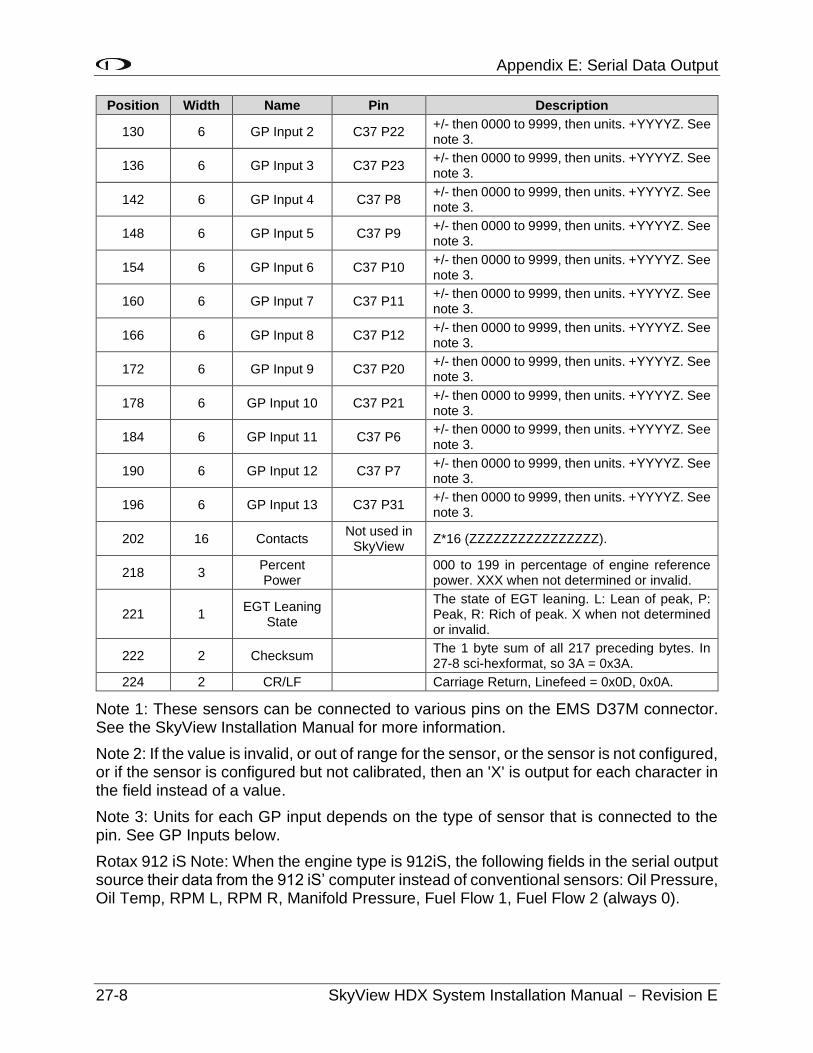
Appendix E: Serial Data Output
27-8 SkyView HDX System Installation Manual - Revision E
Position Width Name Pin Description
130 6 GP Input 2 C37 P22 +/- then 0000 to 9999, then units. +YYYYZ. See note 3.
136 6 GP Input 3 C37 P23 +/- then 0000 to 9999, then units. +YYYYZ. See note 3.
142 6 GP Input 4 C37 P8 +/- then 0000 to 9999, then units. +YYYYZ. See note 3.
148 6 GP Input 5 C37 P9 +/- then 0000 to 9999, then units. +YYYYZ. See note 3.
154 6 GP Input 6 C37 P10 +/- then 0000 to 9999, then units. +YYYYZ. See note 3.
160 6 GP Input 7 C37 P11 +/- then 0000 to 9999, then units. +YYYYZ. See note 3.
166 6 GP Input 8 C37 P12 +/- then 0000 to 9999, then units. +YYYYZ. See note 3.
172 6 GP Input 9 C37 P20 +/- then 0000 to 9999, then units. +YYYYZ. See note 3.
178 6 GP Input 10 C37 P21 +/- then 0000 to 9999, then units. +YYYYZ. See note 3.
184 6 GP Input 11 C37 P6 +/- then 0000 to 9999, then units. +YYYYZ. See note 3.
190 6 GP Input 12 C37 P7 +/- then 0000 to 9999, then units. +YYYYZ. See note 3.
196 6 GP Input 13 C37 P31 +/- then 0000 to 9999, then units. +YYYYZ. See note 3.
202 16 Contacts Not used in
SkyView Z*16 (ZZZZZZZZZZZZZZZZ).
218 3 Percent Power
000 to 199 in percentage of engine reference power. XXX when not determined or invalid.
221 1 EGT Leaning
State
The state of EGT leaning. L: Lean of peak, P: Peak, R: Rich of peak. X when not determined or invalid.
222 2 Checksum The 1 byte sum of all 217 preceding bytes. In 27-8 sci-hexformat, so 3A = 0x3A.
224 2 CR/LF Carriage Return, Linefeed = 0x0D, 0x0A.
Note 1: These sensors can be connected to various pins on the EMS D37M connector. See the SkyView Installation Manual for more information.
Note 2: If the value is invalid, or out of range for the sensor, or the sensor is not configured, or if the sensor is configured but not calibrated, then an 'X' is output for each character in the field instead of a value.
Note 3: Units for each GP input depends on the type of sensor that is connected to the pin. See GP Inputs below.
Rotax 912 iS Note: When the engine type is 912iS, the following fields in the serial output source their data from the 912 iS’ computer instead of conventional sensors: Oil Pressure, Oil Temp, RPM L, RPM R, Manifold Pressure, Fuel Flow 1, Fuel Flow 2 (always 0).
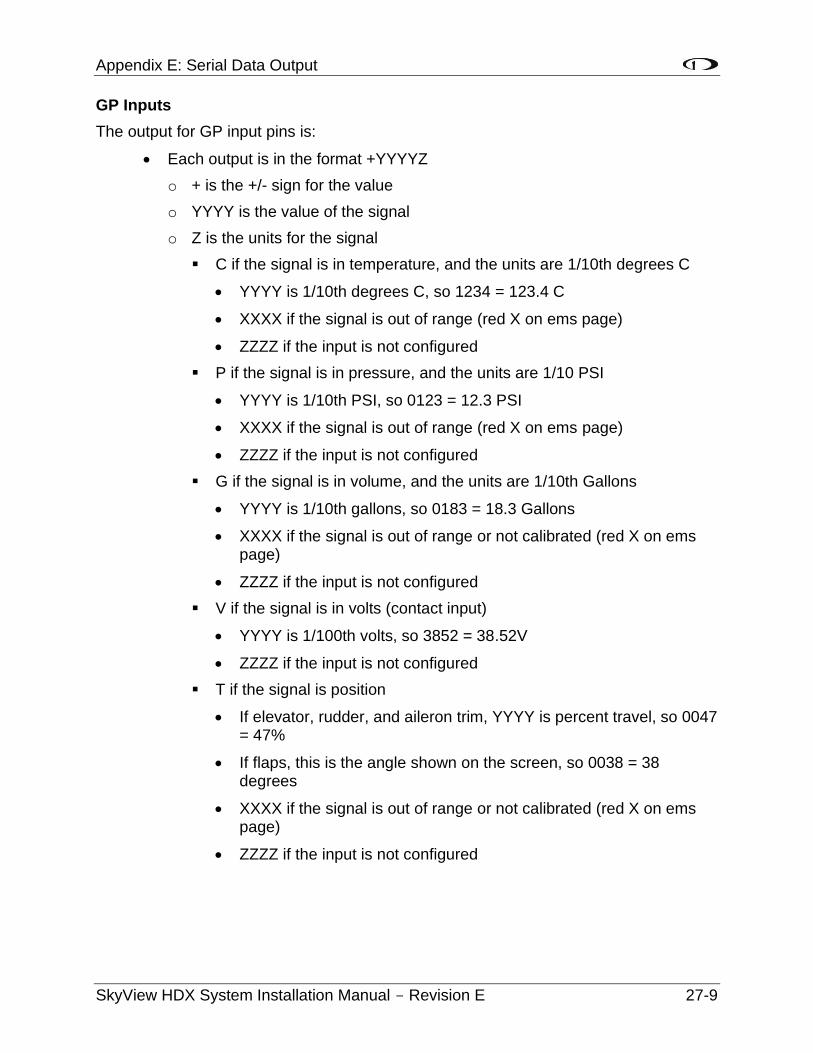
Appendix E: Serial Data Output
SkyView HDX System Installation Manual - Revision E 27-9
GP Inputs
The output for GP input pins is:
• Each output is in the format +YYYYZ
o + is the +/- sign for the value
o YYYY is the value of the signal
o Z is the units for the signal
C if the signal is in temperature, and the units are 1/10th degrees C
• YYYY is 1/10th degrees C, so 1234 = 123.4 C
• XXXX if the signal is out of range (red X on ems page)
• ZZZZ if the input is not configured
P if the signal is in pressure, and the units are 1/10 PSI
• YYYY is 1/10th PSI, so 0123 = 12.3 PSI
• XXXX if the signal is out of range (red X on ems page)
• ZZZZ if the input is not configured
G if the signal is in volume, and the units are 1/10th Gallons
• YYYY is 1/10th gallons, so 0183 = 18.3 Gallons
• XXXX if the signal is out of range or not calibrated (red X on ems page)
• ZZZZ if the input is not configured
V if the signal is in volts (contact input)
• YYYY is 1/100th volts, so 3852 = 38.52V
• ZZZZ if the input is not configured
T if the signal is position
• If elevator, rudder, and aileron trim, YYYY is percent travel, so 0047 = 47%
• If flaps, this is the angle shown on the screen, so 0038 = 38 degrees
• XXXX if the signal is out of range or not calibrated (red X on ems page)
• ZZZZ if the input is not configured
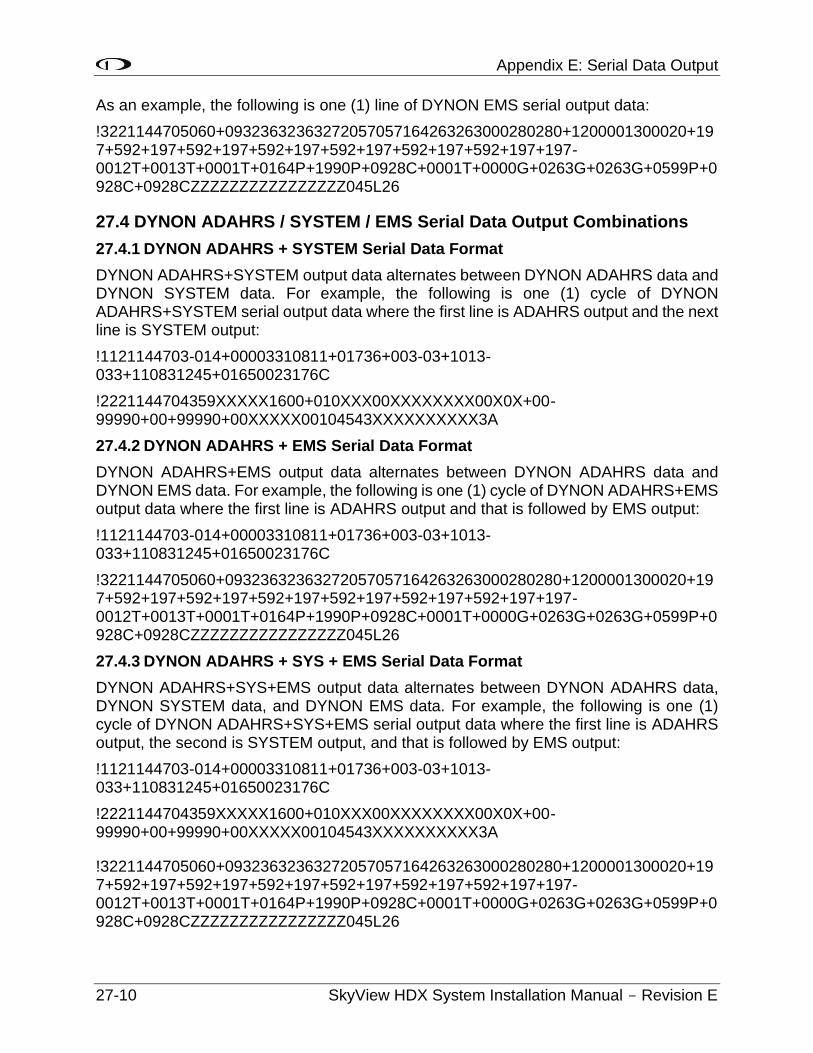
Appendix E: Serial Data Output
27-10 SkyView HDX System Installation Manual - Revision E
As an example, the following is one (1) line of DYNON EMS serial output data:
!3221144705060+09323632363272057057164263263000280280+1200001300020+197+592+197+592+197+592+197+592+197+592+197+592+197+197-0012T+0013T+0001T+0164P+1990P+0928C+0001T+0000G+0263G+0263G+0599P+0928C+0928CZZZZZZZZZZZZZZZZ045L26
27.4 DYNON ADAHRS / SYSTEM / EMS Serial Data Output Combinations
27.4.1 DYNON ADAHRS + SYSTEM Serial Data Format
DYNON ADAHRS+SYSTEM output data alternates between DYNON ADAHRS data and DYNON SYSTEM data. For example, the following is one (1) cycle of DYNON ADAHRS+SYSTEM serial output data where the first line is ADAHRS output and the next line is SYSTEM output:
!1121144703-014+00003310811+01736+003-03+1013-033+110831245+01650023176C
!2221144704359XXXXX1600+010XXX00XXXXXXXX00X0X+00-99990+00+99990+00XXXXX00104543XXXXXXXXXX3A
27.4.2 DYNON ADAHRS + EMS Serial Data Format
DYNON ADAHRS+EMS output data alternates between DYNON ADAHRS data and DYNON EMS data. For example, the following is one (1) cycle of DYNON ADAHRS+EMS output data where the first line is ADAHRS output and that is followed by EMS output:
!1121144703-014+00003310811+01736+003-03+1013-033+110831245+01650023176C
!3221144705060+09323632363272057057164263263000280280+1200001300020+197+592+197+592+197+592+197+592+197+592+197+592+197+197-0012T+0013T+0001T+0164P+1990P+0928C+0001T+0000G+0263G+0263G+0599P+0928C+0928CZZZZZZZZZZZZZZZZ045L26
27.4.3 DYNON ADAHRS + SYS + EMS Serial Data Format
DYNON ADAHRS+SYS+EMS output data alternates between DYNON ADAHRS data, DYNON SYSTEM data, and DYNON EMS data. For example, the following is one (1) cycle of DYNON ADAHRS+SYS+EMS serial output data where the first line is ADAHRS output, the second is SYSTEM output, and that is followed by EMS output:
!1121144703-014+00003310811+01736+003-03+1013-033+110831245+01650023176C
!2221144704359XXXXX1600+010XXX00XXXXXXXX00X0X+00-99990+00+99990+00XXXXX00104543XXXXXXXXXX3A
!3221144705060+09323632363272057057164263263000280280+1200001300020+197+592+197+592+197+592+197+592+197+592+197+592+197+197-0012T+0013T+0001T+0164P+1990P+0928C+0001T+0000G+0263G+0263G+0599P+0928C+0928CZZZZZZZZZZZZZZZZ045L26
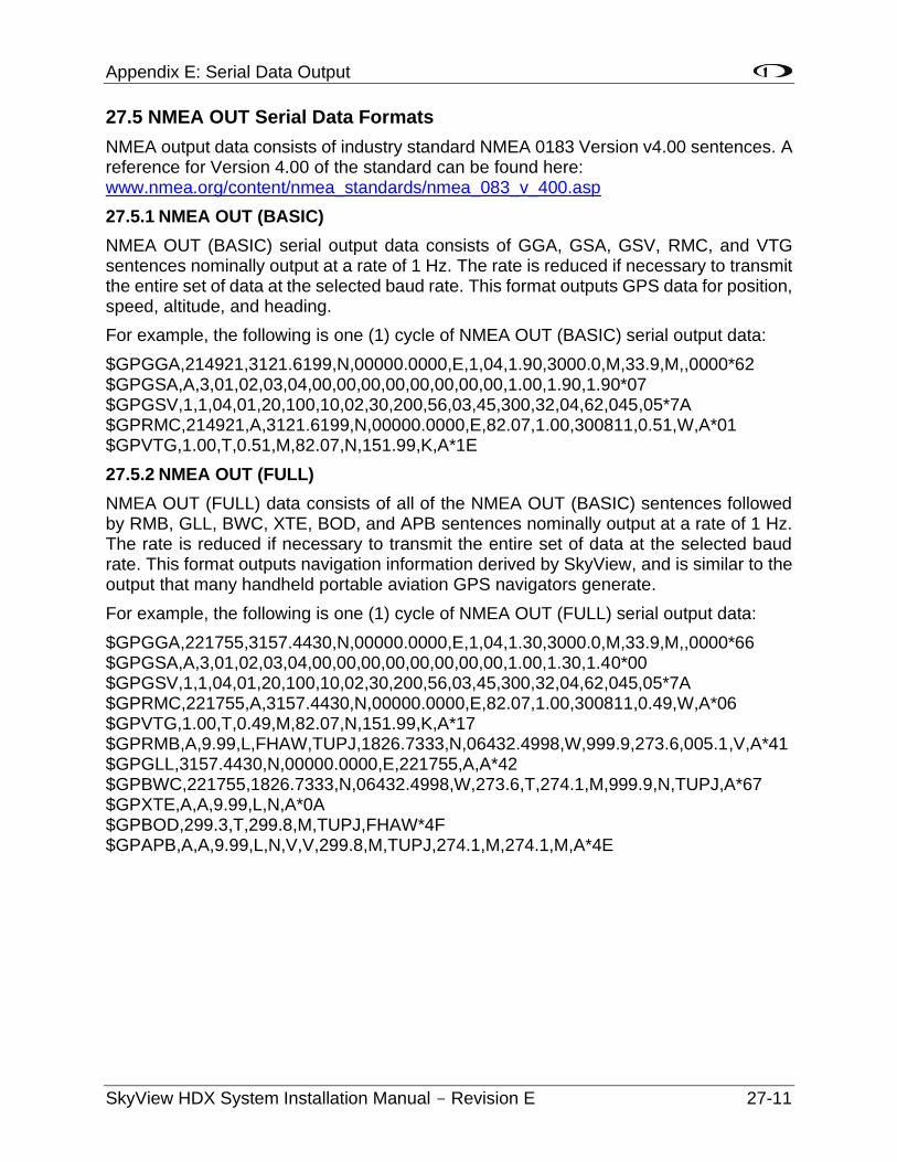
Appendix E: Serial Data Output
SkyView HDX System Installation Manual - Revision E 27-11
27.5 NMEA OUT Serial Data Formats
NMEA output data consists of industry standard NMEA 0183 Version v4.00 sentences. A reference for Version 4.00 of the standard can be found here: www.nmea.org/content/nmea_standards/nmea_083_v_400.asp
27.5.1 NMEA OUT (BASIC)
NMEA OUT (BASIC) serial output data consists of GGA, GSA, GSV, RMC, and VTG sentences nominally output at a rate of 1 Hz. The rate is reduced if necessary to transmit the entire set of data at the selected baud rate. This format outputs GPS data for position, speed, altitude, and heading.
For example, the following is one (1) cycle of NMEA OUT (BASIC) serial output data:
$GPGGA,214921,3121.6199,N,00000.0000,E,1,04,1.90,3000.0,M,33.9,M,,0000*62 $GPGSA,A,3,01,02,03,04,00,00,00,00,00,00,00,00,1.00,1.90,1.90*07 $GPGSV,1,1,04,01,20,100,10,02,30,200,56,03,45,300,32,04,62,045,05*7A $GPRMC,214921,A,3121.6199,N,00000.0000,E,82.07,1.00,300811,0.51,W,A*01 $GPVTG,1.00,T,0.51,M,82.07,N,151.99,K,A*1E
27.5.2 NMEA OUT (FULL)
NMEA OUT (FULL) data consists of all of the NMEA OUT (BASIC) sentences followed by RMB, GLL, BWC, XTE, BOD, and APB sentences nominally output at a rate of 1 Hz. The rate is reduced if necessary to transmit the entire set of data at the selected baud rate. This format outputs navigation information derived by SkyView, and is similar to the output that many handheld portable aviation GPS navigators generate.
For example, the following is one (1) cycle of NMEA OUT (FULL) serial output data:
$GPGGA,221755,3157.4430,N,00000.0000,E,1,04,1.30,3000.0,M,33.9,M,,0000*66 $GPGSA,A,3,01,02,03,04,00,00,00,00,00,00,00,00,1.00,1.30,1.40*00 $GPGSV,1,1,04,01,20,100,10,02,30,200,56,03,45,300,32,04,62,045,05*7A $GPRMC,221755,A,3157.4430,N,00000.0000,E,82.07,1.00,300811,0.49,W,A*06 $GPVTG,1.00,T,0.49,M,82.07,N,151.99,K,A*17 $GPRMB,A,9.99,L,FHAW,TUPJ,1826.7333,N,06432.4998,W,999.9,273.6,005.1,V,A*41 $GPGLL,3157.4430,N,00000.0000,E,221755,A,A*42 $GPBWC,221755,1826.7333,N,06432.4998,W,273.6,T,274.1,M,999.9,N,TUPJ,A*67 $GPXTE,A,A,9.99,L,N,A*0A $GPBOD,299.3,T,299.8,M,TUPJ,FHAW*4F $GPAPB,A,A,9.99,L,N,V,V,299.8,M,TUPJ,274.1,M,274.1,M,A*4E

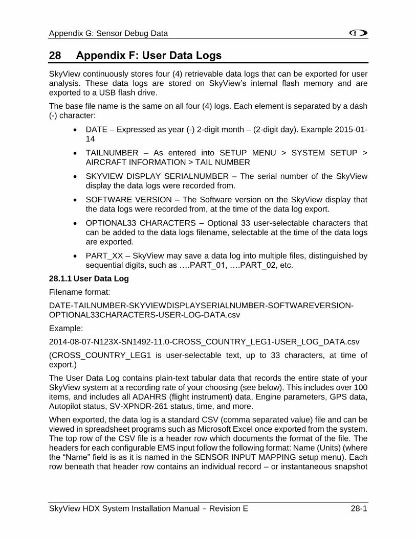
Appendix G: Sensor Debug Data
SkyView HDX System Installation Manual - Revision E 28-1
28 Appendix F: User Data Logs
SkyView continuously stores four (4) retrievable data logs that can be exported for user analysis. These data logs are stored on SkyView’s internal flash memory and are exported to a USB flash drive.
The base file name is the same on all four (4) logs. Each element is separated by a dash (-) character:
• DATE – Expressed as year (-) 2-digit month – (2-digit day). Example 2015-01-14
• TAILNUMBER – As entered into SETUP MENU > SYSTEM SETUP > AIRCRAFT INFORMATION > TAIL NUMBER
• SKYVIEW DISPLAY SERIALNUMBER – The serial number of the SkyView display the data logs were recorded from.
• SOFTWARE VERSION – The Software version on the SkyView display that the data logs were recorded from, at the time of the data log export.
• OPTIONAL33 CHARACTERS – Optional 33 user-selectable characters that can be added to the data logs filename, selectable at the time of the data logs are exported.
• PART_XX – SkyView may save a data log into multiple files, distinguished by sequential digits, such as ….PART_01, ….PART_02, etc.
28.1.1 User Data Log
Filename format:
DATE-TAILNUMBER-SKYVIEWDISPLAYSERIALNUMBER-SOFTWAREVERSION-OPTIONAL33CHARACTERS-USER-LOG-DATA.csv
Example:
2014-08-07-N123X-SN1492-11.0-CROSS_COUNTRY_LEG1-USER_LOG_DATA.csv
(CROSS_COUNTRY_LEG1 is user-selectable text, up to 33 characters, at time of export.)
The User Data Log contains plain-text tabular data that records the entire state of your SkyView system at a recording rate of your choosing (see below). This includes over 100 items, and includes all ADAHRS (flight instrument) data, Engine parameters, GPS data, Autopilot status, SV-XPNDR-261 status, time, and more.
When exported, the data log is a standard CSV (comma separated value) file and can be viewed in spreadsheet programs such as Microsoft Excel once exported from the system. The top row of the CSV file is a header row which documents the format of the file. The headers for each configurable EMS input follow the following format: Name (Units) (where the “Name” field is as it is named in the SENSOR INPUT MAPPING setup menu). Each row beneath that header row contains an individual record – or instantaneous snapshot
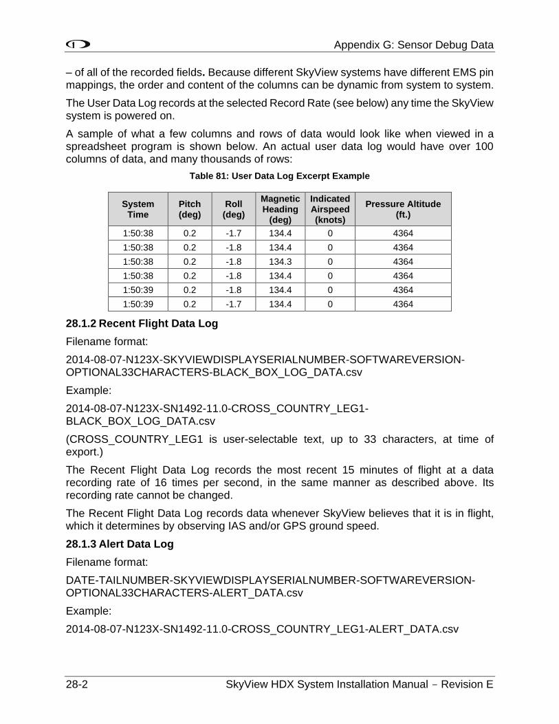
Appendix G: Sensor Debug Data
28-2 SkyView HDX System Installation Manual - Revision E
– of all of the recorded fields. Because different SkyView systems have different EMS pin mappings, the order and content of the columns can be dynamic from system to system.
The User Data Log records at the selected Record Rate (see below) any time the SkyView system is powered on.
A sample of what a few columns and rows of data would look like when viewed in a spreadsheet program is shown below. An actual user data log would have over 100 columns of data, and many thousands of rows:
Table 81: User Data Log Excerpt Example
System Time
Pitch (deg)
Roll (deg)
Magnetic Heading
(deg)
Indicated Airspeed (knots)
Pressure Altitude (ft.)
1:50:38 0.2 -1.7 134.4 0 4364
1:50:38 0.2 -1.8 134.4 0 4364
1:50:38 0.2 -1.8 134.3 0 4364
1:50:38 0.2 -1.8 134.4 0 4364
1:50:39 0.2 -1.8 134.4 0 4364
1:50:39 0.2 -1.7 134.4 0 4364
28.1.2 Recent Flight Data Log
Filename format:
2014-08-07-N123X-SKYVIEWDISPLAYSERIALNUMBER-SOFTWAREVERSION-OPTIONAL33CHARACTERS-BLACK_BOX_LOG_DATA.csv
Example:
2014-08-07-N123X-SN1492-11.0-CROSS_COUNTRY_LEG1-BLACK_BOX_LOG_DATA.csv
(CROSS_COUNTRY_LEG1 is user-selectable text, up to 33 characters, at time of export.)
The Recent Flight Data Log records the most recent 15 minutes of flight at a data recording rate of 16 times per second, in the same manner as described above. Its recording rate cannot be changed.
The Recent Flight Data Log records data whenever SkyView believes that it is in flight, which it determines by observing IAS and/or GPS ground speed.
28.1.3 Alert Data Log
Filename format:
DATE-TAILNUMBER-SKYVIEWDISPLAYSERIALNUMBER-SOFTWAREVERSION- OPTIONAL33CHARACTERS-ALERT_DATA.csv
Example:
2014-08-07-N123X-SN1492-11.0-CROSS_COUNTRY_LEG1-ALERT_DATA.csv
Appendix G: Sensor Debug Data
SkyView HDX System Installation Manual - Revision E 28-3
(CROSS_COUNTRY_LEG1 is user-selectable text, up to 33 characters, at time of export.)
The Alert Data Log contains plain-text tabular data. A new record is appended each time a SkyView alert of any kind is triggered, including audible alerts and system messages. The Alert Data Log is useful for diagnosing alerts that automatically clear on a brief condition, for example, oil pressure going into the red zone for a few seconds, then back into green, and automatically clearing.
When exported, the data log is a standard CSV (comma separated value) file and can be viewed in spreadsheet programs such as Microsoft Excel once exported from the system. The top row of the CSV file is a header row which documents the format of the file. Each record consists of supporting data such as time, GPS data, type of alert, the type of alert action, and the description of the alert. The Alert Data Log is allocated 2 MB which may be sufficient to record more than 1500 hours of operation assuming as many as 10 alerts per hour. The Alert Data Log is not affected by the RECORD RATE setting below.
28.1.4 History Data Log
Filename format:
DATE-TAILNUMBER-SKYVIEWDISPLAYSERIALNUMBER-SOFTWAREVERSION-OPTIONAL33CHARACTERS-HISTORY_LOG_DATA.csv
Example:
2014-08-07-N123X-SN1492-11.0-CROSS_COUNTRY_LEG1-HISTORY_LOG_DATA.csv
(CROSS_COUNTRY_LEG1 is user-selectable text, up to 33 characters, at time of export.)
The History Data Log is a cumulative history of files loaded onto the SkyView and other changes mostly used for troubleshooting when requested from Dynon Avionics Technical Support.
28.1.5 Data Logging Recording Options
28.1.5.1 Record Rate
You can choose the frequency of the data that is recorded from SkyView’s various systems for your particular needs. SkyView can record data as frequently as sixteen (16) times per second or as infrequently as once every ten (10) seconds. Recording more frequently trades off the amount of time that the data log covers. If you choose once every ten (10) seconds, SkyView’s User Data Log can store up to about 150 hours of data. At sixteen (16) times per second, the log stores about two (2) hours of data. When the data log fills up, the oldest data is automatically discarded to make room for new data.
Navigate to SETUP MENU > SYSTEM SETUP > DATA LOG SETUP > RECORD RATE to choose the frequency that data is recorded to the internal User Data Log.
28.1.5.2 Clearing Data Logs
Navigate to SETUP MENU > SYSTEM SETUP > DATA LOG SETUP > CLEAR ALL DATA to erase the User Data Log, Recent Flight Data Log, and Alert Data Log. Note that
Appendix G: Sensor Debug Data
28-4 SkyView HDX System Installation Manual - Revision E
this does not clear History Data Log, as this is a log of all significant changes to the configuration of the SkyView system.
28.1.6 Exporting Data Logs
In a dual engine configuration (dual SV-EMS-22x with at least two (2) SkyView displays), data logs for each engine are recorded / exported only on the display that is monitoring each engine. Example – in a system where the left display is configured to monitor the left engine, the data log exported from the left display contains the data log for the left engine (only). It is recommended to use a separate USB flash drive per engine to prevent the possibility of overwriting data logs.
Connect a USB flash drive with at least 100 MB of available storage capacity to your SkyView display. Then, navigate to SETUP MENU > SYSTEM SOFTWARE > EXPORT USER DATA LOGS to export the three (3) data logs to the USB flash drive.
If your SkyView system has not yet flown, or has not flown since the data logs were last cleared, there may not be a Recent Flight Data Log available.
The data logs that are exported are in CSV (comma separated values) format and can be opened by common spreadsheet programs such as Microsoft Excel.
28.1.6.1 Web-based Engine Analysis
Savvy Analysis – http://www.savvyanalysis.com is a free web-based tool that supports the upload and analysis of the engine information that is contained within SkyView’s User Data Logs. Instructions for creating an account and uploading data logs are on the Savvy Analysis website.
Other than technical cooperation to ensure that SkyView data logs can be correctly parsed as formats are periodically updated, Dynon Avionics has no relationship with Savvy Analysis.
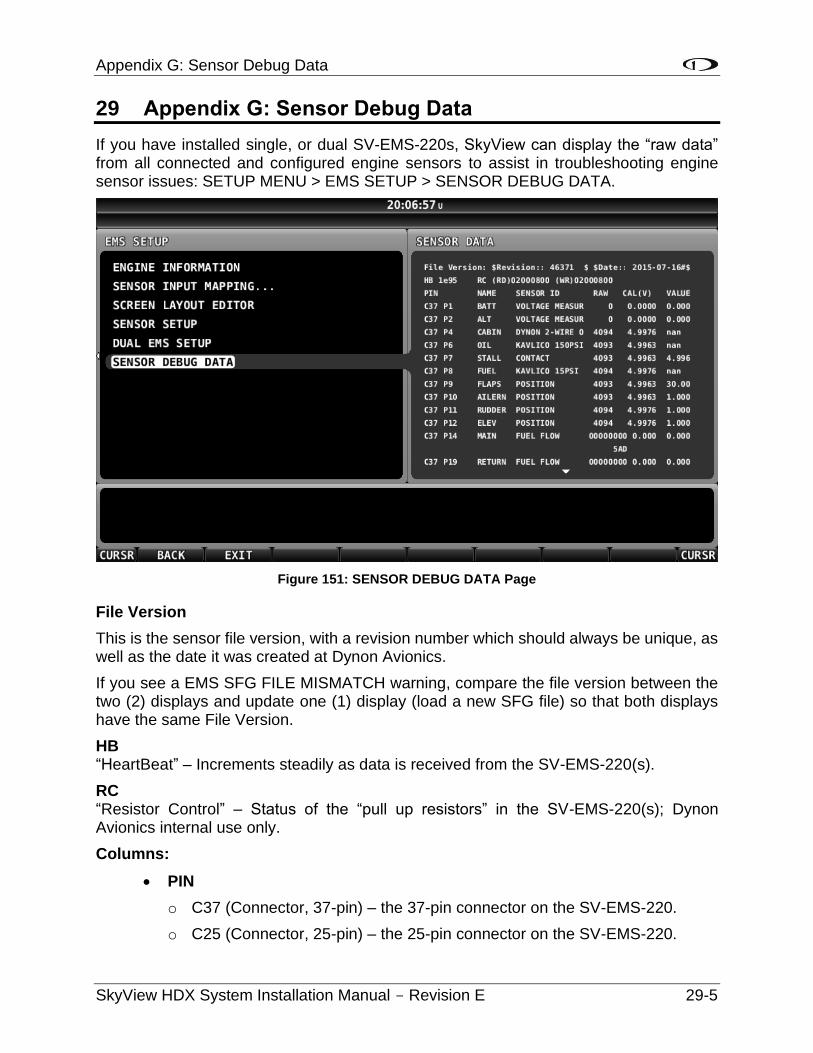
Appendix G: Sensor Debug Data
SkyView HDX System Installation Manual - Revision E 29-5
29 Appendix G: Sensor Debug Data
If you have installed single, or dual SV-EMS-220s, SkyView can display the “raw data” from all connected and configured engine sensors to assist in troubleshooting engine sensor issues: SETUP MENU > EMS SETUP > SENSOR DEBUG DATA.
Figure 151: SENSOR DEBUG DATA Page
File Version
This is the sensor file version, with a revision number which should always be unique, as well as the date it was created at Dynon Avionics.
If you see a EMS SFG FILE MISMATCH warning, compare the file version between the two (2) displays and update one (1) display (load a new SFG file) so that both displays have the same File Version.
HB “HeartBeat” – Increments steadily as data is received from the SV-EMS-220(s).
RC “Resistor Control” – Status of the “pull up resistors” in the SV-EMS-220(s); Dynon Avionics internal use only.
Columns:
• PIN
o C37 (Connector, 37-pin) – the 37-pin connector on the SV-EMS-220.
o C25 (Connector, 25-pin) – the 25-pin connector on the SV-EMS-220.
Appendix G: Sensor Debug Data
29-6 SkyView HDX System Installation Manual - Revision E
o Px refers to an individual pin on the 37-pin or the 25-pin connector.
o Px/x refers to a pair of pins used for thermocouples (CHT/EGTs) on the 37-pin or the 25-pin connector.
• NAME – The name selected in SENSOR INPUT MAPPING for this sensor / input / pin.
• SENSOR ID – The type of sensor selected in SENSOR INPUT MAPPING for this sensor / input / pin.
• RAW – Raw number from the Analog to Digital converter; Dynon Avionics internal use only.
• CAL(V) – The exact voltage that is present on this pin. The output of many sensors is converted to a voltage in the SV-EMS-220 for processing. For example, Dynon Avionics temperature sensors are thermistors, which vary their resistance with changing temperature, and are converted to a voltage internally, before resulting in a display of temperature in ° Fahrenheit or ° Celsius.
• VALUE – Output of the (selected) sensor in (converted) units (such as pressure, temperature, etc.) corrected for the measurement unit selected (temperature in ° Fahrenheit, etc.). This is the same number that is displayed in the widget on the EMS page.
o “NAN” is “Not A Number”; the input being received on this pin is invalid for this particular sensor. This is normal when the input is not configured, or the sensor is not connected or defective.
Specialized Function Pins
Pin 14
Primary fuel flow sensor, monitoring fuel flow from the tank to the engine. The RAW value will increment for every pulse received from the fuel flow sensor in the current boot cycle (reset when the SkyView display is powered off).
In the figure above, the displayed RAW value is shown as “5AD” (not 00000000). This value is displayed as a hexadecimal number (Base 16), and increments by 1 for each pulse. Succeeding pulses would change this value to 5AE, then 5AF, then 5B0, etc.
If the engine is on (fuel is flowing from the fuel tank to the engine), the RAW value should be incrementing. If the RAW value is not incrementing, no pulses are being received from the fuel flow sensor.
CAL(V) and VALUE both show the fuel flow rate, corrected for the “K-factor” selected in FUEL FLOW CALIBRATION (pulses per unit per hour) and the unit selected (Gallons or Liters).
Pin 19
Return fuel flow sensor, monitoring fuel flow from the engine back to the tank. The RAW value will increment for every pulse received from the fuel flow sensor in the current boot cycle (reset when the SkyView display is powered off).
Appendix G: Sensor Debug Data
SkyView HDX System Installation Manual - Revision E 29-7
Similarly, as Pin 14, in the figure above, the displayed RAW value is shown as “5AD” (not 00000000). This value is displayed as a hexadecimal number (Base 16), and increments by 1 for each pulse. Succeeding pulses would change this value to 5AE, then 5AF, then 5B0, etc.
If the engine is on (fuel is flowing from the engine back to the tank), the RAW value should be incrementing. If the RAW value is not incrementing, no pulses are being received from the fuel flow sensor.
Note that pulses received on Pin 14 are used to SUBTRACT from fuel flow monitored by Pin 14; pulses received on Pin 19 are subtracted from pulses received on Pin 14. For example, if 100 pulses are received on Pin 14, and 50 pulses are received on Pin 19, the net number of pulses used by the SkyView fuel computer to display actual fuel flow will use 50 “net” pulses.
CAL(V) and VALUE both show the fuel flow rate, corrected for the “K-factor” selected in FUEL FLOW CALIBRATION (pulses per unit per hour) and the unit selected (Gallons or Liters).
RPM Left – Pins C37 P32/34
Pin C37 Pin 32 and C37 Pin 34 are different signal levels to the RPM Left Input.
Pin 32 is used for standard (attenuated) signal (typically received from a magneto or other “high level” RPM output) for the RPM Left Input.
Pin 34 is used for low-voltage RPM signal (typically received from an Electronic Control Unit [ECU]).
RPM Right – Pins C37 P33/35
Pin C37 Pin 33 and C37 Pin 35 are different signal levels to the RPM Right Input.
Pin 33 is used for standard (attenuated) signal (typically received from a magneto or other “high level” RPM output) for the RPM Right Input.
Pin 35 is used for low-voltage RPM signal (typically received from an Electronic Control Unit [ECU]).
RPM Left – Pins C37 P32/34 and RPM Right – Pins C37 P33/35
Pin C37 P32/34 and Pin C37 P33/35 display an incrementing number in "RAW". Similar to what’s shown in the figure above for Pin 14, the displayed RAW value is displayed as a hexadecimal number (Base 16), and increments by 1 for each pulse. Similar to the hexadecimal value shown for Pin 14, succeeding RPM pulses would change this value to 5AE, then 5AF, then 5B0, etc.
Thermocouples
Thermocouples (CHTs, EGTs) display as voltage in millivolts. .0084 is 84 millivolts, and which converts to 383 degrees F in a J type thermocouple.
Vref+ is an internal calibration voltage. If it's not near 5.00V in CAL(V) something in the voltage regulator circuitry is not operating correctly and will likely not read correctly.
Vdiff: Value should be near 100. This only affects thermocouples.
Appendix G: Sensor Debug Data
29-8 SkyView HDX System Installation Manual - Revision E
0diff: VALUE should be near 0.4. This only affects thermocouples.
ColdJ: Cold junction, which is the temp of the EMS box. VALUE should be the temp of the EMS box in degrees F. This only affects thermocouples.
Appendix H: Checklists
SkyView HDX System Installation Manual - Revision E 30-1
30 Appendix H: Checklists
Personalized Checklists can be displayed in SkyView: TOOLS > CHECKLIST. Checklists cannot be displayed with earlier versions of SkyView Software.
Until a Checklist file is loaded into your SkyView system, the CHECKLIST button will not appear in the TOOLS menu.
SkyView Checklists are composed on a computer and then transferred to SkyView with a USB flash drive. Checklists can be composed with any text editor such as the “Notepad” app included with Microsoft Windows PCs, or the “TextEdit” app included with Apple Macs, providing that the text editor can save the Checklist file using “UTF-8-character encoding”. The “font” that your text editor application displays as you are composing your Checklist will not be used to display your Checklist on SkyView – your Checklist will be displayed in the standard “system font” used by SkyView to display text.
SkyView uses the “UTF-8-character encoding” standard to display text on the screen; thus, Checklist files, to properly display on SkyView, must also be “UTF-8 Character Encoding”.
Although Microsoft Word and Microsoft WordPad will also work to compose a Checklist file, the “character encoding” for a Checklist file must be “UTF-8 Character Encoding” and when saving a file from Word or WordPad, it is difficult to ensure that the file is saved using “UTF-8 Character Encoding”. If you do use Word or WordPad, before using your Checklist file on SkyView, open it in Windows Notepad or Mac OS TextEdit and save it per the instructions below.
The filename of your Checklist file should end in .txt. The filename should be made solely of alphanumeric characters, with no space in the name. Mixed case in the filename is acceptable. Examples:
• The filename “checklist.txt” is acceptable.
• The filename “chklst.txt” is acceptable.
• The filename “checklist.text” is not acceptable (extension must be .txt).
• The filename “checklist” is not acceptable (there must be a .txt extension).
• The filename “check list.txt” is not acceptable (note the space between check and list).
• The filename “check%list” is not acceptable.
If you develop multiple Checklist files, it is recommended to begin a Checklist file with the word CHECKLIST, such as CHECKLIST01.txt, CHECKLIST02.txt, etc. This will allow all of your Checklist files to be grouped together and all Checklists easily seen on your USB flash drive when you are loading the Checklist into your SkyView display.
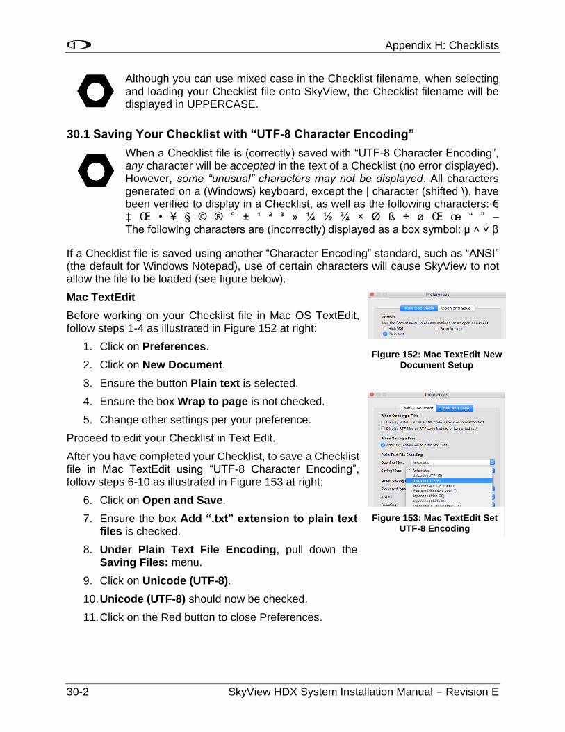
Appendix H: Checklists
30-2 SkyView HDX System Installation Manual - Revision E
Although you can use mixed case in the Checklist filename, when selecting and loading your Checklist file onto SkyView, the Checklist filename will be displayed in UPPERCASE.
30.1 Saving Your Checklist with “UTF-8 Character Encoding”
When a Checklist file is (correctly) saved with “UTF-8 Character Encoding”, any character will be accepted in the text of a Checklist (no error displayed). However, some “unusual” characters may not be displayed. All characters generated on a (Windows) keyboard, except the | character (shifted \), have been verified to display in a Checklist, as well as the following characters: € ‡ Œ • ¥ § © ® ° ± ¹ ² ³ » ¼ ½ ¾ × Ø ß ÷ ø Œ œ “ ” – The following characters are (incorrectly) displayed as a box symbol: µ ˄ ˅ β
If a Checklist file is saved using another “Character Encoding” standard, such as “ANSI” (the default for Windows Notepad), use of certain characters will cause SkyView to not allow the file to be loaded (see figure below).
Mac TextEdit
Before working on your Checklist file in Mac OS TextEdit, follow steps 1-4 as illustrated in Figure 152 at right:
1. Click on Preferences.
2. Click on New Document.
3. Ensure the button Plain text is selected.
4. Ensure the box Wrap to page is not checked.
5. Change other settings per your preference.
Proceed to edit your Checklist in Text Edit.
After you have completed your Checklist, to save a Checklist file in Mac TextEdit using “UTF-8 Character Encoding”, follow steps 6-10 as illustrated in Figure 153 at right:
6. Click on Open and Save.
7. Ensure the box Add “.txt” extension to plain text files is checked.
8. Under Plain Text File Encoding, pull down the Saving Files: menu.
9. Click on Unicode (UTF-8).
10. Unicode (UTF-8) should now be checked.
11. Click on the Red button to close Preferences.
Figure 153: Mac TextEdit Set UTF-8 Encoding
Figure 152: Mac TextEdit New Document Setup
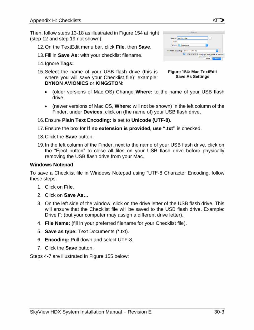
Appendix H: Checklists
SkyView HDX System Installation Manual - Revision E 30-3
Then, follow steps 13-18 as illustrated in Figure 154 at right (step 12 and step 19 not shown):
12. On the TextEdit menu bar, click File, then Save.
13. Fill in Save As: with your checklist filename.
14. Ignore Tags:
15. Select the name of your USB flash drive (this is where you will save your Checklist file); example: DYNON AVIONICS or KINGSTON:
• (older versions of Mac OS) Change Where: to the name of your USB flash drive.
• (newer versions of Mac OS, Where: will not be shown) In the left column of the Finder, under Devices, click on (the name of) your USB flash drive.
16. Ensure Plain Text Encoding: is set to Unicode (UTF-8).
17. Ensure the box for If no extension is provided, use “.txt” is checked.
18. Click the Save button.
19. In the left column of the Finder, next to the name of your USB flash drive, click on the “Eject button” to close all files on your USB flash drive before physically removing the USB flash drive from your Mac.
Windows Notepad
To save a Checklist file in Windows Notepad using “UTF-8 Character Encoding, follow these steps:
1. Click on File.
2. Click on Save As…
3. On the left side of the window, click on the drive letter of the USB flash drive. This will ensure that the Checklist file will be saved to the USB flash drive. Example: Drive F: (but your computer may assign a different drive letter).
4. File Name: (fill in your preferred filename for your Checklist file).
5. Save as type: Text Documents (*.txt).
6. Encoding: Pull down and select UTF-8.
7. Click the Save button.
Steps 4-7 are illustrated in Figure 155 below:
Figure 154: Mac TextEdit Save As Settings
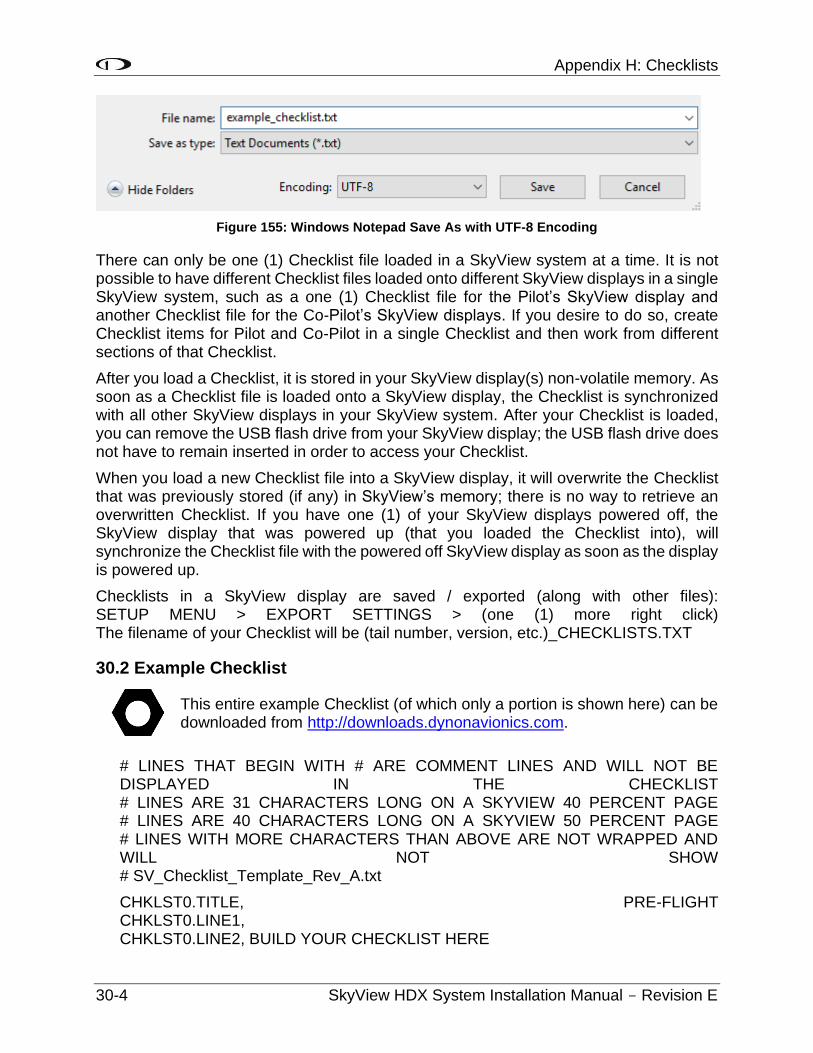
Appendix H: Checklists
30-4 SkyView HDX System Installation Manual - Revision E
Figure 155: Windows Notepad Save As with UTF-8 Encoding
There can only be one (1) Checklist file loaded in a SkyView system at a time. It is not possible to have different Checklist files loaded onto different SkyView displays in a single SkyView system, such as a one (1) Checklist file for the Pilot’s SkyView display and another Checklist file for the Co-Pilot’s SkyView displays. If you desire to do so, create Checklist items for Pilot and Co-Pilot in a single Checklist and then work from different sections of that Checklist.
After you load a Checklist, it is stored in your SkyView display(s) non-volatile memory. As soon as a Checklist file is loaded onto a SkyView display, the Checklist is synchronized with all other SkyView displays in your SkyView system. After your Checklist is loaded, you can remove the USB flash drive from your SkyView display; the USB flash drive does not have to remain inserted in order to access your Checklist.
When you load a new Checklist file into a SkyView display, it will overwrite the Checklist that was previously stored (if any) in SkyView’s memory; there is no way to retrieve an overwritten Checklist. If you have one (1) of your SkyView displays powered off, the SkyView display that was powered up (that you loaded the Checklist into), will synchronize the Checklist file with the powered off SkyView display as soon as the display is powered up.
Checklists in a SkyView display are saved / exported (along with other files): SETUP MENU > EXPORT SETTINGS > (one (1) more right click) The filename of your Checklist will be (tail number, version, etc.)_CHECKLISTS.TXT
30.2 Example Checklist
This entire example Checklist (of which only a portion is shown here) can be downloaded from http://downloads.dynonavionics.com.
# LINES THAT BEGIN WITH # ARE COMMENT LINES AND WILL NOT BE DISPLAYED IN THE CHECKLIST # LINES ARE 31 CHARACTERS LONG ON A SKYVIEW 40 PERCENT PAGE # LINES ARE 40 CHARACTERS LONG ON A SKYVIEW 50 PERCENT PAGE # LINES WITH MORE CHARACTERS THAN ABOVE ARE NOT WRAPPED AND WILL NOT SHOW # SV_Checklist_Template_Rev_A.txt
CHKLST0.TITLE, PRE-FLIGHT CHKLST0.LINE1, CHKLST0.LINE2, BUILD YOUR CHECKLIST HERE
Appendix H: Checklists
SkyView HDX System Installation Manual - Revision E 30-5
CHKLST1.TITLE, BEFORE STARTING ENGINE CHKLST1.LINE1, CHKLST1.LINE2, BUILD YOUR CHECKLIST HERE
CHKLST2.TITLE, ENGINE START CHKLST2.LINE1, CHKLST2.LINE2, BUILD YOUR CHECKLIST HERE
CHKLST3.TITLE, PRE-TAXI & TAXI CHKLST3.LINE1, CHKLST3.LINE2, BUILD YOUR CHECKLIST HERE
CHKLST4.TITLE, RUN-UP & PRE-TAKEOFF CHKLST4.LINE1, CHKLST4.LINE2, BUILD YOUR CHECKLIST HERE
# …
CHKLST21.TITLE, MISC: TRANSPONDER CODES CHKLST21.LINE1, CHKLST21.LINE2, VFR - 1200 (USA) CHKLST21.LINE3, VFR - 7000 (Europe) CHKLST21.LINE4, Hijack – 7500 CHKLST21.LINE5, Radio Fail – 7600 CHKLST21.LINE6, Emergency - 7700
30.3 Example Checklist Formatting Notes:
Comment lines (not displayed as a Checklist item) begin with #. Example:
# This line in a checklist file will not be displayed in a checklist.
Checklist numbering starts with 0; the first Checklist displayed is CHKLST0.
For additional Checklists, increment the name CHKLIST in each section from 0. Example:
• CHKLST0
• CHKLST1
• CHKLST10
• CHKLIST11
• (etc.)
Each Checklist requires a title line in this format:
CHKLST(section number).TITLE, (title). Example: CHKLST0.TITLE, PRE-FLIGHT
Each Checklist can have any number of Checklist items (including none), but each item must be sequentially numbered, beginning from 1, in this format:
Appendix H: Checklists
30-6 SkyView HDX System Installation Manual - Revision E
CHKLST(section number).LINE(checklist item), (title). Example: CHKLST0.LINE1, CHKLST0.LINE2, BUILD YOUR CHECKLIST HERE
Each Checklist Name and Checklist Item will only display 31 characters for a 40% Page, and 40 characters on a 50% page. Characters in excess of these lengths will not be wrapped and will simply not appear.
# LINES ARE 31 CHARACTERS LONG ON A SKYVIEW 40 PERCENT PAGE # LINES WITH MORE CHARACTERS THAN ABOVE ARE NOT WRAPPED AND WILL NOT SHOW CHKLST0.TITLE, 1234567890123456789012345678901 CHKLST0.LINE1, 1234567890123456789012345678901
# LINES ARE 40 CHARACTERS LONG ON A SKYVIEW 50 PERCENT PAGE # LINES WITH MORE CHARACTERS THAN ABOVE ARE NOT WRAPPED AND WILL NOT SHOW CHKLST0.TITLE, 1234567890123456789012345678901234567890 CHKLST0.LINE1, 1234567890123456789012345678901234567890
If you wish to keep track of the version of Checklist that you develop, this is easily done by making the title of your last Checklist a version number (with no Checklist items), such as:
CHKLST23.TITLE, CHECKLIST INFO CHKLST23.LINE1, CHKLST23.LINE2, LAST UPDATED 2016-01-12 CHKLST23.LINE3, (DATE MUST BE MANUALLY UPDATED)
This will appear on the last line of the Checklist as:
CHECKLIST INFO >
When you click the arrow:
LAST UPDATED 2016-01-12
(DATE MUST BE MANUALLY UPDATED)
30.4 Excel Checklist Generation Tool
Dynon Avionics has developed a SkyView Checklist Generation Tool based on Excel for Mac or PC; this tool will not work in the versions of Excel accessible online or in versions of Excel on tablet devices (these versions do not have “macro” capability). Using this tool is easier than creating a Checklist manually in a text editor, allowing you to focus on the contents of your particular Checklist. The tool ensures that the formatting of the Checklist is correct. The tool requires that your computer have Microsoft Excel installed as it uses Excel’s macro capability to perform the formatting.
The tool is called “Excel-based Checklist Creator” and can be downloaded from http://downloads.dynonavionics.com. Dynon Avionics has also released
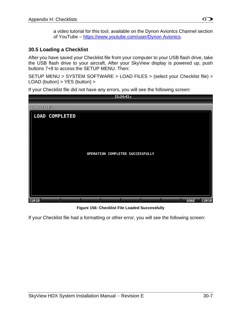
Appendix H: Checklists
SkyView HDX System Installation Manual - Revision E 30-7
a video tutorial for this tool, available on the Dynon Avionics Channel section of YouTube – https://www.youtube.com/user/Dynon Avionics.
30.5 Loading a Checklist
After you have saved your Checklist file from your computer to your USB flash drive, take the USB flash drive to your aircraft. After your SkyView display is powered up, push buttons 7+8 to access the SETUP MENU. Then:
SETUP MENU > SYSTEM SOFTWARE > LOAD FILES > (select your Checklist file) > LOAD (button) > YES (button) >
If your Checklist file did not have any errors, you will see the following screen:
Figure 156: Checklist File Loaded Successfully
If your Checklist file had a formatting or other error, you will see the following screen:
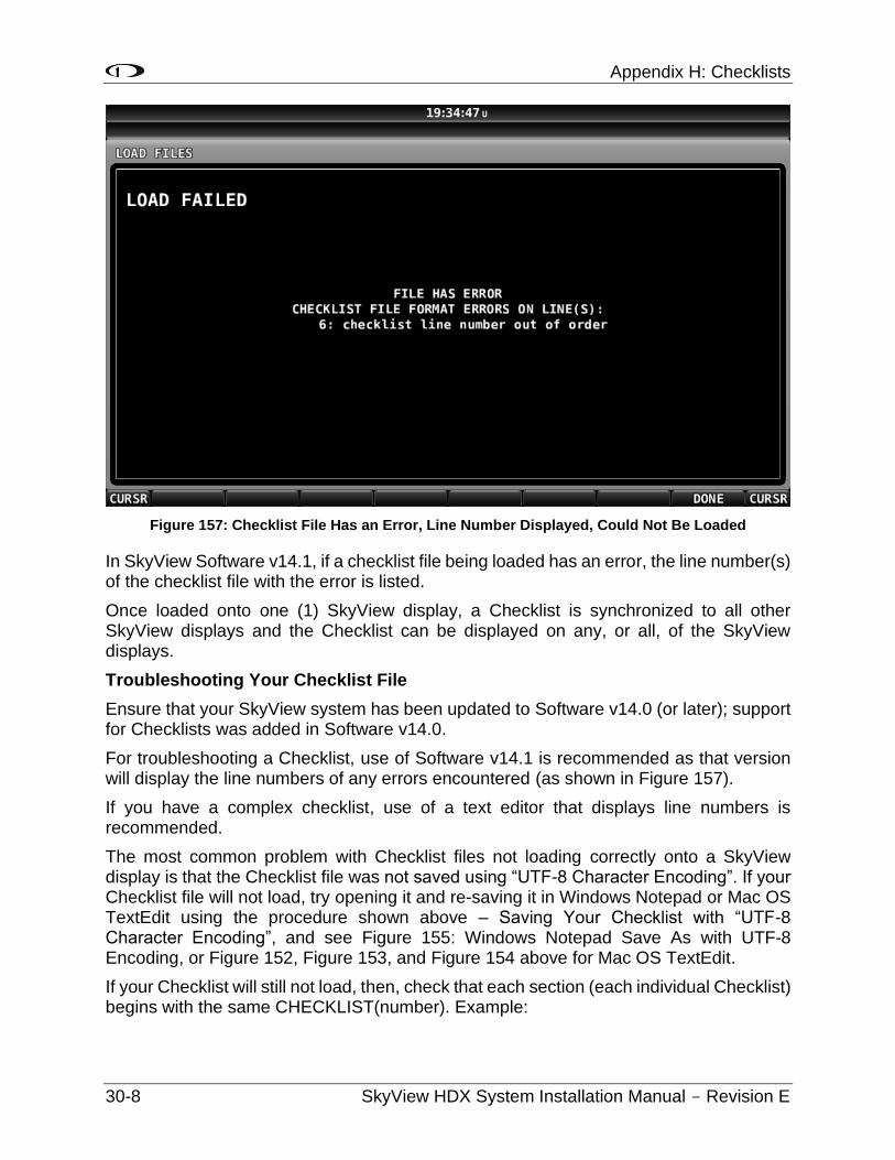
Appendix H: Checklists
30-8 SkyView HDX System Installation Manual - Revision E
Figure 157: Checklist File Has an Error, Line Number Displayed, Could Not Be Loaded
In SkyView Software v14.1, if a checklist file being loaded has an error, the line number(s) of the checklist file with the error is listed.
Once loaded onto one (1) SkyView display, a Checklist is synchronized to all other SkyView displays and the Checklist can be displayed on any, or all, of the SkyView displays.
Troubleshooting Your Checklist File
Ensure that your SkyView system has been updated to Software v14.0 (or later); support for Checklists was added in Software v14.0.
For troubleshooting a Checklist, use of Software v14.1 is recommended as that version will display the line numbers of any errors encountered (as shown in Figure 157).
If you have a complex checklist, use of a text editor that displays line numbers is recommended.
The most common problem with Checklist files not loading correctly onto a SkyView display is that the Checklist file was not saved using “UTF-8 Character Encoding”. If your Checklist file will not load, try opening it and re-saving it in Windows Notepad or Mac OS TextEdit using the procedure shown above – Saving Your Checklist with “UTF-8 Character Encoding”, and see Figure 155: Windows Notepad Save As with UTF-8 Encoding, or Figure 152, Figure 153, and Figure 154 above for Mac OS TextEdit.
If your Checklist will still not load, then, check that each section (each individual Checklist) begins with the same CHECKLIST(number). Example:
Appendix H: Checklists
SkyView HDX System Installation Manual - Revision E 30-9
CHKLST0.TITLE, PRE-FLIGHT CHKLST0.LINE1, CHKLST0.LINE2, BUILD YOUR CHECKLIST HERE is correct.
CHKLST0.TITLE, PRE-FLIGHT CHKLST0.LINE1, CHKLST1.LINE2, BUILD YOUR CHECKLIST HERE is not correct (Checklist numbers do not match).
Also, check that each Checklist item) has a correct, sequential number. Example: CHKLST0.TITLE, PRE-FLIGHT CHKLST0.LINE1 CHKLST0.LINE2, BUILD YOUR CHECKLIST HERE is correct. CHKLST0.TITLE, PRE-FLIGHT CHKLST0.LINE1, CHKLST0.LINE1, BUILD YOUR CHECKLIST HERE is not correct (there are two (2) CHKLST0.LINE1 lines; the second should be CHKLST0.LINE2).
If you cannot get your Checklist file to load (“FILE HAS ERROR” screen), you can isolate where the problem is in your Checklist file by “commenting out” individual lines, or entire sections, by prepending the line with a # and a space character. Example:
# CHKLST0.TITLE, PRE-FLIGHT
A future version of SkyView Software will enhance the error message shown in Figure 157 above to display the line number where an error is encountered.
Lines that begin with # will not be processed / checked when the Checklist file is loaded. Admittedly this will be tedious if your SkyView display is in your aircraft and your computer is at home, so this is best done using a laptop computer in the aircraft, so you can edit, export, and test rapidly on your SkyView display.
Once a Checklist is loaded, there is no way to delete the current Checklist. The closest thing to a “delete Checklists” function is to load an empty file (no text in it) with a filename such as blankchecklist.txt. This will have the effect of displaying a blank page when the CHECKLIST button is pressed.
30.6 Displaying Your Checklist on your SkyView Display
Until a Checklist file is loaded into your SkyView system, the CHECKLIST button will not appear in the TOOLS menu. A default / example Checklist is not installed in new SkyView displays, nor is a default / example Checklist automatically installed into a SkyView display as part of updating your SkyView system to Software v14.0.
To access your Checklist on a SkyView display, from the main menu, go to the TOOLS menu and push the CHECKLIST button. The Checklist will continue to be displayed until
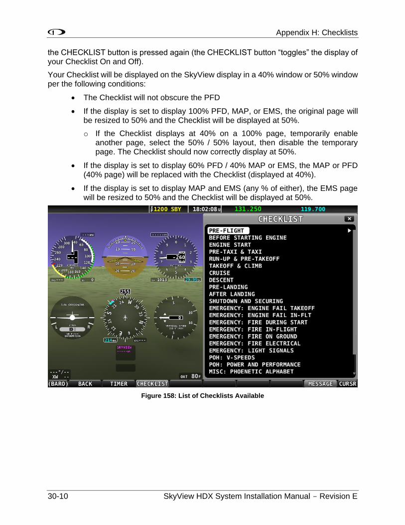
Appendix H: Checklists
30-10 SkyView HDX System Installation Manual - Revision E
the CHECKLIST button is pressed again (the CHECKLIST button “toggles” the display of your Checklist On and Off).
Your Checklist will be displayed on the SkyView display in a 40% window or 50% window per the following conditions:
• The Checklist will not obscure the PFD
• If the display is set to display 100% PFD, MAP, or EMS, the original page will be resized to 50% and the Checklist will be displayed at 50%.
o If the Checklist displays at 40% on a 100% page, temporarily enable another page, select the 50% / 50% layout, then disable the temporary page. The Checklist should now correctly display at 50%.
• If the display is set to display 60% PFD / 40% MAP or EMS, the MAP or PFD (40% page) will be replaced with the Checklist (displayed at 40%).
• If the display is set to display MAP and EMS (any % of either), the EMS page will be resized to 50% and the Checklist will be displayed at 50%.
Figure 158: List of Checklists Available
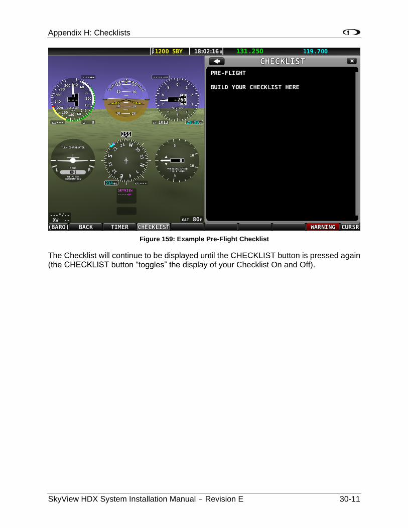
Appendix H: Checklists
SkyView HDX System Installation Manual - Revision E 30-11
Figure 159: Example Pre-Flight Checklist
The Checklist will continue to be displayed until the CHECKLIST button is pressed again (the CHECKLIST button “toggles” the display of your Checklist On and Off).

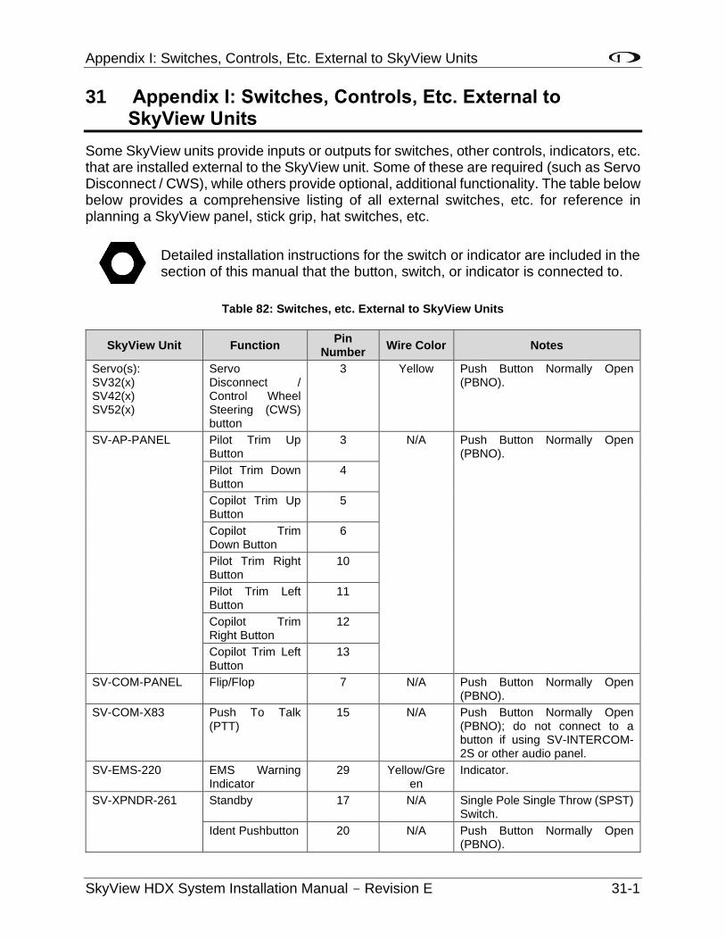
Appendix I: Switches, Controls, Etc. External to SkyView Units
SkyView HDX System Installation Manual - Revision E 31-1
31 Appendix I: Switches, Controls, Etc. External to SkyView Units
Some SkyView units provide inputs or outputs for switches, other controls, indicators, etc. that are installed external to the SkyView unit. Some of these are required (such as Servo Disconnect / CWS), while others provide optional, additional functionality. The table below below provides a comprehensive listing of all external switches, etc. for reference in planning a SkyView panel, stick grip, hat switches, etc.
Detailed installation instructions for the switch or indicator are included in the section of this manual that the button, switch, or indicator is connected to.
Table 82: Switches, etc. External to SkyView Units
SkyView Unit Function Pin
Number Wire Color Notes
Servo(s): SV32(x) SV42(x) SV52(x)
Servo Disconnect / Control Wheel Steering (CWS) button
3 Yellow Push Button Normally Open (PBNO).
SV-AP-PANEL Pilot Trim Up Button
3 N/A Push Button Normally Open (PBNO).
Pilot Trim Down Button
4
Copilot Trim Up Button
5
Copilot Trim Down Button
6
Pilot Trim Right Button
10
Pilot Trim Left Button
11
Copilot Trim Right Button
12
Copilot Trim Left Button
13
SV-COM-PANEL Flip/Flop 7 N/A Push Button Normally Open (PBNO).
SV-COM-X83 Push To Talk (PTT)
15 N/A Push Button Normally Open (PBNO); do not connect to a button if using SV-INTERCOM-2S or other audio panel.
SV-EMS-220 EMS Warning Indicator
29 Yellow/Green
Indicator.
SV-XPNDR-261 Standby 17 N/A Single Pole Single Throw (SPST) Switch.
Ident Pushbutton 20 N/A Push Button Normally Open (PBNO).
Appendix I: Switches, Controls, Etc. External to SkyView Units
31-2 SkyView HDX System Installation Manual - Revision E
Recommended


