Embed Size (px)
Citation preview
21 January 2015
Introduction
Types
History
Uses
Equipment
Positioning of the Patient
Evaluation of Radiograph
Landmarks and Planes
Analysis
References
Cephalometry
The analysis and interpretation of standardized
radiographs of facial bones
- Using standardized skull radiograph to assess facial,
dental and skeletal relationships as well as airway
analysis
1) Lateral Cephalogram
• Lateral view of skull
• X-ray beam perpendicular to the patient's sagittal plane
2) Frontal Cephalogram
• Anteroposterior view of skull
• X-ray beam perpendicular to the patient’s coronal plane
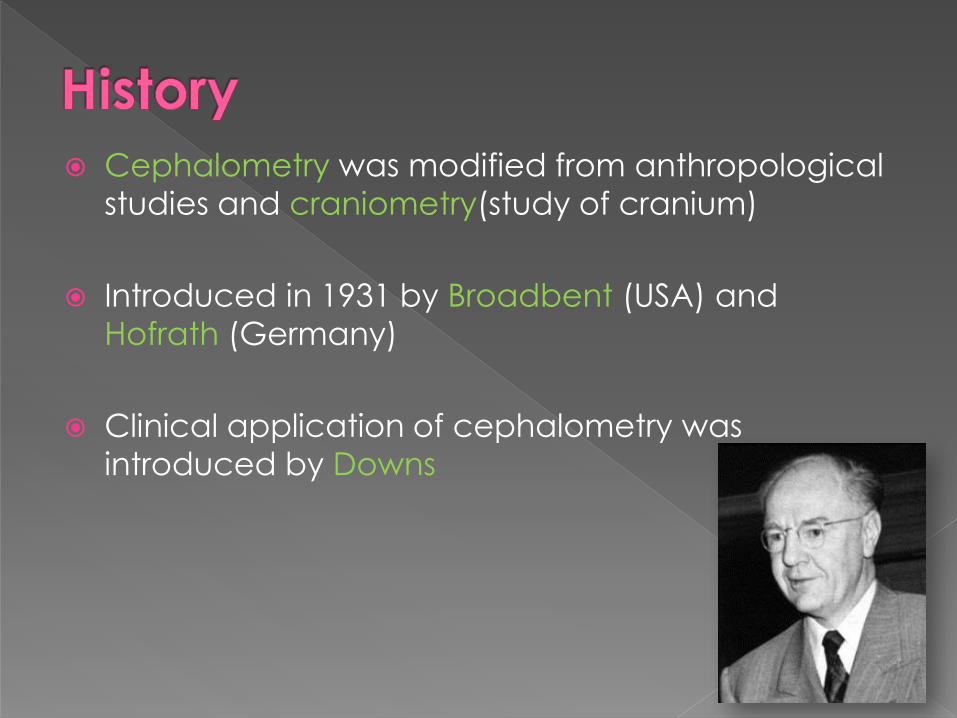
Cephalometry was modified from anthropological
studies and craniometry(study of cranium)
Introduced in 1931 by Broadbent (USA) and
Hofrath (Germany)
Clinical application of cephalometry was
introduced by Downs
In orthodontic diagnosis and treatment planning.
› Assesment of horizontal/vertical skeletal relationship,
incisor position/inclination, soft tissue profile
› Orthognathic surgery
Helps in classification of skeletal and dental
abnormalities.
Helps in evaluation of treatment results.
› Post-functional to assess skeletal/dental relationship
› Plan retention and monitor post retention phase
Helps in predicting growth related changes.
Research purpose
• Collimated X-ray source - 5 feet from midsagittal plane of
patient
• Cephalostat - head positioner(with 2 ear rods and forehead
clamp)
• Aluminium wedge/ Barium paste - increases soft tissue
definition
• Film - placed 1.5-1.8 foot behind midsagittal plane of
patient with rare earth metal intensifying screen
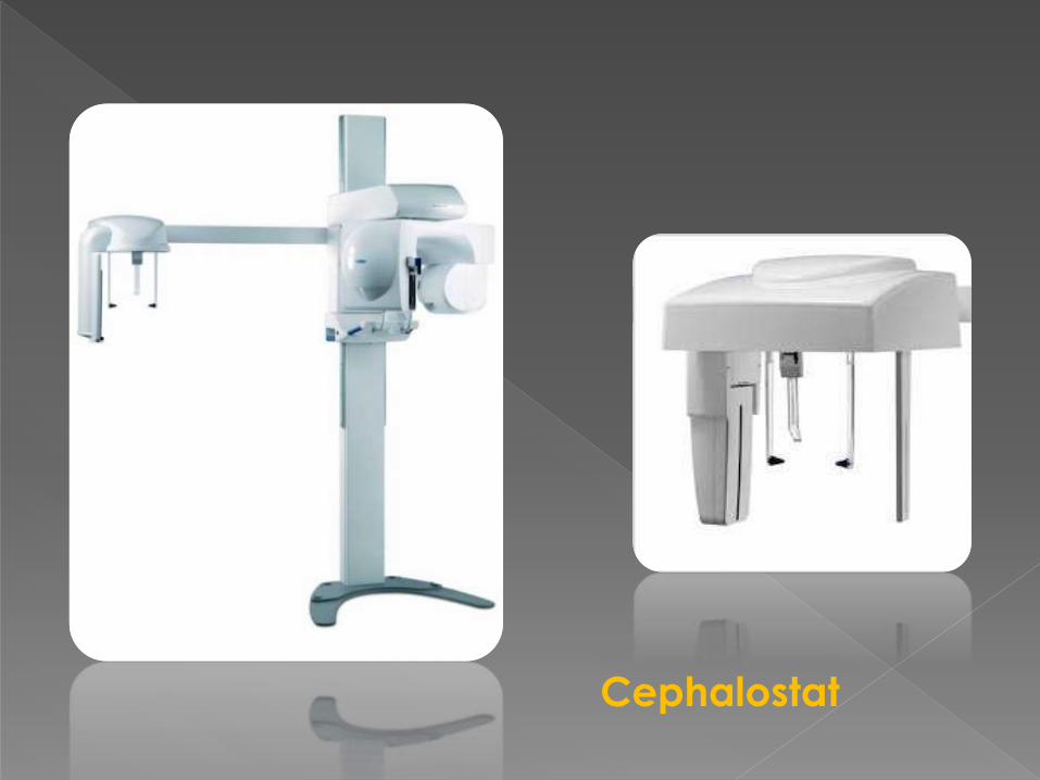
Cephalostat
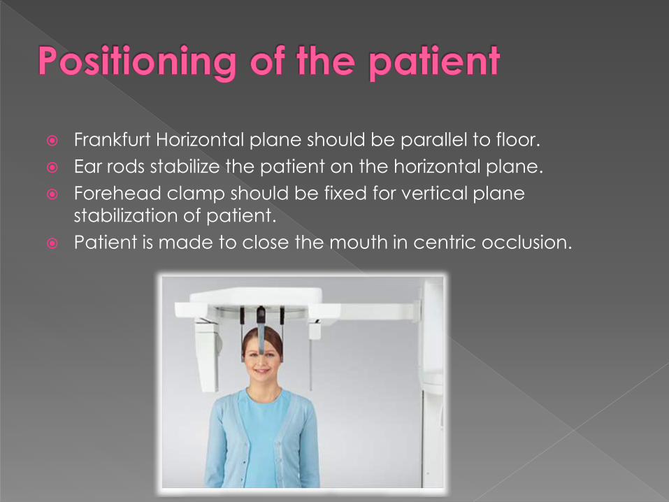
Frankfurt Horizontal plane should be parallel to floor.
Ear rods stabilize the patient on the horizontal plane.
Forehead clamp should be fixed for vertical plane
stabilization of patient.
Patient is made to close the mouth in centric occlusion.
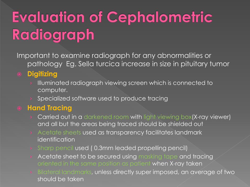
Important to examine radiograph for any abnormalities or
pathology Eg. Sella turcica increase in size in pituitary tumor
Digitizing
› Illuminated radiograph viewing screen which is connected to computer.
› Specialized software used to produce tracing
Hand Tracing
› Carried out in a darkened room with light viewing box(X-ray viewer) and all but the areas being traced should be shielded out
› Acetate sheets used as transparency facilitates landmark identification
› Sharp pencil used ( 0.3mm leaded propelling pencil)
› Acetate sheet to be secured using masking tape and tracing oriented in the same position as patient when X-ray taken
› Bilateral landmarks, unless directly super imposed, an average of two should be taken
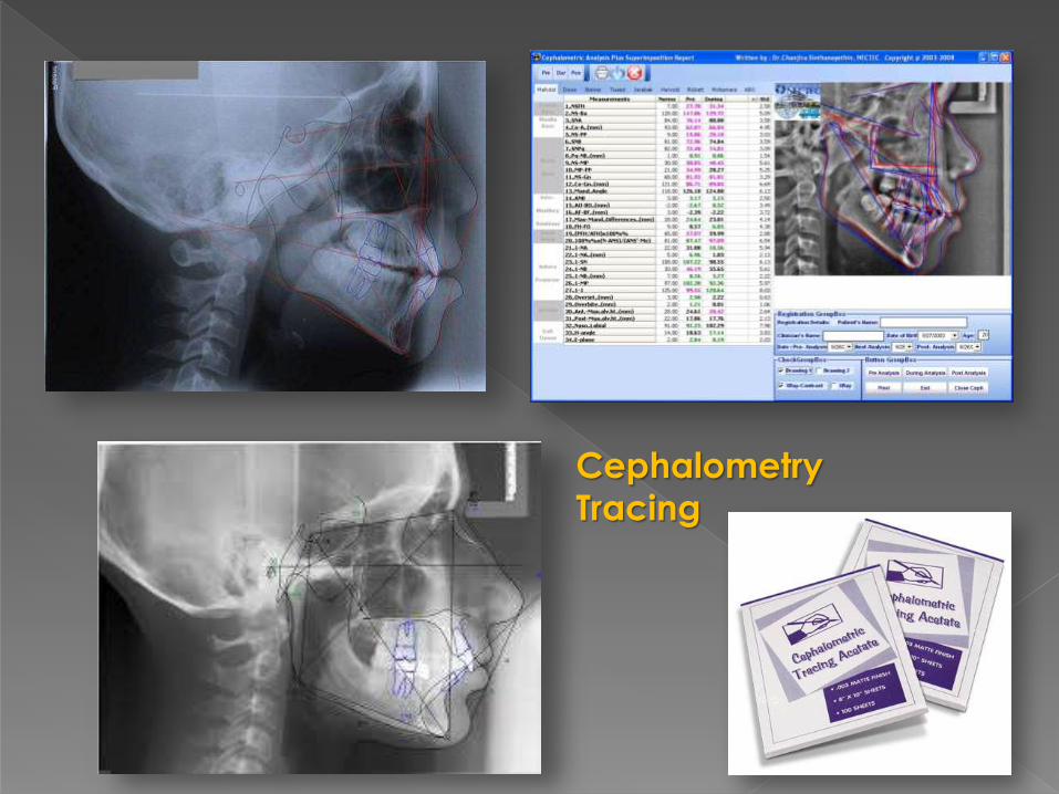
Cephalometry
Tracing
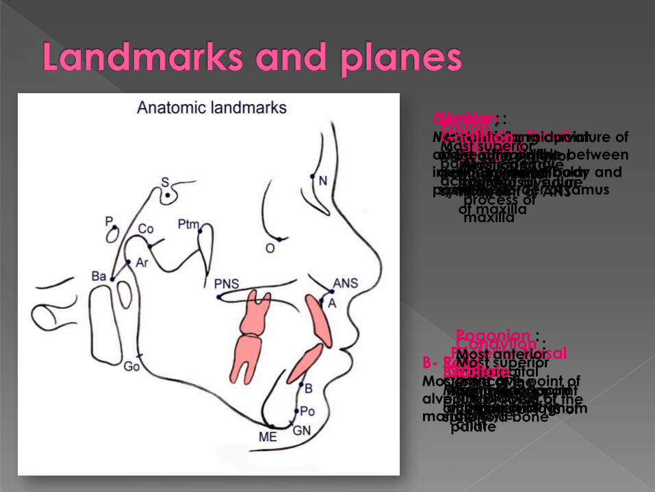
Sella : Centre of the
pituitary fossa of the
sphenoid bone
Nasion :Junction of
frontonasal suture
Basion :Most anterior point
of foramen magnum
Anterior Nasal
Spine :Most anterior
midpoint of ANS
of maxilla
Posterior Nasal
Spine :Most posterior
midpoint of PNS of
palate
A- Point :Most concave
point of alveolar
process of
maxilla
B- Point :Most concave point of
alveolar process of
mandible
Menton :Most inferior midpoint
of the chin on the
outline of mandibular
symphysis
Pogonion :Most anterior
midsaggital
point along
convexity of
chin
Gonion :Midpoint along curvature of
angle of mandible between
inferior border of body and
posterior border of ramus
Condylion :Most superior
point of
mandibular
condyle
Gnathion :Most anteroinferior
point on mental
symphysis
Orbitale :Most inferior point
of infraorbital rim
Porion :Most superior
point of external
accoustic
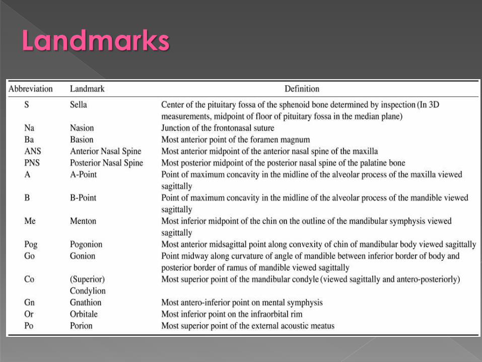
Landmarks
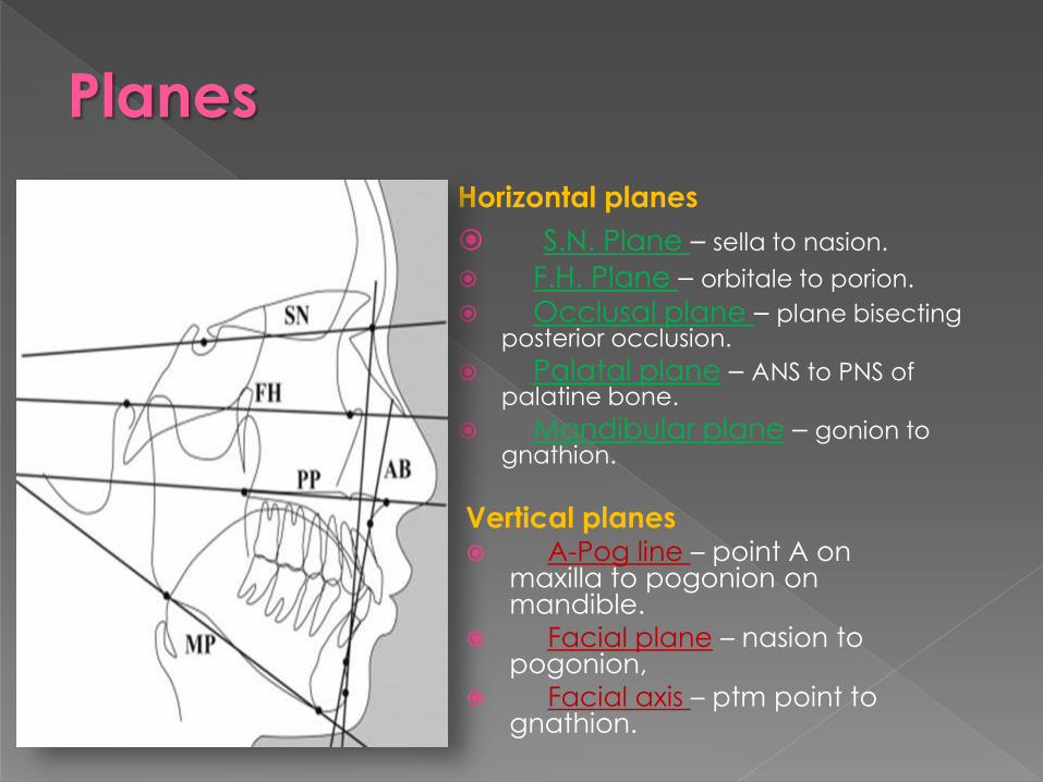
Horizontal planes
S.N. Plane – sella to nasion.
F.H. Plane – orbitale to porion.
Occlusal plane – plane bisecting posterior occlusion.
Palatal plane – ANS to PNS of palatine bone.
Mandibular plane – gonion to gnathion.
Vertical planes A-Pog line – point A on
maxilla to pogonion on mandible.
Facial plane – nasion to pogonion,
Facial axis – ptm point to gnathion.
Planes

Examples
Down's
Steiner
Rickett
Harvold
McNamara
Sassouni
Wits by Johnston
Wylie
Tweed
Downs Analysis
First published by Downs in 1948
Most frequently used cephalometric analysis
According to Downs,
“Balance of face is determined by position of
mandible”
Frankfurt Horizontal plane used as reference plan to
degree of retrognathism or prognathism
Skeletal Perimeters
Facial angle
Inferior angle formed by intersection of nasion-
pogonion plane and F.H. plane.
Average value: 87.5o ( 82o - 95o)
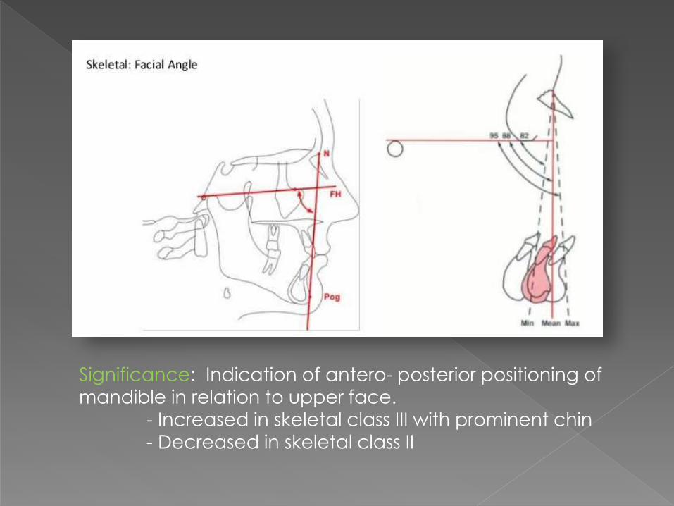
Significance: Indication of antero- posterior positioning of
mandible in relation to upper face. - Increased in skeletal class III with prominent chin
- Decreased in skeletal class II
Angle of convexity
Nasion-point A to point A – pogonion.
Average value: 0o ( -8.5o - 10o).
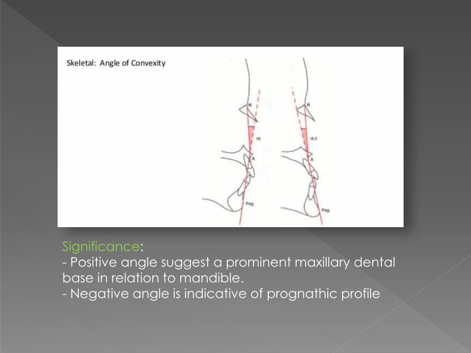
Significance:
- Positive angle suggest a prominent maxillary dental
base in relation to mandible.- Negative angle is indicative of prognathic profile
A-B plane angle
Point A – point B to nasion – pogonion.
Average value: -4.6o ( -9 to 0o)
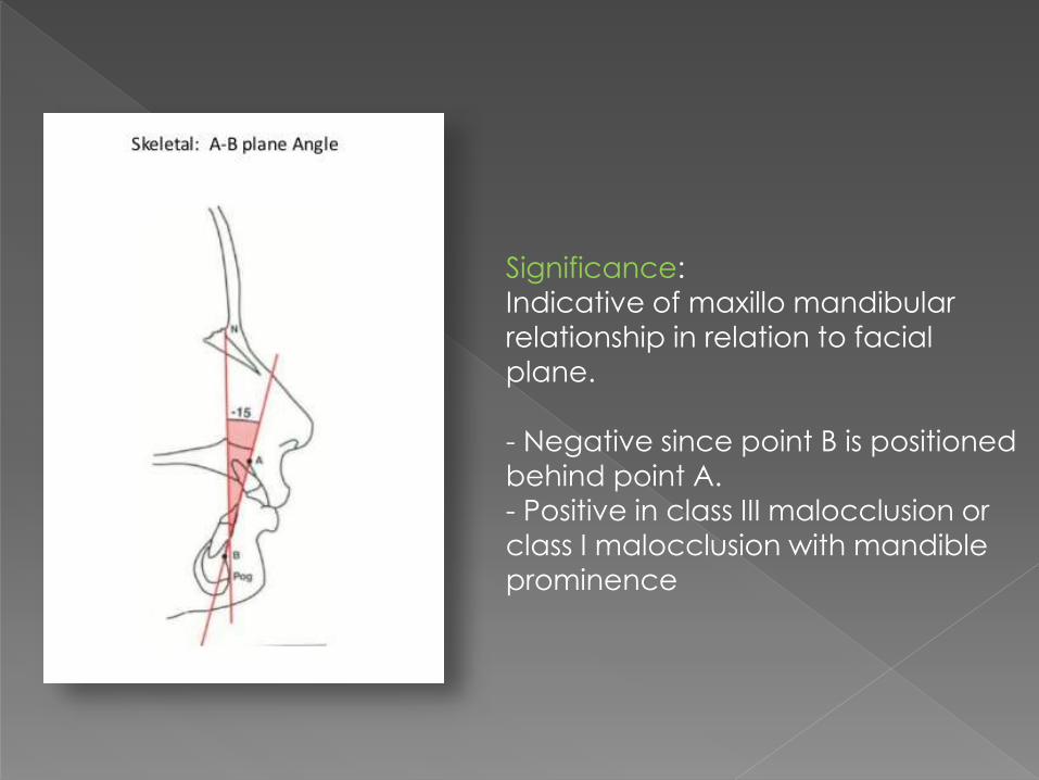
Significance:
Indicative of maxillo mandibular
relationship in relation to facial plane.
- Negative since point B is positioned
behind point A.
- Positive in class III malocclusion or
class I malocclusion with mandible
prominence

Y-Axis
Sella gnathion to F.H. plane.
Average value: 59.4o ( 53 to 66o)
Significance:
Indicates growth pattern of a individual
- Increased in Class II facial patterns – Vertical growth
pattern of mandible
- Decreased in Class III facial patterns – Horizontal growth
pattern of mandible
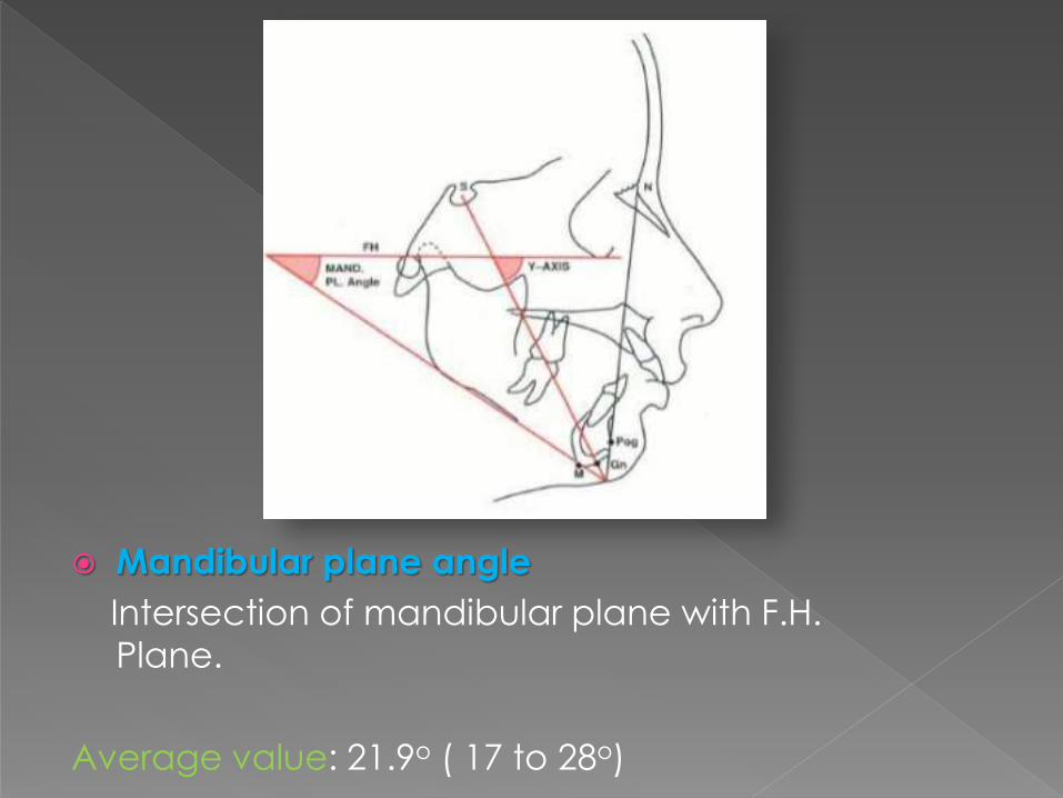
Mandibular plane angle
Intersection of mandibular plane with F.H.
Plane.
Average value: 21.9o ( 17 to 28o)

Dental Parameters Cant of occlusal plane
Occlusal plane to F.H. plane
Average value: 9.3o ( 1.5o - 14o)
Gives a measure of slope of occlusal plane relative
to F.H. Plane.
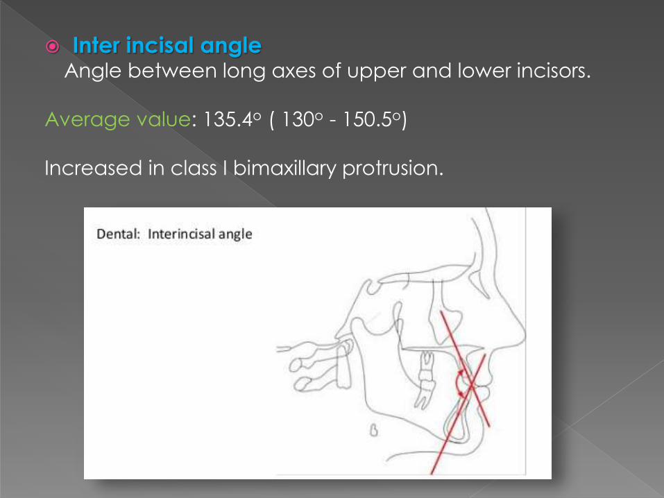
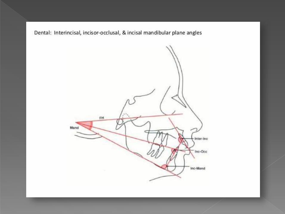
Inter incisal angleAngle between long axes of upper and lower incisors.
Average value: 135.4o ( 130o - 150.5o)
Increased in class I bimaxillary protrusion.
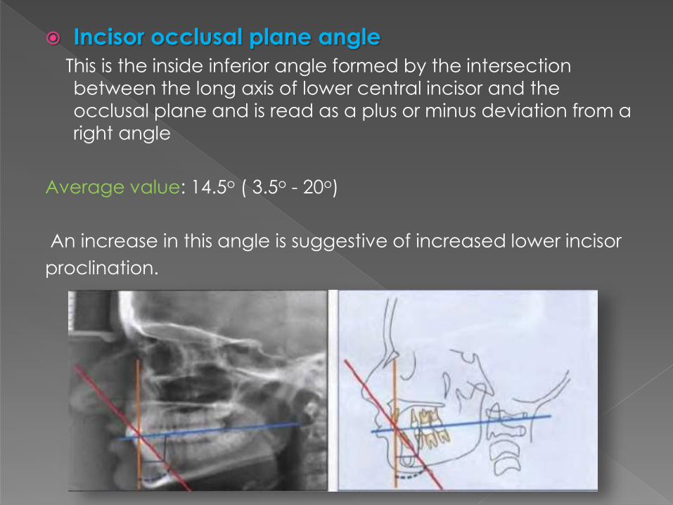
Incisor occlusal plane angle
This is the inside inferior angle formed by the intersection
between the long axis of lower central incisor and the
occlusal plane and is read as a plus or minus deviation from a
right angle
Average value: 14.5o ( 3.5o - 20o)
An increase in this angle is suggestive of increased lower incisor
proclination.
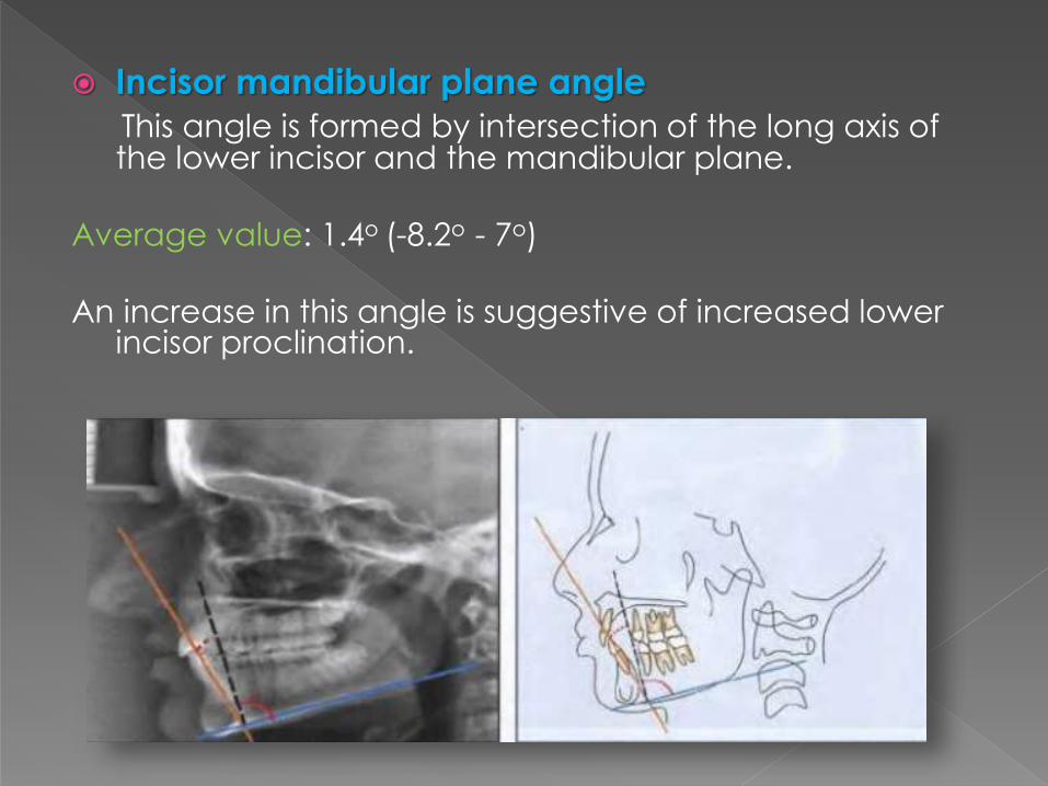
Incisor mandibular plane angle
This angle is formed by intersection of the long axis of the lower incisor and the mandibular plane.
Average value: 1.4o (-8.2o - 7o)
An increase in this angle is suggestive of increased lower incisor proclination.
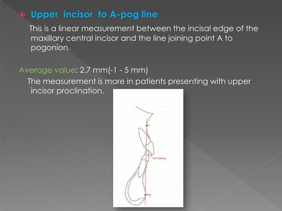
Upper incisor to A-pog line
This is a linear measurement between the incisal edge of the
maxillary central incisor and the line joining point A to
pogonion.
Average value: 2.7 mm(-1 - 5 mm)
The measurement is more in patients presenting with upper
incisor proclination.
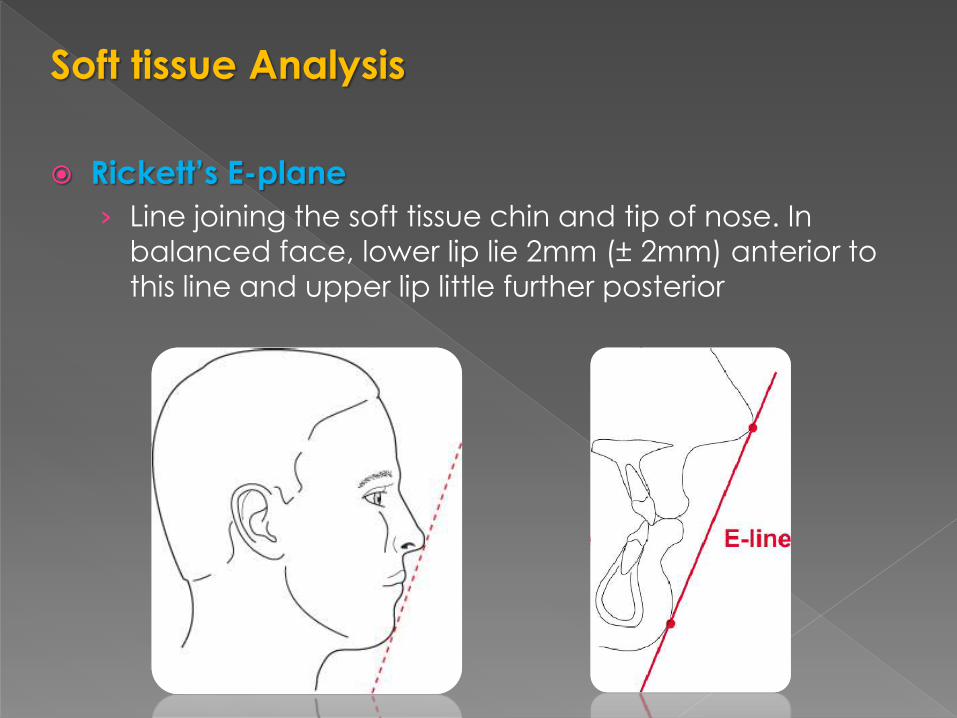
Soft tissue Analysis
Rickett’s E-plane
› Line joining the soft tissue chin and tip of nose. In
balanced face, lower lip lie 2mm (± 2mm) anterior to
this line and upper lip little further posterior
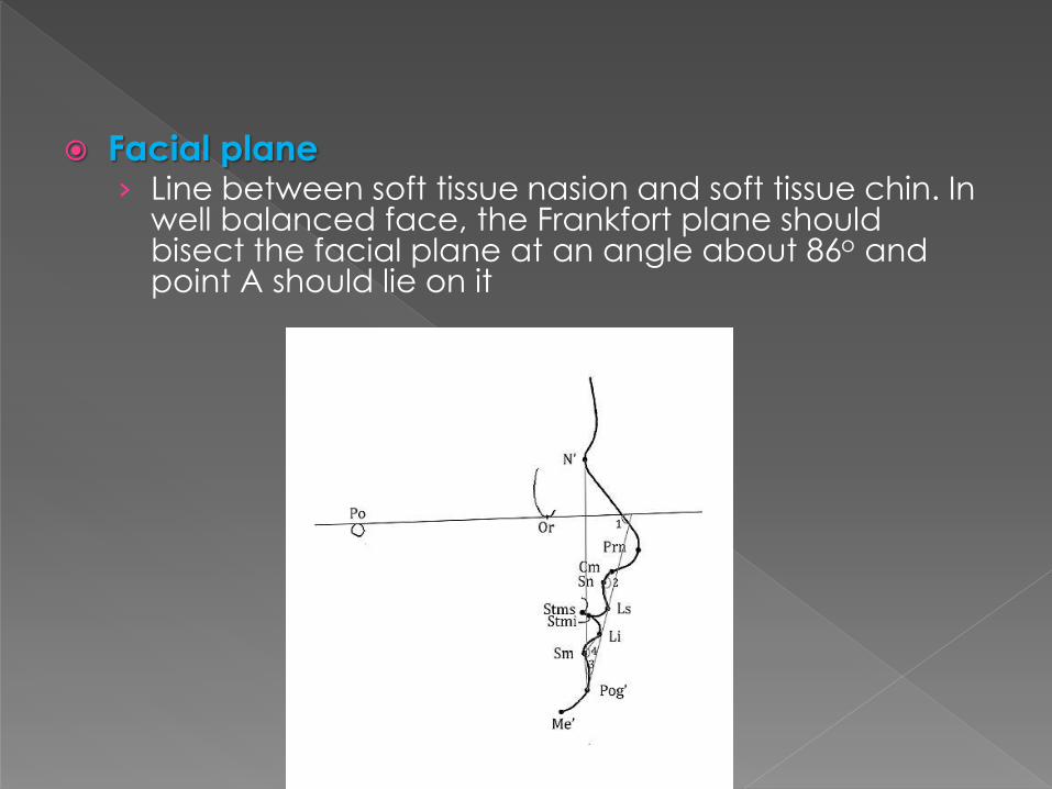
Facial plane› Line between soft tissue nasion and soft tissue chin. In
well balanced face, the Frankfort plane should bisect the facial plane at an angle about 86o and point A should lie on it
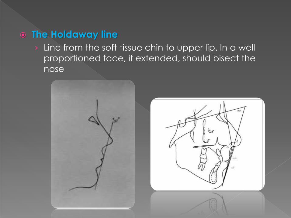
The Holdaway line
› Line from the soft tissue chin to upper lip. In a well
proportioned face, if extended, should bisect the
nose

An introduction to orthodontics, Laura Mitchell (3rd
edition)
Radiographic Cephalometrics, Alexander Jacobson
Contemporary Orthodontics, William R. Proffit (4th
edition)
Comparisons of the Consistency and Sensitivity of Five Reference Lines of the Horizontal Position of the Upper and Lower Lip to Lateral Facial Harmony, The Orthodontic Cyberjournal