Embed Size (px)
Citation preview
* GB785488 (A)
Description: GB785488 (A) ? 1957-10-30
Improvements in or relating to electric motor pump units
Description of GB785488 (A)
f- PATENT SPECIFICATION 785 g 488 Date of Application and filing Complete Specification: June 24, 1955. No 18302155. Application made in United States of America on July 1, 1954. Complete Specification Published: Oct 30, 1957. Index at Acceptance:-Classes 35, A( 2 C 2 2 E 4 2 F 14); and 110 ( 1), C 2 (A 2: C: G). Internati 6 onal Classification:-FO 5 c H 02 k. COMPLETE SPECIFICATION Improvements in or relating to Electric Motor Pump Units. We, WESTINGHOUSE ELECTRIC INTERNATIONAL C Om PANY, of 40, Wall Street, New York 5, State of New York, United States of America, a Corporation organised and existing under the Laws of the State of Delaware, in said United States of America, do hereby declare the invention, for which we pray that a patent may be granted to us, and the method by which it is to be performed, to be particularly described in and by the following statement:- The invention relates, generally, to motor pump units and, more particularly, to motor pump units which are adapted to be mounted in completely sealed casings. Such motor pump units are designed to operate in a system where the system pressure often is independent of the pressure produced by the pump, extremely high in relation to atmospheric pressure In addition to the high pressures involved in such a pumping system, the fluid is often corrosive, explosive, or otherwise of a dangerous nature In such pumping systems there is established a substantially zero leakage allowance, i e substantially no leakage is allowable, in order to eliminate the danger caused by leakage of the fluid Under these
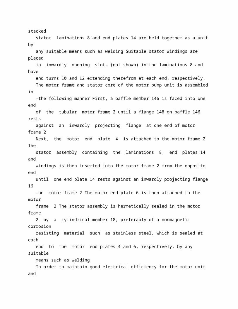
conditions it has been the practice to design the motor unit so that it could be immersed in the pump fluid, thus eliminating the need for mechanical shaft seals, and providing a pump with substantially zero leakage allowance. There are many disadvantages to prior designs, especially when the fluid being pumped was at an elevated temperature and of low viscosity Under these conditions, much difficulty has been experienced in attempting to lubricate the bearings with the pump fluid in which the motor unit was immersed Additional difficulties were experienced in cooling the motor unit due to the elevated temperature of the pumped fluid. In these prior designs, the stator assembly was usually isolated from the pumped fluid by a thin walled metal cylinder which was sealed at lPrice 3 s 6 d l both ends to the motor end plates and passed through the motor air gap In order to support this thin-walled cylinder the stator assembly was filled with oil and an external balance chamber used to equalize the pressure of the 50 oil and the pumped fluid and thus support the thin-walled cylinder This is undesirable due to the fact that when the bellows used in the balance chamber fails, the stator assembly is flooded with pumped fluid and much damage 55 to the motor unit may result, as well as danger to the surrounding area due to the escape of the pumped fluid. The invention provides a novel means for isolating the motor windings and eliminating 60 the need, for oil and a balance chamber to support the thin-walled cylinder used to isolate the stator windings In addition, a unique cooling and lubricating system is provided so that the motor pump unit can operate in a low-viscosity, 65 high-temperature fluid without failure. Accordingly, it is the principal object of the invention to provide a sealed motor pump unit of simplified construction having improved electrical efficiency and substantially zero 70 leakage. The invention will become more readily apparent from the following description of a preferred embodiment thereof, illustrated by way of example in the accompanying drawings 75 Figure 1 is a side elevation in partial longitudinal section of a motor-pump unit; Fig 2 is a sectional view of the unit shown in Fig 1, taken substantially along the line II-I 1 of Fig 1 but omitting the pump impeller for 80 clarity; and Fig 3 is a partial, enlarged view of the labyrinth seal and adjacent thrust pad shown in Fig 1 with the pump impeller omitted. The motor pump unit comprises a motor 85 unit having a stator and rotor and a pump unit attached to one end of the motor unit The motor unit has a solid tubular motor frame 2 with annular end plates 4 and 6 attached to each end of the motor frame 2 by any suitable 90 , 785488 means, such as by welding Inserted in the motdr frame is a stator core
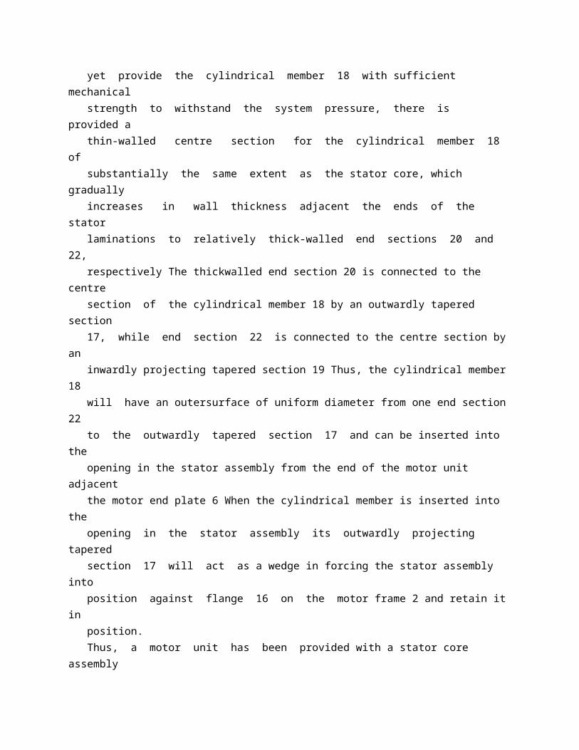
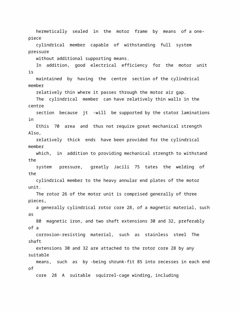
comprised of ringshaped laminations 8, of a magnetic material such as a magnetic steel, which are stacked between end plates 14 The stacked stator laminations 8 and end plates 14 are held together as a unit by any suitable means such as welding Suitable stator windings are placed in inwardly opening slots (not shown) in the laminations 8 and have end turns 10 and 12 extending therefrom at each end, respectively. The motor frame and stator core of the motor pump unit is assembled in -the following manner First, a baffle member 146 is faced into one end of the tubular motor frame 2 until a flange 148 on baffle 146 rests against an inwardly projecting flange at one end of motor frame 2 Next, the motor end plate 4 is attached to the motor frame 2 The stator assembly containing the laminations 8, end plates 14 and windings is then inserted into the motor frame 2 from the opposite end until one end plate 14 rests against an inwardly projecting flange 16 -on motor frame 2 The motor end plate 6 is then attached to the motor frame 2 The stator assembly is hermetically sealed in the motor frame 2 by a cylindrical member 18, preferably of a nonmagnetic corrosion resisting material such as stainless steel, which is sealed at each end to the motor end plates 4 and 6, respectively, by any suitable means such as welding. In order to maintain good electrical efficiency for the motor unit and yet provide the cylindrical member 18 with sufficient mechanical strength to withstand the system pressure, there is provided a thin-walled centre section for the cylindrical member 18 of substantially the same extent as the stator core, which gradually increases in wall thickness adjacent the ends of the stator laminations to relatively thick-walled end sections 20 and 22, respectively The thickwalled end section 20 is connected to the centre section of the cylindrical member 18 by an outwardly tapered section 17, while end section 22 is connected to the centre section by an inwardly projecting tapered section 19 Thus, the cylindrical member 18 will have an outersurface of uniform diameter from one end section 22 to the outwardly tapered section 17 and can be inserted into the opening in the stator assembly from the end of the motor unit adjacent the motor end plate 6 When the cylindrical member is inserted into the opening in the stator assembly its outwardly projecting tapered section 17 will act as a wedge in forcing the stator assembly into position against flange 16 on the motor frame 2 and retain it in position. Thus, a motor unit has been provided with a stator core assembly hermetically sealed in the motor frame by means of a one-piece cylindrical member capable of withstanding full system pressure without additional supporting means. In addition, good electrical efficiency for the motor unit is
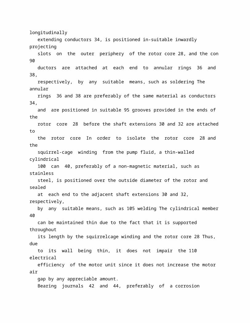
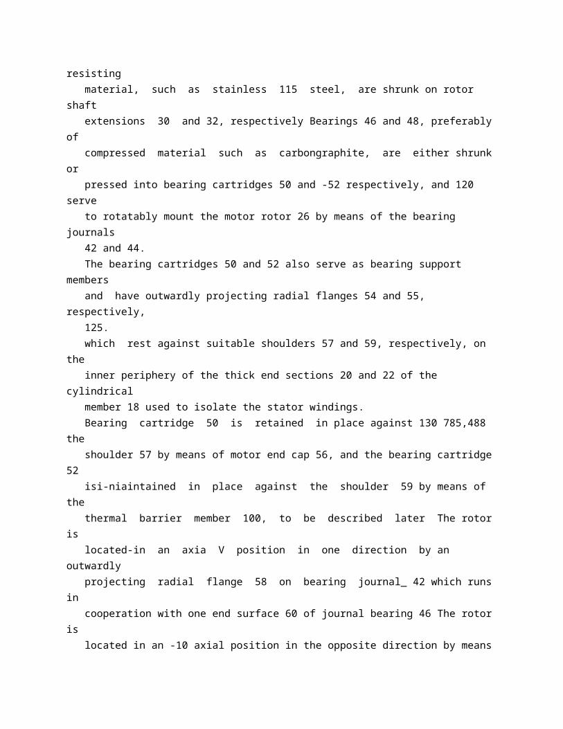
maintained by having the centre section of the cylindrical member relatively thin where it passes through the motor air gap. The cylindrical member can have relatively thin walls in the centre section because jt -will be supported by the stator laminations in Ethis 70 area and thus not require great mechanical strength Also, relatively thick ends have been provided for the cylindrical member which, in addition to providing mechanical strength to withstand the system pressure, greatly Jacili 75 tates the welding of the cylindrical member to the heavy annular end plates of the motor unit. The rotor 26 of the motor unit is comprised generally of three pieces, a generally cylindrical rotor core 28, of a magnetic material, such as 80 magnetic iron, and two shaft extensions 30 and 32, preferably of a corrosion-resisting material, such as stainless steel The shaft extensions 30 and 32 are attached to the rotor core 28 by any suitable means, such as by -being shrunk-fit 85 into recesses in each end of core 28 A suitable squirrel-cage winding, including longitudinally extending conductors 34, is positioned in-suitable inwardly projecting slots on the outer periphery of the rotor core 28, and the con 90 ductors are attached at each end to annular rings 36 and 38, respectively, by any suitable means, such as soldering The annular rings 36 and 38 are preferably of the same material as conductors 34, and are positioned in suitable 95 grooves provided in the ends of the rotor core 28 before the shaft extensions 30 and 32 are attached to the rotor core In order to isolate the rotor core 28 and the squirrel-cage winding from the pump fluid, a thin-walled cylindrical 100 can 40, preferably of a non-magnetic material, such as stainless steel, is positioned over the outside diameter of the rotor and sealed at each end to the adjacent shaft extensions 30 and 32, respectively, by any suitable means, such as 105 welding The cylindrical member 40 can be maintained thin due to the fact that it is supported throughout its length by the squirrelcage winding and the rotor core 28 Thus, due to its wall being thin, it does not impair the 110 electrical efficiency of the motor unit since it does not increase the motor air gap by any appreciable amount. Bearing journals 42 and 44, preferably of a corrosion resisting material, such as stainless 115 steel, are shrunk on rotor shaft extensions 30 and 32, respectively Bearings 46 and 48, preferably of compressed material such as carbongraphite, are either shrunk or pressed into bearing cartridges 50 and -52 respectively, and 120 serve to rotatably mount the motor rotor 26 by means of the bearing journals 42 and 44. The bearing cartridges 50 and 52 also serve as bearing support members and have outwardly projecting radial flanges 54 and 55, respectively, 125.
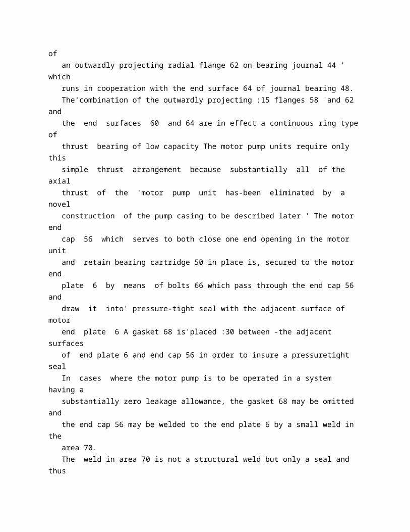
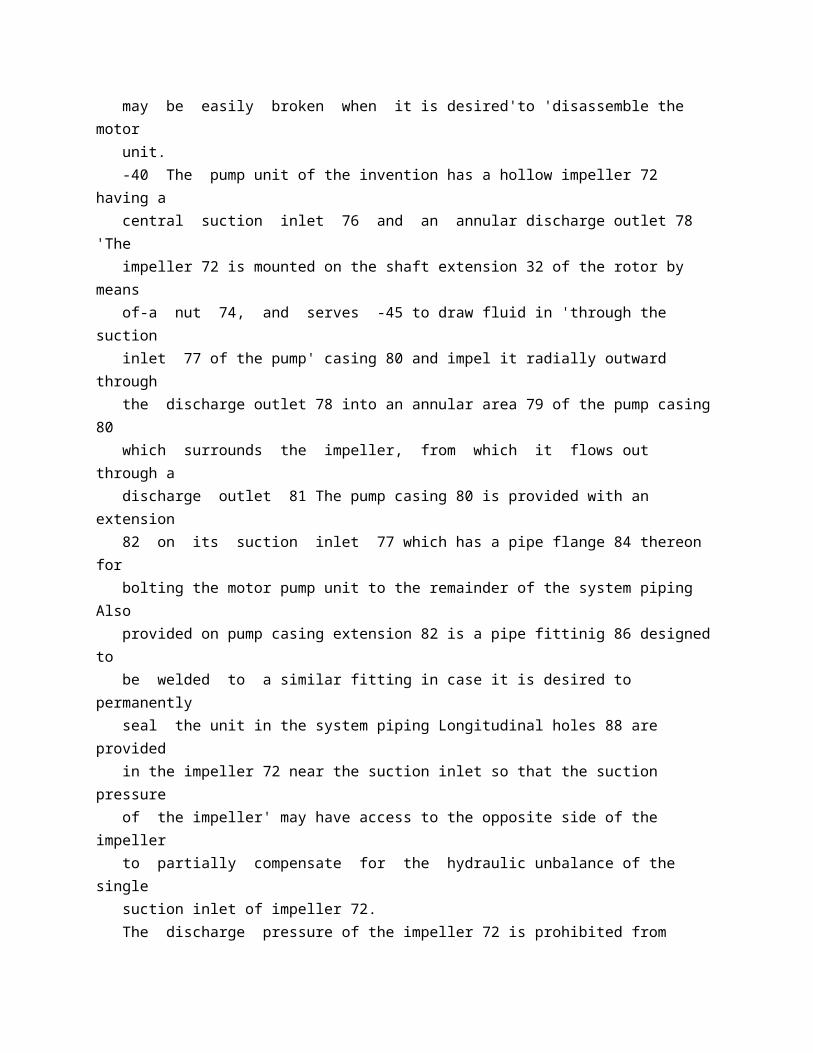
which rest against suitable shoulders 57 and 59, respectively, on the inner periphery of the thick end sections 20 and 22 of the cylindrical member 18 used to isolate the stator windings. Bearing cartridge 50 is retained in place against 130 785,488 the shoulder 57 by means of motor end cap 56, and the bearing cartridge 52 isi-niaintained in place against the shoulder 59 by means of the thermal barrier member 100, to be described later The rotor is located-in an axia V position in one direction by an outwardly projecting radial flange 58 on bearing journal_ 42 which runs in cooperation with one end surface 60 of journal bearing 46 The rotor is located in an -10 axial position in the opposite direction by means of an outwardly projecting radial flange 62 on bearing journal 44 ' which runs in cooperation with the end surface 64 of journal bearing 48. The'combination of the outwardly projecting :15 flanges 58 'and 62 and the end surfaces 60 and 64 are in effect a continuous ring type of thrust bearing of low capacity The motor pump units require only this simple thrust arrangement because substantially all of the axial thrust of the 'motor pump unit has-been eliminated by a novel construction of the pump casing to be described later ' The motor end cap 56 which serves to both close one end opening in the motor unit and retain bearing cartridge 50 in place is, secured to the motor end plate 6 by means of bolts 66 which pass through the end cap 56 and draw it into' pressure-tight seal with the adjacent surface of motor end plate 6 A gasket 68 is'placed :30 between -the adjacent surfaces of end plate 6 and end cap 56 in order to insure a pressuretight seal In cases where the motor pump is to be operated in a system having a substantially zero leakage allowance, the gasket 68 may be omitted and the end cap 56 may be welded to the end plate 6 by a small weld in the area 70. The weld in area 70 is not a structural weld but only a seal and thus may be easily broken when it is desired'to 'disassemble the motor unit. -40 The pump unit of the invention has a hollow impeller 72 having a central suction inlet 76 and an annular discharge outlet 78 'The impeller 72 is mounted on the shaft extension 32 of the rotor by means of-a nut 74, and serves -45 to draw fluid in 'through the suction inlet 77 of the pump' casing 80 and impel it radially outward through the discharge outlet 78 into an annular area 79 of the pump casing 80 which surrounds the impeller, from which it flows out through a discharge outlet 81 The pump casing 80 is provided with an extension 82 on its suction inlet 77 which has a pipe flange 84 thereon for bolting the motor pump unit to the remainder of the system piping Also provided on pump casing extension 82 is a pipe fittinig 86 designed to be welded to a similar fitting in case it is desired to permanently
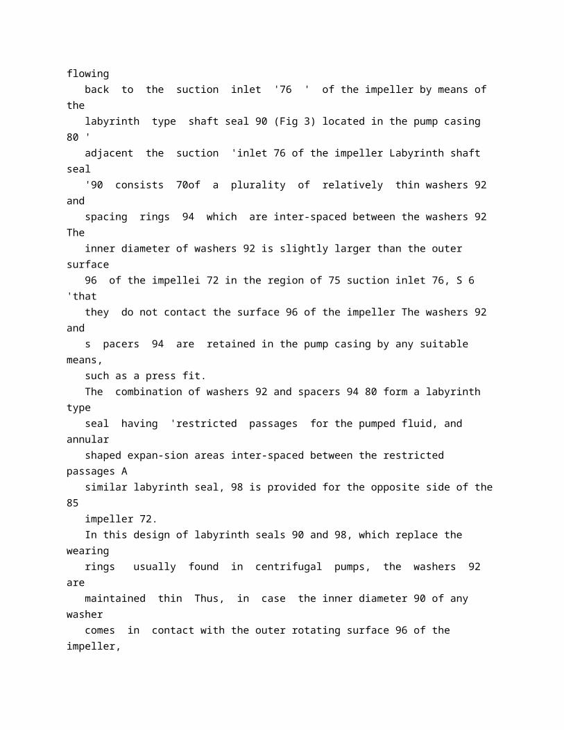
seal the unit in the system piping Longitudinal holes 88 are provided in the impeller 72 near the suction inlet so that the suction pressure of the impeller' may have access to the opposite side of the impeller to partially compensate for the hydraulic unbalance of the single suction inlet of impeller 72. The discharge pressure of the impeller 72 is prohibited from flowing back to the suction inlet '76 ' of the impeller by means of the labyrinth type shaft seal 90 (Fig 3) located in the pump casing 80 ' adjacent the suction 'inlet 76 of the impeller Labyrinth shaft seal '90 consists 70of a plurality of relatively thin washers 92 and spacing rings 94 which are inter-spaced between the washers 92 The inner diameter of washers 92 is slightly larger than the outer surface 96 of the impellei 72 in the region of 75 suction inlet 76, S 6 'that they do not contact the surface 96 of the impeller The washers 92 and s pacers 94 are retained in the pump casing by any suitable means, such as a press fit. The combination of washers 92 and spacers 94 80 form a labyrinth type seal having 'restricted passages for the pumped fluid, and annular shaped expan-sion areas inter-spaced between the restricted passages A similar labyrinth seal, 98 is provided for the opposite side of the 85 impeller 72. In this design of labyrinth seals 90 and 98, which replace the wearing rings usually found in centrifugal pumps, the washers 92 are maintained thin Thus, in case the inner diameter 90 of any washer comes in contact with the outer rotating surface 96 of the impeller, it will not seize and weld itself to the impeller but only weat a little and still continue to funbtion as a seal The problem of seizing of conventional 95 wearing rings is especially troublesome where all of the pump parts must be made of a corrosion-resisting material, such as stainless steel, due to the corrosive nature of the fluid being pumped It is well known that the 100 slightest surface contact between a rotating and a stationary member where b 6th are made of stainless steel will cause them to seize or weld together This problem has been solved by miaintaining the washers thin, thus their inner 105 diameter will wear without seizing the rotating member in case they should come into contact. Thelse seals have proven to be very effective in preventing the escape of fluid from the discharge of the pump to the suction side of the 110 pump and have required very little maintenance and in some cases no maintenance has been required. In order to inhibit 'flow of heat from the pump unit to the motor unit, a novel thermal 115 barrier is provided This thermal barrier consists of outer and inner annular members and 102, respectively, which are sealed together by any suitable means such as welding to
enclose a sealed annular area 104 Annular 120 G area 104 being a dead air space effectively inhibits the flow of heat from the fluid in the pump unit to the fluid in the motor unit The annular members 100 and 102 are positioned between the pump casing 80 and the motor 125 end plate 4 so that the thermal barrier surrounds the rotor shaft extension 32 and effectively separates'the pump unit from the motor unit. In case it is desired to increa'se the effectiveness of the -thermal barrier, the annular area 104 130 may be filled with any suitable insulating material such as glass wool. The fluid in the pump unit is prevented from freely flowing into the motor unit by means of labyrinth seal 106 located on the inner surface of thermal barrier member 102 between the pump impeller 72 and journal bearing 48, which is similar in construction to the labyrinth seal 90 described above Labyrinth seal 106 prevents the fluid from freely flowing into the motor unit, but allows it to seep by so that the rotor space of the motor unit is completely filled with fluid at substantially full system pressure Labyrinth seal 106 also substantially eliminates circulation of the fluid between the pump unit and motor unit and thus greatly reduces the transfer of heat from the fluid in the pump unit to the fluid in the motor unit. A vent 128 is provided in the motor end cap 56 for venting any air entrapped in the motor unit so that it may be completely filled with fluid from the pump Vent 128 is adapted to be sealed by means of a cap (not shown) which may be welded in place after the motor is vented of entrapped air Also provided in end cap 56 is a drain 130, also adapted to be sealed by means of a welded cap (not shown) which is used to drain the motor unit in case it is desired to disassemble the motor pump unit. The pump unit is attached to the motor unit by means of -studs 110 and nuts 112 which serve to bolt -the motor end plate 4 and the pump casing 80 together A gasket 114 is placed between the adjacent surfaces of the pump casing 80 and annular member 100 of the thermal barrier, while gasket 116 is placed between the adjacent surfaces of annular member 100 and spacing ring 23 on motor end plate 4 to insure a pressure tight seal In case it is desired to install the motor pump in the pumping system having a zero leakage allowance, the gaskets 114 and 116 may be omitted and the pump casing 80 may be sealed to the annular member 100 of the thermal barrier which, in turn, is sealed to the spacer ring 23 on motor end plate 4, by any suitable means, such as welding, in the areas 118 and 120 respectively. The motor unit can still be readily removed from the pump unit for servicing by breaking the weld in area 120 between the pump casing and the thermal barrier and removing the nuts and the studs 112 The weld
in area 120 is easily broken as it is not a structural weld but only a seal between the members Thermal barrier 100 also serves to hold the bearing cartridge 52 in position against shoulder 59 as previously described. The journal bearing 48 between the motor rotor and the pump unit is lubricated and cooled by the fluid contained in the rotor space of the motor unit, which is circulated by means of small vanes 122 formed on rotor shaft 32 The vanes 122 act as a centrifugal pump and circulate the fluid longitudinally through outer passageway 125 contained in the bearing cartridge 52 into annular area 123 which surrounds the rotor shaft 32 from which it returns to the vanes 122 by means of an inner longitudinal passageway 124 also contained in bearing cartridge 52 Part of the fluid in 70 annular area 123 also flows past the radial bearing 48 thus lubricating it The fluid by flowing through the longitudinal passageway is effectively cooled by means of-the cooling medium circulated through the stator assembly, 75 to be described below, due to the small crosssection of longitudinal passages 124 which causes the fluid to circulate at a rapid rate. The stator assembly of the motor unit is cooled by means of an external cooling medium, 80 preferably an insulating fluid, such as oil, which is admitted through inlet pipe 134 in the motor frame 2 adjacent motor end plate 6 and then flows through the stator assembly and out the pipe outlet 136 at the opposite end of the 85: motor frame in end plate 4 The cooling medium, upon entering the stator assembly through inlet 134, flows into annular area 138 where it circulates around the end turns 10 of the stator winding After circulating around 90 the end turns 10, the cooling medium flows through a plurality of longitudinal passageways near the outer periphery of the stator laminations 8 and a plurality of longitudinal passageways 142 near the inner periphery of 95 the stator laminations 8 The passageways 140 and 142 have a small cross-section so that the cooling medium will have considerable velocity when flowing through the stator laminations 8 and thus effectively cool the stator That part 100 of the fluid that flows through longitudinal passageways 140 flows into annular area 144, where it circulates around end turns 12 at the opposite end ofthe stator assembly, thus cooling them This coolant then joins with the coolant 105 that-flows through longitudinal passageways 142 and flows through annular area 152 between the circular baffle 150 and cylindrical member 18, and then out radial passageway 154 to the outlet 136 The radial passageway 154 and 110 annular area 512 are formed by means of a circular baffle 146 which has a general U shape in section with longitudinally projecting flanges from both ends of one leg of the U One of these longitudinal flanges 150, in cooperation 115; with the cylindrical member 18 which
isolates the stator assembly from the fluid in the rotor space of the motor unit, serves to form annular area 152 The other flange 148 serves to locate the baffle and is attached to the motor frame 2 120 by any suitable means (not shown) The radial passageway 154 is formed by means of the other leg 146 of the U-shaped baffle and the adjacent surface of the motor end plate 4 By maintaining the cross-section of annular area 125: 152 and passageway 154 small, the velocity of the cooling medium through them is maintained high, which increases the effectiveness of the cooling medium. Journal bearing 46 runs completely flooded 130 785,488 substantial reduction in the axial thrust load is achieved already byinstalling them on only one radial surface, preferably the surface on the same side of the pump casing as the direction of the axial thrust, -radial surface 166 for the 70 embodiment shown in Fig 1 It was observed that when the thrust pads were installed on only one radial surface, the thrust load varied over a much greater range with changes in the rate of, flow of the pump than when they are 75 installed on both radial surfaces Of course, the installation of the thrust pads on only one surface could be designed so that for any given rate of flow of the pumps, for example, full capacity, the thrust load would be substantially 80 zero. Provision is made for the small axial thrust loads that may occur in the motor pump unit, to be absorbed by the shoulders 58 and 62 on the bearing journals 42 and 44, respectively, 85 which run against the end surfaces 60 and 64 of journal bearings 46 and 48, respectively. Before installation of the thrust pads described above, the end surfaces 60 and 64 of the journal bearings often failed in service due to overloads 90 caused by excessive axial thrust. The above arrangement for substantially reducing the axial thrust, or eliminating it entirely, is easily manufactured and requires no maintenance The lack of maintenance is very 95 important in a -pump designed to operate in a sealed system pumping highly dangerous and explosive fluids In addition to the above advantages, the thrust pads cost considerably less to manufacture than conventional type 100 thrust bearings. The reliability of the motor pump unit has been further increased by providing the novel thermal barrier described above, which inhibits the flow of heat from the fluid in the 105 pump casing to the fluid in the motor unit In addition, the stator cooling system has an efficient baffling arrangement and utilizes an external cooling medium By providing circulation of the fluid in the rotor space of the 110 motor unit around and through the normal bearing adjacent to the pump unit in combination with the thermal barrier and stator cooling system
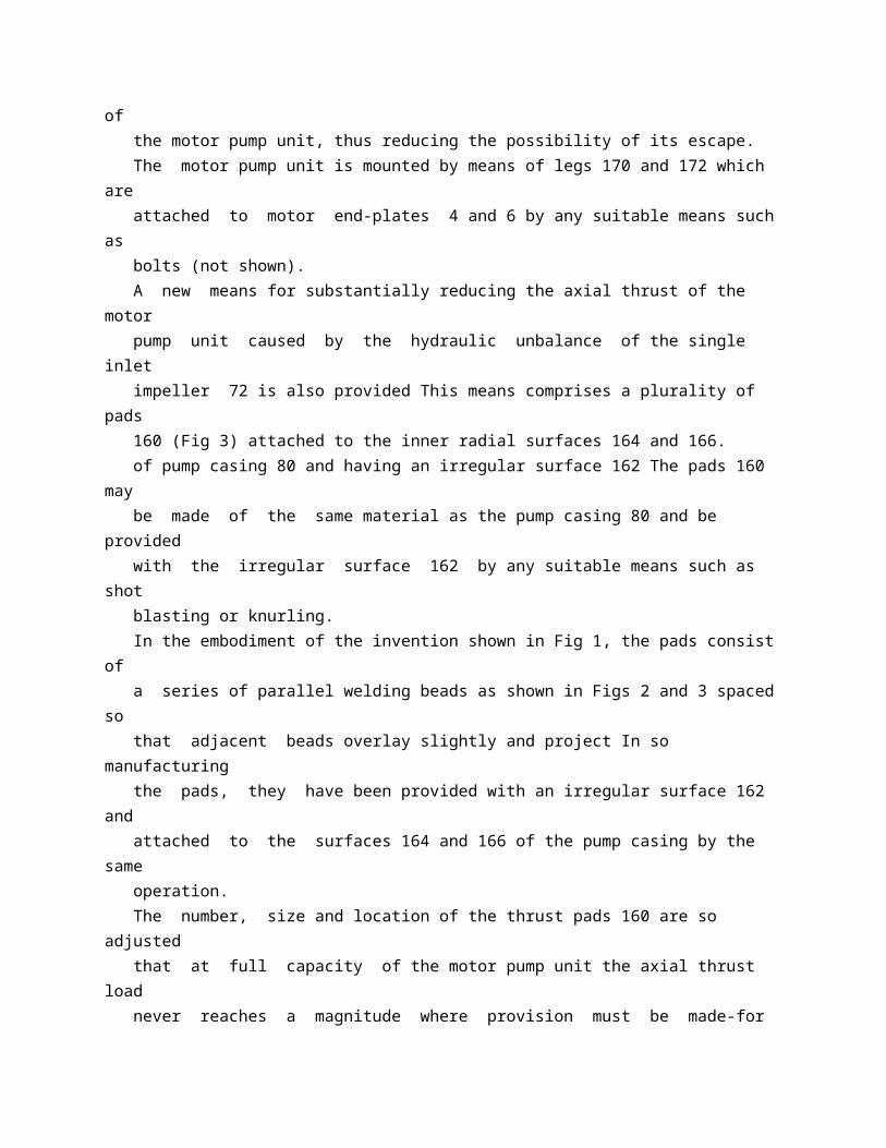
mentioned above, motor pump units have been operated in fluids having a tempera 115 ture of 600 'F ( 316 TC) without injuring the motor or its windings By eliminating the need for external heat exchangers, the construction of the motor pump unit has been simplified and the possibility of fluid escaping decreased, 120 since none of the fluid being pumped is circulated outside of the unit's outer casing except in the system piping. The use of the novel labyrinth type of seals for shaft seals and wearing rings increases the 125 reliability of the motor pump unit over previous designs, because they require little or no maintenance All previous shaft seals and sealing rings for centrifugal pump units require replacement at periodic intervals due to wear and 130 in a space filled with the fluid being pumped and is cooled and lubricated by this fluid The rotating bearing journal 42 tends to draw the fluid between itself and bearing 46, thus lubricating and cooling the bearing 46. The cooling system described above provides an external cooling medium on one side of the cylindrical member 18 and circulates the pumped fluid contained in the rotor space-of themotor unit on the other side Thus, the heat from the pump fluid is effectively transferred to the external cooling medium due to the high velocities of both fluids in this area It can thus be seen that the fluid circulated past radial bearing 48 acts as an effective cooling and lubricating agent The cooling system also has the advantage that none of the fluid being pumped is circulated externally, but only within the rotor space of the motor pump unit, thus reducing the possibility of its escape. The motor pump unit is mounted by means of legs 170 and 172 which are attached to motor end-plates 4 and 6 by any suitable means such as bolts (not shown). A new means for substantially reducing the axial thrust of the motor pump unit caused by the hydraulic unbalance of the single inlet impeller 72 is also provided This means comprises a plurality of pads 160 (Fig 3) attached to the inner radial surfaces 164 and 166. of pump casing 80 and having an irregular surface 162 The pads 160 may be made of the same material as the pump casing 80 and be provided with the irregular surface 162 by any suitable means such as shot blasting or knurling. In the embodiment of the invention shown in Fig 1, the pads consist of a series of parallel welding beads as shown in Figs 2 and 3 spaced so that adjacent beads overlay slightly and project In so manufacturing the pads, they have been provided with an irregular surface 162 and attached to the surfaces 164 and 166 of the pump casing by the same operation. The number, size and location of the thrust pads 160 are so adjusted
that at full capacity of the motor pump unit the axial thrust load never reaches a magnitude where provision must be made-for its absorption by the use of conventional thrust bearings As an example, a motor pump unit constructed in the manner illustrated in Fig 1 was rated at 100 gallons ( 378 -litres) per minute at 100 pounds per square inch ( 7 kg/cm 2) and had a 300 pound ( 136 kg) axial thrust in the direction of the suction inlet before the thrust pads 160 were installed In order to substantially eliminate this thrust load, four thrust pads 160 were installed extending approximately from the inner diameter to the outer diameter of the pump casing 80 as shown in Fig 2 on both radial surfaces 164 and 166 of the pump casing 80 The installation of these pads reduced the 300 pound ( 136 kg) axial thrust to a maximum of 30 pounds ( 13 6 kg) It is preferred to install the thrust pads on both radial surfaces of the pump casing, although a 785,488 are subject to scoring or seizing in case they come in contact with the rotating member.
* Sitemap * Accessibility * Legal notice * Terms of use * Last updated: 08.04.2015 * Worldwide Database * 5.8.23.4; 93p
* GB785489 (A)
Description: GB785489 (A) ? 1957-10-30
Improvements in or relating to hermetically sealed electric motor pump units
Description of GB785489 (A)
PATENT SPECIFICATION T 785,489 Date of Application and filing Comnplete Specification: June 24, 1955. No 18303155. Application made in United States of America on July 1, 1954.
Complete Specification PublishedOct30, 1957 - Index (at Acceptance:-Classes 35, A 2 (C 2: E 2: E 4: F: M), A 14; and 110 ( 1), C 2 A 2. International Classification:-F 05 cH 02 k COMPLETE SPECIFICATION Improvements in or relating to Hermetically Sealed Electric Motor Pump Units. We, WESTINGHOUSE ELECTRIC INTERNATIONAL COMPANY of 40 Wall Street, New York 5, State of New York, United States of America, a Corporation organised and existing under the Laws of the State of Delaware,iin said United States of America, do hereby declare the invention, for which we pray that a patent may be granted to us, and the method by which 'it is to be performed, to be'particularly described in and by the following statement:- The invention-relates generally to pumps driven by electric motors, and more particularlyl to such devices which are adapted to be mounted in completely sealed casings. In such devices the fluid being pumped often is independent of the pressure produced by the pump, at a high pressure above atmospheric pressure Under such conditions, it has been proposed to have the motor unit in a sealed casing to which the pumped fluid has access at full system pressure, thus eliminating the need for shaft seals between the motor and' pump units, but previous proposed designs have been relatively complicated, and thus difficult to manufacture and maintain. Other difficulties are encountered when the motor pump unit must be installed in a hermetically sealed pumping system, with substantially zero leakage allowance (i e. where substantially no leakage is allowable), especially when pumping corrosive or explosive fluids at elevated temperatures where any leakage becomes dangerous -In such systems, maintenance is difficult, and cooling of the motor presents additional problems, particularly if a unit of simple design is to be achieved which is capable of running at the elevated temperatures encountered In order to eliminate these difficulties, the invention provides a hermetically sealed motor pump unit free of external high pressure connections, yet having an efficient cooling arrangement, which pump can be removed from the pumping system as a unit, and having the motor rotor and stator member hermetically sealed in metal cylinders so that they can be immersed in the pumped fluid'at full system pressure In addition, 50 the motor terminals are sealed where they emerge from the unit so that if the cylinder' sealing the stator should rupture, none of the pumped fluid can escape. The invention will become more readily 55 apparent from the following detailed description of several preferred embodiments thereof,
illustrated by way of example in the accompanying drawings. Figure 1 is a partial longitudinal section 60 view of the upper end of a hermetically sealed motor pump unit constructed according to the invention; i Fig 1 A is a partial longitudinal sectional view of the lower end of the motor pump 65 unit shown in Fig 1; Fig 2 is a partial transverse sectional view, taken along the line II-II of Fig 1; Fig 3 is a partial longitudinal section of the upper end of a motor pump unit showing 70 another embodiment of the invention; Fig 3 A is a partial longitudinal section of the lower end of the motor pump unit shown in Fig 3; Fig 4 is a partial longitudinal section of the 75 upper end of a motor pump unit showing another embodiment of the invention; Fig 4 A is a partial longitudinal section of the lower end of the motor pump unit shown in Fig 4; and 80 Fig 5 is a top view of the terminal box shown in Fig 4, with the cover removed, drawn to an enlarged scale. The hermetically sealed motor pump unit shown in Figs 1 and 1 A is designed for 85 operating in a pumping system where the pressure is high, independent of the action of the pump, in relation to atmospheric pressure. In addition, the-unit can be used for pumping highly dangerous fluids, as there are no 90 41 1 2 785,489 external connections, because the pumped fluid is utilized as both a cooling and a lubrlicating medium. The motor unit has a solid tubular motor frame 1, of a corrosion-resistant material, such as stainless steel, with suitable annular end plates 2 and 3 of the same material welded to opposite ends of the frame, respectively, and each having a circular opening for receiving the rotor of the motor unit. The stator consists of a number of ringshaped laminations 4, of a suitable magnetic material, such as iron; stacked in the frame I and having inwardly opening slots for receiving the stator windings 6 The stator windings 6 terminate in end turns 7 which are enclosed by heavy walled cylinders 8 and 9, respectively, preferably of a corrosion resistant material, such as, stainless steel The cylinders 8 and 9 are welded at their outer ends to the -end plates 2 and 3, respectively. The inner ends of cylinders 8 and 9 are each supported by an annular groove 10 ' in heavy annular finger plates 10 (Figs 1, 1 A and 2) located at each end of the laminations 4. The finger plates 10 serve to locate the stator laminations 4 in the frame 1, and each contains suitable inwardly opening slots for the stator windings 6 to pass through as they emerge from the stator iron 4, with insulation 6 ' interposed between the windings and the slots Positioned on the inner periphery of the annular finger plates 10 are rings 11, which bridge the gaps in the annular finger plates caused, by the slots through which the stator windings pass The inner surface
-of the cylinders 8 and 9, rings 11 and the inner surface of the stator laminations 4 thus form a relatively smooth cylindrical stator bore opening through the motor unit A thin walled cylinder 12 preferably of corrosion resisting non-magnetic material, having a high electrical resistance, such as stainless steel, hermetically seals the stator 4 and its winding 6 in the motor frame 1 Cylinder 12 is supported on its outer surface by the aforementioned continuous circular opening, and is welded at each end to thin annular flanges 13 and 14 projecting integrally from the outer ends of cylinders 8 and 9, respectively The use of thin annular flanges on cylinders 8 and 9 allows the welding of the thin walled cylinder 12 to a similar material of the same thickness which simplifies the welding procedure and insures the hermetic sealing of the stator 4 and its winding 6 in the motor frame 1. By means of the above described construction, a solid tubular motor frame is provided containing a stator which is hermetically sealed in the motor frame by a thin walled cylinder The cylinder being of corrosion resisting non-magnetic material -of high electrical resistance has a negligible effect on the magnetic characteristics of the stator, and by maintaining the cylinder wall thin, the gap between the stator and the rotor is small. In order for the thin cylinder 12 to withstand extremely high pressures without rupturing, the unique construction mentioned has been 70, provided to support it throughout its length. A generally cylindrical solid rotor -15, preferably of a corrosion resisting magnetic material, such as a chromium stainless steel, having suitable slots on its outer surface for 75 squirrel-cage type windings 16, is -rotatably mounted by means of shaft extensions 17 and 18 secured thereto at opposite ends The squirrel-cage windings 16 are joined at their ends by means of annular rings 19 (only one 80 of which is shown) in engagement with the inner edges of the windings Bearing journals and 21,'pieferably of a corrosion resisting material, such as stainless steel, are shrunk on the rotor shaft extensions 17 and 18, respec 85 tively, to provide a hard bearing journal surface with a smooth finish The bearing journals 20 and 21 are supported by sleeve bearings 22 and 23 preferably-of compressed carbon graphite or compressed ceramic 90 material, the choice depending on the fluid to be pumped The sleeve bearings 22 and 23 are mounted in flanged cylindrical cartridges 24 and 25, respectively, said cartridges having caps 26 and 27 for retaining the bearing 95 sleeves in the cartridges The cylindrical cartridges 24 and 25 containing the sleeve bearings 22 and 23 are pivotally mounted by means of spherical protuberances 24 ' and 25 ' on the outer surface cartridges 24 and 25, 10 ( respectively, which seat against the inner surface of hardened ring inserts 28 ' in

bearing housing 30 and 31 Two pairs of pins 28 and 29 are mounted in bearing housings 30 and 31, respectively, and extend into over 105 size holes in opposite sides of the cartridges 24 and 25, respectively, and serve to retain the cartridges in position while not influencing adversely their self-aligning features Bearing housing 30 has an outer flange secured against 110 a shoulder on end plate 2, and bearing housing 31 has a flange 31 ' which is bolted to end plate 3. The axial thrust of the unit is carried by means of thrust runner 32 which is secured 115 to shaft extension 18, and runs between thrust bearings 33 and 34, which are preferably made from the same material as sleeve bearings 22 and 23 Thrust bearing 33 is a continuous annular ring which may be suit 120 ably radially grooved and scraped to form a conventional tapered-land bearing and is mounted in a channel formed in bearing housing 31, while thrust bearing 34 shown in Fig 1 A, is one of a plurality of pivoted pad 125 thrust shoes pivotally mounted on supporting linkage 35 in an annular channeled bearing retainer 35 ' supported by an annular bearing support 36 Support 36 may be secured to end plate 3 by the same bolts which secure 130 - 8,8 3 bearing housing 31 to end plate 3. The rotor 15 is hermetically enclosed in, a thin walled cylinder 37, which is similar to the cylinder 12 and is welded at-each end to thin flanges 38 (only one of which is shown) projecting from annular rings 39 alsomade from non-magnetic corrosion resisting ma terial, such as stainless steel Rings 39 are positioned at each end of the rotor and each has an annular flange 39 ' projecting inwardly over the reduced end portions of windings 16 to hold them in place and in engagement with connecting ring 19 Each ring 39 has a second thin flange 38 ' which is welded to a similar flange on the rotor 1 15 at its inner surface, thus hermetically sealing the squirrelcage windings in the rotor Since the cylinder 37 is non-magnetic and has a high-electrical resistance, it has negligible effect on the magnetic characteristics of the rotor, and due to its thin wall it does not appreciably increase the gap between the rotor 15 and the stator 4, thus the electrical efficiency of the motor unit is substantially maintained The cylinder -25 37 is supported throughout its length by the rotor 15 and its windings 16, and at each end by annular rings 39, thus it is capable qf withstanding extremely high pressures without rupturing. The pump includes a rotary impeller 40 of the centrifugal type which is mounted on motor shaft extension 18 in a position overhanging both radial bearing 23 and thrust bearings 33 and 34 Impeller 40 is designed to draw fluid in through an axial suction inlet 41 at its outer end and impel it radially outward through passages formed in the impeller into a volute-shaped cavity 42 in pump casing 44 From cavity 42, the fluid, flows -40 out the discharge opening 43 in pump casing
44 Fluid in cavity 42 is prevented -from flowing back to suction inlet 41 by means, of a labyrinth type seal comprising a plurality of annular projections 45 formed on guide collar 45 ' which is mounted in inlet 41 of pumpcasing 44 by means of cap screws 46. The projections, 45 closely fit the outer peri. phery of the suction inlet of impeller 40. A plurality of passages 40 ' (only one of which :50 is shown) in impeller 40 are designed to allow suction pressure of the fluid'access to the opposite side of the impeller 40 to partly compensate for the hydraulic unbalance caused by the single suction inlet of the impeller At the opposite or upper side of the impeller there is a cavity 42 ' between the impeller and thrust bearing support 36 The fluid in cavity 42 'is prevented from flowing into cavity 42 ' 'by means of a labyrinth seal 47, similar to labyrinth seal 45 described above'. The fluid in cavity 42 ' is prevented from freely flowing into the motor unit hby a labyrinth seal 48 similar to labyrinth seal 47. Labyrinth seal 48 is formed on an extension sleeve portion of bearing support 36 adjacent to shaft extension 1 '8, Fluid can,' however, seep by labyrinth seal 48 so as to completely fill the airgap 49 and the remainder of the stator bore in the motor unit at substantially full system pressure Although the fluid corm 70 pletely fills the stat Qr botre, -it is isolated from the motor windings b y the thin walled cylinders 12 and 37 described above The labyrinth seal 48, while allowing the fluid in the motor unit to build up to the full system 75 pressure, effectively limits:any communication, between the fluid in the cavity 42 and the fluid in the motor unit, to that caused by diffusion along said labyrinth seal. The stator windings are connected at their 80 upper end turns 7 to main terminal studs 59 which extend through openings in end plate 2. Main terminal studs 59 have a square head portion 59 ', which fits in a cooperating rect-, angular shaped insulating sleeve 60, preferably 85 of moulded insulating material such as a synthetic phenolic Insulating sleeve 60 is retained in the opening in end plate 2 by means of a threaded gland 60 ' Main terminal studs 59 are sealed in the end plate 2 90 by means of a channeled ring type packing 6,1 ', preferably of resilient material such as reinforced high temperature rubber, A close fitting washer 62 is used to minimize the possibility of the cup packing-61 ' extending 95 under pressure A heavy back-up for the terminals 59 is provided by insulating block 62 ', preferably of a moulded insulating material such as a synthetic phenolic, which in turn is secured to end plate 2 by means of 100 cap screws, 63 Each main terminal stud 59 is finally secured in end plate 2 by tightening nut 63 ' which retains the complete assembly in place yet allows the cup packing 61 ' freedom of movement so, that it can seal against 105
internal pressure Suitable power cables may be connected to auxiliary terminals 64 which in turn are connected to main terminal studs 59,by means of a connecting plate 64 ', of an electrical conducting material such as copper 110. Plate 64 ' may be secured to back up block 62 ' by cap screws (not shown) By this means repeated connecting of the power cables is done only on the auxiliary terminals 64 which can be easily replaced, instead of' on main 115 terminal studs 59 which can only be replaced with great difficulty and expense A ceiitral'opening in the upper journal bearing support member 30 is provided for inserting a lifting eye bolt into a threaded 120 portion of rotor shaft extension 17 to facilitate withdrawal of the rotor from the motor. The central opening in motor end plate 2 is sealed by means of a threaded cap 67 which is scre Wed, into motor end plate 2 and 125two sealing rings 66 and '65, preferably of a resilient material,'such as rubber Rings 66 afid 65 fit into cooperating recesses in end plate 2 and'bearing housing 30, respectively, to be engaged',boearing support 30 and cap 130 785,489 67 respectively Cap 67 retains bearing support member 30 in a rigid-position by engagement with a projecting flange on bearing housing 30, which seats on a shoulder on motor end plate 2 Two small annular converging flanges 68 and 69 are secured to and project from the cap 67 and motor end plate 2, respectively, and are welded together at -the outer ends with a small seal weld 70, thus effecting a hermetical seal between the motor end plate 2 and the cap 67 The motor unit may still be disassembled by breaking the small seal weld 70 and removing the cap 67. The seal weld 70 can be checked for leakage by introducing helium or other gas under pressure into the ring-like area 71 by means of a passageway 72 formed in end plate 2, then checking for leakage of gas by means of a mass-spectrometer type leak detector or the like The gas will be prevented from leaking into the remainder of the unit by sealing rings 65 and 66 previously described above. After seal weld 70 has been checked for leakage, the passageway 72 is sealed by means of threaded plug 73 and a cap 74 which is welded in place. The motor unit, including the bearings and pump impeller, is attached to the pump casing 44, which may previously -have been permanently installed in the pumping system, as a unit, by means of annular clamping ring 75 which cooperates-with a flange 76 projecting from the motor end plate 3, in drawing the motor pump unit into a pressuretight seal with the pump casing 44 A gasket 77, preferably of a ductile material, such as copper, is installed between the outer end of flange 76 and the pump casing 44 in order to seal the motor unit to the pump casing.
Bolts 78 extending through the clamping ring 75 and threading into pump casing 44 force the gasket 77 into a pressure-tight seal with the pump casing 44 The motor unit is additionally hermetically sealed to the pump casing 44 by means of a seal weld 79, which is similar in construction to the seal weld 70 previously described for closing the opening in motor end plate 2 Seal weld 79 can be checked for leakage by the same method described for the seal weld 70 The circular opening in the top of pump casing 44 is of a greater diameter than the impeller 40 so that the motor unit with both the impeller 40 and elements comprising the thermal barrier hereinafter described attached, can be inserted or withdrawn without disturbing the pump casing 44. By means of the above construction, a hermetically sealed motor pump unit has been provided where the pump casing can be permanently installed in the pumping system piping yet allowing removal of the motor unit containing the bearings and pump impeller from the system for servicing This is advantageous where the unit isused to pump dangerous fluids, because servicing of the unit can be performed in an area removed from the pumping system and the danger of fluid being pumped The seal weld 79 can be readily made when the motor unit is in 70 stalled on the pump casing because it is not a-structural weld that must withstand stresses but only a protective seal to prevent any leakage from the system in case the gasket 77 should fail 75 In checking seal welds 70 and 79 for leakage, there is provided a unique method for checking the motor pump unit for leakage which can be done after it is installed in the system without operating the motor pump 80 unit and subjecting the complete system to pressure because subjecting the complete system to -fluid pressure would involve considerable risk when the fluid being pumped is dangerous and a leak is present All other 85 elements of the motor pump unit except the seal welds 70 and 79 are fabricated during the manufacture of the unit and thus can be tested individually at many times the designed pressure for leakage, thus the only avenue for 90 leakage of the fluid from the -unit-is through the seal -welds 70 and 79: The use of sealing rings 65 and 66 adjacent to the cap 67, and the gasket 77, effectively seal the opening in the upper motor end, and the joint between 95 the motor unit and pump casing, respectively, thus when gas is introduced into the area enclosed by the seal weld it will not pass into the pumping system but will be contained in the seal weld, thus allowing a 100 test of the seal weld for leakage by use of a mass spectrometer or other type of leak detector. -A novel thermal barrier is provided to inhibit the passage of heat from the fluid in 105 pump casing 44 to the fluid contained in the stator bore and the remainder of the motor unit The thermal barrier is
comprised of a composite annular flanged member 80, which is attached to motor end cap 3 by means of 110 cap screws 81 extending through its flange. Member 80 contains sealed cavities 82 and 83. The dead air space contained within sealed cavities 82 and 83 effectively inhibits the flow of heat from pump casing 44 to the fluid in 115 cavity 54 of the motor unit, but if it is desired to increase the effectiveness of the thermal barrier, spaces 82 and 83 may be filled with any well-known heat insulating material, such as glass wool or the like 120Another sealed cavity 84 is formed in the bearing support 36 to further inhibit the transfer of heat from pump casing 44 to the motor unit An annular spring 85 which is V-shaped in section is used to seal any 125 opening between bearing support 36 and member 80, thus preventing the fluid in pump casing 44 from circulating past the labyrinth seal 48 through the thrust bearings 33 and 35 and back into the pump casing 44 by means 130 785,489 opening 58 ' and circulated in the annular space between the motor frame 1 and -the outer casing 58, and discharged through a lower opening 56 ' (Fig 1 A) thus cooling the fluid circulating in coiled tubes 56 in those 70 cases where the fluid being pumped is at an -elevated temperature The coiled tubes 56 being in intimate contact with motor frame 1 and outer casing 58, form a natural spiral path for this external cooling medium, which 75 path greatly accelerates the' transfer of heat to the external cooling medium from the cooling medium circulating in the coil tubes 56 The spiral path for the external cooling medium may be more' definitely established 80 by a spirally coiled strip '85 'which is interspaced between every fourth coil and is in intimate contact-with both the motor frame 1 and the outer casing 58 ? Figs 3 and 3 A represent another embodi 85 inent of the invention similar to that, shown in Figs 1 and 1 A except for certain features of the cooling system The construction of this unit being similar to the unit shown in Figs 1 and 1 A only a general description 90 will be given-except for those elements that are materially different The iunit consists of a solid tubular motor frame 101 having annular end plates 102 and 103 welded to opposite sends Stator laminations '104 having 95 slots for suitable windings 106, are '-h'ermetically sealed in-motor frame 101 by means of a thin walled cylinder 112, backed up by -the stator laminations and end cylinders 108 and 109, annular finger rings 110 and annular 100 rings 111, similar to the structure of Figs 1 and IA End turns 107 at one end (Fig 3) are enclosed by an outer cylinder-105 Which is supported atone end in an annular gro 6 ve ' in finger ring 110, and welded at the 105 other end' to annular' ring'105 ' which is welded on -its infiir periphery to back up cylinder 10 ' S -A: rotor 115,' similar in 'construction to rotor -15 in Figs V sand 1 A; is
hermetically 110 sealed by a thin walled cylinder 137 in the same manner as rotor 15, and has shaft extensions 117 and 118 at opposite ends. Bearing journals 120 and 121 are shrunk on shaft extensions 117 and 118, respectively, 115 and are rotatably mounted in sleeve bearings 122 and 123, 'respectively 'Sleeve 'beatings 122 and 123 are mounted in a manlier similar to bearings 22 and 23 iri Figs 1 and TA and are supported, on annular support members 120 and'131, respectively Bearing support member 130 is'alttached to motor end plate 102 ' by any suitable means such as bolts which pass through an outward projecting flange on'bearing support 130 -Bearing sup 125 port 130 also serves as an end cap-to close the opening in the motor end plate 102 and may be sealed by a small weld'170 which prevents any leakage through the opening in end plate 102 Axial thrust is absorbed by 130 of the opening between members 36 and 80. If circulation belween the fluid' in pump casing 44 and the fluid in the annular space 54 was possible, the temperature of the fluid would be equalized and the fluid in the m 6 tor uinit would not be as effective as a cooling medium for the motor unit The cooling system of the unit utilizes the fluid contained in the motor unit as a cooling and lubricating medium, and the latter is circulated throughout the system by means of an auxiliary impeller 50 which is pressed on the shaft extension 17 ahead of the bearing journal 20 The auxiliary impeller 50 draws the fluid through axial passage 51 in shaft extension 17 and impels it radially outward through radial passages in the shaft and impeller 50, and then the major portion flows through the air gap 49 between the rotor 15 and the stator 4 The remainder i ows upward past bearing 22, thus lubricating and cooling bearing 22, into cavity 52 and returns by way of passage 51 to the suction side -of the auxiliary impeller 50 After the major portion of the fluid flows through the air gap, part of the fluid flows through an annular space between bearing support member 31 and thin walled cylinder 12 (Fig 1 A) then through passage 53 in member 31 and into the cavity 54, the remainder flowing -past journal bearing 23, then past the thrust bearings 33 and 34 by means of axial holes in thrust runner 32, and into cavity 54, thereby lubricating and cooling journal bearing 23, and thrust bearings 33 and '34 ' From cavity 54, the fluid flows in the opposite direction through a plurality of circumferentially spaced passageways 55 provided in end plate 3 into a corresponding number of coiled tubes 56 which are helically coiled in parallel relation about the motor frame 1, and then the fluid Westurns to the cavity 52 by means of passageways 57 in the motor end plate 2 and bearing support member 30 The coiled tubes 56 are in intimate contact with the motor frame 1, so that heat generated in the stator -laminations 4, -which
are in intimate contact with the inner surface of the motor frame I on their outer peripheries, and with cylinder 12 on their inner peripheries, -can flow directly through a solid metal path to the cooling fluid circulated through the air gap and the coiled tubes This greatly increases the heat transfer rate from the stator 4 over that possible if the motor frame 1 was cooled by -circulating air on its outer periphery only In addition, the-entire cooling system is a sealed part of the motor unit, and no external connections are necessary when the motor pump unit is installed. A composite tubular outer'casing 58 surrounds the coiled tubes 56 and is welded at its ends to motor end plates 2 and 3, respectively, thus allowing an external cooling medium to be introduced through an upper 785,489 thrust runner 132 on shaft extension 118, and cooperating thrust bearings 133 and 134, which in turn are supported by members 131 and 136, respectively This arrangement is :5 similar to that disclosed in Fig IA for thrust runner 32 and thrust bearings 33 and 34. A rotary pump impeller 140 of the centrifugal type is mounted on shaft extension 118 and operates in the same manner as impeller 40 in Fig l A to draw fluid in through inlet 141 in the pump casing 144 and discharge it through the outlet 143 A plurality of passages 140 ' (only one of which is shown) in impeller 140 are designed to allow suction pressure of the fluid access to cavity 142 ' on the opposite side of impeller 140 to partly compensate for the hydraulic unbalance of impeller 140 Labyrinth seal 147 prevents, the fluid from flowing freely into the cavity 142 ' from pump cavity 142 The fluid in cavity 142 ' is prevented from freely flowing into the motor unit by labyrinth seal 148 but is allowed to seep by so that the air gap 149 and the remainder of the motor unit are filled with fluid at substantially full system pressure Surrounding the motor frame 101 and spaced radially from it is a solid outer tube 156 which is welded at one end to pump casing 144 (Fig 3 A). The motor unit including the frame 101, bearings, motor and pump impeller is attached to the pump casing 156, which has previously been installed in the pumping system, by means of a clamping ring 175 which is bolted to a heavy annular ring 158 attached to the outer tube 156 by any suitable means suchas welding and cooperates with a flange 176 on the motor end plate 102, to draw the motor unit into a pressure-tight seal with the adjacent end of the outer tube 156 A gasket 177, preferably of ductile metal, such as copper, is positioned between flange 176 and the end of outer tube 156 to effect a pressuretight seal A small seal weld 179 is used to hermetically seal the motor unit to the outer tube 156 in a manner similar to that described for seal weld 70 in Fig 1 Seal weld 179 can be checked for
leakage by the same method disclosed in connection with Fig 1 for checking seal weld 70, the passageway through which the helium is introduced is not shown in Fig 3. The cooling and lubricating system of the unit disclosed in Fig 3 and Fig 3 A is similar to that disclosed in Figs 1 and 1 A but is modified in some elements to improve its operation An auxiliary impeller 150 which is shrunk on shaft extension 117 ahead of journal bearing 120 circulates the major part of the fluid through the air gap 149 between the stator and the rotor, with the remainder flowing upward past bearing 122 and returning to the suction side of auxiliary impeller The majority of the fluid after flowing through the air gap 149 between the rotor and the stator flows past bearing 123 and thrust bearings 133 and 134 into annular cavity 93 It then flows back through the annular space 155 between the motor frame 101 and the outer tube 156 and returns 70 through passageways 157 in motor end plate 102 and bearing support 130 to the suction side of auxiliary impeller 150 Thus the construction shown in Figs 1 and IA has been somewhat simplified by substituting the 75 annular space 155 for the coiled tubes 56 of Figs 1 and 1 A, while at the same time maintaining an efficient cooling system by keeping the annular space 155 small in cross-section thereby increasing the velocity of flow of the 80, fluid past the motor frame 101 which increases the heat transfer from the motor frame 101 to the fluid. An external cooling medium, preferably an insulating oil, may be provided for the 85 stator 104 and introduced through an inlet extending through end plate 102 and ring 105 ' into the annular stator space 161 where it circulates around the end turns 107 in space 161 It then flows through a number 9 G of longitudinal slots 162 formed on the inner periphery of the stator 104 and closed by' cylinder 112, to the opposite end of the stator The cooling medium then flows into an annular space 163 where it circulates 95 around the end turns 107 at the other end of the stator windings 106, then outward around the free end of tubular baffle 163 ' which is welded at its other end to finger ring 110 (Fig 3 A) and through the longitu 100 dinal slots 164 formed in the stator laminations 104 and the motor frame 101 then through outlet 165 in motor end plate 102 and back to the external source. The stator cooling system disclosed above, 105 while highly efficient in cooling the stator and its windings, remains relatively simple and easy to manufacture The cooling medium in flowing through many small longitudinal slots on the inner periphery of the stator is 110 in contact with a large area of the stator, and due to the small cross sectional area of these slots the cooling medium must flow at a rapid rate thus effectively cooling the stator without adding to the size or complication 115 of the complete unit In addition, the cooling medium
will be in contact with the outer surface of the thin walled cylinder 112 which seals the stator in the motor frame and thus assists in cooling the remainder of the unit 120 by absorbing heat from the fluid circulated in the stator bore In returning the fluid to the-external source by means of the longitudinal slots on the outer periphery of the stator, an additional area of contact between 125. the fluid and the stator has been provided thus removing additional heat from the motor unit. Figs 4 and 4 A show another embodiment of the invention similar to that shown in 130 785,489 Figs 1 and IA, with the additional provision so as to fill the air gap 249 and the remainder of a pressure-tight sealed terminal for the of the motor unit with-fluid at substantially stator windings and a thermal barrier of the same pressure as the fluid in area 242. unique, and simplified construction The Although the fluid fills the motor unit, it is general construction is similar to that shown isolated from the motor windings -by the 70 and described in Figs 1 and l A and only thin walled cylinders 212 and 237 which those elements that differ materially will be hermetically enclose the motor windings. described in detail A solid tubular motor The opening in motor end plate 202 is frame 201 has annular end plates 202 and 203 sealed by means of a threaded cap 266 and welded at each end Stator laminations 204 sealing ring 265, preferably of a resilient 75 having a suitable stator winding 206 are material, such as neoprene, which, in addihermetically sealed in the motor frame by tion to sealing motor end plate 202 also means of a thin walled cylinder 212, backed retains bearing support member 230 in place. up by ring structures consisting of cylinders The cap 266 and motor, end plate 202 are 208 and 209, and annular finger rings 210 hermetically sealed by a seal weld 270 which 80 and rings 211 utilizing the same method as is similar in construction to seal weld 70 in disclosed in Figs 1 and 1 A for sealing stator 4 Figs 1 and l A, and can be checked for in motor frame 1 A rotor 215 containing a leakage by the same method used in checking suitable squirrel-cage winding 216, and having seal weld 70. -20 shaft extensions 217 and 218 at opposite The motor unit including the bearings and 85 ends is hermetically, sealed by means of a pump impeller is attached to the pump casing thin walled cylinder 237 which is hermetically 244 by means of clamping ring 275 and cosealed to heavy annular rings 239 positioned operating flange 276 projecting from motor at each end of the rotor 215 utilizing the end plate' 203 Bolts 278 are used to draw same construction as disclosed in Figs 1 and the motor unit into a pressure-tight seal with 90 IA for
hermetically sealing rotor 15 in thin the pump casing 244, with a copper or the walled cylinder 37 Suitable bearing journals like gasket 277 being positioned between 220 and 221 are shrunk on shaft extensions these two members to effect a seal The 217 and 218, respectively, and are rotatably motor unit and pump casing 244 are hersupported in sleeve bearings 222 and 223, metically sealed by a small seal weld 279 95 respectively Bearings 222 and 223 are en which is similar in construction to seal weld closed in suitable housings which are sup 79 in Fig l A and is checked for leakage by ported by members 230 and 231, respectively, the same method used in checking seal weld mounted on the respective end plates 202 and 70 in Fig 1. -35 203 in a manner similar to that disclosed in The auxiliary impeller 250 circulates the 100 Figs 1 and l A fluid contained in the stator bore through the Axial thrust of the unit is absorbed by air gap 249 between the rotor 215 and the means of a thrust runner 232 and cooperating stator 204 Part of the fluid discharged from pivoted pad thrust bearing pads 233 and 234 impeller 250 flows past the bearing 222 but Thrust pads 233 and 234 are supported by the major part flows through the air gap and 105 members 231 and 236, respectively, with then past bearing 221 and thrust bearings member 236 being rigidly bolted to motor 233 and 234 The fluid then flows into end plate 203 The arrangement described annular cavity 286 from which it enters above for absorbing the axial thrust of the coiled tubes 256, by means of passages 255 unit is similar to that disclosed in Figs 1 through end plate 203 The fluid circulates 110 and l A except stationary thrust bearing 33 through the coiled tubes 256, thereby cooling of Fig IA has been replaced with a pivoted the stator 204, and back to auxiliary impeller pad thrust bearing 233 similar to thrust suction inlet 251 by means of passages 257 bearing 34 of Fig 1 A in end plate 202 and bearing support 230. A rotary pump impeller 240 of the centri Surrounding the coiled tubes 256 is a com 115 fugal type draws the fluid in through suction posite outer tubular casing 258, the coiled opening 241 in pump casing 244 and impels tubes being in intimate contact with both the it radially outward into annular area 242 and motor frame 201 on one side and with outer out discharge opening 243 in the pump casing casing 258 on the other side These tubes are A plurality of openings 240 ' (only one of positioned in intimate metal-to-metal contact 120 which is shown) in impeller 240 are designed with both the motor frame and outer casing to allow suction pressure of the fluid access in order to provide a direct path through the to annular cavity 242 ' on the opposite side metal members of the units to the cooling of impeller 240 to partly compensate for the medium for the heat generated in the stator, hydraulic unbalance of impeller 240 The and to prevent the bypass of
the secondary 125 fluid in area 242 is prevented from flowing cooling fluid which flows outside of and into the cavity 242 ' by labyrinth seal 247 around tubes 256 Also by providing intiFluid in cavity 242 ' is prevented from freely mate contact between the coiled tubes 256 flowing into the motor unit by a labyrinth and the motor frame 201 and casing 258, a seal 248 but is allowed to seep by this seal spiral path has been provided for an external 130 785,489 secondary coolant, which can be introduced force used in attaching the supply conductor through an inlet opening 228 at one end of is not transmitted to the terminal posts 259 composite casing 258 adjacent end plate 202 since the supply conductor is attached to an and returned to the external source through independent auxiliary terminal post which in an outlet opening 238 at the opposite end of turn is connected to terminal post by a 70 casing 258 In this way, the secondary flexible shunt In previous designs, much coolant-will be flowing in the opposite direc difficulty has been experienced with leakage tion to the flow of fluid through coiled tubes around terminal posts in cases where the 256 and in contact with coiled tubes 256, thin walled cylinders encasing the stator have thus effectively cooling the fluid circulating ruptured allowing fluid to escape, since the 75 in the cooling system when the motor pump sealing arrangement was disturbed each unit is installed in a system pumping fluids time the supply conductors were attached or at elevated temperatures Another feature of detached this cooling system is the fact-that all of the Means is also provided for replacing the fluid from the pumping system utilized in the sealing sleeve 260 which seals the terminal 80 cooling system is contained inside the outer post in the motor end plate without disturbing casing 258, -and no external connections in the terminal post 259 which is important in volving the fluid from the pumping system a motor unit where the stator is hermetically are necessary This is especially important sealed in the motor frame In order to change where the fluid in the pumping system is -the terminal seal, one only has to remove the 85 highly dangerous and any leakage would be flexible shunt 274 and the nut 263 and bridge harmful, since all elements of the motor unit member 262 from the terminal, then by cooling system are assembled during manu removing the gland 271 and bushing 261, the facture and can thus be tested individually at tapered seal 260 may be removed In premany times system -pressure vious designs, it was necessary to remove the 90 The stator end turns 207 at the top (Fig 4) terminal from the inside of the motor frame are connected-to tapered terminal posts 259, first before the seal ring could be replaced three in the motor shown due to the three due to the tapered nature of the terminal phase stator winding, which pass through and this is impossible unless the hermetic openings in motor end plate 202 Each seals sealing the
stator are first broken It 95 opening in end plate 202 has a tapered bush would also be necessary to disassemble the ing 261 with an outward projecting flange unit in order to gain access to the hermetic for engaging a mating shoulder in the opening seals sealing the stator; in end plate 202 and is sealed in the opening by The simplified thermal barrier of this '6 &fimeans of a small sealing ring 264, preferably -bodiment of the invention is formed by 100 of a resilient material such as neoprene, and bearing support member 236 which includes a threaded gland 271 Each tapered terminal cavities 283 and 284 therein sealed by annular post 259 is sealed in the tapered bushing 261 plate 236 ' welded to member 236 over the by means of a tapered sealing and insulating cavities The dead air spaces contained within sleeve 260, preferably of a resilient insulating cavities 283 and 284 act as a barrier to the 105 material, such as nylon, and is drawn into transfer of heat from the fluid in the pump pressure-tight contact with the tapered bush casing-to the fluid in the stator bore Bearing ing 261 by means of a bridge member 262, support member 236 together with a part of preferably of an insulating material, such as the pump casing 244, enclose an annular area a moulded plastic, and nut-263 on the terminal 282 which has restricted access, by means of 110 post 259 (Figs 4 and 5) On the outer side the joint 280 to the fluid in the annular pump of end plate 202, a plate 272 for each terminal area 242 but is closed to the cavity -286 in post (Figs 4 and-5), preferably of an electrical the motor unit by means of the bolted sealed conducting material such -as copper, is joint at 286 ' This cavity 282 of stagnant rigidly mounted on a suitable insulating fluid also acts as an effective thermal barrier 115 block 273, such as a moulded plastic material, to the transfer of heat from the fluid in which in -turn is rigidly attached to the motor annular area 242 to the fluid in cavity 286. end plate 202 in any desired way, for example By sealing the bearing support member 236 by screws (not shown) Each tapered terminal to the motor end plate 203 the fluid is pre259 is connected to a plate 272 by means of vented from circulating from the cavity 242 '120 flexible shunt 274 of a braided or laminated past the labyrinth seal 248 through the thrust electrical conducting material, such as braided bearing 233 and 234 -and into the cavity 286 copper, which is attached to a stud -245 on and then back to the annular pump area 242. plate 272 An auxiliary terminal post 246 By eliminating any such circulation in this is provided on each plate 272 to which a area, the fluid in the motor unit is main 125 supply conductor 290 may be attached A tained at a temperature considerably below composite casing 291 is provided for enclosing that contained in the pump unit, since all the terminals and is provided with a removal heat must be
transferred by diffusion through cover 292 so that access can be gained to the the fluid along labyrinth seal 248. terminals By means of this arrangement, the By including part of the thermal barrier as 130 785,489 meads being adapted to allow fluid in the pump casing sufficient access to the stator bore and to the cooling system to fill the same, but preventing a free flow of said fluid between the pump casing on one hand, and 70 the stator bore and cooling system on the other hand; and means separate from said pump impeller for circulating through said stator bore and cooling system the fluid contained therein so as to cool said motor and 75 bearings. 2 A unit as claimed in claim 1, characterised in that the cooling system communicates with the stator bore at points beyond the bearings so that the fluid is circulated 80 past said bearings and lubricates same. 3 A unit as claimed in claim 1 or 2, characterized in that the cooling system comprises an auxiliary circulating impeller mounted on one of said shaft extensions 85 within the stator bore so as to circulate the fluid in the stator bore through the air gap of the motor, then through the bearing for the other of said shaft extensions, then outwardly and through the annular space be 90 tween the outer casing and said motor frame in the opposite direction to the flow through said air gap, then inwardly and back to said circulating impeller. 4 A unit as claimed in claim 1, 2 or 3, 95 including a stator cooling system comprising means for circulating a cooling medium around the end turns of one end of the stator, then through the stator core adjacent the inner peripheral surface of said stator, 100 then around the end turns on the other end of said stator and then back through the stator core adjacent the outer peripheral surface of said stator. A unit as claimed in any one of the 105 preceding claims, characterized in that the cooling system comprises spirally coiled tubing located inside said outer casing and surrounding said motor frame, said spirally coiled tubing being in intimate contact with 110 both said motor frame and said outer casing so as to provide a solid metallic path for heat to flow from said motor frame through said coiled tubing to the cooling fluid. 6 A unit as claimed in any one of the 115 preceding claims, characterized by a thermal barrier comprising an annular member between the pump casing and motor frame which is sealed on its outer circumference to said motor frame and has a labyrinth seal on 120 the inner peripheral surface in substantial engagement with the rotor shaft extension on which the rotary pump impeller is mounted, so that said thermal barrier prevents the circulation of fluid between said 125 pump casing and said stator opening. 7 A unit as claimed in claim 6, characterized in that the annular
member of the thermal barrier is so shaped as to form between itself and the pump casing a cavity 130 an integral part of bearing support 236 and utilizing the pump casing 244 and bearing support 236 to form the remainder, this one member serves the purpose of the two members 36 and 80 in Fig 1 A, thus simplifying construction Also by sealing the bearing support 236 to end plate 203 the need for the annular spring 85 (Fig 1 A) which is difficult to manufacture and may fail in service, has been eliminated. Thus, motor pump units have been provided in Figs 1, IA, 3, 3 A, 4 and 4 A which are simple to manufacture and completely sealed so that they can be operated in pump-15 ing systems with substantially zero leakage allowance The units are designed to operate with the motor unit submerged in the fluid being pumped, but by means of a unique method of hermetically enclosing the motor -20 windings they are isolated from the pumped fluid The fluid in the motor unit is circulated by means of an auxiliary impeller through a closed cooling system to cool the unit and lubricate its bearings In utilizing the pumped fluid as a cooling medium, external connections have been eliminated, thus reducing the possibility of fluid escaping from the system In order to maintain the fluid in the motor unit at a temperature sufficiently -30 low to act as a cooling medium, novel thermal barriers have been provided to retard the transfer of heat between the pump unit and motor unit In the unit shown in Figs 4 and 4 A this thermal barrier has been simplified -35 so that one composite member serves as both a support for the thrust bearing and a thermal barrier Also in the unit shown in Figs 4 and 4 A a new type of leak proof motor terminal has been provided so that in case -40 the thin walled cylinder enclosing the stator windings should rupture none of the fluid will escape from the system.
* Sitemap * Accessibility * Legal notice * Terms of use * Last updated: 08.04.2015 * Worldwide Database * 5.8.23.4; 93p
* GB785490 (A)
Description: GB785490 (A) ? 1957-10-30
Process for the 'complete gasification' of liquid and of powdered orpulverulent solid fuels
Description of GB785490 (A) Translate this text into Tooltip
[75][(1)__Select language] Translate this text into
The EPO does not accept any responsibility for the accuracy of data and information originating from other authorities than the EPO; in particular, the EPO does not guarantee that they are complete, up-to-date or fit for specific purposes.
PATENT SPECIFICATION Date of Application and Filing Complete Specification: July 15, 1955. Application made in Italy on July 16, 1954. Complete Specification Published: Oct 30, 1957. 7859490 No 20498/55. Index at Acceptance:-Class 55 ( 2), D 2 (F: G), DU(C 3: E 2: Gil R: W Y), International Classification:-C l Ob. COMPLETE SPECIFICATION Process for the 'Complete Gasification? of Liquid and of Powdered or Pulverulent Solid Fuels. l, Ivo GIORDANO, Italian Nationality, of 371, Via Aniello Falconi, Napoli, Italy, do hereby declare the invefntion, for which I pray that a patefit may be granted to me, and the method -by which it is to be performed, to be particularly described in and by the following statement: - This inventioii relates to a process for the "complete gasification" of liquid and of powdered or pulverulent solid fuels. The 'production of combustible gases (such as e g H 2, CO, etc) and of gaseous hydrocarbons (such as e g paraffins, oleIns,' etc) by transforming liquid fuels of any character, composition and molecular weight, offers in practice difficulties of embodiment which increase with growing complexity of the raw materials to be treated. Among the many processes investigated, a number of processes were carried out on an industrial scale in these last years. In general however, it can be said that so far no process yet has succeeded in attaining a " complete gasification" of the fuel treated: moreover, the processes 'which attain elevated conversion ratios require the aid of catalytic masses and in those cases the processes
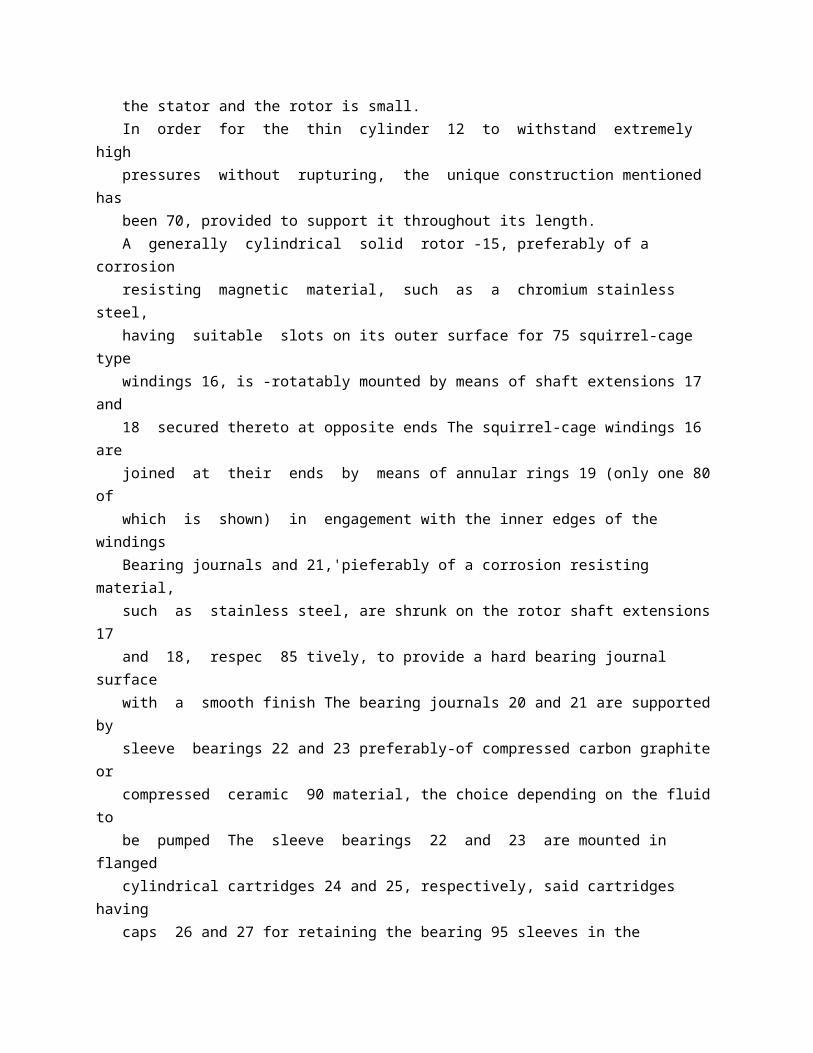
are complicated and burdensome and so are the respective plants. Even with the intervention of -catalytic masses, if more complex starting materials with higher molecular weight are employed, the yield of gaseous products tends towards limits which are not acceptable from the point of view of industry. Owing to the enormous interest that the problem has from the point of view of " synthetic gas" production and from that of the production of fuel gases to replace " technical gases," and which is growing with the growing availability of cheap residues from the processing of petroliferous products, it is an object of the invention to provide a process which not only is simple in installation and operation, but which also affords the possibility of transforming any combustible liquid substance, even if complx aind of pitchy character, as well as minute solid fuels, poor or' rich in ashes, substantially completely into gaseous products, 50 after previous admixture with small amounts'of liquid fuels. The transforming of a liquid fuel into gaseous products may be considered as be' ing essentially constituted of three basic op 55 etations, viz: (A)-Cracking at determined temperatures according to the kind of gaseous products to be obtained. ( 3)-Gasifying the solid residue obtained 60 in operation (A), with one of the processes that are best suited to yield the desired gas (water gas, air gas, oxygas, etc, the latter two 'gases being the products of incomplete combustion of carbon in air and in oxygen 65 respectively). (C)-If needed, gasification of the gaseous products obtained in operation (A) (with steam, a steam-and-air mixture of a steam-and-oxygen mixture) 70 While operation' (A), that is, the decomposition and structural transformation of the molecules undei'the action of heat, is easily attainable with simple means, with comparatively low temperatures and with 75 high velocity of transformation, operation (B) requires complicated equipment and, moreover, elevated 6 perating temperatures and long reaction timne, these characteristics being functions of the equilibrium constants 8 @ and reactivity of the material. Gasification in distinct stages as indicate-A' above would be difficult and not feasible industrially because of the complicated installations involved, because of the unpractica 85 bility of operation, and above all because of the graphitic character of the solid residue obtainable on the one hand and its powdery and friable (crumbly, " short -) structure on the other 90 (Prit The three operations A-B-C should therefore be carried out contemporaneously in Mne single apparatus with steams injez-ion.
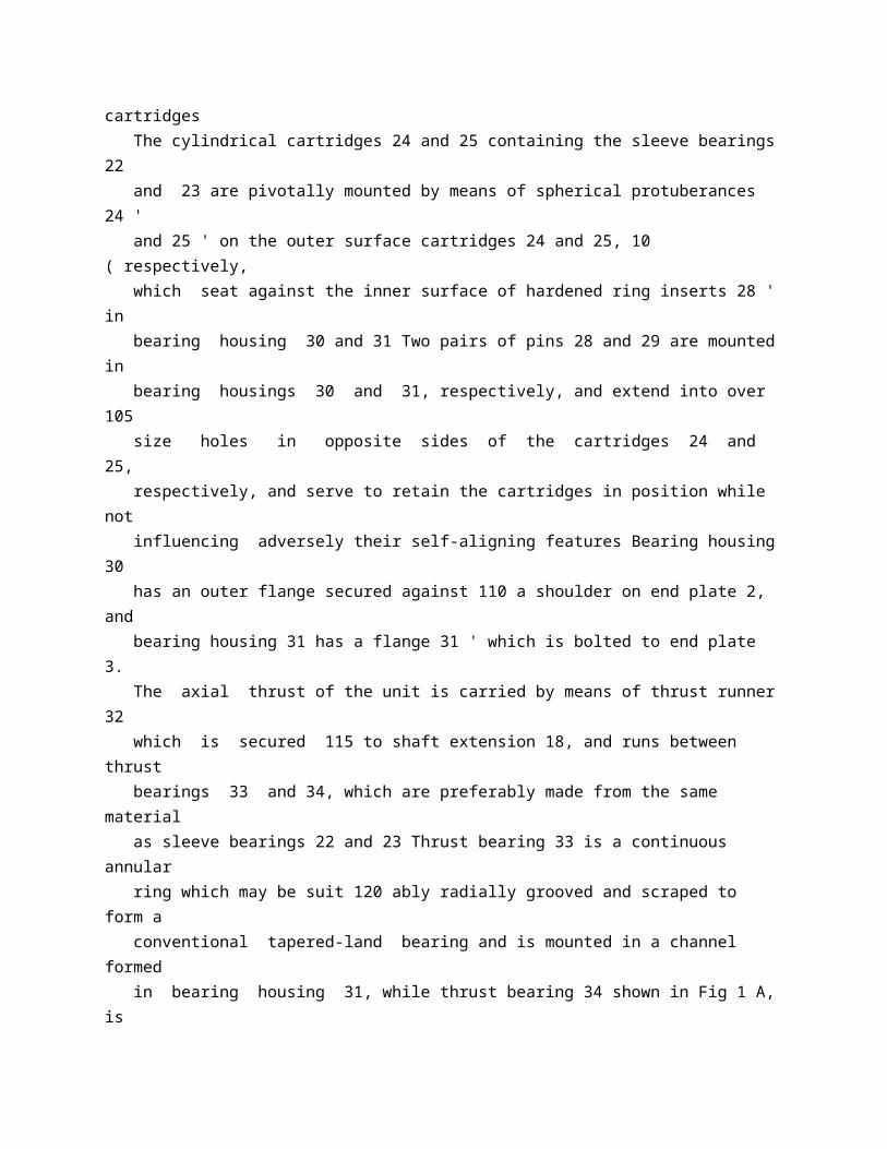
or with steam and oxygen injection (or steam and air injection), so as to carry out besides operations (A) and (B) also operation (C), that is, the partial gasification of the gaseous hydrocarbons. It should be noted that the two operatlions (A) and (B) could be carried out confemporaneously only if the reaction velocities had similar values, while on the contrary they have not and, therefore, the carbon liberated in operation (A) gasifies only in part and the carbon particles in the nascent state which remain free tend to group, originating carbonaceous deposits (carbon black) of graphitic character and with low reactivity. In order to avoid this very serious inconvenience, the whole of the operations must be carried out while applying suitable contrivances for slowing down the phenomenon of cracking and for accelerating contemporaneously gasification of carbon in such a way as to afford a possibility for the carbon particles to react with the steam, or oxygen, or both steam and oxygen, at the very time at which these carbon particles are in the nascent state, presumably in the molecular state, preventing their subsequent transformation into graphitic aggregations having low reactivity. It should be borne in mind among other things, that the low reactivity of graphitic agaregations tends to be made more and more low as a consequence of the tendency of the particles to increase in diameter, and Af the disactivation produced by the action of heat to which said particles come to be subjected. As a result of studies and investigation in the field of the gasification of liquid and solid fuels and particularly of the investigations tending to obtain an increase and enhancement of the reactivity of fuels by means of the addition of catalysts, as well as of the observations relating to the behavour of oily emulsions under the action of heat, the process according to the present invention has been found and provides means of obtaining the " complete gasification" of liquid fuels of any density and characteristics as well as of solid powdered fuels, in the latter case added to emulsions of liquid fuels Said process comprises essentially mixing the liquid fuel to be gasified at a suitable temperature according to its character, intimately with water or with a catalyst in aqueous solution, preheating the emulsion thus obtained and injecting said emulsion through an atomizing device or devices into a reaction chamber previously heated to a temperature lying within 65the range 700 '-900 'C together with superheated steam, which is at a temperature of at least 400 450 'C, and which may be mixed with oxygen (pure or air), which too is preheated, maintaining said temperature during the reaction either by means of ex 70 ternal heating, if the gasification is carried out with steam only, or by utilizing the
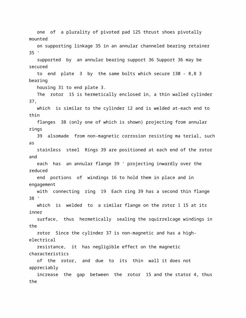
exothermic character of the reaction with oxygen if the gasification is performed also with oxygen (or air) 75 In the case of the gasification of powdery or comminuted fuels, the fuel is mixed intimately with an emulsion constituted bv a liquid fuel and water or by a liquid fuel and a catalyst in aqueous solution The op 80 eration is then continued as hereinbefore set forth for the gasification of liquid fuels. The emulsion may be prepared from an aqueous solution or suspension of a substance which is capable of catalyzing a 85 cracking or gas-formation reaction Typical examples of such catalysts are salts of the alkali metals, e g sodium carbonate and bicarbonate and potassium carbonate, salts and oxides of tne alkal ne ea th Tmet-uts, e g 90 calcium oxide, carbonate and hypochlorite; and salts of iron manganese and copper. A typical emulsion conwninin, a catalyst consists of a heavy fuel oil emulsified by addition of 15 ' < of an aqueous solution which 95 contains 5 i of sodium bicarbonate. The amount of catalyst in the solution and the proportion of solution to be mixed if needed with the fuel (be it solid in powder form or liquid) depends on the chemial an A 100 physical characteristics of the fuel to be gasified. It has been found that within the limits between the minimum amount of solution to be added, as required with light fuels, and 105 the maximum, for heavy fuels and complex fuels, a perfect emulsion is rapidly obtained, which is completely stable even at elevated pre-heating temperatures. The temperature of the super-heated 110 steam which is injected with the emulsion into the reaction chamber should be as high as possible, and at least 400 '-450 'C The normal temperature at which the reaction takes place is quite low compared with 115 those more usual in this type of process, and lies within the range 700 '-900 'C, according to the nature of the fuel being treated and of the catalyst employed. The process is suitable for the " complete 120 gasification" of all liquid fuels and of a large number of solid fuels, powdered or pulverulent The liquid fuels may be derived, for example, from petroleum, or may be the products of high-or low-temperature 125 distillation of solid fuels, such as tar or tarry oils. The process according to the invention may be applied, for example, to the production of gases for technical uses, of coal gas 130 785,490 together with the steam. The structure of the reaction chamber differs according to whether external heating is used for operation with steam only, or operation without external heating, in 70 which latter case the heat of reaction is provided by the exothermic reaction with oxygen.
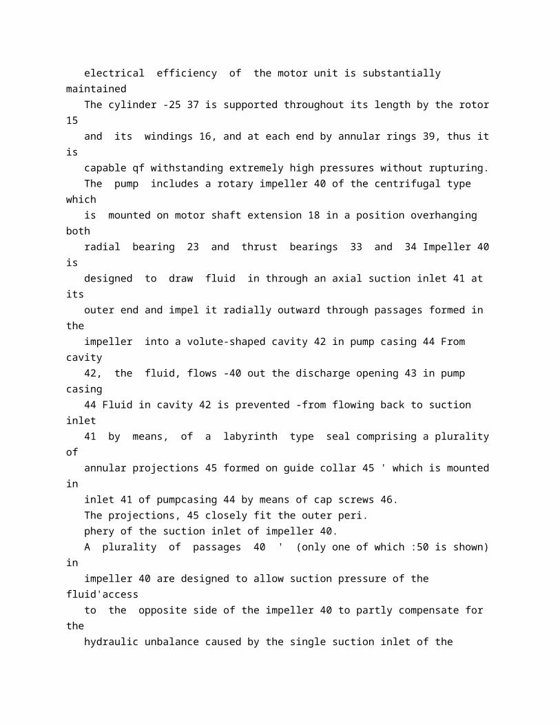
The gas leaving the reaction chamber passes through the heater for super-heating 75 the steam and then through the heater for heating the air (or oxygen), to pass then into a waste heat boiler, and is then cooled down in a water cooler. The whole is obviously completed by the 80 auxiliary features adapted to afford the maximum yield of the installation and the regularity of operation.
* Sitemap * Accessibility * Legal notice * Terms of use * Last updated: 08.04.2015 * Worldwide Database * 5.8.23.4; 93p
* GB785491 (A)
Description: GB785491 (A) ? 1957-10-30
A high-pressure axial flow steam or gas turbine
Description of GB785491 (A)
PATENT SPECIFICATION 735,491 -" 'Date of Application and filing Complete Specification: July 19, 1955. No 20863/55 Application made in,Germany on July 19, 1954. Complete Specification Published: Oct 30, 1957. Index at Acceptance:-Class 110 ( 3), R( 1 A 1 C:2 C). International Classification:-F Old. COMPLETE SPECIFICATION A High-pressure Axial Flow Steam or Gas Turbine. We, LICENTIA PATENT VERWALTUNGSG.M B H, a German Body Corporate, 6 f 31-32, Hohe Bleichen, Hamburg, Germany, do herebv declare the invention for which we pray that a patent may be granted to us, and the method by which it is to be performed, to be particularly described in and by the following statement:- The present invention relates tb highpressure axial flow steam or gas
turbines. High-pressure axial flow steam or gas turbineg are known which comprise two stage groups, a high-pressure stage group and a low-pressure stage group, and which are so designed that the admission -of the highpressure driving medium is effected between the two stage groups, and the driving medium exhausted from the high-pressure stage group is caused to flow through transfer pipes, by-passing the high-pressure stage group outside the turbine casing, to the inner end of the low-pressure stage group This arrangement has the essential advantage that the axial thrust which the driving medium exerts is compensated to a great extent due to the fact that the two stage groups are traversed by the driving medium in opposite directions On the other hand, the turbine casing is subjected to high and varying thermal stresses and the connection and sealing of the transfer pipes is difficult to perform. It has also been proposed to arrange the active member of the turbine, i e the rotor and the stationary guide blades, within a separate body, e g within an insert surrounded by the turbine casing In this way, the turbine casing is relieved from the high thermal stresses to which conventional turbine casings are subjected The insert is supported by the turbine casing in such a manner that it is free to expand in an axial direction, and the interspace between the insert, and the casing is usually in communication with the exhaust of the driving medium so that the casing is only subjected lPrice 3 s 6 d l to the lowest pressure and temperature which occur in the turbine Consequently, the wall of the outer casing may have a smaller thickness. The present invention relates to a high 50 pressure axial flow steam or gas turbine of the kind comprising two stage groups, a highpressure stage group and a low-pressure stage. group, and admission of the driving medium between the two stage groups, the arrange 55 ment being such that the driving medium exhausted from the one (high-pressure) stage group is caused to flow through transfer channels by-passing the high-pressure stage group to the inner end of the low-pressure 60 stage group, which turbine is characterised according to the invention in that the turbine has within its outer casing an insert which surrounds the turbine rotor and serves as guide blade carrier, and which is so mounted 65 in the outer casing that it is free to expand from the centrally disposed admission point for the driving medium towards both exhaust ends, and that the insert is divided along an axial plane, both parts being provided with 70 flanges for their connection, and that the transfer channels, by-passing the high pressure stage group, are provided within the upper flange or within the lower flange or within both of them 75 This construction combines the advantages of the hereinbefore
mentioned known constructions and avoids the disadvantages which they possess, and it has essential additional advantages: The outer casing is subjected to 80 a substantially uniform temperature during operation Transfer pipes outside the turbine casing are no longer required Consequently, there are no longer sealing problems and no difficulties in respect of heat expansion and 85 heat losses in this respect Within the insert well defined temperature conditions in every respect subsist In the region of the central admission there will be the hottest part of the insert Due to the fact that the driving 90 medium exhausted from the high-pressure stage group is admitted to the low-pressure stage group in the region of the central admission, and also due to the fact that this driving medium has about the average temperature between the inlet and outlet of the turbine, the difference of temperature and pressure to which the part of the insert between the two admission points is subjected, is reduced to a minimum The insert is adapted to follow quickly the varying heat conditions, so that the turbine blades and the labyrinth seals may have small radial and axial clearances There will be no large temperature drop in a radial direction within the wall of the insert in the region of the highpressure group due to the fact that the driving medium is led through channels along this high-pressure stage group This advantage becomes apparent particularly by the provision of a greater number, e g four, transfer channels within the insert In order to obtain the required channel cross-section, usually four channels will be provided, i e two in the upper part and two in the lower part of the insert However, should it prove to be impossible to provide the required channel cross-section, then a part of the driving medium, which has to be transferred to the low pressure stage group, will have to be taken outside the casing. In order that the invention may be clearly understood, a constructional example will now be described in more detail with reference to the accompanying drawings, wherein Fig 1 shows a longitudinal section of a two-part turbine insert along a plane C-D of Fig 3, i.e perpendicular to the joint, Fig 2 represents a plan view of the joint and also shows the turbine rotor, and Fig 3 shows a cross section along the plane A-B of Fig 1 The outer casing is not represented. As shown, the insert 1 is divided along a horizontal plane into an upper part 19 and a lower part 20 Both parts form a cylindrical cavity in which a shaft 32 is co-axially disposed The shaft 32 carries the rotary turbine blades 33 and thus forms the rotor of the turbine The stationary guide blades 34 are supported by the interior wall of the cavity of the insert The admission of the driving medium into the turbine blading takes place in the region of the insert marked 28 in
Fig 1, and the succeeding stages, each consisting of a stationary guide blade ring 34 and a revolving rotor blade ring 33, at the left-hand side of the region 28 form the high-pressure stage group 14 and the succeeding stages extending at the right-hand side of the said region 28 form the low-pressure stage group 17. The high-pressure driving medium is supplied through four channels 2 to an annular transversely disposed admission channel which is divided into four sections 3, 4, 5 and 6, each section being supplied through one channel 2 The division is effected in the plane 13 of the joint by webs 9, 10 and 11 12, and in a plane at right angles to the first mentioned plane by webs 7 and 8 The highpressure driving medium then passes through 7 Q the high-pressure stage group 14, partly expanding while doing work, and it is exhausted from this stage group at the points 18 The partly expanded driving medium then enters transfer channels 15 which by-pass the high 75 pressure stage group 14 and open into another transversely disposed annular channel 27 which serves for the admission of the partly expanded driving medium into the lowerpressure stage group 17 80 As shown, each insert part 19 and 20 has lateral extensions or flanges 22, 23 and 24 25 respectively, and the by-pass channels 15 are disposed within these flanges Thus, there are four by-pass channels 15 Part of the con 85 necting screws or bolts 21 for the connection of the two parts of the insert are disposed in a region between the channels 15 and the internal wall of the insert's cavity. It is not necessary to divide the annular 90 channel 27 which receives the partly expanded driving medium into four segments in a manner similar to the division of the annular channel into which the high-pressure driving medium is admitted; however, it is advisable 95 to provide a division along the joint of the two insert parts in order to ensure a better seal between them; to this end webs similar to the webs 9 to 12 may be provided. The admission nozzles 30 for the first stage 100 29 of the low-pressure stage group are directly in communication with the annular channel 26, 27 as shown Alternatively, another undivided transverse channel may be disposed between the divided transverse channel 26, 27 105 and the ring of admission nozzles in order to equalise any differences in pressure which the partial streams of driving medium may have when arriving to the low-pressure stage group due to fact that the resistance to flow may 110 differ to some extent in the individual transfer channels 15 After passing through the lowpressure stage group 17, the driving medium is exhausted from the insert at 31. As mentioned before, the outer casing of 115 the turbine, not shown, surrounds the insert so that, apart from the supporting points an
annular interspace is left, and this interspace will be in communication with the exhaust end 31 of the insert so that the casing is in 120contact with the exhausted driving medium and therefore exposed only to the low pressure and temperature which the exhausted driving medium has It is advantageous to provide the exhaust opening from the outer casing at a 125 point opposite to the discharge end 31 of the insert, so that the exhausted driving medium is caused to flow through the interspaces between the outer casing and the insert. The turbine shaft 32 is surrounded in the 13 785,491 the other and one serving for the admission of the high-pressure driving medium into the high-pressure stage group, and the other for the admission of the partially expanded driving medium into the low-pressure stage 45 group, and wherein the said transfer channels lead from the exhaust point of the highpressure stage group, by-passing this group, towards and open into the transverse annular channel associated with the low-pressure 50 stage group. 3 A turbine according to claim 2, wherein the said transverse annular admission channels are divided into individual sections along the plane of the joint between the two parts of the 55 insert. 4 A turbine according to claim 3, wherein an undivided annular channel is provided between the annular channel for the admission of the partly expanded driving medium into 60 the low-pressure stage group and the first nozzle ring of this group. A turbine according to any of the preceding claims, wherein the turbine shaft is surrounded by a gland in the region between 65 the high-pressure stage group and the lowpressure stage group, and wherein the gland has an annular extraction channel which is in communication by means of radial bores with the annular admission channel for the 70 partly expanded driving medium. 6 An axial flow steam or gas turbine substantially as described with reference to and as illustrated in the accompanying drawings. For the Applicants: MATTHEWS, HADDAN & CO, Chartered Patent Agents, 31-32, Bedford Street, Strand, London, W C 2. admission region 28 by a gland to seal the space of the high-pressure stages 14 from the space of the low-pressure stages 17 The gland is provided with an annular extraction channel which is in communication through radial bores 35 with the transverse annular channel 26, 27 which serves for the admission of the partially expanded driving medium. In this way it is possible to utilise in the 710 low-pressure stage group that portion of the high-pressure driving medium which unavoidably escapes through the gland.
* Sitemap * Accessibility * Legal notice * Terms of use * Last updated: 08.04.2015 * Worldwide Database * 5.8.23.4; 93p
* GB785492 (A)
Description: GB785492 (A) ? 1957-10-30
Improvements in and relating to valves
Description of GB785492 (A)
PATENT SPECIFICATION 785,492 Date of Application and filing Complete Specification July 28, 1955. No 21851/55. Application made in France on September 28, 1954. Complete Specification Published: October 30, 1957. Index at acceptance:-Ciass 135, VD 1, VE(I K: 6 B), VM 2 H. International Classification:-FO 6 k. COMPLETE SPECIFICATION Improvements in and relating to Valves We, SOCIETE LE BOZEC ET GAUTIER, a French body corporate, of 28, rue Carle H Wbert, Courbevoie (Seine), France, do hereby declare the invention, for which we pray that a patent may be granted to us, and the method by which it is to be performed, to be particularly described in and by the following statement:- The present invention relates to a fourway valve, capable of being used as a distributing and reversing valve, and designed especially for large outputs of liquids, under a high pressure, as is often the case in handling liquid fuels. One type of utilisation, particularly advantageous, of such a valve consists in connecting two ways thereof, respectively, to the intake and to the delivery of a pump: it is thus possible, thereafter, without changing anything to the
operation of the pamp, to circulate the liquid in the two other ways, in any direction whatsoever, by simply operating the valve. The valve, thus used in combination with a pump may be applied to numerous types of apparatus, and particularly to tank wagons, as it makes it possible to fill the tank from a store-room and to discharge it into all receiving tanks, such as those on an aircraft, using the same connecting hose. The valve according to the invention comprises a plate, having four openings at the four corners of a square, a case, two rigidly connected domes mounted to pivot inside the case against a face of the plate and capable of connecting the four openings two by two, an internally threaded hollow shaft arranged to turn the assembly of domes and provided with a control lever or the like and a threaded rod extending through the hollow shaft in engagement with the threads thereof and controlled by a handwheel or the like which enables the assembly of domes to be forced against the plate by turn4 Sing the rod. (Price _jrij) 4 S 6 d A valve in accordance with the invention will now be described, by way of example, with reference to the accompanying drawings wherein: Figure 1 is a front view of the valve 50 Figure 2 is an axial section of the valve along line II-II of Figure 1. Figure 3 is a view of the valve along III-III in Figure 2. Figure 4 is a view of the distributor along 55 line IV-IV in Figure 2. Figure 5 is a transverse section of the distributor. Figures 6 and 7 are diagrammatic views showing the distributor in its two positions 60 of utilization. The distributing and reversing valve shown on these Figures, comprises a circular plate 1, drilled with four apertures designated 21, 22, 23, and 24 and having, as 65 shown particularly in Figure 3, their centers placed at the four corners of a square. On one side of the plate, these apertures are provided with flanges or similar devices by means of which they can be connected with 70 four conduits shown diagrammatically in Figures 6 and 7 designated respectively C, RP, AP and E On the other side of the plate, these apertures are capped, two by two, by two associated caps 6 and 7 applied 75 by their edges against the plate and forming part of a distributor 5 The cap -6 comprises two apertures 31 and 32 and the cap 7 two apertures 33 and 34; these apertures being arranged at the corners of a square in 80 the same manner as the apertures in the plate, so that they may be brought in coincidence therewith. The tightness between the plate 1 and the distributor 5 is obtained, first, by a careful 85 machining of the surfaces facing one another and then by means of gaskets such as 26 and 27 skirting the apertures
21 to 24 of the plate. The distributor 5 is enclosed in a housing 90 & W k 4 785,492 2 tightly secured to the plate 1, by means of screws such as 3 with the interposition of a gasket 4. Externally, the distributor 5 comprises two parallel wings 8 and 9 (Figure 4), between which is engaged, by its two flat parts 11 and 12, a collar 18 on a shaft 10 entering partly the distributor 5 and going through the housing 2; this shaft is placed at the center of the square formed by the apartures 21 to 24 The sealing of the passage for the shaft 10 through the housing 2 is ensured by gaskets 14 and 15. At its end outside the housing 2, the shaft 10 forms a non-circular bearing, square for instance, on which a wrench 13 is engaged, held by a nut 25 screwed on the shaft 10. About the center of its face opposite the plate 1, the distributor carries a stop is the shape of a circular arc, 16, housed in a recess 28 of the plate and cooparating with a stop 17 secured to said plate, by means of which the possibility of rotation of the distributor is limited to a 90 angle. According to the example represented, the valve comprises a device for clamping the distributor against the plate This device comprises a shaft 19 housed inside the shaft 10, drilled to that effect; at its outer end, the shaft 19 carries a small control handwheel, while on the inside it offers a screwthread 41 engaged in a tapping corresponding to the shaft 10; in addition, quite at its end, the shaft 19 is provided with a steel stud 45 facing which the distributor 5 comprises a steel wafer 46 The tightness between the shafts 10 and 19 is ensured by gaskets 42 and 43. On the other side of the distributor, in the recess 28 of the plate, a coil spring 44 is housed, having a tendency to move the distributor 5 away the plate 1. The operation of the valve thus described is as follows: If it is assumed for instance that the valve is mounted on a truck comprising a pump and a tank, the conduit C is connected permanently to the tank, the conduit AP to the pump intake, the conduit RP to the pump delivery and the conduit E consists of a hose capable of being connected with an outer enclosure, the latter being possibly either a store-room from which liquid will be drawn, or a fixed or a movable tank which will have to be filled. In order to fill the tank on the truck, the outer conduit E is placed in communication with a store-room which is to supply the necessary liquid The handwheel 20 is rotated so as to unscrew slightly the shaft 19; the stud 45 moves away from the wafer 46 and the spring 44 moves the distributor away from the plate 1; the wrench 13 is then operated so as to bring it to the position shown in figure 6; in that position,
the cap 7 connects the intake AP of the pump with the outer conduit E and the storeroom, while the cap 6 places the delivery of the pump RP in communication with the tank on the truck 70 By means of the handwheel 20, the shaft 19 is screwed back which, through the stud and the wafer 46 pushes the distributor back against the plate and clamps this distributor There only remains, then to 75 start the pump in order to fill the tank with the liquid from the store-room. The tank thus having been filled with liquid if the portion of this liquid has to be transferred to a reservoir, such as that of an 80 aircraft, the conduit E is connected with the reservoir to be filled, and after having loosened the distributor 5 by operation of the handwheel 20, the wrench 13 is acted upon so as to bring it to the position of figure 85 7, in which the cap 7 places the tank in communication with the intake AP of the pump while the cap 6 connects the delivery RP of the pump with the conduit E and the reservoir The shaft 19 is then tightened 90 and the pump started again, in the same direction as before The liquid in the tank is thus forced into the reservoir. It may happen that, due to a premature starting of the pump, part of the liquid 95 passes between the distributor 5 and the plate 1, and upon entering the box 2 this liquid under a high pressure would be liable to clamp the distributor against the plate. For removing the liquid thus introduced 100 there has been provided a drain aperture 48 which can be closed by a removable plug 47 (Figure 2).
* Sitemap * Accessibility * Legal notice * Terms of use * Last updated: 08.04.2015 * Worldwide Database * 5.8.23.4; 93p