Embed Size (px)
Citation preview
VACUUM SCIENCE AND TECHNOLOGY FOR THIN FILM DEVICE PROCESSINGAlastair BuckleyUniversity of Sheffield

The three things you can do in vacuum
Evaporate materials as a coating method
Thermionic emission from a hot metal surface Richardson-Shottky equation
Create a plasma Electrons, ions, neutrals Electron energy distribution function
Extract an ion beam Etching, sputtering
2 /kTRJ A T e
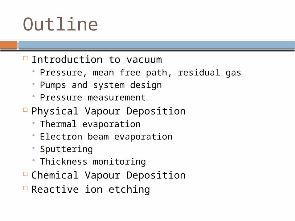
Outline Introduction to vacuum
Pressure, mean free path, residual gas Pumps and system design Pressure measurement
Physical Vapour Deposition Thermal evaporation Electron beam evaporation Sputtering Thickness monitoring
Chemical Vapour Deposition Reactive ion etching

Introduction Why vacuum processing?
Solar PV c-Si cell fabrication – doping, etching, electrode deposition a-si cell fabrication – deposition, etch, electrode deposition CdTe – deposition, etc.. OPV – electrode deposition Perovskite – electrode deposition
Microelectronics Plastic electronics Structural coatings, discharge lamps, CRTSs
Vacuum is how all “high tech” is done at the moment
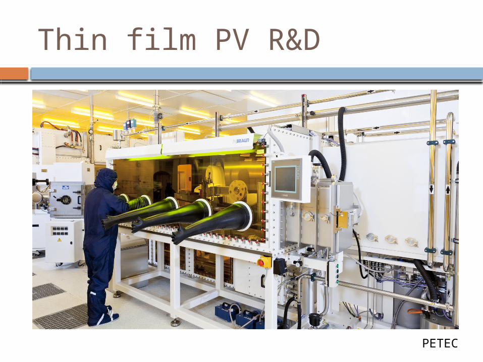
Thin film PV R&D
PETEC
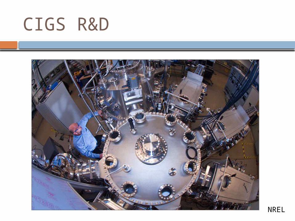
CIGS R&D
NREL

OLED lighting
IPMS

CMOS foundry

What can you do in vacuum?
Deposition Metals Dielectrics Organics
Etch Chemical Ion beam
Implant / doping Not going to cover this – this is how silicon transistors are made
Surface science (Not going to cover this either) SEM XPS Auger Etc..

Introduction to vacuum
Pressure, mean free path, residual gas Pumps and system design Pressure measurement

PressureVacuum quality Torr Pa mbar Gas
Atmospheric pressure
760 1.013×10+5 1013
Low vacuum 760 to 25 1×10+5 to 3×10+3 1000 to 30
Medium vacuum 25 to 1×10⁻³ 3×10+3 to 1×10⁻¹ 30 to 1×10⁻³
High vacuum 1×10⁻³ to 1×10⁻⁹
1×10⁻¹ to 1×10⁻⁷
1×10⁻³ to 1×10⁻⁹
Ultra high vacuum
1×10⁻⁹ to 1×10⁻¹²
1×10⁻⁷ to 1×10⁻¹⁰
1×10⁻⁹ to 1×10⁻¹²
Extremely high vacuum <1×10⁻¹² <1×10⁻¹⁰ <1×10⁻¹²
Outer space 1×10⁻⁶ to <3×10⁻¹⁷
1×10⁻⁴ to < 3×10⁻¹⁵
1×10⁻⁶ to <3×10⁻¹⁷
Perfect vacuum 0 0 0

Mean free pathHow far does a molecule travel before it collides
If you want a stable plasma then you will need collisionsIf you want to thermally evaporate material then you want no collisionsThe threshold for chambers that are about 1 m wide is around 10-3 to 10-4 mbar

Flow in vacuum Viscous, turbulent Molecular, laminar

Residual gases I wanted to show a chart of the different pump speeds and different
residual gases in a vacuum chamber at different pressures.
I couldn’t find one though – so we will measure that in the practical! What do you think it will look like?
Which gases do you think dominate at (mbar) 10-2
10-4
10-6
10-8
What do you think the different pump rates of these gases are?

Vacuum pumps
http://www.globalspec.com/learnmore/manufacturing_process_equipment/vacuum_equipment/vacuum_pumps/vacuum_pumps_all_types

Vacuum pumps Backing pumps
Rotary High vac pumps
Cryo Turbo Diffusion
UHV pumps Sublimation
chamber
High vac pump Backing pump
exhaustforeline
UHV pump (if needed)

Rotary pump Compression by a mechanical motion P > 10-3 mbar “Roughing” to pump air out of chamber “Backing” to maintain foreline pressure
for high vacuum pump
https://www.youtube.com/watch?v=AFHogF-9eGA

Cryo pump “Freezes” residual gas to
internal surface – basically a very big fridge inside the vacuum chamber
Operates at ~10-20 K Need regenerating every
so often and routine maintenance in filters
Very effective for pumping water, N2 and O2

Turbopump Momentum transfer pump Gas molecules diffuse into
pump and are “hit” by rotor blades, changing the molecules direction into the body of the pump.
Expensive and bearings go eventually but otherwise maintenance free

Turbo Light gases pump more slowly Full pump rate only below 10-3 mbar
Pfeiffer

Diffusion pump
Like the turbo pump operates by momentum transfer
An oil spray generates a net momentum and gas compression towards the foreline
Oil contamination makes unsuitable for most processes in semicon
Used widely in old vacuum TV tube industry due to low cost

Sublimation pump Metals like chromium and titanium
sublime and as they do so they condense on the chamber wall trapping residual gas with them.

Chamber design Short path to pump Simple shapes Pressure gauge close to chamber but not
looking directly at the pump (ie. Opposite)

Pressure measurementType Pressure
range/ mbar
Mechanism
Pirani 10-4 -1 Temperature/pressure relationship of hot filament
Baratron 10-3-102 Capacitance of plates deflected by pressure change
Hot filamentIon guage
10-10-10-4 Ionisation current using thermionic electrons
Cold cathodePenning
10-6-10-2 Ionisation current using high EM field

Hot filament ion guage Electrons are emitted thermally from the filament The electrons accelerate towards the grid (+ve) They ionise gas atoms/molecules The +ve ions accelerate to the collector The collector current is proportional to the ion density
and therefore the pressure
gridcollector
emitter

Baratron (capacitance) gauge
Capacitance of parallel pair of electrodes is measured
One electrode is displaced by the pressure in the vacuum chamber
Pressure is calibrated to capacitance change
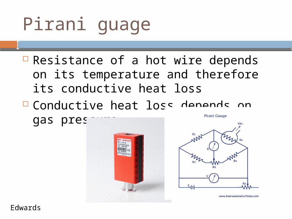
Pirani guage Resistance of a hot wire depends on its
temperature and therefore its conductive heat loss
Conductive heat loss depends on gas pressure
Edwards

Cold cathode (Penning) guage
A kV bias is applied to the anode. This ionises gas in the gauge. A magnet confines the ions in a circular path within the gauge resulting in further collisions and ionisation generating a measurable current at the cathode.
Cheap

Residual gas analysis (RGA) Quadrupole RGA Gas is ionised by electron collision near the cathode. Ions are accelerated into a quadrupole that has an oscillating field
applied. Only certain masses make it through to the detector at certain
frequencies of oscillation.

Physical vapour deposition Layer by layer deposition of materials
Roughness, adhesion Thickness control – intra and inter substrate Defectivity – pinholes, particles

Physical vapour deposition
Hauzer
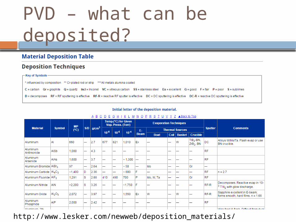
PVD – what can be deposited?
http://www.lesker.com/newweb/deposition_materials/materialdeposition.cfm?pgid=0

Resistive evaporation Resistive heating Boats, crucibles and furnaces Metals (Ca, Al, Ag, Ni, Cr…) Some salts (LiF, BaF2, etc..) Some oxides (MoO3, V2O5)

Electron beam evaporation A hot filament emits electrons into vacuum These electrons are accelerated towards a target
material and collide with the material having kinetic energy that heats the target to an evaporation temperature
The evaporant has a line of path to the substrate to be coated
https://www.youtube.com/watch?v=ZN7NZYXGSbk

Sputtering
A glow discharge plasma is formed in vacuum at around 10-2 to10-3 mbar
A target of a material to be deposited is biased negative with respect to the plasma and ions from the plasma accelerate into the target ejecting target material towards the substrate.

Magnetron sputtering If the plasma is confined close to the target then
the sputtering rate can be enhanced significantly. A magnetic field can be used and in this case the
technique is know as magnetron sputtering.
Electron race track

RF, DC and pulsed sputtering To maintain a stable plasma and a stable
sputter rate a stable bias between the plasma and the target is needed.
For conducting targets this is possible with a DC field
For insulating targets RF fields can be used but the sputter rate is often lower than for DC.
In industrial coating applications often pulsed DC is used as a compromise.http://www.advanced-energy.com/upload/File/White_Papers/ENG-
ChooseIndPwrSup-270-01.pdf

Ion assisted deposition Can be used with ebeam, thermal or
sputter deposition Increases the adhesion and density of
the film

Quartz crystal microbalance The resonant frequency
of a piezo electric crystal depends on its mass.
An oscillating field is applied across a quartz crystal and its resonance monitored
The rate of change of mass addition can be measured

Chemical vapour deposition Precursor heated (in a furnace) with a
substrate and converted to inorganic layer
Different precursors give different films
http://www1.phc.uni-kiel.de/cms/index.php/en/research-m-gfr/140-cvd.html

Plasma enhanced CVD (PECVD)
Applied Materials – TCO deposition for gen8 display glasshttp://www.appliedmaterials.com/display

Atomic layer deposition Layer by layer chemical deposition
technique that can make atomically perfect films
Great for hermetic encapsulation Great for conformal film forming Really slow

Reactive ion etching Reactive ions are generated in a plasma The ions react with the substrate creatin
volatile products that are pumps away. Fluorine ions react with most oxides
(SiO2) Chlorine ions react with most metals (Al)
http://www.sentech.com/en/Plasma-Process-Technology__2288/
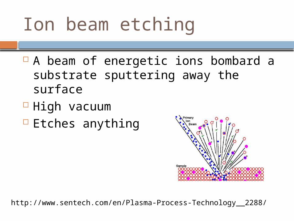
Ion beam etching A beam of energetic ions bombard a
substrate sputtering away the surface High vacuum Etches anything
http://www.sentech.com/en/Plasma-Process-Technology__2288/

Final slide.. What I hope you have learned.
Vacuum processing is ubiquitous in high tech
There are loads of different process techniques Many are not available in the science lab – but they are
available in industry
When you do vacuum fabrication think: Pressure is mean free path – 10-4 mbar is transition to collision free Pressure is residual gas – 10-4 to10-6 mbar is mostly water
In the vacuum practical you will measure P vs t for different residual gases. You will measure the pump rates of the different gases.