Embed Size (px)
Citation preview

SF-TAP: Scalable and Flexible Traffic Analysis Platform
L7レベルネットワークトラフィック解析器
北陸先端科学技術大学院大学 情報通信研究機構
1

おしながき• 本研究の目的
• 既存研究と本研究の位置づけ
• SF-TAPの動作図及び構成要素
• 応用例
• 設計・実装
• デモ
• パフォーマンス計測
2
目的(1) 高速なL7トラフィックの解析
high pps
high bps3
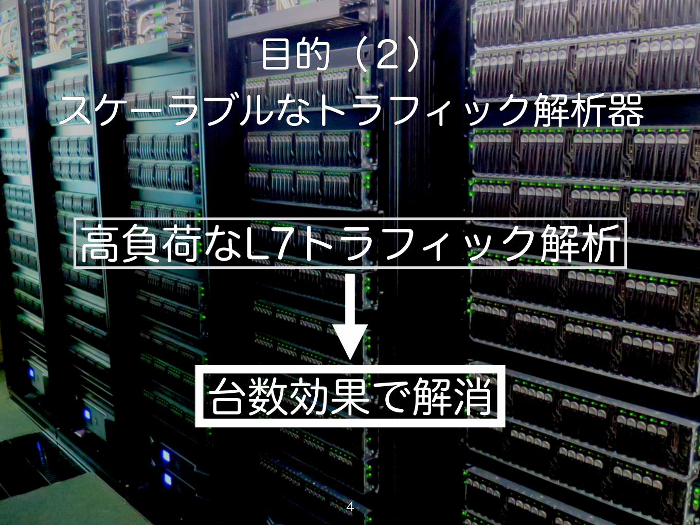
目的(2) スケーラブルなトラフィック解析器
目的(2) スケーラブルなトラフィック解析器
高負荷なL7トラフィック解析
台数効果で解消
4

目的(3) 解析器のプログラマブルな作成
目的に応じた言語で解析器の実装を可能に
ちょっとした検証ならPython, Ruby
機械学習ならJava,C++
高速性を求めるならC
5

目的(4) コモディティベース
ベンダーロックインからの開放
アプライアンスは機能追加が困難研究・開発フェーズには不向き
6
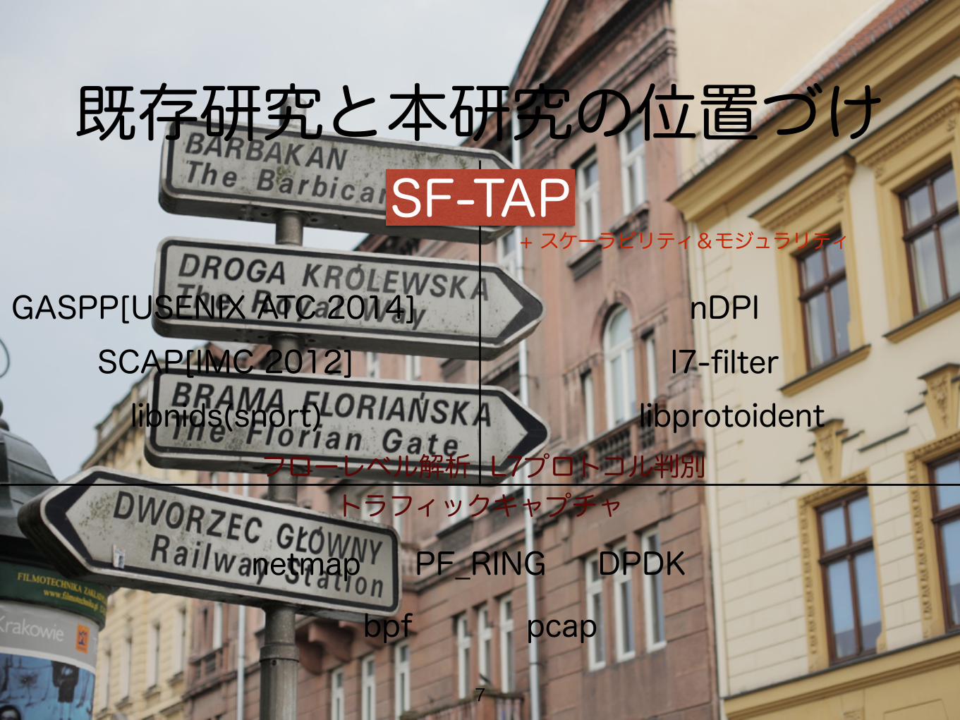
既存研究と本研究の位置づけ
GASPP[USENIX ATC 2014]SCAP[IMC 2012]libnids(snort)
netmap PF_RING DPDK
bpf pcap
フローレベル解析 L7プロトコル判別トラフィックキャプチャ
nDPIl7-filter
libprotoident
SF-TAP+ スケーラビリティ&モジュラリティ
7
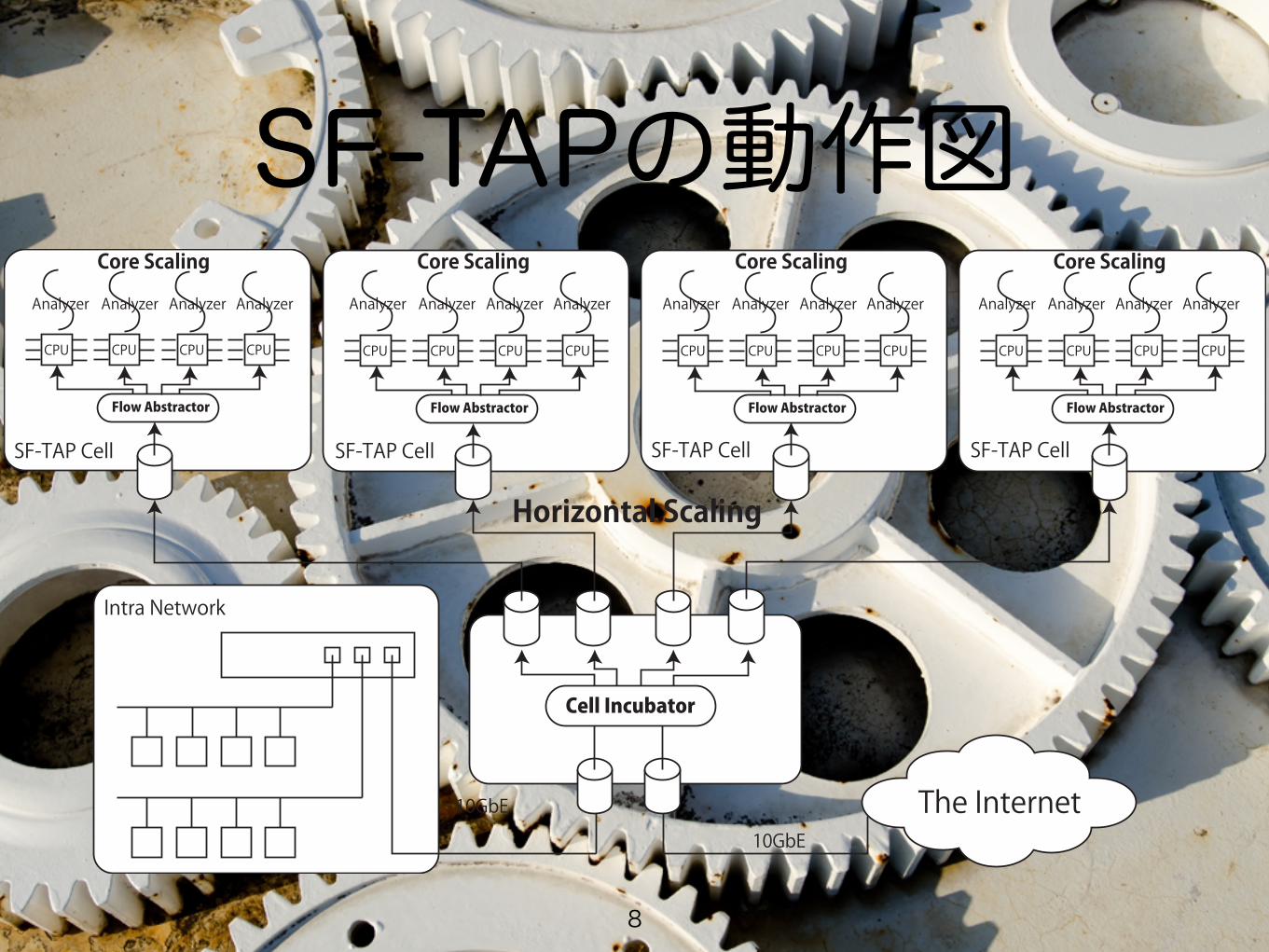
SF-TAPの動作図CPU CPU CPU CPU
Flow Abstractor
CPU CPU CPU CPU
Flow Abstractor
CPU CPU CPU CPU
Flow Abstractor
CPU CPU CPU CPU
Flow Abstractor
Cell Incubator
The Internet
SF-TAP Cell SF-TAP Cell SF-TAP Cell SF-TAP Cell
Intra Network
Core ScalingCore Scaling Core Scaling Core Scaling
Horizontal Scaling
Analyzer Analyzer Analyzer Analyzer Analyzer Analyzer Analyzer Analyzer Analyzer Analyzer Analyzer Analyzer Analyzer Analyzer Analyzer Analyzer
10GbE
10GbE
8
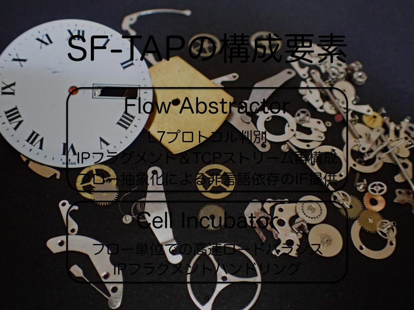
SF-TAPの構成要素Flow Abstractor
Cell Incubator
L7プロトコル判別IPフラグメント&TCPストリーム再構成フロー抽象化による非言語依存のIF提供
フロー単位での高速ロードバランスIPフラグメントハンドリング
9
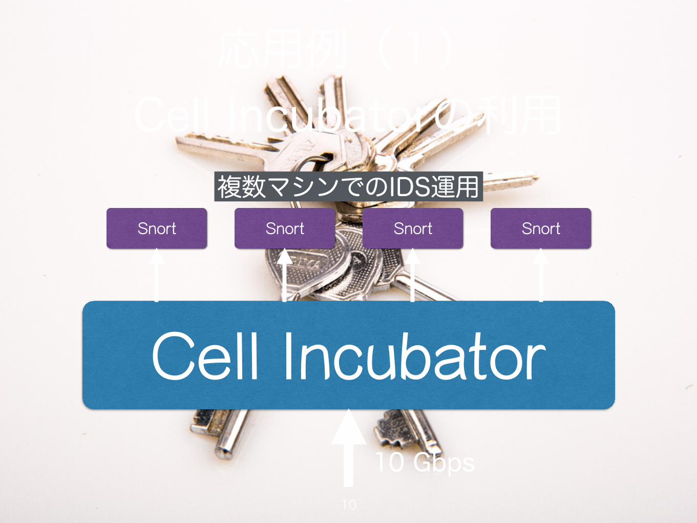
応用例(1) Cell Incubatorの利用
Cell Incubator
Snort Snort Snort Snort
10 Gbps
複数マシンでのIDS運用
10
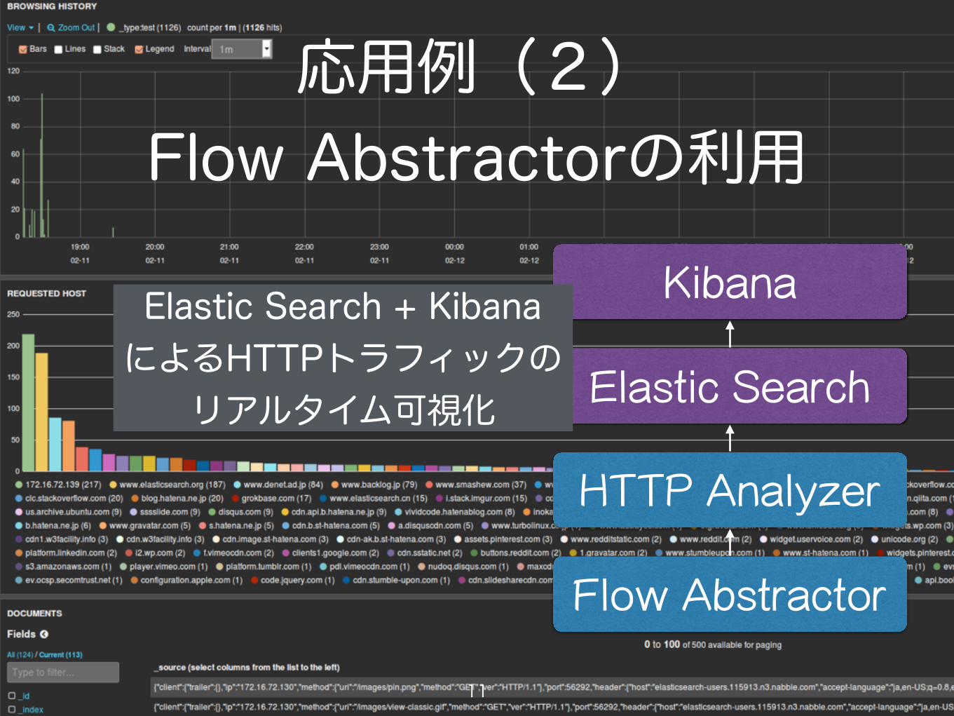
応用例(2) Flow Abstractorの利用
Flow Abstractor
HTTP Analyzer
Elastic Search
KibanaElastic Search + Kibana によるHTTPトラフィックの リアルタイム可視化
11
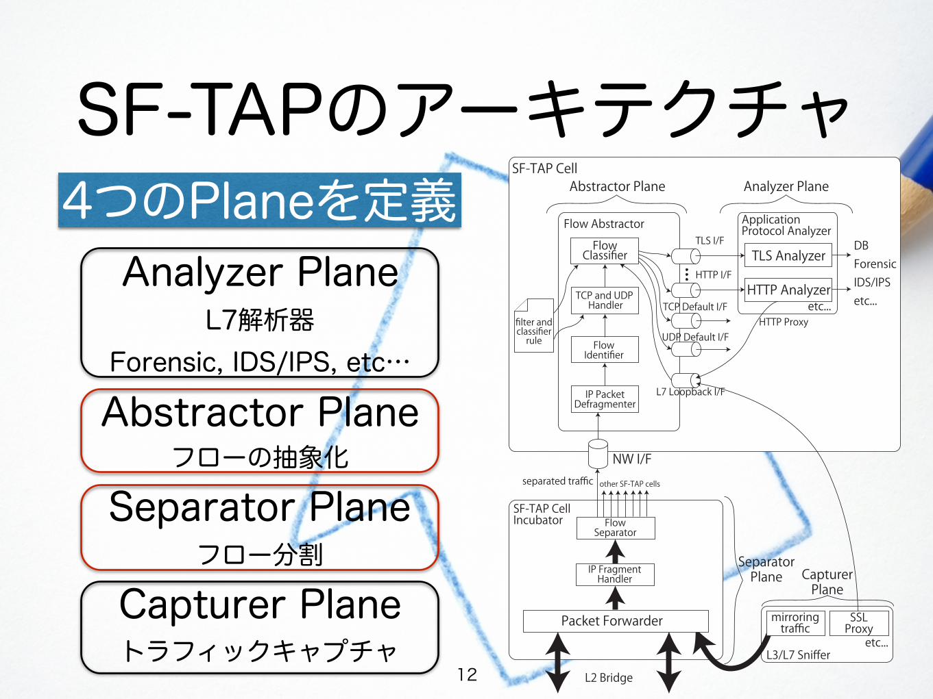
SF-TAPのアーキテクチャ
NW I/F
HTTP I/F
TLS I/FFlow Abstractor
FlowClassifier TLS Analyzer
HTTP Analyzer
HTTP Proxy
TCP and UDP Handler
filter andclassifierrule
L7 Loopback I/F
DBForensicIDS/IPSetc...
ApplicationProtocol Analyzer
etc...TCP Default I/F
UDP Default I/F
Analyzer PlaneAbstractor Plane
CapturerPlane
SF-TAP CellIncubator
FlowIdentifier
FlowSeparator
SeparatorPlane
separated traffic
SF-TAP Cell
L3/L7 Sniffer
SSLProxyetc...
other SF-TAP cells
IP PacketDefragmenter
L2 Bridge
mirroringtrafficPacket Forwarder
IP FragmentHandler
4つのPlaneを定義Analyzer Plane
L7解析器Forensic, IDS/IPS, etc…
Abstractor Planeフローの抽象化
Separator Planeフロー分割
Capturer Planeトラフィックキャプチャ
12
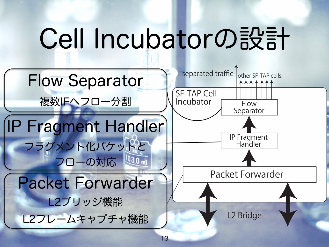
Cell Incubatorの設計SF-TAP CellIncubator Flow
Separator
separated traffic other SF-TAP cells
L2 Bridge
Packet Forwarder
IP FragmentHandler
Packet ForwarderL2ブリッジ機能
L2フレームキャプチャ機能
IP Fragment Handlerフラグメント化パケットと
フローの対応
Flow Separator複数IFへフロー分割
13
Flow Abstractorの 設計(1)
14
NW I/F
HTTP I/F
TLS I/FFlow Abstractor
FlowClassifier
TCP and UDP Handler
filter andclassifierrule
L7 Loopback I/F
TCP Default I/F
UDP Default I/FFlowIdentifier
IP PacketDefragmenter
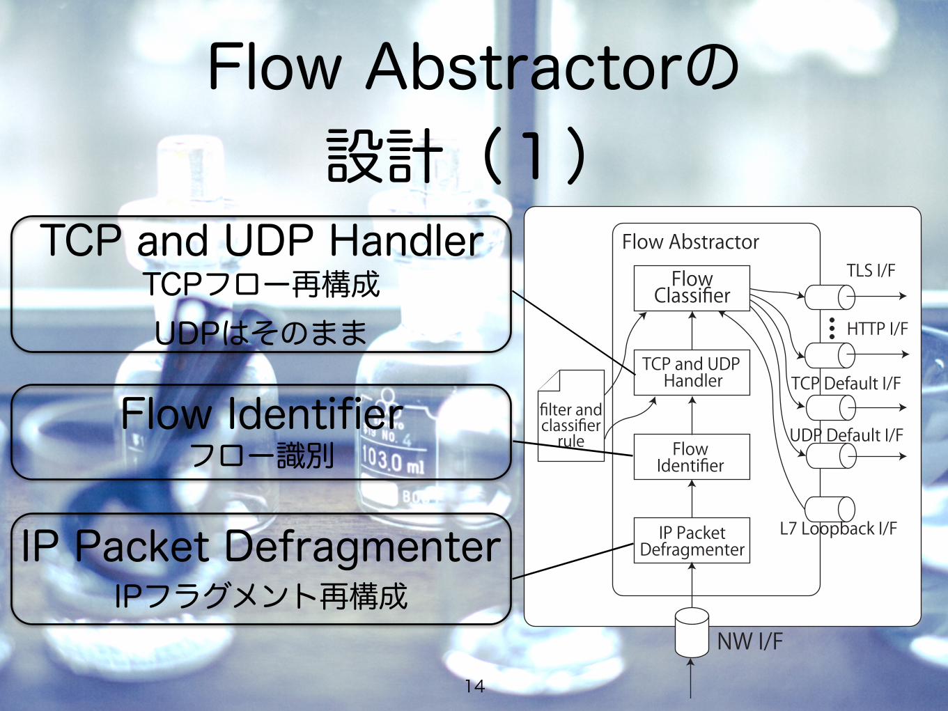
TCP and UDP Handler
Flow Identifier
IP Packet Defragmenter
TCPフロー再構成
フロー識別
UDPはそのまま
IPフラグメント再構成
Flow Abstractorの 設計(2)
15
NW I/F
HTTP I/F
TLS I/FFlow Abstractor
FlowClassifier
TCP and UDP Handler
filter andclassifierrule
L7 Loopback I/F
TCP Default I/F
UDP Default I/FFlowIdentifier
IP PacketDefragmenter
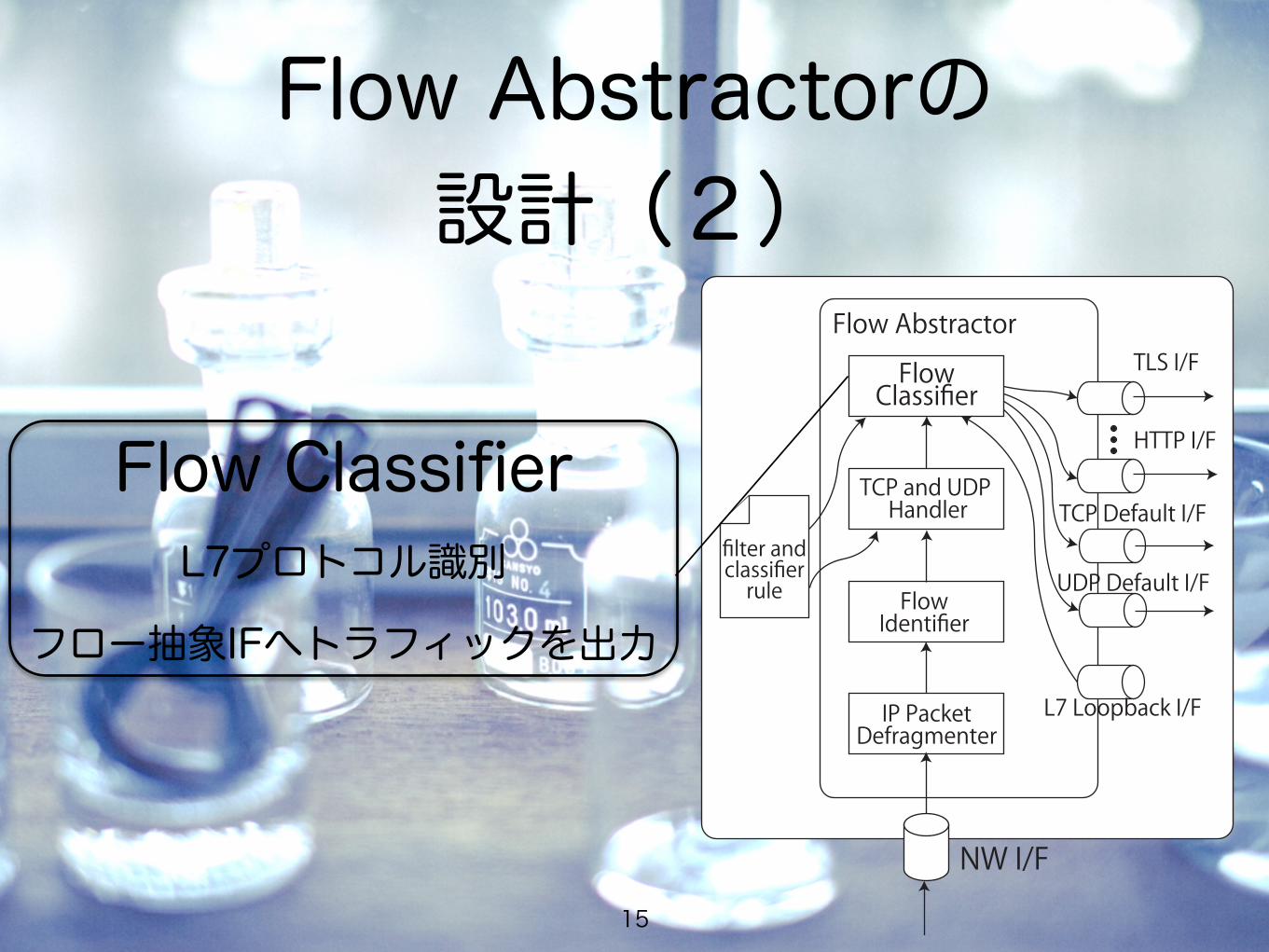
Flow ClassifierL7プロトコル識別
フロー抽象IFへトラフィックを出力
Flow Abstractorの 設定ファイル(1)
16
interfaces. Traffic analyzer developers can develop ana-lyzers by accessing the interfaces provided by this plane.The analyzer plane is a plane for analyzers developed bythe users of SF-TAP. Users can implements analyzers inany programming language.
In this paper, we discuss only the separator and ab-stractor planes, because the components of the capturerplane are well-known, and the analyzers of the analyzerplane are developed by SF-TAP users. In the followingsections, we describe the design of the flow abstractorand the cell incubator, and show an example of an ana-lyzer for HTTP.
3.2 Design of Flow AbstractorWe now describe the design of the flow abstractor illus-trated in Figure 2 by using an actual implementation con-figuration file, shown in Figure 3, to allow easy under-standing. The flow abstractor consists of four compo-nents: the IP packet defragmenter, the flow identifier, theTCP and UDP handler, and the flow classifier.
3.2.1 Flow Reconstruction
The flow abstractor defragments fragmented IP packets,and reconstructs TCP streams. Thus, analyzer develop-ers need not implement the complicated reconstructionlogic required for L7-level analysis.
The IP packet defragmenter shown in Figure 2 is acomponent that provides IP packet defragmentation. De-fragmented IP packets are forwarded to the flow identi-fier, which identifies the flow as L3/L4-level. We iden-tify flows by using 5-tuples consisting of the sourceand destination IP addresses, source and destination portnumbers, and a hop count, which is described in Sec-tion 3.2.2. After the flows have been identified, the TCPstreams are reconstructed by the TCP and UDP handler,and then the flows are forwarded to the flow classifier.
3.2.2 Flow Abstraction Interface
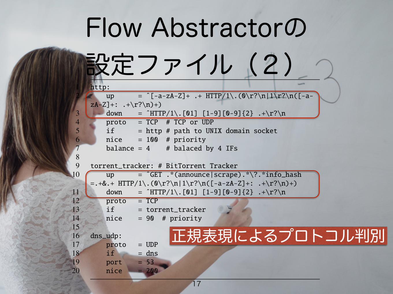
The flow abstractor provides interfaces that abstractflows as L7-level. For example, in Figure 2, the TLSand HTTP interfaces are illustrated, and in Figure 3, theHTTP, BitTorrent Tracker [2], and DNS interfaces aredefined.
The flow classifier classifies flows as the various L7protocols, and forwards them to flow abstraction inter-faces, which are implemented using a UNIX domainsocket, illustrated in Figure 4. The file names of the in-terfaces are actually defined by items of if; for exam-ple, at lines 5, 13, and 18 in Figure 3, the interfacesof HTTP, BitTorrent Tracker, and DNS are defined ashttp, torrent tracker, and dns, respectively. By
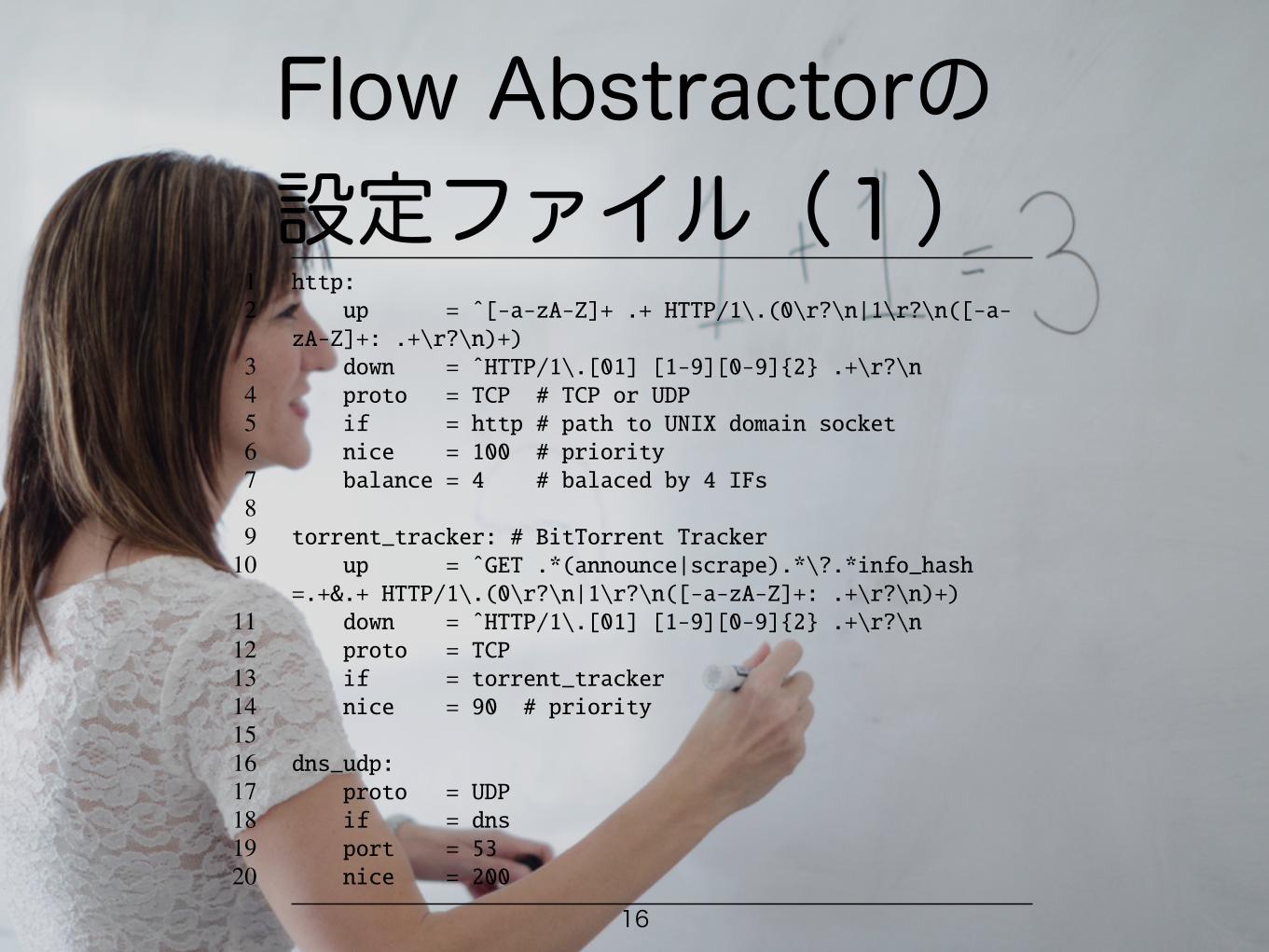
1 http:2 up = ˆ[-a-zA-Z]+ .+ HTTP/1\.(0\r?\n|1\r?\n([-a-zA-Z]+: .+\r?\n)+)
3 down = ˆHTTP/1\.[01] [1-9][0-9]{2} .+\r?\n4 proto = TCP # TCP or UDP5 if = http # path to UNIX domain socket6 nice = 100 # priority7 balance = 4 # balaced by 4 IFs89 torrent_tracker: # BitTorrent Tracker
10 up = ˆGET .*(announce|scrape).*\?.*info_hash=.+&.+ HTTP/1\.(0\r?\n|1\r?\n([-a-zA-Z]+: .+\r?\n)+)
11 down = ˆHTTP/1\.[01] [1-9][0-9]{2} .+\r?\n12 proto = TCP13 if = torrent_tracker14 nice = 90 # priority1516 dns_udp:17 proto = UDP18 if = dns19 port = 5320 nice = 200
Figure 3: Configuration Example of Flow Abstractor
1 $ ls -R /tmp/sf-tap2 loopback7= tcp/ udp/34 /tmp/sf-tap/tcp:5 default= http2= ssh=6 dns= http3= ssl=7 ftp= http_proxy= torrent_tracker=8 http0= irc= websocket=9 http1= smtp=
1011 /tmp/sf-tap/udp:12 default= dns= torrent_dht=
Figure 4: Directory Structure of Flow Abstraction Inter-face
providing independent interfaces for each L7 protocol,any programming language can be used to implement an-alyzers.
Furthermore, we designed a special interface for flowinjection called the L7 loopback interface, L7 LoopbackI/F in Figure 2. This interface is convenient for encapsu-lated protocols such as HTTP proxy. For example, HTTPproxy can encapsulate other protocols in HTTP, but theencapsulated traffic should also be analyzed as L7-level.In this situation, further analysis of encapsulated trafficcan be easily achieved by re-injecting encapsulated traf-fic into the flow abstractor via the L7 loopback interface.The flow abstractor handles re-injected traffic in the samemanner. Therefore, implementation of L7-level analysisof encapsulated traffic can be simplified, although in gen-eral it tends to be complex. It should be noted that the L7loopback interface may cause infinite injection. To avoidthis problem, we introduce a hop count and hop limita-tion. The flow abstractor drops injected traffic only whenits hop count exceeds the hop limitation.
In addition to the flow abstraction and the L7 loop-back interfaces, the flow abstractor provides the default
4
Flow Abstractorの 設定ファイル(2)
17
interfaces. Traffic analyzer developers can develop ana-lyzers by accessing the interfaces provided by this plane.The analyzer plane is a plane for analyzers developed bythe users of SF-TAP. Users can implements analyzers inany programming language.
In this paper, we discuss only the separator and ab-stractor planes, because the components of the capturerplane are well-known, and the analyzers of the analyzerplane are developed by SF-TAP users. In the followingsections, we describe the design of the flow abstractorand the cell incubator, and show an example of an ana-lyzer for HTTP.
3.2 Design of Flow AbstractorWe now describe the design of the flow abstractor illus-trated in Figure 2 by using an actual implementation con-figuration file, shown in Figure 3, to allow easy under-standing. The flow abstractor consists of four compo-nents: the IP packet defragmenter, the flow identifier, theTCP and UDP handler, and the flow classifier.
3.2.1 Flow Reconstruction
The flow abstractor defragments fragmented IP packets,and reconstructs TCP streams. Thus, analyzer develop-ers need not implement the complicated reconstructionlogic required for L7-level analysis.
The IP packet defragmenter shown in Figure 2 is acomponent that provides IP packet defragmentation. De-fragmented IP packets are forwarded to the flow identi-fier, which identifies the flow as L3/L4-level. We iden-tify flows by using 5-tuples consisting of the sourceand destination IP addresses, source and destination portnumbers, and a hop count, which is described in Sec-tion 3.2.2. After the flows have been identified, the TCPstreams are reconstructed by the TCP and UDP handler,and then the flows are forwarded to the flow classifier.
3.2.2 Flow Abstraction Interface
The flow abstractor provides interfaces that abstractflows as L7-level. For example, in Figure 2, the TLSand HTTP interfaces are illustrated, and in Figure 3, theHTTP, BitTorrent Tracker [2], and DNS interfaces aredefined.
The flow classifier classifies flows as the various L7protocols, and forwards them to flow abstraction inter-faces, which are implemented using a UNIX domainsocket, illustrated in Figure 4. The file names of the in-terfaces are actually defined by items of if; for exam-ple, at lines 5, 13, and 18 in Figure 3, the interfacesof HTTP, BitTorrent Tracker, and DNS are defined ashttp, torrent tracker, and dns, respectively. By
1 http:2 up = ˆ[-a-zA-Z]+ .+ HTTP/1\.(0\r?\n|1\r?\n([-a-zA-Z]+: .+\r?\n)+)
3 down = ˆHTTP/1\.[01] [1-9][0-9]{2} .+\r?\n4 proto = TCP # TCP or UDP5 if = http # path to UNIX domain socket6 nice = 100 # priority7 balance = 4 # balaced by 4 IFs89 torrent_tracker: # BitTorrent Tracker
10 up = ˆGET .*(announce|scrape).*\?.*info_hash=.+&.+ HTTP/1\.(0\r?\n|1\r?\n([-a-zA-Z]+: .+\r?\n)+)
11 down = ˆHTTP/1\.[01] [1-9][0-9]{2} .+\r?\n12 proto = TCP13 if = torrent_tracker14 nice = 90 # priority1516 dns_udp:17 proto = UDP18 if = dns19 port = 5320 nice = 200
Figure 3: Configuration Example of Flow Abstractor
1 $ ls -R /tmp/sf-tap2 loopback7= tcp/ udp/34 /tmp/sf-tap/tcp:5 default= http2= ssh=6 dns= http3= ssl=7 ftp= http_proxy= torrent_tracker=8 http0= irc= websocket=9 http1= smtp=
1011 /tmp/sf-tap/udp:12 default= dns= torrent_dht=
Figure 4: Directory Structure of Flow Abstraction Inter-face
providing independent interfaces for each L7 protocol,any programming language can be used to implement an-alyzers.
Furthermore, we designed a special interface for flowinjection called the L7 loopback interface, L7 LoopbackI/F in Figure 2. This interface is convenient for encapsu-lated protocols such as HTTP proxy. For example, HTTPproxy can encapsulate other protocols in HTTP, but theencapsulated traffic should also be analyzed as L7-level.In this situation, further analysis of encapsulated trafficcan be easily achieved by re-injecting encapsulated traf-fic into the flow abstractor via the L7 loopback interface.The flow abstractor handles re-injected traffic in the samemanner. Therefore, implementation of L7-level analysisof encapsulated traffic can be simplified, although in gen-eral it tends to be complex. It should be noted that the L7loopback interface may cause infinite injection. To avoidthis problem, we introduce a hop count and hop limita-tion. The flow abstractor drops injected traffic only whenits hop count exceeds the hop limitation.
In addition to the flow abstraction and the L7 loop-back interfaces, the flow abstractor provides the default
4
正規表現によるプロトコル判別
Flow Abstractorの 設定ファイル(3)
18
interfaces. Traffic analyzer developers can develop ana-lyzers by accessing the interfaces provided by this plane.The analyzer plane is a plane for analyzers developed bythe users of SF-TAP. Users can implements analyzers inany programming language.
In this paper, we discuss only the separator and ab-stractor planes, because the components of the capturerplane are well-known, and the analyzers of the analyzerplane are developed by SF-TAP users. In the followingsections, we describe the design of the flow abstractorand the cell incubator, and show an example of an ana-lyzer for HTTP.
3.2 Design of Flow AbstractorWe now describe the design of the flow abstractor illus-trated in Figure 2 by using an actual implementation con-figuration file, shown in Figure 3, to allow easy under-standing. The flow abstractor consists of four compo-nents: the IP packet defragmenter, the flow identifier, theTCP and UDP handler, and the flow classifier.
3.2.1 Flow Reconstruction
The flow abstractor defragments fragmented IP packets,and reconstructs TCP streams. Thus, analyzer develop-ers need not implement the complicated reconstructionlogic required for L7-level analysis.
The IP packet defragmenter shown in Figure 2 is acomponent that provides IP packet defragmentation. De-fragmented IP packets are forwarded to the flow identi-fier, which identifies the flow as L3/L4-level. We iden-tify flows by using 5-tuples consisting of the sourceand destination IP addresses, source and destination portnumbers, and a hop count, which is described in Sec-tion 3.2.2. After the flows have been identified, the TCPstreams are reconstructed by the TCP and UDP handler,and then the flows are forwarded to the flow classifier.
3.2.2 Flow Abstraction Interface
The flow abstractor provides interfaces that abstractflows as L7-level. For example, in Figure 2, the TLSand HTTP interfaces are illustrated, and in Figure 3, theHTTP, BitTorrent Tracker [2], and DNS interfaces aredefined.
The flow classifier classifies flows as the various L7protocols, and forwards them to flow abstraction inter-faces, which are implemented using a UNIX domainsocket, illustrated in Figure 4. The file names of the in-terfaces are actually defined by items of if; for exam-ple, at lines 5, 13, and 18 in Figure 3, the interfacesof HTTP, BitTorrent Tracker, and DNS are defined ashttp, torrent tracker, and dns, respectively. By
1 http:2 up = ˆ[-a-zA-Z]+ .+ HTTP/1\.(0\r?\n|1\r?\n([-a-zA-Z]+: .+\r?\n)+)
3 down = ˆHTTP/1\.[01] [1-9][0-9]{2} .+\r?\n4 proto = TCP # TCP or UDP5 if = http # path to UNIX domain socket6 nice = 100 # priority7 balance = 4 # balaced by 4 IFs89 torrent_tracker: # BitTorrent Tracker
10 up = ˆGET .*(announce|scrape).*\?.*info_hash=.+&.+ HTTP/1\.(0\r?\n|1\r?\n([-a-zA-Z]+: .+\r?\n)+)
11 down = ˆHTTP/1\.[01] [1-9][0-9]{2} .+\r?\n12 proto = TCP13 if = torrent_tracker14 nice = 90 # priority1516 dns_udp:17 proto = UDP18 if = dns19 port = 5320 nice = 200
Figure 3: Configuration Example of Flow Abstractor
1 $ ls -R /tmp/sf-tap2 loopback7= tcp/ udp/34 /tmp/sf-tap/tcp:5 default= http2= ssh=6 dns= http3= ssl=7 ftp= http_proxy= torrent_tracker=8 http0= irc= websocket=9 http1= smtp=
1011 /tmp/sf-tap/udp:12 default= dns= torrent_dht=
Figure 4: Directory Structure of Flow Abstraction Inter-face
providing independent interfaces for each L7 protocol,any programming language can be used to implement an-alyzers.
Furthermore, we designed a special interface for flowinjection called the L7 loopback interface, L7 LoopbackI/F in Figure 2. This interface is convenient for encapsu-lated protocols such as HTTP proxy. For example, HTTPproxy can encapsulate other protocols in HTTP, but theencapsulated traffic should also be analyzed as L7-level.In this situation, further analysis of encapsulated trafficcan be easily achieved by re-injecting encapsulated traf-fic into the flow abstractor via the L7 loopback interface.The flow abstractor handles re-injected traffic in the samemanner. Therefore, implementation of L7-level analysisof encapsulated traffic can be simplified, although in gen-eral it tends to be complex. It should be noted that the L7loopback interface may cause infinite injection. To avoidthis problem, we introduce a hop count and hop limita-tion. The flow abstractor drops injected traffic only whenits hop count exceeds the hop limitation.
In addition to the flow abstraction and the L7 loop-back interfaces, the flow abstractor provides the default
4
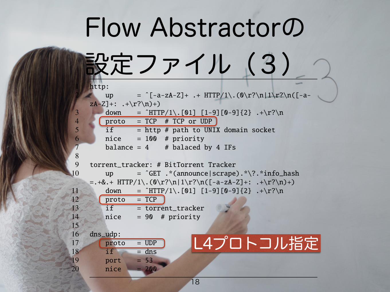
L4プロトコル指定
Flow Abstractorの 設定ファイル(4)
19
interfaces. Traffic analyzer developers can develop ana-lyzers by accessing the interfaces provided by this plane.The analyzer plane is a plane for analyzers developed bythe users of SF-TAP. Users can implements analyzers inany programming language.
In this paper, we discuss only the separator and ab-stractor planes, because the components of the capturerplane are well-known, and the analyzers of the analyzerplane are developed by SF-TAP users. In the followingsections, we describe the design of the flow abstractorand the cell incubator, and show an example of an ana-lyzer for HTTP.
3.2 Design of Flow AbstractorWe now describe the design of the flow abstractor illus-trated in Figure 2 by using an actual implementation con-figuration file, shown in Figure 3, to allow easy under-standing. The flow abstractor consists of four compo-nents: the IP packet defragmenter, the flow identifier, theTCP and UDP handler, and the flow classifier.
3.2.1 Flow Reconstruction
The flow abstractor defragments fragmented IP packets,and reconstructs TCP streams. Thus, analyzer develop-ers need not implement the complicated reconstructionlogic required for L7-level analysis.
The IP packet defragmenter shown in Figure 2 is acomponent that provides IP packet defragmentation. De-fragmented IP packets are forwarded to the flow identi-fier, which identifies the flow as L3/L4-level. We iden-tify flows by using 5-tuples consisting of the sourceand destination IP addresses, source and destination portnumbers, and a hop count, which is described in Sec-tion 3.2.2. After the flows have been identified, the TCPstreams are reconstructed by the TCP and UDP handler,and then the flows are forwarded to the flow classifier.
3.2.2 Flow Abstraction Interface
The flow abstractor provides interfaces that abstractflows as L7-level. For example, in Figure 2, the TLSand HTTP interfaces are illustrated, and in Figure 3, theHTTP, BitTorrent Tracker [2], and DNS interfaces aredefined.
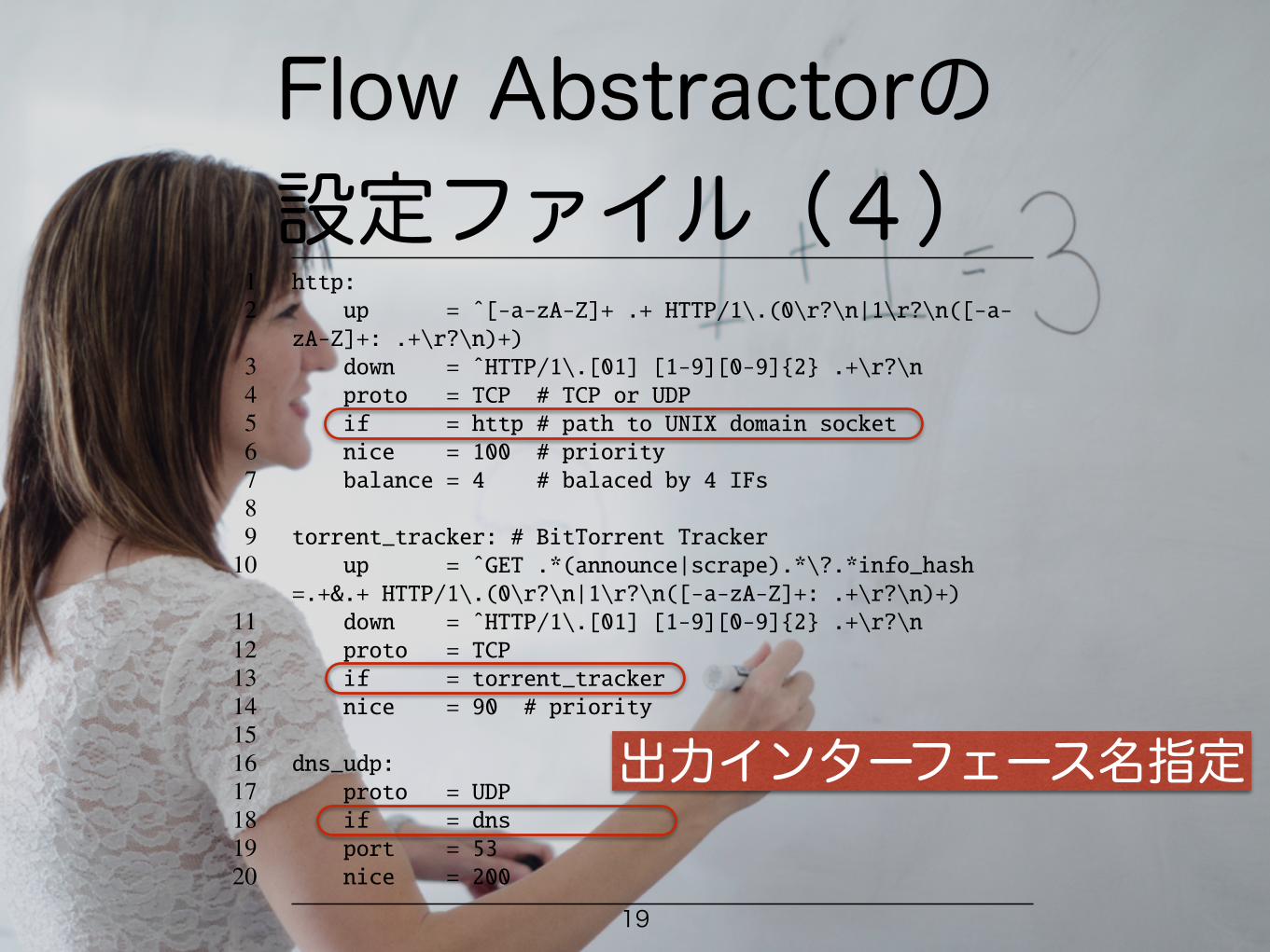
The flow classifier classifies flows as the various L7protocols, and forwards them to flow abstraction inter-faces, which are implemented using a UNIX domainsocket, illustrated in Figure 4. The file names of the in-terfaces are actually defined by items of if; for exam-ple, at lines 5, 13, and 18 in Figure 3, the interfacesof HTTP, BitTorrent Tracker, and DNS are defined ashttp, torrent tracker, and dns, respectively. By
1 http:2 up = ˆ[-a-zA-Z]+ .+ HTTP/1\.(0\r?\n|1\r?\n([-a-zA-Z]+: .+\r?\n)+)
3 down = ˆHTTP/1\.[01] [1-9][0-9]{2} .+\r?\n4 proto = TCP # TCP or UDP5 if = http # path to UNIX domain socket6 nice = 100 # priority7 balance = 4 # balaced by 4 IFs89 torrent_tracker: # BitTorrent Tracker
10 up = ˆGET .*(announce|scrape).*\?.*info_hash=.+&.+ HTTP/1\.(0\r?\n|1\r?\n([-a-zA-Z]+: .+\r?\n)+)
11 down = ˆHTTP/1\.[01] [1-9][0-9]{2} .+\r?\n12 proto = TCP13 if = torrent_tracker14 nice = 90 # priority1516 dns_udp:17 proto = UDP18 if = dns19 port = 5320 nice = 200
Figure 3: Configuration Example of Flow Abstractor
1 $ ls -R /tmp/sf-tap2 loopback7= tcp/ udp/34 /tmp/sf-tap/tcp:5 default= http2= ssh=6 dns= http3= ssl=7 ftp= http_proxy= torrent_tracker=8 http0= irc= websocket=9 http1= smtp=
1011 /tmp/sf-tap/udp:12 default= dns= torrent_dht=
Figure 4: Directory Structure of Flow Abstraction Inter-face
providing independent interfaces for each L7 protocol,any programming language can be used to implement an-alyzers.
Furthermore, we designed a special interface for flowinjection called the L7 loopback interface, L7 LoopbackI/F in Figure 2. This interface is convenient for encapsu-lated protocols such as HTTP proxy. For example, HTTPproxy can encapsulate other protocols in HTTP, but theencapsulated traffic should also be analyzed as L7-level.In this situation, further analysis of encapsulated trafficcan be easily achieved by re-injecting encapsulated traf-fic into the flow abstractor via the L7 loopback interface.The flow abstractor handles re-injected traffic in the samemanner. Therefore, implementation of L7-level analysisof encapsulated traffic can be simplified, although in gen-eral it tends to be complex. It should be noted that the L7loopback interface may cause infinite injection. To avoidthis problem, we introduce a hop count and hop limita-tion. The flow abstractor drops injected traffic only whenits hop count exceeds the hop limitation.
In addition to the flow abstraction and the L7 loop-back interfaces, the flow abstractor provides the default
4
出力インターフェース名指定
Flow Abstractorの 設定ファイル(5)
20
interfaces. Traffic analyzer developers can develop ana-lyzers by accessing the interfaces provided by this plane.The analyzer plane is a plane for analyzers developed bythe users of SF-TAP. Users can implements analyzers inany programming language.
In this paper, we discuss only the separator and ab-stractor planes, because the components of the capturerplane are well-known, and the analyzers of the analyzerplane are developed by SF-TAP users. In the followingsections, we describe the design of the flow abstractorand the cell incubator, and show an example of an ana-lyzer for HTTP.
3.2 Design of Flow AbstractorWe now describe the design of the flow abstractor illus-trated in Figure 2 by using an actual implementation con-figuration file, shown in Figure 3, to allow easy under-standing. The flow abstractor consists of four compo-nents: the IP packet defragmenter, the flow identifier, theTCP and UDP handler, and the flow classifier.
3.2.1 Flow Reconstruction
The flow abstractor defragments fragmented IP packets,and reconstructs TCP streams. Thus, analyzer develop-ers need not implement the complicated reconstructionlogic required for L7-level analysis.
The IP packet defragmenter shown in Figure 2 is acomponent that provides IP packet defragmentation. De-fragmented IP packets are forwarded to the flow identi-fier, which identifies the flow as L3/L4-level. We iden-tify flows by using 5-tuples consisting of the sourceand destination IP addresses, source and destination portnumbers, and a hop count, which is described in Sec-tion 3.2.2. After the flows have been identified, the TCPstreams are reconstructed by the TCP and UDP handler,and then the flows are forwarded to the flow classifier.
3.2.2 Flow Abstraction Interface
The flow abstractor provides interfaces that abstractflows as L7-level. For example, in Figure 2, the TLSand HTTP interfaces are illustrated, and in Figure 3, theHTTP, BitTorrent Tracker [2], and DNS interfaces aredefined.
The flow classifier classifies flows as the various L7protocols, and forwards them to flow abstraction inter-faces, which are implemented using a UNIX domainsocket, illustrated in Figure 4. The file names of the in-terfaces are actually defined by items of if; for exam-ple, at lines 5, 13, and 18 in Figure 3, the interfacesof HTTP, BitTorrent Tracker, and DNS are defined ashttp, torrent tracker, and dns, respectively. By
1 http:2 up = ˆ[-a-zA-Z]+ .+ HTTP/1\.(0\r?\n|1\r?\n([-a-zA-Z]+: .+\r?\n)+)
3 down = ˆHTTP/1\.[01] [1-9][0-9]{2} .+\r?\n4 proto = TCP # TCP or UDP5 if = http # path to UNIX domain socket6 nice = 100 # priority7 balance = 4 # balaced by 4 IFs89 torrent_tracker: # BitTorrent Tracker
10 up = ˆGET .*(announce|scrape).*\?.*info_hash=.+&.+ HTTP/1\.(0\r?\n|1\r?\n([-a-zA-Z]+: .+\r?\n)+)
11 down = ˆHTTP/1\.[01] [1-9][0-9]{2} .+\r?\n12 proto = TCP13 if = torrent_tracker14 nice = 90 # priority1516 dns_udp:17 proto = UDP18 if = dns19 port = 5320 nice = 200
Figure 3: Configuration Example of Flow Abstractor
1 $ ls -R /tmp/sf-tap2 loopback7= tcp/ udp/34 /tmp/sf-tap/tcp:5 default= http2= ssh=6 dns= http3= ssl=7 ftp= http_proxy= torrent_tracker=8 http0= irc= websocket=9 http1= smtp=
1011 /tmp/sf-tap/udp:12 default= dns= torrent_dht=
Figure 4: Directory Structure of Flow Abstraction Inter-face
providing independent interfaces for each L7 protocol,any programming language can be used to implement an-alyzers.
Furthermore, we designed a special interface for flowinjection called the L7 loopback interface, L7 LoopbackI/F in Figure 2. This interface is convenient for encapsu-lated protocols such as HTTP proxy. For example, HTTPproxy can encapsulate other protocols in HTTP, but theencapsulated traffic should also be analyzed as L7-level.In this situation, further analysis of encapsulated trafficcan be easily achieved by re-injecting encapsulated traf-fic into the flow abstractor via the L7 loopback interface.The flow abstractor handles re-injected traffic in the samemanner. Therefore, implementation of L7-level analysisof encapsulated traffic can be simplified, although in gen-eral it tends to be complex. It should be noted that the L7loopback interface may cause infinite injection. To avoidthis problem, we introduce a hop count and hop limita-tion. The flow abstractor drops injected traffic only whenits hop count exceeds the hop limitation.
In addition to the flow abstraction and the L7 loop-back interfaces, the flow abstractor provides the default
4
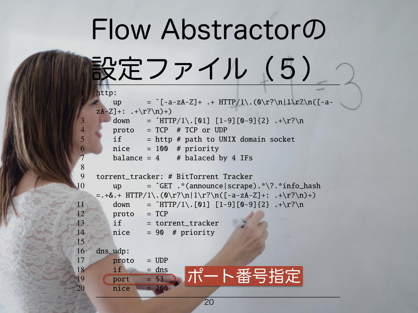
ポート番号指定
Flow Abstractorの 設定ファイル(6)
21
interfaces. Traffic analyzer developers can develop ana-lyzers by accessing the interfaces provided by this plane.The analyzer plane is a plane for analyzers developed bythe users of SF-TAP. Users can implements analyzers inany programming language.
In this paper, we discuss only the separator and ab-stractor planes, because the components of the capturerplane are well-known, and the analyzers of the analyzerplane are developed by SF-TAP users. In the followingsections, we describe the design of the flow abstractorand the cell incubator, and show an example of an ana-lyzer for HTTP.
3.2 Design of Flow AbstractorWe now describe the design of the flow abstractor illus-trated in Figure 2 by using an actual implementation con-figuration file, shown in Figure 3, to allow easy under-standing. The flow abstractor consists of four compo-nents: the IP packet defragmenter, the flow identifier, theTCP and UDP handler, and the flow classifier.
3.2.1 Flow Reconstruction
The flow abstractor defragments fragmented IP packets,and reconstructs TCP streams. Thus, analyzer develop-ers need not implement the complicated reconstructionlogic required for L7-level analysis.
The IP packet defragmenter shown in Figure 2 is acomponent that provides IP packet defragmentation. De-fragmented IP packets are forwarded to the flow identi-fier, which identifies the flow as L3/L4-level. We iden-tify flows by using 5-tuples consisting of the sourceand destination IP addresses, source and destination portnumbers, and a hop count, which is described in Sec-tion 3.2.2. After the flows have been identified, the TCPstreams are reconstructed by the TCP and UDP handler,and then the flows are forwarded to the flow classifier.
3.2.2 Flow Abstraction Interface
The flow abstractor provides interfaces that abstractflows as L7-level. For example, in Figure 2, the TLSand HTTP interfaces are illustrated, and in Figure 3, theHTTP, BitTorrent Tracker [2], and DNS interfaces aredefined.
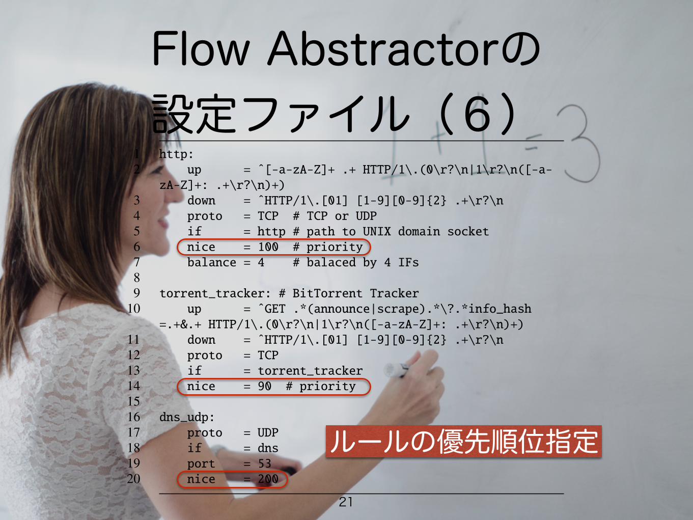
The flow classifier classifies flows as the various L7protocols, and forwards them to flow abstraction inter-faces, which are implemented using a UNIX domainsocket, illustrated in Figure 4. The file names of the in-terfaces are actually defined by items of if; for exam-ple, at lines 5, 13, and 18 in Figure 3, the interfacesof HTTP, BitTorrent Tracker, and DNS are defined ashttp, torrent tracker, and dns, respectively. By
1 http:2 up = ˆ[-a-zA-Z]+ .+ HTTP/1\.(0\r?\n|1\r?\n([-a-zA-Z]+: .+\r?\n)+)
3 down = ˆHTTP/1\.[01] [1-9][0-9]{2} .+\r?\n4 proto = TCP # TCP or UDP5 if = http # path to UNIX domain socket6 nice = 100 # priority7 balance = 4 # balaced by 4 IFs89 torrent_tracker: # BitTorrent Tracker
10 up = ˆGET .*(announce|scrape).*\?.*info_hash=.+&.+ HTTP/1\.(0\r?\n|1\r?\n([-a-zA-Z]+: .+\r?\n)+)
11 down = ˆHTTP/1\.[01] [1-9][0-9]{2} .+\r?\n12 proto = TCP13 if = torrent_tracker14 nice = 90 # priority1516 dns_udp:17 proto = UDP18 if = dns19 port = 5320 nice = 200
Figure 3: Configuration Example of Flow Abstractor
1 $ ls -R /tmp/sf-tap2 loopback7= tcp/ udp/34 /tmp/sf-tap/tcp:5 default= http2= ssh=6 dns= http3= ssl=7 ftp= http_proxy= torrent_tracker=8 http0= irc= websocket=9 http1= smtp=
1011 /tmp/sf-tap/udp:12 default= dns= torrent_dht=
Figure 4: Directory Structure of Flow Abstraction Inter-face
providing independent interfaces for each L7 protocol,any programming language can be used to implement an-alyzers.
Furthermore, we designed a special interface for flowinjection called the L7 loopback interface, L7 LoopbackI/F in Figure 2. This interface is convenient for encapsu-lated protocols such as HTTP proxy. For example, HTTPproxy can encapsulate other protocols in HTTP, but theencapsulated traffic should also be analyzed as L7-level.In this situation, further analysis of encapsulated trafficcan be easily achieved by re-injecting encapsulated traf-fic into the flow abstractor via the L7 loopback interface.The flow abstractor handles re-injected traffic in the samemanner. Therefore, implementation of L7-level analysisof encapsulated traffic can be simplified, although in gen-eral it tends to be complex. It should be noted that the L7loopback interface may cause infinite injection. To avoidthis problem, we introduce a hop count and hop limita-tion. The flow abstractor drops injected traffic only whenits hop count exceeds the hop limitation.
In addition to the flow abstraction and the L7 loop-back interfaces, the flow abstractor provides the default
4
ルールの優先順位指定
Flow Abstractorの 設定ファイル(7)
22
interfaces. Traffic analyzer developers can develop ana-lyzers by accessing the interfaces provided by this plane.The analyzer plane is a plane for analyzers developed bythe users of SF-TAP. Users can implements analyzers inany programming language.
In this paper, we discuss only the separator and ab-stractor planes, because the components of the capturerplane are well-known, and the analyzers of the analyzerplane are developed by SF-TAP users. In the followingsections, we describe the design of the flow abstractorand the cell incubator, and show an example of an ana-lyzer for HTTP.
3.2 Design of Flow AbstractorWe now describe the design of the flow abstractor illus-trated in Figure 2 by using an actual implementation con-figuration file, shown in Figure 3, to allow easy under-standing. The flow abstractor consists of four compo-nents: the IP packet defragmenter, the flow identifier, theTCP and UDP handler, and the flow classifier.
3.2.1 Flow Reconstruction
The flow abstractor defragments fragmented IP packets,and reconstructs TCP streams. Thus, analyzer develop-ers need not implement the complicated reconstructionlogic required for L7-level analysis.
The IP packet defragmenter shown in Figure 2 is acomponent that provides IP packet defragmentation. De-fragmented IP packets are forwarded to the flow identi-fier, which identifies the flow as L3/L4-level. We iden-tify flows by using 5-tuples consisting of the sourceand destination IP addresses, source and destination portnumbers, and a hop count, which is described in Sec-tion 3.2.2. After the flows have been identified, the TCPstreams are reconstructed by the TCP and UDP handler,and then the flows are forwarded to the flow classifier.
3.2.2 Flow Abstraction Interface
The flow abstractor provides interfaces that abstractflows as L7-level. For example, in Figure 2, the TLSand HTTP interfaces are illustrated, and in Figure 3, theHTTP, BitTorrent Tracker [2], and DNS interfaces aredefined.
The flow classifier classifies flows as the various L7protocols, and forwards them to flow abstraction inter-faces, which are implemented using a UNIX domainsocket, illustrated in Figure 4. The file names of the in-terfaces are actually defined by items of if; for exam-ple, at lines 5, 13, and 18 in Figure 3, the interfacesof HTTP, BitTorrent Tracker, and DNS are defined ashttp, torrent tracker, and dns, respectively. By
1 http:2 up = ˆ[-a-zA-Z]+ .+ HTTP/1\.(0\r?\n|1\r?\n([-a-zA-Z]+: .+\r?\n)+)
3 down = ˆHTTP/1\.[01] [1-9][0-9]{2} .+\r?\n4 proto = TCP # TCP or UDP5 if = http # path to UNIX domain socket6 nice = 100 # priority7 balance = 4 # balaced by 4 IFs89 torrent_tracker: # BitTorrent Tracker
10 up = ˆGET .*(announce|scrape).*\?.*info_hash=.+&.+ HTTP/1\.(0\r?\n|1\r?\n([-a-zA-Z]+: .+\r?\n)+)
11 down = ˆHTTP/1\.[01] [1-9][0-9]{2} .+\r?\n12 proto = TCP13 if = torrent_tracker14 nice = 90 # priority1516 dns_udp:17 proto = UDP18 if = dns19 port = 5320 nice = 200
Figure 3: Configuration Example of Flow Abstractor
1 $ ls -R /tmp/sf-tap2 loopback7= tcp/ udp/34 /tmp/sf-tap/tcp:5 default= http2= ssh=6 dns= http3= ssl=7 ftp= http_proxy= torrent_tracker=8 http0= irc= websocket=9 http1= smtp=
1011 /tmp/sf-tap/udp:12 default= dns= torrent_dht=
Figure 4: Directory Structure of Flow Abstraction Inter-face
providing independent interfaces for each L7 protocol,any programming language can be used to implement an-alyzers.
Furthermore, we designed a special interface for flowinjection called the L7 loopback interface, L7 LoopbackI/F in Figure 2. This interface is convenient for encapsu-lated protocols such as HTTP proxy. For example, HTTPproxy can encapsulate other protocols in HTTP, but theencapsulated traffic should also be analyzed as L7-level.In this situation, further analysis of encapsulated trafficcan be easily achieved by re-injecting encapsulated traf-fic into the flow abstractor via the L7 loopback interface.The flow abstractor handles re-injected traffic in the samemanner. Therefore, implementation of L7-level analysisof encapsulated traffic can be simplified, although in gen-eral it tends to be complex. It should be noted that the L7loopback interface may cause infinite injection. To avoidthis problem, we introduce a hop count and hop limita-tion. The flow abstractor drops injected traffic only whenits hop count exceeds the hop limitation.
In addition to the flow abstraction and the L7 loop-back interfaces, the flow abstractor provides the default
4
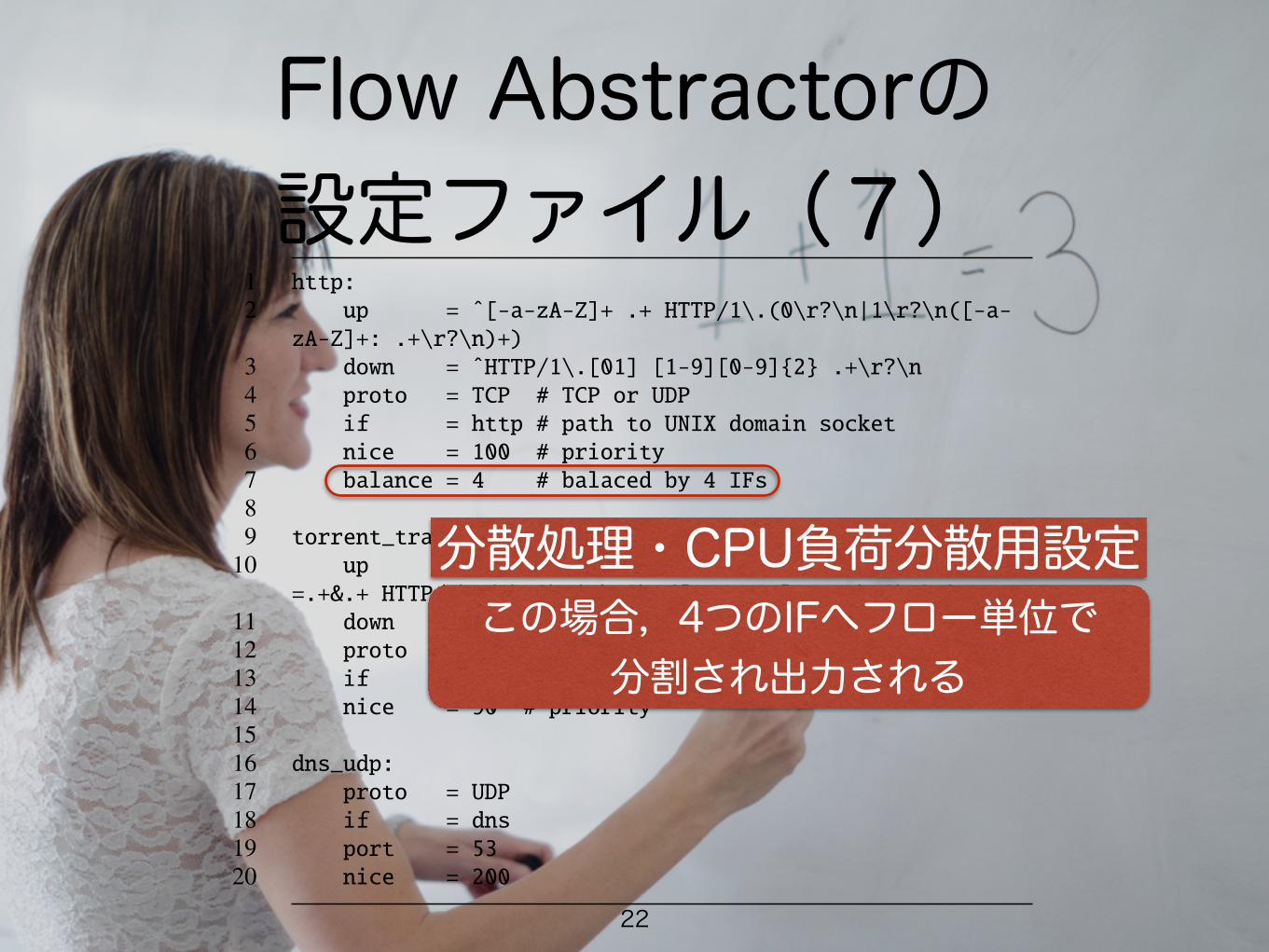
分散処理・CPU負荷分散用設定この場合,4つのIFへフロー単位で
分割され出力される
抽象フローIFの ディレクトリ構造
interfaces. Traffic analyzer developers can develop ana-lyzers by accessing the interfaces provided by this plane.The analyzer plane is a plane for analyzers developed bythe users of SF-TAP. Users can implements analyzers inany programming language.
In this paper, we discuss only the separator and ab-stractor planes, because the components of the capturerplane are well-known, and the analyzers of the analyzerplane are developed by SF-TAP users. In the followingsections, we describe the design of the flow abstractorand the cell incubator, and show an example of an ana-lyzer for HTTP.
3.2 Design of Flow AbstractorWe now describe the design of the flow abstractor illus-trated in Figure 2 by using an actual implementation con-figuration file, shown in Figure 3, to allow easy under-standing. The flow abstractor consists of four compo-nents: the IP packet defragmenter, the flow identifier, theTCP and UDP handler, and the flow classifier.
3.2.1 Flow Reconstruction
The flow abstractor defragments fragmented IP packets,and reconstructs TCP streams. Thus, analyzer develop-ers need not implement the complicated reconstructionlogic required for L7-level analysis.
The IP packet defragmenter shown in Figure 2 is acomponent that provides IP packet defragmentation. De-fragmented IP packets are forwarded to the flow identi-fier, which identifies the flow as L3/L4-level. We iden-tify flows by using 5-tuples consisting of the sourceand destination IP addresses, source and destination portnumbers, and a hop count, which is described in Sec-tion 3.2.2. After the flows have been identified, the TCPstreams are reconstructed by the TCP and UDP handler,and then the flows are forwarded to the flow classifier.
3.2.2 Flow Abstraction Interface
The flow abstractor provides interfaces that abstractflows as L7-level. For example, in Figure 2, the TLSand HTTP interfaces are illustrated, and in Figure 3, theHTTP, BitTorrent Tracker [2], and DNS interfaces aredefined.
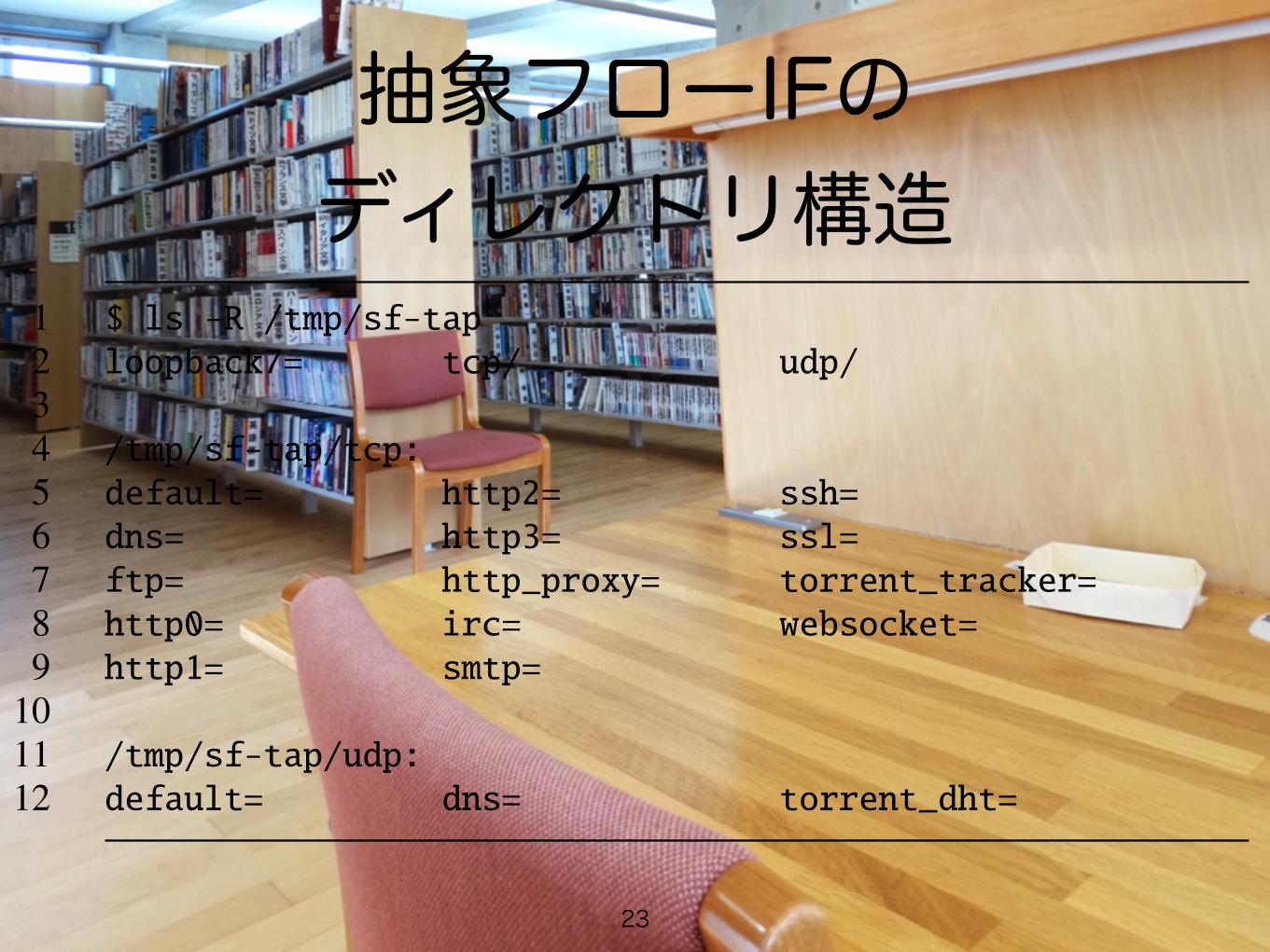
The flow classifier classifies flows as the various L7protocols, and forwards them to flow abstraction inter-faces, which are implemented using a UNIX domainsocket, illustrated in Figure 4. The file names of the in-terfaces are actually defined by items of if; for exam-ple, at lines 5, 13, and 18 in Figure 3, the interfacesof HTTP, BitTorrent Tracker, and DNS are defined ashttp, torrent tracker, and dns, respectively. By
1 http:2 up = ˆ[-a-zA-Z]+ .+ HTTP/1\.(0\r?\n|1\r?\n([-a-zA-Z]+: .+\r?\n)+)
3 down = ˆHTTP/1\.[01] [1-9][0-9]{2} .+\r?\n4 proto = TCP # TCP or UDP5 if = http # path to UNIX domain socket6 nice = 100 # priority7 balance = 4 # balaced by 4 IFs89 torrent_tracker: # BitTorrent Tracker
10 up = ˆGET .*(announce|scrape).*\?.*info_hash=.+&.+ HTTP/1\.(0\r?\n|1\r?\n([-a-zA-Z]+: .+\r?\n)+)
11 down = ˆHTTP/1\.[01] [1-9][0-9]{2} .+\r?\n12 proto = TCP13 if = torrent_tracker14 nice = 90 # priority1516 dns_udp:17 proto = UDP18 if = dns19 port = 5320 nice = 200
Figure 3: Configuration Example of Flow Abstractor
1 $ ls -R /tmp/sf-tap2 loopback7= tcp/ udp/34 /tmp/sf-tap/tcp:5 default= http2= ssh=6 dns= http3= ssl=7 ftp= http_proxy= torrent_tracker=8 http0= irc= websocket=9 http1= smtp=
1011 /tmp/sf-tap/udp:12 default= dns= torrent_dht=
Figure 4: Directory Structure of Flow Abstraction Inter-face
providing independent interfaces for each L7 protocol,any programming language can be used to implement an-alyzers.
Furthermore, we designed a special interface for flowinjection called the L7 loopback interface, L7 LoopbackI/F in Figure 2. This interface is convenient for encapsu-lated protocols such as HTTP proxy. For example, HTTPproxy can encapsulate other protocols in HTTP, but theencapsulated traffic should also be analyzed as L7-level.In this situation, further analysis of encapsulated trafficcan be easily achieved by re-injecting encapsulated traf-fic into the flow abstractor via the L7 loopback interface.The flow abstractor handles re-injected traffic in the samemanner. Therefore, implementation of L7-level analysisof encapsulated traffic can be simplified, although in gen-eral it tends to be complex. It should be noted that the L7loopback interface may cause infinite injection. To avoidthis problem, we introduce a hop count and hop limita-tion. The flow abstractor drops injected traffic only whenits hop count exceeds the hop limitation.
In addition to the flow abstraction and the L7 loop-back interfaces, the flow abstractor provides the default
4
23
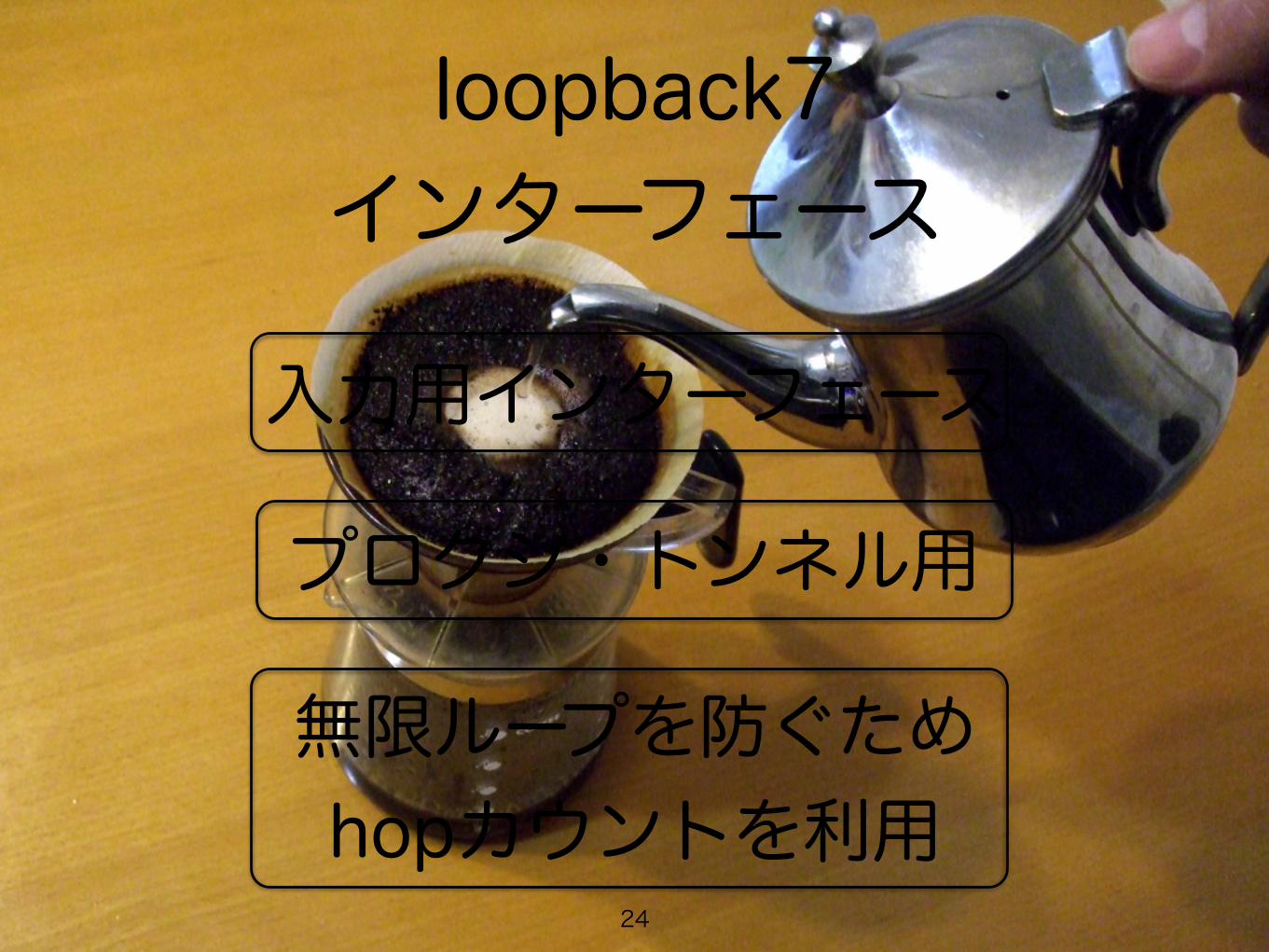
loopback7 インターフェース
入力用インターフェース
プロクシ・トンネル用
無限ループを防ぐため hopカウントを利用
24
default インターフェース
どのルールにもマッチしなかった フローが出力される
25

5タプルフローID
IPアドレス x 2
ポート番号 x 2
ホップカウント
26

TCPイベントの抽象化
CREATED
DATA
DESTROYED
27

実装Flow Abstractor
C++Consumer Producer Patternスレッド間のバルクデータ転送
Cell IncubatorC++netmap
CASを使った軽量ロック28

デモ29

複数インターフェスによる CPU負荷計測
(a) HTTP Analyzer x 1 (b) HTTP Analyzer x 2 (c) HTTP Analyzer x 4
generate 50 clients / sec, 1000 clients maximum, 2500 requests / sec on average
Figure 7: CPU Load of HTTP Analyzer and Flow Abstractor
Figure 8: Total Memory Usage of HTTP Analyzer
per measurement. It is shown that the flow abstractor canhandle high-bandwidth network traffic when the numberof flows is small.
Figure 12 shows the physical memory usage of theflow abstractor when generating 10 K TCP CPS. Theamount of memory usage of the flow abstractor dependsmainly on the number of TCP sessions. Hence, it in-creases proportionally with the number of TCP sessions.
5.3 Performance Evaluation of Cell Incu-bator
In the experiments on the cell incubator, we used a com-puter (DDR3 16 GB Memory and Intel Xeon E5-2470 v2(10 cores, 2.4 GHz, 25 MB cache)) and FreeBSD 10.1.The computer equipped with four Intel quad-port 1 GbENIC and an Intel dual-port 10 GbE NIC. We generatednetwork traffic consisting of short packets (64 bytes L2frame) on the 10 GbE lines for the evaluations. The cellincubator separated the traffic on the basis of the flowsand the separated flows were forwarded to the twelve 1GbE lines. Figure 13 shows the experimental network.We conducted the experiments as three patterns. (1) The
Figure 9: Packet Drop against CPS
cell incubator worked in the mirroring mode, which usesport mirroring of the L2 switch. In other words, it cap-tured packets at α and forwarded packets to γ. (2) Thecell incubator worked in the inline mode, but did not for-ward packets to 1 GbE NICs; α to β only. (3) The cellincubator worked in the inline mode. In other words, itcaptured packets at α, and forwarded to both β and γ.
Table 1 shows the performance of the cell incubator.When pattern (1), the mirroring mode, the cell incubatorcould deal with packets up to 12.49 Mpps. When pattern(2), the cell incubator working in an L2 bridge, it couldforward packets up to 11.60 Mpps. When pattern (3),it forwarding packets to β and γ, it could forward pack-ets to β and γ up to 11.44 Mpps. The performance ofthe inline mode is worse than the mirroring mode’s be-cause packets were forwarded to two NICs when the in-line mode. However, the inline mode is more suitable forspecific purposes such as IDS/IPS because same packetsare dropped at β and γ. In other words, all transmittedpackets can be captured when the inline mode.
Table 2 shows the CPUs’ load averages of the cell in-cubator when the inline mode and forwarding 64 bytesframe. When 5.95 and 10.42 Mpps, packets were not
8
30
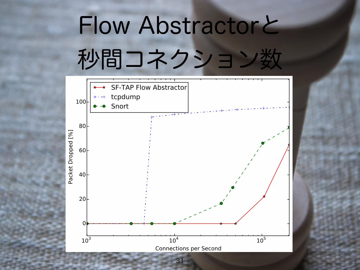
Flow Abstractorと 秒間コネクション数
31
(a) HTTP Analyzer x 1 (b) HTTP Analyzer x 2 (c) HTTP Analyzer x 4
generate 50 clients / sec, 1000 clients maximum, 2500 requests / sec on average
Figure 7: CPU Load of HTTP Analyzer and Flow Abstractor
Figure 8: Total Memory Usage of HTTP Analyzer
per measurement. It is shown that the flow abstractor canhandle high-bandwidth network traffic when the numberof flows is small.
Figure 12 shows the physical memory usage of theflow abstractor when generating 10 K TCP CPS. Theamount of memory usage of the flow abstractor dependsmainly on the number of TCP sessions. Hence, it in-creases proportionally with the number of TCP sessions.
5.3 Performance Evaluation of Cell Incu-bator
In the experiments on the cell incubator, we used a com-puter (DDR3 16 GB Memory and Intel Xeon E5-2470 v2(10 cores, 2.4 GHz, 25 MB cache)) and FreeBSD 10.1.The computer equipped with four Intel quad-port 1 GbENIC and an Intel dual-port 10 GbE NIC. We generatednetwork traffic consisting of short packets (64 bytes L2frame) on the 10 GbE lines for the evaluations. The cellincubator separated the traffic on the basis of the flowsand the separated flows were forwarded to the twelve 1GbE lines. Figure 13 shows the experimental network.We conducted the experiments as three patterns. (1) The
Figure 9: Packet Drop against CPS
cell incubator worked in the mirroring mode, which usesport mirroring of the L2 switch. In other words, it cap-tured packets at α and forwarded packets to γ. (2) Thecell incubator worked in the inline mode, but did not for-ward packets to 1 GbE NICs; α to β only. (3) The cellincubator worked in the inline mode. In other words, itcaptured packets at α, and forwarded to both β and γ.
Table 1 shows the performance of the cell incubator.When pattern (1), the mirroring mode, the cell incubatorcould deal with packets up to 12.49 Mpps. When pattern(2), the cell incubator working in an L2 bridge, it couldforward packets up to 11.60 Mpps. When pattern (3),it forwarding packets to β and γ, it could forward pack-ets to β and γ up to 11.44 Mpps. The performance ofthe inline mode is worse than the mirroring mode’s be-cause packets were forwarded to two NICs when the in-line mode. However, the inline mode is more suitable forspecific purposes such as IDS/IPS because same packetsare dropped at β and γ. In other words, all transmittedpackets can be captured when the inline mode.
Table 2 shows the CPUs’ load averages of the cell in-cubator when the inline mode and forwarding 64 bytesframe. When 5.95 and 10.42 Mpps, packets were not
8
Cell Incubatorの パフォーマンス
32
最大11.44 Mpps (10 フロー)
詳細は別資料にて・・・

まとめ• 汎用L7解析器SF-TAPを提案
• スケーラブル
• モジュラリティ
• コモディティ
• 非言語依存のインターフェース
• プログラマブルなネットワーク解析が可能に
• 高速なネットワークに対しても適用可能に
33