Embed Size (px)
Citation preview

ARTICLE BEGINNING
STEERING SYSTEM
PRECAUTION
� Care must be taken to replace parts properly because they could affect the performance of the steering system and result in a driving hazard.
� The PRIUS is equipped with SRS (Supplemental Restraint System) such as the driver AIRBAG and passenger AIRBAG. Failure to carry out service operation in the correct sequence could cause the SRS to unexpectedly deploy during servicing, possibly leading to a serious accident. Before servicing (including removal or installation of parts, inspection or replacement), be sure to read the precautionary notices in the AIR BAG RESTRAINT SYSTEMS article.
TROUBLESHOOTING
PROBLEM SYMPTOMS TABLE
Use the table below to help you find the cause of the problem. The numbers indicate the priority of the likely cause of the problem. Check each part in the order shown. If necessary, repair or replace these parts.
PROBLEM SYMPTOMS
Symptom/Suspect Area See
Hard Steering
Tires (Improperly Inflated) Check Tire Pressure
Front Wheel Alignment (Incorrect) SPECIFICATIONS & PROCEDURES
Steering System Joints (Worn) Check Steering System Joints
Suspension Arm Ball Joints (Worn) BALL JOINT INSPECTION
Steering Column (Binding) Check Steering Column
Electric Power Steering Gear ELECTRIC POWER STEERING GEAR
Poor Return
Tires (Improperly Inflated) Check Tire Pressure
Front Wheel Alignment (Incorrect) SPECIFICATIONS & PROCEDURES
Steering Column (Binding) Check Steering Column
Electric Power Steering Gear ELECTRIC POWER STEERING GEAR
Excessive Play
Steering System Joints (Worn) Check Steering System Joints
Suspension Arm Ball Joints (Worn) BALL JOINT INSPECTION
Intermediate Shaft, Sliding Yoke (Worn) Check Intermediate Shaft,Sliding Yoke
Front Wheel Bearing (Worn) WHEEL BEARING INSPECTION
Electric Power Steering Gear ELECTRIC POWERSTEERING GEAR
Página 1 de 58STEERING SYSTEM -2002 Toyota Prius
27/02/2013http://ondemand5.com/mric/common/asp/printart.aspx

STEERING WHEEL
INSPECTION
Step 1 - Check Steering Wheel Freeplay
a. Stop the vehicle and face the tires straight ahead.
b. Rock the steering wheel gently up and down with a finger lightly, check the steering wheel freeplay.
Fig. 1: Checking Steering Wheel Free PlayCourtesy of TOYOTA MOTOR SALES, U.S.A., INC.
Maximum freeplay: 30 mm (1.18 in.) .
Abnormal Noise
Steering System Joints (Worn) Check Steering System Joints
Electric Power Steering Gear ELECTRIC POWER STEERING GEAR
NOTE: When the problem occurs on the electric motor power steering system, refer to ELECTRIC MOTOR POWER STEERING .
Página 2 de 58STEERING SYSTEM -2002 Toyota Prius
27/02/2013http://ondemand5.com/mric/common/asp/printart.aspx

Step 2 - Check Steering Effort
a. Center the steering wheel.
b. Remove the steering wheel pad. See STEP 1 - REMOVE STEERING WHEEL PAD .
c. Start the engine and run it at idle.
Fig. 2: Determining Steering Wheel EffortCourtesy of TOYOTA MOTOR SALES, U.S.A., INC.
d. Measure the steering effort in both directions.
Steering effort (Reference): 6.5 N.m (65 kgf.cm, 58 in.lbf).
NOTE: Take the tire type, pressure and contact surface into consideration before making your diagnosis.
Página 3 de 58STEERING SYSTEM -2002 Toyota Prius
27/02/2013http://ondemand5.com/mric/common/asp/printart.aspx

e. Install the steering wheel set nut.
Torque: 50 N.m (510 kgf.cm, 37 ft.lbf)
f. Install the steering wheel pad. See Step 18 - Install Steering Wheel Pad .
REPAIR PROCEDURES
Step 1 - Inspect Steering Wheel Off Center
a. Apply masking tape on the top center of the steering wheel and steering column upper cover.
NOTE: This is the repair procedure for steering off center.
Página 4 de 58STEERING SYSTEM -2002 Toyota Prius
27/02/2013http://ondemand5.com/mric/common/asp/printart.aspx

Fig. 3: Identifying Masking Tape Applications PointsCourtesy of TOYOTA MOTOR SALES, U.S.A., INC.
b. Drive the vehicle in a straight line for 100 meters at a constant speed of 35 mph (56 km/h), and hold the steering wheel to maintain the course.
c. Draw a line on the masking tape as shown in Fig. 4 .
Fig. 4: Marking Applied Masking TapeCourtesy of TOYOTA MOTOR SALES, U.S.A., INC.
d. Turn the steering wheel to its straight position.
NOTE: Refer to the upper surface of the steering wheel, steering spoke and SRS AIRBAG line for the straight position.
Página 5 de 58STEERING SYSTEM -2002 Toyota Prius
27/02/2013http://ondemand5.com/mric/common/asp/printart.aspx

e. Draw a new line on the masking tape of the steering wheel as shown in Fig. 5 .
Fig. 5: Marking Angular Calculation LineCourtesy of TOYOTA MOTOR SALES, U.S.A., INC.
f. Measure the distance between the 2 lines on the masking tape of the steering wheel.
g. Convert the measured distance to steering angle.
Measured distance 1 mm (0.04 in.) = Steering angle approximately 1 deg.
NOTE: Make a record of the steering angle.
Página 6 de 58STEERING SYSTEM -2002 Toyota Prius
27/02/2013http://ondemand5.com/mric/common/asp/printart.aspx

Step 2 - Adjust Steering Angle
a. Draw a line on the RH and LH tie rod and rack ends where it can easily be seen.
Fig. 6: Marking & Measuring Tie Rod EndsCourtesy of TOYOTA MOTOR SALES, U.S.A., INC.
b. Using a paper gauge, measure the distance from RH and LH tie rod ends to the rack end screws.
c. Remove the RH and LH boot clips from the rack boots.
NOTE:� Measure the RH side and LH side.
� Make a note of the measured values.
Página 7 de 58STEERING SYSTEM -2002 Toyota Prius
27/02/2013http://ondemand5.com/mric/common/asp/printart.aspx

Fig. 7: Identifying Boot Clips & Tie Rod End Lock NutsCourtesy of TOYOTA MOTOR SALES, U.S.A., INC.
d. Loosen the RH and LH lock nuts.
e. Turn the RH and LH rack end by the same amount (but in different directions) according to the steering angle.
1 turn 360 deg. of rack end (1.5 mm (0.059 in.) horizontal movement) = 12 deg. of steering angle
f. Tighten the RH and LH lock nuts.
Torque: 56 N.m (570 kgf.cm, 41 ft.lbf)
g. Install the RH and LH boot clips.
TILT STEERING COLUMN
COMPONENTS
NOTE: Make sure that the difference in length between RH and LH tie rod ends and rack end screws are within 1.5 mm (0.059 in.).
Página 8 de 58STEERING SYSTEM -2002 Toyota Prius
27/02/2013http://ondemand5.com/mric/common/asp/printart.aspx

Fig. 8: Identifying Tilt Steering Column Related ComponentsCourtesy of TOYOTA MOTOR SALES, U.S.A., INC.
Página 9 de 58STEERING SYSTEM -2002 Toyota Prius
27/02/2013http://ondemand5.com/mric/common/asp/printart.aspx

Fig. 9: Exploded View Tilt Steering ColumnCourtesy of TOYOTA MOTOR SALES, U.S.A., INC.
REMOVAL
Step 1 - Remove Steering Wheel Pad
Página 10 de 58STEERING SYSTEM -2002 Toyota Prius
27/02/2013http://ondemand5.com/mric/common/asp/printart.aspx

a. Place the front wheels facing straight ahead.
b. Using a Torx socket wrench, loosen the 2 Torx screws until the groove along the screw circumference catches on the screw case.
Fig. 10: Locating Steering Pad Torx ScrewsCourtesy of TOYOTA MOTOR SALES, U.S.A., INC.
c. Pull out the wheel pad from the steering wheel and disconnect the AIRBAG connector.
NOTE: If the AIRBAG connector is disconnected with the ignition switch at ON, DTCs will be recorded.
Página 11 de 58STEERING SYSTEM -2002 Toyota Prius
27/02/2013http://ondemand5.com/mric/common/asp/printart.aspx

Fig. 11: Locating Air Bag Connector & Identifying Safe Air Bag Handling ProceduresCourtesy of TOYOTA MOTOR SALES, U.S.A., INC.
Página 12 de 58STEERING SYSTEM -2002 Toyota Prius
27/02/2013http://ondemand5.com/mric/common/asp/printart.aspx

d. Disconnect the connector.
Step 2 - Remove Steering Wheel
a. Remove the steering wheel set nut.
b. Place matchmarks on the steering wheel and main shaft assembly.
Fig. 12: Matchmarking Steering Wheel & Main ShaftCourtesy of TOYOTA MOTOR SALES, U.S.A., INC.
c. Using SST, remove the steering wheel.
SST 09950-50013 (09951-05010, 09952-05010, 09953-05020, 09954-05021).
Step 3 - Remove Lower Instrument Finish Panel
a. Remove the 2 screws and disconnect hood lock release lever.
WARNING:� When storing the wheel pad, keep the upper surface of the pad
facing upward.
� Never disassemble the wheel pad.
NOTE: When removing the wheel pad, take care not to pull the AIRBAG wireharness.
Página 13 de 58STEERING SYSTEM -2002 Toyota Prius
27/02/2013http://ondemand5.com/mric/common/asp/printart.aspx

b. Remove the screw and bolt.
c. Disconnect the connectors and DLC3, and remove the lower instrument finish panel.
Step 4 - Remove Upper & Lower Column Covers
a. Remove the 3 screws and lower column cover.
b. Remove the screw and upper column cover.
Step 5 - Remove Combination Switch With Spiral Cable
a. Disconnect the connectors.
b. Disconnect the AIRBAG connector.
c. Remove the 3 screws and combination switch with spiral cable.
Step 6 - Remove Spiral Cable
See COMPONENTS .
Step 7 - Disconnect Transmission Control Cable
Fig. 13: Identifying Transmission Control Cable Mounting Bolt & Clip
NOTE: Do not disassemble the spiral cable or apply oil to it.
Página 14 de 58STEERING SYSTEM -2002 Toyota Prius
27/02/2013http://ondemand5.com/mric/common/asp/printart.aspx

Courtesy of TOYOTA MOTOR SALES, U.S.A., INC.
Step 8 - Remove Shift Lever Assembly
See STEP 6 - REMOVE SHIFT LEVER ASSEMBLY .
Step 9 - Disconnect Column Hole Cover
Remove the 3 clips and disconnect the column hole cover.
Step 10 - Remove Shift Lock Computer Sub-Assembly
Remove the screw and shift lock computer sub-assembly.
Step 11 - Disconnect No. 2 Intermediate Shaft Assembly
a. Place matchmarks on the No. 2 intermediate shaft assembly and control valve shaft.
Fig. 14: Locating No. 2 Intermediate Shaft Matchmarks & Identifying Bolts A & BCourtesy of TOYOTA MOTOR SALES, U.S.A., INC.
b. Loosen the bolt "A" and remove the bolt "B", then disconnect the No. 2 intermediate shaft assembly from the control valve shaft.
Página 15 de 58STEERING SYSTEM -2002 Toyota Prius
27/02/2013http://ondemand5.com/mric/common/asp/printart.aspx

Step 12 - Remove Instrument Finish Panel
Remove the 3 screws and instrument finish panel.
Step 13 - Remove Steering Column Assembly
a. Disconnect the connectors.
b. Remove the 2 bolts, 2 nuts and steering column assembly.
Step 14 - Remove No. 2 Intermediate Shaft Assembly
Remove the bolt and No. 2 intermediate shaft assembly from the sliding yoke.
Step 15 - Remove Sliding Yoke
Remove the bolt and sliding yoke from the main shaft assembly.
Step 16 - Remove Column Hole Cover
Step 17 - Remove Main Shaft Lower Dust Seal
a. Remove the 2 nuts and parking brake cable bracket.
Página 16 de 58STEERING SYSTEM -2002 Toyota Prius
27/02/2013http://ondemand5.com/mric/common/asp/printart.aspx

Fig. 15: Locating Parking Brake Cable Bracket Mounting NutsCourtesy of TOYOTA MOTOR SALES, U.S.A., INC.
b. Remove the 2 bolts and disconnect the accelerator pedal.
c. Remove the 3 nuts and main shaft lower dust seal.
DISASSEMBLY
1. Remove the screw and transponder key coil.
2. Remove column upper bracket and column upper clamp :
a. Using a centering punch, mark the center of the 2 tapered-head bolts.
b. Using a 3 - 4 mm (0.12 - 0.16 in.) drill, drill into the 2 bolts.
NOTE: When using a vise, do not overtighten it.
Página 17 de 58STEERING SYSTEM -2002 Toyota Prius
27/02/2013http://ondemand5.com/mric/common/asp/printart.aspx

Fig. 16: Extracting Column Upper Bracket & Clamp BoltsCourtesy of TOYOTA MOTOR SALES, U.S.A., INC.
c. Using a screw extractor, remove the 2 bolts, column upper bracket and column upper clamp.
3. Remove tilt steering support :
a. Remove the look nut.
b. Remove the washer, steering pawl set bolt and tilt steering support.
c. Remove the 2 No. 1 tilt steering support collars.
4. Remove 2 energy absorbing plates :
a. Using pliers, remove the 2 energy absorbing clips.
Página 18 de 58STEERING SYSTEM -2002 Toyota Prius
27/02/2013http://ondemand5.com/mric/common/asp/printart.aspx

Fig. 17: Identifying Energy Absorbing ClipsCourtesy of TOYOTA MOTOR SALES, U.S.A., INC.
b. Remove the 2 energy absorbing plates, 2 energy absorbing guides, and 2 break away capsules.
5. Using a screw driver, remove the torsion spring .
Página 19 de 58STEERING SYSTEM -2002 Toyota Prius
27/02/2013http://ondemand5.com/mric/common/asp/printart.aspx

Fig. 18: Locating & Removing Torsion SpringCourtesy of TOYOTA MOTOR SALES, U.S.A., INC.
6. Remove tilt lever and break away bracket :
NOTE: This bolt is left-handed one.
Página 20 de 58STEERING SYSTEM -2002 Toyota Prius
27/02/2013http://ondemand5.com/mric/common/asp/printart.aspx

Fig. 19: Removing Tilt Lever Lock Bolt & No. 1 Tilt Steering Support ReinforceCourtesy of TOYOTA MOTOR SALES, U.S.A., INC.
a. Remove No. 2 tilt lever lock bolt and No. 1 tilt steering support reinforce.
NOTE: This bolt is left-handed one.
Página 21 de 58STEERING SYSTEM -2002 Toyota Prius
27/02/2013http://ondemand5.com/mric/common/asp/printart.aspx

Fig. 20: Locating & Removing Tilt Steering Adjust NutCourtesy of TOYOTA MOTOR SALES, U.S.A., INC.
b. Remove the tilt steering adjusting nut, tilt lever, tilt sub lever, tilt lever lock bolt and break away bracket.
7. Remove main shaft assembly and main shaft bushing :
a. Using a snap ring expander, remove the snap ring on the upper side.
b. Using a brass bar and a hammer, tap out the main shaft assembly with the main shaft bushing.
Página 22 de 58STEERING SYSTEM -2002 Toyota Prius
27/02/2013http://ondemand5.com/mric/common/asp/printart.aspx

Fig. 21: Removing Main Shaft Assembly & BushingCourtesy of TOYOTA MOTOR SALES, U.S.A., INC.
c. Remove the main shaft bushing.
d. Using a snap ring expander, remove the snap ring on the lower side.
INSPECTION
1. Inspect steering lock operation :
Check that the steering lock mechanism operates properly.
Página 23 de 58STEERING SYSTEM -2002 Toyota Prius
27/02/2013http://ondemand5.com/mric/common/asp/printart.aspx

Fig. 22: Verifying Steering Lock OperationCourtesy of TOYOTA MOTOR SALES, U.S.A., INC.
2. If necessary, replace key cylinder :
a. Place the ignition key at the ACC position.
b. Push down the stop pin with a screwdriver, and pull out the key cylinder.
Página 24 de 58STEERING SYSTEM -2002 Toyota Prius
27/02/2013http://ondemand5.com/mric/common/asp/printart.aspx

Fig. 23: Removing Key CylinderCourtesy of TOYOTA MOTOR SALES, U.S.A., INC.
c. Install a new key cylinder.
3. Inspect ignition switch . See STEP 1 - INSPECT IGNITION SWITCH CONTINUITY .
4. IF NECESSARY, REPLACE IGNITION SWITCH
a. Remove the 2 screws and ignition switch.
b. Install a new ignition switch with the 2 screws.
5. Inspect key unlock warning switch . See STEP 2 - INSPECT KEY UNLOCK WARNING SWITCH CONTINUITY .
6. If necessary, replace key unlock warning switch :
a. Slide the key unlock warning switch out of the column upper bracket.
b. Slide a new key unlock warning switch in the column upper bracket.
7. Inspect key interlock solenoid . See STEP 4 - INSPECT KEY INTERLOCK SOLENOID .
8. If necessary, replace key interlock solenoid :
a. Remove the 2 screws and key interlock solenoid.
b. Install a new key interlock solenoid with the 2 screws.
9. Inspect transponder key coil . See step 1 of HYBRID VEHICLE IMMOBILIZER SYSTEM INSPECTION .
10. If necessary, replace transponder key coil .
11. Inspect bearing :
NOTE: Make sure the key is at the ACC position.
Página 25 de 58STEERING SYSTEM -2002 Toyota Prius
27/02/2013http://ondemand5.com/mric/common/asp/printart.aspx

Check the bearing rotation condition and check for abnormal noise.
Fig. 24: Verifying Proper Bearing ConditionCourtesy of TOYOTA MOTOR SALES, U.S.A., INC.
If faulty, replace the steering column upper tube sub-assembly.
REASSEMBLY
1. Coat parts indicated by arrows with molybdenum disulfide lithium base grease . See Fig. 9 .
2. Install main shaft assembly :
a. Using a snap ring expander, install a new snap ring on the lower side.
b. Install the main shaft assembly.
c. Using a snap ring expander, install a new snap ring on the upper side.
3. Install main shaft busing :
NOTE: When using a vise, do not overtighten it.
Página 26 de 58STEERING SYSTEM -2002 Toyota Prius
27/02/2013http://ondemand5.com/mric/common/asp/printart.aspx

a. Coat a new bushing with molybdenum disulfide lithium base grease.
b. Using SST and a hammer, tap in the main shaft bushing. SST 09608-06041.
Fig. 25: Installing Main Shaft BushingCourtesy of TOYOTA MOTOR SALES, U.S.A., INC.
4. Install break away bracket and tilt lever :
NOTE: Align the holes in the break away bracket with the projections of the tilt lever lock bolt and tilt sub lever.
Página 27 de 58STEERING SYSTEM -2002 Toyota Prius
27/02/2013http://ondemand5.com/mric/common/asp/printart.aspx

Fig. 26: Locating & Installing Tilt Steering Adjust NutCourtesy of TOYOTA MOTOR SALES, U.S.A., INC.
a. Install break away bracket, tilt lever lock bolt, tilt sub lever and tilt lever.
b. Install the tilt steering adjusting nut by rotating it counterclockwise.
Torque: 13 N.m (130 kgf.cm, 9 ft.lbf) .
NOTE: Align the No. 1 support reinforce with the nut to eliminate looseness by turning the No. 1 support reinforce counterclockwise a little, then torque the No. 2 tilt lever lock bolt.
Página 28 de 58STEERING SYSTEM -2002 Toyota Prius
27/02/2013http://ondemand5.com/mric/common/asp/printart.aspx

Fig. 27: Installing Tilt Lever Lock Bolt & No. 1 Tilt Steering Support ReinforceCourtesy of TOYOTA MOTOR SALES, U.S.A., INC.
c. Install the No. 1 tilt steering support reinforce with the No. 2 tilt lever lock bolt by turning itcounterclockwise.
Torque: 5.4 N.m (55 kgf.cm, 48 in.lbf) .
5. Install torsion spring .
Página 29 de 58STEERING SYSTEM -2002 Toyota Prius
27/02/2013http://ondemand5.com/mric/common/asp/printart.aspx

Fig. 28: Identifying Torsion SpringCourtesy of TOYOTA MOTOR SALES, U.S.A., INC.
6. Install 2 energy absorbing plates :
a. Install the 2 break away capsules, 2 energy absorbing guides and 2 energy absorbing plates.
Página 30 de 58STEERING SYSTEM -2002 Toyota Prius
27/02/2013http://ondemand5.com/mric/common/asp/printart.aspx

Fig. 29: Identifying Energy Absorbing ClipCourtesy of TOYOTA MOTOR SALES, U.S.A., INC.
b. Install the 2 new energy absorbing clips.
7. Install tilt steering support :
a. Install the 2 No. 1 tilt steering support collars.
b. Install the tilt steering support, steering pawl set bolt, washer.
c. Install the lock nut.
Torque: 9.5 N.m (100 kgf.cm, 87 in.lbf)
8. Install column upper bracket and column upper clamp :
a. Install the column upper bracket and column upper clamp with 2 new tapered-head bolts.
b. Tighten the 2 tapered-head bolts until the bolt heads break off.
Página 31 de 58STEERING SYSTEM -2002 Toyota Prius
27/02/2013http://ondemand5.com/mric/common/asp/printart.aspx
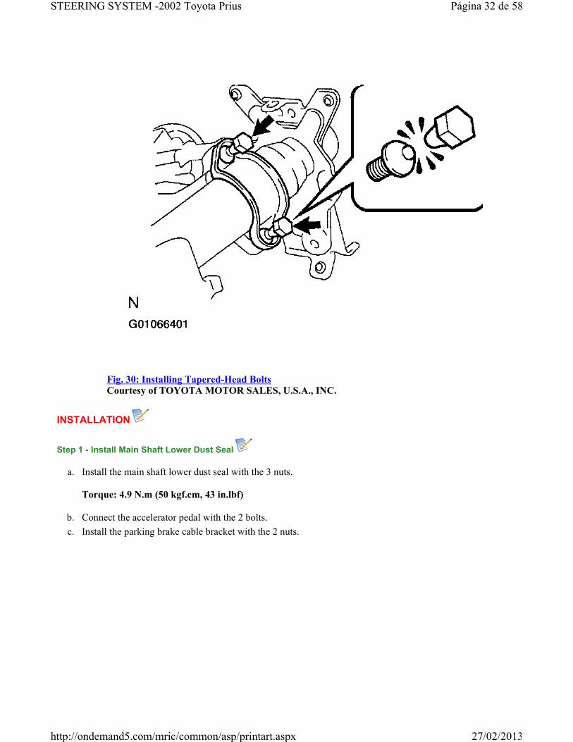
Fig. 30: Installing Tapered-Head BoltsCourtesy of TOYOTA MOTOR SALES, U.S.A., INC.
INSTALLATION
Step 1 - Install Main Shaft Lower Dust Seal
a. Install the main shaft lower dust seal with the 3 nuts.
Torque: 4.9 N.m (50 kgf.cm, 43 in.lbf)
b. Connect the accelerator pedal with the 2 bolts.
c. Install the parking brake cable bracket with the 2 nuts.
Página 32 de 58STEERING SYSTEM -2002 Toyota Prius
27/02/2013http://ondemand5.com/mric/common/asp/printart.aspx

Fig. 31: Locating Parking Brake Cable Bracket Mounting NutsCourtesy of TOYOTA MOTOR SALES, U.S.A., INC.
Step 2 - Install Column Hole Cover
Step 3 - Install Sliding Yoke
Install the sliding yoke to the main shaft assembly with the bolt.
Torque: 35 N.m (360 kgf.cm, 26 ft.lbf) .
Step 4 - Install No. 2 Intermediate Shaft Assembly
Temporarily install the No. 2 intermediate shaft assembly to the sliding yoke with the bolt.
Step 5 - Install Steering Column Assembly
a. Install the steering column assembly with the 2 bolts and 2 nuts.
Torque: 25 N.m (260 kgf.cm, 19 ft.lbf) .
b. Connect the connectors.
Página 33 de 58STEERING SYSTEM -2002 Toyota Prius
27/02/2013http://ondemand5.com/mric/common/asp/printart.aspx

Step 6 - Install Instrument Finish Panel
Install the instrument finish panel with the 3 screws.
Step 7 - Connect No. 2 Intermediate Shaft Assembly
a. Align the matchmarks on the No. 2 intermediate shaft assembly and control valve shaft.
Fig. 32: Locating No. 2 Intermediate Shaft Matchmarks & Identifying Bols A & BCourtesy of TOYOTA MOTOR SALES, U.S.A., INC.
b. Install the bolt "B" and torque the bolt "A".
Torque: 35 N.m (360 kgf.cm, 26 ft.lbf) .
Step 8 - Install Shift Lock Computer Sub-Assembly
Install the shift lock computer sub-assembly with the screw.
Step 9 - Connect Column Hole Cover
Connect the column hole cover with the 3 clips.
Página 34 de 58STEERING SYSTEM -2002 Toyota Prius
27/02/2013http://ondemand5.com/mric/common/asp/printart.aspx

Step 10 - Install Shift Lever Assembly
See STEP 1 - INSTALL SHIFT LEVER ASSEMBLY .
Step 11 - Connect Transmission Control Cable
Fig. 33: Identifying Transmission Control Cable Mounting Bolt & ClipCourtesy of TOYOTA MOTOR SALES, U.S.A., INC.
Step 12 - Install Spiral Cable
See COMPONENTS .
Step 13 - Install Combination Switch With Spiral Cable
a. Install the combination switch with spiral cable with the 3 screws.
b. Connect the AIRBAG connector.
c. Connect the connectors.
Step 14 - Install Upper & Lower Column Covers
a. Install the upper column cover with the screw.
b. Install the lower column cover with the 3 screws.
Página 35 de 58STEERING SYSTEM -2002 Toyota Prius
27/02/2013http://ondemand5.com/mric/common/asp/printart.aspx
Step 15 - Install Lower Instrument Finish Panel
a. Connect the connectors and DLC3 and install the lower instrument finish panel.
b. Install the screw and bolt.
c. Connect the hood lock release lever with the 2 screws.
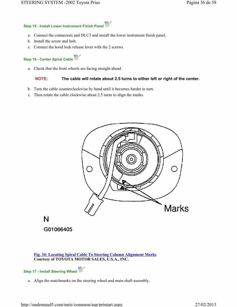
Step 16 - Center Spiral Cable
a. Check that the front wheels are facing straight ahead.
b. Turn the cable counterclockwise by hand until it becomes harder to turn.
c. Then rotate the cable clockwise about 2.5 turns to align the marks.
Fig. 34: Locating Spiral Cable To Steering Column Alignment MarksCourtesy of TOYOTA MOTOR SALES, U.S.A., INC.
Step 17 - Install Steering Wheel
a. Align the matchmarks on the steering wheel and main shaft assembly.
NOTE: The cable will rotate about 2.5 turns to either left or right of the center.
Página 36 de 58STEERING SYSTEM -2002 Toyota Prius
27/02/2013http://ondemand5.com/mric/common/asp/printart.aspx

b. Install the steering wheel set nut.
Torque: 50 N.m (510 kgf.cm, 37 ft.lbf)
Step 18 - Install Steering Wheel Pad
a. Connect the connector.
b. Connect the AIRBAG connector.
c. Install the steering wheel pad after confirming that the circumference groove of the Torx screws is caught on the screw case.
d. Using a Torx socket wrench, torque the 2 screws.
Fig. 35: Locating Steering Pad Torx ScrewsCourtesy of TOYOTA MOTOR SALES, U.S.A., INC.
Torque: 8.8 N.m (90 kgf.cm, 78 in.lbf) .
NOTE:� Never use AIRBAG parts from another vehicle. When replacing parts,
replace with new ones.
� Make sure the wheel pad is installed with the specified torque.
� If the wheel pad has been dropped, or there are cracks, dents or other defects in the case or connector, replace the wheel pad with a new one.
� When installing the wheel pad, take care that the wirings do not interfere with other parts and that they are not pinched between other parts.
Página 37 de 58STEERING SYSTEM -2002 Toyota Prius
27/02/2013http://ondemand5.com/mric/common/asp/printart.aspx

Step 19 - Check Steering Wheel Center Point
Step 20 - Perform Calibration Of Torque Sensor Zero Point
See STEP 3 - CALIBRATION OF TORQUE SENSOR ZERO POINT under PRE-CHECK .
ELECTRIC POWER STEERING GEAR
COMPONENTS
Página 38 de 58STEERING SYSTEM -2002 Toyota Prius
27/02/2013http://ondemand5.com/mric/common/asp/printart.aspx

Fig. 36: Locating Electric Power Steering Gear Related ComponentsCourtesy of TOYOTA MOTOR SALES, U.S.A., INC.
Fig. 37: Exploded View Of Steering Gear Assembly
Página 39 de 58STEERING SYSTEM -2002 Toyota Prius
27/02/2013http://ondemand5.com/mric/common/asp/printart.aspx

Courtesy of TOYOTA MOTOR SALES, U.S.A., INC.
REMOVAL
Step 1 - Place Front Wheels Facing Straight Ahead
Step 2 - Remove steering wheel pad
See STEP 1 - REMOVE STEERING WHEEL PAD .
Step 3 - Remove Steering Wheel
See STEP 2 - REMOVE STEERING WHEEL .
Step 4 - Remove RH & LH Engine Under Covers
Step 5 - Disconnect Tie Rod Ends
Disconnect RH AND LH TIE ROD ENDS .
Step 6 - Disconnect Stabilizer Bar
See STABILIZER BAR .
Step 7 - Disconnect Lower Suspension Arm From Lower Ball Joint
See BALL JOINTS .
Step 8 - Disconnect 2 Connectors & EMPS Bracket
a. Disconnect the 2 connectors.
b. Disconnect the 2 clamps.
c. Remove the bolt and disconnect the earth wire.
Tips Click a link to view tip
Tech1 Tip: 2002 toyota prius "ps light on info center
NOTE: Remove the steering wheel assembly before the steering gear removal, because there is possibility of breaking of the spiral cable.
Página 40 de 58STEERING SYSTEM -2002 Toyota Prius
27/02/2013http://ondemand5.com/mric/common/asp/printart.aspx

Fig. 38: Locating EMPS Bracket Mounting Bolts & Ground WireCourtesy of TOYOTA MOTOR SALES, U.S.A., INC.
d. Remove the 2 bolts and EMPS bracket.
Step 9 - Disconnect No. 2 Intermediate Shaft Assembly
a. Place the matchmarks on the No. 2 intermediate shaft assembly and control valve shaft.
b. Loosen the bolt "A" and remove the bolt "B" then disconnect the No. 2 intermediate shaft assembly from the control valve shaft.
Página 41 de 58STEERING SYSTEM -2002 Toyota Prius
27/02/2013http://ondemand5.com/mric/common/asp/printart.aspx
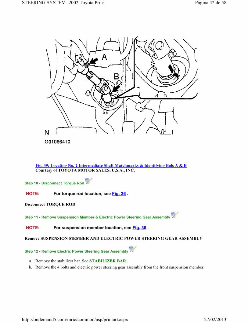
Fig. 39: Locating No. 2 Intermediate Shaft Matchmarks & Identifying Bols A & BCourtesy of TOYOTA MOTOR SALES, U.S.A., INC.
Step 10 - Disconnect Torque Rod
Disconnect TORQUE ROD
Step 11 - Remove Suspension Member & Electric Power Steering Gear Assembly
Remove SUSPENSION MEMBER AND ELECTRIC POWER STEERING GEAR ASSEMBLY
Step 12 - Remove Electric Power Steering Gear Assembly
a. Remove the stabilizer bar. See STABILIZER BAR .
b. Remove the 4 bolts and electric power steering gear assembly from the front suspension member.
NOTE: For torque rod location, see Fig. 36 .
NOTE: For suspension member location, see Fig. 36 .
Página 42 de 58STEERING SYSTEM -2002 Toyota Prius
27/02/2013http://ondemand5.com/mric/common/asp/printart.aspx

Fig. 40: Locating Electric Power Steering Gear To Suspension Member Mounting BoltsCourtesy of TOYOTA MOTOR SALES, U.S.A., INC.
c. Remove the bracket and grommet from the electric power steering gear assembly.
DISASSEMBLY
1. Using SST, secure the electric power steering gear assembly in a vise. SST 09612-00012.
NOTE: When using a vise, do not overtighten it.
Página 43 de 58STEERING SYSTEM -2002 Toyota Prius
27/02/2013http://ondemand5.com/mric/common/asp/printart.aspx

Fig. 41: Identifying SST 09612-00012Courtesy of TOYOTA MOTOR SALES, U.S.A., INC.
2. Remove RH and LH tie rod ends and lock nuts :
a. Place matchmarks on the tie rod end, lock nut and rock end.
Página 44 de 58STEERING SYSTEM -2002 Toyota Prius
27/02/2013http://ondemand5.com/mric/common/asp/printart.aspx
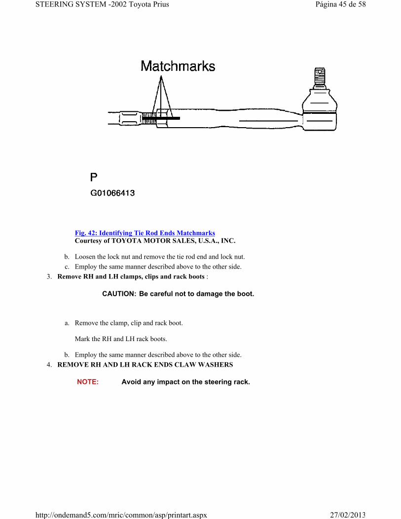
Fig. 42: Identifying Tie Rod Ends MatchmarksCourtesy of TOYOTA MOTOR SALES, U.S.A., INC.
b. Loosen the lock nut and remove the tie rod end and lock nut.
c. Employ the same manner described above to the other side.
3. Remove RH and LH clamps, clips and rack boots :
a. Remove the clamp, clip and rack boot.
Mark the RH and LH rack boots.
b. Employ the same manner described above to the other side.
4. REMOVE RH AND LH RACK ENDS CLAW WASHERS
CAUTION: Be careful not to damage the boot.
NOTE: Avoid any impact on the steering rack.
Página 45 de 58STEERING SYSTEM -2002 Toyota Prius
27/02/2013http://ondemand5.com/mric/common/asp/printart.aspx

Fig. 43: Unstaking Claw WasherCourtesy of TOYOTA MOTOR SALES, U.S.A., INC.
a. Using a screwdriver and a hammer, unstake the washer.
NOTE: Use SST 09922 - 10010 in the direction shown in Fig. 44 .Mark the RH and LH rack ends.
Página 46 de 58STEERING SYSTEM -2002 Toyota Prius
27/02/2013http://ondemand5.com/mric/common/asp/printart.aspx

Fig. 44: Removing Rack EndCourtesy of TOYOTA MOTOR SALES, U.S.A., INC.
b. Using a spanner, hold the steering rack steadily and using SST, remove the rack end. SST 09922 -10010.
c. Remove the claw washer.
d. Employ the same manner described above to the other side.
5. Remove the bolt and earth wire.
REASSEMBLY
1. Install the earth wire with the bolt.
Torque: 5.5 N.m (60 kgf.cm, 52 in.lbf)
2. Install RH and LH claw washers and rack ends :
NOTE: When using a vise, do not overtighten it.
NOTE: Align the claws of the claw washer with the steering rack grooves.
Página 47 de 58STEERING SYSTEM -2002 Toyota Prius
27/02/2013http://ondemand5.com/mric/common/asp/printart.aspx

Fig. 45: Installing Claw Washer & Rack EndCourtesy of TOYOTA MOTOR SALES, U.S.A., INC.
a. Install a new claw washer and temporarily install the rack end.
NOTE: Use a torque wrench with a fulcrum length of 380 mm (14.96 in.).
Use SST 09922 - 10010 in the direction shown in Fig. 46 .
Página 48 de 58STEERING SYSTEM -2002 Toyota Prius
27/02/2013http://ondemand5.com/mric/common/asp/printart.aspx

Fig. 46: Torquing Rack EndCourtesy of TOYOTA MOTOR SALES, U.S.A., INC.
b. Using a spanner, hold the steering rack steadily and using SST, torque the rack end. SST 09922 -10010.
Torque: 62 N.m (630 kgf.cm, 46 ft.lbf) .
CAUTION: Avoid any impact on the steering rack.
Página 49 de 58STEERING SYSTEM -2002 Toyota Prius
27/02/2013http://ondemand5.com/mric/common/asp/printart.aspx

Fig. 47: Staking Claw WasherCourtesy of TOYOTA MOTOR SALES, U.S.A., INC.
c. Using a brass bar and a hammer, stake the claw washer.
d. Employ the same manner described above to the other side.
3. Install RH and LH rack boots, clips and clamps :
a. Ensure that the steering rack hole is not clogged with grease.
b. Install the boot, clip and clamp.
c. Employ the same manner described above to the other side.
4. Install RH and LH tie rod ends and lock nut :
a. Screw the lock nut and tie rod end onto the rack end and the matchmarks aligned.
CAUTION: If the hole is clogged, the pressure inside the boot will change after it is assembled and the steering wheel is turned.
CAUTION: Be careful not to damage or twist the boot.
Página 50 de 58STEERING SYSTEM -2002 Toyota Prius
27/02/2013http://ondemand5.com/mric/common/asp/printart.aspx

Fig. 48: Identifying Tie Rod Ends MatchmarksCourtesy of TOYOTA MOTOR SALES, U.S.A., INC.
b. After adjusting toe-in, torque the nut. See SPECIFICATIONS & PROCEDURES .
c. Employ the same manner described above to the other side.
INSTALLATION
Step 1 - Install Electric Power Steering Gear Assembly
NOTE: Install the bracket with the inscribed mark facing to the front of the vehicle.
Página 51 de 58STEERING SYSTEM -2002 Toyota Prius
27/02/2013http://ondemand5.com/mric/common/asp/printart.aspx

Fig. 49: Identifying Inscribed Mark & Installation Direction Of BracketCourtesy of TOYOTA MOTOR SALES, U.S.A., INC.
Página 52 de 58STEERING SYSTEM -2002 Toyota Prius
27/02/2013http://ondemand5.com/mric/common/asp/printart.aspx

Fig. 50: Locating Electric Power Steering Gear To Suspension Member Mounting BoltsCourtesy of TOYOTA MOTOR SALES, U.S.A., INC.
a. Install the grommet and bracket to the electric power steering gear assembly.
b. Install the electric power steering gear assembly with the 4 new bolts to the front suspension member.
Torque: 83 N.m (850 kgf.cm, 61 ft.lbf)
c. Install the STABILIZER BAR .
d. To prevent the main shaft lower dust seal from damaging, wind vinyl tape on the serrated part of the control valve shaft.
Página 53 de 58STEERING SYSTEM -2002 Toyota Prius
27/02/2013http://ondemand5.com/mric/common/asp/printart.aspx

Fig. 51: Identifying Control Valve Shaft SerrationsCourtesy of TOYOTA MOTOR SALES, U.S.A., INC.
e. Turn over the main shaft lower dust seal from the engine compartment side to the cab.
Página 54 de 58STEERING SYSTEM -2002 Toyota Prius
27/02/2013http://ondemand5.com/mric/common/asp/printart.aspx

Fig. 52: Determining Engine Compartment & Cab Side Of Main Shaft Lower SealCourtesy of TOYOTA MOTOR SALES, U.S.A., INC.
Step 2 - Install Suspension Member & Electric Power Steering Gear Assembly
Install SUSPENSION MEMBER AND ELECTRIC POWER STEERING GEAR ASSEMBLY .
Step 3 - Connect Torque Rod
Connect TORQUE ROD .
Step 4 - Connect EMPS Bracket & 2 Connectors
a. Connect the EMPS bracket with the 2 bolts.
NOTE: For torque rod location, see Fig. 36 .
Página 55 de 58STEERING SYSTEM -2002 Toyota Prius
27/02/2013http://ondemand5.com/mric/common/asp/printart.aspx

Fig. 53: Locating EMPS Bracket Mounting Bolts & Ground WireCourtesy of TOYOTA MOTOR SALES, U.S.A., INC.
Torque: 5.5 N.m (60 kgf.cm, 52 in.lbf)
b. Connect the earth wire with the bolt.
Torque: 5.5 N.m (60 kgf.cm, 52 in.lbf)
c. Connect the 2 clamps.
d. Connect the 2 connectors.
Step 5 - Connect Lower Suspension Arm To Lower Ball Joint
See BALL JOINTS .
Step 6 - Connect Stabilizer Bar
See STABILIZER BAR .
Step 7 - Connect No. 2 Intermediate Shaft Assembly
Página 56 de 58STEERING SYSTEM -2002 Toyota Prius
27/02/2013http://ondemand5.com/mric/common/asp/printart.aspx

a. Put the dust seal back to the engine compartment side.
b. Remove the vinyl tape from the serrated part of the control valve shaft.
c. Align the matchmarks on the No. 2 intermediate shaft assembly and control valve shaft.
d. Install the bolt "B" and torque the bolt "A".
Fig. 54: Locating No. 2 Intermediate Shaft Matchmarks & Identifying Bols A & BCourtesy of TOYOTA MOTOR SALES, U.S.A., INC.
Torque: 35 N.m (360 kgf.cm, 22 ft.lbf)
Step 8 - Connect Tie Rod Ends
Connect RH AND LH TIE ROD ENDS .
Step 9 - Place Front Wheels Facing Straight Ahead
Step 10 - Center Spiral Cable
See STEP 16 - CENTER SPIRAL CABLE .
Step 11 - Install Steering Wheel
NOTE: Do it with the front of the vehicle jacked up.
Página 57 de 58STEERING SYSTEM -2002 Toyota Prius
27/02/2013http://ondemand5.com/mric/common/asp/printart.aspx

a. Align the matchmarks on the steering wheel and steering column main shaft.
b. Temporarily tighten the steering wheel set nut.
Step 12 - Check Steering Wheel Center Point
Step 13 - Torque Steering Wheel Set Nut
Torque: 50 N.m (510 kgf.cm, 37 ft.lbf) .
Step 14 - Install Steering Wheel Pad
See STEP 18 - INSTALL STEERING WHEEL PAD .
Step 15 - Check Front Wheel Alignment
Step 16 - Perform Calibration Of Torque Sensor Zero Point
See STEP 3 - CALIBRATION OF TORQUE SENSOR ZERO POINT under PRE-CHECK .
© 2008 Mitchell Repair Information Co., LLC.
Página 58 de 58STEERING SYSTEM -2002 Toyota Prius
27/02/2013http://ondemand5.com/mric/common/asp/printart.aspx