Embed Size (px)
Citation preview

Cook Legacy College
Training Module P3021:
AirBurst Fundamentals
Goals of This 15-Minute Module
Know how an AirBurst works
including the basic physics
Understand major components and
features
Operate an AirBurst System
Troubleshoot AirBurst Problems (You’ll need your AirBurst Troubleshooting Guide)
3
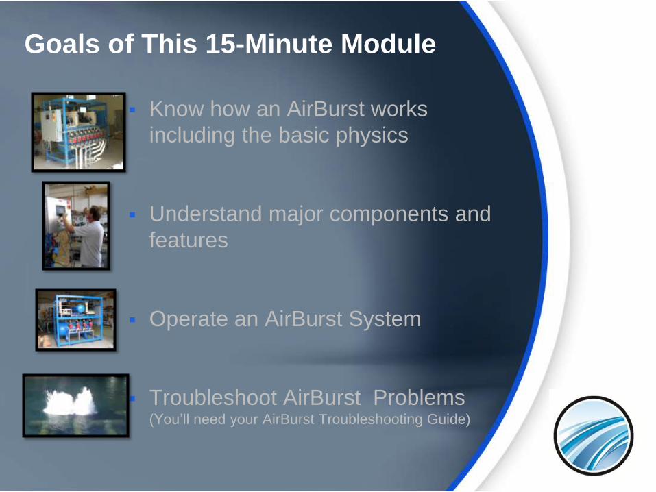
AirBurst Fundamentals
AB 103:
Review and Quiz
AB 102: Fundamentals
AB 101: Overview and Background
4
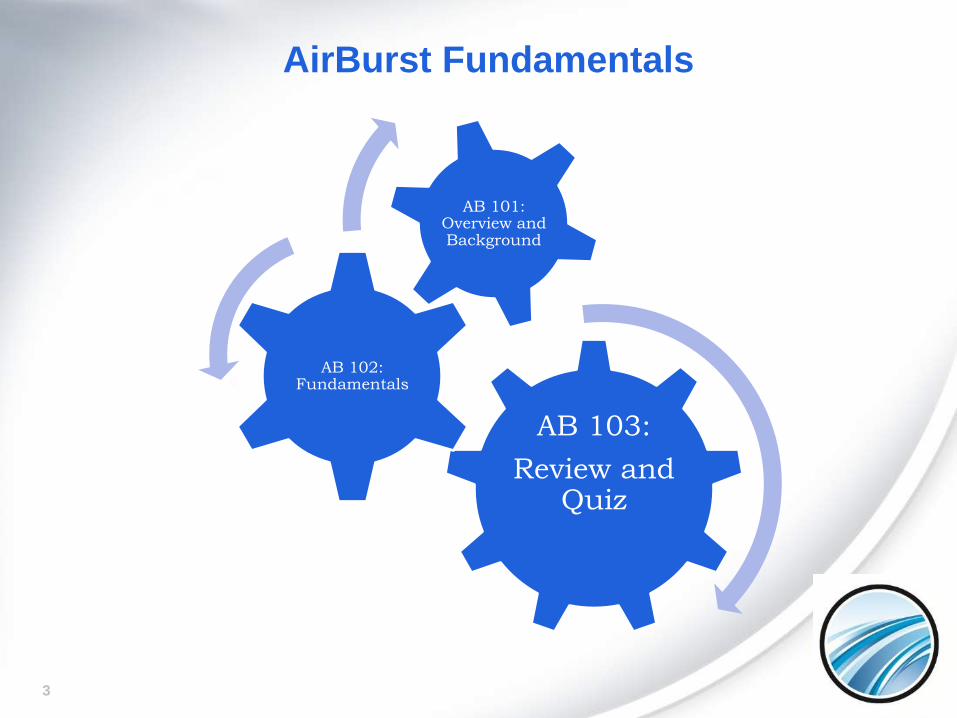
Passive Screens Often Use Airburst
Cleaning
Passive screens often include an AirBurst diffuser within the internal of the screen. The diffuser size and perforation pattern vary based on the screen type and orientation. The goal is to ensure that all of the screen surface is struck by coarse bubbles with sufficient velocity and mass to carry away debris.
5
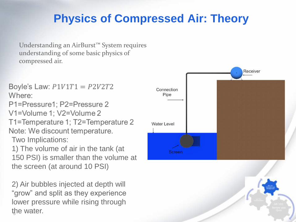
Physics of Compressed Air: Theory
Understanding an AirBurst™ System requires understanding of some basic physics of compressed air.
Two Implications:
1) The volume of air in the tank (at
150 PSI) is smaller than the volume at
the screen (at around 10 PSI)
2) Air bubbles injected at depth will
“grow” and split as they experience
lower pressure while rising through
the water.
6
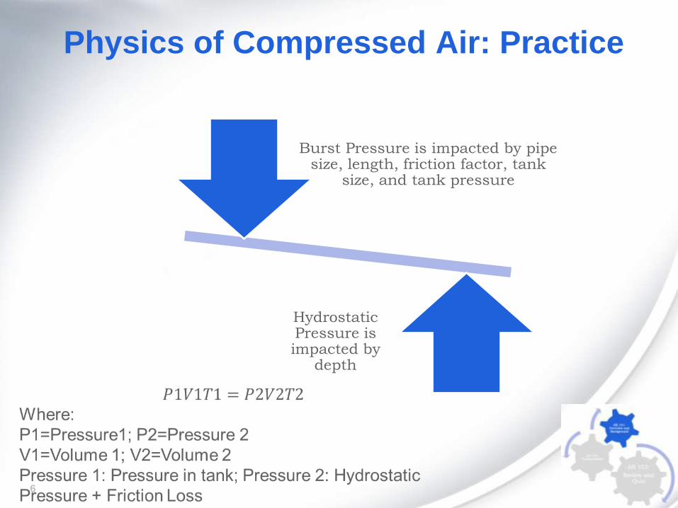
Physics of Compressed Air: Practice
Hydrostatic Pressure is impacted by
depth
Burst Pressure is impacted by pipe size, length, friction factor, tank
size, and tank pressure
7
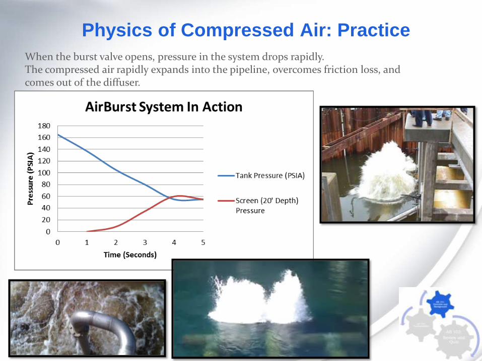
Physics of Compressed Air: Practice
When the burst valve opens, pressure in the system drops rapidly.The compressed air rapidly expands into the pipeline, overcomes friction loss, and comes out of the diffuser.
8
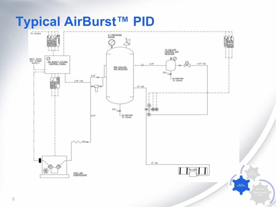
Typical AirBurst™ PID
9
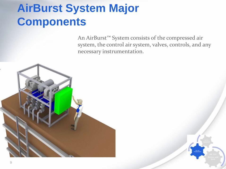
AirBurst System Major
Components
An AirBurst™ System consists of the compressed air system, the control air system, valves, controls, and any necessary instrumentation.
10
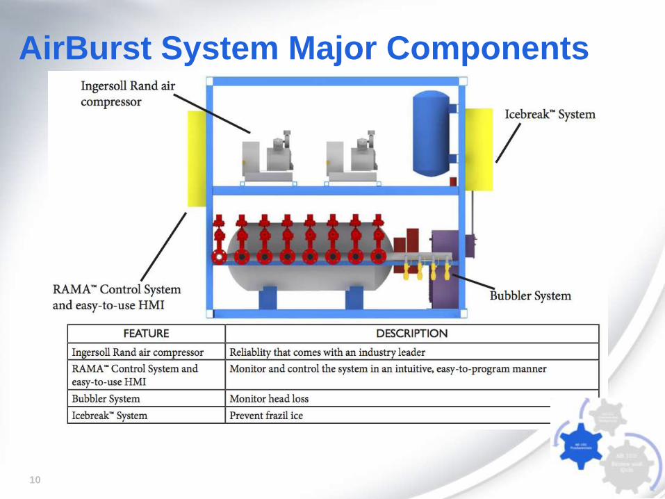
AirBurst System Major Components

11
Compressed Air SystemThe compressed air system includes
the compressor, filters, and gauges to
provide air to the system.
12
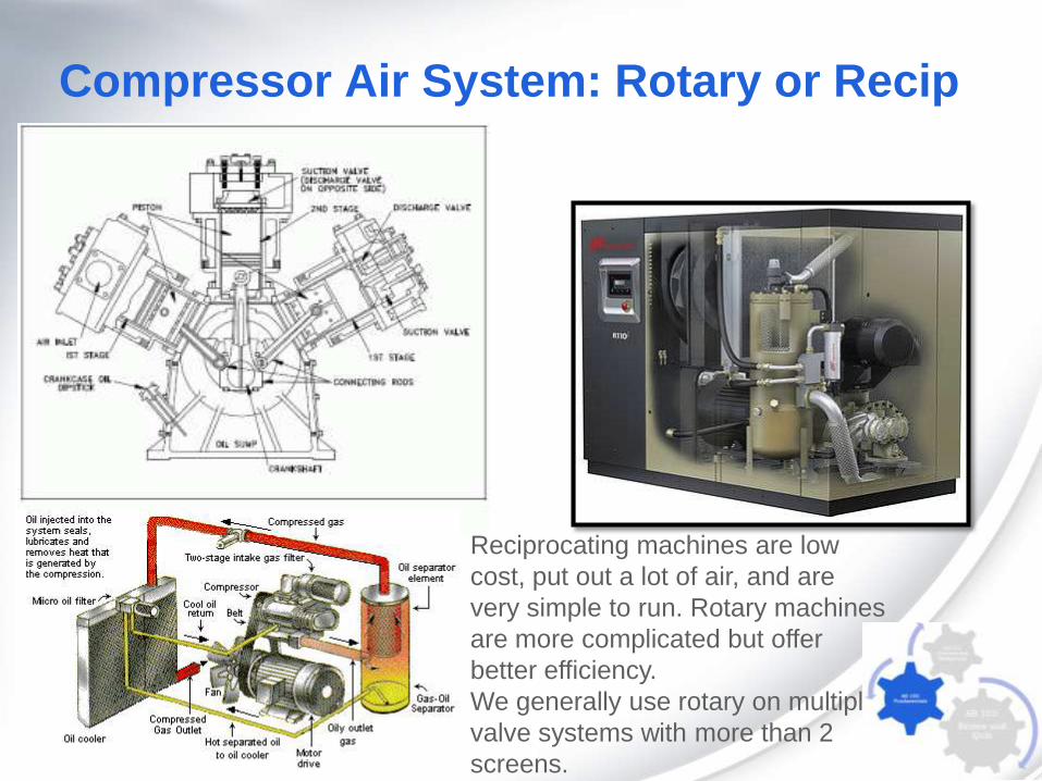
Compressor Air System: Rotary or Recip
Reciprocating machines are low
cost, put out a lot of air, and are
very simple to run. Rotary machines
are more complicated but offer
better efficiency.
We generally use rotary on multiple
valve systems with more than 2
screens.
13
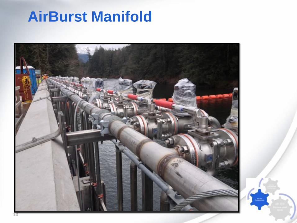
AirBurst Manifold
14
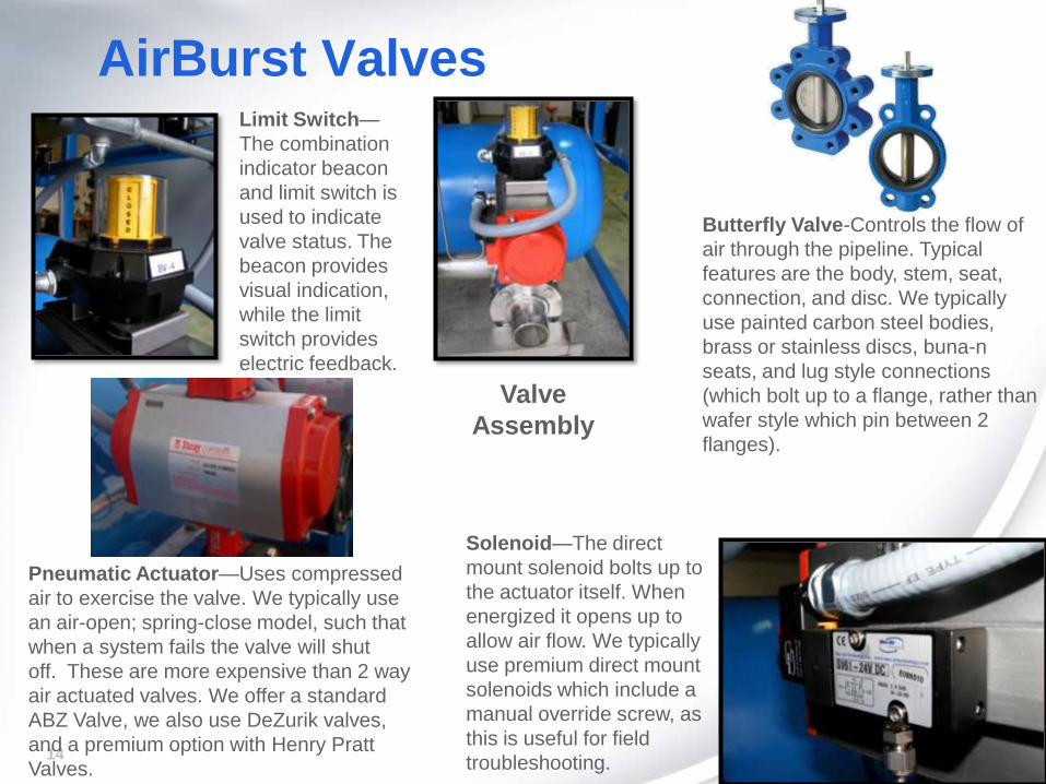
AirBurst Valves
Valve
Assembly
Butterfly Valve-Controls the flow of
air through the pipeline. Typical
features are the body, stem, seat,
connection, and disc. We typically
use painted carbon steel bodies,
brass or stainless discs, buna-n
seats, and lug style connections
(which bolt up to a flange, rather than
wafer style which pin between 2
flanges).
Limit Switch—
The combination
indicator beacon
and limit switch is
used to indicate
valve status. The
beacon provides
visual indication,
while the limit
switch provides
electric feedback.
Solenoid—The direct
mount solenoid bolts up to
the actuator itself. When
energized it opens up to
allow air flow. We typically
use premium direct mount
solenoids which include a
manual override screw, as
this is useful for field
troubleshooting.
Pneumatic Actuator—Uses compressed
air to exercise the valve. We typically use
an air-open; spring-close model, such that
when a system fails the valve will shut
off. These are more expensive than 2 way
air actuated valves. We offer a standard
ABZ Valve, we also use DeZurik valves,
and a premium option with Henry Pratt
Valves.
15
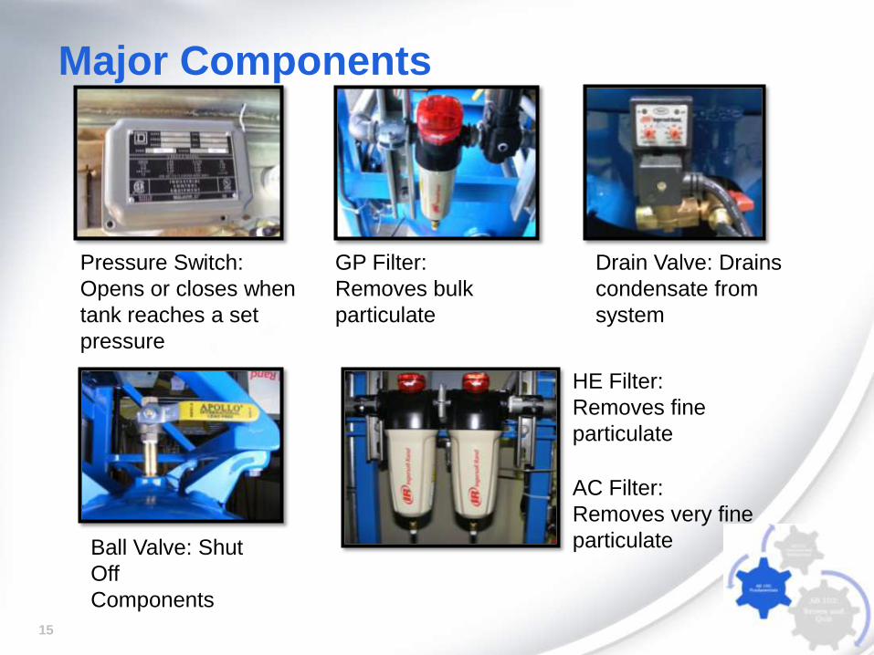
Major Components
Drain Valve: Drains
condensate from
system
Pressure Switch:
Opens or closes when
tank reaches a set
pressure
GP Filter:
Removes bulk
particulate
Ball Valve: Shut
Off
Components
HE Filter:
Removes fine
particulate
AC Filter:
Removes very fine
particulate
16
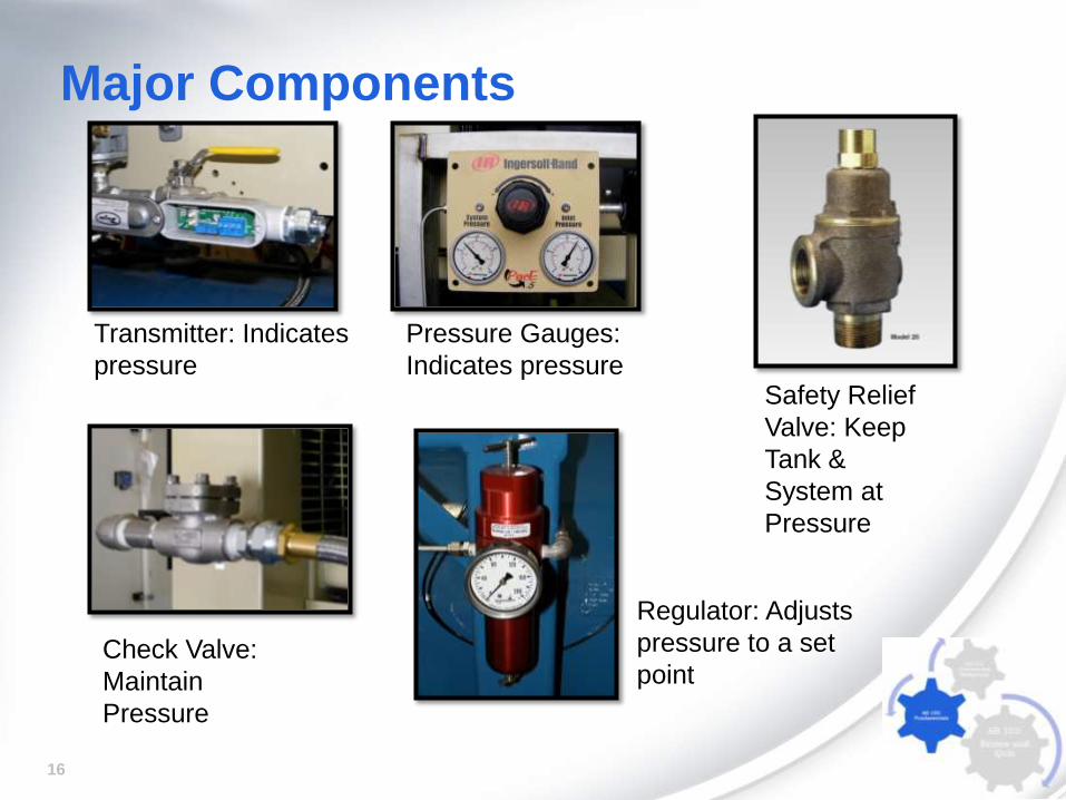
Major Components
Transmitter: Indicates
pressure
Regulator: Adjusts
pressure to a set
pointCheck Valve:
Maintain
Pressure
Safety Relief
Valve: Keep
Tank &
System at
Pressure
Pressure Gauges:
Indicates pressure
17
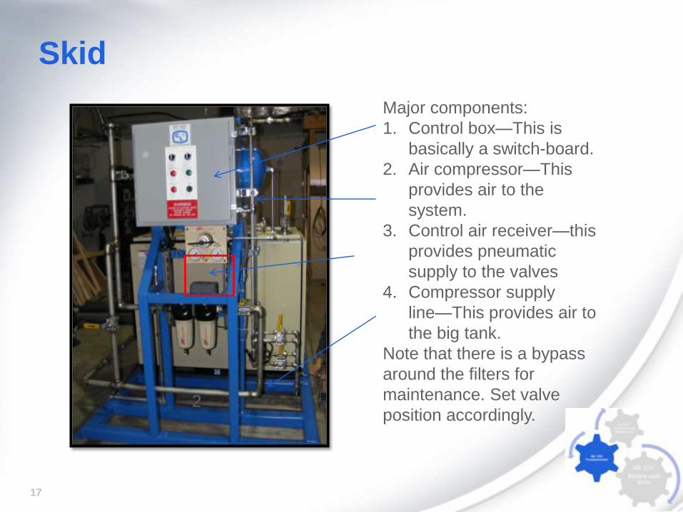
Skid
2
Major components:
1. Control box—This is
basically a switch-board.
2. Air compressor—This
provides air to the
system.
3. Control air receiver—this
provides pneumatic
supply to the valves
4. Compressor supply
line—This provides air to
the big tank.
Note that there is a bypass
around the filters for
maintenance. Set valve
position accordingly.
18
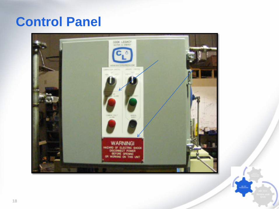
Control Panel
19
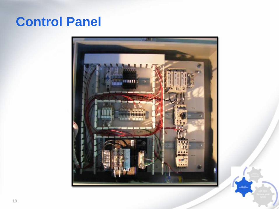
Control Panel
20
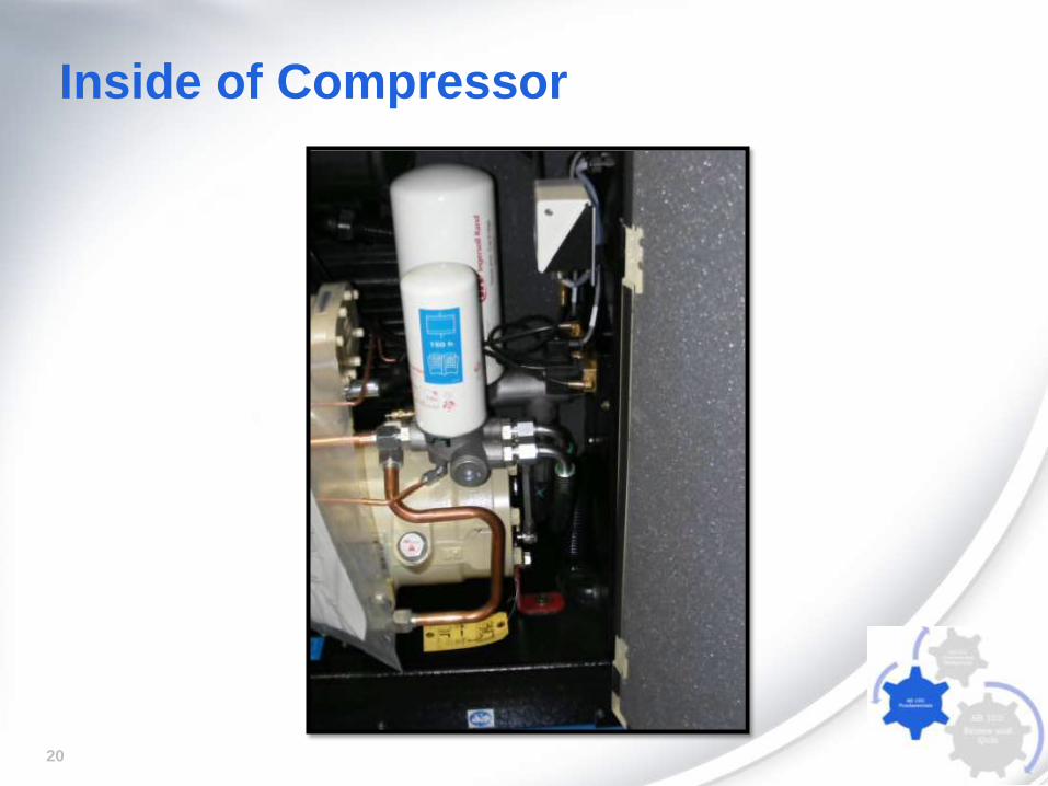
Inside of Compressor
21
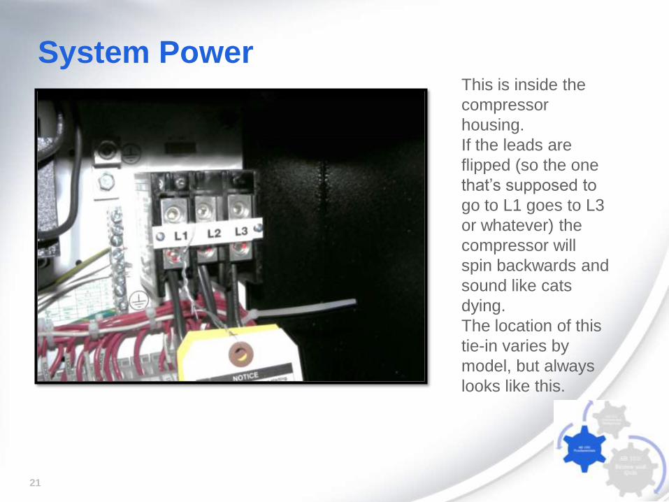
System PowerThis is inside the
compressor
housing.
If the leads are
flipped (so the one
that’s supposed to
go to L1 goes to L3
or whatever) the
compressor will
spin backwards and
sound like cats
dying.
The location of this
tie-in varies by
model, but always
looks like this.
22
AirBurst™ System Testing Air Burst system Hydrostatic test per job completion form. The hydrostatic test
follows ASME Protocol to ensure that the welds are properly performed. We typically use
the safest procedure, “Air over water” where a suitable section of the work is filled with
water, capped with blind flanges, and then pressurized with a regulated amount of
compressed air. It is then tested over time to ensure that there are no leaks and the
pressure holds.
Control system inspection. The control system is visually inspected to ensure a clean,
orderly set up of all components, proper labels and stickers, compliance with raceway
and other physical layout requirements, and the accurate termination of wires.
Control system continuity test. The control system is tested to ensure continuity
between the PLC, instruments and terminals.
Control system HMI and PLC testing. Once the basic function of the system is
confirmed we test the control system using the real or simulated instruments to ensure
that all of the functions are present. For example a simple toggle switch might be used in
place of a limit switch.
Complete functional testing of the AirBurst system. When the system component
testing is complete we focus on testing the system against the O&M Manual to ensure
that all functions and alarms are available and functional.
23
Troubleshooting a Project
• A valve on the AirBurst System
does not operate. What do you
do to troubleshoot the problem?
• The system is not building
pressure. What do you need to
do?
24
Review Questions
• What are the components of P1 when
calculating burst pressure and volume?
• What is the purpose of the control tank within
an AirBurst™ System?