Embed Size (px)
Citation preview

Kimon Afsaridis M.Sc Mechanical Engineering
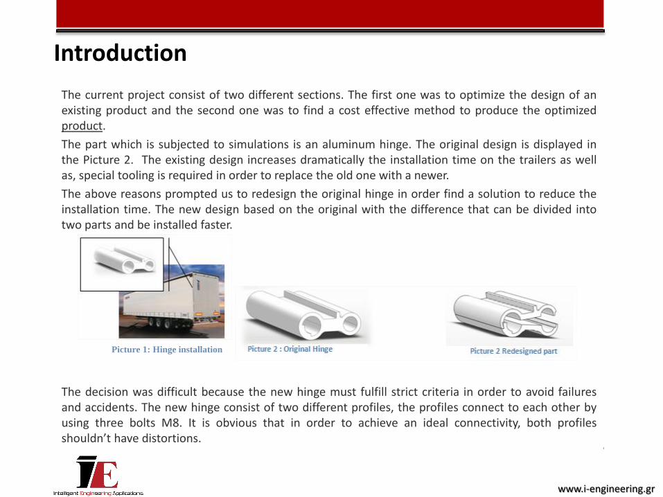
The current project consist of two different sections. The first one was to optimize the design of an existing product and the second one was to find a cost effective method to produce the optimized product.
The part which is subjected to simulations is an aluminum hinge. The original design is displayed in the Picture 2. The existing design increases dramatically the installation time on the trailers as well as, special tooling is required in order to replace the old one with a newer.
The above reasons prompted us to redesign the original hinge in order find a solution to reduce the installation time. The new design based on the original with the difference that can be divided into two parts and be installed faster.
The decision was difficult because the new hinge must fulfill strict criteria in order to avoid failures and accidents. The new hinge consist of two different profiles, the profiles connect to each other by using three bolts M8. It is obvious that in order to achieve an ideal connectivity, both profiles shouldn’t have distortions.
Picture 1: Hinge installation
Introduction
www.i-engineering.gr
Introduction
From manufacturing point of view we are trying to find a cost effective way to produce these profiles taking into account the small quantities per order.
Thus, the objective was to find a solution to produce both profiles at the same time by using one die. In trying to achieve the objective mentioned above, we integrate the manufacturing company, Doral S.A. , in order to provide us with their machine data which are used later on as an input for the simulations
www.i-engineering.gr
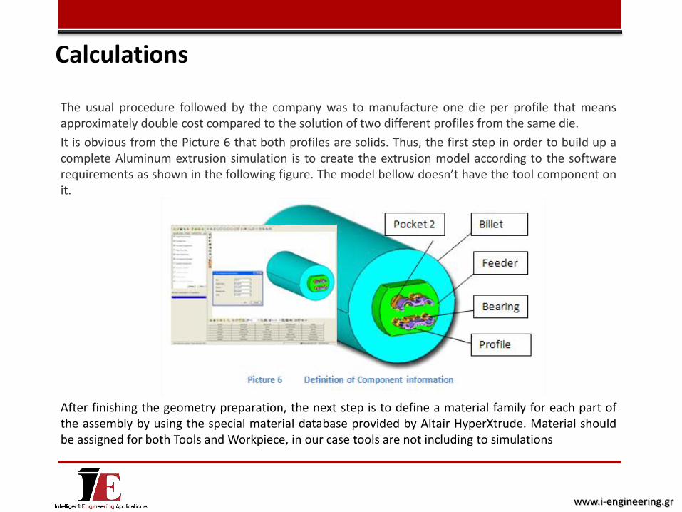
The usual procedure followed by the company was to manufacture one die per profile that means approximately double cost compared to the solution of two different profiles from the same die.
It is obvious from the Picture 6 that both profiles are solids. Thus, the first step in order to build up a complete Aluminum extrusion simulation is to create the extrusion model according to the software requirements as shown in the following figure. The model bellow doesn’t have the tool component on it.
After finishing the geometry preparation, the next step is to define a material family for each part of the assembly by using the special material database provided by Altair HyperXtrude. Material should be assigned for both Tools and Workpiece, in our case tools are not including to simulations
Calculations
www.i-engineering.gr
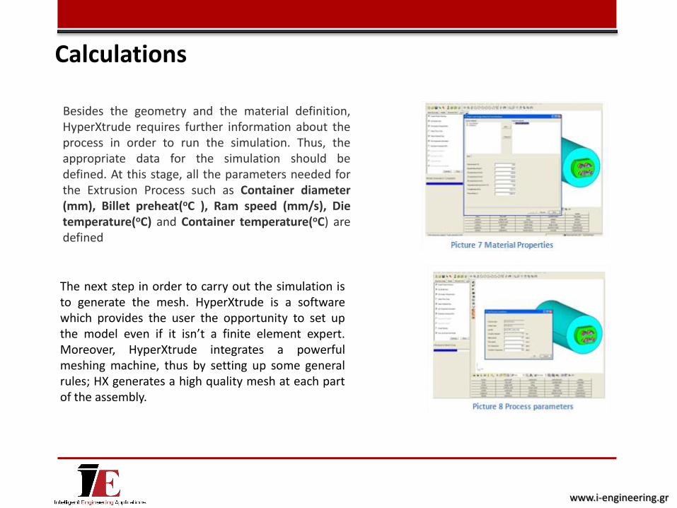
Besides the geometry and the material definition, HyperXtrude requires further information about the process in order to run the simulation. Thus, the appropriate data for the simulation should be defined. At this stage, all the parameters needed for the Extrusion Process such as Container diameter (mm), Billet preheat(oC ), Ram speed (mm/s), Die temperature(oC) and Container temperature(oC) are defined
The next step in order to carry out the simulation is to generate the mesh. HyperXtrude is a software which provides the user the opportunity to set up the model even if it isn’t a finite element expert. Moreover, HyperXtrude integrates a powerful meshing machine, thus by setting up some general rules; HX generates a high quality mesh at each part of the assembly.
Calculations
www.i-engineering.gr
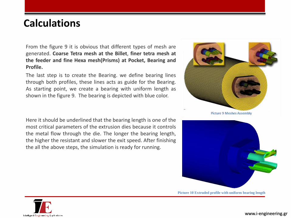
From the figure 9 it is obvious that different types of mesh are generated. Coarse Tetra mesh at the Billet, finer tetra mesh at the feeder and fine Hexa mesh(Prisms) at Pocket, Bearing and Profile.
The last step is to create the Bearing. we define bearing lines through both profiles, these lines acts as guide for the Bearing. As starting point, we create a bearing with uniform length as shown in the figure 9. The bearing is depicted with blue color.
Here it should be underlined that the bearing length is one of the most critical parameters of the extrusion dies because it controls the metal flow through the die. The longer the bearing length, the higher the resistant and slower the exit speed. After finishing the all the above steps, the simulation is ready for running.
Calculations
Picture 10 Extruded profile with uniform bearing length
www.i-engineering.gr
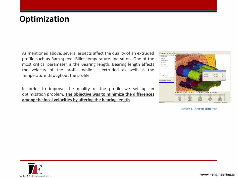
As mentioned above, several aspects affect the quality of an extruded profile such as Ram speed, Billet temperature and so on. One of the most critical parameter is the Bearing length. Bearing length affects the velocity of the profile while is extruded as well as the Temperature throughout the profile.
In order to improve the quality of the profile we set up an optimization problem. The objective was to minimize the differences among the local velocities by altering the bearing length
Picture 11 Bearing definition
Optimization
www.i-engineering.gr
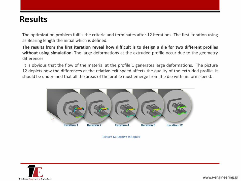
The optimization problem fulfils the criteria and terminates after 12 iterations. The first iteration using as Bearing length the initial which is defined.
The results from the first iteration reveal how difficult is to design a die for two different profiles without using simulation. The large deformations at the extruded profile occur due to the geometry differences.
It is obvious that the flow of the material at the profile 1 generates large deformations. The picture 12 depicts how the differences at the relative exit speed affects the quality of the extruded profile. It should be underlined that all the areas of the profile must emerge from the die with uniform speed.
Picture 12 Relative exit speed
Results
www.i-engineering.gr

At the last iteration, the relative speed is almost uniform through the section of the profile, which means that the deformations lie bellow the critical boundary. At a well designed die the bearing length should be shorter when the profile is thin and longer when the profile is thicker, in order to achieve uniform speed.
Temperature of the extruded profile affected also from the bearing length. The friction between Bearing and the profile increases the Temperature throughout the profile.
Picture 13 Velocities
Picture 14 Temperatures
Results
www.i-engineering.gr
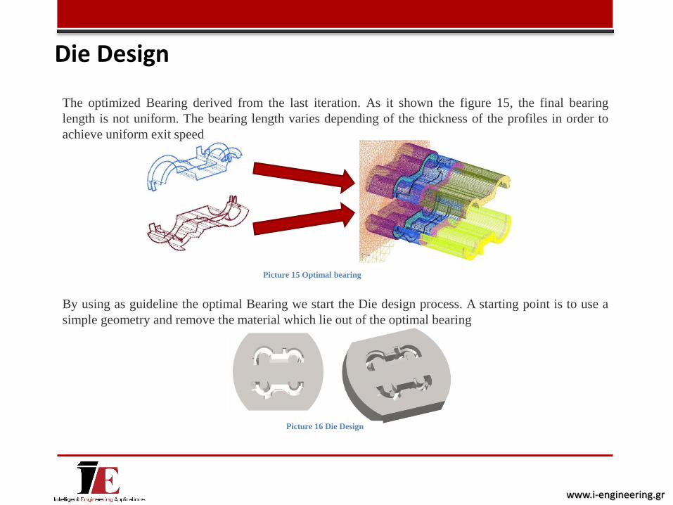
The optimized Bearing derived from the last iteration. As it shown the figure 15, the final bearing
length is not uniform. The bearing length varies depending of the thickness of the profiles in order to
achieve uniform exit speed
By using as guideline the optimal Bearing we start the Die design process. A starting point is to use a
simple geometry and remove the material which lie out of the optimal bearing
Picture 16 Die Design
Die Design
Picture 15 Optimal bearing
www.i-engineering.gr

Picture 17 Pressure
Picture 17 Pressure Picture 18 Constraint Picture 19 Deformation
at the internal side
Picture 20 Deformation
at the constraint side
Picture Stresses at the
internal side
Picture 22 Stresses at
the internal side
The simulation of the extrusion process gives as the required outputs, such as Velocities, Temperatures and Pressure. The applied pressure from the extruded material on the die shown in the following pictures
The next step is to investigate the strength of the die. HyperXtrude calculates the stresses which are generated during the extrusion process
In our case, the applied pressure at the die with the optimized bearing length is 260MPa. By using this value, we are running a simulation in order to check if our design is strong enough to withstand the applied pressure. Structural analysis enables us to predict the life cycle of the die.
Die Design
www.i-engineering.gr

From the discussion made in previous sections, it is obvious that the quality of an extruded profile is
strongly affected by the die design. Die design is a really complicated process, the current case
study reveals how an Engineering software such as Altair HyperXtrude enable the user to find the
optimal die design without using the traditional, time consuming and expensive methods such as
‘’trial and error’’.
Conclusion
www.i-engineering.gr

i-engineering consists of a network of specialized engineers, ready to provide technical consulting
services for industrial applications.
i-engineering provides a full range of engineering solutions for every aspect of your business. Through
the use of advanced technology, we help our customers to find the best solution to their problems.
More specifically, we can provide solutions in the fields of: Product Design (2D-3D) and drafting of
comprehensive technical documentation for each product, CAM applications, structural analysis, casting
simulations, design optimization, extrusion simulation and etc.
i-engineering has alliances with leading engineering companies such as Altair Engineering, INTERFEA
and ESI GROUP, an assurance of our reliability.
i-engineering is the best partner for finding solutions for your company’s requirements.
Visit us:
www.i-engineering.gr
About i-engineering
www.i-engineering.gr