Embed Size (px)
Citation preview
Solution Overview
© 2014 Cisco and/or its affiliates. All rights reserved. This document is Cisco Public Information. Page 1 of 26
Cisco Unified Computing System: Architecture for Implementing the Next Phase in an Industry Transition
An Industry in Transition
The computer industry is on the threshold of a major transition. The x86 architecture has remained virtually
unchanged since the 1990s, and while processors and systems have become smaller and more powerful, the
challenges of server sprawl, power and cooling, policy coherency, security, and management have continued to
grow. Over the past decade the widespread adoption of virtualization has enabled server consolidation and has
made the virtual machine a basic deployment object. Yet complexity has increased unabated, and the data center
deployment model has continued to require the manual assembly of a large number of individual components.
Consider the sources of complexity in today’s virtualized and nonvirtualized server environments:
● Every rack-mount or blade server and chassis is a separate point of management, each having its own
unique identity and I/O configuration that is tied to the hardware, reducing the ability to respond quickly to
workload changes.
● Updating server, blade, and chassis firmware is a manual and time-consuming process.
● The network access layer has fragmented into multiple levels, including access-layer switches, switches
integrated into blade chassis, and software switches required by virtualization software. Each switch has its
own unique set of features and limitations that add new layers of management to an already complex
environment.
● Virtual server sprawl has resulted from the notion that virtual machines are “free,” yet the IT organizations
that support them know that a new set of issues has been created. The increasing number of components
in data center environments has caused a proliferation of management tools that has made network policy
difficult to track with virtual machine movement and has increased the difficulty of securing both networks
and storage to the same standards as discrete servers and operating systems.
● Shared storage is a requirement for using some of virtualization’s best features, including dynamic virtual
machine movement and high availability. When access to Fibre Channel SANs is added to every server in a
rack, suddenly the required number of cables, adapters, and upstream switch ports increases dramatically.
The industry is on the threshold of the next logical step in a natural progression that began with standardization on
the x86 architecture and virtualization. The second phase was accomplished by the delivery of a unified network
fabric that optimizes and extends data center technologies through consolidation and virtualization across the
network, storage, servers, and applications. The third phase virtualizes the entire data center through an integrated
architecture that brings together network, compute, storage access, and virtualization resources. At Cisco we refer
to this transition as unified computing, and the Cisco® Unified Computing System is its first realization.
© 2014 Cisco and/or its affiliates. All rights reserved. This document is Cisco Public Information. Page 2 of 26
Introducing the Cisco Unified Computing System
The Cisco Unified Computing System is a next-generation data center platform that unites compute, network,
storage access, and virtualization into a cohesive system designed to reduce total cost of ownership (TCO) and
increase business agility. The system integrates a low-latency, lossless 10 Gigabit Ethernet unified network fabric
with enterprise-class, x86-architecture servers. The system is an integrated, scalable, multichassis platform in
which all resources participate in a unified management domain. The main system components include:
● Compute: The system is based on an entirely new class of computing system that incorporates blade
servers based on Intel Xeon 5500 Series processors. The blade servers offer patented Cisco Extended
Memory Technology to support applications with large data sets and allow more virtual machines per
server.
● Network: The system is integrated onto a low-latency, lossless, 10-Gbps unified network fabric. This
network foundation consolidates what today are three separate networks: LANs, SANs, and high-
performance computing networks. The unified fabric lowers costs by reducing the number of network
adapters, switches, and cables, and by decreasing power and cooling requirements.
● Virtualization: The system unleashes the full potential of virtualization by enhancing the scalability,
performance, and operational control of virtual environments. Cisco security, policy enforcement, and
diagnostic features are now extended into virtualized environments to better support changing business and
IT requirements.
● Storage access: The system provides consolidated access to both SAN storage and network attached
storage (NAS) over the unified fabric. Unifying storage access means that the Cisco Unified Computing
System can access storage over Ethernet, Fibre Channel, Fibre Channel over Ethernet (FCoE), and iSCSI,
providing customers with choice and investment protection. In addition, administrators can pre-assign
storage-access policies for system connectivity to storage resources, simplifying storage connectivity and
management while helping increase productivity.
● Management: The system uniquely integrates all the system components, enabling the entire solution to be
managed as a single entity through Cisco UCS Manager software. Cisco UCS Manager provides an
intuitive graphical user interface (GUI), a command-line interface (CLI), and a robust application-
programming interface (API) to manage all system configuration and operations. Cisco UCS Manager helps
increase IT staff productivity, enabling storage, network, and server administrators to collaborate on defining
service profiles for applications. Service profiles are logical representations of desired physical
configurations and infrastructure policies. They help automate provisioning and increase business agility,
allowing data center managers to provision resources in minutes instead of days.
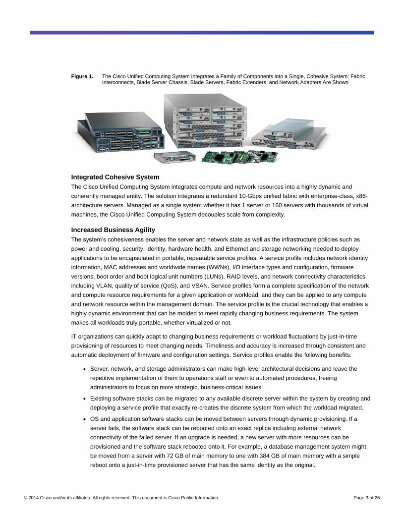
Working as a single, cohesive system, these components unify technology in the data center. They represent a
radical simplification in comparison to traditional systems, helping simplify data center operations while reducing
power and cooling requirements. The system amplifies IT agility for improved business outcomes. The Cisco
Unified Computing System components illustrated in Figure 1 include, from left to right, fabric interconnects, blade
server chassis, blade servers, and in the foreground, fabric extenders and network adapters.
© 2014 Cisco and/or its affiliates. All rights reserved. This document is Cisco Public Information. Page 3 of 26
Figure 1. The Cisco Unified Computing System Integrates a Family of Components into a Single, Cohesive System; Fabric Interconnects, Blade Server Chassis, Blade Servers, Fabric Extenders, and Network Adapters Are Shown
Integrated Cohesive System
The Cisco Unified Computing System integrates compute and network resources into a highly dynamic and
coherently managed entity. The solution integrates a redundant 10-Gbps unified fabric with enterprise-class, x86-
architecture servers. Managed as a single system whether it has 1 server or 160 servers with thousands of virtual
machines, the Cisco Unified Computing System decouples scale from complexity.
Increased Business Agility
The system’s cohesiveness enables the server and network state as well as the infrastructure policies such as
power and cooling, security, identity, hardware health, and Ethernet and storage networking needed to deploy
applications to be encapsulated in portable, repeatable service profiles. A service profile includes network identity
information, MAC addresses and worldwide names (WWNs), I/O interface types and configuration, firmware
versions, boot order and boot logical unit numbers (LUNs), RAID levels, and network connectivity characteristics
including VLAN, quality of service (QoS), and VSAN. Service profiles form a complete specification of the network
and compute resource requirements for a given application or workload, and they can be applied to any compute
and network resource within the management domain. The service profile is the crucial technology that enables a
highly dynamic environment that can be molded to meet rapidly changing business requirements. The system
makes all workloads truly portable, whether virtualized or not.
IT organizations can quickly adapt to changing business requirements or workload fluctuations by just-in-time
provisioning of resources to meet changing needs. Timeliness and accuracy is increased through consistent and
automatic deployment of firmware and configuration settings. Service profiles enable the following benefits:
● Server, network, and storage administrators can make high-level architectural decisions and leave the
repetitive implementation of them to operations staff or even to automated procedures, freeing
administrators to focus on more strategic, business-critical issues.
● Existing software stacks can be migrated to any available discrete server within the system by creating and
deploying a service profile that exactly re-creates the discrete system from which the workload migrated.
● OS and application software stacks can be moved between servers through dynamic provisioning. If a
server fails, the software stack can be rebooted onto an exact replica including external network
connectivity of the failed server. If an upgrade is needed, a new server with more resources can be
provisioned and the software stack rebooted onto it. For example, a database management system might
be moved from a server with 72 GB of main memory to one with 384 GB of main memory with a simple
reboot onto a just-in-time provisioned server that has the same identity as the original.
© 2014 Cisco and/or its affiliates. All rights reserved. This document is Cisco Public Information. Page 4 of 26
● Virtual machine migration is supported throughout the system. I/O and network profiles, including VLAN
settings, access-control lists (ACLs), QoS settings, buffering characteristics, and bandwidth parameters,
move automatically with virtual machines to increase availability, security, and performance.
Scalability Decoupled from Complexity
The system is designed to be highly scalable, with up to 20 blade chassis and 160 blade servers connected by a
single pair of fabric interconnects. New computing resources can be put into service quickly, saving valuable time
otherwise consumed by manual provisioning processes. Cisco UCS Manager can recognize new resources as
they are inserted into blade chassis slots, provision them, and put them into immediate use based on predefined
policies. In addition, Cisco Extended Memory Technology provides more than double the amount of memory (384
GB) than traditional two-socket servers, increasing performance and capacity for demanding virtualization and
large-data-set workloads. Additionally, this technology offers a more cost-effective path to support standard
memory footprints for less-demanding workloads.
Radical Architectural Simplification
The Cisco Unified Computing System represents a radical simplification compared to the way that servers and
networks are deployed today. It reduces network access-layer fragmentation by eliminating switching inside the
blade server chassis. It integrates compute resources on a unified I/O fabric that supports standard IP protocols as
well as Fibre Channel through Fibre Channel over Ethernet (FCoE) encapsulation. The system eliminates the
limitations of fixed I/O configurations with an I/O architecture that can be changed through software on a per-server
basis to provide needed connectivity using a just-in-time deployment model. The result of this radical simplification
is fewer switches, cables, adapters, and management points, helping reduce cost, complexity, power needs, and
cooling overhead.
End-to-End Optimization
The system delivers end-to-end optimization designed for virtualized environments while creating a more dynamic
and mobile physical environment for traditional OS and application stacks. This feature empowers IT organizations
to use the computing model that is most appropriate for the business problem to be solved, while protecting
investments by allowing any compute resource to support either environment equally well.
When configured in blade servers, the Cisco UCS M81KR Virtual Interface Card unleashes the full capabilities of
the system’s end-to-end support for virtualization. The card supports I/O devices whose type and identity are
configured on demand. The card’s dynamically provisioned network interfaces can be connected directly to virtual
machines through pass-through switching or hypervisor bypass technology. The resulting interface definition and
the network profile associated with it moves between servers along with virtual machines, allowing dynamic
adjustment of the overall system to balance workloads, accommodate new applications, and respond to changing
business requirements.
With end-to-end optimization comes reduced risk. The system’s ability to provision and manage virtual machine
connections just like physical machine network connections provides visibility into these virtual links. Now they can
be managed for standards and regulatory compliance, audited, and managed on a per-virtual machine basis. QoS,
for example, can be set up for virtual links as well as physical ones. The risk of a rogue virtual machine consuming
all of a link’s available bandwidth is mitigated not only by the capability to deploy per-virtual-link QoS, but also by
the capability to discontinue that virtual machine’s network connectivity without affecting other virtual machines on
the same system.
© 2014 Cisco and/or its affiliates. All rights reserved. This document is Cisco Public Information. Page 5 of 26
Based on Industry Standards
The Cisco Unified Computing System reflects an exceptionally close collaboration between Cisco and its
ecosystem partners. The unified fabric is based on 10 Gigabit Ethernet standards. It implements a set of
standardized extensions that comprise Cisco Data Center Ethernet (Cisco DCE™
), along with additional
standardized features to support FCoE, enhanced flow control, and network management. Network adapters
incorporate Ethernet NIC and Fibre Channel host bus adapter (HBA) silicon from Cisco partners to provide
compatibility with existing systems and drivers, management software, and data center best practices. Computing
resources are based on industry-standard x86 system components. In addition, Cisco UCS Manager can export
the system’s configuration information to configuration management databases (CMDBs), facilitating processes
based on Information Technology Infrastructure Library (ITIL) concepts. Cisco UCS Manager’s XML API also
facilitates coordination with third-party provisioning tools that can deploy virtual machines as well as install
operating systems and application software on servers configured with Cisco UCS Manager.
Designed for Energy Efficiency
Essentially every aspect of the Cisco Unified Computing System is designed for energy efficiency. The blade
chassis is designed for outstanding airflow, with 63 percent of the midplane open for unobstructed airflow. Power
supplies are 92-percent efficient. Eliminating blade chassis switches and consolidating NICs and HBAs reduces
power requirements. The blade servers’ Intel Xeon 5500 Series processors balance power consumption with
performance by stepping down power during times of light use, and accelerating the clock rate of individual cores
when demand is high and thermal conditions permit. The capability to install more memory per server eliminates
the need to purchase, power, and cool additional two- or four-socket servers just to accommodate higher memory
needs.
An Investment That Is Ready for the Future
The Cisco Unified Computing System gives data centers room to scale while anticipating future technology
developments, helping increase return on investment today while protecting that investment over time. The blade
server chassis, power supplies, and midplane are capable of handling future servers with even greater processing
capacity. The chassis is ready to support future 40 Gigabit Ethernet standards when available.
Streamlined System Architecture
From a high-level perspective, the Cisco Unified Computing System consists of one or two Cisco UCS 6100 Series
Fabric Interconnects and one or more Cisco UCS 5100 Series Blade Server Chassis populated with Cisco UCS B-
Series Blade Servers. Cisco UCS Manager software is embedded in the fabric interconnects and supports all
server chassis as a single, redundant management domain.
Each chassis requires at least one 10 Gigabit unified fabric connection to a Cisco UCS 6100 Series Fabric
Interconnect. A maximum configuration of 40 blade chassis housing 320 blade servers would occupy all 40 fixed
ports of a redundant pair of Cisco UCS 6140XP Fabric Interconnects. A typical configuration would have 2 to 4
unified fabric connections from each chassis to each member of an active-active pair of fabric interconnects.
For example, Figure 2 illustrates 36 blade server chassis connected to an active-active pair of fabric interconnects
that support failover. Expansion modules from the two fabric interconnects deliver LAN traffic to the LAN
aggregation or core layer and SAN traffic through native Fibre Channel to either of SAN A or SAN B.
© 2014 Cisco and/or its affiliates. All rights reserved. This document is Cisco Public Information. Page 6 of 26
The Cisco Unified Computing System reflects an exceptionally close collaboration between Cisco and its
ecosystem partners. The unified fabric is based on 10 Gigabit Ethernet standards. It implements a set of
standardized extensions that comprise Cisco Data Center Ethernet (Cisco DCE™
), along with additional
standardized features to support FCoE, enhanced flow control, and network management. CNAs incorporate
Ethernet NIC and Fibre Channel host bus adapter (HBA) silicon from Cisco partners to provide compatibility with
existing systems and drivers, management software, and data center best practices. Computing resources are
based on industry-standard x86 system components. In addition, Cisco UCS Manager supports integration with
standards-based enterprise management systems; through its standards-based open API, the manager can
integrate with higher-level provisioning and management tools that can provision OS and application stacks onto
just-in-time provisioned servers.
A Future-Proof Investment
The Cisco Unified Computing System gives data centers room to scale while anticipating future technology
developments, helping increase return on investment today while protecting that investment over time. The blade
server chassis, power supplies, and midplane are capable of handling future servers with even greater processing
capacity; future, higher-power CPUs; and future 40 Gigabit Ethernet standards that are expected to bring a total of
80 Gbps of bandwidth to each half-width blade server.
System Overview
From a high-level perspective, the Cisco Unified Computing System consists of one or two Cisco UCS 6100 Series
Fabric Interconnects and one or more Cisco UCS 5100 Series Blade Server Chassis populated with Cisco UCS B-
Series Blade Servers. Cisco UCS Manager is embedded in the fabric interconnects, and it supports all server
chassis as a single, redundant management domain.
Each chassis requires at least one 10 Gigabit unified fabric connection to a Cisco UCS 6100 Series Fabric
Interconnect. A maximum configuration would occupy all 40 fixed ports of a redundant pair of Cisco UCS 6140XP
Fabric Interconnects with 40 blade server chassis and a total of up to 320 blade servers. A typical configuration
would have 2 to 4 unified fabric connections from each chassis to each of an active-active pair of switches.
For example, Figure 2 illustrates 36 blade server chassis connected to an active-active pair of fabric interconnects
that support failover. Uplinks from the two fabric interconnects deliver LAN traffic to the LAN aggregation or core
layer and SAN traffic through native Fibre Channel to either of SAN A or SAN B.
© 2014 Cisco and/or its affiliates. All rights reserved. This document is Cisco Public Information. Page 7 of 26
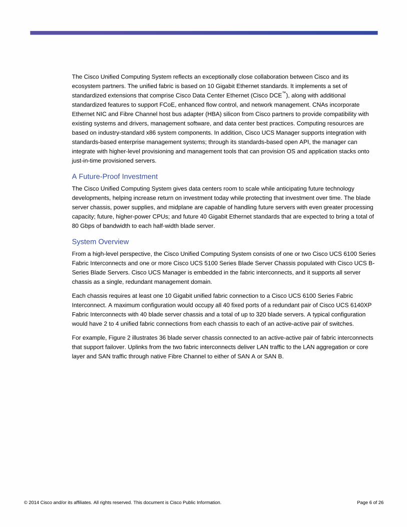
Figure 2. Example Cisco Unified Computing System with 36 Cisco UCS5100 Series Blade Server Chassis and 2 Cisco UCS 6140XP Series Fabric Interconnects
Figure 3 shows the components that make up the Cisco Unified Computing System:
● The unified fabric is supported by Cisco UCS 6100 Series Fabric Interconnects. The figure shows a Cisco
UCS 6120XP Fabric Interconnect with 20 fixed ports and one expansion module slot.
● Cisco UCS Manager runs within the two Cisco UCS 6100 Series Fabric Interconnects and manages the
system as a single, unified, management domain. The management software is deployed in a clustered
active-passive configuration so that the management plane remains intact even through the failure of an
interconnect.
● The unified fabric is extended to each of up to 40 blade chassis through up to two Cisco UCS 2100 Series
Fabric Extenders per blade chassis, each supporting up to four unified fabric connections. Each chassis
must have at least one connection to a parent Cisco UCS 6100 Series Fabric Interconnect.
© 2014 Cisco and/or its affiliates. All rights reserved. This document is Cisco Public Information. Page 8 of 26
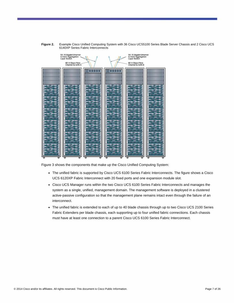
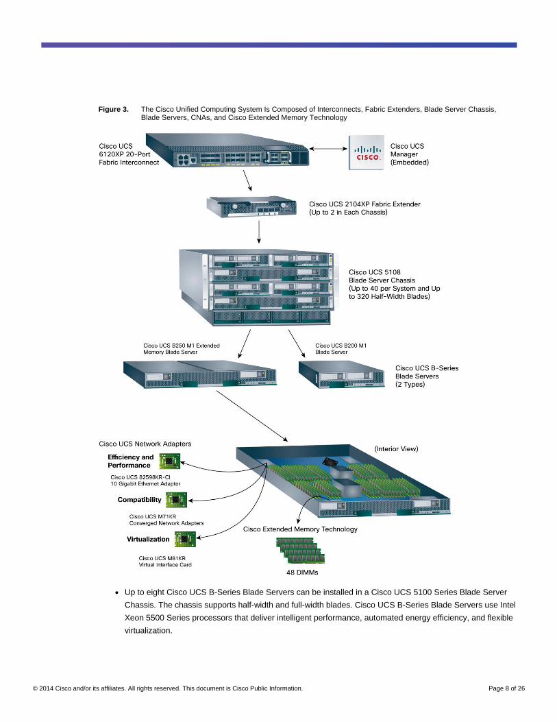
Figure 3. The Cisco Unified Computing System Is Composed of Interconnects, Fabric Extenders, Blade Server Chassis, Blade Servers, CNAs, and Cisco Extended Memory Technology
● Up to eight Cisco UCS B-Series Blade Servers can be installed in a Cisco UCS 5100 Series Blade Server
Chassis. The chassis supports half-width and full-width blades. Cisco UCS B-Series Blade Servers use Intel
Xeon 5500 Series processors that deliver intelligent performance, automated energy efficiency, and flexible
virtualization.
© 2014 Cisco and/or its affiliates. All rights reserved. This document is Cisco Public Information. Page 9 of 26
● Transparent access to the unified fabric is provided by one of three types of network adapters in a
mezzanine card form factor optimized for different purposes: a virtual interface card that incorporates Cisco
VN-Link technology and up to 128 virtual interface devices configured dynamically, converged network
adapters (CNAs) that provide a fixed number of Ethernet and fibre channel over Ethernet (FCoE)
connections and are compatible with existing Fibre Channel driver stacks, and a network interface designed
to deliver efficient, high-performance 10 Gigabit Ethernet.
● Cisco Extended Memory Technology in the Cisco UCS B250 M1 Extended Memory Blade Server expands
the memory footprint available to two-socket x86 servers. The extended memory blade server can support
up to 384 GB of DDR3 memory with up to 48 industry-standard DIMMs.
Cisco UCS Manager
Data centers have become complex environments with a proliferation of management points. From a network
perspective, the access layer has fragmented, with traditional access-layer switches, switches in blade servers,
and software switches used in virtualization software all having separate feature sets and management paradigms.
Most of today’s blade systems have separate power and environmental management modules, adding cost and
management complexity. Ethernet NICs and Fibre Channel HBAs, whether installed in blade systems or rack-
mount servers, require configuration and firmware updates. Blade and rack-mount server firmware must be
maintained, and BIOS settings must be managed for consistency. As a result, data center environments have
become more difficult and costly to maintain, while security and performance may be less than desired. Change is
the norm in data centers, but the combination of x86 server architectures and the older deployment paradigm
makes change difficult:
● In fixed environments in which servers run OS and application software stacks, rehosting software on
different servers as needed for scaling and load management is difficult to accomplish. I/O devices and their
configuration, network configurations, firmware, and BIOS settings all must be configured manually to move
software from one server to another, adding delays and introducing the possibility of errors in the process.
Typically, these environments deploy fixed spare servers already configured to meet peak workload needs.
Most of the time these servers are either idle or highly underutilized, raising both capital and operating
costs.
● Virtual environments inherit all the drawbacks of fixed environments, and more. The fragmentation of the
access layer makes it difficult to track virtual machine movement and to apply network policies to virtual
machines to protect security, improve visibility, support per-virtual machine QoS, and maintain I/O
connectivity. Virtualization offers significant benefits; however, it adds more complexity.
Programmatically Deploying Server Resources
Cisco UCS Manager provides centralized management capabilities, creates a unified management domain, and
serves as the central nervous system of the Cisco Unified Computing System. Cisco UCS Manager is embedded
device-management software that manages the system from end to end as a single logical entity through an
intuitive GUI, CLI, or XML API. Cisco UCS Manager implements role- and policy-based management using service
profiles and templates. This construct improves IT productivity and business agility. Now infrastructure can be
provisioned in minutes instead of days, shifting IT’s focus from maintenance to strategic initiatives.
© 2014 Cisco and/or its affiliates. All rights reserved. This document is Cisco Public Information. Page 10 of 26
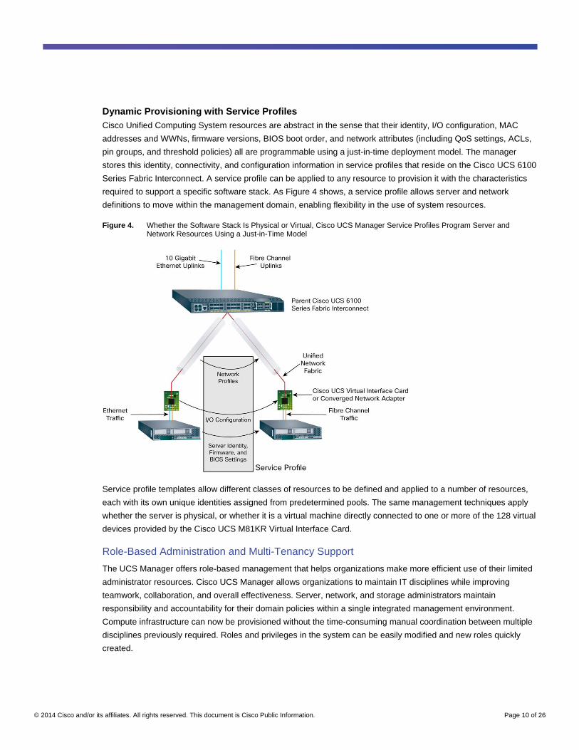
Dynamic Provisioning with Service Profiles
Cisco Unified Computing System resources are abstract in the sense that their identity, I/O configuration, MAC
addresses and WWNs, firmware versions, BIOS boot order, and network attributes (including QoS settings, ACLs,
pin groups, and threshold policies) all are programmable using a just-in-time deployment model. The manager
stores this identity, connectivity, and configuration information in service profiles that reside on the Cisco UCS 6100
Series Fabric Interconnect. A service profile can be applied to any resource to provision it with the characteristics
required to support a specific software stack. As Figure 4 shows, a service profile allows server and network
definitions to move within the management domain, enabling flexibility in the use of system resources.
Figure 4. Whether the Software Stack Is Physical or Virtual, Cisco UCS Manager Service Profiles Program Server and Network Resources Using a Just-in-Time Model
Service profile templates allow different classes of resources to be defined and applied to a number of resources,
each with its own unique identities assigned from predetermined pools. The same management techniques apply
whether the server is physical, or whether it is a virtual machine directly connected to one or more of the 128 virtual
devices provided by the Cisco UCS M81KR Virtual Interface Card.
Role-Based Administration and Multi-Tenancy Support
The UCS Manager offers role-based management that helps organizations make more efficient use of their limited
administrator resources. Cisco UCS Manager allows organizations to maintain IT disciplines while improving
teamwork, collaboration, and overall effectiveness. Server, network, and storage administrators maintain
responsibility and accountability for their domain policies within a single integrated management environment.
Compute infrastructure can now be provisioned without the time-consuming manual coordination between multiple
disciplines previously required. Roles and privileges in the system can be easily modified and new roles quickly
created.
© 2014 Cisco and/or its affiliates. All rights reserved. This document is Cisco Public Information. Page 11 of 26
Administrators focus on defining policies needed to provision compute infrastructure and network connectivity.
Administrators can collaborate on strategic architectural issues, and implementation of basic server configuration
can now be automated. Cisco UCS Manager supports multi-tenant service providers and enterprise data centers
serving internal clients as separate business entities. The system can be logically partitioned and allocated to
different clients or customers to administer as their own.
Cisco UCS 6100 Series Fabric Interconnects
A primary goal in today’s data centers is to equip each server with redundant Ethernet NICs and Fibre Channel
HBAs for uninterrupted access to both network and storage resources. For access to Fibre Channel storage, this
requires a redundant, parallel infrastructure that includes HBAs, costly fiber transceivers, and delicate cabling from
each server to SAN access-layer switches. All these components must be purchased, configured, maintained,
powered, and cooled. This complexity adds to mounting capital and operating costs in the data center. Indeed, the
cost of this redundant infrastructure often limits the capability of providing uniform storage access to every server in
the data center. This is a significant limitation as the full benefits of virtual machine portability for high availability
and load balancing can generally be exploited only by servers with access to shared storage.
Unified Fabric Interconnects
Cisco UCS 6100 Series Fabric Interconnects is a family of line-rate, low-latency, lossless 10 Gigabit Ethernet,
Cisco DCE, and FCoE interconnect switches that consolidate I/O at the system level. Based on the same switching
technology as the Cisco Nexus™
5000 Series Switches, the Cisco UCS 6100 Series Fabric Interconnects provide
the additional features and management capabilities that make up the core of the Cisco Unified Computing
System.
The fabric interconnects supply a unified fabric that connects every server in the system though wire-once 10
Gigabit Ethernet and FCoE downlinks and flexible 10 Gigabit Ethernet and 1/2/4-Gbps Fibre Channel uplinks
(Figure 5). Out-of-band management, including switch redundancy, is supported through dedicated management
and clustering ports. The interconnects feature front-to-back cooling, redundant front-plug fans and power supplies,
and rear cabling that facilitates efficient cooling and serviceability. Typically deployed in active-active redundant
pairs, the fabric interconnects provide uniform access to both networks and storage, eliminating the barriers to
deploying a fully virtualized environment based on a flexible, programmable pool of resources.
© 2014 Cisco and/or its affiliates. All rights reserved. This document is Cisco Public Information. Page 12 of 26
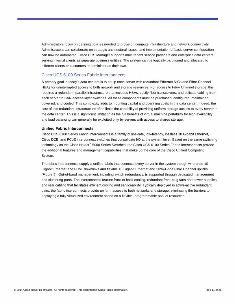
Figure 5. A Unified Fabric Carries Multiple Traffic Streams to Cisco UCS 6100 Series Fabric Interconnects, Where Ethernet and Fibre Channel Traffic Splits onto Separate Networks
The fabric interconnects consolidate I/O at the rack level, supporting traffic between the blade chassis and the
interconnects over a low-cost, low-latency, Small Form-Factor Pluggable Plus (SFP+) direct-attach 10 Gigabit
copper link or over a 10 Gigabit optical link. While operating systems see the Ethernet and Fibre Channel devices
that they expect to access in a traditional server environment, the physical implementation uses a single physical
link. Fibre Channel traffic can be transferred to native Fibre Channel networks through expansion modules
providing Fibre Channel connectivity.
Cisco DCE features enhance management and performance of individual traffic streams over a single network link.
IEEE 802.1Qbb standard Priority-based Flow Control (PFC) allows management of separate traffic streams so
that, for example, a lossless class can be created to support storage traffic without affecting the way that standard
IP network traffic is managed. IEEE 802.1Qaz Enhanced Transmission Selection shapes the allocation of
bandwidth to traffic classes; it can be used, for example, to dedicate network bandwidth to storage traffic. These
features enhance management of FCoE and iSCSI protocols.
Appearance as a Single System
The fabric interconnects make the entire management domain appear as a single system to upstream Ethernet
and Fibre Channel switches. This feature dramatically simplifies Ethernet Layer 2 management and Fibre Channel
network configuration, reducing cost while increasing performance by supporting active-active network uplinks with
switch-managed failover in the event of a link outage.
This simplification is accomplished using both Ethernet and Fibre Channel end-host modes, which eliminates
Spanning Tree Protocol and instead pins the MAC addresses and WWNs for both physical and virtual servers at
the uplink interfaces. This approach gives the interconnect complete control over the unified fabric connecting it to
servers and allows greater utilization of uplink port bandwidth through the use of active-active Ethernet uplinks.
© 2014 Cisco and/or its affiliates. All rights reserved. This document is Cisco Public Information. Page 13 of 26
Virtualization Optimization
The Cisco UCS 6100 Series Fabric Interconnects support Cisco VN-Link architecture. Cisco VN-Link supports
policy-based virtual machine connectivity, network properties that move with virtual machines, and a consistent
operational model for both physical and virtual environments.
Long-Term Data Center Cabling Strategy
The Cisco UCS 6100 Series Fabric interconnects support a long-term data center cabling strategy that uses
copper interconnects for intra-rack and intra-pod cabling with fiber in data center overhead cable trays.
The strategy begins with the uses of SPF+ direct-attach 10 Gigabit copper cabling between the blade chassis and
fabric interconnects. This low-cost, low-latency product is ideal for supporting the numerous, short-distance
connections between blade chassis and their parent interconnects.
Fiber is the most common interconnect for longer runs within the data center. Use of fiber in overhead cable trays
allows a relatively small number of cables to be run to each rack position in a data center, with the cables used for
different purposes over time. Fiber offers greater investment protection over time than copper connections because
nearly every advancement in interconnect speed is implemented in fiber first. Thus, data centers running fiber in
overhead cable trays are better prepared to support future LAN and SAN speeds.
Cisco UCS 2100 Series Fabric Extenders
The proliferation of switches in traditional blade systems fragments the access layer by adding another layer of
switching. These switches add to the capital cost of the blade systems while they increase management cost and
complexity. This cost and complexity increases with each chassis added to the data center. In addition, blade
systems typically introduce their own branded switches with their own unique feature sets, making coordination of
network configuration and consistent policy enforcement difficult to achieve across servers and chassis. This
increases complexity in virtualized environments as virtual machines move from one server to another.
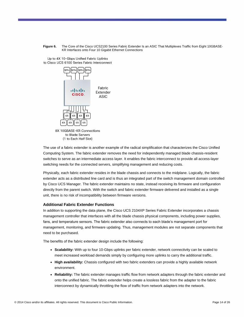
The Cisco UCS 2104XP Fabric Extender brings the I/O fabric into the blade server chassis and supports up to four
10-Gbps connections between blade servers and the parent fabric interconnect, simplifying diagnostics, cabling,
and management. The fabric extender multiplexes and forwards all traffic using a cut-through architecture over one
to four 10-Gbps unified fabric connections. All traffic is passed to the parent fabric interconnect, where network
profiles are managed efficiently and effectively by the fabric interconnects. Each of up to two fabric extenders per
blade server chassis has eight 10GBASE-KR connections to the blade chassis midplane, with one connection to
each fabric extender from each of the chassis’ eight half slots (Figure 6). This configuration gives each half-width
blade server access to each of two 10-Gbps unified fabric connections for high throughput and redundancy.
© 2014 Cisco and/or its affiliates. All rights reserved. This document is Cisco Public Information. Page 14 of 26
Figure 6. The Core of the Cisco UCS2100 Series Fabric Extender Is an ASIC That Multiplexes Traffic from Eight 10GBASE-KR Interfaces onto Four 10 Gigabit Ethernet Connections
The use of a fabric extender is another example of the radical simplification that characterizes the Cisco Unified
Computing System. The fabric extender removes the need for independently managed blade chassis-resident
switches to serve as an intermediate access layer. It enables the fabric interconnect to provide all access-layer
switching needs for the connected servers, simplifying management and reducing costs.
Physically, each fabric extender resides in the blade chassis and connects to the midplane. Logically, the fabric
extender acts as a distributed line card and is thus an integrated part of the switch management domain controlled
by Cisco UCS Manager. The fabric extender maintains no state, instead receiving its firmware and configuration
directly from the parent switch. With the switch and fabric extender firmware delivered and installed as a single
unit, there is no risk of incompatibility between firmware versions.
Additional Fabric Extender Functions
In addition to supporting the data plane, the Cisco UCS 2104XP Series Fabric Extender incorporates a chassis
management controller that interfaces with all the blade chassis physical components, including power supplies,
fans, and temperature sensors. The fabric extender also connects to each blade’s management port for
management, monitoring, and firmware updating. Thus, management modules are not separate components that
need to be purchased.
The benefits of the fabric extender design include the following:
● Scalability: With up to four 10-Gbps uplinks per fabric extender, network connectivity can be scaled to
meet increased workload demands simply by configuring more uplinks to carry the additional traffic.
● High availability: Chassis configured with two fabric extenders can provide a highly available network
environment.
● Reliability: The fabric extender manages traffic flow from network adapters through the fabric extender and
onto the unified fabric. The fabric extender helps create a lossless fabric from the adapter to the fabric
interconnect by dynamically throttling the flow of traffic from network adapters into the network.
© 2014 Cisco and/or its affiliates. All rights reserved. This document is Cisco Public Information. Page 15 of 26
● Manageability: The fabric extender model extends the access layer without increasing complexity or points
of management, freeing administrative staff to focus more on strategic than tactical issues. Because the
fabric extender also manages blade chassis components and monitors environmental conditions, fewer
points of management are needed, and cost is reduced.
● Virtualization optimization: The fabric extender supports Cisco VN-Link architecture. Its integration with
VN-Link features in other Cisco UCS components such as the fabric interconnect and network adapters
enables virtualization-related benefits including virtual machine-based policy enforcement, mobility of
network properties, better visibility, and easier problem diagnosis in virtualized environments.
● Investment protection: The modular nature of the fabric extender allows future development of equivalent
modules with different bandwidth or connectivity characteristics, protecting investments in blade server
chassis.
● Cost savings: The fabric extender technology allows the cost of the unified network to be accrued
incrementally, helping reduce costs in times of limited budgets. The alternative is to implement and fund a
large, fixed-configuration fabric infrastructure long before the capacity is required.
Cisco UCS 5100 Series Blade Server Chassis
Most blade chassis increase management complexity with per-chassis management modules and chassis-resident
LAN and SAN switches. In contrast, the Cisco UCS 5100 Series Blade Server Chassis is logically part of the parent
interconnects, creating a single, coherent management domain. Server management is handled by the fabric
interconnect, while I/O and network management is extended to every chassis and blade server. Basing the I/O
infrastructure on a unified fabric allows the Cisco Unified Computing System to have a simple and streamlined
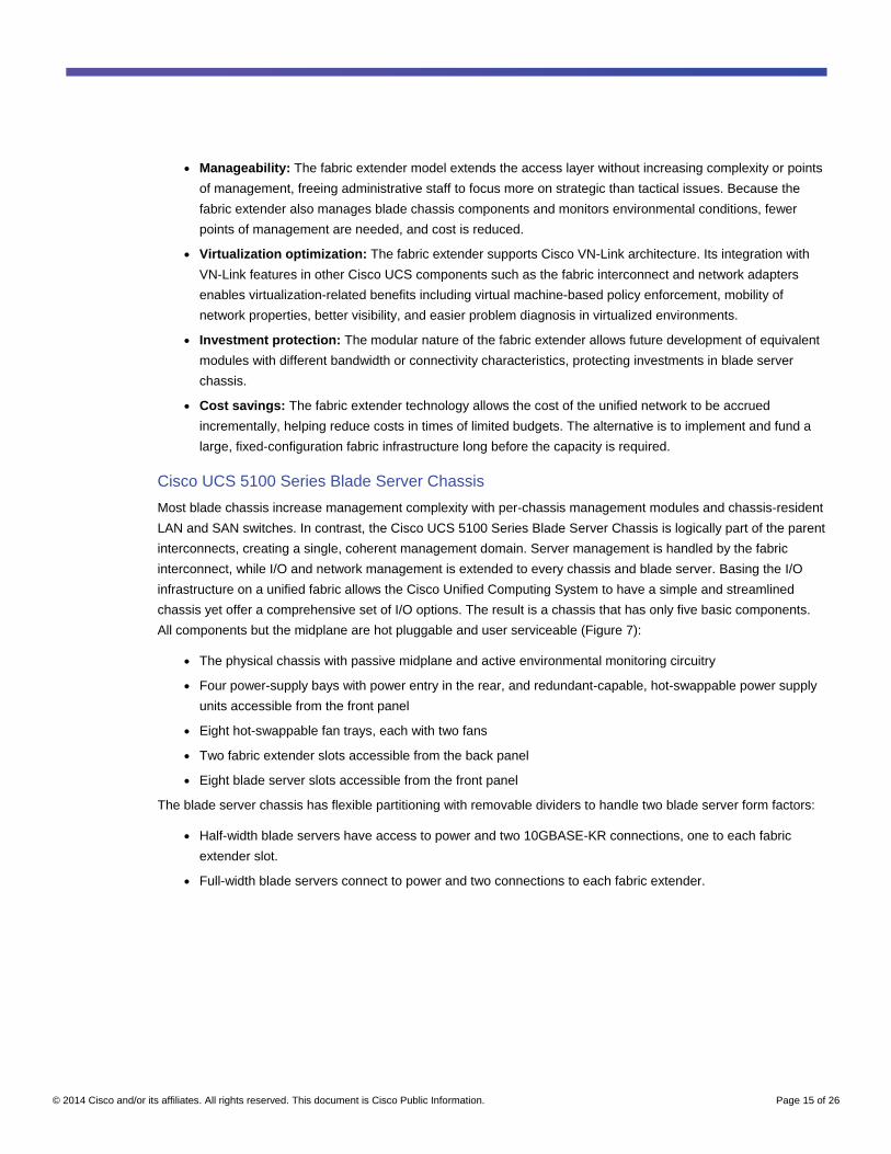
chassis yet offer a comprehensive set of I/O options. The result is a chassis that has only five basic components.
All components but the midplane are hot pluggable and user serviceable (Figure 7):
● The physical chassis with passive midplane and active environmental monitoring circuitry
● Four power-supply bays with power entry in the rear, and redundant-capable, hot-swappable power supply
units accessible from the front panel
● Eight hot-swappable fan trays, each with two fans
● Two fabric extender slots accessible from the back panel
● Eight blade server slots accessible from the front panel
The blade server chassis has flexible partitioning with removable dividers to handle two blade server form factors:
● Half-width blade servers have access to power and two 10GBASE-KR connections, one to each fabric
extender slot.
● Full-width blade servers connect to power and two connections to each fabric extender.
© 2014 Cisco and/or its affiliates. All rights reserved. This document is Cisco Public Information. Page 16 of 26
Figure 7. The Cisco UCS 5108 Series Blade Server Chassis Supports Two Blade Form Factors
Blade Chassis Designed for the Future
The blade server chassis is built to support blade servers with some of the most powerful x86-architecture
processors available today. The chassis is designed to support even more powerful blade servers and network
technology in the future through the following features:
● Four N+1 and N+N 2500-watt (W) grid-redundant power supplies are designed for 92 percent efficiency and
to deliver high efficiency at low power draws. The power supplies are also designed with headroom to
support future blade servers configured with processors that may draw up to 130W each.
● The simplified design results in a midplane that is 63 percent open. Air passes in a straight line from front to
back, reducing dead zones and turbulence that can cause hot spots and inefficiency. This design supports
the airflow needed to cool future blade servers with higher heat dissipation requirements.
● The midplane is designed with future needs in mind, with support for up to 40 Gbps of bandwidth per link.
© 2014 Cisco and/or its affiliates. All rights reserved. This document is Cisco Public Information. Page 17 of 26
Cisco UCS B-Series Blade Servers
The x86 architecture has essentially become the standard in enterprise data centers because of its widespread
availability, low cost, and software support. Software including Microsoft Windows, Linux, variants of the UNIX
operating system, and virtualization software including VMware ESX Server all run on x86 architecture servers.
Cisco UCS B-Series Blade Servers are designed for compatibility, performance, energy efficiency, large memory
footprints, manageability, and unified I/O connectivity:
● Compatibility: Each Cisco UCS B-Series Blade Server is designed around two multicore Intel Xeon 5500
Series processors, DDR3 memory, and an I/O bridge. Each blade server’s front panel provides direct
access for video, two USB, and console connections.
● Performance: Cisco’s blade servers use the Intel Xeon 5500 Series, Intel’s next-generation server
processors, which deliver intelligent performance, automated energy efficiency, and flexible virtualization.
Intel Turbo Boost Technology automatically boosts processing power through increased frequency and use
of hyperthreading to deliver high performance when workloads demand and thermal conditions permit. Intel
Virtualization Technology provides best-in-class support for virtualized environments, including hardware
support for direct connections between virtual machines and physical I/O devices.
● Energy efficiency: Most workloads vary over time. Some workloads are bursty on a moment-by-moment
basis, while others have predictable daily, weekly, or monthly cycles. Intel Intelligent Power Technology
monitors the CPU utilization and automatically reduces energy consumption by putting processor cores into
a low-power state based on real-time workload characteristics.
● Large-memory-footprint support: As each processor generation delivers even more power to
applications, the demand for memory capacity to balance CPU performance increases as well. The
widespread use of virtualization increases memory demands even further due to the need to run multiple
OS instances on the same server. Cisco blade servers with Cisco Extended Memory Technology can
support up to 384 GB per blade.
● Manageability: The Cisco Unified Computing System is managed as a cohesive system. Blade servers are
designed to be configured and managed by Cisco UCS Manager, which can access and update blade
firmware, BIOS settings, and RAID controller settings from the parent Cisco UCS 6100 Series Fabric
Interconnect. Environmental parameters are also monitored by Cisco UCS Manager, reducing the number
of points of management.
● Unified I/O: Cisco UCS B-Series Blade Servers are designed to support up to two network adapters. This
design can reduce the number of adapters, cables, and access-layer switches by as much as half because
it eliminates the need for multiple parallel infrastructure for both LAN and SAN at the server, chassis, and
rack levels. This design results in reduced capital and operating expenses through lower administrative
overhead and power and cooling requirements.
Two Blade Server Offerings
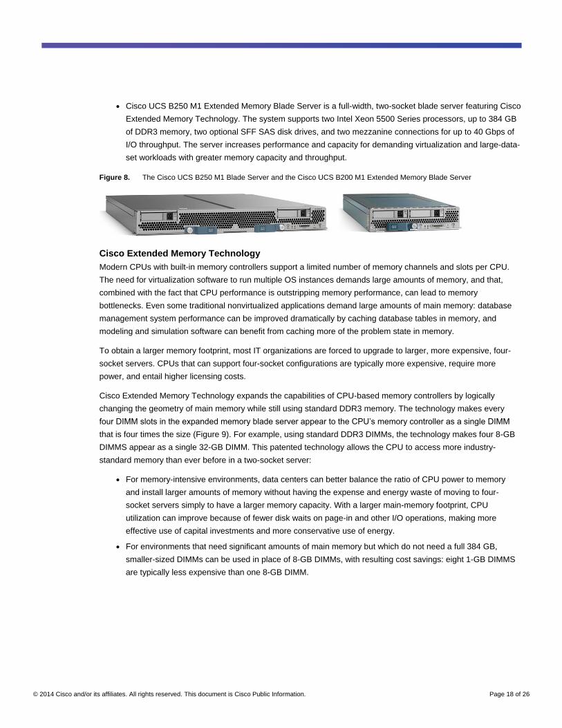
The Cisco Unified Computing System is announced with two blade server offerings (Figure 8):
● The Cisco UCS B200 M1 Blade Server is a half-width, two-socket blade server. The system uses two Intel
Xeon 5500 Series processors, up to 96 GB of DDR3 memory, two optional hot-swappable small form factor
(SFF) serial attached SCSI (SAS) disk drives, and a single mezzanine connector for up to 20 Gbps of I/O
throughput. The server balances simplicity, performance, and density for production-level virtualization and
other mainstream data center workloads.
© 2014 Cisco and/or its affiliates. All rights reserved. This document is Cisco Public Information. Page 18 of 26
● Cisco UCS B250 M1 Extended Memory Blade Server is a full-width, two-socket blade server featuring Cisco
Extended Memory Technology. The system supports two Intel Xeon 5500 Series processors, up to 384 GB
of DDR3 memory, two optional SFF SAS disk drives, and two mezzanine connections for up to 40 Gbps of
I/O throughput. The server increases performance and capacity for demanding virtualization and large-data-
set workloads with greater memory capacity and throughput.
Figure 8. The Cisco UCS B250 M1 Blade Server and the Cisco UCS B200 M1 Extended Memory Blade Server
Cisco Extended Memory Technology
Modern CPUs with built-in memory controllers support a limited number of memory channels and slots per CPU.
The need for virtualization software to run multiple OS instances demands large amounts of memory, and that,
combined with the fact that CPU performance is outstripping memory performance, can lead to memory
bottlenecks. Even some traditional nonvirtualized applications demand large amounts of main memory: database
management system performance can be improved dramatically by caching database tables in memory, and
modeling and simulation software can benefit from caching more of the problem state in memory.
To obtain a larger memory footprint, most IT organizations are forced to upgrade to larger, more expensive, four-
socket servers. CPUs that can support four-socket configurations are typically more expensive, require more
power, and entail higher licensing costs.
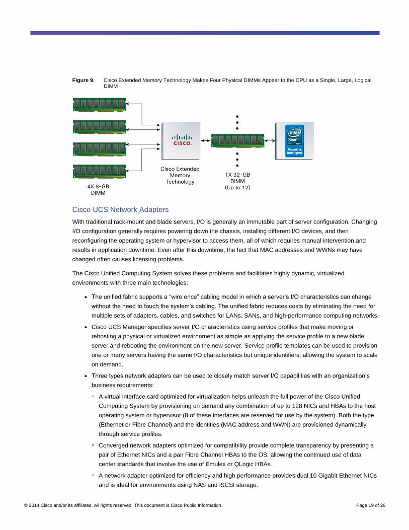
Cisco Extended Memory Technology expands the capabilities of CPU-based memory controllers by logically
changing the geometry of main memory while still using standard DDR3 memory. The technology makes every
four DIMM slots in the expanded memory blade server appear to the CPU’s memory controller as a single DIMM
that is four times the size (Figure 9). For example, using standard DDR3 DIMMs, the technology makes four 8-GB
DIMMS appear as a single 32-GB DIMM. This patented technology allows the CPU to access more industry-
standard memory than ever before in a two-socket server:
● For memory-intensive environments, data centers can better balance the ratio of CPU power to memory
and install larger amounts of memory without having the expense and energy waste of moving to four-
socket servers simply to have a larger memory capacity. With a larger main-memory footprint, CPU
utilization can improve because of fewer disk waits on page-in and other I/O operations, making more
effective use of capital investments and more conservative use of energy.
● For environments that need significant amounts of main memory but which do not need a full 384 GB,
smaller-sized DIMMs can be used in place of 8-GB DIMMs, with resulting cost savings: eight 1-GB DIMMS
are typically less expensive than one 8-GB DIMM.
© 2014 Cisco and/or its affiliates. All rights reserved. This document is Cisco Public Information. Page 19 of 26
Figure 9. Cisco Extended Memory Technology Makes Four Physical DIMMs Appear to the CPU as a Single, Large, Logical DIMM
Cisco UCS Network Adapters
With traditional rack-mount and blade servers, I/O is generally an immutable part of server configuration. Changing
I/O configuration generally requires powering down the chassis, installing different I/O devices, and then
reconfiguring the operating system or hypervisor to access them, all of which requires manual intervention and
results in application downtime. Even after this downtime, the fact that MAC addresses and WWNs may have
changed often causes licensing problems.
The Cisco Unified Computing System solves these problems and facilitates highly dynamic, virtualized
environments with three main technologies:
● The unified fabric supports a “wire once” cabling model in which a server’s I/O characteristics can change
without the need to touch the system’s cabling. The unified fabric reduces costs by eliminating the need for
multiple sets of adapters, cables, and switches for LANs, SANs, and high-performance computing networks.
● Cisco UCS Manager specifies server I/O characteristics using service profiles that make moving or
rehosting a physical or virtualized environment as simple as applying the service profile to a new blade
server and rebooting the environment on the new server. Service profile templates can be used to provision
one or many servers having the same I/O characteristics but unique identifiers, allowing the system to scale
on demand.
● Three types network adapters can be used to closely match server I/O capabilities with an organization’s
business requirements:
◦ A virtual interface card optimized for virtualization helps unleash the full power of the Cisco Unified
Computing System by provisioning on demand any combination of up to 128 NICs and HBAs to the host
operating system or hypervisor (8 of these interfaces are reserved for use by the system). Both the type
(Ethernet or Fibre Channel) and the identities (MAC address and WWN) are provisioned dynamically
through service profiles.
◦ Converged network adapters optimized for compatibility provide complete transparency by presenting a
pair of Ethernet NICs and a pair Fibre Channel HBAs to the OS, allowing the continued use of data
center standards that involve the use of Emulex or QLogic HBAs.
◦ A network adapter optimized for efficiency and high performance provides dual 10 Gigabit Ethernet NICs
and is ideal for environments using NAS and iSCSI storage.
© 2014 Cisco and/or its affiliates. All rights reserved. This document is Cisco Public Information. Page 20 of 26
Cisco UCS network adapters are designed to fit into Cisco UCS B-Series Blade Servers using a mezzanine card
form factor. The adapters have two unified fabric connections on the midplane, one reaching each of the two fabric
extender slots, enabling even half-width blade servers to connect to a redundant network fabric, enhancing
bandwidth utilization and availability.
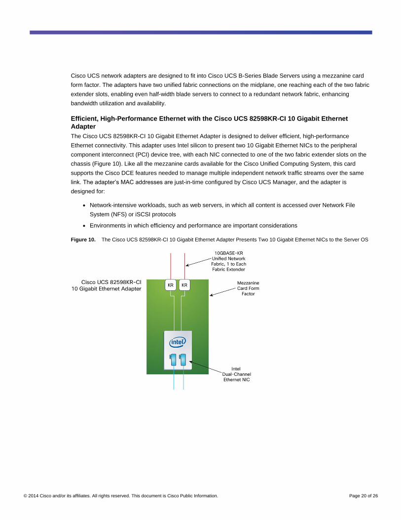
Efficient, High-Performance Ethernet with the Cisco UCS 82598KR-CI 10 Gigabit Ethernet
Adapter
The Cisco UCS 82598KR-CI 10 Gigabit Ethernet Adapter is designed to deliver efficient, high-performance
Ethernet connectivity. This adapter uses Intel silicon to present two 10 Gigabit Ethernet NICs to the peripheral
component interconnect (PCI) device tree, with each NIC connected to one of the two fabric extender slots on the
chassis (Figure 10). Like all the mezzanine cards available for the Cisco Unified Computing System, this card
supports the Cisco DCE features needed to manage multiple independent network traffic streams over the same
link. The adapter’s MAC addresses are just-in-time configured by Cisco UCS Manager, and the adapter is
designed for:
● Network-intensive workloads, such as web servers, in which all content is accessed over Network File
System (NFS) or iSCSI protocols
● Environments in which efficiency and performance are important considerations
Figure 10. The Cisco UCS 82598KR-CI 10 Gigabit Ethernet Adapter Presents Two 10 Gigabit Ethernet NICs to the Server OS
© 2014 Cisco and/or its affiliates. All rights reserved. This document is Cisco Public Information. Page 21 of 26
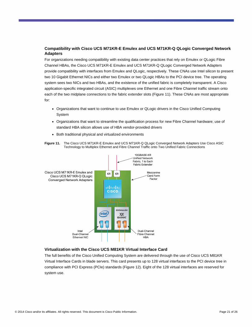
Compatibility with Cisco UCS M71KR-E Emulex and UCS M71KR-Q QLogic Converged Network
Adapters
For organizations needing compatibility with existing data center practices that rely on Emulex or QLogic Fibre
Channel HBAs, the Cisco UCS M71KR-E Emulex and UCS M71KR-Q QLogic Converged Network Adapters
provide compatibility with interfaces from Emulex and QLogic, respectively. These CNAs use Intel silicon to present
two 10 Gigabit Ethernet NICs and either two Emulex or two QLogic HBAs to the PCI device tree. The operating
system sees two NICs and two HBAs, and the existence of the unified fabric is completely transparent. A Cisco
application-specific integrated circuit (ASIC) multiplexes one Ethernet and one Fibre Channel traffic stream onto
each of the two midplane connections to the fabric extender slots (Figure 11). These CNAs are most appropriate
for:
● Organizations that want to continue to use Emulex or QLogic drivers in the Cisco Unified Computing
System
● Organizations that want to streamline the qualification process for new Fibre Channel hardware; use of
standard HBA silicon allows use of HBA vendor-provided drivers
● Both traditional physical and virtualized environments
Figure 11. The Cisco UCS M71KR-E Emulex and UCS M71KR-Q QLogic Converged Network Adapters Use Cisco ASIC Technology to Multiplex Ethernet and Fibre Channel Traffic onto Two Unified Fabric Connections
Virtualization with the Cisco UCS M81KR Virtual Interface Card
The full benefits of the Cisco Unified Computing System are delivered through the use of Cisco UCS M81KR
Virtual Interface Cards in blade servers. This card presents up to 128 virtual interfaces to the PCI device tree in
compliance with PCI Express (PCIe) standards (Figure 12). Eight of the 128 virtual interfaces are reserved for
system use.
© 2014 Cisco and/or its affiliates. All rights reserved. This document is Cisco Public Information. Page 22 of 26
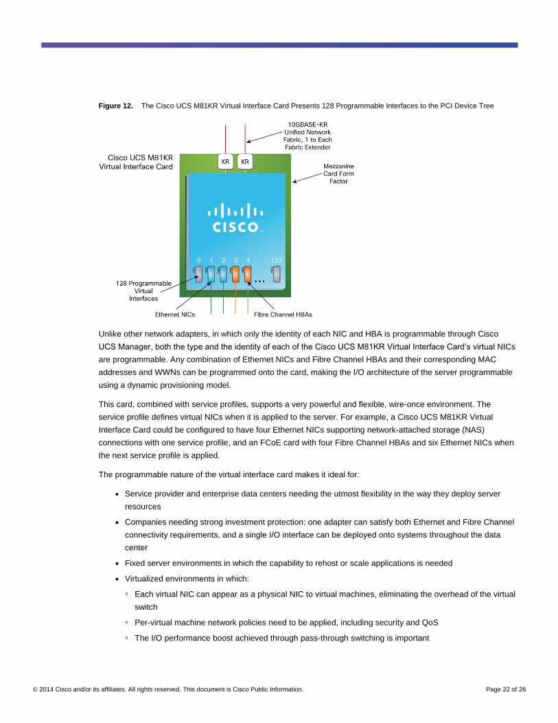
Figure 12. The Cisco UCS M81KR Virtual Interface Card Presents 128 Programmable Interfaces to the PCI Device Tree
Unlike other network adapters, in which only the identity of each NIC and HBA is programmable through Cisco
UCS Manager, both the type and the identity of each of the Cisco UCS M81KR Virtual Interface Card’s virtual NICs
are programmable. Any combination of Ethernet NICs and Fibre Channel HBAs and their corresponding MAC
addresses and WWNs can be programmed onto the card, making the I/O architecture of the server programmable
using a dynamic provisioning model.
This card, combined with service profiles, supports a very powerful and flexible, wire-once environment. The
service profile defines virtual NICs when it is applied to the server. For example, a Cisco UCS M81KR Virtual
Interface Card could be configured to have four Ethernet NICs supporting network-attached storage (NAS)
connections with one service profile, and an FCoE card with four Fibre Channel HBAs and six Ethernet NICs when
the next service profile is applied.
The programmable nature of the virtual interface card makes it ideal for:
● Service provider and enterprise data centers needing the utmost flexibility in the way they deploy server
resources
● Companies needing strong investment protection: one adapter can satisfy both Ethernet and Fibre Channel
connectivity requirements, and a single I/O interface can be deployed onto systems throughout the data
center
● Fixed server environments in which the capability to rehost or scale applications is needed
● Virtualized environments in which:
◦ Each virtual NIC can appear as a physical NIC to virtual machines, eliminating the overhead of the virtual
switch
◦ Per-virtual machine network policies need to be applied, including security and QoS
◦ The I/O performance boost achieved through pass-through switching is important
© 2014 Cisco and/or its affiliates. All rights reserved. This document is Cisco Public Information. Page 23 of 26
Outstanding Flexibility in Virtualized Environments
The existence of up to 128 programmable virtual devices gives virtualized environments a sufficient number of
devices to allow the hypervisor to assign devices directly to virtual machines. In the ultimate model, each virtual
machine owns its own physical devices, eliminating the need to use CPU cycles to emulate hardware network
switches, and eliminating the overhead of hypervisor intervention for each virtual machine I/O operation. The
coordination between virtualization software and the Cisco UCS 6100 Series Fabric Interconnects supports
movement of virtual machines between servers and chassis, with devices and network profiles dynamically
configured on the destination server.
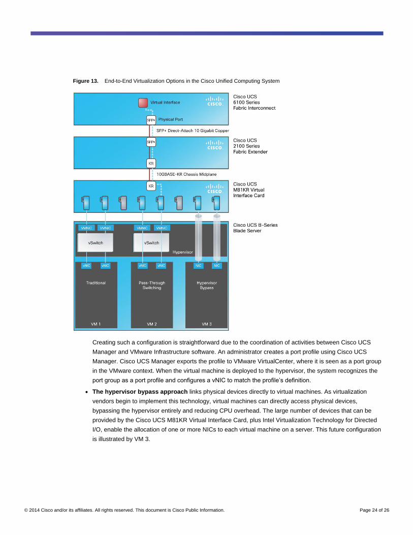
The virtual devices provided by the Cisco UCS M81KR Virtual Interface Card can be put to use in virtualized
environments in three ways. The approaches are illustrated through the ways in which the virtual machines in
Figure 13 interface with virtual devices. Each successive approach provides more flexibility and has lower
overhead, helping increase the use of resources and increase ROI.
● The traditional approach, illustrated by VM 1, is to represent physical devices as virtual machine NICs
(VMNICs), and virtual devices in virtual machines as virtual NICs (vNICs), connecting the two with a virtual
switch (vSwitch). This approach has the overhead and management complexity and inherent inefficiency of
network switching implemented in the hypervisor. Nevertheless, the Cisco UCS M81KR Virtual Interface
Card can support this traditional configuration, allowing the continued use of this virtual network model
In addition to the traditional approach, the system supports the Cisco Nexus 1000V Series virtual machine
access switches. The Cisco Nexus 1000V Series is an intelligent software switch implementation for
VMware ESX Server environments. Running inside VMware ESX Server, the Cisco Nexus 1000V Series
supports VN-Link server virtualization technology, providing
◦ Policy-based virtual machine connectivity: a scalable mechanism to provision virtual machine networking
◦ Mobile virtual machine security and network policy: persistent policies that follow the virtual machines as
they move between servers
◦ A nondisruptive operational model for server virtualization and networking teams through full integration
with the Cisco CLI, Simple Network Management Protocol (SNMP), and XML API with VMware
VirtualCenter
◦ Expanded scalability, with up to 256 virtual interfaces per server
● The pass-through switching approach, facilitated by the availability of a large number of programmable
devices, directly connects vNICs with VMNICs. This approach, illustrated by VM 2, reduces the overhead
and management complexity of implementing switching in software. It still requires a small amount of
hypervisor intervention for each I/O operation.
© 2014 Cisco and/or its affiliates. All rights reserved. This document is Cisco Public Information. Page 24 of 26
Figure 13. End-to-End Virtualization Options in the Cisco Unified Computing System
Creating such a configuration is straightforward due to the coordination of activities between Cisco UCS
Manager and VMware Infrastructure software. An administrator creates a port profile using Cisco UCS
Manager. Cisco UCS Manager exports the profile to VMware VirtualCenter, where it is seen as a port group
in the VMware context. When the virtual machine is deployed to the hypervisor, the system recognizes the
port group as a port profile and configures a vNIC to match the profile’s definition.
● The hypervisor bypass approach links physical devices directly to virtual machines. As virtualization
vendors begin to implement this technology, virtual machines can directly access physical devices,
bypassing the hypervisor entirely and reducing CPU overhead. The large number of devices that can be
provided by the Cisco UCS M81KR Virtual Interface Card, plus Intel Virtualization Technology for Directed
I/O, enable the allocation of one or more NICs to each virtual machine on a server. This future configuration
is illustrated by VM 3.
© 2014 Cisco and/or its affiliates. All rights reserved. This document is Cisco Public Information. Page 25 of 26
Virtual Link Movement with Virtual Machine Migration
Virtual machine movement is facilitated at the network level by the VN-Link capabilities of Cisco UCS 6100 Series
Fabric Interconnects. These switches virtualize the network links, allowing a flexible, many-to-one mapping of
virtual links to physical links.
When a virtual machine moves between physical servers, the hypervisor triggers a process similar to that
described for VM 3. The process establishes the device profile required by the virtual machine on the destination
server. When the server-to-server migration is complete, the virtual machine remains connected to exactly the
same devices with the same identity.
A network link from a virtual device is connected to a virtual port within the switch, as illustrated by the blue dotted
line in Figure 13. A virtual port has all the same characteristics as a physical port except that its binding to a
physical port is ephemeral and can change as the corresponding virtual machine moves between physical switch
ports. Thus, all the important network profiles that manage traffic flow, ACLs, QoS, bandwidth, and other
characteristics move automatically as the virtual port’s binding is changed from one physical port to another.
Conclusion
The Cisco Unified Computing System is a next-generation data center platform that unites compute, network,
storage access, and virtualization into a cohesive system designed to reduce TCO and increase business agility.
The system integrates a low-latency, lossless, 10-Gbps unified fabric with enterprise-class, x86-architecture
servers. The system is an integrated, scalable, multichassis platform in which all resources participate in a unified
management domain.
The system’s architecture enhances the portability of both physical and virtual machines with server identity, LAN
and SAN addressing, I/O configu¬rations, firmware, and network connectivity profiles that dynamically provision
and integrate server and network resources. Defining hardware properties and deploying systems with service
profiles creates a dynamic and stateless environment that can be adapted to meet rapidly changing business
requirements, including just-in-time deployment of new computing resources, and simplified, reliable movement of
traditional and virtual workloads. The system improves availability, security, performance, and business agility
through its integrated design, helping deliver:
● Increased IT staff productivity and business agility through just-in-time provisioning and mobility support for
both virtualized and nonvirtualized environments
● Reduced TCO at the platform, site, and organizational levels through infrastructure consolidation
● A cohesive, integrated system that is managed, serviced, and tested as a whole
● Scalability through a design for up to 320 discrete servers and thousands of virtual machines, and the
capability to scale I/O bandwidth to match demand
● Open industry standards supported by a partner ecosystem of industry leaders
● A system that can scale to meet future data center needs for computing power, memory footprints, and I/O
bandwidth; it can grow as the industry moves to new processors and standards such as 40 Gigabit Ethernet
© 2014 Cisco and/or its affiliates. All rights reserved. This document is Cisco Public Information. Page 26 of 26
For More Information
For more information about the Cisco Unified Computing System, please visit
http://www.cisco.com/go/unifiedcomputing or contact your local Cisco representative.
Printed in USA C22-522771-02 08/14