Embed Size (px)
Citation preview

INTEGRATED HOME SYSTEMS COURSE .N
Guy Kasier
Revised edition 2015
ECI Publication
Available from www.leonardo-energy.org

Publication No Cu0223
Issue Date: 2015-08-08
Page i
Document Issue Control Sheet
Document Title: Integrated Home Systems course
Publication No:
Issue:
Release: Public
Author(s): Guy Kasier
Reviewer(s):
Document History
Issue Date Purpose
1
2
3
Disclaimer
While this publication has been prepared with care, European Copper Institute and other contributors provide
no warranty with regards to the content and shall not be liable for any direct, incidental or consequential
damages that may result from the use of the information or the data contained.
Copyright© European Copper Institute.
Reproduction is authorized providing the material is unabridged and the source is acknowledged.

Publication No Cu0223
Issue Date: 2015-08-08
Page ii
CONTENTS
CHAPTER 1: DEFINITION ................................................................ 2
CHAPTER 2: FUNCTIONALITIES ..................................................... 26
CHAPTER 3: THE IHS SYSTEM FILE ................................................. 39
CHAPTER 4: A TECHNICAL EXAMINATION ........................................ 69
CHAPTER 5: STRUCTURED CABLING IN THE HOME ........................... 114
CHAPTER 6: CONTROLLING HEATING WITH IHS ............................... 126
Publication No Cu0223
Issue Date: 2015-08-08
Page 2
INTEGRATED HOME SYSTEMS COURSE CHAPTER 1: DEFINITION
Guy Kasier
2015-08-08
ECI Publication No Cu0223
Available from www.leonardo-energy.org

Publication No Cu0223
Issue Date: 2015-08-08
Page 3
CONTENTS
1. Introduction ................................................................................................................................................ 4
2. The situation without integrated home systems ......................................................................................... 5
2.1. History of the electrical installation ................................................................................................................. 5
2.1.1. The traditional electrical installation .............................................................................................. 5
2.1.2. The installation with remote-controlled switches ......................................................................... 5
2.1.3. Lighting control systems ................................................................................................................. 7
2.1.4. Other intelligent control systems ................................................................................................... 7
2.2. Electricity clients in the home ......................................................................................................................... 8
2.3. New and other needs ...................................................................................................................................... 9
2.4. Problem ........................................................................................................................................................... 9
3. Definition of integrated home systems ..................................................................................................... 10
4. Analysis of the definition .......................................................................................................................... 11
4.1. Integrated system .......................................................................................................................................... 11
4.2. All electrical equipment ................................................................................................................................. 12
4.3. Home ............................................................................................................................................................. 13
4.4. Increasing comfort ......................................................................................................................................... 13
4.5. Increasing flexibility ....................................................................................................................................... 15
4.5.1. Long-term flexibility ..................................................................................................................... 15
4.5.2. Short-term flexibility .................................................................................................................... 16
4.6. Increasing communication ............................................................................................................................ 16
4.7. Increasing safety and security ....................................................................................................................... 17
4.7.1. Fire protection .............................................................................................................................. 17
4.7.2. Security against burglars .............................................................................................................. 18
4.7.3. Personal alarm .............................................................................................................................. 20
4.8. Improving energy consumption ..................................................................................................................... 21
4.9 The care components ..................................................................................................................................... 22
5. Integrated home systems versus other systems ........................................................................................ 24
5.1. Home automation.......................................................................................................................................... 24
5.2. Building automation ...................................................................................................................................... 24

Publication No Cu0223
Issue Date: 2015-08-08
Page 4
1. INTRODUCTION The terms ‘domotics’, ‘immotics’, ‘automation’, ‘smart homes’, ‘building automation’, ‘Integrated Home
Systems (IHS), and other similar terms are currently widely used. However, all of these terms present us with a
problem because they are so-called container words. Stated otherwise, if they are not made specific, they can
mean anything. Everyone gives these terms their own interpretation when using them. It is therefore
increasingly common for people to be talking with each other, and yet not accurately understand what the other
person is saying despite using the same terms.
To avoid this sort of confusion and misunderstanding, in this course we will use the term Integrated Home
Systems. We will shorten the term further to IHS. In this chapter we will first look at the history of the electrical
installation in homes. We will then examine why we initially needed and continue to need a flexible installation
with more and better functions. This will be followed by a definition of IHS, and we will analyse its key
components. We will always give practical examples.
Finally, we will offer arguments for why we use the term IHS and point out differences from other terms.
Publication No Cu0223
Issue Date: 2015-08-08
Page 5
2. THE SITUATION WITHOUT INTEGRATED HOME SYSTEMS In the first instance we will look at the traditional electrical installation, the domestic electrical appliances that
we use every day, and the various subsystems within the home.
2.1. HISTORY OF THE ELECTRICAL INSTALLATION The emergence of the electrical installation did not in fact take place so long ago. It was only in 1879 that Alva
Edison developed an improved version of the incandescent lamp invented by Joseph Swan. Since then, the
gaslights, oil lamps and candles were gradually replaced by the new electrical light source. Power sockets in the
home only became commonplace around 1920. The Singer electric sewing machines then came into the home,
and the electrical installation for the home was born. It did not amount to very much. A light and a switch were
placed in every room. A power socket was put in certain rooms. Even today there are still many older homes
that have only minimal electrical facilities. Fortunately, thanks to growing consumer awareness, this is rarely the
case with newbuilds and well thought out renovations. More light groups and power sockets are installed, which
has increased the comfort of the electrical installation.
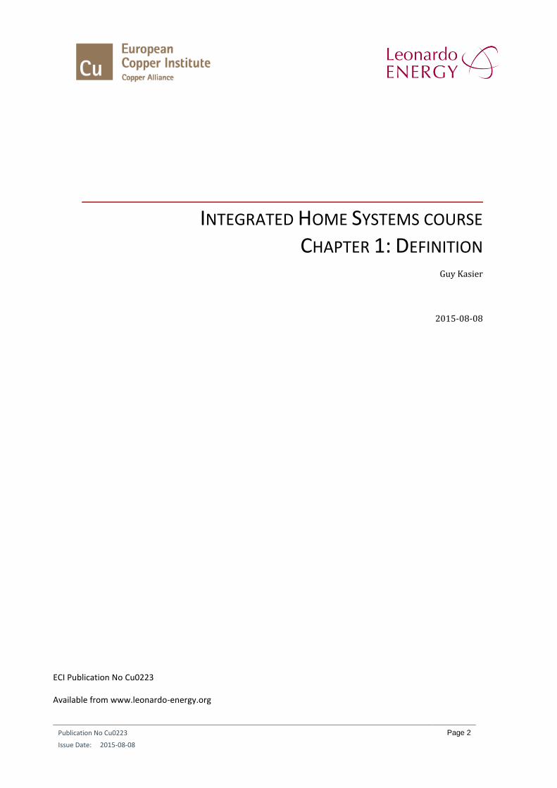
2.1.1. THE TRADITIONAL ELECTRICAL INSTALLATION
Today the traditional electrical installation has not changed much, although the materials used and the safety
standards have advanced greatly. However, the installation still has the same basic structure as before. Supply
cables come from the fuse box to a switch. This in turn is connected by cables to a client, for example a light.
Once an installation has been put in place, it can hardly be changed. The flexibility of the traditional electrical
installation is quite limited. The potential provided by traditional installations can also be described as limited.
The traditional installation is still fairly commonly installed in homes or remains in place from older homes, in
stark contrast to the needs of contemporary home users. After all, they expect more flexibility, functions,
security and opportunities for energy savings. The traditional installation is therefore giving way to more
intelligent installations, such as IHS systems.
Figure 1:
The structure of a traditional electrical installation. (Illustration source: E&D Systems)
2.1.2. THE INSTALLATION WITH REMOTE-CONTROLLED SWITCHES The remote-controlled switch had already been introduced to the installer a number of decades ago. It
centralized the switching of clients in the fuse cupboard, in contrast to ordinary traditional switches installed in
a decentralized manner around the home. The cabling to the clients is in star formation, as is the cabling to the
operating buttons. They send impulses to the remote-controlled switch when it has to switch over. In practice,
this form of installation is used far too little. It nevertheless has unmistakable benefits with regard to the
flexibility of an installation. Pushbuttons can be added to existing operating points without having to install
10A 10A 10A 10A
10A 10A 10A 10A 10A
10A

Publication No Cu0223
Issue Date: 2015-08-08
Page 6
additional cabling. A number of pushbuttons can be connected in parallel with a single remote-controlled switch
or client. In certain cases, group control and central control can be achieved. The safety of the installation is also
increased by using remote-controlled switches that operate on a very low voltage (24V).
Figure 2:
Example of a quadruple remote-controlled switch where every remote-controlled switch can be controlled
separately, in a group, or centrally using pushbuttons. (Illustration source: Eltako)
Figure 3:
Structure of the remote-controlled switch installation. By having a few reserve wires in place next to the
pushbuttons, it is always possible to install a pushbutton later without having to install new cabling.
(Illustration source: E&D Systems)
10A 10A 10A 10A
10A 10A 10A 10A 10A
10A
16 x 0.8 mm²16 x 0.8 mm²

Publication No Cu0223
Issue Date: 2015-08-08
Page 7
In the above example we can see that somewhat more cable will probably have to be installed, but the initial
installation of it is easier. The grinding and cutting from the operating point to the ceiling, and the drilling into
the ceiling is eliminated. All cables to the clients (lights) run over the floor plate. This facilitates and accelerates
the installation work.
2.1.3. LIGHTING CONTROL SYSTEMS At a certain point in the last hundred years or so, electronic lighting control systems found their way into the
home. They enable groups of lights to be locally operated separately or jointly. The creation of lighting
atmospheres, where a number of lights are set to different dimming levels at the same time, is also possible.
Such lighting control systems are generally found in the world of stage lighting, and are thus often carried out
professionally. The separate light groups or atmospheres can be operated with pushbuttons connected to their
own bus system, or by means of infrared remote control.
Figure 4:
These four-channel dimmer packs together form a lighting control system for twelve circuits of lamps. With two
additional modules, four dimmable fluorescent lights can also be controlled. (Illustration source: Light
Technology)
2.1.4. OTHER INTELLIGENT CONTROL SYSTEMS Other intelligent control systems are increasingly entering the home. For example, the heating system where
the electronic controller takes account of the outside temperature in order to adjust the water temperature, or
calculates the time needed to go from night temperature to comfort temperature.
The electrically operated garage door and the roll-down shutter system that takes account of the rising and
setting of the sun as well as movement detectors can also be counted among intelligent systems. The drawback
of all these systems is that they work on a standalone basis. When we open the garage door with the remote
control in the car, our home does not know that we have arrived home. Our intelligent heating system does not
know that we want comfort temperature as of that moment. There is thus no communication between the
different systems.

Publication No Cu0223
Issue Date: 2015-08-08
Page 8
Figure 5:
Presence detectors have sufficient electronics and intelligence to switch the lighting on and off independently
when needed. (Illustration source: Klemko)
2.2. ELECTRICITY CLIENTS IN THE HOME Another development that we have seen over the last few decades is the explosive growth in the number of
electrical appliances used in the home. Clients were originally lights and ceiling fans. A central light with a switch
by the door was put in every room, and a power socket directly below for the vacuum cleaner. However, more
handy equipment quickly came onto the market such as the washing machine, the tumble dryer and the electric
iron. The kitchen in particular has been packed full of electrical appliances: the dishwasher, the kitchen boiler,
the fridge and freezer, the oven, microwave oven, steam oven and also the coffee machine, egg boiler, electric
knife, fruit juicer and can opener are examples of appliances that we all know, have and probably use.
At a certain point in time, the central lighting point in the living room and dining room was extended by using
recessed or surface-mounted low-voltage spotlights. We thus had more lights and lighting groups in these
rooms. They were often controlled by dimmers. In recent years, the traditional incandescent bulb has been
banned from our homes and eco-halogen bulbs, energy-efficient bulbs and LED luminaires have taken its place.
A great deal has also changed in terms of audio, video and TV. The traditional CRT television lost out long ago to
much larger plasma and LCD screens in HD quality. We no longer watch analogue television, but use the much
greater possibilities of digital TV. The video recorder has also disappeared and in its place we use the DVD player
and record TV programs with the digital TV set-top recorder box. Nowadays, a multimedia player is also often
connected to our audio appliances and television with which we can listen to and view music, photos and films.
The TV now also has an internet connection and we have a home cinema system to gain a movie theater-like
experience.
We also use more electrical subsystems in our current homes than was previously the case. Besides the lighting
and the power sockets, these include the roll-down shutters, the sun canopy, the garage door and the fence,
the door communication (possibly with video), the garden sprinkler, access control, et cetera In addition, the
heating, cooling and ventilation are controlled by electrical components.
The purpose of all these appliances is to increase the comfort of the individual user, and sometimes security as
well. The opportunities within the home increase with every additional appliance that we buy. Using appliances
also gives us more free time; and that is not unimportant in families where everyone works outside the home.
When we are at home, we want to make it comfortable, invite friends, and cocoon. In recent years the garden
too has undergone a similar transformation. Flowers, plants, rockeries, ponds, deck terraces, garden lighting and
the fountain...they are all part of it.

Publication No Cu0223
Issue Date: 2015-08-08
Page 9
But the addition of all these electrical appliances in our home has not always improved our comfort in a simple
manner. We see, for example, the fruit bowl on the coffee table filled with remote controls, each used for a
different device. Most electrical appliances in the home are standalone devices. In other words, they do what
they have to do, but cannot communicate much with each other. Specifically, data from one appliance cannot
be used to switch another appliance on or off.
2.3. NEW AND OTHER NEEDS Our way of life has also changed in recent decades. We do not stay at home as much as we used to. We prefer
to live close to where we work. We also change jobs more than we used to. In short, we have had to learn to
live with an increased demand for flexibility. However, this demand is not met in homes with a traditional
installation.
With newbuilds we have more of an eye for the life cycle endurance of the home. We want more flexibility in
the home itself so that we can adapt it to our changing needs. Family composition can also be a trigger for those
changing needs. But other things, such as full or part-time telecommuting, starting our own business, falling ill,
et cetera, can also radically change our lifestyle and needs.
With the ageing of the population, many people are also becoming aware of the fact that they will have to live
at home independently for longer in the future. There will be too few facilities in hospitals, rest homes and flats
for the elderly.
2.4. PROBLEM We noted above that the electrical installation in the home has not changed much over the past 50 years. Today,
the traditional electrical installation, the flexibility of which can be described as zero, is still installed far too
often. Furthermore, we can identify many types of subsystems in a modern home. Everything does its own thing,
but there is no mutual communication. They are all standalone systems. Finally, we note that the user
friendliness of many systems and equipment leaves a lot to be desired. If we want to live flexibly and
comfortably, we need something else that provides this flexibility, better comfort and greater ease of use. It will
enable us to enjoy our free time more in order to relax and to adapt our home to changing requirements over
time. A young couple with small children has completely different requirements in their home compared to an
elderly couple (with debilitating physical conditions) whose children have long since flown the nest.
IHS systems offer an answer. But in order to avoid confusion, we have to give a concrete interpretation to the
term. That is why we need to look closely at what exactly IHS systems are and what they are not.

Publication No Cu0223
Issue Date: 2015-08-08
Page 10
3. DEFINITION OF INTEGRATED HOME SYSTEMS The first word of the term “Integrated Home System” is a word often used in electronics and computing.
However, it would be too simple to assume that an IHS system is the control of electrical clients using electronics
and computers. The reality, and thus the definition, is rather more complex. Every producer, importer, installer
and user has their own definition. Their definition is generally correct for a certain system, but not for the entire
IHS market. The following definition is brand independent and has been used for many years by many companies
and organizations.
An integrated home system is the integrated system that operates and manages all electrical
equipment in the home for the purpose of increasing comfort, flexibility, communication, safety and
security, rational energy consumption, and care components.
It is of course not the intention to use this definition in this form when communicating with end users.
Nevertheless, as an installer it is useful to know this definition and to be able to use elements of it in meetings
with architects and end users.

Publication No Cu0223
Issue Date: 2015-08-08
Page 11
4. ANALYSIS OF THE DEFINITION Let us examine a few key words from the definition and analyze them.
4.1. INTEGRATED SYSTEM One of the most important points that we endeavor to achieve with an integrated home system is integration.
A good IHS system has to be able to integrate a wide variety of standalone equipment and subsystems in the
home so that mutual communication is possible. That does not mean however that all intelligence must now be
given a place in the IHS system. In fact the opposite is preferable. Nevertheless, communication between the
different systems has to be encouraged.
A modern heating boiler already has its own intelligence in order to adjust the water temperature and take into
account the outside temperature. The IHS system should not take over this intelligence. A function that we do
want however is that when we leave the home and issue an “all out” command, the heating system knows it
can switch to a reduced heating mode in all rooms of the home. As a result, the resident does not have to go to
every thermostat in the home in order to set them to night mode manually.
Integration also means that one and the same operating system can operate a variety of equipment. An example
of this is the universal remote control. This is a device with which we not only operate the television, but also
the lighting and roll-down shutters. This enables us to get rid of many separate remote controls. They can go
into the cupboard and the fruit back in the fruit bowl.
Figure 6:
The remote controls in the fruit bowl make way for the fruit. (Illustration source: Niko)
Example of integration:
In the diagram below we see an example of access control, lighting, audio distribution, gate and heating
subsystems. We also imagine that these subsystems are present in a single family home where the father and
mother live with their two children. Both parents work outside the home. The children go to school. Let us
assume that on working days the mother is the first to come home at around 4:30 and that she normally goes
to the kitchen to prepare a snack for her children. Then we can also envision the following. The mother presents

Publication No Cu0223
Issue Date: 2015-08-08
Page 12
her personal proximity card to the proximity reader by the door. The gate then opens. If it is dark, a light path
to the kitchen is immediately switched on. The garage door also opens. The heating system switches to comfort
mode in the living areas and kitchen. Mother’s favorite CD comes on in the kitchen.
Figure 7:
An integrated home system integrates various subsystems in the home. From left to right: access control,
heating, gates and doors, audio distribution and lighting. (Illustration source: DK Design)
The children also have an access card instead of a traditional key. When they come into the home, lighting is
immediately provided in the room where they come in (garage or entrance) but we do not provide a light path.
After all, we do not know where they will go. The youngest immediately runs to the kitchen to be with Mum,
but the older teenager goes to her bedroom to do her homework or text her girlfriend. When the children come
into the home, the command is also given to turn up the heating in their bedrooms to comfort mode. After all,
children also use their bedrooms as a living area to play or to study.
Thursday morning 07:55. Everybody has left for work or school. The housekeeper puts her access card in the
card reader. However she does not get access, because her instructions are that she can only enter the home
on Thursdays from 08:00 to 12:00. If it is still dark, we give her a light path; in this case, to the room where the
cleaning products and equipment are kept. We do not leave the heating in comfort mode, but at 17 °C for
example. This is neither too warm nor too cold to actively clean. If the cleaner likes to work with background
music, we leave her favorite radio channel on in the entire home. If this housekeeper decides to quit the
following week and takes her access card with her, there is no problem. The access card is blocked and a new
access card is made for the new housekeeper. The old access card cannot be used (abused) by anybody to enter
the home. None of the locks and keys have to be replaced.
4.2. ALL ELECTRICAL EQUIPMENT Integrated home systems operate and manage electrical equipment. The integrated home system can switch a
light on or off. If a light is connected to a dimmer, a certain dimming level can also be set. At present an
integrated home system cannot do anything more with a traditional light. Nevertheless we should make a
comment here. LEDs are now beginning to be used more and more in light fittings. In certain cases the light color
can also be adjusted with RGB control.
The ability to switch certain equipment on and off does not always provide added value. The television is a good
example. When we switch off the power socket that connects the television to the mains in order to completely
switch it off, and then power it back up again, you will not see a lot happen with this equipment. It will just go
to standby mode. A better situation would be that when we press the “watch TV” button, the television is not
only connected to the mains, but also zaps to the channel watched most often and at a preferred sound volume.
This is not possible with simple switching actions. With an IHS system in place however the equipment can be
controlled with infrared (IR). This technique infrared can also be used with other devices such as audio systems
and air conditioning. In some cases radio frequency (RF) signals can also be employed.
An IHS system thus controls electrical equipment, not only electrically but also by using IR and RF.
Publication No Cu0223
Issue Date: 2015-08-08
Page 13
4.3. HOME The term “Integrated Home System” is used for homes in their widest sense. There must be at least one
residential function in the building. This also covers buildings with a combined living and working function. For
example, a building with a residential function combined with a doctor’s practice or a small accountancy firm is
still covered by the IHS definition.
IHS systems are certainly not the sole preserve of larger detached residences. They can also be installed and be
very useful in smaller homes, apartments, and even flats for the elderly. IHS systems already occupy an
important position in the social housing sector.
A properly designed IHS system is able to cover the entire home. There thus has to be enough inputs and outputs.
Certain intelligent systems that can only drive twelve outputs do not come under the heading of integrated
home systems.
Furthermore, it is also useful to be able to control the entire home with an IHS system. Installations where the
IHS system only controls a few rooms (living areas) and where the rest of the installation operates in the
traditional way cannot be considered true IHS installations. The “all out” function at the front door and the
garage door would thereby lose much of its value.
It is obvious then, that to meet our changing needs, we are moving away from the traditional electrical
installation. An installation with an IHS system guarantees far greater flexibility and functionality, both now and
in the future. IHS installations are increasingly recognized as the new standard for the conventional electrical
installation of homes.
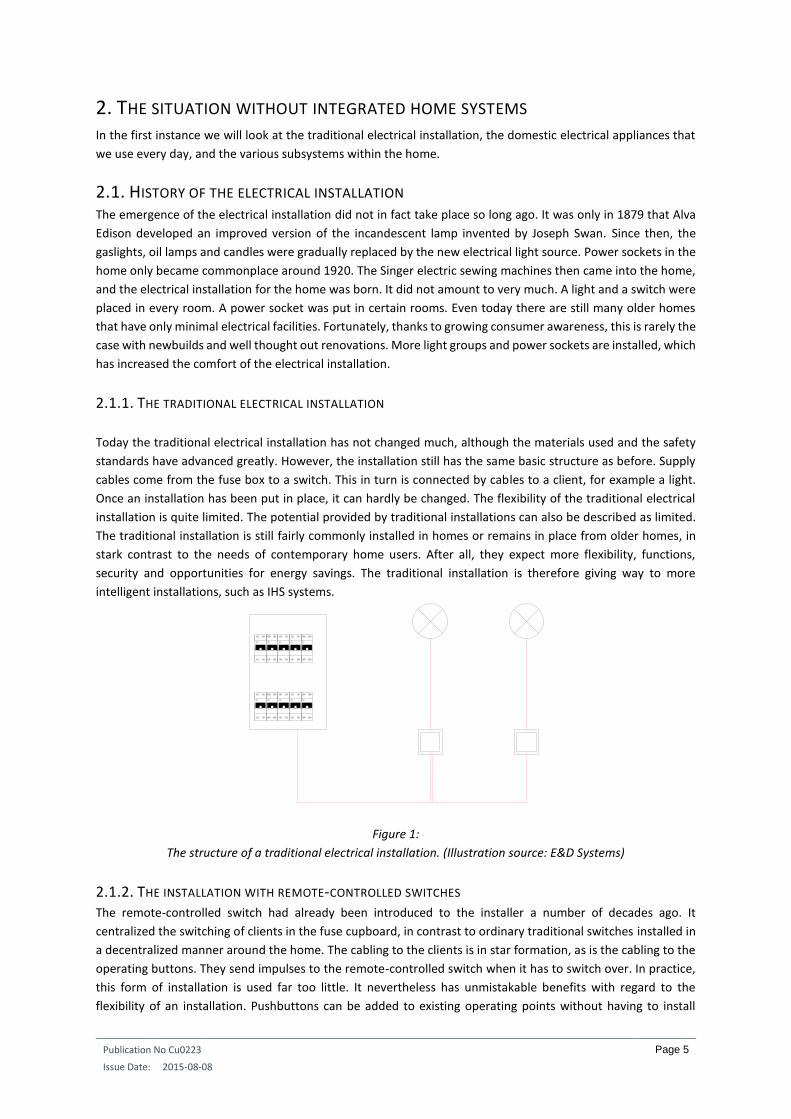
4.4. INCREASING COMFORT Increasing comfort with an IHS system can be achieved on a number of levels. The first item that we take to
hand is reducing or minimizing the number of operations that the user has to perform to achieve something. An
example: with a traditional installation, every evening we have to reset dimmer controlled light circuits to the
desired setting in order to watch television. If there are more lighting circuits for example, we must bring all four
dimmers to an appropriate setting. With an IHS system however we can program a “watch TV” button. When
we press this button (a single convenient operation by the user) the four lighting circuits will immediately go to
the desired dimmed setting and the TV will also come on and go to the preferred channel at a certain sound
level. Furthermore, the roll-down shutter will close or open depending on whether it is light or dark outside. This
is an example of the use of single button operation in order to create local “atmospheres”. In the living room for
example we can place buttons to receive guests, play with the children, optimize the light for reading a good
book, or even push a button for a romantic interlude.
Single button operations are not only convenient locally but also generally. An example of this is the “all out”
button at the front door and the garage door. The last person to leave the home can simply press it so that all
clients go to the off state. The user no longer has to check whether all lights are off and all roll-down shutters
are down (or up) or even worry about the electric iron still being on in the laundry room.
Publication No Cu0223
Issue Date: 2015-08-08
Page 14
Figure 8:
Single button operation to reduce the number of operations. (Illustration source: Agora Press)
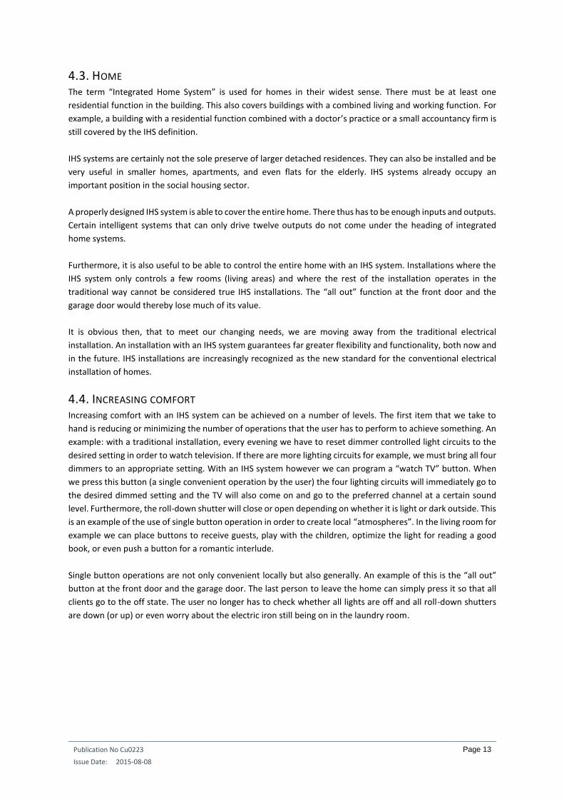
A second way of increasing comfort and certainly convenience is to increase user friendliness. This can be
accomplished in many ways, for example by ensuring a similar method of operation throughout the home. The
general lighting in each room can for example be the top left pushbutton on an operating panel. An “all off” for
every room is then placed at the bottom right of the operating panel. Roll-down shutter up/down can be the
top right pushbutton of the operating panel if you wish. Smart phones and tablets can also help increase user
convenience. The user can perform all sorts of actions on the smart phone screen, via symbols and text, not only
in the room where he or she is, but also in the rest of the home. Actions can even be performed through these
appliances when no one is at home. Apart from performing actions, the smart phone or tablet can also be used
to check the status of particular electrical consumers. Thus, if necessary, while in the living room in the evening,
the father or mother can check whether the son or daughter (who should already be fast asleep) has turned out
the lights in his or her bedroom.
Figure 9:
Icons and text on the smart phone make the system user-friendly. (Illustration source: Niko)
Finally, a third way of increasing comfort is to use automatic processes. These might include the automatic
raising and lowering of the roll-down shutters or sunblind, or the automatic controlling of the heating according
to whether anyone is home. The possibilities also include controlling the outside lighting according to the
Publication No Cu0223
Issue Date: 2015-08-08
Page 15
brightness outside and the time of day and season. However, we must be careful not to over-automate and the
residents must always be able to determine what they want to happen at a particular time. In short, they must
not get the feeling that they have to adapt to the home automation system. The opposite must be the case. The
system is there to adapt to their needs. For example, roll-down shutters that lower automatically when people
are sitting in the garden having a barbecue is not such a good idea.
4.5. INCREASING FLEXIBILITY
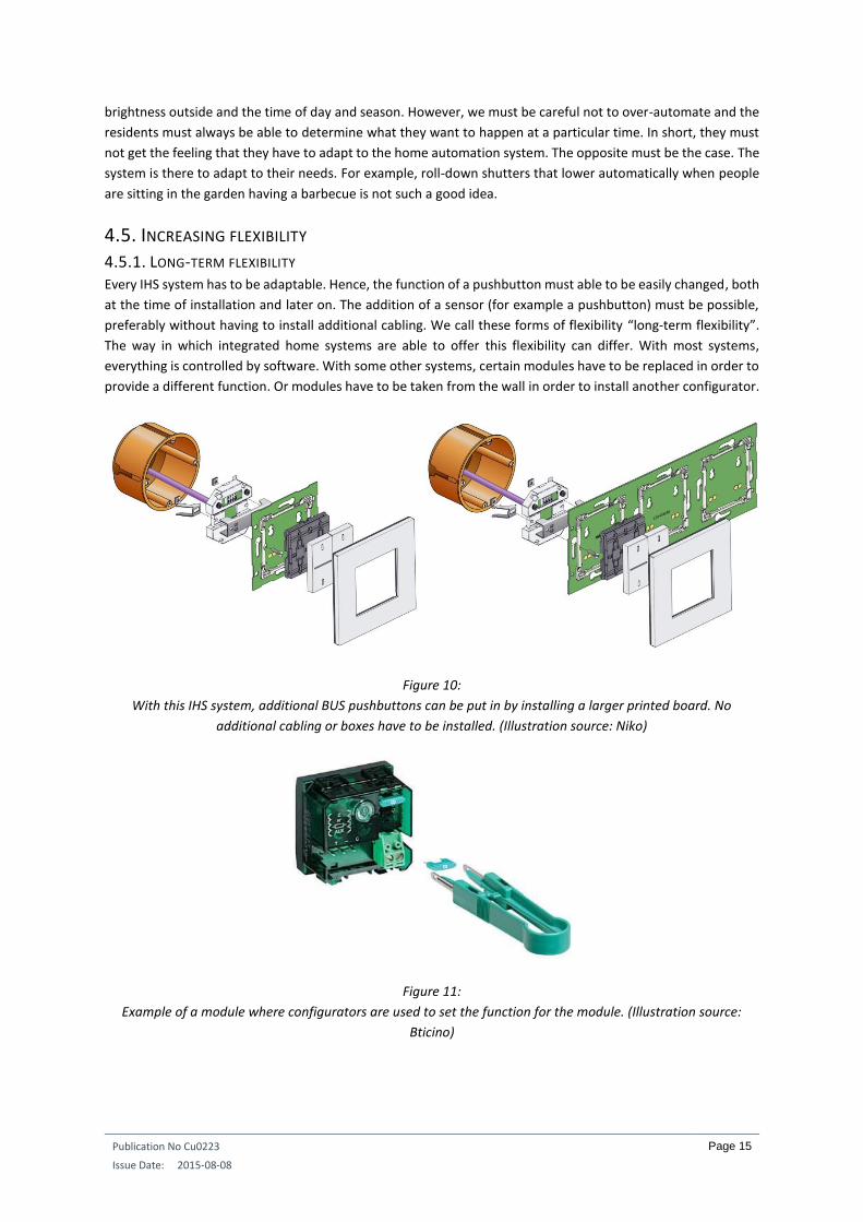
4.5.1. LONG-TERM FLEXIBILITY Every IHS system has to be adaptable. Hence, the function of a pushbutton must able to be easily changed, both
at the time of installation and later on. The addition of a sensor (for example a pushbutton) must be possible,
preferably without having to install additional cabling. We call these forms of flexibility “long-term flexibility”.
The way in which integrated home systems are able to offer this flexibility can differ. With most systems,
everything is controlled by software. With some other systems, certain modules have to be replaced in order to
provide a different function. Or modules have to be taken from the wall in order to install another configurator.
Figure 10:
With this IHS system, additional BUS pushbuttons can be put in by installing a larger printed board. No
additional cabling or boxes have to be installed. (Illustration source: Niko)
Figure 11:
Example of a module where configurators are used to set the function for the module. (Illustration source:
Bticino)

Publication No Cu0223
Issue Date: 2015-08-08
Page 16
4.5.2. SHORT-TERM FLEXIBILITY IHS systems in which the configuration and programming can be carried out by computer are able to make use
of short-term flexibility. It is then possible to send a different user file from the computer to the IHS system at
any time. Sending generally only takes a few minutes.
Example: Imagine you have a holiday home or apartment fitted with an IHS system that can be programmed via
the computer. When you are present in the holiday home, the pushbuttons are programmed with the functions
you want them to perform. If, however, the holiday home is also occasionally used by others (adult children or
tenants), it is handy to have a “rental file” for the IHS system. This will prevent the temporary tenants from using
certain functions, such as the operation of the audio distribution system or the setting of the heating or
inadvertently the draining of the swimming pool, et cetera. Just before the tenants arrive, the “rental file” is
downloaded to the IHS system. After the rental period, your own “house file” is sent back to the system,
returning all pushbuttons and other controls to your preferred settings. Nowadays this can in many cases even
be done via an internet connection, saving you a visit to the premises.
Flexibility in the short-term is also a handy tool for the maintenance and adaptation of installations in service
flats for the elderly. When the flat has to be adapted for a new resident, this can be accomplished in a very short
space of time.
4.6. INCREASING COMMUNICATION Who is not amazed when we look at our use of means of communication in the 1990s and compare this with
our current use habits? Both our means of communication and their use have increased dramatically. The smart
phone was only introduced on a large scale in 2007, but today an astonishing number of the general population
has one, and certainly no longer use it to just to make calls or send texts. The tablet is an even more recent
innovation introduced in 2010 and its users are already growing at an equally astonishing rate. We also have
superfast internet connections. Social media and app developers have been keen to take advantage of all this
digital capability, with the result that our fingers go through life tapping, dragging and sliding over touchscreens.
These developments have also influenced IHS systems. Most systems now offer, either as standard or as a
custom unit, a server through which we can integrate the appliances discussed above and the computer with
the IHS system, both at home and at virtually any other location. We can not only perform and check actions,
but can also upload a new IHS file or adjust settings. In addition, ‘alarm messages’ of all kinds (technical, fire,
burglary, et cetera) can be sent to the smart phone.
However, integration goes even further. Door communication with audio and video can be forwarded to the
smart phone. So when someone rings at the front door, we can speak to them and where appropriate give that
person access to the home, even though we are not there (a housekeeper or gardener, for example). Images
from other cameras in and around the home can also be called up.
Communication is also acquiring an essential place maintaining service flats for the elderly and informal care.
Thus, the non-resident carer can receive information if the person being cared for has not performed any actions
with the IHS system before a particular time in the morning. This could suggest they are ill or perhaps have
suffered a fall. Not closing the curtains or roll-down shutters after a certain time in the evening could be another
trigger.
The elderly person can connect through the television screen, a camera and a set-top box to a care center if he
or she has certain questions concerning, for example, the taking of medication. But services such as providing
meals can also be operated through these channels. In certain cases, it may even be desirable to send medical

Publication No Cu0223
Issue Date: 2015-08-08
Page 17
readings such as blood pressure, heart rate and glucose values to the doctor each day. If there are anomalies,
he or she will contact the person concerned for a consultation and examination. This avoids a lot of unnecessary
travel by the person concerned to the doctor and vice versa.
Figure 12:
The videophone can also be used to operate the integrated home system. (Illustration source: Bticino)
Figure 13:
Visual communication is becoming a hot topic within the field of care for older people living independently.
(Illustration source: Motiva)
4.7. INCREASING SAFETY AND SECURITY An integrated home system is not in and of itself a safety or security system. But we will nevertheless see that
the IHS system can increase the safety and security of the home and the people in it. We will first look at fire
protection, followed by security against burglars. Finally we will make some observations about personal alarms.
4.7.1. FIRE PROTECTION Let us first imagine a home in which smoke detectors have been installed. We will assume that there is a
connection to the IHS system. When one or more smoke detectors give an alarm, a voltage-free contact is made
with the IHS system. When this contact closes, the IHS system knows that there is a fire alarm. At that time the
Publication No Cu0223
Issue Date: 2015-08-08
Page 18
IHS system (for as long as the mains voltage is present in the home) can respond appropriately to ensure that
everyone there (sometimes sleeping) can evacuate as quickly as possible. All non-essential equipment such as
the dishwasher, washing machine, dryer, and heating is immediately switched off. The lighting is put on in
strategic places within the home (living areas, bedrooms, corridors, entrance and garden) to ensure safe egress.
The electrically operated roll-down shutters are raised so that people can also escape through the windows if
there is no other way out. If necessary, the audio installation can be set to a high volume temporarily to ensure
that sleeping residents are awakened promptly. We can also have certain lights outside flashing so that
neighbors, passers-by and carers immediately know that something is amiss, and equally important the location.
This will enable them to take the necessary steps to help.
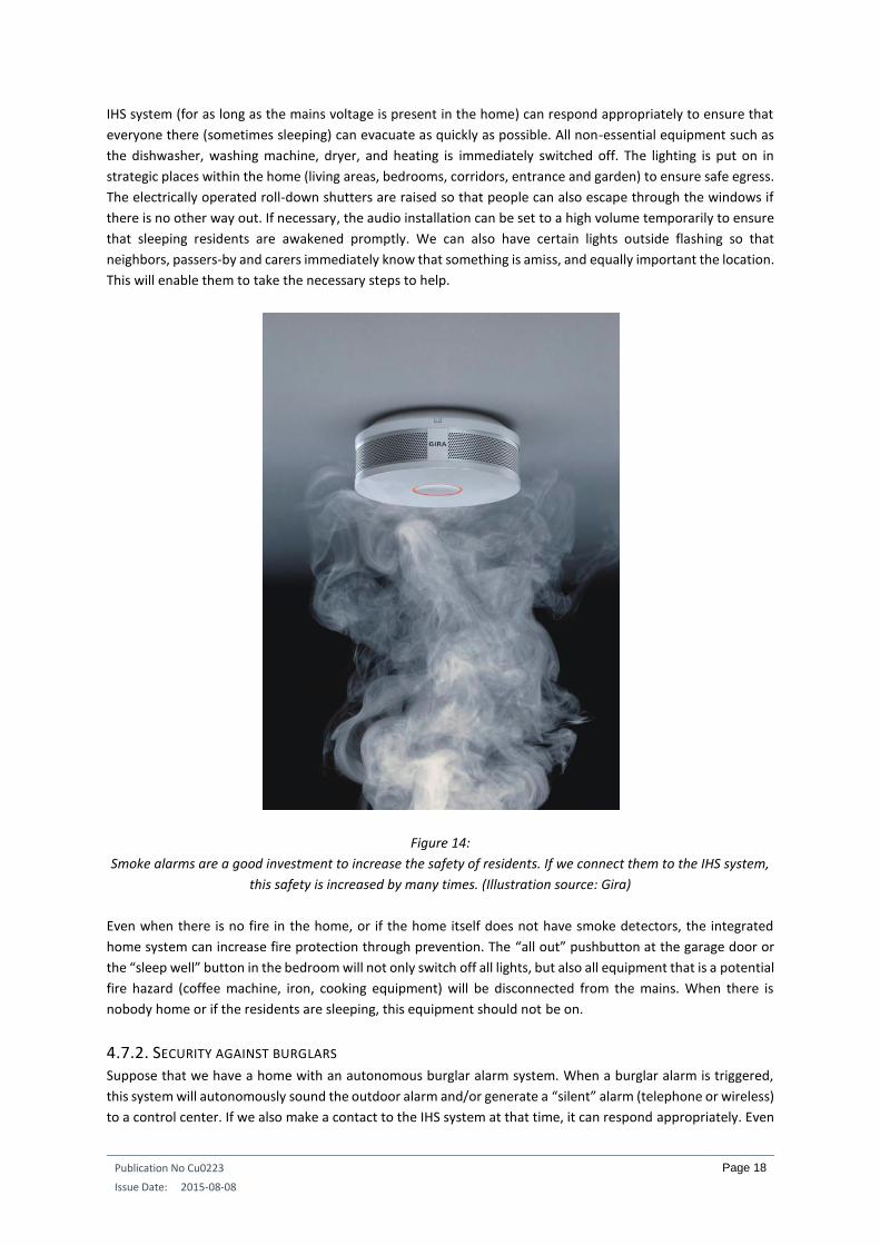
Figure 14:
Smoke alarms are a good investment to increase the safety of residents. If we connect them to the IHS system,
this safety is increased by many times. (Illustration source: Gira)
Even when there is no fire in the home, or if the home itself does not have smoke detectors, the integrated
home system can increase fire protection through prevention. The “all out” pushbutton at the garage door or
the “sleep well” button in the bedroom will not only switch off all lights, but also all equipment that is a potential
fire hazard (coffee machine, iron, cooking equipment) will be disconnected from the mains. When there is
nobody home or if the residents are sleeping, this equipment should not be on.
4.7.2. SECURITY AGAINST BURGLARS Suppose that we have a home with an autonomous burglar alarm system. When a burglar alarm is triggered,
this system will autonomously sound the outdoor alarm and/or generate a “silent” alarm (telephone or wireless)
to a control center. If we also make a contact to the IHS system at that time, it can respond appropriately. Even

Publication No Cu0223
Issue Date: 2015-08-08
Page 19
a simple burglary can require considerable concentration by the perpetrator. For example, if they are working
in the dark using a torch. There is also audio concentration. The burglar listens for noise signals that can tell the
thief that someone is coming down stairs, or perhaps that a car has driven into the drive. If we can break this
concentration, the burglar has far less control over the situation. Since they do not wish to be recognized or
caught, they will quickly leave the home, possibly without any stolen items.
Figure 15:
Break the concentration of the burglar and they will be startled and quickly leave the home. (Illustration source:
DK Design)
We can break this concentration in a number of ways. First of all we can switch on a lot of lighting, the visual
concentration is then immediately broken. We can also flash the outside lighting in order to indicate to the police
and neighbors that something is wrong. In order to break his audio concentration, the audio distribution system
can be switched on at a high volume.
There are differing opinions as to whether the roll-down shutters should be raised or lowered at the time of a
burglary.
Opinion 1: Raise the roll-down shutters in the event of a burglary:
This is based on the view that we want to force the burglar out of the home as quickly as possible. If the roll-
down shutters are raised and the lighting has been controlled, the burglar is visible from outside. He does not
want this and so leaves the home as quickly as possible.
Opinion 2: Lower the roll-down shutters in the event of a burglary:
Some people are convinced that they would rather trap the burglar in the home, so that he can easily be
apprehended by the police. To this end, doors and roll-down shutters are closed. However, in this case there is
a good chance that the burglar will try every conceivable way to escape, and as a result there will be more
damage to the home. If residents are also present at the time of the burglary, this also increases the chance of
a hostage situation.
Contact the resident and security specialist to find out what is desired.

Publication No Cu0223
Issue Date: 2015-08-08
Page 20
When there is no burglary, the IHS system can act preventively. If we are not at home, and even at certain times
when we are asleep, we can use activity simulation. This gives the appearance to the outside world that there
are people at home and there is human activity.
There are various ways of achieving this presence simulation.
One way consists of activating and deactivating a number of consumers (mainly lights and roll-
down shutters) every day. In this case, try not to have the consumers activated at the same time
every day.
Some IHS systems have a system for presence simulation whereby randomly determined, pre-
selected consumers will be activated and deactivated.
Finally, there are also IHS systems that store residents’ operations in a memory. When presence
simulation is activated, the actions in the memory are then repeated. This simulation method is
the most realistic, but of course certain consumers must be excluded from this setup. For example,
the garage door does not need to open and the heating does not need to switch to comfort mode
when you are not at home.
In order to further increase the feeling of security of residents when they are at home, we can also fit a “panic
button” in the master bedroom or in other places. If you hear suspicious noises during the night, you activate
this function. All lights on the ground floor then go on, and also the outdoor lighting. If you then go to check
what is happening, you will always enter an area that is already well lit. Just by switching on the lighting, the
concentration of any burglar is broken and they will probably already be out of the door before you come into
contact.
Figure 16:
Good activity simulation helps reduce the risk of unwanted visitors. (Illustration source: Tronixx)
4.7.3. PERSONAL ALARM An IHS system can also be used for older people living alone in particular, in order to protect the person. This
can be achieved in various ways.
Publication No Cu0223
Issue Date: 2015-08-08
Page 21
For example, switching off cooking equipment (cooker, oven, et cetera) when the system notices that a single
elderly person has not been in the kitchen for a certain specified. (10 to 15 minutes for example) during the
cooking process, or when they go to bed or lie down on the sofa.
Another example is the automatic light path to the toilet when the resident gets up during the night. This
prevents them from running into something in the dark or from falling over.
A “no activity alarm” can also be activated when the system notices that there has been no activity in the home
for a number of hours. The elderly person might be ill in bed or have fallen. If during the set time no buttons
have been pressed, for example to operate the lights, or a movement detector has not detected any movement,
an alarm will be passed on to a social services center via the Personal Alarm System (PAS). When the PAS system
is activated, the IHS system can turn on certain lights and also disconnect sound sources such as radio and
television from the mains. This ensures that the internal communication system of the PAS system is not
disrupted by other sounds in the home. It is then easier for the social services center to check what is happening
and if necessary send a helper or carer to the location.
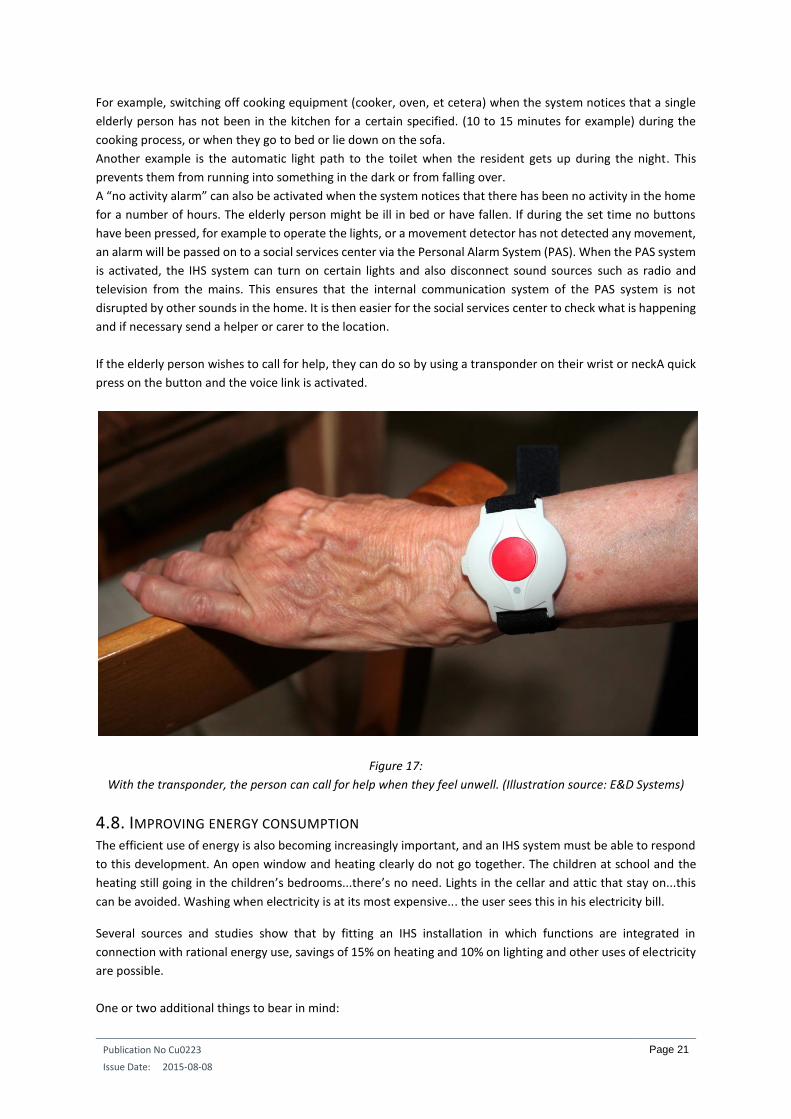
If the elderly person wishes to call for help, they can do so by using a transponder on their wrist or neckA quick
press on the button and the voice link is activated.
Figure 17:
With the transponder, the person can call for help when they feel unwell. (Illustration source: E&D Systems)
4.8. IMPROVING ENERGY CONSUMPTION The efficient use of energy is also becoming increasingly important, and an IHS system must be able to respond
to this development. An open window and heating clearly do not go together. The children at school and the
heating still going in the children’s bedrooms...there’s no need. Lights in the cellar and attic that stay on...this
can be avoided. Washing when electricity is at its most expensive... the user sees this in his electricity bill.
Several sources and studies show that by fitting an IHS installation in which functions are integrated in
connection with rational energy use, savings of 15% on heating and 10% on lighting and other uses of electricity
are possible.
One or two additional things to bear in mind:

Publication No Cu0223
Issue Date: 2015-08-08
Page 22
Management of stand-by power.
Management of the ‘major’ household consumers (washing machine, tumble dryer, dishwasher, hot
water boiler, heating, et cetera).
Taking into account the fact that the consumer is mainly going to be motivated to use energy rationally
if it does not impact too heavily on his comfort.
Management of connecting and tap-off power.
It has also been demonstrated for several years that direct feedback on energy consumption can make residents
more sensitive to saving energy. IHS systems respond to this by taking measurements and converting these into
graphs. These can then be consulted on a touchscreen in the wall, on the computer or on the smart phone or
tablet. In many cases, not only is energy consumption displayed, but also the energy generated by the customer
themselves (PV panels, for example).
As more and more homes become fitted with so-called smart meters in the future, integration with the IHS
system can go a step further. For example, peak consumption at certain times could lead to certain heavy
consumers (washing machine, dishwasher, et cetera) being disconnected from the mains.
Finally, it is expected that in the near future homes will use their own storage devices. This means it may be
possible to store the unconsumed part of the energy generated by PV panels in batteries. This energy can then
be used in the home when the PV panels are not generating energy. In this sense, the laying of DC cabling in the
home will also offer perspectives for connecting all kinds of appliances that run off a DC supply. In this way, there
would be no more losses as a result of AC being converted to DC in every appliance or in chargers.
In certain European countries, the total power of the home electricity supply is rather limited. The main switch
will trip when too much equipment is being used at the same time. IHS systems can play a clever role here by
temporarily switching off certain units when an overload is imminent, and with the desires of the residents taken
into account.
Figure 18:
Reducing energy consumption by reducing the power of the connection. Integrated home systems can play a
clever role here. (Illustration source: Bticino)
4.9 THE CARE COMPONENTS
In the previous sections we have seen that IHS systems can also be used to improve certain care components.
This mainly involves integrating certain functions that could ensure that older people, who may or may not be
living independently and who require care, can maintain their independence at a reasonable level for longer. By
extension, however, this also applies to people with a disability or people who have to deal with a disease (e.g.
ALS or MS) whereby their physical capabilities gradually decline.

Publication No Cu0223
Issue Date: 2015-08-08
Page 23
In all these cases, IHS systems can ensure that the person concerned can continue to live at home for longer
instead of having to be admitted to a care institution or home for the elderly.
Publication No Cu0223
Issue Date: 2015-08-08
Page 24
5. INTEGRATED HOME SYSTEMS VERSUS OTHER SYSTEMS
5.1. HOME AUTOMATION In English-speaking countries in particular, the term “home automation” is often used. We prefer not to use this
term, however, when it comes to IHS systems. The first reason is that the term refers too strongly to automation.
And as you know, we have to be careful about overdoing automation in the home. The residents must not feel
that they have to adapt their lives to certain controllers imposed by the system. The roll-down shutters must be
lowered or raised when the residents so wish, and not simply because the sun rises or sets each day.
A second reason why we prefer not to use the term “home automation” is the fact that it is also used for small
standalone systems. For example, on the internet we find sites that use the term “home automation”, while
they are only selling home cinema systems. Since the aim of IHS systems is integration, the term “home
automation” can in certain cases conflict with the definition of IHS systems. The two terms refer to different
things.
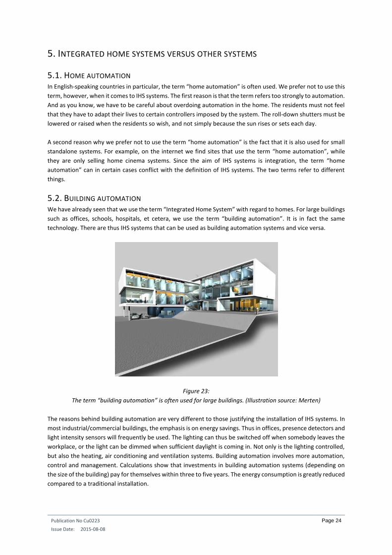
5.2. BUILDING AUTOMATION We have already seen that we use the term “Integrated Home System” with regard to homes. For large buildings
such as offices, schools, hospitals, et cetera, we use the term “building automation”. It is in fact the same
technology. There are thus IHS systems that can be used as building automation systems and vice versa.
Figure 23:
The term “building automation” is often used for large buildings. (Illustration source: Merten)
The reasons behind building automation are very different to those justifying the installation of IHS systems. In
most industrial/commercial buildings, the emphasis is on energy savings. Thus in offices, presence detectors and
light intensity sensors will frequently be used. The lighting can thus be switched off when somebody leaves the
workplace, or the light can be dimmed when sufficient daylight is coming in. Not only is the lighting controlled,
but also the heating, air conditioning and ventilation systems. Building automation involves more automation,
control and management. Calculations show that investments in building automation systems (depending on
the size of the building) pay for themselves within three to five years. The energy consumption is greatly reduced
compared to a traditional installation.

Publication No Cu0223
Issue Date: 2015-08-08
Page 25
Furthermore a building management system also offers considerable benefits with regard to flexibility. If a
partition is installed in an open plan office because of a reorganization, many cables have to be installed and
new connections made. However, with building automation, the system computer can be used to make a small
adjustment to the program and download it to the system. The costs of a change or modification are much lower
than with a traditional installation.

Publication No Cu0223
Issue Date: 2015-08-08
Page 26
INTEGRATED HOME SYSTEMS COURSE CHAPTER 2: FUNCTIONALITIES
Guy Kasier
2015-08-08
ECI Publication No Cu0224
Available from www.leonardo-energy.org

Publication No Cu0223
Issue Date: 2015-08-08
Page 27
CONTENTS
1. Introduction .............................................................................................................................................. 28
2. Exercise ..................................................................................................................................................... 29
3. Thinking in terms of integrated home systems versus traditional approaches .......................................... 30
4. User-friendliness ....................................................................................................................................... 31
5. Software functions in integrated home systems ....................................................................................... 33
6. Tailor-made functions ............................................................................................................................... 35
7. Identifying requirements .......................................................................................................................... 38

Publication No Cu0223
Issue Date: 2015-08-08
Page 28
1. INTRODUCTION It is perfectly possible to install a domestic electrical installation with a distribution board brimming with
Integrated Home System (IHS) equipment, but without any of the IHS functions implemented. In such a case, all
programmed functions could have been implemented through a traditional electrical installation, which would
have been much cheaper. However we cannot call such a situation an IHS, as it would be an abuse of the term.
It should be clear that the installer has to provide added value before they can properly call it an IHS. To do this,
they have to start with the needs of the people living there chiefly in mind. Let us suppose two identical homes
next to the other. And suppose further that they are each equipped the same IHS equipment. A young couple
with two young children live in the first home, while in the second, an elderly married couple move in. The IHS
functions implemented in one home will be of a different nature to the other. Young people with small children
have totally different needs than those of the elderly couples whose children have long since left home.

Publication No Cu0223
Issue Date: 2015-08-08
Page 29
2. EXERCISE Let us first conduct an exercise.
Let us look at the drawing of a bedroom in a home. It contains three light groups. Light point 1 (LP1) is connected
to a dimmer and serves as general lighting. Light point 2 (LP2) provides the lighting for the fitted wardrobe. Light
point 3 (LP3) is also connected to a dimmer and provides the lighting by the bed. There is another light group
(LP4) on the landing. There is also a roll-down shutter (M1) in the bedroom. We can ignore the heating in this
example.
Figure 1:
How many pushbuttons are installed in this bedroom and what functions will they perform? (Illustration source:
E&D Systems)
Assignment: Where and how many pushbuttons would you provide in this bedroom and what function will they
perform?
Complete this exercise before reading further.
M
Bedroom 1
LP1
LP1LP2
LP2
LP3
LP3
M1
LP4 LP4 LP4 LP4

Publication No Cu0223
Issue Date: 2015-08-08
Page 30
3. THINKING IN TERMS OF INTEGRATED HOME SYSTEMS VERSUS TRADITIONAL
APPROACHES In a traditional electrical installation, installers will have learned that it is necessary to provide at least one
switch and, in some cases, several switches, for each consumer (lighting point, roll-down shutter, et cetera).
This is the traditional way of thinking. Every consumer has its own switch. But even with modern IHS, we find
that installers often proceed in the same way. The result is that the IHS only provides the same basic utilitarian
traditional installation.
Many installers would like to install five push-buttons to operate the separate lighting circuits one through four
respectively, with the fifth push-button reserved for the roll-down shutter. We thus see that traditional thinking
prevails. Every consumer has its own push-button. IHS systems are not needed for such designs. They can be
realized with a traditional installation.
If we want to add value to the above example, then we have to think about the intentions of the residents when
they suppose the bedroom. Suppose that the occupant enters the bedroom with the intention of going to sleep.
Then we provide an “I’m going to sleep” button. When this button is pressed, the general lighting can, for
example, be dimmed to 70% and the lighting by the bed to 50%. In the meantime, the roll-down shutter is
lowered. If the light in the corridor is still on, then this lighting circuit is instructed to switch off after an
appropriate delay.
When the residents leave the bedroom in the morning, we provide an “I’m leaving the room” button. Pressing
this button could mean that the lighting in the corridor goes on when there is not enough daylight in the corridor.
Furthermore, all lights that are on in the bedroom can be given a delayed fade function. The possibilities are
endless. For example, the lights that are connected to a dimmer can be given a fade-out time of one minute.
You are, therefore, not immediately in the dark when you operate the button. The roll-down shutter will also be
given the command to rise.
In the above example, a few push-buttons will of course be provided for individual operations. If you want to
get something out of the built-in wardrobe, then a separate button near the wardrobe would be handy for
turning on the light. If so desired, this light could also be controlled by a magnetic switch in the wardrobe. When
the wardrobe is opened, the light will come on automatically. When the wardrobe is closed, it goes off again.
Other intention buttons will also be fitted in this room. There can be a “sleep well” button beside the bed. All
lighting in the bedroom is switched off with this button and the roll-down shutter is closed (if not yet done).
With very small children who are afraid of the dark, it is perhaps advisable to leave the lights on next to the bed,
dimmed at 10% to 20%. After a while, these lights can fade out softly and slowly.
That concludes the example in the bedroom. In the living room too, and in all other rooms, we need to consider
what the intentions of the residents might be when entering and leaving the room, or when using the room. In
the living room, it might be: watching TV, receiving guests, playing with the children, reading a good book,
spending a romantic interlude with a partner, et cetera. In such a case, we are inclined to provide a push-button
for every intention.

Publication No Cu0223
Issue Date: 2015-08-08
Page 31
4. USER-FRIENDLINESS To make sure the user is not confronted with too many pushbuttons, controls for individual light points, roll-
down shutters, et cetera can be placed on a remote control. Several intention buttons are then installed in the
walls.
The pushbuttons can also be provided with an icon or text to indicate what function they will perform if pressed.
This means the user does not always have to remember precisely which button must be pressed to activate a
particular function.
Figure 2:
Icons that indicate the function of a button increase user-friendliness. (Illustration source: Teletask)
Figure 3:
Icons are also used in service flats for the elderly to clearly indicate the function of a pushbutton. (Illustration
source: E&D Systems)

Publication No Cu0223
Issue Date: 2015-08-08
Page 32
Figure 4:
Example of a keypad on which the user can read the function of the buttons. (Illustration source: Vantage)

Publication No Cu0223
Issue Date: 2015-08-08
Page 33
5. SOFTWARE FUNCTIONS IN INTEGRATED HOME SYSTEMS There are IHS systems on the market that use small building blocks during programming. The installer can use
these building blocks to create the functions the future residents require. Such systems are generally derivatives
of the programmable logic controller (PLC), where the software always goes through a program from top to
bottom.
The software of most other IHS systems offers the capability to use ready-made IHS functions. Generally, you
cannot create the functions yourself with these systems. On the other hand, some functions can be combined
and used within other functions. In this way complex problems can be solved. The advantage of such systems is
the speed with which currently existing functions can be allocated to a button.
Let us have a look at common software functions of IHS systems.
- Switch function: Every time you press the button, the consumer will switch over. With this function, you can only allocate one consumer that is connected to a relay.
- Dimming: A brief push of the button takes the light connected to a dimmer to a setting held in the memory. Another short press results in the light switching off. If the same button is pushed for longer, a dimming process is started. When the pushbutton is released, the light stays in the desired dimmed state. When switching the light on and off, you can use a fade-in and fade-out time. Here too, only one consumer can be allocated to the function.
- Timed function: This function is often used in stairwells. When the button is pressed, the light immediately switches on for a programmed time (for example, five minutes). The light then automatically switches off after this time. With this function, you can select a relay-controlled light or a dimmer-controlled light. In the latter case, a fade-out time, for example of two minutes, can be specified. It ensures that the light goes off very slowly, so that you are not immediately caught in the dark when the set time has elapsed.
- Motor start/stop: Briefly pressing the programmed button will make a motor that can operate in two directions (roll-down shutter, sunblind, et cetera) run in the opposite direction to the previous time. If you press the button while the motor is running, the motor stops. Here too, only one motor can be allocated. If you press the button for longer (> one second), the motor continues running until the button is released.
- Fan function: This is a combination of a light and a fan. When the button is pressed, the light switches on. Pressing it again results in the light switching off and the fan coming on. After a prescribed time, the fan stops automatically. This function is often used in toilets and bathrooms.
- Local mood: This function is used to create local atmospheres. There are several lines in the function. A consumer can be placed on each line (relay controlled, dimmer controlled, motor). Each consumer can be told what it has to do: on, off, in a certain dimming state, raise or lower roll-down shutter, et cetera. Aside from specific consumers, other functions of the IHS can also be included on the lines (for example, a timed function or another local mood).
- Timed local mood: Similar to the previous function. However, for each line, you can specify the time interval between the previous line being executed and the current line being executed. You can also specify whether the function should be automatically repeated after the last line has been executed.

Publication No Cu0223
Issue Date: 2015-08-08
Page 34
- General mood: This function is used for general operations relating to the entire home. You can specify whether the on or off condition has to be generated for each relay. You can do the same for the list of dimmers. Aside from on or off, each dimmer can also be set to a certain dimming state. In addition to the status of the relays and the dimmers, several other functions can be assigned to a general mood. These can be simple or complex functions (e.g. local moods).
- Transparent function: With this function, the output follows the input. For example, the button at the front door and the doorbell. As soon as the button is pressed, the doorbell rings.
- Audio functions: The functions listed below all relate to controlling an audio distribution system in the home. You choose the audio zone where you want to do something. Then, you select the audio device (CD player, tuner, amplifier, et cetera) and specify the function to be performed (volume up/down, next CD, next preferred radio station, et cetera).
- Sensor functions: This series of functions is connected to analogue sensors (temperature, humidity, light). With temperature sensors for example, the day temperature or night temperature can be activated with this function. You can also raise the temperature in steps of + 0.5 °C or lower it - 0.5 °C, or set the frost protection temperature.
- Clock functions: These functions relate to the execution of all types of actions that are activated by clocks. A number of clock tables can be activated or deactivated here. There is a choice of a working day clock table, a weekend clock table and a simulation clock table. Only one of the three can be active at any one time. There is also a special clock table that can be switched on or off. Finally, there is the continuous clock table. Actions in this table are always executed.
- If-then-else functions: When this function is allocated to a button, then when the button is pressed, it looks at a condition or stipulation. If the condition is true, a certain program is executed. If the condition is not true, no program or another program is executed.
- Process function: With this function, a consumer continually follows another consumer, state or condition. The state of an output or condition is continually examined and monitored. This function is used to switch on the boiler contact for the central heating boiler as soon as one of the zone valves is open, and to switch it off again as soon as all zone valves are closed.
- Messages and alarms: Text messages can be generated on keypads with LCD displays, touch screens or on the television. A message appears on the screen and disappears automatically after a set time. Examples of a message can be: “Somebody is coming up the drive”. Alarm texts can also be generated. They stay on the display until they have been reset by the user. The text: “Somebody came to the door during your absence” is an example of this.

Publication No Cu0223
Issue Date: 2015-08-08
Page 35
6. TAILOR-MADE FUNCTIONS Earlier, we looked at what software functions are normally available in IHS systems. However, these are merely
the tools we need to create functions that are grafted to a particular home in which certain residents live with
their own needs. Now let's take a look at solutions which guarantee the personal ease and comfort of the
residence.
Below are several examples of additional functions. As mentioned earlier, not every function needs to be
installed in every home. It depends entirely upon the family composition, the lifestyles and the needs of the
residents. The first example below could be attractive for families with small children, but will be of no value to
a family without children.
- Light path to the children’s room: Young children often wake up during the night. One of the parents has to get up to see to the child. By using dimmers, we can ensure that the one who gets up is given a dimmed light path to the children’s room. Using a button (perhaps with LED) next to the bed, the lighting sequence is set in motion. The light next to the bed is switched on softly at 20%. In the meantime, the lights in the corridor and the child’s room go on at 50%. Arriving in the room, you can decide to increase the lighting with a local switch. When the night-time intervention has ended and the parent is back in bed, the button to switch on the light path is pressed again. Everything is gently dimmed to 0%. When the children are older, this function may no longer be needed. Then, if so desired, you can decide to reprogram this button to operate the garden lighting from the master bedroom when you hear strange noises or a noisy cat in the garden at night.
- Light path to the toilet: A similar light path can also be created at nights from every bedroom to the toilet. Thus, we do not have to fumble around in the dark nor do we get the full intensity of the bright lights in our still sleepy eyes.
- Little Eva is awake: Little Eva (3 years old) is in bed, but cannot sleep. She gets up in the dark and goes down the darkened, dangerous stairs. The risk of her falling is high. In order to prevent this, we can place a pressure mat beside her bed. When she wants to go on her night-time wanderings, the lighting in her room will switch on at 30%, as well as in the corridor and on the stairs. While Eva’s parents are watching television, a message appears on the TV: “Eva is awake.” The unsafe situation has changed to a safe one.
- Surgeon D is on call: Surgeon D is home, but he or she is on call and can be called at any time of night by the hospital because an urgent operation is needed. We provide a “call button” in the bedroom. When the surgeon answers a call after 22:00 in the evening with the phone beside the bed, it is detected by the integrated home system. The light on that side of the bed comes on at 30%. If the telephone call is made to call surgeon to the hospital, then he or she presses the call button. This creates a light path to the bathroom. In the meantime, the circulation pump for the hot tap water is activated. The surgeon goes to the bathroom to freshen up and dress. When the lighting is switched off in the bathroom, given that the telephone next to the bed was answered after 22:00 and the call button has been pressed, a light path is made to the garage. When he goes into the garage, a motion detector detects his presence. There is already light, but now the garage door automatically opens. The driveway lighting goes on for five minutes. The light path to the garage is switched off. The garage door is closed manually with the remote control in the surgeon’s car. It is clear that many of these automated features were only executed because two things had happened: the telephone next to the bed was answered after 22:00 and the call button was pressed. In all other cases, the garage door will not automatically open and a light path will not be created.

Publication No Cu0223
Issue Date: 2015-08-08
Page 36
- Corridor lighting 100% during the day and 30% at night: In the corridor, we have some switches to operate the corridor lighting. If we operate such a switch between 07:00 and 22:00, then the corridor lighting will adjust between 0% and 100%. At night, however, the same switch will adjust the corridor lighting between 0% and 30%. At night, there only needs to be enough light to get through the corridor safely. If, however, we want to clean the corridor during the day, then the lights must be at 100% so we can see adequately.
- Mood buttons in the living room and kitchen: In the living room and kitchen, we can fit mood buttons that correspond to the intentions of the residents when going in, leaving or using these rooms. For the living room, there can be a button to watch TV, receive guests, play with the children, read in good light, enjoy a romantic interlude, have a nice dinner, et cetera. For the kitchen, we can provide a button that puts on all lighting when we are cooking and a button for breakfast in the morning (soft lighting and heating in comfort mode). If the residents want to adjust individual lights in the living room, then it can be done by remote control instead of the push-buttons on the wall. Thus, the buttons on the wall remain linked to the intentions of the residents and they can set everything individually with the remote control.
- Intelligent “all out” button: At the garage door, the front door, and perhaps the back door, there is an “all out” button. The last person to leave the home presses it. All lights in the home are switched off, except in the area where the “all out” button has been pressed. To increase safety, certain appliances (coffee machine, iron) can be disconnected from the mains. The dormant consumers (appliances in standby mode) can be switched off, and also the kitchen boiler under the sink. All heating is set to night mode. If desired, all roll-down shutters can be raised or lowered, depending on the time of day. If it is still dark outside (for example in the winter), the lighting in the area where the “all out” button has been pressed will stay on for a while and then automatically switch off. If it is dark the outside lighting will also come on and automatically switch off after a set time. If, however, it is already light when the person leaves the home, these last two actions will, of course, not be executed. If the home has a burglar alarm, then the last resident to leave the home has to enter the code into the alarm panel. In such a case, a separate “all out” button is not needed. The alarm system tells the IHS that an “all out” function can be generated. When returning home, the code is entered again. The alarm system now tells the IHS that the residents have returned. The heating can then be set to comfort mode automatically.
- Bathroom fan: As in the toilet, we install a fan in the bathroom and we let it run for a few minutes after the person has left the room. This can avoid the build-up of excess humidity from a shower or bath. Fitting a humidity sensor in the bathroom avoids steamed up mirrors. When the humidity gets too high, the fan will automatically come on to rid the room of the damp air. If the use of an analogue humidity sensor is not possible, then you can do the following: when the light is switched on in the bathroom, a timer can run for a specified period. If the person continues to stay in the bathroom, the fan will come on after the set time. The chance that we are taking a bath or a shower is greater because we are in the bathroom for longer.
- Stairwell controller with flashing LED: In part five, we looked at the timed function. This is intended to switch on the light in a stairwell, and switch it off automatically after a certain time. That is fine, in and of itself, certainly when we connect the light to a dimmer. However, we can go one step further. We can give the switches that activate this stairwell controller a LED. When the stairwell is shrouded in darkness, the LED is on. The person can thus see which button has to be pressed for light. As soon as this action is done, the stair lighting goes on at 100% and the LED flashes quickly. When the set time has lapsed, the stair lighting slowly goes out (fade-out function) to 0%. As of that moment, the LED is on all the time. If, for example, the user wants to stay in the stairwell for a longer period while the light is fading, he can press the button with the flashing LED again. The scenario starts again. This same stairwell has to be cleaned every now and again. When the same button is pressed for a little

Publication No Cu0223
Issue Date: 2015-08-08
Page 37
longer, the stair lighting will come on without switching off automatically. Then you do not need to press the button every five minutes to obtain light again. In this situation, the LED also flashes, but at a much lower frequency. In order to switch off the stair lighting, the same button is pressed again for a longer period, so that the lights immediately go off, or the button is pressed briefly whereby the timed function is activated.
- Automatically switching the kitchen boiler: The kitchen boiler can be switched on automatically
when the kitchen is used. At night and when no one is in, the kitchen boiler may be switched off to save energy.
- Sleep well button beside the bed: This button has almost the same function as the “all out” button. The entire home is set to sleep mode: all the lights are switched off, the heating is set to night mode, the roll-down shutters are closed, a light path on the landing comes on, et cetera.
- Door locking: When the front door is closed, the door is automatically locked in night mode. To open the door from inside, you simply have to push the door handle downwards. The door can be opened automatically remotely by means of a pushbutton or by an access control system.
- Presence simulation: Presence simulation as prevention against burglary. When you are not at home
your home can still show the outside world that someone is in. This is done by activating lights, roll-down shutters and other consumers at particular times.
The above list is certainly not intended to be exhaustive. The needs of the residents and the creativity of the
installer and architect will certainly be put to the test in developing specific IHS features.

Publication No Cu0223
Issue Date: 2015-08-08
Page 38
7. IDENTIFYING REQUIREMENTS What has to be installed and programmed in a certain home depends entirely on the habits and lifestyles of the
residents. Hence, the installer has to use them as a basis for developing and implementing the specific IHS
functions. It is not good idea to merely let the IHS functions provided determine the capabilities of the installed
IHS system. The choice of an IHS system functions has to be determined by the user requirements and lifestyles
and not because the installer always uses the same IHS out of habit and is not familiar enough with other
systems.
Nevertheless, there is a practical problem. How does the installer and/or architect detect and list the IHS
requirements of the customer? A chat with the customer is an absolute must, but without appropriate tools this
is time-consuming. To make this process simpler, a checklist has been drawn up. On the one hand this presents
the customer with practical, everyday IHS functions and acquaints them with possibilities that they were not
aware of or had perhaps never considered. On the other hand, the customer can tick off on the checklist whether
or not a particular functionality is wanted, or that a function must be able to be installed later but will not be
immediately required. It can be seen for each function by means of green icons, whether it promotes comfort,
communication, energy consumption, security or the care components.
Figure 5:
Example of a function from the Design Guide for IHS systems. (Illustration source: E&D Systems)
In this way, the determination of the customer’s needs runs much more smoothly, takes less time and reduces
the chance of missing something important that will later be needed. The end result is that the installer and the
customer have a list showing which functions will be installed. This avoids surprises for all parties on delivery.
The ‘Checklist—Design Guide for IHS systems’ can be downloaded here.

Publication No Cu0223
Issue Date: 2015-08-08
Page 39
INTEGRATED HOME SYSTEMS COURSE CHAPTER 3: THE IHS SYSTEM FILE
Guy Kasier
September 2015
ECI Publication No Cu0228
Available from www.leonardo-energy.org

Publication No Cu0228
Issue Date: September 2015
Page 40
CONTENTS
1. Introduction .............................................................................................................................................. 42
2. Definition of the problem ......................................................................................................................... 43
2.1. The architect’s drawings ................................................................................................................................ 43
2.2. Addition of an IHS system pushbutton .......................................................................................................... 43
3. Drawing with a computer ......................................................................................................................... 45
3.1. Using layers .................................................................................................................................................... 45
3.2. Symbols .......................................................................................................................................................... 46
4. The integrated home system file ............................................................................................................... 49
4.1. Collecting information ................................................................................................................................... 49
4.2. The order of the work .................................................................................................................................... 49
4.3. Drawing the floor plans ................................................................................................................................. 49
4.3.1. The layer for the lights ................................................................................................................. 49
4.3.2. The power sockets layer ............................................................................................................... 50
4.3.3. The motors layer .......................................................................................................................... 51
4.3.4. The other consumers.................................................................................................................... 52
4.3.5. Adding a second code................................................................................................................... 52
4.3.6. The pushbuttons .......................................................................................................................... 53
4.3.7. The touch panels .......................................................................................................................... 54
4.3.8. The motion detectors ................................................................................................................... 54
4.3.9. The light sensors ........................................................................................................................... 55
4.3.10. The temperature sensors ........................................................................................................... 55
4.3.11. Other sensors and subsystems ................................................................................................... 55
4.4. The spreadsheets ........................................................................................................................................... 56
4.4.1. The list of consumers ................................................................................................................... 56
4.4.2. The list of pushbuttons ................................................................................................................. 58
4.4.3. Other lists ..................................................................................................................................... 60
4.4.4. The connection of the pushbuttons ............................................................................................. 60
4.5. Additional drawings ....................................................................................................................................... 62
4.6. The single-line diagram .................................................................................................................................. 63
4.6.1. Overvoltage protection ................................................................................................................ 64

Publication No Cu0228
Issue Date: September 2015
Page 41
4.6.2. The IHS relays ............................................................................................................................... 64
4.6.3. Dimmers ....................................................................................................................................... 65
4.6.4. Motors .......................................................................................................................................... 66
4.7. Drawing of the distribution box ..................................................................................................................... 67
4.8. Advantages of the IHS system file for the installer ........................................................................................ 67

Publication No Cu0228
Issue Date: September 2015
Page 42
1. INTRODUCTION A modern electrical installation, equipped with an Integrated Home System (IHS), must be user friendly and
transparent for the end user. The user does not need to know how and through what cables the system data
communications are carried out. What is important for them is the function allocated to the pushbuttons and
other components. They simply need to know what happens when a certain pushbutton is pressed. Perhaps just
one light goes on or off. However, with another pushbutton a number of lights may come on in a dimmed state,
the roll-down shutters may be lowered, and the temperature can be set to comfort mode. In any case, the
function of each pushbutton, motion detector, card reader, et cetera, must be clear and intuitive right from the
start.
IHS systems can then be remarkably easy for the end user. The same thing cannot be said for the installer. An
IHS system presents them with a number of subsystems in the home. All kinds of connections are made to
enhance integration. It is actually the very flexibility of an IHS system that makes it difficult to set out the required
information on paper. Nevertheless, it is very important to do so. Every installed IHS system must be
accompanied by a file. This file will not only be used for the acceptance, but also as a working instrument for the
installer. A working instrument will certainly prove its worth during installation and be equally useful during
after-sales service.
A number of meetings with the customer are often required before a useful file can be drawn up. As an installer,
you have to know what the customer will do with their IHS system. What functions do they want? This aspect
forms part of the sales meeting. Please refer to Chapter 2 of this course for useful information and guidelines
for conducting a successful sales meeting.
The method that we present here for drawing up and using an IHS system file is only one of many possible
methods. However the method presented here can easily be adapted to your own working method, and to the
specific IHS system in question. In this part of the IHS course, we only want to give an example of how it can be
done. You can of course adapt it to turn it into your own unique working instrument.

Publication No Cu0228
Issue Date: September 2015
Page 43
2. DEFINITION OF THE PROBLEM
2.1. THE ARCHITECT’S DRAWINGS
When the architect, generally together with the customer, has determined where the consumers and the
operating points have to go for a traditional electrical installation, the architect then places the symbols on the
floor plan. The same approach is applicable for an IHS system. The architect generally uses the traditional
symbols and the traditional method. Let’s take a look at how the architect does this.
Figure 1: An architect’s plan. (Source illustration: E&D Systems)
This simple plan shows four consumers: a lighting group above the dining table, a lighting group above the lounge
area, a power socket in the lounge area and a power socket in the dining area. Switches have been drawn in at
the entrance to the kitchen and at the door to the vestibule. The curved lines that the architect has drawn
between the switches and consumers indicate which consumers they will operate. The curved lines do not
indicate the electrical cables, but rather the relationship between one or more operating elements (switches)
and one or more consumers (in this case lights and power sockets). We thus see in the above drawing that there
is a switch that will operate the power socket in the dining area, there are two switches that operate the lighting
group above the dining table, and there are two switches that operate the lighting group above the lounge area.
There is also a switch to operate the power socket in the lounge area. These drawings give the installer the
information needed to install a traditional system. They tell the installer where the consumers and operating
components are and what functions they will have.
2.2. ADDITION OF AN IHS SYSTEM PUSHBUTTON
Let’s now assume that we fit an IHS pushbutton at the door to the vestibule. The function of this switch is to
switch off all consumers when we go out of the living room into the vestibule.
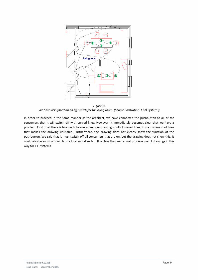
Publication No Cu0228
Issue Date: September 2015
Page 44
Figure 2: We have also fitted an all off switch for the living room. (Source illustration: E&D Systems)
In order to proceed in the same manner as the architect, we have connected the pushbutton to all of the
consumers that it will switch off with curved lines. However, it immediately becomes clear that we have a
problem. First of all there is too much to look at and our drawing is full of curved lines. It is a mishmash of lines
that makes the drawing unusable. Furthermore, the drawing does not clearly show the function of the
pushbutton. We said that it must switch off all consumers that are on, but the drawing does not show this. It
could also be an all on switch or a local mood switch. It is clear that we cannot produce useful drawings in this
way for IHS systems.
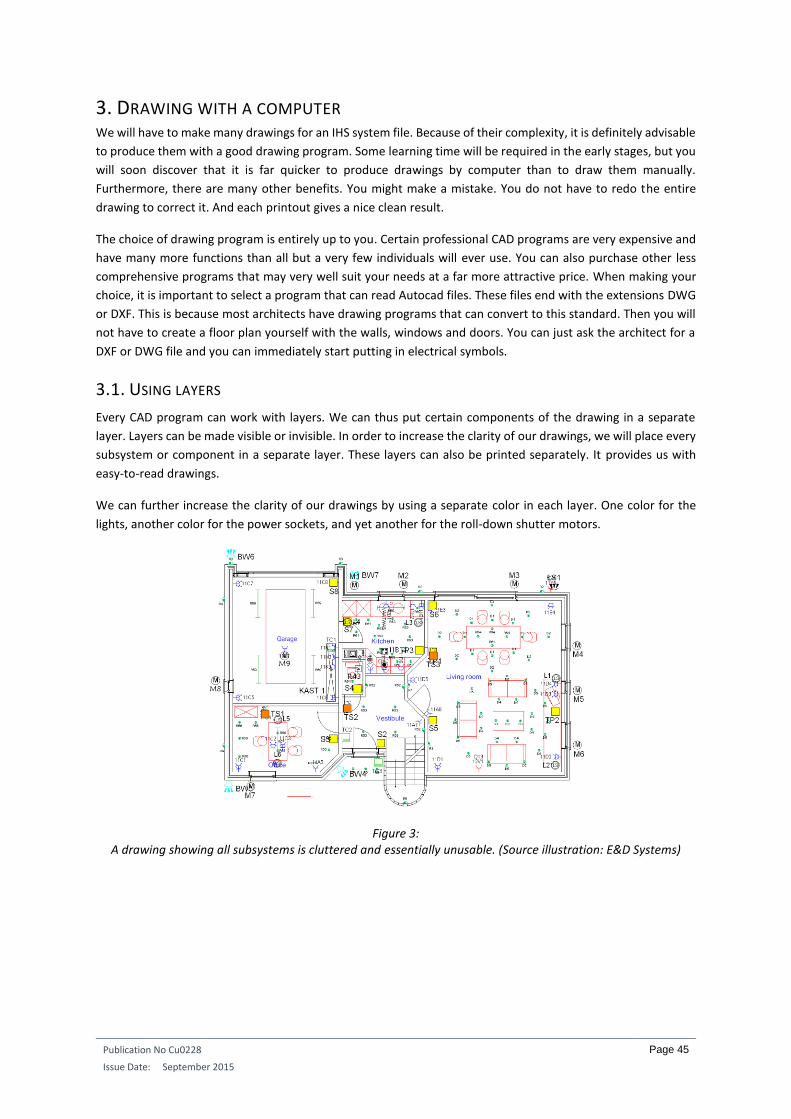
Publication No Cu0228
Issue Date: September 2015
Page 45
3. DRAWING WITH A COMPUTER We will have to make many drawings for an IHS system file. Because of their complexity, it is definitely advisable
to produce them with a good drawing program. Some learning time will be required in the early stages, but you
will soon discover that it is far quicker to produce drawings by computer than to draw them manually.
Furthermore, there are many other benefits. You might make a mistake. You do not have to redo the entire
drawing to correct it. And each printout gives a nice clean result.
The choice of drawing program is entirely up to you. Certain professional CAD programs are very expensive and
have many more functions than all but a very few individuals will ever use. You can also purchase other less
comprehensive programs that may very well suit your needs at a far more attractive price. When making your
choice, it is important to select a program that can read Autocad files. These files end with the extensions DWG
or DXF. This is because most architects have drawing programs that can convert to this standard. Then you will
not have to create a floor plan yourself with the walls, windows and doors. You can just ask the architect for a
DXF or DWG file and you can immediately start putting in electrical symbols.
3.1. USING LAYERS
Every CAD program can work with layers. We can thus put certain components of the drawing in a separate
layer. Layers can be made visible or invisible. In order to increase the clarity of our drawings, we will place every
subsystem or component in a separate layer. These layers can also be printed separately. It provides us with
easy-to-read drawings.
We can further increase the clarity of our drawings by using a separate color in each layer. One color for the
lights, another color for the power sockets, and yet another for the roll-down shutter motors.
Figure 3: A drawing showing all subsystems is cluttered and essentially unusable. (Source illustration: E&D Systems)
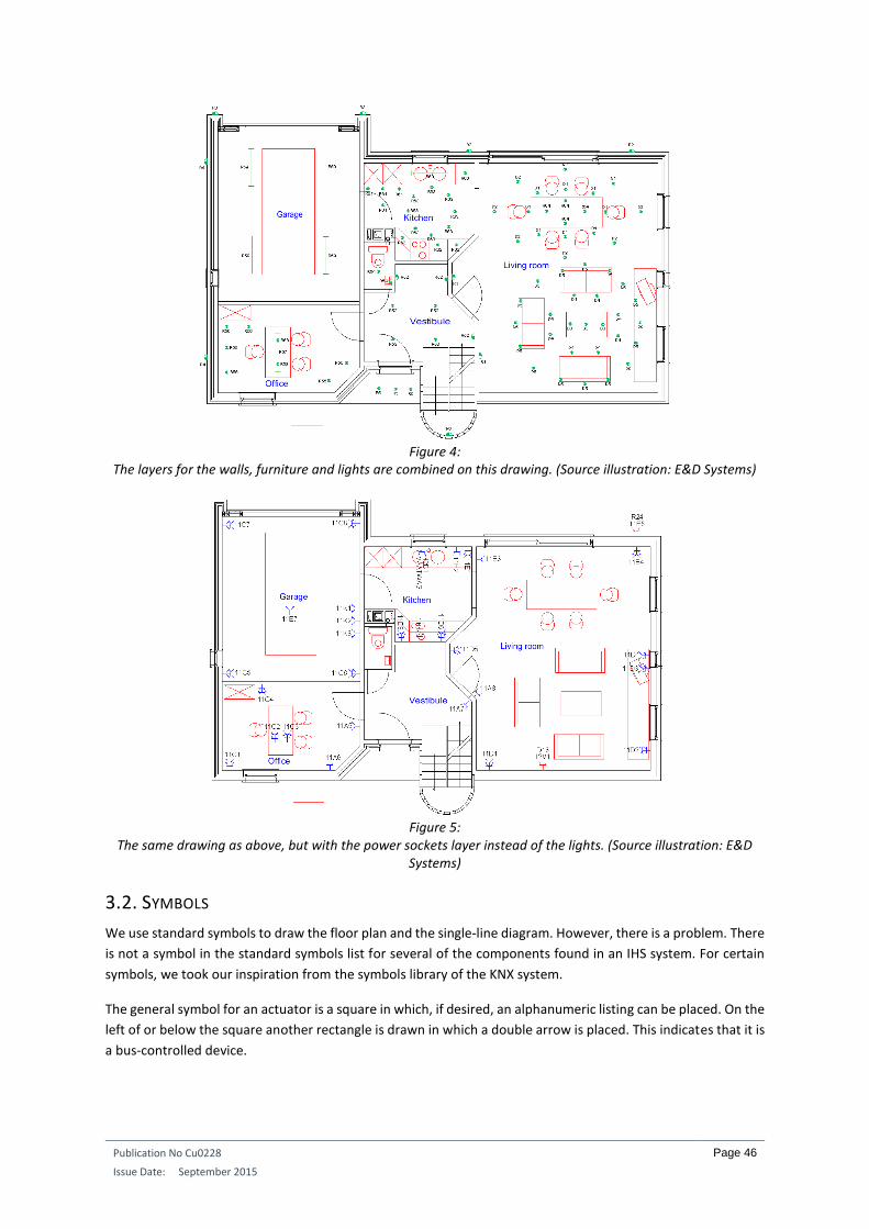
Publication No Cu0228
Issue Date: September 2015
Page 46
Figure 4:
The layers for the walls, furniture and lights are combined on this drawing. (Source illustration: E&D Systems)
Figure 5:
The same drawing as above, but with the power sockets layer instead of the lights. (Source illustration: E&D Systems)
3.2. SYMBOLS
We use standard symbols to draw the floor plan and the single-line diagram. However, there is a problem. There
is not a symbol in the standard symbols list for several of the components found in an IHS system. For certain
symbols, we took our inspiration from the symbols library of the KNX system.
The general symbol for an actuator is a square in which, if desired, an alphanumeric listing can be placed. On the
left of or below the square another rectangle is drawn in which a double arrow is placed. This indicates that it is
a bus-controlled device.

Publication No Cu0228
Issue Date: September 2015
Page 47
Figure 6:
On the left, the general symbol for an actuator of the IHS system. On the right we see different versions of
actuators. (Source illustration: E&D Systems)
1. General symbol for actuator
2. Single 10 A relay
3. 3-position relay for controlling roller-shutter motors
4. Bus -controlled dimmer
5. 0-10 V controlled dimmer
An oblique stroke is placed in the square for the sensors and interfaces.
Figure 7:
On the left, the general symbol for a sensor of the IHS system. On the right we see different versions of sensors,
all of them bus-controlled. (Source illustration: E&D Systems)
1. General symbol for sensor
2. Bus -controlled sensor module with n-number pushbuttons
3.Buss controlled PIR (passive infrared) sensor
4. Analog light sensor
5. Analog temperature sensor
Combined actuator/sensor devices are also available. Some manufacturers decentralize their actuators and
may or may not provide them with pushbuttons, temperature sensors, clocks, motion detectors, et cetera.

Publication No Cu0228
Issue Date: September 2015
Page 48
Figure 8:
Example of a combined device, consisting of a single-pole relay (actuator) and 4 pushbuttons (sensors). (Source
illustration: E&D Systems)
Sometimes a module can also contain several actuators or sensors.
Figure 9:
This bus-controlled device has 4 pushbuttons and an IR receiver. (Source illustration: E&D Systems)
In certain cases, an IHS system can also use modules that are not bus-controlled. In that event, the rectangle
with the double arrow is omitted for the symbol.
Figure 10:
Example of a non-bus-controlled operating point with n-number pushbuttons. (Source illustration: E&D
Systems)
In Figure 10 the pushbuttons are connected to an input module of the IHS system. The input module is then
connected to the bus system.
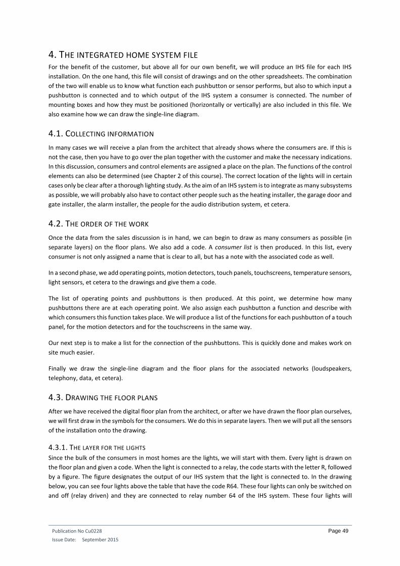
Publication No Cu0228
Issue Date: September 2015
Page 49
4. THE INTEGRATED HOME SYSTEM FILE For the benefit of the customer, but above all for our own benefit, we will produce an IHS file for each IHS
installation. On the one hand, this file will consist of drawings and on the other spreadsheets. The combination
of the two will enable us to know what function each pushbutton or sensor performs, but also to which input a
pushbutton is connected and to which output of the IHS system a consumer is connected. The number of
mounting boxes and how they must be positioned (horizontally or vertically) are also included in this file. We
also examine how we can draw the single-line diagram.
4.1. COLLECTING INFORMATION
In many cases we will receive a plan from the architect that already shows where the consumers are. If this is
not the case, then you have to go over the plan together with the customer and make the necessary indications.
In this discussion, consumers and control elements are assigned a place on the plan. The functions of the control
elements can also be determined (see Chapter 2 of this course). The correct location of the lights will in certain
cases only be clear after a thorough lighting study. As the aim of an IHS system is to integrate as many subsystems
as possible, we will probably also have to contact other people such as the heating installer, the garage door and
gate installer, the alarm installer, the people for the audio distribution system, et cetera.
4.2. THE ORDER OF THE WORK
Once the data from the sales discussion is in hand, we can begin to draw as many consumers as possible (in
separate layers) on the floor plans. We also add a code. A consumer list is then produced. In this list, every
consumer is not only assigned a name that is clear to all, but has a note with the associated code as well.
In a second phase, we add operating points, motion detectors, touch panels, touchscreens, temperature sensors,
light sensors, et cetera to the drawings and give them a code.
The list of operating points and pushbuttons is then produced. At this point, we determine how many
pushbuttons there are at each operating point. We also assign each pushbutton a function and describe with
which consumers this function takes place. We will produce a list of the functions for each pushbutton of a touch
panel, for the motion detectors and for the touchscreens in the same way.
Our next step is to make a list for the connection of the pushbuttons. This is quickly done and makes work on
site much easier.
Finally we draw the single-line diagram and the floor plans for the associated networks (loudspeakers,
telephony, data, et cetera).
4.3. DRAWING THE FLOOR PLANS
After we have received the digital floor plan from the architect, or after we have drawn the floor plan ourselves,
we will first draw in the symbols for the consumers. We do this in separate layers. Then we will put all the sensors
of the installation onto the drawing.
4.3.1. THE LAYER FOR THE LIGHTS Since the bulk of the consumers in most homes are the lights, we will start with them. Every light is drawn on
the floor plan and given a code. When the light is connected to a relay, the code starts with the letter R, followed
by a figure. The figure designates the output of our IHS system that the light is connected to. In the drawing
below, you can see four lights above the table that have the code R64. These four lights can only be switched on
and off (relay driven) and they are connected to relay number 64 of the IHS system. These four lights will

Publication No Cu0228
Issue Date: September 2015
Page 50
therefore always go on and off together. They may be connected to each other in parallel. The wall light on the
outside wall will be connected to relay number 2 of the system.
Figure 11: Every light is given a code that immediately provides us with a great deal of information. (Source illustration:
E&D Systems)
If lights are connected to a dimmer, the code starts with the letter D, followed by a figure. Here too, the figure
indicates the number of the dimmer that the light is connected to. We will also use the same figures later in the
software. This means that when we want to program a certain light, we can easily find it in the software.
4.3.2. THE POWER SOCKETS LAYER In many cases, not all power sockets in the home will be controlled by the IHS system. Such controls are generally
limited to a few power sockets such as the ones for the coffee machine, the iron, a few non-fixed light fittings,
outdoor power sockets, the kitchen boiler, et cetera. In order to make it absolutely clear which power sockets
are controlled (switched or dimmed) and which are not, we put them on the drawing in different colors. The
drawing below shows the power sockets that are not controlled by the IHS system in blue. The controlled power
sockets are in red. When on site, we can immediately see when a cable has to be laid directly to the fuse box
containing the relays or dimmers for the red power socket.
For the controlled power sockets, we enter a code in the same way as for the lights: an R or a D followed by a
number. In the drawing below, the red power socket will be controlled by dimmer 13.
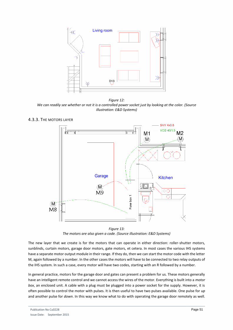
Publication No Cu0228
Issue Date: September 2015
Page 51
Figure 12: We can readily see whether or not it is a controlled power socket just by looking at the color. (Source
illustration: E&D Systems)
4.3.3. THE MOTORS LAYER
Figure 13: The motors are also given a code. (Source illustration: E&D Systems)
The new layer that we create is for the motors that can operate in either direction: roller-shutter motors,
sunblinds, curtain motors, garage door motors, gate motors, et cetera. In most cases the various IHS systems
have a separate motor output module in their range. If they do, then we can start the motor code with the letter
M, again followed by a number. In the other cases the motors will have to be connected to two relay outputs of
the IHS system. In such a case, every motor will have two codes, starting with an R followed by a number.
In general practice, motors for the garage door and gates can present a problem for us. These motors generally
have an intelligent remote control and we cannot access the wires of the motor. Everything is built into a motor
box, an enclosed unit. A cable with a plug must be plugged into a power socket for the supply. However, it is
often possible to control the motor with pulses. It is then useful to have two pulses available. One pulse for up
and another pulse for down. In this way we know what to do with operating the garage door remotely as well.

Publication No Cu0228
Issue Date: September 2015
Page 52
The cables to be used are then immediately drawn in the above drawing. M1, M2 and M8 are ordinary motors
that operate in both directions. They can be connected to ordinary 230V cabling. We need four wires: common,
turn left, turn right, and the earth. M9 is the motor box for the garage door. Here we use a thin-section signal
cable to control the door. A power socket will be drawn in the power sockets layer at the same location to ensure
a supply to the motor box.
The position on the drawing is important. M1 is drawn on the outside wall of the terrace. This is the motor for
the sunblind. M2 is also drawn on the same wall, but at the kitchen window. This motor will operate a roll-down
shutter. If we draw the symbol on the inside of the window, it will be a curtain control.
4.3.4. THE OTHER CONSUMERS
Figure 14: The electric valves for the heating control also have a code, designating the relay they are connected to.
(Source illustration: E&D Systems)
Analogous to the drawings that we did for the lights, power sockets and motors, we also make separate layers
for all other consumers. For example the electric oven, the electric heating or the valves for the central heating,
the fans for the toilet and the bathroom, the garden sprinkler, the circulation pump for the hot tap water, et
cetera.
4.3.5. ADDING A SECOND CODE To have a clear connection between the floor plans and the single-wire diagram, each consumer (whether or
not controlled by the IHS system) must be given a code. For consumers controlled by the IHS system, this means
a second code that must be added. This second code tells us to which circuit of the electrical installation the
consumer is connected. Let us take a look at an example.
Figure 15:
Not only the red, controlled power socket, but also all other power sockets (not controlled by IHS) are given a
code that indicates to which circuit of the installation they are connected. (Source illustration: E&D Systems)
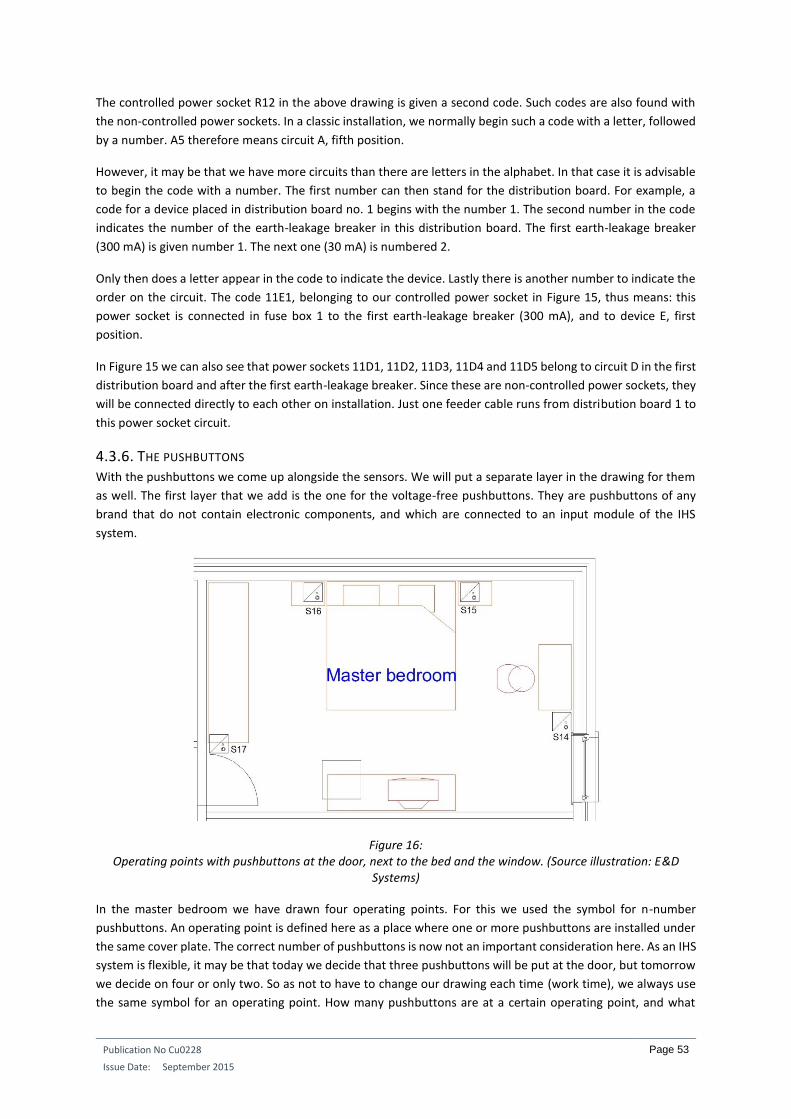
Publication No Cu0228
Issue Date: September 2015
Page 53
The controlled power socket R12 in the above drawing is given a second code. Such codes are also found with
the non-controlled power sockets. In a classic installation, we normally begin such a code with a letter, followed
by a number. A5 therefore means circuit A, fifth position.
However, it may be that we have more circuits than there are letters in the alphabet. In that case it is advisable
to begin the code with a number. The first number can then stand for the distribution board. For example, a
code for a device placed in distribution board no. 1 begins with the number 1. The second number in the code
indicates the number of the earth-leakage breaker in this distribution board. The first earth-leakage breaker
(300 mA) is given number 1. The next one (30 mA) is numbered 2.
Only then does a letter appear in the code to indicate the device. Lastly there is another number to indicate the
order on the circuit. The code 11E1, belonging to our controlled power socket in Figure 15, thus means: this
power socket is connected in fuse box 1 to the first earth-leakage breaker (300 mA), and to device E, first
position.
In Figure 15 we can also see that power sockets 11D1, 11D2, 11D3, 11D4 and 11D5 belong to circuit D in the first
distribution board and after the first earth-leakage breaker. Since these are non-controlled power sockets, they
will be connected directly to each other on installation. Just one feeder cable runs from distribution board 1 to
this power socket circuit.
4.3.6. THE PUSHBUTTONS With the pushbuttons we come up alongside the sensors. We will put a separate layer in the drawing for them
as well. The first layer that we add is the one for the voltage-free pushbuttons. They are pushbuttons of any
brand that do not contain electronic components, and which are connected to an input module of the IHS
system.
Figure 16: Operating points with pushbuttons at the door, next to the bed and the window. (Source illustration: E&D
Systems) In the master bedroom we have drawn four operating points. For this we used the symbol for n-number
pushbuttons. An operating point is defined here as a place where one or more pushbuttons are installed under
the same cover plate. The correct number of pushbuttons is now not an important consideration here. As an IHS
system is flexible, it may be that today we decide that three pushbuttons will be put at the door, but tomorrow
we decide on four or only two. So as not to have to change our drawing each time (work time), we always use
the same symbol for an operating point. How many pushbuttons are at a certain operating point, and what

Publication No Cu0228
Issue Date: September 2015
Page 54
function they will have, will not be shown in the drawing but later on in a spreadsheet. At every operating point
we also place a code. It can start with the letter S for switch for example, followed by a unique number. We
could also use PB (pushbuttons) or OP (Operating Point), but that would mean having to key in an extra letter
each time, while the intention is to save ourselves as much work as possible.
4.3.7. THE TOUCH PANELS Many IHS producers have their own brand-dependent operating panels with one or more buttons. However,
they are not voltage-free contacts. There are electronic components behind or in the panel. Such a touch panel
is generally connected to the IHS system via a bus cable. They are sometimes equipped with an internal buzzer,
an infrared receiver, a temperature sensor, LED indication and a display.
We also make a separate layer for the touch panels. And of course we add a unique code, this time with the
letters TP (touch panel), followed by a figure.
Figure 17: A touch panel next to the TV in the bedroom. This allows operations from the bed with the infrared remote
control. (Source illustration: E&D Systems)
4.3.8. THE MOTION DETECTORS Sensors also include motion detectors. We also give them a place on the plan and give them a code, starting
with the letters MD (motion detector) and followed by a figure.
Figure 18: The motion detectors at the garage door, the terrace, the front door and front garden. (Source illustration: E&D
Systems)
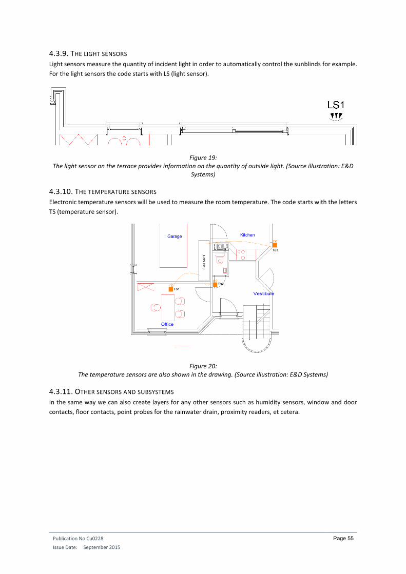
Publication No Cu0228
Issue Date: September 2015
Page 55
4.3.9. THE LIGHT SENSORS Light sensors measure the quantity of incident light in order to automatically control the sunblinds for example.
For the light sensors the code starts with LS (light sensor).
Figure 19: The light sensor on the terrace provides information on the quantity of outside light. (Source illustration: E&D
Systems)
4.3.10. THE TEMPERATURE SENSORS Electronic temperature sensors will be used to measure the room temperature. The code starts with the letters
TS (temperature sensor).
Figure 20: The temperature sensors are also shown in the drawing. (Source illustration: E&D Systems)
4.3.11. OTHER SENSORS AND SUBSYSTEMS In the same way we can also create layers for any other sensors such as humidity sensors, window and door
contacts, floor contacts, point probes for the rainwater drain, proximity readers, et cetera.
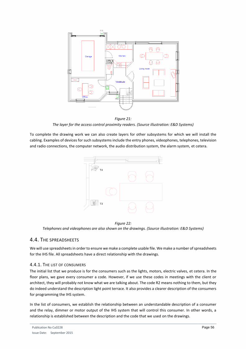
Publication No Cu0228
Issue Date: September 2015
Page 56
Figure 21:
The layer for the access control proximity readers. (Source illustration: E&D Systems)
To complete the drawing work we can also create layers for other subsystems for which we will install the
cabling. Examples of devices for such subsystems include the entry phones, videophones, telephones, television
and radio connections, the computer network, the audio distribution system, the alarm system, et cetera.
Figure 22: Telephones and videophones are also shown on the drawings. (Source illustration: E&D Systems)
4.4. THE SPREADSHEETS
We will use spreadsheets in order to ensure we make a complete usable file. We make a number of spreadsheets
for the IHS file. All spreadsheets have a direct relationship with the drawings.
4.4.1. THE LIST OF CONSUMERS The initial list that we produce is for the consumers such as the lights, motors, electric valves, et cetera. In the
floor plans, we gave every consumer a code. However, if we use these codes in meetings with the client or
architect, they will probably not know what we are talking about. The code R2 means nothing to them, but they
do indeed understand the description light point terrace. It also provides a clearer description of the consumers
for programming the IHS system.
In the list of consumers, we establish the relationship between an understandable description of a consumer
and the relay, dimmer or motor output of the IHS system that will control this consumer. In other words, a
relationship is established between the description and the code that we used on the drawings.
T3
T4

Publication No Cu0228
Issue Date: September 2015
Page 57
Figure 23: Bathroom fan tells us much more than the code R11. (Source illustration: E&D Systems)
The list consists of six columns. The first column contains a description of the consumer. Column two contains
its code if it is a consumer connected to a relay. The codes of the consumers that are connected to a motor
output or a dimmer output are put in columns three and four respectively.
In larger installations it is usual to fit a number of fuse boxes in the home: for example one in an equipment
room, one in the attic and one in the garden pavilion. We give each fuse box a number. We note this number
alongside each consumer in column five of the list. In this way we can see which fuse box the consumer has to
be connected to during the installation
Figure 24: De lijst van de motoren. (Source illustration: E&D Systems)
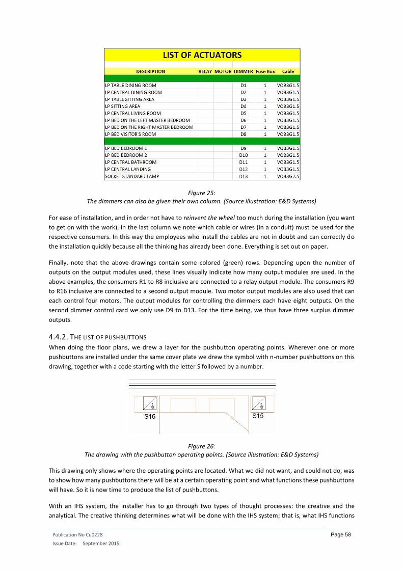
Publication No Cu0228
Issue Date: September 2015
Page 58
Figure 25: The dimmers can also be given their own column. (Source illustration: E&D Systems)
For ease of installation, and in order not have to reinvent the wheel too much during the installation (you want
to get on with the work), in the last column we note which cable or wires (in a conduit) must be used for the
respective consumers. In this way the employees who install the cables are not in doubt and can correctly do
the installation quickly because all the thinking has already been done. Everything is set out on paper.
Finally, note that the above drawings contain some colored (green) rows. Depending upon the number of
outputs on the output modules used, these lines visually indicate how many output modules are used. In the
above examples, the consumers R1 to R8 inclusive are connected to a relay output module. The consumers R9
to R16 inclusive are connected to a second output module. Two motor output modules are also used that can
each control four motors. The output modules for controlling the dimmers each have eight outputs. On the
second dimmer control card we only use D9 to D13. For the time being, we thus have three surplus dimmer
outputs.
4.4.2. THE LIST OF PUSHBUTTONS When doing the floor plans, we drew a layer for the pushbutton operating points. Wherever one or more
pushbuttons are installed under the same cover plate we drew the symbol with n-number pushbuttons on this
drawing, together with a code starting with the letter S followed by a number.
Figure 26: The drawing with the pushbutton operating points. (Source illustration: E&D Systems)
This drawing only shows where the operating points are located. What we did not want, and could not do, was
to show how many pushbuttons there will be at a certain operating point and what functions these pushbuttons
will have. So it is now time to produce the list of pushbuttons.
With an IHS system, the installer has to go through two types of thought processes: the creative and the
analytical. The creative thinking determines what will be done with the IHS system; that is, what IHS functions
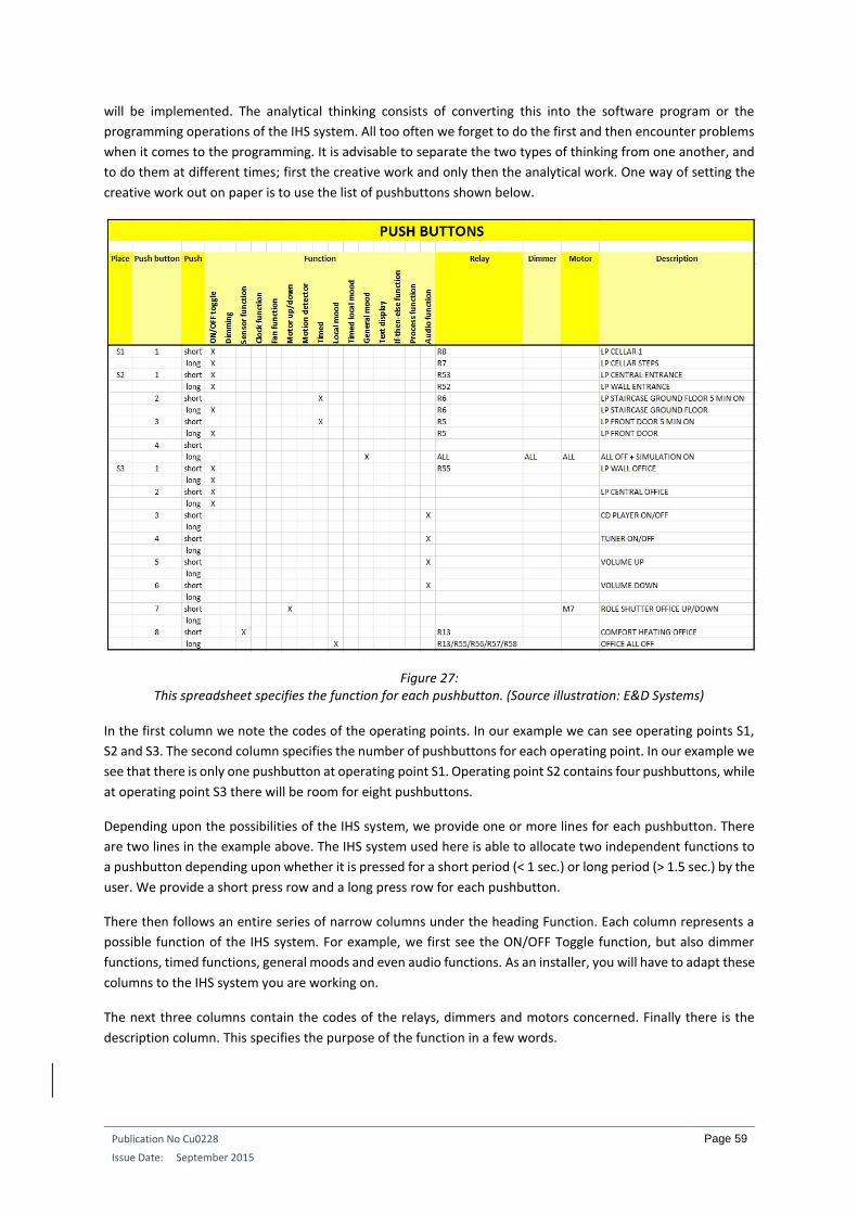
Publication No Cu0228
Issue Date: September 2015
Page 59
will be implemented. The analytical thinking consists of converting this into the software program or the
programming operations of the IHS system. All too often we forget to do the first and then encounter problems
when it comes to the programming. It is advisable to separate the two types of thinking from one another, and
to do them at different times; first the creative work and only then the analytical work. One way of setting the
creative work out on paper is to use the list of pushbuttons shown below.
Figure 27: This spreadsheet specifies the function for each pushbutton. (Source illustration: E&D Systems)
In the first column we note the codes of the operating points. In our example we can see operating points S1,
S2 and S3. The second column specifies the number of pushbuttons for each operating point. In our example we
see that there is only one pushbutton at operating point S1. Operating point S2 contains four pushbuttons, while
at operating point S3 there will be room for eight pushbuttons.
Depending upon the possibilities of the IHS system, we provide one or more lines for each pushbutton. There
are two lines in the example above. The IHS system used here is able to allocate two independent functions to
a pushbutton depending upon whether it is pressed for a short period (< 1 sec.) or long period (> 1.5 sec.) by the
user. We provide a short press row and a long press row for each pushbutton.
There then follows an entire series of narrow columns under the heading Function. Each column represents a
possible function of the IHS system. For example, we first see the ON/OFF Toggle function, but also dimmer
functions, timed functions, general moods and even audio functions. As an installer, you will have to adapt these
columns to the IHS system you are working on.
The next three columns contain the codes of the relays, dimmers and motors concerned. Finally there is the
description column. This specifies the purpose of the function in a few words.
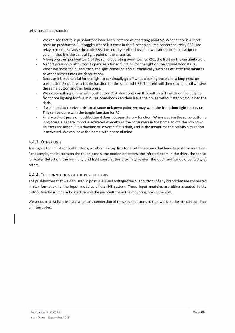
Publication No Cu0228
Issue Date: September 2015
Page 60
Let’s look at an example:
- We can see that four pushbuttons have been installed at operating point S2. When there is a short press on pushbutton 1, it toggles (there is a cross in the function column concerned) relay R53 (see relay column). Because the code R53 does not by itself tell us a lot, we can see in the description column that it is the central light point of the entrance.
- A long press on pushbutton 1 of the same operating point toggles R52, the light on the vestibule wall. - A short press on pushbutton 2 operates a timed function for the light on the ground floor stairs.
When we press the pushbutton, the light comes on and automatically switches off after five minutes or other preset time (see description).
- Because it is not helpful for the light to continually go off while cleaning the stairs, a long press on pushbutton 2 operates a toggle function for the same light R6. The light will then stay on until we give the same button another long press.
- We do something similar with pushbutton 3. A short press on this button will switch on the outside front door lighting for five minutes. Somebody can then leave the house without stepping out into the dark.
- If we intend to receive a visitor at some unknown point, we may want the front door light to stay on. This can be done with the toggle function for R5.
- Finally a short press on pushbutton 4 does not operate any function. When we give the same button a long press, a general mood is activated whereby all the consumers in the home go off, the roll-down shutters are raised if it is daytime or lowered if it is dark, and in the meantime the activity simulation is activated. We can leave the home with peace of mind.
4.4.3. OTHER LISTS Analogous to the lists of pushbuttons, we also make up lists for all other sensors that have to perform an action.
For example, the buttons on the touch panels, the motion detectors, the infrared beam in the drive, the sensor
for water detection, the humidity and light sensors, the proximity reader, the door and window contacts, et
cetera.
4.4.4. THE CONNECTION OF THE PUSHBUTTONS The pushbuttons that we discussed in point 4.4.2. are voltage-free pushbuttons of any brand that are connected
in star formation to the input modules of the IHS system. These input modules are either situated in the
distribution board or are located behind the pushbuttons in the mounting box in the wall.
We produce a list for the installation and connection of these pushbuttons so that work on the site can continue
uninterrupted.
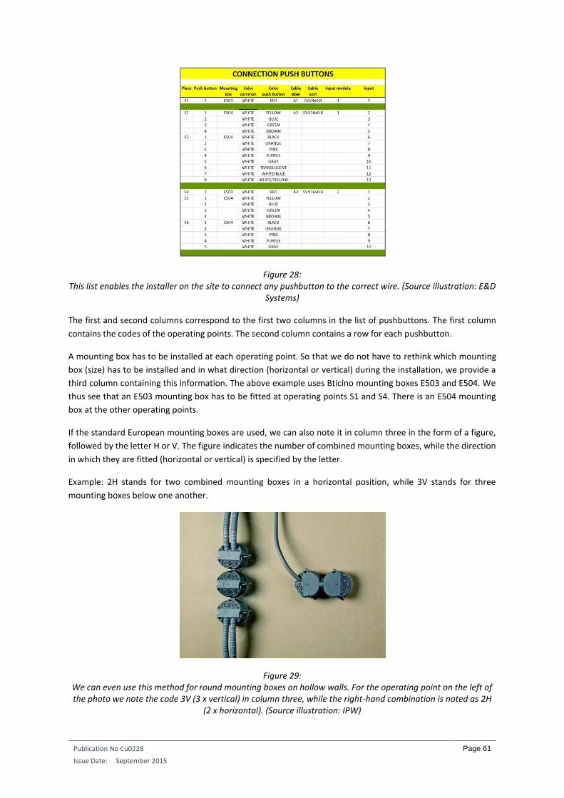
Publication No Cu0228
Issue Date: September 2015
Page 61
Figure 28: This list enables the installer on the site to connect any pushbutton to the correct wire. (Source illustration: E&D
Systems)
The first and second columns correspond to the first two columns in the list of pushbuttons. The first column
contains the codes of the operating points. The second column contains a row for each pushbutton.
A mounting box has to be installed at each operating point. So that we do not have to rethink which mounting
box (size) has to be installed and in what direction (horizontal or vertical) during the installation, we provide a
third column containing this information. The above example uses Bticino mounting boxes E503 and E504. We
thus see that an E503 mounting box has to be fitted at operating points S1 and S4. There is an E504 mounting
box at the other operating points.
If the standard European mounting boxes are used, we can also note it in column three in the form of a figure,
followed by the letter H or V. The figure indicates the number of combined mounting boxes, while the direction
in which they are fitted (horizontal or vertical) is specified by the letter.
Example: 2H stands for two combined mounting boxes in a horizontal position, while 3V stands for three
mounting boxes below one another.
Figure 29: We can even use this method for round mounting boxes on hollow walls. For the operating point on the left of the photo we note the code 3V (3 x vertical) in column three, while the right-hand combination is noted as 2H
(2 x horizontal). (Source illustration: IPW)

Publication No Cu0228
Issue Date: September 2015
Page 62
The pushbuttons are connected in star formation (making use of a common wire) to the fuse box. In our case
we use an SVV cable. This cable consists of a number of separate insulated and colored copper conductors of
0.8 mm², surrounded by a grey outer sheath. The table in Figure 28 shows the use of the green colored horizontal
lines. All operating points located between two consecutive green lines are connected with the same cable. We
note the type of cable in column seven: SVV 4x0.8 or SVV 16x0.8, a cable with 4 or 16 conductors respectively.
We provide an identification label at the point where these cables go into the fuse box. In the above list we see
that the first cable (SVV 4x0.8) has the label A1 and only goes from the fuse box to operating point S1 (there is
a green line below it). The cable with the label A2 (SVV 16x0.8) goes from the fuse box to operating point S2,
and from there to operating point S3. The next cable (A3) goes to operating points S4, S5 and S6.
Column four shows that the white wire of the cables will always be used as the common wire for all pushbuttons.
Furthermore, each pushbutton is given a unique wire in column five. By drawing up this list beforehand, you do
not waste time on site noting which wire has been connected to which pushbutton. Few mistakes are made as
a result.
Finally, we would also like to know which input of the IHS system a pushbutton is connected to. This is indicated
in the last two columns. In the penultimate column we note the number of the input module. In the last column
we note the input of the input module to which the relevant pushbutton is connected.
Depending on the IHS system concerned, we can also make a modification here. We do not need to note wire
colors for all systems that use BUS cabling and pushbutton modules that are directly connected to it. It is
sufficient to note the address of the module or the pushbuttons
4.5. ADDITIONAL DRAWINGS
A number of additional drawings also have to be produced. However, these drawings can be used on any site.
First of all, there is the drawing to show where a certain pushbutton is installed at an operating point. If we have
to connect four pushbuttons under one cover plate, which pushbutton is then No. 1, 2, 3 of 4? The drawing
below makes this clear. This drawing has been produced for use with Bticino pushbuttons. If another brand of
pushbutton is used (Berker, Gira, Jung, Legrand, Lithoss, Merten, Niko, Peha, Siemens, Simon, et cetera) an
appropriate drawing will of course have to be produced with a number of possible combinations.
Figure 30:
An example of possible arrangements for Bticino pushbuttons. (Source illustration: E&D Systems)
1 1 1
11 1
2 2
22
2
3
33 3
4 4 45 5 6
1 2 3 41
1 1 1
2
2 2 2
3
33 3
4
4 44
5
5 5 56 6 67 7 8
BT
icin
o
503 503
504504504
503
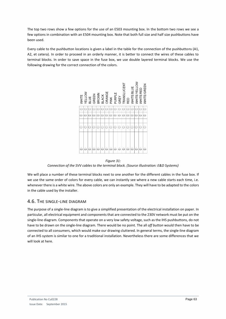
Publication No Cu0228
Issue Date: September 2015
Page 63
The top two rows show a few options for the use of an E503 mounting box. In the bottom two rows we see a
few options in combination with an E504 mounting box. Note that both full size and half size pushbuttons have
been used.
Every cable to the pushbutton locations is given a label in the table for the connection of the pushbuttons (A1,
A2, et cetera). In order to proceed in an orderly manner, it is better to connect the wires of these cables to
terminal blocks. In order to save space in the fuse box, we use double layered terminal blocks. We use the
following drawing for the correct connection of the colors.
Figure 31: Connection of the SVV cables to the terminal block. (Source illustration: E&D Systems)
We will place a number of these terminal blocks next to one another for the different cables in the fuse box. If
we use the same order of colors for every cable, we can instantly see where a new cable starts each time, i.e.
whenever there is a white wire. The above colors are only an example. They will have to be adapted to the colors
in the cable used by the installer.
4.6. THE SINGLE-LINE DIAGRAM
The purpose of a single-line diagram is to give a simplified presentation of the electrical installation on paper. In
particular, all electrical equipment and components that are connected to the 230V network must be put on the
single-line diagram. Components that operate on a very low safety voltage, such as the IHS pushbuttons, do not
have to be drawn on the single-line diagram. There would be no point. The all off button would then have to be
connected to all consumers, which would make our drawing cluttered. In general terms, the single-line diagram
of an IHS system is similar to one for a traditional installation. Nevertheless there are some differences that we
will look at here.
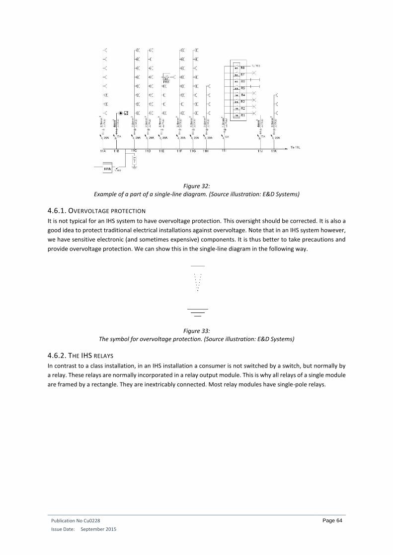
Publication No Cu0228
Issue Date: September 2015
Page 64
Figure 32: Example of a part of a single-line diagram. (Source illustration: E&D Systems)
4.6.1. OVERVOLTAGE PROTECTION It is not typical for an IHS system to have overvoltage protection. This oversight should be corrected. It is also a
good idea to protect traditional electrical installations against overvoltage. Note that in an IHS system however,
we have sensitive electronic (and sometimes expensive) components. It is thus better to take precautions and
provide overvoltage protection. We can show this in the single-line diagram in the following way.
Figure 33: The symbol for overvoltage protection. (Source illustration: E&D Systems)
4.6.2. THE IHS RELAYS In contrast to a class installation, in an IHS installation a consumer is not switched by a switch, but normally by
a relay. These relays are normally incorporated in a relay output module. This is why all relays of a single module
are framed by a rectangle. They are inextricably connected. Most relay modules have single-pole relays.
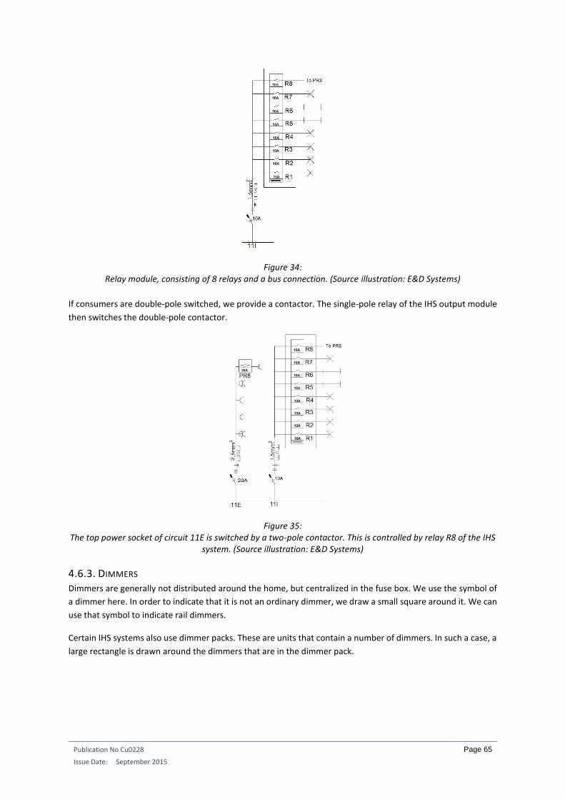
Publication No Cu0228
Issue Date: September 2015
Page 65
Figure 34: Relay module, consisting of 8 relays and a bus connection. (Source illustration: E&D Systems)
If consumers are double-pole switched, we provide a contactor. The single-pole relay of the IHS output module
then switches the double-pole contactor.
Figure 35: The top power socket of circuit 11E is switched by a two-pole contactor. This is controlled by relay R8 of the IHS
system. (Source illustration: E&D Systems)
4.6.3. DIMMERS Dimmers are generally not distributed around the home, but centralized in the fuse box. We use the symbol of
a dimmer here. In order to indicate that it is not an ordinary dimmer, we draw a small square around it. We can
use that symbol to indicate rail dimmers.
Certain IHS systems also use dimmer packs. These are units that contain a number of dimmers. In such a case, a
large rectangle is drawn around the dimmers that are in the dimmer pack.

Publication No Cu0228
Issue Date: September 2015
Page 66
Figure 36: Presentation of a 12-channel dimmer pack and a single dimmer. All dimmers in this drawing are controlled by a
0-10 V control and not directly by a bus system. (Source illustration: E&D Systems)
4.6.4. MOTORS We can also use a separate symbol for the motors of roller-shutters, sunblinds, et cetera. IHS systems normally
provide modules for controlling bi-directional motors. All relays of a single module are then framed by a
rectangle.
Figure 37:
Here too, the number of the relay used is always indicated. (Source illustration: E&D Systems)
In the above drawing, we see that the four relays that control the motors (when considered together) form a
motor control module that is controlled by a bus connection.

Publication No Cu0228
Issue Date: September 2015
Page 67
4.7. DRAWING OF THE DISTRIBUTION BOX
It can certainly be useful with larger installations to provide a sketch of the distribution board in which all
components are allocated a place.
Figure 38:
Example of a drawn fuse box, equipped with an earth-leakage breaker, overvoltage protection, automatic breakers and various other types of IHS equipment. (Source illustration: E&D Systems)
4.8. ADVANTAGES OF THE IHS SYSTEM FILE FOR THE INSTALLER
It will be clear that the production of a professional IHS system file will take some time. However, this time pays
dividends during installation on site. A number of the benefits are set out below:
Time saved on site. If, when on site, you still need to think about how many pushbuttons there must be at a particular point and what function these pushbuttons will have to perform, then you are wasting time.
Time saved when installing pushbuttons. If such a method is not used, you will still have to write everything down on site. The color of a wire that is connected to a particular pushbutton must also be easily identified in the fuse box, without a so-called continuity test having to be carried out.
O UT08aut obus
O UT M O TO R 230V
I NP08ANI NP16D TELint er f .
DI Mint er f .
2 3 0 F M L
2 4 F M L
CT
M
E
12
C O A X
T E S T
h a g e r4 0 A 3 0 m A
N
2 0 A 2 0 A 2 0 A 2 0 A
1 6 A 1 6 A1 6 A1 6 A 6 A1 0 A 6 A 6 A
2 5 A
2 3 0 F M L
2 0 A 2 0 A
12
34
56
78
O M R O N
12
34
56
78
O M R O N
12
34
56
78
O M R O N
12
34
56
78
O M R O N
12
34
56
78
O M R O N
12
34
56
78
O M R O N
12
34
56
78
O M R O N
12
34
56
78
O M R O N
12
34
56
78
O M R O N
12
34
56
78
O M R O N
12
34
56
78
O M R O N
12
34
56
78
O M R O N
12
34
56
78
O M R O N
O UT08aut obus
O UT08aut obus O UT08aut obus
Po we rs u p p ly
1 2 V DC

Publication No Cu0228
Issue Date: September 2015
Page 68
Time saved when programming. Once the installation has been completed and has to be programmed, at that point you no longer want to be thinking about the function of a pushbutton. Everything is clearly written down in the tables.
Clarity. The printouts allow you to work with a comprehensive overall view of the installation. All details can easily be found.
Easily adaptable. A minor or major change must be made in the diagrams and tables. Changes can be quickly made and are clear.
Up-to-date information. In principle, the latest changes and modifications discussed must always be visible in the diagrams and tables. It is therefore a good idea to always include the date on drawings and tables.
Clear site instructions. When employees go to the site with plans and tables, they are armed with clear information. Mistakes are almost entirely excluded.
Indications on the plans and diagrams made by employees can easily and neatly be incorporated into the file.
Tidiness. Working in a tidy fashion has several positive side effects. Someone who can submit a tidy file will gain trust more readily than if a few scraps of paper are presented. As a secondary effect, it can boost your image. You are viewed as someone who will deliver quality.
The diagrams for the inspection are ready. Obviously the entire file does not need to be submitted for inspection. As the drawing work has already been done, a printout of the floor plans and the single-wire diagram can suffice.
Time saved in after-sales service. Once the property is occupied, if modifications and changes have to be made (hardware or software), you can fall back on a complete file. This means you do not waste valuable time having to investigate and test individual connections.
The customer gets a complete file. If you are unavailable, the customer still has the necessary information to have any modifications carried out by someone else. Obviously this point forms part of the sales agreement.

Publication No Cu0228
Issue Date: September 2015
Page 69
INTEGRATED HOME SYSTEMS COURSE CHAPTER 4: A TECHNICAL EXAMINATION
Guy Kasier
December 2015
ECI Publication No Cu0236
Available from www.leonardo-energy.org

Publication No. Cu0236
Issue Date: December 2015
Page 70
CONTENTS
1. Introduction ............................................................................................................................................................... 73
2. Centralised, decentralised or semi-centralised intelligence ......................................................................................... 74
2.1. Centralised systems ......................................................................................................................................................... 74
2.1.1. Advantages of centralised systems ................................................................................................................ 74
2.1.2. Disadvantages of centralised systems ............................................................................................................ 74
2.2. Decentralised systems: .................................................................................................................................................... 74
2.2.1. Advantages of decentralised systems ............................................................................................................ 75
2.2.2. Disadvantages of decentralised systems........................................................................................................ 75
2.3. Semi-centralised systems:................................................................................................................................................ 75
3. Topology .................................................................................................................................................................... 77
3.1. Star topology .................................................................................................................................................................... 77
3.1.1. Advantage: ..................................................................................................................................................... 77
3.1.2. Disadvantages: ............................................................................................................................................... 77
3.2. BUS topology ................................................................................................................................................................... 77
3.2.1. Advantages:.................................................................................................................................................... 78
3.2.2. Disadvantages: ............................................................................................................................................... 78
3.3. Tree topology or free topology ........................................................................................................................................ 78
3.3.1. Advantages:.................................................................................................................................................... 78
3.3.2. Disadvantages: ............................................................................................................................................... 78
4. Media used ................................................................................................................................................................. 79
4.1. Multicable ........................................................................................................................................................................ 79
4.2. Twisted Pair (TP) .............................................................................................................................................................. 79
4.3. Powerline (PL) .................................................................................................................................................................. 80
4.4. Coax 80
4.5. Radio frequency (RF) ........................................................................................................................................................ 80
4.6. Infrared (IR) ...................................................................................................................................................................... 81
4.7. Optical fibre ..................................................................................................................................................................... 81
5. Integrated home system components......................................................................................................................... 82
5.1. The consumers ................................................................................................................................................................. 82
5.2. The actuators ................................................................................................................................................................... 82
5.3. Input modules .................................................................................................................................................................. 83
5.3.1. Digital input modules ..................................................................................................................................... 83
5.3.2. Analogue input modules ................................................................................................................................ 83
5.4. The sensors ...................................................................................................................................................................... 83

Publication No. Cu0236
Issue Date: December 2015
Page 71
5.4.1. Switches and push buttons ............................................................................................................................ 84
5.4.2. Operating panels ............................................................................................................................................ 84
5.4.3. Voltage-free contacts ..................................................................................................................................... 85
5.4.4. Touch screen .................................................................................................................................................. 85
5.4.5. The touch window.......................................................................................................................................... 86
5.4.6. RF transmitters ............................................................................................................................................... 86
5.4.7. IR remote controls ......................................................................................................................................... 87
5.4.8. Smartphone ................................................................................................................................................... 87
5.4.9. Tablet ............................................................................................................................................................. 87
5.4.10. The computer ............................................................................................................................................... 87
5.4.11. Motion detectors ......................................................................................................................................... 88
5.4.12. Presence detectors ...................................................................................................................................... 88
5.4.13. Smoke detectors .......................................................................................................................................... 89
5.4.14. Gas detectors ............................................................................................................................................... 89
5.4.15. Magnetic contacts ........................................................................................................................................ 90
5.4.16. Thermostats ................................................................................................................................................. 90
5.4.17. Analogue temperature sensors .................................................................................................................... 90
5.4.18. Level sensors ................................................................................................................................................ 90
5.4.19. Water leak detector ..................................................................................................................................... 91
5.4.20. Humidity detectors ...................................................................................................................................... 91
5.4.21. Light sensors ................................................................................................................................................ 91
5.4.22. Wind sensors ................................................................................................................................................ 91
5.4.23. Rain sensors ................................................................................................................................................. 91
5.4.24. Weather station ........................................................................................................................................... 92
5.4.26. Card readers and proximity readers ............................................................................................................ 92
5.4.27. Code panels .................................................................................................................................................. 92
5.4.28. Biometric detectors...................................................................................................................................... 92
5.4.29. Energy meters .............................................................................................................................................. 93
5.5. Other interfaces ............................................................................................................................................................... 93
6. Safety and security in and around the home ............................................................................................................... 94
6.1. Positioning of IHS components in wet rooms .................................................................................................................. 94

Publication No. Cu0236
Issue Date: December 2015
Page 72
6.2. Manual operation of roll-down shutters and doors ........................................................................................................ 95
6.3. Take care with clocks ....................................................................................................................................................... 95
6.4. Switching off outdoor power points ................................................................................................................................ 95
7. Installation techniques and tips .................................................................................................................................. 97
7.1. Protecting relay modules ................................................................................................................................................. 97
7.2. Fitting overvoltage protection ......................................................................................................................................... 98
7.3. Avoiding large loops with IHS cables................................................................................................................................ 99
7.4. Manual switching ........................................................................................................................................................... 100
7.5. EMC 101
7.6. CE mark .......................................................................................................................................................................... 101
7.7. Earthing of modules ....................................................................................................................................................... 101
7.8. Use the specified cables ................................................................................................................................................. 101
7.9. Respect the maximum distances ................................................................................................................................... 102
7.10. Use of screening........................................................................................................................................................... 102
7.11. Keep cables with different voltages away from one another ...................................................................................... 102
7.12. Use of multicable ......................................................................................................................................................... 103
7.13. Labelling cables and wires ........................................................................................................................................... 103
7.14. Good connecting techniques ....................................................................................................................................... 104
7.15. Fitting terminating resistors ......................................................................................................................................... 105
7.16. Filters in powerline systems......................................................................................................................................... 105
7.17. Note the addresses of BUS participants....................................................................................................................... 105
7.18. Calculation of the power supply .................................................................................................................................. 106
7.19. Select the correct relay contacts.................................................................................................................................. 106
7.19.1. Resistive loads ............................................................................................................................................ 108
7.19.2. Inductive loads ........................................................................................................................................... 108
7.19.3. Capacitive loads ......................................................................................................................................... 108
7.19.4. Switch-on currents ..................................................................................................................................... 109
7.20. Connection of tube motors .......................................................................................................................................... 109
7.21. Operating components at a usable height ................................................................................................................... 111
7.22. Positioning of thermostats or temperature sensors .................................................................................................... 111
7.23. Maintaining flexibility .................................................................................................................................................. 112
7.23.1. Multicable .................................................................................................................................................. 112
7.23.2. Separate cabling for push buttons ............................................................................................................. 113

Publication No. Cu0236
Issue Date: December 2015
Page 73
1. INTRODUCTION In this chapter of the Integrated Home Systems (IHS) course we focus on the technological aspects of an IHS
installation. Among other things, we discuss where the system intelligence is located, the topology and the
media of the installation. We also devote attention to the components of an IHS system and touch on various
safety issues. In the final section, we discuss several installation techniques and provide some handy tips for
installing an IHS system.
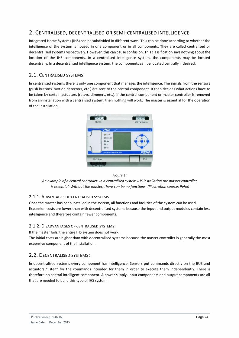
Publication No. Cu0236
Issue Date: December 2015
Page 74
2. CENTRALISED, DECENTRALISED OR SEMI-CENTRALISED INTELLIGENCE Integrated Home Systems (IHS) can be subdivided in different ways. This can be done according to whether the
intelligence of the system is housed in one component or in all components. They are called centralised or
decentralised systems respectively. However, this can cause confusion. This classification says nothing about the
location of the IHS components. In a centralised intelligence system, the components may be located
decentrally. In a decentralised intelligence system, the components can be located centrally if desired.
2.1. CENTRALISED SYSTEMS
In centralised systems there is only one component that manages the intelligence. The signals from the sensors
(push buttons, motion detectors, etc.) are sent to the central component. It then decides what actions have to
be taken by certain actuators (relays, dimmers, etc.). If the central component or master controller is removed
from an installation with a centralised system, then nothing will work. The master is essential for the operation
of the installation.
Figure 1:
An example of a central controller. In a centralised system IHS installation the master controller
is essential. Without the master, there can be no functions. (Illustration source: Peha)
2.1.1. ADVANTAGES OF CENTRALISED SYSTEMS Once the master has been installed in the system, all functions and facilities of the system can be used.
Expansion costs are lower than with decentralised systems because the input and output modules contain less
intelligence and therefore contain fewer components.
2.1.2. DISADVANTAGES OF CENTRALISED SYSTEMS If the master fails, the entire IHS system does not work.
The initial costs are higher than with decentralised systems because the master controller is generally the most
expensive component of the installation.
2.2. DECENTRALISED SYSTEMS:
In decentralised systems every component has intelligence. Sensors put commands directly on the BUS and
actuators “listen” for the commands intended for them in order to execute them independently. There is
therefore no central intelligent component. A power supply, input components and output components are all
that are needed to build this type of IHS system.

Publication No. Cu0236
Issue Date: December 2015
Page 75
Figure 2:
The KNX IHS system is a typical example of a system with decentralised intelligence.
Sensors and actuators are connected to one another by the BUS (green lines). There is no master
that controls everything. Every component can “listen” and/or “send”. (Illustration source: KNX)
Example:
Figure 3:
In this IHS system all control and sensor components and all actuators are connected to the
same BUS. At the left there is a power supply for the BUS, but there is no master controller in the system. Each
component has its own intelligence. (Illustration source: Bticino)
2.2.1. ADVANTAGES OF DECENTRALISED SYSTEMS The initial cost for a small installation is low. All that is needed is a power supply, an input module and an output
module. No expensive master is required.
When a component fails, in principle it will not affect the operation of the other components.
2.2.2. DISADVANTAGES OF DECENTRALISED SYSTEMS Expansions are generally more expensive than with a centralised system, as every component must carry the
necessary intelligence.
Specific components have to be installed in the system in order to execute certain functions.
2.3. SEMI-CENTRALISED SYSTEMS:
Some brands work with what is called “semi-centralised intelligence”. In practice, this means that every output
module has intelligence for its own outputs. The sensors are connected to the output modules over a common

Publication No. Cu0236
Issue Date: December 2015
Page 76
BUS. When a sensor sends a signal, each module checks whether the signal is intended for it. If it is, the module
then checks which module outputs the signal is intended for, and which function needs to be performed.
Each module works as a stand-alone. An installation with just one module can be treated as a centralised system.
If the installation contains several intelligent output modules, it acts like a group of master modules working in
parallel.
When one of the output modules (small controller) fails, the rest of the installation can still work.
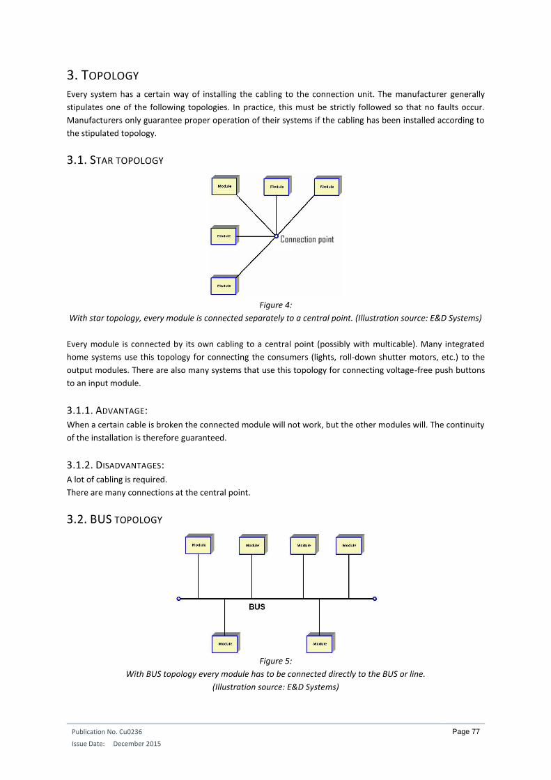
Publication No. Cu0236
Issue Date: December 2015
Page 77
3. TOPOLOGY Every system has a certain way of installing the cabling to the connection unit. The manufacturer generally
stipulates one of the following topologies. In practice, this must be strictly followed so that no faults occur.
Manufacturers only guarantee proper operation of their systems if the cabling has been installed according to
the stipulated topology.
3.1. STAR TOPOLOGY
Figure 4:
With star topology, every module is connected separately to a central point. (Illustration source: E&D Systems)
Every module is connected by its own cabling to a central point (possibly with multicable). Many integrated
home systems use this topology for connecting the consumers (lights, roll-down shutter motors, etc.) to the
output modules. There are also many systems that use this topology for connecting voltage-free push buttons
to an input module.
3.1.1. ADVANTAGE: When a certain cable is broken the connected module will not work, but the other modules will. The continuity
of the installation is therefore guaranteed.
3.1.2. DISADVANTAGES: A lot of cabling is required.
There are many connections at the central point.
3.2. BUS TOPOLOGY
Figure 5:
With BUS topology every module has to be connected directly to the BUS or line.
(Illustration source: E&D Systems)

Publication No. Cu0236
Issue Date: December 2015
Page 78
The bus cable here goes from module to module. A branch connected to a number of modules is not allowed.
The bus cable starts from one module, goes to the next module, and then on to the next until it is finally
connected to the last module. In practice, a terminating resistor has to be put on the bus at the start and at the
end to stop reflections on the bus.
3.2.1. ADVANTAGES: Less cable has to be installed.
In most cases, it requires fewer connections.
3.2.2. DISADVANTAGES: A break in the cable will cause a substantial section of the installation not to work.
3.3. TREE TOPOLOGY OR FREE TOPOLOGY
Figure 6:
In practice, tree topology gives great freedom of installation. (Illustration source: E&D Systems)
The tree topology is a combination of the star and bus topologies. It is also called free topology because the
installer is free to make any kind of branch for connecting modules to the bus cable. The only restriction is that
closed loops cannot be created.
3.3.1. ADVANTAGES: The installer can make branches anywhere.
The flexibility of the installation is increased.
3.3.2. DISADVANTAGES: Here too, a break in the cable can paralyse a substantial section of the installation.
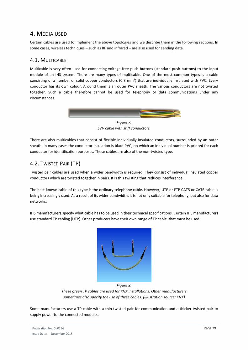
Publication No. Cu0236
Issue Date: December 2015
Page 79
4. MEDIA USED Certain cables are used to implement the above topologies and we describe them in the following sections. In
some cases, wireless techniques – such as RF and infrared – are also used for sending data.
4.1. MULTICABLE
Multicable is very often used for connecting voltage-free push buttons (standard push buttons) to the input
module of an IHS system. There are many types of multicable. One of the most common types is a cable
consisting of a number of solid copper conductors (0.8 mm²) that are individually insulated with PVC. Every
conductor has its own colour. Around them is an outer PVC sheath. The various conductors are not twisted
together. Such a cable therefore cannot be used for telephony or data communications under any
circumstances.
Figure 7:
SVV cable with stiff conductors.
There are also multicables that consist of flexible individually insulated conductors, surrounded by an outer
sheath. In many cases the conductor insulation is black PVC, on which an individual number is printed for each
conductor for identification purposes. These cables are also of the non-twisted type.
4.2. TWISTED PAIR (TP)
Twisted pair cables are used when a wider bandwidth is required. They consist of individual insulated copper
conductors which are twisted together in pairs. It is this twisting that reduces interference.
The best-known cable of this type is the ordinary telephone cable. However, UTP or FTP CAT5 or CAT6 cable is
being increasingly used. As a result of its wider bandwidth, it is not only suitable for telephony, but also for data
networks.
IHS manufacturers specify what cable has to be used in their technical specifications. Certain IHS manufacturers
use standard TP cabling (UTP). Other producers have their own range of TP cable that must be used.
Figure 8:
These green TP cables are used for KNX installations. Other manufacturers
sometimes also specify the use of these cables. (Illustration source: KNX)
Some manufacturers use a TP cable with a thin twisted pair for communication and a thicker twisted pair to
supply power to the connected modules.
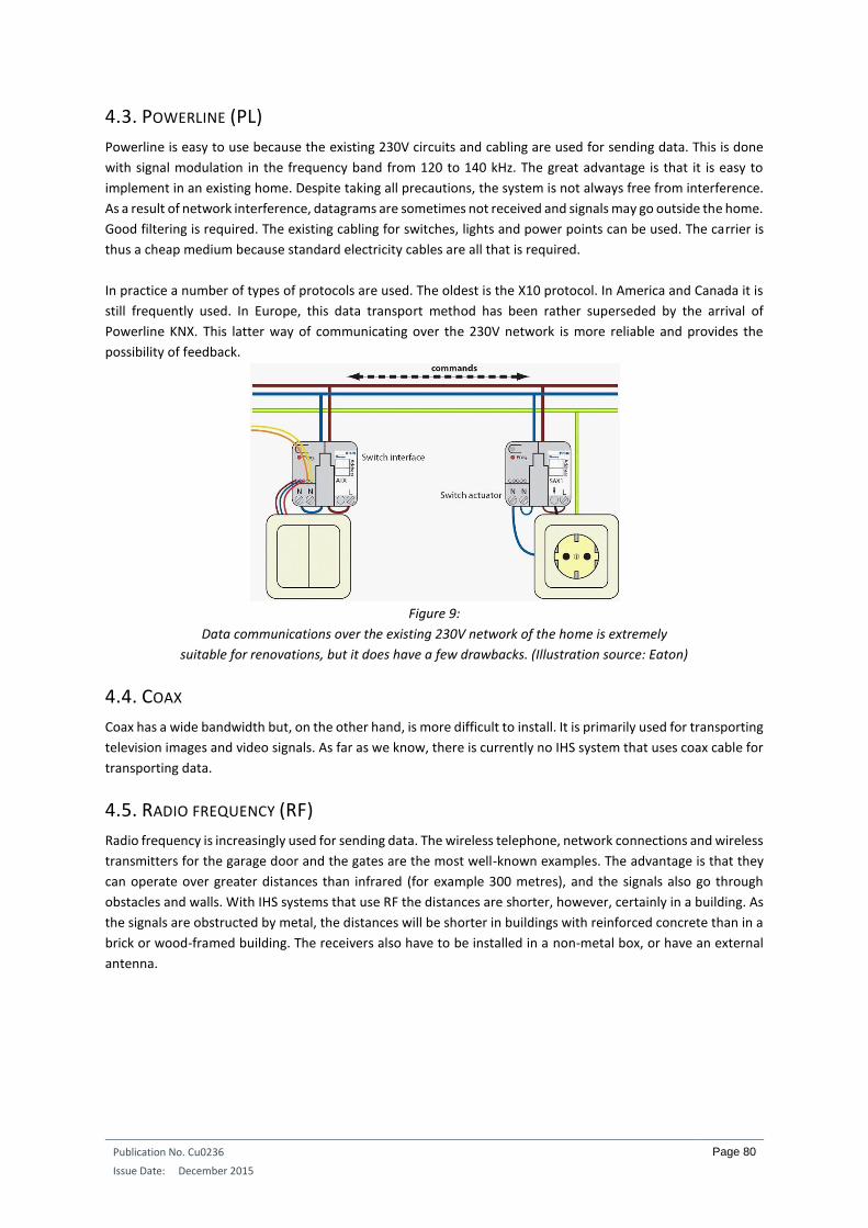
Publication No. Cu0236
Issue Date: December 2015
Page 80
4.3. POWERLINE (PL)
Powerline is easy to use because the existing 230V circuits and cabling are used for sending data. This is done
with signal modulation in the frequency band from 120 to 140 kHz. The great advantage is that it is easy to
implement in an existing home. Despite taking all precautions, the system is not always free from interference.
As a result of network interference, datagrams are sometimes not received and signals may go outside the home.
Good filtering is required. The existing cabling for switches, lights and power points can be used. The carrier is
thus a cheap medium because standard electricity cables are all that is required.
In practice a number of types of protocols are used. The oldest is the X10 protocol. In America and Canada it is
still frequently used. In Europe, this data transport method has been rather superseded by the arrival of
Powerline KNX. This latter way of communicating over the 230V network is more reliable and provides the
possibility of feedback.
Figure 9:
Data communications over the existing 230V network of the home is extremely
suitable for renovations, but it does have a few drawbacks. (Illustration source: Eaton)
4.4. COAX
Coax has a wide bandwidth but, on the other hand, is more difficult to install. It is primarily used for transporting
television images and video signals. As far as we know, there is currently no IHS system that uses coax cable for
transporting data.
4.5. RADIO FREQUENCY (RF)
Radio frequency is increasingly used for sending data. The wireless telephone, network connections and wireless
transmitters for the garage door and the gates are the most well-known examples. The advantage is that they
can operate over greater distances than infrared (for example 300 metres), and the signals also go through
obstacles and walls. With IHS systems that use RF the distances are shorter, however, certainly in a building. As
the signals are obstructed by metal, the distances will be shorter in buildings with reinforced concrete than in a
brick or wood-framed building. The receivers also have to be installed in a non-metal box, or have an external
antenna.

Publication No. Cu0236
Issue Date: December 2015
Page 81
Figure 10:
RF operation is increasingly being used by a number of manufacturers.
Transmitters are used in the form of an ordinary wall switch or hand-held
remote control. The receivers are available in different forms. (Illustration source: Bticino)
4.6. INFRARED (IR)
Infrared is used for sending signals to be used locally. It is a much-used medium in current IHS systems and is
generally found in the form of a hand-held remote control used as an interface between man and an IHS system.
A multifunctional remote control for the TV, audio, video and IHS functions increases comfort and ease-of-use.
Infrared is rather a slow medium and the distance from transmitter to receiver is limited.
Some IHS systems also have an IR control module. In that case, signals from the IHS BUS are converted into IR
signals. These signals can be used to control all sorts of equipment items that have IR remote control capability
(mainly audio and video).
4.7. OPTICAL FIBRE
In the future, optical fibre might enter our homes because of its immense bandwidth. However, it is currently
difficult and expensive to install. It consists of a glass or plastic core through which light signals are sent.
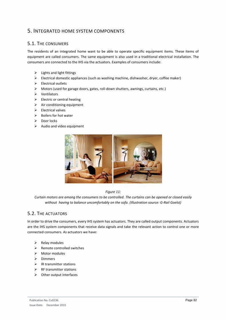
Publication No. Cu0236
Issue Date: December 2015
Page 82
5. INTEGRATED HOME SYSTEM COMPONENTS
5.1. THE CONSUMERS
The residents of an integrated home want to be able to operate specific equipment items. These items of
equipment are called consumers. The same equipment is also used in a traditional electrical installation. The
consumers are connected to the IHS via the actuators. Examples of consumers include:
Lights and light fittings
Electrical domestic appliances (such as washing machine, dishwasher, dryer, coffee maker)
Electrical outlets
Motors (used for garage doors, gates, roll-down shutters, awnings, curtains, etc.)
Ventilators
Electric or central heating
Air conditioning equipment
Electrical valves
Boilers for hot water
Door locks
Audio and video equipment
Figure 11:
Curtain motors are among the consumers to be controlled. The curtains can be opened or closed easily
without having to balance uncomfortably on the sofa. (Illustration source: G-Rail Goelst)
5.2. THE ACTUATORS
In order to drive the consumers, every IHS system has actuators. They are called output components. Actuators
are the IHS system components that receive data signals and take the relevant action to control one or more
connected consumers. As actuators we have:
Relay modules
Remote controlled switches
Motor modules
Dimmers
IR transmitter stations
RF transmitter stations
Other output interfaces

Publication No. Cu0236
Issue Date: December 2015
Page 83
Figure 12:
A 10-fold relay output module. (Illustration source: Hager)
5.3. INPUT MODULES
The input modules process the signals from the sensors. There are basically two types: digital input modules and
analogue input modules.
5.3.1. DIGITAL INPUT MODULES A digital input module converts the signals from voltage-free contacts (push buttons, switches, etc.) to signals
that can be used on the BUS or that can be sent to a master module. Sometimes the modules are clipped onto
a DIN rail on the distribution board. However, there are also input modules that can, for example, be placed
behind a push button in a flush-mounted electrical box.
5.3.2. ANALOGUE INPUT MODULES Sensors that generate analogue output signals are connected to analogue input modules. Some examples are
light sensors, humidity detectors, temperature sensors, etc.
5.4. THE SENSORS
Sensors are the IHS components that collect information. This information is put directly on the BUS or
transferred through an input module. An actuator does not take any action on its own initiative. It has to be
given instructions. These instructions come from the information placed on the BUS or are generated by the
master controller. Most sensors act as a human interface so that people can operate the IHS system.
The first IHS systems on the European market appeared around 1990. At that time only a limited number and
variety of sensors were available, such as push buttons, button panels and motion detectors. However, there
are now many other sensor types. Technology is constantly evolving, which also means that some sensors are
no longer available.
One example is the phone interface. Some manufacturers had an interface that allowed the IHS to be controlled
by the buttons of a conventional telephone. Now that smartphones are so popular, these phone interfaces have
disappeared from the market. We saw the same disappearing act with personal digital assistants, better known
as PDAs. They could also be used as control devices, but this function has now moved to smartphones.
There have also been some fads that disappeared from the market just as quickly as they entered it. An example
of this is the IHS system's voice control. The idea was that the lights could be switched on with a voice command.
Some manufacturers had this option in their product range, but the market was not ready for everyone to walk
around their homes constantly wearing microphones. The technology was also not fully developed with
background noise from radios, televisions, conversations and so on hindering its functioning.
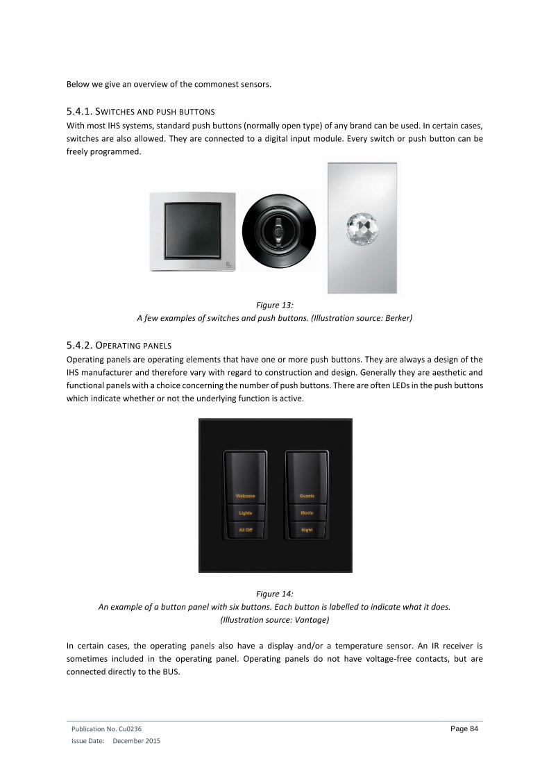
Publication No. Cu0236
Issue Date: December 2015
Page 84
Below we give an overview of the commonest sensors.
5.4.1. SWITCHES AND PUSH BUTTONS With most IHS systems, standard push buttons (normally open type) of any brand can be used. In certain cases,
switches are also allowed. They are connected to a digital input module. Every switch or push button can be
freely programmed.
Figure 13:
A few examples of switches and push buttons. (Illustration source: Berker)
5.4.2. OPERATING PANELS Operating panels are operating elements that have one or more push buttons. They are always a design of the
IHS manufacturer and therefore vary with regard to construction and design. Generally they are aesthetic and
functional panels with a choice concerning the number of push buttons. There are often LEDs in the push buttons
which indicate whether or not the underlying function is active.
Figure 14:
An example of a button panel with six buttons. Each button is labelled to indicate what it does.
(Illustration source: Vantage)
In certain cases, the operating panels also have a display and/or a temperature sensor. An IR receiver is
sometimes included in the operating panel. Operating panels do not have voltage-free contacts, but are
connected directly to the BUS.

Publication No. Cu0236
Issue Date: December 2015
Page 85
5.4.3. VOLTAGE-FREE CONTACTS In order to achieve integration, certain subsystems can make voltage-free contacts available to the IHS system
– for example the contacts of the security system. In this way the IHS system “knows” whether or not the home
is in an activated state, and whether or not an alarm is being generated. The IHS system can respond
appropriately in such cases.
5.4.4. TOUCH SCREEN Touch screens can be placed on the walls of the home in strategic positions. By touching the icons or text on the
screen, the person can go through a menu structure and all types of operations can be carried out on the IHS
system.
Figure 15:
A touch screen can provide an overview of the entire IHS system. (Illustration source: Gira)
Certain touch screens are true multimedia units. Not only can they be used to communicate with the door
videophone, they can also be used to call up images from other cameras in and around the home, watch
television or listen to the radio. Sometimes they are also connected to the computer network so that e-mails
can be sent or the internet can be used. Viewing energy consumption charts is also an increasingly popular
option.
Touch screens are mainly used with relatively large and expensive projects. However, there they are facing more
and more competition from much cheaper tablets.

Publication No. Cu0236
Issue Date: December 2015
Page 86
5.4.5. THE TOUCH WINDOW A touch window is similar to a touch screen, but does not contain an active screen. It is also operated with the
finger tips. What can be seen on the screen is a printout (via the printer) on a film. The screen thus never changes,
unless you print out a new film and place it behind the sensitive glass plate.
Figure 16:
A touch window contains no mechanical buttons and the screen cannot change
as a result of performing an operation. (Illustration source: Teletask)
In recent years touch windows equipped with OLED technology have also appeared. This allows the text and
icons to be displayed with fairly high resolution.
Figure 17:
This OLED touch screen also eliminates mechanical buttons. (Illustration source: Teletask)
5.4.6. RF TRANSMITTERS These are hand-held or wall transmitters that convey RF signals to RF receivers. The hand-held transmitters are
generally battery operated. In certain cases the wall transmitters can also be supplied by the 230V network or
be voltage-free, operated by a piezoelectric element.
Figure 18:
An RF wall transmitter can look like an ordinary switch. (Illustration source: Gira)
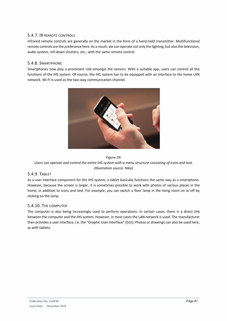
Publication No. Cu0236
Issue Date: December 2015
Page 87
5.4.7. IR REMOTE CONTROLS Infrared remote controls are generally on the market in the form of a hand-held transmitter. Multifunctional
remote controls are the preference here. As a result, we can operate not only the lighting, but also the television,
audio system, roll-down shutters, etc., with the same remote control.
5.4.8. SMARTPHONE Smartphones now play a prominent role amongst the sensors. With a suitable app, users can control all the
functions of the IHS system. Of course, the IHS system has to be equipped with an interface to the home LAN
network. Wi-Fi is used as the two-way communication channel.
Figure 19:
Users can operate and control the entire IHS system with a menu structure consisting of icons and text.
(Illustration source: Niko)
5.4.9. TABLET As a user interface component for the IHS system, a tablet basically functions the same way as a smartphone.
However, because the screen is larger, it is sometimes possible to work with photos of various places in the
home, in addition to icons and text. For example, you can switch a floor lamp in the living room on or off by
clicking on the lamp.
5.4.10. THE COMPUTER The computer is also being increasingly used to perform operations. In certain cases, there is a direct link
between the computer and the IHS system. However, in most cases the LAN network is used. The manufacturer
then provides a user interface, i.e. the “Graphic User Interface” (GUI). Photos or drawings can also be used here,
as with tablets.

Publication No. Cu0236
Issue Date: December 2015
Page 88
Figure 20:
Operations can be carried out with the computer using such screens of the home.
Buttons are placed on the diagram for controlling the lighting, roll-down shutters, power points,
heating, audio and even for viewing with IP cameras. (Illustration source: E&D Systems)
5.4.11. MOTION DETECTORS Motion detectors were primarily used in the past in outdoor applications. The detector observes someone
coming up the driveway and automatically switches the lights on when it is dark. However, motion detectors are
increasingly being used inside the home. They are particularly suitable at entrance doors and in spaces where
people do not spend a long time, such as cellars, attics, stairwells or the garage. A few IHS systems have motion
detectors of their own brand that can be connected directly to their “bus”. Other IHS systems use motion
detectors available on the market.
Figure 21:
An intelligent motion detector for outdoor use with remote control and holiday function.
(Illustration source: Busch-Jaeger)
5.4.12. PRESENCE DETECTORS If you want to detect the presence of people in rooms where there is not much movement, you have to use a
presence detector. The technique used is similar to a motion detector, but the detection sectors are much finer
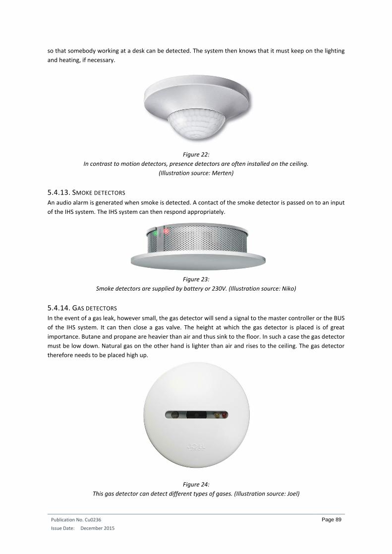
Publication No. Cu0236
Issue Date: December 2015
Page 89
so that somebody working at a desk can be detected. The system then knows that it must keep on the lighting
and heating, if necessary.
Figure 22:
In contrast to motion detectors, presence detectors are often installed on the ceiling.
(Illustration source: Merten)
5.4.13. SMOKE DETECTORS An audio alarm is generated when smoke is detected. A contact of the smoke detector is passed on to an input
of the IHS system. The IHS system can then respond appropriately.
Figure 23:
Smoke detectors are supplied by battery or 230V. (Illustration source: Niko)
5.4.14. GAS DETECTORS In the event of a gas leak, however small, the gas detector will send a signal to the master controller or the BUS
of the IHS system. It can then close a gas valve. The height at which the gas detector is placed is of great
importance. Butane and propane are heavier than air and thus sink to the floor. In such a case the gas detector
must be low down. Natural gas on the other hand is lighter than air and rises to the ceiling. The gas detector
therefore needs to be placed high up.
Figure 24:
This gas detector can detect different types of gases. (Illustration source: Joel)
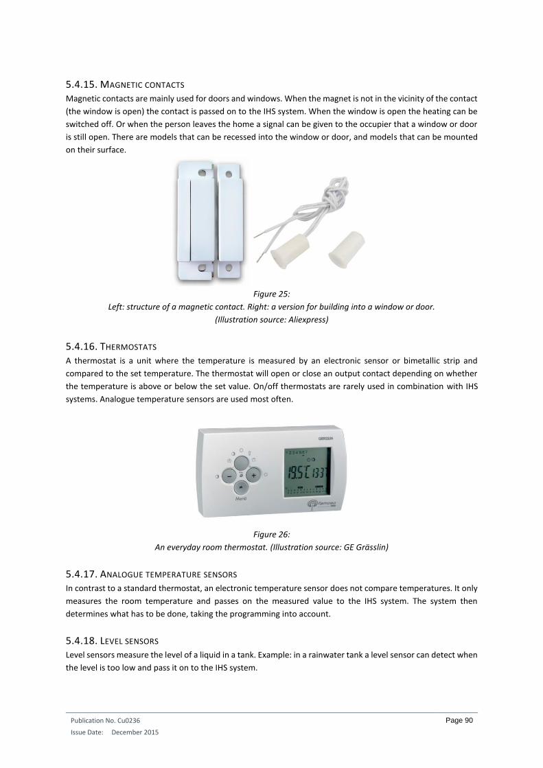
Publication No. Cu0236
Issue Date: December 2015
Page 90
5.4.15. MAGNETIC CONTACTS Magnetic contacts are mainly used for doors and windows. When the magnet is not in the vicinity of the contact
(the window is open) the contact is passed on to the IHS system. When the window is open the heating can be
switched off. Or when the person leaves the home a signal can be given to the occupier that a window or door
is still open. There are models that can be recessed into the window or door, and models that can be mounted
on their surface.
Figure 25:
Left: structure of a magnetic contact. Right: a version for building into a window or door.
(Illustration source: Aliexpress)
5.4.16. THERMOSTATS A thermostat is a unit where the temperature is measured by an electronic sensor or bimetallic strip and
compared to the set temperature. The thermostat will open or close an output contact depending on whether
the temperature is above or below the set value. On/off thermostats are rarely used in combination with IHS
systems. Analogue temperature sensors are used most often.
Figure 26:
An everyday room thermostat. (Illustration source: GE Grässlin)
5.4.17. ANALOGUE TEMPERATURE SENSORS In contrast to a standard thermostat, an electronic temperature sensor does not compare temperatures. It only
measures the room temperature and passes on the measured value to the IHS system. The system then
determines what has to be done, taking the programming into account.
5.4.18. LEVEL SENSORS Level sensors measure the level of a liquid in a tank. Example: in a rainwater tank a level sensor can detect when
the level is too low and pass it on to the IHS system.
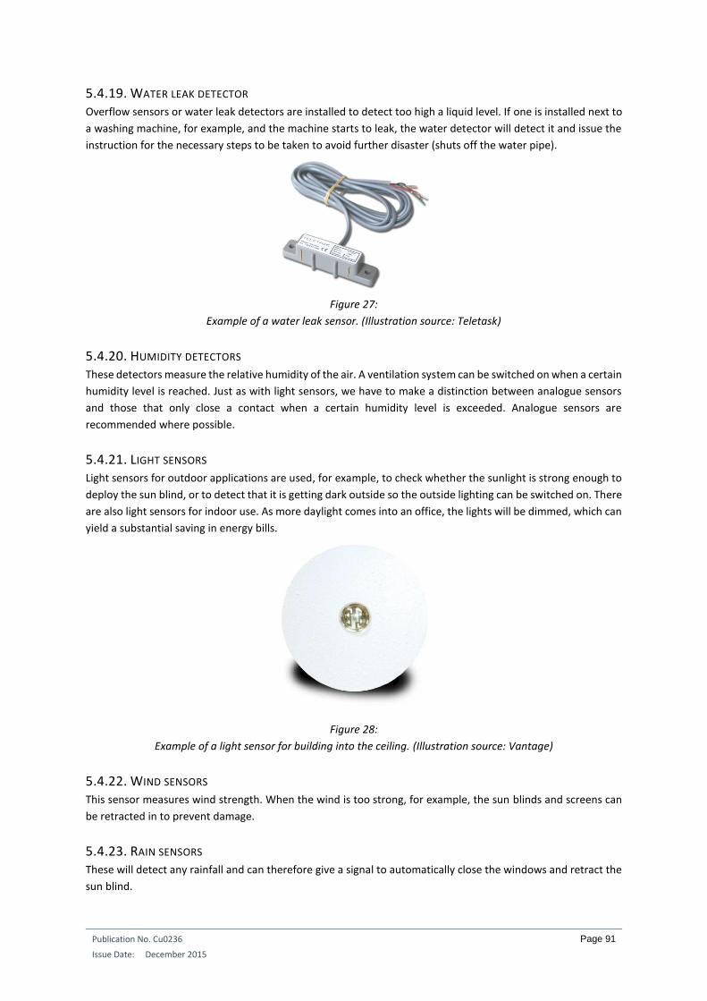
Publication No. Cu0236
Issue Date: December 2015
Page 91
5.4.19. WATER LEAK DETECTOR Overflow sensors or water leak detectors are installed to detect too high a liquid level. If one is installed next to
a washing machine, for example, and the machine starts to leak, the water detector will detect it and issue the
instruction for the necessary steps to be taken to avoid further disaster (shuts off the water pipe).
Figure 27:
Example of a water leak sensor. (Illustration source: Teletask)
5.4.20. HUMIDITY DETECTORS These detectors measure the relative humidity of the air. A ventilation system can be switched on when a certain
humidity level is reached. Just as with light sensors, we have to make a distinction between analogue sensors
and those that only close a contact when a certain humidity level is exceeded. Analogue sensors are
recommended where possible.
5.4.21. LIGHT SENSORS Light sensors for outdoor applications are used, for example, to check whether the sunlight is strong enough to
deploy the sun blind, or to detect that it is getting dark outside so the outside lighting can be switched on. There
are also light sensors for indoor use. As more daylight comes into an office, the lights will be dimmed, which can
yield a substantial saving in energy bills.
Figure 28:
Example of a light sensor for building into the ceiling. (Illustration source: Vantage)
5.4.22. WIND SENSORS This sensor measures wind strength. When the wind is too strong, for example, the sun blinds and screens can
be retracted in to prevent damage.
5.4.23. RAIN SENSORS These will detect any rainfall and can therefore give a signal to automatically close the windows and retract the
sun blind.
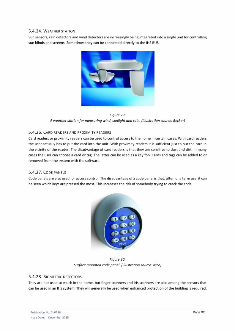
Publication No. Cu0236
Issue Date: December 2015
Page 92
5.4.24. WEATHER STATION Sun sensors, rain detectors and wind detectors are increasingly being integrated into a single unit for controlling
sun blinds and screens. Sometimes they can be connected directly to the IHS BUS.
Figure 29:
A weather station for measuring wind, sunlight and rain. (Illustration source: Becker)
5.4.26. CARD READERS AND PROXIMITY READERS Card readers or proximity readers can be used to control access to the home in certain cases. With card readers
the user actually has to put the card into the unit. With proximity readers it is sufficient just to put the card in
the vicinity of the reader. The disadvantage of card readers is that they are sensitive to dust and dirt. In many
cases the user can choose a card or tag. The latter can be used as a key fob. Cards and tags can be added to or
removed from the system with the software.
5.4.27. CODE PANELS Code panels are also used for access control. The disadvantage of a code panel is that, after long term use, it can
be seen which keys are pressed the most. This increases the risk of somebody trying to crack the code.
Figure 30:
Surface mounted code panel. (Illustration source: Nice)
5.4.28. BIOMETRIC DETECTORS They are not used so much in the home, but finger scanners and iris scanners are also among the sensors that
can be used in an IHS system. They will generally be used when enhanced protection of the building is required.

Publication No. Cu0236
Issue Date: December 2015
Page 93
5.4.29. ENERGY METERS More and more IHS systems are able to measure energy consumption and self-generated energy (from PV
panels) to track energy usage and to display it in charts on a smartphone, tablet or PC. These measurements can
be made for electricity, gas and water consumption. The sensors send pulses to the IHS system, which processes
them and displays them to the user as a chart.
5.5. OTHER INTERFACES
As well as the previously mentioned actuators and sensors, there are many other interfaces. The interface
between the IHS system and the home LAN network is an example, but there are also many types of audio
interfaces. There are also interfaces that can be used to connect an intrusion alarm system to the IHS system.

Publication No. Cu0236
Issue Date: December 2015
Page 94
6. SAFETY AND SECURITY IN AND AROUND THE HOME Fire or burglary protection will not be dealt with here as they have already been covered in Chapter 1 of this
course as far as IHS systems are concerned. In order to further increase the safety and security of people in an
automated home, here are some important tips to consider in the installation process.
6.1. POSITIONING OF IHS COMPONENTS IN WET ROOMS
We assume there are regulations in every country concerning the installation of electrical components in
bathrooms and shower rooms. However, the legislation can differ from country to country. Irrespective of the
country in which you live or work, electricity and water do not go together. It is best for a person who takes a
shower or bath to stay as far away as possible from electrical equipment and components.
As the operating buttons and keypads in IHS systems are connected to a very low safety voltage, it is sometimes
wrongly concluded that such components do not present any danger to people in the bathroom. As an example,
we will look at the legislation in this respect in Belgium.
Note: the example below only relates to the situation in Belgium. Consult and apply the regulations applicable
to your country.
Figure 31:
In Belgium, electrical equipment, power points and switches connected to the 230V
network may only be installed in volume 3. (Illustration source: Vinçotte Academy)
The space around the bath or shower is divided into different volumes. Therefore, 230V components may never
be installed in volumes 0, 1 and 2 (up to a height of 2.25 metres above the bath or shower platform). However,
this rule changes when lower voltages are used. Take volume 1 as an example. Without additional external
protection and for a pure DC voltage, components can be installed in this volume up to a maximum voltage of
20V. However, if external protection of IPX4 is applied, the voltage used in this volume can increase to 30V.
Looking at the voltages used by integrated home systems, they lie between 9V and 30V. In practice, this means
that all these products can be put in volume 1 if they have IPX4 protection, yet they do not generally have this
level of protection. Without external protection against contact, the voltage can only be 20V. This means that
only the products that work on 9V or 12V can be put in volume 1, but the 24V and 30V products must never be
put in this zone as they will cause danger to the user.

Publication No. Cu0236
Issue Date: December 2015
Page 95
6.2. MANUAL OPERATION OF ROLL-DOWN SHUTTERS AND DOORS
The installer, architect and occupier must be aware that many things can be automated, but that this can
sometimes lead to unsafe situations. This is the case for example when all windows and doors have electrically
operated roll-down shutters. If there is a fire in the home when all the roll-down shutters are down, and the
electricity is off (cable burned through), the occupiers must still be able to escape. It is then sensible to give
certain roll-down shutters in strategic places the option of manual operation.
Figure 32:
A mechanical emergency handle for an automated roll-down shutter might not
be pretty, but the safety of the occupiers takes precedence. (Illustration source: E&D Systems)
It would not be the first time that a pleasant barbecue has been abruptly stopped because the clocks or light
sensor of the IHS system have suddenly closed all roll-down shutters automatically. If the doors are also fitted
with roll-down shutters and everybody is outside, then there is a problem. However, this can be solved by fitting
motion detectors on the terrace and in the garden. As long as they detect motion, the IHS system cannot
automatically close the roll-down shutters.
If the home has electrically locked doors, the residents must still be able to get out at all times, even if there is
no electricity. There has to be a mechanical means of unlocking them.
6.3. TAKE CARE WITH CLOCKS
In certain cases the clocks of the IHS system can also be a danger to a home and its occupants. Let’s take the
example of the coffee maker that we left on in the evening. By pressing the “sleep well” button when we went
to sleep, we disconnected the socket from the network. We assume that the next day is a normal working day,
so the clock of the IHS system reconnects this power point at 07:00 in the morning. This isn’t a problem if we
get up at that time and go into the kitchen to have breakfast. However, if we are ill and decide to stay in bed,
then there is a dangerous situation. The coffee maker was left on and is now connected to the mains again. It
can cause a fire. It might be sensible to only allow such clock-controlled potentially hazardous equipment to be
connected to the power for a limited time.
6.4. SWITCHING OFF OUTDOOR POWER POINTS
If the outdoor power points are always connected to the power, then a burglar can use a piece of wire to make
a link between the power point and earth. The earth leakage breaker will then trip. We can now forget all the
actions that the IHD system would normally take in the event of a break in. Nothing will work. Hence it is
advisable for outdoor power points to only be under power when we want to use them. They can be switched
off with the “all out” command (for example when leaving the home) or with the “sleep well” button next to the
bed (when we go to bed).

Publication No. Cu0236
Issue Date: December 2015
Page 96
Figure 33:
By switching off the outdoor power points when we are not at home, our neighbours will not be tempted
to use our increasingly expensive electricity to mow their lawns. (Illustration source: Niko)

Publication No. Cu0236
Issue Date: December 2015
Page 97
7. INSTALLATION TECHNIQUES AND TIPS
7.1. PROTECTING RELAY MODULES
When protecting electrical circuits against overloads, it is the weakest link in the circuit that has to be considered
for the selection of the fuse or circuit breaker. If it is only a lighting circuit in a standard installation with standard
switches, then in practice it will be protected with a 16A breaker. However, many installers also use this rule for
an IHS installation, which is often incorrect.
Most IHS manufacturers produce relay output modules whose internal relays cannot take high currents. The
nominal current the relays can take is often 10A, but there are also examples of 6A, 4A and even 2A contacts.
When installers use these relays to control lighting, they protect the circuit (out of force of habit) with a 16A
breaker. As a result, the weakest link in the circuit (the relay contact) is not well protected against overload.
Figure 34:
Peha has an output module in its range that has 4A contacts (left). The other output
module contains 4 contacts of 6A and 4 contacts of 10A. (Illustration source: Peha)
Below is a schematic diagram of the Peha output module that contains 2 groups of 4 relays of 4A. Each group of
4 relays is connected together internally in the module. The same protection is therefore used for each group.
Each relay can take a maximum of 4A but, as they are connected together internally, the entire group must be
protected according to its weakest element, and that is 4A.
Figure 35:
In such an installation more circuit breakers will have to be used to protect the electrical circuits correctly.
(Illustration source: E&D Systems)
1,5mm
4A
1,5mm
4A
4A 4A 4A 4A 4A 4A 4A 4A

Publication No. Cu0236
Issue Date: December 2015
Page 98
Figure 36:
Here the relays are protected for their nominal value. (Illustration source: E&D Systems)
Above is a schematic diagram of the Peha output module with 6A and 10A contacts. In this module all contacts
go to the outside. When the connected load is not too high, we can protect all 6A contacts together with a 6A
breaker, and all 10A contacts with a 10A breaker. However, if heavier consumers have to be connected to certain
relays, then in certain cases separate relays will have to be protected separately. In the example below, the load
of relay 4 is 5A, and the loads of relays 1, 2 and 3 are 1.5A. The first three relays can then be connected together
on a 6A breaker, for example, while relay 4 has to be protected with a separate 6A breaker. In the drawing we
see that relays 5 and 6 with 10A contacts are each protected separately because heavy consumers are connected
to them.
Figure 37:
Separately protected relays on account of a high individual load. (Illustration source: E&D Systems)
The master controller or supply of the IHS system must be suitably protected. We can assume that these
components are not heavy consumers. In most cases a 2A or 4A breaker will suffice. However, if we use a 10A
or 16A breaker here, then these components will not be well protected against overload, resulting in possible
damage when an anomaly occurs.
7.2. FITTING OVERVOLTAGE PROTECTION
In installations without an IHS installation, it is a good idea to fit overvoltage protection to protect sensitive
equipment in the home (computers, flat-screen TV, audio system, telephone exchange, etc.) against indirect
lightning strikes. The electronic components in IHS systems are also sensitive to overvoltages. Certain
overvoltages will cause them to fail immediately. On the other hand, certain overvoltages can substantially
6A 6A 6A 6A 10A 10A 10A 10A
1,5mm
6A
1,5mm
10A
6A 6A 6A 6A 10A 10A 10A 10A
1,5mm
6A
1,5mm
10A
1,5mm
6A
1,5mm
10A
1,5mm
10A

Publication No. Cu0236
Issue Date: December 2015
Page 99
reduce the lifetime of electronic components so that the equipment will only function properly for a shorter
period of time.
Homes that have external lightning protection must also have internal protection against direct lightning strikes.
However, most homes will only have medium protection against indirect lightning strikes and possibly additional
protection for individual items of equipment.
It is necessary to efficiently protect all electrical cables coming into the home. If we only protect 230V cables,
there can still effectively be discharges into telephone cables and coax cables. Cables leaving the home also need
to be protected, for example when a supply cable from the home goes underground into a garden shed. If the
integrated home system bus goes outside the home, appropriate measures need to be taken.
Figure 38:
This overvoltage protection limits the peak voltage to 275V. (Illustration source: Dehn)
Figure 39:
When choosing appropriate overvoltage protection, account has to be taken of the nominal
voltage, the current and frequency of the cables to be protected. (Illustration source: Dehn)
Very sensitive equipment can be individually fitted with fine protection. This reduces further the voltage spike
that remains after the medium protection. Such equipment is generally constructed as a plug strip. In certain
cases, not only is fine protection applied to the 230V circuit, but also to telephone and coax cables.
7.3. AVOIDING LARGE LOOPS WITH IHS CABLES
If large loops are unintentionally created when installing IHS system cabling, they can create problems with
indirect lightning strikes. High overvoltages can be generated in the loops through induction. The peak voltages
are in proportion to the size of the loop. During installation the loop surface must therefore be kept as small as
possible.

Publication No. Cu0236
Issue Date: December 2015
Page 100
In the example below a master controller and an output module of an IHS system are supplied at 230V. There
is, however, BUS cabling between the master and the output module. When the cables are installed far apart
(left-hand drawing) the voltage difference induced by an indirect lightning strike can be too great. There can also
be a discharge between the BUS cable and the 230V part. Best practice would consist of installing the cables
concerned closer together. In the case of an indirect lightning strike, the potential difference generated between
the two cables would be smaller.
Figure 40:
In practice loops cannot always be avoided, but try to keep them as small as possible
by installing the cables as close together as possible. (Illustration source: E&D Systems)
Loops can also occur between earth cables (or the BUS screening) and bare earthed metal parts of the home.
Therefore, as an example, cables and electrical equipment should always be installed at a safe distance from
metal water pipes.
7.4. MANUAL SWITCHING
If for some reason the IHS system does not work, it is important that the user can still manually control some
functions such as lighting and heating. This allows the user to perform some basic tasks manually if there is a
system outage in the weekend or during a holiday period, until an installer can come.
For this purpose, some IHS systems have output modules with a button for each output. If this option is not
available, specific outputs can be rerouted through an external contactor that can be switched manually.
Figure 41:
This output module has a toggle switch for automatic or manual operation. In the manual
state, the individual outputs can be switched with push buttons. (Illustration source: Hager)
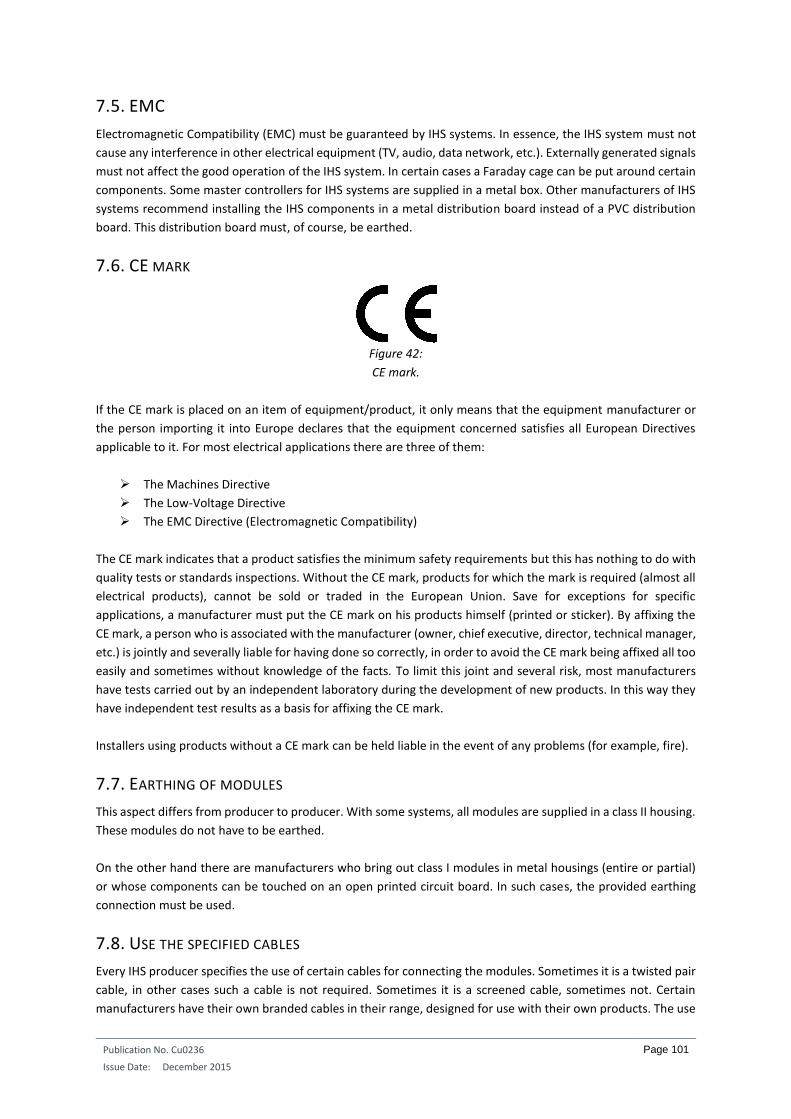
Publication No. Cu0236
Issue Date: December 2015
Page 101
7.5. EMC
Electromagnetic Compatibility (EMC) must be guaranteed by IHS systems. In essence, the IHS system must not
cause any interference in other electrical equipment (TV, audio, data network, etc.). Externally generated signals
must not affect the good operation of the IHS system. In certain cases a Faraday cage can be put around certain
components. Some master controllers for IHS systems are supplied in a metal box. Other manufacturers of IHS
systems recommend installing the IHS components in a metal distribution board instead of a PVC distribution
board. This distribution board must, of course, be earthed.
7.6. CE MARK
Figure 42:
CE mark.
If the CE mark is placed on an item of equipment/product, it only means that the equipment manufacturer or
the person importing it into Europe declares that the equipment concerned satisfies all European Directives
applicable to it. For most electrical applications there are three of them:
The Machines Directive
The Low-Voltage Directive
The EMC Directive (Electromagnetic Compatibility)
The CE mark indicates that a product satisfies the minimum safety requirements but this has nothing to do with
quality tests or standards inspections. Without the CE mark, products for which the mark is required (almost all
electrical products), cannot be sold or traded in the European Union. Save for exceptions for specific
applications, a manufacturer must put the CE mark on his products himself (printed or sticker). By affixing the
CE mark, a person who is associated with the manufacturer (owner, chief executive, director, technical manager,
etc.) is jointly and severally liable for having done so correctly, in order to avoid the CE mark being affixed all too
easily and sometimes without knowledge of the facts. To limit this joint and several risk, most manufacturers
have tests carried out by an independent laboratory during the development of new products. In this way they
have independent test results as a basis for affixing the CE mark.
Installers using products without a CE mark can be held liable in the event of any problems (for example, fire).
7.7. EARTHING OF MODULES
This aspect differs from producer to producer. With some systems, all modules are supplied in a class II housing.
These modules do not have to be earthed.
On the other hand there are manufacturers who bring out class I modules in metal housings (entire or partial)
or whose components can be touched on an open printed circuit board. In such cases, the provided earthing
connection must be used.
7.8. USE THE SPECIFIED CABLES
Every IHS producer specifies the use of certain cables for connecting the modules. Sometimes it is a twisted pair
cable, in other cases such a cable is not required. Sometimes it is a screened cable, sometimes not. Certain
manufacturers have their own branded cables in their range, designed for use with their own products. The use

Publication No. Cu0236
Issue Date: December 2015
Page 102
of the specified cable is highly advisable as the manufacturer only guarantees correct operation of his system
when the correct cables are used in the installation.
7.9. RESPECT THE MAXIMUM DISTANCES
Every IHS system also specifies the maximum distances for the cables used. This too comes back to the guarantee
of good operation. Sometimes, only a maximum length is specified for the BUS cabling. In other cases, maximum
mutual distances are specified between different BUS participants. In many cases there are also distance
restrictions for connecting sensors and push buttons to input modules. The non-observance of these maximum
distances could lead to poor data communications. In order to bridge greater distances, BUS amplifiers or
repeaters can sometimes be used.
7.10. USE OF SCREENING
If a screened cable is used, the manufacturer also specifies what has to be done with the screening. In most
cases, it is generally specified that the screening of the BUS cable must be connected to earth at a certain place.
At every module the screening is connected through to the last module on the bus. The screening is not
connected to earth at any other place, so that no undesired loop currents can occur.
For KNX installations, the BUS cable consists of an external sheath covering a metal screen and a continuity wire.
It is specified however that this screen must not be connected to earth, or come into contact with it. As a result,
in practice shrink sleeving is always put over the ends of the cable.
Figure 43:
Schematic presentation of the EIB/KNX cable with screening. (Illustration source: KNX)
Figure 44:
The ends of the KNX cable have shrink sleeving. (Illustration source: KNX)
7.11. KEEP CABLES WITH DIFFERENT VOLTAGES AWAY FROM ONE ANOTHER
All kinds of components are brought together in the distribution board. The supplies, controllers and output
modules are connected with 230V cabling. On the other hand, there are input modules where only very low
safety voltage is used. The cables used for the two networks are very different. The discharge voltage of 230V
cables and wires is much higher than for the cables and wires used for the BUS or for connecting the push
buttons. In practice, we must keep these cables and wires separated and as far away from one another as

Publication No. Cu0236
Issue Date: December 2015
Page 103
possible, although it is not always easy to do so. After all, certain modules not only have connections for 230V,
but also for the bus.
Figure 45:
Cables and insulated wires with a different discharge voltage must be kept a safe distance from one another.
The Belgian installation regulations specify that it must be at least 4 mm. (Illustration source: E&D Systems)
When positioning the components in the distribution board, we can also ensure that the components on a very
low safety voltage are put in a separate place, at some distance from the 230V components.
7.12. USE OF MULTICABLE
Quite a few integrated home systems use multicable for connecting push buttons to the input modules. We can
generally choose from different types of cable because they are not critical connections. In many cases SVV cable
is used. This consists of a number of insulated solid copper conductors which in turn are surrounded by an
insulating outer sheath. The cross-section of the conductors is 0.8 mm². Every conductor has its own insulation
colour, making work very easy. The right wire (a certain colour) can be immediately taken from the bundle of
wires in the cable to connect a push button. However, there are, also brands of SVV cable where the colours
yellow, red, blue, etc., are used twice. The risk is therefore greater that the wrong wire will be used for the
connection.
In addition, we also have flexible multicable. The individual conductors consist of a number of fine copper
strands surrounded by individual black insulation on which figures are printed. All individual conductors are
together surrounded by a grey outer sheath. These cables are available in different cross-sections. In practice,
using these cables is somewhat more laborious. To select a certain wire, you first have to look for its number
among all the other black wires. You cannot just select the right wire, which means a certain time loss on site.
7.13. LABELLING CABLES AND WIRES
As in most IHS systems, the output modules are given a certain place in the distribution board and many cables
come together at this position. In order to know which cable goes where, it is important to label all cables going
into the distribution board. This saves a lot of search work later on.
Figure 46:
Labelling cables results in time savings. (Illustration source: Dobiss)

Publication No. Cu0236
Issue Date: December 2015
Page 104
In larger installations it is also advisable to label every wire in the distribution board. In this way we can quickly
trace the start and end of a wire without measuring equipment. The cable ducts can stay closed.
Figure 47:
Except for the purple common wires, all other wires have their own number. (Illustration source: E&D Systems)
7.14. GOOD CONNECTING TECHNIQUES
Many cables come into the distribution board which have to be connected to the terminals on the output or
input modules, but preferably not directly. To make work easy and to keep things tidy and workable, it is better
to use terminal blocks. This facilitates measurements later on. There are still terminal blocks in which the wire
is secured by tightening a screw. However, we are increasingly finding terminal blocks on the market that used
the cage-clamp technique, where the wire is held fast by a spring. This technique not only gives a good and safe
connection, but is also a lot faster. Wago has an IHS terminal block in its range. The cabling that comes from a
consumer (for example, a light) is connected directly to the terminal: neutral, live and earth. For the earth, the
terminal block automatically makes a connection to the DIN rail of the distribution board. On the underside of
the terminal, the neutral and the live are connected through to a relay. As it is a tiered terminal block, a lot of
space is saved in the distribution board.
Figure 48:
The IHS terminal block of Wago. (Illustration source: Wago)
Many onward connections often have to be made at the operating points (push buttons). That is certainly the
case when the push buttons are connected in star topology to an input module in the distribution board. Here
it is preferable not to use connectors where a small screw presses into the wire. There are always vibrations in
a building and, after a certain period of time, they can loosen the connection. It is better to use special pressure
clamps. The insulated conductors are put in the pressure clamp and then the cover of the pressure clamp is
pressed down using pliers. This causes a small blade to cut through the insulation and make a connection
between the wires. A little glue is also released that secures the individual conductors in the clamp. Vibrations
cannot break the connection here.

Publication No. Cu0236
Issue Date: December 2015
Page 105
Figure 49:
Such terminals can be used with solid copper conductors. (Illustration source: Scotch)
7.15. FITTING TERMINATING RESISTORS
If the IHS BUS has to be installed with a BUS or line topology, then the manufacturer will generally specify that
there must be terminating resistors on the BUS by the first and last components to avoid reflections on the BUS.
In some cases a small resistor must be connected in parallel to the BUS. In other cases, there is already a
terminating resistor on the components, which can be activated and deactivated with a mini-jumper.
7.16. FILTERS IN POWERLINE SYSTEMS
When using powerline systems, a rejection filter has to be fitted at the start of the installation. This filter prevents
the high frequency signals generated on the home network from getting outside the home. If we do not do so,
your neighbour with a similar system and with similar addressing would be able to operate your lights and vice-
versa. Secondly, the filter also ensures that interference from the mains does not get into the home. The
installation then operates efficiently without any problems.
In a three-phase network, each phase has to have a filter. In such a case, a phase coupler is also required. These
ensure that a data signal generated on one phase is passed through to the phase connected to the component
for which the signal is intended.
Within the home installation certain electrical equipment sometimes has to be supplied separately from a filter.
This is the case particularly for equipment that presents a high capacitive load, or equipment that generates
network interference, such as computers, fluorescent lighting with compensating ballasts or washing machines.
Figure 50:
A rejection filter for every phase and a phase coupler with powerline systems.
(Illustration source: E&D Systems)
7.17. NOTE THE ADDRESSES OF BUS PARTICIPANTS
With certain components and brands it is advisable to note the allocated address of the BUS participant on the
equipment. During after-sales service you will not have to search for the address for a long time. It is noted and
always available.

Publication No. Cu0236
Issue Date: December 2015
Page 106
Figure 51:
On this multiple dimming actuator at the top right we see a sticker
on which the BUS address can be noted. (Illustration source: Merten)
7.18. CALCULATION OF THE POWER SUPPLY
IHS systems always use a BUS voltage for which integrated or separate supplies are needed. Every BUS
participant has its own consumption. The sum of all consumptions gives us an idea of the size of the power
supply. In certain cases, multiple supplies will have to be used but it is not advisable to just connect multiple
supplies in parallel to obtain greater power. The manufacturer will often propose a solution when multiple
supplies have to be used.
In addition, account must also be taken of the voltage drop as a result of the length of the BUS cable. The longer
the BUS cable, the lower the voltage will be for the furthest participant. If the voltage is too low, an additional
supply may have to be placed along the BUS. Many suppliers provide a calculation tool for easily calculating the
number of supplies and the voltage drop.
Figure 52:
Under certain conditions, it is possible to connect two power supplies together with the aid of a few diodes.
However, the manufacturer must always be consulted about this. (Illustration source: Schneider Electric)
7.19. SELECT THE CORRECT RELAY CONTACTS
IHS suppliers generally provide relay modules themselves. The current that can go through the relay contacts is
normally stated on them (nominal current). However, there are other factors to be taken into account when
selecting the correct relay contacts.
The lifetime of a relay is subdivided into a mechanical and an electrical lifetime. When determining the
mechanical lifetime, a test is carried out to ascertain how many times the relay contacts can be closed and
opened, without a load connected to the contact. In this test, no current is thus passing through the contact.
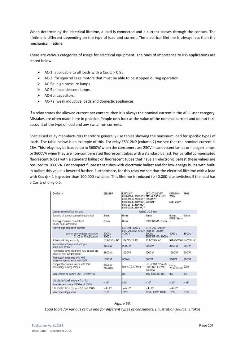
Publication No. Cu0236
Issue Date: December 2015
Page 107
When determining the electrical lifetime, a load is connected and a current passes through the contact. The
lifetime is different depending on the type of load and current. The electrical lifetime is always less than the
mechanical lifetime.
There are various categories of usage for electrical equipment. The ones of importance to IHS applications are
stated below:
AC-1: applicable to all loads with a Cos φ > 0.95.
AC-3: for squirrel cage motors that must be able to be stopped during operation.
AC-5a: high pressure lamps.
AC-5b: incandescent lamps.
AC-6b: capacitors.
AC-7a: weak inductive loads and domestic appliances.
If a relay states the allowed current per contact, then it is always the nominal current in the AC-1 user category.
Mistakes are often made here in practice. People only look at the value of the nominal current and do not take
account of the type of load and any switch-on currents.
Specialised relay manufacturers therefore generally use tables showing the maximum load for specific types of
loads. The table below is an example of this. For relay ESR12NP (column 2) we see that the nominal current is
16A. This relay may be loaded up to 3600W when the consumers are 230V incandescent lamps or halogen lamps,
or 3600VA when they are non-compensated fluorescent tubes with a standard ballast. For parallel compensated
fluorescent tubes with a standard ballast or fluorescent tubes that have an electronic ballast these values are
reduced to 1000VA. For compact fluorescent tubes with electronic ballast and for low-energy bulbs with built-
in ballast this value is lowered further. Furthermore, for this relay we see that the electrical lifetime with a load
with Cos φ = 1 is greater than 100,000 switches. This lifetime is reduced to 40,000-plus switches if the load has
a Cos φ of only 0.6.
Figure 53:
Load table for various relays and for different types of consumers. (Illustration source: Eltako)

Publication No. Cu0236
Issue Date: December 2015
Page 108
In theory we can divide the various loads into resistive, inductive or capacitive. In practice, however, consumers
are often a mixture of these types of loads, but they have a stronger component that predominates, which puts
them in a certain group. Let’s look at the characteristics of each group.
7.19.1. RESISTIVE LOADS With resistive loads the switch-on current is in principle equal to the nominal current. In principle Ohm’s law can
thus be used to calculate the current, but nevertheless we have to take care. 230V incandescent lamps and
halogen lamps belong to this group, but have a switch-on current that can be up to 20 times the nominal current.
The reason for this switch-on current is mainly due to the fact that the resistance is much less when the lamp is
cold than when the lamp is at its service temperature.
7.19.2. INDUCTIVE LOADS Inductive loads are formed by windings and coils. The standard wound transformer used for low voltage halogen
lamps is an example of this. Inductive loads have a switch-on current that can be significantly higher.
Furthermore, to calculate the nominal current we have to take account of the Cos φ of the load. We use the
following formula for this: I = P/(U x Cos φ).
The smaller the Cos φ, the greater the nominal current. A purely resistive load of 1150W at 230V yields a current
of 5A. However, with an appliance with a Cos φ of 0.75 the current increases to 6.666A. If we had chosen 6A
relay contacts for this load, they would not last very long.
Figure 54:
A standard wound transformer is a typical example of an inductive load. (Illustration source: Erea)
7.19.3. CAPACITIVE LOADS In practice we find capacitive loads in the form of electronic transformers or converters. The same applies here
as with the inductive loads with regard to the nominal current. However, the switch-on current can be a lot
higher than with inductive loads. The chosen relay contacts must be able to withstand this.
Figure 55:
Electronic converters often present a capacitive load. (Illustration source: Erea)
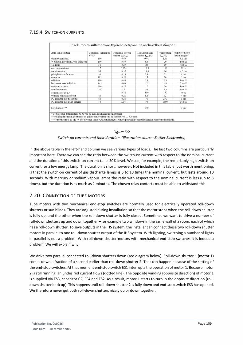
Publication No. Cu0236
Issue Date: December 2015
Page 109
7.19.4. SWITCH-ON CURRENTS
Figure 56:
Switch-on currents and their duration. (Illustration source: Zettler Electronics)
In the above table in the left-hand column we see various types of loads. The last two columns are particularly
important here. There we can see the ratio between the switch-on current with respect to the nominal current
and the duration of this switch-on current to its 50% level. We see, for example, the remarkably high switch-on
current for a low energy lamp. The duration is short, however. Not included in this table, but worth mentioning,
is that the switch-on current of gas discharge lamps is 5 to 10 times the nominal current, but lasts around 10
seconds. With mercury or sodium vapour lamps the ratio with respect to the nominal current is less (up to 3
times), but the duration is as much as 2 minutes. The chosen relay contacts must be able to withstand this.
7.20. CONNECTION OF TUBE MOTORS
Tube motors with two mechanical end-stop switches are normally used for electrically operated roll-down
shutters or sun blinds. They are adjusted during installation so that the motor stops when the roll-down shutter
is fully up, and the other when the roll-down shutter is fully closed. Sometimes we want to drive a number of
roll-down shutters up and down together – for example two windows in the same wall of a room, each of which
has a roll-down shutter. To save outputs in the IHS system, the installer can connect these two roll-down shutter
motors in parallel to one roll-down shutter output of the IHS system. With lighting, switching a number of lights
in parallel is not a problem. With roll-down shutter motors with mechanical end-stop switches it is indeed a
problem. We will explain why.
We drive two parallel connected roll-down shutters down (see diagram below). Roll-down shutter 1 (motor 1)
comes down a fraction of a second earlier than roll-down shutter 2. That can happen because of the setting of
the end-stop switches. At that moment end-stop switch ES1 interrupts the operation of motor 1. Because motor
2 is still running, an undesired current flows (dotted line). The opposite winding (opposite direction) of motor 1
is supplied via ES3, capacitor C2, ES4 and ES2. As a result, motor 1 starts to turn in the opposite direction (roll-
down shutter back up). This happens until roll-down shutter 2 is fully down and end-stop switch ES3 has opened.
We therefore never get both roll-down shutters nicely up or down together.
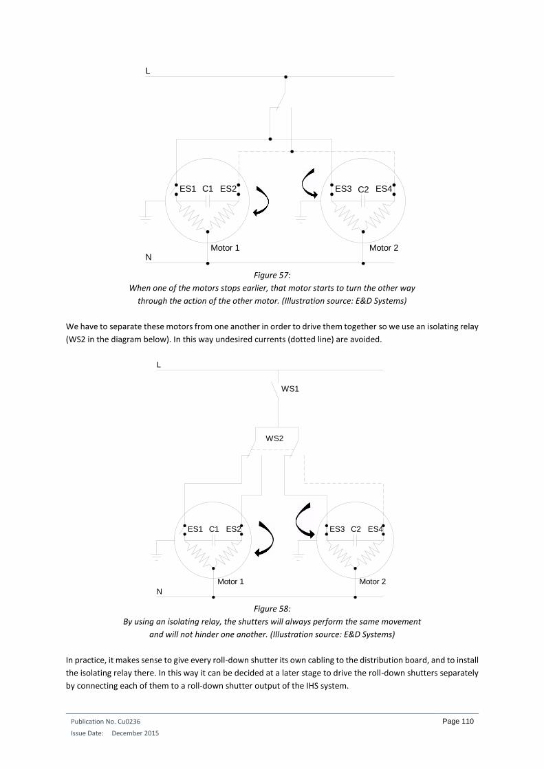
Publication No. Cu0236
Issue Date: December 2015
Page 110
Figure 57:
When one of the motors stops earlier, that motor starts to turn the other way
through the action of the other motor. (Illustration source: E&D Systems)
We have to separate these motors from one another in order to drive them together so we use an isolating relay
(WS2 in the diagram below). In this way undesired currents (dotted line) are avoided.
Figure 58:
By using an isolating relay, the shutters will always perform the same movement
and will not hinder one another. (Illustration source: E&D Systems)
In practice, it makes sense to give every roll-down shutter its own cabling to the distribution board, and to install
the isolating relay there. In this way it can be decided at a later stage to drive the roll-down shutters separately
by connecting each of them to a roll-down shutter output of the IHS system.
N
L
C1 C2ES1 ES2 ES3 ES4
Motor 1 Motor 2
N
ES1 ES2C1 ES3 ES4C2
WS1
WS2
Motor 1 Motor 2
L

Publication No. Cu0236
Issue Date: December 2015
Page 111
There are also tube motors on the market that have electronic end-stop switches. They do not impede one
another when connected in parallel.
7.21. OPERATING COMPONENTS AT A USABLE HEIGHT
Operating components such as keypads with an LCD display, touch screens or other controls on which text or
other information is displayed, must be fitted at a usable height. Ordinary switches and push buttons are
generally fitted at a height of 110cm from the finished floor. For operating components on which something
needs to be read, this is far too low but we are not able to dictate a specific height for this. Firstly, the height
depends on the operating component itself. A touch screen can be somewhat higher than a keypad with LCD
readout. Secondly, the height will also depend on the average height of the occupiers. The average Dutch person
is a fair bit taller than the average Japanese person. In such cases the height at which a keypad with display is
fitted will differ by tens of centimetres. But there are, of course, also short Dutchmen and tall Japanese. There
is therefore no fixed rule for the height of such operating components.
Figure 59:
Both the information of the LCD window and the description of the buttons must be readable without the
person having to stand on his toes or bend his knees. (Illustration source: Jung)
7.22. POSITIONING OF THERMOSTATS OR TEMPERATURE SENSORS
When we want to measure the room temperature we will (depending on the IHS system) use thermostats or
electronic temperature sensors. To obtain a good measurement, the positioning of these components is very
important. The greatest heat loss in a room occurs on the outside walls and at the window. That is therefore
also the place to compensate for the heat losses so the heating element is installed here, creating an airflow in
the room. Normally the room temperature is measured at the wall opposite the heating element. Generally the
room sensor is placed at a height of 1.5 to 1.6 metres. In any case they are not put on outside walls or next to a
door, which could lead to inaccurate measurements.
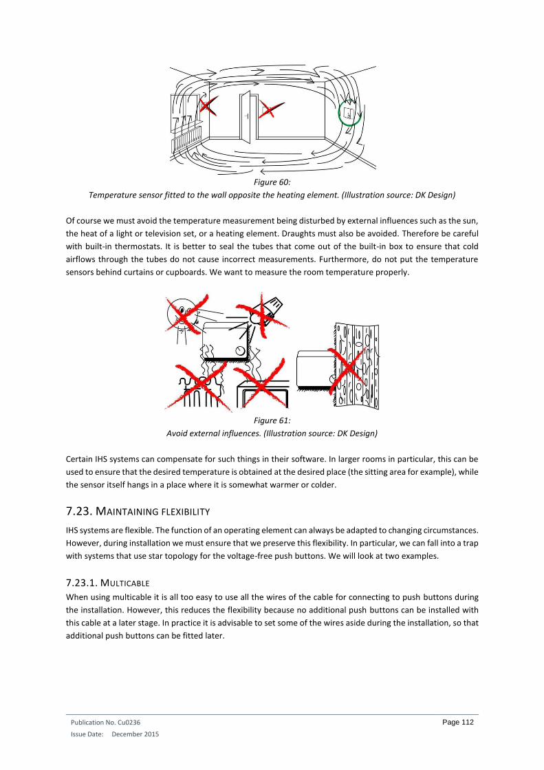
Publication No. Cu0236
Issue Date: December 2015
Page 112
Figure 60:
Temperature sensor fitted to the wall opposite the heating element. (Illustration source: DK Design)
Of course we must avoid the temperature measurement being disturbed by external influences such as the sun,
the heat of a light or television set, or a heating element. Draughts must also be avoided. Therefore be careful
with built-in thermostats. It is better to seal the tubes that come out of the built-in box to ensure that cold
airflows through the tubes do not cause incorrect measurements. Furthermore, do not put the temperature
sensors behind curtains or cupboards. We want to measure the room temperature properly.
Figure 61:
Avoid external influences. (Illustration source: DK Design)
Certain IHS systems can compensate for such things in their software. In larger rooms in particular, this can be
used to ensure that the desired temperature is obtained at the desired place (the sitting area for example), while
the sensor itself hangs in a place where it is somewhat warmer or colder.
7.23. MAINTAINING FLEXIBILITY
IHS systems are flexible. The function of an operating element can always be adapted to changing circumstances.
However, during installation we must ensure that we preserve this flexibility. In particular, we can fall into a trap
with systems that use star topology for the voltage-free push buttons. We will look at two examples.
7.23.1. MULTICABLE When using multicable it is all too easy to use all the wires of the cable for connecting to push buttons during
the installation. However, this reduces the flexibility because no additional push buttons can be installed with
this cable at a later stage. In practice it is advisable to set some of the wires aside during the installation, so that
additional push buttons can be fitted later.

Publication No. Cu0236
Issue Date: December 2015
Page 113
7.23.2. SEPARATE CABLING FOR PUSH BUTTONS In corridors where there are a number of doors, a push button is often placed at each door. Every push button
then performs the same function, i.e. switching the lighting in the connecting area, entrance or night hall. From
an economic point of view the temptation is high to connect all the push buttons in parallel locally, and then to
connect them to one input of the IHS system in the distribution board. This saves the number of inputs required
in the system. However, it is better to give all push buttons their own cabling up to the distribution board and
make the parallel connection there. In this way, if desired the push buttons can be disconnected from one
another in order to perform a different function.
In the example below, an IHS system has been used where it is possible to perform a certain function with a
short press on the push button and a completely different function when the same push button is pressed for
longer (1.5 to 2 secs). The intention was for push buttons DK1 to DK4 to switch the light in the connecting area
(LP1) with a short press. By pressing DK4 for longer, the lighting in the kitchen could be switched. Pressing longer
on DK2 would result in switching the garage lighting. In the same way, the lighting of garden 1 and garden 2
could be operated with push buttons DK1 and DK3. However, this could not be done in practice because the
installer had connected the four push buttons in parallel locally with two wires.
Figure 62:
Push buttons that have to perform the same function are nevertheless cabled separately
to the distribution board in order to preserve flexibility. (Illustration source: E&D Systems)

Publication No. Cu0236
Issue Date: December 2015
Page 114
INTEGRATED HOME SYSTEMS COURSE CHAPTER 5: STRUCTURED CABLING IN THE HOME
Guy Kasier
November 2015
ECI Publication No. Cu0234
Available from www.leonardo-energy.org

Publication No. Cu0234
Issue Date: November 2015
Page 115
CONTENTS
1. Introduction ............................................................................................................................................ 116
2. The basics ............................................................................................................................................... 117
2.1. BUS topology ............................................................................................................................................... 117
2.2. Star topology ............................................................................................................................................... 117
3. The traditional installation method ........................................................................................................ 118
4. Smart installation methods ..................................................................................................................... 120
4.1. With patch box ............................................................................................................................................ 120
4.2. Without patch box ....................................................................................................................................... 122
5. Installation tips ....................................................................................................................................... 123
6. A wired or wireless network? ................................................................................................................. 124
6.1. The wired network....................................................................................................................................... 124
6.2. The wireless network ................................................................................................................................... 125

Publication No. Cu0234
Issue Date: November 2015
Page 116
1. INTRODUCTION It used to be a lot easier. At one time 230V cabling would be laid in a newly-built home, to which a few sockets,
power points and switches were connected. At most, there was also a telephone socket in the wall and a coax
cable connection for the television. A small distribution board was sufficient to protect a few socket and lighting
circuits. The installation was ready.
That is no longer the case today. With the arrival of Integrated Home Systems (IHS) and many other technological
marvels of this day and age, the number of networks in the home has increased sharply. Generally, one
telephone connection is no longer enough; we want a connection in almost every room. This is also the case for
the television and radio. In addition to the flat-screen TV in the living room, we also want a television in the
bedroom and kitchen. We also have a desktop computer, a network printer and a network hard drive that
require separate cabling. These devices are supplemented by a portable computer, a tablet and several
smartphones. These may all use a wireless network. There is a video entry phone at the front door which we
want to use in various places throughout the home. When we are watching television, the picture of the person
at the door appears as a PIP (picture in picture) on the screen, and why not on the computer, the tablet and the
smartphone when we are using these devices or have them to hand. Furthermore, we would also like to hear
our entire MP3 collection on the audio system in the living room and the audio equipment in the children’s
rooms. In the bathroom and kitchen, we want to listen to the news on the radio. We may also want to use IP
cameras for various reasons.
The expansion of the various networks in the home is enormous. It is therefore obvious that we are looking for
solutions for dealing with such network cabling in the home in a well thought out way. In this chapter, we will
discuss a few practical examples and smart solutions. We will see that the flexibility (the adaptability) of the
installation will play an important role.

Publication No. Cu0234
Issue Date: November 2015
Page 117
2. THE BASICS Depending on the systems that have to be cabled, we generally use different cabling methods.
2.1. BUS TOPOLOGY
The first is to connect from component to component. This method is used, for example, when the operating
points of an IHS system are connected to a BUS system via a decentralised interface.
Figure 1:
Connection of operating points to the same bus cable. (Illustration source: E&D Systems)
The advantage of this form of cabling is that only a few connections have to be made. The disadvantage is that
there will be a greater loss of function when the cable is damaged.
Figure 2:
An IHS button is connected to the bus cable here. We see two red and two black cables. The bus comes to the
connector and then goes on to the next component. (Illustration source: E&D Systems)
2.2. STAR TOPOLOGY
A second cabling method, which is used more often, is star cabling or “home run”. Every component is connected
to a central point by its own cable. There are many examples of this, such as the telephones that are connected
to the local telephone exchange with their own cabling, or the speakers of a multi-room system that are
connected to the central amplifiers with their own cabling as well. The most well-known example is probably
ethernet cabling, where each device is connected to a hub or router by its own cable.

Publication No. Cu0234
Issue Date: November 2015
Page 118
Figure 3:
IHS system buttons that are connected to a central point using a star topology.
(Illustration source: E&D Systems)
Figure 4:
Example of an audio system and a telephone system in which every component is
connected to a central point by its own cabling. (Illustration source: Russound)
The advantage of star cabling is that there is only a limited loss of function when a cable is defective. The
disadvantage is that many connections have to be made at the central point.
3. THE TRADITIONAL INSTALLATION METHOD
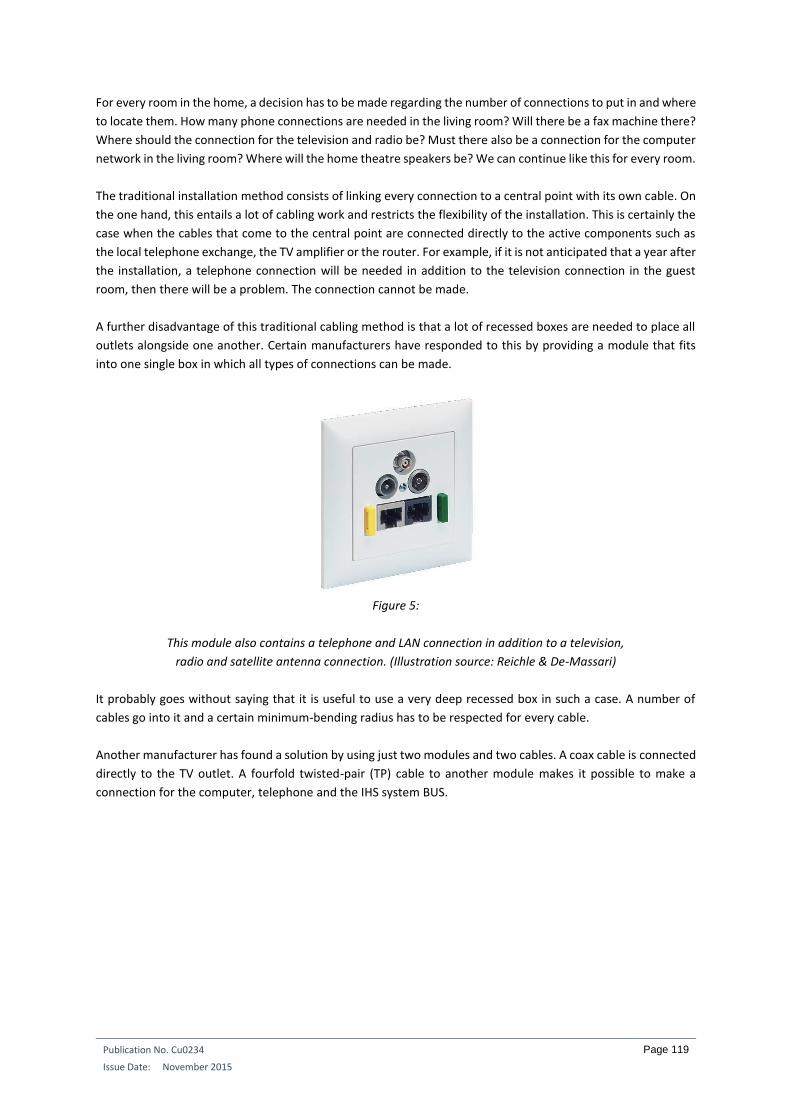
Publication No. Cu0234
Issue Date: November 2015
Page 119
For every room in the home, a decision has to be made regarding the number of connections to put in and where
to locate them. How many phone connections are needed in the living room? Will there be a fax machine there?
Where should the connection for the television and radio be? Must there also be a connection for the computer
network in the living room? Where will the home theatre speakers be? We can continue like this for every room.
The traditional installation method consists of linking every connection to a central point with its own cable. On
the one hand, this entails a lot of cabling work and restricts the flexibility of the installation. This is certainly the
case when the cables that come to the central point are connected directly to the active components such as
the local telephone exchange, the TV amplifier or the router. For example, if it is not anticipated that a year after
the installation, a telephone connection will be needed in addition to the television connection in the guest
room, then there will be a problem. The connection cannot be made.
A further disadvantage of this traditional cabling method is that a lot of recessed boxes are needed to place all
outlets alongside one another. Certain manufacturers have responded to this by providing a module that fits
into one single box in which all types of connections can be made.
Figure 5:
This module also contains a telephone and LAN connection in addition to a television,
radio and satellite antenna connection. (Illustration source: Reichle & De-Massari)
It probably goes without saying that it is useful to use a very deep recessed box in such a case. A number of
cables go into it and a certain minimum-bending radius has to be respected for every cable.
Another manufacturer has found a solution by using just two modules and two cables. A coax cable is connected
directly to the TV outlet. A fourfold twisted-pair (TP) cable to another module makes it possible to make a
connection for the computer, telephone and the IHS system BUS.

Publication No. Cu0234
Issue Date: November 2015
Page 120
Figure 6:
This multimedia solution uses two cables. (Illustration source: Bticino)
4. SMART INSTALLATION METHODS If everything continues to be connected directly at the central point to the active units, then there will soon be
a problem regarding the flexibility of the installation. It is better to use a patch cabinet, in which every individual
cable comes to an outlet in the cabinet. The correct connection can then be made using patch cables. A decision
can be made whether to use an outlet in the home for a computer connection or for a telephone or fax machine.
Certain manufacturers go much further here and only use one cable for telephony, audio, video, television and
computer connections throughout the home. We will look at a few examples.
4.1. WITH PATCH BOX
Manufacturers often use their own cable. In this specific case, it is a screened TP cable with four pairs of
conductors. One pair of conductors in the cable is screened separately. This pair can be used for the distribution
of video and television signals.
Figure 7:
The Abitana cable, in which the brown-white pair is screened separately. (Illustration source: Abitana)
All RJ45 outlets throughout the home are connected in a star topology to a separate multimedia distribution
board by this cable.

Publication No. Cu0234
Issue Date: November 2015
Page 121
Figure 8:
The multimedia distribution board. (Illustration source: Abitana)
All incoming cables are connected to an RJ45 outlet in this distribution board. These outlets are mounted on the
DIN rail. Depending on the residents’ needs, one or more active components can also be incorporated into the
multimedia distribution board, e.g., video distributors, a hub or router, an audio distributor, a telephone
distributor, etc. An outlet in a certain room can be connected to any active component by using patch cables. In
practice, this means that, for example, an unused outlet in the children’s room can be connected to the local
telephone exchange because a fixed telephone is needed there as well. If it is decided to take the telephone out
of the room and replace it with a data connection for the computer or a TV connection, then it can be carried
out in no time at all in the patch cabinet.
Figure 9:
Left: a TV distributor that is secured to the DIN rail in the patch cabinet. It has 4 RJ45 outputs.
Right: the coupling from an RJ45 outlet in a room to a coax connection for the television.
(Illustration source: Abitana)
In order to further increase flexibility, splitters are also supplied. These ensure that an RJ45 outlet can be used
not just for one unit, but also for a number of units. For example, two telephones can be connected to one RJ45,
or a telephone and a computer, etc.
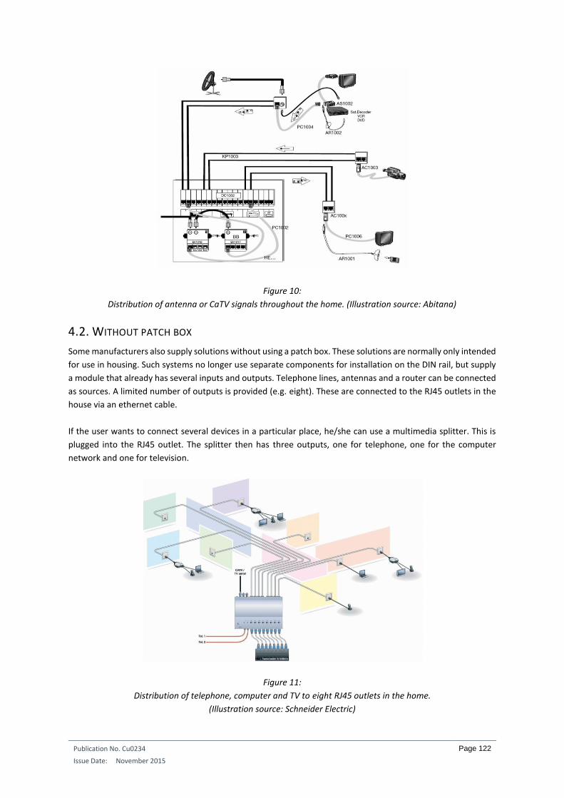
Publication No. Cu0234
Issue Date: November 2015
Page 122
Figure 10:
Distribution of antenna or CaTV signals throughout the home. (Illustration source: Abitana)
4.2. WITHOUT PATCH BOX
Some manufacturers also supply solutions without using a patch box. These solutions are normally only intended
for use in housing. Such systems no longer use separate components for installation on the DIN rail, but supply
a module that already has several inputs and outputs. Telephone lines, antennas and a router can be connected
as sources. A limited number of outputs is provided (e.g. eight). These are connected to the RJ45 outlets in the
house via an ethernet cable.
If the user wants to connect several devices in a particular place, he/she can use a multimedia splitter. This is
plugged into the RJ45 outlet. The splitter then has three outputs, one for telephone, one for the computer
network and one for television.
Figure 11:
Distribution of telephone, computer and TV to eight RJ45 outlets in the home.
(Illustration source: Schneider Electric)

Publication No. Cu0234
Issue Date: November 2015
Page 123
Figure 12:
Up to three units can be connected to one RJ45 outlet using the multimedia splitter.
(Illustration source: Schneider Electric)
5. INSTALLATION TIPS When installing structured cabling, a few basic principles must be followed:
Provide sufficient universal connection points (outlets) in each room.
Use universal cable types, suitable for multiple applications and independent of the brand of end
device.
For each cable type, use one type of connection (connector), regardless of the application.
Install the cables according to a fixed pattern (no spaghetti cabling), starting from a common
distribution board (patch panel).
Do not use daisy chain connections (looping). This makes them interdependent. Use a star topology.
Respect the specified maximum lengths and install the cables in accordance with the regulations.
Label each cable at both ends and draw a diagram of the installation.
Measure the quality of all connections and keep these data (test report) for later.
Every manufacturer provides sufficient information on how the outlets have to be connected to the cables. For
example, the length to which the outermost cable insulation must be cut back is important, as is the length of
the screening with STP or FTP cables. These instructions have to be strictly adhered to in order to ensure
optimum data communications.
Figure 13:
Example of the way in which a manufacturer indicates how the connection has to be made to an outlet.
(Illustration source: Niko)
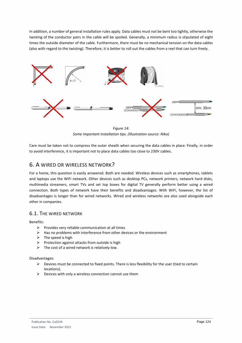
Publication No. Cu0234
Issue Date: November 2015
Page 124
In addition, a number of general installation rules apply. Data cables must not be bent too tightly, otherwise the
twisting of the conductor pairs in the cable will be spoiled. Generally, a minimum radius is stipulated of eight
times the outside diameter of the cable. Furthermore, there must be no mechanical tension on the data cables
(also with regard to the twisting). Therefore, it is better to roll out the cables from a reel that can turn freely.
Figure 14:
Some important installation tips. (Illustration source: Niko)
Care must be taken not to compress the outer sheath when securing the data cables in place. Finally, in order
to avoid interference, it is important not to place data cables too close to 230V cables.
6. A WIRED OR WIRELESS NETWORK? For a home, this question is easily answered. Both are needed. Wireless devices such as smartphones, tablets
and laptops use the WiFi network. Other devices such as desktop PCs, network printers, network hard disks,
multimedia streamers, smart TVs and set top boxes for digital TV generally perform better using a wired
connection. Both types of network have their benefits and disadvantages. With WiFi, however, the list of
disadvantages is longer than for wired networks. Wired and wireless networks are also used alongside each
other in companies.
6.1. THE WIRED NETWORK
Benefits:
Provides very reliable communication at all times Has no problems with interference from other devices or the environment The speed is high Protection against attacks from outside is high The cost of a wired network is relatively low.
Disadvantages:
Devices must be connected to fixed points. There is less flexibility for the user (tied to certain locations).
Devices with only a wireless connection cannot use them

Publication No. Cu0234
Issue Date: November 2015
Page 125
6.2. THE WIRELESS NETWORK
Benefits:
The user can move freely about the home or office with his or her wireless devices. If no wired connection is available in a certain place, WiFi can offer a way out.
Disadvantages:
Devices with only a wired connection cannot use them. WiFi is less reliable, depending on the circumstances. The range is difficult to determine in advance. This depends on, among other things, the materials
used in the building. Wooden walls block the least amount of radiation. However, concrete walls, aluminium windows and radiators can reduce the signal by up to 90%, which will quickly shorten the range and cause communication to fall short. If the range is too short, a repeater has to be used.
WiFi is still many times slower than a wired network. The speed can be reduced dramatically by simultaneous use.
The specified speed is never the speed of the data traffic. So-called ‘overhead’ traffic is needed to allow wireless devices to communicate with the router. This overhead traffic can take up a significant part of the total bandwidth.
A disruptive influence from other devices (microwave ovens, DECT telephones, baby monitors, other WiFi networks on the same channel, etc.) operating in the same frequency band is possible.
Protection against attacks or use from outside is less. Some people believe radiation has a negative effect on health. No scientific evidence has yet been
provided for this. However, it has already been shown that radiation from a WiFi network can have a negative impact on the leaves of certain trees.
The cost of a WiFi network can be more than for a wired network.
Figure 15:
The materials used for walls, ceilings and floors can seriously reduce the range of wireless networks:
1 Stone walls 20% to 40% loss. 2 Wooden and plasterboard walls 5% to 20% loss.
3 Reinforced concrete 40% to 90% loss. 4 Metal and steel 90% to 100%.
(Illustration source: Niko)

Publication No. Cu0234
Issue Date: November 2015
Page 126
INTEGRATED HOME SYSTEMS COURSE CHAPTER 6: CONTROLLING HEATING WITH IHS
Guy Kasier
October 2015
ECI Publication No Cu0229
Available from www.leonardo-energy.org

Publication No Cu0229
Issue Date: October 2015
Page 127
CONTENTS
1. Introduction ............................................................................................................................................ 137
1.1. Reasons to integrate .................................................................................................................................... 137
2. The need for heating ............................................................................................................................... 139
3. Types of energy ....................................................................................................................................... 140
4. Conventional CH installations ................................................................................................................. 141
4.1. A central heating system: ............................................................................................................................ 141
4.1.1. Fuel oil boilers ............................................................................................................................ 141
4.1.2. Gas boilers .................................................................................................................................. 141
4.1.3. The heat pump ........................................................................................................................... 142
4.2. Types of boiler: ............................................................................................................................................ 143
4.2.1. The conventional boiler .............................................................................................................. 143
4.2.2. The low-temperature boiler ....................................................................................................... 143
4.3. Thermostats: ................................................................................................................................................ 143
4.3.1. Mechanical thermostats. ............................................................................................................ 143
4.3.2. Electronic thermostats ............................................................................................................... 144
4.3.3. Data thermostats ........................................................................................................................ 145
4.4. Other measuring devices: ............................................................................................................................ 145
4.5. Hydraulic circuits of a CH installation: ......................................................................................................... 145
4.6. Regulation systems: ..................................................................................................................................... 147
4.6.1. Thermostat control on the circulating pump. ............................................................................ 147
4.6.2. Thermostat control on the burner. ............................................................................................ 147
4.6.3. Thermostat control on the burner and the circulating pump. ................................................... 147
4.6.4. Regulation unit for heating and sanitary hot water. .................................................................. 148
4.6.5. Regulation unit with motorized mixer valve. ............................................................................. 148
4.6.6. Thermostatic valves. ................................................................................................................... 148
4.6.7. Weather-dependent regulation unit. ......................................................................................... 149
4.6.8. The circulating pump .................................................................................................................. 150
5. Controlling heating with an IHS system ................................................................................................... 152
5.1. How to intervene in the heating: ................................................................................................................. 152
5.2. Controls with KNX ........................................................................................................................................ 153

Publication No Cu0229
Issue Date: October 2015
Page 128
5.3. Tips relating to valves .................................................................................................................................. 153
5.4. IHS temperature measurements: ................................................................................................................ 156
5.4.1. A conventional thermostat......................................................................................................... 156
5.4.2. An electronic temperature sensor. ............................................................................................ 157
5.5. Types of control ........................................................................................................................................... 158
5.5.1. Two-point controls ..................................................................................................................... 158
5.5.2. PWM controls ............................................................................................................................. 159
5.5.3. Analog controls: ......................................................................................................................... 160
5.6. Software: ..................................................................................................................................................... 160
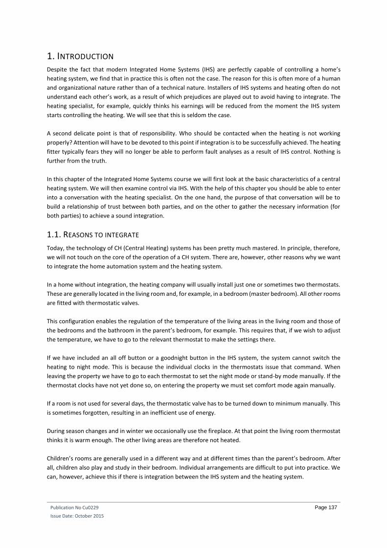
Publication No Cu0229
Issue Date: October 2015
Page 137
1. INTRODUCTION Despite the fact that modern Integrated Home Systems (IHS) are perfectly capable of controlling a home’s
heating system, we find that in practice this is often not the case. The reason for this is often more of a human
and organizational nature rather than of a technical nature. Installers of IHS systems and heating often do not
understand each other’s work, as a result of which prejudices are played out to avoid having to integrate. The
heating specialist, for example, quickly thinks his earnings will be reduced from the moment the IHS system
starts controlling the heating. We will see that this is seldom the case.
A second delicate point is that of responsibility. Who should be contacted when the heating is not working
properly? Attention will have to be devoted to this point if integration is to be successfully achieved. The heating
fitter typically fears they will no longer be able to perform fault analyses as a result of IHS control. Nothing is
further from the truth.
In this chapter of the Integrated Home Systems course we will first look at the basic characteristics of a central
heating system. We will then examine control via IHS. With the help of this chapter you should be able to enter
into a conversation with the heating specialist. On the one hand, the purpose of that conversation will be to
build a relationship of trust between both parties, and on the other to gather the necessary information (for
both parties) to achieve a sound integration.
1.1. REASONS TO INTEGRATE
Today, the technology of CH (Central Heating) systems has been pretty much mastered. In principle, therefore,
we will not touch on the core of the operation of a CH system. There are, however, other reasons why we want
to integrate the home automation system and the heating system.
In a home without integration, the heating company will usually install just one or sometimes two thermostats.
These are generally located in the living room and, for example, in a bedroom (master bedroom). All other rooms
are fitted with thermostatic valves.
This configuration enables the regulation of the temperature of the living areas in the living room and those of
the bedrooms and the bathroom in the parent’s bedroom, for example. This requires that, if we wish to adjust
the temperature, we have to go to the relevant thermostat to make the settings there.
If we have included an all off button or a goodnight button in the IHS system, the system cannot switch the
heating to night mode. This is because the individual clocks in the thermostats issue that command. When
leaving the property we have to go to each thermostat to set the night mode or stand-by mode manually. If the
thermostat clocks have not yet done so, on entering the property we must set comfort mode again manually.
If a room is not used for several days, the thermostatic valve has to be turned down to minimum manually. This
is sometimes forgotten, resulting in an inefficient use of energy.
During season changes and in winter we occasionally use the fireplace. At that point the living room thermostat
thinks it is warm enough. The other living areas are therefore not heated.
Children’s rooms are generally used in a different way and at different times than the parent’s bedroom. After
all, children also play and study in their bedroom. Individual arrangements are difficult to put into practice. We
can, however, achieve this if there is integration between the IHS system and the heating system.

Publication No Cu0229
Issue Date: October 2015
Page 138
When we stretch out on the sofa in the evening to relax, watch a film or read a book, the home automation
system can ensure that the heating is immediately set a few degrees higher, as we might feel a little colder
through being less active.
We can also set the heating via the IHD system from outside the home using a smartphone, tablet or computer.
This is particulary handy if the occupants work irregular hours. In that case the heating system does not need to
switch to comfort temperature if we are not yet home.
With an IHS system the heating system can be switched off briefly just for the room in question when the
windows are opened. Only the anti-freeze protection will then be active. The children’s rooms can be set to
normal comfort temperatures when they are used for playing or to study. Likewise, the bathroom heating can
temporarily be set to a higher level for taking a bath or shower, without also having to raise the temperature of
the bedrooms.
The heating for the different rooms can also be regulated using the IHS clocks, taking into account various
parameters. Thus, for example, an IHS system can take account of whether or not the occupants are at home.
Working days, weekends, so called orphaned or bridge single days between a public holiday and the weekend
or vice versa, or being off sick for a day can also be taken into account to switch the heating to a specific mode
(or not). If it is sunny for a longer period of time, but heat is needed in the home, the IHS system can keep the
sun blinds raised so that the free heat of the sun can be put to good use.
Here too we find that the possible functions are limited not so much by the technical possibilities of integration,
but by the creative possibilities of the two fitters.
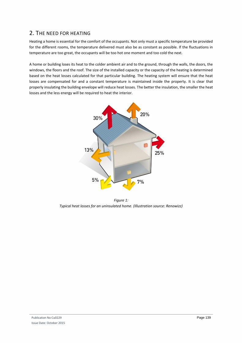
Publication No Cu0229
Issue Date: October 2015
Page 139
2. THE NEED FOR HEATING Heating a home is essential for the comfort of the occupants. Not only must a specific temperature be provided
for the different rooms, the temperature delivered must also be as constant as possible. If the fluctuations in
temperature are too great, the occupants will be too hot one moment and too cold the next.
A home or building loses its heat to the colder ambient air and to the ground, through the walls, the doors, the
windows, the floors and the roof. The size of the installed capacity or the capacity of the heating is determined
based on the heat losses calculated for that particular building. The heating system will ensure that the heat
losses are compensated for and a constant temperature is maintained inside the property. It is clear that
properly insulating the building envelope will reduce heat losses. The better the insulation, the smaller the heat
losses and the less energy will be required to heat the interior.
Figure 1:
Typical heat losses for an uninsulated home. (Illustration source: Renowizz)

Publication No Cu0229
Issue Date: October 2015
Page 140
3. TYPES OF ENERGY In most cases, fossil fuels are still used to heat the home. However, supplies of these are limited. In the near
future they will be exhausted. In any case, when burned they produce CO2, which is highly detrimental to global
climate change.
Recently, pellet stoves have appeared on the market. These use pellets made from wood waste. One of the
disadvantages of this system is that besides the space for the stove, they also need space to store the pellets.
Also, the heat exchanger has to be cleaned every 700 to 1,000 kg of pellets used (generally two to three times a
year). Note that while this is a renewable source of energy, it still generates CO2.
All systems that burn fuels require a chimney to remove the waste gases. That is not the case when using a heat
pump, which runs on electricity. Such pumps do not give off any waste gases, and renewable energies such as
wind power and solar energy can be used, as well as the heat present in the outside air or the ground.
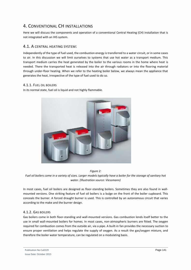
Publication No Cu0229
Issue Date: October 2015
Page 141
4. CONVENTIONAL CH INSTALLATIONS Here we will discuss the components and operation of a conventional Central Heating (CH) installation that is
not integrated with an IHS system.
4.1. A CENTRAL HEATING SYSTEM:
Independently of the type of fuel used, the combustion energy is transferred to a water circuit, or in some cases
to air. In this discussion we will limit ourselves to systems that use hot water as a transport medium. This
transport medium carries the heat generated by the boiler to the various rooms in the home where heat is
needed. There the transported heat is released into the air through radiators or into the flooring material
through under-floor heating. When we refer to the heating boiler below, we always mean the appliance that
generates the heat, irrespective of the type of fuel used to do so.
4.1.1. FUEL OIL BOILERS In its normal state, fuel oil is liquid and not highly flammable.
Figure 2:
Fuel oil boilers come in a variety of sizes. Larger models typically have a boiler for the storage of sanitary hot
water. (Illustration source: Viessmann)
In most cases, fuel oil boilers are designed as floor-standing boilers. Sometimes they are also found in wall-
mounted versions. One striking feature of fuel oil boilers is a bulge on the front of the boiler cupboard. This
conceals the burner. A forced draught burner is used. This is controlled by an autonomous circuit that varies
according to the make and the burner design.
4.1.2. GAS BOILERS Gas boilers come in both floor-standing and wall-mounted versions. Gas combustion lends itself better to the
use in small wall-mounted boilers for homes. In most cases, non-atmospheric burners are fitted. The oxygen
required for combustion comes from the outside air, via a pipe. A built-in fan provides the necessary suction to
ensure proper ventilation and helps regulate the supply of oxygen. As a result the gas/oxygen mixture, and
therefore the boiler water temperature, can be regulated on a modulating basis.

Publication No Cu0229
Issue Date: October 2015
Page 142
Figure 3:
An opened wall-mounted gas boiler.
4.1.3. THE HEAT PUMP Heat pumps are generally of two types: the air/water or the ground/water heat pump. In the first version the
heat of the outside air is used to release heat into the water circuit of the CH installation. In the second example,
underground heat present is used as the source. Actually, the working principle is quite similar to that of a
refrigerator. There the heat within the refrigerator is also extracted and released into the ambient air. In the
heat pump, however, this extracted heat is released into the water circuit. Electricity is needed for the
compressor to work. Efficiency is normally expressed in COP (Coefficient Of Performance). The higher the COP
value, the greater the efficiency. With a COP of 4, the heat pump uses 25% electrical energy to produce 100% of
its heat.
Figure 4:
Basic illustration of an air/water heat pump. (Illustration source: Building performance)

Publication No Cu0229
Issue Date: October 2015
Page 143
4.2. TYPES OF BOILER:
4.2.1. THE CONVENTIONAL BOILER The normal, older conventional boilers running on fossil fuels heats the boiler water to a temperature of 70 °C
to 90 °C. In practice, however, this produces considerable energy losses.
4.2.2. THE LOW-TEMPERATURE BOILER A low-temperature boiler is a heat generator that is designed or equipped such that the temperature of the
heating water can fluctuate between 10°C and 75°C. In practice, however, the temperature will never fall below
25 °Cto 30 °C. This is the minimum value at which a real exchange of heat is guaranteed. Such boilers enable the
heating installation to operate at a temperature of 45 °C to 55 °C for most of the heating period. This reduces
losses to the environment, thereby also lowering energy consumption. When it is very cold outside, the boiler
can obviously operate at higher temperatures to compensate for the increasing heat losses of the property. Low-
temperature boilers are available that run on both gas and fuel oil. Heat pumps also operate at low
temperatures.
A different type within the group of low-temperature combustion boilers (gas or fuel oil) is the condensing boiler.
Condensing boilers achieve a high efficiency by recovering the heat that is still present in the combustion gases.
These gases, and therefore also the heat, normally disappear up the chimney. With a condensing boiler, this
heat is reused to preheat the temperature of the return water.
4.3. THERMOSTATS:
A thermostat is used in conventional heating installations to measure the temperature within a room. This will
indicate to the boiler whether or not heat is required. To maintain a high level of comfort, the temperature of
the room must remain as constant as possible. Fluctuations must remain minimal if comfort is to be assured.
The temperature differential of the thermostat must therefore be as small as possible. This is the difference in
temperature between the thermostat switching on and off.
Thermostats can be divided into three groups, namely: mechanical, electronic and data thermostats.
4.3.1. MECHANICAL THERMOSTATS.
4.3.1.1. THE BIMETAL THERMOSTAT:
The built-in bimetal deforms under the influence of changes in temperature. This causes a contact switch to
close or open. A spring and a small permanent magnet speed up the movement of the contact.
Figure 5:
A simple bimetal thermostat.

Publication No Cu0229
Issue Date: October 2015
Page 144
The disadvantages of a normal bimetal thermostat are the significant fluctuations in the room temperature. This
is due to the relatively slow action of the bimetal. Once the desired temperature has been reached (e.g. 22°C),
it takes a little while before the bimetal switches off. This is known as the overshoot.
Figure 6:
Example of overshoot, whereby the room temperature can exhibit considerable fluctuations. (Illustration
source: E&D Systems)
4.3.1.2. BIMETAL THERMOSTAT WITH PARALLEL COMPENSATION:
To improve the temperature differential of the thermostat, a parallel-compensation resistor can be added. This
resistor is activated when the contact in the thermostat closes. This leads to the development of heat, which
increases the follow-on speed of the bimetal on switch-off.
Figure 7:
Bimetal thermostat with parallel compensation. The compensation resistor (7) helps to heat up the bimetal.
4.3.1.3. THE BULB THERMOSTAT:
The operation of the bulb thermostat is based on the expansion and contraction of fluid. The bulb or bell is the
actual temperature sensor. This type of thermostat is mainly used with under-floor heating.
4.3.2. ELECTRONIC THERMOSTATS Electronic thermostats are much more sensitive than their mechanical equivalents. Their temperature
differential is limited to 0.2°C to 0.5°C. The heat is measured by an NTC resistor.
Normal electronic thermostats switch a contact that is transmitted to the boiler. The more sophisticated (read
expensive) models produce an output voltage, the size of which depends on the difference between the actual
temperature and the requested temperature. This means they not only measure, but also regulate.

Publication No Cu0229
Issue Date: October 2015
Page 145
Figure 8:
Electronic room thermostat. (Illustration source: Grässlin)
4.3.3. DATA THERMOSTATS Different boiler manufacturers offer their own electronic thermostat that is specifically built into their own
proprietary systems. It does not have an on/off contact, but rather sends data to the boiler.
4.4. OTHER MEASURING DEVICES:
Heating fitters generally use other sensors as well. These may include devices for measuring the temperature of
fluids (aquastat), gases (airostat) and for measuring the outside temperature (outside sensor). The latter sensor
takes into account not only temperature, but also the influence of the wind (wind chill).
4.5. HYDRAULIC CIRCUITS OF A CH INSTALLATION:
Figure 9:
A simple hydraulic CH circuit. The red line is the supply of hot water to the radiators. The blue line is the return
line to the boiler. (Illustration source: Tempolec)
AA: outside sensor
T: boiler thermostat
VV1: boiler sensor
VV3: return sensor
SAR: room sensor without clock (optional)
SAD: room sensor with clock (optional)
1: circulating pump
2: non-return valve
3: radiators circuit
The figure above illustrates the structure of a simple hydraulic CH circuit. Hot water is sent from the boiler to
the radiator by a circulating pump and a non-return valve. The cooled water returns to the boiler from the
radiator. In the above case, a weather-dependent regulator is used as a control, since the circuit includes an
outside sensor (AA).

Publication No Cu0229
Issue Date: October 2015
Page 146
We will see that the circulating pump is generally included in the boiler housing. That is the case in the following
drawing. Here we can also see that an automatic bypass has been provided in the boiler. This bypass opens to
allow the pump to continue running at the moment when the thermostatic valves of the heating elements are
closed.
Figure 10:
Simple hydraulic circuit for under-floor heating or for radiators. (Illustration source: Vaillant)
2: circulating pump
4: automatic bypass
5: room thermostat
7: outside sensor
8: under-floor heating thermostat
9: thermostatic valve
10: thermostatic radiator valve
A three-way or even four-way mixer valve is often used with more complex installations. Controlling this mixer
valve enables the use of the return water in regulating the temperature of the hot water leaving the circuit.
In the under-floor heating circuit in the following drawing, the temperature of the water will be regulated by
controlling the three-way mixer valve, with less or more return water being added to the boiler water. A sensor
at the start of the circuit (VV2) will check the supply temperature for the under-floor heating (4). If this threatens
to become too high, the three-way valve (6) will send more return water to the circuit and increasingly reduce
or shut off the overly hot boiler water.
Figure 11:
Note that this diagram is already quite a bit more complex than the previous one. This is because the hot
heating water is not only fed to a circuit with radiators, but also to a circuit with under-floor heating and
another separate circuit for sanitary hot water. (Illustration source: Tempolec)
AA: outside sensor T: boiler thermostat

Publication No Cu0229
Issue Date: October 2015
Page 147
VV1: boiler sensor
VV2: supply sensor
VV3: return sensor
BO: boiler sensor
SAR: room sensor without clock (optional)
SAD: room sensor with clock (optional)
1: circulating pump
2: non-return valve
3: radiators circuit
4: under-floor heating circuit
5: boiler
6: three-way mixer valve
7: stepper motor
In larger installations, a hydraulic separator (9 in the diagram below) is often added to the installation. This
ensures that the pressure in the installation can be managed, both at times when specific circuits require heating
and at times when no circuit requires heating. In this case one pump is always installed before the hydraulic
separator and one or more pumps after the hydraulic separator.
Figure 12:
Use of the hydraulic separator (9) in larger installations. (Illustration source: Vaillant)
4.6. REGULATION SYSTEMS:
The hot boiler water must be sent to the hydraulic circuit at very specific times. That does not just happen. In
practice, different regulation systems are used. Certain regulation systems only take into account a requested
temperature, while others take several parameters into consideration. One regulation system therefore
provides greater comfort than another.
4.6.1. THERMOSTAT CONTROL ON THE CIRCULATING PUMP. A thermostat (with an on/off contact) switches the heating on and off by switching the circulating pump on and
off. The burner mechanism is controlled by the boiler thermostat. Here, the boiler water remains at a constant
temperature at all times. It is clear that this is a fairly energy-intensive method.
4.6.2. THERMOSTAT CONTROL ON THE BURNER. This is a comparable control to the one immediately above. The difference is that the thermostat does not now
control the circulating pump but rather controls the burner directly. In this case the circulating pump runs
continuously. This form of regulation is somewhat less energy-intensive than the previous one, since the boiler
water is only heated at the time heat is requested.
4.6.3. THERMOSTAT CONTROL ON THE BURNER AND THE CIRCULATING PUMP. Here both the previous techniques are used by means of an autonomous regulation unit.

Publication No Cu0229
Issue Date: October 2015
Page 148
4.6.4. REGULATION UNIT FOR HEATING AND SANITARY HOT WATER. Here at least two separate hydraulic circuits are used, one for the heating and one for the sanitary hot water.
Each circuit has its own circulating pump. The production of sanitary hot water takes priority over the heating.
The regulation unit does what is necessary in that regard.
Figure 13:
A solution with two separate pumps, one for the heating and one for the sanitary hot water. (Illustration
source: Tempolec)
4.6.5. REGULATION UNIT WITH MOTORIZED MIXER VALVE. A motorized mixer valve (three-way or four-way) ensures that the temperature in the hydraulic circuit can be
regulated. This is accomplished by the use of the return water, which is added to a lesser or greater extent to
the hot water coming from the boiler. These mixer valves are designed with a servo or stepper motor, which in
turn is controlled by a regulation unit.
Figure 14:
Control with a four-way mixer valve. (Illustration source: Tempolec)
4.6.6. THERMOSTATIC VALVES. The thermostatic valve on a radiator continuously regulates the flow of heat. However, it is dependent upon on
the operation of the boiler. If, for example, the boiler is not operating because a room thermostat in the living

Publication No Cu0229
Issue Date: October 2015
Page 149
room indicates that it is warm enough, the other rooms fitted with thermostatic valves will not be heated. The
disadvantage of the thermostatic valve is that the user always has to set each radiator individually. This setting
will naturally require adjustment as the seasons change. On a warm day in May the setting will also have to be
different from what it is on a chillier day in May. This therefore creates both a convenience and a comfort issue.
In principle, thermostatic valves are not fitted in the same room where the room thermostat is installed. If that
is the case however, they must be fully open.
Figure 15:
The thermostatic valve has several disadvantages in terms of comfort and saving energy. (Illustration source:
Honeywell)
4.6.7. WEATHER-DEPENDENT REGULATION UNIT. In certain European regions there can be significant temperature differences in the outside air on the same
day. Fluctuations of 7 °C to 8 °C within a span of only two hours are not exceptional. Given the generally slow
reaction of a heating installation, it is impossible under such circumstances to keep the room temperature
contantly stable.
Figure 16:
Possible temperature fluctuations on the same day. (Illustration source: E&D Systems)
Increasing use is being made of weather dependent controls to cope with these significant temperature
fluctuations. Such controls regulate the temperature of the boiler water according to the outside temperature
and the cold influence of the wind. Such a control ensures that the inside temperature remains fairly constant.
The temperature of the CH water is controlled according to the heating curve that is set.

Publication No Cu0229
Issue Date: October 2015
Page 150
Figure 17:
Heating line 3 (dotted line) is the setting for a low-temperature system. The x-axis shows the outside
temperature, and the y-axis the boiler water temperature. (Illustration source: Theben)
A heating line is set in the regulation unit, depending upon the local average outside temperature. With heating
line 3 (dotted line) the temperature of the boiler water will be approximately 65 °C at an outside temperature
of -10 °C. At an outside temperature of 0 °C this heating temperature drops to 50 °C. And at an outside
temperature of +10 °C this temperature is 38 °C.
In principle, the use of a room temperature sensor is optional. Sometimes, however, a room temperature sensor
is installed in a reference room, so that the user can, for example, raise or lower the temperature by just a few
degrees.
Note: Such a room temperature sensor is not a thermostat that controls an on/off contact. The room
temperature sensor must instead be regarded as a sort of remote control for the control panel on the burner’s
regulation unit.
At a water temperature of 45 °C to 50 °C, the heat losses in the pipes and at the heat source (boiler) only amount
to one third of what the heat losses would be if the heating temperature were 70 °C. Because the boiler is
operating at a lower temperature, downtime losses are reduced and the boiler operates more regularly. This
ultimately increases the efficiency of the boiler. Even in a small installation, installing a weather-dependent
control reduces energy consumption. For an average installation, consumption can be reduced by 10 to 20%.
The additional cost of this control can then be written off in three to four heating seasons.
4.6.8. THE CIRCULATING PUMP Every CH installation includes at least one circulating pump. After all, the hot water from the boiler does not
flow through the hydraulic circuit of the installation of its own accord. In some cases, the pump runs constantly.
In the summer period it may then be switched off manually as appropriate via the summer/winter switch on the
burner.
Usually, though, the control of the boiler or the regulation unit will operate the pump. The pump will run when
the boiler is producing heat. When the desired boiler temperature is reached, the pump will continue to run for
a certain time (usually 10 minutes). The advantage of this is that no unnecessary energy is used when there is

Publication No Cu0229
Issue Date: October 2015
Page 151
no need for the pump to be running. Certain regulation units will also offer a manual switch for summer/winter
mode. In the summer period, however, they will have the pump run for a short while at regular intervals to
prevent it from becoming blocked.
In some cases a frequency-controlled pump is used. The speed of the pump will be regulated so that the pressure
in the installation remains constant. If just one heating zone is open, it will run slowly. If several zones require
heating, the speed will increase.
Note: The pump and the boiler must never be stopped at the same time. The pump must always stop after the
boiler. Otherwise there is a risk that the boiler will overheat.
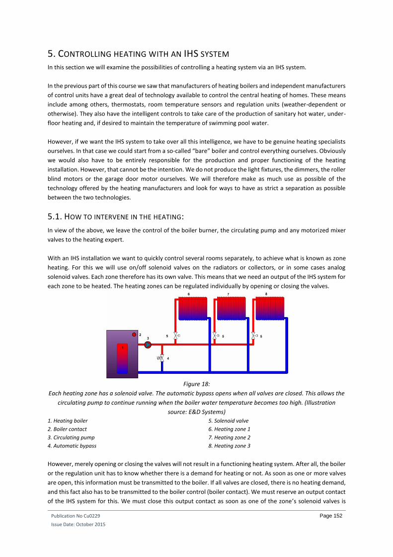
Publication No Cu0229
Issue Date: October 2015
Page 152
5. CONTROLLING HEATING WITH AN IHS SYSTEM In this section we will examine the possibilities of controlling a heating system via an IHS system.
In the previous part of this course we saw that manufacturers of heating boilers and independent manufacturers
of control units have a great deal of technology available to control the central heating of homes. These means
include among others, thermostats, room temperature sensors and regulation units (weather-dependent or
otherwise). They also have the intelligent controls to take care of the production of sanitary hot water, under-
floor heating and, if desired to maintain the temperature of swimming pool water.
However, if we want the IHS system to take over all this intelligence, we have to be genuine heating specialists
ourselves. In that case we could start from a so-called “bare” boiler and control everything ourselves. Obviously
we would also have to be entirely responsible for the production and proper functioning of the heating
installation. However, that cannot be the intention. We do not produce the light fixtures, the dimmers, the roller
blind motors or the garage door motor ourselves. We will therefore make as much use as possible of the
technology offered by the heating manufacturers and look for ways to have as strict a separation as possible
between the two technologies.
5.1. HOW TO INTERVENE IN THE HEATING:
In view of the above, we leave the control of the boiler burner, the circulating pump and any motorized mixer
valves to the heating expert.
With an IHS installation we want to quickly control several rooms separately, to achieve what is known as zone
heating. For this we will use on/off solenoid valves on the radiators or collectors, or in some cases analog
solenoid valves. Each zone therefore has its own valve. This means that we need an output of the IHS system for
each zone to be heated. The heating zones can be regulated individually by opening or closing the valves.
Figure 18:
Each heating zone has a solenoid valve. The automatic bypass opens when all valves are closed. This allows the
circulating pump to continue running when the boiler water temperature becomes too high. (Illustration
source: E&D Systems)
1. Heating boiler
2. Boiler contact
3. Circulating pump
4. Automatic bypass
5. Solenoid valve
6. Heating zone 1
7. Heating zone 2
8. Heating zone 3
However, merely opening or closing the valves will not result in a functioning heating system. After all, the boiler
or the regulation unit has to know whether there is a demand for heating or not. As soon as one or more valves
are open, this information must be transmitted to the boiler. If all valves are closed, there is no heating demand,
and this fact also has to be transmitted to the boiler control (boiler contact). We must reserve an output contact
of the IHS system for this. We must close this output contact as soon as one of the zone’s solenoid valves is

Publication No Cu0229
Issue Date: October 2015
Page 153
open. When all solenoid valves are closed, we open this contact. The CH installation therefore knows that no
more heat is required.
Figure 19:
The electrical wiring diagram of a CH installation. On the bottom right of the drawing we can see a terminal
block with terminals 3 and 4. There is a wire bridge between these as standard. If we wish to control using IHS,
we must connect the additional relay contact here and remove the wire bridge. (Illustration source: Vaillant)
We must add together all the separate zones to be heated and add one relay contact for controlling the boiler
contact to determine the number of outputs (relay or 0-10 V outputs) of the IHS system needed to control the
heating.
5.2. CONTROLS WITH KNX
The above control method can be used by almost any IHS system, as only relay outputs or analog 0-10 V outputs
are used. However, there are other possibilities with a KNX system. Here the control forms an integral part of
the heating boiler and heating control. This is because some manufacturers of heating boilers have a KNX module
that can be attached to the boiler control. With such a control the IHS system not only intervenes in the valves,
but also in the boiler itself. As a result, the separation between the heating technology and the IHS technology
disappears. It is therefore clear that communication between the heating fitter and the electrician must be
optimal in this regard. Both must be aware of the entire system and must make clear agreements about who is
responsible for what.
5.3. TIPS RELATING TO VALVES
We must make a distinction between two-point valves and analog valves. Two-point valves have only two
possible positions: open or closed. Conversely, analog valves can be set to any position. They allow better control
but are more expensive than two-point valves. Analog valves are controlled by a 0-10 V signal. At 0 V, the valve
is closed. At 10 V it is fully open. And at a voltage of 5 V it is half-open. This allows stepless regulation of the flow
rate of the hot water that is sent to a radiator circuit.
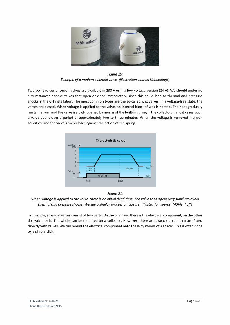
Publication No Cu0229
Issue Date: October 2015
Page 154
Figure 20:
Example of a modern solenoid valve. (Illustration source: Möhlenhoff)
Two-point valves or on/off valves are available in 230 V or in a low-voltage version (24 V). We should under no
circumstances choose valves that open or close immediately, since this could lead to thermal and pressure
shocks in the CH installation. The most common types are the so-called wax valves. In a voltage-free state, the
valves are closed. When voltage is applied to the valve, an internal block of wax is heated. The heat gradually
melts the wax, and the valve is slowly opened by means of the built-in spring in the collector. In most cases, such
a valve opens over a period of approximately two to three minutes. When the voltage is removed the wax
solidifies, and the valve slowly closes against the action of the spring.
Figure 21:
When voltage is applied to the valve, there is an initial dead time. The valve then opens very slowly to avoid
thermal and pressure shocks. We see a similar process on closure. (Illustration source: Möhlenhoff)
In principle, solenoid valves consist of two parts. On the one hand there is the electrical component, on the other
the valve itself. The whole can be mounted on a collector. However, there are also collectors that are fitted
directly with valves. We can mount the electrical component onto these by means of a spacer. This is often done
by a simple click.

Publication No Cu0229
Issue Date: October 2015
Page 155
Figure 22:
On the top left we can see the collector that is equipped with valves. The rod that moves up and down can
clearly be seen. On the top right we can see the electrical component. This is clicked onto the spacer. On the
bottom left we can see that the valve is closed when no voltage is connected. On the bottom right, however,
voltage is being applied, the valve has opened and the so called hat of the electrical component has also lifted
up. (Illustration source: Tecnolec)
In the above photo we can see that, when the valve is open, a small cylinder on the electrical component moves
upwards. We can therefore observe the position of the valve visually. If, however, there is still doubt as to the
position of the valve, the electrical component can be removed directly and the valve rod moved to a particular
position manually. This can be a handy way of determining whether heating that is not working properly is due
to the IHS system or to the heating system. Awkward discussions with the heating fitter are thus avoided.
Publication No Cu0229
Issue Date: October 2015
Page 156
5.4. IHS TEMPERATURE MEASUREMENTS:
The IHS system will have to measure the room temperature itself. With these measured values, specific heating
settings can then be made. Except when a conventional thermostat is used (not recommended), several
temperature settings can be controlled by the IHS system.
Comfort temperature: This is the basic setting when the occupants are present in the property during
the day.
Night temperature (also known as eco-mode): This is a reduced mode for the night or times when the
occupants are not at home. The night temperature is usually not more than 6°C below the comfort
temperature.
Anti-freeze protection: This mode is used if, for example, the room temperature drops below 5°C. It
prevents central heating pipes from freezing, as well as the water pipes.
Stand-by temperature: Here the room temperature is taken to around 2°C below the comfort
temperature. At a comfort temperature of 20°C the stand-by temperature is thus 18°C. This mode is
very handy if you return home at irregular times. Imagine a clock in the IHS system is set to activate the
comfort temperature every working day at 5 p.m. (because that is when the occupants come home).
However, when the occupants first call in to see grandma and do some shopping, and so get home two
hours later, the heating has delivered two hours of comfort temperature that was not needed. With
IHS systems with which it is possible, we will program the clock so that the stand-by temperature is
activated instead of the comfort temperature. This reduces energy consumption. A reduction in
temperature of 1 °C for one hour results in an energy saving of around 6%. If the occupants get home
later than planned, the home will no longer feel cold and the temperature difference from the comfort
temperature (2 °C) is quickly bridged.
Higher: This allows the user to increase the set temperature in steps of half a degree.
Lower: This allows the user to reduce the set temperature in steps of half a degree.
5.4.1. A CONVENTIONAL THERMOSTAT.
Some IHS systems work with a conventional thermostat. The output contact of this thermostat is then used as
an input for the IHS system. Such thermostats usually have a button to manually select between comfort or night
temperature. With an IHS installation, however, we can do very little with it. In this case a general control (all
off, for example) leaves the thermostats untouched. It is better to use thermostats that have a so-called
telephone contact. This allows the thermostat to be forced into night or day mode via a voltage-free contact of
the IHS system.
With such measurements we therefore also have to provide an output contact of the IHS system for each zone
for the control of the zone thermostat. Our research has shown that there are currently no thermostats where,
a stand-by temperature can also be set other than a comfort temperature and a night temperature. IHS systems
that use a conventional thermostat will therefore have a hard time generating the stand-by temperature.

Publication No Cu0229
Issue Date: October 2015
Page 157
Figure 23:
A conventional clock thermostat for measuring the temperature of the room. (Illustration source: Siemens)
Note: If you want to control multiple thermostats at the same time with a remote control, a separate voltage-
free contact must be provided for each thermostat. This is because in most cases, the control does not work if
just one contact is used for multiple thermostats.
5.4.2. AN ELECTRONIC TEMPERATURE SENSOR. Most IHS systems use electronic temperature sensors to measure the room temperature. These transmit an
analog value to the IHS system. This is quite interesting, as the room temperature measured in this way can
always be compared with the requested temperature for a particular room. If it is too cold, the room can be
heated. If it is too warm, the room can be cooled. If the temperature drops below a certain minimum value, the
room can also be heated to support the anti-freeze protection. We could also use electronic measurement, for
example, to detect excessively quick heating above a specific maximum room temperature . Such an instance
might occur in the event of a fire, for example.
Figure 24:
This electronic room temperature sensor is built into a cable gland plate. (Illustration source: Dobiss)
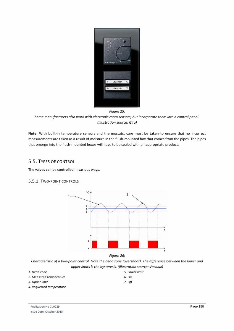
Publication No Cu0229
Issue Date: October 2015
Page 158
Figure 25:
Some manufacturers also work with electronic room sensors, but incorporate them into a control panel.
(Illustration source: Gira)
Note: With built-in temperature sensors and thermostats, care must be taken to ensure that no incorrect
measurements are taken as a result of moisture in the flush-mounted box that comes from the pipes. The pipes
that emerge into the flush-mounted boxes will have to be sealed with an appropriate product.
5.5. TYPES OF CONTROL
The valves can be controlled in various ways.
5.5.1. TWO-POINT CONTROLS
Figure 26:
Characteristic of a two-point control. Note the dead zone (overshoot). The difference between the lower and
upper limits is the hysteresis. (Illustration source: Vecolux)
1. Dead zone
2. Measured temperature
3. Upper limit
4. Requested temperature
5. Lower limit
6. On
7. Off

Publication No Cu0229
Issue Date: October 2015
Page 159
Most IHS systems use two-point controls. This means they control a two-point solenoid valve in an extremely
simple way. When heat is requested, the valve is opened. When the upper hysteresis limit is reached, the valve
is closed. The disadvantage of this control is the dead time, or overshoot. This can lead to fairly considerable
differences in room temperature. One minute it is too hot, the next too cold. Every effort must therefore be
made to keep these differences in room temperature as small as possible.
5.5.2. PWM CONTROLS A Pulse Width Modulation (PWM) control uses two-point valves. Now, however, these are no longer only
controlled according to the demand for heat, but also according to a cycle time. This time can vary from one
heating system to another. If the difference between the room temperature and the requested temperature is
large, the relay that controls the valve is closed for the majority of the cycle time. The closer the room
temperature gets to the requested temperature, the smaller the pulse time will be at which the relay is closed.
When the room temperature is the same as the requested temperature, the relay will for example be closed for
only 10% of the cycle time to compensate for the prevailing heat losses.
The cycle time chosen depends upon the speed of the heating system. In an installation with normal modern
radiators, for example, this time will be 15 minutes. In an installation with old cast iron radiators, the cycle time
will have to be longer (e.g. 20 minutes). This is because it takes a little longer to heat up such a radiator. Once
hot, a cast iron radiator will give off its heat for longer. The cast iron radiator works more slowly than modern
radiators. With under-floor heating, the cycle time will be increase to e.g. 30 minutes.
Figure 27:
Characteristic of a pulse width modulation. (Illustration source: Vecolux)
1. Measured temperature
2. Requested temperature
3. On
4. Off
5. Cycle time 15 minutes, for example
6. The pulse width within the cycle time is recalculated if
the actuating value changes
Despite the fact that the PWM control is an extremely good control and ensures a fairly constant room
temperature, it cannot be used everywhere. It is not a good idea to use a PWM control if the boiler already has
a modulating control that takes account of the outside temperature and the difference between the starting
temperature and the return temperature. This is because the PWM control will work with smaller pulses at the
time the room temperature approaches the requested temperature. At that point, the boiler senses there is a
smaller difference between the starting temperature and the return temperature and will therefore reduce its
starting temperature. The result is that it takes longer for the room to be brought to the desired temperature.
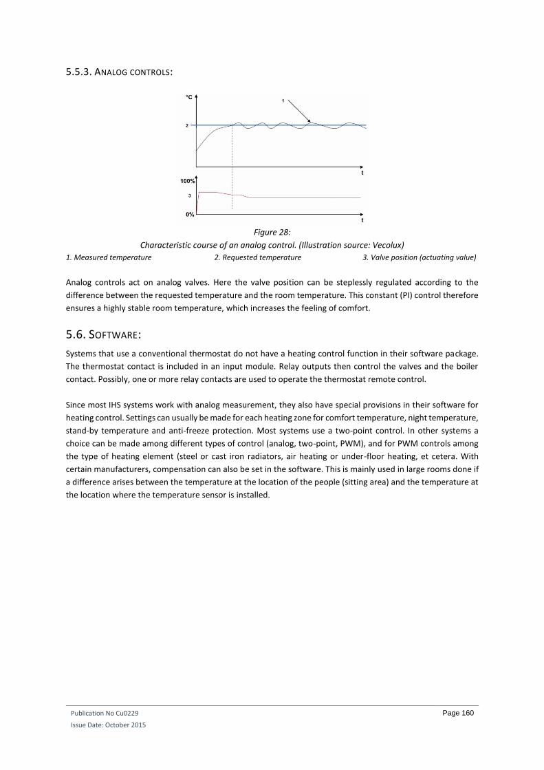
Publication No Cu0229
Issue Date: October 2015
Page 160
5.5.3. ANALOG CONTROLS:
Figure 28:
Characteristic course of an analog control. (Illustration source: Vecolux)
1. Measured temperature 2. Requested temperature 3. Valve position (actuating value)
Analog controls act on analog valves. Here the valve position can be steplessly regulated according to the
difference between the requested temperature and the room temperature. This constant (PI) control therefore
ensures a highly stable room temperature, which increases the feeling of comfort.
5.6. SOFTWARE:
Systems that use a conventional thermostat do not have a heating control function in their software package.
The thermostat contact is included in an input module. Relay outputs then control the valves and the boiler
contact. Possibly, one or more relay contacts are used to operate the thermostat remote control.
Since most IHS systems work with analog measurement, they also have special provisions in their software for
heating control. Settings can usually be made for each heating zone for comfort temperature, night temperature,
stand-by temperature and anti-freeze protection. Most systems use a two-point control. In other systems a
choice can be made among different types of control (analog, two-point, PWM), and for PWM controls among
the type of heating element (steel or cast iron radiators, air heating or under-floor heating, et cetera. With
certain manufacturers, compensation can also be set in the software. This is mainly used in large rooms done if
a difference arises between the temperature at the location of the people (sitting area) and the temperature at
the location where the temperature sensor is installed.