Embed Size (px)
Citation preview
KNOW YOUR OPTIONS: 138 KV POWER CABLES
43 44
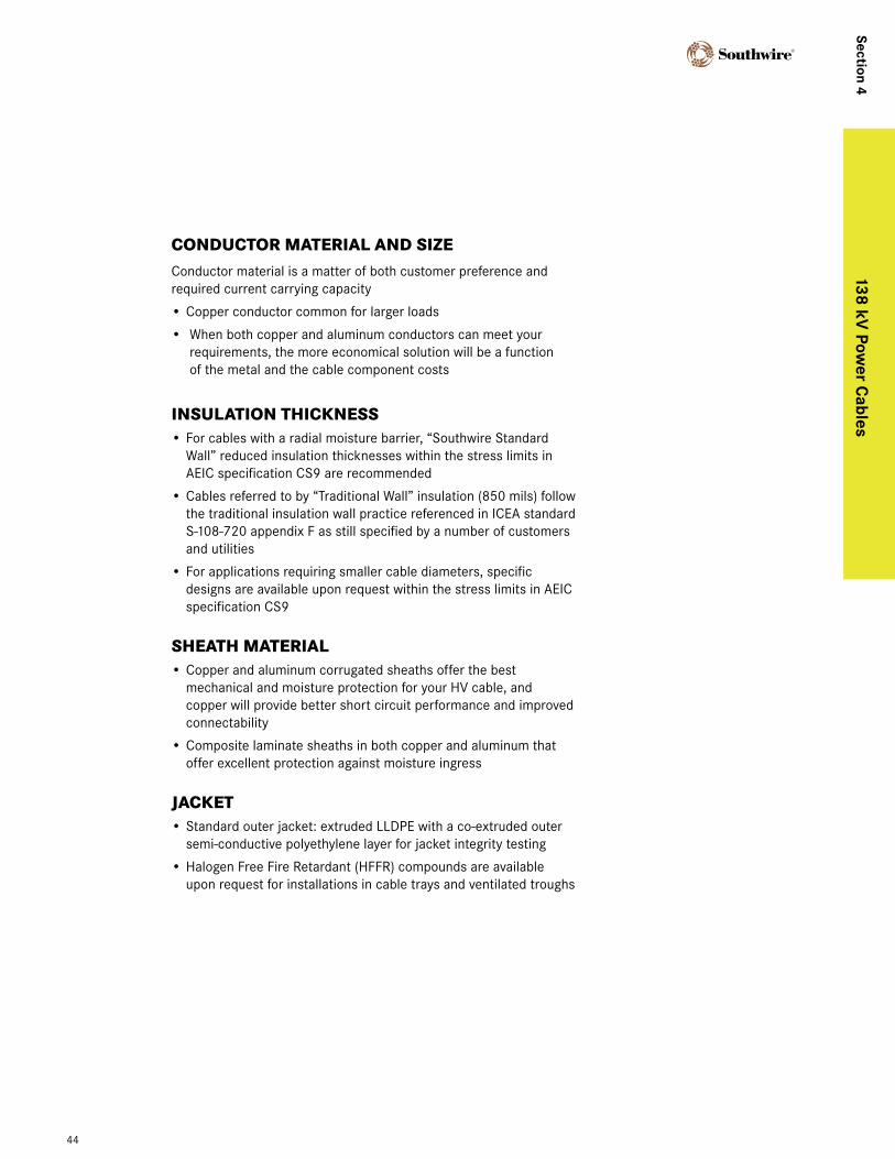
CONDUCTOR MATERIAL AND SIzEConductor material is a matter of both customer preference and required current carrying capacity
• Copper conductor common for larger loads
• When both copper and aluminum conductors can meet your requirements, the more economical solution will be a function of the metal and the cable component costs
INSULATION THICKNESS• For cables with a radial moisture barrier, “Southwire Standard
Wall” reduced insulation thicknesses within the stress limits in AEIC specification CS9 are recommended
• Cables referred to by “Traditional Wall” insulation (850 mils) follow the traditional insulation wall practice referenced in ICEA standard S-108-720 appendix F as still specified by a number of customers and utilities
• For applications requiring smaller cable diameters, specific designs are available upon request within the stress limits in AEIC specification CS9
SHEATH MATERIAL• Copper and aluminum corrugated sheaths offer the best
mechanical and moisture protection for your HV cable, and copper will provide better short circuit performance and improved connectability
• Composite laminate sheaths in both copper and aluminum that offer excellent protection against moisture ingress
JACKET• Standard outer jacket: extruded LLDPE with a co-extruded outer
semi-conductive polyethylene layer for jacket integrity testing
• Halogen Free Fire Retardant (HFFR) compounds are available upon request for installations in cable trays and ventilated troughs
44
Section 4138 kV
power c
ables
138 kV XLPE - Copper Conductor
cable data
Voltage Characteristics (kV)
Max Voltage Rating 145
BIL Rating 650
Temperatures (oC)
Nominal Conductor 90
Max. Emergency Conductor 105
Short Circuit Conductor 250
Minimum Installation -10
Design Characteristics
Design Standards AEIC, IEC
Typical Test Voltages 240 kV / 15 min.
XLPE Loss Factor 0.0005
Relative Permittivity 2.3
45
138 kV power cables
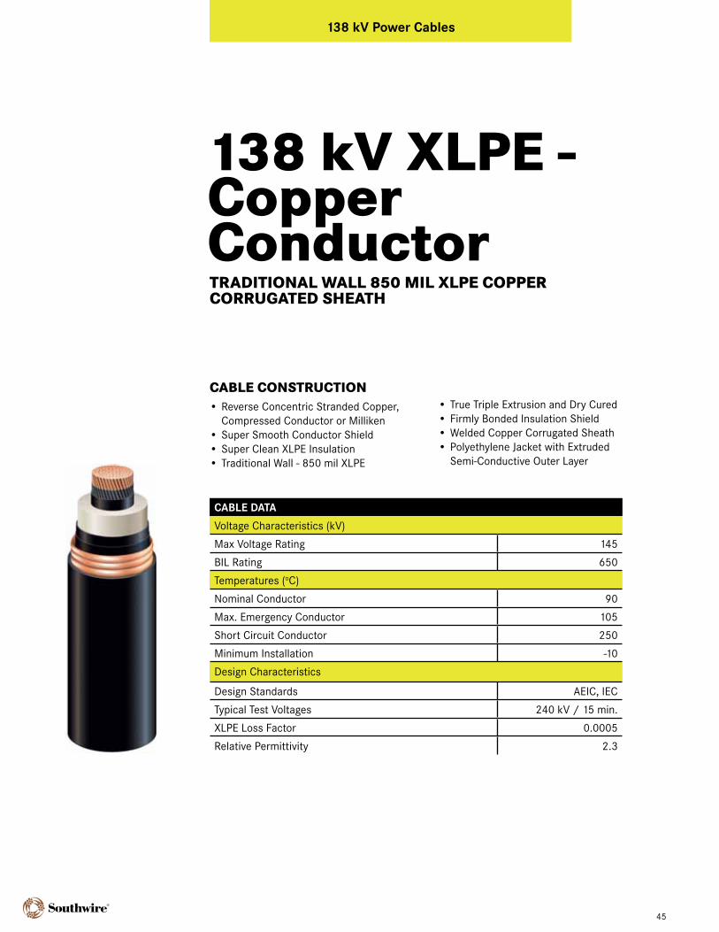
CABLE CONSTRUCTION• Reverse Concentric Stranded Copper,
Compressed Conductor or Milliken• Super Smooth Conductor Shield • Super Clean XLPE Insulation• Traditional Wall - 850 mil XLPE
• True Triple Extrusion and Dry Cured• Firmly Bonded Insulation Shield• Welded Copper Corrugated Sheath• Polyethylene Jacket with Extruded
Semi-Conductive Outer Layer
TRADITIONAL WALL 850 MIL XLPE COPPER CORRUgATED SHEATH
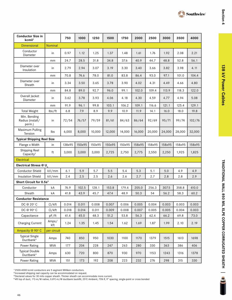
conductor Size in kcmil1 750 1000 1250 1500 1750 2000 2500 3000 3500 4000
Dimensional Nominal
Conductor Diameter in 0.97 1.12 1.25 1.37 1.48 1.61 1.76 1.92 2.08 2.21
mm 24.7 28.5 31.8 34.8 37.6 40.9 44.7 48.8 52.8 56.1
Diameter over Insulation in 2.79 2.94 3.07 3.19 3.30 3.40 3.66 3.82 3.98 4.11
mm 70.8 74.6 78.0 81.0 83.8 86.4 93.0 97.1 101.0 104.4
Diameter over Sheath in 3.34 3.50 3.65 3.78 3.90 4.02 4.31 4.49 4.66 4.80
mm 84.8 89.0 92.7 96.0 99.1 102.0 109.4 113.9 118.3 122.0
Overall Jacket Diameter in 3.62 3.78 3.93 4.06 4.18 4.30 4.59 4.77 4.94 5.08
mm 91.9 96.1 99.8 103.1 106.2 109.1 116.6 121.1 125.4 129.1
Total Weight lbs/ft 6.8 7.9 8.9 9.9 10.9 11.9 14.1 16.0 18.0 19.8
Min. Bending Radius (install/
perm.)in 72/54 76/57 79/59 81/61 84/63 86/64 92/69 95/71 99/74 102/76
Maximum Pulling Tension lbs 6,000 8,000 10,000 12,000 14,000 16,000 20,000 24,000 28,000 32,000
typical Shipping reel Size
Flange x Width in 138x95 150x95 150x95 150x95 150x95 158x95 158x95 158x95 158x95 158x95
Shipping Reel Capacity2 ft 3,000 3,000 3,000 2,725 2,750 2,775 2,550 2,250 1,925 1,825
Electrical
electrical Stress @ Uo
Conductor Shield kV/mm 6.1 5.9 5.7 5.5 5.4 5.3 5.1 5.0 4.9 4.9
Insulation Shield kV/mm 2.4 2.5 2.5 2.6 2.6 2.7 2.7 2.8 2.8 2.9
Short circuit for 0.5s3
Conductor kA 76.9 102.5 128.1 153.8 179.4 205.0 256.3 307.5 358.8 410.0
Sheath kA 41.8 43.9 45.7 47.4 48.9 50.3 54 56.2 58.3 60.2
conductor resistance
DC @ 20o C Ω/kft 0.014 0.011 0.008 0.007 0.006 0.005 0.004 0.003 0.003 0.003
DC @ 90o C Ω/kft 0.018 0.014 0.011 0.009 0.008 0.007 0.005 0.005 0.004 0.003
Capacitance pF/ft 41.4 45.0 48.3 51.2 53.8 56.3 62.4 66.2 69.8 73.0
Charging Current Amps/kft 1.24 1.35 1.45 1.54 1.62 1.69 1.87 1.99 2.10 2.19
Ampacity @ 90o C per circuit
Typical Single Ductbank4 Amps 740 850 950 1030 1100 1170 1379 1515 1613 1698
Power Rating MVA 177 204 228 247 263 280 330 363 386 406
Typical Double Ductbank4 Amps 630 720 800 870 930 970 1153 1243 1316 1378
Power Rating MVA 151 173 192 208 223 232 276 298 315 330
138 kV XLPE - Copper Conductor
tra
ditio
na
l Wa
ll 850 mil xlpe c
opper c
orrU
gated
SHeatH
46
Section 4138 kV
power c
ables
1 2500-4000 kcmil conductors are 5 segment Milliken conductors.2 Increased shipping reel capacity can be accommodated on request.3 Declared values for 30 mils copper sheath. Thicker sheath can accommodate more current.4 4ft top of duct, 1oC-m/W native, 0.8oC-m/W ductbank backfill, 25oC Ambient, 75% lf, 9” spacing, single-point or cross bonded
138 kV XLPE - Copper Conductor
cable data
Voltage Characteristics (kV)
Max Voltage Rating 145
BIL Rating 650
Temperatures (oC)
Nominal Conductor 90
Max. Emergency Conductor 105
Short Circuit Conductor 250
Minimum Installation -10
Design Characteristics
Design Standards AEIC, IEC
Typical Test Voltages 240 kV / 15 min.
XLPE Loss Factor 0.0005
Relative Permittivity 2.3
47
138 kV power cables
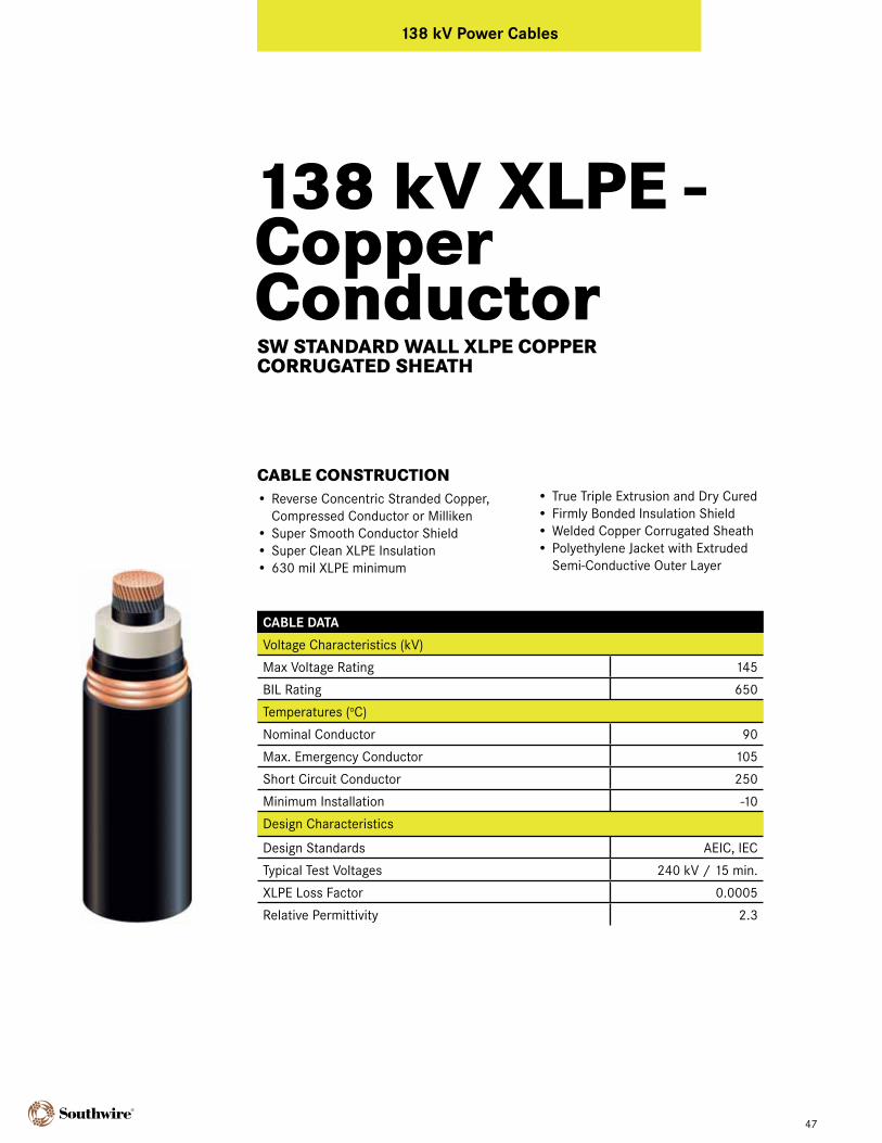
CABLE CONSTRUCTION• Reverse Concentric Stranded Copper,
Compressed Conductor or Milliken• Super Smooth Conductor Shield • Super Clean XLPE Insulation• 630 mil XLPE minimum
• True Triple Extrusion and Dry Cured• Firmly Bonded Insulation Shield• Welded Copper Corrugated Sheath• Polyethylene Jacket with Extruded
Semi-Conductive Outer Layer
SW STANDARD WALL XLPE COPPER CORRUgATED SHEATH
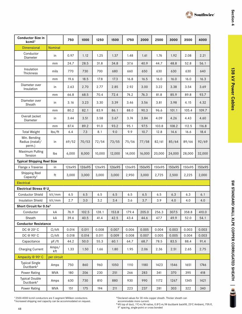
conductor Size in kcmil1 750 1000 1250 1500 1750 2000 2500 3000 3500 4000
Dimensional Nominal
Conductor Diameter in 0.97 1.12 1.25 1.37 1.48 1.61 1.76 1.92 2.08 2.21
mm 24.7 28.5 31.8 34.8 37.6 40.9 44.7 48.8 52.8 56.1
Insulation Thickness mils 770 730 700 680 660 650 630 630 630 640
mm 19.6 18.5 17.8 17.3 16.8 16.5 16.0 16.0 16.0 16.3
Diameter over Insulation in 2.63 2.70 2.77 2.85 2.92 3.00 3.22 3.38 3.54 3.69
mm 66.8 68.5 70.4 72.4 74.2 76.3 81.8 85.9 89.8 93.7
Diameter over Sheath in 3.16 3.23 3.30 3.39 3.46 3.56 3.81 3.98 4.15 4.32
mm 80.2 82.1 83.9 86.1 88.0 90.3 96.6 101.1 105.4 109.7
Overall Jacket Diameter in 3.44 3.51 3.58 3.67 3.74 3.84 4.09 4.26 4.43 4.60
mm 87.4 89.2 91.0 93.2 95.1 97.5 103.8 108.2 112.5 116.8
Total Weight lbs/ft 6.4 7.3 8.1 9.0 9.9 10.7 12.8 14.6 16.6 18.4
Min. Bending Radius (install/
perm.)in 69/52 70/53 72/54 73/55 75/56 77/58 82/61 85/64 89/66 92/69
Maximum Pulling Tension lbs 6,000 8,000 10,000 12,000 14,000 16,000 20,000 24,000 28,000 32,000
typical Shipping reel Size
Flange x Traverse in 126x95 126x95 126x95 126x95 126x95 150x95 150x95 150x95 150x95 150x95
Shipping Reel Capacity2 ft 3,000 3,000 3,000 3,000 2,950 3,000 2,725 2,500 2,225 2,000
Electrical
electrical Stress @ Uo
Conductor Shield kV/mm 6.5 6.5 6.5 6.5 6.5 6.5 6.5 6.3 6.3 6.1
Insulation Shield kV/mm 2.7 3.0 3.2 3.4 3.6 3.7 3.9 4.0 4.0 4.0
Short circuit for 0.5s3
Conductor kA 76.9 102.5 128.1 153.8 179.4 205.0 256.3 307.5 358.8 410.0
Sheath kA 39.6 40.5 41.4 42.5 43.4 44.6 47.7 49.9 52.0 54.1
conductor resistance
DC @ 20o C Ω/kft 0.014 0.011 0.008 0.007 0.006 0.005 0.004 0.003 0.003 0.003
DC @ 90o C Ω/kft 0.018 0.014 0.011 0.009 0.008 0.007 0.005 0.005 0.004 0.003
Capacitance pF/ft 44.2 50.0 55.3 60.1 64.7 68.7 78.5 83.5 88.4 91.4
Charging Current Amps/kft 1.33 1.50 1.66 1.80 1.95 2.06 2.36 2.51 2.65 2.75
Ampacity @ 90o C per circuit
Typical Single Ductbank4 Amps 750 860 960 1050 1110 1180 1423 1546 1651 1746
Power Rating MVA 180 206 230 251 266 283 341 370 395 418
Typical Double Ductbank4 Amps 630 730 810 880 930 990 1172 1267 1345 1421
Power Rating MVA 151 175 194 211 223 237 281 303 322 340
138 kV XLPE - Copper Conductor
SW Sta
nd
ard
Wa
ll xlpe co
pper co
rrUg
ated SH
eatH
48
Section 4138 kV
power c
ables
1 2500-4000 kcmil conductors are 5 segment Milliken conductors.2 Increased shipping reel capacity can be accommodated on request.
3 Declared values for 30 mils copper sheath. Thicker sheath can accommodate more current.
4 4ft top of duct, 1oC-m/W native, 0.8oC-m/W ductbank backfill, 25oC Ambient, 75% lf, 9” spacing, single-point or cross bonded
138 kV XLPE - Aluminum Conductor
cable data
Voltage Characteristics (kV)
Max Voltage Rating 145
BIL Rating 650
Temperatures (oC)
Nominal Conductor 90
Max. Emergency Conductor 105
Short Circuit Conductor 250
Minimum Installation -10
Design Characteristics
Design Standards AEIC, IEC
Typical Test Voltages 240 kV / 15 min.
XLPE Loss Factor 0.0005
Relative Permittivity 2.3
49
138 kV power cables
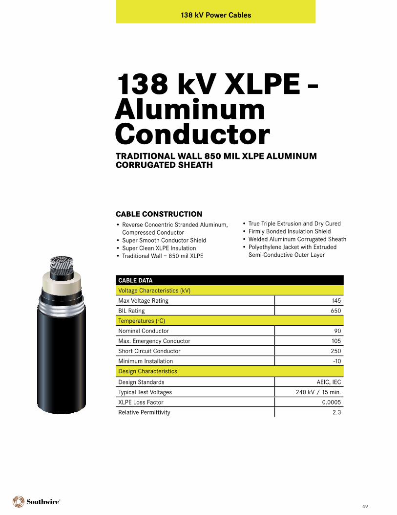
CABLE CONSTRUCTION• Reverse Concentric Stranded Aluminum,
Compressed Conductor• Super Smooth Conductor Shield • Super Clean XLPE Insulation• Traditional Wall – 850 mil XLPE
• True Triple Extrusion and Dry Cured• Firmly Bonded Insulation Shield• Welded Aluminum Corrugated Sheath• Polyethylene Jacket with Extruded
Semi-Conductive Outer Layer
TRADITIONAL WALL 850 MIL XLPE ALUMINUM CORRUgATED SHEATH
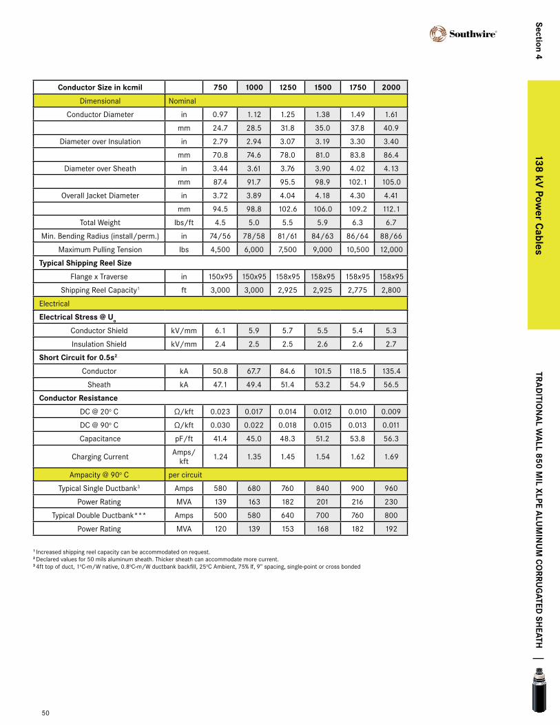
conductor Size in kcmil 750 1000 1250 1500 1750 2000
Dimensional Nominal
Conductor Diameter in 0.97 1.12 1.25 1.38 1.49 1.61
mm 24.7 28.5 31.8 35.0 37.8 40.9
Diameter over Insulation in 2.79 2.94 3.07 3.19 3.30 3.40
mm 70.8 74.6 78.0 81.0 83.8 86.4
Diameter over Sheath in 3.44 3.61 3.76 3.90 4.02 4.13
mm 87.4 91.7 95.5 98.9 102.1 105.0
Overall Jacket Diameter in 3.72 3.89 4.04 4.18 4.30 4.41
mm 94.5 98.8 102.6 106.0 109.2 112.1
Total Weight lbs/ft 4.5 5.0 5.5 5.9 6.3 6.7
Min. Bending Radius (install/perm.) in 74/56 78/58 81/61 84/63 86/64 88/66
Maximum Pulling Tension lbs 4,500 6,000 7,500 9,000 10,500 12,000
typical Shipping reel Size
Flange x Traverse in 150x95 150x95 158x95 158x95 158x95 158x95
Shipping Reel Capacity1 ft 3,000 3,000 2,925 2,925 2,775 2,800
Electrical
electrical Stress @ Uo
Conductor Shield kV/mm 6.1 5.9 5.7 5.5 5.4 5.3
Insulation Shield kV/mm 2.4 2.5 2.5 2.6 2.6 2.7
Short circuit for 0.5s2
Conductor kA 50.8 67.7 84.6 101.5 118.5 135.4
Sheath kA 47.1 49.4 51.4 53.2 54.9 56.5
conductor resistance
DC @ 20o C Ω/kft 0.023 0.017 0.014 0.012 0.010 0.009
DC @ 90o C Ω/kft 0.030 0.022 0.018 0.015 0.013 0.011
Capacitance pF/ft 41.4 45.0 48.3 51.2 53.8 56.3
Charging Current Amps/kft 1.24 1.35 1.45 1.54 1.62 1.69
Ampacity @ 90o C per circuit
Typical Single Ductbank3 Amps 580 680 760 840 900 960
Power Rating MVA 139 163 182 201 216 230
Typical Double Ductbank*** Amps 500 580 640 700 760 800
Power Rating MVA 120 139 153 168 182 192
138 kV XLPE - Aluminum Conductor
tra
ditio
na
l Wa
ll 850 mil xlpe a
lUm
inU
m c
orrU
gated
SHeatH
50
Section 4138 kV
power c
ables
1 Increased shipping reel capacity can be accommodated on request.2 Declared values for 50 mils aluminum sheath. Thicker sheath can accommodate more current.3 4ft top of duct, 1oC-m/W native, 0.8oC-m/W ductbank backfill, 25oC Ambient, 75% lf, 9” spacing, single-point or cross bonded
138 kV XLPE - Aluminum Conductor
cable data
Voltage Characteristics (kV)
Max Voltage Rating 145
BIL Rating 650
Temperatures (oC)
Nominal Conductor 90
Max. Emergency Conductor 105
Short Circuit Conductor 250
Minimum Installation -10
Design Characteristics
Design Standards AEIC, IEC
Typical Test Voltages 240 kV / 15 min.
XLPE Loss Factor 0.0005
Relative Permittivity 2.3
51
138 kV power cables
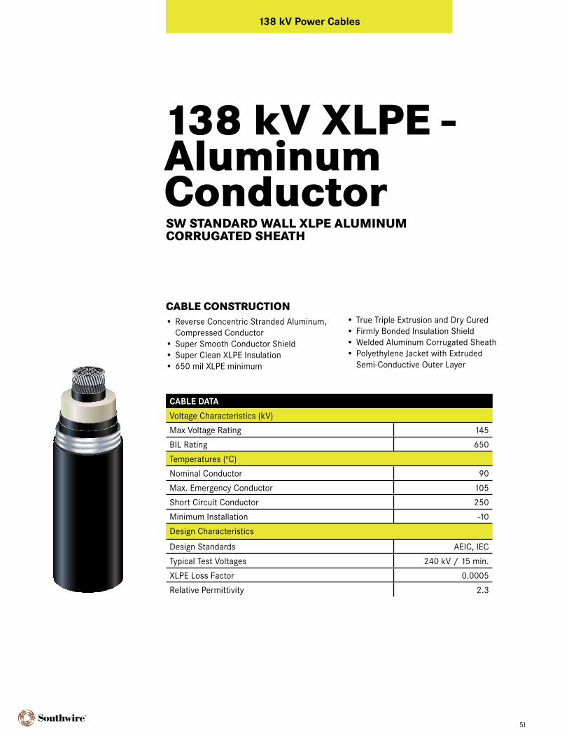
CABLE CONSTRUCTION• Reverse Concentric Stranded Aluminum,
Compressed Conductor• Super Smooth Conductor Shield • Super Clean XLPE Insulation• 650 mil XLPE minimum
• True Triple Extrusion and Dry Cured• Firmly Bonded Insulation Shield• Welded Aluminum Corrugated Sheath• Polyethylene Jacket with Extruded
Semi-Conductive Outer Layer
SW STANDARD WALL XLPE ALUMINUM CORRUgATED SHEATH
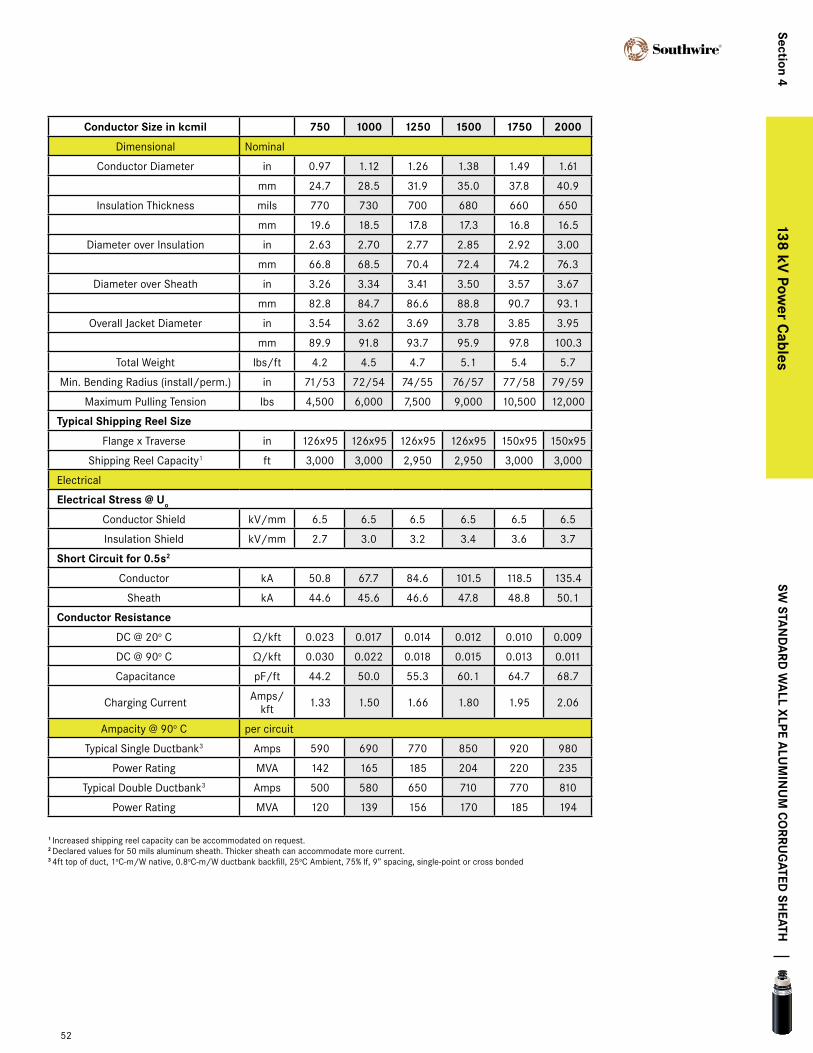
conductor Size in kcmil 750 1000 1250 1500 1750 2000
Dimensional Nominal
Conductor Diameter in 0.97 1.12 1.26 1.38 1.49 1.61
mm 24.7 28.5 31.9 35.0 37.8 40.9
Insulation Thickness mils 770 730 700 680 660 650
mm 19.6 18.5 17.8 17.3 16.8 16.5
Diameter over Insulation in 2.63 2.70 2.77 2.85 2.92 3.00
mm 66.8 68.5 70.4 72.4 74.2 76.3
Diameter over Sheath in 3.26 3.34 3.41 3.50 3.57 3.67
mm 82.8 84.7 86.6 88.8 90.7 93.1
Overall Jacket Diameter in 3.54 3.62 3.69 3.78 3.85 3.95
mm 89.9 91.8 93.7 95.9 97.8 100.3
Total Weight lbs/ft 4.2 4.5 4.7 5.1 5.4 5.7
Min. Bending Radius (install/perm.) in 71/53 72/54 74/55 76/57 77/58 79/59
Maximum Pulling Tension lbs 4,500 6,000 7,500 9,000 10,500 12,000
typical Shipping reel Size
Flange x Traverse in 126x95 126x95 126x95 126x95 150x95 150x95
Shipping Reel Capacity1 ft 3,000 3,000 2,950 2,950 3,000 3,000
Electrical
electrical Stress @ Uo
Conductor Shield kV/mm 6.5 6.5 6.5 6.5 6.5 6.5
Insulation Shield kV/mm 2.7 3.0 3.2 3.4 3.6 3.7
Short circuit for 0.5s2
Conductor kA 50.8 67.7 84.6 101.5 118.5 135.4
Sheath kA 44.6 45.6 46.6 47.8 48.8 50.1
conductor resistance
DC @ 20o C Ω/kft 0.023 0.017 0.014 0.012 0.010 0.009
DC @ 90o C Ω/kft 0.030 0.022 0.018 0.015 0.013 0.011
Capacitance pF/ft 44.2 50.0 55.3 60.1 64.7 68.7
Charging Current Amps/kft 1.33 1.50 1.66 1.80 1.95 2.06
Ampacity @ 90o C per circuit
Typical Single Ductbank3 Amps 590 690 770 850 920 980
Power Rating MVA 142 165 185 204 220 235
Typical Double Ductbank3 Amps 500 580 650 710 770 810
Power Rating MVA 120 139 156 170 185 194
138 kV XLPE - Aluminum Conductor
SW Sta
nd
ard
Wa
ll xlpe alU
min
Um
co
rrUg
ated SH
eatH
52
Section 4138 kV
power c
ables
1 Increased shipping reel capacity can be accommodated on request.2 Declared values for 50 mils aluminum sheath. Thicker sheath can accommodate more current.3 4ft top of duct, 1oC-m/W native, 0.8oC-m/W ductbank backfill, 25oC Ambient, 75% lf, 9” spacing, single-point or cross bonded
138 kV XLPE - Copper Conductor
cable data
Voltage Characteristics (kV)
Max Voltage Rating 145
BIL Rating 650
Temperatures (oC)
Nominal Conductor 90
Max. Emergency Conductor 105
Short Circuit Conductor 250
Minimum Installation -10
Design Characteristics
Design Standards AEIC, IEC
Typical Test Voltages 240 kV / 15 min.
XLPE Loss Factor 0.0005
Relative Permittivity 2.3
53
138 kV power cables
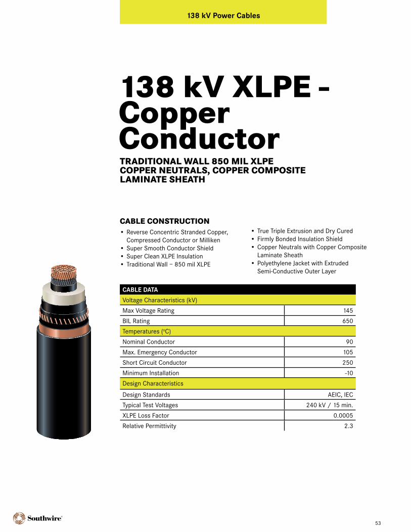
CABLE CONSTRUCTION• Reverse Concentric Stranded Copper,
Compressed Conductor or Milliken• Super Smooth Conductor Shield • Super Clean XLPE Insulation• Traditional Wall – 850 mil XLPE
• True Triple Extrusion and Dry Cured• Firmly Bonded Insulation Shield• Copper Neutrals with Copper Composite
Laminate Sheath• Polyethylene Jacket with Extruded
Semi-Conductive Outer Layer
TRADITIONAL WALL 850 MIL XLPE COPPER NEUTRALS, COPPER COMPOSITE LAMINATE SHEATH

conductor Size in kcmil1 750 1000 1250 1500 1750 2000 2500 3000 3500 4000
Dimensional Nominal
Conductor Diameter in 0.97 1.12 1.25 1.37 1.48 1.61 1.76 1.92 2.08 2.21
mm 24.7 28.5 31.8 34.8 37.6 40.9 44.7 48.8 52.8 56.1
Diameter over Insulation in 2.79 2.94 3.07 3.19 3.30 3.40 3.66 3.82 3.98 4.11
mm 70.8 74.6 78.0 81.0 83.8 86.4 93.0 97.1 101.0 104.4
Diameter over Sheath in 3.17 3.32 3.46 3.58 3.69 3.79 4.07 4.23 4.39 4.52
mm 80.6 84.4 87.8 90.8 93.6 96.2 103.4 107.5 111.4 114.8
Overall Jacket Diameter in 3.49 3.64 3.78 3.90 4.01 4.11 4.39 4.55 4.71 4.84
mm 88.7 92.5 95.9 98.9 101.7 104.3 111.5 115.6 119.5 123.0
Total Weight lbs/ft 6.8 7.8 8.8 9.7 10.7 11.6 13.8 15.6 17.5 19.3
Min. Bending Radius (install/
perm.)in 70/52 73/55 76/57 78/58 80/60 82/62 88/66 91/68 94/71 97/73
Maximum Pulling Tension lbs 6,000 8,000 10,000 12,000 14,000 16,000 20,000 24,000 28,000 32,000
typical Shipping reel Size
Flange x Width in 138x95 138x95 150x95 150x95 150x95 150x95 158x95 158x95 158x95 158x95
Shipping Reel Capacity2 ft 3,000 3,000 3,000 3,000 2,733 2,725 2,700 2,375 2,125 1,900
Electrical
electrical Stress @ Uo
Conductor Shield kV/mm 6.1 5.9 5.7 5.5 5.4 5.3 5.1 5.0 4.9 4.9
Insulation Shield kV/mm 2.4 2.5 2.5 2.6 2.6 2.7 2.7 2.8 2.8 2.9
Short circuit for 0.5s3
Conductor kA 76.9 102.5 128.1 153.8 179.4 205.0 256.3 307.5 358.8 410.0
Sheath kA 43.9 44.2 44.6 44.9 45.2 45.5 46.2 46.6 47.0 47.4
conductor resistance
DC @ 20o C Ω/kft 0.014 0.011 0.008 0.007 0.006 0.005 0.004 0.003 0.003 0.003
DC @ 90o C Ω/kft 0.018 0.014 0.011 0.009 0.008 0.007 0.005 0.005 0.004 0.003
Capacitance pF/ft 41.4 45.0 48.3 51.2 53.8 56.3 62.4 66.2 69.8 73.0
Charging Current Amps/kft 1.24 1.35 1.45 1.54 1.62 1.69 1.87 1.99 2.10 2.19
Ampacity @ 90o C per circuit
Typical Single Ductbank4 Amps 750 870 970 1060 1140 1210 1455 1592 1714 1821
Power Rating MVA 180 208 232 254 273 290 348 381 410 436
Typical Double Ductbank4 Amps 640 740 820 890 950 1000 1206 1314 1410 1493
Power Rating MVA 153 177 196 213 228 240 289 315 338 357
138 kV XLPE - Copper Conductor
54
Section 4138 kV
power c
ables
1 2500-4000 kcmil conductors are 5 segment Milliken conductors.2 Increased shipping reel capacity can be accommodated on request.3 Declared values for 80 x 14 AWG copper wire screen with 6 mil copper tape shield. Larger wires can accommodate more current.4 4ft top of duct, 1oC-m/W native, 0.8oC-m/W ductbank backfill, 25oC Ambient, 75% lf, 9” spacing, single-point or cross bonded
tra
ditio
na
l Wa
ll 850 mil xlpe c
opper n
eUtr
alS, c
opper
co
mpo
Site lam
inate SH
eatH

138 kV XLPE - Copper Conductor
cable data
Voltage Characteristics (kV)
Max Voltage Rating 145
BIL Rating 650
Temperatures (oC)
Nominal Conductor 90
Max. Emergency Conductor 105
Short Circuit Conductor 250
Minimum Installation -10
Design Characteristics
Design Standards AEIC, IEC
Typical Test Voltages 240 kV / 15 min.
XLPE Loss Factor 0.0005
Relative Permittivity 2.3
55
138 kV power cables
CABLE CONSTRUCTION• Reverse Concentric Stranded Copper,
Compressed Conductor or Milliken• Super Smooth Conductor Shield • Super Clean XLPE Insulation• 630 mil XLPE minimum
• True Triple Extrusion and Dry Cured• Firmly Bonded Insulation Shield• Copper Neutrals with Copper Composite
Laminate Sheath• Polyethylene Jacket with Extruded
Semi-Conductive Outer Layer
SW STANDARD WALL XLPE COPPER NEUTRALS, COPPER COMPOSITE LAMINATE SHEATH
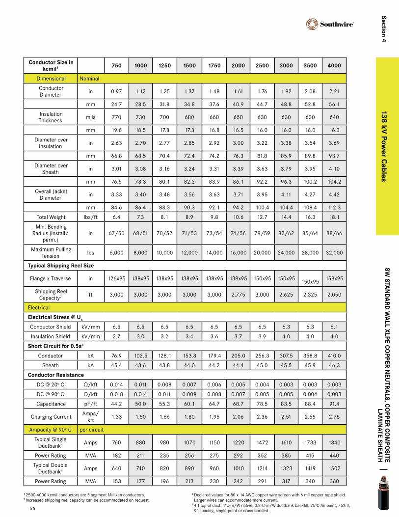
conductor Size in kcmil1 750 1000 1250 1500 1750 2000 2500 3000 3500 4000
Dimensional Nominal
Conductor Diameter in 0.97 1.12 1.25 1.37 1.48 1.61 1.76 1.92 2.08 2.21
mm 24.7 28.5 31.8 34.8 37.6 40.9 44.7 48.8 52.8 56.1
Insulation Thickness mils 770 730 700 680 660 650 630 630 630 640
mm 19.6 18.5 17.8 17.3 16.8 16.5 16.0 16.0 16.0 16.3
Diameter over Insulation in 2.63 2.70 2.77 2.85 2.92 3.00 3.22 3.38 3.54 3.69
mm 66.8 68.5 70.4 72.4 74.2 76.3 81.8 85.9 89.8 93.7
Diameter over Sheath in 3.01 3.08 3.16 3.24 3.31 3.39 3.63 3.79 3.95 4.10
mm 76.5 78.3 80.1 82.2 83.9 86.1 92.2 96.3 100.2 104.2
Overall Jacket Diameter in 3.33 3.40 3.48 3.56 3.63 3.71 3.95 4.11 4.27 4.42
mm 84.6 86.4 88.3 90.3 92.1 94.2 100.4 104.4 108.4 112.3
Total Weight lbs/ft 6.4 7.3 8.1 8.9 9.8 10.6 12.7 14.4 16.3 18.1
Min. Bending Radius (install/
perm.)in 67/50 68/51 70/52 71/53 73/54 74/56 79/59 82/62 85/64 88/66
Maximum Pulling Tension lbs 6,000 8,000 10,000 12,000 14,000 16,000 20,000 24,000 28,000 32,000
typical Shipping reel Size
Flange x Traverse in 126x95 138x95 138x95 138x95 138x95 138x95 150x95 150x95 150x95 158x95
Shipping Reel Capacity2 ft 3,000 3,000 3,000 3,000 3,000 2,775 3,000 2,625 2,325 2,050
Electrical
electrical Stress @ Uo
Conductor Shield kV/mm 6.5 6.5 6.5 6.5 6.5 6.5 6.5 6.3 6.3 6.1
Insulation Shield kV/mm 2.7 3.0 3.2 3.4 3.6 3.7 3.9 4.0 4.0 4.0
Short circuit for 0.5s3
Conductor kA 76.9 102.5 128.1 153.8 179.4 205.0 256.3 307.5 358.8 410.0
Sheath kA 45.4 43.6 43.8 44.0 44.2 44.4 45.0 45.5 45.9 46.3
conductor resistance
DC @ 20o C Ω/kft 0.014 0.011 0.008 0.007 0.006 0.005 0.004 0.003 0.003 0.003
DC @ 90o C Ω/kft 0.018 0.014 0.011 0.009 0.008 0.007 0.005 0.005 0.004 0.003
Capacitance pF/ft 44.2 50.0 55.3 60.1 64.7 68.7 78.5 83.5 88.4 91.4
Charging Current Amps/kft 1.33 1.50 1.66 1.80 1.95 2.06 2.36 2.51 2.65 2.75
Ampacity @ 90o C per circuit
Typical Single Ductbank4 Amps 760 880 980 1070 1150 1220 1472 1610 1733 1840
Power Rating MVA 182 211 235 256 275 292 352 385 415 440
Typical Double Ductbank4 Amps 640 740 820 890 960 1010 1214 1323 1419 1502
Power Rating MVA 153 177 196 213 230 242 291 317 340 360
138 kV XLPE - Copper Conductor
Section 4138 kV
power c
ables
1 2500-4000 kcmil conductors are 5 segment Milliken conductors.2 Increased shipping reel capacity can be accommodated on request.
3 Declared values for 80 x 14 AWG copper wire screen with 6 mil copper tape shield. Larger wires can accommodate more current.
4 4ft top of duct, 1oC-m/W native, 0.8oC-m/W ductbank backfill, 25oC Ambient, 75% lf, 9” spacing, single-point or cross bonded
SW Sta
nd
ard
Wa
ll xlpe co
pper neU
tra
lS, co
pper co
mpo
Site la
min
ate SHeatH
56
138 kV XLPE - Aluminum Conductor
cable data
Voltage Characteristics (kV)
Max Voltage Rating 145
BIL Rating 650
Temperatures (oC)
Nominal Conductor 90
Max. Emergency Conductor 105
Short Circuit Conductor 250
Minimum Installation -10
Design Characteristics
Design Standards AEIC, IEC
Typical Test Voltages 240 kV / 15 min.
XLPE Loss Factor 0.0005
Relative Permittivity 2.3
57
138 kV power cables
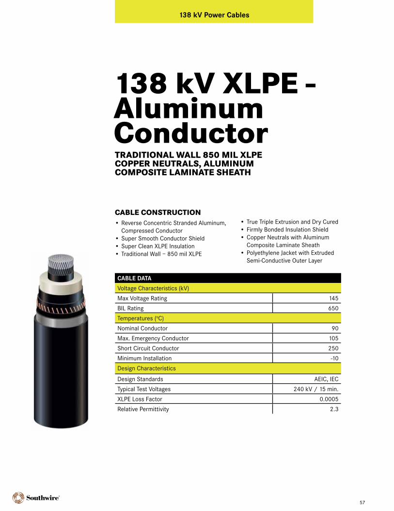
CABLE CONSTRUCTION• Reverse Concentric Stranded Aluminum,
Compressed Conductor• Super Smooth Conductor Shield • Super Clean XLPE Insulation• Traditional Wall – 850 mil XLPE
• True Triple Extrusion and Dry Cured• Firmly Bonded Insulation Shield• Copper Neutrals with Aluminum
Composite Laminate Sheath• Polyethylene Jacket with Extruded
Semi-Conductive Outer Layer
TRADITIONAL WALL 850 MIL XLPE COPPER NEUTRALS, ALUMINUM COMPOSITE LAMINATE SHEATH
conductor Size in kcmil 750 1000 1250 1500 1750 2000
Dimensional Nominal
Conductor Diameter in 0.97 1.12 1.26 1.38 1.49 1.61
mm 24.7 28.5 31.9 35.0 37.8 40.9
Diameter over Insulation in 2.79 2.94 3.07 3.19 3.30 3.40
mm 70.8 74.6 78.0 81.0 83.8 86.4
Diameter over Sheath in 3.18 3.33 3.46 3.58 3.69 3.79
mm 80.7 84.5 87.8 90.9 93.7 96.3
Overall Jacket Diameter in 3.50 3.65 3.78 3.90 4.01 4.11
mm 88.8 92.6 96.0 99.0 101.8 104.4
Total Weight lbs/ft 5.0 5.5 5.9 6.3 6.7 7.1
Min. Bending Radius (install/perm.) in 70/52 73/55 76/57 78/58 80/60 82/62
Maximum Pulling Tension lbs 4,500 6,000 7,500 9,000 10,500 12,000
typical Shipping reel Size
Flange x Width in 138x95 138x95 150x95 150x95 150x95 150x95
Shipping Reel Capacity1 ft 3,000 3,000 3,000 3,000 2,725 2,725
Electrical
electrical Stress @ Uo
Conductor Shield kV/mm 6.1 5.9 5.7 5.5 5.4 5.3
Insulation Shield kV/mm 2.4 2.5 2.5 2.6 2.6 2.7
Short circuit for 0.5s2
Conductor kA 50.8 67.7 84.6 101.5 118.5 135.4
Sheath kA 42.9 43.2 43.5 43.8 44.1 44.3
conductor resistance
DC @ 20o C Ω/kft 0.023 0.017 0.014 0.012 0.010 0.009
DC @ 90o C Ω/kft 0.030 0.022 0.018 0.015 0.013 0.011
Capacitance pF/ft 41.4 45.0 48.3 51.2 53.8 56.3
Charging Current Amps/kft 1.24 1.35 1.45 1.54 1.62 1.69
Ampacity @ 90o C per circuit
Typical Single Ductbank3 Amps 590 690 780 860 930 990
Power Rating MVA 142 165 187 206 223 237
Typical Double Ductbank3 Amps 500 580 650 720 770 830
Power Rating MVA 120 139 156 173 185 199
138 kV XLPE - Aluminum Conductor
58
Section 4138 kV
power c
ables
1 Increased shipping reel capacity can be accommodated on request.2 Declared values for 80 x 14 AWG copper wire screen with 8 mil aluminum tape shield. Larger wires can accommodate more current.34ft top of duct, 1oC-m/W native, 0.8oC-m/W ductbank backfill, 25oC Ambient, 75% lf, 9” spacing, single-point or cross bonded
tra
ditio
na
l Wa
ll 850 mil xlpe c
opper n
eUtr
alS, a
lUm
inU
m
co
mpo
Site lam
inate SH
eatH
138 kV XLPE - Aluminum Conductor
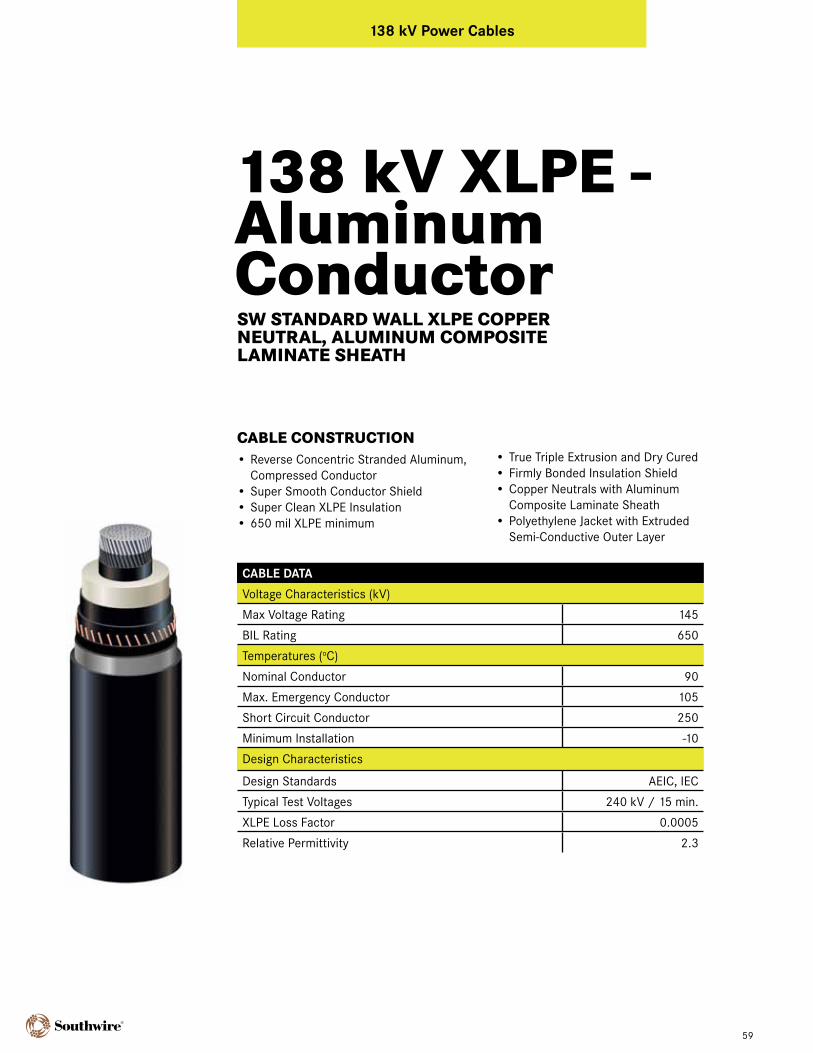
cable data
Voltage Characteristics (kV)
Max Voltage Rating 145
BIL Rating 650
Temperatures (oC)
Nominal Conductor 90
Max. Emergency Conductor 105
Short Circuit Conductor 250
Minimum Installation -10
Design Characteristics
Design Standards AEIC, IEC
Typical Test Voltages 240 kV / 15 min.
XLPE Loss Factor 0.0005
Relative Permittivity 2.3
59
138 kV power cables
CABLE CONSTRUCTION• Reverse Concentric Stranded Aluminum,
Compressed Conductor• Super Smooth Conductor Shield • Super Clean XLPE Insulation• 650 mil XLPE minimum
• True Triple Extrusion and Dry Cured• Firmly Bonded Insulation Shield• Copper Neutrals with Aluminum
Composite Laminate Sheath• Polyethylene Jacket with Extruded
Semi-Conductive Outer Layer
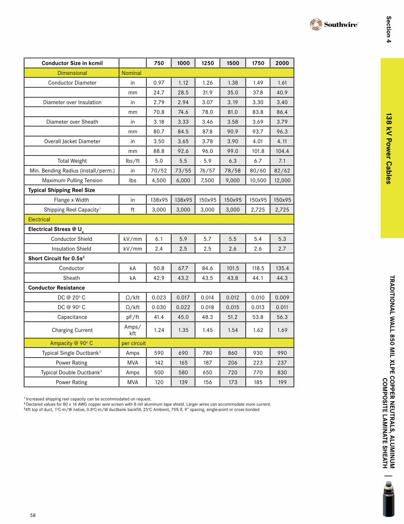
SW STANDARD WALL XLPE COPPER NEUTRAL, ALUMINUM COMPOSITE LAMINATE SHEATH
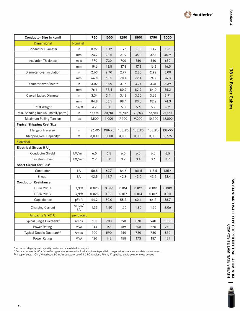
conductor Size in kcmil 750 1000 1250 1500 1750 2000
Dimensional Nominal
Conductor Diameter in 0.97 1.12 1.26 1.38 1.49 1.61
mm 24.7 28.5 31.9 35.0 37.8 40.9
Insulation Thickness mils 770 730 700 680 660 650
mm 19.6 18.5 17.8 17.3 16.8 16.5
Diameter over Insulation in 2.63 2.70 2.77 2.85 2.92 3.00
mm 66.8 68.5 70.4 72.4 74.2 76.3
Diameter over Sheath in 3.02 3.09 3.16 3.24 3.31 3.39
mm 76.6 78.4 80.2 82.2 84.0 86.2
Overall Jacket Diameter in 3.34 3.41 3.48 3.56 3.63 3.71
mm 84.8 86.5 88.4 90.3 92.2 94.3
Total Weight lbs/ft 4.7 5.0 5.3 5.6 5.9 6.2
Min. Bending Radius (install/perm.) in 67/50 68/51 70/52 71/53 73/54 74/56
Maximum Pulling Tension lbs 4,500 6,000 7,500 9,000 10,500 12,000
typical Shipping reel Size
Flange x Traverse in 126x95 138x95 138x95 138x95 138x95 138x95
Shipping Reel Capacity1 ft 3,000 3,000 3,000 3,000 3,000 2,775
Electrical
electrical Stress @ Uo
Conductor Shield kV/mm 6.5 6.5 6.5 6.5 6.5 6.5
Insulation Shield kV/mm 2.7 3.0 3.2 3.4 3.6 3.7
Short circuit for 0.5s2
Conductor kA 50.8 67.7 84.6 101.5 118.5 135.4
Sheath kA 42.5 42.7 42.8 43.0 43.2 43.4
conductor resistance
DC @ 20o C Ω/kft 0.023 0.017 0.014 0.012 0.010 0.009
DC @ 90o C Ω/kft 0.028 0.021 0.017 0.014 0.012 0.011
Capacitance pF/ft 44.2 50.0 55.3 60.1 64.7 68.7
Charging Current Amps/kft 1.33 1.50 1.66 1.80 1.95 2.06
Ampacity @ 90o C per circuit
Typical Single Ductbank3 Amps 600 700 790 870 940 1000
Power Rating MVA 144 168 189 208 225 240
Typical Double Ductbank3 Amps 500 590 660 720 780 830
Power Rating MVA 120 142 158 173 187 199
60
Section 4138 kV
power c
ables
1 Increased shipping reel capacity can be accommodated on request.2 Declared values for 80 x 14 AWG copper wire screen with 8 mil aluminum tape shield. Larger wires can accommodate more current.34ft top of duct, 1oC-m/W native, 0.8oC-m/W ductbank backfill, 25oC Ambient, 75% lf, 9” spacing, single-point or cross bonded
SW Sta
nd
ard
Wa
ll xlpe co
pper neU
tra
l, alU
min
Um
c
om
poSite la
min
ate SHeatH