Embed Size (px)
Citation preview

D-5134_Rev. A 1
In-Service PON Monitoring
Real-Time Monitoring of Passive Optical Networks
White paper
Introduction
The practice of optical fiber for data transmission from transoceanic to domestic applications is nothing new. While initially the immunity to electromagnetic interference (EMI) played a vital role in propelling the fiber-optic network ahead, recent demonstration of wavelength division multiplexed (WDM) transmission of 101 Tb/s (1Tb/s = 1000Gb/s) over a distance of 165 km single mode fiber only future-proofs the existence of fiber-optic communication. Increased fiber penetration in applications such as fiber-to-the-home (FFTH) to fiber-to-the-antenna (FFTA) is inevitable however raises key questions concerning network monitoring and protection.
For a service provider, ensuring a high level of network performance is of utmost importance. Every second of the interruption in the data traffic not only leads to economic dismay but also exhaustion of valuable resources (time and expert personnel) that would be much appreciated elsewhere.
In this paper, we delve into the basics of existing monitoring technology and discuss an interesting in-service real-time monitoring solution that provides instantaneous root cause of the fault without any influence on data traffic. Furthermore, applications of this novel technology are also illustrated.
Fiber Monitoring Background: How does an OTDR work?
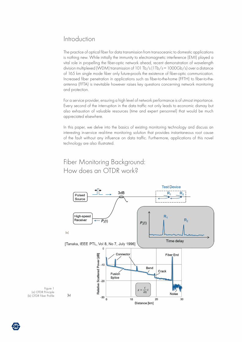
Figure 1 (a) OTDR Principle
(b) OTDR Fiber Profile

D-5134_Rev. A 3
In-Service PON Monitoring
While almost all field-deployed active optical systems are equipped with management layer on top to monitor the data-in-transit, the actual fault location in the fiber or passive equipment in a passive optical network (PON) needs further investment. The Operations, Administration and Maintenance (OAM) service detects, isolates and notifies the operator of the fault. Classically, a power meter or an optical time-domain reflectometer (OTDR) is then utilized to analyze the spatial information of the detected failure.
This is also the convention during fiber installations. An engineer has to be at the location and check the optical fiber individually with the OTDR while all the services in the fiber are paused during this period.
The working principle of OTDR is based on Rayleigh backscattering and Fresnel reflection. As depicted in Figure.1a, the OTDR has a transmitter which launches short duration optical pulses into the fiber and a high-speed receiver which measures the reflected signal.
The measured reflected signal is then traced against time delay. In the actual OTDR display (see Figure.1b), the time axis is already converted to length of the fiber, the knowledge of which helps locate the fault with a certain tolerance (1m for standard OTDRs). The OTDR trace can be easily interpreted as the peaks and dips can be traced back to the physical effects of the fiber as follows (ref. Figure 1. b)
1) Distributed loss The types of fibers and operation wavelengths impact the profile that is seen in the OTDR display. The OTDR needs to know the type of fiber being analyzed, i.e. the refractive index of the fiber which influences the speed of light in the fiber. Then the OTDR can accurately measure distance from the total time delay of the reflected pulse. Distributed loss seen in the profile comes from Rayleigh backscattering in the fiber. The distributed loss will appear different for different operating wavelengths. Longer wavelengths exhibit less scattering and therefore will have lower loss per km than shorter wavelengths.
2) Discrete reflectionsA drastic change in the fiber density causes Fresnel reflections. While the fiber itself is homogenous, these discrete peaks occur when an OTDR pulse encounters connectors, ends of fibers or fiber breaks. The magnitude of the peak is influenced by the change in the material density and the connector type (angled or straight). In the event of fiber break, the OTDR displays a huge peak followed by random noise at the location of the fault.
3) Dips The dips in the profile arise from bends or splices. At these points a part of the signal leaks out thus reducing the signal power. Longer wavelengths suffer more as they leak out of a fiber easier than shorter wavelengths.
A conventional OTDR can test the fiber in three wavelengths, which are in-effect the operating wavelengths of the fiber, ie., 850 nm, 1300 nm, and 1550 nm. Therefore, a conventional OTDR can be used when the fibers are being installed or only after discontinuing the services. Additionally, the use of an optical power splitter in PON to split with higher number of tributaries reduces the resolution of the OTDR and the spatial information is lost.

These drawbacks limit the application of classical OTDR to monitoring point-to-point networks [Hornung, ICC , Vol. 4, pp. 1563 –1571, IEEE 1990]. As a consequence, numerous other monitoring systems have been recommended. In this paper, the reflector-based real-time monitoring is explained.
Novel Reflector-Based Real-Time Fiber Monitoring
The passive optical network, as the name reflects, is implemented using only passive components between the optical line terminal (OLT) placed at the central office (CO) and the optical network terminals (ONT) located on the customer premise (Ref. Figure 2).
PON is widely applied as the optimal fiber infrastructure for employing fiber-to-the-x (x can be house, antenna, curb and so on). PON can have either time division multiplexed (TDM) or wavelength division multiplexed (WDM) services. In TDM-PON, a passive optical power splitter is implemented which distributes all the services (voice, data and CATV) from OLT into a number of required tributaries connected to the ONT.
On the other hand a WDM-PON is realized when a dedicated wavelength needs to be transmitted to the ONT. In this case, all the tributaries will have different signals. A WDM-PON has the best application for fiber-based mobile front-hauling (or FFTA) which reduces latency and synchronization issues pertinent to mobile backhaul networks.
Numerous point-to-multipoint monitoring ideas, from inserting OTDR functionality into the transceiver to modifying ONU have been proposed and tests conducted however deemed impractical. An interesting approach was presented by Ozawa and team [Kazumasa et al, Conference on Optical Fibre Sensors , Venice 2000] that used a tunable OTDR at the CO and each ONT was equipped with a reflector which was wavelength selective to identify different branches.
Figure 2FTTH PON Architecture

D-5134_Rev. A 5
In-Service PON Monitoring
However, in practice the cost of manufacturing reflectors with different specifications and the use of costly tunable OTDR have limited the application of this method. Recently, a modified version of this method has gained popularity which is discussed further in this paper.
The novel reflector-based real-time fiber monitoring for FFTH application is implemented as shown in Figure 3. This method not only detects the fault but also identifies the underlying cause, aiding the operator with a targeted remedy and saving service costs.
A WDM multiplexer is required at the CO to couple the services (CATV at 1550 nm and video and data at 1310 nm and 1490 nm) with 1650 nm port for OTDR monitoring. At the customer edge, a reflector with form-factor that of an in-line attenuator is inserted. As shown in Figure 4, a filter integrated in the adapter blocks the 1650 nm wavelength and transmits the wavelengths from 1260-1618 nm. The reflected 1650 nm OTDR signal traverses back to the OTDR receiver which then displays the distance where the reflectors are positioned. The reflector can also be manufactured as a patch cable or a pigtail. The choice of the form factor depends on the desired specification and the installation requirements.
In practice, one has to take care that the reflectors at different branches are not located at the same distance from the splitter. In an event, where two or more reflectors are equidistant from the splitter, the OTDR monitoring will not be able to distinguish the branch. Therefore, during installation, a detailed network layout has to be designed including the exact location of the reflectors.
Figure 3 FTTH PON Monitoring
Figure 4 Reflector

The reflector also introduces an insertion loss of maximum 1dB which needs to be calculated during network planning. Once installed properly, these reflectors can be used to diagnose live network without interrupting the services. The fault is allocated by comparing the reference trace taken during installation from every branch with the live trace. Because of the high reflectivity (95%) of the reflector, the spatial-resolution of the OTDR is improved for better performance outlook.
Additionally, the splitting proportion can be extended from 16(without reflectors) to 32 branches.
Similar monitoring approach can be implemented for Ethernet passive optical networks that deliver Ethernet services to business customers. As depicted in Figure 5, a WDM coupler is used to insert the OTDR monitoring signal which gets reflected from the far-end implanted reflector. In such a scenario, a continuous fiber monitoring incorporates an optical switching device located at the CO which switches the OTDR monitoring port from different branches.
The switch sweeps through all the used ports and the reflected signal is measured quasi-real time. As there is no power splitter included, the OTDR in such a scenario enjoys a high dynamic range and therefore can pinpoint locate even the smallest of fiber defects.
Advantages
The reflector-based novel technology to monitor passive optical networks without influencing data traffic enjoys several benefits. Because of the small and robust form-factor of the reflectors, it can be easily installed into an existing network and its passive nature makes it a cost-effective solution. The automatic OTDR-based system supports the operators with initial installation, measuring and further on remote monitoring of the network. It ensures a high productivity in network operation and maintenance by providing the operators the root cause and the pin-point location of the faults.
Figure 5 Direct Ethernet Monitoring

D-5134_Rev. A 7
In-Service PON Monitoring
Conclusion
The reflector-based real-time monitoring requires a comprehensive network planning and design to equip the subscriber links with the reflectors at the correct distances. Once deployed, the operators can enjoy the remote diagnosis via OTDR of the network which is fully automatic. The advantages of simplicity and cost efficiency stand out for the reflector-based system that makes this solution timeless.
About the Author
Susmita Adhikari has a M.Sc. in Digital Communication with over six years of research and product management experience from long-haul communication to metro. At HUBER+SUHNER Cube Optics, she works as a Product Placement Manager and ensures a good visibility of newly introduced products via technical marketing and customer interactions.

HUBER+SUHNER Cube Optics AGRobert-Koch-Strasse 3055129 MainzGermany
phone: +49-6131-69851-0 fax: +49-6131-69851-79 [email protected]
www.hubersuhner.comwww.cubeoptics.com
HUBER+SUHNER Cube Optics AG is certified according to ISO 9001.
WAIVERIt is exclusively in written agreements that we provide our customers with warrants and representations as to the technical specifications and/or the fitness for any particular purpose. The facts and figures contained herein are carefully compiled to the best of our knowledge, but they are intended for general informational purposes only.
D-5134 Rev. A