Embed Size (px)
Citation preview
Protected by copyright. Copying for private or commercial purposes, in part or in whole, is not permitted unless authorised by AUDI AG. AUDI AG does not guarantee or accept any liability with respect to the correctness of information in this document. Copyright by AUDI AG.
Audi 100 1991 ➤Fuel supply system - petrol enginesEngine ID AAD AAE AAH AAN AAR ABB ABC ABH ABK
ACE ACK ACZ ADA ADR ADW AEC AEJ AHK
Service
Service Department. Technical Information
Protected by copyright. Copying for private or commercial purposes, in part or in whole, is not permitted unless authorised by AUDI AG. AUDI AG does not guarantee or accept any liability with respect to the correctness of information in this document. Copyright by AUDI AG.
List of Workshop Manual Repair GroupsList of Workshop ManualRepair GroupsList of Workshop Manual Repair GroupsAudi 100 1991 ➤Fuel supply system - petrol engines
Repair Group20 - Fuel supply system
Technical information should always be available to the foremen and mechanics, because their carefuland constant adherence to the instructions is essential to ensure vehicle road-worthiness and safety. Inaddition, the normal basic safety precautions for working on motor vehicles must, as a matter of course,be observed.
Service
All rights reserved.No reproduction without prior agreement from publisher.
Copyright © 2010 Audi AG, Ingolstadt A0052509920
Protected by copyright. Copying for private or commercial purposes, in part or in whole, is not permitted unless authorised by AUDI AG. AUDI AG does not guarantee or accept any liability with respect to the correctness of information in this document. Copyright by AUDI AG.
Contents
20 - Fuel supply system . . . . . . . . . . . . . . . . . . . . . . . . . . . . . . . . . . . . . . . . . . . . . . . .11 Notes on performing work on fuel supply system . . . . . . . . . . . . . . . . . . . . . . . . . . . . . . . . . .11.1 Notes on performing work on fuel supply system . . . . . . . . . . . . . . . . . . . . . . . . . . . . . . . . . .11.2 General repair instructions . . . . . . . . . . . . . . . . . . . . . . . . . . . . . . . . . . . . . . . . . . . . . . . . . .11.3 Safety precautions when working on fuel supply system . . . . . . . . . . . . . . . . . . . . . . . . . . . .11.4 Rules for cleanliness . . . . . . . . . . . . . . . . . . . . . . . . . . . . . . . . . . . . . . . . . . . . . . . . . . . . . .22 Fuel supply system - Front-wheel drive . . . . . . . . . . . . . . . . . . . . . . . . . . . . . . . . . . . . . . . .22.1 Fuel supply system - Front-wheel drive . . . . . . . . . . . . . . . . . . . . . . . . . . . . . . . . . . . . . . . .22.2 Exploded view of components: Fuel tank with attachments . . . . . . . . . . . . . . . . . . . . . . . . . .32.3 Draining fuel tank . . . . . . . . . . . . . . . . . . . . . . . . . . . . . . . . . . . . . . . . . . . . . . . . . . . . . . . . . .62.4 Removing and installing fuel tank with attachments . . . . . . . . . . . . . . . . . . . . . . . . . . . . . . . .82.5 Exploded view of components: Fuel delivery unit and fuel gauge sender . . . . . . . . . . . . . .132.6 Electrical checking of fuel pump . . . . . . . . . . . . . . . . . . . . . . . . . . . . . . . . . . . . . . . . . . . . . .162.7 Checking fuel pump delivery rate - 4-cyl. engine (code letters AAE) . . . . . . . . . . . . . . . . . .192.8 Checking fuel pump delivery rate - 4-cyl. engine (code letters AAD, ABB, ACE) . . . . . . . .212.9 Checking fuel pump delivery rate - 4-cyl. engine (code letters ABK, ADA, ADW) . . . . . . . .232.10 Checking fuel pump delivery rate - 4-cyl. engine (code letters ADR) . . . . . . . . . . . . . . . . . .252.11 Checking fuel pump delivery rate - 5-cyl. engine (code letters AAR) . . . . . . . . . . . . . . . . . .282.12 Checking fuel pump delivery rate - 6-cyl. engine . . . . . . . . . . . . . . . . . . . . . . . . . . . . . . . . . .302.13 Removing and installing fuel delivery unit . . . . . . . . . . . . . . . . . . . . . . . . . . . . . . . . . . . . . .332.14 Dismantling fuel delivery unit - 4-cyl. engine (code letters AAE) . . . . . . . . . . . . . . . . . . . . . .392.15 Dismantling fuel delivery unit - 4 and 6-cyl. engine (code letters AAH, ABC, ABK, ACK, ACZ,
ADA, ADR, ADW, AEJ) . . . . . . . . . . . . . . . . . . . . . . . . . . . . . . . . . . . . . . . . . . . . . . . . . . . .442.16 Dismantling fuel delivery unit (pump ø 40 mm) - 4 and 5-cyl. engine (code letters AAD, AAR,
ABB, ACE) . . . . . . . . . . . . . . . . . . . . . . . . . . . . . . . . . . . . . . . . . . . . . . . . . . . . . . . . . . . . . .502.17 Dismantling fuel delivery unit (pump ø 60 mm) - 4 and 5-cyl. engine (code letters AAD, AAR,
ABB, ACE) . . . . . . . . . . . . . . . . . . . . . . . . . . . . . . . . . . . . . . . . . . . . . . . . . . . . . . . . . . . . . .542.18 Checking fuel gauge sender -G . . . . . . . . . . . . . . . . . . . . . . . . . . . . . . . . . . . . . . . . . . . . . .572.19 Removing and installing fuel gauge sender . . . . . . . . . . . . . . . . . . . . . . . . . . . . . . . . . . . . . .603 Fuel supply system - Four-wheel drive . . . . . . . . . . . . . . . . . . . . . . . . . . . . . . . . . . . . . . . . . .643.1 Fuel supply system - Four-wheel drive . . . . . . . . . . . . . . . . . . . . . . . . . . . . . . . . . . . . . . . . . .643.2 Exploded view of components: Fuel tank with attachments . . . . . . . . . . . . . . . . . . . . . . . . . .643.3 Draining fuel tank . . . . . . . . . . . . . . . . . . . . . . . . . . . . . . . . . . . . . . . . . . . . . . . . . . . . . . . . . .673.4 Removing and installing fuel tank with attachments . . . . . . . . . . . . . . . . . . . . . . . . . . . . . . . .693.5 Exploded view of components: Fuel delivery unit and fuel gauge sender . . . . . . . . . . . . . .753.6 Electrical checking of fuel pump . . . . . . . . . . . . . . . . . . . . . . . . . . . . . . . . . . . . . . . . . . . . . .793.7 Checking fuel pump delivery rate - 4-cyl. engine (code letters AAD, ACE) . . . . . . . . . . . . . .823.8 Checking fuel pump delivery rate - 4-cyl. engine (code letters ADR) . . . . . . . . . . . . . . . . . .843.9 Checking fuel pump delivery rate - 5-cyl. engine (code letters AAR) . . . . . . . . . . . . . . . . . .873.10 Checking fuel pump delivery rate - 5-cyl. engine (code letters AAN, ABY) . . . . . . . . . . . . . .893.11 Checking fuel pump delivery rate - 6-cyl. engine . . . . . . . . . . . . . . . . . . . . . . . . . . . . . . . . . .913.12 Checking fuel pump delivery rate - 8-cyl. engine . . . . . . . . . . . . . . . . . . . . . . . . . . . . . . . . . .943.13 Removing and installing fuel delivery unit . . . . . . . . . . . . . . . . . . . . . . . . . . . . . . . . . . . . . .973.14 Dismantling fuel delivery unit - 4, 5, 6 and 8-cyl. engine (code letters AAH, AAN, ABC, ABH,
ABY, ACK, ACZ, ADR, AEC, AEJ) . . . . . . . . . . . . . . . . . . . . . . . . . . . . . . . . . . . . . . . . . . . .1033.15 Dismantling fuel delivery unit (pump ø 40 mm) - 4 and 5-cyl. engine (code letters AAD, AAR,
ACE) . . . . . . . . . . . . . . . . . . . . . . . . . . . . . . . . . . . . . . . . . . . . . . . . . . . . . . . . . . . . . . . . . . . .1093.16 Dismantling fuel delivery unit (pump ø 60 mm) - 4 and 5-cyl. engine (code letters AAD, AAR,
ACE) . . . . . . . . . . . . . . . . . . . . . . . . . . . . . . . . . . . . . . . . . . . . . . . . . . . . . . . . . . . . . . . . . . . .1143.17 Dismantling fuel delivery unit - 8-cyl. engine (code letters AHK) . . . . . . . . . . . . . . . . . . . . . .1193.18 Checking fuel gauge sender -G . . . . . . . . . . . . . . . . . . . . . . . . . . . . . . . . . . . . . . . . . . . . . .1233.19 Removing and installing fuel gauge sender -G . . . . . . . . . . . . . . . . . . . . . . . . . . . . . . . . . .1264 Exploded view of components - fuel filter . . . . . . . . . . . . . . . . . . . . . . . . . . . . . . . . . . . . . . . .1304.1 Exploded view of components - fuel filter . . . . . . . . . . . . . . . . . . . . . . . . . . . . . . . . . . . . . . . .1305 Servicing activated charcoal filter system components . . . . . . . . . . . . . . . . . . . . . . . . . . . .133
Audi 100 1991 ➤Fuel supply system - petrol engines
Contents i
Protected by copyright. Copying for private or commercial purposes, in part or in whole, is not permitted unless authorised by AUDI AG. AUDI AG does not guarantee or accept any liability with respect to the correctness of information in this document. Copyright by AUDI AG.
5.1 Servicing activated charcoal filter system components . . . . . . . . . . . . . . . . . . . . . . . . . . . .1335.2 Exploded view for 4, 5 and 6-cyl. engine . . . . . . . . . . . . . . . . . . . . . . . . . . . . . . . . . . . . . . . .1345.3 Exploded view for 8-cyl. engine . . . . . . . . . . . . . . . . . . . . . . . . . . . . . . . . . . . . . . . . . . . . . .1386 Servicing accelerator mechanism . . . . . . . . . . . . . . . . . . . . . . . . . . . . . . . . . . . . . . . . . . . .1406.1 Servicing accelerator mechanism . . . . . . . . . . . . . . . . . . . . . . . . . . . . . . . . . . . . . . . . . . . .1406.2 Exploded view of accelerator mechanism - 4-cyl. engine (code letters AAE) . . . . . . . . . . . .1416.3 Removing and installing throttle cable - 4-cyl. engine (code letters AAE) . . . . . . . . . . . . . .1436.4 Adjusting throttle cable - 4-cyl. engine (code letters AAE) . . . . . . . . . . . . . . . . . . . . . . . . . .1446.5 Exploded view of accelerator mechanism - 4-cyl. engine (code letters AAD, ABB, ABK, ACE,
ADA, ADW) . . . . . . . . . . . . . . . . . . . . . . . . . . . . . . . . . . . . . . . . . . . . . . . . . . . . . . . . . . . . . .1466.6 Removing and installing throttle cable - 4-cyl. engine (code letters AAD, ABB, ABK, ACE,
ADA, ADW) . . . . . . . . . . . . . . . . . . . . . . . . . . . . . . . . . . . . . . . . . . . . . . . . . . . . . . . . . . . . . .1486.7 Adjusting throttle cable - 4-cyl. engine (code letters AAD, ABB, ABK, ACE, ADA, ADW) . . 1496.8 Exploded view of accelerator mechanism - 4-cyl. engine (code letters ADR) . . . . . . . . . . . .1516.9 Removing and installing throttle cable - 4-cyl. engine (code letters ADR) . . . . . . . . . . . . . .1536.10 Adjusting throttle cable - 4-cyl. engine (code letters ADR) . . . . . . . . . . . . . . . . . . . . . . . . . .1546.11 Exploded view of accelerator mechanism - 5-cyl. engine (code letters AAR) . . . . . . . . . . . .1556.12 Removing and installing throttle cable - 5-cyl. engine (code letters AAR) . . . . . . . . . . . . . .1576.13 Adjusting throttle cable - 5-cyl. engine (code letters AAR) . . . . . . . . . . . . . . . . . . . . . . . . . .1586.14 Exploded view of accelerator mechanism - 5-cyl. engine (code letters AAN, ABY) . . . . . . . .1606.15 Removing and installing throttle cable - 5-cyl. engine (code letters AAN, ABY) . . . . . . . . . .1626.16 Adjusting throttle cable - 5-cyl. engine (code letters AAN, ABY) . . . . . . . . . . . . . . . . . . . . . .1636.17 Exploded view of accelerator mechanism - 6-cyl. engine (code letters AAH, ABC, ACZ, AEJ)
. . . . . . . . . . . . . . . . . . . . . . . . . . . . . . . . . . . . . . . . . . . . . . . . . . . . . . . . . . . . . . . . . . . . . . . .1646.18 Removing and installing throttle cable - 6-cyl. engine (code letters AAH, ABC, ACZ, AEJ)
. . . . . . . . . . . . . . . . . . . . . . . . . . . . . . . . . . . . . . . . . . . . . . . . . . . . . . . . . . . . . . . . . . . . . . . .1666.19 Adjusting throttle cable - 6-cyl. engine (code letters AAH, ABC, ACZ, AEJ) . . . . . . . . . . . .1686.20 Exploded view of accelerator mechanism - 6-cyl. engine (code letters ACK) . . . . . . . . . . . .1696.21 Removing and installing throttle cable - 6-cyl. engine (code letters ACK) . . . . . . . . . . . . . .1716.22 Adjusting throttle cable - 6-cyl. engine (code letters ACK) . . . . . . . . . . . . . . . . . . . . . . . . . .1726.23 Exploded view of accelerator mechanism - 8-cyl. engine . . . . . . . . . . . . . . . . . . . . . . . . . .1746.24 Removing and installing throttle cable - 8-cyl. engine (code letters ABH, AEC) . . . . . . . . . .1786.25 Adjusting throttle cable - 8-cyl. engine (code letters ABH, AEC) . . . . . . . . . . . . . . . . . . . . . .1806.26 Removing and installing throttle cable - 8-cyl. engine (code letters AHK) . . . . . . . . . . . . . .1836.27 Adjusting throttle cable - 8-cyl. engine (code letters AHK) . . . . . . . . . . . . . . . . . . . . . . . . . .1856.28 Checking throttle cable adjustment on vehicles with automatic gearbox (checking kickdown
switch) . . . . . . . . . . . . . . . . . . . . . . . . . . . . . . . . . . . . . . . . . . . . . . . . . . . . . . . . . . . . . . . . . .186
Audi 100 1991 ➤Fuel supply system - petrol engines
ii Contents
Protected by copyright. Copying for private or commercial purposes, in part or in whole, is not permitted unless authorised by AUDI AG. AUDI AG does not guarantee or accept any liability with respect to the correctness of information in this document. Copyright by AUDI AG.
20 - Fuel supply system
1 - Notes on performing work on fuel supply system1.1 - Notes on performing work on fuel supply system
1.2 - General repair instructions
Heed safety precautions => Page 1 .
Observe rules for cleanliness =>Page 2 .
Check fuel-pump relay and actuation.
=> Injection and Ignition System; Repair Group 24
=> Injection and Ignition System; Repair Group 25
1.3 - Safety precautions when working on fuel supply system
Attention:◆ Fuel system is pressurised. Wrap cloth around joint before opening system. Then dissipate pressure by
carefully unfastening joint.◆ After unfastening fuel supply pipe on vehicles with K- or KE-Jetronic and KE-Motronic, pressure container
is drained and approx. 10 cm of fuel squirts out.
Take the following measures before starting work on fuel supply system:
◆ Disconnect battery earth strap with ignition switched off.◆ Briefly open fuel tank cap and close again.
Pay attention to the following when removing and installing components from inside full or partially filled fueltank:
Attention:Fuel tank may only be partially filled. The amount of fuel which can be left in the tank is indicated at the appro‐priate location in the text. Drain fuel tank if necessary. Procedure for front-wheel drive vehicles => Page 67 .
◆ Before starting work, switch on exhaust extraction system and place extraction hose in the vicinity of thefuel tank assembly opening to draw off the fuel vapours escaping.If no exhaust extraction system is available, use can be made of a radial fan with a displacement of morethan 15 m3/h provided that motor is not in air flow.
◆ Do not allow fuel to come into contact with skin. Wear fuel-resistant gloves.
Pay attention to the following when removing and installing fuel tank:
Audi 100 1991 ➤Fuel supply system - petrol engines
1.1 - Notes on performing work on fuel supply system 1
Protected by copyright. Copying for private or commercial purposes, in part or in whole, is not permitted unless authorised by AUDI AG. AUDI AG does not guarantee or accept any liability with respect to the correctness of information in this document. Copyright by AUDI AG.
Attention:Fuel tank must be empty to reduce weight. Drain fuel tank if necessary. Procedure for front-wheel drive vehicles=> Page 67 .
1.4 - Rules for cleanliness
When working on fuel supply/injection system, pay careful attention to the following rules:
◆ Carefully clean all joints and adjacent areas before disconnecting.◆ Place parts removed on a clean surface and cover them over. Do not use fluffy cloths.◆ Carefully cover or seal opened components if repairs are not to be performed immediately.◆ Only install clean components:
Do not remove replacement parts from wrapping until immediately prior to installation.Do not use parts that have been stored loose (e.g. in tool boxes).
◆ When system is open:Do not work with compressed air.Do not move vehicle unless absolutely necessary.
2 - Fuel supply system - Front-wheel drive2.1 - Fuel supply system - Front-wheel drive
Notes:
◆ Secure all hose connections with standard hose clamps.
=> Parts List
◆ Special tool V.A.G 1921 is recommended for fitting spring clips.◆ Always replace sealing rings and gaskets on assembly.
Audi 100 1991 ➤Fuel supply system - petrol engines
2 20 - Fuel supply system
Protected by copyright. Copying for private or commercial purposes, in part or in whole, is not permitted unless authorised by AUDI AG. AUDI AG does not guarantee or accept any liability with respect to the correctness of information in this document. Copyright by AUDI AG.
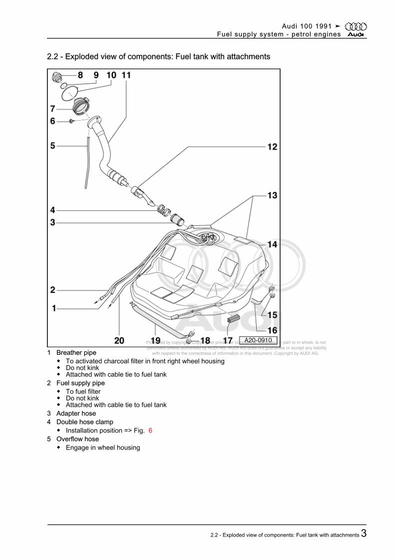
2.2 - Exploded view of components: Fuel tank with attachments
1 Breather pipe◆ To activated charcoal filter in front right wheel housing◆ Do not kink◆ Attached with cable tie to fuel tank
2 Fuel supply pipe◆ To fuel filter◆ Do not kink◆ Attached with cable tie to fuel tank
3 Adapter hose4 Double hose clamp
◆ Installation position => Fig. 65 Overflow hose
◆ Engage in wheel housing
Audi 100 1991 ➤Fuel supply system - petrol engines
2.2 - Exploded view of components: Fuel tank with attachments 3
Protected by copyright. Copying for private or commercial purposes, in part or in whole, is not permitted unless authorised by AUDI AG. AUDI AG does not guarantee or accept any liability with respect to the correctness of information in this document. Copyright by AUDI AG.
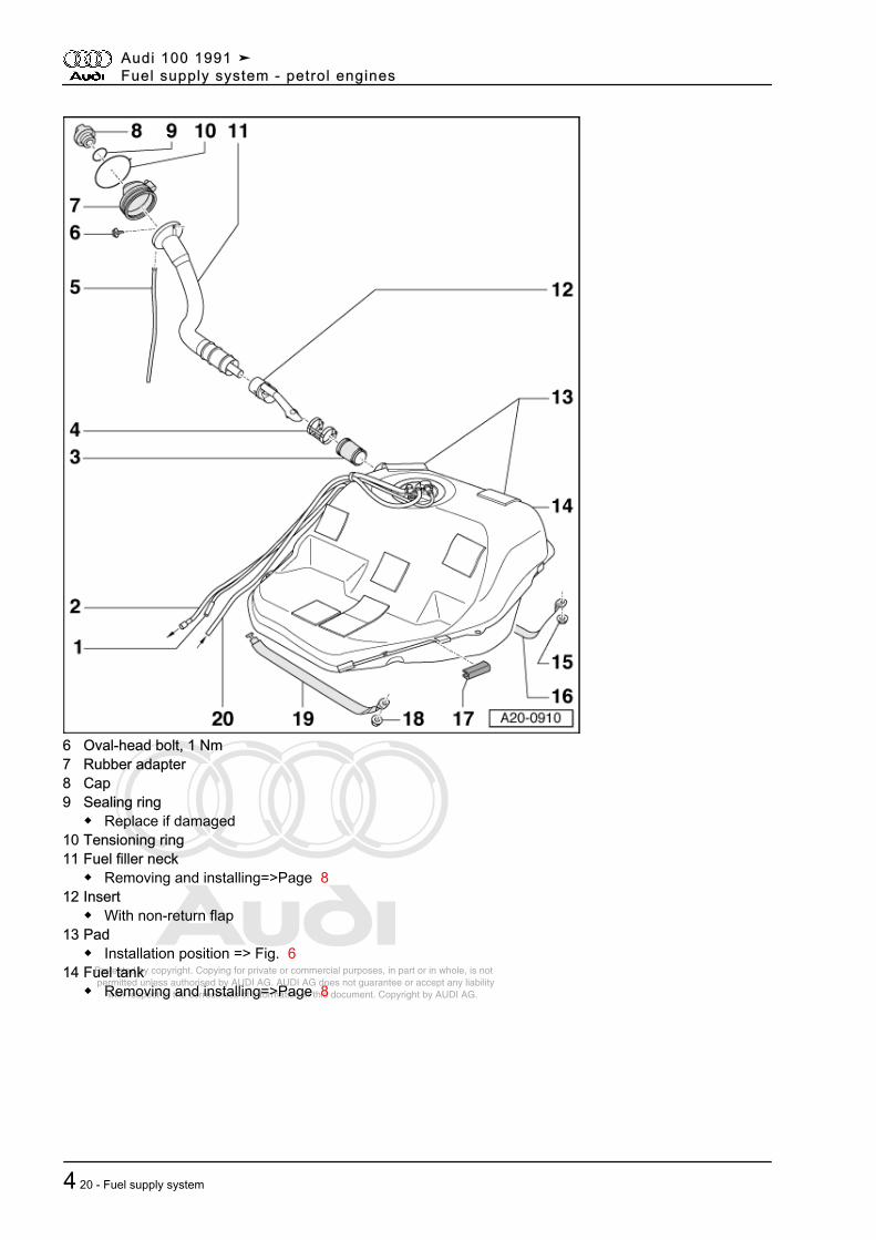
6 Oval-head bolt, 1 Nm7 Rubber adapter8 Cap9 Sealing ring
◆ Replace if damaged10 Tensioning ring11 Fuel filler neck
◆ Removing and installing=>Page 812 Insert
◆ With non-return flap13 Pad
◆ Installation position => Fig. 614 Fuel tank
◆ Removing and installing=>Page 8
Audi 100 1991 ➤Fuel supply system - petrol engines
4 20 - Fuel supply system
Protected by copyright. Copying for private or commercial purposes, in part or in whole, is not permitted unless authorised by AUDI AG. AUDI AG does not guarantee or accept any liability with respect to the correctness of information in this document. Copyright by AUDI AG.
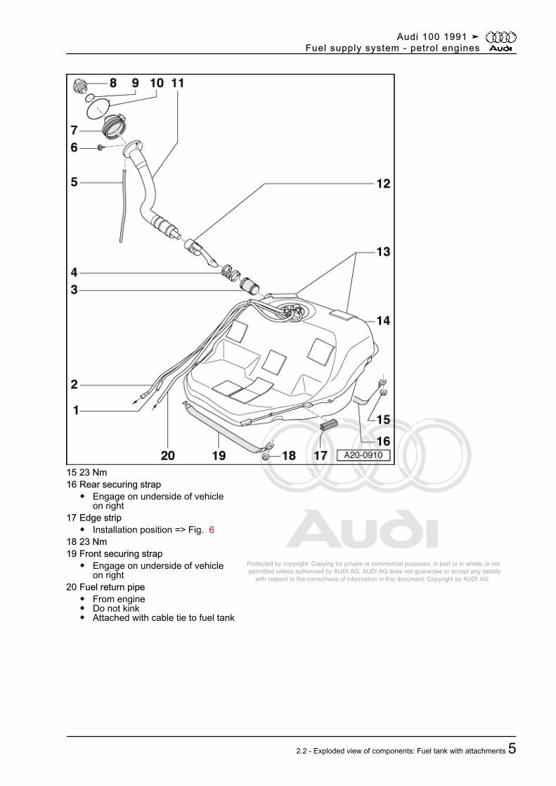
15 23 Nm16 Rear securing strap
◆ Engage on underside of vehicleon right
17 Edge strip◆ Installation position => Fig. 6
18 23 Nm19 Front securing strap
◆ Engage on underside of vehicleon right
20 Fuel return pipe◆ From engine◆ Do not kink◆ Attached with cable tie to fuel tank
Audi 100 1991 ➤Fuel supply system - petrol engines
2.2 - Exploded view of components: Fuel tank with attachments 5
Protected by copyright. Copying for private or commercial purposes, in part or in whole, is not permitted unless authorised by AUDI AG. AUDI AG does not guarantee or accept any liability with respect to the correctness of information in this document. Copyright by AUDI AG.
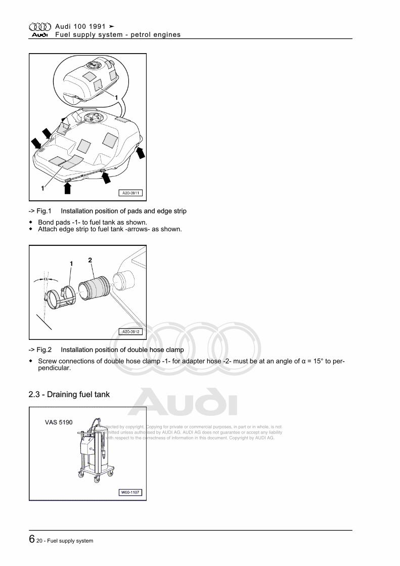
-> Fig.1 Installation position of pads and edge strip◆ Bond pads -1- to fuel tank as shown.◆ Attach edge strip to fuel tank -arrows- as shown.
-> Fig.2 Installation position of double hose clamp◆ Screw connections of double hose clamp -1- for adapter hose -2- must be at an angle of α = 15° to per‐
pendicular.
2.3 - Draining fuel tank
Audi 100 1991 ➤Fuel supply system - petrol engines
6 20 - Fuel supply system
Protected by copyright. Copying for private or commercial purposes, in part or in whole, is not permitted unless authorised by AUDI AG. AUDI AG does not guarantee or accept any liability with respect to the correctness of information in this document. Copyright by AUDI AG.
Special tools and workshop equipment required
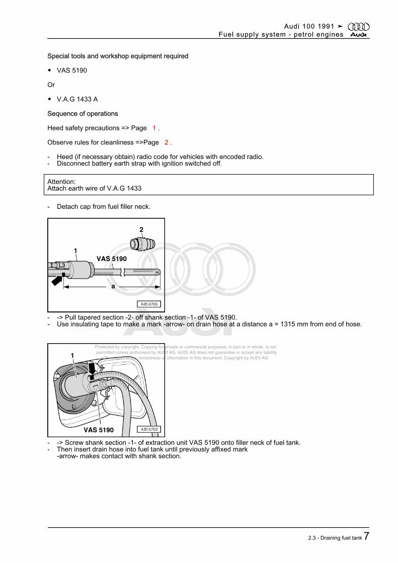
◆ VAS 5190
Or
◆ V.A.G 1433 A
Sequence of operations
Heed safety precautions => Page 1 .
Observe rules for cleanliness =>Page 2 .
- Heed (if necessary obtain) radio code for vehicles with encoded radio.- Disconnect battery earth strap with ignition switched off.
Attention:Attach earth wire of V.A.G 1433
- Detach cap from fuel filler neck.
- -> Pull tapered section -2- off shank section -1- of VAS 5190.- Use insulating tape to make a mark -arrow- on drain hose at a distance a = 1315 mm from end of hose.
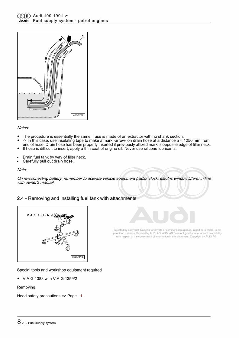
- -> Screw shank section -1- of extraction unit VAS 5190 onto filler neck of fuel tank.- Then insert drain hose into fuel tank until previously affixed mark
-arrow- makes contact with shank section.
Audi 100 1991 ➤Fuel supply system - petrol engines
2.3 - Draining fuel tank 7
Protected by copyright. Copying for private or commercial purposes, in part or in whole, is not permitted unless authorised by AUDI AG. AUDI AG does not guarantee or accept any liability with respect to the correctness of information in this document. Copyright by AUDI AG.
Notes:
◆ The procedure is essentially the same if use is made of an extractor with no shank section.◆ -> In this case, use insulating tape to make a mark -arrow- on drain hose at a distance a = 1250 mm from
end of hose. Drain hose has been properly inserted if previously affixed mark is opposite edge of filler neck.◆ If hose is difficult to insert, apply a thin coat of engine oil. Never use silicone lubricants.
- Drain fuel tank by way of filler neck.- Carefully pull out drain hose.
Note:
On re-connecting battery, remember to activate vehicle equipment (radio, clock, electric window lifters) in linewith owner's manual.
2.4 - Removing and installing fuel tank with attachments
Special tools and workshop equipment required
◆ V.A.G 1383 with V.A.G 1359/2
Removing
Heed safety precautions => Page 1 .
Audi 100 1991 ➤Fuel supply system - petrol engines
8 20 - Fuel supply system
Protected by copyright. Copying for private or commercial purposes, in part or in whole, is not permitted unless authorised by AUDI AG. AUDI AG does not guarantee or accept any liability with respect to the correctness of information in this document. Copyright by AUDI AG.
Observe rules for cleanliness =>Page 2 .• Fuel tank must be empty when removing it from vehicle so as to reduce weight. Drain fuel tank if necessary.
Procedure => Page 6 .
- Heed (if necessary obtain) radio code for vehicles with encoded radio.- Disconnect battery earth strap with ignition switched off.- Remove luggage compartment lining.
Avant:- Remove load compartment floor.- If necessary, fold forward right backrest of rear seat bench.
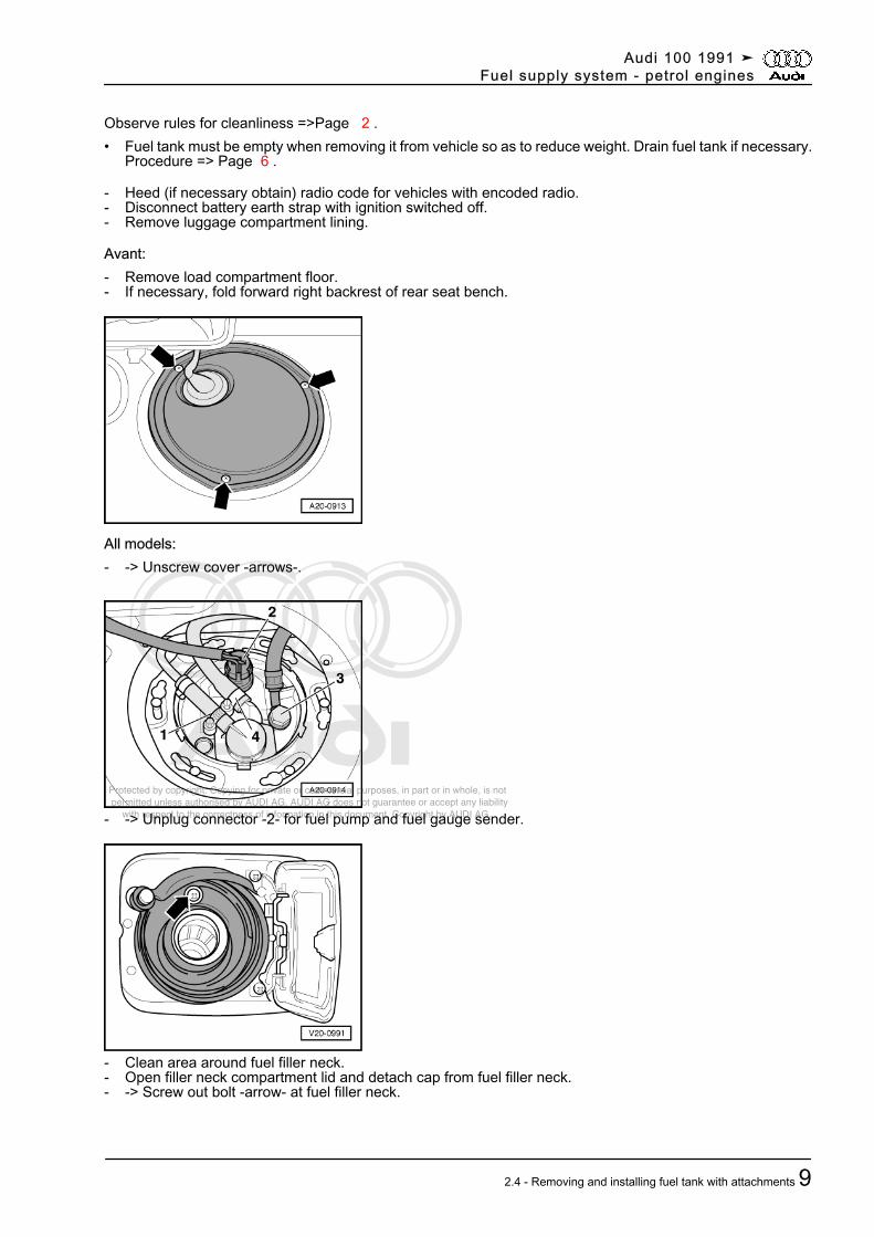
All models:- -> Unscrew cover -arrows-.
- -> Unplug connector -2- for fuel pump and fuel gauge sender.
- Clean area around fuel filler neck.- Open filler neck compartment lid and detach cap from fuel filler neck.- -> Screw out bolt -arrow- at fuel filler neck.
Audi 100 1991 ➤Fuel supply system - petrol engines
2.4 - Removing and installing fuel tank with attachments 9
Protected by copyright. Copying for private or commercial purposes, in part or in whole, is not permitted unless authorised by AUDI AG. AUDI AG does not guarantee or accept any liability with respect to the correctness of information in this document. Copyright by AUDI AG.
- Remove rear right wheel housing liner.
=> General Body Repairs; Repair Group 66; Wheel housing liners Wheel housing liners
- Detach overflow hose from holder.
Attention:Even if fuel tank is empty, a small quantity of fuel may escape on unfastening hose clamp at adapter hose.
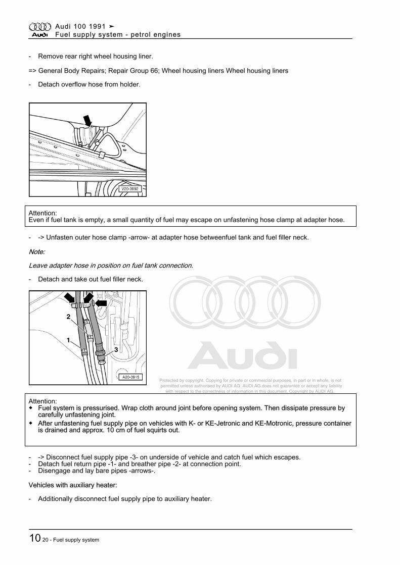
- -> Unfasten outer hose clamp -arrow- at adapter hose betweenfuel tank and fuel filler neck.
Note:
Leave adapter hose in position on fuel tank connection.
- Detach and take out fuel filler neck.
Attention:◆ Fuel system is pressurised. Wrap cloth around joint before opening system. Then dissipate pressure by
carefully unfastening joint.◆ After unfastening fuel supply pipe on vehicles with K- or KE-Jetronic and KE-Motronic, pressure container
is drained and approx. 10 cm of fuel squirts out.
- -> Disconnect fuel supply pipe -3- on underside of vehicle and catch fuel which escapes.- Detach fuel return pipe -1- and breather pipe -2- at connection point.- Disengage and lay bare pipes -arrows-.
Vehicles with auxiliary heater:
- Additionally disconnect fuel supply pipe to auxiliary heater.
Audi 100 1991 ➤Fuel supply system - petrol engines
10 20 - Fuel supply system
Protected by copyright. Copying for private or commercial purposes, in part or in whole, is not permitted unless authorised by AUDI AG. AUDI AG does not guarantee or accept any liability with respect to the correctness of information in this document. Copyright by AUDI AG.
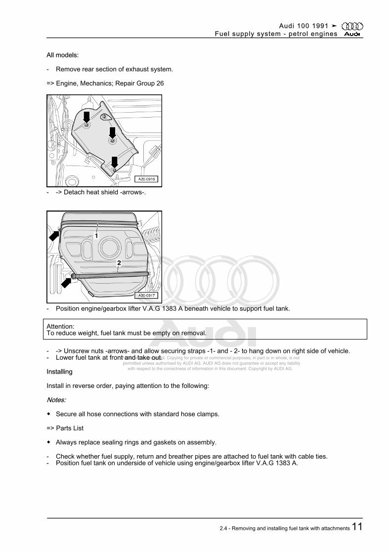
All models:
- Remove rear section of exhaust system.
=> Engine, Mechanics; Repair Group 26
- -> Detach heat shield -arrows-.
- Position engine/gearbox lifter V.A.G 1383 A beneath vehicle to support fuel tank.
Attention:To reduce weight, fuel tank must be empty on removal.
- -> Unscrew nuts -arrows- and allow securing straps -1- and - 2- to hang down on right side of vehicle.- Lower fuel tank at front and take out.
Installing
Install in reverse order, paying attention to the following:
Notes:
◆ Secure all hose connections with standard hose clamps.
=> Parts List
◆ Always replace sealing rings and gaskets on assembly.
- Check whether fuel supply, return and breather pipes are attached to fuel tank with cable ties.- Position fuel tank on underside of vehicle using engine/gearbox lifter V.A.G 1383 A.
Audi 100 1991 ➤Fuel supply system - petrol engines
2.4 - Removing and installing fuel tank with attachments 11
Protected by copyright. Copying for private or commercial purposes, in part or in whole, is not permitted unless authorised by AUDI AG. AUDI AG does not guarantee or accept any liability with respect to the correctness of information in this document. Copyright by AUDI AG.
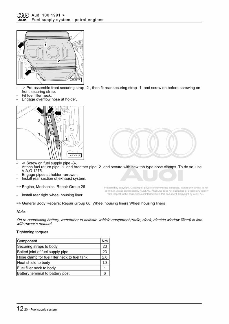
- -> Pre-assemble front securing strap -2-, then fit rear securing strap -1- and screw on before screwing onfront securing strap.
- Fit fuel filler neck.- Engage overflow hose at holder.
- -> Screw on fuel supply pipe -3-.- Attach fuel return pipe -1- and breather pipe -2- and secure with new tab-type hose clamps. To do so, use
V.A.G 1275.- Engage pipes at holder -arrows-.- Install rear section of exhaust system.
=> Engine, Mechanics; Repair Group 26
- Install rear right wheel housing liner.
=> General Body Repairs; Repair Group 66; Wheel housing liners Wheel housing liners
Note:
On re-connecting battery, remember to activate vehicle equipment (radio, clock, electric window lifters) in linewith owner's manual.
Tightening torques
Component NmSecuring straps to body 23Bolted joint of fuel supply pipe 23Hose clamp for fuel filler neck to fuel tank 2.6Heat shield to body 1.3Fuel filler neck to body 1Battery terminal to battery post 6
Audi 100 1991 ➤Fuel supply system - petrol engines
12 20 - Fuel supply system
Protected by copyright. Copying for private or commercial purposes, in part or in whole, is not permitted unless authorised by AUDI AG. AUDI AG does not guarantee or accept any liability with respect to the correctness of information in this document. Copyright by AUDI AG.
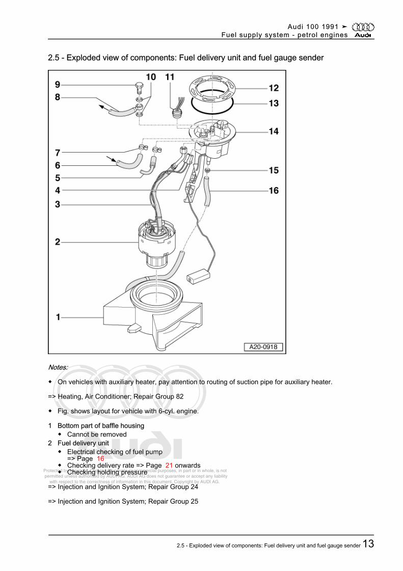
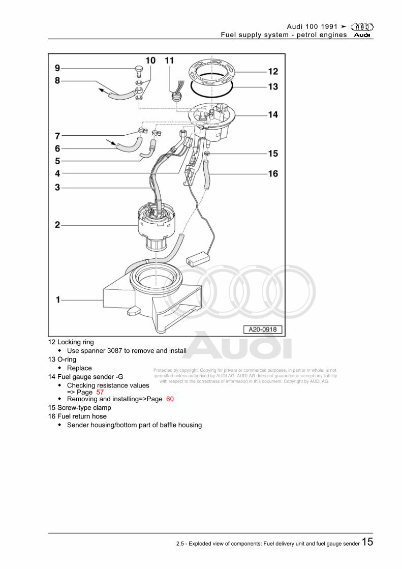
2.5 - Exploded view of components: Fuel delivery unit and fuel gauge sender
Notes:
◆ On vehicles with auxiliary heater, pay attention to routing of suction pipe for auxiliary heater.
=> Heating, Air Conditioner; Repair Group 82
◆ Fig. shows layout for vehicle with 6-cyl. engine.
1 Bottom part of baffle housing◆ Cannot be removed
2 Fuel delivery unit◆ Electrical checking of fuel pump
=> Page 16◆ Checking delivery rate => Page 21 onwards◆ Checking holding pressure
=> Injection and Ignition System; Repair Group 24
=> Injection and Ignition System; Repair Group 25
Audi 100 1991 ➤Fuel supply system - petrol engines
2.5 - Exploded view of components: Fuel delivery unit and fuel gauge sender 13
Protected by copyright. Copying for private or commercial purposes, in part or in whole, is not permitted unless authorised by AUDI AG. AUDI AG does not guarantee or accept any liability with respect to the correctness of information in this document. Copyright by AUDI AG.
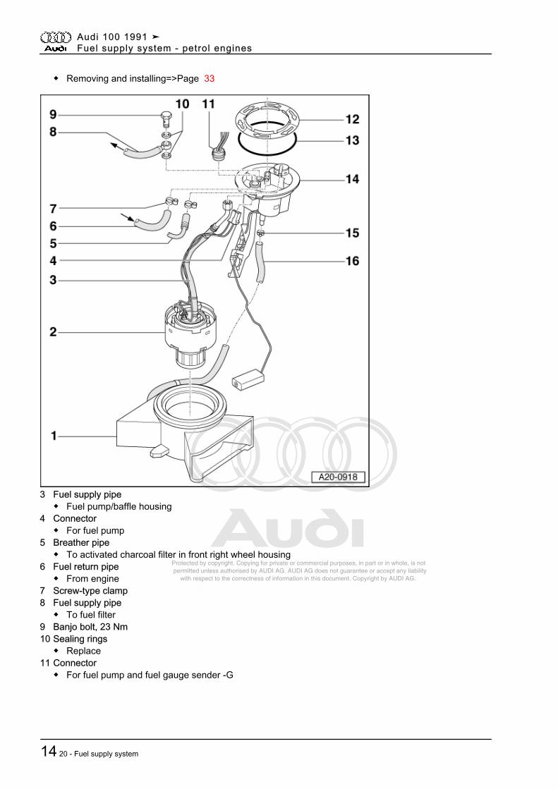
◆ Removing and installing=>Page 33
3 Fuel supply pipe◆ Fuel pump/baffle housing
4 Connector◆ For fuel pump
5 Breather pipe◆ To activated charcoal filter in front right wheel housing
6 Fuel return pipe◆ From engine
7 Screw-type clamp8 Fuel supply pipe
◆ To fuel filter9 Banjo bolt, 23 Nm10 Sealing rings
◆ Replace11 Connector
◆ For fuel pump and fuel gauge sender -G
Audi 100 1991 ➤Fuel supply system - petrol engines
14 20 - Fuel supply system
Protected by copyright. Copying for private or commercial purposes, in part or in whole, is not permitted unless authorised by AUDI AG. AUDI AG does not guarantee or accept any liability with respect to the correctness of information in this document. Copyright by AUDI AG.
12 Locking ring◆ Use spanner 3087 to remove and install
13 O-ring◆ Replace
14 Fuel gauge sender -G◆ Checking resistance values
=> Page 57◆ Removing and installing=>Page 60
15 Screw-type clamp16 Fuel return hose
◆ Sender housing/bottom part of baffle housing
Audi 100 1991 ➤Fuel supply system - petrol engines
2.5 - Exploded view of components: Fuel delivery unit and fuel gauge sender 15
Protected by copyright. Copying for private or commercial purposes, in part or in whole, is not permitted unless authorised by AUDI AG. AUDI AG does not guarantee or accept any liability with respect to the correctness of information in this document. Copyright by AUDI AG.
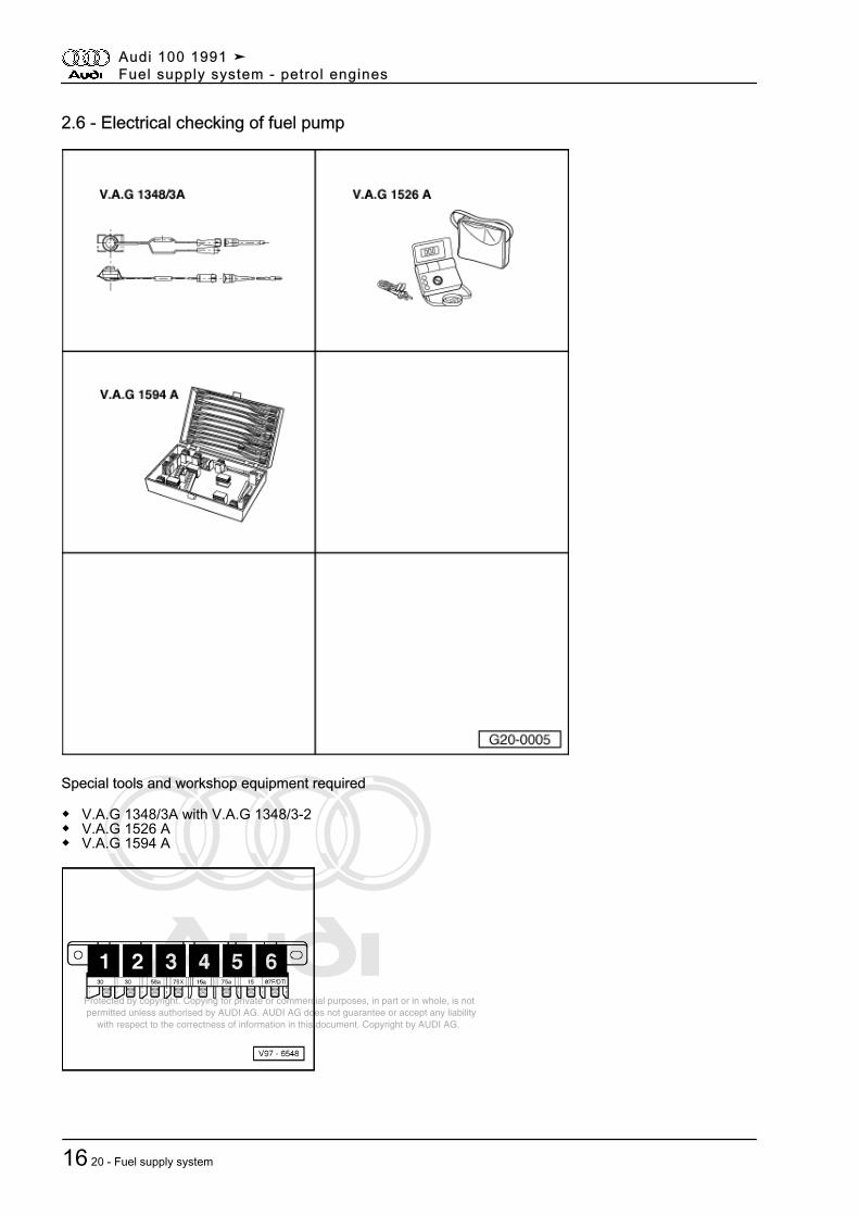
2.6 - Electrical checking of fuel pump
Special tools and workshop equipment required
◆ V.A.G 1348/3A with V.A.G 1348/3-2◆ V.A.G 1526 A◆ V.A.G 1594 A
Audi 100 1991 ➤Fuel supply system - petrol engines
16 20 - Fuel supply system
Protected by copyright. Copying for private or commercial purposes, in part or in whole, is not permitted unless authorised by AUDI AG. AUDI AG does not guarantee or accept any liability with respect to the correctness of information in this document. Copyright by AUDI AG.
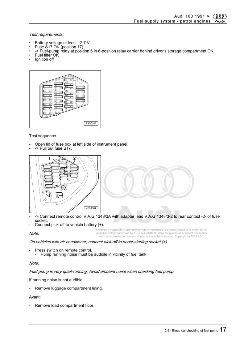
Test requirements:
• Battery voltage at least 12.7 V• Fuse S17 OK (position 17)• -> Fuel-pump relay at position 6 in 6-position relay carrier behind driver's storage compartment OK• Fuel filter OK• Ignition off
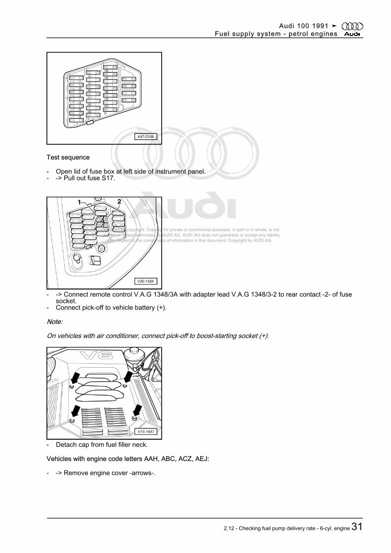
Test sequence
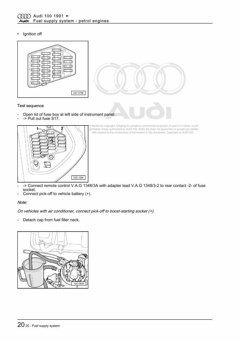
- Open lid of fuse box at left side of instrument panel.- -> Pull out fuse S17.
- -> Connect remote control V.A.G 1348/3A with adapter lead V.A.G 1348/3-2 to rear contact -2- of fusesocket.
- Connect pick-off to vehicle battery (+).
Note:
On vehicles with air conditioner, connect pick-off to boost-starting socket (+).
- Press switch on remote control.- Pump running noise must be audible in vicinity of fuel tank
Note:
Fuel pump is very quiet-running. Avoid ambient noise when checking fuel pump.
If running noise is not audible:
- Remove luggage compartment lining.
Avant:
- Remove load compartment floor.
Audi 100 1991 ➤Fuel supply system - petrol engines
2.6 - Electrical checking of fuel pump 17
Protected by copyright. Copying for private or commercial purposes, in part or in whole, is not permitted unless authorised by AUDI AG. AUDI AG does not guarantee or accept any liability with respect to the correctness of information in this document. Copyright by AUDI AG.
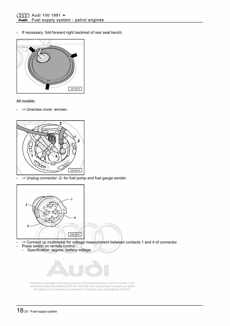
- If necessary, fold forward right backrest of rear seat bench.
All models:
- -> Unscrew cover -arrows-.
- -> Unplug connector -2- for fuel pump and fuel gauge sender.
- -> Connect up multimeter for voltage measurement between contacts 1 and 4 of connector.- Press switch on remote control.
- Specification: approx. battery voltage
Audi 100 1991 ➤Fuel supply system - petrol engines
18 20 - Fuel supply system
Protected by copyright. Copying for private or commercial purposes, in part or in whole, is not permitted unless authorised by AUDI AG. AUDI AG does not guarantee or accept any liability with respect to the correctness of information in this document. Copyright by AUDI AG.
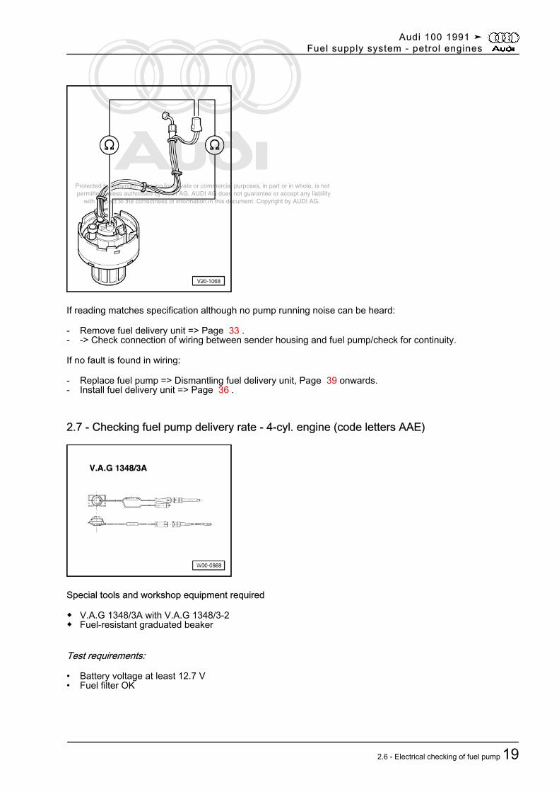
If reading matches specification although no pump running noise can be heard:
- Remove fuel delivery unit => Page 33 .- -> Check connection of wiring between sender housing and fuel pump/check for continuity.
If no fault is found in wiring:
- Replace fuel pump => Dismantling fuel delivery unit, Page 39 onwards.- Install fuel delivery unit => Page 36 .
2.7 - Checking fuel pump delivery rate - 4-cyl. engine (code letters AAE)
Special tools and workshop equipment required
◆ V.A.G 1348/3A with V.A.G 1348/3-2◆ Fuel-resistant graduated beaker
Test requirements:
• Battery voltage at least 12.7 V• Fuel filter OK
Audi 100 1991 ➤Fuel supply system - petrol engines
2.6 - Electrical checking of fuel pump 19
Protected by copyright. Copying for private or commercial purposes, in part or in whole, is not permitted unless authorised by AUDI AG. AUDI AG does not guarantee or accept any liability with respect to the correctness of information in this document. Copyright by AUDI AG.
• Ignition off
Test sequence
- Open lid of fuse box at left side of instrument panel.- -> Pull out fuse S17.
- -> Connect remote control V.A.G 1348/3A with adapter lead V.A.G 1348/3-2 to rear contact -2- of fusesocket.
- Connect pick-off to vehicle battery (+).
Note:
On vehicles with air conditioner, connect pick-off to boost-starting socket (+).
- Detach cap from fuel filler neck.
Audi 100 1991 ➤Fuel supply system - petrol engines
20 20 - Fuel supply system
Protected by copyright. Copying for private or commercial purposes, in part or in whole, is not permitted unless authorised by AUDI AG. AUDI AG does not guarantee or accept any liability with respect to the correctness of information in this document. Copyright by AUDI AG.
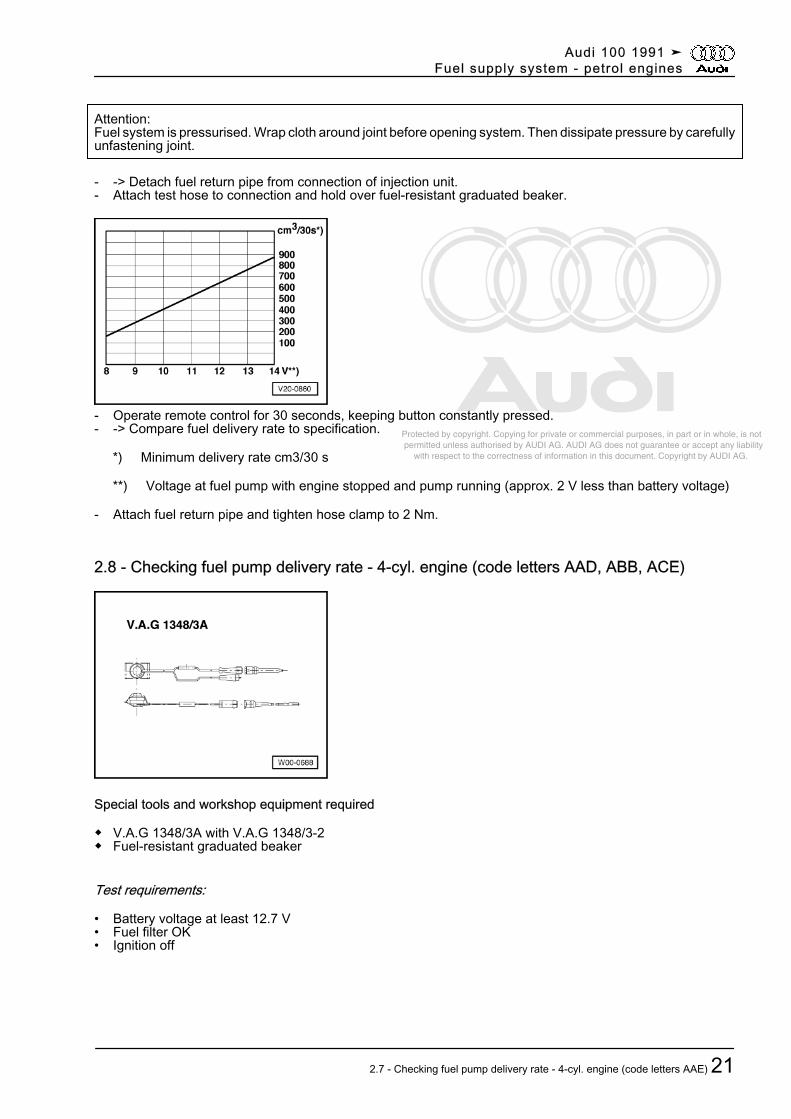
Attention:Fuel system is pressurised. Wrap cloth around joint before opening system. Then dissipate pressure by carefullyunfastening joint.
- -> Detach fuel return pipe from connection of injection unit.- Attach test hose to connection and hold over fuel-resistant graduated beaker.
- Operate remote control for 30 seconds, keeping button constantly pressed.- -> Compare fuel delivery rate to specification.
*) Minimum delivery rate cm3/30 s
**) Voltage at fuel pump with engine stopped and pump running (approx. 2 V less than battery voltage)
- Attach fuel return pipe and tighten hose clamp to 2 Nm.
2.8 - Checking fuel pump delivery rate - 4-cyl. engine (code letters AAD, ABB, ACE)
Special tools and workshop equipment required
◆ V.A.G 1348/3A with V.A.G 1348/3-2◆ Fuel-resistant graduated beaker
Test requirements:
• Battery voltage at least 12.7 V• Fuel filter OK• Ignition off
Audi 100 1991 ➤Fuel supply system - petrol engines
2.7 - Checking fuel pump delivery rate - 4-cyl. engine (code letters AAE) 21
Protected by copyright. Copying for private or commercial purposes, in part or in whole, is not permitted unless authorised by AUDI AG. AUDI AG does not guarantee or accept any liability with respect to the correctness of information in this document. Copyright by AUDI AG.
Test sequence
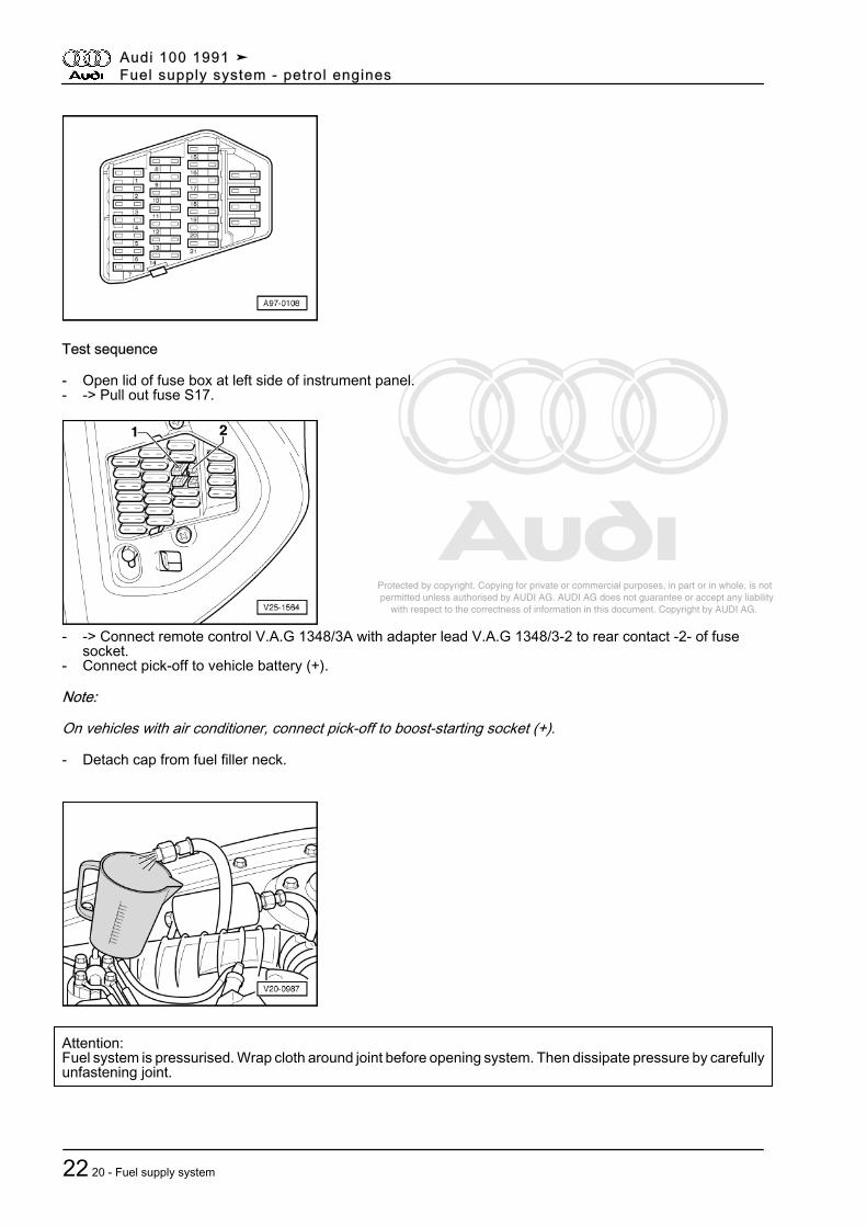
- Open lid of fuse box at left side of instrument panel.- -> Pull out fuse S17.
- -> Connect remote control V.A.G 1348/3A with adapter lead V.A.G 1348/3-2 to rear contact -2- of fusesocket.
- Connect pick-off to vehicle battery (+).
Note:
On vehicles with air conditioner, connect pick-off to boost-starting socket (+).
- Detach cap from fuel filler neck.
Attention:Fuel system is pressurised. Wrap cloth around joint before opening system. Then dissipate pressure by carefullyunfastening joint.
Audi 100 1991 ➤Fuel supply system - petrol engines
22 20 - Fuel supply system
Protected by copyright. Copying for private or commercial purposes, in part or in whole, is not permitted unless authorised by AUDI AG. AUDI AG does not guarantee or accept any liability with respect to the correctness of information in this document. Copyright by AUDI AG.
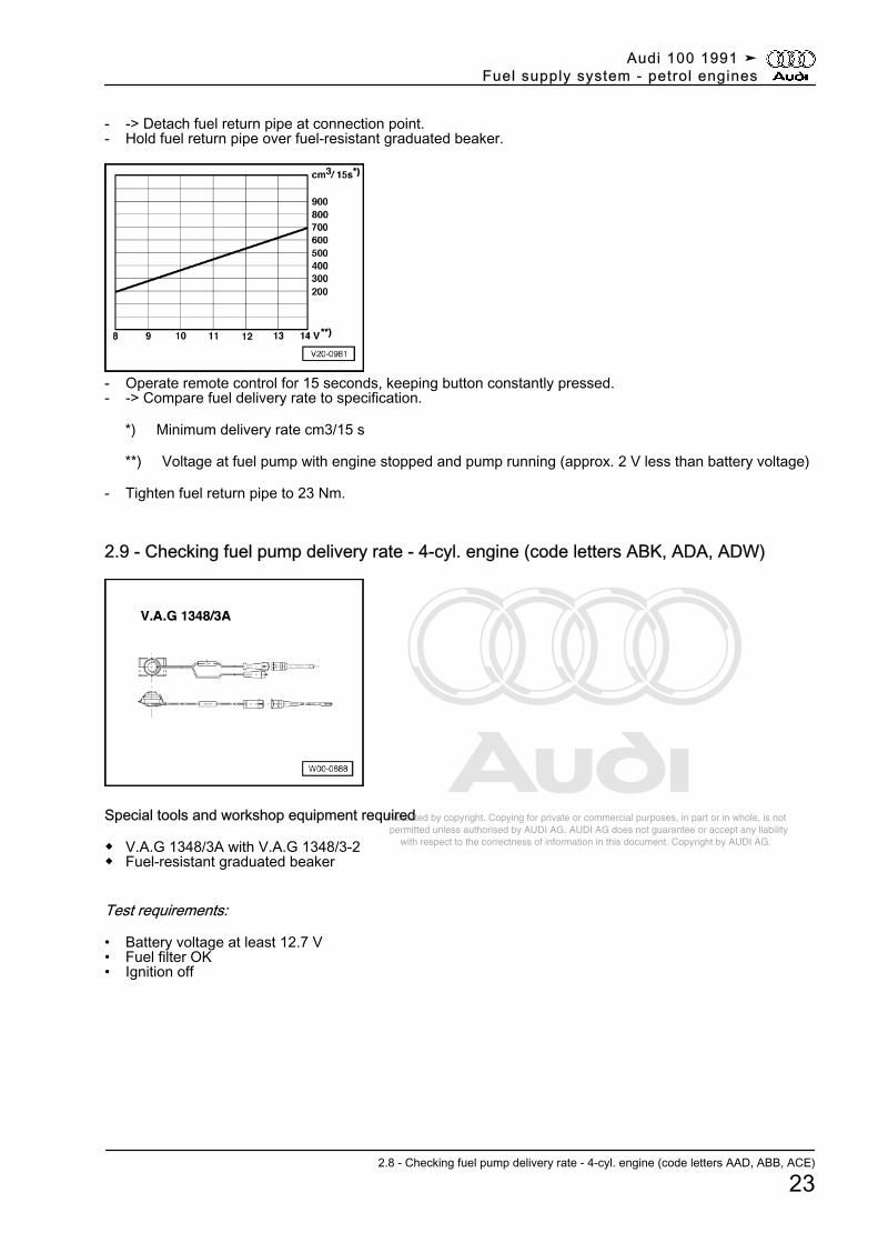
- -> Detach fuel return pipe at connection point.- Hold fuel return pipe over fuel-resistant graduated beaker.
- Operate remote control for 15 seconds, keeping button constantly pressed.- -> Compare fuel delivery rate to specification.
*) Minimum delivery rate cm3/15 s
**) Voltage at fuel pump with engine stopped and pump running (approx. 2 V less than battery voltage)
- Tighten fuel return pipe to 23 Nm.
2.9 - Checking fuel pump delivery rate - 4-cyl. engine (code letters ABK, ADA, ADW)
Special tools and workshop equipment required
◆ V.A.G 1348/3A with V.A.G 1348/3-2◆ Fuel-resistant graduated beaker
Test requirements:
• Battery voltage at least 12.7 V• Fuel filter OK• Ignition off
Audi 100 1991 ➤Fuel supply system - petrol engines
2.8 - Checking fuel pump delivery rate - 4-cyl. engine (code letters AAD, ABB, ACE)
23
Protected by copyright. Copying for private or commercial purposes, in part or in whole, is not permitted unless authorised by AUDI AG. AUDI AG does not guarantee or accept any liability with respect to the correctness of information in this document. Copyright by AUDI AG.
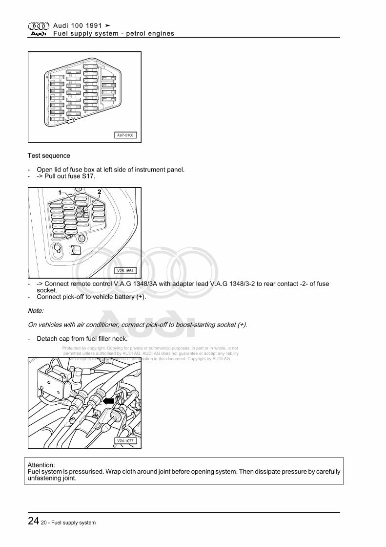
Test sequence
- Open lid of fuse box at left side of instrument panel.- -> Pull out fuse S17.
- -> Connect remote control V.A.G 1348/3A with adapter lead V.A.G 1348/3-2 to rear contact -2- of fusesocket.
- Connect pick-off to vehicle battery (+).
Note:
On vehicles with air conditioner, connect pick-off to boost-starting socket (+).
- Detach cap from fuel filler neck.
Attention:Fuel system is pressurised. Wrap cloth around joint before opening system. Then dissipate pressure by carefullyunfastening joint.
Audi 100 1991 ➤Fuel supply system - petrol engines
24 20 - Fuel supply system
Protected by copyright. Copying for private or commercial purposes, in part or in whole, is not permitted unless authorised by AUDI AG. AUDI AG does not guarantee or accept any liability with respect to the correctness of information in this document. Copyright by AUDI AG.
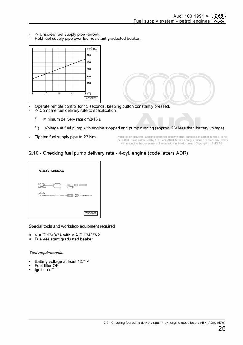
- -> Unscrew fuel supply pipe -arrow-.- Hold fuel supply pipe over fuel-resistant graduated beaker.
- Operate remote control for 15 seconds, keeping button constantly pressed.- -> Compare fuel delivery rate to specification.
*) Minimum delivery rate cm3/15 s
**) Voltage at fuel pump with engine stopped and pump running (approx. 2 V less than battery voltage)
- Tighten fuel supply pipe to 23 Nm.
2.10 - Checking fuel pump delivery rate - 4-cyl. engine (code letters ADR)
Special tools and workshop equipment required
◆ V.A.G 1348/3A with V.A.G 1348/3-2◆ Fuel-resistant graduated beaker
Test requirements:
• Battery voltage at least 12.7 V• Fuel filter OK• Ignition off
Audi 100 1991 ➤Fuel supply system - petrol engines
2.9 - Checking fuel pump delivery rate - 4-cyl. engine (code letters ABK, ADA, ADW)
25
Protected by copyright. Copying for private or commercial purposes, in part or in whole, is not permitted unless authorised by AUDI AG. AUDI AG does not guarantee or accept any liability with respect to the correctness of information in this document. Copyright by AUDI AG.
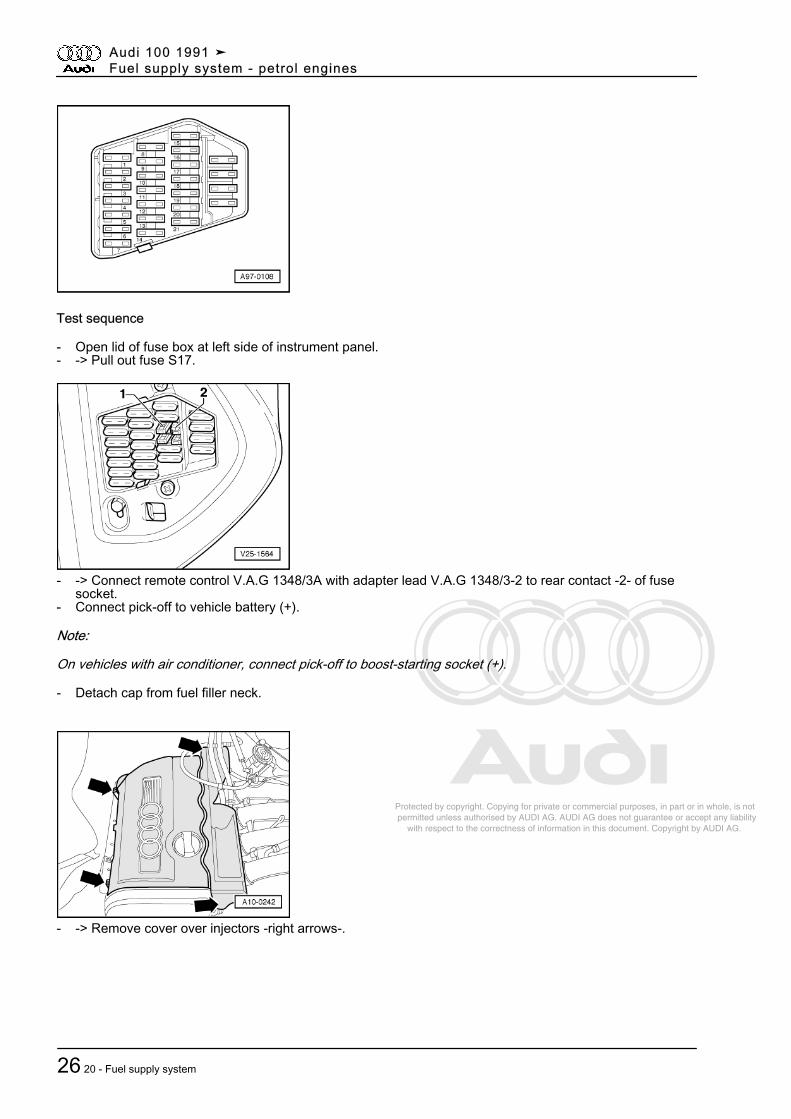
Test sequence
- Open lid of fuse box at left side of instrument panel.- -> Pull out fuse S17.
- -> Connect remote control V.A.G 1348/3A with adapter lead V.A.G 1348/3-2 to rear contact -2- of fusesocket.
- Connect pick-off to vehicle battery (+).
Note:
On vehicles with air conditioner, connect pick-off to boost-starting socket (+).
- Detach cap from fuel filler neck.
- -> Remove cover over injectors -right arrows-.
Audi 100 1991 ➤Fuel supply system - petrol engines
26 20 - Fuel supply system
Protected by copyright. Copying for private or commercial purposes, in part or in whole, is not permitted unless authorised by AUDI AG. AUDI AG does not guarantee or accept any liability with respect to the correctness of information in this document. Copyright by AUDI AG.
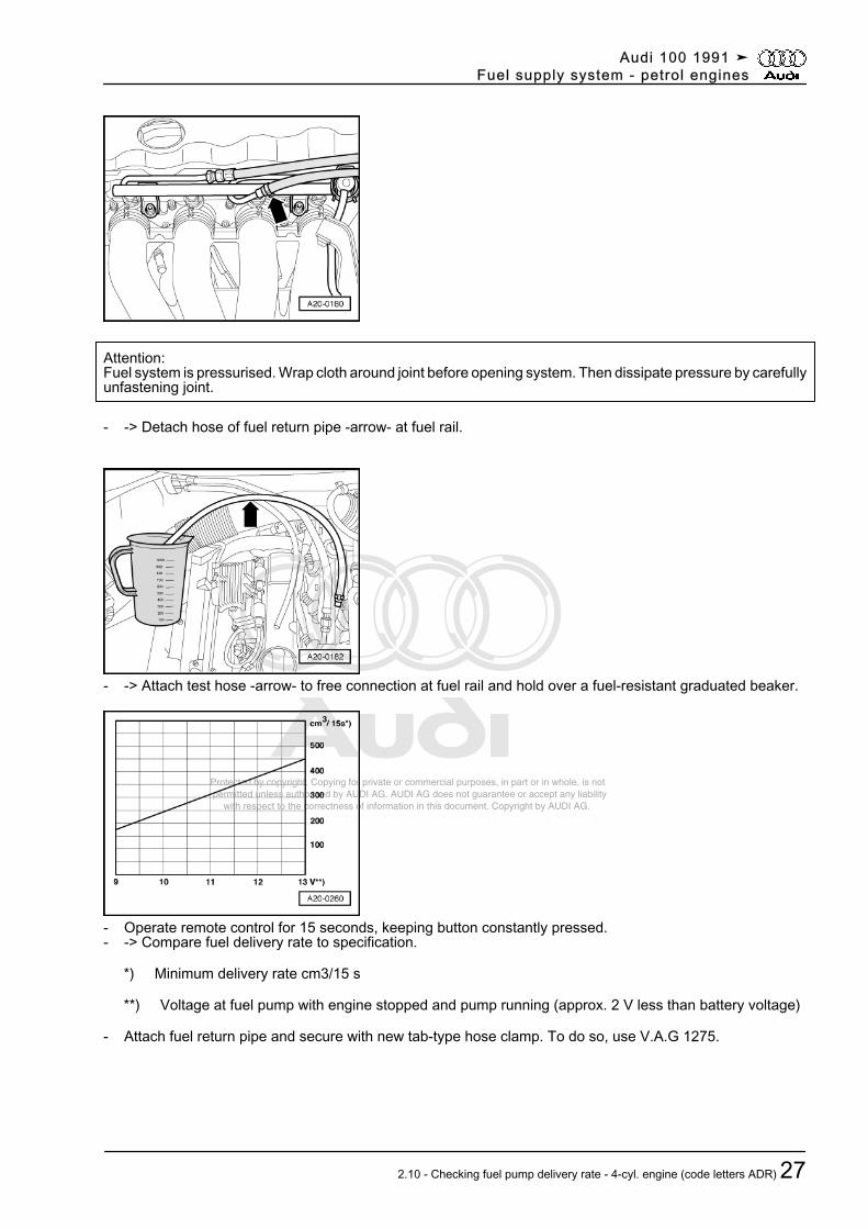
Attention:Fuel system is pressurised. Wrap cloth around joint before opening system. Then dissipate pressure by carefullyunfastening joint.
- -> Detach hose of fuel return pipe -arrow- at fuel rail.
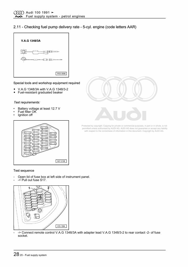
- -> Attach test hose -arrow- to free connection at fuel rail and hold over a fuel-resistant graduated beaker.
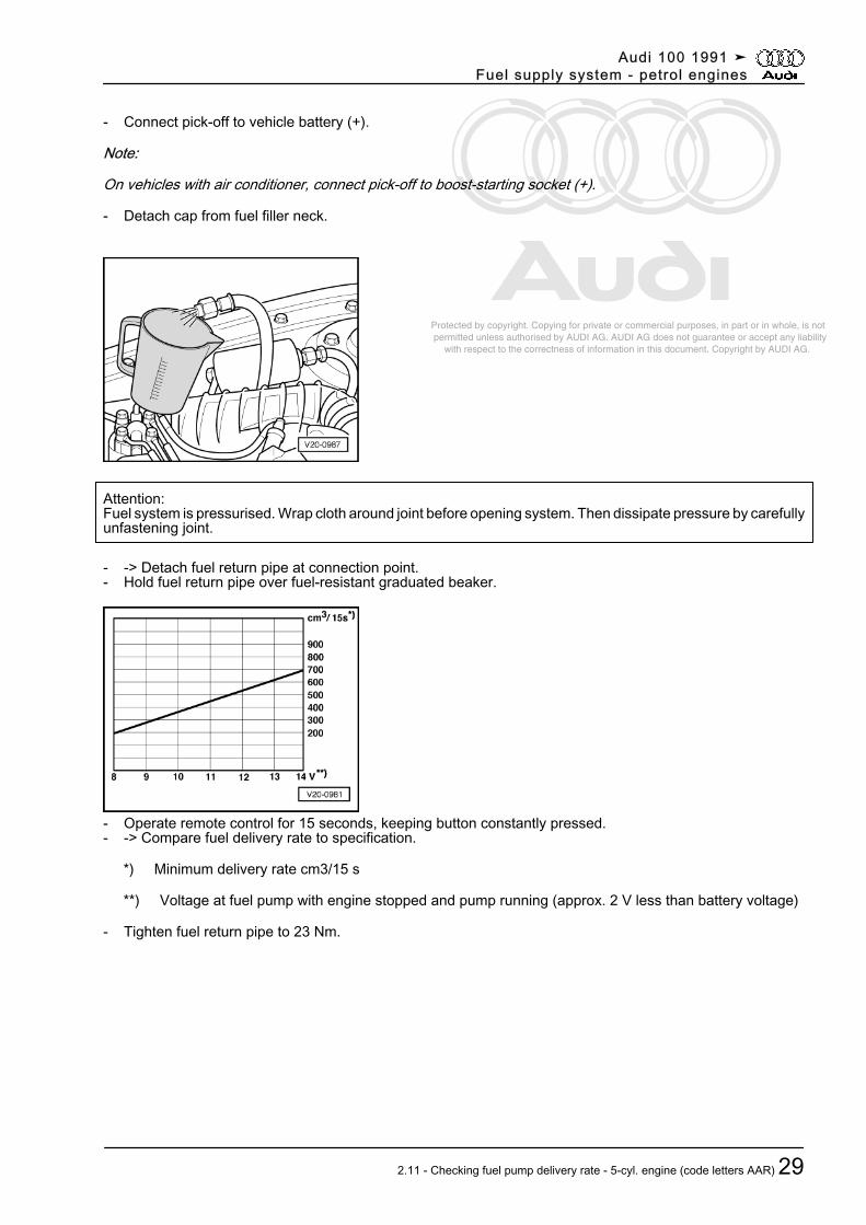
- Operate remote control for 15 seconds, keeping button constantly pressed.- -> Compare fuel delivery rate to specification.
*) Minimum delivery rate cm3/15 s
**) Voltage at fuel pump with engine stopped and pump running (approx. 2 V less than battery voltage)
- Attach fuel return pipe and secure with new tab-type hose clamp. To do so, use V.A.G 1275.
Audi 100 1991 ➤Fuel supply system - petrol engines
2.10 - Checking fuel pump delivery rate - 4-cyl. engine (code letters ADR) 27
Protected by copyright. Copying for private or commercial purposes, in part or in whole, is not permitted unless authorised by AUDI AG. AUDI AG does not guarantee or accept any liability with respect to the correctness of information in this document. Copyright by AUDI AG.
2.11 - Checking fuel pump delivery rate - 5-cyl. engine (code letters AAR)
Special tools and workshop equipment required
◆ V.A.G 1348/3A with V.A.G 1348/3-2◆ Fuel-resistant graduated beaker
Test requirements:
• Battery voltage at least 12.7 V• Fuel filter OK• Ignition off
Test sequence
- Open lid of fuse box at left side of instrument panel.- -> Pull out fuse S17.
- -> Connect remote control V.A.G 1348/3A with adapter lead V.A.G 1348/3-2 to rear contact -2- of fusesocket.
Audi 100 1991 ➤Fuel supply system - petrol engines
28 20 - Fuel supply system
Protected by copyright. Copying for private or commercial purposes, in part or in whole, is not permitted unless authorised by AUDI AG. AUDI AG does not guarantee or accept any liability with respect to the correctness of information in this document. Copyright by AUDI AG.
- Connect pick-off to vehicle battery (+).
Note:
On vehicles with air conditioner, connect pick-off to boost-starting socket (+).
- Detach cap from fuel filler neck.
Attention:Fuel system is pressurised. Wrap cloth around joint before opening system. Then dissipate pressure by carefullyunfastening joint.
- -> Detach fuel return pipe at connection point.- Hold fuel return pipe over fuel-resistant graduated beaker.
- Operate remote control for 15 seconds, keeping button constantly pressed.- -> Compare fuel delivery rate to specification.
*) Minimum delivery rate cm3/15 s
**) Voltage at fuel pump with engine stopped and pump running (approx. 2 V less than battery voltage)
- Tighten fuel return pipe to 23 Nm.
Audi 100 1991 ➤Fuel supply system - petrol engines
2.11 - Checking fuel pump delivery rate - 5-cyl. engine (code letters AAR) 29
Protected by copyright. Copying for private or commercial purposes, in part or in whole, is not permitted unless authorised by AUDI AG. AUDI AG does not guarantee or accept any liability with respect to the correctness of information in this document. Copyright by AUDI AG.
2.12 - Checking fuel pump delivery rate - 6-cyl. engine
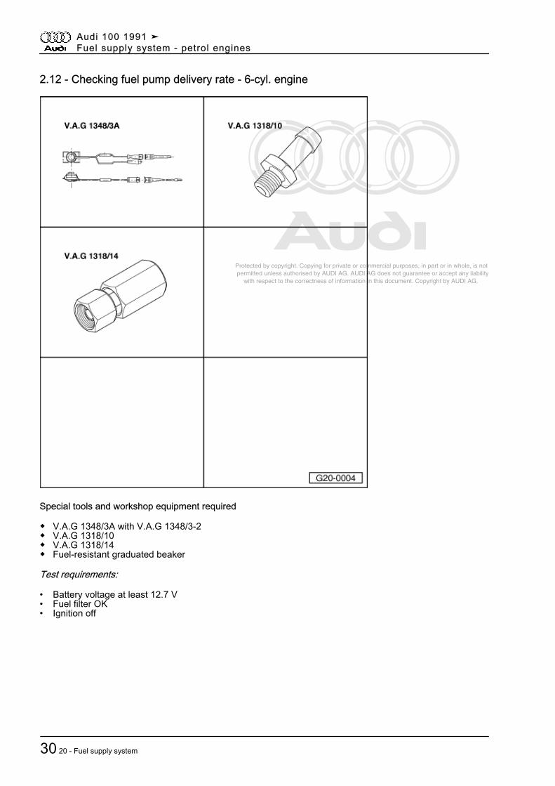
Special tools and workshop equipment required
◆ V.A.G 1348/3A with V.A.G 1348/3-2◆ V.A.G 1318/10◆ V.A.G 1318/14◆ Fuel-resistant graduated beaker
Test requirements:
• Battery voltage at least 12.7 V• Fuel filter OK• Ignition off
Audi 100 1991 ➤Fuel supply system - petrol engines
30 20 - Fuel supply system
Protected by copyright. Copying for private or commercial purposes, in part or in whole, is not permitted unless authorised by AUDI AG. AUDI AG does not guarantee or accept any liability with respect to the correctness of information in this document. Copyright by AUDI AG.
Test sequence
- Open lid of fuse box at left side of instrument panel.- -> Pull out fuse S17.
- -> Connect remote control V.A.G 1348/3A with adapter lead V.A.G 1348/3-2 to rear contact -2- of fusesocket.
- Connect pick-off to vehicle battery (+).
Note:
On vehicles with air conditioner, connect pick-off to boost-starting socket (+).
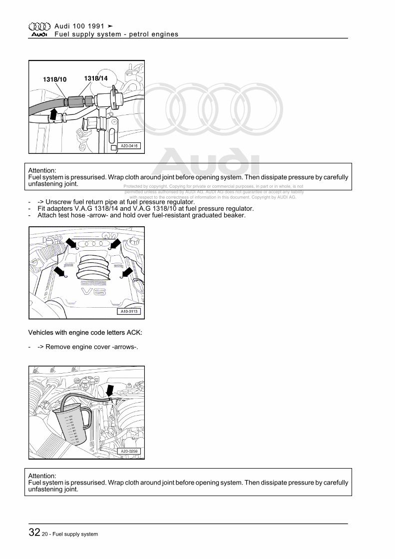
- Detach cap from fuel filler neck.
Vehicles with engine code letters AAH, ABC, ACZ, AEJ:
- -> Remove engine cover -arrows-.
Audi 100 1991 ➤Fuel supply system - petrol engines
2.12 - Checking fuel pump delivery rate - 6-cyl. engine 31
Protected by copyright. Copying for private or commercial purposes, in part or in whole, is not permitted unless authorised by AUDI AG. AUDI AG does not guarantee or accept any liability with respect to the correctness of information in this document. Copyright by AUDI AG.
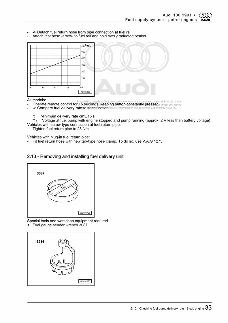
Attention:Fuel system is pressurised. Wrap cloth around joint before opening system. Then dissipate pressure by carefullyunfastening joint.
- -> Unscrew fuel return pipe at fuel pressure regulator.- Fit adapters V.A.G 1318/14 and V.A.G 1318/10 at fuel pressure regulator.- Attach test hose -arrow- and hold over fuel-resistant graduated beaker.
Vehicles with engine code letters ACK:
- -> Remove engine cover -arrows-.
Attention:Fuel system is pressurised. Wrap cloth around joint before opening system. Then dissipate pressure by carefullyunfastening joint.
Audi 100 1991 ➤Fuel supply system - petrol engines
32 20 - Fuel supply system
Protected by copyright. Copying for private or commercial purposes, in part or in whole, is not permitted unless authorised by AUDI AG. AUDI AG does not guarantee or accept any liability with respect to the correctness of information in this document. Copyright by AUDI AG.
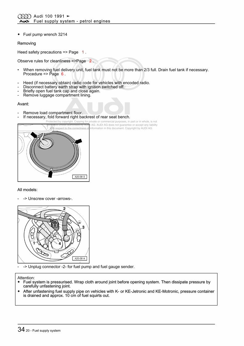
- -> Detach fuel return hose from pipe connection at fuel rail.- Attach test hose -arrow- to fuel rail and hold over graduated beaker.
All models:- Operate remote control for 15 seconds, keeping button constantly pressed.- -> Compare fuel delivery rate to specification.
*) Minimum delivery rate cm3/15 s **) Voltage at fuel pump with engine stopped and pump running (approx. 2 V less than battery voltage)Vehicles with screw-type connection at fuel return pipe:- Tighten fuel return pipe to 23 Nm.
Vehicles with plug-in fuel return pipe:- Fit fuel return hose with new tab-type hose clamp. To do so, use V.A.G 1275.
2.13 - Removing and installing fuel delivery unit
Special tools and workshop equipment required◆ Fuel gauge sender wrench 3087
Audi 100 1991 ➤Fuel supply system - petrol engines
2.12 - Checking fuel pump delivery rate - 6-cyl. engine 33
Protected by copyright. Copying for private or commercial purposes, in part or in whole, is not permitted unless authorised by AUDI AG. AUDI AG does not guarantee or accept any liability with respect to the correctness of information in this document. Copyright by AUDI AG.
◆ Fuel pump wrench 3214
Removing
Heed safety precautions => Page 1 .
Observe rules for cleanliness =>Page 2 .
• When removing fuel delivery unit, fuel tank must not be more than 2/3 full. Drain fuel tank if necessary.Procedure => Page 6 .
- Heed (if necessary obtain) radio code for vehicles with encoded radio.- Disconnect battery earth strap with ignition switched off.- Briefly open fuel tank cap and close again.- Remove luggage compartment lining.
Avant:
- Remove load compartment floor.- If necessary, fold forward right backrest of rear seat bench.
All models:
- -> Unscrew cover -arrows-.
- -> Unplug connector -2- for fuel pump and fuel gauge sender.
Attention:◆ Fuel system is pressurised. Wrap cloth around joint before opening system. Then dissipate pressure by
carefully unfastening joint.◆ After unfastening fuel supply pipe on vehicles with K- or KE-Jetronic and KE-Motronic, pressure container
is drained and approx. 10 cm of fuel squirts out.
Audi 100 1991 ➤Fuel supply system - petrol engines
34 20 - Fuel supply system
Protected by copyright. Copying for private or commercial purposes, in part or in whole, is not permitted unless authorised by AUDI AG. AUDI AG does not guarantee or accept any liability with respect to the correctness of information in this document. Copyright by AUDI AG.
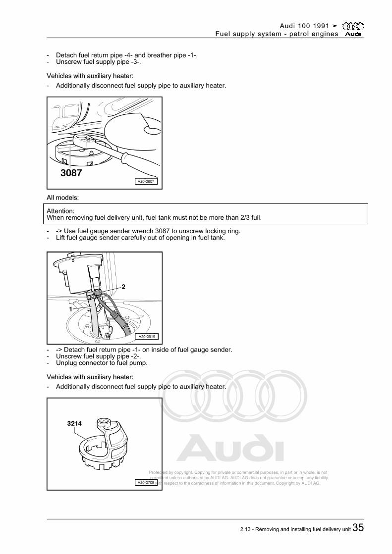
- Detach fuel return pipe -4- and breather pipe -1-.- Unscrew fuel supply pipe -3-.
Vehicles with auxiliary heater:- Additionally disconnect fuel supply pipe to auxiliary heater.
All models:
Attention:When removing fuel delivery unit, fuel tank must not be more than 2/3 full.
- -> Use fuel gauge sender wrench 3087 to unscrew locking ring.- Lift fuel gauge sender carefully out of opening in fuel tank.
- -> Detach fuel return pipe -1- on inside of fuel gauge sender.- Unscrew fuel supply pipe -2-.- Unplug connector to fuel pump.
Vehicles with auxiliary heater:- Additionally disconnect fuel supply pipe to auxiliary heater.
Audi 100 1991 ➤Fuel supply system - petrol engines
2.13 - Removing and installing fuel delivery unit 35
Protected by copyright. Copying for private or commercial purposes, in part or in whole, is not permitted unless authorised by AUDI AG. AUDI AG does not guarantee or accept any liability with respect to the correctness of information in this document. Copyright by AUDI AG.
All models:
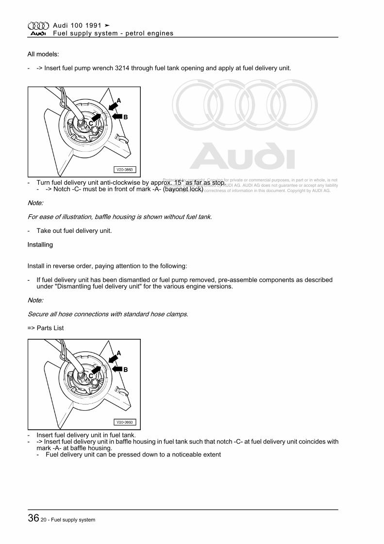
- -> Insert fuel pump wrench 3214 through fuel tank opening and apply at fuel delivery unit.
- Turn fuel delivery unit anti-clockwise by approx. 15° as far as stop.- -> Notch -C- must be in front of mark -A- (bayonet lock)
Note:
For ease of illustration, baffle housing is shown without fuel tank.
- Take out fuel delivery unit.
Installing
Install in reverse order, paying attention to the following:
- If fuel delivery unit has been dismantled or fuel pump removed, pre-assemble components as describedunder "Dismantling fuel delivery unit" for the various engine versions.
Note:
Secure all hose connections with standard hose clamps.
=> Parts List
- Insert fuel delivery unit in fuel tank.- -> Insert fuel delivery unit in baffle housing in fuel tank such that notch -C- at fuel delivery unit coincides with
mark -A- at baffle housing.- Fuel delivery unit can be pressed down to a noticeable extent
Audi 100 1991 ➤Fuel supply system - petrol engines
36 20 - Fuel supply system
Protected by copyright. Copying for private or commercial purposes, in part or in whole, is not permitted unless authorised by AUDI AG. AUDI AG does not guarantee or accept any liability with respect to the correctness of information in this document. Copyright by AUDI AG.
Note:
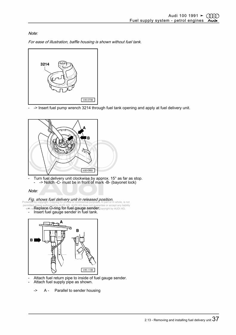
For ease of illustration, baffle housing is shown without fuel tank.
- -> Insert fuel pump wrench 3214 through fuel tank opening and apply at fuel delivery unit.
- Turn fuel delivery unit clockwise by approx. 15° as far as stop.- -> Notch -C- must be in front of mark -B- (bayonet lock)
Note:
Fig. shows fuel delivery unit in released position.
- Replace O-ring for fuel gauge sender.- Insert fuel gauge sender in fuel tank.
- Attach fuel return pipe to inside of fuel gauge sender.- Attach fuel supply pipe as shown.
-> A - Parallel to sender housing
Audi 100 1991 ➤Fuel supply system - petrol engines
2.13 - Removing and installing fuel delivery unit 37
Protected by copyright. Copying for private or commercial purposes, in part or in whole, is not permitted unless authorised by AUDI AG. AUDI AG does not guarantee or accept any liability with respect to the correctness of information in this document. Copyright by AUDI AG.
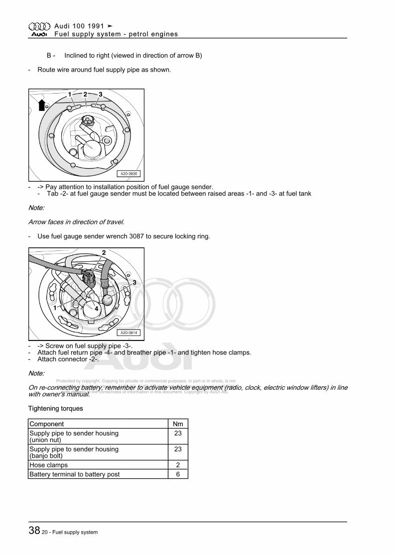
B - Inclined to right (viewed in direction of arrow B)
- Route wire around fuel supply pipe as shown.
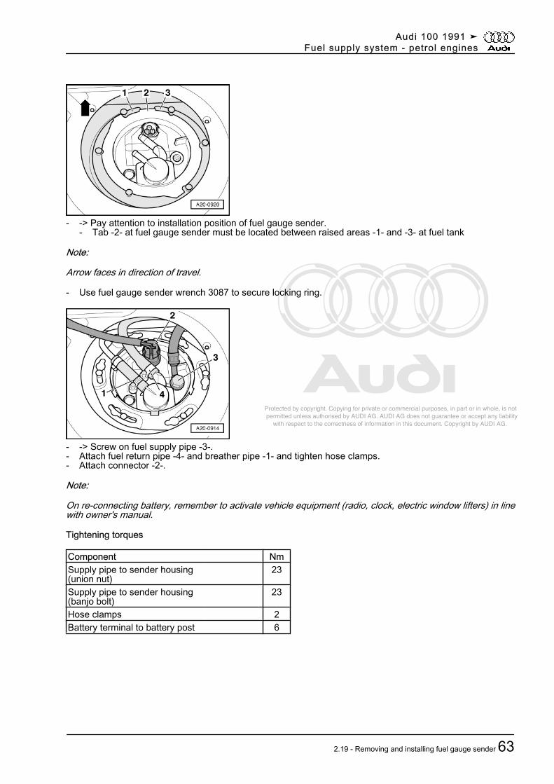
- -> Pay attention to installation position of fuel gauge sender.- Tab -2- at fuel gauge sender must be located between raised areas -1- and -3- at fuel tank
Note:
Arrow faces in direction of travel.
- Use fuel gauge sender wrench 3087 to secure locking ring.
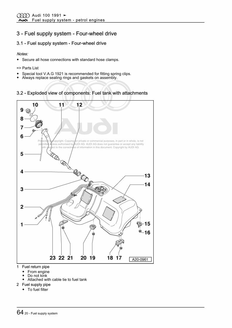
- -> Screw on fuel supply pipe -3-.- Attach fuel return pipe -4- and breather pipe -1- and tighten hose clamps.- Attach connector -2-.
Note:
On re-connecting battery, remember to activate vehicle equipment (radio, clock, electric window lifters) in linewith owner's manual.
Tightening torques
Component NmSupply pipe to sender housing(union nut)
23
Supply pipe to sender housing(banjo bolt)
23
Hose clamps 2Battery terminal to battery post 6
Audi 100 1991 ➤Fuel supply system - petrol engines
38 20 - Fuel supply system
Protected by copyright. Copying for private or commercial purposes, in part or in whole, is not permitted unless authorised by AUDI AG. AUDI AG does not guarantee or accept any liability with respect to the correctness of information in this document. Copyright by AUDI AG.
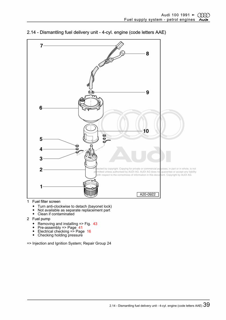
2.14 - Dismantling fuel delivery unit - 4-cyl. engine (code letters AAE)
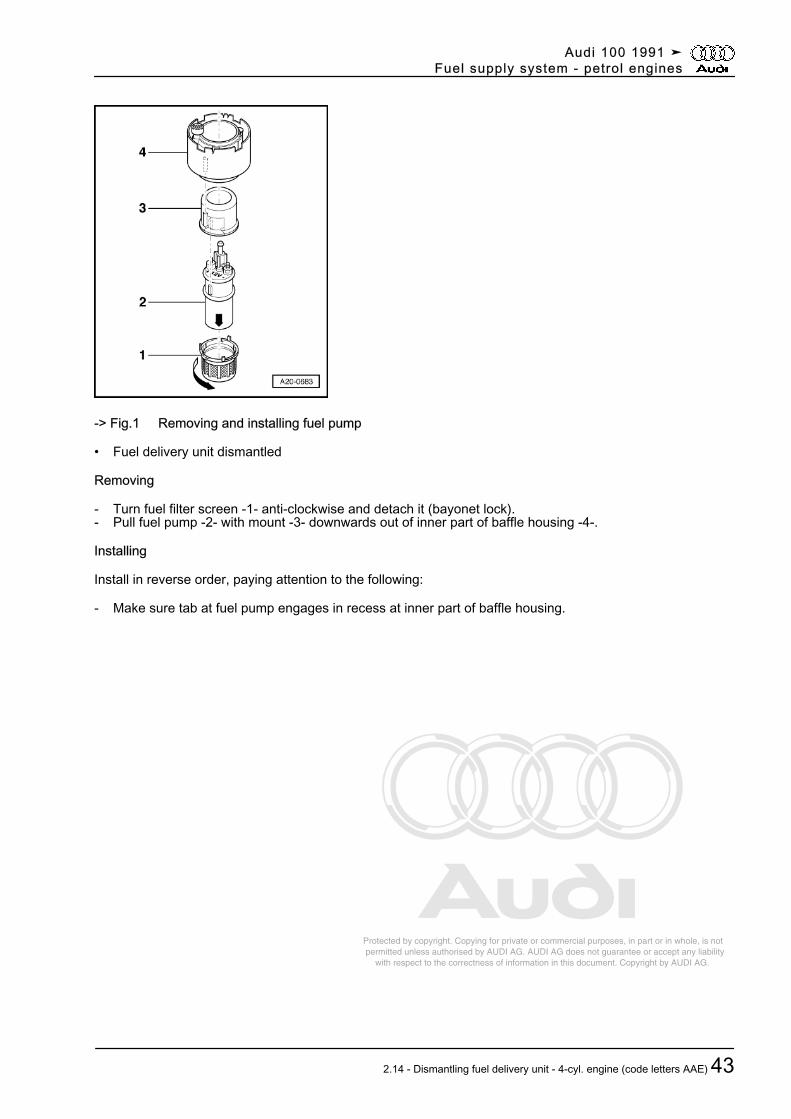
1 Fuel filter screen◆ Turn anti-clockwise to detach (bayonet lock)◆ Not available as separate replacement part◆ Clean if contaminated
2 Fuel pump◆ Removing and installing => Fig. 43◆ Pre-assembly => Page 41◆ Electrical checking => Page 16◆ Checking holding pressure
=> Injection and Ignition System; Repair Group 24
Audi 100 1991 ➤Fuel supply system - petrol engines
2.14 - Dismantling fuel delivery unit - 4-cyl. engine (code letters AAE) 39
Protected by copyright. Copying for private or commercial purposes, in part or in whole, is not permitted unless authorised by AUDI AG. AUDI AG does not guarantee or accept any liability with respect to the correctness of information in this document. Copyright by AUDI AG.
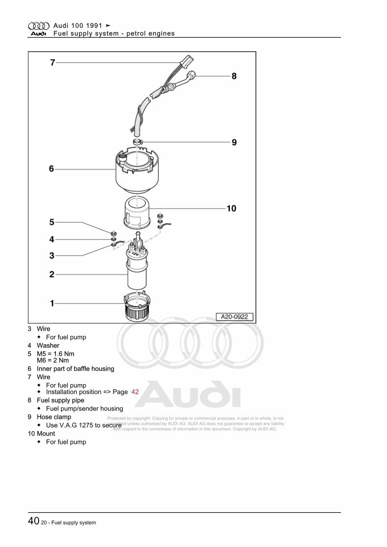
3 Wire◆ For fuel pump
4 Washer5 M5 = 1.6 Nm
M6 = 2 Nm6 Inner part of baffle housing7 Wire
◆ For fuel pump◆ Installation position => Page 42
8 Fuel supply pipe◆ Fuel pump/sender housing
9 Hose clamp◆ Use V.A.G 1275 to secure
10 Mount◆ For fuel pump
Audi 100 1991 ➤Fuel supply system - petrol engines
40 20 - Fuel supply system
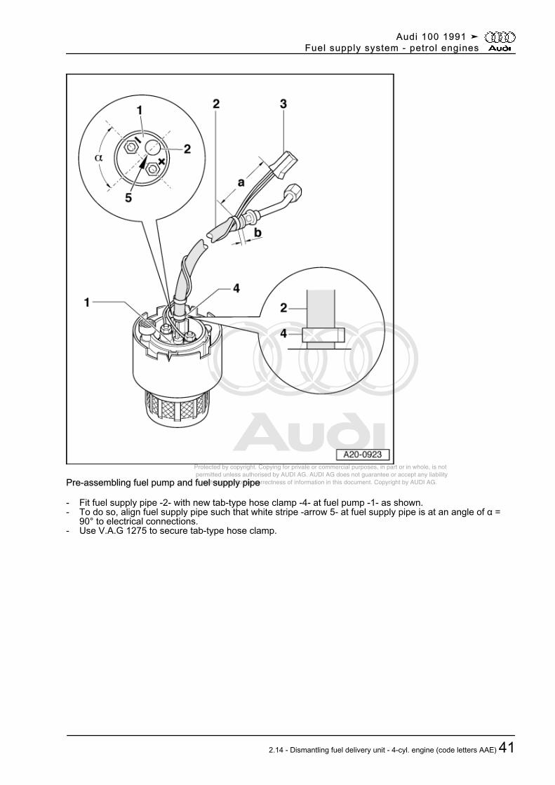
Protected by copyright. Copying for private or commercial purposes, in part or in whole, is not permitted unless authorised by AUDI AG. AUDI AG does not guarantee or accept any liability with respect to the correctness of information in this document. Copyright by AUDI AG.Pre-assembling fuel pump and fuel supply pipe
- Fit fuel supply pipe -2- with new tab-type hose clamp -4- at fuel pump -1- as shown.- To do so, align fuel supply pipe such that white stripe -arrow 5- at fuel supply pipe is at an angle of α =
90° to electrical connections.- Use V.A.G 1275 to secure tab-type hose clamp.
Audi 100 1991 ➤Fuel supply system - petrol engines
2.14 - Dismantling fuel delivery unit - 4-cyl. engine (code letters AAE) 41
Protected by copyright. Copying for private or commercial purposes, in part or in whole, is not permitted unless authorised by AUDI AG. AUDI AG does not guarantee or accept any liability with respect to the correctness of information in this document. Copyright by AUDI AG.
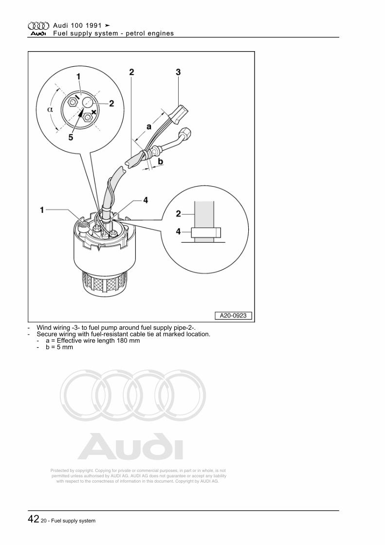
- Wind wiring -3- to fuel pump around fuel supply pipe-2-.- Secure wiring with fuel-resistant cable tie at marked location.
- a = Effective wire length 180 mm- b = 5 mm
Audi 100 1991 ➤Fuel supply system - petrol engines
42 20 - Fuel supply system
Protected by copyright. Copying for private or commercial purposes, in part or in whole, is not permitted unless authorised by AUDI AG. AUDI AG does not guarantee or accept any liability with respect to the correctness of information in this document. Copyright by AUDI AG.
-> Fig.1 Removing and installing fuel pump
• Fuel delivery unit dismantled
Removing
- Turn fuel filter screen -1- anti-clockwise and detach it (bayonet lock).- Pull fuel pump -2- with mount -3- downwards out of inner part of baffle housing -4-.
Installing
Install in reverse order, paying attention to the following:
- Make sure tab at fuel pump engages in recess at inner part of baffle housing.
Audi 100 1991 ➤Fuel supply system - petrol engines
2.14 - Dismantling fuel delivery unit - 4-cyl. engine (code letters AAE) 43
Protected by copyright. Copying for private or commercial purposes, in part or in whole, is not permitted unless authorised by AUDI AG. AUDI AG does not guarantee or accept any liability with respect to the correctness of information in this document. Copyright by AUDI AG.
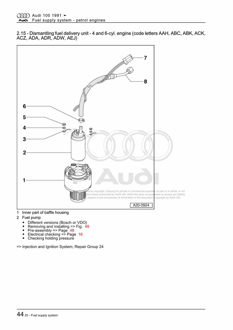
2.15 - Dismantling fuel delivery unit - 4 and 6-cyl. engine (code letters AAH, ABC, ABK, ACK,ACZ, ADA, ADR, ADW, AEJ)
1 Inner part of baffle housing2 Fuel pump
◆ Different versions (Bosch or VDO)◆ Removing and installing => Fig. 49◆ Pre-assembly => Page 48◆ Electrical checking => Page 16◆ Checking holding pressure
=> Injection and Ignition System; Repair Group 24
Audi 100 1991 ➤Fuel supply system - petrol engines
44 20 - Fuel supply system
Protected by copyright. Copying for private or commercial purposes, in part or in whole, is not permitted unless authorised by AUDI AG. AUDI AG does not guarantee or accept any liability with respect to the correctness of information in this document. Copyright by AUDI AG.
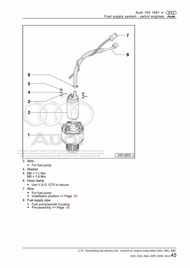
3 Wire◆ For fuel pump
4 Washer5 M4 = 1.1 Nm
M5 = 1.6 Nm6 Hose clamp
◆ Use V.A.G 1275 to secure7 Wire
◆ For fuel pump◆ Installation position => Page 49
8 Fuel supply pipe◆ Fuel pump/sender housing◆ Pre-assembly => Page 48
Audi 100 1991 ➤Fuel supply system - petrol engines
2.15 - Dismantling fuel delivery unit - 4 and 6-cyl. engine (code letters AAH, ABC, ABK,
ACK, ACZ, ADA, ADR, ADW, AEJ) 45
Protected by copyright. Copying for private or commercial purposes, in part or in whole, is not permitted unless authorised by AUDI AG. AUDI AG does not guarantee or accept any liability with respect to the correctness of information in this document. Copyright by AUDI AG.
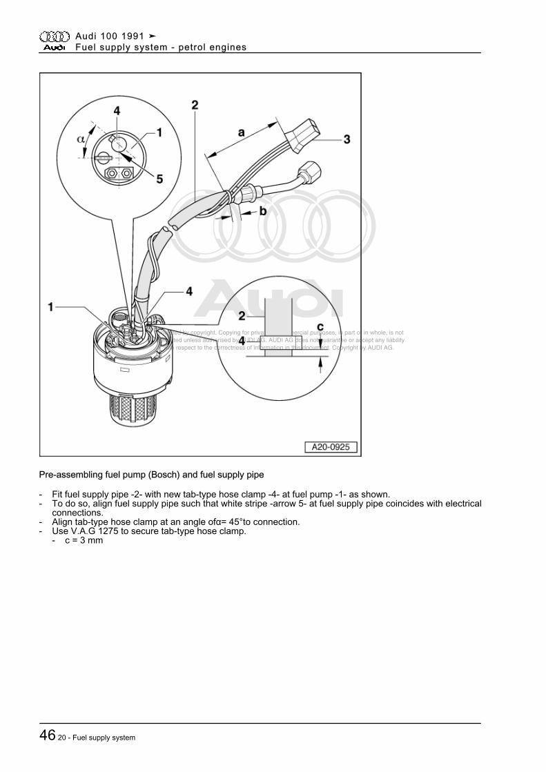
Pre-assembling fuel pump (Bosch) and fuel supply pipe
- Fit fuel supply pipe -2- with new tab-type hose clamp -4- at fuel pump -1- as shown.- To do so, align fuel supply pipe such that white stripe -arrow 5- at fuel supply pipe coincides with electrical
connections.- Align tab-type hose clamp at an angle ofα= 45°to connection.- Use V.A.G 1275 to secure tab-type hose clamp.
- c = 3 mm
Audi 100 1991 ➤Fuel supply system - petrol engines
46 20 - Fuel supply system
Protected by copyright. Copying for private or commercial purposes, in part or in whole, is not permitted unless authorised by AUDI AG. AUDI AG does not guarantee or accept any liability with respect to the correctness of information in this document. Copyright by AUDI AG.
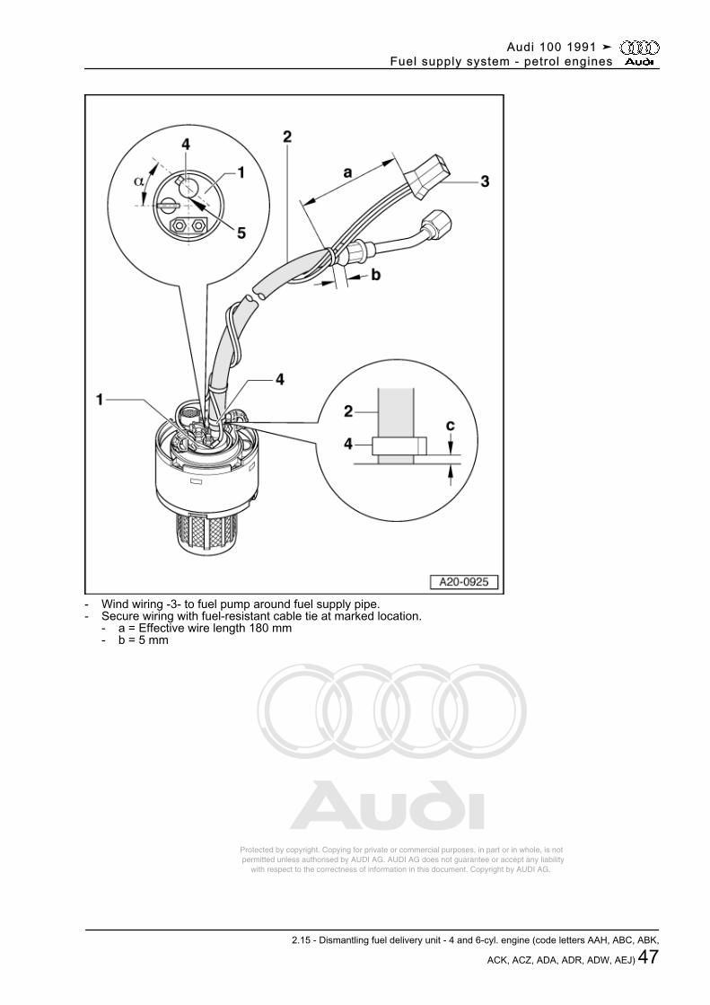
- Wind wiring -3- to fuel pump around fuel supply pipe.- Secure wiring with fuel-resistant cable tie at marked location.
- a = Effective wire length 180 mm- b = 5 mm
Audi 100 1991 ➤Fuel supply system - petrol engines
2.15 - Dismantling fuel delivery unit - 4 and 6-cyl. engine (code letters AAH, ABC, ABK,
ACK, ACZ, ADA, ADR, ADW, AEJ) 47
Protected by copyright. Copying for private or commercial purposes, in part or in whole, is not permitted unless authorised by AUDI AG. AUDI AG does not guarantee or accept any liability with respect to the correctness of information in this document. Copyright by AUDI AG.
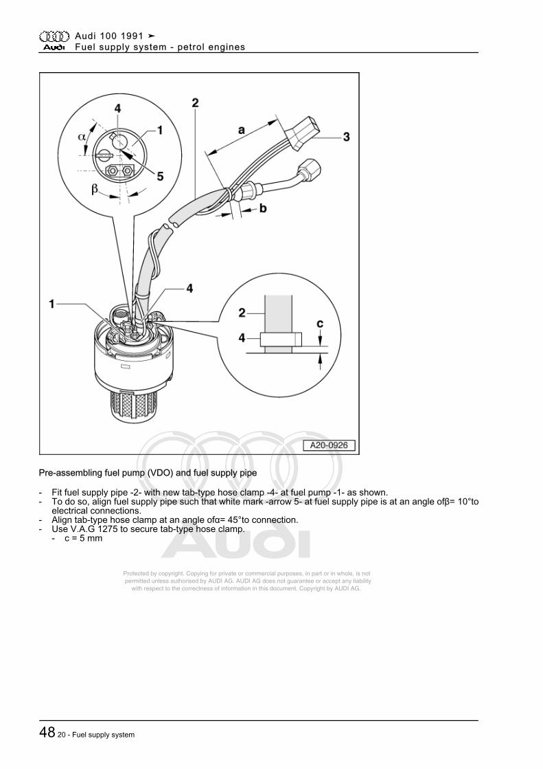
Pre-assembling fuel pump (VDO) and fuel supply pipe
- Fit fuel supply pipe -2- with new tab-type hose clamp -4- at fuel pump -1- as shown.- To do so, align fuel supply pipe such that white mark -arrow 5- at fuel supply pipe is at an angle ofβ= 10°to
electrical connections.- Align tab-type hose clamp at an angle ofα= 45°to connection.- Use V.A.G 1275 to secure tab-type hose clamp.
- c = 5 mm
Audi 100 1991 ➤Fuel supply system - petrol engines
48 20 - Fuel supply system
Protected by copyright. Copying for private or commercial purposes, in part or in whole, is not permitted unless authorised by AUDI AG. AUDI AG does not guarantee or accept any liability with respect to the correctness of information in this document. Copyright by AUDI AG.
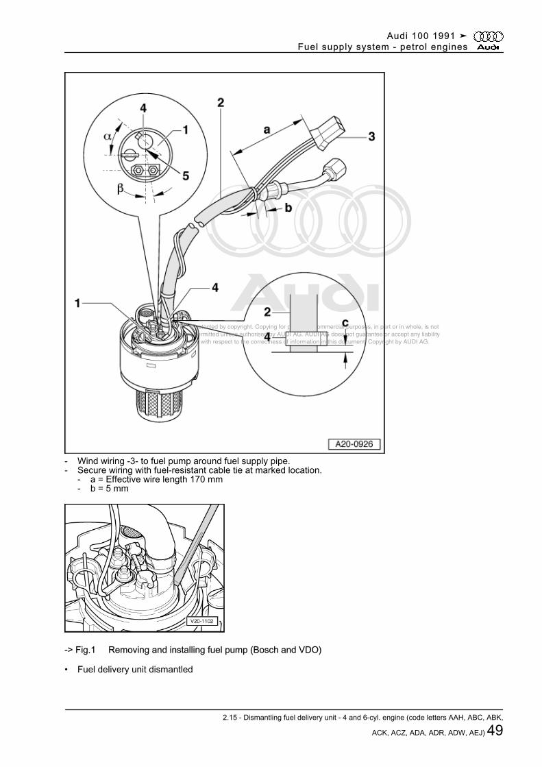
- Wind wiring -3- to fuel pump around fuel supply pipe.- Secure wiring with fuel-resistant cable tie at marked location.
- a = Effective wire length 170 mm- b = 5 mm
-> Fig.1 Removing and installing fuel pump (Bosch and VDO)
• Fuel delivery unit dismantled
Audi 100 1991 ➤Fuel supply system - petrol engines
2.15 - Dismantling fuel delivery unit - 4 and 6-cyl. engine (code letters AAH, ABC, ABK,
ACK, ACZ, ADA, ADR, ADW, AEJ) 49
Protected by copyright. Copying for private or commercial purposes, in part or in whole, is not permitted unless authorised by AUDI AG. AUDI AG does not guarantee or accept any liability with respect to the correctness of information in this document. Copyright by AUDI AG.
Removing- Use screwdriver to press both locking lugs at baffle housing outwards and at the same time pull fuel pump
slightly upwards to prevent re-engagement of locking lugs.- Repeat procedure at second shoulder of fuel pump.- Twist fuel pump and pull it upwards out of baffle housing.
InstallingInstall in reverse order, paying attention to the following:◆ Installation position: Offset connection at bottom of fuel pump must be inserted in hole in inner part of baffle
housing
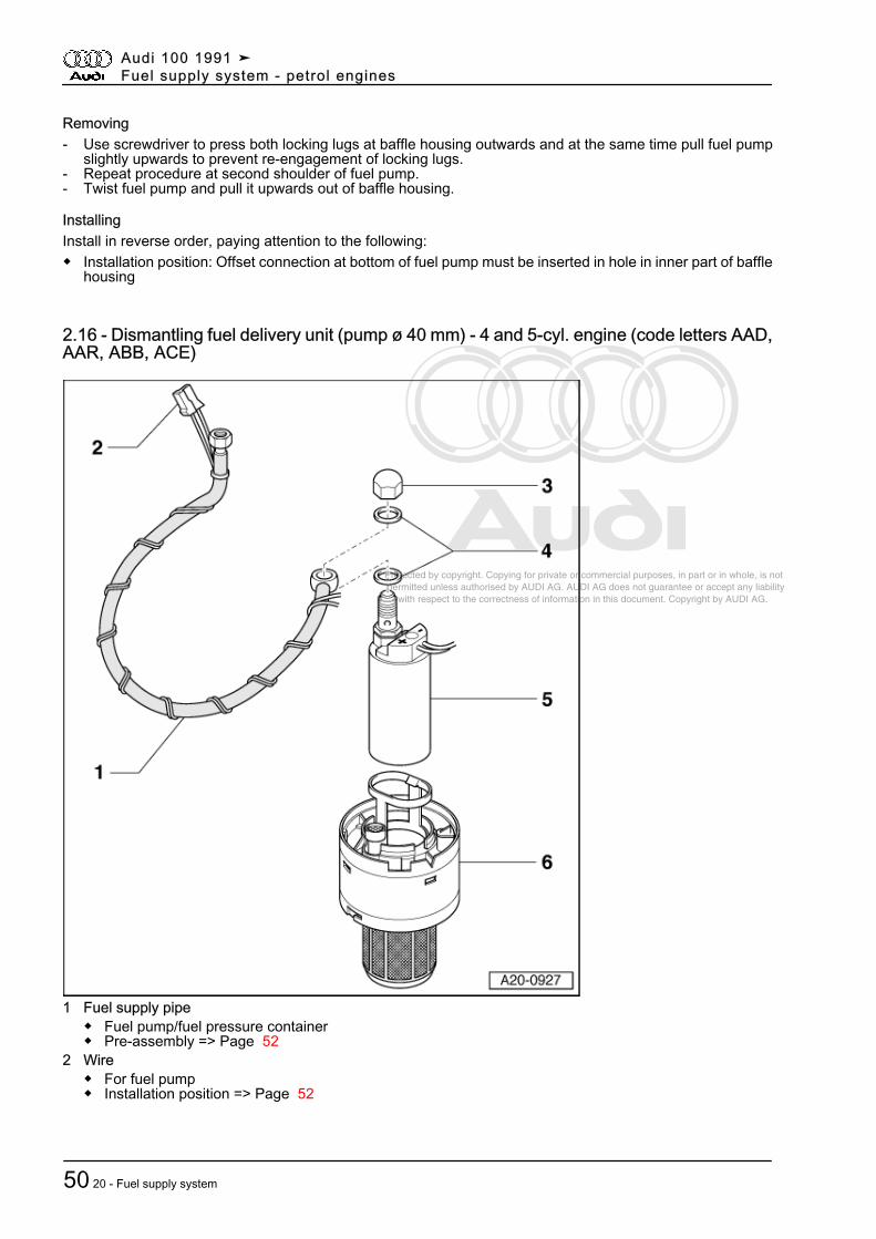
2.16 - Dismantling fuel delivery unit (pump ø 40 mm) - 4 and 5-cyl. engine (code letters AAD,AAR, ABB, ACE)
1 Fuel supply pipe◆ Fuel pump/fuel pressure container◆ Pre-assembly => Page 52
2 Wire◆ For fuel pump◆ Installation position => Page 52
Audi 100 1991 ➤Fuel supply system - petrol engines
50 20 - Fuel supply system
Protected by copyright. Copying for private or commercial purposes, in part or in whole, is not permitted unless authorised by AUDI AG. AUDI AG does not guarantee or accept any liability with respect to the correctness of information in this document. Copyright by AUDI AG.
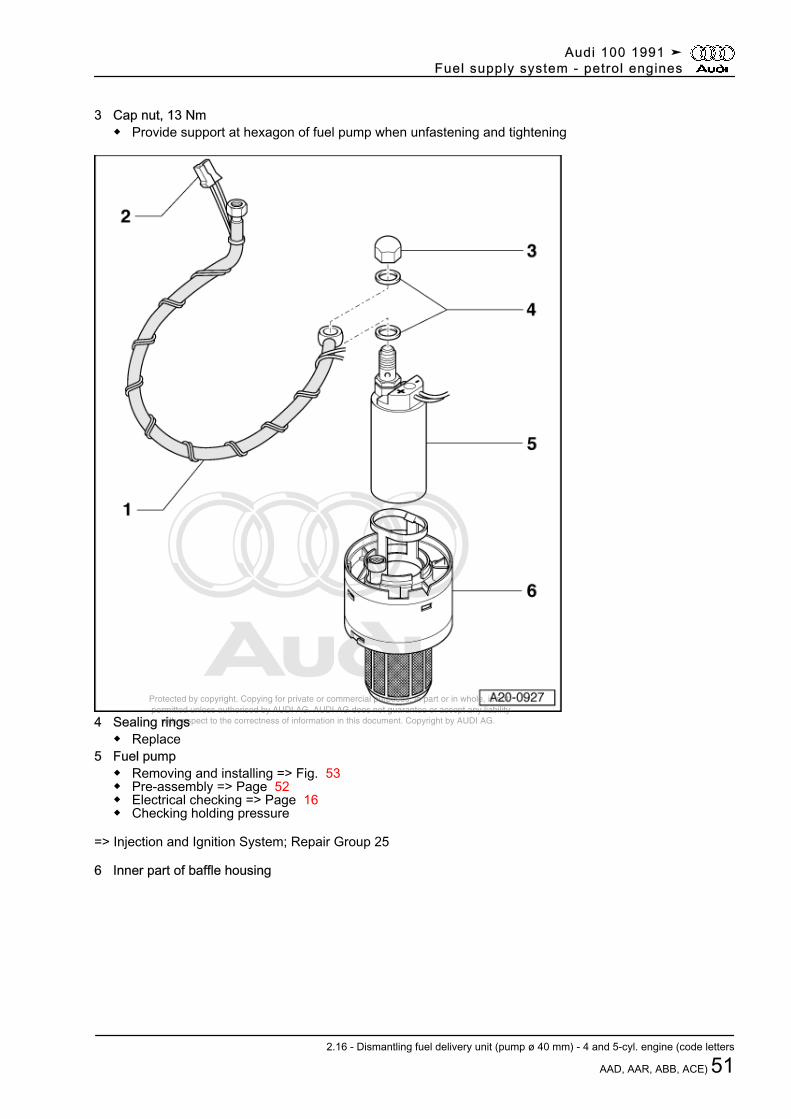
3 Cap nut, 13 Nm◆ Provide support at hexagon of fuel pump when unfastening and tightening
4 Sealing rings◆ Replace
5 Fuel pump◆ Removing and installing => Fig. 53◆ Pre-assembly => Page 52◆ Electrical checking => Page 16◆ Checking holding pressure
=> Injection and Ignition System; Repair Group 25
6 Inner part of baffle housing
Audi 100 1991 ➤Fuel supply system - petrol engines
2.16 - Dismantling fuel delivery unit (pump ø 40 mm) - 4 and 5-cyl. engine (code letters
AAD, AAR, ABB, ACE) 51
Protected by copyright. Copying for private or commercial purposes, in part or in whole, is not permitted unless authorised by AUDI AG. AUDI AG does not guarantee or accept any liability with respect to the correctness of information in this document. Copyright by AUDI AG.
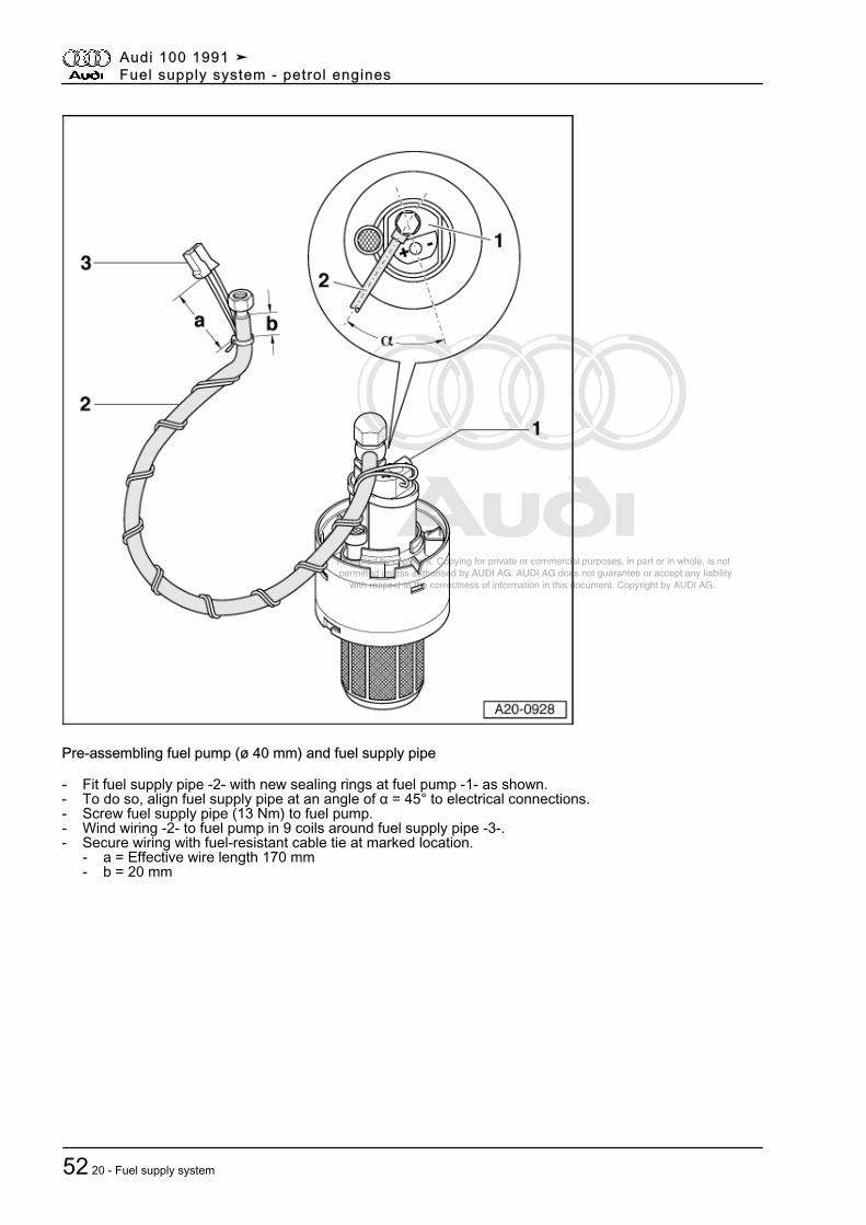
Pre-assembling fuel pump (ø 40 mm) and fuel supply pipe
- Fit fuel supply pipe -2- with new sealing rings at fuel pump -1- as shown.- To do so, align fuel supply pipe at an angle of α = 45° to electrical connections.- Screw fuel supply pipe (13 Nm) to fuel pump.- Wind wiring -2- to fuel pump in 9 coils around fuel supply pipe -3-.- Secure wiring with fuel-resistant cable tie at marked location.
- a = Effective wire length 170 mm- b = 20 mm
Audi 100 1991 ➤Fuel supply system - petrol engines
52 20 - Fuel supply system
Protected by copyright. Copying for private or commercial purposes, in part or in whole, is not permitted unless authorised by AUDI AG. AUDI AG does not guarantee or accept any liability with respect to the correctness of information in this document. Copyright by AUDI AG.
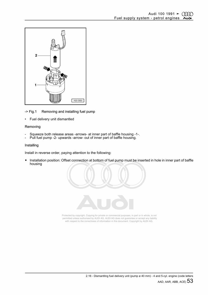
-> Fig.1 Removing and installing fuel pump
• Fuel delivery unit dismantled
Removing
- Squeeze both release areas -arrows- at inner part of baffle housing -1-.- Pull fuel pump -2- upwards -arrow- out of inner part of baffle housing.
Installing
Install in reverse order, paying attention to the following:
◆ Installation position: Offset connection at bottom of fuel pump must be inserted in hole in inner part of bafflehousing
Audi 100 1991 ➤Fuel supply system - petrol engines
2.16 - Dismantling fuel delivery unit (pump ø 40 mm) - 4 and 5-cyl. engine (code letters
AAD, AAR, ABB, ACE) 53
Protected by copyright. Copying for private or commercial purposes, in part or in whole, is not permitted unless authorised by AUDI AG. AUDI AG does not guarantee or accept any liability with respect to the correctness of information in this document. Copyright by AUDI AG.
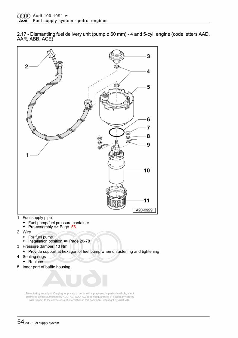
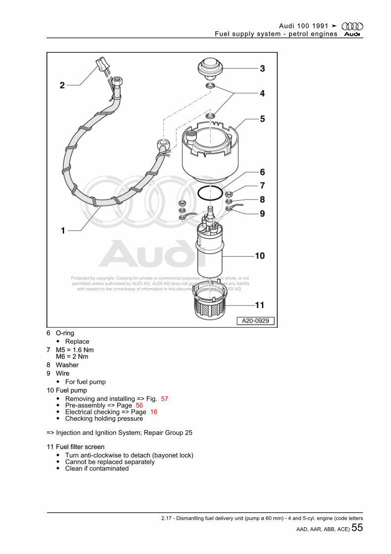
2.17 - Dismantling fuel delivery unit (pump ø 60 mm) - 4 and 5-cyl. engine (code letters AAD,AAR, ABB, ACE)
1 Fuel supply pipe◆ Fuel pump/fuel pressure container◆ Pre-assembly => Page 56
2 Wire◆ For fuel pump◆ Installation position => Page 20-78
3 Pressure damper, 13 Nm◆ Provide support at hexagon of fuel pump when unfastening and tightening
4 Sealing rings◆ Replace
5 Inner part of baffle housing
Audi 100 1991 ➤Fuel supply system - petrol engines
54 20 - Fuel supply system
Protected by copyright. Copying for private or commercial purposes, in part or in whole, is not permitted unless authorised by AUDI AG. AUDI AG does not guarantee or accept any liability with respect to the correctness of information in this document. Copyright by AUDI AG.
6 O-ring◆ Replace
7 M5 = 1.6 NmM6 = 2 Nm
8 Washer9 Wire
◆ For fuel pump10 Fuel pump
◆ Removing and installing => Fig. 57◆ Pre-assembly => Page 56◆ Electrical checking => Page 16◆ Checking holding pressure
=> Injection and Ignition System; Repair Group 25
11 Fuel filter screen◆ Turn anti-clockwise to detach (bayonet lock)◆ Cannot be replaced separately◆ Clean if contaminated
Audi 100 1991 ➤Fuel supply system - petrol engines
2.17 - Dismantling fuel delivery unit (pump ø 60 mm) - 4 and 5-cyl. engine (code letters
AAD, AAR, ABB, ACE) 55
Protected by copyright. Copying for private or commercial purposes, in part or in whole, is not permitted unless authorised by AUDI AG. AUDI AG does not guarantee or accept any liability with respect to the correctness of information in this document. Copyright by AUDI AG.
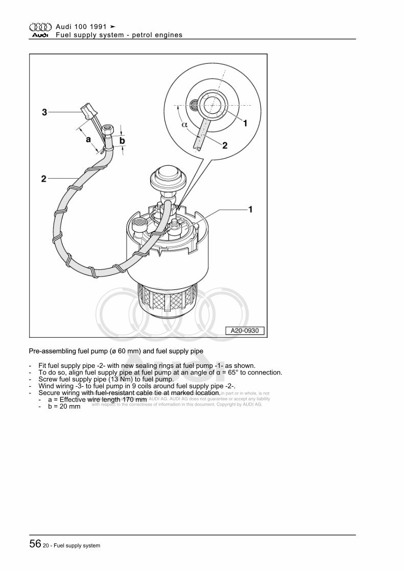
Pre-assembling fuel pump (ø 60 mm) and fuel supply pipe
- Fit fuel supply pipe -2- with new sealing rings at fuel pump -1- as shown.- To do so, align fuel supply pipe at fuel pump at an angle of α = 65° to connection.- Screw fuel supply pipe (13 Nm) to fuel pump.- Wind wiring -3- to fuel pump in 9 coils around fuel supply pipe -2-.- Secure wiring with fuel-resistant cable tie at marked location.
- a = Effective wire length 170 mm- b = 20 mm
Audi 100 1991 ➤Fuel supply system - petrol engines
56 20 - Fuel supply system
Protected by copyright. Copying for private or commercial purposes, in part or in whole, is not permitted unless authorised by AUDI AG. AUDI AG does not guarantee or accept any liability with respect to the correctness of information in this document. Copyright by AUDI AG.
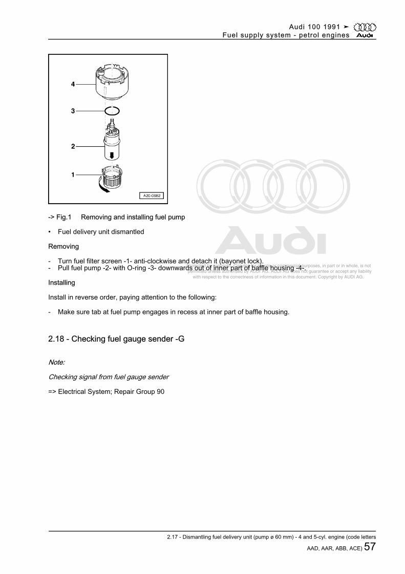
-> Fig.1 Removing and installing fuel pump
• Fuel delivery unit dismantled
Removing
- Turn fuel filter screen -1- anti-clockwise and detach it (bayonet lock).- Pull fuel pump -2- with O-ring -3- downwards out of inner part of baffle housing -4-.
Installing
Install in reverse order, paying attention to the following:
- Make sure tab at fuel pump engages in recess at inner part of baffle housing.
2.18 - Checking fuel gauge sender -G
Note:
Checking signal from fuel gauge sender
=> Electrical System; Repair Group 90
Audi 100 1991 ➤Fuel supply system - petrol engines
2.17 - Dismantling fuel delivery unit (pump ø 60 mm) - 4 and 5-cyl. engine (code letters
AAD, AAR, ABB, ACE) 57
Protected by copyright. Copying for private or commercial purposes, in part or in whole, is not permitted unless authorised by AUDI AG. AUDI AG does not guarantee or accept any liability with respect to the correctness of information in this document. Copyright by AUDI AG.
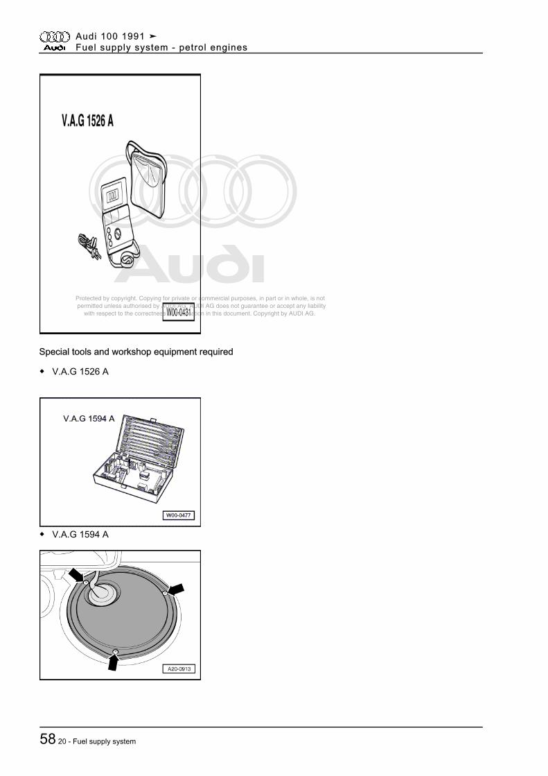
Special tools and workshop equipment required
◆ V.A.G 1526 A
◆ V.A.G 1594 A
Audi 100 1991 ➤Fuel supply system - petrol engines
58 20 - Fuel supply system
Protected by copyright. Copying for private or commercial purposes, in part or in whole, is not permitted unless authorised by AUDI AG. AUDI AG does not guarantee or accept any liability with respect to the correctness of information in this document. Copyright by AUDI AG.
Test sequence
- Remove luggage compartment lining.
Avant:
- Remove load compartment floor.- If necessary, fold forward right backrest of rear seat bench.
All models:
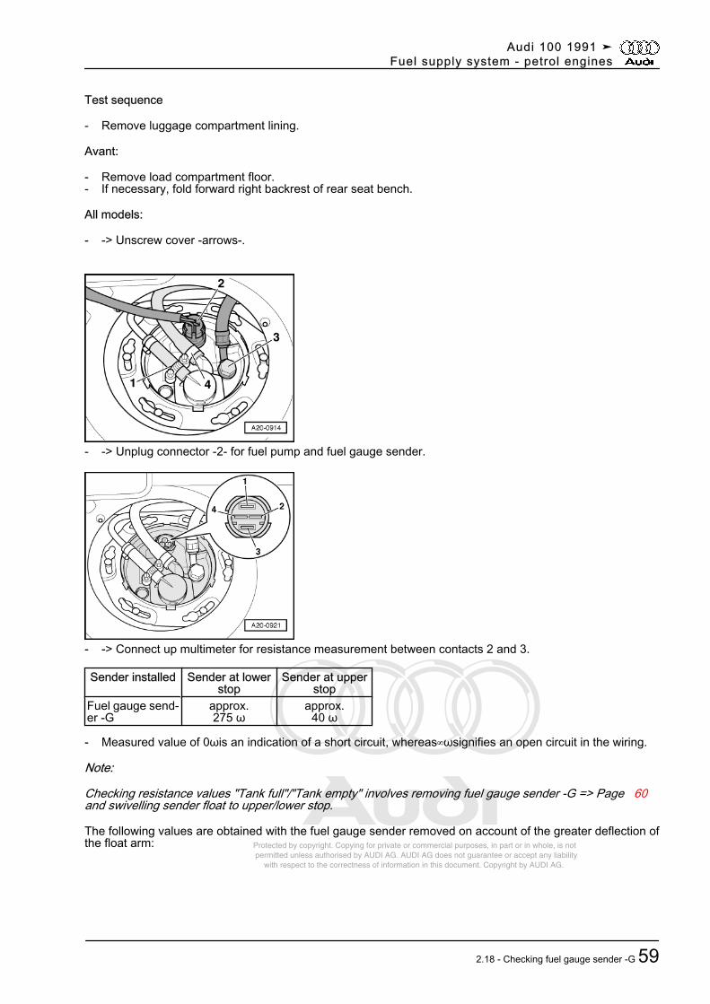
- -> Unscrew cover -arrows-.
- -> Unplug connector -2- for fuel pump and fuel gauge sender.
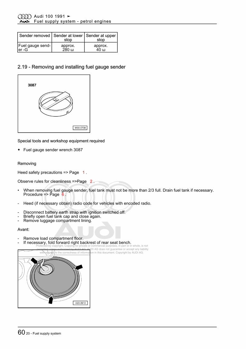
- -> Connect up multimeter for resistance measurement between contacts 2 and 3.
Sender installed Sender at lowerstop
Sender at upperstop
Fuel gauge send‐er -G
approx.275 ω
approx.40 ω
- Measured value of 0ωis an indication of a short circuit, whereas∞ωsignifies an open circuit in the wiring.
Note:
Checking resistance values "Tank full"/"Tank empty" involves removing fuel gauge sender -G => Page 60and swivelling sender float to upper/lower stop.
The following values are obtained with the fuel gauge sender removed on account of the greater deflection ofthe float arm:
Audi 100 1991 ➤Fuel supply system - petrol engines
2.18 - Checking fuel gauge sender -G 59
Protected by copyright. Copying for private or commercial purposes, in part or in whole, is not permitted unless authorised by AUDI AG. AUDI AG does not guarantee or accept any liability with respect to the correctness of information in this document. Copyright by AUDI AG.
Sender removed Sender at lowerstop
Sender at upperstop
Fuel gauge send‐er -G
approx.280 ω
approx.40 ω
2.19 - Removing and installing fuel gauge sender
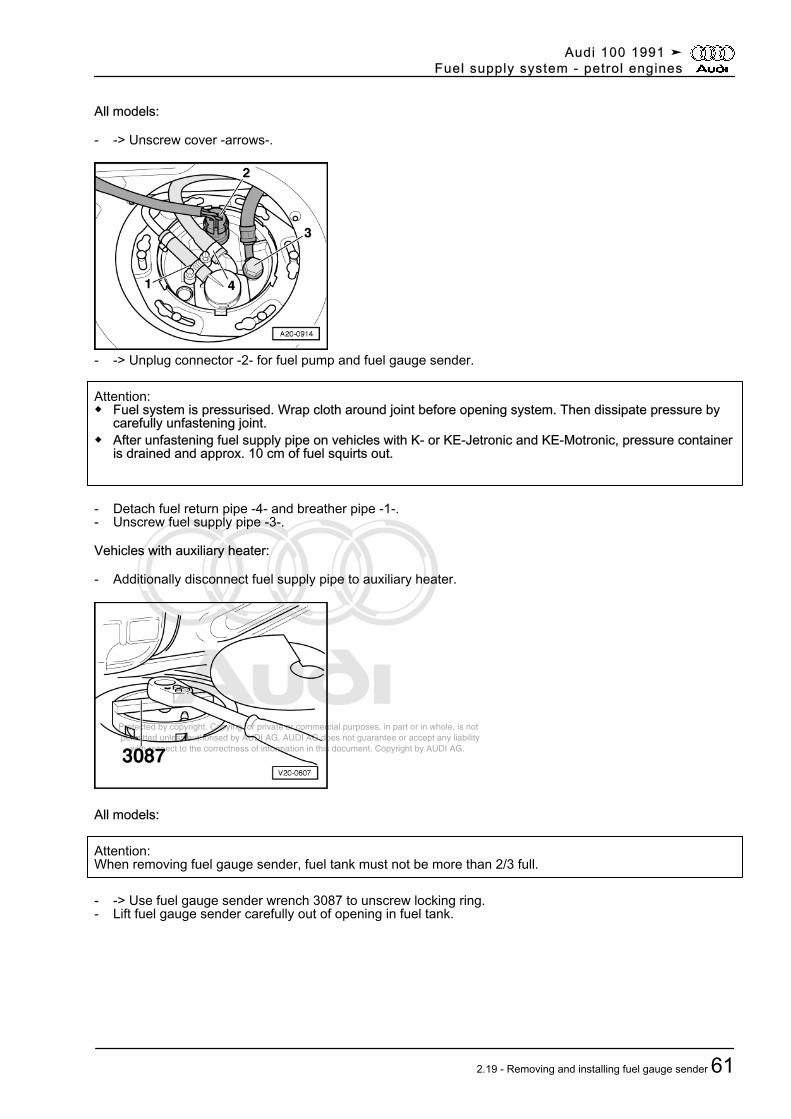
Special tools and workshop equipment required
◆ Fuel gauge sender wrench 3087
Removing
Heed safety precautions => Page 1 .
Observe rules for cleanliness =>Page 2 .
• When removing fuel gauge sender, fuel tank must not be more than 2/3 full. Drain fuel tank if necessary.Procedure => Page 6 .
- Heed (if necessary obtain) radio code for vehicles with encoded radio.
- Disconnect battery earth strap with ignition switched off.- Briefly open fuel tank cap and close again.- Remove luggage compartment lining.
Avant:
- Remove load compartment floor.- If necessary, fold forward right backrest of rear seat bench.
Audi 100 1991 ➤Fuel supply system - petrol engines
60 20 - Fuel supply system
Protected by copyright. Copying for private or commercial purposes, in part or in whole, is not permitted unless authorised by AUDI AG. AUDI AG does not guarantee or accept any liability with respect to the correctness of information in this document. Copyright by AUDI AG.
All models:
- -> Unscrew cover -arrows-.
- -> Unplug connector -2- for fuel pump and fuel gauge sender.
Attention:◆ Fuel system is pressurised. Wrap cloth around joint before opening system. Then dissipate pressure by
carefully unfastening joint.◆ After unfastening fuel supply pipe on vehicles with K- or KE-Jetronic and KE-Motronic, pressure container
is drained and approx. 10 cm of fuel squirts out.
- Detach fuel return pipe -4- and breather pipe -1-.- Unscrew fuel supply pipe -3-.
Vehicles with auxiliary heater:
- Additionally disconnect fuel supply pipe to auxiliary heater.
All models:
Attention:When removing fuel gauge sender, fuel tank must not be more than 2/3 full.
- -> Use fuel gauge sender wrench 3087 to unscrew locking ring.- Lift fuel gauge sender carefully out of opening in fuel tank.
Audi 100 1991 ➤Fuel supply system - petrol engines
2.19 - Removing and installing fuel gauge sender 61
Protected by copyright. Copying for private or commercial purposes, in part or in whole, is not permitted unless authorised by AUDI AG. AUDI AG does not guarantee or accept any liability with respect to the correctness of information in this document. Copyright by AUDI AG.
- -> Detach fuel return pipe -1- on inside of fuel gauge sender.- Unscrew fuel supply pipe -2-.- Unplug connector to fuel pump.
Vehicles with auxiliary heater:
- Additionally disconnect fuel supply pipe to auxiliary heater.
All models:
- Take fuel gauge sender carefully out of opening in fuel tank.
Installing
Install in reverse order, paying attention to the following:
- If fuel delivery unit has been dismantled or fuel pump removed, pre-assemble components as describedunder "Dismantling fuel delivery unit" for the various engine versions.
Note:
Secure all hose connections with standard hose clamps.
=> Parts List
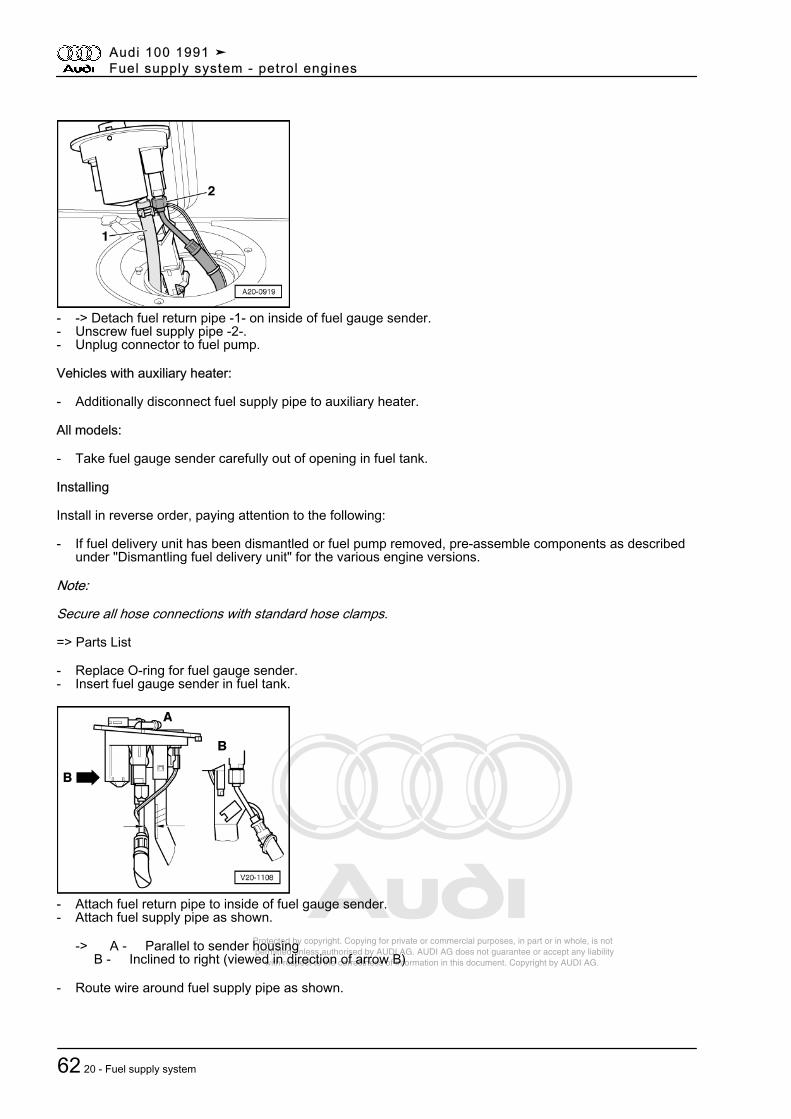
- Replace O-ring for fuel gauge sender.- Insert fuel gauge sender in fuel tank.
- Attach fuel return pipe to inside of fuel gauge sender.- Attach fuel supply pipe as shown.
-> A - Parallel to sender housing B - Inclined to right (viewed in direction of arrow B)
- Route wire around fuel supply pipe as shown.
Audi 100 1991 ➤Fuel supply system - petrol engines
62 20 - Fuel supply system
Protected by copyright. Copying for private or commercial purposes, in part or in whole, is not permitted unless authorised by AUDI AG. AUDI AG does not guarantee or accept any liability with respect to the correctness of information in this document. Copyright by AUDI AG.
- -> Pay attention to installation position of fuel gauge sender.- Tab -2- at fuel gauge sender must be located between raised areas -1- and -3- at fuel tank
Note:
Arrow faces in direction of travel.
- Use fuel gauge sender wrench 3087 to secure locking ring.
- -> Screw on fuel supply pipe -3-.- Attach fuel return pipe -4- and breather pipe -1- and tighten hose clamps.- Attach connector -2-.
Note:
On re-connecting battery, remember to activate vehicle equipment (radio, clock, electric window lifters) in linewith owner's manual.
Tightening torques
Component NmSupply pipe to sender housing(union nut)
23
Supply pipe to sender housing(banjo bolt)
23
Hose clamps 2Battery terminal to battery post 6
Audi 100 1991 ➤Fuel supply system - petrol engines
2.19 - Removing and installing fuel gauge sender 63
Protected by copyright. Copying for private or commercial purposes, in part or in whole, is not permitted unless authorised by AUDI AG. AUDI AG does not guarantee or accept any liability with respect to the correctness of information in this document. Copyright by AUDI AG.
3 - Fuel supply system - Four-wheel drive3.1 - Fuel supply system - Four-wheel drive
Notes:◆ Secure all hose connections with standard hose clamps.
=> Parts List◆ Special tool V.A.G 1921 is recommended for fitting spring clips.◆ Always replace sealing rings and gaskets on assembly.
3.2 - Exploded view of components: Fuel tank with attachments
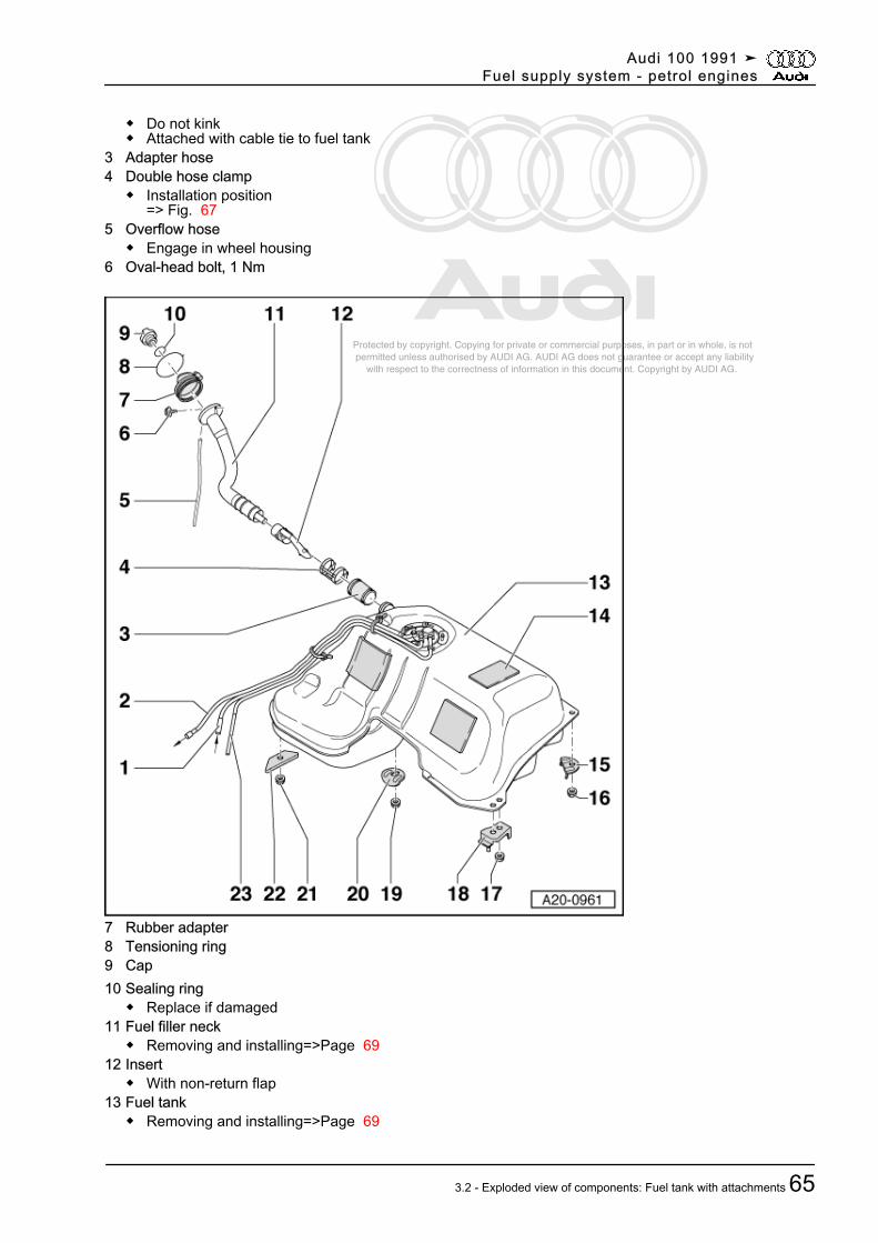
1 Fuel return pipe◆ From engine◆ Do not kink◆ Attached with cable tie to fuel tank
2 Fuel supply pipe◆ To fuel filter
Audi 100 1991 ➤Fuel supply system - petrol engines
64 20 - Fuel supply system
Protected by copyright. Copying for private or commercial purposes, in part or in whole, is not permitted unless authorised by AUDI AG. AUDI AG does not guarantee or accept any liability with respect to the correctness of information in this document. Copyright by AUDI AG.
◆ Do not kink◆ Attached with cable tie to fuel tank
3 Adapter hose4 Double hose clamp
◆ Installation position=> Fig. 67
5 Overflow hose◆ Engage in wheel housing
6 Oval-head bolt, 1 Nm
7 Rubber adapter8 Tensioning ring9 Cap10 Sealing ring
◆ Replace if damaged11 Fuel filler neck
◆ Removing and installing=>Page 6912 Insert
◆ With non-return flap13 Fuel tank
◆ Removing and installing=>Page 69
Audi 100 1991 ➤Fuel supply system - petrol engines
3.2 - Exploded view of components: Fuel tank with attachments 65
Protected by copyright. Copying for private or commercial purposes, in part or in whole, is not permitted unless authorised by AUDI AG. AUDI AG does not guarantee or accept any liability with respect to the correctness of information in this document. Copyright by AUDI AG.
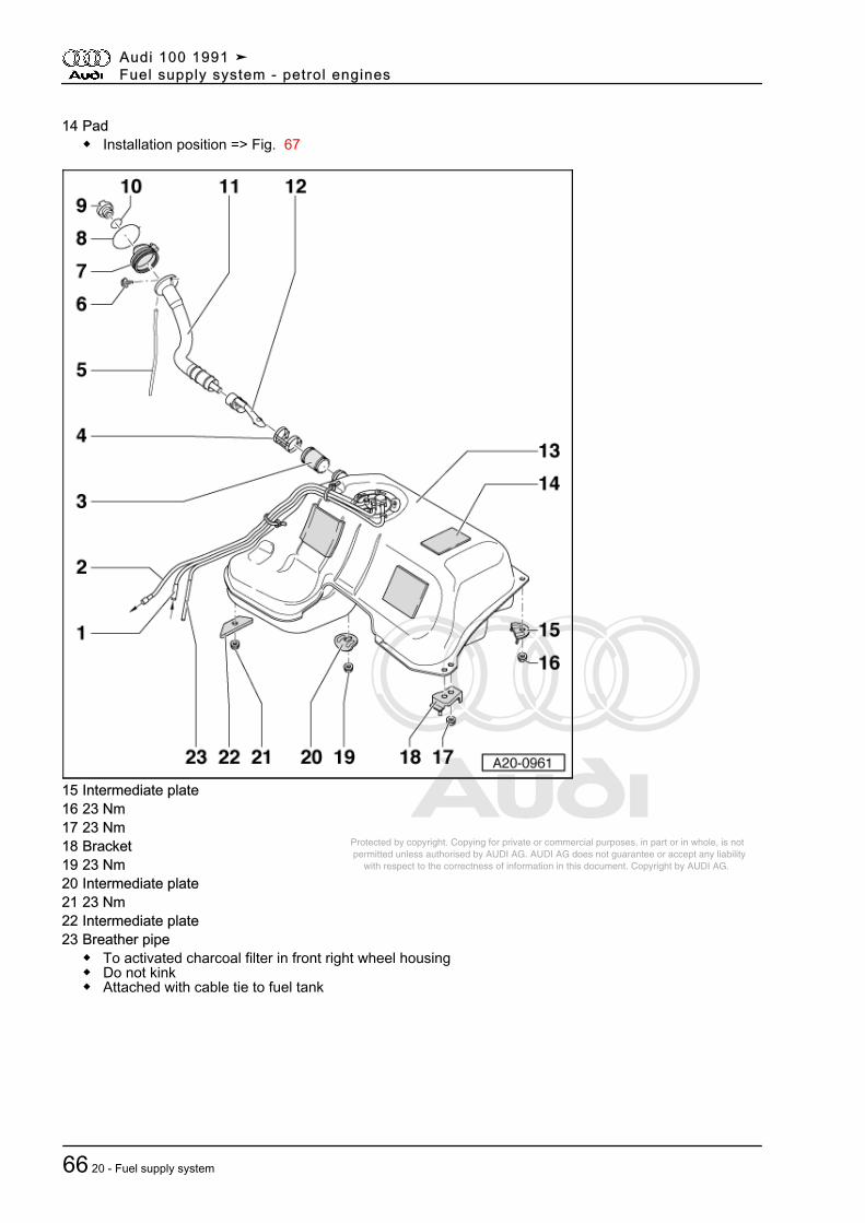
14 Pad◆ Installation position => Fig. 67
15 Intermediate plate16 23 Nm17 23 Nm18 Bracket19 23 Nm20 Intermediate plate21 23 Nm22 Intermediate plate23 Breather pipe
◆ To activated charcoal filter in front right wheel housing◆ Do not kink◆ Attached with cable tie to fuel tank
Audi 100 1991 ➤Fuel supply system - petrol engines
66 20 - Fuel supply system
Protected by copyright. Copying for private or commercial purposes, in part or in whole, is not permitted unless authorised by AUDI AG. AUDI AG does not guarantee or accept any liability with respect to the correctness of information in this document. Copyright by AUDI AG.
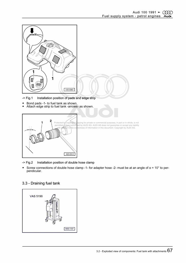
-> Fig.1 Installation position of pads and edge strip◆ Bond pads -1- to fuel tank as shown.◆ Attach edge strip to fuel tank -arrows- as shown.
-> Fig.2 Installation position of double hose clamp◆ Screw connections of double hose clamp -1- for adapter hose -2- must be at an angle of α = 10° to per‐
pendicular.
3.3 - Draining fuel tank
Audi 100 1991 ➤Fuel supply system - petrol engines
3.2 - Exploded view of components: Fuel tank with attachments 67
Protected by copyright. Copying for private or commercial purposes, in part or in whole, is not permitted unless authorised by AUDI AG. AUDI AG does not guarantee or accept any liability with respect to the correctness of information in this document. Copyright by AUDI AG.
Special tools and workshop equipment required
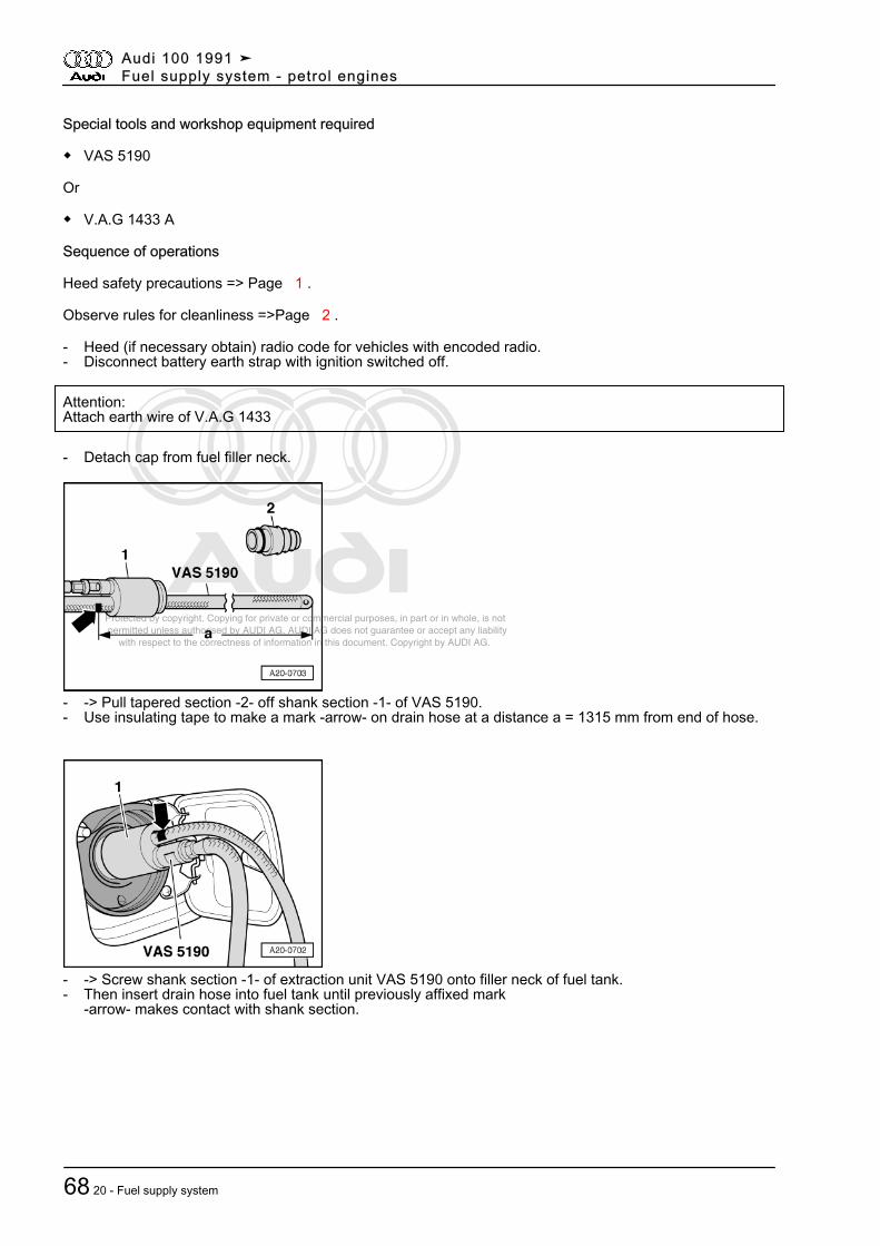
◆ VAS 5190
Or
◆ V.A.G 1433 A
Sequence of operations
Heed safety precautions => Page 1 .
Observe rules for cleanliness =>Page 2 .
- Heed (if necessary obtain) radio code for vehicles with encoded radio.- Disconnect battery earth strap with ignition switched off.
Attention:Attach earth wire of V.A.G 1433
- Detach cap from fuel filler neck.
- -> Pull tapered section -2- off shank section -1- of VAS 5190.- Use insulating tape to make a mark -arrow- on drain hose at a distance a = 1315 mm from end of hose.
- -> Screw shank section -1- of extraction unit VAS 5190 onto filler neck of fuel tank.- Then insert drain hose into fuel tank until previously affixed mark
-arrow- makes contact with shank section.
Audi 100 1991 ➤Fuel supply system - petrol engines
68 20 - Fuel supply system
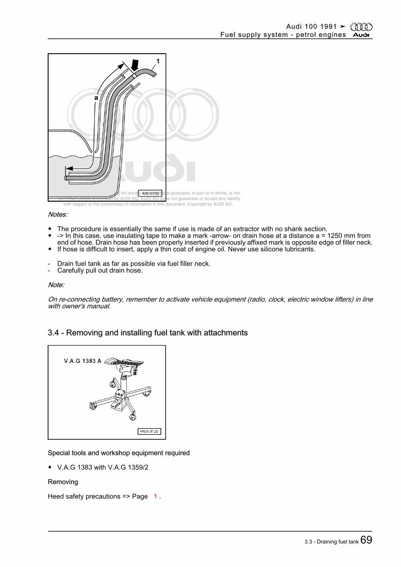
Protected by copyright. Copying for private or commercial purposes, in part or in whole, is not permitted unless authorised by AUDI AG. AUDI AG does not guarantee or accept any liability with respect to the correctness of information in this document. Copyright by AUDI AG.
Notes:
◆ The procedure is essentially the same if use is made of an extractor with no shank section.◆ -> In this case, use insulating tape to make a mark -arrow- on drain hose at a distance a = 1250 mm from
end of hose. Drain hose has been properly inserted if previously affixed mark is opposite edge of filler neck.◆ If hose is difficult to insert, apply a thin coat of engine oil. Never use silicone lubricants.
- Drain fuel tank as far as possible via fuel filler neck.- Carefully pull out drain hose.
Note:
On re-connecting battery, remember to activate vehicle equipment (radio, clock, electric window lifters) in linewith owner's manual.
3.4 - Removing and installing fuel tank with attachments
Special tools and workshop equipment required
◆ V.A.G 1383 with V.A.G 1359/2
Removing
Heed safety precautions => Page 1 .
Audi 100 1991 ➤Fuel supply system - petrol engines
3.3 - Draining fuel tank 69
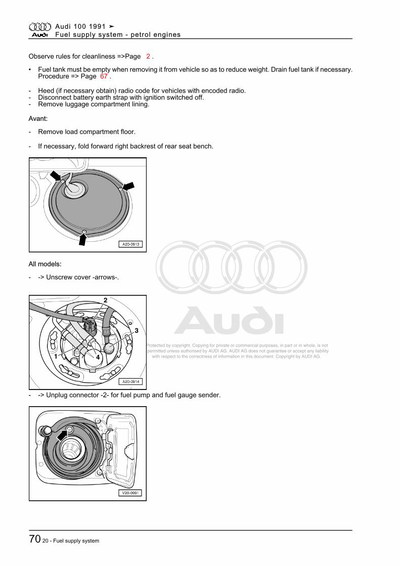
Protected by copyright. Copying for private or commercial purposes, in part or in whole, is not permitted unless authorised by AUDI AG. AUDI AG does not guarantee or accept any liability with respect to the correctness of information in this document. Copyright by AUDI AG.
Observe rules for cleanliness =>Page 2 .
• Fuel tank must be empty when removing it from vehicle so as to reduce weight. Drain fuel tank if necessary.Procedure => Page 67 .
- Heed (if necessary obtain) radio code for vehicles with encoded radio.- Disconnect battery earth strap with ignition switched off.- Remove luggage compartment lining.
Avant:
- Remove load compartment floor.
- If necessary, fold forward right backrest of rear seat bench.
All models:
- -> Unscrew cover -arrows-.
- -> Unplug connector -2- for fuel pump and fuel gauge sender.
Audi 100 1991 ➤Fuel supply system - petrol engines
70 20 - Fuel supply system
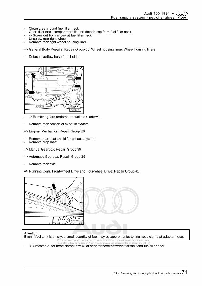
Protected by copyright. Copying for private or commercial purposes, in part or in whole, is not permitted unless authorised by AUDI AG. AUDI AG does not guarantee or accept any liability with respect to the correctness of information in this document. Copyright by AUDI AG.
- Clean area around fuel filler neck.- Open filler neck compartment lid and detach cap from fuel filler neck.- -> Screw out bolt -arrow- at fuel filler neck.- Unscrew rear right wheel.- Remove rear right wheel housing liner.
=> General Body Repairs; Repair Group 66; Wheel housing liners Wheel housing liners
- Detach overflow hose from holder.
- -> Remove guard underneath fuel tank -arrows-.
- Remove rear section of exhaust system.
=> Engine, Mechanics; Repair Group 26
- Remove rear heat shield for exhaust system.- Remove propshaft.
=> Manual Gearbox; Repair Group 39
=> Automatic Gearbox; Repair Group 39
- Remove rear axle.
=> Running Gear, Front-wheel Drive and Four-wheel Drive; Repair Group 42
Attention:Even if fuel tank is empty, a small quantity of fuel may escape on unfastening hose clamp at adapter hose.
- -> Unfasten outer hose clamp -arrow- at adapter hose betweenfuel tank and fuel filler neck.
Audi 100 1991 ➤Fuel supply system - petrol engines
3.4 - Removing and installing fuel tank with attachments 71
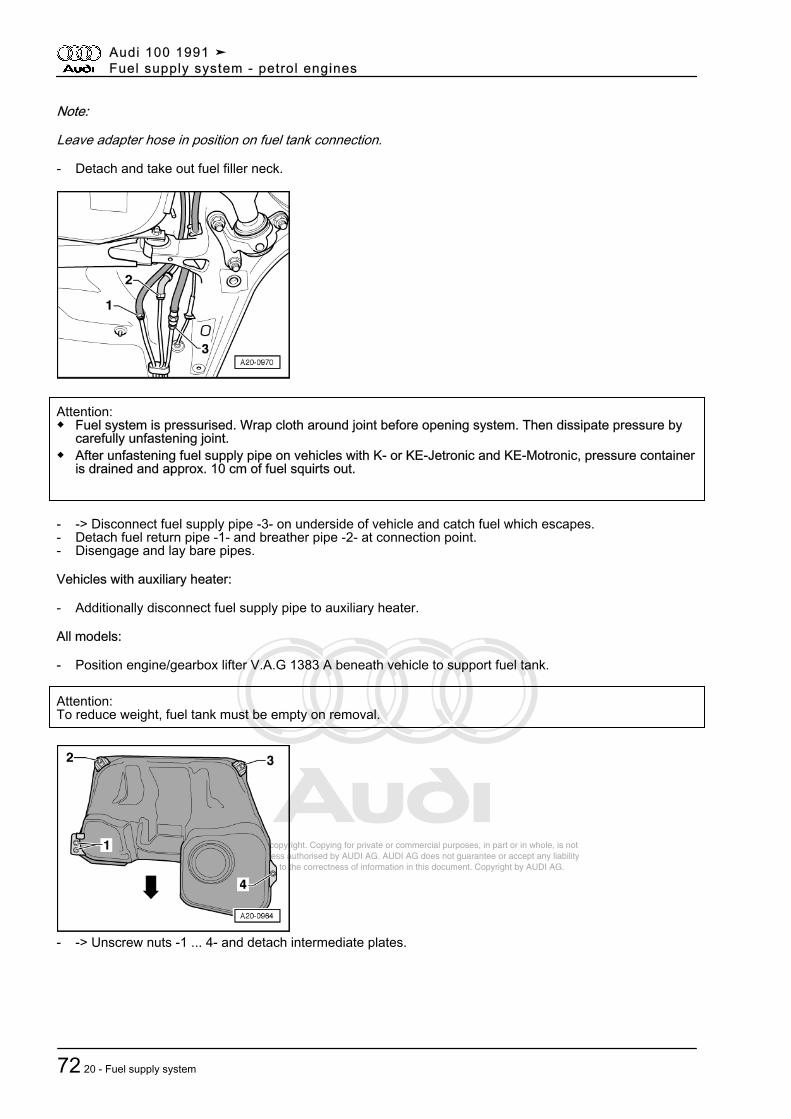
Protected by copyright. Copying for private or commercial purposes, in part or in whole, is not permitted unless authorised by AUDI AG. AUDI AG does not guarantee or accept any liability with respect to the correctness of information in this document. Copyright by AUDI AG.
Note:
Leave adapter hose in position on fuel tank connection.
- Detach and take out fuel filler neck.
Attention:◆ Fuel system is pressurised. Wrap cloth around joint before opening system. Then dissipate pressure by
carefully unfastening joint.◆ After unfastening fuel supply pipe on vehicles with K- or KE-Jetronic and KE-Motronic, pressure container
is drained and approx. 10 cm of fuel squirts out.
- -> Disconnect fuel supply pipe -3- on underside of vehicle and catch fuel which escapes.- Detach fuel return pipe -1- and breather pipe -2- at connection point.- Disengage and lay bare pipes.
Vehicles with auxiliary heater:
- Additionally disconnect fuel supply pipe to auxiliary heater.
All models:
- Position engine/gearbox lifter V.A.G 1383 A beneath vehicle to support fuel tank.
Attention:To reduce weight, fuel tank must be empty on removal.
- -> Unscrew nuts -1 ... 4- and detach intermediate plates.
Audi 100 1991 ➤Fuel supply system - petrol engines
72 20 - Fuel supply system
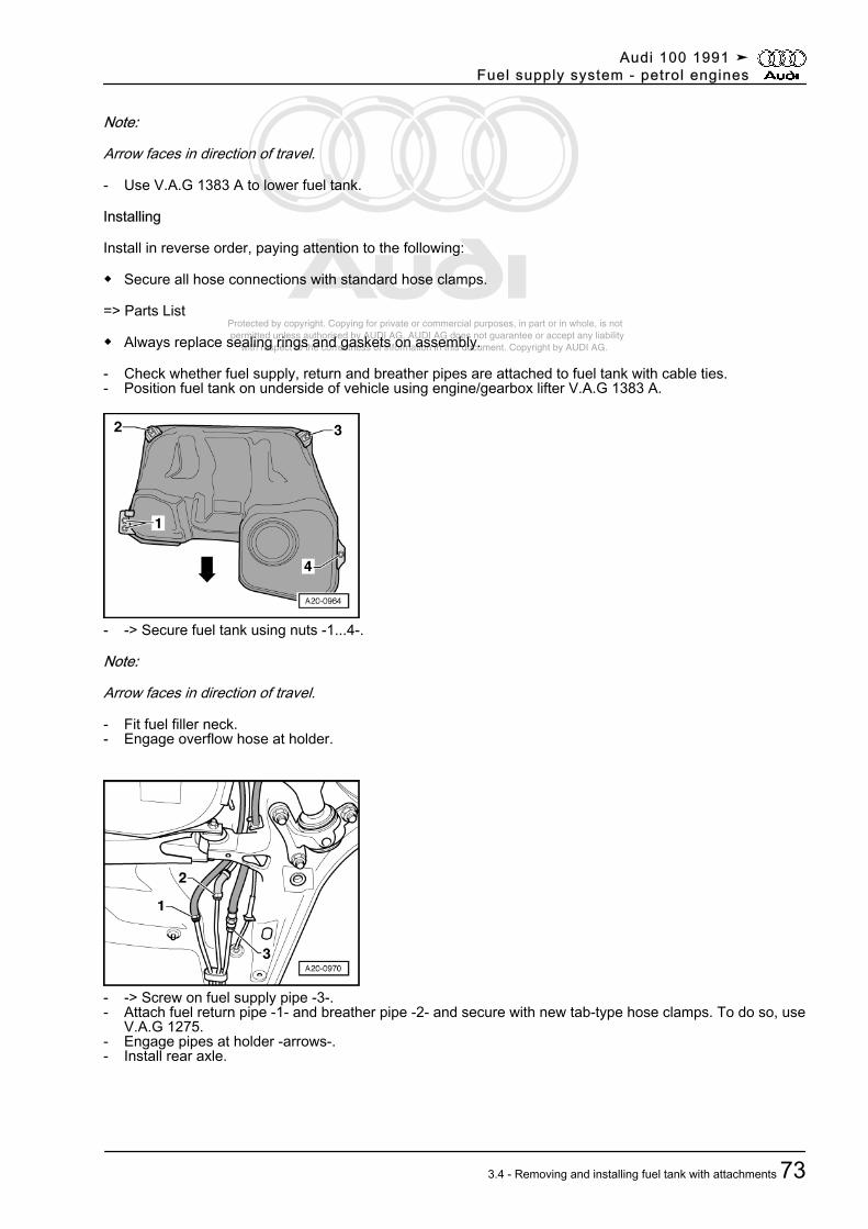
Protected by copyright. Copying for private or commercial purposes, in part or in whole, is not permitted unless authorised by AUDI AG. AUDI AG does not guarantee or accept any liability with respect to the correctness of information in this document. Copyright by AUDI AG.
Note:
Arrow faces in direction of travel.
- Use V.A.G 1383 A to lower fuel tank.
Installing
Install in reverse order, paying attention to the following:
◆ Secure all hose connections with standard hose clamps.
=> Parts List
◆ Always replace sealing rings and gaskets on assembly.
- Check whether fuel supply, return and breather pipes are attached to fuel tank with cable ties.- Position fuel tank on underside of vehicle using engine/gearbox lifter V.A.G 1383 A.
- -> Secure fuel tank using nuts -1...4-.
Note:
Arrow faces in direction of travel.
- Fit fuel filler neck.- Engage overflow hose at holder.
- -> Screw on fuel supply pipe -3-.- Attach fuel return pipe -1- and breather pipe -2- and secure with new tab-type hose clamps. To do so, use
V.A.G 1275.- Engage pipes at holder -arrows-.- Install rear axle.
Audi 100 1991 ➤Fuel supply system - petrol engines
3.4 - Removing and installing fuel tank with attachments 73
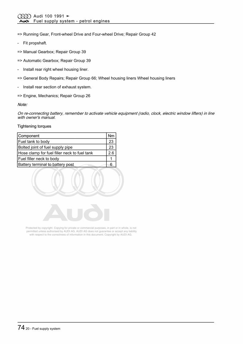
Protected by copyright. Copying for private or commercial purposes, in part or in whole, is not permitted unless authorised by AUDI AG. AUDI AG does not guarantee or accept any liability with respect to the correctness of information in this document. Copyright by AUDI AG.
=> Running Gear, Front-wheel Drive and Four-wheel Drive; Repair Group 42
- Fit propshaft.
=> Manual Gearbox; Repair Group 39
=> Automatic Gearbox; Repair Group 39
- Install rear right wheel housing liner.
=> General Body Repairs; Repair Group 66; Wheel housing liners Wheel housing liners
- Install rear section of exhaust system.
=> Engine, Mechanics; Repair Group 26
Note:
On re-connecting battery, remember to activate vehicle equipment (radio, clock, electric window lifters) in linewith owner's manual.
Tightening torques
Component NmFuel tank to body 23Bolted joint of fuel supply pipe 23Hose clamp for fuel filler neck to fuel tank 2.6Fuel filler neck to body 1Battery terminal to battery post 6
Audi 100 1991 ➤Fuel supply system - petrol engines
74 20 - Fuel supply system
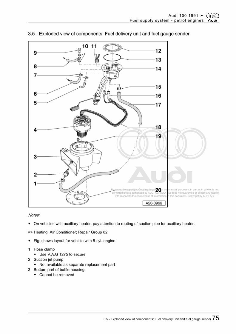
Protected by copyright. Copying for private or commercial purposes, in part or in whole, is not permitted unless authorised by AUDI AG. AUDI AG does not guarantee or accept any liability with respect to the correctness of information in this document. Copyright by AUDI AG.
3.5 - Exploded view of components: Fuel delivery unit and fuel gauge sender
Notes:
◆ On vehicles with auxiliary heater, pay attention to routing of suction pipe for auxiliary heater.
=> Heating, Air Conditioner; Repair Group 82
◆ Fig. shows layout for vehicle with 5-cyl. engine.
1 Hose clamp◆ Use V.A.G 1275 to secure
2 Suction jet pump◆ Not available as separate replacement part
3 Bottom part of baffle housing◆ Cannot be removed
Audi 100 1991 ➤Fuel supply system - petrol engines
3.5 - Exploded view of components: Fuel delivery unit and fuel gauge sender 75
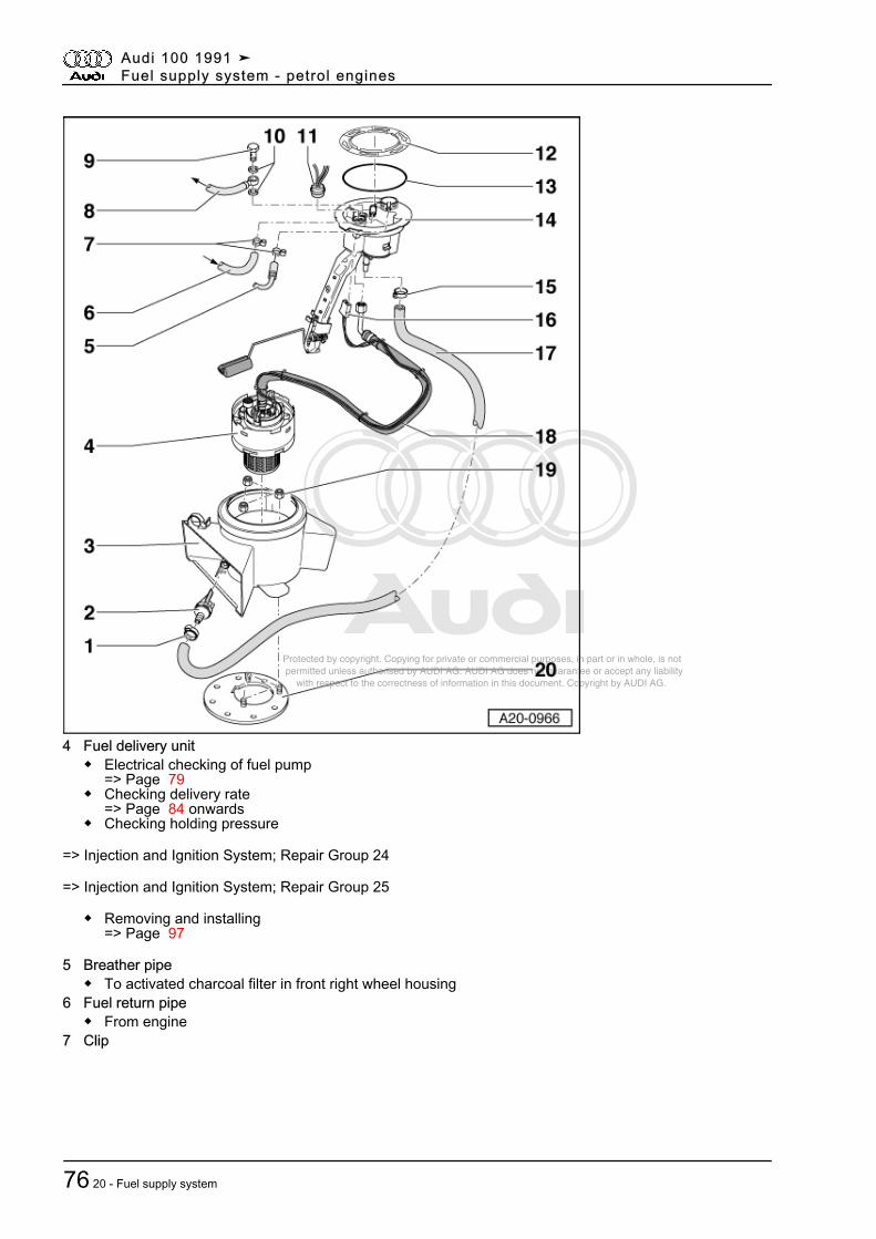
Protected by copyright. Copying for private or commercial purposes, in part or in whole, is not permitted unless authorised by AUDI AG. AUDI AG does not guarantee or accept any liability with respect to the correctness of information in this document. Copyright by AUDI AG.
4 Fuel delivery unit◆ Electrical checking of fuel pump
=> Page 79◆ Checking delivery rate
=> Page 84 onwards◆ Checking holding pressure
=> Injection and Ignition System; Repair Group 24
=> Injection and Ignition System; Repair Group 25
◆ Removing and installing=> Page 97
5 Breather pipe◆ To activated charcoal filter in front right wheel housing
6 Fuel return pipe◆ From engine
7 Clip
Audi 100 1991 ➤Fuel supply system - petrol engines
76 20 - Fuel supply system
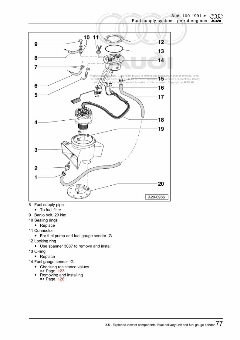
Protected by copyright. Copying for private or commercial purposes, in part or in whole, is not permitted unless authorised by AUDI AG. AUDI AG does not guarantee or accept any liability with respect to the correctness of information in this document. Copyright by AUDI AG.
8 Fuel supply pipe◆ To fuel filter
9 Banjo bolt, 23 Nm10 Sealing rings
◆ Replace11 Connector
◆ For fuel pump and fuel gauge sender -G12 Locking ring
◆ Use spanner 3087 to remove and install13 O-ring
◆ Replace14 Fuel gauge sender -G
◆ Checking resistance values=> Page 123
◆ Removing and installing=> Page 126
Audi 100 1991 ➤Fuel supply system - petrol engines
3.5 - Exploded view of components: Fuel delivery unit and fuel gauge sender 77
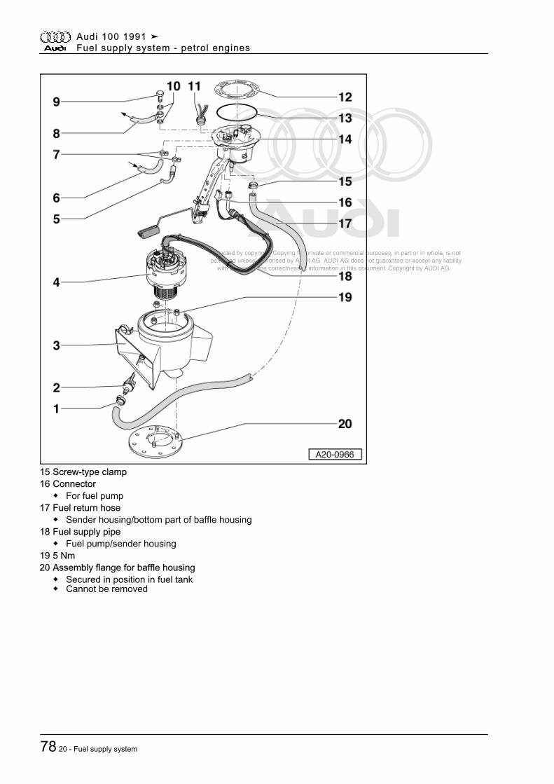
Protected by copyright. Copying for private or commercial purposes, in part or in whole, is not permitted unless authorised by AUDI AG. AUDI AG does not guarantee or accept any liability with respect to the correctness of information in this document. Copyright by AUDI AG.
15 Screw-type clamp16 Connector
◆ For fuel pump17 Fuel return hose
◆ Sender housing/bottom part of baffle housing18 Fuel supply pipe
◆ Fuel pump/sender housing19 5 Nm20 Assembly flange for baffle housing
◆ Secured in position in fuel tank◆ Cannot be removed
Audi 100 1991 ➤Fuel supply system - petrol engines
78 20 - Fuel supply system
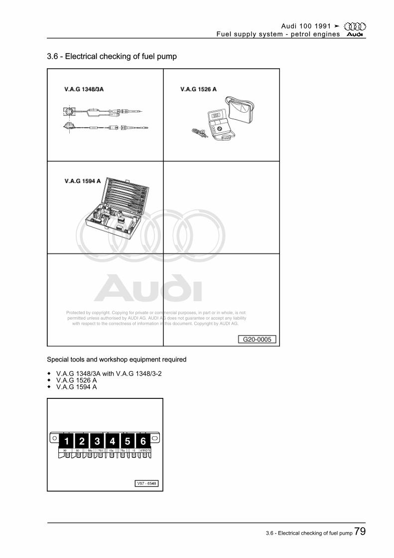
Protected by copyright. Copying for private or commercial purposes, in part or in whole, is not permitted unless authorised by AUDI AG. AUDI AG does not guarantee or accept any liability with respect to the correctness of information in this document. Copyright by AUDI AG.
3.6 - Electrical checking of fuel pump
Special tools and workshop equipment required
◆ V.A.G 1348/3A with V.A.G 1348/3-2◆ V.A.G 1526 A◆ V.A.G 1594 A
Audi 100 1991 ➤Fuel supply system - petrol engines
3.6 - Electrical checking of fuel pump 79
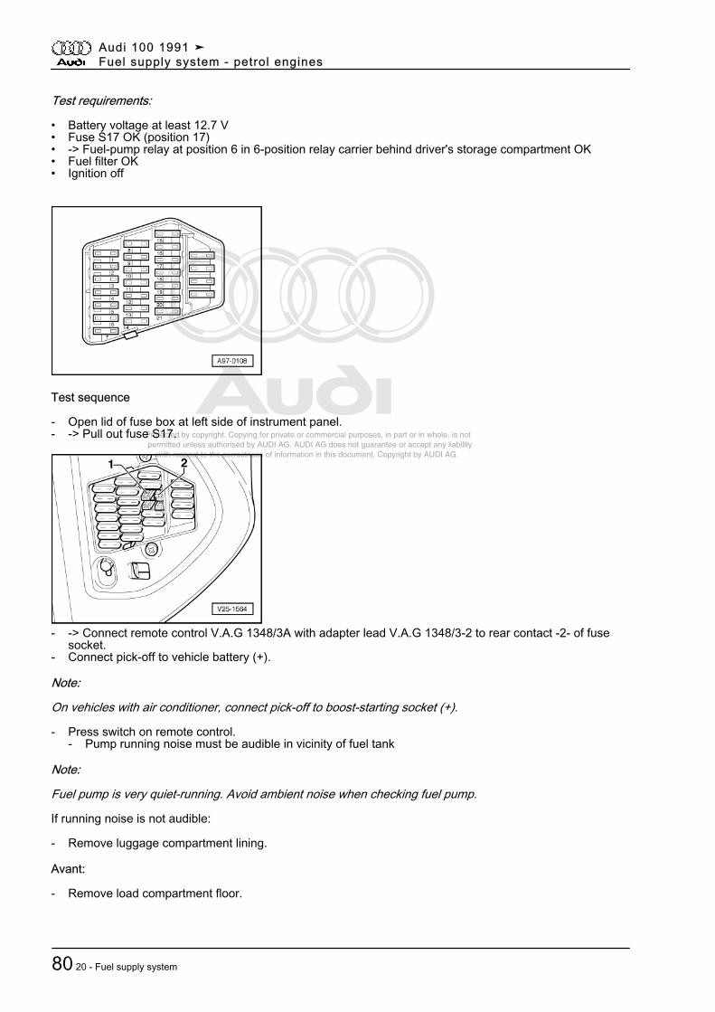
Protected by copyright. Copying for private or commercial purposes, in part or in whole, is not permitted unless authorised by AUDI AG. AUDI AG does not guarantee or accept any liability with respect to the correctness of information in this document. Copyright by AUDI AG.
Test requirements:
• Battery voltage at least 12.7 V• Fuse S17 OK (position 17)• -> Fuel-pump relay at position 6 in 6-position relay carrier behind driver's storage compartment OK• Fuel filter OK• Ignition off
Test sequence
- Open lid of fuse box at left side of instrument panel.- -> Pull out fuse S17.
- -> Connect remote control V.A.G 1348/3A with adapter lead V.A.G 1348/3-2 to rear contact -2- of fusesocket.
- Connect pick-off to vehicle battery (+).
Note:
On vehicles with air conditioner, connect pick-off to boost-starting socket (+).
- Press switch on remote control.- Pump running noise must be audible in vicinity of fuel tank
Note:
Fuel pump is very quiet-running. Avoid ambient noise when checking fuel pump.
If running noise is not audible:
- Remove luggage compartment lining.
Avant:
- Remove load compartment floor.
Audi 100 1991 ➤Fuel supply system - petrol engines
80 20 - Fuel supply system
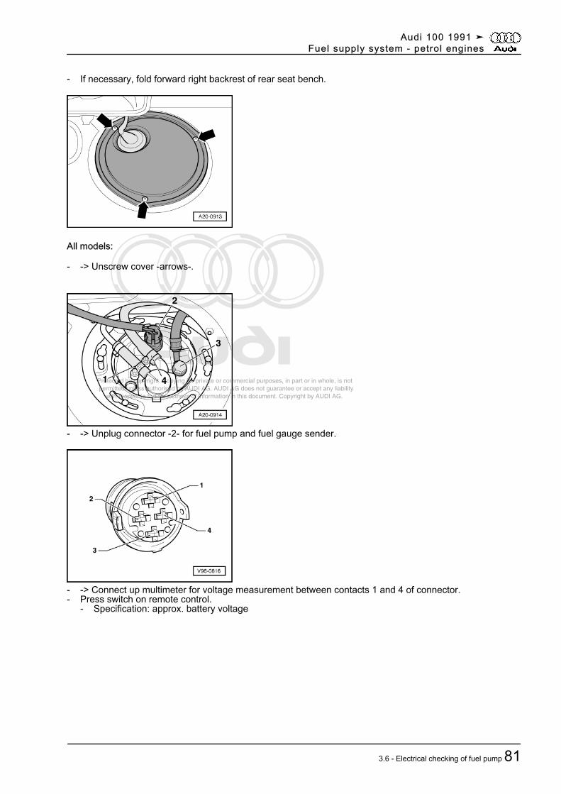
Protected by copyright. Copying for private or commercial purposes, in part or in whole, is not permitted unless authorised by AUDI AG. AUDI AG does not guarantee or accept any liability with respect to the correctness of information in this document. Copyright by AUDI AG.
- If necessary, fold forward right backrest of rear seat bench.
All models:
- -> Unscrew cover -arrows-.
- -> Unplug connector -2- for fuel pump and fuel gauge sender.
- -> Connect up multimeter for voltage measurement between contacts 1 and 4 of connector.- Press switch on remote control.
- Specification: approx. battery voltage
Audi 100 1991 ➤Fuel supply system - petrol engines
3.6 - Electrical checking of fuel pump 81
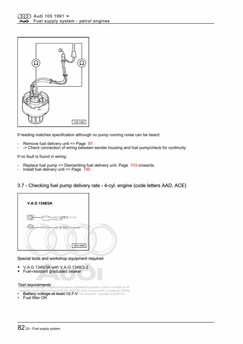
Protected by copyright. Copying for private or commercial purposes, in part or in whole, is not permitted unless authorised by AUDI AG. AUDI AG does not guarantee or accept any liability with respect to the correctness of information in this document. Copyright by AUDI AG.
If reading matches specification although no pump running noise can be heard:
- Remove fuel delivery unit => Page 97 .- -> Check connection of wiring between sender housing and fuel pump/check for continuity.
If no fault is found in wiring:
- Replace fuel pump => Dismantling fuel delivery unit, Page 103 onwards.- Install fuel delivery unit => Page 100 .
3.7 - Checking fuel pump delivery rate - 4-cyl. engine (code letters AAD, ACE)
Special tools and workshop equipment required
◆ V.A.G 1348/3A with V.A.G 1348/3-2◆ Fuel-resistant graduated beaker
Test requirements:
• Battery voltage at least 12.7 V• Fuel filter OK
Audi 100 1991 ➤Fuel supply system - petrol engines
82 20 - Fuel supply system
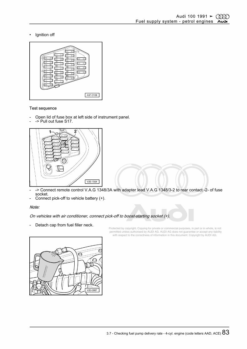
Protected by copyright. Copying for private or commercial purposes, in part or in whole, is not permitted unless authorised by AUDI AG. AUDI AG does not guarantee or accept any liability with respect to the correctness of information in this document. Copyright by AUDI AG.
• Ignition off
Test sequence
- Open lid of fuse box at left side of instrument panel.- -> Pull out fuse S17.
- -> Connect remote control V.A.G 1348/3A with adapter lead V.A.G 1348/3-2 to rear contact -2- of fusesocket.
- Connect pick-off to vehicle battery (+).
Note:
On vehicles with air conditioner, connect pick-off to boost-starting socket (+).
- Detach cap from fuel filler neck.
Audi 100 1991 ➤Fuel supply system - petrol engines
3.7 - Checking fuel pump delivery rate - 4-cyl. engine (code letters AAD, ACE) 83
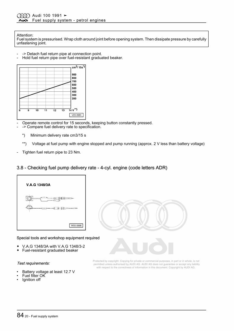
Protected by copyright. Copying for private or commercial purposes, in part or in whole, is not permitted unless authorised by AUDI AG. AUDI AG does not guarantee or accept any liability with respect to the correctness of information in this document. Copyright by AUDI AG.
Attention:Fuel system is pressurised. Wrap cloth around joint before opening system. Then dissipate pressure by carefullyunfastening joint.
- -> Detach fuel return pipe at connection point.- Hold fuel return pipe over fuel-resistant graduated beaker.
- Operate remote control for 15 seconds, keeping button constantly pressed.- -> Compare fuel delivery rate to specification.
*) Minimum delivery rate cm3/15 s
**) Voltage at fuel pump with engine stopped and pump running (approx. 2 V less than battery voltage)
- Tighten fuel return pipe to 23 Nm.
3.8 - Checking fuel pump delivery rate - 4-cyl. engine (code letters ADR)
Special tools and workshop equipment required
◆ V.A.G 1348/3A with V.A.G 1348/3-2◆ Fuel-resistant graduated beaker
Test requirements:
• Battery voltage at least 12.7 V• Fuel filter OK• Ignition off
Audi 100 1991 ➤Fuel supply system - petrol engines
84 20 - Fuel supply system
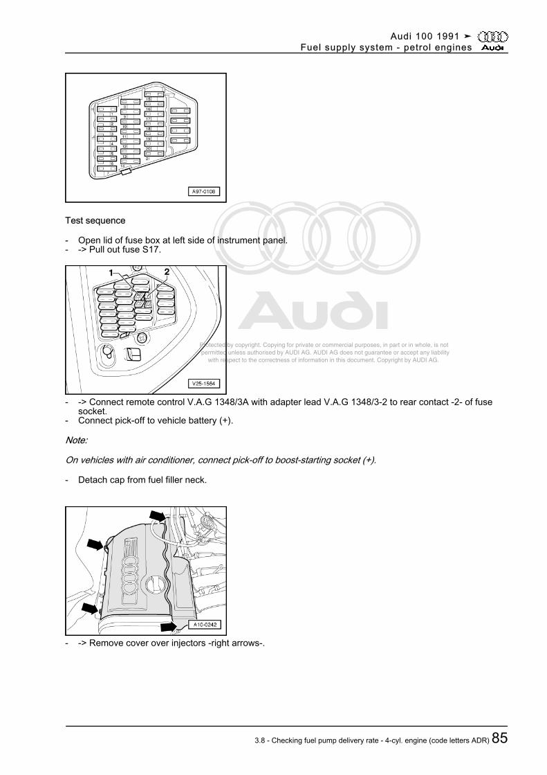
Protected by copyright. Copying for private or commercial purposes, in part or in whole, is not permitted unless authorised by AUDI AG. AUDI AG does not guarantee or accept any liability with respect to the correctness of information in this document. Copyright by AUDI AG.
Test sequence
- Open lid of fuse box at left side of instrument panel.- -> Pull out fuse S17.
- -> Connect remote control V.A.G 1348/3A with adapter lead V.A.G 1348/3-2 to rear contact -2- of fusesocket.
- Connect pick-off to vehicle battery (+).
Note:
On vehicles with air conditioner, connect pick-off to boost-starting socket (+).
- Detach cap from fuel filler neck.
- -> Remove cover over injectors -right arrows-.
Audi 100 1991 ➤Fuel supply system - petrol engines
3.8 - Checking fuel pump delivery rate - 4-cyl. engine (code letters ADR) 85
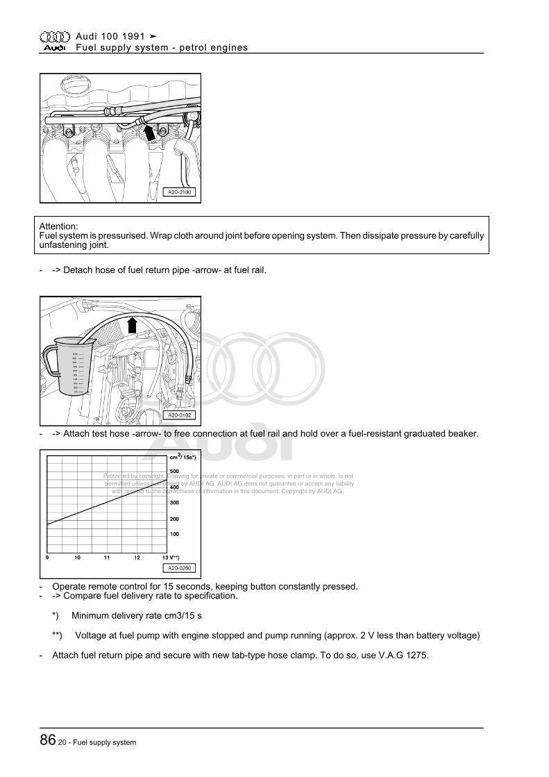
Protected by copyright. Copying for private or commercial purposes, in part or in whole, is not permitted unless authorised by AUDI AG. AUDI AG does not guarantee or accept any liability with respect to the correctness of information in this document. Copyright by AUDI AG.
Attention:Fuel system is pressurised. Wrap cloth around joint before opening system. Then dissipate pressure by carefullyunfastening joint.
- -> Detach hose of fuel return pipe -arrow- at fuel rail.
- -> Attach test hose -arrow- to free connection at fuel rail and hold over a fuel-resistant graduated beaker.
- Operate remote control for 15 seconds, keeping button constantly pressed.- -> Compare fuel delivery rate to specification.
*) Minimum delivery rate cm3/15 s
**) Voltage at fuel pump with engine stopped and pump running (approx. 2 V less than battery voltage)
- Attach fuel return pipe and secure with new tab-type hose clamp. To do so, use V.A.G 1275.
Audi 100 1991 ➤Fuel supply system - petrol engines
86 20 - Fuel supply system
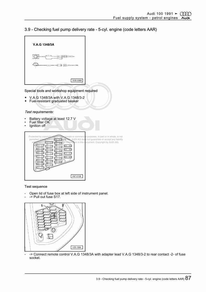
Protected by copyright. Copying for private or commercial purposes, in part or in whole, is not permitted unless authorised by AUDI AG. AUDI AG does not guarantee or accept any liability with respect to the correctness of information in this document. Copyright by AUDI AG.
3.9 - Checking fuel pump delivery rate - 5-cyl. engine (code letters AAR)
Special tools and workshop equipment required
◆ V.A.G 1348/3A with V.A.G 1348/3-2◆ Fuel-resistant graduated beaker
Test requirements:
• Battery voltage at least 12.7 V• Fuel filter OK• Ignition off
Test sequence
- Open lid of fuse box at left side of instrument panel.- -> Pull out fuse S17.
- -> Connect remote control V.A.G 1348/3A with adapter lead V.A.G 1348/3-2 to rear contact -2- of fusesocket.
Audi 100 1991 ➤Fuel supply system - petrol engines
3.9 - Checking fuel pump delivery rate - 5-cyl. engine (code letters AAR) 87
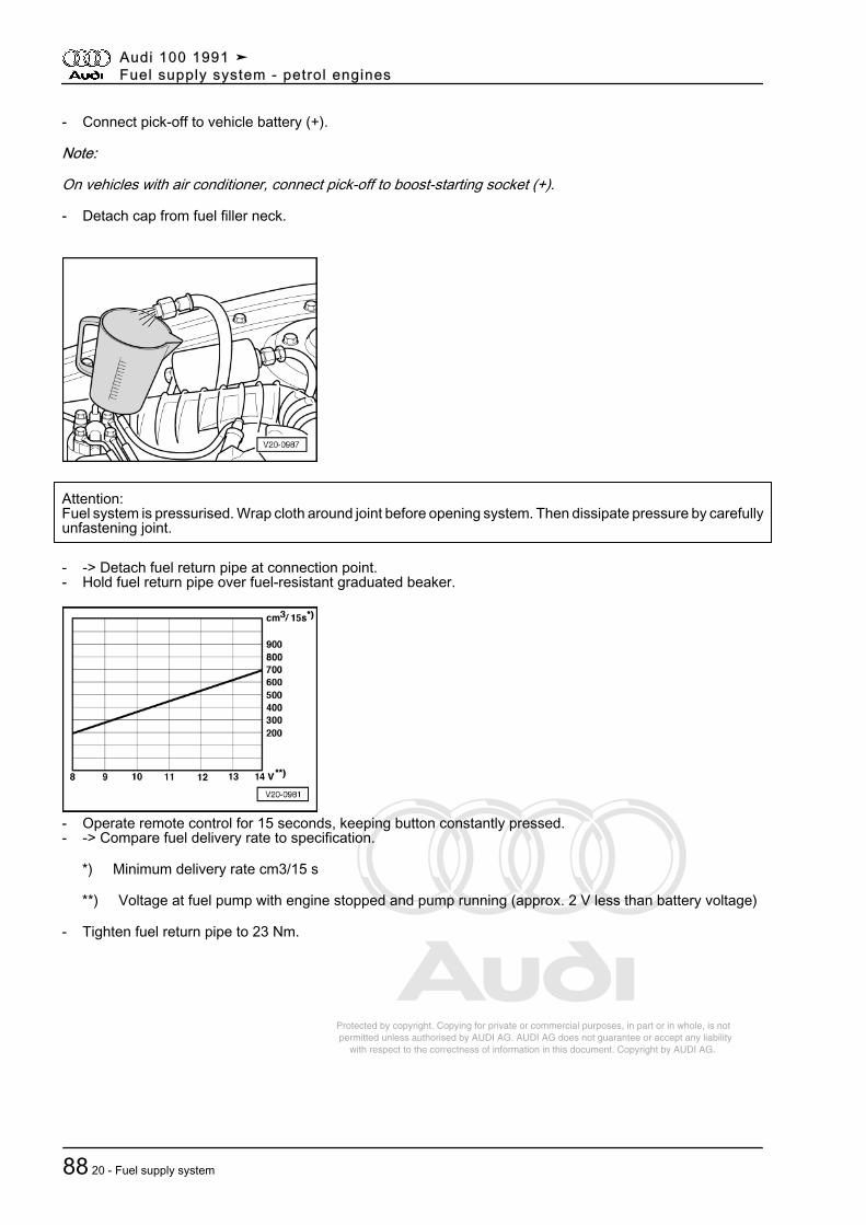
Protected by copyright. Copying for private or commercial purposes, in part or in whole, is not permitted unless authorised by AUDI AG. AUDI AG does not guarantee or accept any liability with respect to the correctness of information in this document. Copyright by AUDI AG.
- Connect pick-off to vehicle battery (+).
Note:
On vehicles with air conditioner, connect pick-off to boost-starting socket (+).
- Detach cap from fuel filler neck.
Attention:Fuel system is pressurised. Wrap cloth around joint before opening system. Then dissipate pressure by carefullyunfastening joint.
- -> Detach fuel return pipe at connection point.- Hold fuel return pipe over fuel-resistant graduated beaker.
- Operate remote control for 15 seconds, keeping button constantly pressed.- -> Compare fuel delivery rate to specification.
*) Minimum delivery rate cm3/15 s
**) Voltage at fuel pump with engine stopped and pump running (approx. 2 V less than battery voltage)
- Tighten fuel return pipe to 23 Nm.
Audi 100 1991 ➤Fuel supply system - petrol engines
88 20 - Fuel supply system
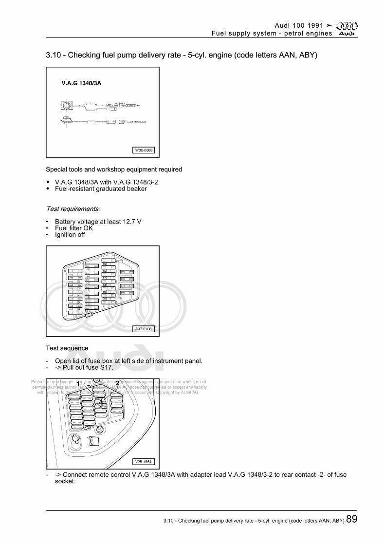
Protected by copyright. Copying for private or commercial purposes, in part or in whole, is not permitted unless authorised by AUDI AG. AUDI AG does not guarantee or accept any liability with respect to the correctness of information in this document. Copyright by AUDI AG.
3.10 - Checking fuel pump delivery rate - 5-cyl. engine (code letters AAN, ABY)
Special tools and workshop equipment required
◆ V.A.G 1348/3A with V.A.G 1348/3-2◆ Fuel-resistant graduated beaker
Test requirements:
• Battery voltage at least 12.7 V• Fuel filter OK• Ignition off
Test sequence
- Open lid of fuse box at left side of instrument panel.- -> Pull out fuse S17.
- -> Connect remote control V.A.G 1348/3A with adapter lead V.A.G 1348/3-2 to rear contact -2- of fusesocket.
Audi 100 1991 ➤Fuel supply system - petrol engines
3.10 - Checking fuel pump delivery rate - 5-cyl. engine (code letters AAN, ABY) 89
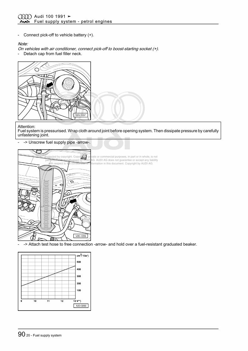
Protected by copyright. Copying for private or commercial purposes, in part or in whole, is not permitted unless authorised by AUDI AG. AUDI AG does not guarantee or accept any liability with respect to the correctness of information in this document. Copyright by AUDI AG.
- Connect pick-off to vehicle battery (+).
Note:On vehicles with air conditioner, connect pick-off to boost-starting socket (+).- Detach cap from fuel filler neck.
Attention:Fuel system is pressurised. Wrap cloth around joint before opening system. Then dissipate pressure by carefullyunfastening joint.- -> Unscrew fuel supply pipe -arrow-.
- -> Attach test hose to free connection -arrow- and hold over a fuel-resistant graduated beaker.
Audi 100 1991 ➤Fuel supply system - petrol engines
90 20 - Fuel supply system
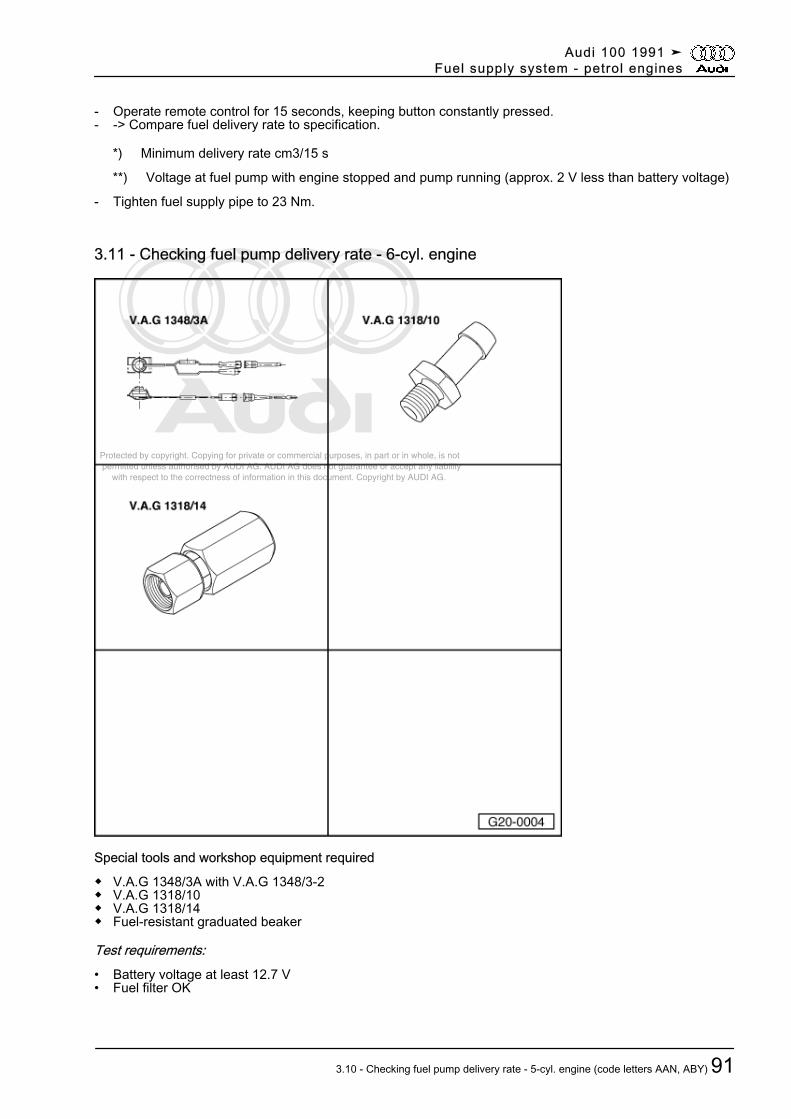
Protected by copyright. Copying for private or commercial purposes, in part or in whole, is not permitted unless authorised by AUDI AG. AUDI AG does not guarantee or accept any liability with respect to the correctness of information in this document. Copyright by AUDI AG.
- Operate remote control for 15 seconds, keeping button constantly pressed.- -> Compare fuel delivery rate to specification.
*) Minimum delivery rate cm3/15 s
**) Voltage at fuel pump with engine stopped and pump running (approx. 2 V less than battery voltage)
- Tighten fuel supply pipe to 23 Nm.
3.11 - Checking fuel pump delivery rate - 6-cyl. engine
Special tools and workshop equipment required
◆ V.A.G 1348/3A with V.A.G 1348/3-2◆ V.A.G 1318/10◆ V.A.G 1318/14◆ Fuel-resistant graduated beaker
Test requirements:• Battery voltage at least 12.7 V• Fuel filter OK
Audi 100 1991 ➤Fuel supply system - petrol engines
3.10 - Checking fuel pump delivery rate - 5-cyl. engine (code letters AAN, ABY) 91
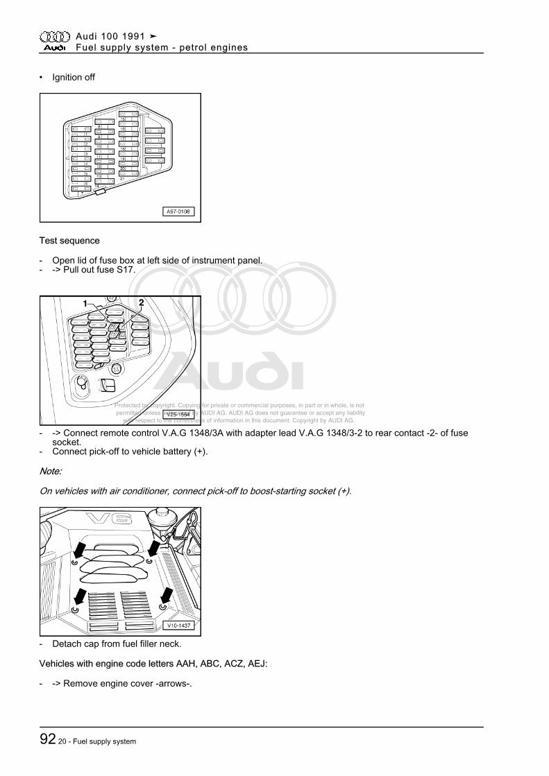
Protected by copyright. Copying for private or commercial purposes, in part or in whole, is not permitted unless authorised by AUDI AG. AUDI AG does not guarantee or accept any liability with respect to the correctness of information in this document. Copyright by AUDI AG.
• Ignition off
Test sequence
- Open lid of fuse box at left side of instrument panel.- -> Pull out fuse S17.
- -> Connect remote control V.A.G 1348/3A with adapter lead V.A.G 1348/3-2 to rear contact -2- of fusesocket.
- Connect pick-off to vehicle battery (+).
Note:
On vehicles with air conditioner, connect pick-off to boost-starting socket (+).
- Detach cap from fuel filler neck.
Vehicles with engine code letters AAH, ABC, ACZ, AEJ:
- -> Remove engine cover -arrows-.
Audi 100 1991 ➤Fuel supply system - petrol engines
92 20 - Fuel supply system
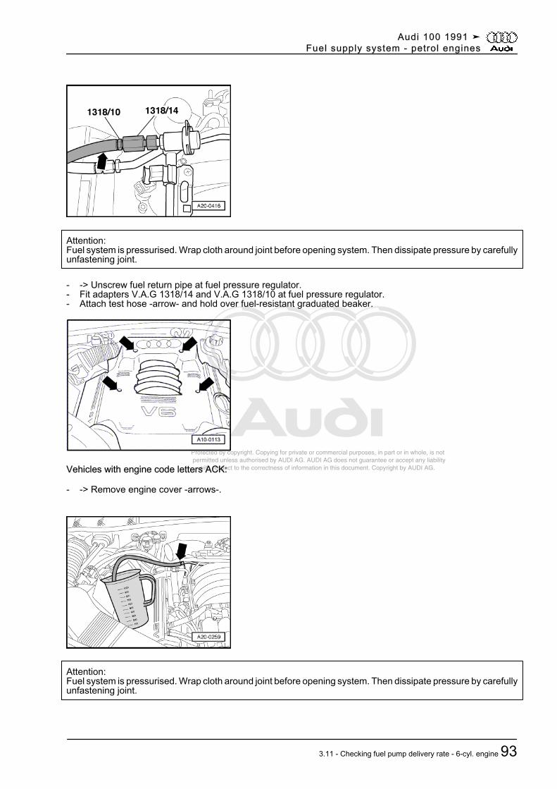
Protected by copyright. Copying for private or commercial purposes, in part or in whole, is not permitted unless authorised by AUDI AG. AUDI AG does not guarantee or accept any liability with respect to the correctness of information in this document. Copyright by AUDI AG.
Attention:Fuel system is pressurised. Wrap cloth around joint before opening system. Then dissipate pressure by carefullyunfastening joint.
- -> Unscrew fuel return pipe at fuel pressure regulator.- Fit adapters V.A.G 1318/14 and V.A.G 1318/10 at fuel pressure regulator.- Attach test hose -arrow- and hold over fuel-resistant graduated beaker.
Vehicles with engine code letters ACK:
- -> Remove engine cover -arrows-.
Attention:Fuel system is pressurised. Wrap cloth around joint before opening system. Then dissipate pressure by carefullyunfastening joint.
Audi 100 1991 ➤Fuel supply system - petrol engines
3.11 - Checking fuel pump delivery rate - 6-cyl. engine 93
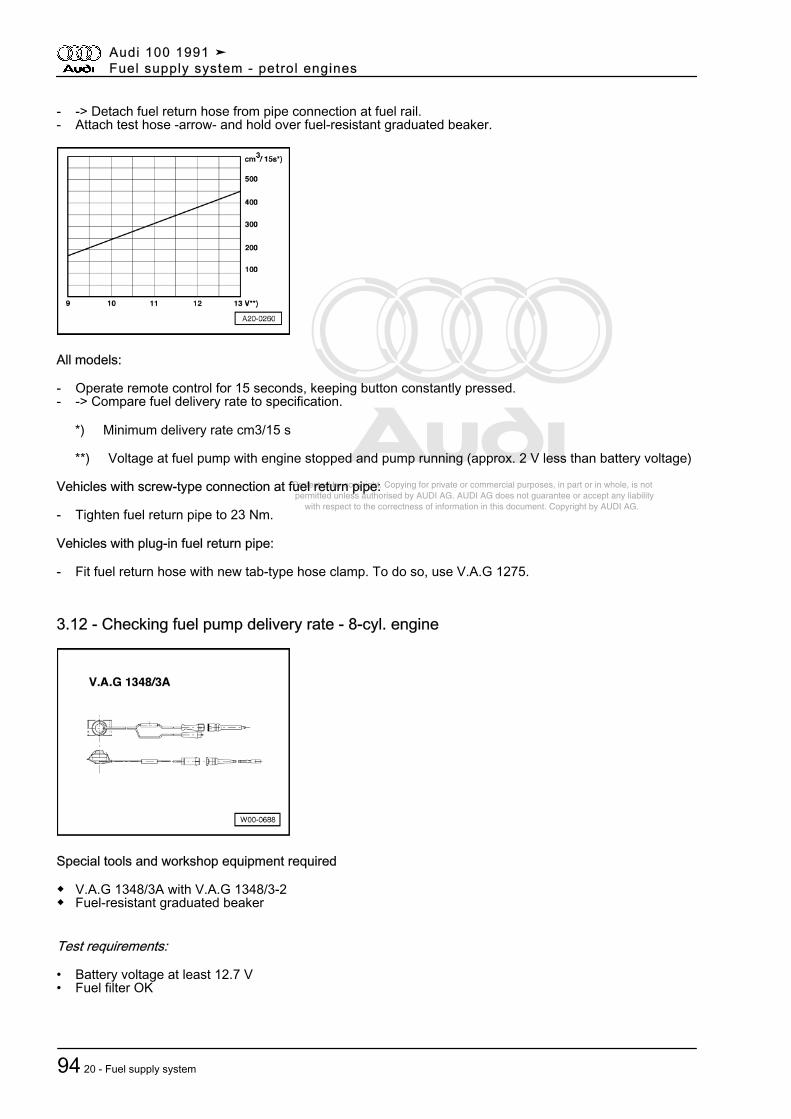
Protected by copyright. Copying for private or commercial purposes, in part or in whole, is not permitted unless authorised by AUDI AG. AUDI AG does not guarantee or accept any liability with respect to the correctness of information in this document. Copyright by AUDI AG.
- -> Detach fuel return hose from pipe connection at fuel rail.- Attach test hose -arrow- and hold over fuel-resistant graduated beaker.
All models:
- Operate remote control for 15 seconds, keeping button constantly pressed.- -> Compare fuel delivery rate to specification.
*) Minimum delivery rate cm3/15 s
**) Voltage at fuel pump with engine stopped and pump running (approx. 2 V less than battery voltage)
Vehicles with screw-type connection at fuel return pipe:
- Tighten fuel return pipe to 23 Nm.
Vehicles with plug-in fuel return pipe:
- Fit fuel return hose with new tab-type hose clamp. To do so, use V.A.G 1275.
3.12 - Checking fuel pump delivery rate - 8-cyl. engine
Special tools and workshop equipment required
◆ V.A.G 1348/3A with V.A.G 1348/3-2◆ Fuel-resistant graduated beaker
Test requirements:
• Battery voltage at least 12.7 V• Fuel filter OK
Audi 100 1991 ➤Fuel supply system - petrol engines
94 20 - Fuel supply system
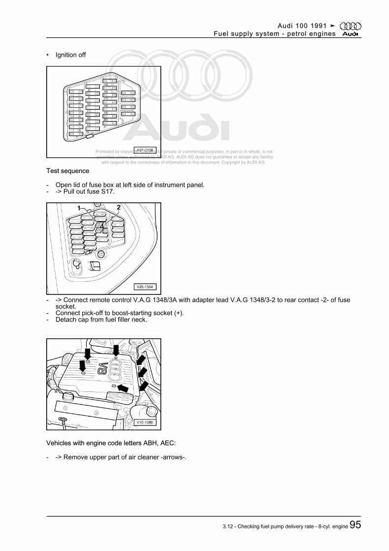
Protected by copyright. Copying for private or commercial purposes, in part or in whole, is not permitted unless authorised by AUDI AG. AUDI AG does not guarantee or accept any liability with respect to the correctness of information in this document. Copyright by AUDI AG.
• Ignition off
Test sequence
- Open lid of fuse box at left side of instrument panel.- -> Pull out fuse S17.
- -> Connect remote control V.A.G 1348/3A with adapter lead V.A.G 1348/3-2 to rear contact -2- of fusesocket.
- Connect pick-off to boost-starting socket (+).- Detach cap from fuel filler neck.
Vehicles with engine code letters ABH, AEC:
- -> Remove upper part of air cleaner -arrows-.
Audi 100 1991 ➤Fuel supply system - petrol engines
3.12 - Checking fuel pump delivery rate - 8-cyl. engine 95
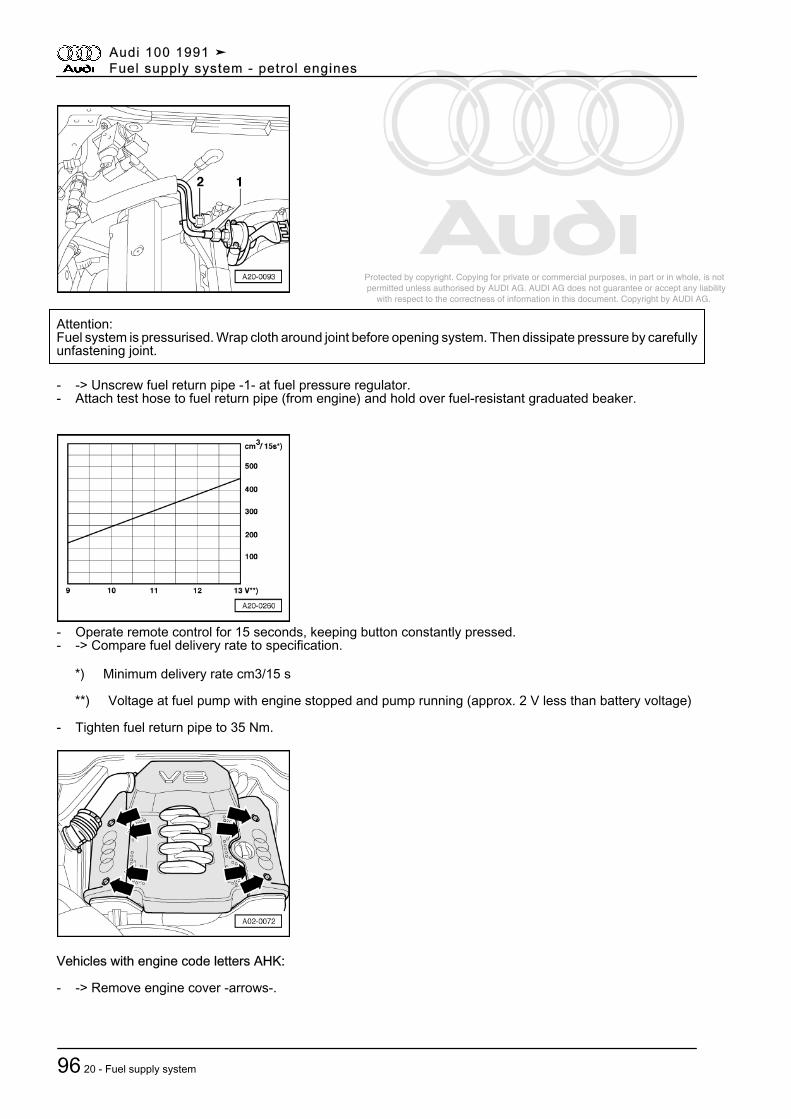
Protected by copyright. Copying for private or commercial purposes, in part or in whole, is not permitted unless authorised by AUDI AG. AUDI AG does not guarantee or accept any liability with respect to the correctness of information in this document. Copyright by AUDI AG.
Attention:Fuel system is pressurised. Wrap cloth around joint before opening system. Then dissipate pressure by carefullyunfastening joint.
- -> Unscrew fuel return pipe -1- at fuel pressure regulator.- Attach test hose to fuel return pipe (from engine) and hold over fuel-resistant graduated beaker.
- Operate remote control for 15 seconds, keeping button constantly pressed.- -> Compare fuel delivery rate to specification.
*) Minimum delivery rate cm3/15 s
**) Voltage at fuel pump with engine stopped and pump running (approx. 2 V less than battery voltage)
- Tighten fuel return pipe to 35 Nm.
Vehicles with engine code letters AHK:
- -> Remove engine cover -arrows-.
Audi 100 1991 ➤Fuel supply system - petrol engines
96 20 - Fuel supply system
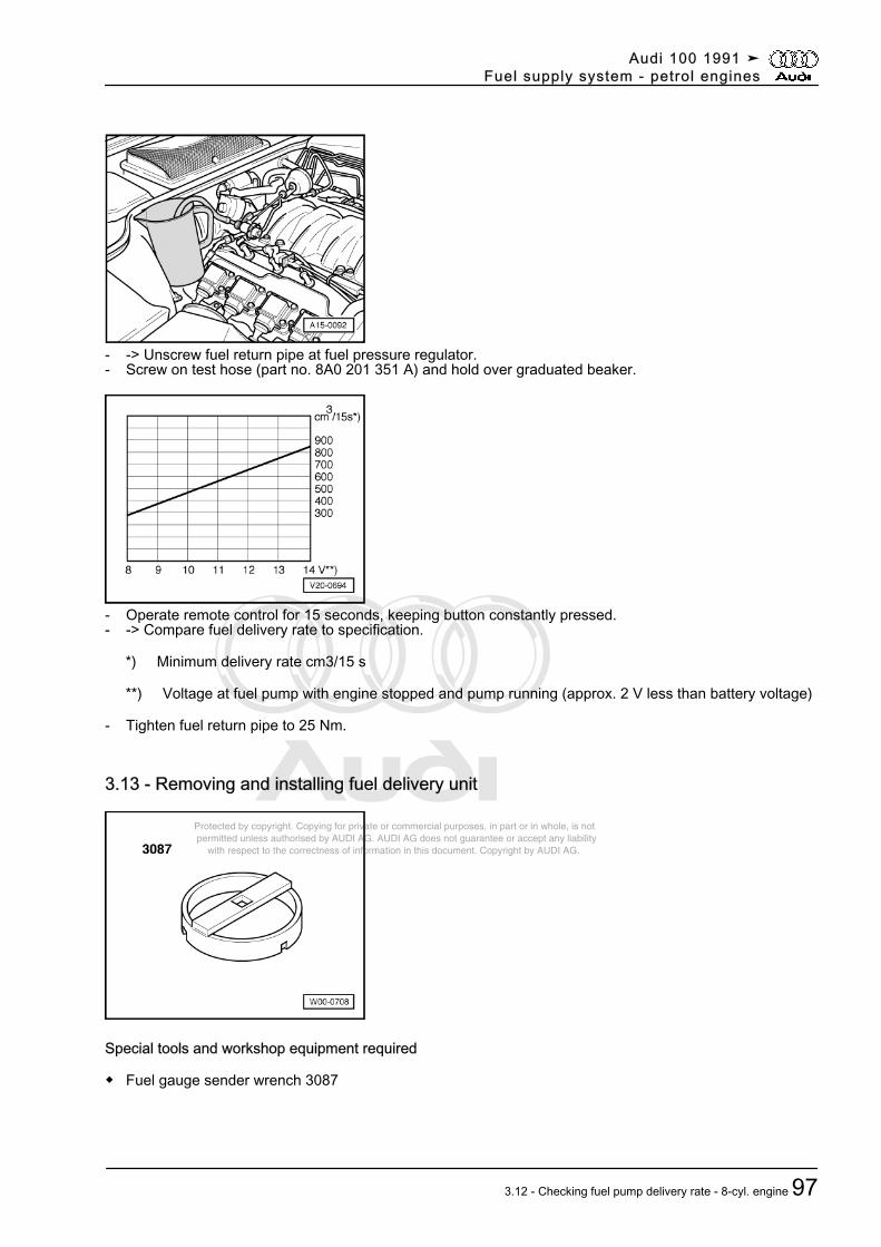
Protected by copyright. Copying for private or commercial purposes, in part or in whole, is not permitted unless authorised by AUDI AG. AUDI AG does not guarantee or accept any liability with respect to the correctness of information in this document. Copyright by AUDI AG.
- -> Unscrew fuel return pipe at fuel pressure regulator.- Screw on test hose (part no. 8A0 201 351 A) and hold over graduated beaker.
- Operate remote control for 15 seconds, keeping button constantly pressed.- -> Compare fuel delivery rate to specification.
*) Minimum delivery rate cm3/15 s
**) Voltage at fuel pump with engine stopped and pump running (approx. 2 V less than battery voltage)
- Tighten fuel return pipe to 25 Nm.
3.13 - Removing and installing fuel delivery unit
Special tools and workshop equipment required
◆ Fuel gauge sender wrench 3087
Audi 100 1991 ➤Fuel supply system - petrol engines
3.12 - Checking fuel pump delivery rate - 8-cyl. engine 97
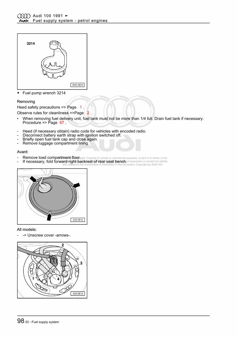
Protected by copyright. Copying for private or commercial purposes, in part or in whole, is not permitted unless authorised by AUDI AG. AUDI AG does not guarantee or accept any liability with respect to the correctness of information in this document. Copyright by AUDI AG.
◆ Fuel pump wrench 3214
RemovingHeed safety precautions => Page 1 .Observe rules for cleanliness =>Page 2 .• When removing fuel delivery unit, fuel tank must not be more than 1/4 full. Drain fuel tank if necessary.
Procedure => Page 67 .
- Heed (if necessary obtain) radio code for vehicles with encoded radio.- Disconnect battery earth strap with ignition switched off.- Briefly open fuel tank cap and close again.- Remove luggage compartment lining.
Avant:- Remove load compartment floor.- If necessary, fold forward right backrest of rear seat bench.
All models:- -> Unscrew cover -arrows-.
Audi 100 1991 ➤Fuel supply system - petrol engines
98 20 - Fuel supply system
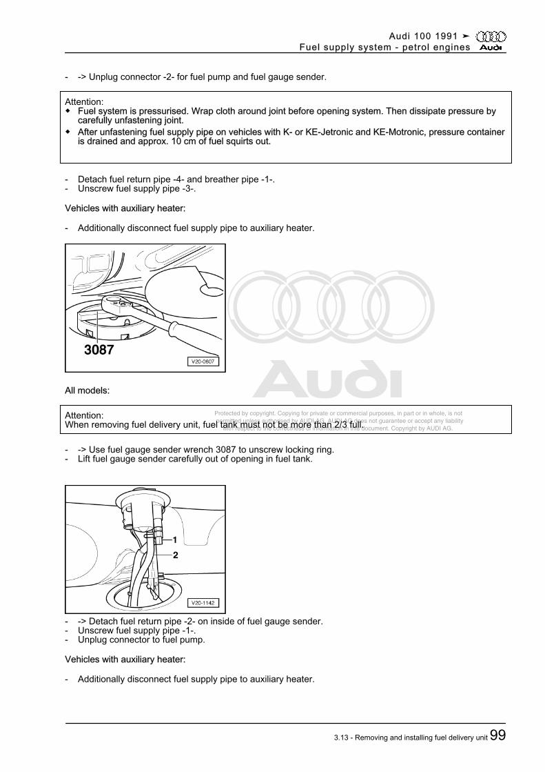
Protected by copyright. Copying for private or commercial purposes, in part or in whole, is not permitted unless authorised by AUDI AG. AUDI AG does not guarantee or accept any liability with respect to the correctness of information in this document. Copyright by AUDI AG.
- -> Unplug connector -2- for fuel pump and fuel gauge sender.
Attention:◆ Fuel system is pressurised. Wrap cloth around joint before opening system. Then dissipate pressure by
carefully unfastening joint.◆ After unfastening fuel supply pipe on vehicles with K- or KE-Jetronic and KE-Motronic, pressure container
is drained and approx. 10 cm of fuel squirts out.
- Detach fuel return pipe -4- and breather pipe -1-.- Unscrew fuel supply pipe -3-.
Vehicles with auxiliary heater:
- Additionally disconnect fuel supply pipe to auxiliary heater.
All models:
Attention:When removing fuel delivery unit, fuel tank must not be more than 2/3 full.
- -> Use fuel gauge sender wrench 3087 to unscrew locking ring.- Lift fuel gauge sender carefully out of opening in fuel tank.
- -> Detach fuel return pipe -2- on inside of fuel gauge sender.- Unscrew fuel supply pipe -1-.- Unplug connector to fuel pump.
Vehicles with auxiliary heater:
- Additionally disconnect fuel supply pipe to auxiliary heater.
Audi 100 1991 ➤Fuel supply system - petrol engines
3.13 - Removing and installing fuel delivery unit 99
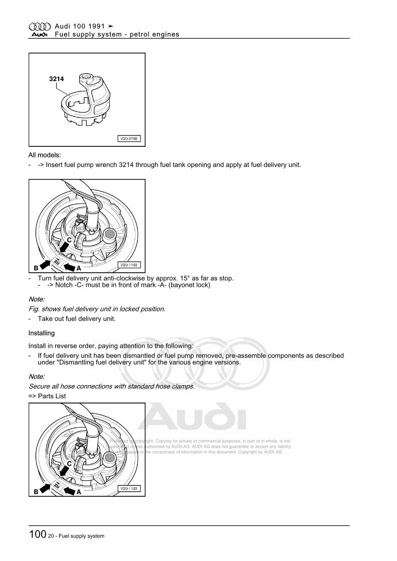
Protected by copyright. Copying for private or commercial purposes, in part or in whole, is not permitted unless authorised by AUDI AG. AUDI AG does not guarantee or accept any liability with respect to the correctness of information in this document. Copyright by AUDI AG.
All models:- -> Insert fuel pump wrench 3214 through fuel tank opening and apply at fuel delivery unit.
- Turn fuel delivery unit anti-clockwise by approx. 15° as far as stop.- -> Notch -C- must be in front of mark -A- (bayonet lock)
Note:Fig. shows fuel delivery unit in locked position.- Take out fuel delivery unit.
Installing
Install in reverse order, paying attention to the following:- If fuel delivery unit has been dismantled or fuel pump removed, pre-assemble components as described
under "Dismantling fuel delivery unit" for the various engine versions.
Note:Secure all hose connections with standard hose clamps.=> Parts List
Audi 100 1991 ➤Fuel supply system - petrol engines
100 20 - Fuel supply system
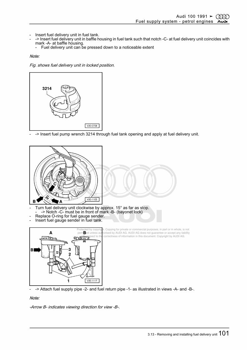
Protected by copyright. Copying for private or commercial purposes, in part or in whole, is not permitted unless authorised by AUDI AG. AUDI AG does not guarantee or accept any liability with respect to the correctness of information in this document. Copyright by AUDI AG.
- Insert fuel delivery unit in fuel tank.- -> Insert fuel delivery unit in baffle housing in fuel tank such that notch -C- at fuel delivery unit coincides with
mark -A- at baffle housing.- Fuel delivery unit can be pressed down to a noticeable extent
Note:
Fig. shows fuel delivery unit in locked position.
- -> Insert fuel pump wrench 3214 through fuel tank opening and apply at fuel delivery unit.
- Turn fuel delivery unit clockwise by approx. 15° as far as stop.- -> Notch -C- must be in front of mark -B- (bayonet lock)
- Replace O-ring for fuel gauge sender.- Insert fuel gauge sender in fuel tank.
- -> Attach fuel supply pipe -2- and fuel return pipe -1- as illustrated in views -A- and -B-.
Note:
-Arrow B- indicates viewing direction for view -B-.
Audi 100 1991 ➤Fuel supply system - petrol engines
3.13 - Removing and installing fuel delivery unit 101
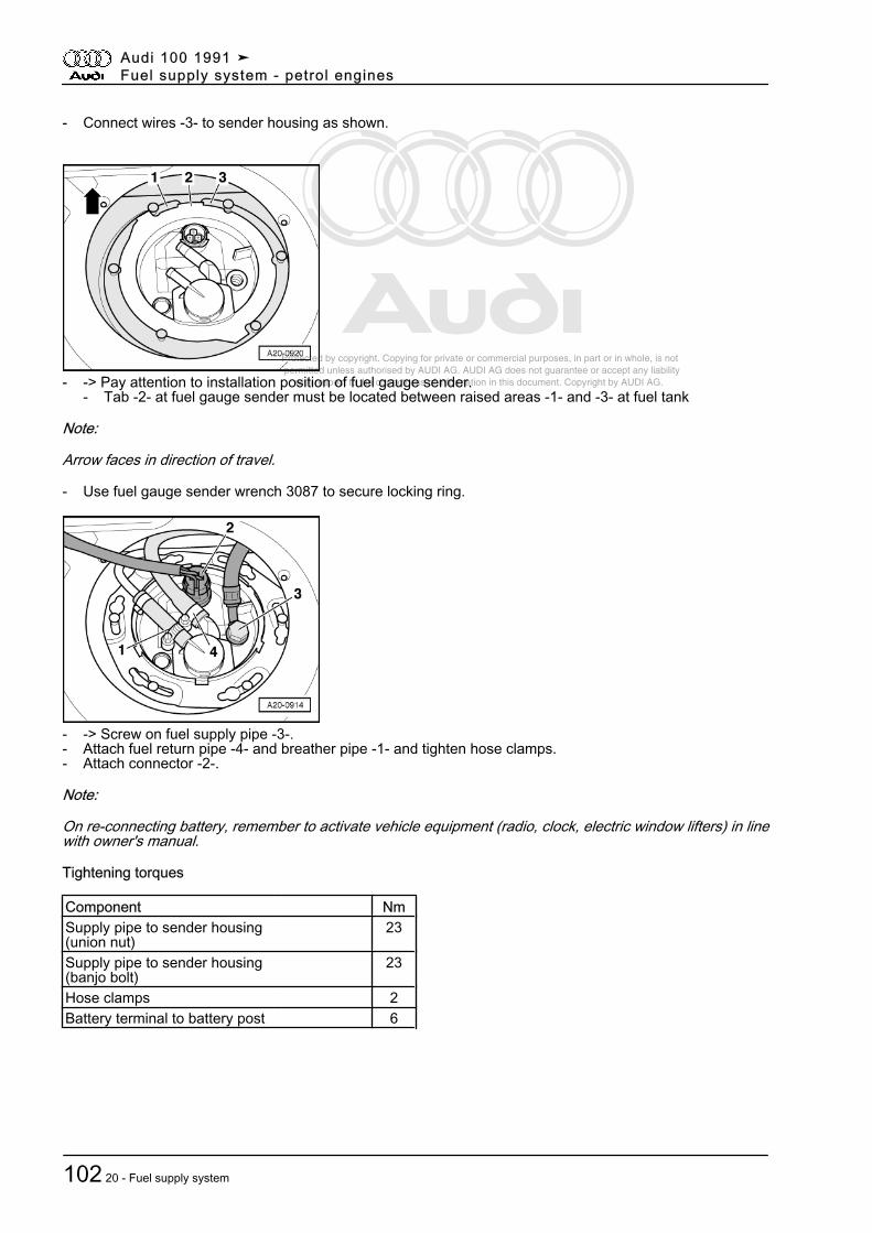
Protected by copyright. Copying for private or commercial purposes, in part or in whole, is not permitted unless authorised by AUDI AG. AUDI AG does not guarantee or accept any liability with respect to the correctness of information in this document. Copyright by AUDI AG.
- Connect wires -3- to sender housing as shown.
- -> Pay attention to installation position of fuel gauge sender.- Tab -2- at fuel gauge sender must be located between raised areas -1- and -3- at fuel tank
Note:
Arrow faces in direction of travel.
- Use fuel gauge sender wrench 3087 to secure locking ring.
- -> Screw on fuel supply pipe -3-.- Attach fuel return pipe -4- and breather pipe -1- and tighten hose clamps.- Attach connector -2-.
Note:
On re-connecting battery, remember to activate vehicle equipment (radio, clock, electric window lifters) in linewith owner's manual.
Tightening torques
Component NmSupply pipe to sender housing(union nut)
23
Supply pipe to sender housing(banjo bolt)
23
Hose clamps 2Battery terminal to battery post 6
Audi 100 1991 ➤Fuel supply system - petrol engines
102 20 - Fuel supply system
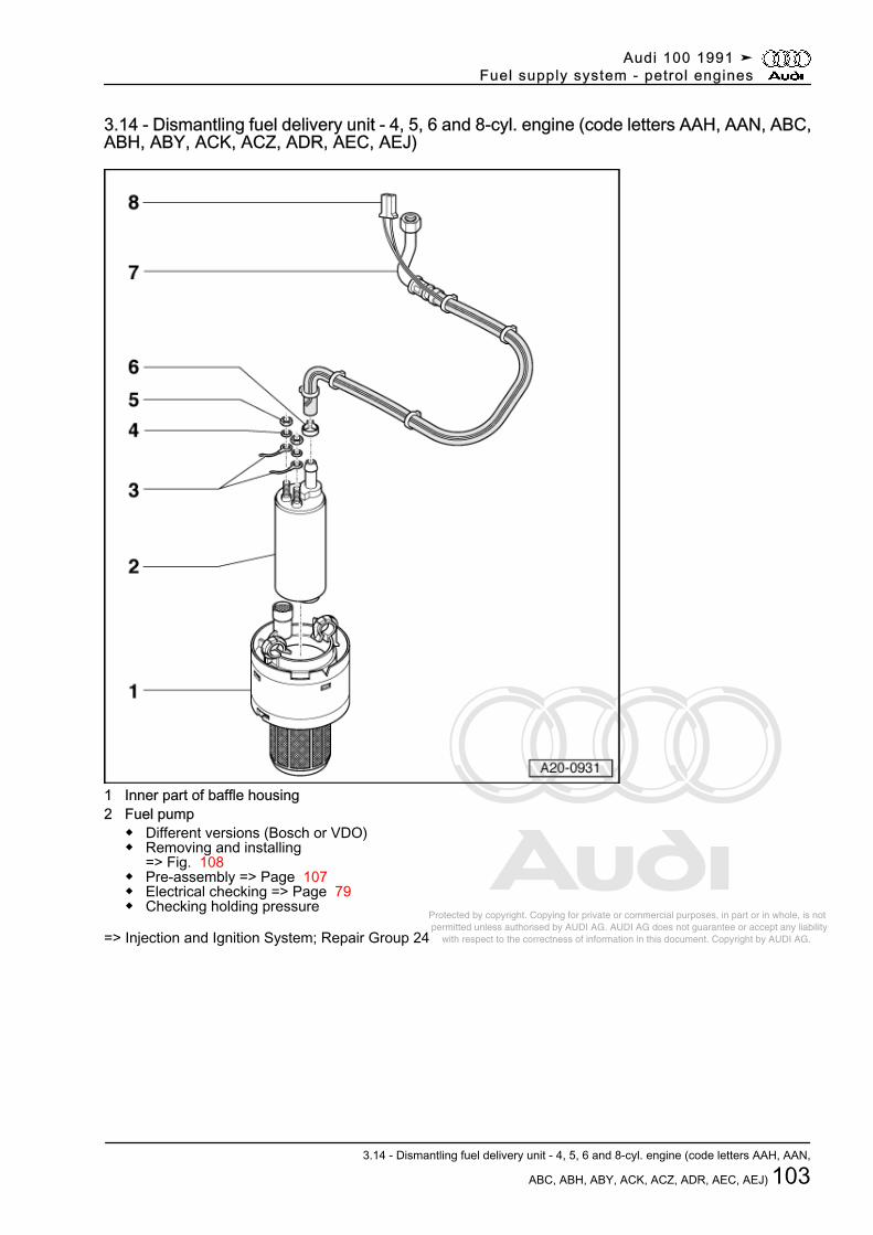
Protected by copyright. Copying for private or commercial purposes, in part or in whole, is not permitted unless authorised by AUDI AG. AUDI AG does not guarantee or accept any liability with respect to the correctness of information in this document. Copyright by AUDI AG.
3.14 - Dismantling fuel delivery unit - 4, 5, 6 and 8-cyl. engine (code letters AAH, AAN, ABC,ABH, ABY, ACK, ACZ, ADR, AEC, AEJ)
1 Inner part of baffle housing2 Fuel pump
◆ Different versions (Bosch or VDO)◆ Removing and installing
=> Fig. 108◆ Pre-assembly => Page 107◆ Electrical checking => Page 79◆ Checking holding pressure
=> Injection and Ignition System; Repair Group 24
Audi 100 1991 ➤Fuel supply system - petrol engines
3.14 - Dismantling fuel delivery unit - 4, 5, 6 and 8-cyl. engine (code letters AAH, AAN,
ABC, ABH, ABY, ACK, ACZ, ADR, AEC, AEJ) 103
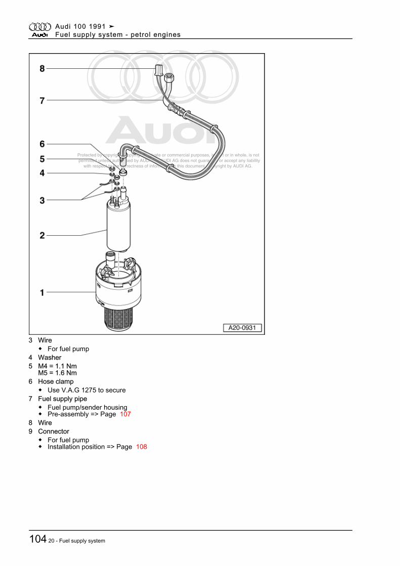
Protected by copyright. Copying for private or commercial purposes, in part or in whole, is not permitted unless authorised by AUDI AG. AUDI AG does not guarantee or accept any liability with respect to the correctness of information in this document. Copyright by AUDI AG.
3 Wire◆ For fuel pump
4 Washer5 M4 = 1.1 Nm
M5 = 1.6 Nm6 Hose clamp
◆ Use V.A.G 1275 to secure7 Fuel supply pipe
◆ Fuel pump/sender housing◆ Pre-assembly => Page 107
8 Wire9 Connector
◆ For fuel pump◆ Installation position => Page 108
Audi 100 1991 ➤Fuel supply system - petrol engines
104 20 - Fuel supply system
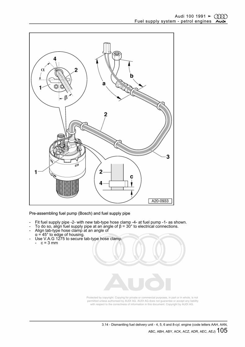
Protected by copyright. Copying for private or commercial purposes, in part or in whole, is not permitted unless authorised by AUDI AG. AUDI AG does not guarantee or accept any liability with respect to the correctness of information in this document. Copyright by AUDI AG.
Pre-assembling fuel pump (Bosch) and fuel supply pipe
- Fit fuel supply pipe -2- with new tab-type hose clamp -4- at fuel pump -1- as shown.- To do so, align fuel supply pipe at an angle of β = 30° to electrical connections.- Align tab-type hose clamp at an angle of
α = 45° to edge of housing.- Use V.A.G 1275 to secure tab-type hose clamp.
- c = 3 mm
Audi 100 1991 ➤Fuel supply system - petrol engines
3.14 - Dismantling fuel delivery unit - 4, 5, 6 and 8-cyl. engine (code letters AAH, AAN,
ABC, ABH, ABY, ACK, ACZ, ADR, AEC, AEJ) 105
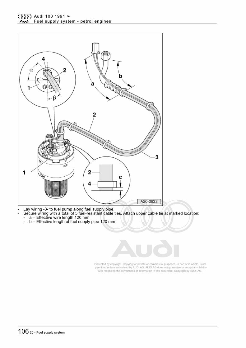
Protected by copyright. Copying for private or commercial purposes, in part or in whole, is not permitted unless authorised by AUDI AG. AUDI AG does not guarantee or accept any liability with respect to the correctness of information in this document. Copyright by AUDI AG.
- Lay wiring -3- to fuel pump along fuel supply pipe.- Secure wiring with a total of 5 fuel-resistant cable ties. Attach upper cable tie at marked location:
- a = Effective wire length 120 mm- b = Effective length of fuel supply pipe 120 mm
Audi 100 1991 ➤Fuel supply system - petrol engines
106 20 - Fuel supply system
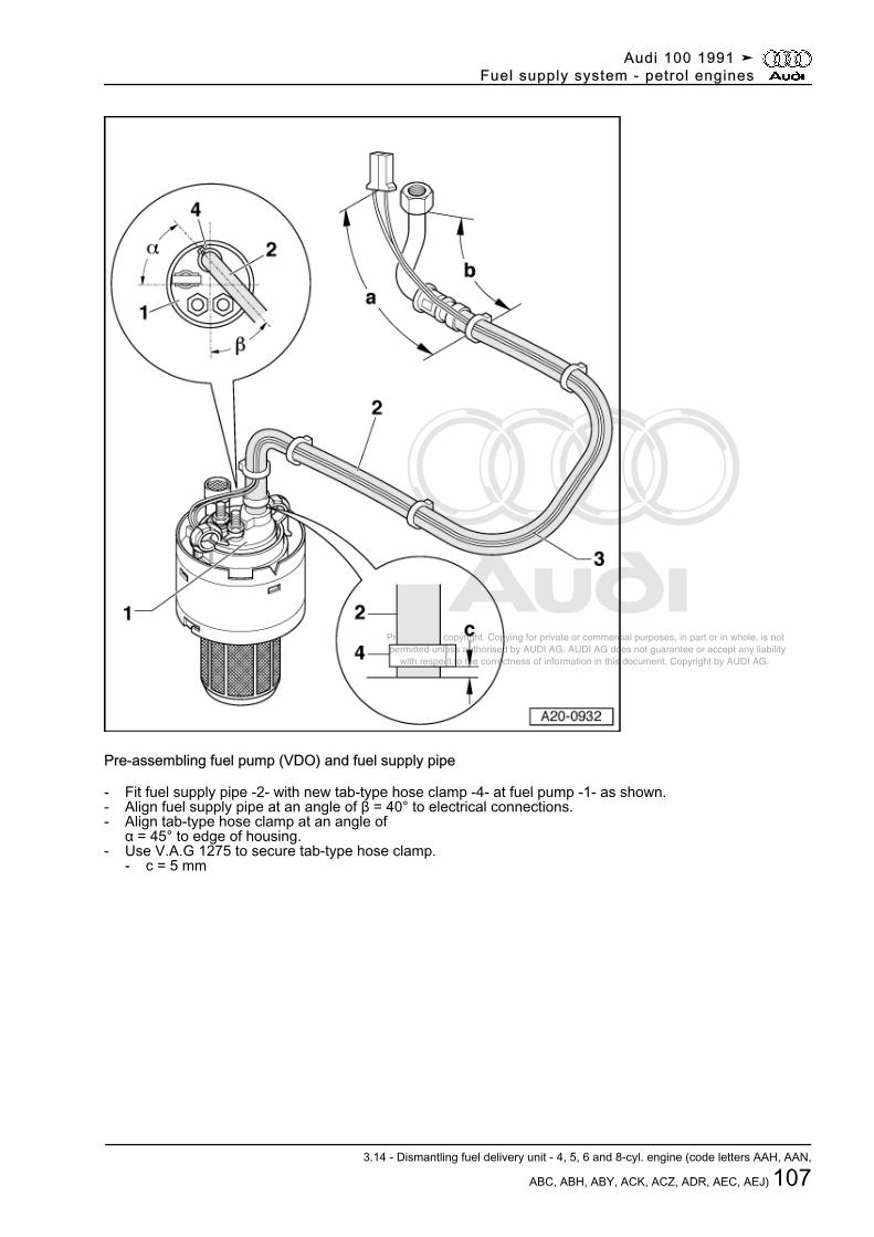
Protected by copyright. Copying for private or commercial purposes, in part or in whole, is not permitted unless authorised by AUDI AG. AUDI AG does not guarantee or accept any liability with respect to the correctness of information in this document. Copyright by AUDI AG.
Pre-assembling fuel pump (VDO) and fuel supply pipe
- Fit fuel supply pipe -2- with new tab-type hose clamp -4- at fuel pump -1- as shown.- Align fuel supply pipe at an angle of β = 40° to electrical connections.- Align tab-type hose clamp at an angle of
α = 45° to edge of housing.- Use V.A.G 1275 to secure tab-type hose clamp.
- c = 5 mm
Audi 100 1991 ➤Fuel supply system - petrol engines
3.14 - Dismantling fuel delivery unit - 4, 5, 6 and 8-cyl. engine (code letters AAH, AAN,
ABC, ABH, ABY, ACK, ACZ, ADR, AEC, AEJ) 107
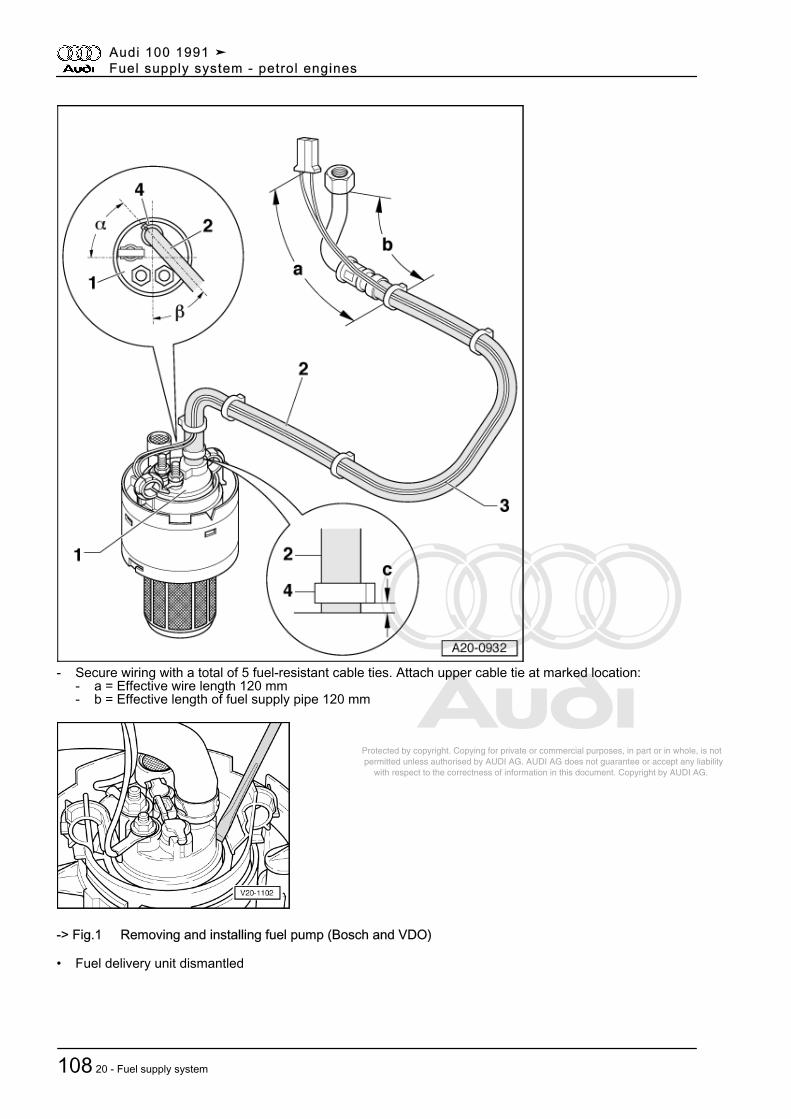
Protected by copyright. Copying for private or commercial purposes, in part or in whole, is not permitted unless authorised by AUDI AG. AUDI AG does not guarantee or accept any liability with respect to the correctness of information in this document. Copyright by AUDI AG.
- Secure wiring with a total of 5 fuel-resistant cable ties. Attach upper cable tie at marked location:- a = Effective wire length 120 mm- b = Effective length of fuel supply pipe 120 mm
-> Fig.1 Removing and installing fuel pump (Bosch and VDO)
• Fuel delivery unit dismantled
Audi 100 1991 ➤Fuel supply system - petrol engines
108 20 - Fuel supply system
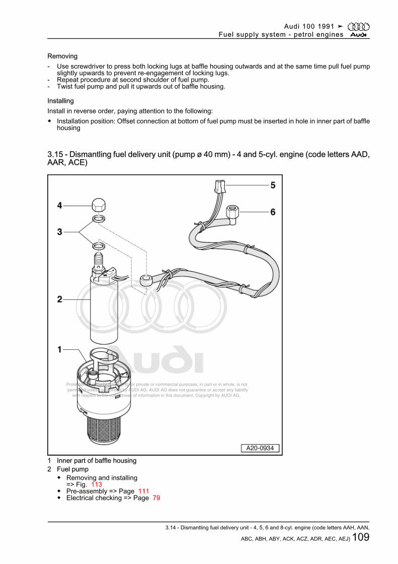
Protected by copyright. Copying for private or commercial purposes, in part or in whole, is not permitted unless authorised by AUDI AG. AUDI AG does not guarantee or accept any liability with respect to the correctness of information in this document. Copyright by AUDI AG.
Removing- Use screwdriver to press both locking lugs at baffle housing outwards and at the same time pull fuel pump
slightly upwards to prevent re-engagement of locking lugs.- Repeat procedure at second shoulder of fuel pump.- Twist fuel pump and pull it upwards out of baffle housing.
InstallingInstall in reverse order, paying attention to the following:◆ Installation position: Offset connection at bottom of fuel pump must be inserted in hole in inner part of baffle
housing
3.15 - Dismantling fuel delivery unit (pump ø 40 mm) - 4 and 5-cyl. engine (code letters AAD,AAR, ACE)
1 Inner part of baffle housing2 Fuel pump
◆ Removing and installing=> Fig. 113
◆ Pre-assembly => Page 111◆ Electrical checking => Page 79
Audi 100 1991 ➤Fuel supply system - petrol engines
3.14 - Dismantling fuel delivery unit - 4, 5, 6 and 8-cyl. engine (code letters AAH, AAN,
ABC, ABH, ABY, ACK, ACZ, ADR, AEC, AEJ) 109
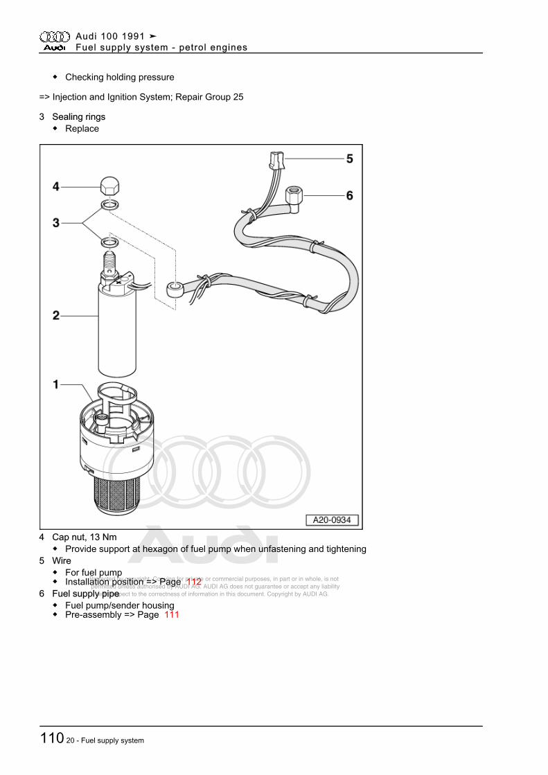
Protected by copyright. Copying for private or commercial purposes, in part or in whole, is not permitted unless authorised by AUDI AG. AUDI AG does not guarantee or accept any liability with respect to the correctness of information in this document. Copyright by AUDI AG.
◆ Checking holding pressure
=> Injection and Ignition System; Repair Group 25
3 Sealing rings◆ Replace
4 Cap nut, 13 Nm◆ Provide support at hexagon of fuel pump when unfastening and tightening
5 Wire◆ For fuel pump◆ Installation position => Page 112
6 Fuel supply pipe◆ Fuel pump/sender housing◆ Pre-assembly => Page 111
Audi 100 1991 ➤Fuel supply system - petrol engines
110 20 - Fuel supply system
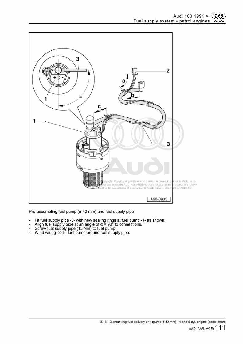
Protected by copyright. Copying for private or commercial purposes, in part or in whole, is not permitted unless authorised by AUDI AG. AUDI AG does not guarantee or accept any liability with respect to the correctness of information in this document. Copyright by AUDI AG.
Pre-assembling fuel pump (ø 40 mm) and fuel supply pipe
- Fit fuel supply pipe -3- with new sealing rings at fuel pump -1- as shown.- Align fuel supply pipe at an angle of α = 90° to connections.- Screw fuel supply pipe (13 Nm) to fuel pump.- Wind wiring -2- to fuel pump around fuel supply pipe.
Audi 100 1991 ➤Fuel supply system - petrol engines
3.15 - Dismantling fuel delivery unit (pump ø 40 mm) - 4 and 5-cyl. engine (code letters
AAD, AAR, ACE) 111
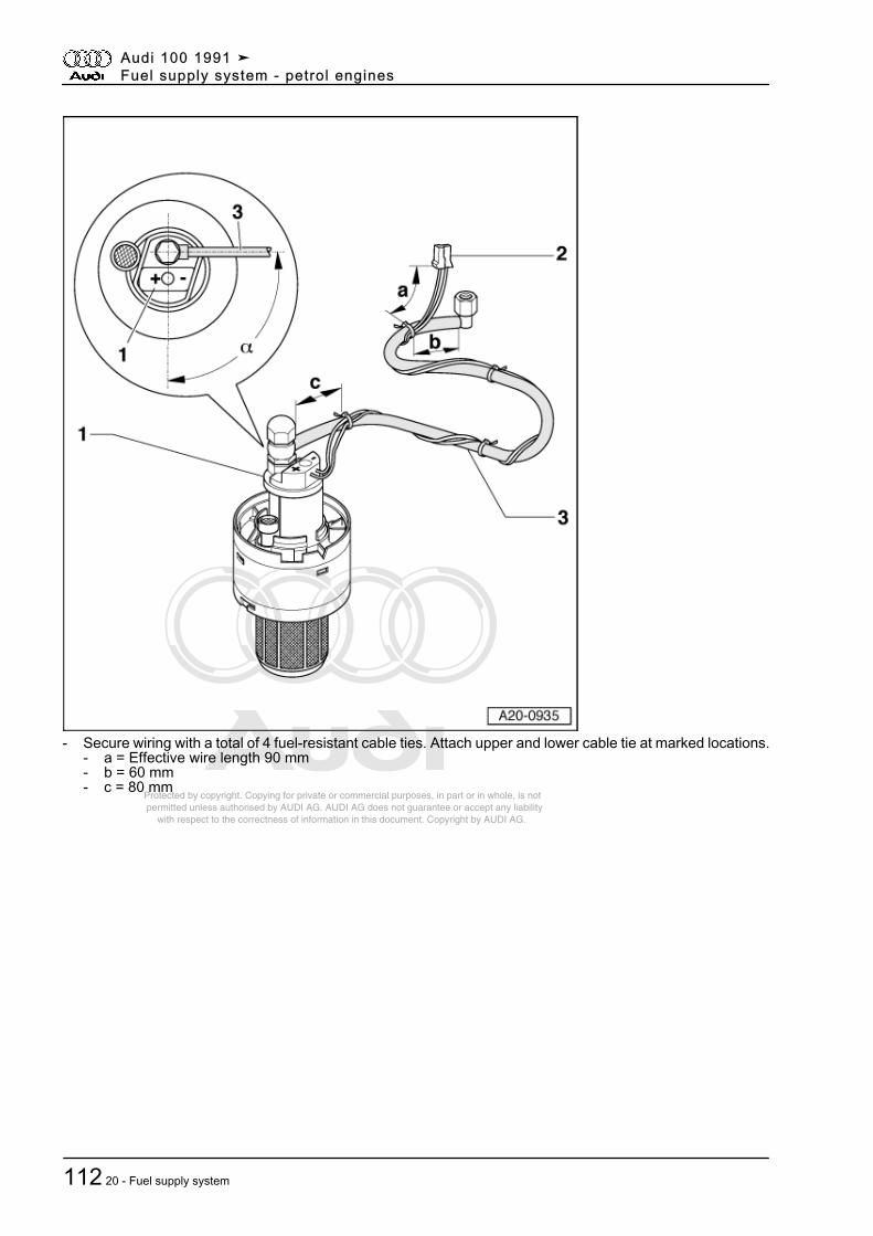
Protected by copyright. Copying for private or commercial purposes, in part or in whole, is not permitted unless authorised by AUDI AG. AUDI AG does not guarantee or accept any liability with respect to the correctness of information in this document. Copyright by AUDI AG.
- Secure wiring with a total of 4 fuel-resistant cable ties. Attach upper and lower cable tie at marked locations.- a = Effective wire length 90 mm- b = 60 mm- c = 80 mm
Audi 100 1991 ➤Fuel supply system - petrol engines
112 20 - Fuel supply system
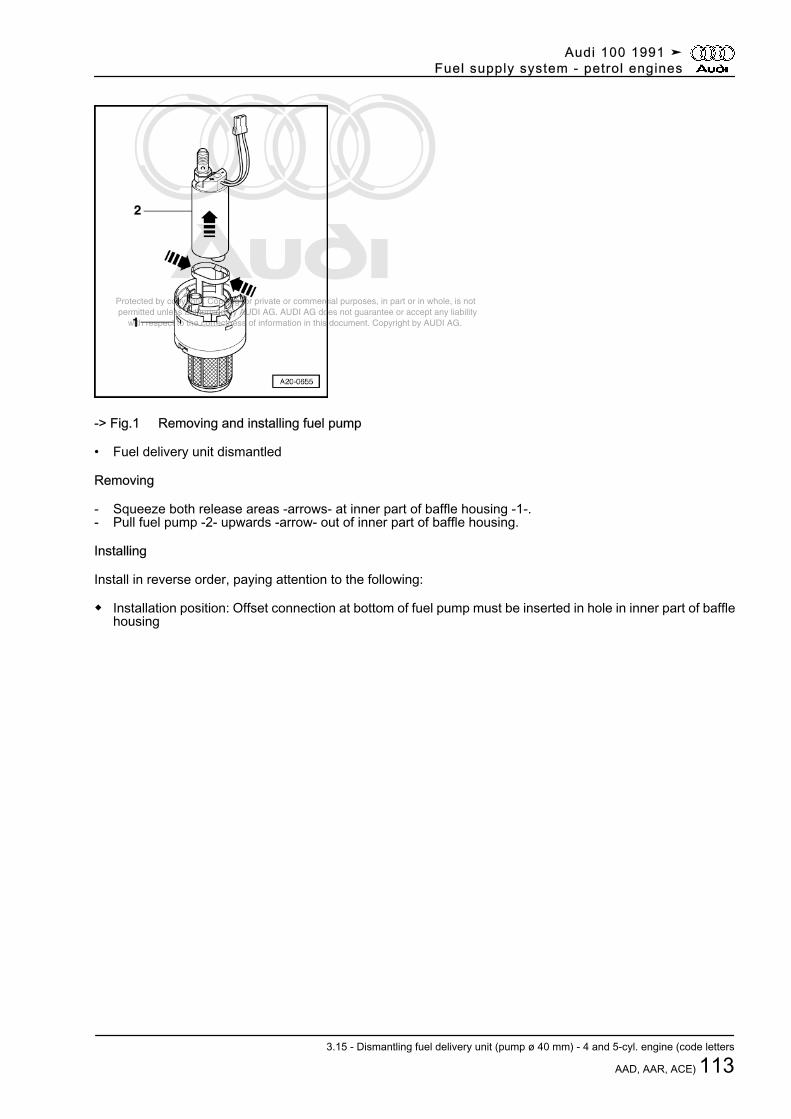
Protected by copyright. Copying for private or commercial purposes, in part or in whole, is not permitted unless authorised by AUDI AG. AUDI AG does not guarantee or accept any liability with respect to the correctness of information in this document. Copyright by AUDI AG.
-> Fig.1 Removing and installing fuel pump
• Fuel delivery unit dismantled
Removing
- Squeeze both release areas -arrows- at inner part of baffle housing -1-.- Pull fuel pump -2- upwards -arrow- out of inner part of baffle housing.
Installing
Install in reverse order, paying attention to the following:
◆ Installation position: Offset connection at bottom of fuel pump must be inserted in hole in inner part of bafflehousing
Audi 100 1991 ➤Fuel supply system - petrol engines
3.15 - Dismantling fuel delivery unit (pump ø 40 mm) - 4 and 5-cyl. engine (code letters
AAD, AAR, ACE) 113
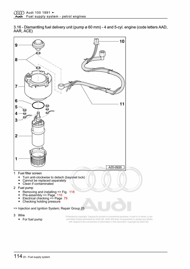
Protected by copyright. Copying for private or commercial purposes, in part or in whole, is not permitted unless authorised by AUDI AG. AUDI AG does not guarantee or accept any liability with respect to the correctness of information in this document. Copyright by AUDI AG.
3.16 - Dismantling fuel delivery unit (pump ø 60 mm) - 4 and 5-cyl. engine (code letters AAD,AAR, ACE)
1 Fuel filter screen◆ Turn anti-clockwise to detach (bayonet lock)◆ Cannot be replaced separately◆ Clean if contaminated
2 Fuel pump◆ Removing and installing => Fig. 118◆ Pre-assembly => Page 116◆ Electrical checking => Page 79◆ Checking holding pressure
=> Injection and Ignition System; Repair Group 25
3 Wire◆ For fuel pump
Audi 100 1991 ➤Fuel supply system - petrol engines
114 20 - Fuel supply system
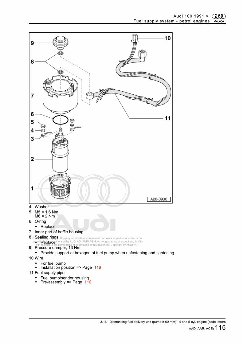
Protected by copyright. Copying for private or commercial purposes, in part or in whole, is not permitted unless authorised by AUDI AG. AUDI AG does not guarantee or accept any liability with respect to the correctness of information in this document. Copyright by AUDI AG.
4 Washer5 M5 = 1.6 Nm
M6 = 2 Nm6 O-ring
◆ Replace7 Inner part of baffle housing8 Sealing rings
◆ Replace9 Pressure damper, 13 Nm
◆ Provide support at hexagon of fuel pump when unfastening and tightening10 Wire
◆ For fuel pump◆ Installation position => Page 116
11 Fuel supply pipe◆ Fuel pump/sender housing◆ Pre-assembly => Page 116
Audi 100 1991 ➤Fuel supply system - petrol engines
3.16 - Dismantling fuel delivery unit (pump ø 60 mm) - 4 and 5-cyl. engine (code letters
AAD, AAR, ACE) 115
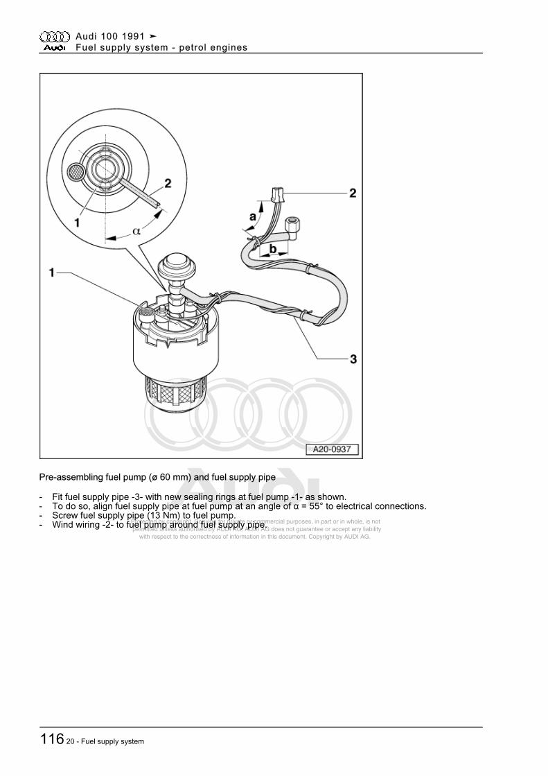
Protected by copyright. Copying for private or commercial purposes, in part or in whole, is not permitted unless authorised by AUDI AG. AUDI AG does not guarantee or accept any liability with respect to the correctness of information in this document. Copyright by AUDI AG.
Pre-assembling fuel pump (ø 60 mm) and fuel supply pipe
- Fit fuel supply pipe -3- with new sealing rings at fuel pump -1- as shown.- To do so, align fuel supply pipe at fuel pump at an angle of α = 55° to electrical connections.- Screw fuel supply pipe (13 Nm) to fuel pump.- Wind wiring -2- to fuel pump around fuel supply pipe.
Audi 100 1991 ➤Fuel supply system - petrol engines
116 20 - Fuel supply system
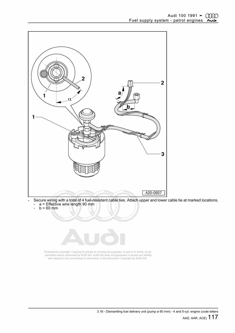
Protected by copyright. Copying for private or commercial purposes, in part or in whole, is not permitted unless authorised by AUDI AG. AUDI AG does not guarantee or accept any liability with respect to the correctness of information in this document. Copyright by AUDI AG.
- Secure wiring with a total of 4 fuel-resistant cable ties. Attach upper and lower cable tie at marked locations.- a = Effective wire length 90 mm- b = 60 mm
Audi 100 1991 ➤Fuel supply system - petrol engines
3.16 - Dismantling fuel delivery unit (pump ø 60 mm) - 4 and 5-cyl. engine (code letters
AAD, AAR, ACE) 117
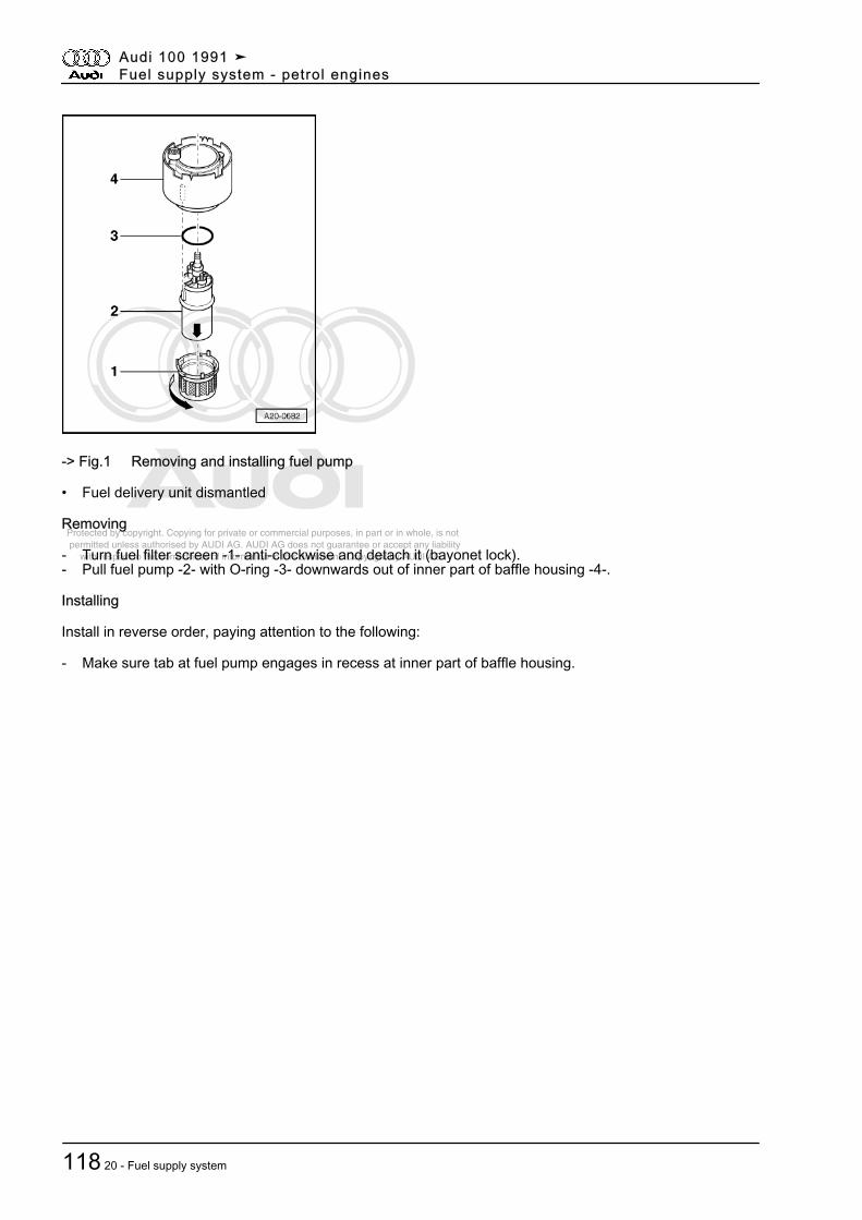
Protected by copyright. Copying for private or commercial purposes, in part or in whole, is not permitted unless authorised by AUDI AG. AUDI AG does not guarantee or accept any liability with respect to the correctness of information in this document. Copyright by AUDI AG.
-> Fig.1 Removing and installing fuel pump
• Fuel delivery unit dismantled
Removing
- Turn fuel filter screen -1- anti-clockwise and detach it (bayonet lock).- Pull fuel pump -2- with O-ring -3- downwards out of inner part of baffle housing -4-.
Installing
Install in reverse order, paying attention to the following:
- Make sure tab at fuel pump engages in recess at inner part of baffle housing.
Audi 100 1991 ➤Fuel supply system - petrol engines
118 20 - Fuel supply system
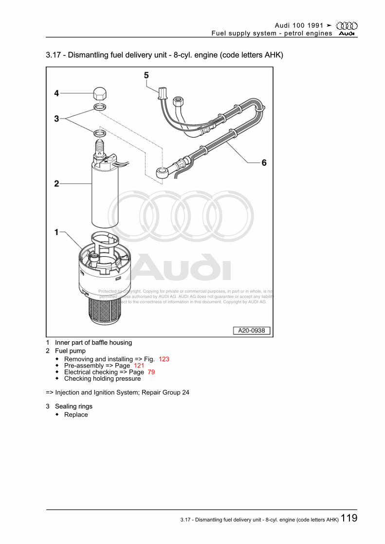
Protected by copyright. Copying for private or commercial purposes, in part or in whole, is not permitted unless authorised by AUDI AG. AUDI AG does not guarantee or accept any liability with respect to the correctness of information in this document. Copyright by AUDI AG.
3.17 - Dismantling fuel delivery unit - 8-cyl. engine (code letters AHK)
1 Inner part of baffle housing2 Fuel pump
◆ Removing and installing => Fig. 123◆ Pre-assembly => Page 121◆ Electrical checking => Page 79◆ Checking holding pressure
=> Injection and Ignition System; Repair Group 24
3 Sealing rings◆ Replace
Audi 100 1991 ➤Fuel supply system - petrol engines
3.17 - Dismantling fuel delivery unit - 8-cyl. engine (code letters AHK) 119
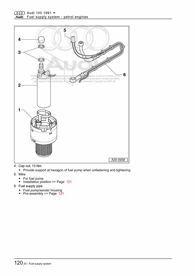
Protected by copyright. Copying for private or commercial purposes, in part or in whole, is not permitted unless authorised by AUDI AG. AUDI AG does not guarantee or accept any liability with respect to the correctness of information in this document. Copyright by AUDI AG.
4 Cap nut, 13 Nm◆ Provide support at hexagon of fuel pump when unfastening and tightening
5 Wire◆ For fuel pump◆ Installation position => Page 121
6 Fuel supply pipe◆ Fuel pump/sender housing◆ Pre-assembly => Page 121
Audi 100 1991 ➤Fuel supply system - petrol engines
120 20 - Fuel supply system
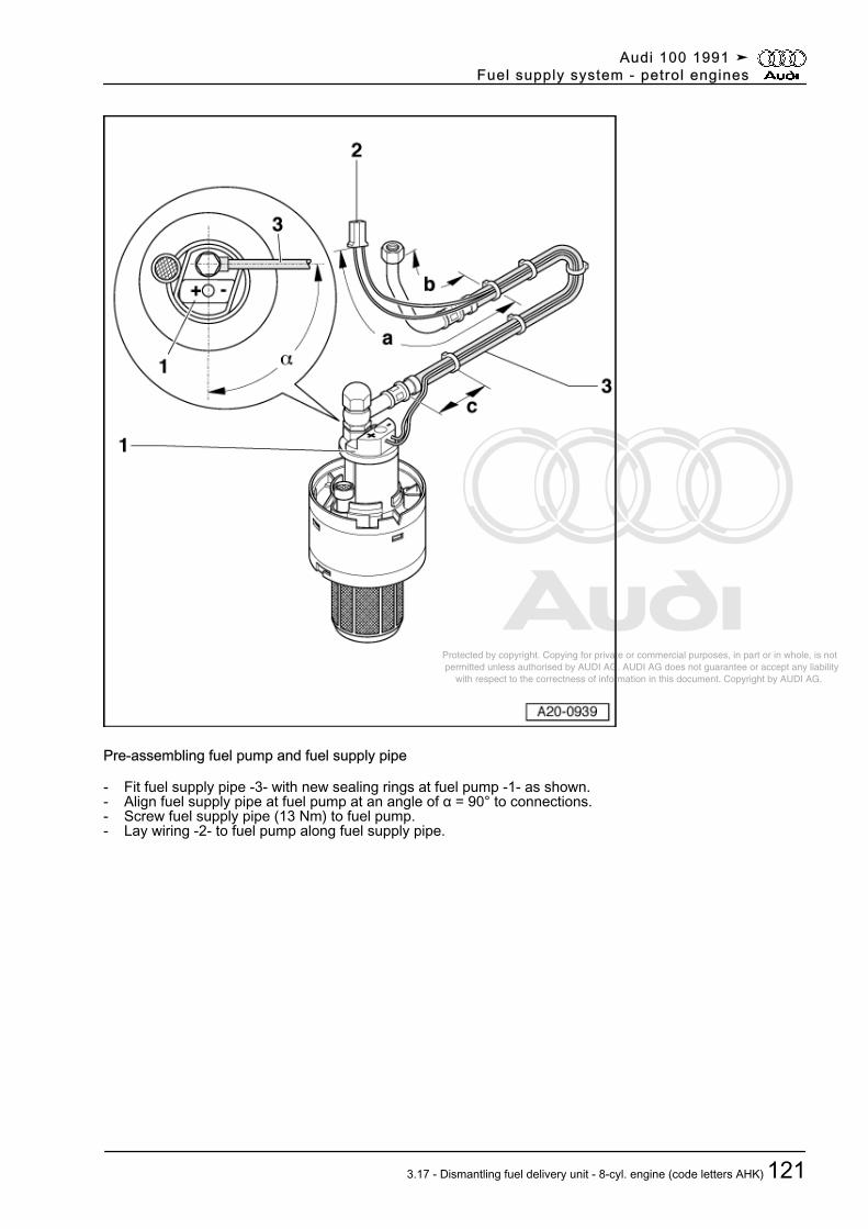
Protected by copyright. Copying for private or commercial purposes, in part or in whole, is not permitted unless authorised by AUDI AG. AUDI AG does not guarantee or accept any liability with respect to the correctness of information in this document. Copyright by AUDI AG.
Pre-assembling fuel pump and fuel supply pipe
- Fit fuel supply pipe -3- with new sealing rings at fuel pump -1- as shown.- Align fuel supply pipe at fuel pump at an angle of α = 90° to connections.- Screw fuel supply pipe (13 Nm) to fuel pump.- Lay wiring -2- to fuel pump along fuel supply pipe.
Audi 100 1991 ➤Fuel supply system - petrol engines
3.17 - Dismantling fuel delivery unit - 8-cyl. engine (code letters AHK) 121
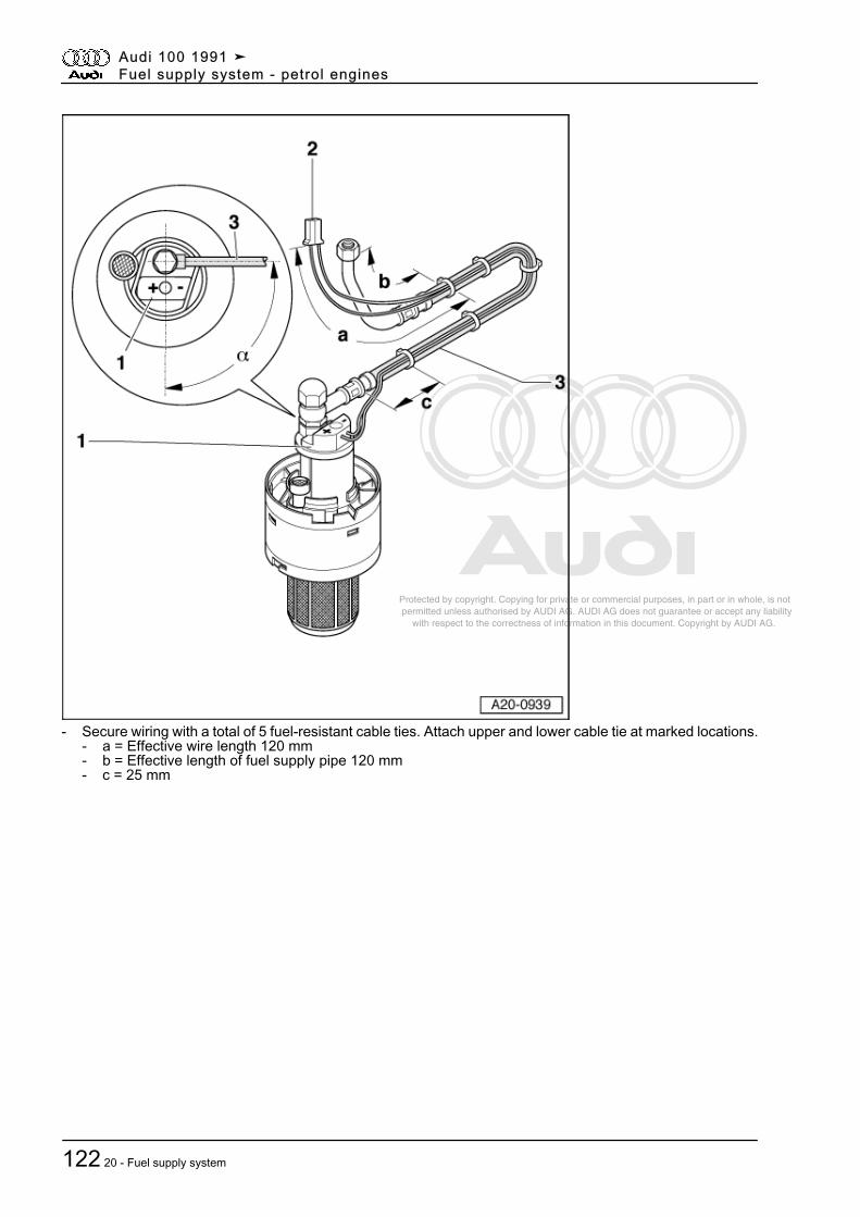
Protected by copyright. Copying for private or commercial purposes, in part or in whole, is not permitted unless authorised by AUDI AG. AUDI AG does not guarantee or accept any liability with respect to the correctness of information in this document. Copyright by AUDI AG.
- Secure wiring with a total of 5 fuel-resistant cable ties. Attach upper and lower cable tie at marked locations.- a = Effective wire length 120 mm- b = Effective length of fuel supply pipe 120 mm- c = 25 mm
Audi 100 1991 ➤Fuel supply system - petrol engines
122 20 - Fuel supply system
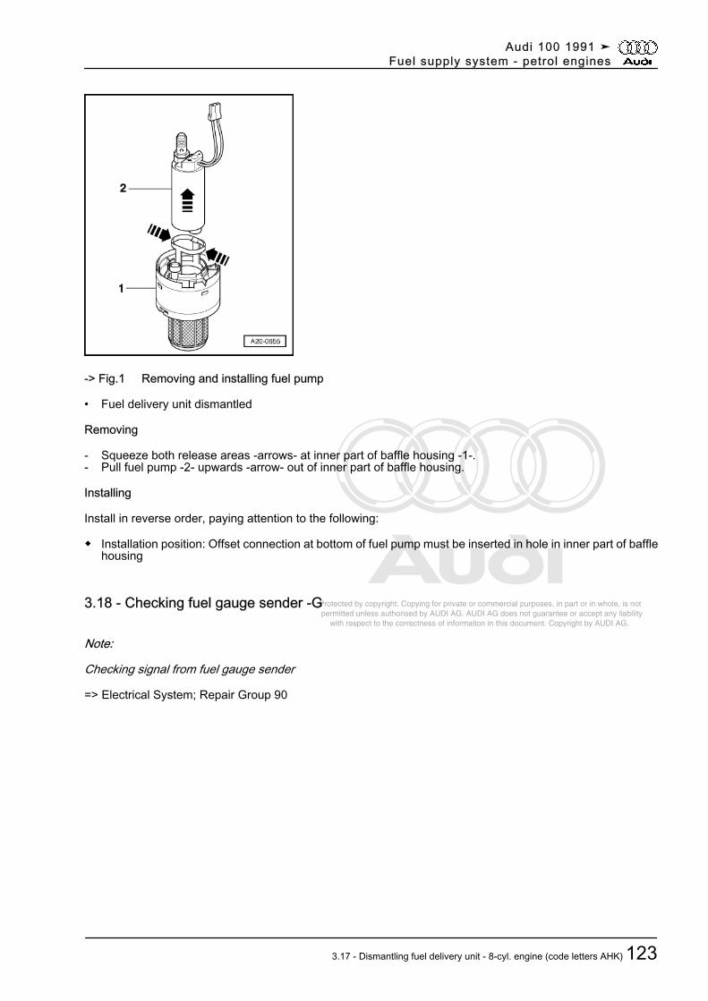
Protected by copyright. Copying for private or commercial purposes, in part or in whole, is not permitted unless authorised by AUDI AG. AUDI AG does not guarantee or accept any liability with respect to the correctness of information in this document. Copyright by AUDI AG.
-> Fig.1 Removing and installing fuel pump
• Fuel delivery unit dismantled
Removing
- Squeeze both release areas -arrows- at inner part of baffle housing -1-.- Pull fuel pump -2- upwards -arrow- out of inner part of baffle housing.
Installing
Install in reverse order, paying attention to the following:
◆ Installation position: Offset connection at bottom of fuel pump must be inserted in hole in inner part of bafflehousing
3.18 - Checking fuel gauge sender -G
Note:
Checking signal from fuel gauge sender
=> Electrical System; Repair Group 90
Audi 100 1991 ➤Fuel supply system - petrol engines
3.17 - Dismantling fuel delivery unit - 8-cyl. engine (code letters AHK) 123

Protected by copyright. Copying for private or commercial purposes, in part or in whole, is not permitted unless authorised by AUDI AG. AUDI AG does not guarantee or accept any liability with respect to the correctness of information in this document. Copyright by AUDI AG.
Special tools and workshop equipment required
◆ V.A.G 1526 A
◆ V.A.G 1594 A
Audi 100 1991 ➤Fuel supply system - petrol engines
124 20 - Fuel supply system
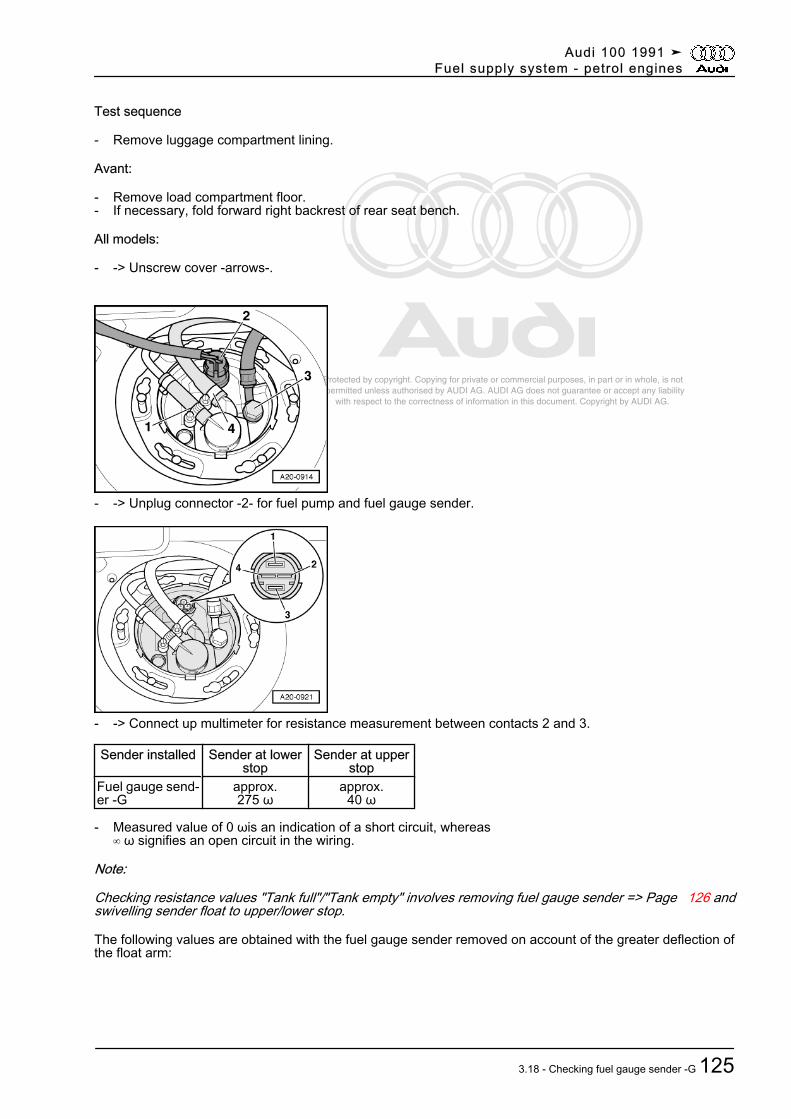
Protected by copyright. Copying for private or commercial purposes, in part or in whole, is not permitted unless authorised by AUDI AG. AUDI AG does not guarantee or accept any liability with respect to the correctness of information in this document. Copyright by AUDI AG.
Test sequence
- Remove luggage compartment lining.
Avant:
- Remove load compartment floor.- If necessary, fold forward right backrest of rear seat bench.
All models:
- -> Unscrew cover -arrows-.
- -> Unplug connector -2- for fuel pump and fuel gauge sender.
- -> Connect up multimeter for resistance measurement between contacts 2 and 3.
Sender installed Sender at lowerstop
Sender at upperstop
Fuel gauge send‐er -G
approx.275 ω
approx.40 ω
- Measured value of 0 ωis an indication of a short circuit, whereas∞ ω signifies an open circuit in the wiring.
Note:
Checking resistance values "Tank full"/"Tank empty" involves removing fuel gauge sender => Page 126 andswivelling sender float to upper/lower stop.
The following values are obtained with the fuel gauge sender removed on account of the greater deflection ofthe float arm:
Audi 100 1991 ➤Fuel supply system - petrol engines
3.18 - Checking fuel gauge sender -G 125
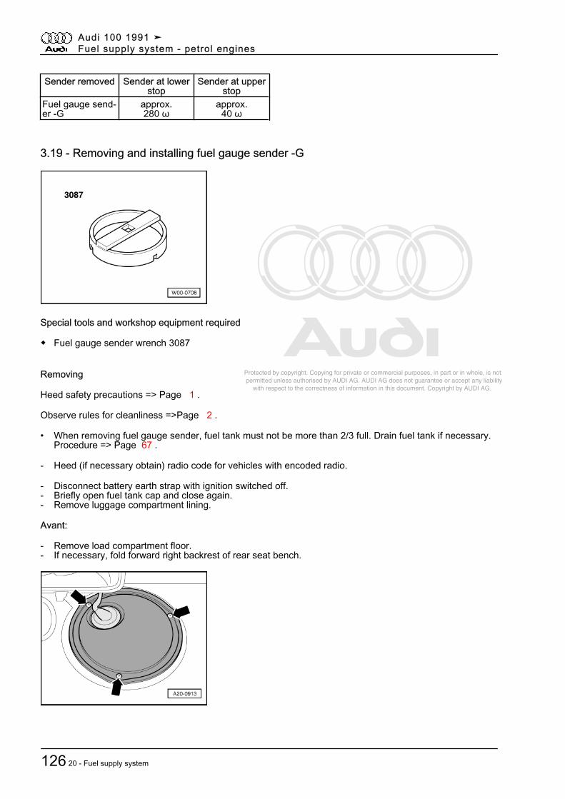
Protected by copyright. Copying for private or commercial purposes, in part or in whole, is not permitted unless authorised by AUDI AG. AUDI AG does not guarantee or accept any liability with respect to the correctness of information in this document. Copyright by AUDI AG.
Sender removed Sender at lowerstop
Sender at upperstop
Fuel gauge send‐er -G
approx.280 ω
approx.40 ω
3.19 - Removing and installing fuel gauge sender -G
Special tools and workshop equipment required
◆ Fuel gauge sender wrench 3087
Removing
Heed safety precautions => Page 1 .
Observe rules for cleanliness =>Page 2 .
• When removing fuel gauge sender, fuel tank must not be more than 2/3 full. Drain fuel tank if necessary.Procedure => Page 67 .
- Heed (if necessary obtain) radio code for vehicles with encoded radio.
- Disconnect battery earth strap with ignition switched off.- Briefly open fuel tank cap and close again.- Remove luggage compartment lining.
Avant:
- Remove load compartment floor.- If necessary, fold forward right backrest of rear seat bench.
Audi 100 1991 ➤Fuel supply system - petrol engines
126 20 - Fuel supply system
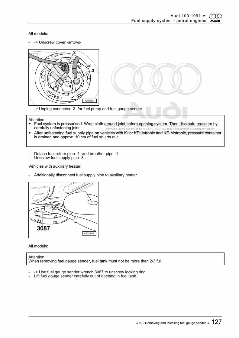
Protected by copyright. Copying for private or commercial purposes, in part or in whole, is not permitted unless authorised by AUDI AG. AUDI AG does not guarantee or accept any liability with respect to the correctness of information in this document. Copyright by AUDI AG.
All models:
- -> Unscrew cover -arrows-.
- -> Unplug connector -2- for fuel pump and fuel gauge sender.
Attention:◆ Fuel system is pressurised. Wrap cloth around joint before opening system. Then dissipate pressure by
carefully unfastening joint.◆ After unfastening fuel supply pipe on vehicles with K- or KE-Jetronic and KE-Motronic, pressure container
is drained and approx. 10 cm of fuel squirts out.
- Detach fuel return pipe -4- and breather pipe -1-.- Unscrew fuel supply pipe -3-.
Vehicles with auxiliary heater:
- Additionally disconnect fuel supply pipe to auxiliary heater.
All models:
Attention:When removing fuel gauge sender, fuel tank must not be more than 2/3 full.
- -> Use fuel gauge sender wrench 3087 to unscrew locking ring.- Lift fuel gauge sender carefully out of opening in fuel tank.
Audi 100 1991 ➤Fuel supply system - petrol engines
3.19 - Removing and installing fuel gauge sender -G 127
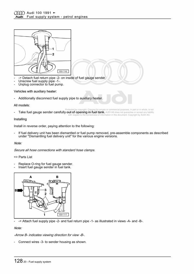
Protected by copyright. Copying for private or commercial purposes, in part or in whole, is not permitted unless authorised by AUDI AG. AUDI AG does not guarantee or accept any liability with respect to the correctness of information in this document. Copyright by AUDI AG.
- -> Detach fuel return pipe -2- on inside of fuel gauge sender.- Unscrew fuel supply pipe -1-.- Unplug connector to fuel pump.
Vehicles with auxiliary heater:
- Additionally disconnect fuel supply pipe to auxiliary heater.
All models:
- Take fuel gauge sender carefully out of opening in fuel tank.
Installing
Install in reverse order, paying attention to the following:
- If fuel delivery unit has been dismantled or fuel pump removed, pre-assemble components as describedunder "Dismantling fuel delivery unit" for the various engine versions.
Note:
Secure all hose connections with standard hose clamps.
=> Parts List
- Replace O-ring for fuel gauge sender.- Insert fuel gauge sender in fuel tank.
- -> Attach fuel supply pipe -2- and fuel return pipe -1- as illustrated in views -A- and -B-.
Note:
-Arrow B- indicates viewing direction for view -B-.
- Connect wires -3- to sender housing as shown.
Audi 100 1991 ➤Fuel supply system - petrol engines
128 20 - Fuel supply system
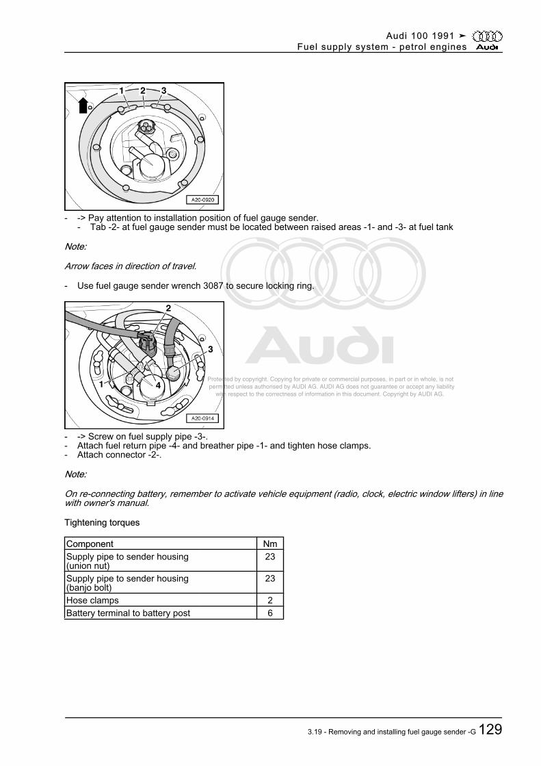
Protected by copyright. Copying for private or commercial purposes, in part or in whole, is not permitted unless authorised by AUDI AG. AUDI AG does not guarantee or accept any liability with respect to the correctness of information in this document. Copyright by AUDI AG.
- -> Pay attention to installation position of fuel gauge sender.- Tab -2- at fuel gauge sender must be located between raised areas -1- and -3- at fuel tank
Note:
Arrow faces in direction of travel.
- Use fuel gauge sender wrench 3087 to secure locking ring.
- -> Screw on fuel supply pipe -3-.- Attach fuel return pipe -4- and breather pipe -1- and tighten hose clamps.- Attach connector -2-.
Note:
On re-connecting battery, remember to activate vehicle equipment (radio, clock, electric window lifters) in linewith owner's manual.
Tightening torques
Component NmSupply pipe to sender housing(union nut)
23
Supply pipe to sender housing(banjo bolt)
23
Hose clamps 2Battery terminal to battery post 6
Audi 100 1991 ➤Fuel supply system - petrol engines
3.19 - Removing and installing fuel gauge sender -G 129
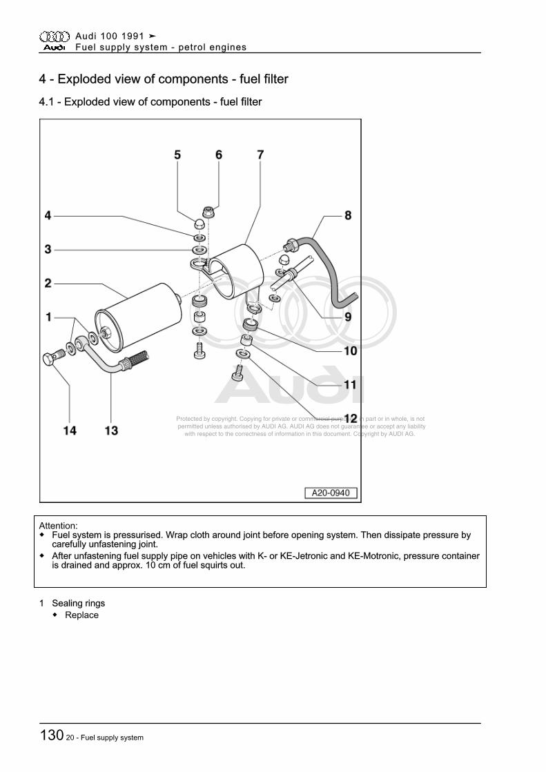
Protected by copyright. Copying for private or commercial purposes, in part or in whole, is not permitted unless authorised by AUDI AG. AUDI AG does not guarantee or accept any liability with respect to the correctness of information in this document. Copyright by AUDI AG.
4 - Exploded view of components - fuel filter4.1 - Exploded view of components - fuel filter
Attention:◆ Fuel system is pressurised. Wrap cloth around joint before opening system. Then dissipate pressure by
carefully unfastening joint.◆ After unfastening fuel supply pipe on vehicles with K- or KE-Jetronic and KE-Motronic, pressure container
is drained and approx. 10 cm of fuel squirts out.
1 Sealing rings◆ Replace
Audi 100 1991 ➤Fuel supply system - petrol engines
130 20 - Fuel supply system
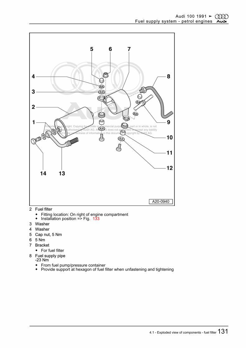
Protected by copyright. Copying for private or commercial purposes, in part or in whole, is not permitted unless authorised by AUDI AG. AUDI AG does not guarantee or accept any liability with respect to the correctness of information in this document. Copyright by AUDI AG.
2 Fuel filter◆ Fitting location: On right of engine compartment◆ Installation position => Fig. 133
3 Washer4 Washer5 Cap nut, 5 Nm6 5 Nm7 Bracket
◆ For fuel filter8 Fuel supply pipe
-23 Nm◆ From fuel pump/pressure container◆ Provide support at hexagon of fuel filter when unfastening and tightening
Audi 100 1991 ➤Fuel supply system - petrol engines
4.1 - Exploded view of components - fuel filter 131
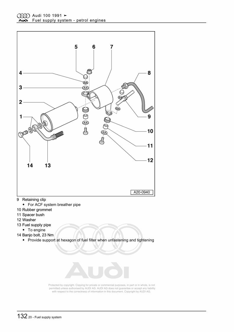
Protected by copyright. Copying for private or commercial purposes, in part or in whole, is not permitted unless authorised by AUDI AG. AUDI AG does not guarantee or accept any liability with respect to the correctness of information in this document. Copyright by AUDI AG.
9 Retaining clip◆ For ACF system breather pipe
10 Rubber grommet11 Spacer bush12 Washer13 Fuel supply pipe
◆ To engine14 Banjo bolt, 23 Nm
◆ Provide support at hexagon of fuel filter when unfastening and tightening
Audi 100 1991 ➤Fuel supply system - petrol engines
132 20 - Fuel supply system
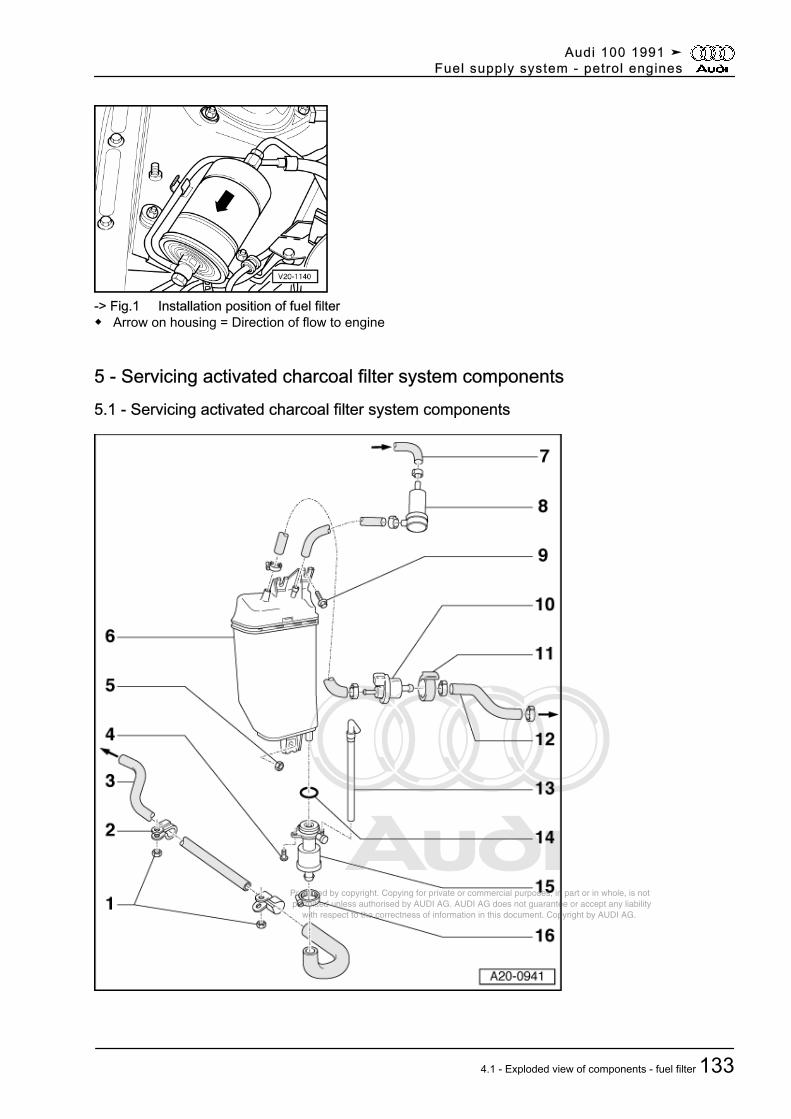
Protected by copyright. Copying for private or commercial purposes, in part or in whole, is not permitted unless authorised by AUDI AG. AUDI AG does not guarantee or accept any liability with respect to the correctness of information in this document. Copyright by AUDI AG.
-> Fig.1 Installation position of fuel filter◆ Arrow on housing = Direction of flow to engine
5 - Servicing activated charcoal filter system components5.1 - Servicing activated charcoal filter system components
Audi 100 1991 ➤Fuel supply system - petrol engines
4.1 - Exploded view of components - fuel filter 133
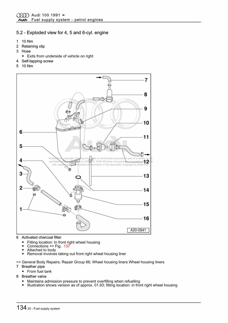
Protected by copyright. Copying for private or commercial purposes, in part or in whole, is not permitted unless authorised by AUDI AG. AUDI AG does not guarantee or accept any liability with respect to the correctness of information in this document. Copyright by AUDI AG.
5.2 - Exploded view for 4, 5 and 6-cyl. engine
1 10 Nm2 Retaining clip3 Hose
◆ Exits from underside of vehicle on right4 Self-tapping screw5 10 Nm
6 Activated charcoal filter◆ Fitting location: In front right wheel housing◆ Connections => Fig. 137◆ Attached to body◆ Removal involves taking out front right wheel housing liner
=> General Body Repairs; Repair Group 66; Wheel housing liners Wheel housing liners7 Breather pipe
◆ From fuel tank8 Breather valve
◆ Maintains admission pressure to prevent overfilling when refuelling◆ Illustration shows version as of approx. 01.93; fitting location: in front right wheel housing
Audi 100 1991 ➤Fuel supply system - petrol engines
134 20 - Fuel supply system
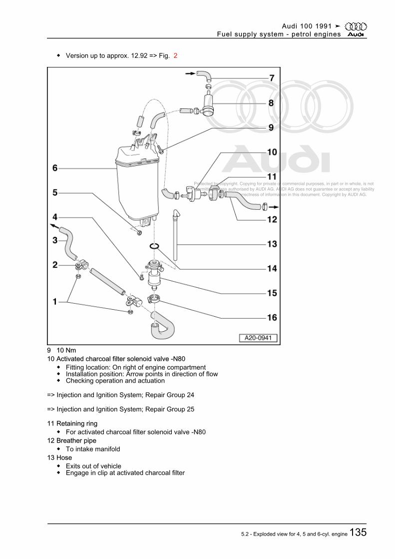
Protected by copyright. Copying for private or commercial purposes, in part or in whole, is not permitted unless authorised by AUDI AG. AUDI AG does not guarantee or accept any liability with respect to the correctness of information in this document. Copyright by AUDI AG.
◆ Version up to approx. 12.92 => Fig. 2
9 10 Nm10 Activated charcoal filter solenoid valve -N80
◆ Fitting location: On right of engine compartment◆ Installation position: Arrow points in direction of flow◆ Checking operation and actuation
=> Injection and Ignition System; Repair Group 24
=> Injection and Ignition System; Repair Group 25
11 Retaining ring◆ For activated charcoal filter solenoid valve -N80
12 Breather pipe◆ To intake manifold
13 Hose◆ Exits out of vehicle◆ Engage in clip at activated charcoal filter
Audi 100 1991 ➤Fuel supply system - petrol engines
5.2 - Exploded view for 4, 5 and 6-cyl. engine 135
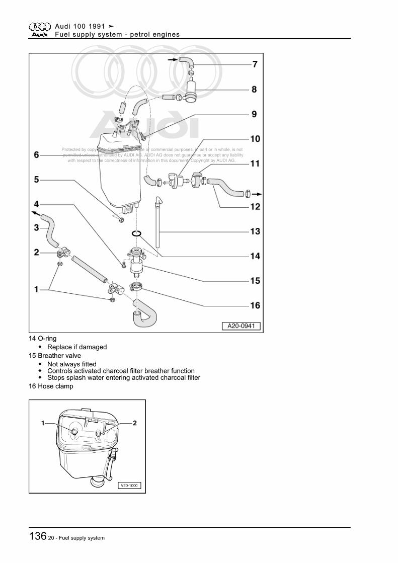
Protected by copyright. Copying for private or commercial purposes, in part or in whole, is not permitted unless authorised by AUDI AG. AUDI AG does not guarantee or accept any liability with respect to the correctness of information in this document. Copyright by AUDI AG.
14 O-ring◆ Replace if damaged
15 Breather valve◆ Not always fitted◆ Controls activated charcoal filter breather function◆ Stops splash water entering activated charcoal filter
16 Hose clamp
Audi 100 1991 ➤Fuel supply system - petrol engines
136 20 - Fuel supply system
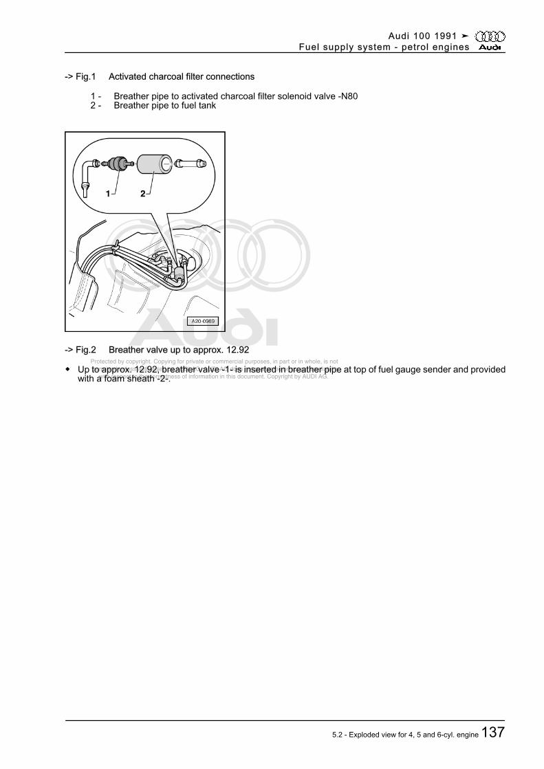
Protected by copyright. Copying for private or commercial purposes, in part or in whole, is not permitted unless authorised by AUDI AG. AUDI AG does not guarantee or accept any liability with respect to the correctness of information in this document. Copyright by AUDI AG.
-> Fig.1 Activated charcoal filter connections
1 - Breather pipe to activated charcoal filter solenoid valve -N80 2 - Breather pipe to fuel tank
-> Fig.2 Breather valve up to approx. 12.92
◆ Up to approx. 12.92, breather valve -1- is inserted in breather pipe at top of fuel gauge sender and providedwith a foam sheath -2-.
Audi 100 1991 ➤Fuel supply system - petrol engines
5.2 - Exploded view for 4, 5 and 6-cyl. engine 137
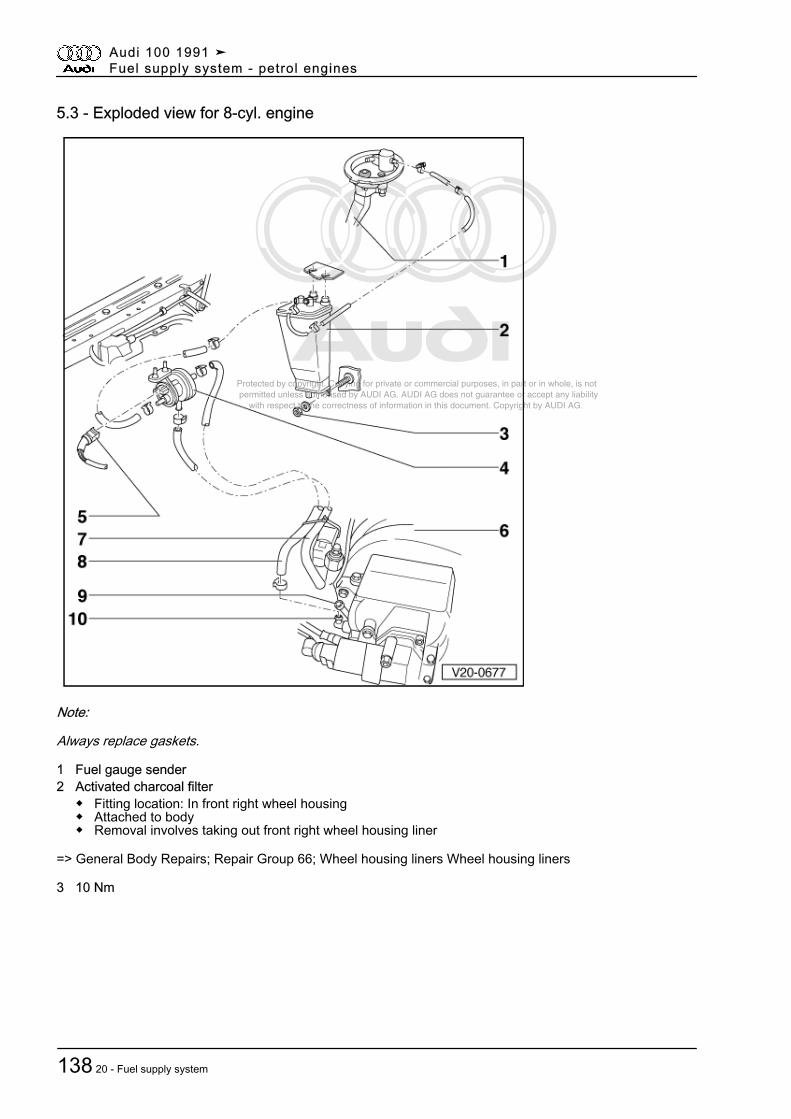
Protected by copyright. Copying for private or commercial purposes, in part or in whole, is not permitted unless authorised by AUDI AG. AUDI AG does not guarantee or accept any liability with respect to the correctness of information in this document. Copyright by AUDI AG.
5.3 - Exploded view for 8-cyl. engine
Note:
Always replace gaskets.
1 Fuel gauge sender2 Activated charcoal filter
◆ Fitting location: In front right wheel housing◆ Attached to body◆ Removal involves taking out front right wheel housing liner
=> General Body Repairs; Repair Group 66; Wheel housing liners Wheel housing liners
3 10 Nm
Audi 100 1991 ➤Fuel supply system - petrol engines
138 20 - Fuel supply system
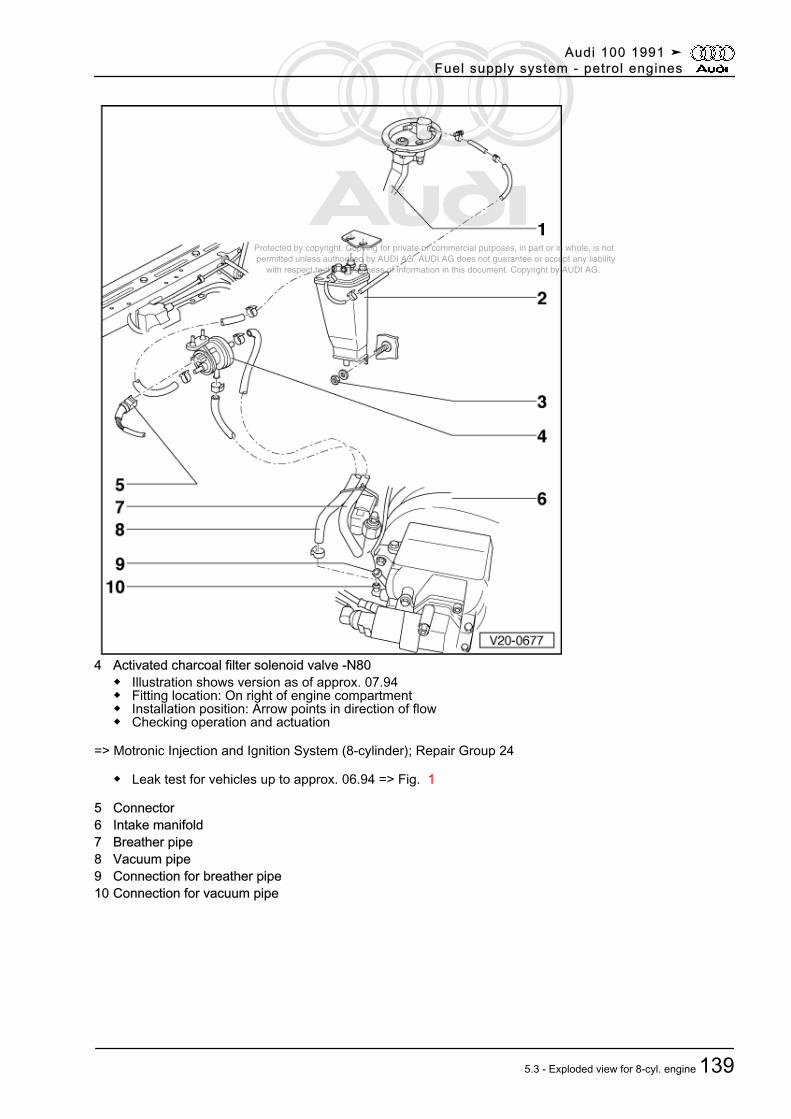
Protected by copyright. Copying for private or commercial purposes, in part or in whole, is not permitted unless authorised by AUDI AG. AUDI AG does not guarantee or accept any liability with respect to the correctness of information in this document. Copyright by AUDI AG.
4 Activated charcoal filter solenoid valve -N80◆ Illustration shows version as of approx. 07.94◆ Fitting location: On right of engine compartment◆ Installation position: Arrow points in direction of flow◆ Checking operation and actuation
=> Motronic Injection and Ignition System (8-cylinder); Repair Group 24
◆ Leak test for vehicles up to approx. 06.94 => Fig. 1
5 Connector6 Intake manifold7 Breather pipe8 Vacuum pipe9 Connection for breather pipe10 Connection for vacuum pipe
Audi 100 1991 ➤Fuel supply system - petrol engines
5.3 - Exploded view for 8-cyl. engine 139
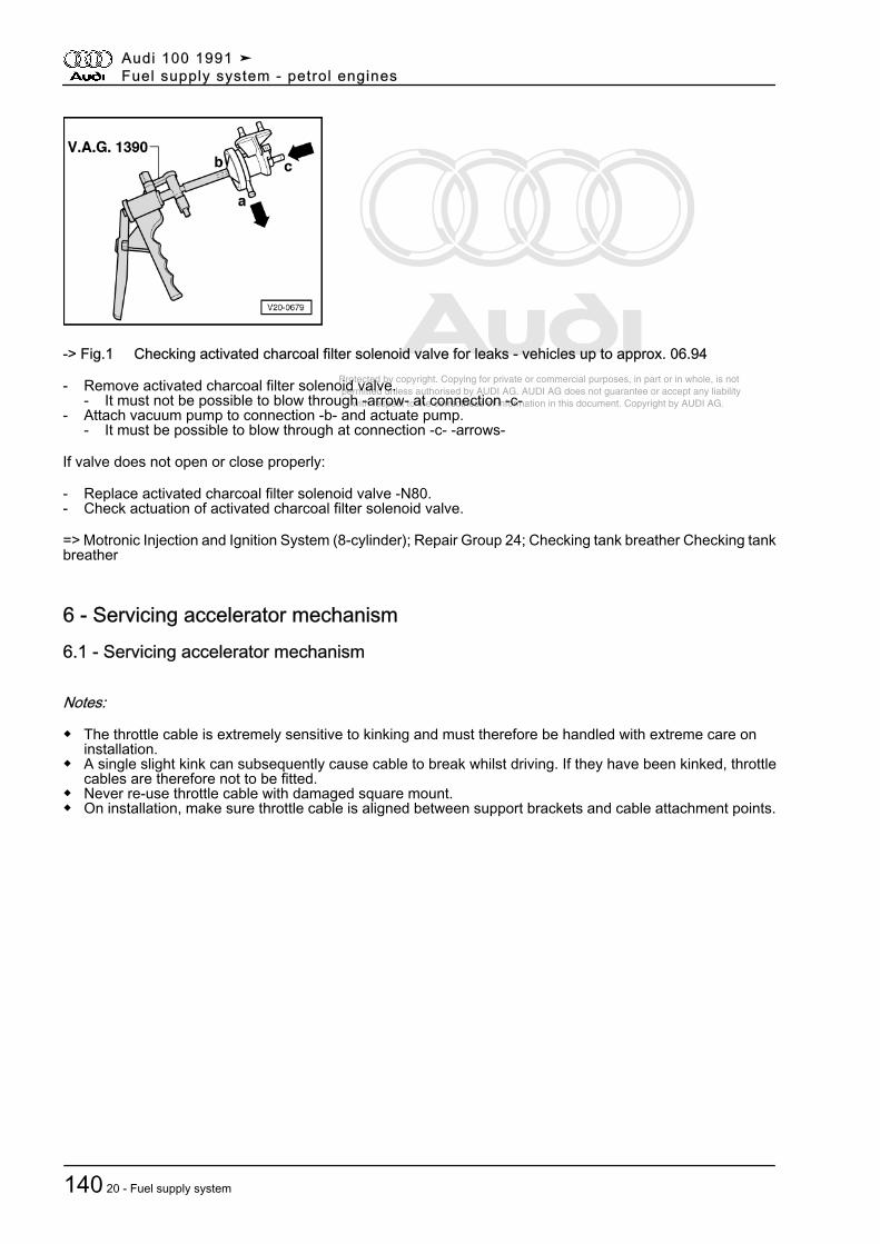
Protected by copyright. Copying for private or commercial purposes, in part or in whole, is not permitted unless authorised by AUDI AG. AUDI AG does not guarantee or accept any liability with respect to the correctness of information in this document. Copyright by AUDI AG.
-> Fig.1 Checking activated charcoal filter solenoid valve for leaks - vehicles up to approx. 06.94
- Remove activated charcoal filter solenoid valve.- It must not be possible to blow through -arrow- at connection -c-
- Attach vacuum pump to connection -b- and actuate pump.- It must be possible to blow through at connection -c- -arrows-
If valve does not open or close properly:
- Replace activated charcoal filter solenoid valve -N80.- Check actuation of activated charcoal filter solenoid valve.
=> Motronic Injection and Ignition System (8-cylinder); Repair Group 24; Checking tank breather Checking tankbreather
6 - Servicing accelerator mechanism6.1 - Servicing accelerator mechanism
Notes:
◆ The throttle cable is extremely sensitive to kinking and must therefore be handled with extreme care oninstallation.
◆ A single slight kink can subsequently cause cable to break whilst driving. If they have been kinked, throttlecables are therefore not to be fitted.
◆ Never re-use throttle cable with damaged square mount.◆ On installation, make sure throttle cable is aligned between support brackets and cable attachment points.
Audi 100 1991 ➤Fuel supply system - petrol engines
140 20 - Fuel supply system
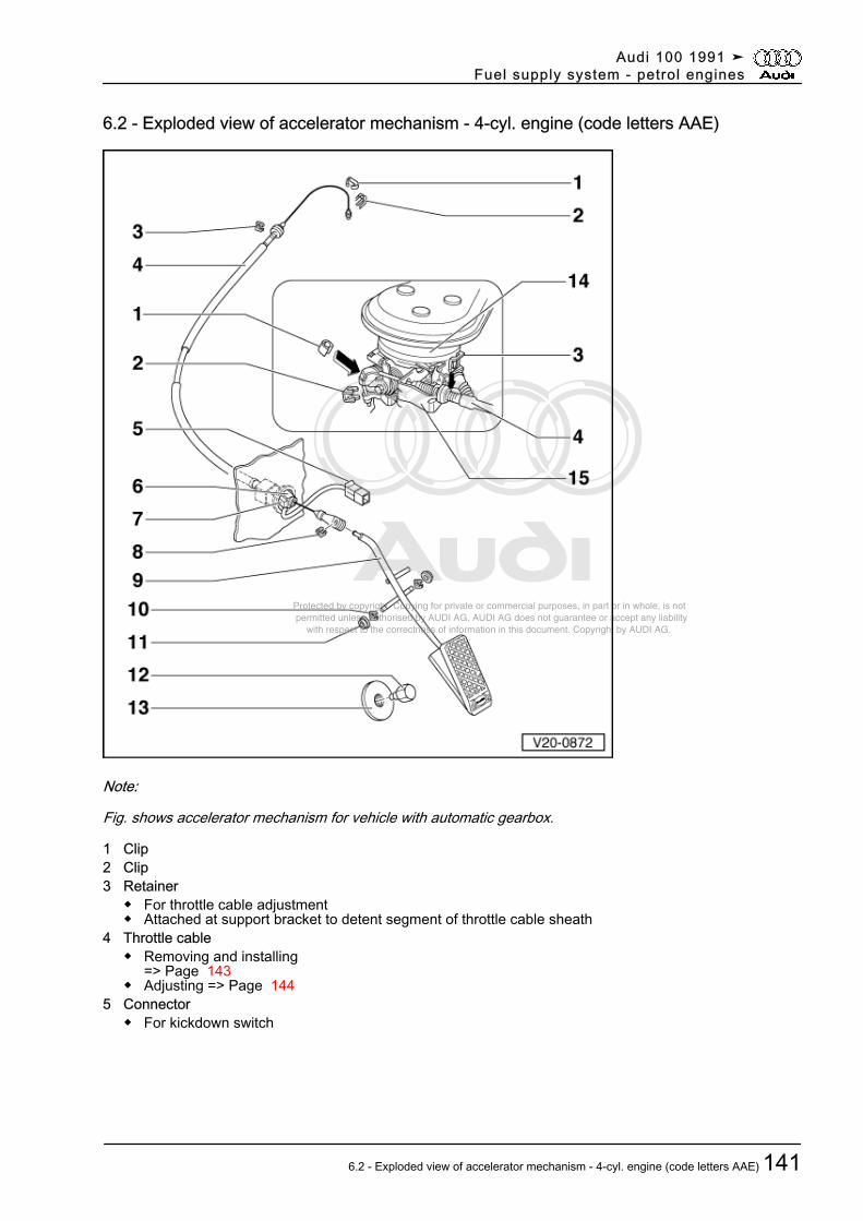
Protected by copyright. Copying for private or commercial purposes, in part or in whole, is not permitted unless authorised by AUDI AG. AUDI AG does not guarantee or accept any liability with respect to the correctness of information in this document. Copyright by AUDI AG.
6.2 - Exploded view of accelerator mechanism - 4-cyl. engine (code letters AAE)
Note:
Fig. shows accelerator mechanism for vehicle with automatic gearbox.
1 Clip2 Clip3 Retainer
◆ For throttle cable adjustment◆ Attached at support bracket to detent segment of throttle cable sheath
4 Throttle cable◆ Removing and installing
=> Page 143◆ Adjusting => Page 144
5 Connector◆ For kickdown switch
Audi 100 1991 ➤Fuel supply system - petrol engines
6.2 - Exploded view of accelerator mechanism - 4-cyl. engine (code letters AAE) 141
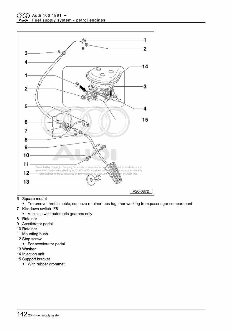
Protected by copyright. Copying for private or commercial purposes, in part or in whole, is not permitted unless authorised by AUDI AG. AUDI AG does not guarantee or accept any liability with respect to the correctness of information in this document. Copyright by AUDI AG.
6 Square mount◆ To remove throttle cable, squeeze retainer tabs together working from passenger compartment
7 Kickdown switch -F8◆ Vehicles with automatic gearbox only
8 Retainer9 Accelerator pedal10 Retainer11 Mounting bush12 Stop screw
◆ For accelerator pedal13 Washer14 Injection unit15 Support bracket
◆ With rubber grommet
Audi 100 1991 ➤Fuel supply system - petrol engines
142 20 - Fuel supply system
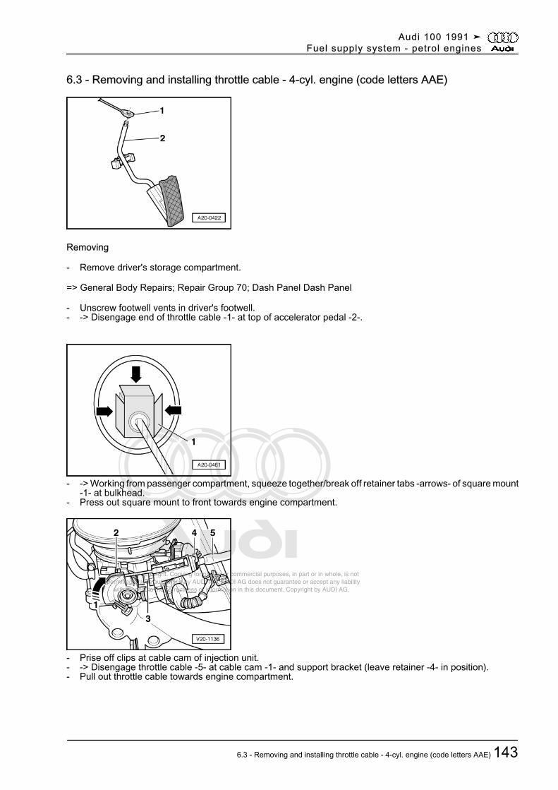
Protected by copyright. Copying for private or commercial purposes, in part or in whole, is not permitted unless authorised by AUDI AG. AUDI AG does not guarantee or accept any liability with respect to the correctness of information in this document. Copyright by AUDI AG.
6.3 - Removing and installing throttle cable - 4-cyl. engine (code letters AAE)
Removing
- Remove driver's storage compartment.
=> General Body Repairs; Repair Group 70; Dash Panel Dash Panel
- Unscrew footwell vents in driver's footwell.- -> Disengage end of throttle cable -1- at top of accelerator pedal -2-.
- -> Working from passenger compartment, squeeze together/break off retainer tabs -arrows- of square mount-1- at bulkhead.
- Press out square mount to front towards engine compartment.
- Prise off clips at cable cam of injection unit.- -> Disengage throttle cable -5- at cable cam -1- and support bracket (leave retainer -4- in position).- Pull out throttle cable towards engine compartment.
Audi 100 1991 ➤Fuel supply system - petrol engines
6.3 - Removing and installing throttle cable - 4-cyl. engine (code letters AAE) 143
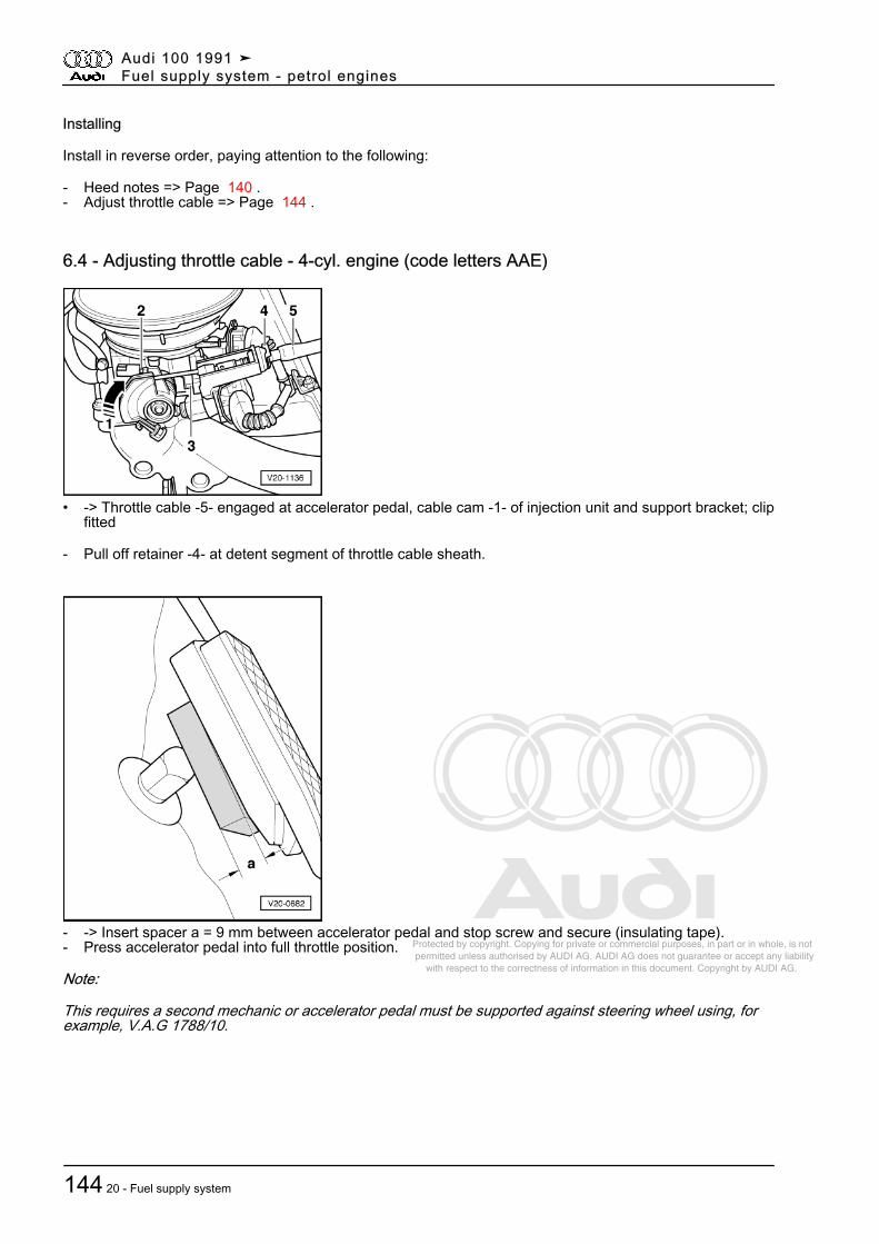
Protected by copyright. Copying for private or commercial purposes, in part or in whole, is not permitted unless authorised by AUDI AG. AUDI AG does not guarantee or accept any liability with respect to the correctness of information in this document. Copyright by AUDI AG.
Installing
Install in reverse order, paying attention to the following:
- Heed notes => Page 140 .- Adjust throttle cable => Page 144 .
6.4 - Adjusting throttle cable - 4-cyl. engine (code letters AAE)
• -> Throttle cable -5- engaged at accelerator pedal, cable cam -1- of injection unit and support bracket; clipfitted
- Pull off retainer -4- at detent segment of throttle cable sheath.
- -> Insert spacer a = 9 mm between accelerator pedal and stop screw and secure (insulating tape).- Press accelerator pedal into full throttle position.
Note:
This requires a second mechanic or accelerator pedal must be supported against steering wheel using, forexample, V.A.G 1788/10.
Audi 100 1991 ➤Fuel supply system - petrol engines
144 20 - Fuel supply system
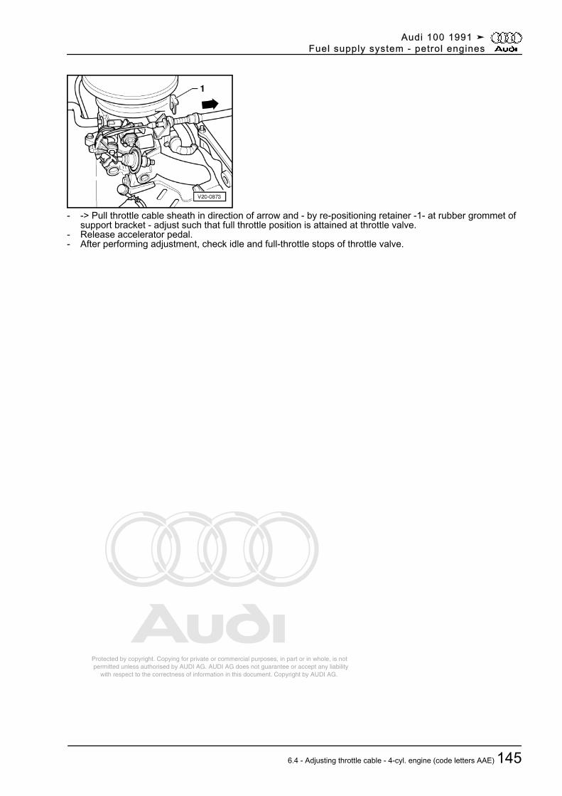
Protected by copyright. Copying for private or commercial purposes, in part or in whole, is not permitted unless authorised by AUDI AG. AUDI AG does not guarantee or accept any liability with respect to the correctness of information in this document. Copyright by AUDI AG.
- -> Pull throttle cable sheath in direction of arrow and - by re-positioning retainer -1- at rubber grommet ofsupport bracket - adjust such that full throttle position is attained at throttle valve.
- Release accelerator pedal.- After performing adjustment, check idle and full-throttle stops of throttle valve.
Audi 100 1991 ➤Fuel supply system - petrol engines
6.4 - Adjusting throttle cable - 4-cyl. engine (code letters AAE) 145
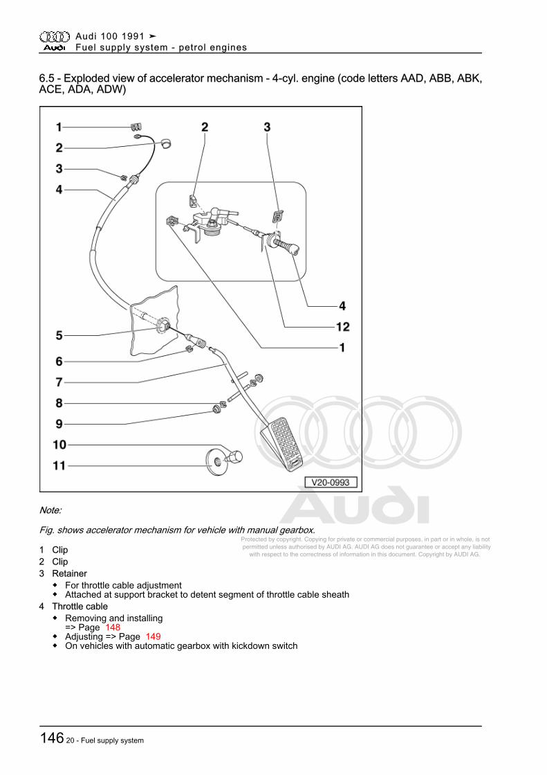
Protected by copyright. Copying for private or commercial purposes, in part or in whole, is not permitted unless authorised by AUDI AG. AUDI AG does not guarantee or accept any liability with respect to the correctness of information in this document. Copyright by AUDI AG.
6.5 - Exploded view of accelerator mechanism - 4-cyl. engine (code letters AAD, ABB, ABK,ACE, ADA, ADW)
Note:
Fig. shows accelerator mechanism for vehicle with manual gearbox.
1 Clip2 Clip3 Retainer
◆ For throttle cable adjustment◆ Attached at support bracket to detent segment of throttle cable sheath
4 Throttle cable◆ Removing and installing
=> Page 148◆ Adjusting => Page 149◆ On vehicles with automatic gearbox with kickdown switch
Audi 100 1991 ➤Fuel supply system - petrol engines
146 20 - Fuel supply system
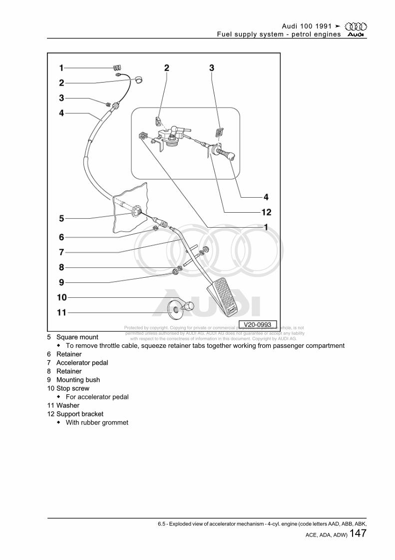
Protected by copyright. Copying for private or commercial purposes, in part or in whole, is not permitted unless authorised by AUDI AG. AUDI AG does not guarantee or accept any liability with respect to the correctness of information in this document. Copyright by AUDI AG.5 Square mount
◆ To remove throttle cable, squeeze retainer tabs together working from passenger compartment6 Retainer7 Accelerator pedal8 Retainer9 Mounting bush10 Stop screw
◆ For accelerator pedal11 Washer12 Support bracket
◆ With rubber grommet
Audi 100 1991 ➤Fuel supply system - petrol engines
6.5 - Exploded view of accelerator mechanism - 4-cyl. engine (code letters AAD, ABB, ABK,
ACE, ADA, ADW) 147
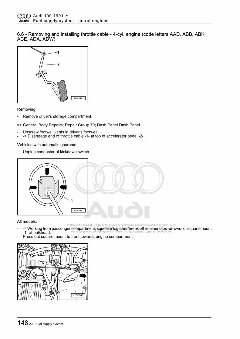
Protected by copyright. Copying for private or commercial purposes, in part or in whole, is not permitted unless authorised by AUDI AG. AUDI AG does not guarantee or accept any liability with respect to the correctness of information in this document. Copyright by AUDI AG.
6.6 - Removing and installing throttle cable - 4-cyl. engine (code letters AAD, ABB, ABK,ACE, ADA, ADW)
Removing- Remove driver's storage compartment.
=> General Body Repairs; Repair Group 70; Dash Panel Dash Panel- Unscrew footwell vents in driver's footwell.- -> Disengage end of throttle cable -1- at top of accelerator pedal -2-.
Vehicles with automatic gearbox:- Unplug connector at kickdown switch.
All models:- -> Working from passenger compartment, squeeze together/break off retainer tabs -arrows- of square mount
-1- at bulkhead.- Press out square mount to front towards engine compartment.
Audi 100 1991 ➤Fuel supply system - petrol engines
148 20 - Fuel supply system
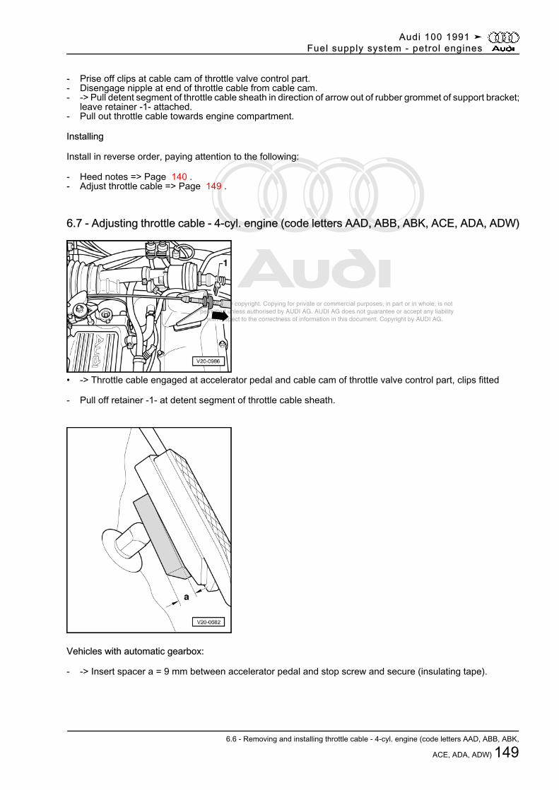
Protected by copyright. Copying for private or commercial purposes, in part or in whole, is not permitted unless authorised by AUDI AG. AUDI AG does not guarantee or accept any liability with respect to the correctness of information in this document. Copyright by AUDI AG.
- Prise off clips at cable cam of throttle valve control part.- Disengage nipple at end of throttle cable from cable cam.- -> Pull detent segment of throttle cable sheath in direction of arrow out of rubber grommet of support bracket;
leave retainer -1- attached.- Pull out throttle cable towards engine compartment.
Installing
Install in reverse order, paying attention to the following:
- Heed notes => Page 140 .- Adjust throttle cable => Page 149 .
6.7 - Adjusting throttle cable - 4-cyl. engine (code letters AAD, ABB, ABK, ACE, ADA, ADW)
• -> Throttle cable engaged at accelerator pedal and cable cam of throttle valve control part, clips fitted
- Pull off retainer -1- at detent segment of throttle cable sheath.
Vehicles with automatic gearbox:
- -> Insert spacer a = 9 mm between accelerator pedal and stop screw and secure (insulating tape).
Audi 100 1991 ➤Fuel supply system - petrol engines
6.6 - Removing and installing throttle cable - 4-cyl. engine (code letters AAD, ABB, ABK,
ACE, ADA, ADW) 149
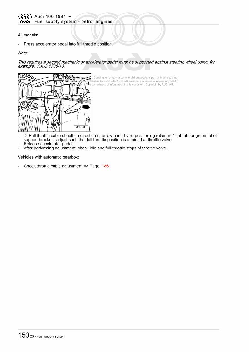
Protected by copyright. Copying for private or commercial purposes, in part or in whole, is not permitted unless authorised by AUDI AG. AUDI AG does not guarantee or accept any liability with respect to the correctness of information in this document. Copyright by AUDI AG.
All models:
- Press accelerator pedal into full throttle position.
Note:
This requires a second mechanic or accelerator pedal must be supported against steering wheel using, forexample, V.A.G 1788/10.
- -> Pull throttle cable sheath in direction of arrow and - by re-positioning retainer -1- at rubber grommet ofsupport bracket - adjust such that full throttle position is attained at throttle valve.
- Release accelerator pedal.- After performing adjustment, check idle and full-throttle stops of throttle valve.
Vehicles with automatic gearbox:
- Check throttle cable adjustment => Page 186 .
Audi 100 1991 ➤Fuel supply system - petrol engines
150 20 - Fuel supply system
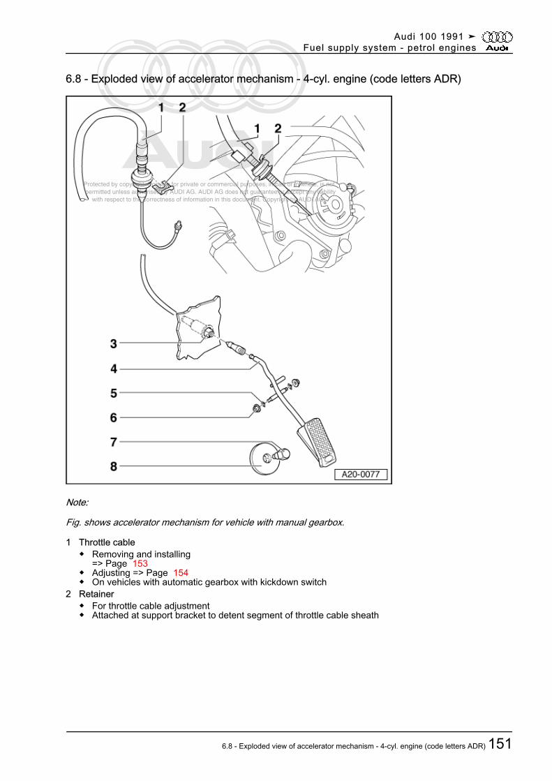
Protected by copyright. Copying for private or commercial purposes, in part or in whole, is not permitted unless authorised by AUDI AG. AUDI AG does not guarantee or accept any liability with respect to the correctness of information in this document. Copyright by AUDI AG.
6.8 - Exploded view of accelerator mechanism - 4-cyl. engine (code letters ADR)
Note:
Fig. shows accelerator mechanism for vehicle with manual gearbox.
1 Throttle cable◆ Removing and installing
=> Page 153◆ Adjusting => Page 154◆ On vehicles with automatic gearbox with kickdown switch
2 Retainer◆ For throttle cable adjustment◆ Attached at support bracket to detent segment of throttle cable sheath
Audi 100 1991 ➤Fuel supply system - petrol engines
6.8 - Exploded view of accelerator mechanism - 4-cyl. engine (code letters ADR) 151
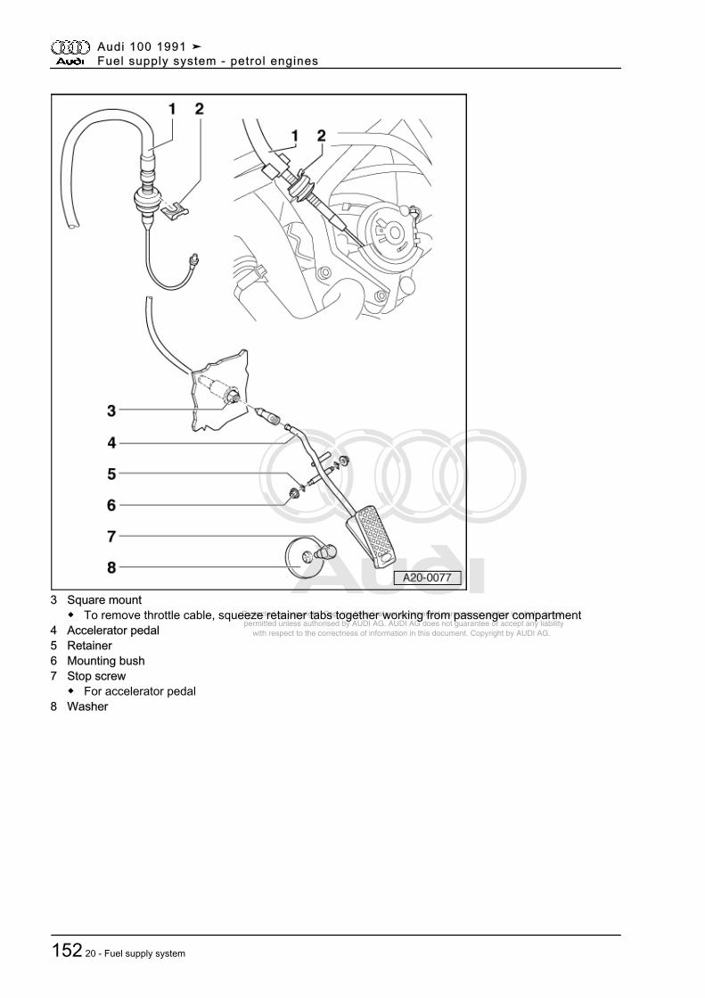
Protected by copyright. Copying for private or commercial purposes, in part or in whole, is not permitted unless authorised by AUDI AG. AUDI AG does not guarantee or accept any liability with respect to the correctness of information in this document. Copyright by AUDI AG.
3 Square mount◆ To remove throttle cable, squeeze retainer tabs together working from passenger compartment
4 Accelerator pedal5 Retainer6 Mounting bush7 Stop screw
◆ For accelerator pedal8 Washer
Audi 100 1991 ➤Fuel supply system - petrol engines
152 20 - Fuel supply system
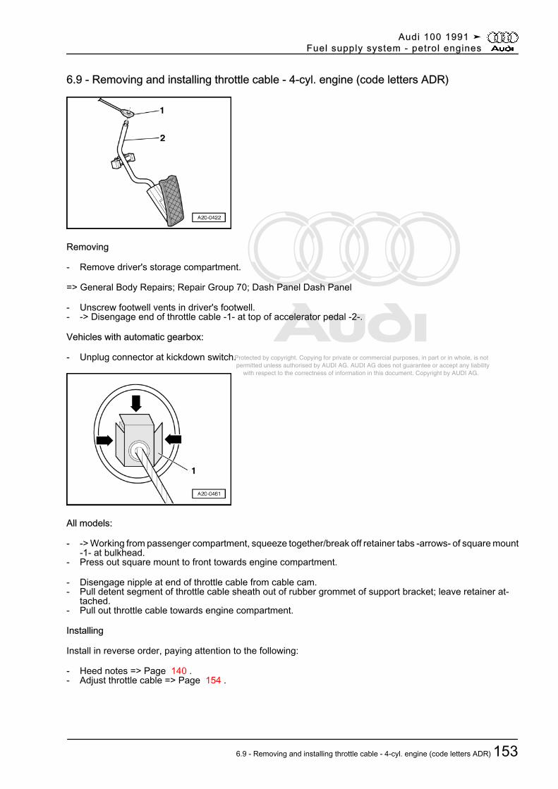
Protected by copyright. Copying for private or commercial purposes, in part or in whole, is not permitted unless authorised by AUDI AG. AUDI AG does not guarantee or accept any liability with respect to the correctness of information in this document. Copyright by AUDI AG.
6.9 - Removing and installing throttle cable - 4-cyl. engine (code letters ADR)
Removing
- Remove driver's storage compartment.
=> General Body Repairs; Repair Group 70; Dash Panel Dash Panel
- Unscrew footwell vents in driver's footwell.- -> Disengage end of throttle cable -1- at top of accelerator pedal -2-.
Vehicles with automatic gearbox:
- Unplug connector at kickdown switch.
All models:
- -> Working from passenger compartment, squeeze together/break off retainer tabs -arrows- of square mount-1- at bulkhead.
- Press out square mount to front towards engine compartment.
- Disengage nipple at end of throttle cable from cable cam.- Pull detent segment of throttle cable sheath out of rubber grommet of support bracket; leave retainer at‐
tached.- Pull out throttle cable towards engine compartment.
Installing
Install in reverse order, paying attention to the following:
- Heed notes => Page 140 .- Adjust throttle cable => Page 154 .
Audi 100 1991 ➤Fuel supply system - petrol engines
6.9 - Removing and installing throttle cable - 4-cyl. engine (code letters ADR) 153
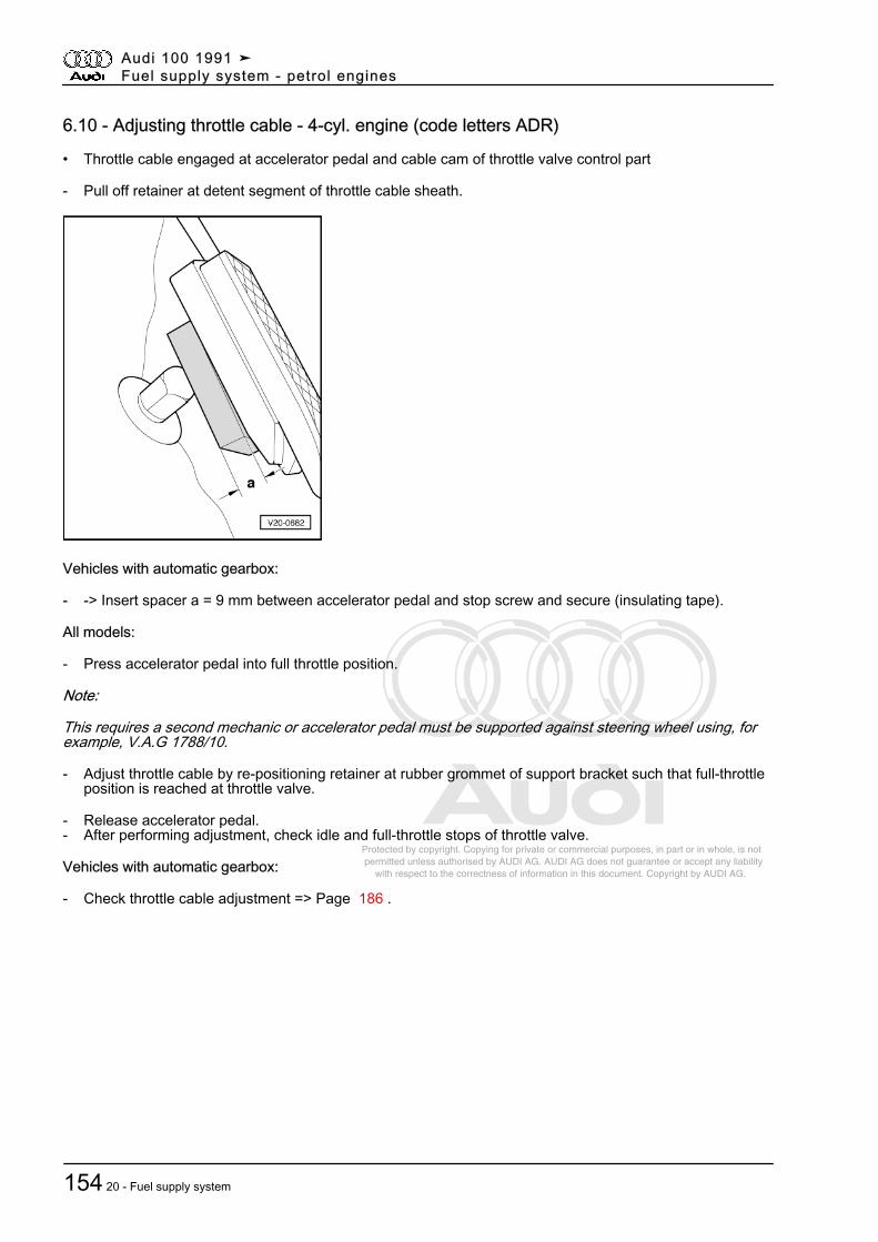
Protected by copyright. Copying for private or commercial purposes, in part or in whole, is not permitted unless authorised by AUDI AG. AUDI AG does not guarantee or accept any liability with respect to the correctness of information in this document. Copyright by AUDI AG.
6.10 - Adjusting throttle cable - 4-cyl. engine (code letters ADR)
• Throttle cable engaged at accelerator pedal and cable cam of throttle valve control part
- Pull off retainer at detent segment of throttle cable sheath.
Vehicles with automatic gearbox:
- -> Insert spacer a = 9 mm between accelerator pedal and stop screw and secure (insulating tape).
All models:
- Press accelerator pedal into full throttle position.
Note:
This requires a second mechanic or accelerator pedal must be supported against steering wheel using, forexample, V.A.G 1788/10.
- Adjust throttle cable by re-positioning retainer at rubber grommet of support bracket such that full-throttleposition is reached at throttle valve.
- Release accelerator pedal.- After performing adjustment, check idle and full-throttle stops of throttle valve.
Vehicles with automatic gearbox:
- Check throttle cable adjustment => Page 186 .
Audi 100 1991 ➤Fuel supply system - petrol engines
154 20 - Fuel supply system
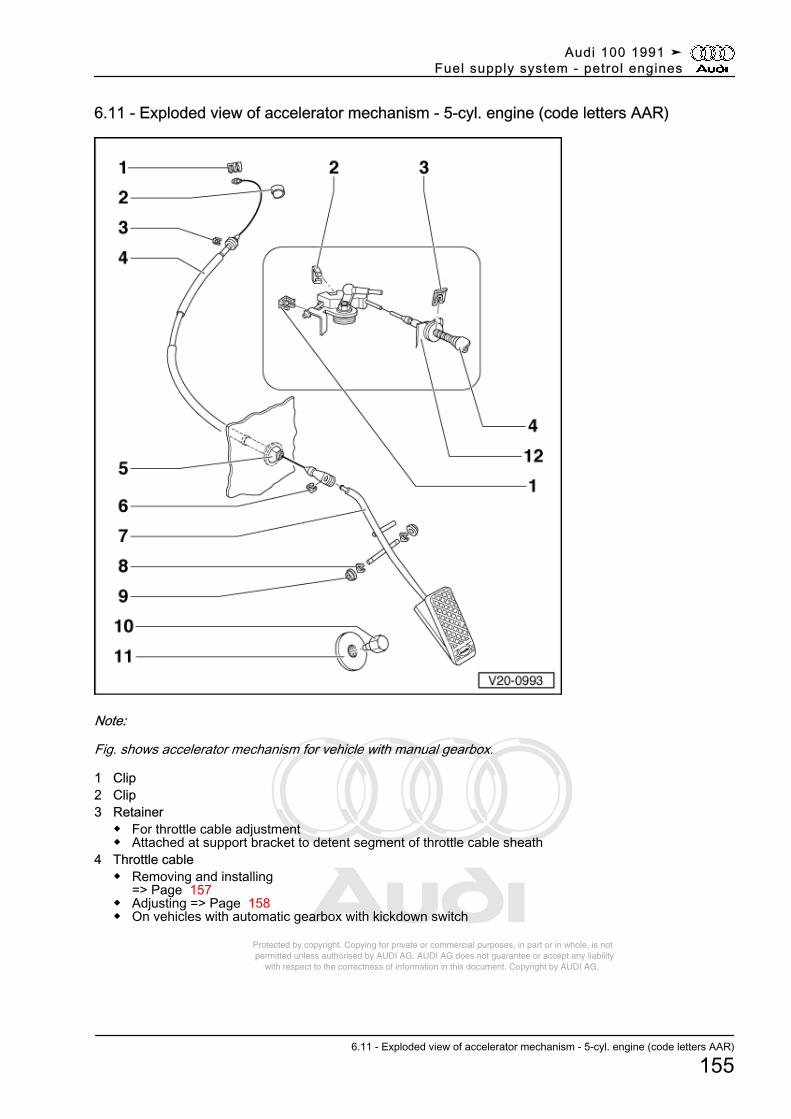
Protected by copyright. Copying for private or commercial purposes, in part or in whole, is not permitted unless authorised by AUDI AG. AUDI AG does not guarantee or accept any liability with respect to the correctness of information in this document. Copyright by AUDI AG.
6.11 - Exploded view of accelerator mechanism - 5-cyl. engine (code letters AAR)
Note:
Fig. shows accelerator mechanism for vehicle with manual gearbox.
1 Clip2 Clip3 Retainer
◆ For throttle cable adjustment◆ Attached at support bracket to detent segment of throttle cable sheath
4 Throttle cable◆ Removing and installing
=> Page 157◆ Adjusting => Page 158◆ On vehicles with automatic gearbox with kickdown switch
Audi 100 1991 ➤Fuel supply system - petrol engines
6.11 - Exploded view of accelerator mechanism - 5-cyl. engine (code letters AAR)
155
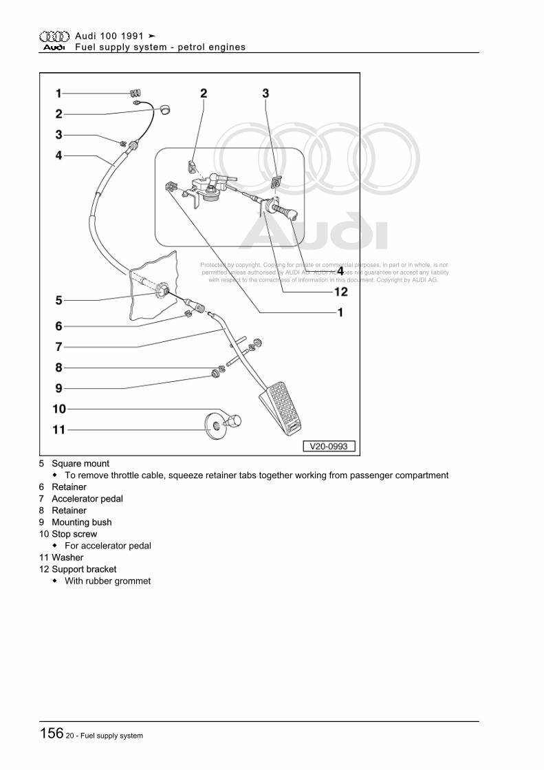
Protected by copyright. Copying for private or commercial purposes, in part or in whole, is not permitted unless authorised by AUDI AG. AUDI AG does not guarantee or accept any liability with respect to the correctness of information in this document. Copyright by AUDI AG.
5 Square mount◆ To remove throttle cable, squeeze retainer tabs together working from passenger compartment
6 Retainer7 Accelerator pedal8 Retainer9 Mounting bush10 Stop screw
◆ For accelerator pedal11 Washer12 Support bracket
◆ With rubber grommet
Audi 100 1991 ➤Fuel supply system - petrol engines
156 20 - Fuel supply system
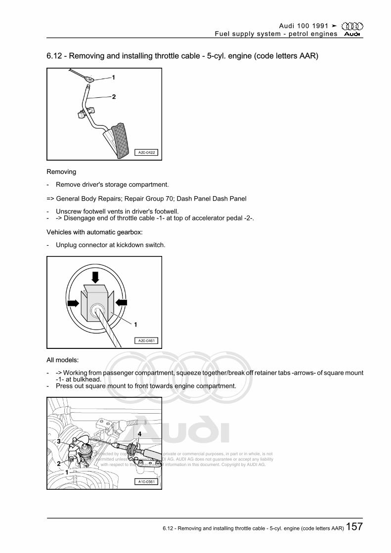
Protected by copyright. Copying for private or commercial purposes, in part or in whole, is not permitted unless authorised by AUDI AG. AUDI AG does not guarantee or accept any liability with respect to the correctness of information in this document. Copyright by AUDI AG.
6.12 - Removing and installing throttle cable - 5-cyl. engine (code letters AAR)
Removing
- Remove driver's storage compartment.
=> General Body Repairs; Repair Group 70; Dash Panel Dash Panel
- Unscrew footwell vents in driver's footwell.- -> Disengage end of throttle cable -1- at top of accelerator pedal -2-.
Vehicles with automatic gearbox:
- Unplug connector at kickdown switch.
All models:
- -> Working from passenger compartment, squeeze together/break off retainer tabs -arrows- of square mount-1- at bulkhead.
- Press out square mount to front towards engine compartment.
Audi 100 1991 ➤Fuel supply system - petrol engines
6.12 - Removing and installing throttle cable - 5-cyl. engine (code letters AAR) 157
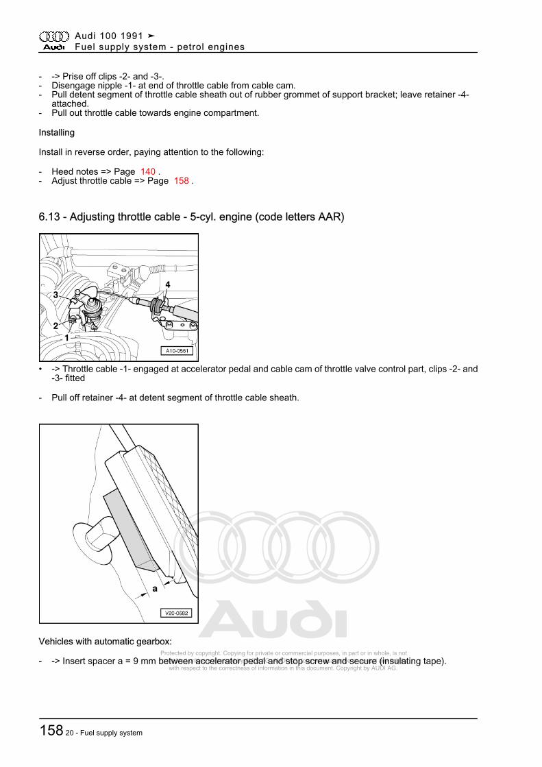
Protected by copyright. Copying for private or commercial purposes, in part or in whole, is not permitted unless authorised by AUDI AG. AUDI AG does not guarantee or accept any liability with respect to the correctness of information in this document. Copyright by AUDI AG.
- -> Prise off clips -2- and -3-.- Disengage nipple -1- at end of throttle cable from cable cam.- Pull detent segment of throttle cable sheath out of rubber grommet of support bracket; leave retainer -4-
attached.- Pull out throttle cable towards engine compartment.
Installing
Install in reverse order, paying attention to the following:
- Heed notes => Page 140 .- Adjust throttle cable => Page 158 .
6.13 - Adjusting throttle cable - 5-cyl. engine (code letters AAR)
• -> Throttle cable -1- engaged at accelerator pedal and cable cam of throttle valve control part, clips -2- and-3- fitted
- Pull off retainer -4- at detent segment of throttle cable sheath.
Vehicles with automatic gearbox:
- -> Insert spacer a = 9 mm between accelerator pedal and stop screw and secure (insulating tape).
Audi 100 1991 ➤Fuel supply system - petrol engines
158 20 - Fuel supply system
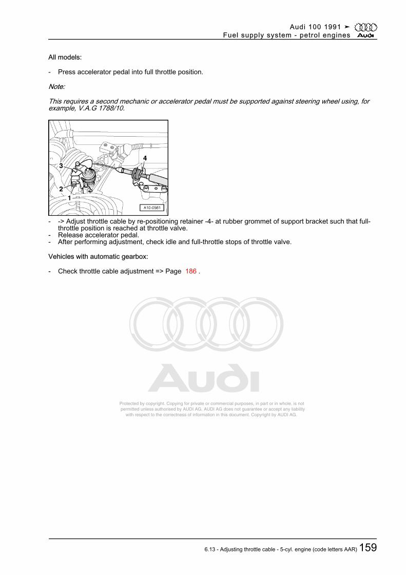
Protected by copyright. Copying for private or commercial purposes, in part or in whole, is not permitted unless authorised by AUDI AG. AUDI AG does not guarantee or accept any liability with respect to the correctness of information in this document. Copyright by AUDI AG.
All models:
- Press accelerator pedal into full throttle position.
Note:
This requires a second mechanic or accelerator pedal must be supported against steering wheel using, forexample, V.A.G 1788/10.
- -> Adjust throttle cable by re-positioning retainer -4- at rubber grommet of support bracket such that full-throttle position is reached at throttle valve.
- Release accelerator pedal.- After performing adjustment, check idle and full-throttle stops of throttle valve.
Vehicles with automatic gearbox:
- Check throttle cable adjustment => Page 186 .
Audi 100 1991 ➤Fuel supply system - petrol engines
6.13 - Adjusting throttle cable - 5-cyl. engine (code letters AAR) 159
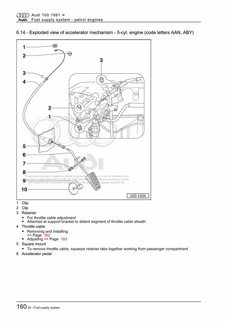
Protected by copyright. Copying for private or commercial purposes, in part or in whole, is not permitted unless authorised by AUDI AG. AUDI AG does not guarantee or accept any liability with respect to the correctness of information in this document. Copyright by AUDI AG.
6.14 - Exploded view of accelerator mechanism - 5-cyl. engine (code letters AAN, ABY)
1 Clip2 Clip3 Retainer
◆ For throttle cable adjustment◆ Attached at support bracket to detent segment of throttle cable sheath
4 Throttle cable◆ Removing and installing
=> Page 162◆ Adjusting => Page 163
5 Square mount◆ To remove throttle cable, squeeze retainer tabs together working from passenger compartment
6 Accelerator pedal
Audi 100 1991 ➤Fuel supply system - petrol engines
160 20 - Fuel supply system
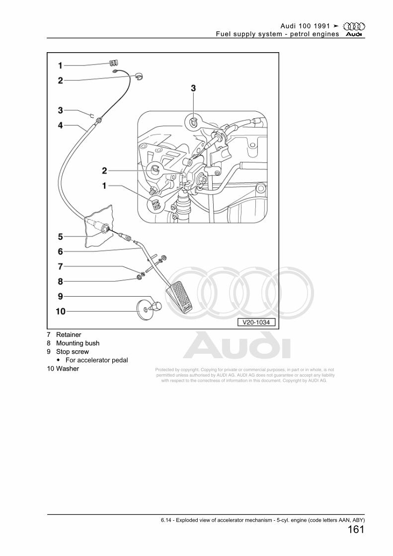
Protected by copyright. Copying for private or commercial purposes, in part or in whole, is not permitted unless authorised by AUDI AG. AUDI AG does not guarantee or accept any liability with respect to the correctness of information in this document. Copyright by AUDI AG.
7 Retainer8 Mounting bush9 Stop screw
◆ For accelerator pedal10 Washer
Audi 100 1991 ➤Fuel supply system - petrol engines
6.14 - Exploded view of accelerator mechanism - 5-cyl. engine (code letters AAN, ABY)
161
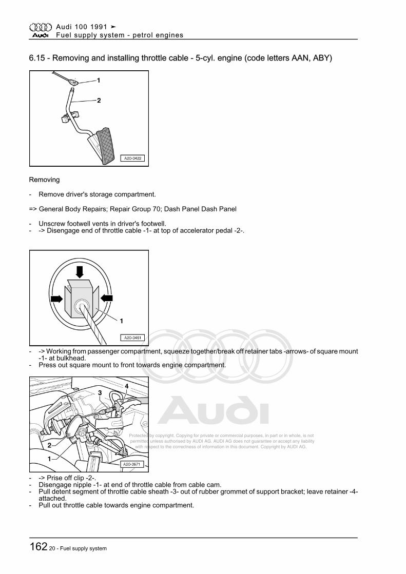
Protected by copyright. Copying for private or commercial purposes, in part or in whole, is not permitted unless authorised by AUDI AG. AUDI AG does not guarantee or accept any liability with respect to the correctness of information in this document. Copyright by AUDI AG.
6.15 - Removing and installing throttle cable - 5-cyl. engine (code letters AAN, ABY)
Removing
- Remove driver's storage compartment.
=> General Body Repairs; Repair Group 70; Dash Panel Dash Panel
- Unscrew footwell vents in driver's footwell.- -> Disengage end of throttle cable -1- at top of accelerator pedal -2-.
- -> Working from passenger compartment, squeeze together/break off retainer tabs -arrows- of square mount-1- at bulkhead.
- Press out square mount to front towards engine compartment.
- -> Prise off clip -2-.- Disengage nipple -1- at end of throttle cable from cable cam.- Pull detent segment of throttle cable sheath -3- out of rubber grommet of support bracket; leave retainer -4-
attached.- Pull out throttle cable towards engine compartment.
Audi 100 1991 ➤Fuel supply system - petrol engines
162 20 - Fuel supply system
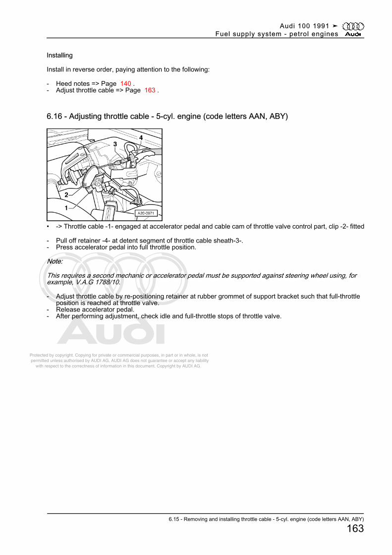
Protected by copyright. Copying for private or commercial purposes, in part or in whole, is not permitted unless authorised by AUDI AG. AUDI AG does not guarantee or accept any liability with respect to the correctness of information in this document. Copyright by AUDI AG.
Installing
Install in reverse order, paying attention to the following:
- Heed notes => Page 140 .- Adjust throttle cable => Page 163 .
6.16 - Adjusting throttle cable - 5-cyl. engine (code letters AAN, ABY)
• -> Throttle cable -1- engaged at accelerator pedal and cable cam of throttle valve control part, clip -2- fitted
- Pull off retainer -4- at detent segment of throttle cable sheath-3-.- Press accelerator pedal into full throttle position.
Note:
This requires a second mechanic or accelerator pedal must be supported against steering wheel using, forexample, V.A.G 1788/10.
- Adjust throttle cable by re-positioning retainer at rubber grommet of support bracket such that full-throttleposition is reached at throttle valve.
- Release accelerator pedal.- After performing adjustment, check idle and full-throttle stops of throttle valve.
Audi 100 1991 ➤Fuel supply system - petrol engines
6.15 - Removing and installing throttle cable - 5-cyl. engine (code letters AAN, ABY)
163
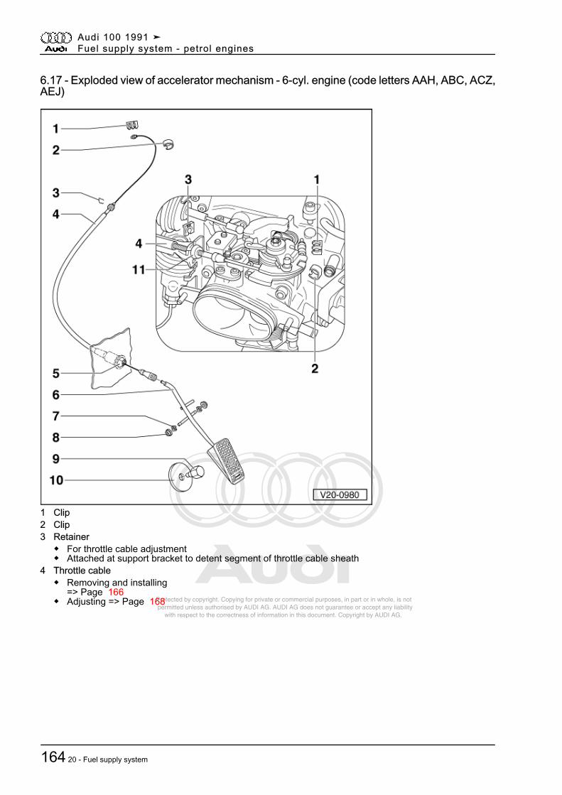
Protected by copyright. Copying for private or commercial purposes, in part or in whole, is not permitted unless authorised by AUDI AG. AUDI AG does not guarantee or accept any liability with respect to the correctness of information in this document. Copyright by AUDI AG.
6.17 - Exploded view of accelerator mechanism - 6-cyl. engine (code letters AAH, ABC, ACZ,AEJ)
1 Clip2 Clip3 Retainer
◆ For throttle cable adjustment◆ Attached at support bracket to detent segment of throttle cable sheath
4 Throttle cable◆ Removing and installing
=> Page 166◆ Adjusting => Page 168
Audi 100 1991 ➤Fuel supply system - petrol engines
164 20 - Fuel supply system
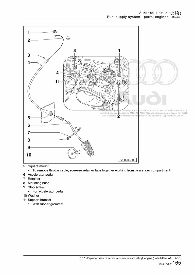
Protected by copyright. Copying for private or commercial purposes, in part or in whole, is not permitted unless authorised by AUDI AG. AUDI AG does not guarantee or accept any liability with respect to the correctness of information in this document. Copyright by AUDI AG.
5 Square mount◆ To remove throttle cable, squeeze retainer tabs together working from passenger compartment
6 Accelerator pedal7 Retainer8 Mounting bush9 Stop screw
◆ For accelerator pedal10 Washer11 Support bracket
◆ With rubber grommet
Audi 100 1991 ➤Fuel supply system - petrol engines
6.17 - Exploded view of accelerator mechanism - 6-cyl. engine (code letters AAH, ABC,
ACZ, AEJ) 165
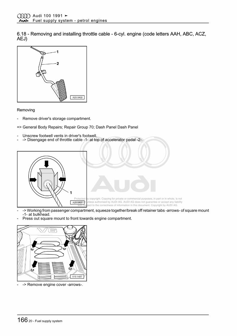
Protected by copyright. Copying for private or commercial purposes, in part or in whole, is not permitted unless authorised by AUDI AG. AUDI AG does not guarantee or accept any liability with respect to the correctness of information in this document. Copyright by AUDI AG.
6.18 - Removing and installing throttle cable - 6-cyl. engine (code letters AAH, ABC, ACZ,AEJ)
Removing
- Remove driver's storage compartment.
=> General Body Repairs; Repair Group 70; Dash Panel Dash Panel
- Unscrew footwell vents in driver's footwell.- -> Disengage end of throttle cable -1- at top of accelerator pedal -2-.
- -> Working from passenger compartment, squeeze together/break off retainer tabs -arrows- of square mount-1- at bulkhead.
- Press out square mount to front towards engine compartment.
- -> Remove engine cover -arrows-.
Audi 100 1991 ➤Fuel supply system - petrol engines
166 20 - Fuel supply system
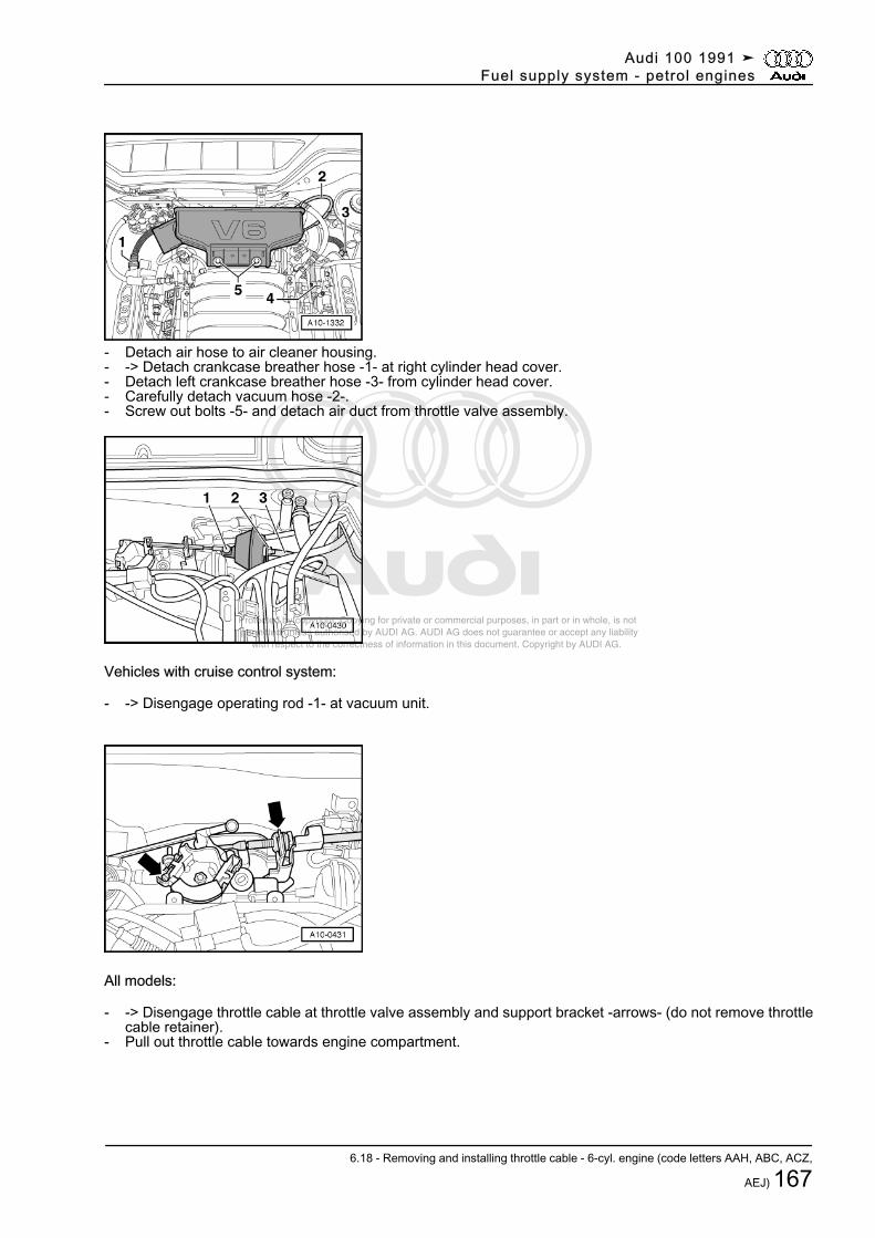
Protected by copyright. Copying for private or commercial purposes, in part or in whole, is not permitted unless authorised by AUDI AG. AUDI AG does not guarantee or accept any liability with respect to the correctness of information in this document. Copyright by AUDI AG.
- Detach air hose to air cleaner housing.- -> Detach crankcase breather hose -1- at right cylinder head cover.- Detach left crankcase breather hose -3- from cylinder head cover.- Carefully detach vacuum hose -2-.- Screw out bolts -5- and detach air duct from throttle valve assembly.
Vehicles with cruise control system:
- -> Disengage operating rod -1- at vacuum unit.
All models:
- -> Disengage throttle cable at throttle valve assembly and support bracket -arrows- (do not remove throttlecable retainer).
- Pull out throttle cable towards engine compartment.
Audi 100 1991 ➤Fuel supply system - petrol engines
6.18 - Removing and installing throttle cable - 6-cyl. engine (code letters AAH, ABC, ACZ,
AEJ) 167
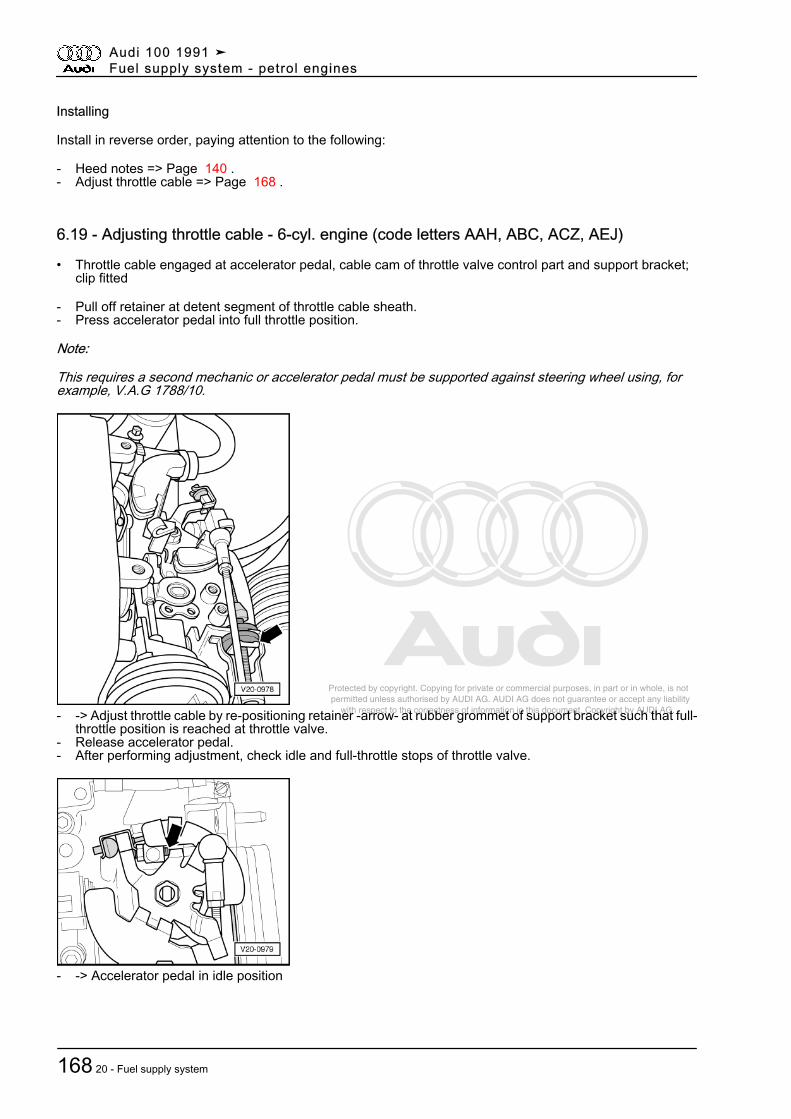
Protected by copyright. Copying for private or commercial purposes, in part or in whole, is not permitted unless authorised by AUDI AG. AUDI AG does not guarantee or accept any liability with respect to the correctness of information in this document. Copyright by AUDI AG.
Installing
Install in reverse order, paying attention to the following:
- Heed notes => Page 140 .- Adjust throttle cable => Page 168 .
6.19 - Adjusting throttle cable - 6-cyl. engine (code letters AAH, ABC, ACZ, AEJ)
• Throttle cable engaged at accelerator pedal, cable cam of throttle valve control part and support bracket;clip fitted
- Pull off retainer at detent segment of throttle cable sheath.- Press accelerator pedal into full throttle position.
Note:
This requires a second mechanic or accelerator pedal must be supported against steering wheel using, forexample, V.A.G 1788/10.
- -> Adjust throttle cable by re-positioning retainer -arrow- at rubber grommet of support bracket such that full-throttle position is reached at throttle valve.
- Release accelerator pedal.- After performing adjustment, check idle and full-throttle stops of throttle valve.
- -> Accelerator pedal in idle position
Audi 100 1991 ➤Fuel supply system - petrol engines
168 20 - Fuel supply system
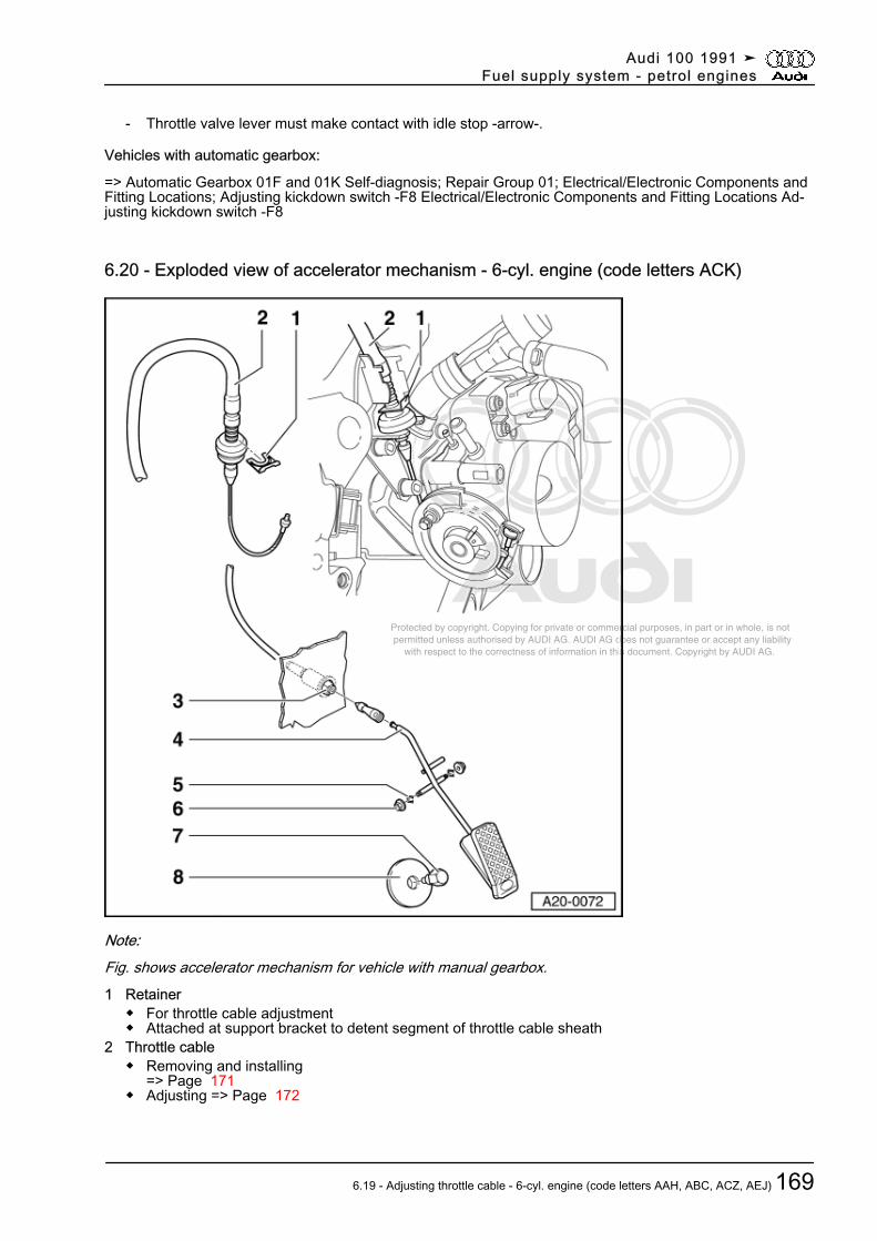
Protected by copyright. Copying for private or commercial purposes, in part or in whole, is not permitted unless authorised by AUDI AG. AUDI AG does not guarantee or accept any liability with respect to the correctness of information in this document. Copyright by AUDI AG.
- Throttle valve lever must make contact with idle stop -arrow-.
Vehicles with automatic gearbox:
=> Automatic Gearbox 01F and 01K Self-diagnosis; Repair Group 01; Electrical/Electronic Components andFitting Locations; Adjusting kickdown switch -F8 Electrical/Electronic Components and Fitting Locations Ad‐justing kickdown switch -F8
6.20 - Exploded view of accelerator mechanism - 6-cyl. engine (code letters ACK)
Note:Fig. shows accelerator mechanism for vehicle with manual gearbox.1 Retainer
◆ For throttle cable adjustment◆ Attached at support bracket to detent segment of throttle cable sheath
2 Throttle cable◆ Removing and installing
=> Page 171◆ Adjusting => Page 172
Audi 100 1991 ➤Fuel supply system - petrol engines
6.19 - Adjusting throttle cable - 6-cyl. engine (code letters AAH, ABC, ACZ, AEJ) 169
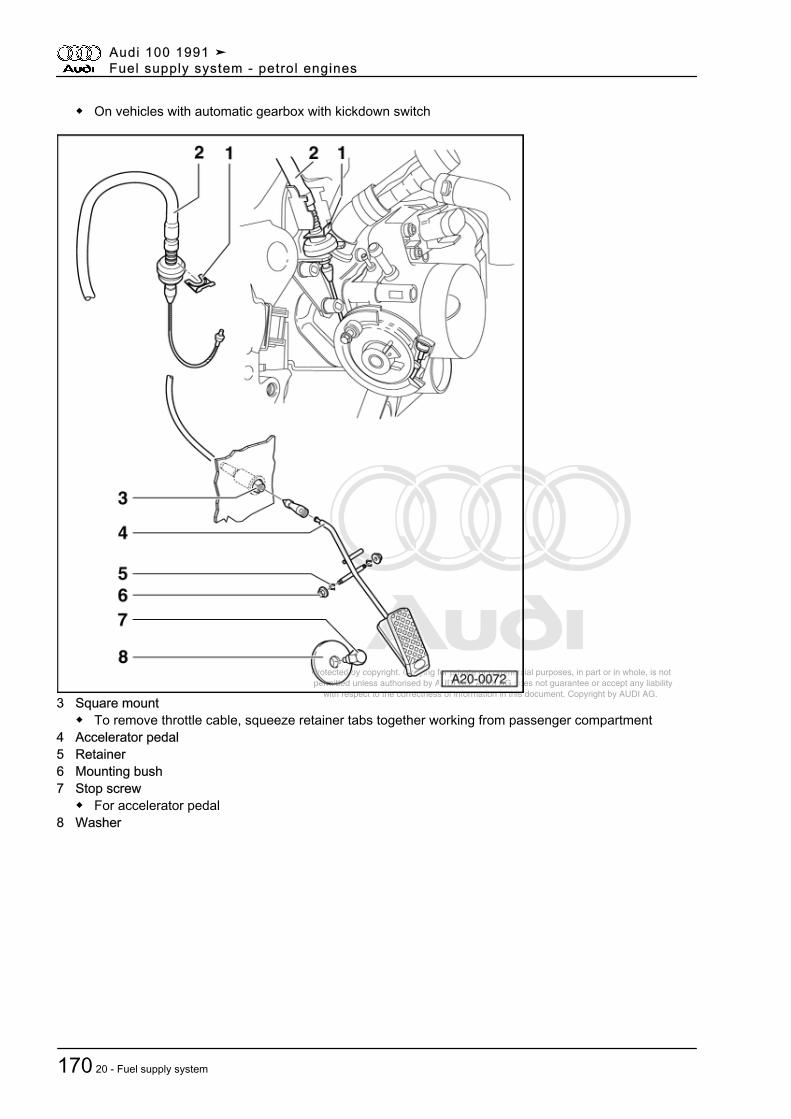
Protected by copyright. Copying for private or commercial purposes, in part or in whole, is not permitted unless authorised by AUDI AG. AUDI AG does not guarantee or accept any liability with respect to the correctness of information in this document. Copyright by AUDI AG.
◆ On vehicles with automatic gearbox with kickdown switch
3 Square mount◆ To remove throttle cable, squeeze retainer tabs together working from passenger compartment
4 Accelerator pedal5 Retainer6 Mounting bush7 Stop screw
◆ For accelerator pedal8 Washer
Audi 100 1991 ➤Fuel supply system - petrol engines
170 20 - Fuel supply system
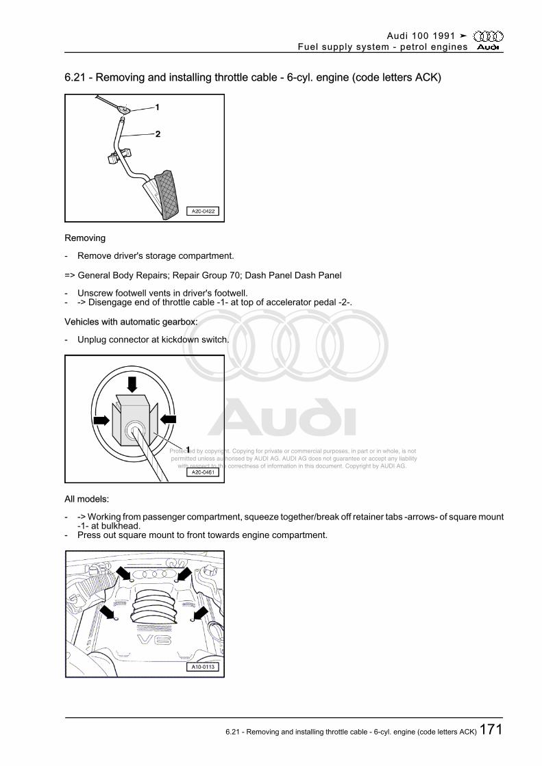
Protected by copyright. Copying for private or commercial purposes, in part or in whole, is not permitted unless authorised by AUDI AG. AUDI AG does not guarantee or accept any liability with respect to the correctness of information in this document. Copyright by AUDI AG.
6.21 - Removing and installing throttle cable - 6-cyl. engine (code letters ACK)
Removing
- Remove driver's storage compartment.
=> General Body Repairs; Repair Group 70; Dash Panel Dash Panel
- Unscrew footwell vents in driver's footwell.- -> Disengage end of throttle cable -1- at top of accelerator pedal -2-.
Vehicles with automatic gearbox:
- Unplug connector at kickdown switch.
All models:
- -> Working from passenger compartment, squeeze together/break off retainer tabs -arrows- of square mount-1- at bulkhead.
- Press out square mount to front towards engine compartment.
Audi 100 1991 ➤Fuel supply system - petrol engines
6.21 - Removing and installing throttle cable - 6-cyl. engine (code letters ACK) 171
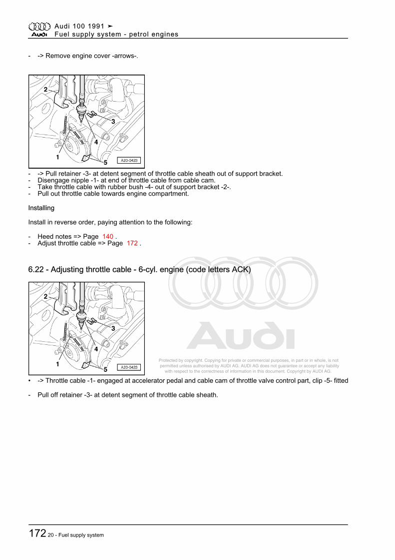
Protected by copyright. Copying for private or commercial purposes, in part or in whole, is not permitted unless authorised by AUDI AG. AUDI AG does not guarantee or accept any liability with respect to the correctness of information in this document. Copyright by AUDI AG.
- -> Remove engine cover -arrows-.
- -> Pull retainer -3- at detent segment of throttle cable sheath out of support bracket.- Disengage nipple -1- at end of throttle cable from cable cam.- Take throttle cable with rubber bush -4- out of support bracket -2-.- Pull out throttle cable towards engine compartment.
Installing
Install in reverse order, paying attention to the following:
- Heed notes => Page 140 .- Adjust throttle cable => Page 172 .
6.22 - Adjusting throttle cable - 6-cyl. engine (code letters ACK)
• -> Throttle cable -1- engaged at accelerator pedal and cable cam of throttle valve control part, clip -5- fitted
- Pull off retainer -3- at detent segment of throttle cable sheath.
Audi 100 1991 ➤Fuel supply system - petrol engines
172 20 - Fuel supply system
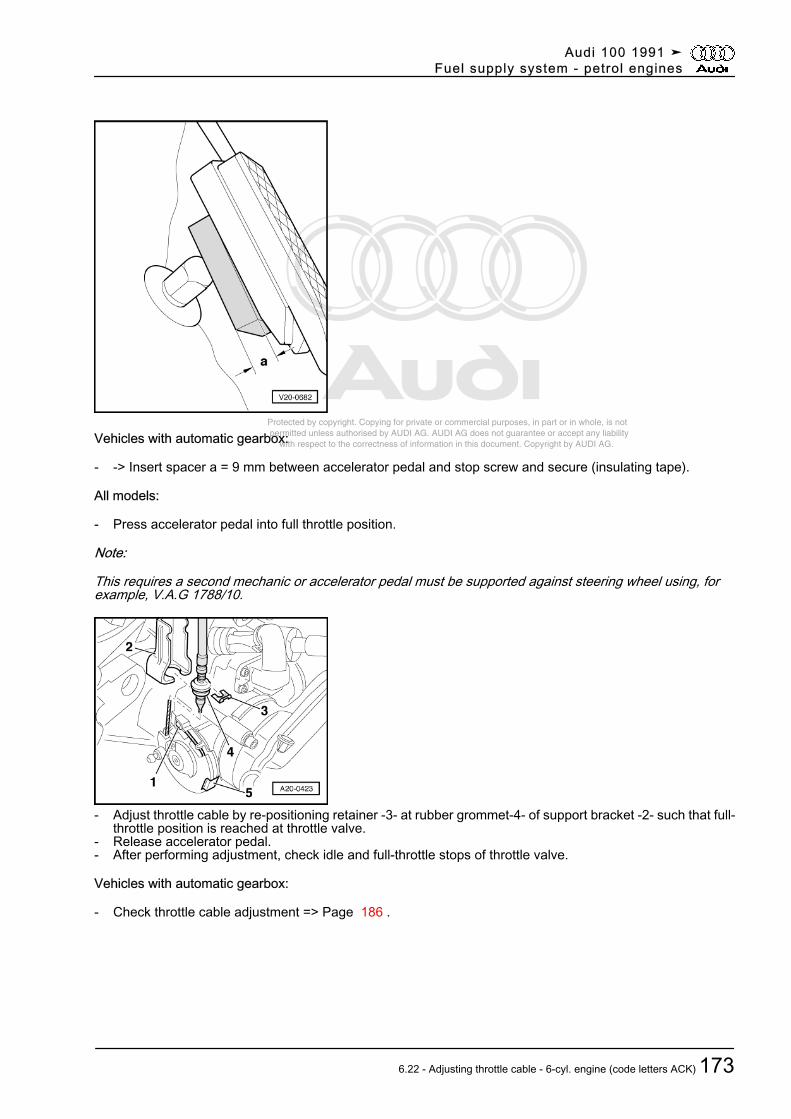
Protected by copyright. Copying for private or commercial purposes, in part or in whole, is not permitted unless authorised by AUDI AG. AUDI AG does not guarantee or accept any liability with respect to the correctness of information in this document. Copyright by AUDI AG.Vehicles with automatic gearbox:
- -> Insert spacer a = 9 mm between accelerator pedal and stop screw and secure (insulating tape).
All models:
- Press accelerator pedal into full throttle position.
Note:
This requires a second mechanic or accelerator pedal must be supported against steering wheel using, forexample, V.A.G 1788/10.
- Adjust throttle cable by re-positioning retainer -3- at rubber grommet-4- of support bracket -2- such that full-throttle position is reached at throttle valve.
- Release accelerator pedal.- After performing adjustment, check idle and full-throttle stops of throttle valve.
Vehicles with automatic gearbox:
- Check throttle cable adjustment => Page 186 .
Audi 100 1991 ➤Fuel supply system - petrol engines
6.22 - Adjusting throttle cable - 6-cyl. engine (code letters ACK) 173
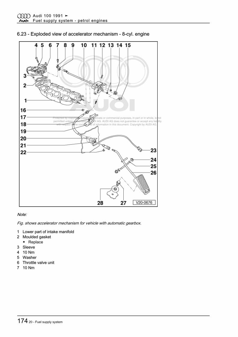
Protected by copyright. Copying for private or commercial purposes, in part or in whole, is not permitted unless authorised by AUDI AG. AUDI AG does not guarantee or accept any liability with respect to the correctness of information in this document. Copyright by AUDI AG.
6.23 - Exploded view of accelerator mechanism - 8-cyl. engine
Note:
Fig. shows accelerator mechanism for vehicle with automatic gearbox.
1 Lower part of intake manifold2 Moulded gasket
◆ Replace3 Sleeve4 10 Nm5 Washer6 Throttle valve unit7 10 Nm
Audi 100 1991 ➤Fuel supply system - petrol engines
174 20 - Fuel supply system
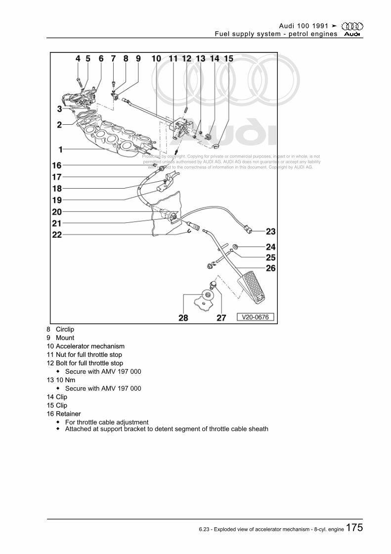
Protected by copyright. Copying for private or commercial purposes, in part or in whole, is not permitted unless authorised by AUDI AG. AUDI AG does not guarantee or accept any liability with respect to the correctness of information in this document. Copyright by AUDI AG.
8 Circlip9 Mount10 Accelerator mechanism11 Nut for full throttle stop12 Bolt for full throttle stop
◆ Secure with AMV 197 00013 10 Nm
◆ Secure with AMV 197 00014 Clip15 Clip16 Retainer
◆ For throttle cable adjustment◆ Attached at support bracket to detent segment of throttle cable sheath
Audi 100 1991 ➤Fuel supply system - petrol engines
6.23 - Exploded view of accelerator mechanism - 8-cyl. engine 175
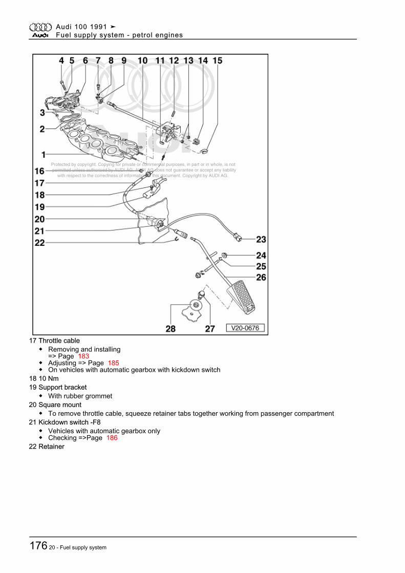
Protected by copyright. Copying for private or commercial purposes, in part or in whole, is not permitted unless authorised by AUDI AG. AUDI AG does not guarantee or accept any liability with respect to the correctness of information in this document. Copyright by AUDI AG.
17 Throttle cable◆ Removing and installing
=> Page 183◆ Adjusting => Page 185◆ On vehicles with automatic gearbox with kickdown switch
18 10 Nm19 Support bracket
◆ With rubber grommet20 Square mount
◆ To remove throttle cable, squeeze retainer tabs together working from passenger compartment21 Kickdown switch -F8
◆ Vehicles with automatic gearbox only◆ Checking =>Page 186
22 Retainer
Audi 100 1991 ➤Fuel supply system - petrol engines
176 20 - Fuel supply system
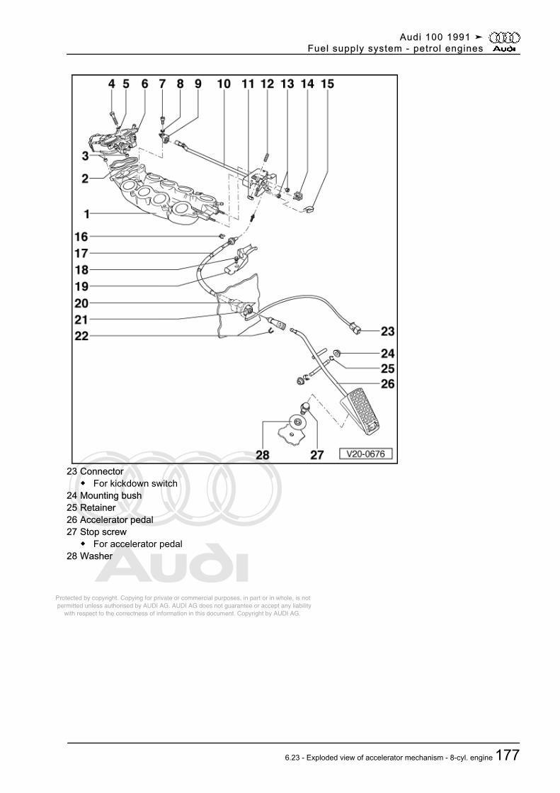
Protected by copyright. Copying for private or commercial purposes, in part or in whole, is not permitted unless authorised by AUDI AG. AUDI AG does not guarantee or accept any liability with respect to the correctness of information in this document. Copyright by AUDI AG.
23 Connector◆ For kickdown switch
24 Mounting bush25 Retainer26 Accelerator pedal27 Stop screw
◆ For accelerator pedal28 Washer
Audi 100 1991 ➤Fuel supply system - petrol engines
6.23 - Exploded view of accelerator mechanism - 8-cyl. engine 177
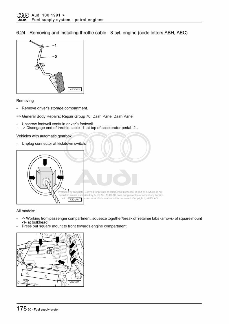
Protected by copyright. Copying for private or commercial purposes, in part or in whole, is not permitted unless authorised by AUDI AG. AUDI AG does not guarantee or accept any liability with respect to the correctness of information in this document. Copyright by AUDI AG.
6.24 - Removing and installing throttle cable - 8-cyl. engine (code letters ABH, AEC)
Removing
- Remove driver's storage compartment.
=> General Body Repairs; Repair Group 70; Dash Panel Dash Panel
- Unscrew footwell vents in driver's footwell.- -> Disengage end of throttle cable -1- at top of accelerator pedal -2-.
Vehicles with automatic gearbox:
- Unplug connector at kickdown switch.
All models:
- -> Working from passenger compartment, squeeze together/break off retainer tabs -arrows- of square mount-1- at bulkhead.
- Press out square mount to front towards engine compartment.
Audi 100 1991 ➤Fuel supply system - petrol engines
178 20 - Fuel supply system
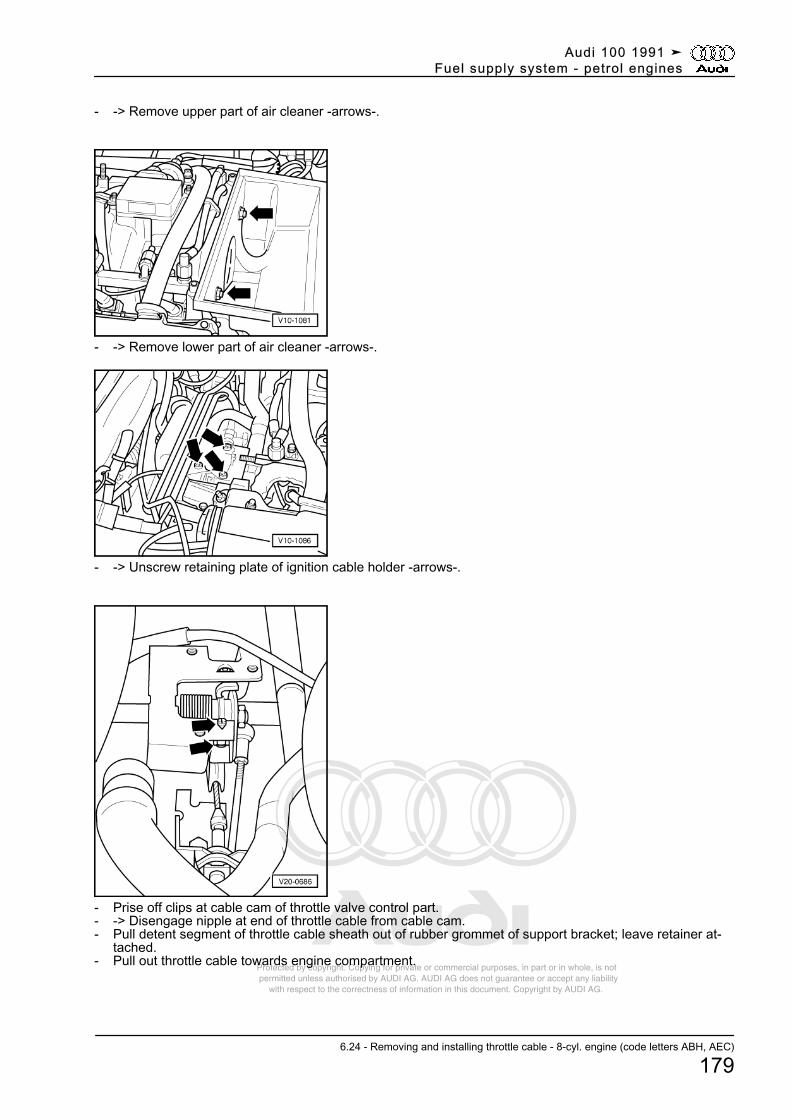
Protected by copyright. Copying for private or commercial purposes, in part or in whole, is not permitted unless authorised by AUDI AG. AUDI AG does not guarantee or accept any liability with respect to the correctness of information in this document. Copyright by AUDI AG.
- -> Remove upper part of air cleaner -arrows-.
- -> Remove lower part of air cleaner -arrows-.
- -> Unscrew retaining plate of ignition cable holder -arrows-.
- Prise off clips at cable cam of throttle valve control part.- -> Disengage nipple at end of throttle cable from cable cam.- Pull detent segment of throttle cable sheath out of rubber grommet of support bracket; leave retainer at‐
tached.- Pull out throttle cable towards engine compartment.
Audi 100 1991 ➤Fuel supply system - petrol engines
6.24 - Removing and installing throttle cable - 8-cyl. engine (code letters ABH, AEC)
179
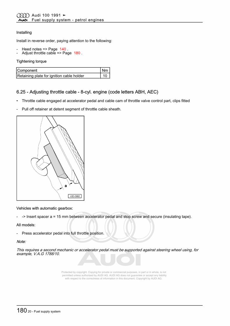
Protected by copyright. Copying for private or commercial purposes, in part or in whole, is not permitted unless authorised by AUDI AG. AUDI AG does not guarantee or accept any liability with respect to the correctness of information in this document. Copyright by AUDI AG.
Installing
Install in reverse order, paying attention to the following:
- Heed notes => Page 140 .- Adjust throttle cable => Page 180 .
Tightening torque
Component NmRetaining plate for ignition cable holder 10
6.25 - Adjusting throttle cable - 8-cyl. engine (code letters ABH, AEC)
• Throttle cable engaged at accelerator pedal and cable cam of throttle valve control part, clips fitted
- Pull off retainer at detent segment of throttle cable sheath.
Vehicles with automatic gearbox:
- -> Insert spacer a = 15 mm between accelerator pedal and stop screw and secure (insulating tape).
All models:
- Press accelerator pedal into full throttle position.
Note:
This requires a second mechanic or accelerator pedal must be supported against steering wheel using, forexample, V.A.G 1788/10.
Audi 100 1991 ➤Fuel supply system - petrol engines
180 20 - Fuel supply system
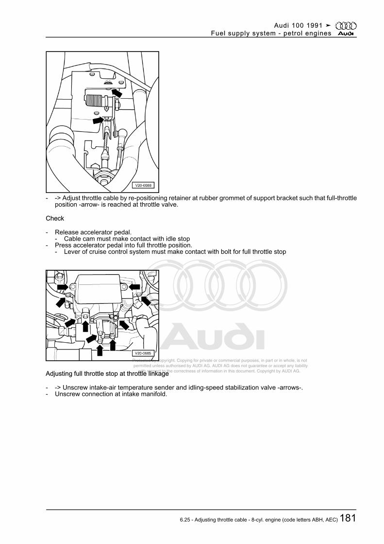
Protected by copyright. Copying for private or commercial purposes, in part or in whole, is not permitted unless authorised by AUDI AG. AUDI AG does not guarantee or accept any liability with respect to the correctness of information in this document. Copyright by AUDI AG.
- -> Adjust throttle cable by re-positioning retainer at rubber grommet of support bracket such that full-throttleposition -arrow- is reached at throttle valve.
Check
- Release accelerator pedal.- Cable cam must make contact with idle stop
- Press accelerator pedal into full throttle position.- Lever of cruise control system must make contact with bolt for full throttle stop
Adjusting full throttle stop at throttle linkage
- -> Unscrew intake-air temperature sender and idling-speed stabilization valve -arrows-.- Unscrew connection at intake manifold.
Audi 100 1991 ➤Fuel supply system - petrol engines
6.25 - Adjusting throttle cable - 8-cyl. engine (code letters ABH, AEC) 181
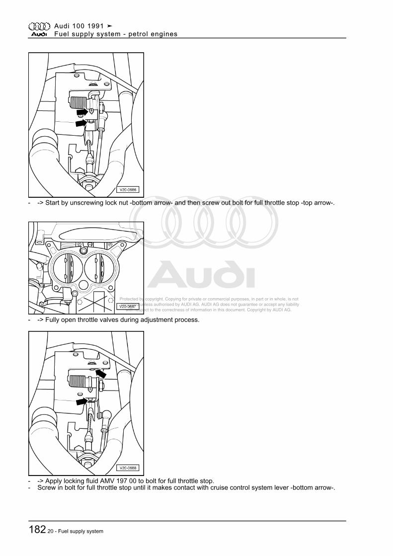
Protected by copyright. Copying for private or commercial purposes, in part or in whole, is not permitted unless authorised by AUDI AG. AUDI AG does not guarantee or accept any liability with respect to the correctness of information in this document. Copyright by AUDI AG.
- -> Start by unscrewing lock nut -bottom arrow- and then screw out bolt for full throttle stop -top arrow-.
- -> Fully open throttle valves during adjustment process.
- -> Apply locking fluid AMV 197 00 to bolt for full throttle stop.- Screw in bolt for full throttle stop until it makes contact with cruise control system lever -bottom arrow-.
Audi 100 1991 ➤Fuel supply system - petrol engines
182 20 - Fuel supply system
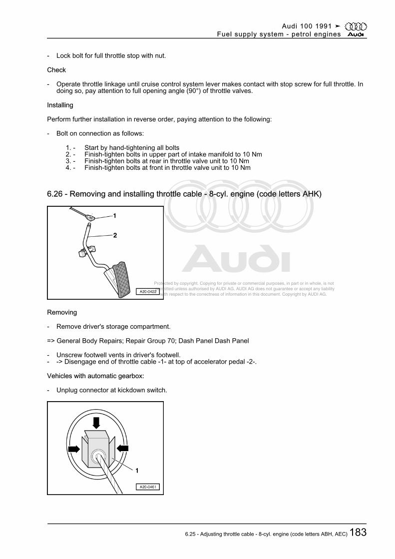
Protected by copyright. Copying for private or commercial purposes, in part or in whole, is not permitted unless authorised by AUDI AG. AUDI AG does not guarantee or accept any liability with respect to the correctness of information in this document. Copyright by AUDI AG.
- Lock bolt for full throttle stop with nut.
Check
- Operate throttle linkage until cruise control system lever makes contact with stop screw for full throttle. Indoing so, pay attention to full opening angle (90°) of throttle valves.
Installing
Perform further installation in reverse order, paying attention to the following:
- Bolt on connection as follows:
1. - Start by hand-tightening all bolts 2. - Finish-tighten bolts in upper part of intake manifold to 10 Nm 3. - Finish-tighten bolts at rear in throttle valve unit to 10 Nm 4. - Finish-tighten bolts at front in throttle valve unit to 10 Nm
6.26 - Removing and installing throttle cable - 8-cyl. engine (code letters AHK)
Removing
- Remove driver's storage compartment.
=> General Body Repairs; Repair Group 70; Dash Panel Dash Panel
- Unscrew footwell vents in driver's footwell.- -> Disengage end of throttle cable -1- at top of accelerator pedal -2-.
Vehicles with automatic gearbox:
- Unplug connector at kickdown switch.
Audi 100 1991 ➤Fuel supply system - petrol engines
6.25 - Adjusting throttle cable - 8-cyl. engine (code letters ABH, AEC) 183
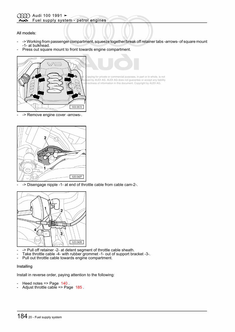
Protected by copyright. Copying for private or commercial purposes, in part or in whole, is not permitted unless authorised by AUDI AG. AUDI AG does not guarantee or accept any liability with respect to the correctness of information in this document. Copyright by AUDI AG.
All models:
- -> Working from passenger compartment, squeeze together/break off retainer tabs -arrows- of square mount-1- at bulkhead.
- Press out square mount to front towards engine compartment.
- -> Remove engine cover -arrows-.
- -> Disengage nipple -1- at end of throttle cable from cable cam-2-.
- -> Pull off retainer -2- at detent segment of throttle cable sheath.- Take throttle cable -4- with rubber grommet -1- out of support bracket -3-.- Pull out throttle cable towards engine compartment.
Installing
Install in reverse order, paying attention to the following:
- Heed notes => Page 140 .- Adjust throttle cable => Page 185 .
Audi 100 1991 ➤Fuel supply system - petrol engines
184 20 - Fuel supply system
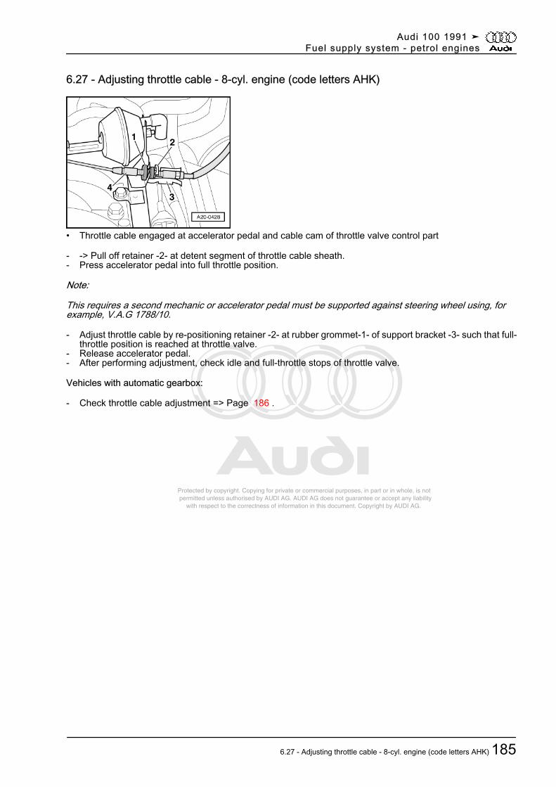
Protected by copyright. Copying for private or commercial purposes, in part or in whole, is not permitted unless authorised by AUDI AG. AUDI AG does not guarantee or accept any liability with respect to the correctness of information in this document. Copyright by AUDI AG.
6.27 - Adjusting throttle cable - 8-cyl. engine (code letters AHK)
• Throttle cable engaged at accelerator pedal and cable cam of throttle valve control part
- -> Pull off retainer -2- at detent segment of throttle cable sheath.- Press accelerator pedal into full throttle position.
Note:
This requires a second mechanic or accelerator pedal must be supported against steering wheel using, forexample, V.A.G 1788/10.
- Adjust throttle cable by re-positioning retainer -2- at rubber grommet-1- of support bracket -3- such that full-throttle position is reached at throttle valve.
- Release accelerator pedal.- After performing adjustment, check idle and full-throttle stops of throttle valve.
Vehicles with automatic gearbox:
- Check throttle cable adjustment => Page 186 .
Audi 100 1991 ➤Fuel supply system - petrol engines
6.27 - Adjusting throttle cable - 8-cyl. engine (code letters AHK) 185
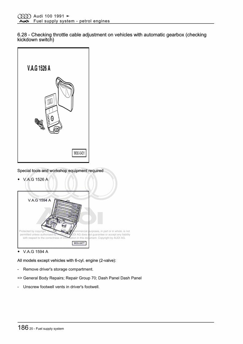
Protected by copyright. Copying for private or commercial purposes, in part or in whole, is not permitted unless authorised by AUDI AG. AUDI AG does not guarantee or accept any liability with respect to the correctness of information in this document. Copyright by AUDI AG.
6.28 - Checking throttle cable adjustment on vehicles with automatic gearbox (checkingkickdown switch)
Special tools and workshop equipment required
◆ V.A.G 1526 A
◆ V.A.G 1594 A
All models except vehicles with 6-cyl. engine (2-valve):
- Remove driver's storage compartment.
=> General Body Repairs; Repair Group 70; Dash Panel Dash Panel
- Unscrew footwell vents in driver's footwell.
Audi 100 1991 ➤Fuel supply system - petrol engines
186 20 - Fuel supply system
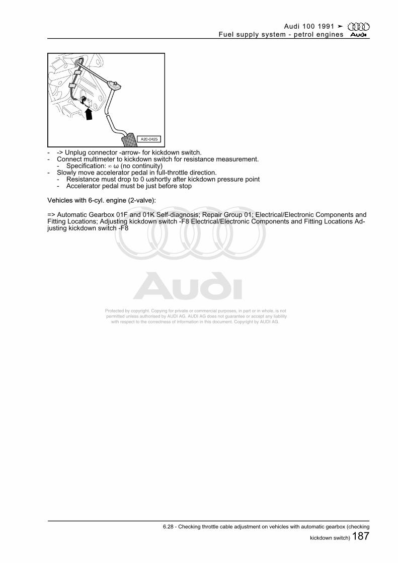
Protected by copyright. Copying for private or commercial purposes, in part or in whole, is not permitted unless authorised by AUDI AG. AUDI AG does not guarantee or accept any liability with respect to the correctness of information in this document. Copyright by AUDI AG.
- -> Unplug connector -arrow- for kickdown switch.- Connect multimeter to kickdown switch for resistance measurement.
- Specification: ∞ ω (no continuity)- Slowly move accelerator pedal in full-throttle direction.
- Resistance must drop to 0 ωshortly after kickdown pressure point- Accelerator pedal must be just before stop
Vehicles with 6-cyl. engine (2-valve):
=> Automatic Gearbox 01F and 01K Self-diagnosis; Repair Group 01; Electrical/Electronic Components andFitting Locations; Adjusting kickdown switch -F8 Electrical/Electronic Components and Fitting Locations Ad‐justing kickdown switch -F8
Audi 100 1991 ➤Fuel supply system - petrol engines
6.28 - Checking throttle cable adjustment on vehicles with automatic gearbox (checking
kickdown switch) 187