Embed Size (px)
Citation preview
165 125 22 140 100 20 4-M16 4-M16
165 125 22 140 100 20 4-M16 4-M16
4- 20
4- 20
185 145 22 150 110 22 4-M16 4- 20
200 160 22 185 145 22 4-M16 4- 204- 18
200 160 22 185 145 22 4-M16 4- 204- 18
200 160 22 165 125 22 4-M16 4- 208- 18
220 180 24 200 160 24 8-M16 4- 258- 18
220 180 24 160 24 8-M16 4- 258- 18
250 210 24 225 180 24 8-M16 4- 258- 18
25
25
40
40
40
40
50
50
50
4- 18
150 110 20 115 85 18 4-M16 4-M12 4- 2025
250 210 24 225 180 24 8-M16 4- 258- 1850
610IMD40-25-130FA 250 70 80 210 160 310 150 150 110 20 115 85 18 4-M16 4-M12 4- 15
610IMD40-25-140FA 250 70 80 210 160 310 150 150 110 20 115 85 18 4-M16 4-M12 4- 15
610IMD40-25-150FA 250 70 80 210 160 310 150 150 110 20 115 85 18 4-M16 4-M12 4- 15
610IMD40-25-160FA 250 70 80 210 160 310 150 150 110 20 115 85 18 4-M16 4-M12 4- 15
610IMD40-25-165FA 250 70 80 210 160 310 150 150 110 20 115 85 18 4-M16 4-M12 4- 15
610IMD40-25-170FA 250 70 80 210 160 310 150 150 110 20 115 85 18 4-M16 4-M12 4- 15
610IMD40-25-185F 250 70 80 210 160 310 150 150 110 20 115 85 18 4-M16 4-M12 4- 15
730IMD50-40-140F 330 70 80 265 212 360 180 165 125 20 150 110 20 4-M16 4-M16 4- 15
730IMD50-40-150F 330 70 80 265 212 360 180 165 125 20 150 110 20 4-M16 4-M16 4- 15
730IMD50-40-160F 330 70 80 265 212 360
180
165 125 20 150 110 20 4-M16 4-M16 4- 15
730IMD50-40-165F 330 70 80 265 212 360
180
165 125 20 150 110 20 4-M16 4-M16 4- 15
730IMD50-32-195F 330 70 90 265 212 365 180 165 125 22 140 100 20 4-M16 4-M16 4- 15
730IMD50-32-200F 330 70 90 265 212 365 180 165 125 22 140 100 20 4-M16 4-M16 4- 15
725IMD65-50-130F 318 95 80 265 212 360 180 185 20 165 125 20 4-M16 4- 154- 18
730IMD65-50-165F 318 95 80 265 212 365 180 145 24 165 125 24 4-M16 4-M16 4- 15
928IMD65-40-200F 410 70 100 290 220 430 230
185
185 145
22
150 110 22 4-M16 4- 154- 18
935IMD80-65-120F 416 70 100 290 220 430 230
200
160
22
185 145 22 4-M16 4- 154- 18
935IMD80-65-140F 416 70 100 290 220 430 230
200
160 22 185 145 22 4-M16
4- 15
4- 18
970IMD80-50-200F 398 70 100 320 240 445 230 160 22 165 125 22 4-M16
4- 15
8- 18
1110IMD100-80-160F 485 95 125 345 280 500 250
200
220 180
24 160 24 8-M16 4- 158- 18
1110IMD100-80-180F 485 95 125 345 280 500 250
220 180
24
200
200 160 24 8-M16 4- 158- 18
1110IMD125-100-160F 490 95 125 345 280 500 250 250 210 24 225 180 24 8-M16 4- 158- 18
730IMD40-25-230F 336 70 100 275 212 370 180 150 110 20 115 85 18 4-M16 4-M12 4- 15
1
2
3
4
5
6
7
8
9
10
11
12
13
14
15
16
17
18
19
20
21
22
23
725IMD65-50-120F 318 95 80 265 212 360 180 185
145
145 20 165 125 20 4-M16 4- 154- 18
24
25 1110IMD125-100-200F 490 95 125 345 280 500 250 250 210 24 225 180 24 8-M16 4- 158- 18
L S P f W T H h a b e g i j n- t n- d n- q
710
710
950
950
950
950
1090
1090
1090
710
1090
340
340
490
490
490
490
525
525
525
340
525
310
310
440
440
440
440
475
475
475
310
475
425
425
510
510
510
525
595
595
595
425
595
240
240
310
310
310
310
345
345
345
240
345
90
90
100
100
100
100
125
125
125
90
125
745IMD50-32-195F 530
745IMD50-32-200F 530 36
1000IMD65-40-200F 740 5
1000IMD80-65-120F 740 5
1000IMD80-65-140F 740 5
1000IMD80-50-200F 740 5
1170IMD100-80-160F 870 30
IMD100-80-180F 870 30
IMD125-100-160F 870 30
36
745IMD40-25-230F 530 36
2
3
4
5
6
7
8
9
10
11 IMD125-100-200F 870 30
L S P f W T H h a b e g i j n- t n- d n- q
1
B r
200
9 10
4- q
1170
1170
1170
Installation dimension figure
Without pedestal (Table 1) With pedestal (Table 2)
Table 1
Table 2
ModelNumber
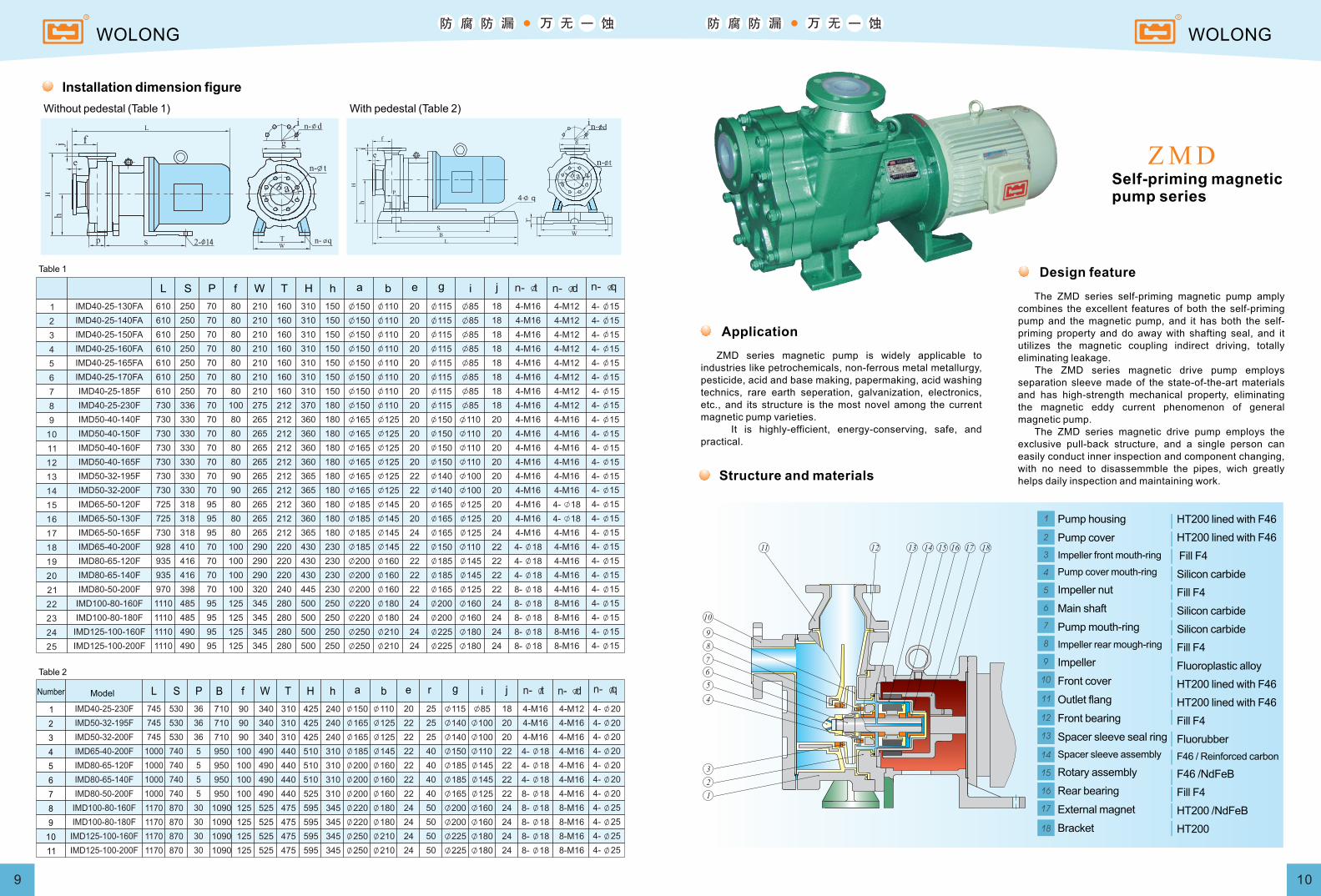
The ZMD series self-priming magnetic pump amply combines the excellent features of both the self-priming pump and the magnetic pump, and it has both the self-priming property and do away with shafting seal, and it utilizes the magnetic coupling indirect driving, totally eliminating leakage. The ZMD series magnetic drive pump employs separation sleeve made of the state-of-the-art materials and has high-strength mechanical property, eliminating the magnetic eddy current phenomenon of general magnetic pump. The ZMD series magnetic drive pump employs the exclusive pull-back structure, and a single person can easily conduct inner inspection and component changing, with no need to disassemmble the pipes, wich greatly helps daily inspection and maintaining work.
Self-priming magneticpump series
Design feature
Application
ZMD series magnetic pump is widely applicable to industries like petrochemicals, non-ferrous metal metallurgy, pesticide, acid and base making, papermaking, acid washing technics, rare earth seperation, galvanization, electronics, etc., and its structure is the most novel among the current magnetic pump varieties. It is highly-efficient, energy-conserving, safe, and practical.
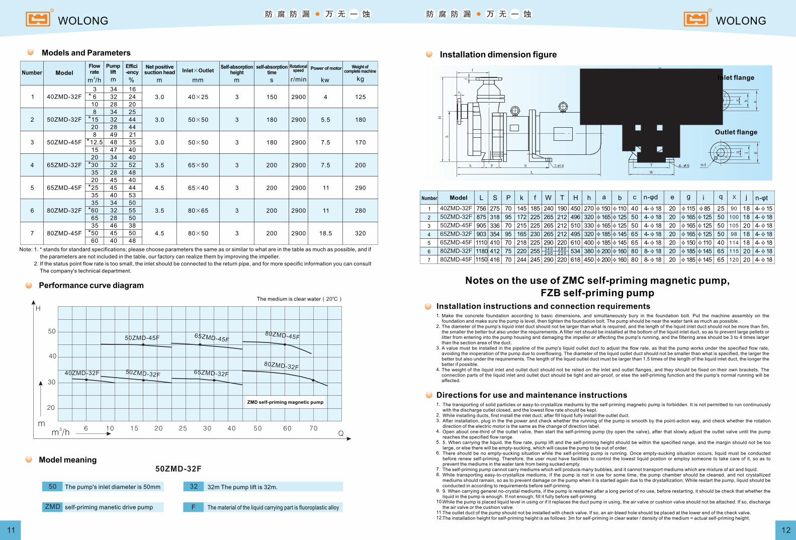
Structure and materials
Pump housing
Pump cover
Impeller front mouth-ring
Pump cover mouth-ring
Impeller nut
Main shaft
Pump mouth-ring
Impeller rear mough-ring
Impeller
Front cover
Outlet flang
Front bearing
Spacer sleeve seal ring
Spacer sleeve assembly
Rotary assembly
Rear bearing
External magnet
Bracket
HT200 lined with F46
HT200 lined with F46
Fill F4
Silicon carbide
Fill F4
Silicon carbide
Silicon carbide
Fill F4
Fluoroplastic alloy
HT200 lined with F46
HT200 lined with F46
Fill F4
Fluorubber
F46 / Reinforced carbon
F46 /NdFeB
Fill F4
HT200 /NdFeB
HT200
WOLONG WOLONG
1 40ZMD-32F
2 50ZMD-32F
3 50ZMD-45F
4 65ZMD-32F
5 65ZMD-45F
6 80ZMD-32F
7 80ZMD-45F
3
6
10
8
15
20
8
12.5
15
20
30
35
20
25
35
35
60
65
35
50
60
34
32
28
34
32
28
49
48
47
34
32
28
45
45
40
34
32
28
46
45
40
16
24
20
25
44
44
21
35
40
40
52
48
40
44
53
50
55
50
38
50
48
3.0
3.0
3.0
3.5
4.5
3.5
4.5
40×25
50×50
50×50
65×50
65×40
80×65
80×50
3
3
3
3
3
3
3
150
180
180
200
200
200
200
2900
2900
2900
2900
2900
2900
2900
4
5.5
7.5
7.5
11
11
18.5
125
180
170
200
290
280
320
*
*
*
*
*
*
*
m3
m /h Q
H
65ZMD-32F
65ZMD-45F
40ZMD-32F 50ZMD-32F
50ZMD-45F80ZMD-45F
80ZMD-32F
50
40
30
20
6 10 15 20 25 30 40 50 60 70
11 12
2
3
4
5
6
7
1
L S P f W T H h a b c e i jn-φdk g n-φtq
40ZMD-32F
50ZMD-32F
50ZMD-45F
65ZMD-32F
65ZMD-45F
80ZMD-32F
80ZMD-45F
756
905
875
903
1110
1180
336
318
354
275
410
412
416
70
95
95
70
70
75
70
215
172
165
145
218
220
225
225
230
185
225
255
265
265
265
240
290
2 9 0
290
212
212
212
190
220
2 2 0
220
510
496
495
450
610
534
330
320
320
270
400
380
φ150
φ165
φ165
φ185
φ185
φ200
φ200
φ110
φ125
φ125
φ145
φ145
φ160
φ160
50
50
65
40
65
80
80
4-φ18
4-φ18
4-φ18
4-φ18
4-φ18
8-φ18
8-φ18
20
20
20
20
20
20
20
φ115
φ165
φ165
φ165
φ150
φ185
φ185
φ85
φ125
φ125
φ125
φ110
φ145
φ145
50
50
50
25
40
65
65
20
18
18
18
18
20
20
4-φ15
4-φ18
4-φ18
4-φ18
4-φ18
4-φ18
4-φ181150 244 245 618 450
3 4 0 2 8 0
4- 15
X
X
90
100
105
98
114
115
120
3m /h m % m mm r/min kw kgm s
Models and Parameters
ModelNumberFlowrate
Pumplift
Effici-ency
Net positivesuction head Inlet×Outlet
Rotationalspeed Power of motor Weight of
complete machine
Note: 1. * stands for standard specifications; please choose parameters the same as or similar to what are in the table as much as possible, and if
the parameters are not included in the table, our factory can realize them by improving the impeller.
2. If the status point flow rate is too small, the inlet should be connected to the return pipe, and for more specific information you can consult
The company's technical department.
Performance curve diagram
The medium is clear water(20℃)
ZMD self-priming magnetic pump
50ZMD-32F
ZMD
50 32
F
Model meaning
The pump's inlet diameter is 50mm
self-priming manetic drive pump
32m The pump lift is 32m.
The material of the liquid carrying part is fluoroplastic alloy
Installation dimension figure
Inlet flange
Outlet flange
Number Model
Notes on the use of ZMC self-priming magnetic pump, FZB self-priming pump
Installation instructions and connection requirementsMake the concrete foundation according to basic dimensions, and simultaneously bury in the foundation bolt. Put the machine assembly on the foundation and make sure the pump is level, then tighten the foundation bolt. The pump should be near the water tank as much as possible.The diameter of the pump's liquid inlet duct should not be larger than what is required, and the length of the liquid inlet duct should not be more than 5m, the smaller the better but also under the requirements. A filter net should be installed at the bottom of the liquid inlet duct, so as to prevent large pellets or litter from entering into the pump housing and damaging the impeller or affecting the pump's running, and the filtering area should be 3 to 4 times larger than the section area of the duct.A value must be installed in the pipeline of the pump's liquid outlet duct to adjust the flow rate, as that the pump works under the specified flow rate, avoiding the inoperation of the pump due to overflowing. The diameter of the liquid outlet duct should not be smaller than what is specified, the larger the better but also under the requirements. The length of the liquid outlet duct must be larger than 1.5 times of the length of the liquid inlet duct, the longer the better if possible.The weight of the liquid inlet and outlet duct should not be relied on the inlet and outlet flanges, and they should be fixed on their own brackets. The connection parts of the liquid inlet and outlet duct should be tight and air-proof, or else the self-priming function and the pump's normal running will be affected.
1.
2.
3.
4.
Directions for use and maintenance instructionsThe transporting of solid particles or easy-to-crystallize mediums by the self-priming magnetic pump is forbidden. It is not permitted to run continuously with the discharge outlet closed, and the lowest flow rate should be kept.While installing ducts, first install the inlet duct, after fill liquid fully install the outlet duct.After installation, plug in the the power and check whether the running of the pump is smooth by the point-action way, and check whether the rotation direction of the electric motor is the same as the change of direction label.Open about one-third of the outlet valve, then start the self-priming pump (by open the valve), after that slowly adjust the outlet valve until the pump reaches the specified flow range.5. When carrying the liquid, the flow rate, pump lift and the self-priming height should be within the specified range, and the margin should not be too large, or else there will be empty-sucking, which will cause the pump to be out of order.There should be no empty-sucking situation while the self-priming pump is running. Once empty-sucking situation occurs, liquid must be conducted before renew self-priming. Therefore, the user must have facilities to control the lowest liquid postion or employ someone to take care of it, so as to prevent the mediums in the water tank from being sucked empty.The self-priming pump cannot carry mediums which will produce many bubbles, and it cannot transport mediums which are mixture of air and liquid.While transporting easy-to-crystallize mediums, if the pump is not in use for some time, the pump chamber should be cleaned, and not crystallized mediums should ramain, so as to prevent damage on the pump when it is started again due to the drystallization; While restart the pump, liquid should be conducted in according to requirements before self-priming.9. When carrying generel no-crystal mediums, if the pump is restarted after a long period of no use, before restarting, it should be check that whether the liquid in the pump is enough. If not enough, fill it fully before self-priming.While the pump is placed liquid level in using or if it replaces the duct pump in using, the air valve or cushion valve should not be attached. If so, discharge the air valve or the cushion valve.The outlet duct of the pump should not be installed with check valve. If so, an air-bleed hole should be placed at the lower end of the check valve.The installation height for self-priming height is as follows: 3m for self-priming in clear water / density of the medium = actual self-priming height.
1.
2.3.
4.
5.
6.
7.8.
9.
10.
11.12.
WOLONG WOLONG
self-absorptiontime
Self-absorptionheight