Embed Size (px)
Citation preview

... i
2 c sla
ve ke
rnel
... f
low
code
for a
rm an
d the
ecrm
40 ..
. µw
atch
...
electronics worldwide
www.elektor.com January 2009 AUS$ 13.90 - NZ$ 16.75 - SAR 88.70 £ 4.10
R04
HOMO RADIENS
Wireless Connection
- Meeting Cost Counter
... for microcontrollers
discovered
- 3-D Light Source- RFID goes UHF
- Capacitive Sensing
Digital Storage OscilloscopeDual Channel Digital Scope with industry standard probes or POD connected analog inputs. Fully opto-isolated.
Mixed Signal OscilloscopeCapture and display analog and logic signals together with sophisticated cross-triggers forprecise analog/logic timing.
Multi-Band Spectrum AnalyzerDisplay analog waveforms and their spectra simultaneously. Base-band or RF displayswith variable bandwidth control.
Direct Digital Synthesis GeneratorArbitrary waveform crystal referenced DDS frequency synthesis. Microsecond one-shottiming precision and burst generation. Independent but sample synchronized with BitScope capture.
Noise, Dither and Entropy GeneratorPseudo-Random Number noise, dither and entropy generation. White, pink or binary withprogrammable or random seed.
Voltage, Clock and Logic GeneratorProgrammable voltage, clock and serial logic generation. Adjustable DC reference and mark/space clocks to 5MHz. Logic level shifting and probe calibration signals.
PC Oscilloscopes & Analyzers
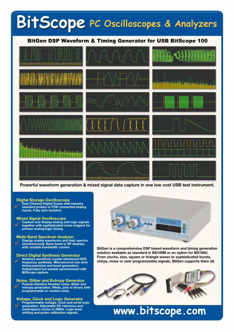
BitGen DSP Waveform & Timing Generator for USB BitScope 100
www.bitscope.com
Powerful waveform generation & mixed signal data capture in one low cost USB test instrument.
BitGen is a comprehensive DSP based waveform and timing generationsolution available as standard in BS100M or an option for BS100U.From clocks, sine, square or triangle waves to sophisticated bursts, chirps, noise or user programmable signals, BitGen supports them all.
0901_elektor_adv_UK.indd 2 28-11-2008 14:05:25
mikroElektronikaDEVELOPMENT TOOLS | COMPILERS | BOOKS
S O F T W A R E A N D H A R D W A R E S O L U T I O N S F O R E M B E D D E D W O R L D
Find your distributor: UK, USA, Germany, Japan, France,Greece, Turkey, Italy, Slovenia, Croatia, Macedonia, Pakistan,Malaysia, Austria, Taiwan, Lebanon, Syria, Egypt, Portugal,India, Thailand, Taiwan, Czech and Slovak Republic.
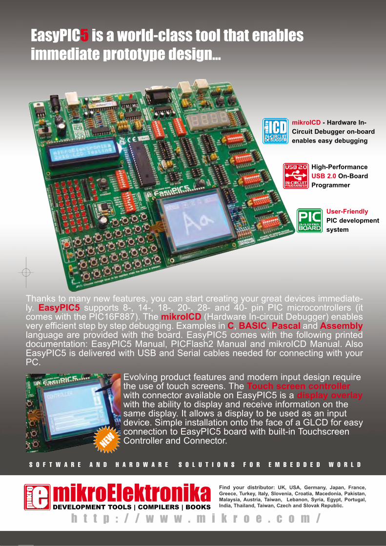
EasyPIC5 is a world-class tool that enablesimmediate prototype design...
Thanks to many new features, you can start creating your great devices immediate-ly. EasyPIC5 supports 8-, 14-, 18-, 20-, 28- and 40- pin PIC microcontrollers (itcomes with the PIC16F887). The mikroICD (Hardware In-circuit Debugger) enablesvery efficient step by step debugging. Examples in C, BASIC, Pascal and Assemblylanguage are provided with the board. EasyPIC5 comes with the following printeddocumentation: EasyPIC5 Manual, PICFlash2 Manual and mikroICD Manual. AlsoEasyPIC5 is delivered with USB and Serial cables needed for connecting with yourPC.
Evolving product features and modern input design requirethe use of touch screens. The Touch screen controllerwith connector available on EasyPIC5 is a display overlaywith the ability to display and receive information on thesame display. It allows a display to be used as an inputdevice. Simple installation onto the face of a GLCD for easyconnection to EasyPIC5 board with built-in TouchscreenController and Connector.
h t t p : / / w w w . m i k r o e . c o m /
High-PerformanceUSB 2.0 On-BoardProgrammer
mikroICD - Hardware In-Circuit Debugger on-boardenables easy debugging
User-FriendlyPIC developmentsystem
0901_elektor_adv_UK.indd 3 28-11-2008 14:05:06
Reader Offer
Cypress CapSense Button & CapSense Slider
development kits page 65
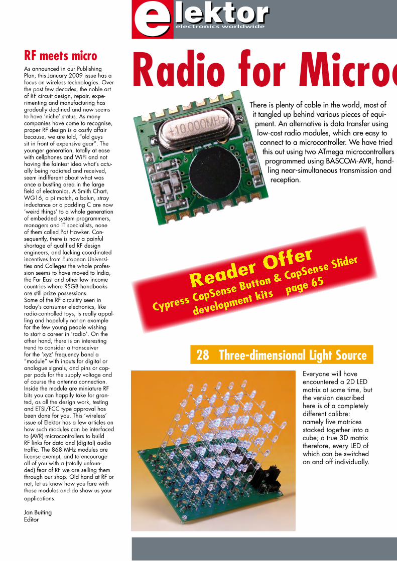
There is plenty of cable in the world, most of it tangled up behind various pieces of equi-pment. An alternative is data transfer using low-cost radio modules, which are easy to connect to a microcontroller. We have tried this out using two ATmega microcontrollers programmed using BASCOM-AVR, hand-ling near-simultaneous transmission and reception.
Everyone will have encountered a 2D LED matrix at some time, but the version described here is of a completely different calibre: namely five matrices stacked together into a cube; a true 3D matrix therefore, every LED of which can be switched on and off individually.
RF meets microAs announced in our Publishing Plan, this January 2009 issue has a focus on wireless technologies. Over the past few decades, the noble art of RF circuit design, repair, expe-rimenting and manufacturing has gradually declined and now seems to have ‘niche’ status. As many companies have come to recognise, proper RF design is a costly affair because, we are told, “old guys sit in front of expensive gear”. The younger generation, totally at ease with cellphones and WiFi and not having the faintest idea what’s actu-ally being radiated and received, seem indifferent about what was once a bustling area in the large field of electronics. A Smith Chart, WG16, a pi match, a balun, stray inductance or a padding C are now ‘weird things’ to a whole generation of embedded system programmers, managers and IT specialists, none of them called Pat Hawker. Con-sequently, there is now a painful shortage of qualified RF design engineers, and lacking coordinated incentives from European Universi-ties and Colleges the whole profes-sion seems to have moved to India, the Far East and other low income countries where RSGB handbooks are still prize possessions.Some of the RF circuitry seen in today’s consumer electronics, like radio-controlled toys, is really appal-ling and hopefully not an example for the few young people wishing to start a career in ‘radio’. On the other hand, there is an interesting trend to consider a transceiver for the ‘xyz’ frequency band a “module” with inputs for digital or analogue signals, and pins or cop-per pads for the supply voltage and of course the antenna connection. Inside the module are miniature RF bits you can happily take for gran-ted, as all the design work, testing and ETSI/FCC type approval has been done for you. This ‘wireless’ issue of Elektor has a few articles on how such modules can be interfaced to (AVR) microcontrollers to build RF links for data and (digital) audio traffic. The 868 MHz modules are license exempt, and to encourage all of you with a (totally unfoun-ded) fear of RF we are selling them through our shop. Old hand at RF or not, let us know how you fare with these modules and do show us your applications.
Jan BuitingEditor
Radio for Microcontrollers
28 Three-dimensional Light Source
There is plenty of cable in the world, most of it tangled up behind various pieces of equi-pment. An alternative is data transfer using low-cost radio modules, which are easy to connect to a microcontroller. We have tried this out using two ATmega microcontrollers programmed using BASCOM-AVR, hand-ling near-simultaneous transmission and reception.
Radio for Microcontrollers
34
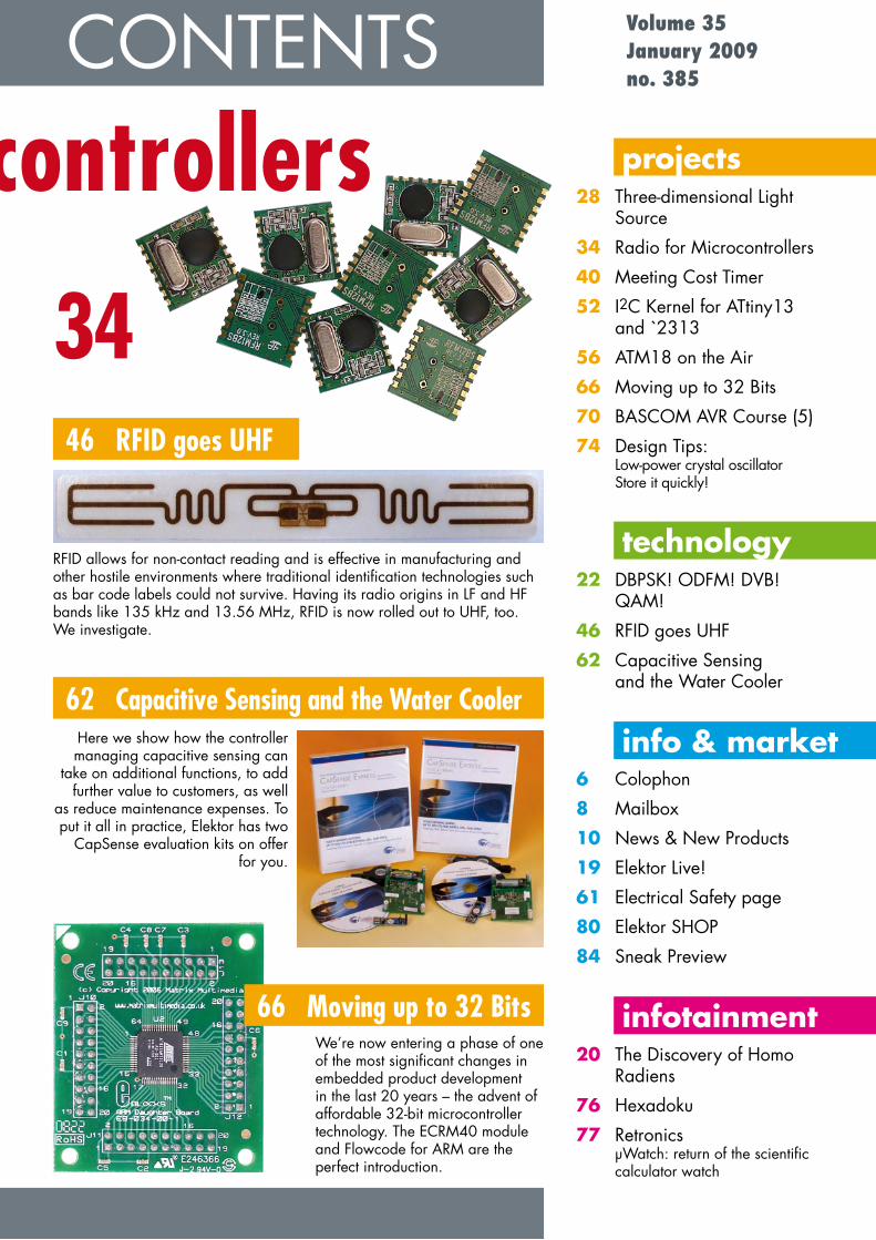
RFID allows for non-contact reading and is effective in manufacturing and other hostile environments where traditional identification technologies such as bar code labels could not survive. Having its radio origins in LF and HF bands like 135 kHz and 13.56 MHz, RFID is now rolled out to UHF, too. We investigate.
46 RFID goes UHF
Here we show how the controller managing capacitive sensing can
take on additional functions, to add further value to customers, as well
as reduce maintenance expenses. To put it all in practice, Elektor has two
CapSense evaluation kits on offer for you.
62 Capacitive Sensing and the Water Cooler
CONTENTSprojects
28 Three-dimensional Light Source
34 Radio for Microcontrollers40 Meeting Cost Timer52 I2C Kernel for ATtiny13
and `231356 ATM18 on the Air66 Moving up to 32 Bits70 BASCOM AVR Course (5)74 Design Tips:
Low-power crystal oscillator Store it quickly!
technology22 DBPSK! ODFM! DVB!
QAM!46 RFID goes UHF62 Capacitive Sensing
and the Water Cooler
info & market6 Colophon8 Mailbox10 News & New Products19 Elektor Live!61 Electrical Safety page80 Elektor SHOP84 Sneak Preview
infotainment20 The Discovery of Homo
Radiens76 Hexadoku77 Retronics
µWatch: return of the scientific calculator watch
Volume 35January 2009no. 385
We’re now entering a phase of one of the most significant changes in embedded product development in the last 20 years – the advent of affordable 32-bit microcontroller technology. The ECRM40 module and Flowcode for ARM are the perfect introduction.
66 Moving up to 32 Bits

elektor - 1/2009
elektor international mediaElektor International Media provides a multimedia and interactive platform for everyone interested in electronics.
From professionals passionate about their work to enthusiasts with professional ambitions. From beginner to diehard, from student to lecturer. Information, education, inspiration and entertainment.
Analogue and digital; practical and theoretical; software and hardware.
elektor electronics worldwide
English GermanDutchFrenchChinese
PortugalItalian
SpanishSwedish
FinnishVolume 35, Number 385, January 2009 ISSN 1757-0875
Elektor aims at inspiring people to master electronics at any personal level by presenting construction projects and spotting developments in electronics and information technology.
Publishers: Elektor International Media, Regus Brentford, 1000 Great West Road, Brentford TW8 9HH, England. Tel. (+44) 208 261 4509, fax: (+44) 208 261 4447 www.elektor.com
The magazine is available from newsagents, bookshops and electronics retail outlets, or on subscription. Elektor is published 11 times a year with a double issue for July & August.
Elektor is also published in French, Spanish, German and Dutch. Together with franchised editions the magazine is on circulation in more than 50 countries.
International Editor: Wisse Hettinga ([email protected])
Editor: Jan Buiting ([email protected])
International editorial staff: Harry Baggen, Thijs Beckers, Ernst Krempelsauer, Jens Nickel, Clemens Valens.
Design staff: Antoine Authier (Head), Ton Giesberts, Luc Lemmens, Daniel Rodrigues, Jan Visser, Christian Vossen
Editorial secretariat: Hedwig Hennekens ([email protected])
Graphic design / DTP: Giel Dols, Mart Schroijen
Managing Director / Publisher: Paul Snakkers
Marketing: Carlo van Nistelrooy
Customer Services: Anouska van Ginkel
Subscriptions: Elektor International Media, Regus Brentford, 1000 Great West Road, Brentford TW8 9HH, England. Tel. (+44) 208 261 4509, fax: (+44) 208 261 4447Internet: www.elektor.com

1/2009 - elektor
Further information and registration atwww.elektor.com/events
Masterclass High-End Valve Amplifi ers
Specifi cally for audio designers,audiophiles, DIY enthusiasts etc. Presenter:
Menno van der Veen, Msc
Leading designer of valve amplifi ers and output
transformers
Programme:
Reception and registration (9.30)
Preamplifi ers: equivalent schematics, limits in
the frequency domain
Power amplifi ers: modelling of class A to B, interaction
of the specifi cations for OPTs and frequency range
and damping factor
Lunch (12.15-12.45)
Negative feedback: how negative feedback can be
done right, remarkable experiments in “the project”
Output transformer: limits and possibilities for the
output transformer
Discussion and end (3.30)
The course fees are £ 160.00 (Including handout,
certifi cate and lunch)
Subscribers to Elektor are entitled to5% discount!
Date: Saturday 21 February 2009 Location: Birmingham City UniversityTime: From 10.00 am to 3.30 pm
REGISTER NOW!Seating capacity is strictly limited
In this Masterclass Menno van der Veen will examine
the predictability and perceptibility of the specifi ca-
tions of valve amplifi ers. Covered are models that
allow the characteristics of valve amplifi ers to be
explored up to the limits of the audible domain from
20 Hz to 20 kHz. This then leads to the minimum
stability requirements that the amplifi er has to satisfy.
The coupling between output valves and output
transformer are also modelled. This gives new insight
into a unique type of distortion: Dynamic Damping
Factor Distortion (DDFD). Negative feedback is
often used in amplifi ers. What is the optimum
and what are the audible consequences?
The correct amplifi cation of micro details
is explained, based on new research, and
new models about this are presented.
certificate
including
electronics worldwide
ELEK UK0901 Mastercl High End s7Sec1:7 Sec1:7 26-11-2008 22:07:09
Email: [email protected] and terms are given on the Subscription Order Form
Head Office: Elektor International Media b.v. P.O. Box 11 NL-6114-ZG Susteren The NetherlandsTelephone: (+31) 46 4389444, Fax: (+31) 46 4370161
Distribution: Seymour, 2 East Poultry Street, London EC1A, England Telephone:+44 207 429 4073
UK Advertising: Huson International Media, Cambridge House, Gogmore Lane, Chertsey, Surrey KT16 9AP, England.Telephone: +44 1932 564999, Fax: +44 1932 564998
Email: [email protected]: www.husonmedia.comAdvertising rates and terms available on request.
Copyright NoticeThe circuits described in this magazine are for domestic use only. All drawings, photo-graphs, printed circuit board layouts, programmed integrated circuits, disks, CD-ROMs, software carriers and article texts published in our books and magazines (other than third-party advertisements) are copyright Elektor International Media b.v. and may not be reproduced or transmitted in any form or by any means, including photocopy-ing, scanning an recording, in whole or in part without prior written permission from the Publisher. Such written permission must also be obtained before any part of this
publication is stored in a retrieval system of any nature. Patent protection may ex-ist in respect of circuits, devices, components etc. described in this magazine. The Publisher does not accept responsibility for failing to identify such patent(s) or other protection. The submission of designs or articles implies permission to the Publisher to alter the text and design, and to use the contents in other Elektor International Media publications and activities. The Publisher cannot guarantee to return any mate-rial submitted to them.
DisclaimerPrices and descriptions of publication-related items subject to change.Errors and omissions excluded.
© Elektor International Media b.v. 2009 Printed in the Netherlands
elektor - 1/2009
info & market mailbox
code into flash memory if the ATxxx is built into a circuit? What is the specific procedure for transforming source code into a running program? And so on.
With the R8C13, this was all explained nicely and gar-nished with hardcopy text. Everything worked right off the bat, but with Bascom I see a constant stream of error mes-sages, such as ‘Selected Chip does not match’, ‘Could not identify Chip-ID’, etc.Perhaps you could post a similar article for newcomers on the Elektor website — that would be nice.Will Sergeant (UK)
Burkhard Kainka, the course aut-hor repliesI am aware of the problem. In many cases, newcomers to Bas-com are also newcomers to the AVR microcontroller. However, there is a countless variety of platforms, development boards and device programmers. We initially considered describing three different systems in some detail, but we abandoned this idea because the ATM18 system is currently the most popular among Elektor readers. Many readers who have purchased this system have already put the hardware learning curve behind them, and what they are interested in now is developing their own programs. For other systems, you may obtain help from fellow readers on the Elek-tor forum.Incidentally, the large number of possible software levels, set-
Counter tubes / E1THi Jan — I just saw the Ret-ronics item about E1T tubes on your website (ref. issue 9/2008, Ed.). I’m inviting you and your readers to have a look at our project at:www.emsp.tu-berlin.de/lehre/mixed-signal-baugruppen/dbtreinfYou might find some interesting ideas here (with full schema-tic diagrams and a detailed description available for download).Here is another link for the general background and some other projects that you may also find interesting:www.emsp.tu-ber-lin.de/lehre/lehre/ mixed-signal-baugruppenHenry Westphal (Germany)
Many thanks for the interesting links Henry. We’re pleased to be able to pass this information on to our readers. We also appreci-ate your feedback on the Retro-nics articles, and we wish your
group all the best with your ‘her-itage component’ projects.
Data cable for mobile phoneDear Elektor — I write in response to your article ‘Remote Control by Mobile Phone’ in the November 2008 issue. For some time now, I have been operating a domestic alarm system using a mobile phone (Siemens S35) and a PIC16F84. The alarm system is activated and de-activated by phone calls. It reports events to me by text messaging (which incurs costs) or by calling (letting the phone ring for 15 seconds and then hanging up).
At first I used a mobile phone data cable and a MAX232, but then it occurred to me that there must be a simpler solution. The Siemens mobile phone has a working signal
level of approximately 3 V, which is high enough to be regarded by the microcontrol-ler as a logic ‘1’ on its input. I use a Zener diode to pull the 5-V signal from the microcon-troller down to 3 V for the mobile phone. Communication between the mobile phone and the microcontroller works per-fectly with this arrangement, without a MAX232 or a data cable (which anyhow includes a MAX232) in the circuit.I also charge the battery of the mobile phone by connecting 7 V to pin 3 of the Siemens socket (Lumberg socket). This ensures that the alarm system continues to work properly even if I am away for an exten-
ded time.On the web are various sites with extensive descriptions of the AT commands (including the Siemens commands), for example, www.nobbi.com. I was able to find PDU Spy, a program that makes coding and decoding text messages especially easy. The connector pin assignments of the Nokia and Siemens mobile phones are also described.Maik Busse (Germany)
Bascom courseHi Editor — to make your Bascom AVR course somewhat easier to understand for begin-ners, it would be a good idea to first explain how to use the Bascom compiler. For instance, some of us don’t know how to use an STK xyz or don’t want to use one. How can you load
1/2009 - elektor
Is there a benign Elektor reader out there who can help me to obtain working Delphi code? I know my micros are sending/receiving HID mes-sages, because I did manage to find an HID snooper. Can any one help?Ceri Clatworthy (UK)
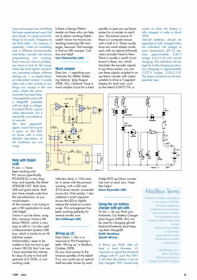
Much simplerDear Jan — regarding your ‘Indicator for Weller Solder-ing Stations’ (July/August 2008, Ed.), I believe I have a much simpler circuit for a heat
indicator lamp: a 10-Ω resis-tor in series with the primary winding, with a LED and 47-Ω series resistor connected across the 10-Ω resistor. I also soldered a small capacitor across the LED to slightly reduce the switch-on current surge. This arrangement has been working perfectly for several months now.Jim Colthorpe (UK)
Wiring up (2)Dear Editor — this is in response to Phil Pumphrey’s letter ‘Wiring up’ in Mailbox, October 2008.Do you have access to the traverse spindles of the table? If so, you could use an optical shaft encoder driven by each
tings and jumpers are something that even experienced users find very handy. It is quite normal for things to not work. It happens to me fairly often – for instance, if yesterday I tried out something with a different microcontroller and today I wonder why device programming isn’t working. Every time you have a problem, you have to look for the cause: check the clock signal, connecti-ons, operating voltage, software settings, etc. — or maybe there’s an intermittent contact. It usually takes only a few minutes to sort things out, except in the rare cases where the micro-controller has been fried. I managed this once with a Mega88, probably with too high a voltage. It worked OK for a good while afterwards, but it eventually succumbed to its wounds.The best approach, again, would be to post a query on the Elek-tor forum with a more detailed description of the hardware you are using.
Help with Delphi codeHi Jan — I have been working with PIC micros (specifically PIC4550) for a very long time, and recently, the Atmel AT90USB1287. Both have USB and good merits. Both also have sample code from the manufacturers, as you would expect.At the moment, I am trying to get a HID application to work with Delphi.I know it can be done, using DLLs, because I have a Vel-leman P8055, which is very easy to talk to. I’ve also used a Measurement Systems USB box, which is similar to an NI LabView system.Unfortunately I seem to be unable to find out how to get a basic HID DLL that I can use. I have searched the internet, for days (!) only to find stuff upwards of £ 2500, or non working code.
spindle, to give you up/down pulses for a counter on each axis. The easiest source of these is a computer mouse with a ball in it. These usually have two small wheels inside, each with an optical (infrared) rotary encoder fixed to them. There is usually a small circuit board in there, too, which translates the encoder signals to up/down pulses; you can use these signals coupled to an up/down counter with output suitable to drive a 7-segment display for each axis, such as the Intersil ICM7217A, a
4-digit BCD up/down counter. Use one on each axis. Hope that helps!Steve Reynolds (UK)
Using the car battery charger with gel cellsHi Jan — do you think your Automatic Car Battery Charger (July/August 2008, Ed.) can be used for charging gel-cell lead-acid batteries (and keep-ing them charged)?Keith Vandross (South Africa)
In theory yes, Keith, after all, lead is lead…However, it’s important to adjust the threshold voltage with P1 such that THY1 is off when the battery is not yet fully charged. THY1 should only
switch on when the battery is fully charged, in order to block THY2.Gel-cell batteries should be regarded as fully charged when the individual cell voltage at room temperature (20 °C) rea-ches approximately 2.45 V (range: 2.4–2.5 V) with normal charging. The individual cell vol-tage for trickle charging (continu-ous charging) is approximately 2.275 V (range: 2.25–2.3 V). The drops somewhat as the tem-perature rises.
MailBox Terms• Publication of reader’s orrespondence
is at the discretion of the Editor.• Viewpoints expressed by
correspondents are not necessarily those of the Editor or Publisher.
• Correspondence may be translated or edited for length, clarity
and style.• When replying to Mailbox
correspondence, please quote Issue number.
• Please send your MailBox correspondence to:
Elektor, The Editor, 1000 Great West Road,
Brentford TW8 9HH, England.
2
3
1IC2.A
6
5
7 2
1
8
4
IC2.BR2
R3 R4
D2
R6
R5
C4
R7
1k5
100k
1k 1M 10k
47k
0Ω33
D3
LED
R1
D1
C1
47µ63V
1 6
neu
neu
4
1
7
2
3
21 3 C2
100n
100n
100n
IC1
+12V78L12
1N4148
IN4004
IC2 = LM358
K1
X1X1
230V
AC
C3
TR1S1
080121- 11
F1
S
C
Lötkolben TCP-S
Lötkolben-potential
WTCP-S
+12V TR1D1
50V 5A
D2
50V 5A
100mA
F1
S1
R1
1k2
1W
LED1
R2
820
Ω
1W
LED2
R4
680
Ω
1W
ON CHARGED
THY1
TIC106D
THY2
D4
1N4004R6
R3
10k
D3
6V8400mW
P1
4k7
C1
22µ25V
R5
1k
D5
1N
BT1
12V
+BATT
–BATT
5402
5A
F2
080224 - 11
230V
18V
18V *
*
see text*

10 elektor - 1/2009
info & market news & new products
Social network and online lab for electronics enthusiastsSchmartBoard recently announced the launch of Solder By Numbers – a social network and online elec-tronic circuit design lab for elec-tronics professionals, educators, students and hobbyists.Professionals can find peers within the electronics industry and con-nect with them to share ideas and discuss electronics issues or employment opportunities. Edu-cators can set up private rooms where they can have students cre-ate circuits online and communi-cate with them via VoIP with web cams to discuss the coursework or teach complete lessons. Students can enhance their learning experi-ence with a plethora of tools and the ability to interact with others from around the world.Hobbyists of all levels and spe-cial interest areas can create and share circuits and learn. Even ‘newbies’ can visit SolderbyNum-bers.com and now build electronic circuits because the site uses the
same concept for building circuits as Paint By Numbers uses for art. With no previous experience users will be able to build electronic cir-cuits. Users who apply for, and are authorized to, publish circuits in a Solder By Numbers format will earn income every time someone builds their circuit.Some of the features on the site are:
• Electronics Lab, Circuit Library• Company Directory,
Jobs Posting• Create Profile, Blog and
Make Friends• Clubs, Forums, Polls,
Event Listings• Chat rooms, VoIP, Web Cams• Post Photos, Documents, Videos• Make Commission on Circuits
To sign up, users can go to the website below.
www.solderbynumbers.com
Workshop RFID Principles and Practice
Saturday 17 January 2009 from 9:00 am to 4.00 pm, Birmingham City University, Technology Innovation Centre.
Presenter: John Verrill BSc (Hons) CCAI PGCE
The principal aim of this one-day course is to introduce the student to the concepts involved in RFID. The course will use E-blocks hardware with one of the common 40-pin PIC microcontrollers. Participants will learn how to use the revolutionary new software ‘Flowcode’ to implement some of the functionality of modern RFID transponders. A prerequisite for the seminar is a basic range of electronics skills and computer proficiency (using Windows).
On completing this course the student will have learned:
- the basic components of a RFID system;- common applications for RFID; - techniques to configure the RFID reader to enable communication with either ICODE or
Mifare transponders;- the commands and syntax used to read and write data from and to RFID transponders.
The course fee is £ 199, including handout, lunch and certificate. Elektor subscribers are entitled to a 5% discount. Be quick to register, there is seating capacity for only 20 participants!
Masterclass High-End Valve Amplifiers
Saturday 21 February 2009 from 10:00 am to 3.30 pm, Birmingham City University, Technology Innovation Centre.
Presenter: Menno van der Veen, MSc.
In this Masterclass Menno van der Veen will examine the predictability and perceptibility of the specifications of valve amplifiers. Covered are models that allow the characteristics of valve amplifiers to be explored up to the limits of the audible domain from 20 Hz to 20 kHz. This then leads to the minimum stability requirements that the amplifier has to satisfy. The coupling between output valves and output transformer are also modelled. This gives new insight into a unique type of distortion: Dynamic Damping Factor Distortion (DDFD). Negative feedback is often used in amplifiers. What is the optimum and what are the audible consequences? The correct amplification of micro details is explained, based on new research, and new models about this are presented.
The course fee is £ 160, including handout, certificate and lunch. Elektor subscribers are entitled to a 5% discount. Register now, seating capacity is strictly limited.
Further information and registration at www.elektor.com/events
Elektor comes to the USAPacked with electronics projects, know-how and technology, Ele-ktor magazine has now come to North America and Canada! A special landing page is available on the web for US and Canadian readers.Elektor USA’s November 2008 and October 2008 trial issues
were distributed by mail as well as at the Audio Engineering Society (AES) Convention held in San Francisco on October 2-5 2008 and Embedded Systems Conference (ESC) Boston, Octo-ber 27-30 2008.This January 2009 issue marks the official launch of Elektor USA magazine, joining the successful
English, Dutch, Spanish, French, German, Italian, Portuguese and Brazilian magazines centrally produced by Elektor International Media, with websites to match.Printed at US letter size and con-taining local advertising, the new US edition of Elektor has basi-cally the same editorial contents
as the UK magazine.American and Canadian read-ers originally subscribed to the European/UK Elektor can now subscribe on-line using the spe-cially created USA landing page, which contains an offer they will find hard to refuse!
www.elektor-usa.com
DEVELOPMENT TOOLS | COMPILERS | BOOKS
S O F T W A R E A N D H A R D W A R E S O L U T I O N S F O R E M B E D D E D W O R L D
12 elektor - 1/2009
info & market news & new products
Elektor at Embedded Systems Conference Boston, USABy Jan Buiting
From 27 to 30 October 2008 Elektor was present at the Boston, USA edition of Embedded Systems Conference. The Elektor booth was initially staffed by Wisse Hettinga (International Coordinat-ing Editor), Jan Buiting (Editor) and Hugo Vanhaecke (Elektor USA Publisher). On the second day of the exhibition, we were joined by Mike Costa and Peter Wostrel from Strategic Media Marketing Inc., Elektor’s US advertising bureau.
The ESC exhibition was used to introduce the US edition of Elektor mag-azine to visitors and exhibitors. The response was positive throughout. Some comment heard on the blue-carpet walkway: “that’s a mighty fresh magazine compared to what we get here”; “Hey I used to take the Euro-pean edition – great but too expensive to get here”; “R u around since 1975? Awesome!”; “How can I subscribe to it?” [using the card inside the mag, or go to www.elektor-usa.com]; “Do you accept contributions from freelance authors?” [sure]. “Cool, you people have your own lab” [yep]. “What, housed in a castle?” [yep].Close to 1,000 copies of the November 2008 trial issue were distributed to visitors and exhibitor staff.The two-day exhibition is embedded (pun intended) into the ESC event
which actually lasts five days and is famous for its conference sessions. At Boston, the sessions were rewarded with good attendance throughout, with the Teardown Sessions and the hands-on lectures on the TI Bea-gle board project and MIT’s Robot Swarms, the most popular.These Teardown Sessions deserve a following! We watched Apple ‘Pip-pin’ and ‘Newton’ PCs (fashionable for a month, then market fiascos) being taken apart ‘less carefully’ and the innards drilled out, smashed and revealed in a journalistic way with a good deal of American calm and humor.Doing our rounds on the show floor we ran into the US representatives of a number of market-leading companies Elektor Europe has been in close contact with for many years.
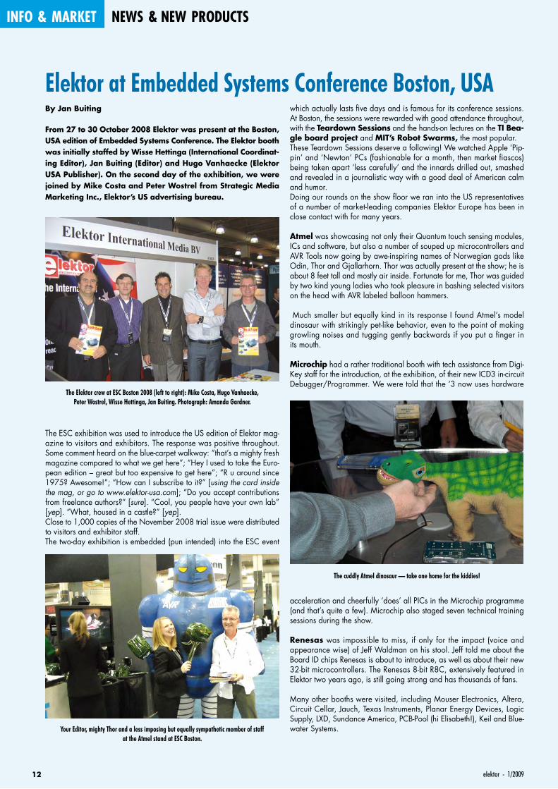
Atmel was showcasing not only their Quantum touch sensing modules, ICs and software, but also a number of souped up microcontrollers and AVR Tools now going by awe-inspiring names of Norwegian gods like Odin, Thor and Gjallarhorn. Thor was actually present at the show; he is about 8 feet tall and mostly air inside. Fortunate for me, Thor was guided by two kind young ladies who took pleasure in bashing selected visitors on the head with AVR labeled balloon hammers.
Much smaller but equally kind in its response I found Atmel’s model dinosaur with strikingly pet-like behavior, even to the point of making growling noises and tugging gently backwards if you put a finger in its mouth.
Microchip had a rather traditional booth with tech assistance from Digi-Key staff for the introduction, at the exhibition, of their new ICD3 in-circuit Debugger/Programmer. We were told that the ‘3 now uses hardware
acceleration and cheerfully ‘does’ all PICs in the Microchip programme (and that’s quite a few). Microchip also staged seven technical training sessions during the show.
Renesas was impossible to miss, if only for the impact (voice and appearance wise) of Jeff Waldman on his stool. Jeff told me about the Board ID chips Renesas is about to introduce, as well as about their new 32-bit microcontrollers. The Renesas 8-bit R8C, extensively featured in Elektor two years ago, is still going strong and has thousands of fans.
Many other booths were visited, including Mouser Electronics, Altera, Circuit Cellar, Jauch, Texas Instruments, Planar Energy Devices, Logic Supply, LXD, Sundance America, PCB-Pool (hi Elisabeth!), Keil and Blue-water Systems.
The Elektor crew at ESC Boston 2008 (left to right): Mike Costa, Hugo Vanhaecke, Peter Wostrel, Wisse Hettinga, Jan Buiting. Photograph: Amanda Gardner.
Your Editor, mighty Thor and a less imposing but equally sympathetic member of staff at the Atmel stand at ESC Boston.
The cuddly Atmel dinosaur — take one home for the kiddies!

0901_elektor_adv_UK.indd 13 28-11-2008 14:05:48
14 elektor - 1/2009
info & market news & new products
Single chip Hi-speed USB 2.0 solutions for serial and parallel interfacing
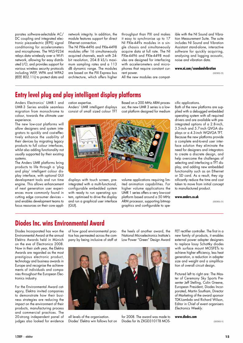
Future Technology Devices Internat ional L imi ted (FTDI) announced the availability of their 5th generation of USB to UART/FIFO ICs. The two new devices support the 480 Mb/s USB 2.0 Hi-Speed specification. The FT2232H and FT4232H devices have the
FT2232H can be configured as a dual FT245 FIFO, a host bus emu-lation mode, a CPU interface FIFO mode or a fast opto-isolated serial interface mode. Both devices support a data trans-fer rate up to 12 Mbaud when configured as an RS232/RS422/RS485 UART interface and > 25 MBytes/second over a parallel FIFO interface (FT2232H only). A USB protocol engine controls the physical Universal Transceiver Macrocell Interface (UTMI) and handles all aspects of the USB 2.0 Hi-Speed interface. Both ICs
integrate a Low Drop-Out (LDO) regulator, an internal 12 MHz to 480 MHz PLL and interface to an external EEPROM. These devices integrate the entire USB protocol on a single chip and provide extremely flexible inter-face configuration options. They provide a flexible method of inter-facing to FPGAs and microcontrol-lers as well as upgrading legacy designs to accommodate USB communication.
www.ftdichip.com(080965-II)
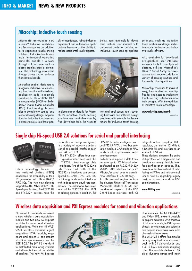
Microchip: inductive touch sensingMicrochip announces new mTouch™ Inductive Touch-Sens-ing Technology, as an addition to its capacitive touch-sensing solutions. Inductive touch sens-ing’s fundamental operating principles enable it to work through a front panel such as plastic, stainless steel or alumin-ium. The technology also works through gloves and on surfaces that contain liquids.
Microchip enables designers to integrate inductive touch-sens-ing functionality within existing application code in a single standard 8-, 16- or 32-bit PIC® microcontroller (MCU) or 16-bit dsPIC® Digital Signal Controller (DSC). Touch sensing also ena-bles a completely sealed and modern-looking design. Applica-tions for inductive touch-sensing include stainless steel front pan-
els for appliances, robust industrial equipment and automotive appli-cations because of the ability to reduce accidental touch triggers.
Implementation details for Micro-chip’s inductive touch sensing solutions are available now by free download from the website
below. Items available for down-load include user manual with quick-start guide for building an inductive touch-sensing applica-
tion and application notes cover-ing hardware and software design practices, with example implemen-tations for inductive touch-sensing
solutions, such as inductive touch mechanical design, induc-tive touch hardware and induc-tive touch software.
Also available for download are graphical user interface software tools for analysis of designs, utilising Microchip’s PICkit™ Serial Analyzer devel-opment tool, source code for a variety of sensing routines and frequently asked questions.
Microchip continues to make it easy, inexpensive and royalty-free for engineers to implement touch-sensing interfaces into their designs. With the addition of inductive touch technology.
www.microchip.com/mtouch(080965-I)
capability of being configured in a variety of industry standard serial or parallel interfaces such as UART or FIFO.The FT4232H offers four con-figurable interfaces and the FT2232H two configurable
interfaces. Two of the FT4232H’s inter faces and both of the FT2232H’s interfaces can be con-figured as UART, JTAG, SPI, I2C or bitbang mode serial interfaces with independent baud rate gen-erators. The additional two inter-faces of the FT4232H offer UART or bitbang options. In addition, the
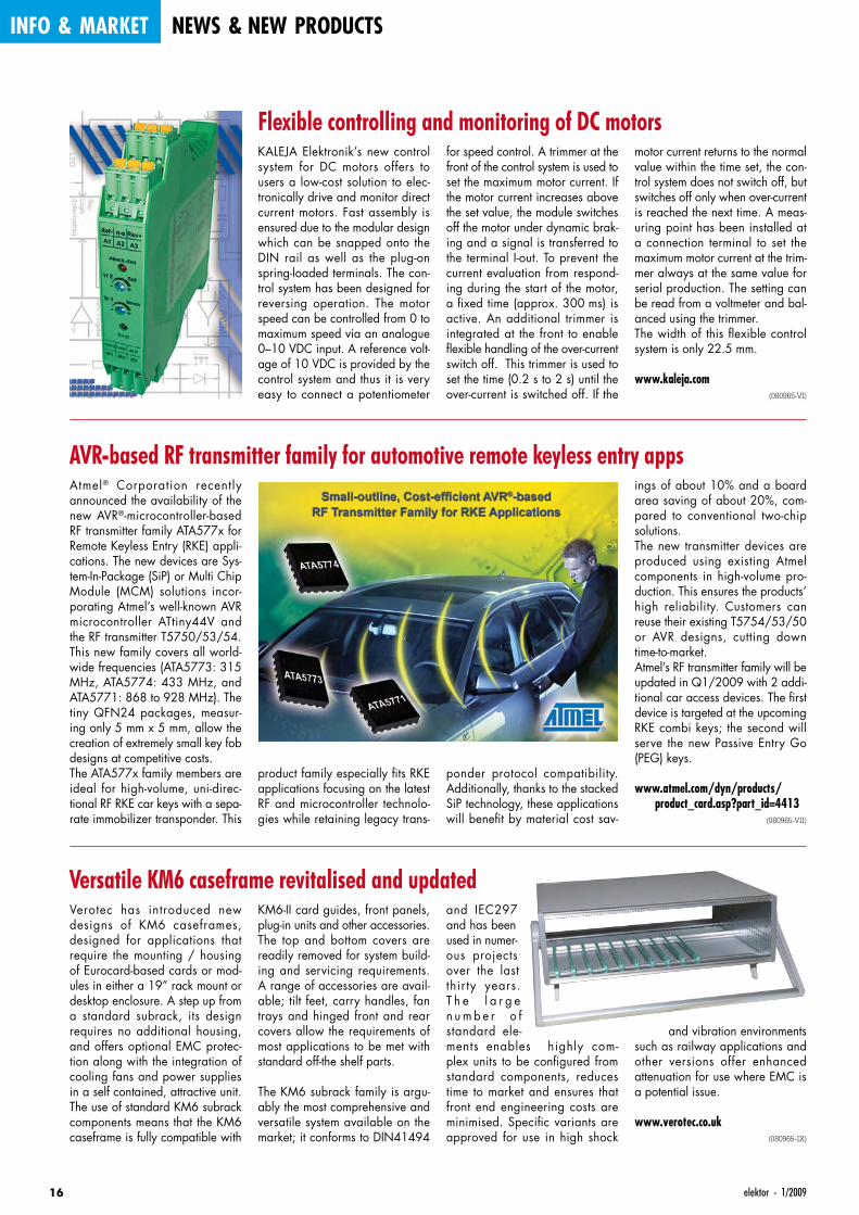
Wireless data acquisition and PXI Express modules for sound and vibration applicationsNational Instruments released a new wireless data acquisition module and two new PXI Express modules for sound and vibration applications. With the NI WLS-9234 wireless dynamic signal acquisition (DSA) module, engi-neers and scientists can stream vibration data wirelessly over the IEEE 802.11g (Wi-Fi) standard to distributed monitoring systems and eliminate the cost and clutter of cabling. The new PXI Express
DSA modules, the NI PXIe-4496 and PXIe-4498, make it possible to acquire data from 272 channels at full rate in a single PXI Express chassis, so engineers and scientists can acquire more data from more channels at faster rates.The WLS-9234 offers four simulta-neously acquired input channels, each with 24-bit resolution and a 51.2 kS/s maximum sampling rate. The module delivers 102 dB of dynamic range and incor-
151/2009 - elektor
porates software-selectable AC/DC coupling and integrated elec-tronic piezoelectric (IEPE) signal conditioning for accelerometers and microphones. The WLS-9234 relays data wirelessly over a Wi-Fi network, allowing for easy distrib-uted I/O, and provides support for various wireless security protocols including WEP, WPA and WPA2 (IEEE 802.11i) to protect data and
network integrity. In addition, the module features support for direct Ethernet connection.The NI PXIe-4496 and PXIe-4498 modules offer 16 simultaneously acquired channels, each with 24-bit resolution, 204.8 kS/s maxi-mum sampling rates and a 113 dB dynamic range. The modules are based on the PXI Express bus architecture, which offers higher
throughput than PXI and makes it easy to synchronise up to 17 NI PXIe-449x modules in a sin-gle chassis and simultaneously acquire data at full rate. The NI PXIe-4496 and PXIe-4498 mod-ules are designed for interfacing with accelerometers and micro-phones that require constant cur-rent power.All the new modules are compat-
ible with the NI Sound and Vibra-tion Measurement Suite. The suite includes NI Sound and Vibration Assistant stand-alone, interactive software for quickly acquiring, analysing and logging acoustic, noise and vibration data.
www.ni.com/soundandvibration(080965-III)
Entry level plug and play intelligent display platformsAnders Electronics’ UMR-1 and UMR-3 Series enable seamless migration from monochrome to colour, towards the ultimate user experience.The new low-cost platforms will allow designers and system inte-grators to quickly and cost-effec-tively enhance the usability of their devices by migrating legacy products to full colour interfaces, whilst also adding functionality not usually supported by their existing systems. The Anders UMR platforms bring products to life through a ‘plug and play’ intelligent colour dis-play interface, with optional GUI development tools and run time engine. This allows enhancement of next generation user experi-ences more commonly found in cutting edge consumer devices – and enables development teams to focus resources on their core appli-
Based on a 200 MHz ARM proces-sor, the new UMR 3 series is a low-cost platform designed for medium
volume applications requiring lim-ited animation capabilities. For higher volume applications the UMR 1 series offers a very low-cost platform based around a 50 MHz ARM processor, supporting bitmap graphics and configurable to spe-
cific applications.Both of the new platforms are sup-plied with a debugged embedded operating system with all required drivers and are available with pre-integrated options of a 2.8-inch, 3.5-inch and 5.7-inch QVGA dis-plays or a 4.3-inch WQVGA TFT.Because the new platforms provide a complete end-to-end user inter-face solution they eliminate the need for designers and integrators to create a discrete design, and help overcome the challenges of selecting and interfacing a TFT dis-play, and adding new embedded functionality such as an Ethernet or SD card. As a result, they sig-nificantly reduce the time and cost taken to move from initial concept to manufactured product.
www.anders.co.uk(080965-IV)
cation expertise. Anders’ UMR intelligent displays consist of small sized colour TFT
displays with touch screen, pre-integrated with a multi-functional, configurable embedded system with ready to run operating sys-tem, optimised to drive the display and run a graphical user interface (GUI).
Diodes Inc. wins Environmental AwardDiodes Incorporated has won the Environmental Award at the annual Elektra Awards held in Münich on the eve of Electronica 2008. Now in their sixth year, the Elektra Awards are regarded as the most prestigious electronic product, technology and business awards in Europe and recognise the achieve-ments of individuals and compa-nies throughout the European Elec-tronics industry.
For the Environmental Award cat-egory, Elektra invited companies to demonstrate how their busi-ness strategies are reducing the impact on the environment of their products, manufacturing process and commercial practices. The 20-strong independent panel of judges also looked for evidence
the heels of another award, the National Microelectronics Institute’s Low Power “Green” Design Award
for 2008. The award was made to Diodes for its ZXGD3101T8 MOS-
FET rectifier controller. The first in a new family of products, it enables external power adapter designers to replace lossy Schottky diodes with surface mount MOSFETs to achieve higher efficiency, less heat generation, a reduction in adapter size and weight and a simplifica-tion of overall circuit design.
Pictured left to right are: The Mas-ter of Ceremony Sky Sports Pre-senter Jeff Stelling, Colin Greene, European President, Diodes Incor-porated, Martin Southam, Director of Marketing of the award sponsor TDK-Lambda and Richard Wilson, Editor in Chief of event organisers Electronics Weekly.
www.diodes.com(080965-V)
of how good environmental prac-tice has permeated across the com-pany by being inclusive of staff at
all levels of the organisation.Diodes’ Elektra win follows hot on
16 elektor - 1/2009
info & market news & new products
Flexible controlling and monitoring of DC motors for speed control. A trimmer at the front of the control system is used to set the maximum motor current. If the motor current increases above the set value, the module switches off the motor under dynamic brak-ing and a signal is transferred to the terminal I-out. To prevent the current evaluation from respond-ing during the start of the motor, a fixed time (approx. 300 ms) is active. An additional trimmer is integrated at the front to enable flexible handling of the over-current switch off. This trimmer is used to set the time (0.2 s to 2 s) until the over-current is switched off. If the
motor current returns to the normal value within the time set, the con-trol system does not switch off, but switches off only when over-current is reached the next time. A meas-uring point has been installed at a connection terminal to set the maximum motor current at the trim-mer always at the same value for serial production. The setting can be read from a voltmeter and bal-anced using the trimmer.The width of this flexible control system is only 22.5 mm.
www.kaleja.com(080965-VI)
KALEJA Elektronik’s new control system for DC motors offers to users a low-cost solution to elec-tronically drive and monitor direct current motors. Fast assembly is ensured due to the modular design which can be snapped onto the DIN rail as well as the plug-on spring-loaded terminals. The con-trol system has been designed for reversing operation. The motor speed can be controlled from 0 to maximum speed via an analogue 0–10 VDC input. A reference volt-age of 10 VDC is provided by the control system and thus it is very easy to connect a potentiometer
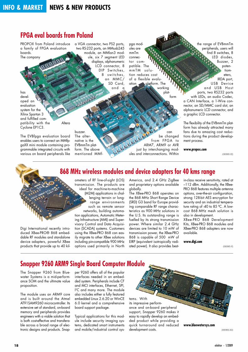
AVR-based RF transmitter family for automotive remote keyless entry appsAtmel® Corporation recently announced the availability of the new AVR®-microcontroller-based RF transmitter family ATA577x for Remote Keyless Entry (RKE) appli-cations. The new devices are Sys-tem-In-Package (SiP) or Multi Chip Module (MCM) solutions incor-porating Atmel’s well-known AVR microcontroller ATtiny44V and the RF transmitter T5750/53/54. This new family covers all world-wide frequencies (ATA5773: 315 MHz, ATA5774: 433 MHz, and ATA5771: 868 to 928 MHz). The tiny QFN24 packages, measur-ing only 5 mm x 5 mm, allow the creation of extremely small key fob designs at competitive costs.The ATA577x family members are ideal for high-volume, uni-direc-tional RF RKE car keys with a sepa-rate immobilizer transponder. This
ponder protocol compatibility. Additionally, thanks to the stacked SiP technology, these applications will benefit by material cost sav-
ings of about 10% and a board area saving of about 20%, com-pared to conventional two-chip solutions.The new transmitter devices are produced using existing Atmel components in high-volume pro-duction. This ensures the products’ high reliability. Customers can reuse their existing T5754/53/50 or AVR designs, cutting down time-to-market. Atmel’s RF transmitter family will be updated in Q1/2009 with 2 addi-tional car access devices. The first device is targeted at the upcoming RKE combi keys; the second will serve the new Passive Entry Go (PEG) keys.
www.atmel.com/dyn/products/product_card.asp?part_id=4413
(080965-VII)
product family especially fits RKE applications focusing on the latest RF and microcontroller technolo-gies while retaining legacy trans-
Versatile KM6 caseframe revitalised and updatedVerotec has introduced new designs of KM6 caseframes, designed for applications that require the mounting / housing of Eurocard-based cards or mod-ules in either a 19” rack mount or desktop enclosure. A step up from a standard subrack, its design requires no additional housing, and offers optional EMC protec-tion along with the integration of cooling fans and power supplies in a self contained, attractive unit. The use of standard KM6 subrack components means that the KM6 caseframe is fully compatible with
and IEC297 and has been used in numer-ous projects over the last thir ty years. T h e l a r g e n u m b e r o f standard ele-ments enables highly com-plex units to be configured from standard components, reduces time to market and ensures that front end engineering costs are minimised. Specific variants are approved for use in high shock
and vibration environments such as railway applications and other versions offer enhanced attenuation for use where EMC is a potential issue.
www.verotec.co.uk(080965-IX)
KM6-II card guides, front panels, plug-in units and other accessories. The top and bottom covers are readily removed for system build-ing and servicing requirements. A range of accessories are avail-able; tilt feet, carry handles, fan trays and hinged front and rear covers allow the requirements of most applications to be met with standard off-the shelf parts.
The KM6 subrack family is argu-ably the most comprehensive and versatile system available on the market; it conforms to DIN41494

0901_elektor_adv_UK.indd 17 28-11-2008 14:06:12
18 elektor - 1/2009
info & market news & new products
868 MHz wireless modules and device adapters for 40 kms range
Digi International recently intro-duced XBee-PRO® 868 embed-dable RF modules and standalone device adapters, powerful XBee products that provide up to 40 kil-
America, and 2.4 GHz ZigBee and proprietary options available globally.The XBee-PRO 868 operates on the 868 MHz Short Range Device (SRD) G3 band for Europe provid-ing comparable RF range charac-teristics as 900 MHz solutions in the U.S. Its outstanding range is fuelled by its strong transmission power. Where similar 2.4 GHz devices are limited to 10 mW of transmission power, the XBee-PRO 868 is capable of 500 mW of EIRP (equivalent isotropically radi-ated power). It also provides best-
in-class receive sensitivity, rated at –112 dBm. Additionally, the XBee-PRO 868 features multiple antenna options, over-the-air configuration, strong 128-bit AES encryption for security and an industrial tempera-ture rating of -40 to 85 ºC. A low-cost 868 MHz mesh solution is also in development.XBee-PRO 868 Development Kits, XBee-PRO 868 modules and XBee-PRO 868 adapters are now available.
www.digi.com(080965-X)
ometers of RF line-of-sight (LOS) transmission. The products are
ideal for machine-to-machine (M2M) applications in chal-
lenging terrain or long-range environments
such as remote sensor networks, building automa-
tion applications, Automatic Meter-ing Infrastructure (AMI) and Super-visory Control and Data Acquisi-tion (SCADA) systems. Customers using the XBee-PRO 868 can eas-ily migrate to other XBee solutions including pin-compatible 900 MHz options used primarily in North
Snapper 9260 ARM9 Single Board Computer ModuleThe Snapper 9260 from Blue-water Systems is a mid-perform-ance SOM and the ultimate value proposition.
The module uses an ARM9 core and is built around the Atmel AT91SAM9260 microcontroller. Its extensive set of standard, on-board memory and peripherals provides engineers with a viable solution that is both cost-effective and transfera-ble across a broad range of elec-tronic designs and products. Snap-
tems. With its impressive perform-ance and on-board peripheral support, Snapper 9260 makes it easy to rapidly develop an embed-ded product while providing a quick turnaround and reduced development costs.
www.bluewatersys.com(080965-XII)
per 9260 offers all of the popular interfaces needed in an embed-ded system. Peripherals include CF and MCI interfaces, Ethernet, SPI, I2C and many more. The module also includes either a fully featured embedded Linux 2.6.20 or WinCE 6.0 kernel and a comprehensive board support package.
Typical applications for this mod-ule include security imaging sys-tems, dedicated smart instruments and mobile/industrial control sys-
FPGA eval boards from PolandPROPOX from Poland introduce a family of FPGA evaluation boards. The company
has devel-oped an evaluation system for the Xilinx Spartan 3 and fulfilled com-patibility with the Altera Cyclone EP1C3.
The EVBfpga evaluation board enables users to connect an MMfp-gaXX mini module containing pro-grammable integrated circuits with various on board peripherals like
pga mod-ules are mmTm connec-tor com-patible. The m m T M s o l u -tion reduces cost of a flexible evalu-ation platform. The
working plat-
form
can be changed
f rom FPGA to ARM7, ARM9 or AVR
just by interchanging mod-ules and interconnections. Within
the range of EVBmmTm peripherals, users will
find 8 switches, 8 LED diodes,
Buzzer, 2 poten-
tiom-eters,
IRDA port, USB Dev i ce
and USB Ho s t ports, two RS232 ports
with LEDs, an audio Codec, a CAN Interface, a 1-Wire con-nector, an SD/MMC card slot, an alphanumeric LCD connector, and a graphic LCD connector.
The flexibility of the EVBmmTm plat-form has already attracted many fans due to amazing cost reduc-tions during the product develop-ment process.
www.propox.com(080965-XI)
a VGA connector, two PS2 ports, two RS-232 ports, an MMusb245
module, an MMlan3 mod-ule, six 7 segment LED
displays, alphanumeric LCD connector, 8
D IP Swi tches , 8 sw i t c he s ,
an MMC/SD Card,
a n d a
buzzer.The alter-native is the EVBmmTm plat-form. The above mentioned MMf-
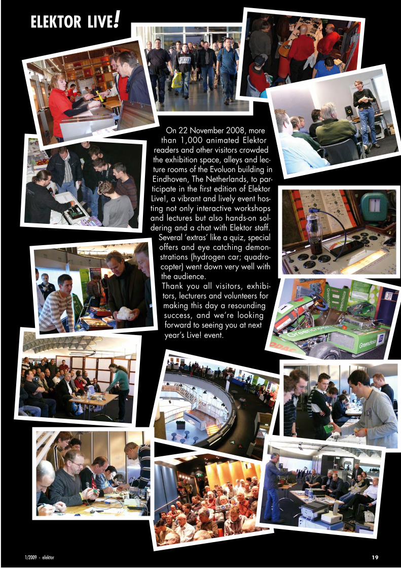
On 22 November 2008, more than 1,000 animated Elektor
readers and other visitors crowded the exhibition space, alleys and lec-ture rooms of the Evoluon building in Eindhoven, The Netherlands, to par-ticipate in the first edition of Elektor Live!, a vibrant and lively event hos-ting not only interactive workshops and lectures but also hands-on sol-dering and a chat with Elektor staff.
Several ‘extras’ like a quiz, special offers and eye catching demon-strations (hydrogen car; quadro-copter) went down very well with the audience.Thank you all visitors, exhibi-tors, lecturers and volunteers for making this day a resounding success, and we’re looking forward to seeing you at next year’s Live! event.
elektor live!
1/2009 - elektor 19

infotainment homo radiens
20 elektor - 1/2009
1
2
34
5
20
25
30
35
40
45
50
55
60
300 M 400 M 500 M 600 M 700 M 800 M 900 M 1000 M230 M
Frequency (Hz)
Leve
l(dB
µV/m
)
Peak
1
2
34
5
20
30
40
50
60
70
80
90
100
110
120
130
300 M 400 M 500 M 600 M 700 M 800 M 900 M 1000 M230 M
Frequency (Hz)
Leve
l(dB
µV/m
)
Peak
Measurement methodology and hazard assessmentIn order to make accurate measurements, all other sources of radiation must be reliably excluded. For these measu-rements, we used a semi-anechoic measuring chamber belonging to DARE, a company located in Woerden, The Ne-
therlands. The chamber is an enormous Faraday cage, which blocks all external radiation, and the interior is non-reflective and absorbent. Consequently, only the radiation of the object in front of the antenna is measured. All measurements were made using a biconical log-periodic antenna (range 30 MHz
to 1 GHz) with a Rohde & Schwarz ESIB 26 EMI Test Receiver (range 20 Hz to 26 GHz) as the measuring receiver.
NotebookWe can expect to see a mixture of signals from a notebook. The processor, front-end bus and memory have their own
frequencies, which range from 250 MHz to more than 1 GHz. The notebook measured here (a Dell Latitude D820) exhibited several strong signal lines at 240 MHz, 680 MHz, and well above the 1-GHz range. The radiation levels
were surprisingly low. These values were recorded with the measuring antenna at a distance of 1 metre.
Is this radiation hazardous?
No – all measured radiation levels are very low and do not pose a hazard. In light
of the strict EMC regulations regarding radiated signals and the fact that all of the
measured devices are fully compliant with these regulations, this is hardly surprising.
A capsule history of the subject of our study: he started off walking on all fours, learned to swing his way through the trees, discovered fire, started hun-ting wild animals and his own kind, began walking on two legs, discovered the fireplace and the sofa, began travelling on two wheels (and later on four), discovered the television set and placed it in front of the sofa, stopped hunting and started feeling neurotic, and – the final step – started radiating.
Elektor went on a quest for Homo Radiens, the new radiant species of mankind. To learn more about this species, we placed a specimen in a measu-ring chamber and examined its frequency spectrum.
The Discovery of Homo Radiens
211/2009 - elektor
12
34
5
10
15
20
25
30
35
40
45
50
300 M 400 M 500 M 600 M 700 M 800 M 900 M 1000 M230 M
Frequency (Hz)
Leve
l(dB
µV/m
)
Peak
1
23
45
10
20
30
40
50
60
70
80
300 M 400 M 500 M 600 M 700 M 800 M 900 M 1000 M230 M
Frequency (Hz)
Leve
l(dB
µV/m
)
Peak
1
2 34
10
15
20
25
30
35
40
45
50
30 M 50 M 100 M 200 M 230 M
Frequency (Hz)
Leve
l(dB
µV/m
)
Peak
1
2
34
5
20
30
40
50
60
70
80
90
100
110
120
130
300 M 400 M 500 M 600 M 700 M 800 M 900 M 1000 M230 M
Frequency (Hz)
Leve
l(dB
µV/m
)
Peak
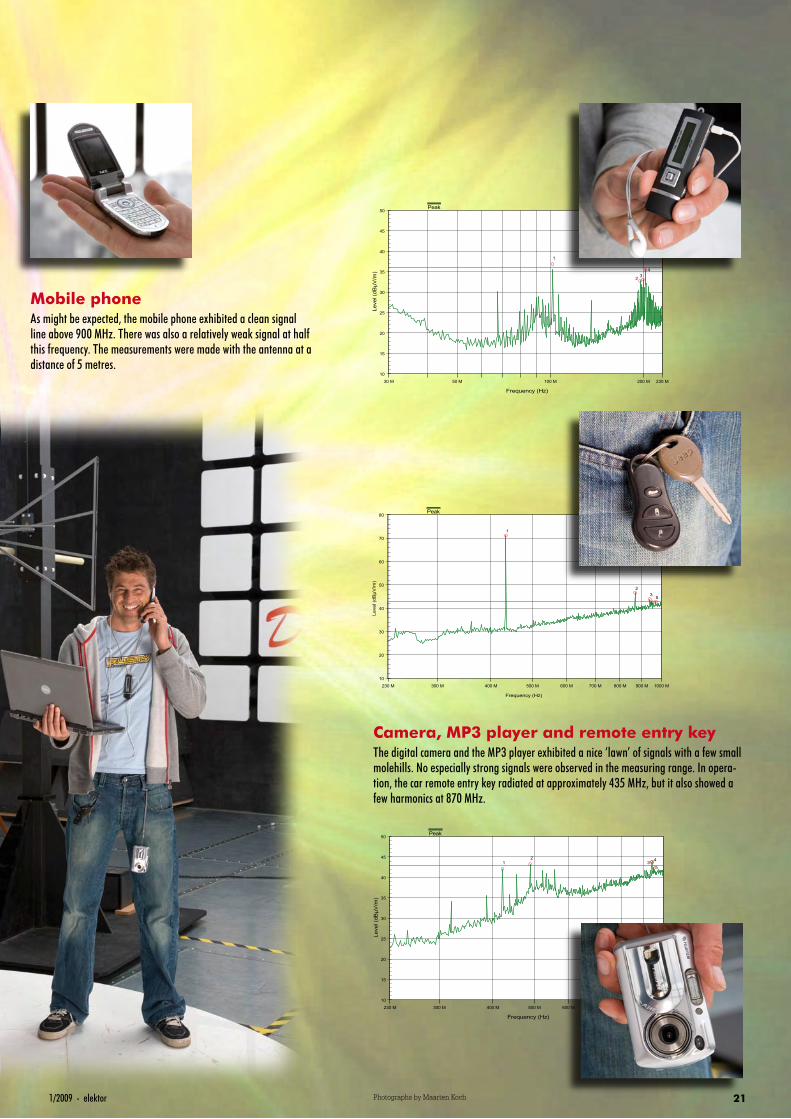
Mobile phoneAs might be expected, the mobile phone exhibited a clean signal line above 900 MHz. There was also a relatively weak signal at half this frequency. The measurements were made with the antenna at a distance of 5 metres.
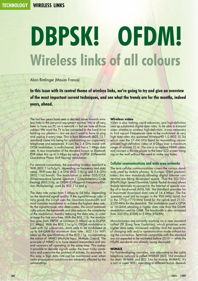
Camera, MP3 player and remote entry keyThe digital camera and the MP3 player exhibited a nice ‘lawn’ of signals with a few small molehills. No especially strong signals were observed in the measuring range. In opera-tion, the car remote entry key radiated at approximately 435 MHz, but it also showed a few harmonics at 870 MHz.
Photographs by Maarten Koch
technology wireless links
22 elektor - 1/2009
The last few years have seen a decided move towards wire-less links in the personal equipment market. We’re all very keen to have our PC on a network — but we hate all those cables! We want the TV to be connected to the hard drive holding our photos — but we don’t want to have to plug and unplug it every time. This is how Bluetooth (802.15.1 standard) came into being for synchronising our organisers, telephones and earpieces. It uses the 2.4 GHz band with GFSK modulation, is multi-channel, and has a 1 Mbps data rate. A new incarnation of the standard known as Bluetooth EDR takes this up to 3 Mbps by using DQPSK (Differential Quadrature Phase Shift Keying) modulation.
For network connections, the prevailing wireless standard is WiFi (802.11a/b/g/n, depending on frequency and data rates). WiFi uses the 2.4 GHz (802.11b/g) and 5.8 GHz (802.11a) bands. The modulation is either DSS/CCK (Direct-sequence Spread Spectrum / Complementary Code Keying) (802.11b), or OFDM (Orthogonal Frequency-Divi-sion Multiplexing), used by 802.11a and g.
The data rate varies from 1 Mbps to 54 Mbs, depending on the received signal quality. If the signal-to-noise ratio is very good, the circuit uses the maximum bandwidth and most complex modulation to achieve the highest data rate. As the signal-to-noise ratio deteriorates, the circuit automati-cally adjusts the bandwidth and also reduces the complexity of the modulation, thereby reducing the data rate, in order to keep the link error-free. With the 802.11b, the modula-tion goes from DBPSK at minimum (1 Mbps) up to DQPSK (11 Mbps). With the 802.11a/g/n, OFDM modulation is used with 52 subcarriers, each able to be modulated at up to 64-QAM for maximum data rate. 802.11n WiFi takes up the specifications of the 802.11g, incorporating the notion of MIMO (Multiple Input, Multiple Output). The principle of MIMO is to have several transmitters and sev-eral receivers all operating at the same time. This makes it possible to decode signals under the most tricky condi-tions and overcome the problem of echoes, for example. In this way, a high data rate can be maintained even when radio propagation conditions are adversely affected by the surroundings.
Wireless videoVideo is also making rapid advances, and high-definition uses up substantial digital data rates. To be able to transmit video streams in wireless high-definition, it was necessary to find vacant frequencies able to be modulated at very high data rates: this spawned WirelessHD 1.0 (802.15.3c) which uses the 57–64 GHz band for transmitting uncom-pressed high-definition video at 4 Gbps over a maximum range of around 10 m. The aim is to replace HDMI cables and connect a Blu-ray player to the latest LCD screen hang-ing on the wall without the need to make any holes.
Cellular communications and wide area networksThe term cellular communications covers the various stand-ards used by mobile phones. In Europe, GSM predomi-nates; the new standards allowing digital Internet con-nection are being developed apace. Thus the 3G/3G+ (HSxPA High Speed Downlink/Uplink Packet Access) allows mobile terminals to connect to the Internet at speeds wor-thy of a hard-wired ADSL link: the standard provides for a maximum download data rate of 14.4 Mbps. The fre-quencies used are no longer in the 900 MHz band, but in the 1710–1770 MHz band for the uplink and 2110–2170 MHz for the downlink. The modulation used is QPSK or 16-QAM allowing a higher data rate than the GSMK modulation used by GSM. The bandwidth is also increased from 200 kHz (GSM) to 5 MHz (HSDPA).
Manufacturers are currently working on a new standard called LTE (Long Term Evolution), which promises even higher data rates, increased mobility, and the possibility of changing cells and/or communication mode without los-ing the connection. Terminals compatible with this standard are not expected to be marketed before 2010 — while the HSxPA standards are already being deployed.
WiMAXFor fast-developing countries, one alternative to the cable telephone network is called WiMAX (802.16d standard for static WiMAX and 802.16e for mobile WiMAX). It’s a sort of super WiFi, operating in different bands depend-
DBPSK! OFDM! DVB! QAM!Wireless links of all coloursAlain Rimlinger (Maxim France)
In this issue with its central theme of wireless links, we’re going to try and give an overview of the most important current techniques, and see what the trends are for the months, indeed years, ahead.

231/2009 - elektor
ing on region or country (2.3–2.7 GHz, 3.5–3.9 GHz, 5.8 GHz and many more). Channel width is programma-ble from 1 to 28 MHz, and operators have the possibility of transmitting voice, data, and even digital TV. The modula-
DBPSK! OFDM! DVB! QAM!
tion used is OFDM. This is a radio alternative to the ADSL networks offering the ‘triple service’. Depending on how much end-users want to pay, they are allocated a different bandwidth; TV requiring the largest bandwidth. In some
Glossary
ASK Amplitude Shift Keying, digital amplitude modulation of a ra-dio carrier. When the amplitude is 0 or 100%, we also speak of OOK for On/Off Keying.
BluetoothShort-range communication standard between peripherals like mobile phones, organizers, earpieces, hand-free kits, and PCs. Bluetooth operates at 2.4 GHz with a 1 Mbps data rate.
BPSK Binary Shift Keying – digital modulation where the bits are en-coded by a phase of 0 or 180°.
DECT Digital Enhanced Cordless Telephone. Transmission standard for domestic cordless phones operating at 1.8 GHz. Allows several handsets to be used with the same base station and for intercom between handsets.
DABDigital Audio Broadcasting – digital audio transmission stand-ard. A standard that enables FM to be replaced with CD-qual-ity radio. It uses particularly robust OFDM modulation. DAB is already widespread in the UK and Germany.
DBPSKDigital Binary Phase Shift Keying. Like DQPSK but with only two phase states.
DMB-TDigital Multimedia Broadcasting Terrestrial, a variant of DAB that also allows transmission of slow-changing graphics in-formation, like a disc sleeve or graphic. This is the standard France has chosen to go over from FM to digital radio.
DQPSKDifferential Quadrature Phase Shift Keying – digital modula-tion where the data are modulated by phase states taking pre-ceding states into account.
DSS/CCKDirect-sequence Spread Spectrum with Complementary Code Keying – digital modulation used by the 802.11b WiFi stand-ard. Data are transmitted by modulating the phase, and spec-trum spreading is achieved by frequency hopping.
DVBDigital Video Broadcast, or digital TV.
FSKFrequency Shift Keying – digital frequency modulation where a 0 corresponds to one frequency and a 1 corresponds to an-other slightly different frequency.
GFSK is a variant of FSK used by Bluetooth amongst others.
HSDPA&HSUPAHigh Speed Downlink/Uplink Packet Access – mobile technol-ogy allowing data transmission by packets at high data rates from the network to the subscriber.
LTELong Term Evolution – a future standard to succeed the UMTS for high data-rate mobile networks.
OFDMOrthogonal Frequency-Division Multiplexing – modulation using several subcarriers within a given bandwidth. Each sub-carrier can then be modulated, for example by QPSK. Each subcarrier normally carries both useful and redundant infor-mation. OFDM is a form of modulation that’s complicated to implement, but is very robust and ensures excellent transmis-sion reliability.
QAMQuadrature Amplitude Modulation – both the phase and the amplitude of a signal are separately varied at the same time in order to transmit a higher number of bits at each moment. The constellation diagram makes it possible to position the groups of bits on concentric circles defining the amplitude and phases.
QPSKQuadrature Phase Shift Keying – four-state digital modula-tion where two bits are coded by a phase state of 0/90/180 or 270°.
WiMAXWorldwide Interoperability for Microwave Access. A sort of long-range ‘super WiFi’ that offers a radio alternative to the (A)DSL network. Many different bands allocated.
ZigBeeRadio communication standard between peripherals, mainly industrial. ZigBee has a comprehensive software network layer that ensures interoperability between peripherals from differ-ent manufacturers.
technology wireless links
24 elektor - 1/2009
regions static WiMAX networks are being developed in areas where ADSL coverage is very poor. In developing countries, WiMAX makes it possible to easily deploy an Internet and communications network using radio relays that are cheaper and quicker to install than an underground copper network.
Convergence of networks and technologiesCurrently, the majority of Internet subscribers use (A)DSL connections. They own one or more PCs, one or more mobile phones, and often a DECT-type cordless phone on their landline. To reduce costs, a popular idea is to tel-ephone over the Internet using software like Skype, using a PC or a dedicated phone that connects to the PC. There are even GSM phones with the Internet option using WiFi. To reduce the number of phone instruments and subscrip-tions, and to make things as simple as possible, some operators have had the idea of turning the box used as an ADSL modem into a mini 3G base station. An electronics card is added into the box, and the operator uses each subscriber as a network repeater station. This is known as a femtobasestation. The transmit power is very low — around 10 mW.
For users, a single 3G phone lets them stay in touch every-where. Free of charge at home using their 3G femtostation, and paying away from home using the normal 3G network. For the operator, this is one way of increasing network coverage at minimal cost, since each femtobasestation is a small repeater that covers a reduced urban zone, where the standard 3G network sometimes has propagation issues because of concrete. The proliferation of femtobasestations ensures the operator of optimized coverage in an urban environment. But this also poses a few technical problems, since each femtobasestation is a real 3G base station, and must not interfere with neighbouring stations, still less with the normal network so-called ‘macro’ station. Tests are in progress to resolve these problems. In the future, several technical solutions will be available for wireless ‘telephon-ing’ and mobile Internet access. Which standard, out of 3G, LTE, WiMAX, and femtobasestation, will be the most widely deployed, only the future and the economic models are going to tell us.
Public radio and TV broadcastingWill FM or AM radio broadcasting soon be coming to an end with a new standard, DMB-T (Digital Multimedia Broadcasting Terrestrial)? This standard makes it possible to replace FM so as to receive CD-quality radio. It too is based on multi-carrier OFDM modulation, using two bands, the L band between 1452–1492 MHz and the VHF band from 168–240 MHz. DMB-T also makes it possible to transmit slow-changing graphics information like a disc sleeve or a graphic. This is the standard a number of countries (includ-ing the UK, Germany and France) have chosen to gradually replace FM and move into the digital radio era. The digital revolution is also underway for HF broadcasting with DRM (Digital Radio Mondial) which also uses OFDM modulation, this time centred around 4 MHz.
Analogue TV was already replaced by digital terrestrial TV in a number of countries. TV was the first to go digital — first of all via satellite, and then via terrestrial. The DVB (Digital Video Broadcast) standards have existed for a long time and are split into several groups: DVB-S for satellite, DVB-C for cable, and DVB-T for terrestrial. The advent of
Q
Signal
Data
Time4T
080818 - 11
3T2TT0
1 0 0 1
1 0 1 0
11 00 01 00
Timing diagram for QPSK modulation. The bitstream is displayed under the time axis. The input datastream is divided into two streams I and Q, with a 90° phase shift. The I and Q components are modulated in BPSK and then combined to form a single QPSK signal. DBPSK and DQPSK are based on the same technique, but use the difference between bits instead of their current value.
Frequenciesanddatarates
3G 1.7 & 2.1 GHz 14.4 Mbps
Bluetooth 2,4 GHz 1 Mbps
DMB 168–240 MHz (VHF) & 1452–1492 MHz
GSM 900 890–915 MHz & 935–960 MHz 24.7 kbps
ISM 433 MHz, 868 MHz & 2.4 GHz
WiFi 2.4 GHz & 5.8 GHz 1–54 Mbps
WiMAX2.3–2.7 GHz & 3.5–3.9 GHz, 5.8 GHz, various other bands
WirelessHD 57–64 GHz 4 Gbps
Wireless USB 3.1–10 GHz 480 Mbps
ZigBee 868 MHz & 2.4 GHz 250 kbps
WiMAX reference development card using
the MAX2838.
251/2009 - elektor
high-defi nition changes the stakes a bit, and DVB-S2 for high-defi nition satellite has made its appearance. By the same token, DVB-T2 is being produced for high-defi nition digital terrestrial TV.
For mobile devices with their smaller screens, defi nition is less important than battery life. So a standard derived from DVB-T has been created for mobiles called DVB-H for ‘handheld’. It uses reduced bandwidth and a lower data rate, which requires less processing, and hence increases battery life.
Industrial radio communicationsIn industry too, radio is widely used for communica-tions between equipment — for instance, wireless telem-etry sensors, video surveillance, or alarm systems. Here again, different standards exist side by side, using different frequencies. The best known is undoubtedly 433.92 MHz, the centre of the ISM (Industrial, Scien-tifi c & Medical) band in the UHF range. There is also an ISM band centred on 868.3 MHz and another between 2.4–2.5 GHz. Each application is free to use its own modulation (generally ASK, FSK, or more rarely QAM) and its own protocol.
To make certain pieces of equipment compatible amongst themselves, the ZigBee standard (802.15.4) was created, operating in the 868 MHz or 2.4 GHz bands. The range is around 100 m, the data rate may be up to 250 kbps,
and there is a software network layer that allows commu-nication between different pieces of equipment from differ-ent manufacturers. This is interoperability on an industrial level. ZigBee is still not very widespread in general public domain, but is growing fast in industry.
TrendsWe are seeing a proliferation of wireless applications. These days, no-one would want a car that didn’t have radio remote controlled door locking. A portable PC would
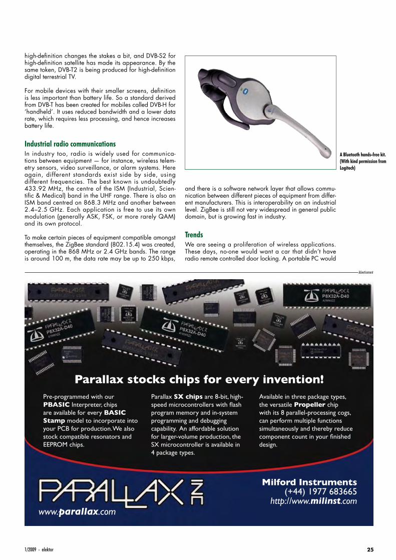
A Bluetooth hands-free kit. (With kind permission from Logitech)
Advertisement
UK0901_22_26_080818_UK_Wireless.25 25 28-11-2008 14:07:03
technology wireless links
26 elektor - 1/2009
no longer sell without a minimum of a WiFi 802.11g connection.All this leads to a multiplication of remote controls, receiv-ers, and transceivers, all working on different frequencies. The risk of mutual interference is increased and the number of frequencies and/or channels available is constantly diminishing.
To allow all these pieces of equipment to work together without interfering with each other, the new standards are more stringent on transmit power levels and adjacent (n+1, n−1) and alternate (n+2, n−2) channel rejection. The bands are divided into sub-bands and each sub-band is reserved for a specific use. Digital data rates are constantly increas-ing, creating a need to open up new bands at ever-higher frequencies. You can’t expect to modulate a 30 MHz car-rier to transmit 500 Mbps; but you can if that carrier is at 50 GHz. New bands in the microwave frequency range are coming into use for short-range, very high data rate links. New chip manufacturing processes are giving ever-higher transition frequencies (maximum operating frequency of a transistor where the gain has dropped to unity i.e. 1) and radios operating at several tens of gigahertz are now possible.
Another trend is the strongly-growing use of mobile devices. Everyone — or almost everyone — has a mobile phone. Portable PCs are becoming widespread, at the expense of office machines, and ultra-mobiles like the EeePC are proving a real commercial success. Peripherals too have felt the urge to go wireless, including mice, keyboards, and indeed certain USB audio/video peripherals with the advent of Wireless USB products using an ultra-wideband protocol in the 3.1–10.6 GHz band, low transmit power, and a very wide operating spectrum. Channel bandwidth is 528 MHz, allowing a usable data rate of 480 Mbps, compatible with USB 2.0. But with a bandwidth and data rate like that, how is it possible to avoid interfering with other transmissions? The transmitted power is very low, of the order of –41 dBm/MHz, and other radio devices see the transmitted signal as background noise. The communi-cation distance is also very short — of the order of three to ten metres maximum.
(080818-I)
Bibliographyandsourceswww.maxim-ic.com
www.analog.com
www.cypress.com
www.csr.com
www.agilent.com/find/wireless
en.wikipedia.org/wiki/Phase-shift_keying
en.wikipedia.org/wiki/Femtocell
en.wikipedia.org/wiki/Ultra-wideband
en.wikipedia.org/wiki/ZigBee
Three antennas! A dual-band WiFi router to the
802.11n MIMO standard. (With kind permission from
Linksys).
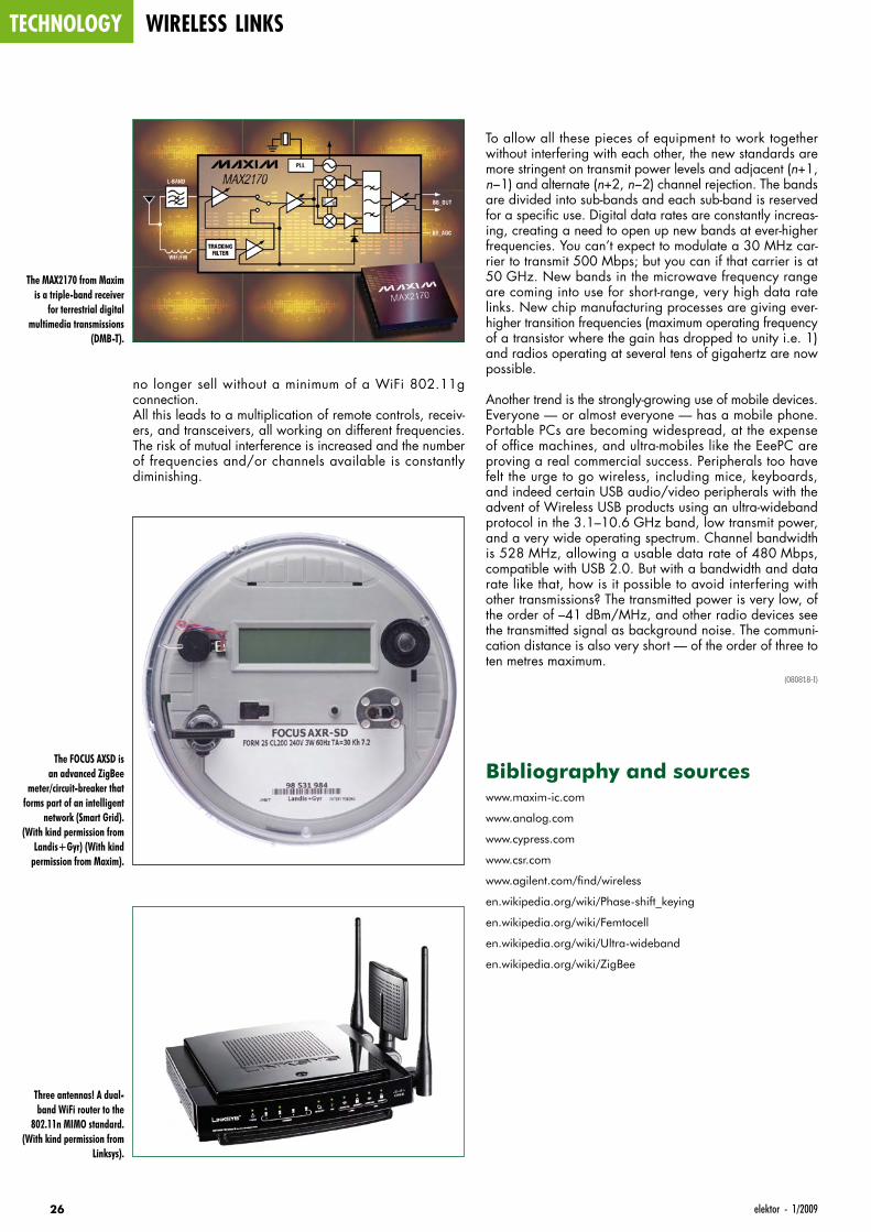
The FOCUS AXSD is an advanced ZigBee
meter/circuit-breaker that forms part of an intelligent
network (Smart Grid). (With kind permission from
Landis+Gyr) (With kind permission from Maxim).
The MAX2170 from Maxim is a triple-band receiver
for terrestrial digital multimedia transmissions
(DMB-T).

271/2009 - elektor
0901_elektor_adv_UK.indd 27 28-11-2008 14:07:17
projects led cube
28 elektor - 1/2009
Three-Dimensional Light SourceProgrammable LED matrix with 125 LEDsJerry Jacobs (The Netherlands)
Everyone will have encountered a 2D LED matrix at some time, but the version described here is of a completely different calibre: namely five matrices stacked together into a cube; a true 3D matrix therefore, every LED of which can be switched on and off individually.
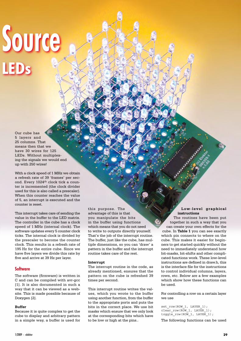
Most people are fascinated by flash-ing LEDs. But these are usually lim-ited to just a few LEDs or only a small display. This LED cube is something entirely different however, because there is an additional dimension for even more LEDs. Here we present a 3D display of LEDs, each of which can
be controlled individually.This magnificent cube has at its heart an Atmel AVR microcontroller. These controllers are easy to obtain and superb open-source tools are available. Not only for Windows, but also for the Linux and Mac operating systems.
OperationYou would expect that with 125 LEDs in the cube you would need a large number of wires to be able to control them individually, but that is not so. A lot of wires can be saved because the signals are multiplexed. One ‘layer’, that is all 25 LEDs which are all at the same height in the columns, can be controlled with a single wire. This results in a total of 26 signal wires. If each LED were to be connected individually then 50 wires would be required.
To turn an LED on we switch the pos-itive voltage to the desired layer on and select the appropriate column.
Table 1. Layer drivers & column drivers
PORT A
Bit 7 Bit 6 Bit 5 Bit 4 Bit 3 Bit 2 Bit 1 Bit 0
PA7 PA6 PA5 PA4 PA3 PA2 PA1 PA0
Column 8 Column 7 Column 6 Column 5 Column 4 Column 3 Column 2 Column 1
PORT B
Bit 7 Bit 6 Bit 5 Bit 4 Bit 3 Bit 2 Bit 1 Bit 0
PB7 PB6 PB5 PB4 PB3 PB2 PB1 PB0
Column 25 – – Layer 5 Layer 4 Layer 3 Layer 2 Layer 1
PORT C
Bit 7 Bit 6 Bit 5 Bit 4 Bit 3 Bit 2 Bit 1 Bit 0
PC7 PC6 PC5 PC4 PC3 PC2 PC1 PC0
Column 16 Column 15 Column 14 Column 13 Column 12 Column 11 Column 10 Column 9
PORT D
Bit 7 Bit 6 Bit 5 Bit 4 Bit 3 Bit 2 Bit 1 Bit 0
PD7 PD6 PD5 PD4 PD3 PD2 PD1 PD0
Column 24 Column 23 Column 22 Column 21 Column 20 Column 19 Column 18 Column 17
Hardware specifications• 125 LEDs in a special 3D matrix
• ATMEGA32 microcontroller running @ 1 MHz internal clock
• 10-way ISP-connector for reprogramming
• 5 transistors for switching the layers
• 25 transistors for switching the columns
291/2009 - elektor
Three-Dimensional Light SourceProgrammable LED matrix with 125 LEDs
Our cube has 5 layers and 25 columns. That means then that we have 30 wires for 125 LEDs. Without multiplex-ing the signals we would end up with 250 wires!
With a clock speed of 1 MHz we obtain a refresh rate of 39 ‘frames’ per sec-ond. Every 1024th clock tick a coun-ter is incremented (the clock divider used for this is also called a prescaler). When this counter reaches the value of 5, an interrupt is executed and the counter is reset.
This interrupt takes care of sending the value in the buffer to the LED matrix. The controller in the cube has a clock speed of 1 MHz (internal clock). The software updates every 5 counter clock ticks. The internal clock is divided by the prescaler to become the counter clock. This results in a refresh rate of 195 Hz for the entire cube. Since we have five layers we divide this rate by five and arrive at 39 Hz per layer.
SoftwareThe software (firmware) is written in C and can be compiled with avr-gcc [1]. It is also documented in such a way that it can be viewed as a web-site. This is made possible because of Doxygen [2].
BufferBecause it is quite complex to get the cube to display and arbitrary pattern in a simple way, a buffer is used for
this purpose. The advantage of this is that you manipulate the bits in the buffer using functions which means that you do not need to write to outputs directly yourself. That’s the job of the interrupt routine. The buffer, just like the cube, has mul-tiple dimensions, so you can ‘draw’ a pattern in the buffer and the interrupt routine takes care of the rest.
InterruptThe interrupt routine in the code, as already mentioned, ensures that the pattern on the cube is refreshed 39 times per second.
This interrupt routine writes the val-ues, which you wrote to the buffer using another function, from the buffer to the appropriate ports and puts the bits in the correct place. We use bit masks which ensure that we only look at the corresponding bits which have to be low or high at the pins..
Low -level graphical instructions
The routines have been put together in such a way that you
can create your own effects for the cube. In Table 1 you can see exactly
which pin connects to where on the cube. This makes it easier for begin-ners to get started quickly without the need to immediately understand how bit-masks, bit-shifts and other compli-cated functions work. These low-level instructions are defined in draw.h, this is the interface file for the instructions to control individual columns, layers, rows, etc. Below are a few examples which show how these functions can be used.
For controlling a row on a certain layer we use
set_row(ROW_1, LAYER_1);clear_row(ROW_1, LAYER_1);toggle_row(ROW_1, LAYER_1);
The following functions can be used
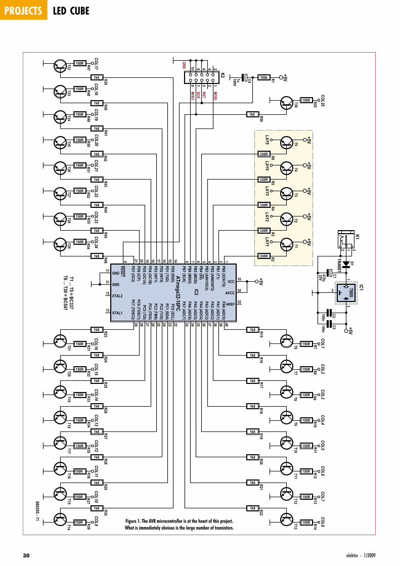
projects led cube
30 elektor - 1/2009
12
34
56
78
910
K2
25V
C1470u
C2100n
C3100n
PB0 (XCK/T0)1
PB1 (T1)2
PB2 (AIN0/INT2)3
PB3 (AIN1/OC0)4
PB4 (SS)5
PB5 (MOSI)6
PB6 (MISO)7
PB7 (SCK)8
RESET9
PD0 (RXD)14
PD1 (TXD)15
PD2 (INT0)16
PD3 (INT1)17
PD4 (OC1B)18
PD5 (OC1A)19
PD6 (ICP)20
PD7 (OC2)21
XTAL212
XTAL113
GND11
PC0 (SCL)22
PC1 (SDA)23
PC2 (TCK)24
PC3 (TMS)25
PC4 (TDO)26
PC5 (TDI)27
PC6 (TOSC1)28
PC7 (TOSC2)29
AREF 32
AVCC 30GND31
PA7 (ADC7)33
PA6 (ADC6)34
PA5 (ADC5)35
PA4 (ADC4)36
PA3 (ADC3)37
PA2 (ADC2)38
PA1 (ADC1)39
PA0 (ADC0)40
VCC 10
IC2
ATmega32-16PC
13
2
IC17805
T1
+5VD1
1N40012 31
K1
R1100k100V
C41u
+5V
+5V
T6
R2330R
+5V
T2
R3330R
+5V
T3
R4330R
+5V
T4
R5330R
+5V
T5
R6330R
+5V
R15
1k8T21
T7
R16
1k8
T8
R17
1k8
T9
R18
1k8
T10
R19
1k8
T11
R20
1k8
T12
R21
1k8
T13
R22
1k8
MOSI
MISO
RSTSCK
GND
COL1R7150R
COL2R8150R
COL3R9150R
COL4R10
150R
COL5R11
150R
COL6R12
150R
COL7R13
150R
COL8R14
150R
R31
150R
R23
1k8T20
COL16R32
150R
R24
1k8
T19
COL15R33
150R
R25
1k8
T18
COL14R34
150R
R26
1k8
T17
COL13R35
150R
R27
1k8
T16
COL12R36
150R
R28
1k8
T15
COL11
R37
150R
R29
1k8
T14
COL9R38
150R
R30
1k8
COL24R54
150R
R46
1k8
T28
COL23R53
150R
R45
1k8
T27
COL22R52
150R
R44
1k8
T26
COL21R51
150R
R43
1k8
T25
COL20R50
150R
R42
1k8
T24
COL19R49
150R
R41
1k8
T23
COL18R48
150R
R40
1k8
T22
COL17R47
150R
R39
1k8
T30
R56
1k8
COL25R55
150R
COL10
LAY5LAY4
LAY3LAY2
LAY1T29T1 ... T5 = BC337
T6 ... T30 = BC547
080355 - 11
Figure 1. The AVR microcontroller is at the heart of this project. What is immediately obvious is the large number of transistors.
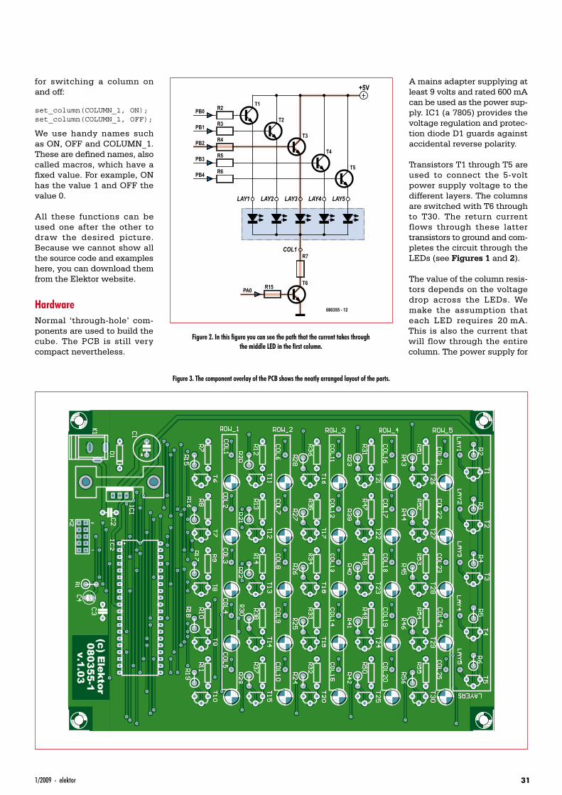
311/2009 - elektor
for switching a column on and off:
set_column(COLUMN_1, ON);set_column(COLUMN_1, OFF);
We use handy names such as ON, OFF and COLUMN_1. These are defined names, also called macros, which have a fixed value. For example, ON has the value 1 and OFF the value 0.
All these functions can be used one after the other to draw the desired picture. Because we cannot show all the source code and examples here, you can download them from the Elektor website.
HardwareNormal ‘through-hole’ com-ponents are used to build the cube. The PCB is still very compact nevertheless.
A mains adapter supplying at least 9 volts and rated 600 mA can be used as the power sup-ply. IC1 (a 7805) provides the voltage regulation and protec-tion diode D1 guards against accidental reverse polarity.
Transistors T1 through T5 are used to connect the 5-volt power supply voltage to the different layers. The columns are switched with T6 through to T30. The return current flows through these latter transistors to ground and com-pletes the circuit through the LEDs (see Figures 1 and 2).
The value of the column resis-tors depends on the voltage drop across the LEDs. We make the assumption that each LED requires 20 mA. This is also the current that will flow through the entire column. The power supply for
R2 T1PB0
LAY1
R3 T2PB1
R4 T3PB2
R5 T4PB3
R6 T5PB4
R7
T6R15PA0
+5V
LAY2 LAY3 LAY4 LAY5
COL1
080355 - 12
Figure 2. In this figure you can see the path that the current takes through the middle LED in the first column.
Figure 3. The component overlay of the PCB shows the neatly arranged layout of the parts.
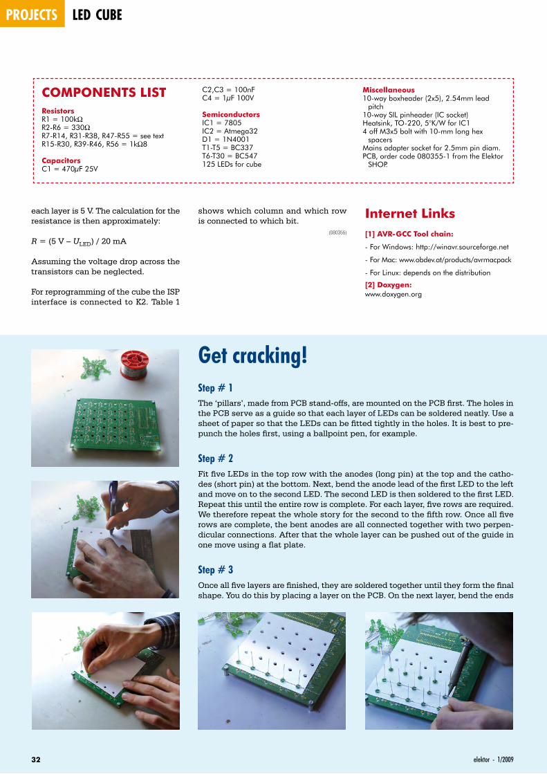
projects led cube
32 elektor - 1/2009
each layer is 5 V. The calculation for the resistance is then approximately:
R = (5 V – ULED) / 20 mA
Assuming the voltage drop across the transistors can be neglected.
For reprogramming of the cube the ISP interface is connected to K2. Table 1
Internet Links[1] AVR-GCC Tool chain:
- For Windows: http://winavr.sourceforge.net
- For Mac: www.obdev.at/products/avrmacpack
- For Linux: depends on the distribution
[2] Doxygen:www.doxygen.org
shows which column and which row is connected to which bit.
(080355)
COMPONENTS LISTResistorsR1 = 100kΩR2-R6 = 330ΩR7-R14, R31-R38, R47-R55 = see textR15-R30, R39-R46, R56 = 1kΩ8
CapacitorsC1 = 470µF 25V
C2,C3 = 100nFC4 = 1µF 100V
SemiconductorsIC1 = 7805IC2 = Atmega32D1 = 1N4001T1-T5 = BC337T6-T30 = BC547125 LEDs for cube
Miscellaneous10-way boxheader (2x5), 2.54mm lead
pitch10-way SIL pinheader (IC socket)Heatsink, TO-220, 5°K/W for IC14 off M3x5 bolt with 10-mm long hex
spacersMains adapter socket for 2.5mm pin diam.PCB, order code 080355-1 from the Elektor
SHOP.
Get cracking!Step # 1The ‘pillars’, made from PCB stand-offs, are mounted on the PCB first. The holes in the PCB serve as a guide so that each layer of LEDs can be soldered neatly. Use a sheet of paper so that the LEDs can be fitted tightly in the holes. It is best to pre-punch the holes first, using a ballpoint pen, for example.
Step # 2Fit five LEDs in the top row with the anodes (long pin) at the top and the catho-des (short pin) at the bottom. Next, bend the anode lead of the first LED to the left and move on to the second LED. The second LED is then soldered to the first LED. Repeat this until the entire row is complete. For each layer, five rows are required. We therefore repeat the whole story for the second to the fifth row. Once all five rows are complete, the bent anodes are all connected together with two perpen-dicular connections. After that the whole layer can be pushed out of the guide in one move using a flat plate.
Step # 3 Once all five layers are finished, they are soldered together until they form the final shape. You do this by placing a layer on the PCB. On the next layer, bend the ends
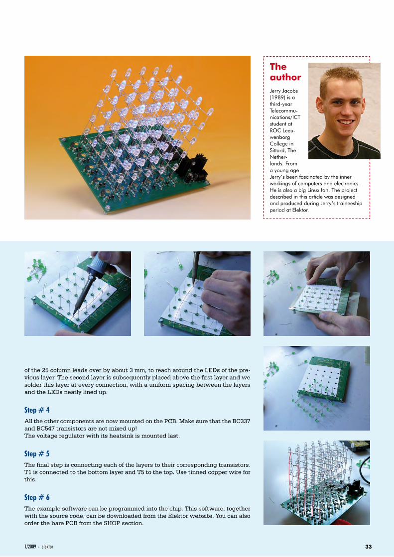
331/2009 - elektor
of the 25 column leads over by about 3 mm, to reach around the LEDs of the pre-vious layer. The second layer is subsequently placed above the first layer and we solder this layer at every connection, with a uniform spacing between the layers and the LEDs neatly lined up.
Step # 4All the other components are now mounted on the PCB. Make sure that the BC337 and BC547 transistors are not mixed up!The voltage regulator with its heatsink is mounted last.
Step # 5The final step is connecting each of the layers to their corresponding transistors. T1 is connected to the bottom layer and T5 to the top. Use tinned copper wire for this.
Step # 6The example software can be programmed into the chip. This software, together with the source code, can be downloaded from the Elektor website. You can also order the bare PCB from the SHOP section.
The authorJerry Jacobs (1989) is a third-year Telecommu-nications/ICT student at ROC Leeu-wenborg College in Sittard, The Nether-lands. From a young age Jerry’s been fascinated by the inner workings of computers and electronics. He is also a big Linux fan. The project described in this article was designed and produced during Jerry’s traineeship period at Elektor.
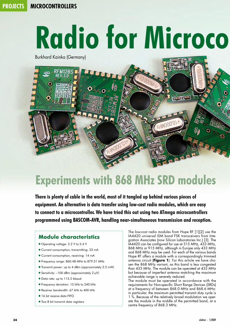
projects microcontrollers
34 elektor - 1/2009
The low-cost radio modules from Hope RF [1][2] use the IA4420 universal ISM band FSK transceivers from Inte-gration Associates (now Silicon Laboratories Inc.) [3]. The IA4420 can be configured for use at 315 MHz, 433 MHz, 868 MHz or 915 MHz, although in Europe only 433 MHz and 868 MHz may be used. For each of the various bands Hope RF offers a module with a correspondingly trimmed antenna circuit (Figure 1). For this article we have cho-sen the 868 MHz variant, as this band is less congested than 433 MHz. The module can be operated at 433 MHz but because of imperfect antenna matching the maximum achievable range is severely reduced.The module must be operated in accordance with the requirements for Non-specific Short Range Devices (SRDs) at a frequency of between 868.0 MHz and 868.6 MHz: in particular, the maximum permitted transmit duty cycle is 1 %. Because of the relatively broad modulation we oper-ate the module in the middle of the permitted band, at a centre frequency of 868.3 MHz.
Radio for Microcontrollers
Experiments with 868 MHz SRD modules
Burkhard Kainka (Germany)
There is plenty of cable in the world, most of it tangled up behind various pieces of equipment. An alternative is data transfer using low-cost radio modules, which are easy to connect to a microcontroller. We have tried this out using two ATmega microcontrollers programmed using BASCOM-AVR, handling near-simultaneous transmission and reception.
Module characteristics• Operating voltage: 2.2 V to 5.4 V
• Current consumption, transmitting: 23 mA
• Current consumption, receiving: 14 mA
• Frequency range: 860.48 MHz to 879.51 MHz
• Transmit power: up to 4 dBm (approximately 2.5 mW)
• Sensitivity: –100 dBm (approximately 2 µV)
• Data rate: up to 115.2 kbaud
• Frequency deviation: 15 kHz to 240 kHz
• Receiver bandwidth: 67 kHz to 400 kHz
• 16 bit receive data FIFO
• Two 8 bit transmit data registers
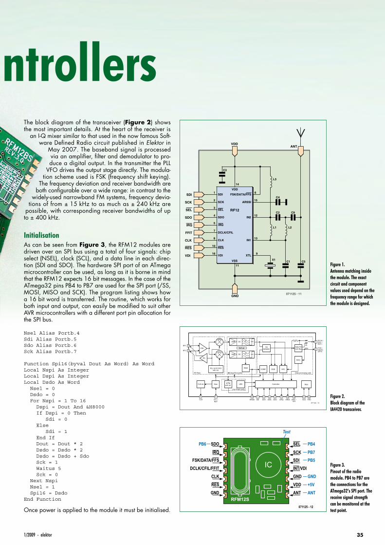
351/2009 - elektor
The block diagram of the transceiver (Figure 2) shows the most important details. At the heart of the receiver is
an I-Q mixer similar to that used in the now famous Soft-ware Defined Radio circuit published in Elektor in
May 2007. The baseband signal is processed via an amplifier, filter and demodulator to pro-duce a digital output. In the transmitter the PLL
VFO drives the output stage directly. The modula-tion scheme used is FSK (frequency shift keying).
The frequency deviation and receiver bandwidth are both configurable over a wide range: in contrast to the
widely-used narrowband FM systems, frequency devia-tions of from ± 15 kHz to as much as ± 240 kHz are
possible, with corresponding receiver bandwidths of up to ± 400 kHz.
InitialisationAs can be seen from Figure 3, the RFM12 modules are driven over an SPI bus using a total of four signals: chip select (NSEL), clock (SCL), and a data line in each direc-tion (SDI and SDO). The hardware SPI port of an ATmega microcontroller can be used, as long as it is borne in mind that the RFM12 expects 16 bit messages. In the case of the ATmega32 pins PB4 to PB7 are used for the SPI port (/SS, MOSI, MISO and SCK). The program listing shows how a 16 bit word is transferred. The routine, which works for both input and output, can easily be modified to suit other AVR microcontrollers with a different port pin allocation for the SPI bus.
Nsel Alias Portb.4Sdi Alias Portb.5Sdo Alias Portb.6Sck Alias Portb.7
Function Spi16(byval Dout As Word) As WordLocal Nspi As IntegerLocal Dspi As IntegerLocal Dsdo As Word Nsel = 0 Dsdo = 0 For Nspi = 1 To 16 Dspi = Dout And &H8000 If Dspi = 0 Then Sdi = 0 Else Sdi = 1 End If Dout = Dout * 2 Dsdo = Dsdo * 2 Dsdo = Dsdo + Sdo Sck = 1 Waitus 5 Sck = 0 Next Nspi Nsel = 1 Spi16 = DsdoEnd Function
Once power is applied to the module it must be initialised.
Radio for Microcontrollers
C3
L1 L2
FSK/DATA/FFS
DCLK/CFIL
ARSSI
RF12
VDD
IRQ
SDI
SCK
SEL
SDO
CLK
RES
VDI
VSS
XTL
IN2
IN1
14
10
16
11
12
13
15
5
3
4
1
2
6
7
8
9
L3
C2 C9
C4
C1 C5X1
IRQ
SDI
SCK
SEL
SDO
CLK
RES
VDI
FFIT
VDD
GND
ANT
071125 - 11
Figure 1. Antenna matching inside the module. The exact circuit and component values used depend on the frequency range for which the module is designed.
RF Parts
Low Power parts
Data processing unitsBB Amp/Filt./Limiter
AMP OC
AMP OC
LNA
MIX I
QMIX
Data FiltCLK Rec data
clk
DQDCOMPRSSI
AFCPLL & I/Q VCOwith cal.
Controller
071125 - 13
Xosc
Self cal.
LBDWTMwith cal.CLK div Bias
13RF1
RF2 12
8 9
CLK XTL /REF
1015nINT /VDI
ARSSI2 3 4 5 11
SCK nSEL SDO nIRQ141
VSS VDDSDI
7
6
DCLK /CFIL /FFIT /
FSK /DATA /nFFS
FIFO
16nRES
PA
I/QDEMOD
Figure 2. Block diagram of the IA4420 transceiver.
SDOPB6
IRQFSK/DATA/FFS
DCLK/CFIL/FFITCLK
RFM12S
IC
RES
GND
SEL
SCKSDIINT/VDIGND
VDD
ANT
071125 - 12
PB4
Test
PB7PB5
GND
+5V
ANT
Figure 3. Pinout of the radio module. PB4 to PB7 are the connections for the ATmega32’s SPI port. The receive signal strength can be monitored at the test point.
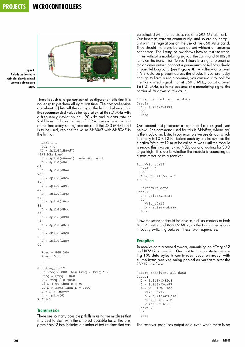
projects microcontrollers
36 elektor - 1/2009
There is such a large number of configuration bits that it is not easy to get them all right first time. The comprehensive datasheet [3] lists all the settings. The listing below shows the recommended values for operation at 868.3 MHz with a frequency deviation of ± 90 kHz and a data rate of 2.4 kbaud. Subroutine Freq_rfm12 is also required as part of the frequency setting procedure. If the 433 MHz band is to be used, replace the value &H80e7 with &H80d7 in the listing.
Nsel = 1 Sck = 0 ‘D = Spi16(&H80d7) ‘433 MHz band D = Spi16(&H80e7) ‘868 MHz band D = Spi16(&H82d9) D = Spi16(&Ha67c) D = Spi16(&Hc647) D = Spi16(&H94a0) D = Spi16(&Hc2ac) D = Spi16(&Hca81) D = Spi16(&Hc483) D = Spi16(&H9854) D = Spi16(&He000) D = Spi16(&Hc800) D = Spi16(&Hc000)
Freq = 868.300 Freq_rfm12 …
Sub Freq_rfm12 If Freq < 800 Then Freq = Freq * 2 Freq = Freq - 860 D = Freq / 0.0050 If D < 96 Then D = 96 If D > 3903 Then D = 3903 D = D + &HA000 D = Spi16(d)End Sub
TransmissionThere are so many possible pitfalls in using the modules that it is best to start with the simplest possible tests. The pro-gram RFM12.bas includes a number of test routines that can
be selected with the judicious use of a GOTO statement. Our first tests transmit continuously, and so are not compli-ant with the regulations on the use of the 868 MHz band. They should therefore be carried out without an antenna connected. The listing below shows how to test the trans-mitter without a modulating signal. The command &H8238 turns on the transmitter. To see if there is a signal present at the antenna output, connect a germanium or Schottky diode in parallel to ground (see Figure 4). A voltage of around 1 V should be present across the diode. If you are lucky enough to have a radio scanner, you can use it to look for the transmitted signal: not at 868.3 MHz, but at around 868.21 MHz, as in the absence of a modulating signal the carrier shifts down to this value.
‘start transmitter, no dataTest1: D = Spi16(&H8238) Do Loop
Our second test produces a modulated data signal (see below). The command used for this is &Hb8xx, where ‘xx’ is the modulating byte. In our example we use &Haa, which in binary is 10101010. Before each byte is transmitted the function Wait_rfm12 must be called to wait until the module is ready: this involves taking NSEL low and waiting for SDO to go high. This works whether the module is operating as a transmitter or as a receiver.
Sub Wait_rfm12 Nsel = 0 Do Loop Until Sdo = 1End Sub
‘transmit dataTest2: D = Spi16(&H8238) Do Wait_rfm12 D = Spi16(&Hb8aa) Loop
Now the scanner should be able to pick up carriers at both 868.21 MHz and 868.39 MHz, as the transmitter is con-tinuously switching between these two frequencies.
ReceptionTo receive data a second system, comprising an ATmega32 and RFM12, is needed. Our next test demonstrates receiv-ing 100 data bytes in continuous reception mode, with all the bytes received being passed on verbatim over the RS232 interface.
‘start receiver, all dataTest4: D = Spi16(&H82c8) D = Spi16(&Hca87) For N = 1 To 100 Wait_rfm12 D = Spi16(&Hb000) Data_in(n) = D Print Chr(d); Next N Do Loop
The receiver produces output data even when there is no
Figure 4. A diode can be used to
verify that there is a signal present at the antenna
output.
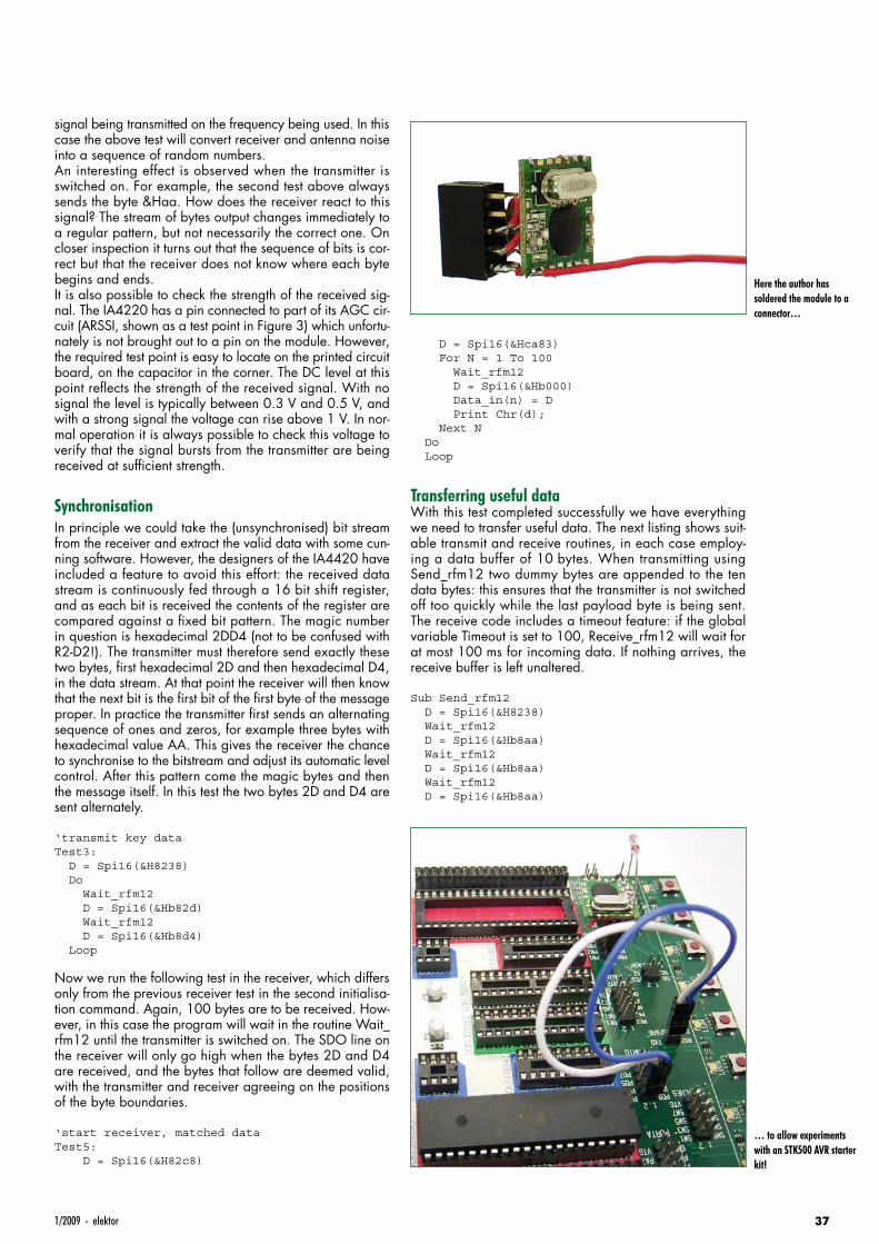
371/2009 - elektor
signal being transmitted on the frequency being used. In this case the above test will convert receiver and antenna noise into a sequence of random numbers.An interesting effect is observed when the transmitter is switched on. For example, the second test above always sends the byte &Haa. How does the receiver react to this signal? The stream of bytes output changes immediately to a regular pattern, but not necessarily the correct one. On closer inspection it turns out that the sequence of bits is cor-rect but that the receiver does not know where each byte begins and ends.It is also possible to check the strength of the received sig-nal. The IA4220 has a pin connected to part of its AGC cir-cuit (ARSSI, shown as a test point in Figure 3) which unfortu-nately is not brought out to a pin on the module. However, the required test point is easy to locate on the printed circuit board, on the capacitor in the corner. The DC level at this point reflects the strength of the received signal. With no signal the level is typically between 0.3 V and 0.5 V, and with a strong signal the voltage can rise above 1 V. In nor-mal operation it is always possible to check this voltage to verify that the signal bursts from the transmitter are being received at sufficient strength.
SynchronisationIn principle we could take the (unsynchronised) bit stream from the receiver and extract the valid data with some cun-ning software. However, the designers of the IA4420 have included a feature to avoid this effort: the received data stream is continuously fed through a 16 bit shift register, and as each bit is received the contents of the register are compared against a fixed bit pattern. The magic number in question is hexadecimal 2DD4 (not to be confused with R2-D2!). The transmitter must therefore send exactly these two bytes, first hexadecimal 2D and then hexadecimal D4, in the data stream. At that point the receiver will then know that the next bit is the first bit of the first byte of the message proper. In practice the transmitter first sends an alternating sequence of ones and zeros, for example three bytes with hexadecimal value AA. This gives the receiver the chance to synchronise to the bitstream and adjust its automatic level control. After this pattern come the magic bytes and then the message itself. In this test the two bytes 2D and D4 are sent alternately.
‘transmit key dataTest3: D = Spi16(&H8238) Do Wait_rfm12 D = Spi16(&Hb82d) Wait_rfm12 D = Spi16(&Hb8d4) Loop
Now we run the following test in the receiver, which differs only from the previous receiver test in the second initialisa-tion command. Again, 100 bytes are to be received. How-ever, in this case the program will wait in the routine Wait_rfm12 until the transmitter is switched on. The SDO line on the receiver will only go high when the bytes 2D and D4 are received, and the bytes that follow are deemed valid, with the transmitter and receiver agreeing on the positions of the byte boundaries.
‘start receiver, matched dataTest5: D = Spi16(&H82c8)
D = Spi16(&Hca83) For N = 1 To 100 Wait_rfm12 D = Spi16(&Hb000) Data_in(n) = D Print Chr(d); Next N Do Loop
Transferring useful dataWith this test completed successfully we have everything we need to transfer useful data. The next listing shows suit-able transmit and receive routines, in each case employ-ing a data buffer of 10 bytes. When transmitting using Send_rfm12 two dummy bytes are appended to the ten data bytes: this ensures that the transmitter is not switched off too quickly while the last payload byte is being sent. The receive code includes a timeout feature: if the global variable Timeout is set to 100, Receive_rfm12 will wait for at most 100 ms for incoming data. If nothing arrives, the receive buffer is left unaltered.
Sub Send_rfm12 D = Spi16(&H8238) Wait_rfm12 D = Spi16(&Hb8aa) Wait_rfm12 D = Spi16(&Hb8aa) Wait_rfm12 D = Spi16(&Hb8aa)
Here the author has soldered the module to a connector…
… to allow experiments with an STK500 AVR starter kit!
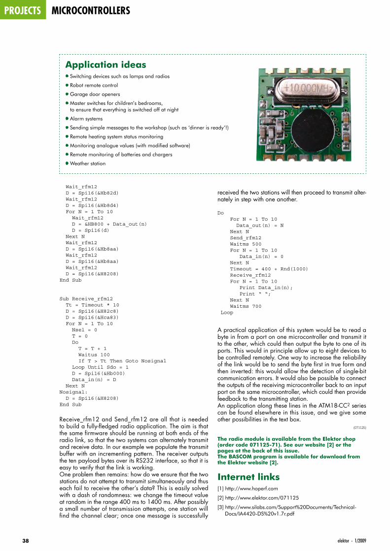
projects microcontrollers
38 elektor - 1/2009
Wait_rfm12 D = Spi16(&Hb82d) Wait_rfm12 D = Spi16(&Hb8d4) For N = 1 To 10 Wait_rfm12 D = &HB800 + Data_out(n) D = Spi16(d) Next N Wait_rfm12 D = Spi16(&Hb8aa) Wait_rfm12 D = Spi16(&Hb8aa) Wait_rfm12 D = Spi16(&H8208)End Sub
Sub Receive_rfm12 Tt = Timeout * 10 D = Spi16(&H82c8) D = Spi16(&Hca83) For N = 1 To 10 Nsel = 0 T = 0 Do T = T + 1 Waitus 100 If T > Tt Then Goto Nosignal Loop Until Sdo = 1 D = Spi16(&Hb000) Data_in(n) = D Next NNosignal: D = Spi16(&H8208)End Sub
Receive_rfm12 and Send_rfm12 are all that is needed to build a fully-fledged radio application. The aim is that the same firmware should be running at both ends of the radio link, so that the two systems can alternately transmit and receive data. In our example we populate the transmit buffer with an incrementing pattern. The receiver outputs the ten payload bytes over its RS232 interface, so that it is easy to verify that the link is working.One problem then remains: how do we ensure that the two stations do not attempt to transmit simultaneously and thus each fail to receive the other’s data? This is easily solved with a dash of randomness: we change the timeout value at random in the range 400 ms to 1400 ms. After possibly a small number of transmission attempts, one station will find the channel clear; once one message is successfully
received the two stations will then proceed to transmit alter-nately in step with one another.
Do For N = 1 To 10 Data_out(n) = N Next N Send_rfm12 Waitms 500 For N = 1 To 10 Data_in(n) = 0 Next N Timeout = 400 + Rnd(1000) Receive_rfm12 For N = 1 To 10 Print Data_in(n); Print “ “; Next N Waitms 700 Loop
A practical application of this system would be to read a byte in from a port on one microcontroller and transmit it to the other, which could then output the byte to one of its ports. This would in principle allow up to eight devices to be controlled remotely. One way to increase the reliability of the link would be to send the byte first in true form and then inverted: this would allow the detection of single-bit communication errors. It would also be possible to connect the outputs of the receiving microcontroller back to an input port on the same microcontroller, which could then provide feedback to the transmitting station.An application along these lines in the ATM18-CC2 series can be found elsewhere in this issue, and we give some other possibilities in the text box.
(071125)
The radio module is available from the Elektor shop (order code 071125-71). See our website [2] or the pages at the back of this issue.The BASCOM program is available for download from the Elektor website [2].
Internet links[1] http://www.hoperf.com
[2] http://www.elektor.com/071125
[3] http://www.silabs.com/Support%20Documents/Technical-Docs/IA4420-DS%20v1.7r.pdf
Application ideas• Switching devices such as lamps and radios
• Robot remote control
• Garage door openers
• Master switches for children’s bedrooms, to ensure that everything is switched off at night
• Alarm systems
• Sending simple messages to the workshop (such as ‘dinner is ready’!)
• Remote heating system status monitoring
• Monitoring analogue values (with modified software)
• Remote monitoring of batteries and chargers
• Weather station

391/2009 - elektor
Loudspeaker
Design Cookbook
7th Edition
by Vance Dickason
Speaker
Building 201by Ray Alden
ORDER YOUR COPIES OF THESE BOOKS FROM MOTH GROUP AT
PRESENTS
10 Dane laneWilsteadBedford MK45 3HT.
Telephone ++44(0)1234 741152Fax ++44(0)1234 742028
email: [email protected]: www.mothgroup.com
INCLUDES
A BONUS CD
WITH ADDED
MATERIAL
AND DESIGN
SOFTWARE
EXPERT ADVICE
FROM THE
INVENTOR
OF THE MTM
A GREAT
INTRODUCTION
TO LOUDSPEAKER
DESIGN WITH
PROJECTS TO
BUILD RIGHT AWAY
Testing Loudspeakers
by Joseph D’Appolito
0901_elektor_adv_UK.indd 39 28-11-2008 14:07:36
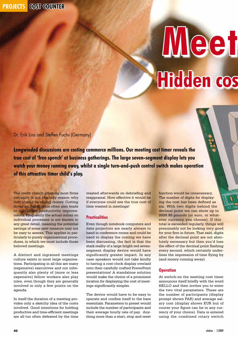
projects cost counter
40 elektor - 1/2009
Meeting Cost TimerHidden costs become totally transparent!
Dr. Erik Lins and Steffen Fuchs (Germany)
Longwinded discussions are costing commerce millions. Our meeting cost timer reveals the true cost of ‘free speech’ at business gatherings. The large seven-segment display lets you watch your money running away, whilst a single turn-and-push control switch makes operation of this attractive timer child’s play.
The credit crunch affecting most firms currently is not the only reason why they should be saving money. Cutting down on direct costs often also leads to significant productivity improve-ments. Frequently the actual outlay on individual processes is not known in any great detail, meaning the potential savings of some new measure may not be easy to assess. This applies in par-ticularly to purely organisational proce-dures, in which we must include those beloved meetings.
A distinct and ingrained meetings culture exists in most large organisa-tions. Participating in all this are many (expensive) executives and not infre-quently also plenty of (more or less expensive) fellow workers also play roles, even though they are generally involved in only a few points on the agenda.
In itself the duration of a meeting pro-vides only a sketchy idea of the costs involved. Good intentions for holding productive and time-efficient meetings are all too often defeated by the time
wasted afterwards on debriefing and reappraisal. How effective it would be if everyone could see the true cost of time wasted in meetings!
PracticalitiesEven though notebook computers and data projectors are nearly always to hand in conference rooms and could be used to display the costing we have been discussing, the fact is that the stark reality of a large bright-red seven-segment display device would have significantly greater impact. In any case speakers would not take kindly to having a cost-clock display overlaid onto their carefully crafted PowerPoint presentations! A standalone solution would make the choice of a prominent location for displaying the cost of meet-ings significantly simpler.
The device would have to be easy to operate and confine itself to the bare essentials. Parameters to preset would include the number of participants and their average hourly rate of pay. Any-thing more than a start, stop and reset
function would be unnecessary.The number of digits for display-ing the cost has been defined as six. With two digits behind the decimal point we can show up to 9999.99 pounds (or euro, or what-ever currency you choose). If this total is exceeded regularly, things will presumably not be looking very good for your firm in future. That said, digits after the decimal point are not abso-lutely necessary but then you’d lose the effect of the decimal point flashing every second, which certainly under-lines the impression of time flying by (and money running away).
OperationAt switch-on the meeting cost timer announces itself briefly with the word HELLO and then invites you to enter the two vital parameters. These are the number of participants (display prompt shows PAR) and average sal-ary cost (display shows EUR but of course your figure can be in any cur-rency of your choice). Data is entered using the combined rotary switch
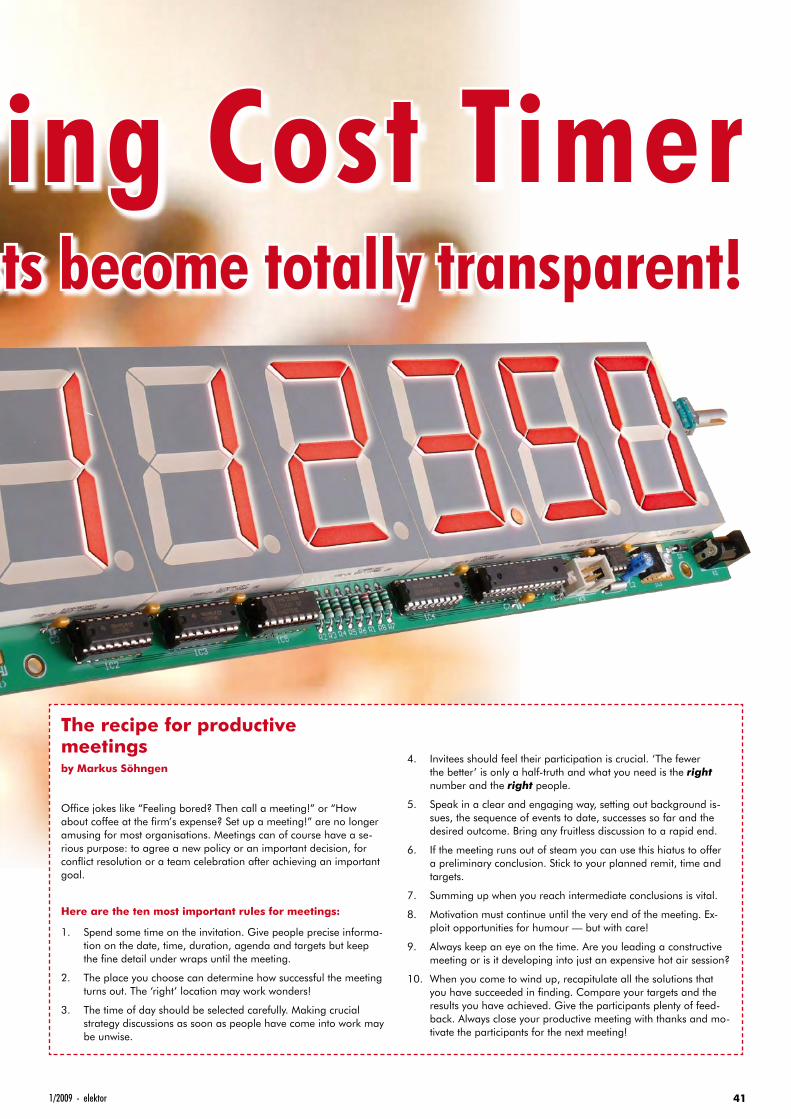
411/2009 - elektor
Meeting Cost TimerHidden costs become totally transparent!
The recipe for productive meetingsby Markus Söhngen
Office jokes like “Feeling bored? Then call a meeting!” or “How about coffee at the firm’s expense? Set up a meeting!” are no longer amusing for most organisations. Meetings can of course have a se-rious purpose: to agree a new policy or an important decision, for conflict resolution or a team celebration after achieving an important goal.
Here are the ten most important rules for meetings:
1. Spend some time on the invitation. Give people precise informa-tion on the date, time, duration, agenda and targets but keep the fine detail under wraps until the meeting.
2. The place you choose can determine how successful the meeting turns out. The ‘right’ location may work wonders!
3. The time of day should be selected carefully. Making crucial strategy discussions as soon as people have come into work may be unwise.
4. Invitees should feel their participation is crucial. ‘The fewer the better’ is only a half-truth and what you need is the right number and the right people.
5. Speak in a clear and engaging way, setting out background is-sues, the sequence of events to date, successes so far and the desired outcome. Bring any fruitless discussion to a rapid end.
6. If the meeting runs out of steam you can use this hiatus to offer a preliminary conclusion. Stick to your planned remit, time and targets.
7. Summing up when you reach intermediate conclusions is vital.
8. Motivation must continue until the very end of the meeting. Ex-ploit opportunities for humour — but with care!
9. Always keep an eye on the time. Are you leading a constructive meeting or is it developing into just an expensive hot air session?
10. When you come to wind up, recapitulate all the solutions that you have succeeded in finding. Compare your targets and the results you have achieved. Give the participants plenty of feed-back. Always close your productive meeting with thanks and mo-tivate the participants for the next meeting!
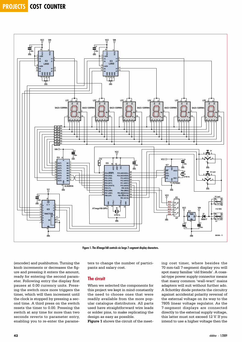
projects cost counter
42 elektor - 1/2009
(encoder) and pushbutton. Turning the knob increments or decreases the fig-ure and pressing it enters the amount, ready for entering the second param-eter. Following entry the display first pauses at 0.00 currency units. Press-ing the switch once more triggers the timer, which will then increment until the clock is stopped by pressing a sec-ond time. A third press on the switch resets the timer to 0.00. Pressing the switch at any time for more than two seconds reverts to parameter entry, enabling you to re-enter the parame-
ing cost timer, where besides the 70 mm-tall 7-segment display you will spot many familiar ‘old friends’. A coax-ial-type power supply connector means that many common ‘wall-wart’ mains adapters will suit without further ado. A Schottky diode protects the circuitry against accidental polarity reversal of the external voltage on its way to the 7805 linear voltage regulator. As the 7-segment displays are connected directly to the external supply voltage, this latter must not exceed 12 V. If you intend to use a higher voltage then the
ters to change the number of partici-pants and salary cost.
The circuitWhen we selected the components for this project we kept in mind constantly the need to choose ones that were readily available from the more pop-ular catalogue distributors. All parts used have straightforward wire leads or solder pins, to make replicating the design as easy as possible.Figure 1 shows the circuit of the meet-
f9
g10
e1
d2
CA3
c4
dp5
b6
a7
CA8LD1
SA23-12SRWAf
9
g10
e1
d2
CA3
c4
dp5
b6
a7
CA8LD2
SA23-12SRWA
f9
g10
e1
d2
CA3
c4
dp5
b6
a7
CA8LD3
SA23-12SRWA
f9
g10
e1
d2
CA3
c4
dp5
b6
a7
CA8LD4
SA23-12SRWA
f9
g10
e1
d2
CA3
c4
dp5
b6
a7
CA8LD5
SA23-12SRWA
f9
g10
e1
d2
CA3
c4
dp5
b6
a7
CA8LD6
SA23-12SRWA
R868R
GND
VIN
VCC VCCVIN VIN
VCC
VCC
GND
VCC
GND
GND
VCC VIN
DE
B A
C
S1
DE
B A
C
S2 (opt)
1Y3
2Y6
VCC2
8
1,2EN1
1A2
2A7
GND
4VC
C116
3,4EN9
4A15
3A10
3Y11
4Y14
GND
5
GND
12
GND
13
IC2L293D
GND
1Y3
2Y6
VCC2
8
1,2EN1
1A2
2A7
GND
4VC
C116
3,4EN9
4A15
3A10
3Y11
4Y14
GND
5
GND
12
GND
13
IC3L293D
GND
168
015
114
510
213
312
411
69
77
X / Y
4
11
22
43
56
EN
&
IC5
74HCT238
GND
K10
IN66
OUT712
IN77
OUT613
OUT514
IN33
OUT415
IN11
OUT316
IN22
OUT811
GND
9
IN44
IN88
IN55
OUT118
OUT217
IC4
ULN2803A
PC6 (RESET)1
PD0 (RXD)2
PD1 (TXD)3
PD2 (INT0)4
PD3 (INT1)5
PD4 (XCK/T0)6
VCC
7
GND
8
XTAL
19
XTAL
210
PD5 (T1)11
PD6 (AIN0)12
PD7 (AIN1)13
PB0 (ICP)14
PB1 (OC1A)15
PB2 (SS/OC1B)16
PB3 (MOSI/OC2)17
PB4 (MISO)18
PB5 (SCK)19
AVCC
20
AREF
21
GND
22
PC0 (ADC0)23
PC1 (ADC1)24
PC2 (ADC2)25
PC3 (ADC3)26
PC4 (ADC4/SDA)27
PC5 (ADC5/SCL)28
IC6
ATmega168-20PU X1
32768 Hz
R9
10k
VDD
8INT
7
SCL6
SDA5
VSS
4
OSC12
OSC01
A03
IC7
PCF8583
123456
K3
13
2
IC17805
2
31
K2 (opt)
2
31
K1
D1
1N5817
MISOVCCSCKMOSIRSTGND
GND
X2
32768 Hz
C5
100n
GND
C6
100n
GND
VCC
C8
100n
GND
C3
100n
GND
C4
100n
GND
ISP
C1
330n
C2
10u
C7
100n
GND
+12 VDC
R768RR668RR568RR468RR368RR268RR1220R
GND
GND
080396 - 11
Figure 1. The ATmega168 controls six large 7-segment display characters.
431/2009 - elektor
series resistors of the cathodes must be changed (see below).
The ‘brain’ of the device is an ATmega168 microcontroller from the Atmel AVR range, which on the one hand takes care of setting the base parameters plus the start, stop and reset functions and on the other sees to controlling the multiplexing for the 7-segment LED displays. The controller is programmed using an ISP connector wired to the standard 6-way pinout, meaning that any common AVR-ISP programmer can be used for this.An optional I²C real-time clock PCF8583 is not required at this stage but could be retrofitted subsequently if you felt the need to add a conventional time display option to the clock.
Data entry is by means of a rotary coder with additional press-switch function (S1 or S2). Twin output sig-nals from the encoder provide two phase-shifted square-wave signals. The sequence of the rising and falling edges provides the number of steps and the directional information. Turn-ing and pressing the encoder triggers interrupts on the I/O pins connected to the microcontroller. The corresponding interrupt service routine evaluates the pins and controls the onward flow of the program.
Reference timing for the display is provided by a 32768-Hz clock crystal, to which the asynchronous oscillator (Timer 2) of the ATmega168 is slaved. This provides a timebase accurate to a second for calculating the cost. The timebase for multiplexing the 7-seg-ment display modules relies on the internal 8-MHz R-C oscillator of the microcontroller. Corresponding pres-calers create a timebase of 488 Hz, so that the human eye is not aware of the time-displaced presentation caused by the fact that each segment is activated at more or less 80 Hz (= 488 Hz / 6 displays).
MultiplexingWere we to attempt to drive the six 7-segment devices in parallel without resorting to multiplexing, this would require a microcontroller with at least 42 I/O pins. Furthermore, large high-brightness 7-segment displays gener-ally use not just one LED per segment but four LEDs in a row (as in the type used here). This demands four times the voltage, in other words a good 8 V.
Each I/O pin would then need a low-side (open collector/open drain) driver too. That would mean 42 drivers plus 6 for the decimal points.
From a circuitry point of view it is far simpler to control the displays by time displacement. The displays are pro-vided with a common anode and sep-arately connected cathodes. We then employ multiplexing to connect a posi-tive voltage to each of the 7-segment display devices in sequence, using one high-side driver each. The respective cathodes of the 7-segment displays are connected to one another so that after each time they are advanced, the appropriate bit pattern is applied to the cathodes of the active displays. In this way our need for driver devices is reduced from 48 low-side drivers to just eight low-side drivers and six high-side drivers and correspondingly only 14 I/O pins on the microcontroller.We can save three more I/O pins by using a 3:8 demultiplexer to select the high-side driver, as then no more than one display is ever active at the same time. Selection is now performed by the bit pattern of the three I/O pins. The output Y0 belonging to bit pattern 000 is not used, to prevent one of the displays being activated by an unpro-grammed controller (all I/O pins are high-impedance). The last output Y7 is also unused, since only six display devices are in operation.For the high-side drivers we are employing two L293D H-bridge driv-ers. Designed primarily for controlling DC motors, each L293D gives us four push-pull outputs (to enable their use as an H-bridge) that can handle cur-rents of up to 600 mA. For our purpose with six displays we need one and a half L293D chips (the two remaining outputs are left open). As the L293D has active-high inputs the demulti-plexer has got to be a 74HCT238 with positive output logic rather than the more commonly used 74HCT138 with negated outputs.
A ULN2803A Darlington transistor array with eight outputs, used as a low-side driver, takes care of control-ling the eight cathodes (seven seg-ments plus decimal point). The emit-ters of the eight transistors are com-moned internally and are connected to GND externally, so that each input can switch one of the outputs to GND. At this point we cannot save any more I/O pins (by using a demultiplexer for instance), as this might lead to several
segments lighting at once.The series resistors for the segments are configured for the widely used supply voltage of 12 V. Each seg-ment accounts for four times the voltage requirement of a single LED (about 1.85 V), meaning that around 4.6 V is unaccounted for. The 68 ohm series resistors limit the current flow-ing through each segment to around 67 mA / 6 = 11 mA (average value). This is slightly below the nominal value according to the data sheet but should nevertheless be perfectly bright enough. The decimal point employs only two LEDs connected in series, so here a different series resistor has to be used. In theory the 220 ohms used is too high and limits the current to just 6 mA or so, but in practice this provides the same ‘perceived’ bright-ness as the other segments to users.
Quick project specs• 70 mm tall 7-segment displays
• Maximum total displayed: 9999.99
• Single switch operation using rotary en-coder with press-button function
• Connections and operating control can be mounted on either the right or left-hand side of the PCB
• Controller: ATMega168-20PU
• ISP adapter for programming
• Power supply using 12 V / 800 mA mains adapter
Meetings run up vast billsIn The Netherlands, a study was made on this controversial topic. At the end of 2007 their first ‘conference barometer’ in-dicated that meetings in the Netherlands alone (population around 16 million) cost the country around 60 billion euro (£ 51 billion) a year!
The average Dutch employee spent some three and a half hours a week in meet-ings, the study revealed. The larger the organisation and the higher the employ-ee’s function, the more time was spent in discussions. Of the annual cost men-tioned, around half was accounted for by the meetings themselves. Another 27 per cent was spent on preparations and the remainder went on travel costs.

projects cost counter
44 elektor - 1/2009
SoftwareSaving drivers for multiplexing is bal-anced by greater complexity in the soft-ware, on account of the constant need to shuffle the 7-segment displays and apply the correct bit patterns to the cathodes in order to give the impres-sion of an always-on display.The software of the meeting cost timer
was developed using the free WinAVR C compiler along with Atmel’s gratis AVR Studio (as a development environ-ment and for in-system programming of the microcontroller).For multiplexing the 7-segment dis-plays the Timer 0 interrupt routine is responsible. Prescalers and the Com-pare Match Register are used to set the timer to 488 Hz. At each call a display counter is counted up from zero to five
The program needs to dwell as briefly as possible in the interrupt routines to avoid delaying the rest of the program flow. For this reason the interrupt rou-tines generally do no more than poll statuses and set flags correspondingly, leaving the main program to handle the actual reaction to status changes and the consequent execution.
The Timer 2 interrupt routine is invoked exactly once a second. All it does is to increment the seconds counter of the cost calculation.The first operation of the main program is generating the welcome message and inviting initial parameter entry. Next comes an endless loop of eval-uating the flags for the press switch. A short depression starts and stops the cost display or resets this to zero.
and matching values for the demulti-plexer are output on port C to the cor-responding display. The cathode bit pattern is made ready correspondingly at port D.Also determined in the Timer 0 interrupt routine is how long the switch has been pressed. This must be for a minimum of around 120 ms (to debounce the switch)
for the program to react. If the button is depressed for more than a second, the program changes into parameter input mode.Recognition of switch depression and rotation of the encoder is handled by the Pin Change 0 interrupt routine. This interrupt routine is invoked automati-cally by pressing or rotating the control switch; it sets corresponding flags that are then evaluated in the Timer 0 inter-rupt routine and in the main program.
COMPONENT LISTResistors(all 0.25W, 5%)R1 = 220ΩR2-R8 = 150ΩR9 = 10kΩ
CapacitorsC1 = 330nF, ceramic, lead pitch 5mmC2 = 10µF 16VC3-C8 = 100nF, ceramic, lead pitch 5mm
SemiconductorsD1 = 1N5817 (Schottky diode, 1A)
IC1 = LM7805 (TO220 case)IC2,IC3 = L293DNE, DIP16 case (Farnell #
1470423)IC4 = ULN2803A, DIP18 case (Farnell #
1047761)IC5 = 74HCT238, DIP16 case (Farnell #
382231)IC6 = ATmega168-20PU, DIP28 case, pro-
grammed, Elektor SHOP # 080396-41IC7 = PCF8583P, DIP8 case (Farnell #
403908)LD1-LD6 = SA23-12SRWA (Kingbright), 7-
segment LED display, red, common anode (Farnell # 1168639)
MiscellaneousX1,X2 = 32768 Hz quartz crystal, cylindrical
housing 3x8mmK1,K2 (optional) = mains adapter connec-
tors for PCB mountingK3 = 6-way DIL pinheader, lead pitch 2.54
mm (Farnell # 1096984)S1,S2 (optional) = EC11B15242 (Alps),
rotary encoder for front panel mounting, 11mm (Farnell #1191733)
PCB no. 080396-1 from the Elektor SHOP www.elektor.com
Figure 2. The PCB of the meeting cost timer.
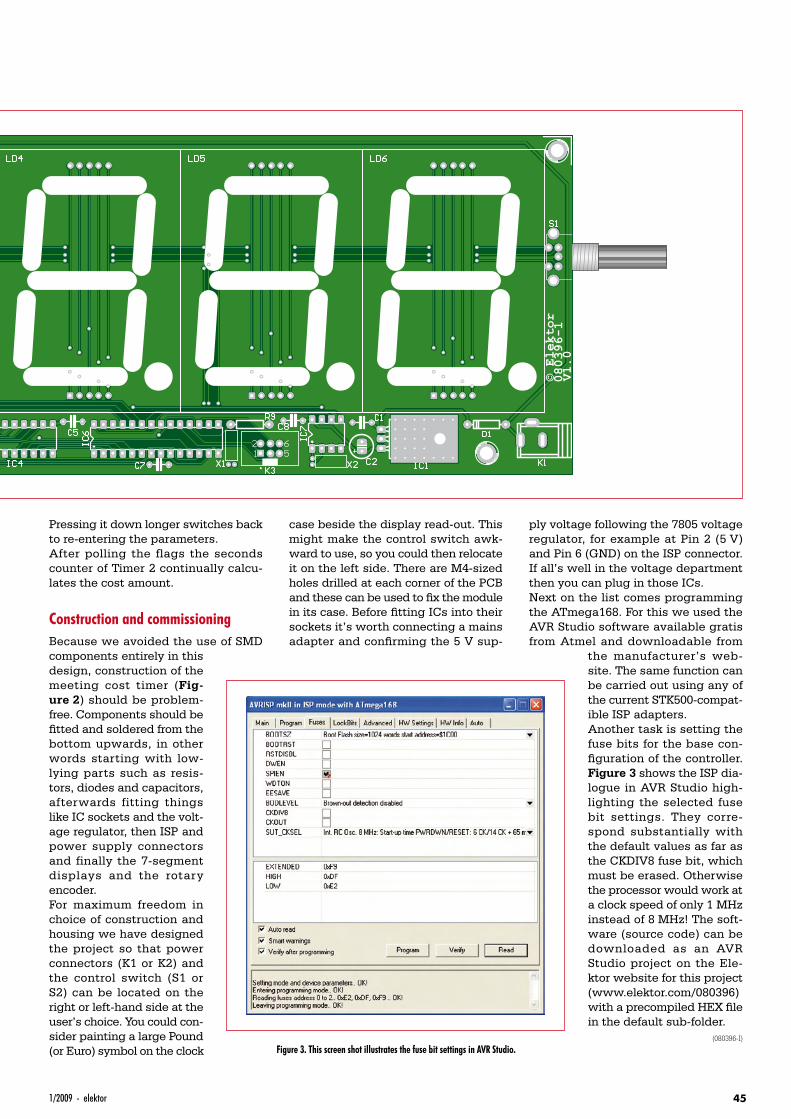
451/2009 - elektor
Pressing it down longer switches back to re-entering the parameters.After polling the flags the seconds counter of Timer 2 continually calcu-lates the cost amount.
Construction and commissioningBecause we avoided the use of SMD components entirely in this design, construction of the meeting cost timer (Fig-ure 2) should be problem-free. Components should be fitted and soldered from the bottom upwards, in other words starting with low-lying parts such as resis-tors, diodes and capacitors, afterwards fitting things like IC sockets and the volt-age regulator, then ISP and power supply connectors and finally the 7-segment displays and the rotary encoder.For maximum freedom in choice of construction and housing we have designed the project so that power connectors (K1 or K2) and the control switch (S1 or S2) can be located on the right or left-hand side at the user’s choice. You could con-sider painting a large Pound (or Euro) symbol on the clock
case beside the display read-out. This might make the control switch awk-ward to use, so you could then relocate it on the left side. There are M4-sized holes drilled at each corner of the PCB and these can be used to fix the module in its case. Before fitting ICs into their sockets it’s worth connecting a mains adapter and confirming the 5 V sup-
ply voltage following the 7805 voltage regulator, for example at Pin 2 (5 V) and Pin 6 (GND) on the ISP connector. If all’s well in the voltage department then you can plug in those ICs.Next on the list comes programming the ATmega168. For this we used the AVR Studio software available gratis from Atmel and downloadable from
the manufacturer’s web-site. The same function can be carried out using any of the current STK500-compat-ible ISP adapters.Another task is setting the fuse bits for the base con-figuration of the controller. Figure 3 shows the ISP dia-logue in AVR Studio high-lighting the selected fuse bit settings. They corre-spond substantially with the default values as far as the CKDIV8 fuse bit, which must be erased. Otherwise the processor would work at a clock speed of only 1 MHz instead of 8 MHz! The soft-ware (source code) can be downloaded as an AVR Studio project on the Ele-ktor website for this project (www.elektor.com/080396) with a precompiled HEX file in the default sub-folder.
(080396-I)
Figure 3. This screen shot illustrates the fuse bit settings in AVR Studio.
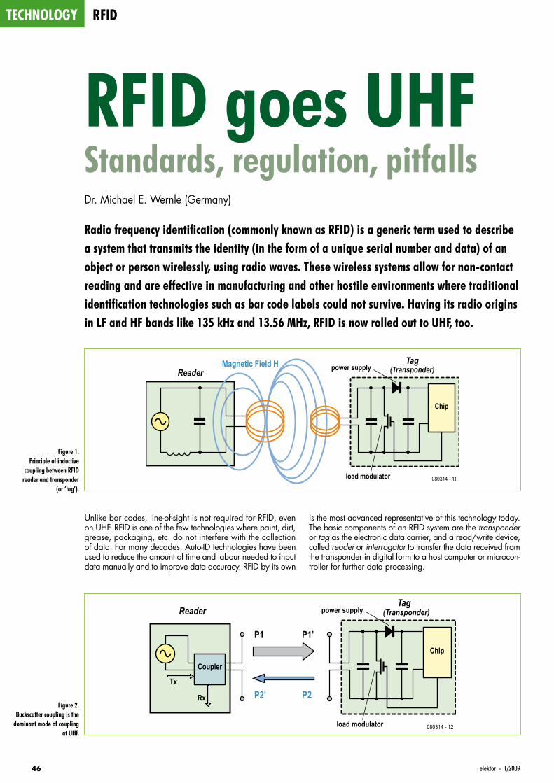
technology rfid
46 elektor - 1/2009
Unlike bar codes, line-of-sight is not required for RFID, even on UHF. RFID is one of the few technologies where paint, dirt, grease, packaging, etc. do not interfere with the collection of data. For many decades, Auto-ID technologies have been used to reduce the amount of time and labour needed to input data manually and to improve data accuracy. RFID by its own
is the most advanced representative of this technology today. The basic components of an RFID system are the transponder or tag as the electronic data carrier, and a read/write device, called reader or interrogator to transfer the data received from the transponder in digital form to a host computer or microcon-troller for further data processing.
RFID goes UHFStandards, regulation, pitfallsDr. Michael E. Wernle (Germany)
Radio frequency identification (commonly known as RFID) is a generic term used to describe a system that transmits the identity (in the form of a unique serial number and data) of an object or person wirelessly, using radio waves. These wireless systems allow for non-contact reading and are effective in manufacturing and other hostile environments where traditional identification technologies such as bar code labels could not survive. Having its radio origins in LF and HF bands like 135 kHz and 13.56 MHz, RFID is now rolled out to UHF, too.
Figure 1. Principle of inductive
coupling between RFID reader and transponder
(or ‘tag’).
Magnetic Field H power supply
load modulator 080314 - 11
ReaderTag
(Transponder)
Chip
power supply
load modulator 080314 - 12
Reader
P1 P1’
P2’ P2
Tag (Transponder)
Chip
Coupler
Tx
RxFigure 2.
Backscatter coupling is the dominant mode of coupling
at UHF.
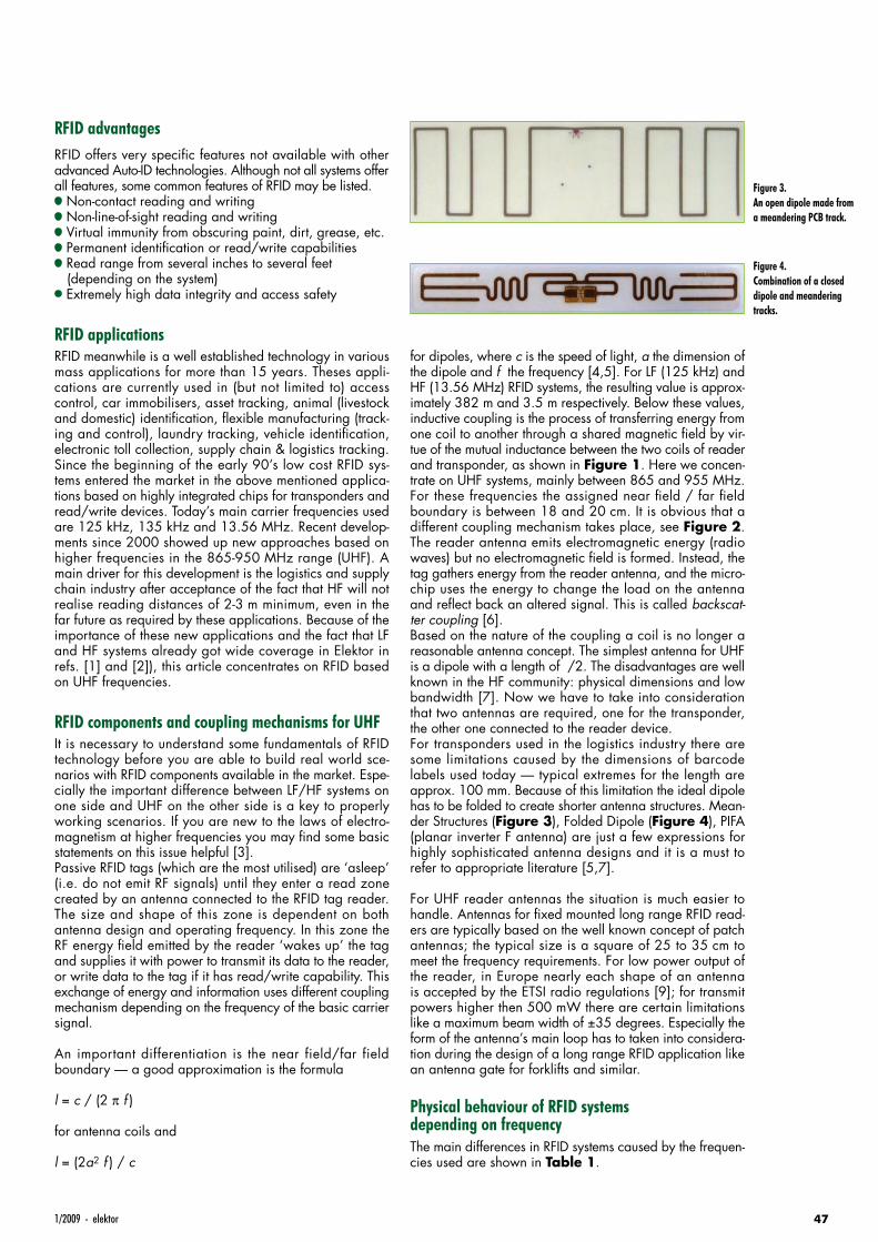
471/2009 - elektor
RFID advantagesRFID offers very specific features not available with other advanced Auto-ID technologies. Although not all systems offer all features, some common features of RFID may be listed.• Non-contact reading and writing• Non-line-of-sight reading and writing• Virtual immunity from obscuring paint, dirt, grease, etc. • Permanent identification or read/write capabilities• Read range from several inches to several feet
(depending on the system)• Extremely high data integrity and access safety
RFID applicationsRFID meanwhile is a well established technology in various mass applications for more than 15 years. Theses appli-cations are currently used in (but not limited to) access control, car immobilisers, asset tracking, animal (livestock and domestic) identification, flexible manufacturing (track-ing and control), laundry tracking, vehicle identification, electronic toll collection, supply chain & logistics tracking. Since the beginning of the early 90’s low cost RFID sys-tems entered the market in the above mentioned applica-tions based on highly integrated chips for transponders and read/write devices. Today’s main carrier frequencies used are 125 kHz, 135 kHz and 13.56 MHz. Recent develop-ments since 2000 showed up new approaches based on higher frequencies in the 865-950 MHz range (UHF). A main driver for this development is the logistics and supply chain industry after acceptance of the fact that HF will not realise reading distances of 2-3 m minimum, even in the far future as required by these applications. Because of the importance of these new applications and the fact that LF and HF systems already got wide coverage in Elektor in refs. [1] and [2]), this article concentrates on RFID based on UHF frequencies.
RFID components and coupling mechanisms for UHFIt is necessary to understand some fundamentals of RFID technology before you are able to build real world sce-narios with RFID components available in the market. Espe-cially the important difference between LF/HF systems on one side and UHF on the other side is a key to properly working scenarios. If you are new to the laws of electro-magnetism at higher frequencies you may find some basic statements on this issue helpful [3].Passive RFID tags (which are the most utilised) are ‘asleep’ (i.e. do not emit RF signals) until they enter a read zone created by an antenna connected to the RFID tag reader. The size and shape of this zone is dependent on both antenna design and operating frequency. In this zone the RF energy field emitted by the reader ‘wakes up’ the tag and supplies it with power to transmit its data to the reader, or write data to the tag if it has read/write capability. This exchange of energy and information uses different coupling mechanism depending on the frequency of the basic carrier signal.
An important differentiation is the near field/far field boundary — a good approximation is the formula
l = c / (2 π f )
for antenna coils and
l = (2a2 f ) / c
for dipoles, where c is the speed of light, a the dimension of the dipole and f the frequency [4,5]. For LF (125 kHz) and HF (13.56 MHz) RFID systems, the resulting value is approx-imately 382 m and 3.5 m respectively. Below these values, inductive coupling is the process of transferring energy from one coil to another through a shared magnetic field by vir-tue of the mutual inductance between the two coils of reader and transponder, as shown in Figure 1. Here we concen-trate on UHF systems, mainly between 865 and 955 MHz. For these frequencies the assigned near field / far field boundary is between 18 and 20 cm. It is obvious that a different coupling mechanism takes place, see Figure 2. The reader antenna emits electromagnetic energy (radio waves) but no electromagnetic field is formed. Instead, the tag gathers energy from the reader antenna, and the micro-chip uses the energy to change the load on the antenna and reflect back an altered signal. This is called backscat-ter coupling [6].Based on the nature of the coupling a coil is no longer a reasonable antenna concept. The simplest antenna for UHF is a dipole with a length of λ/2. The disadvantages are well known in the HF community: physical dimensions and low bandwidth [7]. Now we have to take into consideration that two antennas are required, one for the transponder, the other one connected to the reader device.For transponders used in the logistics industry there are some limitations caused by the dimensions of barcode labels used today — typical extremes for the length are approx. 100 mm. Because of this limitation the ideal dipole has to be folded to create shorter antenna structures. Mean-der Structures (Figure 3), Folded Dipole (Figure 4), PIFA (planar inverter F antenna) are just a few expressions for highly sophisticated antenna designs and it is a must to refer to appropriate literature [5,7].
For UHF reader antennas the situation is much easier to handle. Antennas for fixed mounted long range RFID read-ers are typically based on the well known concept of patch antennas; the typical size is a square of 25 to 35 cm to meet the frequency requirements. For low power output of the reader, in Europe nearly each shape of an antenna is accepted by the ETSI radio regulations [9]; for transmit powers higher then 500 mW there are certain limitations like a maximum beam width of ±35 degrees. Especially the form of the antenna’s main loop has to taken into considera-tion during the design of a long range RFID application like an antenna gate for forklifts and similar.
Physical behaviour of RFID systems depending on frequencyThe main differences in RFID systems caused by the frequen-cies used are shown in Table 1.
Figure 3. An open dipole made from a meandering PCB track.
Figure 4. Combination of a closed dipole and meandering tracks.
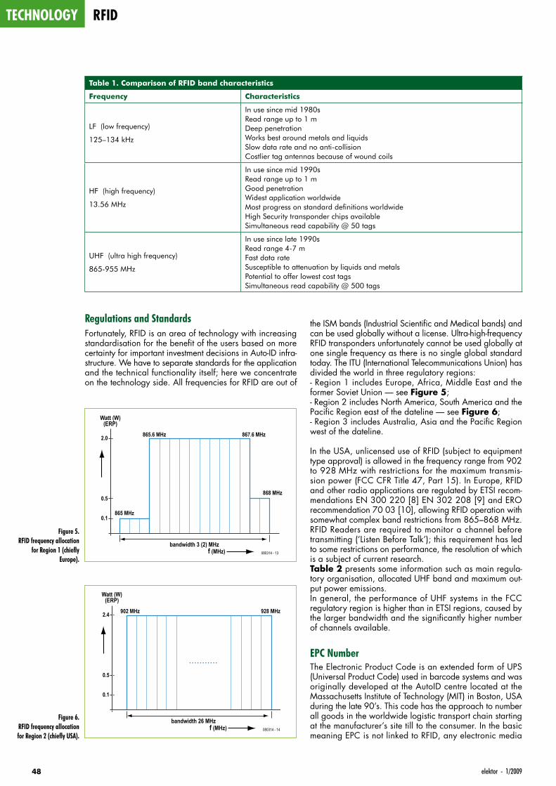
technology rfid
48 elektor - 1/2009
Regulations and StandardsFortunately, RFID is an area of technology with increasing standardisation for the benefit of the users based on more certainty for important investment decisions in Auto-ID infra-structure. We have to separate standards for the application and the technical functionality itself; here we concentrate on the technology side. All frequencies for RFID are out of
the ISM bands (Industrial Scientific and Medical bands) and can be used globally without a license. Ultra-high-frequency RFID transponders unfortunately cannot be used globally at one single frequency as there is no single global standard today. The ITU (International Telecommunications Union) has divided the world in three regulatory regions:- Region 1 includes Europe, Africa, Middle East and the former Soviet Union — see Figure 5;- Region 2 includes North America, South America and the Pacific Region east of the dateline — see Figure 6;- Region 3 includes Australia, Asia and the Pacific Region west of the dateline.
In the USA, unlicensed use of RFID (subject to equipment type approval) is allowed in the frequency range from 902 to 928 MHz with restrictions for the maximum transmis-sion power (FCC CFR Title 47, Part 15). In Europe, RFID and other radio applications are regulated by ETSI recom-mendations EN 300 220 [8] EN 302 208 [9] and ERO recommendation 70 03 [10], allowing RFID operation with somewhat complex band restrictions from 865–868 MHz. RFID Readers are required to monitor a channel before transmitting (‘Listen Before Talk’); this requirement has led to some restrictions on performance, the resolution of which is a subject of current research. Table 2 presents some information such as main regula-tory organisation, allocated UHF band and maximum out-put power emissions.In general, the performance of UHF systems in the FCC regulatory region is higher than in ETSI regions, caused by the larger bandwidth and the significantly higher number of channels available.
EPC NumberThe Electronic Product Code is an extended form of UPS (Universal Product Code) used in barcode systems and was originally developed at the AutoID centre located at the Massachusetts Institute of Technology (MIT) in Boston, USA during the late 90’s. This code has the approach to number all goods in the worldwide logistic transport chain starting at the manufacturer’s site till to the consumer. In the basic meaning EPC is not linked to RFID, any electronic media
Figure 5. RFID frequency allocation
for Region 1 (chiefly Europe).
bandwidth 3 (2) MHz
Watt (W)(ERP)
865 MHz0.1
0.5
2.0
868 MHz
865.6 MHz 867.6 MHz
f (MHz) 080314 - 13
Table 1. Comparison of RFID band characteristics
Frequency Characteristics
LF (low frequency)
125–134 kHz
In use since mid 1980s Read range up to 1 m Deep penetration Works best around metals and liquids Slow data rate and no anti-collision Costlier tag antennas because of wound coils
HF (high frequency)
13.56 MHz
In use since mid 1990s Read range up to 1 m Good penetration Widest application worldwide Most progress on standard definitions worldwide High Security transponder chips available Simultaneous read capability @ 50 tags
UHF (ultra high frequency)
865-955 MHz
In use since late 1990s Read range 4-7 m Fast data rate Susceptible to attenuation by liquids and metals Potential to offer lowest cost tags Simultaneous read capability @ 500 tags
Figure 6. RFID frequency allocation for Region 2 (chiefly USA).
bandwidth 26 MHz
Watt (W)(ERP)
0.1
0.5
2.4 902 MHz 928 MHz
f (MHz) 080314 - 14
. . . . . . . . . . .
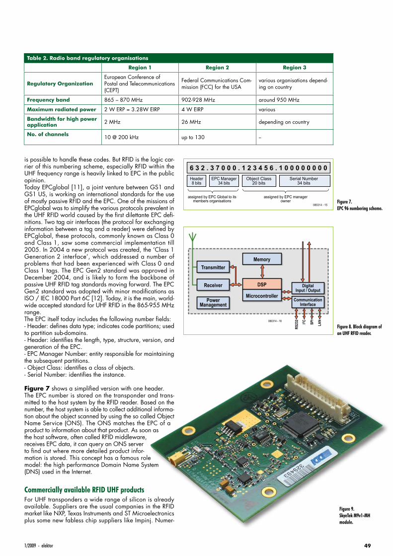
491/2009 - elektor
is possible to handle these codes. But RFID is the logic car-rier of this numbering scheme, especially RFID within the UHF frequency range is heavily linked to EPC in the public opinion.Today EPCglobal [11], a joint venture between GS1 and GS1 US, is working on international standards for the use of mostly passive RFID and the EPC. One of the missions of EPCglobal was to simplify the various protocols prevalent in the UHF RFID world caused by the first dilettante EPC defi-nitions. Two tag air interfaces (the protocol for exchanging information between a tag and a reader) were defined by EPCglobal, these protocols, commonly known as Class 0 and Class 1, saw some commercial implementation till 2005. In 2004 a new protocol was created, the ‘Class 1 Generation 2 interface’, which addressed a number of problems that had been experienced with Class 0 and Class 1 tags. The EPC Gen2 standard was approved in December 2004, and is likely to form the backbone of passive UHF RFID tag standards moving forward. The EPC Gen2 standard was adopted with minor modifications as ISO / IEC 18000 Part 6C [12]. Today, it is the main, world-wide accepted standard for UHF RFID in the 865-955 MHz range.The EPC itself today includes the following number fields:- Header: defines data type; indicates code partitions; used to partition sub-domains.- Header: identifies the length, type, structure, version, and generation of the EPC.- EPC Manager Number: entity responsible for maintaining the subsequent partitions.- Object Class: identifies a class of objects.- Serial Number: identifies the instance.
Figure 7 shows a simplified version with one header.The EPC number is stored on the transponder and trans-mitted to the host system by the RFID reader. Based on the number, the host system is able to collect additional informa-tion about the object scanned by using the so called Object Name Service (ONS). The ONS matches the EPC of a product to information about that product. As soon as the host software, often called RFID middleware, receives EPC data, it can query an ONS server to find out where more detailed product infor-mation is stored. This concept has a famous role model: the high performance Domain Name System (DNS) used in the Internet.
Commercially available RFID UHF productsFor UHF transponders a wide range of silicon is already available. Suppliers are the usual companies in the RFID market like NXP, Texas Instruments and ST Microelectronics plus some new fabless chip suppliers like Impinj. Numer-
Table 2. Radio band regulatory organisations
Region 1 Region 2 Region 3
Regulatory OrganizationEuropean Conference of Postal and Telecommunications (CEPT)
Federal Communications Com-mission (FCC) for the USA
various organisations depend-ing on country
Frequency band 865 – 870 MHz 902-928 MHz around 950 MHz
Maximum radiated power 2 W ERP = 3.28W EIRP 4 W EIRP various
Bandwidth for high power application 2 MHz 26 MHz depending on country
No. of channels 10 @ 200 kHz up to 130 --
Figure 7. EPC 96 numbering scheme.
6 3 2 . 3 7 0 0 0 . 1 2 3 4 5 6 . 1 0 0 0 0 0 0 0 0Header8 bits
EPC Manager34 bits
assigned by EPC Global to itsmembers organisations
assigned by EPC managerowner
080314 - 15
Object Class20 bits
Serial Number34 bits
Figure 8. Block diagram of an UHF RFID reader.
TransmitterMemory
DigitalInput / Output
RS23
2
SPI
LANI2 C
CommunicationInterface
DSP
080314 - 16
Microcontroller
Receiver
PowerManagement
Figure 9. SkyeTek M9v1-MH module.
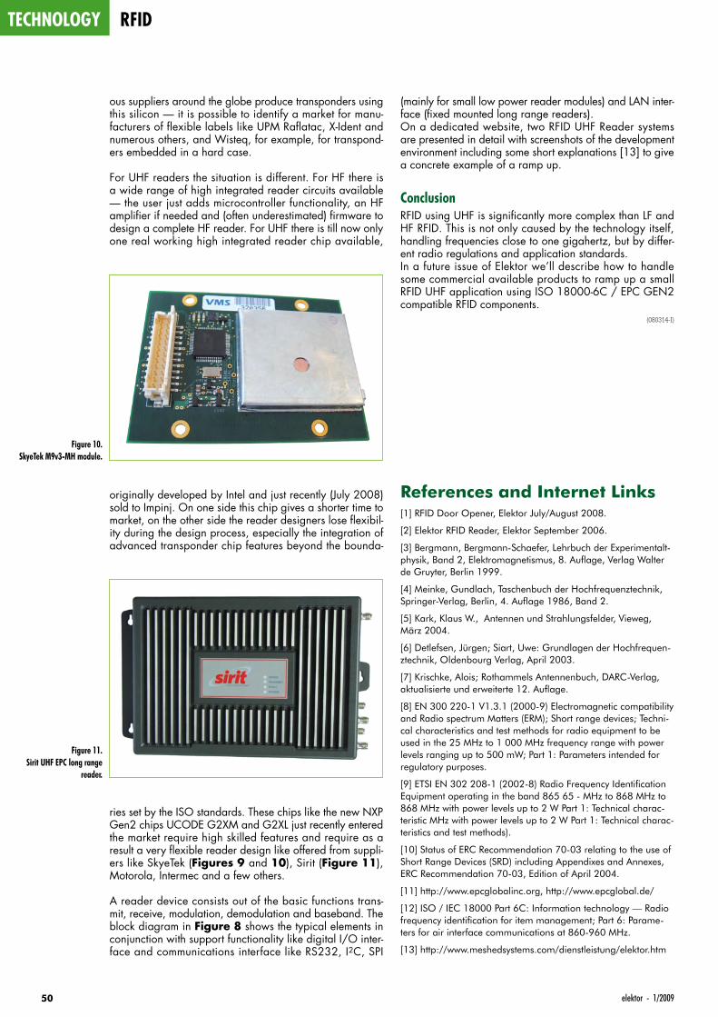
technology rfid
50 elektor - 1/2009
ous suppliers around the globe produce transponders using this silicon — it is possible to identify a market for manu-facturers of flexible labels like UPM Raflatac, X-Ident and numerous others, and Wisteq, for example, for transpond-ers embedded in a hard case.
For UHF readers the situation is different. For HF there is a wide range of high integrated reader circuits available — the user just adds microcontroller functionality, an HF amplifier if needed and (often underestimated) firmware to design a complete HF reader. For UHF there is till now only one real working high integrated reader chip available,
originally developed by Intel and just recently (July 2008) sold to Impinj. On one side this chip gives a shorter time to market, on the other side the reader designers lose flexibil-ity during the design process, especially the integration of advanced transponder chip features beyond the bounda-
ries set by the ISO standards. These chips like the new NXP Gen2 chips UCODE G2XM and G2XL just recently entered the market require high skilled features and require as a result a very flexible reader design like offered from suppli-ers like SkyeTek (Figures 9 and 10), Sirit (Figure 11), Motorola, Intermec and a few others.
A reader device consists out of the basic functions trans-mit, receive, modulation, demodulation and baseband. The block diagram in Figure 8 shows the typical elements in conjunction with support functionality like digital I/O inter-face and communications interface like RS232, I2C, SPI
(mainly for small low power reader modules) and LAN inter-face (fixed mounted long range readers).On a dedicated website, two RFID UHF Reader systems are presented in detail with screenshots of the development environment including some short explanations [13] to give a concrete example of a ramp up.
ConclusionRFID using UHF is significantly more complex than LF and HF RFID. This is not only caused by the technology itself, handling frequencies close to one gigahertz, but by differ-ent radio regulations and application standards.In a future issue of Elektor we’ll describe how to handle some commercial available products to ramp up a small RFID UHF application using ISO 18000-6C / EPC GEN2 compatible RFID components.
(080314-I)
References and Internet Links[1] RFID Door Opener, Elektor July/August 2008.
[2] Elektor RFID Reader, Elektor September 2006.
[3] Bergmann, Bergmann-Schaefer, Lehrbuch der Experimentalt-physik, Band 2, Elektromagnetismus, 8. Auflage, Verlag Walter de Gruyter, Berlin 1999.
[4] Meinke, Gundlach, Taschenbuch der Hochfrequenztechnik, Springer-Verlag, Berlin, 4. Auflage 1986, Band 2.
[5] Kark, Klaus W., Antennen und Strahlungsfelder, Vieweg, März 2004.
[6] Detlefsen, Jürgen; Siart, Uwe: Grundlagen der Hochfrequen-ztechnik, Oldenbourg Verlag, April 2003.
[7] Krischke, Alois; Rothammels Antennenbuch, DARC-Verlag, aktualisierte und erweiterte 12. Auflage.
[8] EN 300 220-1 V1.3.1 (2000-9) Electromagnetic compatibility and Radio spectrum Matters (ERM); Short range devices; Techni-cal characteristics and test methods for radio equipment to be used in the 25 MHz to 1 000 MHz frequency range with power levels ranging up to 500 mW; Part 1: Parameters intended for regulatory purposes.
[9] ETSI EN 302 208-1 (2002-8) Radio Frequency Identification Equipment operating in the band 865 65 - MHz to 868 MHz to 868 MHz with power levels up to 2 W Part 1: Technical charac-teristic MHz with power levels up to 2 W Part 1: Technical charac-teristics and test methods).
[10] Status of ERC Recommendation 70-03 relating to the use of Short Range Devices (SRD) including Appendixes and Annexes, ERC Recommendation 70-03, Edition of April 2004.
[11] http://www.epcglobalinc.org, http://www.epcglobal.de/
[12] ISO / IEC 18000 Part 6C: Information technology — Radio frequency identification for item management; Part 6: Parame-ters for air interface communications at 860-960 MHz.
[13] http://www.meshedsystems.com/dienstleistung/elektor.htm
Figure 10. SkyeTek M9v3-MH module.
Figure 11. Sirit UHF EPC long range
reader.
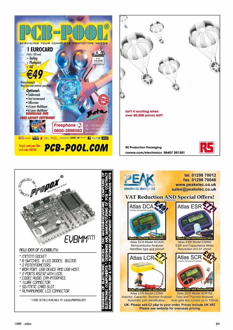
511/2009 - elektor
UK: Please add £2 p&p to your order. Prices include UK VAT.Please see website for overseas pricing.
Atlas DCAModel DCA55Semiconductor AnalyserIdentifies type pinout!and
Atlas ESR Model ESR60ESR and Capacitance MeterResolution of 0.01 ohms!
VAT Reduction AND Special Offers!
tel. 01298 70012fax. 01298 70046
Atlas SCR Model SCR100Triac and Thyristor Analyser
Auto gate test current up to 100mA
Atlas LCR Model LCR40Inductor, Capacitor, Resistor Analyser
Automatic part identification.
Atlas ESR£77!was
£85
Atlas DCA£49!was
£55
Atlas LCR Atlas SCRincludes new premium probes!
£87!was£99
£77was£79
Special Offer AND Reduced VAT ! Special Offer AND Reduced VAT !
Special Offer AND Reduced VAT !Better than 2 VAT Reduction!½ %
includes new premium probes!
Isn’t it exciting whenover 80,000 prices fall?
RS Production Packaging
rswww.com/electronics 08457 201201
DE
SIG
NIN
G O
F E
LE
CT
RO
NIC
D
EV
ICE
S *
CN
C M
AC
HIN
ING
(CA
D/C
AM
) *
CO
MP
OU
ND
O
F
ELE
CT
RO
NIC
C
OM
PO
NE
NT
S *
DE
SIG
NIN
G A
ND
M
AN
UFA
CT
UR
ING
O
F P
CB
*
CO
NT
RA
CT
M
AN
UFA
CT
UR
ING
SM
T &
TH
T *
SO
FT
WA
RE
DE
VE
LO
PM
EN
T *
EV
ALU
AT
ION
BO
AR
DS
* K
ITS
* MORE DETAILS AVAILABLE AT: WWW.PROPOX.COM
R
Many ideas one solution
TMEVBmmNEW IDEA OF FLEXIBILITY:
* MMTM SOCKET
* 8 switches, 8 LED diodes, Buzzer,
* 2 potentiometers,
* IRDA port, USB Device and USB Host,
* 2 ports RS232 with LEDs,
* Codec Audio, CAN Interface,
* 1WIRE connector,
* SD/MMC card slot,
* Alphanumeric LCD connector,
0901_elektor_adv_UK.indd 51 28-11-2008 14:08:00
projects i2c
52 elektor - 1/2009
I2C Slave Kernel for ATtiny13 and ’2313Stir in BascomAVR, add a pinch of assembly code
Vladimir Mitrovic (Croatia)
With all the processing power under the hood of the Atmel ATtiny13 and ATtiny2313 micros, it’s not too difficult to get them interfaced to the I2C bus: some Basic and embedded assembly code will do just nicely.
The I2C bus (a.k.a. IIC or inter-IC bus) as well as integrated circuits designed to work on it, have been described numerous times in this magazine, just look at references [1] and [2] for two recent articles. Although there exist hundreds of ICs with I2C compatibility, each and every one of these will have one specific function it was designed to handle. For example, humidity sens-ing, relay driving, LCD controlling, data memorising, push button activity detection, keyboard decoding, bus cur-rent boosting — you mention it, it’s all available, and cheap too! However, the true electronics enthusiast is creative and wants to be able to1. glue home-brew things to the I2C
bus;2. design his/her own I2C
peripheral(s) to do just what’s desired using preferred components.
For both, it is necessary to have a mini-mum of I2C slave functionality and then take it from there with all levels of flex-ibility. If this sounds like ‘software’, it is: if you can program it, just do it.
Project outline and hardwareThe AVR microcontroller is pro-grammed to act as an I2C slave. The write address of this slave is memo-rised in its internal EEPROM, at the address 0, bits 7-1. Bit 0 should be zero. The most important I2C rules are implemented in the program: it rec-ognizes multiple STARTs as well as unexpected START and STOP signals in the middle of a data sequence and keeps the SCL line Low while prepar-
ing the byte to be sent to the master. The program is optimised for speed and with an 8 MHz oscillator it will accept an I2C clock with a frequency of up to 400 kHz. This means that the ATtiny2313 or ATtiny13 can make do with their internal oscillators.As everything is realised in software, no external components are needed and we arrive at bare-bones circuit dia-grams shown in Figure 1 and Figure 2. The pull-up resistors on the SCL and SDA lines may be omitted if they are provided elsewhere on the I2C bus. For hardware, it doesn’t get simpler than that.
The kernelThe program has several time-criti-cal routines that are written in assem-bler. These routines constantly monitor the traffic on the I2C bus and call the appropriate subroutines if a valid write or read address is recognized. The program kernel acts as any other I2C slave, with the following conditioned functionality.
1. If the first byte following the START signal is recognized as its own write address (bit 0 = 0), it will:- confirm it with ACK;- accept up to two following bytes, con-firming each of them with ACKs;wait for RESET (any additional byte before RESET is ignored);- call the ‘Process_received_data’ sub-routine after RESET;- wait for the next START.
2. If the first byte following the START signal is recognized as its own read address (bit 0 = 1), it will:- confirm it with ACK;- pull down the SCL line to signal the I2C master that data is prepared (delayed SCL);- call the ‘Prepare_data_for_master’ subroutine;- free the SCL line to enable further communication;- send one byte of data contained in the ‘Data_for_master’ variable to the master;- wait for the next START.
3. If the first byte following the START signal is not recognised as its own write or read address, it will ignore all communication on the I2C bus until the new START signal.
It is the programmer’s (i.e. your!) responsibility — and challenge — to provide the code for the ‘Process_received_data’ and ‘Prepare_data_for_master’ subroutines in order to proc-ess received data or to prepare data to be sent to the host. In order to facili-tate programming even for a not very skilled programmer, the assembler ker-
Technical Spec• Atmel ATtiny13 or ATtiny2313
programmed to act as a slave device on the I2C bus
• Mix of BascomAVR and assembly code
• Software open-ended and free to community
• No fixed device address• Learning mode and hardware
activation built in
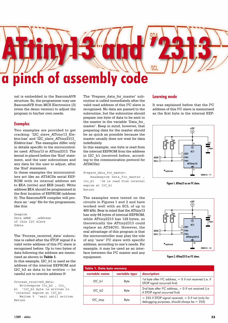
531/2009 - elektor
I2C Slave Kernel for ATtiny13 and ’2313Stir in BascomAVR, add a pinch of assembly code
nel is embedded in the BascomAVR structure. So, the programmer may use BascomAVR from MCS Electronics [3] (even the demo version) to adjust the program to his/her own needs.
ExamplesTwo examples are provided to get cracking: ‘I2C_slave_ATtiny13_Ele-ktor.bas’ and ‘I2C_slave_ATtiny2313_Elektor.bas’. The examples differ only in details specific to the microcontrol-ler used: ATtiny13 or ATtiny2313. The kernel is placed before the ‘End’ state-ment, and the user subroutines and any data for the user to adjust, after the ‘End’ statement.In these examples the microcontrol-lers act like an AT24C0x serial EEP-ROM with its internal address set to $EA (write) and $EB (read). Write address $EA should be programmed in the first location of EEPROM (address 0). The BascomAVR compiler will pro-duce an ‘.eep’ file for the programmer, like this:
$eepromData &HAE ‚address of this I2C slave$data
The ‘Process_received_data’ subrou-tine is called after the STOP signal if a valid write address of this I2C slave is recognised before. Up to two bytes of data following the address are memo-rised as shown in Table 1.In this example, I2C_b1 is used as the address of the internal EEPROM and I2C_b2 as data to be written — be careful not to rewrite address 0!
Process_received_data: Writeeeprom I2c_b2 , I2c_b1 ‘I2C_b2 byte is written to‘internal eeprom at I2C_b1 Waitms 5 ‘wait until writtenReturn
The ‘Prepare_data_for_master’ sub-routine is called immediately after the valid read address of this I2C slave is recognised. No data are passed to the subroutine, but the subroutine should prepare one byte of data to be sent to the master in the variable ‘Data_for_master’. Keep in mind, however, that preparing data for the master should be as quick as possible because the master usually does not wait for data indefinitely.In this example, one byte is read from the internal EEPROM from the address in I2C_b1 (received before, accord-ing to the communication protocol for AT24C0x):
Prepare_data_for_master:
Readeeprom Data_for_master ,
I2c_b1 ‘1B is read from internal
eeprom at I2C_b1
Return
The examples were tested on the circuits in Figures 1 and 2 and have worked well with an SCL of up to 400 kHz. Bear in mind that the ATtiny13 has only 64 bytes of internal EEPROM, while ATtiny2313 has 128 bytes, so theoretically the ATtiny2313 could replace an AT24C01. However, the real advantage of this program is that the microcontroller may play the role of any ‘new’ I2C slave with specific address, according to one’s needs. For example, it may be used as an inter-face between the I2C master and any equipment.
Learning mode
It was explained before that the I2C address of this I2C slave is memorised as the first byte in the internal EEP-
ATtiny13
IC1RST
PB3
PB4
8
4
1
2
3
R2
4k7
R1
4k7
+5V
C1
100n
SDA
SCL
080613 - 11
* *
*optional
Figure 1. ATtiny13 as an I2C slave.
ATtiny2313
IC1RST
PB3
PB4
20
10
1
15
16
R2
4k7
R1
4k7
+5V
C1
100n
SDA
SCL
080613 - 12
* *
*optional
Figure 2. ATtiny2313 as I2C slave.
Table 1. Data byte memory
variable name variable type description
I2C_b1 Byte1st byte after I2C address, = 0 if not received (i.e. if STOP signal occurred first)
I2C_b2 Byte2nd byte after I2C address, = 0 if not received (i.e. if STOP signal occurred first)
I2C_stop Byte= 255 if STOP signal received, = 0 if not (only for debugging purposes, should always be = 255)
PROJECTS I2C
54 elektor - 1/2009
ROM. It may be defined in the pro-gram and programmed in EEPROM after programming the fl ash memory as explained in the example. As an additional benefit, the microcontrol-ler may be set in ‘learning mode’ and accept and memorise the new address from the I2C bus. There are two ways to activate the learning mode, soft-ware and hardware. In both cases, the ‘Learning_mode’ flag is set and the fi rst I2C address (1st byte after the next START signal) will be accepted and memorized as the new I2C address of this slave. Immediately after this procedure the ‘Learning_mode’ fl ag is erased and the microcontroller acts as explained before. The whole procedure is already programmed in the kernel; you only have to set the fl ag!An example of software activation of the learning mode is given below. Here, we check if a specifi c data com-bination is received and set the ‘Learn-ing_mode’ fl ag if it is:
Process_received_data: ... ...
Config Pinb.0 = Output If Pinb.0 = 0 Then Learning_mode = 1 End IfReturn
ResourcesThe Basic programs (written in Bas-comAVR) and hex object code fi les for the microcontrollers are available as a free download from the Elektor website [4]. Due care should be taken with the hex fi les as they may not be compat-ible with every programming system for the ATtiny13 and ‘2313 microcon-trollers. In case of doubt, compile the .bas fi les locally and work out the com-patibility with your programmer.
(080613-I)
References and Internet Links[1] The Secrets of I2C, Elektor March 2008.
[2] Bits on Parade, Elektor December 2008.
[3] www.mcselec.com
[4] www.elektor.com/080613
If I2c_b1 = xxx and I2c_b2 = yyy Then ‘check if specific key combination is received Learning_mode = 1 ‘set learning flag End If ... ...Return
hardware activationUse any free I/O pin, e.g. PINB.0 and provide a jumper or pushbutton to con-nect it to the GND. When you want to reprogram the I2C address of this slave, keep the pushbutton pressed for two seconds at power-up or reset. At the beginning of the program the ‘Learn-ing_mode_hw_activation’ subroutine is called. This subroutine is normally empty (i.e. it contains no more than ‘Return’). If you want to enable hard-ware activation of the learning mode, you should check the state of the cho-sen I/O pin (Pinb.0 in this example) and set the Learning_mode fl ag if the expected condition occurs (Pinb.0 = 0 in this example):
Learning_mode_hw_activation:
Advertisement
See your design in print!
Elektor Electronics (Publishing)
are looking for
Freelance Technical Authors/Designers
If you havean innovative or otherwise original design you would like to see in print in Europe’s largest magazine on practical electronics
above average skills in designing electronic circuitsexperience in writing electronics-related softwarebasic skills in complementing your design with an explanatory texta PC, email and Internet access for efficient communication with our in-house design staff;
then do not hesitate to contact us for exciting opportunities in getting your designs published on a regular basis.
Elektor ElectronicsJan Buiting, EditorP.O. Box 11, NL-6141-AV Susteren, The Netherlands, Fax: (+31) 46 4370161Email: [email protected]
UK0901_52_54_080613-UK I2C Slave54 54 27-11-2008 14:21:52

electronics worldwide
“Elektor is substance for professionals and those wanting to reach the level. The perfect entry to my studies!”
– Christian, 19, freshman –
20%Discount! Electronics at all the right levels
Advantages to subscribers
Students qualify for a discount of no less than 20%compared to the normal price of an annual subscription
Subscribers get up to 40% discounton special Elektor products
No queues, travelling, parking fees or ‘sold out’ Elektor is supplied to your doorstep every month
Always up to date – read your copy before everyone else
Secure a head start in electronics with a Student Subscription!*
STU-
UK-1
* Only available in UK. Ask for the conditions.
www.elektor.com/subs · Tel. +44 20 8261 4509
0901_elektor_adv_UK.indd 55 28-11-2008 14:08:24
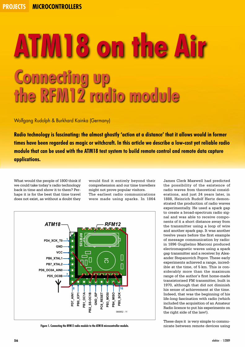
projects microcontrollers
56 elektor - 1/2009
ATM18 on the AirConnecting up the RFM12 radio moduleWolfgang Rudolph & Burkhard Kainka (Germany)
Radio technology is fascinating: the almost ghostly ‘action at a distance’ that it allows would in former times have been regarded as magic or witchcraft. In this article we describe a low-cost yet reliable radio module that can be used with the ATM18 test system to build remote control and remote data capture applications.
What would the people of 1800 think if we could take today’s radio technology back in time and show it to them? Per-haps it is for the best that time travel does not exist, as without a doubt they
would find it entirely beyond their comprehension and our time travellers might not prove popular visitors.The earliest radio communications were made using sparks. In 1864
James Clerk Maxwell had predicted the possibility of the existence of radio waves from theoretical consid-erations, and just 24 years later, in 1888, Heinrich Rudolf Hertz demon-strated the production of radio waves experimentally. He used a spark gap to create a broad-spectrum radio sig-nal and was able to receive compo-nents of it a short distance away from the transmitter using a loop of wire and another spark gap. It was another twelve years before the first example of message communication by radio: in 1896 Guglielmo Marconi produced electromagnetic waves using a spark gap transmitter and a receiver by Alex-ander Stepanovich Popov. These early experiments achieved a range, incred-ible at the time, of 5 km. This is con-siderably more than the maximum range of the author’s first home-made transistorised FM transmitter, built in 1970, although that did not diminish his sense of achievement at the time. Indeed, that was the beginning of his life-long fascination with radio (which included the acquisition of an Amateur Radio licence to put his experiments on the right side of the law!).
These days it is very simple to commu-nicate between remote devices using
RFM
12S
IC
1PD4_XCK_T0
GND
ATM18 RFM12
VCC
PB6_XTAL1
PB7_XTAL2
PD6_OC0A_AIN0
PD5_OC0B
080852 - 11
PD7_
AIN1
PB0_
ICP1
PB1_
OC1
A
PB2_
SS-O
C1B
GND
_ISP
PC6_
RESE
T
PB3_
MO
SI
PB4_
MIS
O
PB5_
SCK
7
8 16
Figure 1. Connecting the RFM12 radio module to the ATM18 microcontroller module.
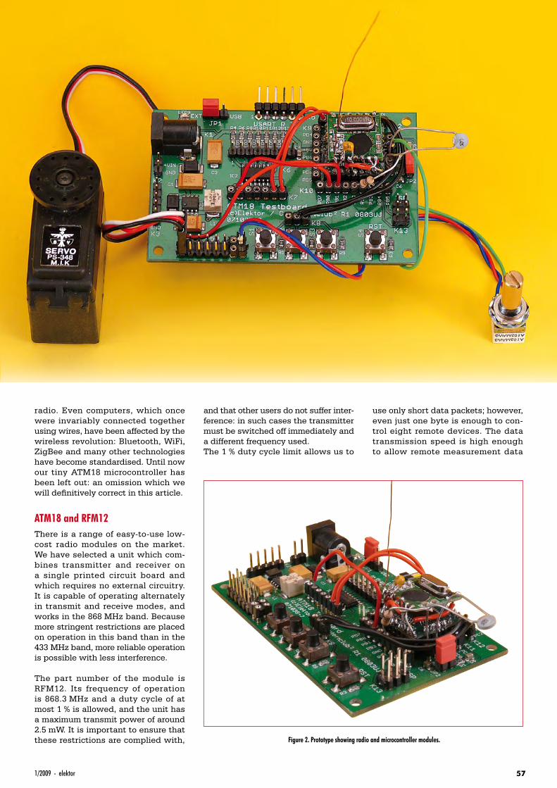
571/2009 - elektor
ATM18 on the AirConnecting up the RFM12 radio module
radio. Even computers, which once were invariably connected together using wires, have been affected by the wireless revolution: Bluetooth, WiFi, ZigBee and many other technologies have become standardised. Until now our tiny ATM18 microcontroller has been left out: an omission which we will definitively correct in this article.
ATM18 and RFM12There is a range of easy-to-use low-cost radio modules on the market. We have selected a unit which com-bines transmitter and receiver on a single printed circuit board and which requires no external circuitry. It is capable of operating alternately in transmit and receive modes, and works in the 868 MHz band. Because more stringent restrictions are placed on operation in this band than in the 433 MHz band, more reliable operation is possible with less interference.
The part number of the module is RFM12. Its frequency of operation is 868.3 MHz and a duty cycle of at most 1 % is allowed, and the unit has a maximum transmit power of around 2.5 mW. It is important to ensure that these restrictions are complied with,
and that other users do not suffer inter-ference: in such cases the transmitter must be switched off immediately and a different frequency used.The 1 % duty cycle limit allows us to
use only short data packets; however, even just one byte is enough to con-trol eight remote devices. The data transmission speed is high enough to allow remote measurement data
Figure 2. Prototype showing radio and microcontroller modules.
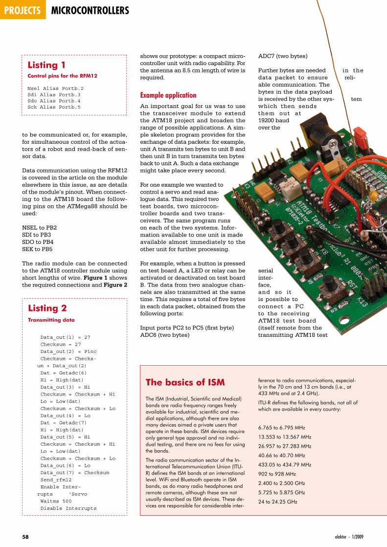
projects microcontrollers
58 elektor - 1/2009
to be communicated or, for example, for simultaneous control of the actua-tors of a robot and read-back of sen-sor data.
Data communication using the RFM12 is covered in the article on the module elsewhere in this issue, as are details of the module’s pinout. When connect-ing to the ATM18 board the follow-ing pins on the ATMega88 should be used:
NSEL to PB2SDI to PB3SDO to PB4SEK to PB5
The radio module can be connected to the ATM18 controller module using short lengths of wire. Figure 1 shows the required connections and Figure 2
ADC7 (two bytes)
Further bytes are needed in the data packet to ensure reli-able communication. The bytes in the data payload is received by the other sys- tem which then sends them out at 19200 baud over the
serial inter-face, and so i t is possible to connect a PC to the receiving ATM18 test board (itself remote from the transmitting ATM18 test
shows our prototype: a compact micro-controller unit with radio capability. For the antenna an 8.5 cm length of wire is required.
Example applicationAn important goal for us was to use the transceiver module to extend the ATM18 project and broaden the range of possible applications. A sim-ple skeleton program provides for the exchange of data packets: for example, unit A transmits ten bytes to unit B and then unit B in turn transmits ten bytes back to unit A. Such a data exchange might take place every second.
For one example we wanted to control a servo and read ana-logue data. This required two test boards, two microcon-troller boards and two trans-ceivers. The same program runs on each of the two systems. Infor-mation available to one unit is made available almost immediately to the other unit for further processing.
For example, when a button is pressed on test board A, a LED or relay can be activated or deactivated on test board B. The data from two analogue chan-nels are also transmitted at the same time. This requires a total of five bytes in each data packet, obtained from the following ports:
Input ports PC2 to PC5 (first byte)ADC6 (two bytes)
Listing 1Control pins for the RFM12
Nsel Alias Portb.2Sdi Alias Portb.3Sdo Alias Portb.4Sck Alias Portb.5
Listing 2Transmitting data
Data_out(1) = 27 Checksum = 27 Data_out(2) = Pinc Checksum = Checks-
um + Data_out(2) Dat = Getadc(6) Hi = High(dat) Data_out(3) = Hi Checksum = Checksum + Hi Lo = Low(dat) Checksum = Checksum + Lo Data_out(4) = Lo Dat = Getadc(7) Hi = High(dat) Data_out(5) = Hi Checksum = Checksum + Hi Lo = Low(dat) Checksum = Checksum + Lo Data_out(6) = Lo Data_out(7) = Checksum Send_rfm12 Enable Inter-
rupts ‘Servo Waitms 500 Disable Interrupts
The basics of ISM
The ISM (Industrial, Scientific and Medical) bands are radio frequency ranges freely available for industrial, scientific and me-dial applications, although there are also many devices aimed a private users that operate in these bands. ISM devices require only general type approval and no indivi-dual testing, and there are no fees for using the bands.
The radio communication sector of the In-ternational Telecommunication Union (ITU-R) defines the ISM bands at an international level. WiFi and Bluetooth operate in ISM bands, as do many radio headphones and remote cameras, although these are not usually described as ISM devices. These de-vices are responsible for considerable inter-
ference to radio communications, especial-ly in the 70 cm and 13 cm bands (i.e., at 433 MHz and at 2.4 GHz).
ITU-R defines the following bands, not all of which are available in every country:
6.765 to 6.795 MHz
13.553 to 13.567 MHz
26.957 to 27.283 MHz
40.66 to 40.70 MHz
433.05 to 434.79 MHz
902 to 928 MHz
2.400 to 2.500 GHz
5.725 to 5.875 GHz
24 to 24.25 GHz
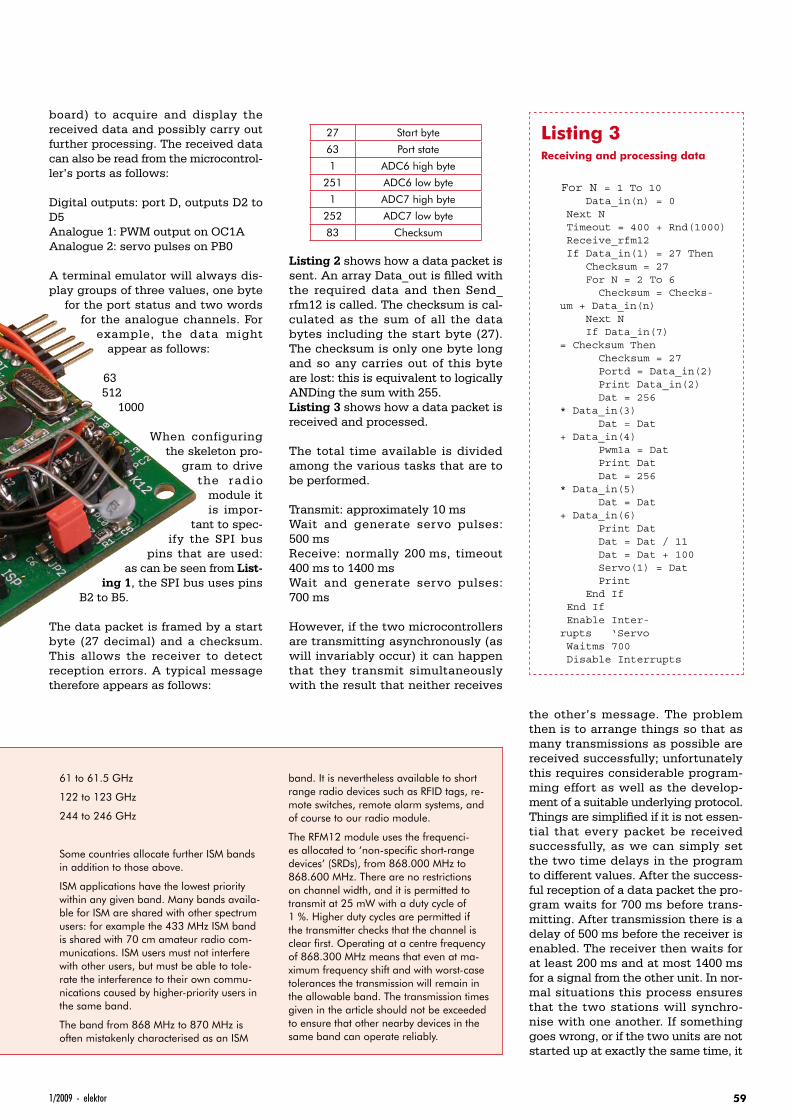
591/2009 - elektor
board) to acquire and display the received data and possibly carry out further processing. The received data can also be read from the microcontrol-ler’s ports as follows:
Digital outputs: port D, outputs D2 to D5Analogue 1: PWM output on OC1AAnalogue 2: servo pulses on PB0
A terminal emulator will always dis-play groups of three values, one byte
for the port status and two words for the analogue channels. For
example, the data might appear as follows:
63512
1000
When configuring the skeleton pro-
gram to drive the radio
module it is impor-
tant to spec-ify the SPI bus
pins that are used: as can be seen from List-
ing 1, the SPI bus uses pins B2 to B5.
The data packet is framed by a start byte (27 decimal) and a checksum. This allows the receiver to detect reception errors. A typical message therefore appears as follows:
27 Start byte
63 Port state
1 ADC6 high byte
251 ADC6 low byte
1 ADC7 high byte
252 ADC7 low byte
83 Checksum
Listing 2 shows how a data packet is sent. An array Data_out is filled with the required data and then Send_rfm12 is called. The checksum is cal-culated as the sum of all the data bytes including the start byte (27). The checksum is only one byte long and so any carries out of this byte are lost: this is equivalent to logically ANDing the sum with 255.Listing 3 shows how a data packet is received and processed.
The total time available is divided among the various tasks that are to be performed.
Transmit: approximately 10 msWait and generate servo pulses: 500 msReceive: normally 200 ms, timeout 400 ms to 1400 msWait and generate servo pulses: 700 ms
However, if the two microcontrollers are transmitting asynchronously (as will invariably occur) it can happen that they transmit simultaneously with the result that neither receives
the other’s message. The problem then is to arrange things so that as many transmissions as possible are received successfully; unfortunately this requires considerable program-ming effort as well as the develop-ment of a suitable underlying protocol. Things are simplified if it is not essen-tial that every packet be received successfully, as we can simply set the two time delays in the program to different values. After the success-ful reception of a data packet the pro-gram waits for 700 ms before trans-mitting. After transmission there is a delay of 500 ms before the receiver is enabled. The receiver then waits for at least 200 ms and at most 1400 ms for a signal from the other unit. In nor-mal situations this process ensures that the two stations will synchro-nise with one another. If something goes wrong, or if the two units are not started up at exactly the same time, it
Listing 3Receiving and processing data
For N = 1 To 10 Data_in(n) = 0 Next N Timeout = 400 + Rnd(1000) Receive_rfm12 If Data_in(1) = 27 Then Checksum = 27 For N = 2 To 6 Checksum = Checks-
um + Data_in(n) Next N If Data_in(7)
= Checksum Then Checksum = 27 Portd = Data_in(2) Print Data_in(2) Dat = 256
* Data_in(3) Dat = Dat
+ Data_in(4) Pwm1a = Dat Print Dat Dat = 256
* Data_in(5) Dat = Dat
+ Data_in(6) Print Dat Dat = Dat / 11 Dat = Dat + 100 Servo(1) = Dat Print End If End If Enable Inter-
rupts ‘Servo Waitms 700 Disable Interrupts
61 to 61.5 GHz
122 to 123 GHz
244 to 246 GHz
Some countries allocate further ISM bands in addition to those above.
ISM applications have the lowest priority within any given band. Many bands availa-ble for ISM are shared with other spectrum users: for example the 433 MHz ISM band is shared with 70 cm amateur radio com-munications. ISM users must not interfere with other users, but must be able to tole-rate the interference to their own commu-nications caused by higher-priority users in the same band.
The band from 868 MHz to 870 MHz is often mistakenly characterised as an ISM
band. It is nevertheless available to short range radio devices such as RFID tags, re-mote switches, remote alarm systems, and of course to our radio module.
The RFM12 module uses the frequenci-es allocated to ‘non-specific short-range devices’ (SRDs), from 868.000 MHz to 868.600 MHz. There are no restrictions on channel width, and it is permitted to transmit at 25 mW with a duty cycle of 1 %. Higher duty cycles are permitted if the transmitter checks that the channel is clear first. Operating at a centre frequency of 868.300 MHz means that even at ma-ximum frequency shift and with worst-case tolerances the transmission will remain in the allowable band. The transmission times given in the article should not be exceeded to ensure that other nearby devices in the same band can operate reliably.
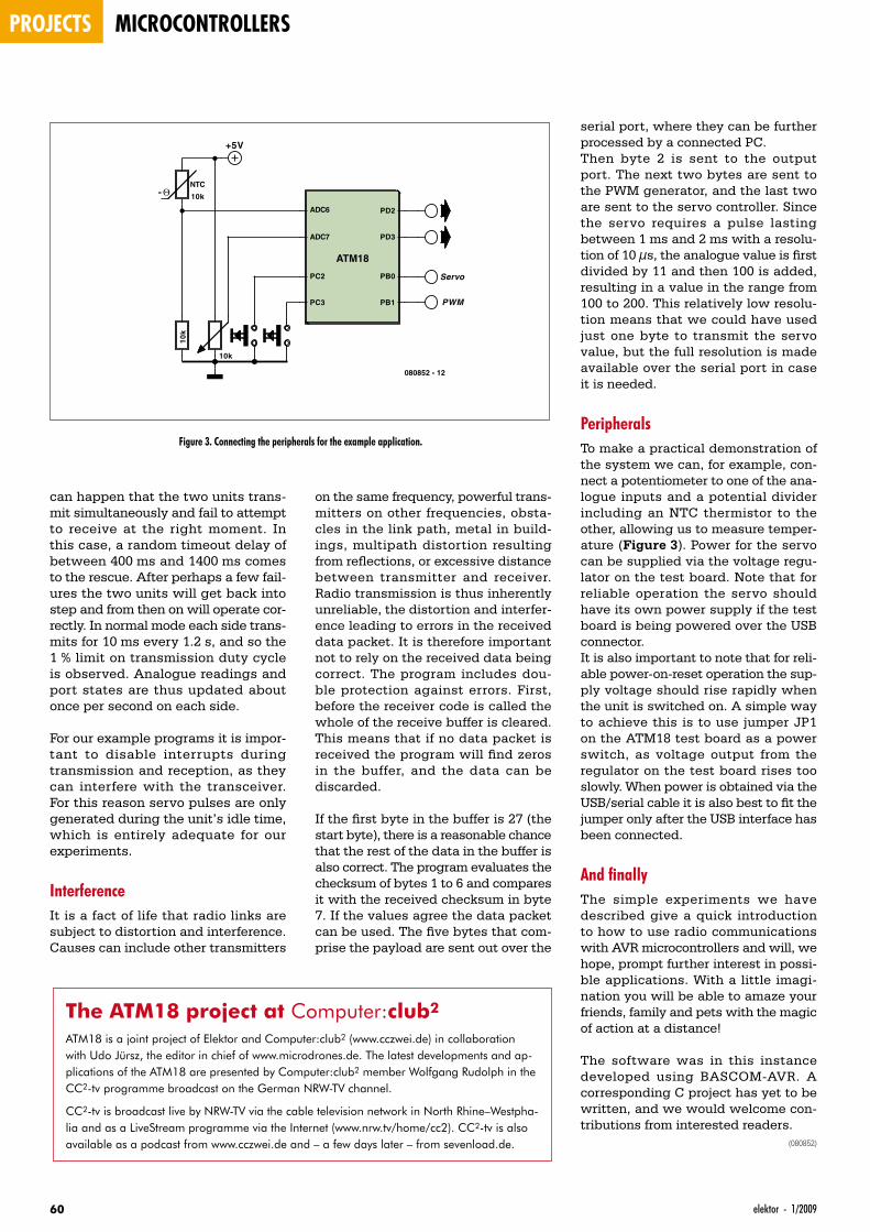
projects microcontrollers
60 elektor - 1/2009
can happen that the two units trans-mit simultaneously and fail to attempt to receive at the right moment. In this case, a random timeout delay of between 400 ms and 1400 ms comes to the rescue. After perhaps a few fail-ures the two units will get back into step and from then on will operate cor-rectly. In normal mode each side trans-mits for 10 ms every 1.2 s, and so the 1 % limit on transmission duty cycle is observed. Analogue readings and port states are thus updated about once per second on each side.
For our example programs it is impor-tant to disable interrupts during transmission and reception, as they can interfere with the transceiver. For this reason servo pulses are only generated during the unit’s idle time, which is entirely adequate for our experiments.
InterferenceIt is a fact of life that radio links are subject to distortion and interference. Causes can include other transmitters
serial port, where they can be further processed by a connected PC.Then byte 2 is sent to the output port. The next two bytes are sent to the PWM generator, and the last two are sent to the servo controller. Since the servo requires a pulse lasting between 1 ms and 2 ms with a resolu-tion of 10 µs, the analogue value is first divided by 11 and then 100 is added, resulting in a value in the range from 100 to 200. This relatively low resolu-tion means that we could have used just one byte to transmit the servo value, but the full resolution is made available over the serial port in case it is needed.
PeripheralsTo make a practical demonstration of the system we can, for example, con-nect a potentiometer to one of the ana-logue inputs and a potential divider including an NTC thermistor to the other, allowing us to measure temper-ature (Figure 3). Power for the servo can be supplied via the voltage regu-lator on the test board. Note that for reliable operation the servo should have its own power supply if the test board is being powered over the USB connector.It is also important to note that for reli-able power-on-reset operation the sup-ply voltage should rise rapidly when the unit is switched on. A simple way to achieve this is to use jumper JP1 on the ATM18 test board as a power switch, as voltage output from the regulator on the test board rises too slowly. When power is obtained via the USB/serial cable it is also best to fit the jumper only after the USB interface has been connected.
And finallyThe simple experiments we have described give a quick introduction to how to use radio communications with AVR microcontrollers and will, we hope, prompt further interest in possi-ble applications. With a little imagi-nation you will be able to amaze your friends, family and pets with the magic of action at a distance!
The software was in this instance developed using BASCOM-AVR. A corresponding C project has yet to be written, and we would welcome con-tributions from interested readers.
(080852)
on the same frequency, powerful trans-mitters on other frequencies, obsta-cles in the link path, metal in build-ings, multipath distortion resulting from reflections, or excessive distance between transmitter and receiver. Radio transmission is thus inherently unreliable, the distortion and interfer-ence leading to errors in the received data packet. It is therefore important not to rely on the received data being correct. The program includes dou-ble protection against errors. First, before the receiver code is called the whole of the receive buffer is cleared. This means that if no data packet is received the program will find zeros in the buffer, and the data can be discarded.
If the first byte in the buffer is 27 (the start byte), there is a reasonable chance that the rest of the data in the buffer is also correct. The program evaluates the checksum of bytes 1 to 6 and compares it with the received checksum in byte 7. If the values agree the data packet can be used. The five bytes that com-prise the payload are sent out over the
The ATM18 project at Computer:club2
ATM18 is a joint project of Elektor and Computer:club2 (www.cczwei.de) in collaboration with Udo Jürsz, the editor in chief of www.microdrones.de. The latest developments and ap-plications of the ATM18 are presented by Computer:club2 member Wolfgang Rudolph in the CC2-tv programme broadcast on the German NRW-TV channel.
CC2-tv is broadcast live by NRW-TV via the cable television network in North Rhine–Westpha-lia and as a LiveStream programme via the Internet (www.nrw.tv/home/cc2). CC2-tv is also available as a podcast from www.cczwei.de and – a few days later – from sevenload.de.
ATM18
ADC6
ADC7
PD2
PD3
PC2 PB0
PC3 PB1
NTC
10k- Θ
10k
10
k
+5V
Servo
PWM
080852 - 12
Figure 3. Connecting the peripherals for the example application.
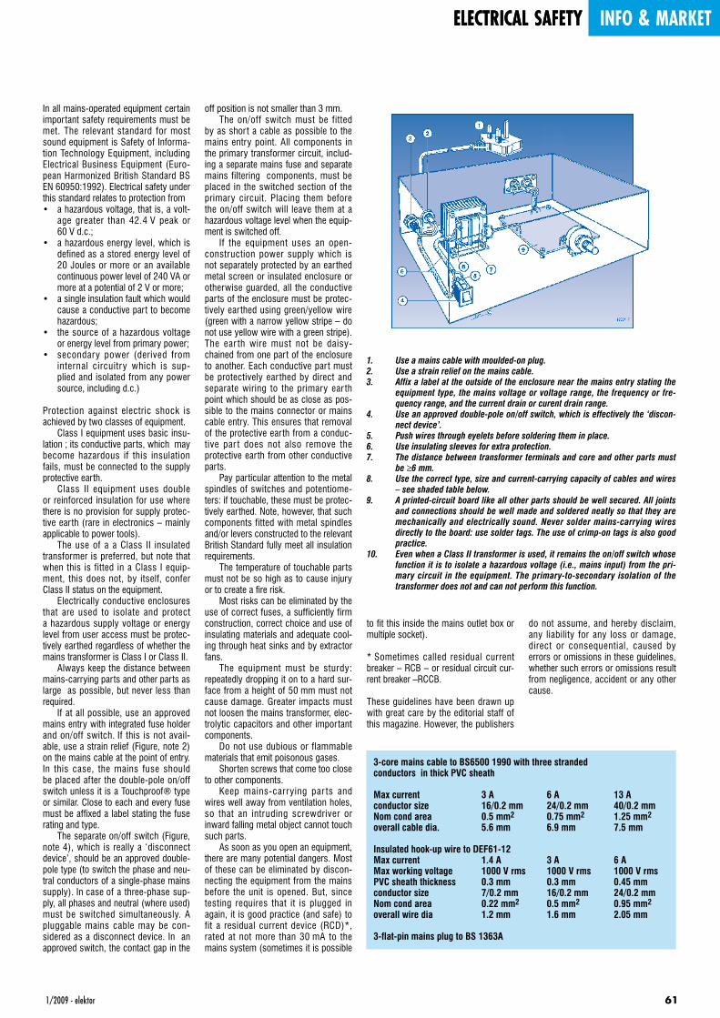
1/2009 - elektor 61
electrical safety info & market
In all mains-operated equipment certain important safety requirements must be met. The relevant standard for most sound equipment is Safety of Informa-tion Technology Equipment, including Electrical Business Equipment (Euro-pean Harmonized British Standard BS EN 60950:1992). Electrical safety under this standard relates to protection from• a hazardous voltage, that is, a volt-
age greater than 42.4 V peak or 60 V d.c.;
• a hazardous energy level, which is defined as a stored energy level of 20 Joules or more or an available continuous power level of 240 VA or more at a potential of 2 V or more;
• a single insulation fault which would cause a conductive part to become hazardous;
• the source of a hazardous voltage or energy level from primary power;
• secondary power (derived from internal circuitry which is sup-plied and isolated from any power source, including d.c.)
Protection against electric shock is achieved by two classes of equipment. Class I equipment uses basic insu-lation ; its conductive parts, which may become hazardous if this insulation fails, must be connected to the supply protective earth. Class II equipment uses double or reinforced insulation for use where there is no provision for supply protec-tive earth (rare in electronics – mainly applicable to power tools). The use of a a Class II insulated transformer is preferred, but note that when this is fitted in a Class I equip-ment, this does not, by itself, confer Class II status on the equipment. Electrically conductive enclosures that are used to isolate and protect a hazardous supply voltage or energy level from user access must be protec-tively earthed regardless of whether the mains transformer is Class I or Class II. Always keep the distance between mains-carrying parts and other parts as large as possible, but never less than required. If at all possible, use an approved mains entry with integrated fuse holder and on/off switch. If this is not avail-able, use a strain relief (Figure, note 2) on the mains cable at the point of entry. In this case, the mains fuse should be placed after the double-pole on/off switch unless it is a Touchproof® type or similar. Close to each and every fuse must be affixed a label stating the fuse rating and type. The separate on/off switch (Figure, note 4), which is really a ‘disconnect device’, should be an approved double-pole type (to switch the phase and neu-tral conductors of a single-phase mains supply). In case of a three-phase sup-ply, all phases and neutral (where used) must be switched simultaneously. A pluggable mains cable may be con-sidered as a disconnect device. In an approved switch, the contact gap in the
off position is not smaller than 3 mm. The on/off switch must be fitted by as short a cable as possible to the mains entry point. All components in the primary transformer circuit, includ-ing a separate mains fuse and separate mains filtering components, must be placed in the switched section of the primary circuit. Placing them before the on/off switch will leave them at a hazardous voltage level when the equip-ment is switched off. If the equipment uses an open-construction power supply which is not separately protected by an earthed metal screen or insulated enclosure or otherwise guarded, all the conductive parts of the enclosure must be protec-tively ear thed using green/yellow wire (green with a narrow yellow stripe – do not use yellow wire with a green stripe). The ear th wire must not be daisy-chained from one part of the enclosure to another. Each conductive part must be protectively ear thed by direct and separate wiring to the primary ear th point which should be as close as pos-sible to the mains connector or mains cable entry. This ensures that removal of the protective earth from a conduc-tive par t does not also remove the protective earth from other conductive parts. Pay particular attention to the metal spindles of switches and potentiome-ters: if touchable, these must be protec-tively earthed. Note, however, that such components fitted with metal spindles and/or levers constructed to the relevant British Standard fully meet all insulation requirements. The temperature of touchable parts must not be so high as to cause injury or to create a fire risk. Most risks can be eliminated by the use of correct fuses, a sufficiently firm construction, correct choice and use of insulating materials and adequate cool-ing through heat sinks and by extractor fans. The equipment must be sturdy: repeatedly dropping it on to a hard sur-face from a height of 50 mm must not cause damage. Greater impacts must not loosen the mains transformer, elec-trolytic capacitors and other important components. Do not use dubious or flammable materials that emit poisonous gases. Shorten screws that come too close to other components. Keep mains-carrying par ts and wires well away from ventilation holes, so that an intruding screwdriver or inward falling metal object cannot touch such parts. As soon as you open an equipment, there are many potential dangers. Most of these can be eliminated by discon-necting the equipment from the mains before the unit is opened. But, since testing requires that it is plugged in again, it is good practice (and safe) to fit a residual current device (RCD)*, rated at not more than 30 mA to the mains system (sometimes it is possible
to fit this inside the mains outlet box or multiple socket).
* Sometimes called residual current breaker – RCB – or residual circuit cur-rent breaker –RCCB.
These guidelines have been drawn up with great care by the editorial staff of this magazine. However, the publishers
do not assume, and hereby disclaim, any liability for any loss or damage, direct or consequential, caused by errors or omissions in these guidelines, whether such errors or omissions result from negligence, accident or any other cause.
3-core mains cable to BS6500 1990 with three stranded conductors in thick PVC sheath
Max current 3 A 6 A 13 Aconductor size 16/0.2 mm 24/0.2 mm 40/0.2 mmNom cond area 0.5 mm2 0.75 mm2 1.25 mm2
overall cable dia. 5.6 mm 6.9 mm 7.5 mm
Insulated hook-up wire to DEF61-12Max current 1.4 A 3 A 6 AMax working voltage 1000 V rms 1000 V rms 1000 V rmsPVC sheath thickness 0.3 mm 0.3 mm 0.45 mmconductor size 7/0.2 mm 16/0.2 mm 24/0.2 mmNom cond area 0.22 mm2 0.5 mm2 0.95 mm2
overall wire dia 1.2 mm 1.6 mm 2.05 mm
3-flat-pin mains plug to BS 1363A
1. Useamainscablewithmoulded-onplug.2. Useastrainreliefonthemainscable.3. Affixalabelattheoutsideoftheenclosurenearthemainsentrystatingthe
equipmenttype,themainsvoltageorvoltagerange,thefrequencyorfre-quencyrange,andthecurrentdrainorcurentdrainrange.
4. Useanapproveddouble-poleon/offswitch,whichiseffectivelythe‘discon-nectdevice’.
5. Pushwiresthrougheyeletsbeforesolderingtheminplace.6. Useinsulatingsleevesforextraprotection.7. Thedistancebetweentransformerterminalsandcoreandotherpartsmust
be≥6mm.8. Usethecorrecttype,sizeandcurrent-carryingcapacityofcablesandwires
–seeshadedtablebelow.9. Aprinted-circuitboardlikeallotherpartsshouldbewellsecured.Alljoints
andconnectionsshouldbewellmadeandsolderedneatlysothattheyaremechanicallyandelectricallysound.Neversoldermains-carryingwiresdirectlytotheboard:usesoldertags.Theuseofcrimp-ontagsisalsogoodpractice.
10. EvenwhenaClassIItransformerisused,itremainstheon/offswitchwhosefunctionitistoisolateahazardousvoltage(i.e.,mainsinput)fromthepri-marycircuitintheequipment.Theprimary-to-secondaryisolationofthetransformerdoesnotandcannotperformthisfunction.
electrical safety info & market

technology capsense
62 elektor - 1/2009
Capacitive Sensing and the Water CoolerNo more bashing the soda vending machineDave Van Ess (Cypress Applications Engineer and Member of Technical Staff) (USA)
The aim of this article is to illustrate not only how capacitive sensing can make devices more reliable, but also how the controller managing capacitive sensing can take on additional functions, to add further value to customers, as well as reduce maintenance expenses. To put it all in practice, Elektor has two CapSense evaluation kits on offer for you.
When using mechanical spigots, a potentially huge problem, is that they can be forced on, or even broken off, causing all the water to be dispensed. It is also easy for a user to override a push button taping it ‘pressed on’ or by jamming some object into its housing to force it continuously on. Mechanical switches do wear out and also pen-etrate their product’s case, allowing contamination into crevasses or cran-nies. The advantage of choosing a capacitive sensor is they do not wear out. The sensor does not penetrate the case, so the crevasses remain clean. This makes them the ideal switch for a product that dispenses food, bever-ages or food grade products.All that is needed to make a capacitive sensor is a trace, a space, and a trace. These traces can be made part of a cir-cuit board with an insulated overlay
placed directly over them. They can be made to conform to a curved surface.To construct the capacitive switch you will need:• a capacitor;• capacitance measuring circuitry;• local intelligence to translate this capacitance values to a sense state.
Basic elements and parametersLet’s look at Figure 1. A typical capaci-tive sensor has a value of 10 to 30 pF. Typical finger coupling capacitance to the sensor through 1 mm of insulating overlay is in the range of 1 to 2 pF. For thicker overlays the coupling capaci-tance decreases. To sense the pres-ence or absence of a finger, it is neces-sary to implement capacitance-sensing circuitry that can resolve better than 1 part in a 100 capacitance change.
Elektor Reader OfferCapSense Evaluation kits
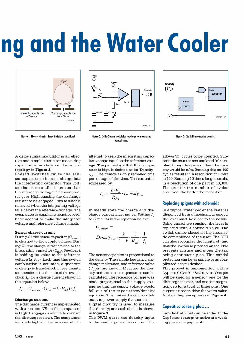
631/2009 - elektor
Capacitive Sensing and the Water Cooler
A delta-sigma modulator is an effec-tive and simple circuit for measuring capacitance, as shown in the typical topology in Figure 2.Phased switches cause the sen-sor capacitor to inject a charge into the integrating capacitor. This volt-age increases until it is greater than the reference voltage. The compara-tor goes High causing the discharge resistor to be engaged. This resistor is removed when the integrating voltage falls below the reference voltage. The comparator is supplying negative feed-back needed to make the integrator voltage and reference voltage match.
Sensor charge currentDuring Φ1 the sense capacitor (Csensor) is charged to the supply voltage. Dur-ing Φ2 the charge is transferred to the integrating capacitor (Cint). Feedback is holding its value to the reference voltage (k·Vdd). Each time this switch combination is actuated, a quantum of charge is transferred. These quanta are transferred at the rate of the switch clock (fc) for a charge current shown in the equation below.
I C V k V fc sensor dd dd c= ⋅ − ⋅ ⋅( )
Discharge currentThe discharge current is implemented with a resistor. When the comparator is High it engages a switch to connect the discharge resistor. The comparator will cycle high and low in some ratio to
attempt to keep the integrating capac-itor voltage equal to the reference volt-age. The percentage that this compa-rator is high is defined as its ‘Density-Out’. The charge is only removed this percentage of the time. The current is expressed by
Ik VR
DensityDd
disout=
⋅⋅
In steady state the charge and dis-charge current must match. Setting IC to ID results in the equation below:
C
Densityk
k R f
sensor
outdis s
=
⋅−
⋅ ⋅1
1 1
The sensor capacitor is proportional to the density. The sample frequency, dis-charge resistance, and reference value (Vdd·k) are known. Measure the den-sity and the sensor capacitance can be calculated. The reference voltage was made proportional to the supply volt-age, so that the supply voltage would fall out of the capacitance/density equation. This makes the circuitry tol-erant to power supply fluctuations.Digital circuitry is used to measure this density; one such circuit is shown in Figure 3.The PWM gates the density input to the enable gate of a counter. This
allows ‘m’ cycles to be counted. Sup-pose the counter accumulated ‘n’ sam-ples during this period, then the den-sity would be n/m. Running this for 100 cycles results in a resolution of 1 part in 100. Running 10 times longer results in a resolution of one part in 10,000. The greater the number of cycles observed, the better the resolution.
Replacing spigots with solenoidsIn a typical water cooler the water is dispensed from a mechanical spigot, the level must be close to the nozzle. Using capacitive sensing, the lever is replaced with a solenoid valve. The switch can be placed for the ergomet-ric convenience of the user. The CPU can also recognize the length of time that the switch is pressed on for. This prevents misuse and stops the tap being continuously on. This vandal protection can be as simple or as com-plicated as you desired.This project is implemented with a Cypress CY24x94 PSoC device. One pin will be used for a sensor, one for the discharge resistor, and one for integra-tion cap for a total of three pins. One output is used to drive the water value. A block diagram appears in Figure 4.
Capacitive sensing plus….Let’s look at what can be added to the CapSense concept to arrive at a work-ing piece of equipment.
Finger
Coupling Capacitancefrom Finger
080875 - 11
Inherent Capacitanceof Sensor
Figure 1. The very basics: three invisible capacitors!
Csensor Cint
Rdis
VDD
k•VDD
fs
080875 - 12
Densityfcφ1
φ2
Figure 2. Delta-Sigma modulator topology for measuring capacitance.
fs080875 - 13
Density
PWM
Counter
Gate
m
Figure 3. Digitally measuring density.
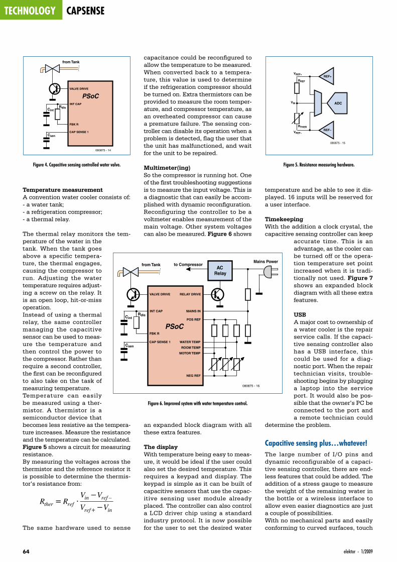
technology capsense
64 elektor - 1/2009
Temperature measurementA convention water cooler consists of:- a water tank;- a refrigeration compressor;- a thermal relay.
The thermal relay monitors the tem-perature of the water in the tank. When the tank goes above a specific tempera-ture, the thermal engages, causing the compressor to run. Adjusting the water temperature requires adjust-ing a screw on the relay. It is an open loop, hit-or-miss operation.Instead of using a thermal relay, the same controller managing the capacitive sensor can be used to meas-ure the temperature and then control the power to the compressor. Rather than require a second controller, the first can be reconfigured to also take on the task of measuring temperature.Temperature can easily be measured using a ther-mistor. A thermistor is a semiconductor device that becomes less resistive as the tempera-ture increases. Measure the resistance and the temperature can be calculated. Figure 5 shows a circuit for measuring resistance.By measuring the voltages across the thermistor and the reference resistor it is possible to determine the thermis-tor’s resistance from:
R RV VV Vther ref
in ref
ref in= ⋅
−
−+
–
The same hardware used to sense
temperature and be able to see it dis-played. 16 inputs will be reserved for a user interface.
TimekeepingWith the addition a clock crystal, the capacitive sensing controller can keep
accurate time. This is an advantage, as the cooler can be turned off or the opera-tion temperature set point increased when it is tradi-tionally not used. Figure 7 shows an expanded block diagram with all these extra features.
USBA major cost to ownership of a water cooler is the repair service calls. If the capaci-tive sensing controller also has a USB interface, this could be used for a diag-nostic port. When the repair technician visits, trouble-shooting begins by plugging a laptop into the service port. It would also be pos-sible that the owner’s PC be connected to the port and a remote technician could
determine the problem.
Capacitive sensing plus…whatever!The large number of I/O pins and dynamic reconfigurable of a capaci-tive sensing controller, there are end-less features that could be added. The addition of a stress gauge to measure the weight of the remaining water in the bottle or a wireless interface to allow even easier diagnostics are just a couple of possibilities.With no mechanical parts and easily conforming to curved surfaces, touch
capacitance could be reconfigured to allow the temperature to be measured. When converted back to a tempera-ture, this value is used to determine if the refrigeration compressor should be turned on. Extra thermistors can be provided to measure the room temper-ature, and compressor temperature, as an overheated compressor can cause a premature failure. The sensing con-troller can disable its operation when a problem is detected, flag the user that the unit has malfunctioned, and wait for the unit to be repaired.
Multimeter(ing)So the compressor is running hot. One of the first troubleshooting suggestions is to measure the input voltage. This is a diagnostic that can easily be accom-plished with dynamic reconfiguration. Reconfiguring the controller to be a voltmeter enables measurement of the main voltage. Other system voltages can also be measured. Figure 6 shows
an expanded block diagram with all these extra features.
The displayWith temperature being easy to meas-ure, it would be ideal if the user could also set the desired temperature. This requires a keypad and display. The keypad is simple as it can be built of capacitive sensors that use the capac-itive sensing user module already placed. The controller can also control a LCD driver chip using a standard industry protocol. It is now possible for the user to set the desired water
RdisCint
Csen
VALVE DRIVE
CAP SENSE 1
INT CAP
FBK R
PSoC
from Tank
080875 - 14
Figure 4. Capacitive sensing controlled water valve.
080875 - 15
REF+RREF
VREF+
VREF-
VIN
RTHERREF–
ADC
Figure 5. Resistance measuring hardware.
RdisCint
Csen
VALVE DRIVE RELAY DRIVE
CAP SENSE 1 WATER TEMP
MOTOR TEMP
ROOM TEMP
MAINS ININT CAP
POS REF
NEG REF
FBK R
PSoC
ACRelay
to CompressorMains Power
from Tank
080875 - 16
Figure 6. Improved system with water temperature control.
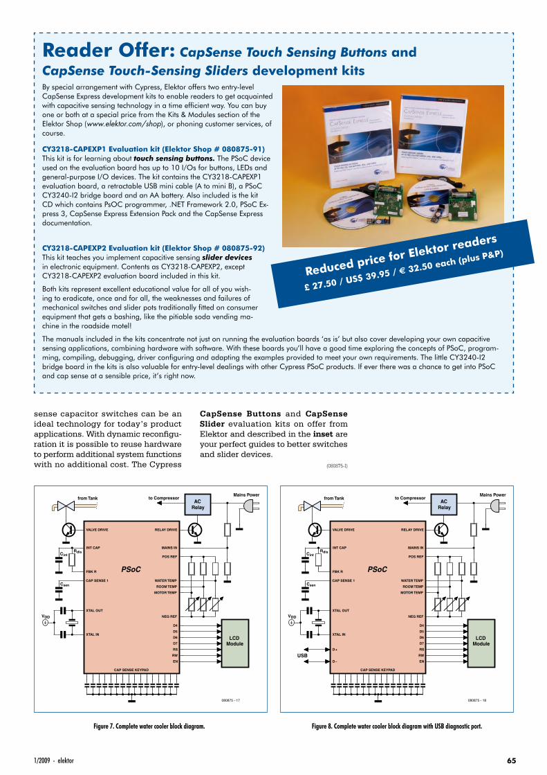
651/2009 - elektor
CapSense Buttons and CapSense Slider evaluation kits on offer from Elektor and described in the inset are your perfect guides to better switches and slider devices.
(080875-I)
sense capacitor switches can be an ideal technology for today’s product applications. With dynamic reconfigu-ration it is possible to reuse hardware to perform additional system functions with no additional cost. The Cypress
Reader Offer: CapSense Touch Sensing Buttons and CapSense Touch-Sensing Sliders development kitsBy special arrangement with Cypress, Elektor offers two entry-level CapSense Express development kits to enable readers to get acquainted with capacitive sensing technology in a time efficient way. You can buy one or both at a special price from the Kits & Modules section of the Elektor Shop (www.elektor.com/shop), or phoning customer services, of course.
CY3218-CAPEXP1 Evaluation kit (Elektor Shop # 080875-91)This kit is for learning about touch sensing buttons. The PSoC device used on the evaluation board has up to 10 I/Os for buttons, LEDs and general-purpose I/O devices. The kit contains the CY3218-CAPEXP1 evaluation board, a retractable USB mini cable (A to mini B), a PSoC CY3240-I2 bridge board and an AA battery. Also included is the kit CD which contains PsOC programmer, .NET Framework 2.0, PSoC Ex-press 3, CapSense Express Extension Pack and the CapSense Express documentation.
CY3218-CAPEXP2 Evaluation kit (Elektor Shop # 080875-92)This kit teaches you implement capacitive sensing slider devices in electronic equipment. Contents as CY3218-CAPEXP2, except CY3218-CAPEXP2 evaluation board included in this kit.
Both kits represent excellent educational value for all of you wish-ing to eradicate, once and for all, the weaknesses and failures of mechanical switches and slider pots traditionally fitted on consumer equipment that gets a bashing, like the pitiable soda vending ma-chine in the roadside motel!
The manuals included in the kits concentrate not just on running the evaluation boards ‘as is’ but also cover developing your own capacitive sensing applications, combining hardware with software. With these boards you’ll have a good time exploring the concepts of PSoC, program-ming, compiling, debugging, driver configuring and adapting the examples provided to meet your own requirements. The little CY3240-I2 bridge board in the kits is also valuable for entry-level dealings with other Cypress PSoC products. If ever there was a chance to get into PSoC and cap sense at a sensible price, it’s right now.
Reduced price for Elektor readers
£ 27.50 / US$ 39.95 / € 32.50 each (plus P&P)
RdisCint
Csen
CAP SENSE KEYPAD
VALVE DRIVE RELAY DRIVE
CAP SENSE 1 WATER TEMP
MOTOR TEMP
ROOM TEMP
MAINS IN
XTAL OUT
INT CAP
POS REF
NEG REF
XTAL IN
FBK R PSoC
D4
D5
D6
D7
RS
RW
EN
VDD
ACRelay
to CompressorMains Power
from Tank
ModuleLCD
080875 - 17
Figure 7. Complete water cooler block diagram. Figure 8. Complete water cooler block diagram with USB diagnostic port.
RdisCint
Csen
CAP SENSE KEYPAD
VALVE DRIVE RELAY DRIVE
CAP SENSE 1 WATER TEMP
MOTOR TEMP
ROOM TEMP
MAINS IN
XTAL OUT
INT CAP
POS REF
NEG REF
XTAL IN
FBK R PSoC
D4
D5
D6
D7
RS
RW
END –
D+
VDD
ACRelay
to CompressorMains Power
from Tank
ModuleLCD
USB
080875 - 18
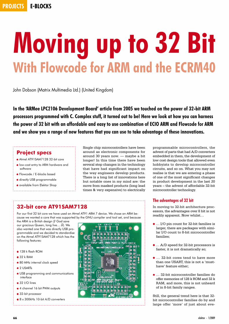
projects e-blocks
66 elektor - 1/2009
Moving up to 32 BitWith Flowcode for ARM and the ECRM40John Dobson (Matrix Multimedia Ltd.) (United Kingdom)
In the ‘ARMee LPC2106 Development Board’ article from 2005 we touched on the power of 32-bit ARM processors programmed with C. Complex stuff, it turned out to be! Here we look at how you can harness the power of 32 bit with an affordable and easy to use combination of ECIO ARM and Flowcode for ARM and we show you a range of new features that you can use to take advantage of these innovations.
Single chip microcontrollers have been around as electronic components for around 30 years now. — maybe a bit longer! In this time there have been several step changes in the technology that have had significant impact on the way engineers develop products. There is a long list of innovations here but notable ones in my mind are: the move from masked products (long lead times & very expensive) to electrically
programmable microcontrollers, the advent of parts that had A/D converters embedded in them, the development of low cost design tools that allowed even hobbyists to develop microcontroller circuits, and so on. What you may not realise is that we are entering a phase of one of the most significant changes in product development in the last 20 years – the advent of affordable 32-bit microcontroller technology.
The advantages of 32 bitIn moving to 32-bit architecture proc-essors, the advantages over 8 bit is not readily apparent. Now whilst…
• … I/O pin count for 32-bit families is larger, there are packages with simi-lar I/O count to 8-bit microcontroller families;
• … A/D speed for 32-bit processors is faster, it is not dramatically so;
• … 32-bit cores tend to have more than one USART, this is not a ‘must-have’ feature either;
• … 32-bit microcontroller families do offer memories of 128 k ROM and 32 k RAM, and more, this is not unheard of in 8-bit family ranges.
Still, the general trend here is that 32-bit microcontroller families do by and large offer ‘more’ of just about eve-
32-bit core AT91SAM7128For our first 32 bit core we have used an Atmel AT91 ARM 7 device. We chose an ARM be-cause we wanted a core that was supported by the GNU compiler and tool set, and because the ARM is a British design (s God save our gracious Queen, long live… r). We also wanted one that was directly USB pro-grammable and we decided to standardise on the Atmel AT91SAM7128 which has the following features:
• 128 k flash ROM
• 32 k RAM
• 80 MHz internal clock speed
• 2 USARTs
• USB programming and communications interface
• 32 I/O lines
• 4 channel 16 bit PWM outputs
• 32-bit processor
• 8 x 300kHz 10-bit A/D converters
Project specs• Atmel AT91SAM7128 32-bit core
• low-cost entry to ARM hardware and software
• Flowcode / E-blocks based
• directly USB programmable
• available from Elektor Shop
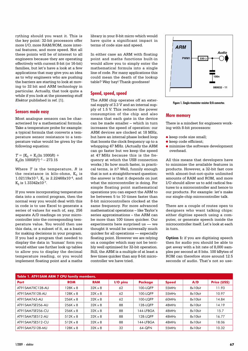
671/2009 - elektor
rything should you want it. This is the key point: 32-bit processors offer more I/O, more RAM/ROM, more inter-nal features, and more speed. Not all these points will be of interest to all engineers because they are operating effectively with current 8-bit (or 16-bit) families, but let’s have a look at a few applications that may give you an idea as to why engineers who are pushing the barriers are starting to look at mov-ing to 32 bit and ARM technology in particular. Actually, that took quite a while if you look at the pioneering stuff Elektor published in ref. [1].
Sensors made easyMost analogue sensors can be char-acterised by a mathematical formula. Take a temperature probe for example: a typical formula that converts a tem-perature sensor resistance to a tem-perature value would be given by the following equation:
T = [K0 + K1(ln 1000R) + K2(ln 1000R)3]–1 – 273.15
Where T is the temperature, R is the resistance in kilo-ohms, K0 is 1.02119x10⁻³, K1 is 2.22468x10⁻⁴, and K2 is 1.33342x10⁻⁷.
If you were incorporating temperature data into a control program, then the normal way you would deal with this in code is to use Excel to generate a series of values for each of, say, 256 separate A/D readings on your micro-controller into the corresponding tem-perature value. You would then use this data, or a subset of it, as a basis for making decisions in your program. If you had a program that needed to display the data in ‘human’ form you would either use further look up tables to allow you to display the decimal temperature reading, or you would implement floating point and a maths
library in your 8-bit micro which would have quite a significant impact in terms of code size and speed.
In either case an ARM with floating point and maths functions built-in would allow you to simply enter the mathematical formula into a single line of code. For many applications this could mean the death of the lookup table? Way hay! Thank goodness!
Speed, speed, speedThe ARM chip operates off an exter-nal supply of 3.3 V and an internal sup-ply of 1.5 V. This reduces the power consumption of the chip and also means that each gate in the device can be made smaller – which in turn increases the speed of operation: our ARM devices are clocked at 18 MHz, but have an internal phase locked loop that boosts the clock frequency up to a whopping 47 MHz. (Actually the ARM can go faster but we keep the speed at 47 MHz because this is the fre-quency at which the USB connection works.) So how much faster, in practi-cal terms, is it? Well, funnily enough that is not a straightforward question: the answer is that it depends on just what the microcontroller is doing. For simple floating point mathematical operations you can expect the ARM to be between 5 to 10 times faster than 8-bit microcontrollers clocked at the same frequency. For more advanced mathematical operations – like Taylor’s series approximations – the ARM can be more than 100 times quicker. Our experiments here surprised us — we thought it would be universally much quicker for all operations — especially floating point. However we are relying on a compiler which may not be terri-bly well optimised for 32-bit operation. Still, the ARM is a multiple of at least a few times quicker than any 8-bit micro-controller we have tried.
More memoryThere is a mindset for engineers work-ing with 8-bit processors:
• keep code size small;• keep code efficient;• minimise the software development
overhead.
All this means that developers have to minimise the available features in products. However, a 32-bit fast core with almost-but-not-quite unlimited amounts of RAM and ROM, and more I/O should allow us to add radical fea-tures to a microcontroller and hence to our products. For example: let’s make our single-chip microcontroller talk.
There are a couple of routes open to designers who want talking chips: either digitise speech using a com-puter, or generate speech inside the microcontroller itself. Let’s look at each in turn.
Option 1: if you are digitising speech then for audio you should be able to get away with a bit rate of 8,000 sam-ples per second at 8 bits. 100 kBytes of ROM can therefore store around 12.5 seconds of audio. That’s not so use-
Table 1. AT91SAM ARM 7 CPU family members.
Part ROM RAM I/O pins Package Speed A/D Price (US$)
AT91SAM7XC128-AU 128K x 8 32K x 8 62 100-LQFP 55MHz 8x10bit 11.93
AT91SAM7X128-AU 128K x 8 32K x 8 62 100-LQFP 55MHz 8x10bit 10.97
AT91SAM7A3-AU 256K x 8 32K x 8 62 100-LQFP 60MHz 8x10bit 14.84
AT91SAM7SE256-AU 256K x 8 32K x 8 88 128-LQFP 48MHz 8x10bit 14.19
AT91SAM7SE256-CU 256K x 8 32K x 8 88 144-LFBGA 48MHz 8x10bit 15.7
AT91SAM7SE512-AU 512K x 8 32K x 8 88 128-LQFP 48MHz 8x10bit 16.77
AT91SAM7SE512-CU 512K x 8 32K x 8 88 144-LFBGA 48MHz 8x10bit 18.06
AT91SAM7S128-MU 128K x 8 32K x 8 32 64-QFN 55MHz 8x10bit 10.32
330 Ω
100n
Audio
PWM1
ARM
080632 - 11
Figure 1. Single-transistor resistor D/A converter.
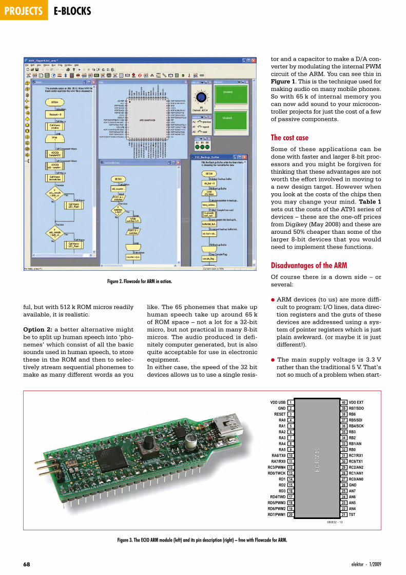
projects e-blocks
68 elektor - 1/2009
ful, but with 512 k ROM micros readily available, it is realistic.
Option 2: a better alternative might be to split up human speech into ‘pho-nemes’ which consist of all the basic sounds used in human speech, to store these in the ROM and then to selec-tively stream sequential phonemes to make as many different words as you
tor and a capacitor to make a D/A con-verter by modulating the internal PWM circuit of the ARM. You can see this in Figure 1. This is the technique used for making audio on many mobile phones. So with 65 k of internal memory you can now add sound to your microcon-troller projects for just the cost of a few of passive components.
The cost caseSome of these applications can be done with faster and larger 8-bit proc-essors and you might be forgiven for thinking that these advantages are not worth the effort involved in moving to a new design target. However when you look at the costs of the chips then you may change your mind. Table 1 sets out the costs of the AT91 series of devices – these are the one-off prices from Digikey (May 2008) and these are around 50% cheaper than some of the larger 8-bit devices that you would need to implement these functions.
Disadvantages of the ARMOf course there is a down side – or several:
• ARM devices (to us) are more diffi-cult to program: I/O lines, data direc-tion registers and the guts of these devices are addressed using a sys-tem of pointer registers which is just plain awkward. (or maybe it is just different!).
• The main supply voltage is 3.3 V rather than the traditional 5 V. That’s not so much of a problem when start-
like. The 65 phonemes that make up human speech take up around 65 k of ROM space – not a lot for a 32-bit micro, but not practical in many 8-bit micros. The audio produced is defi-nitely computer generated, but is also quite acceptable for use in electronic equipment.In either case, the speed of the 32 bit devices allows us to use a single resis-
Figure 2. Flowcode for ARM in action.
Figure 3. The ECIO ARM module (left) and its pin description (right) – free with Flowcode for ARM.
1VDD USB2GND3RESET4RA05RA16RA27RA38RA4
ECRM
409RA510RA6/TX011RA7/RX012RC3/PWM413RD0/TWCK14RD115RD216RD317RD4/TWD18RD5/PWM319RD6/PWM220RD7/PWM1
40 VDD EXT39 RB7/SDO38 RB637 RB5/SDI36 RB4/SCK35 RB334 RB233 RB1/AN32 RB031 RC7/RX130 RC6/TX129 RC2/AN228 RC1/AN127 RC0/AN026 GND25 AN724 AN623 AN522 AN421 TST
080632 - 13
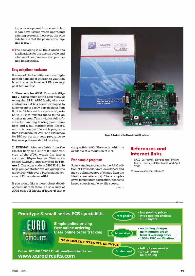
691/2009 - elektor
ing a development from scratch but it can have issues when upgrading existing systems. (however, the plus side here is that the power consump-tion is low).
• The packaging is all SMD which has implications for the design cycle and – for small companies – also produc-tion implications.
Easy adoption: hardwareIf some of the benefi ts we have high-lighted here are of interest to you then how do you get involved? We can sug-gest two routes!
1. Flowcode for ARM. Flowcode (Fig-ure 2) takes much of the pain away of using the AT91 ARM family of micro-controllers – it has been developed to allow users to easily port designs from 8 bit to 32 bits with a system of ports (A to E) that mirrors those found on smaller micros. This includes full soft-ware for handling fl oating point num-bers and a full mathematics library, and it is compatible with programs from Flowcode for AVR and Flowcode for PIC so porting your programs to this new platform should be easy.
2. ECRM40. Also available from the Elektor Shop is a 40-pin 0.6-inch ver-sion of the AT91 which fits into a standard 40-pin header. This one’s called ECRM40 and pictured in Fig-ure 3. The order code is 080632-91. To help you get started we are giving this away free with every Professional ver-sion of Flowcode for ARM.
If you would like a more robust devel-opment kit then there is also a suite of ARM based E-blocks (Figure 4) that’s
compatible with Flowcode which is available at a reduction of 30%.
Free sample programsSome sample programs for the ARM edi-tion of Flowcode were developed and may be obtained free of charge from the Elektor website at [2]. The examples cover temperature calculation, phoneme based speech and ‘wav’ fi le speech.
(080632-I)
References and Internet links[1] LPC210x ‘ARMee’ Development System
(parts 1 and 2), Elektor March and April 2005.
[2] www.elektor.com/080632
Figure 4. Contents of the Flowcode for ARM package.
Advertisement
- low pooling prices - wide pooling choices- 1 – 8 layers
- full options service- 1 - 16 layers - UL marking
- no tooling charges- no minimum order - from 3 working days- 100% DRC verification
All services
NEW ONLINE STENCIL SERVICE
Order pooling
On demand
Prototype & small series PCB specialists
www.eurocircuits.comCall us: 020 8816 7005 Email: [email protected]
Simple online pricingFast online orderingClear online order tracking
UK0901_66_69_080632-UK E-blocks.69 69 28-11-2008 14:09:22
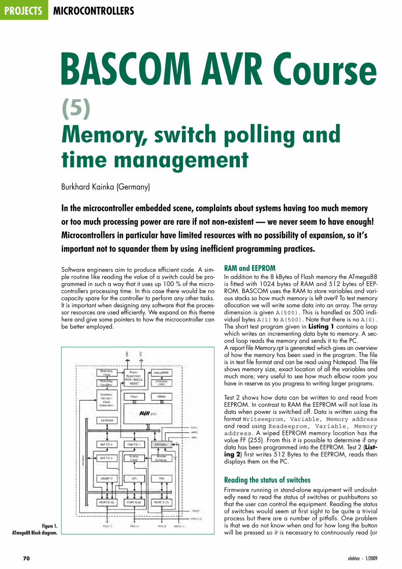
projects microcontrollers
70 elektor - 1/2009
Software engineers aim to produce efficient code. A sim-ple routine like reading the value of a switch could be pro-grammed in such a way that it uses up 100 % of the micro-controllers processing time. In this case there would be no capacity spare for the controller to perform any other tasks. It is important when designing any software that the proces-sor resources are used efficiently. We expand on this theme here and give some pointers to how the microcontroller can be better employed.
BASCOM AVR Course Memory, switch polling and time managementBurkhard Kainka (Germany)
In the microcontroller embedded scene, complaints about systems having too much memory or too much processing power are rare if not non-existent — we never seem to have enough! Microcontrollers in particular have limited resources with no possibility of expansion, so it’s important not to squander them by using inefficient programming practices.
RAM and EEPROMIn addition to the 8 kBytes of Flash memory the ATmega88 is fitted with 1024 bytes of RAM and 512 bytes of EEP-ROM. BASCOM uses the RAM to store variables and vari-ous stacks so how much memory is left over? To test memory allocation we will write some data into an array. The array dimension is given A(500). This is handled as 500 indi-vidual bytes A(1) to A(500). Note that there is no A(0). The short test program given in Listing 1 contains a loop which writes an incrementing data byte to memory. A sec-ond loop reads the memory and sends it to the PC.A report file Memory.rpt is generated which gives an overview of how the memory has been used in the program. The file is in text file format and can be read using Notepad. The file shows memory size, exact location of all the variables and much more; very useful to see how much elbow room you have in reserve as you progress to writing larger programs.
Test 2 shows how data can be written to and read from EEPROM. In contrast to RAM the EEPROM will not lose its data when power is switched off. Data is written using the format Writeeeprom, Variable, Memory address and read using Readeeprom, Variable, Memory address. A wiped EEPROM memory location has the value FF (255). From this it is possible to determine if any data has been programmed into the EEPROM. Test 2 (List-ing 2) first writes 512 Bytes to the EEPROM, reads then displays them on the PC.
Reading the status of switchesFirmware running in stand-alone equipment will undoubt-edly need to read the status of switches or pushbuttons so that the user can control the equipment. Reading the status of switches would seem at first sight to be quite a trivial process but there are a number of pitfalls. One problem is that we do not know when and for how long the button will be pressed so it is necessary to continuously read (or
(5)
Figure 1. ATmega88 Block diagram.
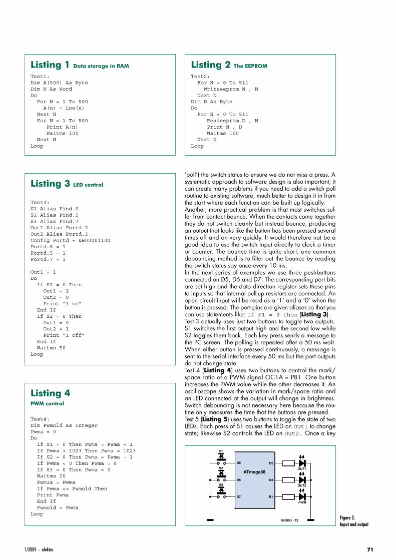
711/2009 - elektor
‘poll’) the switch status to ensure we do not miss a press. A systematic approach to software design is also important; it can create many problems if you need to add a switch poll routine to existing software, much better to design it in from the start where each function can be built up logically.Another, more practical problem is that most switches suf-fer from contact bounce. When the contacts come together they do not switch cleanly but instead bounce, producing an output that looks like the button has been pressed several times off and on very quickly. It would therefore not be a good idea to use the switch input directly to clock a timer or counter. The bounce time is quite short, one common debouncing method is to filter out the bounce by reading the switch status say once every 10 ms.In the next series of examples we use three pushbuttons connected on D5, D6 and D7. The corresponding port bits are set high and the data direction register sets these pins to inputs so that internal pull-up resistors are connected. An open circuit input will be read as a ‘1’ and a ‘0’ when the button is pressed. The port pins are given aliases so that you can use statements like: If S1 = 0 then (Listing 3).Test 3 actually uses just two buttons to toggle two outputs. S1 switches the first output high and the second low while S2 toggles them back. Each key press sends a message to the PC screen. The polling is repeated after a 50 ms wait. When either button is pressed continuously, a message is sent to the serial interface every 50 ms but the port outputs do not change state.Test 4 (Listing 4) uses two buttons to control the mark/space ratio of a PWM signal OC1A = PB1. One button increases the PWM value while the other decreases it. An oscilloscope shows the variation in mark/space ratio and an LED connected at the output will change in brightness. Switch debouncing is not necessary here because the rou-tine only measures the time that the buttons are pressed.Test 5 (Listing 5) uses two buttons to toggle the state of two LEDs. Each press of S1 causes the LED on Out1 to change state; likewise S2 controls the LED on Out2. Once a key
Listing 1 Data storage in RAM
Test1:Dim A(500) As ByteDim N As WordDo For N = 1 To 500 A(n) = Low(n) Next N For N = 1 To 500 Print A(n) Waitms 100 Next NLoop
Listing 2 The EEPROM
Test2: For N = 0 To 511 Writeeeprom N , N Next NDim D As ByteDo For N = 0 To 511 Readeeprom D , N Print N , D Waitms 100 Next NLoop
Listing 3 LED control
Test3:S1 Alias Pind.6S2 Alias Pind.5S3 Alias Pind.7Out1 Alias Portd.2Out2 Alias Portd.3Config Portd = &B00001100Portd.6 = 1Portd.5 = 1Portd.7 = 1
Out1 = 1Do If S1 = 0 Then Out1 = 1 Out2 = 0 Print “1 on” End If If S2 = 0 Then Out1 = 0 Out2 = 1 Print “1 off” End If Waitms 50Loop
ATmega88
D6
D5
D2
D3
D7 B1
S1
S2
S3
OUT1
OUT2
PWM
080853 - 12Figure 2. Input and output
Listing 4 PWM control
Test4:Dim Pwmold As IntegerPwma = 0Do If S1 = 0 Then Pwma = Pwma + 1 If Pwma > 1023 Then Pwma = 1023 If S2 = 0 Then Pwma = Pwma - 1 If Pwma < 0 Then Pwma = 0 If S3 = 0 Then Pwma = 0 Waitms 20 Pwm1a = Pwma If Pwma <> Pwmold Then Print Pwma End If Pwmold = PwmaLoop
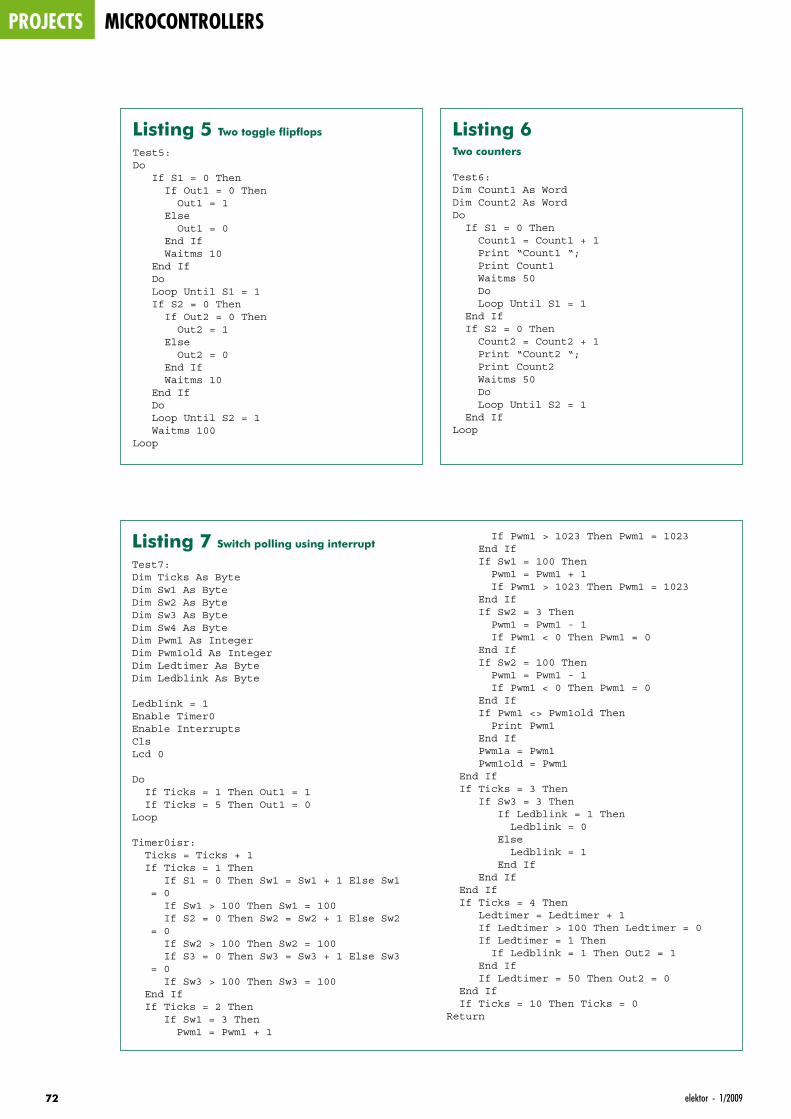
projects microcontrollers
72 elektor - 1/2009
Listing 5 Two toggle flipflops
Test5:Do If S1 = 0 Then If Out1 = 0 Then Out1 = 1 Else Out1 = 0 End If Waitms 10 End If Do Loop Until S1 = 1 If S2 = 0 Then If Out2 = 0 Then Out2 = 1 Else Out2 = 0 End If Waitms 10 End If Do Loop Until S2 = 1 Waitms 100Loop
Listing 6 Two counters
Test6:Dim Count1 As WordDim Count2 As WordDo If S1 = 0 Then Count1 = Count1 + 1 Print “Count1 “; Print Count1 Waitms 50 Do Loop Until S1 = 1 End If If S2 = 0 Then Count2 = Count2 + 1 Print “Count2 “; Print Count2 Waitms 50 Do Loop Until S2 = 1 End IfLoop
Listing 7 Switch polling using interrupt
Test7:Dim Ticks As ByteDim Sw1 As ByteDim Sw2 As ByteDim Sw3 As ByteDim Sw4 As ByteDim Pwm1 As IntegerDim Pwm1old As IntegerDim Ledtimer As ByteDim Ledblink As Byte
Ledblink = 1Enable Timer0Enable InterruptsClsLcd 0
Do If Ticks = 1 Then Out1 = 1 If Ticks = 5 Then Out1 = 0Loop
Timer0isr: Ticks = Ticks + 1 If Ticks = 1 Then If S1 = 0 Then Sw1 = Sw1 + 1 Else Sw1
= 0 If Sw1 > 100 Then Sw1 = 100 If S2 = 0 Then Sw2 = Sw2 + 1 Else Sw2
= 0 If Sw2 > 100 Then Sw2 = 100 If S3 = 0 Then Sw3 = Sw3 + 1 Else Sw3
= 0 If Sw3 > 100 Then Sw3 = 100 End If If Ticks = 2 Then If Sw1 = 3 Then Pwm1 = Pwm1 + 1
If Pwm1 > 1023 Then Pwm1 = 1023 End If If Sw1 = 100 Then Pwm1 = Pwm1 + 1 If Pwm1 > 1023 Then Pwm1 = 1023 End If If Sw2 = 3 Then Pwm1 = Pwm1 - 1 If Pwm1 < 0 Then Pwm1 = 0 End If If Sw2 = 100 Then Pwm1 = Pwm1 - 1 If Pwm1 < 0 Then Pwm1 = 0 End If If Pwm1 <> Pwm1old Then Print Pwm1 End If Pwm1a = Pwm1 Pwm1old = Pwm1 End If If Ticks = 3 Then If Sw3 = 3 Then If Ledblink = 1 Then Ledblink = 0 Else Ledblink = 1 End If End If End If If Ticks = 4 Then Ledtimer = Ledtimer + 1 If Ledtimer > 100 Then Ledtimer = 0 If Ledtimer = 1 Then If Ledblink = 1 Then Out2 = 1 End If If Ledtimer = 50 Then Out2 = 0 End If If Ticks = 10 Then Ticks = 0Return
731/2009 - elektor
press is detected the program switches the LED and loops until the switch is released. A 10 ms wait is used to fi lter any bounce otherwise the LED would change state on every edge of the switch bounce waveform, leaving the LED ran-domly on or off.The same routine can be used to increment the values of two counters (Test 6). Each time a counter value changes, its value is sent to the PC.
Switch polling using timer interruptAll of the preceding methods of switch polling do not use the processor resources effi ciently, it spends its time either waiting or reading the switch inputs. In reality there will be more switches to read and other tasks for the fi rmware to take care of. The next stage is to take a more structured approach to software design so that resources are better managed. Test 7 (Listing 7) shows one method of how this can be achieved. Switch polling occurs in the background in a timer interrupt routine. The main program is now free to take care of other tasks.For each button S1, S2 and S3 there is an associated vari-able Sw1, Sw2 and Sw3. While a button is not pressed its variable has the value zero. As long as a button is pressed the variable is incremented up to 100 where it stops. The variable indicates how long the key has been pressed, so you may for example wish to initiate some process only when its value reaches three. A long key press gives a value of 100.The timer routine uses a counter to produce short time inter-vals Ticks which is incremented each time the timer inter-
rupts (it is reset when it reaches 10). The three switches are read only once every ten Ticks (when Ticks = 1). The interval takes care of switch debouncing and occurs often enough not to miss any press.At other tick values different duties are performed. When Ticks = 2 switch counters are read and a PWM signal is generated. When Ticks = 3 the switch counter is read and Ledblink is toggled to switch a fl ashing LED. The LED output is produced when Ticks = 4. The sequential dis-tribution of tasks gives the impression that all the activities are performed simultaneously. The processor still has ample processing power in reserve for many additional tasks. The main program switches output Out1 high for fi ve ticks and low for fi ve ticks. An LED connected to this output appears slightly dim; the on/off repetition rate is so fast that you can-not see any fl ickering. The LED brightness is constant, indicat-ing that the program is maintaining a 50:50 output clock.The mark/space ratio of the PWM output is controlled by buttons Sw1 and Sw2. The software determines if there is a short button press or a long one. A short press changes the value by one, a longer press changes the counter value con-tinuously. This allows the user to quickly reach the desired value.
(080853-I)
Downloads and further informationThe programming examples and more information for this course can be downloaded from the project page at www.elektor.com. We also look forward to your feedback on the Elektor forum.
Advertisement
Further information and ordering at www.elektor.com/arm-kit
a low cost entry into ARM development
Flowcode 3 for ARM (CD-ROM) £119.00
E-blocks ARM board £89.20
E-blocks LED board £15.15
E-blocks LCD board £20.00
E-blocks Switch board £15.15
USB cable £3.70
Power supply £12.30
Total value £274.50
Special offer £162.00
Starter Kit Professional for ARM
40% DISCOUNT!Order now at
www.elektor.com/arm-kitThis bundle is perfect for low cost entry into ARM develop-ment and is great for engineers who need to develop prototypes of electronic systems quickly using the super fast ARM 7 core from Atmel. The pack is fully compatible with the range of E-block accessories. Datasheets on each individual item are available separately.
ElektorRegus Brentford1000 Great West RoadBrentford TW8 9HHUnited Kingdom Tel. +44 20 8261 4509
Free P&P!
UK0901_70_73_080853_UK_Bascom_5.73 73 28-11-2008 14:10:13
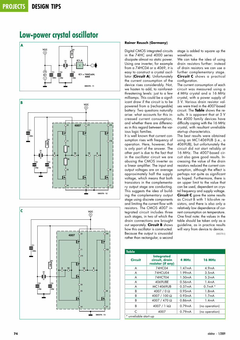
projects design tips
74 elektor - 1/2009
Low-power crystal oscillatorRainer Reusch (Germany)
Digital CMOS integrated circuits in the 74HC and 4000 series dissipate almost no static power. Using one inverter, for example from a 74HC04 or a 4069, it is easy to construct a crystal oscil-lator (Circuit A). Unfortunately the current consumption of the device rises considerably. Not, we hasten to add, to rainforest-threatening levels: just to a few milliamps. This could be a signif-icant draw if the circuit is to be powered from a (rechargeable) battery. Two questions naturally arise: what accounts for this in-creased current consumption, and whether there are differenc-es in this regard between the var-ious logic families.It is well known that current con-sumption rises with frequency of operation. Here, however, that is only part of the answer. The other part is due to the fact that in the oscillator circuit we are abusing the CMOS inverter as a linear amplifier. The input and output voltages are on average approximately half the supply voltage, which means that both transistors in the complementa-ry output stage are conducting. This suggests the idea of build-ing the complementary output stage using discrete components and limiting the current flow with resistors. The CMOS 4007 in-tegrated circuit includes three such stages, in two of which the drain connections are brought out separately. Circuit B shows how this oscillator is constructed. Because the output is sinusoidal rather than rectangular, a second
stage is added to square up the waveform.We can take the idea of using drain resistors further: instead of drain resistors we can use a further complementary stage. Circuit C shows a practical configuration.The current consumption of each circuit was measured using a 4 MHz crystal and a 16 MHz crystal, with a power supply of 5 V. Various drain resistor val-ues were tried in the 4007-based circuit. The Table shows the re-sults. It is apparent that at 5 V the 4000 family devices have difficulty coping with the 16 MHz crystal, with resultant unreliable start-up characteristics.The best results were obtained using an MC14069UB (i.e., a 4069UB), but unfortunately the circuit did not start reliably at 16 MHz. The 4007-based cir-cuit also gave good results. In-creasing the value of the drain resistors reduced the current con-sumption, although the effect is perhaps not quite as significant as hoped. Furthermore, there is an upper limit to the value that can be used, dependent on crys-tal frequency and supply voltage. Circuit C gave the same results as Circuit B with 1 kilo-ohm re-sistors, and there is also only a relatively low dependence of cur-rent consumption on temperature. One final note: the values in the table should be taken only as a guideline, as in practice results will vary from device to device.
(080378-I)
Table
CircuitIntegrated
circuit, drain resistor (if any)
4 MHz 16 MHz
A 74HC04 1.47mA 4.9mAA 74HCU04 1.99mA 3.5mAA 74HCT04 1.50mA 5.2mAA 4069UBE 0.56mA 1.4mAA MC14069UB 0.37mA 0.7mA *B 4007 / 0 Ω 0.95mA 1.8mAB 4007 / 100 Ω 0.93mA 1.7mAB 4007 / 470 Ω 0.86mA 1.4mA
B 4007 / 1 kΩ 0.79mA (no operation)
C 4007 0.79mA (no operation)* unreliable start-up
1 21
IC1.AX1
R1
10M
C3
22p
C2
22p
IC1
14
7
C1
100n
VCC
080378 - 11
IC1 = 74HCx04;4069
A
X1
R1
10M
C3
22p
C2
22p
C1
100n
VCC
080378 - 12
5
4
1
2
R
R
3 10
9
11
7
14
12
13
8
6
4007
B
X1
R1
10M
C3
22p
C2
22p
C1
100n
VCC
5
4
1
2
3 10
9
11
7
14
13
8
6
080378 - 13
12
4007
C
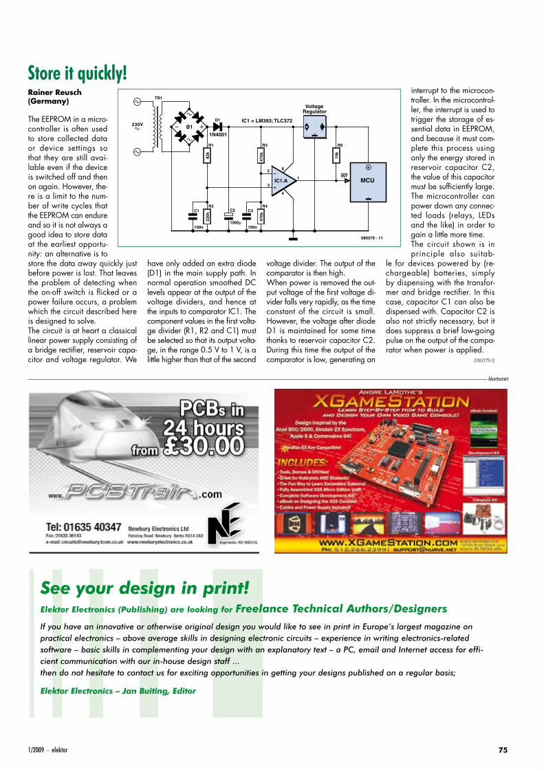
751/2009 - elektor
Store it quickly!Rainer Reusch (Germany)
The EEPROM in a micro-controller is often used to store collected data or device settings so that they are still avai-lable even if the device is switched off and then on again. However, the-re is a limit to the num-ber of write cycles that the EEPROM can endure and so it is not always a good idea to store data at the earliest opportu-nity: an alternative is to store the data away quickly just before power is lost. That leaves the problem of detecting when the on-off switch is flicked or a power failure occurs, a problem which the circuit described here is designed to solve.The circuit is at heart a classical linear power supply consisting of a bridge rectifier, reservoir capa-citor and voltage regulator. We
have only added an extra diode (D1) in the main supply path. In normal operation smoothed DC levels appear at the output of the voltage dividers, and hence at the inputs to comparator IC1. The component values in the first volta-ge divider (R1, R2 and C1) must be selected so that its output volta-ge, in the range 0.5 V to 1 V, is a little higher than that of the second
voltage divider. The output of the comparator is then high.When power is removed the out-put voltage of the first voltage di-vider falls very rapidly, as the time constant of the circuit is small. However, the voltage after diode D1 is maintained for some time thanks to reservoir capacitor C2. During this time the output of the comparator is low, generating an
interrupt to the microcon-troller. In the microcontrol-ler, the interrupt is used to trigger the storage of es-sential data in EEPROM, and because it must com-plete this process using only the energy stored in reservoir capacitor C2, the value of this capacitor must be sufficiently large. The microcontroller can power down any connec-ted loads (relays, LEDs and the like) in order to gain a little more time.The circuit shown is in principle also suitab-
le for devices powered by (re-chargeable) batteries, simply by dispensing with the transfor-mer and bridge rectifier. In this case, capacitor C1 can also be dispensed with. Capacitor C2 is also not strictly necessary, but it does suppress a brief low-going pulse on the output of the compa-rator when power is applied.
(080379-I)
B1
TR1
R1
82k
R222
0k
D1
1N4001
R3
470k
R4
470k
C1
100n
C3
100n
2
3
1IC1.A
8
4
RegulatorVoltage
R5
10k
C2
1000
MCUINT
IC1 = LM393; TLC372
080379 - 11
230V
Advertisement
See your design in print!Elektor Electronics (Publishing) are looking for Freelance Technical Authors/Designers
If you have an innovative or otherwise original design you would like to see in print in Europe’s largest magazine on practical electronics – above average skills in designing electronic circuits – experience in writing electronics-related software – basic skills in complementing your design with an explanatory text – a PC, email and Internet access for effi-cient communication with our in-house design staff ...then do not hesitate to contact us for exciting opportunities in getting your designs published on a regular basis;
Elektor Electronics – Jan Buiting, Editor

Solve Hexadoku and win!
Correct solutions received enter a prize draw for an
E-blocks Starter Kit Professional worth £249
and three Elektor SHOP Vouchers worth £40.00 each.
We believe these prizes should encourage
all our readers to participate!
The competition is not open to employees of Elektor International Media, its business partners and/or associated publishing houses.
The instructions for this puzzle are straightforward.
In the diagram composed of 16 x 16 boxes, enter numbers such that all hexadecimal numbers 0 through F (that’s 0-9 and A-F) occur once only in each row, once in each column and in each of the 4x4 boxes (marked by the thicker black lines).
PaRTiCiPaTe!Please send your solution (the numbers in the grey boxes) by email to:
[email protected] - Subject: hexadoku 01-2009 (please copy exactly).
Include with your solution: full name and street address.
Alternatively, by fax or post to: Elektor HexadokuRegus Brentford - 1000 Great West Road - Brentford TW8 9HHUnited Kingdom - Fax (+44) 208 2614447
The closing date is 1 February 2009.
Hexadoku Puzzle with an electronics touch
in the new year we cheerfully continue with our Hexadoku puzzle. we’ve stocked up and a new batch of these brain teasers should prevent boredom on a rainy day when faced with missing components, or lacking inspiration for the next groundbreaking project on the workbench. Send us your solution and enter a prize draw for an e-blocks Starter kit Professional and three elektor Shop vouchers.
PRiZe winneRSThe solution of the November 2008 Hexadoku is: FC2B6. The E-blocks Starter Kit Professional goes to: John Riches (UK).
An Elektor SHOP voucher worth £40.00 goes to: Elia Mady (UK), Marcel Haim (ISR), Ian Somers (UK).
Congratulations everybody!
A number of clues are given in the puzzle and these determine the start situation.All correct entries received for each month’s puzzle go into a draw for a main prize and three lesser prizes. All you need to do is send us the numbers in the grey boxes. The puzzle is also available as a free download from our website.
infotainment puzzle
76 elektor - 1/2009
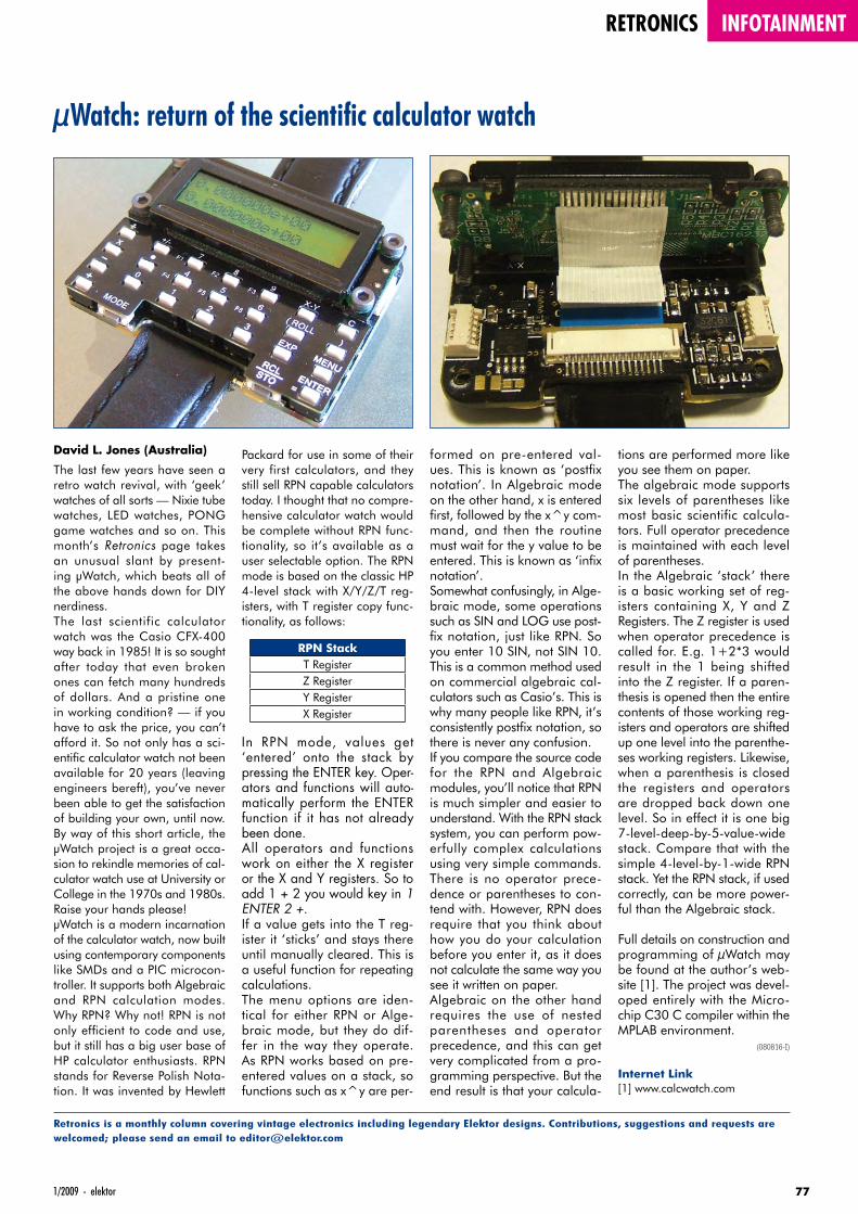
771/2009 - elektor
retronics infotainment
David L. Jones (Australia)
The last few years have seen a retro watch revival, with ‘geek’ watches of all sorts — Nixie tube watches, LED watches, PONG game watches and so on. This month’s Retronics page takes an unusual slant by present-ing µWatch, which beats all of the above hands down for DIY nerdiness.The last scientific calculator watch was the Casio CFX-400 way back in 1985! It is so sought after today that even broken ones can fetch many hundreds of dollars. And a pristine one in working condition? — if you have to ask the price, you can’t afford it. So not only has a sci-entific calculator watch not been available for 20 years (leaving engineers bereft), you’ve never been able to get the satisfaction of building your own, until now. By way of this short article, the µWatch project is a great occa-sion to rekindle memories of cal-culator watch use at University or College in the 1970s and 1980s. Raise your hands please!µWatch is a modern incarnation of the calculator watch, now built using contemporary components like SMDs and a PIC microcon-troller. It supports both Algebraic and RPN calculation modes. Why RPN? Why not! RPN is not only efficient to code and use, but it still has a big user base of HP calculator enthusiasts. RPN stands for Reverse Polish Nota-tion. It was invented by Hewlett
Packard for use in some of their very first calculators, and they still sell RPN capable calculators today. I thought that no compre-hensive calculator watch would be complete without RPN func-tionality, so it’s available as a user selectable option. The RPN mode is based on the classic HP 4-level stack with X/Y/Z/T reg-isters, with T register copy func-tionality, as follows:
RPN StackT RegisterZ RegisterY RegisterX Register
In RPN mode, values get ‘entered’ onto the stack by pressing the ENTER key. Oper-ators and functions will auto-matically perform the ENTER function if it has not already been done.All operators and functions work on either the X register or the X and Y registers. So to add 1 + 2 you would key in 1 ENTER 2 +.If a value gets into the T reg-ister it ‘sticks’ and stays there until manually cleared. This is a useful function for repeating calculations.The menu options are iden-tical for either RPN or Alge-braic mode, but they do dif-fer in the way they operate. As RPN works based on pre-entered values on a stack, so functions such as x^y are per-
µWatch: return of the scientific calculator watch
Retronics is a monthly column covering vintage electronics including legendary Elektor designs. Contributions, suggestions and requests are welcomed; please send an email to [email protected]
formed on pre-entered val-ues. This is known as ‘postfix notation’. In Algebraic mode on the other hand, x is entered first, followed by the x^y com-mand, and then the routine must wait for the y value to be entered. This is known as ‘infix notation’.Somewhat confusingly, in Alge-braic mode, some operations such as SIN and LOG use post-fix notation, just like RPN. So you enter 10 SIN, not SIN 10. This is a common method used on commercial algebraic cal-culators such as Casio’s. This is why many people like RPN, it’s consistently postfix notation, so there is never any confusion.If you compare the source code for the RPN and Algebraic modules, you’ll notice that RPN is much simpler and easier to understand. With the RPN stack system, you can perform pow-erfully complex calculations using very simple commands. There is no operator prece-dence or parentheses to con-tend with. However, RPN does require that you think about how you do your calculation before you enter it, as it does not calculate the same way you see it written on paper.Algebraic on the other hand requires the use of nested parentheses and operator precedence, and this can get very complicated from a pro-gramming perspective. But the end result is that your calcula-
tions are performed more like you see them on paper.The algebraic mode supports six levels of parentheses like most basic scientific calcula-tors. Full operator precedence is maintained with each level of parentheses.In the Algebraic ‘stack’ there is a basic working set of reg-isters containing X, Y and Z Registers. The Z register is used when operator precedence is called for. E.g. 1+2*3 would result in the 1 being shifted into the Z register. If a paren-thesis is opened then the entire contents of those working reg-isters and operators are shifted up one level into the parenthe-ses working registers. Likewise, when a parenthesis is closed the registers and operators are dropped back down one level. So in effect it is one big 7-level-deep-by-5-value-wide stack. Compare that with the simple 4-level-by-1-wide RPN stack. Yet the RPN stack, if used correctly, can be more power-ful than the Algebraic stack.
Full details on construction and programming of µWatch may be found at the author’s web-site [1]. The project was devel-oped entirely with the Micro-chip C30 C compiler within the MPLAB environment.
(080816-I)
Internet Link[1] www.calcwatch.com
78 elektor - 1/2009
E L E K T O R S H O W C A S ETo book your showcase space contact Huson International MediaTel. 0044 (0) 1932 564999 Fax 0044 (0) 1932 564998
DESIGNER SYSTEMShttp://www.designersystems.co.ukProfessional product development services.• Marine (Security, Tracking, Monitoring & control)• Automotive (AV, Tracking,
Gadget, Monitoring & control)• Industrial (Safety systems,
Monitoring over Ethernet)• Telecoms (PSTN handsets, GSM/GPRS)• AudioVisual ((HD)DVD accessories & controllers)Tel: +44 (0)1872 223306
EASYDAQwww.easydaq.biz• USB powered, 4 relays + 4 DIO channels• Will switch 240VAC @ 10 amps• Screw terminal access• LabVIEW, VB, VC• Free shipping• From £38Design & supply of USB, USB Wireless, Ethernet & Serial, DAQ, Relay & DIO card products. [email protected]
EASYSYNChttp://www.easysync.co.ukEasySync Ltd sells a wide range of single and multi-port USB to RS232/RS422 and RS485 converters at competitive prices.
ELNEC www.elnec.com • device programmer
manufacturer • selling through contracted
distributors all over the world • universal and dedicated device programmers • excellent support and after sale support • free SW updates • reliable HW• once a months new SW release • three years warranty for most programmers
YOUR ELECTRONICS OPEN SOURCE http://dev.emcelettronica.com Website full of Projects and Resources for Electronics Engineers and DIY.• Tutorial • Hardware (Schematic
& Gerber) • Firmware ( Asm & C ) • Reference Design Everyone can submit a story as a useful source! 'Share for life'
AVIT RESEARCHwww.avitresearch.co.ukUSB has never been so simple...with our USB to Microcontroller Interface cable. Appears just like a serial port to both PC and Microcontroller, for really easy USB connection to your projects, or replacement of existing RS232
interfaces. See our webpage for more details. From £10.00.
BETA LAYOUTwww.pcb-pool.comBeta layout Ltd Award-winning site in both English and German offers prototype PCBs at a fraction of the cost of the usual manufacturer’s prices.
BYVACwww.byvac.com• USB to I2C• Microcontrollers• Forth• Serial Devices
C S TECHNOLOGY LTDwww.cstech.co.ukLow cost PIC prototyping kits, PCB's and components, DTMF decoder kits, CTCSS, FFSK, GPS/GSM, radio equipment and manuals.PCB design and PIC program development.
DECIBIT CO.LTD.www.decibit.com • Development Kit 2.4 GHz• Transceiver nRF24L01• AVR MCU ATmega168
www.elektor.
com
FIRST TECHNOLOGY TRANSFER LTD.http://www.ftt.co.uk/PICProTrng.htmlMicrochip Professional C and Assembly Programming Courses.The future is embedded. Microchip Consultant / Training Partner developed courses:• Distance learning / instructor led• Assembly / C-Programming of PIC16, PIC18,
PIC24, dsPIC microcontrollers• Foundation / Intermediate
FLEXIPANEL LTDwww.flexipanel.comTEAclippers - the smallest PIC programmers in the world, from £20 each: • Per-copy firmware sales• Firmware programming & archiving• In-the-field firmware updates• Protection from design theft by subcontractors
FUTURE TECHNOLOGY DEVICEShttp://www.ftdichip.comFTDI designs and sellsUSB-UART and USB-FIFOinterface i.c.’s.Complete with PC drivers,these devices simplify the task of designing orupgrading peripherals to USB
LONDON ELECTRONICS COLLEGEhttp://www.lec.org.ukVocational training and education for national qualifications in Electronics Engineering and Information Technology (BTEC First National, Higher National NVQs, GCSEs and GCEs). Also Technical Management and Languages.
LCDMOD KIThttp://www.lcdmodkit.comWorldwide On-line retailer• Electronics components• SMT chip components• USB interface LCD• Kits & Accessories• PC modding parts• LCD modules
0901_elektor_adv_UK.indd 78 28-11-2008 14:10:40

791/2009 - elektor
MQP ELECTRONICSwww.mqp.com• Low cost USB Bus Analysers• High, Full or Low speed captures• Graphical analysis and filtering• Automatic speed detection• Bus powered from high speed PC• Capture buttons and feature connector• Optional analysis classes
OBD2CABLES.COMhttp://www.obd2cables.com• Thousands of OBD cables and connectors in
stock• Custom cable design and manufacturing• OBD breakout boxes and simulators• Guaranteed lowest prices • Single quantity orders OK• Convenient online ordering• Fast shipping Visit our website, or email us at: [email protected]
ROBOT ELECTRONICShttp://www.robot-electronics.co.ukAdvanced Sensors and Electronics for Robotics• Ultrasonic Range Finders• Compass modules• Infra-Red Thermal sensors• Motor Controllers• Vision Systems• Wireless Telemetry Links• Embedded Controllers
Elektor Electronics has a feature to help customers promote their business, Showcase - a permanent feature of the magazine where you will be able to showcase your products and services.
• For just £242 + VAT (£22 per issue for eleven issues) Elektor will publish your company name, website address and a 30-word description
• For £363 + VAT for the year (£33 per issue for eleven issues) we will publish the above plus run a 3cm deep full colour
image - e.g. a product shot, a screen shot from your site, a company logo - your choice
Places are limited and spaces will go on a strictly first come, first served basis. So-please fax back your order today!
I wish to promote my company, please book my space:• Text insertion only for £220 + VAT • Text and photo for £330 + VAT
NAME: .....................................................................................................ORGANISATION: .......................................................................................
JOB TITLE: ......................................................................................................................................................................................................................
ADDRESS: .......................................................................................................................................................................................................................
...........................................................................................................................................................................................................................................
...................................................................................................................TEL: ..............................................................................................................
PLEASE COMPLETE COUPON BELOW AND FAX BACK TO 00-44-(0)1932 564998
COMPANY NAME .........................................................................................................................................................................................................
WEB ADDRESS ..............................................................................................................................................................................................................
30-WORD DESCRIPTION .............................................................................................................................................................................................
...........................................................................................................................................................................................................................................
...........................................................................................................................................................................................................................................
...........................................................................................................................................................................................................................................
...........................................................................................................................................................................................................................................
SHOWCASE YOUR COMPANY HERE
ROBOTIQ http://www.robotiq.co.ukBuild your own Robot!Fun for the whole family!• MeccanoTM Compatible• Computer Control• Radio Control• Tank Treads• HydraulicsInternet Technical Bookshop,1-3 Fairlands House, North Street, Carshalton, Surrey SM5 2HWemail: [email protected] Tel: 020 8669 0769
RADIOMETRIXwww.radiometrix.comThe leading global developer of ISM band, low power radio modules for wireless data transmission: • Transmitters • Receivers • Transceivers • RF modems • Evaluation Kits
www.elektor.
com
p r o d u c t s a n d s e r v i c e s d i r e c t o r y
SCANTOOL.NEThttp://www.scantool.netScanTool.net offers a complete line of PC-based scan tools for under £50.• 1 year unconditional warranty• 90 day money back guarantee• For use with EOBD compliant vehicles• Fast shipping• Compatible with a wide range
of diagnostic softwareVisit our website, or email us at: [email protected]
USB INSTRUMENTShttp://www.usb-instruments.comUSB Instruments specialises in PC based instrumentation products and software such as Oscilloscopes, Data Loggers, Logic Analaysers which interface to your PC via USB.
VIRTINS TECHNOLOGYwww.virtins.comPC and Pocket PC based virtual instrument such as sound card real time oscilloscope, spectrum analyzer, signal generator, multimeter, sound meter, distortion analyzer, LCR meter. Free to download and try.
0901_elektor_adv_UK.indd 79 28-11-2008 14:10:58

80 elektor - 01/2009
SHOP BOOKS, CD-ROMS, KITS & MODULES
110 issues, more than 2,100 articles
Elektor 1990 through 1999This DVD-ROM contains the full range of 1990-1999 volumes (all 110 issues) of Elektor Elec-
tronics magazine (PDF). The more than 2,100 separate articles have been classifi ed chrono-
logically by their dates of publication (month/year), but are also listed alphabetically by topic. A
comprehensive index enables you to search the entire DVD. The DVD also contains (free of
charge) the entire ‘The Elektor Datasheet Collection 1…5’ CD-ROM series, with the original full
datasheets of semiconductors, memory ICs, microcontrollers, and much more.
ISBN 978-0-905705-76-7 • £69.00 • US $109.00
Prices and item descriptions subject to change. E. & O.E
Going StrongA world of electronics from a single shop!
Fully elaborated electronics projects
309 CircuitsThe present tenth edition of the popular
‘30x Circuits’ series of books once again
contains a comprehensive variety of cir-
cuits, sub-circuits, tips and tricks and de-
sign ideas for electronics. Among many
other inspiring topics, the following cat-
egories are well presented in this book:
test & measurement; RF (radio); com-
puters and peripherals; audio & video;
hobby and modelling; microcontrollers;
home & garden; etcetera.
432 pages • ISBN 978-0-905705-69-9 £19.95 • US $39.95
CD/D
VD-R
OMs
Limited Period Offer
for Subscribers!
£15 DISCOUNTwww.elektor.com/january
Modern technology for everyone
FPGA CourseFPGAs have established a fi rm position in
the modern electronics designer’s toolkit.
Until recently, these ‘super components’
were practically reserved for specialists in
high-tech companies. The nine lessons
on this courseware CD-ROM are a step
by step guide to the world of Field Pro-
grammable Gate Array technology. Sub-
jects covered include not just digital logic
and bus systems but also building an
FPGA webserver, a 4-channel multimeter
and a USB controller. The CD also con-
tains PCB layout files in pdf format, a
Quartus manual, project software and
various supplementary instructions.
ISBN 978-90-5381-225-9 • £14.50 • US $29.00
Bestseller!
Software Tools & Hardware Tips
Ethernet ToolboxThis CD-ROM contains all essential in-
formation regarding Ethernet interfaces!
Ethernet Toolbox includes a collection of
datasheets for dedicated Ethernet inter-
face ICs from many different manufac-
turers. It provides a wealth of information
about connectors and components for the
physical layer (PHY) and specifi c software
tools for use with the Ethernet (Software).
To help you learn about the Ethernet in-
terfaces, we have compiled a collection
of all articles on this topic that have ap-
peared in Elektor and complemented
them with additional documentation and
links to introductory articles on Ethernet
interfaces. The documents are PDF fi les.
ISBN 978-90-5381-214-3 • £19.50 • US $39.00
NEW!
ELEK UK0901 shop.indd 80 26-11-2008 22:08:18

8101/2009 - elektor
Books
More information on theElektor Website:
www.elektor.comElektor
Regus Brentford
1000 Great West Road
Brentford
TW8 9HH
United Kingdom
Tel.: +44 20 8261 4509
Fax: +44 20 8261 4447
Email: [email protected]
A DIY system made from recycled components
Design your own
Embedded Linuxcontrol centre on a PCThis book covers a do-it-your-self system
made from recycled components. The
main system described in this book re-
uses an old PC, a wireless mains outlet
with three switches and one controller,
and a USB webcam. All this is linked to-
gether by Linux. This book will serve up
the basics of setting up a Linux environ-
ment – including a software develop-
ment environment – so it can be used as
a control centre. The book will also guide
you through the necessary setup and
confi guration of a webserver, which will
be the interface to your very own home
control centre. All software needed will
be available for downloading from the
Elektor website.
234 pages • ISBN 978-0-905705-72-9£24.00 • US $48.00
Silent alarm, poetry box, night buzzer and more
PIC MicrocontrollersThis hands-on book covers a series of
exciting and fun projects with PIC micro-
controllers. You can built more than 50
projects for your own use. The clear expla-
nations, schematics, and pictures of each
project on a breadboard make this a fun
activity. The technical background infor-
mation in each project explains why the
project is set up the way it is, including the
use of datasheets. Even after you’ve built
all the projects it will still be a valuable
reference guide to keep next to your PC.
446 pages • ISBN 978-0-905705-70-5£27.95 • US $55.90
From LED to graphical LCD
Universal Display Bookfor PIC MicrocontrollersThis book begins with simple programs to
fl ash LEDs, and eventually by stages to use
other display indicators such as the 7-seg-
ment and alphanumeric liquid crystal dis-
plays. As the reader progresses through the
book, bigger and upgraded PIC chips are
introduced, with full circuit diagrams and
source code, both in assembler and C. A
tutorial is included using the MPLAB program-
ming environment, together with the PCB
design package and EAGLE schematic to
enable readers to create their own designs.
192 pages • ISBN 978-0-905705-73-6£23.00 • US $46.00
Principles and Practice
Computer VisionComputer vision is probably the most ex-
citing branch of image processing, and
the number of applications in robo tics, au-
tomation technology and quality control is
constantly increasing. Unfor tunately enter-
ing this research area is, as yet, not sim-
ple. Those who are interested must fi rst go
through a lot of books, publications and
software libraries. With this book, howev-
er, the fi rst step is easy. The theoretically
founded content is understandable and is
supplemented by many examples.
320 pages • ISBN 978-0-905705-71-2£32.00 • US $64.00
5.0, 6.0, VBA, .NET, 2005
Visual Basic for Electronics Engineering ApplicationsThis book is targeted towards those
people that want to control existing or
self-built hardware from their com-
puter. After familiarizing yourself with
Visual Basic, its development environment
and the toolset it offers are discussed in
detail. Each topic is accompanied by
clear, ready to run code, and where nec-
essary, schematics are provided that will
get your projects up to speed in no time.
476 pages • ISBN 978-0-905705-68-2£29.95 • US $59.90
Bestseller!
ELEK UK0901 shop.indd 81 26-11-2008 22:08:26
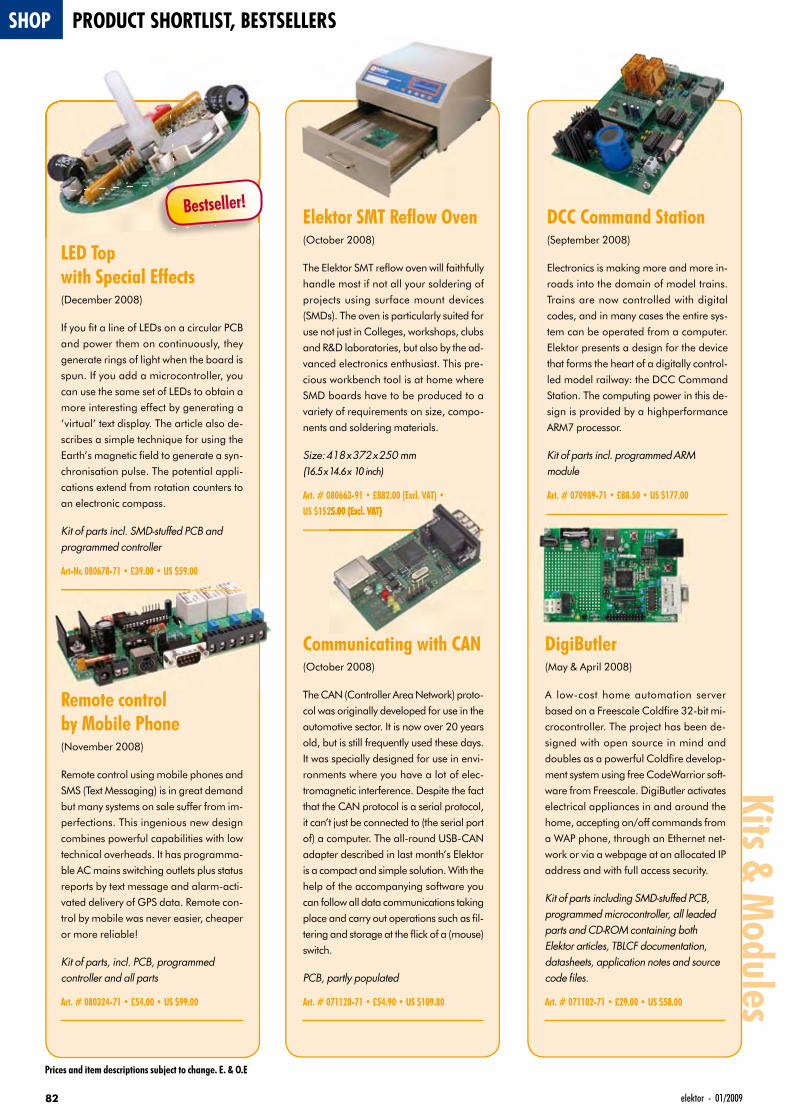
82 elektor - 01/2009
Prices and item descriptions subject to change. E. & O.E
SHOP PRODUCT SHORTLIST, BESTSELLERSKits & M
odules
LED Topwith Special Effects(December 2008)
If you fi t a line of LEDs on a circular PCB
and power them on continuously, they
generate rings of light when the board is
spun. If you add a microcontroller, you
can use the same set of LEDs to obtain a
more interesting effect by generating a
‘virtual’ text display. The article also de-
scribes a simple technique for using the
Earth’s magnetic fi eld to generate a syn-
chronisation pulse. The potential appli-
cations extend from rotation counters to
an electronic compass.
Kit of parts incl. SMD-stuffed PCB and programmed controller
Art-Nr. 080678-71 • £39.00 • US $59.00
Remote controlby Mobile Phone(November 2008)
Remote control using mobile phones and
SMS (Text Messaging) is in great demand
but many systems on sale suffer from im-
perfections. This ingenious new design
combines powerful capabilities with low
technical overheads. It has programma-
ble AC mains switching outlets plus status
reports by text message and alarm-acti-
vated delivery of GPS data. Remote con-
trol by mobile was never easier, cheaper
or more reliable!
Kit of parts, incl. PCB, programmed controller and all parts
Art. # 080324-71 • £54.00 • US $99.00
Elektor SMT Refl ow Oven(October 2008)
The Elektor SMT refl ow oven will faithfully
handle most if not all your soldering of
projects using surface mount devices
(SMDs). The oven is particularly suited for
use not just in Colleges, workshops, clubs
and R&D laboratories, but also by the ad-
vanced electronics enthusiast. This pre-
cious workbench tool is at home where
SMD boards have to be produced to a
variety of requirements on size, compo-
nents and soldering materials.
Size: 418 x 372 x 250 mm(16.5 x 14.6 x 10 inch)
Art. # 080663-91 • £882.00 (Excl. VAT) •US $1525.00 (Excl. VAT)
Communicating with CAN(October 2008)
The CAN (Controller Area Network) proto-
col was originally developed for use in the
automotive sector. It is now over 20 years
old, but is still frequently used these days.
It was specially designed for use in envi-
ronments where you have a lot of elec-
tromagnetic interference. Despite the fact
that the CAN protocol is a serial protocol,
it can’t just be connected to (the serial port
of) a computer. The all-round USB-CAN
adapter described in last month’s Elektor
is a compact and simple solution. With the
help of the accompanying software you
can follow all data communications taking
place and carry out operations such as fi l-
tering and storage at the fl ick of a (mouse)
switch.
PCB, partly populated
Art. # 071120-71 • £54.90 • US $109.80
DCC Command Station(September 2008)
Electronics is making more and more in-
roads into the domain of model trains.
Trains are now controlled with digital
codes, and in many cases the entire sys-
tem can be operated from a computer.
Elektor presents a design for the device
that forms the heart of a digitally control-
led model railway: the DCC Command
Station. The computing power in this de-
sign is provided by a highperformance
ARM7 processor.
Kit of parts incl. programmed ARM module
Art. # 070989-71 • £88.50 • US $177.00
DigiButler(May & April 2008)
A low-cost home automation server
based on a Freescale Coldfi re 32-bit mi-
crocontroller. The project has been de-
signed with open source in mind and
doubles as a powerful Coldfi re develop-
ment system using free CodeWarrior soft-
ware from Freescale. DigiButler activates
electrical appliances in and around the
home, accepting on/off commands from
a WAP phone, through an Ethernet net-
work or via a webpage at an allocated IP
address and with full access security.
Kit of parts including SMD-stuffed PCB, programmed microcontroller, all leaded parts and CD-ROM containing both Elektor articles, TBLCF documentation, datasheets, application notes and source code fi les.
Art. # 071102-71 • £29.00 • US $58.00
Bestseller!
ELEK UK0901 shop.indd 82 26-11-2008 22:08:37
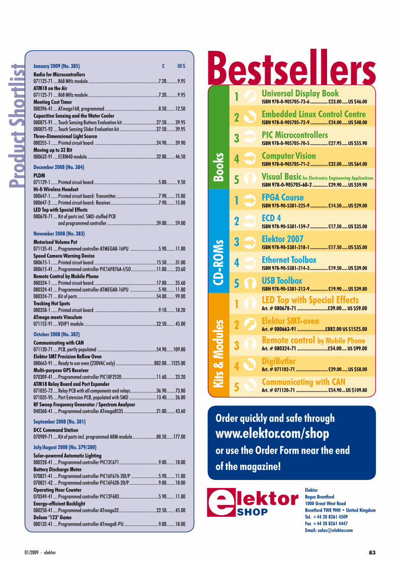
8301/2009 - elektor
Order quickly and safe throughwww.elektor.com/shopor use the Order Form near the end of the magazine!
ElektorRegus Brentford1000 Great West RoadBrentford TW8 9HH • United KingdomTel. +44 20 8261 4509Fax +44 20 8261 4447Email: [email protected]
Bestsellers
Book
sKi
ts &
Mod
ules
CD-R
OMs
Prod
uct S
hortl
ist
£
Book
sKi
ts &
Mod
ules
1
2
3
4
5
1
2
3
4
5
1
2
3
4
5
CD-R
OMs
Universal Display BookISBN 978-0-905705-73-6 ............... £23.00 .....US $46.00
Embedded Linux Control CentreISBN 978-0-905705-72-9 ............... £24.00 .....US $48.00
PIC MicrocontrollersISBN 978-0-905705-70-5 ............... £27.95 .....US $55.90
Computer VisionISBN 978-0-905705-71-2 ............... £32.00 .....US $64.00
Visual Basic for Electronics Engineering ApplicationsISBN 978-0-905705-68-2 ............. £29.90 .....US $59.90
FPGA CourseISBN 978-90-5381-225-9 ............... £14.50 .....US $29.00
ECD 4ISBN 978-90-5381-159-7 ............... £17.50 .....US $35.00
Elektor 2007ISBN 978-90-5381-218-1 ............... £17.50 .....US $35.00
Ethernet ToolboxISBN 978-90-5381-214-3 ............... £19.50 .....US $39.00
USB ToolboxISBN 978-90-5381-212-9 ............... £19.90 .....US $39.80
LED Top with Special EffectsArt. # 080678-71 ..........................£39.00 .... US $59.00
Elektor SMT-ovenArt. # 080663-91 ........................£882.00 US $1525.00
Remote control by Mobile PhoneArt. # 080324-71 ..........................£54.00 .... US $99.00
DigiButlerArt. # 071102-71 ........................... £29.00 .....US $58.00
Communicating with CANArt. # 071120-71 ........................... £54.90 ...US $109.80
US $January 2009 (No. 385)Radio for Microcontrollers071125-71 .... 868 MHz module ................................................................7.20 ..........9.95ATM18 on the Air071125-71 .... 868 MHz module ................................................................7.20 ..........9.95Meeting Cost Timer080396-41 ....ATmega168, programmed .................................................8.50 ........12.50Capacitive Sensing and the Water Cooler080875-91 .... Touch Sensing Buttons Evaluation kit ...............................27.50 ........39.95080875-92 .... Touch Sensing Slider Evaluation kit ..................................27.50 ........39.95Three-Dimensional Light Source080355-1 ......Printed circuit board ........................................................24.90 ........39.90Moving up to 32 Bit080632-91 .... ECRM40 module ...............................................................32.00 ........46.50
December 2008 (No. 384) PLDM071129-1 ......Printed circuit board ...........................................................5.80 ..........9.50Hi-fi Wireless Headset 080647-1 ......Printed circuit board: Transmitter .......................................7.90 ........15.80080647-2 ......Printed circuit board: Receiver............................................7.90 ........15.80LED Top with Special Effects080678-71 ....Kit of parts incl. SMD-stuffed PCB and programmed controller .............................................39.00 ........59.00
November 2008 (No. 383)Motorised Volume Pot071135-41 ....Programmed controller ATMEGA8-16PU ..........................5.90 ........11.80Speed Camera Warning Device080615-1 ......Printed circuit board .........................................................15.50 ........31.00080615-41 ....Programmed controller PIC16F876A-I/SO .......................11.80 ........23.60Remote Control by Mobile Phone080324-1 ......Printed circuit board .........................................................17.80 ........35.60080324-41 ....Programmed controller ATMEGA8-16PU ..........................5.90 ........11.80080324-71 ....Kit of parts ........................................................................54.00 ........99.00Tracking Hot Spots080358-1 ......Printed circuit board ..........................................................9.10 ........18.20ATmega meets Vinculum071152-91 ....VDIP1 module ..................................................................22.50 ........45.00
October 2008 (No. 382)Communicating with CAN071120-71 ....PCB, partly populated ......................................................54.90 ......109.80Elektor SMT Precision Refl ow Oven080663-91 ....Ready to use oven (230VAC only) ...................................882.00 ....1525.00Multi-purpose GPS Receiver070309-41 ....Programmed controller PIC18F2520 ................................11.60 ........23.20ATM18 Relay Board and Port Expander071035-72 ....Relay PCB with all components and relays........................36.90 ........73.80071035-95 ....Port Extension PCB, populated with SMD .........................13.40 ........26.80RF Sweep Frequency Generator / Spectrum Analyser040360-41 ....Programmed controller ATmega8535 ..............................21.80 ........43.60
September 2008 (No. 381)DCC Command Station070989-71 ....Kit of parts incl. programmed ARM module ......................88.50 ......177.00
July/August 2008 (No. 379/380)Solar-powered Automatic Lighting080228-41 ....Programmed controller PIC12C671 ....................................9.00 ........18.00Battery Discharge Meter070821-41 ....Programmed controller PIC16F676-20I/P .........................5.90 ........11.80070821-42 ....Programmed controller PIC16F628-20/P ...........................9.00 ........18.00Operating Hour Counter070349-41 ....Programmed controller PIC12F683 ....................................5.90 ........11.80Energy-effi cient Backlight080250-41 ....Programmed controller ATmega32 ..................................22.50 ........45.00Deluxe ‘123’ Game080132-41 ....Programmed controller ATmega8-PU ................................9.00 ........18.00
ELEK UK0901 shop.indd 83 26-11-2008 22:08:48
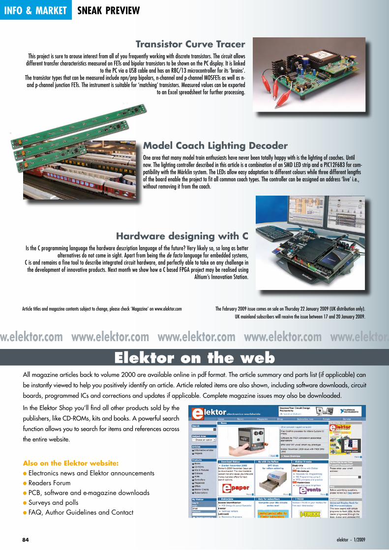
Elektor on the webwww.elektor.com www.elektor.com www.elektor.com www.elektor.com www.elektor.com
info & market sneak preview
84 elektor - 1/2009
Hardware designing with CIs the C programming language the hardware description language of the future? Very likely so, so long as better
alternatives do not come in sight. Apart from being the de facto language for embedded systems, C is and remains a fine tool to describe integrated circuit hardware, and perfectly able to take on any challenge in the development of innovative products. Next month we show how a C based FPGA project may be realised using
Altium’s Innovation Station.
Transistor Curve TracerThis project is sure to arouse interest from all of you frequently working with discrete transistors. The circuit allows
different transfer characteristics measured on FETs and bipolar transistors to be shown on the PC display. It is linked to the PC via a USB cable and has an R8C/13 microcontroller for its ‘brains’.
The transistor types that can be measured include npn/pnp bipolars, n-channel and p-channel MOSFETs as well as n- and p-channel junction FETs. The instrument is suitable for ‘matching’ transistors. Measured values can be exported
to an Excel spreadsheet for further processing.
Model Coach Lighting DecoderOne area that many model train enthusiasts have never been totally happy with is the lighting of coaches. Until now. The lighting controller described in this article is a combination of an SMD LED strip and a PIC12F683 for com-patibility with the Märklin system. The LEDs allow easy adaptation to different colours while three different lengths of the board enable the project to fit all common coach types. The controller can be assigned an address ‘live’ i.e., without removing it from the coach.
All magazine articles back to volume 2000 are available online in pdf format. The article summary and parts list (if applicable) can
be instantly viewed to help you positively identify an article. Article related items are also shown, including software downloads, circuit
boards, programmed ICs and corrections and updates if applicable. Complete magazine issues may also be downloaded.
In the Elektor Shop you’ll find all other products sold by the
publishers, like CD-ROMs, kits and books. A powerful search
function allows you to search for items and references across
the entire website.
Also on the Elektor website:
• Electronics news and Elektor announcements
• Readers Forum
• PCB, software and e-magazine downloads
• Surveys and polls
• FAQ, Author Guidelines and Contact
Article titles and magazine contents subject to change, please check ‘Magazine’ on www.elektor.com The February 2009 issue comes on sale on Thursday 22 January 2009 (UK distribution only). UK mainland subscribers will receive the issue between 17 and 20 January 2009.
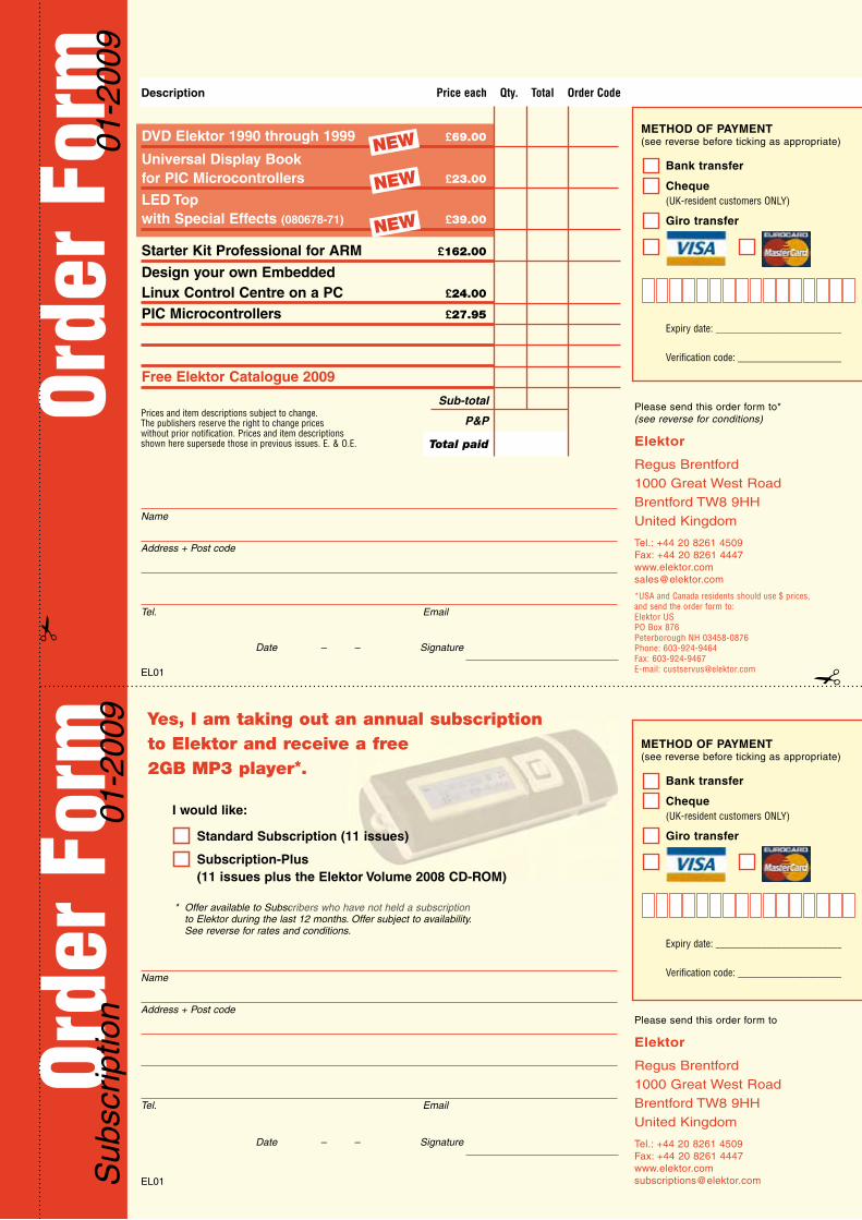
Orde
r For
mOr
der F
orm
01-2
009
01-2
009
Sub
scrip
tion
DVD Elektor 1990 through 1999 £69.00
Universal Display Book for PIC Microcontrollers £23.00
LED Topwith Special Effects (080678-71) £39.00
Starter Kit Professional for ARM £162.00
Design your own Embedded Linux Control Centre on a PC £24.00
PIC Microcontrollers £27.95
Free Elektor Catalogue 2009
Description Price each Qty. Total Order Code
Sub-total
P&P
Total paid
Please send this order form to*(see reverse for conditions)
Elektor
Regus Brentford
1000 Great West Road
Brentford TW8 9HH
United Kingdom
Tel.: +44 20 8261 4509Fax: +44 20 8261 [email protected]
*USA and Canada residents should use $ prices, and send the order form to: Elektor USPO Box 876Peterborough NH 03458-0876Phone: 603-924-9464Fax: 603-924-9467E-mail: [email protected]
Please send this order form to
Elektor
Regus Brentford
1000 Great West Road
Brentford TW8 9HH
United Kingdom
Tel.: +44 20 8261 4509Fax: +44 20 8261 [email protected]
Prices and item descriptions subject to change. The publishers reserve the right to change prices without prior notification. Prices and item descriptions shown here supersede those in previous issues. E. & O.E.
EL01
EL01
Name
Address + Post code
Tel. Email
Date – – Signature
Name
Address + Post code
Tel. Email
Date – – Signature
* Offer available to Subscribers who have not held a subscription to Elektor during the last 12 months. Offer subject to availability. See reverse for rates and conditions.
NEW
cribers who have not held a subscription
Yes, I am taking out an annual subscription to Elektor and receive a free 2GB MP3 player*.
I would like:
Standard Subscription (11 issues)
Subscription-Plus(11 issues plus the Elektor Volume 2008 CD-ROM)
NEW
METHOD OF PAYMENT(see reverse before ticking as appropriate)
Bank transfer
Cheque (UK-resident customers ONLY)
Giro transfer
Expiry date: _________________________
Verification code: _____________________
METHOD OF PAYMENT(see reverse before ticking as appropriate)
Bank transfer
Cheque (UK-resident customers ONLY)
Giro transfer
Expiry date: _________________________
Verification code: _____________________
NEW
ELEK UK0901 Orderform.indd 1 26-11-2008 22:05:45

ORDERING INSTRUCTIONS, P&P CHARGES
All orders, except for subscriptions (for which see below), must be sent BY POST or FAX to our Brentford address using the Order Form overleaf. Online ordering: www.elektor.com/shopReaders in the USA and Canada should send orders, except for subscriptions (for which see below), to the USA address given on the order form. Please apply to Elektor US for applicable P&P charges. Please allow 4-6 weeks for delivery.Orders placed on our Brentford office must include P&P charges (Priority or Standard) as follows: Europe: £6.00 (Standard) or £7.00 (Prio rity) Outside Europe: £9.00 (Standard) or £11.00 (Priority)
HOW TO PAY
All orders must be accompanied by the full payment, including postage and packing charges as stated above or advised by Customer Services staff.
Bank transfer into account no. 40209520 held by Elektor Electronics with ABN-AMRO Bank, London. IBAN: GB35 ABNA 4050 3040 2095 20. BIC: ABNAGB2L. Currency: sterling (UKP). Please ensure your full name and address gets communicated to us.Cheque sent by post, made payable to Elektor Electronics. We can only accept sterling cheques and bank drafts from UK-resident customers or subscribers. We regret that no cheques can be accepted from customers or subscribers in any other country.Giro transfer into account no. 34-152-3801, held by Elektor Electronics. Please do not send giro transfer/deposit forms directly to us, but insteaduse the National Giro postage paid envelope and send it to your National Giro Centre.Credit card VISA and MasterCard can be processed by mail, email, web, fax and telephone. Online ordering through our website is SSL-protected for your security.
COMPONENTS
Components for projects appearing in Elektor are usually available from certain advertisers in this magazine. If difficulties in the supply of components are envisaged, a source will normally be advised in the article. Note, however, that the source(s) given is (are) not exclusive.
TERMS OF BUSINESS
Delivery Although every effort will be made to dispatch your order within 2-3 weeks from receipt of your instructions, we can not guarantee this time scale for all orders. Returns Faulty goods or goods sent in error may be returned for replacement or refund, but not before obtaining our consent. All goods returned should be packed securely in a padded bag or box, enclosing a covering letter stating the dispatch note number. If the goods are returned because of a mistake on our part, we will refund the return postage. Damaged goods Claims for damaged goods must be received at our Brentford office within 10-days (UK); 14-days (Europe) or 21-days (all other countries). Cancelled orders All cancelled orders will be subject to a 10% handling charge with a minimum charge of £5.00. Patents Patent protection may exist in respect of circuits, devices, components, and so on, described in our books and magazines. Elektor does not accept responsibility or liability for failing to identify such patent or other protection. Copyright All drawings, photographs, articles, printed circuit boards, programmed integrated circuits, diskettes and software carriers published in our books and magazines (other than in third-party advertisements) are copyright and may not be reproduced or transmitted in any form or by any means, including photocopying and recording, in whole or in part, without the prior permission of Elektor in writing. Such written permission must also be obtained before any part of these publications is stored in a retrieval system of any nature. Notwithstanding the above, printed-circuit boards may be produced for private and personal use without prior permission. Limitation of liabilityElektor shall not be liable in contract, tort, or otherwise, for any loss or damage suffered by the purchaser whatsoever or howsoever arising out of, or in connexion with, the supply of goods or services by Elektor other than to supply goods as described or, at the option of Elektor, to refund the purchaser any money paid in respect of the goods. Law Any question relating to the supply of goods and services by Elektor shall be determined in all respects by the laws of England.
January 2009
HOW TO PAY
Bank transfer into account no. 40209520 held by Elektor Electronics. with ABN-AMRO Bank, London. IBAN: GB35 ABNA 4050 3040 2095 20. BIC: ABNAGB2L. Currency: sterling (UKP). Please ensure your full name and address gets communicated to us.Cheque sent by post, made payable to Elektor Electronics. We can only accept sterling cheques and bank drafts from UK-resident customers or subscribers. We regret that no cheques can be accepted from customers or subscribers in any other country.Giro transfer into account no. 34-152-3801, held by Elektor Electronics. Please do not send giro transfer/deposit forms directly to us, but instead use the National Giro postage paid envelope and send it to your National Giro Centre.Credit card VISA and MasterCard can be processed by mail, email, web, fax and telephone. Online ordering through our website is SSL-protected for your security.
SUBSCRIPTION CONDITIONS
The standard subscription order period is twelve months. If a permanent change of address during the subscription period means that copies have to be despatched by a more expensive service, no extra charge will be made. Conversely, no refund will be made, nor expiry date extended, if a change of address allows the use of a cheaper service.Student applications, which qualify for a 20% (twenty per cent) reduction in current rates, must be supported by evidence of stu-dentship signed by the head of the college, school or university faculty. A standard Student Subscription costs £35.00, a Student Subscription-Plus costs £44.20 (UK only).Please note that new subscriptions take about four weeks from receipt of order to become effective.Cancelled subscriptions will be subject to a charge of 25% (twenty-five per cent) of the full subscription price or £7.50, whichever is the higher, plus the cost of any issues already dispatched. Subsciptions cannot be cancelled after they have run for six months or more.
January 2009
SUBSCRIPTION RATES FOR ANNUAL
SUBSCRIPTION
Standard PlusUnited Kingdom £44.00 £53.00
Surface MailRest of the World £58.00 £67.00
AirmailRest of the World £74.00 £83.00
USA £59.95
Canada £70.95
See www.elektor.com/usafor special offers
ELEK UK0901 Orderform.indd 2 26-11-2008 22:05:47
871/2009 - elektor
INDEX OF ADVERTISERS
Antex Electronics Ltd . . . . . . . . . . . . . . . . . www.antex.co.uk. . . . . . . . . . . . . . . . . . . . . . . 27
Audio Amateur . . . . . . . . . . . . . . . . . . . . . . www.mothgroup.com . . . . . . . . . . . . . . . . . . . 39
Avit Research, Showcase. . . . . . . . . . . . . . www.avitresearch.co.uk . . . . . . . . . . . . . . . . . 78
Beijing Draco . . . . . . . . . . . . . . . . . . . . . . . www.ezpcb.com . . . . . . . . . . . . . . . . . . . . . . . 27
Beta Layout, Showcase . . . . . . . . . . . . . . . www.pcb-pool.com. . . . . . . . . . . . . . . . . . 51, 78
Bitscope Designs . . . . . . . . . . . . . . . . . . . www.bitscope.com . . . . . . . . . . . . . . . . . . . . . . 2
ByVac, Showcase . . . . . . . . . . . . . . . . . . . www.byvac.com . . . . . . . . . . . . . . . . . . . . . . . 78
C S Technology Ltd, Showcase . . . . . . . . . www.cstech.co.uk. . . . . . . . . . . . . . . . . . . . . . 78
Decibit Co. Ltd, Showcase . . . . . . . . . . . . . www.decibit.com . . . . . . . . . . . . . . . . . . . . . . 78
Designer Systems, Showcase . . . . . . . . . . www.designersystems.co.uk. . . . . . . . . . . . . . 78
EasyDAQ, Showcase . . . . . . . . . . . . . . . . . www.easydaq.biz . . . . . . . . . . . . . . . . . . . . . . 78
Easysync, Showcase . . . . . . . . . . . . . . . . . www.easysync.co.uk. . . . . . . . . . . . . . . . . . . . 78
Elnec, Showcase . . . . . . . . . . . . . . . . . . . . www.elnec.com . . . . . . . . . . . . . . . . . . . . . . . 78
EMCelettronica Srl, Showcase . . . . . . . . . . www.emcelettronica.com . . . . . . . . . . . . . . . . 78
Eurocircuits . . . . . . . . . . . . . . . . . . . . . . . . www.eurocircuits.com . . . . . . . . . . . . . . . . . . 69
First Technology Transfer Ltd, Showcase . . www.ftt.co.uk . . . . . . . . . . . . . . . . . . . . . . . . . 78
FlexiPanel Ltd, Showcase . . . . . . . . . . . . . . www.flexipanel.com . . . . . . . . . . . . . . . . . . . . 78
Future Technology Devices, Showcase . . . . www.ftdichip.com . . . . . . . . . . . . . . . . . . . . . . 78
General Circuits . . . . . . . . . . . . . . . . . . . . . www.pcbcart.com. . . . . . . . . . . . . . . . . . . . . . 39
Labcenter. . . . . . . . . . . . . . . . . . . . . . . . . . www.labcenter.com. . . . . . . . . . . . . . . . . . . . . 88
Lcdmod Kit, Showcase . . . . . . . . . . . . . . . www.lcdmodkit.com . . . . . . . . . . . . . . . . . . . . 78
London Electronics College, Showcase . . . www.lec.org.uk . . . . . . . . . . . . . . . . . . . . . . . . 78
MikroElektronika. . . . . . . . . . . . . . . . . . . . . www.mikroe.com . . . . . . . . . . . . . . . . . . . . 3, 11
MQP Electronics, Showcase. . . . . . . . . . . . www.mqp.com . . . . . . . . . . . . . . . . . . . . . . . . 79
Newbury Electronics . . . . . . . . . . . . . . . . . www.newburyelectronics.co.uk . . . . . . . . . . . . 75
Nurve Networks . . . . . . . . . . . . . . . . . . . . . www.xgamestation.com . . . . . . . . . . . . . . . . . 75
Parallax . . . . . . . . . . . . . . . . . . . . . . . . . . . www.parallax.com. . . . . . . . . . . . . . . . . . . . . . 25
Peak Electronic Design. . . . . . . . . . . . . . . . www.peakelec.co.uk . . . . . . . . . . . . . . . . . . . . 51
Pico. . . . . . . . . . . . . . . . . . . . . . . . . . . . . . www.picotech.com . . . . . . . . . . . . . . . . . . . . . 13
Propox Sp.. . . . . . . . . . . . . . . . . . . . . . . . . www.propox.com . . . . . . . . . . . . . . . . . . . . . . 51
Quasar Electronics . . . . . . . . . . . . . . . . . . . www.quasarelectronics.com . . . . . . . . . . . . . . 17
Radiometrix, Showcase . . . . . . . . . . . . . . . www.radiometrix.com . . . . . . . . . . . . . . . . . . . 79
Robot Electronics, Showcase. . . . . . . . . . . www.robot-electronics.co.uk. . . . . . . . . . . . . . 79
Robotiq, Showcase . . . . . . . . . . . . . . . . . . www.robotiq.co.uk . . . . . . . . . . . . . . . . . . . . . 79
RS Components. . . . . . . . . . . . . . . . . . . . . www.rswww.com/edp . . . . . . . . . . . . . . . . . . . 51
ScanTool, Showcase . . . . . . . . . . . . . . . . . www.obd2cables.com, www.scantool.net . . . . 79
Showcase . . . . . . . . . . . . . . . . . . . . . . . . . . . . . . . . . . . . . . . . . . . . . . . . . . . . . . . . . . 78, 79
USB Instruments, Showcase . . . . . . . . . . . www.usb-instruments.com . . . . . . . . . . . . . . . 79
Virtins Technology, Showcase . . . . . . . . . . www.virtins.com . . . . . . . . . . . . . . . . . . . . . . . 79
Advertising space for the issue of 19 February 2009 may be reserved not later than 20 January 2009
with Huson International Media – Cambridge House – Gogmore Lane – Chertsey, Surrey KT16 9AP – England – Telephone 01932 564 999 – Fax 01932 564998 – e-mail: [email protected] to whom all correspondence, copy instructions and artwork should be addressed.
Further information and ordering at www.elektor.com/smtoven
Art. # 080663-91 • Price: £ 882 • € 1095 • US$ 1525 (Excl. VAT)
Main technical specifi cations
Line voltage: 230 VAC / 1650 W
Line frequency: 50-60 Hz
Size: 418 x 372 x 250 mm (16.5 x 14.6 x 10 inch)
Weight: 16.7 kg (net)
Effective PCB area: 280 x 280 mm (11 x 11 inch)
• Selected, tested & certifi ed by Elektor
• Including Elektor-produced user manual
• Fully menu controlled
• Ideal for R&D laboratories, schools, small companies and…
electronics enthusiasts
• Product support from Elektor Customer Services
Elektor SMT OvenMulti-purpose and indispensable to professional and enthusiast
Demo video on
www.elektor.com/smtoven
mation and ordering at www.elektor.com/smtoven
0901_elektor_adv_UK.indd 87 28-11-2008 14:11:09

0901_elektor_adv_UK.indd 88 28-11-2008 14:11:18


