Embed Size (px)
Citation preview
13366
121212121212131313131515161818192021222324252627
2829
3031
32
333434343435363637373839
目录目录
目录
A.-Output-Tabs:-Picture-ZonesPicture Zones
B.-Output-Tabs:-DewarpingDewarping
Building-from-Source-Code-on-Linux-and-Mac-OS-XBuilding on Linux
PrerequisitesConfigurationCompilation and Installation
Building on Mac OS XMacPortsPrerequisitesConfigurationCompilation and Installation
C.-Output-Tabs:-Despeckling-&-Fill-zonesDespecklingFill Zones
DeskewLinks to all other stages:
FAQ1. What does the question mark on a thumbnail in the preview panel mean?2. I'm not allowed to do Output, saying that I need to complete previous stages - but I've already passed them !3. I started working on a scantailor project, but missed some pages. Can I add them to the existed project?4. Scan Tailor's auto mode often makes failures with my scans. Why ?5. What does the top right button (located over the thumbnails panel) do? What is it useful for?6. On some pages the content is reduced to a fraction of its original size. Is there a workaround for this problem?7. I don't understand the DPI concept. How to estimate unknown DPI ?8. Everything is OK with the DPI in my scans. Why does ST ask me to fix it ?9. There is strange light exposure on white/black scans. The cover images sometimes are not outputed well either. What isthis? How to process such pages ?10. How to correct geometric distortions for the photo-page below ?11. How can ScanTailor be automated? I have programmed an application ... [calling some others in a batch]. Is there acommand-line version of Scan Tailor?12. How to build ST for Windows from the source files?13. How does output TIFF type correlate with the input type ? Will the 16-bit TIFF sent to the ST produce better results or is itnot necessary?14. Is it possible to get separate output for the mask and background layers in ST instead of assigning the task of dividingthem to the DJVU encoder?
Fix-OrientationRotateApply toLinks to all other stages:
HomeOutput
Stage "Output"The format of output filesLinks to all other stages:
Page-LayoutLinks to all other stages:
目录
1 / 56
404041414242424242424242434444454647484848484849505151525252535455
Quick-Start-GuideSee also
Quick-StartSee also
Roadmap-1.0Organising the repositoryDocumentationMiscellaneous (not important at all)Missing Features
EnhancedPlusFeaturedqt5
Select-ContentLinks to all other stages:
Split-PagesLinks to all other stages:
Tips-for-ScanningUser-Guide
AboutInstallation and first start
For WindowsFor GNU / Linux and Mac OS X
Create ProjectThe concept of processing scans in Scan TailorProgram menu
File menuTools MenuHelp menu
Processing stagesSee also
Workflow-Description_Sidebar
目录
2 / 56
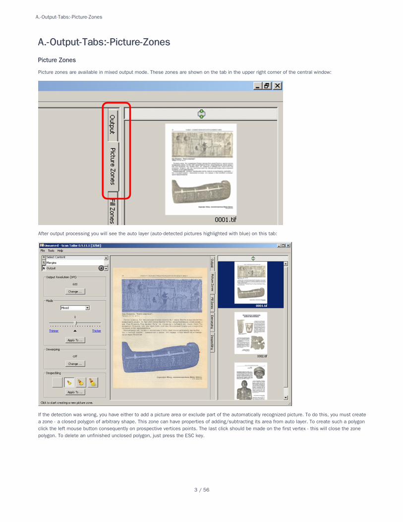
Picture zones are available in mixed output mode. These zones are shown on the tab in the upper right corner of the central window:
After output processing you will see the auto layer (auto-detected pictures highlighted with blue) on this tab:
If the detection was wrong, you have either to add a picture area or exclude part of the automatically recognized picture. To do this, you must createa zone - a closed polygon of arbitrary shape. This zone can have properties of adding/subtracting its area from auto layer. To create such a polygonclick the left mouse button consequently on prospective vertices points. The last click should be made on the first vertex - this will close the zonepolygon. To delete an unfinished unclosed polygon, just press the ESC key.
A.-Output-Tabs:-Picture-ZonesA.-Output-Tabs:-Picture-Zones
Picture ZonesPicture Zones
A.-Output-Tabs:-Picture-Zones
3 / 56
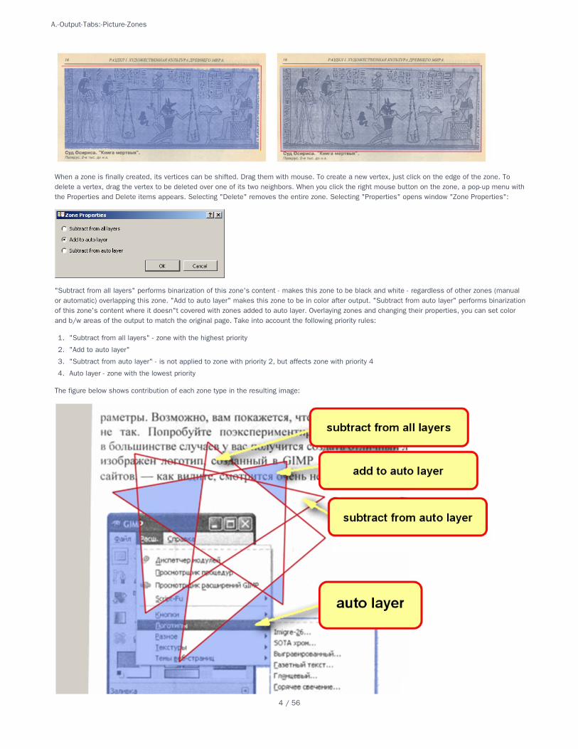
When a zone is finally created, its vertices can be shifted. Drag them with mouse. To create a new vertex, just click on the edge of the zone. Todelete a vertex, drag the vertex to be deleted over one of its two neighbors. When you click the right mouse button on the zone, a pop-up menu withthe Properties and Delete items appears. Selecting "Delete" removes the entire zone. Selecting "Properties" opens window "Zone Properties":
"Subtract from all layers" performs binarization of this zone's content - makes this zone to be black and white - regardless of other zones (manualor automatic) overlapping this zone. "Add to auto layer" makes this zone to be in color after output. "Subtract from auto layer" performs binarizationof this zone's content where it doesn"t covered with zones added to auto layer. Overlaying zones and changing their properties, you can set colorand b/w areas of the output to match the original page. Take into account the following priority rules:
1. "Subtract from all layers" - zone with the highest priority
2. "Add to auto layer"
3. "Subtract from auto layer" - is not applied to zone with priority 2, but affects zone with priority 4
4. Auto layer - zone with the lowest priority
The figure below shows contribution of each zone type in the resulting image:
A.-Output-Tabs:-Picture-Zones
4 / 56
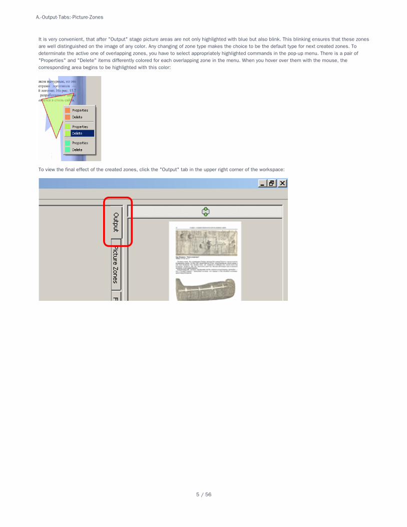
It is very convenient, that after "Output" stage picture areas are not only highlighted with blue but also blink. This blinking ensures that these zonesare well distinguished on the image of any color. Any changing of zone type makes the choice to be the default type for next created zones. Todeterminate the active one of overlapping zones, you have to select appropriately highlighted commands in the pop-up menu. There is a pair of"Properties" and "Delete" items differently colored for each overlapping zone in the menu. When you hover over them with the mouse, thecorresponding area begins to be highlighted with this color:
To view the final effect of the created zones, click the "Output" tab in the upper right corner of the workspace:
A.-Output-Tabs:-Picture-Zones
5 / 56
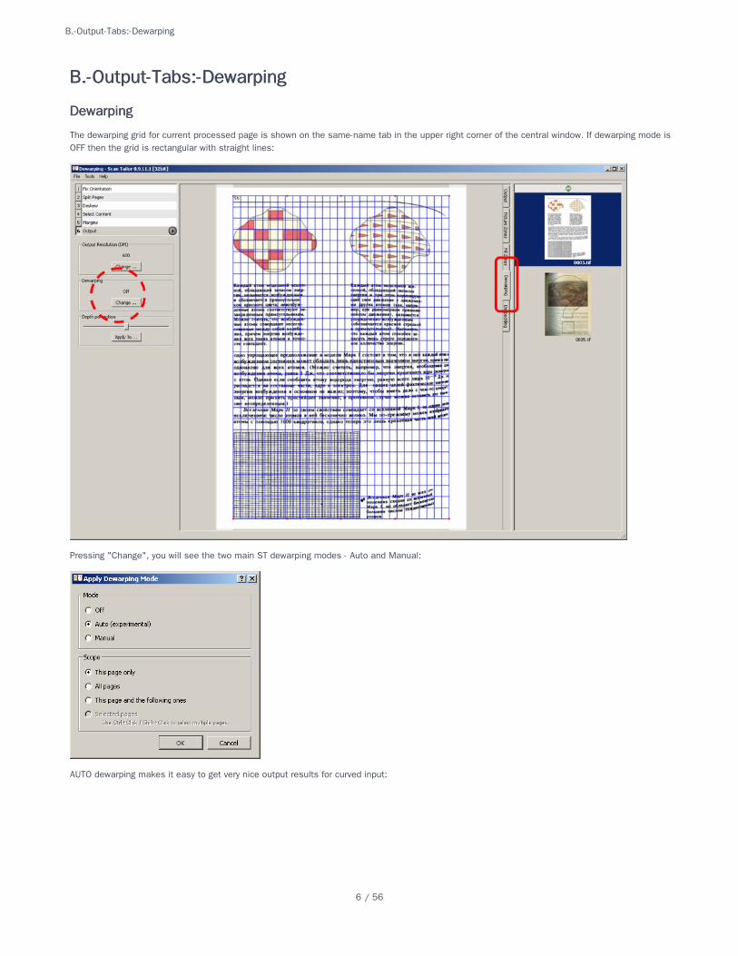
The dewarping grid for current processed page is shown on the same-name tab in the upper right corner of the central window. If dewarping mode isOFF then the grid is rectangular with straight lines:
Pressing "Change", you will see the two main ST dewarping modes - Auto and Manual:
AUTO dewarping makes it easy to get very nice output results for curved input:
B.-Output-Tabs:-DewarpingB.-Output-Tabs:-Dewarping
DewarpingDewarping
B.-Output-Tabs:-Dewarping
6 / 56
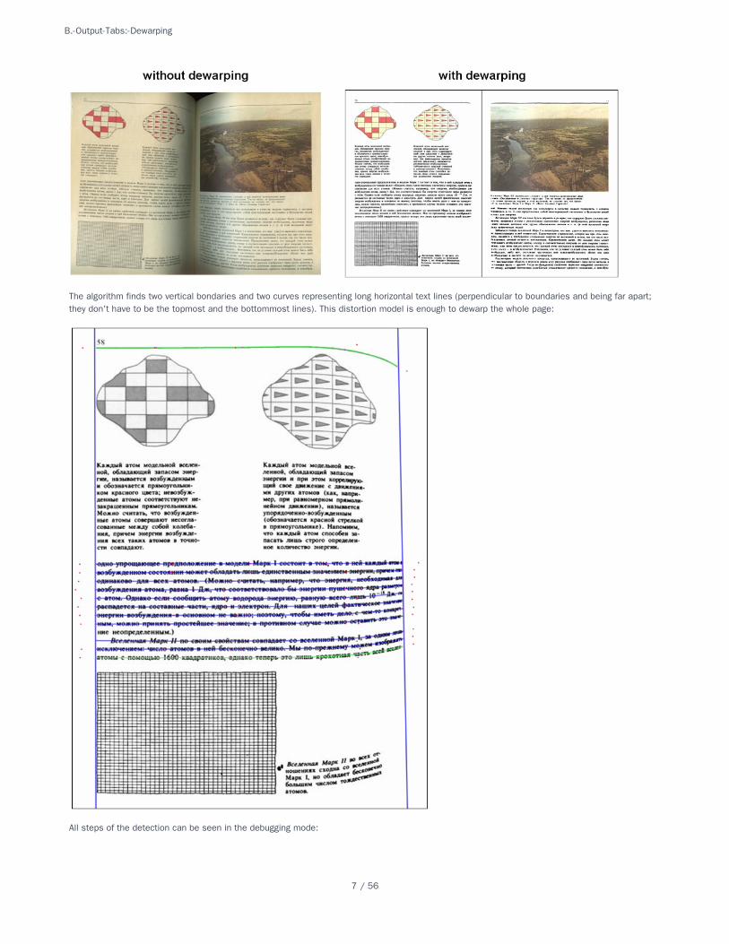
The algorithm finds two vertical bondaries and two curves representing long horizontal text lines (perpendicular to boundaries and being far apart;they don't have to be the topmost and the bottommost lines). This distortion model is enough to dewarp the whole page:
All steps of the detection can be seen in the debugging mode:
B.-Output-Tabs:-Dewarping
7 / 56
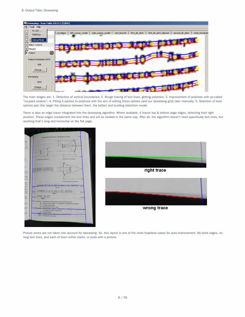
The main stages are: 1. Detection of vertical boundaries; 2. Rough tracing of text lines, getting polylines; 3. Improvement of polylines with so-called"coupled snakes"; 4. Fitting X-splines to polylines with the aim of editing these splines (and our dewarping grid) later manually; 5. Selection of bestsplines pair (the larger the distance between them, the better) and building distortion model.
There is also an edge tracer integrated into the dewarping algorithm. Where available, it traces top & bottom page edges, detecting their rightposition. These edges complement the text lines and will be treated in the same way. After all, the algorithm doesn't need specifically text lines, butanything that's long and horizontal on the flat page.
Picture zones are not taken into account for dewarping. So, this layout is one of the most hopeless cases for auto-improvement. No book edges, nolong text lines, and each of them either starts, or ends with a picture:
B.-Output-Tabs:-Dewarping
8 / 56
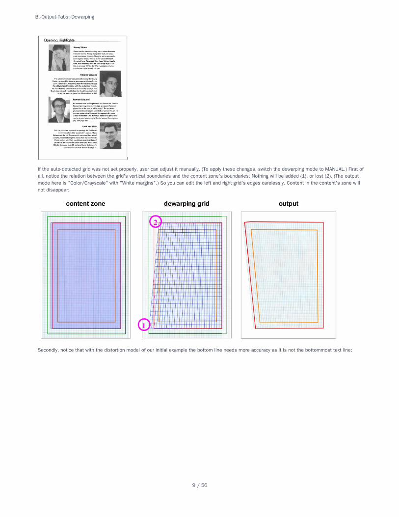
If the auto-detected grid was not set properly, user can adjust it manually. (To apply these changes, switch the dewarping mode to MANUAL.) First ofall, notice the relation between the grid's vertical boundaries and the content zone's boundaries. Nothing will be added (1), or lost (2). (The outputmode here is "Color/Grayscale" with "White margins".) So you can edit the left and right grid's edges carelessly. Content in the content's zone willnot disappear:
Secondly, notice that with the distortion model of our initial example the bottom line needs more accuracy as it is not the bottommost text line:
B.-Output-Tabs:-Dewarping
9 / 56
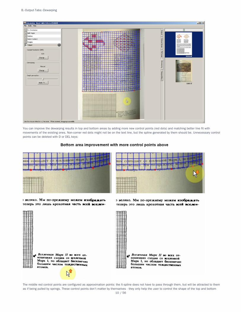
You can improve the dewarping results in top and bottom areas by adding more new control points (red dots) and matching better line fit withmovements of the existing ones. Non-corner red dots might not be on the text line, but the spline generated by them should be. Unnecessary controlpoints can be deleted with D or DEL keys:
The middle red control points are configured as approximation points: the X-spline does not have to pass through them, but will be attracted to themas if being pulled by springs. These control points don't matter by themselves - they only help the user to control the shape of the top and bottom
B.-Output-Tabs:-Dewarping
10 / 56
curves. If you delete all midpoints and these curves will be straight lines, you will get dekeystoning without dewarping.
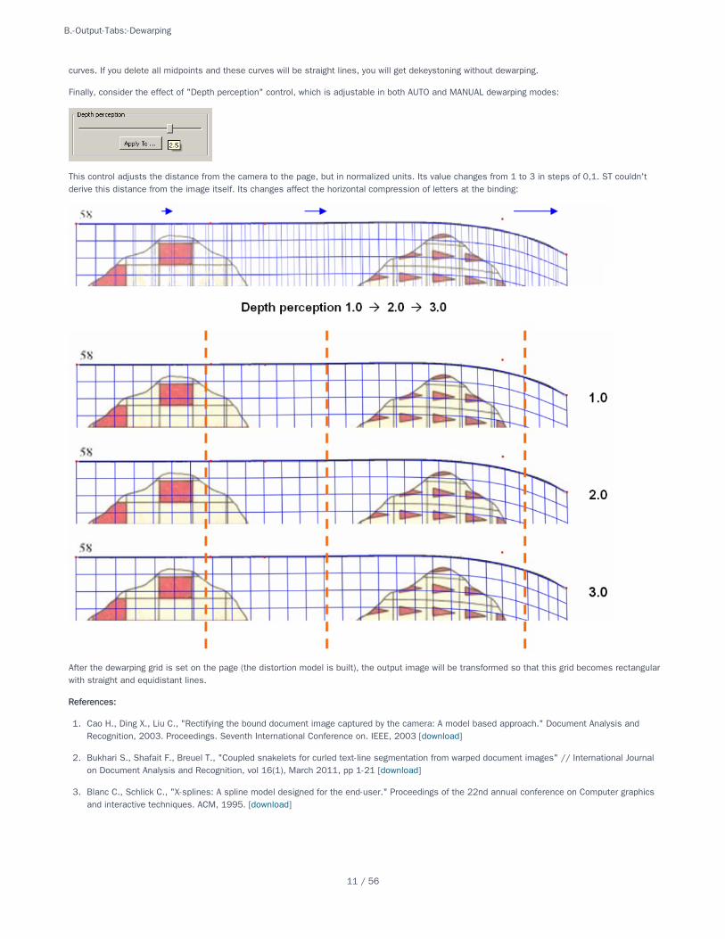
Finally, consider the effect of "Depth perception" control, which is adjustable in both AUTO and MANUAL dewarping modes:
This control adjusts the distance from the camera to the page, but in normalized units. Its value changes from 1 to 3 in steps of 0,1. ST couldn'tderive this distance from the image itself. Its changes affect the horizontal compression of letters at the binding:
After the dewarping grid is set on the page (the distortion model is built), the output image will be transformed so that this grid becomes rectangularwith straight and equidistant lines.
References:References:
1. Cao H., Ding X., Liu C., "Rectifying the bound document image captured by the camera: A model based approach." Document Analysis andRecognition, 2003. Proceedings. Seventh International Conference on. IEEE, 2003 [download]
2. Bukhari S., Shafait F., Breuel T., "Coupled snakelets for curled text-line segmentation from warped document images" // International Journalon Document Analysis and Recognition, vol 16(1), March 2011, pp 1-21 [download]
3. Blanc C., Schlick C., "X-splines: A spline model designed for the end-user." Proceedings of the 22nd annual conference on Computer graphicsand interactive techniques. ACM, 1995. [download]
B.-Output-Tabs:-Dewarping
11 / 56
All requisites should be available for your distribution. The most important are:
The basic program build tools. On Ubuntu and Debian these are available in the meta-package build-essential. On other distributions, you mayneed to install the GNU C++ compiler separately. The package is going to have c++ or g++ in its name. If you can't find the equivalent of build-essential meta-package for your distribution, be sure to install the "make" utility as well.
CMake, the cross platform build system.
Qt version 4.4.0 or higher (but Qt version 5.x won't work). If you have KDE 4.1 or later installed then you will have the runtime libraries but youmay have to install the header files and utilities. These are in the package libqt4-dev on Ubuntu and Debian. Generally, developer packageshave the -dev or -devel suffix.
Several more developer packages:
These are the package names on Debian and Ubuntu, find the similar ones for your distribution. For Fedora, use "-devel" instead of "-dev" as suffixand drop the version numbers.
PackagePackage VersionVersion Possible Package NamesPossible Package Names
libjpeg anylibjpeg62-dev Fedora: libjpeg-turbo-devel
zlib any zlib1g-dev
libpng any libpng12-dev
libtiff any libtiff4-dev
libboost >= 1.35libboost1.40-all-dev boost-libs (if that fails, try: libboost1.55-all-dev)
libxrender anylibxrender-dev libXrender-devel
Open a console window and go to the directory that contains the scantailor sources. From there, run the following (notice the dot at the end):
cmake .
There will be lots of messages from cmake ending with:
- Configuring done - Generating done
If you have missing dependencies you will get an error message telling you what is missing. You can then search for the missing package andinstall it.
If you have a library and header files installed in a non-standard place then cmake will not find them. In that case you can run the interactiveprogram '''ccmake''' which allows you to specify paths to libraries and header files.
makesudo make install
Building-from-Source-Code-on-Linux-and-Mac-OS-XBuilding-from-Source-Code-on-Linux-and-Mac-OS-X
Building on LinuxBuilding on Linux
PrerequisitesPrerequisites
ConfigurationConfiguration
Compilation and InstallationCompilation and Installation
Building on Mac OS XBuilding on Mac OS X
Building-from-Source-Code-on-Linux-and-Mac-OS-X
12 / 56
MacPorts has already scantailor as a package (Xcode prerequisites for MacPorts apply)
sudo port selfupdatesudo port install scantailor
Building on Mac OS X is very similar to building on Linux but the package names are different and the MacPorts packaging system needs to beinstalled in order to get the needed packages. Also the nonstandard location that MacPorts installs qmake to needs to be specified.
Xcode. Install it either from your Mac OS X install media or better, go download the latest version fromhttp://developer.apple.com/TOOLS/Xcode/
MacPorts. Choose and install the correct dmg version for your version of Mac OS X from http://www.macports.org/install.php, then open aTerminal window and run:
sudo port selfupdate
Then install the rest of the needed packages with
sudo port install cmake qt4-mac-devel boost xrender
This installs:
CMake, the cross platform build system.
Qt version 4.6.0 beta currently
Boost version 1.40.0 including libboost
libxrender
The rest of the needed packages are installed as dependencies of these.
Download the scantailor source code package and then upack the source by entering the following in the directory where the source packageresides:
tar xf scantailor-0.9.8.1.tar.gz
Replace the file name above with the name of the version that you have downloaded. Typing the first few letters of the name and typing tab willautocomplete the filename for you.
Then navigate to the directory that contains the scantailor sources. From there, run the following (single line and mind the dot at the end):
cmake -DCMAKE_LIBRARY_PATH=/opt/local/lib -DCMAKE_INCLUDE_PATH=/opt/local/include-DQT_QMAKE_EXECUTABLE=/opt/local/libexec/qt4-mac-devel/bin/qmake .
There will be lots of messages from cmake ending with
- Configuring done - Generating done
If you have missing dependencies you will get an error message telling you what is missing. You can then search for the missing package andinstall it.
If you have a library and header files installed in a non-standard place then cmake will not find them. In that case you can specify them asabove for qmake or run the interactive program '''ccmake''' which allows you to specify paths to libraries and header files.
MacPortsMacPorts
PrerequisitesPrerequisites
ConfigurationConfiguration
Compilation and InstallationCompilation and Installation
Building-from-Source-Code-on-Linux-and-Mac-OS-X
13 / 56
makesudo make install
Building-from-Source-Code-on-Linux-and-Mac-OS-X
14 / 56
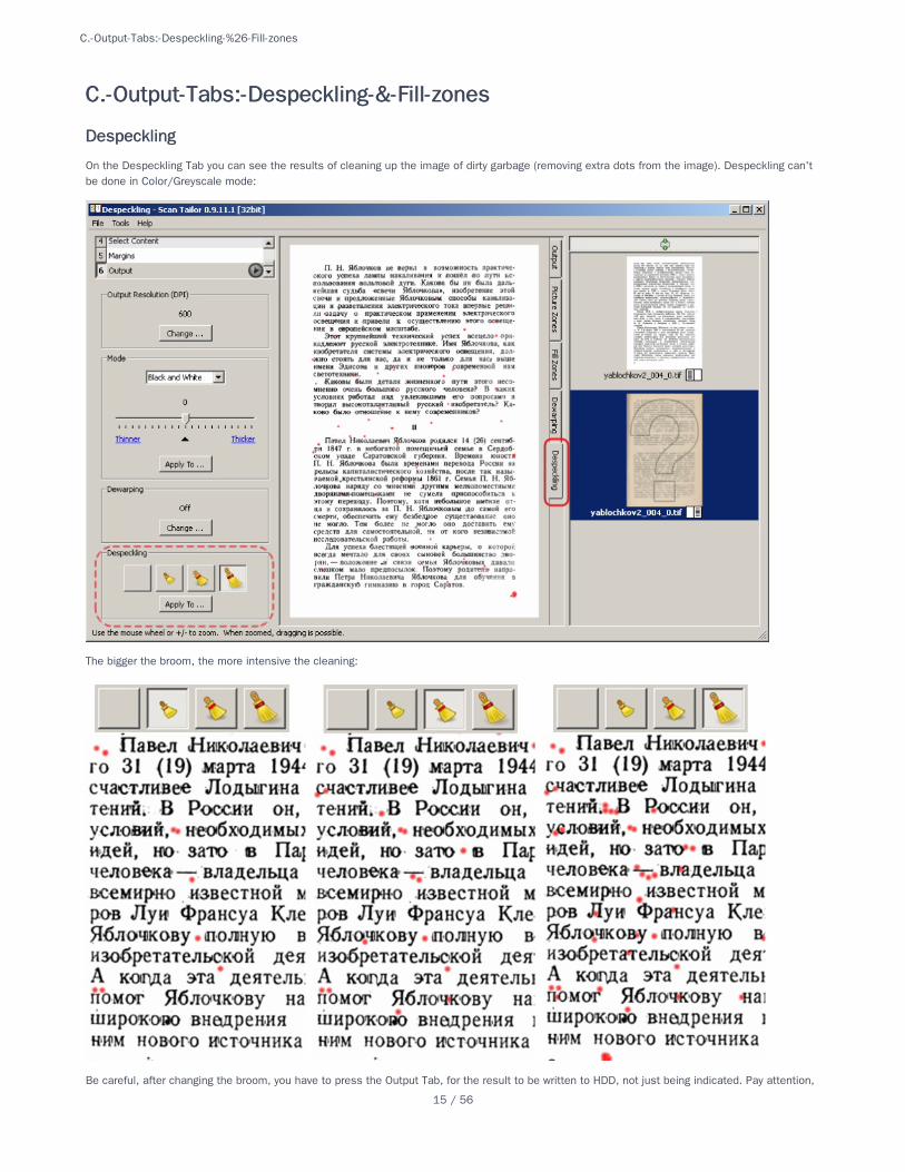
On the Despeckling Tab you can see the results of cleaning up the image of dirty garbage (removing extra dots from the image). Despeckling can'tbe done in Color/Greyscale mode:
The bigger the broom, the more intensive the cleaning:
Be careful, after changing the broom, you have to press the Output Tab, for the result to be written to HDD, not just being indicated. Pay attention,
C.-Output-Tabs:-Despeckling-&-Fill-zonesC.-Output-Tabs:-Despeckling-&-Fill-zones
DespecklingDespeckling
C.-Output-Tabs:-Despeckling-%26-Fill-zones
15 / 56
that after such changes the question mark appears on the page thumbnail in the preview bar. Two workflows are suggested: 1. Do the output inbatch mode -> switch to the tab Despeckling -> go through all the pages switching the broom manually where necessary -> run batch processing forthe second time (this will be done faster than at the first time). 2. Every time having changed the level of despeckling, switch to the tab Output towrite the result to disk.
The broom is not just a filter by size. The model is more complicated. There exist an upper limit on size, and larger objects will not be removed.Letters exceed this limit, but not the punctuation marks. Then likewise to celestial bodies: an object can hold another object if it is not too large ortoo far away. That object, in turn, can also hold other objects and so on. For each object ST checks, if there is any object-holder in the chain thathas reached the upper limit in size.
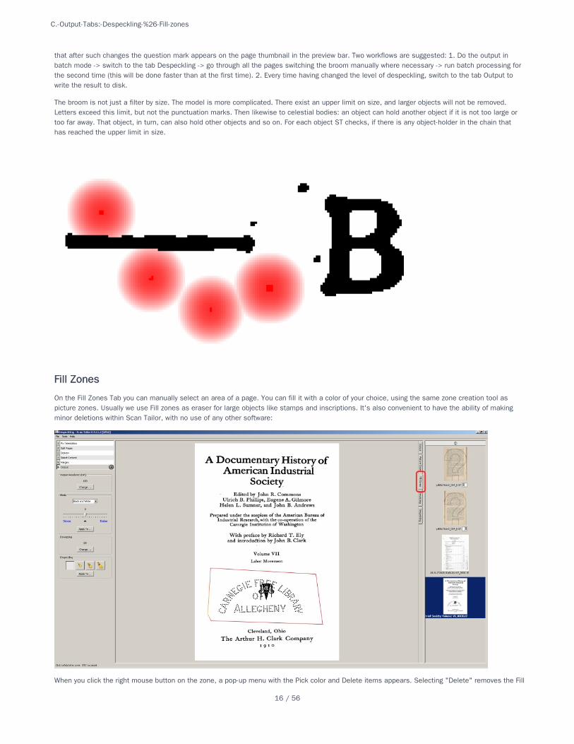
On the Fill Zones Tab you can manually select an area of a page. You can fill it with a color of your choice, using the same zone creation tool aspicture zones. Usually we use Fill zones as eraser for large objects like stamps and inscriptions. It's also convenient to have the ability of makingminor deletions within Scan Tailor, with no use of any other software:
When you click the right mouse button on the zone, a pop-up menu with the Pick color and Delete items appears. Selecting "Delete" removes the Fill
Fill ZonesFill Zones
C.-Output-Tabs:-Despeckling-%26-Fill-zones
16 / 56
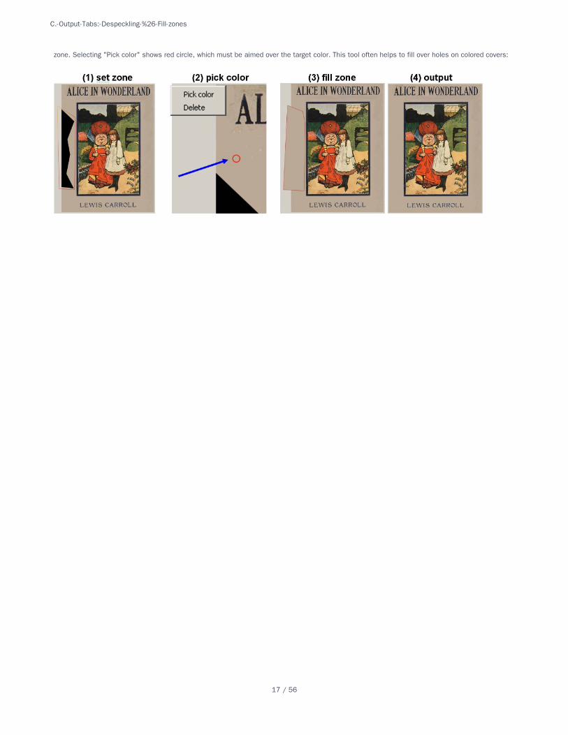
zone. Selecting "Pick color" shows red circle, which must be aimed over the target color. This tool often helps to fill over holes on colored covers:
C.-Output-Tabs:-Despeckling-%26-Fill-zones
17 / 56
At this stage one may determine the angle which the page needs to be turned for the text to be properly horizontal. Since compensation is a simplerotation such distortions as keystone or curling can not be corrected at this stage. The rotation angle is determined automatically, but you can alsoset it manually.
Here is the working area in this mode:
Images can be rotated by dragging the round handles at the edges.
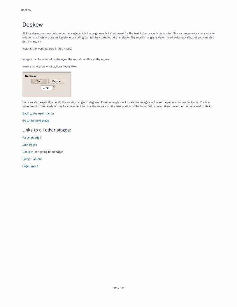
Here's what a panel of options looks like:
You can also explicitly specify the rotation angle in degrees. Positive angles will rotate the image clockwise, negative counter-clockwise. For fineadjustment of the angle it may be convenient to click the mouse on the text portion of the input field corner, then move the mouse wheel to fix it.
Back to the user manual
Go to the next stage
Fix Orientation
Split Pages
Deskew (correcting tilted pages)
Select Content
Page Layout
DeskewDeskew
Links to all other stages:Links to all other stages:
Deskew
18 / 56

FAQFAQ
FAQ
19 / 56
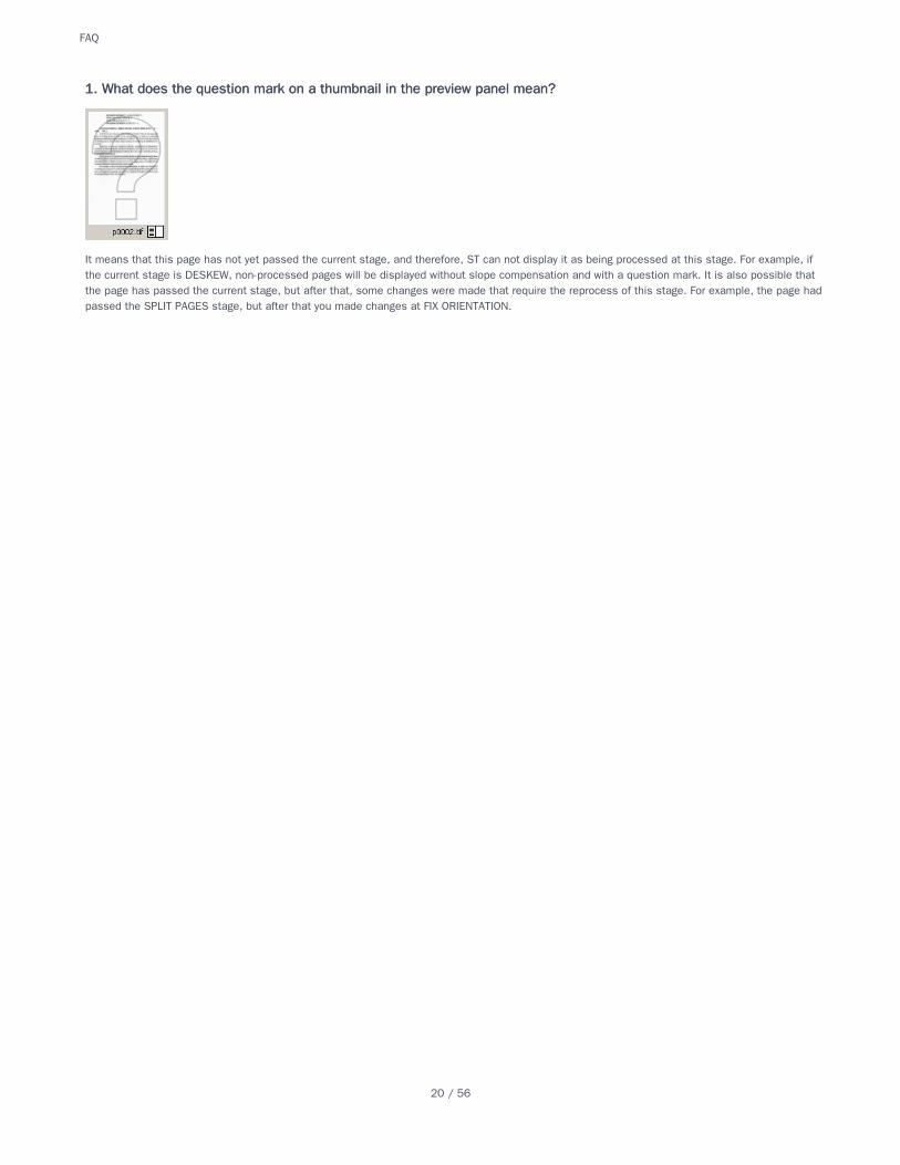
It means that this page has not yet passed the current stage, and therefore, ST can not display it as being processed at this stage. For example, ifthe current stage is DESKEW, non-processed pages will be displayed without slope compensation and with a question mark. It is also possible thatthe page has passed the current stage, but after that, some changes were made that require the reprocess of this stage. For example, the page hadpassed the SPLIT PAGES stage, but after that you made changes at FIX ORIENTATION.
1. What does the question mark on a thumbnail in the preview panel mean?1. What does the question mark on a thumbnail in the preview panel mean?
FAQ
20 / 56
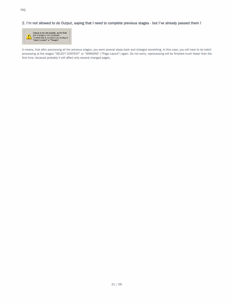
It means, that after processing all the previous stages, you went several steps back and changed something. In this case, you will have to do batchprocessing at the stages "SELECT CONTENT" or "MARGINS" ("Page Layout") again. Do not worry, reprocessing will be finished much faster than thefirst time, because probably it will affect only several changed pages.
2. I'm not allowed to do Output, saying that I need to complete previous stages - but I've already 2. I'm not allowed to do Output, saying that I need to complete previous stages - but I've already passed them !passed them !
FAQ
21 / 56
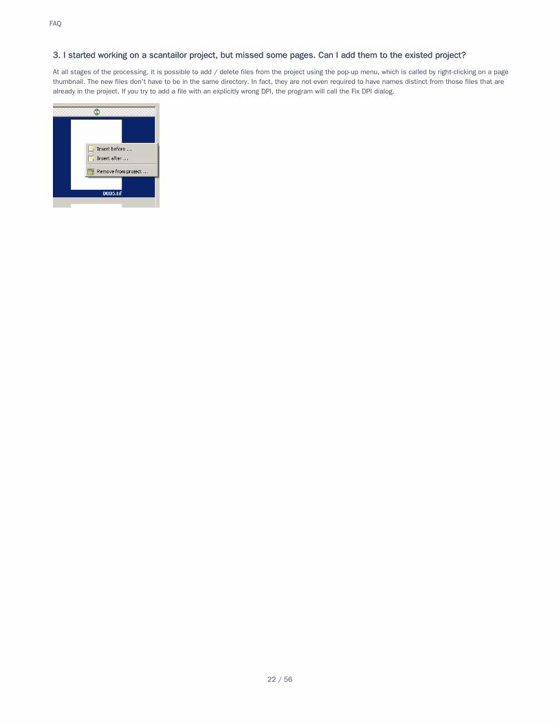
At all stages of the processing, it is possible to add / delete files from the project using the pop-up menu, which is called by right-clicking on a pagethumbnail. The new files don't have to be in the same directory. In fact, they are not even required to have names distinct from those files that arealready in the project. If you try to add a file with an explicitly wrong DPI, the program will call the Fix DPI dialog.
3. I started working on a scantailor project, but missed some pages. Can I add them to the existed project?3. I started working on a scantailor project, but missed some pages. Can I add them to the existed project?
FAQ
22 / 56
If errors occur very often, it means that your source material violates pre-assumptions made by Scan Tailor. Here are some of them:
there are fields around the content, and the larger they are, the better. Anything touching the edge is assumed to be garbage;
there are at least two lines of text on the page;
the DPI written in images or specified manually is near the real one.
letters are not too small (text is readable, not degraded), what sometimes happens for camera shots;
Frequently problems arise when scanner software pre-processes (improves) raw scans. This material is an inexhaustible source of problems. Ingeneral, good work on such scans should be perceived as a miracle, and a bad one - as a reality. Unless you have a good reason, feed Scan Tailorwith raw scans / photos. Scan Tailor likes its input to be as raw as possible, that is the less "enhancements" done by the scanner software, thebetter.
4. Scan Tailor's auto mode often makes failures with my scans. Why ?4. Scan Tailor's auto mode often makes failures with my scans. Why ?
FAQ
23 / 56
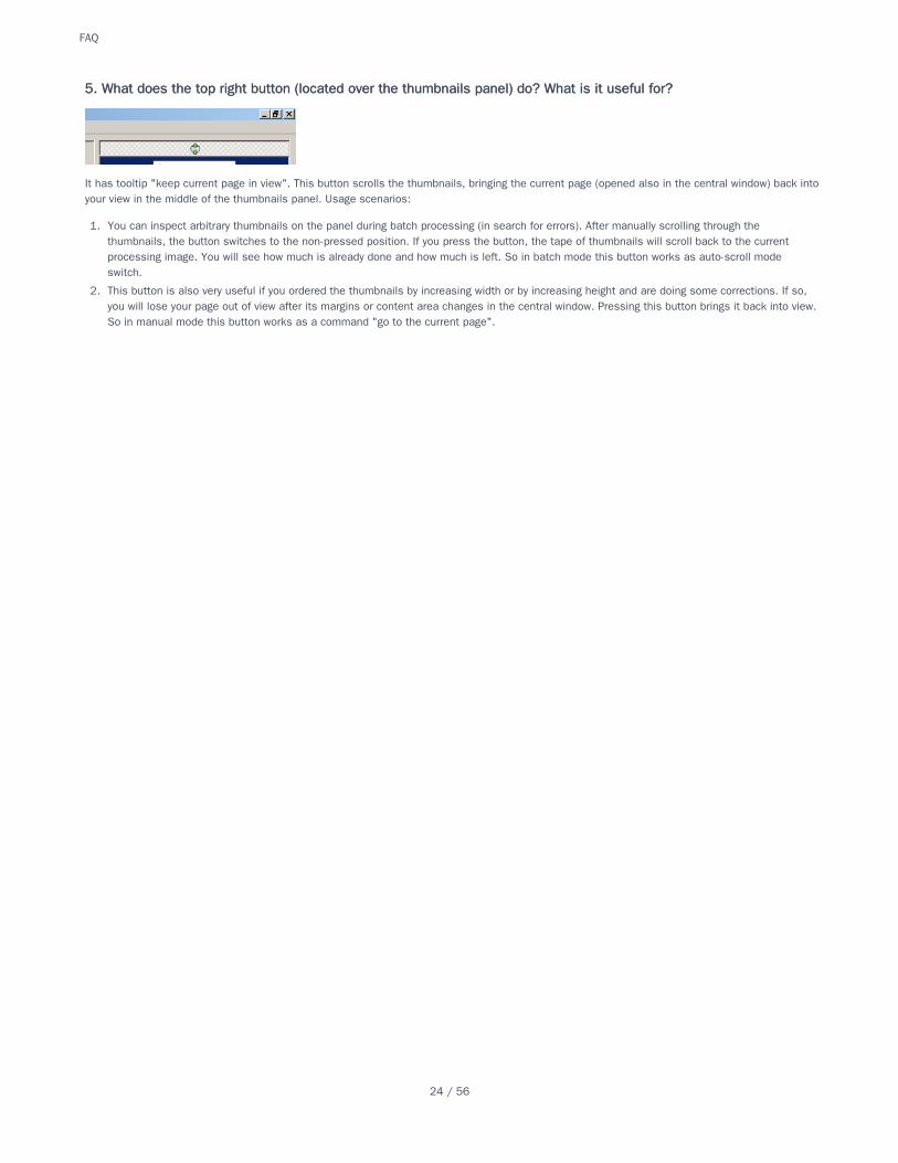
It has tooltip "keep current page in view". This button scrolls the thumbnails, bringing the current page (opened also in the central window) back intoyour view in the middle of the thumbnails panel. Usage scenarios:
1. You can inspect arbitrary thumbnails on the panel during batch processing (in search for errors). After manually scrolling through thethumbnails, the button switches to the non-pressed position. If you press the button, the tape of thumbnails will scroll back to the currentprocessing image. You will see how much is already done and how much is left. So in batch mode this button works as auto-scroll modeswitch.
2. This button is also very useful if you ordered the thumbnails by increasing width or by increasing height and are doing some corrections. If so,you will lose your page out of view after its margins or content area changes in the central window. Pressing this button brings it back into view.So in manual mode this button works as a command "go to the current page".
5. What does the top right button (located over the thumbnails panel) do? What is it useful for?5. What does the top right button (located over the thumbnails panel) do? What is it useful for?
FAQ
24 / 56
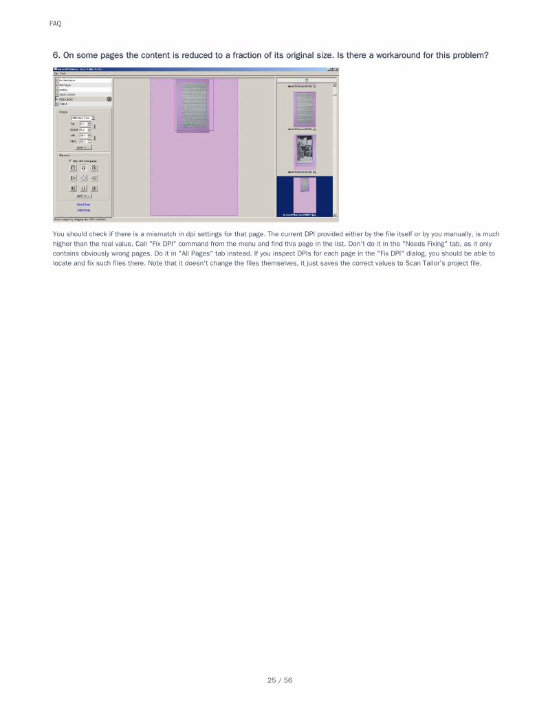
You should check if there is a mismatch in dpi settings for that page. The current DPI provided either by the file itself or by you manually, is muchhigher than the real value. Call "Fix DPI" command from the menu and find this page in the list. Don't do it in the "Needs Fixing" tab, as it onlycontains obviously wrong pages. Do it in "All Pages" tab instead. If you inspect DPIs for each page in the "Fix DPI" dialog, you should be able tolocate and fix such files there. Note that it doesn't change the files themselves, it just saves the correct values to Scan Tailor's project file.
6. On some pages the content is reduced to a fraction of its original size. Is there a workaround for this problem?6. On some pages the content is reduced to a fraction of its original size. Is there a workaround for this problem?
FAQ
25 / 56
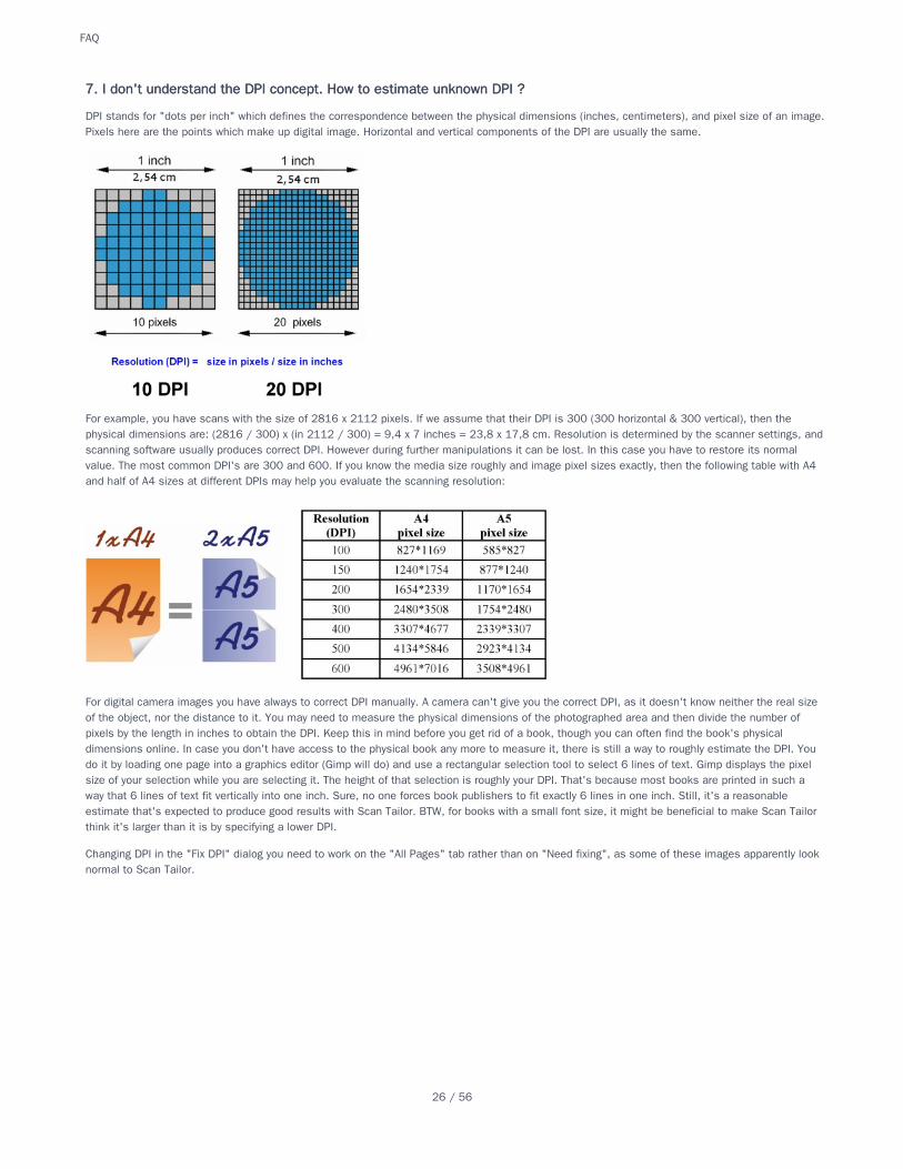
DPI stands for "dots per inch" which defines the correspondence between the physical dimensions (inches, centimeters), and pixel size of an image.Pixels here are the points which make up digital image. Horizontal and vertical components of the DPI are usually the same.
For example, you have scans with the size of 2816 x 2112 pixels. If we assume that their DPI is 300 (300 horizontal & 300 vertical), then thephysical dimensions are: (2816 / 300) x (in 2112 / 300) = 9,4 x 7 inches = 23,8 x 17,8 cm. Resolution is determined by the scanner settings, andscanning software usually produces correct DPI. However during further manipulations it can be lost. In this case you have to restore its normalvalue. The most common DPI's are 300 and 600. If you know the media size roughly and image pixel sizes exactly, then the following table with A4and half of A4 sizes at different DPIs may help you evaluate the scanning resolution:
For digital camera images you have always to correct DPI manually. A camera can't give you the correct DPI, as it doesn't know neither the real sizeof the object, nor the distance to it. You may need to measure the physical dimensions of the photographed area and then divide the number ofpixels by the length in inches to obtain the DPI. Keep this in mind before you get rid of a book, though you can often find the book's physicaldimensions online. In case you don't have access to the physical book any more to measure it, there is still a way to roughly estimate the DPI. Youdo it by loading one page into a graphics editor (Gimp will do) and use a rectangular selection tool to select 6 lines of text. Gimp displays the pixelsize of your selection while you are selecting it. The height of that selection is roughly your DPI. That's because most books are printed in such away that 6 lines of text fit vertically into one inch. Sure, no one forces book publishers to fit exactly 6 lines in one inch. Still, it's a reasonableestimate that's expected to produce good results with Scan Tailor. BTW, for books with a small font size, it might be beneficial to make Scan Tailorthink it's larger than it is by specifying a lower DPI.
Changing DPI in the "Fix DPI" dialog you need to work on the "All Pages" tab rather than on "Need fixing", as some of these images apparently looknormal to Scan Tailor.
7. I don't understand the DPI concept. How to estimate unknown DPI ?7. I don't understand the DPI concept. How to estimate unknown DPI ?
FAQ
26 / 56
When ST declares that the image resolution (dpi) requires correction, it checks the following horizontally and vertically:
1. The resolution is within [150-9999]. If dpi <150, then it is too small to get acceptable results. If dpi> 9999, then it is most likely wrong.
2. The physical image size for the given DPI does not exceed 50 cm. (500 < 25.4 * pixel_size / dpi) So, if not, then in fact, not DPI is wrong, butthe image size is too big. This may really mean that you are working with very large print materials, but most likely this indicates an incorrectDPI (too low). An underestimated DPI can easily lead to lack of memory, especially in 32bit PC environment.
Hint: In this case you can try to cheat Scan Tailor by entering fake higher dpi values in Fix DPI dialog. But you need to make it proportionally higherfor other pages as well.
8. Everything is OK with the DPI in my scans. Why does ST ask me to fix it ?8. Everything is OK with the DPI in my scans. Why does ST ask me to fix it ?
FAQ
27 / 56
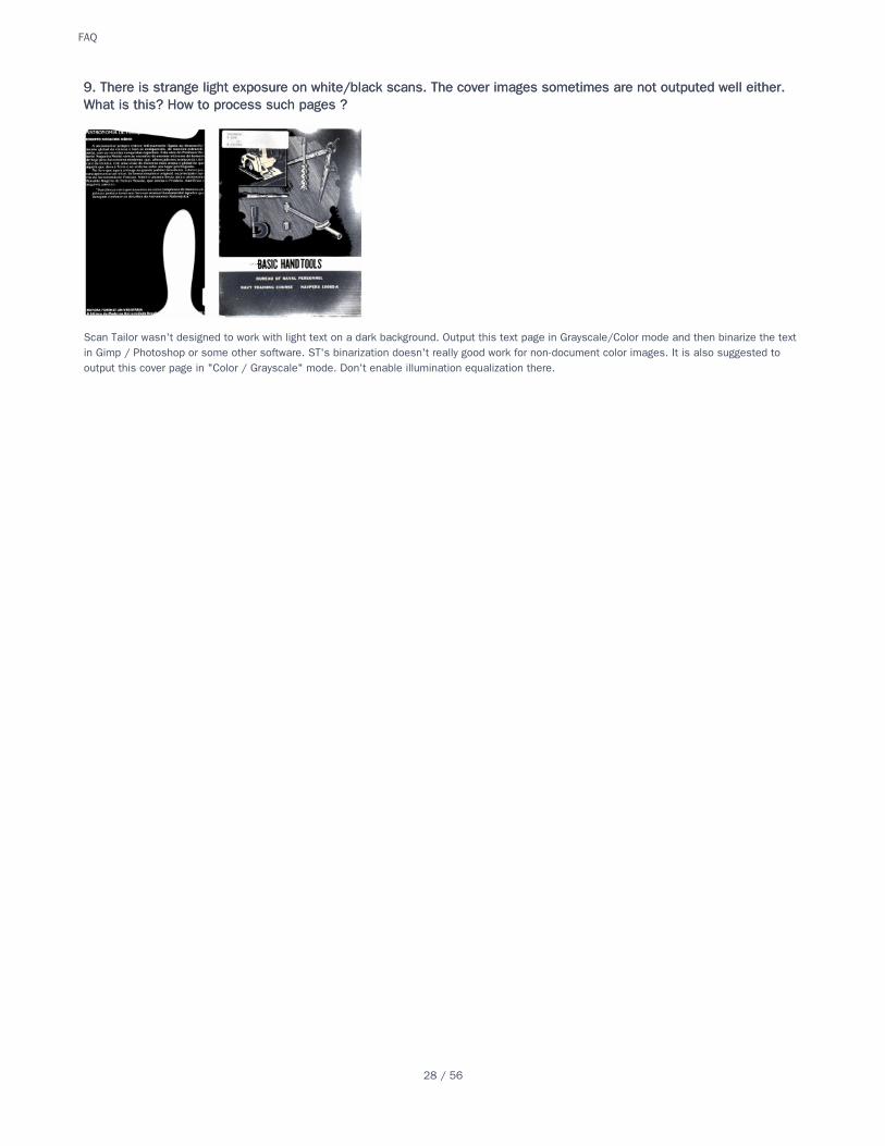
Scan Tailor wasn't designed to work with light text on a dark background. Output this text page in Grayscale/Color mode and then binarize the textin Gimp / Photoshop or some other software. ST's binarization doesn't really good work for non-document color images. It is also suggested tooutput this cover page in "Color / Grayscale" mode. Don't enable illumination equalization there.
9. There is strange light exposure on white/black scans. The cover images sometimes are not outputed well either.9. There is strange light exposure on white/black scans. The cover images sometimes are not outputed well either.What is this? How to process such pages ?What is this? How to process such pages ?
FAQ
28 / 56
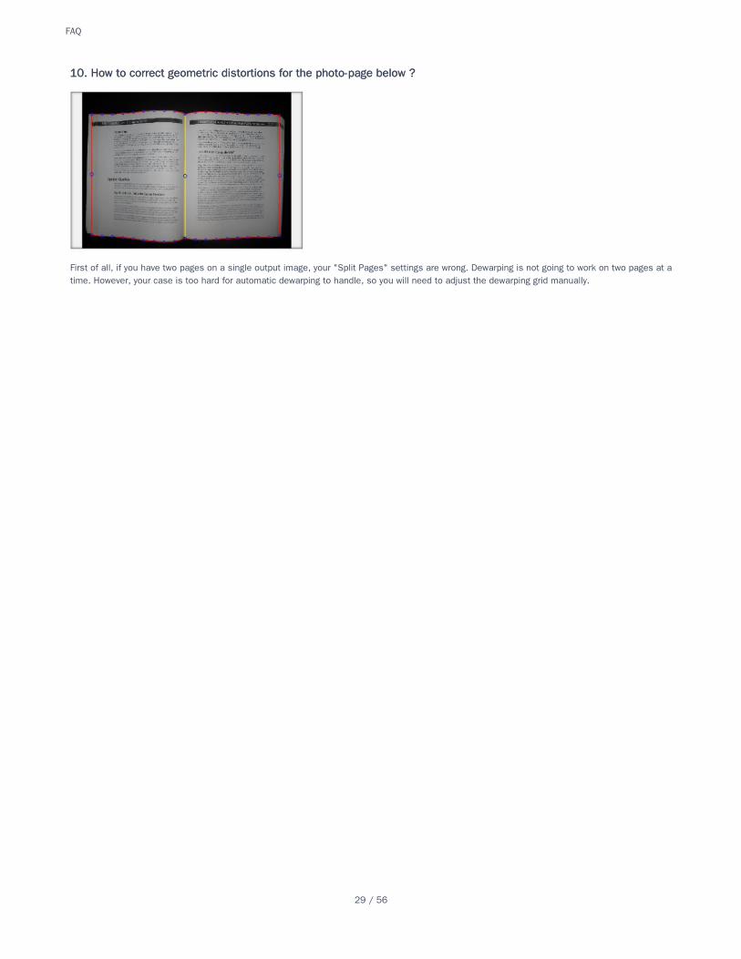
First of all, if you have two pages on a single output image, your "Split Pages" settings are wrong. Dewarping is not going to work on two pages at atime. However, your case is too hard for automatic dewarping to handle, so you will need to adjust the dewarping grid manually.
10. How to correct geometric distortions for the photo-page below ?10. How to correct geometric distortions for the photo-page below ?
FAQ
29 / 56
The CLI branch (Scan Tailor Command Line Interface) was actually included in the main version some time ago. So, if you are on Windows, you canjust download the ST distribution package and you'll find scantailor-cli.exe inside. The CLI version is able to process images from command line.You also can give it an existed project file. If output_directory is specified as last argument, it overwrites the one in project file.
scantailor-cli [options] <project_file> [output_directory]
scantailor-cli [options] <image, image, ...> <output_directory>
11. How can ScanTailor be automated? I have programmed an application ... [calling some others in a batch]. Is there11. How can ScanTailor be automated? I have programmed an application ... [calling some others in a batch]. Is therea command-line version of Scan Tailor?a command-line version of Scan Tailor?
FAQ
30 / 56
There is a README file in the source archive. It is the required assembly instruction.
12. How to build ST for Windows from the source files?12. How to build ST for Windows from the source files?
FAQ
31 / 56
Scan Tailor output TIFFs for B/W output mode are 1 bit, for Color/Grayscale mode - RGB or grayscale, depending on the original. It's either 8, 24 oreven 32 bits if the original image had transparency. It never goes beyond 8 bit per channel though. In Mixed mode ST outputs grayscale or colorimages and doesn't output B/W ones, even for pages without any pictures. That's an implementation detail. It's always the same as "Color /Grayscale" mode, that is 8 bit Grayscale or 8+8+8 bit RGB or 8+8+8+8 bit RGBA. There is no benefit to export 16 bit images for input into ScanTailor. As all internal processing is done in 8 bits per channel, the very first thing that's done to an input image is converting it to that format.
13. How does output TIFF type correlate with the input type ? Will the 16-bit TIFF sent to the ST produce better results13. How does output TIFF type correlate with the input type ? Will the 16-bit TIFF sent to the ST produce better resultsor is it not necessary?or is it not necessary?
FAQ
32 / 56
Separate output of picture images and text images in ST is not planned, although it is not difficult to organize, as this separation still occurs in amixed mode. (FOR REFERENCE: such export of separated text/pictures output exists in branch "Featured".) ST's Mixed output and in fact all otheroutput modes follow a certain convention to make it easy to separate B/W content from pictures. The convention is to never use pure black andpure white colors in pictures. Pure colors are reserved for text areas only. For 8bit grey images in picture areas color 0x00 is replaced with color0x01 and color 0xFF with 0xFE. For both RGB32 and ARGB32 picture areas color 0x00000000 switches to 0xFF010101 and color 0x00FFFFFF to0xFFFEFEFE. This behaviour makes it possible to detect those picture areas later and treat them differently, for example encoding them as abackground layer in DjVu format. That's how such external utilities as PDFMaker and djvubind separate text and pictures, using ST output.
14. Is it possible to get separate output for the mask and background layers in ST instead of assigning the task of14. Is it possible to get separate output for the mask and background layers in ST instead of assigning the task ofdividing them to the DJVU encoder?dividing them to the DJVU encoder?
FAQ
33 / 56
At this stage it is possible to turn scans by multiples of 90 degrees. i.e., to correct sideways or upside-down scans.
This is a manual stage because the program does not know how to determine the correct orientation of scans - the user must do this. This alsomeans that using batch processing at this stage is useless. (However, note that the images will be cached on the preview tape, which can be usefulwith large source files.)
Settings panel for this stage appears as follows:
Buttons with yellow arrows rotate scans 90 degrees in one direction or the other. A green pointer shows which direction the scan is oriented at thegiven moment. The button "reset" returns the scan to the initial position - the green pointer will indicate upward.
This makes it possible to turn not only this page (which is done automatically), but also others. This dialogue is opened by clicking on the "Apply to..." button and it appears as follows:
The first two options in the list do not require explanation. “This page and the following ones” will apply the same operation that has been applied tothe current page to each page after the current one. “Every other page” will apply rotation to either each even or to each odd page in accordancewith whether the current page is even or odd. The last two options are activated only if two or more pages are selected from the preview pane. Touse “Every other selected page” the selected pages must be continuous. To select continuous pages it's often more convenient to use Shift + click.
Back to the user manual
Go to the next stage
Fix Orientation
Split Pages
Deskew (correcting tilted pages)
Select Content
Page Layout
Fix-OrientationFix-Orientation
RotateRotate
Apply toApply to
Links to all other stages:Links to all other stages:
Fix-Orientation
34 / 56
You are currently at Scan Tailor project's Wiki. A Wiki is a content management system that allows visitors to add new and edit existing content.This Wiki is intended for Scan Tailor's documentation, Frequently Asked Questions, Tips and things like that. There is also a discussion system thatallows commenting on the content of a particular page.
The English pages are currently in an active stage of development. If you are interested, you are welcome to add such content. You need to belogged in as Github user to do that. You can also contact me about working on these pages.
User Guide
Quick Start Guide
Video Tutorial
Tips for Scanning
Building from Source Code on Linux and Mac OS X
HomeHome
Home
35 / 56
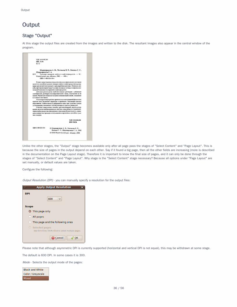
At this stage the output files are created from the images and written to the disk. The resultant images also appear in the central window of theprogram.
Unlike the other stages, the "Output" stage becomes available only after all page pass the stages of "Select Content" and "Page Layout". This isbecause the size of pages in the output depend on each other. Say if it found a big page, then all the other fields are increasing (more is describedin the documentation on the Page Layout stage). Therefore it is important to know the final size of pages, and it can only be done through thestages of "Select Content" and "Page Layout". Why stage is the "Select Content" stage necessary? Because all options under "Page Layout" areset manually, or default values are taken.
Configure the following:
Output Resolution (DPI) - you can manually specify a resolution for the output files:
Please note that although asymmetric DPI is currently supported (horizontal and vertical DPI is not equal), this may be withdrawn at some stage.
The default is 600 DPI. In some cases it is 300.
Mode - Selects the output mode of the pages:
OutputOutput
Stage "Output"Stage "Output"
Output
36 / 56
Black and WhiteBlack and White mode hardly requires explanation but clearly there are no greytones available so this would not be suitable for any images andsome drawings. There is an option to "despeckle", and to increase or decrease the line thickness (i.e. of the text). In general it is best to notdespeckle if the image is reasonably clean as despeckling can result in the loss of some portions of text. This may be compensated for to a degreeby increasing the line thickness but it's probably important to experiment on a few pages before applying to the entire project.
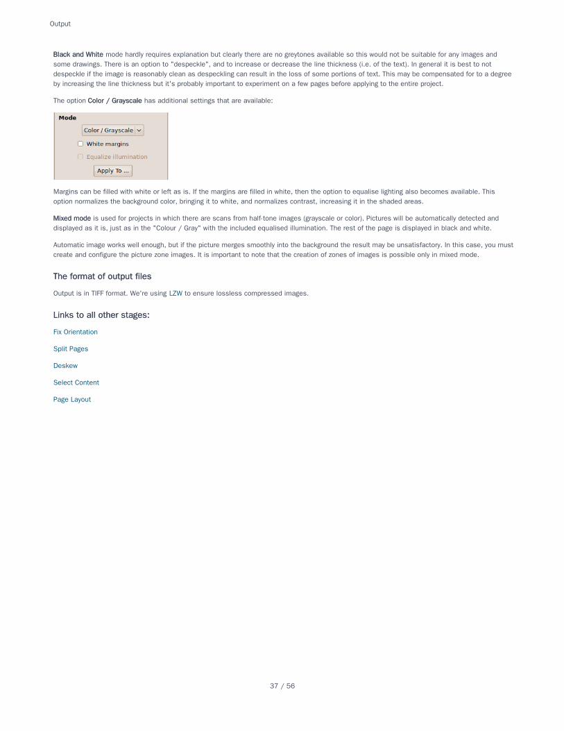
The option Color / GrayscaleColor / Grayscale has additional settings that are available:
Margins can be filled with white or left as is. If the margins are filled in white, then the option to equalise lighting also becomes available. Thisoption normalizes the background color, bringing it to white, and normalizes contrast, increasing it in the shaded areas.
Mixed modeMixed mode is used for projects in which there are scans from half-tone images (grayscale or color). Pictures will be automatically detected anddisplayed as it is, just as in the "Colour / Gray" with the included equalised illumination. The rest of the page is displayed in black and white.
Automatic image works well enough, but if the picture merges smoothly into the background the result may be unsatisfactory. In this case, you mustcreate and configure the picture zone images. It is important to note that the creation of zones of images is possible only in mixed mode.
Output is in TIFF format. We're using LZW to ensure lossless compressed images.
Fix Orientation
Split Pages
Deskew
Select Content
Page Layout
The format of output filesThe format of output files
Links to all other stages:Links to all other stages:
Output
37 / 56
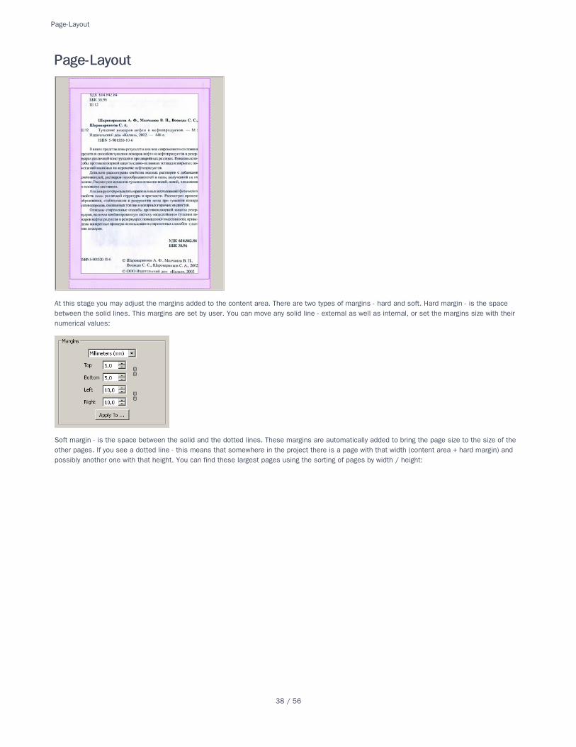
At this stage you may adjust the margins added to the content area. There are two types of margins - hard and soft. Hard margin - is the spacebetween the solid lines. This margins are set by user. You can move any solid line - external as well as internal, or set the margins size with theirnumerical values:
Soft margin - is the space between the solid and the dotted lines. These margins are automatically added to bring the page size to the size of theother pages. If you see a dotted line - this means that somewhere in the project there is a page with that width (content area + hard margin) andpossibly another one with that height. You can find these largest pages using the sorting of pages by width / height:
Page-LayoutPage-Layout
Page-Layout
38 / 56
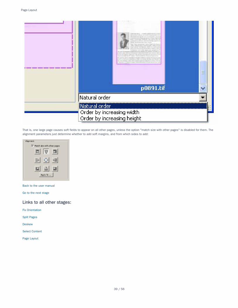
That is, one large page causes soft fields to appear on all other pages, unless the option "match size with other pages" is disabled for them. Thealignment parameters just determine whether to add soft margins, and from which sides to add:
Back to the user manual
Go to the next stage
Fix Orientation
Split Pages
Deskew
Select Content
Page Layout
Links to all other stages:Links to all other stages:
Page-Layout
39 / 56
1. Open ScanTailor & select "new project" to begin with a new set of images.
2. Browse to select the directory that contains the images you wish to process
3. Select the images as required.
4. ScanTailor will default to using the same directory appended with an "out" directory for processed images but you can select a differentdirectory at this stage if you wish.
5. At the next stage it's necessary to set the DPI level. Click on "all pages", set or use drop arrow in ‘custom’ to select the level. For accuratecontent selection use a lower setting (300 x 300). For digital camera images you may need to measure the physical dimensions of the area ofwhich the picture was taken and then divide to get the DPI (dots or pixels per inch).
6. Set the orientation of the first image, if necessary click "apply to" and select "all pages" to propagate that setting to the rest of the images.
7. Click to "split pages". If the image is of two pages of a book for instance ScanTailor will attempt to split the image into the two pages. Click onthe > arrow to have ScanTailor batch process split for the remainder of the images. Splits can be set using the page layout section.
8. In all cases individual pages can be inspected in the thumbnails to the right of the main page, clicking on a thumbnail will load that page to themain area and allow for adjustment of various parameters.
9. Select "deskew" if it’s needed and ScanTailor will attempt to straighten up text and images based on the edges of the text/image. Once againuse the > arrow to batch process as needed and use the thumbnails to quickly check each page.
10. Click on "select content" and batch process (> right arrow). Check thumbnails and adjust by selecting that thumbnail and altering main page asneeded (click and drag edges of the content box). If no content is selected a content box may be manually entered by selecting that image andright-click in the main window, add content box and adjust as needed. Likewise one may remove a content box from a page by right-click anddelete.
11. Then move to "page layout" and adjust the various parameters according to your requirements. ScanTailor defaults work well for most cases.
12. Finally click on "output" and select the type of image output desired. Black and white will produce a clean output image for simple text and linedrawings. If some text appears to be "missing" try adjusting the line thickness to see if it appears (increase). Once set this may be applied toall pages and run through the batch process. Alternatively for images with photographs etc one may select "mixed" or even colour/grayscale. Inall cases it’s wise to check the thumbs after processing particularly in black & white or mixed mode to ensure that all the required content isincluded.
13. Files will be saved as tiff's in the selected directory and may be further manipulated or used as required from there.
Video Tutorial
Quick-Start-GuideQuick-Start-Guide
See alsoSee also
Quick-Start-Guide
40 / 56
Try to press different buttons, drag all kinds of frames and lines. Thus you will understand their functions much better than when reading theexplanations.
In short, there are six main stages of the process workflow in ScanTailor:
1. FIX ORIENTATION - rotation of scans at 90, 180 or 270 degrees;
2. SPLIT PAGES - division of two-page spreads into two pages / cut-off of the waste part of another page from single pages;
3. DESKEW - rotation of scans at 0-90 degrees, making text lines horizontal;
4. SELECT CONTENT - selection of the text area on the page, embracing it with special frame;
5. MARGINS (ex PAGE LAYOUT) - setting the margins and matching page size with other pages;
6. OUTPUT - creation of final page images. Optional here are binarization (converting color images into b/w), picture areas detection (for savingtheir colors), despeckling (noise removal), dewarping (straightening of page curvature).
It is suggested to work as follows: create a project, add files, if ST asks - fix DPI. If necessary, correct the page orientation. Then go directly to"Select Content" stage. Start batch processing. After that check errors. If there are many errors, it is better to view all pages consequentially. If not,use the Widest Page / Tallest Page sorting and check only the smallest and the largest ones. If the problem is caused by incorrect splitting, go backto the previous stage and fix the position of the cut line. Then return to "Select Content" stage and process that page again. When you are doneselecting the content, go to the "Margins" stage and edit the page layout. Simply set the default sizes of page fields, align all content areas in thecenter and then change the alignment for individual non-standard pages. Now go to the "Output" stage, set the parameters there, apply them to allpages, and start batch processing again. Check the output images. If necessary, you can set other parameters for individual pages and re-outputthem.
Video Tutorial
Quick-StartQuick-Start
See alsoSee also
Quick-Start
41 / 56
The first main target should be a cleanup of existing code and issues, so we can target a v1.0.0 branch
☐ identify useful enhanced features
☐ merge enhanced features into master
☐ remove old/unused branches
☐ cleaner file/folder organisation
☐ document code (so we can generate sphinx or some other documentation)
☐ javadoc like file header comments(@copyright, @license)
☐ write some tests
☐ document (new) features
☐ write some contribution guide
☐ define some standards (naming conventions, tests)
☑ implement some ircbot (@sakulstra)
☐ scrutinizer-ci(@sakulstra - (c++ not yet supported)
We need to identify which features in the enhanced, plus, featured, and possibly qt5 branches are not in the main branch, and add each one as afeature request on the Github issue tracker.
Pop out thumbnail and control windows
Apply to this page and the following every other page
Apply to every other selected page
Split Pages: Apply Cut
Content Box disable
Page BoxFine Tune page corners
disable/auto/manual
Auto margins
alignment: auto, manual, original
Tiff compression options (LZW, Deflate, Packbits, JPEG)
Picture Shape: Free / Rectangular
Start Batch Processing Dialog
Deviation patch
Picture Shape: Free/Rectangle
Autosave
Default Project Settings
Binarization Threshold Range Value
Equalize Illumination checkbox in Mixed Mode
CCITT Groupe 4 Fax TIFF output
Delete_3_Red_Points
Manual_Dewarp_Auto_Switch
Roadmap-1.0Roadmap-1.0
Organising the repositoryOrganising the repository
DocumentationDocumentation
Miscellaneous (not important at all)Miscellaneous (not important at all)
Missing FeaturesMissing Features
EnhancedEnhanced
PlusPlus
FeaturedFeatured
Roadmap-1.0
42 / 56
Blue_Dewarp_Line_Vert_Drag
Square_Picture_Zones
Ortho_Corner_Move_Square_Picture_Zones
Export_Subscans
Auto_Save_Project
Dont_Equalize_Illumination_Pic_Zones
Original_Foreground_Mixed
Picture_Shape
Picture_Shape_Bug
Quadro_Zoner
Marginal_Dewarping
Auto_Dewarping_Vert_Half_Correction
qt5qt5
Roadmap-1.0
43 / 56
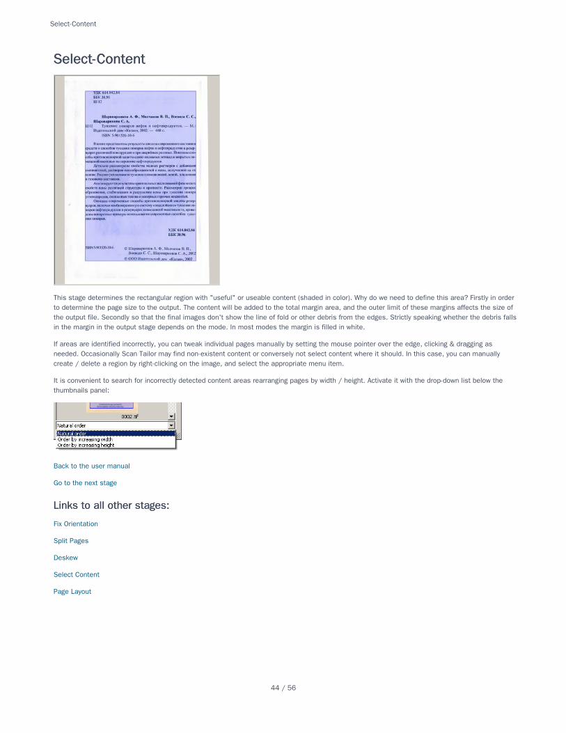
This stage determines the rectangular region with "useful" or useable content (shaded in color). Why do we need to define this area? Firstly in orderto determine the page size to the output. The content will be added to the total margin area, and the outer limit of these margins affects the size ofthe output file. Secondly so that the final images don't show the line of fold or other debris from the edges. Strictly speaking whether the debris fallsin the margin in the output stage depends on the mode. In most modes the margin is filled in white.
If areas are identified incorrectly, you can tweak individual pages manually by setting the mouse pointer over the edge, clicking & dragging asneeded. Occasionally Scan Tailor may find non-existent content or conversely not select content where it should. In this case, you can manuallycreate / delete a region by right-clicking on the image, and select the appropriate menu item.
It is convenient to search for incorrectly detected content areas rearranging pages by width / height. Activate it with the drop-down list below thethumbnails panel:
Back to the user manual
Go to the next stage
Fix Orientation
Split Pages
Deskew
Select Content
Page Layout
Select-ContentSelect-Content
Links to all other stages:Links to all other stages:
Select-Content
44 / 56
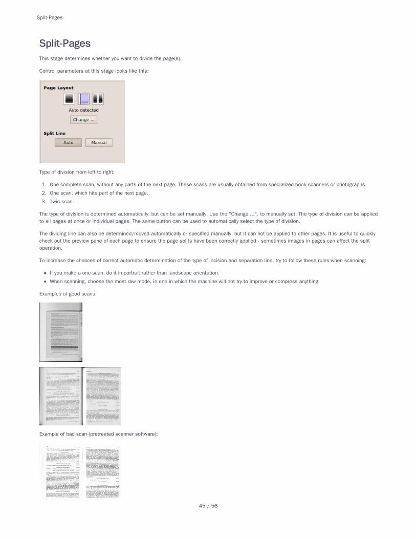
This stage determines whether you want to divide the page(s).
Control parameters at this stage looks like this:
Type of division from left to right:
1. One complete scan, without any parts of the next page. These scans are usually obtained from specialized book scanners or photographs.
2. One scan, which hits part of the next page.
3. Twin scan.
The type of division is determined automatically, but can be set manually. Use the "Change ...", to manually set. The type of division can be appliedto all pages at once or individual pages. The same button can be used to automatically select the type of division.
The dividing line can also be determined/moved automatically or specified manually, but it can not be applied to other pages. It is useful to quicklycheck out the preview pane of each page to ensure the page splits have been correctly applied - sometimes images in pages can affect the splitoperation.
To increase the chances of correct automatic determination of the type of incision and separation line, try to follow these rules when scanning:
If you make a one-scan, do it in portrait rather than landscape orientation.
When scanning, choose the most raw mode, ie one in which the machine will not try to improve or compress anything.
Examples of good scans:
Example of bad scan (pretreated scanner software):
Split-PagesSplit-Pages
Split-Pages
45 / 56
Back to the user manual
Go to the next stage
Fix Orientation
Split Pages
Deskew (correcting tilted pages)
Select Content
Page Layout
Links to all other stages:Links to all other stages:
Split-Pages
46 / 56
To get a good result with Scan Tailor, and minimise errors in the automatic processing, follow these rules when scanning:
Don’t scan in black and white mode - use grayscale, or, if necessary, colour.
Don’t scan at any lower resolution than 300 DPI, typically scan at 300 or 600 DPI.
Do not scan to JPEG – the format is lossy, and converting to other formats will not result in better quality. (Camera users will most likely needto use JPG mode but use the best resolution and the best JPEG quality settings possible).
When scanning typically use TIFF format, but be careful as TIFF can be used for jpeg-compression algorithms.
If you need to compress the image then choose LZW - a lossless format
If unable to use TIFF then scan to PNG - it is guaranteed to use lossless compression algorithms, or, in extreme cases, to BMP (file size will beuncompressed and therefore enormous, and should preferably be converted into a format that uses lossless compression).
Avoid scanning mode "Document", and generally try to disable all options to improve the scans.
Tips-for-ScanningTips-for-Scanning
Tips-for-Scanning
47 / 56
Scan Tailor is an interactive tool for post-processing of scanned pages. It gives the ability to cut or crop pages, compensate for skew angle, and add/ delete content fields and margins, among others. You begin with raw scans, and end up with tiff's that are ready for printing or assembly in PDF orDjVu file.
Scanning, OCR, and the building of single-file multi-page documents are not included in the project objectives.
The program is developed for Windows, GNU / Linux, and other Unix-like systems such as Mac OS X.
Versions for Windows come in the form of an installer. Install the program and run through the self-explanatory menu.
32-bit installer 0.9.11.1
64-bit installer 0.9.11.1
If your distribution does not have Scan Tailor in its repositories (and the only distributions I know of are Alt Linux and Debian), then you have to buildit from source. After assembly, you can run Scan Tailor via Alt + F2, using the command "scantailor" (without the quotes), or if you don't have aGnome environment you can type the same command on the command line. On Mac OS X, it currently must be run from the terminal after buildingand installation.
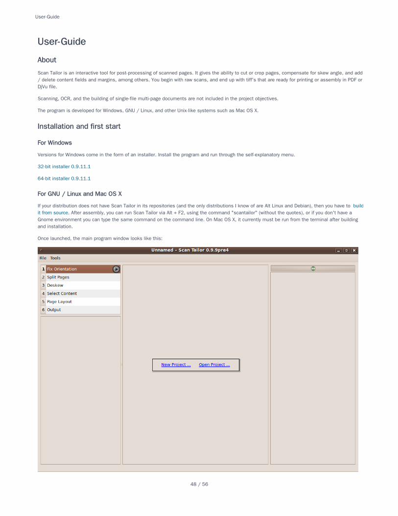
Once launched, the main program window looks like this:
User-GuideUser-Guide
AboutAbout
Installation and first startInstallation and first start
For WindowsFor Windows
For GNU / Linux and Mac OS XFor GNU / Linux and Mac OS X
User-Guide
48 / 56
In the central panel we see the items "New project ...", " Open Project ... " and a list of recent projects, if any.
So, let's create our first project. First, we need the raw material - Scan Tailor requires the presence of at least one image file in the project. Thissource material can be scanned or photographed pages of a book or a magazine. Follow these tips for scanning to get the best results.
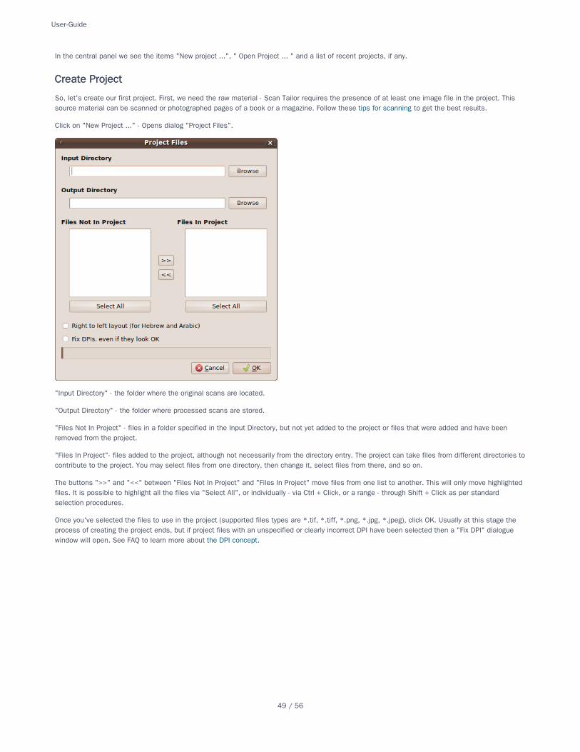
Click on "New Project ..." - Opens dialog "Project Files".
"Input Directory" - the folder where the original scans are located.
"Output Directory" - the folder where processed scans are stored.
"Files Not In Project" - files in a folder specified in the Input Directory, but not yet added to the project or files that were added and have beenremoved from the project.
"Files In Project"- files added to the project, although not necessarily from the directory entry. The project can take files from different directories tocontribute to the project. You may select files from one directory, then change it, select files from there, and so on.
The buttons ">>" and "<<" between "Files Not In Project" and "Files In Project" move files from one list to another. This will only move highlightedfiles. It is possible to highlight all the files via "Select All", or individually - via Ctrl + Click, or a range - through Shift + Click as per standardselection procedures.
Once you've selected the files to use in the project (supported files types are *.tif, *.tiff, *.png, *.jpg, *.jpeg), click OK. Usually at this stage theprocess of creating the project ends, but if project files with an unspecified or clearly incorrect DPI have been selected then a "Fix DPI" dialoguewindow will open. See FAQ to learn more about the DPI concept.
Create ProjectCreate Project
User-Guide
49 / 56
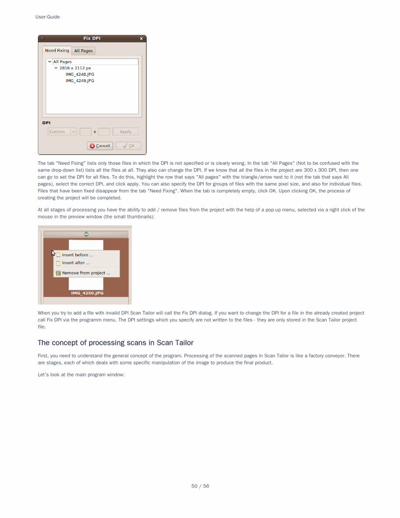
The tab "Need Fixing" lists only those files in which the DPI is not specified or is clearly wrong. In the tab "All Pages" (Not to be confused with thesame drop-down list) lists all the files at all. They also can change the DPI. If we know that all the files in the project are 300 x 300 DPI, then onecan go to set the DPI for all files. To do this, highlight the row that says "All pages" with the triangle/arrow next to it (not the tab that says Allpages), select the correct DPI, and click apply. You can also specify the DPI for groups of files with the same pixel size, and also for individual files.Files that have been fixed disappear from the tab "Need Fixing". When the tab is completely empty, click OK. Upon clicking OK, the process ofcreating the project will be completed.
At all stages of processing you have the ability to add / remove files from the project with the help of a pop-up menu, selected via a right click of themouse in the preview window (the small thumbnails):
When you try to add a file with invalid DPI Scan Tailor will call the Fix DPI dialog. If you want to change the DPI for a file in the already created projectcall Fix DPI via the programm menu. The DPI settings which you specify are not written to the files - they are only stored in the Scan Tailor projectfile.
First, you need to understand the general concept of the program. Processing of the scanned pages in Scan Tailor is like a factory conveyor. Thereare stages, each of which deals with some specific manipulation of the image to produce the final product.
Let's look at the main program window:
The concept of processing scans in Scan TailorThe concept of processing scans in Scan Tailor
User-Guide
50 / 56
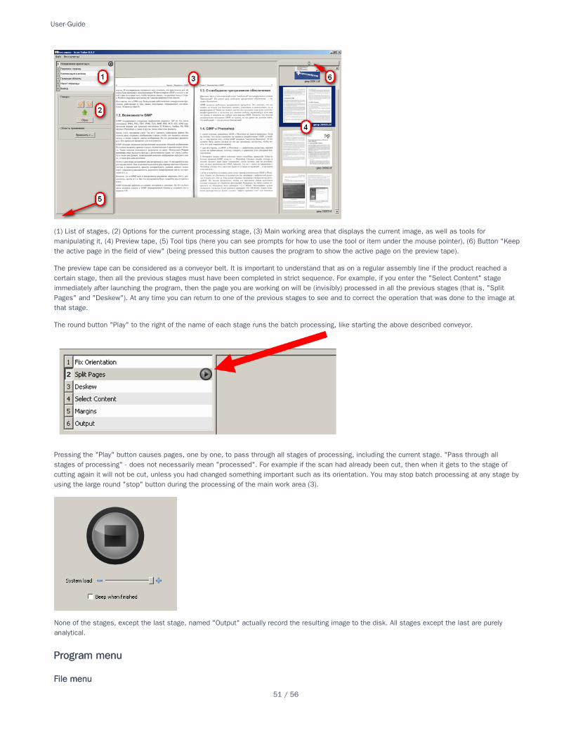
(1) List of stages, (2) Options for the current processing stage, (3) Main working area that displays the current image, as well as tools formanipulating it, (4) Preview tape, (5) Tool tips (here you can see prompts for how to use the tool or item under the mouse pointer), (6) Button "Keepthe active page in the field of view" (being pressed this button causes the program to show the active page on the preview tape).
The preview tape can be considered as a conveyor belt. It is important to understand that as on a regular assembly line if the product reached acertain stage, then all the previous stages must have been completed in strict sequence. For example, if you enter the "Select Content" stageimmediately after launching the program, then the page you are working on will be (invisibly) processed in all the previous stages (that is, "SplitPages" and "Deskew"). At any time you can return to one of the previous stages to see and to correct the operation that was done to the image atthat stage.
The round button "Play" to the right of the name of each stage runs the batch processing, like starting the above described conveyor.
Pressing the "Play" button causes pages, one by one, to pass through all stages of processing, including the current stage. "Pass through allstages of processing" - does not necessarily mean "processed". For example if the scan had already been cut, then when it gets to the stage ofcutting again it will not be cut, unless you had changed something important such as its orientation. You may stop batch processing at any stage byusing the large round "stop" button during the processing of the main work area (3).
None of the stages, except the last stage, named "Output" actually record the resulting image to the disk. All stages except the last are purelyanalytical.
Program menuProgram menu
File menuFile menu
User-Guide
51 / 56
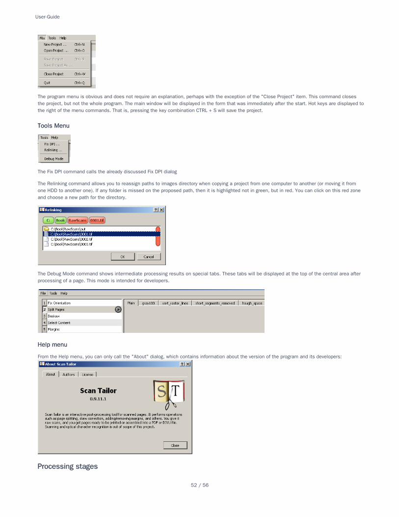
The program menu is obvious and does not require an explanation, perhaps with the exception of the "Close Project" item. This command closesthe project, but not the whole program. The main window will be displayed in the form that was immediately after the start. Hot keys are displayed tothe right of the menu commands. That is, pressing the key combination CTRL + S will save the project.
The Fix DPI command calls the already discussed Fix DPI dialog
The Relinking command allows you to reassign paths to images directory when copying a project from one computer to another (or moving it fromone HDD to another one). If any folder is missed on the proposed path, then it is highlighted not in green, but in red. You can click on this red zoneand choose a new path for the directory.
The Debug Mode command shows intermediate processing results on special tabs. These tabs will be displayed at the top of the central area afterprocessing of a page. This mode is intended for developers.
From the Help menu, you can only call the "About" dialog, which contains information about the version of the program and its developers:
Tools MenuTools Menu
Help menuHelp menu
Processing stagesProcessing stages
User-Guide
52 / 56
Fix Orientation
Split Pages
Deskew
Select Content
Page Layout
Video Tutorial
See alsoSee also
User-Guide
53 / 56
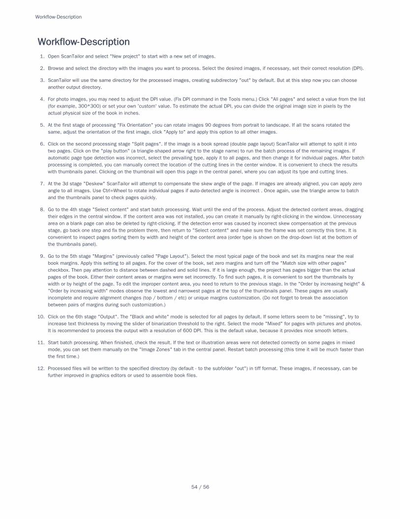
1. Open ScanTailor and select "New project" to start with a new set of images.
2. Browse and select the directory with the images you want to process. Select the desired images, if necessary, set their correct resolution (DPI).
3. ScanTailor will use the same directory for the processed images, creating subdirectory "out" by default. But at this step now you can chooseanother output directory.
4. For photo images, you may need to adjust the DPI value. (Fix DPI command in the Tools menu.) Click "All pages" and select a value from the list(for example, 300*300) or set your own 'custom' value. To estimate the actual DPI, you can divide the original image size in pixels by theactual physical size of the book in inches.
5. At the first stage of processing "Fix Orientation" you can rotate images 90 degrees from portrait to landscape. If all the scans rotated thesame, adjust the orientation of the first image, click "Apply to" and apply this option to all other images.
6. Click on the second processing stage "Split pages". If the image is a book spread (double page layout) ScanTailor will attempt to split it intotwo pages. Click on the "play button" (a triangle-shaped arrow right to the stage name) to run the batch process of the remaining images. Ifautomatic page type detection was incorrect, select the prevailing type, apply it to all pages, and then change it for individual pages. After batchprocessing is completed, you can manually correct the location of the cutting lines in the center window. It is convenient to check the resultswith thumbnails panel. Clicking on the thumbnail will open this page in the central panel, where you can adjust its type and cutting lines.
7. At the 3d stage "Deskew" ScanTailor will attempt to compensate the skew angle of the page. If images are already aligned, you can apply zeroangle to all images. Use Ctrl+Wheel to rotate individual pages if auto-detected angle is incorrect . Once again, use the triangle arrow to batchand the thumbnails panel to check pages quickly.
8. Go to the 4th stage "Select content" and start batch processing. Wait until the end of the process. Adjust the detected content areas, draggingtheir edges in the central window. If the content area was not installed, you can create it manually by right-clicking in the window. Unnecessaryarea on a blank page can also be deleted by right-clicking. If the detection error was caused by incorrect skew compensation at the previousstage, go back one step and fix the problem there, then return to "Select content" and make sure the frame was set correctly this time. It isconvenient to inspect pages sorting them by width and height of the content area (order type is shown on the drop-down list at the bottom ofthe thumbnails panel).
9. Go to the 5th stage "Margins" (previously called "Page Layout"). Select the most typical page of the book and set its margins near the realbook margins. Apply this setting to all pages. For the cover of the book, set zero margins and turn off the "Match size with other pages"checkbox. Then pay attention to distance between dashed and solid lines. If it is large enough, the project has pages bigger than the actualpages of the book. Either their content areas or margins were set incorrectly. To find such pages, it is convenient to sort the thumbnails bywidth or by height of the page. To edit the improper content area, you need to return to the previous stage. In the "Order by increasing height" &"Order by increasing width" modes observe the lowest and narrowest pages at the top of the thumbnails panel. These pages are usuallyincomplete and require alignment changes (top / bottom / etc) or unique margins customization. (Do not forget to break the associationbetween pairs of margins during such customization.)
10. Click on the 6th stage "Output". The "Black and white" mode is selected for all pages by default. If some letters seem to be "missing", try toincrease text thickness by moving the slider of binarization threshold to the right. Select the mode "Mixed" for pages with pictures and photos.It is recommended to process the output with a resolution of 600 DPI. This is the default value, because it provides nice smooth letters.
11. Start batch processing. When finished, check the result. If the text or illustration areas were not detected correctly on some pages in mixedmode, you can set them manually on the "Image Zones" tab in the central panel. Restart batch processing (this time it will be much faster thanthe first time.)
12. Processed files will be written to the specified directory (by default - to the subfolder "out") in tiff format. These images, if necessary, can befurther improved in graphics editors or used to assemble book files.
Workflow-DescriptionWorkflow-Description
Workflow-Description
54 / 56
[[Home]]
[[Roadmap 1.0]]
Video Tutorial
[[User Guide]]Installation
Quick Start
Workflow Description
[[Tips for Scanning]]
[[FAQ]]
Steps[[Fix Orientation]]
[[Split Pages]]
[[Deskew]]
[[Select Content]]
Margins
[[Output]]Picture Zones
Dewarping
Despeckling & Fill Zones
_Sidebar_Sidebar
_Sidebar
55 / 56

_Sidebar
56 / 56


