Embed Size (px)
Citation preview
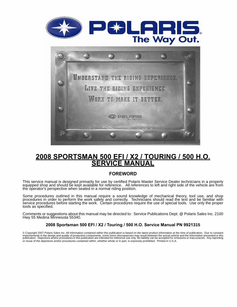
2008 SPORTSMAN 500 EFI / X2 / TOURING / 500 H.O.SERVICE MANUAL
FOREWORDThis service manual is designed primarily for use by certified Polaris Master Service Dealer technicians in a properlyequipped shop and should be kept available for reference. All references to left and right side of the vehicle are fromthe operator's perspective when seated in a normal riding position.
Some procedures outlined in this manual require a sound knowledge of mechanical theory, tool use, and shopprocedures in order to perform the work safely and correctly. Technicians should read the text and be familiar withservice procedures before starting the work. Certain procedures require the use of special tools. Use only the propertools as specified.
Comments or suggestions about this manual may be directed to: Service Publications Dept. @ Polaris Sales Inc. 2100Hwy 55 Medina Minnesota 55340.
2008 Sportsman 500 EFI / X2 / Touring / 500 H.O. Service Manual PN 9921315
© Copyright 2007 Polaris Sales Inc. All information contained within this publication is based on the latest product information at the time of publication. Due to constantimprovements in the design and quality of production components, some minor discrepancies may result between the actual vehicle and the information presented in thispublication. Depictions and/or procedures in this publication are intended for reference use only. No liability can be accepted for omissions or inaccuracies. Any reprintingor reuse of the depictions and/or procedures contained within, whether whole or in part, is expressly prohibited. Printed in U.S.A.
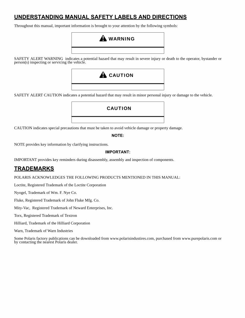
UNDERSTANDING MANUAL SAFETY LABELS AND DIRECTIONSThroughout this manual, important information is brought to your attention by the following symbols:
SAFETY ALERT WARNING indicates a potential hazard that may result in severe injury or death to the operator, bystander orperson(s) inspecting or servicing the vehicle.
SAFETY ALERT CAUTION indicates a potential hazard that may result in minor personal injury or damage to the vehicle.
CAUTION indicates special precautions that must be taken to avoid vehicle damage or property damage.
NOTE:
NOTE provides key information by clarifying instructions.
IMPORTANT:
IMPORTANT provides key reminders during disassembly, assembly and inspection of components.
TRADEMARKSPOLARIS ACKNOWLEDGES THE FOLLOWING PRODUCTS MENTIONED IN THIS MANUAL:
Loctite, Registered Trademark of the Loctite Corporation
Nyogel, Trademark of Wm. F. Nye Co.
Fluke, Registered Trademark of John Fluke Mfg. Co.
Mity-Vac, Registered Trademark of Neward Enterprises, Inc.
Torx, Registered Trademark of Textron
Hilliard, Trademark of the Hilliard Corporation
Warn, Trademark of Warn Industries
Some Polaris factory publications can be downloaded from www.polarisindustires.com, purchased from www.purepolaris.com orby contacting the nearest Polaris dealer.
WARNING
CAUTION
CAUTION
1GENERAL
2MAINTENANCE
3ENGINE
4FUEL SYSTEM
5BODY / SUSPENSION
6CLUTCH
7TRANSMISSION
8FINAL DRIVE
9BRAKES
10ELECTRICAL
11INTERNATIONAL

NOTES
GENERAL INFORMATION
CHAPTER 1GENERAL INFORMATION 1
MODEL NUMBER INFORMATION . . . . . . . . . . . . . . . . . . . . . . . . . . . . . . . . . . . . . . . . . . 1.2MODEL NUMBER. . . . . . . . . . . . . . . . . . . . . . . . . . . . . . . . . . . . . . . . . . . . . . . . . . . . . . . 1.2ENGINE DESIGNATION NUMBERS . . . . . . . . . . . . . . . . . . . . . . . . . . . . . . . . . . . . . . . . 1.2VEHICLE IDENTIFICATION NUMBER (VIN) . . . . . . . . . . . . . . . . . . . . . . . . . . . . . . . . . . 1.2TRANSMISSION I.D. LOCATION. . . . . . . . . . . . . . . . . . . . . . . . . . . . . . . . . . . . . . . . . . . 1.2ENGINE AND MACHINE SERIAL NUMBERS . . . . . . . . . . . . . . . . . . . . . . . . . . . . . . . . . 1.2PUBLICATIONS . . . . . . . . . . . . . . . . . . . . . . . . . . . . . . . . . . . . . . . . . . . . . . . . . . . . . . . . 1.3PAINT CODES . . . . . . . . . . . . . . . . . . . . . . . . . . . . . . . . . . . . . . . . . . . . . . . . . . . . . . . . . 1.3REPLACEMENT KEYS . . . . . . . . . . . . . . . . . . . . . . . . . . . . . . . . . . . . . . . . . . . . . . . . . . 1.3
2008 SPORTSMAN 500 . . . . . . . . . . . . . . . . . . . . . . . . . . . . . . . . . . . . . . . . . . . . . . . . . . 1.4MODEL NUMBER: A08MH50AX, AZ . . . . . . . . . . . . . . . . . . . . . . . . . . . . . . . . . . . . . . . 1.4
2008 SPORTSMAN 500 EFI . . . . . . . . . . . . . . . . . . . . . . . . . . . . . . . . . . . . . . . . . . . . . . . 1.6MODEL NUMBER: A08MN50AF, AN, AQ, AS, AX . . . . . . . . . . . . . . . . . . . . . . . . . . . . . 1.6
2008 SPORTSMAN X-2 500 EFI . . . . . . . . . . . . . . . . . . . . . . . . . . . . . . . . . . . . . . . . . . . . 1.8MODEL NUMBER: A08TN50AX, AZ / A08TN50EA . . . . . . . . . . . . . . . . . . . . . . . . . . . 1.8
2008 SPORTSMAN TOURING 500 EFI . . . . . . . . . . . . . . . . . . . . . . . . . . . . . . . . . . . . . 1.10MODEL NUMBER: A08DN50AF, AS, AZ / A08DN50EA. . . . . . . . . . . . . . . . . . . . . . . . 1.10
MISC. NUMBERS/CHARTS . . . . . . . . . . . . . . . . . . . . . . . . . . . . . . . . . . . . . . . . . . . . . . 1.12STANDARD TORQUE SPECIFICATIONS. . . . . . . . . . . . . . . . . . . . . . . . . . . . . . . . . . . 1.12SAE TAP DRILL SIZES . . . . . . . . . . . . . . . . . . . . . . . . . . . . . . . . . . . . . . . . . . . . . . . . . 1.13METRIC TAP DRILL SIZES . . . . . . . . . . . . . . . . . . . . . . . . . . . . . . . . . . . . . . . . . . . . . . 1.13DECIMAL EQUIVALENTS . . . . . . . . . . . . . . . . . . . . . . . . . . . . . . . . . . . . . . . . . . . . . . . 1.13CONVERSION TABLE . . . . . . . . . . . . . . . . . . . . . . . . . . . . . . . . . . . . . . . . . . . . . . . . . . 1.14GLOSSARY OF TERMS. . . . . . . . . . . . . . . . . . . . . . . . . . . . . . . . . . . . . . . . . . . . . . . . . 1.15
1.1
GENERAL INFORMATION
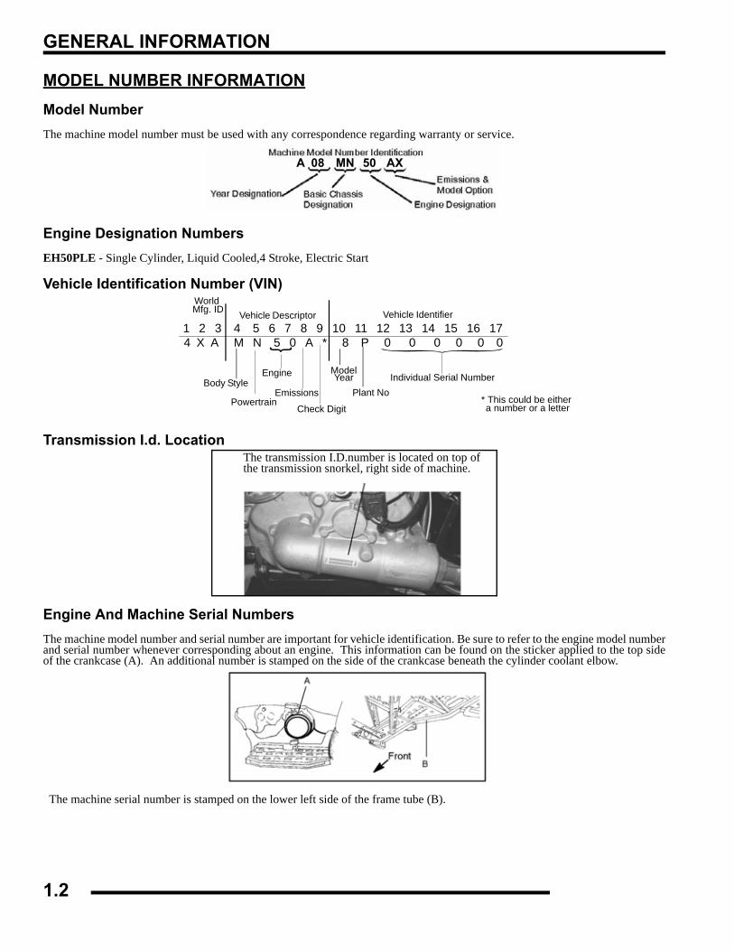
MODEL NUMBER INFORMATIONModel NumberThe machine model number must be used with any correspondence regarding warranty or service.
Engine Designation NumbersEH50PLE - Single Cylinder, Liquid Cooled,4 Stroke, Electric Start
Vehicle Identification Number (VIN)
Transmission I.d. Location
Engine And Machine Serial NumbersThe machine model number and serial number are important for vehicle identification. Be sure to refer to the engine model numberand serial number whenever corresponding about an engine. This information can be found on the sticker applied to the top sideof the crankcase (A). An additional number is stamped on the side of the crankcase beneath the cylinder coolant elbow.
The machine serial number is stamped on the lower left side of the frame tube (B).
A 08 MN 50 AX
1 2 3 4 5 6 7 8 9 10 11 12 13 14 15 16 17
World Mfg. ID
Engine
Vehicle Descriptor Vehicle Identifier Check Digit
ModelYear Body Style
Plant NoIndividual Serial Number
* This could be either a number or a letterPowertrain
Emissions
4 X A M N 5 0 A * 8 P 0 0 0 0 0 0
The transmission I.D.number is located on top ofthe transmission snorkel, right side of machine.
1.2
GENERAL INFORMATION
1
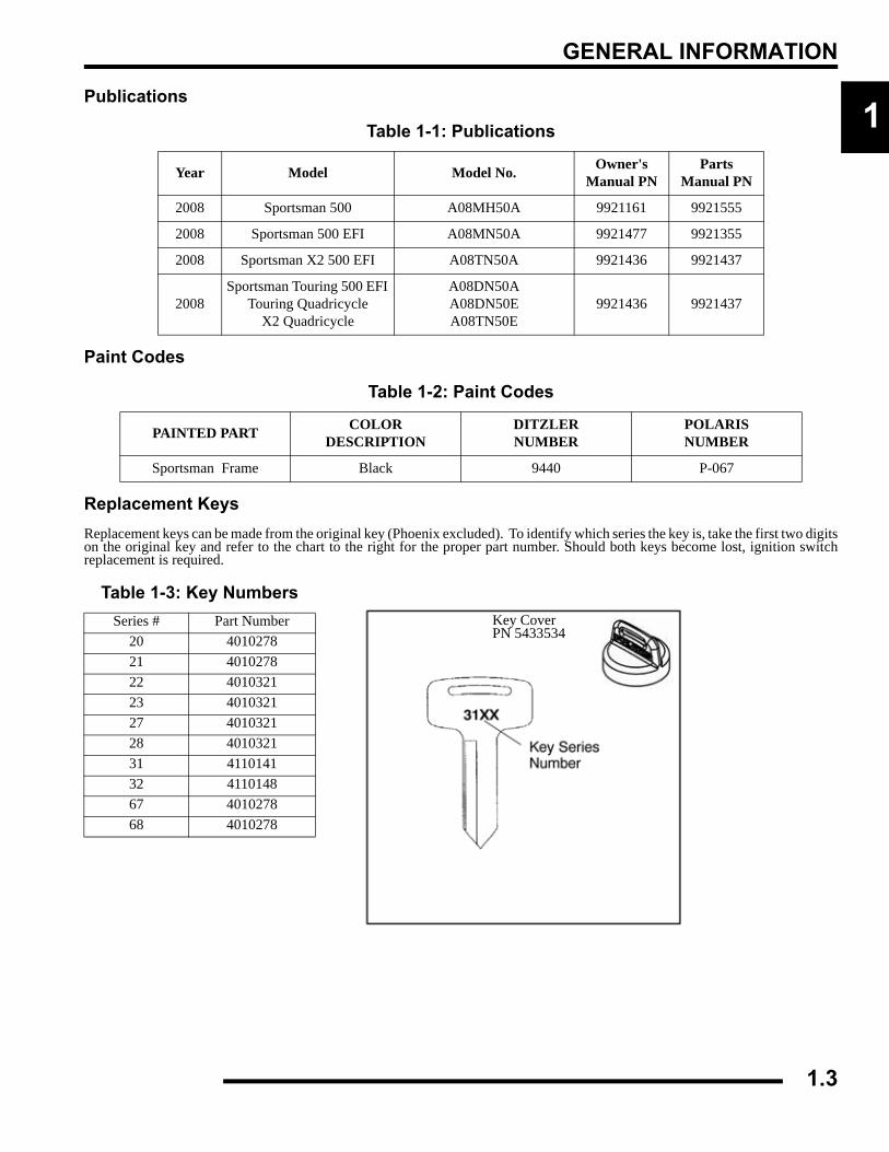
PublicationsPaint Codes
Replacement KeysReplacement keys can be made from the original key (Phoenix excluded). To identify which series the key is, take the first two digitson the original key and refer to the chart to the right for the proper part number. Should both keys become lost, ignition switchreplacement is required.
Table 1-1: Publications
Year Model Model No. Owner's Manual PN
Parts Manual PN
2008 Sportsman 500 A08MH50A 9921161 9921555
2008 Sportsman 500 EFI A08MN50A 9921477 9921355
2008 Sportsman X2 500 EFI A08TN50A 9921436 9921437
2008Sportsman Touring 500 EFI
Touring QuadricycleX2 Quadricycle
A08DN50AA08DN50EA08TN50E
9921436 9921437
Table 1-2: Paint Codes
PAINTED PART COLOR DESCRIPTION
DITZLER NUMBER
POLARIS NUMBER
Sportsman Frame Black 9440 P-067
Table 1-3: Key NumbersSeries # Part Number
20 401027821 401027822 401032123 401032127 401032128 401032131 411014132 411014867 401027868 4010278
Key CoverPN 5433534
1.3
GENERAL INFORMATION
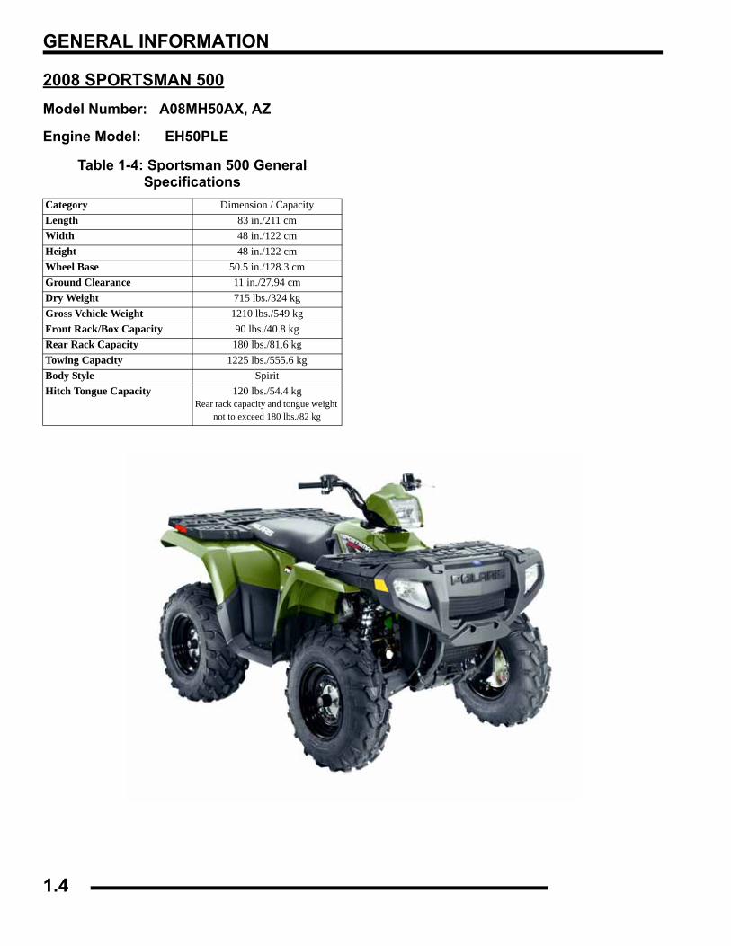
2008 SPORTSMAN 500Model Number: A08MH50AX, AZ
Engine Model: EH50PLE
Table 1-4: Sportsman 500 General Specifications
Category Dimension / CapacityLength 83 in./211 cmWidth 48 in./122 cmHeight 48 in./122 cmWheel Base 50.5 in./128.3 cmGround Clearance 11 in./27.94 cmDry Weight 715 lbs./324 kgGross Vehicle Weight 1210 lbs./549 kgFront Rack/Box Capacity 90 lbs./40.8 kgRear Rack Capacity 180 lbs./81.6 kgTowing Capacity 1225 lbs./555.6 kgBody Style SpiritHitch Tongue Capacity 120 lbs./54.4 kg
Rear rack capacity and tongue weight not to exceed 180 lbs./82 kg
1.4
GENERAL INFORMATION
1
Table 1-5: Sportsman 500ENGINE
Platform Fuji Single Cylinder
Engine Model Number EH50PLE
Engine Displacement 499cc
Number of Cylinders 1
Bore & Stroke (mm) 92 x 75 mm
Compression Ratio 10.2:1
Compression Pressure 50-90 psi W/Compression Release
Engine Idle Speed 1100 ± 50 RPM
Engine Max Operating Rpm 6000 Rpm ± 200 Rpm
Cooling System / Capacity Liquid - 2.7 qt / 2.5 ltr
Overheat Warning HOT on Instrument Cluster
Lubrication Pressurized Dry Sump
Oil Requirements / Capacity Polaris 2W-50 2 qt. / 1.9 ltr
Exhaust System Single Pipe USFS Approved
Fuel SystemCarburetor Mikuni BST 40mm
Main Jet 155
Pilot Jet 40
Jet Needle / Clip Position 6MGH1-94-3
Needle Jet X-6M
Pilot Screw 2 Turns Out (initial)
Pilot Air Jet 160
Float Height 14.7mm ± 1 (.58 ± 0.40")
Fuel Delivery Fuel Pump
Fuel Capacity / Requirement 4.25 gal US / 19.9 liters87 Octane (minimum)
or 89 Oxygenated
ElectricalAlternator Output 260 w @ 3000 RPM
Voltage Regulator 3-phase - PDMLights : Pod 50 watts
Grill 2 x 37 watts
Brake 26.9 watts
Tail 8.26 watts
Worklight 13 watts
Indicator 1 watt
Operating RPM 6000 RPM
Ignition System DC/CDI Ignition
Ignition Timing 30°± 2° BTDC @ 5000 RPM
Spark plug / Gap BKR6E / .035 in. / 0.9 mm
Battery / Amp Hr Maintenance-Free / 12 Amp Hr.
Circuit Protection Solid State - PDMStarting Electric / Recoil
Instrument Cluster Analog Speedo w/ LCD
Table 1-6: Sportsman 500DrivetrainTransmission Type Drumshift - H/L/N/R/P
Transmission Capacity 32 oz. / 948 ml
Front Gearcase Capacity 8.97 oz. / 265 ml
Gear Ratio : Low Rev High Front Drive
23.91:116.30:110.49:13.82:1
Clutch Type PVT Non-EBS
Belt 3211077
Steering / SuspensionFront Suspension / Shock A-arm / MacPherson Strut
Front Travel 8.2 in. / 20.8 cm
Rear Suspension / Shock Progressive Rate Independent - w/ 2" Coil-over shock
Rear Travel 9.5 in. / 24.13 cm
Ground Clearance 11 in. / 27.94 cm
Shock Preload AdjustmentFront / Rear
Front -Non Adjustable.Rear - Ratchet Style- Std.
Turning Radius 65 in./165.10 cm unloaded
Toe Out 0-1/16 in / .0 - .159 mm
Wheels / BrakesWheel / Tire Size / Pattern - Front Steel 25x8 - 12 / 4-156
Wheel / Tire Size / Pattern - Rear Steel 25x11 - 12 / 4-156
Recommended Air Pressure Front & Rear - 5 psi
Brake - Front Dual Hydraulic Disc
Brake - Rear Single Hydraulic Disc
Brake Fluid DOT - approved only
Table 1-7: Sportsman 500 Jetting
Altitude
AMBIENT TEMPERATURE
Below 40 ° FBelow 5 ° C
+40 to +80 ° F+5 to +28 ° C
Meters (Feet)
0-1800(0-6000) 160 155
1800-3700(6000-12000) 152.5 147.5
Table 1-8: A08MH50A Clutching
Altitude Shift Weight
Drive Clutch Spring
Driven Clutch Spring
Driven-Helix
Meters (Feet)
0-1800(0-6000)
10 WH (5630710)
Blu/Grn (7041157)
Black (7041782)
41-37°2+2
(5132344)
1800-3700(6000-12000)
10 RH (5630709
Blu/Grn (7041157)
Black (7041782)
41-37°2+2
(5132344)
1.5
GENERAL INFORMATION
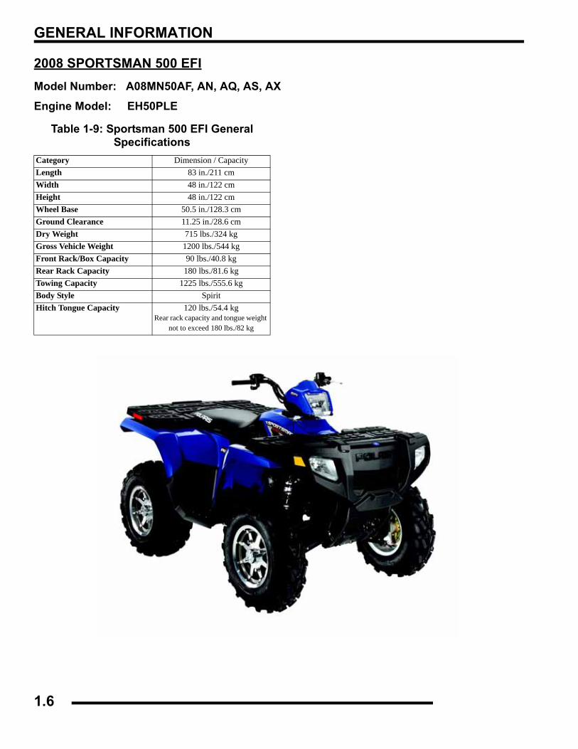
2008 SPORTSMAN 500 EFIModel Number: A08MN50AF, AN, AQ, AS, AX
Engine Model: EH50PLE
Table 1-9: Sportsman 500 EFI General Specifications
Category Dimension / CapacityLength 83 in./211 cmWidth 48 in./122 cmHeight 48 in./122 cmWheel Base 50.5 in./128.3 cmGround Clearance 11.25 in./28.6 cmDry Weight 715 lbs./324 kgGross Vehicle Weight 1200 lbs./544 kgFront Rack/Box Capacity 90 lbs./40.8 kgRear Rack Capacity 180 lbs./81.6 kgTowing Capacity 1225 lbs./555.6 kgBody Style SpiritHitch Tongue Capacity 120 lbs./54.4 kg
Rear rack capacity and tongue weight not to exceed 180 lbs./82 kg
1.6
GENERAL INFORMATION
1
Table 1-10: Sportsman 500 EFIENGINE
Platform Fuji Single Cylinder
Engine Model Number EH50PLE
Engine Displacement 499cc
Number of Cylinders 1
Bore & Stroke (mm) 92 x 75 mm
Compression Ratio 10.2:1
Compression Pressure 50-90 psi W/Compression Release
Engine Idle Speed 1100 ± 200 RPM
Engine Max Operating Rpm 6000 Rpm ± 200 Rpm
Cooling System / Capacity Liquid - 2.7 qt / 2.5 ltr
Overheat Warning HOT on Instrument Cluster
Lubrication Pressurized Dry Sump
Oil Requirements / Capacity Polaris 2W-50 2 qt. / 1.9 ltr
Exhaust System Single Pipe USFS Approved
Fuel SystemFuel System Electronic Fuel Injection (EFI)
Fuel Pump (in tank assembly) 25L per hr. at 39 psi
Fuel Filter(s) 10 micron in-line30 micron in tank - (not replaceable)
Fuel Injector(s) Visteon
EFI Controller Visteon
Fuel Capacity / Requirement 4.13 gal US / 15.63 liters87 Octane (minimum)
or 89 Oxygenated
ElectricalAlternator Output 350 w @ 6000 RPM
Lights : Pod 50 watts
Grill 2 x 37 watts
Brake 2 x 8.26 watts
Tail 2 x 26.9 watts
Worklight 2 x 13 watts
Indicator 1 watt
Operating RPM 6000 RPM
Ignition System DC/CDI Ignition
Ignition Timing 13°± 3 BTDC @ 1150 RPM
Spark plug / Gap BKR6E / .035 in. / 0.9 mm
Battery / Amp Hr Lead Acid / 30 Amp Hr.
Circuit Breakers Fan 12 amp / Switched Power 10 amp / Fuel Pump 10 amp / ECU 15 amp / Ignition Coil 10 amp /
Accessory Power 10 amp / Lights 20 Amp
Starting Electric / Recoil
Instrument Cluster Analog Speedo w/ LCD
Table 1-11: Sportsman 500 EFIDrivetrainTransmission Type Drumshift - H/L/N/R/P
Transmission Capacity 32 oz. / 948 ml
Front Gearcase Capacity- CH 8.97 / 265 ml
Front Gearcase Capacity- ADC 9.3 / 275 ml
Gear Ratio : Low Rev High Front Drive
23.91:121.74:110.57:13.82:1
Clutch Type PVT (Standard Models)PVT w/EBS (Deluxe Models)
Belt 3211113 EBS3211077 Non-EBS
Steering / SuspensionFront Suspension / Shock A-arm / MacPherson Strut
Front Travel 8.2 in. / 20.8 cm
Rear Suspension / Shock Progressive Rate Independent - Coil - over shock
Rear Travel 9.5 in. / 24.13 cm
Ground Clearance 11 in. / 27.94 cm
Shock Preload AdjustmentFront / Rear
Front -Non Adjustable.Rear - Ratchet Style- Std.
Turning Radius 65 in./165.10 cm unloaded
Toe Out 0-1/16 in / .0 - .159 mm
Wheels / BrakesWheel/Tire Size / Pattern - Front 26 x 8 - 12 / 4-156
Wheel/Tire Size / Pattern - Rear 26 x 11 - 12 / 4-156
Recommended Air Pressure Front & Rear - 5 psi
Brake - Front Dual Hydraulic Disc
Brake - Rear Single Hydraulic Disc
Brake Fluid DOT - approved only
Table 1-12: A08MN50A ClutchingAltitude Shift
WeightDrive Clutch Spring
Driven Clutch Spring
Helix**No
Adjustment
Meters (Feet)
0-1800(0-6000)
10 WH (5630710)
Blu/Green (7041157)
Red (3234451)
EBS (3234356)
1800-3700(6000-12000)
10 RH (5630709)
Blu/Green (7041157)
Red (3234451)
EBS (3234356)
1.7
GENERAL INFORMATION
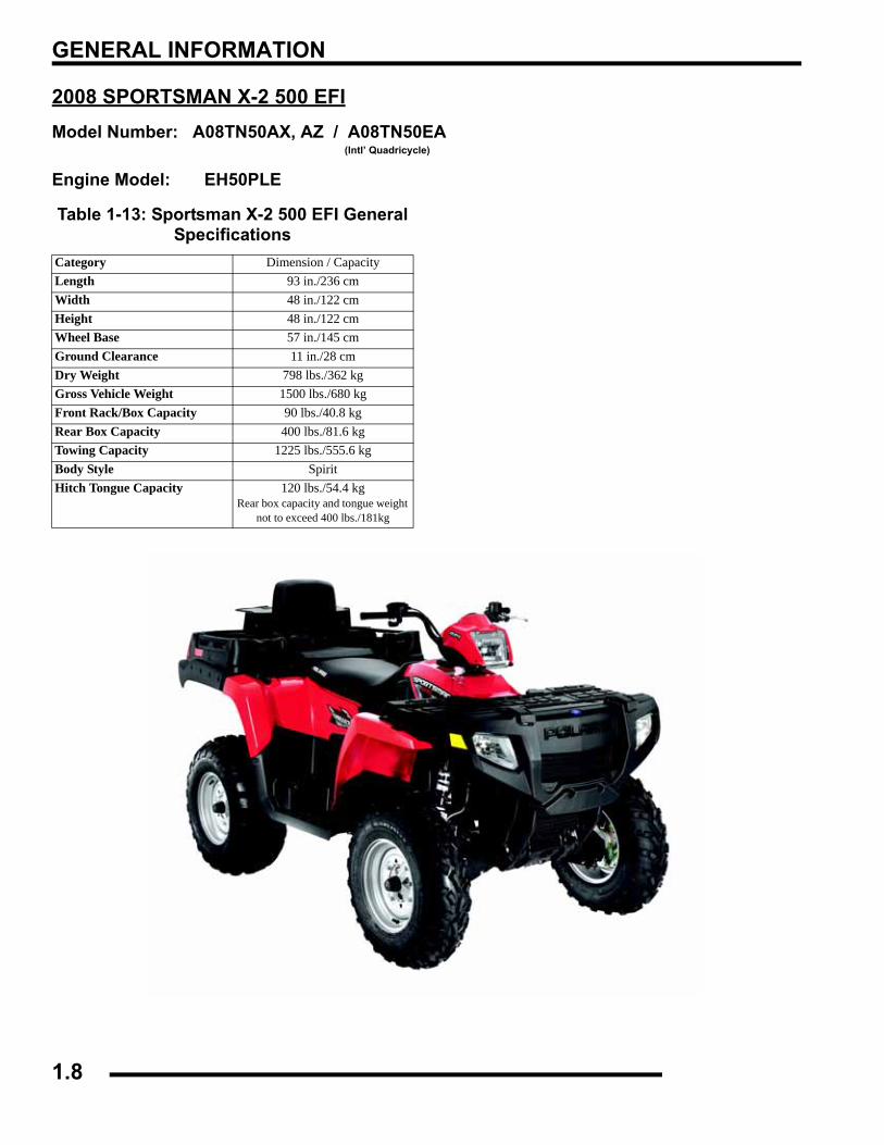
2008 SPORTSMAN X-2 500 EFIModel Number: A08TN50AX, AZ / A08TN50EA
(Intl’ Quadricycle)
Engine Model: EH50PLE
Table 1-13: Sportsman X-2 500 EFI General Specifications
Category Dimension / CapacityLength 93 in./236 cmWidth 48 in./122 cmHeight 48 in./122 cmWheel Base 57 in./145 cmGround Clearance 11 in./28 cmDry Weight 798 lbs./362 kgGross Vehicle Weight 1500 lbs./680 kgFront Rack/Box Capacity 90 lbs./40.8 kgRear Box Capacity 400 lbs./81.6 kgTowing Capacity 1225 lbs./555.6 kgBody Style SpiritHitch Tongue Capacity 120 lbs./54.4 kg
Rear box capacity and tongue weight not to exceed 400 lbs./181kg
1.8
GENERAL INFORMATION
1
Table 1-14: Sportsman X2 500 EFIENGINE
Platform Fuji Single Cylinder
Engine Model Number EH50PLE
Engine Displacement 499cc
Number of Cylinders 1
Bore & Stroke (mm) 92 x 75 mm
Compression Ratio 10.2:1
Compression Pressure 60-90 psi W/Compression Release
Engine Idle Speed 1150 ± 50 RPM
Engine Max Operating Rpm 6000 Rpm ± 200 Rpm
Cooling System / Capacity Liquid - 2.7 qt / 2.5 ltr
Overheat Warning HOT on Instrument Cluster
Lubrication Pressurized Dry Sump
Oil Requirements / Capacity Polaris 2W-50 2 qt. / 1.9 ltr
Exhaust System Single Pipe USFS Approved
Fuel SystemFuel System Electronic Fuel Injection (EFI)
Fuel Pump (in tank assembly) 25L per hr. at 39 psi
Fuel Filter(s) 30 micron in tank - (not replaceable)
Fuel Injector(s) Visteon
EFI Controller Visteon
Fuel Capacity / Requirement 6 gal US / 22.7 liters87 Octane (minimum)
or 89 Oxygenated
ElectricalAlternator Output 350 w @ 6000 RPM
Lights : Pod 50 watts
Grill 2 x 37 watts
Brake 2 x 8.26 watts
Tail 2 x 26.9 watts
Worklight 2 x 13 watts
Indicator 1 watt
Operating RPM 6000 RPM
Ignition System DC/CDI Ignition
Ignition Timing 10°± 1 BTDC @ 1150 RPM
Spark plug / Gap BKR6E / .035 in. / 0.9 mm
Battery / Amp Hr Lead Acid / 30 Amp Hr.
Circuit Breakers Fan 12 amp / Switched Power 10 amp / Fuel Pump 10 amp / ECU 15 amp / Ignition Coil 10 amp /
Accessory Power 10 amp / Lights 20 Amp
Starting Electric / Recoil
Instrument Cluster Analog Speedo w/ LCD
Table 1-15: Sportsman X2 500 EFIDrivetrainTransmission Type Drumshift - H/L/N/Rev/Park
Transmission Capacity 32 oz. / 948 ml
Front Gearcase Capacity- CH 8.97 / 265 ml
Front Gearcase Capacity- ADC 9.3 / 275 ml
Gear Ratio : Low Rev High Front Drive
23.91:121.74:110.57:13.82:1
Clutch Type PVT w/EBS
Belt 3211113
Steering / SuspensionFront Suspension / Shock A-arm / MacPherson Strut
Front Travel 8.2 in. / 20.8 cm
Rear Suspension / Shock Progressive Rate Independent - Coil - over shock
Rear Travel 8.75 in. / 22.2 cm
Ground Clearance 11 in. / 28 cm
Shock Preload AdjustmentFront / Rear
Front -Non Adjustable.Rear - Ratchet Style- Std.
Turning Radius 82 in./208 cm unlocked
Toe Out 0-1/16 in / .0 - .159 mm
Wheels / BrakesWheel Size / Pattern - Front Steel 12x6 / 4-156
Wheel Size / Pattern - Rear Steel 12x8 / 4-156
Front Tire Size 25x8-12
Rear Tire Size 25x11-12
Recommended Air Pressure Front & Rear - 5 psi
Brake - Front Dual Hydraulic Disc
Brake - Rear Dual Hydraulic Disc
Table 1-16: A08TN50A ClutchingAltitude Shift
WeightDrive Clutch Spring
Driven Clutch Spring
Helix**No
Adjustment
Meters (Feet)
0-1800(0-6000)
10 WH (5630710)
Blu/Green (7041157)
White/Yel (7041635)
EBS (5131674)
1800-3700(6000-12000)
10 RH (5630709)
Blu/Green (7041157)
White/Yel (7041635)
EBS (5131674)
1.9
GENERAL INFORMATION
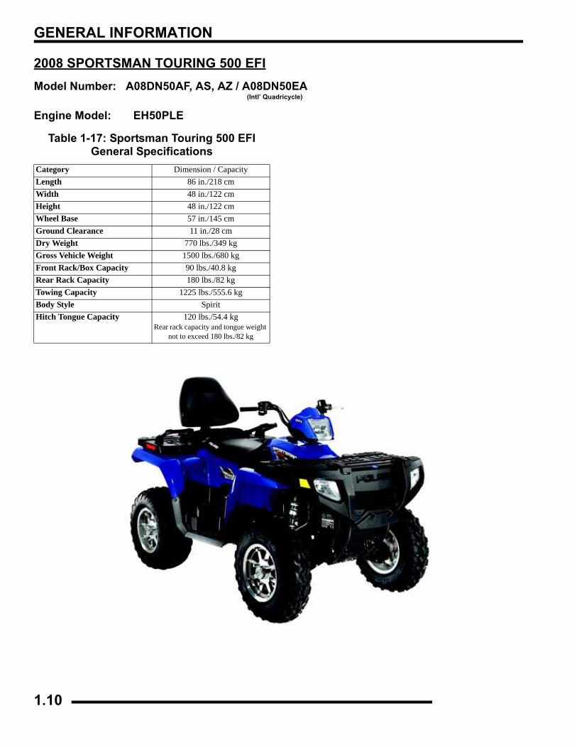
2008 SPORTSMAN TOURING 500 EFIModel Number: A08DN50AF, AS, AZ / A08DN50EA
(Intl’ Quadricycle)
Engine Model: EH50PLE
Table 1-17: Sportsman Touring 500 EFI General Specifications
Category Dimension / CapacityLength 86 in./218 cmWidth 48 in./122 cmHeight 48 in./122 cmWheel Base 57 in./145 cmGround Clearance 11 in./28 cmDry Weight 770 lbs./349 kgGross Vehicle Weight 1500 lbs./680 kgFront Rack/Box Capacity 90 lbs./40.8 kgRear Rack Capacity 180 lbs./82 kgTowing Capacity 1225 lbs./555.6 kgBody Style SpiritHitch Tongue Capacity 120 lbs./54.4 kg
Rear rack capacity and tongue weight not to exceed 180 lbs./82 kg
1.10

GENERAL INFORMATION
1
Table 1-18: Sportsman Touring 500 EFIENGINE
Platform Fuji Single Cylinder
Engine Model Number EH50PLE
Engine Displacement 499cc
Number of Cylinders 1
Bore & Stroke (mm) 92 x 75 mm
Compression Ratio 10.2:1
Compression Pressure 60-90 psi W/Compression Release
Engine Idle Speed 1150 ± 50 RPM
Engine Max Operating Rpm 6000 Rpm ± 200 Rpm
Cooling System / Capacity Liquid - 2.7 qt / 2.5 ltr
Overheat Warning HOT on Instrument Cluster
Lubrication Pressurized Dry Sump
Oil Requirements / Capacity Polaris 0W-40 2 qt. / 1.9 ltr
Exhaust System Single Pipe USFS Approved
Fuel SystemFuel System Electronic Fuel Injection (EFI)
Fuel Pump (in tank assembly) 25L per hr. at 39 psi
Fuel Filter(s) 30 micron in tank - (not replaceable)
Fuel Injector(s) Visteon
EFI Controller Visteon
Fuel Capacity / Requirement 6 gal US / 22.7 liters87 Octane (minimum)
or 89 Oxygenated
ElectricalAlternator Output 350 w @ 6000 RPM
Lights : Pod 50 watts
Grill 2 x 37 watts
Brake 2 x 8.26 watts
Tail 2 x 26.9 watts
Worklight 2 x 13 watts
Indicator 1 watt
Operating RPM 6000 RPM
Ignition System DC/CDI Ignition
Ignition Timing 10°± 1 BTDC @ 1150 RPM
Spark plug / Gap BKR6E / .035 in. / 0.9 mm
Battery / Amp Hr Lead Acid / 30 Amp Hr.
Circuit Breakers Fan 12 amp / Switched Power 10 amp / Fuel Pump 10 amp / ECU 15 amp / Ignition Coil 10 amp /
Accessory Power 10 amp / Lights 20 Amp
Starting Electric / Recoil
Instrument Cluster Analog Speedo w/ LCD
Table 1-19: Sportsman Touring 500 EFIDrivetrainTransmission Type Drumshift - H/L/N/Rev/Park
Transmission Capacity 32 oz. / 948 ml
Front Gearcase Capacity- CH 8.97 / 265 ml
Front Gearcase Capacity- ADC 9.3 / 275 ml
Gear Ratio : Low Rev High Front Drive
23.91:121.74:110.57:13.82:1
Clutch Type PVT w/EBS
Belt 3211113
Steering / SuspensionFront Suspension / Shock A-arm / MacPherson Strut
Front Travel 8.2 in. / 20.8 cm
Rear Suspension / Shock Progressive Rate Independent - Coil - over shock
Rear Travel 8.75 in. / 22.2 cm
Ground Clearance 11 in. / 28 cm
Shock Preload AdjustmentFront / Rear
Front -Non Adjustable.Rear - Ratchet Style- Std.
Turning Radius 82 in./208 cm unlocked
Toe Out 0-1/16 in / .0 - .159 mm
Wheels / BrakesWheel Size / Pattern - Front Steel 12x6 / 4-156
Wheel Size / Pattern - Rear Steel 12x8 / 4-156
Front Tire Size 25x8-12
Rear Tire Size 25x11-12
Recommended Air Pressure Front & Rear - 5 psi
Brake - Front Dual Hydraulic Disc
Brake - Rear Dual Hydraulic Disc
Table 1-20: A08DN50A ClutchingAltitude Shift
WeightDrive Clutch Spring
Driven Clutch Spring
Helix**No
Adjustment
Meters (Feet)
0-1800(0-6000)
10 WH (5630710)
Blu/Green (7041157)
White/Yel (7041635)
EBS (5131674)
1800-3700(6000-12000)
10 RH (5630709)
Blu/Green (7041157)
White/Yel (7041635)
EBS (5131674)
1.11
GENERAL INFORMATION
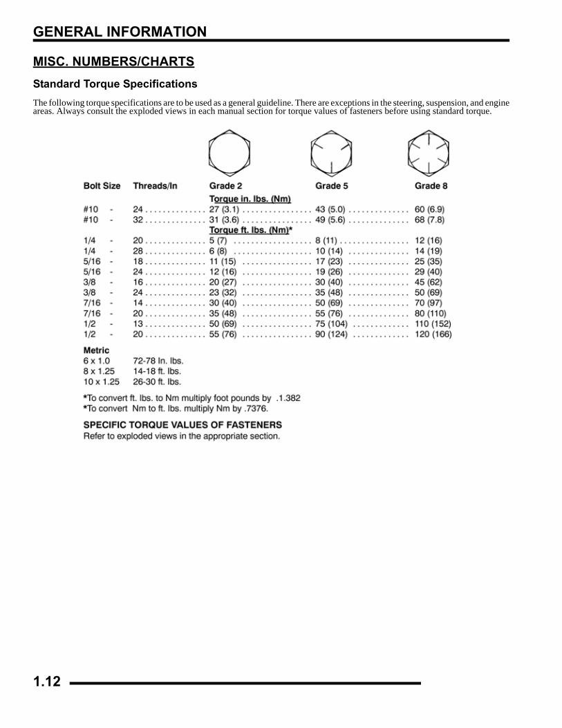
MISC. NUMBERS/CHARTSStandard Torque SpecificationsThe following torque specifications are to be used as a general guideline. There are exceptions in the steering, suspension, and engineareas. Always consult the exploded views in each manual section for torque values of fasteners before using standard torque.
1.12
GENERAL INFORMATION
1
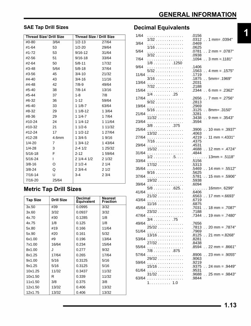
SAE Tap Drill SizesMetric Tap Drill Sizes
Decimal Equivalents1/64 . . . . . . . . . . .. . . . . . . .0156
1/32 . . . . . . .. . . . . . . .0312 . . 1 mm= .0394"3/64 . . . . . . . . . . .. . . . . . . .0469
1/16 . . . . . . .. . . . . . . .06255/64 . . . . . . . . . . .. . . . . . . .0781 . . 2 mm = .0787"
3/32 . . . . . . .. . . . . . . .09387/64 . . . . . . . . . . .. . . . . . . .1094 . . 3 mm =.1181"
1/8 . . . . . . . . .12509/64 . . . . . . . . . . .. . . . . . . .1406
5/32 . . . . . . .. . . . . . . .1563 . . 4 mm = .1575"11/64 . . . . . . . . . . .. . . . . . . .1719
3/16 . . . . . . .. . . . . . . .1875 . . 5mm= .1969"13/64 . . . . . . . . . . .. . . . . . . .2031
7/32 . . . . . . .. . . . . . . .218815/64 . . . . . . . . . . .. . . . . . . .2344 . . 6 mm = .2362"
1/4 . . . . . . . . .2517/64 . . . . . . . . . . .. . . . . . . .2656 . . 7 mm = .2756"
9/32 . . . . . . .. . . . . . . .281319/64 . . . . . . . . . . .. . . . . . . .2969
5/16 . . . . . . .. . . . . . . .3125 . . 8mm= .3150"21/64 . . . . . . . . . . .. . . . . . . .3281
11/32 . . . . . .. . . . . . . .3438 . . 9 mm = .3543"23/64 . . . . . . . . . . .. . . . . . . .3594
3/8 . . . . . . . . .37525/64 . . . . . . . . . . .. . . . . . . .3906 . . 10 mm = .3937"
13/32 . . . . . .. . . . . . . .406327/64 . . . . . . . . . . .. . . . . . . .4219 . . 11 mm =.4331"
7/16 . . . . . . .. . . . . . . .437529/64 . . . . . . . . . . .. . . . . . . .4531
15/32 . . . . . .. . . . . . . .4688 . . 12 mm = .4724"31/64 . . . . . . . . . . .. . . . . . . .4844
1/2 . . . . . . . . .5 . . . . . . . . . . . 13mm = .5118"33/64 . . . . . . . . . . .. . . . . . . .5156
17/32 . . . . . .. . . . . . . .531335/64 . . . . . . . . . . .. . . . . . . .5469 . . 14 mm = .5512"
9/16 . . . . . . .. . . . . . . .562537/64 . . . . . . . . . . .. . . . . . . .5781 . . 15 mm = .5906"
19/32 . . . . . .. . . . . . . .593839/64 . . . . . . . . . . .. . . . . . . .6094
5/8 . . . . . . . . .625 . . . . . . . . . 16mm=. 6299"41/64 . . . . . . . . . . .. . . . . . . .6406
21/32 . . . . . .. . . . . . . .6563 . . 17 mm =.6693"43/64 . . . . . . . . . . .. . . . . . . .6719
11/16 . . . . . .. . . . . . . .687545/64 . . . . . . . . . . .. . . . . . . .7031 . . 18 mm = .7087"
23/32 . . . . . .. . . . . . . .718847/64 . . . . . . . . . . .. . . . . . . .7344 . . 19 mm = .7480"
3/4 . . . . . . . . .7549/64 . . . . . . . . . . .. . . . . . . .7656
25/32 . . . . . .. . . . . . . .7813 . . 20 mm = .7874"51/64 . . . . . . . . . . .. . . . . . . .7969
13/16 . . . . . .. . . . . . . .8125 . . 21 mm =.8268"53/64 . . . . . . . . . . .. . . . . . . .8281
27/32 . . . . . .. . . . . . . .843855/64 . . . . . . . . . . .. . . . . . . .8594 . . 22 mm = .8661"
7/8 . . . . . . . . .87557/64 . . . . . . . . . . .. . . . . . . .8906 . . 23 mm = .9055"
29/32 . . . . . .. . . . . . . .906359/64 . . . . . . . . . . .. . . . . . . .9219
15/16 . . . . . .. . . . . . . .9375 . . 24 mm = .9449"61/64 . . . . . . . . . . .. . . . . . . .9531
31/32 . . . . . .. . . . . . . .9688 . . 25 mm = .9843"63/64 . . . . . . . . . . .. . . . . . . .9844
1. . . . . . . . . . 1.0
Thread Size/ Drill Size Thread Size / Drill Size#0-80 3/64 1/2-13 27/64#1-64 53 1/2-20 29/64#1-72 53 9/16-12 31/64#2-56 51 9/16-18 33/64#2-64 50 5/8-11 17/32#3-48 5/64 5/8-18 37/64#3-56 45 3/4-10 21/32#4-40 43 3/4-16 11/16#4-48 42 7/8-9 49/64#5-40 38 7/8-14 13/16#5-44 37 1-8 7/8#6-32 36 1-12 59/64#6-40 33 1 1/8-7 63/64#8-32 29 1 1/8-12 1 3/64#8-36 29 1 1/4-7 1 7/64#10-24 24 1 1/4-12 1 11/64#10-32 21 1 1/2-6 1 11/32#12-24 17 1 1/2-12 1 27/64#12-28 4.6mm 1 3/4-5 1 9/161/4-20 7 1 3/4-12 1 43/641/4-28 3 2-4 1/2 1 25/325/16-18 F 2-12 1 59/645/16-24 I 2 1/4-4 1/2 2 1/323/8-16 O 2 1/2-4 2 1/43/8-24 Q 2 3/4-4 2 1/27/16-14 U 3-4 2 3/47/16-20 25/64
Tap Size Drill Size DecimalEquivalent
NearestFraction
3x.50 #39 0.0995 3/323x.60 3/32 0.0937 3/324x.70 #30 0.1285 1/84x.75 1/8 0.125 1/85x.80 #19 0.166 11/645x.90 #20 0.161 5/326x1.00 #9 0.196 13/647x1.00 16/64 0.234 15/648x1.00 J 0.277 9/328x1.25 17/64 0.265 17/649x1.00 5/16 0.3125 5/169x1.25 5/16 0.3125 5/1610x1.25 11/32 0.3437 11/3210x1.50 R 0.339 11/3211x1.50 3/8 0.375 3/812x1.50 13/32 0.406 13/3212x1.75 13/32 0.406 13/32
1.13
GENERAL INFORMATION
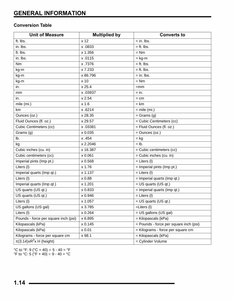
Conversion Table
°C to °F: 9 (°C + 40) ÷ 5 - 40 = °F °F to °C: 5 (°F + 40) ÷ 9 - 40 = °C
Unit of Measure Multiplied by Converts toft. lbs. x 12 = in. lbs.in. lbs. x .0833 = ft. lbs.ft. lbs. x 1.356 = Nmin. lbs. x .0115 = kg-mNm x .7376 = ft. lbs.kg-m x 7.233 = ft. lbs.kg-m x 86.796 = in. lbs.kg-m x 10 = Nmin. x 25.4 =mmmm x .03937 = in.in. x 2.54 = cmmile (mi.) x 1.6 = kmkm x .6214 = mile (mi.)Ounces (oz.) x 28.35 = Grams (g)Fluid Ounces (fl. oz.) x 29.57 = Cubic Centimeters (cc)Cubic Centimeters (cc) x .03381 = Fluid Ounces (fl. oz.)Grams (g) x 0.035 = Ounces (oz.)lb. x .454 = kgkg x 2.2046 = lb.Cubic inches (cu. in) x 16.387 = Cubic centimeters (cc)Cubic centimeters (cc) x 0.061 = Cubic inches (cu. in)Imperial pints (Imp pt.) x 0.568 = Liters (l)Liters (l) x 1.76 = Imperial pints (Imp pt.)Imperial quarts (Imp qt.) x 1.137 = Liters (l)Liters (l) x 0.88 = Imperial quarts (Imp qt.)Imperial quarts (Imp qt.) x 1.201 = US quarts (US qt.)US quarts (US qt.) x 0.833 = Imperial quarts (Imp qt.)US quarts (US qt.) x 0.946 = Liters (l)Liters (l) x 1.057 = US quarts (US qt.)US gallons (US gal) x 3.785 =Liters (l)Liters (l) x 0.264 = US gallons (US gal)Pounds - force per square inch (psi) x 6.895 = Kilopascals (kPa)Kilopascals (kPa) x 0.145 = Pounds - force per square inch (psi)Kilopascals (kPa) x 0.01 = Kilograms - force per square cmKilograms - force per square cm x 98.1 = Kilopascals (kPa)π(3.14)xR2x H (height) = Cylinder Volume
1.14
GENERAL INFORMATION
1
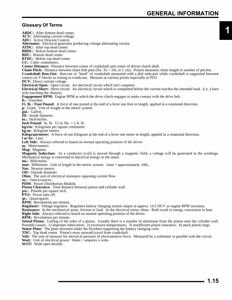
Glossary Of TermsABDC: After bottom dead center.ACV: Alternating current voltage.ADC: Active Descent Control.Alternator: Electrical generator producing voltage alternating current.ATDC: After top dead center.BBDC: Before bottom dead center.BDC: Bottom dead center.BTDC: Before top dead center.CC: Cubic centimeters.Center Distance: Distance between center of crankshaft and center of driven clutch shaft.Chain Pitch: Distance between chain link pins (No. 35 = 3/8, or 1 cm). Polaris measures chain length in number of pitches.Crankshaft Run-Out: Run-out or "bend" of crankshaft measured with a dial indicator while crankshaft is supported betweencenters on V blocks or resting in crankcase. Measure at various points especially at PTO.DCV: Direct current voltage.Electrical Open: Open circuit. An electrical circuit which isn't complete.Electrical Short: Short circuit. An electrical circuit which is completed before the current reaches the intended load. (i.e. a barewire touching the chassis).Engagement RPM: Engine RPM at which the drive clutch engages to make contact with the drive belt.ft.: Foot/feet.Ft. lb. / Foot Pound: A force of one pound at the end of a lever one foot in length, applied in a rotational direction.g: Gram. Unit of weight in the metric system.gal.: Gallon.ID: Inside diameter.in.: Inch/inches.Inch Pound: In. lb. 12 in. lbs. = 1 ft. lb.kg/cm: Kilograms per square centimeter.kg-m: Kilogram meters.Kilogram/meter: A force of one kilogram at the end of a lever one meter in length, applied in a rotational direction.l or ltr: Liter.Left Side: Always referred to based on normal operating position of the driver.m: Meter/meters.Mag: Magneto.Magnetic Induction: As a conductor (coil) is moved through a magnetic field, a voltage will be generated in the windings.Mechanical energy is converted to electrical energy in the stator.mi.: Mile/miles.mm: Millimeter. Unit of length in the metric system. 1mm = approximately .040,.Nm: Newton meters.OD: Outside diameter.Ohm: The unit of electrical resistance opposing current flow.oz.: Ounce/ounces.PDM: Power Distribution Module.Piston Clearance: Total distance between piston and cylinder wall.psi.: Pounds per square inch.PTO: Power take off.qt.: Quart/quarts.RPM: Revolutions per minute.Regulator: Voltage regulator. Regulates battery charging system output at approx. 14.5 DCV as engine RPM increases.Resistance: In the mechanical sense, friction or load. In the electrical sense, ohms. Both result in energy conversion to heat.Right Side: Always referred to based on normal operating position of the driver.RPM: Revolutions per minute.Seized Piston: Galling of the sides of a piston. Usually there is a transfer of aluminum from the piston onto the cylinder wall.Possible causes: 1) improper lubrication; 2) excessive temperatures; 3) insufficient piston clearance; 4) stuck piston rings.Stator Plate: The plate mounted under the flywheel supporting the battery charging coils.TDC: Top dead center. Piston's most outward travel from crankshaft.Volt: The unit of measure for electrical pressure of electromotive force. Measured by a voltmeter in parallel with the circuit.Watt: Unit of electrical power. Watts = amperes x volts.WOT: Wide open throttle.1.15

GENERAL INFORMATION
NOTES
1.16
MAINTENANCE
CHAPTER 2MAINTENANCE
2
MAINTENANCE. . . . . . . . . . . . . . . . . . . . . . . . . . . . . . . . . . . . . . . . . . . . . . . . . . . . . . . . . 2.3PERIODIC MAINTENANCE CHART . . . . . . . . . . . . . . . . . . . . . . . . . . . . . . . . . . . . . . . . 2.3MAINTENANCE CHART KEY . . . . . . . . . . . . . . . . . . . . . . . . . . . . . . . . . . . . . . . . . . . . . 2.3PERIODIC MAINTENANCE CHART . . . . . . . . . . . . . . . . . . . . . . . . . . . . . . . . . . . . . . . . 2.4LUBRICATION / FLUIDS. . . . . . . . . . . . . . . . . . . . . . . . . . . . . . . . . . . . . . . . . . . . . . . . . . 2.7SPORTSMAN COMPONENT LOCATIONS. . . . . . . . . . . . . . . . . . . . . . . . . . . . . . . . . . . 2.7SPORTSMAN X2-TOURING COMPONENT LOCATIONS . . . . . . . . . . . . . . . . . . . . . . . 2.8POLARIS LUBRICANTS, MAINTENANCE AND SERVICE PRODUCTS . . . . . . . . . . . . 2.9POLARIS LUBRICANT SYMBOL IDENTIFICATION . . . . . . . . . . . . . . . . . . . . . . . . . . . 2.10PRE-RIDE / DAILY INSPECTION . . . . . . . . . . . . . . . . . . . . . . . . . . . . . . . . . . . . . . . . . 2.10LUBRICATION COMPONENTS. . . . . . . . . . . . . . . . . . . . . . . . . . . . . . . . . . . . . . . . . . . 2.11FRONT GEARCASE LUBRICATION . . . . . . . . . . . . . . . . . . . . . . . . . . . . . . . . . . . . . . . 2.12TRANSMISSION LUBRICATION . . . . . . . . . . . . . . . . . . . . . . . . . . . . . . . . . . . . . . . . . . 2.13ADC DIFFERENTIAL HYDRAULIC CIRCUIT FLUID CHANGE. . . . . . . . . . . . . . . . . . . 2.14
VEHICLE INSPECTION. . . . . . . . . . . . . . . . . . . . . . . . . . . . . . . . . . . . . . . . . . . . . . . . . . 2.14SHIFT LINK ROD INSPECTION. . . . . . . . . . . . . . . . . . . . . . . . . . . . . . . . . . . . . . . . . . . 2.14THROTTLE INSPECTION . . . . . . . . . . . . . . . . . . . . . . . . . . . . . . . . . . . . . . . . . . . . . . . 2.15THROTTLE CABLE / ELECTRONIC THROTTLE CONTROL ADJUSTMENT . . . . . . . 2.15FUEL SYSTEM. . . . . . . . . . . . . . . . . . . . . . . . . . . . . . . . . . . . . . . . . . . . . . . . . . . . . . . . 2.16FUEL LINES . . . . . . . . . . . . . . . . . . . . . . . . . . . . . . . . . . . . . . . . . . . . . . . . . . . . . . . . . . 2.16VENT LINES. . . . . . . . . . . . . . . . . . . . . . . . . . . . . . . . . . . . . . . . . . . . . . . . . . . . . . . . . . 2.16FUEL FILTER . . . . . . . . . . . . . . . . . . . . . . . . . . . . . . . . . . . . . . . . . . . . . . . . . . . . . . . . . 2.17CHOKE (ENRICHER) ADJUSTMENT - (500 CARB) . . . . . . . . . . . . . . . . . . . . . . . . . . . 2.17COMPRESSION TEST. . . . . . . . . . . . . . . . . . . . . . . . . . . . . . . . . . . . . . . . . . . . . . . . . . 2.17ENGINE MOUNTS . . . . . . . . . . . . . . . . . . . . . . . . . . . . . . . . . . . . . . . . . . . . . . . . . . . . . 2.17SPARK PLUG. . . . . . . . . . . . . . . . . . . . . . . . . . . . . . . . . . . . . . . . . . . . . . . . . . . . . . . . . 2.18ACTIVE DESCENT CONTROL (ADC) RESERVOIR LEVEL. . . . . . . . . . . . . . . . . . . . . 2.18BATTERY MAINTENANCE . . . . . . . . . . . . . . . . . . . . . . . . . . . . . . . . . . . . . . . . . . . . . . 2.18LIQUID COOLING SYSTEM OVERVIEW . . . . . . . . . . . . . . . . . . . . . . . . . . . . . . . . . . . 2.19COOLANT STRENGTH / TYPE . . . . . . . . . . . . . . . . . . . . . . . . . . . . . . . . . . . . . . . . . . . 2.19COOLING SYSTEM HOSES . . . . . . . . . . . . . . . . . . . . . . . . . . . . . . . . . . . . . . . . . . . . . 2.19RADIATOR/GRILL SCREEN . . . . . . . . . . . . . . . . . . . . . . . . . . . . . . . . . . . . . . . . . . . . . 2.19COOLING SYSTEM PRESSURE TEST. . . . . . . . . . . . . . . . . . . . . . . . . . . . . . . . . . . . . 2.20COOLANT LEVEL INSPECTION . . . . . . . . . . . . . . . . . . . . . . . . . . . . . . . . . . . . . . . . . . 2.20RADIATOR COOLANT LEVEL INSPECTION . . . . . . . . . . . . . . . . . . . . . . . . . . . . . . . . 2.20AIR FILTER/PRE-FILTER SERVICE . . . . . . . . . . . . . . . . . . . . . . . . . . . . . . . . . . . . . . . 2.20AIR BOX SEDIMENT TUBE . . . . . . . . . . . . . . . . . . . . . . . . . . . . . . . . . . . . . . . . . . . . . . 2.21BREATHER FILTER INSPECTION . . . . . . . . . . . . . . . . . . . . . . . . . . . . . . . . . . . . . . . . 2.22BREATHER HOSE . . . . . . . . . . . . . . . . . . . . . . . . . . . . . . . . . . . . . . . . . . . . . . . . . . . . . 2.22RECOIL HOUSING. . . . . . . . . . . . . . . . . . . . . . . . . . . . . . . . . . . . . . . . . . . . . . . . . . . . . 2.22ENGINE OIL LEVEL . . . . . . . . . . . . . . . . . . . . . . . . . . . . . . . . . . . . . . . . . . . . . . . . . . . . 2.23OIL AND FILTER CHANGE . . . . . . . . . . . . . . . . . . . . . . . . . . . . . . . . . . . . . . . . . . . . . . 2.23OIL PUMP PRIMING PROCEDURE . . . . . . . . . . . . . . . . . . . . . . . . . . . . . . . . . . . . . . . 2.25VALVE CLEARANCE . . . . . . . . . . . . . . . . . . . . . . . . . . . . . . . . . . . . . . . . . . . . . . . . . . . 2.25INTAKE VALVE CLEARANCE ADJUSTMENT . . . . . . . . . . . . . . . . . . . . . . . . . . . . . . . 2.26EXHAUST VALVE CLEARANCE ADJUSTMENT . . . . . . . . . . . . . . . . . . . . . . . . . . . . . 2.26STEERING . . . . . . . . . . . . . . . . . . . . . . . . . . . . . . . . . . . . . . . . . . . . . . . . . . . . . . . . . . . 2.26TIE ROD END/STEERING INSPECTION . . . . . . . . . . . . . . . . . . . . . . . . . . . . . . . . . . . 2.27CAMBER AND CASTER . . . . . . . . . . . . . . . . . . . . . . . . . . . . . . . . . . . . . . . . . . . . . . . . 2.27WHEEL ALIGNMENT . . . . . . . . . . . . . . . . . . . . . . . . . . . . . . . . . . . . . . . . . . . . . . . . . . . 2.27TOE ALIGNMENT ADJUSTMENT . . . . . . . . . . . . . . . . . . . . . . . . . . . . . . . . . . . . . . . . . 2.28EXHAUST PIPE . . . . . . . . . . . . . . . . . . . . . . . . . . . . . . . . . . . . . . . . . . . . . . . . . . . . . . . 2.28BRAKE SYSTEM INSPECTION. . . . . . . . . . . . . . . . . . . . . . . . . . . . . . . . . . . . . . . . . . . 2.29BRAKE PAD INSPECTION . . . . . . . . . . . . . . . . . . . . . . . . . . . . . . . . . . . . . . . . . . . . . . 2.30
2.1
MAINTENANCE
HOSE/FITTING INSPECTION . . . . . . . . . . . . . . . . . . . . . . . . . . . . . . . . . . . . . . . . . . . . 2.30AUXILIARY BRAKE TESTING . . . . . . . . . . . . . . . . . . . . . . . . . . . . . . . . . . . . . . . . . . . . 2.30AUXILIARY BRAKE ADJUSTMENT (HYDRAULIC) . . . . . . . . . . . . . . . . . . . . . . . . . . . 2.31SUSPENSION SPRING PRELOAD ADJUSTMENT . . . . . . . . . . . . . . . . . . . . . . . . . . . 2.31FRONT SUSPENSION. . . . . . . . . . . . . . . . . . . . . . . . . . . . . . . . . . . . . . . . . . . . . . . . . . 2.31CV SHAFT BOOT INSPECTION . . . . . . . . . . . . . . . . . . . . . . . . . . . . . . . . . . . . . . . . . . 2.31CONTROLS . . . . . . . . . . . . . . . . . . . . . . . . . . . . . . . . . . . . . . . . . . . . . . . . . . . . . . . . . . 2.32WHEELS. . . . . . . . . . . . . . . . . . . . . . . . . . . . . . . . . . . . . . . . . . . . . . . . . . . . . . . . . . . . . 2.32WHEEL, HUB, AND SPINDLE TORQUE TABLE. . . . . . . . . . . . . . . . . . . . . . . . . . . . . . 2.32WHEEL REMOVAL FRONT OR REAR . . . . . . . . . . . . . . . . . . . . . . . . . . . . . . . . . . . . . 2.32WHEEL INSTALLATION . . . . . . . . . . . . . . . . . . . . . . . . . . . . . . . . . . . . . . . . . . . . . . . . 2.33TIRE PRESSURE. . . . . . . . . . . . . . . . . . . . . . . . . . . . . . . . . . . . . . . . . . . . . . . . . . . . . . 2.33TIRE INSPECTION. . . . . . . . . . . . . . . . . . . . . . . . . . . . . . . . . . . . . . . . . . . . . . . . . . . . . 2.33FRAME, NUTS, BOLTS, FASTENERS . . . . . . . . . . . . . . . . . . . . . . . . . . . . . . . . . . . . . 2.33STORAGE COMPARTMENTS. . . . . . . . . . . . . . . . . . . . . . . . . . . . . . . . . . . . . . . . . . . . 2.34WINCH OPERATION (IF EQUIPPED) . . . . . . . . . . . . . . . . . . . . . . . . . . . . . . . . . . . . . . 2.34ATV CLEANING & STORAGE . . . . . . . . . . . . . . . . . . . . . . . . . . . . . . . . . . . . . . . . . . . . 2.36
SPORTSMAN 500 CARBURETED MAINTENENCE . . . . . . . . . . . . . . . . . . . . . . . . . . . 2.38CHOKE (ENRICHER) ADJUSTMENT . . . . . . . . . . . . . . . . . . . . . . . . . . . . . . . . . . . . . . 2.38PILOT SCREW. . . . . . . . . . . . . . . . . . . . . . . . . . . . . . . . . . . . . . . . . . . . . . . . . . . . . . . . 2.38PILOT SCREW ADJUSTMENT . . . . . . . . . . . . . . . . . . . . . . . . . . . . . . . . . . . . . . . . . . . 2.39IDLE SPEED ADJUSTMENT . . . . . . . . . . . . . . . . . . . . . . . . . . . . . . . . . . . . . . . . . . . . . 2.39FUEL FILTER . . . . . . . . . . . . . . . . . . . . . . . . . . . . . . . . . . . . . . . . . . . . . . . . . . . . . . . . . 2.40CARBURETOR DRAINING . . . . . . . . . . . . . . . . . . . . . . . . . . . . . . . . . . . . . . . . . . . . . . 2.40MAINTENANCE SCHEDULE. . . . . . . . . . . . . . . . . . . . . . . . . . . . . . . . . . . . . . . . . . . . . 2.41
2.2
MAINTENANCE
2
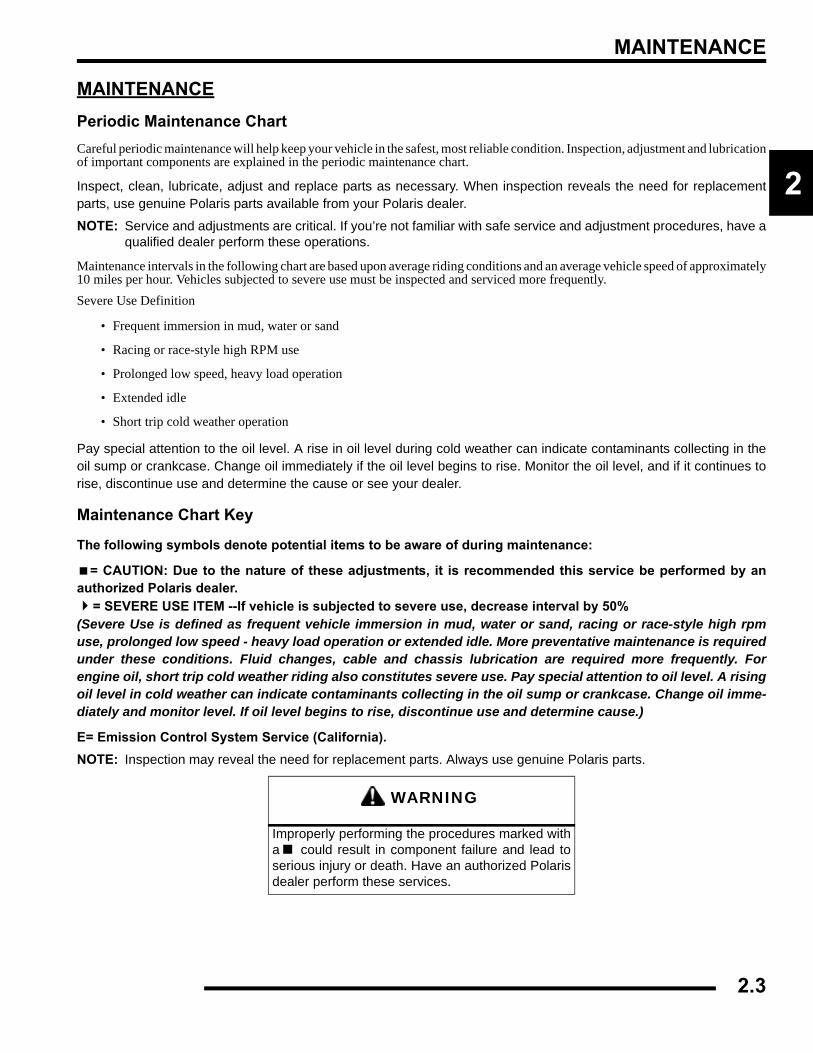
MAINTENANCEPeriodic Maintenance ChartCareful periodic maintenance will help keep your vehicle in the safest, most reliable condition. Inspection, adjustment and lubricationof important components are explained in the periodic maintenance chart.
Inspect, clean, lubricate, adjust and replace parts as necessary. When inspection reveals the need for replacementparts, use genuine Polaris parts available from your Polaris dealer.
NOTE: Service and adjustments are critical. If you’re not familiar with safe service and adjustment procedures, have aqualified dealer perform these operations.
Maintenance intervals in the following chart are based upon average riding conditions and an average vehicle speed of approximately10 miles per hour. Vehicles subjected to severe use must be inspected and serviced more frequently.Severe Use Definition
• Frequent immersion in mud, water or sand
• Racing or race-style high RPM use
• Prolonged low speed, heavy load operation
• Extended idle
• Short trip cold weather operation
Pay special attention to the oil level. A rise in oil level during cold weather can indicate contaminants collecting in theoil sump or crankcase. Change oil immediately if the oil level begins to rise. Monitor the oil level, and if it continues torise, discontinue use and determine the cause or see your dealer.
Maintenance Chart Key
The following symbols denote potential items to be aware of during maintenance:
= CAUTION: Due to the nature of these adjustments, it is recommended this service be performed by anauthorized Polaris dealer.
= SEVERE USE ITEM --If vehicle is subjected to severe use, decrease interval by 50% (Severe Use is defined as frequent vehicle immersion in mud, water or sand, racing or race-style high rpmuse, prolonged low speed - heavy load operation or extended idle. More preventative maintenance is requiredunder these conditions. Fluid changes, cable and chassis lubrication are required more frequently. Forengine oil, short trip cold weather riding also constitutes severe use. Pay special attention to oil level. A risingoil level in cold weather can indicate contaminants collecting in the oil sump or crankcase. Change oil imme-diately and monitor level. If oil level begins to rise, discontinue use and determine cause.)
E= Emission Control System Service (California).NOTE: Inspection may reveal the need for replacement parts. Always use genuine Polaris parts.
WARNING
Improperly performing the procedures marked witha could result in component failure and lead toserious injury or death. Have an authorized Polarisdealer perform these services.
2.3
MAINTENANCE
Periodic Maintenance Chart
Perform these procedures more often for vehicles subjected to severe use. E Emission Control System Service (California)
Have an authorized Polaris dealer perform these services.
Item Maintenance Interval(whichever comes first)
Remarks
Hours Calendar Miles (KM)
Steering - Pre-Ride -
Make adjustments as needed.
Front-suspension - Pre-Ride -Rear-suspension - Pre-Ride -Tires - Pre-Ride -ADC fluid level - Pre-Ride -Brake fluid level - Pre-Ride -Brake lever travel - Pre-Ride -Brake systems - Pre-Ride -Wheels /fasteners - Pre-Ride -Frame fasteners - Pre-Ride -
EEngine oil level - Pre-Ride -
Passenger Seat Lock Out - Pre-Ride - Verify Seat is securedDump Box Operation - Pre-Ride - Verify Box is latched
EAir filter, pre-filter - Daily - Inspect; clean often
EAir box sediment tube - Daily - Drain deposits when visible
Coolant - Daily - Check level daily, change coolant every 2 years
Headlamp/tail lamp - Daily - Check operation; apply dielectric grease if replacing
EAir filter,main element - Weekly - Inspect; replace as needed
Recoil housing - Weekly - Drain water as needed, check often if operating in wet conditions
Brake pad wear 10 H Monthly 60 (100) Inspect periodically
Battery 20 H Monthly 125 (200) Check terminals; clean; testFront gearcase oil (if equipped) 25 H Monthly 155 (250) Inspect level; change yearly
Middle gearcase oil (if equipped) 25 H Monthly 155 (250) Inspect level; change yearly
Rear gearcase oil (if equipped) 25 H Monthly 155 (250) Inspect level; change yearly
Transmission oil 25 H Monthly 155 (250) Inspect level; change yearly
2.4
MAINTENANCE
2
Periodic Maintenance Chart
Perform these procedures more often for vehicles subjected to severe use. E Emission Control System Service (California)
Have an authorized Polaris dealer perform these services.
Item Maintenance Interval (whichever comes first)
Remarks
Hours Calendar Miles (KM)
EEngine breather filter (if equipped) 25 H Monthly 155 (250) Inspect; replace if necessary
EEngine oil change (break-in) 25 H 1 M 155 (250) Perform a break-in oil change at one
monthGeneral lubrication 50 H 3 M 310 (500) Lubricate all grease fittings, pivots,
cables, etc.Shift Linkage 50 H 6 M 310 (500) Inspect, lubricate, adjustSteering 50 H 6 M 310 (500) LubricateFront suspension 50 H 6 M 310 (500) LubricateRear suspension 50 H 6 M 310 (500) Lubricate
EThrottle Cable/ETC Switch 50 H 6 M 310 (500) Inspect; adjust; lubricate; replace if
necessary
E Air intake ducts/flange 50 H 6 M 310 (500) Inspect ducts for proper sealing/air
leaksDrive belt 50 H 6 M 310 (500) Inspect; adjust; replace as neededCooling system (if applicable) 50 H 6 M 310 (500) Inspect coolant strength seasonally;
pressure test system yearly
EEngine oil change 100 H 6 M 620 (1000) Perform a break-in oil change at 25
hours/one month
EOil filter change 100 H 6 M 620 (1000) Replace with oil change
EOil tank vent hose 100 H 12 M 620 (1000) Inspect routing, condition
EValve clearance 100 H 12 M 620 (1000) Inspect; adjust
2.5
MAINTENANCE
Periodic Maintenance Chart
Perform these procedures more often for vehicles subjected to severe use. E Emission Control System Service (California)
Have an authorized Polaris dealer perform these services.
Item Maintenance Interval (whichever comes first)
Remarks
Hours Calendar Miles(Km)
E Fuel system 100 H 12M 620(1000)
Check for leaks at tank cap, lines, fuel valve, filter, pump, carburetor; replace lines every two years
E Fuel Filter 100 H 12M 620(1000) Replace yearly
Radiator(if applicable) 100 H 12M 620
(1000) Inspect; clean external surfaces
Cooling hoses(if applicable) 100 H 12M 620
(1000) Inspect for leaks
Engine mounts 100 H 12M 620(1000) Inspect
Exhaust muffler / pipe 100 H 12M 620
(1000) Inspect
E Spark plug 100 H 12M 620(1000) Inspect; replace as needed
E Ignition Timing 100 H 12M 620(1000) Inspect
Wiring 100 H 12M 620(1000)
Inspect for wear, routing, security; apply dielectric grease to connectors subjected to water, mud, etc.
Clutches (drive and driven) 100 H 12M 620
(1000) Inspect; clean; replace worn parts
Front wheel bearings 100 H 12M 1000
(1600) Inspect; replace as needed
Brake fluid 200 H 24M 1240(2000) Change every two years
Spark arrestor 300 H 36M 1860(3000) Clean out
Toe adjustment - Inspect periodically; adjust when parts are replaced
Auxiliary brake - Inspect daily; adjust as needed
Headlight aim - Adjust as needed
2.6
MAINTENANCE
2
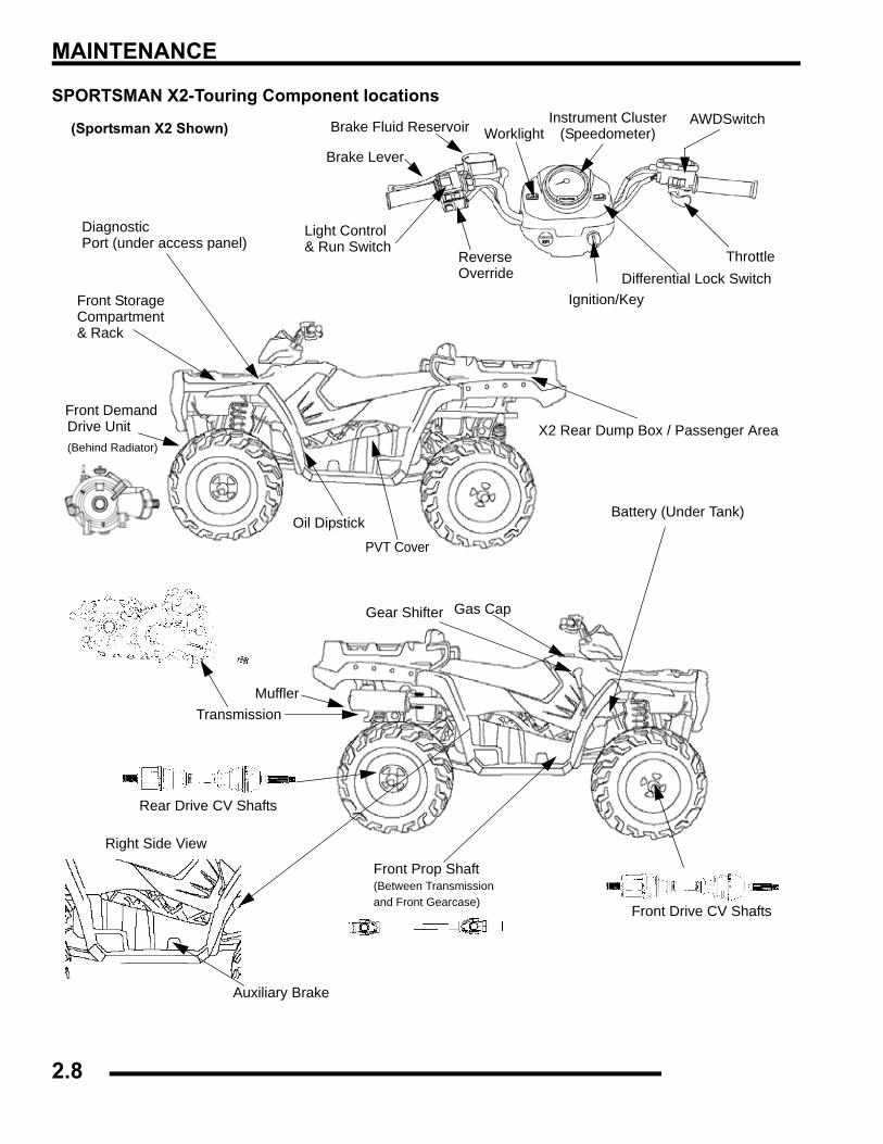
LUBRICATION / FLUIDSSPORTSMAN Component Locations
(Sportsman Only)
(Deluxe)
Choke - 500 Carburetor
2.7
MAINTENANCE
SPORTSMAN X2-Touring Component locationsAWDSwitch
Throttle
Ignition/Key
Instrument ClusterWorklight
Diagnostic
Reverse
Brake Fluid Reservoir
Brake Lever
Light Control& Run Switch
(Speedometer)
Override
X2 Rear Dump Box / Passenger Area
PVT Cover
Oil Dipstick
Front Demand
(Behind Radiator)
Front Storage Compartment& Rack
Gas CapGear Shifter
Front Drive CV Shafts
Front Prop Shaft(Between Transmissionand Front Gearcase)
TransmissionMuffler
Right Side View
Auxiliary Brake
Port (under access panel)
Drive Unit
Battery (Under Tank)
Rear Drive CV Shafts
Differential Lock Switch
(Sportsman X2 Shown)
2.8
MAINTENANCE
2
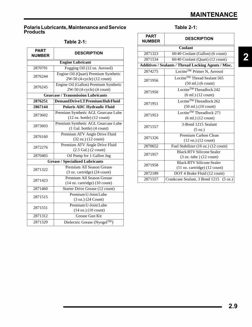
Polaris Lubricants, Maintenance and Service Products
Table 2-1: PART
NUMBER DESCRIPTION
Engine Lubricant2870791 Fogging Oil (12 oz. Aerosol)
2876244 Engine Oil (Quart) Premium Synthetic 2W-50 (4-cycle) (12 count)
2876245 Engine Oil (Gallon) Premium Synthetic 2W-50 (4-cycle) (4 count)
Gearcase / Transmission Lubricants2876251 Demand Drive LT Premium Hub Fluid 2867144 Polaris ADC Hydraulic Fluid
2873602 Premium Synthetic AGL Gearcase Lube (12 oz. bottle) (12 count)
2873603 Premium Synthetic AGL Gearcase Lube (1 Gal. bottle) (4 count)
2876160 Premium ATV Angle Drive Fluid (32 oz.) (12 count)
2872276 Premium ATV Angle Drive Fluid (2.5 Gal.) (2 count)
2870465 Oil Pump for 1 Gallon JugGrease / Specialized Lubricants
2871322 Premium All Season Grease (3 oz. cartridge) (24 count)
2871423 Premium All Season Grease (14 oz. cartridge) (10 count)
2871460 Starter Drive Grease (12 count)
2871515 Premium U-Joint Lube (3 oz.) (24 Count)
2871551 Premium U-Joint Lube (14 oz.) (10 count)
2871312 Grease Gun Kit2871329 Dielectric Grease (Nyogel™)
Coolant2871323 60/40 Coolant (Gallon) (6 count)2871534 60/40 Coolant (Quart) (12 count)
Additives / Sealants / Thread Locking Agents / Misc.2874275 Loctite™ Primer N, Aerosol
2871956 Loctite™ Thread Sealant 565 (50 ml.) (6 count)
2871950 Loctite™ Threadlock 242 (6 ml.) (12 count)
2871951 Loctite™ Threadlock 262 (50 ml.) (10 count)
2871953 Loctite™ Threadlock 271 (6 ml.) (12 count)
2871557 3-Bond 1215 Sealant(5 oz.)
2871326 Premium Carbon Clean (12 oz.) (12 count)
2870652 Fuel Stabilizer (16 oz.) (12 count)
2871957 Black RTV Silicone Sealer (3 oz. tube ) (12 count)
2871958 Black RTV Silicone Sealer (11 oz. cartridge) (12 count)
2872189 DOT 4 Brake Fluid (12 count)2871557 Crankcase Sealant, 3 Bond 1215 (5 oz.)
Table 2-1: PART
NUMBER DESCRIPTION
2.9
MAINTENANCE
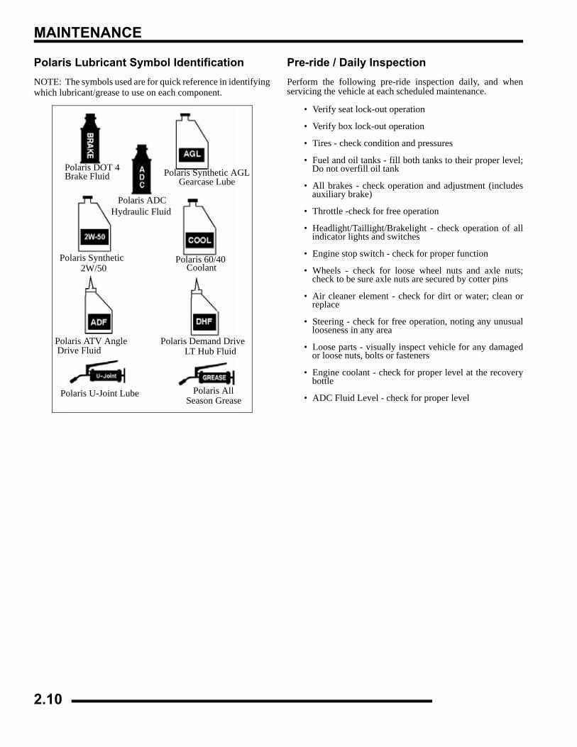
Polaris Lubricant Symbol IdentificationNOTE: The symbols used are for quick reference in identifyingwhich lubricant/grease to use on each component.
Pre-ride / Daily InspectionPerform the following pre-ride inspection daily, and whenservicing the vehicle at each scheduled maintenance.
• Verify seat lock-out operation
• Verify box lock-out operation
• Tires - check condition and pressures
• Fuel and oil tanks - fill both tanks to their proper level;Do not overfill oil tank
• All brakes - check operation and adjustment (includesauxiliary brake)
• Throttle -check for free operation
• Headlight/Taillight/Brakelight - check operation of allindicator lights and switches
• Engine stop switch - check for proper function
• Wheels - check for loose wheel nuts and axle nuts;check to be sure axle nuts are secured by cotter pins
• Air cleaner element - check for dirt or water; clean orreplace
• Steering - check for free operation, noting any unusuallooseness in any area
• Loose parts - visually inspect vehicle for any damagedor loose nuts, bolts or fasteners
• Engine coolant - check for proper level at the recoverybottle
• ADC Fluid Level - check for proper level
Polaris DOT 4 Brake Fluid Polaris Synthetic AGL
Gearcase Lube
Polaris Synthetic Polaris 60/40
Polaris Demand DriveLT Hub Fluid
Polaris U-Joint Lube Polaris All Season Grease
Polaris ATV Angle Drive Fluid
2W/50 Coolant
Polaris ADCHydraulic Fluid
2.10
MAINTENANCE
2
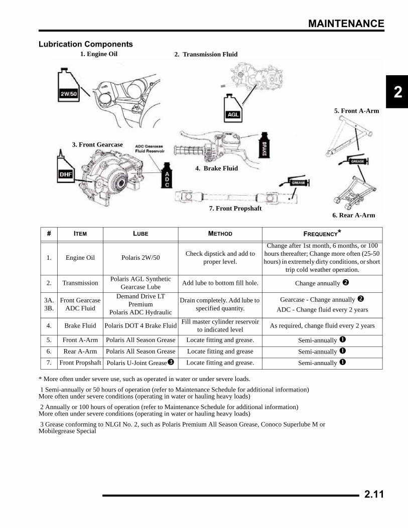
Lubrication Components
* More often under severe use, such as operated in water or under severe loads. 1 Semi-annually or 50 hours of operation (refer to Maintenance Schedule for additional information)More often under severe conditions (operating in water or hauling heavy loads) 2 Annually or 100 hours of operation (refer to Maintenance Schedule for additional information)More often under severe conditions (operating in water or hauling heavy loads) 3 Grease conforming to NLGI No. 2, such as Polaris Premium All Season Grease, Conoco Superlube M orMobilegrease Special
# ITEM LUBE METHOD FREQUENCY*
1. Engine Oil Polaris 2W/50 Check dipstick and add to proper level.
Change after 1st month, 6 months, or 100 hours thereafter; Change more often (25-50 hours) in extremely dirty conditions, or short
trip cold weather operation.
2. Transmission Polaris AGL Synthetic Gearcase Lube Add lube to bottom fill hole. Change annually
3A.3B.
Front GearcaseADC Fluid
Demand Drive LT Premium
Polaris ADC Hydraulic
Drain completely. Add lube to specified quantity.
Gearcase - Change annually ADC - Change fluid every 2 years
4. Brake Fluid Polaris DOT 4 Brake Fluid Fill master cylinder reservoir to indicated level As required, change fluid every 2 years
5. Front A-Arm Polaris All Season Grease Locate fitting and grease. Semi-annually
6. Rear A-Arm Polaris All Season Grease Locate fitting and grease Semi-annually
7. Front Propshaft Polaris U-Joint Grease Locate fitting and grease. Semi-annually
1. Engine Oil 2. Transmission Fluid
3. Front Gearcase
4. Brake Fluid
5. Front A-Arm
6. Rear A-Arm7. Front Propshaft
2.11
MAINTENANCE
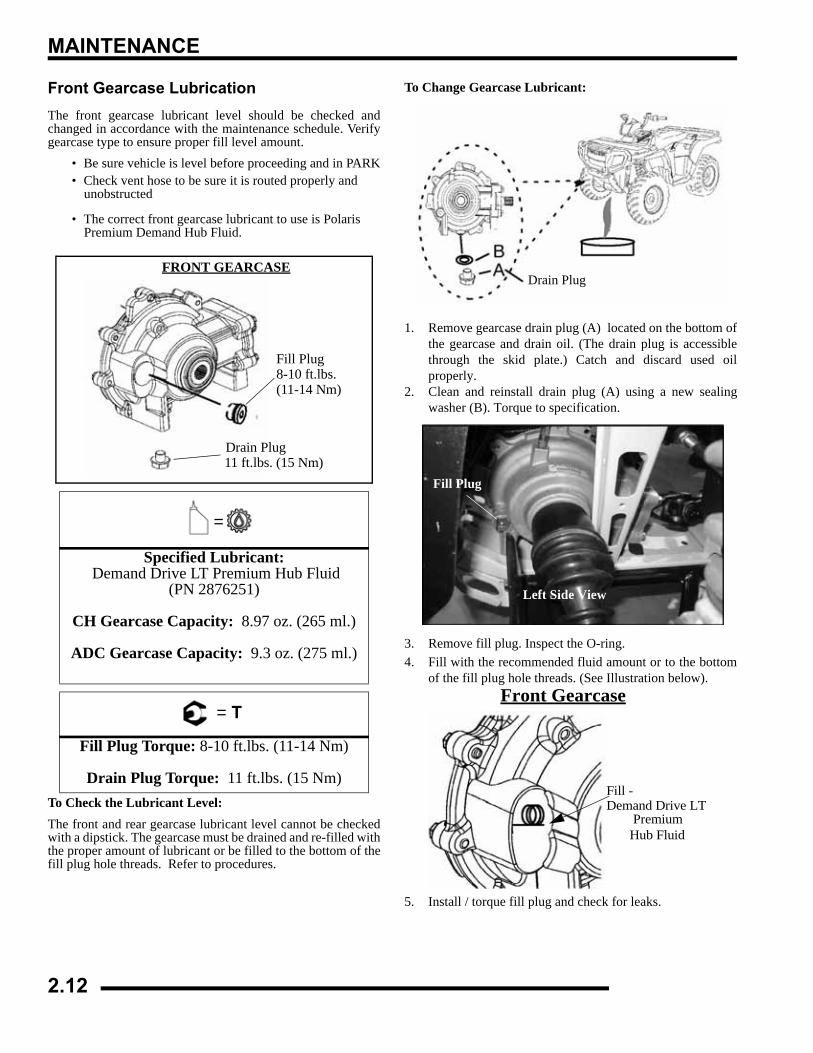
Front Gearcase LubricationThe front gearcase lubricant level should be checked andchanged in accordance with the maintenance schedule. Verifygearcase type to ensure proper fill level amount.
• Be sure vehicle is level before proceeding and in PARK• Check vent hose to be sure it is routed properly and
unobstructed
• The correct front gearcase lubricant to use is Polaris Premium Demand Hub Fluid.
To Check the Lubricant Level:The front and rear gearcase lubricant level cannot be checkedwith a dipstick. The gearcase must be drained and re-filled withthe proper amount of lubricant or be filled to the bottom of thefill plug hole threads. Refer to procedures.
To Change Gearcase Lubricant:
1. Remove gearcase drain plug (A) located on the bottom ofthe gearcase and drain oil. (The drain plug is accessiblethrough the skid plate.) Catch and discard used oilproperly.
2. Clean and reinstall drain plug (A) using a new sealingwasher (B). Torque to specification.
3. Remove fill plug. Inspect the O-ring.4. Fill with the recommended fluid amount or to the bottom
of the fill plug hole threads. (See Illustration below).
5. Install / torque fill plug and check for leaks.
=
Specified Lubricant: Demand Drive LT Premium Hub Fluid
(PN 2876251)
CH Gearcase Capacity: 8.97 oz. (265 ml.)
ADC Gearcase Capacity: 9.3 oz. (275 ml.)
= T
Fill Plug Torque: 8-10 ft.lbs. (11-14 Nm)
Drain Plug Torque: 11 ft.lbs. (15 Nm)
FRONT GEARCASE
Fill Plug8-10 ft.lbs.(11-14 Nm)
Drain Plug 11 ft.lbs. (15 Nm)
Drain Plug
Left Side View
Fill Plug
Front Gearcase
Fill -
Hub Fluid Demand Drive LT
Premium
2.12
MAINTENANCE
2
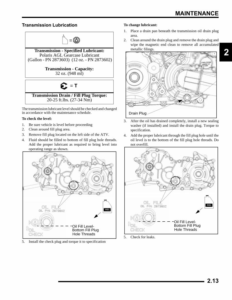
Transmission Lubrication
The transmission lubricant level should be checked and changedin accordance with the maintenance schedule. To check the level:1. Be sure vehicle is level before proceeding2. Clean around fill plug area.3. Remove fill plug located on the left side of the ATV.4. Fluid should be filled to bottom of fill plug hole threads.
Add the proper lubricant as required to bring level intooperating range as shown.
5. Install the check plug and torque it to specification
To change lubricant:1. Place a drain pan beneath the transmission oil drain plug
area.2. Clean around the drain plug and remove the drain plug and
wipe the magnetic end clean to remove all accumulatedmetallic filings.
3. After the oil has drained completely, install a new sealingwasher (if installed) and install the drain plug. Torque tospecification.
4. Add the proper lubricant through the fill plug hole until theoil level is to the bottom of the fill plug hole threads. Donot overfill.
5. Check for leaks.
=
Transmission - Specified Lubricant:Polaris AGL Gearcase Lubricant
(Gallon - PN 2873603) (12 oz. - PN 2873602)
Transmission - Capacity: 32 oz. (948 ml)
= T
Transmission Drain / Fill Plug Torque: 20-25 ft.lbs. (27-34 Nm)
Oil Fill Plug
Oil Fill Level-Bottom Fill PlugHole Threads
Drain Plug
Oil Fill Plug
Oil Fill Level-Bottom Fill PlugHole Threads
2.13
MAINTENANCE
ADC Differential Hydraulic Circuit Fluid Change1. Make sure vehicle is parked on flat ground and allowed to
sit at least 30 minutes prior to bleeding hydraulic circuit.2. Thoroughly clean area around and on remote reservoir and
bleeder valves.3. Remove reservoir cap and diaphragm assembly.4. Make sure hydraulic oil inside reservoir is free of debris.
If any debris is found, use clean rag or suction device toremove from the reservoir.
NOTE: Debris in reservoir may block porting andproduce inadequate bleeding of the system.Decreased performance may be encountered withinadequate bleed of the hydraulic circuit.
5. Begin the bleeding process by filling reservoir to ‘MAX’line with clean Polaris ADC hyrdraulic fluid.
6. Locate bleeder valves found on either side of differentialand remove the protective caps.
7. Turn bleeder valves counter-clockwise to loosen. Loosenbleeder screw slowly, allowing oil and any trapped air toflow out of fitting.
IMPORTANT: Do not allow hydraulic fluid in reservoirto drain below minimum fill line. Close bleeder valvebefore oil level falls below minimum fill line. Refillingempty reservoir will result in air pockets becomingtrapped.
NOTE: If empty reservoir is encountered, filling offluid is still possible. Verify air is not trapped beforeproceeding with step 7.
8. Continue steps 6-8 on both sides in sequence until cleanfluid is seen when bleeding occurs.
9. Re-torque both bleeder valves to specification and reinstallcover caps.
10. Fill reservoir with to a level midway between ‘MAX’ and‘MIN’ fill lines. Verify no debris is found in reservoir oil.
11. Replace reservoir cap securely and wipe clean any residue.
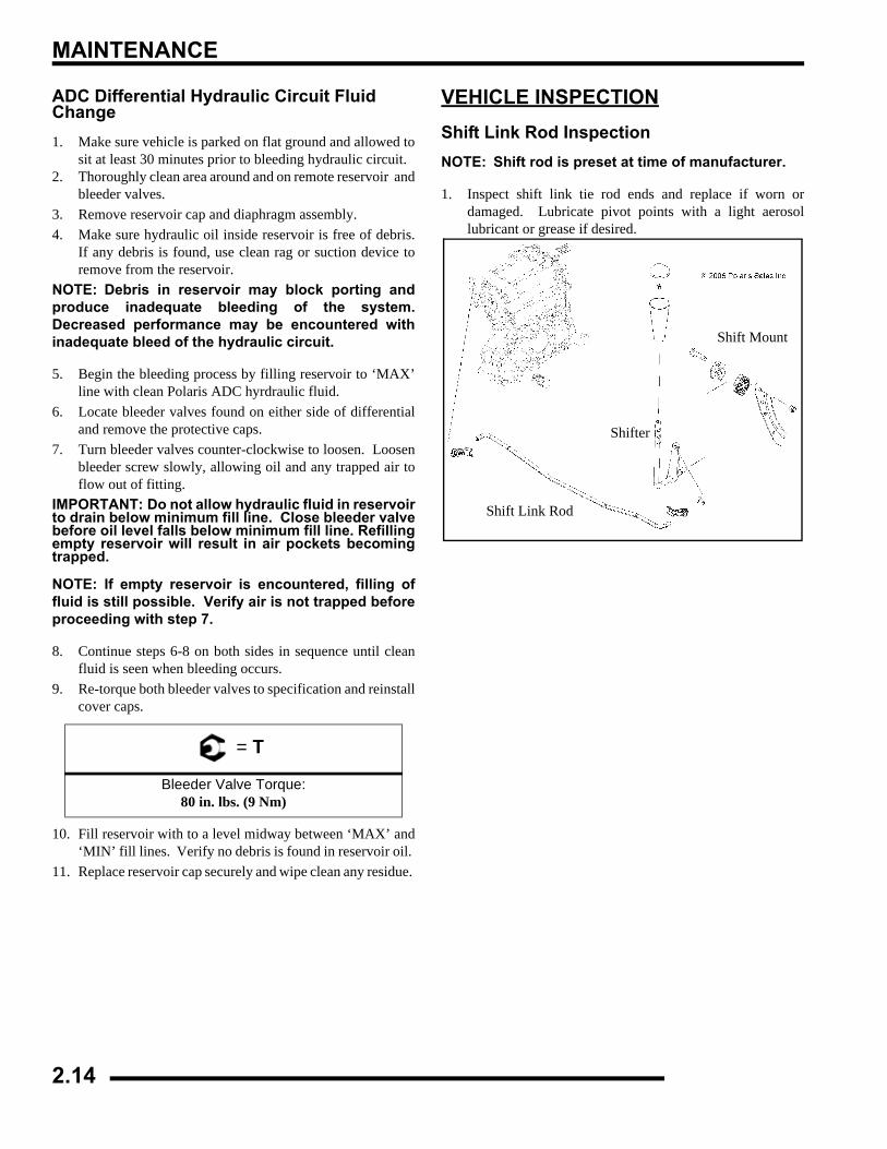
VEHICLE INSPECTIONShift Link Rod InspectionNOTE: Shift rod is preset at time of manufacturer.
1. Inspect shift link tie rod ends and replace if worn ordamaged. Lubricate pivot points with a light aerosollubricant or grease if desired.
= T
Bleeder Valve Torque:80 in. lbs. (9 Nm)
Shift Mount
Shifter
Shift Link Rod
2.14
MAINTENANCE
2
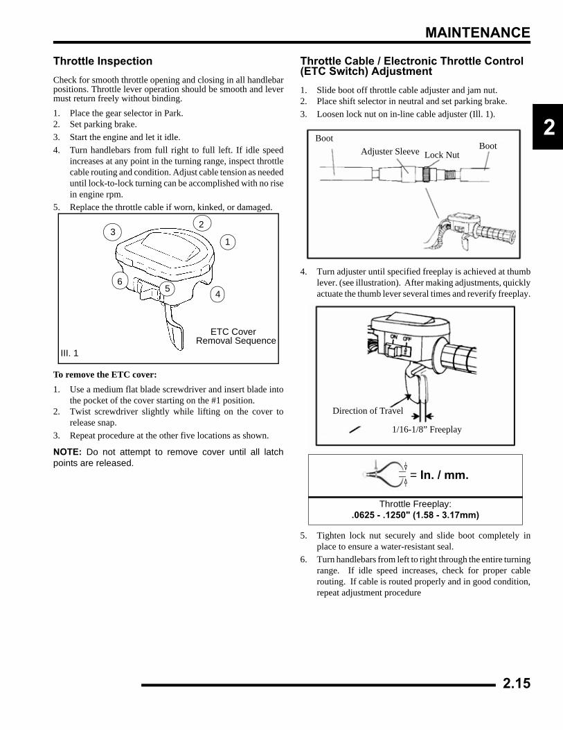
Throttle InspectionCheck for smooth throttle opening and closing in all handlebarpositions. Throttle lever operation should be smooth and levermust return freely without binding.1. Place the gear selector in Park.2. Set parking brake.3. Start the engine and let it idle.4. Turn handlebars from full right to full left. If idle speed
increases at any point in the turning range, inspect throttlecable routing and condition. Adjust cable tension as neededuntil lock-to-lock turning can be accomplished with no risein engine rpm.
5. Replace the throttle cable if worn, kinked, or damaged.
To remove the ETC cover:1. Use a medium flat blade screwdriver and insert blade into
the pocket of the cover starting on the #1 position.2. Twist screwdriver slightly while lifting on the cover to
release snap.3. Repeat procedure at the other five locations as shown.
NOTE: Do not attempt to remove cover until all latchpoints are released.
Throttle Cable / Electronic Throttle Control (ETC Switch) Adjustment1. Slide boot off throttle cable adjuster and jam nut.2. Place shift selector in neutral and set parking brake.3. Loosen lock nut on in-line cable adjuster (Ill. 1).
4. Turn adjuster until specified freeplay is achieved at thumblever. (see illustration). After making adjustments, quicklyactuate the thumb lever several times and reverify freeplay.
5. Tighten lock nut securely and slide boot completely inplace to ensure a water-resistant seal.
6. Turn handlebars from left to right through the entire turningrange. If idle speed increases, check for proper cablerouting. If cable is routed properly and in good condition,repeat adjustment procedure
ETC CoverRemoval Sequence
III. 1
1
23
456
= In. / mm.
Throttle Freeplay:.0625 - .1250" (1.58 - 3.17mm)
BootAdjuster Sleeve Lock Nut
Boot
Direction of Travel
1/16-1/8” Freeplay
2.15
MAINTENANCE
Fuel System
• Always stop the engine and refuel outdoors or in a wellventilated area.
• Do not smoke or allow open flames or sparks in or nearthe area where refueling is performed or where gasolineis stored.
• Do not overfill the tank. Do not fill the tank neck.
• If you get gasoline in your eyes or if you swallowgasoline, seek medical attention immediately.
• If you spill gasoline on your skin or clothing,immediately wash it off with soap and water and changeclothing.
• Never start the engine or let it run in an enclosed area.Engine exhaust fumes are poisonous and can result lossof consciousness or death in a short time.
• Never drain the system when the engine is hot.Severe burns may result.
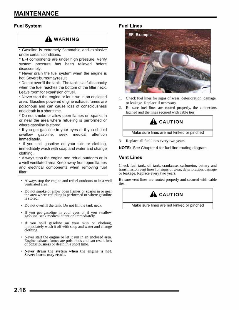
Fuel Lines
1. Check fuel lines for signs of wear, deterioration, damage,or leakage. Replace if necessary.
2. Be sure fuel lines are routed properly, the connectorslatched and the lines secured with cable ties.
3. Replace all fuel lines every two years.
NOTE: See Chapter 4 for fuel line routing diagram.
Vent LinesCheck fuel tank, oil tank, crankcase, carburetor, battery andtransmission vent lines for signs of wear, deterioration, damageor leakage. Replace every two years.Be sure vent lines are routed properly and secured with cableties.
WARNING
* Gasoline is extremely flammable and explosiveunder certain conditions. * EFI components are under high pressure. Verifysystem pressure has been relieved beforedisassembly. * Never drain the fuel system when the engine ishot. Severe burns may result * Do not overfill the tank. The tank is at full capacitywhen the fuel reaches the bottom of the filler neck.Leave room for expansion of fuel. * Never start the engine or let it run in an enclosedarea. Gasoline powered engine exhaust fumes arepoisonous and can cause loss of consciousnessand death in a short time. * Do not smoke or allow open flames or sparks inor near the area where refueling is performed orwhere gasoline is stored. * If you get gasoline in your eyes or if you shouldswallow gasoline, seek medical attentionimmediately. * If you spill gasoline on your skin or clothing,immediately wash with soap and water and changeclothing. * Always stop the engine and refuel outdoors or ina well ventilated area.Keep away from open flamesand electrical components when removing fuelfilter.
CAUTION
Make sure lines are not kinked or pinched
CAUTION
Make sure lines are not kinked or pinched
EFI Example
2.16
MAINTENANCE
2
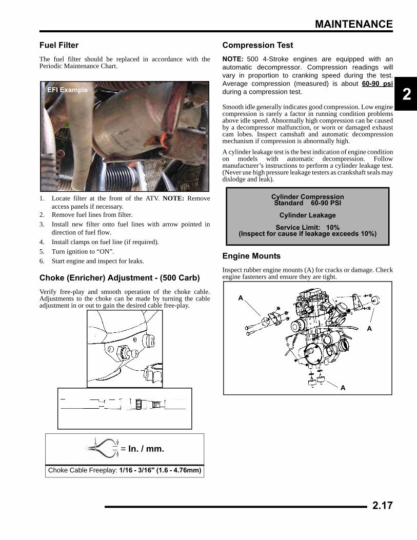
Fuel FilterThe fuel filter should be replaced in accordance with thePeriodic Maintenance Chart.
1. Locate filter at the front of the ATV. NOTE: Removeaccess panels if necessary.
2. Remove fuel lines from filter.3. Install new filter onto fuel lines with arrow pointed in
direction of fuel flow.4. Install clamps on fuel line (if required).5. Turn ignition to “ON”.6. Start engine and inspect for leaks.
Choke (Enricher) Adjustment - (500 Carb)Verify free-play and smooth operation of the choke cable.Adjustments to the choke can be made by turning the cableadjustment in or out to gain the desired cable free-play.
Compression TestNOTE: 500 4-Stroke engines are equipped with anautomatic decompressor. Compression readings willvary in proportion to cranking speed during the test.Average compression (measured) is about 60-90 psiduring a compression test.
Smooth idle generally indicates good compression. Low enginecompression is rarely a factor in running condition problemsabove idle speed. Abnormally high compression can be causedby a decompressor malfunction, or worn or damaged exhaustcam lobes. Inspect camshaft and automatic decompressionmechanism if compression is abnormally high.A cylinder leakage test is the best indication of engine conditionon models with automatic decompression. Followmanufacturer’s instructions to perform a cylinder leakage test.(Never use high pressure leakage testers as crankshaft seals maydislodge and leak).
Engine MountsInspect rubber engine mounts (A) for cracks or damage. Checkengine fasteners and ensure they are tight.
= In. / mm.
Choke Cable Freeplay: 1/16 - 3/16" (1.6 - 4.76mm)
EFI Example
Cylinder Compression Standard 60-90 PSI
Cylinder Leakage
Service Limit: 10%(Inspect for cause if leakage exceeds 10%)
A
A
A
2.17
MAINTENANCE
Spark Plug1. Remove spark plug high tension lead. Clean plug area so
no dirt and debris can fall into engine when plug isremoved.
2. Remove spark plug.3. Inspect electrodes for wear and carbon buildup. Look for a
sharp outer edge with no rounding or erosion of theelectrodes.
4. Clean with electrical contact cleaner or a glass bead sparkplug cleaner only. CAUTION: A wire brush or coatedabrasive should not be used.
5. Measure gap with a wire gauge. Refer to specifications forproper spark plug type and gap. Adjust gap if necessary bybending the side electrode carefully.
6. If necessary, replace spark plug with proper type.
7. Apply a small amount of anti-seize compound to the sparkplug threads.
8. Install spark plug and torque to specification.
Active Descent Control (ADC) Reservoir LevelThe Active Descent Control reservoir (Equipped Models Only)is located by the radiator fill cap. Check the level and verify itis between the ‘MAX’ and ‘MIN’ lines. Add only Polaris ADCfluid when required.
Battery MaintenanceComplete battery servicing information for both conventinoaland sealed batteries can be found in Chapter 10 of thismanual.
NOTE: Expected battery shelf life is 6-8 monthsdepending on storage conditions. As a general rulebefore placing the battery into service, check thebattery condition and charge accordingly.
CAUTION
Severe engine damage may occur if the incorrect spark plug is used.
= T
Recommended Spark PlugRefer to the Specifications page in
Chapter 1 for spark plug type.Spark Plug Torque: 14 Ft. Lbs. (19 Nm)
Spark Plug Gap
.036” (0.9 mm)
WARNING
Battery electrolyte is poisonous. It contains sulfuric acid. Serious burns can result from contact with
skin, eyes or clothing. Antidote:
External: Flush with water.
Internal: Drink large quantities of water or milk. Follow with milk of magnesia, beaten egg, or
vegetable oil. Call physician immediately.
Eyes: Flush with water for 15 minutes and get prompt medical attention.
Batteries produce explosive gases. Keep sparks, flame, cigarettes, etc. away. Ventilate when
charging or using in an enclosed space. Always shield eyes when working near batteries. KEEP OUT OF REACH OF CHILDREN.
2.18
MAINTENANCE
2
New Batteries: Batteries must be fully chargedbefore use or battery life can be reduced by 10-30%of full potential. Charge battery for 3-5 hours at acurrent equivalent of 1/10 of the battery’s rated amp/hour capacity (i.e. 12amp hr x .10 = 1.2 amp charg-ing). Do not use the alternator to charge a new bat-tery.
Liquid Cooling System OverviewThe engine coolant level is controlled or maintained by therecovery system. The recovery system components are therecovery bottle, radiator filler neck, radiator pressure cap andconnecting hose.As coolant operating temperature increases, the expanding(heated) excess coolant is forced out of the radiator past thepressure cap and into the recovery bottle. As engine coolanttemperature decreases the contracting (cooled) coolant is drawnback up from the tank past the pressure cap and into the radiator.Some coolant level drop on new machines is normal as thesystem is purging itself of trapped air. Observe coolant levelsoften during the break-in period.Overheating of engine could occur if air is not fully purged fromsystem.Polaris Premium 60/40 is already premixed and ready to use. Donot dilute with water.
Coolant Strength / TypeTest the strength of the coolant using an antifreeze hydrometer.
• A 50/50 or 60/40 mixture of antifreeze and distilledwater will provide the optimum cooling, corrosionprotection, and antifreeze protection.
• Do not use tap water, straight antifreeze, or straightwater in the system. Tap water contains minerals andimpurities which build up in the system.
• Straight water or antifreeze may cause the system tofreeze, corrode, or overheat.
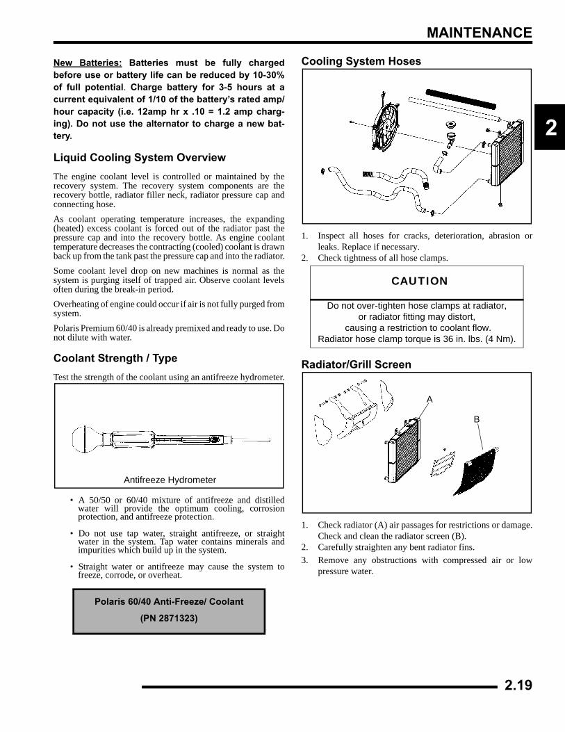
Cooling System Hoses
1. Inspect all hoses for cracks, deterioration, abrasion orleaks. Replace if necessary.
2. Check tightness of all hose clamps.
Radiator/Grill Screen
1. Check radiator (A) air passages for restrictions or damage.Check and clean the radiator screen (B).
2. Carefully straighten any bent radiator fins.3. Remove any obstructions with compressed air or low
pressure water.
Polaris 60/40 Anti-Freeze/ Coolant
(PN 2871323)
Antifreeze Hydrometer
CAUTION
Do not over-tighten hose clamps at radiator, or radiator fitting may distort,
causing a restriction to coolant flow. Radiator hose clamp torque is 36 in. lbs. (4 Nm).
A
B
2.19
MAINTENANCE
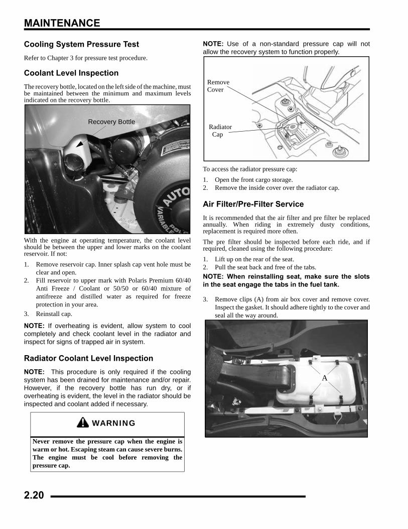
Cooling System Pressure TestRefer to Chapter 3 for pressure test procedure.
Coolant Level InspectionThe recovery bottle, located on the left side of the machine, mustbe maintained between the minimum and maximum levelsindicated on the recovery bottle.
With the engine at operating temperature, the coolant levelshould be between the upper and lower marks on the coolantreservoir. If not:1. Remove reservoir cap. Inner splash cap vent hole must be
clear and open.2. Fill reservoir to upper mark with Polaris Premium 60/40
Anti Freeze / Coolant or 50/50 or 60/40 mixture ofantifreeze and distilled water as required for freezeprotection in your area.
3. Reinstall cap.
NOTE: If overheating is evident, allow system to coolcompletely and check coolant level in the radiator andinspect for signs of trapped air in system.
Radiator Coolant Level InspectionNOTE: This procedure is only required if the coolingsystem has been drained for maintenance and/or repair.However, if the recovery bottle has run dry, or ifoverheating is evident, the level in the radiator should beinspected and coolant added if necessary.
NOTE: Use of a non-standard pressure cap will notallow the recovery system to function properly.
To access the radiator pressure cap:1. Open the front cargo storage.2. Remove the inside cover over the radiator cap.
Air Filter/Pre-Filter ServiceIt is recommended that the air filter and pre filter be replacedannually. When riding in extremely dusty conditions,replacement is required more often.The pre filter should be inspected before each ride, and ifrequired, cleaned using the following procedure:1. Lift up on the rear of the seat.2. Pull the seat back and free of the tabs. NOTE: When reinstalling seat, make sure the slotsin the seat engage the tabs in the fuel tank.
3. Remove clips (A) from air box cover and remove cover.Inspect the gasket. It should adhere tightly to the cover andseal all the way around.
WARNING
Never remove the pressure cap when the engine iswarm or hot. Escaping steam can cause severe burns.The engine must be cool before removing thepressure cap.
Recovery Bottle
RemoveCover
Radiator Cap
A
2.20
MAINTENANCE
2
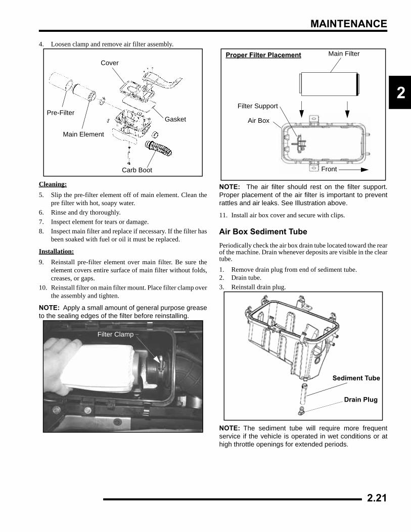
4. Loosen clamp and remove air filter assembly.
Cleaning:5. Slip the pre-filter element off of main element. Clean the
pre filter with hot, soapy water.6. Rinse and dry thoroughly.7. Inspect element for tears or damage.8. Inspect main filter and replace if necessary. If the filter has
been soaked with fuel or oil it must be replaced.
Installation:9. Reinstall pre-filter element over main filter. Be sure the
element covers entire surface of main filter without folds,creases, or gaps.
10. Reinstall filter on main filter mount. Place filter clamp overthe assembly and tighten.
NOTE: Apply a small amount of general purpose greaseto the sealing edges of the filter before reinstalling.
NOTE: The air filter should rest on the filter support.Proper placement of the air filter is important to preventrattles and air leaks. See Illustration above.
11. Install air box cover and secure with clips.
Air Box Sediment TubePeriodically check the air box drain tube located toward the rearof the machine. Drain whenever deposits are visible in the cleartube.1. Remove drain plug from end of sediment tube.2. Drain tube.3. Reinstall drain plug.
NOTE: The sediment tube will require more frequentservice if the vehicle is operated in wet conditions or athigh throttle openings for extended periods.
Gasket
Carb Boot
Main Element
Pre-Filter
Cover
Filter Clamp
Front
Main Filter
Filter Support
Air Box
Proper Filter Placement
Sediment Tube
Drain Plug
2.21
MAINTENANCE
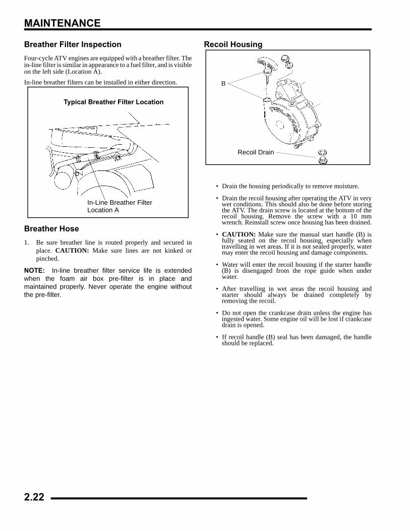
Breather Filter InspectionFour-cycle ATV engines are equipped with a breather filter. Thein-line filter is similar in appearance to a fuel filter, and is visibleon the left side (Location A).In-line breather filters can be installed in either direction.
Breather Hose1. Be sure breather line is routed properly and secured in
place. CAUTION: Make sure lines are not kinked orpinched.
NOTE: In-line breather filter service life is extendedwhen the foam air box pre-filter is in place andmaintained properly. Never operate the engine withoutthe pre-filter.
Recoil Housing
• Drain the housing periodically to remove moisture.
• Drain the recoil housing after operating the ATV in verywet conditions. This should also be done before storingthe ATV. The drain screw is located at the bottom of therecoil housing. Remove the screw with a 10 mmwrench. Reinstall screw once housing has been drained.
• CAUTION: Make sure the manual start handle (B) isfully seated on the recoil housing, especially whentravelling in wet areas. If it is not sealed properly, watermay enter the recoil housing and damage components.
• Water will enter the recoil housing if the starter handle(B) is disengaged from the rope guide when underwater.
• After travelling in wet areas the recoil housing andstarter should always be drained completely byremoving the recoil.
• Do not open the crankcase drain unless the engine hasingested water. Some engine oil will be lost if crankcasedrain is opened.
• If recoil handle (B) seal has been damaged, the handleshould be replaced.
Typical Breather Filter Location
In-Line Breather FilterLocation A
Recoil Drain
B
2.22
MAINTENANCE
2
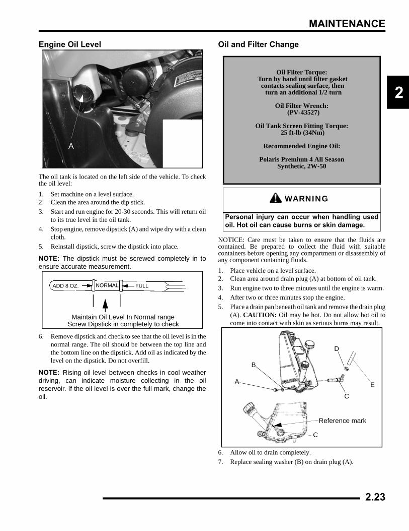
Engine Oil Level
The oil tank is located on the left side of the vehicle. To checkthe oil level:1. Set machine on a level surface.2. Clean the area around the dip stick.3. Start and run engine for 20-30 seconds. This will return oil
to its true level in the oil tank.4. Stop engine, remove dipstick (A) and wipe dry with a clean
cloth.5. Reinstall dipstick, screw the dipstick into place.
NOTE: The dipstick must be screwed completely in toensure accurate measurement.
6. Remove dipstick and check to see that the oil level is in thenormal range. The oil should be between the top line andthe bottom line on the dipstick. Add oil as indicated by thelevel on the dipstick. Do not overfill.
NOTE: Rising oil level between checks in cool weatherdriving, can indicate moisture collecting in the oilreservoir. If the oil level is over the full mark, change theoil.
Oil and Filter Change
NOTICE: Care must be taken to ensure that the fluids arecontained. Be prepared to collect the fluid with suitablecontainers before opening any compartment or disassembly ofany component containing fluids.1. Place vehicle on a level surface.2. Clean area around drain plug (A) at bottom of oil tank. 3. Run engine two to three minutes until the engine is warm. 4. After two or three minutes stop the engine. 5. Place a drain pan beneath oil tank and remove the drain plug
(A). CAUTION: Oil may be hot. Do not allow hot oil tocome into contact with skin as serious burns may result.
6. Allow oil to drain completely.7. Replace sealing washer (B) on drain plug (A).
A
ADD 8 OZ. NORMAL FULL
Maintain Oil Level In Normal rangeScrew Dipstick in completely to check
Oil Filter Torque: Turn by hand until filter gasket
contacts sealing surface, then turn an additional 1/2 turn
Oil Filter Wrench: (PV-43527)
Oil Tank Screen Fitting Torque: 25 ft-lb (34Nm)
Recommended Engine Oil:
Polaris Premium 4 All SeasonSynthetic, 2W-50
WARNING
Personal injury can occur when handling usedoil. Hot oil can cause burns or skin damage.
A
B
C
D
E
Reference mark
C
2.23
MAINTENANCE
NOTE: The sealing surfaces on the drain plug andthe oil tank should be clean and free of burrs, nicksor scratches.
8. Reinstall the drain plug (A) and torque it to specification.
9. Loosen clamp (D).10. Remove oil hose (E) from screen fitting (C) on bottom of
oil tank.11. Remove screen fitting (C) and clean the screen.12. Apply Loctite™ thread sealant 505 or an equivalent pipe
thread sealant or PTFE sealant tape to clean, oil free threadsof fitting (C).
13. Install screen fitting (C) and rotate a minimum of 2 1/2 turns(clockwise) into the tank threads. Then rotate the screenfitting clockwise until the nipple of the screen fitting alignswith the reference marking on the tank.
NOTE: Maximum torque for the screen fitting is 25ft-lb (34Nm), do not over tighten.
14. Install oil hose (E) on fitting (C) and re-install clamp (D).15. Place shop towels beneath oil filter. Use Oil Filter Wrench
(PV-43527), turn filter counterclockwise to remove.
16. Using a clean dry cloth, clean filter sealing surface on thecrankcase.
17. Lubricate the o-ring on new filter with a thin film of engineoil. Check to make sure the O-ring is in good condition.
18. Install the new filter and turn it by hand until the filtergasket contacts the sealing surface, then turn an additional1/2 of a turn.
19. Approximately 1 cup of engine oil will remain in thecrankcase. To drain, remove drain plug found on lower rightside of crankcase.
NOTE: The sealing surfaces on the drain plug andcrankcase should be clean and free of burrs, nicks orscratches.
20. Reinstall drain plug and torque to specification.21. Remove dipstick and fill tank with 2 quarts (1.9 L) of
Polaris Premium 4 Synthetic Oil.22. Place gear selector in Park and set parking brake.
NOTE: Clamp or pinch off the vent line 2” from the oiltank as shown in the Oil Pump Priming Procedure.
23. Re-check the oil level on the dipstick and add oil asnecessary to bring the level to the upper mark on thedipstick.
24. Dispose of used filter and oil properly.
= T
Oil Tank Drain Plug Torque: 14 ft. lbs. (19 Nm)
Crankcase Drain Plug Torque:14 ft. lbs. (19 Nm)
CAUTION
Maximum torque for the screen fittingis 25 ft-lb (34Nm), do not over tighten.
Oil Filter
Engine Sump
Engine Sump Drain Plug- Bottom View
Drain
2.24
MAINTENANCE
2
Oil Pump Priming ProcedureNOTE: This priming procedure must be performedwhenever the oil hose connection between the oiltank and pump inlet has been disconnected.
1. Clamp or pinch off vent line (A) approximately 2” from oiltank to avoid the end of oil tank vent fitting, and the ventline’s pressure relief slit
2. Run engine at IDLE for 10-15 seconds.3. Remove the vent line clamp. The oil pump will now be
properly primed and ready for field operation. Note: If thesystem is primed properly you should hear some air release.If you do not, the system has not primed. Repeat the processif necessary.
Valve ClearanceInspect and adjust valve clearance while the engine is cold andthe piston positioned at Top Dead Center (TDC) on compressionstroke.1. Remove the seat.2. Remove body panels and fuel tank as necessary to gain
access to valve cover.3. Remove the spark plug high tension lead and remove the
spark plug. CAUTION: Place a clean shop towel into thespark plug cavity to prevent dirt from entering.
4. Remove rocker cover bolts, cover and gasket.
NOTE: It may be necessary to tap cover lightly with asoft-faced hammer to loosen it from the cylinder head.
5. Remove timing inspection plug from recoil housing.
6. Rotate engine slowly with recoil rope, watching the intakevalve(s) open and close.
NOTE: At this point watch the camshaft sprocketlocating pin and slowly rotate engine until locating pin isfacing upward, directly in line with the crankshaft tocamshaft center line as shown. The camshaft lobesshould be pointing downward.
Slit
(A)
(A) Vent Hose to Air Box
Oil LinesTo Engine
CAUTION
Failure to position the crankshaft at TDC oncompression stroke will result in improper valveadjustment.
Sprocket alignment pin facing up
Crankshaft-to-Camshaft Centerline
2.25
MAINTENANCE
7. Verify accurate TDC positioning by observing the “T”mark aligned with the pointer in the timing inspection hole.In this position there should be clearance on all valves.
Intake Valve Clearance Adjustment1. Insert a .006" (.15mm) feeler gauge between end of intake
valve stem and clearance adjuster screw.2. Using a 10 mm wrench and a screwdriver, loosen adjuster
lock nut and turn adjusting screw until there is a slight dragon the feeler gauge.
3. Hold adjuster screw and tighten adjuster lock nut securely.4. Re-check the valve clearance.5. Repeat adjustment procedure if necessary until clearance is
correct with locknut secured.6. Repeat this step for the other intake valve.
Exhaust Valve Clearance Adjustment
NOTE: The exhaust valves share a common rockerarm, and must be adjusted using two feeler gauges.
1. Insert a .006" (.15mm) feeler gauge between end ofexhaust valve stem and adjuster screw(s).
2. Loosen locknut(s) and turn adjuster screw(s) until there isa slight drag on feeler gauge(s). The Valve/Clutch AdjusterTool (PA-44689) can be used to adjust the engines valves.
NOTE: Both feeler gauges should remain insertedduring adjustment of each valve.
3. When clearance is correct, hold adjuster screw and tightenlocknut securely.
4. Re-check the valve clearance.5. Repeat adjustment procedure if necessary until clearance is
correct with locknut secured.
SteeringThe steering components should be checked periodically forloose fasteners, worn tie rod ends, and damage. Also check tomake sure all cotter pins are in place. If cotter pins are removed,they must not be re-used. Always use new cotter pins.Replace any worn or damaged steering components. Steeringshould move freely through entire range of travel withoutbinding. Check routing of all cables, hoses, and wiring to be surethe steering mechanism is not restricted or limited. NOTE:Whenever steering components are replaced, check front endalignment. Use only genuine Polaris parts.INTAKE VALVE CLEARANCE
.006” (.15 mm)
Feeler gauge for both valves
EXHAUST VALVE CLEARANCE
.006” (.15 mm)
WARNING
Due to the critical nature of the procedures outlined in this chapter, Polaris recommends steering component repair and adjustment be performed by an authorized
MSD-certified technician when replacing worn or damaged steering parts.
Use only genuine Polaris replacement parts.
2.26
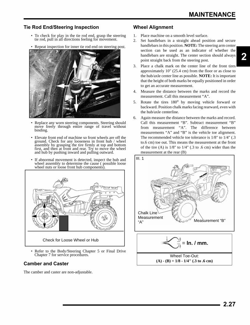
MAINTENANCE
2
Tie Rod End/Steering Inspection • To check for play in the tie rod end, grasp the steering
tie rod, pull in all directions feeling for movement.
• Repeat inspection for inner tie rod end on steering post.
• Replace any worn steering components. Steering shouldmove freely through entire range of travel withoutbinding.
• Elevate front end of machine so front wheels are off theground. Check for any looseness in front hub / wheelassembly by grasping the tire firmly at top and bottomfirst, and then at front and rear. Try to move the wheeland hub by pushing inward and pulling outward.
• If abnormal movement is detected, inspect the hub andwheel assembly to determine the cause ( possible loosewheel nuts or loose front hub components).
• Refer to the Body/Steering Chapter 5 or Final DriveChapter 7 for service procedures.
Camber and CasterThe camber and caster are non-adjustable.
Wheel Alignment1. Place machine on a smooth level surface.2. Set handlebars in a straight ahead position and secure
handlebars in this position. NOTE: The steering arm centersection can be used as an indicator of whether thehandlebars are straight. The center section should alwayspoint straight back from the steering post.
3. Place a chalk mark on the center line of the front tiresapproximately 10" (25.4 cm) from the floor or as close tothe hub/axle center line as possible. NOTE: It is importantthat the height of both marks be equally positioned in orderto get an accurate measurement.
4. Measure the distance between the marks and record themeasurement. Call this measurement “A”.
5. Rotate the tires 180o by moving vehicle forward orbackward. Position chalk marks facing rearward, even withthe hub/axle centerline.
6. Again measure the distance between the marks and record.Call this measurement “B”. Subtract measurement “B”from measurement “A”. The difference betweenmeasurements “A” and “B” is the vehicle toe alignment.The recommended vehicle toe tolerance is 1/8" to 1/4" (.3to.6 cm) toe out. This means the measurement at the frontof the tire (A) is 1/8" to 1/4" (.3 to .6 cm) wider than themeasurement at the rear (B)
Check for Loose Wheel or Hub = In. / mm.
Wheel Toe-Out:(A) - (B) = 1/8 - 1/4" (.3 to .6 cm)
III. 1
Chalk Line Measurement“A” Measurement “B”
2.27
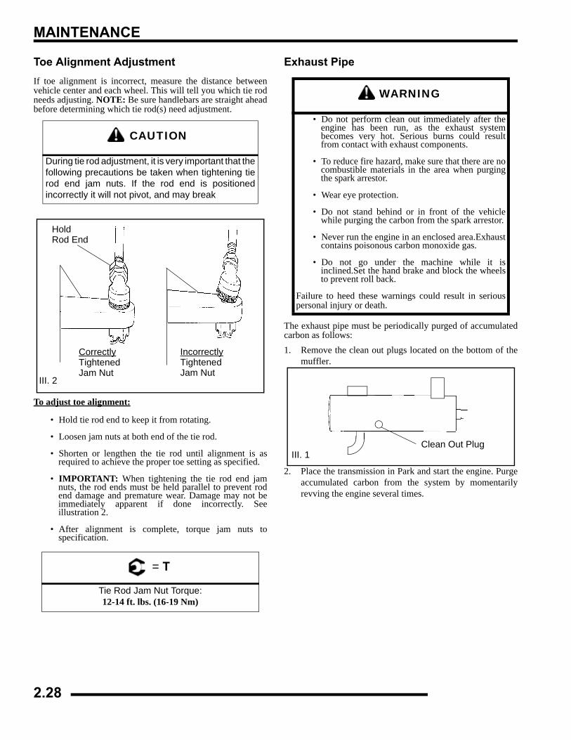
MAINTENANCE
Toe Alignment AdjustmentIf toe alignment is incorrect, measure the distance betweenvehicle center and each wheel. This will tell you which tie rodneeds adjusting. NOTE: Be sure handlebars are straight aheadbefore determining which tie rod(s) need adjustment.
To adjust toe alignment:
• Hold tie rod end to keep it from rotating.
• Loosen jam nuts at both end of the tie rod.
• Shorten or lengthen the tie rod until alignment is asrequired to achieve the proper toe setting as specified.
• IMPORTANT: When tightening the tie rod end jamnuts, the rod ends must be held parallel to prevent rodend damage and premature wear. Damage may not beimmediately apparent if done incorrectly. Seeillustration 2.
• After alignment is complete, torque jam nuts tospecification.
Exhaust Pipe
The exhaust pipe must be periodically purged of accumulatedcarbon as follows:1. Remove the clean out plugs located on the bottom of the
muffler.
2. Place the transmission in Park and start the engine. Purgeaccumulated carbon from the system by momentarilyrevving the engine several times.
CAUTION
During tie rod adjustment, it is very important that thefollowing precautions be taken when tightening tierod end jam nuts. If the rod end is positionedincorrectly it will not pivot, and may break
= T
Tie Rod Jam Nut Torque:12-14 ft. lbs. (16-19 Nm)
HoldRod End
CorrectlyTightenedJam Nut
IncorrectlyTightenedJam Nut
III. 2
WARNING
• Do not perform clean out immediately after theengine has been run, as the exhaust systembecomes very hot. Serious burns could resultfrom contact with exhaust components.
• To reduce fire hazard, make sure that there are nocombustible materials in the area when purgingthe spark arrestor.
• Wear eye protection.
• Do not stand behind or in front of the vehiclewhile purging the carbon from the spark arrestor.
• Never run the engine in an enclosed area.Exhaustcontains poisonous carbon monoxide gas.
• Do not go under the machine while it isinclined.Set the hand brake and block the wheelsto prevent roll back.
Failure to heed these warnings could result in seriouspersonal injury or death.
III. 1Clean Out Plug
2.28
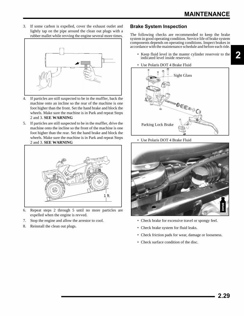
MAINTENANCE
2
3. If some carbon is expelled, cover the exhaust outlet andlightly tap on the pipe around the clean out plugs with arubber mallet while revving the engine several more times.
4. If particles are still suspected to be in the muffler, back themachine onto an incline so the rear of the machine is onefoot higher than the front. Set the hand brake and block thewheels. Make sure the machine is in Park and repeat Steps2 and 3. SEE WARNING
5. If particles are still suspected to be in the muffler, drive themachine onto the incline so the front of the machine is onefoot higher than the rear. Set the hand brake and block thewheels. Make sure the machine is in Park and repeat Steps2 and 3. SEE WARNING
6. Repeat steps 2 through 5 until no more particles areexpelled when the engine is revved.
7. Stop the engine and allow the arrestor to cool.8. Reinstall the clean out plugs.
Brake System InspectionThe following checks are recommended to keep the brakesystem in good operating condition. Service life of brake systemcomponents depends on operating conditions. Inspect brakes inaccordance with the maintenance schedule and before each ride.
• Keep fluid level in the master cylinder reservoir to theindicated level inside reservoir.
• Use Polaris DOT 4 Brake Fluid
• Use Polaris DOT 4 Brake Fluid
• Check brake for excessive travel or spongy feel.
• Check brake system for fluid leaks.
• Check friction pads for wear, damage or looseness.
• Check surface condition of the disc.
1 ft.
Sight Glass
Parking Lock Brake
2.29
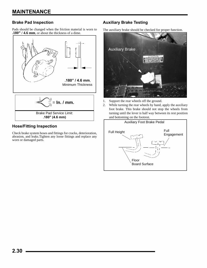
MAINTENANCE
Brake Pad InspectionPads should be changed when the friction material is worn to.180” / 4.6 mm, or about the thickness of a dime.
Hose/Fitting InspectionCheck brake system hoses and fittings for cracks, deterioration,abrasion, and leaks.Tighten any loose fittings and replace anyworn or damaged parts.
Auxiliary Brake Testing
The auxiliary brake should be checked for proper function.
1. Support the rear wheels off the ground.2. While turning the rear wheels by hand, apply the auxiliary
foot brake. This brake should not stop the wheels fromturning until the lever is half way between its rest positionand bottoming on the footrest.
= In. / mm.
Brake Pad Service Limit:.180" (4.6 mm)
Minimum Thickness.180” / 4.6 mm,
Auxiliary Brake
Full Height FullEngagement
FloorBoard Surface
Auxiliary Foot Brake Pedal
2.30
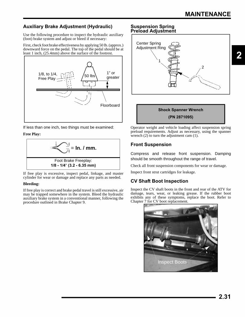
MAINTENANCE
2
Auxiliary Brake Adjustment (Hydraulic) Use the following procedure to inspect the hydraulic auxiliary(foot) brake system and adjust or bleed if necessary:First, check foot brake effectiveness by applying 50 lb. (approx.)downward force on the pedal. The top of the pedal should be atleast 1 inch, (25.4mm) above the surface of the footrest.
If less than one inch, two things must be examined:
Free Play:
If free play is excessive, inspect pedal, linkage, and mastercylinder for wear or damage and replace any parts as needed.Bleeding:If free play is correct and brake pedal travel is still excessive, airmay be trapped somewhere in the system. Bleed the hydraulicauxiliary brake system in a conventional manner, following theprocedure outlined in Brake Chapter 9.
Suspension Spring Preload Adjustment
Operator weight and vehicle loading affect suspension springpreload requirements. Adjust as necessary, using the spannerwrench (2) to turn the adjustment cam (1).
Front Suspension
Compress and release front suspension. Dampingshould be smooth throughout the range of travel.
Check all front suspension components for wear or damage.Inspect front strut cartridges for leakage.
CV Shaft Boot InspectionInspect the CV shaft boots in the front and rear of the ATV fordamage, tears, wear, or leaking grease. If the rubber bootexhibits any of these symptoms, replace the boot. Refer toChapter 7 for CV boot replacement.
= In. / mm.
Foot Brake Freeplay:1/8 - 1/4" (3.2 - 6.35 mm)
1” orgreater
1/8, to 1/4,Free Play
Floorboard
50 lbs
Shock Spanner Wrench
(PN 2871095)
Center Spring Adjustment Ring
12
Inspect Boots
2.31
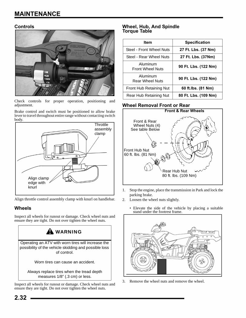
MAINTENANCE
Controls
Check controls for proper operation, positioning andadjustment.Brake control and switch must be positioned to allow brakelever to travel throughout entire range without contacting switchbody.
Align throttle control assembly clamp with knurl on handlebar.
WheelsInspect all wheels for runout or damage. Check wheel nuts andensure they are tight. Do not over tighten the wheel nuts.
Inspect all wheels for runout or damage. Check wheel nuts andensure they are tight. Do not over tighten the wheel nuts.
Wheel, Hub, And Spindle Torque Table
Wheel Removal Front or Rear
1. Stop the engine, place the transmission in Park and lock theparking brake.
2. Loosen the wheel nuts slightly.
• Elevate the side of the vehicle by placing a suitablestand under the footrest frame.
3. Remove the wheel nuts and remove the wheel.
WARNING
Operating an ATV with worn tires will increase the possibility of the vehicle skidding and possible loss
of control.
Worn tires can cause an accident.
Always replace tires when the tread depth measures 1/8” (.3 cm) or less.
Throttleassemblyclamp
Align clampedge withknurl
Item Specification
Steel - Front Wheel Nuts 27 Ft. Lbs. (37 Nm)
Steel - Rear Wheel Nuts 27 Ft. Lbs. (37Nm)
AluminumFront Wheel Nuts 90 Ft. Lbs. (122 Nm)
AluminumRear Wheel Nuts 90 Ft. Lbs. (122 Nm)
Front Hub Retaining Nut 60 ft.lbs. (81 Nm)
Rear Hub Retaining Nut 80 Ft. Lbs. (109 Nm)
Front & Rear Wheels
Front & RearWheel Nuts (4)
See table Below
Front Hub Nut60 ft. lbs. (81 Nm)
Rear Hub Nut80 ft. lbs. (109 Nm)
2.32
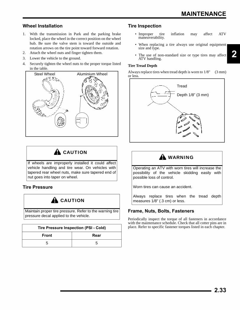
MAINTENANCE
2
Wheel Installation1. With the transmission in Park and the parking brake
locked, place the wheel in the correct position on the wheelhub. Be sure the valve stem is toward the outside androtation arrows on the tire point toward forward rotation.
2. Attach the wheel nuts and finger tighten them.3. Lower the vehicle to the ground.4. Securely tighten the wheel nuts to the proper torque listed
in the table.
Tire Pressure
Tire Inspection• Improper tire inflation may affect ATV
maneuverability.
• When replacing a tire always use original equipmentsize and type.
• The use of non-standard size or type tires may affectATV handling.
Tire Tread DepthAlways replace tires when tread depth is worn to 1/8" (3 mm)or less.
Frame, Nuts, Bolts, FastenersPeriodically inspect the torque of all fasteners in accordancewith the maintenance schedule. Check that all cotter pins are inplace. Refer to specific fastener torques listed in each chapter.
CAUTION
If wheels are improperly installed it could affectvehicle handling and tire wear. On vehicles withtapered rear wheel nuts, make sure tapered end ofnut goes into taper on wheel.
CAUTION
Maintain proper tire pressure. Refer to the warning tirepressure decal applied to the vehicle.
Tire Pressure Inspection (PSI - Cold)
Front Rear
5 5
Steel Wheel Aluminium Wheel
WARNING
Operating an ATV with worn tires will increase thepossibility of the vehicle skidding easily withpossible loss of control.
Worn tires can cause an accident.
Always replace tires when the tread depthmeasures 1/8” (.3 cm) or less.
Tread
Depth 1/8” (3 mm)
2.33
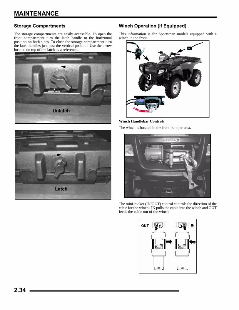
MAINTENANCE
Storage CompartmentsThe storage compartments are easily accessible. To open thefront compartment turn the latch handle to the horizontalposition on both sides. To close the storage compartment turnthe latch handles just past the vertical position. Use the arrowlocated on top of the latch as a reference.
Winch Operation (If Equipped)This information is for Sportsman models equipped with awinch in the front.
Winch Handlebar ControlsThe winch is located in the front bumper area.
The mini-rocker (IN/OUT) control controls the direction of thecable for the winch. IN pulls the cable into the winch and OUTfeeds the cable out of the winch.
Unlatch
Latch
2.34
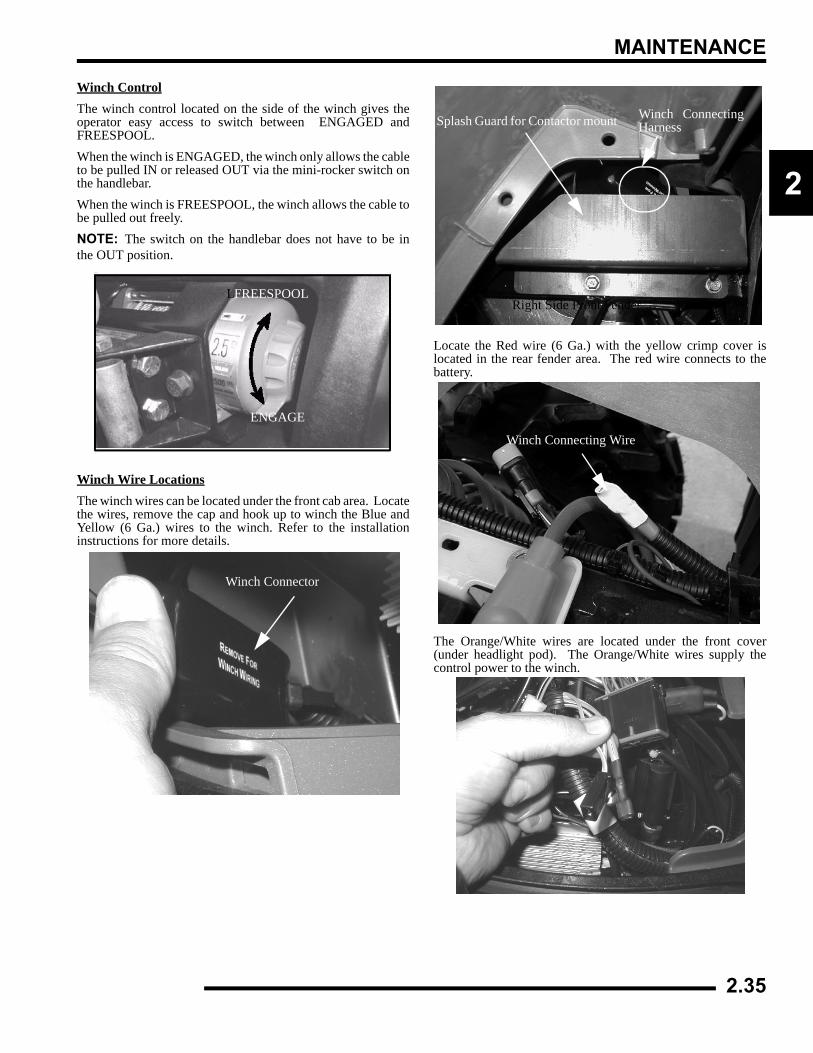
MAINTENANCE
2
Winch ControlThe winch control located on the side of the winch gives theoperator easy access to switch between ENGAGED andFREESPOOL.When the winch is ENGAGED, the winch only allows the cableto be pulled IN or released OUT via the mini-rocker switch onthe handlebar.When the winch is FREESPOOL, the winch allows the cable tobe pulled out freely. NOTE: The switch on the handlebar does not have to be inthe OUT position.
Winch Wire LocationsThe winch wires can be located under the front cab area. Locatethe wires, remove the cap and hook up to winch the Blue andYellow (6 Ga.) wires to the winch. Refer to the installationinstructions for more details.
Locate the Red wire (6 Ga.) with the yellow crimp cover islocated in the rear fender area. The red wire connects to thebattery.
The Orange/White wires are located under the front cover(under headlight pod). The Orange/White wires supply thecontrol power to the winch.
FREESPOOLL
ENGAGE
Winch Connector
Splash Guard for Contactor mount Winch ConnectingHarness
Right Side Front Fender
Winch Connecting Wire
2.35
MAINTENANCE
ATV Cleaning & StorageCleaning the ATVKeeping your ATV clean will not only improve its appearancebut it can also extend the life of various components. With a fewprecautions, your ATV can be cleaned much like an automobile.Washing the ATVThe best and safest way to clean your ATV is with a garden hoseand a pail of mild soap and water. Use a professional typewashing mitten, cleaning the upper body first and the lower partslast. Rinse with water frequently and dry with a chamois toprevent water spots. NOTE: If warning and safety labels aredamaged, contact your a Polaris dealer for free replacement.Polaris does not recommend the use of a high pressure type carwash system for washing the ATV. If a high pressure system isused, exercise extreme care to avoid water damage to the wheelbearings, transmission seals, body panels, brakes and warninglabels. NOTE: Grease all zerk fittings immediately afterwashing, and allow the vehicle to run for a while to evaporateany water that may have entered the engine or exhaust system.Waxing the ATVYour ATV can be waxed with any non-abrasive automotivepaste wax. Avoid the use of harsh cleaners since they can scratchthe body finish. Polaris offers a detailing kit for ATVs.
Storage TipsSee Page 2.9 for the part numbers of Polaris products.
Clean the Exterior
Make necessary repairs and then clean the ATV thoroughly withmild soap and warm water to remove all dirt and grime. Don’tuse harsh detergents or high pressure washers. Some detergentsdeteriorate rubber parts. Use dish soap type cleaners only. Highpressure washers may force water past seals.Stabilize the FuelFill the fuel tank. Add Polaris Carbon Clean Fuel Treatment orPolaris Fuel Stabilizer. Follow the instructions on the containerfor the recommended amount. (Carbon clean will also reducethe possibility of bacterial growth in the fuel system). Allow 15-20 minutes of operation for the stabilizer to disperse through thefuel in the tank and EFI sytem / carburetor. Turn the fuel valveoff and drain the carburetor bowl (500 Carb only).
Oil and FilterWarm the engine and change the oil and filter. Follow theprocedure in this chapter for proper oil change.Air Filter / Air BoxInspect and clean or replace the pre-cleaner and air filter. Cleanthe air box and drain the sediment tube.Breather FilterInspect and clean or replace the breather filter.Fluid LevelsInspect the following fluid levels and change if necessary: frontgearcase; transmission; brake fluid (change every two years oras required if fluid looks dark or contaminated).Drain the Recoil HousingRemove the recoil housing drain plug and drain any moisture.Storage KitsPolaris offers storage kits for ATVs. See a Polaris dealer or visitwww.purepolaris.com.Fog the EngineTo properly store the engine, use Polaris Fogging Oil accordingto the directions.If you choose not to use Polaris Fogging Oil, perform thefollowing procedure:1. Support the front end of the machine so the engine is level
or tilted slightly rearward.2. Treat the fuel system with Polaris Carbon Clean according
to the directions. If Polaris fuel system additive is not used,fuel tank, and fuel lines should be completely drained ofgasoline
3. Remove the spark plug and add 2-3 tablespoons ofSynthetic 2W-50 engine oil. To access the plug hole, use asection of clear 1/4” hose and a small plastic squeeze bottlefilled with the pre-measured amount of oil. Note: Do thiscarefully! If you miss the plug hole, oil will drain from thespark plug cavity into the hole at the front of the cylinderhead, and appear to be an oil leak. Install the spark plugand pull the engine over slowly with the recoil starter. Oilwill be forced in and around the piston rings and ring lands,coating the cylinder with a protective film of fresh oil.
4. Apply dielectric grease to the inside of the spark plug capand install the cap onto the plug.
5. Turn the engine over several times with the recoil only toensure coverage of piston rings, cylinder walls andcrankshaft bearings.
6. .
CAUTION
Certain products, including insect repellents andchemicals, will damage plastic surfaces. Use cautionwhen using these products near plastic surfaces.
CAUTION
Starting the engine during the storage period willdisturb the protective film created by fogging anddamage could occur. Never start the engine duringthe storage period.
2.36
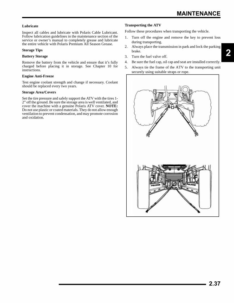
MAINTENANCE
2
Lubricate
Inspect all cables and lubricate with Polaris Cable Lubricant.Follow lubrication guidelines in the maintenance section of theservice or owner’s manual to completely grease and lubricatethe entire vehicle with Polaris Premium All Season Grease. Storage TipsBattery StorageRemove the battery from the vehicle and ensure that it’s fullycharged before placing it in storage. See Chapter 10 forinstructions.Engine Anti-FreezeTest engine coolant strength and change if necessary. Coolantshould be replaced every two years.Storage Area/CoversSet the tire pressure and safely support the ATV with the tires 1-2” off the ground. Be sure the storage area is well ventilated, andcover the machine with a genuine Polaris ATV cover. NOTE:Do not use plastic or coated materials. They do not allow enoughventilation to prevent condensation, and may promote corrosionand oxidation.
Transporting the ATVFollow these procedures when transporting the vehicle.1. Turn off the engine and remove the key to prevent loss
during transporting.2. Always place the transmission in park and lock the parking
brake.3. Turn the fuel valve off.4. Be sure the fuel cap, oil cap and seat are installed correctly.5. Always tie the frame of the ATV to the transporting unit
securely using suitable straps or rope.
2.37
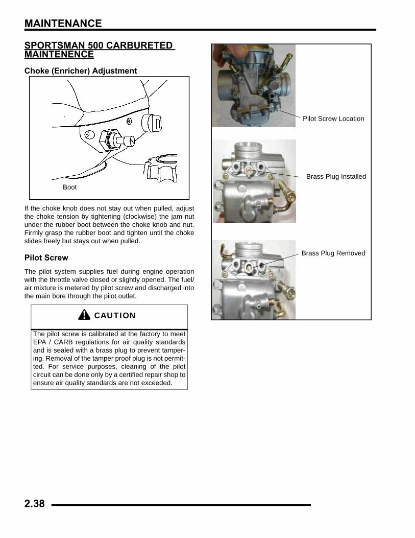
MAINTENANCE
SPORTSMAN 500 CARBURETED MAINTENENCEChoke (Enricher) Adjustment
If the choke knob does not stay out when pulled, adjustthe choke tension by tightening (clockwise) the jam nutunder the rubber boot between the choke knob and nut.Firmly grasp the rubber boot and tighten until the chokeslides freely but stays out when pulled.
Pilot ScrewThe pilot system supplies fuel during engine operationwith the throttle valve closed or slightly opened. The fuel/air mixture is metered by pilot screw and discharged intothe main bore through the pilot outlet.
CAUTION
The pilot screw is calibrated at the factory to meetEPA / CARB regulations for air quality standardsand is sealed with a brass plug to prevent tamper-ing. Removal of the tamper proof plug is not permit-ted. For service purposes, cleaning of the pilotcircuit can be done only by a certified repair shop toensure air quality standards are not exceeded.
Boot
Pilot Screw Location
Brass Plug Installed
Brass Plug Removed
2.38
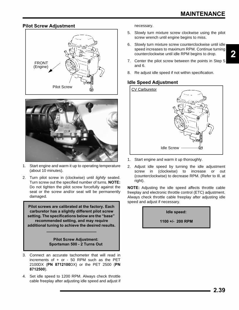
MAINTENANCE
2
Pilot Screw Adjustment
1. Start engine and warm it up to operating temperature(about 10 minutes).
2. Turn pilot screw in (clockwise) until lightly seated.Turn screw out the specified number of turns. NOTE:Do not tighten the pilot screw forcefully against theseat or the screw and/or seat will be permanentlydamaged.
3. Connect an accurate tachometer that will read inincrements of + or - 50 RPM such as the PET2100DX (PN 8712100DX) or the PET 2500 (PN8712500).
4. Set idle speed to 1200 RPM. Always check throttlecable freeplay after adjusting idle speed and adjust if
necessary.
5. Slowly turn mixture screw clockwise using the pilotscrew wrench until engine begins to miss.
6. Slowly turn mixture screw counterclockwise until idlespeed increases to maximum RPM. Continue turningcounterclockwise until idle RPM begins to drop.
7. Center the pilot screw between the points in Step 5and 6.
8. Re adjust idle speed if not within specification.
Idle Speed Adjustment
1. Start engine and warm it up thoroughly.
2. Adjust idle speed by turning the idle adjustmentscrew in (clockwise) to increase or out(counterclockwise) to decrease RPM. (Refer to Ill. atright).
NOTE: Adjusting the idle speed affects throttle cablefreeplay and electronic throttle control (ETC) adjustment.Always check throttle cable freeplay after adjusting idlespeed and adjust if necessary.
Pilot screws are calibrated at the factory. Each carburetor has a slightly different pilot screw
setting. The specifications below are the “base” recommended setting, and may require
additional tuning to achieve the desired results._______________________
Pilot Screw Adjustment: Sportsman 500 - 2 Turns Out
Pilot Screw
FRONT(Engine)
Idle speed:
1100 +/- 200 RPM
CV Carburetor
Idle Screw
2.39
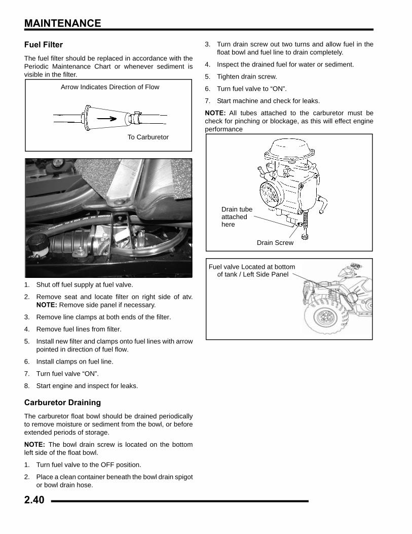
MAINTENANCE
Fuel FilterThe fuel filter should be replaced in accordance with thePeriodic Maintenance Chart or whenever sediment isvisible in the filter.
1. Shut off fuel supply at fuel valve.
2. Remove seat and locate filter on right side of atv.NOTE: Remove side panel if necessary.
3. Remove line clamps at both ends of the filter.
4. Remove fuel lines from filter.
5. Install new filter and clamps onto fuel lines with arrowpointed in direction of fuel flow.
6. Install clamps on fuel line.
7. Turn fuel valve “ON”.
8. Start engine and inspect for leaks.
Carburetor DrainingThe carburetor float bowl should be drained periodicallyto remove moisture or sediment from the bowl, or beforeextended periods of storage.
NOTE: The bowl drain screw is located on the bottomleft side of the float bowl.
1. Turn fuel valve to the OFF position.
2. Place a clean container beneath the bowl drain spigotor bowl drain hose.
3. Turn drain screw out two turns and allow fuel in thefloat bowl and fuel line to drain completely.
4. Inspect the drained fuel for water or sediment.
5. Tighten drain screw.
6. Turn fuel valve to “ON”.
7. Start machine and check for leaks.
NOTE: All tubes attached to the carburetor must becheck for pinching or blockage, as this will effect engineperformance
Arrow Indicates Direction of Flow
To Carburetor
Drain Screw
Drain tubeattachedhere
Fuel valve Located at bottom of tank / Left Side Panel
2.40
MAINTENANCE
2
Maintenance Schedule
Service Date Hours / Miles Service Performed Serviced By:
2.41

MAINTENANCE
Maintenance Schedule
Service Date Hours / Miles Service Performed Serviced By:
2.42
CHAPTER 3ENGINE
3
ENGINE
SPECIFICATIONS. . . . . . . . . . . . . . . . . . . . . . . . . . . . . . . . . . . . . . . . . . . . . . . . . . . . . . . 3.3TORQUE SPECIFICATIONS . . . . . . . . . . . . . . . . . . . . . . . . . . . . . . . . . . . . . . . . . . . . . . 3.3SPECIAL TOOLS . . . . . . . . . . . . . . . . . . . . . . . . . . . . . . . . . . . . . . . . . . . . . . . . . . . . . . . 3.3ENGINE FASTENER TORQUE PATTERNS . . . . . . . . . . . . . . . . . . . . . . . . . . . . . . . . . . 3.3ENGINE SERVICE DATA. . . . . . . . . . . . . . . . . . . . . . . . . . . . . . . . . . . . . . . . . . . . . . . . . 3.4ENGINE SERVICE DATA. . . . . . . . . . . . . . . . . . . . . . . . . . . . . . . . . . . . . . . . . . . . . . . . . 3.5
GENERAL ENGINE SERVICE . . . . . . . . . . . . . . . . . . . . . . . . . . . . . . . . . . . . . . . . . . . . . 3.6PISTON IDENTIFICATION. . . . . . . . . . . . . . . . . . . . . . . . . . . . . . . . . . . . . . . . . . . . . . . . 3.6COOLING SYSTEM SPECIFICATIONS. . . . . . . . . . . . . . . . . . . . . . . . . . . . . . . . . . . . . . 3.6COOLING SYSTEM . . . . . . . . . . . . . . . . . . . . . . . . . . . . . . . . . . . . . . . . . . . . . . . . . . . . . 3.7ACCESSIBLE COMPONENTS. . . . . . . . . . . . . . . . . . . . . . . . . . . . . . . . . . . . . . . . . . . . . 3.8ENGINE REMOVAL (TYPICAL) . . . . . . . . . . . . . . . . . . . . . . . . . . . . . . . . . . . . . . . . . . . . 3.8ENGINE INSTALLATION NOTES . . . . . . . . . . . . . . . . . . . . . . . . . . . . . . . . . . . . . . . . . . 3.9CYLINDER HONE SELECTION/ HONING PROCEDURE. . . . . . . . . . . . . . . . . . . . . . . . 3.9HONING TO OVERSIZE . . . . . . . . . . . . . . . . . . . . . . . . . . . . . . . . . . . . . . . . . . . . . . . . . 3.9CLEANING THE CYLINDER AFTER HONING . . . . . . . . . . . . . . . . . . . . . . . . . . . . . . . 3.10CRANKSHAFT STRAIGHTENING. . . . . . . . . . . . . . . . . . . . . . . . . . . . . . . . . . . . . . . . . 3.10ENGINE LUBRICATION- EH 50PL . . . . . . . . . . . . . . . . . . . . . . . . . . . . . . . . . . . . . . . . 3.11OIL PRESSURE TEST - EH 50PL . . . . . . . . . . . . . . . . . . . . . . . . . . . . . . . . . . . . . . . . . 3.11OIL PUMP PRIMING PROCEDURE . . . . . . . . . . . . . . . . . . . . . . . . . . . . . . . . . . . . . . . 3.11OIL FLOW - EH50PL . . . . . . . . . . . . . . . . . . . . . . . . . . . . . . . . . . . . . . . . . . . . . . . . . . . 3.11EH50PL OIL FLOW DIAGRAM. . . . . . . . . . . . . . . . . . . . . . . . . . . . . . . . . . . . . . . . . . . . 3.12EH50PL ENGINE EXPLODED VIEWS. . . . . . . . . . . . . . . . . . . . . . . . . . . . . . . . . . . . . . 3.13
ENGINE DISASSEMBLY. . . . . . . . . . . . . . . . . . . . . . . . . . . . . . . . . . . . . . . . . . . . . . . . . 3.14CAM CHAIN TENSIONER/ROCKER ARM/ CAMSHAFT REMOVAL . . . . . . . . . . . . . . 3.14CAM CHAIN TENSIONER INSPECTION. . . . . . . . . . . . . . . . . . . . . . . . . . . . . . . . . . . . 3.14ROCKER ARM/SHAFT INSPECTION . . . . . . . . . . . . . . . . . . . . . . . . . . . . . . . . . . . . . . 3.15CAMSHAFT REMOVAL . . . . . . . . . . . . . . . . . . . . . . . . . . . . . . . . . . . . . . . . . . . . . . . . . 3.16AUTOMATIC COMPRESSION RELEASE REMOVAL/INSPECTION . . . . . . . . . . . . . . 3.17AUTOMATIC COMPRESSION RELEASE INSTALLATION. . . . . . . . . . . . . . . . . . . . . . 3.18CAMSHAFT INSPECTION . . . . . . . . . . . . . . . . . . . . . . . . . . . . . . . . . . . . . . . . . . . . . . . 3.18CYLINDER HEAD REMOVAL . . . . . . . . . . . . . . . . . . . . . . . . . . . . . . . . . . . . . . . . . . . . 3.19CYLINDER HEAD EXPLODED VIEW, EH50PL. . . . . . . . . . . . . . . . . . . . . . . . . . . . . . . 3.20CYLINDER HEAD INSPECTION . . . . . . . . . . . . . . . . . . . . . . . . . . . . . . . . . . . . . . . . . . 3.21CYLINDER HEAD WARP. . . . . . . . . . . . . . . . . . . . . . . . . . . . . . . . . . . . . . . . . . . . . . . . 3.21CYLINDER HEAD DISASSEMBLY . . . . . . . . . . . . . . . . . . . . . . . . . . . . . . . . . . . . . . . . 3.21VALVE INSPECTION . . . . . . . . . . . . . . . . . . . . . . . . . . . . . . . . . . . . . . . . . . . . . . . . . . . 3.22COMBUSTION CHAMBER. . . . . . . . . . . . . . . . . . . . . . . . . . . . . . . . . . . . . . . . . . . . . . . 3.23VALVE SEAT RECONDITIONING . . . . . . . . . . . . . . . . . . . . . . . . . . . . . . . . . . . . . . . . . 3.23CYLINDER HEAD ASSEMBLY . . . . . . . . . . . . . . . . . . . . . . . . . . . . . . . . . . . . . . . . . . . 3.26VALVE SEALING TEST . . . . . . . . . . . . . . . . . . . . . . . . . . . . . . . . . . . . . . . . . . . . . . . . . 3.26VALVE CLEARANCE ADJUSTMENT . . . . . . . . . . . . . . . . . . . . . . . . . . . . . . . . . . . . . . 3.26CYLINDER/PISTON REMOVAL AND INSPECTION . . . . . . . . . . . . . . . . . . . . . . . . . . . 3.27PISTON REMOVAL . . . . . . . . . . . . . . . . . . . . . . . . . . . . . . . . . . . . . . . . . . . . . . . . . . . . 3.28CYLINDER INSPECTION. . . . . . . . . . . . . . . . . . . . . . . . . . . . . . . . . . . . . . . . . . . . . . . . 3.28PISTON-TO-CYLINDER CLEARANCE . . . . . . . . . . . . . . . . . . . . . . . . . . . . . . . . . . . . . 3.29PISTON/ROD INSPECTION. . . . . . . . . . . . . . . . . . . . . . . . . . . . . . . . . . . . . . . . . . . . . . 3.29PISTON RING INSTALLED GAP . . . . . . . . . . . . . . . . . . . . . . . . . . . . . . . . . . . . . . . . . . 3.30CRANKCASE DISASSEMBLY . . . . . . . . . . . . . . . . . . . . . . . . . . . . . . . . . . . . . . . . . . . . 3.30STARTER DRIVE REMOVAL/INSPECTION . . . . . . . . . . . . . . . . . . . . . . . . . . . . . . . . . 3.31FLYWHEEL/STATOR REMOVAL/INSPECTION . . . . . . . . . . . . . . . . . . . . . . . . . . . . . . 3.31CAM CHAIN/TENSIONER BLADE. . . . . . . . . . . . . . . . . . . . . . . . . . . . . . . . . . . . . . . . . 3.32ONE WAY VALVE REMOVAL . . . . . . . . . . . . . . . . . . . . . . . . . . . . . . . . . . . . . . . . . . . . 3.32CRANKCASE SEPARATION . . . . . . . . . . . . . . . . . . . . . . . . . . . . . . . . . . . . . . . . . . . . . 3.33
3.1
ENGINE
OIL PUMP REMOVAL/INSPECTION. . . . . . . . . . . . . . . . . . . . . . . . . . . . . . . . . . . . . . . 3.33OIL PUMP ASSEMBLY . . . . . . . . . . . . . . . . . . . . . . . . . . . . . . . . . . . . . . . . . . . . . . . . . 3.34COUNTER BALANCER SHAFT REMOVAL/INSPECTION . . . . . . . . . . . . . . . . . . . . . . 3.34CRANKSHAFT REMOVAL/INSPECTION . . . . . . . . . . . . . . . . . . . . . . . . . . . . . . . . . . . 3.35CRANKCASE BEARING INSPECTION . . . . . . . . . . . . . . . . . . . . . . . . . . . . . . . . . . . . . 3.36PUMP SHAFT OIL SEAL/WATER PUMP MECHANICAL SEAL REMOVAL. . . . . . . . . 3.36CRANKCASE INSPECTION . . . . . . . . . . . . . . . . . . . . . . . . . . . . . . . . . . . . . . . . . . . . . 3.36BEARING INSTALLATION. . . . . . . . . . . . . . . . . . . . . . . . . . . . . . . . . . . . . . . . . . . . . . . 3.37END PLAY INSPECTION/ADJUSTMENT . . . . . . . . . . . . . . . . . . . . . . . . . . . . . . . . . . . 3.37CRANKSHAFT END PLAY ADJUSTMENT . . . . . . . . . . . . . . . . . . . . . . . . . . . . . . . . . . 3.37COUNTER BALANCER SHAFT END PLAY ADJUSTMENT. . . . . . . . . . . . . . . . . . . . . 3.38OIL PUMP SHAFT END PLAY ADJUSTMENT . . . . . . . . . . . . . . . . . . . . . . . . . . . . . . . 3.39
ENGINE REASSEMBLY . . . . . . . . . . . . . . . . . . . . . . . . . . . . . . . . . . . . . . . . . . . . . . . . . 3.40PUMP SHAFT OIL SEAL INSTALLATION. . . . . . . . . . . . . . . . . . . . . . . . . . . . . . . . . . . 3.40CRANKSHAFT/COUNTER BALANCE/OIL PUMP INSTALLATION . . . . . . . . . . . . . . . 3.40CRANKCASE ASSEMBLY. . . . . . . . . . . . . . . . . . . . . . . . . . . . . . . . . . . . . . . . . . . . . . . 3.41WATER PUMP MECHANICAL SEAL INSTALLATION . . . . . . . . . . . . . . . . . . . . . . . . . 3.41WATER PUMP MECHANICAL SEAL REMOVAL - ENGINE INSTALLED . . . . . . . . . . 3.41ONE WAY VALVE INSTALLATION . . . . . . . . . . . . . . . . . . . . . . . . . . . . . . . . . . . . . . . . 3.42CAM CHAIN DRIVE SPROCKET INSTALLATION . . . . . . . . . . . . . . . . . . . . . . . . . . . . 3.43TENSIONER BLADE INSTALLATION . . . . . . . . . . . . . . . . . . . . . . . . . . . . . . . . . . . . . . 3.43PISTON RING INSTALLATION . . . . . . . . . . . . . . . . . . . . . . . . . . . . . . . . . . . . . . . . . . . 3.43PISTON INSTALLATION . . . . . . . . . . . . . . . . . . . . . . . . . . . . . . . . . . . . . . . . . . . . . . . . 3.44CYLINDER INSTALLATION. . . . . . . . . . . . . . . . . . . . . . . . . . . . . . . . . . . . . . . . . . . . . . 3.44CYLINDER HEAD INSTALLATION . . . . . . . . . . . . . . . . . . . . . . . . . . . . . . . . . . . . . . . . 3.45CAM CHAIN/CAMSHAFT INSTALLATION . . . . . . . . . . . . . . . . . . . . . . . . . . . . . . . . . . 3.45CAMSHAFT TIMING . . . . . . . . . . . . . . . . . . . . . . . . . . . . . . . . . . . . . . . . . . . . . . . . . . . 3.46CAMSHAFT TIMING . . . . . . . . . . . . . . . . . . . . . . . . . . . . . . . . . . . . . . . . . . . . . . . . . . . 3.48CAM CHAIN TENSIONER INSTALLATION. . . . . . . . . . . . . . . . . . . . . . . . . . . . . . . . . . 3.49STATOR, FLYWHEEL AND STARTER DRIVE INSTALLATION. . . . . . . . . . . . . . . . . . 3.49ROCKER SHAFT/ROCKER ARM ASSEMBLY INSTALLATION . . . . . . . . . . . . . . . . . . 3.50THERMOSTAT INSTALLATION . . . . . . . . . . . . . . . . . . . . . . . . . . . . . . . . . . . . . . . . . . 3.50OIL PIPES . . . . . . . . . . . . . . . . . . . . . . . . . . . . . . . . . . . . . . . . . . . . . . . . . . . . . . . . . . . 3.50
RECOIL . . . . . . . . . . . . . . . . . . . . . . . . . . . . . . . . . . . . . . . . . . . . . . . . . . . . . . . . . . . . . . 3.51RECOIL DISASSEMBLY/INSPECTION. . . . . . . . . . . . . . . . . . . . . . . . . . . . . . . . . . . . . 3.51RECOIL ASSEMBLY . . . . . . . . . . . . . . . . . . . . . . . . . . . . . . . . . . . . . . . . . . . . . . . . . . . 3.52
TROUBLESHOOTING. . . . . . . . . . . . . . . . . . . . . . . . . . . . . . . . . . . . . . . . . . . . . . . . . . . 3.53SPARK PLUG FOULING . . . . . . . . . . . . . . . . . . . . . . . . . . . . . . . . . . . . . . . . . . . . . . . . 3.53ENGINE . . . . . . . . . . . . . . . . . . . . . . . . . . . . . . . . . . . . . . . . . . . . . . . . . . . . . . . . . . . . . 3.53COOLING SYSTEM . . . . . . . . . . . . . . . . . . . . . . . . . . . . . . . . . . . . . . . . . . . . . . . . . . . . 3.54
3.2
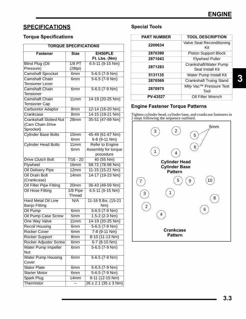
ENGINE
3
SPECIFICATIONSTorque Specifications
Special Tools
Engine Fastener Torque PatternsTighten cylinder head, cylinder base, and crankcase fasteners in3 steps following the sequence outlined.
TORQUE SPECIFICATIONS
Fastener Size EH50PLEFt. Lbs. (Nm)
Blind Plug (Oil Pressure)
1/8 PT (28tpi)
6.5-11 (9-15 Nm)
Camshaft Sprocket 6mm 5-6.5 (7-9 Nm)Camshaft Chain Tensioner Lever
6mm 5-6.5 (7-9 Nm)
Camshaft Chain Tensioner
6mm 5-6.5 (7-9 Nm)
Camshaft Chain Tensioner Cap
11mm 14-19 (20-25 Nm)
Carburetor Adaptor 8mm 12-14 (16-20 Nm)Crankcase 8mm 14-15 (19-21 Nm)Crankshaft Slotted Nut (Cam Chain Drive Sprocket)
28mm 35-51 (47-69 Nm)
Cylinder Base Bolts 10mm6mm
45-49 (61-67 Nm)6-8 (9-11 Nm)
Cylinder Head Bolts 11mm6mm
Refer to Engine Assembly for torque
procedureDrive Clutch Bolt 7/16 - 20 40 (55 Nm)Flywheel 16mm 58-72 (78-98 Nm)Oil Delivery Pipe 12mm 11-15 (15-21 Nm)Oil Drain Bolt (Crankcase)
14mm 14-17 (19-23 Nm)
Oil Filter Pipe Fitting 20mm 36-43 (49-59 Nm)Oil Hose Fitting 1/8 Pipe
Thread6.5-11 (9-15 Nm)
Hard Metal Oil Line Banjo Fitting
N/A 11-16 ft.lbs. (15-21 Nm)
Oil Pump 6mm 5-6.5 (7-9 Nm)Oil Pump Case Screw 5mm 1.5-2 (2-3 Nm)One Way Valve 11mm 14-19 (20-25 Nm)Recoil Housing 6mm 5-6.5 (7-9 Nm)Rocker Cover 6mm 7-8 (9-11 Nm)Rocker Support 8mm 8-10 (11-13 Nm)Rocker Adjuster Screw 6mm 6-7 (8-10 Nm)Water Pump Impeller Nut
6mm 5-6.5 (7-9 Nm)
Water Pump Housing Cover
6mm 5-6.5 (7-9 Nm)
Stator Plate 6mm 5-6.5 (7-9 Nm)Starter Motor 6mm 5-6.5 (7-9 Nm)Spark Plug 14mm 9-11 (12-15 Nm)Thermistor -- 26 ± 2.1 (35 ± 3 Nm)
PART NUMBER TOOL DESCRIPTION
2200634 Valve Seat Reconditioning Kit
2870390 Piston Support Block2871043 Flywheel Puller
2871283 Crankshaft/Water Pump Seal Install Kit
5131135 Water Pump Install Kit2870569 Crankshaft Truing Stand
2870975 Mity Vac™ Pressure Test Tool
PV-43527 OIl Filter Wrench
1
23
4
5
6
7
8
9 10
1
2
3
4
5
6
6mm
Cylinder HeadCylinder Base Pattern
Crankcase Pattern
3.3
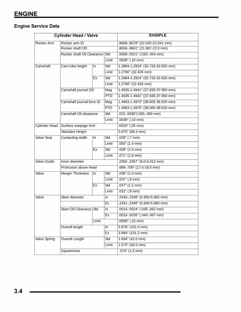
ENGINE
Engine Service Data
Cylinder Head / Valve EH50PLE
Rocker Arm Rocker arm ID .8669-.8678" (22.020-22.041 mm)Rocker shaft OD .8656-.8661" (21.987-22.0 mm)
Rocker shaft Oil Clearance Std .0008-.0021" (.020-.054 mm)
Limit .0039" (.10 mm)
Camshaft Cam lobe height In Std 1.2884-1.2924” (32.726-32.826 mm)
Limit 1.2766" (32.426 mm)
Ex Std 1.2884-1.2924” (32.726-32.826 mm)
Limit 1.2766" (32.426 mm)
Camshaft journal OD Mag 1.4935-1.4941” (37.935-37.950 mm)
PTO 1.4935-1.4941” (37.935-37.950 mm)
Camshaft journal bore ID Mag 1.4963-1.4970” (38.005-38.025 mm)
PTO 1.4963-1.4970” (38.005-38.025 mm)
Camshaft Oil clearance Std .022-.0035”(.055-.090 mm)
Limit .0039" (.10 mm)
Cylinder Head Surface warpage limit .0020" (.05 mm)
Standard Height 3.870" (98.3 mm)
Valve Seat Contacting width In Std .028" (.7 mm)
Limit .055" (1.4 mm)
Ex Std .039" (1.0 mm)
Limit .071" (1.8 mm)
Valve Guide Inner diameter .2362-.2367" (6.0-6.012 mm)
Protrusion above head .689-.709" (17.5-18.0 mm)
Valve Margin Thickness In Std .039" (1.0 mm)
Limit .031" (.8 mm)
Ex Std .047" (1.2 mm)
Limit .031" (.8 mm)
Valve Stem diameter In .2343-.2348" (5.950-5.965 mm)
Ex .2341-.2346" (5.945-5.960 mm)
Stem Oil Clearance Std In .0014-.0024" (.035-.062 mm)
Ex .0016-.0026" (.040-.067 mm)
Limit .0059" (.15 mm)
Overall length In 3.976" (101.0 mm)
Ex 3.984" (101.2 mm)
Valve Spring Overall Length Std 1.654" (42.0 mm)
Limit 1.575" (40.0 mm)
Squareness .075” (1.9 mm)
3.4
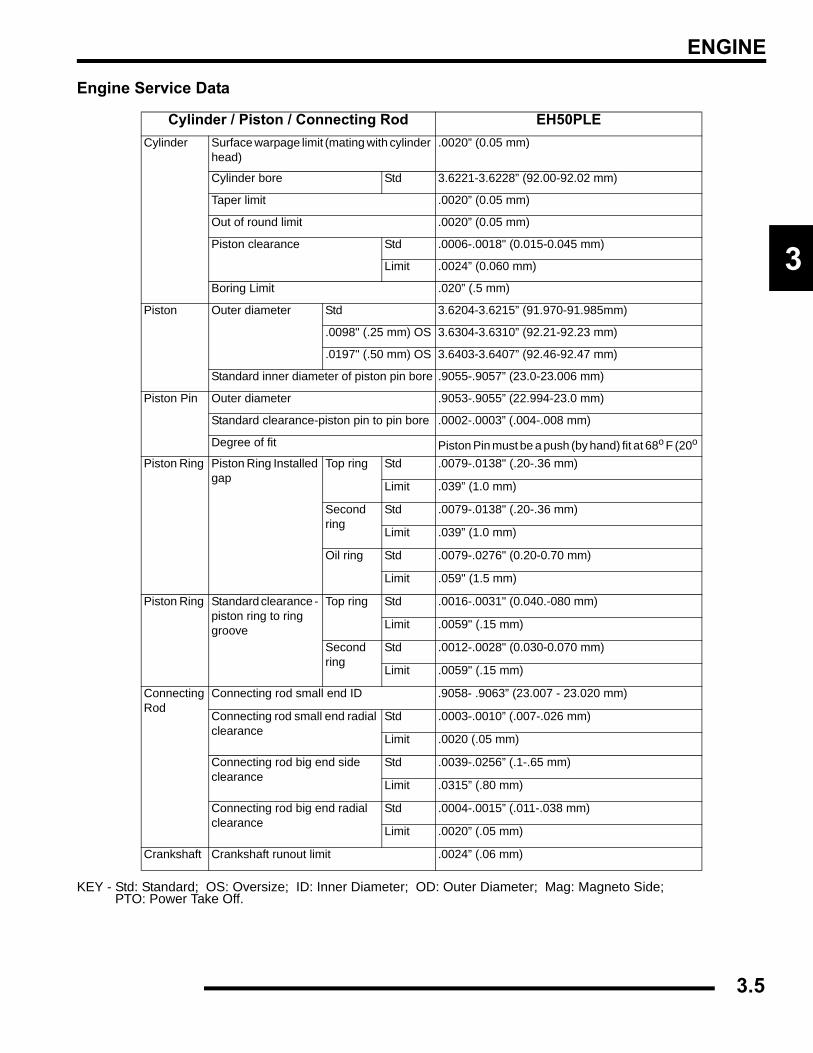
ENGINE
3
Engine Service Data
KEY - Std: Standard; OS: Oversize; ID: Inner Diameter; OD: Outer Diameter; Mag: Magneto Side;PTO: Power Take Off.
Cylinder / Piston / Connecting Rod EH50PLECylinder Surface warpage limit (mating with cylinder
head).0020” (0.05 mm)
Cylinder bore Std 3.6221-3.6228” (92.00-92.02 mm)
Taper limit .0020” (0.05 mm)
Out of round limit .0020” (0.05 mm)
Piston clearance Std .0006-.0018" (0.015-0.045 mm)
Limit .0024” (0.060 mm)
Boring Limit .020” (.5 mm)
Piston Outer diameter Std 3.6204-3.6215” (91.970-91.985mm)
.0098" (.25 mm) OS 3.6304-3.6310” (92.21-92.23 mm)
.0197" (.50 mm) OS 3.6403-3.6407” (92.46-92.47 mm)
Standard inner diameter of piston pin bore .9055-.9057” (23.0-23.006 mm)
Piston Pin Outer diameter .9053-.9055” (22.994-23.0 mm)
Standard clearance-piston pin to pin bore .0002-.0003” (.004-.008 mm)
Degree of fit Piston Pin must be a push (by hand) fit at 68o F (20o Piston Ring Piston Ring Installed
gapTop ring Std .0079-.0138" (.20-.36 mm)
Limit .039” (1.0 mm)
Second ring
Std .0079-.0138" (.20-.36 mm)
Limit .039” (1.0 mm)
Oil ring Std .0079-.0276" (0.20-0.70 mm)
Limit .059" (1.5 mm)
Piston Ring Standard clearance - piston ring to ring groove
Top ring Std .0016-.0031" (0.040.-080 mm)
Limit .0059" (.15 mm)
Second ring
Std .0012-.0028" (0.030-0.070 mm)
Limit .0059" (.15 mm)
Connecting Rod
Connecting rod small end ID .9058- .9063” (23.007 - 23.020 mm)
Connecting rod small end radial clearance
Std .0003-.0010” (.007-.026 mm)
Limit .0020 (.05 mm)
Connecting rod big end side clearance
Std .0039-.0256” (.1-.65 mm)
Limit .0315” (.80 mm)
Connecting rod big end radial clearance
Std .0004-.0015” (.011-.038 mm)
Limit .0020” (.05 mm)
Crankshaft Crankshaft runout limit .0024” (.06 mm)
3.5
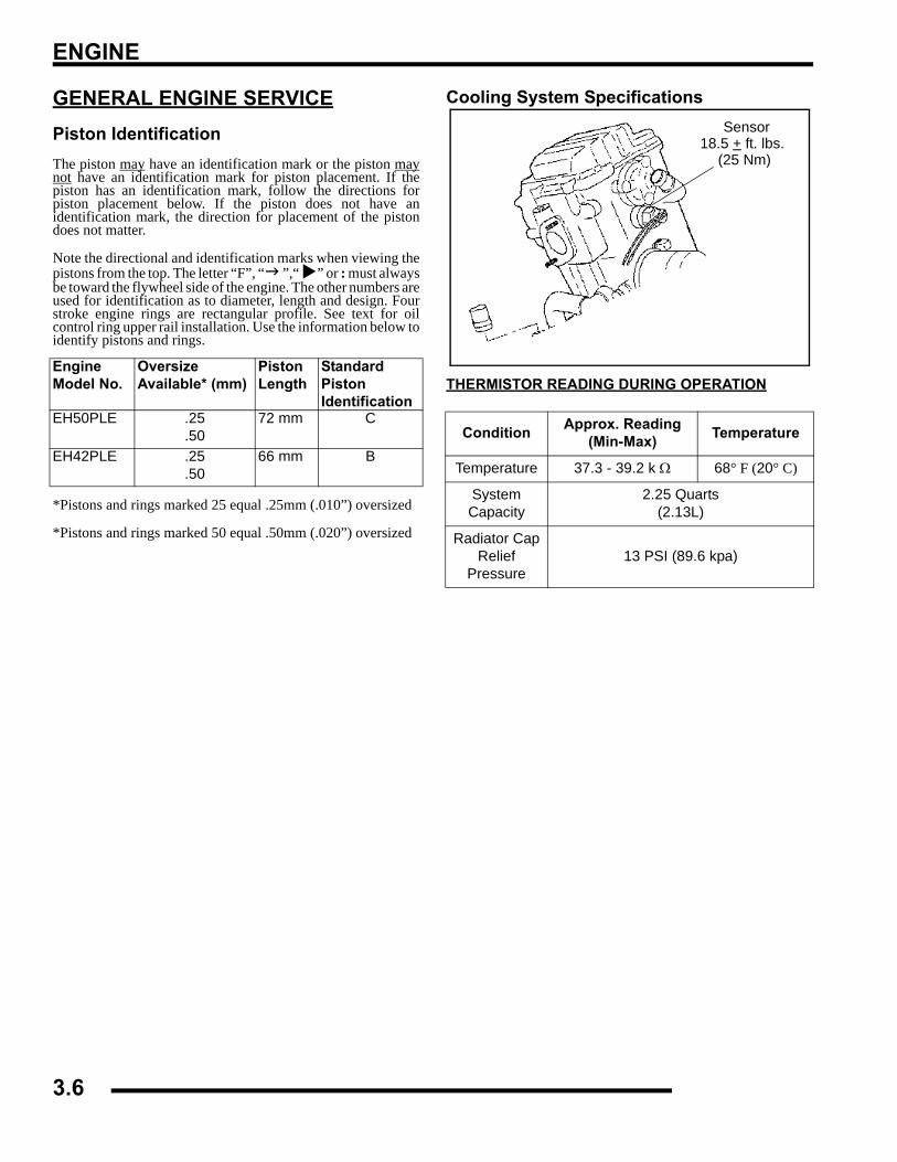
ENGINE
GENERAL ENGINE SERVICEPiston IdentificationThe piston may have an identification mark or the piston maynot have an identification mark for piston placement. If thepiston has an identification mark, follow the directions forpiston placement below. If the piston does not have anidentification mark, the direction for placement of the pistondoes not matter.
Note the directional and identification marks when viewing thepistons from the top. The letter “F”, “ ”,“ ” or : must alwaysbe toward the flywheel side of the engine. The other numbers areused for identification as to diameter, length and design. Fourstroke engine rings are rectangular profile. See text for oilcontrol ring upper rail installation. Use the information below toidentify pistons and rings.
*Pistons and rings marked 25 equal .25mm (.010”) oversized
*Pistons and rings marked 50 equal .50mm (.020”) oversized
Cooling System Specifications
THERMISTOR READING DURING OPERATIONEngine Model No.
Oversize Available* (mm)
Piston Length
Standard Piston Identification
EH50PLE .25.50
72 mm C
EH42PLE .25.50
66 mm BCondition Approx. Reading
(Min-Max) Temperature
Temperature 37.3 - 39.2 k Ω 68° F (20° C)
SystemCapacity
2.25 Quarts(2.13L)
Radiator Cap Relief
Pressure13 PSI (89.6 kpa)
Sensor18.5 + ft. lbs.
(25 Nm)
3.6
ENGINE
3
Cooling System System Pressure Test1. Remove radiator cap cover located in storage box.2. Remove recovery bottle hose from coolant filler.3. Connect a Mity Vac™ (PN 2870975) to radiator and
pressurize system to 10 PSI (68.9 kpa). The system mustretain 10 lbs of pressure for five minutes or longer. Ifpressure loss is evident within five minutes, check radiator,all cooling system hoses and clamps, or water pump seal.
Radiator Cap Pressure Test1. Remove radiator cap and test using a cap tester
(commercially available).2. The radiator cap relief pressure is 13 lbs (89.6 kpa).
WARNING
Never remove radiator cap when engine is warm or hot.The cooling system is under pressure and serious burnsmay result. Allow the engine and cooling system to coolbefore servicing.
Radiator
Water Pump
CylinderCylinder
Thermostat
FLOW
Head
Upper HoseRadiator
Fan
Lower HoseFiller Neck
Overflow Bottle
Top
Bottom
RadiatorLeft SideView
RadiatorFront View
3.7
ENGINE
RECOMMENDED COOLANTUse only high quality antifreeze/coolant mixed with distilledwater in a 50/50 or 60/40 ratio, depending on freeze protectionrequired in your area..
Accessible ComponentsThe following components can be serviced or removed with theengine installed in the frame:
• Flywheel
• Alternator/Stator
• Starter Motor/Starter Drive
• Cylinder Head
• Cylinder
• Piston/RIngs
• Camshaft
• Rocker Arms
• Cam Chain and Sprockets
• Water Pump / Water Pump Mechanical Seal*
The following components require engine removal forservice:
• Oil pump / Oil Pump Drive Gear
• Counterbalance Shaft or Bearing(s)
• Connecting Rod
• Crankshaft
• Crankshaft Main Bearings
• Crankcase
*It may be necessary to loosen engine mounts and moveengine slightly to access water pump. Use the WaterPump Mechanical Seal Puller (PN 2872105) to replacemechanical seal with engine in frame.
Engine Removal (TYPICAL)1. Clean work area.2. Thoroughly clean the ATV engine and chassis.3. Disconnect battery negative(-) cable.4. Remove the following parts as required.
• Seat
• Left and Right Side Covers (Refer to Chapter 5)
• Fuel Tank Cover / Front Cab (Refer to Chapter 5)
• Fuel Tank (Refer to Chapter 4)
5. Disconnect spark plug high tension lead.6. Remove springs from exhaust pipe and remove pipe.7. Drain coolant and engine oil.8. Remove air pre-cleaner and duct.9. Remove airbox.10. Remove carburetor. Insert a shop towel into the carburetor
flange to prevent dirt from entering the intake port.11. Remove center chain guard on chain drive AWD models.12. Remove center drive and driven sprocket bolts and remove
chain and sprockets as an assembly.13. Refer to PVT System to remove outer clutch cover, drive
belt, drive clutch, driven clutch, and inner cover.14. Starter motor. Note ground cable location. Mark positive
(+) cable mounting angle and remove cable.15. Remove transmission linkage rod(s) from gear selector and
secure out of the way.16. Disconnect coolant temperature sensor wire.17. Remove engine to chassis ground cable.18. Remove all engine mount nuts and / or engine mount plates.19. Remove engine through right side of frame.
CAUTION
Using tap water in the cooling system will lead to a buildup of deposits which may restrict coolant flow and reduce heat dissipation, resulting in possible
engine damage. Polaris Premium 60/40 Antifreeze/Coolant is recommended for use in all cooling systems, and comes pre-mixed, ready to use.
3.8
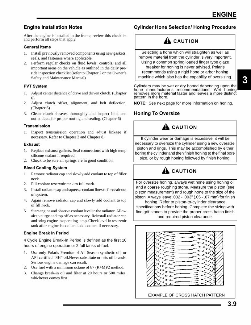
ENGINE
3
Engine Installation NotesAfter the engine is installed in the frame, review this checklistand perform all steps that apply.
General Items1. Install previously removed components using new gaskets,
seals, and fasteners where applicable.2. Perform regular checks on fluid levels, controls, and all
important areas on the vehicle as outlined in the daily pre-ride inspection checklist (refer to Chapter 2 or the Owner’sSafety and Maintenance Manual).
PVT System1. Adjust center distance of drive and driven clutch. (Chapter
6)2. Adjust clutch offset, alignment, and belt deflection.
(Chapter 6)3. Clean clutch sheaves thoroughly and inspect inlet and
outlet ducts for proper routing and sealing. (Chapter 6)
Transmission1. Inspect transmission operation and adjust linkage if
necessary. Refer to Chapter 2 and Chapter 8.
Exhaust1. Replace exhaust gaskets. Seal connections with high temp
silicone sealant if required.2. Check to be sure all springs are in good condition.
Bleed Cooling System1. Remove radiator cap and slowly add coolant to top of filler
neck.2. Fill coolant reservoir tank to full mark.3. Install radiator cap and squeeze coolant lines to force air out
of system.4. Again remove radiator cap and slowly add coolant to top
of fill neck.5. Start engine and observe coolant level in the radiator. Allow
air to purge and top off as necessary. Reinstall radiator capand bring engine to operating temp. Check level in reservoirtank after engine is cool and add coolant if necessary.
Engine Break In Period
4 Cycle Engine Break-In Period is defined as the first 10hours of engine operation or 2 full tanks of fuel.
1. Use only Polaris Premium 4 All Season synthetic oil, orAPI certified “SH” oil.Never substitute or mix oil brands.Serious engine damage can result.
2. Use fuel with a minimum octane of 87 (R+M)/2 method.3. Change break-in oil and filter at 20 hours or 500 miles,
whichever comes first.
Cylinder Hone Selection/ Honing Procedure
Cylinders may be wet or dry honed depending upon thehone manufacturer’s recommendations. Wet honingremoves more material faster and leaves a more distinctpattern in the bore.NOTE: See next page for more information on honing.
Honing To Oversize
CAUTION
Selecting a hone which will straighten as well as remove material from the cylinder is very important.
Using a common spring loaded finger type glaze breaker for honing is never advised. Polaris
recommends using a rigid hone or arbor honing machine which also has the capability of oversizing.
CAUTION
If cylinder wear or damage is excessive, it will be necessary to oversize the cylinder using a new oversize piston and rings. This may be accomplished by either
boring the cylinder and then finish honing to the final bore size, or by rough honing followed by finish honing.
CAUTION
For oversize honing, always wet hone using honing oil and a coarse roughing stone. Measure the piston (see piston measurement) and rough hone to the size of the piston. Always leave .002 - .003" (.05 - .07 mm) for finish
honing. Refer to piston-to-cylinder clearance specifications before honing. Complete the sizing with fine grit stones to provide the proper cross-hatch finish
and required piston clearance.
EXAMPLE OF CROSS HATCH PATTERN
3.9
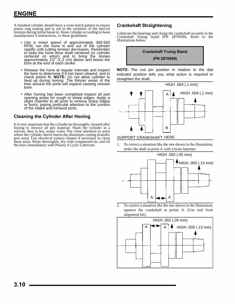
ENGINE
A finished cylinder should have a cross-hatch pattern to ensurepiston ring seating and to aid in the retention of the fuel/oilmixture during initial break in. Hone cylinder according to honemanufacturer’s instructions, or these guidelines:
• Use a motor speed of approximately 300-500RPM, run the hone in and out of the cylinderrapidly until cutting tension decreases. Rememberto keep the hone drive shaft centered (or cylindercentered on arbor) and to bring the stonesapproximately 1/2” (1.3 cm) above and below thebore at the end of each stroke.
• Release the hone at regular intervals and inspectthe bore to determine if it has been cleared, and tocheck piston fit. NOTE: Do not allow cylinder toheat up during honing. The thinner areas of theliner around the ports will expand causing unevenbore.
• After honing has been completed inspect all portopening areas for rough or sharp edges. Apply aslight chamfer to all ports to remove sharp edgesor burrs, paying particular attention to the cornersof the intake and exhaust ports.
Cleaning the Cylinder After HoningIt is very important that the cylinder be thoroughly cleaned afterhoning to remove all grit material. Wash the cylinder in asolvent, then in hot, soapy water. Pay close attention to areaswhere the cylinder sleeve meets the aluminum casting (transferport area). Use electrical contact cleaner if necessary to cleanthese areas. Rinse thoroughly, dry with compressed air, and oilthe bore immediately with Polaris 4 Cycle Lubricant.
Crankshaft StraighteningLubricate the bearings and clamp the crankshaft securely in theCrankshaft Truing Stand (PN 2870569). Refer to theillustrations below.
NOTE: The rod pin position in relation to the dialindicator position tells you what action is required tostraighten the shaft.
1. To correct a situation like the one shown in the illustration,strike the shaft at point A with a brass hammer.
2. To correct a situation like the one shown in the illustration,squeeze the crankshaft at points A. (Use tool fromalignment kit).
Crankshaft Truing Stand
(PN 2870569)
A
B
HIGH .004 (.1 mm) HIGH .004 (.1 mm)
SUPPORT CRANKSHAFT HERE
AA
HIGH .002 (.05 mm)
HIGH .005 (.13 mm)
AA
HIGH .002 (.05 mm)
HIGH .005 (.13 mm)
3.10
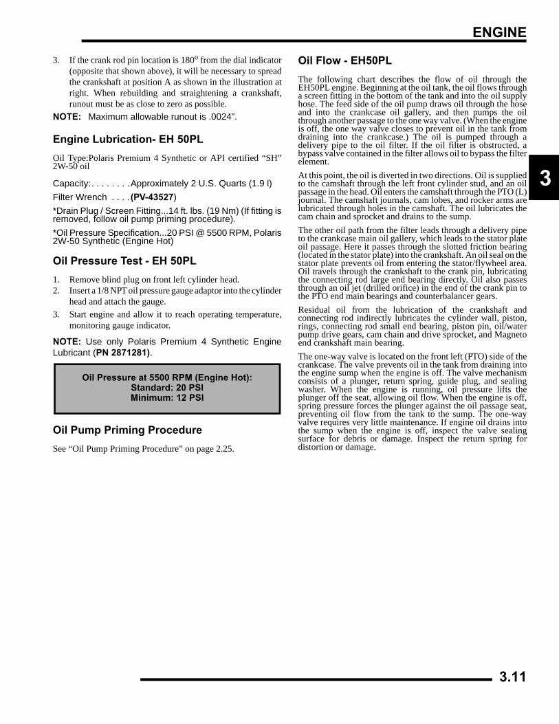
ENGINE
3
3. If the crank rod pin location is 180o from the dial indicator(opposite that shown above), it will be necessary to spreadthe crankshaft at position A as shown in the illustration atright. When rebuilding and straightening a crankshaft,runout must be as close to zero as possible.
NOTE: Maximum allowable runout is .0024”.
Engine Lubrication- EH 50PLOil Type:Polaris Premium 4 Synthetic or API certified “SH”2W-50 oil
Capacity:. . . . . . . .Approximately 2 U.S. Quarts (1.9 l)Filter Wrench . . . . (PV-43527)*Drain Plug / Screen Fitting...14 ft. lbs. (19 Nm) (If fitting isremoved, follow oil pump priming procedure).*Oil Pressure Specification...20 PSI @ 5500 RPM, Polaris2W-50 Synthetic (Engine Hot)
Oil Pressure Test - EH 50PL1. Remove blind plug on front left cylinder head.2. Insert a 1/8 NPT oil pressure gauge adaptor into the cylinder
head and attach the gauge.3. Start engine and allow it to reach operating temperature,
monitoring gauge indicator.
NOTE: Use only Polaris Premium 4 Synthetic EngineLubricant (PN 2871281).
Oil Pump Priming ProcedureSee “Oil Pump Priming Procedure” on page 2.25.
Oil Flow - EH50PLThe following chart describes the flow of oil through theEH50PL engine. Beginning at the oil tank, the oil flows througha screen fitting in the bottom of the tank and into the oil supplyhose. The feed side of the oil pump draws oil through the hoseand into the crankcase oil gallery, and then pumps the oilthrough another passage to the one way valve. (When the engineis off, the one way valve closes to prevent oil in the tank fromdraining into the crankcase.) The oil is pumped through adelivery pipe to the oil filter. If the oil filter is obstructed, abypass valve contained in the filter allows oil to bypass the filterelement.At this point, the oil is diverted in two directions. Oil is suppliedto the camshaft through the left front cylinder stud, and an oilpassage in the head. Oil enters the camshaft through the PTO (L)journal. The camshaft journals, cam lobes, and rocker arms arelubricated through holes in the camshaft. The oil lubricates thecam chain and sprocket and drains to the sump.The other oil path from the filter leads through a delivery pipeto the crankcase main oil gallery, which leads to the stator plateoil passage. Here it passes through the slotted friction bearing(located in the stator plate) into the crankshaft. An oil seal on thestator plate prevents oil from entering the stator/flywheel area.Oil travels through the crankshaft to the crank pin, lubricatingthe connecting rod large end bearing directly. Oil also passesthrough an oil jet (drilled orifice) in the end of the crank pin tothe PTO end main bearings and counterbalancer gears.Residual oil from the lubrication of the crankshaft andconnecting rod indirectly lubricates the cylinder wall, piston,rings, connecting rod small end bearing, piston pin, oil/waterpump drive gears, cam chain and drive sprocket, and Magnetoend crankshaft main bearing.The one-way valve is located on the front left (PTO) side of thecrankcase. The valve prevents oil in the tank from draining intothe engine sump when the engine is off. The valve mechanismconsists of a plunger, return spring, guide plug, and sealingwasher. When the engine is running, oil pressure lifts theplunger off the seat, allowing oil flow. When the engine is off,spring pressure forces the plunger against the oil passage seat,preventing oil flow from the tank to the sump. The one-wayvalve requires very little maintenance. If engine oil drains intothe sump when the engine is off, inspect the valve sealingsurface for debris or damage. Inspect the return spring fordistortion or damage.
Oil Pressure at 5500 RPM (Engine Hot):Standard: 20 PSIMinimum: 12 PSI
3.11
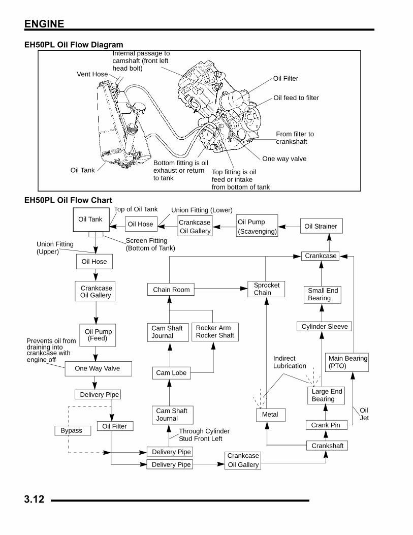
ENGINE
EH50PL Oil Flow Diagram
EH50PL Oil Flow Chart
Vent Hose
Oil Tank
Oil Filter
Oil feed to filter
From filter to
One way valve
crankshaft
Top fitting is oilfeed or intakefrom bottom of tank
Bottom fitting is oilexhaust or returnto tank
Internal passage tocamshaft (front lefthead bolt)
Oil TankOil Hose Crankcase
Oil Gallery
CrankcaseOil Gallery
Oil Pump(Scavenging)
Oil Hose
Oil Strainer
Crankcase Oil Gallery
Oil Pump(Feed)
One Way Valve
Bypass Oil Filter
Delivery Pipe
Crankshaft
Prevents oil fromdraining intocrankcase withengine off
Top of Oil Tank
Delivery Pipe
Delivery Pipe
Crank Pin
Large EndBearing
Cylinder Sleeve
Small EndBearing
Crankcase
(PTO)Main Bearing
Cam ShaftJournal
Cam Lobe
Cam ShaftJournal
Chain RoomSprocket Chain
Metal
Union Fitting (Lower)
Union Fitting(Upper)
Through CylinderStud Front Left
OilJet
IndirectLubrication
Screen Fitting(Bottom of Tank)
Rocker ArmRocker Shaft
3.12
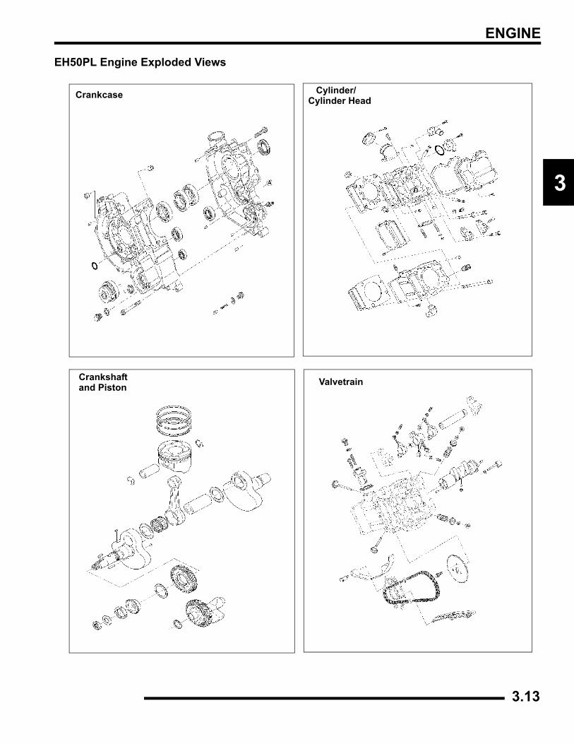
ENGINE
3
EH50PL Engine Exploded Views
Crankshaft
Cylinder/
and Piston
Cylinder HeadCrankcase
Valvetrain
3.13
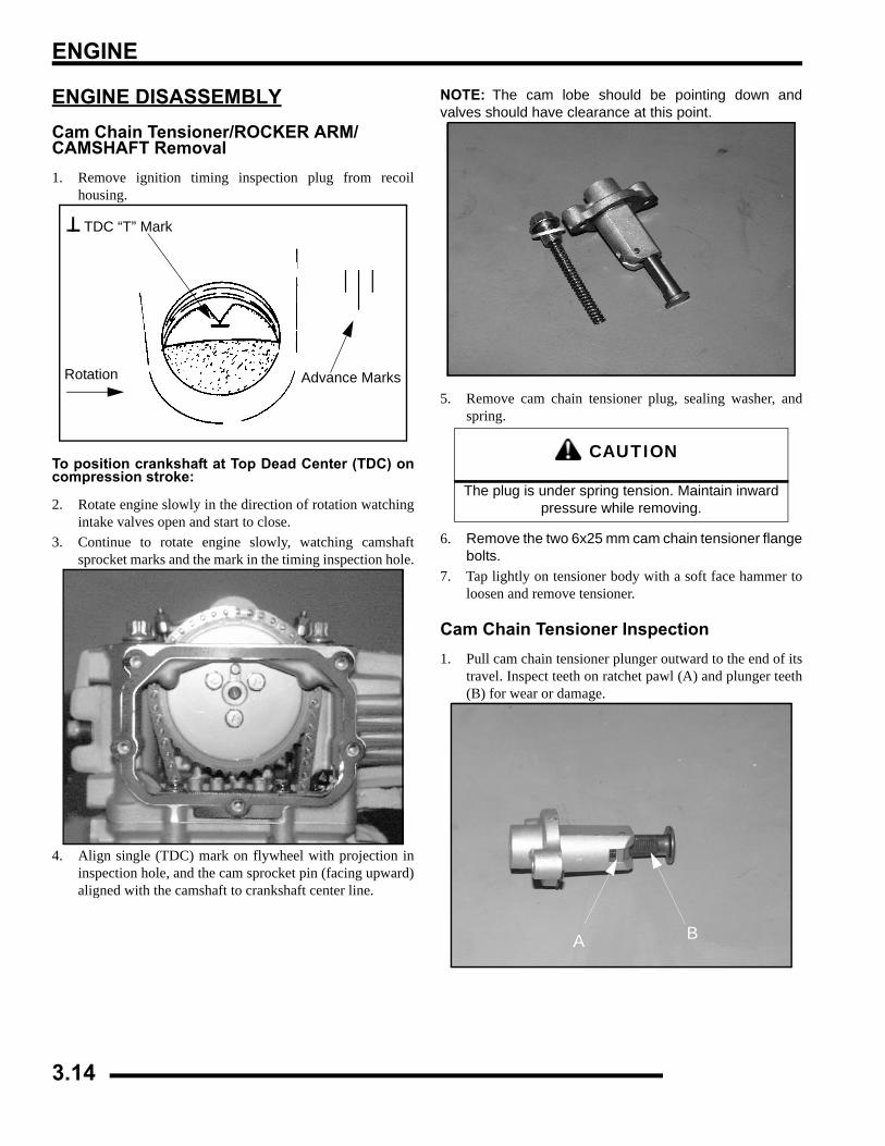
ENGINE
ENGINE DISASSEMBLYCam Chain Tensioner/ROCKER ARM/ CAMSHAFT Removal1. Remove ignition timing inspection plug from recoil
housing.
To position crankshaft at Top Dead Center (TDC) oncompression stroke:
2. Rotate engine slowly in the direction of rotation watchingintake valves open and start to close.
3. Continue to rotate engine slowly, watching camshaftsprocket marks and the mark in the timing inspection hole.
4. Align single (TDC) mark on flywheel with projection ininspection hole, and the cam sprocket pin (facing upward)aligned with the camshaft to crankshaft center line.
NOTE: The cam lobe should be pointing down andvalves should have clearance at this point.
5. Remove cam chain tensioner plug, sealing washer, andspring.
6. Remove the two 6x25 mm cam chain tensioner flangebolts.
7. Tap lightly on tensioner body with a soft face hammer toloosen and remove tensioner.
Cam Chain Tensioner Inspection1. Pull cam chain tensioner plunger outward to the end of its
travel. Inspect teeth on ratchet pawl (A) and plunger teeth(B) for wear or damage.
Advance MarksRotation
TDC “T” Mark
CAUTION
The plug is under spring tension. Maintain inward pressure while removing.
A B
3.14
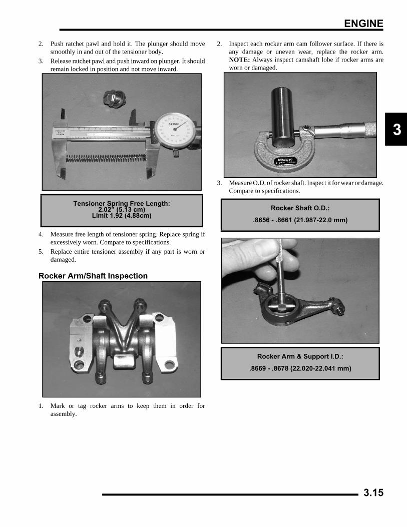
ENGINE
3
2. Push ratchet pawl and hold it. The plunger should movesmoothly in and out of the tensioner body.
3. Release ratchet pawl and push inward on plunger. It shouldremain locked in position and not move inward.
4. Measure free length of tensioner spring. Replace spring ifexcessively worn. Compare to specifications.
5. Replace entire tensioner assembly if any part is worn ordamaged.
Rocker Arm/Shaft Inspection
1. Mark or tag rocker arms to keep them in order forassembly.
2. Inspect each rocker arm cam follower surface. If there isany damage or uneven wear, replace the rocker arm.NOTE: Always inspect camshaft lobe if rocker arms areworn or damaged.
3. Measure O.D. of rocker shaft. Inspect it for wear or damage.Compare to specifications.
Tensioner Spring Free Length:2.02” (5.13 cm)
Limit 1.92 (4.88cm)Rocker Shaft O.D.:
.8656 - .8661 (21.987-22.0 mm)
Rocker Arm & Support I.D.:
.8669 - .8678 (22.020-22.041 mm)
3.15
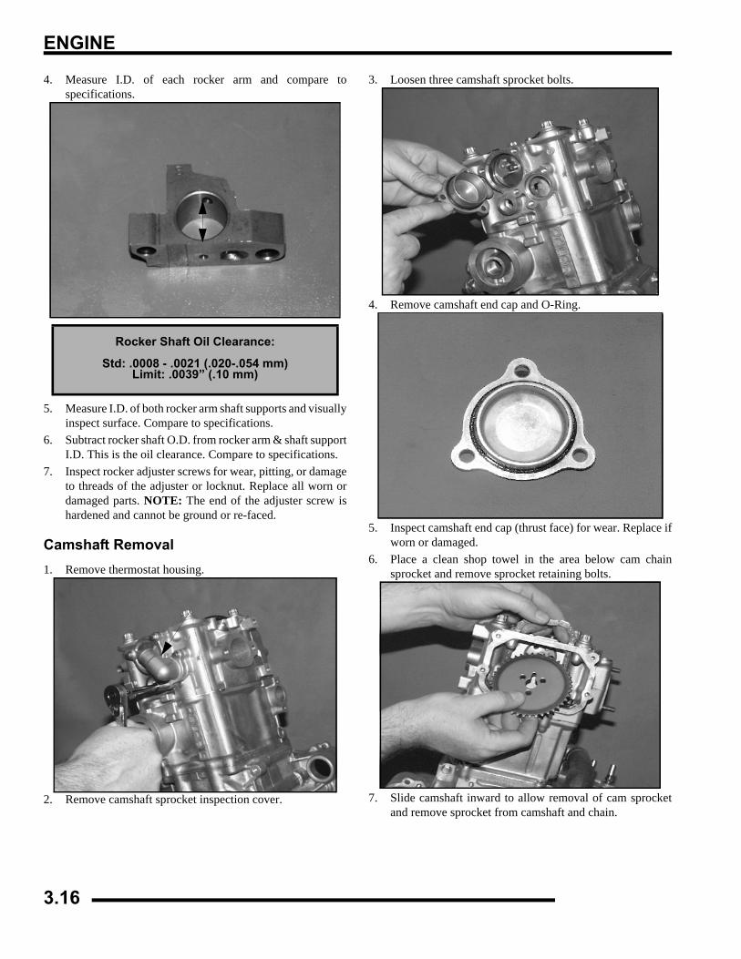
ENGINE
4. Measure I.D. of each rocker arm and compare tospecifications.
5. Measure I.D. of both rocker arm shaft supports and visuallyinspect surface. Compare to specifications.
6. Subtract rocker shaft O.D. from rocker arm & shaft supportI.D. This is the oil clearance. Compare to specifications.
7. Inspect rocker adjuster screws for wear, pitting, or damageto threads of the adjuster or locknut. Replace all worn ordamaged parts. NOTE: The end of the adjuster screw ishardened and cannot be ground or re-faced.
Camshaft Removal1. Remove thermostat housing.
2. Remove camshaft sprocket inspection cover.
3. Loosen three camshaft sprocket bolts.
4. Remove camshaft end cap and O-Ring.
5. Inspect camshaft end cap (thrust face) for wear. Replace ifworn or damaged.
6. Place a clean shop towel in the area below cam chainsprocket and remove sprocket retaining bolts.
7. Slide camshaft inward to allow removal of cam sprocketand remove sprocket from camshaft and chain.
Rocker Shaft Oil Clearance:
Std: .0008 - .0021 (.020-.054 mm)Limit: .0039” (.10 mm)
3.16
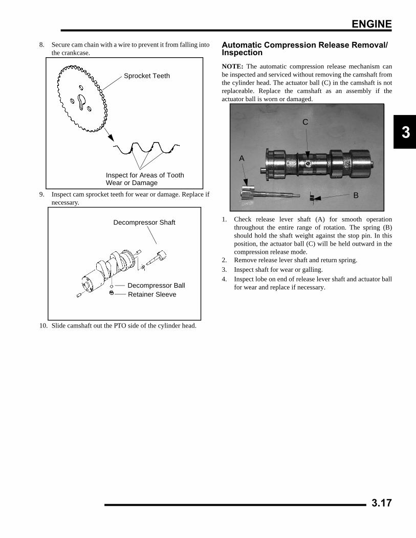
ENGINE
3
8. Secure cam chain with a wire to prevent it from falling intothe crankcase.
9. Inspect cam sprocket teeth for wear or damage. Replace ifnecessary.
10. Slide camshaft out the PTO side of the cylinder head.
Automatic Compression Release Removal/InspectionNOTE: The automatic compression release mechanism canbe inspected and serviced without removing the camshaft fromthe cylinder head. The actuator ball (C) in the camshaft is notreplaceable. Replace the camshaft as an assembly if theactuator ball is worn or damaged.
1. Check release lever shaft (A) for smooth operationthroughout the entire range of rotation. The spring (B)should hold the shaft weight against the stop pin. In thisposition, the actuator ball (C) will be held outward in thecompression release mode.
2. Remove release lever shaft and return spring.3. Inspect shaft for wear or galling.4. Inspect lobe on end of release lever shaft and actuator ball
for wear and replace if necessary.
Sprocket Teeth
Inspect for Areas of ToothWear or Damage
Decompressor Shaft
Decompressor BallRetainer Sleeve
A
C
B
3.17
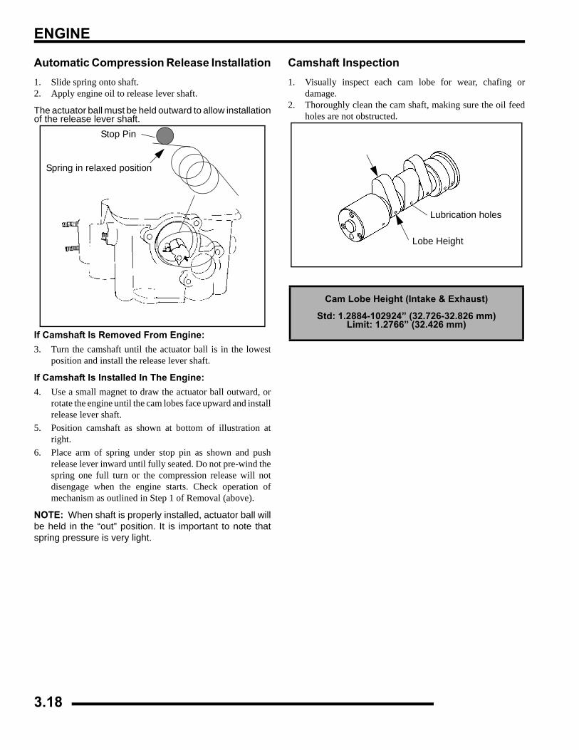
ENGINE
Automatic Compression Release Installation1. Slide spring onto shaft.2. Apply engine oil to release lever shaft.
The actuator ball must be held outward to allow installationof the release lever shaft.
If Camshaft Is Removed From Engine:3. Turn the camshaft until the actuator ball is in the lowest
position and install the release lever shaft.
If Camshaft Is Installed In The Engine:4. Use a small magnet to draw the actuator ball outward, or
rotate the engine until the cam lobes face upward and installrelease lever shaft.
5. Position camshaft as shown at bottom of illustration atright.
6. Place arm of spring under stop pin as shown and pushrelease lever inward until fully seated. Do not pre-wind thespring one full turn or the compression release will notdisengage when the engine starts. Check operation ofmechanism as outlined in Step 1 of Removal (above).
NOTE: When shaft is properly installed, actuator ball willbe held in the “out” position. It is important to note thatspring pressure is very light.
Camshaft Inspection1. Visually inspect each cam lobe for wear, chafing or
damage.2. Thoroughly clean the cam shaft, making sure the oil feed
holes are not obstructed.
Stop Pin
Spring in relaxed position
Cam Lobe Height (Intake & Exhaust)
Std: 1.2884-102924” (32.726-32.826 mm)Limit: 1.2766” (32.426 mm)
Lubrication holes
Lobe Height
3.18
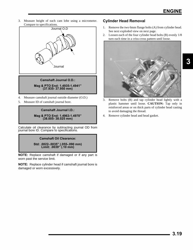
ENGINE
3
3. Measure height of each cam lobe using a micrometer.Compare to specifications.
4. Measure camshaft journal outside diameter (O.D.)5. Measure ID of camshaft journal bore.
Calculate oil clearance by subtracting journal OD fromjournal bore ID. Compare to specifications.
NOTE: Replace camshaft if damaged or if any part isworn past the service limit.
NOTE: Replace cylinder head if camshaft journal bore isdamaged or worn excessively.
Cylinder Head Removal1. Remove the two 6mm flange bolts (A) from cylinder head.
See next exploded view on next page.2. Loosen each of the four cylinder head bolts (B) evenly 1/8
turn each time in a criss-cross pattern until loose.
3. Remove bolts (B) and tap cylinder head lightly with aplastic hammer until loose. CAUTION: Tap only inreinforced areas or on thick parts of cylinder head castingto avoid damaging the thread.
4. Remove cylinder head and head gasket.
Camshaft Journal O.D.:
Mag & PTO End: 1.4935-1.4941”(37.935- 37.950 mm)
Camshaft Journal I.D.:
Mag & PTO End: 1.4963-1.4970”(38.005- 38.025 mm)
Camshaft Oil Clearance:
Std: .0022-.0035” (.055-.090 mm)Limit: .0039” (.10 mm)
Journal
Journal O.D
B
3.19
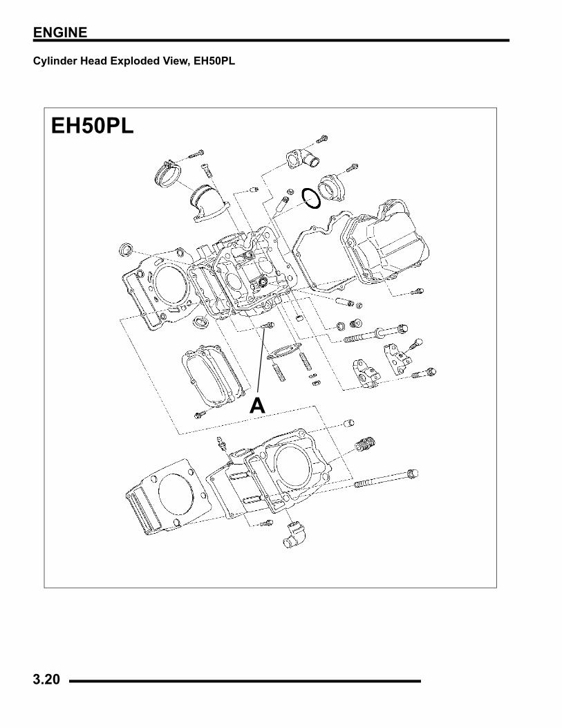
ENGINE
Cylinder Head Exploded View, EH50PL
EH50PL
A
3.20
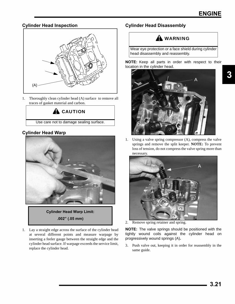
ENGINE
3
Cylinder Head Inspection
1. Thoroughly clean cylinder head (A) surface to remove alltraces of gasket material and carbon.
Cylinder Head Warp
1. Lay a straight edge across the surface of the cylinder headat several different points and measure warpage byinserting a feeler gauge between the straight edge and thecylinder head surface. If warpage exceeds the service limit,replace the cylinder head.
Cylinder Head Disassembly
NOTE: Keep all parts in order with respect to theirlocation in the cylinder head.
1. Using a valve spring compressor (A), compress the valvesprings and remove the split keeper. NOTE: To preventloss of tension, do not compress the valve spring more thannecessary.
2. Remove spring retainer and spring.
NOTE: The valve springs should be positioned with thetightly wound coils against the cylinder head onprogressively wound springs (A).
3. Push valve out, keeping it in order for reassembly in thesame guide.
CAUTION
Use care not to damage sealing surface.
Cylinder Head Warp Limit:
.002” (.05 mm)
(A)
WARNING
Wear eye protection or a face shield during cylinderhead disassembly and reassembly.
A
A
3.21
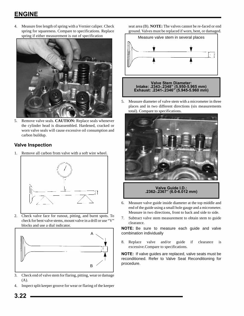
ENGINE
4. Measure free length of spring with a Vernier caliper. Checkspring for squareness. Compare to specifications. Replacespring if either measurement is out of specification
5. Remove valve seals. CAUTION: Replace seals wheneverthe cylinder head is disassembled. Hardened, cracked orworn valve seals will cause excessive oil consumption andcarbon buildup.
Valve Inspection1. Remove all carbon from valve with a soft wire wheel.
2. Check valve face for runout, pitting, and burnt spots. Tocheck for bent valve stems, mount valve in a drill or use “V”blocks and use a dial indicator.
3. Check end of valve stem for flaring, pitting, wear or damage(A).
4. Inspect split keeper groove for wear or flaring of the keeper
seat area (B). NOTE: The valves cannot be re-faced or endground. Valves must be replaced if worn, bent, or damaged.
5. Measure diameter of valve stem with a micrometer in threeplaces and in two different directions (six measurementstotal). Compare to specifications.
6. Measure valve guide inside diameter at the top middle andend of the guide using a small hole gauge and a micrometer.Measure in two directions, front to back and side to side.
7. Subtract valve stem measurement to obtain stem to guideclearance.
NOTE: Be sure to measure each guide and valvecombination individually
8. Replace valve and/or guide if clearance isexcessive.Compare to specifications.
NOTE: If valve guides are replaced, valve seats must bereconditioned. Refer to Valve Seat Reconditioning forprocedure.
A
B
Valve Stem Diameter:Intake: .2343-.2348” (5.950-5.965 mm)
Exhaust: .2341-.2346” (5.945-5.960 mm)
Valve Guide I.D.:.2362-.2367” (6.0-6.012 mm)
Measure valve stem in several places
3.22
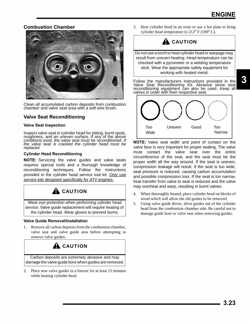
ENGINE
3
Combustion Chamber
Clean all accumulated carbon deposits from combustionchamber and valve seat area with a soft wire brush.
Valve Seat ReconditioningValve Seat Inspection
Inspect valve seat in cylinder head for pitting, burnt spots,roughness, and an uneven surface. If any of the aboveconditions exist, the valve seat must be reconditioned. Ifthe valve seat is cracked the cylinder head must bereplaced.Cylinder Head ReconditioningNOTE: Servicing the valve guides and valve seatsrequires special tools and a thorough knowledge ofreconditioning techniques. Follow the instructionsprovided in the cylinder head service tool kit. Only useservice kits designed specifically for ATV engines.
Valve Guide Removal/Installation1. Remove all carbon deposits from the combustion chamber,
valve seat and valve guide area before attempting toremove valve guides.
2. Place new valve guides in a freezer for at least 15 minuteswhile heating cylinder head.
3. Heat cylinder head in an oven or use a hot plate to bringcylinder head temperature to 212o F (100o C).
Follow the manufacturers instructions provided in theValve Seat Reconditioning Kit. Abrasive stone seatreconditioning equipment can also be used. Keep allvalves in order with their respective seat.
NOTE: Valve seat width and point of contact on thevalve face is very important for proper sealing. The valvemust contact the valve seat over the entirecircumference of the seat, and the seat must be theproper width all the way around. If the seat is uneven,compression leakage will result. If the seat is too wide,seat pressure is reduced, causing carbon accumulationand possible compression loss. If the seat is too narrow,heat transfer from valve to seat is reduced and the valvemay overheat and warp, resulting in burnt valves.
4. When thoroughly heated, place cylinder head on blocks ofwood which will allow the old guides to be removed.
5. Using valve guide driver, drive guides out of the cylinderhead from the combustion chamber side. Be careful not todamage guide bore or valve seat when removing guides.
CAUTION
Wear eye protection when performing cylinder head service. Valve guide replacement will require heating of
the cylinder head. Wear gloves to prevent burns.
CAUTION
Carbon deposits are extremely abrasive and may damage the valve guide bore when guides are removed.
CAUTION
Do not use a torch to heat cylinder head or warpage may result from uneven heating. Head temperature can be checked with a pyrometer or a welding temperature
stick. Wear the appropriate safety equipment for working with heated metal.
Too Uneven Good Too Wide Narrow
3.23
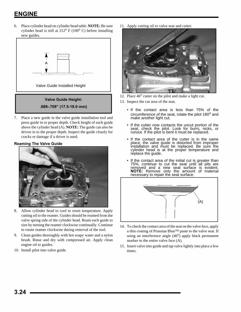
ENGINE
6. Place cylinder head on cylinder head table. NOTE: Be surecylinder head is still at 212o F (100o C) before installingnew guides.
7. Place a new guide in the valve guide installation tool andpress guide in to proper depth. Check height of each guideabove the cylinder head (A). NOTE: The guide can also bedriven in to the proper depth. Inspect the guide closely forcracks or damage if a driver is used.
Reaming The Valve Guide
8. Allow cylinder head to cool to room temperature. Applycutting oil to the reamer. Guides should be reamed from thevalve spring side of the cylinder head. Ream each guide tosize by turning the reamer clockwise continually. Continueto rotate reamer clockwise during removal of the tool.
9. Clean guides thoroughly with hot soapy water and a nylonbrush. Rinse and dry with compressed air. Apply cleanengine oil to guides.
10. Install pilot into valve guide.
11. Apply cutting oil to valve seat and cutter.
12. Place 46o cutter on the pilot and make a light cut.13. Inspect the cut area of the seat.
• If the contact area is less than 75% of thecircumference of the seat, rotate the pilot 180o andmake another light cut.
• If the cutter now contacts the uncut portion of theseat, check the pilot. Look for burrs, nicks, orrunout. If the pilot is bent it must be replaced.
• If the contact area of the cutter is in the sameplace, the valve guide is distorted from improperinstallation and must be replaced. Be sure thecylinder head is at the proper temperature andreplace the guide.
• If the contact area of the initial cut is greater than75%, continue to cut the seat until all pits areremoved and a new seat surface is evident.NOTE: Remove only the amount of materialnecessary to repair the seat surface.
14. To check the contact area of the seat on the valve face, applya thin coating of Prussian Blue™ paste to the valve seat. Ifusing an interference angle (46o) apply black permanentmarker to the entire valve face (A).
15. Insert valve into guide and tap valve lightly into place a fewtimes.
Valve Guide Height:
.689-.709” (17.5-18.0 mm)
Valve Guide Installed Height
(A)
3.24
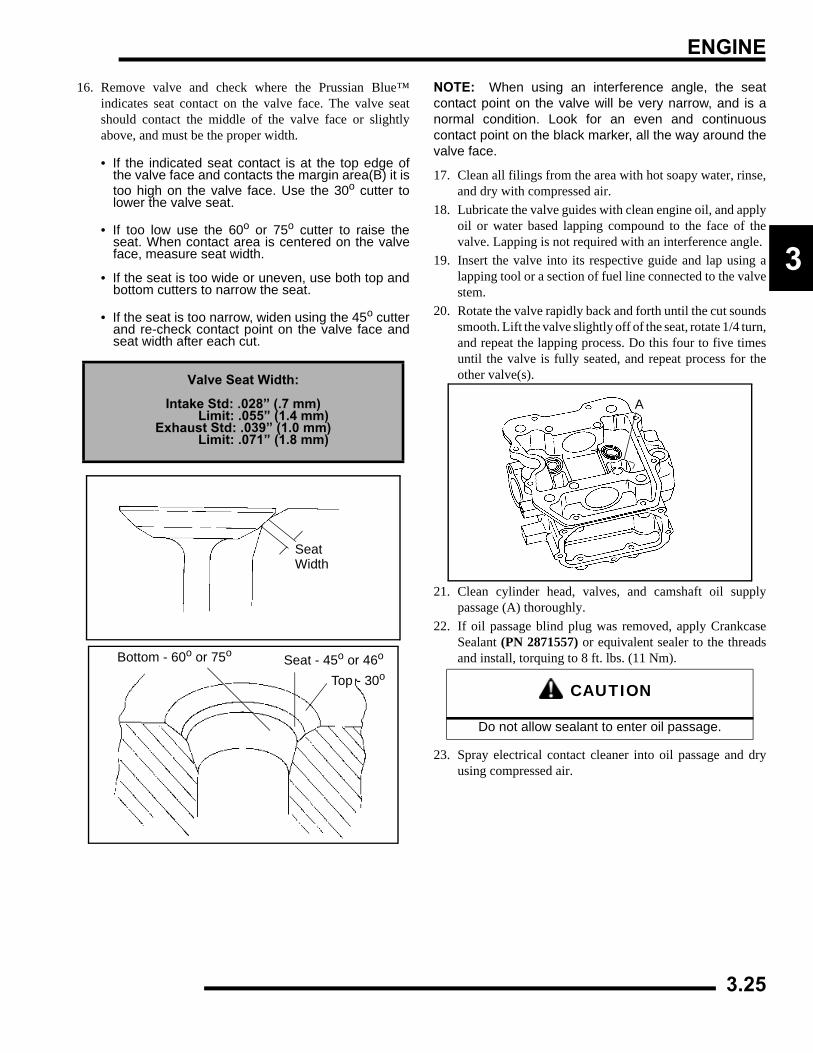
ENGINE
3
16. Remove valve and check where the Prussian Blue™indicates seat contact on the valve face. The valve seatshould contact the middle of the valve face or slightlyabove, and must be the proper width.
• If the indicated seat contact is at the top edge ofthe valve face and contacts the margin area(B) it istoo high on the valve face. Use the 30o cutter tolower the valve seat.
• If too low use the 60o or 75o cutter to raise theseat. When contact area is centered on the valveface, measure seat width.
• If the seat is too wide or uneven, use both top andbottom cutters to narrow the seat.
• If the seat is too narrow, widen using the 45o cutterand re-check contact point on the valve face andseat width after each cut.
NOTE: When using an interference angle, the seatcontact point on the valve will be very narrow, and is anormal condition. Look for an even and continuouscontact point on the black marker, all the way around thevalve face.
17. Clean all filings from the area with hot soapy water, rinse,and dry with compressed air.
18. Lubricate the valve guides with clean engine oil, and applyoil or water based lapping compound to the face of thevalve. Lapping is not required with an interference angle.
19. Insert the valve into its respective guide and lap using alapping tool or a section of fuel line connected to the valvestem.
20. Rotate the valve rapidly back and forth until the cut soundssmooth. Lift the valve slightly off of the seat, rotate 1/4 turn,and repeat the lapping process. Do this four to five timesuntil the valve is fully seated, and repeat process for theother valve(s).
21. Clean cylinder head, valves, and camshaft oil supplypassage (A) thoroughly.
22. If oil passage blind plug was removed, apply CrankcaseSealant (PN 2871557) or equivalent sealer to the threadsand install, torquing to 8 ft. lbs. (11 Nm).
23. Spray electrical contact cleaner into oil passage and dryusing compressed air.
Valve Seat Width:
Intake Std: .028” (.7 mm) Limit: .055” (1.4 mm)Exhaust Std: .039” (1.0 mm) Limit: .071” (1.8 mm)
SeatWidth
Bottom - 60o or 75o Seat - 45o or 46o
Top - 30oCAUTION
Do not allow sealant to enter oil passage.
A
3.25
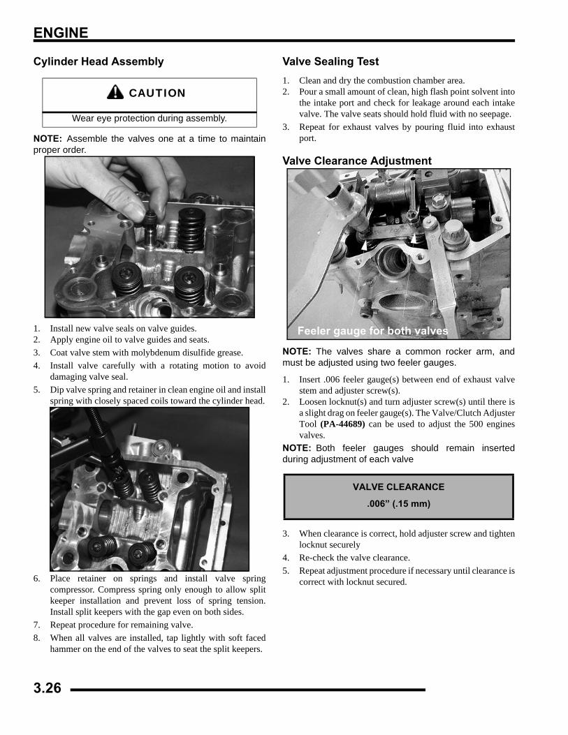
ENGINE
Cylinder Head Assembly
NOTE: Assemble the valves one at a time to maintainproper order.
1. Install new valve seals on valve guides.2. Apply engine oil to valve guides and seats.3. Coat valve stem with molybdenum disulfide grease.4. Install valve carefully with a rotating motion to avoid
damaging valve seal.5. Dip valve spring and retainer in clean engine oil and install
spring with closely spaced coils toward the cylinder head.
6. Place retainer on springs and install valve springcompressor. Compress spring only enough to allow splitkeeper installation and prevent loss of spring tension.Install split keepers with the gap even on both sides.
7. Repeat procedure for remaining valve.8. When all valves are installed, tap lightly with soft faced
hammer on the end of the valves to seat the split keepers.
Valve Sealing Test1. Clean and dry the combustion chamber area.2. Pour a small amount of clean, high flash point solvent into
the intake port and check for leakage around each intakevalve. The valve seats should hold fluid with no seepage.
3. Repeat for exhaust valves by pouring fluid into exhaustport.
Valve Clearance Adjustment
NOTE: The valves share a common rocker arm, andmust be adjusted using two feeler gauges.
1. Insert .006 feeler gauge(s) between end of exhaust valvestem and adjuster screw(s).
2. Loosen locknut(s) and turn adjuster screw(s) until there isa slight drag on feeler gauge(s). The Valve/Clutch AdjusterTool (PA-44689) can be used to adjust the 500 enginesvalves.
NOTE: Both feeler gauges should remain insertedduring adjustment of each valve
3. When clearance is correct, hold adjuster screw and tightenlocknut securely
4. Re-check the valve clearance.5. Repeat adjustment procedure if necessary until clearance is
correct with locknut secured.
CAUTION
Wear eye protection during assembly.
VALVE CLEARANCE
.006” (.15 mm)
Feeler gauge for both valves
3.26
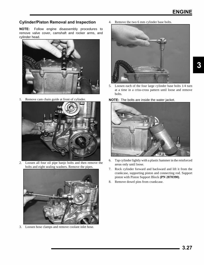
ENGINE
3
Cylinder/Piston Removal and InspectionNOTE: Follow engine disassembly procedures toremove valve cover, camshaft and rocker arms, andcylinder head.
1. Remove cam chain guide at front of cylinder.
2. Loosen all four oil pipe banjo bolts and then remove thebolts and eight sealing washers. Remove the pipes.
3. Loosen hose clamps and remove coolant inlet hose.
4. Remove the two 6 mm cylinder base bolts.
5. Loosen each of the four large cylinder base bolts 1/4 turnat a time in a criss-cross pattern until loose and removebolts.
NOTE: The bolts are inside the water jacket.
6. Tap cylinder lightly with a plastic hammer in the reinforcedareas only until loose.
7. Rock cylinder forward and backward and lift it from thecrankcase, supporting piston and connecting rod. Supportpiston with Piston Support Block (PN 2870390).
8. Remove dowel pins from crankcase.
3.27
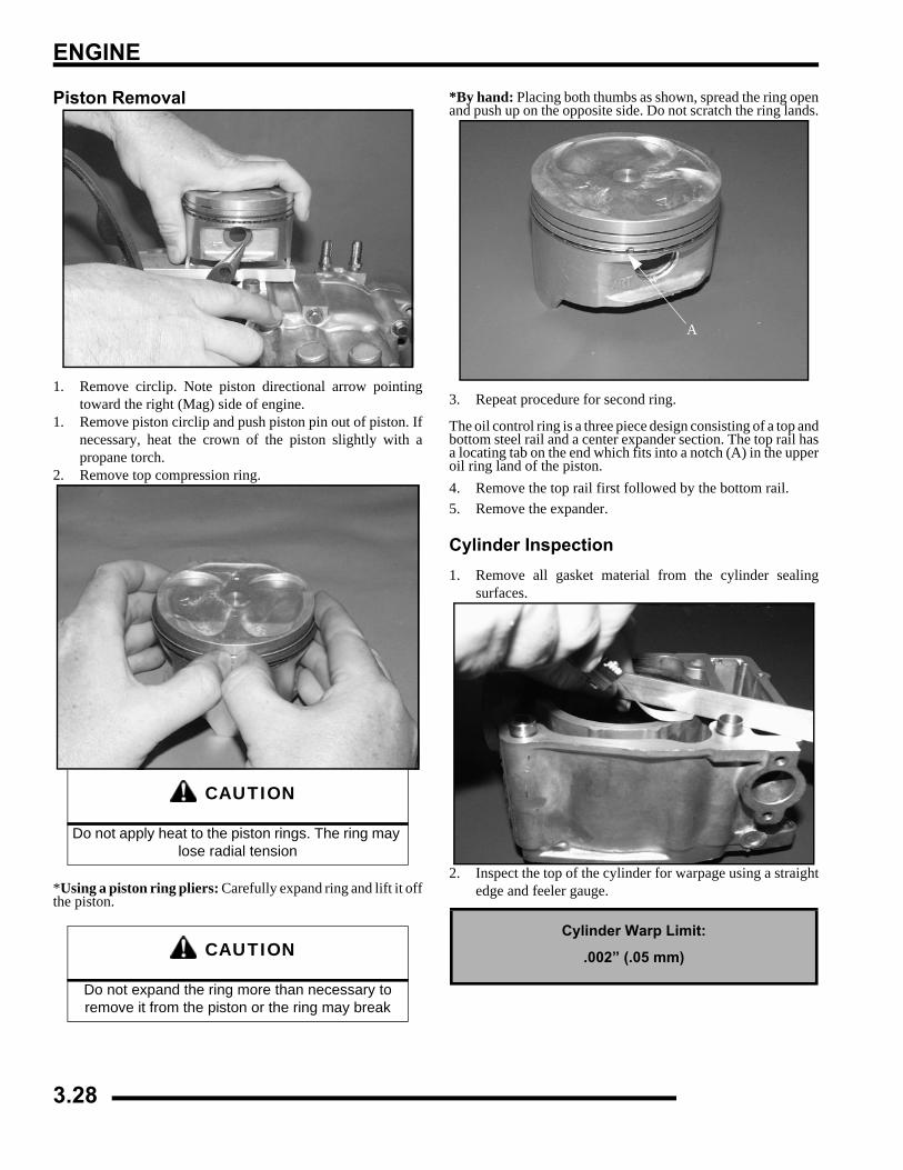
ENGINE
Piston Removal
1. Remove circlip. Note piston directional arrow pointingtoward the right (Mag) side of engine.
1. Remove piston circlip and push piston pin out of piston. Ifnecessary, heat the crown of the piston slightly with apropane torch.
2. Remove top compression ring.
*Using a piston ring pliers: Carefully expand ring and lift it offthe piston.
*By hand: Placing both thumbs as shown, spread the ring openand push up on the opposite side. Do not scratch the ring lands.
3. Repeat procedure for second ring.
The oil control ring is a three piece design consisting of a top andbottom steel rail and a center expander section. The top rail hasa locating tab on the end which fits into a notch (A) in the upperoil ring land of the piston.4. Remove the top rail first followed by the bottom rail.5. Remove the expander.
Cylinder Inspection1. Remove all gasket material from the cylinder sealing
surfaces.
2. Inspect the top of the cylinder for warpage using a straightedge and feeler gauge.
CAUTION
Do not apply heat to the piston rings. The ring may lose radial tension
CAUTION
Do not expand the ring more than necessary to remove it from the piston or the ring may break
Cylinder Warp Limit:
.002” (.05 mm)
A
3.28
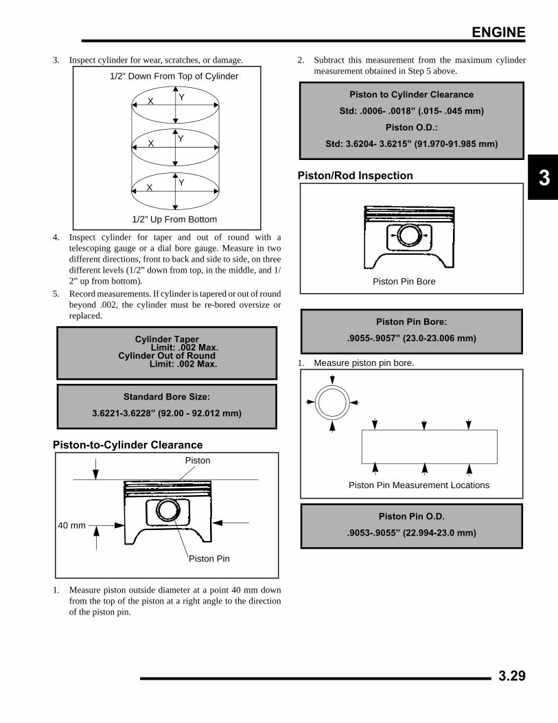
ENGINE
3
3. Inspect cylinder for wear, scratches, or damage.
4. Inspect cylinder for taper and out of round with atelescoping gauge or a dial bore gauge. Measure in twodifferent directions, front to back and side to side, on threedifferent levels (1/2” down from top, in the middle, and 1/2” up from bottom).
5. Record measurements. If cylinder is tapered or out of roundbeyond .002, the cylinder must be re-bored oversize orreplaced.
Piston-to-Cylinder Clearance
1. Measure piston outside diameter at a point 40 mm downfrom the top of the piston at a right angle to the directionof the piston pin.
2. Subtract this measurement from the maximum cylindermeasurement obtained in Step 5 above.
Piston/Rod Inspection
1. Measure piston pin bore.
Cylinder Taper Limit: .002 Max.Cylinder Out of Round Limit: .002 Max.
Standard Bore Size:
3.6221-3.6228” (92.00 - 92.012 mm)
1/2” Down From Top of Cylinder
1/2” Up From Bottom
X
X
X
Y
Y
Y
Piston Pin
Piston
40 mm
Piston to Cylinder Clearance
Std: .0006- .0018” (.015- .045 mm)
Piston O.D.:
Std: 3.6204- 3.6215” (91.970-91.985 mm)
Piston Pin Bore:
.9055-.9057” (23.0-23.006 mm)
Piston Pin O.D.
.9053-.9055” (22.994-23.0 mm)
Piston Pin Bore
Piston Pin Measurement Locations
3.29
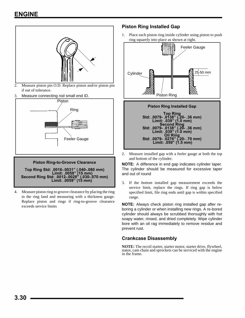
ENGINE
2. Measure piston pin O.D. Replace piston and/or piston pinif out of tolerance.
3. Measure connecting rod small end ID.
4. Measure piston ring to groove clearance by placing the ringin the ring land and measuring with a thickness gauge.Replace piston and rings if ring-to-groove clearanceexceeds service limits
Piston Ring Installed Gap1. Place each piston ring inside cylinder using piston to push
ring squarely into place as shown at right.
2. Measure installed gap with a feeler gauge at both the topand bottom of the cylinder.
NOTE: A difference in end gap indicates cylinder taper.The cylinder should be measured for excessive taperand out of round
3. If the bottom installed gap measurement exceeds theservice limit, replace the rings. If ring gap is belowspecified limit, file ring ends until gap is within specifiedrange.
NOTE: Always check piston ring installed gap after re-boring a cylinder or when installing new rings. A re-boredcylinder should always be scrubbed thoroughly with hotsoapy water, rinsed, and dried completely. Wipe cylinderbore with an oil rag immediately to remove residue andprevent rust.
Crankcase DisassemblyNOTE: The recoil starter, starter motor, starter drive, flywheel,stator, cam chain and sprockets can be serviced with the enginein the frame.
Piston Ring-to-Groove Clearance
Top Ring Std: .0016-.0031” (.040-.080 mm) Limit: .0059” (15 mm)
Second Ring Std: .0012-.0028” (.030-.070 mm) Limit: .0059” (15 mm)
Piston
Ring
Feeler Gauge
Piston Ring Installed Gap
Top RingStd: .0079- .0138” (.20- .36 mm)
Limit: .039” (1.0 mm)Second Ring
Std: .0079- .0138” (.20- .36 mm)Limit: .039” (1.0 mm)
Oil RingStd: .0079- .0276” (.20- .70 mm)
Limit: .059” (1.5 mm)
Feeler Gauge
Cylinder
Piston Ring
25-50 mm
3.30
ENGINE
3
Starter Drive Removal/Inspection1. Remove recoil housing bolts and remove housing.
2. Remove starter drive assembly. Note the thrust washerlocated at the rear of the drive mechanism.
3. Inspect the thrust washer for wear or damage and replaceif necessary.
4. Measure the OD of the starter drive shaft on both ends andrecord.
5. Measure the ID of the bushing in the recoil housing (A) andin the crankcase and record. Measure in two directions 90o
apart to determine if bushing is out of round. Calculatebushing clearance. Replace bushing if clearance exceedsthe service limit.
6. Inspect gear teeth on starter drive. Replace starter drive ifgear teeth are cracked, worn, or broken.
Flywheel/Stator Removal/Inspection1. Remove flywheel nut and washer.2. Install Flywheel Puller (PN 2871043) and remove
flywheel.
3. Mark or note position of stator plate on crankcase.4. Remove bolts and carefully remove stator assembly, being
careful not to damage crankshaft bushing on stator plate.5. Replace crankshaft seal (A).
6. Remove oil passage O-Ring (B).Std. Bushing ID:
.4735”-.4740” (11.11-12.04 mm)
Std. Shaft OD:.470”-.472” (11.93-11.99 mm)
Starter Drive Bushing Clearance:Std: .0015-.004” (.038-.102 mm)
Service Limit:.008” (.203 mm)
A
CAUTION
Do not thread the puller bolts into the flywheel more than 1/4" or stator coils may be damaged
A
B
3.31
ENGINE
7. Remove large sealing O-Ring from outer edge of statorplate.
Cam Chain/Tensioner Blade1. Remove bolt securing tensioner blade to crankcase (A).
2. Remove blade and inspect for cracks, wear, or damage.
3. Remove cam chain (B). Inspect chain for worn or missingrollers or damage. Stretch chain tight on a flat surface andapply a 10 lb. (4.53 kg) load. Measure length of a 20 pitch
section of chain. Replace if worn past service limit.
4. Using the special socket, remove the crankshaft slotted nut.NOTE: The crankshaft slotted nut is a left-hand thread.
5. Remove cam chain drive sprocket and woodruff key fromcrankshaft.
6. Inspect sprocket teeth for wear or damage.7. Inspect woodruff key for wear.8. Replace any worn or damaged parts.
One Way Valve RemovalThe one way valve prevents oil from draining out of the oiltank and into the crankcase when the engine is off. It mustbe clean and have adequate spring pressure in order toseal properly.
1. Remove cap bolt (A), sealing washer (B), spring (C), andone way valve (D) from PTO side crankcase.
2. Inspect free length of spring and check coils for distortion.
3. Inspect valve for wear.4. Check seat area for nicks or foreign material that may
prevent proper sealing of valve.
A
B
20 Pitch Section
Chain Service Limit: 5.407” (13.7 cm)
One Way Valve Spring Free Length:
Std: 1.450” (3.68 cm)
D CB A
3.32
ENGINE
3
Crankcase Separation
1. Remove flange bolts (10) from magneto side crankcaseevenly in a criss-cross pattern.
2. Separate crankcase by tapping with a soft faced hammer inreinforced areas.
3. Tap lightly on balancer gear with a brass drift through thehole in the crankcase if necessary, to ensure the balancershaft stays in the PTO side crankcase. Watch the gap alongthe crankcase mating surface and separate the crankcaseevenly. It may also be necessary to tap the oil pump shaftlightly to separate the crankcase.
4. Remove the Mag (RH) crankcase from the PTO case.
Oil Pump Removal/Inspection
1. Remove pump shaft bearing (A) and thrust washer (B)from pump shaft.
2. Remove (2) bolts holding pump drive gear (C).
3. Inspect drive gear teeth for cracks, damage or excessivewear.
4. Remove three oil pump retaining bolts and pump.5. Inspect mating surface of crankcase and oil pump. Check
for nicks, burrs, or surface irregularities.
6. Remove the three screws and strainer screen from pump.7. Clean screen thoroughly.8. Remove pump body screw and feed chamber cover.
CAUTION
Do not strike the oil pump shaft at an angle or the shaft may bend, causing irreparable damage. Tap
only lightly on the pump shaft if necessary.
CB
A
3.33
ENGINE
9. Measure pump end clearance using a feeler gauge andstraight edge.
10. Measure clearance between outer feed rotor and pump bodywith a feeler gauge.
11. Measure rotor tip clearance with a feeler gauge.12. Remove inner and outer feed rotor and pump chamber
body.13. Repeat measurements for scavenge rotor.14. Remove inner and outer scavenge rotor and inspect pump
shaft for wear.
Oil Pump Assembly1. Clean and dry all parts thoroughly. Apply clean engine oil
to all parts. Do not use gasket sealer on the pump bodymating surfaces or oil passages will become plugged.
2. Install pump shaft and scavenge rotor drive pin.3. Install outer scavenge rotor, inner scavenge rotor, and
scavenge casing.4. Install outer feed rotor and inner feed rotor drive pin.5. Install inner feed rotor and feed chamber cover with screw.6. Tighten screw securely.7. Install screen on pump body.8. Install oil pump on crankcase and torque bolts to 6 ft. lbs.
(8 Nm).
Counter Balancer Shaft Removal/Inspection1. Remove the shim washer (A) from the counter balancer
shaft.
2. Note the alignment dots on the balancer and crankshaftgears, the marks must be aligned during reassembly.
Pump End Clearance:
Std: .001 -.003 (.0254-.0762 mm)
Wear Limit: .004 (.1016 mm)
Rotor Tip Clearance:
Std: .005 (.127 mm)
Wear Limit: .008 (.2032 mm)
Oil Pump Attaching Bolt Torque: 6 ft. lbs. (8 Nm)
A
3.34
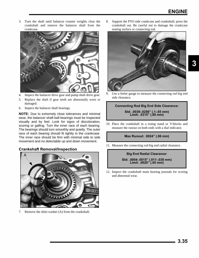
ENGINE
3
3. Turn the shaft until balancer counter weights clear thecrankshaft and remove the balancer shaft from thecrankcase.
4. Inspect the balancer drive gear and pump shaft drive gear.5. Replace the shaft if gear teeth are abnormally worn or
damaged.6. Inspect the balancer shaft bearings.
NOTE: Due to extremely close tolerances and minimalwear, the balancer shaft ball bearings must be inspectedvisually and by feel. Look for signs of discoloration,scoring or galling. Turn the inner race of each bearing.The bearings should turn smoothly and quietly. The outerrace of each bearing should fit tightly in the crankcase.The inner race should be firm with minimal side to sidemovement and no detectable up and down movement.
Crankshaft Removal/Inspection
7. Remove the shim washer (A) from the crankshaft.
8. Support the PTO side crankcase and crankshaft; press thecrankshaft out. Be careful not to damage the crankcasemating surface or connecting rod.
9. Use a feeler gauge to measure the connecting rod big endside clearance.
10. Place the crankshaft in a truing stand or V-blocks andmeasure the runout on both ends with a dial indicator.
11. Measure the connecting rod big end radial clearance.
12. Inspect the crankshaft main bearing journals for scoringand abnormal wear.
A
Connecting Rod Big End Side Clearance:
Std: .0039-.0256” (.1-.65 mm)Limit: .0315” (.80 mm)
Max Runout: .0024” (.06 mm)
Big End Radial Clearance:
Std: .0004-.0015” (.011-.038 mm)Limit: .0020” (.05 mm)
3.35
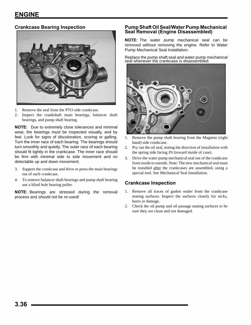
ENGINE
Crankcase Bearing Inspection
1. Remove the seal from the PTO side crankcase.2. Inspect the crankshaft main bearings, balancer shaft
bearings, and pump shaft bearing.
NOTE: Due to extremely close tolerances and minimalwear, the bearings must be inspected visually, and byfeel. Look for signs of discoloration, scoring or galling.Turn the inner race of each bearing. The bearings shouldturn smoothly and quietly. The outer race of each bearingshould fit tightly in the crankcase. The inner race shouldbe firm with minimal side to side movement and nodetectable up and down movement.
3. Support the crankcase and drive or press the main bearingsout of each crankcase.
4. To remove balancer shaft bearings and pump shaft bearinguse a blind hole bearing puller.
NOTE: Bearings are stressed during the removalprocess and should not be re-used!
Pump Shaft Oil Seal/Water Pump Mechanical Seal Removal (Engine Disassembled)NOTE: The water pump mechanical seal can beremoved without removing the engine. Refer to WaterPump Mechanical Seal Installation.
Replace the pump shaft seal and water pump mechanicalseal whenever the crankcase is disassembled.
1. Remove the pump shaft bearing from the Magneto (righthand) side crankcase.
2. Pry out the oil seal, noting the direction of installation withthe spring side facing IN (toward inside of case).
3. Drive the water pump mechanical seal out of the crankcasefrom inside to outside. Note: The new mechanical seal mustbe installed after the crankcases are assembled, using aspecial tool. See Mechanical Seal Installation.
Crankcase Inspection1. Remove all traces of gasket sealer from the crankcase
mating surfaces. Inspect the surfaces closely for nicks,burrs or damage.
2. Check the oil pump and oil passage mating surfaces to besure they are clean and not damaged.
3.36
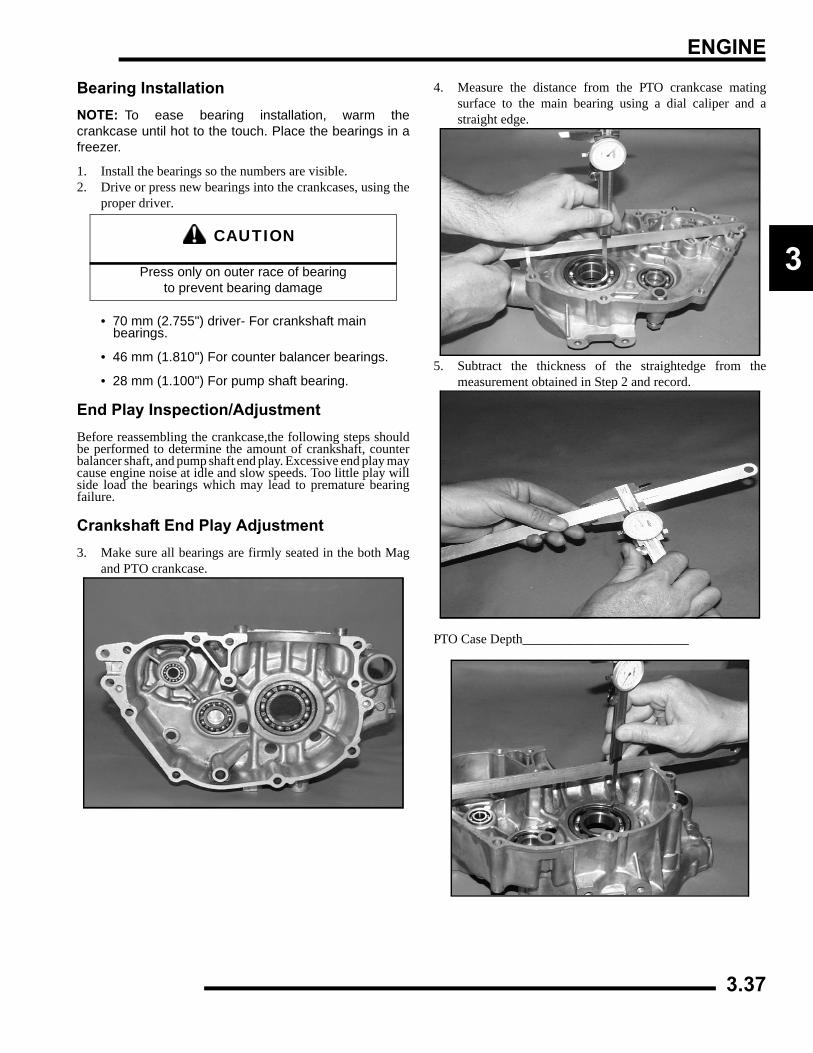
ENGINE
3
Bearing InstallationNOTE: To ease bearing installation, warm thecrankcase until hot to the touch. Place the bearings in afreezer.
1. Install the bearings so the numbers are visible.2. Drive or press new bearings into the crankcases, using the
proper driver.
• 70 mm (2.755") driver- For crankshaft main bearings.
• 46 mm (1.810") For counter balancer bearings.
• 28 mm (1.100") For pump shaft bearing.
End Play Inspection/AdjustmentBefore reassembling the crankcase,the following steps shouldbe performed to determine the amount of crankshaft, counterbalancer shaft, and pump shaft end play. Excessive end play maycause engine noise at idle and slow speeds. Too little play willside load the bearings which may lead to premature bearingfailure.
Crankshaft End Play Adjustment3. Make sure all bearings are firmly seated in the both Mag
and PTO crankcase.
4. Measure the distance from the PTO crankcase matingsurface to the main bearing using a dial caliper and astraight edge.
5. Subtract the thickness of the straightedge from themeasurement obtained in Step 2 and record.
PTO Case Depth_________________________
CAUTION
Press only on outer race of bearing to prevent bearing damage
3.37
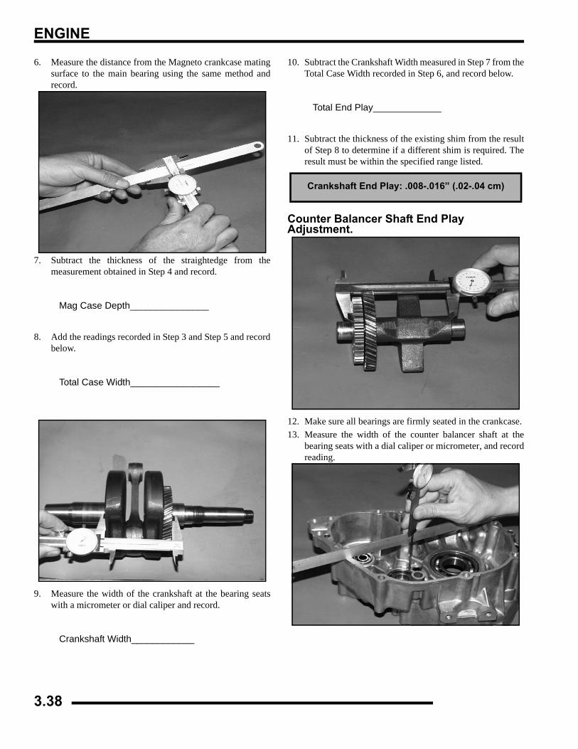
ENGINE
6. Measure the distance from the Magneto crankcase matingsurface to the main bearing using the same method andrecord.
7. Subtract the thickness of the straightedge from themeasurement obtained in Step 4 and record.
Mag Case Depth_______________
8. Add the readings recorded in Step 3 and Step 5 and recordbelow.
Total Case Width_________________
9. Measure the width of the crankshaft at the bearing seatswith a micrometer or dial caliper and record.
Crankshaft Width____________
10. Subtract the Crankshaft Width measured in Step 7 from theTotal Case Width recorded in Step 6, and record below.
Total End Play_____________
11. Subtract the thickness of the existing shim from the resultof Step 8 to determine if a different shim is required. Theresult must be within the specified range listed.
Counter Balancer Shaft End Play Adjustment.
12. Make sure all bearings are firmly seated in the crankcase.13. Measure the width of the counter balancer shaft at the
bearing seats with a dial caliper or micrometer, and recordreading.
Crankshaft End Play: .008-.016” (.02-.04 cm)
3.38
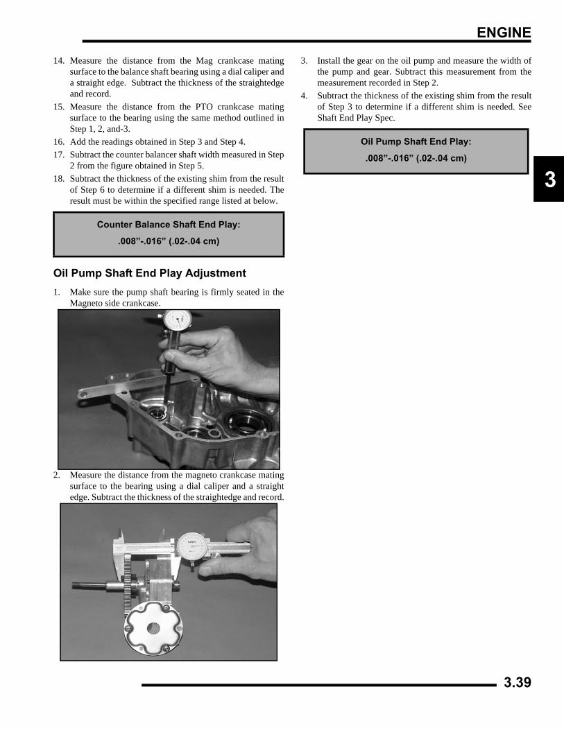
ENGINE
3
14. Measure the distance from the Mag crankcase matingsurface to the balance shaft bearing using a dial caliper anda straight edge. Subtract the thickness of the straightedgeand record.
15. Measure the distance from the PTO crankcase matingsurface to the bearing using the same method outlined inStep 1, 2, and-3.
16. Add the readings obtained in Step 3 and Step 4.17. Subtract the counter balancer shaft width measured in Step
2 from the figure obtained in Step 5.18. Subtract the thickness of the existing shim from the result
of Step 6 to determine if a different shim is needed. Theresult must be within the specified range listed at below.
Oil Pump Shaft End Play Adjustment1. Make sure the pump shaft bearing is firmly seated in the
Magneto side crankcase.
2. Measure the distance from the magneto crankcase matingsurface to the bearing using a dial caliper and a straightedge. Subtract the thickness of the straightedge and record.
3. Install the gear on the oil pump and measure the width ofthe pump and gear. Subtract this measurement from themeasurement recorded in Step 2.
4. Subtract the thickness of the existing shim from the resultof Step 3 to determine if a different shim is needed. SeeShaft End Play Spec.
Counter Balance Shaft End Play:
.008”-.016” (.02-.04 cm)
Oil Pump Shaft End Play:
.008”-.016” (.02-.04 cm)
3.39
ENGINE
ENGINE REASSEMBLYPump Shaft Oil Seal Installation
1. Install the seal from the outside of the crankcase (waterpump side) with the spring facing inward, toward the pumpshaft bearing.
2. Drive or press the seal into place using a 25 mm (.985") sealdriver, until flush with the outer edge of the seal bore.
3. Lubricate the seal lip with grease.
Crankshaft/Counter Balance/Oil Pump Installation
Lubricate all bearings with clean engine oil beforeassembly.
Use the Crankshaft/Water Pump Installation Kit (PN2871283) to prevent damage to the crankshaft and mainbearings during installation.1. Install the crankshaft into the PTO side crankcase. Screw
the threaded rod into the crankshaft until the threads areengaged a minimum of one inch (25.4mm).
2. Install the collar, washer, and nut onto the threaded rod.Hold the crankshaft and tighten the nut to draw thecrankshaft into the main bearings until fully seated. Loosenthe nut and remove the threaded rod from the crankshaft.If removal is difficult, install two nuts on the end of thethreaded rod and tighten against each other.
3. Install the proper shim on the magneto end of thecrankshaft.
4. Place the balancer shaft in the PTO crankcase aligning thetiming marks on the crankshaft and balancer gears. Installthe proper shim washer on the shaft.
5. Inspect the oil pump sealing surface on the crankcase.Apply a light film of engine oil to the surface and install theoil pump.
NOTE: Do not use gasket sealer on the pump matingsurfaces.
NOTE: After engine is assembled and machine isreadied for field operation, oil pump MUST be primed.Follow oil pump priming procedure.
6. Align the drive gear with the drive pin on the pump shaftand install the gear. Be sure the gear is fully seated andproperly engaged.
7. Install the proper shim washer on the pump shaft.
Oil Pump Bolt Torque:
6 ft. lbs. (8 Nm)
3.40
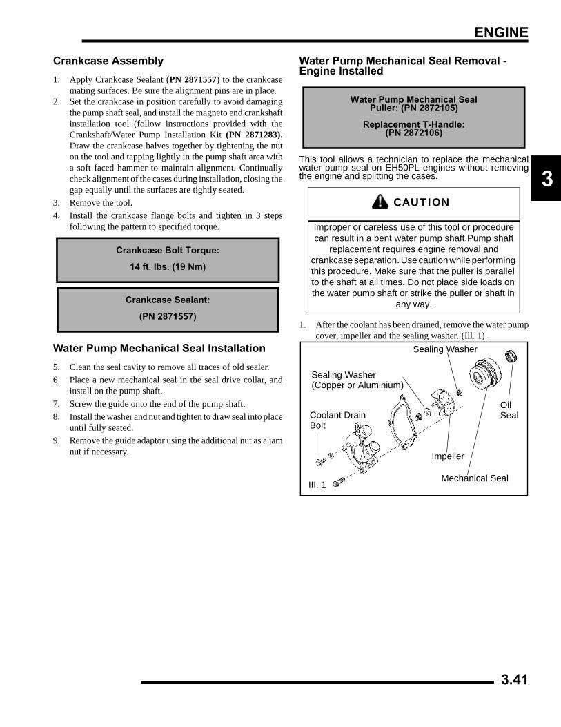
ENGINE
3
Crankcase Assembly1. Apply Crankcase Sealant (PN 2871557) to the crankcase
mating surfaces. Be sure the alignment pins are in place.2. Set the crankcase in position carefully to avoid damaging
the pump shaft seal, and install the magneto end crankshaftinstallation tool (follow instructions provided with theCrankshaft/Water Pump Installation Kit (PN 2871283).Draw the crankcase halves together by tightening the nuton the tool and tapping lightly in the pump shaft area witha soft faced hammer to maintain alignment. Continuallycheck alignment of the cases during installation, closing thegap equally until the surfaces are tightly seated.
3. Remove the tool. 4. Install the crankcase flange bolts and tighten in 3 steps
following the pattern to specified torque.
Water Pump Mechanical Seal Installation5. Clean the seal cavity to remove all traces of old sealer.6. Place a new mechanical seal in the seal drive collar, and
install on the pump shaft.7. Screw the guide onto the end of the pump shaft.8. Install the washer and nut and tighten to draw seal into place
until fully seated.9. Remove the guide adaptor using the additional nut as a jam
nut if necessary.
Water Pump Mechanical Seal Removal - Engine Installed
This tool allows a technician to replace the mechanicalwater pump seal on EH50PL engines without removingthe engine and splitting the cases.
1. After the coolant has been drained, remove the water pumpcover, impeller and the sealing washer. (Ill. 1).
Crankcase Bolt Torque:
14 ft. lbs. (19 Nm)
Crankcase Sealant:
(PN 2871557)
Water Pump Mechanical SealPuller: (PN 2872105)
Replacement T-Handle:(PN 2872106)
CAUTION
Improper or careless use of this tool or procedure can result in a bent water pump shaft.Pump shaft
replacement requires engine removal and crankcase separation. Use caution while performing this procedure. Make sure that the puller is parallel to the shaft at all times. Do not place side loads on the water pump shaft or strike the puller or shaft in
any way.
Sealing Washer
Sealing Washer(Copper or Aluminium)
Coolant DrainBolt
Impeller
Mechanical SealIII. 1
OilSeal
3.41
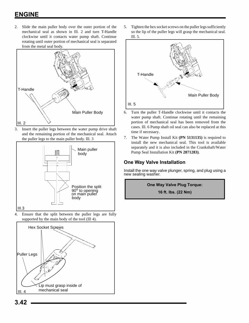
ENGINE
2. Slide the main puller body over the outer portion of themechanical seal as shown in Ill. 2 and turn T-Handleclockwise until it contacts water pump shaft. Continuerotating until outer portion of mechanical seal is separatedfrom the metal seal body.
3. Insert the puller legs between the water pump drive shaftand the remaining portion of the mechanical seal. Attachthe puller legs to the main puller body. Ill. 3
4. Ensure that the split between the puller legs are fullysupported by the main body of the tool (Ill 4).
5. Tighten the hex socket screws on the puller legs sufficientlyso the lip of the puller legs will grasp the mechanical seal.Ill. 5.
6. Turn the puller T-Handle clockwise until it contacts thewater pump shaft. Continue rotating until the remainingportion of mechanical seal has been removed from thecases. Ill. 6 Pump shaft oil seal can also be replaced at thistime if necessary.
7. The Water Pump Install Kit (PN 5131135) is required toinstall the new mechanical seal. This tool is availableseparately and it is also included in the Crankshaft/WaterPump Seal Installation Kit (PN 2871283).
One Way Valve InstallationInstall the one way valve plunger, spring, and plug using anew sealing washer.
III. 2
Main Puller Body
T-Handle
III.3
Position the split90o to openingon main pullerbody
Main pullerbody
Hex Socket Screws
Puller Legs
Lip must grasp inside of mechanical sealIII. 4
One Way Valve Plug Torque:
16 ft. lbs. (22 Nm)
III. 5
T-Handle
Main Puller Body
3.42
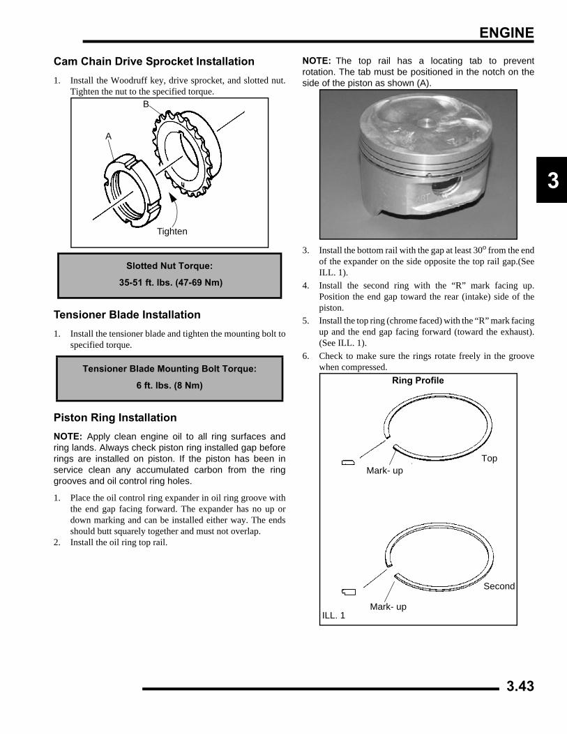
ENGINE
3
Cam Chain Drive Sprocket Installation1. Install the Woodruff key, drive sprocket, and slotted nut.
Tighten the nut to the specified torque.
Tensioner Blade Installation1. Install the tensioner blade and tighten the mounting bolt to
specified torque.
Piston Ring InstallationNOTE: Apply clean engine oil to all ring surfaces andring lands. Always check piston ring installed gap beforerings are installed on piston. If the piston has been inservice clean any accumulated carbon from the ringgrooves and oil control ring holes.
1. Place the oil control ring expander in oil ring groove withthe end gap facing forward. The expander has no up ordown marking and can be installed either way. The endsshould butt squarely together and must not overlap.
2. Install the oil ring top rail.
NOTE: The top rail has a locating tab to preventrotation. The tab must be positioned in the notch on theside of the piston as shown (A).
3. Install the bottom rail with the gap at least 30o from the endof the expander on the side opposite the top rail gap.(SeeILL. 1).
4. Install the second ring with the “R” mark facing up.Position the end gap toward the rear (intake) side of thepiston.
5. Install the top ring (chrome faced) with the “R” mark facingup and the end gap facing forward (toward the exhaust).(See ILL. 1).
6. Check to make sure the rings rotate freely in the groovewhen compressed.
Slotted Nut Torque:
35-51 ft. lbs. (47-69 Nm)
Tensioner Blade Mounting Bolt Torque:
6 ft. lbs. (8 Nm)
Tighten
A
B
Ring Profile
Top
Mark- up
Second
Mark- up
ILL. 1
3.43
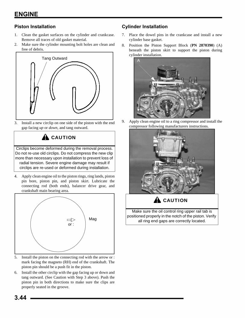
ENGINE
Piston Installation1. Clean the gasket surfaces on the cylinder and crankcase.
Remove all traces of old gasket material.2. Make sure the cylinder mounting bolt holes are clean and
free of debris.
3. Install a new circlip on one side of the piston with the endgap facing up or down, and tang outward.
4. Apply clean engine oil to the piston rings, ring lands, pistonpin bore, piston pin, and piston skirt. Lubricate theconnecting rod (both ends), balancer drive gear, andcrankshaft main bearing area.
5. Install the piston on the connecting rod with the arrow or :mark facing the magneto (RH) end of the crankshaft. Thepiston pin should be a push fit in the piston.
6. Install the other circlip with the gap facing up or down andtang outward. (See Caution with Step 3 above). Push thepiston pin in both directions to make sure the clips areproperly seated in the groove.
Cylinder Installation7. Place the dowel pins in the crankcase and install a new
cylinder base gasket.8. Position the Piston Support Block (PN 2870390) (A)
beneath the piston skirt to support the piston duringcylinder installation.
9. Apply clean engine oil to a ring compressor and install thecompressor following manufacturers instructions.
CAUTION
Circlips become deformed during the removal process. Do not re-use old circlips. Do not compress the new clip more than necessary upon installation to prevent loss of
radial tension. Severe engine damage may result if circlips are re-used or deformed during installation.
Tang Outward
or :Mag
CAUTION
Make sure the oil control ring upper rail tab is positioned properly in the notch of the piston. Verify
all ring end gaps are correctly located.
A
3.44
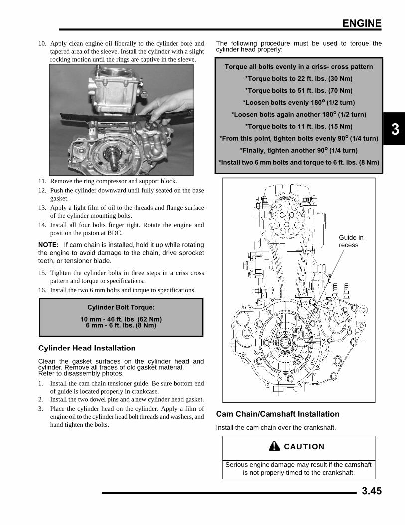
ENGINE
3
10. Apply clean engine oil liberally to the cylinder bore andtapered area of the sleeve. Install the cylinder with a slightrocking motion until the rings are captive in the sleeve.
11. Remove the ring compressor and support block.12. Push the cylinder downward until fully seated on the base
gasket.13. Apply a light film of oil to the threads and flange surface
of the cylinder mounting bolts.14. Install all four bolts finger tight. Rotate the engine and
position the piston at BDC.
NOTE: If cam chain is installed, hold it up while rotatingthe engine to avoid damage to the chain, drive sprocketteeth, or tensioner blade.
15. Tighten the cylinder bolts in three steps in a criss crosspattern and torque to specifications.
16. Install the two 6 mm bolts and torque to specifications.
Cylinder Head InstallationClean the gasket surfaces on the cylinder head andcylinder. Remove all traces of old gasket material.Refer to disassembly photos.1. Install the cam chain tensioner guide. Be sure bottom end
of guide is located properly in crankcase.2. Install the two dowel pins and a new cylinder head gasket.3. Place the cylinder head on the cylinder. Apply a film of
engine oil to the cylinder head bolt threads and washers, andhand tighten the bolts.
The following procedure must be used to torque thecylinder head properly:
Cam Chain/Camshaft InstallationInstall the cam chain over the crankshaft.
Cylinder Bolt Torque:
10 mm - 46 ft. lbs. (62 Nm)6 mm - 6 ft. lbs. (8 Nm)
Torque all bolts evenly in a criss- cross pattern
*Torque bolts to 22 ft. lbs. (30 Nm)
*Torque bolts to 51 ft. lbs. (70 Nm)
*Loosen bolts evenly 180o (1/2 turn)
*Loosen bolts again another 180o (1/2 turn)
*Torque bolts to 11 ft. lbs. (15 Nm)
*From this point, tighten bolts evenly 90o (1/4 turn)
*Finally, tighten another 90o (1/4 turn)
*Install two 6 mm bolts and torque to 6 ft. lbs. (8 Nm)
CAUTION
Serious engine damage may result if the camshaft is not properly timed to the crankshaft.
Guide inrecess
3.45
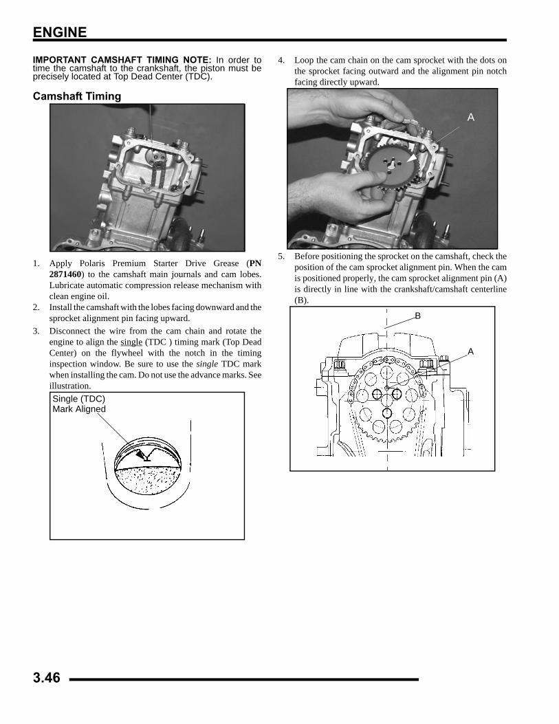
ENGINE
IMPORTANT CAMSHAFT TIMING NOTE: In order totime the camshaft to the crankshaft, the piston must beprecisely located at Top Dead Center (TDC).
Camshaft Timing
1. Apply Polaris Premium Starter Drive Grease (PN2871460) to the camshaft main journals and cam lobes.Lubricate automatic compression release mechanism withclean engine oil.
2. Install the camshaft with the lobes facing downward and thesprocket alignment pin facing upward.
3. Disconnect the wire from the cam chain and rotate theengine to align the single (TDC ) timing mark (Top DeadCenter) on the flywheel with the notch in the timinginspection window. Be sure to use the single TDC markwhen installing the cam. Do not use the advance marks. Seeillustration.
4. Loop the cam chain on the cam sprocket with the dots onthe sprocket facing outward and the alignment pin notchfacing directly upward.
5. Before positioning the sprocket on the camshaft, check theposition of the cam sprocket alignment pin. When the camis positioned properly, the cam sprocket alignment pin (A)is directly in line with the crankshaft/camshaft centerline(B).
Single (TDC)Mark Aligned
A
A
B
3.46
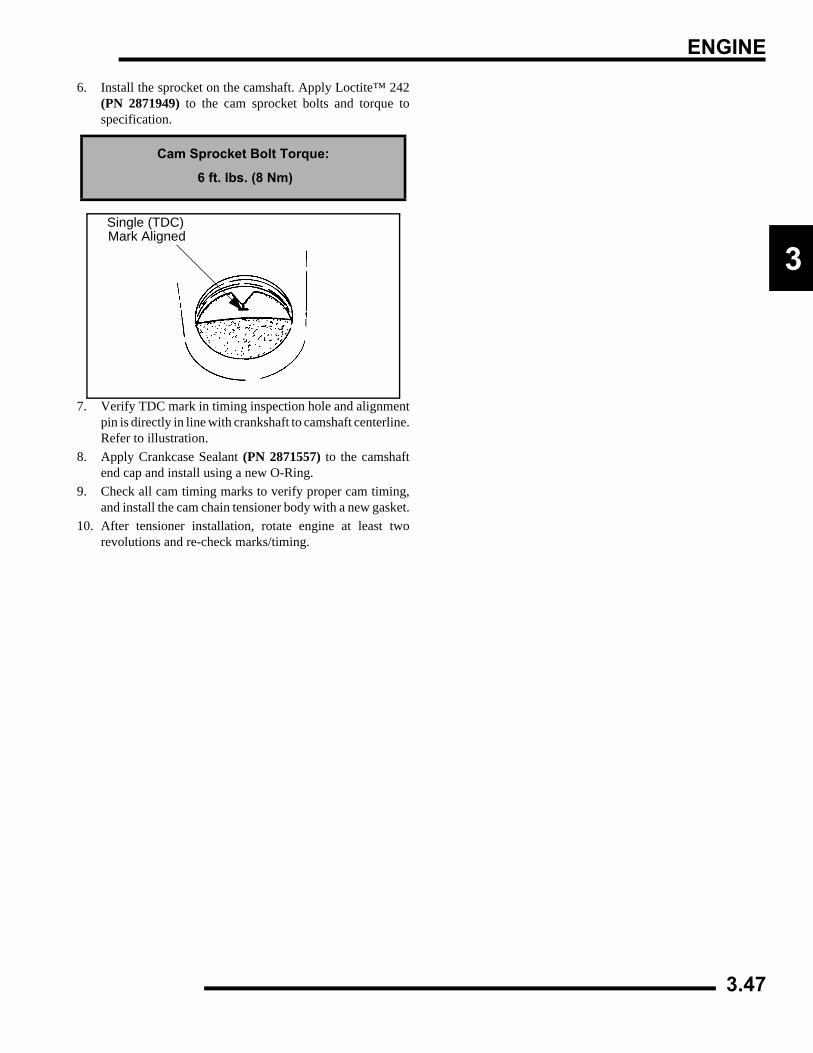
ENGINE
3
6. Install the sprocket on the camshaft. Apply Loctite™ 242(PN 2871949) to the cam sprocket bolts and torque tospecification.
7. Verify TDC mark in timing inspection hole and alignmentpin is directly in line with crankshaft to camshaft centerline.Refer to illustration.
8. Apply Crankcase Sealant (PN 2871557) to the camshaftend cap and install using a new O-Ring.
9. Check all cam timing marks to verify proper cam timing,and install the cam chain tensioner body with a new gasket.
10. After tensioner installation, rotate engine at least tworevolutions and re-check marks/timing.
Cam Sprocket Bolt Torque:
6 ft. lbs. (8 Nm)
Mark AlignedSingle (TDC)
3.47
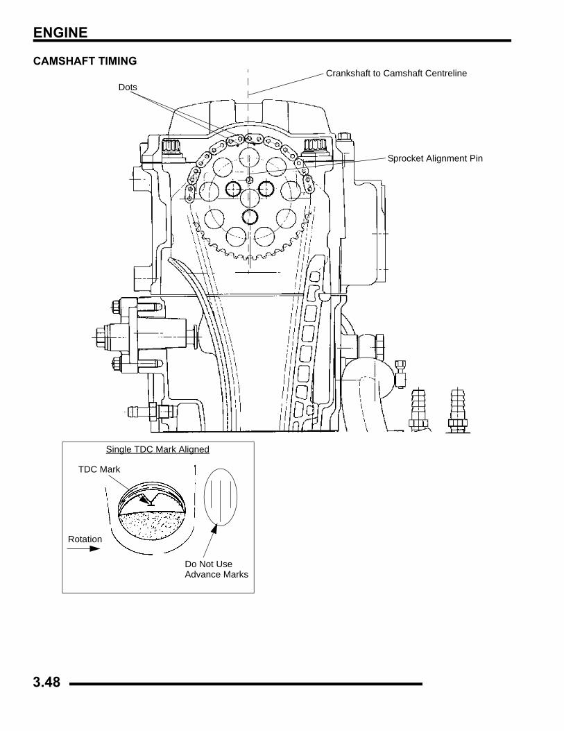
ENGINE
CAMSHAFT TIMING
DotsCrankshaft to Camshaft Centreline
Sprocket Alignment Pin
Single TDC Mark Aligned
TDC Mark
Rotation
Do Not Use Advance Marks
3.48
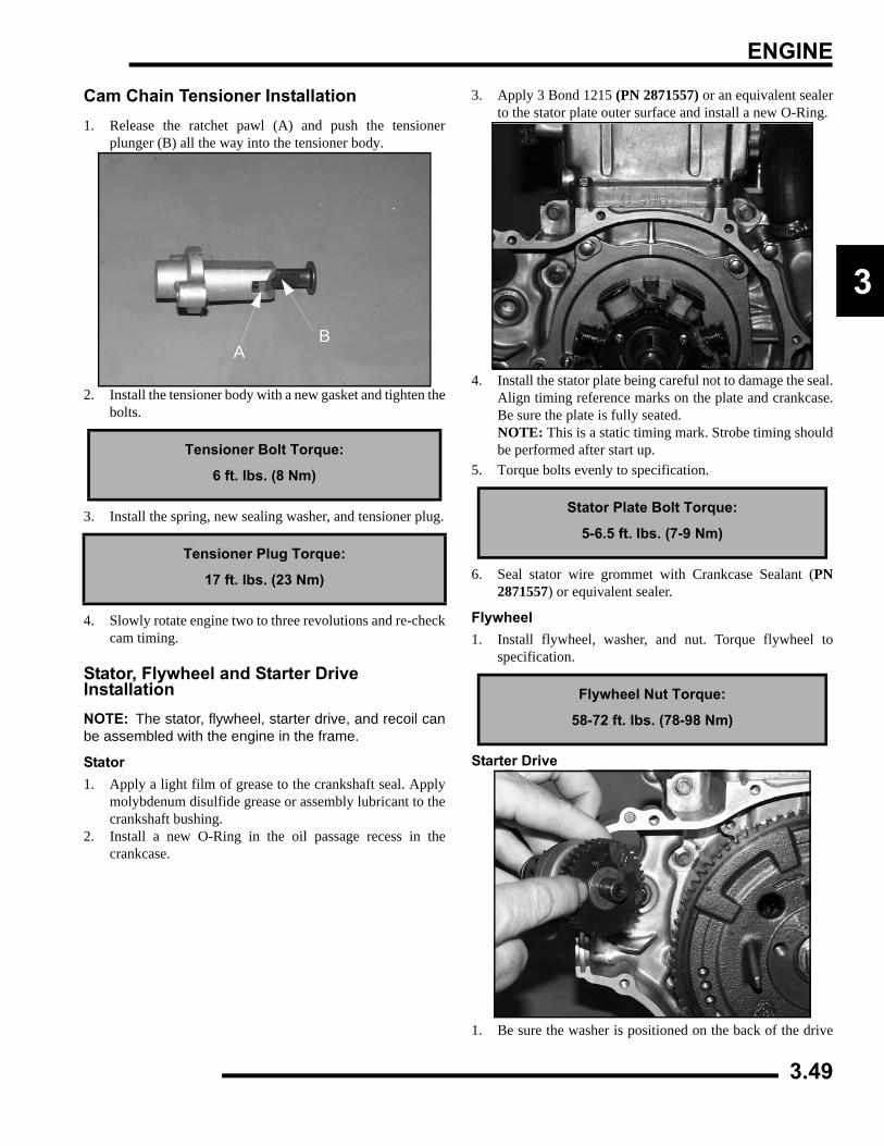
ENGINE
3
Cam Chain Tensioner Installation1. Release the ratchet pawl (A) and push the tensioner
plunger (B) all the way into the tensioner body.
2. Install the tensioner body with a new gasket and tighten thebolts.
3. Install the spring, new sealing washer, and tensioner plug.
4. Slowly rotate engine two to three revolutions and re-checkcam timing.
Stator, Flywheel and Starter Drive InstallationNOTE: The stator, flywheel, starter drive, and recoil canbe assembled with the engine in the frame.
Stator1. Apply a light film of grease to the crankshaft seal. Apply
molybdenum disulfide grease or assembly lubricant to thecrankshaft bushing.
2. Install a new O-Ring in the oil passage recess in thecrankcase.
3. Apply 3 Bond 1215 (PN 2871557) or an equivalent sealerto the stator plate outer surface and install a new O-Ring.
4. Install the stator plate being careful not to damage the seal.Align timing reference marks on the plate and crankcase.Be sure the plate is fully seated.NOTE: This is a static timing mark. Strobe timing shouldbe performed after start up.
5. Torque bolts evenly to specification.
6. Seal stator wire grommet with Crankcase Sealant (PN2871557) or equivalent sealer.
Flywheel1. Install flywheel, washer, and nut. Torque flywheel to
specification.
Starter Drive
1. Be sure the washer is positioned on the back of the drive
Tensioner Bolt Torque:
6 ft. lbs. (8 Nm)
Tensioner Plug Torque:
17 ft. lbs. (23 Nm)
AB
Stator Plate Bolt Torque:
5-6.5 ft. lbs. (7-9 Nm)
Flywheel Nut Torque:
58-72 ft. lbs. (78-98 Nm)
3.49
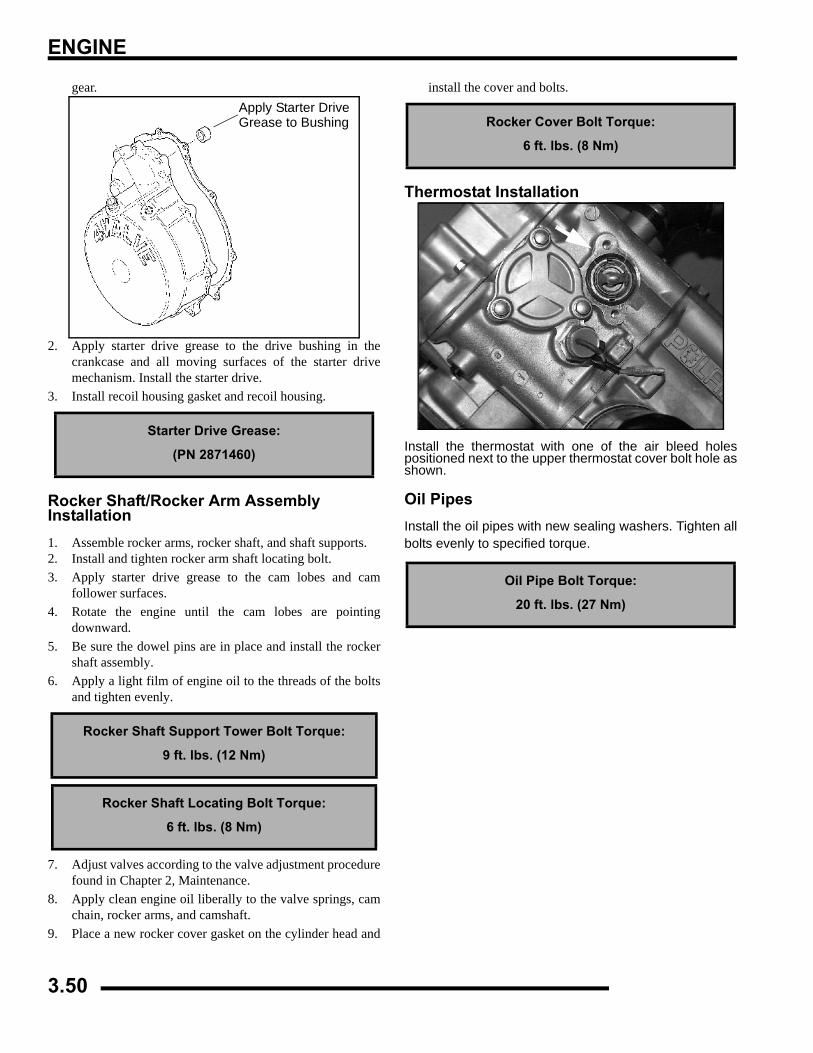
ENGINE
gear.
2. Apply starter drive grease to the drive bushing in thecrankcase and all moving surfaces of the starter drivemechanism. Install the starter drive.
3. Install recoil housing gasket and recoil housing.
Rocker Shaft/Rocker Arm Assembly Installation1. Assemble rocker arms, rocker shaft, and shaft supports.2. Install and tighten rocker arm shaft locating bolt.3. Apply starter drive grease to the cam lobes and cam
follower surfaces.4. Rotate the engine until the cam lobes are pointing
downward.5. Be sure the dowel pins are in place and install the rocker
shaft assembly.6. Apply a light film of engine oil to the threads of the bolts
and tighten evenly.
7. Adjust valves according to the valve adjustment procedurefound in Chapter 2, Maintenance.
8. Apply clean engine oil liberally to the valve springs, camchain, rocker arms, and camshaft.
9. Place a new rocker cover gasket on the cylinder head and
install the cover and bolts.
Thermostat Installation
Install the thermostat with one of the air bleed holespositioned next to the upper thermostat cover bolt hole asshown.
Oil PipesInstall the oil pipes with new sealing washers. Tighten allbolts evenly to specified torque.
Starter Drive Grease:
(PN 2871460)
Rocker Shaft Support Tower Bolt Torque:
9 ft. lbs. (12 Nm)
Rocker Shaft Locating Bolt Torque:
6 ft. lbs. (8 Nm)
Apply Starter Drive
Grease to Bushing Rocker Cover Bolt Torque:
6 ft. lbs. (8 Nm)
Oil Pipe Bolt Torque:
20 ft. lbs. (27 Nm)
3.50
ENGINE
3
RECOILRecoil Disassembly/Inspection
Replace any parts found to be worn or damaged.
1. Remove bolts and recoil from the engine.2. Pull recoil rope (if applicable) so it is extended
approximately 12-18" (30-46cm). Check handle c-ring forproper tension, and the handle for cracks or damage whichmay allow water or dirt to enter the recoil housing throughthe rope.
3. Remove handle from the rope and allow spring tension onrecoil to relax.
NOTE: The handle must seal tightly on the recoilhousing to prevent water from entering.
4. Remove center bolt from recoil friction plate (A).
5. Inspect plate for wear or damage. Inspect plate frictionspring for wear, damage, and proper tension. The springshould fit tightly on friction plate.
6. Remove ratchet pawl with spring and inspect. Replacespring or ratchet pawl if worn, broken, or damaged.
NOTE: Long arm of spring engages reel. Short endagainst pawl.
7. Hold reel firmly in housing. Pull rope handle until 12-18"(30-46cm) of rope is exposed, and hold reel in place.
8. Place rope in notch on outer edge of reel. Release tensionon hub and allow reel to unwind approximately 6-7 turnsuntil spring tension is released.
9. Slowly and carefully remove reel from recoil housingmaking sure the spring remains in the housing. Inspect thereel hub and bushing (A) for wear.
10. Unwind rope and inspect for cuts or abrasions.11. Inspect drive tab on hub return spring for damage. To
remove hub return spring, hold outer coils in place with onehand and slowly remove spring one coil at a time from theinside out.
12. Pull knot out of recoil reel. Untie knot. Remove rope fromreel.
CAUTION
The recoil is under spring tension. A face shield and eye protection is required during this procedure.
A
A
3.51
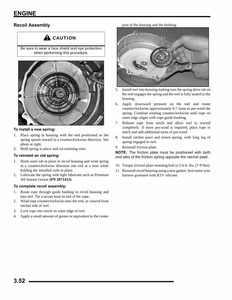
ENGINE
Recoil Assembly
To install a new spring:1. Place spring in housing with the end positioned so the
spring spirals inward in a counterclockwise direction. Seephoto at right.
2. Hold spring in place and cut retaining wire.
To reinstall an old spring:1. Hook outer tab in place in recoil housing and wind spring
in a counterclockwise direction one coil at a time whileholding the installed coils in place.
2. Lubricate the spring with light lubricant such as PremiumAll Season Grease (PN 2871423).
To complete recoil assembly:1. Route rope through guide bushing in recoil housing and
into reel. Tie a secure knot in end of the rope.2. Wind rope counterclockwise onto the reel, as viewed from
ratchet side of reel.3. Lock rope into notch on outer edge of reel.4. Apply a small amount of grease or equivalent to the center
post of the housing and the bushing.
5. Install reel into housing making sure the spring drive tab onthe reel engages the spring and the reel is fully seated in thehousing.
6. Apply downward pressure on the reel and rotatecounterclockwise approximately 6-7 turns to pre-wind thespring. Continue rotating counterclockwise until rope onouter edge aligns with rope guide bushing.
7. Release rope from notch and allow reel to rewindcompletely. If more pre-wind is required, place rope innotch and add additional turns of pre-wind.
8. Install ratchet pawl and return spring, with long leg ofspring engaged in reel.
9. Reinstall friction plate.NOTE: The friction plate must be positioned with bothend tabs of the friction spring opposite the ratchet pawl.
10. Torque friction plate retaining bolt to 5-6 ft. lbs. (7-9 Nm).11. Reinstall recoil housing using a new gasket. Seal stator wire
harness grommet with RTV silicone.
CAUTION
Be sure to wear a face shield and eye protection when performing this procedure.
3.52
ENGINE
3
TROUBLESHOOTINGSpark Plug Fouling
• Spark plug cap loose or faulty
• Choke cable adjustment or plunger/cable sticking
• Foreign material on choke plunger seat or plunger
• Incorrect spark plug heat range or gap
• Carburetor inlet needle and seat worn
• Jet needle and/or needle jet worn or improperlyadjusted
• Excessive carburetor vibration (loose or missingneedle jet locating pins)
• Loose jets in carburetor or calibration incorrect foraltitude/temperature
• Incorrect float level setting
• PVT system calibrated incorrectly or componentsworn or mis-adjusted
• Fuel quality poor (old) or octane too high
• Low compression
• Restricted exhaust
• Weak ignition (loose coil ground, faulty coil, stator,or ETC switch)
• ETC switch mis-adjusted
• Restricted air filter (main or pre-cleaner) orbreather system
• Improperly assembled air intake system
• Restricted engine breather system
• Oil contaminated with fuel
• Restricted oil tank vent
EngineEngine Turns Over But Fails to Start
• No fuel
• Dirt in fuel line or filter
• Fuel will not pass through fuel valve
• Fuel pump inoperative/restricted
• Tank vent plugged
• Carb starter circuit
• Engine flooded
• Low compression (high cylinder leakage)
• No spark (Spark plug fouled)
Engine Does Not Turn Over
• Dead battery
• Starter motor does not turn
• Engine seized, rusted, or mechanical failure
Engine Runs But Will Not Idle
• Restricted carburetor pilot system
• Carburetor misadjusted
• Choke not adjusted properly
• Low compression
• Crankcase breather restricted
Engine Idles But Will Not Rev Up
• Spark plug fouled/weak spark
• Broken throttle cable
• Obstruction in air intake
• Air box removed (reinstall all intake components)
• Incorrect or restricted carburetor jetting
• ETC switch limiting speed
• Reverse speed limiter limiting speed
• Carburetor vacuum slide sticking/diaphragmdamaged
• Incorrect ignition timing
• Restricted exhaust system
3.53
ENGINE
Engine Has Low Power
• Spark plug fouled
• Cylinder, piston, ring, or valve wear or damage(check compression)
• PVT not operating properly
• Restricted exhaust muffler
• Carburetor vacuum slide sticking/diaphragmdamaged
• Dirty carburetor
Piston Failure - Scoring
• Lack of lubrication
• Dirt entering engine through cracks in air filter orducts
• Engine oil dirty or contaminated
Excessive Smoke and Carbon Buildup
• Excessive piston-to-cylinder clearance
• Wet sumping
• Worn rings, piston, or cylinder
• Worn valve guides or seals
• Restricted breather
• Air filter dirty or contaminated
Low Compression
• Decompressor stuck
• Cylinder head gasket leak
• No valve clearance or incorrectly adjusted
• Cylinder or piston worn
• Piston rings worn, leaking, broken, or sticking
• Bent valve or stuck valve
• Valve spring broken or weak
• Valve not seating properly (bent or carbonaccumulated on sealing surface)
• Rocker arm sticking
Backfiring
• ETC or speed limiter system malfunction
• Fouled spark plug or incorrect plug or plug gap
• Carburetion faulty - lean condition
• Exhaust system air leaks
• Ignition system faulty:Spark plug cap cracked/brokenIgnition coil faultyIgnition or kill switch circuit faultyIgnition timing incorrectSheared flywheel key
• Poor connections in ignition system
• System wiring wet
• Valve sticking
• Air leaks in intake
• Lean condition
Cooling System Overheating
• Low coolant level
• Air in cooling system
• Wrong type of coolant
• Faulty pressure cap or system leaks
• Restricted system (mud or debris in radiator fins orrestriction to air flow, passages blocked in radiator,lines, pump, or water jacket)
• Lean mixture (restricted jets, vents, fuel pump orfuel valve)
• Fuel pump output weak
• Restricted radiator (internally or cooling fins)
• Water pump failure
• Cooling system restriction
• Cooling fan inoperative or turning too slowly(perform current draw test)
• Ignition timing misadjusted
• Low oil level
• Spark plug incorrect heat range
• Faulty hot light circuit
• Thermostat stuck closed or not openingcompletely
• Possible loose or missing diverter inside radiator
Temperature Too Low
• Thermostat stuck open
Leak at Water Pump Weep Hole
• Faulty water pump mechanical seal (coolant leak)
• Faulty pump shaft oil seal (oil leak)
3.54
FUEL SYSTEM
4.1
CHAPTER 4FUEL SYSTEM
4
ELECTRONIC FUEL INJECTION . . . . . . . . . . . . . . . . . . . . . . . . . . . . . . . . 4.3 - 4.30CARBURETOR (SPORTSMAN 500) . . . . . . . . . . . . . . . . . . . . . . . . . . . . . 4.31 - 4.47

FUEL SYSTEM
4.2
FUEL INJECTION
4.3
CHAPTER 4FUEL INJECTION
4
SPECIAL TOOLS . . . . . . . . . . . . . . . . . . . . . . . . . . . . . . . . . . . . . . . . . . . . . . . . . . . . . . . 4.4PART NUMBERS / DESCRIPTIONS . . . . . . . . . . . . . . . . . . . . . . . . . . . . . . . . . . . . . . . . 4.4
EFI SERVICE NOTES . . . . . . . . . . . . . . . . . . . . . . . . . . . . . . . . . . . . . . . . . . . . . . . . . . . . 4.6EFI SYSTEM EXPLODED VIEW. . . . . . . . . . . . . . . . . . . . . . . . . . . . . . . . . . . . . . . . . . . . 4.7EFI SYSTEM . . . . . . . . . . . . . . . . . . . . . . . . . . . . . . . . . . . . . . . . . . . . . . . . . . . . . . . . . . . 4.8
COMPONENT LOCATIONS/IDENTIFICATION . . . . . . . . . . . . . . . . . . . . . . . . . . . . . . . . 4.8FUEL TANK . . . . . . . . . . . . . . . . . . . . . . . . . . . . . . . . . . . . . . . . . . . . . . . . . . . . . . . . . . . . 4.9
EXPLODED VIEW . . . . . . . . . . . . . . . . . . . . . . . . . . . . . . . . . . . . . . . . . . . . . . . . . . . . . . 4.9ELECTRONIC FUEL INJECTION . . . . . . . . . . . . . . . . . . . . . . . . . . . . . . . . . . . . . . . . . . . 4.9
EFI OPERATION OVERVIEW . . . . . . . . . . . . . . . . . . . . . . . . . . . . . . . . . . . . . . . . . . . . . 4.9INITIAL PRIMING / STARTING PROCEDURE . . . . . . . . . . . . . . . . . . . . . . . . . . . . . . . 4.10
FUEL LINES . . . . . . . . . . . . . . . . . . . . . . . . . . . . . . . . . . . . . . . . . . . . . . . . . . . . . . . . . . 4.10QUICK CONNECT REMOVAL/INSTALLATION. . . . . . . . . . . . . . . . . . . . . . . . . . . . . . . 4.10
ELECTRONIC CONTROL UNIT (ECU). . . . . . . . . . . . . . . . . . . . . . . . . . . . . . . . . . . . . . 4.11OPERATION OVERVIEW . . . . . . . . . . . . . . . . . . . . . . . . . . . . . . . . . . . . . . . . . . . . . . . 4.11ECU REPLACEMENT . . . . . . . . . . . . . . . . . . . . . . . . . . . . . . . . . . . . . . . . . . . . . . . . . . 4.11ECU SERVICE . . . . . . . . . . . . . . . . . . . . . . . . . . . . . . . . . . . . . . . . . . . . . . . . . . . . . . . . 4.11
FUEL PUMP ASSEMBLY . . . . . . . . . . . . . . . . . . . . . . . . . . . . . . . . . . . . . . . . . . . . . . . . 4.12OPERATION / TESTING . . . . . . . . . . . . . . . . . . . . . . . . . . . . . . . . . . . . . . . . . . . . . . . . 4.12FUEL PUMP TEST . . . . . . . . . . . . . . . . . . . . . . . . . . . . . . . . . . . . . . . . . . . . . . . . . . . . . 4.12FUEL PUMP / TANK ASSEMBLY REPLACEMENT . . . . . . . . . . . . . . . . . . . . . . . . . . . 4.13
FUEL PRESSURE REGULATOR . . . . . . . . . . . . . . . . . . . . . . . . . . . . . . . . . . . . . . . . . . 4.14FUEL FILTER . . . . . . . . . . . . . . . . . . . . . . . . . . . . . . . . . . . . . . . . . . . . . . . . . . . . . . . . . 4.14FUEL INJECTOR. . . . . . . . . . . . . . . . . . . . . . . . . . . . . . . . . . . . . . . . . . . . . . . . . . . . . . . 4.15CRANKSHAFT POSITION SENSOR (CPS) . . . . . . . . . . . . . . . . . . . . . . . . . . . . . . . . . . 4.16MANIFOLD AIR PRESSURE SENSOR (MAP) . . . . . . . . . . . . . . . . . . . . . . . . . . . . . . . . 4.17
OPERATION OVERVIEW . . . . . . . . . . . . . . . . . . . . . . . . . . . . . . . . . . . . . . . . . . . . . . . 4.17MAP SENSOR TEST . . . . . . . . . . . . . . . . . . . . . . . . . . . . . . . . . . . . . . . . . . . . . . . . . . . 4.17MAP SENSOR REPLACEMENT . . . . . . . . . . . . . . . . . . . . . . . . . . . . . . . . . . . . . . . . . . 4.17
INTAKE AIR TEMPERATURE SENSOR (IAT) . . . . . . . . . . . . . . . . . . . . . . . . . . . . . . . . 4.17OPERATION OVERVIEW . . . . . . . . . . . . . . . . . . . . . . . . . . . . . . . . . . . . . . . . . . . . . . . 4.17INTAKE AIR TEMPERATURE SENSOR TEST . . . . . . . . . . . . . . . . . . . . . . . . . . . . . . . 4.17INTAKE AIR TEMPERATURE SENSOR REPLACEMENT . . . . . . . . . . . . . . . . . . . . . . 4.17
IDLE AIR CONTROL (IAC) . . . . . . . . . . . . . . . . . . . . . . . . . . . . . . . . . . . . . . . . . . . . . . . 4.18THROTTLE POSITION SENSOR (TPS) . . . . . . . . . . . . . . . . . . . . . . . . . . . . . . . . . . . . . 4.18
OPERATION OVERVIEW . . . . . . . . . . . . . . . . . . . . . . . . . . . . . . . . . . . . . . . . . . . . . . . 4.18THROTTLE POSITION SENSOR TEST . . . . . . . . . . . . . . . . . . . . . . . . . . . . . . . . . . . . 4.18THROTTLE POSITION SENSOR REPLACEMENT. . . . . . . . . . . . . . . . . . . . . . . . . . . . 4.19THROTTLE POSITION SENSOR (TPS) INITIALIZATION. . . . . . . . . . . . . . . . . . . . . . . 4.20
ENGINE TEMPERATURE SENSOR. . . . . . . . . . . . . . . . . . . . . . . . . . . . . . . . . . . . . . . . 4.20ENGINE TEMPERATURE SENSOR TEST . . . . . . . . . . . . . . . . . . . . . . . . . . . . . . . . . . 4.21ENGINE TEMPERATURE SENSOR REPLACEMENT . . . . . . . . . . . . . . . . . . . . . . . . . 4.21
FUEL SYSTEM TROUBLESHOOTING. . . . . . . . . . . . . . . . . . . . . . . . . . . . . . . . . . . . . . 4.21FUEL STARVATION / LEAN MIXTURE . . . . . . . . . . . . . . . . . . . . . . . . . . . . . . . . . . . . . 4.21
EFI DIAGNOSTICS USING ‘BLINK CODES’ . . . . . . . . . . . . . . . . . . . . . . . . . . . . . . . . . 4.23BLINK CODES - OPERATION . . . . . . . . . . . . . . . . . . . . . . . . . . . . . . . . . . . . . . . . . . . 4.23
TROUBLESHOOTING DIAGRAMS. . . . . . . . . . . . . . . . . . . . . . . . . . . . . . . . . . . . . . . . . 4.24EFI CIRCUIT - POWER ON . . . . . . . . . . . . . . . . . . . . . . . . . . . . . . . . . . . . . . . . . . . . . . 4.24EFI CIRCUIT - CRANK POSITION SENSOR. . . . . . . . . . . . . . . . . . . . . . . . . . . . . . . . . 4.24EFI CIRCUIT - FUEL PUMP. . . . . . . . . . . . . . . . . . . . . . . . . . . . . . . . . . . . . . . . . . . . . . 4.25EFI CIRCUIT - IGNITION COIL . . . . . . . . . . . . . . . . . . . . . . . . . . . . . . . . . . . . . . . . . . . 4.25EFI CIRCUIT - IDLE AIR CONTROL . . . . . . . . . . . . . . . . . . . . . . . . . . . . . . . . . . . . . . . 4.26EFI CIRCUIT - THROTTLE POSITION SENSOR . . . . . . . . . . . . . . . . . . . . . . . . . . . . . 4.26EFI CIRCUIT - MANIFOLD ABSOLUTE PRESSURE SENSOR . . . . . . . . . . . . . . . . . . 4.27EFI CIRCUIT - ENGINE COOLANT TEMPERATURE . . . . . . . . . . . . . . . . . . . . . . . . . . 4.27EFI CIRCUIT - AIR TEMPERATURE SENSOR . . . . . . . . . . . . . . . . . . . . . . . . . . . . . . . 4.28EFI CIRCUIT - MALFUNCTION INDICATOR LIGHT . . . . . . . . . . . . . . . . . . . . . . . . . . . 4.28
FUEL INJECTION
SPECIAL TOOLSPart Numbers / Descriptions
Fuel Pressure Tester - PU-43506IMPORTANT: The EFI fuel system remains under highpressure, even when the engine is not running.Before attempting to service any part of the fuelsystem, the pressure must be relieved. The pressureadapter has an integrated relief valve. Connect to thetest valve and release the pressure.
Fuel Pressure Test Valve - PU-47476
Polaris EFI Diagnostic Software Digital Wrench™ - PU-47063This dealer-only software installs on laptop computers equippedwith a CD drive and serial port connection, and is designed toreplace multiple shop tools often used to test EFI components.It also includes step-by-step diagnostic procedures to aidtechnician repair and troubleshooting.
Table 4-1: PART NUMBER TOOL DESCRIPTION
PU-47063Polaris EFI Diagnostic
Software (Digital Wrench™)
PU-43506 Fuel PressureTest Kit
PU-47476 Fuel PressureTest Valve Kit
2201519 Throttle Position Sensor Tester
PU-47471 Digital Wrench™ SmartLink Kit
WARNING
• Gasoline is extremely flammable and explosiveunder certain conditions.• EFI components are under high pressure. Verifysystem pressure has been relieved beforedisassembly.• Never drain the fuel system when the engine ishot. Severe burns may result. • Do not overfill the tank. The tank is at full capacitywhen the fuel reaches the bottom of the filler neck.Leave room for expansion of fuel.• Never start the engine or let it run in an enclosedarea. Gasoline powered engine exhaust fumes arepoisonous and can cause loss of consciousnessand death in a short time.• Do not smoke or allow open flames or sparks inor near the area where refueling is performed orwhere gasoline is stored.• If you get gasoline in your eyes or if you shouldswallow gasoline, seek medical attentionimmediately.• If you spill gasoline on your skin or clothing,immediately wash with soap and water and changeclothing. • Always stop the engine and refuel outdoors or ina well ventilated area.
Fuel Pressure Tester -PU-43506
Test Valve
4.4
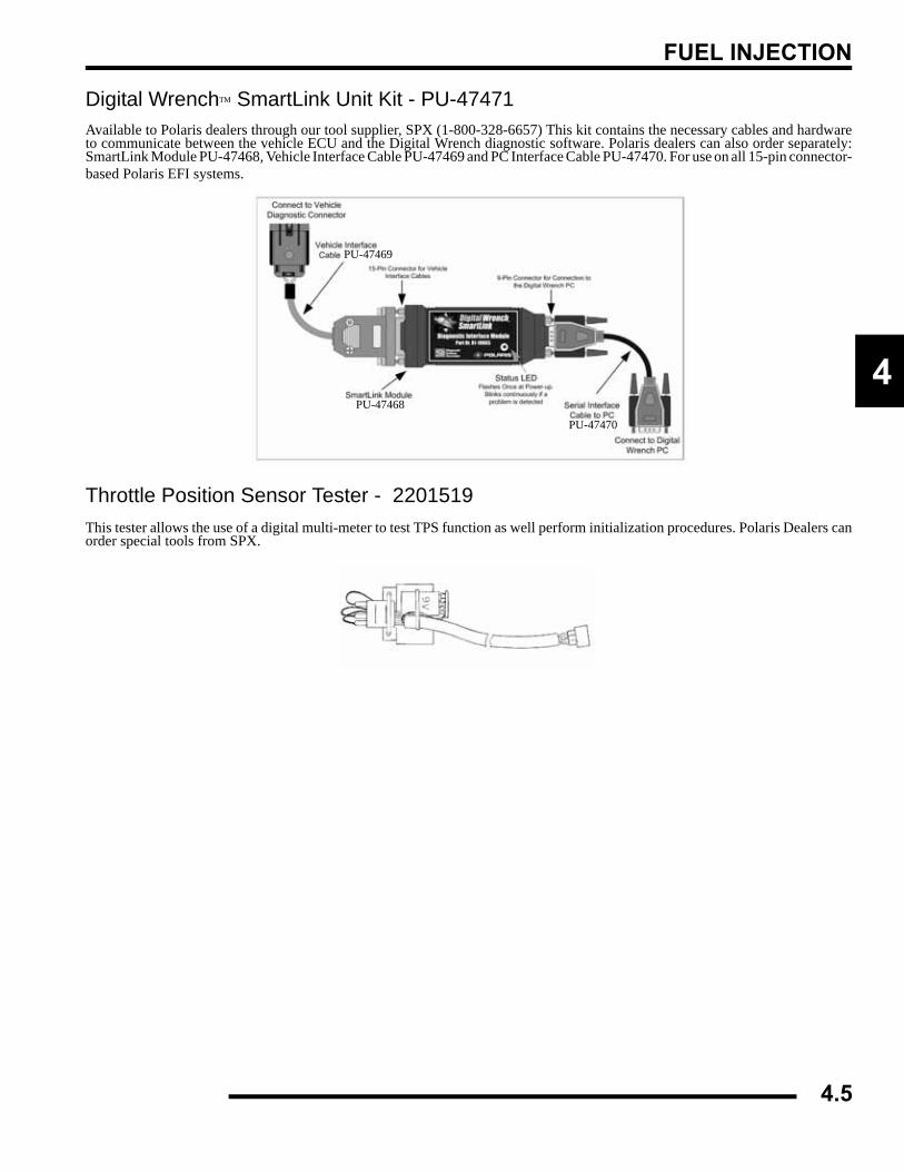
FUEL INJECTION
4
Digital Wrench™ SmartLink Unit Kit - PU-47471Available to Polaris dealers through our tool supplier, SPX (1-800-328-6657) This kit contains the necessary cables and hardwareto communicate between the vehicle ECU and the Digital Wrench diagnostic software. Polaris dealers can also order separately:SmartLink Module PU-47468, Vehicle Interface Cable PU-47469 and PC Interface Cable PU-47470. For use on all 15-pin connector-based Polaris EFI systems.
Throttle Position Sensor Tester - 2201519This tester allows the use of a digital multi-meter to test TPS function as well perform initialization procedures. Polaris Dealers canorder special tools from SPX.
PU-47468
PU-47469
PU-47470
4.5
FUEL INJECTION
EFI SERVICE NOTESGeneral Service Information
• For more convenient and accurate testing of EFI components, it is recommended dealers utilize the Polaris Diagnostic Software (dealer only), or limited testing may be done manually using the procedures provided.
• 80% of all EFI problems are caused by wiring harness connections. Follow a common sense approach when diagnosing a potential EFI issue:
1. Disconnect the harness at the suspected sensor connector.2. Inspect the connector ends for damage or contamination. If damaged, repair; if contaminated, clean. Reconnect and
check function.3. If the problem persists, perform a sensor bench test according to the specific sensor requirements.4. If the sensor bench tests pass, disconnect the connector at the ECU and perform a continuity check between the sensor
connector and the appropriate pin at the ECU connector (all connections for that sensor). Wiring resistance should be less than five (5) ohms.
5. If the resistance is high (or open), a wiring harness inspection is dictated (including a thorough inspection of the ECU connector for contamination or damage).
6. If the sensor passes and the wiring passes inspection, and reconnecting the ECU does not resolve the issue, then at that point a known-good ECU (from another 500 EFI ATV) could be connected and tested for problem resolution.
• For the purpose of troubleshooting difficult running issues, a known-good ECU from a same-model Polaris 500 ATV EFI system may be used without damaging system or engine components.
• Do not use dielectric grease on sealed connectors (connectors with a rubber grommet), as it may displace the rubber seal and allow contaminants to enter the connector.
• Never attempt to service any fuel system component while engine is running or ignition switch is turned to "on".
• USE CARE when removing or installing the ECU connector, as well as all other harness connections on the ATV. Dirt, even in small quantities, can cause significant problems. Clean connectors thoroughly before opening to prevent dirt from entering. Properly connect and disconnect the ECU harness to minimize damage to the connector pins and locking mechanism.
• Do not use compressed air if the EFI system is open. Cover any parts removed and wrap any open joints with plastic if they will remain open for any length of time. New parts should be removed from their protective packaging just prior to installation.
• Although every precaution has been taken to prevent water intrusion failure, avoid direct water or spray contact with system components.
• Do not disconnect or reconnect the wiring harness connector to the control unit or any individual components with the ignition "on." This can send a damaging voltage spike through the ECU.
• Do not allow the battery cables to touch opposing terminals. When connecting battery cables attach the positive (+) cable to positive (+) battery terminal first, followed by negative (-) cable to negative (-) battery terminal.
• Never start the engine when the cables are loose or poorly connected to the battery terminals.• Never disconnect battery while engine is running.• Never use a quick-start battery charger to start the engine.• Always unplug ECU from the wire harness before performing any welding on the ATV.
4.6
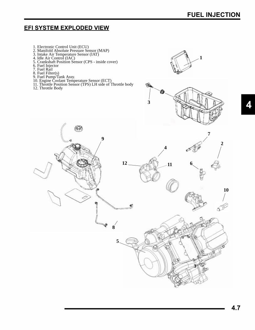
FUEL INJECTION
4
EFI SYSTEM EXPLODED VIEW
1. Electronic Control Unit (ECU)2. Manifold Absolute Pressure Sensor (MAP) 3. Intake Air Temperature Sensor (IAT)4. Idle Air Control (IAC) 5. Crankshaft Position Sensor (CPS - inside cover) 6. Fuel Injector7. Fuel Rail 8. Fuel Filter(s) 9. Fuel Pump/Tank Assy. 10. Engine Coolant Temperature Sensor (ECT) 11. Throttle Position Sensor (TPS) LH side of Throttle body12. Throttle Body
1
2
3
4
5
6
7
8
9
10
12
3
11
4.7
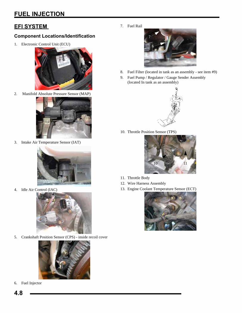
FUEL INJECTION
EFI SYSTEM Component Locations/Identification1. Electronic Control Unit (ECU)
2. Manifold Absolute Pressure Sensor (MAP)
3. Intake Air Temperature Sensor (IAT)
4. Idle Air Control (IAC)
5. Crankshaft Position Sensor (CPS) - inside recoil cover
6. Fuel Injector
7. Fuel Rail
8. Fuel Filter (located in tank as an assembly - see item #9)9. Fuel Pump / Regulator / Gauge Sender Assembly
(located In tank as an assembly)
10. Throttle Position Sensor (TPS)
11. Throttle Body12. Wire Harness Assembly13. Engine Coolant Temperature Sensor (ECT)
2
9 & 10
2
9 & 10
6
7
2
9 & 10
2
9 & 1010 11
11
4.8
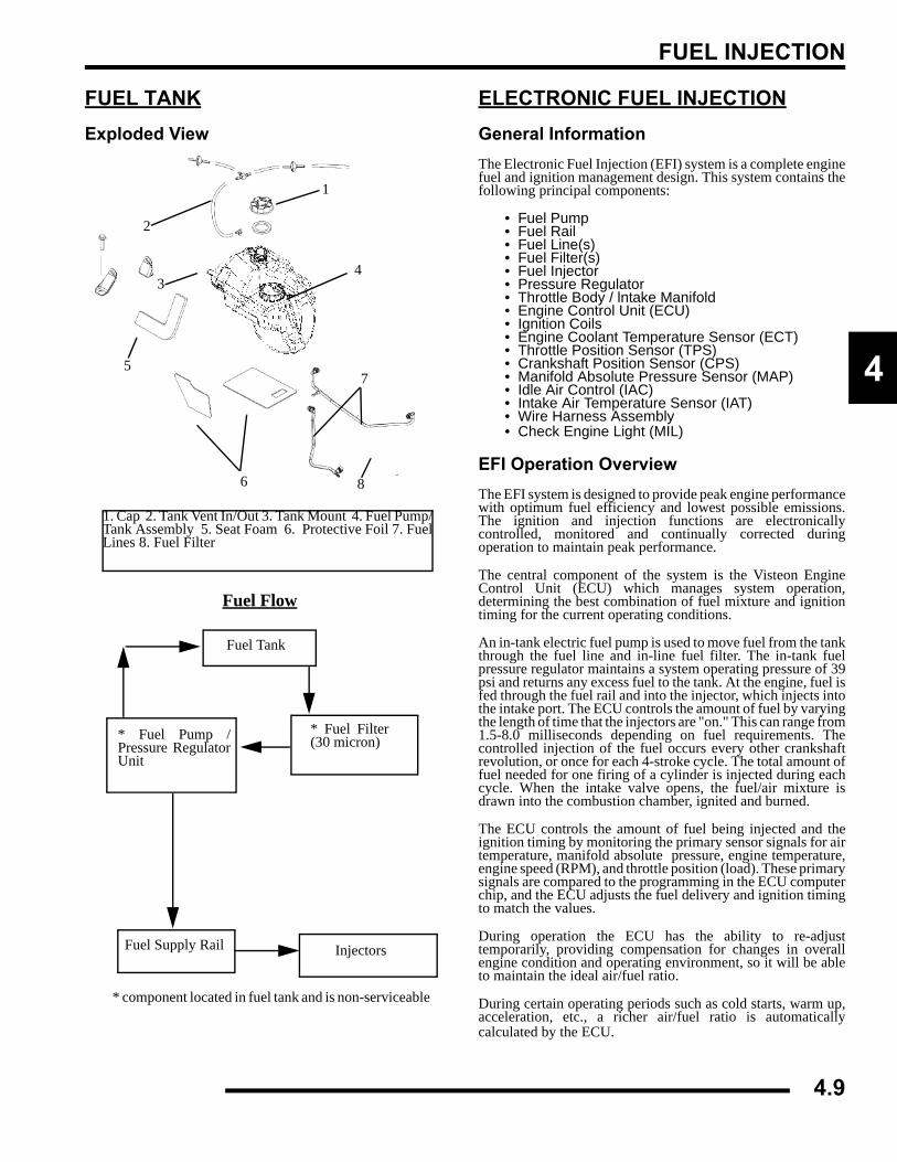
FUEL INJECTION
4
FUEL TANKExploded View
ELECTRONIC FUEL INJECTIONGeneral InformationThe Electronic Fuel Injection (EFI) system is a complete enginefuel and ignition management design. This system contains thefollowing principal components:
• Fuel Pump• Fuel Rail• Fuel Line(s)• Fuel Filter(s)• Fuel Injector• Pressure Regulator• Throttle Body / lntake Manifold• Engine Control Unit (ECU)• Ignition Coils• Engine Coolant Temperature Sensor (ECT)• Throttle Position Sensor (TPS)• Crankshaft Position Sensor (CPS)• Manifold Absolute Pressure Sensor (MAP)• Idle Air Control (IAC)• Intake Air Temperature Sensor (IAT)• Wire Harness Assembly• Check Engine Light (MIL)
EFI Operation OverviewThe EFI system is designed to provide peak engine performancewith optimum fuel efficiency and lowest possible emissions.The ignition and injection functions are electronicallycontrolled, monitored and continually corrected duringoperation to maintain peak performance.
The central component of the system is the Visteon EngineControl Unit (ECU) which manages system operation,determining the best combination of fuel mixture and ignitiontiming for the current operating conditions.
An in-tank electric fuel pump is used to move fuel from the tankthrough the fuel line and in-line fuel filter. The in-tank fuelpressure regulator maintains a system operating pressure of 39psi and returns any excess fuel to the tank. At the engine, fuel isfed through the fuel rail and into the injector, which injects intothe intake port. The ECU controls the amount of fuel by varyingthe length of time that the injectors are "on." This can range from1.5-8.0 milliseconds depending on fuel requirements. Thecontrolled injection of the fuel occurs every other crankshaftrevolution, or once for each 4-stroke cycle. The total amount offuel needed for one firing of a cylinder is injected during eachcycle. When the intake valve opens, the fuel/air mixture isdrawn into the combustion chamber, ignited and burned.
The ECU controls the amount of fuel being injected and theignition timing by monitoring the primary sensor signals for airtemperature, manifold absolute pressure, engine temperature,engine speed (RPM), and throttle position (load). These primarysignals are compared to the programming in the ECU computerchip, and the ECU adjusts the fuel delivery and ignition timingto match the values.
During operation the ECU has the ability to re-adjusttemporarily, providing compensation for changes in overallengine condition and operating environment, so it will be ableto maintain the ideal air/fuel ratio.
During certain operating periods such as cold starts, warm up,acceleration, etc., a richer air/fuel ratio is automaticallycalculated by the ECU.
1. Cap 2. Tank Vent In/Out 3. Tank Mount 4. Fuel Pump/Tank Assembly 5. Seat Foam 6. Protective Foil 7. FuelLines 8. Fuel Filter
1
2
34
6
5
8
7
Fuel Tank
* Fuel Filter(30 micron)* Fuel Pump /
Pressure RegulatorUnit
Fuel Supply Rail Injectors
Fuel Flow
* component located in fuel tank and is non-serviceable
4.9

FUEL INJECTION
Initial Priming / Starting ProcedureNOTE: The Injection system must be purged of allair prior to the initial start up, and/or any time thesystem has been disassembled.
If the EFI system is completely empty of fuel or has beendisassembled and repaired:
1. Cycle the key switch from “OFF” to “ON” 6 times,waiting for approximately 3 seconds at “ON” and 5seconds at “OFF” in sequence to allow the fuel pump tocycle and shut down.
2. Once step 1 is completed, turn the key switch to “START”until the engine starts or 5 seconds has passed.
3. If the engine failed to start, repeat step 1 for 2 more cyclesand attempt to start the engine.
If the engine fails to start, a problem may still exist, and shouldbe diagnosed.
NOTE: Accurate testing of EFI components isrecommended utilizing the Polaris DiagnosticSoftware (dealer only).
FUEL LINESQuick Connect Removal/Installation
Sportsman 500 EFI models use quick connect fuel lines. Referto the steps for fuel line removal / installation:
1. Thoroughly clean the connector. Place a shop towelaround the fuel line to catch any dripping fuel. Squeeze theconnector tabs together and push the locking tab out.
2. Pull out on the fuel line for removal.3. To install the line, verify the connector and nipple are clean
and free of debris.4. Snap the fuel line back over the nipple, verify the connector
tabs snap back into place.
CAUTION
Verify fuel system has been depressurized before performing this procedure.
Squeeze Connector Tabs
4.10
FUEL INJECTION
4
ELECTRONIC CONTROL UNIT (ECU)Operation OverviewThe ECU is the brain or central processing computer of theentire EFI fuel/ignition management system. During operation,sensors continuously gather data which is relayed through thewiring harness to input circuits within the ECU. Signals to theECU include: ignition (on/off), crankshaft position and speed(RPM), throttle position, engine coolant temperature, airtemperature, intake manifold air pressure and battery voltage.
The ECU compares the input signals to the programmed mapsin its memory and determines the appropriate fuel and sparkrequirements for the immediate operating conditions. The ECUthen sends output signals to set the injector duration and ignitiontiming.
During operation, the ECU continually performs a diagnosticcheck of itself, each of the sensors, and system performance. Ifa fault is detected, the ECU turns on the Malfunction IndicatorLight (MIL) (Check Engine Light) on the speedometer andstores the fault code in its fault memory. A technician canaccess the stored fault codes manually using a “blink code”diagnosis flashed out through the instrument cluster or using theDigital Wrench Diagnostic Software. The ECU requires aminimum of 7.0 volts to operate. The memory in the ECU isoperational the moment the battery cables are connected.Depending on the significance or severity of the fault, normaloperation may continue, or a "Fail-Safe" operation may beinitiated. In the event a “Fail-Safe” mode occurs, a base fuelingtable is used to determine the injector pulse width. This strategywill not compensate for engine temperature, intake airtemperature, or altitude change, but instead operates based onthe latest valid information taken from those sensors.
To prevent engine over-speed and possible failure, an RPM-limiting feature is programmed into the ECU. If the maximumRPM limit (7000) is exceeded, the ECU will suppress theignition signal or injection signal. This process repeats itself inrapid succession, limiting operation to the preset maximum.
Sportsman 500 EFI RPM Limit:
This EFI system utilizes 2 methods -
“Hard” Limit - Ignition suppression occurs when RPM peaksrapidly:
• High: 7000 RPM
• Returns: 6900 RPM
“Soft” Limit - Injector suppression occurs when RPM reachespeak gradually:
• High: 7000 RPM
• Returns: 6900 RPM
RPM limits may vary slightly under operating conditions.
ECU Replacement1. Remove the 2 retaining screws holding the ECU. NOTE:
Retain upper-left spacer located behind the ECU for re-installation.
2. With the ignition turned off, disconnect the wire harness bypulling the black slider away from the ECU. Once the slideris fully extended, pull the connector from the ECU, usinggreat care not to damage the harness connector or lockingmechanism. NOTE: Should the black slider becomebroken, replacement parts are available.
3. To install, reverse the procedures, DO NOT apply dielectricgrease to the connector, as it is a sealed connector. Installthe upper-left retaining screw spacer and screws. Tightenscrews to 10 in. lbs. (1.1 Nm).
ECU ServiceNever attempt to disassemble the ECU. It is sealed to preventdamage to internal components. Warranty is void if the case isopened or tampered with in any way.
All operating and control functions within the ECU are pre-set.No internal servicing or readjustment may be performed. If aproblem is encountered, and you determine the ECU to befaulty, contact the Polaris Service Department for specifichandling instructions. Do not replace the ECU without factoryauthorization.
The relationship between the ECU and the throttle positionsensor (TPS) is very critical to proper system operation. If theTPS is faulty, or the mounting position of the TPS is altered, theTPS must be re-initialized.
For the purpose of troubleshooting, a known-good ECU from asame-model Polaris 500 ATV EFI may be used without systemor engine component damage.
ECU
4.11
FUEL INJECTION
FUEL PUMP ASSEMBLYOperation / TestingNOTE: All EFI units utilize quick connect fuel lines.
An electric fuel pump assembly is used to transfer fuel to the EFIsystem from inside the fuel tank. This assembly includes the fuelpump, regulator and fuel gauge sender. The pump is rated for aminimum output of 25 liters per hour at 39 psi and has a non-serviceable internal 30-micron filter.
When the key switch is turned to "ON", the ECU activates thefuel pump, which pressurizes the system for start-up.
The ECU switches off the pump preventing the continueddelivery of fuel in these instances:
• If the key switch is not promptly turned to the "start" position.
• If the engine fails to start, or
• If the engine is stopped with the key switch "on" (as in the case of an accident)
In these situations, the “check engine” light will go on, but willturn off after 4 cranking revolutions if system function is OK.Once the engine is running, the fuel pump remains on.
NOTE: FUEL GAUGE SENDER TEST - To test fuelgauge sender function, refer to Chapter 10 in thisservice manual.
FUEL PUMP TESTNOTE: The fuel pump/tank assembly is a non-serviceable assembly and must be replaced ifdetermined to be faulty. If a fuel delivery problem issuspected, make certain the filters are not plugged,that the pump is being activated through the ECU, all
electrical connections are properly secured, thefuses are good, and a minimum of 7.0 volts is beingsupplied. If during starting, the battery voltage dropsbelow 7.0 volts, a reduction of fuel pressure mayoccur resulting in a lean starting condition. Ifrequired, testing of the fuel pump and circuitry maybe conducted.
1. Insert the fuel test valve adapter PU-47476. Connect thepressure hose of the Polaris pressure tester (PN PU-43506)to the test valve. Route the clear hose into a portablegasoline container or the equipment fuel tank.
2. Turn on the key switch to activate the pump and check thesystem pressure on the gauge. If system pressure of 39 psi± 3 is observed, the ignition switch, ECU, fuel pump, andpressure regulator are working properly. Turn the keyswitch “off” and depress the valve button on the tester torelieve the system pressure.
NOTE: If the pressure is too high or too low, replacethe fuel pump assembly.
Fuel pump notreplaceable, picturefor reference only.
Regulator
Fuel Pump
Internal 30 MicronStrainer (Bottom)
Fuel Gauge Sender
CAUTION
Check the fuel test valve for any possible fuel seepage after performing any tests or procedures. Fuel is extremely flammable and may cause severe burns, injury, or death. Do not use any device that
produces a flame or electrical devices that may spark around fuel or fuel vapors.
Fuel Pump Pressure - 39 psi ± 3
4.12
FUEL INJECTION
4
3. If the pump did not activate (Step 2), disconnect the plugfrom the fuel pump. Connect a DC voltmeter acrossterminals “A” and “C” in the plug, turn on the key switchand observe if a minimum of 7 volts is present. If voltageis between 7 and 14, turn key switch off and connect anohmmeter between the terminals “A” and “C”' on the pumpto check for continuity.
NOTE: If there was no continuity between the pumpterminals, replace the fuel pump/tank assembly.
NOTE: If the voltage is below 7Vdc, test the battery,ignition switch, wiring harness and ECU.
4. If voltage at the plug was good, and there was continuityacross the pump terminals, reconnect the plug to the pump,making sure you have good, clean connections. Turn on thekey switch and listen for the pump to activate.
NOTE: If the pump starts, repeat steps 1 and 2 toverify correct pressure.
NOTE: If the pump still does not operate, check forcorrect ECU operation by plugging in a known-goodECU.
NOTE: If the pump still does not operate, replace thepump/tank assembly.
Fuel Pump / Tank Assembly ReplacementNOTE: All EFI units utilize quick connect fuel lines.
NOTE: The fuel pump cannot be replaced as anindividual part, the entire fuel pump and fuel tank isreplaced as an assembly. Refer to your parts bookfor the proper part number.
1. Disconnect the negative battery cable.2. Remove the side panels and front cab assembly. Refer to
“COVER PANEL REMOVAL” in Chapter 5 for details.
3. Remove the clamps on the PVT intake duct and remove thePVT duct.
4. Remove the gas tank cover vent hoses. Be sure to properlyroute the vent hoses upon reassembly.
5. With all the body panels removed from the front of the ATVand the gas tank exposed, disconnect the pump wiringharness.
6. Relieve the fuel pressure.
WARNING
Always wear safety goggles when working with high pressure or flammable fluids. Failure to do so
could result in serious injury or complications. WARNING
Wear safety goggles while performing this procedure, failure to do so could result in serious
injuries.
4.13
FUEL INJECTION
7. Loosen the fuel tank hose and pull the fuel line from thetank.
NOTE: A small amount of fuel may come out of thefuel line or tank. Plug the fuel line and tank inlet oruse a shop towel during removal.
8. Remove the air box cover and remove the two gas tankmounting bolts at the rear of the gas tank.
9. Carefully pull the fuel tank out of the frame. Keep the fueltank horizontal during removal, this will keep the fuel in thetank from spilling out the top inlet.
Fuel Tank Installation1. Reinstall the tank assembly.2. Reconnect the sender wiring harness and route the harness
properly. Install the fuel line(s) and verify they are secure. 3. Reinstall the two fuel tank mounting bolts at back of tank.4. Reinstall the PVT intake duct, gas tank vent line, front cab
assembly, and side panels. NOTE: Properly route the gas tank vent lines, usetape to secure the vent line in place. (See Pic 1).
5. Reconnect the negative battery cable. Test the sender forproper operation.
FUEL PRESSURE REGULATORGeneral InformationThe fuel pressure regulator maintains the required operatingsystem pressure of 39 psi + 3psi. A rubber-fiber diaphragmdivides the regulator into two separate sections, the fuelchamber and the pressure regulating chamber. The pressureregulating spring presses against the valve holder (part of thediaphragm), pressing the valve against the valve seat. Thecombination of atmospheric pressure and regulating springtension equals the desired operating pressure. Any time the fuelpressure against the bottom of the diaphragm exceeds thedesired (top) pressure, the valve opens, relieving the excesspressure, returning the excess fuel back to the tank.
Fuel Pressure Regulator Test Refer to the “FUEL PUMP TEST” procedure.
Fuel Pressure Regulator ReplacementThe regulator is a sealed, non-serviceable assembly. If it isfaulty, the pump assembly must be replaced. Refer to the FuelPump/Tank Assembly Replacement procedure.
FUEL FILTERGeneral InformationNOTE: All EFI units utilize quick connect fuel lines.
All EFI Engines use a non-serviceable, high-volume, high-pressure, 30-micron internal fuel pump filter. The filter islocated inside the tank as part of the fuel pump assembly.
Fuel Filter ServiceThe in-tank filter is non-serviceable. Tank flushing to removesediments may temporarily restore fuel flow, but is not arecommended service procedure.
Fuel Filter ReplacementNOTE: Tank replacment is required.
CAUTION
Check the fuel test valve for any possible fuel seepage after performing any tests or procedures. Fuel is extremely flammable and may cause severe burns, injury, or death. Do not use any device that
produces a flame or electrical devices that may spark around fuel or fuel vapors.
Fuel Line
Fuel Pump
4.14
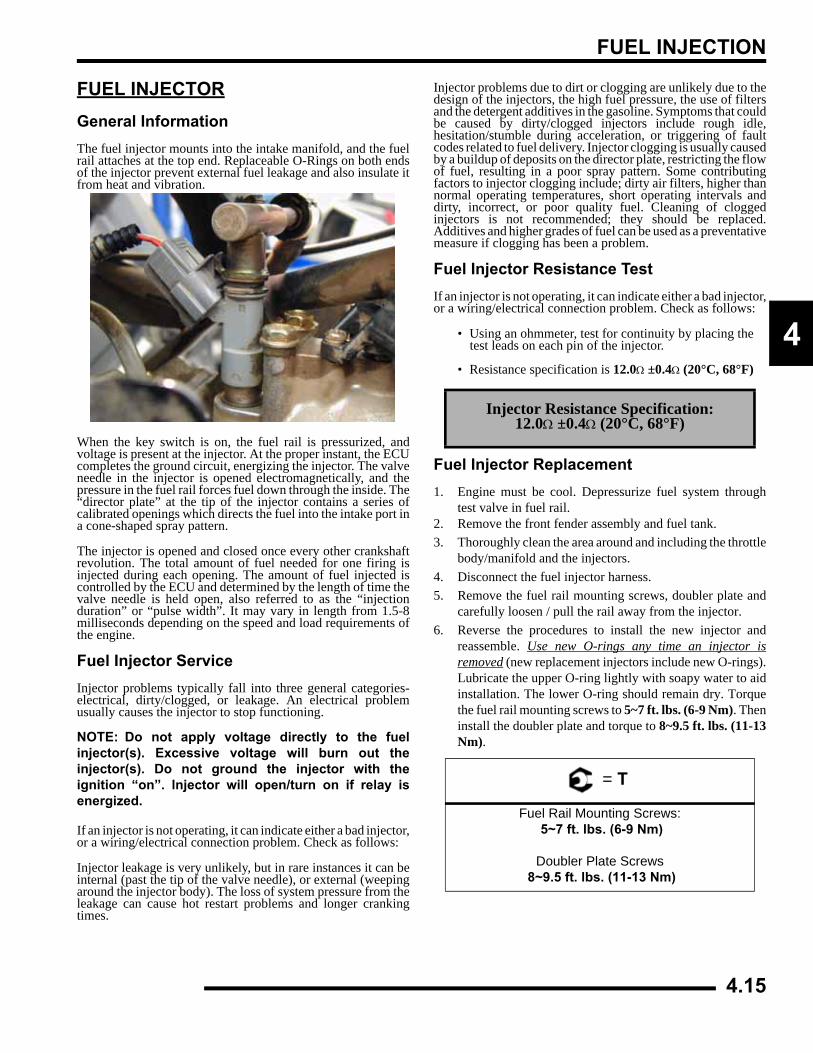
FUEL INJECTION
4
FUEL INJECTORGeneral InformationThe fuel injector mounts into the intake manifold, and the fuelrail attaches at the top end. Replaceable O-Rings on both endsof the injector prevent external fuel leakage and also insulate itfrom heat and vibration.
When the key switch is on, the fuel rail is pressurized, andvoltage is present at the injector. At the proper instant, the ECUcompletes the ground circuit, energizing the injector. The valveneedle in the injector is opened electromagnetically, and thepressure in the fuel rail forces fuel down through the inside. The“director plate” at the tip of the injector contains a series ofcalibrated openings which directs the fuel into the intake port ina cone-shaped spray pattern.
The injector is opened and closed once every other crankshaftrevolution. The total amount of fuel needed for one firing isinjected during each opening. The amount of fuel injected iscontrolled by the ECU and determined by the length of time thevalve needle is held open, also referred to as the “injectionduration” or “pulse width”. It may vary in length from 1.5-8milliseconds depending on the speed and load requirements ofthe engine.
Fuel Injector ServiceInjector problems typically fall into three general categories-electrical, dirty/clogged, or leakage. An electrical problemusually causes the injector to stop functioning.
NOTE: Do not apply voltage directly to the fuelinjector(s). Excessive voltage will burn out theinjector(s). Do not ground the injector with theignition “on”. lnjector will open/turn on if relay isenergized.
If an injector is not operating, it can indicate either a bad injector,or a wiring/electrical connection problem. Check as follows:
Injector leakage is very unlikely, but in rare instances it can beinternal (past the tip of the valve needle), or external (weepingaround the injector body). The loss of system pressure from theleakage can cause hot restart problems and longer crankingtimes.
Injector problems due to dirt or clogging are unlikely due to thedesign of the injectors, the high fuel pressure, the use of filtersand the detergent additives in the gasoline. Symptoms that couldbe caused by dirty/clogged injectors include rough idle,hesitation/stumble during acceleration, or triggering of faultcodes related to fuel delivery. Injector clogging is usually causedby a buildup of deposits on the director plate, restricting the flowof fuel, resulting in a poor spray pattern. Some contributingfactors to injector clogging include; dirty air filters, higher thannormal operating temperatures, short operating intervals anddirty, incorrect, or poor quality fuel. Cleaning of cloggedinjectors is not recommended; they should be replaced.Additives and higher grades of fuel can be used as a preventativemeasure if clogging has been a problem.
Fuel Injector Resistance TestIf an injector is not operating, it can indicate either a bad injector,or a wiring/electrical connection problem. Check as follows:
• Using an ohmmeter, test for continuity by placing the test leads on each pin of the injector.
• Resistance specification is 12.0Ω ±0.4Ω (20°C, 68°F)
Fuel Injector Replacement1. Engine must be cool. Depressurize fuel system through
test valve in fuel rail.2. Remove the front fender assembly and fuel tank.3. Thoroughly clean the area around and including the throttle
body/manifold and the injectors.4. Disconnect the fuel injector harness.5. Remove the fuel rail mounting screws, doubler plate and
carefully loosen / pull the rail away from the injector.6. Reverse the procedures to install the new injector and
reassemble. Use new O-rings any time an injector isremoved (new replacement injectors include new O-rings).Lubricate the upper O-ring lightly with soapy water to aidinstallation. The lower O-ring should remain dry. Torquethe fuel rail mounting screws to 5~7 ft. lbs. (6-9 Nm). Theninstall the doubler plate and torque to 8~9.5 ft. lbs. (11-13Nm).
Injector
Injector
Injector Resistance Specification:12.0Ω ±0.4Ω (20°C, 68°F)
= T
Fuel Rail Mounting Screws: 5~7 ft. lbs. (6-9 Nm)
Doubler Plate Screws 8~9.5 ft. lbs. (11-13 Nm)
4.15
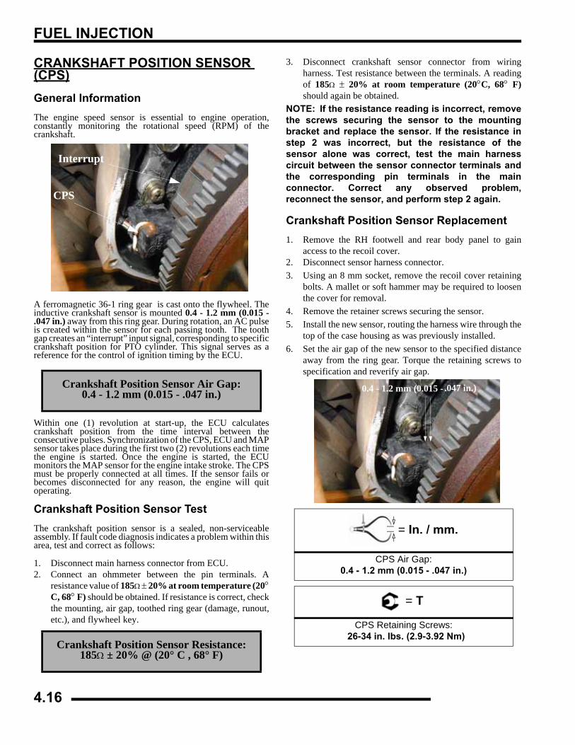
FUEL INJECTION
CRANKSHAFT POSITION SENSOR (CPS)General InformationThe engine speed sensor is essential to engine operation,constantly monitoring the rotational speed (RPM) of thecrankshaft.
A ferromagnetic 36-1 ring gear is cast onto the flywheel. Theinductive crankshaft sensor is mounted 0.4 - 1.2 mm (0.015 -.047 in.) away from this ring gear. During rotation, an AC pulseis created within the sensor for each passing tooth. The toothgap creates an “interrupt” input signal, corresponding to specificcrankshaft position for PTO cylinder. This signal serves as areference for the control of ignition timing by the ECU.
Within one (1) revolution at start-up, the ECU calculatescrankshaft position from the time interval between theconsecutive pulses. Synchronization of the CPS, ECU and MAPsensor takes place during the first two (2) revolutions each timethe engine is started. Once the engine is started, the ECUmonitors the MAP sensor for the engine intake stroke. The CPSmust be properly connected at all times. If the sensor fails orbecomes disconnected for any reason, the engine will quitoperating.
Crankshaft Position Sensor TestThe crankshaft position sensor is a sealed, non-serviceableassembly. If fault code diagnosis indicates a problem within thisarea, test and correct as follows:
1. Disconnect main harness connector from ECU.2. Connect an ohmmeter between the pin terminals. A
resistance value of 185Ω ± 20% at room temperature (20°C, 68° F) should be obtained. If resistance is correct, checkthe mounting, air gap, toothed ring gear (damage, runout,etc.), and flywheel key.
3. Disconnect crankshaft sensor connector from wiringharness. Test resistance between the terminals. A readingof 185Ω ± 20% at room temperature (20°C, 68° F)should again be obtained.
NOTE: If the resistance reading is incorrect, removethe screws securing the sensor to the mountingbracket and replace the sensor. If the resistance instep 2 was incorrect, but the resistance of thesensor alone was correct, test the main harnesscircuit between the sensor connector terminals andthe corresponding pin terminals in the mainconnector. Correct any observed problem,reconnect the sensor, and perform step 2 again.
Crankshaft Position Sensor Replacement1. Remove the RH footwell and rear body panel to gain
access to the recoil cover.2. Disconnect sensor harness connector.3. Using an 8 mm socket, remove the recoil cover retaining
bolts. A mallet or soft hammer may be required to loosenthe cover for removal.
4. Remove the retainer screws securing the sensor.5. Install the new sensor, routing the harness wire through the
top of the case housing as was previously installed.6. Set the air gap of the new sensor to the specified distance
away from the ring gear. Torque the retaining screws tospecification and reverify air gap.
Crankshaft Position Sensor Air Gap:0.4 - 1.2 mm (0.015 - .047 in.)
Crankshaft Position Sensor Resistance:185Ω ± 20% @ (20° C , 68° F)
CPS
Interrupt
= In. / mm.
CPS Air Gap:0.4 - 1.2 mm (0.015 - .047 in.)
= T
CPS Retaining Screws: 26-34 in. lbs. (2.9-3.92 Nm)
0.4 - 1.2 mm (0.015 - .047 in.)
4.16
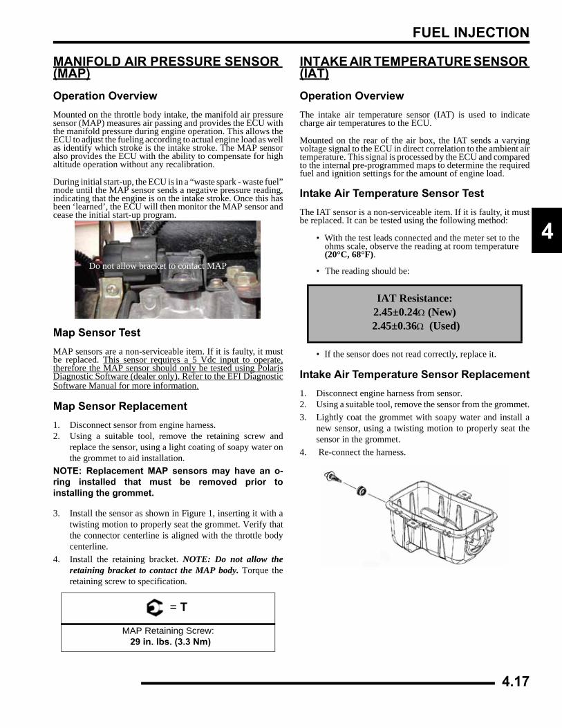
FUEL INJECTION
4
MANIFOLD AIR PRESSURE SENSOR (MAP)Operation OverviewMounted on the throttle body intake, the manifold air pressuresensor (MAP) measures air passing and provides the ECU withthe manifold pressure during engine operation. This allows theECU to adjust the fueling according to actual engine load as wellas identify which stroke is the intake stroke. The MAP sensoralso provides the ECU with the ability to compensate for highaltitude operation without any recalibration.
During initial start-up, the ECU is in a “waste spark - waste fuel”mode until the MAP sensor sends a negative pressure reading,indicating that the engine is on the intake stroke. Once this hasbeen ‘learned’, the ECU will then monitor the MAP sensor andcease the initial start-up program.
Map Sensor TestMAP sensors are a non-serviceable item. If it is faulty, it mustbe replaced. This sensor requires a 5 Vdc input to operate,therefore the MAP sensor should only be tested using PolarisDiagnostic Software (dealer only). Refer to the EFI DiagnosticSoftware Manual for more information.
Map Sensor Replacement1. Disconnect sensor from engine harness.2. Using a suitable tool, remove the retaining screw and
replace the sensor, using a light coating of soapy water onthe grommet to aid installation.
NOTE: Replacement MAP sensors may have an o-ring installed that must be removed prior toinstalling the grommet.
3. Install the sensor as shown in Figure 1, inserting it with atwisting motion to properly seat the grommet. Verify thatthe connector centerline is aligned with the throttle bodycenterline.
4. Install the retaining bracket. NOTE: Do not allow theretaining bracket to contact the MAP body. Torque theretaining screw to specification.
INTAKE AIR TEMPERATURE SENSOR (IAT)Operation OverviewThe intake air temperature sensor (IAT) is used to indicatecharge air temperatures to the ECU.
Mounted on the rear of the air box, the IAT sends a varyingvoltage signal to the ECU in direct correlation to the ambient airtemperature. This signal is processed by the ECU and comparedto the internal pre-programmed maps to determine the requiredfuel and ignition settings for the amount of engine load.
Intake Air Temperature Sensor TestThe IAT sensor is a non-serviceable item. If it is faulty, it mustbe replaced. It can be tested using the following method:
• With the test leads connected and the meter set to the ohms scale, observe the reading at room temperature (20°C, 68°F).
• The reading should be:
• If the sensor does not read correctly, replace it.
Intake Air Temperature Sensor Replacement1. Disconnect engine harness from sensor.2. Using a suitable tool, remove the sensor from the grommet.3. Lightly coat the grommet with soapy water and install a
new sensor, using a twisting motion to properly seat thesensor in the grommet.
4. Re-connect the harness.
= T
MAP Retaining Screw: 29 in. lbs. (3.3 Nm)
Do not allow bracket to contact MAP
IAT Resistance:2.45±0.24Ω (New)
2.45±0.36Ω (Used)
4.17
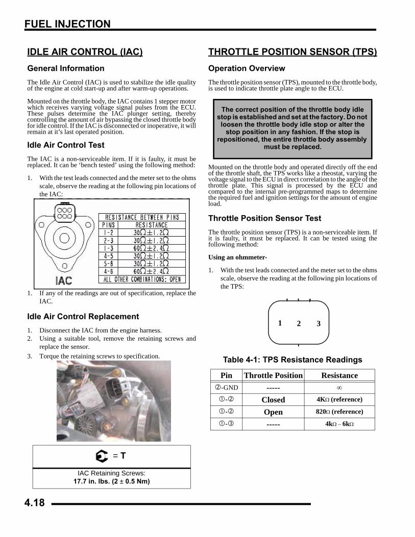
FUEL INJECTION
IDLE AIR CONTROL (IAC)General InformationThe Idle Air Control (IAC) is used to stabilize the idle qualityof the engine at cold start-up and after warm-up operations.
Mounted on the throttle body, the IAC contains 1 stepper motorwhich receives varying voltage signal pulses from the ECU.These pulses determine the IAC plunger setting, therebycontrolling the amount of air bypassing the closed throttle bodyfor idle control. If the IAC is disconnected or inoperative, it willremain at it’s last operated position.
Idle Air Control TestThe IAC is a non-serviceable item. If it is faulty, it must bereplaced. It can be ‘bench tested’ using the following method:
1. With the test leads connected and the meter set to the ohmsscale, observe the reading at the following pin locations ofthe IAC:
1. If any of the readings are out of specification, replace theIAC.
Idle Air Control Replacement1. Disconnect the IAC from the engine harness.2. Using a suitable tool, remove the retaining screws and
replace the sensor.3. Torque the retaining screws to specification.
THROTTLE POSITION SENSOR (TPS)Operation OverviewThe throttle position sensor (TPS), mounted to the throttle body,is used to indicate throttle plate angle to the ECU.
Mounted on the throttle body and operated directly off the endof the throttle shaft, the TPS works like a rheostat, varying thevoltage signal to the ECU in direct correlation to the angle of thethrottle plate. This signal is processed by the ECU andcompared to the internal pre-programmed maps to determinethe required fuel and ignition settings for the amount of engineload.
Throttle Position Sensor TestThe throttle position sensor (TPS) is a non-serviceable item. Ifit is faulty, it must be replaced. It can be tested using thefollowing method:
Using an ohmmeter-
1. With the test leads connected and the meter set to the ohmsscale, observe the reading at the following pin locations ofthe TPS:
= T
IAC Retaining Screws:17.7 in. lbs. (2 ± 0.5 Nm)
The correct position of the throttle body idle stop is established and set at the factory. Do not loosen the throttle body idle stop or alter the
stop position in any fashion. If the stop is repositioned, the entire throttle body assembly
must be replaced.
Table 4-1: TPS Resistance Readings
Pin Throttle Position Resistance-GND ----- ∞
- Closed 4KΩ (reference)
- Open 820Ω (reference)
- ----- 4kΩ − 6kΩ
1 2 3
4.18
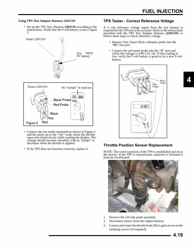
FUEL INJECTION
4
Using TPS Test Adapter Harness 2201519-
• Set up the TPS Test Harness 2201519 according to the instructions. Verify that the 9 volt battery is new. Figure 2
• Connect the test leads connected as shown in Figure 2 and the meter set to the “vdc” scale, move the throttle open and closed slowly while reading the display. The voltage should increase smoothly with no “jumps” or decreases when the throttle is applied.
• If the TPS does not function correctly, replace it.
TPS Tester - Correct Reference VoltageA 5 volt reference voltage signal from the test harness isrequired for the TPS test to be accurate. Refer to the instructionsprovided with the TPS Test Adapter Harness (2201519) orfollow these steps to check reference voltage.
• Harness Test: Insert black voltmeter probe into the “Bk” test port.
• Connect the red meter probe into the “R” port and verify the voltage is 4.99-5.01 vdc. If this reading is low, verify the 9 volt battery is good or try a new 9 volt battery.
Throttle Position Sensor ReplacementNOTE: The correct position of the TPS is established and set atthe factory. If the TPS is repositioned, replaced or loosened itmust be recalibrated.
1. Remove the LH side panel assembly.2. Disconnect sensor from the engine harness.3. Loosen and rotate the throttle body (B) to gain access to the
retaining screws (if required).
Use NEW9V battery
Tester 2201519
Tester 2201519 No “Jumps” in read out
4.19
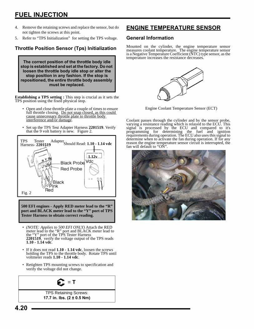
FUEL INJECTION
4. Remove the retaining screws and replace the sensor, but donot tighten the screws at this point.
5. Refer to “TPS Initialization” for setting the TPS voltage.
Throttle Position Sensor (Tps) Initialization
Establishing a TPS setting : This step is crucial as it sets theTPS position using the fixed physical stop.
• Open and close throttle plate a couple of times to ensure full throttle closing. Do not snap closed, as this could cause unnecessary throttle plate to throttle body interference and/or damage.
• Set up the TPS Test Adapter Harness 2201519. Verify that the 9 volt battery is new. Figure 2.
• (NOTE: Applies to 500 EFI ONLY) Attach the RED meter lead to the “R” port and BLACK meter lead to the “Y” port of the TPS Tester Harness 2201519, verify the voltage output of the TPS reads 1.10 - 1.14 vdc.
• If it does not read 1.10 - 1.14 vdc, loosen the screws holding the TPS to the throttle body. Rotate TPS until voltmeter reads 1.10 - 1.14 vdc.
• Retighten TPS mounting screws to specification and verify the voltage did not change.
ENGINE TEMPERATURE SENSORGeneral InformationMounted on the cylinder, the engine temperature sensormeasures coolant temperature. The engine temperature sensoris a Negative Temperature Coefficient (NTC) type sensor, as thetemperature increases the resistance decreases.
Coolant passes through the cylinder and by the sensor probe,varying a resistance reading which is relayed to the ECU. Thissignal is processed by the ECU and compared to it'sprogramming for determining the fuel and ignitionrequirements during operation. The ECU also uses this signal todetermine when to activate the fan during operation. If for anyreason the engine temperature sensor circuit is interrupted, thefan will default to “ON”.
The correct position of the throttle body idle stop is established and set at the factory. Do not loosen the throttle body idle stop or alter the
stop position in any fashion. If the stop is repositioned, the entire throttle body assembly
must be replaced.
500 EFI engines - Apply RED meter lead to the “R”port and BLACK meter lead to the “Y” port of TPSTester Harness to obtain correct reading.
= T
TPS Retaining Screws:17.7 in. lbs. (2 ± 0.5 Nm)
TPS Tester AdapterHarness- 2201519
Fig. 2
1.12v
Should Read: 1.10 - 1.14 vdc
Engine Coolant Temperature Sensor (ECT)
4.20
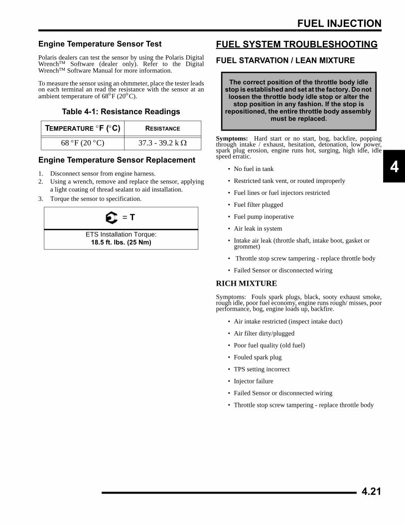
FUEL INJECTION
4
Engine Temperature Sensor TestPolaris dealers can test the sensor by using the Polaris DigitalWrench™ Software (dealer only). Refer to the DigitalWrench™ Software Manual for more information.
To measure the sensor using an ohmmeter, place the tester leadson each terminal an read the resistance with the sensor at anambient temperature of 68°F (20°C).
Engine Temperature Sensor Replacement1. Disconnect sensor from engine harness.2. Using a wrench, remove and replace the sensor, applying
a light coating of thread sealant to aid installation.3. Torque the sensor to specification.
FUEL SYSTEM TROUBLESHOOTINGFUEL STARVATION / LEAN MIXTURE
Symptoms: Hard start or no start, bog, backfire, poppingthrough intake / exhaust, hesitation, detonation, low power,spark plug erosion, engine runs hot, surging, high idle, idlespeed erratic.
• No fuel in tank
• Restricted tank vent, or routed improperly
• Fuel lines or fuel injectors restricted
• Fuel filter plugged
• Fuel pump inoperative
• Air leak in system
• Intake air leak (throttle shaft, intake boot, gasket or grommet)
• Throttle stop screw tampering - replace throttle body
• Failed Sensor or disconnected wiring
RICH MIXTURESymptoms: Fouls spark plugs, black, sooty exhaust smoke,rough idle, poor fuel economy, engine runs rough/ misses, poorperformance, bog, engine loads up, backfire.
• Air intake restricted (inspect intake duct)
• Air filter dirty/plugged
• Poor fuel quality (old fuel)
• Fouled spark plug
• TPS setting incorrect
• Injector failure
• Failed Sensor or disconnected wiring
• Throttle stop screw tampering - replace throttle body
Table 4-1: Resistance Readings
TEMPERATURE °F (°C) RESISTANCE
68 °F (20 °C) 37.3 - 39.2 k Ω
= T
ETS Installation Torque:18.5 ft. lbs. (25 Nm)
The correct position of the throttle body idle stop is established and set at the factory. Do not loosen the throttle body idle stop or alter the
stop position in any fashion. If the stop is repositioned, the entire throttle body assembly
must be replaced.
4.21
FUEL INJECTION
POOR IDLE
Symptom: Idle Too High (If greater than 1300 RPM whenengine is warm)
• Throttle stop screw tampering - replace throttle body
• Throttle cable sticking, improperly adjusted, routed incorrectly
• Failed Sensor or disconnected wiring
• IAC stuck or inoperative
• Intake air leak
Symptom: Idle Too Low (if less than 900 RPM when engine iswarm)
• Plugged air filter
• Leaking injector (rich condition)
• Belt dragging
• Throttle stop screw tampering - replace throttle body
• Failed Sensor or disconnected wiring
Symptom: Erratic Idle
• Throttle cable incorrectly adjusted
• Air Leaks, dirty injector
• TPS damaged or adjusted
• Tight valves
• Belt dragging
• Dirty air cleaner
• Engine worn
• Spark Plug fouled
• Throttle stop screw tampering - replace throttle body
• Failed Sensor or disconnected wiring
4.22
FUEL INJECTION
4
EFI DIAGNOSTICS USING ‘BLINK CODES’Blink Codes - OperationTo enable the blink codes, turn the ignition from “OFF” to“ON” 3 times, leaving it 'on' the 3rd time, within 5 seconds.
Any “blink codes” that are stored in the ECU will display, oneat a time, in numerical order. The word ‘WAIT’ will appear onthe LCD display and the Malfunction Indicator Light (MIL) orCheck Engine light will begin to flash. Read and record thenumber of flashes of the MIL light. A code ‘12’ indicates thebeginning of the diagnostic sequence. A code ‘61’ will flashafter all codes have been transmitted.
NOTE: To clear codes manually, disconnect thepositive battery lead for 20 seconds.
ON
Table 4-1: DIAGNOSTIC “BLINK CODES” CHARTBLINK NAME MIL LIGHT
21 Loss of Synchronization Yes22 TPS Circuit: Sensor Low Yes22 TPS Circuit: Sensor High Yes25 Transmission Input - Invalid Gear Yes26 Vehicle Speed Sensor - Implausible Yes31 System Voltage Low Yes31 System Voltage High Yes41 Air Temp Sensor (IAT): Low Voltage Yes41 Air Temp Sensor (IAT): High Voltage Yes42 Engine Temperature Sensor Circuit (ECT): Low Voltage Yes42 Engine Temperature Sensor Circuit (ECT): High Voltage Yes44 CPS Circuit Fault Yes45 Barometric Pressure Sensor: MAP Circuit Low Input Yes46 Barometric Pressure Sensor: MAP Circuit High Input Yes47 IAC: Open Load Yes47 IAC: Short to Ground Yes51 Injector 1: Open Load / Short Circuit to Ground Yes51 Injector 1: Short Circuit to Battery Yes55 Diagnostic Lamp: Open Load Yes55 Diagnostic Lamp: Short Circuit to Ground Yes55 Diagnostic Lamp: Short Circuit To Battery Yes56 Fuel Pump: Open Load / Short Circuit to Ground Yes56 Fuel Pump: Short Circuit to Battery Yes61 END SEQUENCE --
Malfunction Indicator Light (MIL) Diagnostic Example
Sequence Begin
Trouble Code
Trouble Code
Trouble Code
Sequence End
4.23
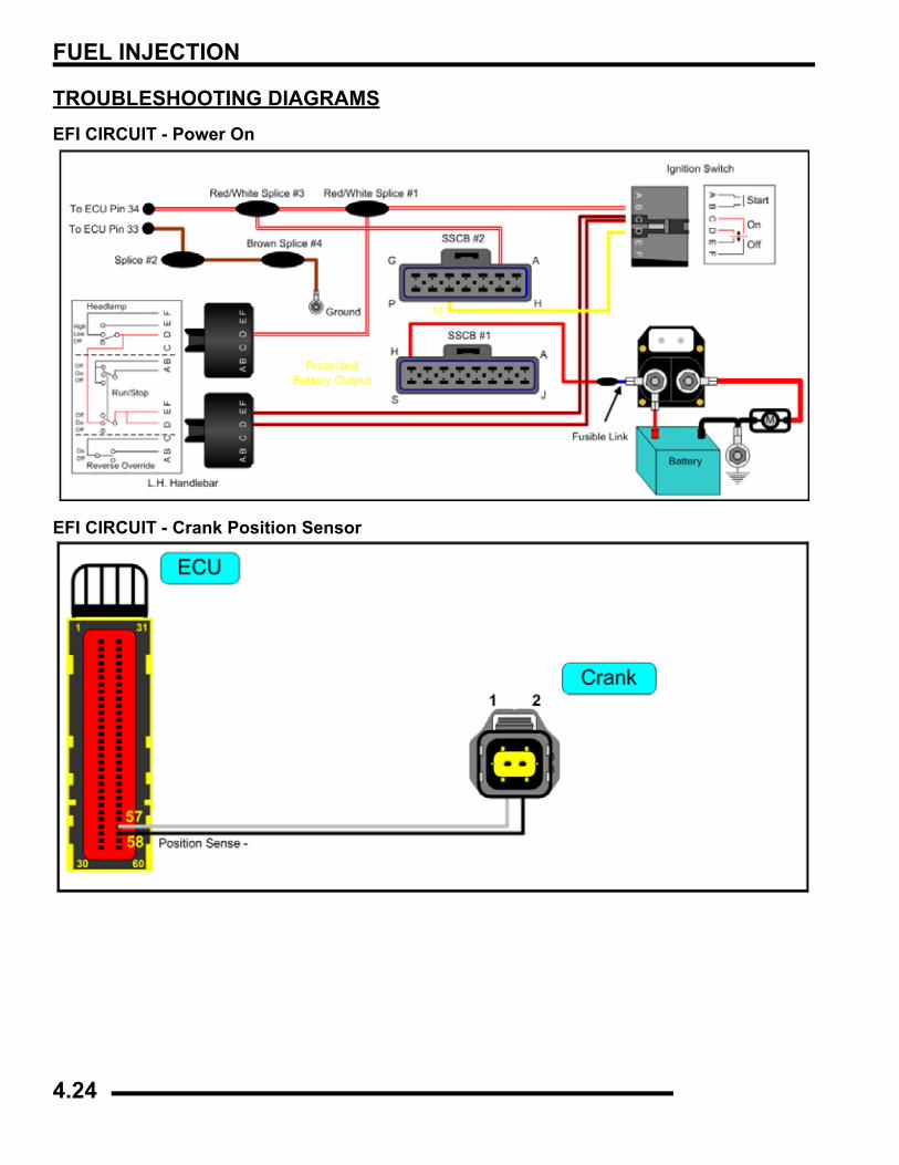
FUEL INJECTION
TROUBLESHOOTING DIAGRAMSEFI CIRCUIT - Power On
EFI CIRCUIT - Crank Position Sensor
4.24
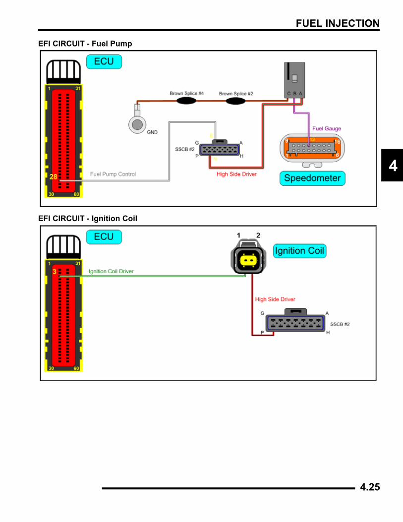
FUEL INJECTION
4
EFI CIRCUIT - Fuel Pump
EFI CIRCUIT - Ignition Coil
4.25
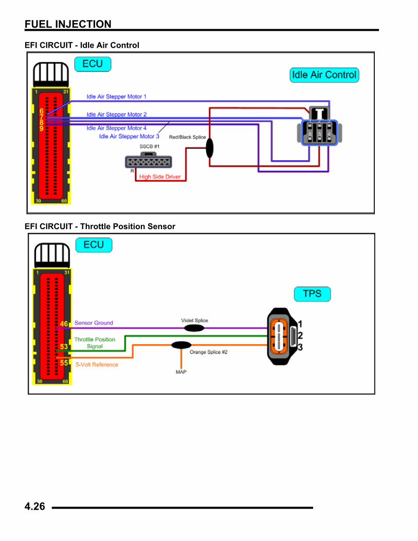
FUEL INJECTION
EFI CIRCUIT - Idle Air Control
EFI CIRCUIT - Throttle Position Sensor
4.26
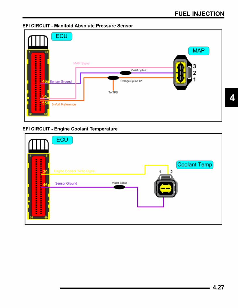
FUEL INJECTION
4
EFI CIRCUIT - Manifold Absolute Pressure Sensor
EFI CIRCUIT - Engine Coolant Temperature
4.27
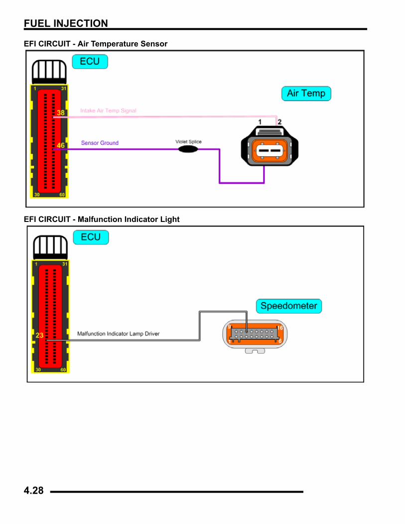
FUEL INJECTION
EFI CIRCUIT - Air Temperature Sensor
EFI CIRCUIT - Malfunction Indicator Light
4.28
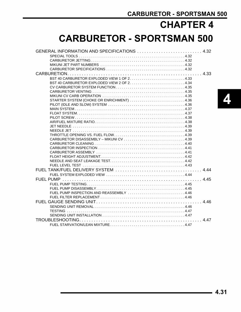
CARBURETOR - SPORTSMAN 500
CHAPTER 4CARBURETOR - SPORTSMAN 500
4
GENERAL INFORMATION AND SPECIFICATIONS . . . . . . . . . . . . . . . . . . . . . . . . . . . 4.32SPECIAL TOOLS . . . . . . . . . . . . . . . . . . . . . . . . . . . . . . . . . . . . . . . . . . . . . . . . . . . . . . 4.32CARBURETOR JETTING. . . . . . . . . . . . . . . . . . . . . . . . . . . . . . . . . . . . . . . . . . . . . . . . 4.32MIKUNI JET PART NUMBERS . . . . . . . . . . . . . . . . . . . . . . . . . . . . . . . . . . . . . . . . . . . 4.32CARBURETOR SPECIFICATIONS . . . . . . . . . . . . . . . . . . . . . . . . . . . . . . . . . . . . . . . . 4.32
CARBURETION. . . . . . . . . . . . . . . . . . . . . . . . . . . . . . . . . . . . . . . . . . . . . . . . . . . . . . . . 4.33BST 40 CARBURETOR EXPLODED VIEW 1 OF 2 . . . . . . . . . . . . . . . . . . . . . . . . . . . . 4.33BST 40 CARBURETOR EXPLODED VIEW 2 OF 2 . . . . . . . . . . . . . . . . . . . . . . . . . . . . 4.34CV CARBURETOR SYSTEM FUNCTION . . . . . . . . . . . . . . . . . . . . . . . . . . . . . . . . . . . 4.35CARBURETOR VENTING . . . . . . . . . . . . . . . . . . . . . . . . . . . . . . . . . . . . . . . . . . . . . . . 4.35MIKUNI CV CARB OPERATION . . . . . . . . . . . . . . . . . . . . . . . . . . . . . . . . . . . . . . . . . . 4.35STARTER SYSTEM (CHOKE OR ENRICHMENT) . . . . . . . . . . . . . . . . . . . . . . . . . . . . 4.36PILOT (IDLE AND SLOW) SYSTEM . . . . . . . . . . . . . . . . . . . . . . . . . . . . . . . . . . . . . . . 4.36MAIN SYSTEM . . . . . . . . . . . . . . . . . . . . . . . . . . . . . . . . . . . . . . . . . . . . . . . . . . . . . . . . 4.37FLOAT SYSTEM. . . . . . . . . . . . . . . . . . . . . . . . . . . . . . . . . . . . . . . . . . . . . . . . . . . . . . . 4.37PILOT SCREW . . . . . . . . . . . . . . . . . . . . . . . . . . . . . . . . . . . . . . . . . . . . . . . . . . . . . . . . 4.38AIR/FUEL MIXTURE RATIO. . . . . . . . . . . . . . . . . . . . . . . . . . . . . . . . . . . . . . . . . . . . . . 4.38JET NEEDLE . . . . . . . . . . . . . . . . . . . . . . . . . . . . . . . . . . . . . . . . . . . . . . . . . . . . . . . . . 4.39NEEDLE JET . . . . . . . . . . . . . . . . . . . . . . . . . . . . . . . . . . . . . . . . . . . . . . . . . . . . . . . . . 4.39THROTTLE OPENING VS. FUEL FLOW. . . . . . . . . . . . . . . . . . . . . . . . . . . . . . . . . . . . 4.39CARBURETOR DISASSEMBLY – MIKUNI CV . . . . . . . . . . . . . . . . . . . . . . . . . . . . . . . 4.39CARBURETOR CLEANING . . . . . . . . . . . . . . . . . . . . . . . . . . . . . . . . . . . . . . . . . . . . . . 4.40CARBURETOR INSPECTION . . . . . . . . . . . . . . . . . . . . . . . . . . . . . . . . . . . . . . . . . . . . 4.41CARBURETOR ASSEMBLY . . . . . . . . . . . . . . . . . . . . . . . . . . . . . . . . . . . . . . . . . . . . . 4.41FLOAT HEIGHT ADJUSTMENT. . . . . . . . . . . . . . . . . . . . . . . . . . . . . . . . . . . . . . . . . . . 4.42NEEDLE AND SEAT LEAKAGE TEST. . . . . . . . . . . . . . . . . . . . . . . . . . . . . . . . . . . . . . 4.42FUEL LEVEL TEST . . . . . . . . . . . . . . . . . . . . . . . . . . . . . . . . . . . . . . . . . . . . . . . . . . . . 4.43
FUEL TANK/FUEL DELIVERY SYSTEM . . . . . . . . . . . . . . . . . . . . . . . . . . . . . . . . . . . . 4.44FUEL SYSTEM EXPLODED VIEW . . . . . . . . . . . . . . . . . . . . . . . . . . . . . . . . . . . . . . . . 4.44
FUEL PUMP . . . . . . . . . . . . . . . . . . . . . . . . . . . . . . . . . . . . . . . . . . . . . . . . . . . . . . . . . . 4.45FUEL PUMP TESTING. . . . . . . . . . . . . . . . . . . . . . . . . . . . . . . . . . . . . . . . . . . . . . . . . . 4.45FUEL PUMP DISASSEMBLY. . . . . . . . . . . . . . . . . . . . . . . . . . . . . . . . . . . . . . . . . . . . . 4.45FUEL PUMP INSPECTION AND REASSEMBLY . . . . . . . . . . . . . . . . . . . . . . . . . . . . . 4.46FUEL FILTER REPLACEMENT . . . . . . . . . . . . . . . . . . . . . . . . . . . . . . . . . . . . . . . . . . . 4.46
FUEL GAUGE SENDING UNIT. . . . . . . . . . . . . . . . . . . . . . . . . . . . . . . . . . . . . . . . . . . . 4.46SENDING UNIT REMOVAL . . . . . . . . . . . . . . . . . . . . . . . . . . . . . . . . . . . . . . . . . . . . . . 4.46TESTING . . . . . . . . . . . . . . . . . . . . . . . . . . . . . . . . . . . . . . . . . . . . . . . . . . . . . . . . . . . . 4.47SENDING UNIT INSTALLATION . . . . . . . . . . . . . . . . . . . . . . . . . . . . . . . . . . . . . . . . . . 4.47
TROUBLESHOOTING. . . . . . . . . . . . . . . . . . . . . . . . . . . . . . . . . . . . . . . . . . . . . . . . . . . 4.47FUEL STARVATION/LEAN MIXTURE . . . . . . . . . . . . . . . . . . . . . . . . . . . . . . . . . . . . . . 4.47
4.31
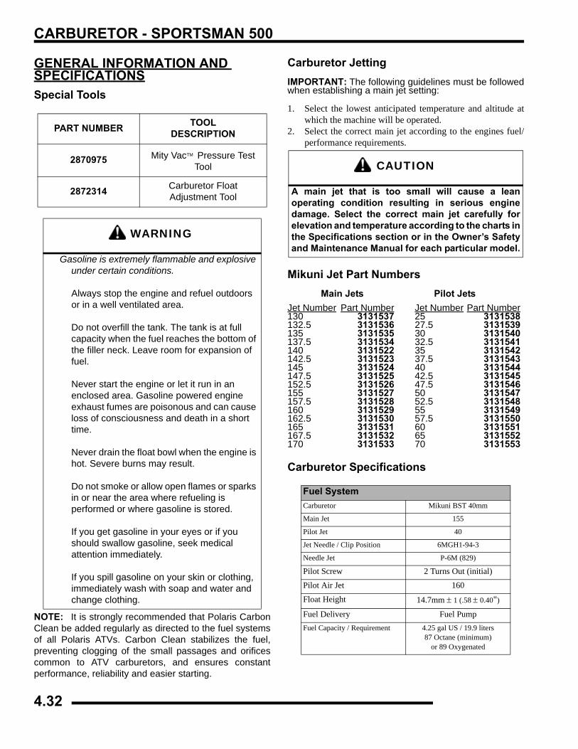
CARBURETOR - SPORTSMAN 500
GENERAL INFORMATION AND SPECIFICATIONSSpecial Tools
NOTE: It is strongly recommended that Polaris CarbonClean be added regularly as directed to the fuel systemsof all Polaris ATVs. Carbon Clean stabilizes the fuel,preventing clogging of the small passages and orificescommon to ATV carburetors, and ensures constantperformance, reliability and easier starting.
Carburetor JettingIMPORTANT: The following guidelines must be followedwhen establishing a main jet setting:
1. Select the lowest anticipated temperature and altitude atwhich the machine will be operated.
2. Select the correct main jet according to the engines fuel/performance requirements.
Mikuni Jet Part NumbersMain Jets Pilot Jets
Jet Number Part Number Jet Number Part Number130 3131537 25 3131538132.5 3131536 27.5 3131539135 3131535 30 3131540137.5 3131534 32.5 3131541140 3131522 35 3131542142.5 3131523 37.5 3131543145 3131524 40 3131544147.5 3131525 42.5 3131545152.5 3131526 47.5 3131546155 3131527 50 3131547157.5 3131528 52.5 3131548160 3131529 55 3131549162.5 3131530 57.5 3131550165 3131531 60 3131551167.5 3131532 65 3131552170 3131533 70 3131553
Carburetor Specifications
PART NUMBER TOOL DESCRIPTION
2870975 Mity VacTM Pressure Test Tool
2872314 Carburetor Float Adjustment Tool
WARNING
Gasoline is extremely flammable and explosive under certain conditions.
Always stop the engine and refuel outdoors or in a well ventilated area.
Do not overfill the tank. The tank is at full capacity when the fuel reaches the bottom of the filler neck. Leave room for expansion of fuel.
Never start the engine or let it run in an enclosed area. Gasoline powered engine exhaust fumes are poisonous and can cause loss of consciousness and death in a short time.
Never drain the float bowl when the engine is hot. Severe burns may result.
Do not smoke or allow open flames or sparks in or near the area where refueling is performed or where gasoline is stored.
If you get gasoline in your eyes or if you should swallow gasoline, seek medical attention immediately.
If you spill gasoline on your skin or clothing, immediately wash with soap and water and change clothing.
CAUTION
A main jet that is too small will cause a leanoperating condition resulting in serious enginedamage. Select the correct main jet carefully forelevation and temperature according to the charts inthe Specifications section or in the Owner’s Safetyand Maintenance Manual for each particular model.
Fuel SystemCarburetor Mikuni BST 40mm
Main Jet 155
Pilot Jet 40
Jet Needle / Clip Position 6MGH1-94-3
Needle Jet P-6M (829)
Pilot Screw 2 Turns Out (initial)
Pilot Air Jet 160
Float Height 14.7mm ± 1 (.58 ± 0.40")
Fuel Delivery Fuel PumpFuel Capacity / Requirement 4.25 gal US / 19.9 liters
87 Octane (minimum) or 89 Oxygenated
4.32
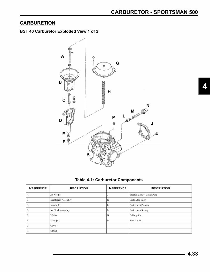
CARBURETOR - SPORTSMAN 500
4
CARBURETIONBST 40 Carburetor Exploded View 1 of 2
Table 4-1: Carburetor Components
REFERENCE DESCRIPTION REFERENCE DESCRIPTION
A Jet Needle J Throttle Control Cover Plate
B Diaphragm Assembly K Carburetor Body
C Needle Jet L Enrichment Plunger
D Jet Block Assembly M Enrichment Spring
E Washer N Cable guide
F Main jet P Pilot Air Jet
G Cover
H Spring
A
B
C
D
E
F
G
H
J
K
LM
N
P
4.33
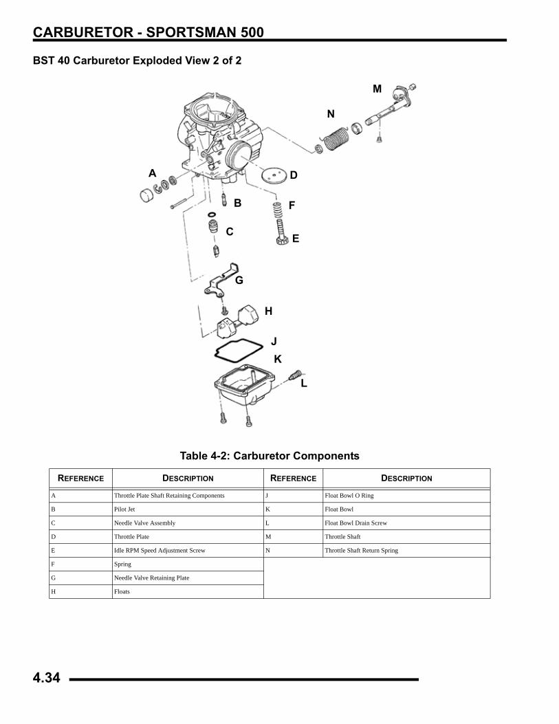
CARBURETOR - SPORTSMAN 500
BST 40 Carburetor Exploded View 2 of 2
Table 4-2: Carburetor Components
REFERENCE DESCRIPTION REFERENCE DESCRIPTION
A Throttle Plate Shaft Retaining Components J Float Bowl O Ring
B Pilot Jet K Float Bowl
C Needle Valve Assembly L Float Bowl Drain Screw
D Throttle Plate M Throttle Shaft
E Idle RPM Speed Adjustment Screw N Throttle Shaft Return Spring
F Spring
G Needle Valve Retaining Plate
H Floats
A
B
C
D
E
F
G
H
JK
L
M
N
4.34
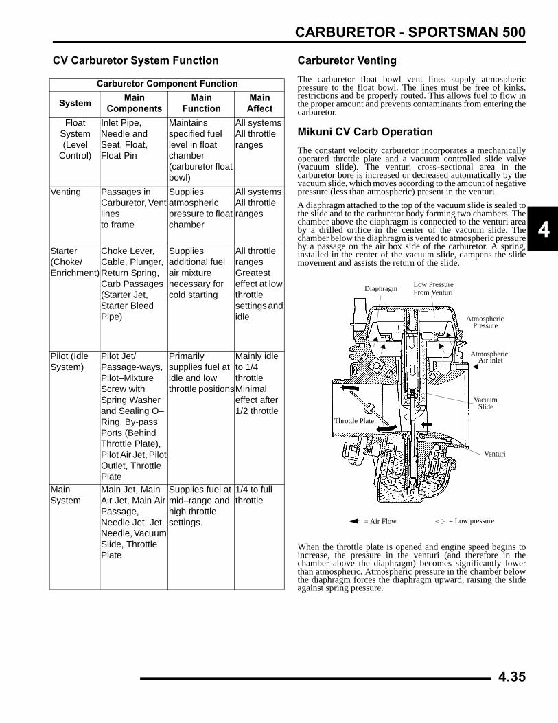
CARBURETOR - SPORTSMAN 500
4
CV Carburetor System Function Carburetor VentingThe carburetor float bowl vent lines supply atmosphericpressure to the float bowl. The lines must be free of kinks,restrictions and be properly routed. This allows fuel to flow inthe proper amount and prevents contaminants from entering thecarburetor.
Mikuni CV Carb OperationThe constant velocity carburetor incorporates a mechanicallyoperated throttle plate and a vacuum controlled slide valve(vacuum slide). The venturi cross–sectional area in thecarburetor bore is increased or decreased automatically by thevacuum slide, which moves according to the amount of negativepressure (less than atmospheric) present in the venturi. A diaphragm attached to the top of the vacuum slide is sealed tothe slide and to the carburetor body forming two chambers. Thechamber above the diaphragm is connected to the venturi areaby a drilled orifice in the center of the vacuum slide. Thechamber below the diaphragm is vented to atmospheric pressureby a passage on the air box side of the carburetor. A spring,installed in the center of the vacuum slide, dampens the slidemovement and assists the return of the slide.
When the throttle plate is opened and engine speed begins toincrease, the pressure in the venturi (and therefore in thechamber above the diaphragm) becomes significantly lowerthan atmospheric. Atmospheric pressure in the chamber belowthe diaphragm forces the diaphragm upward, raising the slideagainst spring pressure.
Carburetor Component Function
System MainComponents
MainFunction
Main Affect
FloatSystem(Level
Control)
Inlet Pipe, Needle and Seat, Float, Float Pin
Maintains specified fuel level in float chamber (carburetor float bowl)
All systemsAll throttle ranges
Venting Passages in Carburetor, Vent linesto frame
Suppliesatmospheric pressure to float chamber
All systemsAll throttle ranges
Starter(Choke/Enrichment)
Choke Lever, Cable, Plunger, Return Spring, Carb Passages (Starter Jet, Starter Bleed Pipe)
Supplies additional fuel air mixture necessary for cold starting
All throttle rangesGreatest effect at low throttle settings and idle
Pilot (Idle System)
Pilot Jet/Passage-ways, Pilot–Mixture Screw with Spring Washer and Sealing O–Ring, By-pass Ports (Behind Throttle Plate), Pilot Air Jet, Pilot Outlet, Throttle Plate
Primarily supplies fuel at idle and low throttle positions
Mainly idle to 1/4 throttleMinimal effect after 1/2 throttle
Main System
Main Jet, Main Air Jet, Main Air Passage, Needle Jet, Jet Needle, Vacuum Slide, Throttle Plate
Supplies fuel at mid–range and high throttle settings.
1/4 to full throttle
Throttle Plate
Diaphragm Low PressureFrom Venturi
AtmosphericPressure
Air inletAtmospheric
VacuumSlide
Venturi
= Air Flow = Low pressure
4.35
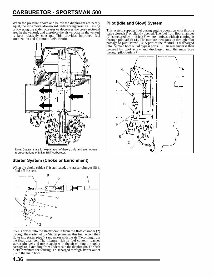
CARBURETOR - SPORTSMAN 500
When the pressure above and below the diaphragm are nearlyequal, the slide moves downward under spring pressure. Raisingor lowering the slide increases or decreases the cross sectionalarea in the venturi, and therefore the air velocity in the venturiis kept relatively constant. This provides improved fuelatomization and optimum fuel/air ratio.
Starter System (Choke or Enrichment)When the choke cable (1) is activated, the starter plunger (5) islifted off the seat.
Fuel is drawn into the starter circuit from the float chamber (2)through the starter jet (3). Starter jet meters this fuel, which thenflows into starter pipe (4) and mixes with the air (7) coming fromthe float chamber. The mixture, rich in fuel content, reachesstarter plunger and mixes again with the air coming through apassage (8) extending from underneath the diaphragm. The richfuel/air mixture for starting is discharged through starter outlet(6) in the main bore.
Pilot (Idle and Slow) System This system supplies fuel during engine operation with throttlevalve closed (1) or slightly opened. The fuel from float chamber(2) is metered by pilot jet (3) where it mixes with air coming inthrough pilot air jet (4). The mixture then goes up through pilotpassage to pilot screw (5). A part of the mixture is dischargedinto the main bore out of bypass ports (6). The remainder is thenmetered by pilot screw and discharged into the main borethrough pilot outlet (7).
Note: Diagrams are for explanation of theory only, and are not truerepresentations of Mikini BST carburetor.
1
2
3
4
5
67
8
4
1
6
7
52
3
4.36
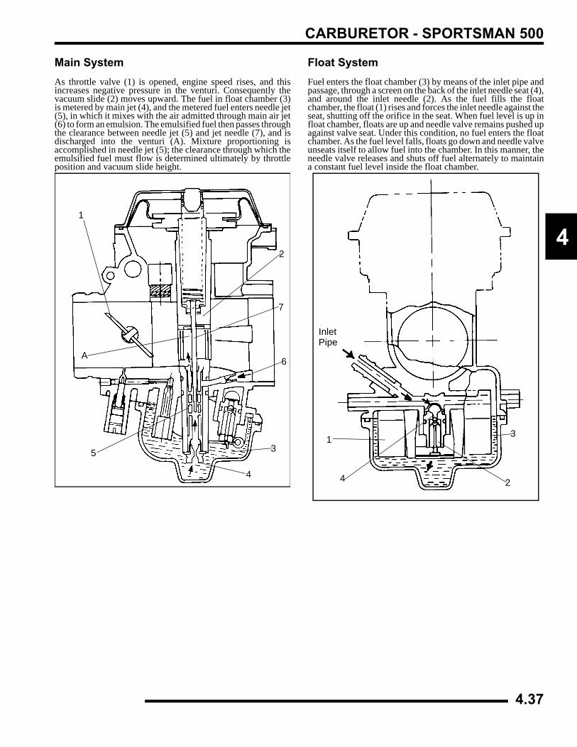
CARBURETOR - SPORTSMAN 500
4
Main SystemAs throttle valve (1) is opened, engine speed rises, and thisincreases negative pressure in the venturi. Consequently thevacuum slide (2) moves upward. The fuel in float chamber (3)is metered by main jet (4), and the metered fuel enters needle jet(5), in which it mixes with the air admitted through main air jet(6) to form an emulsion. The emulsified fuel then passes throughthe clearance between needle jet (5) and jet needle (7), and isdischarged into the venturi (A). Mixture proportioning isaccomplished in needle jet (5); the clearance through which theemulsified fuel must flow is determined ultimately by throttleposition and vacuum slide height.
Float System Fuel enters the float chamber (3) by means of the inlet pipe andpassage, through a screen on the back of the inlet needle seat (4),and around the inlet needle (2). As the fuel fills the floatchamber, the float (1) rises and forces the inlet needle against theseat, shutting off the orifice in the seat. When fuel level is up infloat chamber, floats are up and needle valve remains pushed upagainst valve seat. Under this condition, no fuel enters the floatchamber. As the fuel level falls, floats go down and needle valveunseats itself to allow fuel into the chamber. In this manner, theneedle valve releases and shuts off fuel alternately to maintaina constant fuel level inside the float chamber.
1
2
3
4
5
6
7
A
InletPipe
1
2
3
4
4.37
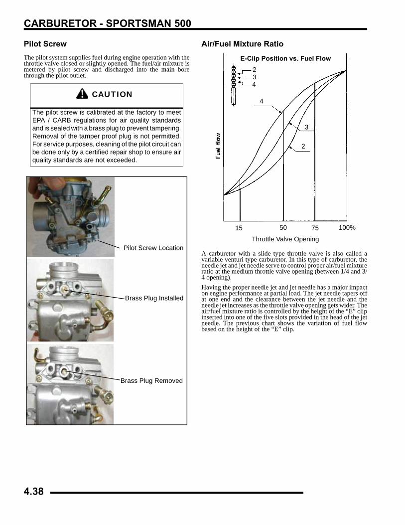
CARBURETOR - SPORTSMAN 500
Pilot ScrewThe pilot system supplies fuel during engine operation with thethrottle valve closed or slightly opened. The fuel/air mixture ismetered by pilot screw and discharged into the main borethrough the pilot outlet.
Air/Fuel Mixture Ratio
A carburetor with a slide type throttle valve is also called avariable venturi type carburetor. In this type of carburetor, theneedle jet and jet needle serve to control proper air/fuel mixtureratio at the medium throttle valve opening (between 1/4 and 3/4 opening). Having the proper needle jet and jet needle has a major impacton engine performance at partial load. The jet needle tapers offat one end and the clearance between the jet needle and theneedle jet increases as the throttle valve opening gets wider. Theair/fuel mixture ratio is controlled by the height of the “E” clipinserted into one of the five slots provided in the head of the jetneedle. The previous chart shows the variation of fuel flowbased on the height of the “E” clip.
CAUTION
The pilot screw is calibrated at the factory to meetEPA / CARB regulations for air quality standardsand is sealed with a brass plug to prevent tampering.Removal of the tamper proof plug is not permitted.For service purposes, cleaning of the pilot circuit canbe done only by a certified repair shop to ensure airquality standards are not exceeded.
Pilot Screw Location
Brass Plug Installed
Brass Plug Removed
E-Clip Position vs. Fuel Flow
Throttle Valve Opening
234
4
3
2
15 50 75 100%
4.38
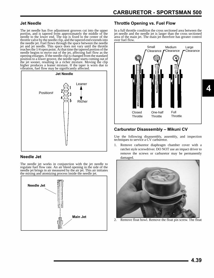
CARBURETOR - SPORTSMAN 500
4
Jet NeedleThe jet needle has five adjustment grooves cut into the upperportion, and is tapered from approximately the middle of theneedle to the lower end. The top is fixed to the center of thethrottle valve by the needle clip, and the tapered end extends intothe needle jet. Fuel flows through the space between the needlejet and jet needle. This space does not vary until the throttlereaches the 1/4 open point. At that time the tapered portion of theneedle begins to move out of the jet, affecting fuel flow as theopening enlarges. If the needle clip is changed from the standardposition to a lower groove, the needle taper starts coming out ofthe jet sooner, resulting in a richer mixture. Moving the cliphigher produces a leaner mixture. If the taper is worn due tovibration, fuel flow may be significantly affected.
Needle JetThe needle jet works in conjunction with the jet needle toregulate fuel flow rate. An air bleed opening in the side of theneedle jet brings in air measured by the air jet. This air initiatesthe mixing and atomizing process inside the needle jet.
Throttle Opening vs. Fuel FlowIn a full throttle condition the cross sectioned area between thejet needle and the needle jet is larger than the cross sectionedarea of the main jet. The main jet therefore has greater controlover fuel flow.
Carburetor Disassembly – Mikuni CVUse the following disassembly, assembly, and inspectiontechniques to service a CV carburetor.1. Remove carburetor diaphragm chamber cover with a
ratchet style screwdriver. DO NOT use an impact driver toremove the screws or carburetor may be permanentlydamaged.
2. Remove float bowl. Remove the float pin screw. The float
Leaner
Richer
Position#
Jet Needle
Needle Jet
Main Jet
ClosedThrottle
One-halfThrottle
FullThrottle
SmallClearance
MediumClearance
LargeClearance
4.39
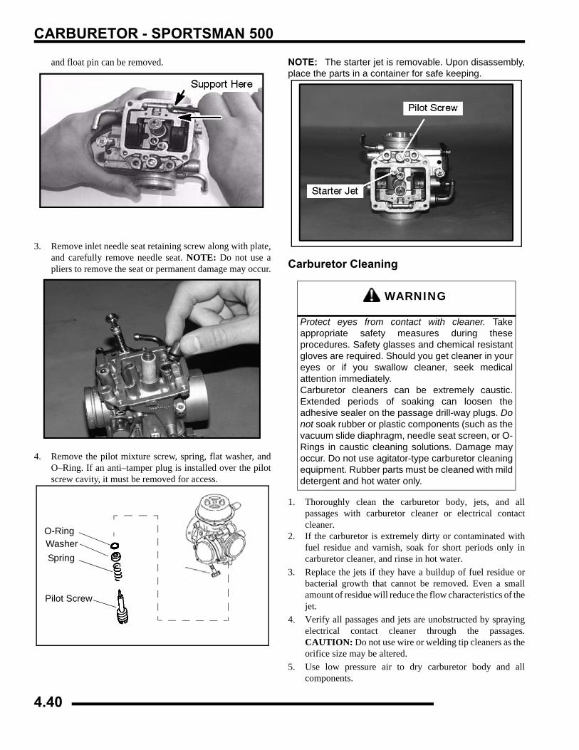
CARBURETOR - SPORTSMAN 500
and float pin can be removed.
3. Remove inlet needle seat retaining screw along with plate,and carefully remove needle seat. NOTE: Do not use apliers to remove the seat or permanent damage may occur.
4. Remove the pilot mixture screw, spring, flat washer, andO–Ring. If an anti–tamper plug is installed over the pilotscrew cavity, it must be removed for access.
NOTE: The starter jet is removable. Upon disassembly,place the parts in a container for safe keeping.
Carburetor Cleaning
1. Thoroughly clean the carburetor body, jets, and allpassages with carburetor cleaner or electrical contactcleaner.
2. If the carburetor is extremely dirty or contaminated withfuel residue and varnish, soak for short periods only incarburetor cleaner, and rinse in hot water.
3. Replace the jets if they have a buildup of fuel residue orbacterial growth that cannot be removed. Even a smallamount of residue will reduce the flow characteristics of thejet.
4. Verify all passages and jets are unobstructed by sprayingelectrical contact cleaner through the passages.CAUTION: Do not use wire or welding tip cleaners as theorifice size may be altered.
5. Use low pressure air to dry carburetor body and allcomponents.
Remove Screw
O-RingWasherSpring
Pilot Screw
WARNING
Protect eyes from contact with cleaner. Takeappropriate safety measures during theseprocedures. Safety glasses and chemical resistantgloves are required. Should you get cleaner in youreyes or if you swallow cleaner, seek medicalattention immediately.Carburetor cleaners can be extremely caustic.Extended periods of soaking can loosen theadhesive sealer on the passage drill-way plugs. Donot soak rubber or plastic components (such as thevacuum slide diaphragm, needle seat screen, or O-Rings in caustic cleaning solutions. Damage mayoccur. Do not use agitator-type carburetor cleaningequipment. Rubber parts must be cleaned with milddetergent and hot water only.
4.40
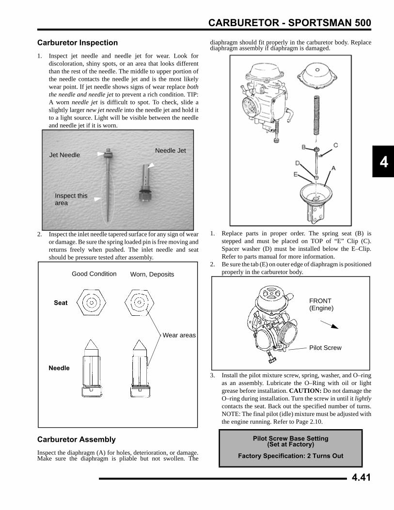
CARBURETOR - SPORTSMAN 500
4
Carburetor Inspection1. Inspect jet needle and needle jet for wear. Look for
discoloration, shiny spots, or an area that looks differentthan the rest of the needle. The middle to upper portion ofthe needle contacts the needle jet and is the most likelywear point. If jet needle shows signs of wear replace boththe needle and needle jet to prevent a rich condition. TIP:A worn needle jet is difficult to spot. To check, slide aslightly larger new jet needle into the needle jet and hold itto a light source. Light will be visible between the needleand needle jet if it is worn.
2. Inspect the inlet needle tapered surface for any sign of wearor damage. Be sure the spring loaded pin is free moving andreturns freely when pushed. The inlet needle and seatshould be pressure tested after assembly.
Carburetor AssemblyInspect the diaphragm (A) for holes, deterioration, or damage.Make sure the diaphragm is pliable but not swollen. The
diaphragm should fit properly in the carburetor body. Replacediaphragm assembly if diaphragm is damaged.
1. Replace parts in proper order. The spring seat (B) isstepped and must be placed on TOP of “E” Clip (C).Spacer washer (D) must be installed below the E–Clip.Refer to parts manual for more information.
2. Be sure the tab (E) on outer edge of diaphragm is positionedproperly in the carburetor body.
3. Install the pilot mixture screw, spring, washer, and O–ringas an assembly. Lubricate the O–Ring with oil or lightgrease before installation. CAUTION: Do not damage theO–ring during installation. Turn the screw in until it lightlycontacts the seat. Back out the specified number of turns.NOTE: The final pilot (idle) mixture must be adjusted withthe engine running. Refer to Page 2.10.
Inspect thisarea
Jet NeedleNeedle Jet
Good Condition Worn, Deposits
Seat
Needle
Wear areas
Pilot Screw Base Setting(Set at Factory)
Factory Specification: 2 Turns Out
FRONT(Engine)
Pilot Screw
4.41
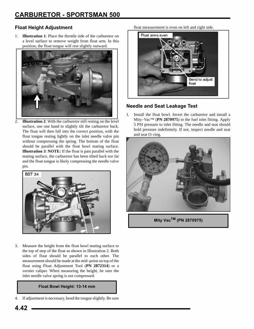
CARBURETOR - SPORTSMAN 500
Float Height Adjustment1. Illustration 1: Place the throttle side of the carburetor on
a level surface to remove weight from float arm. In thisposition, the float tongue will rest slightly outward.
2. Illustration 2: With the carburetor still resting on the levelsurface, use one hand to slightly tilt the carburetor back.The float will then fall into the correct position, with thefloat tongue resting lightly on the inlet needle valve pinwithout compressing the spring. The bottom of the floatshould be parallel with the float bowl mating surface.Illustration 3: NOTE: If the float is past parallel with themating surface, the carburetor has been tilted back too farand the float tongue is likely compressing the needle valvepin.
3. Measure the height from the float bowl mating surface tothe top of step of the float as shown in Illustration 2. Bothsides of float should be parallel to each other. Themeasurement should be made at the mid–point on top of thefloat using Float Adjustment Tool (PN 2872314) or avernier caliper. When measuring the height, be sure theinlet needle valve spring is not compressed.
4. If adjustment is necessary, bend the tongue slightly. Be sure
float measurement is even on left and right side.
Needle and Seat Leakage Test1. Install the float bowl. Invert the carburetor and install a
Mity–Vac™ (PN 2870975) to the fuel inlet fitting. Apply5 PSI pressure to inlet fitting. The needle and seat shouldhold pressure indefinitely. If not, inspect needle and seatand seat O–ring.
Float Bowl Height: 13-14 mm
Float parallel with floatbowl mating surface
Mity VacTM (PN 2870975)
4.42
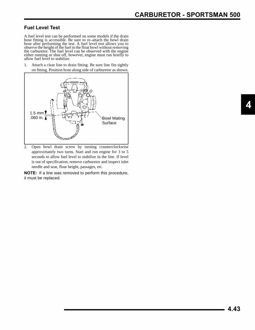
CARBURETOR - SPORTSMAN 500
4
Fuel Level TestA fuel level test can be performed on some models if the drainhose fitting is accessible. Be sure to re–attach the bowl drainhose after performing the test. A fuel level test allows you toobserve the height of the fuel in the float bowl without removingthe carburetor. The fuel level can be observed with the engineeither running or shut off, however, engine must run briefly toallow fuel level to stabilize.1. Attach a clear line to drain fitting. Be sure line fits tightly
on fitting. Position hose along side of carburetor as shown.
2. Open bowl drain screw by turning counterclockwiseapproximately two turns. Start and run engine for 3 to 5seconds to allow fuel level to stabilize in the line. If levelis out of specification, remove carburetor and inspect inletneedle and seat, float height, passages, etc.
NOTE: If a line was removed to perform this procedure,it must be replaced.
Bowl MatingSurface
1.5 mm.060 in.
4.43
CARBURETOR - SPORTSMAN 500
FUEL TANK/FUEL DELIVERY SYSTEMFuel System Exploded View
4.44
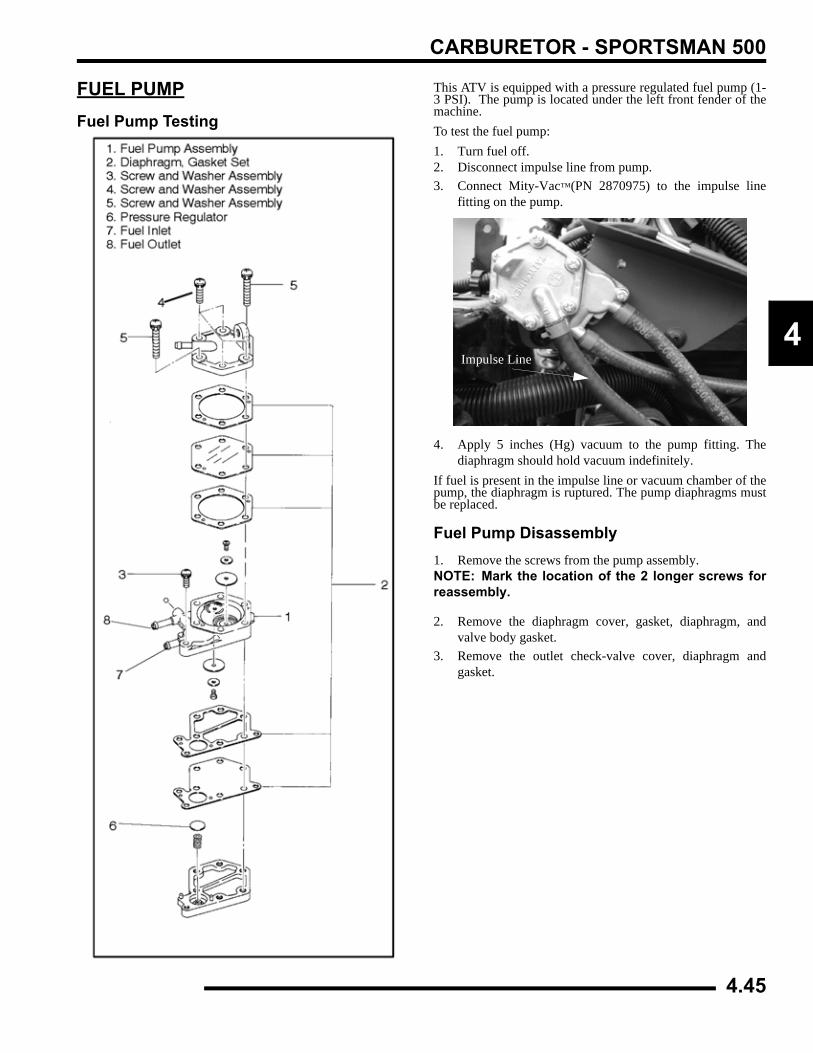
CARBURETOR - SPORTSMAN 500
4
FUEL PUMPFuel Pump Testing
This ATV is equipped with a pressure regulated fuel pump (1-3 PSI). The pump is located under the left front fender of themachine.To test the fuel pump:1. Turn fuel off.2. Disconnect impulse line from pump.3. Connect Mity-Vac™(PN 2870975) to the impulse line
fitting on the pump.
4. Apply 5 inches (Hg) vacuum to the pump fitting. Thediaphragm should hold vacuum indefinitely.
If fuel is present in the impulse line or vacuum chamber of thepump, the diaphragm is ruptured. The pump diaphragms mustbe replaced.
Fuel Pump Disassembly1. Remove the screws from the pump assembly.NOTE: Mark the location of the 2 longer screws forreassembly.
2. Remove the diaphragm cover, gasket, diaphragm, andvalve body gasket.
3. Remove the outlet check-valve cover, diaphragm andgasket.
Impulse Line
4.45
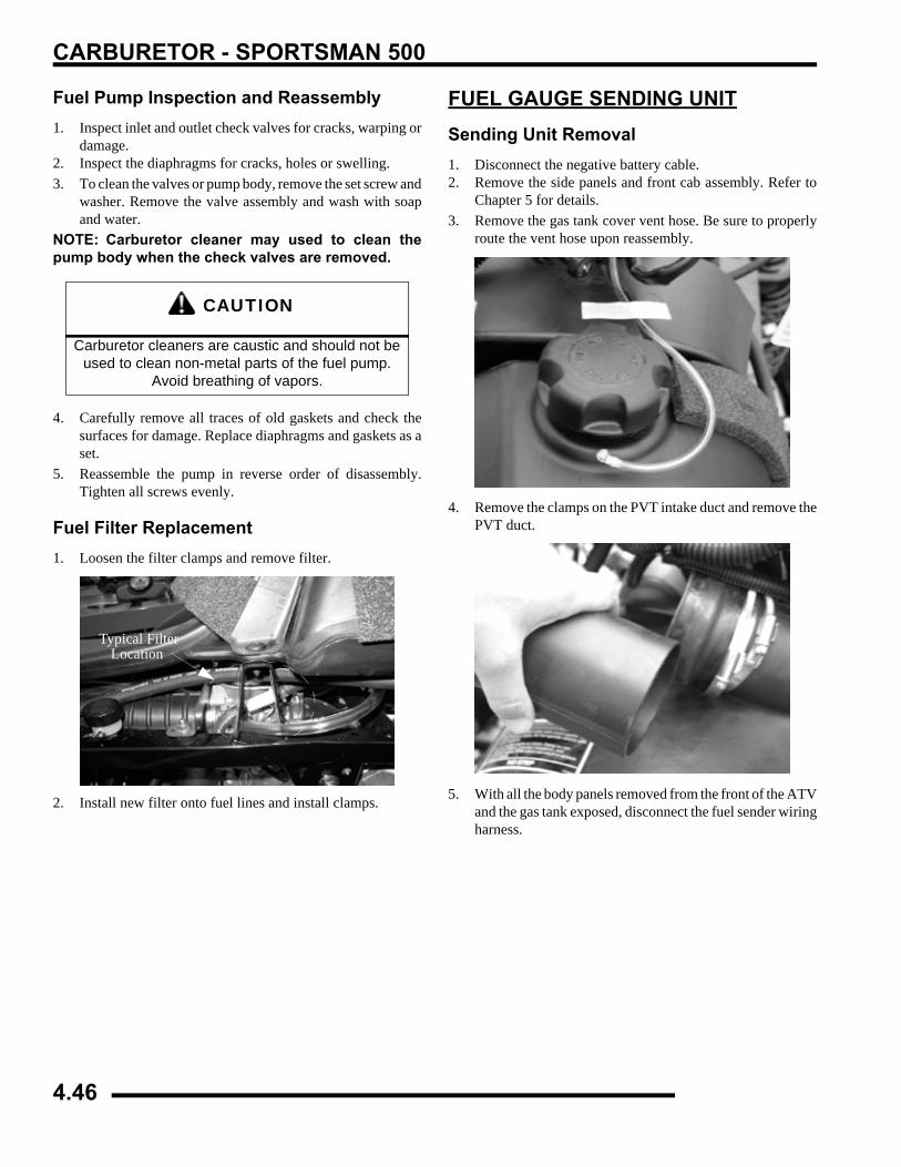
CARBURETOR - SPORTSMAN 500
Fuel Pump Inspection and Reassembly1. Inspect inlet and outlet check valves for cracks, warping or
damage.2. Inspect the diaphragms for cracks, holes or swelling.3. To clean the valves or pump body, remove the set screw and
washer. Remove the valve assembly and wash with soapand water.
NOTE: Carburetor cleaner may used to clean thepump body when the check valves are removed.
4. Carefully remove all traces of old gaskets and check thesurfaces for damage. Replace diaphragms and gaskets as aset.
5. Reassemble the pump in reverse order of disassembly.Tighten all screws evenly.
Fuel Filter Replacement1. Loosen the filter clamps and remove filter.
2. Install new filter onto fuel lines and install clamps.
FUEL GAUGE SENDING UNITSending Unit Removal1. Disconnect the negative battery cable.2. Remove the side panels and front cab assembly. Refer to
Chapter 5 for details.3. Remove the gas tank cover vent hose. Be sure to properly
route the vent hose upon reassembly.
4. Remove the clamps on the PVT intake duct and remove thePVT duct.
5. With all the body panels removed from the front of the ATVand the gas tank exposed, disconnect the fuel sender wiringharness.
CAUTION
Carburetor cleaners are caustic and should not be used to clean non-metal parts of the fuel pump.
Avoid breathing of vapors.
Typical FilterLocation
4.46
CARBURETOR - SPORTSMAN 500
4
6. Remove the 5 screws that secure the fuel sender to the tank.
7. Slowly lift the sender out of the tank. Lift the sender out atan angle, so the float will more easily come out of the fueltank.
TestingRefer to Chapter 10 for fuel gauge sending unit troubleshooting.
Sending Unit Installation1. Reinstall the fuel sender with a new gasket, using care not
to bend or damage the float arm.2. Install the 5 screws and torque the screws to specification.
Reconnect the sender and route the harness properly.
3. Reinstall the PVT intake duct, gas tank vent line, front cabassembly, and side panels.
NOTE: Properly route the gas tank vent line, usetape to secure the vent line in place. (See Pic 1).
4. Reconnect the negative battery cable. Test the sender forproper operation.
TROUBLESHOOTINGFUEL STARVATION/LEAN MIXTURE
Symptoms: Hard start or no start, bog, backfire, poppingthrough intake / exhaust, hesitation, detonation, low power,spark plug erosion, engine runs hot, surging, high idle, idlespeed erratic.
• No fuel in tank
• Restricted tank vent, or routed improperly
• Fuel lines or fuel valve restricted
• Fuel filter plugged
• Carburetor vent line(s) restricted
• Plugged or restricted inlet needle and seat screenor inlet passage
• Clogged jets or passages
• Float stuck, holding inlet needle closed or inletneedle stuck
• Float level too low
• Intake air leak ( throttle shaft, intake ducts, airboxor air cleaner cover)
• Jet needle position incorrect
• Incorrect pilot screw adjustment
RICH MIXTURESymptoms: Fouls spark plugs, black, sooty exhaust smoke,rough idle, poor fuel economy, engine runs rough/ misses, poorperformance, bog, engine loads up, backfire.
• Air intake restricted (inspect intake duct)
• Air filter dirty/plugged
• Electric choke inoperative
• Incorrect pilot air/fuel screw adjustment
• Faulty inlet needle and seat
• Faulty inlet needle seat O-Ring
• Float level too high
• Poor fuel quality (old fuel)
• Loose jets
• Worn jet needle/needle jet or other carburetorparts
• Dirty carburetor (air bleed passages or jets)
= T
Sending Unit Screw Torque:18--24 in.lbs. (2--3 Nm) in criss-cross pattern
4.47
CARBURETOR - SPORTSMAN 500
POOR IDLEIdle Too High
• Idle adjusted improperly/idle mixture screwdamaged
• Sticky vacuum slide
• Throttle cable sticking, improperly adjusted, routedincorrectly
• Choke cable sticking, improperly adjusted, routedincorrectly
• Plugged or restricted idle jet
Idle Too Low• Choke cable bending or incorrectly adjusted
• Idle speed set incorrectly
• Idle mixture screw misadjusted or damaged
• Belt dragging
• Ignition timing incorrect
• Worn jet needle/needle jet
• Plugged or restricted idle jet
Erratic Idle• Choke cable bending or incorrectly adjusted
• Throttle cable incorrectly adjusted
• Air leaks, dirty carburetor passages (pilot circuit)
• Pilot mixture screw damaged or adjustedincorrectly
• Tight valves
• Ignition timing incorrect
• Belt dragging
• Dirty air cleaner
• Engine worn
• Spark plug fouled
• Idle speed set incorrectly (speed limiter)
• Worn jet needle/needle jet
• Plugged or restricted idle jet
4.48
BODY / STEERING / SUSPENSION
CHAPTER 5BODY / STEERING / SUSPENSION
5
GENERAL INFORMATION . . . . . . . . . . . . . . . . . . . . . . . . . . . . . . . . . . . . . . . . . . . . . . . . 5.2TORQUE SPECIFICATIONS . . . . . . . . . . . . . . . . . . . . . . . . . . . . . . . . . . . . . . . . . . . . . . 5.2SPECIAL TOOLS . . . . . . . . . . . . . . . . . . . . . . . . . . . . . . . . . . . . . . . . . . . . . . . . . . . . . . . 5.2DECAL REPLACEMENT . . . . . . . . . . . . . . . . . . . . . . . . . . . . . . . . . . . . . . . . . . . . . . . . . 5.2PLASTIC INSERT REMOVAL / INSTALLATION . . . . . . . . . . . . . . . . . . . . . . . . . . . . . . . 5.3
BODY. . . . . . . . . . . . . . . . . . . . . . . . . . . . . . . . . . . . . . . . . . . . . . . . . . . . . . . . . . . . . . . . . 5.4SIDE PANEL REMOVAL . . . . . . . . . . . . . . . . . . . . . . . . . . . . . . . . . . . . . . . . . . . . . . . . . 5.4FRONT COVER REMOVAL / INSTALLATION. . . . . . . . . . . . . . . . . . . . . . . . . . . . . . . . . 5.4FOOT WELL REMOVAL / INSTALLATION . . . . . . . . . . . . . . . . . . . . . . . . . . . . . . . . . . . 5.5X2-TOURING FOOT WELL REMOVAL / INSTALLATION. . . . . . . . . . . . . . . . . . . . . . . . 5.5FRONT STORAGE REMOVAL . . . . . . . . . . . . . . . . . . . . . . . . . . . . . . . . . . . . . . . . . . . . 5.6FRONT STORAGE INSTALLATION . . . . . . . . . . . . . . . . . . . . . . . . . . . . . . . . . . . . . . . . 5.8SPORTSMAN REAR RACK REMOVAL / INSTALLATION . . . . . . . . . . . . . . . . . . . . . . . 5.8FRONT CAB/FENDER REMOVAL/INSTALLATION . . . . . . . . . . . . . . . . . . . . . . . . . . . . 5.9SPORTSMAN REAR CAB / FENDER REMOVAL / INSTALLATION. . . . . . . . . . . . . . . 5.10X2-TOURING REAR QUARTER PANEL REMOVAL / INSTALLATION . . . . . . . . . . . . 5.10SPORTSMAN REAR STORAGE REMOVAL / INSTALLATION . . . . . . . . . . . . . . . . . . 5.11RADIATOR SCREEN REMOVAL. . . . . . . . . . . . . . . . . . . . . . . . . . . . . . . . . . . . . . . . . . 5.11SPORTSMAN BODY ASSEMBLY EXPLODED VIEW. . . . . . . . . . . . . . . . . . . . . . . . . . 5.12X2-TOURING BODY ASSEMBLY EXPLODED VIEW . . . . . . . . . . . . . . . . . . . . . . . . . . 5.13TOURING BODY/RACK ASSEMBLY EXPLODED VIEW . . . . . . . . . . . . . . . . . . . . . . . 5.14BODY / RACK EXPLODED VIEWS . . . . . . . . . . . . . . . . . . . . . . . . . . . . . . . . . . . . . . . . 5.15TOURING BODY/SEAT ASSEMBLY EXPLODED VIEW. . . . . . . . . . . . . . . . . . . . . . . . 5.16HEADLIGHT POD EXPLODED VIEW . . . . . . . . . . . . . . . . . . . . . . . . . . . . . . . . . . . . . . 5.17
STEERING . . . . . . . . . . . . . . . . . . . . . . . . . . . . . . . . . . . . . . . . . . . . . . . . . . . . . . . . . . . 5.18HANDLEBAR BLOCK INSTALLATION PROCEDURE . . . . . . . . . . . . . . . . . . . . . . . . . 5.18STEERING / A-ARM EXPLODED VIEW . . . . . . . . . . . . . . . . . . . . . . . . . . . . . . . . . . . . 5.19A-ARM REPLACEMENT . . . . . . . . . . . . . . . . . . . . . . . . . . . . . . . . . . . . . . . . . . . . . . . . 5.20BALL JOINT REPLACEMENT . . . . . . . . . . . . . . . . . . . . . . . . . . . . . . . . . . . . . . . . . . . . 5.21STEERING POST REMOVAL . . . . . . . . . . . . . . . . . . . . . . . . . . . . . . . . . . . . . . . . . . . . 5.22STEERING POST ASSEMBLY . . . . . . . . . . . . . . . . . . . . . . . . . . . . . . . . . . . . . . . . . . . 5.22
SUSPENSION . . . . . . . . . . . . . . . . . . . . . . . . . . . . . . . . . . . . . . . . . . . . . . . . . . . . . . . . . 5.22FRONT STRUT CARTRIDGE REPLACEMENT . . . . . . . . . . . . . . . . . . . . . . . . . . . . . . 5.22STRUT ASSEMBLY . . . . . . . . . . . . . . . . . . . . . . . . . . . . . . . . . . . . . . . . . . . . . . . . . . . . 5.23SPORTSMAN REAR SUSPENSION ASSEMBLY . . . . . . . . . . . . . . . . . . . . . . . . . . . . . 5.24X2-TOURING REAR SUSPENSION EXPLODED VIEW . . . . . . . . . . . . . . . . . . . . . . . . 5.25X2-TOURING TORSION BAR EXPLODED VIEW . . . . . . . . . . . . . . . . . . . . . . . . . . . . . 5.26
X2 CARGO BOX . . . . . . . . . . . . . . . . . . . . . . . . . . . . . . . . . . . . . . . . . . . . . . . . . . . . . . . 5.27EXPLODED VIEW . . . . . . . . . . . . . . . . . . . . . . . . . . . . . . . . . . . . . . . . . . . . . . . . . . . . . 5.27REMOVAL / INSTALLATION . . . . . . . . . . . . . . . . . . . . . . . . . . . . . . . . . . . . . . . . . . . . . 5.28
X2 SEAT ASSEMBLY . . . . . . . . . . . . . . . . . . . . . . . . . . . . . . . . . . . . . . . . . . . . . . . . . . . 5.30EXPLODED VIEWS . . . . . . . . . . . . . . . . . . . . . . . . . . . . . . . . . . . . . . . . . . . . . . . . . . . . 5.30X2 SEAT OPERATION - CONFIGURING CARGO BOX FOR PASSENGER RIDING . 5.31X2 DRIVER SEAT BACKREST REMOVAL / INSTALLATION. . . . . . . . . . . . . . . . . . . . 5.32X2 PASSENGER SEAT BACKREST REMOVAL / INSTALLATION . . . . . . . . . . . . . . . 5.32
5.1
BODY / STEERING / SUSPENSION
GENERAL INFORMATIONTorque Specifications
NOTE: Refer to exploded views throughout thischapter for identification and location ofcomponents.
Special Tools
Decal ReplacementFlame Treating Decal AreaPlastic polyethylene material must be “flame treated" prior toinstalling a decal to ensure good adhesion. The flame treatingprocedure can often be used to reduce or eliminate the whitishstress marks that are sometimes left after a fender or cab is bent,flexed, or damaged.
1. Pass the flame tip of a propane torch back and forth quicklyover the area where the decal is to be applied until thesurface appears slightly glossy. This should occur afterjust a few seconds of flame treating. Do not hold the torchtoo close to the surface. Keep the torch moving to preventdamage.
2. Apply the decal.
Table 5-1:
COMPONENTFT.LBS. (IN.LBS.) NM
Front Hub Nut 60 81
Front A-Arm Attaching Bolt 37 50
Front A-Arm Ball Joint Stud Nut 30 41
Handlebar Adjuster Block 14 23
Master Cylinder Clamp Bolt (45-55) 5.2-6.3
Rear Shock Bolt (Upper) 30 41
Rear Shock Bolt (Lower) 30 41
Rear Wheel Hub Nut 80 109
Upper Stabilizer Support Nuts 17 27
Upper Control Arm Mounting Bolt 37 50
Lower Wheel Bearing Carrier Bolt 37 50
Strut Rod Retaining Nut (Top) 15 21
Strut Casting Pinch Bolt 17 27
Tie Rod End Jam Nut 12 17
Tie Rod End Castle Nut 45 61
Tie Rod End Attaching Bolt 24 33
Upper Shock Mounting Bolt 37 50
Lower Shock Mounting Bolt 37 50
Table 5-2:
PART NUMBER DESCRIPTION
2870871 Ball Joint Replacement Tool
2870872 Shock Spanner Wrench
2870623 Shock Absorber Spring Compression Tool
2871572 Strut Rod Wrench
2871573 LH Strut Spring Compressor
2871574 RH Strut Spring Compressor
WARNING
The following procedure involves the use of an open flame. Wear the appropriate safety equipment
at all times. Perform this procedure in a well ventilated area, away from gasoline or other
flammable materials. Verify the area to be flame treated is clean and free of gasoline or flammable
residue.
5.2
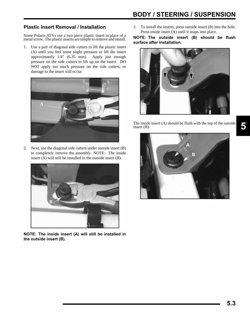
BODY / STEERING / SUSPENSION
5
Plastic Insert Removal / InstallationSome Polaris ATVs use a two piece plastic insert in place of ametal screw. The plastic inserts are simple to remove and install.
1. Use a pair of diagonal side cutters to lift the plastic insert(A) until you feel some slight pressure or lift the insertapproximately 1/4" (6.35 mm). Apply just enoughpressure on the side cutters to lift up on the insert. DONOT apply too much pressure on the side cutters, ordamage to the insert will occur.
2. Next, use the diagonal side cutters under outside insert (B)to completely remove the assembly. NOTE: The insideinsert (A) will still be installed in the outside insert (B).
NOTE: The inside insert (A) will still be installed inthe outside insert (B).
3. To install the inserts, press outside insert (B) into the hole.Press inside insert (A) until it snaps into place.
NOTE: The outside insert (B) should be flushsurface after installation.
The inside insert (A) should be flush with the top of the outsideinsert (B).
A
B
A
B
5.3
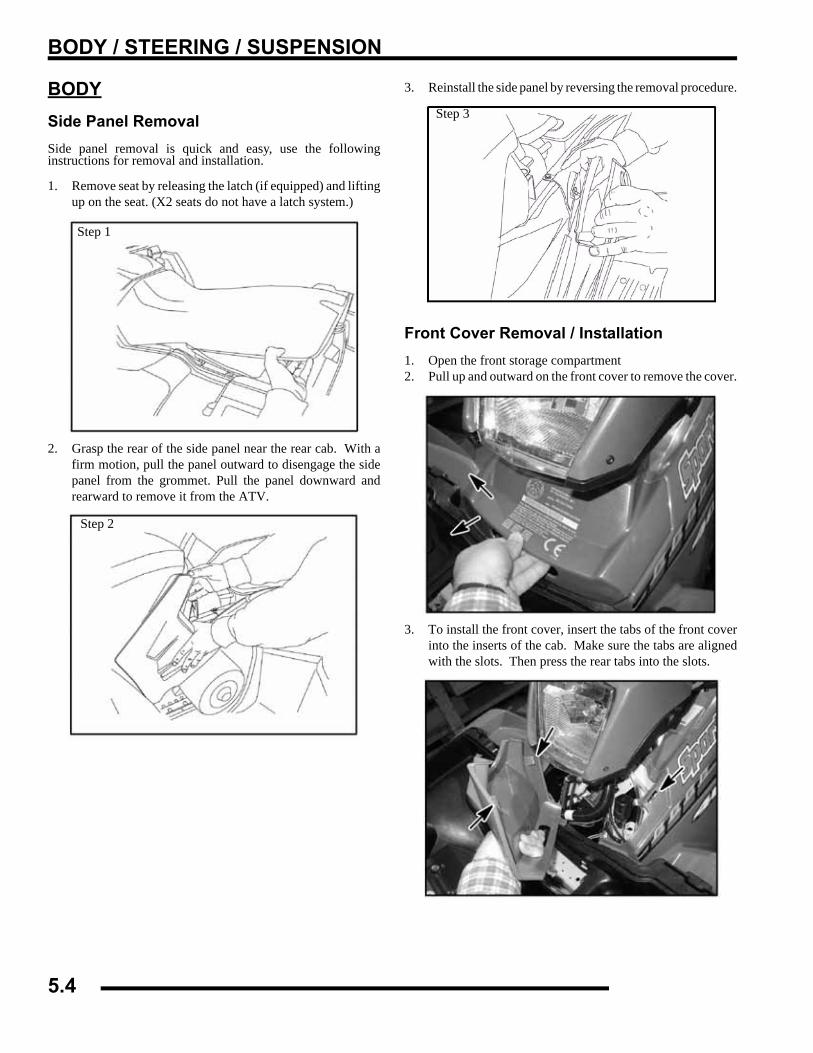
BODY / STEERING / SUSPENSION
BODYSide Panel RemovalSide panel removal is quick and easy, use the followinginstructions for removal and installation.
1. Remove seat by releasing the latch (if equipped) and liftingup on the seat. (X2 seats do not have a latch system.)
2. Grasp the rear of the side panel near the rear cab. With afirm motion, pull the panel outward to disengage the sidepanel from the grommet. Pull the panel downward andrearward to remove it from the ATV.
3. Reinstall the side panel by reversing the removal procedure.
Front Cover Removal / Installation1. Open the front storage compartment2. Pull up and outward on the front cover to remove the cover.
3. To install the front cover, insert the tabs of the front coverinto the inserts of the cab. Make sure the tabs are alignedwith the slots. Then press the rear tabs into the slots.
Step 1
Step 2
Step 3
5.4
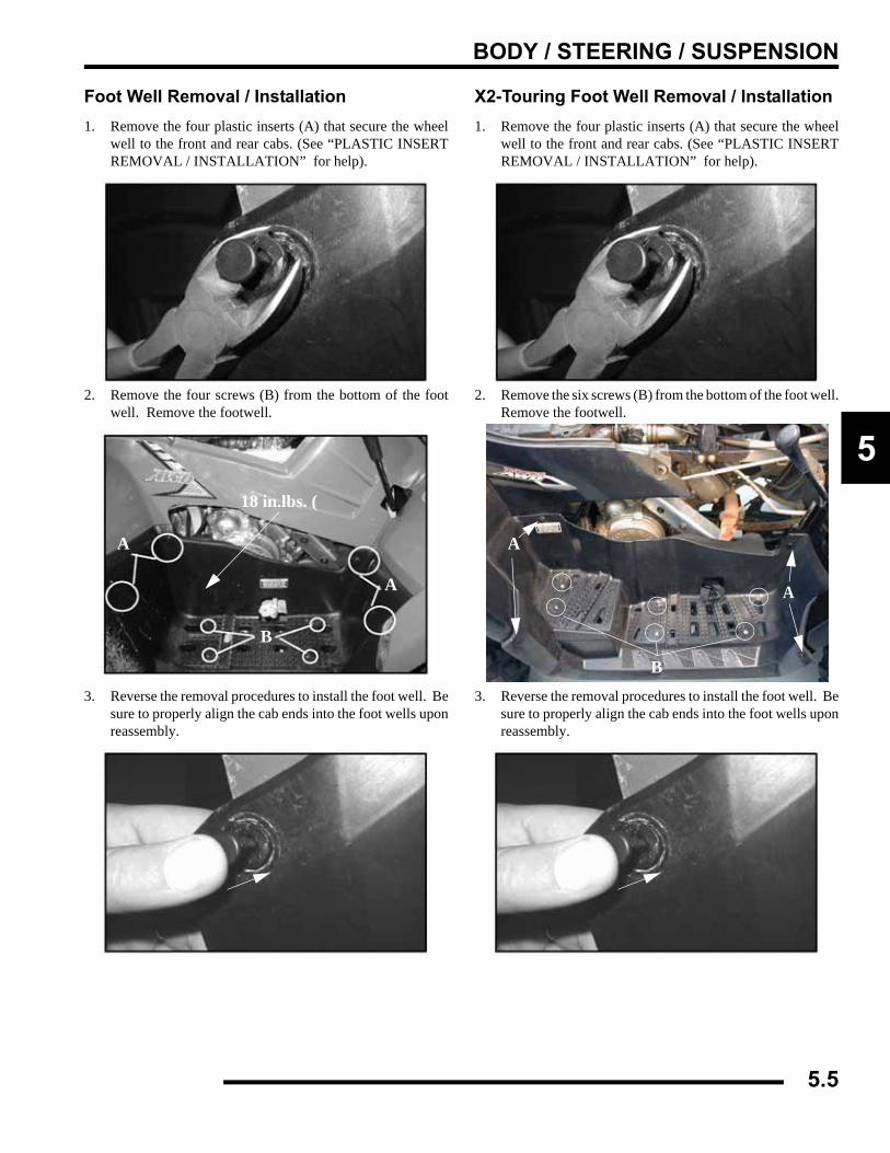
BODY / STEERING / SUSPENSION
5
Foot Well Removal / Installation1. Remove the four plastic inserts (A) that secure the wheel
well to the front and rear cabs. (See “PLASTIC INSERTREMOVAL / INSTALLATION” for help).
2. Remove the four screws (B) from the bottom of the footwell. Remove the footwell.
3. Reverse the removal procedures to install the foot well. Besure to properly align the cab ends into the foot wells uponreassembly.
X2-Touring Foot Well Removal / Installation1. Remove the four plastic inserts (A) that secure the wheel
well to the front and rear cabs. (See “PLASTIC INSERTREMOVAL / INSTALLATION” for help).
2. Remove the six screws (B) from the bottom of the foot well.Remove the footwell.
3. Reverse the removal procedures to install the foot well. Besure to properly align the cab ends into the foot wells uponreassembly.
A
B
A
18 in.lbs. (
A
B
A
5.5
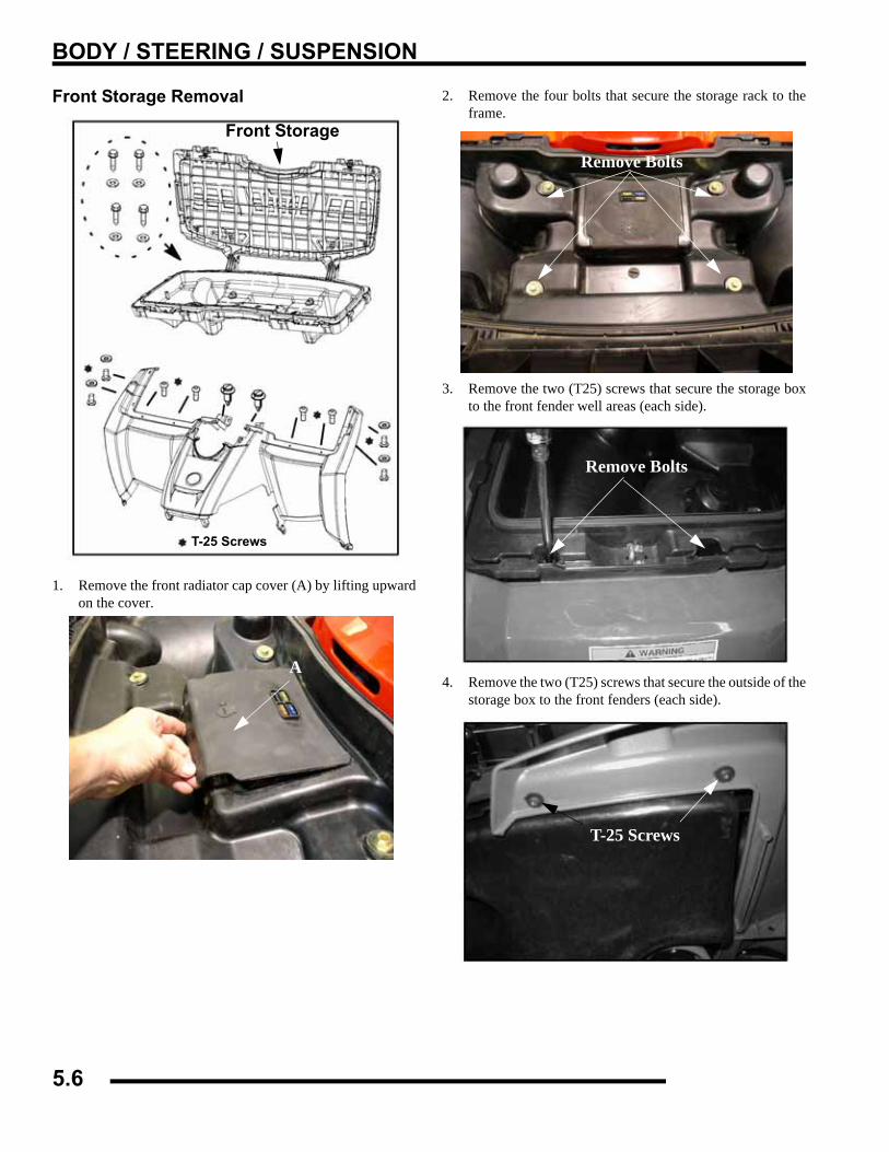
BODY / STEERING / SUSPENSION
Front Storage Removal
1. Remove the front radiator cap cover (A) by lifting upwardon the cover.
2. Remove the four bolts that secure the storage rack to theframe.
3. Remove the two (T25) screws that secure the storage boxto the front fender well areas (each side).
4. Remove the two (T25) screws that secure the outside of thestorage box to the front fenders (each side).
Front Storage
T-25 Screws
A
Remove Bolts
Remove Bolts
T-25 Screws
5.6
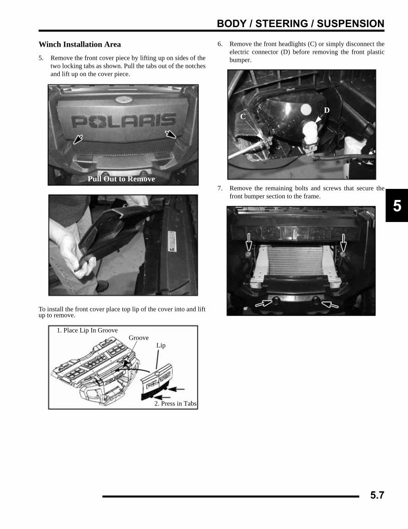
BODY / STEERING / SUSPENSION
5
Winch Installation Area
5. Remove the front cover piece by lifting up on sides of thetwo locking tabs as shown. Pull the tabs out of the notchesand lift up on the cover piece.
To install the front cover place top lip of the cover into and liftup to remove.
6. Remove the front headlights (C) or simply disconnect theelectric connector (D) before removing the front plasticbumper.
7. Remove the remaining bolts and screws that secure thefront bumper section to the frame.
Pull Out to Remove
1. Place Lip In GrooveGroove
Lip
2. Press in Tabs
CD
5.7
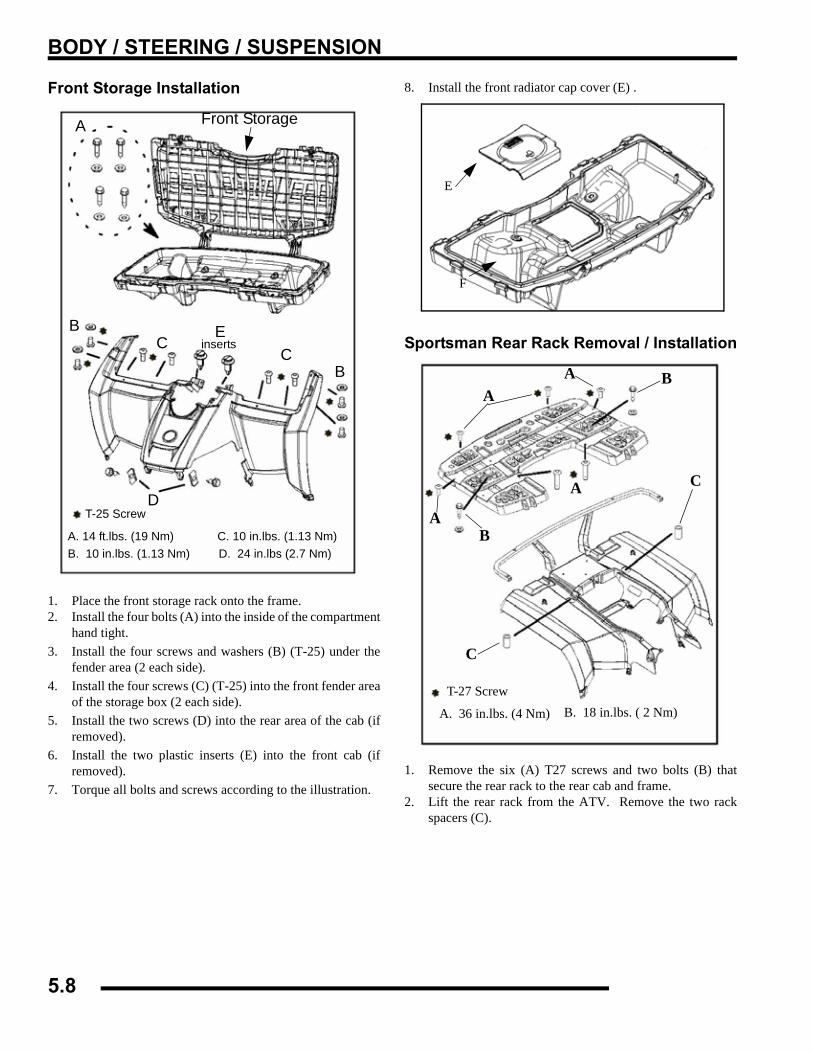
BODY / STEERING / SUSPENSION
Front Storage Installation
1. Place the front storage rack onto the frame.2. Install the four bolts (A) into the inside of the compartment
hand tight.3. Install the four screws and washers (B) (T-25) under the
fender area (2 each side).4. Install the four screws (C) (T-25) into the front fender area
of the storage box (2 each side).5. Install the two screws (D) into the rear area of the cab (if
removed).6. Install the two plastic inserts (E) into the front cab (if
removed).7. Torque all bolts and screws according to the illustration.
8. Install the front radiator cap cover (E) .
Sportsman Rear Rack Removal / Installation
1. Remove the six (A) T27 screws and two bolts (B) thatsecure the rear rack to the rear cab and frame.
2. Lift the rear rack from the ATV. Remove the two rackspacers (C).
Front StorageA
BC
CB
D
Einserts
T-25 Screw
A. 14 ft.lbs. (19 Nm)B. 10 in.lbs. (1.13 Nm)
C. 10 in.lbs. (1.13 Nm)D. 24 in.lbs (2.7 Nm)
E
F
T-27 Screw
A. 36 in.lbs. (4 Nm) B. 18 in.lbs. ( 2 Nm)
A
A
A
A B
B
C
C
5.8
BODY / STEERING / SUSPENSION
5
3. Place spacers on frame.
4. Install rear rack onto rear frame and cab.5. Install the two bolts (B) and six (A) T-27 screws. Torque
the bolts (A) to 18 in.lbs. (2 Nm) and six T-27 screws to 36in.lbs. (4 Nm). Refer to the illustration for torque values.
Front Cab/Fender Removal/Installation1. Follow the “FRONT RACK / BUMPER REMOVAL”
section to begin removal of the front cab, rack, andbumper.
2. Remove the plastic inserts (A) that secure the front cab tothe upper strut support.
3. Remove the two screws (B) that secure the front cab to theframe in the fuel tank mount area.
4. Remove the side panels (D), refer to the “SIDE PANELREMOVAL” section.
5. Remove the plastic inserts (E) that secure the front of thefoot wells to the front cab.
6. Remove the fuel cap and place a clean lint free shop towelinto the tank neck to keep any debris from falling into thetank.
7. The front cab should now slide back over the fuel tank andfuel tank neck.
NOTE: When removing the front cab use caution sothe plastic cab does not scratch or get caught onother components.
8. Reverse the removal steps for installation. Torque twofront cab to frame screws to specification.
A
= T
Cab to Frame Screws24 in.lbs. (2.7 Nm)
B
B
A
D
E
5.9
BODY / STEERING / SUSPENSION
Sportsman Rear Cab / Fender Removal / Installation1. Follow the “REAR RACK REMOVAL” procedure to
remove the rear rack.2. Remove the plastic inserts that secure the rear cab to the
frame and plastic.
3. Disconnect the rear lights by pulling the locks on each sideand removing the connectors. Lift the rear cab from theframe.
4. Reverse the removal steps for installation.
X2-Touring Rear Quarter Panel Removal / Installation1. Remove the seat.2. Remove the plastic inserts (circled) that secure the quarter
panel to the rear footwell. (See “PLASTIC INSERTREMOVAL / INSTALLATION” for information).
3. Reverse the removal procedures to install the quarterpanels. Verify panels are properly aligned to the footwellend upon reassembly.Remove plastic dart inserts.
Remove Connectors
Lock
5.10
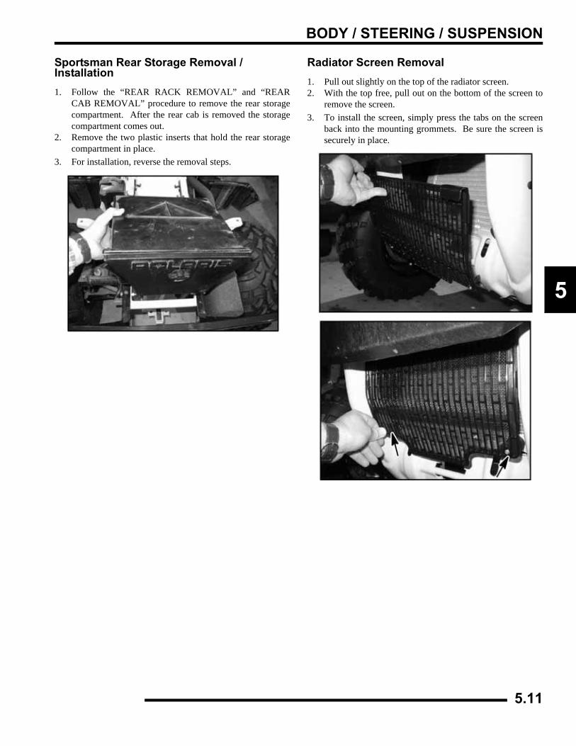
BODY / STEERING / SUSPENSION
5
Sportsman Rear Storage Removal / Installation1. Follow the “REAR RACK REMOVAL” and “REAR
CAB REMOVAL” procedure to remove the rear storagecompartment. After the rear cab is removed the storagecompartment comes out.
2. Remove the two plastic inserts that hold the rear storagecompartment in place.
3. For installation, reverse the removal steps.
Radiator Screen Removal1. Pull out slightly on the top of the radiator screen.2. With the top free, pull out on the bottom of the screen to
remove the screen.3. To install the screen, simply press the tabs on the screen
back into the mounting grommets. Be sure the screen issecurely in place.
5.11
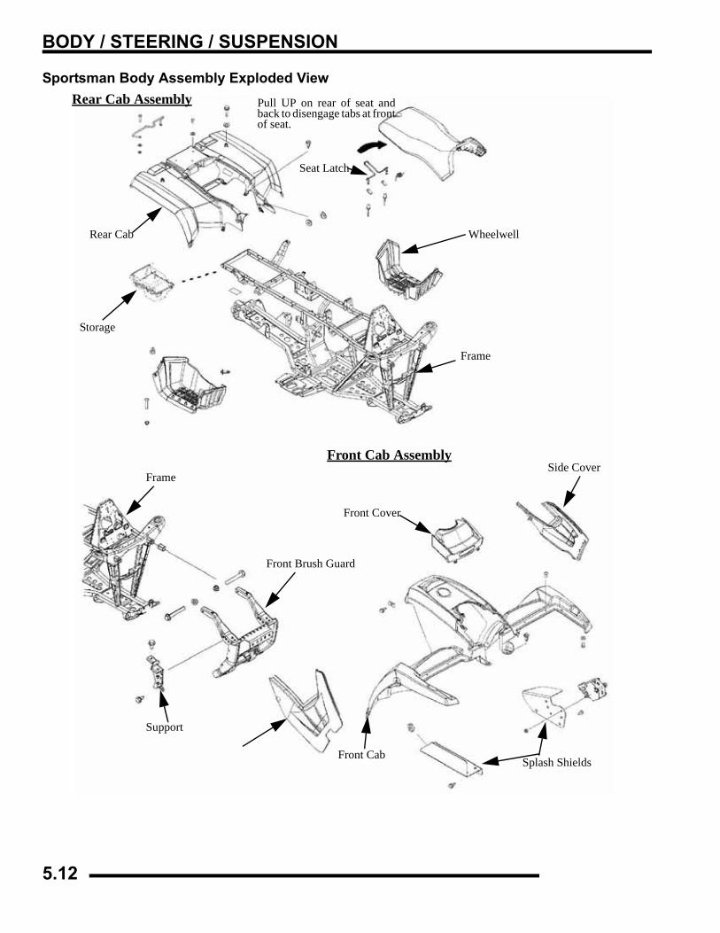
BODY / STEERING / SUSPENSION
Sportsman Body Assembly Exploded ViewRear Cab Assembly Pull UP on rear of seat and
back to disengage tabs at frontof seat.
Seat Latch
Rear Cab
Storage
Frame
Wheelwell
Frame
Front Brush Guard
Support
Side Cover
Splash ShieldsFront Cab
Front Cover
Front Cab Assembly
5.12
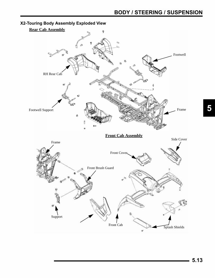
BODY / STEERING / SUSPENSION
5
X2-Touring Body Assembly Exploded ViewRear Cab Assembly
Frame
Front Brush Guard
Support
Side Cover
Splash ShieldsFront Cab
Front Cover
Front Cab Assembly
Footwell
Frame
RH Rear Cab
Footwell Support
5.13
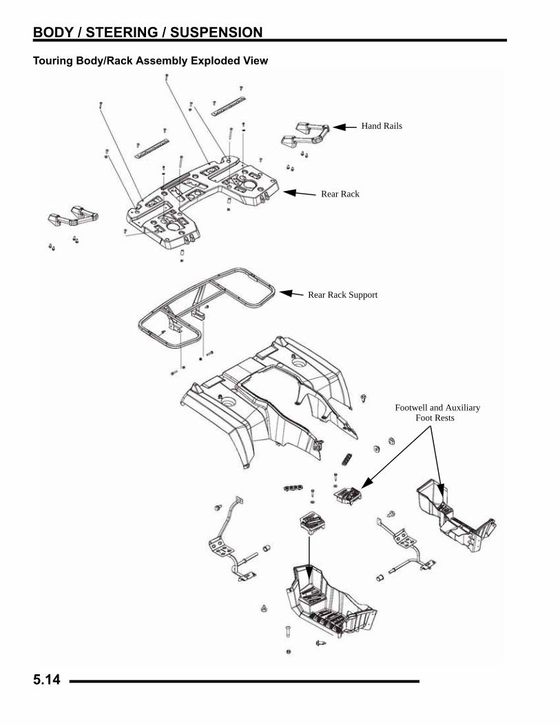
BODY / STEERING / SUSPENSION
Touring Body/Rack Assembly Exploded View
Footwell and AuxiliaryFoot Rests
Rear Rack
Rear Rack Support
Hand Rails
5.14
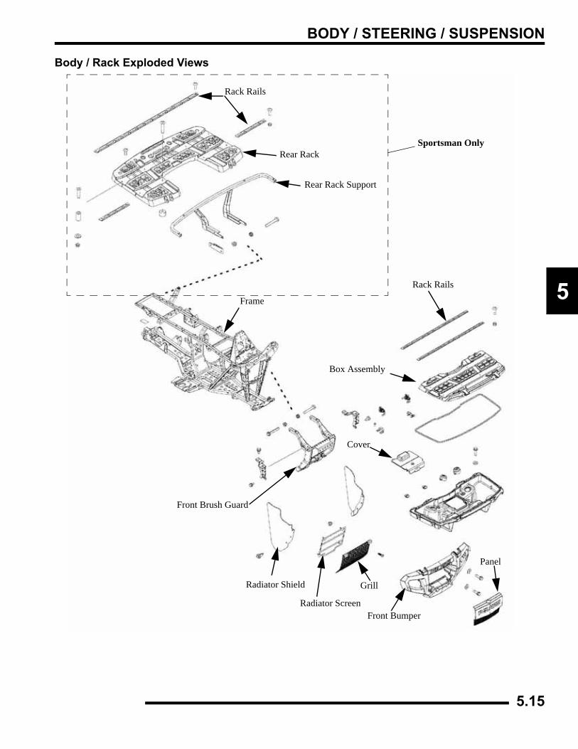
BODY / STEERING / SUSPENSION
5
Body / Rack Exploded Views
Rack Rails
Rear Rack
Rear Rack Support
Frame
Front Brush Guard
Radiator Shield
Radiator Screen
Grill
Front Bumper
Panel
Rack Rails
Box Assembly
Cover
Sportsman Only
5.15
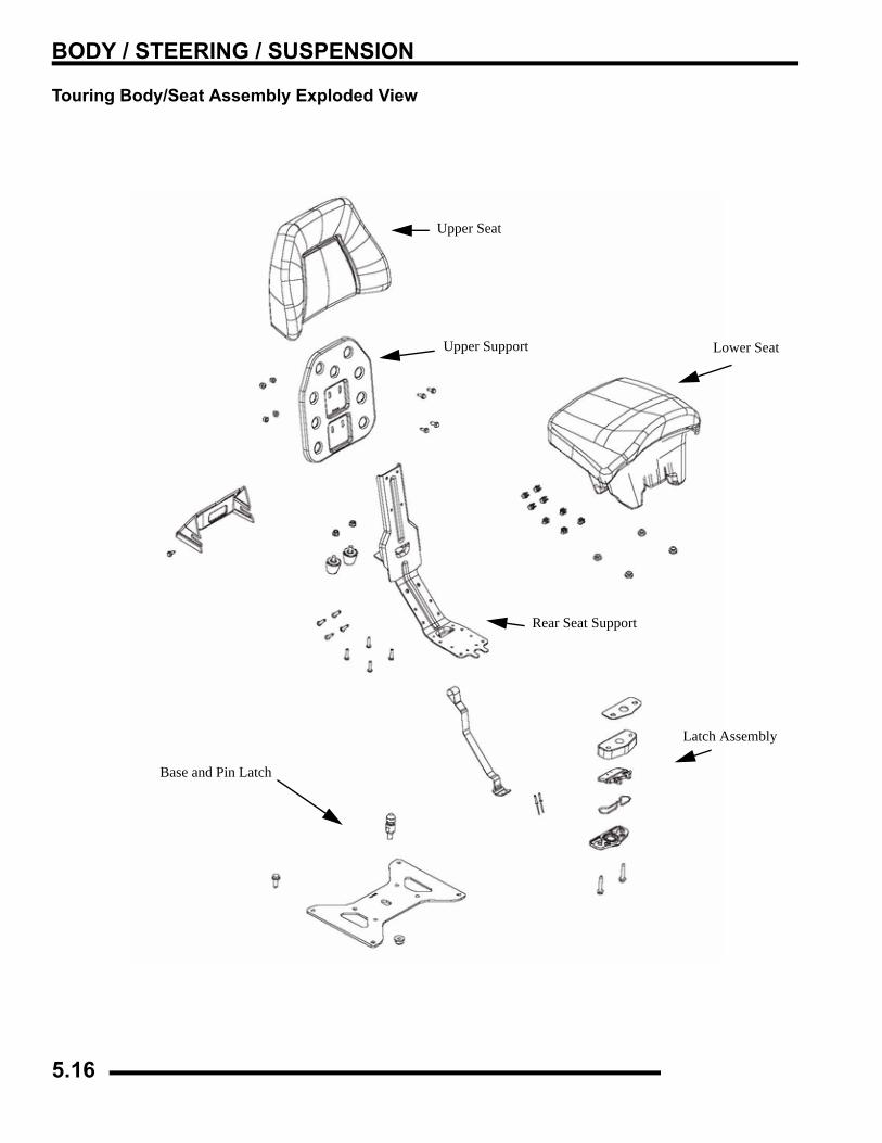
BODY / STEERING / SUSPENSION
Touring Body/Seat Assembly Exploded View
Upper Support
Rear Seat Support
Upper Seat
Base and Pin Latch
Latch Assembly
Lower Seat
5.16
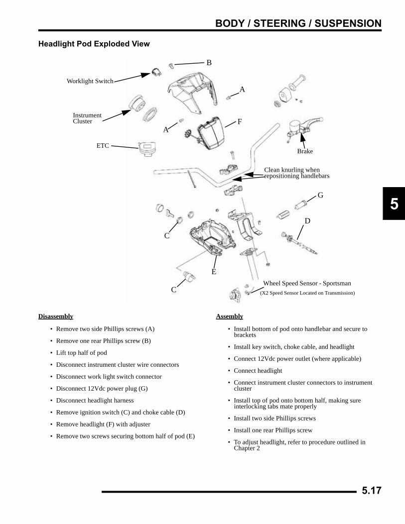
BODY / STEERING / SUSPENSION
5
Headlight Pod Exploded View
Disassembly
• Remove two side Phillips screws (A)
• Remove one rear Phillips screw (B)
• Lift top half of pod
• Disconnect instrument cluster wire connectors
• Disconnect work light switch connector
• Disconnect 12Vdc power plug (G)
• Disconnect headlight harness
• Remove ignition switch (C) and choke cable (D)
• Remove headlight (F) with adjuster
• Remove two screws securing bottom half of pod (E)
Assembly
• Install bottom of pod onto handlebar and secure to brackets
• Install key switch, choke cable, and headlight
• Connect 12Vdc power outlet (where applicable)
• Connect headlight
• Connect instrument cluster connectors to instrument cluster
• Install top of pod onto bottom half, making sure interlocking tabs mate properly
• Install two side Phillips screws
• Install one rear Phillips screw
• To adjust headlight, refer to procedure outlined in Chapter 2
Worklight Switch
InstrumentCluster
A
A
F
B
C
C
E
D
Brake
Clean knurling when repositioning handlebars
Wheel Speed Sensor - Sportsman
G
ETC
(X2 Speed Sensor Located on Transmission)
5.17
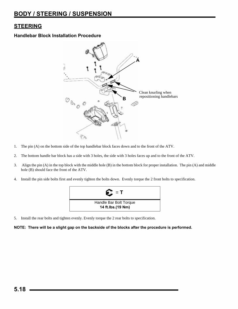
BODY / STEERING / SUSPENSION
STEERINGHandlebar Block Installation Procedure
1. The pin (A) on the bottom side of the top handlebar block faces down and to the front of the ATV.
2. The bottom handle bar block has a side with 3 holes, the side with 3 holes faces up and to the front of the ATV.
3. Align the pin (A) in the top block with the middle hole (B) in the bottom block for proper installation. The pin (A) and middlehole (B) should face the front of the ATV.
4. Install the pin side bolts first and evenly tighten the bolts down. Evenly torque the 2 front bolts to specification.
5. Install the rear bolts and tighten evenly. Evenly torque the 2 rear bolts to specification.
NOTE: There will be a slight gap on the backside of the blocks after the procedure is performed.
= T
Handle Bar Bolt Torque14 ft.lbs.(19 Nm)
A
Clean knurling whenrepositioning handlebarsB
5.18
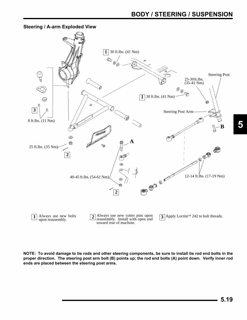
BODY / STEERING / SUSPENSION
5
Steering / A-arm Exploded View
NOTE: To avoid damage to tie rods and other steering components, be sure to install tie rod end bolts in theproper direction. The steering post arm bolt (B) points up; the rod end bolts (A) point down. Verify inner rodends are placed between the steering post arms.
Apply Loctite™ 242 to bolt threads.
8 ft.lbs. (11 Nm)
25 ft.lbs. (35 Nm)
2
2
2
Always use new cotter pins uponreassembly. Install with open endtoward rear of machine.
1 Always use new boltsupon reassembly.
1
1
25-30 ft.lbs. (35-41 Nm)
Steering Post
Steering Post Arm
12-14 ft.lbs. (17-19 Nm)
A
30 ft.lbs. (41 Nm)
40-45 ft.lbs. (54-61 Nm)
30 ft.lbs. (41 Nm)
3
3
B
5.19
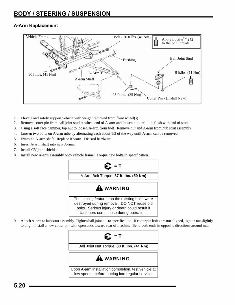
BODY / STEERING / SUSPENSION
A-Arm Replacement
1. Elevate and safely support vehicle with weight removed from front wheel(s).2. Remove cotter pin from ball joint stud at wheel end of A-arm and loosen nut until it is flush with end of stud.3. Using a soft face hammer, tap nut to loosen A-arm from bolt. Remove nut and A-arm from hub strut assembly.4. Loosen two bolts on A-arm tube by alternating each about 1/3 of the way until A-arm can be removed.5. Examine A-arm shaft. Replace if worn. Discard hardware.6. Insert A-arm shaft into new A-arm. 7. Install CV joint shields.8. Install new A-arm assembly onto vehicle frame. Torque new bolts to specification.
9. Attach A-arm to hub strut assembly. Tighten ball joint nut to specification. If cotter pin holes are not aligned, tighten nut slightlyto align. Install a new cotter pin with open ends toward rear of machine. Bend both ends in opposite directions around nut.
= T
A-Arm Bolt Torque: 37 ft. lbs. (50 Nm)
WARNING
The locking features on the existing bolts were destroyed during removal. DO NOT reuse old
bolts. Serious injury or death could result if fasteners come loose during operation.
= T
Ball Joint Nut Torque: 30 ft. lbs. (41 Nm)
WARNING
Upon A-arm installation completion, test vehicle at low speeds before putting into regular service.
30 ft.lbs. (41 Nm)A-arm Shaft
Apply Loctite™ 242to the bolt threads.
Vehicle Frame Bolt - 30 ft.lbs. (41 Nm)
Bushing Ball Joint Stud
8 ft.lbs. (11 Nm)
Cotter Pin - (Install New)25 ft.lbs. (35 Nm)
A-Arm Tube
5.20
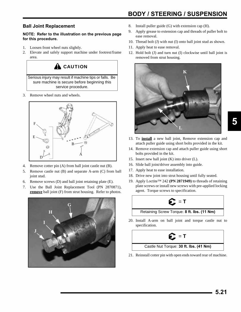
BODY / STEERING / SUSPENSION
5
Ball Joint ReplacementNOTE: Refer to the illustration on the previous pagefor this procedure.
1. Loosen front wheel nuts slightly.2. Elevate and safely support machine under footrest/frame
area.
3. Remove wheel nuts and wheels.
4. Remove cotter pin (A) from ball joint castle nut (B).5. Remove castle nut (B) and separate A-arm (C) from ball
joint stud.6. Remove screws (D) and ball joint retaining plate (E).7. Use the Ball Joint Replacement Tool (PN 2870871),
remove ball joint (F) from strut housing. Refer to photos.
8. Install puller guide (G) with extension cap (H).9. Apply grease to extension cap and threads of puller bolt to
ease removal.10. Thread bolt (J) with nut (I) onto ball joint stud as shown.11. Apply heat to ease removal.12. Hold bolt (J) and turn nut (I) clockwise until ball joint is
removed from strut housing.
13. To install a new ball joint, Remove extension cap andattach puller guide using short bolts provided in the kit.
14. Remove extension cap and attach puller guide using shortbolts provided in the kit.
15. Insert new ball joint (K) into driver (L).16. Slide ball joint/driver assembly into guide.17. Apply heat to ease installation.18. Drive new joint into strut housing until fully seated.19. Apply Loctite™ 242 (PN 2871949) to threads of retaining
plate screws or install new screws with pre-applied lockingagent. Torque screws to specification.
20. Install A-arm on ball joint and torque castle nut tospecification.
21. Reinstall cotter pin with open ends toward rear of machine.
CAUTION
Serious injury may result if machine tips or falls. Be sure machine is secure before beginning this
service procedure.
F
E
DA
B
GH
I
J
= T
Retaining Screw Torque: 8 ft. lbs. (11 Nm)
= T
Castle Nut Torque: 30 ft. lbs. (41 Nm)
K
L
5.21
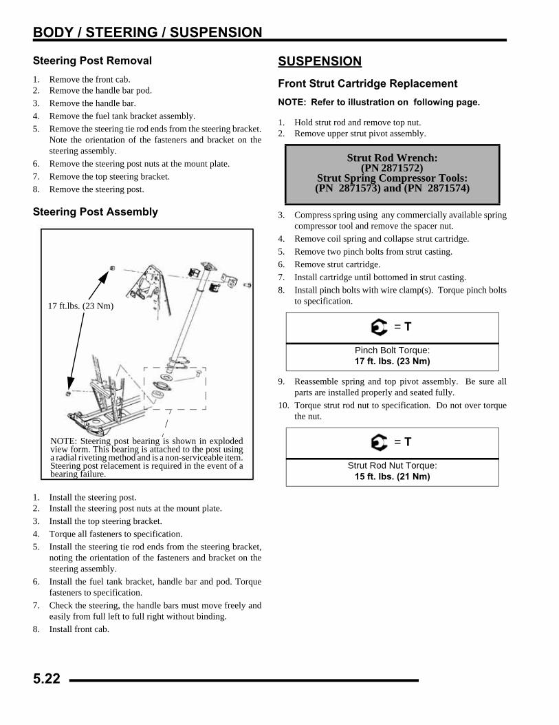
BODY / STEERING / SUSPENSION
Steering Post Removal1. Remove the front cab. 2. Remove the handle bar pod. 3. Remove the handle bar. 4. Remove the fuel tank bracket assembly.5. Remove the steering tie rod ends from the steering bracket.
Note the orientation of the fasteners and bracket on thesteering assembly.
6. Remove the steering post nuts at the mount plate.7. Remove the top steering bracket.8. Remove the steering post.
Steering Post Assembly
1. Install the steering post.2. Install the steering post nuts at the mount plate.3. Install the top steering bracket.4. Torque all fasteners to specification.5. Install the steering tie rod ends from the steering bracket,
noting the orientation of the fasteners and bracket on thesteering assembly.
6. Install the fuel tank bracket, handle bar and pod. Torquefasteners to specification.
7. Check the steering, the handle bars must move freely andeasily from full left to full right without binding.
8. Install front cab.
SUSPENSIONFront Strut Cartridge ReplacementNOTE: Refer to illustration on following page.
1. Hold strut rod and remove top nut.2. Remove upper strut pivot assembly.
3. Compress spring using any commercially available springcompressor tool and remove the spacer nut.
4. Remove coil spring and collapse strut cartridge.5. Remove two pinch bolts from strut casting.6. Remove strut cartridge.7. Install cartridge until bottomed in strut casting.8. Install pinch bolts with wire clamp(s). Torque pinch bolts
to specification.
9. Reassemble spring and top pivot assembly. Be sure allparts are installed properly and seated fully.
10. Torque strut rod nut to specification. Do not over torquethe nut.
17 ft.lbs. (23 Nm)
NOTE: Steering post bearing is shown in explodedview form. This bearing is attached to the post usinga radial riveting method and is a non-serviceable item.Steering post relacement is required in the event of abearing failure.
Strut Rod Wrench: (PN 2871572)
Strut Spring Compressor Tools: (PN 2871573) and (PN 2871574)
= T
Pinch Bolt Torque:17 ft. lbs. (23 Nm)
= T
Strut Rod Nut Torque:15 ft. lbs. (21 Nm)
5.22
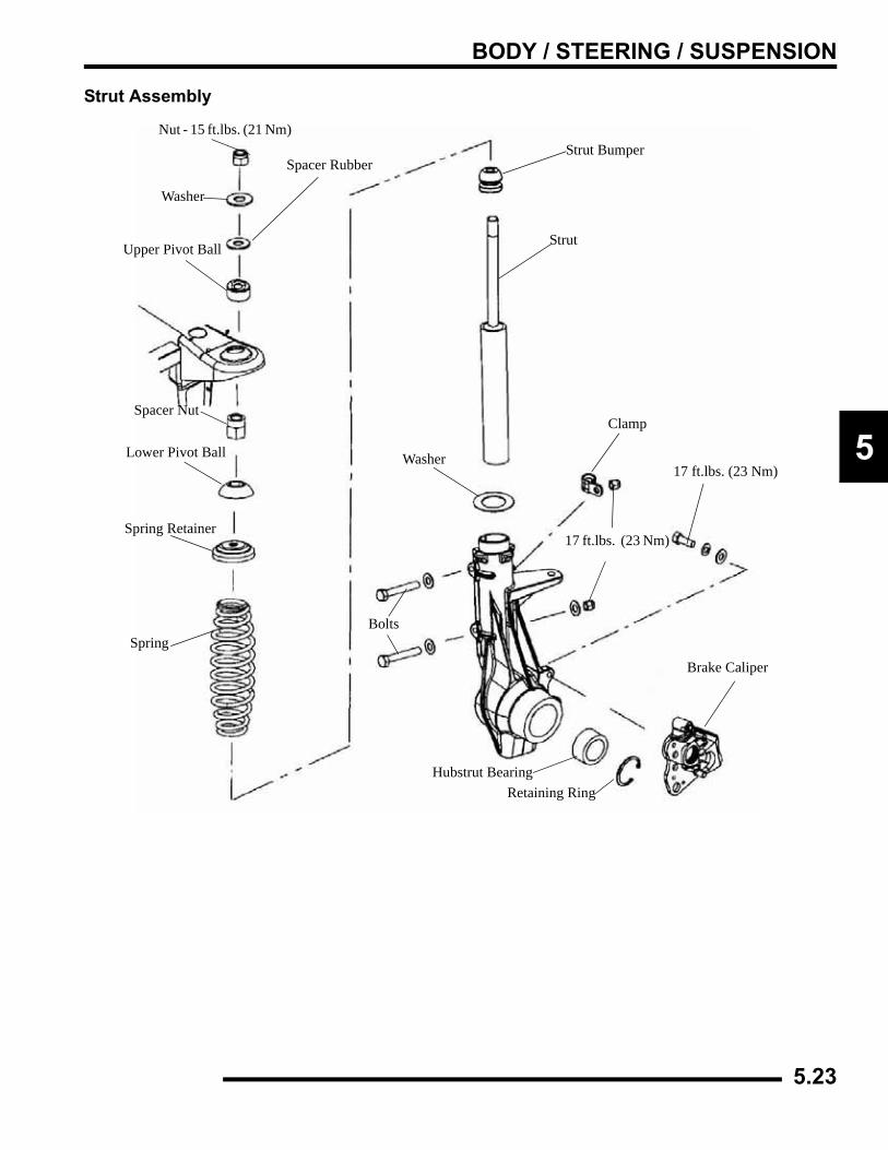
BODY / STEERING / SUSPENSION
5
Strut Assembly
Nut - 15 ft.lbs. (21 Nm)
Washer
Spacer Rubber
Upper Pivot Ball
Spacer Nut
Lower Pivot Ball
Spring Retainer
Spring
Strut Bumper
Strut
Washer
Bolts
Hubstrut BearingRetaining Ring
Brake Caliper
17 ft.lbs. (23 Nm)
Clamp
17 ft.lbs. (23 Nm)
5.23
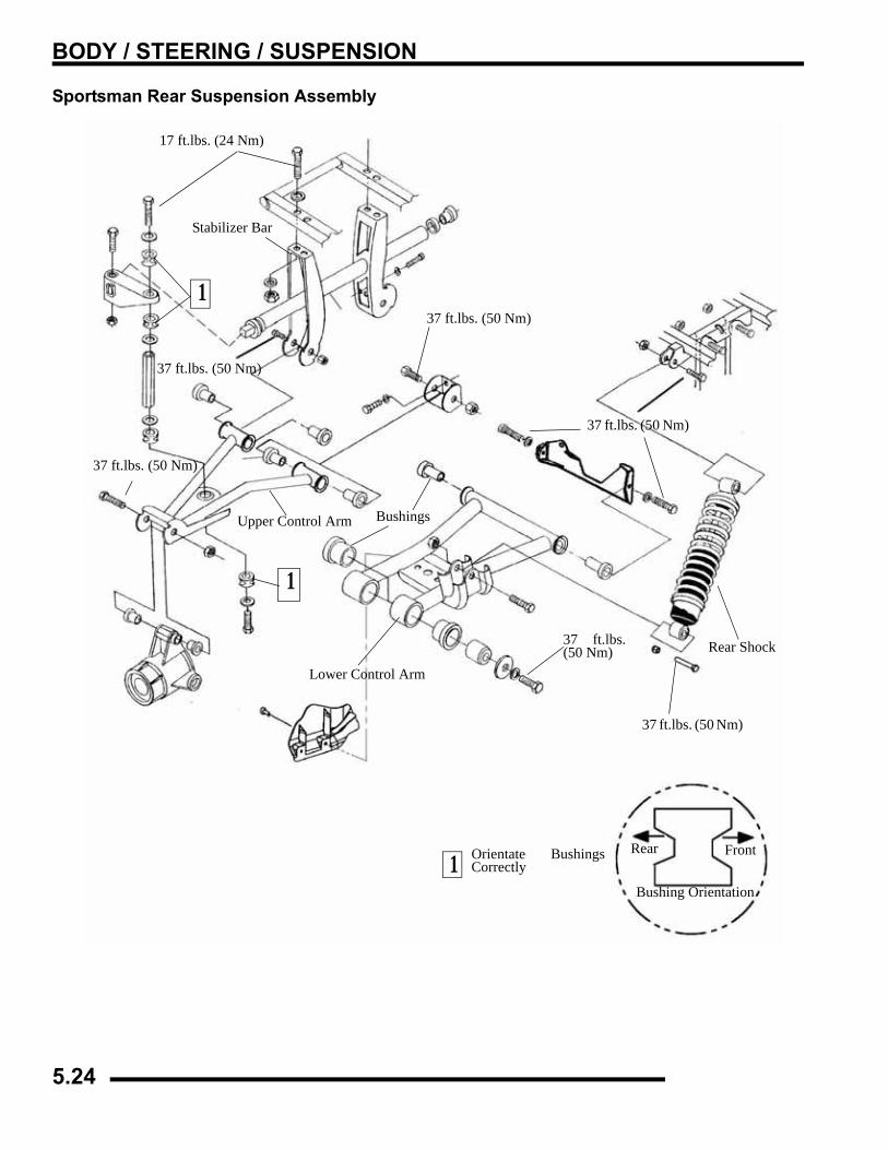
BODY / STEERING / SUSPENSION
Sportsman Rear Suspension Assembly
17 ft.lbs. (24 Nm)
Stabilizer Bar
37 ft.lbs. (50 Nm)
37 ft.lbs. (50 Nm)
Rear Shock
Lower Control Arm
Bushings
37 ft.lbs. (50 Nm)
Upper Control Arm
37 ft.lbs. (50 Nm)
Rear Front1 Orientate Bushings
Correctly
1
1
37 ft.lbs. (50 Nm)
Bushing Orientation
37 ft.lbs.(50 Nm)
5.24
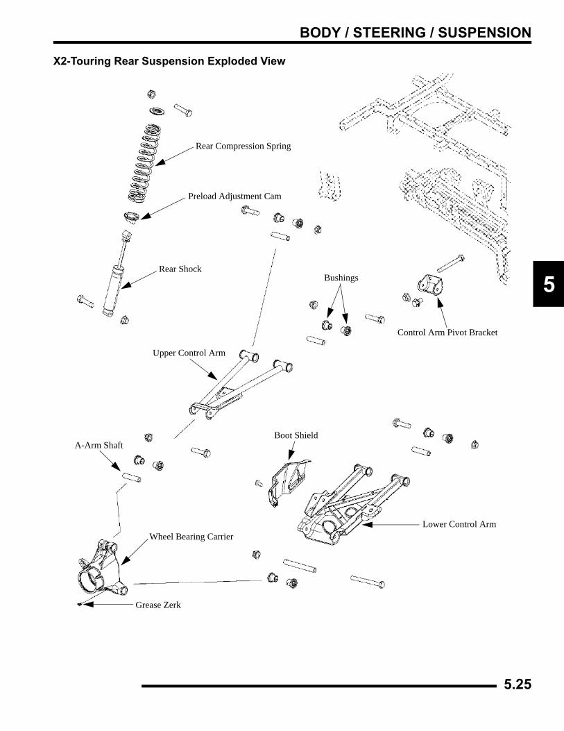
BODY / STEERING / SUSPENSION
5
X2-Touring Rear Suspension Exploded View
Upper Control Arm
Lower Control Arm
Rear ShockBushings
Rear Compression Spring
Preload Adjustment Cam
A-Arm Shaft
Wheel Bearing Carrier
Grease Zerk
Boot Shield
Control Arm Pivot Bracket
5.25
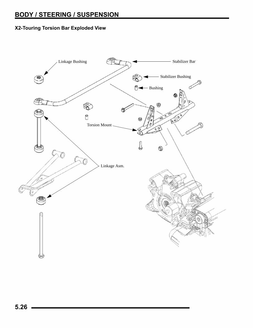
BODY / STEERING / SUSPENSION
X2-Touring Torsion Bar Exploded View
Linkage Bushing Stabilizer Bar
Torsion Mount
Linkage Asm.
Bushing
Stabilizer Bushing
5.26
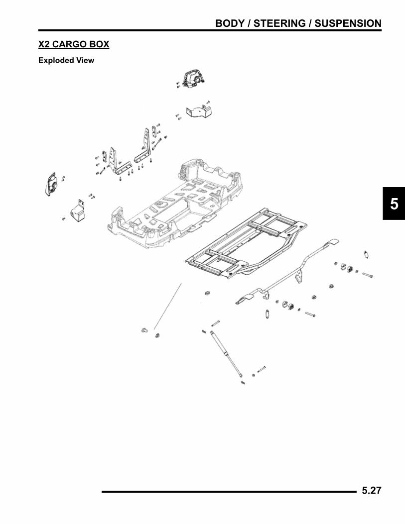
BODY / STEERING / SUSPENSION
5
X2 CARGO BOXExploded View
5.27
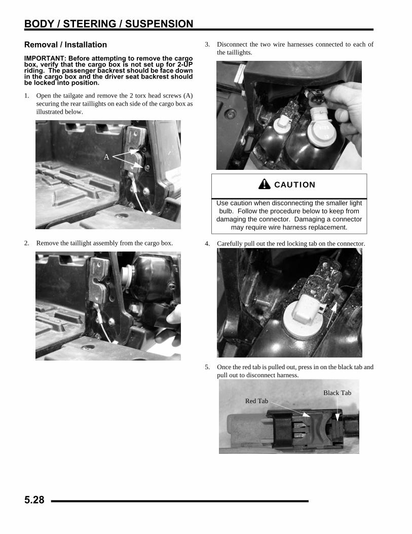
BODY / STEERING / SUSPENSION
Removal / InstallationIMPORTANT: Before attempting to remove the cargobox, verify that the cargo box is not set up for 2-UPriding. The passenger backrest should be face downin the cargo box and the driver seat backrest shouldbe locked into position.
1. Open the tailgate and remove the 2 torx head screws (A)securing the rear taillights on each side of the cargo box asillustrated below.
2. Remove the taillight assembly from the cargo box.
3. Disconnect the two wire harnesses connected to each ofthe taillights.
4. Carefully pull out the red locking tab on the connector.
5. Once the red tab is pulled out, press in on the black tab andpull out to disconnect harness.
A
CAUTION
Use caution when disconnecting the smaller light bulb. Follow the procedure below to keep from
damaging the connector. Damaging a connector may require wire harness replacement.
Black TabRed Tab
5.28
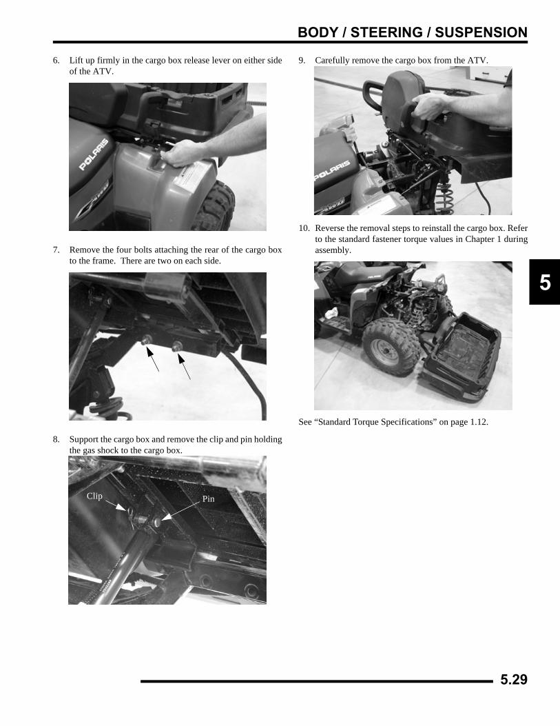
BODY / STEERING / SUSPENSION
5
6. Lift up firmly in the cargo box release lever on either sideof the ATV.
7. Remove the four bolts attaching the rear of the cargo boxto the frame. There are two on each side.
8. Support the cargo box and remove the clip and pin holdingthe gas shock to the cargo box.
9. Carefully remove the cargo box from the ATV.
10. Reverse the removal steps to reinstall the cargo box. Referto the standard fastener torque values in Chapter 1 duringassembly.
See “Standard Torque Specifications” on page 1.12.
Clip Pin
5.29
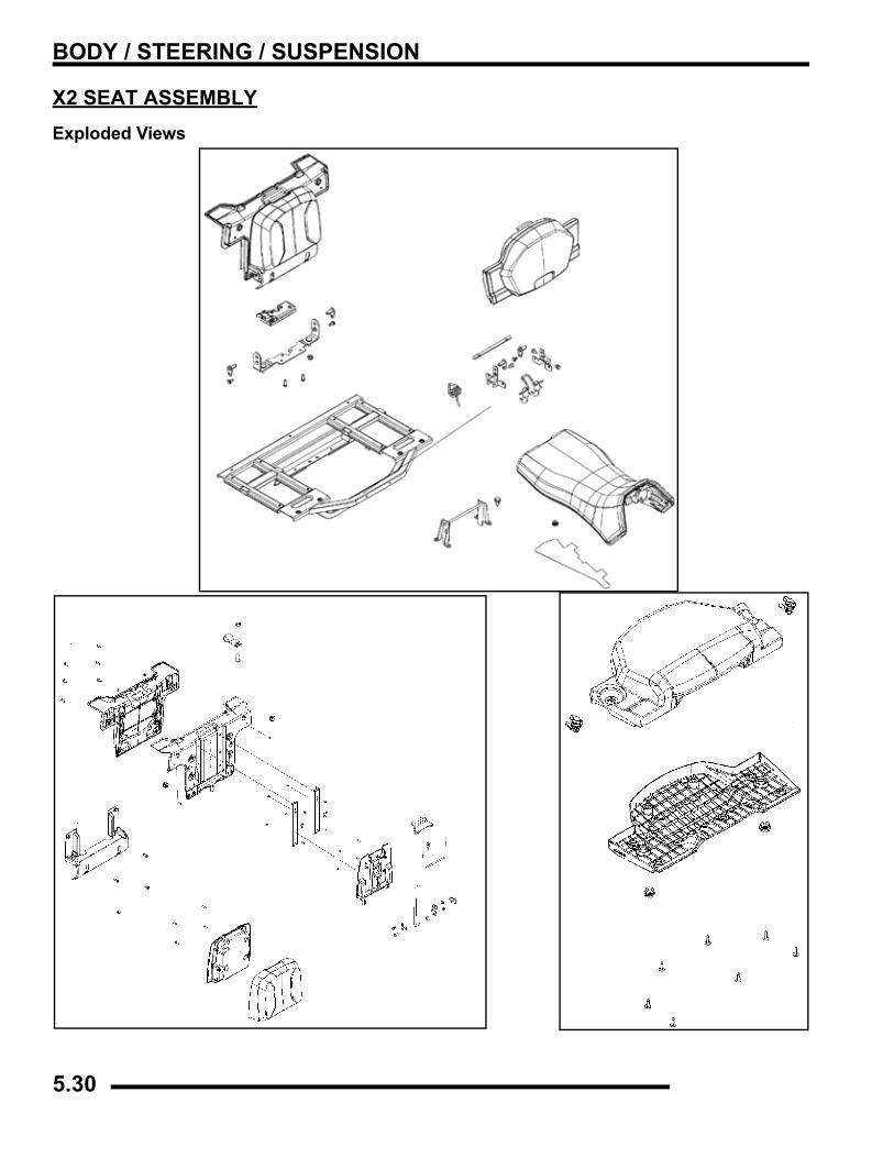
BODY / STEERING / SUSPENSION
X2 SEAT ASSEMBLYExploded Views
5.30
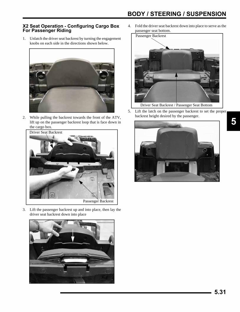
BODY / STEERING / SUSPENSION
5
X2 Seat Operation - Configuring Cargo Box For Passenger Riding1. Unlatch the driver seat backrest by turning the engagement
knobs on each side in the directions shown below.
2. While pulling the backrest towards the front of the ATV,lift up on the passenger backrest loop that is face down inthe cargo box.
3. Lift the passenger backrest up and into place, then lay thedriver seat backrest down into place
4. Fold the driver seat backrest down into place to serve as thepassenger seat bottom.
5. Lift the latch on the passenger backrest to set the properbackrest height desired by the passenger.
A
B
Passenger Backrest
Driver Seat Backrest
A
B
Passenger Backrest
Driver Seat Backrest / Passenger Seat Bottom
5.31
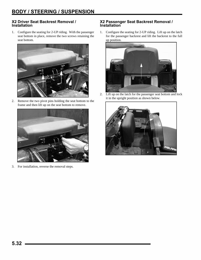
BODY / STEERING / SUSPENSION
X2 Driver Seat Backrest Removal / Installation1. Configure the seating for 2-UP riding. With the passenger
seat bottom in place, remove the two screws retaining theseat bottom.
2. Remove the two pivot pins holding the seat bottom to theframe and then lift up on the seat bottom to remove.
3. For installation, reverse the removal steps.
X2 Passenger Seat Backrest Removal / Installation1. Configure the seating for 2-UP riding. Lift up on the latch
for the passenger backrest and lift the backrest to the fullup position.
2. Lift up on the latch for the passenger seat bottom and lockit in the upright position as shown below.
5.32
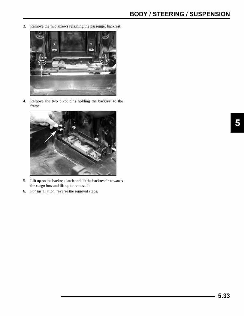
BODY / STEERING / SUSPENSION
5
3. Remove the two screws retaining the passenger backrest.
4. Remove the two pivot pins holding the backrest to theframe.
5. Lift up on the backrest latch and tilt the backrest in towardsthe cargo box and lift up to remove it.
6. For installation, reverse the removal steps.
5.33
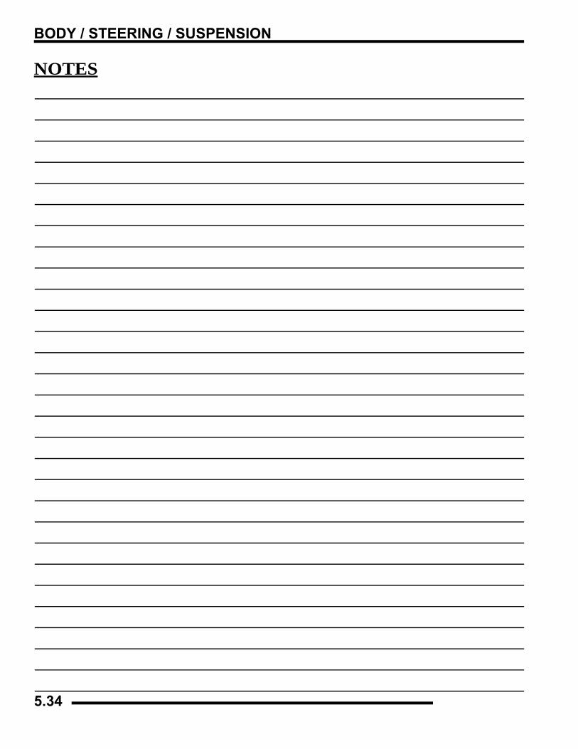
BODY / STEERING / SUSPENSION
NOTES
5.34
CLUTCH SYSTEM
6.1
CHAPTER 6CLUTCH SYSTEM
6
SPECIAL TOOLS AND SPECIFICATIONS. . . . . . . . . . . . . . . . . . . . . . . . . . . . . . . . . . . . 6.2SPECIAL TOOLS . . . . . . . . . . . . . . . . . . . . . . . . . . . . . . . . . . . . . . . . . . . . . . . . . . . . . . . 6.2SERVICE NOTE . . . . . . . . . . . . . . . . . . . . . . . . . . . . . . . . . . . . . . . . . . . . . . . . . . . . . . . . 6.2COMPONENT FASTENER TORQUES . . . . . . . . . . . . . . . . . . . . . . . . . . . . . . . . . . . . . . 6.2
PVT EXPLODED VIEWS. . . . . . . . . . . . . . . . . . . . . . . . . . . . . . . . . . . . . . . . . . . . . . . . . . 6.3PVT SEALING AND DUCTING COMPONENTS . . . . . . . . . . . . . . . . . . . . . . . . . . . . . . . 6.3DRIVE CLUTCH EXPLODED VIEWS . . . . . . . . . . . . . . . . . . . . . . . . . . . . . . . . . . . . . . . 6.3DRIVEN CLUTCH EXPLODED VIEWS . . . . . . . . . . . . . . . . . . . . . . . . . . . . . . . . . . . . . . 6.4ENGINE BRAKING SYSTEM (EBS) EXPLODED VIEW . . . . . . . . . . . . . . . . . . . . . . . . . 6.5
PVT SYSTEM . . . . . . . . . . . . . . . . . . . . . . . . . . . . . . . . . . . . . . . . . . . . . . . . . . . . . . . . . . 6.6PVT OPERATION OVERVIEW . . . . . . . . . . . . . . . . . . . . . . . . . . . . . . . . . . . . . . . . . . . . 6.6DRIVE CLUTCH OPERATION . . . . . . . . . . . . . . . . . . . . . . . . . . . . . . . . . . . . . . . . . . . . . 6.6DRIVEN CLUTCH OPERATION. . . . . . . . . . . . . . . . . . . . . . . . . . . . . . . . . . . . . . . . . . . . 6.6EBS CLUTCH OPERATION. . . . . . . . . . . . . . . . . . . . . . . . . . . . . . . . . . . . . . . . . . . . . . . 6.7PVT MAINTENANCE / INSPECTION. . . . . . . . . . . . . . . . . . . . . . . . . . . . . . . . . . . . . . . . 6.7DRIVE CLUTCH SPRING. . . . . . . . . . . . . . . . . . . . . . . . . . . . . . . . . . . . . . . . . . . . . . . . . 6.8OPTIONAL SHIFT WEIGHTS. . . . . . . . . . . . . . . . . . . . . . . . . . . . . . . . . . . . . . . . . . . . . . 6.9PVT DRYING . . . . . . . . . . . . . . . . . . . . . . . . . . . . . . . . . . . . . . . . . . . . . . . . . . . . . . . . . 6.10PVT DISASSEMBLY. . . . . . . . . . . . . . . . . . . . . . . . . . . . . . . . . . . . . . . . . . . . . . . . . . . . 6.10PVT INSTALLATION . . . . . . . . . . . . . . . . . . . . . . . . . . . . . . . . . . . . . . . . . . . . . . . . . . . 6.11DRIVE BELT REMOVAL / INSPECTION . . . . . . . . . . . . . . . . . . . . . . . . . . . . . . . . . . . . 6.12DRIVE BELT INSTALLATION . . . . . . . . . . . . . . . . . . . . . . . . . . . . . . . . . . . . . . . . . . . . 6.13CLUTCH ALIGNMENT . . . . . . . . . . . . . . . . . . . . . . . . . . . . . . . . . . . . . . . . . . . . . . . . . . 6.14CLUTCH OFFSET . . . . . . . . . . . . . . . . . . . . . . . . . . . . . . . . . . . . . . . . . . . . . . . . . . . . . 6.14
EBS DRIVE CLUTCH SERVICE . . . . . . . . . . . . . . . . . . . . . . . . . . . . . . . . . . . . . . . . . . . 6.15DRIVE CLUTCH DISASSEMBLY. . . . . . . . . . . . . . . . . . . . . . . . . . . . . . . . . . . . . . . . . . 6.15SPIDER REMOVAL . . . . . . . . . . . . . . . . . . . . . . . . . . . . . . . . . . . . . . . . . . . . . . . . . . . . 6.15BUTTON TO TOWER CLEARANCE INSPECTION. . . . . . . . . . . . . . . . . . . . . . . . . . . . 6.17SHIFT WEIGHT INSPECTION . . . . . . . . . . . . . . . . . . . . . . . . . . . . . . . . . . . . . . . . . . . . 6.17DRIVE CLUTCH INSPECTION . . . . . . . . . . . . . . . . . . . . . . . . . . . . . . . . . . . . . . . . . . . 6.17MOVEABLE SHEAVE BUSHING INSPECTION . . . . . . . . . . . . . . . . . . . . . . . . . . . . . . 6.18DRIVE CLUTCH BUSHING SERVICE . . . . . . . . . . . . . . . . . . . . . . . . . . . . . . . . . . . . . . 6.18ONE-WAY CLUTCH INSPECTION (DRIVE CLUTCH) . . . . . . . . . . . . . . . . . . . . . . . . . 6.20DRIVE CLUTCH REASSEMBLY . . . . . . . . . . . . . . . . . . . . . . . . . . . . . . . . . . . . . . . . . . 6.20
EBS DRIVEN CLUTCH SERVICE. . . . . . . . . . . . . . . . . . . . . . . . . . . . . . . . . . . . . . . . . . 6.22DRIVEN CLUTCH DISASSEMBLY . . . . . . . . . . . . . . . . . . . . . . . . . . . . . . . . . . . . . . . . 6.22DRIVEN CLUTCH BUSHING REMOVAL/INSTALLATION . . . . . . . . . . . . . . . . . . . . . . 6.24EBS DRIVEN CLUTCH REASSEMBLY . . . . . . . . . . . . . . . . . . . . . . . . . . . . . . . . . . . . . 6.25
STANDARD DRIVE CLUTCH - 500 CARBURETOR . . . . . . . . . . . . . . . . . . . . . . . . . . . 6.28DRIVE CLUTCH DISASSEMBLY. . . . . . . . . . . . . . . . . . . . . . . . . . . . . . . . . . . . . . . . . . 6.28SPIDER REMOVAL . . . . . . . . . . . . . . . . . . . . . . . . . . . . . . . . . . . . . . . . . . . . . . . . . . . . 6.29BUTTON TO TOWER CLEARANCE INSPECTION. . . . . . . . . . . . . . . . . . . . . . . . . . . . 6.30SHIFT WEIGHT INSPECTION . . . . . . . . . . . . . . . . . . . . . . . . . . . . . . . . . . . . . . . . . . . . 6.30SHEAVE / BUSHING INSPECTION. . . . . . . . . . . . . . . . . . . . . . . . . . . . . . . . . . . . . . . . 6.31DRIVE CLUTCH BUSHING SERVICE . . . . . . . . . . . . . . . . . . . . . . . . . . . . . . . . . . . . . . 6.31DRIVE CLUTCH REASSEMBLY . . . . . . . . . . . . . . . . . . . . . . . . . . . . . . . . . . . . . . . . . . 6.32
STANDARD DRIVEN CLUTCH - 500 CARBURETOR . . . . . . . . . . . . . . . . . . . . . . . . . . 6.34EXPLODED VIEW . . . . . . . . . . . . . . . . . . . . . . . . . . . . . . . . . . . . . . . . . . . . . . . . . . . . . 6.34CLUTCH DISASSEMBLY / INSPECTION . . . . . . . . . . . . . . . . . . . . . . . . . . . . . . . . . . . 6.34BUSHING SERVICE. . . . . . . . . . . . . . . . . . . . . . . . . . . . . . . . . . . . . . . . . . . . . . . . . . . . 6.35MOVEABLE SHEAVE - BUSHING INSTALLATION . . . . . . . . . . . . . . . . . . . . . . . . . . . 6.36CLUTCH ASSEMBLY. . . . . . . . . . . . . . . . . . . . . . . . . . . . . . . . . . . . . . . . . . . . . . . . . . . 6.37
PVT TROUBLESHOOTING. . . . . . . . . . . . . . . . . . . . . . . . . . . . . . . . . . . . . . . . . . . . . . . 6.39OVERHEATING . . . . . . . . . . . . . . . . . . . . . . . . . . . . . . . . . . . . . . . . . . . . . . . . . . . . . . . 6.39PROBLEM, CAUSE AND REMEDY CHART . . . . . . . . . . . . . . . . . . . . . . . . . . . . . . . . . 6.40
CLUTCH SYSTEM
SPECIAL TOOLS AND SPECIFICATIONSSpecial Tools
Service Note• Upon installation of a drive clutch, ALWAYS use a
NEW drive clutch bolt. The old drive clutch bolt has been weakened by the removal process and will not provide a true clamp load during the torque procedure.
Component Fastener Torques
TOOL DESCRIPTION PART NUMBER
Clutch Puller 2870506
Clutch Holding Wrench 9314177
Clutch Holding Fixture 2871358
Spider Nut Socket 2870338
Drive Clutch Spider Removal & Install Tool 2870341
Driven Clutch Puller 2870913
Roller Pin Tool 2870910
Clutch Bushing Replacement Tool Kit 2871226
Piston Pin Puller 2870386
EBS Clutch Alignment Tool 2872292
EBS Bushing Replacement Kit 2201379
Clutch Compression Tool 8700220
Clutch Bushing Replacement Tool Kit 2871025
Clutch Compression ToolExtensions PS-45909
COMPONENTFT.LBS. (IN.LBS.) NM
Drive Clutch Retaining Bolt 40 54
Driven Clutch Retaining Bolt 17 23
PVT Inner Cover Bolts 12 16
Drive Clutch Spider EBS Clutch 200 271
Drive Clutch Spider Lock Nut 15 20.3
Drive Clutch Cover Plate (90) 10
6.2
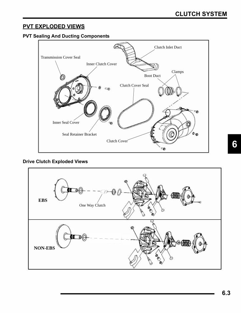
CLUTCH SYSTEM
6
PVT EXPLODED VIEWSPVT Sealing And Ducting Components
Drive Clutch Exploded Views
Clutch Inlet Duct
ClampsBoot Duct
Clutch Cover
Clutch Cover Seal
Seal Retainer Bracket
Inner Seal Cover
Inner Clutch Cover
Transmission Cover Seal
NON-EBS
One Way ClutchEBS
6.3
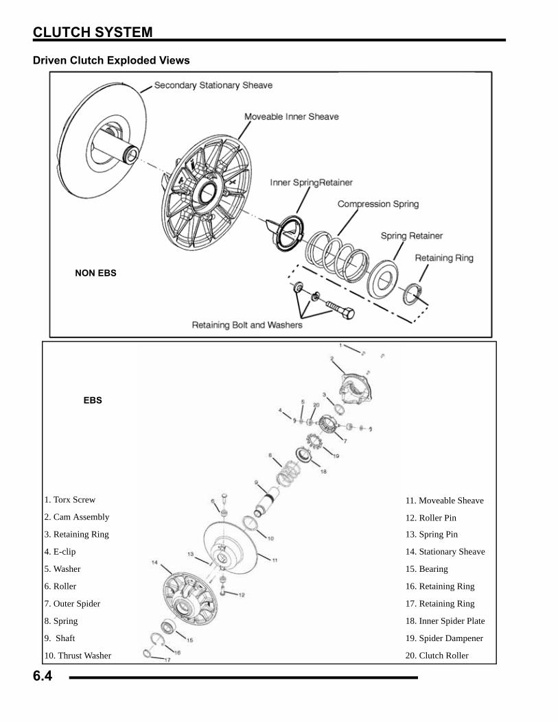
CLUTCH SYSTEM
Driven Clutch Exploded Views
NON EBS
1. Torx Screw
2. Cam Assembly
3. Retaining Ring
4. E-clip
5. Washer
6. Roller
7. Outer Spider
8. Spring
9. Shaft
10. Thrust Washer
11. Moveable Sheave
12. Roller Pin
13. Spring Pin
14. Stationary Sheave
15. Bearing
16. Retaining Ring
17. Retaining Ring
18. Inner Spider Plate
19. Spider Dampener
20. Clutch Roller
EBS
6.4
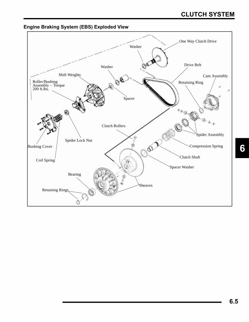
CLUTCH SYSTEM
6
Engine Braking System (EBS) Exploded View
WasherOne Way Clutch Drive
Washer
Spacer
Shift Weights
Roller/BushingAssembly - Torque200 ft.lbs.
Spider Lock Nut
Coil Spring
Bushing Cover
Drive Belt
Cam AssemblyRetaining Ring
Spider Assembly
Compression Spring
Clutch Shaft
Spacer Washer
Sheaves
Clutch Rollers
Bearing
Retaining Rings
6.5
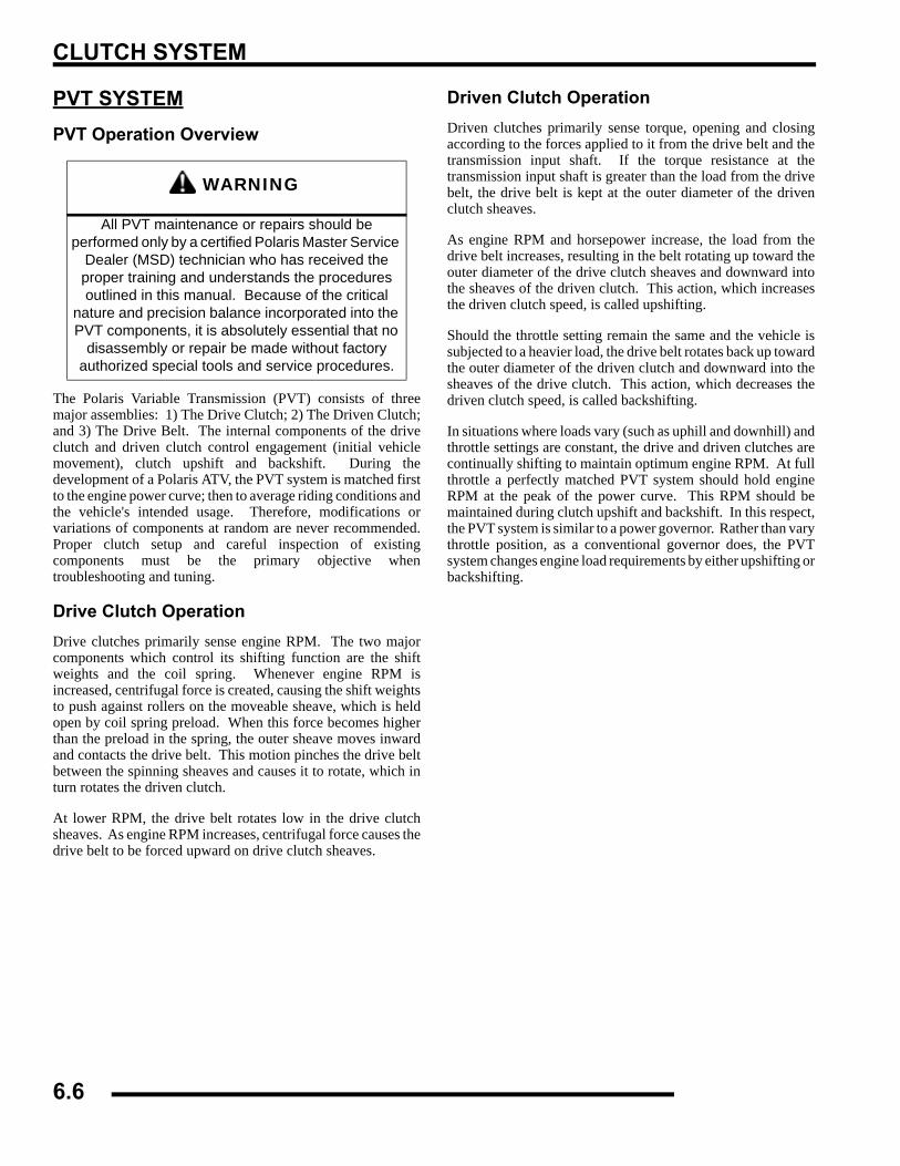
CLUTCH SYSTEM
PVT SYSTEMPVT Operation Overview
The Polaris Variable Transmission (PVT) consists of threemajor assemblies: 1) The Drive Clutch; 2) The Driven Clutch;and 3) The Drive Belt. The internal components of the driveclutch and driven clutch control engagement (initial vehiclemovement), clutch upshift and backshift. During thedevelopment of a Polaris ATV, the PVT system is matched firstto the engine power curve; then to average riding conditions andthe vehicle's intended usage. Therefore, modifications orvariations of components at random are never recommended.Proper clutch setup and careful inspection of existingcomponents must be the primary objective whentroubleshooting and tuning.
Drive Clutch OperationDrive clutches primarily sense engine RPM. The two majorcomponents which control its shifting function are the shiftweights and the coil spring. Whenever engine RPM isincreased, centrifugal force is created, causing the shift weightsto push against rollers on the moveable sheave, which is heldopen by coil spring preload. When this force becomes higherthan the preload in the spring, the outer sheave moves inwardand contacts the drive belt. This motion pinches the drive beltbetween the spinning sheaves and causes it to rotate, which inturn rotates the driven clutch.
At lower RPM, the drive belt rotates low in the drive clutchsheaves. As engine RPM increases, centrifugal force causes thedrive belt to be forced upward on drive clutch sheaves.
Driven Clutch OperationDriven clutches primarily sense torque, opening and closingaccording to the forces applied to it from the drive belt and thetransmission input shaft. If the torque resistance at thetransmission input shaft is greater than the load from the drivebelt, the drive belt is kept at the outer diameter of the drivenclutch sheaves.
As engine RPM and horsepower increase, the load from thedrive belt increases, resulting in the belt rotating up toward theouter diameter of the drive clutch sheaves and downward intothe sheaves of the driven clutch. This action, which increasesthe driven clutch speed, is called upshifting.
Should the throttle setting remain the same and the vehicle issubjected to a heavier load, the drive belt rotates back up towardthe outer diameter of the driven clutch and downward into thesheaves of the drive clutch. This action, which decreases thedriven clutch speed, is called backshifting.
In situations where loads vary (such as uphill and downhill) andthrottle settings are constant, the drive and driven clutches arecontinually shifting to maintain optimum engine RPM. At fullthrottle a perfectly matched PVT system should hold engineRPM at the peak of the power curve. This RPM should bemaintained during clutch upshift and backshift. In this respect,the PVT system is similar to a power governor. Rather than varythrottle position, as a conventional governor does, the PVTsystem changes engine load requirements by either upshifting orbackshifting.
WARNING
All PVT maintenance or repairs should be performed only by a certified Polaris Master Service
Dealer (MSD) technician who has received the proper training and understands the procedures outlined in this manual. Because of the critical
nature and precision balance incorporated into the PVT components, it is absolutely essential that no
disassembly or repair be made without factory authorized special tools and service procedures.
6.6
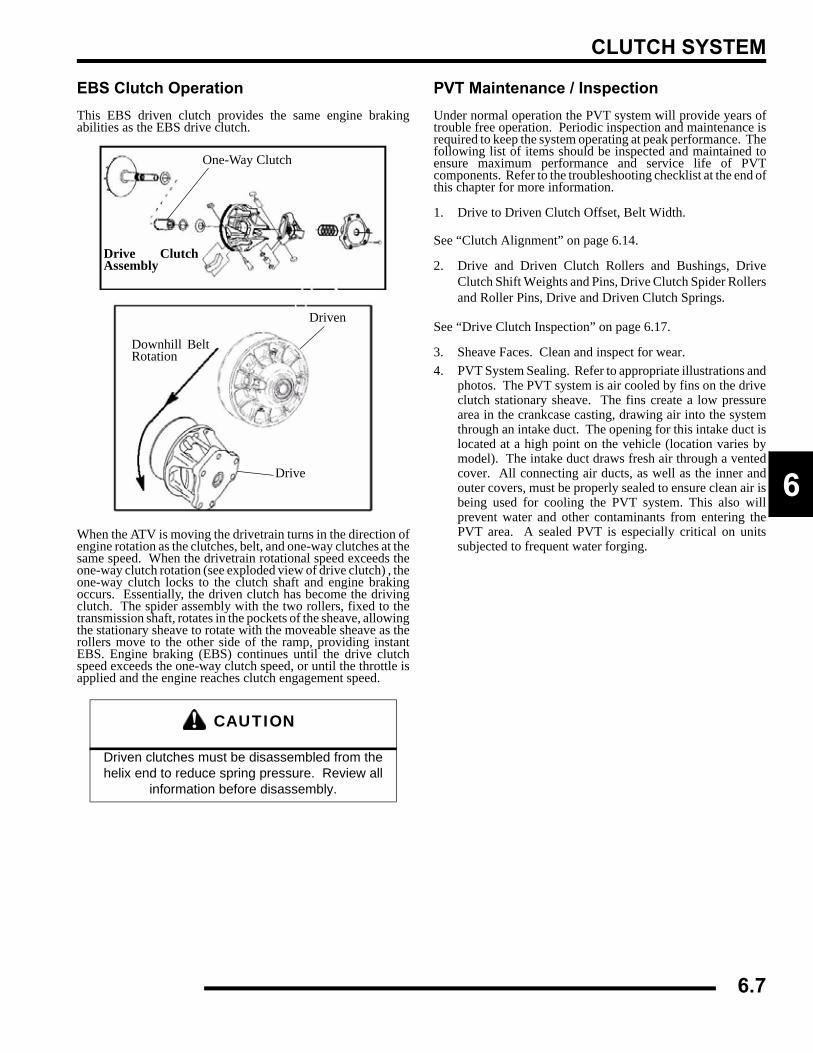
CLUTCH SYSTEM
6
EBS Clutch OperationThis EBS driven clutch provides the same engine brakingabilities as the EBS drive clutch.
When the ATV is moving the drivetrain turns in the direction ofengine rotation as the clutches, belt, and one-way clutches at thesame speed. When the drivetrain rotational speed exceeds theone-way clutch rotation (see exploded view of drive clutch) , theone-way clutch locks to the clutch shaft and engine brakingoccurs. Essentially, the driven clutch has become the drivingclutch. The spider assembly with the two rollers, fixed to thetransmission shaft, rotates in the pockets of the sheave, allowingthe stationary sheave to rotate with the moveable sheave as therollers move to the other side of the ramp, providing instantEBS. Engine braking (EBS) continues until the drive clutchspeed exceeds the one-way clutch speed, or until the throttle isapplied and the engine reaches clutch engagement speed.
PVT Maintenance / InspectionUnder normal operation the PVT system will provide years oftrouble free operation. Periodic inspection and maintenance isrequired to keep the system operating at peak performance. Thefollowing list of items should be inspected and maintained toensure maximum performance and service life of PVTcomponents. Refer to the troubleshooting checklist at the end ofthis chapter for more information.
1. Drive to Driven Clutch Offset, Belt Width.
See “Clutch Alignment” on page 6.14.
2. Drive and Driven Clutch Rollers and Bushings, DriveClutch Shift Weights and Pins, Drive Clutch Spider Rollersand Roller Pins, Drive and Driven Clutch Springs.
See “Drive Clutch Inspection” on page 6.17.
3. Sheave Faces. Clean and inspect for wear.4. PVT System Sealing. Refer to appropriate illustrations and
photos. The PVT system is air cooled by fins on the driveclutch stationary sheave. The fins create a low pressurearea in the crankcase casting, drawing air into the systemthrough an intake duct. The opening for this intake duct islocated at a high point on the vehicle (location varies bymodel). The intake duct draws fresh air through a ventedcover. All connecting air ducts, as well as the inner andouter covers, must be properly sealed to ensure clean air isbeing used for cooling the PVT system. This also willprevent water and other contaminants from entering thePVT area. A sealed PVT is especially critical on unitssubjected to frequent water forging.
CAUTION
Driven clutches must be disassembled from the helix end to reduce spring pressure. Review all
information before disassembly.
One-Way Clutch
Drive ClutchAssembly
Downhill BeltRotation
Driven
Drive
6.7
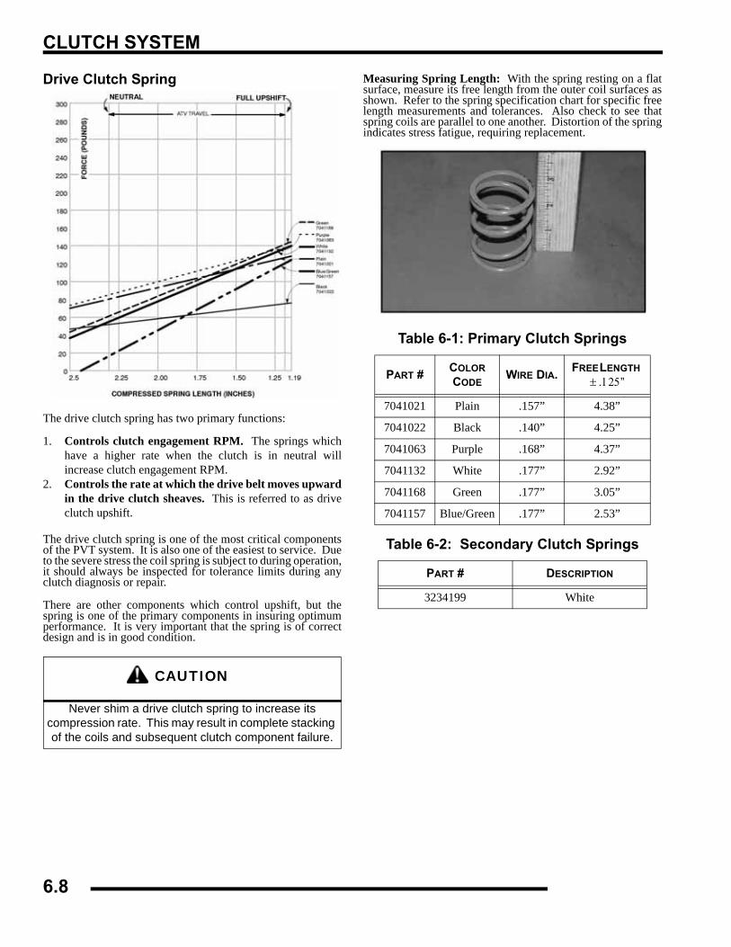
CLUTCH SYSTEM
Drive Clutch Spring
The drive clutch spring has two primary functions:
1. Controls clutch engagement RPM. The springs whichhave a higher rate when the clutch is in neutral willincrease clutch engagement RPM.
2. Controls the rate at which the drive belt moves upwardin the drive clutch sheaves. This is referred to as driveclutch upshift.
The drive clutch spring is one of the most critical componentsof the PVT system. It is also one of the easiest to service. Dueto the severe stress the coil spring is subject to during operation,it should always be inspected for tolerance limits during anyclutch diagnosis or repair.
There are other components which control upshift, but thespring is one of the primary components in insuring optimumperformance. It is very important that the spring is of correctdesign and is in good condition.
Measuring Spring Length: With the spring resting on a flatsurface, measure its free length from the outer coil surfaces asshown. Refer to the spring specification chart for specific freelength measurements and tolerances. Also check to see thatspring coils are parallel to one another. Distortion of the springindicates stress fatigue, requiring replacement.
CAUTION
Never shim a drive clutch spring to increase its compression rate. This may result in complete stacking of the coils and subsequent clutch component failure.
Table 6-1: Primary Clutch Springs
PART # COLOR CODE
WIRE DIA. FREE LENGTH ± .125”
7041021 Plain .157” 4.38”
7041022 Black .140” 4.25”
7041063 Purple .168” 4.37”
7041132 White .177” 2.92”
7041168 Green .177” 3.05”
7041157 Blue/Green .177” 2.53”
Table 6-2: Secondary Clutch Springs
PART # DESCRIPTION
3234199 White
6.8
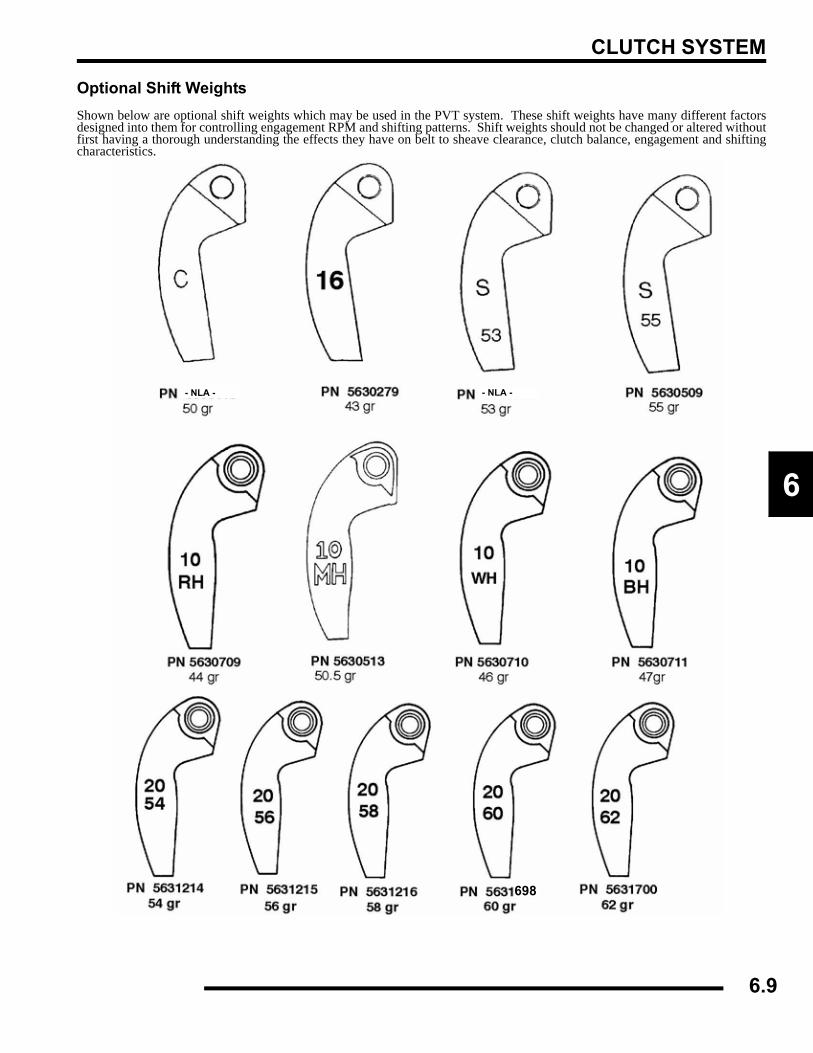
CLUTCH SYSTEM
6
Optional Shift WeightsShown below are optional shift weights which may be used in the PVT system. These shift weights have many different factorsdesigned into them for controlling engagement RPM and shifting patterns. Shift weights should not be changed or altered withoutfirst having a thorough understanding the effects they have on belt to sheave clearance, clutch balance, engagement and shiftingcharacteristics.
- NLA -- NLA -
698
6.9
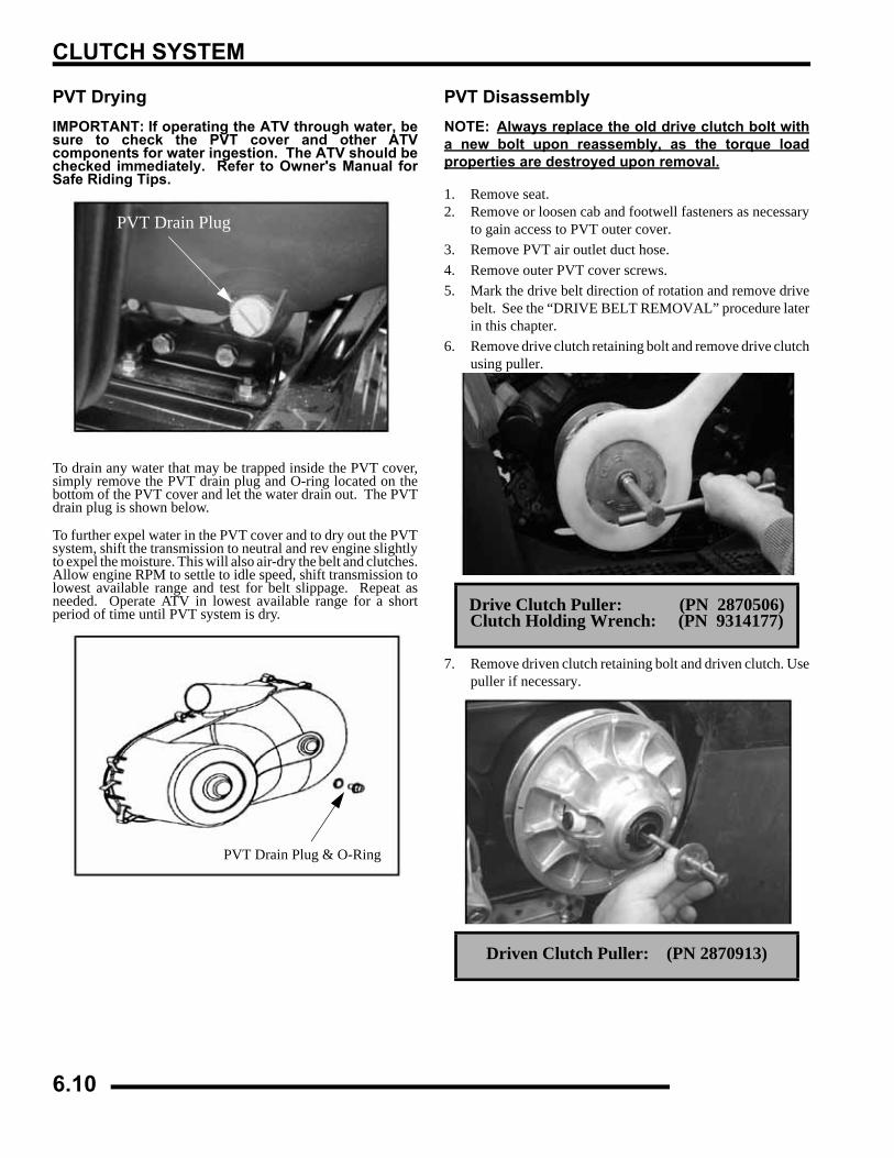
CLUTCH SYSTEM
PVT DryingIMPORTANT: If operating the ATV through water, besure to check the PVT cover and other ATVcomponents for water ingestion. The ATV should bechecked immediately. Refer to Owner's Manual forSafe Riding Tips.
To drain any water that may be trapped inside the PVT cover,simply remove the PVT drain plug and O-ring located on thebottom of the PVT cover and let the water drain out. The PVTdrain plug is shown below.
To further expel water in the PVT cover and to dry out the PVTsystem, shift the transmission to neutral and rev engine slightlyto expel the moisture. This will also air-dry the belt and clutches.Allow engine RPM to settle to idle speed, shift transmission tolowest available range and test for belt slippage. Repeat asneeded. Operate ATV in lowest available range for a shortperiod of time until PVT system is dry.
PVT DisassemblyNOTE: Always replace the old drive clutch bolt witha new bolt upon reassembly, as the torque loadproperties are destroyed upon removal.
1. Remove seat.2. Remove or loosen cab and footwell fasteners as necessary
to gain access to PVT outer cover.3. Remove PVT air outlet duct hose.4. Remove outer PVT cover screws. 5. Mark the drive belt direction of rotation and remove drive
belt. See the “DRIVE BELT REMOVAL” procedure laterin this chapter.
6. Remove drive clutch retaining bolt and remove drive clutchusing puller.
7. Remove driven clutch retaining bolt and driven clutch. Usepuller if necessary.
PVT Drain Plug
PVT Drain Plug & O-Ring
Drive Clutch Puller: (PN 2870506)Clutch Holding Wrench: (PN 9314177)
Driven Clutch Puller: (PN 2870913)
6.10
CLUTCH SYSTEM
6
8. Remove driven clutch offset spacers from the transmissioninput shaft. NOTE: Remember to keep spacers in order forproper clutch offset on reassembly.
9. Remove cover screws and retainer plate.
10. Remove inner cover retaining bolts at rear of cover.11. Remove cover along with foam seal on back of cover or
shaft.
PVT Installation1. Inspect PVT inner cover-to-engine seal. Replace if
cracked or damaged. Align the alignment mark on thecover with the mark on the engine seal.
2. Place a new seal on transmission input shaft.3. Apply RTV silicone sealant to outside edge of inner cover-
to-engine seal, to ensure a water tight fit between the sealand the cover on engine side. Surfaces must be clean toensure adhesion of silicone sealant.
4. Reinstall cover and tighten rear cover bolts just enough tohold it in place.
5. Fit lip of inner cover seal (A) to engine. Install seal retainerplate and tighten screws securely.
6. Torque rear inner cover bolts (B) to specification.
Offset Spacer
Inner Cover
Retainer Seal
Foam Seal
= T
Inner Cover Bolt Torque (B):12 ft. lbs. (16.6 Nm)
Seal This Edge To Cover On Engine
B
C
Seal Outer Edge To Coverw/ RTV silicone sealant
A
6.11
CLUTCH SYSTEM
7. Install clutch offset spacer(s) on transmission input shaft.
8. Clean splines inside driven clutch and on the transmissioninput shaft.
9. Apply a light film of grease to the splines on the shaft.10. Install the driven clutch, washer, lock washer, and retaining
bolt. Torque to specification.
11. Clean end of taper on crankshaft and the taper bore insidedrive clutch.
12. Install a NEW drive clutch bolt and torque retaining boltto specification.
13. Reinstall drive belt noting direction of rotation. If a newbelt is installed, install so numbers can be easily read.
14. Only replace PVT outer cover rubber gasket if it isdamaged. Place the gasket with the narrow side out (C).
15. Reinstall PVT outer cover and secure with screws. Torqueto specification.
16. Reinstall cab/footwell assembly, panel and seat.
Drive Belt Removal / Inspection1. Remove outer PVT cover as described in PVT
Disassembly.2. Mark drive belt direction of rotation so that it can be
installed in the same direction. The belt is normallypositioned so part numbers are easily read.
3. To remove drive belt, apply brake, pull upward andrearward on belt while turning the back (moveable) drivensheave clockwise to open driven clutch sheaves. Pull outand down on belt to slip over the driven clutch outer sheave.
4. Measure belt width and replace if worn. Generally, beltsshould be replaced if clutches can no longer be adjusted toprovide proper belt deflection.
NOTE: If the top edges are trimmed on some drivebelts, it will be necessary to project the side profilesin order to measure from corner-to-corner.
5. Place a straight edge on each side of the drive belt. Placeanother straight edge on top of belt.
= T
Driven Clutch Retaining Bolt Torque:17 ft. lbs. (23.5 Nm)
= T
Drive Clutch Retaining Bolt Torque:40 ft. lbs. (55 Nm)
ALWAYS USE A NEW BOLT UPON INSTALLATION
Offset Spacer
PVT Cover Gasket
Towards Outside Cover
6.12
CLUTCH SYSTEM
6
6. Measure the distance where the side straight edges intersectthe top, as shown in the illustration.
7. Inspect belt for loose cords, missing cogs, cracks,abrasions, thin spots, or excessive wear. Replace ifnecessary.
8. Inspect belt for hour glassing (extreme circular wear in atleast one spot and on both sides of the belt). Hour glassingoccurs when the drive train does not move and the driveclutch engages the belt continuously in one spot.
9. Measure belt length with a tape measure around the outercircumference of the belt. Belts which measure longer thannominal length may require driven shimming or engineadjustment for a longer center distance to obtain proper beltdeflection. Belts which measure shorter than nominallength may require driven shimming or a shorter centerdistance. Remember, proper belt deflection is the desiredgoal - not a specific center distance.
10. Replace belt if worn past the service limit. Belts with thinspots, burn marks, etc., should be replaced to eliminatenoise, vibration, or erratic PVT operation. SeeTroubleshooting Chart at the end of this chapter forpossible causes.
DRIVE BELT INSTALLATIONNOTE: Be sure to position belt so part number is easilyread. Verify new belt is seated properly in the clutchesbefore operating the ATV.
1. Loop belt over drive and over top of driven sheave.2. While pushing down on top of belt, turn the back or
moveable driven sheave clockwise.
3. The belt then should be able to be pushed down into andbetween the sheaves.
4. Install clutch cover temporarily. Verify engine is in PARK.Start engine and raise engine RPM enough to engage theclutch, rotating the belt and seating it in the clutches.Remove clutch cover and verify belt is seated properlybefore final cover installation.
Belt Width:Wear Limit 1.125" (2.86 cm)
Clutch Center Distance: 10.05 ± .05" (254 ± 2.51mm)
Projected Belt Width
CenterDistance
6.13
CLUTCH SYSTEM
Clutch Alignment1. Remove belt and install the Clutch Offset Alignment Tool
as shown.
2. With tool touching rear of driven clutch inner sheave, thedistance at point “A” should be 1/8”.
NOTE: If the distance is greater than 1/8, or lessthan 1/16,, clutch alignment must be adjusted asfollows:
3. Remove drive and driven clutch. See “PVTDIASSEMBLY” at the beginning of the chapter.
4. Remove PVT inner cover.5. Loosen all engine mounts. Move front of engine to the right
or left slightly until alignment is correct.6. Tighten engine mounts and verify alignment is correct.
7. Measure belt deflection and measure offset both above andbelow shaft centerlines. Adjust if necessary.
NOTE: On some models, minor adjustments can bemade by adding shims between the frame and frontlower left engine mount to increase the distance atpoint “A”. If a shim is present, it can be removed todecrease the distance at point “A”.
Clutch OffsetIMPORTANT: Inspect clutch alignment and centerdistance before adjusting offset.
Offset is correct when rear of tool contacts rear of inner sheavewith driven clutch pushed completely inward, spacers installed(if required) on shaft and bolt torqued to specification.
1. Install alignment tool as shown. Remember to measureabove and below the shaft centerlines.
2. Adjust offset by adding or removing spacer washersbetween back of driven clutch and spacer.
B
A 1/8” + 0 / -1/16 (3.2mm + 0 / - 1.6)
Offset Alignment Tool
Shim Kit (PN 2200126)
Spacer Washer (PN 7556401)
Center Line
Measure Above and Below Centerline
6.14
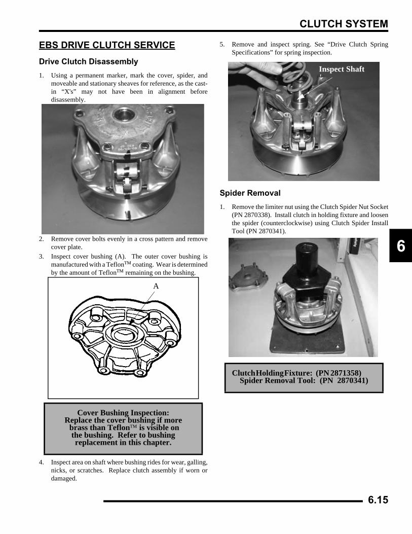
CLUTCH SYSTEM
6
EBS DRIVE CLUTCH SERVICEDrive Clutch Disassembly1. Using a permanent marker, mark the cover, spider, and
moveable and stationary sheaves for reference, as the cast-in “X's” may not have been in alignment beforedisassembly.
2. Remove cover bolts evenly in a cross pattern and removecover plate.
3. Inspect cover bushing (A). The outer cover bushing ismanufactured with a Teflon™ coating. Wear is determinedby the amount of Teflon™ remaining on the bushing.
4. Inspect area on shaft where bushing rides for wear, galling,nicks, or scratches. Replace clutch assembly if worn ordamaged.
5. Remove and inspect spring. See “Drive Clutch SpringSpecifications” for spring inspection.
Spider Removal1. Remove the limiter nut using the Clutch Spider Nut Socket
(PN 2870338). Install clutch in holding fixture and loosenthe spider (counterclockwise) using Clutch Spider InstallTool (PN 2870341).
Cover Bushing Inspection:Replace the cover bushing if more brass than Teflon™ is visible on
the bushing. Refer to bushing replacement in this chapter.
A
Clutch Holding Fixture: (PN 2871358) Spider Removal Tool: (PN 2870341)
Inspect Shaft
6.15
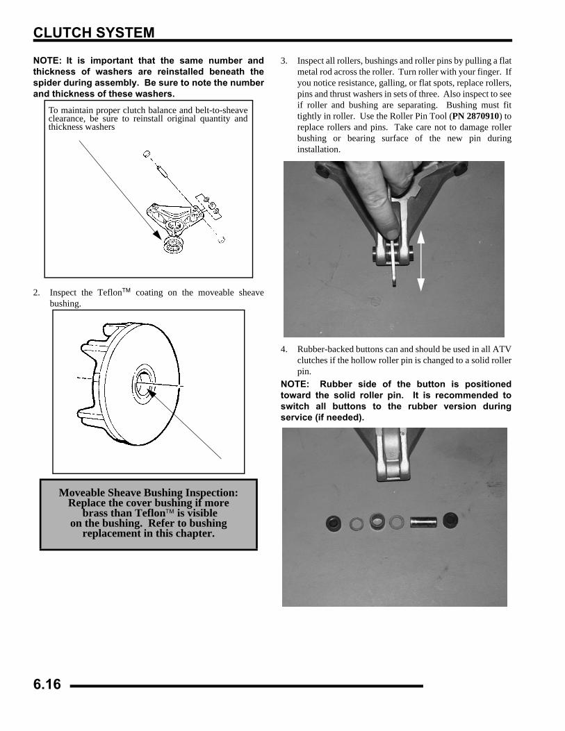
CLUTCH SYSTEM
NOTE: It is important that the same number andthickness of washers are reinstalled beneath thespider during assembly. Be sure to note the numberand thickness of these washers.
2. Inspect the Teflon™ coating on the moveable sheavebushing.
3. Inspect all rollers, bushings and roller pins by pulling a flatmetal rod across the roller. Turn roller with your finger. Ifyou notice resistance, galling, or flat spots, replace rollers,pins and thrust washers in sets of three. Also inspect to seeif roller and bushing are separating. Bushing must fittightly in roller. Use the Roller Pin Tool (PN 2870910) toreplace rollers and pins. Take care not to damage rollerbushing or bearing surface of the new pin duringinstallation.
4. Rubber-backed buttons can and should be used in all ATVclutches if the hollow roller pin is changed to a solid rollerpin.
NOTE: Rubber side of the button is positionedtoward the solid roller pin. It is recommended toswitch all buttons to the rubber version duringservice (if needed).
Moveable Sheave Bushing Inspection: Replace the cover bushing if more
brass than Teflon™ is visible on the bushing. Refer to bushing
replacement in this chapter.
To maintain proper clutch balance and belt-to-sheaveclearance, be sure to reinstall original quantity andthickness washers
6.16
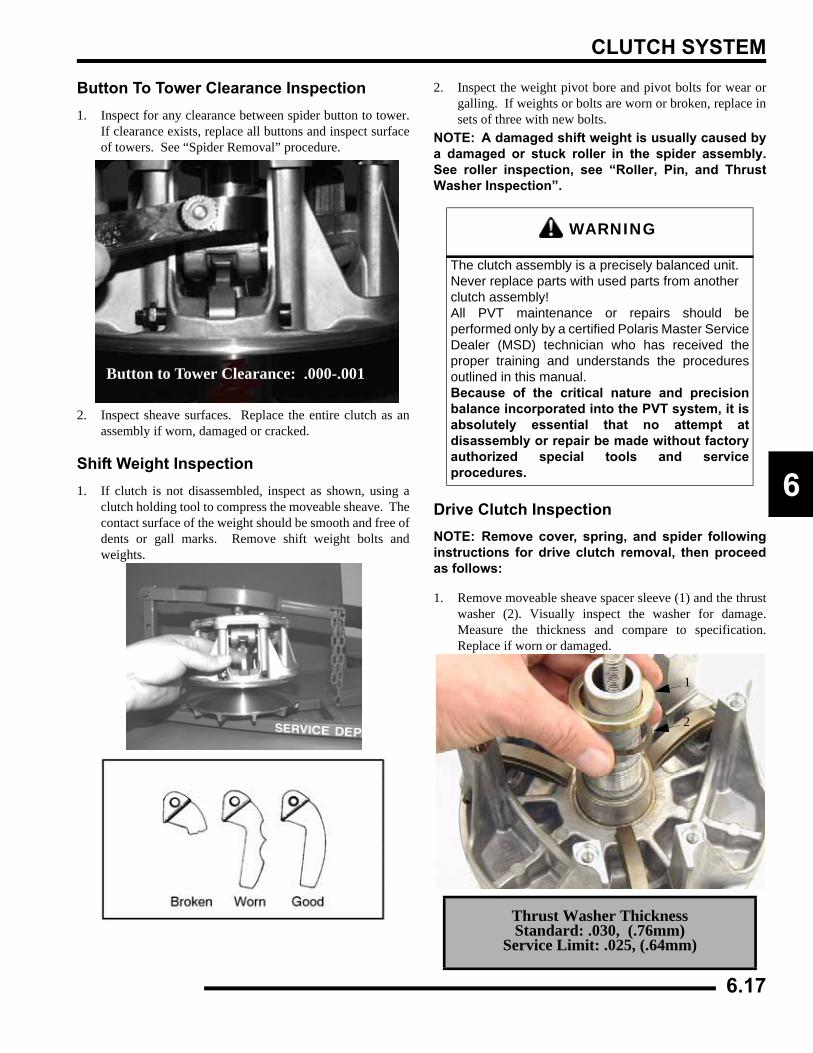
CLUTCH SYSTEM
6
Button To Tower Clearance Inspection1. Inspect for any clearance between spider button to tower.
If clearance exists, replace all buttons and inspect surfaceof towers. See “Spider Removal” procedure.
2. Inspect sheave surfaces. Replace the entire clutch as anassembly if worn, damaged or cracked.
Shift Weight Inspection1. If clutch is not disassembled, inspect as shown, using a
clutch holding tool to compress the moveable sheave. Thecontact surface of the weight should be smooth and free ofdents or gall marks. Remove shift weight bolts andweights.
2. Inspect the weight pivot bore and pivot bolts for wear orgalling. If weights or bolts are worn or broken, replace insets of three with new bolts.
NOTE: A damaged shift weight is usually caused bya damaged or stuck roller in the spider assembly.See roller inspection, see “Roller, Pin, and ThrustWasher Inspection”.
Drive Clutch InspectionNOTE: Remove cover, spring, and spider followinginstructions for drive clutch removal, then proceedas follows:
1. Remove moveable sheave spacer sleeve (1) and the thrustwasher (2). Visually inspect the washer for damage.Measure the thickness and compare to specification.Replace if worn or damaged.
Button to Tower Clearance: .000-.001
WARNING
The clutch assembly is a precisely balanced unit. Never replace parts with used parts from another clutch assembly!All PVT maintenance or repairs should beperformed only by a certified Polaris Master ServiceDealer (MSD) technician who has received theproper training and understands the proceduresoutlined in this manual. Because of the critical nature and precisionbalance incorporated into the PVT system, it isabsolutely essential that no attempt atdisassembly or repair be made without factoryauthorized special tools and serviceprocedures.
Thrust Washer ThicknessStandard: .030, (.76mm)
Service Limit: .025, (.64mm)
1
2
6.17
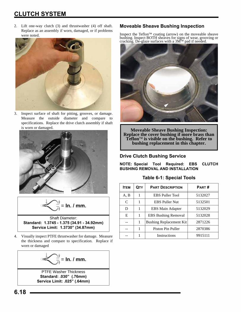
CLUTCH SYSTEM
2. Lift one-way clutch (3) and thrustwasher (4) off shaft.Replace as an assembly if worn, damaged, or if problemswere noted.
3. Inspect surface of shaft for pitting, grooves, or damage.Measure the outside diameter and compare tospecifications. Replace the drive clutch assembly if shaftis worn or damaged.
4. Visually inspect PTFE thrustwasher for damage. Measurethe thickness and compare to specification. Replace ifworn or damaged
Moveable Sheave Bushing InspectionInspect the Teflon™ coating (arrow) on the moveable sheavebushing. Inspect BOTH sheaves for signs of wear, grooving orcracking. De-glaze surfaces with a 3M™ pad if needed.
Drive Clutch Bushing ServiceNOTE: Special Tool Required: EBS CLUTCHBUSHING REMOVAL AND INSTALLATION
= In. / mm.
Shaft Diameter:Standard: 1.3745 - 1.375 (34.91 - 34.92mm)
Service Limit: 1.3730” (34.87mm)
= In. / mm.
PTFE Washer ThicknessStandard: .030” (.76mm)
Service Limit: .025” (.64mm)
Moveable Sheave Bushing Inspection:Replace the cover bushing if more brass than
Teflon™ is visible on the bushing. Refer to bushing replacement in this chapter.
Table 6-1: Special Tools
ITEM QTY PART DESCRIPTION PART #
A, B 1 EBS Puller Tool 5132027
C 1 EBS Puller Nut 5132501
D 1 EBS Main Adapter 5132029
E 1 EBS Bushing Removal 5132028
-- 1 Bushing Replacement Kit 2871226
-- 1 Piston Pin Puller 2870386
-- 1 Instructions 9915111
6.18
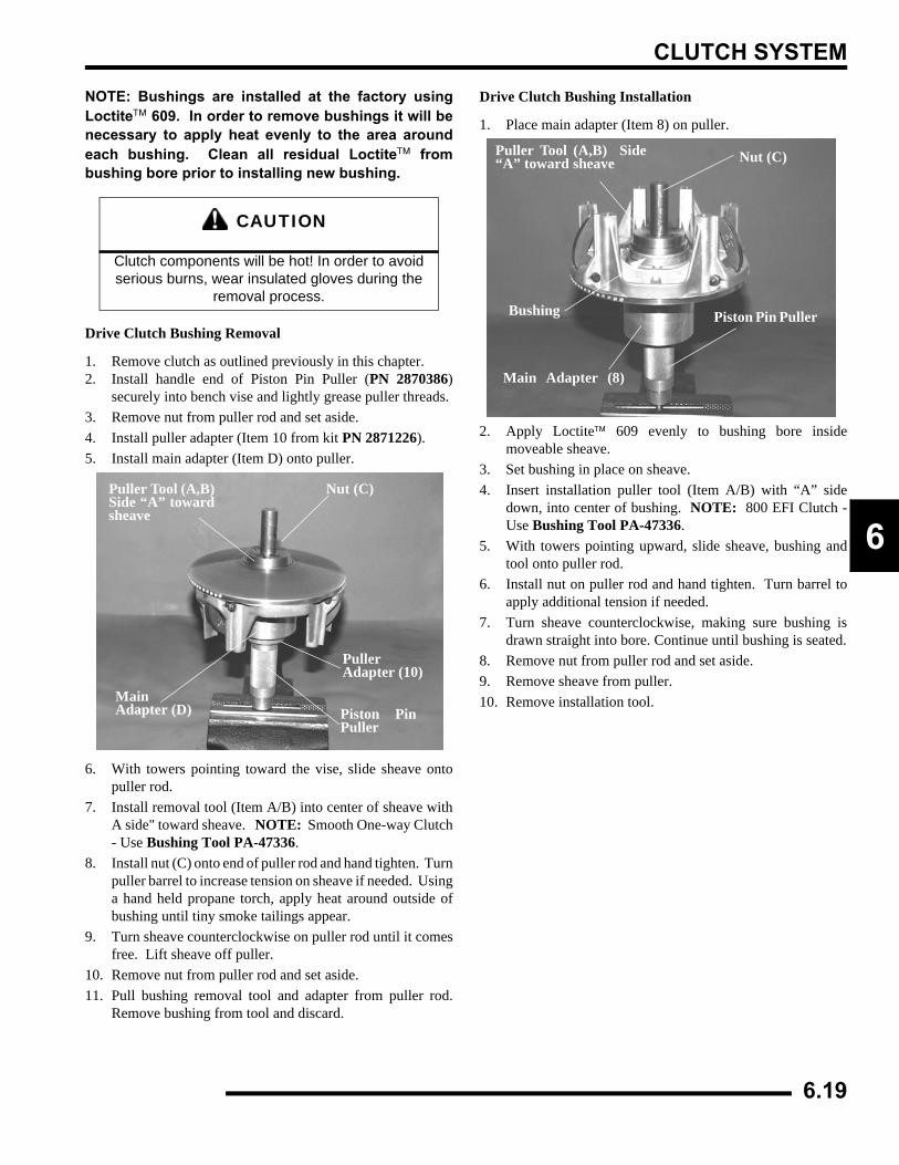
CLUTCH SYSTEM
6
NOTE: Bushings are installed at the factory usingLoctite™ 609. In order to remove bushings it will benecessary to apply heat evenly to the area aroundeach bushing. Clean all residual Loctite™ frombushing bore prior to installing new bushing.
Drive Clutch Bushing Removal
1. Remove clutch as outlined previously in this chapter.2. Install handle end of Piston Pin Puller (PN 2870386)
securely into bench vise and lightly grease puller threads.3. Remove nut from puller rod and set aside.4. Install puller adapter (Item 10 from kit PN 2871226).5. Install main adapter (Item D) onto puller.
6. With towers pointing toward the vise, slide sheave ontopuller rod.
7. Install removal tool (Item A/B) into center of sheave withA side" toward sheave. NOTE: Smooth One-way Clutch- Use Bushing Tool PA-47336.
8. Install nut (C) onto end of puller rod and hand tighten. Turnpuller barrel to increase tension on sheave if needed. Usinga hand held propane torch, apply heat around outside ofbushing until tiny smoke tailings appear.
9. Turn sheave counterclockwise on puller rod until it comesfree. Lift sheave off puller.
10. Remove nut from puller rod and set aside.11. Pull bushing removal tool and adapter from puller rod.
Remove bushing from tool and discard.
Drive Clutch Bushing Installation
1. Place main adapter (Item 8) on puller.
2. Apply Loctite™ 609 evenly to bushing bore insidemoveable sheave.
3. Set bushing in place on sheave.4. Insert installation puller tool (Item A/B) with “A” side
down, into center of bushing. NOTE: 800 EFI Clutch -Use Bushing Tool PA-47336.
5. With towers pointing upward, slide sheave, bushing andtool onto puller rod.
6. Install nut on puller rod and hand tighten. Turn barrel toapply additional tension if needed.
7. Turn sheave counterclockwise, making sure bushing isdrawn straight into bore. Continue until bushing is seated.
8. Remove nut from puller rod and set aside.9. Remove sheave from puller.10. Remove installation tool.
CAUTION
Clutch components will be hot! In order to avoid serious burns, wear insulated gloves during the
removal process.
Puller Tool (A,B)Side “A” towardsheave
Nut (C)
MainAdapter (D)
PullerAdapter (10)
Piston PinPuller
Puller Tool (A,B) Side“A” toward sheave Nut (C)
Bushing
Main Adapter (8)
Piston Pin Puller
6.19
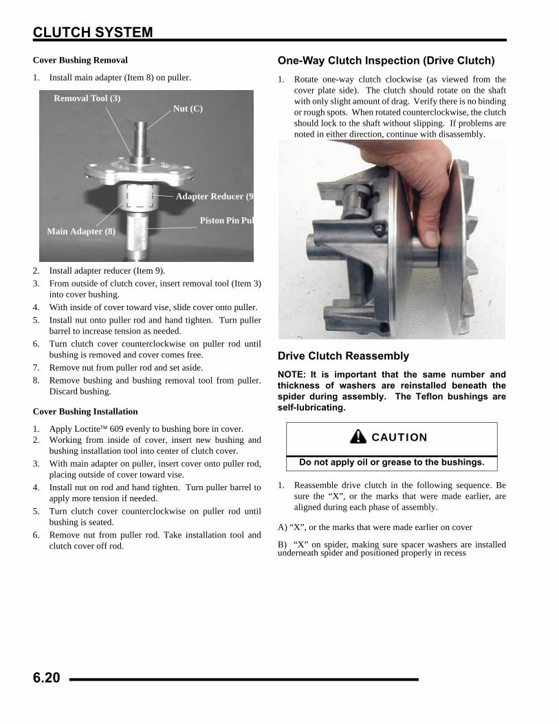
CLUTCH SYSTEM
Cover Bushing Removal
1. Install main adapter (Item 8) on puller.
2. Install adapter reducer (Item 9).3. From outside of clutch cover, insert removal tool (Item 3)
into cover bushing.4. With inside of cover toward vise, slide cover onto puller.5. Install nut onto puller rod and hand tighten. Turn puller
barrel to increase tension as needed.6. Turn clutch cover counterclockwise on puller rod until
bushing is removed and cover comes free.7. Remove nut from puller rod and set aside. 8. Remove bushing and bushing removal tool from puller.
Discard bushing.
Cover Bushing Installation
1. Apply Loctite™ 609 evenly to bushing bore in cover.2. Working from inside of cover, insert new bushing and
bushing installation tool into center of clutch cover.3. With main adapter on puller, insert cover onto puller rod,
placing outside of cover toward vise.4. Install nut on rod and hand tighten. Turn puller barrel to
apply more tension if needed.5. Turn clutch cover counterclockwise on puller rod until
bushing is seated.6. Remove nut from puller rod. Take installation tool and
clutch cover off rod.
One-Way Clutch Inspection (Drive Clutch)1. Rotate one-way clutch clockwise (as viewed from the
cover plate side). The clutch should rotate on the shaftwith only slight amount of drag. Verify there is no bindingor rough spots. When rotated counterclockwise, the clutchshould lock to the shaft without slipping. If problems arenoted in either direction, continue with disassembly.
Drive Clutch ReassemblyNOTE: It is important that the same number andthickness of washers are reinstalled beneath thespider during assembly. The Teflon bushings areself-lubricating.
1. Reassemble drive clutch in the following sequence. Besure the “X”, or the marks that were made earlier, arealigned during each phase of assembly.
A) “X”, or the marks that were made earlier on cover
B) “X” on spider, making sure spacer washers are installedunderneath spider and positioned properly in recess
Removal Tool (3)Nut (C)
Adapter Reducer (9)
Piston Pin PulleMain Adapter (8)
CAUTION
Do not apply oil or grease to the bushings.
6.20
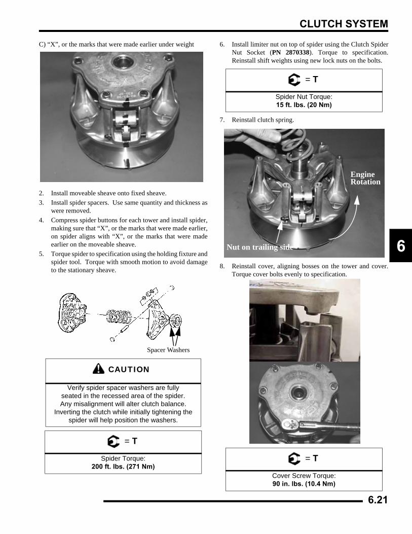
CLUTCH SYSTEM
6
C) “X”, or the marks that were made earlier under weight
2. Install moveable sheave onto fixed sheave.3. Install spider spacers. Use same quantity and thickness as
were removed.4. Compress spider buttons for each tower and install spider,
making sure that “X”, or the marks that were made earlier,on spider aligns with “X”, or the marks that were madeearlier on the moveable sheave.
5. Torque spider to specification using the holding fixture andspider tool. Torque with smooth motion to avoid damageto the stationary sheave.
6. Install limiter nut on top of spider using the Clutch SpiderNut Socket (PN 2870338). Torque to specification.Reinstall shift weights using new lock nuts on the bolts.
7. Reinstall clutch spring.
8. Reinstall cover, aligning bosses on the tower and cover.Torque cover bolts evenly to specification.
CAUTION
Verify spider spacer washers are fully seated in the recessed area of the spider. Any misalignment will alter clutch balance.
Inverting the clutch while initially tightening the spider will help position the washers.
= T
Spider Torque:200 ft. lbs. (271 Nm)
Spacer Washers
= T
Spider Nut Torque:15 ft. lbs. (20 Nm)
= T
Cover Screw Torque:90 in. lbs. (10.4 Nm)
EngineRotation
Nut on trailing side
6.21
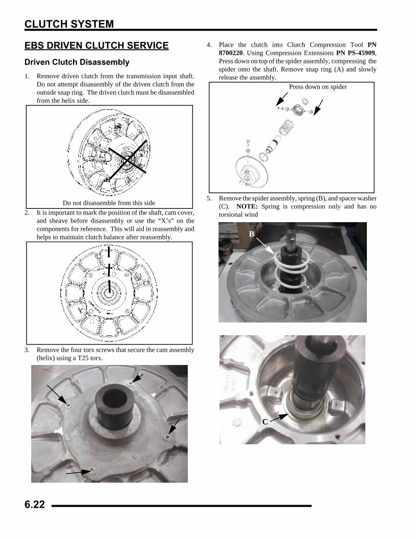
CLUTCH SYSTEM
EBS DRIVEN CLUTCH SERVICEDriven Clutch Disassembly 1. Remove driven clutch from the transmission input shaft.
Do not attempt disassembly of the driven clutch from theoutside snap ring. The driven clutch must be disassembledfrom the helix side.
2. It is important to mark the position of the shaft, cam cover,and sheave before disassembly or use the “X’s” on thecomponents for reference. This will aid in reassembly andhelps to maintain clutch balance after reassembly.
3. Remove the four torx screws that secure the cam assembly(helix) using a T25 torx.
4. Place the clutch into Clutch Compression Tool PN8700220. Using Compression Extensions PN PS-45909,Press down on top of the spider assembly, compressing thespider onto the shaft. Remove snap ring (A) and slowlyrelease the assembly.
5. Remove the spider assembly, spring (B), and spacer washer(C). NOTE: Spring is compression only and has notorsional wind
Do not disassemble from this side
Press down on spider
B
C
6.22
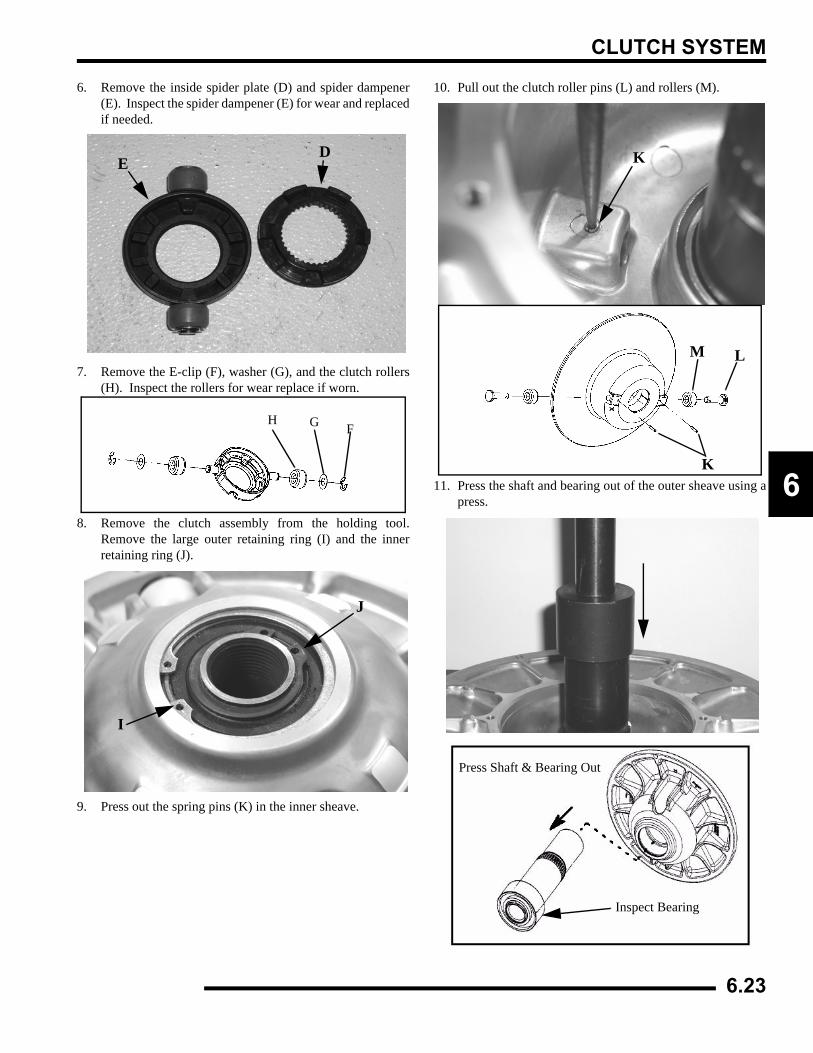
CLUTCH SYSTEM
6
6. Remove the inside spider plate (D) and spider dampener(E). Inspect the spider dampener (E) for wear and replacedif needed.
7. Remove the E-clip (F), washer (G), and the clutch rollers(H). Inspect the rollers for wear replace if worn.
8. Remove the clutch assembly from the holding tool.Remove the large outer retaining ring (I) and the innerretaining ring (J).
9. Press out the spring pins (K) in the inner sheave.
10. Pull out the clutch roller pins (L) and rollers (M).
11. Press the shaft and bearing out of the outer sheave using apress.
ED
H G F
I
J
K
K
M L
Press Shaft & Bearing Out
Inspect Bearing
6.23
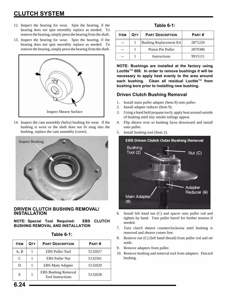
CLUTCH SYSTEM
12. Inspect the bearing for wear. Spin the bearing, if thebearing does not spin smoothly replace as needed. Toremove the bearing, simply press the bearing from the shaft.
13. Inspect the bearing for wear. Spin the bearing, if thebearing does not spin smoothly replace as needed. Toremove the bearing, simply press the bearing from the shaft.
14. Inspect the cam assembly (helix) bushing for wear. If thebushing is worn or the shaft does not fit snug into thebushing, replace the cam assembly (cover).
DRIVEN CLUTCH BUSHING REMOVAL/INSTALLATIONNOTE: Special Tool Required: EBS CLUTCHBUSHING REMOVAL AND INSTALLATION
NOTE: Bushings are installed at the factory usingLoctite™ 609. In order to remove bushings it will benecessary to apply heat evenly to the area aroundeach bushing. Clean all residual Loctite™ frombushing bore prior to installing new bushing.
Driven Clutch Bushing Removal1. Install main puller adapter (Item 8) onto puller.2. Install adapter reducer (Item 9).3. Using a hand held propane torch, apply heat around outside
of bushing until tiny smoke tailings appear.4. Flip sheave over so bushing faces downward and install
onto puller.5. Install bushing tool (Item 2).
6. Install left hand nut (C) and spacer onto puller rod andtighten by hand. Turn puller barrel for further tension ifneeded.
7. Turn clutch sheave counterclockwise until bushing isremoved and sheave comes free.
8. Remove nut (C) (left hand thread) from puller rod and setaside.
9. Remove adapters from puller.10. Remove bushing and removal tool from adapters. Discard
bushing.
Table 6-1:
ITEM QTY PART DESCRIPTION PART #
A, B 1 EBS Puller Tool 5132027
C 1 EBS Puller Nut 5132501
D 1 EBS Main Adapter 5132029
E 1 EBS Bushing Removal Tool Instructions 5132028
Inspect Sheave Surface
Inspect Bushing
-- 1 Bushing Replacement Kit 2871226
-- 1 Piston Pin Puller 2870386
-- 1 Instructions 9915111
Table 6-1:
ITEM QTY PART DESCRIPTION PART #
6.24
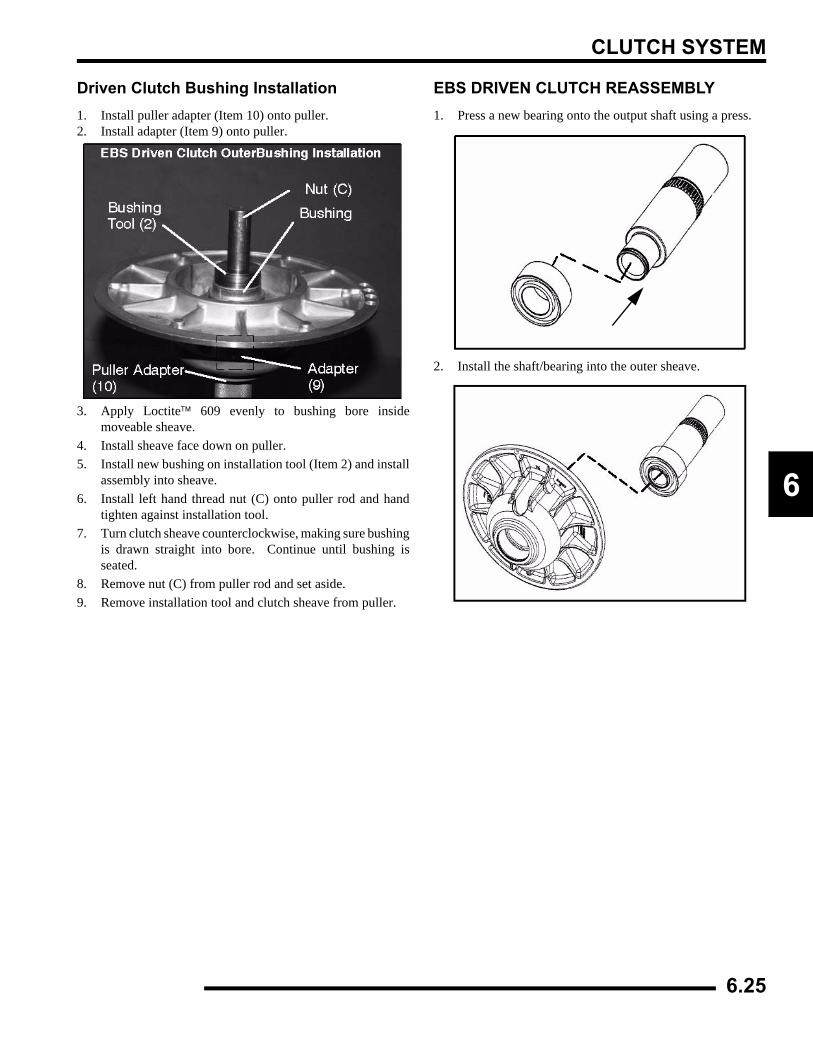
CLUTCH SYSTEM
6
Driven Clutch Bushing Installation1. Install puller adapter (Item 10) onto puller.2. Install adapter (Item 9) onto puller.
3. Apply Loctite™ 609 evenly to bushing bore insidemoveable sheave.
4. Install sheave face down on puller.5. Install new bushing on installation tool (Item 2) and install
assembly into sheave.6. Install left hand thread nut (C) onto puller rod and hand
tighten against installation tool. 7. Turn clutch sheave counterclockwise, making sure bushing
is drawn straight into bore. Continue until bushing isseated.
8. Remove nut (C) from puller rod and set aside.9. Remove installation tool and clutch sheave from puller.
EBS DRIVEN CLUTCH REASSEMBLY1. Press a new bearing onto the output shaft using a press.
2. Install the shaft/bearing into the outer sheave.
6.25
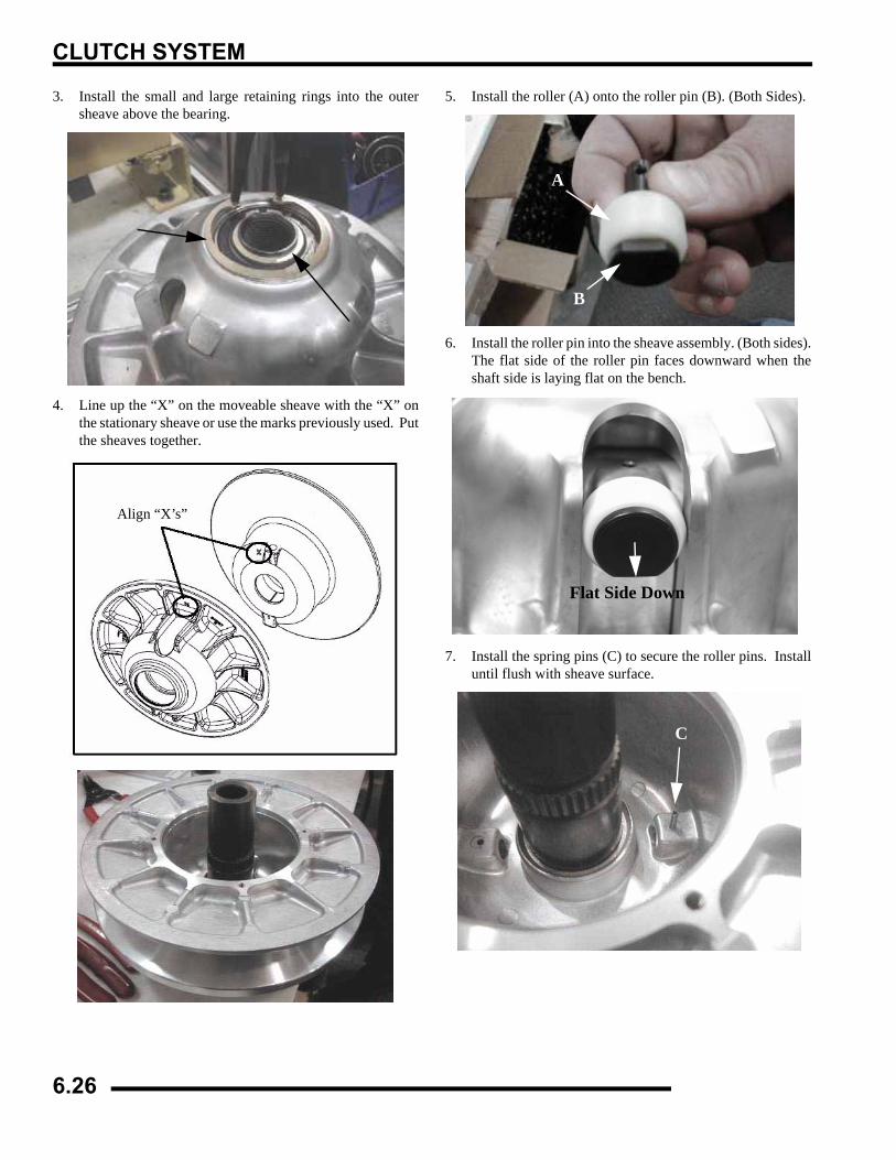
CLUTCH SYSTEM
3. Install the small and large retaining rings into the outersheave above the bearing.
4. Line up the “X” on the moveable sheave with the “X” onthe stationary sheave or use the marks previously used. Putthe sheaves together.
5. Install the roller (A) onto the roller pin (B). (Both Sides).
6. Install the roller pin into the sheave assembly. (Both sides).The flat side of the roller pin faces downward when theshaft side is laying flat on the bench.
7. Install the spring pins (C) to secure the roller pins. Installuntil flush with sheave surface.
Align “X’s”
A
B
Flat Side Down
C
6.26
CLUTCH SYSTEM
6
8. Install the spacer washer.
9. Install the spring over the shaft (arrow).
10. Install the clutch rollers (D) onto each side of the outsidespider. Install the washers (E) and E-clips (F) to secure therollers. Spin the roller, the rollers should spin freely.
11. Install the spider dampener (G) inside the outer spider andinstall the inside spider plate (H).
12. Install the spider assembly onto the shaft with the retainingring on top of the spider. NOTE: Use the marks previouslymade to align the skip tooth spider, or use the “X” on topof the spider and align it with the skip tooth on the shaft.
13. Place the clutch into Clutch Compression Tool PN8700220. Using Compression Extensions PN PS-45909,Press down on the top of the spider assembly, pushing thespider onto the shaft.
14. Slowly compress the spider into place. If the spider appearsto bind while compressing, stop and make sure the skiptooth on the shaft and the spider are aligned. Once thespider passes the retaining ring notch on the shaft, installthe retaining ring (A).
Install Spacer Washer
Outer Spider
H
G
D E F
Align Marks
Press Down on Spider
A
6.27
CLUTCH SYSTEM
15. Install the cam assembly (helix) over the shaft. Line up the“X” on the cam, “X” on spider, and “X” on the stationarysheave or use the marks previously made beforedisassembly. NOTE: If the cam assembly (helix) isdifficult to install, be sure the sheaves are aligned. To alignthe sheaves place the clutch assembly on a flat surface withthe cam assembly (helix) side down. Press down on themoveable sheave belt face with both hands and the helixwill release.
16. Use a T25 torx to install the four torx screws and torque tospecification.
STANDARD DRIVE CLUTCH - 500 CARBURETORDrive Clutch Disassembly1. Using a permanent marker, mark the cover, spider, and
moveable and stationary sheaves for reference, as theprevious “X's” may not have been in alignment beforedisassembly.
2. Remove cover bolts evenly in a cross pattern and removecover plate.
3. Inspect cover bushing (A). The outer cover bushing ismanufactured with a Teflon™ coating. Wear is determinedby the amount of Teflon™ remaining on the bushing.
4. Inspect area on shaft where bushing rides for wear, galling,nicks, or scratches. Replace clutch assembly if worn ordamaged.
5. Remove and inspect spring. See “Drive Clutch SpringSpecifications” for spring inspection.
= T
T25 Torx:42-52 in. lbs. (4.75 - 5.88 Nm)
Press Down to Loosen Helix
Cover Bushing Inspection:Replace the cover bushing if more brass than Teflon™ is visible on
the bushing. Refer to bushing replacement in this chapter.
A
Inspect Shaft
6.28
CLUTCH SYSTEM
6
Spider Removal1. Remove the limiter nut using the Clutch Spider Nut Socket
PN 2870338. Install clutch in holding fixture and loosenthe spider (counterclockwise) using Clutch Spider InstallTool PN 2870341.
NOTE: It is important that the same number andthickness of washers are reinstalled beneath thespider during assembly. Be sure to note the numberand thickness of these washers.
2. Inspect the Teflon™ coating on the moveable sheavebushing.
3. Inspect all rollers, bushings and roller pins by pulling a flatmetal rod across the roller. Turn roller with your finger. Ifyou notice resistance, galling, or flat spots, replace rollers,pins and thrust washers in sets of three. Also inspect to seeif roller and bushing are separating. Bushing must fittightly in roller. Use the Roller Pin Tool (PN 2870910) toreplace rollers and pins. Take care not to damage rollerbushing or bearing surface of the new pin duringinstallation.
Clutch Holding Fixture: PN 2871358 Spider Removal Tool: PN 2870341
To maintain proper clutch balance and belt-to-sheaveclearance, be sure to reinstall original quantity andthickness washers under the spider assembly.
Moveable Sheave Bushing Inspection: Replace the cover bushing if more
brass than Teflon™ is visible on the bushing. Refer to bushing
replacement in this chapter.
6.29
CLUTCH SYSTEM
4. Rubber backed buttons can and should be used in all ATVclutches if the hollow roller pin is changed to a solid rollerpin.
NOTE: The rubber side of the button is positionedtoward the solid roller pin. It is recommended toswitch all buttons to the rubber version duringservice (if needed).
Button To Tower Clearance Inspection1. Inspect for any clearance between spider button to tower.
If clearance exists, replace all buttons and inspect surfaceof towers. See “Spider Removal” procedure.
2. Inspect sheave surfaces. Replace the entire clutch as anassembly if worn, damaged or cracked.
Shift Weight Inspection1. If clutch is not disassembled, inspect as shown, using a
clutch holding tool to compress the moveable sheave. Thecontact surface of the weight should be smooth and free ofdents or gall marks. Remove shift weight bolts andweights.
2. Inspect the weight pivot bore and pivot bolts for wear orgalling. If weights or bolts are worn or broken, replace insets of three with new bolts.
NOTE: A damaged shift weight is usually caused bya damaged or stuck roller in the spider assembly.See roller inspection, see “Roller, Pin, and ThrustWasher Inspection”.
Button to Tower Clearance: .000-.001
WARNING
The clutch assembly is a precisely balanced unit. Never replace parts with used parts from another clutch assembly!All PVT maintenance or repairs should beperformed only by a certified Polaris Master ServiceDealer (MSD) technician who has received theproper training and understands the proceduresoutlined in this manual. Because of the critical nature and precisionbalance incorporated into the PVT system, it isabsolutely essential that no attempt atdisassembly or repair be made without factoryauthorized special tools and serviceprocedures.
6.30
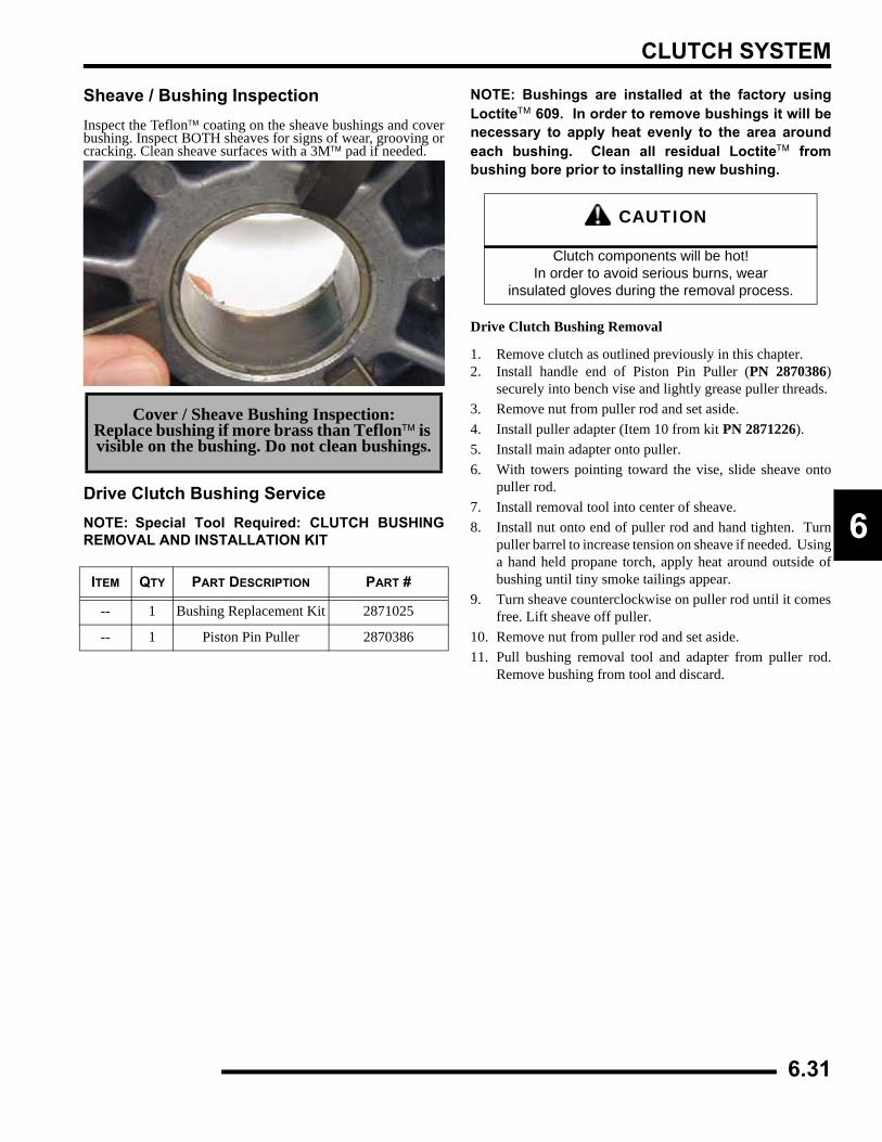
CLUTCH SYSTEM
6
Sheave / Bushing InspectionInspect the Teflon™ coating on the sheave bushings and coverbushing. Inspect BOTH sheaves for signs of wear, grooving orcracking. Clean sheave surfaces with a 3M™ pad if needed.
Drive Clutch Bushing ServiceNOTE: Special Tool Required: CLUTCH BUSHINGREMOVAL AND INSTALLATION KIT
NOTE: Bushings are installed at the factory usingLoctite™ 609. In order to remove bushings it will benecessary to apply heat evenly to the area aroundeach bushing. Clean all residual Loctite™ frombushing bore prior to installing new bushing.
Drive Clutch Bushing Removal
1. Remove clutch as outlined previously in this chapter.2. Install handle end of Piston Pin Puller (PN 2870386)
securely into bench vise and lightly grease puller threads.3. Remove nut from puller rod and set aside.4. Install puller adapter (Item 10 from kit PN 2871226).5. Install main adapter onto puller.6. With towers pointing toward the vise, slide sheave onto
puller rod.7. Install removal tool into center of sheave.8. Install nut onto end of puller rod and hand tighten. Turn
puller barrel to increase tension on sheave if needed. Usinga hand held propane torch, apply heat around outside ofbushing until tiny smoke tailings appear.
9. Turn sheave counterclockwise on puller rod until it comesfree. Lift sheave off puller.
10. Remove nut from puller rod and set aside.11. Pull bushing removal tool and adapter from puller rod.
Remove bushing from tool and discard.
Cover / Sheave Bushing Inspection:Replace bushing if more brass than Teflon™ is visible on the bushing. Do not clean bushings.
ITEM QTY PART DESCRIPTION PART #
-- 1 Bushing Replacement Kit 2871025
-- 1 Piston Pin Puller 2870386
CAUTION
Clutch components will be hot! In order to avoid serious burns, wear
insulated gloves during the removal process.
6.31
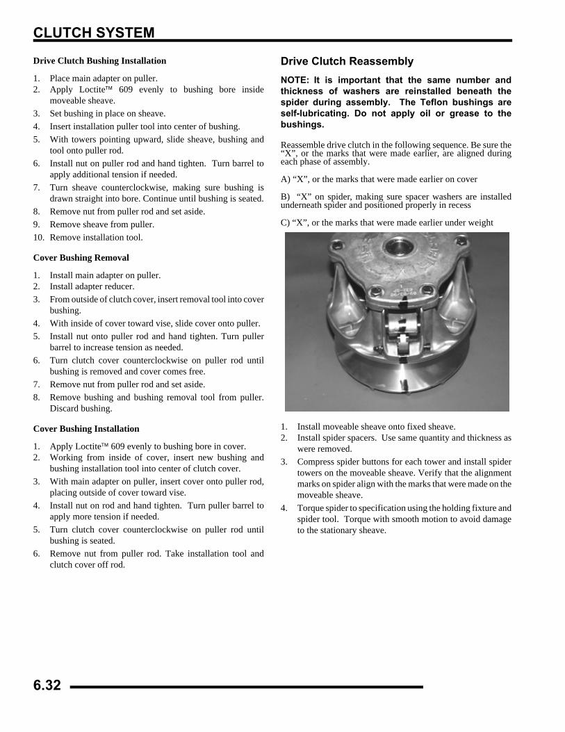
CLUTCH SYSTEM
Drive Clutch Bushing Installation
1. Place main adapter on puller.2. Apply Loctite™ 609 evenly to bushing bore inside
moveable sheave.3. Set bushing in place on sheave.4. Insert installation puller tool into center of bushing.5. With towers pointing upward, slide sheave, bushing and
tool onto puller rod. 6. Install nut on puller rod and hand tighten. Turn barrel to
apply additional tension if needed.7. Turn sheave counterclockwise, making sure bushing is
drawn straight into bore. Continue until bushing is seated.8. Remove nut from puller rod and set aside.9. Remove sheave from puller.10. Remove installation tool.
Cover Bushing Removal
1. Install main adapter on puller.2. Install adapter reducer.3. From outside of clutch cover, insert removal tool into cover
bushing.4. With inside of cover toward vise, slide cover onto puller.5. Install nut onto puller rod and hand tighten. Turn puller
barrel to increase tension as needed.6. Turn clutch cover counterclockwise on puller rod until
bushing is removed and cover comes free.7. Remove nut from puller rod and set aside. 8. Remove bushing and bushing removal tool from puller.
Discard bushing.
Cover Bushing Installation
1. Apply Loctite™ 609 evenly to bushing bore in cover.2. Working from inside of cover, insert new bushing and
bushing installation tool into center of clutch cover.3. With main adapter on puller, insert cover onto puller rod,
placing outside of cover toward vise.4. Install nut on rod and hand tighten. Turn puller barrel to
apply more tension if needed.5. Turn clutch cover counterclockwise on puller rod until
bushing is seated.6. Remove nut from puller rod. Take installation tool and
clutch cover off rod.
Drive Clutch ReassemblyNOTE: It is important that the same number andthickness of washers are reinstalled beneath thespider during assembly. The Teflon bushings areself-lubricating. Do not apply oil or grease to thebushings.
Reassemble drive clutch in the following sequence. Be sure the“X”, or the marks that were made earlier, are aligned duringeach phase of assembly.
A) “X”, or the marks that were made earlier on cover
B) “X” on spider, making sure spacer washers are installedunderneath spider and positioned properly in recess
C) “X”, or the marks that were made earlier under weight
1. Install moveable sheave onto fixed sheave.2. Install spider spacers. Use same quantity and thickness as
were removed.3. Compress spider buttons for each tower and install spider
towers on the moveable sheave. Verify that the alignmentmarks on spider align with the marks that were made on themoveable sheave.
4. Torque spider to specification using the holding fixture andspider tool. Torque with smooth motion to avoid damageto the stationary sheave.
6.32
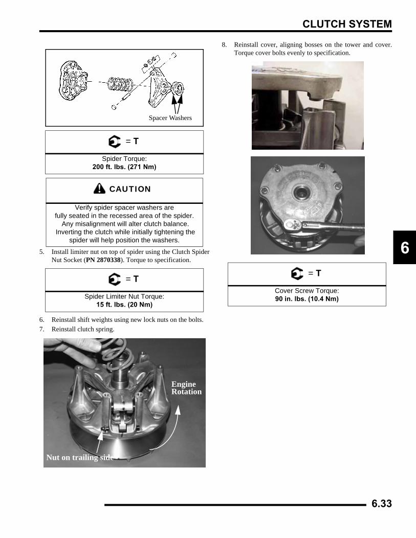
CLUTCH SYSTEM
6
5. Install limiter nut on top of spider using the Clutch SpiderNut Socket (PN 2870338). Torque to specification.6. Reinstall shift weights using new lock nuts on the bolts.7. Reinstall clutch spring.
8. Reinstall cover, aligning bosses on the tower and cover.Torque cover bolts evenly to specification.
= T
Spider Torque:200 ft. lbs. (271 Nm)
CAUTION
Verify spider spacer washers are fully seated in the recessed area of the spider.
Any misalignment will alter clutch balance. Inverting the clutch while initially tightening the
spider will help position the washers.
= T
Spider Limiter Nut Torque:15 ft. lbs. (20 Nm)
Spacer Washers
EngineRotation
Nut on trailing side
= T
Cover Screw Torque:90 in. lbs. (10.4 Nm)
6.33
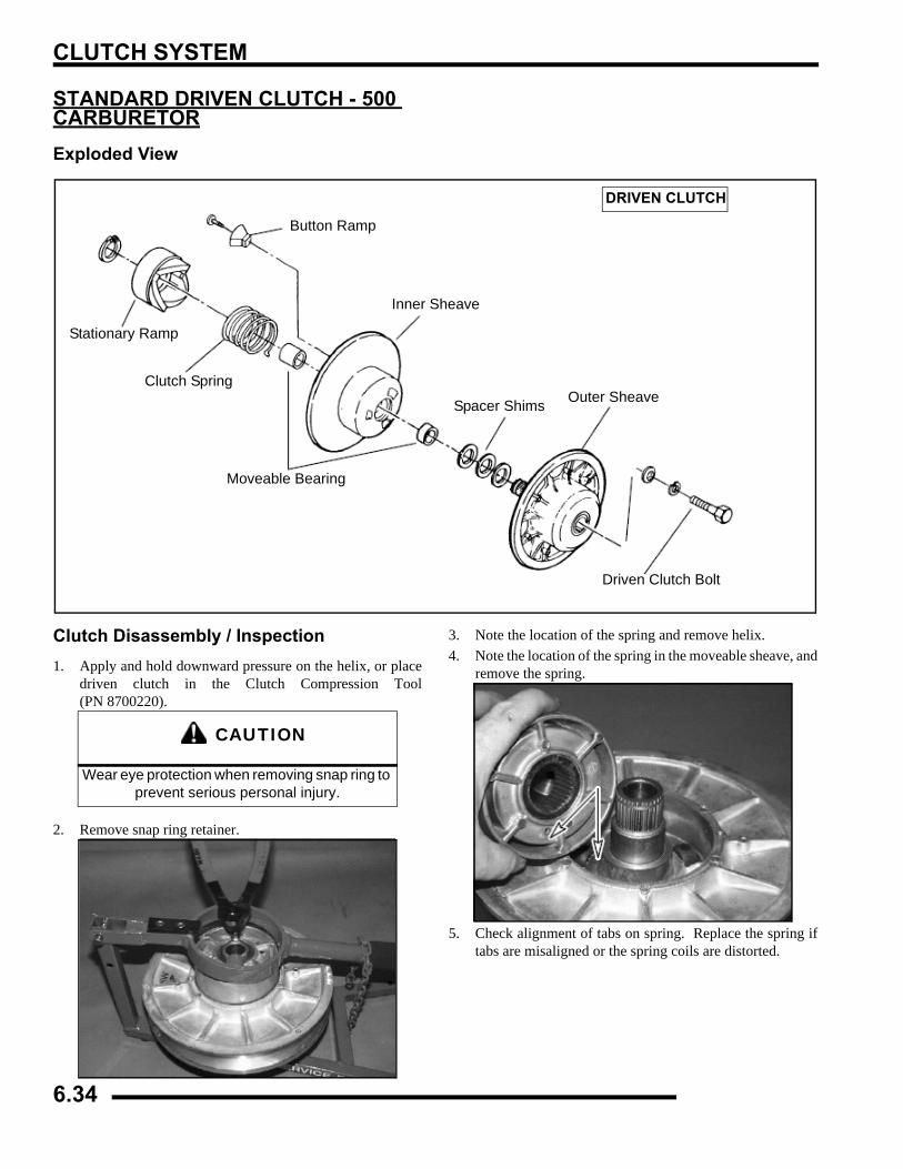
CLUTCH SYSTEM
STANDARD DRIVEN CLUTCH - 500 CARBURETORExploded View
Clutch Disassembly / Inspection1. Apply and hold downward pressure on the helix, or place
driven clutch in the Clutch Compression Tool(PN 8700220).
2. Remove snap ring retainer.
3. Note the location of the spring and remove helix.4. Note the location of the spring in the moveable sheave, and
remove the spring.
5. Check alignment of tabs on spring. Replace the spring iftabs are misaligned or the spring coils are distorted.
Button Ramp
Inner Sheave
Spacer Shims Outer Sheave
Driven Clutch Bolt
Moveable Bearing
Stationary Ramp
Clutch Spring
DRIVEN CLUTCH
CAUTION
Wear eye protection when removing snap ring to prevent serious personal injury.
6.34
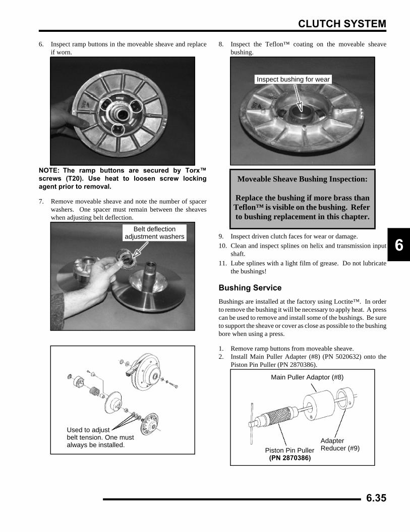
CLUTCH SYSTEM
6
6. Inspect ramp buttons in the moveable sheave and replaceif worn.
NOTE: The ramp buttons are secured by Torx™screws (T20). Use heat to loosen screw lockingagent prior to removal.
7. Remove moveable sheave and note the number of spacerwashers. One spacer must remain between the sheaveswhen adjusting belt deflection.
8. Inspect the Teflon™ coating on the moveable sheavebushing.
9. Inspect driven clutch faces for wear or damage.10. Clean and inspect splines on helix and transmission input
shaft.11. Lube splines with a light film of grease. Do not lubricate
the bushings!
Bushing ServiceBushings are installed at the factory using Loctite™. In orderto remove the bushing it will be necessary to apply heat. A presscan be used to remove and install some of the bushings. Be sureto support the sheave or cover as close as possible to the bushingbore when using a press.
1. Remove ramp buttons from moveable sheave.2. Install Main Puller Adapter (#8) (PN 5020632) onto the
Piston Pin Puller (PN 2870386).
Belt deflectionadjustment washers
Used to adjustbelt tension. One mustalways be installed.
Moveable Sheave Bushing Inspection:
Replace the bushing if more brass than Teflon™ is visible on the bushing. Refer to bushing replacement in this chapter.
Inspect bushing for wear
Piston Pin Puller(PN 2870386)
Main Puller Adaptor (#8)
AdapterReducer (#9)
6.35
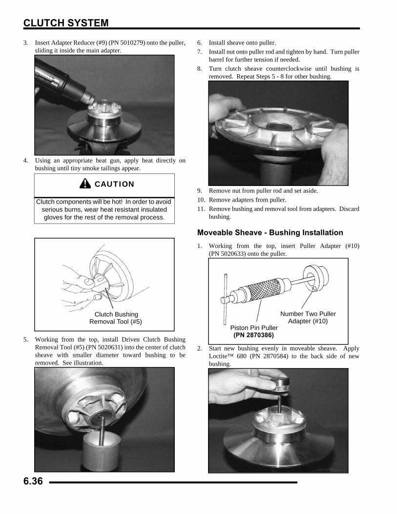
CLUTCH SYSTEM
3. Insert Adapter Reducer (#9) (PN 5010279) onto the puller,sliding it inside the main adapter.
4. Using an appropriate heat gun, apply heat directly onbushing until tiny smoke tailings appear.
5. Working from the top, install Driven Clutch BushingRemoval Tool (#5) (PN 5020631) into the center of clutchsheave with smaller diameter toward bushing to beremoved. See illustration.
6. Install sheave onto puller.7. Install nut onto puller rod and tighten by hand. Turn puller
barrel for further tension if needed.8. Turn clutch sheave counterclockwise until bushing is
removed. Repeat Steps 5 - 8 for other bushing.
9. Remove nut from puller rod and set aside.10. Remove adapters from puller.11. Remove bushing and removal tool from adapters. Discard
bushing.
Moveable Sheave - Bushing Installation1. Working from the top, insert Puller Adapter (#10)
(PN 5020633) onto the puller.
2. Start new bushing evenly in moveable sheave. ApplyLoctite™ 680 (PN 2870584) to the back side of newbushing.
CAUTION
Clutch components will be hot! In order to avoid serious burns, wear heat resistant insulated gloves for the rest of the removal process.
Clutch BushingRemoval Tool (#5)
Piston Pin Puller(PN 2870386)
Number Two PullerAdapter (#10)
6.36
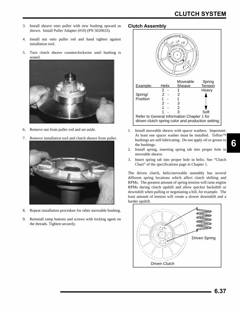
CLUTCH SYSTEM
6
3. Install sheave onto puller with new bushing upward asshown. Install Puller Adapter (#10) (PN 5020633).
4. Install nut onto puller rod and hand tighten againstinstallation tool.
5. Turn clutch sheave counterclockwise until bushing isseated.
6. Remove nut from puller rod and set aside.
7. Remove installation tool and clutch sheave from puller.
8. Repeat installation procedure for other moveable bushing.
9. Reinstall ramp buttons and screws with locking agent onthe threads. Tighten securely.
Clutch Assembly
1. Install moveable sheave with spacer washers. Important:At least one spacer washer must be installed. Teflon™bushings are self-lubricating. Do not apply oil or grease tothe bushings.
2. Install spring, inserting spring tab into proper hole inmoveable sheave.
3. Insert spring tab into proper hole in helix. See “ClutchChart” of the specifications page in Chapter 1.
The driven clutch, helix/moveable assembly has severaldifferent spring locations which affect clutch shifting andRPMs. The greatest amount of spring tension will raise engineRPMs during clutch upshift and allow quicker backshift ordownshift when pulling or negotiating a hill, for example. Theleast amount of tension will create a slower downshift and aharder upshift.
Example: Helix Sheave Tension 2 - 1 HeavySpring/ 2 - 2 Position 1 - 1 2 - 3 1 - 2 1 - 3 SoftRefer to General Information Chapter 1 for driven clutch spring color and production setting.
Moveable Spring
Driven Clutch
Driven Spring
6.37
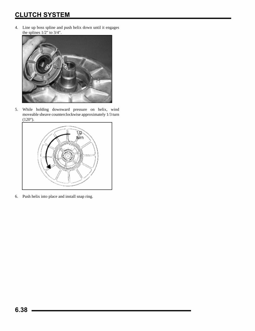
CLUTCH SYSTEM
4. Line up boss spline and push helix down until it engagesthe splines 1/2" to 3/4".
5. While holding downward pressure on helix, windmoveable sheave counterclockwise approximately 1/3 turn(120°).
6. Push helix into place and install snap ring.
6.38
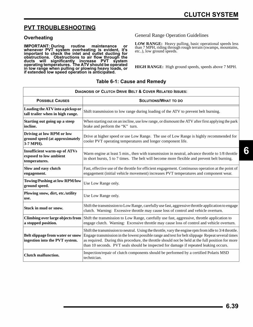
CLUTCH SYSTEM
6
PVT TROUBLESHOOTINGOverheatingIMPORTANT: During routine maintenance orwhenever PVT system overheating is evident, it'simportant to check the inlet and outlet ducting forobstructions. Obstructions to air flow through theducts will significantly increase PVT systemoperating temperatures. The ATV should be operatedin low range when pulling or plowing heavy loads, orif extended low speed operation is anticipated.
General Range Operation GuidelinesLOW RANGE: Heavy pulling, basic operational speeds lessthan 7 MPH, riding through rough terrain (swamps, mountains,etc..), low ground speeds.
HIGH RANGE: High ground speeds, speeds above 7 MPH.
Table 6-1: Cause and Remedy
DIAGNOSIS OF CLUTCH DRIVE BELT & COVER RELATED ISSUES:
POSSIBLE CAUSES SOLUTIONS/WHAT TO DO
Loading the ATV into a pickup or tall trailer when in high range. Shift transmission to low range during loading of the ATV to prevent belt burning.
Starting out going up a steep incline.
When starting out on an incline, use low range, or dismount the ATV after first applying the park brake and perform the “K” turn.
Driving at low RPM or low ground speed (at approximately 3-7 MPH).
Drive at higher speed or use Low Range. The use of Low Range is highly recommended for cooler PVT operating temperatures and longer component life.
Insufficient warm-up of ATVs exposed to low ambient temperatures.
Warm engine at least 5 min., then with transmission in neutral, advance throttle to 1/8 throttle in short bursts, 5 to 7 times. The belt will become more flexible and prevent belt burning.
Slow and easy clutch engagement.
Fast, effective use of the throttle for efficient engagement. Continuous operation at the point of engagement (initial vehicle movement) increases PVT temperatures and component wear.
Towing/Pushing at low RPM/low ground speed. Use Low Range only.
Plowing snow, dirt, etc./utility use. Use Low Range only.
Stuck in mud or snow. Shift the transmission to Low Range, carefully use fast, aggressive throttle application to engage clutch. Warning: Excessive throttle may cause loss of control and vehicle overturn.
Climbing over large objects from a stopped position.
Shift the transmission to Low Range, carefully use fast, aggressive, throttle application to engage clutch. Warning: Excessive throttle may cause loss of control and vehicle overturn.
Belt slippage from water or snow ingestion into the PVT system.
Shift the transmission to neutral. Using the throttle, vary the engine rpm from idle to 3/4 throttle. Engage transmission in the lowest possible range and test for belt slippage Repeat several times as required. During this procedure, the throttle should not be held at the full position for more than 10 seconds. PVT seals should be inspected for damage if repeated leaking occurs.
Clutch malfunction. Inspection/repair of clutch components should be performed by a certified Polaris MSD technician.
6.39
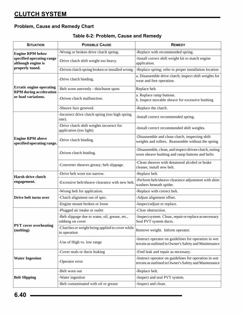
CLUTCH SYSTEM
Problem, Cause and Remedy Chart
Table 6-2: Problem, Cause and Remedy
SITUATION POSSIBLE CAUSE REMEDY
Engine RPM below specified operating range although engine is properly tuned.
-Wrong or broken drive clutch spring. -Replace with recommended spring.
-Drive clutch shift weight too heavy. -Install correct shift weight kit to match engine application.
-Driven clutch spring broken or installed wrong . -Replace spring; refer to proper installation location
Erratic engine operating RPM during acceleration or load variations.
-Drive clutch binding.a. Disassemble drive clutch; inspect shift weights for wear and free operation.
-Belt worn unevenly - thin/burnt spots Replace belt
-Driven clutch malfunction.a. Replace ramp buttons. b. Inspect movable sheave for excessive bushing
-Sheave face grooved. -Replace the clutch.
Engine RPM above specified operating range.
-Incorrect drive clutch spring (too high spring rate). -Install correct recommended spring.
-Drive clutch shift weights incorrect for application (too light) -Install correct recommended shift weights.
-Drive clutch binding.-Disassemble and clean clutch, inspecting shift weights and rollers. Reassemble without the spring
-Driven clutch binding.-Disassemble, clean, and inspect driven clutch, noting worn sheave bushing and ramp buttons and helix
-Converter sheaves greasy; belt slippage. -Clean sheaves with denatured alcohol or brake cleaner, install new belt.
Harsh drive clutch engagement.
-Drive belt worn too narrow. -Replace belt.
-Excessive belt/sheave clearance with new belt. -Perform belt/sheave clearance adjustment with shim washers beneath spider.
Drive belt turns over-Wrong belt for application. -Replace with correct belt.-Clutch alignment out of spec. -Adjust alignment offset.-Engine mount broken or loose -Inspect/adjust or replace.
PVT cover overheating (melting)
-Plugged air intake or outlet -Clear obstruction.-Belt slippage due to water, oil, grease, etc., rubbing on cover
-Inspect system. Clean , repair or replace as necessary. Seal PVT system ducts.
-Clutches or weight being applied to cover while in operation Remove weight. Inform operator.
-Use of High vs. low range-Instruct operator on guidelines for operation in wet terrain as outlined in Owner's Safety and Maintenance
Water Ingestion-Cover seals or ducts leaking -Find leak and repair as necessary.
-Operator error-Instruct operator on guidelines for operation in wet terrain as outlined in Owner's Safety and Maintenance
Belt Slipping-Belt worn out -Replace belt.-Water ingestion -Inspect and seal PVT system.-Belt contaminated with oil or grease -Inspect and clean.
6.40
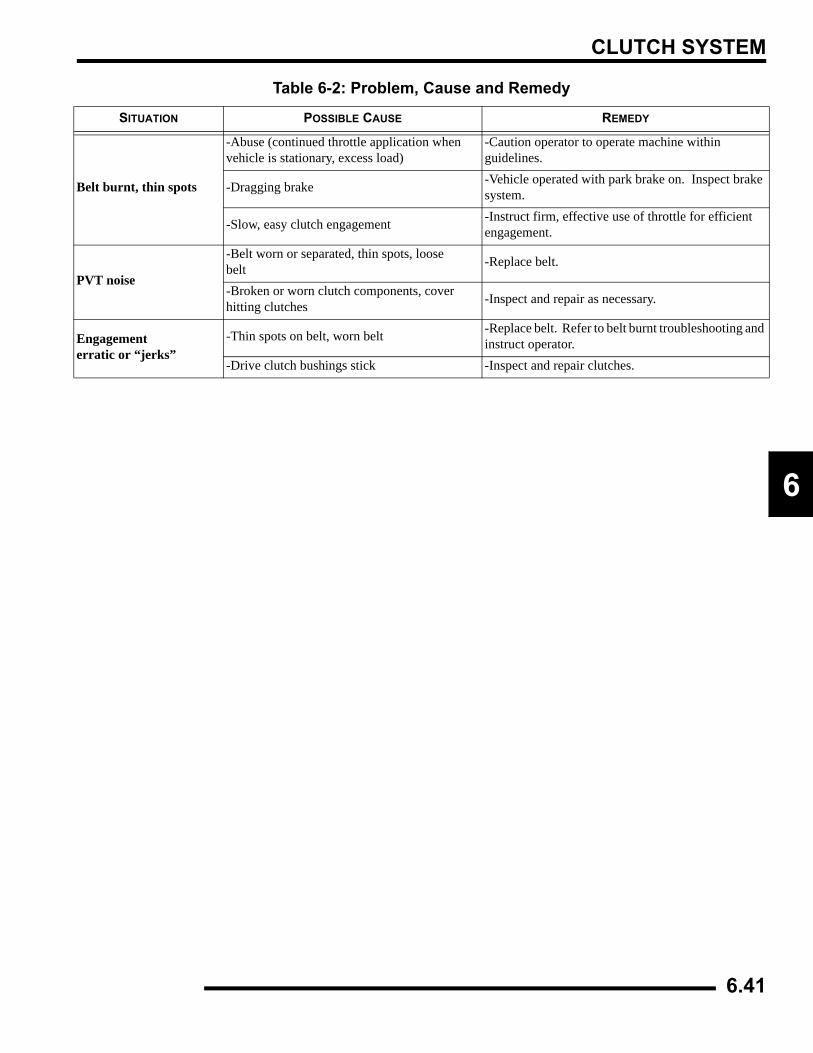
CLUTCH SYSTEM
6
Belt burnt, thin spots
-Abuse (continued throttle application when vehicle is stationary, excess load)
-Caution operator to operate machine within guidelines.
-Dragging brake -Vehicle operated with park brake on. Inspect brake system.
-Slow, easy clutch engagement -Instruct firm, effective use of throttle for efficient engagement.
PVT noise
-Belt worn or separated, thin spots, loosebelt -Replace belt.
-Broken or worn clutch components, cover hitting clutches -Inspect and repair as necessary.
Engagementerratic or “jerks”
-Thin spots on belt, worn belt -Replace belt. Refer to belt burnt troubleshooting and instruct operator.
-Drive clutch bushings stick -Inspect and repair clutches.
Table 6-2: Problem, Cause and Remedy
SITUATION POSSIBLE CAUSE REMEDY
6.41

CLUTCH SYSTEM
NOTES
6.42
FINAL DRIVE
7.1
CHAPTER 7FINAL DRIVE
7
SPECIFICATIONS. . . . . . . . . . . . . . . . . . . . . . . . . . . . . . . . . . . . . . . . . . . . . . . . . . . . . . . 7.2TORQUE TABLE . . . . . . . . . . . . . . . . . . . . . . . . . . . . . . . . . . . . . . . . . . . . . . . . . . . . . . . 7.2SPECIAL TOOLS . . . . . . . . . . . . . . . . . . . . . . . . . . . . . . . . . . . . . . . . . . . . . . . . . . . . . . . 7.2GEARCASE FLUID / CAPACITY . . . . . . . . . . . . . . . . . . . . . . . . . . . . . . . . . . . . . . . . . . . 7.2
FRONT HUB . . . . . . . . . . . . . . . . . . . . . . . . . . . . . . . . . . . . . . . . . . . . . . . . . . . . . . . . . . . 7.2DISASSEMBLY. . . . . . . . . . . . . . . . . . . . . . . . . . . . . . . . . . . . . . . . . . . . . . . . . . . . . . . . . 7.2ASSEMBLY . . . . . . . . . . . . . . . . . . . . . . . . . . . . . . . . . . . . . . . . . . . . . . . . . . . . . . . . . . . 7.3
FRONT DRIVE SHAFT (CV) SERVICE. . . . . . . . . . . . . . . . . . . . . . . . . . . . . . . . . . . . . . . 7.3REMOVAL . . . . . . . . . . . . . . . . . . . . . . . . . . . . . . . . . . . . . . . . . . . . . . . . . . . . . . . . . . . . 7.3INSTALLATION . . . . . . . . . . . . . . . . . . . . . . . . . . . . . . . . . . . . . . . . . . . . . . . . . . . . . . . . 7.4INSPECTION . . . . . . . . . . . . . . . . . . . . . . . . . . . . . . . . . . . . . . . . . . . . . . . . . . . . . . . . . . 7.5CV JOINT/BOOT REPLACEMENT . . . . . . . . . . . . . . . . . . . . . . . . . . . . . . . . . . . . . . . . . 7.5
PROP SHAFT - FRONT . . . . . . . . . . . . . . . . . . . . . . . . . . . . . . . . . . . . . . . . . . . . . . . . . . 7.7REMOVAL AND INSTALLATION . . . . . . . . . . . . . . . . . . . . . . . . . . . . . . . . . . . . . . . . . . . 7.7
U-JOINT. . . . . . . . . . . . . . . . . . . . . . . . . . . . . . . . . . . . . . . . . . . . . . . . . . . . . . . . . . . . . . . 7.7DISASSEMBLY. . . . . . . . . . . . . . . . . . . . . . . . . . . . . . . . . . . . . . . . . . . . . . . . . . . . . . . . . 7.7ASSEMBLY . . . . . . . . . . . . . . . . . . . . . . . . . . . . . . . . . . . . . . . . . . . . . . . . . . . . . . . . . . . 7.8
DRIVE AXLE EXPLODED VIEWS. . . . . . . . . . . . . . . . . . . . . . . . . . . . . . . . . . . . . . . . . . 7.10DRIVE SHAFTS AND PROPSHAFT . . . . . . . . . . . . . . . . . . . . . . . . . . . . . . . . . . . . . . . 7.10
FRONT GEARCASE - CENTRALIZED HILLIARD . . . . . . . . . . . . . . . . . . . . . . . . . . . . . 7.11EXPLODED VIEW . . . . . . . . . . . . . . . . . . . . . . . . . . . . . . . . . . . . . . . . . . . . . . . . . . . . . 7.11OPERATION. . . . . . . . . . . . . . . . . . . . . . . . . . . . . . . . . . . . . . . . . . . . . . . . . . . . . . . . . . 7.12GEARCASE REMOVAL . . . . . . . . . . . . . . . . . . . . . . . . . . . . . . . . . . . . . . . . . . . . . . . . . 7.12DISASSEMBLY / INSPECTION . . . . . . . . . . . . . . . . . . . . . . . . . . . . . . . . . . . . . . . . . . . 7.13REASSEMBLY / INSPECTION. . . . . . . . . . . . . . . . . . . . . . . . . . . . . . . . . . . . . . . . . . . . 7.17SETTING RING GEAR BACKLASH. . . . . . . . . . . . . . . . . . . . . . . . . . . . . . . . . . . . . . . . 7.18FRONT GEARCASE DIAGNOSIS . . . . . . . . . . . . . . . . . . . . . . . . . . . . . . . . . . . . . . . . . 7.19GEARCASE INSTALLATION . . . . . . . . . . . . . . . . . . . . . . . . . . . . . . . . . . . . . . . . . . . . . 7.20
FRONT GEARCASE - ACTIVE DESCENT CONTROL. . . . . . . . . . . . . . . . . . . . . . . . . . 7.21ADC GEARCASE EXPLODED VIEW. . . . . . . . . . . . . . . . . . . . . . . . . . . . . . . . . . . . . . . 7.21OPERATION. . . . . . . . . . . . . . . . . . . . . . . . . . . . . . . . . . . . . . . . . . . . . . . . . . . . . . . . . . 7.22ADC COIL TESTING . . . . . . . . . . . . . . . . . . . . . . . . . . . . . . . . . . . . . . . . . . . . . . . . . . . 7.23ADC DIFFERENTIAL HYDRAULIC CIRCUIT BLEEDING . . . . . . . . . . . . . . . . . . . . . . . 7.23DISASSEMBLY / INSPECTION . . . . . . . . . . . . . . . . . . . . . . . . . . . . . . . . . . . . . . . . . . . 7.23ADC GEARCASE PISTON REPLACEMENT PROCEDURE. . . . . . . . . . . . . . . . . . . . . 7.27ASSEMBLY . . . . . . . . . . . . . . . . . . . . . . . . . . . . . . . . . . . . . . . . . . . . . . . . . . . . . . . . . . 7.29
REAR HUB . . . . . . . . . . . . . . . . . . . . . . . . . . . . . . . . . . . . . . . . . . . . . . . . . . . . . . . . . . . 7.32REMOVAL . . . . . . . . . . . . . . . . . . . . . . . . . . . . . . . . . . . . . . . . . . . . . . . . . . . . . . . . . . . 7.32DISASSEMBLY. . . . . . . . . . . . . . . . . . . . . . . . . . . . . . . . . . . . . . . . . . . . . . . . . . . . . . . . 7.33ASSEMBLY . . . . . . . . . . . . . . . . . . . . . . . . . . . . . . . . . . . . . . . . . . . . . . . . . . . . . . . . . . 7.34INSTALLATION . . . . . . . . . . . . . . . . . . . . . . . . . . . . . . . . . . . . . . . . . . . . . . . . . . . . . . . 7.34
REAR DRIVE (CV) SHAFT SERVICE. . . . . . . . . . . . . . . . . . . . . . . . . . . . . . . . . . . . . . . 7.35REMOVAL . . . . . . . . . . . . . . . . . . . . . . . . . . . . . . . . . . . . . . . . . . . . . . . . . . . . . . . . . . . 7.35SERVICE . . . . . . . . . . . . . . . . . . . . . . . . . . . . . . . . . . . . . . . . . . . . . . . . . . . . . . . . . . . . 7.36CV BOOT REPLACEMENT . . . . . . . . . . . . . . . . . . . . . . . . . . . . . . . . . . . . . . . . . . . . . . 7.37INSTALLATION . . . . . . . . . . . . . . . . . . . . . . . . . . . . . . . . . . . . . . . . . . . . . . . . . . . . . . . 7.38DRIVE SHAFT AND CV JOINT HANDLING TIPS . . . . . . . . . . . . . . . . . . . . . . . . . . . . . 7.38
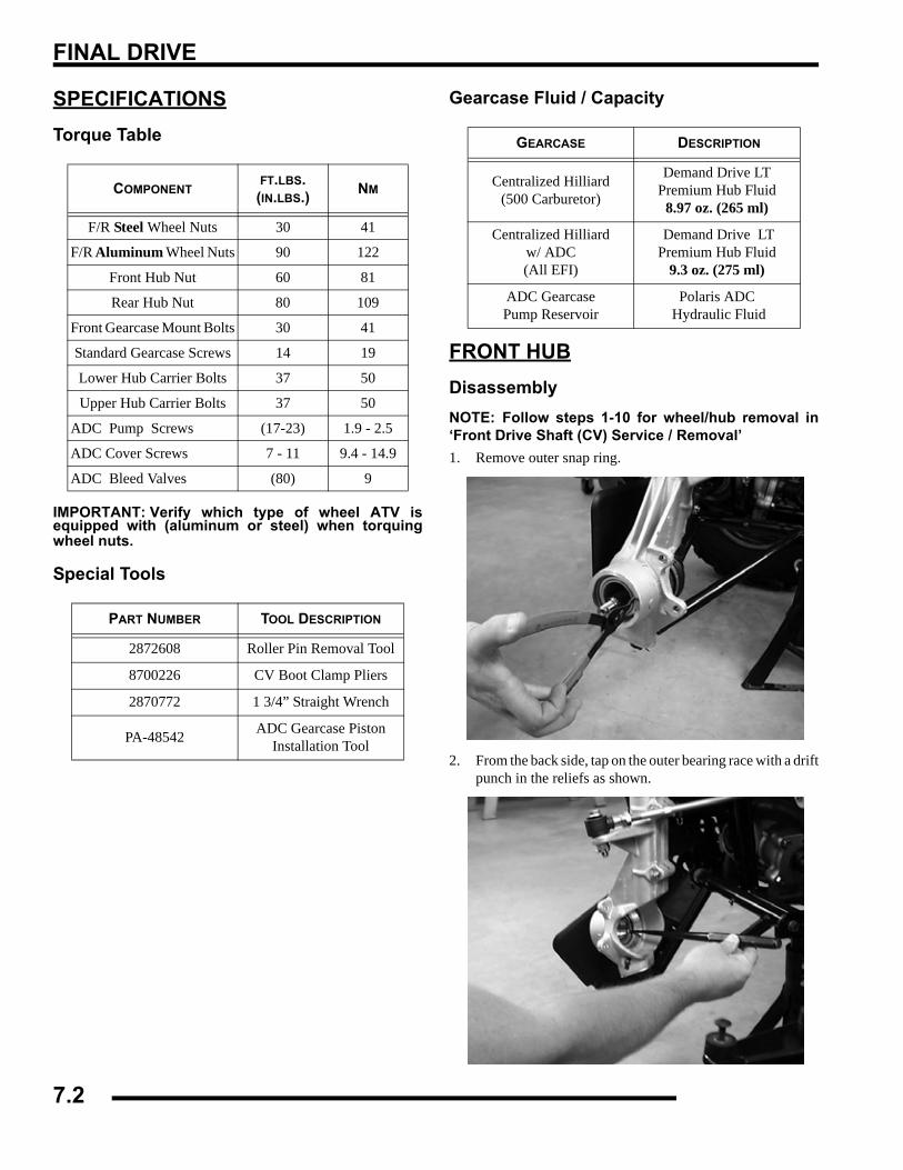
FINAL DRIVE
SPECIFICATIONSTorque Table
IMPORTANT: Verify which type of wheel ATV isequipped with (aluminum or steel) when torquingwheel nuts.
Special Tools
Gearcase Fluid / Capacity
FRONT HUBDisassemblyNOTE: Follow steps 1-10 for wheel/hub removal in‘Front Drive Shaft (CV) Service / Removal’1. Remove outer snap ring.
2. From the back side, tap on the outer bearing race with a driftpunch in the reliefs as shown.
COMPONENTFT.LBS. (IN.LBS.) NM
F/R Steel Wheel Nuts 30 41
F/R Aluminum Wheel Nuts 90 122
Front Hub Nut 60 81
Rear Hub Nut 80 109
Front Gearcase Mount Bolts 30 41
Standard Gearcase Screws 14 19
Lower Hub Carrier Bolts 37 50
Upper Hub Carrier Bolts 37 50
ADC Pump Screws (17-23) 1.9 - 2.5
ADC Cover Screws 7 - 11 9.4 - 14.9
ADC Bleed Valves (80) 9
PART NUMBER TOOL DESCRIPTION
2872608 Roller Pin Removal Tool
8700226 CV Boot Clamp Pliers
2870772 1 3/4” Straight Wrench
PA-48542 ADC Gearcase PistonInstallation Tool
GEARCASE DESCRIPTION
Centralized Hilliard(500 Carburetor)
Demand Drive LTPremium Hub Fluid
8.97 oz. (265 ml)
Centralized Hilliard w/ ADC(All EFI)
Demand Drive LTPremium Hub Fluid
9.3 oz. (275 ml)
ADC GearcasePump Reservoir
Polaris ADC Hydraulic Fluid
7.2
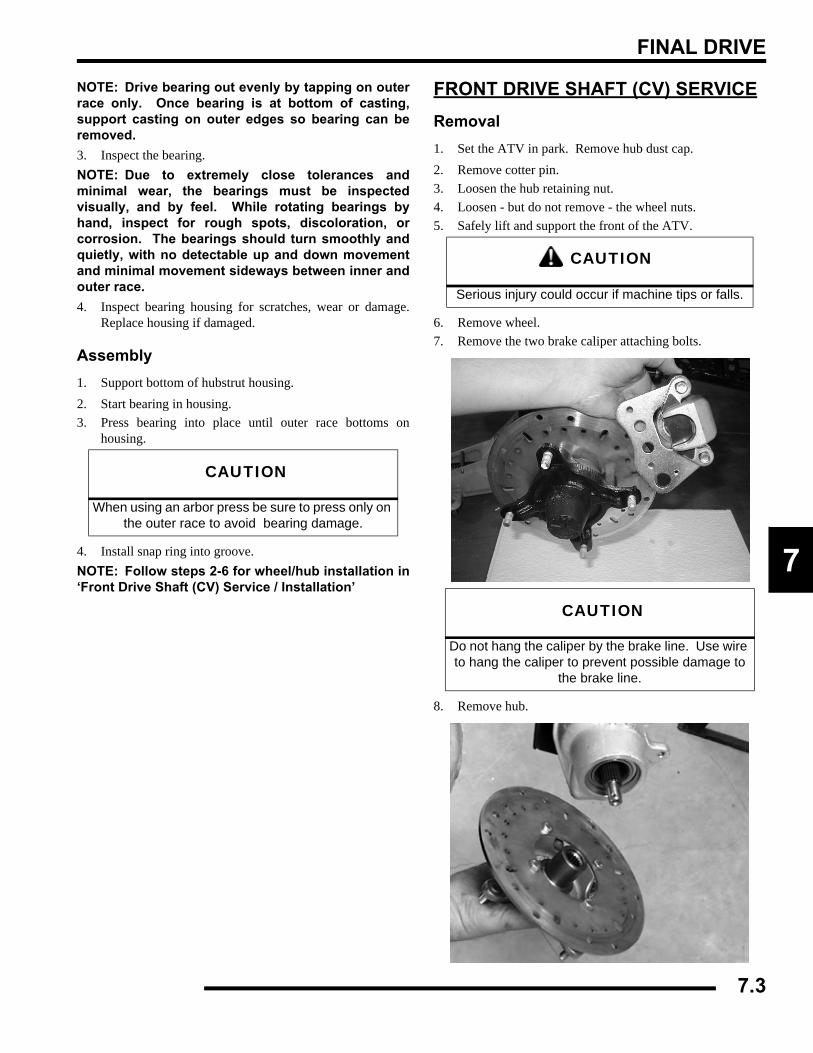
FINAL DRIVE
7
NOTE: Drive bearing out evenly by tapping on outerrace only. Once bearing is at bottom of casting,support casting on outer edges so bearing can beremoved.3. Inspect the bearing.NOTE: Due to extremely close tolerances andminimal wear, the bearings must be inspectedvisually, and by feel. While rotating bearings byhand, inspect for rough spots, discoloration, orcorrosion. The bearings should turn smoothly andquietly, with no detectable up and down movementand minimal movement sideways between inner andouter race.4. Inspect bearing housing for scratches, wear or damage.
Replace housing if damaged.
Assembly1. Support bottom of hubstrut housing.2. Start bearing in housing.3. Press bearing into place until outer race bottoms on
housing.
4. Install snap ring into groove.NOTE: Follow steps 2-6 for wheel/hub installation in‘Front Drive Shaft (CV) Service / Installation’
FRONT DRIVE SHAFT (CV) SERVICERemoval1. Set the ATV in park. Remove hub dust cap.2. Remove cotter pin.3. Loosen the hub retaining nut.4. Loosen - but do not remove - the wheel nuts.5. Safely lift and support the front of the ATV.
6. Remove wheel.7. Remove the two brake caliper attaching bolts.
8. Remove hub.
CAUTION
When using an arbor press be sure to press only on the outer race to avoid bearing damage.
CAUTION
Serious injury could occur if machine tips or falls.
CAUTION
Do not hang the caliper by the brake line. Use wire to hang the caliper to prevent possible damage to
the brake line.
7.3
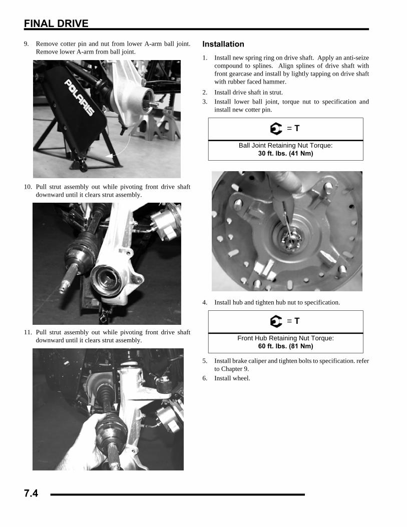
FINAL DRIVE
9. Remove cotter pin and nut from lower A-arm ball joint.Remove lower A-arm from ball joint.
10. Pull strut assembly out while pivoting front drive shaftdownward until it clears strut assembly.
11. Pull strut assembly out while pivoting front drive shaftdownward until it clears strut assembly.
Installation1. Install new spring ring on drive shaft. Apply an anti-seize
compound to splines. Align splines of drive shaft withfront gearcase and install by lightly tapping on drive shaftwith rubber faced hammer.
2. Install drive shaft in strut.3. Install lower ball joint, torque nut to specification and
install new cotter pin.
4. Install hub and tighten hub nut to specification.
5. Install brake caliper and tighten bolts to specification. referto Chapter 9.
6. Install wheel.
= T
Ball Joint Retaining Nut Torque:30 ft. lbs. (41 Nm)
= T
Front Hub Retaining Nut Torque:60 ft. lbs. (81 Nm)
7.4
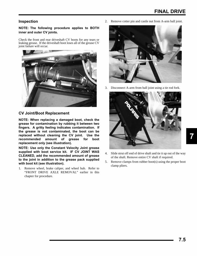
FINAL DRIVE
7
InspectionNOTE: The following procedure applies to BOTHinner and outer CV joints.
Check the front and rear driveshaft CV boots for any tears orleaking grease. If the driveshaft boot loses all of the grease CVjoint failure will occur.
CV Joint/Boot ReplacementNOTE: When replacing a damaged boot, check thegrease for contamination by rubbing it between twofingers. A gritty feeling indicates contamination. Ifthe grease is not contaminated, the boot can bereplaced without cleaning the CV joint. Use therecommended amount of grease for bootreplacement only (see illustration).NOTE: Use only the Constant Velocity Joint greasesupplied with boot service kit. IF CV JOINT WASCLEANED, add the recommended amount of greaseto the joint in addition to the grease pack suppliedwith boot kit (see illustration).1. Remove wheel, brake caliper, and wheel hub. Refer to
“FRONT DRIVE AXLE REMOVAL” earlier in thischapter for procedure.
2. Remove cotter pin and castle nut from A-arm ball joint.
3. Disconnect A-arm from ball joint using a tie rod fork.
4. Slide strut off end of drive shaft and tie it up out of the wayof the shaft. Remove entire CV shaft if required.
5. Remove clamps from rubber boot(s) using the proper bootclamp pliers.
7.5
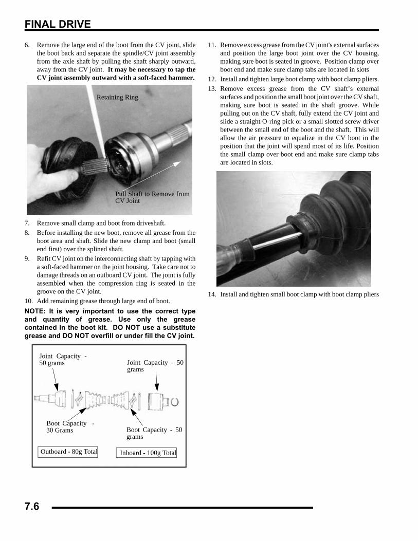
FINAL DRIVE
6. Remove the large end of the boot from the CV joint, slidethe boot back and separate the spindle/CV joint assemblyfrom the axle shaft by pulling the shaft sharply outward,away from the CV joint. It may be necessary to tap theCV joint assembly outward with a soft-faced hammer.
7. Remove small clamp and boot from driveshaft.8. Before installing the new boot, remove all grease from the
boot area and shaft. Slide the new clamp and boot (smallend first) over the splined shaft.
9. Refit CV joint on the interconnecting shaft by tapping witha soft-faced hammer on the joint housing. Take care not todamage threads on an outboard CV joint. The joint is fullyassembled when the compression ring is seated in thegroove on the CV joint.
10. Add remaining grease through large end of boot.NOTE: It is very important to use the correct typeand quantity of grease. Use only the greasecontained in the boot kit. DO NOT use a substitutegrease and DO NOT overfill or under fill the CV joint.
11. Remove excess grease from the CV joint's external surfacesand position the large boot joint over the CV housing,making sure boot is seated in groove. Position clamp overboot end and make sure clamp tabs are located in slots
12. Install and tighten large boot clamp with boot clamp pliers.13. Remove excess grease from the CV shaft’s external
surfaces and position the small boot joint over the CV shaft,making sure boot is seated in the shaft groove. Whilepulling out on the CV shaft, fully extend the CV joint andslide a straight O-ring pick or a small slotted screw driverbetween the small end of the boot and the shaft. This willallow the air pressure to equalize in the CV boot in theposition that the joint will spend most of its life. Positionthe small clamp over boot end and make sure clamp tabsare located in slots.
14. Install and tighten small boot clamp with boot clamp pliers
Retaining Ring
Pull Shaft to Remove fromCV Joint
Joint Capacity -50 grams
Boot Capacity -30 Grams
Outboard - 80g Total
Joint Capacity - 50grams
Boot Capacity - 50grams
Inboard - 100g Total
7.6
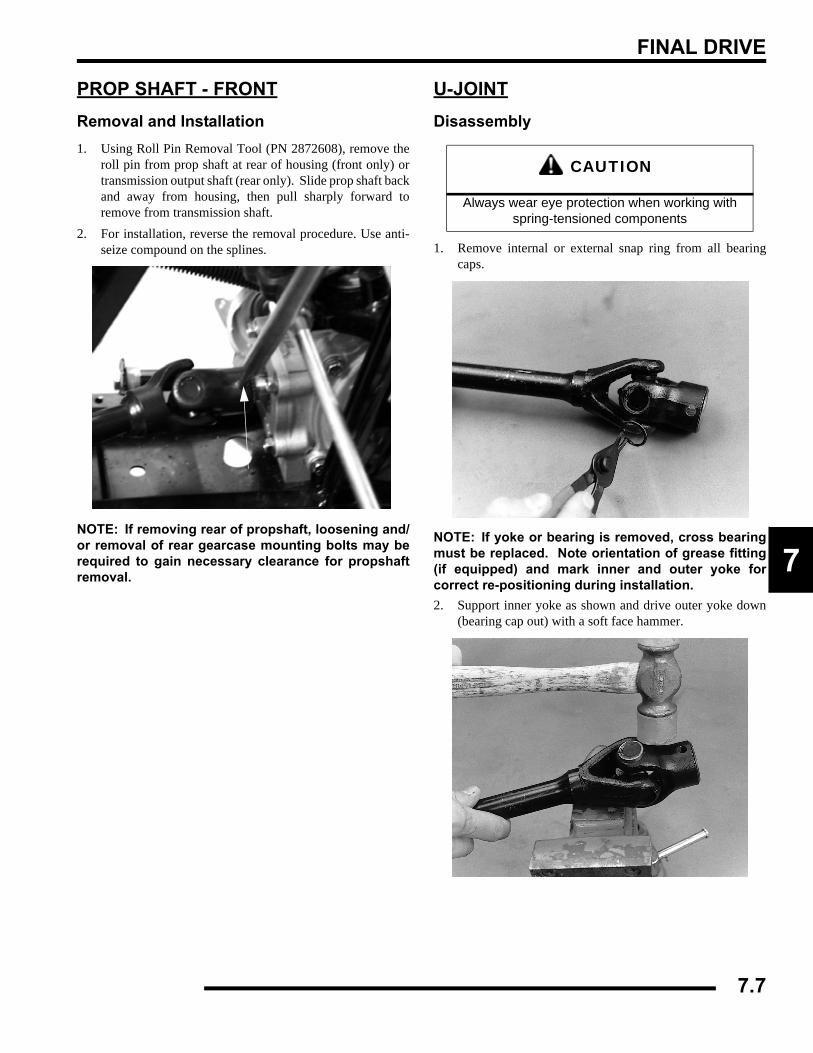
FINAL DRIVE
7
PROP SHAFT - FRONTRemoval and Installation1. Using Roll Pin Removal Tool (PN 2872608), remove the
roll pin from prop shaft at rear of housing (front only) ortransmission output shaft (rear only). Slide prop shaft backand away from housing, then pull sharply forward toremove from transmission shaft.
2. For installation, reverse the removal procedure. Use anti-seize compound on the splines.
NOTE: If removing rear of propshaft, loosening and/or removal of rear gearcase mounting bolts may berequired to gain necessary clearance for propshaftremoval.
U-JOINTDisassembly
1. Remove internal or external snap ring from all bearingcaps.
NOTE: If yoke or bearing is removed, cross bearingmust be replaced. Note orientation of grease fitting(if equipped) and mark inner and outer yoke forcorrect re-positioning during installation.2. Support inner yoke as shown and drive outer yoke down
(bearing cap out) with a soft face hammer.
CAUTION
Always wear eye protection when working with spring-tensioned components
7.7
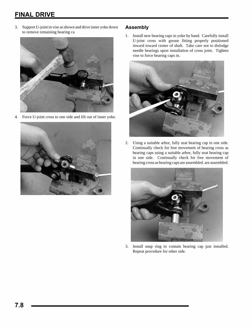
FINAL DRIVE
3. Support U-joint in vise as shown and drive inner yoke downto remove remaining bearing ca
4. Force U-joint cross to one side and lift out of inner yoke.
Assembly1. Install new bearing caps in yoke by hand. Carefully install
U-joint cross with grease fitting properly positionedinward toward center of shaft. Take care not to dislodgeneedle bearings upon installation of cross joint. Tightenvise to force bearing caps in.
2. Using a suitable arbor, fully seat bearing cap in one side.Continually check for free movement of bearing cross asbearing caps using a suitable arbor, fully seat bearing capin one side. Continually check for free movement ofbearing cross as bearing caps are assembled. are assembled.
3. Install snap ring to contain bearing cap just installed.Repeat procedure for other side.
7.8
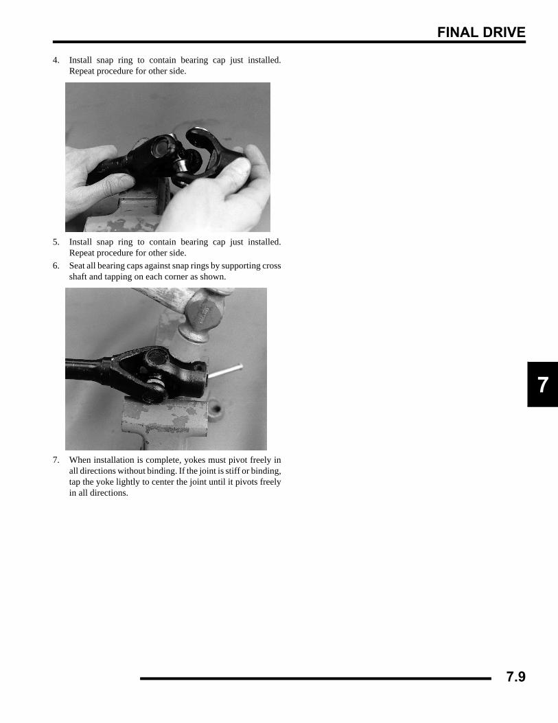
FINAL DRIVE
7
4. Install snap ring to contain bearing cap just installed.Repeat procedure for other side.
5. Install snap ring to contain bearing cap just installed.Repeat procedure for other side.
6. Seat all bearing caps against snap rings by supporting crossshaft and tapping on each corner as shown.
7. When installation is complete, yokes must pivot freely inall directions without binding. If the joint is stiff or binding,tap the yoke lightly to center the joint until it pivots freelyin all directions.
7.9
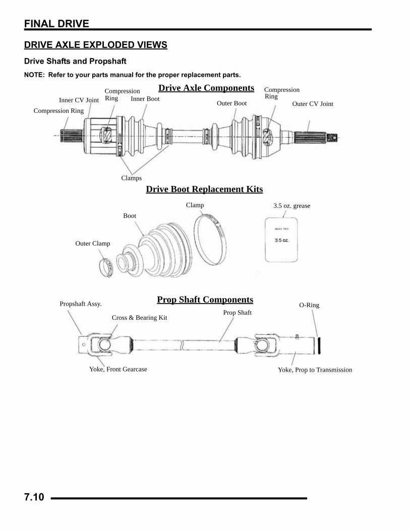
FINAL DRIVE
DRIVE AXLE EXPLODED VIEWSDrive Shafts and PropshaftNOTE: Refer to your parts manual for the proper replacement parts.
Compression RingInner CV Joint Ring Inner Boot
Outer BootRing
Outer CV Joint
Drive Axle Components
Drive Boot Replacement Kits
Prop Shaft Components
Clamps
Outer Clamp
BootClamp 3.5 oz. grease
Propshaft Assy.
Cross & Bearing KitProp Shaft
O-Ring
Yoke, Prop to TransmissionYoke, Front Gearcase
CompressionCompression
7.10
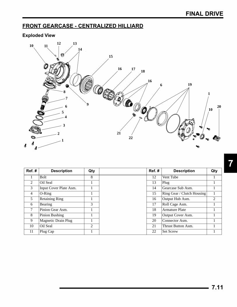
FINAL DRIVE
7
FRONT GEARCASE - CENTRALIZED HILLIARDExploded View
Ref. # Description Qty Ref. # Description Qty1 Bolt 8 12 Vent Tube 12 Oil Seal 1 13 Plug 13 Input Cover Plate Asm. 1 14 Gearcase Sub Asm. 14 O-Ring 1 15 Ring Gear / Clutch Housing 15 Retaining Ring 1 16 Output Hub Asm. 26 Bearing 3 17 Roll Cage Asm. 17 Pinion Gear Asm. 1 18 Armature Plate 18 Pinion Bushing 1 19 Output Cover Asm. 19 Magnetic Drain Plug 1 20 Connector Asm. 1
10 Oil Seal 2 21 Thrust Button Asm. 111 Plug Cap 1 22 Set Screw 1
1
2
3
45
6
7
8
9
10 1112 13
14
15
16 17 18
166
1
1020
2122
19
7.11
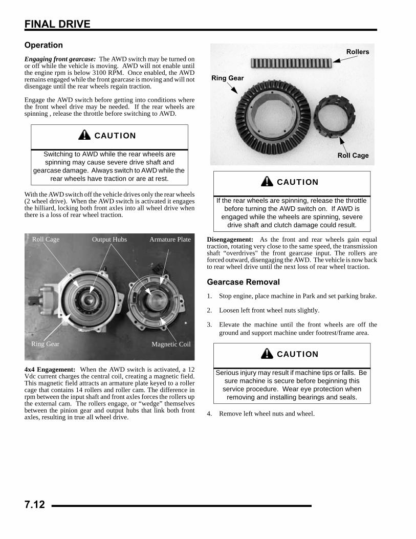
FINAL DRIVE
OperationEngaging front gearcase: The AWD switch may be turned onor off while the vehicle is moving. AWD will not enable untilthe engine rpm is below 3100 RPM. Once enabled, the AWDremains engaged while the front gearcase is moving and will notdisengage until the rear wheels regain traction.
Engage the AWD switch before getting into conditions wherethe front wheel drive may be needed. If the rear wheels arespinning , release the throttle before switching to AWD.
With the AWD switch off the vehicle drives only the rear wheels(2 wheel drive). When the AWD switch is activated it engagesthe hilliard, locking both front axles into all wheel drive whenthere is a loss of rear wheel traction.
4x4 Engagement: When the AWD switch is activated, a 12Vdc current charges the central coil, creating a magnetic field.This magnetic field attracts an armature plate keyed to a rollercage that contains 14 rollers and roller cam. The difference inrpm between the input shaft and front axles forces the rollers upthe external cam. The rollers engage, or “wedge” themselvesbetween the pinion gear and output hubs that link both frontaxles, resulting in true all wheel drive.
Disengagement: As the front and rear wheels gain equaltraction, rotating very close to the same speed, the transmissionshaft “overdrives" the front gearcase input. The rollers areforced outward, disengaging the AWD. The vehicle is now backto rear wheel drive until the next loss of rear wheel traction.
Gearcase Removal1. Stop engine, place machine in Park and set parking brake.
2. Loosen left front wheel nuts slightly.
3. Elevate the machine until the front wheels are off theground and support machine under footrest/frame area.
4. Remove left wheel nuts and wheel.
CAUTION
Switching to AWD while the rear wheels are spinning may cause severe drive shaft and
gearcase damage. Always switch to AWD while the rear wheels have traction or are at rest.
Armature PlateRoll Cage Output Hubs
Ring Gear Magnetic Coil
CAUTION
If the rear wheels are spinning, release the throttle before turning the AWD switch on. If AWD is
engaged while the wheels are spinning, severe drive shaft and clutch damage could result.
CAUTION
Serious injury may result if machine tips or falls. Be sure machine is secure before beginning this
service procedure. Wear eye protection when removing and installing bearings and seals.
Ring Gear
Rollers
Roll Cage
7.12
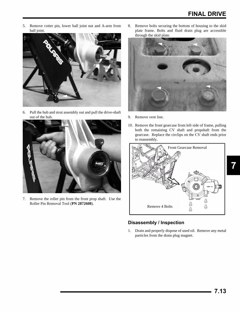
FINAL DRIVE
7
5. Remove cotter pin, lower ball joint nut and A-arm fromball joint.
6. Pull the hub and strut assembly out and pull the drive-shaftout of the hub.
7. Remove the roller pin from the front prop shaft. Use theRoller Pin Removal Tool (PN 2872608).
8. Remove bolts securing the bottom of housing to the skidplate frame. Bolts and fluid drain plug are accessiblethrough the skid plate.
9. Remove vent line.
10. Remove the front gearcase from left side of frame, pullingboth the remaining CV shaft and propshaft from thegearcase. Replace the circlips on the CV shaft ends priorto reassembly.
Disassembly / Inspection1. Drain and properly dispose of used oil. Remove any metal
particles from the drain plug magnet.
Front Gearcase Removal
Remove 4 Bolts
7.13
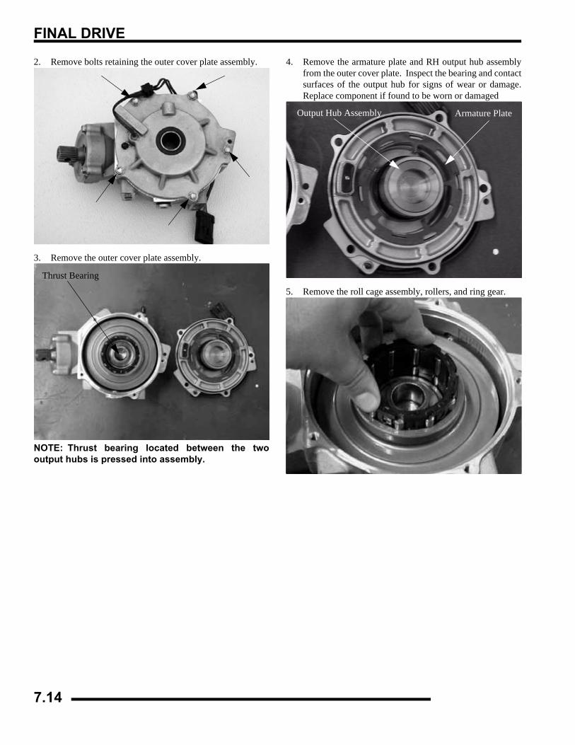
FINAL DRIVE
2. Remove bolts retaining the outer cover plate assembly.
3. Remove the outer cover plate assembly.
NOTE: Thrust bearing located between the twooutput hubs is pressed into assembly.
4. Remove the armature plate and RH output hub assemblyfrom the outer cover plate. Inspect the bearing and contactsurfaces of the output hub for signs of wear or damage.Replace component if found to be worn or damaged
5. Remove the roll cage assembly, rollers, and ring gear.
Thrust Bearing
Armature PlateOutput Hub Assembly
7.14
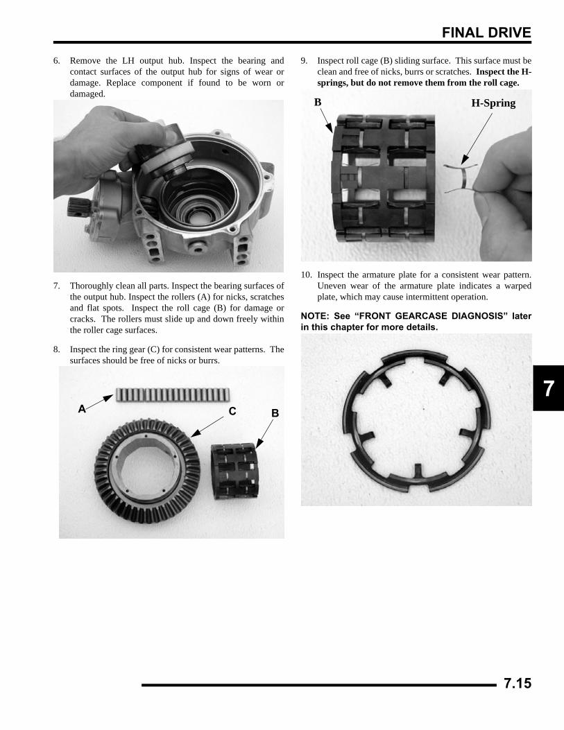
FINAL DRIVE
7
6. Remove the LH output hub. Inspect the bearing andcontact surfaces of the output hub for signs of wear ordamage. Replace component if found to be worn ordamaged.
7. Thoroughly clean all parts. Inspect the bearing surfaces ofthe output hub. Inspect the rollers (A) for nicks, scratchesand flat spots. Inspect the roll cage (B) for damage orcracks. The rollers must slide up and down freely withinthe roller cage surfaces.
8. Inspect the ring gear (C) for consistent wear patterns. Thesurfaces should be free of nicks or burrs.
9. Inspect roll cage (B) sliding surface. This surface must beclean and free of nicks, burrs or scratches. Inspect the H-springs, but do not remove them from the roll cage.
10. Inspect the armature plate for a consistent wear pattern.Uneven wear of the armature plate indicates a warpedplate, which may cause intermittent operation.
NOTE: See “FRONT GEARCASE DIAGNOSIS” laterin this chapter for more details.
C BA
B H-Spring
7.15
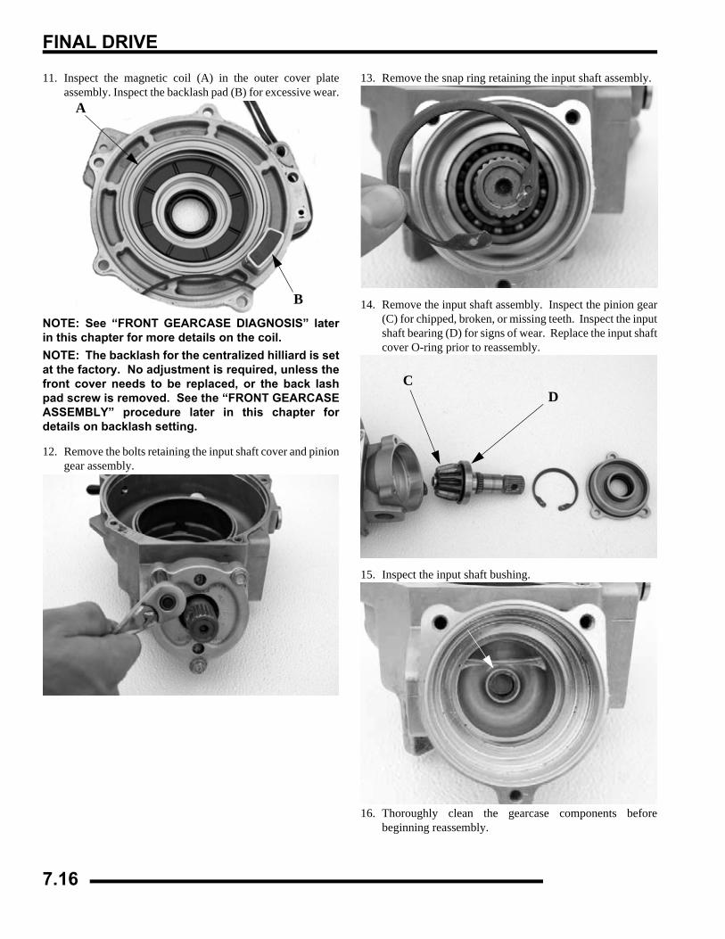
FINAL DRIVE
11. Inspect the magnetic coil (A) in the outer cover plateassembly. Inspect the backlash pad (B) for excessive wear.
NOTE: See “FRONT GEARCASE DIAGNOSIS” laterin this chapter for more details on the coil.NOTE: The backlash for the centralized hilliard is setat the factory. No adjustment is required, unless thefront cover needs to be replaced, or the back lashpad screw is removed. See the “FRONT GEARCASEASSEMBLY” procedure later in this chapter fordetails on backlash setting.
12. Remove the bolts retaining the input shaft cover and piniongear assembly.
13. Remove the snap ring retaining the input shaft assembly.
14. Remove the input shaft assembly. Inspect the pinion gear(C) for chipped, broken, or missing teeth. Inspect the inputshaft bearing (D) for signs of wear. Replace the input shaftcover O-ring prior to reassembly.
15. Inspect the input shaft bushing.
16. Thoroughly clean the gearcase components beforebeginning reassembly.
A
B
CD
7.16

FINAL DRIVE
7
Reassembly / Inspection1. Replace all O-rings, seals, and worn components.
2. Press the pinion shaft seal into the pinion cover, until theseal is flush with the sealing surface.
3. Inspect bearings on output and pinion shafts. To replace,press new bearing on to shaft.
NOTE: Due to extremely close tolerances andminimal wear, the bearings must be inspectedvisually, and by feel. While rotating bearings byhand, inspect for rough spots, discoloration, orcorrosion. The bearings should turn smoothly andquietly, with no detectable up and down movementand minimal movement side to side.
4. Install input shaft, bearing, snap ring, and input cover withnew o-ring. Torque bolts to specification.
5. Install the LH output hub (A) into the gearcase housing.The output hub should spin freely.
6. Install the RH output hub (B) into the output cover. Theoutput hub should spin freely.
7. Install the rollers and roll cage into the ring gear. Insert therollers as the roll cage is installed.
= T
Input Cover Bolt Torque 14 ft. lbs. (19 Nm)
A
A
B
C B
7.17
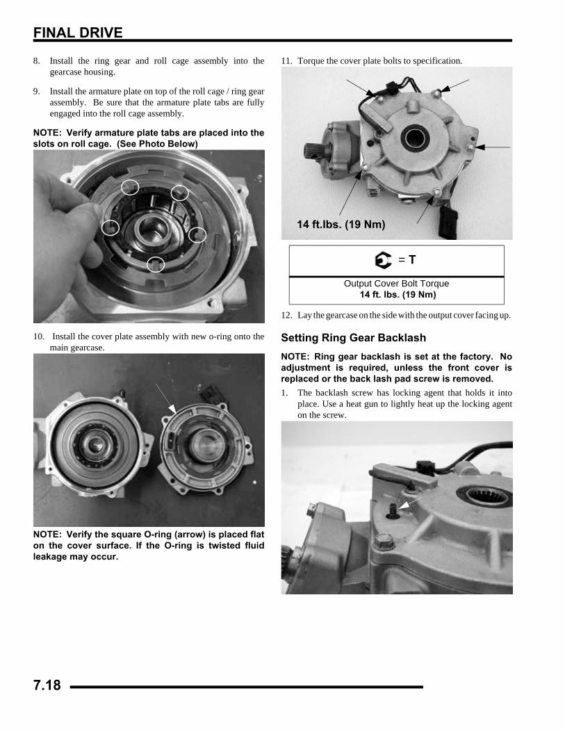
FINAL DRIVE
8. Install the ring gear and roll cage assembly into thegearcase housing.
9. Install the armature plate on top of the roll cage / ring gearassembly. Be sure that the armature plate tabs are fullyengaged into the roll cage assembly.
NOTE: Verify armature plate tabs are placed into theslots on roll cage. (See Photo Below)
10. Install the cover plate assembly with new o-ring onto themain gearcase.
NOTE: Verify the square O-ring (arrow) is placed flaton the cover surface. If the O-ring is twisted fluidleakage may occur.
11. Torque the cover plate bolts to specification.
12. Lay the gearcase on the side with the output cover facing up.
Setting Ring Gear BacklashNOTE: Ring gear backlash is set at the factory. Noadjustment is required, unless the front cover isreplaced or the back lash pad screw is removed. 1. The backlash screw has locking agent that holds it into
place. Use a heat gun to lightly heat up the locking agenton the screw.
= T
Output Cover Bolt Torque 14 ft. lbs. (19 Nm)
14 ft.lbs. (19 Nm)
7.18
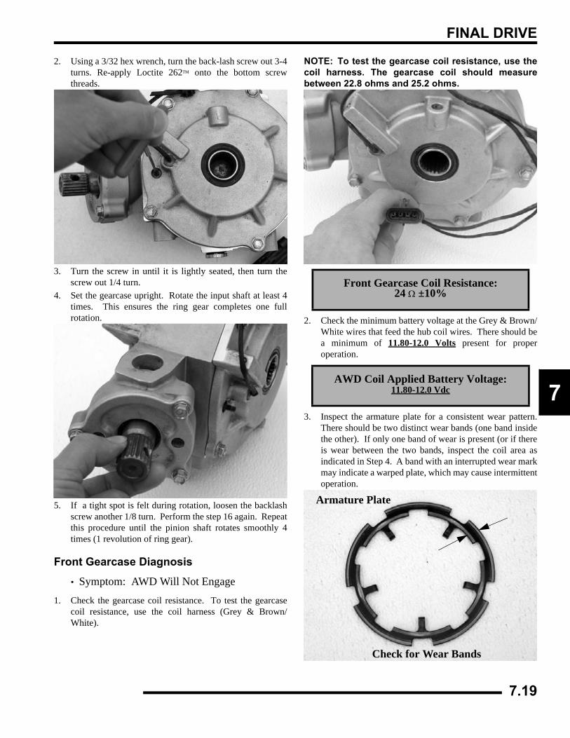
FINAL DRIVE
7
2. Using a 3/32 hex wrench, turn the back-lash screw out 3-4turns. Re-apply Loctite 262™ onto the bottom screwthreads.
3. Turn the screw in until it is lightly seated, then turn thescrew out 1/4 turn.
4. Set the gearcase upright. Rotate the input shaft at least 4times. This ensures the ring gear completes one fullrotation.
5. If a tight spot is felt during rotation, loosen the backlashscrew another 1/8 turn. Perform the step 16 again. Repeatthis procedure until the pinion shaft rotates smoothly 4times (1 revolution of ring gear).
Front Gearcase Diagnosis
• Symptom: AWD Will Not Engage
1. Check the gearcase coil resistance. To test the gearcasecoil resistance, use the coil harness (Grey & Brown/White).
NOTE: To test the gearcase coil resistance, use thecoil harness. The gearcase coil should measurebetween 22.8 ohms and 25.2 ohms.
2. Check the minimum battery voltage at the Grey & Brown/White wires that feed the hub coil wires. There should bea minimum of 11.80-12.0 Volts present for properoperation.
3. Inspect the armature plate for a consistent wear pattern.There should be two distinct wear bands (one band insidethe other). If only one band of wear is present (or if thereis wear between the two bands, inspect the coil area asindicated in Step 4. A band with an interrupted wear markmay indicate a warped plate, which may cause intermittentoperation.
Front Gearcase Coil Resistance: 24 Ω ±10%
AWD Coil Applied Battery Voltage:11.80-12.0 Vdc
Armature Plate
Check for Wear Bands
7.19
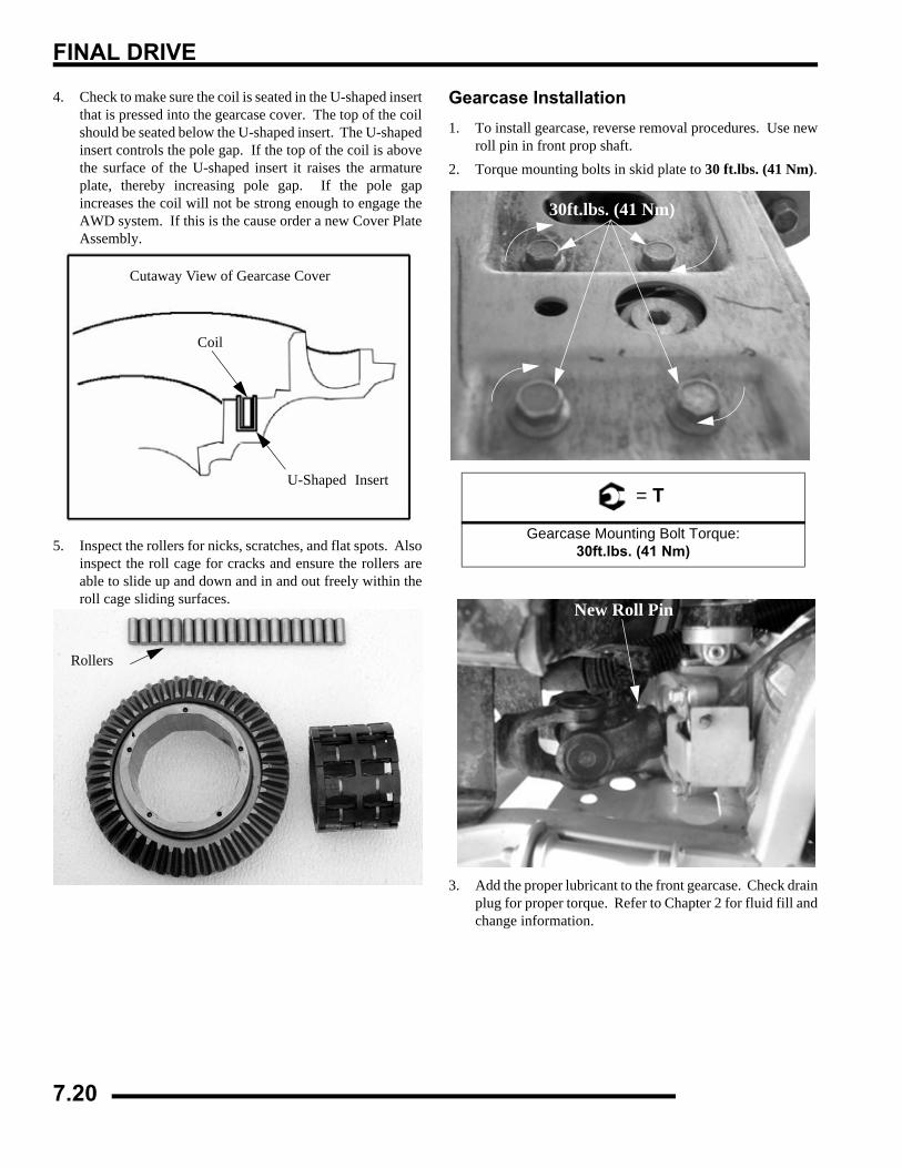
FINAL DRIVE
4. Check to make sure the coil is seated in the U-shaped insertthat is pressed into the gearcase cover. The top of the coilshould be seated below the U-shaped insert. The U-shapedinsert controls the pole gap. If the top of the coil is abovethe surface of the U-shaped insert it raises the armatureplate, thereby increasing pole gap. If the pole gapincreases the coil will not be strong enough to engage theAWD system. If this is the cause order a new Cover PlateAssembly.
5. Inspect the rollers for nicks, scratches, and flat spots. Alsoinspect the roll cage for cracks and ensure the rollers areable to slide up and down and in and out freely within theroll cage sliding surfaces.
Gearcase Installation1. To install gearcase, reverse removal procedures. Use new
roll pin in front prop shaft.2. Torque mounting bolts in skid plate to 30 ft.lbs. (41 Nm).
3. Add the proper lubricant to the front gearcase. Check drainplug for proper torque. Refer to Chapter 2 for fluid fill andchange information.
U-Shaped Insert
Coil
Cutaway View of Gearcase Cover
Rollers
= T
Gearcase Mounting Bolt Torque:30ft.lbs. (41 Nm)
30ft.lbs. (41 Nm)
New Roll Pin
7.20
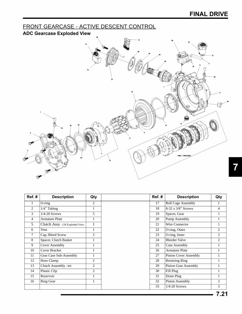
FINAL DRIVE
7
FRONT GEARCASE - ACTIVE DESCENT CONTROLADC Gearcase Exploded View
Ref. # Description Qty Ref. # Description Qty1 O-ring 2 17 Roll Cage Assembly 12 1/4" Tubing 1 18 8-32 x 3/8" Screws 43 1/4-20 Screws 5 19 Spacer, Gear 14 Armature Plate 1 20 Pump Assembly 15 Clutch Assy - LH Exploded View 1 21 Wire Connector 16 Vent 1 22 O-ring, Outer 27 Cap, Bleed Screw 2 23 O-ring, Inner 28 Spacer, Clutch Basket 1 24 Bleeder Valve 29 Cover Assembly 1 25 Cam Assembly 1
10 Cover Bracket 1 26 Armature Plate 111 Gear Case Sub-Assembly 1 27 Pinion Cover Assembly 112 Hose Clamp 2 28 Retaining Ring 113 Clutch Assembly - RH 2 29 Pinion Gear Assembly 114 Plastic Clip 2 30 Fill Plug 115 Reservoir 1 31 Drain Plug 116 Ring Gear 1 32 Piston Assembly 2
33 1/4-20 Screws 3
5
7.21
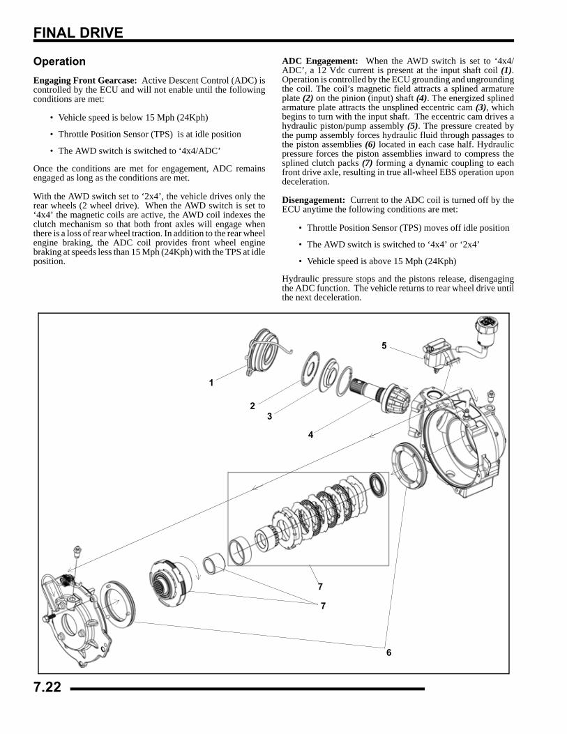
FINAL DRIVE
OperationEngaging Front Gearcase: Active Descent Control (ADC) iscontrolled by the ECU and will not enable until the followingconditions are met:
• Vehicle speed is below 15 Mph (24Kph)
• Throttle Position Sensor (TPS) is at idle position
• The AWD switch is switched to ‘4x4/ADC’
Once the conditions are met for engagement, ADC remainsengaged as long as the conditions are met.
With the AWD switch set to ‘2x4’, the vehicle drives only therear wheels (2 wheel drive). When the AWD switch is set to‘4x4’ the magnetic coils are active, the AWD coil indexes theclutch mechanism so that both front axles will engage whenthere is a loss of rear wheel traction. In addition to the rear wheelengine braking, the ADC coil provides front wheel enginebraking at speeds less than 15 Mph (24Kph) with the TPS at idleposition.
ADC Engagement: When the AWD switch is set to ‘4x4/ADC’, a 12 Vdc current is present at the input shaft coil (1).Operation is controlled by the ECU grounding and ungroundingthe coil. The coil’s magnetic field attracts a splined armatureplate (2) on the pinion (input) shaft (4). The energized splinedarmature plate attracts the unsplined eccentric cam (3), whichbegins to turn with the input shaft. The eccentric cam drives ahydraulic piston/pump assembly (5). The pressure created bythe pump assembly forces hydraulic fluid through passages tothe piston assemblies (6) located in each case half. Hydraulicpressure forces the piston assemblies inward to compress thesplined clutch packs (7) forming a dynamic coupling to eachfront drive axle, resulting in true all-wheel EBS operation upondeceleration.
Disengagement: Current to the ADC coil is turned off by theECU anytime the following conditions are met:
• Throttle Position Sensor (TPS) moves off idle position
• The AWD switch is switched to ‘4x4’ or ‘2x4’
• Vehicle speed is above 15 Mph (24Kph)
Hydraulic pressure stops and the pistons release, disengagingthe ADC function. The vehicle returns to rear wheel drive untilthe next deceleration.
1
23
4
5
6
7
7
7.22
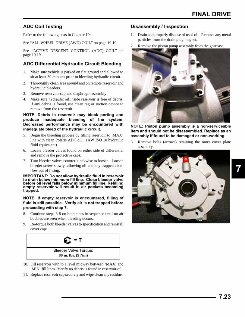
FINAL DRIVE
7
ADC Coil TestingRefer to the following tests in Chapter 10:
See “ALL WHEEL DRIVE (AWD) COIL” on page 10.19.
See “ACTIVE DESCENT CONTROL (ADC) COIL” onpage 10.19.
ADC Differential Hydraulic Circuit Bleeding1. Make sure vehicle is parked on flat ground and allowed to
sit at least 30 minutes prior to bleeding hydraulic circuit.2. Thoroughly clean area around and on remote reservoir and
hydraulic bleeders.3. Remove reservoir cap and diaphragm assembly.4. Make sure hydraulic oil inside reservoir is free of debris.
If any debris is found, use clean rag or suction device toremove from the reservoir.
NOTE: Debris in reservoir may block porting andproduce inadequate bleeding of the system.Decreased performance may be encountered withinadequate bleed of the hydraulic circuit.5. Begin the bleeding process by filling reservoir to ‘MAX’
line with clean Polaris ADC oil . (AW ISO 10 hydraulicfluid equivalent).
6. Locate bleeder valves found on either side of differentialand remove the protective caps.
7. Turn bleeder valves counter-clockwise to loosen. Loosenbleeder screw slowly, allowing oil and any trapped air toflow out of fitting.
IMPORTANT: Do not allow hydraulic fluid in reservoirto drain below minimum fill line. Close bleeder valvebefore oil level falls below minimum fill line. Refillingempty reservoir will result in air pockets becomingtrapped.
NOTE: If empty reservoir is encountered, filling offluid is still possible. Verify air is not trapped beforeproceeding with step 7.8. Continue steps 6-8 on both sides in sequence until no air
bubbles are seen when bleeding occurs. 9. Re-torque both bleeder valves to specification and reinstall
cover caps.
10. Fill reservoir with to a level midway between ‘MAX’ and‘MIN’ fill lines. Verify no debris is found in reservoir oil.
11. Replace reservoir cap securely and wipe clean any residue.
Disassembly / Inspection1. Drain and properly dispose of used oil. Remove any metal
particles from the drain plug magnet.2. Remove the piston pump assembly from the gearcase.
NOTE: Piston pump assembly is a non-serviceableitem and should not be disassembled. Replace as anassembly if found to be damaged or non-working.3. Remove bolts (arrows) retaining the outer cover plate
assembly.
= T
Bleeder Valve Torque:80 in. lbs. (9 Nm)
7.23
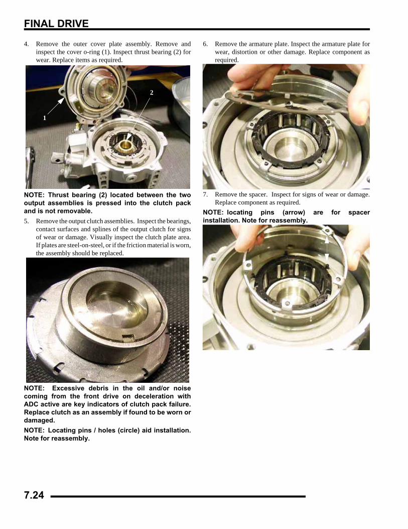
FINAL DRIVE
4. Remove the outer cover plate assembly. Remove andinspect the cover o-ring (1). Inspect thrust bearing (2) forwear. Replace items as required.
NOTE: Thrust bearing (2) located between the twooutput assemblies is pressed into the clutch packand is not removable.5. Remove the output clutch assemblies. Inspect the bearings,
contact surfaces and splines of the output clutch for signsof wear or damage. Visually inspect the clutch plate area.If plates are steel-on-steel, or if the friction material is worn,the assembly should be replaced.
NOTE: Excessive debris in the oil and/or noisecoming from the front drive on deceleration withADC active are key indicators of clutch pack failure.Replace clutch as an assembly if found to be worn ordamaged. NOTE: Locating pins / holes (circle) aid installation.Note for reassembly.
6. Remove the armature plate. Inspect the armature plate forwear, distortion or other damage. Replace component asrequired.
7. Remove the spacer. Inspect for signs of wear or damage.Replace component as required.
NOTE: locating pins (arrow) are for spacerinstallation. Note for reassembly.
2
1
7.24
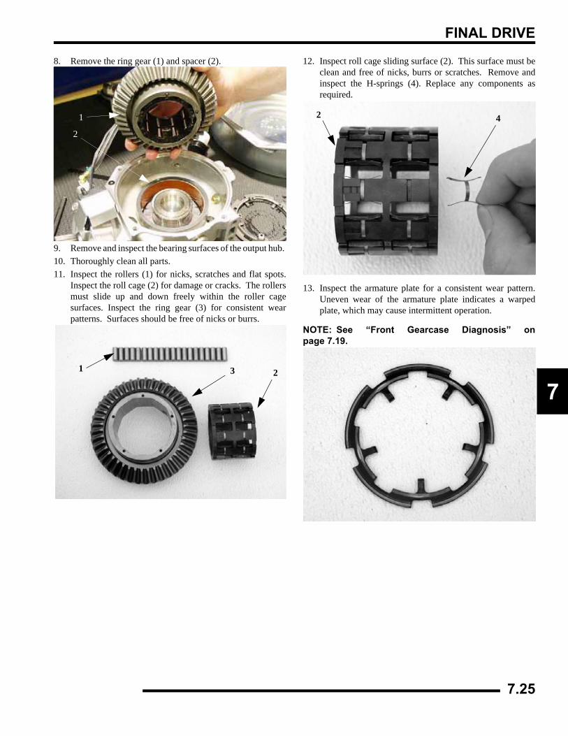
FINAL DRIVE
7
8. Remove the ring gear (1) and spacer (2).
9. Remove and inspect the bearing surfaces of the output hub. 10. Thoroughly clean all parts.11. Inspect the rollers (1) for nicks, scratches and flat spots.
Inspect the roll cage (2) for damage or cracks. The rollersmust slide up and down freely within the roller cagesurfaces. Inspect the ring gear (3) for consistent wearpatterns. Surfaces should be free of nicks or burrs.
12. Inspect roll cage sliding surface (2). This surface must beclean and free of nicks, burrs or scratches. Remove andinspect the H-springs (4). Replace any components asrequired.
13. Inspect the armature plate for a consistent wear pattern.Uneven wear of the armature plate indicates a warpedplate, which may cause intermittent operation.
NOTE: See “Front Gearcase Diagnosis” onpage 7.19.
1
2
3 21
2 4
7.25
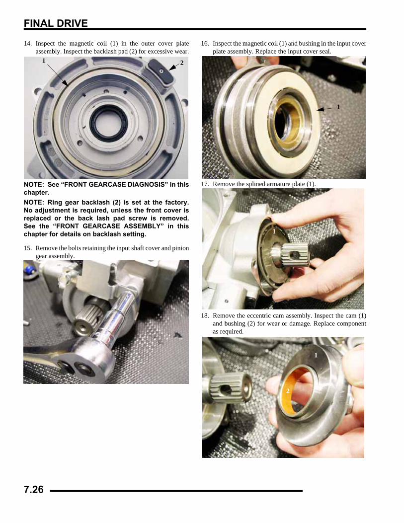
FINAL DRIVE
14. Inspect the magnetic coil (1) in the outer cover plateassembly. Inspect the backlash pad (2) for excessive wear.
NOTE: See “FRONT GEARCASE DIAGNOSIS” in thischapter.NOTE: Ring gear backlash (2) is set at the factory.No adjustment is required, unless the front cover isreplaced or the back lash pad screw is removed.See the “FRONT GEARCASE ASSEMBLY” in thischapter for details on backlash setting.
15. Remove the bolts retaining the input shaft cover and piniongear assembly.
16. Inspect the magnetic coil (1) and bushing in the input coverplate assembly. Replace the input cover seal.
17. Remove the splined armature plate (1).
18. Remove the eccentric cam assembly. Inspect the cam (1)and bushing (2) for wear or damage. Replace componentas required.
1 2
1
1
1
2
7.26
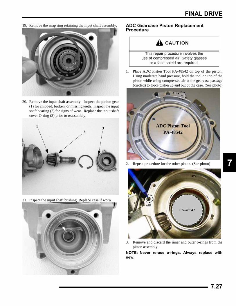
FINAL DRIVE
7
19. Remove the snap ring retaining the input shaft assembly.
20. Remove the input shaft assembly. Inspect the pinion gear(1) for chipped, broken, or missing teeth. Inspect the inputshaft bearing (2) for signs of wear. Replace the input shaftcover O-ring (3) prior to reassembly.
21. Inspect the input shaft bushing. Replace case if worn.
ADC Gearcase Piston Replacement Procedure
1. Place ADC Piston Tool PA-48542 on top of the piston.Using moderate hand pressure, hold the tool on top of thepiston while using compressed air at the gearcase passage(circled) to force piston up and out of the case. (See photo)
2. Repeat procedure for the other piston. (See photo)
3. Remove and discard the inner and outer o-rings from thepiston assembly.
NOTE: Never re-use o-rings. Always replace withnew.
12
3
CAUTION
This repair procedure involves the use of compressed air. Safety glasses
or a face shield are required.
AIR
ADC Piston Tool PA-48542
PA-48542AIR
7.27
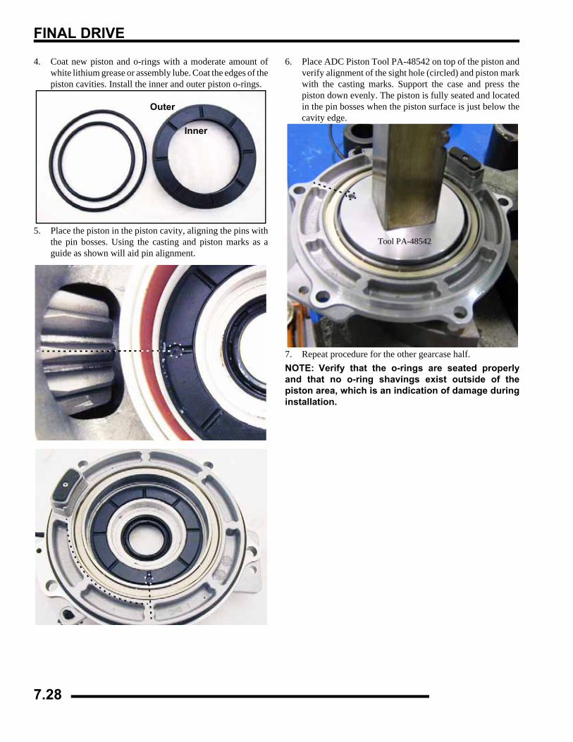
FINAL DRIVE
4. Coat new piston and o-rings with a moderate amount ofwhite lithium grease or assembly lube. Coat the edges of thepiston cavities. Install the inner and outer piston o-rings.
5. Place the piston in the piston cavity, aligning the pins withthe pin bosses. Using the casting and piston marks as aguide as shown will aid pin alignment.
6. Place ADC Piston Tool PA-48542 on top of the piston andverify alignment of the sight hole (circled) and piston markwith the casting marks. Support the case and press thepiston down evenly. The piston is fully seated and locatedin the pin bosses when the piston surface is just below thecavity edge.
7. Repeat procedure for the other gearcase half.NOTE: Verify that the o-rings are seated properlyand that no o-ring shavings exist outside of thepiston area, which is an indication of damage duringinstallation.
Inner
Outer
Tool PA-48542
7.28
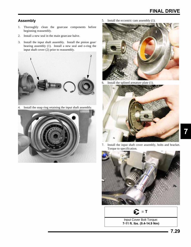
FINAL DRIVE
7
Assembly1. Thoroughly clean the gearcase components before
beginning reassembly. 2. Install a new seal in the main gearcase halve.
3. Install the input shaft assembly. Install the pinion gear/bearing assembly (1). Install a new seal and o-ring theinput shaft cover (2) prior to reassembly.
4. Install the snap ring retaining the input shaft assembly.
5. Install the eccentric cam assembly (1).
6. Install the splined armature plate (1).
7. Install the input shaft cover assembly, bolts and bracket.Torque to specification.
12
= T
Input Cover Bolt Torque:7-11 ft. lbs. (9.4-14.9 Nm)
1
1
7.29
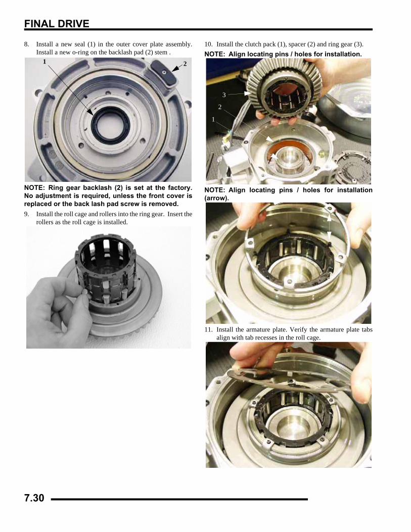
FINAL DRIVE
8. Install a new seal (1) in the outer cover plate assembly.Install a new o-ring on the backlash pad (2) stem .
NOTE: Ring gear backlash (2) is set at the factory.No adjustment is required, unless the front cover isreplaced or the back lash pad screw is removed.9. Install the roll cage and rollers into the ring gear. Insert the
rollers as the roll cage is installed.
10. Install the clutch pack (1), spacer (2) and ring gear (3).NOTE: Align locating pins / holes for installation.
NOTE: Align locating pins / holes for installation(arrow).
11. Install the armature plate. Verify the armature plate tabsalign with tab recesses in the roll cage.
1 2
3
2
1
7.30
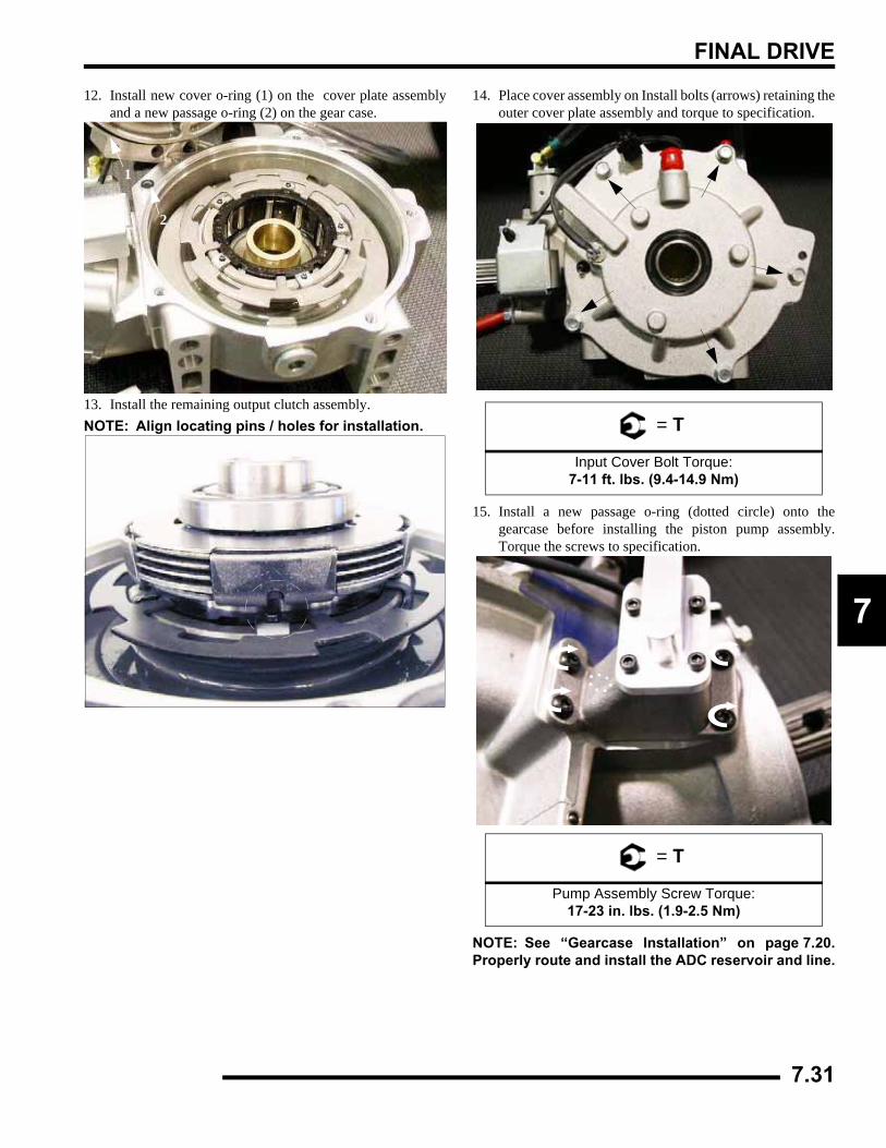
FINAL DRIVE
7
12. Install new cover o-ring (1) on the cover plate assemblyand a new passage o-ring (2) on the gear case.
13. Install the remaining output clutch assembly. NOTE: Align locating pins / holes for installation.
14. Place cover assembly on Install bolts (arrows) retaining theouter cover plate assembly and torque to specification.
15. Install a new passage o-ring (dotted circle) onto thegearcase before installing the piston pump assembly.Torque the screws to specification.
NOTE: See “Gearcase Installation” on page 7.20.Properly route and install the ADC reservoir and line.
1
2
= T
Input Cover Bolt Torque:7-11 ft. lbs. (9.4-14.9 Nm)
= T
Pump Assembly Screw Torque:17-23 in. lbs. (1.9-2.5 Nm)
7.31
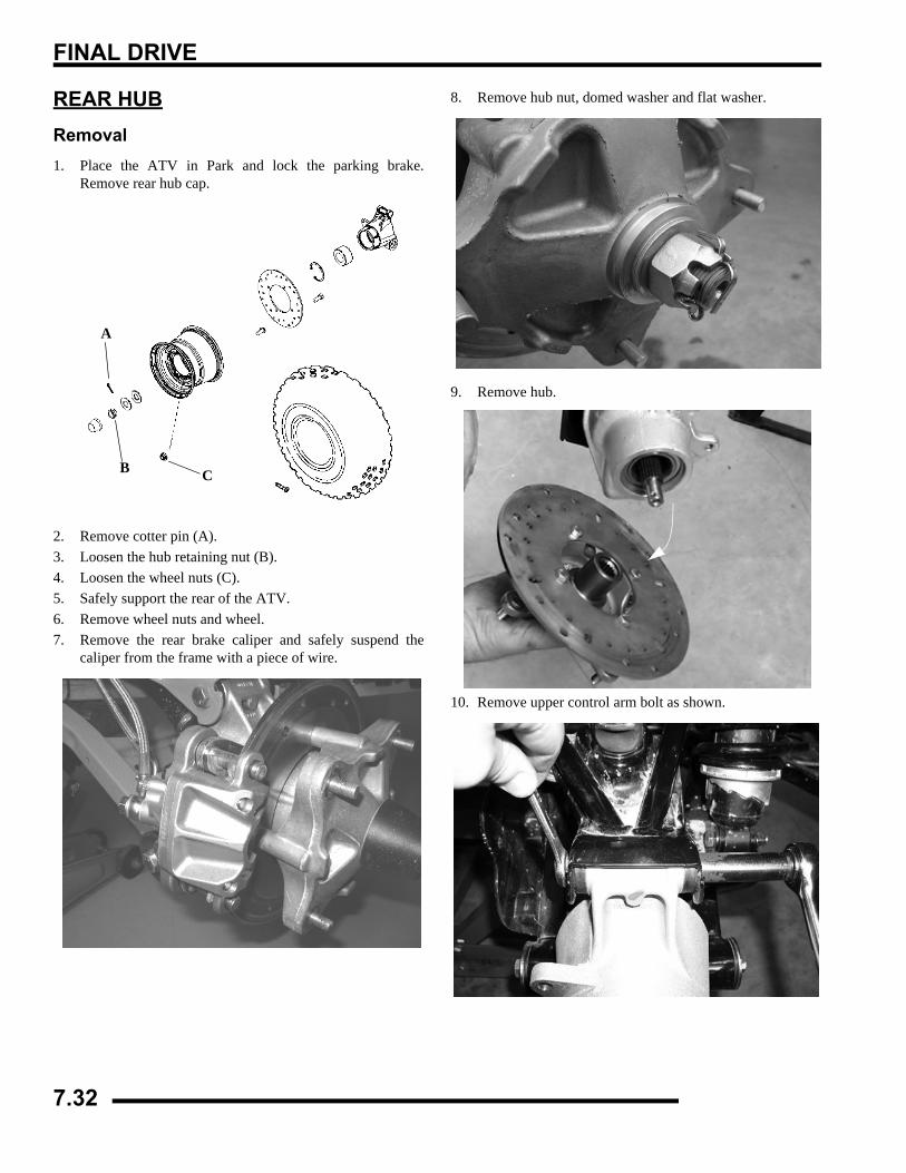
FINAL DRIVE
REAR HUBRemoval1. Place the ATV in Park and lock the parking brake.
Remove rear hub cap.
2. Remove cotter pin (A).3. Loosen the hub retaining nut (B).4. Loosen the wheel nuts (C).5. Safely support the rear of the ATV.6. Remove wheel nuts and wheel.7. Remove the rear brake caliper and safely suspend the
caliper from the frame with a piece of wire.
8. Remove hub nut, domed washer and flat washer.
9. Remove hub.
10. Remove upper control arm bolt as shown.
A
B C
7.32
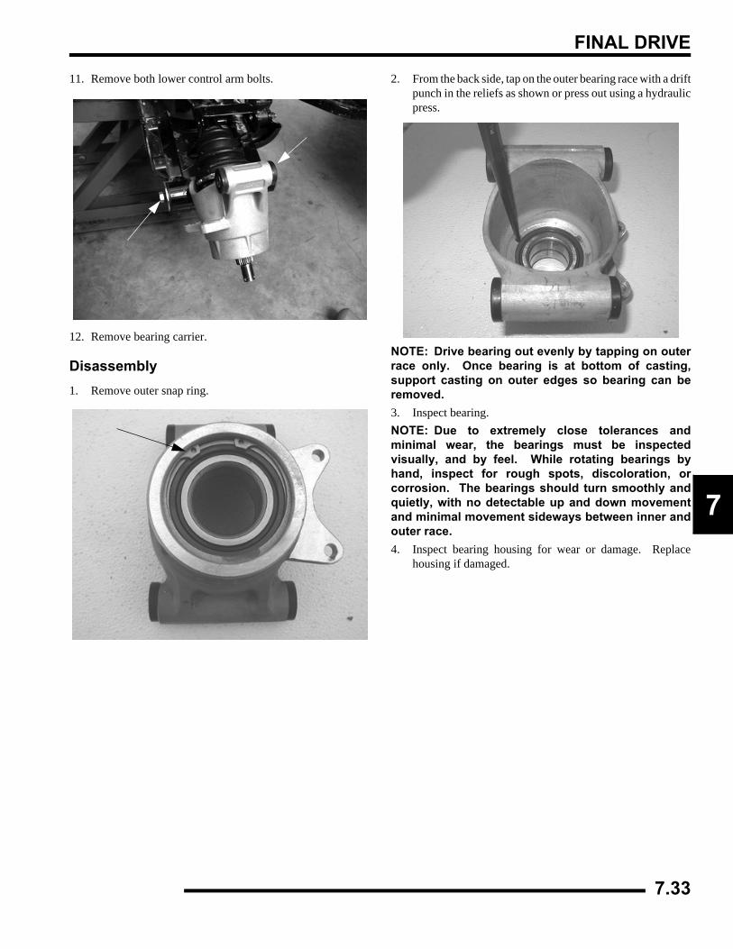
FINAL DRIVE
7
11. Remove both lower control arm bolts.
12. Remove bearing carrier.
Disassembly1. Remove outer snap ring.
2. From the back side, tap on the outer bearing race with a driftpunch in the reliefs as shown or press out using a hydraulicpress.
NOTE: Drive bearing out evenly by tapping on outerrace only. Once bearing is at bottom of casting,support casting on outer edges so bearing can beremoved.3. Inspect bearing.NOTE: Due to extremely close tolerances andminimal wear, the bearings must be inspectedvisually, and by feel. While rotating bearings byhand, inspect for rough spots, discoloration, orcorrosion. The bearings should turn smoothly andquietly, with no detectable up and down movementand minimal movement sideways between inner andouter race.4. Inspect bearing housing for wear or damage. Replace
housing if damaged.
7.33
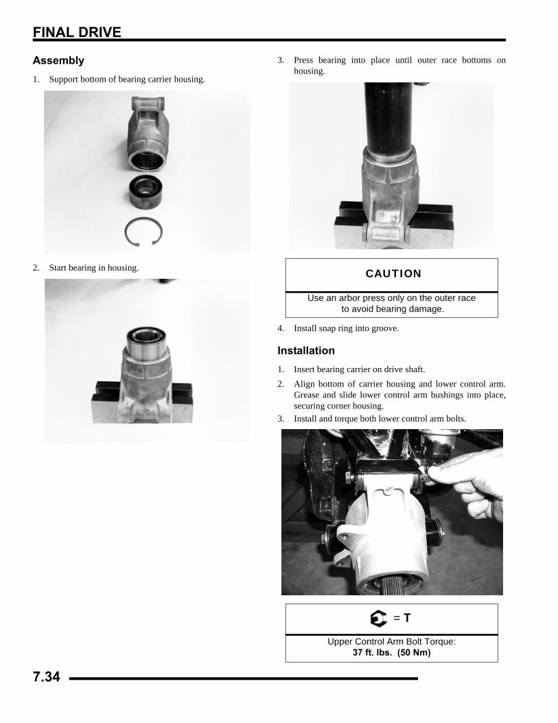
FINAL DRIVE
Assembly1. Support bottom of bearing carrier housing.
2. Start bearing in housing.
3. Press bearing into place until outer race bottoms onhousing.
4. Install snap ring into groove.
Installation1. Insert bearing carrier on drive shaft.2. Align bottom of carrier housing and lower control arm.
Grease and slide lower control arm bushings into place,securing corner housing.
3. Install and torque both lower control arm bolts.
CAUTION
Use an arbor press only on the outer race to avoid bearing damage.
= T
Upper Control Arm Bolt Torque: 37 ft. lbs. (50 Nm)
7.34
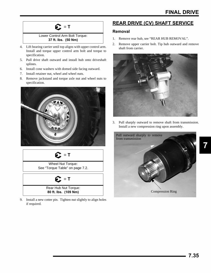
FINAL DRIVE
7
4. Lift bearing carrier until top aligns with upper control arm.Install and torque upper control arm bolt and torque tospecification.
5. Pull drive shaft outward and install hub onto driveshaftsplines.
6. Install cone washers with domed side facing outward.7. Install retainer nut, wheel and wheel nuts.8. Remove jackstand and torque axle nut and wheel nuts to
specification.
9. Install a new cotter pin. Tighten nut slightly to align holesif required.
REAR DRIVE (CV) SHAFT SERVICERemoval1. Remove rear hub, see “REAR HUB REMOVAL”.2. Remove upper carrier bolt. Tip hub outward and remove
shaft from carrier.
3. Pull sharply outward to remove shaft from transmission.Install a new compression ring upon assembly.
= T
Lower Control Arm Bolt Torque: 37 ft. lbs. (50 Nm)
= T
Wheel Nut Torque: See “Torque Table” on page 7.2.
= T
Rear Hub Nut Torque: 80 ft. lbs. (109 Nm)
Pull outward sharply to removefrom transmission
Compression Ring
7.35
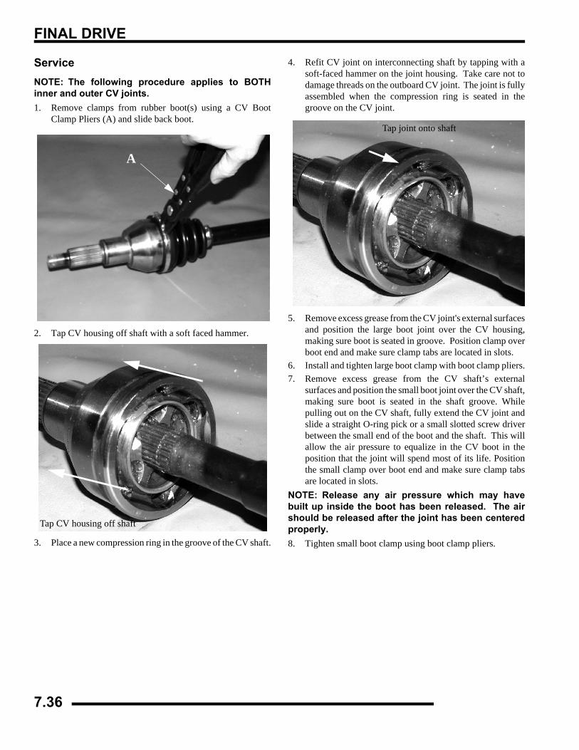
FINAL DRIVE
ServiceNOTE: The following procedure applies to BOTHinner and outer CV joints.1. Remove clamps from rubber boot(s) using a CV Boot
Clamp Pliers (A) and slide back boot.
2. Tap CV housing off shaft with a soft faced hammer.
3. Place a new compression ring in the groove of the CV shaft.
4. Refit CV joint on interconnecting shaft by tapping with asoft-faced hammer on the joint housing. Take care not todamage threads on the outboard CV joint. The joint is fullyassembled when the compression ring is seated in thegroove on the CV joint.
5. Remove excess grease from the CV joint's external surfacesand position the large boot joint over the CV housing,making sure boot is seated in groove. Position clamp overboot end and make sure clamp tabs are located in slots.
6. Install and tighten large boot clamp with boot clamp pliers.7. Remove excess grease from the CV shaft’s external
surfaces and position the small boot joint over the CV shaft,making sure boot is seated in the shaft groove. Whilepulling out on the CV shaft, fully extend the CV joint andslide a straight O-ring pick or a small slotted screw driverbetween the small end of the boot and the shaft. This willallow the air pressure to equalize in the CV boot in theposition that the joint will spend most of its life. Positionthe small clamp over boot end and make sure clamp tabsare located in slots.
NOTE: Release any air pressure which may havebuilt up inside the boot has been released. The airshould be released after the joint has been centeredproperly. 8. Tighten small boot clamp using boot clamp pliers.
A
Tap CV housing off shaft
Tap joint onto shaft
7.36
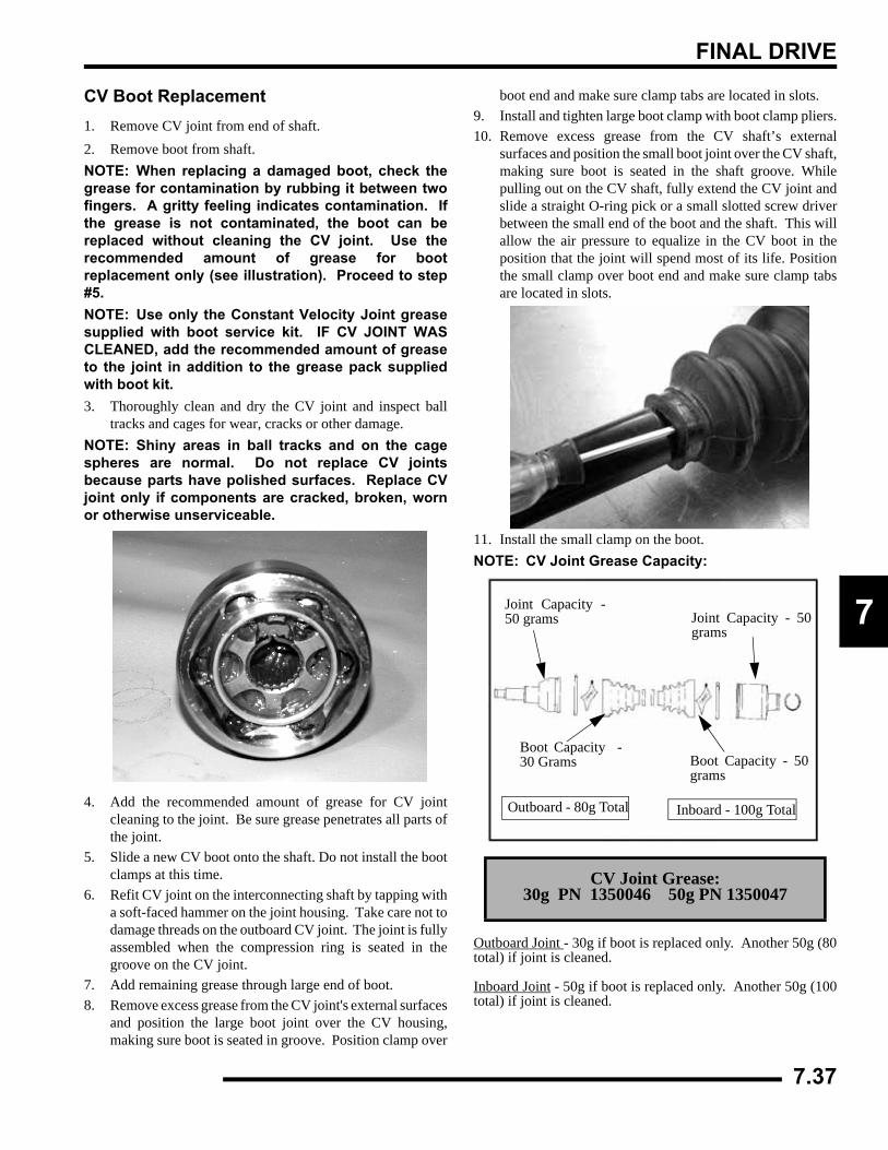
FINAL DRIVE
7
CV Boot Replacement1. Remove CV joint from end of shaft.2. Remove boot from shaft.NOTE: When replacing a damaged boot, check thegrease for contamination by rubbing it between twofingers. A gritty feeling indicates contamination. Ifthe grease is not contaminated, the boot can bereplaced without cleaning the CV joint. Use therecommended amount of grease for bootreplacement only (see illustration). Proceed to step#5.NOTE: Use only the Constant Velocity Joint greasesupplied with boot service kit. IF CV JOINT WASCLEANED, add the recommended amount of greaseto the joint in addition to the grease pack suppliedwith boot kit.3. Thoroughly clean and dry the CV joint and inspect ball
tracks and cages for wear, cracks or other damage.NOTE: Shiny areas in ball tracks and on the cagespheres are normal. Do not replace CV jointsbecause parts have polished surfaces. Replace CVjoint only if components are cracked, broken, wornor otherwise unserviceable.
4. Add the recommended amount of grease for CV jointcleaning to the joint. Be sure grease penetrates all parts ofthe joint.
5. Slide a new CV boot onto the shaft. Do not install the bootclamps at this time.
6. Refit CV joint on the interconnecting shaft by tapping witha soft-faced hammer on the joint housing. Take care not todamage threads on the outboard CV joint. The joint is fullyassembled when the compression ring is seated in thegroove on the CV joint.
7. Add remaining grease through large end of boot.8. Remove excess grease from the CV joint's external surfaces
and position the large boot joint over the CV housing,making sure boot is seated in groove. Position clamp over
boot end and make sure clamp tabs are located in slots.9. Install and tighten large boot clamp with boot clamp pliers.10. Remove excess grease from the CV shaft’s external
surfaces and position the small boot joint over the CV shaft,making sure boot is seated in the shaft groove. Whilepulling out on the CV shaft, fully extend the CV joint andslide a straight O-ring pick or a small slotted screw driverbetween the small end of the boot and the shaft. This willallow the air pressure to equalize in the CV boot in theposition that the joint will spend most of its life. Positionthe small clamp over boot end and make sure clamp tabsare located in slots.
11. Install the small clamp on the boot.NOTE: CV Joint Grease Capacity:
Outboard Joint - 30g if boot is replaced only. Another 50g (80total) if joint is cleaned.
Inboard Joint - 50g if boot is replaced only. Another 50g (100total) if joint is cleaned.
CV Joint Grease: 30g PN 1350046 50g PN 1350047
Joint Capacity -50 grams
Boot Capacity -30 Grams
Outboard - 80g Total
Joint Capacity - 50grams
Boot Capacity - 50grams
Inboard - 100g Total
7.37
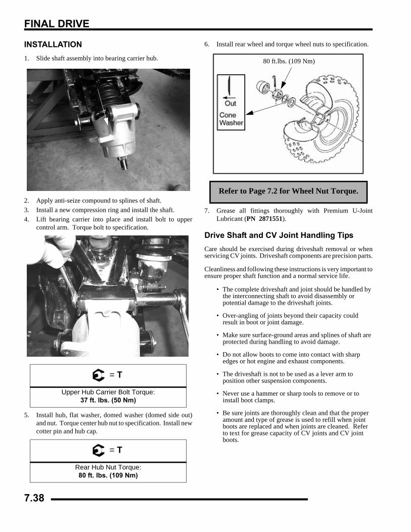
FINAL DRIVE
INSTALLATION1. Slide shaft assembly into bearing carrier hub.
2. Apply anti-seize compound to splines of shaft.3. Install a new compression ring and install the shaft.4. Lift bearing carrier into place and install bolt to upper
control arm. Torque bolt to specification.
5. Install hub, flat washer, domed washer (domed side out)and nut. Torque center hub nut to specification. Install newcotter pin and hub cap.
6. Install rear wheel and torque wheel nuts to specification.
7. Grease all fittings thoroughly with Premium U-JointLubricant (PN 2871551).
Drive Shaft and CV Joint Handling TipsCare should be exercised during driveshaft removal or whenservicing CV joints. Driveshaft components are precision parts.
Cleanliness and following these instructions is very important toensure proper shaft function and a normal service life.
• The complete driveshaft and joint should be handled by the interconnecting shaft to avoid disassembly or potential damage to the driveshaft joints.
• Over-angling of joints beyond their capacity could result in boot or joint damage.
• Make sure surface-ground areas and splines of shaft are protected during handling to avoid damage.
• Do not allow boots to come into contact with sharp edges or hot engine and exhaust components.
• The driveshaft is not to be used as a lever arm to position other suspension components.
• Never use a hammer or sharp tools to remove or to install boot clamps.
• Be sure joints are thoroughly clean and that the proper amount and type of grease is used to refill when joint boots are replaced and when joints are cleaned. Refer to text for grease capacity of CV joints and CV joint boots.
= T
Upper Hub Carrier Bolt Torque:37 ft. lbs. (50 Nm)
= T
Rear Hub Nut Torque:80 ft. lbs. (109 Nm)
Refer to Page 7.2 for Wheel Nut Torque.
80 ft.lbs. (109 Nm)
7.38
TRANSMISSION
CHAPTER 8TRANSMISSION
8
TRANSMISSION - GENERAL . . . . . . . . . . . . . . . . . . . . . . . . . . . . . . . . . . . . . . . . . . . . . . 8.2MOUNTING EXPLODED VIEW . . . . . . . . . . . . . . . . . . . . . . . . . . . . . . . . . . . . . . . . . . . . 8.2TORQUE SPECIFICATIONS . . . . . . . . . . . . . . . . . . . . . . . . . . . . . . . . . . . . . . . . . . . . . . 8.3SPECIAL TOOLS . . . . . . . . . . . . . . . . . . . . . . . . . . . . . . . . . . . . . . . . . . . . . . . . . . . . . . . 8.3LUBRICATION . . . . . . . . . . . . . . . . . . . . . . . . . . . . . . . . . . . . . . . . . . . . . . . . . . . . . . . . . 8.3GEAR SELECTOR REMOVAL. . . . . . . . . . . . . . . . . . . . . . . . . . . . . . . . . . . . . . . . . . . . . 8.3TRANSMISSION REMOVAL . . . . . . . . . . . . . . . . . . . . . . . . . . . . . . . . . . . . . . . . . . . . . . 8.3TRANSMISSION INSTALLATION . . . . . . . . . . . . . . . . . . . . . . . . . . . . . . . . . . . . . . . . . . 8.5TROUBLESHOOTING CHECKLIST. . . . . . . . . . . . . . . . . . . . . . . . . . . . . . . . . . . . . . . . . 8.6
TRANSMISSION SERVICE. . . . . . . . . . . . . . . . . . . . . . . . . . . . . . . . . . . . . . . . . . . . . . . . 8.7X2 - TOURING EXPLODED VIEW. . . . . . . . . . . . . . . . . . . . . . . . . . . . . . . . . . . . . . . . . . 8.7500 CARBURETED EXPLODED VIEW . . . . . . . . . . . . . . . . . . . . . . . . . . . . . . . . . . . . . . 8.9TRANSMISSION DISASSEMBLY . . . . . . . . . . . . . . . . . . . . . . . . . . . . . . . . . . . . . . . . . 8.11TRANSMISSION ASSEMBLY . . . . . . . . . . . . . . . . . . . . . . . . . . . . . . . . . . . . . . . . . . . . 8.16TRANSMISSION FRONT OUTPUT SHAFT BACKLASH PROCEDURE . . . . . . . . . . . 8.17
8.1
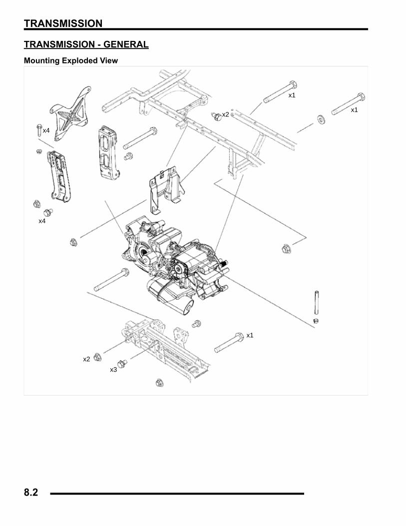
TRANSMISSION
TRANSMISSION - GENERALMounting Exploded View
x2x3
x4
x4
x2
x1
x1
x1
8.2
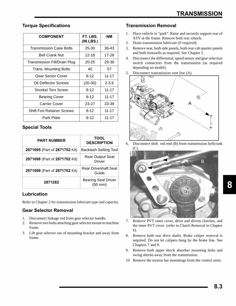
TRANSMISSION
8
Torque Specifications
Special Tools
LubricationRefer to Chapter 2 for transmission lubricant type and capacity.
Gear Selector Removal1. Disconnect linkage rod from gear selector handle.2. Remove two bolts attaching gear selector mount to machine
frame.3. Lift gear selector out of mounting bracket and away from
frame.
Transmission Removal1. Place vehicle in “park”. Raise and securely support rear of
ATV at the frame. Remove both rear wheels.2. Drain transmission lubricant (if required).3. Remove seat, both side panels, both rear cab quarter panels
and both footwells as required. See Chapter 5.4. Disconnect the differential, speed sensor and gear selection
switch connectors from the transmission (as requireddepending on model).
5. Disconnect transmission vent line (A).
6. Disconnect shift rod end (B) from transmission bellcrank(C).
7. Remove PVT outer cover, drive and driven clutches, andthe inner PVT cover. (refer to Clutch Removal in Chapter6).
8. Remove both rear drive shafts. Brake caliper removal isrequired. Do not let calipers hang by the brake line. SeeChapters 7 and 9.
9. Remove both upper shock absorber mounting bolts andswing shocks away from the transmission.
10. Remove the torsion bar mountings from the control arms.
COMPONENT FT. LBS. (IN.LBS.)
NM
Transmission Case Bolts 25-30 36-43
Bell Crank Nut 12-18 17-26
Transmission Fill/Drain Plug 20-25 29-36
Trans. Mounting Bolts 40 57
Gear Sector Cover 8-12 11-17
Oil Deflector Screws (20-30) 2-3.6
Snorkel Torx Screw 8-12 11-17
Bearing Cover 8-12 11-17
Carrier Cover 23-27 33-39
Shift Fort Retainer Screws 8-12 11-17
Park Plate 8-12 11-17
PART NUMBER TOOL DESCRIPTION
2871695 (Part of 2871702 Kit) Backlash Setting Tool
2871698 (Part of 2871702 Kit) Rear Output Seal Driver
2871699 (Part of 2871702 Kit) Rear Driveshaft Seal Guide
2871282 Bearing Seal Driver (50 mm)
A
CB
8.3
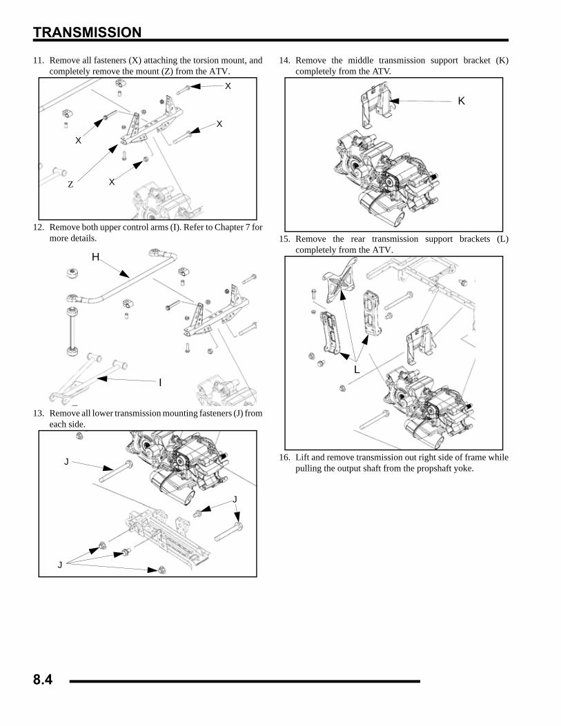
TRANSMISSION
11. Remove all fasteners (X) attaching the torsion mount, andcompletely remove the mount (Z) from the ATV.
12. Remove both upper control arms (I). Refer to Chapter 7 formore details.
13. Remove all lower transmission mounting fasteners (J) fromeach side.
14. Remove the middle transmission support bracket (K)completely from the ATV.
15. Remove the rear transmission support brackets (L)completely from the ATV.
16. Lift and remove transmission out right side of frame whilepulling the output shaft from the propshaft yoke.
X
X
X
X
Z
H
I
J
J
J
K
L
8.4
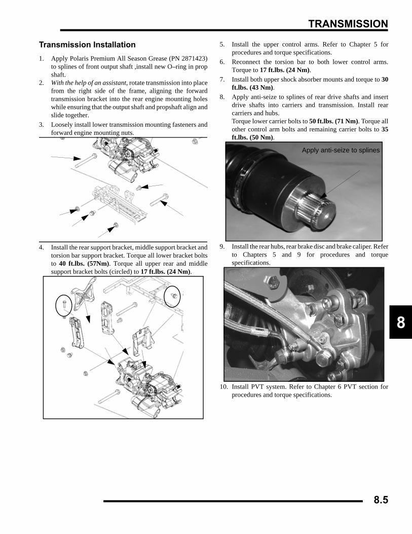
TRANSMISSION
8
Transmission Installation1. Apply Polaris Premium All Season Grease (PN 2871423)
to splines of front output shaft ,install new O–ring in propshaft.
2. With the help of an assistant, rotate transmission into placefrom the right side of the frame, aligning the forwardtransmission bracket into the rear engine mounting holeswhile ensuring that the output shaft and propshaft align andslide together.
3. Loosely install lower transmission mounting fasteners andforward engine mounting nuts.
4. Install the rear support bracket, middle support bracket andtorsion bar support bracket. Torque all lower bracket boltsto 40 ft.lbs. (57Nm). Torque all upper rear and middlesupport bracket bolts (circled) to 17 ft.lbs. (24 Nm).
5. Install the upper control arms. Refer to Chapter 5 forprocedures and torque specifications.
6. Reconnect the torsion bar to both lower control arms.Torque to 17 ft.lbs. (24 Nm).
7. Install both upper shock absorber mounts and torque to 30ft.lbs. (43 Nm).
8. Apply anti-seize to splines of rear drive shafts and insertdrive shafts into carriers and transmission. Install rearcarriers and hubs. Torque lower carrier bolts to 50 ft.lbs. (71 Nm). Torque allother control arm bolts and remaining carrier bolts to 35ft.lbs. (50 Nm).
9. Install the rear hubs, rear brake disc and brake caliper. Referto Chapters 5 and 9 for procedures and torquespecifications.
10. Install PVT system. Refer to Chapter 6 PVT section forprocedures and torque specifications.
Apply anti-seize to splines
8.5
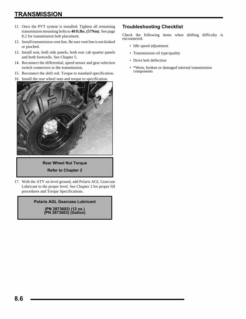
TRANSMISSION
11. Once the PVT system is installed. Tighten all remainingtransmission mounting bolts to 40 ft.lbs. (57Nm). See page8.2 for transmission bolt placement.
12. Install transmission vent line. Be sure vent line is not kinkedor pinched.
13. Install seat, both side panels, both rear cab quarter panelsand both footwells. See Chapter 5.
14. Reconnect the differential, speed sensor and gear selectionswitch connectors to the transmission.
15. Reconnect the shift rod. Torque to standard specification. 16. Install the rear wheel nuts and torque to specification.
17. With the ATV on level ground, add Polaris AGL GearcaseLubricant to the proper level. See Chapter 2 for proper fillprocedures and Torque Specifications.
Troubleshooting ChecklistCheck the following items when shifting difficulty isencountered.
• Idle speed adjustment
• Transmission oil type/quality
• Drive belt deflection
• *Worn, broken or damaged internal transmission components
Rear Wheel Nut Torque
Refer to Chapter 2
Polaris AGL Gearcase Lubricant
(PN 2873602) (12 oz.)(PN 2873603) (Gallon)
8.6
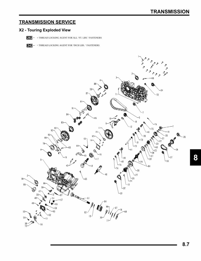
TRANSMISSION
8
TRANSMISSION SERVICEX2 - Touring Exploded View
262
242
= THREAD LOCKING AGENT FOR ALL ‘FT. LBS.’ FASTENERS
= THREAD LOCKING AGENT FOR ‘INCH LBS. ‘ FASTENERS
8.7
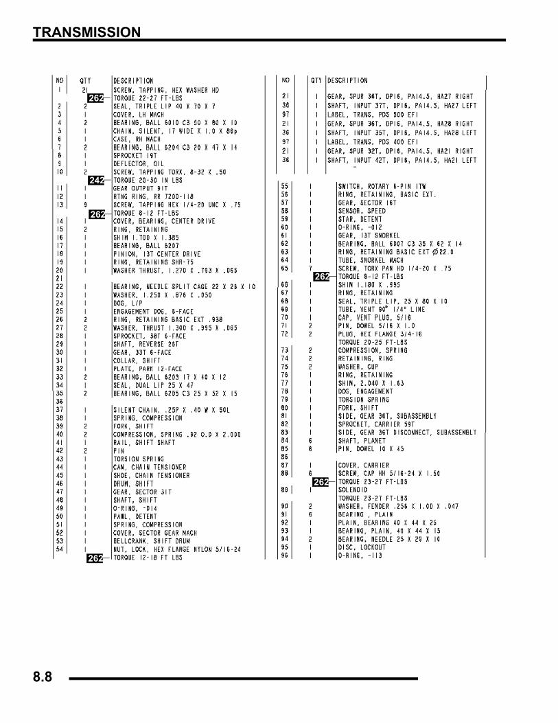
TRANSMISSION
242
262
262
262
262
262
8.8
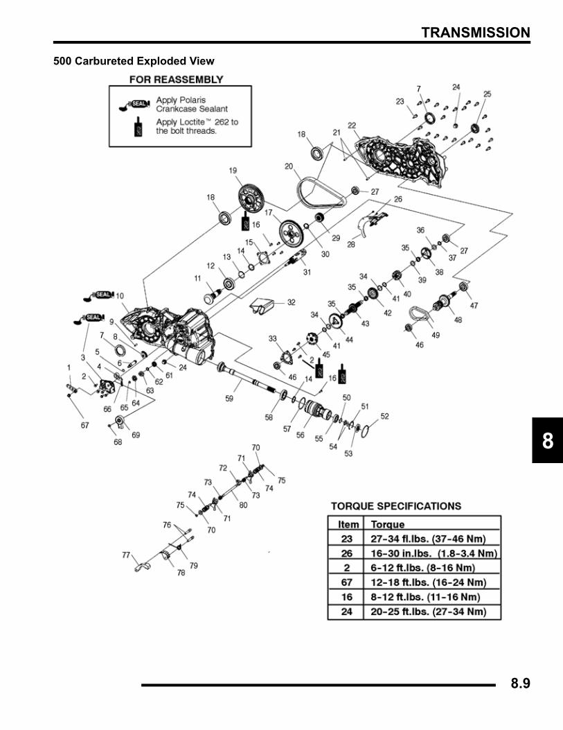
TRANSMISSION
8
500 Carbureted Exploded View
8.9
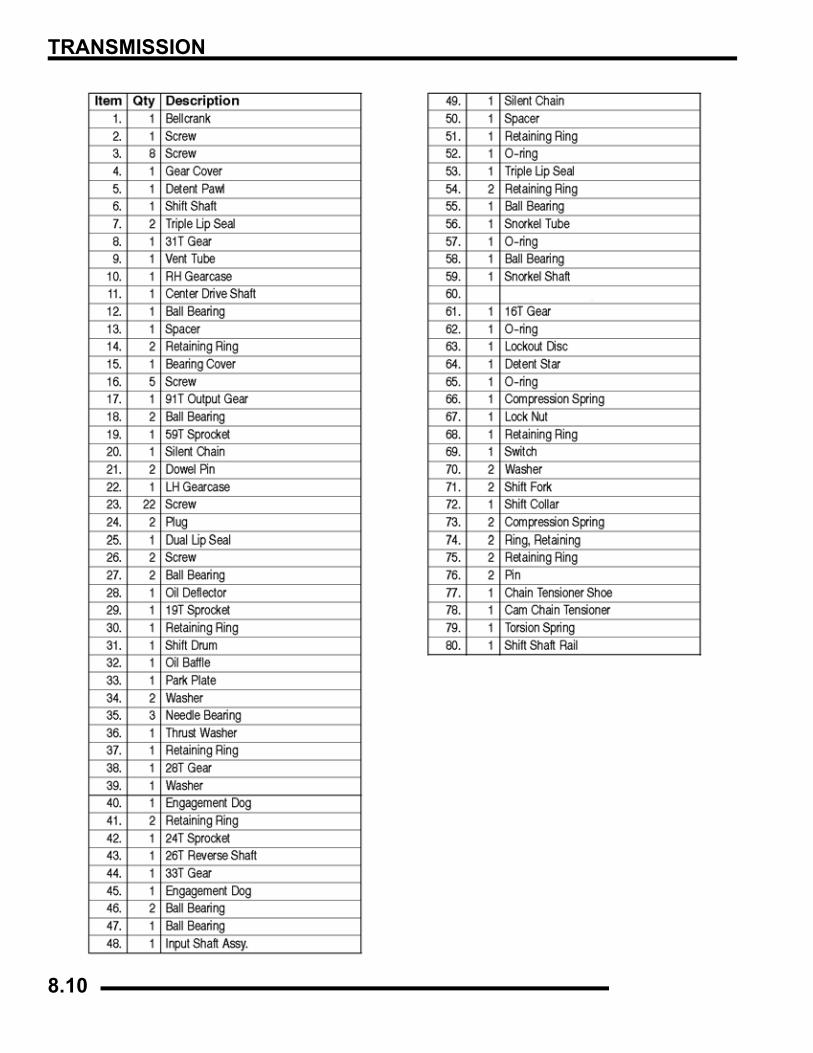
TRANSMISSION
8.10
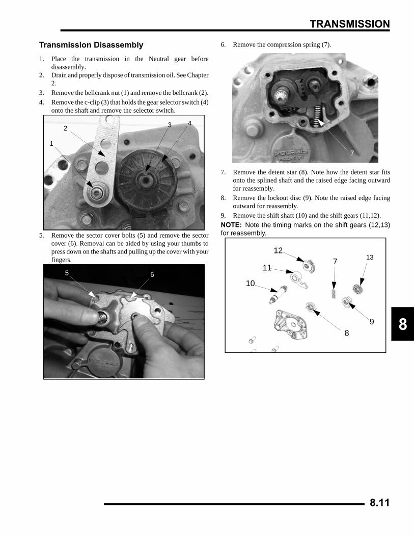
TRANSMISSION
8
Transmission Disassembly1. Place the transmission in the Neutral gear before
disassembly.2. Drain and properly dispose of transmission oil. See Chapter
2.3. Remove the bellcrank nut (1) and remove the bellcrank (2).4. Remove the c-clip (3) that holds the gear selector switch (4)
onto the shaft and remove the selector switch.
5. Remove the sector cover bolts (5) and remove the sectorcover (6). Removal can be aided by using your thumbs topress down on the shafts and pulling up the cover with yourfingers.
6. Remove the compression spring (7).
7. Remove the detent star (8). Note how the detent star fitsonto the splined shaft and the raised edge facing outwardfor reassembly.
8. Remove the lockout disc (9). Note the raised edge facingoutward for reassembly.
9. Remove the shift shaft (10) and the shift gears (11,12).NOTE: Note the timing marks on the shift gears (12,13)for reassembly.
1
2 3 4
65
7
89
10
11
127 13
8.11
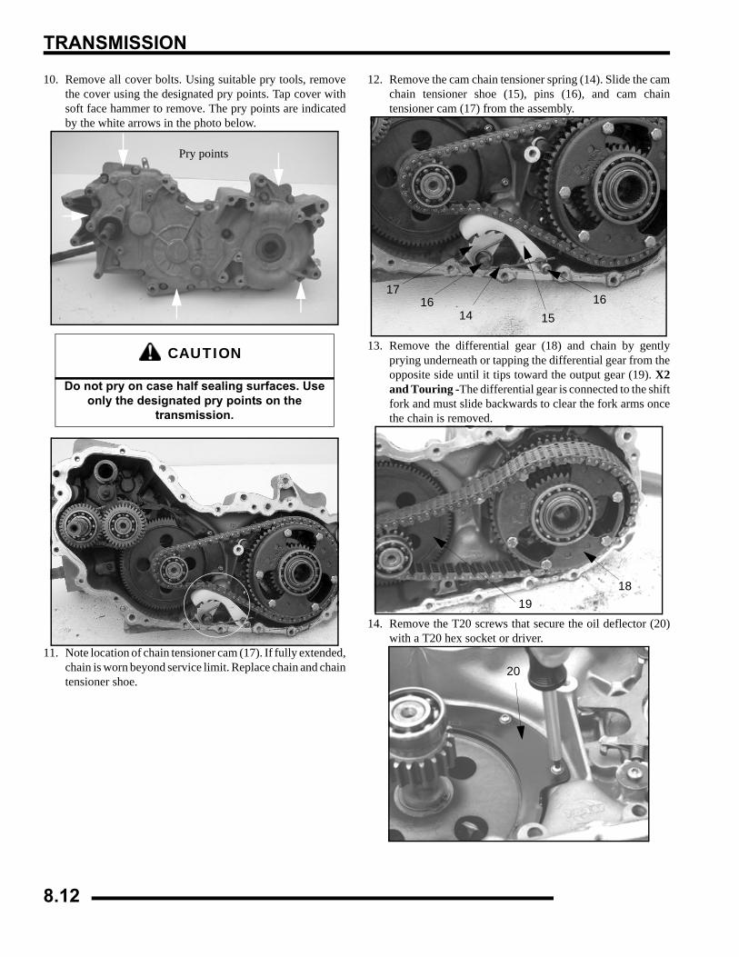
TRANSMISSION
10. Remove all cover bolts. Using suitable pry tools, removethe cover using the designated pry points. Tap cover withsoft face hammer to remove. The pry points are indicatedby the white arrows in the photo below.
11. Note location of chain tensioner cam (17). If fully extended,chain is worn beyond service limit. Replace chain and chaintensioner shoe.
12. Remove the cam chain tensioner spring (14). Slide the camchain tensioner shoe (15), pins (16), and cam chaintensioner cam (17) from the assembly.
13. Remove the differential gear (18) and chain by gentlyprying underneath or tapping the differential gear from theopposite side until it tips toward the output gear (19). X2and Touring -The differential gear is connected to the shiftfork and must slide backwards to clear the fork arms oncethe chain is removed.
14. Remove the T20 screws that secure the oil deflector (20)with a T20 hex socket or driver.
CAUTION
Do not pry on case half sealing surfaces. Use only the designated pry points on the
transmission.
Pry points
161514
1617
1819
20
8.12
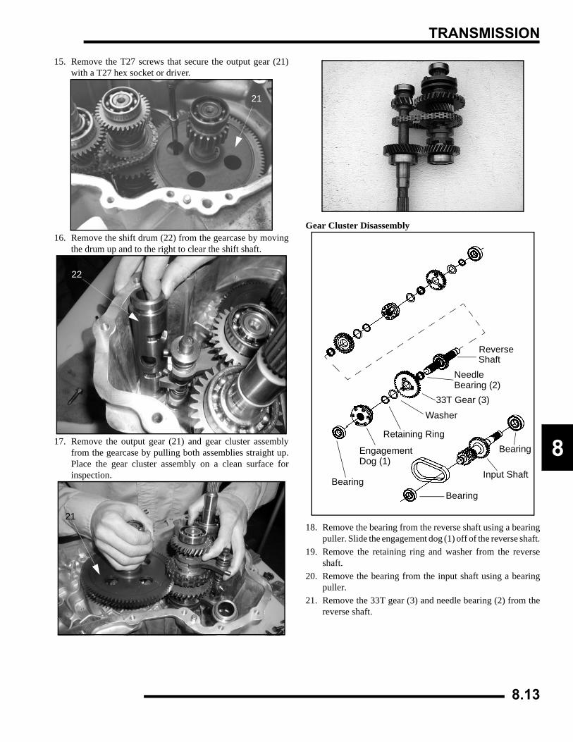
TRANSMISSION
8
15. Remove the T27 screws that secure the output gear (21)with a T27 hex socket or driver.
16. Remove the shift drum (22) from the gearcase by movingthe drum up and to the right to clear the shift shaft.
17. Remove the output gear (21) and gear cluster assemblyfrom the gearcase by pulling both assemblies straight up.Place the gear cluster assembly on a clean surface forinspection.
Gear Cluster Disassembly
18. Remove the bearing from the reverse shaft using a bearingpuller. Slide the engagement dog (1) off of the reverse shaft.
19. Remove the retaining ring and washer from the reverseshaft.
20. Remove the bearing from the input shaft using a bearingpuller.
21. Remove the 33T gear (3) and needle bearing (2) from thereverse shaft.
21
22
21
Bearing
Input Shaft
Bearing
Reverse
Needle
33T Gear (3)Washer
Retaining Ring
Bearing (2)
EngagementDog (1)
Bearing
Shaft
8.13
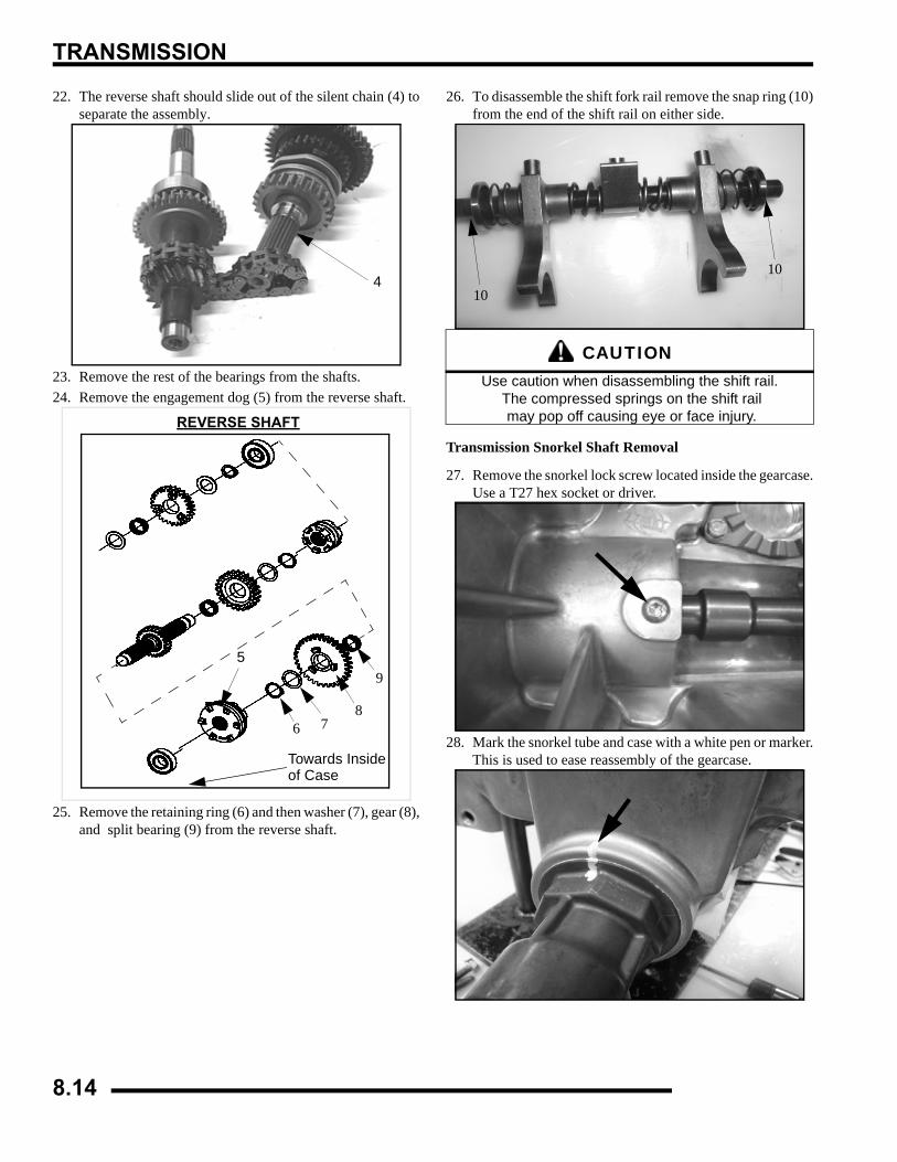
TRANSMISSION
22. The reverse shaft should slide out of the silent chain (4) toseparate the assembly.
23. Remove the rest of the bearings from the shafts.24. Remove the engagement dog (5) from the reverse shaft.
25. Remove the retaining ring (6) and then washer (7), gear (8),and split bearing (9) from the reverse shaft.
26. To disassemble the shift fork rail remove the snap ring (10)from the end of the shift rail on either side.
Transmission Snorkel Shaft Removal
27. Remove the snorkel lock screw located inside the gearcase.Use a T27 hex socket or driver.
28. Mark the snorkel tube and case with a white pen or marker.This is used to ease reassembly of the gearcase.
4
REVERSE SHAFT
Towards Insideof Case
5
6 78
9
CAUTIONUse caution when disassembling the shift rail.
The compressed springs on the shift rail may pop off causing eye or face injury.
10
10
8.14
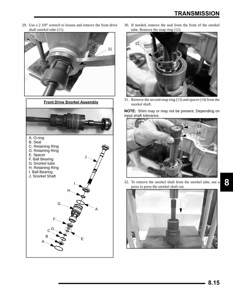
TRANSMISSION
8
29. Use a 2 3/8” wrench to loosen and remove the front driveshaft snorkel tube (11).
30. If needed, remove the seal from the front of the snorkeltube. Remove the snap ring (12).
31. Remove the second snap ring (13) and spacer (14) from thesnorkel shaft.
NOTE: Shim may or may not be present. Depending oninput shaft tolerance.
32. To remove the snorkel shaft from the snorkel tube, use apress to press the snorkel shaft out.
11
Front Drive Snorkel Assembly
A. O-ringB. SealC. Retaining RingD. Retaining RingE. SpacerF. Ball BearingG. Snorkel tubeH. Retaining RingI. Ball BearingJ. Snorkel Shaft
A
AB E
DC
I
H
G
F
J
12
13
14
8.15
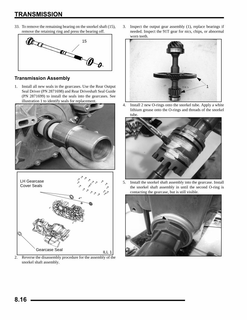
TRANSMISSION
33. To remove the remaining bearing on the snorkel shaft (15),remove the retaining ring and press the bearing off.
Transmission Assembly1. Install all new seals in the gearcases. Use the Rear Output
Seal Driver (PN 2871698) and Rear Driveshaft Seal Guide(PN 2871699) to install the seals into the gearcases. Seeillustration 1 to identify seals for replacement.
2. Reverse the disassembly procedure for the assembly of thesnorkel shaft assembly.
3. Inspect the output gear assembly (1), replace bearings ifneeded. Inspect the 91T gear for nics, chips, or abnormalworn teeth.
4. Install 2 new O-rings onto the snorkel tube. Apply a whitelithium grease onto the O-rings and threads of the snorkeltube.
5. Install the snorkel shaft assembly into the gearcase. Installthe snorkel shaft assembly in until the second O-ring iscontacting the gearcase, but is still visible.
15
LH GearcaseCover Seals
Gearcase Seal ILL 1
1
8.16
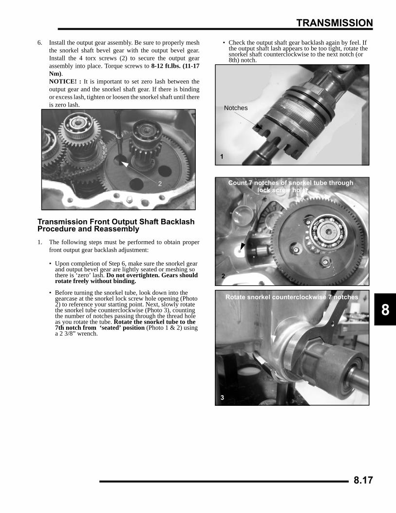
TRANSMISSION
8
6. Install the output gear assembly. Be sure to properly meshthe snorkel shaft bevel gear with the output bevel gear.Install the 4 torx screws (2) to secure the output gearassembly into place. Torque screws to 8-12 ft.lbs. (11-17Nm).NOTICE! : It is important to set zero lash between theoutput gear and the snorkel shaft gear. If there is bindingor excess lash, tighten or loosen the snorkel shaft until thereis zero lash.
Transmission Front Output Shaft Backlash Procedure and Reassembly1. The following steps must be performed to obtain proper
front output gear backlash adjustment:
• Upon completion of Step 6, make sure the snorkel gear and output bevel gear are lightly seated or meshing so there is ‘zero’ lash. Do not overtighten. Gears should rotate freely without binding.
• Before turning the snorkel tube, look down into the gearcase at the snorkel lock screw hole opening (Photo 2) to reference your starting point. Next, slowly rotate the snorkel tube counterclockwise (Photo 3), counting the number of notches passing through the thread hole as you rotate the tube. Rotate the snorkel tube to the 7th notch from ‘seated’ position (Photo 1 & 2) using a 2 3/8” wrench.
• Check the output shaft gear backlash again by feel. If the output shaft lash appears to be too tight, rotate the snorkel shaft counterclockwise to the next notch (or 8th) notch.
2
Notches
1
Count 7 notches of snorkel tube throughlock screw hole.
2
Rotate snorkel counterclockwise 7 notches
3
8.17
TRANSMISSION
2. Once the gear backlash is found, to install the snorkel lockscrew, you may have to rotate the snorkel tube clockwiseor counterclockwise slightly. This will allow the lock screwto thread itself into one of the slots of the snorkel tube (Seeillustration below) to secure the snorkel tube.
3. With the snorkel shaft assembly in place, remove the 4 Torxscrews from the output shaft assembly. Remove the outputshaft assembly.
4. Assemble the input shaft assembly if previouslydisassembled.
5. Assemble the reverse shaft assembly if previouslydisassembled.
Screw Fits in Slots of Snorkel Tube
8-12 ft-lb. (11-17) Nm
Input Shaft AssemblyA. Ball BearingB. Input ShaftC. Silent Chain
A
AB
C
REVERSE SHAFT
Towards Insideof Case
A. Ball BearingB. Engagement DogC. Retaining RingD. WasherE. GearF. Needle BearingG. Reverse ShaftH. Needle BearingI. Sprocket
J. WasherK. retaining RingL. Engagement DogM. WasherN. Needle BearingO. GearP. WasherQ. Retaining RingR. Ball bearing
A
BC
D
EFG
H
I JK
L
RQP
ON
M
8.18
TRANSMISSION
8
6. Inspect the shift drum for any damage or wear. Inspect thesplines of the shift drum. Replace the O-rings on the end ofthe shift drum and lubricate them before assembly.
7. Stretch the silent chain on a flat surface and measure thelength of 8 pitches in a minimum of three places on thechain. Replace the chain if the measurement is longer than3.0904” (7.8496 cm).
8. The shift drum (C), reverse shaft (D), input shaft (E), andoutput gear assembly must be installed at the same time toproperly align all components.
NOTE: To ease assembly use a plastic tie strap to holdthe shift forks (D) and the shift drum (C) together duringassembly.
9. With the gearcase on it’s side, hold the gear clusterassembly and output assembly together. Carefully installeach shaft into their respective recess in the gearcase.
10. With all of the components in the correct positions installthe 4 output gear assembly screws. Apply Loctite™ 262(PN 2871952) to the threads of the screws. Torque thescrews to 8-12 ft.lbs. (11-17 Nm). NOTE: If thetransmission is in locked in Park, place the transmission inNeutral.
11. Install the oil deflector shield into the gearcase. ApplyLoctite™ 242 to the threads of the screws. Torque thescrews to 16-30 in.lbs. (2-3.6 Nm).
Silent Chain Length:
3.0904” (7.8496 cm)
D
E
C
8.19
TRANSMISSION
12. Install the rear drive differential and drive chain, followingthese precautions:
• The case half rear output seal should be removed prior to installation of the differential, as seal damage can occur with seal installed due to the angle of entry.
• X2 and Touring - Install the differential sliding geardog onto the shift fork arms at the same time the silent chain is installed.
• The differential gear bearing may be lightly tapped into place. The case half seal can be installed once the assembly is in place.
13. Tensioner Installation:NOTE: Case-halve mating may be difficult due to tensionerinstallation. Release tension to aid installation.
• Place the tensioner cam on the front spacer and tensioner shoe on the rear spacer.
• Insert the pins through the cam and through the shoe.
• Place the spring over the front pin and hook the spring leg under the cam.
• Lift the leg of the spring up and over the rear pin. The tensioner cam will lift the shoe and tension chain.
14. Apply a continuous bead of Crankcase Sealant (3-Bond)(PN 2871557) to the LH gearcase mating surface and installthe cover. Install and tighten the 22 screws in a criss crosspattern to evenly secure the cover. Torque the screws to 25-30 ft.lbs. (36-43 Nm).
NOTE: Case-halve mating may be difficult due to tensionerinstallation. Release tension to aid installation.
View From Left Side of Transmission
Forward
Hook Spring Leg Under CamLift Spring Over RearMounting Pin
Tensioner Assembly - Top View
Forward
Spring LegTensioner
Lock Cam
25-30 ft-lb. (36-43 Nm)
8.20
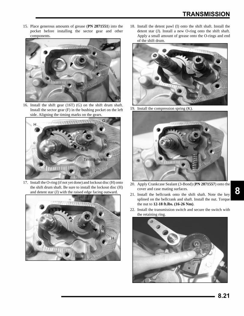
TRANSMISSION
8
15. Place generous amounts of grease (PN 2871551) into thepocket before installing the sector gear and othercomponents.
16. Install the shift gear (16T) (G) on the shift drum shaft.Install the sector gear (F) in the bushing pocket on the leftside. Aligning the timing marks on the gears.
17. Install the O-ring (if not yet done) and lockout disc (H) ontothe shift drum shaft. Be sure to install the lockout disc (H)and detent star (J) with the raised edge facing outward.
18. Install the detent pawl (I) onto the shift shaft. Install thedetent star (J). Install a new O-ring onto the shift shaft.Apply a small amount of grease onto the O-rings and endof the shift drum.
19. Install the compression spring (K).
20. Apply Crankcase Sealant (3-Bond) (PN 2871557) onto thecover and case mating surfaces.
21. Install the bellcrank onto the shift shaft. Note the keysplined on the bellcrank and shaft. Install the nut. Torquethe nut to 12-18 ft.lbs. (16-26 Nm).
22. Install the transmission switch and secure the switch withthe retaining ring.
GH
Timing marks
H
8.21

TRANSMISSION
NOTES
8.22
BRAKES
9.1
CHAPTER 9BRAKES
9
SPECIFICATIONS. . . . . . . . . . . . . . . . . . . . . . . . . . . . . . . . . . . . . . . . . . . . . . . . . . . . . . . 9.2TORQUE TABLE . . . . . . . . . . . . . . . . . . . . . . . . . . . . . . . . . . . . . . . . . . . . . . . . . . . . . . . 9.2COMPONENT SERVICE LIMITS . . . . . . . . . . . . . . . . . . . . . . . . . . . . . . . . . . . . . . . . . . . 9.2
BRAKE SYSTEM EXPLODED VIEWS . . . . . . . . . . . . . . . . . . . . . . . . . . . . . . . . . . . . . . . 9.3X2, TOURING SYSTEM COMPONENT EXPLODED VIEW . . . . . . . . . . . . . . . . . . . . . . 9.3SPORTSMAN SYSTEM COMPONENT EXPLODED VIEW . . . . . . . . . . . . . . . . . . . . . . 9.4
BRAKE CALIPER EXPLODED VIEWS . . . . . . . . . . . . . . . . . . . . . . . . . . . . . . . . . . . . . . . 9.5SPORTSMAN AND X2, TOURING FRONT CALIPER ASSEMBLY . . . . . . . . . . . . . . . . 9.5X2, TOURING REAR CALIPER ASSEMBLY . . . . . . . . . . . . . . . . . . . . . . . . . . . . . . . . . . 9.5SPORTSMAN REAR CALIPER ASSEMBLY . . . . . . . . . . . . . . . . . . . . . . . . . . . . . . . . . . 9.6
HYDRAULIC BRAKE SYSTEM . . . . . . . . . . . . . . . . . . . . . . . . . . . . . . . . . . . . . . . . . . . . . 9.6OPERATION OVERVIEW . . . . . . . . . . . . . . . . . . . . . . . . . . . . . . . . . . . . . . . . . . . . . . . . 9.6BRAKE NOISE TROUBLESHOOTING . . . . . . . . . . . . . . . . . . . . . . . . . . . . . . . . . . . . . . 9.7BRAKE BLEEDING / FLUID CHANGE. . . . . . . . . . . . . . . . . . . . . . . . . . . . . . . . . . . . . . . 9.7
FRONT MASTER CYLINDER . . . . . . . . . . . . . . . . . . . . . . . . . . . . . . . . . . . . . . . . . . . . . . 9.9REMOVAL . . . . . . . . . . . . . . . . . . . . . . . . . . . . . . . . . . . . . . . . . . . . . . . . . . . . . . . . . . . . 9.9INSTALLATION . . . . . . . . . . . . . . . . . . . . . . . . . . . . . . . . . . . . . . . . . . . . . . . . . . . . . . . . 9.9
FRONT BRAKES. . . . . . . . . . . . . . . . . . . . . . . . . . . . . . . . . . . . . . . . . . . . . . . . . . . . . . . 9.10PAD REMOVAL . . . . . . . . . . . . . . . . . . . . . . . . . . . . . . . . . . . . . . . . . . . . . . . . . . . . . . . 9.10ASSEMBLY . . . . . . . . . . . . . . . . . . . . . . . . . . . . . . . . . . . . . . . . . . . . . . . . . . . . . . . . . . 9.11BRAKE BURNISHING PROCEDURE . . . . . . . . . . . . . . . . . . . . . . . . . . . . . . . . . . . . . . 9.12
FRONT BRAKE DISC . . . . . . . . . . . . . . . . . . . . . . . . . . . . . . . . . . . . . . . . . . . . . . . . . . . 9.12INSPECTION . . . . . . . . . . . . . . . . . . . . . . . . . . . . . . . . . . . . . . . . . . . . . . . . . . . . . . . . . 9.12REMOVAL / REPLACEMENT . . . . . . . . . . . . . . . . . . . . . . . . . . . . . . . . . . . . . . . . . . . . 9.13
FRONT CALIPER . . . . . . . . . . . . . . . . . . . . . . . . . . . . . . . . . . . . . . . . . . . . . . . . . . . . . . 9.14REMOVAL . . . . . . . . . . . . . . . . . . . . . . . . . . . . . . . . . . . . . . . . . . . . . . . . . . . . . . . . . . . 9.14INSPECTION . . . . . . . . . . . . . . . . . . . . . . . . . . . . . . . . . . . . . . . . . . . . . . . . . . . . . . . . . 9.15REASSEMBLY . . . . . . . . . . . . . . . . . . . . . . . . . . . . . . . . . . . . . . . . . . . . . . . . . . . . . . . . 9.15INSTALLATION . . . . . . . . . . . . . . . . . . . . . . . . . . . . . . . . . . . . . . . . . . . . . . . . . . . . . . . 9.16
REAR BRAKE PAD . . . . . . . . . . . . . . . . . . . . . . . . . . . . . . . . . . . . . . . . . . . . . . . . . . . . . 9.17X2, TOURING PAD REMOVAL . . . . . . . . . . . . . . . . . . . . . . . . . . . . . . . . . . . . . . . . . . . 9.17X2, TOURING PAD INSTALLATION . . . . . . . . . . . . . . . . . . . . . . . . . . . . . . . . . . . . . . . 9.18SPORTSMAN REAR PAD REMOVAL . . . . . . . . . . . . . . . . . . . . . . . . . . . . . . . . . . . . . . 9.19SPORTSMAN REAR PAD INSTALLATION . . . . . . . . . . . . . . . . . . . . . . . . . . . . . . . . . . 9.20BRAKE BURNISHING PROCEDURE . . . . . . . . . . . . . . . . . . . . . . . . . . . . . . . . . . . . . . 9.20
X2, TOURING REAR CALIPER. . . . . . . . . . . . . . . . . . . . . . . . . . . . . . . . . . . . . . . . . . . . 9.21REMOVAL . . . . . . . . . . . . . . . . . . . . . . . . . . . . . . . . . . . . . . . . . . . . . . . . . . . . . . . . . . . 9.21INSPECTION . . . . . . . . . . . . . . . . . . . . . . . . . . . . . . . . . . . . . . . . . . . . . . . . . . . . . . . . . 9.22REASSEMBLY . . . . . . . . . . . . . . . . . . . . . . . . . . . . . . . . . . . . . . . . . . . . . . . . . . . . . . . . 9.22
SPORTSMAN REAR CALIPER. . . . . . . . . . . . . . . . . . . . . . . . . . . . . . . . . . . . . . . . . . . . 9.23REMOVAL AND INSPECTION. . . . . . . . . . . . . . . . . . . . . . . . . . . . . . . . . . . . . . . . . . . . 9.23ASSEMBLY . . . . . . . . . . . . . . . . . . . . . . . . . . . . . . . . . . . . . . . . . . . . . . . . . . . . . . . . . . 9.24
REAR BRAKE DISC . . . . . . . . . . . . . . . . . . . . . . . . . . . . . . . . . . . . . . . . . . . . . . . . . . . . 9.25INSPECTION . . . . . . . . . . . . . . . . . . . . . . . . . . . . . . . . . . . . . . . . . . . . . . . . . . . . . . . . . 9.25
REAR MASTER CYLINDER . . . . . . . . . . . . . . . . . . . . . . . . . . . . . . . . . . . . . . . . . . . . . . 9.26X2, TOURING EXPLODED VIEW . . . . . . . . . . . . . . . . . . . . . . . . . . . . . . . . . . . . . . . . . 9.26OVERVIEW. . . . . . . . . . . . . . . . . . . . . . . . . . . . . . . . . . . . . . . . . . . . . . . . . . . . . . . . . . . 9.27X2, TOURING REAR MASTER CYLINDER REMOVAL AND INSTALLATION. . . . . . . 9.27SPORTSMAN REAR MASTER CYLINDER REMOVAL / INSTALLATION . . . . . . . . . . 9.28PEDAL REMOVAL AND INSTALLATION . . . . . . . . . . . . . . . . . . . . . . . . . . . . . . . . . . . 9.29
TROUBLESHOOTING. . . . . . . . . . . . . . . . . . . . . . . . . . . . . . . . . . . . . . . . . . . . . . . . . . . 9.29
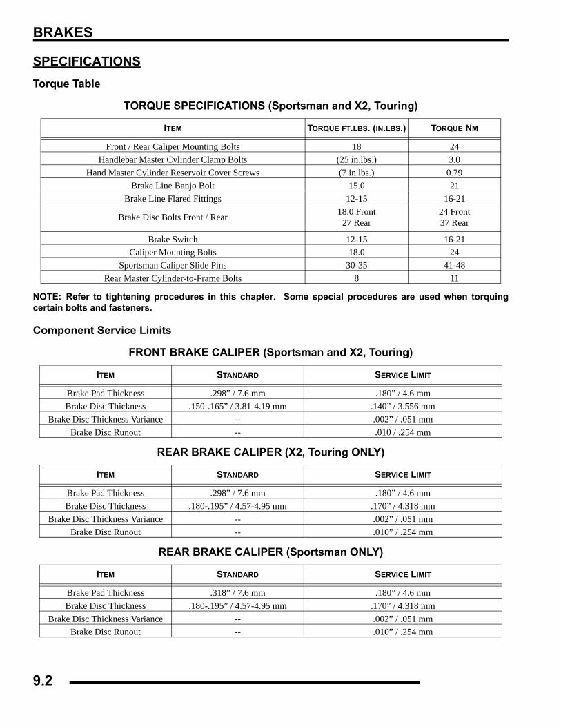
BRAKES
SPECIFICATIONSTorque Table
NOTE: Refer to tightening procedures in this chapter. Some special procedures are used when torquingcertain bolts and fasteners.
Component Service Limits
TORQUE SPECIFICATIONS (Sportsman and X2, Touring)
ITEM TORQUE FT.LBS. (IN.LBS.) TORQUE NM
Front / Rear Caliper Mounting Bolts 18 24Handlebar Master Cylinder Clamp Bolts (25 in.lbs.) 3.0
Hand Master Cylinder Reservoir Cover Screws (7 in.lbs.) 0.79Brake Line Banjo Bolt 15.0 21
Brake Line Flared Fittings 12-15 16-21
Brake Disc Bolts Front / Rear 18.0 Front27 Rear
24 Front37 Rear
Brake Switch 12-15 16-21Caliper Mounting Bolts 18.0 24
Sportsman Caliper Slide Pins 30-35 41-48Rear Master Cylinder-to-Frame Bolts 8 11
FRONT BRAKE CALIPER (Sportsman and X2, Touring)
ITEM STANDARD SERVICE LIMIT
Brake Pad Thickness .298” / 7.6 mm .180” / 4.6 mmBrake Disc Thickness .150-.165” / 3.81-4.19 mm .140” / 3.556 mm
Brake Disc Thickness Variance -- .002” / .051 mmBrake Disc Runout -- .010 / .254 mm
REAR BRAKE CALIPER (X2, Touring ONLY)
ITEM STANDARD SERVICE LIMIT
Brake Pad Thickness .298” / 7.6 mm .180” / 4.6 mmBrake Disc Thickness .180-.195” / 4.57-4.95 mm .170” / 4.318 mm
Brake Disc Thickness Variance -- .002” / .051 mmBrake Disc Runout -- .010” / .254 mm
REAR BRAKE CALIPER (Sportsman ONLY)
ITEM STANDARD SERVICE LIMIT
Brake Pad Thickness .318” / 7.6 mm .180” / 4.6 mmBrake Disc Thickness .180-.195” / 4.57-4.95 mm .170” / 4.318 mm
Brake Disc Thickness Variance -- .002” / .051 mmBrake Disc Runout -- .010” / .254 mm
9.2
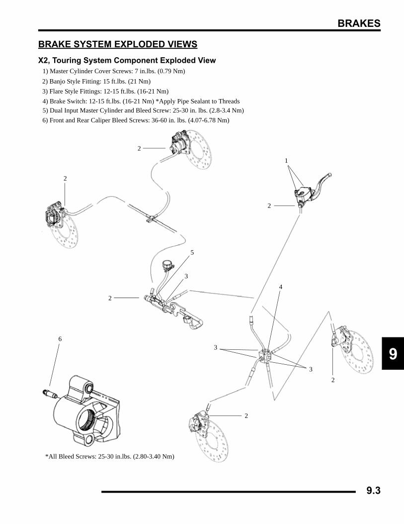
BRAKES
9
BRAKE SYSTEM EXPLODED VIEWSX2, Touring System Component Exploded View
1) Master Cylinder Cover Screws: 7 in.lbs. (0.79 Nm)2) Banjo Style Fitting: 15 ft.lbs. (21 Nm)3) Flare Style Fittings: 12-15 ft.lbs. (16-21 Nm)4) Brake Switch: 12-15 ft.lbs. (16-21 Nm) *Apply Pipe Sealant to Threads
2
2
1
2
2
3
3
2
2
34
*All Bleed Screws: 25-30 in.lbs. (2.80-3.40 Nm)
5) Dual Input Master Cylinder and Bleed Screw: 25-30 in. lbs. (2.8-3.4 Nm)6) Front and Rear Caliper Bleed Screws: 36-60 in. lbs. (4.07-6.78 Nm)
6
5
9.3
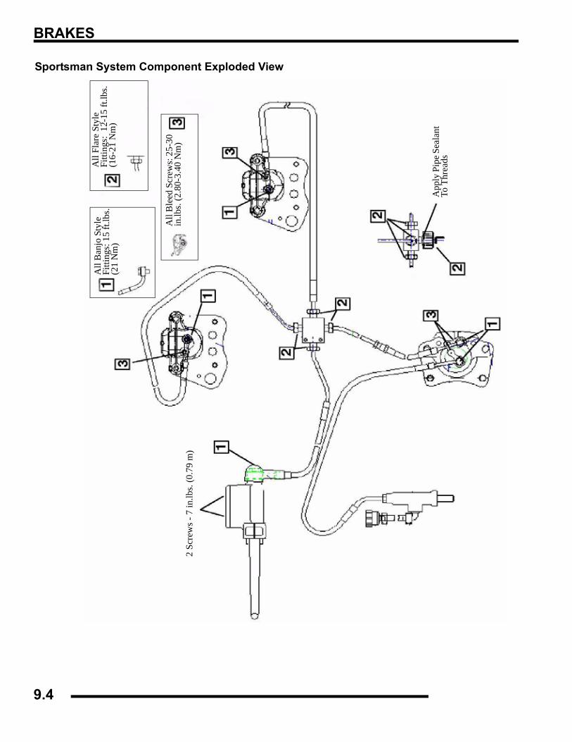
BRAKES
Sportsman System Component Exploded View
All
Ban
jo S
tyle
Fi
tting
s: 1
5 ft.
lbs.
(21
Nm
)
All
Flar
e St
yle
Fitti
ngs:
12-
15 ft
.lbs.
(16-
21 N
m)
All
Ble
ed S
crew
s: 2
5-30
in
.lbs.
(2.8
0-3.
40 N
m)
App
ly P
ipe S
eala
nt
To T
hrea
ds
2 Sc
rew
s - 7
in.lb
s. (0
.79
m)
9.4
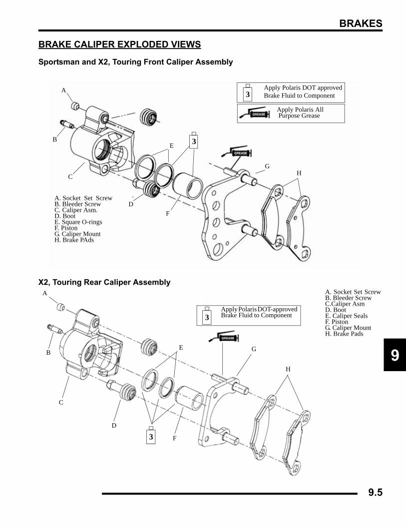
BRAKES
9
BRAKE CALIPER EXPLODED VIEWS
Sportsman and X2, Touring Front Caliper Assembly
X2, Touring Rear Caliper Assembly
A. Socket Set ScrewB. Bleeder Screw C. Caliper Asm. D. Boot E. Square O-rings F. Piston G. Caliper Mount H. Brake PAds
A
B
C
D
E
F
GH
Apply Polaris All Purpose Grease
3
3Apply Polaris DOT approved Brake Fluid to Component
A. Socket Set ScrewB. Bleeder Screw C.Caliper Asm D. Boot E. Caliper Seals F. Piston G. Caliper Mount H. Brake Pads
A
B
C
D
E
F
G
H
Apply Polaris DOT-approved Brake Fluid to Component3
3
9.5
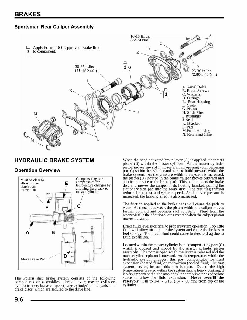
BRAKES
Sportsman Rear Caliper Assembly
HYDRAULIC BRAKE SYSTEMOperation Overview
The Polaris disc brake system consists of the followingcomponents or assemblies: brake lever; master cylinder;hydraulic hose; brake calipers (slave cylinder); brake pads; andbrake discs, which are secured to the drive line.
When the hand activated brake lever (A) is applied it contactspiston (B) within the master cylinder. As the master cylinderpiston moves inward it closes a small opening (compensatingport C) within the cylinder and starts to build pressure within thebrake system. As the pressure within the system is increased,the piston (D) located in the brake caliper moves outward andapplies pressure to the brake pad. This pad contacts the brakedisc and moves the caliper in its floating bracket, pulling thestationary side pad into the brake disc. The resulting frictionreduces brake disc and vehicle speed. As the lever pressure isincreased, the braking affect is also increased.
The friction applied to the brake pads will cause the pads towear. As these pads wear, the piston within the caliper movesfurther outward and becomes self adjusting. Fluid from thereservoir fills the additional area created when the caliper pistonmoves outward.
Brake fluid level is critical to proper system operation. Too littlefluid will allow air to enter the system and cause the brakes tofeel spongy. Too much fluid could cause brakes to drag due tofluid expansion.
Located within the master cylinder is the compensating port (C)which is opened and closed by the master cylinder pistonassembly. The port is open when the lever is released and themaster cylinder piston is outward. As the temperature within thehydraulic system changes, this port compensates for fluidexpansion (heated fluid) or contraction (cooled fluid). Duringsystem service, be sure this port is open. Due to the hightemperatures created within the system during heavy braking, itis very important that the master cylinder reservoir has adequatespace to allow for fluid expansion. Never overfill thereservoir! Fill to 1/4, - 5/16, (.64 - .80 cm) from top of thecylinder.
A. Anvil Bolts B. Bleed Screws C. Washers D. O-rings E. Rear Housing F. Seals G. Piston H. Slide Pins I. Bushings J. Seal K. Bracket L. Pad M.Front Housing N. Retaining Clips
3Apply Polaris DOT approved Brake fluidto component.
A
B
CD
E
F
GH
I
J
K
L
M
N
3
330-35 ft.lbs. (41-48 Nm) 25-30 in lbs.
(2.80-3.40 Nm)
16-18 ft.lbs. (22-24 Nm)
A B
C
D
E
F
Must be clear to allow proper diaphragm movement
Compensating port compensates for temperature changes by allowing fluid back to master cylinder
Move Brake Pad
9.6
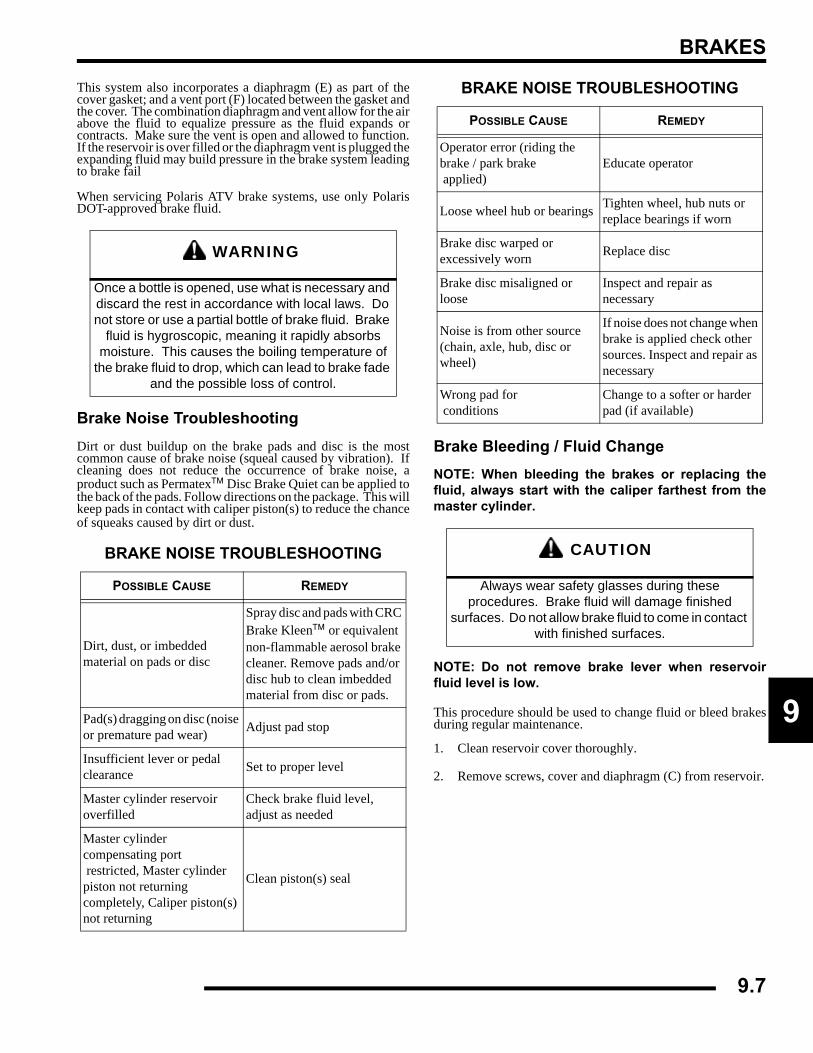
BRAKES
9
This system also incorporates a diaphragm (E) as part of thecover gasket; and a vent port (F) located between the gasket andthe cover. The combination diaphragm and vent allow for the airabove the fluid to equalize pressure as the fluid expands orcontracts. Make sure the vent is open and allowed to function.If the reservoir is over filled or the diaphragm vent is plugged theexpanding fluid may build pressure in the brake system leadingto brake fail
When servicing Polaris ATV brake systems, use only PolarisDOT-approved brake fluid.
Brake Noise TroubleshootingDirt or dust buildup on the brake pads and disc is the mostcommon cause of brake noise (squeal caused by vibration). Ifcleaning does not reduce the occurrence of brake noise, aproduct such as Permatex™ Disc Brake Quiet can be applied tothe back of the pads. Follow directions on the package. This willkeep pads in contact with caliper piston(s) to reduce the chanceof squeaks caused by dirt or dust.
Brake Bleeding / Fluid ChangeNOTE: When bleeding the brakes or replacing thefluid, always start with the caliper farthest from themaster cylinder.
NOTE: Do not remove brake lever when reservoirfluid level is low.
This procedure should be used to change fluid or bleed brakesduring regular maintenance.
1. Clean reservoir cover thoroughly.
2. Remove screws, cover and diaphragm (C) from reservoir.
WARNING
Once a bottle is opened, use what is necessary and discard the rest in accordance with local laws. Do not store or use a partial bottle of brake fluid. Brake
fluid is hygroscopic, meaning it rapidly absorbs moisture. This causes the boiling temperature of
the brake fluid to drop, which can lead to brake fade and the possible loss of control.
BRAKE NOISE TROUBLESHOOTING
POSSIBLE CAUSE REMEDY
Dirt, dust, or imbedded material on pads or disc
Spray disc and pads with CRC Brake Kleen™ or equivalent non-flammable aerosol brake cleaner. Remove pads and/or disc hub to clean imbedded material from disc or pads.
Pad(s) dragging on disc (noise or premature pad wear) Adjust pad stop
Insufficient lever or pedal clearance Set to proper level
Master cylinder reservoir overfilled
Check brake fluid level, adjust as needed
Master cylinder compensating port restricted, Master cylinder piston not returning completely, Caliper piston(s) not returning
Clean piston(s) seal
Operator error (riding the brake / park brake applied)
Educate operator
Loose wheel hub or bearings Tighten wheel, hub nuts or replace bearings if worn
Brake disc warped or excessively worn Replace disc
Brake disc misaligned or loose
Inspect and repair as necessary
Noise is from other source (chain, axle, hub, disc or wheel)
If noise does not change when brake is applied check other sources. Inspect and repair as necessary
Wrong pad for conditions
Change to a softer or harder pad (if available)
CAUTION
Always wear safety glasses during these procedures. Brake fluid will damage finished
surfaces. Do not allow brake fluid to come in contact with finished surfaces.
BRAKE NOISE TROUBLESHOOTING
POSSIBLE CAUSE REMEDY
9.7
BRAKES
3. Inspect vent slots (A) in cover and remove any debris orblockage.
4. If changing fluid, remove old fluid from reservoir with aMity Vac™ pump (PN 2870975) or similar tool.
5. Begin bleeding procedure with the caliper that is farthestfrom the master cylinder. Install a box end wrench oncaliper bleeder screw. Attach a clean, clear hose to fittingand place the other end in a clean container. Be sure thehose fits tightly on fitting.
NOTE: Fluid may be forced from supply port (B)when brake lever is pumped. Place diaphragm (C) inreservoir to prevent spills. Do not install cover. SeeIllustration above.
6. Slowly pump the brake lever until pressure builds andholds.
7. While maintaining lever pressure, open bleeder screw.Close bleeder screw and release brake lever.
NOTE: Do not release lever before bleeder screw istight or air may be drawn into caliper.
8. Repeat procedure until clean fluid appears in bleeder hoseand all air has been purged. Add fluid as necessary tomaintain level in reservoir.
9. Tighten bleeder screw securely and remove bleeder hose.Torque the bleeder screw to specification.
10. Repeat procedure Steps 5-9 for the remaining caliper(s).
11. Add Polaris DOT-approved Brake Fluid to MAX levelinside reservoir.
A
D
C
B
Sight Glass
Fill Line
Bleeder Screw
CAUTION
Maintain at least 1/2", (1.27 cm) of brake fluid in the reservoir to prevent air from
entering the master cylinder.
= T
Bleeder Screw Torque: 25-30 in.lbs. (2.80-3.40 Nm)
9.8
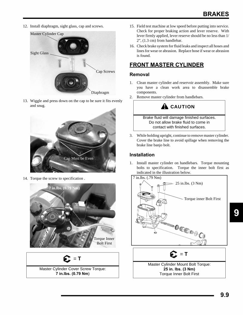
BRAKES
9
12. Install diaphragm, sight glass, cap and screws.
13. Wiggle and press down on the cap to be sure it fits evenlyand snug.
14. Torque the screw to specification .
15. Field test machine at low speed before putting into service.Check for proper braking action and lever reserve. Withlever firmly applied, lever reserve should be no less than 1/2”, (1.3 cm) from handlebar.
16. Check brake system for fluid leaks and inspect all hoses andlines for wear or abrasion. Replace hose if wear or abrasionis found.
FRONT MASTER CYLINDERRemoval1. Clean master cylinder and reservoir assembly. Make sure
you have a clean work area to disassemble brakecomponents.
2. Remove master cylinder from handlebars.
3. While holding upright, continue to remove master cylinder.Cover the brake line to avoid spillage when removing thebrake line banjo bolt.
Installation1. Install master cylinder on handlebars. Torque mounting
bolts to specification. Torque the inner bolt first asindicated in the illustration below.
= T
Master Cylinder Cover Screw Torque:7 in.lbs. (0.79 Nm)
Sight Glass
Master Cylinder Cap
Diaphragm
Cap Screws
Cap Must be Even
Torque Inner Bolt First
7 in.lbs. (0.79 Nm)
CAUTION
Brake fluid will damage finished surfaces. Do not allow brake fluid to come in
contact with finished surfaces.
= T
Master Cylinder Mount Bolt Torque:25 in. lbs. (3 Nm)
Torque Inner Bolt First
7 in.lbs. (.79 Nm)
Torque inner Bolt First
25 in.lbs. (3 Nm)
9.9
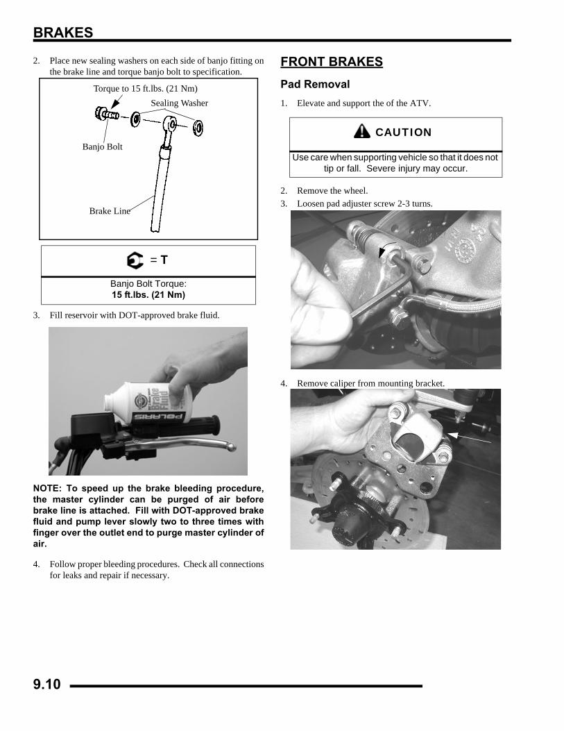
BRAKES
2. Place new sealing washers on each side of banjo fitting onthe brake line and torque banjo bolt to specification.
3. Fill reservoir with DOT-approved brake fluid.
NOTE: To speed up the brake bleeding procedure,the master cylinder can be purged of air beforebrake line is attached. Fill with DOT-approved brakefluid and pump lever slowly two to three times withfinger over the outlet end to purge master cylinder ofair.
4. Follow proper bleeding procedures. Check all connectionsfor leaks and repair if necessary.
FRONT BRAKESPad Removal1. Elevate and support the of the ATV.
2. Remove the wheel. 3. Loosen pad adjuster screw 2-3 turns.
4. Remove caliper from mounting bracket.
= T
Banjo Bolt Torque:15 ft.lbs. (21 Nm)
Torque to 15 ft.lbs. (21 Nm)
Banjo Bolt
Sealing Washer
Brake Line
CAUTION
Use care when supporting vehicle so that it does not tip or fall. Severe injury may occur.
9.10
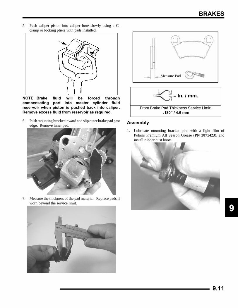
BRAKES
9
5. Push caliper piston into caliper bore slowly using a C-clamp or locking pliers with pads installed.
NOTE: Brake fluid will be forced throughcompensating port into master cylinder fluidreservoir when piston is pushed back into caliper.Remove excess fluid from reservoir as required.
6. Push mounting bracket inward and slip outer brake pad pastedge. Remove inner pad.
7. Measure the thickness of the pad material. Replace pads ifworn beyond the service limit.
Assembly1. Lubricate mounting bracket pins with a light film of
Polaris Premium All Season Grease (PN 2871423), andinstall rubber dust boots.
= In. / mm.
Front Brake Pad Thickness Service Limit: .180” / 4.6 mm
Measure Pad
9.11
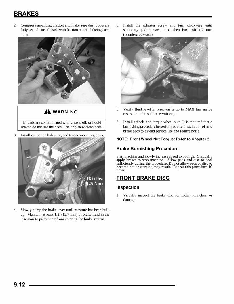
BRAKES
2. Compress mounting bracket and make sure dust boots arefully seated. Install pads with friction material facing eachother.
3. Install caliper on hub strut, and torque mounting bolts.
4. Slowly pump the brake lever until pressure has been builtup. Maintain at least 1/2, (12.7 mm) of brake fluid in thereservoir to prevent air from entering the brake system.
5. Install the adjuster screw and turn clockwise untilstationary pad contacts disc, then back off 1/2 turn(counterclockwise).
6. Verify fluid level in reservoir is up to MAX line insidereservoir and install reservoir cap.
7. Install wheels and torque wheel nuts. It is required that aburnishing procedure be performed after installation of newbrake pads to extend service life and reduce noise.
NOTE: Front Wheel Nut Torque: Refer to Chapter 2.
Brake Burnishing ProcedureStart machine and slowly increase speed to 30 mph. Graduallyapply brakes to stop machine. Allow pads and disc to coolsufficiently during the procedure. Do not allow pads or disc tobecome hot or warping may result. Repeat this procedure 10times.
FRONT BRAKE DISCInspection1. Visually inspect the brake disc for nicks, scratches, or
damage.
WARNING
If pads are contaminated with grease, oil, or liquid soaked do not use the pads. Use only new clean pads.
18 ft.lbs.(25 Nm)
9.12
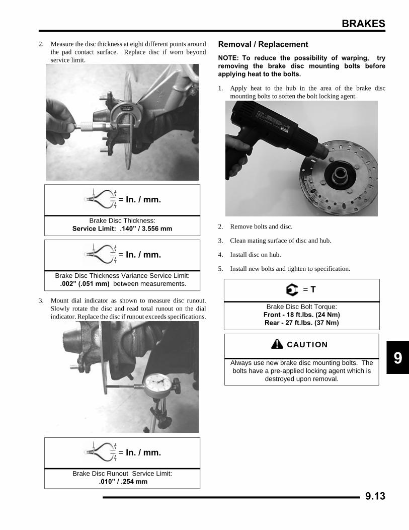
BRAKES
9
2. Measure the disc thickness at eight different points aroundthe pad contact surface. Replace disc if worn beyondservice limit.
3. Mount dial indicator as shown to measure disc runout.Slowly rotate the disc and read total runout on the dialindicator. Replace the disc if runout exceeds specifications.
Removal / ReplacementNOTE: To reduce the possibility of warping, tryremoving the brake disc mounting bolts beforeapplying heat to the bolts.
1. Apply heat to the hub in the area of the brake discmounting bolts to soften the bolt locking agent.
2. Remove bolts and disc.
3. Clean mating surface of disc and hub.
4. Install disc on hub.
5. Install new bolts and tighten to specification.
= In. / mm.
Brake Disc Thickness: Service Limit: .140” / 3.556 mm
= In. / mm.
Brake Disc Thickness Variance Service Limit: .002” (.051 mm) between measurements.
= In. / mm.
Brake Disc Runout Service Limit: .010” / .254 mm
= T
Brake Disc Bolt Torque:Front - 18 ft.lbs. (24 Nm)Rear - 27 ft.lbs. (37 Nm)
CAUTION
Always use new brake disc mounting bolts. The bolts have a pre-applied locking agent which is
destroyed upon removal.
9.13
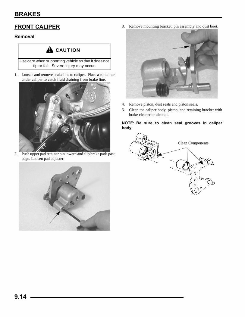
BRAKES
FRONT CALIPERRemoval
1. Loosen and remove brake line to caliper. Place a containerunder caliper to catch fluid draining from brake line.
2. Push upper pad retainer pin inward and slip brake pads pastedge. Loosen pad adjuster.
3. Remove mounting bracket, pin assembly and dust boot.
4. Remove piston, dust seals and piston seals.5. Clean the caliper body, piston, and retaining bracket with
brake cleaner or alcohol.
NOTE: Be sure to clean seal grooves in caliperbody.
CAUTION
Use care when supporting vehicle so that it does not tip or fall. Severe injury may occur.
Clean Components
9.14
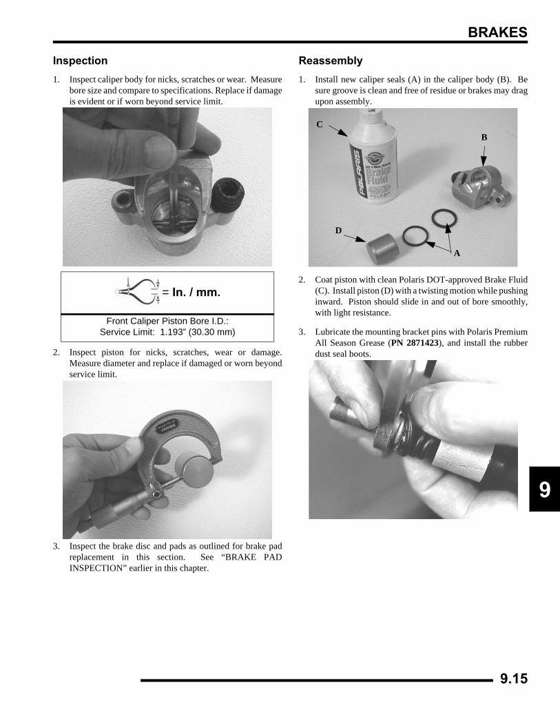
BRAKES
9
Inspection1. Inspect caliper body for nicks, scratches or wear. Measure
bore size and compare to specifications. Replace if damageis evident or if worn beyond service limit.
2. Inspect piston for nicks, scratches, wear or damage.Measure diameter and replace if damaged or worn beyondservice limit.
3. Inspect the brake disc and pads as outlined for brake padreplacement in this section. See “BRAKE PADINSPECTION” earlier in this chapter.
Reassembly1. Install new caliper seals (A) in the caliper body (B). Be
sure groove is clean and free of residue or brakes may dragupon assembly.
2. Coat piston with clean Polaris DOT-approved Brake Fluid(C). Install piston (D) with a twisting motion while pushinginward. Piston should slide in and out of bore smoothly,with light resistance.
3. Lubricate the mounting bracket pins with Polaris PremiumAll Season Grease (PN 2871423), and install the rubberdust seal boots.
= In. / mm.
Front Caliper Piston Bore I.D.:Service Limit: 1.193” (30.30 mm)
A
BC
D
9.15
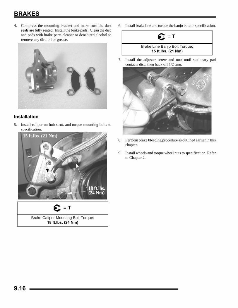
BRAKES
4. Compress the mounting bracket and make sure the dustseals are fully seated. Install the brake pads. Clean the discand pads with brake parts cleaner or denatured alcohol toremove any dirt, oil or grease.
Installation5. Install caliper on hub strut, and torque mounting bolts to
specification.
6. Install brake line and torque the banjo bolt to specification.
7. Install the adjuster screw and turn until stationary padcontacts disc, then back off 1/2 turn.
8. Perform brake bleeding procedure as outlined earlier in thischapter.
9. Install wheels and torque wheel nuts to specification. Referto Chapter 2.
= T
Brake Caliper Mounting Bolt Torque:18 ft.lbs. (24 Nm)
15 ft.lbs. (21 Nm)
18 ft.lbs.(24 Nm)
= T
Brake Line Banjo Bolt Torque:15 ft.lbs. (21 Nm)
9.16
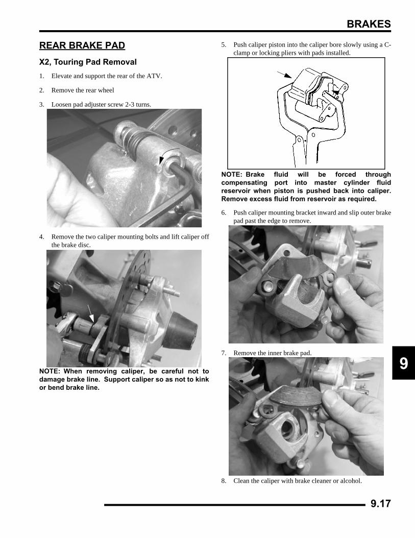
BRAKES
9
REAR BRAKE PADX2, Touring Pad Removal1. Elevate and support the rear of the ATV.
2. Remove the rear wheel
3. Loosen pad adjuster screw 2-3 turns.
4. Remove the two caliper mounting bolts and lift caliper offthe brake disc.
NOTE: When removing caliper, be careful not todamage brake line. Support caliper so as not to kinkor bend brake line.
5. Push caliper piston into the caliper bore slowly using a C-clamp or locking pliers with pads installed.
NOTE: Brake fluid will be forced throughcompensating port into master cylinder fluidreservoir when piston is pushed back into caliper.Remove excess fluid from reservoir as required.
6. Push caliper mounting bracket inward and slip outer brakepad past the edge to remove.
7. Remove the inner brake pad.
8. Clean the caliper with brake cleaner or alcohol.
9.17
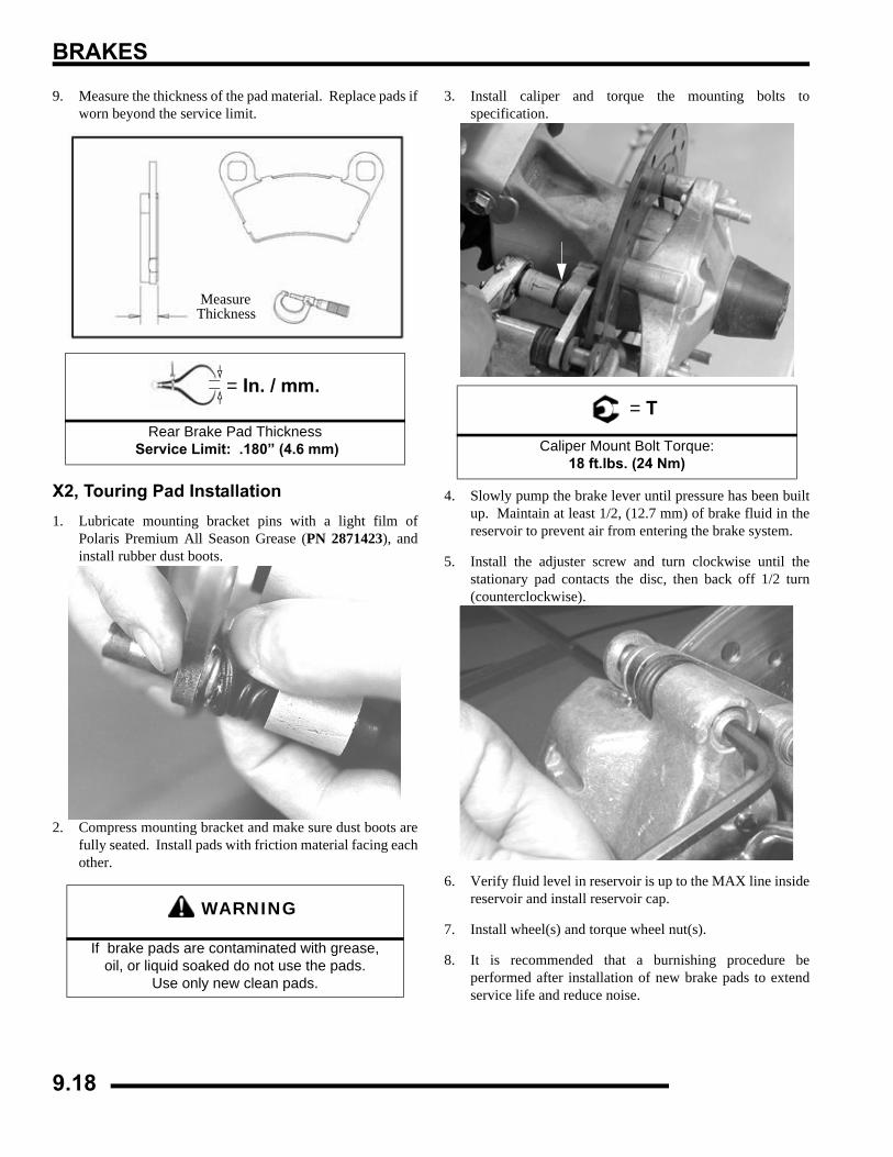
BRAKES
9. Measure the thickness of the pad material. Replace pads ifworn beyond the service limit.
X2, Touring Pad Installation1. Lubricate mounting bracket pins with a light film of
Polaris Premium All Season Grease (PN 2871423), andinstall rubber dust boots.
2. Compress mounting bracket and make sure dust boots arefully seated. Install pads with friction material facing eachother.
3. Install caliper and torque the mounting bolts tospecification.
4. Slowly pump the brake lever until pressure has been builtup. Maintain at least 1/2, (12.7 mm) of brake fluid in thereservoir to prevent air from entering the brake system.
5. Install the adjuster screw and turn clockwise until thestationary pad contacts the disc, then back off 1/2 turn(counterclockwise).
6. Verify fluid level in reservoir is up to the MAX line insidereservoir and install reservoir cap.
7. Install wheel(s) and torque wheel nut(s).
8. It is recommended that a burnishing procedure beperformed after installation of new brake pads to extendservice life and reduce noise.
= In. / mm.
Rear Brake Pad Thickness Service Limit: .180” (4.6 mm)
WARNING
If brake pads are contaminated with grease, oil, or liquid soaked do not use the pads.
Use only new clean pads.
MeasureThickness
= T
Caliper Mount Bolt Torque:18 ft.lbs. (24 Nm)
9.18
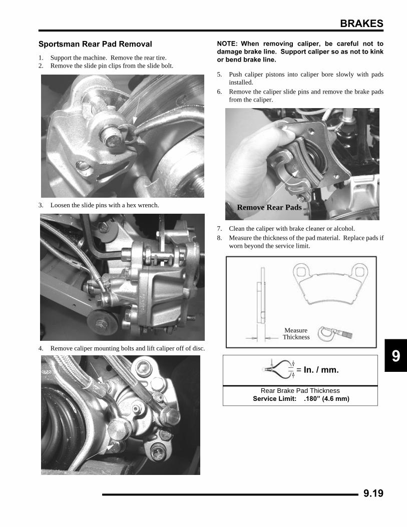
BRAKES
9
Sportsman Rear Pad Removal1. Support the machine. Remove the rear tire.2. Remove the slide pin clips from the slide bolt.
3. Loosen the slide pins with a hex wrench.
4. Remove caliper mounting bolts and lift caliper off of disc.
NOTE: When removing caliper, be careful not todamage brake line. Support caliper so as not to kinkor bend brake line.
5. Push caliper pistons into caliper bore slowly with padsinstalled.
6. Remove the caliper slide pins and remove the brake padsfrom the caliper.
7. Clean the caliper with brake cleaner or alcohol.8. Measure the thickness of the pad material. Replace pads if
worn beyond the service limit.
= In. / mm.
Rear Brake Pad Thickness Service Limit: .180” (4.6 mm)
Remove Rear Pads
MeasureThickness
9.19
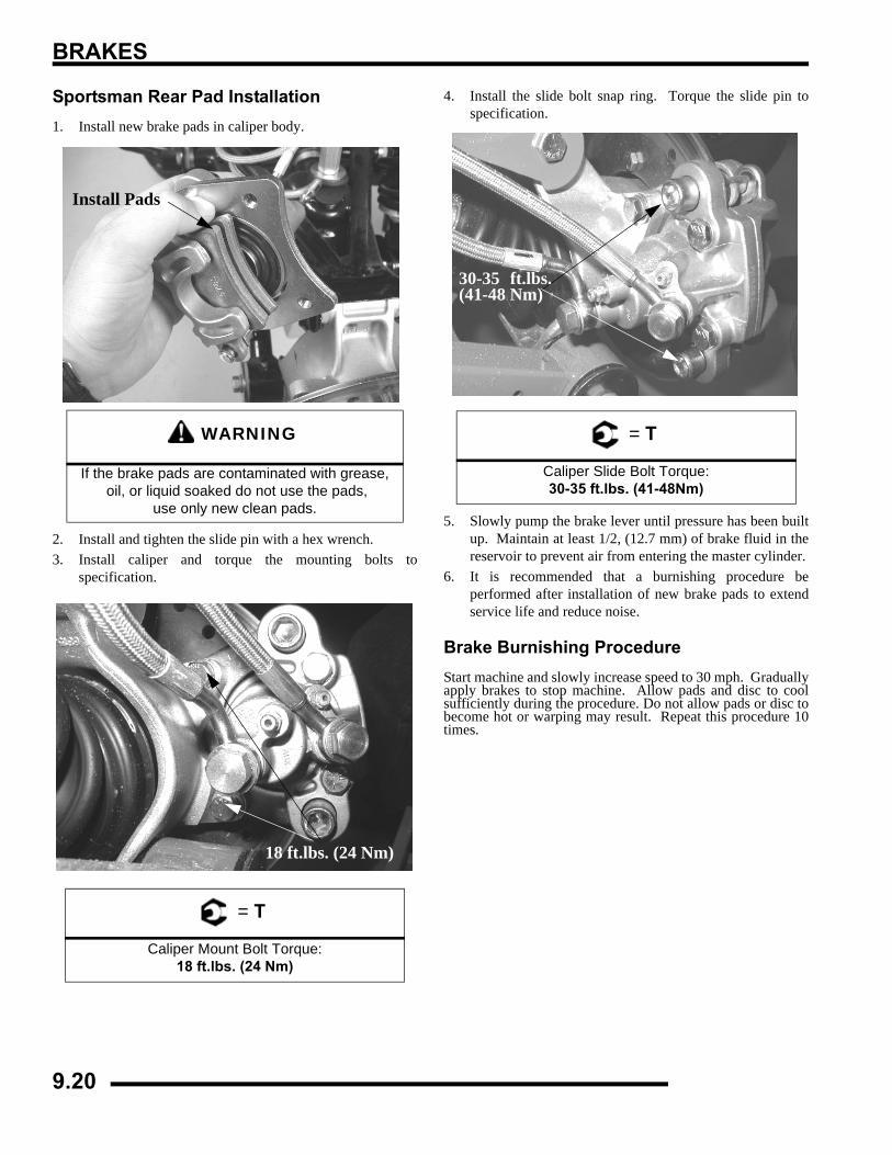
BRAKES
Sportsman Rear Pad Installation1. Install new brake pads in caliper body.
2. Install and tighten the slide pin with a hex wrench.3. Install caliper and torque the mounting bolts to
specification.
4. Install the slide bolt snap ring. Torque the slide pin tospecification.
5. Slowly pump the brake lever until pressure has been builtup. Maintain at least 1/2, (12.7 mm) of brake fluid in thereservoir to prevent air from entering the master cylinder.
6. It is recommended that a burnishing procedure beperformed after installation of new brake pads to extendservice life and reduce noise.
Brake Burnishing ProcedureStart machine and slowly increase speed to 30 mph. Graduallyapply brakes to stop machine. Allow pads and disc to coolsufficiently during the procedure. Do not allow pads or disc tobecome hot or warping may result. Repeat this procedure 10times.
WARNING
If the brake pads are contaminated with grease, oil, or liquid soaked do not use the pads,
use only new clean pads.
= T
Caliper Mount Bolt Torque:18 ft.lbs. (24 Nm)
Install Pads
18 ft.lbs. (24 Nm)
= T
Caliper Slide Bolt Torque:30-35 ft.lbs. (41-48Nm)
30-35 ft.lbs.(41-48 Nm)
9.20
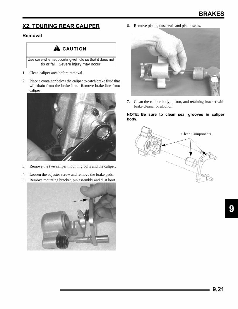
BRAKES
9
X2, TOURING REAR CALIPERRemoval
1. Clean caliper area before removal.
2. Place a container below the caliper to catch brake fluid thatwill drain from the brake line. Remove brake line fromcaliper
3. Remove the two caliper mounting bolts and the caliper.
4. Loosen the adjuster screw and remove the brake pads.5. Remove mounting bracket, pin assembly and dust boot.
6. Remove piston, dust seals and piston seals.
7. Clean the caliper body, piston, and retaining bracket withbrake cleaner or alcohol.
NOTE: Be sure to clean seal grooves in caliperbody.
CAUTION
Use care when supporting vehicle so that it does not tip or fall. Severe injury may occur.
Clean Components
9.21
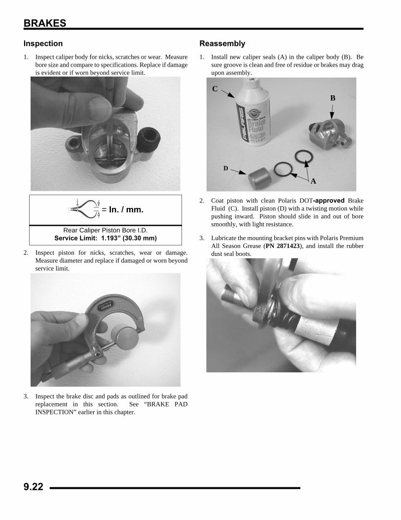
BRAKES
Inspection1. Inspect caliper body for nicks, scratches or wear. Measure
bore size and compare to specifications. Replace if damageis evident or if worn beyond service limit.
2. Inspect piston for nicks, scratches, wear or damage.Measure diameter and replace if damaged or worn beyondservice limit.
3. Inspect the brake disc and pads as outlined for brake padreplacement in this section. See “BRAKE PADINSPECTION” earlier in this chapter.
Reassembly1. Install new caliper seals (A) in the caliper body (B). Be
sure groove is clean and free of residue or brakes may dragupon assembly.
2. Coat piston with clean Polaris DOT-approved BrakeFluid (C). Install piston (D) with a twisting motion whilepushing inward. Piston should slide in and out of boresmoothly, with light resistance.
3. Lubricate the mounting bracket pins with Polaris PremiumAll Season Grease (PN 2871423), and install the rubberdust seal boots.
= In. / mm.
Rear Caliper Piston Bore I.D.Service Limit: 1.193” (30.30 mm)
A
BC
D
9.22
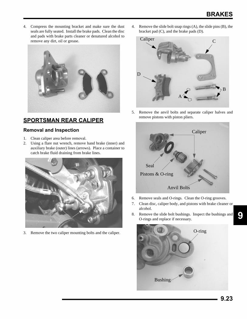
BRAKES
9
4. Compress the mounting bracket and make sure the dustseals are fully seated. Install the brake pads. Clean the discand pads with brake parts cleaner or denatured alcohol toremove any dirt, oil or grease.
SPORTSMAN REAR CALIPERRemoval and Inspection1. Clean caliper area before removal.2. Using a flare nut wrench, remove hand brake (inner) and
auxiliary brake (outer) lines (arrows). Place a container tocatch brake fluid draining from brake lines.
3. Remove the two caliper mounting bolts and the caliper.
4. Remove the slide bolt snap rings (A), the slide pins (B), thebracket pad (C), and the brake pads (D).
5. Remove the anvil bolts and separate caliper halves andremove pistons with piston pliers.
6. Remove seals and O-rings. Clean the O-ring grooves.7. Clean disc, caliper body, and pistons with brake cleaner or
alcohol.8. Remove the slide bolt bushings. Inspect the bushings and
O-rings and replace if necessary.
Caliper C
B
D
A
Caliper
Seal
Pistons & O-ring
Anvil Bolts
O-ring
Bushing
9.23
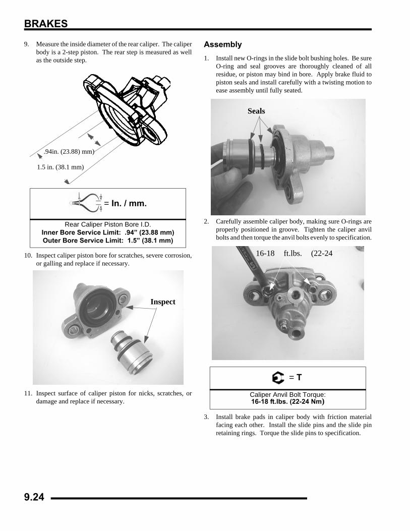
BRAKES
9. Measure the inside diameter of the rear caliper. The caliperbody is a 2-step piston. The rear step is measured as wellas the outside step.
10. Inspect caliper piston bore for scratches, severe corrosion,or galling and replace if necessary.
11. Inspect surface of caliper piston for nicks, scratches, ordamage and replace if necessary.
Assembly1. Install new O-rings in the slide bolt bushing holes. Be sure
O-ring and seal grooves are thoroughly cleaned of allresidue, or piston may bind in bore. Apply brake fluid topiston seals and install carefully with a twisting motion toease assembly until fully seated.
2. Carefully assemble caliper body, making sure O-rings areproperly positioned in groove. Tighten the caliper anvilbolts and then torque the anvil bolts evenly to specification.
3. Install brake pads in caliper body with friction materialfacing each other. Install the slide pins and the slide pinretaining rings. Torque the slide pins to specification.
= In. / mm.
Rear Caliper Piston Bore I.D.Inner Bore Service Limit: .94” (23.88 mm)Outer Bore Service Limit: 1.5” (38.1 mm)
.94in. (23.88) mm)
1.5 in. (38.1 mm)
Inspect
= T
Caliper Anvil Bolt Torque:16-18 ft.lbs. (22-24 Nm)
Seals
16-18 ft.lbs. (22-24
9.24
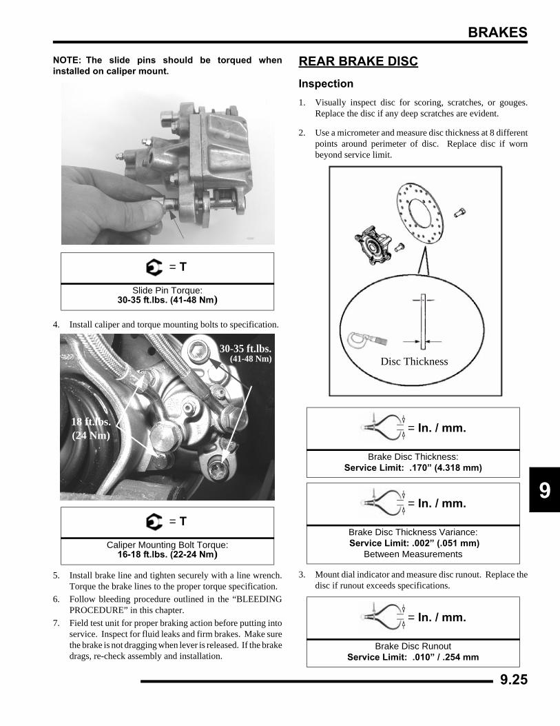
BRAKES
9
NOTE: The slide pins should be torqued wheninstalled on caliper mount.
4. Install caliper and torque mounting bolts to specification.
5. Install brake line and tighten securely with a line wrench.Torque the brake lines to the proper torque specification.
6. Follow bleeding procedure outlined in the “BLEEDINGPROCEDURE” in this chapter.
7. Field test unit for proper braking action before putting intoservice. Inspect for fluid leaks and firm brakes. Make surethe brake is not dragging when lever is released. If the brakedrags, re-check assembly and installation.
REAR BRAKE DISCInspection1. Visually inspect disc for scoring, scratches, or gouges.
Replace the disc if any deep scratches are evident.
2. Use a micrometer and measure disc thickness at 8 differentpoints around perimeter of disc. Replace disc if wornbeyond service limit.
3. Mount dial indicator and measure disc runout. Replace thedisc if runout exceeds specifications.
= T
Slide Pin Torque:30-35 ft.lbs. (41-48 Nm)
= T
Caliper Mounting Bolt Torque:16-18 ft.lbs. (22-24 Nm)
18 ft.lbs.(24 Nm)
30-35 ft.lbs.(41-48 Nm)
= In. / mm.
Brake Disc Thickness: Service Limit: .170” (4.318 mm)
= In. / mm.
Brake Disc Thickness Variance: Service Limit: .002” (.051 mm)
Between Measurements
= In. / mm.
Brake Disc Runout Service Limit: .010” / .254 mm
Disc Thickness
9.25
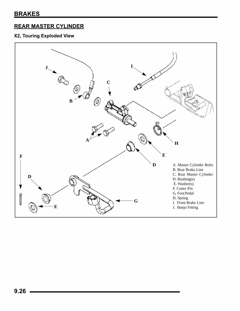
BRAKES
REAR MASTER CYLINDERX2, Touring Exploded View
A
B
D
EF
G
I
H
C
D
E
J
A. Master Cylinder BoltsB. Rear Brake Line C. Rear Master CylinderD. Bushing(s) E. Washer(s) F. Cotter Pin G. Foot Pedal H. Spring I. Front Brake Line J. Banjo Fitting
9.26
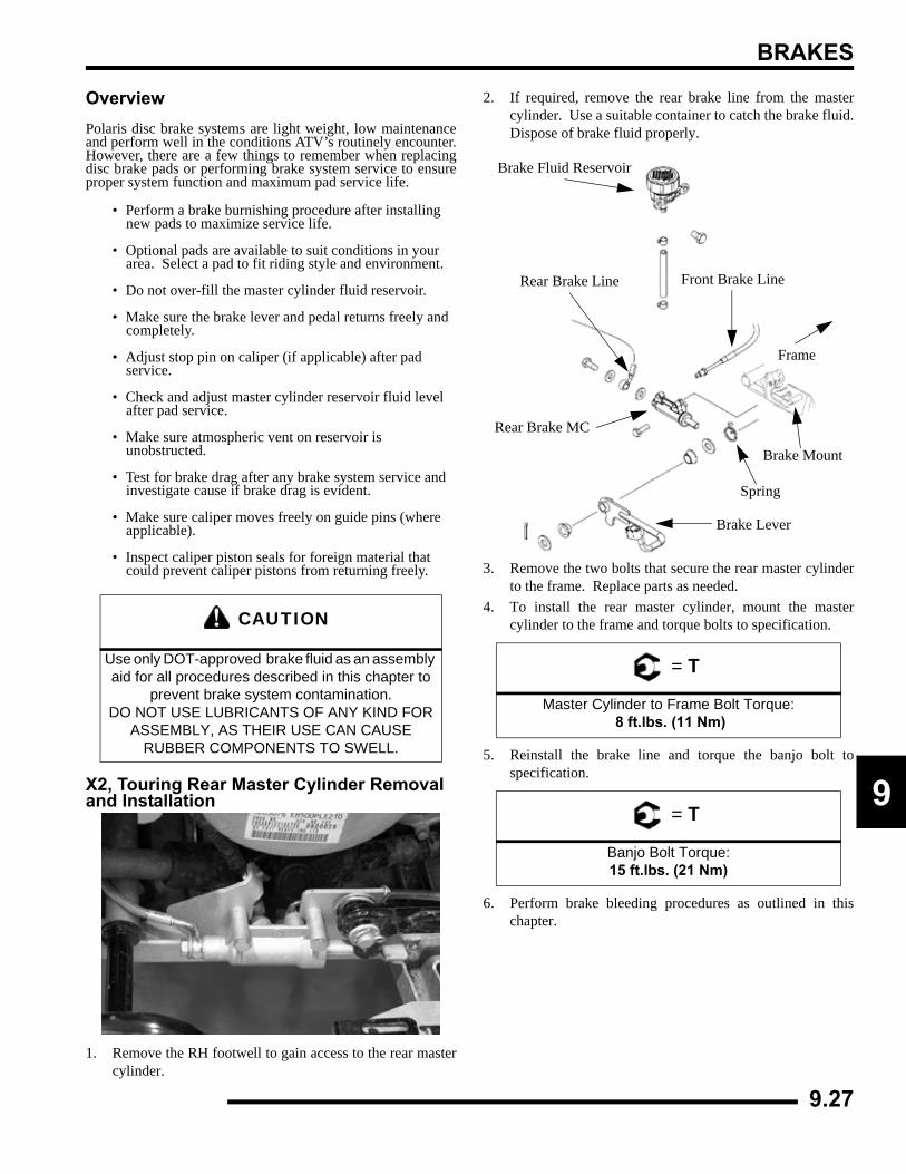
BRAKES
9
OverviewPolaris disc brake systems are light weight, low maintenanceand perform well in the conditions ATV’s routinely encounter.However, there are a few things to remember when replacingdisc brake pads or performing brake system service to ensureproper system function and maximum pad service life.
• Perform a brake burnishing procedure after installing new pads to maximize service life.
• Optional pads are available to suit conditions in your area. Select a pad to fit riding style and environment.
• Do not over-fill the master cylinder fluid reservoir.
• Make sure the brake lever and pedal returns freely and completely.
• Adjust stop pin on caliper (if applicable) after pad service.
• Check and adjust master cylinder reservoir fluid level after pad service.
• Make sure atmospheric vent on reservoir is unobstructed.
• Test for brake drag after any brake system service and investigate cause if brake drag is evident.
• Make sure caliper moves freely on guide pins (where applicable).
• Inspect caliper piston seals for foreign material that could prevent caliper pistons from returning freely.
X2, Touring Rear Master Cylinder Removal and Installation
1. Remove the RH footwell to gain access to the rear mastercylinder.
2. If required, remove the rear brake line from the mastercylinder. Use a suitable container to catch the brake fluid.Dispose of brake fluid properly.
3. Remove the two bolts that secure the rear master cylinderto the frame. Replace parts as needed.
4. To install the rear master cylinder, mount the mastercylinder to the frame and torque bolts to specification.
5. Reinstall the brake line and torque the banjo bolt tospecification.
6. Perform brake bleeding procedures as outlined in thischapter.
CAUTION
Use only DOT-approved brake fluid as an assembly aid for all procedures described in this chapter to
prevent brake system contamination. DO NOT USE LUBRICANTS OF ANY KIND FOR
ASSEMBLY, AS THEIR USE CAN CAUSE RUBBER COMPONENTS TO SWELL.
= T
Master Cylinder to Frame Bolt Torque: 8 ft.lbs. (11 Nm)
= T
Banjo Bolt Torque:15 ft.lbs. (21 Nm)
Frame
Brake Fluid Reservoir
Brake Lever
Front Brake Line
Brake Mount
Rear Brake Line
Spring
Rear Brake MC
9.27
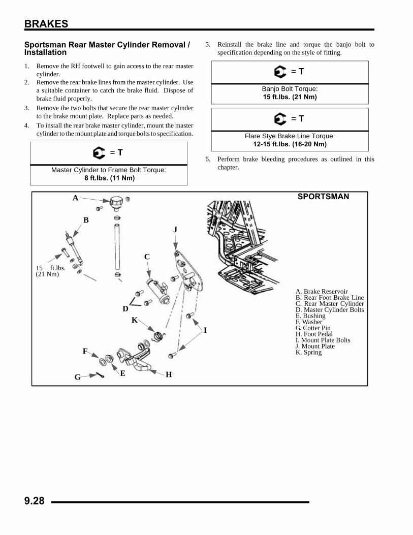
BRAKES
Sportsman Rear Master Cylinder Removal / Installation1. Remove the RH footwell to gain access to the rear master
cylinder.2. Remove the rear brake lines from the master cylinder. Use
a suitable container to catch the brake fluid. Dispose ofbrake fluid properly.
3. Remove the two bolts that secure the rear master cylinderto the brake mount plate. Replace parts as needed.
4. To install the rear brake master cylinder, mount the mastercylinder to the mount plate and torque bolts to specification.
5. Reinstall the brake line and torque the banjo bolt tospecification depending on the style of fitting.
6. Perform brake bleeding procedures as outlined in thischapter.
= T
Master Cylinder to Frame Bolt Torque: 8 ft.lbs. (11 Nm)
= T
Banjo Bolt Torque:15 ft.lbs. (21 Nm)
= T
Flare Stye Brake Line Torque:12-15 ft.lbs. (16-20 Nm)
15 ft.lbs.(21 Nm)
A. Brake Reservoir B. Rear Foot Brake LineC. Rear Master CylinderD. Master Cylinder BoltsE. Bushing F. Washer G. Cotter Pin H. Foot Pedal I. Mount Plate Bolts J. Mount Plate K. Spring
A
B
C
D
E
F
G H
I
J
K
SPORTSMAN
9.28

BRAKES
9
Pedal Removal and Installation
1. Remove the RH footwell to gain access to the rear mastercylinder.
2. Remove the cotter key.
3. Remove the washers, bushings, and tension spring.
4. Reverse the steps for installation, use a new cotter keyduring installation.
TROUBLESHOOTINGBrakes Squeal
• Dirty/contaminated friction pads
• Improper alignment
• Worn disc
• Worn disc splines
Poor Brake Performance• Air in system
• Water in system (brake fluid contaminated)
• Caliper/disc misaligned
• Caliper dirty or damaged
• Brake line damaged or lining ruptured
• Worn disc and/or friction pads
• Incorrectly adjusted lever
• Incorrectly adjusted stationary pad
• Worn or damaged master cylinder or components
• Improper clearance between lever and switch
Lever Vibration• Disc damaged
• Disc worn (runout or thickness variance exceeds service limit)
Caliper Overheats (Brakes Drag)• Compensating port plugged
• Pad clearance set incorrectly
• Auxiliary brake pedal incorrectly adjusted
• Brake lever or pedal binding or unable to return fully
• Parking brake left on
• Residue build up under caliper seals
• Operator riding brakes
Brakes Lock
• Alignment of caliper to disc
X2, Touring Shown
9.29

BRAKES
NOTES
9.30
ELECTRICAL
0.1
CHAPTER 10ELECTRICAL
10
1
GENERAL INFORMATION . . . . . . . . . . . . . . . . . . . . . . . . . . . . . . . . . . . . . . . . . . . . . . . 10.3SPECIAL TOOLS . . . . . . . . . . . . . . . . . . . . . . . . . . . . . . . . . . . . . . . . . . . . . . . . . . . . . . 10.3IGNITION SYSTEM / BASIC ELECTRICAL COMPONENTS . . . . . . . . . . . . . . . . . . . . 10.3ELECTRICAL SERVICE NOTES . . . . . . . . . . . . . . . . . . . . . . . . . . . . . . . . . . . . . . . . . . 10.4TROUBLESHOOTING . . . . . . . . . . . . . . . . . . . . . . . . . . . . . . . . . . . . . . . . . . . . . . . . . . 10.4
POWER DISTRIBUTION MODULE (PDM) . . . . . . . . . . . . . . . . . . . . . . . . . . . . . . . . . . . 10.5SPORTSMAN 500 CARBURETED OVERVIEW . . . . . . . . . . . . . . . . . . . . . . . . . . . . . . 10.5
INSTRUMENT CLUSTER . . . . . . . . . . . . . . . . . . . . . . . . . . . . . . . . . . . . . . . . . . . . . . . . 10.8OVERVIEW. . . . . . . . . . . . . . . . . . . . . . . . . . . . . . . . . . . . . . . . . . . . . . . . . . . . . . . . . . . 10.8INSTRUMENT CLUSTER DIAGNOSTIC MODE . . . . . . . . . . . . . . . . . . . . . . . . . . . . . . 10.9SETTING A NEW SERVICE INTERVAL . . . . . . . . . . . . . . . . . . . . . . . . . . . . . . . . . . . 10.11EFI DIAGNOSTIC MODE . . . . . . . . . . . . . . . . . . . . . . . . . . . . . . . . . . . . . . . . . . . . . . . 10.12SPEEDOMETER REMOVAL . . . . . . . . . . . . . . . . . . . . . . . . . . . . . . . . . . . . . . . . . . . . 10.13SPEEDOMETER INSTALLATION . . . . . . . . . . . . . . . . . . . . . . . . . . . . . . . . . . . . . . . . 10.13
ALL WHEEL DRIVE AND SPEEDOMETER TROUBLESHOOTING . . . . . . . . . . . . . . 10.14TEST 1 - NO ALL WHEEL DRIVE . . . . . . . . . . . . . . . . . . . . . . . . . . . . . . . . . . . . . . . . 10.14TEST 2 - NO SPEEDOMETER DISPLAY . . . . . . . . . . . . . . . . . . . . . . . . . . . . . . . . . . 10.15TEST 3 - NO REVERSE SPEED LIMIT . . . . . . . . . . . . . . . . . . . . . . . . . . . . . . . . . . . . 10.15TEST 4 - NO AWD HUB SAFETY LIMIT . . . . . . . . . . . . . . . . . . . . . . . . . . . . . . . . . . . 10.16TEST 5 - REVERSE SPEED LIMITER ACTIVATED IN FORWARD GEAR . . . . . . . . 10.17TEST 6 - WHEEL SPEED SENSOR . . . . . . . . . . . . . . . . . . . . . . . . . . . . . . . . . . . . . . 10.17TEST 7 - FUEL GAUGE DISPLAY NOT WORKING . . . . . . . . . . . . . . . . . . . . . . . . . . 10.18TEST 8 - SHIFT INDICATOR NOT WORKING . . . . . . . . . . . . . . . . . . . . . . . . . . . . . . 10.18
ACTIVE DESCENT CONTROL (ADC) COIL. . . . . . . . . . . . . . . . . . . . . . . . . . . . . . . . . 10.19OPERATION OVERVIEW - EFI ONLY. . . . . . . . . . . . . . . . . . . . . . . . . . . . . . . . . . . . . 10.19DIAGNOSING SYSTEM FAILURES. . . . . . . . . . . . . . . . . . . . . . . . . . . . . . . . . . . . . . . 10.19
ALL WHEEL DRIVE (AWD) COIL . . . . . . . . . . . . . . . . . . . . . . . . . . . . . . . . . . . . . . . . . 10.19OPERATION OVERVIEW . . . . . . . . . . . . . . . . . . . . . . . . . . . . . . . . . . . . . . . . . . . . . . 10.19DIAGNOSING SYSTEM FAILURES. . . . . . . . . . . . . . . . . . . . . . . . . . . . . . . . . . . . . . . 10.19
COOLING SYSTEM COMPONENTS . . . . . . . . . . . . . . . . . . . . . . . . . . . . . . . . . . . . . . 10.20FAN CONTROL CIRCUIT OPERATION . . . . . . . . . . . . . . . . . . . . . . . . . . . . . . . . . . . 10.20FAN CONTROL BYPASS TEST. . . . . . . . . . . . . . . . . . . . . . . . . . . . . . . . . . . . . . . . . . 10.20FAN MOTOR CURRENT DRAW TEST . . . . . . . . . . . . . . . . . . . . . . . . . . . . . . . . . . . . 10.20COOLANT TEMPERATURE SENSOR . . . . . . . . . . . . . . . . . . . . . . . . . . . . . . . . . . . . 10.21
GEAR POSITION INDICATOR SWITCH. . . . . . . . . . . . . . . . . . . . . . . . . . . . . . . . . . . . 10.21TEST DIAGRAM. . . . . . . . . . . . . . . . . . . . . . . . . . . . . . . . . . . . . . . . . . . . . . . . . . . . . . 10.21
ELECTRONIC THROTTLE CONTROL (ETC) SWITCH . . . . . . . . . . . . . . . . . . . . . . . . 10.22OPERATION OVERVIEW . . . . . . . . . . . . . . . . . . . . . . . . . . . . . . . . . . . . . . . . . . . . . . 10.22ETC TEST. . . . . . . . . . . . . . . . . . . . . . . . . . . . . . . . . . . . . . . . . . . . . . . . . . . . . . . . . . . 10.22
IGNITION SYSTEM . . . . . . . . . . . . . . . . . . . . . . . . . . . . . . . . . . . . . . . . . . . . . . . . . . . . 10.23OVERVIEW. . . . . . . . . . . . . . . . . . . . . . . . . . . . . . . . . . . . . . . . . . . . . . . . . . . . . . . . . . 10.23COMPONENTS OF ALTERNATOR AND DC / CDI IGNITION SYSTEM . . . . . . . . . . 10.24EFI IGNITION SYSTEM TESTING FLOW CHART . . . . . . . . . . . . . . . . . . . . . . . . . . . 10.25CRANKSHAFT POSITION SENSOR GAP. . . . . . . . . . . . . . . . . . . . . . . . . . . . . . . . . . 10.26IGNITION TROUBLESHOOTING. . . . . . . . . . . . . . . . . . . . . . . . . . . . . . . . . . . . . . . . . 10.26IGNITION OUTPUT TEST USING GAP TESTER . . . . . . . . . . . . . . . . . . . . . . . . . . . . 10.26
CHARGING SYSTEM . . . . . . . . . . . . . . . . . . . . . . . . . . . . . . . . . . . . . . . . . . . . . . . . . . 10.27CURRENT DRAW - KEY OFF . . . . . . . . . . . . . . . . . . . . . . . . . . . . . . . . . . . . . . . . . . . 10.27BREAK EVEN TEST. . . . . . . . . . . . . . . . . . . . . . . . . . . . . . . . . . . . . . . . . . . . . . . . . . . 10.27ALTERNATOR OUTPUT TEST . . . . . . . . . . . . . . . . . . . . . . . . . . . . . . . . . . . . . . . . . . 10.28CHARGING SYSTEM TESTING DIAGRAMS . . . . . . . . . . . . . . . . . . . . . . . . . . . . . . . 10.29
RELAYS. . . . . . . . . . . . . . . . . . . . . . . . . . . . . . . . . . . . . . . . . . . . . . . . . . . . . . . . . . . . . 10.31OPERATION - EFI MODELS . . . . . . . . . . . . . . . . . . . . . . . . . . . . . . . . . . . . . . . . . . . . 10.31
FUSES/CIRCUIT BREAKER . . . . . . . . . . . . . . . . . . . . . . . . . . . . . . . . . . . . . . . . . . . . . 10.32OPERATION - EFI MODELS . . . . . . . . . . . . . . . . . . . . . . . . . . . . . . . . . . . . . . . . . . . . 10.32
ELECTRICAL
DIFFERENTIAL SOLENOID . . . . . . . . . . . . . . . . . . . . . . . . . . . . . . . . . . . . . . . . . . . . . 10.32OVERVIEW - X2 AND TOURING. . . . . . . . . . . . . . . . . . . . . . . . . . . . . . . . . . . . . . . . . 10.32TESTING . . . . . . . . . . . . . . . . . . . . . . . . . . . . . . . . . . . . . . . . . . . . . . . . . . . . . . . . . . . 10.32REPLACEMENT. . . . . . . . . . . . . . . . . . . . . . . . . . . . . . . . . . . . . . . . . . . . . . . . . . . . . . 10.33DIFFERENTIAL SOLENOID DIAGRAM - X2 AND TOURING. . . . . . . . . . . . . . . . . . . 10.33
LIGHTING . . . . . . . . . . . . . . . . . . . . . . . . . . . . . . . . . . . . . . . . . . . . . . . . . . . . . . . . . . . 10.34HIGH BEAM HEADLIGHT BULB REPLACEMENT . . . . . . . . . . . . . . . . . . . . . . . . . . . 10.34HEADLIGHT HOUSING RELACEMENT . . . . . . . . . . . . . . . . . . . . . . . . . . . . . . . . . . . 10.34HIGH BEAM HEADLIGHT ADJUSTMENT. . . . . . . . . . . . . . . . . . . . . . . . . . . . . . . . . . 10.35LOWER HEADLAMP REMOVAL / INSTALLATION. . . . . . . . . . . . . . . . . . . . . . . . . . . 10.36LOW BEAM HEADLIGHT ADJUSTMENT . . . . . . . . . . . . . . . . . . . . . . . . . . . . . . . . . . 10.37HEADLAMP SWITCH TEST. . . . . . . . . . . . . . . . . . . . . . . . . . . . . . . . . . . . . . . . . . . . . 10.37WORK LIGHT / DIFFERENTIAL LOCKOUT SWITCH. . . . . . . . . . . . . . . . . . . . . . . . . 10.37BRAKE LIGHT / WORK LIGHT REPLACEMENT . . . . . . . . . . . . . . . . . . . . . . . . . . . . 10.38BRAKE LIGHT SWITCH TEST. . . . . . . . . . . . . . . . . . . . . . . . . . . . . . . . . . . . . . . . . . . 10.39
SPEED SENSOR . . . . . . . . . . . . . . . . . . . . . . . . . . . . . . . . . . . . . . . . . . . . . . . . . . . . . 10.39TESTING . . . . . . . . . . . . . . . . . . . . . . . . . . . . . . . . . . . . . . . . . . . . . . . . . . . . . . . . . . . 10.39REPLACEMENT. . . . . . . . . . . . . . . . . . . . . . . . . . . . . . . . . . . . . . . . . . . . . . . . . . . . . . 10.39
FUEL SENDER . . . . . . . . . . . . . . . . . . . . . . . . . . . . . . . . . . . . . . . . . . . . . . . . . . . . . . . 10.40TESTING . . . . . . . . . . . . . . . . . . . . . . . . . . . . . . . . . . . . . . . . . . . . . . . . . . . . . . . . . . . 10.40
ACCESSORY POWER . . . . . . . . . . . . . . . . . . . . . . . . . . . . . . . . . . . . . . . . . . . . . . . . . 10.40WIRE CONNECTIONS. . . . . . . . . . . . . . . . . . . . . . . . . . . . . . . . . . . . . . . . . . . . . . . . . 10.40
STARTER SYSTEM . . . . . . . . . . . . . . . . . . . . . . . . . . . . . . . . . . . . . . . . . . . . . . . . . . . 10.41TROUBLESHOOTING . . . . . . . . . . . . . . . . . . . . . . . . . . . . . . . . . . . . . . . . . . . . . . . . . 10.41VOLTAGE DROP TEST . . . . . . . . . . . . . . . . . . . . . . . . . . . . . . . . . . . . . . . . . . . . . . . . 10.41STARTER LOCKOUT TROUBLESHOOTING- EFI MODELS . . . . . . . . . . . . . . . . . . . 10.42STARTER LOCKOUT TROUBLESHOOTING- SPORTSMAN 500 CARBURETED . . 10.42STARTER LOCKOUT DIAGRAM- EFI . . . . . . . . . . . . . . . . . . . . . . . . . . . . . . . . . . . . . 10.43STARTER LOCKOUT DIAGRAM- SPORTSMAN 500 CARBURETED. . . . . . . . . . . . 10.43STARTER MOTOR REMOVAL / DISASSEMBLY . . . . . . . . . . . . . . . . . . . . . . . . . . . . 10.44BRUSH INSPECTION / REPLACEMENT . . . . . . . . . . . . . . . . . . . . . . . . . . . . . . . . . . 10.44ARMATURE TESTING. . . . . . . . . . . . . . . . . . . . . . . . . . . . . . . . . . . . . . . . . . . . . . . . . 10.45STARTER REASSEMBLY . . . . . . . . . . . . . . . . . . . . . . . . . . . . . . . . . . . . . . . . . . . . . . 10.46STARTER SOLENOID BENCH TEST . . . . . . . . . . . . . . . . . . . . . . . . . . . . . . . . . . . . . 10.46STARTER EXPLODED VIEW . . . . . . . . . . . . . . . . . . . . . . . . . . . . . . . . . . . . . . . . . . . 10.46
STARTER DRIVE . . . . . . . . . . . . . . . . . . . . . . . . . . . . . . . . . . . . . . . . . . . . . . . . . . . . . 10.47PINION GEAR - ANTI-KICK OUT SHOE, GARTER SPRING REPLACEMENT . . . . . 10.47
STARTER SYSTEM TESTING FLOW CHART. . . . . . . . . . . . . . . . . . . . . . . . . . . . . . . 10.48BASIC WINCH WIRING . . . . . . . . . . . . . . . . . . . . . . . . . . . . . . . . . . . . . . . . . . . . . . . . 10.49
PRE-WIRED MODELS. . . . . . . . . . . . . . . . . . . . . . . . . . . . . . . . . . . . . . . . . . . . . . . . . 10.49BATTERY . . . . . . . . . . . . . . . . . . . . . . . . . . . . . . . . . . . . . . . . . . . . . . . . . . . . . . . . . . . 10.50
BATTERY IDENTIFICATION . . . . . . . . . . . . . . . . . . . . . . . . . . . . . . . . . . . . . . . . . . . . 10.50BATTERY ACTIVATION. . . . . . . . . . . . . . . . . . . . . . . . . . . . . . . . . . . . . . . . . . . . . . . . 10.50TERMINAL PREPARATION. . . . . . . . . . . . . . . . . . . . . . . . . . . . . . . . . . . . . . . . . . . . . 10.51BATTERY REMOVAL. . . . . . . . . . . . . . . . . . . . . . . . . . . . . . . . . . . . . . . . . . . . . . . . . . 10.51BATTERY INSTALLATION. . . . . . . . . . . . . . . . . . . . . . . . . . . . . . . . . . . . . . . . . . . . . . 10.51OFF SEASON STORAGE . . . . . . . . . . . . . . . . . . . . . . . . . . . . . . . . . . . . . . . . . . . . . . 10.52LOW MAINTENANCE BATTERY OFF-SEASON STORAGE . . . . . . . . . . . . . . . . . . . 10.52BATTERY TESTING. . . . . . . . . . . . . . . . . . . . . . . . . . . . . . . . . . . . . . . . . . . . . . . . . . . 10.52CONVENTIONAL BATTERY OCV - OPEN CIRCUIT VOLTAGE TEST . . . . . . . . . . . 10.52CONVENTIONAL BATTERY SPECIFIC GRAVITY TEST . . . . . . . . . . . . . . . . . . . . . . 10.52BATTERY LOAD TEST . . . . . . . . . . . . . . . . . . . . . . . . . . . . . . . . . . . . . . . . . . . . . . . . 10.53CHARGING PROCEDURE . . . . . . . . . . . . . . . . . . . . . . . . . . . . . . . . . . . . . . . . . . . . . 10.53LOW MAINTENANCE BATTERY CHECK: . . . . . . . . . . . . . . . . . . . . . . . . . . . . . . . . . 10.54LOW MAINTENANCE BATTERY CHARGING . . . . . . . . . . . . . . . . . . . . . . . . . . . . . . 10.54LOW MAINTENANCE BATTERY - OCV- OPEN CIRCUIT VOLTAGE TEST . . . . . . . 10.55LOW MAINTENANCE BATTERY LOAD TEST . . . . . . . . . . . . . . . . . . . . . . . . . . . . . . 10.55LOW MAINTENANCE BATTERY CHARGING PROCEDURE . . . . . . . . . . . . . . . . . . 10.55
TROUBLESHOOTING DIAGRAMS . . . . . . . . . . . . . . . . . . . . . . . . . . . . . . . . . . . . . . . 10.56ALL WHEEL DRIVE - EFI. . . . . . . . . . . . . . . . . . . . . . . . . . . . . . . . . . . . . . . . . . . . . . . 10.56FUEL PUMP AND IGNITION COIL - EFI . . . . . . . . . . . . . . . . . . . . . . . . . . . . . . . . . . . 10.56REVERSE OVERRIDE - EFI . . . . . . . . . . . . . . . . . . . . . . . . . . . . . . . . . . . . . . . . . . . . 10.57FAN CONTROL - EFI . . . . . . . . . . . . . . . . . . . . . . . . . . . . . . . . . . . . . . . . . . . . . . . . . . 10.57
10.2
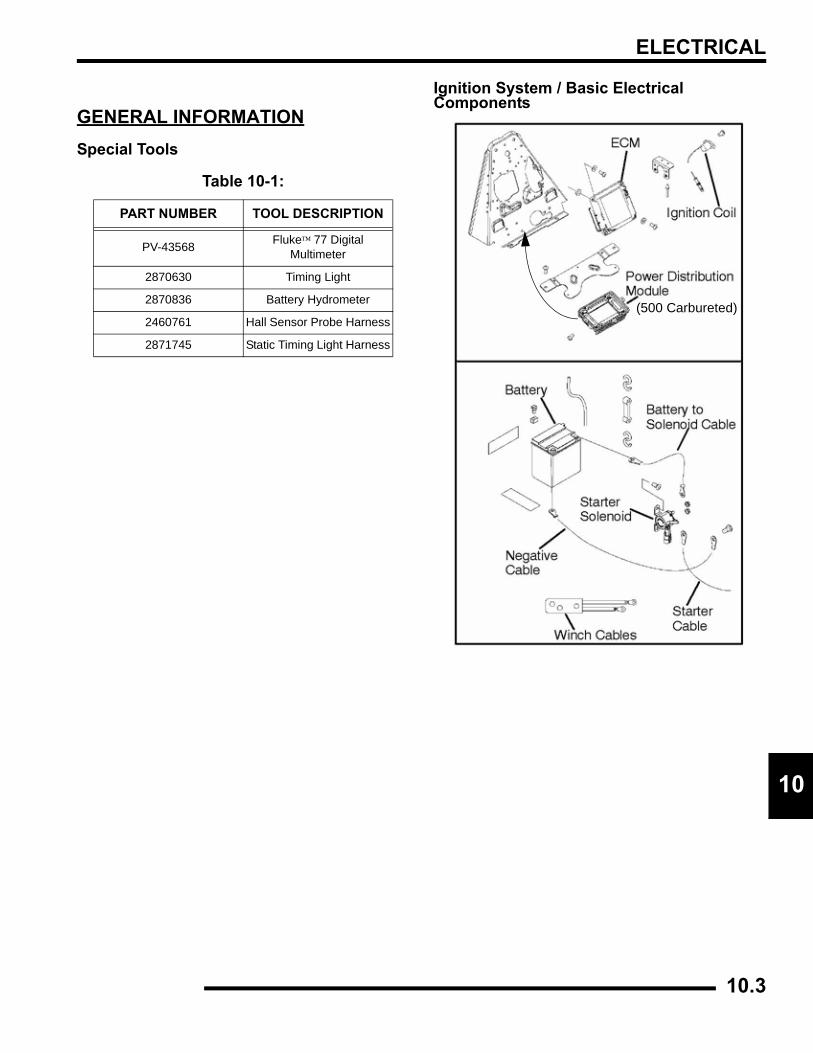
ELECTRICAL
0
1GENERAL INFORMATIONSpecial Tools
Ignition System / Basic Electrical Components
Table 10-1:
PART NUMBER TOOL DESCRIPTION
PV-43568 Fluke™ 77 DigitalMultimeter
2870630 Timing Light
2870836 Battery Hydrometer
2460761 Hall Sensor Probe Harness
2871745 Static Timing Light Harness
(500 Carbureted)
10.3
ELECTRICAL
Electrical Service NotesKeep the following notes in mind when diagnosing an electricalproblem:
• Refer to wiring diagram for stator and electrical component resistance specifications.
• When measuring resistance of a component that has a resistance value under 10 Ohms, remember to subtract meter lead resistance from the reading. Connect the leads together and record the resistance. The resistance of the component is equal to tested value minus the lead resistance.
• Become familiar with the operation of your meter. Be sure leads are in the proper jack for the test being performed (i.e. 10Ajack for current readings). Refer to the Owner’s manual included with your meter for more information.
• Voltage, amperage, and resistance values included in this manual are obtained with a Fluke™ 77 Digital Multimeter (PV-43568). This meter is used for when diagnosing electrical problems. Readings obtained with other meters may differ.
• Pay attention to the prefix on the multimeter reading (K, M, etc.) and the position of the decimal point.
• For resistance readings, isolate the component to be tested. Disconnect it from the wiring harness or power supply.
TroubleshootingNo Spark, Weak or Intermittent Spark
• Spark plug gap incorrect
• Fouled spark plug
• Faulty spark plug cap or poor connection to high tension lead
• Related wiring loose, disconnected, shorted or corroded
• Engine stop switch or ignition switch faulty
• ETC switch misadjusted or faulty
• Wire harness or connections wet, corroded or broken
• Poor ignition coil ground
• Incorrect wiring after repair (inspect color coding in connectors, etc.)
• Faulty ignition coil windings (measure resistance of primary and secondary)
• Sheared flywheel key
• Flywheel Loose or damaged
• Excessive crankshaft runout - should not exceed .0024”
• Faulty ECU
• Faulty CPS
• Low Battery
10.4
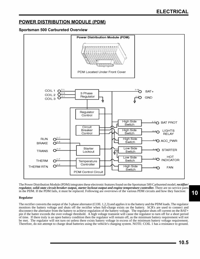
ELECTRICAL
0
1POWER DISTRIBUTION MODULE (PDM)Sportsman 500 Carbureted Overview
The Power Distribution Module (PDM) integrates these electronic features found on the Sportsman 500 Carbureted model; rectifier/regulator, solid-state circuit breaker output, starter lockout output and engine temperature controller. There are no service partsin the PDM. If the PDM fails, it must be replaced. Following are overviews of the various PDM circuits and how they function:
Regulator
The rectifier converts the output of the 3-phase alternator (COIL 1,2,3) and applies it to the battery and the PDM loads. The regulatormonitors the battery voltage and shuts off the rectifier when full-charge exists on the battery. SCR's are used to connect anddisconnect the alternator from the battery to achieve regulation of the battery voltage. The regulator shuts off current on the BAT+pin if the batter exceeds the over-voltage threshold. A high voltage transient will cause the regulator to turn off for a short periodof time. If there truly is an open battery condition then the regulator will remain off, as the minimum battery requirement will notbe met. The regulator will not turn on unless there exists battery voltage in excess of the minimum battery voltage requirement.Therefore, do not attempt to charge dead batteries using the vehicle's charging system. NOTE: COIL 1 has a resistance to ground.
10.5
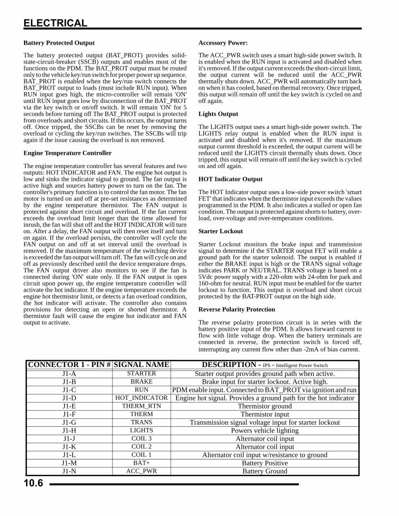
ELECTRICAL
Battery Protected Output
The battery protected output (BAT_PROT) provides solid-state-circuit-breaker (SSCB) outputs and enables most of thefunctions on the PDM. The BAT_PROT output must be routedonly to the vehicle key/run switch for proper power up sequence.BAT_PROT is enabled when the key/run switch connects theBAT_PROT output to loads (must include RUN input). WhenRUN input goes high, the micro-controller will remain 'ON'until RUN input goes low by disconnection of the BAT_PROTvia the key switch or on/off switch. It will remain 'ON' for 5seconds before turning off The BAT_PROT output is protectedfrom overloads and short circuits. If this occurs, the output turnsoff. Once tripped, the SSCBs can be reset by removing theoverload or cycling the key/run switches. The SSCBs will tripagain if the issue causing the overload is not removed.
Engine Temperature Controller
The engine temperature controller has several features and twooutputs: HOT INDICATOR and FAN. The engine hot output islow and sinks the indicator signal to ground. The fan output isactive high and sources battery power to turn on the fan. Thecontroller's primary function is to control the fan motor. The fanmotor is turned on and off at pre-set resistances as determinedby the engine temperature thermistor. The FAN output isprotected against short circuit and overload. If the fan currentexceeds the overload limit longer than the time allowed forinrush, the fan will shut off and the HOT INDICATOR will turnon. After a delay, the FAN output will then reset itself and turnon again. If the overload persists, the controller will cycle theFAN output on and off at set interval until the overload isremoved. If the maximum temperature of the switching deviceis exceeded the fan output will turn off. The fan will cycle on andoff as previously described until the device temperature drops.The FAN output driver also monitors to see if the fan isconnected during 'ON' state only. If the FAN output is opencircuit upon power up, the engine temperature controller willactivate the hot indicator. If the engine temperature exceeds theengine hot thermistor limit, or detects a fan overload condition,the hot indicator will activate. The controller also containsprovisions for detecting an open or shorted thermistor. Athermistor fault will cause the engine hot indicator and FANoutput to activate.
Accessory Power:
The ACC_PWR switch uses a smart high-side power switch. Itis enabled when the RUN input is activated and disabled whenit's removed. If the output current exceeds the short-circuit limit,the output current will be reduced until the ACC_PWRthermally shuts down. ACC_PWR will automatically turn backon when it has cooled, based on thermal recovery. Once tripped,this output will remain off until the key switch is cycled on andoff again.
Lights Output
The LIGHTS output uses a smart high-side power switch. TheLIGHTS relay output is enabled when the RUN input isactivated and disabled when it's removed. If the maximumoutput current threshold is exceeded, the output current will bereduced until the LIGHTS circuit thermally shuts down. Oncetripped, this output will remain off until the key switch is cycledon and off again.
HOT Indicator Output
The HOT Indicator output uses a low-side power switch 'smartFET' that indicates when the thermistor input exceeds the valuesprogrammed in the PDM. It also indicates a stalled or open fancondition. The output is protected against shorts to battery, over-load, over-voltage and over-temperature conditions.
Starter Lockout
Starter Lockout monitors the brake input and transmissionsignal to determine if the STARTER output FET will enable aground path for the starter solenoid. The output is enabled ifeither the BRAKE input is high or the TRANS signal voltageindicates PARK or NEUTRAL. TRANS voltage is based on a5Vdc power supply with a 220-ohm with 24-ohm for park and160-ohm for neutral. RUN input must be enabled for the starterlockout to function. This output is overload and short circuitprotected by the BAT-PROT output on the high side.
Reverse Polarity Protection
The reverse polarity protection circuit is in series with thebattery positive input of the PDM. It allows forward current toflow with little voltage drop. When the battery terminals areconnected in reverse, the protection switch is forced off,interrupting any current flow other than -2mA of bias current.
CONNECTOR 1 - PIN # SIGNAL NAME DESCRIPTION - IPS = Intelligent Power Switch
J1-A STARTER Starter output provides ground path when active.J1-B BRAKE Brake input for starter lockout. Active high.J1-C RUN PDM enable input. Connected to BAT_PROT via ignition and run J1-D HOT_INDICATOR Engine hot signal. Provides a ground path for the hot indicator J1-E THERM_RTN Thermistor groundJ1-F THERM Thermistor inputJ1-G TRANS Transmission signal voltage input for starter lockoutJ1-H LIGHTS Powers vehicle lightingJ1-J COIL 3 Alternator coil inputJ1-K COIL 2 Alternator coil inputJ1-L COIL 1 Alternator coil input w/resistance to groundJ1-M BAT+ Battery Positive J1-N ACC_PWR Battery Ground
10.6
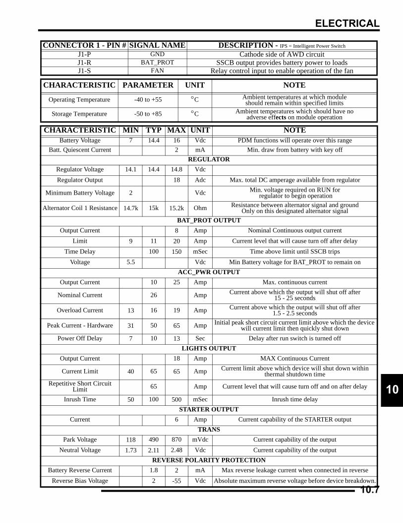
ELECTRICAL
0
10.7
1
J1-P GND Cathode side of AWD circuitJ1-R BAT_PROT SSCB output provides battery power to loadsJ1-S FAN Relay control input to enable operation of the fan
CHARACTERISTIC PARAMETER UNIT NOTE
Operating Temperature -40 to +55 °C Ambient temperatures at which moduleshould remain within specified limits
Storage Temperature -50 to +85 °C Ambient temperatures which should have no adverse effects on module operation
CHARACTERISTIC MIN TYP MAX UNIT NOTEBattery Voltage 7 14.4 16 Vdc PDM functions will operate over this range
Batt. Quiescent Current 2 mA Min. draw from battery with key offREGULATOR
Regulator Voltage 14.1 14.4 14.8 VdcRegulator Output 18 Adc Max. total DC amperage available from regulator
Minimum Battery Voltage 2 Vdc Min. voltage required on RUN for regulator to begin operation
Alternator Coil 1 Resistance 14.7k 15k 15.2k Ohm Resistance between alternator signal and groundOnly on this designated alternator signal
BAT_PROT OUTPUTOutput Current 8 Amp Nominal Continuous output current
Limit 9 11 20 Amp Current level that will cause turn off after delayTime Delay 100 150 mSec Time above limit until SSCB trips
Voltage 5.5 Vdc Min Battery voltage for BAT_PROT to remain onACC_PWR OUTPUT
Output Current 10 25 Amp Max. continuous current
Nominal Current 26 Amp Current above which the output will shut off after 15 - 25 seconds
Overload Current 13 16 19 Amp Current above which the output will shut off after 1.5 - 2.5 seconds
Peak Current - Hardware 31 50 65 Amp Initial peak short circuit current limit above which the device will current limit then quickly shut down
Power Off Delay 7 10 13 Sec Delay after run switch is turned offLIGHTS OUTPUT
Output Current 18 Amp MAX Continuous Current
Current Limit 40 65 65 Amp Current limit above which device will shut down within thermal shutdown time
Repetitive Short Circuit Limit 65 Amp Current level that will cause turn off and on after delay
Inrush Time 50 100 500 mSec Inrush time delaySTARTER OUTPUT
Current 6 Amp Current capability of the STARTER outputTRANS
Park Voltage 118 490 870 mVdc Current capability of the outputNeutral Voltage 1.73 2.11 2.48 Vdc Current capability of the output
REVERSE POLARITY PROTECTIONBattery Reverse Current 1.8 2 mA Max reverse leakage current when connected in reverse
Reverse Bias Voltage 2 -55 Vdc Absolute maximum reverse voltage before device breakdown.
CONNECTOR 1 - PIN # SIGNAL NAME DESCRIPTION - IPS = Intelligent Power Switch
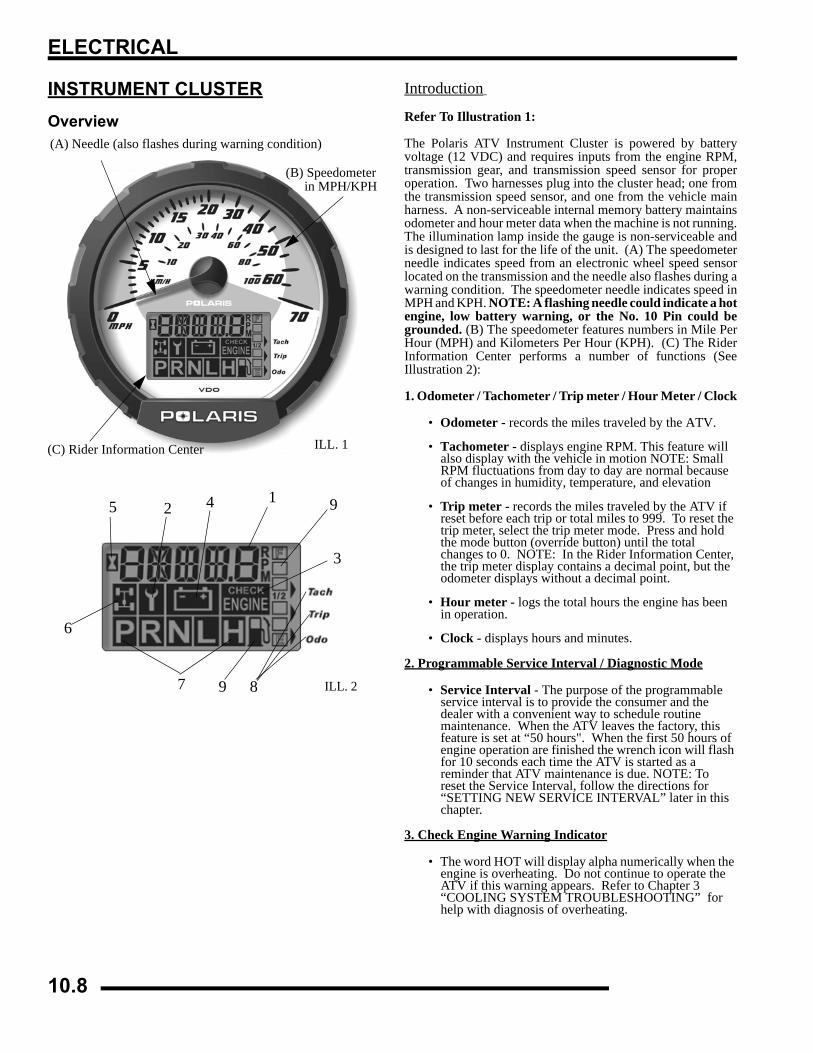
ELECTRICAL
INSTRUMENT CLUSTEROverview
Introduction
Refer To Illustration 1:
The Polaris ATV Instrument Cluster is powered by batteryvoltage (12 VDC) and requires inputs from the engine RPM,transmission gear, and transmission speed sensor for properoperation. Two harnesses plug into the cluster head; one fromthe transmission speed sensor, and one from the vehicle mainharness. A non-serviceable internal memory battery maintainsodometer and hour meter data when the machine is not running.The illumination lamp inside the gauge is non-serviceable andis designed to last for the life of the unit. (A) The speedometerneedle indicates speed from an electronic wheel speed sensorlocated on the transmission and the needle also flashes during awarning condition. The speedometer needle indicates speed inMPH and KPH. NOTE: A flashing needle could indicate a hotengine, low battery warning, or the No. 10 Pin could begrounded. (B) The speedometer features numbers in Mile PerHour (MPH) and Kilometers Per Hour (KPH). (C) The RiderInformation Center performs a number of functions (SeeIllustration 2):
1. Odometer / Tachometer / Trip meter / Hour Meter / Clock
• Odometer - records the miles traveled by the ATV.
• Tachometer - displays engine RPM. This feature will also display with the vehicle in motion NOTE: Small RPM fluctuations from day to day are normal because of changes in humidity, temperature, and elevation
• Trip meter - records the miles traveled by the ATV if reset before each trip or total miles to 999. To reset the trip meter, select the trip meter mode. Press and hold the mode button (override button) until the total changes to 0. NOTE: In the Rider Information Center, the trip meter display contains a decimal point, but the odometer displays without a decimal point.
• Hour meter - logs the total hours the engine has been in operation.
• Clock - displays hours and minutes.
2. Programmable Service Interval / Diagnostic Mode
• Service Interval - The purpose of the programmable service interval is to provide the consumer and the dealer with a convenient way to schedule routine maintenance. When the ATV leaves the factory, this feature is set at “50 hours". When the first 50 hours of engine operation are finished the wrench icon will flash for 10 seconds each time the ATV is started as a reminder that ATV maintenance is due. NOTE: To reset the Service Interval, follow the directions for “SETTING NEW SERVICE INTERVAL” later in this chapter.
3. Check Engine Warning Indicator
• The word HOT will display alpha numerically when the engine is overheating. Do not continue to operate the ATV if this warning appears. Refer to Chapter 3 “COOLING SYSTEM TROUBLESHOOTING” for help with diagnosis of overheating.
(A) Needle (also flashes during warning condition)
(B) Speedometerin MPH/KPH
(C) Rider Information Center ILL. 1
1425
6
7 8
3
9
9
ILL. 2
10.8

ELECTRICAL
0
14. High/Low Battery Voltage
• This warning usually indicates that the ATV is being operated at an RPM too low to keep the battery charged. A low battery warning may also occur under normal operation if the machine is at idle and high electrical load (lights, cooling fan, accessories) is applied. Driving at a higher RPM or connecting a battery charger will usually clear the warning.
5. Engine Hour Display Indicator
• Displays number of hours of engine operation.
6. AWD Indicator
• Illuminates when the electrical portion of the AWD system is enabled.
7. Gear Indicator
• Specifies what position the shift lever and transmission are in. This area is blank if a fault occurs.
8. Mode Indicator
• Indicates which modes are being utilized.
9. Fuel Gauge
• The segments of the fuel gauge indicate the level of fuel in the fuel tank. When the last segment clears, a low fuel warning is activated. All related icons will flash, “FUEL” will display in the LCD, and the speedometer needle will blink. If riding, be sure to refuel immediately.
Instrument Cluster Diagnostic ModeNOTE: This gauge features auto shut-off protectionif the voltage on the DC bus is excessive. This isusually the result of an open battery condition, andthe gauge is designed to survive such an event.
NOTE: If the gauge will not indicate what gear it is inand will not allow AWD operation, AWD can still beenabled by holding in the mode/override button.
NOTE: As long as you are in the diagnostic mode,the wrench icon will remain lit.
NOTE: Any movement of the tires will trigger thespeedometer out of the diagnostic mode and intostandard display mode.
NOTE: To leave the diagnostic mode, turn the keyswitch off and on.
1. Turn the key switch off and wait 10 seconds.2. Set the park brake and shift the transmission to neutral.3. Hold the mode/reverse override button as you turn the key
switch on.4. Release the switch as soon as the display is activated.
Use the mode/reverse override button to toggle through thediagnostic screens.
NOTE: The initial screen display refers to thesoftware version installed on your ATV. Thisinformation is only displayed briefly.
Screen 1: The first screen indicates battery voltage. Refer to Ill.2.
Blink When Low On Fuel
Ill. 2
10.9
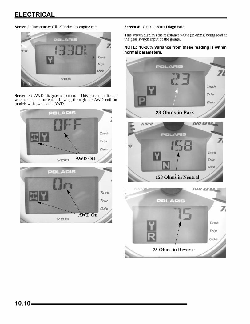
ELECTRICAL
Screen 2: Tachometer (Ill. 3) indicates engine rpm.
Screen 3: AWD diagnostic screen. This screen indicateswhether or not current is flowing through the AWD coil onmodels with switchable AWD.
Screen 4: Gear Circuit Diagnostic
This screen displays the resistance value (in ohms) being read atthe gear switch input of the gauge.
NOTE: 10-20% Variance from these reading is withinnormal parameters.
Ill.3
AWD Off
AWD On
23 Ohms in Park
158 Ohms in Neutral
75 Ohms in Reverse
10.10
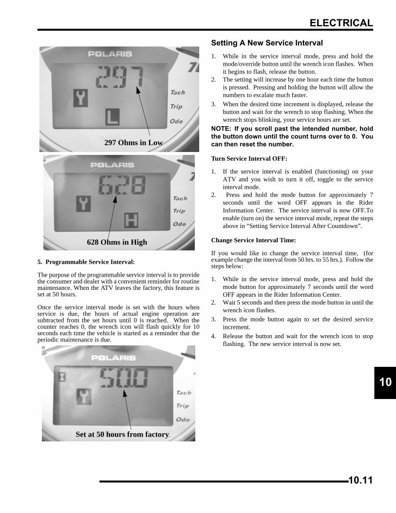
ELECTRICAL
0
15. Programmable Service Interval:
The purpose of the programmable service interval is to providethe consumer and dealer with a convenient reminder for routinemaintenance. When the ATV leaves the factory, this feature isset at 50 hours.
Once the service interval mode is set with the hours whenservice is due, the hours of actual engine operation aresubtracted from the set hours until 0 is reached. When thecounter reaches 0, the wrench icon will flash quickly for 10seconds each time the vehicle is started as a reminder that theperiodic maintenance is due.
Setting A New Service Interval1. While in the service interval mode, press and hold the
mode/override button until the wrench icon flashes. Whenit begins to flash, release the button.
2. The setting will increase by one hour each time the buttonis pressed. Pressing and holding the button will allow thenumbers to escalate much faster.
3. When the desired time increment is displayed, release thebutton and wait for the wrench to stop flashing. When thewrench stops blinking, your service hours are set.
NOTE: If you scroll past the intended number, holdthe button down until the count turns over to 0. Youcan then reset the number.
Turn Service Interval OFF:
1. If the service interval is enabled (functioning) on yourATV and you wish to turn it off, toggle to the serviceinterval mode.
2. Press and hold the mode button for approximately 7seconds until the word OFF appears in the RiderInformation Center. The service interval is now OFF.Toenable (turn on) the service interval mode, repeat the stepsabove in “Setting Service Interval After Countdown”.
Change Service Interval Time:
If you would like to change the service interval time, (forexample change the interval from 50 hrs. to 55 hrs.). Follow thesteps below:
1. While in the service interval mode, press and hold themode button for approximately 7 seconds until the wordOFF appears in the Rider Information Center.
2. Wait 5 seconds and then press the mode button in until thewrench icon flashes.
3. Press the mode button again to set the desired serviceincrement.
4. Release the button and wait for the wrench icon to stopflashing. The new service interval is now set.
297 Ohms in Low
628 Ohms in High
Set at 50 hours from factory.
10.11
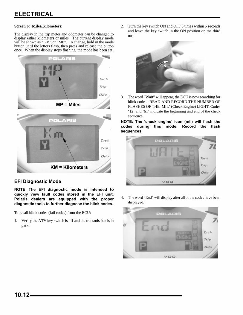
ELECTRICAL
Screen 6: Miles/Kilometers:
The display in the trip meter and odometer can be changed todisplay either kilometers or miles. The current display modewill be shown as “KM” or “MP”. To change, hold in the modebutton until the letters flash, then press and release the buttononce. When the display stops flashing, the mode has been set.
EFI Diagnostic Mode NOTE: The EFI diagnostic mode is intended toquickly view fault codes stored in the EFI unit.Polaris dealers are equipped with the properdiagnostic tools to further diagnose the blink codes.
To recall blink codes (fail codes) from the ECU:
1. Verify the ATV key switch is off and the transmission is inpark.
2. Turn the key switch ON and OFF 3 times within 5 secondsand leave the key switch in the ON position on the thirdturn.
3. The word “Wait” will appear, the ECU is now searching forblink codes. READ AND RECORD THE NUMBER OFFLASHES OF THE ‘MIL’ (Check Engine) LIGHT. Codes‘12’ and ‘61’ indicate the beginning and end of the checksequence.
NOTE: The ‘check engine’ icon (mil) will flash thecodes during this mode. Record the flashsequences.
4. The word “End” will display after all of the codes have beendisplayed.
MP = Miles
KM = Kilometers
ON
10.12
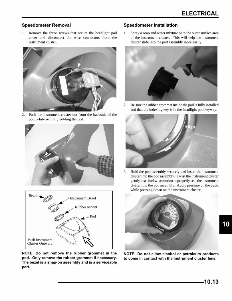
ELECTRICAL
0
1Speedometer Removal1. Remove the three screws that secure the headlight pod
cover and disconnect the wire connectors from theinstrument cluster.
2. Push the instrument cluster out from the backside of thepod, while securely holding the pod.
NOTE: Do not remove the rubber grommet in thepod. Only remove the rubber grommet if necessary.The bezel is a snap-on assembly and is a serviceablepart.
Speedometer Installation1. Spray a soap and water mixture onto the outer surface area
of the instrument cluster. This will help the instrumentcluster slide into the pod assembly more easily.
2. Be sure the rubber grommet inside the pod is fully installedand that the indexing key is in the headlight pod keyway.
3. Hold the pod assembly securely and insert the instrumentcluster into the pod assembly. Twist the instrument clustergently in a clockwise motion to properly seat the instrumentcluster into the pod assembly. Apply pressure on the bezelwhile pressing down on the instrument cluster.
NOTE: Do not allow alcohol or petroleum productsto come in contact with the instrument cluster lens.
Pod
Rubber Mount
Instrument BezelBezel
Push Instrument Cluster Outward
Align
10.13
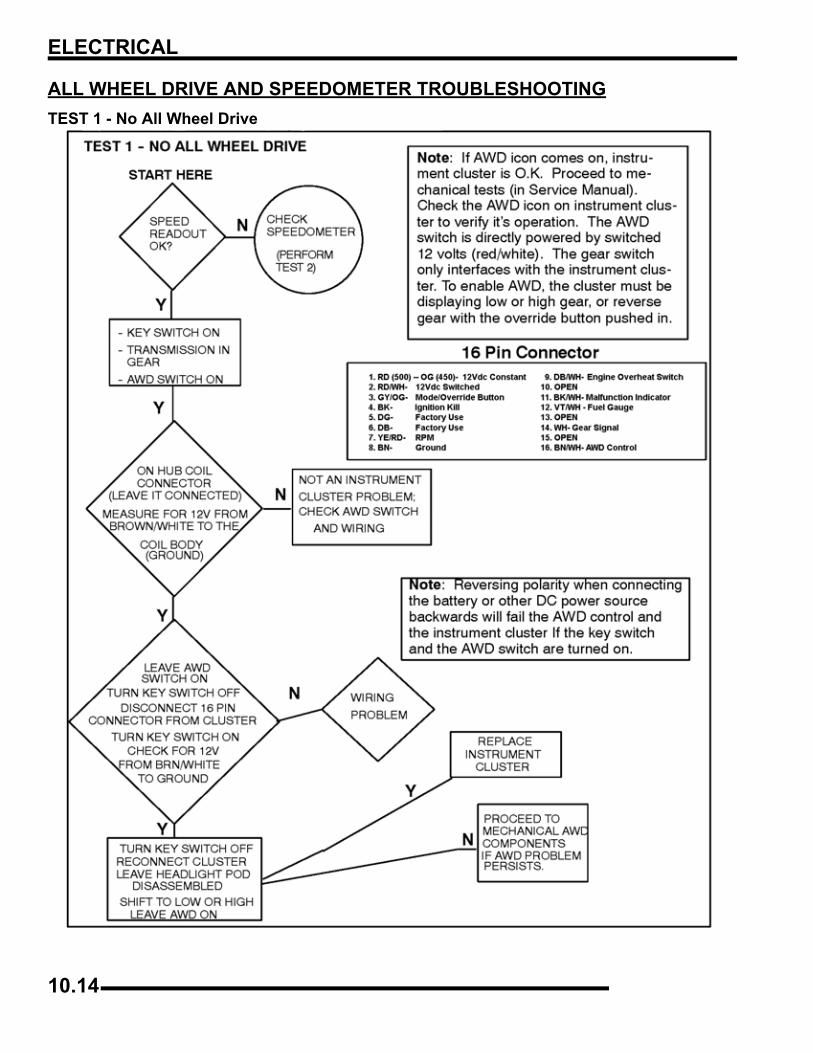
ELECTRICAL
ALL WHEEL DRIVE AND SPEEDOMETER TROUBLESHOOTINGTEST 1 - No All Wheel Drive
10.14
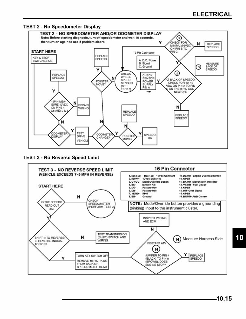
ELECTRICAL
0
1TEST 2 - No Speedometer Display
TEST 3 - No Reverse Speed Limit
10.15
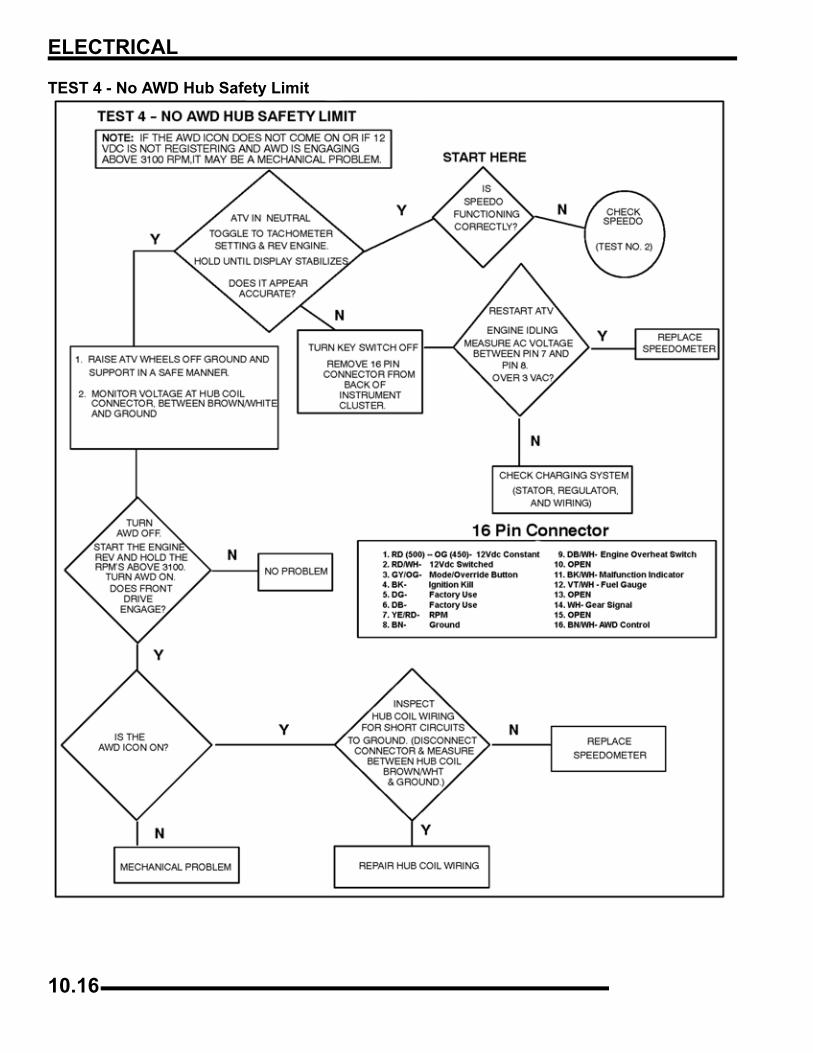
ELECTRICAL
TEST 4 - No AWD Hub Safety Limit
10.16
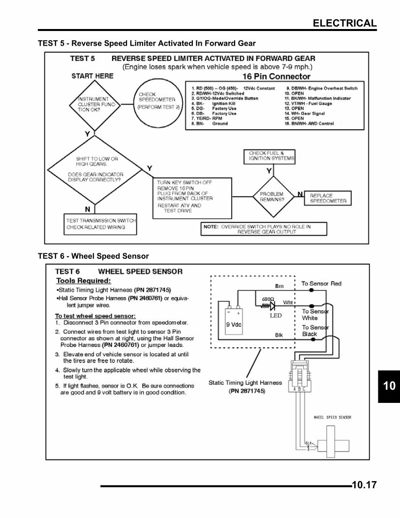
ELECTRICAL
0
1TEST 5 - Reverse Speed Limiter Activated In Forward Gear
TEST 6 - Wheel Speed Sensor
10.17
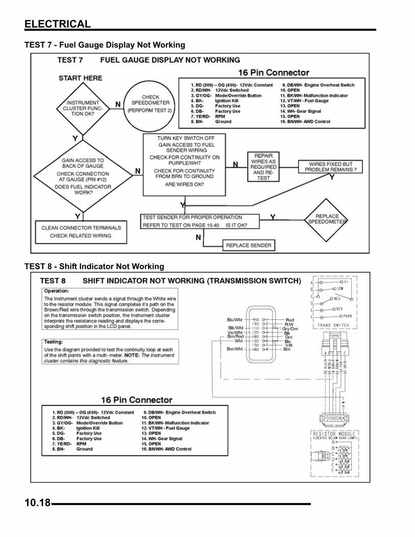
ELECTRICAL
TEST 7 - Fuel Gauge Display Not Working
TEST 8 - Shift Indicator Not Working
10.18
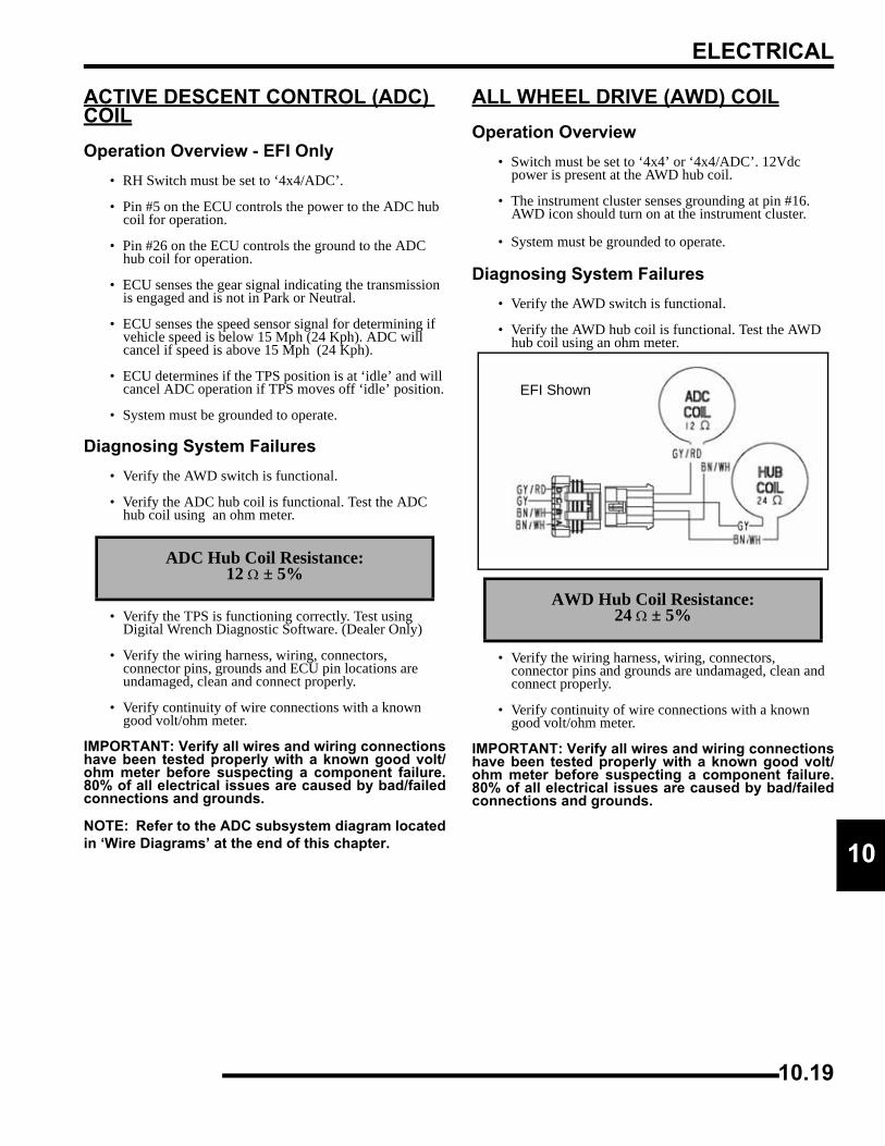
ELECTRICAL
0
1ACTIVE DESCENT CONTROL (ADC) COILOperation Overview - EFI Only
• RH Switch must be set to ‘4x4/ADC’.
• Pin #5 on the ECU controls the power to the ADC hub coil for operation.
• Pin #26 on the ECU controls the ground to the ADC hub coil for operation.
• ECU senses the gear signal indicating the transmission is engaged and is not in Park or Neutral.
• ECU senses the speed sensor signal for determining if vehicle speed is below 15 Mph (24 Kph). ADC will cancel if speed is above 15 Mph (24 Kph).
• ECU determines if the TPS position is at ‘idle’ and will cancel ADC operation if TPS moves off ‘idle’ position.
• System must be grounded to operate.
Diagnosing System Failures• Verify the AWD switch is functional.
• Verify the ADC hub coil is functional. Test the ADC hub coil using an ohm meter.
• Verify the TPS is functioning correctly. Test using Digital Wrench Diagnostic Software. (Dealer Only)
• Verify the wiring harness, wiring, connectors, connector pins, grounds and ECU pin locations are undamaged, clean and connect properly.
• Verify continuity of wire connections with a known good volt/ohm meter.
IMPORTANT: Verify all wires and wiring connectionshave been tested properly with a known good volt/ohm meter before suspecting a component failure.80% of all electrical issues are caused by bad/failedconnections and grounds.
NOTE: Refer to the ADC subsystem diagram locatedin ‘Wire Diagrams’ at the end of this chapter.
ALL WHEEL DRIVE (AWD) COILOperation Overview
• Switch must be set to ‘4x4’ or ‘4x4/ADC’. 12Vdc power is present at the AWD hub coil.
• The instrument cluster senses grounding at pin #16. AWD icon should turn on at the instrument cluster.
• System must be grounded to operate.
Diagnosing System Failures• Verify the AWD switch is functional.
• Verify the AWD hub coil is functional. Test the AWD hub coil using an ohm meter.
• Verify the wiring harness, wiring, connectors, connector pins and grounds are undamaged, clean and connect properly.
• Verify continuity of wire connections with a known good volt/ohm meter.
IMPORTANT: Verify all wires and wiring connectionshave been tested properly with a known good volt/ohm meter before suspecting a component failure.80% of all electrical issues are caused by bad/failedconnections and grounds.
ADC Hub Coil Resistance:12 Ω ± 5%
AWD Hub Coil Resistance:24 Ω ± 5%
EFI Shown
10.19
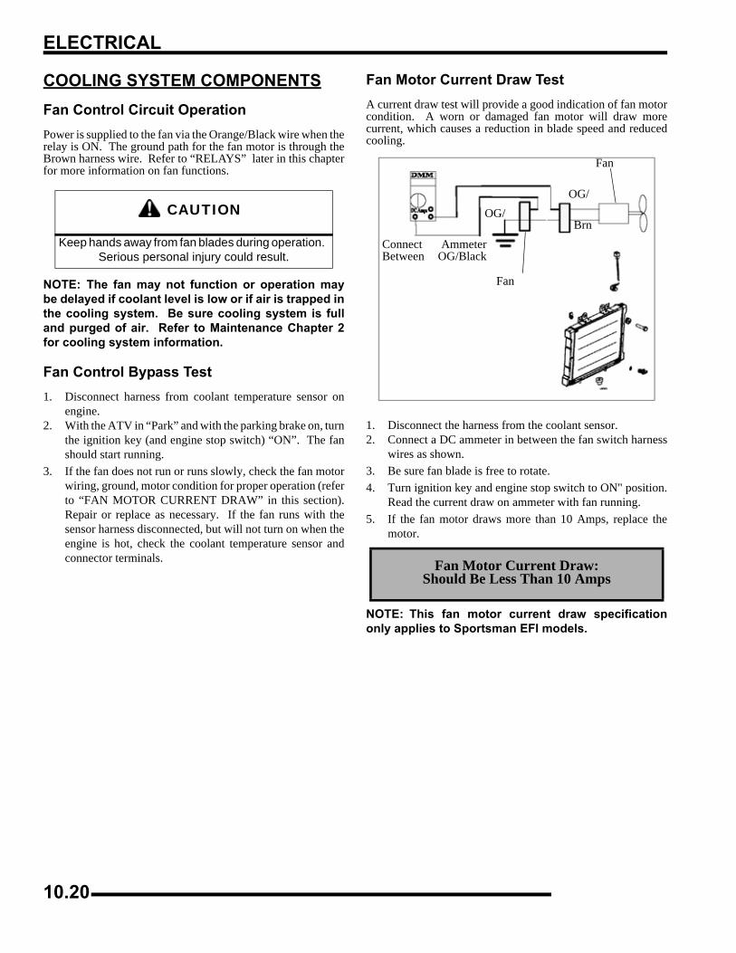
ELECTRICAL
COOLING SYSTEM COMPONENTSFan Control Circuit OperationPower is supplied to the fan via the Orange/Black wire when therelay is ON. The ground path for the fan motor is through theBrown harness wire. Refer to “RELAYS” later in this chapterfor more information on fan functions.
NOTE: The fan may not function or operation maybe delayed if coolant level is low or if air is trapped inthe cooling system. Be sure cooling system is fulland purged of air. Refer to Maintenance Chapter 2for cooling system information.
Fan Control Bypass Test1. Disconnect harness from coolant temperature sensor on
engine.2. With the ATV in “Park” and with the parking brake on, turn
the ignition key (and engine stop switch) “ON”. The fanshould start running.
3. If the fan does not run or runs slowly, check the fan motorwiring, ground, motor condition for proper operation (referto “FAN MOTOR CURRENT DRAW” in this section).Repair or replace as necessary. If the fan runs with thesensor harness disconnected, but will not turn on when theengine is hot, check the coolant temperature sensor andconnector terminals.
Fan Motor Current Draw TestA current draw test will provide a good indication of fan motorcondition. A worn or damaged fan motor will draw morecurrent, which causes a reduction in blade speed and reducedcooling.
1. Disconnect the harness from the coolant sensor.2. Connect a DC ammeter in between the fan switch harness
wires as shown.3. Be sure fan blade is free to rotate.4. Turn ignition key and engine stop switch to ON" position.
Read the current draw on ammeter with fan running.5. If the fan motor draws more than 10 Amps, replace the
motor.
NOTE: This fan motor current draw specificationonly applies to Sportsman EFI models.
CAUTION
Keep hands away from fan blades during operation. Serious personal injury could result.
Fan Motor Current Draw:Should Be Less Than 10 Amps
Connect AmmeterBetween OG/Black
OG/
Fan
Brn
OG/
Fan
10.20
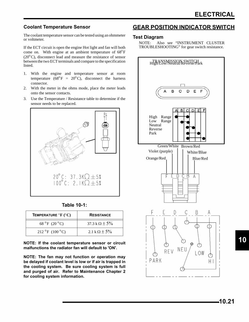
ELECTRICAL
0
1Coolant Temperature SensorThe coolant temperature sensor can be tested using an ohmmeteror voltmeter.
If the ECT circuit is open the engine Hot light and fan will bothcome on. With engine at an ambient temperature of 68°F(20°C), disconnect lead and measure the resistance of sensorbetween the two ECT terminals and compare to the specificationlisted.
1. With the engine and temperature sensor at roomtemperature (68°F = 20°C), disconnect the harnessconnector.
2. With the meter in the ohms mode, place the meter leadsonto the sensor contacts.
3. Use the Temperature / Resistance table to determine if thesensor needs to be replaced.
NOTE: If the coolant temperature sensor or circuitmalfunctions the radiator fan will default to 'ON'.
NOTE: The fan may not function or operation maybe delayed if coolant level is low or if air is trapped inthe cooling system. Be sure cooling system is fulland purged of air. Refer to Maintenance Chapter 2for cooling system information.
GEAR POSITION INDICATOR SWITCHTest Diagram
Table 10-1:
TEMPERATURE °F (°C) RESISTANCE
68 °F (20 °C) 37.3 k Ω ± 5%
212 °F (100 °C) 2.1 k Ω ± 5%
NOTE: Also see “INSTRUMENT CLUSTERTROUBLESHOOTING” for gear switch resistance.
High RangeLow RangeNeutralReversePark
Orange/Red
Violet (purple)Green/White Brown/Red
White/BlueBlue/Red
TRANSMISSION SWITCHHigh/Low/Neutral/Reverse/Park
10.21
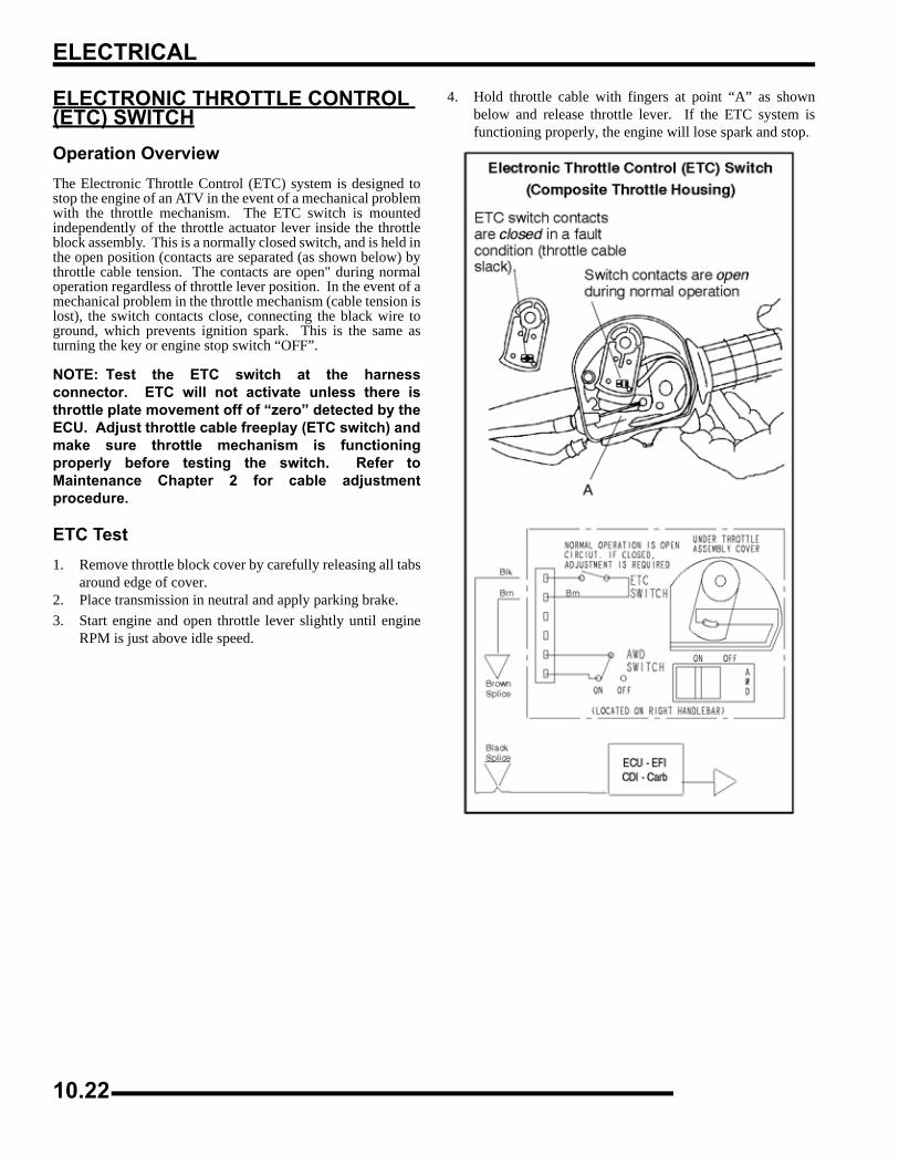
ELECTRICAL
ELECTRONIC THROTTLE CONTROL (ETC) SWITCHOperation OverviewThe Electronic Throttle Control (ETC) system is designed tostop the engine of an ATV in the event of a mechanical problemwith the throttle mechanism. The ETC switch is mountedindependently of the throttle actuator lever inside the throttleblock assembly. This is a normally closed switch, and is held inthe open position (contacts are separated (as shown below) bythrottle cable tension. The contacts are open" during normaloperation regardless of throttle lever position. In the event of amechanical problem in the throttle mechanism (cable tension islost), the switch contacts close, connecting the black wire toground, which prevents ignition spark. This is the same asturning the key or engine stop switch “OFF”.
NOTE: Test the ETC switch at the harnessconnector. ETC will not activate unless there isthrottle plate movement off of “zero” detected by theECU. Adjust throttle cable freeplay (ETC switch) andmake sure throttle mechanism is functioningproperly before testing the switch. Refer toMaintenance Chapter 2 for cable adjustmentprocedure.
ETC Test1. Remove throttle block cover by carefully releasing all tabs
around edge of cover.2. Place transmission in neutral and apply parking brake.3. Start engine and open throttle lever slightly until engine
RPM is just above idle speed.
4. Hold throttle cable with fingers at point “A” as shownbelow and release throttle lever. If the ETC system isfunctioning properly, the engine will lose spark and stop.
10.22
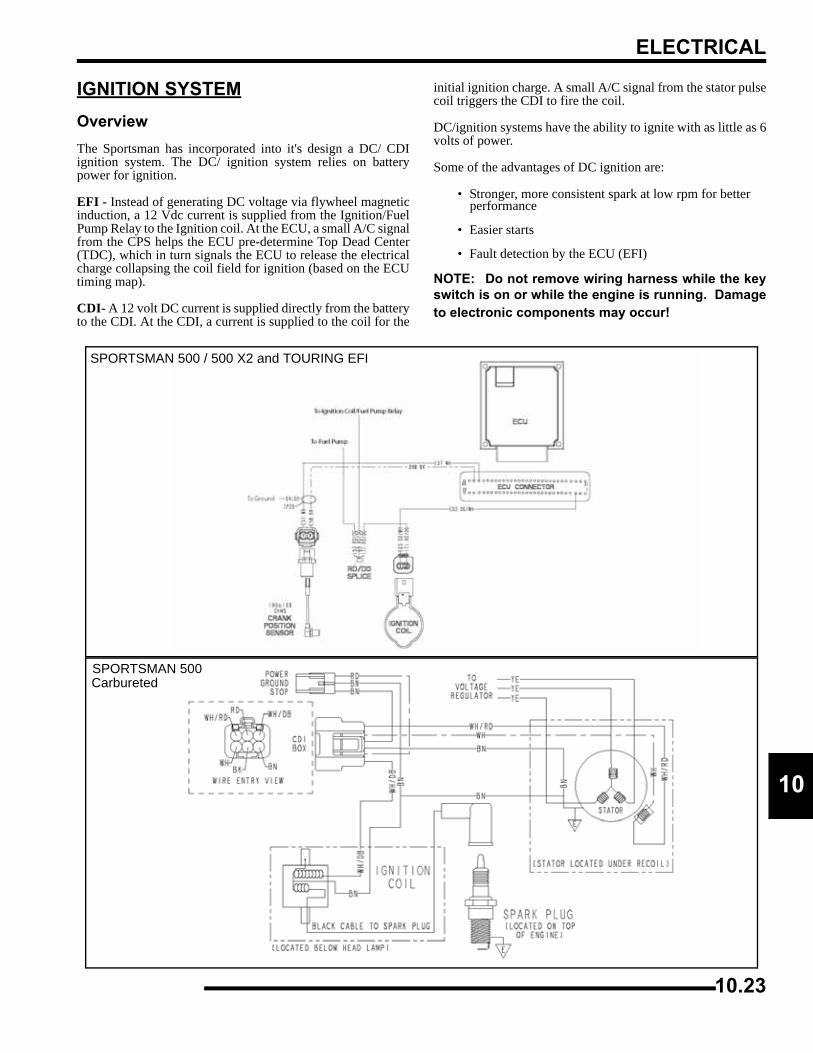
ELECTRICAL
0
1IGNITION SYSTEMOverviewThe Sportsman has incorporated into it's design a DC/ CDIignition system. The DC/ ignition system relies on batterypower for ignition.
EFI - Instead of generating DC voltage via flywheel magneticinduction, a 12 Vdc current is supplied from the Ignition/FuelPump Relay to the Ignition coil. At the ECU, a small A/C signalfrom the CPS helps the ECU pre-determine Top Dead Center(TDC), which in turn signals the ECU to release the electricalcharge collapsing the coil field for ignition (based on the ECUtiming map).
CDI- A 12 volt DC current is supplied directly from the batteryto the CDI. At the CDI, a current is supplied to the coil for the
initial ignition charge. A small A/C signal from the stator pulsecoil triggers the CDI to fire the coil.
DC/ignition systems have the ability to ignite with as little as 6volts of power.
Some of the advantages of DC ignition are:
• Stronger, more consistent spark at low rpm for better performance
• Easier starts
• Fault detection by the ECU (EFI)
NOTE: Do not remove wiring harness while the keyswitch is on or while the engine is running. Damageto electronic components may occur!
SPORTSMAN 500 / 500 X2 and TOURING EFI
SPORTSMAN 500Carbureted
10.23
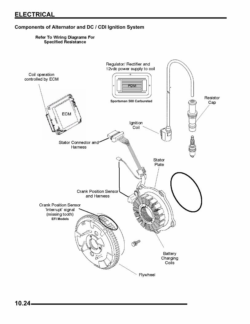
ELECTRICAL
Components of Alternator and DC / CDI Ignition System
Sportsman 500 Carbureted
EFI Models
10.24
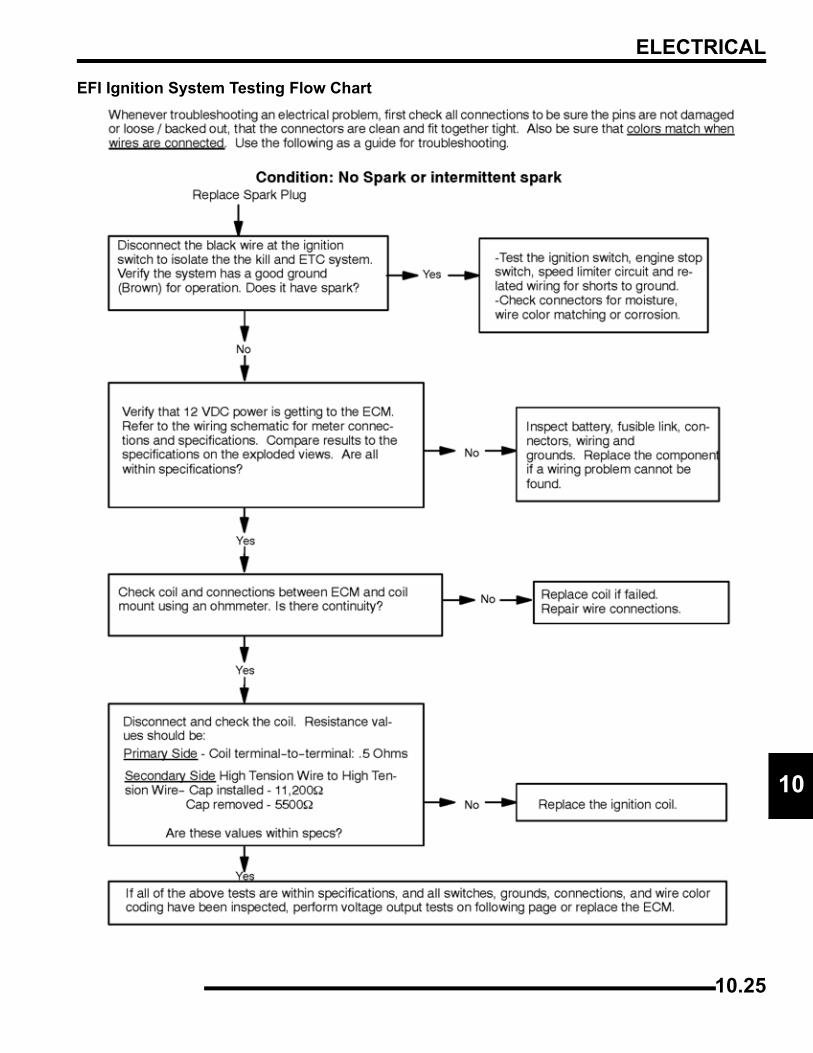
ELECTRICAL
0
1EFI Ignition System Testing Flow Chart
10.25
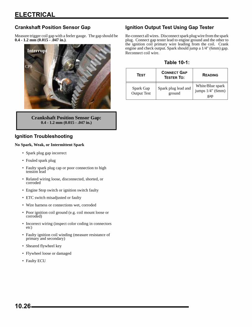
ELECTRICAL
Crankshaft Position Sensor GapMeasure trigger coil gap with a feeler gauge. The gap should be0.4 - 1.2 mm (0.015 - .047 in.).
Ignition TroubleshootingNo Spark, Weak, or Intermittent Spark
• Spark plug gap incorrect
• Fouled spark plug
• Faulty spark plug cap or poor connection to high tension lead
• Related wiring loose, disconnected, shorted, or corroded
• Engine Stop switch or ignition switch faulty
• ETC switch misadjusted or faulty
• Wire harness or connections wet, corroded
• Poor ignition coil ground (e.g. coil mount loose or corroded)
• Incorrect wiring (inspect color coding in connectors etc)
• Faulty ignition coil winding (measure resistance of primary and secondary)
• Sheared flywheel key
• Flywheel loose or damaged
• Faulty ECU
Ignition Output Test Using Gap TesterRe-connect all wires. Disconnect spark plug wire from the sparkplug. Connect gap tester lead to engine ground and the other tothe ignition coil primary wire leading from the coil. Crankengine and check output. Spark should jump a 1/4" (6mm) gap.Reconnect coil wire.
Crankshaft Position Sensor Gap:0.4 - 1.2 mm (0.015 - .047 in.)
CPS
Interrupt
Table 10-1:
TESTCONNECT GAP
TESTER TO: READING
Spark GapOutput Test
Spark plug lead and ground
White/Blue spark jumps 1/4" (6mm)
gap
10.26
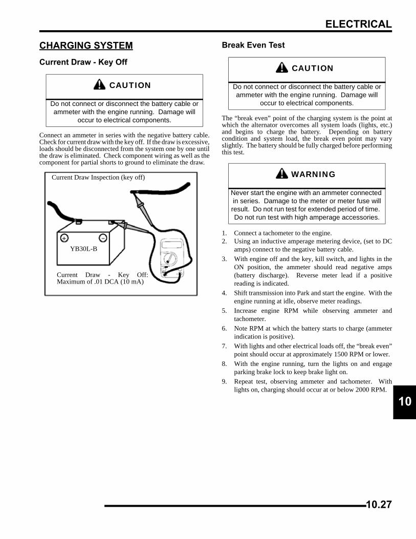
ELECTRICAL
0
1CHARGING SYSTEMCurrent Draw - Key Off
Connect an ammeter in series with the negative battery cable.Check for current draw with the key off. If the draw is excessive,loads should be disconnected from the system one by one untilthe draw is eliminated. Check component wiring as well as thecomponent for partial shorts to ground to eliminate the draw.
Break Even Test
The “break even” point of the charging system is the point atwhich the alternator overcomes all system loads (lights, etc.)and begins to charge the battery. Depending on batterycondition and system load, the break even point may varyslightly. The battery should be fully charged before performingthis test.
1. Connect a tachometer to the engine.2. Using an inductive amperage metering device, (set to DC
amps) connect to the negative battery cable.3. With engine off and the key, kill switch, and lights in the
ON position, the ammeter should read negative amps(battery discharge). Reverse meter lead if a positivereading is indicated.
4. Shift transmission into Park and start the engine. With theengine running at idle, observe meter readings.
5. Increase engine RPM while observing ammeter andtachometer.
6. Note RPM at which the battery starts to charge (ammeterindication is positive).
7. With lights and other electrical loads off, the “break even”point should occur at approximately 1500 RPM or lower.
8. With the engine running, turn the lights on and engageparking brake lock to keep brake light on.
9. Repeat test, observing ammeter and tachometer. Withlights on, charging should occur at or below 2000 RPM.
CAUTION
Do not connect or disconnect the battery cable or ammeter with the engine running. Damage will
occur to electrical components.
YB30L-B
Current Draw Inspection (key off)
Current Draw - Key Off:Maximum of .01 DCA (10 mA)
CAUTION
Do not connect or disconnect the battery cable or ammeter with the engine running. Damage will
occur to electrical components.
WARNING
Never start the engine with an ammeter connected in series. Damage to the meter or meter fuse will result. Do not run test for extended period of time. Do not run test with high amperage accessories.
10.27
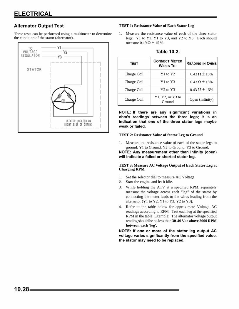
ELECTRICAL
Alternator Output TestThree tests can be performed using a multimeter to determinethe condition of the stator (alternator).
TEST 1: Resistance Value of Each Stator Leg
1. Measure the resistance value of each of the three statorlegs: Y1 to Y2, Y1 to Y3, and Y2 to Y3. Each shouldmeasure 0.19 Ω ± 15 %.
NOTE: If there are any significant variations inohm's readings between the three legs; it is anindication that one of the three stator legs maybeweak or failed.
TEST 2: Resistance Value of Stator Leg to Ground
1. Measure the resistance value of each of the stator legs toground: Y1 to Ground, Y2 to Ground, Y3 to Ground.
NOTE: Any measurement other than Infinity (open)will indicate a failed or shorted stator leg.
TEST 3: Measure AC Voltage Output of Each Stator Leg atCharging RPM
1. Set the selector dial to measure AC Voltage.2. Start the engine and let it idle.3. While holding the ATV at a specified RPM, separately
measure the voltage across each “leg” of the stator byconnecting the meter leads to the wires leading from thealternator (Y1 to Y2, Y1 to Y3, Y2 to Y3).
4. Refer to the table below for approximate Voltage ACreadings according to RPM. Test each leg at the specifiedRPM in the table. Example: The alternator voltage outputreading should be no less than 30-40 Vac above 2000 RPMbetween each 'leg'.
NOTE: If one or more of the stator leg output ACvoltage varies significantly from the specified value,the stator may need to be replaced.
Table 10-2:
TESTCONNECT METER
WIRES TO: READING IN OHMS
Charge Coil Y1 to Y2 0.43 Ω ± 15%
Charge Coil Y1 to Y3 0.43 Ω ± 15%
Charge Coil Y2 to Y3 0.43 Ω ± 15%
Charge Coil Y1, Y2, or Y3 to Ground Open (Infinity)
10.28
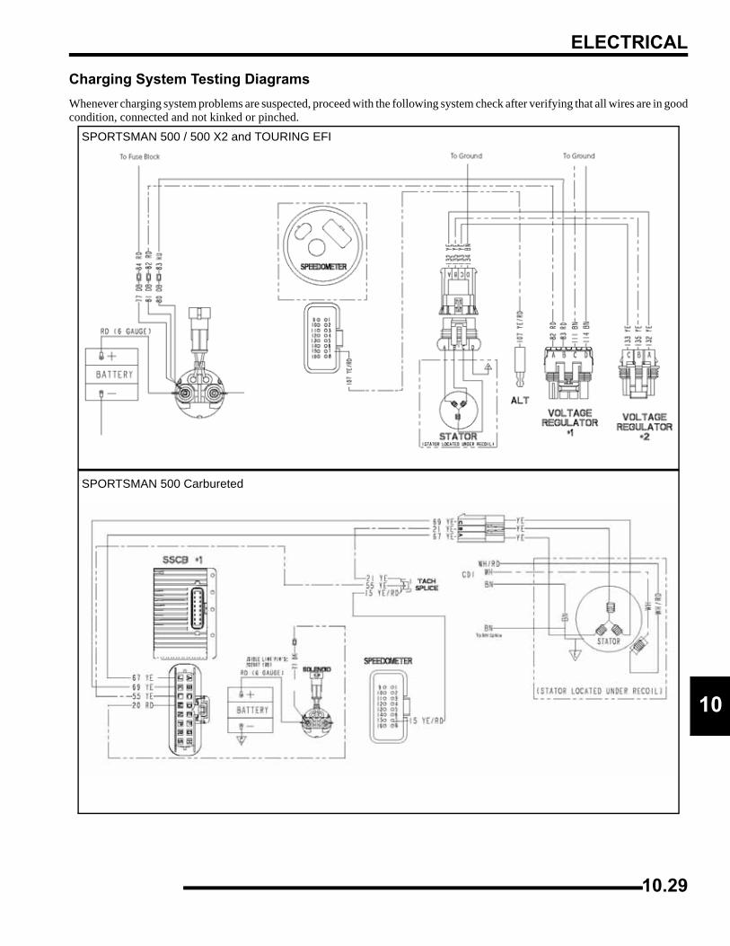
ELECTRICAL
0
1Charging System Testing DiagramsWhenever charging system problems are suspected, proceed with the following system check after verifying that all wires are in goodcondition, connected and not kinked or pinched.
SPORTSMAN 500 / 500 X2 and TOURING EFI
SPORTSMAN 500 Carbureted
10.29
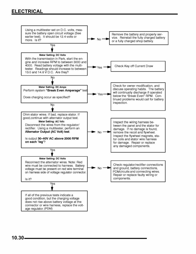
ELECTRICAL
(PDM)
10.30
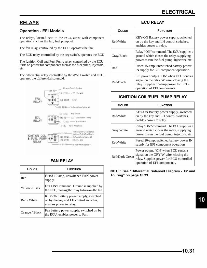
ELECTRICAL
0
1RELAYSOperation - EFI ModelsThe relays, located next to the ECU, assist with componentoperation such as the fan, fuel pump, etc.
The fan relay, controlled by the ECU, operates the fan.
The ECU relay, controlled by the key switch, operates the ECU
The Ignition Coil and Fuel Pump relay, controlled by the ECU,turns on power for components such as the fuel pump, injectors,etc.
The differential relay, controlled by the AWD switch and ECU,operates the differential solenoid.
NOTE: See “Differential Solenoid Diagram - X2 andTouring” on page 10.33.
FAN RELAY
COLOR FUNCTION
Red Fused 10-amp, unswitched FAN power supply.
Yellow /Black Fan 'ON' Command. Ground is supplied by the ECU, closing the relay to turn on the fan.
Red / WhiteKEY-ON Battery power supply, switched on by the key and LH control switches, enables power to relay.
Orange / Black Fan battery power supply, switched on by the ECU, enables power to Fan.
ECU RELAY
COLOR FUNCTION
Red/WhiteKEY-ON Battery power supply, switched on by the key and LH control switches, enables power to relay.
Gray/BlackRelay “ON” command. The ECU supplies a ground which closes the relay, supplying power to run the fuel pump, injectors, etc.
Red Fused 15-amp, unswitched battery power IN supply for EFI component operation.
Red/Black
EFI power output. 'ON' when ECU sends a signal on the GRY/W wire, closing the relay. Supplies 15-amp power for ECU-operation of EFI components.
IGNITION COIL/FUEL PUMP RELAY
COLOR FUNCTION
Red/WhiteKEY-ON Battery power supply, switched on by the key and LH control switches, enables power to relay.
Gray/WhiteRelay “ON” command. The ECU supplies a ground which closes the relay, supplying power to run the fuel pump, injectors, etc.
Red/White Fused 20-amp, switched battery power IN supply for EFI component operation.
Red/Dark Green
Power output. 'ON' when ECU sends a signal on the GRY/W wire, closing the relay. Supplies power for ECU-controlled operation of EFI components.
10.31
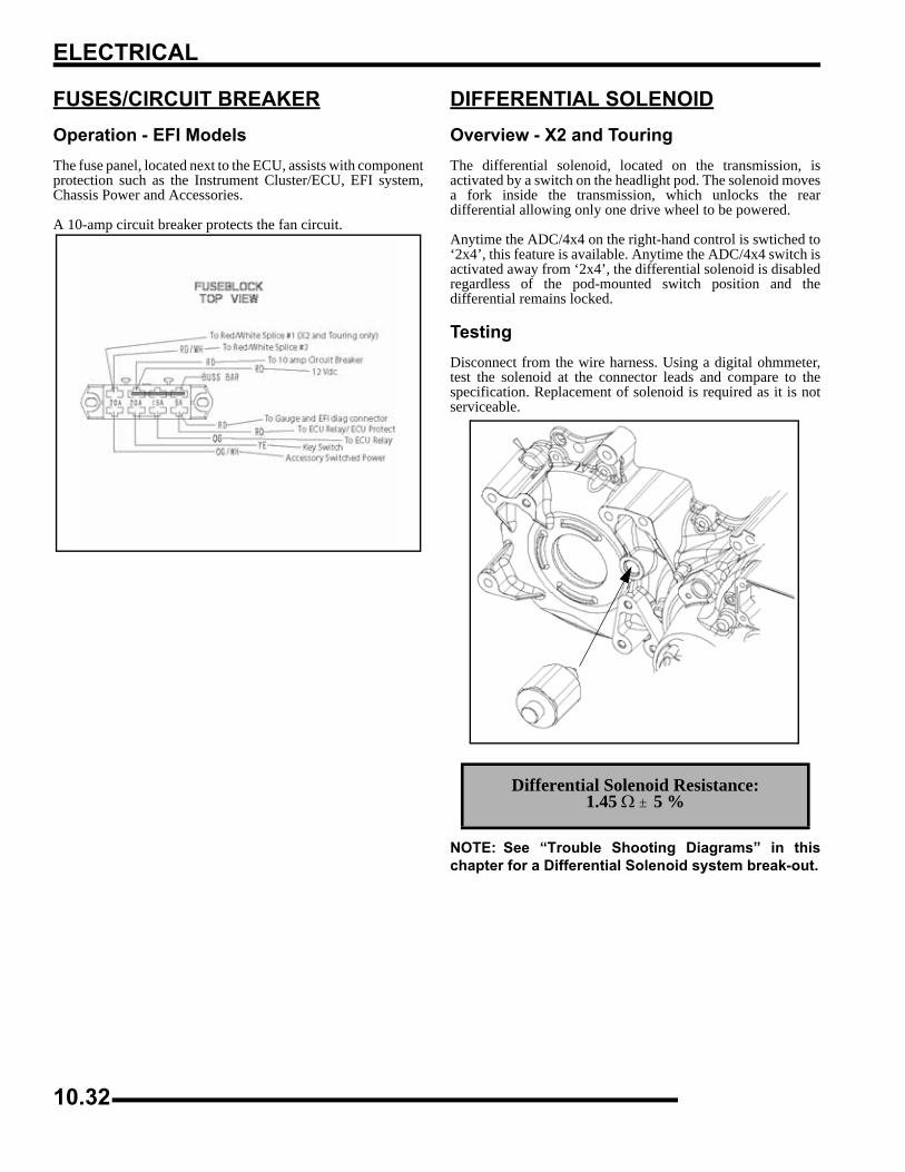
ELECTRICAL
FUSES/CIRCUIT BREAKEROperation - EFI ModelsThe fuse panel, located next to the ECU, assists with componentprotection such as the Instrument Cluster/ECU, EFI system,Chassis Power and Accessories.
A 10-amp circuit breaker protects the fan circuit.
DIFFERENTIAL SOLENOIDOverview - X2 and TouringThe differential solenoid, located on the transmission, isactivated by a switch on the headlight pod. The solenoid movesa fork inside the transmission, which unlocks the reardifferential allowing only one drive wheel to be powered.
Anytime the ADC/4x4 on the right-hand control is swtiched to‘2x4’, this feature is available. Anytime the ADC/4x4 switch isactivated away from ‘2x4’, the differential solenoid is disabledregardless of the pod-mounted switch position and thedifferential remains locked.
TestingDisconnect from the wire harness. Using a digital ohmmeter,test the solenoid at the connector leads and compare to thespecification. Replacement of solenoid is required as it is notserviceable.
NOTE: See “Trouble Shooting Diagrams” in thischapter for a Differential Solenoid system break-out.
Differential Solenoid Resistance:1.45 Ω ± 5 %
10.32
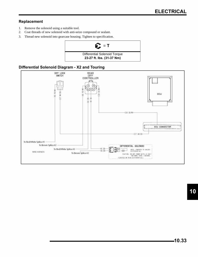
ELECTRICAL
0
1Replacement1. Remove the solenoid using a suitable tool. 2. Coat threads of new solenoid with anti-seize compound or sealant.3. Thread new solenoid into gearcase housing. Tighten to specification.
Differential Solenoid Diagram - X2 and Touring
= T
Differential Solenoid Torque23-27 ft. lbs. (31-37 Nm)
10.33
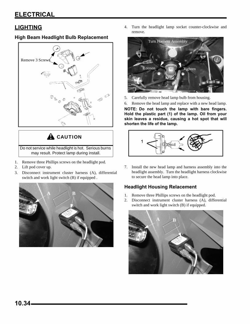
ELECTRICAL
LIGHTINGHigh Beam Headlight Bulb Replacement
1. Remove three Phillips screws on the headlight pod.2. Lift pod cover up.3. Disconnect instrument cluster harness (A), differential
switch and work light switch (B) if equipped .
4. Turn the headlight lamp socket counter-clockwise andremove.
5. Carefully remove head lamp bulb from housing.6. Remove the head lamp and replace with a new head lamp.NOTE: Do not touch the lamp with bare fingers.Hold the plastic part (1) of the lamp. Oil from yourskin leaves a residue, causing a hot spot that willshorten the life of the lamp.
7. Install the new head lamp and harness assembly into theheadlight assembly. Turn the headlight harness clockwiseto secure the head lamp into place.
Headlight Housing Relacement1. Remove three Phillips screws on the headlight pod.2. Disconnect instrument cluster harness (A), differential
switch and work light switch (B) if equipped.
CAUTION
Do not service while headlight is hot. Serious burns may result. Protect lamp during install.
Remove 3 Screws
A B
Turn Harness Assembly
TightenLoosen
A B
10.34
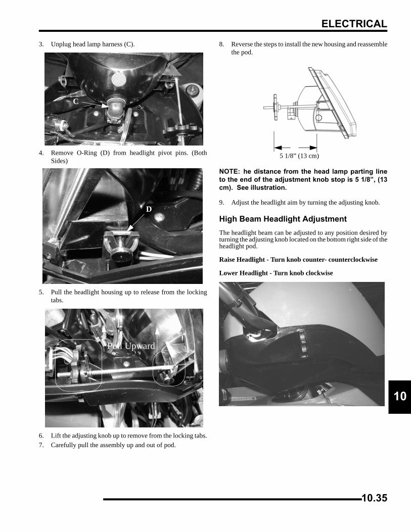
ELECTRICAL
0
13. Unplug head lamp harness (C).
4. Remove O-Ring (D) from headlight pivot pins. (BothSides)
5. Pull the headlight housing up to release from the lockingtabs.
6. Lift the adjusting knob up to remove from the locking tabs.7. Carefully pull the assembly up and out of pod.
8. Reverse the steps to install the new housing and reassemblethe pod.
NOTE: he distance from the head lamp parting lineto the end of the adjustment knob stop is 5 1/8”, (13cm). See illustration.
9. Adjust the headlight aim by turning the adjusting knob.
High Beam Headlight AdjustmentThe headlight beam can be adjusted to any position desired byturning the adjusting knob located on the bottom right side of theheadlight pod.
Raise Headlight - Turn knob counter- counterclockwise
Lower Headlight - Turn knob clockwise
C
D
l
Pull Upward
5 1/8” (13 cm)
10.35
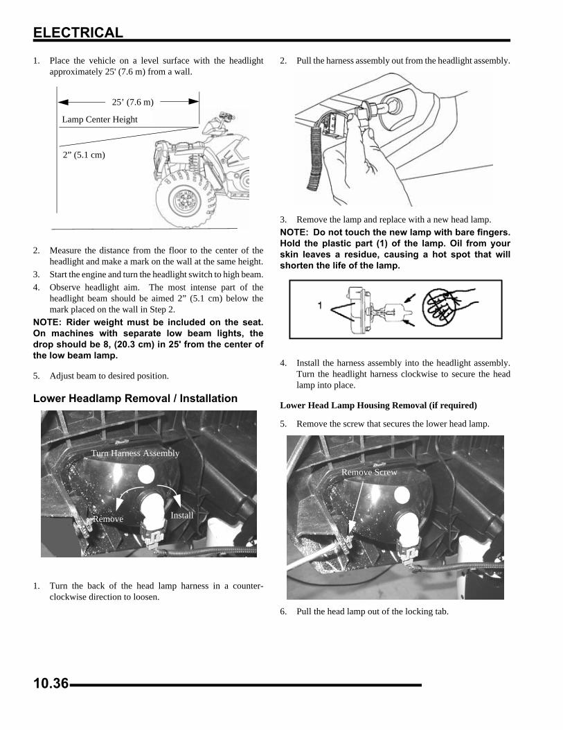
ELECTRICAL
1. Place the vehicle on a level surface with the headlightapproximately 25' (7.6 m) from a wall.
2. Measure the distance from the floor to the center of theheadlight and make a mark on the wall at the same height.
3. Start the engine and turn the headlight switch to high beam.4. Observe headlight aim. The most intense part of the
headlight beam should be aimed 2” (5.1 cm) below themark placed on the wall in Step 2.
NOTE: Rider weight must be included on the seat.On machines with separate low beam lights, thedrop should be 8, (20.3 cm) in 25' from the center ofthe low beam lamp.
5. Adjust beam to desired position.
Lower Headlamp Removal / Installation
1. Turn the back of the head lamp harness in a counter-clockwise direction to loosen.
2. Pull the harness assembly out from the headlight assembly.
3. Remove the lamp and replace with a new head lamp.NOTE: Do not touch the new lamp with bare fingers.Hold the plastic part (1) of the lamp. Oil from yourskin leaves a residue, causing a hot spot that willshorten the life of the lamp.
4. Install the harness assembly into the headlight assembly.Turn the headlight harness clockwise to secure the headlamp into place.
Lower Head Lamp Housing Removal (if required)
5. Remove the screw that secures the lower head lamp.
6. Pull the head lamp out of the locking tab.
25’ (7.6 m)
2” (5.1 cm)
Lamp Center Height
Remove Install
Turn Harness Assembly
Remove Screw
10.36
ELECTRICAL
0
1Low Beam Headlight Adjustment1. The low beam can be adjusted slightly upward or
downward.
2. Loosen the phillips screw located at the rear of the headlamp.
3. Tilt the head lamp upward or downward.4. Tighten the screw.
Headlamp Switch Test1. Remove the headlight pod cover.2. Set meter to DC Volts and probe the head lamp plug wires
(Brown and Yellow) at back of connector for 12 Volts.3. Turn ignition and headlight on. If there is no power,
continue with checks to the harness and PDM.
Work Light / Differential Lockout SwitchRemove the headlight pod cover to locate the switch wires. Theswitch (A) snaps out by pushing in on the tabs on both sides ofthe switch.
• Check for continuity between the switch contacts - Place meter leads between two contacts with switch in ON position.
• Probe the worklight plug wires at back of vehicle, there should be at least 12V at the plug with the key ‘ON’.
• Check for 12 volt power at the wire.
Loosen Screw
Brown
Yellow
Upper Headlamp Plug Wires
Brown
Green
Lower Headlamp Plug Wires
A
Work Light Shown
Squeeze Tabs - Push ThroughPod To Remove
Worklight / Differential Lockout Connector Wires
Test
10.37
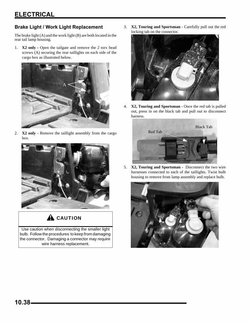
ELECTRICAL
Brake Light / Work Light ReplacementThe brake light (A) and the work light (B) are both located in therear tail lamp housing.
1. X2 only - Open the tailgate and remove the 2 torx headscrews (A) securing the rear taillights on each side of thecargo box as illustrated below.
2. X2 only - Remove the taillight assembly from the cargobox.
3. X2, Touring and Sportsman - Carefully pull out the redlocking tab on the connector.
4. X2, Touring and Sportsman - Once the red tab is pulledout, press in on the black tab and pull out to disconnectharness.
5. X2, Touring and Sportsman - Disconnect the two wireharnesses connected to each of the taillights. Twist bulbhousing to remove from lamp assembly and replace bulb.
CAUTION
Use caution when disconnecting the smaller light bulb. Follow the procedures to keep from damaging the connector. Damaging a connector may require
wire harness replacement.
A
Black TabRed Tab
RemoveInstall
10.38
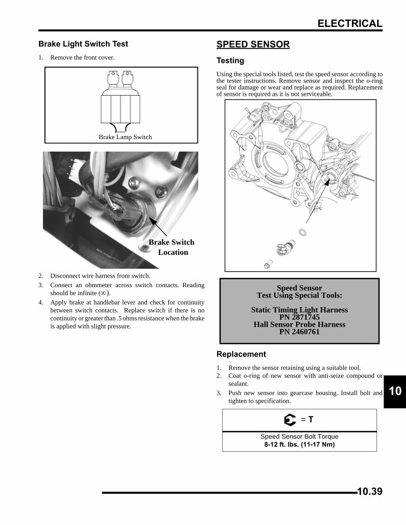
ELECTRICAL
0
1Brake Light Switch Test1. Remove the front cover.
2. Disconnect wire harness from switch.3. Connect an ohmmeter across switch contacts. Reading
should be infinite (∞).4. Apply brake at handlebar lever and check for continuity
between switch contacts. Replace switch if there is nocontinuity or greater than .5 ohms resistance when the brakeis applied with slight pressure.
SPEED SENSORTestingUsing the special tools listed, test the speed sensor according tothe tester instructions. Remove sensor and inspect the o-ringseal for damage or wear and replace as required. Replacementof sensor is required as it is not serviceable.
Replacement1. Remove the sensor retaining using a suitable tool. 2. Coat o-ring of new sensor with anti-seize compound or
sealant.3. Push new sensor into gearcase housing. Install bolt and
tighten to specification.
Brake Lamp Switch
Brake Switch Location
Speed SensorTest Using Special Tools:
Static Timing Light Harness PN 2871745
Hall Sensor Probe HarnessPN 2460761
= T
Speed Sensor Bolt Torque8-12 ft. lbs. (11-17 Nm)
10.39
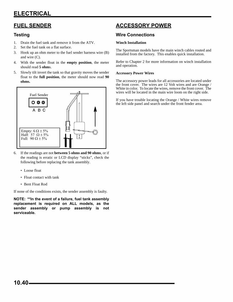
ELECTRICAL
FUEL SENDERTesting1. Drain the fuel tank and remove it from the ATV.2. Set the fuel tank on a flat surface.3. Hook up an ohm meter to the fuel sender harness wire (B)
and wire (C).4. With the sender float in the empty position, the meter
should read 5 ohms.5. Slowly tilt invert the tank so that gravity moves the sender
float to the full position, the meter should now read 90ohms.
6. If the readings are not between 5 ohms and 90 ohms, or ifthe reading is erratic or LCD display “sticks”, check thefollowing before replacing the tank assembly.
• Loose float
• Float contact with tank
• Bent Float Rod
If none of the conditions exists, the sender assembly is faulty.
NOTE: **In the event of a failure, fuel tank assemblyreplacement is required on ALL models, as thesender assembly or pump assembly is notserviceable.
ACCESSORY POWERWire ConnectionsWinch Installation
The Sportsman models have the main winch cables routed andinstalled from the factory. This enables quick installation.
Refer to Chapter 2 for more information on winch installationand operation.
Accessory Power Wires
The accessory power leads for all accessories are located underthe front cover. The wires are 12 Volt wires and are Orange /White in color. To locate the wires, remove the front cover. Thewires will be located in the main wire loom on the right side.
If you have trouble locating the Orange / White wires removethe left side panel and search under the front fender area.
Fuel Sender
Empty: 6 Ω ± 5%Half: 57 Ω ± 5% Full: 90 Ω ± 5%
10.40
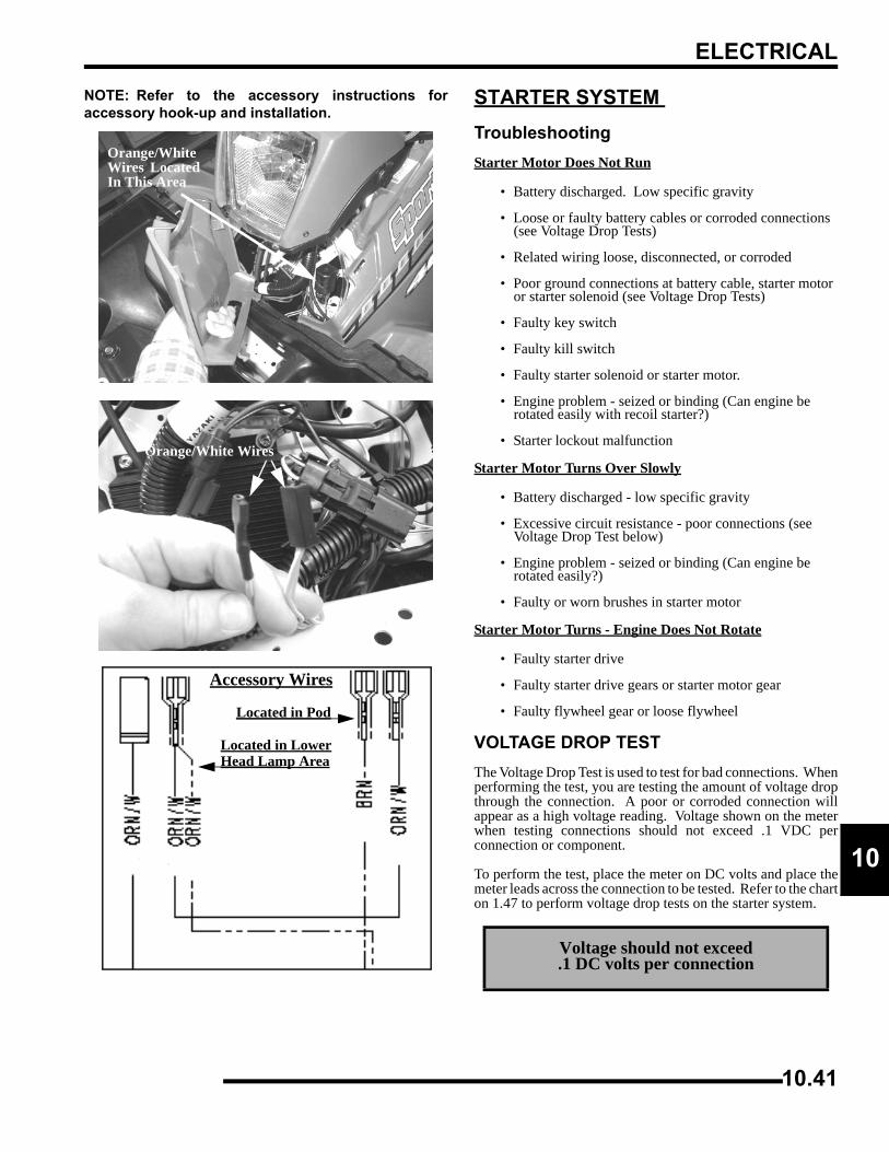
ELECTRICAL
0
1NOTE: Refer to the accessory instructions foraccessory hook-up and installation.
STARTER SYSTEM TroubleshootingStarter Motor Does Not Run
• Battery discharged. Low specific gravity
• Loose or faulty battery cables or corroded connections (see Voltage Drop Tests)
• Related wiring loose, disconnected, or corroded
• Poor ground connections at battery cable, starter motor or starter solenoid (see Voltage Drop Tests)
• Faulty key switch
• Faulty kill switch
• Faulty starter solenoid or starter motor.
• Engine problem - seized or binding (Can engine be rotated easily with recoil starter?)
• Starter lockout malfunction
Starter Motor Turns Over Slowly
• Battery discharged - low specific gravity
• Excessive circuit resistance - poor connections (see Voltage Drop Test below)
• Engine problem - seized or binding (Can engine be rotated easily?)
• Faulty or worn brushes in starter motor
Starter Motor Turns - Engine Does Not Rotate
• Faulty starter drive
• Faulty starter drive gears or starter motor gear
• Faulty flywheel gear or loose flywheel
VOLTAGE DROP TESTThe Voltage Drop Test is used to test for bad connections. Whenperforming the test, you are testing the amount of voltage dropthrough the connection. A poor or corroded connection willappear as a high voltage reading. Voltage shown on the meterwhen testing connections should not exceed .1 VDC perconnection or component.
To perform the test, place the meter on DC volts and place themeter leads across the connection to be tested. Refer to the charton 1.47 to perform voltage drop tests on the starter system.
Orange/WhiteWires LocatedIn This Area
Orange/White Wires
Accessory Wires
Located in Pod
Located in LowerHead Lamp Area
Voltage should not exceed.1 DC volts per connection
10.41
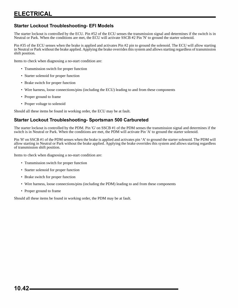
ELECTRICAL
Starter Lockout Troubleshooting- EFI ModelsThe starter lockout is controlled by the ECU. Pin #52 of the ECU senses the transmission signal and determines if the switch is inNeutral or Park. When the conditions are met, the ECU will activate SSCB #2 Pin 'N' to ground the starter solenoid.
Pin #35 of the ECU senses when the brake is applied and activates Pin #2 pin to ground the solenoid. The ECU will allow startingin Neutral or Park without the brake applied. Applying the brake overrides this system and allows starting regardless of transmissionshift position.
Items to check when diagnosing a no-start condition are:
• Transmission switch for proper function
• Starter solenoid for proper function
• Brake switch for proper function
• Wire harness, loose connections/pins (including the ECU) leading to and from these components
• Proper ground to frame
• Proper voltage to solenoid
Should all these items be found in working order, the ECU may be at fault.
Starter Lockout Troubleshooting- Sportsman 500 CarburetedThe starter lockout is controlled by the PDM. Pin 'G' on SSCB #1 of the PDM senses the transmission signal and determines if theswitch is in Neutral or Park. When the conditions are met, the PDM will activate Pin 'A' to ground the starter solenoid.
Pin 'H' on SSCB #1 of the PDM senses when the brake is applied and activates pin ‘A’ to ground the starter solenoid. The PDM willallow starting in Neutral or Park without the brake applied. Applying the brake overrides this system and allows starting regardlessof transmission shift position.
Items to check when diagnosing a no-start condition are:
• Transmission switch for proper function
• Starter solenoid for proper function
• Brake switch for proper function
• Wire harness, loose connections/pins (including the PDM) leading to and from these components
• Proper ground to frame
Should all these items be found in working order, the PDM may be at fault.
10.42
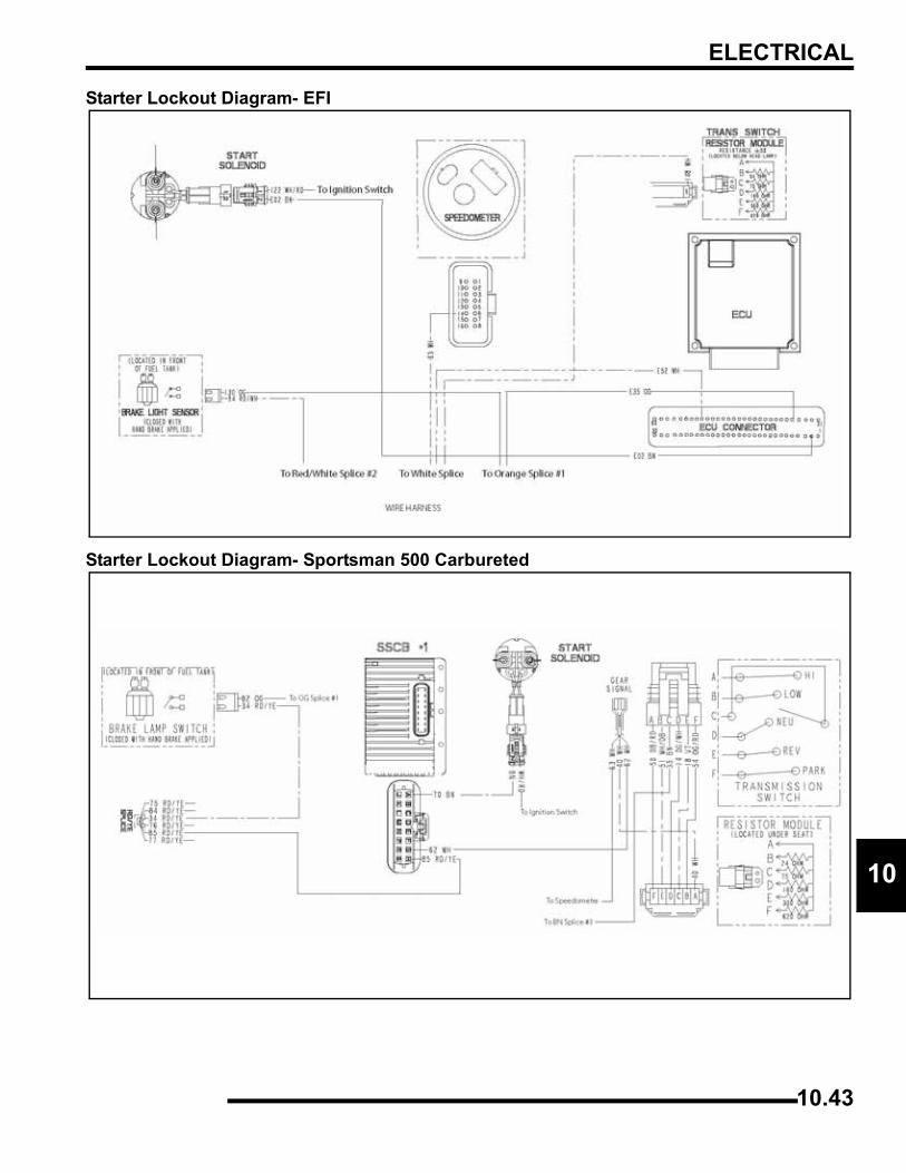
ELECTRICAL
0
1Starter Lockout Diagram- EFI
Starter Lockout Diagram- Sportsman 500 Carbureted
10.43
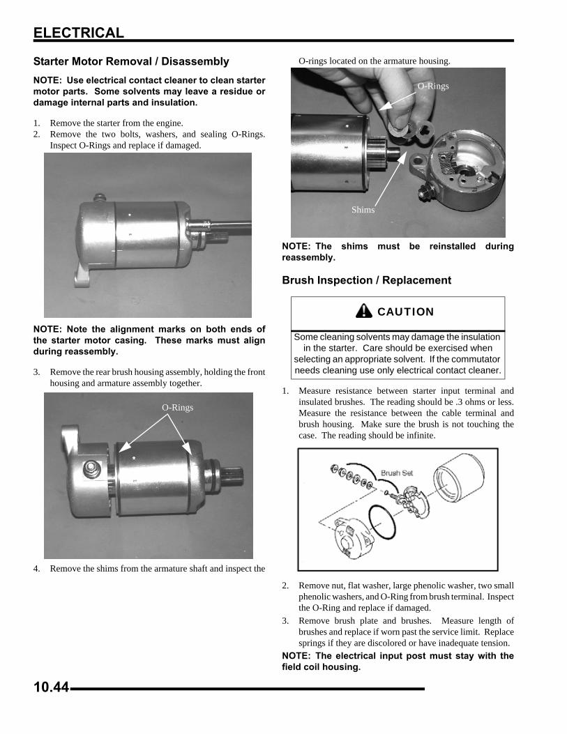
ELECTRICAL
Starter Motor Removal / DisassemblyNOTE: Use electrical contact cleaner to clean startermotor parts. Some solvents may leave a residue ordamage internal parts and insulation.
1. Remove the starter from the engine.2. Remove the two bolts, washers, and sealing O-Rings.
Inspect O-Rings and replace if damaged.
NOTE: Note the alignment marks on both ends ofthe starter motor casing. These marks must alignduring reassembly.
3. Remove the rear brush housing assembly, holding the fronthousing and armature assembly together.
4. Remove the shims from the armature shaft and inspect the
O-rings located on the armature housing.
NOTE: The shims must be reinstalled duringreassembly.
Brush Inspection / Replacement
1. Measure resistance between starter input terminal andinsulated brushes. The reading should be .3 ohms or less.Measure the resistance between the cable terminal andbrush housing. Make sure the brush is not touching thecase. The reading should be infinite.
2. Remove nut, flat washer, large phenolic washer, two smallphenolic washers, and O-Ring from brush terminal. Inspectthe O-Ring and replace if damaged.
3. Remove brush plate and brushes. Measure length ofbrushes and replace if worn past the service limit. Replacesprings if they are discolored or have inadequate tension.
NOTE: The electrical input post must stay with thefield coil housing.
O-Rings
CAUTION
Some cleaning solvents may damage the insulation in the starter. Care should be exercised when
selecting an appropriate solvent. If the commutator needs cleaning use only electrical contact cleaner.
O-Rings
Shims
10.44
ELECTRICAL
0
14. Inspect surface of commutator for wear or discoloration.See Steps 3-6 of ‘Armature Testing’.
Brush Inspection
1. Measure length of each carbon brush. Replace brushassembly when worn to 5/16” (8 mm) or less. The brushesmust slide freely in their holders.
Brush Replacement
1. Install a new carbon brush assembly in the brush housing.NOTE: Be sure that the terminal bolt insulating washer isproperly seated in the housing, and the tab on the brushplate engages the notch in the brush plate housing.
2. Place a wrap of electrical tape on the threads of the terminalbolt to prevent O-Ring damage during reinstallation.
3. Install the O-Ring over the bolt. Make sure the O-ring isfully seated.
4. Remove the electrical tape and reinstall the two smallphenolic washers, the large phenolic washer, flat washer,and nut.
Armature Testing1. Remove armature from starter casing. NOTE: Note order of shims on drive end for reassembly.
2. Inspect surface of commutator. Replace if excessivelyworn or damaged.
3. Using a digital multitester, measure the resistance betweeneach of the commutator segments. The reading should be.3 ohms or less.
4. Measure the resistance between each commutator segmentand the armature shaft. The reading should be infinite (nocontinuity).
5. Check commutator bars for discoloration. Bars discoloredin pairs indicate shorted coils, requiring replacement of thestarter motor.
6. Place armature in a growler. Turn growler on and positiona hacksaw blade or feeler gauge lengthwise 1/8” (.3 cm)above armature coil laminates. Rotate armature 360°. Ifhacksaw blade is drawn to armature on any pole, thearmature is shorted and must be replaced.
Limit 5/16” (8 mm)
Brush Length
10.45
ELECTRICAL
Starter Reassembly
1. Inspect permanent magnets in starter housing. Make surethey are not cracked or separated from housing. Placearmature in field magnet casing.
2. Place shims on drive end of armature shaft with phenolicwasher outermost on shaft. Engage tabs of stationarywasher in drive end housing, holding it in place with a lightfilm of grease.
3. Install case sealing O-Ring. Make sure O-Ring is in goodcondition and not twisted on the case. Lubricate needlebearing and oil seal with a light film of grease, and installhousing, aligning marks.
4. Install O-Ring on other end of field magnet casing. Makesure it is in good condition and not twisted on the case.
5. Align casing marks and install housing, pushing backbrushes while installing shaft in bushing.
6. Reinstall starter motor housing bolts. Make sure O-Ringsare in good condition and seated in groove.
7. Align brush plate and install cover and screws.8. Install the starter onto the engine case. Hand tighten the
starter bolt. Torque the bolt to 9 ft.lbs. (12 Nm).
Starter Solenoid Bench TestTo measure the resistance of the pull-in coil, connect one meterlead to the solenoid lead wire and the other to ground. Theresistance should be 3.7 ohms ± 5 %. Refer to “Electric StarterSystem Testing” in this section to further test the solenoid.
Starter Exploded View
CAUTION
Use care when handling starter housing. Do not drop or strike the housing as magnet damage is
possible. If magnets are damaged, starter must be replaced.
10.46
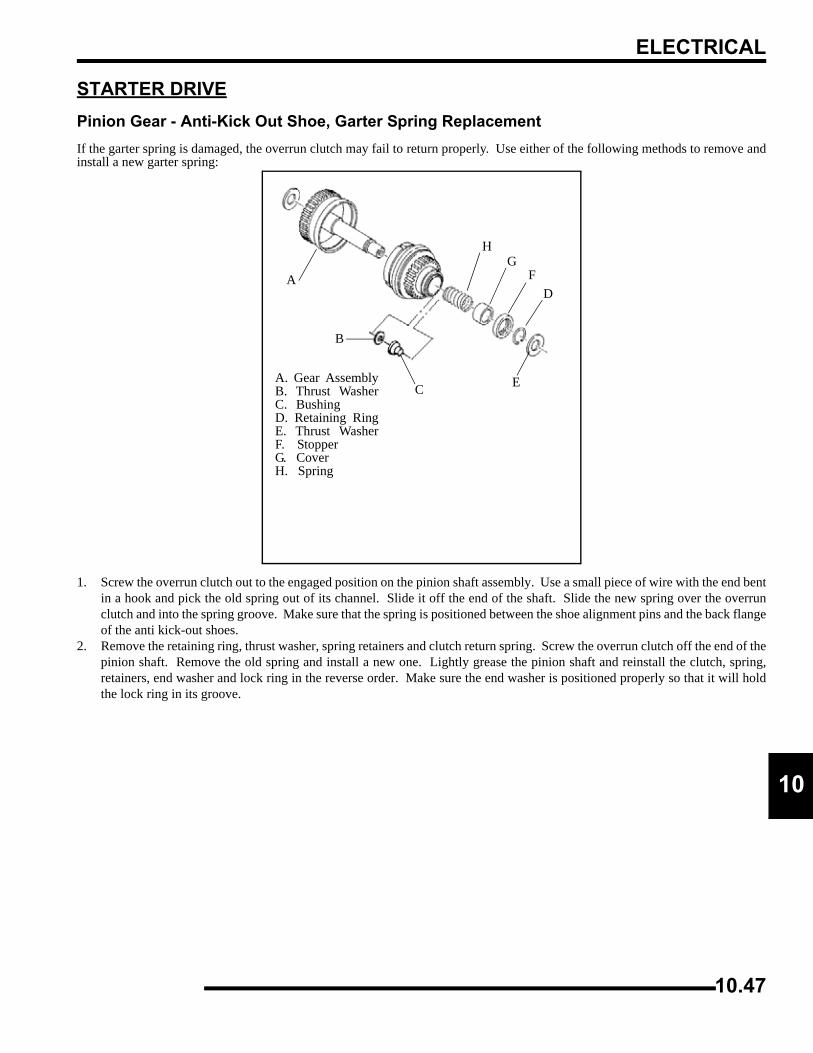
ELECTRICAL
0
1STARTER DRIVEPinion Gear - Anti-Kick Out Shoe, Garter Spring ReplacementIf the garter spring is damaged, the overrun clutch may fail to return properly. Use either of the following methods to remove andinstall a new garter spring:
1. Screw the overrun clutch out to the engaged position on the pinion shaft assembly. Use a small piece of wire with the end bentin a hook and pick the old spring out of its channel. Slide it off the end of the shaft. Slide the new spring over the overrunclutch and into the spring groove. Make sure that the spring is positioned between the shoe alignment pins and the back flangeof the anti kick-out shoes.
2. Remove the retaining ring, thrust washer, spring retainers and clutch return spring. Screw the overrun clutch off the end of thepinion shaft. Remove the old spring and install a new one. Lightly grease the pinion shaft and reinstall the clutch, spring,retainers, end washer and lock ring in the reverse order. Make sure the end washer is positioned properly so that it will holdthe lock ring in its groove.
A. Gear AssemblyB. Thrust WasherC. Bushing D. Retaining RingE. Thrust WasherF. Stopper G. Cover H. Spring
A
B
C
D
E
FG
H
10.47
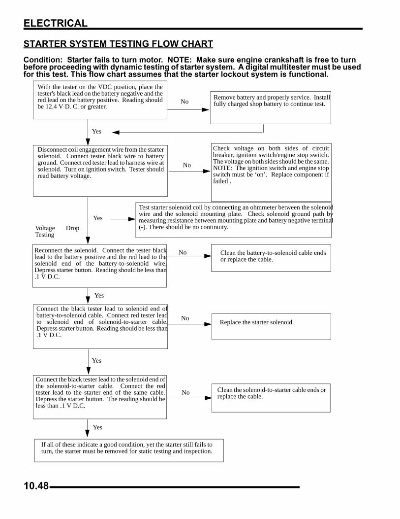
ELECTRICAL
STARTER SYSTEM TESTING FLOW CHARTCondition: Starter fails to turn motor. NOTE: Make sure engine crankshaft is free to turn before proceeding with dynamic testing of starter system. A digital multitester must be used for this test. This flow chart assumes that the starter lockout system is functional.
With the tester on the VDC position, place thetester's black lead on the battery negative and thered lead on the battery positive. Reading shouldbe 12.4 V D. C. or greater.
Remove battery and properly service. Installfully charged shop battery to continue test.
Disconnect coil engagement wire from the startersolenoid. Connect tester black wire to batteryground. Connect red tester lead to harness wire atsolenoid. Turn on ignition switch. Tester shouldread battery voltage.
Check voltage on both sides of circuitbreaker, ignition switch/engine stop switch.The voltage on both sides should be the same.NOTE: The ignition switch and engine stopswitch must be ‘on’. Replace component iffailed .
Test starter solenoid coil by connecting an ohmmeter between the solenoidwire and the solenoid mounting plate. Check solenoid ground path bymeasuring resistance between mounting plate and battery negative terminal(-). There should be no continuity.
Reconnect the solenoid. Connect the tester blacklead to the battery positive and the red lead to thesolenoid end of the battery-to-solenoid wire.Depress starter button. Reading should be less than.1 V D.C.
Clean the battery-to-solenoid cable endsor replace the cable.
Connect the black tester lead to solenoid end ofbattery-to-solenoid cable. Connect red tester leadto solenoid end of solenoid-to-starter cable.Depress starter button. Reading should be less than.1 V D.C.
Replace the starter solenoid.
Connect the black tester lead to the solenoid end ofthe solenoid-to-starter cable. Connect the redtester lead to the starter end of the same cable.Depress the starter button. The reading should beless than .1 V D.C.
Clean the solenoid-to-starter cable ends orreplace the cable.
If all of these indicate a good condition, yet the starter still fails toturn, the starter must be removed for static testing and inspection.
Yes
Yes
Yes
Yes
No
No
No
Yes
No
No
Voltage DropTesting
10.48
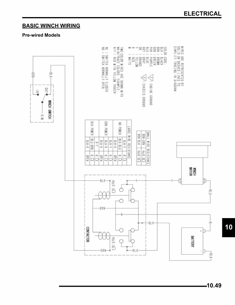
ELECTRICAL
0
1BASIC WINCH WIRINGPre-wired Models
10.49
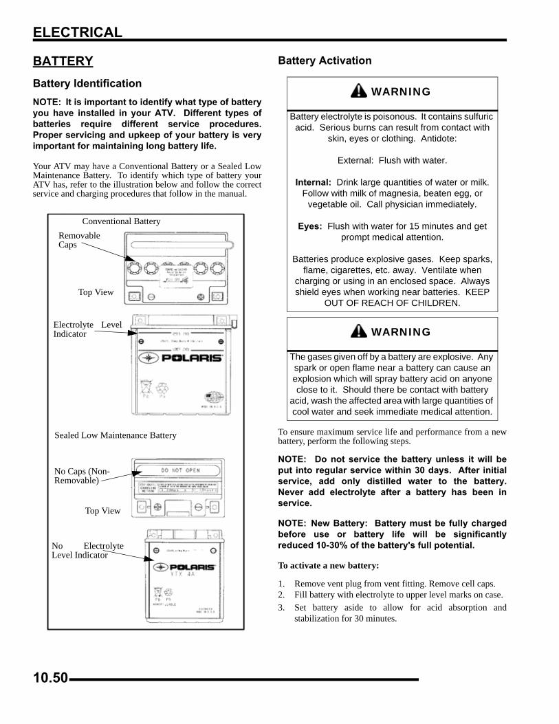
ELECTRICAL
BATTERYBattery IdentificationNOTE: It is important to identify what type of batteryyou have installed in your ATV. Different types ofbatteries require different service procedures.Proper servicing and upkeep of your battery is veryimportant for maintaining long battery life.
Your ATV may have a Conventional Battery or a Sealed LowMaintenance Battery. To identify which type of battery yourATV has, refer to the illustration below and follow the correctservice and charging procedures that follow in the manual.
Battery Activation
To ensure maximum service life and performance from a newbattery, perform the following steps.
NOTE: Do not service the battery unless it will beput into regular service within 30 days. After initialservice, add only distilled water to the battery.Never add electrolyte after a battery has been inservice.
NOTE: New Battery: Battery must be fully chargedbefore use or battery life will be significantlyreduced 10-30% of the battery's full potential.
To activate a new battery:
1. Remove vent plug from vent fitting. Remove cell caps.2. Fill battery with electrolyte to upper level marks on case.3. Set battery aside to allow for acid absorption and
stabilization for 30 minutes.
RemovableCaps
Top View
Electrolyte LevelIndicator
No Caps (Non-Removable)
Top View
No ElectrolyteLevel Indicator
Sealed Low Maintenance Battery
Conventional Battery
WARNING
Battery electrolyte is poisonous. It contains sulfuric acid. Serious burns can result from contact with
skin, eyes or clothing. Antidote:
External: Flush with water.
Internal: Drink large quantities of water or milk. Follow with milk of magnesia, beaten egg, or
vegetable oil. Call physician immediately.
Eyes: Flush with water for 15 minutes and get prompt medical attention.
Batteries produce explosive gases. Keep sparks, flame, cigarettes, etc. away. Ventilate when
charging or using in an enclosed space. Always shield eyes when working near batteries. KEEP
OUT OF REACH OF CHILDREN.
WARNING
The gases given off by a battery are explosive. Any spark or open flame near a battery can cause an explosion which will spray battery acid on anyone close to it. Should there be contact with battery
acid, wash the affected area with large quantities of cool water and seek immediate medical attention.
10.50
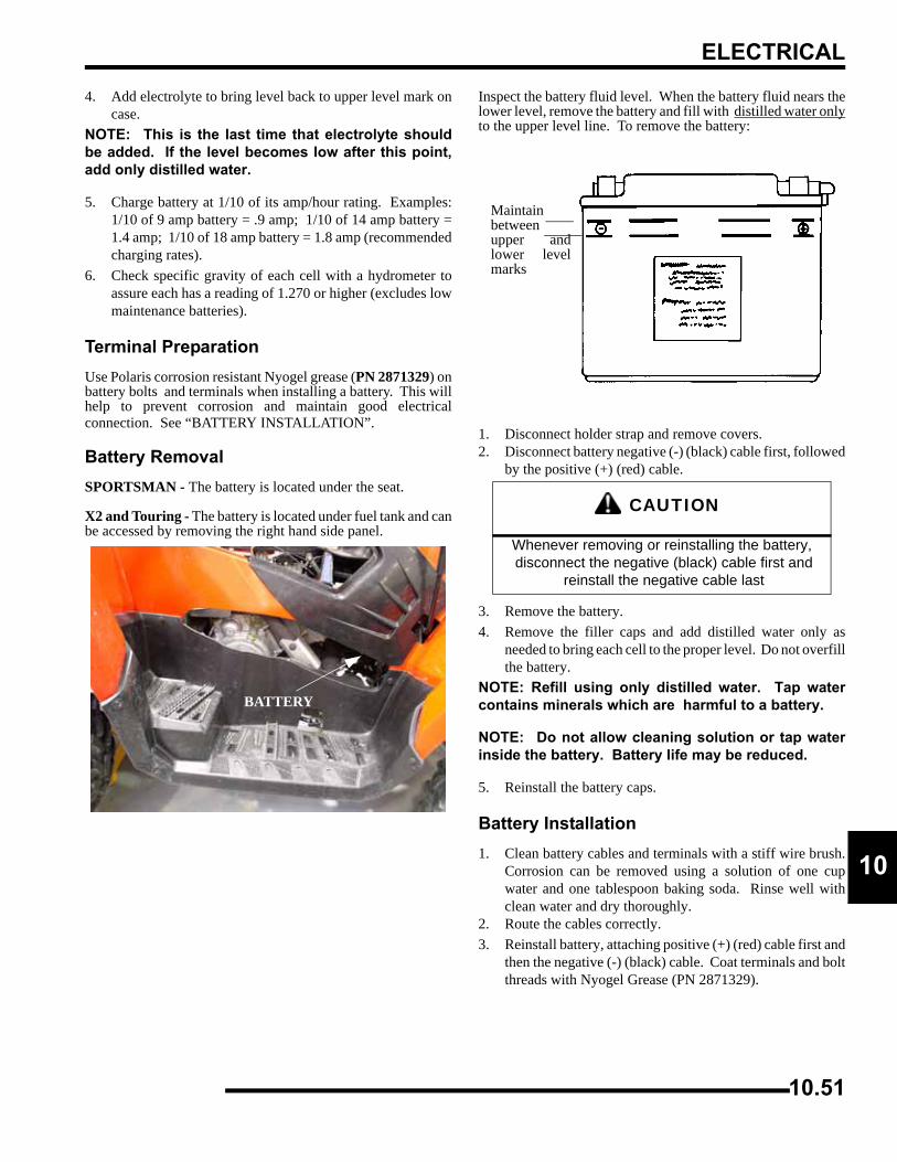
ELECTRICAL
0
14. Add electrolyte to bring level back to upper level mark oncase.
NOTE: This is the last time that electrolyte shouldbe added. If the level becomes low after this point,add only distilled water.
5. Charge battery at 1/10 of its amp/hour rating. Examples:1/10 of 9 amp battery = .9 amp; 1/10 of 14 amp battery =1.4 amp; 1/10 of 18 amp battery = 1.8 amp (recommendedcharging rates).
6. Check specific gravity of each cell with a hydrometer toassure each has a reading of 1.270 or higher (excludes lowmaintenance batteries).
Terminal PreparationUse Polaris corrosion resistant Nyogel grease (PN 2871329) onbattery bolts and terminals when installing a battery. This willhelp to prevent corrosion and maintain good electricalconnection. See “BATTERY INSTALLATION”.
Battery RemovalSPORTSMAN - The battery is located under the seat.
X2 and Touring - The battery is located under fuel tank and canbe accessed by removing the right hand side panel.
Inspect the battery fluid level. When the battery fluid nears thelower level, remove the battery and fill with distilled water onlyto the upper level line. To remove the battery:
1. Disconnect holder strap and remove covers.2. Disconnect battery negative (-) (black) cable first, followed
by the positive (+) (red) cable.
3. Remove the battery.4. Remove the filler caps and add distilled water only as
needed to bring each cell to the proper level. Do not overfillthe battery.
NOTE: Refill using only distilled water. Tap watercontains minerals which are harmful to a battery.
NOTE: Do not allow cleaning solution or tap waterinside the battery. Battery life may be reduced.
5. Reinstall the battery caps.
Battery Installation1. Clean battery cables and terminals with a stiff wire brush.
Corrosion can be removed using a solution of one cupwater and one tablespoon baking soda. Rinse well withclean water and dry thoroughly.
2. Route the cables correctly.3. Reinstall battery, attaching positive (+) (red) cable first and
then the negative (-) (black) cable. Coat terminals and boltthreads with Nyogel Grease (PN 2871329).
BATTERY
CAUTION
Whenever removing or reinstalling the battery, disconnect the negative (black) cable first and
reinstall the negative cable last
Maintainbetweenupper andlower levelmarks
10.51
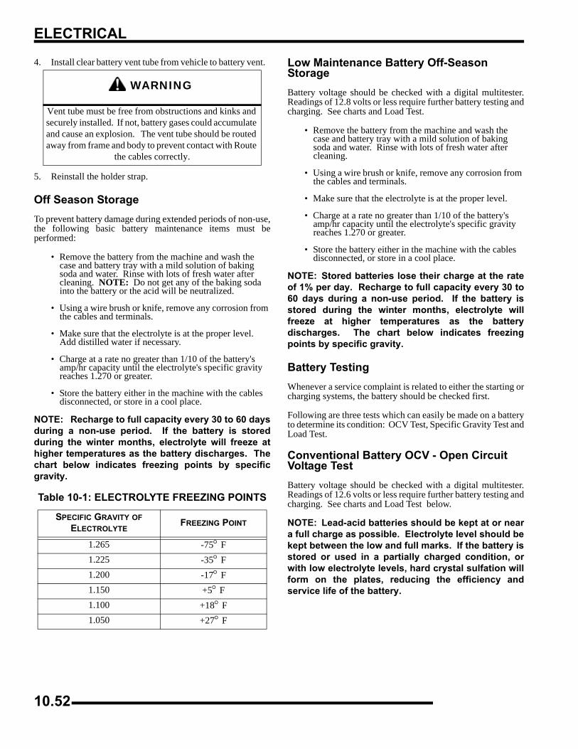
ELECTRICAL
4. Install clear battery vent tube from vehicle to battery vent.
5. Reinstall the holder strap.
Off Season StorageTo prevent battery damage during extended periods of non-use,the following basic battery maintenance items must beperformed:
• Remove the battery from the machine and wash the case and battery tray with a mild solution of baking soda and water. Rinse with lots of fresh water after cleaning. NOTE: Do not get any of the baking soda into the battery or the acid will be neutralized.
• Using a wire brush or knife, remove any corrosion from the cables and terminals.
• Make sure that the electrolyte is at the proper level. Add distilled water if necessary.
• Charge at a rate no greater than 1/10 of the battery's amp/hr capacity until the electrolyte's specific gravity reaches 1.270 or greater.
• Store the battery either in the machine with the cables disconnected, or store in a cool place.
NOTE: Recharge to full capacity every 30 to 60 daysduring a non-use period. If the battery is storedduring the winter months, electrolyte will freeze athigher temperatures as the battery discharges. Thechart below indicates freezing points by specificgravity.
Low Maintenance Battery Off-Season StorageBattery voltage should be checked with a digital multitester.Readings of 12.8 volts or less require further battery testing andcharging. See charts and Load Test.
• Remove the battery from the machine and wash the case and battery tray with a mild solution of baking soda and water. Rinse with lots of fresh water after cleaning.
• Using a wire brush or knife, remove any corrosion from the cables and terminals.
• Make sure that the electrolyte is at the proper level.
• Charge at a rate no greater than 1/10 of the battery's amp/hr capacity until the electrolyte's specific gravity reaches 1.270 or greater.
• Store the battery either in the machine with the cables disconnected, or store in a cool place.
NOTE: Stored batteries lose their charge at the rateof 1% per day. Recharge to full capacity every 30 to60 days during a non-use period. If the battery isstored during the winter months, electrolyte willfreeze at higher temperatures as the batterydischarges. The chart below indicates freezingpoints by specific gravity.
Battery TestingWhenever a service complaint is related to either the starting orcharging systems, the battery should be checked first.
Following are three tests which can easily be made on a batteryto determine its condition: OCV Test, Specific Gravity Test andLoad Test.
Conventional Battery OCV - Open Circuit Voltage TestBattery voltage should be checked with a digital multitester.Readings of 12.6 volts or less require further battery testing andcharging. See charts and Load Test below.
NOTE: Lead-acid batteries should be kept at or neara full charge as possible. Electrolyte level should bekept between the low and full marks. If the battery isstored or used in a partially charged condition, orwith low electrolyte levels, hard crystal sulfation willform on the plates, reducing the efficiency andservice life of the battery.
WARNING
Vent tube must be free from obstructions and kinks and securely installed. If not, battery gases could accumulate and cause an explosion. The vent tube should be routed away from frame and body to prevent contact with Route
the cables correctly.
Table 10-1: ELECTROLYTE FREEZING POINTS
SPECIFIC GRAVITY OF ELECTROLYTE
FREEZING POINT
1.265 -75° F1.225 -35° F1.200 -17° F1.150 +5° F1.100 +18° F1.050 +27° F
10.52
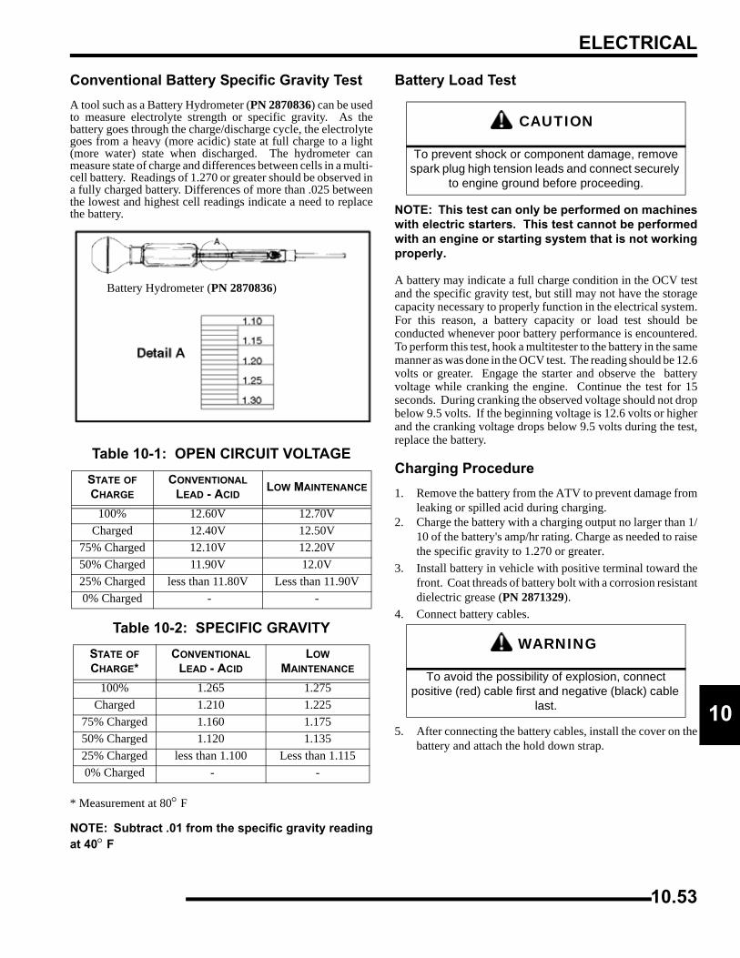
ELECTRICAL
0
1Conventional Battery Specific Gravity TestA tool such as a Battery Hydrometer (PN 2870836) can be usedto measure electrolyte strength or specific gravity. As thebattery goes through the charge/discharge cycle, the electrolytegoes from a heavy (more acidic) state at full charge to a light(more water) state when discharged. The hydrometer canmeasure state of charge and differences between cells in a multi-cell battery. Readings of 1.270 or greater should be observed ina fully charged battery. Differences of more than .025 betweenthe lowest and highest cell readings indicate a need to replacethe battery.
* Measurement at 80° F
NOTE: Subtract .01 from the specific gravity readingat 40° F
Battery Load Test
NOTE: This test can only be performed on machineswith electric starters. This test cannot be performedwith an engine or starting system that is not workingproperly.
A battery may indicate a full charge condition in the OCV testand the specific gravity test, but still may not have the storagecapacity necessary to properly function in the electrical system.For this reason, a battery capacity or load test should beconducted whenever poor battery performance is encountered.To perform this test, hook a multitester to the battery in the samemanner as was done in the OCV test. The reading should be 12.6volts or greater. Engage the starter and observe the batteryvoltage while cranking the engine. Continue the test for 15seconds. During cranking the observed voltage should not dropbelow 9.5 volts. If the beginning voltage is 12.6 volts or higherand the cranking voltage drops below 9.5 volts during the test,replace the battery.
Charging Procedure1. Remove the battery from the ATV to prevent damage from
leaking or spilled acid during charging.2. Charge the battery with a charging output no larger than 1/
10 of the battery's amp/hr rating. Charge as needed to raisethe specific gravity to 1.270 or greater.
3. Install battery in vehicle with positive terminal toward thefront. Coat threads of battery bolt with a corrosion resistantdielectric grease (PN 2871329).
4. Connect battery cables.
5. After connecting the battery cables, install the cover on thebattery and attach the hold down strap.
Table 10-1: OPEN CIRCUIT VOLTAGESTATE OF CHARGE
CONVENTIONAL LEAD - ACID
LOW MAINTENANCE
100% 12.60V 12.70VCharged 12.40V 12.50V
75% Charged 12.10V 12.20V50% Charged 11.90V 12.0V25% Charged less than 11.80V Less than 11.90V0% Charged - -
Table 10-2: SPECIFIC GRAVITYSTATE OF CHARGE*
CONVENTIONAL LEAD - ACID
LOW MAINTENANCE
100% 1.265 1.275Charged 1.210 1.225
75% Charged 1.160 1.17550% Charged 1.120 1.13525% Charged less than 1.100 Less than 1.1150% Charged - -
Battery Hydrometer (PN 2870836)
CAUTION
To prevent shock or component damage, remove spark plug high tension leads and connect securely
to engine ground before proceeding.
WARNING
To avoid the possibility of explosion, connect positive (red) cable first and negative (black) cable
last.
10.53
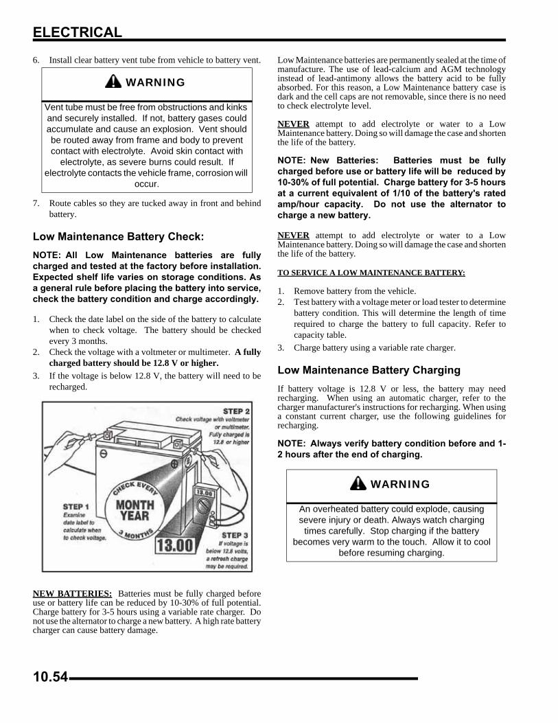
ELECTRICAL
6. Install clear battery vent tube from vehicle to battery vent.
7. Route cables so they are tucked away in front and behindbattery.
Low Maintenance Battery Check:NOTE: All Low Maintenance batteries are fullycharged and tested at the factory before installation.Expected shelf life varies on storage conditions. Asa general rule before placing the battery into service,check the battery condition and charge accordingly.
1. Check the date label on the side of the battery to calculatewhen to check voltage. The battery should be checkedevery 3 months.
2. Check the voltage with a voltmeter or multimeter. A fullycharged battery should be 12.8 V or higher.
3. If the voltage is below 12.8 V, the battery will need to berecharged.
NEW BATTERIES: Batteries must be fully charged beforeuse or battery life can be reduced by 10-30% of full potential.Charge battery for 3-5 hours using a variable rate charger. Donot use the alternator to charge a new battery. A high rate batterycharger can cause battery damage.
Low Maintenance batteries are permanently sealed at the time ofmanufacture. The use of lead-calcium and AGM technologyinstead of lead-antimony allows the battery acid to be fullyabsorbed. For this reason, a Low Maintenance battery case isdark and the cell caps are not removable, since there is no needto check electrolyte level.
NEVER attempt to add electrolyte or water to a LowMaintenance battery. Doing so will damage the case and shortenthe life of the battery.
NOTE: New Batteries: Batteries must be fullycharged before use or battery life will be reduced by10-30% of full potential. Charge battery for 3-5 hoursat a current equivalent of 1/10 of the battery's ratedamp/hour capacity. Do not use the alternator tocharge a new battery.
NEVER attempt to add electrolyte or water to a LowMaintenance battery. Doing so will damage the case and shortenthe life of the battery.
TO SERVICE A LOW MAINTENANCE BATTERY:
1. Remove battery from the vehicle.2. Test battery with a voltage meter or load tester to determine
battery condition. This will determine the length of timerequired to charge the battery to full capacity. Refer tocapacity table.
3. Charge battery using a variable rate charger.
Low Maintenance Battery ChargingIf battery voltage is 12.8 V or less, the battery may needrecharging. When using an automatic charger, refer to thecharger manufacturer's instructions for recharging. When usinga constant current charger, use the following guidelines forrecharging.
NOTE: Always verify battery condition before and 1-2 hours after the end of charging.
WARNING
Vent tube must be free from obstructions and kinks and securely installed. If not, battery gases could accumulate and cause an explosion. Vent should be routed away from frame and body to prevent contact with electrolyte. Avoid skin contact with
electrolyte, as severe burns could result. If electrolyte contacts the vehicle frame, corrosion will
occur.
WARNING
An overheated battery could explode, causing severe injury or death. Always watch charging
times carefully. Stop charging if the battery becomes very warm to the touch. Allow it to cool
before resuming charging.
10.54
ELECTRICAL
0
1Low Maintenance Battery - OCV- Open Circuit Voltage TestBattery voltage should be checked with a digital multitester.Readings of 12.8 volts or less require further battery testing andcharging. See charts and Load Test.
NOTE: Lead-acid batteries should be kept at or neara full charge as possible. If the battery is stored orused in a partially charged condition, or with lowelectrolyte levels, hard crystal sulfation will form onthe plates, reducing the efficiency and service life ofthe battery.
NOTE: Use a voltmeter or multimeter to test batteryvoltage.
* Measurement at 80° F
NOTE: Subtract .01 from the specific gravity readingat 40° F.
Low Maintenance Battery Load Test
NOTE: This test can only be performed on machineswith electric starters. Test cannot be performed withan engine or starting system that is not workingproperly.
A battery may indicate a full charge condition in the OCV testand the specific gravity test, but still may not have the storagecapacity necessary to properly function in the electrical system.For this reason, a battery capacity or load test should beconducted whenever poor battery performance is encountered.To perform this test:
1. Hook a multitester to the battery in the same manner as wasdone in the OCV test. The reading should be 12.8 volts orgreater.
2. Engage the starter and observe the battery voltage whilecranking the engine. Continue the test for 15 seconds.
3. During cranking the observed voltage should not dropbelow 9.5 volts.
4. If the beginning voltage is 12.8 volts or higher and thecranking voltage drops below 9.5 volts during the test,replace the battery.
Low Maintenance Battery Charging Procedure1. Remove the battery from the ATV to prevent damage from
leaking or spilled acid during charging.2. Charge the battery with a variable rate charging output.
Charge as needed to raise the specific gravity to 1.270 orgreater.
3. Install battery in vehicle with positive terminal toward thefront. Coat threads of battery bolt with a corrosion resistantNyogel Grease (PN 2871329).
4. Route cables so they are tucked away in front and behindbattery.
5. Connect battery cables.
6. Install cover on the battery and attach hold down strap.
Table 10-1: LOW MAINTENANCE BATTERY CHARGING REFERENCE TABLE
STATE OF CHARGE
VOLTAGE ACTIONCHARGE
TIME
100% 12.8-13 V
None, check voltage at 3 mos. after manufacture
date
None Required
75-100% 12.5-12.8 V May need slight charge 3-6 Hours
50-75% 12.0-12.5 V Needs Charge 5-11 Hours
25-50% 11.5-12.0 V Needs ChargeAt least 13
hours, verify state of charge
0-25% 11.5 V or less Needs Charge At least 20 hours
Table 10-1: OPEN CIRCUIT VOLTAGESTATE OF CHARGE
LOW MAINTENANCE BATTERY
CONVENTIONAL BATTERY
100 % 13.0V 12.70V75% Charged 12.80V 12.50V
50% 12.50V 12.20V25% 12.20V 12.0V
0% Charged less than 12.0V less than 11.9V
CAUTION
To prevent shock or component damage, remove spark plug high tension leads and connect securely
to engine ground before proceeding.
WARNING
To avoid the possibility of sparks and explosion, connect positive (red) cable first and negative
(black) cable last.
10.55
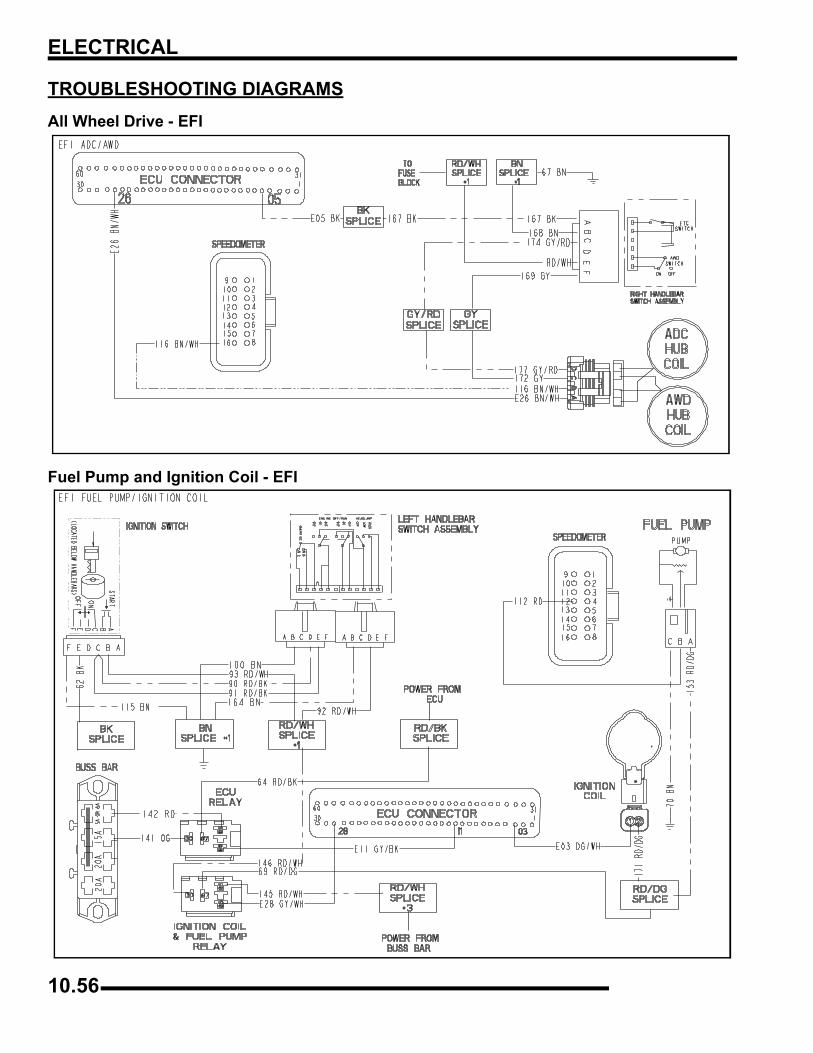
ELECTRICAL
TROUBLESHOOTING DIAGRAMSAll Wheel Drive - EFI
Fuel Pump and Ignition Coil - EFI
10.56
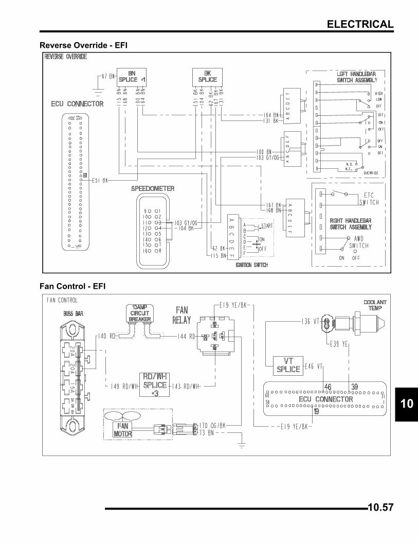
ELECTRICAL
0
1Reverse Override - EFI
Fan Control - EFI
10.57

ELECTRICAL
NOTES
10.58
500 EFI X2 / TOURING QUADRICYCLE
CHAPTER 11500 EFI X2 / TOURING QUADRICYCLE
11
500 EFI X2 / TOURING QUADRICYCLE BRAKE SYSTEM . . . . . . . . . . . . . . . . . . . . . . 11.2OVERVIEW. . . . . . . . . . . . . . . . . . . . . . . . . . . . . . . . . . . . . . . . . . . . . . . . . . . . . . . . . . . 11.2EXPLODED VIEW . . . . . . . . . . . . . . . . . . . . . . . . . . . . . . . . . . . . . . . . . . . . . . . . . . . . . 11.3
500 EFI X2 / TOURING QUADRICYCLE STEERING POST AND LOCK. . . . . . . . . . . . 11.4STEERING ASSEMBLY EXPLODED VIEW . . . . . . . . . . . . . . . . . . . . . . . . . . . . . . . . . 11.4
500 EFI QUADRICYCLE EMISSIONS SYSTEM. . . . . . . . . . . . . . . . . . . . . . . . . . . . . . . 11.5OVERVIEW. . . . . . . . . . . . . . . . . . . . . . . . . . . . . . . . . . . . . . . . . . . . . . . . . . . . . . . . . . . 11.5
500 QUADRICYCLE ELECTRICAL. . . . . . . . . . . . . . . . . . . . . . . . . . . . . . . . . . . . . . . . . 11.6TURN / HAZARD SIGNAL DIAGRAM . . . . . . . . . . . . . . . . . . . . . . . . . . . . . . . . . . . . . . 11.6
NOTE: This chapter illustrates components that are unique to the Sportsman 500 EFI Quadricycle models (International).
Except where noted, any servicing of these components or other components on the ATV can be done using this service manual’s procedures and illustrations.
11.1
500 EFI X2 / TOURING QUADRICYCLE
1
1500 EFI X2 / TOURING QUADRICYCLE BRAKE SYSTEMOverviewThe Sportsman Quadricycle brake system consists of a complete hydraulic brake system. All-wheel braking is integrated into thefoot brake and hand brake systems and allows 4 wheel braking from either control separately, or at the same time.
When the foot brake is applied, all brake calipers are active, as braking pressure is routed from the foot brake master cylinder throughthe proportioning valve and distribution block, exiting one line to the front calipers, while the other line exits the proportioning valveand feeds the outer line of the rear calipers.
When the hand brake is applied, all brake calipers are active, as braking pressure is routed from the hand brake master cylinderthrough the distribution block, exiting one line to the front calipers, while the other line feeds the inner line of the rear calipers.
11.2
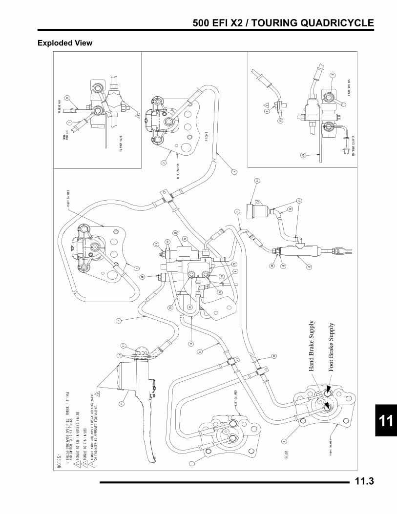
500 EFI X2 / TOURING QUADRICYCLE
1
1Exploded View
Foot
Bra
ke S
uppl
y
Han
d B
rake
Sup
ply
11.3
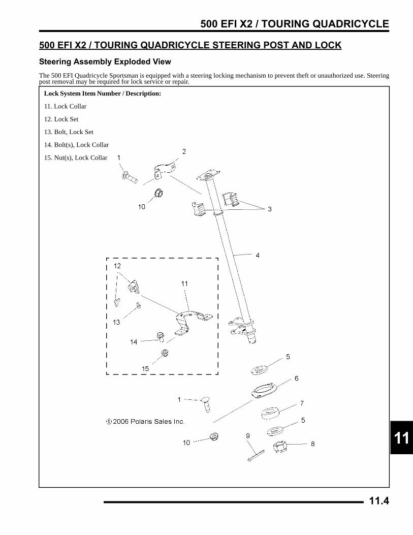
500 EFI X2 / TOURING QUADRICYCLE
1
1500 EFI X2 / TOURING QUADRICYCLE STEERING POST AND LOCKSteering Assembly Exploded ViewThe 500 EFI Quadricycle Sportsman is equipped with a steering locking mechanism to prevent theft or unauthorized use. Steeringpost removal may be required for lock service or repair.
Lock System Item Number / Description:
11. Lock Collar
12. Lock Set
13. Bolt, Lock Set
14. Bolt(s), Lock Collar
15. Nut(s), Lock Collar
11.4
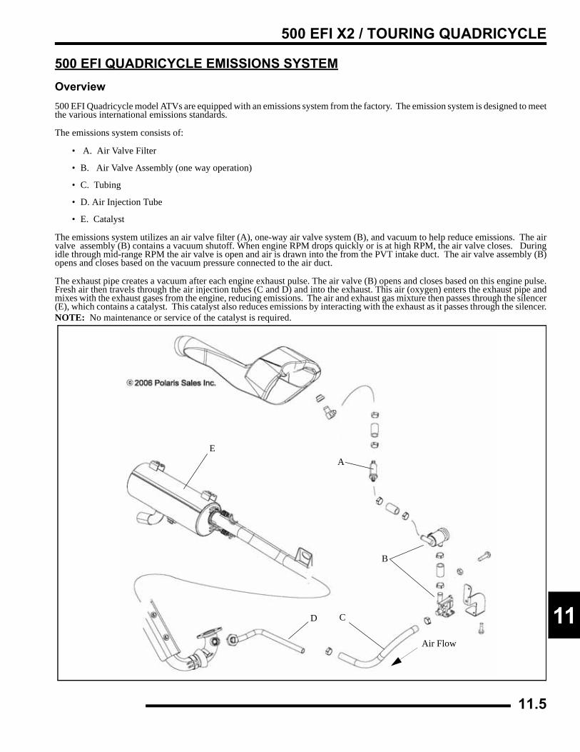
500 EFI X2 / TOURING QUADRICYCLE
1
1500 EFI QUADRICYCLE EMISSIONS SYSTEMOverview500 EFI Quadricycle model ATVs are equipped with an emissions system from the factory. The emission system is designed to meetthe various international emissions standards.
The emissions system consists of:
• A. Air Valve Filter
• B. Air Valve Assembly (one way operation)
• C. Tubing
• D. Air Injection Tube
• E. Catalyst
The emissions system utilizes an air valve filter (A), one-way air valve system (B), and vacuum to help reduce emissions. The airvalve assembly (B) contains a vacuum shutoff. When engine RPM drops quickly or is at high RPM, the air valve closes. Duringidle through mid-range RPM the air valve is open and air is drawn into the from the PVT intake duct. The air valve assembly (B)opens and closes based on the vacuum pressure connected to the air duct.
The exhaust pipe creates a vacuum after each engine exhaust pulse. The air valve (B) opens and closes based on this engine pulse.Fresh air then travels through the air injection tubes (C and D) and into the exhaust. This air (oxygen) enters the exhaust pipe andmixes with the exhaust gases from the engine, reducing emissions. The air and exhaust gas mixture then passes through the silencer(E), which contains a catalyst. This catalyst also reduces emissions by interacting with the exhaust as it passes through the silencer.NOTE: No maintenance or service of the catalyst is required.
A
B
D
Air Flow
E
C
11.5
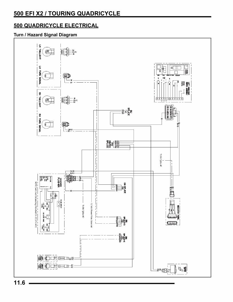
500 EFI X2 / TOURING QUADRICYCLE
500 QUADRICYCLE ELECTRICALTurn / Hazard Signal Diagram
11.6
X
IAA-Arm Replacement . . . . . . . . . . . . . . . . . . . . . . . . . . . . 5.20Active Descent Control (ADC) Coil . . . . . . . . . . . . . . 10.19Active Descent Control Gearcase . . . . . . . . . . . . . . . . . . 7.22ADC Gearcase Piston Service . . . . . . . . . . . . . . . . . . . . 7.27ADC Gearcase, Disassembly / Inspection . . . . . . . . . . . 7.23ADC reservoir level inspection . . . . . . . . . . . . . . . . . . . 2.18Air Filter, Service . . . . . . . . . . . . . . . . . . . . . . . . . . . . . . 2.20Alignment, Wheel . . . . . . . . . . . . . . . . . . . . . . . . . . . . . . 2.27All Wheel Drive (AWD) Coil . . . . . . . . . . . . . . . . . . . 10.19All Wheel Drive and Speedometer Troubleshooting Tests . .10.14Alternator / Ignition Components . . . . . . . . . . . . . . . . . 10.24Alternator Output Test . . . . . . . . . . . . . . . . . . . . . . . . . 10.28ATV Cleaning and Storage . . . . . . . . . . . . . . . . . . . . . . . 2.36BBall Joint Replacement, Front . . . . . . . . . . . . . . . . . . . . 5.21Battery Activation, Conventional . . . . . . . . . . . . . . . . . 10.50Battery Charging Procedure, Low Maintenance . . . . . 10.55Battery Load Test . . . . . . . . . . . . . . . . . . . . . . . . . . . . . 10.53Battery Load Test, Low Maintenance . . . . . . . . . . . . . 10.55Battery Off Season Storage . . . . . . . . . . . . . . . . . . . . . 10.52Battery Off Season Storage, Low Maintenance . . . . . . 10.52Battery Open Circuit Voltage (OCV), Low Maintenance . . .10.55Battery Removal / Inspection, Conventional . . . . . . . . 10.51Battery Specific Gravity Tes, Conventional . . . . . . . . . 10.53Battery Terminals/Bolts . . . . . . . . . . . . . . . . . . . . . . . . 10.51Battery, Installation . . . . . . . . . . . . . . . . . . . . . . . . . . . 10.51Battery, Maintenance . . . . . . . . . . . . . . . . . . . . . . . . . . . 2.18Body and Steering Torque Values . . . . . . . . . . . . . . . . . . 5.2Body Assembly Exploded View . . . . . 5.12, 5.13, 5.14, 5.16Body Rack Exploded View . . . . . . . . . . . . . . . . . . . . . . 5.15Brake Bleeding . . . . . . . . . . . . . . . . . . . . . . . . . . . . . . . . . 9.7Brake Burnishing Procedure . . . . . . . . . . . . . . . . . . . . . . 9.12Brake Caliper Exploded View . . . . . . . . . . . . . . . . . . . . . 9.5Brake Caliper Removal, Rear . . . . . . . . . . . . . . . . 9.21, 9.23Brake Caliper, Assembly . . . . . . . . . . . . . . . . . . . . . . . . 9.24Brake Caliper, Front . . . . . . . . . . . . . . . . . . . . . . . . . . . . 9.14Brake Disc, Front . . . . . . . . . . . . . . . . . . . . . . . . . . . . . . 9.12Brake Disc, Inspection . . . . . . . . . . . . . . . . . . . . . . . . . . 9.25Brake Light / Work Light Switch Replacement . . . . . . 10.38Brake Light Switch . . . . . . . . . . . . . . . . . . . . . . . . . . . . 10.39Brake Noise Troubleshooting . . . . . . . . . . . . . . . . . . . . . . 9.7Brake Pad Install, Rear . . . . . . . . . . . . . . . . . . . . . . . . . . 9.20Brake Pad Removal, Rear . . . . . . . . . . . . . . . . . . . . . . . . 9.19Brake Pad, Rear . . . . . . . . . . . . . . . . . . . . . . . . . . . . . . . 9.17Brake Pad, Removal and Installation . . . . . . . . . . . . . . . 9.10Brake System Components, Std, Sportsman . . . . . . . . . . 9.4Brake System Components, X2 . . . . . . . . . . . . . . . . . . . . 9.3Brake System Exploded View, International . . . . . . . . . 11.3Brake System Exploded Views . . . . . . . . . . . . . . . . . . . . 9.3Brake System Overview, International . . . . . . . . . . . . . . 11.2Brake, Master Cylinder Removal . . . . . . . . . . . . . . . . . . . 9.9Brake, Rear Auxiliary Brake . . . . . . . . . . . . . . . . . . . . . 9.28
Brake, Rear Auxiliary Master Cylinder . . . . . . . . . . . . .9.26Brake, Torque Specifications . . . . . . . . . . . . . . . . . . . . . .9.2Brakes, Inspection . . . . . . . . . . . . . . . . . . . . . . . . . . . . . .2.29Brakes, Operation Overview . . . . . . . . . . . . . . . . . . . . . . .9.6Brakes, Troubleshooting . . . . . . . . . . . . . . . . . . . . . . . . .9.29
CCam Chain Removal . . . . . . . . . . . . . . . . . . . . . . . . . . . .3.14Cam Chain Tensioner, Inspection . . . . . . . . . . . . . . . . . .3.14Camshaft Removal . . . . . . . . . . . . . . . . . . . . . . . . . . . . .3.16Camshaft Timing . . . . . . . . . . . . . . . . . . . . . . . . . . . . . . .3.46Carburetor (BST34) Exploded View . . . . . . . . . . . . . . . .4.33Carburetor Jetting . . . . . . . . . . . . . . . . . . . . . . . . . . . . . .4.32Carburetor Operation . . . . . . . . . . . . . . . . . . . . . . . . . . . .4.35Carburetor Venting . . . . . . . . . . . . . . . . . . . . . . . . . . . . .4.35Carburetor, Air/Fuel Ratio . . . . . . . . . . . . . . . . . . . . . . .4.38Carburetor, Assembly . . . . . . . . . . . . . . . . . . . . . . . . . . .4.41Carburetor, Choke System . . . . . . . . . . . . . . . . . . . . . . .4.36Carburetor, Cleaning . . . . . . . . . . . . . . . . . . . . . . . . . . . .4.40Carburetor, Disassembly . . . . . . . . . . . . . . . . . . . . . . . . .4.39Carburetor, Float Adjustment . . . . . . . . . . . . . . . . . . . . .4.42Carburetor, Float System . . . . . . . . . . . . . . . . . . . . . . . . .4.37Carburetor, Idle System . . . . . . . . . . . . . . . . . . . . . . . . . .4.36Carburetor, Inspection . . . . . . . . . . . . . . . . . . . . . . . . . . .4.41Carburetor, Jet Needle . . . . . . . . . . . . . . . . . . . . . . . . . . .4.39Carburetor, Main System . . . . . . . . . . . . . . . . . . . . . . . .4.37Carburetor, Needle Jet . . . . . . . . . . . . . . . . . . . . . . . . . . .4.39Carburetor, Operation . . . . . . . . . . . . . . . . . . . . . . . . . . .4.35Carburetor, Pilot Screw . . . . . . . . . . . . . . . . . . . . . . . . . .4.38Carburetor, Throttle Opening vs. Fuel Flow . . . . . . . . . .4.39Cargo Box, Removal and Installation . . . . . . . . . . . . . . .5.28Charging Procedure . . . . . . . . . . . . . . . . . . . . . . . . . . . .10.53Charging System - Break Even Test . . . . . . . . . . . . . . .10.27Charging System Flow Chart . . . . . . . . . . . . . . 10.25, 10.29Choke System . . . . . . . . . . . . . . . . . . . . . . . . . . . . . . . . .4.36Circuit Breaker . . . . . . . . . . . . . . . . . . . . . . . . . . . . . . .10.32Clutch Alignment . . . . . . . . . . . . . . . . . . . . . . . . . . . . . .6.14Clutch Offset . . . . . . . . . . . . . . . . . . . . . . . . . . . . . . . . . .6.14Clutch, Troubleshooting . . . . . . . . . . . . . . . . . . . . . . . . .6.39Clutching Chart . . . . . . . . . . . . . . . . . . . . .1.4, 1.6, 1.8, 1.10Component Locations . . . . . . . . . . . . . . . . . . . . . . . . . . . .2.8Component Locations, Sportsman . . . . . . . . . . . . . . . . . .2.7Compression Test . . . . . . . . . . . . . . . . . . . . . . . . . . . . . .2.17Controls, Inspection . . . . . . . . . . . . . . . . . . . . . . . . . . . .2.32Conversion Table . . . . . . . . . . . . . . . . . . . . . . . . . . . . . .1.14Coolant Sensor Test . . . . . . . . . . . . . . . . . . . . . . . . . . .10.21Coolant, Level Inspection . . . . . . . . . . . . . . . . . . . . . . . .2.20Coolant, Recommended Ratio . . . . . . . . . . . . . . . . . . . . . .3.8Cooling System Pressure Test . . . . . . . . . . . . . . . . . . . . . .3.7Cooling System Specifications . . . . . . . . . . . . . . . . . . . . .3.6Cooling System, Maintenance . . . . . . . . . . . . . . . . . . . . .2.19Counter Balancer Endplay Adjustment . . . . . . . . . . . . . .3.38Counter Balancer, Removal and Inspection . . . . . . . . . .3.34Crankcase Breather Filter, Service . . . . . . . . . . . . . . . . .2.22Crankcase Separation . . . . . . . . . . . . . . . . . . . . . . . . . . .3.33Crankshaft Endplay Adjustment . . . . . . . . . . . . . . . . . . .3.37
IX.1
Crankshaft Position Sensor (CPS) . . . . . . . . . . . . . . . . . .4.16Crankshaft Position Sensor Gap . . . . . . . . . . . . . . . . . .10.26Crankshaft Straightening . . . . . . . . . . . . . . . . . . . . . . . . .3.10Crankshaft, Removal and Inspection . . . . . . . . . . . . . . . .3.35Current Draw - Key Off Test . . . . . . . . . . . . . . . . . . . .10.27CV Boot, Front Replacement . . . . . . . . . . . . . . . . . . . . . .7.5CV Boot, Inspection . . . . . . . . . . . . . . . . . . . . . . . . . . . .2.31CV Boot, Rear Replacement . . . . . . . . . . . . . . . . . . . . . .7.37CV Carburetor System Function . . . . . . . . . . . . . . . . . . .4.35Cylinder Head Removal . . . . . . . . . . . . . . . . . . . . . . . . .3.19Cylinder Head Torque Procedure . . . . . . . . . . . . . . . . . .3.45Cylinder Honing . . . . . . . . . . . . . . . . . . . . . . . . . . . . . . . .3.9Cylinder Installation . . . . . . . . . . . . . . . . . . . . . . . . . . . .3.44Cylinder Removal . . . . . . . . . . . . . . . . . . . . . . . . . . . . . .3.27
DDecal Replacement . . . . . . . . . . . . . . . . . . . . . . . . . . . . . .5.2Diagnostic Codes . . . . . . . . . . . . . . . . . . . . . . . . . . . . . .10.12Diagnostic Mode, EFI System . . . . . . . . . . . . . . . . . . .10.12Differential Solenoid . . . . . . . . . . . . . . . . . . . . . . . . . . .10.32Drive Belt, Installation . . . . . . . . . . . . . . . . . . . . . . . . . .6.13Drive Belt, Removal/Inspection . . . . . . . . . . . . . . . . . . .6.12Drive Clutch Service, EBS . . . . . . . . . . . . . . . . . . . . . . .6.15Drive Clutch Springs . . . . . . . . . . . . . . . . . . . . . . . . . . . . .6.8Drive Clutch Weights . . . . . . . . . . . . . . . . . . . . . . . . . . . .6.9Drive Clutch, Operation . . . . . . . . . . . . . . . . . . . . . . . . . .6.6Drive Clutch, Standard . . . . . . . . . . . . . . . . . . . . . . . . . .6.28Drive Shaft Boot Inspection . . . . . . . . . . . . . . . . . . . . . . .7.5Driven Clutch Service, EBS . . . . . . . . . . . . . . . . . . . . . .6.22Driven Clutch, Assembly . . . . . . . . . . . . . . . . . . . . . . . .6.37Driven Clutch, Bushing Service . . . . . . . . . . . . . . . . . . .6.35Driven Clutch, Disassembly / Inspection . . . . . . . . . . . .6.34Driven Clutch, Exploded View . . . . . . . . . . . . . . . . . . . .6.34Driven Clutch, Operation . . . . . . . . . . . . . . . . . . . . . . . . .6.6Driven Clutch, Standard . . . . . . . . . . . . . . . . . . . . . . . . .6.34
EEBS Drive Clutch Service . . . . . . . . . . . . . . . . . . . . . . . .6.15EBS Driven Clutch Service . . . . . . . . . . . . . . . . . . . . . . .6.22EBS Exploded View . . . . . . . . . . . . . . . . . . . . . . . . . 6.4, 6.5EBS, Driven Clutch Operation . . . . . . . . . . . . . . . . . . . . .6.7EFI Operation Overview . . . . . . . . . . . . . . . . . . . . . . . . . .4.9EFI Priming / Starting Procedure . . . . . . . . . . . . . . . . . .4.10Electrical Service Notes . . . . . . . . . . . . . . . . . . . . . . . . .10.4Electrical, Service Notes . . . . . . . . . . . . . . . . . . . . . . . . .10.4Electrical, Special Tools . . . . . . . . . . . . . . . . . . . . . . . . .10.3Electronic Control Unit (ECU) . . . . . . . . . . . . . . . . . . . .4.11Elelctrical, Troubleshooting Diagrams . . . . . . . . . . . . .10.56Engine Diagnostic Codes . . . . . . . . . . . . . . . . . . . . . . . .4.23Engine Disassembly . . . . . . . . . . . . . . . . . . . . . . . . . . . .3.14Engine Exploded Views . . . . . . . . . . . . . . . . . . . . . . . . .3.13Engine Installation Notes . . . . . . . . . . . . . . . . . . . . . . . . .3.9Engine Oil, Inspection . . . . . . . . . . . . . . . . . . . . . . . . . . .2.23Engine Reassembly . . . . . . . . . . . . . . . . . . . . . . . . . . . . .3.40Engine Removal . . . . . . . . . . . . . . . . . . . . . . . . . . . . . . . .3.8Engine Service Data . . . . . . . . . . . . . . . . . . . . . . . . . . . . .3.4Engine Temperature Sensor . . . . . . . . . . . . . . . . . . . . . .4.20
Engine Temperature Sensor Replacement . . . . . . . . . . . 4.21Engine Temperature Sensor Test . . . . . . . . . . . . . . . . . . 4.21Engine, Fastener Torque Patterns . . . . . . . . . . . . . . . . . . 3.3Engine, Lubrication Requirements . . . . . . . . . . . . . . . . 3.11Engine, Oil and Filter Change . . . . . . . . . . . . . . . . . . . . 2.23Engine, Oil Pump Priming . . . . . . . . . . . . . . . . . . . . . . . 2.25Engine, Torque Specifications . . . . . . . . . . . . . . . . . . . . . 3.3Engine, Valve Clearance / Adjustment . . . . . . . . . . . . . 2.25ETC Operation Test . . . . . . . . . . . . . . . . . . . . . . . . . . . 10.22ETC Switch Operation . . . . . . . . . . . . . . . . . . . . . . . . . 10.22
FFan Control Circuit Operation . . . . . . . . . . . . . . . . . . . 10.20Fan Control Circuit Operation / Testing . . . . . . . . . . . 10.20Fan Motor Current Draw . . . . . . . . . . . . . . . . . . . . . . . 10.20Final Drive Torque Specifications . . . . . . . . . . . . . . . . . . 7.2Flywheel / Stator Removal . . . . . . . . . . . . . . . . . . . . . . . 3.31Foot Well Removal / Installation . . . . . . . . . . . . . . . . . . . 5.5Front Cab Removal / Installation . . . . . . . . . . . . . . . . . . . 5.9Front Cover Removal / Installation . . . . . . . . . . . . . . . . . 5.4Front Drive Axle Installation . . . . . . . . . . . . . . . . . . . . . . 7.4Front Drive Axle Removal . . . . . . . . . . . . . . . . . . . . . . . . 7.3Front Gearcase - Back Lash Pad Adjustment . . . . . . . . 7.18Front Gearcase Coil Resistance . . . . . . . . . . . . . . .7.14, 7.23Front Gearcase Lubrication . . . . . . . . . . . . . . . . . . . . . . 2.12Front Gearcase, Active Descent Control Exploded View 7.21Front Gearcase, Diagnoses . . . . . . . . . . . . . . . . . . . . . . . 7.19Front Gearcase, Disassembly / Inspection . . . . . . . . . . . 7.13Front Gearcase, Exploded View . . . . . . . . . . . . . . . . . . 7.11Front Gearcase, Installation . . . . . . . . . . . . . . . . . . . . . . 7.20Front Gearcase, Operation . . . . . . . . . . . . . . . . . . . . . . . 7.11Front Gearcase, Reassembly . . . . . . . . . . . . . . . . . . . . . 7.29Front Gearcase, Reassembly / Inspection . . . . . . . . . . . 7.17Front Gearcase, Removal . . . . . . . . . . . . . . . . . . . . . . . . 7.12Front Hub, Assembly . . . . . . . . . . . . . . . . . . . . . . . . . . . . 7.3Front Hub, Disassembly . . . . . . . . . . . . . . . . . . . . . . . . . . 7.2Front Storage Installation . . . . . . . . . . . . . . . . . . . . . . . . . 5.8Front Storage Removal . . . . . . . . . . . . . . . . . . . . . . . . . . 5.6Fuel Filter . . . . . . . . . . . . . . . . . . . . . . . . . . . . . . . . . . . . 4.14Fuel Filter, Replacement . . . . . . . . . . . . . . . . . . . .2.17, 4.46Fuel Gauge Sender, Installation . . . . . . . . . . . . . . . . . . . 4.47Fuel Gauge Sender, Removal . . . . . . . . . . . . . . . . . . . . . 4.46Fuel Injection, Component Locations . . . . . . . . . . . . . . . 4.8Fuel Injection, Exploded View . . . . . . . . . . . . . . . . . . . . 4.7Fuel Injection, Service Notes . . . . . . . . . . . . . . . . . . . . . . 4.6Fuel Injection, Special Tools . . . . . . . . . . . . . . . . . . . . . . 4.4Fuel Injector . . . . . . . . . . . . . . . . . . . . . . . . . . . . . . . . . . 4.15Fuel Level Test . . . . . . . . . . . . . . . . . . . . . . . . . . . . . . . . 4.43Fuel Pressure Regulator . . . . . . . . . . . . . . . . . . . . . . . . . 4.14Fuel Pump / Tank Assembly . . . . . . . . . . . . . . . . . . . . . 4.12Fuel Pump, Testing . . . . . . . . . . . . . . . . . . . . . . . . . . . . 4.45Fuel Sender Test . . . . . . . . . . . . . . . . . . . . . . . . . . . . . . 10.40Fuel System Special Tools . . . . . . . . . . . . . . . . . . . . . . . 4.32Fuel System, EFI Circuit Diagrams . . . . . . . . . . . . . . . . 4.24Fuel System, Inspection . . . . . . . . . . . . . . . . . . . . . . . . . 2.16Fuel Tank Location . . . . . . . . . . . . . . . . . . . . . . . . . . . . . 4.9
IX.2
X
IFuel Tank/Fuel Delivery System . . . . . . . . . . . . . . . . . . 4.44Fuses . . . . . . . . . . . . . . . . . . . . . . . . . . . . . . . . . . . . . . . 10.32GGear Position Indicator Switch Test . . . . . . . . . . . . . . . 10.21Gearcase, ADC Hydraulic Fluid Change . . . . . . . . . . . . 2.14Gearcase, Front Capacity and Fluid Type . . . . . . . . . . . . 7.2Glossary of Terms . . . . . . . . . . . . . . . . . . . . . . . . . . . . . 1.15
HHandlebar Block Installation Procedure . . . . . . . . . . . . . 5.18Headlamp Switch Test . . . . . . . . . . . . . . . . . . . . . . . . . 10.37Headlight Housing Replacement . . . . . . . . . . . . . . . . . 10.34Headlight Pod Exploded View . . . . . . . . . . . . . . . . . . . . 5.17High Beam Bulb Replacement . . . . . . . . . . . . . . . . . . . 10.34High Beam Headlight Adjustment . . . . . . . . . . . . . . . . 10.35Hydraulic Brake System Operation Overview . . . . . . . . . 9.6
IIgnition System . . . . . . . . . . . . . . . . . . . . . . . . . . . . . . . 10.23Ignition System Troubleshooting . . . . . . . . . . . . . . . . . 10.26Instrument Cluster (Speedometer) Overview . . . . . . . . . 10.8Instrument Cluster Diagnostic Mode . . . . . . . . . . . . . . . 10.9Instrument Cluster Overview . . . . . . . . . . . . . . . . . . . . . 10.8Instrument Cluster, Setting New Service Interval . . . . 10.11
KKeys, Replacement . . . . . . . . . . . . . . . . . . . . . . . . . . . . . . 1.3
LLow Beam Headlight Adjustment . . . . . . . . . . . . . . . . 10.37Low Maintenance Battery Charging . . . . . . . . . . . . . . . 10.54Low Maintenance Battery Info . . . . . . . . . . . . . . . . . . . 10.54Lower Headlamp Housing Removal . . . . . . . . . . . . . . 10.36Lower Headlamp Removal . . . . . . . . . . . . . . . . . . . . . . 10.36Lubricants/Fluids, Polaris Brand Part Numbers . . . . . . . . 2.9Lubricants/Fluids, Polaris Brand Symbol Identification Chart 2.10
MMaintenance Chart . . . . . . . . . . . . . . . . . . . . . . . . . . . . . . 2.4Maintenance Schedule . . . . . . . . . . . . . . . . . . . . . 2.41, 2.42Maintenance, General Information . . . . . . . . . . . . . . . . . . 2.3MAP Sensor . . . . . . . . . . . . . . . . . . . . . . . . . . . . . . . . . . 4.17Mikuni Jet Part Numbers . . . . . . . . . . . . . . . . . . . . . . . . 4.32Misc. Tables . . . . . . . . . . . . . . . . . . . . . . . . . . . . . . . . . . 1.12Model . . . . . . . . . . . . . . . . . . . . . . . . . . . . . . . . . . . . . . . . 1.2Model Number Information . . . . . . . . . . . . . . . . . . . . . . . 1.2
NNeedle and Seat, Leakage Test . . . . . . . . . . . . . . . . . . . . 4.42
OOil Flow Chart . . . . . . . . . . . . . . . . . . . . . . . . . . . . . . . . 3.12Oil Flow, Overview . . . . . . . . . . . . . . . . . . . . . . . . . . . . 3.11Oil Pressure Test, Engine . . . . . . . . . . . . . . . . . . . . . . . . 3.11Oil Pump Priming Procedure . . . . . . . . . . . . . . . . . . . . . 3.11Oil Pump Shaft Endplay Adjustment . . . . . . . . . . . . . . . 3.39Oil Pump, Removal and Inspection . . . . . . . . . . . . . . . . 3.33
PPaint Codes . . . . . . . . . . . . . . . . . . . . . . . . . . . . . . . . . . . .1.3Passenger Seat, Operation . . . . . . . . . . . . . . . . . . . . . . . .5.31PDM, 450 Connector Pin Table . . . . . . . . . . . . . . . . . . .10.6PDM, 500 Carbureted Overview . . . . . . . . . . . . . . . . . . .10.5Pilot System . . . . . . . . . . . . . . . . . . . . . . . . . . . . . . . . . . .4.36Piston Identification . . . . . . . . . . . . . . . . . . . . . . . . . . . . .3.6Piston Removal . . . . . . . . . . . . . . . . . . . . . . . . . . . . . . . .3.28Piston Ring Installation . . . . . . . . . . . . . . . . . . . . . 3.30, 3.43Plastic Inserts . . . . . . . . . . . . . . . . . . . . . . . . . . . . . . . . . . .5.3Pre-ride Checklist . . . . . . . . . . . . . . . . . . . . . . . . . . . . . .2.10Propshaft, Removal . . . . . . . . . . . . . . . . . . . . . . . . . . . . . .7.7Publication Numbers . . . . . . . . . . . . . . . . . . . . . . . . . . . . .1.3PVT Assembly . . . . . . . . . . . . . . . . . . . . . . . . . . . . . . . .6.11PVT Disassembly . . . . . . . . . . . . . . . . . . . . . . . . . . . . . .6.10PVT Drive Clutch Operation . . . . . . . . . . . . . . . . . . . . . . .6.6PVT Drive Clutch Shift Weights . . . . . . . . . . . . . . . . . . .6.9PVT Drive Clutch Specifications . . . . . . . . . . . . . . . . . . .6.8PVT Driven Clutch Operation . . . . . . . . . . . . . . . . . . . . . .6.6PVT Drying . . . . . . . . . . . . . . . . . . . . . . . . . . . . . . . . . . .6.10PVT Ducting . . . . . . . . . . . . . . . . . . . . . . . . . . . . . . . . . . .6.3PVT Maintenance / Inspection . . . . . . . . . . . . . . . . . . . . .6.7PVT Operation . . . . . . . . . . . . . . . . . . . . . . . . . . . . . . . . .6.6PVT Overheating Chart . . . . . . . . . . . . . . . . . . . . . . . . . .6.39PVT Special Tools . . . . . . . . . . . . . . . . . . . . . . . . . . . . . .6.2PVT Torque Specs . . . . . . . . . . . . . . . . . . . . . . . . . . . . . .6.2PVT Troubleshooting Chart . . . . . . . . . . . . . . . . . . . . . .6.40PVT, Button to Tower Clearance . . . . . . . . . . . . . 6.17, 6.30PVT, Clutch Alignment . . . . . . . . . . . . . . . . . . . . . . . . . .6.14PVT, Clutch Offset . . . . . . . . . . . . . . . . . . . . . . . . . . . . .6.14PVT, Drive Belt Installation . . . . . . . . . . . . . . . . . . . . . .6.13PVT, Drive Belt Removal/Inspection . . . . . . . . . . . . . . .6.12PVT, Drive Clutch Disassembly . . . . . . . . . . . . . . 6.15, 6.28PVT, Drive Clutch Exploded View . . . . . . . . . . . . . . . . . .6.3PVT, Drive Clutch Reassembly . . . . . . . . . . . . . . 6.20, 6.32PVT, Drive Clutch Spider Removal . . . . . . . . . . . 6.15, 6.29PVT, Driven Clutch Bushing Service . . . . . . . . . . . . . . .6.24PVT, Driven Clutch Disassembly . . . . . . . . . . . . . . . . . .6.22PVT, Driven Clutch Reassembly . . . . . . . . . . . . . . . . . .6.25PVT, EBS Clutch Operation . . . . . . . . . . . . . . . . . . . . . . .6.7PVT, EBS Drive Clutch Bushing Service . . . . . . . 6.18, 6.31PVT, EBS Drive Clutch Cover Bushing Remove/Install 6.19, 6.32PVT, Moveable Sheave Inspection . . . . . . . . . . . . 6.18, 6.31
RRadiator Cap Pressure Test . . . . . . . . . . . . . . . . . . . . . . . .3.7Radiator Screen Removal . . . . . . . . . . . . . . . . . . . . . . . .5.11Rear Cab Removal / Installation . . . . . . . . . . . . . . . . . . .5.10Rear Master Cylinder, Exploded View . . . . . . . . . . . . . .9.26Rear Rack Removal / Installation . . . . . . . . . . . . . . . . . . .5.8Rear Storage Removal / Installation . . . . . . . . . . . . . . . .5.11Rear Suspension Assembly . . . . . . . . . . . . . . . . . . 5.24, 5.25Recoil Housing, Draining / Inspection . . . . . . . . . . . . . .2.22Recoil, Reassembly . . . . . . . . . . . . . . . . . . . . . . . . . . . . .3.52Recoil, Removal . . . . . . . . . . . . . . . . . . . . . . . . . . . . . . .3.51
IX.3
Relays . . . . . . . . . . . . . . . . . . . . . . . . . . . . . . . . . . . . . .10.31S
Shift Linkage Inspection . . . . . . . . . . . . . . . . . . . . . . . . .2.14Side Panel Removal . . . . . . . . . . . . . . . . . . . . . . . . . . . . .5.4Solenoid, Differential . . . . . . . . . . . . . . . . . . . . . . . . . .10.32Spark Plug, Inspection / Replacement . . . . . . . . . . . . . . .2.18Special Tools, Body & Steering . . . . . . . . . . . . . . . . . . . .5.2Special Tools, EFI . . . . . . . . . . . . . . . . . . . . . . . . . . . . . . .4.4Special Tools, Engine . . . . . . . . . . . . . . . . . . . . . . . . . . . .3.3Special Tools, Final Drive . . . . . . . . . . . . . . . . . . . . . . . . .7.2Special Tools, Speed Sensor . . . . . . . . . . . . . . . . . . . . .10.39Specificaiton, Stator Plate Bolt Torque . . . . . . . . . . . . . .3.49Specification, Brake Disc Service Limit . . . . . . . . . . . . .9.25Specification, Brake Disc Thickness . . . . . . . . . . . . . . . .9.25Specification, Brake Pad Thickness . . . . . . . . . . . . . . . .9.19Specification, Cam Chain Stretch . . . . . . . . . . . . . . . . . .3.32Specification, Cam Chain Tensioner Spring . . . . . . . . . .3.15Specification, Camshaft Lobe Height . . . . . . . . . . . . . . .3.18Specification, Crankcase Bolt Torque . . . . . . . . . . . . . . .3.41Specification, Crankshaft Slotted Nut Torque . . . . . . . .3.43Specification, Cylinder Compression . . . . . . . . . . . . . . .2.17Specification, Cylinder Head Torque Procedure . . . . . . .3.45Specification, Cylinder Head Warp . . . . . . . . . . . . . . . . .3.21Specification, Cylinder Taper . . . . . . . . . . . . . . . . . . . . .3.29Specification, Cylinder Warp . . . . . . . . . . . . . . . . . . . . .3.28Specification, Differential Solenoid Resistance 10.32, 10.39Specification, Differential Solenoid Torque . . . 10.33, 10.39Specification, Drill and Tap Sizes . . . . . . . . . . . . . . . . . .1.13Specification, Flywheel Nut Torque . . . . . . . . . . . . . . . .3.49Specification, Fuel Pump Pressure . . . . . . . . . . . . . . . . .4.12Specification, Oil and Filter . . . . . . . . . . . . . . . . . . . . . .2.23Specification, Oil Pip Bolt Torque . . . . . . . . . . . . . . . . .3.50Specification, Oil Pump Bolt Torque . . . . . . . . . . . . . . .3.34Specification, Oil Pump Shaft Endplay . . . . . . . . . . . . . .3.39Specification, One Way Valve Spring Length . . . . . . . .3.32Specification, Piston to Cylinder Clearance . . . . . . . . . .3.29Specification, PVT Center-to-Center Distance . . . . . . . .6.13Specification, PVT Component Torque Table . . . . . . . . .6.2Specification, PVT Drive Belt Width . . . . . . . . . . . . . . .6.13Specification, Rocker Arm and Shaft . . . . . . . . . . . . . . .3.15Specification, Rocker Shaft Bolt Torque . . . . . . . . . . . .3.50Specification, Spark Plug Gap . . . . . . . . . . . . . . . . . . . .2.18Specification, Speed Sensor Bolt Torque . . . . . . . . . . .10.39Specification, Tensioner Blade Bolt Torque . . . . . . . . . .3.43Specification, Transmission Silent Chain Length . . . . . .8.19Specification, Valve Clearance . . . . . . . . . . . . . . . 2.26, 3.26Specification, Valve Guide Height . . . . . . . . . . . . . . . . .3.23Specification, Valve Stem and Guide . . . . . . . . . . . . . . .3.22Specifications, Body and Steering Torque Values . . . . . .5.2Specifications, Brake Component Service Limits . . . . . . .9.2Specifications, Brake Component Torque Values . . . . . .9.2Specifications, Engine Fastener Torque . . . . . . . . . . . . . .3.3Specifications, Engine Service Data . . . . . . . . . . . . . . . . .3.4Specifications, Final Drive Torque Values . . . . . . . . . . . .7.2Specifications, Front Gearcase Lubrication Type/Capacity 7.2
Specifications, Piston . . . . . . . . . . . . . . . . . . . . . . . . . . . 3.29Specifications, Power Distribution Module . . . . . . . . . . 10.5Specifications, Standard Torque Values . . . . . . . . . . . . 1.12Specifications, Vehicle . . . . . . . . . . . . . . . 1.4, 1.6, 1.8, 1.10Speed Sensor . . . . . . . . . . . . . . . . . . . . . . . . . . . . . . . . 10.39Speedometer Installation . . . . . . . . . . . . . . . . . . . . . . . 10.13Speedometer Removal . . . . . . . . . . . . . . . . . . . . . . . . . 10.13Speedometer Troubleshooting Tests . . . . . . . . . . . . . . 10.14Starter Armature Testing . . . . . . . . . . . . . . . . . . . . . . . 10.45Starter Assembly Exploded View . . . . . . . . . . . . . . . . 10.46Starter Brush Inspection / Replacement . . . . . . . . . . . . 10.44Starter Drive . . . . . . . . . . . . . . . . . . . . . . . . . . . . . . . . . 10.47Starter Drive Removal . . . . . . . . . . . . . . . . . . . . . . . . . . 3.31Starter Lockout, Troubleshooting . . . . . . . . . . . . . . . . 10.42Starter Motor Dissassembly / Replacement . . . . . . . . . 10.44Starter Reassembly / Installation . . . . . . . . . . . . . . . . . 10.46Starter System Flow Chart . . . . . . . . . . . . . . . . . . . . . . 10.48Steering A-Arm Exploded View . . . . . . . . . . . . . . . . . . 5.19Steering Lock, Exploded View . . . . . . . . . . . . . . . . . . . 11.4Steering Post Assembly . . . . . . . . . . . . . . . . . . . . . . . . . 5.22Steering Post Removal . . . . . . . . . . . . . . . . . . . . . . . . . . 5.22Steering Torque Values . . . . . . . . . . . . . . . . . . . . . . . . . . 5.2Steering, Inspection . . . . . . . . . . . . . . . . . . . . . . . . . . . . 2.26Storage Compartment, Latch Operation . . . . . . . . . . . . 2.34Strut Assembly . . . . . . . . . . . . . . . . . . . . . . . . . . . . . . . . 5.23Strut Cartridge Replacement, Front . . . . . . . . . . . . . . . . 5.22Suspension, Inspection . . . . . . . . . . . . . . . . . . . . . . . . . . 2.31
TThermostat Installation . . . . . . . . . . . . . . . . . . . . . . . . . 3.50Throttle Cable . . . . . . . . . . . . . . . . . . . . . . . . . . . . . . . . 2.15Throttle Position Sensor . . . . . . . . . . . . . . . . . . . . . . . . . 4.18Throttle Position Sensor Initialization . . . . . . . . . . . . . . 4.20Throttle Position Sensor Replacement . . . . . . . . . . . . . . 4.19Throttle, Linkage Inspection . . . . . . . . . . . . . . . . . . . . . 2.15Tie Rod, Inspection . . . . . . . . . . . . . . . . . . . . . . . . . . . . 2.27Trail Boss Emissions System . . . . . . . . . . . . . . . . . . . . . 11.5Transmission . . . . . . . . . . . . . . . . . . . . . . . . . . . . . . . . . . 8.1Transmission I.D. Information . . . . . . . . . . . . . . . . . . . . . 1.2Transmission Mounts, Exploded View . . . . . . . . . . . . . . 8.2Transmission, 500 Carbureted Exploded View . . . . . . . . 8.9Transmission, Disassembly . . . . . . . . . . . . . . . . . . . . . . 8.11Transmission, Exploded View . . . . . . . . . . . . . . . . . . . . . 8.7Transmission, Fluid Check / Change . . . . . . . . . . . . . . . 2.13Transmission, Install . . . . . . . . . . . . . . . . . . . . . . . . . . . . 8.5Transmission, Output Shaft Backlash Procedure . . . . . . 8.17Transmission, Reassembly . . . . . . . . . . . . . . . . . . . . . . . 8.16Transmission, Removal . . . . . . . . . . . . . . . . . . . . . . . . . . 8.3Transmission, Special Tools . . . . . . . . . . . . . . . . . . . . . . 8.3Troubleshooting Diagrams, Elelctrical . . . . . . . . . . . . 10.56Troubleshooting, EFI Circuit Diagrams . . . . . . . . . . . . . 4.24Troubleshooting, Engine . . . . . . . . . . . . . . . . . . . . . . . . 3.53
UU-joint, Disassembly and Assembly . . . . . . . . . . . . . . . . 7.7
IX.4
X
IVValve Clearance Adjustment . . . . . . . . . . . . . . . . 2.26, 3.26Valve Seat Reconditioning . . . . . . . . . . . . . . . . . . . . . . . 3.23Vehicle Identification Number (VIN) . . . . . . . . . . . . . . . 1.2Voltage Drop Test . . . . . . . . . . . . . . . . . . . . . . . . . . . . 10.41WWarn Winch Operation . . . . . . . . . . . . . . . . . . . . . . . . . . 2.34Water Pump Seal, Installation . . . . . . . . . . . . . . . . . . . . 3.41Wheel Alignment . . . . . . . . . . . . . . . . . . . . . . . . . . . . . . 2.27Wheels, Removal . . . . . . . . . . . . . . . . . . . . . . . . . . . . . . 2.32Wheels, Tire Pressure . . . . . . . . . . . . . . . . . . . . . . . . . . . 2.33Wheels, Torque Table . . . . . . . . . . . . . . . . . . . . . . . . . . . 2.32Wire Diagram, Winch Basic . . . . . . . . . . . . . . . . . . . . . 10.49Wire Diagrams, Electrical . . . . . . . . . . . . . . . . . . . . . . 10.56Work Light Switch . . . . . . . . . . . . . . . . . . . . . . . . . . . . 10.37
XX2, Seat Disassembly . . . . . . . . . . . . . . . . . . . . . . . . . . . 5.32
IX.5

PAGE INTENTIONALLY BLANK
IX.6
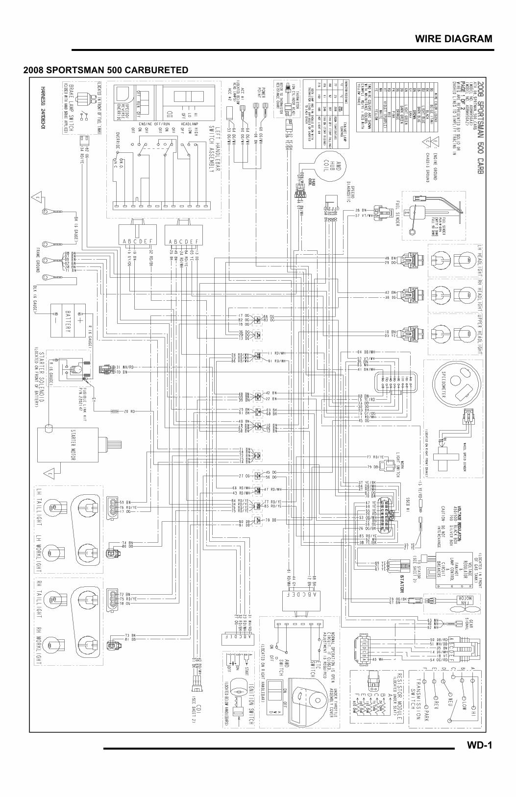
WD-1
WIRE DIAGRAM
2008 SPORTSMAN 500 CARBURETED
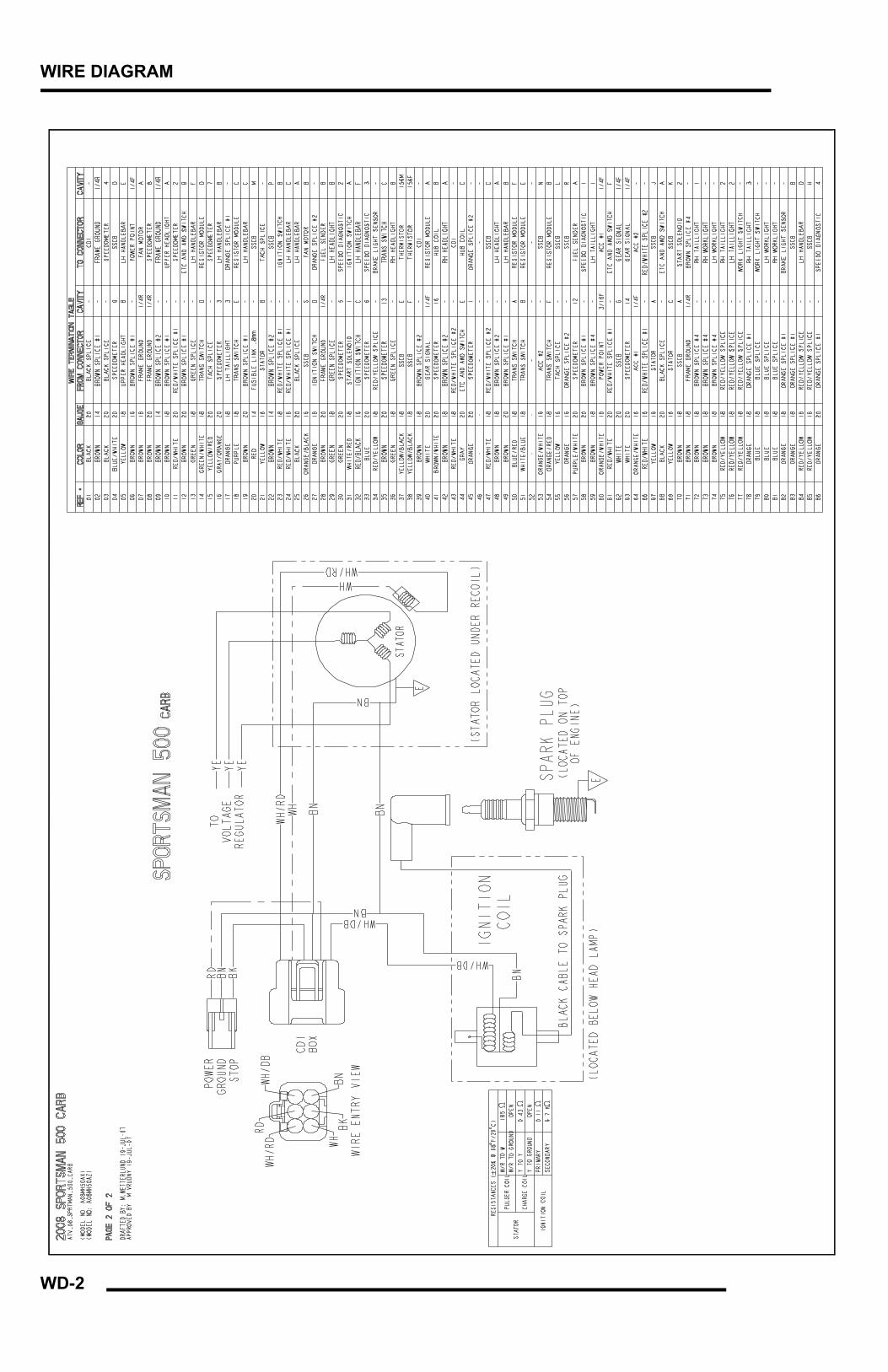
WD-2
WIRE DIAGRAM
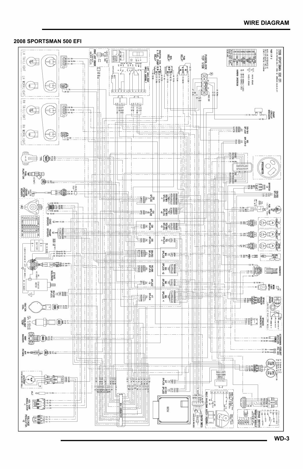
WD-3
WIRE DIAGRAM
2008 SPORTSMAN 500 EFI
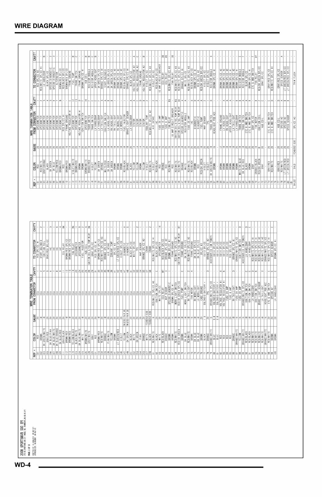
WD-4
WIRE DIAGRAM
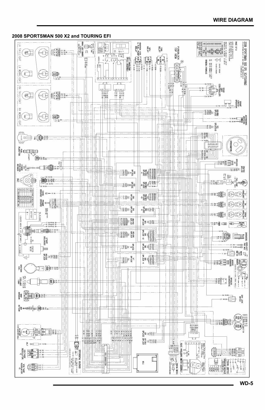
WD-5
WIRE DIAGRAM
2008 SPORTSMAN 500 X2 and TOURING EFI
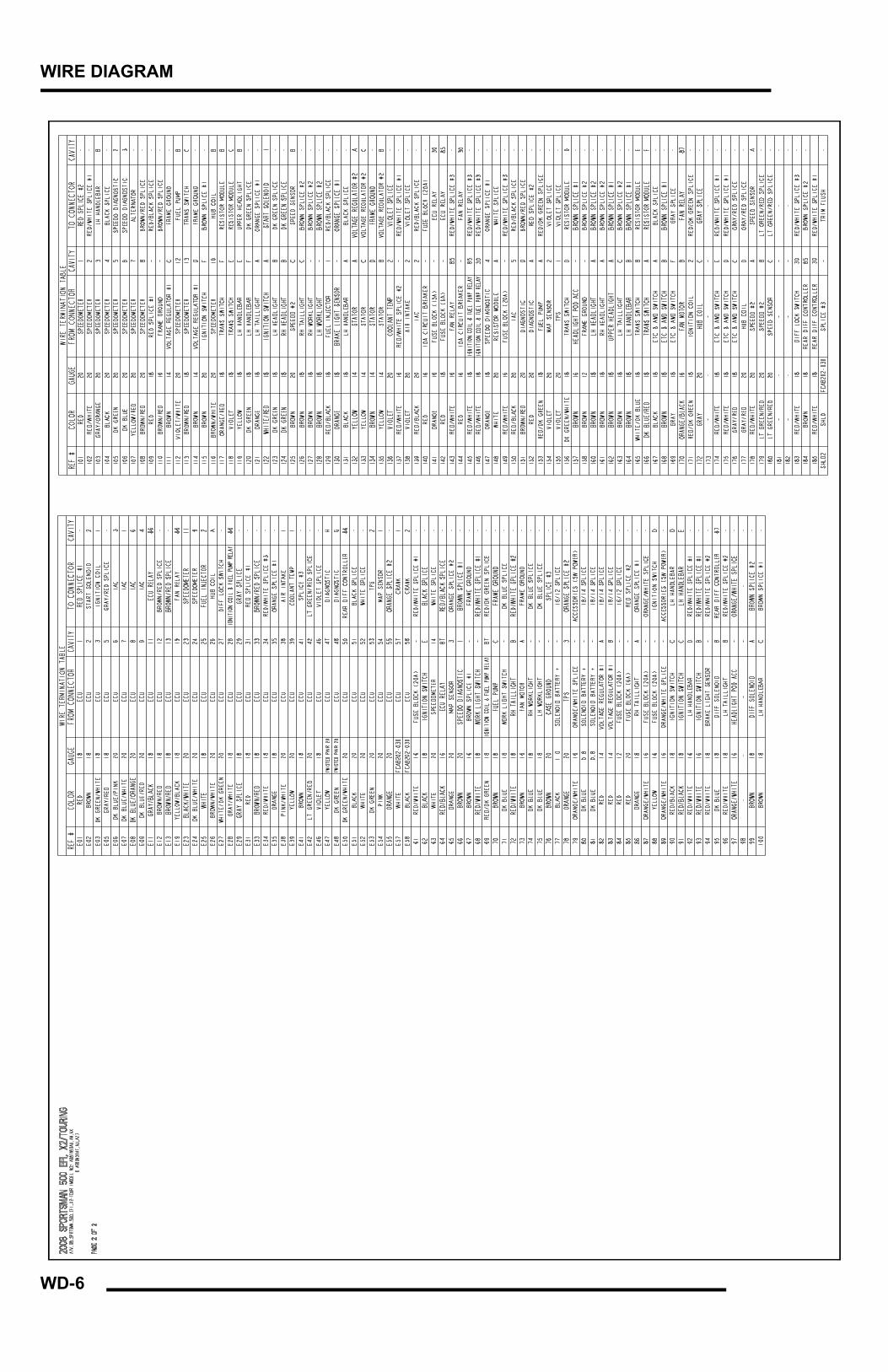
WD-6
WIRE DIAGRAM
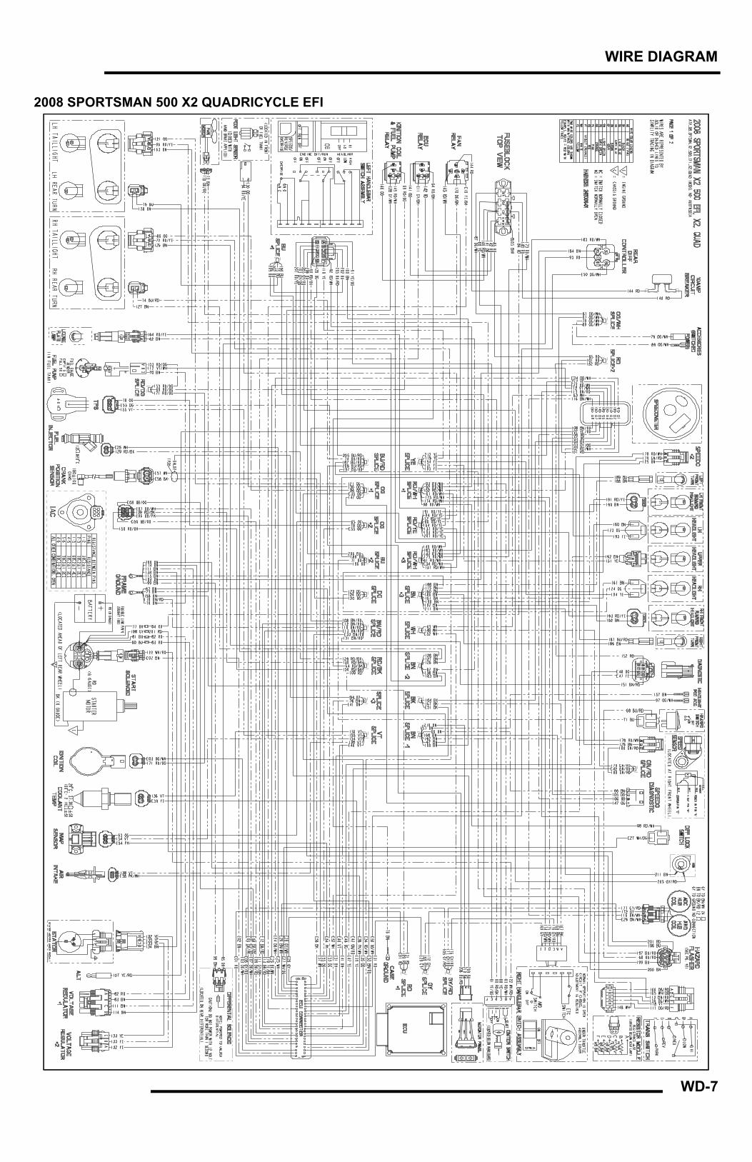
WD-7
WIRE DIAGRAM
2008 SPORTSMAN 500 X2 QUADRICYCLE EFI
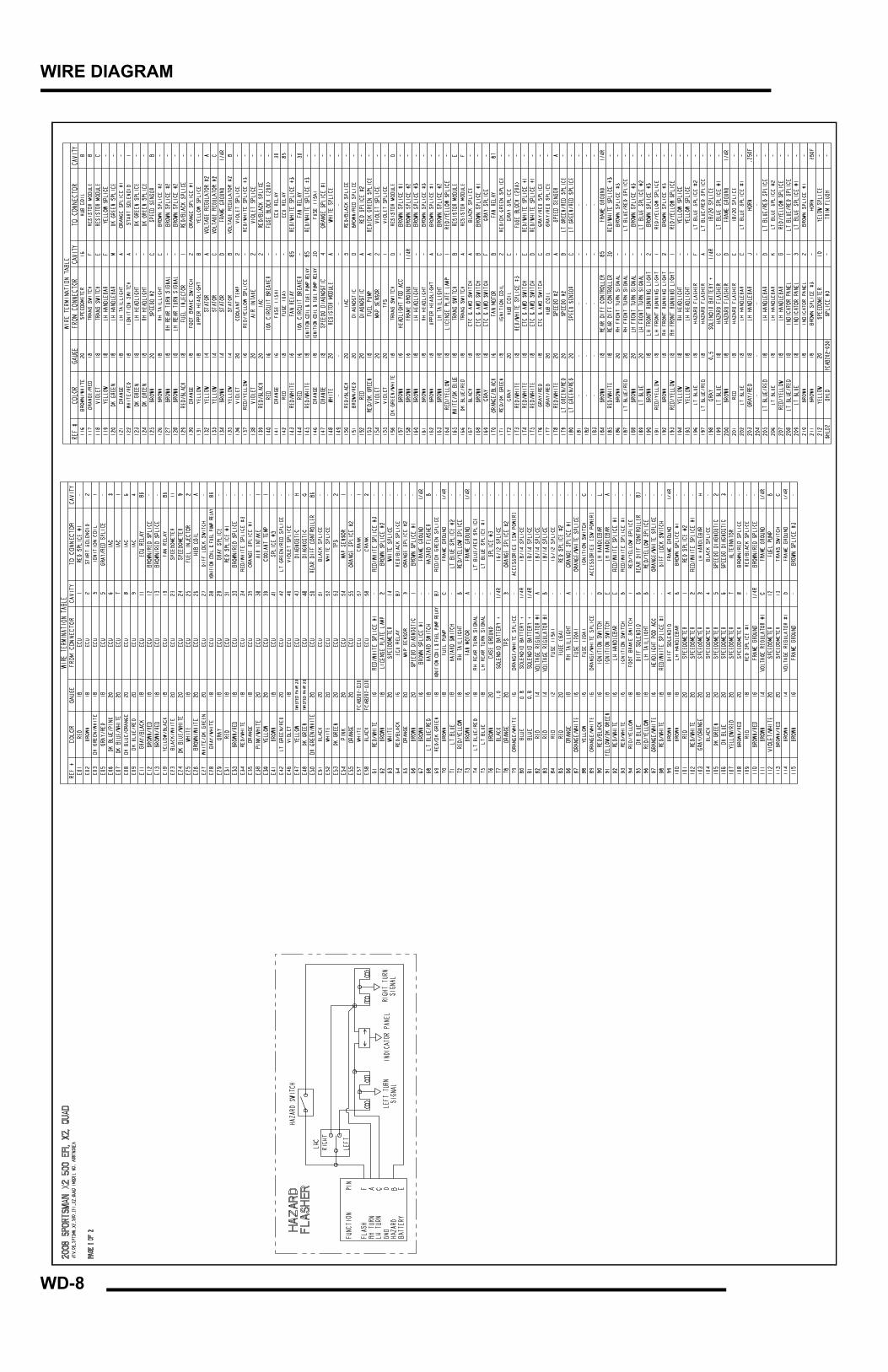
WD-8
WIRE DIAGRAM