Embed Size (px)
Citation preview

4?es c-A1,-^Z**'*0 /
FM 55-500-2 FIELD MANUAL
Wâ. m »
/ /
n y\
/y Q
m SS 1 VA ïI I G
■Kd
1
C2 K V TP5 2SH
K fôw57 î^'f!57
11 a (.CH^Cf)Â
7H
0 F T H E AD DARTERS, D EPARTMEin
RETURN^TS'^RMY7 LIBRARY
ROOM 1 A 518 RENTAGE
ARMY
N

*FM 55-506-2
HEADQUARTERS DEPARTMENT OF THE ARMY
Washington, DC, 22 April 1977
ACKNOWLEDGMENT
The contents of this manual were furnished by the courtesy of NAVEDTRAPRODEVCEN under the Interservice Mutual Support of Services and Training Agreement for exchange of training materials.
FOREWORD
This manual provides electrical theory necessary to effectively troubleshoot and repair shipboard electrical components and systems. The manual can be used at all marine maintenance levels; however, it is primarily intended for the engineering personnel assigned aboard Army watercraft. The words "he", "his", "crewman", and "men" are intended to include both the masculine and the feminine genders. Any exceptions to these intentions will be so noted.
NOTE TO ARMY PERSONNEL
Chapter 1, Career Challenges for the Electrician's Mate, does not apply to Army personnel.
*This publication, together with FM 55-506-1, supersedes TM 55-506, 4 September 1963.
i
/

FM 55-506-2
By Order of the Secretary of the Army:
BERNARD W. ROGERS General, United States Army
Chief of Staff
Official:
PAUL T. SMITH Major General, United States Army
The Adjutant Genera!
DISTRIBUTION:
Active Army, USAR, and ARNG:To be distributed in accordance with DA Form 12-1 IB, Require- ments for Transportation Harbor Craft Units and Marine Maintenance Units (Qty rqr block no. 396); plus: DA Form 12-12, Section III (5 copies each account) for unitshaving a requirement for training publications relating specifically toTOE 55-128,55-129,55-157,55-158,55-530; plus: DA Form 12-34B, Requirements for Marine and Amphibious Operations (Qty rqr block no. 152).
Additional copies can be requisitioned (DA Form 17) from the US Army Adjutant General Publications Center, 2800 Eastern Boulevard, Baltimore, MD 21220.
il

CONTENTS
CHAPTER Page
1. Career Challenges for the Electrician’s Mate 1
2. Safety Precautions 7
3. Test Equipment 28
4. Electrical Installations 59
5. A-C Power Distribution Systems 112
6. D-C Power Distribution Systems 151
7. Motor Controllers 158
8. Maintenance and Repair of Motors and Generators 179
9. Shipboard Lighting 224
10. Degaussing 255
11. Electrical Propulsion and Controls 275
12. Central Operations System 300
13. Basic Electronic Components and Circuits 321
14. Logic. Systems 358
15. Electrical Auxiliaries 366
16. Sound Motion Picture Systems 420
APPENDIX
I. Electronics Symbols 443
INDEX 450
iii

iv

CHAPTER 1
CAREER CHALLENGES FOR THE ELECTRICIAN’S MATE
This rate training manual is intended to help you develop your technical skills. Itis the know- ledge and skill of men like yourself that make our modern Navy possible. By learning the infor- mation in this manual and gaining practical ex- perience on the job, you will prepare yourself for a successful and rewardingnavy career. The N avy has developed a training system to help you learn the duties of the next higher grade in your rating. When you can demonstrate, by your per- formance on the job, by your mastery of the re- quired skills, and by written examination, that you are well qualified to perform these duties, you will be advanced to the next higher grade. Even as you are working toward advancement, the extra effort and study that you devote toward learning your rating will reward you in self- satisfaction and the capability to work on more complex equipment.
As an Electrician’s Mate you will be working with motors, generators, power and lighting dis- tribution systems and a wide variety of test equipment. All of these systems were designed using theories developed many years before their value to mankind was realized. Among these notables were German-born physicist Georg Ohm and Alessandro Volta, an Italian physicist. A. M. Ampere, a French physicist, was noted for his theories in the field of elec- trical energy. James Watt, also a physicist and inventor from Scotland, was an important contributor to a fundamental theory we use every day in the field of electricity.
Until 1948, when the I.C. rate was established, Electrician’s Mates maintained the telephone systems, announcing systems, gyro compasses and order and indicating systems as well as the power and lighting distribution systems. The Electrician’s Mate was required to attend either the gyro compass or Interior Communication school in order to qualify for Chief Petty Officer.
With the! expansion of the Navy and the estab- lishment of a two-ocean Navy inJuly 1940, many senior Petty Officers were needed. Electrician’s
Mate “A” schools were established in colleges all over the country and a class “B” school was established at Camp Perry, Virginia. This school was moved to Great Lakes, Illinois in 1944.
Your training for the Electrician’s Mate rating will include electronics and electrical theory, fundamentals of operation of motors and generators, alarms, sensors and a wide variety of other electrical equipment. You must become proficient in the use of hand tools and electrical measuring equipment in order to troubleshoot electrical systems. You must also be able to read and analyze blueprints and schematic dia- grams in order to understand the performance of an electrical circuit. The Electrician’s Mate rating is a general rating and is not divided into service ratings. (An example of a rating divided into service ratings is the ET; its service ratings are the ETN and the ETR. The ETN specializes in communications equipment; the ÉTN special- izes in radar.)
The qualifications of the Electrician’s Mate are oriented to shipboard duties; he is found on almost all naval vessels. Ashore, he may work in his rating in a repair facility or as an instruc- tor, but is just as likely to be working outside his rating in a duty such as shore patrol or recruiting.
The requirements for advancement outlined by the Manual of Qualifications for Advancement are designed to ensure that an Electrician’s Mate assigned to any ship in the fleet will have the general qualifications to perform his assigned duties. Since some ships, particularly the more modern ones, have specialty equipment, suchas Mine Sweepers with the acoustic and special degaussing systems, he must have special train- ing. A Navy Enlisted Classification (NEC) coding system helps identify the men who have this special training.
NAVY ENLISTED CLASSIFICATION CODES
Though your rate shows what you are qualified to do, it doe s not by itself show any of your special
1

ELECTRICIAN’S MATE 3 & 2
qualifications, or skills» either within your rate or outside of it0NECsareusedto show sig- nificant qualifications not shown by the rate des- ignation. The N EC coding system identifies spe- cial qualifications through a four digit number. Not everyone in the Navy has a special code num- ber» but some individuals have more than one» depending on their qualifications. The qualifi- cation considered to be the most important is identified by the first code number; the one con- sidered to be of secondary importance by the second code number. These code numbers can be obtained by completing special training or class C schools.
QUALIFICATIONS FOR ADVANCEMENT
As an Electrician’s Mate you will perform both military and professional duties. The mili- tary requirements and professional qualifica- tions for all ratings in the Navy are listed in the Quais Manual which is periodically revised to reflect organizational and procedural changes in the Navy that affect the ratings, and to incorpo- rate additional skills and techniques required by the development and installation of new equip- ment.
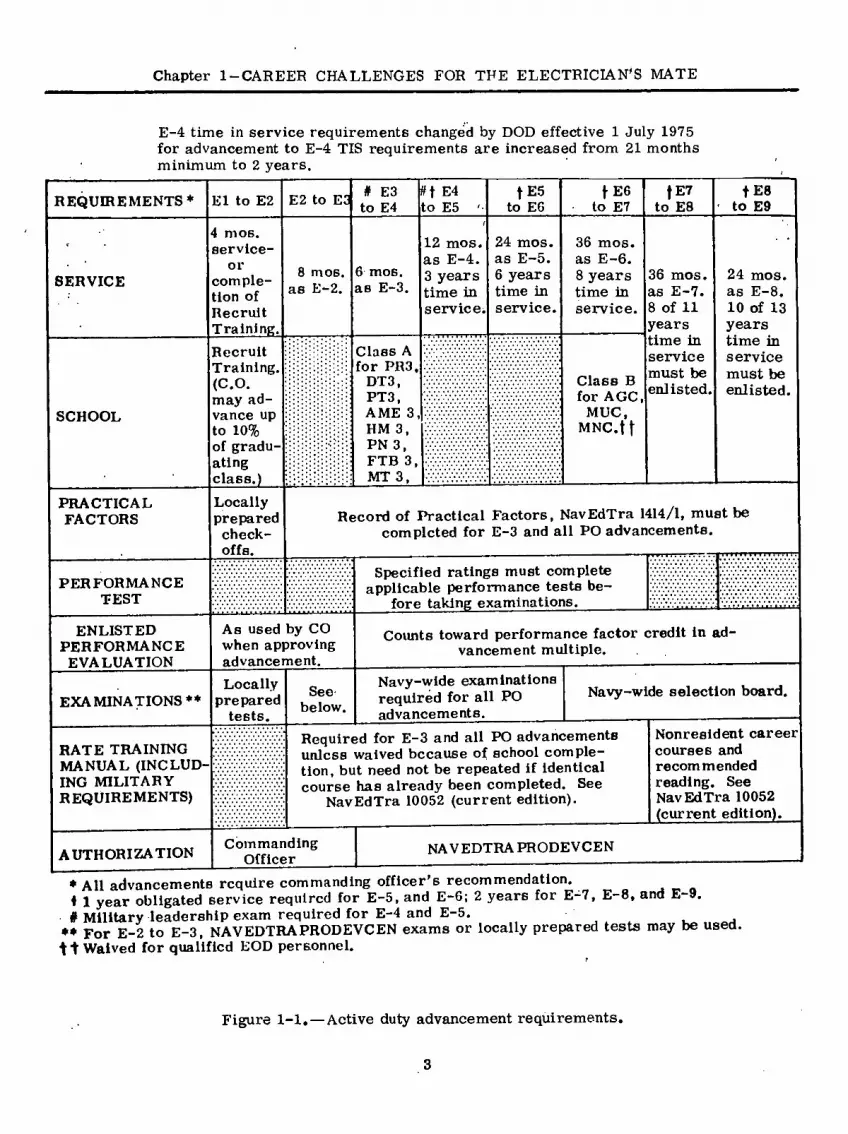
The military duties for the Electrician’s Mate are the same as those for other petty offi- cers, This Rate Training Manual primarily con- cerns the professionaldutiesof the Electrician’s Mate and does not attempt any detailed consider- ation of the military duties. The military re- quirements are discussed in Military Require- ments for Petty Officer 3 & 2. Figure 1-1 shows the requirements for advancement of active duty personnel; figure 1=2 does the same for inactive duty personnel.
The professional or technical duties per- formed by the Electrician’s Mate include a vari- ety of tasks that require many specialized skills and techniques necessary to perform properly the occupational duties of his rate. The profes- sional qualifications for the EM rating have been used as a guide in preparing this Rate Training Manual and will be used in constructing the ser- vicewide competitive examinations. In preparing to take these examinations you should consult the latest revision of NavPers 18068C, Manual of Qualifications for Advancement for changes dis- tributed after the publication of this Rate Train- ing Manual, The next change to NavPers 18068C for the EM rating is scheduled for distribution in June 1976,
SOURCES OF INFORMATION
No single publication can give you all the information you need to perform the duties of your rating. You should learn where to look for accurate, authoritative, up-to-date information on all subjects related to the military require- ments for advancement and the professional qualifications of your rating. Information re- lated to requisitioning materials, requiredmain- tenance forms, leadership and supervision should be obtained from Military Requirements for Petty Officer 3 fe 2.
Some of the publications described here are subject to change or revision from time to time — some at regular intervals, others as the need arises. When using any publication that is sub- ject to change or revision, be surethatyou have the latest edition. When using any publication that is kept currentby means of changes, be sûre you have a copy in which all official changes have been made. Studying canceled or obsolete infor- mation will not help you to do your work or to advance; it is likely to be a waste of time, and may even be seriously misleading.
You must bear in mind, however, that you cannot depend on the printed word alone; you must supplement the information you obtain from books with actual practice, and with the know- ledge acquired from observing experienced men at work.
NAVAL EDUCATION AND TRAINING PUBLICATIONS (NAVEDTRAPUB)
Effective 15 January 1972, the Naval Training Support Command and its field activities came directly under the command of the Chief of Naval Training (later changed to Chief of Naval Edu- cation and Training) instead of the Chief of Naval Personnel. Training materials published by the Naval Education and Training Support Command after the above date are designated NAVEDTRA in lieu of NAVPERS; in mosteases, the numbers remain as originally assigned. The designators of publications printed before the above date will be changed as each publication is revised.
The naval training publications described here include some that are absolutely essential for meeting your job requirements and some that are extremely helpful, although not essen- tial.
Bibliography for Advancement Study, NAVEDTRA 10052
This pamphlet provides a working list of material for enlisted personnel who are studying
2
Chapter 1-CAREER CHALLENGES FOR THE ELECTRICIAN'S MATE
E-4 time in service requirements changed by DOD effective 1 July 1975 for advancement to E-4 TIS requirements are increased from 21 months minimum to 2 years.
REQUIREMENTS1 El to E2 E2 to E3 # E3 to E4
E4 to E5
f E5 to EG
tE6 to E7
f E7 to E8
f E8 to E9
SERVICE
mos. service-
or comple- tion of Recruit Training,
8 mos. as E-2.
6 mos. as E-3.
12 mos. as E-4. 3 years time in service;
24 mos. as E-5. 6 years time in service.
36 mos. as E-6. 8 years time in service.
SCHOOL
Recruit Training. (C.O. may ad- vance up to 10% of gradu- ating class.)
Class A for PR3,
DT3, PT3, AME 3, HM 3, PN 3, FTB 3, MT 3,
Class B for AGC,
MUC, MNC.ft
36 mos. as E-7. 8 of 11 years time in service must be enlisted,
24 mos. as E-8. 10 of 13 years time in service must be enlisted.
PRACTICAL FACTORS
Locally prepared check- offs.
Record of Practical Factors, NavEdTra 1414/1, must be completed for E-3 and all PO advancements.
PERFORMANCE TEST
ENLISTED PERFORMANCE EVALUATION
As used by CO when approving advancement.
EXAMINATIONS **
Locally prepared
tests.
RATE TRAINING MANUAL (INCLUD ING MILITARY REQUIREMENTS)
See below.
Specified ratings must complete applicable performance tests be-
fore taking examinations.
Counts toward performance factor credit in ad- vancement multiple.
Navy-wide examinations required for all PO advancements.
Navy-wide selection board.
Required for E-3 and all PO advancements unless waived because of school comple- tion, but need not be repeated if identical course has already been completed. See
NavEdTra 10052 (current edition).
Nonresident career courses and recommended reading. See NavEdTra 10052 (current edition).
AUTHORIZATION Commanding
Officer NAVEDTRAPRODEVCEN
* All advancements require commanding officer’s recommendation. ♦ 1 year obligated service required for E-5, and E-6; 2 years for E-7, E-8, and E-9. # Military leadership exam required for E-4 and E-5.
** For E-2 to E-3, NAVEDTRAPRODEVCEN exams or locally prepared tests may be used. Waived for qualified EOD personnel.
Figure 1-1, — Active duty advancement requirements.
3

ELECTRICIAN’S MATE 3 & 2
REQUIREMENTS
TOTAL TIME IN GRADE
El to E2
4 mos.
E2 to E3
8 mos.
E3 to E4
6 mos.
[4 to E5
12 mos.
E5 to E6
24 mos.
EG to E7
36 mos. with total 8 yrs
service
E8
36 mos with total
11 yrs service
E9
24 mos. with total
13 yrs service
TOTAL TRAINING DUTY IN GRADE t 14 days 14 days 14 days 14 days 28 days 42 days 42 days 28 days
PERFORMANCE TESTS
Specified ratings must complete applicable performance tests before- taking examination.
DRILL PARTICIPATION
Satisfactory participation as a member of a drill unit in accordance with BUPERSINST 5400.42 series.
PRACTICAL FACTORS (INCLUDING MILITARY
REQUIREMENTS) Record of Practical Factors, NavEdTra 1414/1, must
be completed for all advancements.
RATE TRAINING MANUAL (INCLUDING MILITARY REQUIRE*
MENTS)
Completion of applicable course or courses must be entered in service record.
EXAMINATION Standard Exam
Standard Exam required for all PO
advancements. Mso pass
Military Leadership Exam for E 4 and E-5.
Standard Exam, Selection Board.
AUTHORIZATION Commanding
Officer NAVEDTRA PRODEVCEN
•Recommendation by commanding officer required for all advancements, t Active duty periods may be substituted for training duty.
Figure 1-2,—Inactive duty advancement requirements.
4

Chapter 1-CAREER CHALLENGES FOR THE ELECTRICIAN'S MATE
for their advancement examinationB.lt is revised and i ssued annually by the Naval Education and Training Support Command. Each revised edi- tion is identified by a letter following the NAVEDTRA number. When using the bibliogra- phy, be sure you have the most recent edition.
The working list contains required and recommended Rate Training Manuals and other references. !A Rate' Training Manual marked with an asterisk (*) in NAVEDTRA 10052 is MANDATORY at the indicated rate level. Re- membèr, however, that you are responsible for all references at lower levels! as well as those listed for the rate to which you are seeking ad- vancement. A mandatory Rate Training Manual may be completed by (1) passing the appro- priate nonresident career course (formerly called correspondence course), based on the manual, (2) passing locally prepared tests based on the mandatory training manual, or (3) in some cases, successfully completing an appro- priate Navy school.
All references, whether mandatory or rec- ommended, listed in NAVEDTRA 10052 may be used as source material for the written ad- vancement examinations, at the appropriate levels. In addition, references cited in a man- datory or recommended Rate Training Manual may be used as source material for examination questions.
Rate Training Manuals «
Thèse manuals help enlisted personnel fulfill their job requirements as expressed by the prac- tical and knowledge factors that they must ac- quire for advancement. Some manuals are gener- al, and intended for more than one rating; others such as this one, are specific to the particular rating. . > . .
Rate Training Manuals are revisedfrom time to time to bring them up-to-date. The revision of a Rate Training Manual is identified by a letter following the NAVEDTRA number. You can tell whether a Rate Training Manual is the latest edition by checking the NAVEDTRA number and the letter following the number in the most recent edition of the List of Training Manuals and Cor- respondence Courses, NAVEDTRA 10061 (re- vised).
DOD INFORMATION SECURITY ' PROGRAM REGULATION
This regulation or DODISPR(for short) is the basic directive for administèring the Information
Security Program throughout the Depart- ment of Defense. It ensures the protection of of- ficial DOD information relating to national secu- rity. DODISPR is supplemented by OPNAV INSTRUCTION 5510. ID to provide necessary instructions and policy guidance for the Depart- ment of the Navy. The format of the Navy sup- plement corresponds to that of DODISPR, except that the supplement contains additional infor- mation which concerns the Department of the Navy Information Security Program. DODISPR and OPNAVINST 5510.1D supersede the canceled Navy Security Manual for Classifiedlnformation.
TECHNICAL MANUALS • .
. Although much of your work will be routine, you will always face new problems, and have to look up information to solve, them. The log room of your ship will contain a comprehensive tech- nical library. The books in this library are pri- marily designed for the engineer officer to use, but you will have occasion to use them. Manufac- turers’ technical manuals for most of the equip- ment in the ship will be found in the log room library. They are valuable sources of informa- tion on operation, maintenance and repair.
The “encyclopedia” of Navy engineering— Naval Ship Systems Command Technical Manual or so-called NAVSHIPS Tech Manual.—is also kept in the log room. Unless assigned to work there, you will not have an opportunity to study the NAVSHIPS Tech Manual, so all the informa- tion in it relating to your advancement require- ments is included in this Rate Training Manual. There are occasions, however, when you will have to use the NAVSHIPS Tech Manual and manufacturers* technical manuals, such ajs, when you are assigned responsibilities for equipment with which you are not familiar or have to per- form complex maintenance or repair operations which you have not done before.
PERIODICALS
The Naval Ship Systems Command Technical News is a monthly publication with useful arti- cles on all aspects of shipboard engineering. It supplements ánd clarifies information contained in the NAVSHIPS Tëch Manual and also presents information on new developments.
Safety Review, published monthly by the Naval Material Command, contains information on the safe storage, handling, or other use of products, and materials. Fathom, published quarterly by the Naval Safety Center, provides
5

ELECTRICIAN’S MATE 3 & 2
accurate, and current information on nautical accident prevention.
The Electronics Information Bulletin (EIB) is published biweekly by the Naval Ship Engineer- ing Center, EIB articles contain advance infor- mation on field changes, installation techniques, maintenance notes, beneficial suggestions, and technical manual distribution. Articles of lasting interest are transcribed into the Electronics Installation and Maintenance Book ( EÏM31 „ The EIMB is a single-source reference document of maintenance and repair policies, installation practices, and overall electronics equipment and material-handling procedures for imple- menting the major policies set forth in chapter 9670 of NAVSHIPS Tech Manual.
HOW TO STUDY
The general methods of study are the same for everyone, but the real art entails discovery of the methods that are best for you. It is always best to study about a particular equipment while working on it. With a piece of equipment avail- able, study the technical manual and relate the physical location and size of the component with it. On the job, learn by doing.
When studying theory or fundamentals of operation, always set up some plan of study. Study is a habit. It is best done under conditions and surroundings that do not distract. Learn in an orderly fashion so that the acquired bits of knowledge will serve as stepping stones in the process of learning. Read and study the mate- rial at hand with as much concentration as pos- sible. Remember that electricity cannot be learned in a hurry. A consistent application of effort, however, brings a man to his goal sooner than he thinks,
BASIC RULES FOR STUDY
The following rules of study will benefit those who find it difficult to learn and retain what they have read.
O Choose a comfortable, quiet, and well- lighted location. Read with pencil and paper handy for recording main points as you proceed.
O Decide on a portion of a chapter and the number of pages to be read.
° Read quickly in order to get the main point of the subject material.
o Reread carefully, then put the study ma- terial aside.
O List the main points, then check them with manual open.
O Reread the material more slowly. Try to remember the details and connections of each part.
O Write a detailed summary, using the manual only if necessary.
STUDYING THIS RATE TRAINING MANUAL
Before proceeding further in this Rate Train- ing Manual, you should know its scope and pur- pose, Go over the table of contents and note the arrangement of topics. Subject matter can be organized and presented in many different ways. You will find it helpful to get an overall view of this manual’s organization before starting to study. Here are some points of interest con- cerning this manual:
O it must be satisfactorily completed before you can advance to EM3 or EM2, whether you are in the Regular Navy or in the Naval Reserve.
O it is designed to provide information on the occupational qualifications for advancement to EM3 and EM2.
O The occupational qualifications that were used as a guide in the preparation of this manual were those promulgated in change 3 of the Man- ual of Qualifications for Advancement, NAVPERS 18068-C (June 1973). Changes in the Electri- cian’s Mate’s qualifications occurring after this edition of the Quais Manual became effective mav not be reflected in the topics of this training manual.
O It includes subject matter that is related to both the KNOWLEDGE FACTORS and the PR\CTICAL FACTORS of the qualifications for advancement to EM3 and EM2. No Rate Training Manual, however, can take the place of on-the-job experience for developing skill in the practical factors. When possible, this manual should be used in conjunction with the Record of Practical Factors, NAVEDTRA1414/1.
O It is NOT'designed to provide information on the military requirements for petty officers.
6

CHAPTER 2
SAFETY PRECAUTIONS
Accidents are preventable. It is your job to recognize unsafe conditions and see that they are corrected. Observance of safety precautions will help keep your equipment operating, help your career in the Navy, and possibly determine whether you survive.
Think “safety.” No man is safer than his most careless act. You will find that safety is stressed throughout this rate training manual. For a more complete reference to electrical safety see NavShips Technical Manual, chapters 9600 and 9670.
ELECTRICAL HAZARDS AND PRECAUTIONS
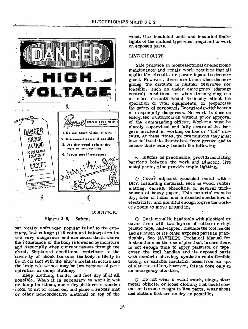
It is important thatyou recognize ahazardous condition and take immediate steps to correct it. Safety posters (figs. 2-1 and 2-2) help warn of dangers in working areas or remind personnel to be safety conscious. Warning signs (red) and caution signs (yellow) should be located where hazardous conditions exist. Be aware of areas that are wet or oily or have stumbling hazards. Wear rubber gloves and protective clothing wherever working conditions warrant it. Make it a habit to look for and to correct defective tools and equipment, improper grounding, and rotating machinery hazards.
HANDTOOLS
Normally you should have no problems when working wifh handtools. In all likelihood, how- ever, you have seen some dangerous practices in the use of handtools that should have been avoided. One unsafe practice involves the use of tools having plastic or wooden handles that are cracked, chipped, splintered,. broken, or otherwise unserviceable. This practice is sure to result in accidents and personal injuries, such as cuts, bruises, andforeign objects in the eyes. If these unserviceable handtools are not repair- able, they should be condemned and replaced.
When necessary (in an emergency only) to improvise an insulated handtool, use the follow- ing approved method which will protect the user against the effects of electric shock: First, apply several layers of approved rubber, insulating tape on the metallic handle. Next, apply a layer or two of friction tape over the insulating tape. Friction tape when used alone does not provide adequate protection from electrical shock, therefore, is used for griping purposes only. For other in- structions on the safe use of handtools, consult Tools and Their Uses, NAVPERS 10085-B.
PORTABLE ELECTRIC POWER TOOLS
Portable power tools should be clean, prop- erly oiled, and in good repair. Before they are used, inspect them to see that they are properly grounded. If a tool is equipped with a 3-prong plug, it should be plugged into a 3-hole electrical receptacle.
Never remove the third prong. Make abso- lutely sure the tool is equipped with a properly grounded conductor. If the tool has a metal cáse, be sure to ground it according to chapter 9600 of NAVSHIPS Technical Manual. Observe safety precautions and wear rubber gloves whenever operating portable equipment.
Before using an extension cord to connect a portable electric tool to its power source, plug the extension cord into a dummy (or deenergized) receptacle and measure the resistance between the housing of the tool and the structure of the ship, using a volt-ohmmeter. The resistance of the grounding conductor must be less than one ohm. Bend and twist the cord while measuring the resistance. A chance in resistance indicates broken strands in the grounding conductor. The extension cord must be replaced.
Other safe practices in the use of a portable electric power tool include the following:
• Inspect the tool cord and plug before using the tool. Do not use the tool if its cord,is
7

ELECTRICIAN’S MATE 3 & 2
At ■■'.,} >' ' ■/ ' "tit1* i ÿ ' >v
SK-^WÍ-^- wj:/' '<s S'' ' J, ••/ 2 '*v ■• V-^
SAFETY P
>*
':â00<|f'fliK!fll' *s s
b •MIMMátÉ
M«
AV«?TVV
mê
sn srafflw® S®
äBM: Ü
m S'H'^
■"'Vo* .^<*G PM
»»►
Wtp
CLEAN WITH
A
**& W w
.. ^1,.- V
DANGEROUS WITH
YOUR HAND
* * V‘ % \
V v ^ A- ^.'V
V ^
p * 'xyz^m
T\
>«* -5 M <*v' ►
% < <
w *
Í ' *
ID
r / WORN
OR DEFECTIVE INSULATION K
/ LOOSE f OR
WORN CONNECTION K.
/ GROUND ' WIRE CONNECTION
Figure 2-1. — Safety posters. 40.67(77C)A
8

Chapter 2—SAFETY PRECAUTIONS
ALL SHOOK UP?
0
i
I GROUND IT BEFORE
IT GROUNDS YOU! I
DON'T CAUSE ACCIDENTS
\S^
¿ • Replace guard
• Cut the power before repairing
il V,
BETTER than I mmmmmmmmsá any tools ever
¡nventedH EPlllEliil PROTECTI
V
THEM! V
r
Figure 2-2. — Safety posters (continued). 40.67(77C)B
9

ELECTRICIAN’S MATE 3 & 2
frayed or its plug damaged or broken. Do not use spliced cables except in an emer- gency that warrants the risk involved.
0 Before using the tool, lay all portable cables so you and others cannot trip over them. Do not use the tool in a damp or wet location.
• Connect the tool cord into the extension cord (when required) before inserting the extension cord into a live receptacle.
0 When using the tool, wear equipment that will protect vour eyes if there is a chance of particles getting in them.
• After using the tool, unplug the extension cord (if any) from the live receptacle be- fore unplugging the tool cord from the extension cord. Do not yank the cords when unplugging.
0 Stow the tool in its assigned place after you are through using it.
Grounding of Shock Mounted Equipment
Normally, on steel-hull vessels, grounds are inherently provided because the metal cases or frames of the equipment are in contact with one another and with the metal structure of the ves- sel. In some instances where such inherent grounding is not provided by the mounting ar- rangements, such as equipment supported on shock mounts, suitable ground connections must be provided.
Maintenance of ground conductors and con- nectors consists primarily of corrective and preventive maintenance. In general, you must ensure that all bonding surfaces (connection points or metallic junctions) are securely fas- tened and free of paint, grease, or other foreign matter that could interfere with the positive metal-to-metal contact at the ground connection point. As a matter or practice, always do the following:
0 Periodically clean all strap-and-clamp type connectors to ensure that all direct metal- to-metal contacts are free from foreign matter.
0 Check all mounting hardware for mechan- ical derangement or loose connection.
0 Replace any faulty, rusted, or otherwise unfit grounding straps, clamps, connections, or components between the equipment and the ground to the ship’s hull.
• When replacing a grounding strap, clean the metallic contact surfaces and establish elec- trical continuity between the equipment and the ship’s hull. Check continuity with an ohmmeter.
0 Recheck to be sure that the connection is securely fastened with the correct mounting hardware, and paint the ground strap and hard- ware in accordance with currently accepted pro- cedures.
CAUTION: Before disconnecting a ground strap on equipment supported by shock mounts be sure the equipment is DEENERGIZED.
RUBBER FLOOR MATTING
To eliminate likely causes of accidents and to afford maximum protection to personnel from the effects of electric shock, use only the ap- proved rubber floor matting for electrical and electronic spaces. Accident investigations often show that the floors around electrical and elec- tronic equipment had been covered with only general-purpose black rubber matting. The elec- trical characteristics of this type of matting do not provide adequate insulation to protect against electric shock; also, the material used in the manufacture of the matting is notfire-retardant.
The only approved rubber floor matting (cur- rently being specified in Military Specification MIL-M-15562) is made of a gray fire-retardant material, has a diamond-shaped surface, and is listed under Federal Stock Number 7220-267- 4630. This matting will protect against electrical potentials up to but not exceeding 3000 volts. In addition, the matting will improve the general overall appearance of an electrical or electronic space. Rubber matting should be glued to the deck whenever practical.
Careful design and fabrication of the floor matting does reduce the possibility of accidents. However, to ensure that tiie matting is complete- ly safe, operating and maintenance personnel must promptly remove from its surfaces all foreign substances that could possibly contami- nate or impair its dielectric properties. The dielectric properties of the matting can be im- paired or destroyed by oil, imbedded metal chips, cracks, holes, or other defects. If it is apparent that the matting is defective for any reason,
10

Chapter 2 —SAFETY PRECAUTIONS
cover the affected area with a piece of new mat- ting.
SAFETY SHORTING PROBE
Before starting to work on deenergized cir- cuits that have large capacitors, maintenance personnel must discharge them with a safety shorting probe.
Figure 2-3 provides the necessary details and list of materials for constructing an approved safety shorting probe. Since the length given may not be suitable for all types of equipment in a specific area, it can be varied as required. How- ever, materials used should conform with or be equivalent to those in the recommended list of materials required.
WARNING
Never reduce the length of the handle to the point where there will be less than 1 foot of clearance between the grip and the shorting rod.
When using the safety shorting probe, always be sure first to connect the test clip to a good ground (if necessary, scrape the paint off of the grounding metal to make a good contact). Then hold the safety shorting probe by the handle and touch the probe end of the shorting rod to the point to be shorted out. The probe end is fashioned so that it can be hooked over the part or terminal to provide a constant connection by the weight of the handle alone. Always take care not to touch any of the metal parts of the safety shorting probe while touching the probe to the exposed “hot” terminal. It pays to be safe; use the safety shorting probe with care.
STEEL WOOL AND EMERY
It is a recognized fact that the use of steel wool, emery cloth, or emery paper is harmful to the normal operation of electric and elec- tronic equipment. The NAVSHIPS Technical Manual and other technical publications warn against the use of steel wool and emery on or near this equipment because of their harmful effects. Scattered as they are by ventilation currents and attracted by the magnetic devices in this equipment, particles of steel wool and emery may cause short circuits, grounds and
excessive equipment wear. Therefore, emery and steel wool are never to be used for cleaning contacts. Clean the contacts with silver polish, sandpaper or burnishing tools. After cleaning, use a vacuum to remove dust.
ELECTRIC SOLDERING IRONS
In using and handling an electric soldering iron, you can avoid getting burned or shocked by adopting the following practices:
• Grasp and hold the iron by its handle. Always assume a soldering iron is hot, whether plugged in or not. (Never use an iron that has a frayed cord or damaged Plug.
m Hold small soldering workpieces with pliers or suitable clamps. Never hold the work in your hand.
• In resting a heated iron, lay it on a metal surface or its'own resting stand. Besides preventing burns, this practice will help prevent fire and equipment damage.
• Clean the iron by wiping it across a can- vas cloth placed on a suitable surface. Do not hold the cleaning cloth in your hand.
• Avoid using too much solder. Use a can- vas to wipe away excess solder. Swinging the solder iron to remove excess hot sol- der, could cause a fire in combustible materials or burn the skin and eyes.
0 Before soldering electronic equipment, disconnect it from the power supply. Do not risk coming in contact with RF cir- cuits or high voltages.
• After soldering, disconnect the iron from its power supply; let the iron cool off be- fore returning it to its designated storage place.
- AEROSOL DISPENSERS
By deviating or ignoring procedures pre- scribed for selecting, applying, storing, or dis- posing of aerosol dispensers, personnel have been poisoned or burned or have suffered other physical injury. It is difficult to compile a list of specific precautions and safe practices for handling aerosol dispensers due to the variety
11

©PROTECTIVE SHIELD 4IN. DIA. XI/4THK. DRILL 1/4 IN. HOLE IN
CENTER OFSHIELD BAKELITE HANDLE ^ (SEE NOTED. (T)
(2) MACHINE SCREWS 6-32 X 3/4 LG
DRILL (2) HOLES (0.I44DIA.) USE A NO. 27 DRILL (SHIELD ONLY) DRILL AND TAP (2)HOLES
6-32X3/4 DEEP (HANDLE ONLY) USE A NO. 34 DRILL (O.lll )
DRILL S TAP (2) HOLES IN LINE ' FOR (2) 4-60NC X 1/4IN SCREWS USE A NO.41 DRILL (0.096) SCREW a SOLDER CONN. IN PLACE. NOTES
'' rCR0SS SECTION WITH
to
Sr[LL ? TAP (I ) HOLE IN HANDLE FOR THREADED END OF ROD-USE A N0.6 DRILL (0.204) (SEE NOTE 3)
CHAMFERED EDGES INSTEAD OF ROUN D CROSS oECTION. ©©
2. IN FASTENING FLEXIBLE COPPER WIRE TO ROO
'¡'IRL SHOULD BE FASTENED WITH TWO SCREWS ’ AND SOLDERED OR, WRAP SIMILAR TO WESTERN
AND SOSLDERE UNT,L MECHANICALLY STRONO -
A® RCC (ITEM 3) WITH A 1/4-20 NC DIE AND SCREW ROD INTO HANDLE (ITEM I).
© 30 IN LENGTH
FLEXIBLECOPPER WIRE NO. 6 OR LARGER
©
FLEXIBLE INSULATOR MECHANICAL a SOLDER
CONNECTION
MUELLER NO 26 MACHINE SCREW 92 5305 “812-6647 6-32 X 3/4IN. L6
NYLON
PROTECTIVE SHIELD 969330-290-3462 MIL-P-I5035 BAKELITE,TYPE FBE 38 IN X 1/4 IN. MESH TEETH
TESTCLIP • MACHINE SCREW KZ5305-637-5884 4-40NCX 1/4 IN. BRASS SOLDER CONNECTION SEE NOTE 3 MESH TEETH TEST CLIP
MUELLER N0.24A OR EOUIV.
FLEXIBLE INSULATOR (RUBBER) ROD 9Z9530-233-I299 1/4 IN. COPPER BEND
AND FIT PER DWG
GROUND WIRE, 30 IN NO 6 FLEXIBLE WIRE,
COPPER 2. ■
HANDLE,BAKELITE, 1-3/4 IN. DIA X 18 IN
9G9330-298-7538 MIL-P-79 BAKELITE
36 IN. LENGTHS
OTY NOMENCLATURE OR
DESCRIPTION PART OR IDENTI-
FICATION NO. SPEC MATERIAL OR NOTE ITEM
NO
Figure 2-3. — Safety shorting probe, 1.1(20C)'
EL
EC
TR
ICIA
N’S
MA
TE 3 &
2

Chapter 2—SAFETY PRECAUTIONS
of industrial sprays that- are available in this kind of . container. Hpwever, users of aerosol dispensers can guard against poisoning, fire, explosion, pressure, and other hazards by read- ing and complying with the instructions printed on each dispenser. The following rules are basic rules in preventing the injury or hazards indicated.
Poisoning—Ventilate adequately closed spaces where poisonous (toxic) substances are sprayed. U se exhaust fans or portable blow- ers to supply these spaces with fresh outside air. Where ventilation is inadequate, either do not spray at all or provide an air respira- tor or self-contained breathing apparatus.
Burns—Avoid spraying ÿôür hands, arms, face, or other exposed parts of the body. Some liquid sprays are strong enough to burn the skin; milder sprays may cause rashes.
Fire — Keep aerosol dispensers away from di- rect sunlight, heaters, and other sources of heat. Do not store any dispenéer in an area where the temperature can exceed the limit printed on the container. Do not spray vola- tile substances on warm or energized equip- ment.
Explosion — Do not puncture an aerosol dispen- ser. Discard used dispensers in approved waste receptacles which will not be emptied into an incinerator.
CLEANING SOLVENTS
Cleaning electrical and electronic equipment with water-based and nonvolatile solvents is an approved practice. These solvents do not vapor- ize readily. When it is not feasible to clean with a water-based solvent, use inhibited methyl chloroform (1,1,1 trichloroethane) . Methyl chlo- roform is a safe, effective cleaner IF used in tin adequately ventilated area, IF not inhaled direct- ly, IF not applied to warm or hot equipment, and IF fire precautions are taken. Do notweara gas mask when cleaning with methyl chloroform; its vapors displace oxygen in the air..
NEVER USE. CARBON TETRACHLORIDE as a cleaning agent. It is a highly toxic (poisonous) compound. Its threshold is 20 times lower than that of methyl chloroform; that is, more danger- ous. (Threshold is the point above which the con- centration of vapor in the air becomes danger- ous.)
Do not clean with VOLATILE substances, such as gasoline, benzine, and ether. Besides being fire hazards, they readily give off vapors that injure the human respiratory system in case they are inhaled directly for too long a time.
When using cleaning solvents in a compart- ment, make it a practice to blow air into the compartment, using a blower or canvas wind chute. Open all usable portholes; place wind scoops in them. Also, keep a ready-to-use fire extinguisher close by. Do not work alone in the compartment if it cannot be ventilated adequately.
You should avoid coming in contact with cleaning solvents. Wear gloves and goggles, es- pecially when equipment is being sprayed. In spraying, it helps to hold the nozzle close to the equipment. Do not spray cleaning solvents on electrical windings or insulation.
RADIOACTIVE ELECTRON TUBES
Electron tubes containing radioactive mate- rial are now commonly used. These tubes are known as TR, ATR, PRE-TR, spark-gap, voltage-regulator, gas-switching, and cold- cathode gas-rectifier tubes. Some of these tubes contain radioactive material and have intensity levels which are dangerous; they are so marked in accordance with Military Specifications. The majority of these tubes contain radioactive cobalt (Co-60), radium (Ra-226), or carbon (C-114); several contain nickel (Ni-63); and a relative few contain cesium-barium (CsBa-137).
As long as the electron tube containing radio- active material remains intact and is not broken, no great hazard exists.. However, if the tube is broken and the radioactive material is exposed, or escapes from the confines of the electron tube, the radioactive material becomes a poten- tial hazard. The concentration of radioactivity in a normal collection of electron tubes at a maintenance shop does not approach a dangerous level, and the hazards of injury from exposure are slight. However, at major supply points, the storage of large quantities of radioactive elec- tron tubes in a relatively small area may create a hazard. For this reason, personnel working with equipments employing electron tubes con- taining radioactive material, or in areas where a large quantity of radioactive tubes is stored, should read and become thoroughly familiar with the safety practices promulgated in ship- board instructions.
Cathode-ray tubes should always be handled with extreme caution. The glass envelope en- closes a high vacuum and, because of its large
13

ELECTRICIAN’S MATE 3 & 2
surface area, is subject to considerable force caused by atmospheric pressure, (The total force on the surface of a 10-inch CRT is 3750 pounds, or nearly two tons; over 1000 pounds is exerted on its face alone.)
The chemical phosphor coating of the CRT face is extremely toxic. When disposing^ of a broken tube, be careful not to come into contact with this compound. Before discarding a CRT make it harmless by breaking the vacuum glass seal. The safest method of rendering a CRT harmless is to place the tube that is to be dis- carded in an empty carton, with its face down. Then carefully break off the locating pin from its base (fig. 2-4).
An alternate method of rendering a CRT harmless is to place it in a carton. Then, using à long, thin rod, pierce through the carton and the side of the CRT.
PAINTS AND VARNISHES
You must take special precautions when re- moving paint or repainting electrical equipment. In general, the removal of paint from electrical equipment should be avoided. The use of scrap- ing or chipping tools on such equipment is liable to injure the insulation or damage relatively delicate parts. Furthermore, paint dust is com- posed of abrasive and semiconducting materials which impair the insulation. All electrical equip- ment, such as generators, switchboards, motors and controllers, should be covered to prevent entrance of the paint dust when paint is being scraped in the vicinity. After the paint is re- moved, the electrical equipment should be thor- oughly cleaned, preferably with a vacuum cleaner.
Electrical equipment should be repainted only when necessary to ward off corrosion due to lack of paint. The painting should then be con- fined to the areas affected. General repainting of electrical equipment or enclosures for elec- trical equipment for the sole purpose of im- proving their appearance is not desirable. Paint should never be applied to any insulating sur- faces in electrical equipment. DO NOT PAINT OVER IDENTIFICATION PLATES.
Electrical insulating varnish should be ap- plied to equipment only as necessary; Frequent applications of insulating varnish builds up a heavy coating which may interfere with heat dissipation and develop surface cracks. Do not apply insulating varnish to dirty or moist insu- lation, as the varnish will seal in the dirt and moisture and make future cleaning impossible.
NECK OF CRT
LOCATING PIN
GLASS VACUUM
SEAL
20.320(40) Figure 2-4. — Cathode-ray tube base structure.
Shellac and lacquer are forms of varnish but must not be used for insulating purposes. The two types of insulating varnishes commonly used in the Navy are clear baking varnish (grade CB), and clear air-drying varnish (grade CA). Grade CB is the preferred grade, however if it is not possible to bake the part to be insulated, grade CA is used.
Do not use grade CA or CB insulating varnish on insulating material other than class O or class A material.
ELECTRICAL FIRES
Fire aboard a Navy vessel at sea sometimes is more fatal and damaging to both personnel and the ship itself, than that resulting from bat- tle. It is important that all personnel know nnd understand the danger of fires. Part of this knowledge is to know the type and location of firefighting equipment and apparatus in the im- mediate working and berthing spaces, and throughout the ship. It is too late to get this knowledge after a fire is started; the timé is now.
Fire Extinguishers
Table 2-1 lists the types of fire extinguishers that are normally available for use. Fire extin- guishers of the proper type must be conveniently located near all equipment that is exposed to constant fire danger, especially high-voltage equipment. Be extremely careful when using fire extinguishing agents around electrical circuits. A stream of salt water or foam directed against an energized circuit can conduct current and shock the firefighters. The same danger is pres- ent though to a lesser degree when freshwater is used. Avoid prolonged exposure to high con- centrations of carbon dioxide in confined spaces
14

Chapter 2—SAFETY PRECAUTIONS
since there is danger of suffocation unless oxy- gen breathing apparatus is used.
Table 2-1. — Types of Fire Extinguishers
EXTINGUISHER USE
CO3 Gas Effective on any type fire particularly electrical fires.
Soda-Acid Effective only on Class A fires. Not recommended for electrical fires as com- pound is good conductor of electricity. Not effective on burning compounds, such as oil and the like.
a. Remove the locking pin from the re- lease valve.
b. Grasp the horn handle by the insul- ation (thermal) grip; the grip is insulated against possible hand frostbite.
c. Squeeze the release lever (or turn the wheel) to open the valve and thus release the carbon dioxide; at the same time, direct the dis- charge flow of the carbon dioxide toward the base of the fire.
d. Aim and move the horn of the extin- guisher slowly from side to side.
e. Do not stop the discharge from the extinguisher too soon. When the fire has been extinguished, coat the critical surface areas involved with carbon dioxide “snow” in order to cool the substances (fuels) involved and pre- vent a rekindling of the fire.
Foam Very effective on burning compounds, such as oil and similar materials. Not sat- isfactory for electrical fires, as compound is a good con- ductor of electricity.
Potassium Bicarbonate
(PKP)
Very effective on Class B fires. Not recommended for electrical fires because it fouls electrical and elec- tronic equipment.
Fighting an Electrical Fire
The following general procedure is used for fighting an electrical fire:
1. Promptly deenergize the circuit or equip- ment affected. Shift the operation to standby cir- cuit or equipment, if possible.
2. Sound an alarm in accordance with station regulations or the ship’s fire bill. When ashore, notify the fire department; if afloat, notify the Officer of the Deck. Give the fire location and state what is burning. If possible, report the extent of the fire, that is, what its effects are upon the surrounding area.
3. Secure ventilation by closing copipartment air vents or windows.
4. Attack the fire with portable CO3 extin- guishers (or a COis hose reel system, if avail- - able) as follows:
DEENERGIZED AND LOW VOLTAGE CIRCUITS
Safety must always be practiced by persons working around electric circuits and equipment to prevent injury from electric shock and from short circuits caused by accidentally placing or dropping a metal tool, flashlight case, or other conductor of electricity across an energized line. The arc and fire started by these short circuits even where the voltage is relatively low, may cause extensive damage to equipment and serious injury to personnel.
No work is done on energized or deenergized switchboards without prior approval of the elec- trical or engineer officer.
All supply switches or cutout switches from which power could possibly be fed should be se- cured in the off or open (safety) position, and tagged. The tag should read “THIS CIRCUIT WAS ORDERED OPEN FOR REPAIRS AND SHALL NOT BE CLOSED EXCEPT BY DIRECT ORDER OF (name and rank ofperson making, or directly in charge of repairs),” or “DANGER-SHOCK HAZARD (fig. 2-5A) —Do not change position of switch EXCEPT by direction of (name and rank of person making or directly in charge of re- pairs).” After first making certain that the cir- cuit is dead, use a fuse puller to remove car^ tridge fuses.
That the danger of shock from the^SO-volt a-c ship’s service system is reasonably well recognized by operating personnel is shown by the relatively few reports of éerious shock re- ceived from this voltage despite its widespread use. On the other hand, -a number of shipboard fatalities have been reported due to contact with 115-volt circuits. Despite a fairly widespread
15
ELECTRICIAN’S MATE 3 & 2
Mm ■ ui n
swoc^
mm CH^Gt 00 NOT
POSITION SVUTCH
EXCEPT it lUtCT«*
VSH«*’ S.6740S» T*ai 060p
FROfiA LIVE WIRE)
1. Do not touch victim or crire
2. Disconnect power if possible
3. Use dry wood pole or dry rope to remove wire
4. Resuscitate if necessary
02
40.67(77C)C Figure 2-5o — Safety,
but totally unfounded popular belief to the con- trary ¿ low voltage (115 volts and below) circuits are very dangerous and can cause death where the resistance of thebody is lowered by moisture and éspecially when current passes through the eheste Shipboard conditions contribute to the ’severity of shock because the body is likely to be in contact with the ship’s metal structure and the body resistance may be low because of per- spiration or damp clothingo
Keep clothing,, hands, and feet dry if at all possible. When it is necessary to work in wet or damp locations, use a dry platform or wooden
' stool to sit or stand on, and place a rubber mat or other nonconductive material on top of the
wood. U se insulated tools and insulated flash- lights of the molded type when required to work on exposed parts.
LIVE CIRCUITS
Sáfe practice in most electrical or electronic maintenance and repair work requires that all applicable circuits or power inputs be deener- gized. However, there are times when deener- gizing the circuits is neither desirable nor feasible, such as under emergency (damage control) conditions or when deenergizing one or more circuits would seriously affect the operation of vital equipments, or jeopardize the safety of personnel. Energized switchboards are especially dangerous. No work is done on energized switchboards without prior approval of the commanding officer. Workers must be closely supervised and fùlly aware of the dan- gers involved in working on live or “hot” cir- cuits. At these times, the precautions they must take to insulate themselves from ground and to ensure their safety include the following:
© Insofar as practicable, provide insulating barriers between the work and adjacent, live metal parts. Also provide ample lighting.
0 Cover adjacent grounded metal with a DRY, insulating material, such as wood, rubber matting, canvas, phenolics, or several thick- nesses of heavy paper. This material must be dry, free of holes and imbedded conductors of electricity, and plentiful enough to give the work- ers room to move around in.
0 Coat metallic handtools with plastisol or cover them with two layers of rubber or vinyl plastic tape, half-lapped. Insulate the tool handle and as much of its other exposed parts as prac- ticable. See NAVSHIPS Technical Manual for instructions on the use of plastisol. In case there is not enough time to apply plastisol or tape, cover the tool handles and,its exposed parts with cambric sleeving, synthetic resin flexible tubing, or suitable insulation taken from scraps of electric cables, however, this is done only in an emergency situation.
0 Do not wear a wrist watch, rings, other metal objects, or loose clothing that could con- tact or become caught in live parts. Wear shoes and clothes that are as dry as possible.
16

Chapter 2—SAFETY PRECAUTIONS
• Tighten the connections of removable test leads on portable meters. In checking live cir- cuits, do not allow the free end of an energized test lead to come adrift from its meter.
• If practicable, work with one hand only; wear a rubber glpve ,pn the other hand. Where the work .permits, wear rubber gloves on both hands.
.• Have immediately available a person who is qualified to administer moúth-to-móuth re- suscitation and. cardiac massage for electric shock.
Rubber Gloves
Rubber. insulating gloves are classified ac- cording to thpir proof-test voltages, as follows: Class I—10,000 v; Class 11—15,000 v; and Class III—20,000 v. The proof-test voltage for a particular class of gloves is not the same as the voltage on which the gloves can be used safely. The maximum safe voltage for rubber gloves is always LESS than the proof-test volt- age. This safe voltage depends on many factors, including the quality and thickness of the rubber, design and age of the gloves, weather conditions, frequency of use, and whether carefully handled and stored. The determining factors in glove selection are the established practice and the working conditions that will ensure an adequate margin of safety.
Since rubber gloves are worn for personal protection, serious injury or death may result if they fail while being worn., To help prevent failure, they are made of natural rubber—the best available material that combines the chemi- cal, physical, and dielectric properties required, as well as the necessary processing character- istics; However, natural rubber is susceptible to attack by oxygen, ozone, and petroleum pro- ducts. The usual antioxidant additives in com- pounded rubber will guard against oxygen attack for reasonable periods of time, but not against tlie effects of ozone, which often forms near discharging electrical apparatus due to the ion- ization 6f surrounding air. Ozone may cause rub- ber gloves to crack or be cut easily when stretched. Petroleum products can cause natural rubber to deteriorate rapidly.
LEAKAGE CURRENTS
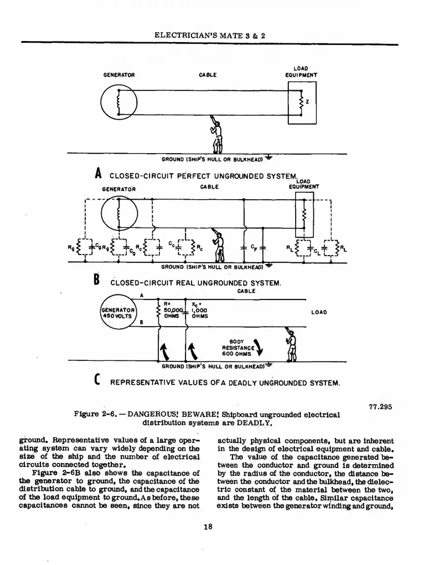
The ungrounded electrical distribution sys- tem used aboard ship differs from the grounded
system used in shore installations. But because the shipboard system is designed to be unground- ed, never think that it is safe io touch one .con- ductor since no electrical current would flow. It is not safe to touch one conductor of the un- grounded shipboard system because each con- ductor and all electrical equipment connected to thë system have an effective capacitancé' to ground which provides an. electrical current path between the conductors and the shipi’s hull. The higher the capacitance, the grëater the cur- rent flow is for a fixed body resistance, if one conductor of the ungrounded system is touched while thé body is in contact with thé ship's hull or other metal enclosures. When body resistance is low due to wet or sweaty hands, for example, the inherent capacitance is sufficient to cause a FATAL electrical current to pass through the body.
A perfect ungrounded system (fig. 2-6A) would be one in which the insulation is perfect on all cables, switchboards, circuit breakers, generators, and load equipment; and there would be no filter capacitors connected from ground to any of the conductors, and none of the system equipment or cables would have any inherent capacitance-to-ground. If all these conditions were met, there would be no path for electrical current to flow to ground from any of the system conductors.
You can see in figure 2-6A that if a man touches a live conductor while standing on the deck, there would be ho completed path for cur- rent to flow from the conductor through the man’s body, and thus, no electrical shock. However, shipboard electrical power distribution systems DO NOT and CANNOT meet the above definition of a PERFECT ungrounded system.
In a representative shipboard “real" un- grounded system, as shown in figure 2-6B, there are additional factors (resistances R and capacitances C) which must be considered, some of which are hot visible..
The resistances, when combinëd in parallel, form the insulation resistance of the system and is periodically measured by using a 500-volt d-c megger. In figure 2-6B, there is a generátqr insulation resistance, an electric cable insul- ation resistance, and a load insulation: resist- ance. The resistors cannot be seen as physical components, but are representative of small current paths through equipment and cable élec- trical insulation. The higher the resistance, the better the system is insulated and thereforë, less current will flow between conductor and
17
ELECTRICIAN’S MATE 3 & 2
GENERATOR CABLE LOAD
EQUIPMENT
GROUND (SHIP’S HULL OR BULKHEAD) '
i CLOSED-CIRCUIT PERFECT UNGROUNDED SYSTEM. LOAD
GENERATOR CABLE EQUIPMENT
AC,
"fJ
L-
___J J I
‘*T C. t L L
GROUND (SHIP’S HULL OR BULKHEAD) ‘
B CLOSED-CIRCUIT REAL UNGROUNDED SYSTEM. CABLE
9O0OQ. . 1,000 GENERATOR 450 VOLTS
R«
OHMS OHMS
BODY «
RESISTANCE 600 OHMS
GROUND (SHIP'S HULL OR BULKHEAD)-^
LOAD
C REPRESENTATIVE VALUES OFA DEADLY UNGROUNDED SYSTEM.
77.295 Figure 2-6. — DANGEROUS.' BEWARE! Shipboard ungrounded electrical
distribution systems are DEADLY.
ground. Representative values of a large oper- ating system can vary widely depending on the size of the ship and the number of electrical circuits connected together.
Figure 2-6B also shows the capacitance of the generator to ground, the capacitance of the distribution cable to ground, and the capacitance of the load equipment to ground. As before, these capacitances cannot be seen, since they are not
actually physical components, but are inherent in the design of electrical equipment and cable.
The value of the capacitance generated be- tween the conductor and ground is determined by the radius of the conductor, the distance be- tween the conductor and the bulkhead, the dielec- tric constant of the material between the two, and the length of the cable. Similar capacitance exists between the generator winding and ground.
18

Chapter 2 —SAFETY PRECAUTIONS
and between various load equipments and ground. Since capacitors ideally have an infinite imped- ance to direct current, their presence cannot be detected by a megger or insulation resistance test. In addition to the nonvisible system capaci- tance, typical shipboard electrical systems con- tain radio frequency interference (RFI) filters which contain capacitors connected from the conductors to ground. These filters may be a part of the load equipment or mounted separately, and are used to reduce interference to communi- cations equipment.
If physical contact is made between cable B and ground (fig. 2-6C) current will flow from the generator through the man’s body to ground and back through the system resistances and capaci- tances to cable A, thus complèting the electrical circuit back to the generator. This presents a serious shock hazard.
Suppose you megger the system of figure 2-6C • and obtain a system value of insulation resistance of approximately 50,000 ohms. You can conclude rightly that no low resistance grounds exist on the system, but wrongly that the system is a “perfect” ungrounded system. Do not forget the system capacitance which exists “in parallel with the resistance.
It should now be clear to you why you are NEVER to touch a live conductor of an elec- trical system, grounded or “ungrounded”. In- sulation resistance tests are made to ensure the system will operate properly, not to make the system safe. High insulation readings in a megger test do not make the system safe — nothing does.
ISOLATED RECEPTACLE CIRCUITS
Isolated receptacle circuits are installed on all new construction ships. These circuits are individually isolated from the main power dis- tribution system by transformers and each cir- cuit is limited to 1500 feet in length to reduce the capacitance to an acceptable level. This de- sign is intended to limit ground leakage currents to 10 milliampères which would produce a non- lethal shock. These receptacles are located where personnel usually plug in electrical power tools or appliances. To maintain a safe level of leakage currents, it is extremely important that the. isolated receptacle circuits be free of all resistance grounds.
SWITCHBOARD METERS AND INSTRUMENT TRANSFORMERS
When removing or installing switchboard and control panel meters and instrument transform- ers, extreme care must be exercised to avoid electric shock to yourself, and damage to the transformers and meters.
The secondary of a current transformer MUST always be short circuited before discon- necting the meter as extremely high voltages
-will build up that could be fatal to an unwary maintenance man.
The primary of a potential transformer must always be opened prior to removal of the meter to prevent damage to the primary circuit due to high circulating currents.
In most installations potential transformer primaries are fused and the transformer and associated meter can be removed after pulling the fuses for the transformer concerned. Indis- connecting the transformer and meter leads, however, avoid contact with nearby energized leads and-terminals.
TEST EQUIPMENT
Test equipments are, for the most part, pre- cision equipments, and must be handled with care if they are to perform their designed functions accurately.
Some equipments may require special han- dling; however, there are precautions which apply to test equipments in general. Rough handling, moisture, and dust all affect the useful life of test equipments. Bumping or dropping a test instrument, for example, may destroy the cali- bration of a meter or short-circuit the elements of an electron tube within the instrument.
The effects of moisture are minimized in electronic test equipments, such as signal gener- ators and oscilloscopes by built-in heaters. These heaters should always- be. opéráted for several minutes before high voltage is applied to the equipment.
Meters are .the most delicate parts of test, equipments. Protect a meter by making certain':* that the amplitude of the input signal under test', is within the range of the meter. Also, keep'á meter as far away as possible from strbng mag- ' nets. ... .7-.
When servicing a meter, disconnect it from the circuit before making resistance or coiiti-. nuity tests to eliminate thepossibility of burning, out the meter movèmèrit.
19

ELECTRICIAN’S MATE 3 & 2
WORKBENCHES
As an Electrician’s Mate you will be doing most of equipment testing and repairing on a workbench in the electric shop. To avoid getting shocked while working there, you must be care- ful, and your workbench must be insulated properly,,
Figure 2-7 shows the construction features of a safe electric or electronics workbench. Its work surface, or top, is usually 30 inches wide and 4 feet long. The bench must be fastened se- curely to the deck.
The joints of surrounding portable deck plates must be insulated with epoxy fiberglass strips (MIL-P-18177, type GEE) and secured with nylon screws as delineated in NAVSHIPS Drawing 05-2104467, if the deck plates have vinyl deck covering. Where vinyl deck covering is not used, matting (not less than 3-foot widths) will be in- stalled over the minimum area necessary to pre- vent electrical shock. Additionally, a 3-foot width of rubber matting will be installed to insulate the walkway in front of insulated work- benches where vinyl sheet is not specified.
The top and front surfaces of an electric or electronics workbench must be insulated with 3/8-inch Benelex 401. In addition, exposed ends of the workbench and kneeholes under auxiliary work tables must be insulated with l/8-inch insulation of the same material. Don’t defeat the purpose of the insulation by attaching vises, locks, hasps, hinges, or other hardware with metal throughbolts to the metal parts of the workbench. When mounting hardware items, insulate them from the workbench.
The workbench must have grounding leads that are 4 feet long and of type D0 size 10 (in accordance with MIL-W-16878). The ground leads must be secured to the ship’s structure or at the back of the workbench and equipped at the free end with a 50-ampere power clip (type PC) and insulated sleeving (both conform- ing to Federal Specification W-C-440). One grounding lead should be installed for every 4 feet of workbench length to ensure positive grounding of the equipment being tested. The grounding leads installed on ships with wooden hulls should be the same as those installed on ships having steel hulls except that the leads should be secured to the ship’s electrical grounding system. A bare solid copper conduc- tor, not less than 83,690 circular mils, must be used for the main internal grounding wire.
Test bench receptacle panels should be in- stalled on test benches where power at various
et.
WORKING AREA (TOP, TOP EDGE, FRONT OF DOORS AND DRAWERS) INSULATED I WITH 3/8 INCH BENELEX 40I(FSN 90-5640-256-5194)
Bi ALL OTHER EXPOSEDMETAL SURFACESIN THE WORKING ARE A (BENCH FRONT
AND SIDES, KNEE HOLE SIDE, UNDERSIDE OF TOP, INSULATED WITH 1/8 INCH
BENELEX 401.
RUBBER MATTING, EITHER GREY(FSN 90-7220-267-4630) OR GREEN (F$N ¿¿¿J 90-7220-913-8751),BUT ATLEAST 3 FEET WIDE
77.308 Figure 2-7. —Typical electric workbench.
voltages and frequencies (other than ships ser- vice) are needed for testing equipment. In addi- tion, one symbol 730.1 (or alternate symbol 730.4) receptacle must be installed within 5 feet of each workbench.
The illumination requirements vary between those for general purpose workbenches and workbenches for the repair of instruments, such as typewriters and meters. A warning plate which reads, ELECTRIC SHOCK-DANGER-DO NOT TOUCH ENERGIZED CIRCUITS must be installed over the workbench. Artificial respir- ation instructions and a description of an ap- proved method of rescuing personnel in contact with energized circuits must also be posted. See figure 2-5C.
A dummy outlet should be installed near the workbench for checking the grounding conductor on portable tools prior to issue.
SHIPBOARD LIGHTING
The best protection against the harmful ef- fects of glare aboard ship is the realization by all hands that prolonged exposure to glare should
20

Chapter 2—SAFETY PRECAUTIONS
he avoided. Usually, it is possible to position the work and place yourself so that you will not face any of the exposed lamps or uncomfortably bright, reflected-glare spots. If this is not prac- ticable, shield your eyes with a visor.
Always use the proper size lamp in every fixture. For example, glare is invariably pro- duced if a 100-watt lamp is used in a fixture that is designed for a 50-watt lamp. This will also result in rapid deterioration of the socket and shorter lamp life due to the increased heat. Install shielded fixtures in areas where extended critical seeing tasks are required. Never use exposed lamps or unshielded globes in such spaces. Replace burned out lamps immediately. Replace fluorescent lamps when their ends start to turn black, causing a reduction in brightness. A flickering fluorescent lamp will irritate the eyes. Flickering can be caused by a defective lamp or a defective starter, which should be re- placed at the earliest opportunity. Light fixtures in machinery spaces are required to be shielded due to the danger of oil accidentally spraying on a naked lamp and igniting.
If a great difference exists between the brightness of the work area, the pupils of the eyes (which automatically adjust to the amount of light entering the eyes) must make an adjust- ment every time the eyes glance away from, and back to, the work. The muscles of the eyes ordi- narily will not be overworked if the ratio of brightness of the work to brightness of the sur- roundings does not exceed 10 to 1. However, if the ratio of brightness is appreciably greater than 10 to 1, eye fatigue will result if the work is continued for a prolonged period. Avoid ex- treme brightness contrasts between work and background. When lighting fixtures are installed beyond the work area that would illuminate the background, turn on these lights.
CONFINED AREAS
Fumes tend to collect in confined areas. Be- cause of the toxic effects of the fumes, it is dan- gerous for men to enter spaces that are not well ventilated, or spaces that have been closed for an appreciable length of time, or spaces that are normally occupied or regularly used but have been vacated and sealed due to damage or other reasons. Typical examples of these spaces are storerooms, blisters, cofferdams,pontoons, shaft alleys, and voids.
All compartments or areas which are con- sidered or suspected of being NOT SAFE are to
be appropriately classified and tagged. No per- son should enter any closed compartment or poorly ventilated space aboard ship, due to the dangers of suffocation or gas poisoning, unless and until the GAS-FREE Engineer (or his author- ized representative) has taken appropriate action and has CLEARED the area for entrance. The area will be properly tagged for entrance, giving the date and time when the safe condition will no longer be in effect.
REPAIR PARTY ELECTRICIAN
As a repair party electrician you may be called ‘ upon to perform various tasks in the event of battle damage. These tasks could range anywhere from manning an OBA to being a stretcher bearer. Your primary responsibili- ties, however, will be those in your rating.
You must be familiar with all electrical power sources and distribution panels in the area assigned to your repair party. In case of fire the scene leader will decide whether or not the power should be secured. If the word is passed to you to secure the power to a specific compartment or piece of equipment, do so quick- ly. Then the task of putting the fire out can move ahead.
At the first sounding of General Quarters the crew proceeds to G.Q. stations and sets material condition Zebra. After Zebra is set you should report to your repair party leader for muster and further instructions. By this time the repair locker should be opened and you should proceed to take an inventory of all the electrical equip- ment in the locker. This equipment will gener- ally consist of items, such as an electrical re- pair kit, floodlights, flashlights and spare bat- teries, submersible pump, casualty power cablë and wrenches, extension cords, rubber gloves and rubber boots. After testing all the electrical equipment to make sure it is operational and safe, stow it in an easily accessible area. If needed it must be taken to the scene quickly;
All members of the repair party are respon- sible for rigging casualty power and tying it to the overhead; however, the repair party elec- trician is responsible for proper connection to the biscuits, (the source and the load) and finally turning on power. He must observe standard safety precautions, wear rubber gloves and rub-' ber boots, and stand on a section of rubber mat- ting while makine these connections.
In tagging the casualtypower cable at various locations, warn all hands of the potential danger that exists. A typical warning sign is shown in
21

ELECTRICIAN’S MATE 3 & 2
figure 2-5B. Casualty power cable maintenance will be discussed further in chapter 3.
RESCUE AND FIRST AID
As the Electrician’s Mate knows, his job is risky even under the best of working conditions; at other times, it is exceedingly dangerous. De- spite the fact that accidents are preventable, an EM runs a good chance of getting shocked and burned, being surrounded as he usually is by one or more of the hazards described earlier. If you are at the scene of an accident, you will be ex- pected to help the victim as quickly as possible.
ELECTRIC SHOCK
How much current does it take to kill a man? When a 60-hertz alternating current, for exam- ple. is passed through a man from hand to hand or from hand to foot and the current is gradually increased from zero it will cause the following effects: (1) at about 1 milliampere (0,001 am- pere) the shock is perceptible; (2i about 10 mil- liampere (0.01 ampere the shock is of sufficient intensity to prevent voluntary control of the mus- cles and a man may be unable to let go and free himself; (3) at about 100 milliampères (0.1 am- pere) the shock is fatal if it lasts for one second or more.
Rescue
All personnel should know that a victim ren- dered unconscious by electric shock should re- ceive artificial respiration and that it should be started in a matter of seconds rather than min- utes. Records show that seven out of ten victims were revived when artificial respiration was started in less than three minutes after the shock. Beyond three minutes, the chances of revival decrease rapidly.
The person nearest the victim should start artificial respiration without delay and call or send others for assistance and medical aid. The only logical permissible delay is that required to free the victim from his contact with the elec- tricity in the quickest, safest way. This step, while it must be taken quickly, must be done with great care, otherwise there may be two victims instead of one. In case the contact is a portable electric tool, light, appliance, equip- ment, or portable outlet extension, turn off the bulkhead supply switch or remove the plug from its bulkhead receptacle. If the switch or bulk- head receptacle cannot be quickly located, the
suspected electric device may be pulled free of the victim by grasping the insulated flexible cable to the device and carefully withdrawing it clear of its contact with the victim. O+her persons ar- riving on the scene must be clearly warned not to touch the suspected equipment until it is un- plugged. Aid should be enlisted to unplug the de- vice as soon as possible.
Where the victim is in contact with stationary equipment such as a bus bar dr the contacts on a machine, he should be pulled free if the equip- ment cannot be quickly deenergized, or if con- siderations of ship operation or survival prevent immediate shutdown of the circuits. To save time in pulling him free, improvise the equiva- lent of the protective insulation for the rescuer. For example, instead of hunting for a pair of rubber gloves to use in grasping the victim,you can safely pull him free if conditions are dry by grasping him by slack in his clothing or by the leather of his shoes. Instead of hunting for a rubber mat on which to stand, use nonconducting materials, such as deck linoleum, a pillow, blan- ket, mattress, dry wood, or coil of rope. At no time during the rescue should any part of the rescuer’s body directly touch hull metal or metal structure or furniture.
Resuscitation
Methods of resuscitating or reviving an elec- tric shock victim include artificial respiration (to establish his breathing) and external heart massage (to reestablish his heart beat and blood circulation).
ARTIFICIAL RESPIRATION. — The proce- dure for administering artificial respiration is given in figure 2-8A. Some techniques are dem- onstrated in figure 2-8B. If desired, in step 6 of the procedure, blow into the victim’s mouth through a cloth or handkerchief placed over his face. If assistance is available, you and an assis- tant can take turns blowing into the victim’s mouth and massaging his heart. See figure 2-8C.
CLOSED CHEST CARDIAC MASSAGE.— Massaging the heart is a practical, two-handed, easy-to-learn method of reviving an electric shock victim. The objective in closed chest car- diac massage is to squeeze the heart through the chest wall, thereby emptying the heart to create a pulse or beat.
Cardiac Arrest.— When there is a complete absence of any pulse at the wrist or in the neck,
22

Chapter 2—SAFETY PRECAUTIONS
ARTIFICIAL RESPIRATION MOUTH-TOMOUTH OR MOUTH-TO-NOSE
RESCUE BREATHING
0 PLACE CASUALTY ON BACK IMMEDIATELY DON’T WASTE TIME MOVING TO A BETTER PLACE OR LOOSENING CLOTHING.
©QUICKLY CLEAR MOUTH AND THROAT REMOVE MUCUS, FOOD AND OTHER OBSTRUCTIONS.
©TILT HEAD BACK AS FAR AS POSSIBLE THE HEAD SHOULD BE IN A "CHIN-UP” OR "SNIFF” POSI- TION AND THE NECK STRETCHED.
©LIFT LOWER JAW FORWARD GRASP JAW BY PLACING THUMB INTO CORNER OF MOUTH. DO NOT HOLD OR DEPRESS TONGUE.
©PINCH NOSE SHUT OR SEAL MOUTH PREVENT AIR LEAKAGE.
©OPEN YOUR MOUTH WIDE AND BLOW TAKE A DEEP BREATH AND BLOW FORCEFULLY (EXCEPT FOR BABIES) INTO MOUTH OR NOSE UNTIL YOU SEE CHEST RISE.
©LISTEN FOR EXHALATION QUICKLY REMOVE YOUR MOUTH WHEN CHEST RISES. LIFT JAW HIGHER IF VICTIM MAKES SNORING OR GURGLING SOUNDS.
©REPEAT STEPS SIX AND SEVEN 12 TO 20 TIMES PER MINUTE CONTINUE UNTIL VICTIM BEGINS TO BREATHE NORMALLY
* FOR INFANTS SEAL BOTH MOUTH AND NOSE WITH YOUR MOUTH BLOW WITH SMALL PUFFS OF AIR FROM YOUR CHEEKS.
-*-(?) CLEAR THE MOUTH AND THROAT
TILT HEAD BACK AND LIFT JAW
©—► 1
(3) PINCH NOSE (OR SEAL LIPS)
N. BLOW 0—* ft ñ
Lw
K \
c Figure 2-8. — Artificial respiration and cardiac massage.
4.224
23

ELECTRICIAN’S MATE 3 & 2
the victim has suffered a cardiac arrest or, in other words, loss of heart beat. At the same time, the pupils of his eyes are dilated and his breathing is weak or stopped. The victim may APPEAR to be dead. Under these circumstances, severe brain damage will occur in four minutes unless circulation of the blood is reestablished.
Heart Massage. —The following method of reviving a victim by cardiac massage is recom- mended by the Bureau of Medicine and Surgery:
1. Place the victim on his back on a firm surface, such as the deck, if possible. Expose his chest.
2. Kneel beside the victim; feel for the lower end of his breastbone; place one hand across the breastbone so the heel of the hand covers the lower part; place the second hand on top of the first so that the fingers point toward neck as in figure 2-8C.
3. With arms nearly straight, rock forward so that a controlled amount of your body weight is transmitted through your arms and hands to the breastbone. The amount of pressure to apply will vary with the victim. It should be applied as smoothly as possible. The chest wall of an adult should be depressed 2 to 3 inches with each pressure application. Keep the hands positioned as described to prevent injury to the liver, ribs, or other body parts.
4. Repeat application of pressure about 60 to 80 times per minute.
5. Have an assistant ventilate the victim’s lungSs preferably with pure oxygen under inter- mittent positive pressure; otherwise, with mouth-to-mouth resuscitation. The heart cannot recover unless supplied with oxygenated blood. Closed chest massage, however, will cause some ventilation of the lungs. When working alone, con- centrate on the massage but interrupt it every half minute or so to start rapid mouth-to-mouth breathing for three or four breaths.
6. Direct other assistants when available to keep checking the victim’s pulse. Use the least pressure that will secure an effective pulse beat. The pupils will become smaller when the cardiac massage takes effect.
7. Pause occasionally to determine whether a spontaneous heart beat has returned.
BURNS
The principal dangers from burns are shock and infection. All casualty care measures must be directed toward combating shock, relieving the casualty’s pain, and preventing infection.
Classification of Burns
Burns may be classified according to their cause as thermal, chemical, or electrical. Ther- mal burns are the direct result of heat such as fire, scalding, sun or explosion blast. Chemical burns are produced by chemical action such as battery acid on tissues. Electrical burns may be caused by electrical current passing through tissues or the superficial wound caused by elec- trical flash.
Bums may alsobe classified as first, second, or 'third degree, based on the depth of skin dam- age (fig. 2-9). First-degree burns are charac- terized only by reddening of the skin. Second- degree burns are characterized by blistering of the skin, either early or late. They are the most painful type of burn. The complete thickness of the skin is not destroyed. Third-degree burns are characterized by complete destruction of the skin with charring and cooking of the deeper tissues. This is the most serious type of burn, for it produces a deeper state of shock and more permanent damage and disfigurement. It is not as painful as a second-degree burn because the sensory nerve endings have been destroyed.
Emergency Treatment
The decree of the burn, as well as the skin area involved, determines the procedures used in treatment of burns. Large skin areas require a different approach than small areas. To esti- mate the amount of skin area affected, use fig. 2-10.
As a guideline, consider that burns exceeding 20 percent of the body surface endanger life; the old or the very young patient will not tolerate burn injuries well; without adequate treatment. Burns of more than 30 percent are usually fatal to adults.
If time and facilities permit caring for pa- tients with superficial burns, the area should be cleaned with soap and water. A simple sterile dressing of fine-mesh, dry gauze is then applied over the area to protect it from infection.
Based on field level casualty treatment con- ditions, superficial burns include first-degree burns and lesser second-degree burns, which need little attention beyond self-care.
When emergency treatment of the more seri- ous second-degree burns and third-degree burns is required, treat the patient for shock first. Make the patient as comfortable as possible, and protect him from cold, excessive heat, and rough handling.
24

Chapter 2—SAFETY PRECAUTIONS
136.32
RMAL
3RD DEGREE EPIDERMIS
IUM
FATTY TISSUE
: MUSCLE nr.
2ND DEGREE
I ST DEGREE
m1
«ms ODO na
cP.
f. >
Figure 2-9. — Types and degrees of burns.
The loss of body fluids is the main-factor in burn shock. Start oral therapy gradually at first lay giving him small amounts of hot coffee, tea, fruit juice, or sugar water. Give the drinks fre- quently but only if the patient is conscious, able to swallow, and has no internal injuries.
To enable trained personnel to determine the kind of treatment required, no medication should be applied to burns during emergency treatment. Pain is closely allied to the degree of shock, and should be relieved as soon as possible. When available, ice water is an effective pain reducer. Flooding with ‘ lots of clean, cool fresh water helps also provided that not too much force is used. In electric shock cases, burns may have to be ignored temporarily while the patient is being revived.
After the patient has been treated for pain and shock, a compress and bandage may be applied to protect the burned area. If a universal protective
■ dressing is not available, fine mesh gauze may be substituted. Constricting articles of clothing and
ornaments should be removed, and the burned area should be elevated and immobilized.
Patients with extensive deep burns must be evacuated to a medical facility for treatment as rapidly as possible. Pain should be alleviated and shock must be controlled before and during evac- uation.
Debris and loose clothing must be removed from burned areas to prevent irritation while the patient is being treated and transported. Clothing that sticks to a burn may be cut around the burn and the adhering cloth allowed to re- main until it can be removed at the medical facility. The area of the burn is usually sterile; therefore, care should be taken not to contami- nate it.
SAFETY PUBLICATIONS AND POSTERS
Electrician’s Mates should become regular readers of safety publications, such as Fathom magazine, Mech, and others. Published quarterly
25

ELECTRICIAN'S MATE 3 & 2
AC
II FRONT II
9*y./ I 18*/. / 19%
IK
18% 18%
136.31 Figure 2-10. — Computing body surface.
by the Naval Safety Center, FATHOM carries the most accurate information available on the subject of nautical accident prevention.
“MECH” is published quarterly and is dis- tributed to aeronautical organizations. It pre- sents the most accurate information available on the prevention of maintenance caused acci- dents and mishaps.
The “TECHNICAL NEWS” published monthly by Naval Sea Systems Command contains infor- mation for personnel in the Naval Establishment on the design, construction, conversion, opera- tion, maintenance, and repair of naval vessels as well as articles on safety hazards and their pre- vention.
These publications, as well as notices and instructions distributed by the cognizant bu- reaus, make excellent reference materials and should be read when made available to the oper- ating forces.
At the beginningof this chapter, it was pointed out that safety posters, such as those in figures 2-1 and 2-2, serve as warnings of danger or re- minders of safe practices. The messages of these and other well-designed safety posters are clear and to the point. The left-hand poster of figure 2-11, for example, reminds personnel to think “safety”; the right-hand poster to act promptly or suffer the consequences. Remember that the messages are aimed at YOU. It is your responsibility to “read and heed.” And don’t forget your ABC’s:
Always
Be
Careful.
26

Chapter 2 —SAFETY PRECAUTIONS
; Jï‘i
\
I
OF SAFETY BLASSES p. \»\» \00
fiat Hitt AM PROMPTLY!
Figure 2-11. —Safety posters.
77.309
27

OMIÄIPTE^ 3
TEST NT
As an Electrician’s Mate, you will find it necessary to use a variety of test equipment to help troubleshoot and repair the newer, more sophisticated electrical/electronie gear aboard- ship. This chapter provides you with a useful and logical troubleshooting procedure, and de- scribes the test equipment that you are likely to operate when troubleshooting and repairing the installed electrical/electronic gear,
TROUBLESHOOTING
Troubleshooting is the art of locating the problem. Like any art, it requires talent and training before it is developed into any degree of skill. Over the years Electrician’s Mates have developed specific theories as to how to go about their work, and since they are passed on to you free of charge it will stand you well to use them.
The FIRST step in logical troubleshooting is to recognize a normal condition; in other words, to determine that everything is working properly. For example, the second hand on our watch is going through 360 degrees in a clockwise direc- tion every minute, the chances are pretty good that the second hand on your watch is working properly. If, however, you had never seen a watch before, you would have no idea that this was the proper method for the second hand to work and therefore would have no way of knowing that the hand was working properly. When you are dealing with a voltage regulator or a large electric circuit breaker, the problem of recog- nition of normal conditions is far more compli- cated and you may need an explanation from a senior or from the manufacturer’s technical manual. The point is you must have a fair com- prehension of the normal condition of a piece of equipment before you can consider maintenance of it.
. A SECOND logical step in the art of trouble- shooting is the ability to recognize that a mal- function is occurring, is about to occur, or has
at some time past occurred. Then we assume that the equipment is not functioning normally, or that we have available information that indi- cates it will not function normally for much longer.
Picture again the watch, taut this time the second hand is stopped. A malfunction has oc- curred at some previous time. It may be that someone has forgotten to wind the watch, but since you recognize that the normal condition is for the second hand to complete 360 degrees in 1 minute and since it is not moving, you are aware that a malfunction has occurred. If, how- ever, when you looked at the watch, you noted that the second hand was moving at a rate of but 10 degrees in a 1-minute period, you could safely assume that a malfunction was occurring at that time. The third situation would be in ef- fect that you find the watch running at the proper rate but noted a grinding sound from somewhere in its interior. You could then assume with some reliability that a malfunction was about to occur at some future time. Again it must be emphasized that the criterion of step one remains true; you must be able to recognize a normal condition be- fore you can determine that there is a malfunction.
Step THREE in logical troubleshooting falls right in place once you are sure of the malfunc- tion’s existence. Collect all available data re- garding the malfunction in order to find the symp- toms. Is the unit running at all? Is it within the normal temperature and pressure range? Has this malfunction occurred before? Is the malfunc- tion occurring only during a specific set of cir- cumstances? Is the unit noisy?—Out of calibra- tion?— Over or under design limits? Don’t over- look anything, as the smallest unit of information that you collect may in the final analysis be the solution to the problem.
Now that you have collected all of the symp- toms of the malfunctions, the next step is to list, mentally or on paper, the possible causes of these symptoms. Many manufacturers’ technical
28

Chapter 3 —TEST EQUIPMENT
manuals list the “prohable cause” in the correc- tive maintenance sections. It is often wise at this point to discuss the malfunction with another Electrician’s Mate. Giving him the symptoms may result in his coming up with several causes that were not apparent to you.
Armed with a complete set of symptoms and with the probable causes of these symptoms, the troubleshooter now begins the painstaking checks which will ultimately lead to isolation of the mal- function. To sectionalize the trouble means to track it down into one specific area of a piece of equipment. This may be done by going over the energizing procedure , slowly and determining when the trouble first appears. It may be done through the use of a troubleshooter’s chart listed in the manufacturer’s technical manual. It also can easily be performed through the use of the probable causes that you have listed.
Once it has been determined which section of a system is malfunctioning, it is usually but a matter of time before the defective component or components are isolated and repairs can be made. During this final step of troubleshooting it is most important that you, the Electrician’s Mate, use every method of isolation. An open resistor can be determined through the use of a meter, but time is wasted if you do ' not note that the component is discolored when you originally open the chassi s for inspection. In troubleshooting you must give full attention — look, listen, smell, and feel — to ensure good, quick, trouble isolation.
TACHOMETERS
A tachometer is an instrument which shows the rate at which a shaft is turning. Tachometers indicate in revolutions per minute (rpm) the turn- ing speed of motors, generators, and other rotat- ing machines. Though tachometers are installed on Navy machinery, such as ships service gener- ators and main engines, an Electrician’s Mate must often determine the speed of a rotating ma- chine that is not equipped with a tachometer. In this case, he uses a portable tachometer.
Portable hand tachometers measure speed by direct contact with the shaft of the measured unit. Each hand tachometer, (fig. 3-1) comes with an assortment of hard rubber tips, one end of which is inserted in the instrument the other applied to the rotating shaft.
Portable tachometers are for use only during testing and should not be used continuously. The tachometer shaft must be aligned to' the center of the shaft of the unit under test; an off-center posi- tion will yield an incorrect reading. Additionally,
you should ensure that the design limit of the tachometer is not exceeded.
Common tachometers employed in the electric shop are both the centrifugal and chronometer types. In the centrifugal type, (fig. 3-1B), centri- fugal force acts upon weights or flyballs which are connected by links to upper and lower collars. The upper collar is affixed to a drive shaft while the lower is free to move up and down the shaft. A spring, which fits over the shaft, connects the upper and lower collars. As the drive shaft be- gins to rotate, the flyballs (or weights) rotate with it.
Centrifugal force tends to pull the flyballs away from the center, thus the lower collar rises and compresses the spring. The lower collar is attached to a pointer and its upward motion, re- stricted by the spring tension, results in an in- crease in the indication on the dial face. The unit when properly used indicates correct shaft speed as long as it is in contact with , the machine shaft under test.
The centrifugal tachometer may be either por- table (single and multiple range) or permanently mounted. The portable multi-range tachometer has three ranges: low (50 to 500 rpm), medium (500 to 5,000 rpm), and high (5,000 to 50,000 rpm).
Normally, permanently mounted centrifugal tachometers operate off the governor or speed limiting assembly. The tachometer continously records the actual rotational speed of the machin- ery shaft.
The shaft, portable/CHRONOMETRIC tacho- meter, shown in figure 3-2A, is a combination watch and revolution counter. It measures the average number of revolutions per minute of a motor shaft, pump shaft, etc. The mechanism of this tachometer is such that its outer drive shaft runs free when applied to a rotating shaft, until a starting button is depressed to start the timing element. Note the starting button beneath the index finger in figure 3-2A. The chronométrie tacho- meter retains readings on its dial after its drive shaft has been disengaged from a rotating shaft, until the pointers are returned to zero by the reset button (usually the starting button). The range of a chronométrie tachometer is usually from 0 to 10,000 rpm, and from 0 to 3,000 feet per minute (fpm).
Each portable centrifugal or chronométrie tachometer is supplied with a small rubber cov- ered wheel and a number of hard rubber tips. The appropriate tip or wheel is fitted on the end of the tachometer drive shaft, and held against the shaft to be measured. Portable tachometers of the centrifugal or chronométrie type are used
29

ELECTRICIAN’S MATE 3 & 2
y****. tO*"
«o»
iss*' *5«# ssírt»a
FIXED- COLLAR
FLY WEIGHTS
MOVABLE COLLAR
DRIVE SHAFT-
^S9 SPRING
IV POINTER
o> I
PIVOT
B
Figure 3-1.—Centrifugal tachometer. 61.17X: 2.66X
for intermittent readings only, and are not used for continuous operations.
The RESONANT REED tachometer, illustrated in figure 3-2B, is particularly useful for measur- ing high rotational speeds such as those that occur in turbines and generators. This type of tachome- ter is particularly suitable where it is practically impossible to reach the moving ends of the ma- chinery shafts. This instrument gives continuous readings and is capable of making very rapid, instantaneous adjustments to rotational speed.
Resonance is the quality of an elastic body which causes it to vibrate vigorously when sub- jected to small, rhythmic impulses at a rate equal to its natural frequency,* or nearly so. In a resonant reed tachometer, resonance provides a simple but accurate means for measuring speed and rate of vibration.
A resonant reed tachometer consists of a set of consecutively tuned steel reeds mounted in a case with a scale to indicate rpm of the shaft and vibrations per minute (vpm) of the reeds. This tachometer has no pointer—only a set of accu- rately tuned reeds — and it operates without direct contact with a moving part under test. It has no
gears or couplings,.and it requires no oiling and practically no maintenance.
Since the frequency of a generator is directly related to its speed, the resonant reed Instrument can be calibrated with a scale to indicate the oper- ating frequency of a generator. When used in this way, the meter is designated a frequency meter.
STROBOSCOPIC TACHOMETER
The stroboscope is an instrument that permits rotating or reciprocating objects to be viewed intermittently and produces the optical effect of slowing down or stopping motion. For example, electric fan blades revolving at 1800 rpm will apparently be stationary if viewed under a light that flashes uniformly 1800 times per minute. At 1799 flashes per minute, the blades will appear to rotate forward at 1 rpm and, at 1810 flashes per minute, they will appear to rotate backward at 1 rpm.
Because the human eye retains images for a fraction of a second, no flicker is seen except at very low speeds. The apparent slow motion is an exact replica of the original higher speed motion,
30

Chapter 3 —TEST EQUIPMENT
I
»
i . J. v ,v <!&•’■
2.66X: 61.16X
Figure 3-2. —Additional tachometers. (A) portable chronométrie; (B) mounted resonant reed.
so that the action of a high-speed machine can be analyzed under normal conditions.
When the flashing rate of the light is adjust- able, the control can be calibrated in flashes (or revolutions) per minute. The stationary image seen when the flashing rate of the lamp and the rotational rate of a shaft are equal permits very precise speed measurements to be made.
The Strobotac is an electronic flash device, in which the flash duration is very short (on the order of a few millionths of a second), which allows very rapid motion to be arrested.
Figure 3-3 is a photograph of the Strobotac. The box contains a swivel mount with a strobotron lamp in a parabolic reflector, an electronic pulse generator to control the flashing rate, and a power supply that operates from the a-c power line. The flashing rate is controlled by the large knob (see photo), and the corresponding speed in rpm is in- dicated on an illuminated dial viewed through win- dows in the knob.
The normal speed range is from 110 to 25,000 rpm. At speeds below 600 rpm, flicker becomes pronounced because the human eye cannot retain
successive images long enough to create the il- lusion of continuous motion. The flicker and the low average level of illumination set 600 rpm as the lower limit of speeds used for slow-motion studies. If slow speeds are to be checked, it is necessary to use an external flash with higher intensity than the built-in flash in order to raise the average level of illumination.
Maintenance
The life of the strobotron tube is approximately 250 hours if used at flashing speeds of less than 5000 rpm, or 100 hours if used at higher speeds.
If the Strobotac is operated continuously at the higher speeds, the strobotron cathode emission may eventually be reduced to the point where the tube is inoperative. When this happens, the tube usually glows with a dull red color, but will not flash. Flickering is another symptom of low cath- ode emission.
It is sometimes possible to restore operation by running the tube at low speeds for several hours. Eventually, however, the tube becomes completely inoperative and must be replaced.
31

ELECTRICIAN'S MATE 3 & 2
B f
X
77.310 Figure 3-3.—Strobotac.
MULTIMETERS
Multimeters combine a voltmeter, ammeter, and ohmmeter in one unit and may be classified as either the electronic or nonelectronic type.
MULTIMETER AN/PSM-4 (SERIES)
Multimeter AN/PSM-4A (fig. 3-4) is a port- able, nonelectronic volt-ohm-milliammeter. It can be used to measure direct current, resistance,
and voltage. The complete unit includes test probes which may be used with their prod tips, or the tips can be fitted with alligator clips or with a telephone plug to simplify contact arrange- ments and connections. A high voltage probe is also included, which makes it possible to read voltages up to 5000 VDC. This probe contains a warning light to indicate the presence of high voltage.
Multimeter AN/PSM-4 is designed for meas- uring the following:
1. Direct current up to 10 amperes. 2. Resistance up to 30 megohms. 3. D-c voltage up to 5000 volts. 4. A-c voltage up to 1000 volts (RMS). 5. Output voltage up to 500 volts (RMS).
The following discussion and the associated block diagrams treat the general circuit within the instrument part of the multimeter as it is arranged when used to measure voltage, current, or resistance. Although improvements have been made to the basic meter, for the purpose of this discussion there are no differences in the AN/ PSM-4A, B, C, and D meters.
D-C Voltmeter Circuits
The block diagram of the circuit in Multimeter AN/PSM-4 which is used for measuring d-c volt- ages is shown infigure 3-5. The circuit is select- ed with function switch SlOl.ineither its DIRECT or REVERSE DCV position. For voltages up through 500 volts, a range is selected with range switch S-102 (only one position shown in figure 3-5). For the 1000-volt range, the red test lead connects into the special 1000 VDC jack (fig. 3-4) and the range switch is not in the circuit. For the 5000-volt range the high voltage probe (not shown) connects the special 5000 VDC jack, and places its resistance in series with the meter movement. For any range, the total resistance in series with the meter movement will regulate the meter cur- rent to provide a proportional current to indicate the amount of voltage in the circuit.
A-C and Output Voltage Circuits
The circuits which measure a-c and output voltages (fig. 3-6), are selected with the ACV and OUTPUT positions of function switch S-101. For voltages up through 500 volts, a range is selected with range switch S-102. For the 1000- volt range, the red test lead connects the special
32
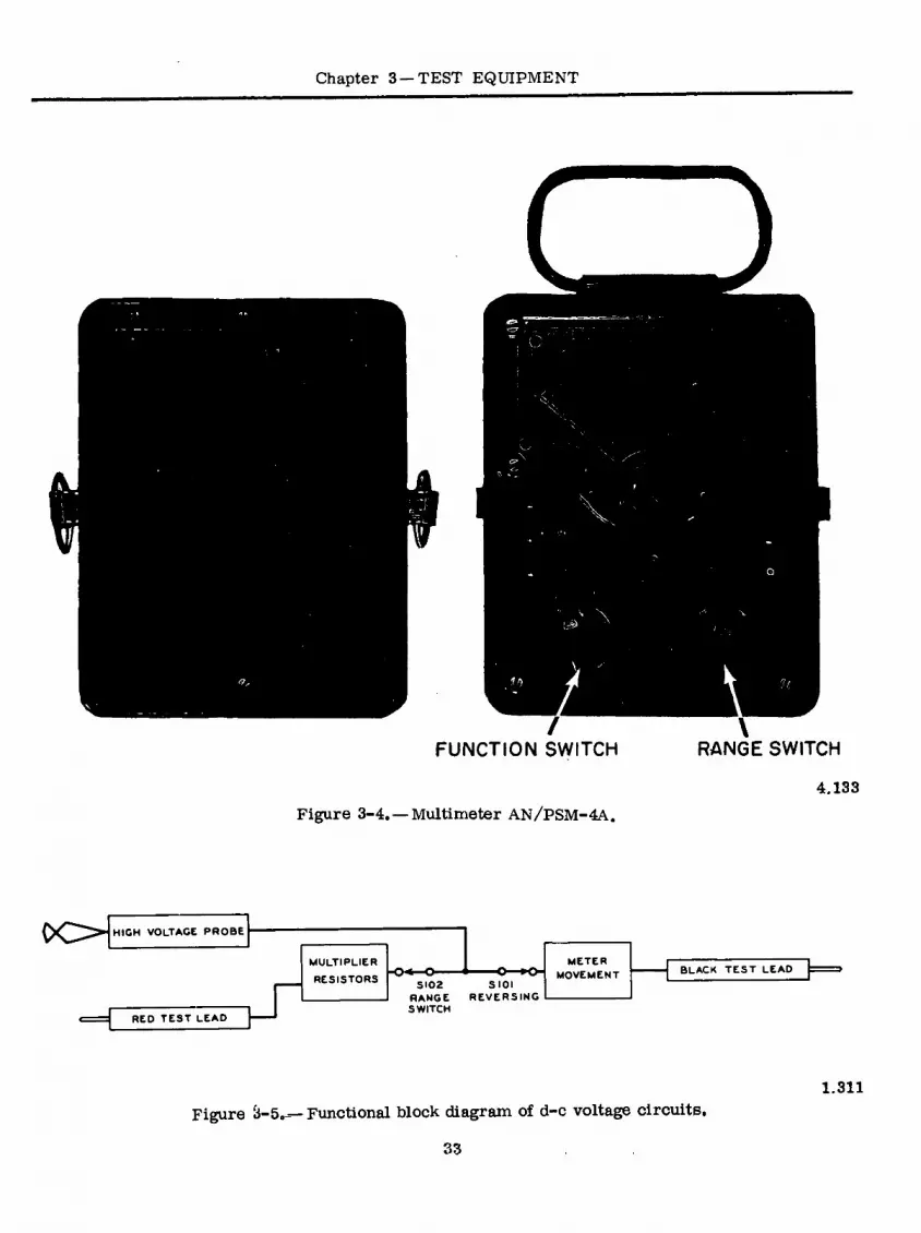
Chapter 3—TEST EQUIPMENT
FUNCTION SWITCH
Figure 3-4. — Multimeter AN/PSM-4A.
RANGE SWITCH
4.133
CO HIGH VOLTAGE PROBE
MULTIPLIER
RESISTORS
RED TEST LEAD
SI02 RANGE SWITCH
SIOI REVERSING
METER MOVEMENT BLACK TEST LEAD
1.811
Figure à-5a—Functional block diagram of d-c voltage circuits.
33

ELECTRICIAN'S MATE 3 & 2
RED TEST LEAD
IACVI U MULTIPLIER
RESISTORS METER
MOVEMENT RECTIFIER
lOUTPUTl CAPACITOR
S 101 FUNCTION
BLACK TEST LEAD
SWITCH
1.312
Figure 3-6. — Functional block diagram of a-c and output voltage circuits.
1000 VAC jack, and the range switch, S-102, is not in the circuit. The a-c voltage impressed across the circuit between the red and black test leads tries to send current through the resistance of the circuit in both directions, but the rectifier allows only one direction of current flow through the meter movement. The meter is calibrated to indicate the RMS value of the a-c voltage applied to the instrument circuit.
Direct Current Circuit
The circuit which measures direct current is selected with the d-c M A MA AMPS position of function switch S-101 pig. 3-4). For-currents up to 1000 milliampères, the range is selected with range switch S-102 (fig. 3-7). For the 10 ampere range, the red test lead connects the special 10 AMPS jack, and range switch S-102 is not in the circuit. Each range provides a parallel shunt re- sistance for the meter movement, and the circuit current divides between these two parallel paths. The proportional part which passes through the meter movement indicates the total circuit cur- rent.
Ohmmeter Circuit
The ohmmeter circuit (fig. 3-8) and its ranges are selected with function switch S-101. The ranges are Rxl, RxlO, RxlOO, RxlOOO, and RxlOOOO. An internal battery furnishes the power for all resistance measurements. For each range, the circuit is arranged so the meter will indicate zero ohms, and full scale deflection when the red test lead and the black test lead are shorted to- gether. When you connect a resistance between the test leads, this resistance will be in series with the instrument circuit, and less current will flow through the meter movement. The amount of reduced meter deflection indicates how much re- sistance is between the test leads.
Function Switch S-101
Function switch S-101, (fig. 3-4) located in the lower left-hand corner of the front panel, selects the type of circuit for which the instrument is connected. There are two positions for d-c volts: DIRECT and REVERSE. The normal position is DIRECT. When using the meter to make a d-c
RED TEST LEAD
METER
MOVEMENT
3 102 RANGE SWITCH
SHUNT o—L-»o
BLACK TEST LEAD
Figure 3-7.—Functional block diagram of d-c circuits 1.313
34

Chapter 3 —TEST EQUIPMENT
RED TEST LEAD ] MULTIPLIER
METER MOVEMENT
ZERO OHMS
MULTIPLIER
SIOI
FUNCTION SWITCH
COMPARISON RESISTOR
BATTERY JrC BLACK TEST LEAD 3=
Figure 3-8. — Functional block diagram of ohmmeter circuits 1.314
voltage measurement and a connection is made which causes the meter to read backwards (de- flection of the pointer to the left), set switch S-101 to REVERSE and the pointer will be de- flected up-scale. To read alternating current voltages, set switch S-101 to the ACV position. A rectifier within the instrument rectifies the a-c voltage to an equivalent d-c value, and the meter indicates the RMS value of the applied voltage. To read the a-c portion of mixed a-c and d-c voltages, set switch S-101 at OUTPUT. Set switch S-101 at D-C ßA MA AMPS to read direct current. As mentioned previously, switch S-iOl also serves as a range switch resist- ance measurements.
Range Switch S-102
This eight-position range switch located in the lower right corner of the front panel permits the selection of voltage and current ranges. The full scale value for each range switch position is marked on the front panel.
Zero Ohms Control
The ZERO OHMS control is located near the center of the front panel. Each time the function switch S-101 is placed in a position to read re- sistance, short the test leads together and rotate the ZERO OHMS control knob to make the pointer read full scale, or zero ohms. If you cannot bring
the pointer to full scale, replace the battery in the rear of the case.
Test Leads and Test Jacks
There are two test leads, W-101 and W-102, (fig. 3-9) which are needed for all measurements except those which require the 5000 VDC range. Test lead W-iOl is red and test lead W-102 is black. Unless otherwise specified, connect black test lead W-102 in the COMMON jack, J106, and connect the red test lead W-101 in the + V MA OHMS jack, J101. For the 1000 VDC range, place red test lead W-101 in the 1000 VDC jack," J-103. For the 1000 VAC range, place red test lead W- 101 in the 1000 VAC jack, J104. Use the red test lead to contact the positive side of the source for d-c measurements and the black test lead to con- tact the negative side. For the 5000 VDC range, use black test lead, W-102 in the COMMON jack, J-106, and use the high voltage test lead, W-103, screwed on over recessed post J-102, +5000 VDC MULTIPLIER. For the 10 ampere range, place red test lead, W101, in the special 10 AMPS jack, J105.
Accessories E-101, E-102, and E-103
There are two alligator clips, E-101 and E-102 which the operator may use to screw on over the end of test leads W-101 and W-102. This is for the convenience of the operator. There is a tele- phone plug, E-103, which may be used to connect both the test leads, W-101 and W-102, to contacts
35

ELECTRICIAN'S MATE 3 & 2
J- 106
101
A -102 -105
J -104
J - 103 W-
J -102 E -101
MULTIMETER E -102
E-
W- 102 W- 101
4.133 (ME-48A/U) Figure 3-9. —Control, jacks, leads, and accessories.
within a two-contact telephone jack. This permits easier connection to the jack contacts for any electrical measurement because the operator can make the measurement directly through an equip- ment panel without opening the case of the equip- ment. The red test lead W-101, connected in the red insulated jack (not shown) on the rear of tele- phone plug E-103, contacts the tip of the plug. The black test lead, W-102, connected in thé bláck insulated jack (not shown) on the rear of the tele- phone plug, E-103, contacts the sleeve of the plug.
MULTIMETER AN/USM-116
At times accuracy is a major consideration In the art of trouble sjiooting. When working with the control circuits or voltage regulator circuits, you must often adjust to tolerances of afew millivolts or perhaps a milliampere. To help you make the adjustments, the Navy has developed a series of electronic multimeters. One of these, the AN/ USM-116, is a portable instrument that can
36

Chapter 3 —TEST EQUIPMENT
accurately measure voltage, current, and resis- tance. It does so through a relatively high input impedance, thereby not having to load the test circuit. This meter (fig. 3-10) requires a 115-volt a-c power source, and along with its 8-foot power cord contains 4 permanently connected test leads.
The AN/USM-116 is designed to measure the following:
1. A-c voltage — 0.01 to 300 volts RMS 2. D-c voltage—0.02 to 1000 volts 3. Direct current—20 microamps to 1000
milliamps 4. Resistance — 0.2 ohms to 1000 megohms
Two unshielded leads are employed in the measurement of both resistance and current. A third, red in color, is used in conjunction with the common of the former two in the measure-, ment of d-c voltage. This probe contains a 36- megohm resistor to eliminate the capacitance caused by interaction with its shield. The fourth lead, used for a-c voltage, is recognizable by the permanent attachment of an RF type probe for use on high-frequency circuits. When measuring high frequency, a ground attachment is employed and connects directly to the a-c probe.
The AN/USM-116 has four operating controls. The Function Switch is used to select the desired parameter to be measured, that is current, re- sistance, a-c voltage, or d-c voltage. It is also
used as an on-off switch with a 15-minute warmup time being recommended for greater meter ac- curacy. The Range Switch is for selection of the scale that the operator uses in reading the meter. The Zero Adjust control permits the accurate setting of all scales through theuseof two single- mounted potentiometers. The Ohms Adjust control is used to calibrate the meter before resistance is measured.
The meter face contains a zero adjustment screw by which the meter can be mechanically preset to true zero. This screw is located directly below the face glass, and should be adjusted prior to warmup. If necessary to re-adjust, do so with all probes disconnected and the function switch in the mils position.
'.It is sometimes necessary to isolate both test leads of test equipment from ground when meas- urements 1 of voltages not referenced to ground are required. (Such measurements are frequently required in SINS and degaussing systems). There are two common methods to achieve the desired isolation. One method is by the use of a remov- able ground strap, but only for instruments pro- vided with this feature. An alternative method is by the use of an isolation transformer between the test instrument’s test terminals and the volt- age source to be measured.
The chassis of some electronic test instru- ments are connected to the instruments metallic case via a removable ground strap, and the case.
MULTIMETER
RF CABLE
ADAPTER
(COAXIAL TEE
CONNECTOR) IMPEDANCE MATCHING
NETWORK (COAXIAL TERMINATION PLUG) \
HANDBOOK
ALLIGATOR CL P
GROUND LEAD
POWER CABLE
OHMS-MILS TEST LEAD
AC TEST PROD
AC TEST LEAD
COMMON TEST LEAD DC TEST LEAD
Figure 3-10.—Multimeter AN/USM 116 4.133
37

ELECTRICIAN'S MATE 3 & 2
is then grounded to the ship’s hull through the portable power line cable,, Removal of the ground strap will then isolate both the chassis and the test lead terminals from ground, but will not re- move the rficmired safety ground connected, to the instrument’s case. This will permit the instrument to be used for measuring “floating” or “above- ground” voltages without jeopardizing personnel safety.
In instruments where the chassis and metallic case are solidly connected, it will be necessary to use an isolation transformer in the test leads to isolate the instrument’s grounded test lead from the source being measured. Isolation trans- formers are presently included in COSAL (Part IIB, Group II, Section A) under SCAT Code 4642 for this purpose.
Never cheat the instrument’s safety ground connection to obtain ground isolation for your test leads. This practice is not only unauthorized, but deadly as well.
FREQUENCY MEASUREMENTS
Frequency measurements are often an essen- tial part of preventive and corrective maintenance for electronic equipment. Rotation frequencies of some mechanical devices must be determined. The output frequency of electric power generators is checked when the engine is started and during preventive maintenance routines.
The rotation frequency of rotating machinery such as radar antennas, servomotors, and other types of electric motors can be measured by the use of a stroboscope. Stroboscopic methods com- pare the rate of one mechanical rotation or vi- bration with another or with the frequency of a fluctuating source of illumination. Tachometers can be used to measure the rotation frequency of armatures in electric motors, dynamotors, and engine-driven generators.
The electrical output frequency of a-c power generators can be measured directly by vibrating reed, tuned circuit, or crossed-coil iron-vane type meters. The vibrating reed device is the simplest type of frequency meter, and has the advantage of being rugged enough to be mounted on generator control panels. It is also used to check the line voltage in the shop to insure that the proper frequency is supplied to the equipment- and/or test sets.
WHEATSTONE BRIDGE
A type of circuit that is widely used for pre- cision measurements of resistance is the Wheat-, stone bridge. The circuit diagram of a Wheatstone
bridge is shown in figure 3-11 (A). Ri, R2, and R3 are precision variable resistors, and Rxis the resistor whose unknown value of resistance is tobe determined. After the bridge has been prop- erly balanced, the unknown resistance may be determined by means of a simple formula. The galvanometer, G, is inserted across terminals b and d to indicate the condition of balance. When the bridge is properly balanced there is no differ- ence in potential across terminals bd, and the galvanometer deflection, when the switch is closed, will be zero.
The operation of the bridge is explained in a few logical steps. When the switch to the battery is closed, electrons flow from the negative termi- nal of the battery to point a. Here the current divides, as it would in any parallel circuit, a part of it passing through and and the remainder passing through R3 and RXo The two currents, labeled 1 and l,, unite at point c and return to the positive terminal of the battery. The value of ^ depends on the sum of resistances R^ and IL , and the value of ^ depends on the sum of resist- ances RQ andRx. Ineachease, according to Ohm’s law, the current is inversely proportional to the resistance.
, Rs , and R3 are adjusted so that when the galvanometer switch is closed there will be no deflection of the needle. When the galvanometer shows no deflection there is no difference of po- tential between points b and d. This means that the voltage drop (E1 ) across R^, between points a and b, is the same as the voltage drop (E3) across R3, between points a and d. By similar reasoning, the voltage drops across Rj and R*-
that is, E and Ex —are also equal. Expressed algebraically,
V = E3 or
and
or
=^R3
Es =EX
Dividing the voltage drops ¿cross Riand R3
by the respective voltage drops across H^and R»
I,*, Simplifying,
Therefore,
R„
V Rx
Rx
38

Chapter 3—TEST EQUIPMENT
<e
y -1 +
SCHEMATIC WHEATSTONE-BRIDGE CIRCUIT
<G>—N,
R2
■AAAr I vv
P L1
bP=LRL - • I t < i
Rx
-VW-
L2 R3
I
\ 1 1 1—I 1 A I—MH 1 1—I 1—I 1 1 •-
V (B)
SLIDE-WIRE BRIDGE
Figure 3-11.—Wheatstone bridge circuit, BE.121
The resistance values of , and Eg are readily determined from the markings on the standard resistors, or from the calibrated dials if a dial-type bridge is used.
The Wheatstone bridge may be of the slide- wire type, as shown in figure 3-11 (B). In the slide-wire circuit, the slide-wire (b to d),corre- sponds to and R, of figure 3-11 (A). The wire may be an alloy of uniform cross section; for example German silver or nichrome, having a
resistance of about 100 ohms. Point a is estab- lished where the slider contacts the wire. The bridge is balanced by moving the slider along the wire.
The equation for solving for Rx in the slide- wire bridge of figure 3-11 (B), is similar to the one used for solving for Rx in figure 3-11 (A). However, in the slide-wire bridge the length L corresponds to the resistance 1^ , and the length 1*3 corresponds to the resistance Rg. Therefore,
39

ELECTRICIAN'S MATE 3 & 2
and Lp may be substituted for R and Rg in the equation. The resistance of and L varies uniformly with slider movement because in a wire of uniform cross section the resistance varies directly with the length; therefore the ratio of the resistances equals to the corresponding ratio of the lengths. Substituting Li and Lg for R1 and R3
D _ La Ife Kx -LT
A meter stick is mounted underneath the slide-wire and 1^ and Lg are easily read in centimeters. For example, if a balance is ob- tained when Eg =150 ohms, = 25 cm. and
= 75 cm., the unknown resistance is
75 Rx -— x 150 = 450 ohms
25
CATHODE-RAY OSCILLOSCOPE
The most versatile piece of test equipment that a technician has at his disposal is the Cath- ode-Ray Oscilloscope (CRO). This device gives a visual presentation of any voltage waveform present in a circuit.
The oscilloscope permits many character- istics of a circuit to be observed and measured. Some of these are: (1) frequency of operation; (2) duration (or time) of occurrence of one or more cycles; (3) phase relationships between voltage waveforms appearing at different points in the circuit; (4) shape of the waveform; and (5) am- plitude of the waveform.
The oscilloscope is used for frequency com- parison, percentage of modulation checks, and many other applications.
BASIC OSCILLOSCOPE
The principal components of a basic oscillo- scope include a cathode-ray tube (CRT); a sweep generator; deflection amplifiers (horizontal'and vertical); a power supply; and suitable controls, switches, and input connectors for proper opera- tion. Figure 3-12 shows the block diagram of a basic oscilloscope.
The horizontal and vertical deflection ampli- fiers increase amplitude of the input voltage to the level necessary for deflection of the beam. The sweep generator supplies a sawtooth voltage to the input of the horizontal amplifier. The power supply provides d-c voltages for operation of the amplifiers and CRT.
The cathode-ray tube is the heart of the oscil- loscope. The CRT contains an electron gun, a deflection system, and a screen inside an evacu- ated glass envelope. The electron gun is an ar- rangement of tube elements to introduce electrons into the envelope, accelerate them, and focus them into a narrow beam. The deflection system controls position of the narrow beam of electrons arriving at the screen. The screen is a chemical phosphor that converts the energy of electrons into light. Figure 3-13 shows construction of a cathode-ray tube.
Deflection
The deflection system, electrostatic in this type of cathode-ray tube, consists of two pairs
HORIZONTAL °- INPUT °IL
EXT. SYNC SIGNAL O'
VERTICAL SIGNAL o—, INPUT —L-
HORIZONTAL DEFLECTION AMPLIFIER
SWEEP GENERATOR CRT POWER
SUPPLY
OÙ» VERTICAL DEFLECTION AMPLIFIER
Figure 3-12. —Block diagram of basic oscilloscope. 20.324
40

Chapter 3 —TEST EQUIPMENT
VERTICAL
FIRST OEFL^TING HEATER ANODE PLATES
z
AOUADAG. COATING
. <Fr CATHODE GRID HORIZONTAL
DEFLECTING PLATES
SECOND ANODE
SCREEN
20.32Ó Figure 3-13.—Construction of a cathode ray tube!
of metal plates, mounted at right angles to each other, and placed inside the neck of the CRT. Figure 3-13 shows the location of the plates. When a difference of potential is applied to the plates, an electrostatic field is developed between the plates. This field acts upon the beam of energy and controls the point at which it will arrive at the screen. Figure 3-14 shows a simplified ar- rangement of the front screen and deflection plates for explanatory purposes.
In figure 3-14A, all plates are at the same potential and no field exists to act upon the beam, so the beam arrives at the center of the screen.
In figure 3-14B, a positive potential is applied to the top plate, re suiting in beam movement towards the top of screen. The greater the amplitude of positive potential, the farther the beam moves away from the center toward the positive potential.
In figure 3-14C, a positive potential is applied to the bottom plate and the beam moves towards the bottom of the screen. In figure 3-14D, the potential is applied to the right horizontal deflec- tion plate, and the beam moves correspondingly. In figure 3-14E, the potential is applied to the left horizontal deflection plate and the beam moves left. In figure 3-14F, a positive potential“ is ap- plied to the left horizontal deflection plate and the top vertical deflection plate causing beam movement to the upper left. By controlling the amplitude of voltage on one plate with respect to the others, the beam can be positioned.
In. a practical oscilloscope deflection ampli- fiers replace batteries. In many circuits, the voltage waveform to be examined does not have sufficient amplitude to cause beam movement across the screen. Deflection amplifiers increase the voltage waveform amplitude, without changing its shape, to a level necessary for deflection.
In figure 3-15, with a sine wave applied to the vertical signal input terminal, the vertical deflec- tion amplifiers amplify this signal and deliver
Figure 3-14. — Simplified CRT beam deflection,
41
179.19

ELECTRICIANS MATE 3 & 2
VERTICAL INPUT
VERTICAL DEFLECTION AMPLIFIER
1
179.20 Figure 3=15o — Vertical deflection,,
two sine waves of opposite polarities to the ver- tical deflection plates. (How two sine waves were developed will be explained later.) This will re- sult in beam movement up and down at a rate determined by the sine wave frequency. Usually, this beam movement is so rapid that the eye cannot follow it, and instead the eye sees just a bright vertical line.
Since the beam has negligible mass, it re- sponds to peak-to-peak excursions of the sine wave. By marking a faceplate in inches or centi- meterSo the oscilloscope can be calibrated with a known voltage before applying the sine wave, and then with the sine wave applied’, its amplitude can be calculated.
Figure 3-16 shows a CRT with'a vertical line drawn 8 centimeters long with 1 centimeter grad- uations. Assuming a 1 volt peak-to-peak signal moved the beam 1 cm, the amplitude of the verti- cal trace shown would be 3 volts peak-to-peak.
Since a voltage waveform is a graphical pre- sentation of a voltage varying with respect to time, it is desirable that the oscilloscope gives this type of presentation. To accomplish this, a voltage is applied to the horizontal deflection plates and varied in such a manner as to move the beam at a linear rate from left to right, and then return the beam back to the left side as rapidly as possible. A sawtooth waveform is used for this purpose, and it is developed in the sweep generator section of the oscilloscope. Figure 3-17 shows a sawtooth waveform. The horizontal axis represents time, in seconds, while the vertical axis represents amplitude in volts. The values assigned were arbitrarily chosen to demonstrate a linear rate of change.
At the end of 1 second, the amplitude has risen to 10 volts. In this example, for a linear rate of change to occur, the amplitude of the sawtooth
should increase 10 volts for each 1 second in- crease in time. Thus, at the end of 2 seconds, the amplitude should be 20 volts, and at the end of 3 seconds, the amplitude should be 30 volts.
Figure 3-18 shows the results of applying a sawtooth waveform to the horizontal deflection plates. At the start of the sweep, the beam is at the left side of the screen. As sawtooth amplitude increases, the beam moves to the right until the sawtooth reaches its maximum amplitude. At this time, the sweep is ended, sawtooth amplitude drops down rapidly, pulling the beam back to the left. This action continues to repeat at a frequency de- termined by the sweep generator. This sweep, or base line, is referred to as the “time base.”
During the brief period that the sawtooth is pulling the beam back to the left side of the screen, called the retrace or flyback time,no useful in- formation is displayed. Therefore, the oscillo- scope contains a circuit (the blanking circuit) that turns the beam off during flyback time so that this portion of the cycle is not seen.
Figure 3=19 shows results of applying a saw- tooth to ^he horizontal deflection plates and a sine wave to the vertical deflection plates. As the saw- tooth moves the beam from left to right, the sine wave simultaneously acts upon the beam to pull it up and down. The combined result of these two actions is the visual reproduction of the sine wave, with the vertical axis representing the amplitude of the sine wave, and the horizontal axis repre- senting the duration, or time, of the sine wave.
Notice the necessity of applying a sawtooth waveform to the horizontal deflection plates. If any other waveform were used, such as a sine
cm
179.21 Figure 3=16. —Calculating voltage amplitude with
calibrated faceplate.
42

Chapter 3 —TEST EQUIPMENT
VOLTAGE 40
30
20
10 —
1 2 3 TIME (sec)
179.22
Figure 3-17. — Sawtooth waveform.
wave, the beam would not move at a constant or linear rate from left to right, and the waveform applied to the vertical deflection plates would not be faithfully reproduced.
There is a definite relationship between the frequency of the signal applied to the vertical deflection plates and the frequency of the saw- tooth. Figure 3-20 illustrates this relationship. Figure 3-20A shows the sine wave and the saw- tooth operating at the same frequency. Recall that during retrace the beam is cut off (blanked), therefore a full cycle of the sine wave cannot be observed. Figure 3-20 B shows the results when the sine wave is twice the frequency of the saw- tooth. Now one full cycle can be observed. In operating the oscilloscope, it is usually best to set the operating controls so that a minimum of two cycles of the input waveform may be viewed. This is done by setting the sweep generator (time- base) frequency to a lower frequency than the vertical input signal.
Just as the vertical axis can be calibrated to measure amplitude, the horizontal axis can be calibrated to measure time. In figure 3-21, the horizontal axis is graduated in centimeters. By knowing the frequency of the sweep generator,- the time of one cycle of the input waveform can be calculated. Suppose the frequency of the sweep generator is 1 Hz, and the horizontal scale is 10 cm wide with 1-cm graduations. The time required for one sawtooth to move the beam from left to right (10 cm) is:
1 1 t = — =—= 1 second.
f 1
TIME
179,23
Figure 3-18. — Horizontal deflection.
Each centimeter then, in time, is l/lO = 0.1 second. Since one cycle of the input sine wave shown in figure 3-31 occupies 5 cm, the time is: 5 x 0.1 = 0.5 seconds; and the frequency is: f = l/t = 1/0.5 = 2 Hz.
Rather than mark the faceplate with gradua- tions, oscilloscope manufacturers provide sepa- rate plates of glass or plastic that are accurately marked and mounted on the oscilloscope in front of the CRT. These plates are called graticules.
Controls
Figure 3-22 is a drawing of the front panel of a general purpose oscilloscope. Oscilloscopes
SWEEP
FLYBACK
VERTICAL INPUT
.U HORIZONTAL INPUT
179.24 Figure 3-19. —Sinewave reproduction.
43

ELECTRICIAN'S MATE 3 & 2
VERTICAL INPUT
HORIZONTAL INPUT
VERTICAL ' INPUT
FLYBACK TIME
HORIZONTAL INPUT FLYBACK
FLYBACK TIME
FLYBACK
179.25 Figure 3-20. — Relationship between horizontal and vertical signal frequencies.
vary greatly in the number of controls and con- nectors. Usually, the more controls and connec- tors, the more versatile is the instrument. Re- gardless of the number, all oscilloscopes have similar controls and connectors, and once the operation of these are learned, the technician can move with ease from one model oscilloscope to another. Occasionally identical controls will be differently labeled from one model to another, but most controls are logically grouped, and the names are indicative of their functions.
The POWER switch may be a toggle, slide, or rotary switch, and it may be mounted separately or on a shaft that is common to another control.
5 cm
179.26 Figure 3-21. — Calculating frequency with
graticule.
ILLUM
H OFF
o VOLTAGE CALIB POWER
ON
o OFF
HOR2 POSITION VERT
POSITION
o FOCUS INTENSITT o o TIME/CM
AC mSec
H VOLTS/CM TRIGGERING ' Int.
Line
Sec
Auto INPUT
O t Ext. TIME BASE VERTICAL
E**. Trig. HORZ GND
GND • • •
1.86
Figure 3-22.—Typical basic oscilloscope.
such as the intensity control. Its function is to apply the line voltage to the power supply.
The INTENSITY (sometimes called brightness or brilliance) control adjusts the brightness of the beam on the CRT, and is a rotary control. The control is turned clockwise to increase the
44

Chapter 3 —TEST EQUIPMENT
Figure 3-23. — Focus extremes. 179.27
intensity of the beam and should be adjusted to a minimum brightness level for comfortable viewing.
The FOCUS control is a rotary control that adjusts the spot (beam) size. Figure 3-23 shows the in-focus and out-of-focus extremes. In figure 3-23A, no deflection is applied and the beam is centered, but out of focus. The focus control is adjusted to give a small, clearly defined, circular dot, as shown in figure 3-23B. In figure 3-23C, horizontal deflection is applied with the focus control misadjusted. The focus control is adjusted to give a thin, sharp line as in figure 3-23D.
The HORIZONTAL POSITION and VERTICAL POSITION controls are rotary controls used to position the trace. Since the graticule is often drawn to represent a graph, some oscilloscopes have the positioning controls labeled to corre- spond to the “X” and “Y” axis of the graph. The “X” axis represents the horizontal move- ment while the “Y” axis represents the vertical movement. Figure 3-24 shows the effects of the positioning controls on the trace.
In figure 3-24A, the horizontal control has been adjusted to move the trace too far to the right while in figure 3-24B the trace has been moved too far to the left. In figure 3-24C, the
Figure 3-24.—Trace positioning,
45
179.28

ELECTRICIAN'S MATE 3 & 2
vertical positioning control has been adjusted to move the trace too doge to the top while in figure 3-24D, the trace has been moved too close to the bottom. Figure 3-24E shows the trace properly positioned.
The vertical INPUT (or “Y” INPUT or SIGNAL INPUT) jack connects the desired signal to be examined to the vertical deflection amplifiers. On some oscilloscopes, there may be two input jacks, one labeled AC and the other labeled DC. Other models may have a single input jack with an associated switch to select the AC or DC con- nection. In the DC position, the signal is connect- ed directly to the vertical deflection amplifiers while in the AC position the signal is fed through a capacitor first. Figure 3-25 shows the sche- matic of one arrangement.
The deflection amplifiers increase the ampli- tude of the inpùt signal level required for the deflection of the CRT beam. These amplifiers must not have any other effect on the signal, such as phanging the shape (called distortion). Figure 3-26 shows the results of distortion occurring in a deflection amplifier.
An amplifier can handle only a limited range of input amplitudes before it begins to distort the signal. To prevent this, oscilloscopes incorporate circuitry to permit adjustment of the input signal amplitude to a level that will prevent distortion from occurring. This adjustment is the ATTEN- UATOR coptrol. This control extends the useful- ness of the oscilloscope by enabling it to handle a wide range of signal amplitudes.
The attenuator usually consists of two con- trols. One is a multi-position switch and the other is a potentiometer (fig. 3-27). Each posi- tion of the switch may be marked;' (1) as to the amount of voltage required to deflect the beam a unit distance, such as volts/cm, or (2) as to the amount of attenuation given to the signal, such as 100, 10, or 1.
In the first case, suppose the .05 volt/cm position were selected. In this position, the beam will be deflected vertically 1 centimeter for every .05 volts of applied signal. If a sine wave occupied 4 cm peak-to-peak, its amplitude would be 4 x .05 = .2 volts pk/pk (refer to fig. 3-28).
The attenuator switch provides a means of ad- justing the input signal level to the amplifiers by steps. These steps are in a definite sequence, such as 1-2-5 as shown in figure 3-27. Another sequence used is 1-10-100, The potentiometer control provides a means of fine, or variable, control between steps. This control may be mounted separately or it may be mounted on the attenuator switch. When the control is mounted
VERTICAL INPUT
AC
VERTICAL DEFLECTION
AMPLIFIER CRT
I !
179.29 Figure 3-25.— Vertical input arrangement.
separately, it is often marked as “Fine Gain” or simply “Gain.” When mounted on the attenu- ator switch, it is usually marked “Variable,” with the panel markings and knob of a different color for ease of identification.
The variable control adds attenuation to the switch step that is selected. When the control
INPUT
DEFLECTION AMPLIFIER
OUTPUT
u 179.30
Figure 3-26. — Deflection amplifier distortion.
is turned fully counterclockwise, it is at the minimum gain, maximum attenuation setting. Since it is difficult to accurately calibrate a potentiometer, the variable control is either left unmarked, or the front panel is arbitrarily marked off in some convenient units (e.g., 1-10, 1-100). The attenuator switch, however, can be
* 05
02
STEPPED ATTENUATOR
VARIABLE ATTENUATOR
179.31 Figure 3-27.—Attenuator control.
46

Chapter 3 —TEST EQUIPMENT
4 cm
179.32
Figure 3-28. —Sinewave attenuation.
accurately calibrated to the front panel designa- tions. To do this, the variable control is turned fully clockwise to cut it out of the attenuator circuit, and this position is usually marked CAL (calibrate) on the panel.
As mentioned previously, the sweep generator devlops the sawtooth waveform that is applied to the horizontal deflection plates of the CRT. This sawtooth causes the beam to move at a linear rate from the left side of the screen to the right side. This trace, or sweep, is the TIME BASE of the oscilloscope. To enable the oscilloscope to accept a wide range of input frequencies, the frequency of the time base is variable. Again, two controls are used. One is a multi-position switch that changes the frequency of the sweep generator in steps, and the second control is a potentiometer that varies the frequency between steps (fig. 3-29). The switch has each step cali- brated and the front panel is marked TIME/CM. A 1-2-5 sequence is used for numbering the switch positions and the front panel has markings that group the numbers into microseconds (yS), milliseconds (ms), and seconds (SEC).
The potentiometer is labeled variable and the panel is marked with an arrow indicating the di- rection to turn the pot to the calibrated (CAL) position. When it is desired to accurately measure the time of one cycle of an input signal, the vari- able control is turned to the CAL position and the TIME/CM switch is turned to select the ap- propriate time base. Suppose the 5 ^sec position was chosen and two cycles of an input signal were being displayed as shown in figure 3-30. One cycle occupies 5 centimeters along the horizontal axis. Each cm is worth 5 ^¿sec in time, so the time of one cycle equals 5 x 5 = 25 yßecß. Fre- quency may be found by using f = l/t.
TIME/CM VARIABLE
msec 10
20 50
50 CAL
20
10 usee
SEC
Figure 3-29. — Time base control. 179.33
In selecting a time base, remember that it should be lower in frequency than the input signal. If the input signal requires 5 ysec to complete one cycle, and the sawtooth issetforO.5 ysec/cm with a 10 cm wide graticule, approximately one cycle will be displayed. If the time base is set for 1 ysec/cm, approximately two cycles will be displayed. If the time base is set at a frequency higher than the input frequency, only a part of the input signal will be displayed.
In the basic oscilloscope, the sweep generator runs continuously (free-running) while in the more elaborate oscilloscopes, it is normally turned off. In the oscilloscope shown in figure 3-22 , the sweep generator requires a signal from somè source to start (trigger) it. This type of oscilloscope is called a “Triggered Oscilloscope.” The triggered oscilloscope permits more accurate time meas-
cm
179.34 Figure 3-30. — Time measurement.
47

ELECTRICIAN'S MATE 3 & 2
urements to be made and gives a more stable presentation.
Front panel controls are provided to permit the selection of the source and polarity of the trigger signal and the amplitude. In addition, pro- vision is usually made to adjust the sweep gener- ator to free-run. These controls are the TRIG- GERING and LEVEL controls. The TRIGGERING control is a multi-position switch and the LEVEL control is a potentiometer.
The TRIGGERING control chooses the source and polarity of the trigger signal. The source may be LINE, INTERNAL, or EXTERNAL, and the polarity selected may be negative (-) or positive (+). When LINE is selected, the power line fre- quency (e.g., 60 Hz) is the trigger frequency. When internal (INT) is selected, part of the input signal is tapped off from the vertical deflection amplifiers, and the input signal frequency is also the trigger frequency. In external (EXT), a front panel binding post is connected through the switch to the sweep generator circuit, and a signal from any external source that is appropriate may be connected to the binding post.
The LEVEL control sets the amplitude level that the triggering signal must exceed to start the sweep generator. With the stability control misadjusted, or no signal available for triggering, the oscilloscope screen will be blank. When the level control is fully counterclockwise, it is in a position marked AUTO. In this position the sweep generator will be free-running. As the level con- trol is turned slowly clockwise, the trace will disappear from the CRT. Continue turning the control clockwise until the trace reappears, and then stop turning. At this point, there will be a stable presentation on the screen.
The triggering and level controls are used to synchronize the sweep generator with the input signal. This gives a stationary waveform display. If they are unsynchronized, the pattern tends to jitter or move across the screen making obser- vation difficult.
Most oscilloscopes provide a test signal to a front panel connector. This signal may be a few volts a-c tapped from the power transformer, or it may be an accurately calibrated square wave. There may be just one panel connector with only one amplitude of voltage available, or there may be several connectors, each providing a different amplitude signal. Some models provide one con- nector with a switch to select any one of a wide
range of amplitudes. The connector, or connec- tors may be labeled TEST SIGNAL, LINE, or VOLTAGE CALIBRATOR. The oscilloscope in figure 3-22 uses three jacks labeled VOLTAGE CALIB, with the output amplitude of a square wave marked over each jack. The voltages avail- able are 5 volts, 0.5 volts, and 0.05 volts peak- to-peak. The voltage calibrator provides a known reference voltage for checking the calibration of the VOLTS/CM control. As an example, suppose the VOLTS/CM control is set to the 1 VOLT/CM position and the VARIABLE control is in the
"T 5 cm
! Figure 3=31. — Calibration check.
179.35
calibrated position. With the 5 volt calibrated waveform connected to the vertical input terminal, the presentation should occupy 5 centimeters in height as shown in figure 3-31.
Most oscilloscopes provide a means of con- necting an external signal to the horizontal de- flection amplifiers in place of the sawtooth from the sweep generator. In figure 3-22, when the TIME/CM control is rotated fully clockwise to the position marked EXT (external), the sweep generator will be disconnected from the horizon- tal deflection amplifiers, and a front panel binding post (HORIZ.) will be connected to the input of the amplifiers. A signal may now be connected to this binding post. The VARIABLE TIME/CM con- trol becomes an amplitude (gain) control to pro- vide a means of controlling the width of the trace when a signal is applied. With no signal applied to the vertical or horizontal input connectors, a small, stationary dot will be present on the CRT. CAUTION: this dot should not be allowed to re- main on the CRT. Either a signal should be ap- plied to one of the inputs, or the INTENSITY con- trol should be turned counterclockwise until the
48
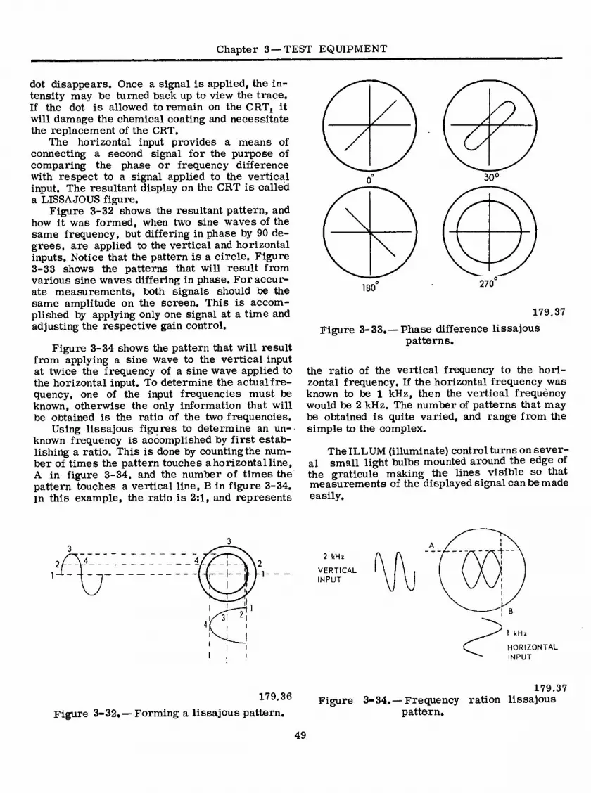
Chapter 3—TEST EQUIPMENT
dot disappears. Once a signal is applied, the in- tensity may toe turned toack up to view the trace. If the dot is allowed to remain on the CRT, it will damage the chemical coating and necessitate the replacement of the CRT.
The horizontal input provides a means of connecting a second signal for the purpose of comparing the phase or frequency difference with respect to a signal applied to the vertical input. The resultant display on the CRT is called a LISSAJOUS figure.
Figure 3-32 shows the resultant pattern, and how it was formed, when two sine waves of the same frequency, tout differing in phase by 90 de- grees, are applied to the vertical and horizontal inputs. Notice that the pattern is a circle. Figure 3-33 shows the patterns that will result from various sine waves differing in phase. For accur- ate measurements, tooth signals should be the same amplitude on the screen. This is accom- plished by applying only one signal at a time and adjusting the respective gain control.
Figure 3-34 shows the pattern that will result from applying a sine wave to the vertical input at twice the frequency of a sine wave applied to the horizontal input. To determine the actual fre- quency, one of the input frequencies must be known, otherwise the only information that will be obtained is the ratio of the two frequencies.
Using lissajous figures to determine an un- known frequency is accomplished by first estab- lishing a ratio. This is done by counting the num- ber of times the pattern touches a horizontal line, A in figure 3-34, and the number of times the pattern touches a vertical line, B in figure 3-34. in this example, the ratio is 2:1, and represents
180
30°
270
179.37
Figure 3-33.—Phase difference lissajous patterns.
the ratio of the vertical frequency to the hori- zontal frequency. If the horizontal frequency was known to be 1 kHz, then the vertical frequèncy would be 2 kHz. The number of patterns that may be obtained is quite varied, and range from the simple to the complex.
The ILL UM (illuminate) control turns on sever- al small light bulbs mounted around the edge of the graticule making the lines visible so that measurements of the displayed signal can be made easily.
l-^-
31
2 kHz
VERTICAL INPUT
- T-5+ —
1 kHz
HORIZONTAL INPUT
179.36
Figure 3-32.—Forming a lissajous pattern.
179.37 Figure 3-34. — Frequency ration lissajous
pattern.
49

ELECTRICIAN'S MATE 3 & 2
The DC BAL (balance) control is a screwdri- ver adjustment to prevent the whole trace from shifting vertically as the VARIABLE VOLTS/CM control is turned through its range. This control may be mounted on the front panel or it may be a service adjustment located inside the oscillo- scope. This control, once set, only requires ad- justment at periodic intervals, not every time the oscilloscope is used.
The STABILITY control is an adjustment that works in conjunction with the LEVEL control to provide a stable display. On the model in figure 3-22 it is a screwdriver adjustment and normally requires no adjustment by the operator. On more advanced oscilloscopes, it is a knob adjustment.
MAG OFF
© MAG ON
179.38 Figure 3-35. — 5 X MAG presentation.
The 5X MAG (magnifier) essentially expands the sweep. When the magnifier is turned on, it increases the sweep speed by a factor of five’. If the TIME/CM control were set at 1 millisecond, and then the 5X MAG turned on, the new sweep
1 msec speed would be: ——— =0.2 msec.
5 The magnifier permits the operator to examine more closely one cycle of a group of cycles rapid- ly, without necessitating the resetting of the TIME/CM control. Figure 3-35 shows the visual presentation with the magnifier off and then turned on. On the oscilloscope in figure 3-22 the 5X MAG is turned on by pulling the horizontal positioning control straight out.
Operation
The oscilloscope is one of the many tools that a technician uses for troubleshooting. Before using the oscilloscope, a check should be made to verify that it is in good operating condition. If the oscilloscope is faulty, it will give false readings and the technician will find himself wasting many hours trying to find a trouble where none exists.
The technician should also be familiar with the operation and limitations of the oscilloscope available. Misadjusting controls will cause false readings to be obtained. Attempting to take meas- urements in a circuit operating beyond the capa- bilities of the oscilloscope will give false read- ings, and may even result in the instrument being damaged. When using an oscilloscope for the first time, consult the technical manual for that partic- ular equipment to determine the correct opera- ting procedure and any limitations.
Since the oscilloscope provides a visual dis- play which is affected by the manipulation of the controls, and usually has its own built in test signal source, its operating condition can be checked rapidly.
For the initial setup of the oscilloscope in figure 3-22, the controls should be set as listed below:
POSITION, FOCUS, AND INTENSITY controls
TRIGGERING : LEVEL : TIME/CM : VARIABLE POWER .
in the center : of their range
of rotation INT + AUTO 1 msec CAL ON
Allow approximately. two minutes for the in- strument to warm up. After the warm up period, a trace should be visible. Turn the positioning controls, one at a time, to see if the trace can be moved to the edges of the CRT face, and then center the trace. Adjust the intensity control for comfortable viewing, and the focus control for a thin, well defined line.
Turn the VOLTS/CM control to the 0.02 posi- tion and the VARIABLE control to CAL. Connect the 0.05 volt output from the voltage calibrator to the vertical input. Turn the LEVEL control from the AUTO position. As this is done, the trace will disappear. Continue turning until the trace reappears. The display should be a stable display of several cycles of a square wave, 2.5 centimeters in height. Disconnect the lead from the voltage calibrator. The equipment is now- ready for use.
Before connecting a signal to the input termi- nal, turn the input attenuator (VOLTS/CM) to the highest attenuation setting (10 volts/cm). Connect the input signal and rotate the attenuator control until the display occupies approximately 2/3 of the screen height. Adjust the time base and level con- trols to select the desired number of cycles of the input and stabilize the display.
50

Chapter 3—TEST EQUIPMENT
[=] 60 400
FREQUENCY METER
ON
OFF
POWER ON
OFF
so
□
XIO XIOO
X I ^XIOOO
OUTPUT LEVEL
OUTPUT LEVEL CONTROL
jfi\\ôôo wr\ § Xl00vV / xi ^ f_ xio \
OUTPUT ATTENUATOR
OUTPUT
Figure 3-36.—Representative audio signal generator 179.17
AUDIO SIGNAL GENERATORS
Audio signal generators produce stable fre- quency signals from about 20 hertz to 200,000 hertz. They are used primarily for testing audio sections of equipment. The major components of an audio signal generator are an oscillator (or oscillators), one or more amplifiers, an output control and a power supply. In addition, voltage regulator circuits are necessary to ensure sta- bility of the oscillator, because the a-c line volt- age sources may vary.
A representative audio frequency signal gen- erator is shown in figure 3-36. This unit is in- tended primarily for bench testing of electronio equipment. It operates from line voltage (115 v.a.c.) and produces the output frequencies over a continuous range in conjunction with a four position multiplier.
Any frequency from 20 to 200,000 Hz may be selected by setting the main tuning dial and the range switch so that the two readings, when mul- tiplied together, equal the desired frequency. For example, to select an output frequency of 52,000
Hz, set the main tuning dialto “52” and the range switch to “X1000”. Voltages from zero to 10 volts may be selected by using the “OUTPUT LEVEL” control in conjunction with the attenuator switch. The attenuator is calibrated in seven decade steps so that with the output meter set to 10, output volt- ages of 10 volts to 10 microvolts can be obtained by simply switching the attenuator. For interme^ diate values of output voltage, the “OUTPUT LEVEL” control is varied so that the output meter reads the desired voltage. The attenuator switch is then set so that its value, multiplied by the output meter reading, gives the desired output voltage level. For example, to obtain an output voltage of 0.04 volts set the meter by means of the “OUTPUT LEVEL” control to read 4 and set the “ATTENUATOR” switch to the “.Ö1” position. The output voltage will then be the meter reading multiplied by the attenuator setting, or 0.04 volts.
Oscillator frequency calibration may be checked, during operation, on the first two bands.
51

ELECTRICIAN'S MATE 3 & 2
CALIBRATE ADJUST CONTROL
0 PE RATE - CALI B RATE SWITCH
SENSITIVITY CONTROL OFF-
STD BY-ON SWITCH
OiCtW. WtTMTn
o
INPUT CONNECTOR
Figure 3-37, — Digital voltmeter, model 481. 151.104
by means of the built-in frequency meter. To check the operation of the oscillator at 60 Hz, set the main tuning dial to “60” and the “RANGE” switch to “XI.” This sets the frequency of the oscillator at 60 hertz. Turn the “FREQUENCY METER” switch on and move the main dial back and forth slightly until the reed vibrates with maximum amplitude. This point is rather criti- cal, and care must be used to see that the point of maximum response is located. The main tuning dial should indicate “60” within one division, if the frequency calibration is correct. Similarly, the output frequency may be checked at 400 hertz, by means of the 400 hertz reed in the frequency meter.
DIGITAL VOLTMETER, MODEL 481
The Digital Voltmeter, Model 481 (fig. 3-37) measures d-c voltages and presents the measured value directly in numerical form on a self-illumi- nated 4-digit readout. The digital voltmeter is essentially a self-balancing potentiometer. Range changing is automatic. The polarity sign and deci- mal point are also automatically displayed. Ac- curacy is +0.01 percent over the three ranges which are 0 to+9.999,+ 10.00 to+99.99, and+100.0 to +999.9 volts7 — — ”
BALANCED POTENTIOMETER CIRCUIT
In order to understand the operation and cali- bration of a voltmeter of this type, it is first necessary to understand how tne device accom- plishes the measurement function. Consider the basic circuit shown schematically in figure 3-38. If an unknown voltage is applied at the input ter- minals and a variable divider adjusted until the voltage EQ is equal in magnitude to the unknown voltage, zero current will flow through the gal- vanometer. This condition is called balance. Note
VARIABLE VOLTAGE DIVIDER
GALVANOMETER
r~<2> UNKNOWN
INPUT VOLTAGE
r~i + REFERENCE VOLTAGE
E
151.105 Figure 3-38. — Basic operation principles of a
digital voltmeter.
52
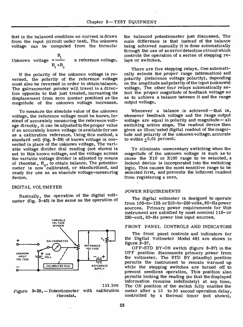
Chapter 3 —TEST EQUIPMENT
that in the balanced condition no current is drawn from the input (circuit under test). The unknown voltage can be computed from the formula:
Unknown voltage x reference voltage. Vr
2
If the polarity of the unknown voltage is re- versed, the polarity of the reference voltage must also be reversed in order to obtain balance. The galvanometer pointer will travel in a direc- tion opposite to that just treated, increasing its displacement from zero (center position) as the magnitude of the unknown voltage increases.
To measure the absolute value of the unknown voltage, the reference voltage must be known. In- stead of accurately measuring the reference volt- age directly, it can be adjusted to the proper value if an accurately known voltage is available for use as a calibration reference. Using this method, a standard cell (fig. 3-39) of known voltage is con- nected in place of the unknown voltage. The vari- able voltage divider dial reading (not shown) is set to this known voltage, and the voltage across the variable voltage divider is adjusted by means of rheostat, Rc, to obtain balance. The potentio- meter is now calibrated, or standardized, and ready for use as an absolute voltage-measuring device.
the balanced potentiometer just discussed. The main difference is that instead of the balance being achieved manually it is done automatically through the use of anerrordetectioncircuitwhich controls the operation of a series of stepping re- lays or switches.
There are five stepping relays. One automati- cally selects the proper range (attenuation) and polarity (reference voltage polarity), depending on the amplitude and polarity of the input (unknown) voltage. The other four relays automatically se- lect the proper magnitude of feedback voltage so as to achieve a balance between it and the range output voltage.
Whenever a balance is achieved — that is, whenever feedback voltage and the range output voltage are equal in polarity and magnitude — all switching action stops. The readout device then gives an illum'nated digital readout of the magni- tude and polarity of the unknown voltage, accurate to within+0.01 percent.'
To eliminate unnecessary switching when the magnitude of the unknown voltage is such as to cause the XlO or XI00 range to be selected, a lockout device is incorporated into the switching logic. This causes the most sensitive range to be selected first, and prevents the leftmost readout from registering a zero.
DIGITAL VOLTMETER
Basically, the operation of the digital volt- meter (fig. 3-40) is the same as the operation of
+ o-
UNKNOWN INPUT
VOLTAGE
GALVANOMETER
+ STD “ CELL
I CALIBRATED DIAL~|
REFERENCE VOLTAGE
“ . .+
HP REFERENCE
SUPPLY
151.106 Figure 3-39. —Potentiometer with calibration
rheostat.
POWER REQUIREMENTS
The digital voltmeter is designed to operate from 105-to-l25 or 210-to-250 volts,60-Hzpower sources. Primary power requirements for this instrument are satisfied by most nominal 115-or 230-volt, 60-Hz power line input sources.
FRONT PANEL CONTROLS AND INDICATORS
The front panel controls and indicators for the Digital Voltmeter Model 481 are shown in figure 3-37.
OFF-STD BY-ON switch (figure 3-37) in the OFF position disconnects primary power from the voltmeter. The STD BY (standby) position permits the instrument to remain warmed up while the stepping switches are turned off to prevent needless operation. This position also permits locking the reading (so that the displayed information remains indefinitely) at any time. The ON position of the switch fully enables the meter after a 15 to 30 second operation delay, controlled by a thermal timer (not shown).
53

Ol
RANGE ATTENUATOR • TRIMMERS
DECADE 3
II RESISTORS
IOOO ft EACH
DECADE 4
II RESISTORS
5000 ft EACH
SIGNAL DECADE DECADE 2
II RESISTORS
200 ft EACH
INPUT 10 RESISTORS
40 ft EACH
\ ¿ \ /:
4.30V 5.0V 10V
© STANDARD CELL
4.269V
O-i—PO— 4.29V 4.9V
4.266V O
4.28V O—
4 6V
FEEDBACK VOLTAGE 4.267V 4 27V 4.7 V
DEC
CHOPPER * 4.266V 4.6V RANGE < >400
IOOK
“—'A CALIB. \
\ sw \
wv 4 265V 4.26V 4.5V
RANGE OUTPUT 3 VOLTAGE 4.264V 4.25V 4 4V
10000
r ft
4 263V
O 4.24V 4.3V
DEC. AMPLIFIER
4.262V I 3V 4.23V 2000 ft
4.261V 4 22V 4.2
POWER SUPPLY 4.260V
O
4.21 V 4. V
DOWN UP PULSES \ PULSES 4.20V 4.0V
SWITCHING LOGIC
POLARITY SW 100
REFERENCE VOLTAGE I0-I5V * MAKE BEFORE BREAK
TYPE CHOPPER CALIB ADJ
READOUT
ASSEMBLY ' SIGNAL GROUND
Figure 3-40. Multirange, digital voltmeter for measuring absolute d-c voltages, simplified circuit diagram.
151.263
EL
EC
TR
ICIA
N'S
MA
TE
3 &
2

Chapter 3 —TEST EQUIPMENT
The operate-calibrate switch selects either an operating or calibrating mode of operation for the digital voltmeter.
The calibrate adjust control (located behind a metal protective cap on the front panel) is used to standardize the digital voltmeter when the following steps are performed:
1. Set the sensitivity control to its full clock- wise position.
2. Ensure that the error amplifier gain of the instrument is properly set. To accomplish this, hold the operate-calibrate switch in the CALIBRATE position and slowly turn the cali- brate-adjust control in the counterclockwise di- rection, stopping each time the meter changes reading. The meter reading should change by one digit each time. If the reading changes by more than one digit, or exhibits instability, ad- justment of the internal gain control is necessary. (The gain setting procedure is described later.) Repeat turning the calibrate adjust control count- erclockwise until ten steps have been satisfactor- ily completed. Once it has been ascertained that the gain adjustment is proper, the instrument may be accurately standardized as described in the next paragraph.
While holding the operate-calibrate switch in the CALIBRATE position, slowly turn the calibrate adjust control in the clockwise direction until the meter reads 1019, then stop. The meter is now standardized.
NOTE: The decimal point may appear in any location during the standardization procedure because the d-c voltage range change circuits (which determines the position of the decimal point) become deenergized during this operation.
The sensitivity control varies the gain of the digital voltmeter. When measuring unstable volt- ages, turn the control counterclockwise until the meter settles at a fixed reading. This reading will be as accurate as the unstable signal measure- ment will allow. Always turn the sensitivity con- trol fully clockwise for proper operation with stable d-c voltages.
GAIN SETTING
For best results, the digital voltmeter should be operated with the amplifier gain set for ad- vancement in single digit steps. If the amplifier gain is not high enough, the resolution of the meter will be too low. On the other hand, excessively high amplifier gain setting may cause instability of the readout display. To set the amplifier gain, proceed as follows:
1. Remove the cover over the calibrate adjust control on the front panel. Hold the operate-cali- brate switch (fig. 3-37) in the CALIBRATE posi- tion.
2. After the usual readout has become stable, use a screwdriver to slowly turn the calibrate adjust control, R13 (fig. 3-41) in a counterclock- wise direction. Observe the magnitude of the de- crease in the readout display. If the value dis- played decreases in steps of one digit and does not become unstable, no adjustment of amplifier gain is necessary. If slowly rotating the calibra- tion control in a counterclockwise direction re- sults in a decrease of two or more digits in the rightmost window, the amplifier gain should be increased by slightly turning the amplifier gain control, R20 (fig. 3-41) in a clockwise direction. Again, observe the number of digits by which the readout display decreases when the calibrate adjust control, Rl3 , is slowly turned counter- clockwise. Repeat the amplifier gain adjustment if necessary, to obtain a readout display decréase of one digit in the rightmost window. If instabil- ity develops in the readout display, turn the am- plifier gain control, R20, counterclockwise until the instability just disappears and the readout display decreases in steps of one digit in the rightmost window as the calibrate adjust control, R13, is slowly turned counterclockwise.
HUM CONTROL ADJUSTMENT
To adjust hum control, R53, (fig. 3-41) located on the amplifier chassis, proceed as follows:
NOTE: Improper adjustment of the hum con- trol will cause considerable error in calibration accuracy. The hum control is accurately set at the factory and should not be reset until it is definitely determined to be out of adjustment. Changing the input tubes can cause the hum con- trol to become incorrectly adjusted. Be sure that the input tube has been aged before resetting the hum control.
1. Connect the chassis to ground (the third pin on the power cordis connected to the chassis). Turn on the digital voltmeter and allow a warmup of 15 minutes. Connect an oscilloscope between either of the two test points (fig. 3-41) and ground. Calibrate the oscilloscope in terms of one digit error. To do this, turn the operate-calibrate switch (fig. 3-37) to CALIBRATE and slowly turn calibrate adjust control, R13, (fig. 3-41) counter- clockwise. Note the amount of error signal on the oscilloscope. This error is equivalent to one digit if the gain is properly set (as described in the
55

ELECTRICIAN'S MATE 3 & 2
gain setting procedure), and the sensitivity control is advanced fully clockwise.
2. With the operate-calibrate switch (fig. 3-38) set to operate, short the input leads to ob- tain a reading of +0.000. Set OFF-STD BY-ON switch to STD BY. Remove the stepping switch
cover. Step range-polarity switch, K5 (fig. 3-41) by hand until the meter reads +00.00. Replace the stepping switch cover. Adjust hum control R53, for zero error signal as displayed on the oscilloscope. It is necessary that the stepping switch cover, bottom plate, and front panel be in position. The hum control is now properly set.
V 6 VII VIO
K
Ma
* ■W K2
TEST POINTS
V5 r K3 W» R20
£ V4
R53 *
VI
K5 V3
OVEN
V2 K6 R23 RI3
Figure 3-41, — Digital voltmeter, model 481, top interior view. 151.108
55

Chapter 3 —TEST EQUIPMENT
3. Check the error signal for all ranges (+00.00, +0.000, -000.0, -00.00, -0.000, and +000.0), each time removing the stepping switch cover, stepping range-polarity switch, K5, (fig. 3-41) by hand, and replacing the cover. Do not readjust hum control, R53. The error signal for all range positions should be less than one-half that allowable in changing from one digit to another. If the error exceeds this amount, there are two possible sources of trouble: (1) exces- sive hum pickup and (2) excessive grid current drawn by the input amplifier tube (not shown). Check all shield and ground leads. Replace the input amplifier tube (type 5751).
NOTE: Do not substitute any other type tube.
STANDARDIZATION ADJUSTMENT
The following standardization procedure is necessary to ensure accurate readout (measure- ments). Before making any adjustments, make sure that the gain and hum controls are properly set and that the digital voltmeter is connected to ground. Calibrate the voltmeter as described in the calibrate adjust procedure treated earlier. Connect a bank of nine standard cells, each of which has an accuracy of at least 0.01 percent, to the input. The meter reading should be correct to within one digit.
NOTE: Be sure to take into account the inter- nal resistance of the standard cells. The digital voltmeter has an input resistance of 10 megohms, and a 9 volt signal will draw 0.9 microamperes. If the reading is not correct, adjust potentiometer, Rll, and repeat the entire procedure. (Potentio- meter, Rll, is located slightly above and to the right of the calibrate adjust control, R13, shown in figure 3-41.)
FEEDBACK VOLTAGE LINEARITY TEST
One of the several factors which may affect the accuracy of digital voltmeters is the linearity of the reference voltage divider (fig. 3-40). This reference voltage divider supplies the feedback voltage which is compared to the range output voltage in order to get a readout, thus, any change in its linearity (or accuracy) will affect the ac- curacy of the readout. While several methods have been devised for testing the linearity of reference voltage dividers, the one described below is found to be most satisfactory. (It is
assumed that the error amplifier gain is pro- perly adjusted before the test is started.)
NOTE: In order to perform this test, a precision voltage divider having a resistance of 1 megohm and an accuracy 5 to 10 times that of the reference voltage divider is used as a standard. The high resistance is necessary to prevent excessive current drain from the refer- ence supply.
Connect the input of the external precision voltage divider to the input of the reference volt- age divider in the digital voltmeter. Disconnect the wire from the arm of the operate-calibrate switch. Connect the output of the external pre- cision voltage divider to this terminal. (Observe proper shielding and grounding rules.) Adjust the standard divider at 00000. The visual readout should display a zero in each window. Adjust the standard voltage divider for 99990. The visual readout display should display a 9 in each window. These two readout displays must be obtained for the indicated standard divider settings. If the voltmeter displays digits other than those indi- cated above for these two end points, an improper circuit condition exists and must be located and corrected before preceeding with this test.
Now set the standard dividerfor various read- ings such as: .89990, .7990, .6990, .08990, .0790, , 00890, .00790, .00080, .00070. The digital voltmeter readout should be equal to the standard divider setting +1 digit.
One advantage of this method of testing voltage divider linearity is that reasonably large (20 percent) deviations in reference voltage from the nominal value of reference voltage have no sig- nificant effect upon test accuracy. This is true because the same voltage is furnished to the input of the reference voltage divider as well as the input of the external standard voltage divider. Hence, for equal settings of the two voltage di- viders, the output voltages should be equal.
RANGE UNIT ADJUSTMENT
The range unit will require scale factor read- justment only if the range unit resistors change their ohmic value, or if the internal electrical loading of the unit output taps changes. The ad- justment method described below requires several accurate voltage dividers and a stable d-c source. This method permits accurate range unit scale factor adjustment regardless of the inaccuracies present in the digital voltage divider. This is be- cause the voltage divider is always brought back to the same position (same numerical display on the voltmeter, ignoring decimal point location)
57

ELECTRICIAN'S MATE 3 & 2
when the correspondence of scale factors on each range is checked.
As in any other test, proper shielding and grounding techniques must be followed to prevent electrical noise pickup from interfering with the stability and resolution of the digital voltmeter. Also, in checking each range, best accuracy is achieved when the test voltage used is as close to full scale for that range as is practicable. The precision voltage divider used in the range unit adjustment procedure must be compensated for the electrical loading effect of the digital volt- meter. The accuracy of the external voltage di- vider should be five to ten times better than the accuracy to which the range unit is to be adjusted.
Access to the range trim potentiometers re- ferred to in the following paragraphs is gained by removing the left-hand protective cap on the front panel (fig. 3-37), These potentiometers are identified by lOOOv and lÖOv on the printed circuit range board.
Adjusting the 100-Volt Range Scale Factor
The following procedure is used:
1. Connect the input terminals of a 10-to-l precision voltage divider to a stable source of d-c voltage, approximately 95 to 99 volts.
2. Connect the input terminals of the digital voltmeter under test to the input of the voltage divide. Observe the readout display and wave- form at the error amplifier test points.
3. Connect the input terminals of the volt- meter to the output terminals of the voltage divider. Observe the readout display and the error amplifier waveform.
4. The 100 volt range is properly adjusted when the readout display in step 3 is exactly
equal to one-tenth of the readout display observed in step 2, (for example: 95.93 in step 2, compared to 9.593 in step 3) and when the error amplifier waveform amplitude and phase are similar tothat observed in step 2, If this correspondence is not present, adjust 100 volt range trim potentiometer R4.
Adjusting the 1000-Volt Range Scale Factor
The following procedure is used:
1. Connect the input terminals of a 100-to-l voltage divider to a stable source of d-c voltage as close to 999 volts as practicable. (Lower volt- ages, no less than 200 volts, can be used, but accuracy will not be as good as whenhigher volt- ages are used.)
2. Connect the input terminals of the volt- meter under test to the input terminals of the voltage divider. Observe the readout display and waveform at the error amplifier test points.
3. Connect the input terminals of the digital voltmeter to the output terminals of the 100-to-l voltage divider. Observe the readout display and error amplifier waveform.
4. The 1000-volt range is properly adjusted when the readout display in step 3 is exactly one- hundredth of the readout display observed in step 2, (for example: 982.3 in step 2, compared with 9.823 in step 3) and when the error amplifier waveform amplitude and phase are similar to that observed in step 2. If this correspondence is not present, adjust the 1000-volt range trim potentio- meter, R2.
NOTE: Tube and transistor testers are de- scribed in Chapter 13.
58

CHAPTER 4
ELECTRICAL INSTALLATIONS
The proper installation and maintenance of the various electrical systems aboard ship are very important to the Electrician’s Mate. The repair of battle damage, accomplishment of ship alterations, and some electrical repairs may require that changes or additions to the ship’s cables, control and protective devices, be made by the Electrician’s Mate. Additionally, during shipyard and tender availabilities, you may be required to inspect, test, and approve thé new installations.
To perform these tasks you must first have a working knowledge of the various types, sizes, capacities, and uses of shipboard electrical cable. The Electrician’s Mate must also be capable of selecting, installing, and maintaining cables in- such a manner as to ensure their ade- quacy. Finally, you must know the purpose, construction, installation, and testing proce- dures of control and protective devices in order to maintain an electrical system properly.
ELECTRICAL CABLES
The EM needs to have a working knowledge of the Cable Comparison Guide, NavShips 0981- 052-8090. This guide fills a need for information on the use of electric shipboard cable, particu- larly for the selection of substitute cable items for replacement of obsolete items. Cable items are listed in the guide by general classifications as to construction and service conditions. These broad groupings are broken down into types and sizes, and indicated as being current (C), dis- continued (D), or obsolete (O), as shown in the first column of Table 4-1.
The term “watertight cable,” designated by an asterisk (*) in the cable guide and in Table 4-1, indicates standard cables in which all spaces under the impervious sheath are filled with material to eliminate voids and to prevent the flow of water through the cable by hose action in the event that an open end of cable is exposed to water under pressure.
Because of the varied service conditions aboard ship, the cable must have the ability to withstand heat, cold, dampness, dryness, bend- ing, crushing, vibration, twisting, and shock. No one type of cable has been designed to meet all of these requirements; therefore, a variety of types are employed in a shipboard cable installation.
Cable types are grouped under the general classifications of; (1) cables for nonflexing ser- vice (table 4-1), (2)' cables for repeated flexing service, and (3) cables for special purposes.
CABLE TYPÉ AND SIZE DESIGNATIONS
The types and sizes of lighting and power cables for shipboard applications are numerous. The initial letter of the type designation for lighting and power cables indicates the number of conductors (cdrs) the cable contains. These initial letters are S, D, T, or F and indicate, respectively, single, double, triple, or four con- ductors. Also included in this lighting and power group is the SGA type cable. The SGA type cable employs silicone rubber and glass as primary insulation, making it heat and flame resistant.
The construction of a SGA cable is shown in figure 4-1. The insulated stranded copper conductors are enclosed in an impervious sheath, braided metal armor, and paint. The cable has been made watertight by the application of water- proof sealing compound to all voids of the con- ductors and cable core. SGA cables are designed to have a minimum outside diameter and weight as compared to older type cable. The SGA type cables supersede the type LPA (Lighting and Power, Armored) cables and the type FPA (Flame Proof-Armored) cables. Using the newer cable saves on space and weight which is at a premium on combatant naval vessels.
59

ELECTRICIAN’S MATE 3 & 2
Table 4-1. — Cables for Nonflexing Service
Cor
Dis
Obs Type & Size
DSGA-400*
DHFA-400* 3HEA-400
No
ol Per Cdrs Cdr
Strands Diam
Copper Cdr
Inch
Area Cdr
Cirmil
Outside Diam
Cable
Max
Inch
r-S tufting
Tube Sjie-i
Deck and
Bulk- Equip- Volt- head ment age
Volts
r-Maxlimim Rating pAmbient
T emperature-
40*C S0*C
1 Min Radius
T of Bend
rms Amperes Inch
LIGHTING AND POWER-Cont.
Federal
EstWt Stock
Per Ft No
Lbs. GX6M5
184-5897
192-7195 192-7221
4.28 2.119
2.508
2.508
492 453 13.0 127 .742 413.600
413.600
413.600
1000
600 492 453 15.5 75 127 .742 492 453 75 127 .742 600
2.010 1000
1000
300 12.0 4.17 6SGA-150*
6SGA-200*
457 157,600
198,700 326
.514 250 369 340 5.19
Maximum ratings for 6SGA cables are for 400 hertz power circuits only. ^Watertight Construction
77.1
The numerals (table 4-1) immediately follow- ing the type letters indicate the cross-sectional area of a single conductor and expressed in thousands of circular mils. For example, 6SGA- 150 indicates approximately 158 thousand circu- lar mils conducting area.
Table 4-1 also lists the sizes of stuffing tubes (metal or plastic tubing containing the cable) used with particular types and sizes of cable. Metal stuffing tubes are used generally for deck and bulkhead installations.
The Electrician’s Mate must also be able to identify cables used for degaussing service. For these applications the initial letters have been restricted to S and M for identifying single
and multiple conductors, respectively. Thus, SDGA is a SINGLE conductor, degaussing, ar- mored cable. These letters are also followed by numbers that give the approximate cross- sectional area expressed in thousands of cir- cular mils.
Type and Size Exceptions
By analyzing the designations for cable types and sizes, you will notice that some letters have more than one meaning. The letter T, for example, usually means THREE. In the designation TTHFWA-10, however, the double T stands for twisted-pair, telephone. The T in TRXF means tough jacket.
STRANDED COPPER CONDUCTOR GLASS FIBER BRAID BINDER IMPERVIOUS SHEATH
VCOLOR CODED) / \
X wmmm
VWVsV
W/A
EXTRUDED SILICONE RUBBER FILLER BRAIDED METAL ARMOR AND PAINT
Figure 4-1.—Type SGA shipboard nonflexing service cable. 29.226(77A)A
60

Chapter 4—ELECTRICAL INSTALLATIONS i
Similarly, there are exceptions regarding the use of numerals in size designations since the numerals may indicate number of copper conductors or size of copper conductor or num- ber and size of a conductor or size and number of strands per conductor or number of twisted pairs or maximum rms rated voltage.
TYPE MDG CABLE
Example: MSCA-7— The 7 stands for the number of conductors, not the con- ductor area (in thousands of circular mils) as in the case of DHFA-400 (table 4-1).
Example: TTHFWA-10 The 10 indicates the number of twisted pairs, that is, 20 conductors.
Example: SS5P The 5 is an indication of maximum rms rated voltage, 5000 in this case.
NONFLEXING SERVICE
Nonflexing service cable designed for use aboard ship is intended for permanent installa- tion and is commonly referred to as such. The cables that are described in the previous para- graphs for use with lighting and power circuits are intended for this nonflexing service. This nonflexing service can be further classified ac- cording to its application and is of two types— general use and special use.
General Use (Nonflexing Service)
Nonflexing service cable is intended for use in nearly all portions of electric distribution systems, including the common telephone cir- cuits and most propulsion circuits. Special cases occur in d-c propulsion circuits for surface ships. In those cases where the impressed voltage is less than 1000 volts, an exception is permitted.
The previously described SGA cable is one type usually found in this general use, nonflexing service. Also in this classification is the type MSCA cable. This cable is nothing more than watertight cable for use in interior communica- tions, as well as in fire control circuits.
J.*
“T CONSTANTAN
B TYPE PBJX CABLE
C TYPE TTHFWA CABLE
29.226(7 7A)B Figure 4-2. — Nonflexing service cable for special
1 use.
installation and other circuits where general- use, nonflexing service cable may meet the nec- essary requirements, yet be economically im- practicable. For these reasons, there are many different types of nonflexing service cable for specialized use, such as degaussing, telephone, radio, and casualty power. Some of these cables are shown in figure 4-2.
Type MDG (fig. 4-2A) is a multiconductor cable used in degaussing circuits. Type PBJX (replaced by type TCJA-mil-C-2l94 on new construction) cable (fig. 4-2B) consists of one conductor of constantan (red) and one conductor of iron (gray), and is used for pyrometer base leads. Type TTHFWA (fig. 4-2C) is a multi- conductor, twisted-pair cable used for telephone circuits.
REPEATED FLEXING SERVICE
Repeated flexing service cable designed for use aboard ship is commonly referred to as being portable because it is principally used as leads to portable electric equipment. It is also of two types — general use and special use.
Special Use (Nonflexing Service)
There are many shipboard electrical circuits where special requirements of voltage, current, frequency and service must be met in the cable
General Use (Flexing Service)
Repeated flexing service cable, is designed for use as leads to portable equipment and per- manently installed equipment where cables are
61

ELECTRICIAN’S MATE 3 & 2
SEPARATOR COTTON TAPE IMPERVIOUS SHEATH
(RUBBER)
/ CONDUCTOR SYNTHETIC RUBBER FILLER BINDER
Figure 4-3. — Type DHOF cable. 29.226(7)7A)C
subjected to repeated bending, twisting, mechani- cal abrasion, oil, sunlight, or where maximum resistance to moisture is required. Its letter designation is HOF (heat and oil resistant, flexible). This cable contains stranded copper conductors that are insulated with butyl rubber, covered with a tape or braid. The designated number of conductors are twisted together, held by a binder, and covered with an impervious sheath (fig. 4-3).
Repeated flexing service cable designed for general use is of four different types, depending on the number of conductors. Type SHOF cable is available in various conductor sizes and designated as types SHOF (single conductor), DHOF (two conductor), THOF (three conductor), and FHOF (four conductor).
Special Use (Flexing Service)
There are many different types of repeating flexing service cable designed for special re- quirements of certain installations, including type TTOP and casualty power cables. Two of these types are shown in figure 4-4. Type MHOF (fig. 4-4A) is used for control circuits in revolving structures, and type TRF (fig. 4-4B) is used for arc-welding circuits.
CABLE REPAIR AND INSTALLATION
Electrical cables installed aboard Navy ves- sels must meet certain requirements determined by the Naval Ships Systems Command. These requirements, published in the General Specifi- cations for Ships in the U.S. Navy, are too numerous to cover in detail in this training
manual; hence, only the more basic ones are included.
The job of installing nonflexing service cable may be performed by the Electrician’s Mate whenever necessary to repair damage or to accomplish authorized ship alterations. Before work is begun on a new cable installation, cable-way plans should be available. If repairs to a damaged section of installed cable are to be effected, information on the original installa- tion can be obtained from the plans of the ship’s electrical system, which are normally on file in the engineering department office (log room) aboard ship. If a ship alteration is to be accom- plished, applicable plans not already on board, can be obtained from the naval shipyard listed on the authorization.for the alteration (SHIP ALT) at the planning yard for the ship.
A TYPE MHOF CABLE
g TYPE TRF CABLE
29.226(77A)D Figure 4-4. — Repeated flexing service cable for
special use.
62

Chapter 4—ELECTRICAL INSTALLATIONS
Wireways
Before installing new cable, survey the area to see if there are spare cables in existing wireways and spare stuffing tubes that can be used in the new installation. The cable run must be located so that damage from battle will be minimized, physical and electrical interference with other equipment and cables will be avoided, and maximum dissipation of internally generated heat will occur. Do not run cables on the ex- terior of the deckhouse or similar structures above the main deck, except where necessary because of the location of the equipment served, or because of structural interferences or avoid- ance of hazardous conditions or locations. Where practicable, route vital cables along the inboard side of beams or other structural members to afford maximum protection against damage by flying splinters or machine gun strafing.
Where practicable, avoid installing cable in locations subject to excessive heat, and never install cable adjacent to machinery, piping, or other hot surfaces haying an exposed surface temperature greater tham 150°F. In general, cables shall not be installed where they may be subjected to excessive moisture.
Selecting Cable
Two-conductor cable shall be installed for 2-wire, d-c and single-phase, a-c circuits. Three- conductor cable shall be installed for 3-wire, d-c or 3-phase, a-c circuits. Four-conductor cable shall be installed where two 2-wire lighting circuits are run in the same cable. Four-conductor and multiconductor cable shall be installed for control circuits and communications circuits as necessary.
To select the proper size cable for a particu- lar installation, it is necessary to know (l) the total connected load current, (2) the demand factor, and (3) the allowable voltage drop.
The total connected load current for d-c power circuits is determined by adding the sum of the rated current of the connected loads as listed on the identification plates of connected motors and appliances and an additional 100 watts for each receptacle not specifically indi- cated. For a-c power circuits the connected load current of the connected motors and appli- ances is added vectorially to obtain the total connected load current.
The demand factor of a circuit is the ratio of the maximum load averaged for a 15-minute period to the total connected load on the cable.
STRAIGHT
TAPERED THREAD
STRAIGHT
(IPS THREAD) BEND
12.78 Figure 4-5. — Nylon stuffing tubes.
If the feeder demand factor for a group of loads cannot be determined, a value of 0.9 may be assumed. For power systems supplying a single- phase load or for a lighting system branch, submain, and main circuits, the demand factor is unity.
The voltage drop (difference in voltage between any two points in a circuit) is expressed as a percentage of the rated switchboard (or switch- gear group) bus voltage or the transformer nominal voltage. The maximum percent voltage drop allowed for a circuit is specified by the Naval Sea Systems Command and varies ac- cording to the intended service of the circuit.
Stuffing Tubes
Stuffing tubes (fig. 4-5A, B, and C) are used to provide for the entry of electric cable into splash- proof, spraytight, submersible, and explosion- proof equipment enclosures. Cable clamps
63

ELECTRICIAN'S MATE 3 & 2
commonly called box connectors (shown in fig. 4-6), may be used for cable entry into all other types of equipment enclosures, except that top entry into these enclosures shall be made drip- proof through stuffing tubes or cable clamps sealed with plastic sealer.
Below the main deck, stuffing tubes are used for cable penetrations of watertight decks, water- tight bulkheads, and watertight portions of bulk- heads that are watertight only to a certain height. Above the main deck, stuffing tubes are used for cable penetrations of (1) watertight or air- tight boundaries; (2) bulkheads designed to with- stand a waterhead; (3) that portion of bulkheads
below the height of the sill or coaming of compartment accesses; (4) flametight or gas- tight, or watertight bulkheads, decks, or wiring trunks within turrets or gun mounts; and (5) structures subject to sprinkling.
Stuffing tubes are made of nylon, steel, brass, or aluminum alloys. Nylon tubes have very nearly replaced metal tubes for cable entry to equipment enclosures. Cable penetra- tion of bulkheads and decks using nylon stuffing tubes is limited for use above the watertight level of a vessel. The watertight level is the highest expected water level (determined by the Naval Sea Systems Command studies of stability
MACHINE SCREW BODY
LOCKNUT
CABLE
B L é/¡&
PLASTIC SEALER HINGE JOINT
ENCLOSURE SHEET METAL OR CAST
ENCLOSURE
SIDE VIEW END VIEW
LOCKNUT \
CABLE
mm/
0 PLASTIC SEALER
BODY MEMBER CLAMPING MEMBER
SHEET METAL OR CAST
ENCLOSURE
ENCLOSURE
MACHINE SCREW
SIDE VIEW END VIEW
Figure 4-6. —Cable clamps 77,8
64

Chapter 4—ELECTRICAL INSTALLATIONS
SHIP'S STRUCTURE
ENCLOSURE
BOOT-TUBE BODY INSERTED FROM INSIDE ENCLOSURE
WRAP END OF CABLE ARMOR WITH FRICTION TAPE TO A
MAX DIAMETER WHICH WILL
FASS THROUGH THE SLIP WASHERS
CABLE 22 BOTTOM WASHER
SLIP WASHERS COAT SURFACE
INDICATED WITH NEOPRENE CEMENT,
0 RING GROMMET
A
ICKNUT
BODY
BOTTOM WASHER
1 SLIP WASHERS
ENCLOSURE SEALING PLUG-SOLID
B
77.10 Figure 4-7. — Representative nylon stuffing tube
installations.
and reserve buoyancy) and is indicated on the applicable ship’s plans. The nylon tube is a lightweight, positive-sealing, noncorrosive stuff- ing tube, which requires only minimum main- tenance for the preservation of watertight integrity (fig. 4-7). The watertight seal between the entrance to the enclosure and nylon body of the stuffing tube is made with a neoprene “O” ring, which is compressed by a nylon locknut. A grommet type, neoprene packing is compressed by a nylon cap to accomplish a watertight seal between the body of the tube and the cable. Two slip washers act as compression washers on the grommet as the
nylon cap of the stuffing tube is tightened. Grommets of the same external size, but with different sized holes for the cable, are available. This allows a single-size stuffing tube to be used for a variety of cable sizes, and makes it possi- ble for nine sizes of nylon tubes to replace 23 sizes of aluminum, steel, and brass tubes.
The nylon stuffing tube is available in two parts. The body, “O” ring, locknut, and cap comprise the tube; and the rubber grommet, two slip washers, and one bottom washer com- prise the packing kit.
A nylon stuffing tube that provides cable entry into an equipment enclosure is applicable to both watertight and nonwatertight enclosures (fig. 4-7A). Note that the tube body is inserted from inside the enclosure. The end of the cable armor, which will pass through the slip washers, is wrapped with friction tape to a maximum diameter. To ensure a watertight seal, one coat of neoprene cement is applied to the inner surface of the rubber grommet and to the cable sheath where it will contact the grommet. After the cement is applied, the grommet is immediately slipped onto the cable. The paint must be cleaned from the surface of the cable sheath before applying the cement.
Sealing plugs are available for sealing nylon stuffing tubes from which the cables have been removed. The solid plug is inserted in place of the grommet, but the slip washers are left in the tube (fig. 4-7B).
A grounded installation that provides for cable entry into an enclosure equipped with a nylon stuffing tube is shown in figure 4-8. This type of installation is required only when radio interference tests indicate that additional grounding is necessary within electronic spaces. In this case, the cable armor is flared and trimmed to the outside diameter of the slip washers. One end of the ground strap, inserted through the cap and one washer, is flared and trimmed to the outside diameter of the washers. Contact between the armor and the strap is maintained by pressure of the cap on the slip washers and the rubbèr grommet.
Tables listing the correct size for deck, bulkhead, and equipment stuffing tubes for light- ing and power cables are found in the Cable Comparison Guide, NavShips 0981-052-8090.
Watertight integrity is vital aboard ship in peacetime or in combat. Just one improper cable installation could endanger the entire ship. For example, if one THFA-4 cable (.812 inches in diameter) is replaced by the newer TSGA-4 cable (.449 inches in diameter) but the fittings
65
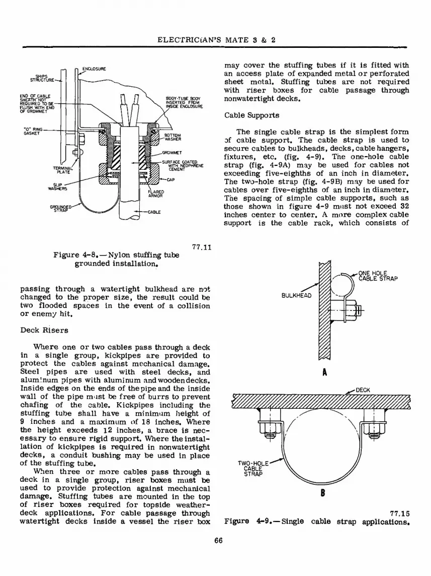
ELECTRICIAN’S MATE 3 & 2
END OF CABLE SHESTTTNÖT“ REQUIRED TOBE- FLUSH WITH END OF GROMMET
BOTTOM WASHER
GROMMET
1/ / TERMINAL
PLATE i i CAP
FLARED ARMOR
BODY-TUBE BODY INSERTED FROM INSIDE ENCLOSURE
SLIP ■ WASHERS
G«D'
SURFACE COATED WITH NEOPHRENE CEMENT
may cover the stuffing tubes if it is fitted with an access plate of expanded metal or perforated sheet metal. Stuffing tubes are not required with riser boxes for cable passage through nonwatertight decks.
Cable Supports
The single cable strap is the simplest form of cable support. The cable strap is used to secure cables to bulkheads, decks, cable hangers, fixtures, etc. (fig. 4-9). The one-hole cable strap (fig. 4-9A) may be used for cables not exceeding five-eighths of an inch in diameter. The two-hole strap (fig. 4-9B) may be used for cables over five-eighths of an inch in diameter. The spacing of simple cable supports, such as those shown in figure 4-9 must not exceed 32 inches center to center. A more complex cable support is the cable rack, which consists of
77.11 Figure 4-8. — Nylon stuffing tube
grounded installation.
passing through a watertight bulkhead are not changed to the proper size, the result could be two flooded spaces in the event of a collision or enemy hit.
Deck Risers
Where one or two cables pass through a deck in a single group, kickpipes are provided to protect the cables against mechanical damage. Steel pipes are used with steel decks, and aluminum pipes with aluminum and wooden decks. Inside edges on the ends of the pipe and the inside wall of the pipe must be free of burrs to prevent chafing of the cable. Kickpipes including the stuffing tube shall have a minimum height of 9 inches and a maximum of 18 inches. Where the height exceeds i2 inches, a brace is nec- essary to ensure rigid support. Where the instal- lation of kickpipes is required in nonwatertight decks, a conduit bushing may be used in place of the stuffing tube.
When three or more cables pass through a deck in a single group, riser boxes must be used to provide protection against mechanical damage. Stuffing tubes are mounted in the top of riser boxes required for topside weather- deck applications. For cable passage through watertight decks inside a vessel the riser box
BULKHEAD I I
ONE HOLE CABLE STRAP
-SB-
DECK
¥ W
TWO-HOLE CABLE STRAP
77.15 Figure 4-9.—Single cable strap applications.
66

Chapter 4—ELECTRICAL INSTALLATIONS
-DECK OR BULKHEAD
// // /./ // // // // // /j /? -//- // // // (/ // jf A * BANDING BUCKLE
A
CABLE Yi MINIMUM BAND
STEEL
A
TUBULAR HANGER-STEELN
15 MAXIMUM ON DECKS
' 9 MAXIMUM ON BULKHEADS '
Figure 4-10. — Cables installed in a cable rack. 77.16
the cable hanger, cable strap, and hanger sup- port (fig. 4-10).
Banding material is five-eighths of an inch wide, and may be zinc-coated steel, corrosion resistant steel or aluminum, depending on the requirements of the installation. For weather- deck installations, use corrosion resistant steel band with copper armored cables; zinc-coated steel with steel armor; and alum’num with aluminum armor.
When applying banding material apply one turn of banding for a single cable less than one inch in diameter. Apply two turns of banding for single cables of one inch or more in diameter and for a row of cables. Apply three turns of banding for partially loaded hangers where hanger width exceeds the width of a single cable or a single row of cable by more than one-half inch.
Cables must be supported so that the sag between supports, when practicable, will not exceed one inch. Five rows of cables may be supported from an overhead in one cable rack, and two rows , of cables may be supported from a bulkhead in one cable rack. As many as 16 rows of cables may be supported in main'cable- ways, in machinery spaces and boiler rooms.
Not more than one row of cables shall be installed on a single hanger.
Modular cable supports (fig. 4-11) are being installed on a number of naval ships. The modular method saves over 50 percent in cable-pulling time and labor. Groups of cables are now passed through wide opened frames, instead of being inserted individually in stuffing tubes. The frames are then welded into the metal bulkheads and decks for cable runs.
The modular method of supporting electrical cables from one compartment to another is de- signed to be fireproof, water- and air-tight.
Modular insert semicircular grooved twin half-blocks are matched around each cable to form a single block. These grooved insert blocks which hold the cables (along with the spare in- sert solid blocks) fill up a cable support frame.
During modular armored cable installation (fig. 4-11B), a sealer is applied in the grooves of each block to seal the space between the armor and cable sheath. The sealer penetrates the braid and prevents air passage under the braid. A lubricant is used when installing the blocks which allow the blocks to slide easily over each other when packing and compressing them over the cable. Stay plates are normally inserted
67
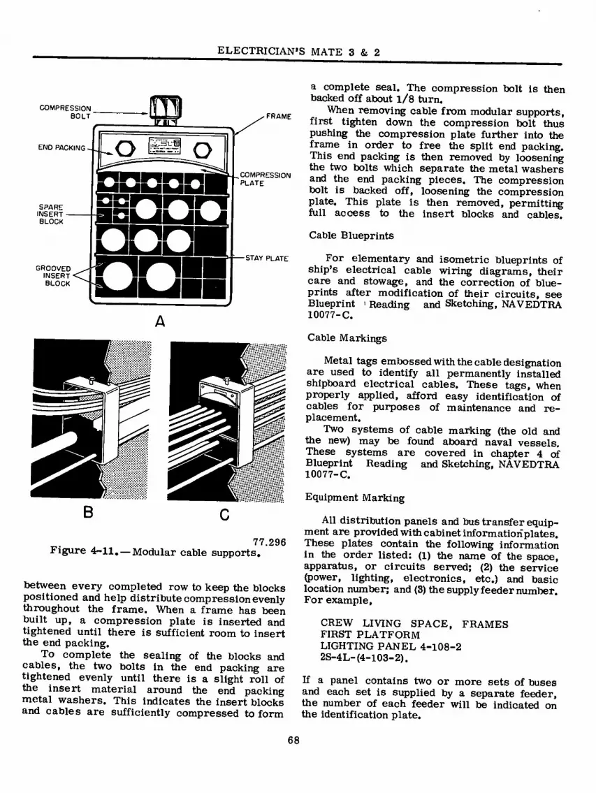
ELECTRICIAN’S MATE 3 & 2
COMPRESSION BOLT
END PACKING o o
□□ GROOVED
INSERT BLOCK
FRAME
COMPRESSION PLATE
SPARE INSERT BLOCK
STAY PLATE
A
77.296 Figure 4-11. — Modular cable supports.
between every completed row to keep the blocks positioned and help distribute compression evenly throughout the frame. When a frame has been built up, a compression plate is inserted and tightened until there is sufficient room to insert the end packing.
To complete the sealing of the blocks and cables, the two bolts in the end packing are tightened evenly until there is a slight roll of the insert material around the end packing metal washers. This indicates the insert blocks and cables are sufficiently compressed to form
a complete seal. The compression bolt is then backed off about l/8 turn.
When removing cable from modular supports, first tighten down the compression bolt thus pushing the compression plate further into the frame in order to free the split end packing. This end packing is then removed by loosening the two bolts which separate the metal washers and the end packing pieces. The compression bolt is backed off, loosening the compression plate. This plate is then removed, permitting full access to the insert blocks and cables.
Cable Blueprints
For elementary and isometric blueprints of ship’s electrical cable wiring diagrams, their care and stowage, and the correction of blue- prints after modification of their circuits, see Blueprint > Reading and Sketching, NAVEDTRA 10077-C.
Cable Markings
Metal tags embossed with the cable designation are used to identify all permanently installed shipboard electrical cables. These tags, when properly applied, afford easy identification of cables for purposes of maintenance and re- placement.
Two systems of cable marking (the old and the new) may be found aboard naval vessels. These systems are covered in chapter 4 of Blueprint Reading and Sketching, NAVEDTRA 10077-C.
Equipment Marking
All distribution panels and bus transfer equip- ment are provided with cabinet information plates. These plates contain the following information in the order listed: (1) the name of the space, apparatus, or circuits served; (2) the service (power, lighting, electronics, etc.) and basic location number; and (3) the supply feeder number. For example,
CREW LIVING SPACE, FRAMES FIRST PLATFORM LIGHTING PANEL 4-108-2 2S-4L-(4-103-2).
If a panel contains two or more sets of buses and each set is supplied by a separate feeder, the number of each feeder will be indicated on the identification plate.
68

Chapter 4—ELECTRICAL INSTALLATIONS
Distribution panels are provided with circuit information plates adjacent to the handle of each circuit breaker or switch. These plates contain the following information in the order listed: (1) the circuit number, (2) the name of the apparatus or circuit controlled, (3) the location of apparatus or space served, and (4) the circuit breaker element or fuse rating. Red markers are attached to circuit information plates to indicate vital circuits. Information plates for circuit breakers supplying circle W and circle Z class ventilation systems contain, in addition to the red marker, the class designation of the ventilation system supplied. Information plates without markings are provided for spare circuit breakers mounted in distribution panels. Panel switches controlling circuits that are deenergized during darkened ship operations are marked DARKENED SHIP. The ON and OFF position of these switches are marked LIGHT SHIP and DARKENED SHIP, respectively.
Circuit information plates are provided inside fuse boxes (adjacent to each set of fuses) and indicate the circuit controlled; the phases, or polarity; and the ampere rating of the fuse.
Conductor Identification
Each terminal and connection of rotating a-c and d-c equipment, controllers, and trans- formers is marked with standard designations. This may be accomplished with synthetic resin tubing or fiber wire markers located as close as practicable to equipment terminals, with fiber tags near the end of each conductor, or by stamping the terminals.
Individual conductors may also be identified by a system of color coding. Color coding of individual conductors in multiconductor cable is in accordance with color coding tables contained in chapter 9621, Naval Ships Technical Manual. The color coding of conductors in power and lighting cables is shown in table 4-2. Neutral polarity, (+), where it exists, is always identified by the white conductor.
Cable Ends
When connecting a newly installed cable to a unit of electrical equipment, the first thing to determine is the proper length of the cable. To do this, form the cable run from the last cable support to the equipment by hand, allowing sufficient slack and radius of bend to permit repairs without renewal of the cable. Carefully estimate where the armor on the cable will have
to be cut to fit the stuffing tube (or connector), and mark the location with a piece of friction tape. In addition to serving as a marker, the tape will prevent unraveling and hold the armor in place during cutting operations.
Determine the length of the cable inside the equipment, using the friction tape as a starting point. Whether the conductors go directly to a connection or form a laced cable with breakoffs, carefully estimate the length of the longest conductor, add approximately 2 l/2 times its length, and mark this position with friction tape. The extra cable length will allow for mistakes in attaching terminal lugs and possible rerouting of the conductors inside the equipment. The length of the cable is now known and it can be cut.
The armor must be removed next. This may be accomplished by using a cable stripper of the
Table 4-2.—Color Code for Power and Lighting Cable Conductor
System No. of
Conductors in Cable
Phase or Polarity
Color Code
3-phase a-c
3-wire d-c
2-wire d-c
2
2
3
2
2
2
2
A B C
AB
BC
AC
+
±
+ and ±
± and -
+ and -
Black White Red
A, black B, white
B, white C, black
A, black C, white Black White Red
+, black ±, white
±, white -, black
+, black -, white
77.332
69

ELECTRICIAN’S MATE 3 & 2
CUTTING BLADE ALIGNMENT DETAIL
DEPRESSING KNOB
KNOB FOR BLADE DEPTH ADJUSTMENT
CLAMPING LEVER'
Q O uv
CUTTING BLADE
■ÚÚ SADDL
ö D iwrf CABLE SIZE
AD 1USTING SCREW
Figure 4-12. — Cable strippers. 77.22
type shown in figure 4^-12. Care must be taken not to cut or puncture the cable sheath where the sheath will contact the rubber grommet of the nylon stuffing tube (fig. 4-7).
Remove the impervious sheath, starting a distance of at least l i/4 inch (or as necessary to fit the requirements of the nylon stuffing tube) from where the armor term-nates. The cable stripper should be used for this job. Do not take a deep cut because the conductor insulation can be easily damaged. Flexing the cable will help separate the sheath after the cut has been made. Clean the paint from the surface of the remaining impervious sheath exposed by the removal of the armor (this paint is conducting).
Once the sheath has been removed, the cable filler can be trimmed with a pair of diagonal cutters.
The proper method of finishing and protecting cable ends that do not require end sealing is shown in figure 4-13. For cables entering enclosed equipment (connection boxes, outlet boxes, fix- tures, etc.) the method shown in figure 4-13A, should be used. An alternate method (when synthetic resin tubing is not readily obtainable) is to apply a coat of air drying insulation varnish to the insulation of each conductor as well as to the crotch of the cable. The end of the insula- tion on each conductor is reinforced and served with treated glass cord, colored to indicate proper phase marking. For cables entering open equipment (switchboards, etc.) the method shown in figure 4-13B, should be used. An alternate
CROTCH OF CABLE TO BE GIVEN A COAT OF INSULATING VARNISH BEFORE APPLYING TUBING.
SERVE WITH TREATED GLASS CORD, COLORED FOR PHASE MARKING
ANY ENCLOSURE TYPE CABLE ENTRANCE FITTING
A
SYNTHETIC RESIN TUBING. APPLY IMMEDIATELY AFTER VARNISHING CROTCH
AFTER VARNISHING AND BEFORE APPLYING TAPE, PUSH TUBING TIGHTLY INTO CROTCH WHILE VARNISH IS STILL WET.
WRAP TIGHTLY WITH TAPE, I LAYER H LAP, TAPE AND SERVE AS ABOVE
SERVE WITH TREATED GLASS CORD COLORED FOR PHASE MARKING
\
VARNISH THIS PORTION
SYNTHETIC RESIN TUBING
B
29,226 Figure 4-13. — Protecting cable ends.
70

Chapter 4— ELECTRICAL INSTALLATIONS
method is to wrap each conductor tightly with one layer of synthetic tape (half lapped) and serve with cord as in the tubing method. Apply tape, air-drying varnish, and serve the crotch and part of the cable for a distance about 2 inches back of the crotch.
Conductor Ends
^¡2 -riiua*
WSHMB Iï**
«HUIMgq?
Wire strippers (fig. 4-14) are used to strip insulation from the conductors. Care must be taken to avoid nicking the conductor stranding while removing the insulation. Side, or diagonal, cutters should not be used for stripping insula- tion from conductors.
Conductor surfaces must be thoroughly cleaned before the terminals are applied. After baring the conductor end for a length equal to the length of the terminal barrel, clean the individual strands thoroughly and twist them tightly together. Solder them to form a neat, solid terminal for fitting either approved clamp type lugs or solder type terminals. If the solder type terminal is used, tin the terminal barrel and clamp it tightly over the prepared conductor (before sol- dering) to provide a solid mechanical joint. Conductor ' ends need not be soldered for use with solderless type terminals applied with crimp- ing tool. Do not use a side, or diagonal, cutter for crimping solderless type terminals.
Solderless type terminals may be used for all lighting, power, interior communications and fire control applications, except with equipment provided with solder type terminals by the manufacturer, and with wiring boxes or equipment in which electrical clearances would be reduced below minimum standards by the use of the solderless type terminal.
For connection under a screwhead where a standard terminal is not practicable, an alternate method cab be used. Bare the conductor for the required distance and thoroughly clean the strands. Then twist the strands tightly together, bend them around a mandrel to form a suitable size loop (or hook where the screw is not removable), and dip the prepared end into solder. Remove the end, shake off the excess solder, and allow it to cool before connecting it.
After the wiring installation has been com- pleted, the insulation resistance of the wiring
1.24 Figure 4-14. —Mechanical wire strippers.
circuit must be measured with a megger or similar (0-100 megohm, 500-volt d-c) insulation resistance measuring instrument. Do not energize a newly installed, repaired, or modified wiring circuit without first ascertaining (by insulation tests) that the circuit is free of short circuits and grounds.
Small refrigerators, drinking fountains and coffee makers are plugged into receptacles con- nected directly to the ship’s wiring. To remove stress from the equipment terminal block and its connected wiring, rigidly clamp the cable to the frame of the equipment close to the point where the cable enters the equipment.
Lacing Conductors
Conductors within equipment must be kept in place in order to present a neat appearance and facilitate tracing of the conductors when altera- tions or repairs are required. When conductors are properly laced, they support each other and form a neat, single cable.
The most common lacing material is waxed cord. The amount of cord required to single lace a group of conductors is approximately 2 l/2 times the length of the longest conductor in the group. Twice this amount is required if the conductors are to be double laced.
Before lacing, lay the conductors out straight and parallel to each other. Do not twist them together because twisting makes conductor lacing and tracing difficult.
A shuttle on which the cord can be wound will keep the cord from fouling during the lacing operations. A shuttle similar to the one shown
71

ELECTRICIAN’S MATE 3 & 2
5.138 Figure 4-15. — A lacing shuttle.
in figure 4-15 may easily be fashioned from aluminum, brass, fiber, or plastic scrap. Rough edges of the material used for the shuttle should be smoothed to prevent injury to the operator and damage to the cord. To fill the shuttle for single lace, measure the cord, cut it, and wind it on the shuttle. For double lace, proceed as before, except double the length of the cord before winding it on the shuttle, and start the ends on the shuttle in order to leave a loop for starting the lace.
Some installations, however, require the use of twisted wires. One example is the use of “twisted pairs” for the a-c filament leads of certain electron tube amplifiers radiation of their magnetic field, thus preventing annoying
hum in the amplifier output. The EM should duplicate the original layout, when relacing any wiring harness.
Single lace may be started with a square knot and at least two marling hitches drawn tight. Details of the square knot and the marling hitch are shown in figure 4-16. Do not confuse the marling hitch with a half hitch. In the marling hitch, the end is passed over and under the strand (fig. 4-16A). After forming the marling hitches, draw them tight against the square knot (fig. 4-16B). The lace consists of a series of marling hitches evenly spaced at one-half inch to one-inch intervals along the length of the group of conductors, as indicated in figure 4-16C.
When dividing conductors to form two or more branches, follow the procedure illustrated in figure 4-17. Bind the conductors with at least
FORM BENDS BEFORE LACING
fi»
fiB 6 TURNS
1
START NEW LACE
SQUARE KNOT
MARLING HITCH
^3
B
11 I=-^ M'I",1,a.1,
c
TERMINATE
AT LEAST EXTRA 2 MARLING
MARLING HITCHES TURNS HITCH \
'A
B
12.247(77A)A Figure 4-16. — Applying single lace.
12.247(77AVB Figure 4-17. — Lacing branches and breakouts.
72

Chapter 4 —ELECTRICAL INSTALLATIONS
STEP I
S3
STEP 2
STEP 3
COMPLETED TELEPHONE
HITCH
3 STEP
Lace the spare conductors of a multiconductor cable separately, and secure them to active conductors of the cable with a few telephone hitches. When two or more cables enter an enclosure, each cable group should be laced separately. When groups parallel each other, they should be bound together at intervals with telephone hitches (fig. 4-20).
4 MARLING HITCHES
SERVING OF 8 TURNS
STEP I
i.
N
STEP 2
5.140,1 Figure 4-19.—The loop method of terminating
the lace.
5.139.1 Figure 4-18.— Starting double lace with the
telephone hitch.
six turns between two marling hitches, and continue the lacing along one of the branches (fig. 4-17A). Start a new lacing along the other branch. To keep the bends in place, form them in the conductors before lacing. Always add an extra marling hitch just prior to a breakout (fig. 4-17 B).
Double lace is applied in a manner similar to single lace, except that it is started with the telephone hitch and is double throughout the length of the lacing (fig. 4-18). Double as well as single lace may be terminated by forming a loop from a separate length of cord and using it to pull the end of the lacing back underneath a serving of approximately eight turns (fig. 4-19).
TELEPHONE -HITCH
5.139 figure 4-20. — Binding cable groups with the
telephone hitch.
73
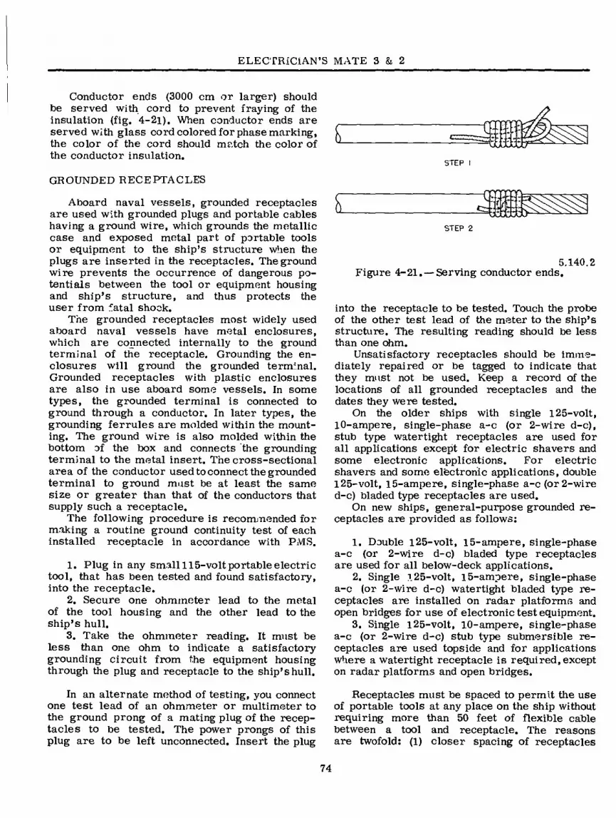
ELECTRICIAN’S MATE 3 & 2
Conductor ends (3000 cm or larger) should be served with cord to prevent fraying of the insulation (fig. 4-2i). When conductor ends are served with glass cord colored for phase marking, the color of the cord should match the color of the conductor insulation.
STEP I
GROUNDED RECEPTACLES
Aboard naval vessels, grounded receptacles are used with grounded plugs and portable cables having a ground wire, which grounds the metallic case and exposed metal part of portable tools or equipment to the ship’s structure when the plugs are inserted in the receptacles. The ground wire prevents the occurrence of dangerous po- tentials between the tool or equipment housing and ship’s structure, and thus protects the user from fatal shock.
The grounded receptacles most widely used aboard naval vessels have metal enclosures, which are connected internally to the ground terminal of the receptacle. Grounding the en- closures will ground the grounded terminal. Grounded receptacles with plastic enclosures are also in use aboard some vessels. In some types, the grounded terminal is connected to ground through a conductor. In later types, the grounding ferrules are molded within the mount- ing. The ground wire is also molded within the bottom of the box and connects the grounding terminal to the metal insert. The cross-sectional area of the conductor used to connect the grounded terminal to ground must be at least the same size or greater than that of the conductors that supply such a receptacle.
The following procedure is recommended for making a routine ground continuity test of each installed receptacle in accordance with PM.S.
1. Plug in any small 115-volt portable electric tool, that has been tested and found satisfactory, into the receptacle.
2. Secure one ohmmeter lead to the metal of the tool housing and the other lead to the ship’s hull.
3. Take the ohmmeter reading. It must be less than one ohm to indicate a satisfactory grounding circuit from the equipment housing through the plug and receptacle to the ship’s hull.
STEP 2
5.140.2 Figure 4-21. — Serving conductor ends.
into the receptacle to be tested. Touch the probe of the other test lead of the meter to the ship’s structure. The resulting reading should be less than one ohm.
Unsatisfactory receptacles should be imme- diately repaired or be tagged to indicate that they must not be used. Keep a record of the locations of all grounded receptacles and the dates they were tested.
On the older ships with single 125-volt, 10-ampere, single-phase a-c (or 2-wire d-c), stub type watertight receptacles are used for all applications except for electric shavers and some electronic applications. For electric shavers and some electronic applications, double 125-volt, 15-ampere, single-phase a-c (or 2-wire d-c) bladed type receptacles are used.
On new ships, general-purpose grounded re- ceptacles are provided as follows:
1. Double l25-volt, 15-ampere, single-phase a-c (or 2-wire d-c) bladed type receptacles are used for all below-deck applications.
2. Single 125-volt, 15-ampere, single-phase a-c (or 2-wire d-c) watertight bladed type re- ceptacles are installed on radar platforms and open bridges for use of electronic test equipment.
3. Single i25-volt, 10-ampere, single-phase a-c (or 2-wire d-c) stub type submersible re- ceptacles are used topside and for applications where a watertight receptacle is required, except on radar platforms and open bridges.
r V
V T < % ^ H
In an alternate method of testing, you connect one test lead of an ohmmeter or multimeter to the ground prong of a mating plug of the recep- tacles to be tested. The power prongs of this plug are to be left unconnected. Insert the plug
Receptacles must be spaced to permit the use of portable tools at any place on the ship without requiring more than 50 feet of flexible cable between a tool and receptacle. The reasons are twofold: (1) closer spacing of receptacles
74
Chapter 4—ELECTRICAL INSTALLATIONS
is wasteful and (2) wider spacing of receptacles results in excessively long and thus a higher resistance grounding conductor which may not protect the operator from shock if a portable equipment fault places potential on the metal case.
Receptacles installed for specific applications, such as radiant heaters, are included in the receptacle spacing to meet the 50-foot limit and therefore may be considered as available for portable tools.
If additional receptacles are required to meet the 50-foot limit, make sure that added receptacles do not result in overloading the circuits. In some ships the receptacles are on an isolated circuit, as an additonal means of preventing fatal shocks.
PLUGS AND CORDS
Nonconducting plastic-cased portable electric tools do not require grounding cords or plugs. The two conductor cords and two-prong un- grounded connector plugs furnished on these plastic-cased tools are acceptable and can be inserted in blade type receptacles aboard ship which may be labeled “WARNING: Insert 3-prong grounded plugs only.” CAUTION: There is a wide range of miscellaneous portable electric equipment that may be received aboard ship without being provided with a cord that has a grounding conductor and a grounded plug that is not plastic encased. This equipment includes galley equipment (fruit juice extractors, food-mixing machines, coffee pots, toasters); office equipment (addingmachines, addressograph machines); shop equipment (key duplicating ma- chines, valve grinders, mica undercutters, hot- plates); medical equipment (infrared lamps, ultraviolet lamps, sterilizers) ; barber shop equip- ment (hair clippers), and laundry equipment (flatirons).
Electrical equipment that is permanently mounted to the hull of the ship does not require the additional ground wire. CAUTION: Shock mounts prevent good grounding.
All 115-volt or 220-volt single-phase a-c and all 115-volt or 230-volt two-wire d-c elec- trically operated equipment now on board ship which do not have a cord with a grounding.con- ductor and grounded plug, and all such equipment subsequently issued to the ship without a cord
which has a grounding conductor and grounded plug, should be provided with a three-conductor flexible cable with grounded plug except as indicated previously.
The three-conductor flexible cable should be type SO or ST color-coded black, white, and green, as listed in the Navy Stock List of General Stores, Group 61. For general use, the plugs should be bladed and have U-shaped grounding prongs. These plugs are available for use with small and large diameter cords. Stub-type plugs which can be made watertight when in use (form- erly designed as type D-2-G) are now furnished with plastic shells.
Test of Plug Connections
Before using portable electrical equipment for the first time, test the plug connections of the equipment for correct wiring. Do the testing in a workshop equipped with a nonconducting surface workbench and diamond tread rubber deck covering. Be sure to wear rubber gloves when testing plug connections.
The cables of portable equipments kept outside the electric shop must be tested weekly. A list of those equipments must be established. The following items should be included: portable hand-held electric tools that are permanently charged out or on loan to other shipboard de- partments or divisions; electric equipment which is frequently touched, such as hot plates, coffee makers, toasters, portable vent sets, movie projectors, and office equipment. A caution card (NAVSEC 5100/2 (4-73) FSN/NO101-148-4010) is to be attached to the above list of equipment.
Bladed Plugs (Round or U- shaped Contact)
Before testing a bladed plug, check to see that the insulation and contacts are in good condition, and that the conductors are secured properly under the terminal screws. Using a volt-ohm meter, measure the resistance from the ground contact to the equipment housing. The measurement must be less than one ohm. Move or work the cable around by bending or twisting it. A change of resistance indicates broken strands in the grounding conductor which means the cable must be replaced.
75

ELECTRICIAN’S MATE 3 & 2
Navy Type D-2-G Plugs
You must also examine these plugs to make sure the insulation and contacts are in good condition and that the conductors are secured properly under the terminal screws. Then check to see that the plug is clean and that the contacts (in particular the ground contact) are free of hangover fringes of molded insulation which could prevent making good contact. As in testing the bladed plugs, measure the resistance from the ground contact to the equipment housing. Again the measurement must be less than one ohm. If bending or twisting the cable causes a change in resistance, the strands in the ground- ing conductor are broken and the cable must be replaced. The type D-2-G plug must be checked on equipment and extension cord. Using a meg- ohmmeter, measure the insulation resistance between the brass shell and each contact on the plug. Push on, pull on, twist, and bend the cable while taking measurements. If the resistance measures less than one megohm, check for twisted bare wires in the plug. Rewire a de- fective plug and replace the brass shell of the plug with a nonconducting plastic (nylon) shell. If the plug has to be replaced due to wear and tear, renew the plug tip and replace the brass plug shell with a nylon shell. Reuse brass shells only if the nylon plug shells are not in stock. In this case, rewire and retest the brass shell plug for temporary use until the nylon shell becomes available. There are two sizes of nylon plug shells. One size is used for 0.425-inch-diameter cables or smaller, the other size for 0.560-inch-diameter cables.
Workmanship
Cord conductors must be fastened securely and properly to wiring terminals. Aboard ship in portable equipment, extension cords, portable receptacles, and plugs, the conductor ends are crimped or soldered into standard eyelets (or hooks where the terminal screws are not re- movable). If eyelets or hooks are not available, the strands of each conductor are twisted to- gether tightly and formed into an eyelet or hook. Then the formed eyelet or hook is coated with solder in order to hold the strands together. There must be no loose strands to come in contact with metal parts, which would place line potential on the metal shell of the plug when it is partially inserted in an energized receptacle. A fatal hand-to-hand electrical shock can result if the receptacle is on the end of
an energized-extension cord and has its metal case raised to line potential (of opposite polarity to that on the shell of the plug) by loose con- ducting strands at the cord connection to the receptacle. Do not let this happen.
Examine ALL cords to make sure they are connected properly to their term'nais. Remove from service damaged plugs and cords that are improperly connected, torn, or chafed. It is not intended that molded rubber plugs and receptacles in which the connections áre encapsulated be cut open for examination of connections.
If the grounding conductor which is connected to the metallic equipment casing is inadvertently connected to a line contact of the plug, a dangerous potential will be placed on the equipment casing. The man handling the portable metal-cased equip- ment when it is plugged into a power receptacle will almost certainly receive a fatal shock since line voltage will be on the exposed parts of the equipment. Do not let this happen either; you can prevent fatal electric shocks. Do not overlook the connections to the cord on each portable tool, equipment, or extension receptacle that is repaired aboard ship or delivered to the ship. Make sure that ALL connections are right before using the tool, equipment, or receptacle.
Extension cords for use with portable tools and equipment are authorized, and consist of 25 feet of three-conductor flexible cable (which includes the grounding wire) with a grounded plug attached to one end and a grounded type portable receptacle suitable for receiving the grounded type tool or equipment plug on the other end.
CASUALTY POWER CABLE
Suitable lengths of portable casualty power cables are stowed on naval vessels close to the locations where they may be needed for making temporary connections in the event the installed distribution systems are damaged. See chapter 5 for a description of the casualty power distribu- tion system. Casualty power cable for a-c dis- tribution systems is type THOF-42, which is capable of carrying 93 amperes at 40°C and 86 amperes at 50°C indefinitely and 200 amperes in an emergency. They are of suitable lengths and distributed throughout the ship in accordance with the Ship’s Information Book. Metal tags installed on the cables designate their proper lengths and locations (fig. 4-22).
The portable cable ends are marked to identify the A, B, and C phases visually or by touch
76

Chapter 4—ELECTRICAL INSTALLATIONS
METAL CABLE TAG
75 2 -73-2
Iff
■L-t Y
THOF-42
i _ 14 MINIMUM
PHASE MARKINGS (TWINE ) .
ica ■P COPPER
3
RED FERRULE
WHITE
SLACK
tv BARE CONDUCTOR
Figure 4-22. —Casualty, power cable —old method of serving. 77.311
r.260
RADIUS TO SU T
r.279 ±.002
RADIUS
2
\ BEFORE FORMING CLOSED END
o AFTER FORMING
FORMING DIE
002
L.286"±.005
Figure 4-23. — Method of securing copper ferrule to conductor. 77.312
77

ELECTRICIAN’S MATE 3 & 2
when illumination is insufficient for visual identi- fication. Phase A is color-coded black and has one serving on the conductor end; phase B is color-coded white and has two servings; and phase C is red with three servings. The insula- tion of the individual conductors is exposed to shipboard ambient temperatures and perhaps oil or oil fumes and accidental damage. After an exposure period of five years or more, the conductor insulation may have lost elasticity to the extent that it will crack when bent while being handled, such as it would be when the casualty power system :s rigged for emergency use. The exposed ends of the individual con- ductors of the casualty power cables should be inspected at least once each year. The best method of determining acceptable insulation is to bend sharply all conductors by hand. If no cracks develop, the insulation is satisfactory. If cracking occurs, repair a defective cable as follows:
1. Cut off the protruding ends and prepare new terminals as shown in figure 4-22. To avoid inserting a bare conductor into bulkhead termi- nals, do not strip more than 1 l/4 inches of the insulation from the conductor.
2. Apply one heavy coat of clear air-drying varnish, grade CA, to the cut ends of the insula- tion. Varnishing makes the cut ends watertight.
3. Place a round copper ferrule on the con- ductor and secure by forming as shown in figure 4-23.
4. Use either of the following methods so the phase can be identified by touch and color. Method l (fig. 4-22). Apply close wrappings of cotton twine approximately 3/64 inch in diameter, knot securely, and coat with varnish. Use one wrapping on the black wire (phase A), two wrap- pings on the white wire (phase B), and three wrappings on the red wire (phase C). Method 2 (fig. 4-24). Instead of cotton twine, O-rings and heat-shrinkable colored tubing are used.
METAL CABLE TAG
■14 MINIMUM
PHASE MARKINGS ( "0"RINGS)
75 2-73 -2
HEAT SHRINKABLE TUBING
COPPER FERRULE
I ■S'
I RED
WHITE
BLACK
TUBING 3/4" I. D. FSN
BLACK 5970-914-3118
WHITE 5970-812-1360
RED 5970-914-3117
CLEAR 5970-767-0511
CLEAR (2" I. D. ) 5970-089-1454
"0" RING (3/8" I.D.) 5330-050-1211
HEAT GUN 4940-561-1002
Figure 4-24. —Casualty power cable —new method of serving, 77.313

Chapter 4—ELECTRICAL INSTALLATIONS
The numher of O-rings correspond to the number of wrappings in method 1 above. Measure the individual conductors for proper placement of the O-rings and roll the rings on the conductors. Then cut the tubing to proper lengths, slide them over the O-rings, and apply heat with a heat gun. The tubing will shrink around the conductors and rings, making clear and distinctive markings for proper identification of the casualty power
»cable. The O-rings, tubing, and heat gun used in this method are readily available in the naval supply system.
Portable casualty power cables should be rigged only when required for use or for prac- tice in rigging the casualty power system. At all other times, they should be stowed in the cable rack indicated on the cable tag. When portable casualty power cables are rigged, con- nections should be made from the load to the supply to avoid handling energized cables.
Casualty power cables are a very important part of the ship’s equipment. Each year the cables and term'nal connections should be closely inspected and tested.
If in checking the work schedule, you find that the division POhasassignedyouanda striker to accomplish the inspection of the casualty power cables, proceed as follows. Remove the appropriate maintenance requirement card from the file or cardholder in your shop. Read the card carefully, it tells what tools and material the job will require, safety precautions to observe, and procedures to follow. The total manhours the job should require will vary depending on your particular type ship. Upon completion of the job, return the MRC to its file and mark the job (x) on the weekly work schedule so the division PO can see that it is completed.
SHORE POWER CABLE
A shore terminal box is provided at a suit- able weatherdeck location aboard ship. Portable cables from shore power or from a ship along- side can be attached to the shore terminal box to supply power to the ship’s distribution system. This same connection can be used to supply power from the ship’s service generators to a ship alongside. The shore power system is designed to handle only enough power to operate necessary machinery and provide ilium nation for habitability and the accomplishment of neces- sary work. Care must be exercised not to exceed the capacity of the system when it is in use.
2 FT
STEP I
STEP 3
o STEP 6
STEP 4
STEP 7
(WHITE)
CK, STEP 7
STEP 5
O S PHASE MARKINGS —
NYLON LOCATING PIN /CONTACT HOUSING
(RtOl
/
(BLACK)
W-
D
B-
70.6:103.141 Figure 4-25. — Shore power cable ends.
Older type flexible shore power cables are connected to their shipboard terminal box(es) by bolted (fig. 4-25B) lugs. Later type cables have molded rubber plugs (fig. 4-25C) with contacts which are plugged into 400-ampere (S-terminal) receptacles.
For a-c systems, the flexible shore power cables are 3-conductor, 400,000 cm (type THOF- 400). These are rated 366-amp and 338-amp in ambient temperature of 40°C and 50°C, re- spectively. Where practical for naaintaining the best voltage regulation, several cables should be connected to limit each conductor’s current below 250 amperes. However, all cables should be able to safely carry 400-ampere loads for 2 to 3 hours when the desired arrangement is not practical.
The lug ends of all shore-power cables (if not already prepared when received aboard ship) should be made up in the following manner:
79

ELECTRICIAN’S MATE 3 & 2
1. Remove the outer sheath from the cable for approximately 2 feet, or a sufficient distance to permit ready attachment to the shore terminal box (step 1, fig. 4-25A). Do not damage the insulation of the individual conductors.
2. Taper the end of the outer sheath, starting about 1 inch back from the cut end (step 2, fig. 4-25A).
3. Apply a coat of air-drying, insulating varnish to the crotch of the cable and allow it to dry (step 3, fig. 4-25A).
4. Apply two layers of pressure-sensitive synthetic resin tape or friction tape (half-lap), starting about 2 inches back of the crotch and finishing about 2 inches in front of the crotch (step 4, fig. 4-25B).
5. Reinforce and seize the tape with a serving of treated glass cord, and coat the completed serving with air-drying insulating varnish (stepS, fig. 4-25B).
6. Apply a serving of treated glass cord, colored for phase marking (step 6, fig. 4-25B).
7. Attach lugs as furnished with the ship’s shore terminal box (step 7, fig. 4-25B). Stamp the lugs to indicate the phase (A, B. C) or polarity (+,+ , -) of the conductors. The lug markings, the colored glass cord serving, and the color of the conductor should all agree with the phase and polarity code for light and power conductors (table 4-2),
The terminal connecting block, and terminals of the ship’s shore terminal box must be plainly marked to indicate phase sequence or polarity, as appropriate. For example, the terminal of the black conductor should be stamped (A) to indicate phase A; or stamped (+) to indicate polarity. The color code of cables should not be implicitly trusted because the conductors (from exposure) may become discolored or lose their original coloring.
When practicable, follow these procedures in connecting shore power cables.
• Test the ship’s shore terminal box for proper marking after energizing the shore termi- nal box from the ship’s service generator. Check the phase sequence of a-c systems by testing the terminals with a phase-sequence indicator,
or check the polarity of d-c systems by testing the terminals with a polarity-indicating voltage tester. (A little later on in this chapter, you will find a description of the phase-sequence indicator and the procedure for checking phase sequence.)
• After determining the correct connections, secure the ship’s power to the shore terminal box by opening the ship’s shore power switch. Tag this switch in the manner prescribed for tagging circuits on which men are working.
• Rig the shore power cable and connect one end of it to the ship’s shore terminal box. Make certain that the leads are properly con- nected in accordance with the terminal markings of the box.
• Check the termi nais on the shore connection with a voltage tester, and after it has been deter- mined that they are deenergized, connect the other end of the shore power cable leads.
• Energize the cable from the shore power supply, and test the phase sequence or polarity, depending on whether the system is a-c or d-c. Only after the phase sequence, or polarity, matches that of the ship’s power may the ship safely be switched to shore power. Tne procedure for switching to shore power is given in chapter 5, A-C Power Distribution Systems.
Warning signs indicating the voltage of the cable should be attached to the shore power cable at intervals to warn personnel to keep clear of the cable. All connections must be tightly made to prevent damage to the terminals or leads as a result of overheating and arcing.
The procedures and precautions that follow apply to all portable cables as well as the shore power cables. Spliced portable cables are ex- tremely dangerous and should not be used unless an emergency warrants the great risk involved. Portable cables must be of sufficient length to prevent their being subjected to longitudinal stresses and the need to be pulled taut to make connections. Current-carrying capacity must be ample for the expected power demand. The cable must be checked frequently to ascertain the degree of heating, and any cable that feels uncomfortably warm to the bare hand (placed outside the insulation) should be checked im- mediately for overloading or loose connections. Interconnections between lengths of portable cable
80

Chapter 4 —ELECTRICAL INSTALLvrONS
x •- -• X,
SHORE POWER X SHIP'S
POWER
Z » X B
!Z
73.52 Figure 4-26. —Phase-sequence indicator
and connections.
shall be made only on approved connection block or by other approved fittings that shall be suitably insulated and enclosed to eliminate all possible hazards from fire or shock to personnel.
Always support portable cables above decks, floor plates, and gratings. Never place them where they can be damaged by falling objects, by being walked on, or by contact with sharp corners or projections in the ship’s hull or other objects. Where portable cables pass through doorways or hatches, provide stops to prevent cables from being pinched by a door or hatch cover.
Phase-Sequence Indicator
As mentioned earlier, a phase-sequence indi- cator is used in connecting shore cables to an a-c distribution system. Phase sequence is the sequence or order in which the voltages of a 3-phase system appear.
An approved type of phase-sequence indicator (fig. 4-26A) has a miniature, 3-phase induction motor and three leads labeled A, B, and C. The miniature motor can be started by means of a momentary contact switch. When the motor starts turning, you can tell its direction of rotation by looking through the three ports in the instrument. Clockwise rotation would indicate correct phase sequence. You stop the motor by releasing the momentary contact switch.
When connecting a-c shore power to the ship, connections must be made so that the phase sequences of the two systems will be the same. To ensure the phase sequences are the same use the phase sequence indicator (fig. 4-26), connect indicator terminal A to Xi, B to Yl, and C to Zl (fig. 4-26B) and press the contact switch, noting the direction of rotation of the motor. Next, move the A terminal to X, the B to Y, and the C to Z, and again press the switch. If the motor turns in the same directions as before, the phase rotation is the same and the connection can be made X to Xl, Y to Yl, and Z to Zl. If the motor turns in the opposite direction, transpose the connections of any two of the incoming shore power leads before making the connection.
It is not absolutely necessary that A of the phase sequence indicator be connected to the top terminal, B to the center terminal, and C to the bottom terminal. The important thing is to ensure that the phase sequence indicator lead that was used on Xl be brought over to X, the one used on Yl to Y, and the one used on Zl to Z. If, after shifting the indicator to X, Y, and Z, the rotation is counterclockwise, reverse any two of the shore power leads which will reverse the direction of rotation of the in- dicator, resulting in clockwise rotation.
RF COAXIAL CABLES
Radio frequency cables may look like power cables, but they require special handling and careful installation. These cables are vital to the proper operation of all electronic equipment and therefore must be installed and maintained with the greatest care.
Construction
Flexible radio-frequency transmission lines (coax) are two-conductor cables, one conductor of which is concentrically contained within the
81

ELECTRICIAN’S MATE 3 & 2
other, as illustrated in figure 4-27, Both con- ductors are essential for efficient operation of the transmission line. The proper connectors and terminations are also necessary for efficient operation of the line.
The inner conductor may be either solid or stranded and may be made of unplated copper, tinned copper, or silver-plated copper. Special alloys may be used for special cables.
The dielectric insulating material is usually polyethylene or teflon, although neoprene or other rubber-like materials are occasionally used for pulse cables. (Pulse cables carry d-c pulses that may have relatively high voltages during a relatively short pulse time.)
Braided copper is usually used for the outer conductor; it may be tinned, silver plated, or bare. The outer conductor is chosen to give the best electrical qualities consistent with maxi- mum flexibility.
The protective insulating jacket is usually a synthetic plastic material (vinyl resin). Neo- prene rubber is generally used on pulse cable; silicone rubber jackets are used for high- temperature applications.
Armor is needed for protection. It may be braided aluminum, or sometimes galvanized steel, similar to that used on power cables.
Polyethylene is a gray, translucent material. Although it is tough under general usage, it will flow when subjected to heavy pressure for a period of time.
Teflon is a white opaque plastic material. This material will withstand high temperatures and will remain flexible as relatively low tem- peratures. It has a peculiar quality in that nothing will stick to it and it is unaffected by the usual solvents.
Synthetic rubber (neoprene) is very flexible and adheres tightly to metals (conductors). This flexible TRF type cable is used primarily as welding cable to carry high current.
Installing the Cables
When possible, cables are run along different well separated paths to reduce the probability of battle damage to several cables simultaneously. Wherever possible, high-temperature locations are avoided« Pulse cables are run separately, when possible, to reduce coupling and inter- ference.
Because attenuation (power loss) in a line increases with its length, cables are kept as short as practicable, consistent with avoiding high-temperature locations, sharp bends, and strain on the cable.
PROTECTIVE OR SHIELDING ARMOR
PROTECTIVE INSULATING JACKET
OUTER CONDUCTOR A
DIELECTRIC INSULATING MATERIAL
INNER CONDUCTO:
1.43 Figure 4-27. — Construction of flexible RF
transmission line.
Flexible cables are flexible only in the sense that they will assume a relatively long bend radius. They are not intended to be stretched, compressed, or twisted; and they are installed with this in mind. Bends are made as large as practicable, the minimum radius of bend being 10 times the diameter of the cable.
The number of connectors are generally kept to a minimum to reduce line losses and maintenance problems.
Fabricated straps are used for holding the cables. They are snug, but not too tight. Back straps (which keep the cable away from a surface) are used in making cable runs along masts or in compartments that are subject to sweating. In more recent installations semicontour straps and cable bands are used for certain applications.
The exact methods of installing cables are included in the Electronics Installation and Main- tenance Book. NavShips 0967-000-0110.
Remember, the Cable Comparison Guide, NavShips 0981-052-8090, contains information pertaining to all types of electronic shipboard cable.
CABLE MAINTENANCE
The primary purpose of electrical cable maintenance is to preserve the insulation resist- ance. Hence, it is important to know the charac- teristics of the insulating materials that are used in naval shipboard electrical equipment and the factors that affect insulation resistance.
Insulation
The purpose of insulation on electric cables and equipment is to (1) isolate current-carrying conductors from metallic and structural parts,
82

Chapter 4—ELECTRICAL INSTALLATIONS
and (2) insulate points of unequal potential on conductors from each other. The resistance of such insulation should toe sufficiently high to result in negligible current flow through or over its surface.
The electrical insulating materials used in naval shipboard electrical equipment (including cables) are grouped according to their chemical composition; for example, class O, class A, class B, class C, class H, class E, and class T insulation.
Class O insulation consists of cotton, silk, paper, and similar organic materials when neither impregnated nor immersed in a liquid dielectric. Class O insulation is seldom used by itself in electrical equipment.
Class A insulation consists of (1) cotton, paper, and similar organic materials when they are impregnated or immersed in a liquid di- electric; (2) molded and laminated materials with cellulose filler, phenolic resins and other resins of similar properties; (3) films and sheets of cellulose acetate and other cellulose derivatives of similar properties; and (4) varnish (enamel), as applied to conductors.
Class B insulation consists of mica, asbestos, fiber glass, and similar inorganic materials in built-up form with organic binding substances.
Class H insulation consists of (1) mica, asbestos, fiber glass, and similar inorganic materials in built-upform with binding substances composed of silicone compounds or materials with equivalent properties; and (2) silicone com- pounds in the rubbery or resinous forms, or materials with equivalent properties.
Class C insulation consists entirely of mica, glass, quartz, and similar inorganic material. Class C materials, like class O, are seldom used alone in electrical equipment.
Class E insulation is an extruded silicone rubber dielectric used in reduced-diameter types of electric cables in sizes 3, 4, and 9. Special care should be exercised in handling the cables to avoid sharp bends and kinks that can damage the silicone rubber insulation on the old types that did not employ a nylon jacket over each insulated conductor.
Class T insulation is a silicone rubber treated glass tape, which is also used in reduced- diameter cables in sizes 14 through 2,000.
Propulsion generators and motors are usually insulated with class B insulating materials. Ship’s service and emergency generators may have either class A, B, or H materials; however, the trend is away from class A. Auxiliary motors are usually class A, although the trend is toward class B and class H materials. Lighting transformers for 60-hertz service are class B insulated, and 400-hertz transformers are class H insulated. Miscellaneous coils for control pur- poses may be class A, B, or H, but the ma jority of such coils are class A insulated.
Temperature Effects on Insulation
It is important to maintain operating tempera- ture of electrical equipment within their designed values to avoid premature failure of insulation. Temperatures only slightly in excess of designed values may produce gradual deterioration, which, though not immediately apparent, shortens the life of the insulation. The highest temperature (hot-spot temperature) to which class O insula- tion may be subjected continuously with normal life expectancy (5 years) is 90° centigrade, class A insulation, 105° centigrade; class B insulation, 130° centigrade; and class H, 200° centigrade. No limit has been established for class C insulation.
The ultimate temperature rise of electrical equipment is reached when the rate at which heat is developed equals the rate at which heat is transferred to the surrounding atmosphere. The heat developed by electrical equipment can usually be measured with accuracy but the temperature of the immediate surrounding area (known as ambient temperature) can become critical to the equipment if proper ventilation is not maintained.
The maximum allowable temperature rise and the design ambient temperature allowed for electrical equipment are usually shown on the nameplate, on equipment drawings, and in the technical manual for the equipment. When in- formation is not available from these sources, the maximum permissible temperature rises, shown in Chapter 9600, NavShips Technical Manual, shall be used as a guide for checking
83

ELECTRICIAN’S MATE 3 & 2
x o
¡TNo FEEDER
2 ADEQUATELY GROUNDED BY CABLE STRAPS AND CLIPS IA SWITCHBOARD
SWITCH OR CIRCUIT BREAKER OPEN LIGHTING
DISTRIBUTION PANEL
SWITCHES CLOSED, FUSES IN
MAIN
O' TO OTHER LOADS LOCAL BRANCH
CIRCUITS AND FIXTURES
DISTRIBUTION BOX, FUSED
I 1
SWITCH OPEN
BRANCH
I I DISTRIBUTION BOX, UNFUSED
-0-
-0
TO OTHER LOADS
i BRANCH BOX
SWITCH OPEN
LOCAL BRANCH CIRCUITS AND FIXTURES
77,25
Figure 4-28. —Measuring insulation resistance of a lighting circuit.
or testing windings of rotating electrical ma- chinery.
The engineering design of ships takes into account the relationship of catole sizes and resistances with the cable load currents and temperatures.
Insulation Resistance Measurements
The insulation resistance of shipboard elec- trical cable must be measured periodically with an insulation-resistance-measuring instrument (megger) to determine the condition of the cable.
84

Chapter 4—ELECTRICAL INSTALLATIONS
Measurements should be made on each in- dividual leg of d-c circuits and each individual phase lead of 3-phase a-c circuits.
For lighting circuits, the legs or phase leads should include all panel wiring, terminals, connection boxes, fittings, fixtures, and outlets normally connected, but with lights turned off at their switches and with all plugs removed from the outlets (fig. 4-28). If local lighting switches are double pole, the insulation resistance of the local branch circuit will not be measured when the switch is open. In such cases, making an insulation test from one leg or phase lead to ground with the local switches closed will determine whether grounds exist on the circuits and fixtures.
For power circuits, the lègs or phase leads should include panel wiring, terminals, connection boxes, fittings, and outlets (plugs removed), motor controller terminals, and other equipment that remains connected when the legs or phase leads are isolated by opening switches (or circuit breakers) at the switchboard, and by leaving motor controller contactors open (fig. 4-29).
For degaussing circuits, measurements should be taken at a degaussing coil connection box;
the legs measured should include the coil cables, through boxes, and feeder cables. Disconnect the supply and control equipment by opening the circuit on the coil side of the control equip- ment. Measure the compass-compensating coil feeder cable with all control equipment dis- connected. Additional information on tests of degaussing installations is obtained in NavShips Technical Manual, Chapter 9813, and in the degaussing folder furnished with each degaussing installation.
Measurements of these circuits (lighting, power, and degaussing circuits) should be made as follows:
1. Check to see that the cable armor is adequately grounded by measuring between the cable • armor and the metal structure of the vessel (step 1, fig. 4-30); normally, grounding has been accomplished by means of cable straps. If a zero reading is not obtained, ground the cable armor.
2. Select one lead to be measured, and connect all the other leads in the cable together and ground them by means of temporary wires (step 2, fig. 4-30).
SWITCH OR CIRCUIT BREAKER OPEN
SWITCHES OR CIRCUIT BREAKERS,
CLOSED
1
OT-'O FEEDER
<7"| ~0 ADEQUATELY GROUNDED BY CABLE STRAPS
AND CLIPS
XQ_
02 QUJ
SWITCHBOARD r-o
I POWER DISTRIBUTION
PANEL CONTACTORS OPEN
I 1 O—T 0 c MAIN
O MOTOR
I I CONTROLLER
Figure 4-29. —Measuring insulation resistance of a power circuit.
77,26
85

ELECTRICIAN’S MATE 3 & 2
STEP-
STEP-3
V §
STEP-2
STEP-4
STEP-5
M s A_
C
77.27 Figure 4-30. — Measuring circuit insulation
resistance.
3. Measure the resistance of the lead being tested to ground (step 3, fig. 4-30). The test voltage should be applied until a constant reading is obtained. Hand-driven generator type instru- ments (meggers) should be cranked for at least 30 seconds to ensure a steady reading.
4. Repeat steps 2 and 3 as necessary to measure each leg or phase lead to ground (steps 4 and 5, fig. 4-30). When circuits contain permanently connected paths between legs or phases, such as transformers, indicator lights, control relays, etc., measurements need.bemade only between one lead and ground unless low readings requiring further tests are obtained.
or at least 0.5 megohms for each complete lighting circuit. The minimum acceptable value of a degaussing circuit to ground is 0.1 megohm from any leg, which includes the coil cables, the through boxes, and the feeder cables, of a degaussing circuit to ground. If the readings are lower than these minimum values, they should be considered satisfactory if they are not lower than previous measurements made under the same conditions (same cable with the same equipment connected and approximately the same average sheath temperature), provided the value of the previous measurements has been established as satisfactory by further investi- gation and satisfactory service operaton.
Where the insulation resistance of a circuit is less than the minimum described above, the low resistance may be due to trouble localized in a segment of the circuit. To determine the cause, segregate the circuit into two or more parts by opening switches and circuit breakers, removing fuses, etc. at the feeder distribution panels and boxes, and measure the insulation resistance of each segment. One or more of the segments may indicate abnormally low resistance. The low values on these segments may be due to low insulation resistance at cable junctions or in equipment remaining connected to the segment. Inspect and correct any such faults by cleaning or corrective action as necessary.
If successive isolation of components from the circuit indicates that the low insulation resistance is due to the cables, the acceptance values which shall be used to judge whether or not a cable is safe to operate depend upon the temperature, the cable length, and the type of cable. Measure- ments shall be made either immediately upon deenergizing circuits which have been energized for at least four hours, or after the circuits have been deenergized for at least four hours. Circuits which have been deenergized for at least four hours shall be classed as either in a warm ambient or in a cold ambient. A warm ambient is defined as a warm climate or a condition in which the entire cable is in a heated space and not in contact with the ship’s hull. A cold ambient is defined as a cold climate or a condition in which most of the cable is in an unheated space or is against the ship’s hull in cold waters. The cable temperature shall be considered to be 104°F if the cable has been energized for four hours, 70°F if it is deenergized in a warm ambient, and 40°F if it is deenergized
These measurements of resistance should be considered satisfactory if they are not less than 1 megohm for each complete power circuit
86

Chapter 4—ELECTRICAL INSTALLATIONS
200
100
50
— 1,000,000
— 100,000
©-I- 0- f-
'<5-!-
0. 1
0.05
— 0.01
NOMOGRAPH FOR OBTAINING
— 10,000
5,000
¡0£0
— 100
■©-—s'- !
*1,000
-500
100
— 50
f“l°
— 5
— 0.01
RESISTANCE PER. FT.
OBTAINING RESISTANCE PER FOOT - Example
Line is drawn on nomograph from 0.8 megohms (measured)
to S00 feet (Length of cable per card or plans). If points
®. or (S) apply, cable is O.K. If points (3),
or apply, cable may be in poor condition - investigate
further.
MINIKtJM ALLOWABLE INSULATION RESISTANCE CABLES (MEGOFWS/FT)
JUST AFTER
SHUTDOWN
104 °F
EQUIPMENT
SECURED MOU»I
WARM CLIMATE
SUNMER OR ALL
IN HEATED SPACE
70°F
COLD CLIMATE
WINTER OR AGAINST COLD HULL 40°F
TYPE OP CABLE
SCA, HF, oc, SCA
95
(POINT (T) )
TTHFA, TTHFWA
40
(POINT ®)
920
(POINT ©)
5500
(POINT @)
380
(POINT ©)
2200
(POINT 0)
RESISTANCE TEST RECORD CARD NAVSHIPS 531-1 (10-63) (RCVCRSE)
Figure 4-31. — Nomograph for obtaining resistance per foot.
in a cold ambient. In figure 4-31, select the point of allowable resistance per foot based on the ambient condition and the type of cable.
j Using the nomograph, a straight line from the measured insulation resistance to the length of cable should cross the resistance per foot line above the selected minim im resistance per foot point. Corrective action is required if the re- sistance per foot is less than the selected point.
You must keep in mind that when checking insulation resistance on circuits where semi- conductor control devices are involved, the 500- volts d-c megger can NOT be used. An electron tube megohmmeter is used on circuits and components where insulation resistance must be checked at a much lower potential. The megohmmeter operates on internal batteries and when circuits or components under test contain a large electrical capacity, the megohm- meter READ button must be depressed for a sufficient time to allow its capacitor to charge before a steady reading is obtained. The test voltage applied by the megohmmeter to an unknown
resistance is approximately 50 volts when measuring resistances of approximately lO meg- ohms and slightly greater than this when measur- ing higher resistances.
CONTROL DEVICES
A CONTROL DEVICE, in its simplest form is an electrical switching device that applies voltage to or removes it from a single load. In more complex control systems, the initial SWITCH may set into action other CONTROL DEVICES that govern the motor speeds, the compartment temperatures, the depth of water, the aiming and firing of guns, or the dii’ection of guided missiles. In fact, all electrical systems and equip- ment are controlled in some manner by one or more CONTROLS.
MANUALLY OPERATED CONTACTS
Manually operated switches are those familiar electrical items which can be conveniently oper- ated with the hand. The pushbutton (fig. 4-32)
87

ELECTRICIAN’S MATE 3 & 2
_L i i _t>J O O Q I o O O
A B ô"uô D
C
73.291 Figure 4-32. —Manually operated contacts.
is the simplest form of electrical control. When the button is pushed down (fig. 4-32A), contact is made across the two circles representing wire connections. When pressure is released, a spring (not shown) opens the contact. Figure 4-32B shows a normally closed contact. When it is pressed, contact at the two terminals is broken. When it is released, a spring-loaded feature (not shown) closes the switch again. The switch in figure 4-32C is designed to make one contact and break another when it is pressed: the upper contact is opened when the lower is closed; again, the spring arrangement (not shown) resets the switch to the position shown. The switch in figure 4-32D is a maintained contact type. When it is pressed, it hinges about the center point and will stay in that position until the other part of the button is pressed.
ELECTRICALLY OPERATED CONTACTS
Schematic wiring diagrams have both push- button and electrically operated contacts. Shown in figure 4-33 are control contacts illustrated by two different methods. Figure 4-33A is shown in the normally open (NO) position therefore, it
closes when operated. Figure 4-33B is shown in the normally close (NC) position therefore, when energized, it opens. Figure 4-33C, D, E, and F are timer contacts. That is, after being energized it will take some time for these contacts to close or open as the case may be. This time element is controlled by a timer motor, by a dashpot, pneumatically, or by mag- netic flux. Notice that those devices that are timed closed or open have this indicated at the lower contacts: TC means timed close, TO means timed open, and TO ENERGIZE means that while this contact is already shown open, before it can be timed open, it must close. In operation this switch might be closed by a clutch in a timer assembly. After the timer motor operates through a given number of revo- lutions, a clutch in the timer will release the contact causing the switch to reopen. The timed switches may also be illustrated with an arrow which indicates whether the contact is timed open or time closed. The direction of the arrow serves to indicate which condition exists.
LIMIT SWITCHES
In certain applications the ON-OFF switch does not give enough control to ensure safety of equipment or personnel. A limit switch is incorporated in the circuit in order that operat- ing limits are not exceeded.
The limit switch is installed in series with the master switch and the voltage supply. Any action causing the limit switch to operate will open the supply circuit.
One application of limit switches is in equip- ^ ment that moves over a track. It is possible to apply power so that operation will continue until the carriage hits an obstruction or runs off the end of the track.
d h NO
—A-
-I I- ^ -I I- h NC TC TO TC TO ENERGIZE
—B C D E F 73.292
Figure 4-33.— Electrically operated contacts.
88

Chapter 4—ELECTRICAL INSTALLATIONS
rSii"
through an opening in the switch operating arm. Collars A and B on the guide rod exert upward or downward pressure on the operating arm as the float approaches minimum or maximum depth positions. The switch operating arm is fastened to the shaft, which is coupled to the switch contact mechanism (fig. 4-36). Collars C and D on the guide rod are held in position toy set- screws so that their positions can be changed to set the operating levels to the desired points.
As the float goes up and down, corresponding to the liquid level, it does not move the operating rod, E, until contact is made with either collar. When the float comes in contact with either collar, the external operating arm of the switch is moved and the switch is operated.
Although the switch assembly is of rugged construction, it must toe checked regularly for proper performance.
Maintenance
77.250 Figure 4-34. — Limit switch, roller actuator arm
operated.
If limit switches are installed near the end of travel, an arm or projection placed on the moving section will trip a lever (as shown in figure 4-34) on the limit switch. The switch then opens the circuit and stops the travel of the car- riage. This type of control is a direct-acting, lever-controlled limit switch. Another type, an intermittent gear drive limit switch, may toe coupled to a motor shaft to stop action when a definite number of shaft revolutions is completed.
FLOAT SWITCHES
A float switch (figs. 4-35 and 4-36) controls electrically driven pumps used to fill or empty tanks.
Construction
In a tank installation (fig. 4-35) the deck and overhead flanges are welded to the deck and overhead of the tank. The float guide rod, E, fits into the bottom flange and extends through the top flange. The float guide rod then passes
The switch contacts should toe kept in good electrical condition. Determine the kind of metal used for the contacts, whether copper or silver, and apply maintenance procedures outlined in Chapter 7, Motor Controllers. Of course, contacts should never be cleaned while power is applied to the circuit. Nor should lubricants toe applied to contact surfaces.
PRESSURE AND TEMPERATURE SWITCHES
Pressure and temperature controls have been grouped together because the switching mecha- nism is the same for tooth controls; the difference is in the operation.
Pressure-controlled switches are operated toy changes in pressure in an enclosure such as a tank. On the other hand, temperature-controlled switches operate from changes in temperature that take place in an enclosure or the air surrounding the temperature-sensing element. Actually, both switches are operated toy changes in pressure. The temperature element is ar- ranged so that changes in temperature cause a change in the internal pressure of a sealed gas or air-filled toulb or helix, which is con- nected to the actuating device by a small tube or pipe. Temperature changes cause a change in the volume of the sealed-in gas, which causes
89

ELECTRICIAN’S MATE 3 & 2
SWITCH OPERATING
ARM A x
STOPS MAX. WEIGHT « 2.7 LBS. ADJUSTABLE WEIGHT TO PROVIDE COUNTER- BALANCE FOR OPERATION ROD.
REDUCE WEIGHT IF NECESSARY TO FIT WEIGHT OF OPERATING ROD.
«is® VERTICAL TRAVEL
OVERHEAD FLANGE
¿L-,
FLOAT
ONE METHOD OF OPERATING SWITCH
ALLOWANCE FOR TRAVEL OF OPERATING ROD 5 INCHES
FLOAT TO CONTAIN 4 LBS. OF BALLAST
DECK FLANGE
!
Figure 4-35. — Float switch tank installation. 77.116
movement of a diaphragm. The movement is transmitted by means of a plunger to the switch arm. The moving contact is on the arm, and a fixed contact may be arranged so that the switch will open or close on a temperature rise.
When the switch is used to control pressure, the temperature element is replaced by a tube that leads to the pressure tank. The pressure inside the tank then operates the switch mech- anism..
90

Chapter 4—ELECTRICAL INSTALLATIONS
m
77.117 Figure 4-36. — Float switch mechanism.
Pressure or temperature controls may he used as a pilot device (fig. 4-37). The circuit operation is exactly the same regardless of the kind of pilot device used to control the circuit. To maintain more or less constant temperature or pressure, switch contacts are arranged to close when the pressure or temperature drops to a predetermined value and to open when the pressure or temperature rises to the desired value. The reverse action can he obtained by changing the contact positions.
The différence in pressure for contact opening and closing is the differential. The switch mecha- nism has a built-in differential adjustment so
that the differential can be varied over a small range. Once set, the differential remains es- sentially constant at all pressure settings.
Each switch has a range adjustment that sets the point at which the circuit is closed. Changing the range adjustment raises or lowers both the closing and opening points without changing the differential.
Operating Adjustments
To set the operating range of the switch, turn the differential adjustment screw (fig. 4-38) counterclockwise against the stop for minimum differential. Bring the pressure to the value at which the circuit is to be closed. If the switch contacts are open at this pressure, turn the range screw slowly clockwise until the contacts close. If the contacts are closed when the desired pressure is reached, turn the range screw counterclockwise until the contacts open; then turn the screw slowly clockwise until the contacts close. These adjustments set the closing pressure.
The pressure (keep in mind that changes in temperature are converted to changes in pressure) is now raised to the point where the circuit is to be opened. Since the differential adjustment is now set at minimum the circuit will probably open at a lower pressure than desired; therefore, turn the differential adjustment screw clockwise to widen the differential until the desired opening pressure is obtained.
V MAIN CONTACTS
NC
STOP S?^*- CONTACTS -O 3 df
r\y START PILOT
FUSE
T?
MOTOR
M1 SOLENOID
n 1 MAN
MF-i PILOT
DEVICE
L AUTO.
77,118 Figure 4-37. — Representative pilot device control circuit.
91

ELECTRICIAN’S MATE 3 & 2
DIFFERENTIAL ADJUSTMENT
RANGE ADJUSTMENT
77.119 Figure 4-38, — Pressure-operated switch.
find variation from the desired operating values, go through the entire procedure again and observe operation through a complete cycle.
PILOT CONTROL DEVICE
A pilot is defined as a director or guide of another thing (or person). You may be familiar with ship pilots, pilot rudders, and pilot ñames. In this text, a pilot is a small device that controls a relatively larger device or mechanism, usually doing so by electrical means. The pre- viously described float switch and pressure operated switches are representative examples of such pilot devices. Pilot devices are limited in their ability to handle large currents and voltage required to operate shipboard motors or power-handling units. Therefore, it is cus- tomary for a pilot device to actuate only a magnetic switch. The magnetic switch can be chosen with characteristics suitable for handling the desired amount of power in the motor circuit.
Use of a Pilot Device
Thermal Unit Type
The bulb and helix units can be connected to the switch section (fig. 4-39). The bulb unit (fig. 4-39A) is normally used when liquid tempera- tures are to be controlled. However, it may control air or gas temperatures, provided the circulation around it is rapid and the temperature changes at a slow rate.
The helical unit (fig. 4-39B) has been speci- fically designed for air and gas temperature control circuits. To be most effective, the thermal unit must be located at a point of unrestricted circulation so it can “feel” the average tempera- ture of the substance that is to be controlled.
Some switches are stamped, “WIDE DIF- FERENTIAL.” They are adjusted in the same manner described for the regular controls. However, because of slight design changes it is possible to get wider variation in differential settings.
Maintenance
When adjusting temperature controls, allow several minutes for the thermal unit to reach the temperatures of the surrounding air, gas, or liquid before setting the operating adjustments. After adjusting the operating range of pressure or temperature controls, check the operation through at least one complete cycle. If you
Float switches used as pilot devices control the pump operation through other controls. A typical control circuit is shown in figure 4-37.
HELIX UNIT BULB —W UNIT
77.120 Figure 4-39. — Thermal units.
92

Chapter 4 —ELECTRICAL INSTALLATIONS
Switch Si makes it possible to have either manual or automatic operation of the motor- driven device. When this switch is in the manual position (the circuit is closed by the start-stop switch, S2) current flows through the contactor (holding coil Ml) which pulls line contacts M closed and applies power to the motor. The motor will then operate until it is stopped manually.
With Si in the automatic position, and the start-stop switch closed, the motor will not run unless the switch on the pilot device is closed. When the pilot device (in this example, the float switch) closes the circuit, current flows through the arm of Si to the operating coil. Ml, which then pulls the line switch contacts closed and starts the motor. The motor drives a pump that fills the tank. When the liquid in the tank rises to the desired level, the pilot device opens the circuit and removes voltage from the operating coil. This action allows the line contacts to open and stop the motor. This start-stop action will continue automatically as long as the start-stop switch is in the ON or START position and Si is in the automatic position.
PROTECTIVE DEVICES
You have learned that the first thing to do in electrical failure is to check the fuses, circuit breakers, or other protective devices. A thorough knowledge of these devices will help you isolate circuits in troubleshooting, find the cause of interruption, clear the trouble, and restore opera- tion with minim im loss of time. This chapter concludes by describing types, operating princi- ples, and maintenance of the relays and circuit breakers that are used for circuit protection.
MAGNETIC OVERLOAD RELAY
A magnetic type of overload relay for a d-c system is illustrated in figure 4-40. A pictorial view and a diagram identifying the various parts are shown in figure 4-40, A and B re- spectively.
In an installation, the operating (series) coil © is connected in series with the protected circuit (fig. 4-40B). Normal current through the coil will have no effect on relay operation. If an overload occurs, increased current will flow
through the coil afad cause an increase in the magnetic flux around the coil. When the flux becomes great enough, the iron plunger (5) will be lifted into the center of the coil, opening con- tacts (?) and ^0) . This action opens the control circuit to the main contactor in series with the motor terminals, thereby disconnecting the motor from the line.
To keep the relay from operating when the motor is drawing a heavy but normal starting current, an oil dashpot mechanism (T) and is built in. This gives a time delay action that is inversely proportional to the amount of overload.
Overload relays may use either single or double coils. In addition, the single-coil over- load relay may be obtained with or without a manual “latching” control. Relays with manual latching are used on three-wire controls and reset automatically after an overload has oc- curred. Double-coil overload relays are used for two-wire control. They have a series coil © carrying the load current and a shunt holding coil (?) mounted above the series coil. These two coils are connected so that their respective fields aid each other. Then, when an overload occurs the plunger moves up into the shunt- connected field coil and is held in the tripped position until the shunt coil is deenergized by the pressing of a reset button or some other form of contact (switch) device.
Before placing the overload relay in service, raise the indicating plate © to allow the dashpot (Î) to be unscrewed from the relay. Lift out the plunger (5) and make certain all of the internal parts are clean. Place about 9/l6 of an inch of dashpot oil (furnished with the relay) in the dashpot. Replace the plunger and indicating plate, and then screw the dashpot on the relay to the desired setting.
The relay is calibrated at the factory for the individual application, and the current values for which it is calibrated are stamped on the calibration plate (4) . The marked values are minimum, maximum, and midpoint currents.
The operating points may be set by first raising the indicating plate (3) which allows the dashpot to be turned. Then, to lower the tripping current, raise the dashpot by turning it. This action raises the plunger further into the magnetic circuit of the relay so that a lower current will trip the relay.
93
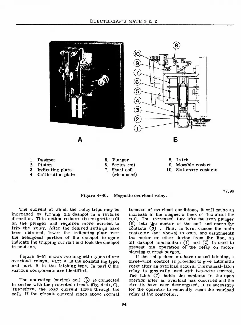
ELECTRICIAN’S MATE 3 & 2
Qi
10
€
4
1 OL LuEL
TH PLUMOCR ASSEMBLY REMOVED
B
1. Dashpot 2. Piston 3. Indicating plate 4. Calibration plate
5. Plunger 6. Series coil 7. Shunt coil
(when used)
8. Latch 9. Movable contact
10. Stationary contacts
Figure 4-40. — Magnetic overload relay 77.99
The current at which the relay trips may be increased by turning the dashpot in a reverse direction. This action reduces the magnetic pull on the plunger and requires more current to trip the relay. After the desired settings have been obtained, lower the indicating plate over the hexagonal portion of the dashpot to again indicate the tripping current and lock the dashpot in position.
Figure 4-41 shows two magnetic types of a-c overload relays. Part A is the nonlatching type, and part Li is the latching type. In part C the various components are identified.
The operating (series) coil (§) is connected in series with the protected circuit (fig. 4-41, C). Therefore, the load current flows through the coil. If the circuit current rises above normal
because of overload conditions, it will cause an increase in the magnetic lines of flux about the coil. The increased flux lifts the iron plunger (5) into the center of the coil and opens the contacts (9) . This, in turn, causes the main contactor (not shown) to open, and disconnects the motor or other device from the line. An oil dashpot mechanism (Î) and (2) is used to prevent the operation of the relay on motor starting current surges.
If the relay does not have manual latching, a three-wire control is provided to give automatic reset after an overload occurs. The manual-latch relay is generally used with two-wire control. The latch (?) holds the contacts in the open position after an overload has occurred and the circuits have been deenergized. It is necessary for the operator to manually reset the overload relay at the controller.
94

Chapter 4—ELECTRICAL INSTALLATIONS
tlfllíP*
rkt
»
2ü
> 2
ft.
IÜ 'IF \fe
«■y»
II LÜ
A-NONLATCHIN6 B-LATCHING
OIL LEVEL WITH PLUNGER ASSEMBLY REMOVED
C- DIAGRAM
1. Dashpot 2. Piston 3. Indicating plate 4. Calibration
plate
5. Plunger 6. Series coil 7. Latch (when used) 8. Insulating splitter 9. Contacts
The essential operating parts of a d-c thermal overload relay (fig. 4-42) are the two heater coils (4) , two solder tube assemblies (5), and control contacts (T) . Under normal conditions the splitter arm (?) (so called because it splits the overload contacts) completes a circuit with the contacts. The spring is then under compression and the operating arm (s) tends to rotate the splitter arm out of the circuit. This action is prevented by the ratchet assembly, which is held by the solder film between the outer and inner part of the solder tubes.
When current flows through the heater coils and produces enough heat to melt the solder film, the inner part of the solder tube assembly rotates and releases the ratchet mechanism to open the control circuits. When this happens, the circuit to the coil handling the power contacts (not shown in the figure) opens and disconnects the load. As soon as the load is disconnected, the heaters cool, and the solder film hardens. When the hardening is complete, the relay is ready to be reset with the reset button.
An adjustable type thermal relay with magnetic reset is illustrated in figure 4-43. This relay may be adjusted to trip at a value between 90 and llO percent of the rated coil current. To change the operating point, loosen the binding screws that hold the relay heater coil ® (fig. 4-42) so that the coil position may be changed. Moving the coil away from the relay will inci’ease the amount of current needed to trip the relay. Moving the coil closer to the relay will decrease the current needed to trip the relay. This range of adjustment is available only within the range of 90 to 110 percent of coil rating. Each rating has a different manufacture part number. The correct rating is installed when the controller is installed in the ship. Do not use another rating. Make sure both heater coils in each overload relay are the same rating.
77.100 Figure 4-41. — A-c overload relays.
THERMAL OVERLOAD RELAY
Thermal type overload relays (a-c and d-c) are designed to open a circuit when excessive current causes the heater coils to reach the temperature at which the ratchet mechanism releases. The heater coils are rated so that normal circuit current will not produce enough heat to release the ratchet mechanism.
The terminal plates and the underside of the slotted brackets of the heater coil assembly are serrated so that the coil is securely held in position when the binding screws are tightened. Some thermal overload relays have reset magnet assemblies attached. It may become necessary to replace the heater coils from the relay. Then remove the four screws that hold the overload relay to the mounting plate. When removing the relay from the mounting plate, use care not to lose the phenolic pin and bearing block located between the thermal blocks on the underside of the relay.
95

ELECTRICIAN’S MATE 3 & 2
-J t L/5
© © £
1. Contact structure
2. Screw 3. Operating arm
4. Heater coil 5. Solder tube 6. Screw 7. Splitter arm
77.101 Figure 4-42.— Thermal overload relay.
Next, remove the four large countersunk screws that hold the mounting plate and the reset magnet assembly to the square posts. Remove the four screws in the mounting plate, which support the reset magnet. Take care not tolose the lever and spring, items (9) and (lO) . Remove the two screws (fí) and pull
ouT the plunger guides. Remove tKe old coil (O) and install the new coil. Then insert the
plunger guides and replace the screws (l2) . Reassemble the magnet, spring, and lever to the mounting plate. Mount the plate on the posts and then mount the overload relay on the mounting plate. Replace the heater coils as the last operation.
Overload relays are PROTECTIVE DEVICES. After an overload relay has performed its safe- guarding function it must be reset by the EM before the system can again be run with overload protection.
CIRCUIT BREAKERS
Circuit breakers have three fundamental pur- poses: First, they are used to provide circuit protection and to perform normal switching operations. Second, they are used to isolate a defective circuit while repairs are being
made. Third, circuit breakers are used inmanual and automatic bus transfer, also as starters for large motors.
Air circuit breakers are used in switchboards, switch gear groups, and in distribution panels. The types installed on naval ships are ACB, AQB, AQB-A, AQB-LF, NQB-A, ALB and NLB. They are called air circuit breakers because the main current carrying contacts interrupt in air.
Circuit breakers are available in manually or electrically operated types. Some types may be operated both ways, while others are restricted to one mode. Manually or electrically operated types may or may not provide protective functions; the following sections describe the differences and uses of the various types of circuit breakers.
ACB
The ACB type of circuit breaker may be for either manual local closing or electrical remote closing. It has an open metallic frame con- struction mounted on a drawout mechansim and is normally applied where heavy loads and high short circuit currents are available.
Figure 4-44 shows the external appearance of a type ACB circuit breaker.
Type ACB circuit breakers are used to connect ship’s service and emergency generators to the power distribution system. They are also used on bus ties and shore connection circuits, and on some feeder circuits from the ship’s service switchboard.
When used in these applications the pilot device may be a reverse-power relay or any of the control devices discussed later in this chapter. The reverse-power relay is mounted on the panel close to the circuit breaker. Other automatic controls may be located at remote points to give maximum protection to the circuit.
Circuit breakers designed for high currents have a double-contact arrangement. The complete contact assembly consists of the main bridging contacts and the arcing contacts. All current carrying contacts are high-conductivity, arc- resisting silver or silver alloy inserts.
Each contact assembly has a means of holding the arcing to a minimum and extinguishing the arc as soon as possible. The arc control section is called an arc chute or arc runner. The contacts are so arranged that when the circuit is closed, the arcing contacts close first. Proper pressure is maintained by springs to ensure the arc contacts close first. The main contacts then close.
When the circuit opens, the main contacts open first. The current is then flowing through
96

Cahpter 4—ELECTRICAL INSTALLATIONS
RESET MAGNET ASSEMBLY
10
©
DETAILS OF RESET MAGNET
9. LEVER II. COIL 10. SPRING 12. SCREWS
Figure 4-43. — Adjustable thermal relay with magnetic reset, 77.102
the arc contacts, which prevents burning of the main contacts. When the arc contacts open, they pass under the front of the arc runner. This causes a magnetic field to be set up, which blows the arc up into the arc quencher and quickly opens the circuit.
Type ACB circuit breakers are available in both manually (hand-operated) and electrically operated types. Electrically operated ACB breakers may be operated from a remote location. The high interrupting types are electrically oper- ated because it is then unnecessary for personnel
to approach them in order to open or close the circuit.
No circuit breaker, regardless of type, should be worked on without opening the circuit. Remem- ber that certain terminals may have voltage applied to them even though the breaker is open. Aboard ship, power may be supplied to either end of the circuit breaker.
AQB
Type AQB circuit breakers (fig. 4-45) are mounted in supporting and enclosing housings
97

ELECTRICIAN’S MATE 3 & 2
FLEXIBLE CONNECTION »— ARC QUENCHERS—»
1 &
%
OVERCURRENT TRIPJ
27.73 Figure 4-44. — Type ACB circuit breaker.
of insulating material and have direct-acting automatic tripping devices. They are used to protect single-load circuits and all feeder circuits coming from a load center distribution panel.
Where the requirements are low enough, the type AQB may be used on generator switchboards. When it becomes necessary to replace one of the older type circuit breakers, it should be replaced by the newer AQB-AlOl, AQB-A250, AQB-A400, AQ3-A600, or AQB-A800 as required.
AQB-A250
The newer AQB type circuit breakers such as the AQB-A250 have several advantages over the older types. The outside dimensions of these new breakers are the same for both the two-pole and three-pole circuit breakers. They are de- signed for front or rear connections as required and may be mounted so as to be removable from the front without removing the circuit breaker cover. The voltage ratings of the AQB-A250 are 500-volts a-c, 60-hertz or 250-volts d-c.
The 250-part of the circuit breaker type designation indicates the frame size of the circuit breaker. In a 250-ampere frame size circuit breaker, the current carrying parts of the breaker
have a continuous rating of 250 amperes. Trip units (fig. 4-46) for this breaker are available with current ratings of 125, 150, 175, and 250 amperes.
The trip unit houses the electrical tripping mechanisms, the thermal element for tripping the circuit breaker on overload conditions, and the instantaneous trip for tripping on short circuit conditions.
In addition 100, 160, and 250 ampere rating trip units with a special calibration are available for use with generator circuit breakers. Regard- less of the trip unit used the breaker is still a 250-ampere frame size. The automatic trip devices of the AQB-A250 circuit breaker are “trip free” of the operating handle; in other words the circuit breaker cannot be held closed by the operating handle if an overload exists. When the circuit breaker has tripped due to overload or short circuit, the handle rests in
\®J®r mi û
[0Ñ]
1. OPERATING HANDLE SHOWN 4. COVER SCREWS IN LATCHED POSITION
2. AMPERE RATING MARKER
3. MOUNTING SCREWS
9. BREAKER NAMEPLATE
6. COTTER KEY HOLE
77.241 Figure 4-45. — AQB-A250 circuit breaker
complete, front view.
98

Chapter 4—ELECTRICAL INSTALLATIONS
©
ri SQJQIJ-
TJ.
"1/ ARC
7 3 11673 I! 7 3 II SUPPRESSOR
(I ) STATIONARY CONTACT
(2) ARC SUPPRESSORS
(3) TERMINAL STUD NUTS AND WASHERS (4) TRIP UNIT LINE TERHÍINAL SCREW-OUTER POLES
(5) TRIP UNIT LINE TERMINAL SCREW-CENTER POLE (6) TRIP UNIT NAMEPLATE
(7) TERMINAL BARRIERS
(8) SHUNT TRIP OR UNDERVOLTAGE DEVICE
(9) AUXILIARY SWITCH (ID.) HOLE FOR SHUNT TRIP OR UNDERVOLTACE
RELEASE PLUNGER
(11) INSTANTANEOUS TRIP ADJUSTING WHEELS (12) COTTER KEY HOLE
77.242 Figure 4-46. — AQB-A250 circuit breaker front view, cover and arc suppressor removed.
a center position. To vedóse after automatic tripping, move the handle to the extreme OFF position which resets the latch in the trip unit, then move the handle to the ON position.
The AQB-A250 circuit breaker may have aux- iliary switches, shunt trip (for remote tripping), or undervoltage release attachments when so specified. However, a shunt trip cannot be pro- vided in the same breaker with an under-voltage release since in all cases the shunt trip coil is momentary rated and must be connected in series with a circuit breaker auxiliary switch. Figure 4-47 shows a trip unit with shunt trip and a trip
D nSR
S
(1) TRIP UNIT LATCH PIN
(2) AUXILIARY SWITCH
(3) AUXILIARY SWITCH MOUNTING SCREWS
(4) AUXILIARY SWITCH LEVER
(9) AUXILIARY SWITCH MOUNTING BRACKET
(6) SHUNT TRIP
17) SHUNT TRIP TUBULAR CORE
(8) SHUNT TRIP MOUNTING SCREWS
I») TUBULAR CORE LOCK NUT
(KS HOLE FOR SHUNT TRIP PUSH PIN
(II) SHUNT TRIP PLUNGER
A
I 45Ö1
bOCV
Q
y m r
n o o (1) UNDERVOLTAGE RELEASE
(2) AUXILIARY SWITCH
(3) AUXILIARY SWITCH MOUNTING SCREWS
(4) AUXILIARY SWITCH LEVER
(3) AUXILIARY SWITCH MOUNTING BRACKET
(6) UNDERVOLTACE RELEASE MOUNTING SCREWS
(7) UNDERVOLTACE RELEASE MAGNET
(8) ARMATURE TRAVEL ADJUSTING SCREW
( 9 ) SET SCREW FOR ARMATURE TRAVEL ADJUSTING SCREW
(10) ARMATURE -MAGNET AIR GAP
(11) UNDERVOLTAGE RELEASE PUSH ROD
OS LOCK NUT FOR PUSH ROD
(IS) UNDERVOLTAGE RELEASE ARMATURE
(14) ARMATURE RETAINING SPRINGS
B
77.243.244 Figure 4-47. — AQB-A250 trip unit: (a) with shunt
trip and auxiliary unit; (b) with undervoltage release and auxiliary switch.
99

ELECTRiCtAN’S MATE 3 & 2
ATTACHMENT WIRING 18" LONG
DRILL OUT FOR LEADS
Ká'.V.s.i»
(1) TERMINAL MOUNTING BLOCKS (2 REQUIRED)
(2) SLIP TYPE CONNECTORS
(3) TERMINAL STUDS
(4) TERMINAL MOUNTING BLOCK INSERTS FOR BREAKER MOUNTING BOLTS
(5) TERMINAL STUD NUTS
77.245 Figure 4-48. —AQB-A250 circuit breaker rear view, with terminal mounting blocks.
unit with undervoltage trip. The coil for a shunt trip has a dual rating for a-c and d-c voltages, whereas the undervoltage trip coils are wound for a specified voltage, such as 450 a-c or 250 d-c and have rated pickup and dropout values. The instantaneous trip setting of the AQB-A250 trip units may be adjusted by the instantaneous trip adjusting wheels shown in figure 4-47. Though not shown in the figure these trip ad- justing wheels are marked for five positions, LO-2-3-4-HI, the trip unit label (not shown) will list the instantaneous trip value obtainable for each marked position. Identical settings must be made on each pole of the circuit breaker. NEVER remove a circuit breaker cover to perform adjustments while the circuit breaker is in the closed (ON) position.
Terminal mounting block assemblies used in conjunction with the circuit breaker (fig. 4-48) for drawout mounting, consist of terminal studs in terminal mounting blocks of insulating material. The terminals of the circuit breaker have slip type connectors which engage the terminal studs as shown in figure 4-48. Two mounting blocks are usually required for each circuit breaker.
This method of connecting a circuit breaker to a bus or circuit is known as a “back-connected circuit breaker.” Circuit breakers which have solderless connectors attached to their terminal are commonly called “front-connected circuit breakers.” The interrupting rating of the AQB- A250 circuit breaker is 20,000 amperes at 500- volts a-c or 15,000 amperes at 250-volts d-c.
AQB-LF250
The AQB-LF250 circuit breaker (fig. 4-49), combines the standard AQB circuit breaker and a current limiting fuse unit which interrupts the circuit when the current is in excess of the interrupting rating of the breaker. Constructed as one compact unit, the AQB-LF circuit breaker incorporates the current limiting fuses (fig. 4-50) as integral parts of the circuit breaker. The common trip features of the AQB-A250 circuit breaker are retained and trip units from 125 to 250 amoeres and available for use in the AQB-LF25Ó.
100

Chapter 4—ELECTRICAL INSTALLATIONS
‘HW'-T
IlfK.WM
Âiîsi»?.-:ïTis^:
( 1 ) OPERATING HANDLE SHOWN IN LATCHED POSITION
(2) AMPERE RATING MARKER (3) BREAKER MOUNTING SCREWS (4) COVER SCREWS (5) BREAKER NAMEPLATE
(6) FUSE UNIT ASSEMBLY (7) FUSE UNIT MOUNTING
SCREWS (8) FUSE UNIT NAMEPLATE (9) BREAKER COVER (10) COTTER KEY HOLE
77.246 Figure 4-49. — AQB-LF250 complete circuit'
breaker, front view.
The current limiting fuse unit is designed so that it trips the breaker and opens all poles if any current limiting fuse (fig. 4-51) is blown. After a fuse has blown, the circuit breaker cannot be reclosed until the blown fuse is re- placed. Any attempt to remove the fuse unit when the circuit breaker is in the closed position will automatically trip the breaker.
The AQB-LF250 circuit breaker is inter- changeable with the AQB-A250 circuit breaker except a larger cutout is required in the switch- board front panel to accommodate the fuse unit of the AQB-LF250.
has an interrupting rating of 100,000 amperes at 500-volts a-c whereas the AQB-A250 circuit breakers interrupting rating is 20,000 amperes at 500-volts a-c.
While the AQB-A250 circuit breaker could be either front or back connected, the AQB-LF250 is designed only for back (drawout type) con- nection, using the same type of slip connectors terminal studs as shown in figure 4-48.
NQB-A250
The NQB-A250 circuit breaker (fig. 4-52) is similar to the AQB-A250 circuit breaker except the NQB-A250 has no automatic tripping devices. This type of circuit breaker is used for circuit isolation and manual transfer applications. This NQB-A250 is still a 250-ampere frame size as the current carrying parts of the breaker are capable of carrying 250 amperes. Technically this circuit breaker is simply a large on-and- off switch. Some type of AQB and NQB breakers are provided with electrical operators mounted on the front of the breaker. These are geared motor devices for remote operation of the breaker handle.
ALB
Type ALB circuit breakers are designated low-voltage, automatic circuit breakers. The continuous duty rating ranges from 5 through 200 amperes at 120-volts a-c or d-c. The breaker is provided with a molded enclosure, drawout type connectors, and nonremoveable and nonadjustable thermal trip elements.
This circuit breaker is a quick-made, quick- break type. If the operating handle is in the tripped (midway between ON and OFF) position, indicating a short circuit or overload, the operat- ing handle must be moved to the extreme off position, which automatically resets the overload unit and the breaker can again be closed.
NLB
Circuit breakers type NLB are identical to ALB types except that they have no automatic tripping device and are used only as on-off switches.
Selective Tripping
The AQB-LF250 circuit breaker is a 250 ampere frame size, however, the circuit breaker
101
The purpose of selective tripping is to isolate the faulty section of the system and at the

ELECTRICIAN’S MATE 3 & 2
0 MUIPG
HI CIlUilT BlnVB
<0
(1) BREAKER OPERATING HANDLE SHOWN IN
TRIPPED POSITION
(2) AMPERE RATING MARKER
^ (3) BREAKER MOUNTING SCREWS
(4) COVER SCREWS
(5) CURRENT LIMITING FUSES
(6) FUSE UNIT ASSEMBLY
(7) FUSE UNIT INTERLOCK PIN
(8) TRIP LEVER
(9) FUSE SLIP-ON CONNECTORS
(10) FUSE RETAINING BLOÇK SCREWS
(11) INSTANTANEOUS TRIP ADJUSTING WHEELS
Q
Figure 4-50. —Complete circuit breaker, front view with fuse unit removed. 77 .247
©
o /
(1) FUSE RETAINING BLOCK
(2,3 4 4) CURRENT LIMITING FUSES
(5) EXTENDED PLUNGER OF BLOWN FUSE
(6) RETRACTED PLUNGER OF UNBLOWN FUSE
(7) FUSE PLUNGER LEVER
(8) FUSE UNIT TRIPPER BAR
(9) FUSE UNIT TRIPPER BAR LEVER
(10) FUSE INTERLOCK PIN
(11) FUSE UNIT HOUSING
Figure 4-51. — Current limiting fuse unit assembly 77,248
102

Chapter 4—ELECTRICAL INSTALLATIONS
6
2
4 I
CD cm
(1) CONNECTOR STRAPS (5) LATCH MOUNTING SCREWS
(2) LATCH POST (6) TRIP UNIT LATCH PIN SLOT
(3) TERMINAL STUD NUTS S WASHERS 171 MECHANISM TRIGGER
(4) TRIP UNIT LINE TERMINAL (8) MECHANISM TRIGGER LATCH
SCREWS - OUTER POLES (SI COTTER KEY HOLE
77.249 Figure 4-52. — NQB-A250 circuit breaker front
view, cover removed.
same time to maintain power on as much of the system as possible. Selective tripping of circuit breakers is obtained by coordination of the time-current characteristic of the protective devices so that the breaker closest to the fault will open first, and the breaker farthest from the fault and closest to the generator will open last.
A portion of a distribution system with circuit breakers employing selective tripping is illustrated in figure 4-53. The so-called instantaneous tripping time is the minimum time required for a breaker to open and clear a circuit when the operation of the breaker is not intentionally delayed. Each circuit breaker will trip in less than 0.1 second (almost instantaneously) when the current exceeds the instantaneous trip current setting of the breaker. In a shipboard selective tripping power system the individual circuit breakers (generator, bus
tie, shore power or feeder breakers) differ from each other depending on:
1. The available load current.
2. The available short circuit current.
3. The tripping time band and trip current settings selected.
Selective tripping of breakers is normally obtained by a short time delay feature. This feature is a mechanical time delay and can be varied with linvtations. The generator circuit breaker, which is closest to the power source, has the maximum continuous current carrying rating, the highest available short circuit current rating and the maximum short time delay trip in order that the generator breaker may be the last breaker to trip. However, it will trip on the generator short circuit current at some definite interval of time within the tolerance of the breaker.
Bus tie circuit breakers are usually set to trip after a prescribed time delay (which is less than the generator circuit breaker time delay), at a current that is nearest to, but not less than 150% of the bus tie breaker coil rating (for multigenerator switchgear groups) or the nearest to but not more than 80% of the generator breaker short-time delay setting (for single generator switchgear groups). Instanta- neous tripping is not normally used on bus tie circuit breakers.
The construction of circuit breakers for selective tripping, for currents less than the instantaneous trip current setting, is such as to cause an intentional delay in the operation of the breaker. The time delay is greater for small currents than for large currents and is therefore known as an inverse time delay. The current that would trip the AQB load circuit breaker instantaneously and clear the circuit will not trip the ACB feeder circuit breaker unless the current flows for a greater length of time. The same sequence of operation occurs for the other groups of circuit breakers adjusted for selective tripping in the system.. The dif- ference between the tripping times of the breakers is sufficient to permit each breaker to trip and clear the circuit before the next breaker starts to operate.
Assume that a fault or defect develops in the cable insulation at point A (fig. 4-53) and
103

ELECTR.ÍCÍAN’S MATE 3 & 2
IS G GENERATOR
2 SG GENERATOR!
1 S SWITCHBOARD
4 TYPE ACB
FEEDER BREAKER
-x-
^ f
TYPE ACB GENERATOR BREAKERS
-TYPE ACB BUS TIE- BREAKERS
2 S f SWITCHBOARD
DISTRIBUTION PANEL
TYPE AQB LOAD
BREAKER
TO LOAD
77.98 Figure 4-53. — Selective tripping of circuit breakers.
allows an overcurrent to flow through the AQB load circuit breaker and the ACB feeder circuit breaker. The AQB load breaker will open the circuit and interrupt the current in an interval of time that is less than the time required to open the ACB feeder circuit breaker. Thus, the ACB feeder breaker will remain closed when the AQB breaker clears the circuit. How- ever, if the fault current should exceed the interrupting capacity of the AQB load breaker (for example, an excess of 10,000 amperes), this breaker would be unable to interrupt the fault current without damage to the breaker. To prevent damage to the AQB load breaker, the ACB feeder breaker (on switchboard IS) serves as a BACK UP breaker for the AQ3 load breaker and will open almost instanta- neously in time.
A fault at point B with overcurrent would trip the ACB feeder breaker in time but not the ACB generator or bus tie breakers, which require longer time intervals in which to trip. A fault at point C with overcurrent would trip both ACB bus tie breakers. A fault at D with
overcurrent on switchboard IS would trip the associated ACB generator breaker and one or both of the ACB bus tie breakers. In each case, the faulty section of the system is isolated, but power is maintained on as much of the system as possible with respect to the location of the fault.
The attainment of selective tripping requires careful coordination of time-current charac- teristics for the different groups of circuit breakers. For example, if the system illustrated in figure 4-53 is operating split plant (bus ties open) and if the time-current characteristics of the ACB feeder breaker and the ACB gen- erator breaker were interchanged, a fault at B with overcurrent would trip generator 1SG off the line but would leave the feeder connected to the switchboard. This action would disconnect power to all equipment supplied by switchboard IS and also would not isolate the faulty section. Therefore, no unauthorized changes should be made to circuit breaker trip settings because these changes may completely disrupt the scheme of protection based on selective tripping.
104

Chapter 4—ELECTRICAL INSTALLATIONS
It is not feasible to provide system protection by selective tripping of circuit breakers in all types of naval ships or for all circuits. For example, d-c distribution systems in older ships and all lighting circuits use fuses to a great extent. Time delay can be incorporated only to the extdnt that is permitted by the charac- teristics of the fuses. The use of progressively large fuse sizes from the load to the generator provide some degree of selectivity for overload or limited fault protection.
Maintenance
Metal locking devices are available that can be attached to the handles of AQB type circuit breakers to prevent accidental operation. All breaker handles are now provided with a 3/32- inch hole permitting fastening the locking device with a standard cotter pin. NavShips Technical Manual, Chapter 9600, lists the stock numbers for three different sizes of breaker handle locking devices.
Circuit breakers require careful inspection and cleaning at least once a year (more fre- quently if subjected to unusually severe service conditions). The special inspections follow.
No work should be undertaken on circuit breakers without first obtaining approval of the electrical or engineer officer, and only after a thorough review of the applicable technical manual, plus Chapter 9600 of NavShips Technical Manual.
Before working on a circuit breaker be aware of its time delay characteristics, whether short time, long time, or instantaneous trip are pro- vided. Tne adjustments for selective tripping of most circuit breakers are made and sealed at the factory. Changes should not normally be made to their trip settings as these changes may completely disrupt their intended functions of protection. Improper tripping action is cor- rected best by replacement of the entire breaker assembly, especially where trouble is encountered in the compact assemblies.
A special inspection should be carefully made of each pair of contacts after a circuit breaker has opened on a heavy short circuit. Before working on a circuit breaker, deenergize all control circuits to which it is connected; the procedure differs somewhat with the type of mounting which is employed. For example, before work is performed on drawout circuit breakers,
they should be switched to the open position and removed. Before working on fixed-mounted circuit breakers, open the disconnecting switches ahead of the breakers. If disconnecting switches are not provided for isolating fixed-mounted circuit breakers, deenergize the supply bus to the circuit breaker, if practicable, before in- specting, adjusting, replacing parts, or doing any work on the circuit breaker.
Contacts are the small metal parts especi- ally selected to resist deterioration and wear from the inherent arcing. The arcing occurs in a circuit breaker while its contacts are opening and carrying current at the same time. When firmly closed, the contacts must not arc.
Contact materials have been subjected to constant research, resulting in various products, ranging from pure carbon or copper, to pure silver, each being used alone and also as alloys with other substances. Modern circuit breakers have contacts coated with silver, or silver mixed with cadmium oxide, or silver and tungsten. The two latter silver alloys are extremely hard and resist being filed. Fortunately, such contacts made of silver or its alloys conduct current when discolored (blackened during arcing) with silver oxide. The blackened condition, therefore, re- quires no filing, polishing, or removal. As with a silver contact, silver oxide is formed during arcing and it has been found that the addition of cadmium oxide greatly improves operation of the contact because it nrninTzes the tendency of one contact to weld to another, retards heavy transfer of one material to another, and inhibits erosion.
Usually, a contactcontainingsilver is service- able as long as the total thickness worn away is on the order of 0.015 to 0.030 inch.
Severe pitting or burning of a silver contact is another matter. It may require some filing (with a fine file or with fine sandpaper. No. 00) to remove raised places on surfaces that prevent intimate and overall closure of the contact surfaces. If necessary, use a CLEAN cloth moistened with INHIBITED methyl chloroform.. Be very certain to provide ample ventilation to remove all DEADLY and TOXIC fumes of the solvent.
When cleaning and dressing copper contacts, maintain the original shape of each contact surface and remove as little copper metal as possible. Inspect and wipe the copper contact surfaces for removal of the black copper-oxide film and, in extreme cases, dress and clean
105

ELECTRICIAN’S MATE 3 & 2
only with fine (No. 00) sandpaper to prevent scratching the surfaces. NEVER use emery cloth or emery paper. Because this copper- oxide film is a partial insulator, follow the sanding procedure toy wiping with a clean cloth moistened with inhibited methyl chloroform sol- vent. Provide VERY LIBERAL ventilation by means of exhaust fans or with portable blowers to entirely remove all traces of the deadly fumes of the solvent.
Calibration problems on circuit breakers should be handled in accordance with chapter 9600 of NavShips Technical Manual.
The function of arcing contacts is not neces- sarily impaired by surface roughness. Remove excessively rough spots with a fine file. Re- place arcing contacts when they have been burned severely and cannot be properly adjusted. Make a contact impression and check the spring pres- sure in accordance with the manufacturers’ instructions. If information on the correct con- tact pressure is not available, the contact pres- sure should be checked with that of similar contacts. When the force is less than the designed value, the contacts either require replacing because they are worn down, or the contact springs should be replaced. Always replace contacts in sets; not singly, and replace contact screws at the same time. Do not use emery paper or emery cloth to clean contacts, and do not clean contacts when the equipment is ener- gized.
Clean all surfaces of the circuit breaker mechanism, particularly the insulation surfaces, with a dry cloth or air hose. Before directing the air on the breaker, be certain that the water is blown out of the hose, that the air is dry, and that the pressure is not over 30 psi. Check the pins, bearings, latches, and all contact and mechanism springs for excessive wear or cor- rosion and evidence of overheating. Replace parts if necessary.
Slowly open and close circuit breakers man- ually a few times to be certain that trip shafts, toggle linkages, latches, and all other mechanical parts operate freely and without binding. Be certain that the arcing contacts make-before and break-after the main contacts. If poor alignment, sluggishness, or other abnormal con- ditions are noted, adjust in accordance with the manufacturer’s instructions for the par- ticular circuit breaker.
Oil-piston type overcurrent tripping devices (grade B timers) are sealed mechanisms and
normally do not require any attention. When oil-film (dashpot) overcurrent tripping devices are used, the oil should be removed and the interior of the oil chambers should be cleaned with kerosene and refilled with new oil every six months. Be certain that the dashpot is free of dirt, which destroys the time-delay effect, and that the tripping device is clean, operates freely, and has sufficient travel to trip the breaker. Do not change the air-gap setting of the moving armature because this would alter the calibration of the tripping device. Lubricate the bearing points and bearing surfaces (in- cluding latches) with a drop or two of light machine oil. Wipe off any excess oil.
Before returning a circuit breaker to service, inspect all mechanical and electrical connections, including mounting bolts and screws, drawout disconnect devices, and control wiring. Tighten where necessary. Give the breaker a final clean- ing with a cloth or compressed air. Operate manually to be certain that all moving, parts function freely. Check the insulation resistance.
The sealing surfaces of circuit-breaker con- tactor and relay magnets should be kept clean and free from rust. Rust on the sealing surface decreases the contact force and may result in overheating of the contact tips. Loud humming or chattering will frequently warn of this condi- tion. A light machine oil wiped sparingly on the sealing surfaces of the contactor magnet will aid in preventing rust.
Oil should always be used sparingly on circuit breakers, contactors, motor controllers, relays, and other control equipment, and should not be used at all unless called for in the manu- facturer’s instructions or unless oil holes are provided. If working surfaces or bearings show signs of rust, disassemble the device and carefully clean the rusted surfaces. Light oil can be wiped on sparingly to prevent further rusting. Oil has a tendency to accumulate dust and grit, which may cause unsatisfactory operation of the device, particularly if the device is delicately balanced.
Arc chutes or boxes should be cleaned by1
scraping with a file if wiping with a cloth is not sufficient. Replace or provide new linings when they are broken or burned too deeply. Be certain that arc chutes are securely fastened and that there is sufficient clearance to ensure that no interfer- ence occurs when the switch or contact is opened or closed.
Shunts and flexible connectors, which are flexed by the motion of moving parts, should be replaced when worn, broken, or frayed.
106

Chapter 4—ELECTRICAL INSTALLATIONS
Operating tests that consist of operating the circuit breakers in the manner in which they are intended to function in service should be conducted regularly. For manually operated cir- cuit breakers, simply open and close the breaker to check the mechanical operation. To check both the mechanical operation and the control wiring, electrically operated circuit breakers should be tested by means of the operating switch or control. Exercise care not to disrupt any electric power supply that is vital to the operation of the ship, or to endanger personnel by inadvertently starting motors and energizing equipment under repair«
REVERSE-POWER RELAY
On all ships with a-c ship service power systems where the generators are operated in parallel, each generator control unit has a reverse power relay. (Motor generators are an exception.) The relay should trip the generator circuit breaker in approximately 10 seconds with reverse power equal to 5 percent of the generator rating.
Reverse power relays trip the generator cir- cuit breaker to prevent motoring the generator. This protection is provided primarily for the prime movdr or system, rather than for the generator. Motoring results from a deficiency in the prime mover input to the a-c generator. This deficiency can be caused by loss of or low steam to the turbine, lack of fuel to the diesel engine or gas turbine, or other factors which affect the operation of the prime mover. In the absence of reverse power protection, when the input to the generator falls below that needed to maintain synchronous generator speed, real power is taken from the ship service power system, and the generator acts as a motor driving the prime mover. Reverse power pro- tection prevents damage to the prime mover in case a reverse power condition should occur.
The reverse-power relay consists of two induction disc type elements. The upper element is the timer, and the lower one is the direction element. Figure 4-54 shows the coil and induction disc arrangement in the induction type relay timer element. The disc is four inches in diameter and is mounted on a vertical shaft. The shaft is mounted on bearings for minimum friction.
An arm Is clamped to an insulated shaft, which is geared to the disc shaft. The moving contact, a small silver hemisphere, is fastened
0^ RELAY CONTACTS
ELECTROMAGNET
DISC ROTATION
ORAGMAGNET
UPPER POLE FLUX
M m ORAGMAGNET
MAIN POLE FLUX SECONDARY
CURRENT
MAIN POLE CURRENT
TO SOURCE
FRONT VIEW
77,105 Figure 4-54. — Coil find disc arrangement, a-c
reverse power relay.
on the end of the arm. The electrical connection to the contact is made through the arm and a spiral spring. One end of the spring is fastened to the arm and the other end to a slotted spring adjusted disc fastened to a molded block mounted on the element frame. The stationary contact is attached to the free end of a leaf spring. The spring is fastened to the molded block, and a setscrew makes it possible to adjust the stationary contact position.
The main relay contacts (not shown in the figure) will safely handle 30 amperes at 250-volts d-c and will carry the current long enough to trip a breaker.
The induction disc is rotated, by an electro- magnet in the rear of the assembly. Movement of the disc is damped by a permanent magnet in front of the assembly.
The operating torque of the timer element is obtained from the electromagnets (fig. 4-54). The main-pole coil is energized by the line voltage. This coil then acts as the primary of a transformer and induces a voltage in the secondary coil. Current then flows through the upper pole coils and thus produces a torque
107
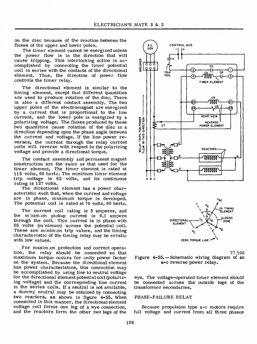
ELECTRICIAN’S MATE 3 & 2
on the disc because of the reaction between the fluxes of the upper and lower poles.
The timer element cannot be energized unless the power flow is in the direction that will cause tripping. This interlocking action is ac- complished by connecting the timer potential coil in series with the contacts of the directional element. Thus, the direction of power flow controls the timer relay.
The directional element is similar to the timing element, except that different quantities are used to produce rotation of the disc. There is also a different contact assembly. The two upper poles of the electromagnet are energized by a current that is proportional to the line current, and the lower pole is energized by a polarizing voltage. The fluxes produced by these two quantities cause rotation of the disc in a direction depending upon the phase angle between the current and voltage. If the line power re- verses, the current through the relay current coils will reverse with respect to the polarizing voltage and provide a directional torque.
The contact assembly and permanent magnet construction are the same as that used for the timer element. The timer element is rated at 115 volts, 60 hertz. The minimum timer element trip voltage is 65 volts, and its continuous rating is 127 volts.
The directional element has a power char- acteristic such that, when the current and voltage are in phase, maximum torque is developed. The potential coil is rated at 70 volts, 60 hertz.
The current coil rating is 5 amperes, and the minimum pickup current is 0.1 ampere through the coil. This current is in phase with 65 volts (nvnimum) across the potential coil. These are minimum trip values, and the timing characteristic of the timing relay may be erratic with low values.
For maximum protection and correct opera- tion, the relay should be connected so that maximum torque occurs for unity power factor on the system. Because the directional element has power characteristics, this connection may be accomplished by using line to neutral voltage for the directional element potential coil (polariz- ing voltage) and the corresponding line current in the series coils. If a neutral is not available, a dummy neutral may be obtained by connecting two reactors, as shown in figure 4-55. When connected in this manner, the directional element voltage coil forms one leg of a wye connection, and the reactors form the other two legs of the
CONTROL BUS
+
A.C. GEN
_L
O O Q © TRIP cv : CR
®—'IWVHI—® COIL
N TIMER ELEMENT
CR
@— CR
REAR VIEW « z REVERSE '
POWER ELEMENT o r. £ o Ç <r o — u. o «/> </> ü r
REACTORS
ABC
DIRECTIONAL
ELEMENT
r i A/ \
\
\ 1 AJW TIMING 7 ELEMENT
\ CLOSING ZONE
ZERO TORQUE LINE
77.106 Figure 4-55. —Schematic wiring diagram of an
a-c reverse power relay.
wye. The voltage-operated timer element should be connected across the outside legs of the transformer secondaries.
PHASE-FAILURE RELAY
Because propulsion type a-c motors require full voltage and current from all three phases
108

Chapter 4—ELECTRICA.L INSTALLATIONS
COILS
Ä REACTOR
RECTOX
RESISTOR
STATIONARY CONTACT(2)
SHUNT SPR INC
STATIONARY CONTACT
MOVING CONTACT
B
77.107 Figure 4-56. — Phase-failure relay.
supplied toy the generator, phase-failure pro- tection is a requirement where this type of shipboard propulsion is used.
This type of relay is used to detect short circuits on alternating current propulsion systems for ships. Ordinary instantaneous trip relays cannot be used because, under certain conditions, for example, when the motor is plugged (direction of a rotation reversed on full voltage) during a crash stop, the momentary current may be as great as the short circuit current.
The relay in use operates when there is a current unbalance. It is connected in the control circuit so that it will shut down the system
-fault. However, operation of the relay is not limited to short-circuit detection, and the relay may be used as a phase-failure relay. A phase- failure relay is shown in figure 4-56. Part A is the arrangement of the parts in the complete assembly, and part B is a closeup of the contact assembly. The entire unit is enclosed in a cover to prevent dirt and dust from interfering with its operation.
The moving contact is the only moving element in the complete relay. There are two stationary contacts that make it possible to have the relay open or close a circuit when it operates.
Two coils are built into the relay. Each coil has two windings that are actuated by direct current from the two Rectox units. Four reactors are used to get sensitivity over a wide frequency range. Because variations in reactance are in- troduced during manufacture, two resistors are provided to balance the systems during the initial adjustment.
Figure 4-57 is the schematic wiring diagram for the phase-failure relay. The windings are identified by numbers that refer to numbered leads in the 3-phase bus. The winding (1-3) is conncected to lines l and 3; the winding (1-2) is connected to lines 1 and 2; and the two windings (2-3) are connected to lines 2 and 3. However, the coils are not directly connected to the bus lines. Instead, connection is made through the Rectox units, which are connected to the line in series with a reactor.
RECTOX RECTOX
-1
2-3 AC AC AC AC 2-3
(-)
RELAY COILS
<-)
t 1-3 1-2 AC AC AC AC
(-)
REACTORS
3 PHASE
BUS
77,108 Figure 4-57. — Schematic wiring of phase-failure
relay.
109
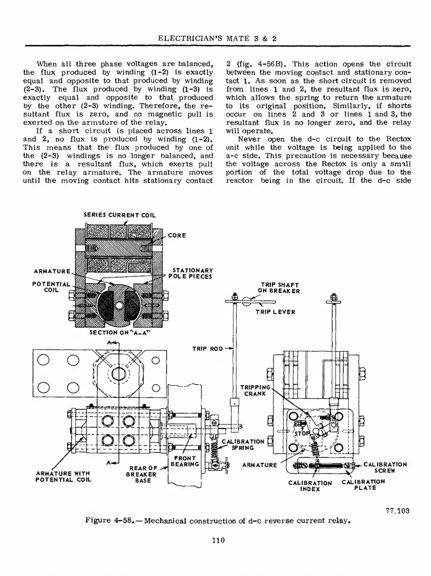
ELECTRICIAN’S MATE 3 & 2
When kll three phase voltages are balanced, the flux produced by winding (1-2) is exactly equal and opposite to that produced by winding (2-3). The flux produced by winding (l-'S) is exactly equal and opposite to that produced by the other (2-3) winding. Therefore, the re- sultant flux is zero, and no magnetic pull is exerted on the armature of the relay.
If a short circuit is placed across lines l and 2, no flux is produced by winding (1-2). This means that the flux produced by one of the (2-3) windings is no longer balanced, and there is a resultant flux, which exerts pull on the relay armature. The armature moves until the moving contact hits stationary contact
2 (fig. 4-56B). This action opens the circuit between the moving contact and stationary con- tact 1. As soon as the short circuit is removed from lines 1 and 2, the resultant flux is zero, which allows the spring to return the armature to its original position. Similarly, if shorts occur on lines 2 and 3 or lines 1 and 3, the resultant flux is no longer zero, and the relay will operate.
Never open the d-c circuit to the Rectox unit while the voltage is being applied to the a-c side. This precaution is necessary because the voltage across the Rectox is only a small portion of the total voltage drop due to the reactor being in the circuit. If the d-c side
SERIES CURRENT COIL
ARMATURE
POTENTIAL COIL
CORE a wwmÆjm.
STATIONARY POLE PIECES
TRIP SHAFT ON BREAKER
TRIP LEVER
SECTION ON 'A-A*'
A-*-, TRIP ROD
o o o o o TRIPPING
CRANK V
S- » kn O ) ©
.. 3 STO
CALIBRATION ^ SPRING o o
FRONT BEARING A-*J 3«S> ARMATURE REAR OF
BREAKER BASE
ARMATURE WITH POTENTIAL COIL
CALIBRATION ** SCREW
CALIBRATION CALIBRATION INDEX PLATE
Figure 4-58. — Mechanical construction of d-c reverse current relay 77.103
110

Chapter 4—ELECTRICAL INSTALLATIONS
is opened, full voltage is applied across the unit, which may cause the unit to break down.
Very little maintenance is required for this relay. No lubrication is needed. However, the relay should be kept clean so that dirt and dust will not interfere with its operation.
Because the relay rarely operates, it is advisable to check its operation every month or two as recommended by NAVSHIPS Technical Manual, Chapter 9620.
REVERSE-CURRENT RELAY
Two or more d-c generators may be con- nected in parallel to supply sufficient power to a circuit. Each d-c generator is driven by its own prime mover. If one prime mover fails, its generator will slow down and draw power from the line. The generator will then operate as a motor and instead of furnishing power to the line, it will draw power from the line. This can result in damage to the prime mover and overloading of the generator. To guard against this possibility, reverse-current relays are used. The reverse-current relay connections are such that when the reverse power reaches a definite percentage of the rated power output, it will trip the generator circuit breaker, disconnecting the generator from the line.
Normally, the reverse-current settings for d-c relays are about 5 percent of rated generator capacity for d-c generators. The reverse-current relay (one for each generator) is located on the generator switchboard and is an integral part of the circuit breaker. The mechanical construction of a d-c relay designed to limit reverse-current flow is illustrated in figure 4-58. Note that the construction is similar to that of a bipolar motor with stationary pole pieces and a rotating armature.
The potential coil is wound on the armature, and a current coil is wound on the stationary pole pieces. When used as a protective device, the current coil is in series with the load, and the potential coil is connected across the line, as shown in figure 4-59. If the line voltage exceeds the value for which the potential coil is designed, a dropping resistor is connected at point X in the circuit.
OC GENERATOR
BREAKER
> .OVERLOAD TRIP COILS
CURRENT I COIL —!
BUS
'AUX. CONTACT OPEN WHEN BREAKER IS OPEN
RESISTOR (IF NEEDED)
MECHANICAL TRIP
I POTENTIAL COIL
■ ¡^-REVERSE
CURRENT RELAY
77.104 Figure 4-590 — D-c reverse current relay
connections.
When the line is energized, current flowing through the series .coil produces a magnetic field across the air gap. Voltage applied to the armature winding produces a current in the armature coil, which interacts with the magnetic field, thereby developing a torque that tends to rotate the armature in a given direction. The construction of the relay is such that the armature cannot turn through 360 degrees as in a motor. Instead, the torque produced by the two fields plus the force from the calibrated spring tends to hold the tripping crank on the armature shaft against a fixed stop. This pressure is maintained as long as current flows through the line in the right direction.
However, if one generator fails, the voltage output of that generator will drop. When the voltage drops below the terminal voltage of the bus to which it is connected, the generator terminal current (through the relay series coil) will reverse. However, the polarity of the voltage applied to the potential coil remains the same. As soon as the reversed current exceeds the calibration setting of the relays, the armature rotates, and through a mechanical linkage, trips the circuit breaker that opens the bus. This action disconnects the generator from the line.
Ill

CHAPTER 5
A-C POWER DISTRIBUTION SYSTEMS
The a-c power distribution system aboard ship consists of the a-c power plant, the means of distributing power, and the equipment which con- sumes the power. The power plant is either the ship service electric plant or the emergency electric plant. The power distribution system comprises the ship service power distribution system, emergency power distribution system, and casualty power distribution system.
SHIP SERVICE POWER DISTRIBUTION
Most a-c power distribution systems in naval ships are 450-volt, 3-phase, 60-hertz, 3-wire systems.
The ship service generator and distribution switchboards are interconnected by bus ties so that any switchboard can be connected to feed power from its generators to one or more of the other switchboards. The bus ties also con- nect two or more switchboards so that the gen- erator plants can be operated in parallel. In large installations (fig. 5-1) distribution to loads is from the generator and distribution switch- boards or switchgear groups to load centers, to distribution panels, and to the loads, or directly from the load centers to some loads.
On some ships, such as large aircraft car- riers, a system of zone control of the ship service and emergency distribution is provided. Essentially, the system establishes a number of vertical zones, each of which contains one or more load center switchboards supplied through bus feeders from the ship service switchgear group. A load center switchboard supplies power to the electrical loads within the electrical zone in which it is located. Thus, zone control is pro- vided for all power within the electrical zone. The emergency switchboards may supply more than one zone, the numiîer of zones depends on the num- ber of emergency generators installed.
In small intallations (fig. 5-2), the distri- bution panels are fed directly from the generator
and distribution switchboards. The distribution panels and load centers (if any) are located cen- trally with respect to the loads that they feed. This arrangement simplifies the installation and requires less weight, space, and equipment than if each load were connected to a switchboard.
At least two independent soui’ces of power are provided for selected vital loads. The distribution of this dual supply is accomplished in several ways: by a normal and an alternate ship service feeder; normal ship service feeder and an emer- gency feeder; or normal and alternate ship service feeder and an emergency feeder,
SWITCHBOARDS
A-c switchboards may consist of a single section or of several sections physically sepa- rated and connected by cables to form a switch- gear group. This arrangement of sections provides greater resistance to damage. It also provides a means for localizing damage, and removal of a damaged section for repairs or replacement.
The switchboard of figure 5-3 or 5-4 is the IS or forward section of a DDG-2 class destroyer. This type of switchboard utilizes sheet steel panels or enclosures from which only the meters and op- erating handles protrude to the front.
The forward ship’s service switchgear group is designated as the control switchboard; it con- tains meters and control equipment for the after generators as well as instruments for the forward generators. In this setup, the Electrician’s Mate on watch forward can control the after generators as well as the forward generators by means of the remote governor motor control switch. The after ship service switchgear group is similar to the forward group, consisting of the same number of panels correspondingly designated. Figure 5-2 is a single-line diagram of the distribution system, showing several of its large loads.
A separate control benchboard (fig. 5-5) is provided in the switchgear groups for cruisers and
112

STEERING
STEERING POWER
TRANSFER SWITCHBOARD
SHIP SERVICE i _ 4 1 GENERATOR Û 1 ^ I DISTRIBUTION
SWITCHBOARD n RADIO
TRANSMITTER NORMAL FEEDER
ALTERNATE FEEDER
BUS RE
EMERGENCY FEEDER
LOAD I CENTER
1—*• TO DISTRIBUTION I PANELS OR LOADS
LOAD CENTER
T DISTRIBUTION PANEL
r i
0 EMERGENCY
RADIO
POWER TRANSFER
SWITCHBOARD IPORT)
LOADS
iti yj i i) Lb =^-
NQ NQ TURRET TURRET TURRET r i LOAD
I ¿1 CENTER I TO DISTRIBUTION M
PANELS OR LOAOS ‘*|J
NO 3 NO. 2 NQI
t
AFT EMERGENCY SWITCHBOARD
LOAD CENTER
TO DISTRIBUTION PANELS OR LOADS (STBD)
I L L rni I
Ü NO. 3 INTERIOR
I COMMUNICATION I SWITCHBOARD II
H i 1 —H I I ¡
I
FWD EMERGENCY
SWITCHBOARD
t——--i-ü
I LIT
77.320
Figure 5-1.—Power distribution in a large combatant ship,
Ch
apter
5—A
-C
PO
WE
R D
ISTR
IBU
TIO
N
SYST
EM
S

ELECTRICIAN’S MATE 3 & 2
GEN ISB a r¡7 I if
! GEN 2E :°1 STEERING
SWBD. 1 a
2E EMERG SWBD.
MISSILE LAUNCHER
J TL
rOIST’N ! PANEL ^
LOAD
LOAD
(gKKl IS
h-il ui O'
I SWGR. GROUP
j M O U NT J
W
<J-i rtr DEGAUSSING
SWBD. /
TO DISTRIBUTION PANEL OR LOADS
INTERIOR COMMUNICATION
SWBD.
jf (MOUNT)
ASROC v 51 y LAUNCHER
2S SWGR GROUP
GEN 2SB a
—i i •
LOAD GEN IE
M) LOAD
IE EMERG SWBD.
rp-'--—i ó¡ r .J
DIST’N I _ PAN EL I
( i NORMAL FEEDER
j I I ALTERNATE FEEDER
—e—0-BUS TIE EMERGENCY FEEDER
o GEN 2SA
Figure 5-2, Power distribution in a guided missile destroyer. 77.321
carriers. This benchboard mounts all the gen- erator control equipment, all measuring instru- ments, and all controls for electrically operated equipment. The arrangement provides for central- ized control of the generators and major switching operations. The control benchboards in ships having four or more ship’s service switchgear groups are provided with a mimic bus whose in- dicating lights show which generator circuit breaker or bus tie breaker is closed throughout the ship. In ships not provided with a control benchboard, the metering and control equipment is mounted on the front panels of the units in the switchboards or switchgear groups.
CONTROL EQUIPMENT
Generator switchboards are equipped with meters to indicate the generator voltage, current, power, frequency, and power factor (new con- struction ships do not have power factor meters). Synchroscopes and synchronizing lamps are also provided for paralleling a-c generators. Indicator
lamps show the operating conditions of various circuits.
The frequency is controlled by generator speed which, in turn, is automatically controlled by the speed governor of the prime mover. The speed governors for large machines can be set to the required speed by a control device mounted on the switchboard.
When running in parallel with other generators, a generator is prevented from operating as a motor by a reverse power relay. This relay trips the generator breaker and takes the generator off the line when power is fed from the line to the generator instead of from the generator to the line.
A voltage regulator is mounted on each switch- board and operates automatically to vary the field excitation in order to maintain the generator voltage constant throughout normal changes in load.
Some ships are provided with a standby reg- ulator and transfer switch to provide automatic voltage regulation if the regulátor in service fails.
114

Chapter 5—A-C POWER DISTRIBUTION SYSTEMS
In recent construction the standby regulator has been deleted. In all installations a means is pro- vided to manually adjust the voltage if the auto- matic regulator fails.
GROUND DETECTOR LAMPS
A set of three ground detector lamps (fig. 5-6), connected through transformers to the main bus of each ship service switchgear group and to the emergency bus, provides a means to check for
grounds on any phase of the 3-phase system.. To check for a ground, turn switch S on and
observe the brilliancy of the three lights. If the lights are equally bright, all lights are receiving the same voltage, and no ground exists. If lamp A is dark and lamps B and C are bright, phase A is grounded. In this case, the primary of the trans- former in phase A is shunted to ground and lamp A receives no voltage. Similarly, if lamp. B is dark and lamps A and C are bright, a ground exists on phase B. If lamp C is dark and lamps A and B are bright, a ground exists on phase C.
Wt
8- 8 M.
•4
I i
litlLsj « -r' K.
8 8 — rffc • iyiii r
8 8 1
8 8
P.
Figure 5-3. — ISA ships service switchboard, DDG-2 class destroyer. 77.322
115

ELECTRICIAN’S MATE 3 & 2
I f I
-4 fc W
i i i
tSJLSJL= íéiJr
I I I
.^SiiJLsLj 1 I 1
4
M •* m i
Figure 5-4. —1SB ships service switchboard, DD02 class destroyer. 77.323
VOLTAGE REGULATORS
A voltage regulator consists of a control element and associated mechanical or electrical means to produce the changes in the generator field current that are necessary to maintain a predetermined constant generator terminal volt- age. The functions performed by voltage regula- tors and their auxiliary equipment are to main- tain the generator terminal voltage within spec- ified limits, and to provide for proper division of the reactive current between generators operating in parallel. The types of voltage regulators used
in naval ships are the direct acting rheostatic type, the rotary amplifier type, or the combined static excitation and voltage regulation team. The type used depends on which is considered most suitable for a particular application.
One regulator is provided for each generator that is to be regulated. In some ship service in- stallations a spare voltage-sensitive (control) element is installed on the switchboard. The switchboard is provided with a transfer switch so that a spare element can be placed in service if the normal control element becomes deranged. Spare control elements are not installed for
116

Chapter 5—A-C POWER DISTRIBUTION SYSTEMS
a Vi XT
I V i 41
f
9 w t 1 o«
9 « P
r
«
27.65.1 Figure 5-5. —Control benchboard.
voltage regulators used on emergency generators. On later ships the spare element has been omitted.
The static excitation and voltage regulator sys- tem furnishes the a-c generator field current by rectifying a part of the a-c generator output. This output is fed to the field as a self-excited generator, after initial flashing from a battery or other source of low voltage direct current, to build up the voltage. The control element is a network of capacitors, reactors, and resistors, and it controls the field current by means of mag- netic amplifiers. This system eliminates the ro- tating exciter and other moving parts and replaces them with an assembly of static components.
Static voltage regulators using silicon- controlled rectifiers and transistors has reduced the size and weight of regulators (as compared with designs using magnetic amplifiers) and are- now furnished for all new ship service generators.
The SILVERSTAT, a direct and quick-acting voltage regulator is used for both ship service and emergency generators (fig. 5-7). In large
alternators the regulating resistance is connected in the shunt-field circuit of the exciter. In small machines that use these regulators the resis- tance may be connected directly in series with the alternator field. The torque element of the Silverstat regulator consists of a control coil operated by a direct current obtained from a Rectox rectifier. A movable core is mounted on an aluminum armature in such a manner that it can move in the air gap of the magnetic cir- cuit of the control coil. The magnetic pull on the armature is balanced by the adjusting spring. A driving member is mounted on the upper end of the armature and bears against an assembly of silver buttons. Each silver button is mounted at the free end of an individual leaf spring of con- ducting material. The leaf springs are individ- ually insulated. A connection is made from the fixed end of each leaf spring to a tap on the regulating resistance, which is in series with the shunt field of the exciter.
When the top of the moving arm is at the left-hand end of its travel, the driving member allows the free ends of the leaf springs, which carry the silver buttons, to rest against a stop of insulating material. In this position the free ends and the silver buttons are separated from one another. As the moving arm travels to the right, the driving member bears against the silver-button assembly, which closes the silver buttons together successively and in sequence. When the moving arm reaches the right-hand limit of travel, all the buttons are in firm con- tact with one another. As the driving member travels back to the left, the buttons successively move apart, in sequence, from one another. Only a travel of a fraction of an inch is required to close or open all the buttons in sequence. Al- though the operation of the silver buttons in
GROUND w TJRT
DETECTOR LAMPS
3)
3 PHASE BUS
77.172 Figure 5-6. — A-c ground detector lamp circuit.
117

ELECTRICIAN’S MATE 3 & 2
SHUNT FIELD ■nm'— REGULATING RESISTOR
EXCITER RHEOSTAT
EXCITER a LEAF
SPRINGS DAMPING TRANSFORMER -vJUULrJ
FIELD _5-| RHEOSTAT^
|-^nnr>- SILVER-I BUTTONS rAAAr-1
ALTERNATOR VOLTAGE ADJUSTING RHEOSTAT
,'= ir mi
COMPENSATING . RESISTOR
PIVOT SPRINGS
RECTOX UNIT
POTENTIAL TRANSFORMER -CORE
Figure 5-7.-A Silverstat voltage regulator on an a-c generator. 73'56
sequence appears to cut small steps of resist- ance in or out in a definite step-by-step manner its operation does not actually do so. As the but tons are operated by the moving arm,thereis¡ progressive change in pressure between the face¡ of the buttons. This change in pressure betweei the silver surfaces varies the effective resist- ance, which amounts to varying the field resist- ance in almost infinitesimal steps.
For a given value of regulated voltage anc load on the machine being regulated there is £ corresponding value of regulating resistance required in the field circuit and a corresponding position of the moving arm and silver buttons which will give this value of resistance. Under such conditions the magnetic pull on the moving
b,alfn<Ied gainst the spring pull at the position of its travel. When a load change occurs on the regulated machine, a corresponding change in termj nal voltage occurs. To restore the voltage to its correct regulated value, the moving arm and the silver buttons take a new position because of
the unbalance between the spring pull and the magnetic pull on the moving arm..
If the voltage of the alternator rises, the armature is drawn further into the air gap of the magnet. This causes the driving member to reduce its pressure on the leaf springs, opens some of the short-circuiting silver buttons, in- serts more resistance into the exciter field and restores the voltage to its correct value ’ Should the alternator voltage drop, the process is reversed.
The phase sequence in naval ships is ABC; that is, the maximum positive voltages on the three phases are reached in the order; A, B, and C. Phase sequence determines the direction of rotation of 3-phase motors. Reversal of the phase sequence reverses the direction of rotation of three phase motors. The phase sequence of
e power supply throughout a ship is always ABC
118

Chapter 5—A-C POWER DISTRIBUTION SYSTEMS
(irrespective of whether power is supplied from any of the switchboards or from the shore power connection) to ensure that 3-phase, a-c motors will always run in the correct direction.
Phase identification is denoted by the letters, A, B, and C in a 3-phase system. Switchboard and distribution-panel bus bars and terminals on the back of switchboards are marked to iden- tify the phase with the appropriate letters, A, B, or C. The standard arrangement of phases in power and lighting switchboards, distribution panels, feeder distribution boxes, feeder junction boxes, and feeder connection boxes is in the order A, B, C from top to bottom, front to back, or right to left when facing the front of the switch- board, panel, or box and left to right when facing the rear of the switchboard, panel, or box.
SHORE POWER CONNECTION
The number and locations of shore power connections vary on different types of ships. Shore power connections are provided at, or near, a suitable weather-deck location to which portable cables from the shore or from ships alongside can be connected to supply power for the ship’s dis- tribution system when the ship service generators are not in operation. This connection also can be used to supply power from the ship service gen- erators to ships alongside.
EMERGENCY POWER DISTRIBUTION
The emergency power distribution system sup- plies an immediate and automatic source of elec- tric power to a limited numlier of selected vital loads in the event of failure of the normal ship service power distribution system. The system, which is separate and distinct from the ship service power distribution system, includes one or more emergency distribution switchboards. Each emergency switchboard is supplied by its associated emergency generator. The emergency feeders run from the emergency switchboards (figs. 5-1 and 5-2) and terminate in manual or automatic bus transfer equipment at the distri- bution panels or loads for which emergency power is provided. The emergency power distribution system is a 450-volt, 3-phase, 60-hertz system with transformer banks at the emergency distri- bution switchboards to provide 120-volt, 3-phase power for the emergency lighting system.
The emergency generators and switchboards are located in separate spaces from those con- taining the ship service generators and distri-
bution switchboards. The emergency feeders are located near the centerline and higher in the ship (above the waterline) than the normal and alter- nate ships service feeders. This arrangement pro- vides for horizontal separationbetween the normal and alternate ship’s service feeders and vertical separation between these feeders and the emer- gency feeders, thereby minimizing the possibility of damaging all three types of feeders simul- taneously.
The emergency switchboard is connected by feeders to at least one and usually to two different ship service switchboards. One of these switch- boards is the preferred source of ship service power for the emergency switchboard and the other is the alternate source (fig. 5-8). The emergency switchboard and distribution system are normally energized from the preferred source of ship ser- vice power. If this source of power should fail, bus transfer equipment automatically transfers the emergency switchboard to the alternate source of the ship service power. If both the preferred and alternate sources of ship service power fails, the prime mover of the emergency generator starts automatically (within 10 seconds after power failure) and the emergency switchboard is automatically transferred to the emergency gen- erator.
When the voltage is restored on either the preferred or alternate source of the ship service power, the emergency switchboard is automat- ically retransferred to the source that is avail- able, or to the preferred source if voltage is restored on both the preferred and alternate sources. However this is only on certain types of ships. Some systems require the emergency gen- erator to be tripped manually before the ABT will transfer back to the available preferred or alternate source. The emergency generator must- be manually shut down. Hence, the emergency switchboard and distribution system are always energized either by a ship service generator or by the emergency generator. Therefore, the emer- gency distribution system can always supply power to a vital load if both the -normal and alternate sources of the ship service power to this load fails. The emergency generator will not start automatically if the emergency switchboard can receive power from a ship service generator.
EMERGENCY SWITCHBOARDS
The forward and after emergency switchboards are located in the forward and after emergency generator rooms -respectively. The emergency
119

ELECTRICIAN’S MATE 3 & 2
rr
vm
mm L_r— xl, , rT J L
INDICATES i 1 SHIP'S SERVICE GENERATOR a I 1 DISTRIBUTION SWITCHBOARD
EMERGENCY SWITCHBOARD
FEEDERS FROM SHIP'S SERVICE TO EMERGENCY SWITCHBOARD
■ ■ ♦ » > BUS TIE BETWEEN SHIPS SERVICE SWITCHBOARDS
Figure 5-8.- Emergency and ship service distribution systems interconnections. 77-165
switchboards provide electric power to vital aux- iliaries and a limited amount of lighting in the event of failure of the ship service power.
The emergency power system is arranged for automatic transfer of the circuit for the steering power panel to the emergency generator. The forward and after emergency switchgear groups are normally energized from the forward and after ship service switchgear groups respectively.
The forward emergency switchgear group (fig. 5-9) controls the forward emergency generating unit; the forward ship service and emergency bus transfer equipment; the local emergency power bus feeders; the remote emergency power bus feeders; and the emergency lighting feeders.
The after emergency switchgear group (not shown) controls the after emergency generating unit; the after ship service and emergency bus transfer equipment; the special emergency power bus feeder; the emergency power bus con- tactor; the local emergency power bus; the remote
emergency power bus feeders; and the emergency lighting feeders.
The generator panels of both the forward and after emergency switchboards are provided with an a-c voltmeter to permit reading at least one phase-to-phase voltage of the a-c generators. An a-c watt-meter for readingthepowerof the emer- gency generator, a frequency meter for reading the frequency of the local power bus, and an a-c ammeter to permit reading the current in at least one phase of the emergency generator.
INTERCONNECTIONS
The connections between the ship service and the emergency generating units and their asso- ciated switchboards and the interconnections be- tween the switchboards for a representative system are illustrated in the schematic line dia- gram in figure 5-2. The a-c bus on the forward
120

Chapter 5—A-C POWER DISTRIBUTION SYSTEMS
* l ty Tí
CJ il i i
Ü L » - »i
M « I I
j as vC
«
t « JSf /
77.324
Figure 5-9. —IE emergency switchboard from a DDG-2 type destroyer.
and after ship service switchboards can be con- nected together through the bus tie circuit breakers.
This arrangement enables one generating unit to supply power to both ship service switchboaras when the other unit is out of service and also pro- vides for parallel operation of the two ships’ service generating units (is and 2S). However, when operating split-plant, the generators are operated separately, each unit supplying power to its own section of the ship. In recent construc-
tion the emergency switchboards have only one bus; however, older types may have two, one local and one remote.
Each emergency switchboard (1E-2E) has a normal, alternate and emergency supply. The emergency supply would be supplied by its re- spective emergency generator. Under normal op- erating conditions the emergency switchboard would be supplied from its normal source and the alternate supply would be available at the
121

ELECTRICIAN’S MATE 3 & 2
switchboard in case of loss of the normal source. In the event normal supply is lost the transfer switch would automatically select the alternate source. If both normal and alternate sources are lost the emergency diesel would start auto- matically and would feed its own switchboard.
This system is provided with feedback circuit breakers so that either the forward or after ship service switchgear group may be provided with limited power from either emergency switch- board.
AUTOMATIC OPERATION
To set up the emergency switchboard for auto- matic operation, main contacts SLC on device 83E
and generator circuit breaker 52E (fig. 5-10) must be closed manually. If the normal source is the preferred source, selector switch 10 is turned to the NORMAL position, which closes its contact in coil circuit of relay CRl. The alternate source automatically becomes the standby source.
When power is available at 382 or more volts from the normal source, voltage relay Vl is energized. Its normally open contacts close and its normally closed contacts open, thereby completing a circuit to relay CRl through contacts Vl/2 and 10 (nor); also, a circuit is completed to timing relay TRl through contact Vl/l. When energized, relay CRl opens its normally closed contacts and closes its normally open contacts to complete
)-)-)GEN
¿ I L 52E
FEED BACK )')")
89
|GTN^ IOOKW DIESEL GENERATOR
Y£ 2
ESC —'VH I
SLC —IHV-
83E
LS3 -H—
CR2 —ihr
43
SHIP SERVICE
TEST SWITCH
EMERGENCY TRANSFER
TEST SWITCH
H HV—
- A1 TO EMERG
B \ DIST
Cj BUS
ALTERNATE
SOURCE 'NHI SSCI SSC2
KV 83N
©3 V2 CRIJVI
© NOR aia-j pais
ALT V2
MO
43
LS2 LSI CRl CRl
Figure 5-10. — Emergency switchboard layout. 77.325
122

Chapter 5—A-C POWER DISTRIBUTION SYSTEMS
a circuit to the motor of device 83N, through the contacts of LSI, CRl, and 43. This motor then operates, closing main contacts SSCI after a delay of about three seconds. Since it is energized through contact Vl/l when the main bus is ener- gized, TR1 opens its normally closed contact (not shown) in the diesel starting circuit, to prevent starting of the emergency diesel generator. Contacts SSC2 and ESC will not close, nor will transfer occur, while power is available from the normal source with selector switch 10 on the NORMAL position. The closing sequence of contacts SSC2 is blocked by the open contacts of CRl. Also, contacts ESC are blocked by an open contact of TRl in the diesel starting circuit. Therefore no power is available to close contacts ESC.
When the alternate source is available and voltage from the normal source falls below 315 volts, voltage relay Vl will drop open by opening its normally open contacts and closing its normally closed contacts. Thus, it deenergizes the circuit to relay CRl and timing relay TRl. At the same time, relay CRl opens its normally open contacts and closes its normally closed contacts to com- plete a circuit to the motor of device 83N through the contacts of LS2, CRl, and 43. This motor then operates in the reverse direction to open main contacts SSCI after a delay of nearly one-half second, .and close main contacts SSC2 after a total delay of about three seconds. Voltage relay V2, energized when there is power available at the alternate source, closes its contact V2-1 in the timing relay circuit. The timing relay then functions as did TRl by opening its contact in the diesel starting circuit.
If voltage is restored to the normal source, there is an automatic retransfer to the normal source, because the position of selector switch 10 determines which voltage relay takes pre- cedence. If the alternate source is selected as the preferred source, selector switch 10 is turned to the ALTERNATE position, which opens contact 10 (nor) and closes contact 10 (alt). Now the normal source is the standby source.
With the alternate source at the proper voltage, the motor of device 83N operates to close the main contacts SSC2 after a delay of about three seconds. When energized, voltage relay V2 opens its contact V2/3 deenergizing or opening relay CRl circuit. The 83N motor circuit is then completed through the contacts of LS2, CRl, and 43. Ener- gizing the main bus completes the timing relay cir- cuit through contact V2/i. The timing relay then opens its contact in the diesel starting circuit to prevent starting of the emergency diesel
generator. Contacts SSCI and ESC will not close, nor will transfer occur, while power is available from the alternate source with selector switch 10 on the ALTERNATE position. The closing se- quence of contacts SSCI is blocked by the open con- tacts of CRl. Also, contacts ESC are blocked by open contacts of TR2 in the diesel starting circuit.
Assume an undervoltage or voltage failure on the alternate source while it is selected as the preferred source, with power available on the normal source. If voltage from the alternate source falls below 315 volts, voltage relay V2 will drop open thus opening its normally open contacts and closing its normally closed contacts. A circuit to relay CRl is then completed through contacts V2/3 and lO(alt). With relay CRl now energized, its normally closed contacts open and its normally open contacts close to complete a cir- cuit to the motor of device 83N through the contacts of LSI, CRl, and 43. This motor then operates as described previously, except that main contacts SSCI and SSC2 are interchanged. The diesel starting circuit is again blocked by operation of the TR2 contacts. If voltage is restored to the alternate source, there is an automatic retransfer to the alternate source, as previously described.
Next, assume an undervoltage or voltage fail- ure on both ship service sources, with the switch- board set up for automatic operation. In this case, voltage relays Vl and V2 drop out by opening their normally open contacts and closing their normally closed contacts. When contacts Vl/l and V2/l open, timing relays TRl and TR2 are deenergized. After a delay of approximately six seconds, timing relay contacts close in the diesel starting circuit which will complete the circuit to the starter motor and start the diesel. When the diesel generator raises the operating voltage to between 382 and 450 volts, relay CR2 is ener- gized through the normally closed contacts Vl/3 and V2/2 of the deenergized relays Vl and V2. Relay CR2 then closes its contacts, completing a circuit to the motor of device 83E, through the con- tacts of LS3, CR2, and 43. This motor then oper- ates to open main contact SLC after a delay of nearly one-half second, and close main contact ESC after a total delay of about three seconds.
RETRANSFER TO SHIP’S SERVICE FROM EMERGENCY
When ship service voltage is restored, re- transfer to the ship service supply must be made manually by turning the handwheel of device 83E to the SHIP’S position. This position opens main contacts SLC, and permits the emergency bus to be energized from the desired ship service supply.
123

ELECTRICIAN’S MATE 3 & 2
TEST OPERATION
A preferred source transfer test switch is provided to simulate a voltage failure on the preferred source, whichever one is selected, causing a transfer to the other ship service supply. An emergency transfer test switch is provided to simulate a voltage failure on both ship service supplies, causing a transfer to the emergency supply. A diesel test switch (not shown) is provided to test the function of the starting controller. The diesel engine starts with- out causing any transfer of load, after generator circuit breaker 52E opens. Devices 83N and 83E are operated manually by engaging and turning their handwheels after the diesel start switch (not shown) is turned to its LOCKOUT position, and the manual-automatic switch (not shown) is turned to its MANUAL position, in the order given. The diesel generator may be started man- ually by turning the diesel start switch to its START position. The START position must be maintained during the entire cranking period.
FEEDBACK OPERATION
Emergency generator power is fed back to a ship service switchboard only when this switch- board is deenergized. The procedure for feeding back is:
o Turn the manual-automatic switch to its MANUAL position to keep device 83E or 83N from operating automatically.
o Turn the operating handwheel of device 83E to its EMER position.
o Position the operating handwheel of device 83N for the ship service source it is desired to energize.
@ Start the diesel generator.
© Close generator circuit breaker 52E and feedback circuit breaker 89.
POWER DISTRIBUTION ON A DLG
The a-c power distribution system of a DLG-23 class destroyer is shown in figure 5-11. This diagram shows in simplified form the electrical system with its interlinking power circuits and emergency connections. All ship service 60-hertz power utilized on this class of ship passes through
switchgear groups IS and 2S and the emergency switchboards lE and 2E.
SHIP SERVICE ELECTRIC PLANTS
The forward electric plant consists of ship service generators 1A, and lB, and ship service switchgear group IS, located in the forward (No.l) engine room.
The after electric plant consists of ship service generators 2A, 2B, and ship service switchgear group 2S, located in the after (No. 2) engineroom.
The four ship service generators are 1000- kw, 450-volt, 1604-ampere, 3-phase, 60-hertz, steam turbine-driven, totally enclosed units.
EMERGENCY ELECTRIC PLANTS
The forward emergency plant consists of the emergency generator IE and the emergency switchboard lE. The emergency generators are physically separated as far as possible from the ship service generators, and each other, to pro- tect against simultaneous damage to the ship’s electrical system from a single source. Both the forward emergency generator lE, and the after emergency generator 2E, are rated 300 kw, 450- volt, 60 hertz, 3-phase. The forward emergency generator is driven by a gas turbine and the after emergency generator is driven by a diesel engine. In figure 5-11 the normal and alternate supplies of the emergency switchboards are labeled, to show these bus feeders from the ship service switchgear groups. The three circuit breakers shown on IE emergency switchboard are elec- trically interlocked when the emergency switch- board is set up for automatic operation. While lE or 2E is set up for automatic transfer, if the normal ship service supply drops to 300 volts or below, the load is automatically transferred to the alternate supply if 400 volts or above are available from the alternate source. If 400 volts or above are restored to the normal supply the load will automatically retransfer to the normal supply. If both ship service supplies fail or their voltages drop below 300 volts, the transfer operates automatically through relays to start the emergency generator and connect it to the emer- gency switchboard. If the emergency generator is supplying the emergency switchboard and ship service power is restored, retransfer will not take place, but can be accomplished by manually tripping the emergency generator circuit breaker. The operation of IE or 2E is the same.
124

Chapter 5—A-C POWER DISTRIBUTION SYSTEMS
SHIP SERVICE SWITCHGEAR
GROUP IS
NORMAL SUPPLY
TO SWBD
IE
SHIP SERVICE SECTION ISA
\ * )52BI
EMER SWBD
I E
GEN
A
—fS~51- N iN DISC SW JS2-IA )s2 BT-I
t—n y SHIP SERVICE SECTION ISB
—1° oh DISC SW
52 — IE EMER
GEN
52 AI
)52SI
TO SHORE POWER 1
CONNECTIONS '
(800 AND 400 ! AMP.) 1
TO SHORE POWER CONNECTION
(800 AMP.)
A I
GEN
2 A
ALTERNATE SUPPLY
TO SWBD IE
SHIP SERVICE
SWITCHGEAR
GROUP 2S
ALTERNATE
SUPPLY TO
SWBD 2E
^52S2 ) 52-2 A
I l UïiHïL
IB I
52 A2 GEN
B EMER
1 SWBD
2E
52-2E
EMER 2 \ GEN 2E
52B2 BUS TIE
I I
GEN \ i
28 / I
1
NORMAL SUPPLY
TO SWBD 2E
DISC SW |o o)
l_SWP_SERVICE SECTION 2SA ¡
^ INTERLOCK CIRCUIT BREAKERS
^52BT-2 '¡SZ-ZB
r r .. i _S rn P_ SERVI CE 1SE_CTI0N_2S^B |
77.252 Figure 5-11.—Power distribution (60 hertz) system on the DLG-23.
When the ship service plants are secured and shore or tender power is not available, the emer- gency generators can feed power back to either switchgear group by means of a bus transfer selector switch on the emergency switchboards. The bus transfer selector switch when placed in the manual position, allows manual operation of the circuit breakers on the emergency switchboards. While the bus transfer selector switch is in the normal preferred or alternate prefer red position, the three circuit breakers on the emergency switchboards are interlocked and only one of them can be closed at a time. The feedback circuits should only be used in special circumstances such
as to supply power to the ship service bus for starting the ship service plant. When the feedback provision is in use, increased vigilance must be observed to prevent overloading of the emergency generators. The feedback circuits must NEVER be used to parallel the emergency generators with each other, with the ship service generators, or with shore power.
SYSTEM OPERATION
The ship service generators may be run either singularly or in parallel with each other. It
125

ELECTRICIAN'S MATE 3 & 2
is possible to run all four ship service generators in parallel (parallel IS and 2S via the bus tie), however no more than three generators can be safely operated in parallel without exceeding the interrupting capacity of the circuit breakers. The
ship service generators should never be paralleled with the emergency generators.
Ship service switchgear groups are repre- sented by showingthe ISA section of the IS switch- gear group in figure 5-12 and the 1SB section in
X Y
IT If r ^J\
f T' I Hi
*-4J
1
xm*
W
i m
s
r r r-j 0
ts S0 P
n
Figure 5-12.—Ship service switchgear No. IS: section ISA. 77.253
126

Chapter 5—A-C POWER DISTRIBUTION SYSTEMS
figure 5-13. If one section is damaged, it may be isolated from the undamaged section by using the disconnect switches as shown on figure 5-11.
Figure 5-14 shows a disconnect device in both the open and closed position. The discon-
nect devices should NEVER be opened or closed on a hot bus. When operating a disconnect device it should always be either completely open or completely closed. The locking springs lock the device to prevent accidental opening or closing
X1
/ / /« < .
W'ÿv.
iÿwÿ. )Mt» ¡«i
#riij JOOlHlt’f'* ['"I,,
ip;;«:::;;,,-
lill-r-“''. fío* 1
¿ r
71
' \ T- KI
Figure 5-13.—Ship service switchgear group No. IS section 1SB 77.254
127

ELECTRICIAN'S MATE 3 & 2
due to vibration. The device is operated com- pletely in either direction until the locking spring is compressed.
SHORE POWER CONNECTIONS
The DLG is equipped with three topside shore power terminal boxes. Two of the shore power terminals (one 800 and one 400 amperes) connect to the bus tie circuit between IS and 2S as shown in figure 5-11. The other shore power connection (800 ampere) is connected to the 2SA section of switchgear 2S via an AQB- A800 ampere frame circuit breaker.
CASUALTY POWER
The back of each emergency switchboard (fig. 5-15) is provided with one casualty power
terminal and each ship service switchgear group is provided with four casualty power term'nals installed on the back of the units (2 for each section (fig. 5-16) and connected to the buses through 250-ampere frame size AQB circuit breakers.
400-HERTZ POWER DISTRIBUTION
In addition to the 60-hertz power supplied by the ship service and emergency generators, the DLG also has 400-hertz systems. The 400-hertz power is generated by motor generator sets and distributed via special frequency switchboards (fig. 5-17) to the various 400-hertz equipments. The DLG has three 200-kw, 400-hertz, 450-volt, 3-phase motor generators which supply the ship service 400-hertz power. These three motor generators, numbered M/G 1, M/G 9, andM/Gl3 in figure 5-18, supply power to ship service special
I *
was
LOCKING SPRING
INSULATED BASE CONTACT
BLOCK
BRIDGING CONTACT
CROSS-HEAD PIN
I LOCKING SPRING
BACKING PLATE
HINGE BLOCK
OPERATING SCREW
Figure 5-14.—Disconnect device. 77.255

Chapter 5—A-C POWER DISTRIBUTION SYSTEMS
V'
A w w
•+ 9L ' &
m mm 'f.-r** ir
- rn n r Mr
V
CASUALTY ' L POWER
TERMINAL
Figure 5-15.—Emergency switchboard IE, rear view. 77.256
frequency switchboards iSF, 5SF, and 6SF, re- spectively. Motor-generator M/G 9 is considered a standby set which can supply iSF or 6SF, or can be operated in parallel with M/G 13. M/G 9 or M/G 13 may be paralleled momentarily with M/G 1 when transferring the load. Figure 5-18 is a simplified line diagram of the 400-hertz ship service bus tie interconnections. The circuits being fed from the 400-hertz ship service switch- boards are deleted from the figure for simplicity. Switchboard ISF supplies the missile, fire control, ASROC and IC circuits in the forward part of the ship, and 6SF supplies the weapons circuits in the
after part of the ship. The DLG also has six 60-kw, 450-volt, 3-phase, 400-hertz motor generator sets for missile fire control radar. Three of these sets (numbered 5, 7, and 8) feed the missile illuminator power switchboard (2SF) forward, and three sets (numbered 10, 11, and 12) supply the missile illuminator power switchboard (4SF) aft. Motor generator number 8 is the forward standby set and number 12 is the after standby set. The weapons control IC switchboard receives its normal 400- hertz power from a separate 60-kw motor gen- erator set (M/G 14) via switchboard 3SF and auto- matic bus transfer equipment. In the event of a
129

ELECTRICIAN'S MATE 3 & 2
f
l %
CASUALTY POWER
TERMINALS
)
Figure 5-16. Ship service switchgear group 2S, a-c generator No. 2A, and distribution section, rear view.
power loss from M/G 14, the weapons IC switch- board power supply is transferred by automatic bus transfer to its alternate power supply, which is from 6SF.
CLOSELY REGULATED POWER SUPPLIES
Certain weapons, interior communications, and other electronics systems aboard modern Navy ships require closely regulated electrical power for proper operation. Special closely reg- ulated MG sets supply the greater part of this power. Static type converters are also used in some installations.
30-KW MOTOR GENERATOR SET
The closely regulated MG set (fig. 5-19),con- sists of a 450-volt, 3-phase, 60-Hz, 50-hp, wound rotor induction motor driving a 450-volt, 3-phase, 400-Hz, 30-kw generator. The set is regulated and controlled by a voltage and frequency regulating system housed in the rotor resistor and regulator unit control cabinets, and a magnetic controller with associated pushbuttons and switches located in the control cabinet.,
The magnetic controller is a conventional size 3 across-the-line semiautomatic motor controller (starter). The voltage regulating system functions to supply the proper field current to the generator so as to maintain the generator output voltage within plus or minus one-half of one percent of rated output voltage for all load conditions. The frequency regulating system functions to control the speed of the drive motor so as to maintain the output frequency of the generator within plus or minus one-half of one percent of its rated value for all load conditions. In addition, power sensing net- works that function to eliminate speed droop with increased generator loads and to maintain equal sharing of the load between paralleled generators are included.
Voltage Regulating System
The voltage regulating system consists of a voltage regulator and a static exciter as shown in figure 5-20. The output from the power section of the regulator, in conjunction with windings within the static exciter, control the static ex- citer output. The static exciter output in turn supplies d-c (excitation current) to the generator field of the proper magnitude so as to maintain
130

Chapter 5 —A-C POWER DISTRIBUTION SYSTEMS
r\ —^7^— •
ifi»<iw.-w»i1»»-^ ■ ■■<- v-^ * _ ”_5,3wa
o -c;. ei: ein r. ® ÎÏI ! dj 'iSi i
al
r —’ i ' I I * ^ ■!! I -t
. o
y
CS
S P rvi X
77.261 Figure 5-17. — 400 hertz switchboard —1 S F.
the generator output voltage within specified limits under all load conditions.
The static exciter consists of a saturable current-potential transformer (SCPT), three linear reactors (chokes), and a 3-phase bridge rectifier unit. The SCPT contains (1) a primary winding consisting of both voltage and current windings, (2) a d-c control winding, and (3) a secondary winding. The voltage primary windings are connected in series with the chokes across the generator output. The current primary windings are connected in series with the load and thus
carry load current. The secondary winding out- put is connected to the bridge rectifier unit which supplies the d-c for the generator field. The SCPT control winding is connected to the output of the voltage regulator.
The voltage regulator consists of a detector circuit, a pre-amp and trigger circuit, and a power section. The detector circuit includes a sensing circuit and a 3-phase bridge rectifier. The sensing circuit consists of three voltage sensing transformers withtheir primary windings connected to the generator output and their sec- ondary windings connected to the bridge rec- tifier. The bridge rectifier provides a d-c output voltage that is proportional to the average of the 3-phase voltage outputs from the generator. This d-c voltage is filtered and fed to a Zener reference bridge in the pre-amp and trigger circuit.
The d-c output from the detector is compared with a constant Zener voltage in the reference bridge and the difference (error) voltage output from the bridge is amplified by transistor amplifiers and fed to a uni- junction transistor circuit which provides the pulses to trigger the silicon controlled rec- tifiers (SCRs) in the power section. The SCR output from the power section is fed to the control winding of the SCPT in the static exciter.
During starting, generator field current is supplied by a field flashing circuit which is cut out after the generator builds up an output volt- age. At no-load voltage the primary windings of the SCPT are energized through the chokè coils and induce a voltage in the SCPT secondary windings. The rectified output of the secondary windings supply the generator field. This is the no-load field excitation.
When a load is applied to the generator, load current flows through the SCPT primary current windings causing a flux which combines vec- torially with the primary voltage windings flux to induce a voltage in the secondary windings. Thus any change in generator load or load power factor is automatically compensated for. This arrangement, without the use of the voltage re- gulator, would hold the generator output voltage fairly constant under all load conditions. The voltage regulator is necessary, however, for the high degree of regulation required. The voltage regulator acts as a fine control by effectively varying the coupling between the SCPT primary and secondary windings.
131

ELECTRICIAN’S MATE 3 & 2
POWER SUPPLY
FROM 2 SB
POWER SUPPLY
FROM 2SA
POWER SUPPLY
FROM ISA
(M) S.S. 400 CYCLE
' G ) M /G 13
SWBD
I
(M)S.S.400 CYCLE (M}S.S.400 CYCLE
fo) M/G 9 © M/G I
ssT] n SWBD. 5SF
J L.c
r
L(
SWBD. I S 7H
BUS TIE BUS TIE
77.262 Figure 5-18. — Bus tie connections on 400 hertz ship serv ice system.
ROTOR RESISTOR CABINET- REGULATOR UNIT
CONTROL CABINET-
CONTROL CABINET
3
2 <* % A
MOTOR GENERATOR-
40.111 Figure 5-19.—Motor^generator set with control equipment.
132

Chapter 5—A-C POWER DISTRIBUTION SYSTEMS
INPUT POWER REGULATED
OUTPUT POWER
GEN.
MOTOR STARTER
MOTOR
r MOTOR ROTOR CONTROL UNIT
STATIC RESISTOR UNIT EXCITER
I DETECTOR ]
DETECTOR i I CIRCUIT I
I STARTER I CIRCUIT
I PRE-AMP i I S TRIGGER I L I L
PRE - AMP S TRIGGER
0 B TRIGGER 1
0 C J TRIGGER
0 A ! 1 I POWER I
Í SECTION I I J
VOLTAGE REGULATOR FREQUENCY REGULATOR
VOLTAGE REGULATING SYSTEM FREQUENCY REGULATING SYSTEM
40.113 Figure 5-20.—Motor-generator set, simplified block diagram.
Frequency Regulating System
The frequency regulating system consists of a motor rotor control and resistor unit and a fre- quency regulator. The detector circuit of the frequency regulator receives its input from a special type frequency sensing transformer whose voltage output varies linearly on changes in gen- erator output frequency. This input is rectified, filtered, compared in a Zener reference bridge, and the bridge output amplified by transistor am- plifiers. The amplified detector output (which re- presents the output frequency of the generator) is fed to the pre-amp and trigger section.
The detector output is further amplified in the. pre-amp and trigger section and this amplified output is used to control three pulse forming net- works which provide trigger pulses for SCRs located in the starter circuit.
The SCRs in the starter circuit (controlled by the weak trigger pulses from the pre-amp and trigger section) provide output pulses of sufficient magnitude to fire other SCRs located in the motor
rotor control unit. The output of the SCRs in the motor rotor control unit is fed through three large (about 3000 watt) resistors which are connected in the wound rotor circuit of the drive motor.
Any change in the generator output frequency from normal will cause the frequency regulating system to function to increase or decrease the rotor current, and hence the speed of the drive motor, to compensate for the change. Thus the output generator frequency is maintained constant by maintaining the speed of the directly connected drive motor.
STATIC CONVERTER
The static converter (fig. 5-2l) converts 450- volt, 3-phase, 60-Hz power to 120-volt, 3-phase, 400-Hz power for use as a shipboard closely regulated power supply. The converter auto- matically maintains the output voltage and fre- quency withinplus or minus one-half of one percent of rated value for all load conditions. This high degree of regulation is maintained even though the input voltage and frequency may vary as much as
133

ELECTRICIAN'S MATE 3 & 2
O O
£SSSL
» Í
ca^os ^i^ge^rr
1» ^-4» ^ ♦iy="w»fc.
Mb
mp*m » < «
3 m nn
Figure 5-21.—Converter, front view.
plus or minus five percent of rated value. The 450-volt, 60-Hz input is stepped down, rectified, and fed to two static inverters. Each static inverter contains two main SCR groups consisting of two SCRs in series. The inverter outputs are fed to Scott-connected transformers to produce the 3- phase output. A simplified block diagram of the converter is shown in figure 5-22.
Transformer Rectifier
The transformer rectifier unit (fig. 5-22) is an autotransformer and a 3-phase, full-wave, bridge rectifier. The rectifier output is filtered and fed through choke coils to the static inverters. The choke coils limit the voltage appearing across the inverter SRCs.
27.315
Oscillator Circuit
The oscillator circuit provides the pulses for firing the SCRs in the main inverter. This circuit consists of a unijunction transistor oscillator which provides pulses at a repetition rate of 800 per second. These pulses switch a bistable (flip- flop) transistor multivibrator circuit whose output supplies the primary of a transformer. The trans- former output (which isa square wave) is amplified by a transistor push-pull circuit and fed to the primary of the oscillator output transformer. This transformer has a separate secondary winding for each main SCR in the main inverter. The output of these secondary windings fed through a differ- entiating circuit (which converts the square waves
134

Chapter 5—A-C POWER DISTRIBUTION SYSTEMS
450 VAC 3;zr60Hz
INPUT TRANSFORMER RECTIFIER
CONTROL POWER
SUPPLIES
OSCILLATOR CIRCUIT
FILTER
PHASE CONTROL CIRCUIT
VOLTAGE REGULATOR
MAIN INVERTER
TEASER INVERTER
SCOTT
T TRANSE
120 VAC 3^400Hz OUTPUT
VOLTAGE REGULATOR
Figure 5-22.—Static converter, simplified block diagram. 27.316
to pulses), is used to fire the SCRs. Each SCR being fired from a separate secondary winding ensures simultaneous firing of the SCRs in series. Also the phasing of the secondaries allows firing of opposite SCRs at 180° intervals for proper inverter action.
Phase Control Circuit
The phase control circuit contains components and circuits (similar to those in the oscillator cir- cuit) which function to control the firing of the SCRs in the teaser (secondary) inverter and main- tain the proper phase relationship between the outputs of the two inverters.
Voltage Regulators
The voltage regulator circuits regulate the converter output voltage by controlling the firing time of the main SCRs in each inverter. The out- put of a transformer connected across the con- verter output is rectified to produce a d-c signal that is proportional to the converter output voltage. This signal is filtered and compared in a Zener
reference bridge to produce an error signal output when the converter output voltage varies from normal. This error signal is used to fire the inverter control SCRs which in turn control the firing time of the main SCRs.
Control Power Supplies
The converter contains two control power supplies (one for each inverter) which supply regulated +30 volts d-c to the various converter circuits. The input to the power supply trans- former is taken from the 450-volt a-c line. The power transformer output is rectified by a full wave bridge rectifier and regulated by a Zener diode regulator to produce the +30 VDC output.
NO-BREAK POWER SUPPLY SYSTEM
A no-break power supply system :s designed to provide an uninterruptable electrical power supply that is relatively constant in voltage and frequency under all load conditions. The no-break supply will automatically take over the power
135

ELECTRICIAN'S MATE 3 & 2
supply to a load when the normal supply is in- terrupted, off-frequency, or off-voltage. This type of system is required by ships with equipment, control, or computer systems which need an un- interrupted electrical power supply for effective operation. It is presently being used with ships using the Central Operations Systems.
The system uses a motor-generator set, batteries, and associated controls to provide its regulated ouput. Either unit of the motor- generator set can perform as a motor with the other as generator, thus permitting two modes of operation.
MOTOR-GENERATOR MODE 1
In mode 1 operation of the motor-generator set (fig. 5-23A), the a-c end of the set is being driven from the ship service power supply; the d-c end is a generator providing power to the system bat- teries. This motor-generator condition exists when the ship service power supply is meeting the voltage and frequency requirements of the critical load.
MOTOR-GENERATOR MODE 2
Mode 2 operation of the motor-generator set (fig. 5-23B) represents the condition by which the set receives power from the batteries and the a-c end of the set provides the power require- ments for the critical load. Mode 2 is referred to as the Stop Gap Operation.
SHIP SERVICE
POWER SUPPLY
400 VAC 3-PHASE 60 HERTZ
CRITICAL LOAD
400 VAC .3-PHASE 60 HERTZ
A C MOTOR
DC.
GENERATOR BATTERIES
MOTOR-GENERATOR SET
A MODE 1 NORMAL OPERATION FROM THE NORMAL SUPPLY
SHIP SERVICE
POWER SUPPLY
400 VAC 3-PHASE 60 HERTZ
CRITICAL LOAD
'400 VAC .3-PHASE 60 HERTZ
A C GENERATOR
DC.
MOTOR BATTERIES
MOTOR-GENERATOR SET
B MODE Z STOP GAP OPERATION FROM ASSOCIATED BATTERIES
77.297 Figure 5-23. — No break power supply, block
diagram.
trip all the generators off the line and result in temporary loss of all ship service power.
SPLIT PLANT OPERATION
OPERATION OF ELECTRIC PLANTS
The ship’s electric power and lighting systems are designed to provide a high degree of flex- ibility to ensure continuity of service to vital power and lighting loads under normal and casualty conditions. The distribution systems in most naval ships are arranged so that the electric plants can be operated in parallel (cross plant) or separately (split plant).
CROSS PLANT OPERATION
The setup for cross plant operation is to CLOSE all the bus ties between the ship service switchboards with the generators running in parallel so that any switchboard or several switch- boards can supply electric power to any other switchboard. However, when the plant is operating CROSS PLANT, a casualty to one switchboard or load center may cause a short circuit that could
The setup for split plant operation is to OPEN the bus ties between the ship service switch- boards so that each switchboard with its gen- erators and loads forms a system that is in- dependent of the others. When the plant is operating SPLIT PLANT, a casualty to one switchboard will result in loss of power for the loads fed from this switchboard but will not affect the loads fed from the other switchboards. Hence, split plant operation should be used under battle (general quarters) or other conditions where maximum assurance against loss of all ship service power is desired.
If auxiliaries are provided with normal and alternate power supplies, the feeder circuit break- ers are CLOSED for both the normal and alternate supplies. Thus, if there is a casualty to one gen- erator plant, power will be immediately avail- able at the manual transfer switch for this vital equipment by means of the alternate power supply from the other generator plant. Battle loads that are not provided with alternate feeders can be
136

Chapter 5—A-C POWER DISTRIBUTION SYSTEMS
supplied over the tous tie feeder if a generator casualty occurs, after isolating the damaged equipment.
OPERATION OF A-C GENERATORS
The a-c generator may toe operated sepa- rately as a single unit or in comtoination with other generator units in paralleling operation. The
»advantages of having generator sets paralleled together are that more current or power is avail- atole in a system, an electric load can be trans- ferred without interruption of power, and that there is greater efficiency under a varying load condition. The basic requirements for paralleling are that the generators must be in phase with each other, have the same phase rotation (ABC), and have the same voltage and frequency.
Nonparallel Operation
The nonparallel operation of a single a-c generator consists of connecting the generator
; to a non-energized bus for operation. The gen- erator should be inspected before starting for any machinery derangements that may be caused
i by operating or repair personnel. Routine checks and inspections are made during generator oper- ation according to operating instructions.
The Machinist’s Mate and Electrician’s Mate have operating instructions to follow when oper- ating generator equipment. Before starting and during idling (warmup time), there are many checks to be made. The EM must be sure he has positioned all switches in the correct position before starting the generator. After starting,
' he must check his instruments and gages for proper operation. Before connecting the generator to the bus he must be sure the generator is running at operating speed. He then manually adjusts the voltage and frequency to the correct rating and places the generator voltage regulator in auto- matic operation and again checks the voltage and frequency. When he is satisfied that all operating conditions are normal, he closes the generator circuit breaker connecting the generator to the bus and load. In some installations, it may be necessary to open certain power and lighting circuit breakers before connecting the generator to the bus so that the generator will not pick up the entire load at one time.
When watchstanding on the a-c generator during operation, the EM is required to note the voltage and frequency readings and adjust, when necessary, check warning lights, gage sight glasses, steam and vacuum gages, and be aware of lube oil alarms, unusual generator noises.
vibrations, odors, and other abnormalities. He may be required to control the voltage manually during emergency operations.
To secure an a-c generator which is con- nected alone to a bus, reduce the load on the generator as much as practicable by opening feeder circuit breakers on the power and lighting circuits. Trip the generator circuit breaker, turn the voltage regulator control switch to the manual position, and place the manual voltage control as far as it will go in the DECREASE VOLTAGE direction.
Parallel Operation
Parallel operation of a-c generators consists of connecting a generator to a bus that is al- ready energized by one or more generators. Again, it is very important to follow the oper- ating instructions.
Synchronizing monitors are now being used on 60-hertz ship service systems to prevent the paralleling of generators which are not syn- chronized. On systems using this type of monitoring, it is not possible to close the cir- cuit breaker on the incoming generator unless the phase angle, frequency, and voltage are within predetermined limits as follows:
1. Phase angle between -30° and +40°.
2. Frequency difference less than 0.2 hertz.
3. Voltage difference less than 5%.
On this type of system, the above conditions nust be met to complete the circuit breaker closing control circuit.
To synchronize generators for parallel oper- ation, bring the incoming generator up to normal speed and voltage. Adjust the incoming generator frequency and voltage to that of the bus. Use the synchroscope to make the fine adjustment. In operation the synchroscope will rotate in one direction or the other. Adjust the speed of the generator by means of the governor motor con- trol switch until the synchroscope rotates very slowly in the clockwise direction. Be certain that the voltages of the bus and the incoming generator are still equal, and close the generator circuit breaker just before the synchroscope pointer passes very slowly through the zero position (pointing vertically upward).
When synchronizing lamps are used instead of the synchroscope, close the circuit breaker just before the midpoint of the dark period of the lamps is reached. The midpoint of the dark
137

ELECTRICIAN’S MATE 3 & 2
period corresponds to the vertical position of the synchroscope pointer. Then turn the syn- chronizing switch to the OFF position.
When a-c generators are operated in paral- lel, the kilowatt and reactive kva load should be divided between them in proportion to the gen- erator ratings. The desired division of the kilo- watt load is obtained by adjusting the governor, which controls the generator speed. To balance the reactive kva load, the generator line currents should be equal for equally rated generators and divided in proportion to generator ratings for unequally rated generators. Where power factor meters are provided, the power factors for all generators in parallel should be equal. Equality of power factor or correct division of generator line currents is obtained by adjusting the voltage- adjusting rheostats of the voltage regulators. Techniques of Operation
During watchstanding there are a few simple operating rules which should be observed on all installations.
Watch the switchboard instruments. They show how the system is operating, reveal overloads, improper division of kilowatt load or of reactive current between generators operating in parallel and other abnormal operating conditions.
Keep the frequency (on a-c systems) and voltage at their correct values. Departure from either affects, to some extent at least, the oper- ation of all equipment supplied with electric power. Low or high voltage has a particularly pronounced effect on lights since low voltage results in a marked decrease in illumination, while high voltages materially shorten lamp life. The operation of vital electronic, interior com- munications, and fire control equipment is also seriously affected. This sensitive equipment re- quires careful adjustment of voltage regulators and prime mover governors to obtain satisfactory performance.
Use judgment when reclosing circuit breakers after they have tripped automatically. If a circuit breaker trips immediately upon the first re- closure, it is desirable to investigate before again reclosing. The circuit breaker may, however, be closed a second time without investigation if the immediate restoration of power to the circuit is important and the interrupting disturbance when the breaker tripped was not excessive. It should should, however, be kept in mind that repeated closing and tripping may result in damage to the circuit breaker and, hence, may increase the re- pair or replacement work needed to get the circuit back in operation again.
Use the hold-in device on circuit breakers with judgment and only when necessary. The hold-in device enables an operator to hold a circuit breaker closed when the current is in excess of the tripping value. The circuit breaker will open automatically as soon as the hold-in device is released if the current is above the tripping current. In anemergency it may be vitally important to obtain power even at the risk of burning out equipment. The hold-in device makes ( it possible to do this. However, when holding a circuit breaker closed, it must be kept in mind that the circuit is deprived of protection against damage by excessive current and the longer the circuit breaker is held closed, the greater is the chance of permanent damage to circuits or equipment.
A circuit breaker should never be held closed unless there is an emergency which justifies the risk.
Never parallel ship service generators until they have been synchronized.
Never close the bus tie circuit breakers to parallel the buses on two energized switchboards until the buses have been synchronized.
Never close the bus tie circuit breaker to restore power to a switchboard which has lost power because of failure of a local generator that was supplying power to the switchboard prior to the generator failure, unless the gen- erator circuit breaker has first been tripped by hand, or unless it has been definitely established that the generator" circuit breaker is in the open position.
Never parallel ship service generators with shore power except for the short interval re- quired to transfer the load from one source of power to the other. Never parallel ship service generators with shore power of a different frequency, such as 50 Hz. Never parallel with shore power without the use of synchroscope or synchronizing lights. On ships where a synchro- scope is not provided for synchonizing between shore power and the bus, the generator breakers shall be opened first and then the shore power breaker shall be closed. On some ships, shore power may be connected to the bus tie with the bus tie breakers open and synchronizing can be accomplished across the bus tie breakers. When placing the shore power and the ships service generators in parallel, the normal synchronizing process is reversed. The incoming shore power is the controlling source and the voltage and fre- quency of the ship service generators must be made to match the shore power voltage and fre- quency. There are several precautions to be
138

Chapter 5—A-C POWER DISTRIBUTION SYSTEMS
taken when paralleling with shore power in ad- dition to the usual ones when paralleling two ship’s service generators. The shore power connection phase rotation must he the same as the ship phase rotation. This is easily determined with a phase-sequence indicator. If there is to he more than one shore power connection and they are to he paralleled, the actual phases of the shore power should not only be in the same rotation but must be connected to match the ship’s phases in order to avoid a short cir- cuit through the ship’s system. When paralleling with shore power for purposes of transferring the load, bring the ship’s voltage up to the shore power voltage or as close thereto as possible. In some cases, the shore power voltage may be around 480 volts.
Increase the ship’s generator to 480 volts. Now bring the ship’s frequency to that of the shore power. Turn on the synchroscope, synchronize the ship’s power with the shore power, and close the shore power breaker. Quickly transfer load to the shore power. Trip the ship service generator breakers.
Always check phase sequence before making connection to a shore power supply and be sure to make connections so that the phase sequence on the shore power will be A, B, C. If the shore power connection is made so that it gives the wrong phase sequence on the ship, motors will run in the wrong direction.
Never parallel an emergency generator with any other generator except on certain ships where the emergency generator also serves as a “standby set’’ and, as such, provisions have been made for paralleling with the ship service power system.
Always observe electrical safety precautions. Never adjust a ventilation opening for personal comfort of watchstanders to a position where spray or solid water entering the system through weather openings can be discharged onto switchboards, distribution panels, bus bars, or other electrical equipment.
Always operate switchboards and distribution system equipment as if no automatic protective devices were installed. Trouble will sooner or later be the inevitable consequence of careless and slipshod operating practices based upon the assumption that automatic protective devices either will prevent incorrect operation or will prevent damage from incorrect operation. They will not because they are not designed or intended to do so. The protective devices used with the distribution system are intended to afford pro- tection against damage as a consequence of
equipment failure, not of operator failure. The intelligence which is needed for the operation of the distribution system is not built into the system but must be furnished by the operator. You must, therefore, read and follow the instructons on warning plates and indicator lights, must know the system and operate it correctly, and must never depend upon automatic devices to keep you from making a mistake or to save you from the consequences of a mistake.
To secure an a-c generator that is operating in parallel with another generator or other gen- erators: (1) turn the governor motor control switch of the generator being secured in the DECREASE SPEED direction and the governor motor control switch (or switches) of the other generator (or generators) in the INCREASE SPEED direction until all the load is shifted from the generator being secured, (2) trip the circuit breaker of the generator being secured, and (3) return the automatic voltage regulator control to the manual position, and the manual voltage con- trol rheostat to the decrease voltage position.
OPERATING RECORDS
An operating record that will concern you is the Electrical Log-Ship’s Service Electric Plant, NavShips 3649 (fig. 5-24). It is a complete daily record (from midnight to midnight) of the oper- ating conditions of the ship’s service electric plant. The log sheet must be kept clean and neat. Any corrections or changes to entries for a watch must be made by the man that signs the log for that watch. However, corrections or additions must not be made after the log she.et has been signed by the engineer officer without his per- mission or direction. The station logs are turned in to the log room every morningfor the engineer officer’s signature and for filing.
The back of the log (not shown) is a contin- uation of the front, and also provides spaces for the engineer officer’s and senior Electrician’s Mate’s signatures.
Other operating records are covered in chapter 11, Electrical Propulsion and Controls.
PARALLEL OPERATIONAL DIFFI- CULTIES WITH A-C GENERATORS
Trouble with parallel operation of a-c gen- erators of similar characteristics is not a common occurrence. When trouble is experienced, it is usually associated with unsatisfactory divi- sion of kilowatt (kw) load between the generators operating in parallel, or with unsatisfactory divi- sion of reactive kilovolt-ampere (kva) load.
139

ELECTRICIAN’S MATE 3 & 2
ELECTRICAL LOG—SHIP'S SERVICE ELECTRICAL PLANT (NavShips 36ASJ NAVSNIM 9M* (MV. H-SP) “ ^ ■iTÄI
PAOI
u. s GENERATOR NO. SPEafEU CVS-33 9 June 1063 TURBINE CONDENSATE LUB OIL INSTRUCTIONS
CROSS OUT INAPmCABLE FOR PRIME MOVER * E P M OF CHLORIDE =0 261 X METER READING IN G. P G OF SEA SAIT ' * FOR AMPS ON SHIPS HAVING 3-WIRE D. C. GENERATORS * ' * REFERRED TO 30" BAROMETER
P S I
TEMPERATURES PRESSURES
TOTAL RILOWATTS
3 PHASE A C D C
Í8Q 29 -38 6Q -95- 01 135 115 800- 450.485. 55 _48 560 22 60 01 135 115 805 450 421 120 421 580 22 66 01 135 60 115 820 450 424 20 120 424 10.8
oeoo-1200
Number 2 generator in operation. 0200 shifted and cleaned lube oil strainers. Routine auxiliary watch-- A l/ ' t
(SEi flfVIKli SIDE)
Figure 5-24.—Electrical Log-Ships Service Electrical Plant, NAVSHIPS 3649 77.2 3 T
Division of Kilowatt Load
The division of kw load between two or more a-c generators operating in parallel is determined by the settings and characteristics of the prime mover governors and is not affected by the generator field currents, hence, is not affected by the operation of the voltage regulators.
The fulfillment of the kw load division is dependent upon the behavior of the prime movers and their governors. When the load division is unsatisfactory, check the governors of the prime movers and make sure that hunting and speed pulsations are reduced to a minimum, that the percentage speed droop from no-load to full load is the same for all generating units, and that their speed loads coincide as nearly as possible over the range from no-load to full- load.
Division of KVA Load
If the total kw load is divided between the machines in proportion to their ratings, then
the total reactive load will be properly divided if the total current is divided in the same propor- tion. When this cannot be obtained during normal paralleling operation, the difficulty is in the division of reactive load between generators operating in parallel. When this condition is apparent, check the voltage regulators.
CASUALTY POWER DISTRIBUTION SYSTEM
Damage to ship service and emergency dis- tribution systems in wartime led to the develop- ment of the casualty power system,. The system provides for making temporary connections to vital circuits and equipment. The system is limited to the facilities necessary to keep the ship afloat and permit it to get out of the danger area. The system also supplies a limited amount of armament, such as antiaircraft guns and their directors to protect the ship when in a damaged condition.
Optimam continuity of service is ensured in ships provided with ship’s service, emer-
140

Chapter 5—A-C POWER DISTRIBUTION SYSTEMS
gency, and casualty power distribution systems. If one generating plant should fail, a remote switchboard can be connected by the bus tie to supply power from the generator or generators that have not failed.
If a circuit or switchboard fails, the vital loads can be transferred to an alternate feeder and source of ship service power by means of a transfer switch near the load.
If both the normal and alternate sources of the ship power fail because of a generator, switchboard, or feeder casualty, the vital aux- iliaries can be shifted to an emergency feeder that receives power from the emergency switch- board.
If the ship’s service and emergency circuits fail, temporary circuits can be rigged with the casualty power distribution system and used to supply power to vital auxiliaries if any of the ship service or emergency generators can be operated.
The casualty power system includes suitable lengths of portable cable stowed on racks through- out the ship. Permanently installed casualty power bulkhead terminals form an important part of the casualty power system. They are used for con- necting the portable cables on opposite sides of bulkheads, so that power may be transmitted through compartments without loss of water- tight integrity; also included are permanently in- stalled riser terminals between decks. The vital equipment selected to receive casualty power will have a terminal box mounted on or near the equipment or panel concerned and connected in parallel with the normal feeder for the equipment.
Sources of supply for the casualty power system are provided at each ship service and emergency generator switchboard. A casualty power riser terminal is installed on the back of the switchboard or switchgear group and connected to the busses through a 225- or 250- ampere AQB circuit breaker. This circuit breaker is connected between the generator circuit breaker and the generator disconnect links so that by pulling the disconnect links the generator may be isolated from the switchboard and used exclusively for casualty power purposes, if desired.
RIGGING CASUALTY POWER
In order to eliminate the necessity of handling live cables and to reduce the hazards to personnel and equipment, there are definite procedures that must be followed and safety precautions that must be observed in rigging casualty power. Only qualified Electrician’s Mates should do the
actual connecting; however, the portable cables may be laid out by other repair party personnel. The repair party electrician must wear rubber gloves and rubber boots, and stand on a rubber mat (if available), while making connections. He must further test each casualty power riser or bulkhead terminal with a voltage tester before making a connection to that terminal. It is the duty of the repair party Electrician’s Mate to determine that all sources of power to the equip- ment concerned are lost before rigging casualty power. The portable cable connections for casualty power should always be made by first connecting at the load, then working back to the source of power.
On large ships, casualty power runs will involve more than one repair party. All repair parties should rig simultaneously, but the rule of “rig from load to source’’ should always be observed. Each repair party must report its section rigged from riser or bulkhead terminal number to riser or bulkhead terminal number to damage control central, which reserves the authority to order the system energized. In making casualty power connections at a load where there are no circuit breakers or transfer switches to interrupt the incoming feeder cable, it must be disconnected or cut at the equipment. It is quite possible that this cable may be damaged by the casualty which caused the loss of power, and such a damaged cable if energized would probably trip the casualty power circuit breakers. If not disconnected, this incoming feeder cable may be reenergized, presenting a hazard to personnel handling the casualty power cables. Care should be exercised, in making all connections, to keep the phase sequence correct in a-c systems. The riser terminals, bulkhead terminals, and portable cable ends are marked to identify the A, B, and C phases either visually by color code or in darkness by touching wrapped around twine or “O” rings.
Ordinarily portable casualty power cables should be tied to the overhead. High voltage signs should be attached at each connection and the word passed over the ship’s 1 MC system, in- forming all hands to stand clear of the casualty power cables while they are energized.
As previously stated, power panels supply- ing equipment designated for casualty power service will have a power terminal box mounted on the panel so that power may be fed into the panel. It is well to remember that these panels also can be used as a source of power for the casualty power system should power still be available from the permanent feeder or feeders
141

ELECTRICIAN’S MATE 3 & 2
to the panel. Some judgment should he exercised, however, in the choice of panels to be used for supplying casualty power loads. Heavy loads should be connected to power panels having large incoming feeders for greater assurance that cir- cuit breakers will not trip and that the cable will not be overheated. For casualty power purposes, a current loading which will allow the cable to be grasped by the hand without burning is not considered excessive. Portable cable used in a-c casualty power systems is Navy THOF 42, and while the normal current carrying capacity of this cable is 93 amperes, its casualty rating is 200 amperes. Under normal conditions this cable will carry 200 amperes for 4 hours without damage to the cable. Cables may be run in parallel to circuits which overload a single cable.
Recommended SAFE procedures to be used in rigging casualty power include:
• Upon report of loss of power, damage control central orders the repair party nearest the equipment concerned to investigate.
• The repair party Electrician’s Mate in the investigating team tests immediately to de- termine if all sources of power to the equipment are lost.
a Upon determining that all power is lost, the Electrician’s Mate opens all supply switches to the equipment and reports all power lost to damage control central.
• Upon receiving report of all power lost, damage control central requests main engine control to designate a source of casualty power for the equipment concerned. The request for a casualty power source may be made to the elec- trical officer on ships háving a combined main engine control and damage control central or where the electrical officer is stationed in damage control central to control generators and power distribution.
• Main engine control or the electrical officer as appropriate, informs damage control central of the casualty power source to be uti- lized (giving riser terminal number) and at the same time informs the Electrician’s Mate on the appropriate switchboard that his board has been designated as a source of casualty power to the riser terminal by number.
• Upon receiving this information, damage control central orders the repair parties con- cerned to rig casualty power from the equipment to the designated source.
• Repair parties rig casualty power and report each section as completed, to damage control central.
• When all sections have reported rigging completed, damage control central then requests the main engine control electrical officer to “energize casualty power.”
9 Upon receiving the request to energize, main engine control or the electrical officer directs the designated switchboard to “connect and energize casualty power,” and to report compliance.
9 The Electrician’s Mate on the designated switchboard rigs the first cable from the source of the system, closes the casualty power circuit breaker, and reports “casualty power energized,” to main engine control or the electrical officer. Main engine control then reports compliance to damage control central.
UNRIGGING CASUALTY POWER
Unrigging casualty power can be hazardous if not handled correctly. To unrig casualty power lines proceed as follows:
• Damage control central requests main engine control to deenergize the casualty power system,
9 Main engine control directs the desig- nated switchboard to “deenergize and discon- nect casualty power,” and to report compliance.
• The Electrician’s Mate at the switchboard opens the casualty power circuit breaker, unrigs both ends of the first portable cable, and reports “casualty power deenergized,” to main engine control. Main engine control reports compliance to damage control central.
• Upon receiving the deenergized report, damage control central then orders casualty power disconnected at the equipment.
• The repair party Electrician’s Mate then disconnects both ends of the last portable cable in the system at the load and reports, when com- pleted, to damage control central.
• Damage control central now requests main engine control to energize normal circuits to the equipment and orders repair parties con- cerned to unrig and restow the remainder of the portable cables.
9 Main engine control directs the desig- nated switchboard to energize all normal cir- cuits to the equipment and to report compliance. Main engine control reports compliance to damage control central. The exercise is considered com- pleted when damage control central receives the report that the equipment is operating on normal power, and that all portable cables are restowed on their proper racks.
142

Chapter 5—A-C POWER DISTRIBUTION SYSTEMS
Speed is desirable in all casualty power oper- ations; however, safety precautions must never be sacrificed to attain speed. A thorough knowledge of the casualty power system and frequent drills by all personnel involved are necessary for safe and expeditious results.
INSPECTION AND MAINTENANCE
Casualty power systems require proper in- spection and maintenance to ensure safe and de- pendable operation.
The insulation of casualty power cables should receive close inspection at least once a year. These cables are exposed to shipboard ambient temperatures and perhaps oil, oil fumes, and accidental damage. After an exposure period of 5 years or more, the conductor insulation may have aged and lost elasticity to the extent that it will crack open when bent during handling incident to emergency use. The best method of detecting overage insulation of the exposed ends of in- dividual conductors is to sharply bend each con- ductor by hand. If no visual cracks develop the insulation is satisfactory. If cracking is noted, the cable ends should be cut back and new terminations prepared in accordance with chapter 4 of this manual.
The casualty power cables should be checked after any_ repairs to ensure they are still of sufficient ‘length to make proper connections to designated risers and equipments.
During the annual inspection of the portable casualty power cables, all risers and terminals should be checked and cleaned of all foreign matter.
DAMAGE CONTROL CHARTS
Numerous damage control charts and diagrams that are very helpful to damage control personnel are prepared for all ships. Among these charts and diagrams there should be a casualty power supply and emergency communication system chart for your ship. This chart will show the ship’s casualty power and emergency communi- cation systems in detail. Another chart that should be available to all personnel concerned with elec- trical damage control is one for vital damage con- trol electrical equipment and power supply. This chart supersedes the electric wiring table that was included in damage control diagrams and charts at the end of World War II. Figure 5-25 shows a portion of a vital damage control electrical equipment chart for a representative ship. These charts and diagrams are usually prepared by the
building activity when a ship is built, however, extra copies are available upon request to Naval Sea Systems Command.
PREVENTATIVE MAINTENANCE
The purpose of preventative maintenance is to ensure that the equipment is ready for service at all times. Three fundamental rules for the maintenance of electrical equipment are: (l) keep equipment clean and dry, (2) keep electrical con- nections and mechanical fastenings tight, and (3) inspect and test at sufficiently short intervals to ensure that the equipment is inoperating condition.
GENERATORS
Generator maintenance is directed primarily to keeping the electrical insulation in good con- dition. It must be clean, dry, and of high re- sistance.
The insulation resistance of each ship service, emergency, and exciter generator should be measured weekly or when securing. When meas- uring a-c revolving fields, make the ground connection to a metallic part of the rotor to eliminate the insulating effect of the bearings. Normally the insulation resistance is measured immediately after a generator is shut down. Per- iodic measurements on idle generators will detect any moisture absorption in the windings.
Portable electric lights (with guard) may be placed inside idle generators not provided with space heaters to keep the insulation dry. Only enough heat to keep the temperature inside the generator, about 5° to 10° above ambient tem- perature is required.
SWITCHBOARDS
Numerous derangements of electrical equip- ment have been caused by loose electrical connec- tions or mechanical fastenings. Loose connections can be readily tightened, but a thorough inspection is necessary to detect them.
Inspection
At least once a year and during each over- haul, each switchboard, propulsion control cu- bicle, distribution panel, and motor controller should be deenergized for a complete inspection and cleaning of all bus work equipment. The inspection of deenergized equipment should not be limited to visual examiniation but should in- clude grasping and shaking electrical connec- tions and mechanical parts to be certain that all
143

ELECTRICIAN'S MATE 3 & 2
PANEL SWITCH ENERGIZED FROM EQUIPMENT ENERGIZED
AST EMER OtSTR MULTI
PURPOSE OUTLET
VENT SYS
GUNS OR
DIRECT
ELEC TRONIC
ELEV OR
HOISTS MISC VALVES
FIRE*I
GUN*5I 5 AMM HOIST *i a2
5 AMM HOIST »364
18 183 2-45 284
72 284
(E) 1-60 (S) 1-65 (E)I-71
(S) 2-76 (E) 1-83
(S) 2-94 (S}2-I06 (E) 1-93-3 ;E)i-ioe-i
TORPEDO TUBE TRAIN MOTOR
27.121 Figure 5-25. — Section of vital damage control electrical equipment and power supply chart.
connections are tight and that mechanical parts are free to function. Be certain that no loose tools or other extraneous articles are left in or around switchboards and distribution panels.
Check the supports of bus work and be cer- tain that the supports will prevent contact between bus bars of opposite polarity or contact between bus bars and grounded parts during periods of shock. Clean the bus work and the surfaces of insulating materials, and be certain that creepage distances (across which leakage currents can flow) are ample. Check the condition of control wiring and replace if necessary.
Be certain that the ventilation of rheostats and resistors is not obstructed. Replace broken or burned out resistors. Temporary repairs can be made by bridging burned out sections when replacements are not available.
Check all electrical connections for tightness and wiring for frayed or broken leads. Check all meters for up-to-date calibration tags. Meters may be calibrated at a calibration laboratory or a tender during a regular availability.
Be certain that fuses are the right size; that clips make firm contact with the fuses; that lock-in devices (if provided) are properly fitted; and that all connections in the wiring to the fuses are tight.
In addition to the foregoing inspections, switchboards and distribution panels should be deenergized after firing of the guns, if prac- ticable, and thoroughly inspected for tightness of electrical connections and mechanical fasten- ings. Emergency switchboards should be tested regularly in accordance with the instructions furnished with the switchboard in order to check
144

Chapter 5—A-C POWER DISTRIBUTION SYSTEMS
the operation of the automatic bus transfer equip- ment and the automatic starting of the emergency generator. This test should be made in connection with the weekly operating test of emergency generators.
Control circuits should be checked to ensure circuit continuity and proper relay and contactor operation. Becaause of the numerous types of control circuits installed in naval ships, it is impracticable to set up any definite operating test procedures in this training manual. In gen- eral, certain control circuits, such as those for the starting of motors or motor-generator sets, or voltmeter switching circuits, are best tested by using the circuits as they are intended to operate under service conditions.
Protective circuits, such as overcurrent, re- verse power, or reverse current circuits, us- ually cannot be tested by actual operation because of the danger involved to the equipment. These circuits should be visually checked, and, when possible, relays should be operated manually to be certain that the rest of the protective circuit performs its intended functions. Exercise extreme care not to disrupt vital power service or to damage electrical equipment.
Cleaning
Bus bars and insulating materials can usually be cleaned sufficiently by wiping with a dry cloth. A vacuum cleaner, if available, can also be used to advantage. Be certain that the switchboard or distribution panel is completely dead and will remain so until the work is completed; avoid cleaning live parts because of the danger to per- sonnel and equipment.
In cleaning the contact buttons of rheostats, use a fine grade of sandpaper.
The insulated front panels of switchboards can be cleaned without deenergizing the switchboard. These panels can usually be cleaned by wiping with a dry cloth. However, a damp, soapy cloth can be used to remove grease and fingerprints. Then wipe the surface with a cloth dampened in clear water to remove all soap and dry with a clean, dry cloth. Cleaning cloths must be wrung out thoroughly so that no water runs down the panel. Clean a small section at a time and then wipe dry. NEVER RUB A METER FACE WITH A DRY CLOTH. Rubbing can cause static electricity to build up on glass faces and affect meter readings. Breathing on a meter face can help dispel a charge of static electricity.
Bus Transfer Equipment
Bus transfer equipment should be tested weekly. For manual bus transfer equipment, manually transfer a load from one power source to another and check the mechanical operation and mechanical interlocks. For automatic bus transfer equipment, check the operation by means of the “test” switches. The test should include operation initiated by cutting off power (opening a feeder circuit breaker) to ascertain if an auto- matic transfer occurs.
CORRECTIVE MAINTENANCE
When it is necessary to perform electrical repair on energized switchboards be sure to first obtain the approval of the commanding officer. Men should be stationed- at switches or circuit breakers and telephone so the switch- board can be deenergized immediately and help called in case of emergency. The person doing the work should wear rubber gloves and should not wear loose clothing or metal articles.
To achieve maximum system reliability and continuity of electrical power under combat con- ditions on naval ships, ungrounded 450-and 120- volt a-c distribution systems are provided. If one line of the distribution system is grounded, such as might be caused by battle damage or deterioration of system insulation resistance,the circuit protective devices (circuit breakers, fuses, etc) will not deenergize the grounded circuit, and electrical power will continue to be delivered to vital load equipment without further damage to the system. Frequent and proper use of the ground detectors provided on the ship ser- vice switchboards and certain power panels will allow maintenance personnel to locate the ground, and make repairs to remove the ground from the system as operating conditions permit. The pri- mary advantage of an ungrounded system i s that power can be maintained to a piece of vital load equipment (such as fire control equipment) during a battle condition, even when a ground occurs on one line of the electrical circuit supplying power to the equipment. If the system were designed as a grounded system, the above mentioned ground on one power line would result in immediate tripping of the circuitprotective devices, possibly deenergizing a piece of vital equipment when it is most needed. When troubleshooting, re- member the electrical hazards that are in- herent in ungrounded systems due to leakage currents.
145

ELECTRICIAN’S MATE 3 & 2
Current Transformers
The secondary of a current transformer should NEVER be open while the primary is carrying current. Failure to observe this precaution could result in damage to the transformer, and the generation of a secondary voltage which may be of sufficient magnitude to injure personnel or damage insulation. Furthermore, a current trans- former energized with an open-circuited second- ary will overheat due to magnetic saturation of the core, and even though the overheating has been insufficienttoproduce permanent damage, the transformer should be carefully demagnetized and recalibrated to ensure accurate measurements. The secondary should, therefore, always be short circuited when not connected to a current coil.
Potential Transformers
The secondary of a potential transformer should NEVER be short circuited. The secondary should be closed only through a high resistance such as a voltmeter or a potential coil circuit or should be open when the primary is energized. A short-circuited secondary allows excessive current to flow which may damage the transformer.
Distribution Circuitry
The main power supply has the total elec- trical load divided into several feeder circuits and each feeder circuit is further divided into several branch circuits. Each final branch cir- cuit is fused to safely carry only its own load while each feeder is safely fused to carry only the total current of its several branches. This reduces the possibility of one circuit failure interrupting the power for the entire ship.
The distribution wiring diagram showing the connections that might be used in a ship’s light- ing system is illustrated in figure 5-26. A ship’s installation might have several feeder distribution boxes, each supplying six or more branch cir- cuits through branch distribution boxes.
Fuses Fl, F2, and F3 protect the main feeder supply from heavy surges such as short circuits or overloads on the feeder cable. Fuses A-Al and B-Bl protect branch No. 1. If trouble develops and work is to be done on branch No. 1, switch Si may be opened to isolate this branch. Branches 2 and 3 are protected and isolated in the same manner by their respective fuses and switches. Usually, receptacles for portable equipment and fans are on branch circuits separate from lighting branch circuits.
LOCATING A DEFECTIVE CIRCUIT.— Suppose that, for some reason, several of the lights are not working in a certain compartment. Be- cause several lights are out, it will be reasonable to assume that the voltage supply has been inter- rupted on one of the branch circuits.
To verify this assumption, you must first locate the distribution box feeding the circuit that is inoperative. Then make sure that the in- operative circuit is not being supplied with volt- age. Unless the circuits are identified in the distribution box, you will first need to measure the voltage at the various circuit terminations. For the following procedures, use the circuits shown in figure 5-26 as an example circuit.
Assume that you are testing at terminals A-B and that normal voltage is present. Move the test lead from A to Al. Normal voltage between Al and B indicates that fuse A-Al is in good condition. To test fuse B-Bl, place the tester leads on A and B, and then move the lead from B to Bl. No voltage between these terminal indicates that fuse B-Bl is open. Full-phase voltage between A and Bl indicates that the fuse is good.
This method of locating blown fuses is pre- ferred to the method in which the voltage tester leads are connected across the suspected fuse terminals because the latter may give a false indication if there is an open circuit at some point in the branch circuit.
Always use a fuse puller when removing fuses and be sure to replace with fuses of the proper rating and capacity.
VOLTAGE TESTING.—The most comnonly used voltage tester now available to the fleet is the multi-frequency tester (fig. 5-27) which utilizes electronic circuitry and glow lamps to indicate voltage, frequency, and polarity. This tester may be used on 60- or 400-hertz or d-c systems. One or more of three lamps is used to indicate the a-c or d-c voltage. The remaining lamps are labeled to identify the fre- quency or whether the circuit being tested has negative polarity applied to either the “red probe” or the “black probe” when the circuit being tested carries d-c. The range of this tester is 28 to 550 volts (a-c) or 28 to 600 volts (d-c).
Prior to being taken from the electric shop to be used on a circuit, a voltage tester must be tested for proper operation on a known voltage source, such as the electric shop test panel. If your voltage tester is inoperative, have it re- paired or replaced. Never use a lamp in a “pigtail” lamp holder as a voltage tester. Lamps designed for use on low voltage (120 v) may
146

Chapter 5—A-C POWER DISTRIBUTION SYSTEMS
I” FEEDER SUPPLY FEEDER SUPPLY
¿ i ¿
FEEDER CABLE 1
i a. o
• = o
O O
A_ A|X .X,
B|Y>Y|
C C
So I . I D D|
E E
S,' F F
C* (? i? I I m ,
^ I
'r3 _ C_ C_C
" FEEDER DISTRIBUTION BOX
K I iii I x I
■^o I
!16 ‘6ii.1
[233 j [°] r°i ~i°]
BRANCH NO. I
BRANCH NO.2 LEGEND
°j ° DOUBLE « POLE
SWITCH
BRANCH N0.3 ^ FUSE
BRANCH DISTRIBUTION BOX
Figure 5-26„ — Three-phase distribution wiring diagram. 65,57
explode when connected across a higher voltage (440 v). In addition, a lamp would only indicate the presence of voltage, not the amount of volt- age. Learn to use and rely on standard test equipment.
TESTING FOR GROUNDS.—When preparing to test a circuit for grounds, first determine what type of circuit it is: lighting, portable equipment, receptacles, or other. Also determine whether there is any low voltage equipment in the circuit that could be damaged by the 500-volt output of the megohm-neter. Transistors, diodes, ca- pacitors, and some rectifiers can be damaged by this high voltage, and therefore must be re- moved or short circuited prior to testing for grounds.
To test for grounds with a megger, find or prepare a spot on the bare metal of the ship’s hull to avoid the insulating effect of paint or enamel. This spot should be on a bulkhead or overhead to ensure a good ground. To protect
yourself while making tests, leave BOTH fuses out of the holder. Then, close switch Si in order to make the ends of the circuit accessible inside the cabinet. In addition, if you close the unfused switch, its contacts and internal connections are included in the tests.
Connect one test lead of the megger to the bare spot prepared on the metal and the second test lead to terminal X (fig. 5-26).
A resistance of 1 megohm or more is toler- able and it indicates that the lead from terminal X to the end of the circuit is free from grounds. The next part of the test is to move the test lead from terminal X to terminal Y. The second test lead should remain connected to ground. If the resistance from Y to ground is 1 megohm or more, the lead from Y to the end of the circuit may be considered free from grounds.
If both leads are found to be free from grounds, check for overloading. This might happen if a machine tool had been connected to a circuit
147

ELECTRICIAN’S MATE 3 & 2
AC DC
BLACK RED
CAUTION IVAW lw*T«»ni Iftfi KU 0L'4I'’> MHi M\> I VOM mt M At I At |A4/I
INDICATOR
wfm K»«; UM ww Mm mn lawinn mr
77o240 Figure 5-27. — Multifrequency voltage tester.
that was already near maximum loading. The ad- ditional load will cause the fuse to blow. There- fore, move that tool to an underloaded circuit.
OTHER TROUBLESHOOTING TECH- NIQUES.— Make it a part of your circuit-testing steps to check if any additional loads were con- nected when the fuse opened. If you find an over- load, remove it. If no overload is present, go back to the branch distribution box, open SI, and replace A-Al and B-Bl fuses. Then, close SI. If the fuse does not blow, you can assume that the first fuse failure was due to aging or some other transient effect.
However, if the replacement fuse blows, the overload may be due to a short circuit between conductors, which would not show up in a megger test for grounds. A megger is not suitable for checking low resistance, and it will be necessary to use an ohmmeter (lowest range scale) in making
further tests. Because an ohmmeter can be dam- aged by connecting it in a circuit that is carrying current, open SI and remove fuses A-A1 andB-Bl before starting the tests. Then close SI so that it will be included in the tests.
The ohmmeter test leads should be connected to terminals A1 and Bl. Zero resistance between these terminals indicates a direct short circuit across the line. However, you should be careful in interpreting the results of this test. For example, consider a case where 10 lamps are connected in parallel.
The number of lamps and the individual wattage of the lamps will determine the circuit resistance measured between A1 and Bl. The resistance checked in this manner isthe “cold” resistance of the lamp filaments. This resistance is not the same value that you would obtain in an Ohm’s law cal- culation, using rated voltage and power because for this condition the filament is hot, andfor tung- sten, resistance increases as the temperature increases.
For example, the cold resistance of a 40-watt, 120-volt lamp may vary between 40 and 50 ohms; whereas, the hot resistance is of the order of 360 ohms. Ten of these lamps connected in parallel will have a “cold” resistance between 4 and 5 ohms. These low values are difficult to measure unless you use considerable care in setting up the ohm- meter and in reading the indicated value. Unless these precautions are taken, you may easily mis- take the normal “cold” resistance of a parallel connected group of lamps for a short circuit.
Assume that your resistance tests have shown a short circuit. How do you locate the trouble?
Although branch No. 1 (fig. 5-26) shows three lamps, an actual circuit may contain more or less than this number. Choose a lamp that ap- pears to be near the center of the affected group and open the housing to expose the leads.
The wire leads are attached to the fixture with screw-type fasteners. The socket shell screws are inserted in metal bars, which serve to con- nect the lamp socket terminals to the line. Two other screws anchored in the socket insu- lation serve as feed-through terminals for line wires entering and leaving the outlet box. There- fore, it will be easy to “pick up” the leads for testing. Disconnect each pair of leads from the fixture terminals.
As a safety precaution, when you open a box or outlet, always check for voltage at that lo- cation; never assume that the circuit is dead.
It is possible to determine the direction of the fault from the opened outlet box. To do this, connect the ohmmeter to the pair of leads that
148

Chapter 5—A-C POWER DISTRIBUTION SYSTEMS
go hack to the distritoution box. If the meter in- dicates ' a short circuit, the fault is in that di- rection. If an open circuit is indicated, the ohm- metef leads should be removed and connected to the pair of wires running toward the end of the circuit. Remember to take lamp resistance into account or remove the lamps from the sockets.
If no short circuits show up when you make this test, the short is in the fixture that has been dis- connected. The trouble will naturally disappear when the defective fixture is disconnected.
Assuming that your tests at the opened box have shown a fault toward the end of the line, open another outlet box at a point approximately halfway between the first opened outlet box and the end of the line. The leads in the second opened butlét should be disconnected from the fixture. Each pair of wires should be tested for a short circuit. This will show whether the trouble is between the two open boxes or between the second open box and the end of the circuit.
If the trouble is found to be between the two opened outlet boxes, open any boxes between them, disconnect the fixture, and make the tests for short' circuits at each box and at the end of the line. Bear in mind that the trouble may be in the cable running between the two boxes. When it is, usually it is necessary to pull in new cable. However, some cables have a spare wire, which might be used to save running a new cable.
On circuits for portable equipment, discon- nect each item. If a short circuit disappears, the trouble is in some of the portable equipment. In this case, the defective fuse can be replaced and the circuit energized. If the short remains with the portable equipment disconnected, the circuit should be tested, as described for lamp circuits.
Of course, if the trouble is due to defective portable equipment, each item should be care- fully checked before it is reconnected to the line. Any defective equipment should be repaired.
To test a circuit for portable devices, it is sometimes helpful to connect an ohmmeter at the distribution box and watch the meter (or have someone watch it for you) as each portable device is disconnected from the line. If the short cir- cuit disappears when one item is disconnected, it is safe to assume that this item was the cause of the trouble.
Three-Phase Fused Circuits
’ The tests previously described relate to in- dividual branch circuit troubles. However, branch circuit faults may not always be confined to an individual branch. Instead, the trouble may be in the feeder distribution system.
The feeder supply circuit is 3-phase, and the lighting branches are single-phase circuits. The changeover from 3-phase to single-phase is made in the branch distribution box by connecting the various branch circuits to the proper feeders. Figure 5-26 illustrates how these connections are made.
Now, assume that a fuse in the feeder dis- tribution box opens. This fuse will open one leg of the 3-phase supply. When this happens, the loads will then form t.wo branch circuits in series across a single-phase branch circuit. It will be easier to visualize this condition by examining figure 5-28, which is a simplification of the figure shown in figure 5-26.
In this circuit, consider that fuse Fl is open. Branch circuit 3 still has normal connections to phase B-C. Therefore, it will receive normal voltage, and all lamps on this circuit will light to normal brilliancy. However, because of the open fuse, Fl, branches 1 and 2 cannot receive normal voltage. They do, however, receive volt- age from terminals B and C. The supply path is from terminal B through fuse F2, branch 1 to branch 2, to fuse F3 and ternvnal C. Therefore^ branches l and 2 are in series across the ter- minals (E and G in fig. 5-28) that supply branch 3.
If the wattages of the series-connected lamps are equal, the voltages will divide equally across each load, and lights connected in these circuits will light to about half brilliancy. However, any load unbalance will cause unequal voltage division
Fa B —r\j~
f3
C-^Lr-
U
1*1
BR 1
.B,
B .E
El
BR 3
G
I BR 2
77.97 Figure 5-28. — Simplified main and branch wiring.
149

ELECTRICIAN’S MATE 3 & 2
in the branch circuits so that, in an actual case, there may be several degrees of lamp brilliance in lighting circuits connected to the same dis- tribution box.
The same action will be noted if fuse F3 opens, except that branch 1 will have normal voltage, and the voltage of this branch will divide across branches 2 and 3 because they will be in series across the supply voltage.
If fuse F2 opens, branch 2 will receive normal voltage, and branches 1 and 3 will be in series across the voltage supply.
Thus, you can see that an open fuse in any leg of the 3-phase supply mains will give an immediate indication as to the cause of the trouble. In this example, the first clue is the dimming of lights on some circuits and full brilliance of lights on others. Suspicions of an open-phase fuse can then be confirmed by voltage measurements.
150

CHAPTER 6
D-C POWER DISTRIBUTION SYSTEMS
Electrical power distribution systems are designated as either a-c or d-c systems. Present practice is to install a-c systems in new con- struction ships. Though not being installed on the newer ships, d-c systems still exist on landing craft, transports, submarines, service craft, and other ship types built before the general adoption of a-c ship service systems.
The purpose of the d-c distribution system is to transmit power from one place to another. It has circuit breakers and fuses which protect the generators and the distribution system from damage which might be caused by defects in the system or connected equipment.
Before proceeding further in the chapter, you are encouraged to review chapter 18 of Basic Electricity, NAVPERS 10086-B, which contains information on generator construction and characteristics, voltage regulation and con- trol, and operation of generators in parallel.
SHIP SERVICE DISTRIBUTION SYSTEM
The electric plant in transport ship (AP) consists of three turbine-driven ship service generating units located in the main engine- room. The schematic diagram of connections for a typical generator and distribution switch- board shown in figure 6-1 illustrates the following features of control and protection:
• Generators are connected to the power distribution system through circuit breakers which are designed to automatically disconnect them from the bus under predetermined con- ditions of overload or short circuit.
• Reverse current trips, integral with the circuit breaker, protect the generators against motorizing when operating in parallel.
• Disconnecting switches permit the circuit breakers to be isolated from the bus for service and repair.
• Circuit breakers with automatic tripping devices are provided on all distribution circuits to isolate circuit faults.
o Voltmeters are connected through se- lector switches to measure generator and bus voltages.
c Two ammeters are provided with three- wire generators to measure the current in the positive and negative leads. These ammeters are connected into the line through suitable shunts.
• Generator field rheostats are connected in series with the shunt field circuits for purposes of adjusting generator voltage.
• Indicating devices include circuit breaker indicating lights and ground detector lights.
The main generator and distribution switch- board consists of three combined generator and power-feeder panels, one feeder panel, one back- up ACB panel, and two combined lighting and power feeder panels (fig. 6-2). The switchboard provides for single and parallel operation of the main generators and for control of the power and lighting feeders emanating from the backup power and lighting buses.
The generators are controlled from panels I, II, and III and furnish 120/240-volt power to the ACB backup circuit breakers Bl, B2, B3, and B4 on panels I and VI. Panels I and VI furnish 120/240-volt, 120-volt, and 240-voltpower to panels IV, V, and VII and the lower portions of panels II and HI. All circuits are protected with manually operated circuit breakers. These circuit breakers are equipped with overcurrent
151

ELECTRICIAN’S MATE 3 & 2
120/240 V.D.C 3-W11E OIK
REV. CURS. TRIP
AM.
Of VM. SW.
-Ay- A/-
SHUKT FUL RHEO.
DßCONNECT SW. OR UNRS
ORR. IND. ITS.
m i'o'a1
«
® ©
:R é >
© F
-Ar- -/V-
CASUALTY POWER
TERMINALS Bus m QRCUIT
F A- A-
SHUNT © © G*D- LTS- R5 R •
R >R
0. 0.0
m O* O Q
ÇH n ir
DIST. OR. BKRS.
5s fí iV DISTRIBUTION OS BKRS.
STABILIZED SHUNT GENERATOR
BALANCE COIL
5
lu \x \x [lx L, »3 fj) |\^
DIST. COL BKRS.
lluli Iharo B-jffl BlBIB
DISTRIBUTION CIS BKRS.
lh li [i 1 j)^j) ^ ^ ^ ^
DISTRIBUTION CIS BKRS.
IT ll IT DIST. OS BKRS.
T) H I j/ I J J7
SYMBOLS
® AMBER LIGHT
® BLUEUGHT
® CLEAR UGHT
i AIR. OS * Btt SWITCH
'V FUSE R
vW RESISTOR
DIST. OS BROS.
27.66 Figure 6-1. —Simplified schematic wiring diagram of d-c switchboard.
devices that operate to open the respective breaker on short circuit or sustained overload. In addition to the overcurrent devices, each generator breaker is equipped with a direct- acting reverse current device, an undervoltage device, and an overspeed device to trip the breaker on current reversal, undervoltage, or overspeed, respectively.
The backup circuit breakers should be closed at all times. If the feeder breaker and backup breaker open on a short circuit, the feeder breaker should be checked to determine that
it is in satisfactory operating condition before closing the backup breaker.
The switchboard meters installed for ob- serving the performance of the generators usuEilly include only voltmeters and ammeters. The generator speed is controlled by the governor of the prime mover. Remote speed control is not required, and no governor motor control switch is used on the switchboard as with a-c generators. Manual voltage control is obtained by a rheostat in the shunt field. This rheostat is operated at the switchboard. Disconnect links, located on the back of the switchboard are
152

Chapter 6 —D-C POWER DISTRIBUTION SYSTEMS
0 0 0 D DODDDO □ □□
□ □0 □ □□□
5 2 6 0 0 0
Î0
‘© O 2a
5 2 6
0 0 0
3[ö)
O □ 2o
nnnn Z e, 7 B 0 “2 o _ 1 □oon
FEEDER FEEDER BREAKERS BREAKERS
) > t-J.
)A2
i _L GEN. I GEN 2
5 2 6
0 0 0
TEST *3
30 a
■O □ ^ 2o
□□□□ □□□0
FEEDER BREAKERS
0 □ 0 D □□ ODD □ ODDDOD DQD 000 □
L
GEN 3
FEEDER BREAKERS
000 000 000
000 000 000 FEEDER
BREAKERS
X
000
FEEDER BREAKERS
S3 ) S4 )
1. Generator field rheostat
2. Generator voltmeter
2a. Voltmeter switch
3. Trip and hold-in device
4. Ground detector lamps
5. Negative gea ammeter
6. Positive gen. ammeter
7. Trip button
8. Mechanical position indicator
LEGEND
Aj Circuit breaker for Panel I gen. no. 1
Ag Circuit breaker for Panel II gen. no. 2
Ag Circuit breaker for Panel III gen. no. 3
Bj Backup breaker for Panel IV feeder breakers on panel VII
Bg Backup breaker for Panel V Ä feeder breakers on
panel n Bg Backup breaker for Panel VI
J feeder breakers on panels III and VI
B^ Backup breaker for Panel VII feeder breakers on panels TV and V
Gen. 1 control and 120/240-volt power
Gen. 2 control and 120/240-volt and 240-volt power
Gen. 3 control and 120/240-volt and 240-volt power 120/240-volt, 120- volt, and 240-volt power 120/240-volt lighting and 120/240-volt and 240-volt power 240-volt backup panel
120/240-volt lighting and power
Figure 6-2.—D-c generator and distribution switchboard.
77.176
153

ELECTRICIAN’S MATE 3 & 2
provided for each generator circuit to isolate the generator circuit breaker and associated devices for maintenance and repairs.
The neutral of the main power system is grounded. The ground connection (fig. 6-3) is made through a ground contactor (normally closed) that is connected in series with a parallel combination comprising a current-limiting resis- tor and a ground-circuit breaker (normally closed). If a ground occurs on either the positive or negative side of the system, the instantaneous trip device will open the ground circuit breaker and insert the resistor in the neutral ground circuit. The resistance is of sufficient mag- nitude to limit the ground current to one percent of the rated full-load current of the generator.
To measure the value of unintentional system grounds, it is necessary to disconnect the neutral ground. A ground lamp test pushbutton, PB, is provided for making ground tests with the ground detector lamps, A and B. When the pushbutton is held closed, the operating coil, G, of the ground contactor is energized and opens contacts G to remove the neutral ground. At the same time, contacts G1 close and place ground on one side of the ground lamp circuit.
An alarm system is provided to indicate operation of the ground circuit breaker, CB. When the ground circuit breaker is tripped by a ground fault, it opens contacts CBl and CB2 and closes contacts CB3. When contacts CBl open, the mechanical interlock opens contacts CB2, which remove a shunt from the ground alarm lamp, R, allowing it to light. When contacts CB3 close, the circuit to the alarm bell is energized.
The alarm system includes an alarm reset relay, A, and pushbutton APB. When the reset relay pushbutton is operated, contacts A close to maintain the operating coil A energized, and contacts Ai open to deenergize the alarm bell. The alarm lamp, R, remains lighted at all times when the ground circuit breaker, CB, is open.
Under normal operating conditions with no ground except through the grounding system (contacts G closed), the main bus is energized; the ground circuit breaker contacts, CBl and CB2 are closed and contacts CB3 are open; the ground lamp test pushbutton is in the normal (open) position; and the ground lamps, A and B, are lighted dimly.
CB2
© ®
APBi
il—i—•—i—'HW'- a CB3 ^ G!
Q &—
ALARM BELL
GROUND RESISTOR ’
77.177 Figure 6-3. — D-c ground detector lamp circuit.
120-VOLT, 2-WIRE SYSTEM
The 120-volt, 2-wire system is usually in- stalled in ships in which the total electrical load is small or in ships in which the 120-volt load is the major part of the connected load. The power loads are usually supplied by feeders running directly from the switchboard.
120/240-VOLT, 3-WIRE SYSTEM
The 120/240-volt, 3-wire system was formerly installed in all large surface ships. This system is still in use in.older ships and in converted merchant ships with large deck machinery loads that warrant the use of d-c power. The 120/240, 3-wire system is lighter in weight, smaller in size, and more efficient in operation than the 120-volt, 2-wire system.
In the 3-wire system the power is generated by a 120/240-volt, 3-wire, d-c generator or a converted 240-volt, 2-wire, d-c generator pro- vided with a transformer balancer (center tapped autotransformer) connected through slip rings to tapping points on the generator armature, which establishes a neutral. The generator neutral is connected to the midpoint of this balance coil and to the load (fig. 6-4). The center of the impedance coil is always midway in potential between the positive and the negative brushes on the commutator, and the connection at that point becomes the generator neutral. The coil is designed to offer a high impedance to alter- nating current and a low resistance to the flow of direct current. A small amount of alternating current flows in the coil at all times and is of constant value for all loaded conditions.
154

Chapter 6 —D-C POWER DISTRIBUTION SYSTEMS
When there is an unbalanced load on the three-wire system, the difference between posi- tive and negative values of current will flow in the neutral. The neutral, therefore, offers a return circuit for the amount of unbalance through the low resistance of the impedance coil back to the generator armature winding. The magni- tude of unbalance allowed with most ship’s service three-wire systems is 25 percent of the full-load current. The present Navy practice is not to ground the neutral (or either leg) of a 3-wire system. The positive, neutral, and nega- tive polarities of bus bars and terminals are indicated + (black), ± (white), and - (red) respec- tively.
Figure 6-5 shows a three-wire, 120/240-volt, 300-kw, stabilized shunt, d-c generator with the dripproof shield removed. Note the collector rings for bringing out the neutral.
TYPES OF DRIVE
Direct-current ship service generators are driven by steam turbines or diesel engines. Because of the high operating speeds of steam turbines, the generators are driven through reduction gears rather than being directly coupled to the turbine shaft. Generators driven by steam turbines range in speed from 900 to 1800 rpm depending upon generator size and design. Gen- erators driven by diesel engines operate at
FIELD RHEOSTAT
SHUNT FIELD
¡rWWv
S2 Si
-AMM— *2
ARMATURE
COMM. FIELD SERIES FIELD
SLIP RINGS
BALANCE COIL IHM.
120 VDC 120 VDC
240 VDC
77.298 Figure 6-4.—Three-wire generator connections.
speeds from 400 to 3000 rpm and are usually directly connected to the engine shaft.
OPERATION OF D-C GENERATORS
The preoperational checks of a d-c generator are essentially the same as for an a-c generator (see chapter 5). After the d-c generator is advanced to operating speeds the shunt field switch is closed and the field resistance is gradually cut out until normal voltage is obtained. The line switch (if provided) and generator circuit breaker are closed. This will place the d-c generator on a nonparallel bus for load conditions.
To secure a d-c generator which is connected alone to a bus, first reduce the load by opening the feed circuit breakers. Then trip the gen- erator circuit breaker, open the line switch, and shut down the prime mover according to operating instructions. All the shunt field resis- tance is cut in and heaters (if installed) are turned on.
When paralleling d-c generators, instead of obtaining normal voltage as above, raise the voltage 1 to 4 volts higher than the bus voltage by cutting out more of the field resistance. Then the line switch and generator circuit breaker are closed and thé generator goes on line. Check the voltage and adjust the field rheostat until the generator is taking its proper share of the load.
To secure a d-c genèrator that is operating in parallel with another generator or generators, gradually cut in the shunt field resistance to reduce generator load, trip the generator circuit breaker, and follow the shutdown procedures as above.
PARALLEL OPERATIONAL DIFFICULTIES
The difficulties which are sometimes experi- enced in parallel operation of d-c generators are usually not due to deficiencies in the inherent characteristics of the generators and their prime movers, but to failure to adjust the generating units so that they satisfy certain conditions which must be fulfilled before satisfactory parallel operation is possible.
If d-c generators will not parallel satis- factorily into a distribution system, the EM must
155

ELECTRICIAN’S MATE 3 & 2
MOUNTING RING
BRACKET
BRUSH HOLDER
V'* COLLECTOR RINGS
STUD 77
BRUSH /
PIGTAIL
Figure 6-5. — Brush holder and brush-rigging assembly. .77.70
find the cause. With the generator operating at the normal operating temperature, without a load, check to see that the fluctuation gen- erator terminal voltage does not vary from the average voltage by more than 1 l/2 volts for a 120-volt generator, nor more than 3 volts for a 240-volt generator. If the voltage fluctuation is greater, it is possible that prime mover governor adjustments are required.
However, before you cause the Enginemen undue work, there are a few additional checks
to be performed. The first step is to apply a constant load of about 20 percent of full load. Then check to see that the average terminal voltage does not fluctuate by more than l/2 volt for a 120-volt generator, nor more than one volt for a 240-volt generator. Then apply a full-load and recheck. Next, gradually reduce the load on the generator to zero without changing the governor or the field rheostat settings. Note the no-load speed and no-load voltage.
Adjust the shunt field rheostat until the voltage at no-load is equal to the rated full-load voltage.
156

Chapter 6 —D-C POWER DISTRIBUTION SYSTEMS
Again increase the load to full-load without changing the governor or field rheostat settings. Note the full-load speed and voltage.
If the voltage fluctuations at no-load and at full - load are still in excess of required limits, the prime mover governor should be adjusted, if necessary, until the speed at full
load is equal to the speed recommended by the manufacturer.
If, after the speed adjustment has been com- pleted, the voltage rise and drop are not within the operating limits, further checks are required. These include the checking for an unbalanced rotor, unequal air gaps, poorly aligned bearings or shaft, or diesel engine malfunction.
157

CHAPTER 7
MOTOR CONTROLLERS
Controllers are commonly used for starting large motors aboard ship to reduce the amounts of current they require when started. The amounts are normally several times greater than the amounts the same large motors use once they are started and running. If these controllers are not used for starting, the motors and the equipment they drive may be damaged, or the operation of other equipment in the same distribution system may be affected adversely. By definition, a motor controller is a device or set of devices which serves to govern, in some predetermined manner, the operation of the d-c or a-c motor to which it is connected. This chapter describes the char- acteristics, uses, and operating principles of various kinds of shipboard motor controllers, in- cluding their relays and switches. The chapter also contains the fundamentals of operation of electric brakes and techniques of troubleshooting motor controllers.
TYPES OF MOTOR CONTROLLERS
Basically a motor controller regulates the speed of its motor and protects it from damage. The controller functions to start the motor, stop it, increase or decrease its speed, or reverse its direction of rotation.
A MANUAL or nonautomatic controller is operated by hand directly through a mechanical system. The operator closes and opens the con- tacts that normally energize and deenergize the connected load. In a MAGNETIC controller these contacts are closed and opened by electrome- chanical devices that are operated by local or remote master switches (defined later). Magnetic controllers may be semiautomatic, automatic, or full and semiautomatic. Normally, all the functions of a sem'automatic magnetic controller are governed by one or more manual master switches; those of an automatic controller are governed by one or more automatic master switches after it is energized initially by means
of a manual master switch. A full and semi- automatic controller can be operated either as an automatic or as a semiautomatic controller.
An ACROSS-THE-LINE controller throws the connected load directly across the main supply line. The motor controller may be either a manual or magnetic type, depending on the rated horse- power of the motor. Across-the-Hne d-c con- trollers are used for starting small (fractional horsepower) motors only. Across-the-lins d-c controllers may be used to start average-sized, squirrel-cage induction motors without damaging effect because the motors can withstand the high inrush currents due to startingwith full-line volt- age applied. Most squirrel-cage motors that drive pumps, compressors, fans, lathes, and other auxiliaries can be started “across the line” without producing excessive line-voltage drop or mechanical shock to a motor or auxiliary.
A d-c RESISTOR motor controller inserts a resistor in series with the armature circuit of the d-c motor to limit current during starts, thereby preventing motor damage and overloading of the power system. In some resistor controllers, the same resistor also helps regulate the speed of the motor after it is started. Other d-c con- trollers may use a rheostat in the motor shunt field circuit for speed control.
An a-c primary resistor controller inserts resistors in the primary circuit of an a-c motor for starting, or staring and speed control. Some of these controllers only limit the starting currents of large motors; others control the speeds of small motors as well as limit their starting currents.
An a-c secondary resistor controller inserts, resistors in the secondary circuit of a wound- rotor a-c motor for starting or speed control.! Though sometimes used to limit starting current secondary resistor controllers usually function
to regulate the speeds of large a-c motors. A motor STATIC VARIABLE-SPEED control-
ler consists of solid state and other devices which regulate motor speeds in infinite increments
158

Chapter 7—MOTOR CONTROLLERS
through a predetermined range. Speed is control- led by manual adjustment or actuation of a sensing device that converts a system parameter, such as temperature, into an electric signal. This signal sets the motor speed automatically.
The AUTOTRANSFORMER controller, or compensator, is an a-c motor controller. It starts the motor at reduced voltage through an autotransformer, then connects the motor to line voltage after the motor accelerates. There are two types of compensators: open transition and closed transition. The open-transition compen- sator cuts off power to the motor during the time '(transition period) that the motor connection is shifted from the autotransformer to the supply line. In the short transition period, the motor may coast and slip out of phase with he power supply. When the motor is connected directly to the supply line, the resulting transition current may be high enough to cause circuit breakers to open. The closed-transition compensator keeps the motor connected to the supply line during the entire transition period. In this way, the motor cannot slip out of phase and no high transition current can develop.
A REACTOR controller inserts a reactor in the primary circuit of an a-c motor during starts, and later short circuits the reactor to apply line voltage to the motor. Though not widely used for starting large a-c motors, the reactor controller is smaller than the closed-transition compensator and does not have the high transition currents that develop in the open-transition compensator.
TYPES OF MASTER SWITCHES
A master switch is a device, such as a pressure or thermostatic switch, which governs the elec- trical operation of a motor controller. The switch can be manually or automatically actuated. Drum, selector, and pushbutton switches are examples of a manual master switch. The automatic switch functions through the effect of a physical force, not an operator. Examples of automatic master switches include float, limit, or pressure switches.
Depending on where it is mounted, a master switch is local or remote. A local switch is mounted in the controller enclosure; a remote switch is not. Local master switches are usually operable from outside the controller.
Master switches may start a series of op- erations when their contacts are closed or when their contacts are opened. In a momentary contact master switch, the contact is closed (or opened) momentarily; it then returns to its original con- dition. In a so-called maintaining contact master
switch, the contact does not return to its original condition after closing (or opening) until again actuated. The position of a normally open or normally closed contact in a master switch is open or closed, respectively, when the switch is deenergized. The deenergized condition for a manual controller is considered the off position.
OVERLOAD RELAYS
Nearly all shipboard motor controllers provide overload protection when motor current is ex- cessive. This protection is provided by THERM AL or MAGNETIC overload relays which disconnect the motors from their power supply, thereby preventing them from overheating.
Overload relays in magnetic controllers have a normally closed contact which is opened by a mechanical device that is tripped by an overload current. Opening the overload relay contact breaks the circuit through the operating coil of the main contactor, causes the main contactor to open, and cuts off power to the motor. Overload relays in manual controllers operate mechanically to trip the main contacts and allow them to open.
Overload relays for naval shipboard use can usually be adjusted to trip at the right current to protect the motor if it is found that the rated tripping current of the relay does not fit the motor it is intended to protect. They can be reset after tripping so the motor can be operated again with overload protection. Some controllers feature an emergency-run button that enables the motor to be run without overload protection in an emergency.
THERMAL OVERLOAD RELAYS
The thermal overload relay has a heat-sen- sitive element and an overload heater which is connected in series with the motor load circuit. When the motor current is excessive, heat from the heater causes the heat-sensitive element to open the overload relay contact. This breaks the circuit through the operating coil of the main con- tactor and disconnects the motor from the power supply. Since it takes time for parts to heat up, the thermal overload relay has an inherent time delay to permit the motor to do maximum work at any reasonable current but only as long as the motor is not being overheated. When it is, the overload relay disconnects the motor.
Coarse adjustment of the tripping current of thermal overload relays is made by changing the heater element. Fine adjustment is made in dif- ferent ways, depending upon the type of overload
159
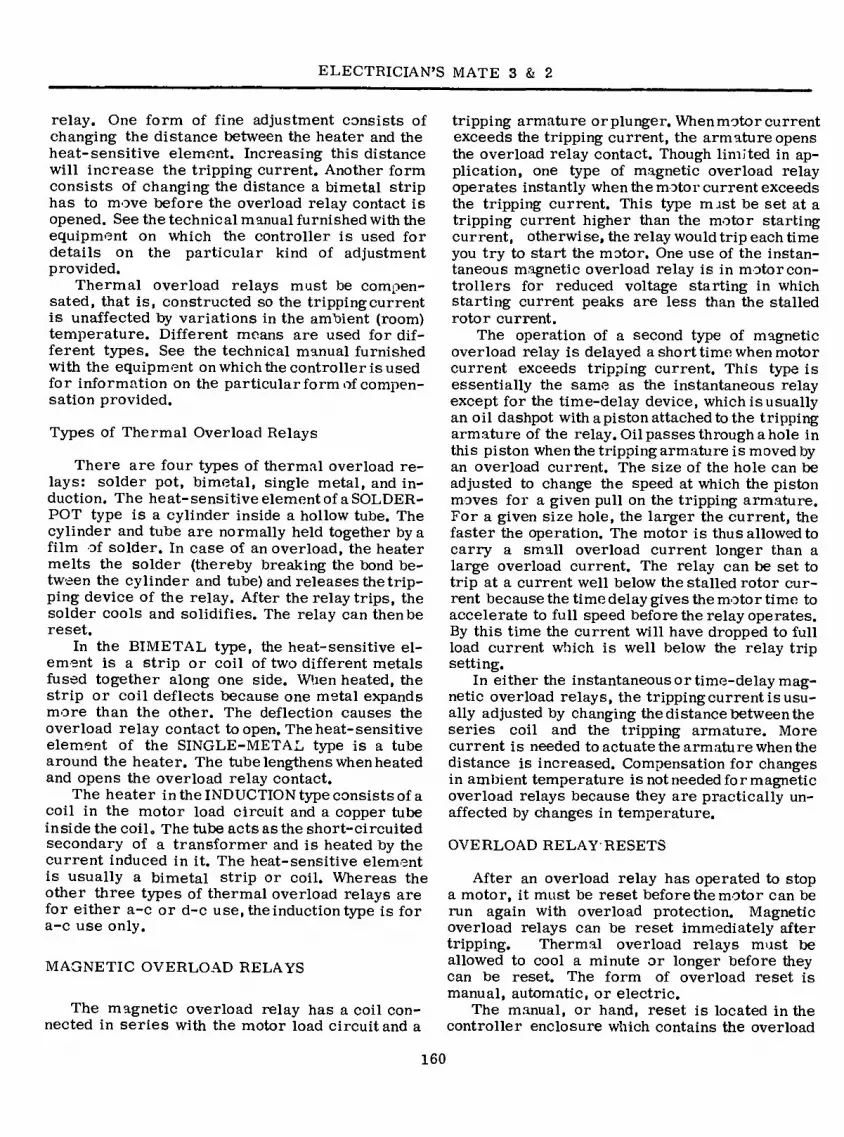
ELECTRICIAN’S MATE 3 & 2
relay. One form of fine adjustment consists of changing the distance between the heater and the heat-sensitive element. Increasing this distance will increase the tripping current. Another form consists of changing the distance a bimetal strip has to move before the overload relay contact is opened. See the technical manual furnished with the equipment on which the controller is used for details on the particular kind of adjustment provided.
Thermal overload relays must be compen- sated, that is, constructed so the tripping current is unaffected by variations in the ambient (room) temperature. Different means are used for dif- ferent types. See the technical manual furnished with the equipment on which the controller is used for information on the particular form of compen- sation provided.
Types of Thermal Overload Relays
There are four types of thermal overload re- lays: solder pot, bimetal, single metal, and in- duction, The heat-sensitive element of a SOLDER- POT type is a cylinder inside a hollow tube. The cylinder and tube are normally held together by a film of solder. In case of an overload, the heater melts the solder (thereby breaking the bond be- tween the cylinder and tube) and releases the trip- ping device of the relay. After the relay trips, the solder cools and solidifies. The relay can then be reset.
In the BIMETAL type, the heat-sensitive el- ement is a strip or coil of two different metals fused together along one side. When heated, the strip or coil deflects because one metal expands more than the other. The deflection causes the overload relay contact to open. The heat-sensitive element of the SINGLE-METAL type is a tube around the heater. The tube lengthens when heated and opens the overload relay contact.
The heater in the INDUCTION type consists of a coil in the motor load circuit and a copper tube inside the coil. The tube acts as the short-circuited secondary of a transformer and is heated by the current induced in it. The heat-sensitive element is usually a bimetal strip or coil. Whereas the other three types of thermal overload relays are for either a-c or d-c use, the induction type is for a-c use only.
MAGNETIC OVERLOAD RELAYS
The magnetic overload relay has a coil con- nected in series with the motor load circuit and a
tripping armature or plunger. When motor current exceeds the tripping current, the armature opens the overload relay contact. Though limited in ap- plication, one type of magnetic overload relay operates instantly when the motor current exceeds the tripping current. This type mast be set at a tripping current higher than the motor starting current, otherwise, the relay would trip each time you try to start the motor. One use of the instan- taneous magnetic overload relay is in motor con- trollers for reduced voltage starting in which starting current peaks are less than the stalled rotor current.
The operation of a second type of magnetic overload relay is delayed a short time when motor current exceeds tripping current. This type is essentially the same as the instantaneous relay except for the time-delay device, which is usually an oil dashpot with a piston attached to the tripping armature of the relay. Oil passes through a hole in this piston when the tripping armature is moved by an overload current. The size of the hole can be adjusted to change the speed at which the piston moves for a given pull on the tripping armature. For a given size hole, the larger the current, the faster the operation. The motor is thus allowed to carry a small overload current longer than a large overload current. The relay can be set to trip at a current well below the stalled rotor cur- rent because the time delay gives the motor time to accelerate to full speed before the relay operates. By this time the current will have dropped to full load current which is well below the relay trip setting.
In either the instantaneous or time-delay mag- netic overload relays, the tripping current is usu- ally adjusted by changing the distance between the series coil and the tripping armature. More current is needed to actuate the armature when the distance is increased. Compensation for changes in ambient temperature is not needed for magnetic overload relays because they are practically un- affected by changes in temperature.
OVERLOAD RELAY RESETS
After an overload relay has operated to stop a motor, it must be reset before the motor can be run again with overload protection. Magnetic overload relays can be reset immediately after tripping. Thermal overload relays must be allowed to cool a minute or longer before they can be reset. The form of overload reset is manual, automatic, or electric.
The manual, or hand, reset is located in the controller enclosure which contains the overload
160

Chapter 7 —MOTOR CONTROLLERS
relay. This form of reset usually has a hand- operated rod, lever, or button that returns the relay tripping mechanism to its original position, resetting interlocks as well, so the motor can be run again with overload protection. An interlock is a mechanical or electrical device actuated by a second device, to which it is connected, to govern succeeding operations of the second or other devices.
The automatic form, usually a spring- or gravity-operated device, resets the overload re- lay without the help of an operator. The electric reset is actuated by an electromagnet controlled by a pushbutton. This form is used when it is de- sired to reset an overload relay from a remote operating point.
OVERLOAD RELAYS-EMERGENCY RUN
Motor controllers having an emergency run feature are used with auxiliaries that cannot be stopped safely in the midst of an operating cycle. By means of this feature, the operator of an aux- iliary can keep it running with motor overloaded until a standby unit can take over, the operating cycle is completed, or the emergency passes. USE THIS FEATURE IN AN EM ERGENCY ONLY. DO NOT USE IT OTHERWISE.
The common means of providing emergency run in magnetic controllers are emergency run pushbutton, reset-emergency run lever, and start- emergency run pushbutton. In each case, the lever or pushbutton must be held closed during the entire emergency.
Figure 7-1 is a schematic diagram of a controller showing a separate EMERGENCY RUN pushbutton with normally open contacts in parallel with the normally closed contact of the overload relay. (A schematic diagram uses standard sym- bols to show the electrical location and operating sequence of the individual elements or devices; the schematic does not indicate their relative physical location .) For emergency run operation, the operator must hold down this pushbutton and press the START button to start the motor. While the emergency run pushbutton is held down, the motor cannot be stopped by opening the over- load relay contact.
A RESET—EMERGENCY RUN lever is shown in figure 7-2, As long as the lever is held down, the overload relay contact is closed. The start button must be momentarily closed to start the motor. Figure 7-3 shows a START—EMERGENCY RUN pushbutton. The motor starts when the button is pushed, and continues to run without overload
i
“ CONTROL CIRCUIT
_ FUSE MOTOR
CONTACTS OF MAIN
CONTACTOR
HEATERS OF THE
OVERLOAD RELAY
EXCESSIVE MOTOR CURRENT OPENS
THE OVERLOAD RELAY CONTACT —■
STOP
Q I n—
EMERGENCY START RUN
-Uh
i t INTERLOCK OF MAIN
CONTACTOR
OVERLOAD RELAY CONTACT
OPERATING COIL OF THE MAIN CONTACTOR. WHEN ENERGIZED, IT CLOSES:
(o) THE CONTACTS OF THE MAIN CONTACTOR -
AND
(b) THE INTERLOCK OF
THE MAIN CONTACTOR •
77.314 Figure 7-1.—Schematic of controller with
emergency run pushbutton.
protection as long as it is held down. For this reason, pushbuttons which are marked START— EMERGENCY RUN should not be kept closed for more than a second or two unless emergency run operation is desired.
Manual controllers may also be provided with the emergency run feature. The usual means is a START-EMERGENCY RUN pushbutton or lever which keeps the main contacts closed despite the tripping action of the overload relay mechanism.
SHORT CIRCUIT PROTECTION
Overload relays and contactors are usually not designed to protect motors from currents greater than about six times normal rated cur- rent of a-c motors or four times normal rated current of d-c motors. Since short-circuited currents are much higher, protection against short circuits in motor controllers is obtained through other devices. Recent Navy practice is to protect against these short circuits with circuit breakers placed in the power supply system. In this way, both the controller and motor are pro- tected, and so are the cables connected to the
161

ELECTRICIAN'S MATE 3 & 2
CONTROL CIRCUIT FUSE
MOTOR
START
STOP
o o
INTERLOCK OF MA N
CONTACTOR
CONTACTS OF MAIN CONTACTOR
HEATERS OF OVERLOAD RELAY
OVERLOAD RELAY CONTACT
OPERATING COIL OF MAIN CONTACTOR
RESET FOR OVERLOAD RELAY AND EMERGENCY RUN
field protection is a feature provided automati- cally by a relay which shunts out the shunt field rheostat for initial acceleration of the motor, and then cuts it into the motor field circuit. In this way, the motor first accelerates to 100 percent or “full field” speed, and then further accelerates to the “weakened field” speed determined by the rheostat settings.
Stepback Protection
The controller for an anchor windlass motor provides this kind or protection by automatically cutting back motor speed to relieve the motor of excessive load.
LOW VOLTAGE PROTECTION
When the supply voltage is reduced or lost altogether, a low-voltage RELEASE controller disconnects the motor from the power supply, keeps it disconnected until the supply voltage returns to normal, then automatically restarts the motor. This type of controller must be equipped with a maintaining master switch. Another type of low-voltage protection controller also disconnects
77.315 Figure 7-2. — Schematic of controller with reset-
emergency run lever.
controller. However, short-circuit protection is provided in the controller in cases where it is not otherwise provided by the power distribution system or where two or more motors are protected but the circuit breaker rating is too high for protection of each motor separately.
Short-circuit protection for control circuits is provided by fuses in the controller enclosure. The fuses are connected in control circuits which run to remote pushbuttons, pressure switches, etc. In general, each control wire that leaves a controller should be protected by a fuse if the lead is not already protected by a current limiting device, such as a coil or resistor, located in the enclosure.
FULL FIELD PROTECTION
CONTROL CIRCUIT FUSE
MOTOR
START AND EMERGENCY
RUN STOP
o I r>
CONTACTS OF MAIN CONTACTOR
HEATERS OF OVERLOAD RELAY
OPERATING COIL OF MAIN CONTACTOR
HI—Hf t t
INTERLOCK OVERLOAD OF MAIN RELAY
CONTACTOR CONTACT
Full field protection is required in the con- troller for a d-c motor in which a shunt field rheostat or resistor is used to weaken the motor field and obtain motor speeds in excess of 150 percent of the speed at rated field current. Full
77.316
Figure 7-3.— Schematic of controller with start- emergency run pushbutton.
162

Chapter 7—MOTOR CONTROLLERS
the motor from the supply and keeps it dis- connected until the supply voltage returns to normal. With this type, however, the operator must restart the motor. This type controller is equipped with a momentary master switch.
MAGNETIC AC ROSS-LINE CONTROLLERS
A typical three-phase across-line controller is shown in figure 7-4. Figure 7-5 shows a small cubical contactor for a 5-hp motor. All are simi- lar in appearance but vary in size. An elementary or schematic diagram of a magnetic controller is shown in figure 7-2.
The motor is started by pushing the START button. The action completes the circuit from Li through the control fuse, STOP button, START button, the overload relay contacts, OL, and the contactor coil, M to L3. When the coil is ener- gized, it closes line contacts Ml, M2, and M3, which connect the full-line voltage to the motor. The line contactor auxiliary contact, MA, also
77.147X Figure 7-5. — Contactor-for a 5-horsepower motor.
i /
27.319X Figure 7-4. — Across-line, 3-phase, controller.
closes and completes a holding circuit for ener- gizing the coil circuit after the START pushbutton has been released.
The motor will continue to run until the contac- tor coil is deenergized by the STOP pushbutton, failure of the line voltage, or tripping of the over- load relay, OL.
REVERSING
The rotation of a 3-phase induction motor is reversed by interchanging any two of the three leads to the motor. The connections for an a-c reversing controller are illustrated infigure 7-6. The STOP, REVERSE, and FORWARD pushbutton controls are all momentary-contact switches. Note the connections to the REVERSE and FOR- WARD switch contacts. (Their contacts close or open momentarily, then return to their original closed or opened condition.)
If the FORWARD pushbutton is pressed (solid to dotted position), coil F will be energized and will close its holding contacts, FA. These con- tacts will remain closed as long as coil F is ener- gized. When the coil is energized, it also closes line contacts, Fl, F2. and F3, which applies full- line voltage to the motor. The motor then runs in a forward direction.
If either the STOP button or the REVERSE button are pressed, the circuit to the F contactor coil will be broken and the coil will release and open line contacts Fl, F2, F3, and holding con- tact FA.
163

I
ELECTRICIAN’S MATE 3 & 2
T0 3PH- /»la A.C.SUPPLY^
10 A C0NTR0LI
FUSE
FI / LI
R1
FZ T2
ÖLS MOTOR
<5 OL F3
R3
OL. OL. STOP FWD REV
RA
MOMENTARY CONTACT PUSHBUTTONS)
77.148 Figure 7-6. — Reversing a-c controller.
LOL HOL LOL HOL
's
MOTOR 2 SPEED 2 WINDIN CONTROL
CIRCUIT FUSE
EMERGENCY RUN Jl'GH
LOW SPEED SPEED STOP
HOL LOL
CONTACTS OF
OVERLOAD RELAYS,
HIGH SPEED AND LOW SPEED
INTERLOCKS OF
MAIN CONTACTORS, HIGH SPEED AND
LOW SPEED.
CONTACTS OF MAIN
CONTACTORS, HM FOR
HIGH SPEED CONTAC-
TOR, LM FOR LOW SPEED CONTACTOR.
HEATERS OF OVERLOAD
RELAYS, HOL FOR
HIGH SPEED, LOL FOR
LOW SPEED.
OPERATING COILS
OF MAIN CONTACTORS, HIGH SPEED AND
LOW SPEED.
77.317 Figure 7-7.— Two-speed, a-c controller.
If the REVERSE pushbutton is pressed (solid to dotted position) coil R will be energized and will close holding contacts RA and line contacts RI, R2, and R3. Note that contacts RI, R2, andR3 reverse the connections of lines 1 and 3 to motor terminals T1 and T3. This causes the motor rotor to rotate in the reverse direction. The F and R contactors are mechanically interlocked to pre- vent both being closed at the same time.
Momentary contact pushbuttons provide low- voltage protection with manual restart in the cir- cuit shown in figure 7-6. If either the F or R operating coil is deenergized, the contactor will not reclose and start the motor when voltage is restored unless the FORWARD or REVERSEpush- button is pressed. The circuit arrangement of the pushbuttons constitutes an electrical interlock that prevents energizing both coils at the same time.
SPEED CONTROL
When it is desired to operate an a-c motor at different speeds, use a controller with a circuit as shown in figure 7-7.
An a-c induction motor that has been designed for two-speed operation may have either a single winding or two separate windings, one for each speed. Figure 7-7 is a schematic diagram of the a-c controller for a 2-speed, 2-winding induc- tion motor. The motor slow winding is connected to terminals Tl, T2, and T3. The motor fast wind- ing is connected to terminals Til, T12, and T13, Overload protection is provided by the LOL coils and contacts for the slow winding and the HOL contacts and coils for the fast winding. The LOL and HOL contacts are connected in series in the maintaining circuit and must both be closed be- fore the motor will operate on either speed.
The control pushbuttons are of the momentary contact type. Pressing the high-speed pushbutton closes the high-speed contactor by energizing coil HM. This coil remains energized, after the pushbutton is released, through holding contacts HA. The coil, HM also closes main line contacts HMi, HMa, and HM3 which apply full-line voltage to the motor high-speed winding. The motor will then run at high speed until coil HM is deenergized.
Pressing the low-speed pushbutton closes the low-speed contactor by energizing coil LM. The coil remains energized, after the button is re- leased, through holding contacts LA. The coil, LM, also closes mainline contacts LMltLM2,and LM g which apply full-line voltage to the motor low-speed winding. The motor will then run at low speed until coil LM is deenergized. The LM and
164

Chapter 7 —MOTOR CONTROLLERS
HM contactors are mechanically interlocked to prevent both being closed at the same time.
AUTOTRANSFORMER CONTROLLERS
A single-phase autotransformer has a tapped winding on a laminated core. Normally, only one coil is used on each core, but it is possible to have two autotransformer coils on the same core. Fig- ure 7-8 shows the connections for a single-phase autotransformer being used to step down voltage. Part of the winding, that between aandb, is com- mon to both primary and secondary and carries a current that is equal to the difference between the load current and the supply current.
Any voltage applied to the terminals, a and c, will be uniformly distributed across the winding in proportion to the number of turns. Therefore, any voltage that is less than the source voltage can be obtained by tapping the proper point on the winding between terminals a and c.
Some autotransformers are designed so that a knob-controlled slider makes contact with wires of the winding in order to vary the load voltage.
The positive directions for current flow through the line, transformer winding, and load are shown by the arrows in figure 7-8. Note that the line current is 2.22 amperes and that this cur- rent also flows through the part of the winding between b and c. In the part of the winding that is between a and b, the load current of 7 amperes is opposed by the line current of 2.22 amperes.
Ei =440 VOLTS lj=7 AMPERES
E} = 140 VOLTS LOAD
li = 5.22 AMPERES
77.143 Figure 7-8. — Single-phase autotransformer
Therefore, the current through this section is equal to the difference between the load current and the line current. If you subtract 2.22 amperes from 7 amperes you will find the secondary cur- rent is 4.78 amperes.
Two common uses for autotransformers are to start 3-phase induction and synchronous motors and to furnish variable voltage for test panels. Figure 7-9 shows an autotransformer motor starter, which incorporates starting and running magnetic contactors, an autotransformer, a ther- mal overload relay, and a mercury timer to con- trol the duration of the starting cycle.
D-C CONTROLLERS
The starting of all d-c motors, with the ex- ception of fractional horsepower sizes, requires a temporary insertion of resistance in series with
77.144 Figure 7-9» — Autotransformer controller.
165

ELECTRICIAN’S MATE 3 & 2
- -O- •„ —
© ' D
« 1
o^C? ^n>
* *;:^>^aá^i^ékíj'.'^ür ■:) '•> '1 ') x) Wn h k) ii'ü^ ~^-<,
I
Figure 7-10. — A representative d-c controller. 27.318X
the armature circuit to limit the high in-rush cur- rent at standstill. Because of this consideration the starting resistance cannot be safely removed from the line until the motor has accelerated in speed and the counter electromotive force is of sufficient strength to limit the current to a safe value.
Auxiliary motors located below deck general- ly drive constant-speed equipment. A rheostat in
the shunt field circuit is, however, provided to fur- nish speed control for motors operating with ventilation fans, forced draft blowers, and certain pumps where conditions may require operation at more than one speed.
With motors of small rating one stage of starting resistance remaining in the line for a few seconds is generally sufficient to limit the starting current. With the larger motors two or more
166

Chapter 7 —MOTOR CONTROLLERS
stages of resistance are connected in the line at starting and are cut out in steps as the motor accelerates to running speed.
Motors supplied with cargo winches and other deck auxiliaries are required to operate over a wide range of speed. Since the speed of a d-c motor with constant load varies almost directly with the voltage, stages of line resistance are used to make speed changes and also to limit the current at starting. These stages of line resis- tance are connected in various combinations as manually selected by a master switch operating in conjunction with a magnetic controller. Thus, the operator directly controls the amount of resis- tance in the line and the resulting speed of the motor at all times.
ONE-STAGE ACCELERATION
Figure 7-10 shows a representative d-c con- troller. The connections for this motor controller with one stage of acceleration is shown in figure 7-11. When the START button is pressed, the path for current is from line terminal L2 through the control fuse, STOP button, the START button, and the line contactor coil LC to line term'nal LI. Current flowing through the contactor coil causes the armature to pull in and close the line contacts, LCl, LC2, LC3, and LC4.
When contacts LCl and LC2 close, motor- starting current flows through the series field, SE, the armature, A, the series relay coil, SR, the starting resistor, R, and the overload relay coil, OL. At the same time, the shunt field winding, SH, is connected across the line and establishes normal shunt field strength. Contacts LC3 close and prepare the circuit for the ac- celerating contactor coil, AC. Contacts LC4 close the holding circuit for the line contactor coil, LC.
The motor armature current flowing through the series relay coil causes its armature to pull in; opening the normally closed contacts, SR. As the motor speed picks up, the armature current drawn from the line decreases. At ap- proximately 110 percent of normal running cur- rent, the series relay current is not enough to hold its armature in; therefore, it drops out and closes its contacts, SR. These contacts are in series with the accelerating relay coil, AC, and cause it to pick up its armature, closing contacts ACl and AC2.
Auxiliary contacts ACl on the accelerating relay keep the circuit to the relay coil closed while the main contacts, AC2, short out the starting resistor and the series relay coil. The motor is then connected directly across the line, and the
SH
Sb OU LC2 SR R LCl SE
AC2
LC3
SR AC
ACl CONTROL
' FUSE
START-EMERG. STOP LC
Ö o 1“—"v
OL
LC4
Figure 7-11. — D-c controller with one stage of acceleration.
77.140

ELECTRICIAN’S MATE 3 & 2
RHEO.
SH
-vw-
Hl- FA
L2, LC
HI—f- SE S v FA, FA2 SR
—\ [
LC
B^c
AC SR
AC
«LI
CONTROL
FUSE
START-EMERG.
STOP
_Q o O- LC
LC OL
Figure 7-12. — D-c controller with shunt field rheostat. 77.142
connection will be maintained until the STOP button is pressed.
If the motor becomes overloaded, the ex- cessive current through the overload coil (OL at the top right of fig. 7-11) will open the over- load contacts (at the bottom of fig. 7-11) to dis- connect the motor from the line.
If the main contactor drops out because of an excessive drop in line voltage or a power failure, the motor will remain disconnected from the line until an operator restarts it with the “START” pushbutton. This prevents automatic re starting of equipment when normal power is restored, which is low voltage protection.
SPEED CONTROL
Figure 7-12 illustrates how a rheostat is added to the basic controller circuit to obtain varying speed.
If resistance is added in series with the field, the field will be weakened and the motor will speed up. If the amount of resistance in series with the field is decreased, the field strength will increase and the motor will slow down.
Contacts FA (fig. 7-12) are closed during the acceleration period providing full shunt field strength. After the motor has accelerated to the across-the-line position, contacts F A open placing the rheostat in the shunt field circuit. This is full field protection.
REVERSING
In certain applications, the direction in which a d-c motor turns is reversed by reversing the connections of the armature with respect to the field. The reversal of connections can be done in the motor controller by adding two electrically and mechanically interlocked contactors.
168

Chapter 7 —MOTOR CONTROLLERS
A d-c motor reversing connection is given in i figure 7-13. Note that there are two START ' touttons—one marked, START EMERG FORWARD (and the other marked, START EM ERG REVERSE. These buttons serve as master switches, and the desired motor rotation is obtained by pressing the proper switch.
Assuming that the FORWARD button has been pressed, the line voltage will be applied through the button to the forward contactor coil, F, which pulls in its armature and closes the normally open contacts in the motor armature circuit, Fl, F2, the forward contactor holding circuit, F3, the line contactor (LC) operating circuit, F4, and
opens its normally closed contact, F5, in the reverse contactor circuit. The normally closed contact, F5, is an electrical interlock. With the forward contactor operated, the reverse contactor cannot be energized.
After the line contactor is energized, ac- celeration is accomplished in the manner de- scribed previously.
D-C CONTACTOR
The complete contactor is composed of an operating magnet, which is activated by either switches or relays, fixed contacts, and moving
SH
LC
L2 O—•-
CONTROL
FUSE
OL LC SR RES. SE
AC
LC
SR AC
AC
START-EMERG.
FORWARD
STOP
-O 1 O- OL
START-EMERG. -1- R
REVERSE
F R
JK-
\ n
LC
Figure 7-13. — Reversing d-c controller.
77.141

ELECTRICIAN’S MATE 3 & 2
contacts. It may be used to handle the load of an entire bus, or a single circuit or device. However, when heavy currents are to be inter- rupted, larger contacts must be used. The con- tacts must snap open or closed to reduce contact arcing and burning. In addition to these pre- cautions, other arc-quenching means are used.
BLOWOUT COILS
When a circuit carrying appreciable direct current is interrupted, the collapse of the flux linking the circuit may induce a voltage, which will cause an arc. If the spacing between the open contacts is small, the arc will continue once it is started. The arc, if it continues long enough, will either melt the contacts or weld them to- gether. Magnetic blowout coils overcome this condition by providing a magnetic field, which blows out the arc in much the same manner as you would blow out a match.
The magnetic blowout operation is illustrated in figure 7-14. It is important that the fluxes
remain in the proper relationship. Otherwise, if the direction of the current is changed, the blowout flux will be reversed and the arc will actually be pulled into the space between the contacts.
When the direction of electron flow and flux are as illustrated in figure 7-14, the blowout force is upward. The blowout effect varies with the magnitude of the current and with the blowout flux. The blowout coil should be chosen to match the current so that the correct amount of flux will be obtained. The blowout flux across the arc gap is concentrated by a magnetic path pro- vided by the steel core in the blowout coil and the steel pole pieces extending from the core to either side of the gap.
ARCING CONTACTS
Because arcing at contacts wears away the usable surface, a second set of contacts (arcing contacts) is shunted across the main contacts.
ARC BEING BLOWN UP
FLUX DUE TO ARC ENCIRCLES ARC
BLOWOUT CORE //' ///
' /
Y
-KsJ i ' ' /
✓ / ' / ' ✓ /
DIRECTION OF FLUX FROM BLOWOUT COIL
STEEL POLE PIECES PROVIDE A FLUX PATH ACROSS THE CONTACTS
DIRECTION OF ELECTRON FLOW THRU THE BLOWOUT COIL AND CONTACTS
77.122 Figure 7-14. — Action of magnetic blowout coil.
170

Chapter 7—MOTOR CONTROLLERS
-r
? —<3)
77.318 Figure 7-15. — Detailed view of arcing contacts.
A shunt-type contactor that will handle 600 amperes at 230 volts is pictured in figure 7-15. The blowout shield is removed in the detailed view. The diagram shows the main sections of the contactor. The arcing contacts (l) are made of rolled copper, which has a heavy protective coating of cadmium. These contacts are self-cleaning because of a sliding or wiping action after the initial contact is made. The wiping action keeps the surface bright and clean and thus maintains a low contact resistance.
The contactor is operated by connecting the coil (2) directly across a source of d-c voltage. When the coil is energized, the movable armature ® is pulled toward the stationary magnet core
This action causes the contacts that carry current (s) (?) (7), and (Î) to close with a sliding action.
The main contacts, (?) and (?), are called brush contacts. They are made of thin leaves of copper, which are backed by several layers of phosphor bronze spring metal. A silver brush arc- ing tip (?) is attached to the copper leaves and makes contact slightly before the leaf contact closes. The stationary contact (?) consists of a
brass plate which has a silver-plated surface. The plating lowers the surface resistance, and there- fore the contact surfaces should never be filed or oiled. If excessive current has caused high spots on the contact, the high places may be smoothed down by careful use of a fine ignition- type file.
Operation and contact spacing may be checked by manually closing the contactor (be sure the pgwer is off). The lowest leaf of brush contact uQ in figure 7-15 should just barely touch contact Qy. If the lower leaf hits the plate too soon, the entire brush assembly should be bent upward slightly.
The contact dimensions should be measured with the contactor in the OPEN position.
Refer to the manufacturer’s instruction book when making these adjustments.
ELECTRIC BRAKES
An electric brake , is an electromagnetic device whose function is to bring a load to rest mech- anically and hold it at rest. Aboard ship, electric brakes, are used on motor-driven hoisting and lowering equipment where it is important to stop the motor quickly. The type of electric brakes used depends on whether the motor is a-c or d-c and also whether a d-c motor is series or shunt wound.
A-C SOLENOID BRAKE
The magnetic brake assembly shown in figure 7-16 is the main component of this electric brake. When the coil is energized, two armatures are pulled horizontally into the coil. The armatures are mechanically linked to the levers. The levers pivot on the pins. When the magnetic pull over- comes the pressure of the coil springs, the pressure of brake shoes on the drum releases and allows it to turn. The drum is mechanically coupled to the motor shaft or the shaft of the device driven by the motor. The coil is connected to the voltage supply lines. The method of connecting the coil (series or parallel) is determined by the coil design. The magnetic brakes are applied when the coil is not energized. A spring or weight holds the band, disc, or shoes against the wheel or drum. When the coil is energized, the armature or sole- noid plunger overcomes the spring tension and releases the brake.
The a-c solenoid brake frame and solenoid are of laminated construction to reduce eddy currents
171

ELECTRICIAN’S MATE 3 & 2
ARMATURES
(Q)
n o o
^J^0IL
o o o
\
_
O O o INS
i'-'N
cou PL NS
V \ ' \
if 1 iT4
tt'iTrînnW^
LEVERS
COIL SPRINGS
Figure 7-16. — Magnetic brake assembly. 77.138
which are characteristic of a-c systems. Because the magnetic flux passes through zero twice each cycle, the magnet pull is not constant. To over- come this, shading coils are used to provide pull during the change of direction of the main flux. The principal disadvantage of an a-c solenoid is that it draws a heavy current when voltage is first applied.
A-C TORQUE MOTOR BRAKE
The torque motor brake uses a specially wound polyphase squirrel-cage motor in place of the brake release solenoids. The motor may be stalled without injury to the winding and without drawing heavy currents. The mechanical arrange- ment of a torque-motor brake assembly and the,
172

Chapter 7 —MOTOR CONTROLLERS
D-C DYNAMIC BRAKE
O lis r 3
£ A BRAKE ASSEMBLY
B BALL-JACK ASSEMBLY
77.139
Figure 7-17. —Torque-motor brake and ball jack assembly.
Dynamic braking is similar to the slowing down of a moving truck by means of the com- pression developed in its engine. A d-c motor also slows down when being driven by its load, if its field remains excited. In this case, the motor acts as a generator and returns power to the supply, thereby holding the load. In an actual braking system, however, the d-c motor is dis- connected from the line; its armature and field are connected in series with a resistor to form a loop. The field connections to the armature are reversed so that the armature countervoltage maintains the field with its original polarity.
Figure 7-18 shows the connections in the dynamic braking system of a series-wound d-c motor. The field switching is carried out by switches Si, S2, and S3, which are parts of a 3TPDT assembly. These switches are magnet- ically operated from a controller. With the switch arms in position 1, the motor operates from the line. When the switch arms are in position 2, the resistor is connected in series with the field, and, at the same time, the field coil connection to the armature is reversed. Thus, as long as the
ball-jack assembly is shown in figure 7-17. This assembly is used with an anchor windlass.
The mechanical connection between the tor- que-motor shaft and the brake operating lever is through a device called a “ball jack” (fig. 7-17B), which converts the rotary motion of the torque- motor shaft to a straight line motion.
When power is applied to the torque motor, the shaft turns in a clockwise direction resulting in an upward movement of the jack screw (?) (fig. 7-17B). The thrust element (T) in the jack pushes upward against the operating lever (2) (fig. 7-17A) to release the brake. As soon as the brake is fully released, the torque motor stalls across the line. This holds pressure against the spring @in figure 7-17A, and keeps the brake released.
When the voltage supply to the torque motor is interrupted, the torque spring forces the brake
1 shoes against the brake drum. This stops and holds the windlass drive shaft.
The torque motor brake can be released manually by raising lever ©, However, if the lever is not held manually in the UP position, the brake will be applied.
LI POS. I
——o
POS. 2
BRAKING RESISTOR
—VMWV—1
ARMATURE
¿S3 S2
SERIES FIELD
—IOOOJ—
77.136
Figure 7-18. —Connections for dynamic braking of a series-wound d-c motor.
173

ELECTRICIAN’S MATE 3 & 2
L2 BRAKING
RESISTOR
J POS.
z; S2
POS. 2 o 20
ARMATURE
SHUNT FIELD
77.137 Figure 7-19„ — Connections for dynamic braking
of a shunt-wound d-c motor.
armature turns, it generates a countervoltage, which forces current through the resistor and the series field. Although the direction of current flow through the armature is reversed (because of the countervoltage), the direction through the series field coil is not reversed. When operating in this way, the motor is essentially a generator that is being driven by the momentum of the ar- mature and mechanical load. Energy is quickly consumed in forcing current through the resistor, and the armature stops turning.
The time required to stop the motor may be varied by using different resistor values. The lower the resistance, the faster the braking action. If two or more resistors are connected by switches, the braking action can be varied by 'switching in different load resistors. Usually,the same braking resistors that are used to stop the motor are also used to reduce the line voltage during acceleration.
When dynamic braking is used with a d-c shunt- wound motor, resistance is connected across the armature (fig. 7-19).
Switches, Si and S2, are parts of a DPDT circuit breaker assembly. When the switch arms are connected to position 2, the armature is across the line, and motor operation is obtained. When the switch arms are in position 1, the armature
is disconnected from the line and connected to the resistor. The shunt field remains connected to the line. As the armature turns, it generates a countervoltage, that forces current through the resistor. The remainder of the action is the same as described for the circuit in figure 7-18.
Although dynamic braking provides an effec- tive means of slowing motors, it is not effective when the field excitation fails or when an at- tempt is made to hold heavy loads; without rotation the countervoltage is zero, and no braking reaction can exist between the armature and the field. D-C MAGNETIC BRAKE
Magnetic brakes are used for complete braking protection. In the event of field excitation failure, they will hold heavy loads. A spring applies the brakes, and the electromagnet releases them.
Disc brakes are arranged for mounting di- rectly to the motor end bell. The brake lining is riveted to a steel disc, which is supported by a hub keyed to the motor shaft. The disc rotates with the motor shaft.
The band type brake has the friction material fastened to a band of steel, which encircles the wheel or drum and may cover as much as 90 percent of the wheel surface. Less braking pressure is required and there is less wear on the brake lining when the braking surface is large.
D-c brakes are operated by a solenoid which is designed the same as the a-c sole- noid brake (fig, 7-16) except the d-c brake construction is of solid metals and requires no laminations as does the a-c magnetic brake.
CONTROLLER TROUBLESHOOTING
Although the Navy maintains a policy of pre- venting trouble, sometimes trouble is unavoidable. In general, when a controller fails to operate, or signs of trouble (heat, smoke, smell of burning insulation, etc) occur, the cause of the trouble can be found by conducting an examination that consists of nothing more than using the sense of feel, sight, and sound. On other occasions, however, locating the cause of the problem will involve more detailed actions.
Troubles tend to gather around mechanical moving parts and where electrical systems are interrupted by the making and breaking of con- tacts. Center your attention in these areas. See table 7-1 for a list of common troubles, their causes, and corrective actions.
174

Chapter 7—MOTOR CONTROLLERS
Table 7-1.—Troubleshooting Chart
Contacts
Trouble Probable cause Remedy
Contact chatter Poor contact in control relay Broken shading coil Excessive jogging
Overheated contact tips Dirty contact tips
Sustained overloads
Weak tip pressure.
Short tip life . . .
Welding or fusing .
Insufficient tip pressure Loose connections Wear allowance gone Poor tip adjustment Low voltage which prevents magnet sealing. Excessive filing or dressing Excessive jogging Abnormal starting currents
Rapid jogging Short circuit currents on contacts
Failure of the flexible con- ductors between fixed and moving parts of contactor
Improper installation Worn out mechanically by large number of
operations.
Moisture or corrosive atmosphere
Burned by arcing or over-heating from loose, oxidized, or corroded connections ....
Clean relay contact. Replace Caution operator to avoid excessive
jogging- Clean and dress, if necessary, in ac-
cordance with chapter 9600 or manufacturer’s instructions.
Find and remedy the cause of the over- loads.
Clean and adjust. Clean and tighten. Replace contacts and adjust. Adjust “gap” and “wipe”. Correct voltage condition. Follow manufacturer’s instructions. Instruct operator in correct operation. Operate manual controllers slower.
Check automatic controllers for cor- rect starting resistors and proper functioning of timing devices or accelerating relays.
Instruct operator in correct operation. Find and remedy causes of short cir-
cuits. Check feeder fuses for pro- per size and replace, if necessary.
See manufacturer’s instructions. Replace.
Replace with flexible conductors suit- able for application.
Clean and tighten connections.
Coils
Trouble Probable cause Remedy
Coil failure: (a) Not overheated
(b) Overheated . .
Moisture, corrosive atmosphere Mechanical damage Vibration or shock damage Overvoltage or high ambient temperature Wrong coil
Too frequent use, or rapid jogging .... Undervoltage, failure of magnet to seal in
Used above current rating Loose connections to coil, or corrosion or oxi-
dation of connection surfaces Improper installation
Use correctly insulated coils. Avoid handling coils by the leads Secure coils properly. Check current and application. Use only the manufacturer’s recom-
mended coil. Use correct operating procedure. Check circuit and correct cause of low
voltage. Install correct coil for the application. Clean and tighten connection.
See manufacturer’s instructions.
77.310
175

ELECTRICIAN’S MATE 3 & 2
Table 7-1. — Troubleshooting Chart (continued)
Electric brakes, solenoid or motor operated
Trouble Probable cause Remedy
Worn or broken parts
Failure to hold load .
Failure to set
Failure to release
High inertia loads, misapplication, excess tem- perature
Worn parts, out of adjustment, wrong brake lining
Grease or oil on brake drum Out of adjustment, worn parts
Mechanical binding . Coil not deenergized.
Out of adjustment . .
Coil not energized Wrong coil Coil open or short circuited Motor will not run Motor binds
Replace parts and refer to technical manual for correct procedures.
Replace parts with correct materials and adjust according to technical manual.
Clean thoroughly with approved solvent. Replace worn parts and adjust in ac-
cordance with technical manual. Clean and adjust. Check circuit to make sure current is
cut off. Adjust in accordance with technical
manual. Check and repair circuit. Replace with correct coil. Replace coil. Refer to technical manual. Aline correctly, check bearings.
Magnets and mechanical parts
Trouble Probable cause Remedy
Worn or broken parts.
Noisy magnet
Broken shading coil
Failure to drop out
Heavy slamming caused by over-voltage or wrong coil
Chattering caused by broken shading coil or poor contact in control circuit
Excessive jogging Mechanical abuse Broken shading coil Magnet faces not true, result of mounting strain. Dirt or rust on magnet face Low voltage
Improper adjustment, magnet overloaded
Heavy slamming caused by over-voltage, magnet under-loaded, weak tip pressure
Gummy substances on magnet faces Worn bearings Nonmagnetic gap in magnet circuit Voltage not removed Not enough mechanical load on magnet, improp-
er adjustment
Replace part and correct cause
Replace. Correct mounting. Clean. Check system voltage and correct if
wrong. Check and adjust according to manu-
facturer’s instructions. Replace coil and correct the cause.
Clean with approved solvent. Replace. Replace magnet. Check coil voltage. Adjust in accordance with manu-
facturer’s instructions.
77.319.1
When a mDtor-control 1er system hàs failed and pressing the START button will- not start the system, then press the overload relay reset pushbuttons and again attempt to start the motor. Observe what happens. The system may start and
operation is restored, or you hear the controller power contacts close but the motor will not start, or the system may be dead. If you hear the power contacts close, then the POWER circuit needs to be checked. If the system remains dead
176

Chapter 7 —MOTOR CONTROLLERS
Table 7-1. — Troubleshooting Chart (continued)
Overload relays
T rouble
Magnetic, instantaneous type: High or low trip . . . .
Probable cause
Wrong coil Mechanical binding, dirt, corrosion, etc. Shorted turns (High trip) Assembled incorrectly
Wrong calibration
Remedy
Install correct coil. Clean with approved solvent, adjust. Test coil, and replace if defective. Refer to manufacturer’s instructions
for correct assembly. Replace.
Magnetic, inverse time delay type: Slow trip Fluid dirty, gummy, etc
Mechanical binding, corrosion, etc Worn or broken parts Fluid too low
Change fluid and nil to correct level. Clean with approved solvent, adjust. Replace and adjust. Drain and refill to correct level.
Thermal type: Failure to trip
Trips at too low tem- perature
Wrong size heater Mechanical binding, dirt, corrosion, etc. . Relay damaged by a previous short circuit Wrong size heater
Install correct size. Clean with approved solvent and adjust. Replace. Install correct size.
Failure to reset
Burning and welding of control contacts . . . .
Turning relays, flux decay type: Too short time
Too long time
Assembled incorrectly
Wrong calibration Broken mechanism or worn parts. Corrosion, dirt, etc Short circuits in control circuits with fuses that
are too large
Dirt in air gap Shim to thick Too much spring or tip pressure
Misalinement
Shim worn too thin Weak spring and tip pressure
Gummy substance on magnet face or mechanical binding.
See technical manual for correct assembly.
Replace. Replace. Clean and adjust. Correct causes of short circuits and
make sure that fuses are right size.
Clean. Replace with thinner shim. Adjust in accordance with technical
manual. Correct aiinement, and remedy cause
of misalinement. Replace with thicker shim. Adjust in accordance with technical
manual. Clean with approved solvent and adjust.
77.319.2
then the CONTROL circuit will have to be checked. An example of troubleshooting a motor-controller electrical system is given in a sequence of steps which may be used in locating a fault (fig. 7-20). First, we will startbyanalyzingthe power circuit.
POWER CIRCUIT ANALYSIS
When no visual signs of failure can be located and an electrical failure is indicated in the power
circuit, you must first check the line voltage and fuses as shown in figure 7-20. Place the volt- meter probes on the hot side of the line fuses as shown at position “A”. A line voltage reading tells you that your voltmeter is operational and that you have voltage to the source side of the line fuses L1-L2, You may also check between L1-L3 and L2-L3. To check the fuse in line-1, place the voltmeter across the line fuse as shown
177

ELECTRICIAN'S MATE 3 & 2
S /S S CONTROL CIRCUIT VM
FUSE
LLJJ HOLDING
RELAY STOP
BUTTON
POWER J_ CONTRACTS ^ START ^
BUTTON o
HOLDING T CONTACT
OLI 0L3 OLI 0L3
CONTRACTOR
POWER CIRCUIT - HEAVY LINES
CONTROL CIRCUIT-LIGHT LINES
Tl ^T2 ^ T3
r<^7
MOTOR
77.299 Figure 7-20o — Troubleshooting 3-phase magnetic
line starter.
at position “B” between L1-L2. A voltage reading shows a good fuse in Ll. Likewise check the other two fuses between L1-L3 and L2-L3. A no-voltage reading would show a faulty fuse.
If the line fuses check good, then check the voltage between terminals T1-T2, T2-T3, and T1-T3. The controller is faulty if there aren’t voltmeter readings on all three of the terminal pairs and you would then proceed to check the power contacts, overloads, and lead connections
within the controller. However, if voltage is in- dicated at all three terminals, then the trouble is either in the motor or lines leading to the motor.
CONTROL CIRCUIT ANALYSIS
Suppose the overload reset buttons have been reset and the start switch closed. If the power contacts do not close, then the control circuit must be checked. A testing procedure follows.
1. Check for voltage at the controller at lines Ll, L2, L3.
2. Place the voltmeter probe sat points C and D (fig. 7-20). You should have a voltage reading when the STOP switch is closed and have a no- voltage reading when the STOP switch is open. The conditions would indicate a good STOP switch.
3. Next, check the voltage between points C and E. If you get a no-voltage reading when the START switch is open and a voltage reading when the START switch is closed, then the START switch is good.
4. Place the voltmeter probes at C and F. A voltage reading with the START button closed would indicate a good OL1, but would also indicate an open OL3, an open relay coil, or an open connection to line-3.
5. Place the voltmeter probes at points C and G and close the START switch. A no-voltage reading locates the trouble in the control circuit; the OLs is faulty.
A faulty holding relay contact will be indi- cated when the system operates only as long as the START pushbutton switch is held in the ON position but will shut down the system when the switch is released.
When starting a 3-phase motor, if the motor fails to start and gives a loud hum, you should stop the motor by pushing the stop button. These symptoms usually mean that one of the phases to the motor is not energized. You can assume that the control circuit is good since the main operat- ing coil has operated and the maintaining contacts are holding the main operating contactor in. Look for trouble in the power circuit (the main contacts, overload relays, cable, and motor).
178

CHAPTER 8
MAINTENANCE AND REPAIR OF MOTORS AND GENERATORS
The main objective of shipboard preventive maintenance is the prevention of breakdown, deterioration, and malfunction of equipment» If this objective is not realized, however, the alternative is repairing or replacing the failed equipment» Byperformingpreventive maintenance in accordance with prescribed procedures, you can ensure long satisfactory service of the equipment of the ship’s electric plant. Also, there will be occasions when, despite your best efforts, corrective action will be required to restore the electric plant to peak operating conditions.
This chapter describes maintenance practices and procedures for preventing casualties to and for diagnosing, repairing, and testing ship- board electric motors and generators. Additional information may be found in chapters 9600, 9610, and 9630 of NAVSHIPS Technical Manual.
CLEANING MOTORS AND GENERATORS
One of your most important jobs is to keep all electrical machinery clean. Dust, dirt, and foreign matter (carbon, copper, mica, etc) tend to block ventilation ducts and increase resis- tance to the dissipation of heat, causing local or general overheating. If the particles are conducting, or form a conducting paste through the absorption of moisture or oil, the winding may eventually be short circuited or grounded. Additionally abrasive particles may puncture insulation, iron dust is particularly harmful since the dust is agitated by magnetic pulsations.
The acceptable methods of cleaning motors and generators involve the use of wiping rags or cloths, suction, compressed air, and solvents.
Wiping with a clean, lint free, dry rag (such as cheesecloth) is effective, for removing loose dust or foreign particles from accessible parts of a machine. When wiping, do not neglect the end windings, mica cone extensions at the com- mutator of d-c machines, slip-ring insulation, connecting leads and terminals.
The use of suction is preferred to the use of compressed air for removing abrasive dust and particles from inaccessible parts of a ma- chine because it lessens the possibility of damage to insulation. If a vacuum cleaner is not available for this purpose, a flexible tube attached to the suction side of a portable blower will make a suitable vacuum cleaner. Always exhaust the blower to a suitable sump or overboard. Grit, iron dust, and copper particles should be removed only by suction methods whenever possible.
The use of cleani dry, compressed air is effective in removing dry, loose dust and foreign particles particularly from inaccessible loca- tions, such as air vents in the armature punchings. Use air pressure up to 30 pounds per square inch to blow out motors or generators of 50 horsepower or 50 kilowatts or less; use pressure up to 75 psi to blow out higher rated machines. Where air lines carry higher pressure than is suitable for blowing out a machine, use a throttling valve to reduce the pressure. Always blow out any accumulation of water in the air pipe or hose before turning the air blast on the machine. Be careful with compressed air particularly if abrasive particles are present, since these may be driven into the insulation and puncture it or be forced beneath insulating tapes. Compressed air should be used only after the machine has been opened up on both ends so as to allow the air and dust to escape. The use of compressed air will prove of small benefit if the dust is not suitably removed from the machine. The most suitable method is to attach a suction blower to an opening in the opposite end from the air jet to remove the dirt-laden air.
The use of solvents for cleaning electrical equipment should be avoided whenever possible. However, their use is necessary for removing grease and pasty substances consisting of oil and carbon or dirt. Alcohol will injure most types of insulating varnishes and should not be used for cleaning electrical equipment. Solvents
179

ELECTRICIAN’S MATE 3 & 2
containing gasoline or benzine must not be used for cleaning purposes under any circum- stances nor is carbon tetrachloride used, because of its extremely high toxicity. Consult Chapter 2 of this training manual for detailed information on the use of solvents for cleaning electrical machinery.
Motors, generators, and other electrical equipment that have been wet with salt water should be flushed out with fresh water and dryed. Never let the equipment dry before flushing with fresh water. For complete information on washing and drying procedures refer to NAVSHIPS Technical Manual Chapter 9600,
BEARINGS
When a shaft is mounted in a device to hold it during rotation, friction develops at the contact point of the shaft with the device. Friction develops heat, and the amount of friction produced in a shaft housing must be reduced to a minimum to obtain satisfactory performance and longer life of the shaft. Devices which reduce the amount of friction produced by shafts in their housings are called bearings.
The two common types of bearings found in motors and generators are antifriction bearings and friction bearings,
ANTIFRICTION BEARINGS
Rolling, antifriction bearings are of two types: ball and roller bearings. Basically, all rolling bearings consist of two hardened steel rings, hardened steel rollers or balls; and separators. The annular, ring-shaped, ball bearing is the type of rolling bearing used most extensively in the construction of electric motors and gen- erators used in the Navy, This bearing is further divided into three types dependent upon the load it is designed to bear — (1) radial, (2) angular contact, and (3) thrust. Examples of these three bearings are shown in figure 8-1.
The rotating element of an electric motor or generator may subject a ball bearing to any one or a combination of three loads—radial, thrust, and angular. Radial loads are the result of forces applied to the bearing perpendicular to the shaft; thrust loads are the result of forces applied to the bearing parallel to the shaft; and angular loads are the result of a combination of radial and thrust loads. Because the load carried by the bearings in electric motors and
A M
Â
'A Á
RADIAL ANGULAR CONTACT THRUST
77.326 Figure 8-1. — Representative types of ball
bearings.
generators is almost entirely due to the weight of the rotating element, it is apparent that thei method of mounting the unit is a major factor in determining the type of bearing employed in its construction. In a vertically mounted unit, the thrust bearing would be used; while thei radial bearing is common to most horizontal units.
Wear
It is usually not necessary to measure the air gap on machines with ball bearings because; the construction of the machines is such as to ensure proper bearing alignment. Additionally, ball bearing wear of sufficient magnitude as to be readily detected by air-gap measurements would be more than enough to cause unsatisfactory operation of the machine.
The easiest way of determining the extent of wear in these bearings is to periodically feel the bearing housing while the machine is running to detect any signs of overheating or excessive vibration, and to listen to the bearing for the presence of unusual noise.
Rapid heating of a bearing is indicative of danger. Bearing temperature may feel uncomfort- able to the hand and might be a sign of dangerous overheating, but it is not always so. The bearing
180

Chapter 8 —MAINTENANCE AND REPAIR OF MOTORS AND GENERATORS
may be all right if it has taken an hour or more to reach that temperature; whereas, serious trouble can be expected if that same temperature is reached within the first 10 or 15 minutes of operation.
The test for excessive vibration relies to a great extent on the experience of the person conducting the test. He should be thoroughly familiar with the normal vibration of the machine in order to be able to correctly detect, identify, and interpret any unusual vibrations. Vibration, like heat and sound, is easily telegraphed, and a thorough search is generally required to locate its source and to determine its cause.
Ball bearings are inherently more noisy in normal operation than sleeve bearings (discussed later) and this fact must be borne in mind by personnel testing for the presence of abnormal noise in the bearing. A good method for sound testing is to place one end of a screwdriver or steel rod against the bearing housing and the other end against the ear. If a loud, irregular grinding, clicking, or scraping noise is heard, trouble is indicated. As before, the degree of reliance in the results of this test depends on the experience of the person conducting the test.
Checking the movement of a motor or gen- erator shaft can also give a good indication of the amount of bearing wear. In figure 8-2A, if the motor shaft has excessive vertical movement it indicates worn bearings. Figure 8-2B shows how to get a rough approximation of generator end-play movement. Excessive movement is cor- rected with bearing shims.
Lubrication
One cause of motor and generator failure is overlubrication. Forcing too much grease into
t;-
t=à
ß
73.300 Figure 8-2. — Checking motor or generatorshaft. (A) Vertical movements, (B) end-play movement.
GREASE CUP ( TO BE USED ONLY WHEN GREASING)
BALL BEARING
2 PIPE PLUG
GREASE FITTING
\
□RAIN PLUG
BEARING HOUSING
77.68 Figure 8-3. — Grease-lubricated ball bearings.
the bearing housing seals and onto the stationary windings and rotating parts of the machine will cause overheating and deterioration of in- sulation, and eventually results in electrical grounds and shorts. Overheating will also cause rapid deterioration of the grease and ultimate destruction of a bearing. To avoid the results of overlubrication, add new lubricant only when necessary.
The frequency with which new grease must be added depends upon the service of the machine and the tightness of the housing seals, and should be determined for each machine by the engineer officer. A large quantity of grease coming through the shaft extension end of the housing probably indicates excessive leakage inside the machine.
To prevent greasing by personnel in operating spaces, grease cups are removed from motors and generators. Pipe plugs are inserted in the place of the grease cups. The pipe plugs are replaced temporarily with grease cups during lubrication (fig. 8-3). (Removable grease cups should remain in the custody of responsible
181

ELECTRICIAN’S MATE 3 & 2
maintenance personnel.) Make sure the grease cups are clean. After the grease is added and before the pipe plugs are replaced, clean the pipe plugs.
The preferred method of adding grease calls for disassembly of the bearing housing. Though not recommended, renewing the bearing grease without at least partially disassembling the hous- ing can be tried under certain conditions (given later).
RENEWAL OF GREASE BY DISASSEMBLING THE BEARING HOUSING. —The extent of disas- sembly necessary will depend upon the construc- tion of the bearing. For the usual construction, bearings with outer bearing caps should be disassembled as follows:
1. Remove the outer bearing cap after thor- oughly wiping all exterior surfaces.
2. Remove old grease from all accessible portions of the housing and clean them thoroughly. Be careful not to introduce dirt or lint into the housing of the bearing.
3. Flush out the bearing cap with clean hot (about 120°F) kerosene, diesel fuel oil, or dry clean fluid. Then flush out with a light mineral oil (not heavier than SAE 10, similar to diesel lubricating oil).
4. Where practical, plug all holes leading into the interior of the machine and flush out the complete housing with the outer bearing cap removed. Use the solvents and procedure described in the preceding step unless the con- ditions are such that the cleaning fluids may leak into the windings. In such cases, omit this step.
5. Drain the mineral oil thoroughly; then pack the housing half full withfresh, clean grease.
6. Fill the grease cup with fresh clean grease and screw it down as far as it will go. KEEP THE MACHINE RUNNING CONTINUOUSLY.
7. Repeat step (6) above until clean grease begins to emerge from the drain hole.
8. At this point stop putting in grease and allow the machine to run until no more grease comes out of the drain hole. THIS STEP IS VERY IMPORTANT.
9. Clean any drain pipes which have been removed, and replace.
10. Replace the drain plug.
RENEWAL 07 GREASE WITHOUT DISAS- SEMBLING THE BEARING HOUSING. —Do not try to add new grease without at least partial dis- assembly of the bearing housing unless the following conditions apply:
1. The machine is horizontal. In vertical machines, there is no adequate means of pro- tecting the windings against displaced lubricant.
2. A suitable fitting is provided for admitting grease. If a grease-gun fitting is provided, it should be replaced by a grease cup.
3. The drain hole on the bearing housing is accessible. Drain pipes do not permit satis- factory escape of displaced grease, and should be removed when renewing grease.
4. The machine is run continuously while renewing grease. If the machine cannot be run continuously during the greasing period without injuring the driven auxiliary or endangering personnel, the bearing housing must be dis- assembled to renew grease.
If the above conditions apply, renew the grease in assembled bearing housings by the following method:
1. Run the machine to warm up the bearings.
2. Wipe any dirt away from the area around the grease fittings.
3. Remove drain plug and drain pipes from the drain hole in the bearing housing.
4. With a clean wire, screwdriver, or similar tool, clear the drain hole of all hardened grease.
5. Remove the grease cup and clear the grease inlet hole of hardened grease.
6. Pack the grease cup with grease and screw the grease cup down all the way, while the motor is running.
7. Repeat step 6 until grease runs out of drain hole.
8. Run the motor until the grease stops running out of the drain hole.
9. Replace the pipe plugs.
OIL-LUBRICATED BALL BEARINGS
Lubrication charts or special instructions are generally furnished for electric motors and
182

Chapter 8 —MAINTENANCE AND REJ2AIR OF MOTORS AND GENERATORS
generators equipped with oil-lubricated ball bear- ings. The oil level inside the bearing housing should be maintained approximately even with the lowest point of the bearing inner ring. At this level, there will be enough oil to lubricate 'the bearing for its operating period, but not enough to cause churning or overheating.
One common method by which the oil level is maintained in ball bearings is the wick-fed method. In this method, the oil is fed from an oil cup to the inside of the bearing housing through an absorbent wick, which also filters the oil and prevents leakage through the cup in the event momentary pressure is built up within the housing. A typical wick-fed, oil- lubricated ball bearing is shown in figure 8-4.
GREASE-LUBRICATED BALL BEARINGS
Ball bearings which normally operate at a. temperature of 194°F (90°C) or below should be lubricated with grease in accordance with Military Specification MIL-G-18709, Stock Nos. W9150-235-5544 and W9150-235-5564; ball bear- ings which normally operate at a higher tempera- ture should be lubricated with a silicone grease in accordance with Military Specification MIL-L- 15719A, Stock No. W9150-257-5358. Each machine
X Q X X X X X X X X X X
A X X OIL CUP «
WICK
77.69 Figure 8-4. — Wick-fed ball bearings.
73.225 Figure 8-5. —Removing a ball bearing with a
bearing puller.
requiring the silicone grease has a caution plate, USE HIGH TEMPERATURE GREASE attached near the grease fitting.
DOUBLE SHIELDED OR DOUBLE SEALED BALL BEARINGS SHOULD NEVER BE DISAS- SEMBLED OR CLEANED. These bearings are prelubricated and cleaning will remove the lubri- cant from the bearings or at least dilute the lubricant until it no longer possesses its original lubricating qualities.
Permanently lubricated ball bearings require no greasing. Equipment furnished with these bearings can be recognized by the absence of grease fittings or provision for attaching grease fittings. When permanently lubricated bearings become inoperative, they should be replaced with bearings of the same kind. If not already provided, nameplates (DO NOT LUBRICATE) should be attached to the bearing housing of machines with sealed bearings.
Cleaning Ball Bearings
Open, single-shielded, or single-sealed ball bearings can be cleaned, but only in an emergency when a suitable replacement is not available. It is difficult to remove dirt from ball bearings. Unless carefully done, more dirt may get into the bearings than is removed.
In cleaning an open, single-shielded, or single- sealed bearing take the bearing off with a bearing puller (fig. 8-5) applied to the inner race of the bearing or to a sleeve which applies pressure
183

ELECTRICIAN’S MATE 3 & 2
to the inner race. Removal of bearings by pulling on the outer race tends to make the balls dent the raceway even when the puller is used. In case the bearing was subjected to such extreme temperatures as to distort the race and balls and cause the race to shrink to a shaft more tightly than the original fit, do not damage the shaft when removing the bearing. Use soft centers which are usually provided with a bearing removal kit. If not, they may be fabricated of soft metal, such as zinc or brass.
After removal, the bearing should be thor- oughly cleaned. A good cleaner to use is Stoddard solvent or clean oil. Soak the bearing in the cleaner for as long as necessary to dislodge dirt or caked grease from around balls and separators. After the bearing is cleaned, wipe it carefully with a dry, lint free cloth. If compressed air is used for drying, direct the air stream across the bearing so that the bearing does not spin. Because dry bearings rust quickly, protect the bearing at once by coating it with clean, low- viscosity lubricating oil.
Rotate the inner ring slowly by hand, and if the bearing feels rough, repeat the cleaning. If the bearing still feels rough when turned slowly by hand, it is not fit for use, and must be renewed.
Bearing Installation
There are three acceptable methods for in- stalling bearings: arbor press, oven or furnace heat, and hot oil bath.
ARBOR PRESS METHOD. —When available and adaptable, an arbor press can be used if proper precautions are taken. Place a pair of flat steel blocks under the inner ring or both rings of the bearing. Never place blocks under the outer ring only. Then line up the shaft verti- cally above the bearing, and place a soft pad between shaft and press ram. After making sure the shaft is started straight in the bearing, press the shaft into the bearing until the bearing is flush against the shaft or housing shoulder. When pressing a bearing onto a shaft, always apply pressure to the inner ring; whenpressing a bearing into a housing, always apply pressure to the outer ring.
HEAT METHOD. — A bearing can be heated in an oven or furnace to expand the inner ring for assembly. This method ensures uniform heating all around the bearing.
Heat the bearing in an infrared oven or a temperature-controlled furnace at a temperature not to exceed 200°F. The bearing should not be left in the oven or furnace beyond the time necessary to expand the inner race the desired amount, since prolonged heating could possibly deteriorate the grease with which the bearing is prelubricated.
BATH METHOD. — In this method of installing bearings, the bearing is heated in oil at 200°F until expanded, and then it is slipped on the shaft. This method is not as desirable as the others and should not be used unless absolutely necessary. The disadvantages of the hot-oil method are the lack of temperature controls and increased chances of enlarging the bearing, deteriorating the grease or contaminating the grease by use of dirty oil.
The bearing should be packed with the proper lubricant and the cleaned bearing housing should be half-filled with the same lubricant. The housing must be properly assembled, that is, all bearing parts, lubricant seals, grease pipes, plugs, and fittings must be securely assembled to complete the housing closure and protect against the entrance of foreign materials. Bolts should be tightened evenly. Any V-grooves in the housing lip should be filled with grease which will act as an additional seal to protect against entrance of dirt.
Before the final assembly has been completed, the entire unit should be thoroughly checked for alignment.
FRICTION BEARINGS
Friction bearings are of three types: RIGHT LINE (motion is parallel to the elements of a sliding surface), JOURNAL (two machine parts rotate relatively to each other), and THRUST (any force acting in the direction of the shaft axis is taken up). Turbine-driven ship’s service generators and propulsion generators and motors are equipped with journal bearings, commonly called SLEEVE bearings. The bearings may be made of bronze, babbitt, or steel-backed babbitt. Preventive maintenance of sleeve bearings re- quires periodic inspections of bearing wear, and lubrication.
Wear
Propulsion generators, motors, andlargeship service generators are usually provided with a gage for measuring bearing wear. Bearing
184
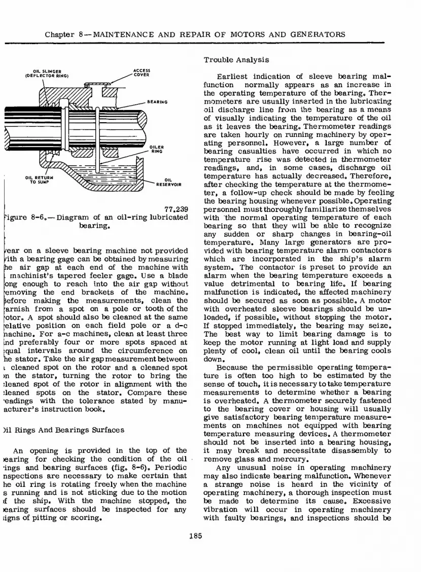
Chapter 8 —MAINTENANCE AND REPAIR OF MOTORS AND GENERATORS
OIL SLINCER (DEFLECTOR RING)
ACCESS COVER
m
OILER RING
%
OIL
W//////////2 RESERVOIR
OIL RETURN TO SUMP
77.239 figure 8-6. — Diagram of an oil-ring lubricated
bearing.
fear on a sleeve bearing machine not provided fith a bearing gage can be obtained by measuring he air gap at each end of the machine with . machinist’s tapered feeler gage. Use a blade ong enough to reach into the air gap without emoving the end brackets of the machine, lefore making the measurements, clean the arnish from a spot on a pole or tooth of the otor. A spot should also be cleaned at the same elative position on each field pole or a d-c nachine. For a-c machines, clean at least three tnd preferably four or more spots spaced at jqual intervals around the circumference on he stator. Take the air gap measurement between i cleaned spot on the rotor and a cleaned spot >n the stator, turning the rotor to bring the ¡leaned spot of the rotor in alignment with the ¡leaned spots on the stator. Compare these ■eadings with the tolerance stated by manu- acturer’s instruction book.
)il Rings And Bearings Surfaces
An opening is provided in the top of the ¡earing for checking the condition of the oil ■ings and bearing surfaces (fig. 8-6). Periodic nspections are necessary to make certain that he oil ring is rotating freely when the machine s running and is not sticking due to the motion >f the ship. With the machine stopped, the ¡earing surfaces should be inspected for any ¡igns of pitting or scoring.
Trouble Analysis
Earliest indication of sleeve bearing mal- function normally appears as an increase in the operating temperature of the bearing. Ther- mometers are usually inserted in the lubricating oil discharge line from the bearing as a means of visually indicating the temperature of the oil as it leaves the bearing. Thermometer readings are taken hourly on running machinery by oper- ating personnel. However, a large number of bearing casualties have occurred in which no temperature rise was detected in thermometer readings, and, in some cases, discharge oil temperature has actually decreased. Therefore, after checking the temperature at the thermome- ter, a follow-up check should be made by feeling the bearing housing whenever possible. Operating personnel must thoroughly familiarize themselves with the normal operating temperature of each bearing so that they will be able to recognize any sudden or sharp changes in bearing-oil temperature. Many large generators are pro- vided with bearing temperature alarm contactors which are incorporated in the ship’s alarm system. The contactor is preset to provide an alarm when the bearing temperature exceeds a value detrimental to bearing life. If bearing malfunction is indicated, the affected machinery should be secured as soon as possible. A motor with overheated sleeve bearings should be un- loaded, if possible, without stopping the motor. If stopped immediately, the bearing may seize. The best way to limit bearing damage is to keep the motor running at light load and supply plenty of cool, clean oil until the bearing cools down.
Because the permissible operating tempera- ture is often too high to be estimated by the sense of touch, it is necessary to take temperature measurements to determine whether a bearing is overheated. A thermometer securely fastened to the bearing cover or housing will usually give satisfactory bearing temperature measure- ments on machines not equipped with bearing temperature measuring devices. A thermometer should not be inserted into a bearing housing, it may break and necessitate disassembly to remove glass and mercury.
Any unusual noise in operating machinery may also indicate bearing malfunction. Whenever a strange noise is heard in the vicinity of operating machinery, a thorough inspection must be made to determine its cause. Excessive vibration will occur in operating machinery with faulty bearings, and inspections should be
185

ELECTRICIAN’S MATE 3 & 2
MOUNTING RING
BRACKET
BRUSH - HOLDER :
STUD
BRUSH /
PIGTAIL
Figure 8-7. — Brush holder and brush-rigging assembly. 77.70
made at frequent intervals in order to detect its presence as soon as possible.
BRUSHES
The brushes used in electric motors and generators are one or more plates of carbon, bearing against a commutator, or collector ring (slip ring) to provide a passage for electrical current to an external circuit. The brushes
are held in position by brush holders mounted on studs or brackets attached to the brush- mounting ring, or yoke. The brush holder studs or brackets, and brush-mounting ring comprise the brush rigging. The brush rigging is insulated from, but attached to, the frame or one end bell of the machine. Flexible leads (pigtails) are used to connect the brushes to the termi- nals of the external circuit. An adjustable spring is generally provided to maintain proper pres- sure of the brush on the commutator in order to effect good commutation. A d-c generator
186

Chapter 8 —MAINTENANCE AND REPAIR OF MOTORS AND GENERATORS
brush holder and brush-rigging assembly are shown in figure 8-7.
Brushes are manufactured in different grades to meet the requirements of the varied types of service. The propertiesof resistance, ampere- carrying capacity, coefficient of friction, and hardness of the brush are determined by the maximum allowable speed and load of the machine in which it is used.
CORRECT BRUSH TYPE
The correct grade of brush and correct brush adjustment are necessary to avoid commutation trouble.
Use the grade of brush shown on the drawing or in the technical manual applicable to the machine, except where Naval Sea Systems Com- mand Instructions issued after the date of the drawing or technical manual (such as the in- structions for brushes to be used in electric propulsion and magnetic mine sweeping equipment) state otherwise. In such cases, the Naval Sea Systems Command Instructions should be fol- lowed. Most of the brushes in shipboard service appear on the Qualified Products List as com- plying with one of six military grades (S, A, H, D, G, and E). In the case of propulsion and magnetic minesweeping equipment, only one grade of each of two different brush manufacturers is permitted for any machine. The restriction on brush interchangeability is due to the vital nature of the machines involved.
CARE
All brush shunts should be securely connected to the brushes and the brush holders. Brushes should move freely in their holders but should not be loose enough to vibrate in the holder. Before replacing a worn brush with a new one, clean all dirt and other foreign material from the brush holder.
Replace with new brushes, all brushes that 1. are worn or chipped so they will not move
properly in their holders; 2. have damaged shunts, shunt connections,
or hammer clips; 3. have riveted connections or hammer clips
and are worn to within 1/8 inch of the metallic part;
4. have tamped connections, are without ham- mer clips, and are worn to one-half or less of the original length of the brush; or
5. have spring-enclosed shunts and are worn to forty percent or less of the original length of the brush exclusive of the head which fits into one end of the spring.
Where adjustable brush springs are of the positive gradient (torsion, tension, or compres- sion) type, adjust them as the brushes wear, in order to keep the brush pressure approxi- mately constant. Springs of the coiled band, constant pressure type and certain springs of the positive gradient type are not adjustable except by changing springs. Brush pressure should be in accordance with the manufacturer’s technical manual. Pressures as low as 1-1/2 pounds per square inch of contact area may be speci- fied for large machines and as high as 8 pounds per square inch of contact area may be specified for small machines. Where technical manuals are not available, a pressure of 2 to 2-1/2 pounds per square inch of contact area is recom- mended for integral horsepower and integral kilowatt machines, and about twice that pressure for fractional horsepower and fractional kilowatt machines. To measure the pressure of brushes operating in box type brush holders, insert one end of a strip of paper between the brush and commutator; use a small brush tension gage (such as the 0 to 5 pound indicating scale) to exert a pull on the brush in the direction of brush holder axis as shown in figure 8-8.
a A
SPRING BALANCE
PIGTAIL LEAD
SPRING
BRUSH
TAKE SPRING READING WHEN SLIP OF PAPER MAY BE DRAWN FROM BETWEEN BRUSH AND COMMUTATOR
COMMUTATOR OR COLLECTOR RING
77.72
Figure 8-8. — Measuring brush tension.
187

ELECTRICIAN’S MATE 3 & 2
Note the reading of the gage when the pulLis just sufficient to release the strip of paper so that it can be pulled out from between the brush and commutator without offering resis- tance. This reading divided by the contact area may be considered to be the unit operating pressure.
The toes of all brushes of each brush stud should line up with each other and with the edge of one commutator segment.
The brushes should be evenly spaced around the commutator. To check brush spacing, wrap a strip of paper around the commutator and mark the paper where the paper laps. Remove the paper from the commutator, cut at the lap, and fold or mark the paper into as many equal parts as there are brush studs. Replace the paper on the commutator and adjust the brush holders so that the toes of the brushes are at the creases or marks.
All brush holders should be the same distance from the commutator, not more than one-eighth inch, nor less than one-sixteenth inch. A brush holder must be free of all burrs which might interfere with the free movement of the brush in the holder. Burrs are easily removed with a fine file.
SEATING
Accurate seating of the brushes must be assured where their surfaces contact the com- mutator. Sandpaper and a brush seater are the best tools to accomplish a true seat.
All power must be disconnected from the machine, and every precaution must be taken to ensure that the machine will not be inad- vertently started before using sandpaper to seat the brushes.
The brushes to be fitted are lifted, and a strip of fine sandpaper (No. 1) approximately the width of the commutator, is inserted (sand side up) between the brushes and the commutator. With the sandpaper held tightly against the com- mutator surface to conform with the curvature and the brushes held down by normal spring pressure, the sandpaper is pulled in the direction of normal rotation of the machine (fig. 8-9). When returning the sandpaper for another pull, the brushes must be lifted. This operation is repeated until the seat of the brush is accurate. Always finish with a finer grade of sandpaper, No. 0. A vacuum is required for removing dust
BRUSH
ROUGH SIDE OF
SANDPAPER
END VIEW
run
or1
SIDE VIEW
1.52 Figure 8-9. — Method of sanding brushes.
while sanding. After sanding, the commutator and windings must be thoroughly cleaned to remove all carbon dust.
The use of a brush seater will improve the fit obtained by sanding as described above. A brush seater consists of a mildly abrasive material loosely bonded into a stick about 5 inches long. To use a brush seater to fit brushes, install the brushes in the brush holders and start the machine. Press a brush securely against the commutator by using a stick of insulating material or by increasing the brush spring tension to its maximum value. Touch the brush seater lightly to the commutator exactly at the heel of the brush (fig. 8-10) so that
BRUSH BRUSH
SEATER
BRUSH
HOLDER HEEL
TOE
DIRECTION
OF ROTATION
COMMUTATOR OR
COLLECTOR RING
1.53 Figure 8-10. — Using the brush seater.
188

Chapter 8 —MAINTENANCE AND REPAIR OF MOTORS AND GENERATORS
abrasive material torn from the brush seater will be carried under the brush. If the seater is placed even one-fourth inch away from the heel of the brush, only a small part of the abrasive passes under the brush. The brush seater must be held in turn behind each brush, applying the seater for a second or two de- pending on brush size. Do not hold the seater steadily against the commutator as the seater will wear away too rapidly and produce too much dust. After seating one or two brushes, examine them to see if the seater is being applied long enough to give a full seat. After seating the brush, if white dust is plainly visible on the seat, insufficient pressure has been applied to the brush or the brush seater has been applied too heavily or too far from the brush. Also, be careful not to remove the copper oxide film from the commutator surface. This film, if removed, must be restored as described later in this chapter.
A vacuum cleaner should be used during the seating operation to prevent dust from reaching the machine windings and bearings. After seating all the brushes, blow out the machine with a power blower or completely dry compressed air or clean thoroughly with a vacuum cleaner.
COMMUTATORS AND COLLECTOR RINGS
STICK 1/4 TO 3/8 INCH THICK
RIVET
A CANVAS WIPER
CANVAS
= O
B USING THE CANVAS WIPER ON A COMMUTATOR
1.54 Figure 8-11. — Cleaning commutator or collector
rings.
After being used approximately two weeks, the commutator of a machine should develop a uniform, glazed, dark brown color on the places where the brushes ride. If a nonuniform or bluish colored surface appears, improper com- mutation conditions are indicated. Periodic in- spections and proper cleaning practices will keep commutator and collector-ring troubles at a minimum.
Cleaning
One of the most effective ways of cleaning the commutator or collector rings is to apply a canvas wiper while the machine is running. The wiper can be made by wrapping several layers of closely woven canvas over the end of a strong stick between one-fourth and three- eighths inch thick (fig. 8-11A). The canvas may be secured with rivets if they, in turn, are covered with linen tape to prevent the possibility of their contacting the commutator. When the outer layer of canvas becomes worn or dirty,
it is removed to expose a clean layer. The wiper is most effective when used frequently. On ship’s service generators, it may be de- sirable to use the wiper once each watch. When using the wiper, exercise care to keep from fouling moving parts of the machine. The manner of applying the wiper to a commutator is il- lustrated in figure 8-llB.
When machines are secured, a toothbrush can be used to clean out the commutator slots, and clean canvas or lintless cloth may be used for wiping the commutator and adjacent parts. In addition to being cleaned by wiping, the com- mutator should be periodically cleaned with a vacuum cleaner or blown out with clean, dry air.
Do not sandpaper a commutator if it is operating well, even if long service has developed threading, grooving, pits, burn areas between bars, longitudinal irregularities, etc, unless sparking is occurring or brushes are wearing excessively. In sanding a commutator, use a fine grade of sandpaper (No. 0000 preferred, taut in no case coarser than No. 00). Sand- papering may also be used to make emergency
189

ELECTRICIAN’S MATE 3 & 2
reduction of high mica, or to polish finish a commutator which has been stoned or turned. The sandpaper, attached to a wooden block shaped to fit the curvature of the commutator, is moved slowly back and forth across the sur- face of the commutator while the machine is running at moderate speed. Rapid movement or. the use of coarse sandpaper will cause scratches, Emery cloth, emery paper, or emery stone should never be used on a commutator or col- lector ring since there is too much danger of causing electrical shorts,
TRUING THE COMMUTATOR
A commutator should be trued in place only if its condition has become so bad it cannot wait until the next shop overhaul for recondi- tioning, Large commutators in the 125-to-850 rpm range, as fitted on most electric propulsion motors and generators, usually operate satis- factorily with runouts up to 0,003 inch. Under no conditions, should you attempt to true a commutator in place unless there is sparking, excessive brush wear, or brush movement suf- ficient to fray the brush pigtails and wear the hammer plates. Do not confuse brush chatter with brush movement by runout.
Sandpapering will not correct flat spots, grooves, eccentricity, or out of round. You can correct some or all of these conditions by machine or hand stoning, by turning on a lathe, or by grinding with a rigidly supported stationary or revolving stone. There are a number of grades of commutator stone, from very coarse to very fine, that can be used for hand stoning or grinding with a rigidly supported stone. Use the finest stone that will do the job in a reasonable time. Do not use coarse stones as they tend to produce scratches which are hard to remove. In turning or grinding a com- mutator, it is essential that the cut be strictly parallel with the axis of the machine; otherwise, a taper on the commutator will result.
Do not disturb the commutator clamping bolts unless the bars are loose (one or more high bars). Then use a calibrated torque wrench and tighten only to the values specified by the manufacturer. For propulsion motors and gen- erators, these values are available in the Naval Sea Systems Command. Make all other needed repairs, such as balancing, rebrazing armature connections, and repairing insulation faults prior to truing the commutator.
After the commutator is trued (whether by stoning, grinding, or turning), finish with a fine grade of stone or sandpaper, undercut the mica, chamfer the commutator bars, clean the commutator and brush holders, and wipe off the brushes with a clean, dry lintless cloth.
Hand Stoning
Hand stoning will remove flat spots, grooves, scoring and deep scratches but will not correct eccentricity, high bars, or an out-of-round con- dition. The machine should be running at, or slightly below, rated speed. Generators can be turned by their prime movers. For motors, remove all but enough brushes to keep the armature turning at the proper speed. Use old brushes for this purpose and discard them after the stoning is completed.
The stone should be formed or worn to the curvature of the commutator and should have a surface much larger than the largest flat spot to be removed. The stone is held in the hand and moved very slowly back and forth parallel to the axis of the commutator. Do not press too hard on the stone, just enough to keep it cutting. Being hasty or crowding the stone results in a rough surface, and sometimes a noncylin- drical-shaped commutator. Avoid jamming the stone between the fixed and moving parts of the machine and, as in grinding, avoid electric shock.
Machine Stoning
Stoning should be done by machine to correct eccentricity, high bars, or an out-of-round condi- tion. In one method of machine stoning a com- mutator dressing stone tool(fig. 8-12), is mounted on the frame of the machine and holds a commu- tator stone against the comutator as the armature is rotated. This method works for some of the large open and dripproof machines. Otherwise, the armature may be removed from the machine and mounted in a lathe where it is rotated. Here the commutator stone is mounted in the tool post and fed to the commutator, or a rotating precision grinder is mounted in the tool post and the grinder wheel is fed to the com- mutator.
Grinding
When practical, the armature should be re- moved from the machine and placed in a lathe for grinding. If not, the commutator can be
190

Chapter 8 —MAINTENANCE AND REPAIR OF MOTORS AND GENERATORS
CLAMPS
.COMMUTATOR STONES ADJUSTMENT FOR COMMUTATOR STONES
0» COMMUTATOR GRINDING SURFACE
BOX
SLIDE FOR BOX
SHORT HANDLE
COMMUTATOR STONE GUIDE LEVERS
CLAMP ON BRUSH ARM
LONG HANDLE
/
Figure 8-12. — Commutator dressing stone tool. 73.227X
ground in the machine provided there is not too much vibration, the windings can be adequately protected from grit, and suitable supports can be found for the stone.
When grinding the commutator in the machine, rotate the armature by using an external prime mover or, in the case of a motor, by supplying power through just enough brushes to take care of the load. Old brushes may be used for this purpose since they should be discarded after grinding. Whenever grinding is done in a motor, take care to avoid electric shock and fouling
of any of the equipment used with the moving parts of the motor.
When used, a commutator surface stone should be rigidly clamped in a holder and supported to keep the stone from chattering or digging into the commutator. The supports must provide for axial motion of the stone. Heavy cuts must be avoided since the stone wears away as it is moved back and forth. If a heavy cut were taken, the commutator would not have the same diameter at both ends. Commutator surfacing stones with tool post handles are carried in
191
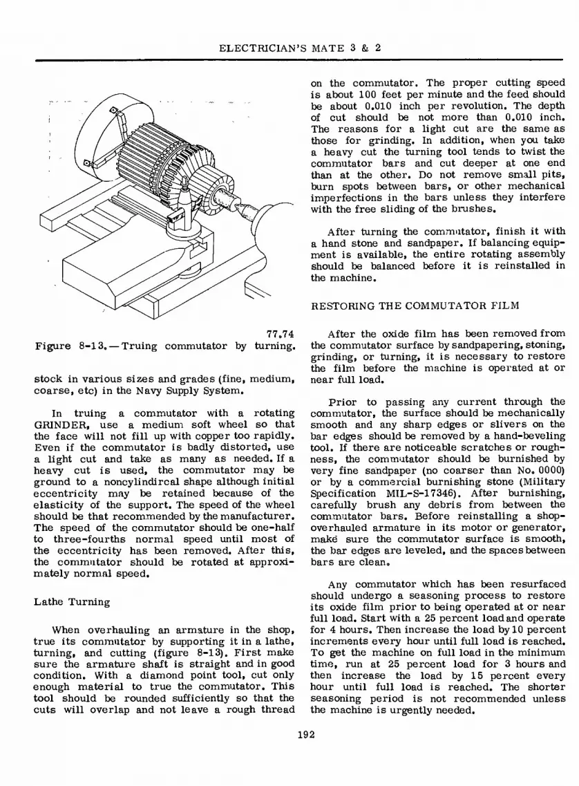
ELECTRICIAN’S MATE 3 & 2
77.74 Figure 8-13. — Truing commutator by turning.
stock in various sizes and grades (fine, medium, coarse, etc) in the Navy Supply System.
In truing a commutator with a rotating GRINDER, use a medium soft wheel so that the face will not fill up with copper too rapidly. Even if the commutator is badly distorted, use a light cut and take as many as needed. If a heavy cut is used, the commutator may be ground to a noncylindircal shape although initial eccentricity may be retained because of the elasticity of the support. The speed of the wheel should be that recommended by the manufacturer. The speed of the commutator should be one-half to three-fourths normal speed until most of the eccentricity has been removed. After this, the commutator should be rotated at approxi- mately normal speed.
Lathe Turning
When overhauling an armature in the shop, true its commutator by supporting it in a lathe, turning, and cutting (figure 8-13). First make sure the armature shaft is straight and in good condition. With a diamond point tool, cut only enough material to true the commutator. This tool should be rounded sufficiently so that the cuts will overlap and not leave a rough thread
on the commutator. The proper cutting speed is about 100 feet per minute and the feed should be about 0.010 inch per revolution. The depth of cut should be not more than 0.010 inch. The reasons for a light cut are the same as those for grinding. In addition, when you take a heavy cut the turning tool tends to twist the commutator bars and cut deeper at one end than at the other. Do not remove small pits, burn spots between bars, or other mechanical imperfections in the bars unless they interfere with the free sliding of the brushes.
After turning the commutator, finish it with a hand stone and sandpaper. If balancing equip- ment is available, the entire rotating assembly should be balanced before it is reinstalled in the machine.
RESTORING THE COMMUTATOR FILM
After the oxide film has been removed from the commutator surface by sandpapering, stoning, grinding, or turning, it is necessary to restore the film before the machine is operated at or near full load.
Prior to passing any current through the commutator, the surface should be mechanically smooth and any sharp edges or slivers on the bar edges should be removed by a hand-beveling tool. If there are noticeable scratches or rough- ness, the commutator should be burnished by very fine sandpaper (no coarser than No. 0000) or by a commercial burnishing stone (Military Specification MIL-S-17346). After burnishing, carefully brush any debris from between the commutator bars. Before reinstalling a shop- overhauled armature in its motor or generator, make sure the commutator surface is smooth, the bar edges are leveled, and the spaces between bars are clean.
Any commutator which has been resurfaced should undergo a seasoning process to restore its oxide film prior to being operated at or near full load. Start with a 25 percent load and operate for 4 hours. Then increase the load by 10 percent increments every hour until full load is reached. To get the machine on full load in the minimum time, run at 25 percent load for 3 hours and then increase the load by 15 percent every hour until full load is reached. The shorter seasoning period is not recommended unless the machine is urgently needed.
192
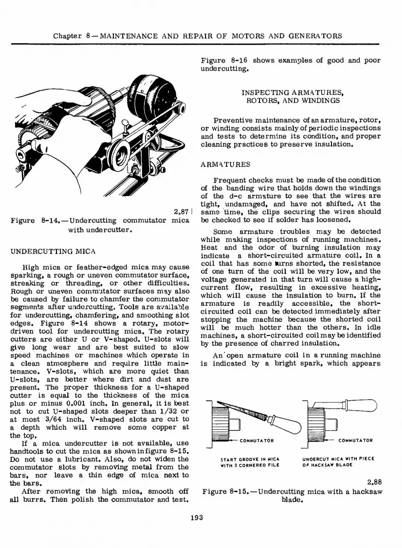
Chapter 8 —MAINTENANCE AND REPAIR OF MOTORS AND GENERATORS
k É
2.87 Figure 8-14. — Undercutting commutator mica
with undercutter.
UNDERCUTTING MICA
High mica or feather-edged mica may cause sparking, a rough or uneven commutator surface, streaking or threading, or other difficulties. Rough or uneven commutator surfaces may also be caused by failure to chamfer the commutator segments after undercutting. Tools are available for undercutting, chamfering, and smoothing slot edges. Figure 8-14 shows a rotary, motor- driven tool for undercutting mica. The rotary cutters are either U or V-shaped. U-slots will give long wear and are best suited to slow speed machines or machines which operate in a clean atmosphere and require little main- tenance. V-slots, which are more quiet than U-slots, are better where dirt and dust are present. The proper thickness for a U-shaped cutter is equal to the thickness of the mica plus or minus 0.001 inch. In general, it is best not to cut U-shaped slots deeper than 1/32 or at most 3/64 inch. V-shaped slots are cut to a depth which will remove some copper at the top.
If a mica undercutter is not available, use handtools to cut the mica as shown in figure 8-15. Do not use a lubricant. Also, do not widen the commutator slots by removing metal from the bars, nor leave a thin edge of mica next to the bars.
After removing the high mica, smooth off all burrs. Then polish the commutator and test.
Figure 8-16 shows examples of good and poor undercutting.
INSPECTING ARMATURES, ROTORS, AND WINDINGS
Preventive maintenance of an armature, rotor, or winding consists mainly of periodic inspections and tests to determine its condition, and proper cleaning practices to preserve insulation.
ARMATURES
Frequent checks must be made of the condition of the banding wire that holds down the windings of the d-c armature to see that the wires are tight, undamaged, and have not shifted. At the same time, the clips securing the wires should be checked to see if solder has loosened.
Some armature troubles may be detected while making inspections of running machines. Heat and the odor of burning insulation may indicate a short-circuited armature coil. In a coil that has some kirns shorted, the resistance of one turn of the coil will be very low, and the voltage generated in that turn will cause a high- current flow, resulting in excessive heating, which will cause the insulation to burn. If the armature is readily accessible, the short- circuited coil can be detected immediately after stopping the machine because the shorted coil will be much hotter than the others. In idle machines, a short-circuited coil may be identified by the presence of charred insulation.
An open armature coil in a running machine is indicated by a bright spark, which appears
COMMUTATOR COMMUTATOR
START GROOVE IN MICA UNDERCUT MICA WITH PIECE WITH 3 CORNERED FILE OF HACKSAW BLADE
2.88 Figure 8-15.—Undercutting mica with a hacksaw
blade.
193

ELECTRICIAN’S MATE 3 & 2
ARMATURE WINDINGS COMMUTATOR RISERS
COMMUTATOR BARS
«
POOR
UNDERCUTTING
MICA INSULATION
GOOD
UNDERCUTTING
Figure 8-16. — Example of good and poor mica undercutting. 2.89
to pass completely around the commutator. When the segment to which the coil is connected passes under the brushes, the brushes momentarily complete the circuit; when the segment leaves the brushes, the circuit is broken, causing a spark to jump the gap. Eventually, it will defi- nitely locate itself by scarring the commutator segment to which one end of the open coil is connected.
When a ground occurs in an armature coil of a running machine, it will cause the ground test lamps on the main switchboard to flicker on and off as the grounded coil segment passes from brush to brush during rotation of the armature. Two grounded coils result in the same effect as a short circuit across a group of coils. Overheating will occur in all of the coils in the group and burn out the winding. Grounded coils in idle machines can be detected by measuring insulation resistance. A megger, or similar insulation measuring device can be connected to the commutator and to the shaft
or frame of the machine in order to properly measure the resistance of the insulation of the coils.
Emergency repairs can be effected by cutting out a short-circuited or open-circuited armature coil. This will permit restoration of the machine to service until permanent repairs can be made. However, permanent repairs should be made as soon as possible. The coil is cut out by disconnecting both ends of the coil and installing a jumper between the two risers from which the coil was disconnected. The coil itself is then cut at both the front and rear of the arma- ture to prevent overheating of the damaged coil. A continuity test from one end to the back of the coil will locate the turns of the faulty coil. If a pin or needle is used to puncture the insulation for this test, insulating varnish can be used to fill the tiny hole in the event the wrong coil is pierced. All conducting sur- faces exposed by the change in connections
194

Chapter 8 —MAINTENANCE AND REPAIR OF MOTORS AND GENERATORS
should be insulated and all loose ends should be tied securely to prevent vibration.
A-C ROTORS
Basically, the rotor of an a-c motor is a squirrel cage rotor or a wound rotor. The squirrel cage rotor usually consists of heavy copper or aluminum bars fitted into slots in the rotor frame. These bars are connected to short-circuiting end rings by being cast or brazed or welded together (fig„ 8-17). In many cases, the cage rotor is manufactured by die- casting the rotor bars, end rings, and cooling fans into one piece. The cage rotor requires less attention than the -wound rotor. However, the cage rotor should be kept clean, and the rotor bars must be checked periodically for evidence of loose or fractured bars and localized over- heating.
Wound rotors (fig. 8-18) consist of wound coils insulated from each other and layed in slots in the rotor core. These coils are wye- connected and terminate at three slip rings.
Wound rotors, like other windings, require periodic inspections, tests, and cleaning. The insulation resistance determines if grounds are present. An open circuit in a wound rotor may
SHAFT
COPPER BAR
WELD AT ALL JOINTS
IRON CORE WELD HOLDING COPPER BAR TO END RING 9)
COPPER
END RINGS END VIEW
77.77(77C) Figure 8-17. — Squirrel cage rotor.
77.78 Figure 8-18. — Wound rotor.
cause reduced torque accompanied by a growling noise, or failure to start under load. In addition to reduced torque, a short circuit in the rotor windings may cause excessive vibration, sparking at the brushes, and uneven collector ring wear. With the brushes removed from the collector rings, a continuity check of the rotor coils will reveal the presence of a faulty coil.
FIELD COILS
The insulation field coils should be tested periodically with a resistance-measuring device. If a ground is detected in the field circuits (shunt, series, and interpole) of a d-c machine, the circuits must be disconnected from each other and tested separately to locate the grounded circuit. Then all the coils in that circuit must be opened and tested separately to locate the grounded coil, which can then be repaired or replaced as necessary.
If an open circuit develps in the field windings of an a-c or d-c generator that is carrying a load, it will be indicated by the immediate loss of load and voltage. An open in the shunt field winding of an operating d-c motor may be indicated by an increase in motor speed, excessive armature current, heavy sparking, or stalling of the motor. When an open occurs in the field circuit of a machine, it must be secured immediately and examined to locate the faulty circuit. The open circit will usually occur at the connections between the coils and can be detected by visual inspection. An open in the coils generally causes enough damage to permit detection by visual inspection.
195

ELECTRICIAN’S MATE 3 & 2
It should be noted that the opening of an energized field circuit induces high voltage that can puncture field insulation and could present a safety hazard.
A-C STATOR COILS
A-c stator windings require the same careful attention as other electrical windings. For a machine to function properly, the stator windings must be free from grounds, short circuits, and open circuits.
A short circuit in the stator of an a-c machine will produce smoke, flame, or the odor of charred insulation. The machine must be secured immediately and tests conducted to find the reason for the abnormal condition.
The first and easiest test that should be conducted is to test the insulation resistance of the winding. This test is made with a megohm- meter or similar resistance-measuring instru- ment. Connect one instrument lead to ground and the other to each motor lead, crank the meter handle and read the scale on the meter face. If the insualtion resistance is in the order of one megohm or above, the stator is not grounded and other tests should be made to locate the trouble.
Next test for continuity with an ohmmeter by connecting the test leads to any two motor leads and then to the next two leads, until all leads have been tested for continuity between each other. Whether the motor is wye or delta- connected you should get nearly zero indication on the ohmmeter between any two leads. A high resistance reading between any two leads is a good indication of an open phase winding.
For your next check, determine whether or not there are any mechanical difficulties, such as frozen bearings or a frozen pump. First disconnect the motor from the driven unit. Spin the motor shaft to see if it is free to turn. Then check the driven end for freedom of movement. If the driven end is frozen you need check no further. Inform the maintenance man responsible for the driven end of your findings.
If the stator windings are burned out or opened, the motor must be disassembled. The proper procedure for disassembly is given later in this chapter.
A visual inspection of the stator will usually reveal where the trouble lies. If the stator is burned out, it must be rewound. If just one phase is open, however, it is possible to effect an emergency repair by carefully soldering the
opened leads back together. Be extra careful in soldering these leads as further damage could result if they are inadvertently shorted. After accomplishing this emergency repair, test the stator winding with low voltage to check the phase balance.
DISASSEMBLY AND REASSEMBLY OF MOTORS AND GENERATORS
When it becomes necessary to disassemble and reassemble a large motor or generator, follow the procedures outlined in the manufac- turer’s insti’uction book, exercising care to prevent damage to any part of the machine. The machine rotors should be supported, while being moved or when stationary, by slings or blocking under the shaft or by a padded cradle or thickly folded canvas under the core lamina- tions. To lift the rotor, rope slings (separated by a spreader to prevent the slings coming in contact with the a-c rotor or d-c armature coils) should be placed under the shaft, clear of the bearing journals. If construction of the shaft provides no room for a sling except around the journals, they must be protected with heavy paper or canvas before applying the sling. When the whole unit (stator and rotor) is to be lifted by lifting the stator, the bottom of the air gap must be tightly shimmed unless both ends of the shaft are supported in bearings. It is easily possible, by rough handling or careless use of bars or hooks, to do more damage to a machine during disassembly and assembly than it will receive in years of normal service.
Never be hasty or careless in disassembling a generator or motor. Handle the delicate compo- nents with care, so as not to damage them, or to create the need for additional adjustment. Use' the proper tools; label the parts as you dismantle them, and store them in an orderly arrangement in a safe place. Note down the necessary information so that you will have no trouble in reassembly.
If you have done a careful job of breaking down a machine into its components, the process of reassembling it should be the reverse order of taking it down.
A few simple steps are to be taken when disassembling a motor or generator. Make sure you mark the frame and mating end bells (fig. 8-19), using a different mark for each end. When separating the end bells from the frame use a mallet or block of wood with a hammer (fig. 8-20) but never pry mating surfaces apart
196
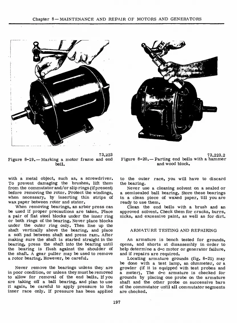
Chapter 8—MAINTENANCE AND REPAIR OF MOTORS AND GENERATORS
73.223 Figure 8-19. — Marking a motor frame and end
hell.
73.223.2 Figure 8-20. — Parting end bells with a hammer
and wood block.
with a metal object, such as, a screwdriver. To prevent damaging the brushes, lift them from the commutator and/or slip rings (if present) before removing the rotor. Protect the windings, when necessary, by inserting thin strips of wax paper between rotor and stator.
When removing bearings, an arbor press can be used if proper precautions are taken. Place a pair of flat steel blocks under the inner ring or both rings of the bearing. Never place blocks under the outer ring only. Then line up the shaft vertically above the bearing, and place a soft pad between shaft and press ram. After making sure the shaft is started straight in the bearing, press the shaft into the bearing until the bearing is flush against the shoulder of the shaft. A gear puller may be used to remove a rotor bearing. However, be careful.
Never remove the bearings unless they are in poor condition, or unless they must be removed to allow for removal of the end bells. If you áre taking off a ball bearing, and plan to use it again, be careful to apply pressure to the inner race only. If pressure has been applied
to the outer race, you will have to discard the bearing.
Never use a cleaning solvent on a sealed or a semisealed ball bearing. Store these bearings in a clean piece of waxed paper, till you are ready to use them.
Clean the end bells with a brush and an approved solvent. Check them for cracks, burrs, nicks, and excessive paint, as well as for dirt.
ARMATURE TESTING AND REPAIRING
An armature is bench tested for grounds, opens, and shorts at disassembly in order to help determine a d-c motor or generator failure, and if repairs are required.
Locating armature grounds (fig. 8-21) may be done with a test lamp, an ohmmeter, or a growler (if it is equipped with test probes and a meter). The d-c armature is checked for grounds by placing one probe on the armature shaft and the other probe on successive bars of the commutator until all commutator segments are checked.
197

ELECTRICIAN’S MATE 3 & 2
2.92 Figure 8-21.— Testing armature for grounds.
TOUCH ADJACENT BARS
DO NOT TOUCH BRUSH SURFACE
2.93 Figure 8-22. — Testing armature coils for open
circuit.
W
W
©
2.90 Figure 8-23. — Checking armature shorts with
growler.
Armature opens may be determined with test equipment having test probes to make commutator bar-to-bar contact around the armature (fig. 8-22). Test equipment may be an incandescent lamp with a low voltage source, a low reading ohmmeter, a milliammeter with a rheostat and a 6-volt battery, or a growler.
An armature coil internally shorted within itself is determined with a growler. The external growler (fig. 8-23 and 8-24) is plugged into a 120-volt, 60-hertz power supply and switched to ON position. A hacksaw blade is held parallel to the windings and run across the top of the armature. The armature is continually rotated in the growler and the hacksaw blade test made until the complete armature has been checked. If a short exists in the winding below the hacksaw blade, the blade will vibrate noticeably and will cause a growling noise known to electricians as an a-c hum, Larger armatures, which do not fit in an external growler, may be checked by moving an internal growler over the outside
198

Chapter 8 — MAINTENANCE AND REPAIR OF MOTORS AND GENERATORS
9
If!
II5V 60'V,
2„92„2(77C) Figure 8-24. — External growler construction.
surface of the armature. Internal growlers are used primarily to check stator windings and are covered later under three-phase stator repair.
Armature commutators should not be out-of- round more than one mil (.001 inch). A dial indicator is used to give commutator radius checks, (figure 8-25)
TYPES OF ARMATURE WINDINGS
You must be able to identify armature windings to interpret trouble indications and to make the necessary repairs.
Lap and Wave Windings
Armature windings, irrespective of how the elements are placed on the armature core, are generally classified as LAP or WAVE windings. The classification designates the meth- od of connecting the ends of the elements, or coils, to the commutator (fig. 8-26). If the ends
SLOT I
© V® © © © © © \
SLOT 7
A SINGLE-TURN LAP COIL
© SLOT I SLOT 7
B SINGLE-TURN WAVE COIL
2.85 Figure 8-25. — Measuring commutator out-of-
round with dial indicator.
111.1 Figure 8-26. —Classification of armature
windings.
199

ELECTRICIAN’S MATE 3 & 2
ELEMENT
POLE PITCH
N
5 I I I
nil i
i
A LAP COIL
POLE PITCH
ELEMENT
B WAVE COIL
Figure 8-27.—Full-pitch coils. 111.2
of the coil are connected to adjacent commutator segments, or to segments that are close to- gether, the coil is designated as a lap-connected coil, and the winding is a lap winding (fig. 8-26A). On the other hand, if the ends of a coil are connected to commutator segments approximately two pole pitches apart, the coil is designated as a wave-connected coil, and the winding is a wave winding (figs. 8-26B and 8-27B).
PITCH. — Both lap and wave windings are placed on the armature core so that the two sides of an element occupy slots that are influ- enced by adjacent poles of opposite polarity, and the emf’s generated in the two sides add together. In other words, if the left side of a coil momentarily occupies a position under the center of a north pole, the right side of the same coil will occupy a position under approxi- mately the center of an adjacent south pole. The distance between the centers of two adjacent poles is the pole pitch. The span of one coil should be equal or nearly equal to one pole pitch. If a coil spans exactly one pole pitch, the winding is FULL PITCH (fig. 8-27), and if a coil spans less than one pole pitch, the winding is FRACTIONAL PITCH. COIL PITCH is recorded and identified by the number of slots spanned by the coil in the armature (fig. 8-28).
contains two coil sides of a single-coil type of winding (fig. 8-26). Thus one side of the winding element is placed in the top of a slot, and the other side is placed in the bottom of another slot. It is inmaterial which side of the element is placed in the top or bottom of the slot. In practice (observing the armature from the com- mutator end) the right side of the coil is usually placed in the bottom of one slot and the left
PITCH I AND 8
• PITCH I AND 6- H PITCH AND 4
73.132 NUMBERING. — D-c armature windings are usually two-layer windings in which each slot
200
Figure 8-28. —Pole pitch.

Chapter 8 —MAINTENANCE AND REPAIR OF MOTORS AND GENERATORS
side is placed in the top of another slot. The coil sides are arbitrarily numbered so that all TOP coil sides have odd numbers and all BOTTOM coil sides have even numbers (fig. 8-26). This system helps to place the coils properly on the armature.
Progressive and Retrogressive Windings
Lap and wave windings can be progressive or retrogressive, as illustrated in figure 8-29.
A PROGRESSIVE WINDING (fig. 8-29A) pro- gresses in a clockwise direction around the armature when trace:’, through the winding from the commutator end. In other words, the winding progresses clockwise from segment (bar) through the coil to segment.
Progressive wave winding and retrogressive lap windings are very seldom encountered because of the inherent undesirable features, such as the end connections of coil groups crossing over each other, added weight, and longer leads. Therefore, with few exceptions lap windings are progressive and wave windings are retrogressive.
A RETROGRESSIVE WINDING (fig. 8-29B) progresses in a counterclockwise direction around the commutator when traced through the winding from the commutator end.
Multiplex Windings
Windings may also be classified and connected in SIMPLEX, DUPLEX, or TRIPLEX. A simplex
s. \ \
\ \ \ \ \ \ \ \
V \
LAP
\ V \ \ \ \ \ \ \
\ \ \ V ' \ ' \ \ \
' /
LAP
%<
WAVE
PROGRESSIVE
WAVE
B RETROGRESSIVE
Figure 8-29. — Meaning of “coil pitch” in armature winding,
111.3

ELECTRICIAN’S MATE 3 & 2
SLOTS OF
CORE
\
END LEAD BEGINNING
LEAD
COMMUTATOR BAR
t I
BEGINNING' LEAD
END LEAD- COM MUTATOR
BAR
_zl
Figure 8-30. —Simplex lap windings; (A) progressive, (B) retrogressive. 73.230
lap winding is one in which the beginning and ending leads of a lap wound coil are connected to adjacent commutator bars. Duplex and triplex lap windings have their leads connected two or three bars apart, respectively.
Progressive and retrogressive simplex lap windings are shown in figure 8-30. As you can see, the progressive lap winding is one in which the current flowing in coil terminates in the commutator bar clockwise adjacent to the starting bar as you view the armature from the commutator end. A retrogressive simplex lap winding is one in which the current in the coil terminates in the bar counterclockwise adjacent to the starting bar.
Simplex progressive and retrogressive wave windings are shown in figure 8-31. Compare these with the lap windings shown in figure 8-30.
TEST PROCEDURES
Use of an organized test procedure will enable you to distinguish the types of armature windings. One method is to use a low-reading ohmmeter to indicate variations in the resis- tance reading as the test probes are shifted around on the commutator. If a low-reading ohmmeter is not available, a milliammeter con- nected in series with a rheostat and a 6-volt battery can be used (fig. 8-32).
Simplex Lap
A schematic diagram of a simplex lap winding is illustrated in figure 8-33. With the test probes placed on adjacent segments, the ammeter will indicate a maximum because the resistance of only one coil shunts the remainder of the winding, and the resistance added to the test circuit is at minimum. Move one test probe to the next segment, and the ammeter reading decreases because the resistance between the probes has increased. With one probe stationary and the other probe contacting each segment in succession around the commutator, the ammeter indications will decrease steadily until the test probes are directly opposite each other, and then start increasing steadily as the other half of the winding is tested. These indications are obtained because of the method of connecting the coils to the commutator, which is determined by the type of winding. A simplex lap winding is the only winding that gives these indications.
Simplex Wave
An important rule to remember for all wave windings is that the ends of each coil are connected to commutator segments that are approximately two pole pitches apart. Using the test procedure described previously, the maximum ammeter reading is indicated when the test probes are connected across that portion
202

Chapter 8 —MAINTENANCE AND REPAIR OF MOTORS AND GENERATORS
COILS 'IN SERIES'
imriiiiirnrirnTiiMMiiri 231 13 7 231 2 3
COMMUTATOR BARS
COILS IN SERIES
mri 11111 n 1111111 NT i i n i
X\ n 7 12
COMMUTATOR BARS
73.231 Figure 8-31.— Four-pole simplex wave windings;
(A) progressive, (B) retrogressive.
£
1 7 111.6
Figure 8-32. — Test circuit for measuring armature.
of the winding in which one coil shunts the remaining portion of the winding. Hence, in all wave windings the maximum reading will be indicated when the probes are placed on com- mutator segments that are approximately two pole pitches apart. The minimum ammeter read- ing will occur when the probes are placed on segments approximately one pole pitch apart.
With one probe stationary on segment 1 (fig. 8-34) and the other probe moved around the commutator from segment to segment (2, 3, 4, and so forth), the ammeter readings steadily decrease until the probes are approximately one pole pitch apart, and then the readings steadily increase until the probes are approxi- mately two pole pitches apart.
If the probe is circled around the remainder of the commutator, the readings will decrease and then increase once for each pair of poles. In the identification of a 6-pole, simplex wave winding there will be three successive decreases and increases in the meter readings as the commutator is circled once. Similarly, in a 4-pole simplex wave winding there will be two successive decreases and increases in the meter readings. Thus, a simplex wave winding can be readily distinguished from a simplex lap winding by measuring the resistances of the armature coils.
ARMATURE REWINDING
When tests or observation shows that a d-c armature or field needs replacing and there is no replacement available, then rewinding is necessary.
+ O'
*7 O' SI
111.7 Figure 8-33. — Schematic of simplex lap winding.
203

ELECTRICIAN’S MATE 3 & 2
34
28
oo
09 OÖ
23
111.12 Figure 8-34. — Portion of 6-pole, simplex wave
winding.
The complete process of armature rewinding involves stripping the armature, insulating the core, placing in machine wound coils or rewinding the coils into the slots by hand, connecting the commutator, testing, varnishing, baking and balancing.
inserter for driving the wedges into partly closed slots.
Stripping
Before stripping an armature, record all available winding data on an armature data card, as shown in figure 8-36 for use in rewinding and for future reference.
After recording the initial winding data, perform a bar-to-bar test to determine if the winding is lap or wave and record this information on the armature data card and proceed to disconnect and remove the coils.
During this process, accumulate the winding data that was impossible to obtain before stripping the armature. Remove the banding wires by filing them in two places. If banding wires are not used, remove the wedges in the slots. A simple means of removing the wedges is to place a hacksaw blade, with the teeth down, on the wedge. Tap the top of the blade to set the teeth in the wedge and then drive out the wedge by tapping the end of the blade.
Next, unsolder the coil leads from the com- mutator and raise the top sides of the coils the
HANDTOOLS
The handtools used in rewinding armatures are relatively few and simple. In fact, they are usually handmade by Electrician’s Mates engaged in this work. Figure 8-35 shows the following tools: (1) fiber horn for shaping the coil ends after the coils are placed in the slots, (2) steel slot drift, or tamping tool, for driving the coils to the bottom of partly closed slots, (3) lead lifter for lifting the coil leads from the commutator risers, (4) hacksaw blades for removing the fiber wedges that hold the coils in the slots, (5) saw for undercutting the commu- tator mica between the segments, (6) wedge driver for driving the fiber wedges out of the slots, (7) lead drift for cutting off the leads at the risers, (8) rotation indicator as an aid to determine the proper connections of the windings, (9) wire scraper for removing the insulation from the ends of the coil leads, and (10) wedge
(o^.
10
111.17 Figure 8-35. — Armature rewinding handtools.
204

Chapter 8—MAINTENANCE AND REPAIR OF MOTORS AND GENERATORS
DC GENERATOR-MOTOR DATA
NAME PLATE DATA
Make
Volts
RPM
Model
ARMATURE DATA
Lap, or Wave Winding
No. of Segments
Type of Connection
Coll Pitch
Progressive, or Retrogressive Winding
Turns per Coil
No. Active Coils
Name
Motor Type
Frame #
No. of Slots
Lead Swing
Simplex, or Duplex, or Triplex Winding
Coils per Slot
Wire Size
Commutator Pitch
No. Dummy Coils
Date
Serial #
Amps KW/HP
Temp Rise
Style
Figure 8-36. — D-c motor
distance of a coil throw (distance between the two halves of a coil). The bottom side of a coil is now accessible, and the other coils can be removed one after the other. Exercise care to preserve at least one of the coils in its original shape for use as a guide in forming in the new coils. Next, record the wire size, number of turns in a coil, and type of insulation on the coils and in the slots.
To raise the coils without damaging the insula- tion, use a small block of wood as a fulcrum resting on the armature core and a steel bar or piece of wood as a lever.
After the coil is partly raised, drive a tapered fiber wedge between the top and bottom coils within the slot to finish raising the top coil from the slot. After stripping the armature, remove all dirt, grease, rust, and scale by sand blasting. File each slot to remove any burrs or slivers and clean the core thoroughly with compressed air. Immerse the cleaned armature core in a varnish and bake in accordance with the steps in table 8-1, using a dilute varnish (20 percent solution) of the same type of varnish to be used after winding.
This treatment prevents the formation of oxides and forms a base for the adherence of the final varnish treatment.
Winding Armature Coils
Formed coils are wound on a coil-winding machine and pulled into the desired shape on
77.300.1 or generator data card.
the forming machine. The shape of the coil is determined by the old coil. The two wires forming the leads are taped with cotton or reinforced mica tape. The binder insulation, consisting of cotton or glass tape, is applied to the entire coil surface.
The coil is now sprayed with a clear air- drying varnish (grade CA), which conforms to Military Specification, MIL-V-1137. After the varnish has dried, the coil ends are tinned to ensure a good connection to the commutator.
Preformed windings should be used on large armatures, but it is more practical to wind small armatures by hand. End room is very limited, and windings must be drawn up tightly to the armature core. Figure 8-37 shows the method of winding an armature by hand. One armature in the figure is small enough to be hand-held. The other, too heavy for this, rests on a support.
Placing Coils in Slots
Before assembling the coils insulate the armature core. This step is of extreme impor- tance; if the armature contacts the coils, you will have to do your work over. Clean the core slots and ends, and true up the laminations. Use fish paper or fuller board for insulation, and let extend 1/4 inch beyond the slots, to prevent
205

ELECTRICIAN’S MATE 3 & 2
Table 8-1.-Varnishing procedure
Typical Treating schedule.—The following treating schedule may be used as a guide in processing electrical windings. The baking time and temperature may vary depending on the type and grade of varnish used and the size of the winding being processed:
Armature coils, armatures, stators and field coils
Class A, Class B and Class H and higher Class F systems temperature systems
Step 1: Prebaking
Step 2: Dipping
Step 3: Draining
Step 4: Wiping
Step 5: Baking
Put into oven at 110°C. (230°F). Hold at temperature for 4 hours Cool to approximately 50°C (1220F°.).
Immerse coils or wound apparatus AT-in organic varnish until bubbling ceases. Viscosity shall be held be- tween 150 to 250 centipoises. Thin Class A, Class B varnish with mineral spirits to maintain viscosity. Use xylene for Class F varnish.
Drain and air dry for 1 hour. Rotate wound apparatus to prevent pocketing the varnish.
After draining but before baking, the metal surfaces of the arma- ture, the bore of the stator and the pole faces of the field structure shall be wiped with a cloth moistened with solvent.
Bake in a circulating type, forced exhaust, baking oven at temperature of 150oC(302oF} for 6 to 8 hours.
Put into oven at 150°C.(302oF). Raise temperature 50°C.(122CF) per hour to a maximum of 204,,C(400oF.). Hold at temperature for 4 hours. Cool to approximately 50oC(122°F.).
Immerse hot coils or wound appara- tus at 40°C(104°F) in silicone var- nish for not over 5 minutes. Varnish types or grades shall not be mixed. Viscosity shall be held between 125 to 225 centipoises. Thin with xylene to maintain viscosity.
Drain and air dry for 1 hour. Rotate wound apparatus to prevent pocketing the varnish.
After draining but before baking, the metal surfaces of the armature, the bore of the'stator and the pole faces of the field structure shall be wiped with a cloth moistened with solvent.
Put into a circulating type, forced exhaust, baking oven at temperature of 200oC(392°F) for 2 hours.
Step 6: Remove from oven and cool to Remove from oven and cool to Cooling approximately 50oC(122°F). approximately 50oC(122°F).
Step 7: Repeat steps 2 (immerse for 1 Second treat- minute), 3, 4, 5, and 6. ment (dip in opposite direction).
Step 8: Repeat steps 2 (immerse for 1 Third treatment minute), 3,5, and 6. (dip in original direction).
Repeat steps 2 (immerse for 1 minute), 3,4, 5, and 6.
Repeat steps 2 (immerse for 1 minute), 3, 5, baking additional 8 hours at 230°C (450°F), and 6.
206

Chapter 8 —MAINTENANCE AND REPAIR OF MOTORS AND GENERATORS
Ulltlllltlltl,
a o
Figure 8-37. — Winding armatures by hand, 73.233
the edges of the laminations from injuring the coils. Figure 8-38 shows a method of insulating the slots.
The ground insulation, consisting of flexible mica wrappers or layers of reinforced mica tape is applied to the coil sides that lie in the slots. The formed coils are next placed in the slots, the lower side first and then the upper side, until all the coils are inserted and the winding is completed. Be certain that the coil pitch is correct. A strip of rigid laminate, type GME- MIL-P-15037, is placed in each slot between the lower and upper coil sides, and a similar strip is placed at the back and front of the armature where top and bottom sides cross each other. If the slots have straight sides, they are filled up with a strip of rigid laminate type GME-MIL-P-15037 on the tops of the coils so that they can be held down by the banding wires. In some armatures the slots are shaped so that fiber wedges can be driven in each slot from one end to hold the coils in place.
Before soldering the coil ends to the commu- tator segments, test the winding for grounds, opens, and shorts. Exercise care (when soldering) to prevent solder from falling or running down the back of the commutator, as this would result in a short circuit. Tip the armature so that the solder will not flow down the back of the commutator. Place the tip of the soldering iron on the commutator near the riser and wait until the iron heats the riser sufficiently to
FISH PAPER
DRIFT STICK
/"'/y;;rtf / tt *
/ //'
PEG TO HOLD INSULATION TIGHT
WHILE WORKING ON NEXT SLOT
0.010 FISH PAPER
FISH PAPER OR
TREATED
FABRIC
Figure 8-38. — Continuous strip insulating slots.
77.232 method of
melt the solder. Touch the solder to the riser and allow it to flow down and around the lead and into the wire slot, and then remove the iron.
The ordinary soldering iron cannot supply sufficient heat fast enough to perform a satis- factory soldering job on a large armature.
207

ELECTRICIAN’S MATE 3 & 2
Therefore, apply a soft flame from an acetylene torch to the outside end of the commutator segments to the riser ends where connections are made. Tin the coil ends (to be connected to the commutator risers) with the soldering iron. Next, tin the slots in the commutator risers with heat from the torch. Then make the connections while applying the flame to the outside end of the commutator segments. Wrap the winding in asbestos tape for protection (when making the commutator connections) because too much heat can damage the winding insulation. The completed armature winding is checked electrically for continuity and for shorted turns.
To prevent centrifugal force from throwing the coils outward, wind a band of high-grade steel piano wire on a strip of leatheroid, which is placed around the armature and over the coils about 2 inches from the edge of the core. This is done before the armature has been dipped and after prebaking.
It is preferable to place the banding wires on the armature while the windings are hot because the insulation shrinks when heated, is more flexible, and can be pulled down tightly much easier than when the armature is cold. When the first banding wire is wound on the armature, small tin clips, with insulation under them, are inserted under the wire. When the required number of turns has been applied, the ends of these clips are turned up over the wires to hold them tightly side by side. The clips are then soldered with a tin solder, and a thin coat of solder is run over the entire band to secure the wires together.
The end windings are secured, if necessary, by groups of wire wound on insulating hoods to protect the coils. On the commutator end, strips of thin mica with overlapping ends are usually placed on the commutator neck and held by a few turns of cord. On large armatures, banding wires are sometimes placed over the laminated portion of the armature. The lamina- tions on these armatures have notches in which the banding wire is placed.
If it is necessary to rebuild a commutator, use molding micanite to insulate between the spider and the commutator. Commutator mica is used as insulation between the segments. After the commutator is assembled, it is heated and tightened with a clamping ring.
If shrink rings are provided, they are not put on until the commutator has been tightened (while hot) and the banding wires tightly placed around it. If defective, small commutators are usually completely replaced.
Insulating Materials
Current-carrying conductors require insula- tion for various reasons. An understanding of the different types of insulation used will be of help to you in the repair of electrical equipment. The different classes of insulation materials are listed in table 8-2.
There are certain conditions when the re- winding of Class A and B insulated motors with Class H insulation becomes necessary. This is done to prevent a recurrence of insula- tion breakdown and ultimate failure. Here are examples of such conditions.
1. Where the location’s ambient temperature exceeds the equipment design ambient (usually 50°C).
2. Where excessive moisture (usually con- densate) is present and the windings are exposed.
3. Where the service life of existingequipment is shortened by overload, heat moisture, or a combination of these factors.
Silicone insulation is not a “cure all’’ for motor and generator failures. Before deciding to use silicone insulation the installation should be checked to determine the cause of failure. Misalignment of bearings, mounting bolts dis- located, a bent shaft, failure or inoperativeness of overload devices or similar causes may have initiated the failure rather than the insulation itself.
Consideration must be given to the conditions to which the windings will be subjected during winding, varnishing, and drying out or baking. Class A, B, and F materials are generally tough and will take a lot of abuse. Class H and N materials are considered somewhat fragile and should be handled with care in order not to damage the resin film.
Varnishing
Prior to varnish treating, the windings or coils should be prebaked to remove all moisture. The windings or coils should be left to cool to a temperature not less than 10°C above room temperature prior to immersion in varnish. The windings or coils should remain in the varnish until bubbling ceases. After dipping, the windings or coils should be allowed to drain and then are baked at the prescribed temperature for the time shown in table 8-1, A maximum of three dips and bakes shall be used. The baking ovens shall be rated at 350°F for Class A,
208
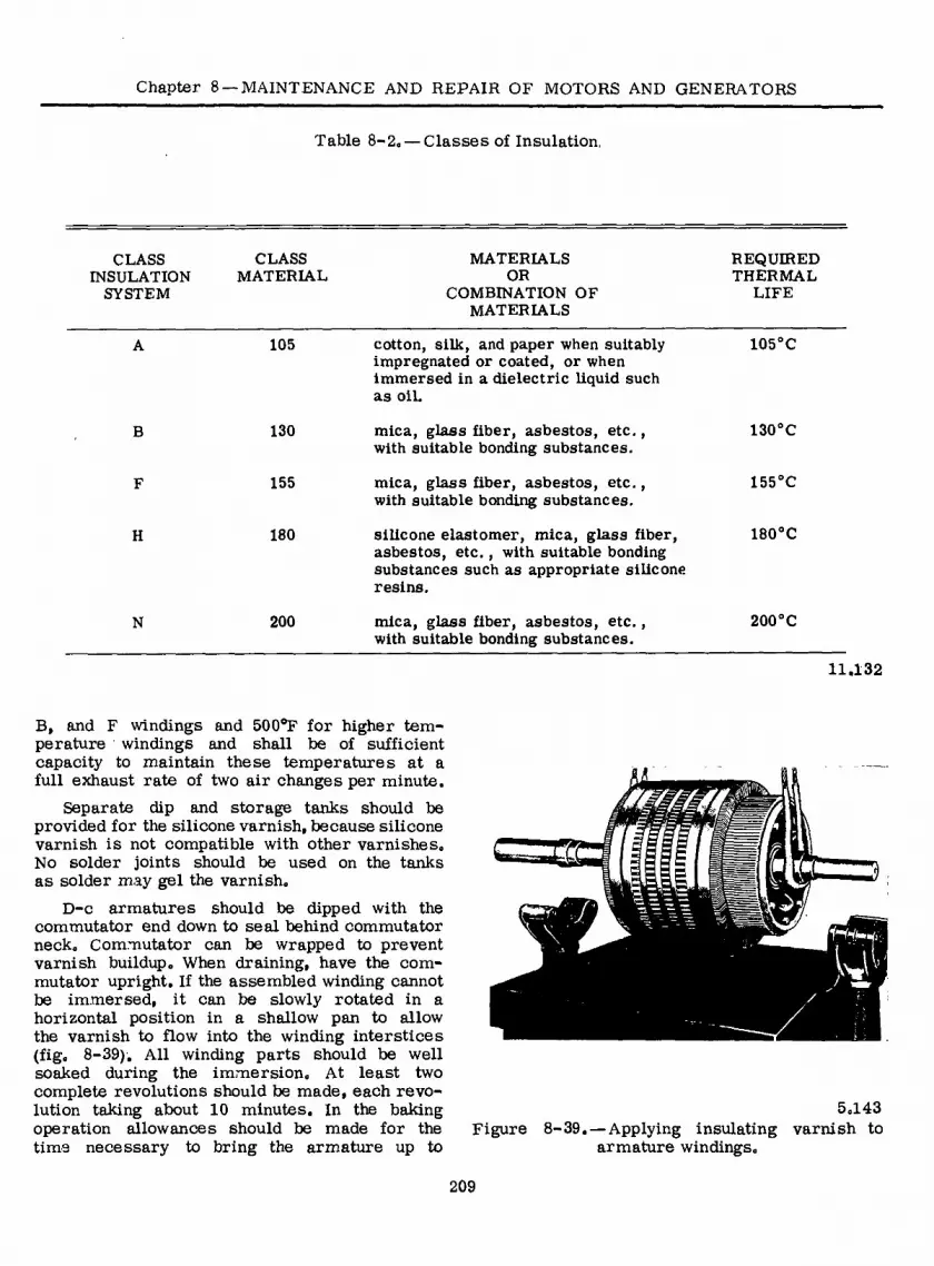
Chapter 8 —MAINTENANCE AND REPAIR OF MOTORS AND GENERATORS
Table 8-2. — Classes of Insulation.
CLASS INSULATION
SYSTEM
CLASS MATERIAL
MATERIALS OR
COMBINATION OF MATERIALS
REQUIRED THERMAL
LIFE
B
H
N
105
130
155
180
200
cotton, silk, and paper when suitably 105°C impregnated or coated, or when immersed in a dielectric liquid such as oil.
mica, glass fiber, asbestos, etc., 130°C with suitable bonding substances.
mica, glass fiber, asbestos, etc., 155°C with suitable bonding substances.
silicone elastomer, mica, glass fiber, 180°C asbestos, etc., with suitable bonding substances such as appropriate silicone resins.
mica, glass fiber, asbestos, etc., 200°C with suitable bonding substances.
11.132
B, and F windings and 500°F for higher tem- perature windings and shall be of sufficient capacity to maintain these temperatures at a full exhaust rate of two air changes per minute.
Separate dip and storage tanks should be provided for the silicone varnish, because silicone varnish is not compatible with other varnishes. No solder joints should be used on the tanks as solder may gel the varnish.
D-c armatures should be dipped with the commutator end down to seal behind commutator neck. Commutator can be wrapped to prevent varnish buildup. When draining, have the com- mutator upright. If the assembled winding cannot be immersed, it can be slowly rotated in a horizontal position in a shallow pan to allow the varnish to flow into the winding interstices (fig. 8-39). All winding parts should be well soaked during the immersion. At least two complete revolutions should be made, each revo- lution taking about 10 minutes. In the baking operation allowances should be made for the time necessary to bring the armature up to
5.143 Figure 8-39. — Applying insulating varnish to
armature windings.
209

ELECTRICIAN’S MATE 3 & 2
temperature. If possible, d=c armatures should be baked with the-commutator end up.
The completed armature is now placed in a lathe and a very light cut taken over the surface of the commutator and over the face and side of the commutator risers to make the assembly perfectly true. Next, the commutator mica should be undercut so that the carbon brushes will not be damaged by the high mica.
You must remember that all armature stator and field windings must be checked for shorts, grounds, and opens after each step of being wound, formed, taped (if necessary), installed, connected, dipped, and baked.
HIGH-POTENTIAL TEST
A high-potential test is made by applying (between insulated parts) a test potential that is higher than the rated operating voltage. High- potential tests are frequently used in connection with the repair, or reconditioning of naval equip- ment ashore.
The purpose of the test is to break down the insulation if it is weak, thereby indicating defective material and workmanship, and per- mitting replacement prior to actual use.
The application of each high-potential test tends to weaken insulation even though it does not produce actual failure at the time. Also, the use of high-potential tests requires special equipment and safety precautions.
When making high-potential tests on electrical equipment that has been reconditioned or rewound in a shop, keep from coming in contact with any part of the circuit or apparatus. Never touch the winding after a high-potential test has been made until it has been connected to ground to remove any static charge it may have retained.
A high-potential test should not be made on a d-c generator or motor until after the reconditioning or rewinding is completed, includ- ing the application of varnish, and the insulation resistance has been measured and found to be higher than the value in the last column of table 8=3.
All leads to the circuit being tested should be connected to one terminal of the source of test voltage. All leads to all other circuits and all metal parts should be connected to ground. No leads are to be left unconnected for a high- potential test as this may cause an extremely severe strain, at some point of the winding. For example, to make a high-potential test on
Table 8=3„ —Minimum Direct Current Generator and Motor Insulation Resistances for High- Potential Tests
Circuit
Insulation Resistance in Megohms at 25? C f After Reconditioning in Shop.
Complete armature circuit^
Armature alone Armature circuit
less armature2 Complete shunt
field circuit2
2 2
2.5
(Footnotes for Table 8-3)
*The figures given are for machines rated at 250 volts or less. For machines having a rated voltage, E, greater than 250 volts, multiply all figures given in the table by E/250.
2 Small machines usually have one of the shunt
field leads connected internally to the armature, cir- cuit. To avoid disassembly in such cases, the com- plete armature circuit and complete shunt field cir- cuit may be measured without breaking this connec- tion. If necessary, the armature can then be isolated by lifting all brushes.
(a) With the brushes left in place, the complete armature circuit will include armature, armature circuit, and the permanently connected shunt field circuit. The values given in the table for the com- plete armature circuit will apply.
(b) With the brushes lifted, the armature cir- cuit less armature and the complete shunt field cir- cuit will be measured. The values given in the table for armature circuit less armature will apply.
m.83
a rewound armature, short circuit the commutator segments by wrapping one or more turns of bare wire around the commutator and apply the high-potential test voltage across the common connection of all the commutator segments and the grounded armature shaft.
The high-potential test voltage is obtained from a 60-hertz a-c source that should have a capacity of 1 kilowatt. When making a test, increase the voltage as rapidly as possible without exceeding the correct value, as indicated on the voltmeter. The full voltage should be maintained for 1 minute. The voltage should
210

Chapter 8 —MAINTENANCE AND REPAIR OF MOTORS AND GENERATORS
then be reduced at a rate that will bring it to one-quarter of the correct value or less in not more than 15 seconds.
REWINDING FIELD COILS
The old field coil is removed from the pole piece and, if spare coils are available, a new one is installed. If a new coil must be made, record all pertinent coil data as the old coil is stripped down.
This data should include the (1) dimensions of the coil, both with the tape on and with the tape removed, (2) weight of the coil without the tape, (3), size of wire, and (4) type of insulation.
The two general classes of coils are (1) shunt field coils, which consist of many turns of fine wire and (2) series and commutating field coils, which consist of fewer turns of heavy wire.
SHUNT COILS
The equipment for rewinding shunt coils includes a lathe or suitable face plate, which can be turned at any desired speed, and an adequate supply of the proper size wire wound on a spool, which can be supported on a shaft so that it is free to turn. Friction should be applied to the spool to provide tension on the wire. A coil form having the exact inside dimen- sions of the coil is secured to the lathe or face plate. The form for shaped field coils can be made from a block of wood shaped exactly to the required size and provided with flanged ends to hold the wire in place (fig. 8-40). One
77.81 Figure 8-40.—Coil form for field coils.
77.84 Figure 8-41. —Edge-wound series coil.
of the flanges should be removable so that the finished coil can be taken from the forming block.
The wire is now wound from the spool onto the forming block for the required number of turns. The turns must be evenly spaced, one against the other, until the winding procedure is completed. The turns of the completed coil are secured by tape, and the wire leading to the spool is cut, leaving sufficient length to make the external connections. The completed coil must be checked electrically for continuity and for shorted turns.
The coil is now prebaked and varnish treated. When varnish treated, the finished field coil should withstand a high-potential test of twice the rated excitation voltage +1,000 volts.
SERIES AND COMMUTATING COILS
Series and commutating field coils are fre- quently wound with strap (rectangular) or ribbon copper instead of round wire. These coils have only a few turns that are wound in a single turn per layer.
A series coil wound (with ribbon copper) on edge is illustrated in figure 8-41. It is more difficult to bend the copper ribbon, but it has an advantage in that both terminal leads protrude on opposite sides ofthe coil. Thus, the connections can be made very easily compared to the strapr wound coils, which have one coil end at the center and the other coil end at the outside of the coil. The strap-wound construction requires
211

ELECTRICIAN’S MATE 3 & 2
leading the inside coil end over the turns of strap in the coil.
After the winding is completed, the coil is tested electrically for continuity and shorted turns. It is then prebaked, varnished, and tested for polarity, grounds, opens, sind shorts as described previously, at each stage in turn.
TESTING FIELD COIL
Before installing a new or repaired coil, it should be tested for shorts, opens, and grounds and its polarity determined. A small magnetic compass may be used to determine the polarity of a field coil by holding it several inches away from the coil along its axis. A small battery is connected to the coil leads, and if the south compass needle points toward the center of the coil, the face of the coil nearest the compass will be a north pole. This will indicate that the coil should be placed on a north pole in the same position it was in during the test, and the field current should flow through the coil in the same direction.
To protect the armature, the same precautions that were observed during removal of the coil must be observed when installing it. All of the shims originally removed from the pole piece must be in position when it is replaced. With the coil in position in the machine, it should be temporarily connected to the other coils in the field circuit and a compass and battery again used to check its polarity. For this test, connect the battery to the proper field leads and check the polarity of all the coils with the compass (fig. 8-42). Adjacent poles must be of opposite polarity. If need be, polarity of the new coil can be reversed by reversing its leads. When the polarity is correct, the coil is connected, and the pole-piece bolts are tight- ened. Air gaps should be measured to ensure uniformity.
REVERSING DIRECTION OF ROTATION OF D-C MOTORS
After repairing d-c motors, check the motor rotation. If the direction of rotation needs to be reversed, the two methods for reversing are (1) changing the direction of current flow through the armature leads and (2) changing the direction of current flow through the motor fields. In compound motors the reversing of current is easier using the first method since a single element is involved. If the second method is used it becomes necessary to reverse the current through both the series field and shunt field windings.
© ◄> <►
H4 □
77.80 Figure 8-42. — Testing polarity of field coils.
CHECKING MOTOR AND GENERATOR SPEEDS AFTER REWINDING
Tachometers indicate in revolutions per minute (rpm) the turning speed of motors, gen- erators, and other rotating machines. Use a portable tachometer, as explained in Chapter 3 of this manual, to measure the speed of a motor or generator after rewinding.
SETTING ON NEUTRAL When a machine is running without load and
with only the main-pole field windings excited, the point on the commutator at which minimum voltage is induced between adjacent commutator bars is the no-load neutral point. This is the best operating position of the brushes on most commutating-pole machines. Usually, the brush studs are doweled in the proper position, and the correct setting is indicated on a stationary part of the machine by a chisel mark or an arrow. In some cases commutation may be improved by shifting the brushes slightly from the marked position.
The correct neutral position can be found by the use of a mechanical, reversed rotation, or inductive kick method. The mechanical method is an approximate method. Turn the armature until the two coil sides of the SAME armature
212

Chapter 8 —MAINTENANCE AND REPAIR OF MOTORS AND GENERATORS
coil are equidistant from the center line of one MAIN field pole. The commutator bars to which the coil is connected give the position of the mechanical neutral.
Use of the reversed rotation method is possible only where it practicable to run a machine in either direction of rotation, with rated load applied. This method differs for motors and generators. For motors, the speed of the motor is, at first, accurately measured when the field current becomes constant under full load at line voltage with the motor running in the normal direction. Then, the rotation of the motor is reversed, full load is applied, and the speed is again measured. When the brushes are shifted so that the speed of the
motor is the same in both directions, the brushes will be in the neutral position. Generators are run at the same field strength and same speed in both directions, and the brushes are shifted until the full-load terminal voltage is the same for both directions of rotation. To ensure ac- curacy, a reliable tachometer must be used to measure the speed of the machines for this method.
The kick method should be used only when the other methods are inadequate and the condi- tions are such as to warrant the risks involved, and then only when sufficient resistance is connected in series with the field coils to reduce the field current to approximately 10 percent of normal value.
ROTATING
ELEMENT
DC EXCITER
ARMATURE
BRUSHES
A AC EXCITER
ARMATURE
ROTATING
ELEMENT
B
#or.
3—PHASE
POWER
OUTPUT
COMMUTATOR
COLLECTOR
RINGS
AC THREE PHASE
GENERATOR ^C/r ROTOR
FIELD STATOR
CO LS Ac FJ£LD
G-
3-PHASE
POWER
OUTPUT
SILICON
RECTIFIER
ASSEMBLY
Figure 8-43.—A-c generator. (A) Brush type, (B> brushless, 73.308:309

ELECTRICIAN'S MATE 3 & 2
77.304 Figure 8-44. — Internal growler.
9^2 y
f ////M , /
IIOV AC POWER
SUPPLY
73.147 Figure 8-45. —Testing a three-phase stator for
shorted coils.
BRUSHLESS GENERATORS
Brushless a-c generators are used in the fleet for ship service and emergency power. Figure 8-43 compares the brush type and brushless a-c generators. In the brush type a-c generator (fig. 8-43A) the currentistransferredfrom the rotating member of the machine to the stationary member and vice versa by the use of commutator, collector rings and brushes. Brushless a-c generators, on the other hand, (fig. 8-43B) have a silicon rectifier assembly which replaces this coupling. This de- velopment is simple, compact, free of sparking and greatly reduces the maintenance of generators. Silicon recitifiers are mounted on the rotating shaft to furnish direct current to the a-c generator rotor field. In the brush type a-c generator the commu- tator serves as a rectifier to perform this function. Feedback from the three phase power output through a voltage regulator control (not shown) furnishes the correct amount of excitation to the exciter field for a-c generator voltage control.
THREE PHASE STATOR TESTING AND REPAIR
In testing stator coils, as in testing d-c armatures, you will find the most common troubles to be grounds, opens, and shorts.
The internal growler (fig. 8-44) is used to check for shorts and opens on the inside of stators and stationary fields, or on large armature sur- faces where and external growler cannot be used.
MAKE
H.P. R.P.M. VOLTS AMPS.
HERTZ TYPE FRAME STYLE
TEMP. MODLE SERIAL PHASE
NO. OF COILS
NO. OF SLOTS CONNECTION
SIZE WIRE NO. OF TURNS
NO. OF GROUPS
COILS- GROUP
NO. OF POLES
PITCH OF COIL
111.65 Figure 8-46. —Stator data sheet.
To make such checks connect the internal growler to rated a-c source. Run the internal growler over the coils of a motor or generator and listen for a buzz (fig. 8-45). When a shorted coil exists, trans- fromer action causes the growling noise. Coils may be tested for opens by deliberately shorting each coil, A buzz at any of the coils means a closed circuit.
If you use a meter-indicating internal growler (fig. 8-44) a pointer deflection indicates a short;
214

Chapter 8 —MAINTENANCE AND REPAIR OF MOTORS AND GENERATORS
no deflection of the pointer indicates an open circuit.
THREE PHASE STATOR REWINDING
When tests or observation determine that a three phase stator needs rewinding, certain data is recorded.
It is most important to keep an accurate record of all the pertinent data concerning the winding on the stator data sheet, as shown in figure 8-46. If possible this information should be obtained before stripping; if not, it can be obtained during the stripping operation.
An a-c stator is stripped in the same manner as a d-c armature.
Figure 8-47 shows coil sides being placed in a stator.
When all the coils have been inserted in the stator slots, the ends insulated, and the slot wedges driven in place, there will be two free ends for each coil (top and bottom) from one side of the stator winding. The free ends must be connected to form a series of groups of coils.
In arranging these coils into pole-phase groups, start by bending (forming) the inside lead of the first coil in toward the center and then bend the outside lead of that coil and the inside lead of the next coil together. Connect the outside lead of the last coil with the inside lead of the next coil and bend the outside lead of this coil away from the center. Repeat this procedure for each of the pole-phase groups all around the stator. Do not solder the connection at this time.
After twisting the ends together, check the individual groups to determine that the proper number of coils have been connected together in each pole-phase group and that they have the proper polarity. Then solder the twisted con- nections and cut off the ends so that the soldered stubs are about three quarters of an inch long. Insulate the stubs with cotton tape or reinforced mica tape.
If the distance to the bearing brackets (frame of the machine) is small, bend the insulated stub in between the coils so that they do not come in contact with the frame when the stator is assembled in the machine.
INSULATION PLACED ON TOP
OF SLOT TO PROTECT WIRE
FROM SCRAPING IRON CORE
1st SLOT
/ 2nd SLOT
ri/n n
BOTTOM SIDE
OF COIL
FIRST C0IL0F WINDING IN PLACE
TOPSIDE NOTIN SLOT
ONE SIDE 1st COIL IN SLOT
2nd COIL
SECOND COIL OF WINDING IN PLACE
111.66 Figure 8-47, — Placing coil sides in slots.
In practice, the coils that comprise the pole-phase groups are usually gang wound. Gang wound coils eliminate the need for stubbing because the coils are wound with a continuous length of wire.
Series-Wye Winding
Before connecting the pole-phase groups together construct a diagram containing the pole-phase groups in each phase and the number of poles for the particular machine, as illus- trated in figure 8-48. Be certain that the pole- phase groups for each phase are connected properly to produce alternate north and south
215

ELECTRICIAN’S MATE 3 & 2
*
N
I STARING POINT
CfW \\
As PHASE
C5 PHASE
cT Be PHASE
* iT
x,. o 111.68.1 111.68.2 Figure 8-48. —Three-phase, 4-pole, series-wye Figure 8-49. —Three-phase, 4-pole, series-wye winding. winding showing the 4-poles
poles by indicating the direction of current flow through each pole-phase group by arrows that must reverse direction for each successive group now connected.
The As, Efe, and Cs phase leads (s stands for start) are all connected to one polarity of a small battery and the Af, Bf, and Cf phase leads (f stands for finish) are all connected to the other polarity of the battery. If connections are correct a compass will give opposite polarity as it is moved from one coil group to another. Note the changing polarity in figure 8-48.
All the arrows on the line leads (fig. 8-48) indicate current in the same direction toward the center of the wye. Actually, the current at one instant may enter the phase A lead and leave by the other two leads. At the next instant current may enter through phases A and B and leave by phase C (Fig. 8-49). At any instant, current is flowing into and leaving, the wye by at least one lead. This illustrates how a four pole motor or generator actually functions. In rewinding, however, having the current going in at all phases and ending at the internal star connection (fig. 8-48) is best for bench testing the stator.
The series-wye connection (figs. 8-48, 49) is employed in a-c machines designed to operate at a comparatively high voltage. Machines that
*
STARTING POINT
*
111.69 Figure 8-50. — Three-phase, 4-pole, parallel-
wye winding.
216

Chapter 8 —MAINTENANCE AND REPAIR OF MOTORS AND GENERATORS
require a relatively high current usually are wound in a multiple or parallel arrangement.
Parallel-Wye Winding
To connect the machine for 3-phase, 4-pole, parallel-wye operation, use the diagram shown in figure 8-50 with the same number of pole-phase groups and the same assumed directions of current flow through the groups as in the series- wye connection, the pole-phase groups of the three phase must be connected so that the current flows through the various groups in the directions indicated to obtain alternate north and south poles. Again connect the battery as previously described by connecting A, B, C start phases to one side of battery and A, B, C finish phases to the other side. Again the 12 compass polarities should be indicated in one revolution of the stator.
The only difference between the parallel-wye winding (fig. 8-50) and the series-wye winding (fig. 8-48) is that the four pole-phase groups, which were originally in series in any one of the phases, are now split into two parallel groups of two each. In phase A the same coil groups are used, but the series group 1 and 4 is placed in parallel with the series group 10 and 7, resulting in an increase in the current- carrying capacity and a corresponding decrease
in voltage of that phase without changing the number of pole-phase groups or without changing the groups themselves.
Series-Delta Winding
The same machine connected for 3-phase, 4-pole, series-delta operation is illustrated in figure 8-51. The same pole-phase group numbers are alloted to the same phase windings and the directions of current flow through the groups are the same as for the other examples.
Note the difference in the series-wye winding (fig. 8-48) and the series-deltawinding(fig. 8-51). In the series-delta winding the three phases are connected so that they form a delta, and the external connections are made at the three corners of the delta.
Parallel-Delta Winding
The machine used in the other examples, connected for 3-phase, 4-pole, parallel-rdelta operation, is illustrated infigure 8-52. The phase, windings contain the same pole-phase group numbers, and the polarities of the pole-phase groups are the same as in the previous cases.
/
STARTING POINT
*
/
8.
\ STARTING
POINT
■ t
111.70 111.71 Figure 8-51. —Three-phase, 4-pole, series-delta Figure 8-52. —Three-phase, 4-pole, parallel-
winding. delta winding.
217

Chapter 8 —MAINTENANCE AND REPAIR OF MOTORS AND GENERATORS
POLYPHASE STATOR TROUBLES
The methods of locating and correcting the common troubles encountered in rewound and reconnected polyphase stator windings are in- cluded for the convenience of Electrician’s Mates engaged in this work.
0r. A.C. SOURCE
A W C
K''/ B
A.C. SOURCE
Shorted Pole-Phase Group WYE CONNECTION
A DELTA CONNECTION
B
An entire pole-phase group may be shorted in a polyphase stator. Such a defect is usually indicated by excessive heat in the defective part. The trouble can be readily located by a compass test. To conduct a compass test, excite the stator windings with a low-voltage, direct current that will set up the poles in the stator (fig. 8-53). When the windings are excited, a compass is moved around the inside circumference of the stator core. As each pole group is approached, the polarity is indicated by the compass. There should be the same number of alternate north and south poles in a 3-rphase winding.
In testing a 3-phase, wye-connected winding (fig. 8-53), test each phase separately by im- pressing the d-c voltage successively on each of the phase leads and the midpoint of the wye connection. If there is no trouble in the winding, the compass will indicate alternately north and south for each pole-phase group around the stator. If a complete pole-phase group is shorted, the compass needle will not be deflected at this point.
oc. SHORT SOURCE
WYE CONNECTION
SHORT
B.Ç SOURCE
DELTA CONNECTION
111.76 Figure 8-53. — Compass test for shorted pole-
phase groups.
111.77 Figure 8-54. — Balanced current test for shorted
phase.
In testing a 3-phase delta-connected winding (fig. 8-53B), open one of the delta connections and apply the direct current to the winding. The current will flow through the three phases in series. If the pole-phase groups are connected properly, the compass will indicate alternate north and south poles around the stator frame. As in the wye-connected winding a shorted pole- phase group is indicated by no deflection of the compass needle.
Shorted Phase
When an entire phase of a 3-phase winding is shorted, the defect is most readily located by a balanced-current test made with a type TA industrial analyzer.
This test can also be made with an ammeter and low-voltage a-c source (fig. 8-54).
In testing a 3-phase wye-connected winding (fig. 8-54A), test each phase separately by impressing the a-c voltage successively on each of the phase leads and the midpoint of the wye connection. If there is no trouble in the windings, and if the impedance of the winding of each phase is the same, the ammeter will indicate approximately the same value of current for each of the three phases. If one phase is shorted, the ammeter will indicate a higher current reading for this phase than those of the other two phases because the impedance is less.
In testing a 3-phase delta-connected winding (fig. 8-54B) open each delta connection and test each phase separately. As in the wye-connected winding, the shorted phase will be indicated by a much higher current reading on the ammeter.
218

Chapter 8 —MAINTENANCE AND REPAIR OF MOTORS AND GENERATORS
CLOSED
A ^ J "CIRCUIT CLOSED
CIRCUITV ,C
OPEN
Ç». •>. o = ÿ g OPEN—
o n
WYE CONNECTION
A DELTA CONNECTION
B
111.78 Figure 8-55. — Ohmmeter test for open circuits.
Open Circuits
An open circuit in a 3-phase winding can be readily located by means of an ohmmeter (fig. 8-55).
In testing a 3-phase wye-connected winding (fig. 8-55A), connect the ohmmeter leads across each of the phases to locate the defective phase. When the ohmmeter leads are placed on terminals A and C, no open circuit (a low reading) is indicated. However, when the leads are placed on terminals C and B, and then on terminals B and A, an open circuit (a high reading) is indicated hi both positions, thus denoting an open in phase B. After the defective phase has been located, test each stub connection of the pole-phase groups with the ohmmeter until the open coil is located.
In testing a 3-phase, delta-connected winding (fig. 8-55B), it is necessary to open one delta connection to avoid shunting the phase being tested. Test each phase separately until the open is located. After the faulty phase is located, test each stub connection of the pole-phase groups, as in the wye-connection, until the open coil is located.
If the windings are parallel, it is necessary to open each parallel group and test each group separately.
REVERSING DIRECTION OF ROTATION OF A THREE PHASE MOTOR
To reverse the direction of rotation of a three phase motor all that needs to be done is to reverse the connections of any two of the three leads of the motor. That is, reverse either the A and B, A and C, or B and C phase leads.
SINGLE PHASE MOTOR REPAIR
There are many applications for single phase motors in the Navy. They are used in interior communication equipment, refrigerators, fans, drinking fountains, portable blowers, portable tools, and in many other applications. Single phase motors are considerably cheaper in frac- tional horsepower sizes, but above 1 horsepower the three phase motors are less expensive. The use of single phase motors also eliminates the need of running three wire service to supply small loads.
Usually it is the starting winding that burns out in single phase motors. The centrifugal switch (8-56) cuts the starting winding out of the system when the motor reaches approximately 75 percent of full speed. When the motor is overloaded the speed decreases and allows the centrifugal switch to energize the starting wind- ings, then the motor speeds up enough so that the centrifugal switch opens the starting circuit again. This constant opening and closing of the starting winding circuit will cause failure of the winding.
Steps in analyzing motor troubles should proceed, as previously mentioned, following a logical sequence to determine what repairs are required for reconditioning the motor: (1) inspect motor for defects, such as, cracked end plates, bent shaft, broken or burned wiring, (2) check motor for bearing troubles, (3) test the motor for grounds, opens and shorts (see armature
A
73.130 Figure 8-56. —Two major parts of a centrifugal
switch.
219

ELECTRICIAN’S MATE 3 & 2
A
Single Phase Capacitor Q Split Phase Q
Mak*
C,c
Amps
Typ«
Model
Rotation facing shaft Clockwise Counter-Clockwise
Winding
Running
No. Colls Per Pole
Running
Starting
Turns Per Pole
Inside Coll Span
Sise Wire
□ XL
Style
Ser. No.
Cap MFD
Type Wire
No. Circuits
Coll Extension
Stator Dimensions
Inside Dio meter length of Core Depth Behind
Name and Cl. No. Date
B
0 ^ ^ o o ^ 0
A 5»
« O9
<r%
77.300.2
Figure 8-57. — Single-phase motor data card. (A) Front side; (B) back side.
and 3-phase stator sections). If rewinding is required record the necessary data on a single phase motor data card (fig. 8-57).
A single phase motor connection is shown in figure 8-58. When the motor is tobe connected to a power source of 110 volts a-c the motor rim windings are connected in paralled by placing the two connecting bars as shown in figure 8-59 A. Note the bar terminals in figure 8-59.
When the motor is to be connected to a power source of 220 volts a-c the run windings must be connected in series by placing the two connecting bars one superimposed on the other as shown in figure 8-59B.
By tracing through the two above series and parallel bar connected circuits you will note that the startingwindingoperates on 110 volts regardless of a parallel or series connection.
220

Chapter 8 —MAINTENANCE AND REPAIR OF MOTORS AND GENERATORS
-z-
> A.C.
POWER SOURCE
-z-
Figure 8-58.—Single phase capacitor-start, induction-run motor diagram 77.305
Figure 8-60 is a diagram of a four-pole single phase motor. The type of winding used on both the running and starting winding is the spiral winding. The difference between the two windings is their impedance and position in the stator slots. The running winding has a low resistance and a high reactance (because of many turns of large wire), whereas, the starting winding has a high resistance and a small reactance (being wound of small or high resistance wire).
The running winding is placed in the bottom of the slots, and the starting winding is placed on top of the running winding. Both windings are energized in parallel at starting. The currents are out of phase with each other, and the combined effects produce a rotating field that starts the motor (some motors use capacitors
for starting). When the motor has almost reached normal speed the centrifugal switch opens the starting winding circuit, and the motor operates as a single-phase induction motor.
A pole for the running or the starting winding in a single phase motor is made up of more than one coil. These coils differ from each other in size and, depending on the winding specifications, in the number of turns per coil. When coils are placed in stator slots they can be wound in place by hand or wound in a coil winder on forms and then placed in the slots of the stator.
Capacitors used with single-phase motors for starting should be checked by means of a capacity tester. This also applies to the capacitor-start capacitor-run type motors.
221

ELECTRICIAN’S MATE 3 & 2
«
t
#
A B
77.306 Figure 8-59. — Connecting bars for A. low voltage
input; B, high voltage input.
RUNNING WINDING
45
/ ►90
180
STARTING WINDING
RUNNING WINDING
111.92 Figure 8-60.—A four pole split phase motor.
REVERSING THE DIRECTION OF ROTATION. OF A SINGLE PHASE MOTOR
Rotation of the single phase motor is usually reversed by reversing the starting winding leads
only. If these leads are brought outside the motor, a switch may be used to reverse the rotation. The direction of rotation is from a starting winding pole to a running winding pole of the same polarity, as shown in figure 8-60.
MOTOR AND GENERATOR AÏR COOLERS
Some large electric motors and generators, such as propulsion generators and motors, are equipped with surface-type air coolers. In this system the air is circulated by fans on the rotor in a continuous path through the machine windings and over the water-cooled tubes of the cooler. The cooler is of double-tube con- struction (one tube inside another) to minimize the possibility of damage due to water leakage. The location of the air cooler in a generator is shown in figure 8-61.
The air and water sides of air cooler tubes must be kept as clean as possible because foreign deposits will decrease heat transfer. When the air side of the tubes requires cleaning, the individual tube bundles may be removed and washed with hot water or cleaned with a steam jet. The water side of cooler tubes must be cleaned in accordance with instructions contained in the NavShina Technical Manual, chapter 9460.
When a leak between an inner tube and the tube sheet occurs, water will seep from the cooler head through the leaky joint into a leak-off compartment and out the leakage drain. If a leak occurs in an inner tube, water will seep
AIR TEMPERATURI
GAGE
A R COOLER
COLLECTOR RING
COVER
GENERATOR
77.85 Figure 8-61.—Generator equipped with an air
cooler.
222

Chapter 8 —MAINTENANCE AND REPAIR OF MOTORS AND GENERATORS
into slots in the outer tube where it is carried to a leak-off compartment and out the leakage drain. The leakage drain line is equipped to give a visual indication of the presence of water in the line.
When a leaky tube is found, both ends of the tube should be plugged with plugs provided as spare parts or with condenser plugs. When the number of plugged tubes in a cooler section becomes large enough to adversely affect the heat-dissipating capacity of the cooler, the cooler section must be removed and replaced.
MANDATORY TURN-IN REPAIRABLES
Since you will no doubt encounter the terms “mandatory turn-ins” and “repairables’’ in the process of obtaining replacement parts from supply, you should understand the purpose of the repairables program and your responsibilities to it.
When a component fails, your primary concern is to locate the trouble, correct it, and get the equipment “back on the line.” In most cases this involves troubleshooting the equipment and tracing the trouble to the defective component, drawing a replacement from supply, installing it and discarding the old one.
The repairables program enters the picture when defective parts are expensive, and can be economically repaired at the factory. In these
cases time and money are saved since it is quicker and cheaper to repair an item than to contract to a manufacturer to have a new one built. The old part should be promptly turned into supply so there is always recycling of that part in the supply system,
For the repairables program to work as intended, you and others have certain responsi- bilities. At the time you turn in your request for a replacement part, supply must inform you at that time whether or not it is a mandatory turn-in item. At this point proceed as follows:
• ■ Remove the defective part without damaging it.
• Provide adequate protection for the part to prevent additional damage. Use the same container in which the new one was packaged if at all possible.
o Return the defective part to supply as soon as practicable.
DO NOT CANNIBALIZE THE PART FOR COM- PONENTS YOU THINK YOU MAY NEED FOR FUTURE USE.
When the required part is not in the storeroom, supply must take appropriate action to obtain it. The failed part should be turned-in to supply prior to receiving the new one, unless its removal will cause limited or reduced operating capabilities.
223

CHAPTER 9
SHIPBOARD LIGHTING
The EM is charged with the responsibility of maintaining the lighting distribution system aboard naval vessels. This system comprises the ship’s service general lighting, navigational lights, and signal lights, including searchlights.
The lighting system must maintain continuity of power to selected vital lighting circuits by means of independent power sources and switch- ing equipment that select, in an orderly fashion, a power source suitable for proper system operation.
At times you will be directed to install new lighting circuits or equipment and may find yourself without installation plans or drawings. Other times you will be correcting deficiencies found while conducting PMS checks, routine tests, or inspections. For these and various other reasons you should be intimately familiar with the lighting system aboard your ship. Always refer to applicable blueprints, drawings, and the Ships Installation Book before attempting repairs on the system.
LIGHTING DISTRIBUTION SYSTEMS
The lighting distribution system in naval vessels is designed for satisfactory illumination, optimum operational economy, maximum con- tinuity of service, and minimum vulnerability to mechanical and battle damage. Many ships have two sources of power supply for lighting fixtures. Normal supply is from the ship service bus. A designated number of fixtures can also be supplied from the emergency distribution system. Additionally, there is a third lighting system that consists of battery-powered, relay- operated, hand lanterns.
The first two systems consist of feeders from the ship’s service or emergency power
switchboards, switchgear groups, or load centers to distribution panels or feeder distribution fuse boxes, located at central distribution points from which power is distributed to the local lighting circuits.
The a-c ship’s service power feeders are either 450-volt or 120-volt, 3-phase, 60-hertz circuits. The lighting supply circuits are 450-volt, 3-phase, 60-hertz, 3-wire circuits supplied from the power distribution system to 450/120 volt transformer banks (fig. 9-1). Each transformer bank consists of three single-phase, delta-delta connected transformers (fig. 9-2).
Three small transformers are used instead of one large transformer because the loss of a composite unit would result in a loss of power. By using three separate transformers reliability is increased. In the event of an enemy hit or failure to one of the bank of three single-phase transformers the remaining two will still carry about 58 percent of the initial bank capacity. By simply disconnecting the defective trans- former the remaining two transformers will be connected open delta. In an open delta connection, the line current must be reduced so as to not exceed the rated current of the individual trans- formers.
A typical vital lighting load has access to two switchboards (fig. 9-1). Selection to either of these sources is automatically accomplished through an automatic bus transfer (ABT) switch. Additionally, the emergency switchboard has three power supplies that are independent of each other. As a result of this arrangement, the vital lighting load can be automatically supplied from several primary sources.
The system shown in figure 9-1 operates as follows. If an undervoltage condition develops on switchboard 2SA, which is the normal supply for ABT switch #1, then the ABT switch will
224

Chapter 9—SHIPBOARD LIGHTING
'Ä'
CD tr 3
o
SS SWB 2SB SS SWBD 2SA SS SWBD 1SB
f 1
450/120 X
LIGHTING LOAD
CENTER PANEL
EMERGENCY LIGHTING 450/120
LOAD CENTER
PANEL
ABT
_i < 2 tr o z
BUS TIE
( (
EMERGENCY SWBD
2E
SSSWBDISA
I 77
450/120
450/120:
ÜL
EMERGENCY SWBD
IE ABT
LIGHTING DISTRIBUTION
PANEL (VITAL LOAD)
© EMERGENCY GENERATOR
2E
EMERGENCY GENERATOR
IE
Figure 9-1. — Lighting distribution system. 77.48(77C)
SUPPLY
A
B C
LOAD A'
B' C
X2
nl
x2
H2
*1
Hi
x2
H2
Xl
450 VAC
120 VAC
73.94 Figure 9-2. — Delta-delta transformer connections.
225

ELECTRICIAN’S MATE 3 & 2
RELAY 4V
DRIVE UNIT TS
AUXILIARY
CONTACT
ASSEMBLY
o o
RELAY © © © □© s IV «
a© © <s> 3 ©
111 O RELAY SE
a®
®
3 ©
©
RELAY 3 O o 2 V
RELAY 3V
AUXILIARY
CONTACT
ASSEMBLY
CONTACT 'ASSEMBLY
DISCONNECT SWITCH
TEST SWITCH
MANUAL SWITCH
CONTACT ASSY.
Figure 9-3.— Pictorial view of A-2 ABT. 140.70
transfer the lighting load center panel to the emergency lighting load center panel. The power source for the later panel is emergency switch- board 2E.
Emergency switchboard 2E is energized either from its normal or alternate ship service supply feeders, or the local emergency generator. Trans- fer between these supplies is accomplished automatically by three electrically operated cir- cuit breakers. The circuit breakers are elec- trically and mechanically interlocked to prevent
closing of more than one breaker at a time. Normally, the emergency switchboard is ener- gized from one of the two ship service supplies. If voltage on the normal ship service supply bus drops to 300 volts, or below, the load is automatically transferred to the alternate supply if 400 volts or above is available at this source. (If 400 volts or above is restored to the normal supply, the load will automatically retransfer to the normal supply.) Should both ship service supplies fail completely, or their voltage drops
226

Chapter 9 —SHIPBOARD LIGHTING
below 300 volts, the transfer system will operate automatically to start the emergency generator and connect it to the emergency switchboard.
AUTOMATIC BUS TRANSFER SWITCHES
The A2 Model Automatic Bus Transfer Unit is designed to handle smaller loads and operate on 120-volt, 60-hertz circuits. This unit (fig. 9-3) may be used on single- or 3-phase circuits. For purposes of explanation the 3-phase unit will be discussed.
The A2 ABT is designed to transfer auto- matically from normal to emergency supply upon a decrease in voltage to within the 8l/69-volt range across any two of its three phases. Upon restoration of the voltage to the range of 98/109 volts the unit is adjusted to retransfer to the normal source of supply. An intentional time delay is included in the circuitry of from 0.3 to 0.5 seconds for both transfer and retransfer to allow for surges in line voltage and short duration losses in power. <
The A2 unit shown in figure 9-4 is equipped for manual operation by placing the control disconnect in the manual position and operating the manual handle.
Automatic operation is accomplished when the normal supply voltage drops to the dropout range and relay IV, 2V, and 3V drop out. Contact 1 Val opens disconnecting relay SE. After a time delay of from 0.3 to 0.5 seconds, relay SE opens closing its SEbl and SEb2 contacts and energizing relay 4V from the emergency source. Contact 4 Val in closing connects the emergency source to coil TS of the transfer switch which in turn operates, transferring the load to the emergency source.
Presently, contacts TSa4 and TSa5 open dis- connecting coil TS from its operating circuit. TS is now held in the operated condition mechani- cally, however and the transfer is now complete to the emergency supply.
Upon restoration of the normal power to the selected range the retransfer is begun by the energizing of relays IV, 2V, and 3V which close energizing relay SE. Contacts SEbl and SEb2 now open, disconnecting relay 4V from the emergency source. After the time delay, relay
4V opens, closing its 4Vbl contact and completing the normal supply circuit to the transfer switch coil, TS, which again operates transferring the load back to the normal supply. Presently the transfer coil contacts TSb4 and TSb5 open, disconnecting the coil from the circuit. The coil is again mechanically held and the retransfer is now complete.
Care must be exercised when testing the ABT units to enure that they do not include in their load vital and sensitive electronic cir- cuitry which will be adversely affected by the loss and almost instant return of power. Elec- trician’s Mates must in this as well as other testing areas ensure that all other groups are adequately informed of the tests to be performed.
LIGHT SOURCES
The sources of electric light used in naval vessels are the (1) incandescent, (2) fluorescent, and (3) glow lamps. A complete list of lamps used by the Navy is contained in federal item identification number sequence in the Illustrated Shipboard Shopping Guide (ISSG). carried aboard all ships. This list includesthe electrical charac- teristics, physical dimensions, applications, ordering designation, and an outline of each Navy-type lamp.
INCANDESCENT LAMPS
The incandescent lamp consists of a tungsten filament supported by a glass stem. The glass stem is mounted in a suitable base that provides the necessary electrical connections to the filiament. The filament is enclosed in a trans- parent, or translucent glass bulb from which the air has been evacuated. The passage of an electric current through the filament causes it to become incandescent and to emit light.
All Navy-type, 115- or 120-volt lamps (up to and including the 50-watt sizes) are of the vacuum type, except Navy-type TG-24; and all lamps above 50 watts are of the gas-filled type, except Navy-type TS-36. The use of an inert gas, which is a mixture of argon and nitrogen gases allows it to be operated at higher tempera- tures that result in higher efficiencies. Lamps under 50 watts are of the vacuum type because the effectiveness of the inert gas in increasing the luminous output is less pronounced in the lower-wattage lamps.
227

ELECTRICIAN’S MATE 3 & 2
SB
3Val2V IR SE IVal
—sH8— —ISEOI HHSEazr—
LOAD TSa2
LB
TSb2
SC PREFERRED SOURCE
TSal
LC
TEST
—n i p—
JVk.
IV 2 Vol
SA o
TLJ&D'SC
SEol +.._ ^
‘ 4vbr: TSb5 „MT CO NT TSb4
-if- tTSa4
2R
TSa5
4 Va’ 4 V
2 TSbl »fJ-LnTy^y j_T
T Tis«,
CIRCUITS SHOWN WITH BOTH SOURCES ENERGIZED
TSa3
LA .
LOAD
NOTE: AUX. CONTACTS TSa6 S TSb6 ARE
PROVIDED FOR FUTURE APPLICATIONS
PREFERRED SOURCE
A\
I SEb2
EMERGENCY SOURCE
JTT---
LOAD \ LOAD 4 V
i M oLB I
AAA LOAD - - IR
SC SB SA LA
2C LC
cT~3fTSbj4[TSal
ilaj TS/a5 \ ¡
Sa2 TSa3 TS
TS
3 SE AAA 02 I
\-\4-, O TSo TSf* 1 I rx Ibl L-O TSb6 b5 a4 I
iTSbl TSb\2 TSb3
n n EC EB EA
2 V 3 V ,al VAl
2R
I—I I
AUTOMATIC
EMERGENCY SOURCE
NORMAL EMERGENCY
THIS WIRING SHOWN AS XQ MANUAL
FLIP HANDLE DO NOT USE HANDLE UNLESS
CONTROL DISCONNECT IS INMANUALPOSmON Df°"™^CT
SEEN FROM FRONTOF PANEL
TEST
Figure 9-4. — Schematic and wiring diagram of A-2 ABT, 140.69
228

Chapter 9 —SHIPBOARD LIGHTING
CANDELABRA (C)
GLOBULAR (G) PARABOLIC (RAR)
STANDARD LINE (A)
c PEAR SHAPED (P) PEAR SHAPE WITH REFLECTOR (R) STRAIGHT SIDE (S) TUBULAR (T)
STRAIGHT SIDE (PS)
TUBULAR
12.80 Figure 9-5. — Classification of lamps according to shape of bulbs.
The incandescent lamp is further subdivided into tungsten- and carbon-filament types. The tungsten-filament lamps comprise most of those listed in this group.
Rating
Incandescent lamps are rated in watts, amperes, volts, candlepower, or lumens, depend- ing on their type. Generally, large lamps are rated in volts, watts, and lumens. Miniature lamps are rated in amperes for a given single voltage and in candlepower for a voltage-range rating.
Classification
Standard incandescent lamps are classified according to the (1) shape of bulb, (2) finish of bulb, and (3) type of base.
The classification of lamps according to the shape of bulb with the corresponding letter designation is illustrated in figure 9-5. The designation letter, which denotes the shape of the bulb, is followed by a numeral (not shown) that denotes the diameter of the bulb in eights of an inch. For example, if the lamp illustrated in figure 8-3F, is designated PS-52, it is a lamp with a pear-shaped bulb and straight sides having a diameter of 52/8, or 6-l/2 inches.
The clear lamp consists of a bulb that is made of unclouded or luminous glass, which exposes the filament to view. These lamps are used with reflecting equipment that completely conceals the lamps to avoid glare. Clear lamps can be used with open-bottom reflecting equip- ment when the units are mounted sufficiently high for the lamps to be out of the line of vision.
229

ELECTRICIAN'S MATE 3 & 2
The inside frosted lamp consists of a glass toulh that has the entire inside surface coated with a frosting, which conceals the filament and diffuses the light emitted from the lamp. These lamps can be used with or without re- flecting equipment.
The white bowl lamp is equipped with a glass bulb that has the lower portion sprayed with a white enamel. The white bowl finish increases the size of the visible light, reduces the brilliancy, and diffuses the light rays to reduce glare. These lamps, which are usually over 120 watts, are used with open-bottom reflecting equipment.
The silvered bowl lamp is provided with a glass globe that has a coating of mirror silver
on the lower half, which shields the filament and provides a highly efficient reflecting surface. The upper portion of the bulb is inside frosted to eliminate shadows of the fixture supports. These lamps are used with units that are de- signed for indirect lighting systems.
The colored lamp may consist of a colored- glass bulb. These lamps are used for battle and general lighting, and safety lights.
The classificaton of lamps according to the type of base is illustrated in figure 9-6. The size of the base is indicated by name, including miniature, candelabra, and intermediate; the type of the base provided with the different sizes is also denoted by name, including screw bayonet, prefocus, and bipin.
\
SCREW BAYONET FLANGED BIPIN (SINGLE CONTACT) (SINGLE CONTACT)
A (MINIATURE)
SCREW
C (INTERMEDIATE) D (ADMEDIUM)
PREFOCUS (SINGLE CONTACT) SCREW SKIRTED
i m i
BIPIN (T-8-F LAMP)
¥ «F m
BI POST
E (MEDIUM)
BIPIN (T-I2-F LAMP)
II 0 ~wsr~ SCREW SCREW WITH BAYONET BAYONET INDEXING
SHORT NUB (SINGLE CONTACT) (DOUBLE CONTACT)
ma ra L1MJ
BAYONET PREFOCUSING COLLAR PREFOCUSING COLLAR BAYONET SKIRTED (DOUBLE CONTACT) ■ (SINGLE CONTACT) (DOUBLE CONTACT) (DOUBLE CONTACT)
B(CANDELABRA)
■
SCREW BIPIN SCREW (THREE CONTACT) PREFOCUS (T-I7-F LAMP)
m-Ui
m ¿.vAU
BIPOST (T-20 LAMP)
BIPOST (T-24 LAMP)
F (MOGUL)
Figure 9-6. — Classification of lamps according to type of base, 12.79
230

Chapter 9—SHIPBOARD LIGHTS
The miniature, candelabra, and intermediate types of bases (fig.‘ 9-6A, B, and C) are used on small size lamps for detail lighting.
The medium base (fig. 9-6E), which is the most commonly used type, is used on lamps (up to and including 300 watts) for general lighting.
The admedium base (fig. 9-6D) is slightly larger in diameter than the medium base and is used on some mercury lamps.
The mogul base (fig. 9-6F) is used on lamps rated above 300 watts. A three-contact mogul jase is usually used on the higher wattage 3-way lamps and the medium screw base is ised on the lower wattage 3-way lamps.
The medium and mogul prefocused bases ire used on lamps provided with concentrated ^laments, such as those used for motion picture jrojection.
The medium'bipin base is used on fluorescent lamps described later in this chapter. The medium bipost base is used on lamps of 500, /50, 10Ö0, 1250, and Í500 watts principally for indirect fixtures. This design allows better heat radiation than can be obtained with the mogul screw base.
The mogul bipost base is used on lamps of 500, 1000, and 1500 watts and above including floodlights.
Characteristics
¿ v . y
The average life of standard lamps for general lighting service, when operated at rated voltage, is 750 hours for some sizes and 1000 hours for others. The light output, life, and electrical characteristics of a lamp are materially affected when it is operated at other than the design voltage. Operating a lamp at less than rated voltage will prolong the life of the lamp and decrease the -light output. Conversely, operating a lamp at higher than rated voltage will shorten the life and increase the light output. Lamps should be operated as closely as possible to their rated voltage.
FLUORESCENT LAMPS
The fluorescent lamp is an electric discharge lamp that consists of an elongated tubular bulb with an oxide-coated filament sealed in each
end to comprise two electrodes (fig. 9-7). The bulb contains a drop of mercury and a small amount of argon gas. The inside surface of the bulb is coated with a fluorescent phosphor. The lamp produces invisible, short-wave (ultra- violet) radiation by the discharge through the mercury vapor in the bulb. The phosphor absorbs the invisible radiant energy and reradiates it over a band of wavelengths that the eye is sensi- tive to. Note: A black dot inside a lamp symbol designates a gas filled tube.
Fluorescent lamps are now used for the majority of both red and white lighting on naval ships. Red lighting is achieved through the use of red plastic sleeves that slide over the lamps. The Navy has standardized on three lamp sizes; 8 watts, 15 watts, and 20 watts. The use of fluorescent lamps of over 20 watts has been limited to special installations. For example, 60-watt lamps are being used in hangar spaces, over workbenches in weapons repair shops, and in dock basins on LSDs (landing ship dock).
Operation
Fluorescent lamps installed aboard ship are of the hot-cathode, preheat starting type. A fluorescent lamp equipped witha glow-switch starter is illustrated in figure 9-7A. The glow- switch starter is essentially a glow lamp containing neon or argon gas and two metallic electrodes. One electrode has a fixed contact, and the other electrode is a U-shaped, bimetal strip having a movable contact. These contacts are normally open.
When the circuit switch is closed there is practically no voltage drop across the ballast, and the voltage across the starter, S, is sufficient to produce a glow around the bimetallic strip in the glow lamp. The heat from the glow causes the bimetal strip to distort and touch the fixed electrode. This action shorts out the glow dis- charge and the bimetal strip starts to cool as the starting circuit of the fluorescent lamp is completed. The starting current flows through the lamp filament in each end of the fluorescent tube, causing the mercury to vaporize. Current does not flow across the lamp between the electrodes at this time because the path is short circuited by thé starter and because the gas in the bulb is nonconducting when the electrodes are cold. The preheating of the fluorescent tube continues until the bimetal strip in the starter cools sufficiently to open the starting circuit.
231

GLOW SWITCH
S
CIRCUIT\¿
SWITCH
LAMP
I J FILAMENTS
AC Nto
BALLAST
r4^1'
A GLOW-SWITCH STARTER
THERMAL SWITCH
S
BALLAST
CIRCUITV SWITCH Y
f AC ¿LINEÓ
s LAMP
FILAMENTS
B THERMAL-SWITCH STARTER
to 03 to
STARTER NO. I
BALLAST NO.
BALLAST NO.2
cJ
r
15V DC
LAMP NO.I
^ LAMP N0.2 C
LAMP N0.3
AC OPERATION
C FOR AC OPERATION
L3
B2
RED BLK WHT
5V AC
BALLAST NO. 3
STARTER NO. 2
fSTARTER NO. 3
r
HUD-1
L. Rl
RESISTANCE BALLAST BOX
r |BALLAST|
ë
20 WATT LAMP
20 WATT LAMP
BALLAST
LIGHTING FIXTURE
S = THERMAL-SWITCH STARTER
RI,R2,R3 ARE 150 OHM RESISTORS
D FOR DC OPERATION
Figure 9-7. — Fluorescent lamps with auxiliary equipment. 77.36
EL
EC
TR
ICIA
N'S M
AT
E
3 &
2

Chapter 9 —SHIPBOARD LIGHTING
When the starting circuit opens, the decrease of current in the ballast produces an induced voltage across the lamp electrodes. The magni- tude of this voltage is sufficient to ionize the mercury vapor and start the lamp. The resulting glow discharge (arc) through the fluorescent lamp produces a large amount of ultraviolet radiation that impinges on the phosphor, causing it to fluoresce and emit a relatively bright light. During normal operation the voltage across the fluorescent lamp is not sufficient to produce a glow in the starter. Hence, the contacts remain open and the starter consumes no energy.
A fluorescent lamp equipped with a thermal- switch starter is illustrated in figure 9-7B. The thermal-switch starter consists of two nor- mally closed metallic contacts and a series resistance contained in a cylindrical enclosure. One contact is fixed, and the movable contact is mounted on a bimetal strip.
When the circuit switch is closed the starting circuit of the fluorescent lamp is completed (through the series resistance, R) to allow the preheating current to flow through the electrodes. The current through the series resistance pro- duces heat that causes the bimetal strip to bend and open the starting circuit. The accompanying induced voltage produced by the the ballast starts the lamp. The normal operating current holds the thermal switch open.
Although the fluorescent lamp is basically an a-c lamp, it can be operated on d-c with the proper auxiliary equipment. The current is con- trolled by an external resistance in series with the lamp (figure 9-7D). Since there is no voltage peak, starting is more difficult and thermal-switch starters are required.
Because of the power lost in the resistance ballast box in the d-c system, the overall lumens per watt efficiency of the d-c system is about 60 percent of the a-c system. Also, lamps operated on d-c may provide as little as 80 percent of rated life.
The majority of thermal-switch starters use some energy during normal operation of the lamp. However, this switch ensures more positive starting by providing an adequate preheating period and a higher induced starting voltage.
The efficiency of the energy conversion of a fluorescent lamp is very sensitive to changes in temperature of the bulb, therefore, a fluo- rescent bulb in a cold ambient will burn very dim and appear to be defective.
The efficiency decreases slowly as the tem- perature is increased above normal, but also decreases very rapidly as the temperature is decreased below normal. Hence, the fluorescent lamp is not satisfactory for locations in which it will be subjected to wide variations in tem- perature.
Fluorescent lamps should be operated at voltage within +10 percent of their rated voltage. If the lamps are operated at lower voltages, uncertain starting may result, and if operated at higher voltages, the ballast may overheat. Operation of the lamps at either lower or higher voltages results in decreased lamp life. The performance of fluorescent lamps depends to a great extent of the characteristics of the ballast, which determines the power delivered to the lamp for a given line voltage.
When fluorescent lamps are operated on a-c circuits, the light output executes cyclic pulsations as the current passes through zero. This reduction in light output produces a flicker that is not usually noticeable at frequencies of 50 and 60-hertz, but may cause unpleasant stroboscopic effects when moving objects are viewed. The cyclic flicker can be minimized by combining two or three lamps in a fixture and operating the lamps on different phases of a 3-phase system (fig. 9-7C). Where only single- phase circuits are available, leading current is supplied to one lamp and lagging current to another so that the light pulsations compensate each other.
The fluorescent lamp is inherently a high power-factor device, but the ballast required to stabilize the arc is a low power-factor device. The voltage drop across the ballast is usually equal to the drop across the arc, and the re- sulting power factor for a single-lamp circuit with ballast is about 50 percent. The low power factor can be corrected in a single-lamp ballast circuit by a capacitor shunted across the line. This correction is accomplished in a two-lamp circuit by means of a “tulamp” auxiliary that connects a capacitor in series with one of the lamps to displace the lamp currents, and, at the same time, to remove the unpleasant strobo- scopic effects when moving objects come into view.
The majority of the difficulties encountered with fluorescent lights are caused by either wornout or defective starters, or by damaged
233

ELECTRICIAN’S MATE 3 & 2
or expended lamps. Lamps are considered de- fective when the ends are noticahly black in color. Hence, when abnormal operation of a fluorescent fixture is observed, the difficulty can usually be remedied by replacing either the starter or the lamp or both.
Attention is called to the danger of mercury in fluorescent lamps. If a lamp is accidently broken, when being replaced avoid breathing the mercury vapor or cut from broken glass. Wash down any possible contaminated areas.
Since lamps will float if cast overboard, they are broken at disposal. Wear goggles, gloves, and sufficient clothing to prevent injury, and break the fluorescent lamps over the lee side of the ship so the wind can carry away the vapor and dust.
GLOW LAMPS
The glow lamp is a device in which light is produced by an ionization process which creates the flow of electrons through an inert gas such as neon or argon, the effect of which causes a visible colored light-glow at the negative electrode.
Glow lamps are used as indicator or pilot lights for various instruments and on control panels. These lamps have relatively low light output, and thus are used to indicate when circuits are energized or to indicate the opera- tion of electrical equipment installed in remote locations.
The glow lamp consists of two closely spaced metallic electrodes sealed in a glass bulb that contains an inert gas. The color of the light emitted by the lamp depends on the gas. Neon gas produces an orange-red light, and argon gas produces a blue light. The lamp must be operated in series with a current-limiting device to stabilize the discharge. This current-limiting device consists of a high resistance that is sometimes contained in the lamp base.
The glow lamp produces light only when the voltage exceeds a certain striking voltage. As the voltage is decreased somewhat below this value, the glow suddenly vanishes. When the lamp is operated on alternating current, light is produced only during a portion of each half cycle and both electrodes are alternately
surrounded with a flow. When the lamp is operated on direct current, light is produced I continuously, and only the negative electrode >
is surrounded with a glow. This characteristic makes it possible to use the glow lamp as an indicator of alternating current and direct current. It has the advantages of small size, ruggedness, long life, negligible current consumption, and can be operated on standard lighting circuits.
LIGHT FIXTURES
A lighting fixture, or unit, is a complete illuminating device that directs, diffuses, or modifies the light from a source to obtain more economical, effective, and safe use of the light. A lighting fixture usually consists of a lamp, globe, reflector, refractor (baffle), housing, and support that is integral with the housing or any combination of these parts (fig. 9-8A). A globe alters the characteristics of the light emitted by the lamp. A clear glass globe (fig. 9-8B) absorbs a small percentage of the light without appreciably changing the distribution of the light. A diffusing glass globe absorbs a little more light and tends to smooth out variations in the spherical distribution of the light; whereas, a colored-glass or plastic globe absorbs a high percentage of the light emitted by the lamp. A baffle conceals the lamp and reduces glare. A reflector intercepts the light traveling in a direction in which it is not needed and reflects it in a direction in which it will be more useful.
CLASSIFICATION
Lighting fixtures are designated according to the type of enclosure provided, as watertight, nonwatertight, pressure-proof, or explosion- proof. They are classified according to use as (1) regular permanent fixtures, (2) regular permanent red-light fixtures, (3) regular portable fixtures, (4) miscellaneous fixtures, (5) naviga- tional lights, and (6) lights for night-flight operations.
Regular permanent fixtures (incandescent, figs. 9-8A and B, fluorescent fig. 9-8C) are permanently installed to provide general illumi- nation and such detail illumination as may be required in specific locations. General illumi- nation is based on the light intensity required
234

Chapter 9—SHIPBOARD LIGHTING
m M
mm
A INCANDESCENT OVERHEAD FIXTURE
B INCANDESCENT BULKHEAD FIXTURE
m. m
C FLUORESCENT OVERHEAD FIXTURE
D FLUORESCENT DESK FIXTURE
Figure 9-8. — Lighting fixtures. 77.38
for the performance of normal routine duties. Detail illumination is provided where the general illumination is inadequate for the performance of specific tasks. Sources include berth fixtures, desk lamps, and plotting lamps.
Regular permanent red light fixtures (incan- descent or fluorescent) are permanently installed to provide low-level, red illumination in berthing areas, in access routes to topside battle and watch stations, and in special compartments and stations. The incandescent fixtures are equipped with steam tight-inside acid-etched red globes.
Regular portable fixtures (incandescent) are provided for lighting applications that cannot be served by permanently installed fixtures. These units are energized by means of portable cables that are plugged into outlets in the ship’s service wiring system and include bedside lights, desk lights, and floodlights.
Miscellaneous fixtures (incandescent or fluo- rescent) are provided for detail and special lighting applications that cannot be served by regular permanent or regular portable lighting fixtures. Theses fixtures include boom lights, crane lights, gangway lights, portable flood lanterns, hand lanterns, and flashlights.
235

ELECTRICIAN'S MATE 3 & 2
T r Cr
SHOCK MOUNTING
BOX ASSEMBLY
INSULATOR
1/4" SQUARE OLDEO RUBBER
GASKET
BASE
SECURING RING
FLANGE
SLIP RING
CENTERING GASKET
LAMPHOLDER
GLOBE
TYPE TR5 50-WATT LAMP
77.49 Figure 9-9. — Symbol 92.2 watertight fixture.
intervals to prevent a waste of energy and low intensity of illumination.
The depreciation of the light caused by the accumulation of dirt, dust, and film on the lamps and fixtures greatly reduces the efficiency of a lighting system. The actual loss of light from this cause will depend on the extent to which oil fumes, dust, and dirt are present in the surrounding atmosphere, and on the fre- quency with which the fixtures are cleaned.
When a fixture requires cleaning, turn off the light and remove the glassware from the lamp, and, if practicable, the reflector (if any). Wash the glassware, lamp, and reflector with soap and water. Avoid the use of strong alkaline and acid detergents when washing alu- minum reflectors. Rinse the washed parts with clean, fresh water to which a few drops of ammonia are added to remove the soap film. Dry the parts with a soft cloth and replace them in the fixture.
To replace a burned-out lamp in a water- tight fixture (fig. 9-9), unscrew the securing ring with a spanner wrench, remove the globe, and replace the burned-out lamp with a new one. Inspect the one-fourth of an inch gasket in the base, and the centering gasket on the outside of the flange and replace with new gaskets if they are worn or deteriorated. Insert the globe and tighten the securing ring onto the base.
Navigational lights (incandescent) include all external lights (running, signal, and anchor), except searchlights, which are used for navi- gational and signaling purposes while underway or at anchor.
Lights for night-flight operations are used to assist pilots (at night) when taking off and landing. These lights also provide visual aid to pilots for locating and identifying the parent aircraft carrier.
MAINTENANCE OF LAMPS
The lighting system should be maintained at its maximum efficiency because artificial light has an important bearing on the effectiveness of operation of a naval vessel. All lighting fixtures should be adequately cleaned at regular
NAVIGATION AND SIGNAL LIGHTS
Navigation and signal lights include all external lights used to reduce the possibility of collision and to transmit intelligence. Figure 9-10 shows a general location of many of these lights aboard ship.
NAVIGATIONAL LIGHTS
The number, location, arc, and range of visibility of the navigation lights, which must be displayed from sunset to sunrise by all ships in International Waters, are established by the International Regulations for Preventing Collisions at Sea. Statutory law requires Naval compliance with the International Rules of the Road, or has allowed an existing waiver or
236
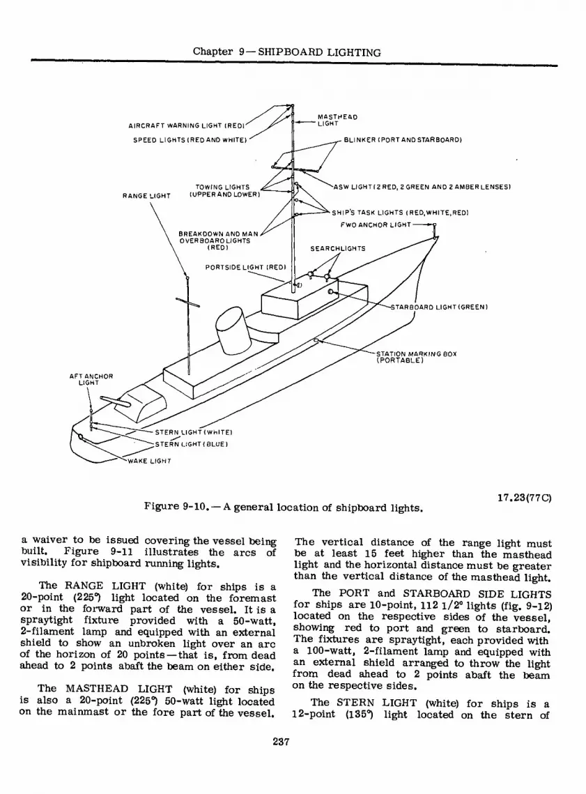
Chapter 9—SHIPBOARD LIGHTING
AIRCRAFT WARNING LIGHT (RED)
SPEED LIGHTS (RED AND WHITE)
RANGE LIGHT TOWING LIGHTS
(UPPER AND LOWER)
BREAKDOWN AND MAN OVERBOARD LIGHTS
(RED)
MASTHEAD LIGHT
’■G;
BLINKER (PORT AND STARBOARD)
ASW LIGHT(2 RED, 2 GREEN AND 2 AMBER LENSES)
SHIPS TASK LIGHTS ( RED, WHITE, RED)
FWD ANCHOR LIGHT-
SEARCHLIGHTS
PORTSIDE LIGHT (RED)
•STARBOARD LIGHT (GREEN)
STATION MARKING BOX (PORTABLE)
AFT ANCHOR LIGHT
-STERN LIGHT (WHITE)
;STERN LIGHT {BLUE)
"WAKE LIGHT
Figure 9-10. — A general location of shipboard lights. 17.23(77C)
a waiver to be issued covering the vessel being built. Figure 9-11 illustrates the arcs of visibility for shipboard running lights.
The RANGE LIGHT (white) for ships is a 20-point (225°) light located on the foremast or in the forward part of the vessel. It is a spraytight fixture provided with a 50-watt, 2-filament lamp and equipped with an external shield to show an unbroken light over an arc of the horizon of 20 points — that is, from dead ahead to 2 points abaft the beam on either side.
The MASTHEAD LIGHT (white) for ships is also a 20-point (225°) 50-watt light located on the mainmast or the fore part of the vessel.
The vertical distance of the range light must be at least 15 feet higher than the masthead light and the horizontal distance must be greater than the vertical distance of the masthead light.
The PORT and STARBOARD SIDE LIGHTS for ships are 10-point, 112 i/2° lights (fig. 9-12) located on the respective sides of the vessel, showing red to port and green to starboard. The fixtures are spraytight, each provided with a 100-watt, 2-filament lamp and equipped with an external shield arranged to throw the light from dead ahead to 2 points abaft the beam on the respective sides.
The STERN LIGHT (white) for ships is a 12-point (135°) light located on the stern of
237

ELECTRICIAN’S MATE 3 & 2
"•Y
STBD SIDE LIGHT
10 PTS.
(7 STERN MASTHEAD LIGHT AND 0 RANGE PTS
LIGHTS
MASTHEAD LIGHT
20 PTS
PORT ‘•SIDE LIGHT *
10 PTS
RANGE-LIGHT ("OPTIONAL" FOR A
VESSEL OF LESS THAN 150 FEET )
20 PTS
. — -A
INTERNATIONAL RULES-ARCS OF VISIBILITY (AND U S. INLAND WATERS-SEAGOING VESSEL)
(ONE POINT = 11-1/4°)
LEGEND:
^ RED
¡ WHITE
QGREEN
69.27 Figure 9-11. — Running lights arcs of visibility.
IDENTIFICATION PLATE
FIXTURE
r L
DIAGONAL SCREEN BASE
PLATE
FORE AND AFT SCREEN
77.41 Figure 9-12. —Side light.
the vessel. It is a watertight fixture provided with a 50-watt, 2-filament lamp and equipped with an external shield to show an unbroken light over an arc of the horizon of 12 points of the compass — that is, from dead astern to 6 points on each side of the ship.
The UPPER and LOWER TOWING LIGHTS (white) for ships not normally engaged in towing
operations are 20-point (225°) lights similar to the previously described masthead and range lights. They are portable fixtures, each equipped with a 50-watt lamp and a type THOF-3 cable and plug connector for energizing the lights from the nearest lighting receptacle connector. When these lights are used, they are located vertically (6 feet apart) in the fore part of the vessel.
The BREAKDOWN and MAN-OVERBOARD LIGHTS (red) for ships are 32-point (360°) lights located 12 feet apart (vertically) and mounted on brackets that extend aft of, and to starboard of the mast or structure. This arrangement permits visibility, as far as prac- ticable, throughout 360° of azimuth. The fixtures are spraytight and equipped with 15-watt, 1- filament lamps. When these lights are used as a man-overboard signal, they are pulsed by a rotary snapswitch (fitted with a crank handle) on the signal and anchor light supply and control panel. These lights are mounted and operated in conjunction with the ship’s task lights.
The SHIP’S TASK LIGHT is an array consisting of three 32-point (360°) lights, stepped out 45 degrees aft and to starboard of the mast, in a vertical line one over the other so that the upper and lower lights shall be the same
238

Chapter 9 —SHIPBOARD LIGHTING
distance from, and not less than six feet above or below, the middle light and be visible all around the horizon at a distance of at least 2 miles. The upper and lower lights of this array shall be red, utilizing the presently installed Man-overboard and Breakdown Lights, relocated as necessary. The center light shall be a clear white light.
These lights shall be connected to the Navi- gational Light Supply and Control (no telltale) Panel as follows:
(1) So that the two red lights may be burned steadily to indicate the ship is Not Under Com- mand;
(2) So that the two red lights may be flashed by rotating the switch (crank type) handle, to indicate a man-overboard condition exists;
(3) So that the three lights will burn simul- taneously to indicate the ship is either launching or recovering aircraft or engaged in replenish- ment-at-sea operations and by the nature of its work is unable to get out of the way of approaching vessels. The switch for this appli- cation shall be labeled “Ship’s Task Lights.”
The FORWARD and AFTER ANCHOR LIGHTS (white) for ships are 32-point (360°) lights. The forward anchor light is located near the stem of the vessel, and the after anchor light is at the top of the flagstaff. The fixtures are splash-proof, each provided with a 50-watt, 1-filament lamp. The anchor lights are energized through individual on-off rotary snap switches on the signal and anchor light supply and control panel in the pilothouse.
Testing Navigational Lights
All shipboard navigational lights are tested daily while at sea. The test is usually made one hour prior to sunset by the Quartermaster.
The SUPPLY, CONTROL, and TELLTALE PANEL for the running lights is a nonwater- tight, sheet metal cabinet designed for bulkhead mounting (fig. 9-13).
This panel is provided to aid a ship in keeping her running lights lit as prescribed by the
© ©
S
& ©
77.42 Figure 9-13. — Supply, control, and telltale panel.
rules for preventing collisions at sea. It is installed in or near the pilot house and gives an alarm when one of the running lights (mast- head, stern, range and side lights) is out or has had a failure of its primary filament and is operating on its secondary filament.
Failure of the primary filament, or its circuit, of any one of ' the following lights: masthead, stern, range, and side lights, deenergizes a relay. This relay effects a transfer of power to the secondary filament of the affected liglit, sounds a buzzer, lights an indicator light and moves an annunciator target to read, OUT (reads RESET when deenergized). The buzzer may^be silenced by turning the handle of the reset switch 90° (to the horizontal position), however the indicator lamp of the affected light stays lit until the repair has been completed and
239

ELECTRICIAN’S MATE 3 & 2
the reset switch is turned hack to the normal (RESET) position. Certain ships have permanent towing lights installed and connected to control switches on the telltale panel. The towing light switches are manual. When failure of the primary filament occurs in towing lights connected to this panel the switch must he manually turned to the position marked “SEC”, to energize the secondary filament*
Sequence of Operations
The operations of the supply control and telltale panel are easily seen hy following the schematic diagram in figure 9-14. For simpli- fication this schematic shows only one of the five running lights, the operation is the same for all five.
When the primary filament of a running light is lighted, relay contacts (X, Y and Z) are open, indicator lamps, annunciator and huzzer are not
energized, reset switch must be kept pointing in the (vertical) “RESET” (marked position) under normal condition or buzzer will not he energized when a failure occurs.
If the primary filament circuit is opened, as when the filament burns out, the relay is de-energized closing contacts (X and Y), second- ary filament is lighted, indicator lamps are lighted, annunciator target moves to “OUT” position (closing contact Z) and the buzzer sounds.
When the “RESET” switch handle is turned to the horizontal (unmarked position, the buzzer is silenced but the indicator lamps remain lighted and the annunciator target is still OUT.
When the defective lamp is replaced, (or fault in primary circuit is corrected) the relay coil is energized and relay contacts (X and Y) are opened, annunciator coil is deenergized (opening contact Z) and target indicates RESET, secondary filament is deenergized, indicator lamps remain lighted.
15 V
SUPPLY PHASE A
DIMMER CONTROL PANEL
I RESISTOR '
115 V SUPPLY PHASE B
OFF OFF PRIMARY DIM RELAY
F LAMENT
WV '\ ON BRIGHT ✓ I
SECONDARY FILAMENT
ANNUNCIATOR
INDICATOR \ LIGHTS
5 V SUPPLY PHASEC
BUZZER
(UNMARKED)
RESET (MARKED)
Figure 9-14. — Running light control schematic diagram. 77.43A
240

Chapter 9—SHIPBOARD LIGHTING
Reset switch is returned to RESET (vertical) position, indicator lamps go out and entire unit is again in normal condition.
A dimmer control panel connected as shown in figure 9-14 is provided for dimming the running lights when directed. This panel provides tout one position of dimming. In the dim position the visibility of the range,masthead, side lights, and stern light is reduced to about 4000 yards. The sequence of operation of the telltale panel is the same whether the running lights are in the light or dimmed condition.
Navigation lights do not conform to the rules of the road when in the dim position; therefore they are dimmed only when directed by higher authority.
FIXTURE
MULTIPLE SOCKET
A B AIRCRAFT WARNING LIGHT
SIGNAL LIGHTS (STATION OR OPERATIONAL)
The AIRCRAFT WARNING LIGHTS (red) for ships are 32-point (360°) lights (fig. 9-15A) installed at the truck of each mast. Two aircraft warning lights are installed if the light cannot be located so that it is visible from any location throughout 360° of azimuth. However, a separate aircraft warning light is not required if a 32- point red light is installed at the truck of a mast for, another purpose. The fixtures are spraytight and equipped with multiple sockets provided with 15-watt, 1-filament lamps (fig. 9-15B).
The STERN LIGHT (blue) for ships is a 12-point (135°) light similar to the previously described white stern light. It is a watertight fixture provided with a 50-watt lamp and is installed near the stern on ships that are engage^ in convoy operations and mounted to show a*f unbroken arc of light from dead astern to six points on each side of the ship.
The WAKE LIGHT (white) for ships is in- stalled on the flagstaff or after part of the ship to illuminate the wake, and mounted so that no part of the ship is illuminated. The fixture is spraytight and of tubular construction. One end of the fixture is fitted with an internal screen, having a 1-inch diameter hole provided with a lens (2-5/16” diameter x 3/8” thick) through which light is emitted from a 100-watt, 2-filament lamp. A suitable mounting bracket
RED
WHITE
FIXTURE
D MULTIPLE SOCKET
SPEED LIGHTS
77.44 Figure 9-15. — Aircraft warning and speed lights.
is included for adjusting the position of the light. Thus, the wake light puts a “target” in the ship’s wake.
The SPEED LIGHTS for ships are combination red (top) and white (bottom), 32-point (360°) lights (fig. 9-15C). They are located at the
241
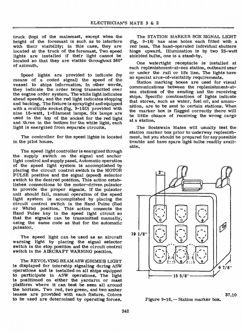
ELECTRICIAN'S MATE 3 & 2
truck (top) of the mainmast, except when the height of the foremast is such as to interfere with their visibility; in this case, they are located at the truck of the foremast,, Two speed lights are installed if their light cannot be located so that they are visible throughout 360° of azimuth.
Speed lights are provided to indicate (by means of a coded signal) the speed of the vessel to ships information. In other words, they indicate the order being transmitted over the engine order system. The white light indicates ahead speeds, and the red light indicates stopping and backing. The fixture is spraytight and equipped with a multiple socket (fig. 9-15D) provided with nine 15-watt, 1-filament lamps. Six lamps are used in the top of the socket for the red light and three in the bottom for the white light, each light is energized from separate circuits.
The controller for the speed lights is located in the pilot house.
The speed light controller is energized through the supply switch on the signal and anchor light control and supply panel. Automatic operation of the speed light system is accomplished by placing the circuit control switch in the MOTOR PULSE position and the signal (speed) selector switch to the desired position. This action estab- lishes connections to the motor-driven pulsator to provide the proper signals. If the pulsator unit should fail, manual operation of the speed light system is accomplished by placing the circuit control switch in the Hand Pulse (Red or White) position. This action connects the Hand Pulse key in the speed light circuit so that the signals can be transmitted manually, using the same code as that for the automatic pulsator.
The speed light can be used as an aircraft warning light by placing the signal selector switch in the stop position and the circuit control switch in the AIRCRAFT WARNING position.
The REVOLVING BEAM ASW (GRIMES) LIGHT is displayed for intership signaling during ASW operations and is installed on all ships equipped to participate in ASW operations. The light is positioned on either the yardarm or mast platform where it can best be seen all around the horizon. Two red, two green, and two amber lenses are provided with each fixture. Colors to be used are determined by operating forces.
The STATION MARKER BOX SIGNAL LIGHT (fig. 9-16) has nine holes each fitted with a red lens. The hand-operated individual shutters hinge upward. Illumination is by two 25-watt shielded bulbs, one is a stand-by.
One watertight receptacle is installed at each replenishment-at-seá station, outboard near or under the rail or life line. The lights have no special arcs-of-visibility requirements.
Station marking boxes are used for visual communications between the replenishment-at- sea stations of the sending and the receiving ships. Specific combinations of lights indicate that stores, such as water, fuel oil, and ammu- nition, are to be sent to certain stations. When the marker box is flagged correctly there will be little chance of receiving the wrong cargo at a station.
The Boatswain Mates will usually test the station marker box prior to underway replenish- ment, but you should be prepared for any possible trouble and have spare light bulbs readily avail- able.
D
e \ f \ « <
19 1/8" \±y f N
\±y M ‘ w ✓ M » ' \±y 4
p 15 5/8"-
6 7/8'
Figure 9-16. — Station markèr box. 37.10
242
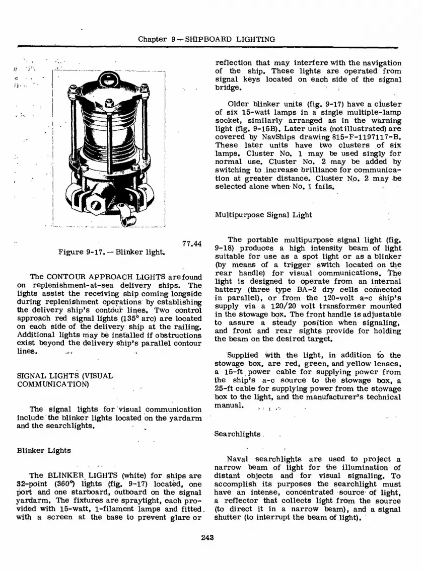
Chapter 9 —SHIPBOARD LIGHTING
.p r\
(S 9
reflection that may interfere with the navigation of the ship. These lights are operated from signal keys located on each side of the signal bridge.
Older blinker units (fig. 9-17) have a cluster of six 15-watt lamps in a single multiple-lamp socket, similarly arranged as in the wàrning light (fig. 9-15B). Later units (notillustrated) are covered by NavShips drawing 815-F-1197117-B. These later units have two clusters of six lamps. Cluster No. 1 may be used singly for normal use. Cluster No. 2 may be added by switching to increase brilliance for communica- tion at greater distance. Cluster No. 2 may be selected alone when No. i fails.
Multipurpose Signal Light
77.44 Figure 9-17. — Blinker light.
The CONTOUR APPROACH LIGHTS are found on replenishment-at-sea delivery ships. The lights assist the receiving ship coming longside during replenishment operations by establishing the delivery ship’s contour lines. Two control approach red signal lights (135° arc) are located on each side of the delivery ship at the railing. Additional lights may bè installed if obstructions exist beyond the delivery ship’s parallel contour lines.
SIGNAL LIGHTS (VISUAL COMMUNICATION)
The signal lights for visual communication include the blinker lights located on the yardarm and the searchlights.
The portable multipurpose signal light (fig. 9-18) produces a high intensity beam of light suitable for use as a spot light or as a blinker (by means of a trigger switch located on the rear handle) for visual communications. The light is designed to operate from an internal battery (three type BA-2 dry cells connected in parallel), or from the 120-volt a-c ship’s supply via a 120/20 volt transformer mounted in the stowage box. The front handle is adjustable to assure a steady position when signaling, and front and rear sights provide for holding the beam on the desired target.
Supplied with the light, in addition to the stowage box, are red, green, and yellow lenses, a 15-ft power cable for supplying power from the ship’s a-c source to the stowage box, a 25-ft cable for supplying power from the stowage box to the light, and the manufacturer’s technical manual. . , -
Searchlights
Blinker Lights
The BLINKER LIGHTS (white) for ships are 32-point (360°) lights (fig. 9-17) locatèd, one port and one starboard, outboard on the signal yardarm. The fixtures are spraytight, each pro- vided with 15-watt, i-filament lamps and fitted, with a screen at the base to prevent glare or
Naval searchlights are used to project a narrow beam of light for the illumination of distant objects and for visual signaling. To accomplish its purposes the searchlight must have an intense, concentrated source of light, a reflector that collects light from the source (to direct it in a narrow beam), and a signal shutter (to interrupt the beam of light).
243

ELECTRICIAN’S MATE 3 & 2
FRONT SIGHT
LAMP RETAINING RING
LAMP GASKET
SEALED-BEAM LAMP
HOUSING
LATCH
FILTER
FRONT HANDLE
COVER BATTERY
sr
0
<x>
TRIGGER J SWITCH / / LOCKING DEVICE
RETRACTED POSITION
REAR SIGHT
SPONGE RUBBER CUSHION
LAMP SOCKET
SWITCH PLATE
SWITCH DPDT
REAR HANDLE ASSEMBLY
CONNECTOR
FORWARD POSITION
Figure 9-18. — Multipurpose signal light. 101.5
Searchlights are classified according to size of reflector and light source. The three general classes are the 8-inch, 12-inch, and 24-inch searchlights. The 8-inch searchlight is of the sealed-beam incandescent type; the 12-inch light is of the incandescent type and the 24-inch searchlight is the carbon-arc type.
incandescent sealed beam lamp. It is designed to withstand high vibratory shock and extreme humidity conditions, and will operate equally well in hot or cold climates.
This searchlight may be furnished for opera- tion with either a 60-hertz 115-volt transformer to step the voltage down to 23 volts, or without transformer to operate on 115 volts using the proper rated sealed beam unit. The same unit
8-INCH SEALED-BEAM SEARCHLIGHT.— The 8-inch signaling searchlight utilizes an
244

Chapter 9—SHIPBOARD LIGHTING
CLAMP RING
BACKSHELL (D HOUSING
BRACKET ^
SHUTTER HOUSING
LAMP
YOKE
BASE (j)
RAIL CLAMP
77.62 Figure 9-19.-8-inch 60-hertz sealed-beam
searchlight.
;,is available for use on small craft from a 28-volt power source.
The searchlight (fig. 9-19) consists of the (1) base, (2) yoke, (3) housing, and (4) lamp. The BASE is equipped with a rail clamp for securing the searchlight to the rail. The YOKE is swivel mounted on the base to allow it to be trained through 360°. The HOUSING provides an enclosure for the lamp and is composed of a front and a rear section. The front section comprises the shutter housing, and the rear section comprises the backshell housing. The two sections are held together by a quick-release clamp ring that permits easy replacement of the lamp. The backshell and lamp assembly, when detached, may be used as a portable searchlight. The entire housing is mounted on brackets attached to the shutter housing and supported by the yoke to allow the searchlight to be elevated or depressed. Clamps are pro- vided for securing the searchlight in train and elevation.
The SHUTTER HOUSING contains the Venetian blind shutter, which is held closed by springs and manually opened by a lever on either side of the housing. The front of the shutter housing is sealed by the cover glass and a gasket. The rear of the shutter housing is enclosed by a gasket and adapter assembly. The adapter assembly provides a locating seat for the lamp and incorporates a hook and key arrangement that aligns the backshell housing and retains it in position while attaching the clamp ring to hold the two sections together.
Three filter assemblies (red, green, and yellow) are provided and can be readily snapped in place over the face of the searchlight. The shutter vanes can be locked in the open position for use as a spotlight.
The backshell housing provides an enclosure for the 115/23 volt transformer.
To remove the lamp from the housing for cleaning or replacement, tip the rear end of the searchlight up to its highest position and lock it in place. Release the clamp ring toggle and remove the clamp ring (fig. 9-19). Remove the backshell assembly by raising it up to disengage it from the hook and tab. Pull the gasketed lamp out of the shutter adapter assembly by gripping the lamp gasket on its periphery and lifting it out to disengage the gasket lugs from the notches in the adapter assembly.
To replace the lamp in the lamp gasket, be certain that the TOP marked on the lamp and on the gasket are aligned, and that the lugs of the lamp are firmly seated in the recesses provided in the gasket. To replace the gasketed lamp in the housing, be certain that the lugs are set into the notches in the adapter assembly located inside, and at the rear of, the shutter housing. Set the backshell assembly over the shutter assembly, engaging the shutter hook into the slot of the taackshell. Using the hook as a hinge, carefully swing the lower part of the backshell down to the shutter assembly, engaging the shutter tab into the notch in the rolled edge of the backshell. Be careful to swing the backshell down in a straight line to make direct engagement and to ensure proper positioning of the lamp contacts on the terminals of the lamp. Replace the clamp ring, being certain to have the hinge pin set into the notches of the adapter and backshell assemblies.
245

ELECTRICIAN’S MATE 3 & 2
VANE SHUTTER SIGHTS ASSEMBLY
PARABOLIC REFLECTOR
DRUM
LAMP
YOKE
/
TRUNNION BEARING
SIGNALING LEVER
LOCKING CLAMP
LOCKING MOUNTING CLAMP BRACKET
101.1 Figure 9-20. — 12-inch incandescent searchlight.
12-INCH INCANDESCENT SEARCHLIGHT.— The 12-inch incandescent searchlight is used primarily for signaling and secondarily for illumination.
The searchlight (fig. 9-20) comprises the (1) mounting bracket, (2) yoke, (3) drum, and (4) lamp. The MOUNTING BRACKET permits the searchlight to be secured to a vertical pipe or to a flat vertical surface. The YOKE is swivel mounted on the bracket to allow the searchlight to be rotated continuously in train. The steel DRUM provides housing for the lamp and its trunnion mounted on the yoke to allow it to be elevated and depressed. Clamps are provided for locking the searchlight in any position of train and elevation.
The SIGNALING SHUTTER is a Venetian blind shutter mounted inside the drum behind the front door. It is held in the CLOSED position by two springs and is manually opened by a lever on either side of the drum. The parabolic metal reflector is mounted on the inside of the rear door.
The LAMP is usually a 1000-watt, 117-volt incandescent lamp having special concentrated filaments that reduce the area of the light beam. The lamp is mounted in a mogul bipost socket. The socket is located in front of the reflector and can be adjusted only slightly. The replacement of the lamp is accomplished through the rear door of the searchlight.
Maintenance on 8- and 12-Inch Searchlights.— These searchlights are maintained in accordance with the same good practice that relates to all electrical and mechanical equipment. Elec- trical contacts must be kept clean and bright. Electrical leads should be checked daily and replaced as soon as defects appear. Depending on the amount of time they are used, moving parts such as trunnion bearings and stanchion socket must be lubricated at intervals. Vane hinges and links should be lubricated once a month, or more frequently if required, with a mixture of graphite and diesel oil (diesel oil floats the graphite into places needing lubrication). Shutters should be opened for a few minutes after lubrication with the door glass and cover open to allow the diesel oil to evaporate. The lubrication mixture is applied sparingly to prevent its clouding the glass or reflector.
At regular intervals the two shutter stop screws, located next to the handles, are adjusted to take up wear in the leather bumpers that cushion the shock of the shutters closing. To prevent twisting the shaft, the bumpers should just touch the stop adjustment when the vanes are closed. Shutter vanes are checked often to ensure that all screws are tight.
The reflector is cleaned weekly or more often to remove dust. Salt spray is removed from the lens and reflector whenever needed. To clean the reflector:
1. Ensure that the surface is cool. Touching a hot surface with your bare skin can result in a serious burn.
2. Use standard Navy brightwork polish.
3. Use cotton or a soft clean cloth.
4. Use radial motion from center toward rim of reflector. Do not use circular motion.
Never paint a bearing surface or the working member of any part of the light. Do not paint bolts, locking nuts, other parts necessary for access to the interior, or over nameplate data. Keep oiling cups and holes free of paint.
Replacing the lamp and focusing should be done only by qualified Electrician’s Mates unless a member of the signal gang is qualified.
246

Chapter 9 —SHIPBOARD LIGHTING
SIGNALING-
SHUTTER
OPERATING
HANDLE
ELEVATION
STOWING LOCK
VENTILATING
FAN HOUSING
LATCH
DRUM
FRAME
HINGE
a HANDLE
IRIS ELEVATION SHUTTER
CLAMP
IRIS SHUTTER HANDWHEEL
DOME
GLASS RIGHT SIDE
LAMP HOUSING
REMOVABLE
ACCESS PLATES MAIN SWITCH
TURNTABLE
WITH ARMS STATIONARY
PEDESTAL TRAIN STOWING LOCK
COLLECTOR RINGS
IN PEDESTAL
BASE
Figure 9-2l. —24-inch carbon-arc searchlight. (Front View.)
77.50.1
The light source must be at the focus of the reflector for minimum beam spread and maximum intensity. Some types of 12-inch incandescent searchlights are provided with focusing adjustment screws. Other types can be adjusted by loosening the screws that hold the lamp-socket support plate in position. Move the entire socket assembly toward or away from the reflector until the beam has a minimum diameter at a distance of 100 feet or more from the light, and retighten the screws. When checking the diameter of the beam, the rear door must be tightly clamped shut.
A screen hood is provided for attachment to the front door to limit the candle power of the beam, to cut down its range, and to reduce stray light, which causes secondary illumination
around the main beam. The hood also provides for the use of colored filters.
24-INCH CARBON-ARC SEARCHLIGHT.— The 24-inch carbon-arc searchlight (fig. 9-21) consists of a (1) stationary pedestal, (2) turntable with arms, (3) drum with iris and signaling shutters, and (4) carbon-arc lamp. The turntable is supported on the pedestal and can rotate continuously in train; and the drum, which provides a housing for the lamp, is trunnioned on the turntable arms and can be elevated or depressed through angles of 110° and 30°, respectively.
The pedestal is secured to the searchlight platform, or base, and provides a mounting for the turntable and main power switch. The turn- table shaft is supported on two large ball bearing
247

ELECTRICIAN’S MATE 3 & 2
assemblies inside the pedestal (not shown) to allow the turntable and arms to rotate continuously in train. The main power switch is mounted inside the pedestal and is operated by a handle that protrudes from the switch cover. Terminal tubes through the pedestal provide entrances to the searchlight for the d-c supply cable and the remote signaling key circuit.
The turntable and arms, which support the drum, provide a mounting for the shutter switch train clamp, elevation clamp, and elevation stowing lock. Three collector rings mounted
on the turntable shaft (not shown) supply power to the lamp and the remote signaling key circuit.
The drum, or barrel, is essentially a sheet- steel. shell that provides an enclosure for the lamp. It is equipped with trunnions that are supported by bearings mounted on the turntable arms to allow the drum to be elevated or depressed through angles of 110° and 30°, respectively. Handles are provided at the front and rear of the barrel for swinging the search- light in train and in elevation to direct the beam of light. The barrel includes the lamp housing, front door and dome glass, iris shutter,
NEGATIVE HEAD
W POSITIVE HEAD
/N_
NEGATIVE CARBON OBTURATOR POSITIVE CONTACT POSITIVE CARBON RELEASE LEVER
NEGATIVE CARBON FEED ROLLERS .
NOSE
POSITIVE CARBON NEGATIVE CARBON
RELEASE LEVER
DETENT
DETENT WHEEL
IF5 POSITIVE CARBON FEED ROLLERS 1 HEADSUPPORTING
COLUMN
NEGATIVE CARBON BRUSH- PRESSURE ADJUSTING NUT
ROTATING POSITIVE DRIVE SHAFT
THERMOSTAT LENS AND FRAME
NEGATIVE DRIVE SHAFT
I
THERMOSTAT WINDOW
LAMP BOX
POSITIVE CONNECTION
POSITIVE FEED SHAFT
HANDLE
POSITIVE TERMINAL
NEGATIVE TERMINAL
Figure 9-22.-24-inch carbon-arc lamp. 77.51

Chapter 9—SHIPBOARD LIGHTING
sector-vane (signaling) shutter, rear door and reflector, and ventilating system.
The carbon-arc lamp utilizes a high intensity d-c arc between special cored carbon electrodes. It is designed for operation with an arc-ballast resistor (located below deck) supplied from the ship’s 120-volt, d-c power. The arc current is adjusted for 75 to 80 amperes with an arc voltage of 65 to 70 volts. The arc-ballast resistor is connected in series with the arc to limit the starting current, stabilize the arc, and absorb the difference between the line voltage and arc voltage.
The function of the lamp mechanism is to hold and control the carbons to produce a source of light (always) at the focus of the reflector. The lamp consists of the positive head, negative head, and lamp operating mechanism (fig. 9-22). The positive and negative heads are secured to the head-supporting column mounted on the lamp base, or box, that contains the mechanism for automatically operating the lamp. The auto- matic features of rotating and feeding the positive carbon, feeding and retracting of the negative carbon, starting the arc, and providing ventilation are accomplished by the lamp (feed) motor and associated equipment contained in the lamp base.
Preventive Maintenance. — The 24-inch car- bon-arc searchlight requires that the signalmen, and other personnel who frequently use search- lights, be carefully instructed on how to operate them. When operating carbon-arc searchlights, personnel must be impressed with the importance of renewing carbons before the positive carbon has burned so short that it cannot be gripped by the feed rollers and fed toward the arc. If the positive carbon is permitted to burn after this condition occurs, the arc burns closer to the positive nose (obturator) and will finally cause it to melt.
Operators must frequently observe the arc of an operating searchlight through the peep sight. They should renew the carbons when the positive carbon is no longer fed forward or when the positive-carbon tip projects less than one-half inch beyond the obturator.
An Electrician’s Mate must remove the old carbons and replace them with a new pair. Carbons are always renewed by pairs to ensure optimum performance. The doors should not be
opened for any purpose until the drum is placed in the horizontal position and the searchlight is locked both in train and elevation. Before changing carbons or attempting any work on a searchlight, turn the power switch to the OFF position. Open the rear door until the latch engages. Make sure that the components are cool before touching with the bare hands. Lift the negative-carbon release lever upward and remove the negative carbon bÿ pushing it out through the rear of the negative head. Lift the positive-carbon release lever and remove the stub by pulling it out over the negative head. If the stub is hot, use pliers to remove it.
The positive and negative heads should be reamed before each recarboning to remove the material deposited by the preceding carbons. ■When using the reamers, the carbon-feed rollers and contacts should be released to prevent the cutting edges of the reamers from damaging these parts. The positive-nose reamer should be inserted from the obturator end, and the negative-head reamer should be inserted from the rear, or release-lever end. Reamers should not be used while the heads are hot unless it is absolutely necessary. However, if it is nec- essary to ream while the heads are hot, the reamer should be kept turning continuously to prevent its seizure by cooling and contracting of the metal parts.
When the reaming is completed, run the new set of carbons through the heads to be certain that they do not jam. Crooked carbons or those having long cracks, or loose cores should be discarded. Rough spots and blisters can be removed with sandpaper. Adjust the protrusion of the positive carbon from the nose cap, and adjust the arc length in accordance with the values specified for the equipment in the manu- facturers’ instruction book. The carbons must be centered in their heads and must not touch the nose caps.
After the carbons are renewed, wipe the reflector, front-door glass, thermostat lens, and thermostat window with a clean, dry cheese- cloth to remove any carbon deposit. Close the lamp housing, turn the power switch to the ON position and operate the searchlight for about 5 minutes to form the crater in the positive carbon and establish a normal arc. The first 5 minutes is the critical period of operation after a carbon renewal. During this interval, closely observe the arc and all lamp parts for any malfunctioning.
249

ELECTRICIAN’S MATE 3 & 2
5'
^ . / /
/ / 1/
^OPEN /OOORWA'Y
\ / \ /
/ /
\ \ x Vx
X x- OUTBOARD DOORWAY
■ PAINT BLACK TO HERE
\ \ ^ \
EYE OF\ 4 OBSERVER
Figure 9-23. — Light trap. 77.46
Lutorication of the lamp mechanism should be limited to the parts specified in the manufac- turers’ instructions unless they are superseded by Naval Sea Systems Command.
DIVERSIFIED LIGHTING EQUIPMENT
Light traps and special lights also serve useful purposes aboard ship. Visibility in all directions must be restricted with most of this equipment where personnel must take into account the lighting as affected by glare and background illumination.
DARKEN SHIP EQUIPMENT
Darkened ship is a security condition designed to prevent the exposure of light, which could reveal the location of the vessel. Darkened-ship condition is achieved by means of (1) light traps that prevent the escape of light from illuminated spaces or (2) door switches that automatically disconnect the lights when the doors are opened.
When darkened-ship condition is ordered, check every door switch installation aboard ship to determine that all lock-devices or short- circuiting switches are set at the DARKENED SHIP position.
Inspect the light traps to determine that they are free of all obstructions. A light colored object of any appreciable size placed in a light trap might be sufficiently illuminated by the interior lighting to be visible beyond the safe limit. Note the positions of the hand lanterns when entering a compartment so that you can find them without delay when they are needed.
Light Trap and Door-Switch
A light trap is an arrangement of screens placed inside access doors or hatches to prevent the escape of direct or reflected light from within (fig. 9-23). The inside surfaces of the screens are painted flat black so that they will reflect a minimum of light falling on them. Light traps that are used to prevent the escape of white light should have at least two black, light-absorbing surfaces interposed between the light source and the outboard openings. Light traps are preferred to door switches in locations where (1) egress and ingress are frequent; (2) interruption of light would cause work stoppage in large areas; (3) light might be exposed from a series of hatches, one above the other on successive deck levels; and (4) many small com- partments and passages are joined by numerous inside and outside doors that would complicate a door-switch installation. ■
A door switch is mounted on the break side of a door jamb (inside the compartment) and operated by a stud welded to the door. When the door is opened, the switch is automatically opened at the same time. Door switches are connected in a variety of ways to suit the arrangement of the compartment concerned.
All door switch installatins are provided with lock-in devices or short-circuiting switches to change the settings of the door switches, as required from lighted ship to darkened ship and vice versa. Each standard door switch is furnished with a mechanical lock-in device for use when only one door switch is installed. When two or more door switches are connected in series, a single, separately mounted short- circuiting switch is installed in an accessible location to avoid the possibility of overlooking any of the door switches when the changeover is made.
When a single door switch at an outer door is connected in parallel with door switches at inner doors, only the door switch at the outer door is provided with a lock-in device, and the lock-in devices are removed from the other outer doors. The location of the control switch
250
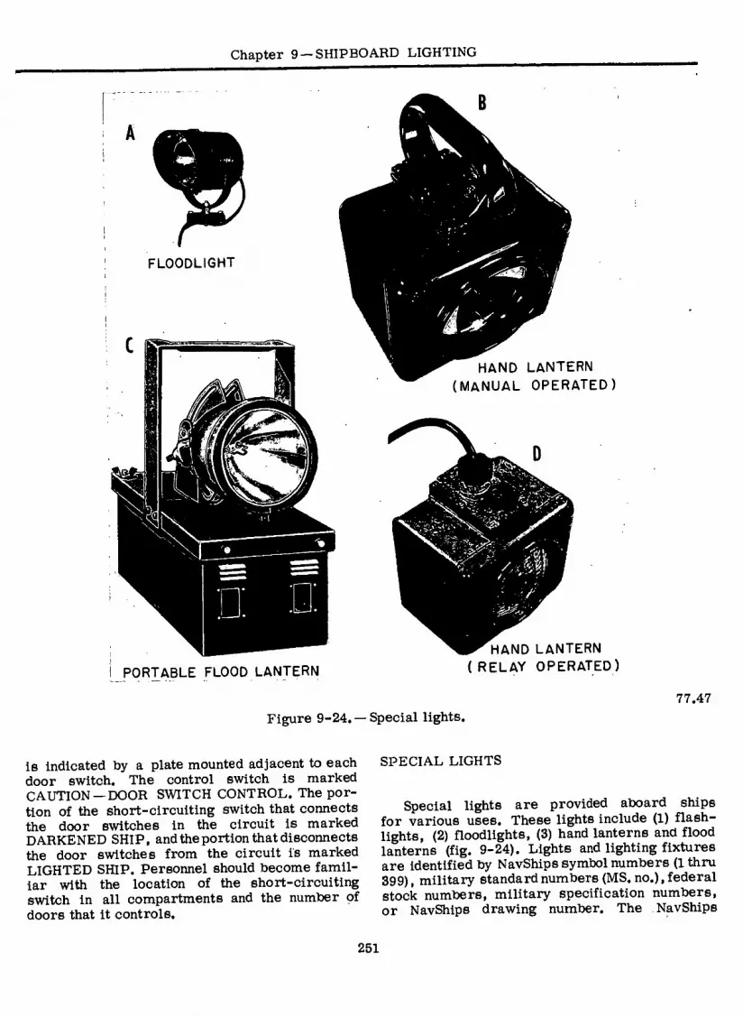
Chapter 9 —SHIPBOARD LIGHTING
FLOODLIGHT
I
PORTABLE FLOOD LANTERN
HAND LANTERN (MANUAL OPERATED)
HAND LANTERN (RELAY OPERATED)
77.47 Figure 9-24. — Special lights.
is indicated by a plate mounted adjacent to each door switch. The control switch is marked CAUTION —DOOR SWITCH CONTROL. The por- tion of the short-circuiting switch that connects the door switches in the circuit is marked DARKENED SHIP, and the portion that disconnects the door switches from the circuit is marked LIGHTED SHIP. Personnel should become famil- iar with the location of the short-circuiting switch in all compartments and the number of doors that it controls.
SPECIAL LIGHTS
Special lights are provided aboard ships for various uses. These lights include (1) flash- lights, (2) floodlights, (3) hand lanterns and flood lanterns (fig. 9-24). Lights and lighting fixtures are identified by NavShips symbol numbers (1 thru 399), military standard numbers (MS. no.), federal stock numbers, military specification numbers, or NavShips drawing number. The NavShips
251

ELECTRICIAN’S MATE 3 & 2
Standard Electrical Symbol List (NavShips 0960- 000-4000) lists the lights and lighting fixtures in current use on naval ships. Fixtures are listed in NavShips symbol number order along with the MS or NavShips drawing number, and federal stock number (FSN).
Floodlight
The floodlight (fig. 9-24A) consists of a splashproof housing equipped with a rain shielded, hinged door secured with a trunk type latch. The 300-watt lamp is a sealed-beam type. The lamp housing is trunnioned on a yoke which in turn is mounted on a shock absorbing base. The light is secured in elevation by a clamp on the yoke. Train positioning is accomplished by friction within the shock absorbing base. Each floodlight is furnished with a three-con- ductor cable (including a green lead to ground the metal housing) for connection into the lighting circuit.
Larger 500-watt floodlights (not shown), using a mogul screw base lamp are also widely used. Floodlights are installed on weather decks at suitable locations to provide sufficient illumina- tion for the operation of cranes and hoists, and the handling of boats. New high-level il- luminating floodlights are being developed for evaluation by Sea System Command.
Hand Lanterns
Two types of dry-battery-powered lanterns are available for installation in certain strategic locations to prevent total darkness if the lighting power fails. One model is hand operated. The other is operated automatically by a relay when the regular power fails.
The MANUALLY OPERATED HAND LAN- TERN (fig. 9-24B), consists of a watertight plastic case containing two (6 volt), batteries connected in parallel. It includes a sealed beam lamp, rated at 5 volts, but operated at 6 volts (when the batteries are new) to increase the light output. A rigid handle is secured to the top of the case. The lantern is operated by a toggle switch, the lever of which is convenient to the thumb. When the batteries are fresh, the lantern can be used continuously for ap- proximately 8 hours before the light output ceases to be useful.
Manually operated lanterns are installed as an emergency source of illumination in spaces that
are manned only occasionally. These lanterns are also used in certain areas to supplement the relay-operated lanterns.
Manually operated hand lanterns must not be removed from the compartments in which they are installed unless the compartments are to be abandoned permanently.
The RELAY-OPERATED HAND LANTERN is similar to the manually operated type except that the relay housing is mounted topside of the lantern case (fig. 9-24D) in place of the handle. The 115-volt a-c version is identified by symbol 101.2. Symbol 102.2 identifies the 115-volt d-c type. A three-conductor cable (including a green conductor to ground the relay metal frame) is provided for connection into the lighting circuit. THE RELAY-CONTROLLED LANTERN MUST ALWAYS BE INSTALLED WITH THE RELAY UPPERMOST. This specifc arrange- ment of the relay prevents a proven fire hazard, which would be caused by liquid electrolyte (formed from battery exhaustion) draining into the (otherwise inverted) relay housing.
Relay-controlled lanterns are assigned to spaces in which it is necessary to maintain practically continuous illumination. These spaces include essential watch stations, control rooms, machinery spaces, battle dressing stations. The lanterns must illuminate the tops and bottoms of all ladders and all flush-mounted scuttles. They must also be mounted so as to illuminate all gages at vital watch stations. Operating personnel will depend on these lanterns for illumination when bringing the machinery back on the line in the event of a casualty. These lanterns must not be installed in magazine or powder-handling spaces in which fixed or semifixed- ammunition is handled), or in any location in which explosion-proof equipment is required.
The lantern relay is connected in the lighting circuit (in the space in which the lantern is installed) on the power supply side of the local light switch that controls the lighting in the space concerned. Thus, the relay operates and causes the lamp in the lantern to be energized from its batteries only when power failure occurs, not when the lighting circuit is deener- gized by the light switch. If the space is supplied with both emergency and ship’s service lights, the lantern relay is connected to the emergency lighting circuit only.
252
Chapter 9 —SHIPBOARD LIGHTING ¿i
The lantern relay should be fused so that a short circuit in the relay leads of one com- partment will be cleared through low-capacity fuses before the fault causes heavier fuses nearer the source of power to blow and cut off the power supply to lighting circuits in other compartments. The fuses that protect the branch circuits are ample protection for the lantern relay. A lantern relay can be connected directly to the load side of the fuses in fuse boxes or switchboxes. If a relay cannot be connected to a branch circuit, it can be connected to the source side of a fuse box or other point on a submain. If the submain supplies lighting to more than one compartment, separate fuses must be installed in the relay circuit.
The operation of the relays in lanterns should be checked at least once every 3 months, by deenergizing the lighting circuitto which the relay is connected. When the circuit is deenergized, the relay should operate and. automatically turn on the lantern. The circuit may be deenergized by pressure exerted on the push switch located on the relay housing. This simulates a loss of 115-volt power. The relay should then drop out and the lantern will light.
To ensure satisfactory operation of hand lanterns, the batteries should be checked at least once every 3 months. The batteries are checked by operating the lantern and observing the brightness of the lamp. If the emitted light is dim, the batteries should be replaced im- mediately. At this time, also check the rubber boot on the switch for tears or cracks. Replace immediately if the boot is defective. The switch must also be grounded to the ship’s hull. A simple test with a multimeter will verify this.
Lanterns that are located in spaces in which the normal temperature is consistently above 90°F should be checked more often. For example, in boiler rooms it may be necessary to replace the batteries weekly to ensure adequate service from the lanterns.
The NAVSHIPS symbol number 104 (not shown) dry battery type (hand carrying or head at- taching) of lantern is used for damage control purposes and is generally stored in damage control lockers. This lantern’s battery container may be clipped over the wearer’s belt, the lamp and reflector assembly may be hand held or worn on the head or helmet of repair party personnel by using a headband attached to the light.
Portable Flood Lanterns
The NavShips symbol number 105 portable flood lantern (fig. 9-24C) consists of a seale^ beam lamp enclosed in a built-in lamp housing equipped with a toggle switch. The lamp housing is adjustably mounted on a dripproof, acid- resistant case provided with two windows in each end.
The case contains four Navy type BB-254/U storage cells. Each cell contains a channeled section in which a green, white, and red ball denotes the state of charge of the cell when viewed through the window. When a cell is fully charged, all three indicator balls float at the surface of the electrolyte. The green ball sinks when approximately 10 percent of the cell capacity has been discharged; the white ball sinks when the cell is 50 percent discharged; and the red ball sinks when the cell is 90 percent discharged.
The lamp is rated at 6 volts but is operated at 8 volts to increase the light output. When operated with fully charged batteries, the lantern can be operated continuously for about three hours without recharging. The batteries should be recharged as soon as possible after the green ball (10 percent discharged) has sunk to the bottom. The lanterns should be checked at least once a week to determine if the green indicator balls are floating. If they are not floating, the battery should be charged at a rate of 1 l/2 to 2 amperes until all indicator balls are floating at the indicator line. If the battery is completely discharged, it will require from 20 to 25 hours to recharge it. After the charging voltage has remained constant at 10 volts for one hour, discontinue the charging.
When necessary, add pure distilled water to keep the electrolyte level at the indicator line marked on the front of the cell. Do not add enough water to bring electrolyte level above the line because overfilling nullifies the nonspill feature of the battery and may cause the electrolyte to spurt out through the vent tube. However, if the electrolyte level is not at the indicator line, the charge indicator balls will not indicate correctly the state of charge of the battery.
Portable flood lanterns are often referred to as damage control lanterns because they are used by damage control personnel to furnish
253

ELECTRICIAN’S MATE 3 & 2
high intensity illumination for emergency repair work or to illuminate inaccessible locations below deck.
THREE-WAY SWITCH CIRCUITS
In most lighting installations aboard ship as well as ashore, you will find double-pole, single-throw switches. However, for special ap- plications a three-way switching arrangement may be required where a light or group of lights may be operated from two separate locations. When two switches are in the positions as shown in figure 9-25 the light will be on. Turning either switch to its alternate position will inter- rupt power to the light and it will go out. Turning the other switch to its alternate position will relight the lamp. Thus, this arrangement is called a 3-way lighting system.
TROUBLESHOOTING
You can locate many troubles by testing the branch circuits of the a-c lighting system, using the methods for 3-wire a-c circuits described in chapter 4.
In addition to the usual tests for open circuits and grounds, look for possible unequal load distribution. Do this by measuring the current in each leg of the three phase system with an ammeter. A high current on one leg will result in low voltage on that leg thereby decreasing
SWITCH 1 SWITCH 2
rm- o
I17VAC
77.313 Figure 9-25. — Three-way switch circuit.
t
the illumination and increasing the chances of blowing a fuse. You can usually tell when a phase fuse blows because some lamps in the systems will glow brilliantly while others will be dim.
When a circuit blows a fuse, ALWAYS replace it with the size indicated on the nameplate. Over- fusing can result in damage to equipment and creates a potential fire hazard.
You can correct an unbalanced condition by shifting some of the load from the overloaded leg of the three phase system to another leg. However, do not start shifting the load until its distribution has been checked for all hours of the day and under all operating conditions. Have recommended changes approved by. the electrical officer and recorded on the ship’s blueprints.
254
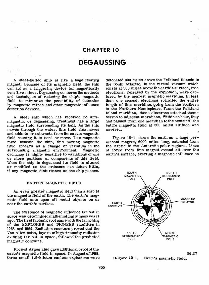
CHAPTER IQ
DEGAUSSING
A steel-hulled ship is like a huge floating magnet. Because of its magnetic field, the ship can act as a triggering device for magnetically sensitive mines. Degaussing concerns the methods and techniques of reducing the ship’s magnetic field to minimize the possibility of detection by magnetic mines and other magnetic influence detection devices.
A steel ship which has received no anti- magnetic, or degaussing, treatment has a large magnetic field surrounding its hull. As the ship move's through the water, this field also moves and adds to or subtracts from the earths magnetic field causing it to bend or move. To a magnetic mine beneath the ship, this moving magnetic field appears as a change or variation in the surrounding magnetic environment. Magnetic ordnance is highly sensitive to variations of one or more portions or components of this field. When the ship is degaussed its field is altered or modified so the ordnance can detect little^, if any magnetic disturbance as the ship passes.
EARTH’S MAGNETIC FIELD
An even greater magnetic field than a ship is the magnetic field of the earth. The earth’s mag- netic field acts upon all metal objects on or near the earth’s surface.
The existence of magnetic influence far out in space was determined mathematically many years ago. The first factual proof came with the launching of the EXPLORER and PIONEER satellites in 1958 and 1959. Radiation counters proved that the Van Allen belts, layers of high-intensity radiation existing far out in space, followed the predicted magnetic contours.
Project Argus also gave additional proof of the earth’s magnetic field in space. In August of 1958, three small 1.5-kiloton nuclear explosions were
detonated 300 miles above the Falkland Islands in the South Atlantic. In the virtual vacuum which exists at 300 miles above the earth’s surface, free electrons, released by the explosion, were cap- tured by the nearest magnetic meridian. In less than one second, electrons spiralled the entire length of this meridian, going from the Southern to the Northern Hemisphere. From the Falkland Island meridian, these electrons attached them- selves to adjacent meridians. Within an hour, they had passed from one meridian to the next until the entire magnetic field at 300 miles altitude was covered.
Figure 10-1 shows the earth as a huge per- manent magnet, 6000 miles long, extended from the Arctic to the Antarctic polar regions. Lines of force from this magnet extend all over thë earth’s surface, exerting a magnetic influence on
EARTH EQUATOR
SOUTH GEOGRAPHIC
POLE
NORTH GEOGRAPHIC
POLE
SOUTH MAGNETIC
POLE
\ NORTH MAGNETIC
POLE
MAGNETIC EQUATOR
56.27 Figure 10-1. — Earth's magnetic field.
255

ELECTRICIAN’S MATE 3 & 2
all ferrous materials on or near the surface. Since many of these ferrous materials themselves become magnetized, they distort the background field into irregular eddies and areas of greatly increased or decreased magnetic strength. Thus the lines of magnetic force at the earth’s surface do not run in straight, converging lines like the meridians on a globe, but appear more like the isobar lines on a weather map.
By convention, the external direction of the magnetic field of a bar magnet is from the north pole to the south pole. Lines of force for the earth’s field, however, leave the earth in the Southern Hemisphere and reenter in the Northern Hemisphere. For this reason, it is necessary to think of the polar region in the Arctic as the north-geographic, south-magnetic pole where po- larity direction in the field of degaussing now is described.
Note in figure 10-1 that the magnetic meridians form closed loops, arching from the earth’s mag- netic core to outer space, and then reentering the earth in the opposite hemisphere. Since, all lines of magnetic force return to their points of origin, they form closed magnetic circuits. An idea of the size of the earth’s magnetic field is apparent by noticing that lines of force at the polar regions seem to extend vertically into space. The size of the closed loops formed by these lines of force is staggering to the imagination. It is impossible to eliminate the earth’s field; however, the effects of the ship on this field may be lessened. It is the purpose of degaussing to prevent the ship from distorting the earth’s magnetic field, and some highly developed techniques are used to do so.
The rest of this chapter explains the funda- mentals of degaussing and describes the operating principles of manual and automatic shipboard de- gaussing systems. Learning these knowledge factors will help the Electrician’s Mate to stand watch at the degaussing switchboard, operate the degaussing equipment, and maintain the installed degaussing system.
The strength and direction of the earth’s field at any point is a function of the strength of the individual components. The angle of the field with the horizontal, sometimes called the dip, may be easily determined by means of a dip needle, a simple compass needle held with the needle pivot axis parallel to the earth’s surface. Since a compass needle always alines itself parallel to the lines of force of a magnetic field, the dip
needle indicates the angle ofthe earth’s field to the horizontal by alining itself with the lines of force entering or leaving the earth at that point. Both direction AND STRENGTH of the field may be determined by means of a mine search coil and flux-measuring equipment.
The earth’s field is resolved into two com- ponents, the H component and the Z component. Since the earth is spherical, an X and Y com- ponent would have little meaning; therefore, X and Y are combined into one component, the H or horizontal component. The vector sum of the H and Z components defines the magnitude and the direction of the total field at any point on the earth’s surface.
Table 10-1 shows horizontal and vertical com- ponent strength, and the resulting total field strength and direction for several representative cities in the Northern and Southern Hemispheres. Note that the vertical component may be assigned either a positive or negative value. This is necessary because lines of force leave the earth in the Southern Hemisphere and reenter in the Northern Hemisphere. For this reason the upward field, in the Southern Hemisphere, is assigned a negative value and the downward field in the Northern Hemisphere, is assigned a positive value. There are two areas of maximum vertical intensity but opposite polarity—the north and south magnetic poles. The vertical intensity at the mag- netic equator is zero since the entire field is horizontal.
SHIP’S MAGNETIC FIELD
The magnetic field of a ship is the resultant of the algebraic sum of the ship’s permanent magnetization and the ship’s induced magnetiza- tion. The ship’s magnetic field may have any angle with respect to the horizontal axis of the ship, and any magnitude.
PERMANENT MAGNETIZATION
The process of building a ship in the pres- ence of the earth’s magnetic field develops a certain amount of permanent magnetism in the ship. The magnitude of the permanent magnetiza- tion depends on the earth’s magnetic field at the place where the ship was built, the material of which the ship is constructed, and the orienta- tion of the ship at time of building with respect to the earth’s field.
256

Chapter 10 —DEGAUSSING
Table 10-1. — Measurements of the Earth’s Magnetic Field at Selected Locations Expressed in Milligauss
LOCATION HORIZONTAL (H) COMPONENT
VERTICAL (Z) COMPONENT
TOTAL FIELD STRENGTH
DIRECTION OF TOTAL FIELD
North Pole (Magnetic)
Fairbanks, Alaska
Stockholm, Sweden
London, England
Washington, D.C.
Tokyo, Japan
Manila, Philippine Islands
Equator (Magnetic)
Rio de Janeiro, Brazil
Capetown, South Africa
Buenos Aires, Argentina
Melbourne, Australia
South Pole (Magnetic)
0
120
150
190
180
300
390
410
230
140
230
230
0
+620
+560
+460
+440
+540
+340
+100
0
-080
-280
-140
-560
-720
620
570
490
470
570
460
410
410
250
320
260
610
720
90° down
78° down
70° down
69° down
72° down
50° down
14° down
0° horizontal
20° up
64° up
30° up
68° up
90° up
NOTE—All measurements are approximate.
The ship’s permanent magnetization can be resolved into the (1) vertical permanent field component and (2) horizontal permanent field component. The horizontal permanent field com- ponent comprises the longitudinal permanent field component and athwartship permanent field com- ponent. The vertical, longitudinal, and athwartship permanent field components are constant, except for slow changes with time, and are not affected by changes in heading or magnetic latitude.
All ships that are to be fitted with a ship- board degaussing installation and some ships that
257
do not require degaussing installations are depermed. Deperming is essentially a large scale version of demagnetizing a watch. The purpose is to reduce permanent magnetization and bring all ships of the same class into a standard condition so that the permanent magnetization, which remains after deperming, is approximately the same for all ships of the class.
INDUCED MAGNETIZATION
After a ship is built, its very existence in the earth’s magnetic field causes a certain amount

ELECTRICIAN'S MATE 3 & 2
of magnetism to be induced in it. The ship’s induced magnetization depends on the strength of the earth’s magnetic field and on the heading of the ship with respect to the inducing (earth’s) field.
The ship’s induced magnetization, like the ship’s permanent magnetization, can be resolved into the (1) vertical induced field component and (2) horizontal induced field component. The hori- zontal induced field component also comprises the longitudinal induced field component and athwart- ship induced field component.
The magnitude of vertical induced magneti- zation depends on the magnetic latitude. The ver- tical induced magnetization is maximum at the magnetic poles and zero at the magnetic equator. The vertical induced magnetization is directed down when the ship is north of the magnetic equator and up when the ship is south of the mag- netic equator. Hence, the vertical induced mag- netization changes with magnetic latitude, and to some extent, when the ship rolls or pitches. The vertical induced magnetization does not change with heading because a change of heading does not change the orientation of the ship with re- spect to the vertical component of the earth’s magnetic field.
The longitudinal induced magnetization changes when either the magnetic latitude or the heading changes, and when the ship pitches. If a ship is headed north geographic, the hori- zontal component of the earth’s magnetic field induces a north pole in the bow and a south pole in the stern (fig. 10-2A). In other words, the horizontal component of the earth’s field induces a longitudinal or fore-and-aft component of mag- netization. The stronger the horizontal component of the earth’s magnetic field, the greater will be the longitudinal component of magnetization. If the ship starts at the south magnetic pole and steams toward the north magnetic pole the lon- gitudinal component of induced magnetization starts at zero at the south magnetic pole, increases to a maximum at the magnetic equator, and de- creases to zero at the north magnetic pole. Hence, for a constant heading the longitudinal component of induced magnetization changes when the ship moves to a position where the horizontal com- ponent of the earth’s magnetic field is different— that is, when the ship changes its magnetic latitude.
If at a given magnetic latitude the ship changes heading from north to east, the longitudinal com- ponent of induced magnetization changes from a maximum on the north heading to zero on the east heading. When the ship changes heading from
east to south, the longitudinal component in- creases from zero on the east heading to a maximum on the south heading. On southerly headings a north pole is induced at the stern and a south pole at the bow, which is a reversal of the conditions on northerly headings when a north pole is induced at the bow and a south pole at the stern. The longitudinal component of in- duced magnetization also changes, to some extent, as the ship pitches.
The athwartship induced magnetization changes when either the magnetic latitude or the heading changes, and when the ship rolls or pitches. When a ship is on an east heading, a north pole is induced on the port side and a south pole on the starboard side (fig. 10-2B), which is the athwartship component of induced magnetization. The magnitude of the athwartship magnetization depends on the strength of the horizontal component of the earth’s magnetic field at that latitude. This component is maximum at the magnetic equator for a ship on an east- west heading, and zero at the magnetic poles for a ship on a north-south heading.
MAGNETIC RANGING
A ship is said to be ranged when its magnetic field is measured at a magnetic range, which is commonly called a degaussing range or degaussing station.
A degaussing range or station is equipped to measure the magnetic field of ships which pass over measuring equipment located at or near the bottom of the channel in which the ships travel.
RANGING PROCEDURES
Ships are ranged prior to deperming in order that the direction and magnitude of their fields may be determined. Magnetometer garden measure- ments also are required during and after the deperming process in order that the quality and effectiveness of the treatment may be evaluated. The most common ranging procedure, called check ranging, is by means of the coil range. Check ranging usually occurs during a ship’s normal entry into port. After passing over the range, the ship is sent a report of its magnetic character- istics. If the strength of its magnetic field exceeds a safe operational level, the ship then is scheduled
258

Chapter 10 — DEGAUSSING
NORTH GEOGRAPHIC
N
n\ ' SOUTH
GEOGRAPHIC
NORTH ' GEOGRAPHIC
SOUTH GEOGRAPHIC
A LONGITUDINAL MAGNETIZATION B.ATHWARTSHIP MAGNETIZATION OF A SHIP. OF A SHIP.
Figure 10-2. — Effect of the
to report for calibration ranging. Here, the ship makes a number of passes over the range, while its shipboard degaussing coils are adjusted and calibrated from information supplied from the range hut. When the new settings for the degaussing coils have been determined, new degaussing control settings are placed in the degaussing folder.
If the ship is unable to compensate adequately for its magnetic field because of excessive per- manent longitudinal or permanent athwartship magnetization or an irregular permanent vertical magnetization, the ship then is scheduled to report for deperming.
DEGAUSSING FOLDER
The degaussing folder aboard each ship con- tains current setting charts that are prepared by the degaussing range when the ship is ranged, and gives the degaussing coil currents to be used for any position on the earth’s surface and any heading of the ship. This folder also contains the forms which show the number of coils and types of circuit installed in the ship. Further details of the degaussing installation are shown on the degaussing plans carried aboard the ship.
27.105:106
's magnetic field upon a ship.
SHIPBOARD DEGAUSSING INSTALLATION
A shipboard degaussing installation consists of one or more coils of electric cable in specific locations inside the ship’s hull, a d-c power source to energize these coils, and a means of controlling the magnitude and polarity of the current through the coils. Compass-compensating, equipment, consisting of compensating coils and control boxes, is also installed as a part of the degaussing system to compensate for the deviation effect of the degaussing coils oh the ship’s mag- netic compasses.
DEGAUSSING COILS
The distortion of the earth’s field caused by the ship’s permanent magnetization (vertical, longitudinal, and athwartship components) and the ship’s induced magnetization (vertical, longi- tudinal, and athwartship components) is neutral- ized by means of degaussing coils. The de- gaussing coils are made with either single- conductor or multiconductor cables. The coils must be energized by direct current, which is supplied from 120-volt or 240-volt, d-c ship service generators or from degaussing power supply equipment installed for the specific purpose of energizing the degaussing coils.
The degaussing coils consists of coils of cable wound on the ship, each having the required
259
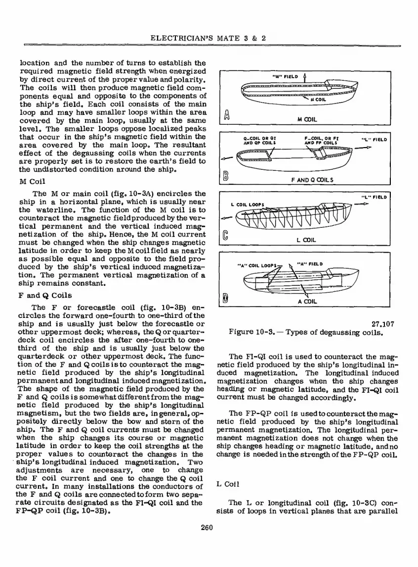
ELECTRICIAN’S MATE 3 & 2
location and the number of turns to establish the required magnetic field strength when energized by direct current of the proper value and polarity. The coils will then produce magnetic field com- ponents equal and opposite to the components of the ship’s field. Each coil consists of the main loop and may have smaller loops within the area covered by the main loop, usually at the same level. The smaller loops oppose localized peaks that occur in the ship’s magnetic field within the area covered by the main loop. The resultant effect of the degaussing coils when the currents are properly set is to restore the earth’s field to the undistorted condition around the ship.
M Coil
The M or main coil (fig. 10-3A) encircles the ship in a horizontal plane, which is usually near the waterline. The function of the M coil is to counteract the magnetic fieldproducedby the ver- tical permanent and the vertical induced mag- netization of the ship. Hence, the M coil current must be changed when the ship changes magnetic latitude in order to keep the M coil field as nearly as possible equal and opposite to the field pro- duced by the ship’s vertical induced magnetiza- tion. The permanent vertical magnetization of a ship remains constant.
F and Q Coils
The F or forecastle coil (fig. 10-3B) en- circles the forward one-fourth to one-third of the ship and is usually just below the forecastle or other uppermost deck; whereas, the Q or quarter- deck coil encircles the after one-fourth to one- third of the ship and is usually just below the quarterdeck or other uppermost deck. The func- tion of the F and Q coils is to counteract the mag- netic field produced by the ship’s longitudinal permanent and longitudinal induced magnetization. The shape of the magnetic field produced by the F and Q coils is somewhat differentfrom the mag- netic field produced by the ship’s longitudinal magnetism, but the two fields are, in general, op- positely directly below the bow and stern of the ship. The F and Q coil currents must be changed when the ship changes its course or magnetic latitude in order to keep the coil strengths at the proper values to counteract the changes in the ship’s longitudinal induced magnetization. Two adjustments are necessary, one to change the F coil current and one to change the Q coil current. In many installations the conductors of the F and Q coils are connected to form two sepa- rate circuits designated as the FI-QI coil and the FP-QP coil (fig. 10-3B).
U” FIELD
tA COIL
A M COIL
Q-COIL OR 01 AND OP COILS
F—COIL, OR FI ANO FF COILS
F ANDO COILS
L COIL LOOPS
L COIL
'•A" COIL LOOPS^p K "A” FIELD
A COIL
27.107 Figure 10-3. — Types of degaussing coils.
The FI-QI coil is used to counteract the mag- netic field produced by the ship’s longitudinal in- duced magnetization. The longitudinal induced magnetization changes when the ship changes heading or magnetic latitude, and the FI-QI coil current must be changed accordingly.
The FP-QP coil is used to counteract the mag- netic field produced by the ship’s longitudinal permanent magnetization. The longitudinal per- manent magnetization does not change when the ship changes heading or magnetic latitude, and no change is needed inthe strength of the FP-QP coil.
L Coil
260
The L or longitudinal coil (fig. 10-3C) con- sists of loops in vertical planes that are parallel

Chapter 10 —DEGAUSSING
to the frames of the ship. The function of the L coil is to counteract the magnetic field produced toy the ship’s longitudinal permanent and longi- tudinal induced magnetization. The L coil is more difficult to install than the F and Q coils or FI-QI and FP-QP coils, tout provides toetter neutralization toecause it more closely simulates the longitudinal magnetization of the ship. The L coil is commonly used in minesweeper vessels.
The longitudinal induced magnetization changes when the ship changes heading or magnetic lat- itude, and the L coil current must be changed accordingly. Dn a.minesweeper, the L coil current must even be changed as the vessel pitches. Roll or pitch adjustments or both are necessary on all the degaussing coils on minesweepers.
A Coil
The A or athwartship coil (fig. 10-3D) consists of loops in vertical fore-and-aft planes. The function of the A coil is to produce a m agnetic field that will counteract the magnetic field caused toy the athwartship permanent and athwartship in- duced magnetization. The athwartship induced magnetization changes when the ship changes heading or magnetic latitude, and the A coil (current) must toe changed accordingly.
MARKING SYSTEM
The degaussing installations in all types of naval vessels are marked in accordance with a standard marking system to facilitate maintenance by the ship’s force. All feeders, mains, and other cables supplying power to degaussing switch- boards, power supplies, and control panels are designated and marked as specified for power and lighting circuits. The system of markings and designations of conductors applies specifically for a multiconductor system, tout it is also ap- plicable to single-conductor type installations.
Degaussing cable identification tags are made of metal. The cables are tagged as close as practicable to tooth sides of decks, bulkheads, or other barriers. Degaussing conductors are marked by hot stamping (branding) insulating sleeving of appropriate size. Each end of all conductors are so marked and correspond to the marking of the terminal to which they connect inside the connection box or through box. The sleeving is pushed over the conductor so that
the marking is parallel to the axis of the conductor. The following letters are used for designating and marking cable tags for degaussing-coil cables and circuits.
D—Degaussing system
A—Athwartship (A) coil
AX—A auxiliary coil
CC—Compass compensating coil
F—Forecastle (F) coil to correct for per- manent and induced magnetization
FDR—Feeder
FI—F coil to correct for induced magnetization
FP—F coil to correct for permanent mag- netization
I—FI-QI coil used in conjunction with feeders, compass-compensating coil, and indicator light leads
IL—Indicator light
L—Longitudinal (L) coil
LX—L auxiliary coil
M—Main (M) coil
MX—M auxiliary coil
P—FP-QP coil used in conjunction with feeders, compass-compensating coil, and indicator light leads.
Q—Quarterdeck (Q) coil to correct for per- manent and induced magnetization
QI—Q coil to correct for induced magnetization
QP—Q coil to correct for permanent mag- netization
SPR—Spare conductor
A detailed description of the marking for degaussing-coil loops, circuits, conductors, and cables and for degaussingfeeder cable and feeder- cable conductors is contained in Chapter 9813 of the NavShips Technical Manual.
CONNECTION AND THROUGH BOXES
Connection and through boxes are similarly constructed watertight boxes, but they are used for different purposes.
A CONNECTION BOX is a watertight box with a removable cover used to connect loops together,
261

ELECTRICIAN'S MATE 3 & 2
to connect conductors in series, and to reverse turns. The power supply connection for a coil and all adjustments of ampere-turn ratios between loops are made within connection boxes. The power supply cable and interconnecting cable for the FI-QI and FP-QP coils terminate in con- nection boxes.
A THROUGH BOX is a watertight box with a removable cover used to connect conductors without changing the order of conductor con- nections. Also, a through box is used when it is necessary to connect sections of cable. In some cases splicing in lieu of through boxes is used.
A wiring diagram of the connections in the box is pasted on the inside of the cover and coated with varnish or shellac. The wiring dia- gram for connection boxes should (1) designate the conductors that may be reversed without reversing the other loops, (2) indicate the ar- rangement of parallel circuits so that equal changes can be made in all parallel circuits when such changes are required, and (3) show the spare conductors. Spare conductors should be secured to connectors and should be connected to form a closed or continuous circuit. All conductors in a connection box should be l-l/2 times the length required to reach any terminal within the box. Connection boxes should also be fitted with drain plugs to provide accessibility for periodic removal of accumulated moisture from the boxes.
Connection and through boxes are provided with IDENTIFICATION PLATES that include; de- gaussing box numbers (Di, D2,etc.), connection box and/or through box as applicable, and coil and loop designations (Ml, M2, Fl2, etc.).
Example, Dl
Connection Box Through Box Ml FI M2
identifies the No. 1 degaussing box serving as a connection box for the Ml and M2, loops and as a through box for the Fl loop.
MANUAL DEGAUSSING SYSTEMS
Degaussing installations, as previously stated, consist of different combinations of degaussing
coils and manual or automatic degaussing equip- ment for control of the current in these coils. The selected combination depends on the size and the intended use of the particular ship.
The currents in the A and FI-QI or F and Q degaussing coils must be changed when there are changes in the ship’s heading, magnetic latitude, or both. The control of the coil currents is ac- complished manually in the older installations and automatically in all new installations. The M and FP-QP coil currents remain essentially constant with the M coil current changing only when the ship changes zones and the FP-QP coil current changing only as a result of calibration.
Degaussing installations that have the coil currents manually controlled are energized from constant voltage d-c generators or from variable voltage motor-generators and are called rheostat and motor-generator installations, respectively.
RHEOSTAT CONTROL
In a rheostat installation the power for the de- gaussing coils is supplied by a constant-voltage d-c generator, and the coil currents are controlled by adjusting a rheostat connected in series with the coil and power supply. An installation in which rheostats are used to control the M, FI-QI, and FP-QP coil currents is illustrated in figure 10-4. Manually operated rheostats are used in some installations and motor-operated rheostats in other installations. In the manual type, the rheo- stat is adjusted locally at the degaussing switch- board by turning the rheostat handle. In the motor-operated type, the rheostat shaft is turned by a motor controlled from a remote station by means of a push-button. Motor-operated rheostats are equipped for manual operation in the event of an emergency.
MOTOR-GENERATOR CONTROL
In a motor-generator installation the power for the degaussing coils (F, Q, and M) is supplied by a motor-generator, and the coil currents are controlled by adjusting a rheostat in the generator field circuit to vary the output of the generator. A single-line diagram of this type installation is illustrated in figure 10-5. The rheostats in the generator fields can be operated manually or by means of a motor to change the generator voltage and thereby adjust the coil current to the desired value.
262

Chapter 10 — DEGAUSSING
REMOTE READING AMMETERS
FI-QI COIL REMOTE
REVERSING SWITCH
120 OR 240 VOLT D.C. SUPPLY BUS
QP-GOIL
-® I COIL M COIL P COIL
FI-QI CIRCUIT
M-CIRCUIT FP-QP CIRCUIT
'Tï
FING i (cccj, y1]— —
RHEOSTAT POWER LXL SUPPLY
LEAOS TO COMPENSATING
CIRCUITRY (CCC)
TO TO C.C.C C.C.C
SERIES RESISTOR
FI-COILS QI-COILS
x.
FP —COIL
COIL
77.181
Figure 10-4. — Manual degaussing system with rheostat control.
POLARITY
The polarity of the degaussing coil currents is of particular importance. If the polarity of any of
the degaussing coils is incorrect, the ship may very likely toe in much greater danger from mag- netic mines than if no degaussing were installed. The polarity of a coil should toe checked toy ob- serving whether the pointer of the ammeter for the
263
ELECTRICIAN’S MATE 3 & 2
coil is on the POSITIVE or NEGATIVE side of the zero-center ammeter. Also, the polarity of a coil can be checked by observing whether the positive or negative plate glows in the neon indicator light for the coil. For positive polarity the right-hand electrode glows, and for negative polarity the left-hand electrode glows.
Reversing switches are used to change the polarity of the coils, except where provision is made to accomplish this change in the design of the rheostat for the constant voltage supply or in the generator control for the variable voltage supply.
The direction of current in a degaussing coil is normally indicated by zero-center ammeters located on the degaussing control panel. The pointer will deflect to the right for positive (di- rection) current through the coil and to the left for negative current. The direction of current can be checked by a degaussing polarity indicator or a small compass. The polarity indicator dial is marked to denote thedirectionof current. When taking polarity readings with the. indicator or small compass, move the device toward the degaussing coil until a good deflection is obtained, and no closer. The needle in the indicator or compass will reverse its magnetic polarity if the
REMOTE CONTROL
PANEL
AMMETER
MOTOR STARTING PUSH BUTTON
RHEO. PUSH BUTTON
AMMETER
INDICATOR LIGHT
PUSH BUTTON © Í
TRANSFER SWITCH
LOCAL CONTROL PANEL
i? v ! TO 44o* 34-A.C.
TO 44ov
30-A.G. TO 44Q* 3p-A.C.
MOTOR
RHEOSTAT
«
IN GEN
FIELD
MOTOR
CONTROLLER
MTR. = GEN. =HXC] = GEN. NELI =¿1 MTR. MTR. = GEN.
l__AMMETER SHUNT
TO COM mss COMPENSATING
COILS
TO COMPASS
COMPENSATING
COILS
TO COMPASS COMPENSATING
I COILS
-ú=
Q COIL F COIL
M COIL
MOTOR } DRIVEF
RHEO.
Figure 10-5. — Manual degaussing system with motor-generator control. 77.182
264

Chapter 10 —DEGAUSSING
device is held too close to the coils. The indicator or compass should he checked after each test to be certain that the magnetic polarity of the needle has not reversed.
CHANGING COIL CURRENTS
Degaussing coil currents will change and re- quire readjustment because of changes in degaussing-coil resistance caused by changes in cable temperature andchangesinthe voltage of the power supply for the degaussing coils.
The degaussing folder for each ship gives the current needed for each coil for all positions on
the earth’s surface and for all headings. One or more of the coil currents must be changed when one of the following conditions occurs:
1. When the ship passes from one Z zone to another.
The vertical intensity (Z component) of the earth’s field, which is maximum at the magnetic poles and zero at the magnetic equator, is divided into a number of Z zones. The number of Z zones will vary, depending on the amount of compensation provided by the particular installation. Degaussing chart No. 1 (fig. 10-6) illustrates the Z zones for the Atlantic and Indian Oceans. The reverse side of this chart (not shown) contains the same number
ATLANTIC- INDIAN OCEAN
DEGAUSSING CHART N> I. nm AREAS we$T or 109a
WIST ANO CAST or iss* CAST see PACiric CHART IOVIAî
CLASS!FICATI ON
\ 84.0
70.5
57.0
43.5 ari«* 30.0
16.5
- 3.0
10.5
24.O
37.5
IM.Omi.Tim FOW IMUWB .treowtl OMIT, MOT TOM I MIT'S U0t
Initial Calibration. Z —} H —; b 58} D 64; Dr 21/25; NM 9; K&S runa; K-Step
baaed on OP 1538 Para 315 ("m" unknown); Post De pera
trunes our •HATCVCR IS NOT ANPUCARLC
COIL SETTINGS* OR VALUES
«UMON.AIfACMt.
AMF OU-TOWNS. %
13.5
... USS - -
FP-QP
15
15
z [ZONE
-33
-A*
-AS
K»TEP
551«' USN DEG FACILITY
(Supertedes SAVWEfS 8950/46À)
CLASSIFICATION AND GROUP HARKING
+ Settings apply to spaces between lines, not to lines
2 May 1969
HAVSHIPS 8950/I1A (REV. 3-67)
OG NO. 8
Figure 10-6.—Degaussing chart No. 1. 69.14
265'

ELECTRICIAN’S MATE 3 & 2
ATLANTIC-INDIAN OCEAN
DEGAUSSING CHART N& 2. FOR AREAS WEST OF IOS* WEST AND EAST OF 135* EAST SEE PACIFIC CHART (OVER)
FI-QI
10.0
13.3
I 16.7
—r. 20.0 F
13.3
10.0
— «a, INFORMATION FOR IS5UIH6 FERSONNEL ONLY , NOT FOR 5HlF’$ USE
Initial Calibration; Z—, H—; B $8;
D 64; Dr 21/25; I baaed on N-S runs.
MANUAL OPERATION
COIL SETTINGS
IN AMPERES
o CJ i
ti
y u 5S
1^*- 1S
-tnr o in
H
ZONE
* STRIKC OOT WHATCVCR IS NOT APPLKASLl
fSettings apply to spaces between lines, NOT to lines.
(NAME , TYPE AND NO. , AND NATION )
uss
SSTE0' üsíi Í¡EC PACILITT_ _ B„t _2_«ay_62 SIGNATURE Of TÇA- /^* f* M
ISSUING OffICER' VÎ - >11
(Supersedes NAVREPS 8950/46B) NAVSHIPS 8950/148 (REV. 3-67) DG NO. 9
Figure 10-7. — Degaussing chart No. 2. 69.15
of Z zones for the Pacific Ocean. The coil current settings are filled in by range personnel for the various zones after the ship has been ranged.
2. When the ship passes from one H zone to another.
The horizontal intensity (H component) of the earth’s magnetic field, which is maximum at the magnetic equator and zero at the magnetic poles, is divided into a number of H zones. Similar to the Z zones, the number of H zones will vary, de- pending on the degree of compensation provided by the degaussing system. A degaussing chart No. 2 (fig. 10-7) illustrates the H zones for the Atlantic
and Indian Oceans and the reverse side (not shown) contains the same number of H zones for the Pacific Ocean.
3. When the ship’s heading changes from one sector to another.
The entire range of headings from 0 to 360° is divided into a number of sectors, each covering a part of the whole range of courses.
None of the degaussing coil currents are changed as long as the ship’s course remains in one sector (if the Z zone and H zone remain unchanged). The FP-QP coil current is NOT changed when the ship’s heading or the ship’s
266

Chapter 10 —DEGAUSSING
position changes. The following changes are necessary when changing from one sector to another or from one zone to another:
1. The M coil current must he changed when the ship moves from one Z zone to another. The M coil current is not changed when the ship moves from one H zone to another or when the heading changes from one sector to another.
2. The F, Q, FI-QI, L, and A coil currents are not changed when the ship moves from one Z zone to another, hut must he changed if thé ship moves to a different H zone, or if the heading changes to a different sector.
In a few . ships, exceptional conditions may require a departure from the foregoing changes. In all cases, the dégaussing folder will show the coil currents to be used.
Rheostat Installation
The degaussing coils in rheostat installations are energized hy closing the main degaussing feeder switch and the individual coil switches in the proper polarity position with all rheostats set for máximum resistance. Set the current in each coil hy cutting out resistance.
Adjust the rhéostats for the M and FP-QP coils (if provided) until the M and FP-QP coil currents have the values specified in the de- gaussing folder for the ship’s position. Adjust the rheostats for the F, Q, FI-QI, L, and A coils (if provided) until the coil cur rents have the values specified in the degaussing folder for the ship’s position and heading. Check the coil currents peri- odically, and change the coil currents as required hy changes in the ship’s position and heading.
In installations employing motor-driven rheo- stats the polarity is changed only when the current is zero either by means of a motor-driven polarity changer, and pushbutton, or hy operating the rheo- stat through and beyond the position of maximum resistance. At this point, reversal of current will occur automatically because of the internal cross- wiring of the rheostat buttons on either side of this point, or hy means of a motor-driven polarity changer actuated hy the rheostat arm.
Motor-driven rheostats can be operated man- ually by turning the emergency handwheels in the
event of failure of the motor-drive system. Always reduce the current to zero before operating the polarity changer. Otherwise, the contacts will arc and may burn out from operation under load.
In installations employing manually operated rheostats, the degaussing switchboard is usually located in the engineróom. This switchboard in- cludes the disconnect switches for the F,Q, FI-QI, L, and A coils; reversing switches for the M and FP-QP coils; series resistors; fuses; and ammeters. A remote degaussing panel is located in the pilot house or chart house to permit changing the F, Q, FI-QI, L, and A coil currents as the ship changes heading. This panel includes ammeters or polarity indicator lights for all coils and rheostats (rheostat pushbuttons); and reversing switches for the F, Q, and L coils or reversing switches for the FI-QI and A coils.
Telephone communications are provided be- tween the remote and main panels. When the degaussing system is to be energized, the remote position (pilot house) may call the main degaussing switchboard station and have all currents set to the values called for in the degaussing folder. The remote position will then continue to maintain the currents in the FI-QI and A coils according to the ship’s location and heading.
Motor-Generator Installation
The degaussing coils in motor-generator in- stallations are energized by closing the dis- connect switch to the motors with the generator field rheostats set for the maximum resistance, and operating the pushbutton to start the motor. The degaussing switchboard is usually located in, or in the vicinity of, the engineroom near the de- gaussing motor-generators. This switchboard includes ammeters, pushbuttons for starting the motors, and the motor-driven field rheostat for the generator. In many installations in which the motor-generators are not located together, a separate switchboard is provided for each group of motor-generators.
After the motor has started, the currents in the coils are set by the pushbuttons that control the motor-driven field rheostats for the gen- erators. The pushbuttons are located on the remote control panel in the pilot house or chart house.
267

ELECTRICIAN’S MATE 3 & 2
or on the degaussing switchboard. Zero-center ammeters mounted above the pushbuttons are used to determine whether the positive or negative pushbutton should be operated to obtain the speci- fied currents. The positive pushbutton will operate the motor-driven generator field rheostat to in- crease the current in the positive direction (de- crease the current in the negative direction). Conversely, the negative pushbutton will operate the motor-driven rheostat to increase the current in the negative direction (decrease the current in the positive direction).
SECURING
Degaussing coils should be secured according to instructions in the degaussing folder for the installation concerned. To cancel any residual magnetism due to the degaussing current, most installations require one or more of the coils to be secured by reversals. The procedure for securing a degaussing coil by reversals is as follows: (1) Starting with the maximum current specified in the degaussing folder, reduce the current to zero then increase to the starting value in the reverse direction. (2) Reduce the current to zero and then increase to 3/4 value in the original direction. (3) Reduce the current to zero and then increase to l/2 value in the reverse direction. (4) Reduce the current to zero and then increase to l/4 value in the orig- inal direction. (5) Reduce the current to zero and then increase to 1/8 value in the reverse direction. (6) Reduce the current to zero and secure.
AUTOMATIC DEGAUSSING SYSTEMS
Installed on all new ships built since 1951, automatic degaussing equipment compensates automatically for induced magnetization by changing currents in the FI-QI and A coils as a ship’s heading changes.
TYPES OF AUTOMATIC DEGAUSSING EQUIPMENT
The letter designation of each degaussing coil current control equipment provides information as to its type. The types are:
1. SM magnetic amplifier; controls selenium rectifier type power supply.
2. GM magnetic amplifier; controls field of generator of degaussing motor-generator.
3. FM magnetic amplifier; controls the field of exciter of degaussing motor-generator.
4. RM magnetic amplifier; controls the motor of motor-operated rheostat; the rheostat is in series with the degaussing coil which is connected across the ship’s constant voltage d-c power supply.
5. SSM semiconductor; silicon controlled rec- tifier type power supplies.
6. EMS semiconductor; magnetometer con- trolled degaussing system.
SM-9A AUTOMATIC DEGAUSSING SYSTEM
The SM-9A automatic degaussing control system comprises a degaussing switchboard (fig. 10-8), a remote switchboard, a FI-QI coil power supply, an FP-QP coil power supply, and a M coil power supply. The degaussing switchboard (fig. 10-9), contains the controls required to op- erate the degaussing system. The FI-QI control panel mounted at the top of the switchboard con- tains all the circuits required to control the FI- QI degaussing currents in both the manual and automatic modes of operation. TheM control panel mounted in the center left section of the switch- board contains the controls and circuitry required to control the M coil current. The FP-QP control panel mounted center right contains the controls for setting the FP-QP coil current. At the bottom is located the power supply overheating alarm circuits and ground fault detector.
The remote control unit mounts three meters which indicate the current in each of the three degaussing coils. Three red lights mounted on the unit indicate whether or not there is trouble in the three circuits. One white light indicates that the system is in manual operation, and another indicates that the FI-QI current is being controlled at the remote control unit by the manual control switch on the remote unit.
The three power supplies contain the circuits necessary to supply the currents required to
268

Chapter 10 — DEGAUSSING
440 VOLT 60 Hr 3 PHASE POWER
117 VOLT 400 Hz POWER
GYRO SIGNAL >
rn 01
c*. »
REMOTE SWITCHBOARD LI SWITCHBOARD
M POWER
SUPPLY
-C. :> DEGAUSSING
COIL
FI-QI POWER
SUPPLY
F I.QI DEGAUSSING COIL
FP-QP POWER SUPPLY
FP-QP DEGAUSSING COIL
FP-QP FI ELD FI-QI FIELD
i
Figure 10-8. — Type SM-9A automatic degaussing control system. 77.327
269

ELECTRICIAN'S MATE 3 & 2
LOCAL CONTROL
UNIT
M CONTROL
PANEL
117 V. CONTROL POWER
PP-QP CONTROL
PANEL
POWER SUPPLY OVERHEAT ALARM
CIRCUITS
GROUND FAULT DETECTOR PANEL
VOLTAGE REGULATOR
ZONE CIRCUIT
Rtgulottd
' j ^H^slgnol (AC)
Signol (AC)
N H Co»A S
MAGNETIC HEADING
INDICATOR DEMODULATOR
^ Signol ( Control DC
FIRST STAGE SIGNAL
MAGNETIC AMPLIFIER
FAULT SIGNAL MAGNETIC AMPLIFIFR
RELAY MAGNETIC AMPLIFIER 4
SElCONÖ SYAdË SIGNAL
MAGNETIC AMPLIFIFf
Ü
4 THIRD STAGE
POWER MAGNETIC
AMPLIFIER
4 REVERSING CONTACTOR
MAGNETIC VARIATION SYNCHRO
>a CONTROL TRANSFORMER
SERVO MOTOR
SERVO AMPLIFIER
COIL POLARITY REVERSING SWITCH
F^OI COIL
111.121 Figure 10-9. — SM-9A degaussing switchboard.
degauss the ship. The only externally mounted components on the supplies are indicator type fuses which fuse the power circuits in the supplies.
FI-QI Channel Functional Description
The FI-QI automatic channel circuit is shown in block diagram form in figure 10-10.
Signals from the ship’s gyro system which are proportional to the ship’s true heading are
111.122 Figure 10-10. — SM-9A FI-QI automatic channel-
block diagram.
converted to signals which are proportional to the magnetic heading by the magnetic variation synchro. The resulting magnetic heading signal drives a servoamplifier and servomotor which positions the magnetic heading indicator dial, control transformer rotor, and synchro resolver which are attached to the gear train.
The servoamplifier provides an impedance match between the control transformer secondary and the servomotor, permitting faster gear train action.
The First Stage Signal Amplifier Circuit is a push-pull amplifier connected for direct current
270

Chapter. IODEGAUSSING
output so that the net output signal (difference between the push-pull outputs) is a reversible polarity direct current signal proportional to the required FI-QI degaussing current for any mag- netic heading and H Zone. The first stage output signal is then used as a control signal for the second stage amplifier.
The second stage signal amplifier receives its control signal from the first stage signal amplifier and supplies the control signal for the third stage power amplifier. Since the second stage signal amplifier and the third stage power am- plifier are “single-ended” stages (not push- pull), they are capable of producing an output current of only one polarity. When a negative current is required (when the signal from the first stage goes in a negative direction), the pilot relay reverses the polarity of the second stage control signal so that it will continue to drive in a positive direction, and the reversing contactor (controlled by the pilot relay) reverses the FI-QI degaussing current.
Operation of the relay amplifier, which con- trols the operation of the pilot relay, is such that when a negative degaussing current is required the pilot relay is energized.
The fault signal circuit produces a visual indication of trouble by lighting the trouble lights (on both the degaussing switchboard and the remote control unit) when the degaussing current is in error with the required degaussing current by more than five percent. The fault signal reactor magnetically compares the output signal from the first stage signal amplifier, which is proportional to the required degaussing current, with a signal from the feedback shunt, which is proportional to the actual degaussing current. If the difference between these two signals exceeds the value at which the fault signal reactor has been adjusted to “fire,” the trouble lights will light.
Gyro Signal Circuit
The ship’s gyrocompass equipment provides a synchro signal which is a function of the ship’s heading from true north. Since degaussing equip- ment must operate from a magnetic bearing, the gyrocompass signal is fed to a synchro differential generator which introduces a correction for magnetic variation. The amount of correction
applied is determined by the setting of the MAGNETIC VARIATION dial on the control unit. The proper setting for any given area in which the ship is operating may be obtained from the ship’s navigational charts.
Signal Amplifier Circuit
Signals from the demodulator circuit (fig. 10-10) are fed through the automatic operation current adjustment rheostat (not shown) to a push-pull magnetic amplifier (the signal mag- netic amplifier). The push-pull amplifier pro- duces a d-c output proportional in magnitude and polarity to the magnitude and polarity of the input signal from the automatic operation current adjustment rheostat which is part of the signal amplifier circuit.
RELAY AMPLIFIER CIRCUIT.—The relay amplifier circuit receives the d-c output signal from the signal amplifier circuit and sends the signal through a magnetic amplifier to a pilot relay. The pilot relay, through its contacts, sends a unidirectional d-c signal at all times to the input of the second stage magnetic amplifier. The pilot relay also controls the reversing contactor. This means that although a reversible signal is received by the relay amplifier, the pilot relay will allow only a d-c signal of the same polarity each time to go to the second stage magnetic amplifier, but still operate the reversing contactor to have the same polarity as the input signal to the relay amplifier.
SECOND AND THIRD STAGE AMPLIFIER CIRCUITS.—The second and output stage am- plifiers are single ended, three phase, magnetic amplifier circuits. These circuits, which are lo- cated within the FI-QI power supply, function to produce a degaussing current proportional to the output signal from the signal amplifier circuit. When a negative degaussing current is required (when the signal amplifier output current is negative), both the control signal input connections and the degaussing current output connections are reversed so that the degaussing current follows the output of the signal amplifier circuit even though the second and output stages are driving only in one direction.
Two feedback signals (shunt feedback and rate feedback) are applied to the second stage am- plifier. Although they are positive to the second stage, they have a negative effect on degaussing
271

ELECTRICIAN’S MATE 3 & 2
coil current because the second stage output is applied to the third stage amplifier in a negative signal winding. These feedback signals improve the linearity and stability of the FI-QI channel. The shunt feedback signal is directly proportional to the degaussing coil current, while the rate feedback signal is proportional to the rate of change of the coil current. The effect of the rate feedback signal is to oppose any tendency of the system to oscillate.
FAULT SIGNAL AMPLIFIER.—The function of the fault signal circuit is to provide a visual indication of trouble when the FI-QI degaussing current is in error with the required degaussing current as dictated by the d-c control signal from the signal amplifier. This is done by com- paring the two signals magnetically within a saturable reactor circuit. Error signals of either polarity will cause an increase in the control current applied to the saturable reactor thus decreasing the impedance of the output windings, causing the trouble light to light.
M and FP-QP Manual Coil Channels
The manual coil channels (M and FP-QP) (fig. 10-11), each consists of a control panel that houses a constant voltage source and the means of controlling the magnitude and polarity of the current to the degaussing coil. This is done by sending a unidirectional d-c signal of a variable magnitude to the first stage and second stage amplifier where the d-c signal is amplified to the value needed in the degaussing coil. The polarity of the degaussing current is determined by the position of the coil polarity reversing switch that is located in the coil channel control panel. The contacts in the reversing switch op- erate the reversing contactor that is connected between the output of the amplifier (second) stage and the degaussing coil. The coil polarity re- versing switch also has a set of contacts that direct the d-c signal voltage to the fault signal amplifier. The fault signal amplifier is a visual indication of whether the manual coil channel is functioning properly. The functioning of the in- dividual units of the manual coil channel follows.
M AND FP-QP CHANNEL CONTROL PANEL.—The M and FP-QP coil channels are manually controlled. The control circuits for the M and FP-QP coil channels are identical. The M coil channel control panel utilizes a constant
CONTROL PANEL
FAULT
SIGNAL AMPLIFIER
FIRST STAGE
MAGNETIC AMPLIFIER
OUTPUT STAGE (SECOND) MAGNETIC AMPLIFIER
POLARITY REVERSING CONTACTOR
teM&J DEGAUSSING COIL
(MaFP-OP)
111.123
Figure 10-11.—SM-9A M and FP-QP manual channel-block diagram.
voltage supply transformer along with a filtering and reducing circuit composed of capacitors, an inductor, and resistors. The resultant a-c voltage is sent to a full-wave rectifier which provides the d-c voltage source which is used as the control voltage in the M coil channel. A manual control adjusting rheostat is used to vary the magnitude of the d-c signal from the full-wave rectifier. The positive side of the resultant d-c voltage is applied through the M coil polarity reversing switch where it is directed to the control winding of the fault signal amplifier and returns back to the output of the M coil channel control panel. The purpose of the signal to the fault signal amplifier is to provide a reference that is used to determine if the circuit is functioning properly. The M coil polarity
272

Chapter lO —DEGAUSSING
reversing switch also operates the reversing contactor of the M coil. The output of the control panel goes to the input of the firststage magnetic amplifier.
FIRST STAGE AND OUTPUT STAGE MAG- NETIC AMPLIFIERS.—The first and output stage of the M coil channel are the same as the second and output stage amplifiers of the FI-QI coil channel. A unidirectional d-c signal from the output M coil channel control panel is sent to the input of the first stage magnetic amplifier. Because the first stage magnetic amplifier is single ended, the d-c signal to the control winding is the same polarity at all times and only varies in magnitude. The means of amplification is identical to the method descrihed for the second and output stage of the FI-QI control panel. The output of the output (second) stage goes to the primary of a power transformer. This trans- former is provided with taps to supply the proper voltage to the degaussing coil. The output of the transformer is connected to a full-wave bridge rectifier where it is rectified and fed through a reversing contactor to the degaussing coil.
The reversing contactor is similar to the one used in the FI-QI control channel. The only dif- ference is that the reversing contactor is always manually controlled from the coil polarity re- versing switch in the control panel.
The fault signal amplifier produces a visual indication of trouble by lighting the trouble lights when the degaussing current is in error with the required degaussing current. The operation is similar to the one mentioned in the FI-QI control channel.
MAINTENANCE
The degaussing installation should be care- fully maintained particularly to prevent deterio- ation resulting from moisture gradually entering the cables. Since the degaussing system consists of electrical cables, rheostats, ammeters, con- nection boxes, motor-generator sets, and costly automatic control equipment it must be main- tained in conformity with the instruction for the maintenance of electrical equipment given in applicable chapters of the NavShips Technical Manual (Chapters 9600 and 9813) and applicable technical manuals for the equipment installed.
First and always, bear in mind that this equipment is energized with dangerous voltages.
All electrical maintenance personnel must ob- serve the safety precautions and electrical main- tenance procedures as presented in chapter 9600 of NavShips Technical Manual.
PREVENTATIVE MAINTENANCE
The maintenance requirements for manual degaussing systems are not as extensive as those for automatic degaussing systems.
Automatic degaussing switchboards and remote panels require more frequent cleaning and inspection as they are more sensitive to heat and dirt due to their fine components.
When the system is not in normal use, all coils should be energized at least once a week to the maximum current specified in the degaussing folder and operated for at least four hours with the current in one direction. Then reduce the current to zero and energize the coils momen- tarily with maximum current in the opposite direction.
Check each degaussing coil for grounds by insulation resistance measurements using a 500- volt megger. When the source of supply for de- gaussing coils is from rectifiers, the rectifiers must be disconnected prior to using a 500-volt megger on the degaussing coils to prevent damage to the rectifiers. These measurements should always be made with the same degaussing equip- ment connected in the circuit and as closely as possible under similar conditions of temperature and humidity. The date and reading of the insulation resistance to ground may be recorded on the resistance test record card (NAVSHIPS 531-1) in accordance with chapter 9600 of the NavShips Technical Manual. These measurements should be taken between the coil disconnect switch and ground. In the F, Q, and A or I, P, and A coils that have a reversing switch on the coil side of the disconnect switch, the measurement should be made with the reversing switch in the CLOSED position. Also, this measurement should be made just before the weekly energizing of the coils so that the comparative readings are obtained under similar conditions. By comparing these weekly readings it is possible to detect abnormal decreases in resistance and take the necessary corrective action before failure occurs. When abnormal decreases are indicated the various components of the circuit should be isolated and
273

ELECTRICIAN'S MATE 3 & 2
the insulation resistances checked individually to determine the cause of the low reading.
The connection boxes may accumulate con- siderable amounts of water due to condensation and leakage through improperly seated gaskets. The moist atmosphere in the box will gradually force moisture into the cable ends and reduce the insulation resistance. If this condition is not checked in time, the cable may be ruined and require replacement. Therefore, remove the con- nection and through-box drain plugs once a month to allow any accumulated water to run out. Boxes that have abnormal accumulations of water should be opened, dried out, and the gaskets checked and replaced if necessary.
Remove corrosion on rheostat contact buttons with fine sandpaper and coat the buttons lightly with a graphite lubricant. Remove accumulations of dirt and dust from automatic degaussing control equipment to facilitate the natural flow of air around the components, and thus eliminate the possibility of overheating. Use a vacuum cleaner or bellows; do not use compressed air.
Observe the preventive maintenance require- ments for automatic control equipment and motor- driven rheostats, as outlined in the applicable technical manual. Also, observe the maintenance of electrical equipment and electrical safety pre- cautions, as required by Chapter 9600 of the NavShips Technical Manual.
CORRECTIVE MAINTENANCE
Corrective maintenance consists principally of locating and eliminating grounds in the various coils, circuits, and components of a degaussing system.
Grounds in a degaussing conductor can be located by breaking the conductor into its
component sections byopening connections at con- nection and throughboxes, and testing each section of the conductor individually. Grounds in FEEDERS and control equipment CIRCUITS can be located by isolating the different components.
When making these tests, reconnect all un- grounded connectors to their terminals immedi- ately after they have tested clear, to prevent misconnection later. To locate grounds in de- gaussing circuits, proceed as follows (observe precautions required when using a 500-volt megger on rectifier circuits):
1. Open the supply switch for the degaussing coil and close the reversing switch in either position.
2. Disconnect the feeder conductors from the degaussing coil at the feeder connection box.
3. Measure the insulation resistance to ground for each of the feeder conductors. If the insulation resistances are satisfactory in accordance with the manufacturer’s technical manual and Chapter 9600 of NavShips Technical Manual, the feeder conductors and the equipment connected to them are clear of objectionable grounds. If the in- sulation resistance to ground is unsatisfactory for either one or more of the feeder conductors, proceed in accordance with the method for lo- cating grounds in feeder conductors, as described in the instruction book accompanying the in- stallation.
4. Measure the insulation resistance from the degaussing coil to ground. If the insulation re- sistance of the degaussing coil is satisfactory in accordance with Chapter 9600, NavShips Tech- nical Manual, no further insulation tests on the coil are necessary.
274

CHAPTER 11
ELECTRICAL PROPULSION AND CONTROLS
The driving units for propulsion systems in- stalled on most Navy ships are either steam turbines or diesel engines. Turbine - driven reduction-gear systems (fig. 11-lA) are standard for all of the fleet’s capital ships, whereas the diesel reduction-gear drives (fig. 11-lB) are found on medium-sized and smaller vessels, such as tank landing ships. Certain classes of the capital ships have central operating systems (de- scribed in the next chapter) to control their power plants automatically.
Also driven by turbine or diesel engine, the systems shown in figures 11-lC and 11-ID are electric propulsion drives. They differ in that a d-c or a-c electrical system replaces the re- duction gear. Electric propulsion is used on modern ships where it has a specialized purpose such as veity good control (use of direct current) or secondary purposes such as tending (furnishing a-c power for ships alongside, from propulsion generators). Otherwise electric propulsion is not competitive in weight and size with the reduction gears which it would replace.
provided to control the drive system from either the engineroom or the pilothouse. The control provides for controlling the outputs of the four propulsion generators and associated exciters, and the speed and direction of rotation of the propulsion motor.
The diesel engines and generators rotate in the same direction for both ahead and astern rotation
Otc
3ÜJ QO
A DRIVE SHAFT
ocr
STEAM TURBINE ]
DIESEL ENGINE
D-C PROPULSION
A representative diesel-electric d-c propul- sion installation in a U. S. fleet tug consists of four diesel engine-driven propulsion generators, which furnish power through the control equip- ment to one propulsion motor, which in turn drives the propeller (fig. 11-2). Each generator is pro- vided with an exciter mounted on an extension of the generator shaft. The four generating units are located amidship, two on the port side and two on the starboard side.
The propulsion motor is directly connected to a single propeller shaft and located on the center- line of the ship in a separate compartment im- mediately aft of the generating units.
The control equipment consists of an engine- room control station and a pilothouse control station with instrument panel. A transfer switch is
ELECTRIC CABLE
ELECT DIESEL ENGINE
GEN. MOTOR
ELECTRIC CABLE
^C3i=C 2 ELECT. MOTOR
GEN. TURBINE
27.327 (77C) Figure ll-l. — Propulsion drives.
275

ELECTRICIAN’S MATE 3 & 2
ELECT
MOTOR
QÍÜ53I GEN GEN
GEN r DIESEL
^ENGINE[J
Figure 11-2. — Four diesel-electric generators with single-motor propulsion system. 27.327
of the propeller. Primary control of the direction of propeller rotation is obtained by changing the polarity of the generator terminal voltage. The control of propeller speed is obtained by changing the magnitude of the generator terminal voltage. The generator terminal voltage is controlled by varying the generator field strength in the lower propeller speed range and by varying the speed of the diesel engines and thus the terminal voltages of the associated generators in the upper speed range.
The control is effected by means of a speed controller in the engineroom or by a speed con- troller in the pilothouse. The speed controller is connected to a rheostat and reversing contacts for controlling the magnitude and direction of the generator field current and to an engine speed transmitter for controlling the engine speed.
The system is designed to permit operation of any combination from one to four generators with the motor. Also, either generator 2 or 3 but not both at the same time, can be used to supply auxiliary power for salvage operations. When this is done the generator cannot be used in propulsion service.
PROPULSION GENERATORS
The four propulsion generators ared-c, sepa- rately excited, 2-wire, split-frame, self- ventilated machines. They are heavy duty marine type units designed for operation over ttie speed range of the diesel engines. Commutating poles are provided to improve commutation. Each gen- erator is rated at 610 kw, 375 volts, 1625 amperes, and 700 rpm.
PROPULSION EXCITERS
As previously stated, each propulsion gen- erator is equipped with a directly connected ex- citer, which provides excitationfor the associated generator field. The exciters are d-c, separately excited, 2-wire, self-ventilated units provided with commutating poles. Each exciter is rated at 3 kw, 70 volts, 43 amperes,and350/700 rpm.
PROPULSION MOTOR
The propulsion motor is a d-c, separately ex- cited, adjustable speed motor having commutating and compensating windings (fig. 11-3). It is actually two identical motors with their armatures mounted on a common shaft. The armatures are operated in series at all times. Each half of the motor is rated at 1500 horsepower, 750 volts, 1610 amperes, and at 112/140 rpm. The power is supplied from the propulsion generators, which are connected with their armatures interposed with those of the propulsion motor so that the maximum voltage across any part of the propul- sion loop does not exceed 750 volts. The shunt type fields of the propulsion motor are excited from the ship’s 240-volt (auxiliary), d-c supply. The two armatures are mounted on a single shaft with their commutators adjacent. The direction of rotation is determined by viewing the commutator end of each armature. The stator frames are in- dependently foot mounted and are also identical except for the brush rigging and the polarities of the shunt field leads, which are made to suit the opposite direction of rotation of the armatures.
The propulsion motor is provided with induced ventilation by means of a separately mounted
276

Chapter 11 — ELECTRICAL PROPULSION AND CONTROLS
BRUSH HOLDERS
FIELD WINDINGS
A
ARMATURES
m CA«*
77.228 Figure 11-3.— D-c propulsion motor.
blower through a duct connected to an opening in the enclosing cover of the commutator at the top of the machines. The air is drawn in through openings in the end bells at both ends of the motor and flows through radial ducts in the armature cores, over the armature surfaces and between the field coils where it passes over the commutators and out the opening at the top.
The blower is driven by a 15-horsepower, 230-volt stabilized shunt, d-c motor. The motor is controlled by a magnetic starter (mounted in a separate cabinet), which is controlled from the main propulsion control board. The starter is equipped with a START-STOP pushbutton for local operation.
PROPULSION CONTROL EQUIPMENT
The propulsion control equipment (fig. 11-4) is assembled as a unit and located on the plat- form level in the ehgineroom. The indicating instruments and the handles of the manually operated devices are mounted on the front of three 2-section panels that comprise the control board. The first two are the generator panels and the third is the motor panel. The third panel does, however, mount some devices that are not directly associated with control of the propulsion motor. Referring to figure 11-4, the four voltmeters Ml mounted on the generator panels indicate the voltages of the four propulsion generators. The two exciter voltmeters M2 indicate the voltages of the four exciter generators. One voltmeter is for exciters 1 and 2 and one is for exciters 3 and 4. These voltmeters are also used as ground detec- tors. The two exciter voltmeter and ground de- tector transfer switches SWl are used to transfer the two voltmeters to the circuits whose voltages are to be read. The excitation voltmeter M9 in- dicates the voltage of the ship’s 240-volt d-c supply. This voltmeter is also used as a ground detector.
The excitation voltmeter and generator field ground detector transfer switch SW4 are used to transfer the voltmeter to the various circuits. The auxiliary power ammeter M3 on the first generator panel indicates the current supplied to the auxiliary power circuits by the generator being used to furnish auxiliary power.
The four engine speed indicators M5 indicate the speeds of the four diesel engines. The aux- iliary power control switch SW2 operates the auxiliary field contactor which energizes the ex- citer field circuit of the generator supplying aux- iliary power. The auxiliary power generator field rheostat RHl is provided to control the strength of the exciter field of the generator supplying auxiliary power.
The four small handwheels SWll are the gen- erator control switches that control the field circuits of the four generators and associated exciters to apply or remove excitation. The four large handwheels SW9 and SWlO control the setup switches of the four generators. The switching arrangement is such that generators 1 and 4 may be used only for propulsion service whereas generators 2 and 3 may be used for either pro- pulsion or auxiliary power service. Operating in conjunction with each generator setup switch, is an engine speed-exciter field setup switch SW5, not shown in figure 11-4.
277

ELECTRICIAN'S MATE 3 & 2
ENGINE
1*10 1*11
¿BBLBELII SHAFT RPM
INDICATOR I
P I SW1 SW2 SW4 SW1
I RH1 #
SW6 WRONG 1 ■
S i—a DIRECTION
SW1I . SW11 jfi INDICATOR SW11 SW11
/ P. ^
4 SW8 SW7
CONTROLLER PI
V SW9 SW10 SWIO SW9 RH2
GENERATOR PANEL
GENERATOR PANEL
MOTOR PANEL
EMERGENCY STOP
RELEASE
MI-GENERATOR VOLTMETER, 500-0-500
M 2-EXCITER AND GROUND DETECTOR VOLTMETER, 100-0-100
M3-AUXILIARY POWER AMMETER, 0-2000
M4- MOTOR AND GROUND DETECTOR VOLTMETER, 1000-0-1000
M5-ENGINE SPEED INDICATOR, 0-1000
M6-M0T0R FIELD AMMETER, 0-150
M7-MOTOR AMMETER, 3000-0-3000
M 8 - PILOT HOUSE.MOTOR AMMETER, 3000-0-3000 (NOT SHOWN)
M9-EXCITATION VOLTMETER (SHIP'S SERVICE), 0-300
SW1-EXCITER VOLTMETER AND GROUND DETECTOR TRANSFER SWITCH
SW2-AUXILIARY POWER GENERATOR FIELD CONTROL SWITCH
SW3-MOTOR VOLTMETER AND GROUND DETECTOR TRANSFER SWITCH SW4-EXCITER VOLTMETER AND GENERATOR FIELD GROUND DETECTOR TRANSFER SWITCH
SW5-ENGINE SPEED - EXCITER FIELD SWITCH ON GENERATOR SET-UP SWITCH (NOT SHOWN)
SW6-ENGINE SPEED CONTROL SWITCH SW7-EXCITATION CONTROL SWITCH SW8-PIL0T HOUSE-ENGINEROOM TRANSFER SWITCH
SW9-10-GENERATOR SET-UP SWITCHES
SW11-GENERATOR CONTROL SWITCH RH 1 -AUXILIARY POWER GENERATOR FIELD RHEOSTAT
RH2-M0T0R FIELD RHEOSTAT
PI -ENGINEROOM CONTROLLER
Figure 11-4. — Propulsion control equipment, 27.100
The motor voltmeter M4 mounted on the motor panel indicates the voltage across the two motor armatures and also functions as a ground detec- tor in the generator and motor armature circuits. The motor voltmeter and ground detector transfer
switch SW3 is used to transfer the voltmeter to the circuits to be read.
The motor field ammeter M6 indicates the current in the motor field circuits. The motor
278

Chapter 11 — ELECTRICAL PROPULSION AND CONTROLS
ammeter M8 indicates the current in the propul- sion circuit.
The control transfer . switch SW8 is provided to transfer control of the propulsion system from the engineroom to the pilot house.
The excitation control switch SW7 operates the exciter contactor which energizes the exciter and motor fields from the ship’s 240-volt d-c supply.
The motor field rheostat handwheel RH2 con- trols the excitation of the motor field. Engineroom controller handwheel Pi controls the operation of the propulsion system from the engineroom. The controller has 24 ahead and 24 astern speed op- erating positions. An emergency stop-release button is located at the 22nd controller position. The operator must press the release button to move the controller beyond this point.
OPERATION
By the use of disconnect blocks (fig. 11-5 part l) either motor armature may be bridged and removed from the propulsion loop in an emergency. When one armature is removed the motor voltage rating is reduced one-half, con- sequently not more than two generators should be operated in the series propulsion loop.
The overload relays OL1 and OL2 are designed to operate in case of a short circuit in the pro- pulsion oj auxiliary power circuit. When a short circuit occurs in the propulsion circuit, relay OLl closes its contacts and energizes the tripping coil for excitation contactor K2,(part 4). When a short circuit occurs in the auxiliary power circuit, relay OL2 opens the circuit to the auxiliary power field contactor Kl.
The two resistors Rll in series with RH2 (part 2) and the two motor fields are provided to adjust the excitation of the motor fields so that the two motor armatures divide their loads equal- ly. The load is divided equally when the voltage drops across the two motor armatures are iden- tical. As the two armatures are identical the ex- citation currents should be approximately the same. Once correctly adjusted, these resistors need not be changed.
Adjustable resistors R4 in the exciter field circuits are provided to equalize the performance characteristics of the generators as they, too, need not be changed after they are properly adjusted. Motor field discharge resistor RlO (part 2) is connected across the motor fields only while the excitation contactor K2 is in the open position. Exciter field discharge resistors R2 are connected across the exciter fields at all times. The main propulsion generator field discharge
279
resistors Rl are thyrite resistors and are per- manently connected across the generator fields. An engine speed transmitter rheostat RH5 (parts) is provided with the engineroom and pilot house controllers. These two transmitters consist of three rheostats mounted together and operated by a common shaft, which is a projection of the propulsion controller operating shaft (fig. 11-6). The three rheostats are adjusted so that each has a different value for any controller position and are connected to a receiver on the engine speed governor.
A third transmitter, the auxiliary power engine speed transmitter RH6, mounted behind the gen- erator panels, controls the speed of the diesel engine which is being used to supply auxiliary power. This transmitter has a fixed setting and each time the transmitter assumes control the engine speed is brought to the predetermined value of 450 rpm.
The engine speed circuits are series circuits. For this reason loading resistors R5 and R6 (fig. 11-5 part 3) are provided to maintain the circuit resistance constant, thereby keeping the synchros in calibration. The resistors are switched in and out of the circuit by the generator setup switches SW5.
Starting
Before starting the system determine that the engineroom controller and the pilot house control- ler are in the STOP position; the excitation control switch SW7 (fig. 11-5, part 4) is in the OFF posi- tion; the engine speed control switch SW6 (part 3) is in the OPEN position; the auxiliary power control switch SW2 (part 4) is in the OFF po- sition; the auxiliary power generator field rheo- stat RH1 (part 2) is in the MAXIMUM RESIS- ANCE position, and the generator setup switches SW9 and SW10 (part 1), and the generator control switches SW11 (part 2) are in the OFF position. (This does not apply to a generator already in aux- iliary power service.) Assume the system is to be controlled from the pilot house.
To start the system, start the diesel engines to be used. The engine speeds should reach and remain at 350 rpm. This allows the generator fan to circulate the air for cooling. Turn the hand- wheel of each generator setup switch SW9 and SWlO to the position corresponding to the service that the generator is to supply. This action connects the main propulsion generator and motor arma- tures in a closed series propulsion loop. Setup switches SW5 operating in conjunction with SW9 and SWlO close contacts 14 and 16 (part 2) in

ELECTRICIAN’S MATE 3 & 2
PART 1 MAIN CIRCUITS
-HYi 3Bv V3A
ISW10 P u. X U.
9
Q- O X o
SW9
OL 1 SH2 RELAY SHUNT
0—i-ö OVERLOAD RELAY OL 2
AUX POWER DISCONNECT BLOCKS
SHUNT SH2
Mi2
PART 3 ENGINE SPEED CIRCUITS
loj“ ^VOG-jíi ENGINE SPEED -CONTROL SW
SW 6
FU 4 FUSES
" 114 Í 114 13
/ [ CONTROL / TRANSFER SWITCH'SW8 I1G 115
OATRANS
CWW \C? |»9 . ROOM )52 132 5 TRANSAJj
CONTROLLER RH 5
CONTROLLER RH 5
28 130
GEN *4 SW SW5 GEN SW
SW3 GEN "I
SET-UP SW SW 9
GEN *2 SW SW5
130 10 1.139 1.147 il. 131 IO
.'2 «
^^Ar =
LTTIïïITAA/W 132 • 140 148 1
I R5 LOAD RES
R5
13e\w ✓-‘“■S 4^
mSr
146 V)
RS SlV_y RECEIVERS
11 ^i57 Jsaj!
1S2-S2
AUK POWER
RH6 12A
27.102.1 Figure 11-5(A).— (Parts 1 & 3) — Simplified propulsion circuits-fleet tug.
280

Chapter 11 — ELECTRICAL PROPULSION AND CONTROLS
PART 2 FIELO CIRCUITS
K2 A---/--
t
240 V DC
20A
RIO;
20
* DISCHARGE . RESISTOR
MT FIELD*! F2 Fl I
J2—vMnôc-
MT FIEL0*2 F2 Fl R11
iJUliriôD
MT FLO MS
CA j 21BTÍ21C
ENGINE ROOM CONTROLLER
I
p!0 |il 20 Ji
L T“ »*• - 4H1
SO
*j 33A|
;AKZ *AS2-K6
TSSA
1 CONTROL TRANSFER *•-
42 SWITCH SWS
PILOT-H0USË1 CONTROLLER
ASI AHI - - -AH2 A52— K6
L
RHI
10 lilC 33 34 Jm Jiic J33 ]S5 1® 1'
RHEQ 14 18 13 19 1« «8 13 19- - 1« 18
" -» I_I=f-fs4 L_E '
AIK POWER J- -± GEN SET-UP SW 11 !t"_ SW5
} 51 ^
GEN CONTROL SW SW11 58A 52A 54A 56A
R4>^
R2
SI 59 R2 ^
Wir
VERNIER 62 ADJUSTMENT 55 jy^_ 61
FikM/X' sKiilyV
^ ^>% ^ Ç&l 7i|—V\Ar
F2-^-MA/+FI
ViAr-
F2-~VjljUL/ + FI GEN^SFLD
77]-V\Ar-
F2l^\M/+ FI
®®f V\Ar~
FZT-VM/TFI
GEN*1 FLO
PART 4 CONTROL 9 INDICATOR LIGHT CIRCUITS
CONTROL TRANSFER SW SW8
EXC CONTROL \ SWITCH _SW7
rUSQA
CONTROLLER ENG ROOM
TCHSW7 —lioUiSI—IXI 12S I .¿T x. —\
{«t^Th- -- ^¡!66 ¡ I j RESISTOR CWSWG (
PILOT HOUSE— J 384
166 OL RELAY
AUX POWER FIELD CONTACTOR AUX POWER
CONTROL SW SW2 AUX P
OVERLOAD RELAY OL 2
COIL
'HT i i_l_!S 169A
I INTERLOCK t 82j |_384
q-
162 MOT FLO WEAKENING CONTACTOR ' |162A
AUX CONTACTS ON SET-UP SWITCH FOR VITAL AUX BUS ON SHIP SERVICE BOARD
27.102.2 Figure 11-5(B).— (Parts 2 & 4) — Simplified propulsion circuits-fleet tug (Continued).
281

ELECTRICIAN’S MATE 3 & 2
240-V. DC
SYNCHRO RECEIVER
Rl
240-V. i DC !
R2l
TRANSMITTER SI
S2
S3
R3
27.103 Figure 11-6. — Engine speed transmitter and
receiver.
the exciter field circuits whose generators are selected for propulsion service and contacts 2, 4, 6, 8, 10, 11, and 12 (part3) in the engine speed circuits for the associated engines.
NOTE: Generators 2 and 3 setup switches are interlocked so that only one or the other may be placed in the auxiliary power position at a time; also a setup switch cannot be moved from the propulsion to auxiliary power position unless the associated generator control switch SWii is in the OFF position. Place the motor field rheo- stat RH2 (part 2) in the position corresponding to the number of generators to be put in service.
Close the generator control switches SWll of the generators to be operated. This action closes relays K4 and K5 in the respective exciter and generator field circuits. Turn the control transfer switch SW8 to the PILOT HOUSE position.
(This switch cannot be moved to transfer control unless the excitation control switch SW7 is in the OFF position.)
Contacts 16 and 18 (part 4), contacts 20, 22, 24, 26, and 28 (part 3) and contacts, 2, 4, 6, 8, 10, 12, and 14 (part 2), close. ContactsX (part 4), are closed only while the controller is in the STOP position. Close the excitation control switch SW7 (part 4). This action completes the circuit to the excitation contactor K2 closing coil (part 4) and the excitation contactor K2 (part 2), closes and latches, making available the ship’s 240-volt d-c power for control and excitation. Excitation con- tactor K2 will not close unless the controller selected by the control transfer switch is in the STOP position. The circuit to the motor field weak- ening contactor coil (part 4), is also completed at this time and the K3 relay operates opening the K3 contact (part 2) allowing light excitation to be ap- plied to the motor fields while the controller is in the STOP position. Place the exciter voltmeter and ground detector switch, SW4 (fig. 11-4) in the first position to determine by voltmeter, M9, that the 240-volt d-c supply is available.
Close the engine speed control switch, SW6 (fig. 11-5, part 3) to apply 240-volt d-c power for operation of the engine speed control system. Place the two exciter voltmeter and ground detec- tor transfer switches, SWl (fig. 11-4), in the first position. In this position the two exciter volt- meters, M2, will indicate the exciter voltages for two of the exciters. Later the switches can be placed in the second position to check the voltages of the other two exciters. Move the pilot house con- troller clockwise to the first position in the ahead direction of propulsion.
This action closes contacts AHl and AH2 (fig. 11-5, part 2) to apply light excitation to the fields of the generators in the propulsion service. Con- tact X (part 4), opens to deenergize the motor field weakening relay K3, and contact K3 (part 2), closes. Excitation to the motor fields is not de- termined by the setting of the motor field rheo- stat, RH2. This motor field excitation is held constant throughout the controller range.
Current now flows in the generator and motor armature circuits causing the propeller to rotate slowly in the ahead direction. Moving the con- troller up to the 11th position progressively ac- celerates the propeller speed by increasing the generator excitation, the engine speeds remaining at 350 rpm. Moving the controller from the 12th to the 24th position accelerates the propeller speed by increasing the speed of the diesel engines while holding the generator excitation constant. To pre- vent the exciters from building up the excitation of
282

Chapter 11 — ELECTRICAL PROPULSION AND CONTROLS
the generators with increased speed, the control- ler inserts blocks of resistance in the exciter field circuits when progressing from the 12th to the 24th controller position. When the maximum rated engine speed of 700 rpm is reached, the output of the system is maximum.
Stopping
To stop the ship while underway in the ahead direction, slowly move the controller handwheel counterclockwise to the STOP position, observing the motor ammeter, M8, in the propulsion circuit. If the controller is moved too rapidly toward the stop position, the motor will tend momentarily to act as a generator, causing the generators to act as motors and hold the engine speed for a time above the speed called for by the controller po- sition. No useful purpose can be gained by bringing the controller too rapidly to the STOP position. When the STOP position is reached, advance the controller gradually step-by-step counterclock- wise in the astern direction until the propeller exerts the desired amount of retarding force. When the ship has come to rest, return the controller to the STOP position.
Reversing
When the controller handwheel is turned counterclockwise for astern rotation, the same operating conditions exist as for the corresponding position in the ahead direction, except the current flow is reversed in the excitation circuits of the exciters by contacts ASl and AS2 (fig. 11-5, part 2), and, hence, a reversal occurs in the motor and generator armature circuits.
To reverse the ship from underway in the ahead direction to underway in the astern di- rection, follow the same procedures for stopping the ship. Continue advancing the controller in the counterclockwise direction for astern propulsion until the desired propelling speed is obtained. An astern ship speed for this type ship should not exceed 10 knots because of the limitations of the steering gear.
Removing Generator From Propulsion Service
The controller is not necessarily moved to the STOP position to cut a generator in or out of the propulsion circuit. However, under normal conditions, the controller should be moved to the 11th position so that the engines are operating at the idling speed of 350 rpm. In an extreme emer- gency a generator can be cut out of the circuit
while the engine is above the idling speed because the generators are designed to withstand short circuiting at full rated speed of 700 rpm with no field current on the generator.
If it is necessary to cut out a generator, open control switch SWll, then pause several seconds to allow the generator field current to decay to zero before operating the associated setup switch, SW9, or SWlO. This time interval is necessary for the generator field excitation to decrease sufficiently to avoid the possibility of motoring the generator and to reduce the current surges in the propulsion circuit to a minimum.
Placing Generator in Propulsion Service
Before cutting an additional generator in the propulsion circuit, the motor field rheostat, RH2, must be adjusted to the correct setting for the total number of generators to be operated in pro- pulsion service. For example, if two generators are in service and another machine is required in the propulsion loop, set the motor field rheo- stat at the correct position for the operation of the generators before cutting inthe third machine. This action is essential and if not performed will result in greatly overloading the diesel engines, generators, and motor immediately when the third generator is cut in the circuit. The effect of this overloading can be serious. Therefore, always ad- just the motor field rheostat, RH2, for the number of generators that are to be used and then cut the generators in the circuit one at a time, as pre- viously explained.
Placing Generator in Auxiliary Power Service
To place a generator in auxiliary power service, turn the setup switch, SWlO, of either generator 2 or 3 to the AUXILIARY POWER po- sition. This will connect the generator output to the auxiliary power bus, 8 and 9 (fig. 11-5, part 1). Associated setup switch, SW5, will close con- tact 1, 3, 5, 7, 9, 11, and 12 (part 3), bringing the associated diesel engine under the control of the auxiliary power engine speed transmitter, RH6, which brings the engine speed to 450 rpm, as mentioned previously.
Contacts 13 and 15 (part 2) in the exciter field circuit for the generator selected will also close (contacts 14 and 16 remaining open). Close the generator control switch, SWll, of the generator to be used, which will close contactors K4 and K5. Remember the setup switch, SWlO, cannot be
283

ELECTRICIAN’S MATE 3 & 2
moved from the auxiliary power position tos the propulsion position unless the generator control switch, SWil, is first turned to the OFFposition, Close the auxiliary power control switch, SW2 (part 4), energizing the auxiliary power field con- tactor, Kl, which will close contact, K1 (part 2). The generator voltage may now be adjusted to nor- mal by the auxiliary power rheostat, RH1.
A-C PROPULSION
Figure 11-7 diagrams the installation of a turbine-electric a-c propulsion system in a de- stroyer escort. This installation consists of two turbine-driven propulsion generators, which furnish power through two individual control cubicles to two propulsion motors, which in turn, drive the propellers. Each generator normally supplies power to one of the propulsion motors. The motors are directly connected to their re- spective propeller shafts. The turbine generators always rotate in the same direction. Reversal of the motors is accomplished by interchanging two of the phase connections to the motors. Speed control is accomplished by control of the turbine speed.
Two similar propulsion control panels are pro- vided, one for the forward engine room and one
for the after engine room. Operation of the equip- ment is by means of levers mounted in the control panel.
In addition, two ship’s service turbine- generator sets and associated switchboards are provided, one in the forward engine room and one in the after engine room. These generators supply the ship’s lighting and power requirements and the power for the propulsion exciter motor- generator sets through the vital propulsion auxil- iary panel 11-8.
PROPULSION GENERATORS
The two propulsion generators are 3-phase, 3- wire, 2-pole, separately excited, self-ventilated machines. Each generator is directly coupled to a steam turbine through a solid coupling forged to the shaft. Ventilation is provided by a fan mounted on each end of the rotor shaft. The air is re- circulated through a single section cooler located on top of the generator frame. Electric heaters are mounted in the generator under the end windings to prevent condensation in the windings when the gen- erator is secured.
Each propulsion generator is rated at 4600 KVA, 2700 volts, 93.3 hertz, 1.0 power factor, and
AFTER MACHINERY SPACE
PROPULSION I CONTROL
VITAL PROPULSION
PANEL
113 PROPULSION MOTOR
( PROPULSION GENERATOR
TUR-
BINE
SHIP'S
SERVICE
sw'eo
AFTER
FIRE ROOM
98
t P SHIP'S SERVICE
TURBINE-GEN. SET
O PROPULSION EXCITER
MOT-GEN SET
FORWARD MACHINERY SPACE
O SHIP’S SERVICE
TURBINE-GEN. SET
PROPULSION EXCITER
MOT-GEN SET
f/ PROPULSION Li GENERATOR
86 T -
SHIP'S
SERVICE
SW'BD.
FORWARD FIRE ROOM
FRAME
.NUMBERS
71
PROPULSION
MOTOR
VITAL
PANEL
PROPULSION CONTROL
* 59
SPACING
BETWEEN
FRAMES«2l"
77.226 Figure 11-7. —Turbine-electric a-c propulsion installation in destroyer escort.
284

FORWARD MACHINERY SPACE
to 00 U1
EXCITER MOTOR‘GENERATOR
SET
A C. RESTRICTED
BUS A C
VITAL I PROPULSION
CONTROL PANEL VITAL WORJLSON AUXILIARY PANEL
60 k* GEN
EXCITATION BUS
89 ha
EOv 0 C. CONTROL POWER
y 0 0 0 y 1
STAND-BY GEN / DC RESTRICTED
BUS
□COTATION CONTROL SWITCH SHIPS SERVICE
GENERATOR SET MAN AUTO I
300
GEN
SHIP S SERVICE GENERATOR AND DISTRIBUTION SWITCHBOARD
TURBINE
AFTER FIRE ROOM NOTE
l SS. GENERATOR CAN BE TRIPPED OFF THE LINE WITHOUT INTERRUPTING SERVICE TO THE VITAL PROPULSON PANEL.
¿VITAL PROPULSION PANEL FURNISHES POWER TO MAIN PROPULSOR EXCITER AND VITAL MOTORS IN THE MACHINERY snccs
AFTER MAQ4INERY SPACE
GO In GEN EXCITER
MOTOR-GENERATOR SET
RESTRICTED VITAL PROPULSION AUXILIARY PANEL
D C RESmCTEDBUS VITAL BUS PROPULSION CONTROL PANEL
99 hp
EXCITATION
40 k GEN SHIPS
SERVICE GENERATOR SET
STAND-BY EXCITATION CONTROL SWITCH
V- GEN MAN AUTO CONTROL
POWER SHIPS SERVICE GENERATOR AND DISTRIBUTION SWITCHBOARD TURBINE
77.277 Figure 11-8. — Switching arrangement and bus ties between ship's service switchboards and propulsion control panels.
Ch
apter 11—
EL
EC
TR
ICA
L P
RO
PU
LSIO
N A
ND C
ON
TR
OL
S

ELECTRICIAN'S MATE 3 & 2
5600 rpm. At reduced turbine speed the gen- erator frequency and voltage are reduced proportionately.
PROPULSION MOTORS
The two propulsion motors are 3-phase, 3- wire, 28-pole separately excited, self-ventilated synchronous motors. Each motor is flanged- coupled to a propeller shaft. A fan mounted on each end of the rotor forces air through the motor and recirculates it through a cooler located on top of the stator frame. To prevent the accumulation of moisture in the windings during periods of in- operation, electric heaters are mounted in the lower part of the motor frame.
Each propulsion motor is rated at 6,000 horse- power, 2,700 volts, 984 amperes, 93.3 hertz, 1.0 power factor, and 400 rpm. The motor speed is 2/28 or l/l4, of the generator speed. Thus, the motor operates at its synchronous speed of 400 rpm at the rated generator speed of 5600 rpm. A squirrel cage winding is provided for use when the motor is operated as an induction motor during starting periods.
PROPULSION EXCITERS
The two propulsion exciter motor-generator sets are identical. Each set consists of an 85-hp, 440-volt, 3-phase, 60-hertz motor and a 60-kw, 110-volt, d-c exciter mounted on the same shaft. A 3-kw, 125-volt, amplidyne generator is mounted above the main exciter and is belt-driven from its shaft. The main exciter provides the field current for both the propulsion motor and generator.
The main exciter field is energized from the amplidyne generator on regulator control and from the 120-volt, d-c vital bus on manual control.
Under automatic control, the voltage regulator is connected to the three amplidyne generator fields, which govern the amplidyne generator armature current, and thus control the exciter field current. During synchronous operation the regulator holds the voltage proportional to the speed.
PROPULSION CONTROL PANELS
The two propulsion control panels are similar. Figure 11-9 lists and locates the relays, switches, meters, levers, handwheels, and other parts of a panels. The function of each part (except No. 36) is given below).
Phase Balance Relays. — Protecting the main propulsion generator and motor against phase faults resulting from a short circuit between phases or to ground or from an open circuit in one phase. The relays compare the current in
each of the three phases and operate if there is 25 percent or more unbalance between phases. Closing of the relay contacts energizes the trip coil of the motor and generator field contactors, causing them to open.
Ground Protective Relay.—Protecting the gen- erator in case of a ground. It has a single op- erating coil which is connected to a current transformer in the generator neutral line to ground. Should one of the generator phases become grounded, current will flow in the neutral line energizing the operating coil of the ground pro- tective relay, causing the relay to close its con- tacts and completing the trip circuitfor the motor and generator field contractors.
Nameplate for Generator Field Amp — Showing the maximum safe generator field current for a given speed, during periods of manual control.
Excitation Set Starting Switch.—Starting and stopping the 60-kw exciter motor generator set. It is a manually operated start-stop switch; the STOP position is ineffective unless the reverser lever is in the OFF position.
Test Block.—Testing or calibrating the meters.
Standby Exciter Control Switch.—Selecting manual or automatic control of the excitation volt- age for the 60-kw exciter field.
Engineroom Telegraph.—Receiving and ac- knowledging engine orders for standard speed changes.
Clock.—Showing time at which orders are re- ceived for recording in the log.
Generator Field Ammeter.—Measuring the generator field current. It has a 0- to 300-amp scale and is red-lined at 122 amperes.
Turbine Speed Indicator. —Showing the speed of the generator turbine. It has a 0- to 6000-rpm scale and is actuated by a small tachometer generator attached to the turbine shaft.
Generator Indicating Wattmeter.—Showing the power output of the main propulsion generator. It has a 0- to 7000-kw scale.
Motor Field Ammeter.—Measuring the motor field current. It has a 0- to 300-amp scale and is red-lined at 200 amperes.
Exciter and Ground Detector Voltmeter.— Measuring the voltage output of the 60-kw exciter and detecting grounds on the various control cir- cuits. It has a 0- to 300-volt scale.
286
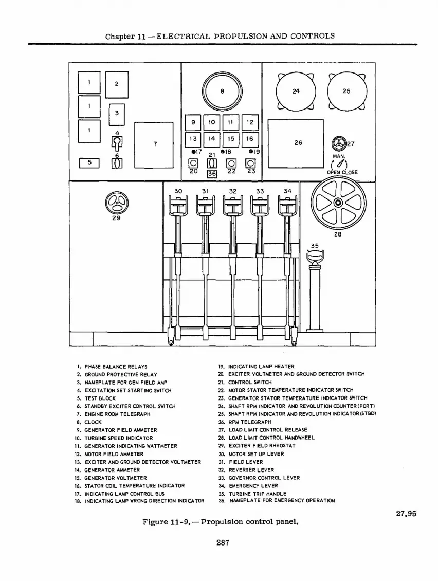
Chapter ll —ELECTRICAL PROPULSION AND CONTROLS
25 24
10 12
0 13 14 5 16 26
•17 21 *18 19 MAN.
Q] ID] 1Ö] [O] 20 22 23
r^5 OPEN CLOSE
PC? 30 32 34
OJR<3 as Q
ÛU 29
28
35
Ü=J 1. PHASE BALANCE RELAYS 19.
2. GROUND PROTECTIVE RELAY 20.
3. NAMEPLATE FOR GEN FIELD AMP 21.
4. EXCITATION SET STARTING SWITCH 22.
5. TEST BLOCK 23.
6. STANDBY EXCITER CONTROL SWITCH 24.
7. ENGINE ROOM TELEGRAPH 25.
8. CLOCK 26.
9. GENERATOR FIELD AMMETER 27.
10. TURBINE SPEED INDICATOR 28.
11. GENERATOR INDICATING WATTMETER 29.
12. MOTOR FIELD AMMETER 30.
13. EXCITER AND GROUND DETECTOR VOLTMETER 31.
14. GENERATOR AMMETER 32.
15. GENERATOR VOLTMETER 33.
16. STATOR COIL TEMPERATURE INDICATOR 34.
17. INDICATING LAMP CONTROL BUS 35.
18. INDICATING LAMP WRONG DIRECTION INDICATOR 36.
INDICATING LAMP HEATER
EXCITER VOLTMETER AND GROUND DETECTOR SWITCH
CONTROL SWITCH
MOTOR STATOR TEMPERATURE INDICATOR SWITCH
GENERATOR STATOR TEMPERATURE INDICATOR SWITCH
SHAFT RPM INDICATOR AND REVOLUTION COUNTER (PORT)
SHAFT RPM INDICATOR AND REVOLUTION INDICATOR(STBD)
RPM TELEGRAPH
LOAD LIMIT CONTROL RELEASE
LOAD LIMIT CONTROL HANDWHEEL
EXCITER FIELD RHEOSTAT
MOTOR SET UP LEVER
FIELD LEVER
REVERSER LEVER
GOVERNOR CONTROL LEVER
EMERGENCY LEVER
TURBINE TRIP HANDLE
NAMEPLATE FOR EMERGENCY OPERATION
Figure 11-9. —Propulsion control panel. 27.95
287

ELECTRICIAN'S MATE 3 & 2
Generator Ammeter.—Measuring the genera- tor line current. It has a 0- to 2000-amp scale and is red-lined at 984 amperes.
Generator Voltmeter. — Measuring the voltage output of the main propulsion generator. It has a 0- to 3500-volt scale and is red-lined at 2700 volts.
Stator Coil Temperature Indicator.—Showing the temperature of the main motor and main gen- erator stators.
Indicating Lamp Control Bus.—Showing a green light when the control bus is energized.
Indicating Lamp Wrong Direction Indicator.— Showing a red light when the reverser lever is operated in the wrong direction in response to an engine order signal from the bridge.
Indicating Lamp Heater.—Showing a red light when the main motor and generator heater are energized.
Exciter Voltmeter and Ground Detector Switch.—Selecting the circuit voltage to be read on voltmeter 13 (fig. 11-9).
Control Switch.—Energizing the control bus from the 120-volt d-c vital bus.
Motor Stator Temperature Indicator Switch.— Selecting the phase in the motor stator whose temperature is to be used.
Generator Stator Temperature Indicator Switch.—Selecting the phase in the generator stator whose temperature is to be read.
Port Shaft RPM Indicator and Revolution Counter.—Showing the instantaneous speed of the port shaft and counting its total revolutions.
Starboard Shaft RPM Indicator and Revolution Counter.—Showing the instantaneous speed of the starboard shaft and counting its total revolutions.
RPM Telegraph. — Receiving and acknowledg- ing engine orders for small changes in speed.
Load Limit Control Release. — Releasing the load limit control handwheel.
Load Limit Control Handwheel.—Limiting the maximum steam flow to the turbine at low speeds.
Exciter Field Rheostat.—Manual controlling of the exciter field voltage.
Motor Setup Lever.—Connecting the two main motors in parallel for two-motor operationorcon- necting them separately for single-motor operation.
Field Lever.—Energizing the main motor and generator fields.
Reverser Lever.—Connecting the phases of the main motor for ahead or astern rotation.
Governor Control Lever. — Controlling the main generator turbine speed and thus controlling the main motor speed.
Emergency Lever. — Controlling the generator turbine speed in the event of a casualty to the gov- ernor control lever.
Turbine Trip Handle. — Tripping the turbine steam throttle valves closed in an emergency that requires stopping the turbine.
The operating levers are the motor setup lever, field lever, reverser lever,turbine governor lever, and emergency control lever. These levers are interlocked mechanically and electrically to prevent improper operation of the equipment. See figure 11-10.
OPERATION
In contrast with the usual alternating current power systems in which the voltage and fre- quency are maintained constant, the turbine elec- tric propulsion system operates with variable voltage and frequency. The propulsion synchro- nous motors start as induction motors on reduced voltage and accelerate to a speed equal to syn- chronous speed minus the slip. Direct current is then applied to the motor fields, pulling the motor into synchronism with the generator. Thereafter propeller speed is controlled by changing the speed of the turbine which in turn changes the frequency and voltage output of the generator. For desirable operating characteristics the main propulsion generator voltage must be maintained, as near as possible, at constant volts per cycle; that is, the generator voltage must be maintained at such a value that the voltage divided by the frequency is constant. Recalling the voltage generated per phase in alternating current generators, one might surmise that constant volts per cycle would be
288
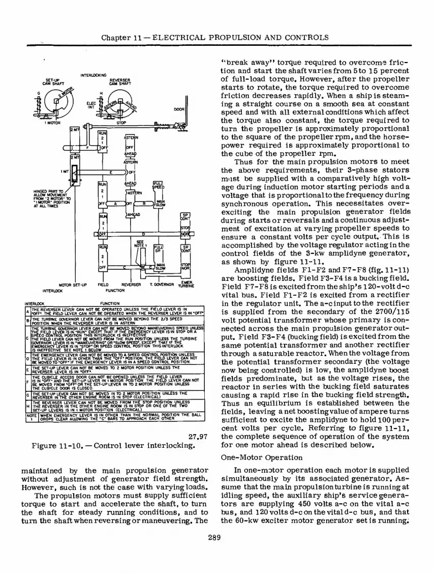
Chapter 11 — ELECTRICAL PROPULSION AND CONTROLS
INTERUXKING
SET-UP CAM SHAFT
a::
HINGED PART TO / ALLOW MOVEMENT FROM ”2 MOTOR" TO "I MOTOR" POSITION AT ALL TIMES
MOTOR SET-UP
INTERLOCK
REVERSER CAM SHAFT
m ELEC INT
DOOR
STOP
2 Ml RUN
ASTERN
OFF OFF
2 MT
ASTERN
»OFF
IFüLD RUN PEE )
MA 4 OFT SLOW
IAHÇAD RUN
CONT
5TO
NO
£ SEE NOTE 1
STOP I NOR
MAN OFF SLOW
EMER. REVERSER TURBINE
. THE REVERSER LEVER CAN NOT BE OPERATED UNLESS THE FIELD LEVER IS IN A ■OFF". THE REID LEVER CAN NOT BE OPERATED WHEN THE REVERSER LEVER IS IN “OFF*
THE TURBINE GOVERNOR LEVER CAN NOT BE MOVED BEYOND THE 2/3 SPEED POSITION WHEN THE REVERSER LEVER IS IN ASTERN
THE TURBINE GOVERNOR LEVER CAN NOT BE MOVED BEYOND MANEUVERING SPEED UNLESS THE FIELD LEVER IS IN "RUN" EXCEPT THAT IF THE EMERGENCY LEVER IS IN STOP OR A SPEED CONTROL POSITION THIS INTERLOCK IS INEFFECTIVE THE FIELD LEVER CAN NOT BE MOVED FROM THE RUN POSITION UNLESS THE TURBINE GOVERNOR LEVER IS IN "MANEUVERING" OR "SLOW SPEED". EXCEPT THAT IF THE EMERGENCY LEVER IS IN "STOP" OR SPEED CONTROL POSITION THIS INTERLOCK IS INEFFECTIVE SEE NOTE 1 BELOW
THE EMERGENCY LEVER CAN NOT BE MOVED TO A SPEED CONTROL POSITION UNLESS THE FIELD LEVER IS IN OTHER THAN THE "OFF" POSITION. THE FIELD LEVER CAN NOT BE MOVED TO “OFF" IF THE EMERGENCY LEVER IS IN A SPEED CONTROL POSITION.
THE SET-UP LEVER CAN NOT BE MOVED TO 2 MOTOR POSITION UNLESS THE REVERSER LEVER IS IN "OFF".
THE CUBICLE ACCESS DOOR CAN NOT BE OPENED UNLESS THE FIELD LEVER IS IN "OFF" AND THE SET-UP LEVER IN t MOTOR POSITION THE FIELD LEVER CAN NOT BE MOVED FROM "OFF" OR THE SET-UP LEVER IN TO 2 MOTOR POSITION UNLESS THE CUBICLE DOOR IS CLOSED.
THE SET-UP LEVER CAN NOT BE MOVED IN TO 2 MOTOR POSITION UNLESS THE REVERSER IN THE OTHER ENGINE ROOM IS IN STOP (ELECTRICAL)
THE REVERSER LEVER CAN NOT BE MOVED FROM THE STOP POSITION UNLESS THE REVERSER IN THE OTHER ENGINE ROOM IS IN STOP OR ONE OF THE TWO SET-UP LEVERS IS IN 1 MOTOR •POSITION (ELECTRICAL)
NOTE WHEN EMERGENCY LEVER IS IN OTHER THAN THE NORMAL POSITION THE BALL DROPS CLEAR ALLOWING THE "C" BARS TO APPROACH EACH OTHER
27.97 Figure 11-10. — Control lever interlocking.
maintained toy the main propulsion generator without adjustment of generator field strength. However, such is not the case with varying loads.
The propulsion motors must supply sufficient torque to start and accelerate the shaft, to turn the shaft for steady running conditions, and to turn the shaft when reversing or maneuvering. The
“break away” torque required to overcome fric- tion and start the shaft varies from 5 to 15 percent of full-load torque. However, after the propeller starts to rotate, the torque required to overcome friction decreases rapidly. When a ship is steam- ing a straight course on a smooth sea at constant speed and with all external conditions which affect the torque also constant, the torque required to turn the propeller is approximately proportional to the square of the propeller rpm, and the horse- power required is approximately proportional to the cube of the propeller rpm.
Thus for the main propulsion motors to meet the atoove requirements, their 3-phase stators must be supplied with a comparatively high volt- age during induction motor starting periods and a voltage that is proportional to the frequency during synchronous operation. This necessitates over- exciting the main propulsion generator fields during starts or reversals and a continuous adjust- ment of excitation at varying propeller speeds to ensure a constant volts per cycle output. This is accomplished by the voltage regulator acting in the control fields of the 3-kw amplidyne generator, as shown by figure 11-11.
Amplidyne fields F1-F2 and F7-F8 (fig. 11-11) are boosting fields. Field F3-F4 is a bucking field. Field F7-F8 is excited from the ship’s 120-volt d-c vital bus. Field F1-F2 is excited from a rectifier in the regulator unit. The a-c input to the rectifier is supplied from the secondary of the 2700/115 volt potential transformer whose primary is con- nected across the main propulsion generator out- put. Field F3-F4 (touckingfield) isexcitedfromthe same potential transformer and another rectifier through a saturable reactor. When the voltage from the potential transformer secondary (the voltage now toeing controlled) is low, the amplidyne boost fields predominate, but as the voltage rises, the reactor in series with the bucking field saturates causing a rapid rise in the bucking field strength. Thus an equilibrium is established between the fields, leaving a net boosting value of ampere turns sufficient to excite the amplidyne to hold 100 per- cent volts per cycle. Referring to figure 11-11, the complete sequence of operation of the system for one motor ahead is described below.
One-Motor Operation
In one-motor operation each motor is supplied simultaneously by its associated generator. As- sume that the main propulsion turbine is running at idling speed, the auxiliary ship’s service genera- tors are supplying 450 volts a-c on the vital a-c bus, and 120 volts d-c on the vital d-c bus, and that the 60-kw exciter motor generator set is running.
289

290
TD 120 VOLT DC VITAL BUS
TO 30 450 VOLT VITAL BUS
VOLTAGE REGULATOR
TO CONTROL PANEL IN OTHER ENGINE ROOM
TO CONTROL PANEL IN OTHER ENGINE ROOM
BUCK EXCITER
AMPL DYNE FIELD BOOST
FIELDS MOTOR STARTER UV PROTECTION ¡Uy 60 KW 3 Kw
125 V F7
IIOV F2 F4
AMPLIA •NJJYNE
PROPULSION / \ «CITATION MOTOR ( MOTOR )
GENERATOR SET V ! ( EXCITER
es yp 440 V
30 60/v
►HWv— RI3
THYRITE DISCHARGE RESISTOR
R8
RI4
rPiÁÁn RHEOSTAT
-.K\ RIO Y —
MAN AUTO R7 RI2
vw RI6 -I-F4
vw—1 PROPULSION EXCITAT ON BUS
• CONTACT CLOSED
REVERSER LEVER
FUSE
01—1 RELAYS > METERS
INSTS. 1 PT.
2700/115 CONTACTORS LEVER POSITION
JIUL» j
AHEAD R5 R4 R2
OFF
FLO. DISC RES.
FLD. ASTERN ADJ.-1- RES
R6 SET-UP LEVER 14-15
MOTOR FIELD CONTACTORS
POS. GEN. FIELD
1 MOTOR
2 MOTOR — TURBINE
P MOTOR 6000 HP 2700 V
30 931/3/v 400 RPM FIELD LEVER
E CONTACTORS
It
POS GND. RELAY
F5 22
OFF C.T 1200/5 GENERATOR 2700 V
30 931/3/v 4600 KVA 5600 RPM
GND. PROT. CX.
R9 RUN
27.98
Figure 11-11. — Simplified schematic diagram of control circuits for one screw.
EL
EC
TR
ICIA
N’S
MA
TE
3 &
2

Chapter 11 — ELECTRICAL PROPULSION AND CONTROLS
Assume the throttleman is in the after engineroom. The positions of the control levers are as follows:
Setup lever — one motor Reverser lever — off Field lever — off Turbine governor lever — maneuvering speed Emergency turbine governor lever—normal Turbine load limit handwheel — open Exciter control switch —off
Turn the exciter control switch to the automatic position. This action connects the voltage regula- tor in the amplidyne field circuits and the armature output of the amplidyne to the 60-kw exciter field. Since the main propulsion generator field is open there will be little or no voltage from the potential transformer secondary and consequently ampli- dyne fields F1-F2 and F3-F4 will not be excited.
Field F7-F8 is excited from the 120-volt d-c vital bus through resistors R12-R14 to supply a small amount of boosting excitation just sufficient to raise the exciter voltage to a value which will ensure correct polarity and a fairly rapid rise of generator field current when the field lever is moved to position one.
Move the reverser lever to the ahead position. This action closes the main line contactors 1, 3, and 5 connecting the generator and motor with the proper phase sequence for ahead rotation.
Move the fieldlevertopositionone.The gener- ator field contactor 21 closes and contactor 20 closes to bypass resistor R6 in the generator field circuit. Contactor F3 closes and F2 opens to insert maximum saturable reactor turns in series with amplidyne field F3-F4 allowing approximately 120 percent volts per cycle generator output. Contac- tors F4 and F5 close, increasing the excitation supplied to field F7-F8 to about 4 times a normal value. The amplidyne armature voltage increases to about 3 times normal, the exciter and main pro- pulsion generator fields increase to a value ap- proaching 3 times normal. During this time the main propulsion motor is starting as an induction motor. The motor field is not energized but is closed on itself through discharge resistor R5. This resistor is connected across the motor field only while the motor field contactor 22 is open. Discharge resistor R1 is connected across the generator field only while the generator field con- tactor 21 is open. Discharge resistor R8 is a spe- cial type thyrite resistor and is permanently con- nected across the exciter field. During the period while the motor is starting and accelerating as an induction motor, the line current indicated by the generator ammeter will increase rapidly and may
go off scale. When the current decreases to ap- proximately 1300 amperes, move the field lever to position two. Contactor 22 closes to energize the motor field through the synchronizing current limit resistor R2 to obtain proper conditions for synchronizing. Contactor 23 also closes. The volt- age regulator continues to maintain 120 percent volts per cycle on the generator. As soon as the line current steadies, indicating that the motor has pulled into synchronism, move the field lever to the RUN position.
Contactor 24 now closes shorting out synchro- nizing resistor R2, and contactor 20 opens in- serting R6 in the generator field. This sets the proper relationship between generator and motor field current for normal operation. Contact F3 opens and contact F2 closes setting the volts per cycle held by the voltage regulator to the normal 100 percent value. The turbine governor lever can now be moved to increase speed as desired and the turbine load limit handwheel can be adjusted to give the desired steam flow.
NOTE: When the field lever is in position one and the motor is operating as an induction motor, the generator is highly overexcited; therefore, the motor should be synchronized as soon as possible. The field lever must not be left in position one for more than one minute.
Two-Motor Operation
Two-motor operation consists of both motors in parallel and supplied by one main propulsion generator. Control is exercised from the engine- room in which the active generator is located. The motor setup levers in both enginerooms must be moved to the two-motor position. This action closes contactors 7, 8, and 9 paralleling the 3- phase stators of the two motors.
Contactors 14 and 15 close paralleling the motor fields. Contactor 13 closes inserting resis- tor R4 in parallel with synchronizing resistor R2 to provide proper motor field current adjustment for two-motor synchronization. As the two motors cannot be operated properly during the induction motor period with a common field discharge resis- tor, contactors 10 and 12 close and contactors 11 and 13 open allowing separate field discharge re- sistors. This circuit cannot be shown completely in the one line diagram in figure 11-11.
The control lever operating sequence is the sarnie for two-motor operation as described for one-motor operation. The generator line current ammeter will go off scale during field lever po- sitions one and two. As soon as the meter returns to scale the lever may be moved to the next
291

ELECTRICIAN’S MATE 3 & 2
position. About 80 percent of full speed is obtain- able during two-motor operation (one generator).
Reversing or Stopping
To reverse or stop the drive system, return the turbine governor lever to the MANEUVERING SPEED position. Return the field lever to the OF F position without pausing in position ONE or TWO. With the reverser lever inthe OFF position, pause for approximately 5 seconds and then move the reverser lever to the desired position. In the event of acrashstoporreversal,this pause should be omitted. Next, operate the field lever in the proper sequence for synchronizing to the RUN po- sition. The turbine governor lever can now be op- erated to increase the speed as desired.
Manual Control of Excitation
In the event that the voltage regulator becomes inoperative, turn the standby excitation control switch 6 on the control panel (fig. 11-9) to the MANUAL position. This action cuts the regulator out of the circuit so that the excitation can be controlled by means of the exciter field rheostat 29.
To prevent overloading the propulsion equip- ment when under manual control, do not exceed the generator field current values specified for the various speeds on the nameplate 3. The speci- fied values of field current are maximum for safe continuous operation.
The change from automatic to manual control of/ excitation or vice versa can be made at any time. Before the change is made, however, the exciter field rheostat should be turned to the posi- tion that gives maximum generator field current. Immediately after the control is switched to manual, adjust the generator field current to the proper value corresponding to the propeller rpm indicated on the nameplate.
Ground or Phase Balance Relay Operation
If a protective relay operates and trips open the propulsion field circuits, place the turbine gov- ernor lever in the MANEUVERING-SPEED posi- tion, return the field lever to the OFF position, return the reverser lever to the OFF position, remove the excitation and control power, and shut down the turbine generator by tripping the throttle valve.
If the setup levers were in the TWO-MOTOR position at the time the relay operated, the setup levers should be returned to the ONE-MOTOR po- sition. Remove the generator neutral ground con- nection by disconnecting the ground current limit
resistor R9 (fig. 11-11). With all circuits deener- gized use an insulation-resistance tester to locate the ground or fault. If the motors were operating in parallel at the time the relay operated, the fault may be in either motor circuit.
Emergency Excitation
If failure of one or both of the 60-kw propulsion exciter motor-generator sets occurs, an emer- gency connection can be made to utilize one of the 40-kw, 120-volt d-c ship’s service generators to provide the necessary propulsion excitation. This emergency connection requires disconnecting the 60-kw exciter from the propulsion excitation bus and connecting the 40-kw ship’s service generator through its circuit breaker to the propulsion ex- citation bus by a temporaiy cable. With this emer- gency connection the 40-kw generator will supply power to only the excitation bus in the same engine room.
Thus, if one 60-kw propulsion exciter motor- generator set is out of service, the 40-kw ship’s service generator in that engineroom can be con- nected to the propulsion excitation bus. The ship can then be operated at approximately full power with the regular propulsion exciter motor- generator set supplying propulsion excitation for one screw and the 40-kw d-c ship’s service gen- erator supplying emergency excitation for the other screw.
If both 60-kw propulsion exciter motor- generator sets are out of service, either the after or forward 40-kw generator can be connected to the corresponding propulsion excitation bus and one propulsion generator, to obtain two-motor operation.
Assume that the forward 40-kw ship’s service generator is to be used to supply emergency ex- citation' for the propulsion system (fig. 11-12). Operation of the ship will then be from the forward engineroom using the forward propulsion genera- tor and the two propulsion motors on two-motor operation. The ship’s service a-c and d-c power must be obtained from the after engineroom. Similarly, the after 40-kw ship’s service genera- tor and after propulsion generator could be con- nected and operated. The forward ship’s service generator would then be required to provide ship’s service power.
It is obvious that both 40-kw ship’s service generators cannot be used for propulsion exci- tation at the same time. Likewise, it will not be possible to use a remote ship’s service generator for the excitation supply.
292

293 FORWARD MACHINERY SPACE
EXCITER
MOTOR-
GENERATOR
SET
TAPE
DS ® \ri EN
VITAL PROPULSION
AUXILIARY PANEL
PROPULSION
CONTROL PANEL 60 KW
GEN
\¿?U EXCITATION
BUS ®( © ©c B5 HP
J 1/© MOTO I
-t S < 120V D.C.
CONTROL
POWER
© STAND-BY
EXCITATION
CONTROL
SWITCHv
O-ji o MAN. AUTO.
/ © UM/— DG.
RESTRICTED
BUS
D.C.
VITAL
BUS
A.C.
RESTRICTED
BUS
VITAL
BUS 40 KW GEN
300K
GEN
SHIP'S SERVICE
GENERATOR SET
\ TURBINET/
SHIP'S SERVICE GENERATOR
AND DISTRIBUTION SWITCHBOARD
AFTER FIRE ROOM NOTE:
THE DIAGRAM SHOWS THE BREAKER POSITIONS WHEN THE FORWARD 40 KW GENERATOR
IS CONNECTED FOR PROPULSION EXCITATION. THE AFTER PROPULSION MACHINERY IS
BEING EXCITED FROM THE AFTER 60 KW MOTOR-GENERATOR SET. SHIP’S SERVICE LOAD
IS BEING SUPPLIED FROM THE AFTER SHIP'S SERVICE GENERATOR.
A SIMILAR PROCEDURE IS FOLLOWED WHEN CONNECPNG THE AFTER 40 KW GENERATOR
FOR PROPULSION EXCITATION.
AFTER MACHINERY SPACE
PROPULSION CONTROL PANEL
4 1
VITAL PROPULSION
AUXILIARY PANEL VARE
ENDS
EXCITER
MOTOR-
GENERATOR
SET
60 KW
GEN
>
u
D.C. A.C.
RESTRICTED
BUS
_ \_
AC.
VITAL
BUS-
EXCITATION
BUS
D.C
RESTRICTED < VITAL 85 HP
MOTOR BUS BUS
\ S <
\MJ STAND-BY
EXCITATION
CONTROL
SWITCH 3
I20V DC
CONTROL( 40KW
GEN POWER SHIPS
SERVICE
Í GENERATOR
MAN. AUTO. SET
SHIP'S SERVICE GENERATOR''
AND
DISTRIBUTION SWITCHBOARD
300 K
GEN
\TURBINE /
TEMPORARY CONNECTION WHEN USING AFTER
46 KW GENERATOR FOR PROPULSION EXCITATION
27.99
Figure 11-12. —One-line diagram of emergency power for propulsion field excitation.
Chapter 11 —
EL
EC
TR
ICA
L P
RO
PU
LSIO
N A
ND C
ON
TR
OL
S

ELECTRICIAN’S MATE 3 & 2
The operation of the propulsion plant will be different from normal and somewhat restricted because the 40-kw generator does not have as large an overload rating as the 60-kw exciter.
To connect the forward 40-kw generator to supply propulsion excitation, it is necessary to first have the after ship’s service turbine- generator set warmed up and ready for operation. Then, in the forward engineroom, perform the following steps in sequence.
® At the vital propulsion auxiliary panel, trans- fer all a-c and d-c loads to the remote source of vital power and open the excitation motor- generator circuit breaker.
o At the ship’s service generator and distribu- tion switchboard, transfer all auxiliary a-c and d-c loads to the remote source of power. Open the a-c generator circuit breaker 1, open the gen- erator field switch 2, open the d-c generator cir- cuit breaker 3, open the d-c breaker for the forward vital propulsion auxiliary switchboard 4, open the d-c breaker for the after vital propul- sion auxiliary switchboard 5, turn the 40-kw gen- erator field rheostat 6 to the minimum d-c voltage, and open the d-c bus tie breaker 7. After testing for zero volts, open the disconnect switch links 8 on the load side of the d-c generator circuit breaker.
® At the 60-kw exciter, disconnect the armature and field leads. Tape all the leads from the exciter and the two field line leads. Connect one end of the shore power cable to the armature line lead 9 and the other end to the disconnect link 8 at the switchboard. Be sure to maintain proper polarity. To reduce heating of the shore power cables, parallel two leads for one leg and use the third conductor for the other leg,
o At the d-c restricted bus section of the forward ship’s service and distribution switchboard, close the d-c bus-tie circuit breaker?; close the 40-kw, d-c generator circuit breaker 3 and lock it; and adjust the propulsion excitation by means of the ship’s service generator field rheostat 6.
A similar procedure is followed when connect- ing the after 40-kw generator to supply emergency power for propulsion excitation. When either 40- kw generator is used, very little torque will be available for starting or reversing because over- excitation (normally supplied to the generator field during starting) cannot be obtained from the 40-kw generator. However, if the operations are properly executed, one motor can be started and synchro- nized successfully even though the ship is dead in the water. One motor canbe successfully reversed when there is a small headway on the ship. During starting and reversing, the current from the 40-kw
generator will exceed the rating of the machine for short intervals of time. As soon as possible after synchronizing, the propulsion generator excitation current should be reduced to the recommended value for manual control of excitation.
To START and RUN one motor, move the pro- pulsion control levers to the positions for normal starting on one motor. Turn the standby excitation control switch to the MANUAL position. Be cer- tain that the 40-kw generator is running at rated speed. Raise the d-c generator voltage as high as possible by means of the d-c generator field rheo- stat (this voltage can be read as exciter volts on the propulsion control panel). Place the field lever in position ONE. When the shaft rpm and line cur- rent are steady move the field lever quickly from position ONE to the RUN position without pausing in position TWO. The propulsion motor should synchronize and run.
Lower the excitation voltage until the propul- sion generator field current corresponds to the specified value for the existing propeller rpm. Adjust the propeller rpm by means of the turbine governor lever. When raising the propeller rpm, watch the 40-kw generator current. When it reaches 330 amperes, the propeller rpm (and therefore the propulsion generator field current) should not be raised any further. The idle propeller will turn unless locked. If allowed to turn, be cer- tain that lubricating oil is supplied to the thrust block and line shaft bearing.
To reverse the direction of the ship when op- erating on one motor, drop the propeller rpm to 100 or less and allow the ship to settle down to this speed. Place the turbine governor lever in the MANEUVERING-SPEED position. Move the field lever to the off position. Move the reverser lever in the desired direction. Raise the d-c gen- erator voltage as high as possible by the d-c generator field rheostat.
Place the field lever in position ONE. When the shaft rpm and line current are steady, move the field lever quickly from position ONE to the RUN position without pausing in position TWO. The propulsion motor should synchronize and run.
Lower the excitation voltage until the propul- sion generator field current corresponds to the specified value for the existing propeller rpm. Ad- just the propeller rpm by means of the turbine governor lever. When raising the propeller rpm, watch the 40-kw generator current and do not allow it to exceed 330 amperes.
To run on two motors with reduced excitation for the turbogenerator in use, first get the ship underway on one motor. Raise the speed until the idle propeller turns without power. Remove power
294

Chapter 11 — ELECTRICAL PROPULSION AND CONTROLS
from the active screw and allow the ship to slow down until both propeller speeds are equal. Move the setup levers in both enginerooms to the TWO- MOTOR position. Restart the motors, as pre- viously explained, for ONE-MOTOR operation.
Adjust the propeller rpm by means of the turbine governor lever. Adjust the propulsion gen- erator field current to the value specified for manual excitation control. When raising the pro- peller rpm do not permit the 40-kw generator current to go beyond 330 amperes.
A reversal of the direction of the ship should not be attempted when operating on two motors. Reversal can be accomplished when operating on two motors, however, by placing both setup levers to the ONE-MOTOR position and allowing the shafts to slow to 100 rpm and then follow the procedures previously explained for reversal on one motor.
Emergency Blocking of Electrical Interlocks
The electrical interlocks previously described can be blocked out manually in an emergency when control power is lost.
If control power is lost in the forward engine- room and it is desired to operate on one motor alone, the forward engineroom reverser interlock must be blocked out.
If it is desired to operate on two motors and the after engineroom is to control, the forward engineroom setup lever interlock must be blocked out. The reverser in the forward engineroom must be left in the OFF position. On the other hand, if the forward engineroom is to control, the for- ward engineroom setup lever interlock and the reverser interlock must be blocked out. The re- verser in the after engineroom must be left in the OFF position.
OPERATING RECORDS A constant check of all machinery and units in
operation must be made by the men on watch in the machinery spaces. The data obtained by the watch- standers is entered on records referred to as op- erating records. These records, in addition to en- suring frequent observation of all machinery in operation, provide a basis for analyzing machinery performance.
The a-c/d-c Electric Propulsion Operating Record, NavShips 3647 (fig. 11-13 A, B), is used on all surface ships equipped with a-c or d-c elec- tric drive. The record is maintained by the Elec- trician’s Mate standing the throttle watch. Spaces are provided on both the front and the back for data concerning the main propulsion equipment.
The electrical log is a complete daily record (from midnight to midnight) of the operating con- ditions of the ship’s electric propulsion plant. The log sheet must be kept clean and neat. Any cor- rections or changes to entries for a watch must be made by the man that signs the log for that watch. However, correctionsor additions must not be made after the log sheet has been signed by the engineer officer without his permission or direc- tion. The station logs are turned in to the log room every morning for the engineer officer’s signature and for filing.
The back of the log is a continuation of the front, and also provides spaces for the signatures of the engineer officer and senior Electrician’s Mate.
LEGAL RECORDS
The Engineer’s Bell Book and the Engineering Log are official legal records. They can be used in any military or civilian court as final proof of any action taken on or by the ship, and as evidence for or against any officer or enlisted man of the ship’s crew who may be brought before the court or board.
The Engineer’s Bell Book and the Engineering Log must be preserved as a permanent record on board for a three-year period after date of last entry unless they are requested by a naval court or board, or the Navy Department. In such a case, a copy (preferably photostatic) -of such sheets that are sent away from the ship are pre- pared and certified as a true copy by the engineer officer for the ship’s files. At the end of the three- year period these records may be destroyed. When a ship is stricken, if either record is less than three years old, it should be forwarded to the near- est Naval Records Management Center.
ENGINEER’S BELL BOOK
The Engineer’s Bell Book (NAVSHIPS 3l20/l fig. 11-14) is a record of all bells, signals and orders, and of the time they are received regarding the movement of the ship’s propellers. The entries are generally made by the throttleman. Whenever the ship is entering port, leaving port, or maneu- vering, an assistant should make the entries, thus enabling the throttleman to give full attention to the signals, bells, and orders.
295

ELECTRICIAN’S MATE 3 & 2
ALL PREVIOUS EDOTONS ARE «SOLETE AC/DC ELECTRIC PROPULSION OPERATING RECORD—SURFACE VESSELS ONLY NAVSHIPS 3647 (REV. 4.36)
I. MOICATE *P OR *C IN COLUMN HEADINGS FOR AU TEMPERATURE READINGS INSTRUCTIONS 2. USESEPARATESHEETPOREACHSHAPT, EXCEPT ON VESSELS WITH MORE THAN TWO GENERATORS OR TWO MOTORS PER SHAFT. IN WHICH CASE USE SHEETS AS REQUIRED.
3. RETAW THB RECORD ON ROARD FOR TWO YEARS AFTER WHICH TIME IT MAY SE DESTROYED IN ACCORDANCE WITH CURRB4T DISPOSAL REGULATIONS.
uss SHAFT GENE RATOS MOTORtS)
ANO
SET QOCU AHEAD OR SACK MMUTES AT. DATE
1 June TIME ZONE
+5 WETDECK. DE-183 19- GENERATOR NO. MOTOR NO.
TEMK" AIR TEMP AIR TEMP TEMP HOUR REMARKS ARM FIELD
VOLTS
FIELD
AMPS
ARM
VOLTS
ARM ARM FIELD
VOLTS
FIELD ARM FIELD FIELD
AMPS OUT INx 'OUT OUT RPM RPM
AMPS VOLTS AMPS AMPS VOLTS VOLTS VOLT
z 0100 110 115 6Q 22QÍ 180(700 80 135 UQ 120
5 7 0200 60 110 22£A 2201
180Í TOO 50 BO 130 110 50 135 115 0200 110 1S0Í2QQ SO 130 50 110 a? 135 115 0400
r=r 3 PI 0800-1200
Routine eteamlng watch Condltlone—normal
~~ ,
set nvnu Slot
AC/DC ELECTRIC PROPULSION OPERATING RECORD—SURFACE VESSELS ONLY NAVSHIPS 3647 (REV 4-36) BACK
GROUND DtT VOLTS SHAFT NO HIGHEST TEAAPERATURES A. C STATOR TOTAL PROP
GEN NO JilMTR. NO.^Z MO- EXOT EXCITATION PROPULSION GEAR NO GEN MTR. PIN NO HOUR LOOP THR'T TOR REMARKS BUS COUNTER RPM BEAR AMPS FELD BEAR.
P IMG f* VOLTS
AMPS
60 120 110 no 1729.70 115 0200 60 120 W952Q 110 115 110
186170 0200 120 110 110 115 0400
ENGINEER OFFICER. USN.
B
77.232
Figure 11-13. — A-c/d-c electric propulsion operating record-surface vessels only. NAVSHIPS 36471 A (front), B(back).
296

Chapter 11 — ELECTRICAL PROPULSION AND CONTROLS
INCINIIB'S Bill BOOK • AU VISSILf
NAVSHIPS 3l?0 I iKfv 10-6^1 ifoin'eilj' NAVSHIP5 \ 16)
S/N 0103-601 - 9463
0 SHIP
TYPE / HULL 'NUMBER
ENGINEER’S BELL BOOK
USS HOEL
D D G 0 1 3
27 •? to Co
0 4 0 0 1 0 1
Ship Nome
□ SHAFT
NUMBER(S)
0 0 0 S
U/c£
En routa (rom
Rocorti of aM "BELLS.” SIGNALS, and ORDERS rwafvod raoardlna movamant of prapoflara thft data. , NORFOLK , VA. .. CADIZ, SPAIN 1 0_ ,2300
(3)
SIGNAL
131
R.PM.
14)
COUNTER
(2)
SIGNAL COUNTER
OR PITCH SET
1600 fu^NÍN§ SEAR 214122
1600 MEGHAN COUNTEJ
GAL R_
999210
1742 DISENG/ GED TURNINl i GEAR 214631
1744 TESTED ENGINE 214634
1758 UNDERWAY 214651
1800 COUNTI R 214660
1801 1/3 32 214660
1803
1805
2/3 78 214730
02/3 214870
1805
1805
214883
BF 214891
1806 BEM 110 214913
1816 214999
1818 1/3 32 215030
1819 2/3 2L 21515L
-0740-
1900 COUNT 218341
1902 11 218500
1920 122 220480
MMFtf ?■ /?. ~ TylSsux.
LT.USH
2000 COUNTE 225360
2009 110 226352
21 ( COUNT i R 232952
2200 COUNT : R 239552
MM3 3. CDs ÂA.
x.y*?. ïtkru. S>¿TJ4,L¿S (
2400 COUNT
MM3
S R 246150
3 .CL’A&t
&
Figure 11-14. — Engineer’s bell book, NAVSHIPS 3l20/l 77;230

ELECTRICIAN’S MATE 3 & 2
Here is a list of instructions for keeping the Engineer’s Bell Book:
1. Use a separate sheet for each shaft each date, except on small ships and craft where the keeping of separate sheets for separate shafts is not practicable. All sheets for the same date should be filed together as a single record. (Entries in the Bell Book shall be made at the time of receipt of each order.) The records for each throttle con- trol station for each day must begin with a new sheet, and the day’s records for all stations must be clipped together and filed as a unit.
2. In column 1, enter the times according to the system used in the Engineering Log.
3. In column 2, enter the signal received. If the signal is transmitted by the engine
(motor) order telegraph, use the following symbols:
Z—stop l/3—ahead one-third speed 2/3—ahead two-thirds speed
I—ahead standard speed II —ahead full speed
III —ahead flank speed
Backing signals for l/3 and 2/3 speed shall be entered as “B l/3” and “B 2/3”, respectively. Signals for full back and emergency back shall be entered as “BE” and *‘BEM” respectively. On small ships and craft, using a single sheet for two or more shafts, the above symbols shall be used with an additional preceding symbol “P,” “S,” or “C” (for port, starboard, or center shaft, re- spectively) if the signal is directed to other than all shafts.
If the signal is transmitted by the engine re- volution telegraph without change in the engine (motor) order telegraph, the number of propeller revolutions signaled shall be entered in column 2. In this case, entries shall not be made in column 3.
4. In column 3, make an entry for each signal received on the engine order telegraph for the propeller corresponding to the engine order tele- graph signal. When a signal is received simul- taneously on the engine order telegraph and the engine revolution telegraph, make appropriate entries in both column 2 and column 3. The rpm entered in either column 2 or column 3 is, in each case, the propeller rpm ordered and not the propeller rpm resulting from the order. For submarines, however, record resulting propeller rpm when plant condition order is given.
5. In column 4, enter the engine counter read- ing at the time the change is made. Also, enter the counter reading each hour on the hour. For ships and craft equipped with controllable reversible pitch propellers, record in column4 the propeller pitch in feet and fractions of feet set in response to a signaled speed change, rather than the shaft counter readings. The entries for astern pitch shall be preceded by the letter “B”. Eachhour on the hour entries shall be made for counter read- ings, thus facilitating the calculation of engine miles steamed during those hours when the propel- ler pitch remains constant at the last value set in response to a signaled order.
6. Before going off duty, the engineer officer of the watch shall sign the Bell Book in the line following the last entry for his watch and the next officer of the watch shall continue the record immediately thereafter. In machinery spaces where an engineer officer of the watch is not stationed, this record shall be signed by the senior petty officer of the watch.
7. Maintain the Bell Book at the station from which the engines are being controlled. When control is shifted, from one station to another staton, the last entry in the Bell Book at the station from which control is being shifted shall indicate the time that control was shifted and the first entry in the Bell Book at the station to which control is shifted shall indicate the time when control was taken. ' The person in charge of the watch station at which the Bell Book is maintained shall sign the Bell Book in the same manner as prescribed for the engineer officer of the watch.
8. Alterations or erasures are not permitted. Correct an entry which is incorrect by drawing a single line through it and making the correct entry on the following line. Such deleted entries shall be initialed by the engineer officer of the watch, senior petty officer, or OOD (in the case of ships and craft equipped with controllable reversible pitch propellers), as appropriate.
9. For ships with automated bell loggers, in- clude the automatic bell logger sheets in the En- gineer’s Bell Book. Limit manual recording of data to data not recorded by the automatic bell logger. The engineer officer of the watch shall sign the automatic bell logger sheets before going off duty. When the automatic bell logger is out of commission, follow the normal procedure for re- cording bells in the Engineer’s Bell Book.
298

Chapter 11 — ELECTRICAL PROPUSLION AND CONTROLS
10. Fill in the top section of the Bell Book as follows:
In spaces 3 and 4, enter the first two letters of ship type and enter remaining letters as appro- priate in the next two shaded unnumbered spaces. In spaces 5-7, enter three-digit ship hull number; if hull number consists of four digits, enter the first digit in the shaded unnumbered space. For example:
DD-X 848 CVS'! :X:::X032 DD0I$: •Í058
In boxes 10-11 consecutively number sheets at each recording station beginning with 01 for the first sheet for each day starting with 0000 local time (time zone used in the Engineering Log).
In box 12, enter last digit of current year. In box 13-14, enter two digits to indicate current month, e.g., 02 = February. In box 15, enter the letter designation for time zone used to record time entries. In boxes 16-17, enter two digits for the day of the month. Start a new sheet when the day changes.
In boxes 74-77, enter all shafts for which this sheet applies, i.e., 1,2,3,4,P=Port, S=Starboard, C=Center, and M=Secondary propulsion motor.
In box 78, enter the appropriate code for highest security classification of data entered on this form. T = TOP SECRET; S = SECRET; C= CONFI- DENTIAL; U= Unclassified.
Any entry in box 79 indicates special security handling; leave blank unless special instructions are received.
11. When directed to make duplicates of sheets, use Duplicate Engineer’s Bell Book (NAVSHIPS 3l20/lD) and follow the additional instructions on the back of it. Check forms for completeness and accuracy prior to submission.
ENGINEERING LOG
The Engineering Log NAVSHIPS 3120/2, (not shown) is a midnight-to-midnight daily record of the ship’s engineering department. It is a complete daily record, by watches, of important events and data pertaining to the engineering department and the operation of the ship’s propulsion plant. The log must show the average hourly speed in re- volutions and knots, the total engine miles steamed for the day, and all major speed changes, draft and displacement; fuel, water, and lubricating oil on hand, received and expended; the engines, boilers, and principal auxiliaries in use, and all changes therein. All injuries to personnel oc- curring within the department and casualties to material assigned to the department, and such other matters as may be specified by competent authority, are entered into the engineering log.
The original entries in the log, neatly prepared in pencil or ink, is the legal record. The remarks must be prepared and signed by the engineering officer of the watch, or day, before leaving his station or being relieved. Any errors must be overlined and initialed by the personpreparing the original entries.
The engineer officer must verify the accuracy and completeness of the entries and sign the log daily. The commanding officer must sign the log on the last calendar day of each month, and on the date of relinquishing command.
299

CHAPTER 12
CENTRAL OPERATIONS SYSTEMS
Advances in engineering technology, the use of solid state devices, and computer circuitry have made it possible to automate shipboard engineering plants. The automation concerns ship control and plant surveillance mainly. Though different types of automated engineering plants, or central operations systems, have been in- stalled on Navy ships (mostly auxiliary ships), all major surface ships under construction will be equipped with some form of a central operations system. There will be no attempt here to describe each different system, but instead you will be given a general description of a representative central operations system.
GENERAL DESCRIPTION The automated engineering plant brings
together in one location all the major control
functions and indications formerly located throughout the engineering spaces. Such a central operations system (COS) incorporates major advances in boiler control, turbine control and plant surveillance, and provides direct control of shaft speed and direction from a console located on the bridge of the ship. By means of the bridge throttle control, the OOD has a better feel of the ship and gets faster responses to desired changes. Moreover, fewer watch- standers are needed to operate the engineering plant.
Major units of the central operations system are shown in figure 12-1. The bridge and engine- room consoles control the propulsion plant. Information on plant conditions is provided by instrument displays, audible alarms, indicating lights, meters, and printout typewriters.
A
©
© ELECTRICAL SECTION
© ELECTRICAL SECTION
© PROPULSION SECTION
© BOILER SECTION
@ AUXILIARY SECTION
DATA LOGGER SECTION
@ DATA LOGGER SECTION
INFORMATION DISPLAY
BRIDGE CONSOLE
ENGINE ROOM CONSOLE
MONITOR AND
ALARM © ©
SUB-LOOP CONTROLS PROGRAM
CONTROLS
SENSORS AND
ACTUATORS
DATA LOGGER
TACHOMETER
¿/ Ù
PROPULSION PLANT
CONTROL 9B¿
Figure 12-1. —Automatic propulsion system major unitSi 27.344
300

Chapter l2—CENTRAL OPERATIONS SYSTEMS
ENGINEROOM CONSOLE
The engineroom console (fig. 12-2) is the heart of the COS, and is divided into five functional sections: generators, propulsion ma- chinery, boilers, auxiliaries, and data logger.
The desk top of each console section houses the controls and devices which must toe within the operator’s reach» The vertical surface above a desk top is primarily used for instruments and other visual indicators. Significant readings of plant conditions are displayed on vertical scale.
■arme UUftU
TS
FRONT VIEW
fr it
w I
»
133 EES lii
B. REAR VIEW
Figure 12-2, — Engineroom console, 27.345
301

ELECTRICIAN’S MATE 3 & 2
3^9 ago ego
Ö o
p
[X'.-l
•)*
IV.
ti ti Mt ■ • ■< «9
ii L >.,.. U.JL -A. J >• -./nr
„.A. I L. • i v >
Figure 12-3. — Generator section. 27.346
flush-mounted electric meters. Readings which need to be checked continuously are displayed on digital (direct-reading) meters which the operator connects to the desired sensing device by dialing the “address” of the device through a switching system. These digital meters are called “digital demand display read-outs.”
In addition to permitting the operator to monitor all important functions and conditions in the plant without leaving his station, the COS automatically and continuously monitors tempera- tures, pressures, levels, and motor conditions at over 200 points in the plant. If any of these points go over or under their proper operating limits, the system alerts the operator by sounding an alarm, and a printout typewriter records the address, value, time and date in red ink.
Generator Section
The generator section (fig. i2-3) of the engineroom console can both monitor and control
the ship’s service generators. From this section the operator can adjust the frequency and voltage of each generator. He can monitor the output of each generator, and know the amount of current in each bus tie and in the shore power connection. He can monitor and operate any circuit breaker in the generators, bus ties, and shore power connection. He can test switchboard busses for grounds, and monitor and operate the space heaters in idle generators.
Starting the generators must be done at the generators. To achieve plant automation, many of the auxiliaries that are steam driven on conventional ships have been replaced with electric motor-driven units. Steam-driven aux- iliary machines are started by lining up steam, lubricating, and condensate systems at the machines. Once running they can be controlled from the consoles.
Propulsion Section
The propulsion section of .the engineroom console (fig. 12-4) contains the throttle controls
302

Chapter 12—CENTRAL OPERATIONS SYSTEMS
9 9 b
#
27.347 Figure 12-4. — Propulsion section.
and transfer switches, engine order telegraph, shaft revolution indicator-transmitter, and the necessary gages and indicators for monitoring the operating conditions of the main turbines, reduction gears, and propeller shaft.
The throttle control handwheel controls the position of pilot valves on hydraulic power actuators. The hydraulic power actuators, in turn, open or close the main steam valves to the ahead and astern turbines, thus controlling the speed and direction of the propeller shaft.
An alternate electrical control and a direct mechanical control of the throttle are also provided. Throttle control may also be shifted to the bridge control console, but may be reclaimed by the engineroom personnel at any time.
Boiler Section
The boiler section (fig. 12-5) contains the necessary pressure, temperature, and level indicators and alarms for monitoring boiler
303

ELECTRICIAN’S MATE 3 & 2
i
« 9 J| LJ LJ
m 9 O O O Q O O
OU
9
27.348 Figure 12-5. — Boiler section.
operation. This section also mounts an under- water log speed indicator and a sound-powered
x telephone handset and jack. Depending on the manufacturer of the controls, the automated combustion controls and burner management for the boilers are combined either on one section of the console or on a separate console located in a central engineering operation station.
Auxiliaries Section
The auxiliaries section (fig. 12-6) provides for remote operation (start and stop) of equipment, such as fire pumps, condensate and circulating pumps, and ventilation systems. It also monitors nonvital systems, such as potable water, air conditioning, and refrigeration. This section also
contains three digital demand meters. These meters will display, upon demand, any one or any three simultaneously, of approximately 170 different readings relating to the boilers, fuel and lube oil, main condensers, main turbines, ship service generators, and auxiliary machinery. To obtain a reading, the operator looks up the number (address) of the function he wishes to read on the function address nameplate located on the data logger section and turns a thumbwheel switch beside the digital demand meter to this address. The meter will then display the value of the function selected. The same function may be selected and read on all three meters or three different functions may be displayed simultaneously.
Data Logger Section
The data logger section (fig. 12-7) consists of plant performance data logging, alarm scanning, and bell logging equipment. The plant performance
S Í53SRE
Q m aa &&&&<£> © © * © © © © M
s u
m
I :
27.349 Figure 12-6. — Auxiliaries section.
304

Chapter l2—CENTRAL OPERATIONS SYSTEMS
TO
GENERAI ^ Elif TIU dvUot Ofumùtnt Sfá/am ' I
Kiä mm W® 3v.{ '
4X • #
I n rk MI H 6 Q
Figure i2-7. —Data logger section. 27.350
logging equipment can toe set up to print, either automatically at regular time intervals, with continuous scanning of all sensor points or on demand. Abnormal conditions are printed in. red by the performance typewriter.
The bell log typewriter (on the right) records each engine order telegraph (EOT) signal along with time and date, throttle control location (bridge or engineroom) and mode of operation (bridge, engineroom, direct and manual), throttle control wheel position (bridge or engineroom), and shaft rpm.
Under normal operation, any change of 5 rpm in shaft speed will produce a printout; however, there are circuits to allow for 10 rpm changes in bad weather, if the shaft is expected to come out of the water (fig. 12-8).
The bell log typewriter can be used for Performance Data if conditions require overhaul of the opposite typewriter.
The Performance Data Logger (on the left, fig. 12-7) will print out in sequence all functions whether in alarm condition or not, and the printout of alarm conditions will toe in RED. In an emergency, either logger can be used for the opposite log. When the alarm conditions are clear, the printout will be in BLACK. If a status request is in effect, the typewriter will continue to print out the remainder of plant status.
On the printout sheet, time and date appear on every 16th line, or unit of 20 numbers, since this part of the system uses an octal computer system and in the octal system, the final digits 8 and 9 are avoided.
If alarm-only printouts are needed for troubleshooting, an alarm log request will give a complete printout in RED of all circuits in alarm condition. Figure 12-9 A and B shows a type of BELL LOG and PERFORMANCE LOG
305

ELECTRICIAN’S MATE 3 & 2
PUTTING SWITCH TO OFF POSITION TURNS PERFORMANCE TYPEWRITER OFF AND PERFORMANCE LOG WILL BE TYPED ON THE BELL LOG TYPE- WRITER, PROVIDING THE BELL LOG TYPEWRITER SWITCH IS IN NORMAL IF BOTH SWITCHES ARE OFF NO LOGS CAN BE TYPED.
IF SWITCH IN HI -DEMAND DISPLAY WILL READ OUT VALUE AT WHICH HIGH LIMIT IS SET. IF SWITCH IN "LO" DEMAND DISPLAY WILL READOUT VALUE AT WHICH LOW LIMIT IS SET. ANY ADDRESS CAN BE CHECKED BY USING TEST ADDRESS AND READING VALUE ON A B B BUFFER LIGHTS.
RESET ALL CONTROL LOGIC TO RESET POSITION
PERF LOG /
TYPEWRITER RESET
PRINT CONTROL BELL LOG
TYPEWRITER NORM NORM
LOW LIMIT
HIGH LIMIT
LOCK OUT
RESET OFF NORM OFF NORM
STATUS ALARM
LOG REQUEST LOG REQUEST
© TYPE-
WRITER ERROR o o ADDRESS SYSTEM
ALARM LOG REQUEST- PRINTS OUT ALL POINTS IN ALARM.
PUTTING SWITCH TO OFF POSITION TURNS BELL LOG TYPEWRITER OFF AND NOW BELL LOG WILL BE TYPED ON PERFORMANCE LOG TYPEWRITER. PROVIDING ITS SWITCH IS IN NORMAL IF BOTH SWITCHES ARE OFF NO LOGS WILL BE TYPED.
REQUEST FOR ONE LOG CYCLE. CANNOT REQUEST IF BELL LOG IN PROGRESS.
.STATUS LOG REQUEST-PRINTS OUT ALL ANALOG POINTS.
FLASHING LIGHT AND ALARM IF DATA LOGGER ADDRESSES MORE THAN ONE POINT AT A_TIME-ALARM WILL CLEAR WHEN SYSTEN GOES TO NEKTADDRESS- ALARM USED TO SHOW THAT A CHECK MUST BE MADE ON ADDRESSING CIRCUITS.
A. PERFORMANCE DATA TYPEWRITER
ALARM AND FLASHING LIGHT IF TYPEWRITER DOES NOT COMPLETE ITS CYCLE. IF SWITCH IS IN NORMAL,CONTROL WILL AUTOMATICALLY ADVANCE CIRCUIT AND GO ON TO NEXT POINT SWITCH MUST BE PUT TO RESET BEFORE LIGHT WILL GO ON EVEN AFTER ACKNOWLEDGE. TO STOP TYPEWRITER CONTROL AT THE POINT OF ERROR PUT SWITCH TO LOCKOUT AND THIS INHIBITS THE AUTOMATIC ERROR ADVANCEMENT SO THAT CIRCUIT CAN BE CHECKED.
FLASHING LIGHT AND ALARM IF DATA LOGGER DOES NOT GO INTO MONITOR MODE AT LEAST EVERY SIX SECONDS. ALARM WILL CLEAR WHEN SYSTEM GOES INTO MONITOR MODE. ALARM INDICATES THAT CHECK MUST BE MADE ON CIRCUITS NOTE! IF MONITOR MODE ISINHIBITEDWITH TEST SWITCH ALARM WILL SOUND.
ANNUNCIATOR NORM HORN TEST
ANNUNCIATOR TEST FOR ENTIRE PANEL-
PUTTING SWITCH TO ANNUNCIATOR TEST
TESTS ALL MONITOR CIRCUITS, ENOUGH TIME MUST BE GIVEN FOR DATA LOGGER
MONITORING TO COMPLETE ONE CYCLE IN ANNUNCIATOR TEST ALARM HORN IS
SILENCED. HORN TEST IS A SPRING RE- TURN TO NORMAL AND TEST ALARM
HORN ONLY.
BELL LOG SHAFT SPEED
CHANGE ALARM LAMP
ACK TEST
BAD WEATHER
NORM o o BELL LOG SHAFT SPEED CHANGE IN NORM A BELL LOG WILL BE REQUESTED WHEN EVER SHAFT SPEED CHANGES BY 5 RPM. IN BAD WEATHER A 10 RPM CHANGE IS REQUIRED.
LIGHT TESTS FOR THE THREE ALARM LIGHTS THAT REST ON THE PLATE IN FRONT OF THE BELL LOG TYPEWRITER
ALARM ACKNOWLEDGE FOR THE THREE ALARMS ON THE PLATE IN FRONT OF THE BELL LOG TYPEWRITER.
B. BELL LOG TYPEWRITER
Figure 12-8. — Typewriter controls 40.185
306

Chapter 12—CENTRAL OPERATIONS SYSTEMS
LEGEND
CONT: THROTTLE CONTROL LOCATION AND MODE
B-BRIDGE; E-ENGINE ROOM¡ D-DIRECT,- O-OFF (USING MANUAL)
EOT-BR: BRIDGE ENGINE ORDER TELEGRAPH POSITION BO-BRIDGE CONTROL; B3-FULL AST; B2-2/3 AST; Bl-l/3 AST; SO-STOP, FI-l/3 AHD; F2-2/3AHD; F3-STANDARD; F4-FULLAHD;F5-FLANK
• EOT-ER: ENGINE ROOM ENGINE ORDER TELEGRAPH POSITION SAME AS EOT-BR
—ran-
2132.7 15T 11
OM 29
' tot «•
ran so
(OKI
■ÇTO1
SO
IHIIOT
Rin
ooo
“TfS
000 TET "SÎ1T W
I0MI
ism
ÏÔTTI
(OK*
TÎTTI
THROT
THR0T
THTST
■w VOT.ÛI
ll.i 2133.0
«ON
11 0»t 29
(01 i»
BO
tot«
SO
THR01 .
000
IF«
001 (OKI RFU
—rm— 2m.3
n*j¡ 2133.2
«ON
11 OH 29
!0! I* BO
tot (I
BO
IKROt
000
RF«
001 THT
«0N
11 o«r
29 (01 if
BO
(OKI
DO
THROT
OOO
“IBT
OOO t*(
213*». 5 «ON
11 OH
29 7(ot t*
BO
101 (»
BO
IHRO!
074 IFM
000 TO«-
ooo
TiST
(OMR
let it
(OKI
(OK*
THROT IF«
Tl«(
213‘*.6 TET
2135.0
«ON
11 OH
29 (01 IR
DO
(01 (R
BO
’ÏÏÜÛT
Jli
IKIOT
"ïïST «ON ÎÔTTÏ
to) it
Tom
wm
rnwr «ON
11 —rsr-
2135.1 —rar~ 2135.6
«ON
11 "EciT 11
TOT
11
OH
29 'On
29
(01 RR
B0 Wit
BO
ToTT*
BO TOKIT
BO
IHlül
100
(F«
luRot
100
JUi
030 “TET TIoT ■BIT “TOST
■w
101 TIS
2136.7
wcIT
11 '«of
W
22
ToTTir
BO
T5TT»1
BO
"TEW-
_1M
Tf.«
"TU—
-W- Ti«I 2137.1
sir
29 (01 IF
BO
(01 (I
BO
TÔT 11
On
29 CONI
0
TôTTR
e-o
IhFOI
100 (OI (R
BO
IHRO*
004 irsm
BO EOITF
00
IF«
101 "BH (Oi Li (01 (I THROT
TSF
2137.3 6»T ,
29 —Tim 2137.8
(01 [R
00 Trm'
BO
INIOl
COO
RFU
053 «ON 6»I lüTTTT TöKR IKIOT
Ti«l
2138.8 «0«
11 tit 29
THROl
OOO
RF«
OOO
«ON
11
OAT
29 TîTTR
BO
ÏÔTTS
BO
THROT
OOO OOP INK
2142.7 «ON
11 OAT
29 (CI 15
B 1 tom
SO
(01 (I
BO Tîrnr
BO
TKlOl
OOO THTöT
OOP
IF«
OOO
(OMR
TcTTf
ton* INROT
TM(
2142.8 «0«
11 OAT
29 RFU
OOD
1U( «ON unr THIîT
TIK
2143.1 HK 2200.0
«0H
11 OAT
29 (or ;R
SO (OI (R
SO
IHROI
OOO
IF«
ooo
TIU(
2144.1 «ON
11 MON
11 DAT
29 EOT (I
so (01 El
SO T® 2202.3
IHROI
OOO IF«
OOO TIM
li
ÏÔMÏ
SO
ïîrar
(OMR SÄ (o«r
"MÎT'
ooa THROT
TT«—
MA.
HON
11 OAT
29 EOT IR
SO (01 (R SO
IHROI
OOO IF«
ooo «ON OH ïôTH israr THIST “W
TiH
2202.0 RON
11 OAT
29 CC*I
0 EOT (A
SO EDI El
SO cm
2205.9 tlU(
2206.2 ria
2206.4
IHROI
OOO IHhOl
OOO THlil
023 IHlct
—(IS
OOO TST
2203.9 —mi—
«nr
li
OAT
29 'ECUR
SO
(OI-M
SO
IKIOT
OOO
imr
OOP HON
11 MON
11 «0*
11 «M
CAT
25 OH
29 OAT
29
CCNI
E CONI
E_ COM
E
(CICR
SO (OUR
SO (01 II
e *■
(Cl (I
SO COM!
SO (OKI
IF«
OOO RFU
OOO
HON
T5T
mst
OAT
(OK*
(OMR
(OMR
T5TTT
Tirar
Tim
TSSTT
INROT I?«
Figure 12-9A. — Typical hell log, 40.186

ELECTRICIAN’S MATE 3 & 2
PLANT STATUS IOC ALARM IOC SKP VALUE A 00 IME MON BUI VALUE AOD TbvR MON OAV
VOVACÎ
S&c-C-&§£--Li-2S- QJ aai KAAACIS
S&^â-â&â- Cx&â TÄSJ. bi®.
S_.
2® ^SA-Oiß 2¿ñ--QÜ âiO.-âi2
aj_s. Êib
¡LL2 ILLS. 5-L2 aiA
flJLZ SA2 LJLLZû U ZSLS 021 hR2 025 0-0-0-02 5 512 01Ü 2ia Q25
OLOQ 121 aüOLjS L1 IM fl 26 553 M2 m is SM Ol IM an
j_u 3M 03^ OM 05 aao os
ajLa an aafl-.3JUL_oi2o.fl u 2J_ (2)
LLZ BJiû fli-2fl . fl as asj 9A1 ana J0JL2
Ofl iis U2 SJJft (3)
r: i Obi (U
35 8 9
(I ) TYPED IN RED (2) ADDRESS 331 ENTERED ALARM AND THEN CLEARED
(3) ALARM LOG REVIEW. ADDRESSES 076 AND 077 ARE IN ALARM
Figure 12-9B0 —Typical performance logs. 40.187
308

Chapter 12—CENTRAL OPERATIONS SYSTEMS
ACKNOWLEDGE LAMPTEST
HORN/ANN TEST
-o o
ALARM HORN
ANNUNCIATOR
TVPICAL SENSOR (FLOAT SWITCH)
60 - NO GO
ALARM LIGHT
that can be used with a printout format discussed in this chapter.
Figure 12-10 shows a basic alarm circuitry that will sound and/or indicate an alarm in a normal setup from a sensor. There are provisions for testing the alarm lights only (lamp test) or sounding an external alarm without affecting the alarm lights (horn/annun. test). The AC- KNOWLEDGE pushbutton is used by the console operator to indicate that he is aware of the alarm. When he pushes this button, the blinking stops and the indicator remains lit until the alarm is cleared.
Figure 12-11 shows a basic interconnecting view of how the scanner connects multiple inputs and logs or indicates the information desired.
BRIDGE CONSOLE
40.188 Figure 12-10. — Basic monitor and alarm.
The bridge console (fig. 12-12) provides remote control of the throttle. The throttle
SENSORS AND/OR TRANSDUCERS -
SCANNER O o
CLOCK AMPLIFIER
A/D CONV.
r SINGLE POINT EXAMINATION
1 LOG PRINT
REFERENCE
COMPARE
DISPLAY
r AUDIBLE ALARMS
ALARM ANNUNCIATOR
1 ALARM PRINT
40.189 Figure 12-11. —Typical data logger.
309

CO (-* o
THROTTLE VALVE POSITION
AHEAD ASTERN
THROTTLE VALVE POSITION INDICATORS
INDICATES RELATIVE OPENING OF THE THROTTLE VALVES, AHEAD AND ASTERN, THE VALVES ARE ELECTRICALLY“INTER- LOCKED SO THAT ONE VALVE MUST BE CLOSED BEFORE THE OTHER CAN OPEN INDICATES RESPONSE OF THE THROTTLE VALVE,WHICH IS PARTICULARLY USEFUL WITH BRIDGE IN CONTROL
THROTTLE CONTROL POWER OFF(ALARM) WHEN LIT BRIDGE AND OR ENGINE ROOM
CONTROLS ARE INOPERATIVE DUE TO SUPPLY VOLTAGES EITHER ABOVEOR BELOW NORMAL.
WHEEL OFF STOP (ALARM) LIGHTS WHEN CONTROL IS IN THE ENGINE
ROOM. WHEN LIT, BRIDGE HANDWHEEL MUST BE PLACED IN STOP POSITION
PLANT MODE INDICATES WHEN PLANT MODE SELECTOR
SWITCH IS IN THE NORMAL POSITION.
BRIDGEIN CONTROL LIGHTS WHEN THROTTLE CONTROL SWITCH
IS IN BRIDGE CONTROL POSITION
BRIDGE ACKNOWLEDGE (PUSHBUTTON) AFTER ENGINE ROOM HAS TURNED SELECTOR SWITCH TO BRIDGE, LIGHT COMES ON CONTROL TRANSFER IS EFFECTED BY PRESSING THE ACKNOWLEDGE PUSHBUTTON
OPEN OPEN
CRACK
POINT
CRACK
POINT
CLOSE CLOSE
THROT CONTROL
POWER OFF
© WHEEL OFF
STOPPED
© NORMAL
PLANT MODE
© BRIDGE
IN CONTROL
© BRIDGE
ACKNOWLEDGE
ENGINE ROOM THROT WHEEL
STOP
SHAFT STOPPED
© EOT OFF BRIDGE
© MANED
PLANT MODE
© MACH SPACE IN CONTROL
© BRIDGE THROT
CONTROL AVAIL
0
ENGINE ROOM THROTTLE A POSITION INDICATOR,USED WHEN TRANS- FERRING CONTROL TO BRIDGE TO POSITION BRIDGE HANDWHEEL PRIOR TO OPERATING. PUSH BRIDGE ACKNOWLEDGE BUTTON TO EFFECT TRANSFER.
SHAFT STOPPED(ALARM) LIGHT COMES ON 64 SECONDS AFTER SHAFT HAS STOPPED. IF SHAFT HAS NOT TURNED IN 128 SECONDS, LIGHT FLASHES AND BUZZER SOUNDS. THIS REMINDS THE BRIDGE TO KEEP SPINNING MAIN ENGINES.
EOT OFF BRIDGE (ALARM) LIGHTS WHEN BRIDGE CONTROL SHAFT RPM AND DIRECTION ARE CONTROLLED BY BRIDGE THROTTLE HANDWHEEL
MANEUVERING PLANT MODE INDICATES THAT PLANT MODE SELECTOR SWITCH IS IN THE MANEUVERING MODE.
MACHINERY SPACE IN CONTROL INDICATES THAT THE THROTTLE CONTROL SWITCH IS IN THE ENGINE ROOM POSITION.
BRIDGE THROTTLE CONTROL AVAILABLE (LIGHT) SEE BRIDGE ACKNOWLEDGE
Figure 12-12. — Bridge console indicators and lights, 40.190
EL
EC
TR
ICIA
N'S
MA
TE
3 &
2

Chapter 12—CENTRAL OPERATIONS SYSTEMS
control handwheel and-other necessary equipment for control of the propulsion plant are mounted on the left section of the console. The ship’s helm and other steering and navigation equipment are mounted on the right section as shown in figure 12-13.
SENSORS
The sensing devices used with the automated controls are in most cases improved versions of detectors already receiving wide usage throughout the fleet. In all cases the manu- facturer’s technical manuals used with the system give complete installation, operation, and maintenance instructions.
Pressure Sensors
Pressure sensors are used to convert plant pressures to electrical signals for further trans- mission to the engineroom console. Two of the main types of sensors are the pressure-to- current transmitter and the pressure switch types.
The pressure-to-current transmitter (fig. 12- 14) converts the applied pressure to a direct current proportional to the applied pressure. This current can then toe applied to a meter (usually a microammeter) for remote indication. The meter is calibrated in the de si red scale (psi).
The pressure switch type transmitter finds its application in the alarm circuitry on the engineroom console. At a given high or low pressure, electrical contacts within the switch housing are actuated completing or breaking a circuit and sounding an alarm.
Level Sensors
Three types of level sensors are generally employed throughout the system. Since pressure may be a function of level, two of the devices are the pressure sensors just mentioned: the pressure-to-current for indication and the pressure switch for alarm.
An additional level sensor is used in bilges and unvented tanks. Its operation is similar to that of a float switch.
Temperature Sensors
Temperature is measured by means of resis- tance temperature detectors (RTD). The RTD
Figure 12-13. — Bridge control 27.351
311
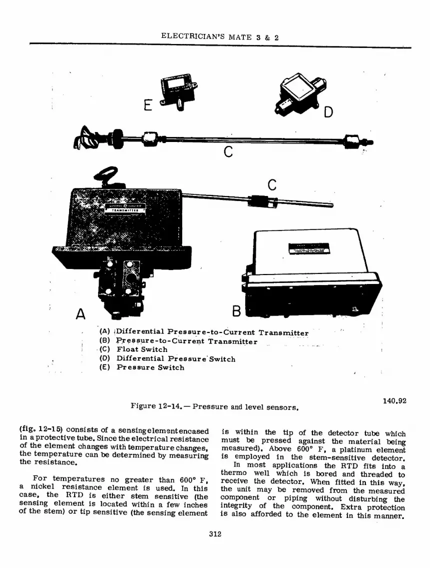
ELECTRICIAN’S MATE 3 & 2
C
B A (A) (Differential Pressure-to-Current Transmitter (B) Pressure-to-Current Transmitter
i (C) Float Switch (0) Differential Pressure'Switch (E) Pressure Switch
Figure 12-14. —Pressure and level sensors. 140.92
(fig« 12-15) consists of a sensing element encased in a protective tube. Since the electrical resistance of the element changes with temperature changes, the temperature can be determined by measuring the resistance.
For temperatures no greater than 600° F, a nickel resistance element is used. In this case, the RTD is either stem sensitive (the sensing element is located within a few inches of the stem) or tip sensitive (the sensing element
is within the tip of the detector tube which must be pressed against the material being measured). Above 600° F, a platinum element is employed in the stem-sensitive detector.
In most applications the RTD fits into a thermo well which is bored and threaded to receive the detector. When fitted in this way, the unit may be removed from the measured component or piping without disturbing the integrity of the component. Extra protection is also afforded to the element in this manner.
312

Chapter l2-CENTRAL OPERATIONS SYSTEMS
C
(A) Stem Sensitive RTD (B) Thermowell with Adapter (C) Tip Sensitive RTD (D) Thermowell with Holder
Figure 12-15. — Resistance temperature detectors.
140.93
Figures 12-16 A and B will give an idea of the amount of monitoring used on equipment to ensure normal system operation.
Figure 12-17 shows the simplified diagrams for signal conditioning and adjustments which may be made, if necessary, for proper operation.
Malfunctions in the sensor/detector circuits (shorts, grounds, etc) will usually be printed out by the typewriter as indicating either full scale rating or a minus condition if a meter is pegged below zero. A sensor malfunction will usually have no immediate effect on normal operation of the rest of the monitoring system.
Synchronous timing generator malfunctions are usually limited to the date/time sensing information and read-out with no effect on the throttle control system.
If malfunctions in the throttle control system develop in any control amplifier stage, the
throttle can either be operated by direct elec- trical controls located on the propulsion section or manually by the ahead or astern handwheel on the front of the console station (fig. 12-18). Direct electrical control will automatically remove the control power from the motor power supply when either the ahead or astern switches are operated.
DATA SCANNER
The DATA SCANNER (fig. 12-19) is the control section for the entire logging system. The functional components of each control module are defined as follows:
SYNCHRONOUS TIMING GENERATOR (22) : Pro- vides a 20-khz signal for normal operation, and selected lower frequencies for troubleshooting the system.
REQUEST (25): Manually operated to select the mode of operation; determines what mode
313

ELECTRICIAN’S MATE 3 & 2
/ \
s i rrj
HIGH PRESSURE TURBINE
LOW PRESSURE TURBINE
S=SENSOR
40.192 Figure 12-16A. — Typical main propulsion unit
bearing temperature monitor.
(manual operation) bell log, alarm log, status log, or display the system will operate in.
PROGRAM CONTROL (23) : Automatically oper- ated; senses and delegates by priority the mode of operation, the system will operate in.
POINT DRIVE (26): Controls the sequence of operation of the scanner whether one function or all the functions are to be logged or displayed.
PROGRAM CONTACT (39) : Determines when the system will adjust for linearization, scaling, high and low alarm points, isolation amplifier gains.
ISOLATION AMPLIFIER (28): Adjusts all analog inputs to have a required 10-volt output for the A/D CONVERTER.
LIMIT CHECK (34): Compares the binary digital signal input to a preset binary value for alarm conditions and supplies the information to the ALARM LOG for printout.
LINEARIZATION (32): Compensates for the non- linear characteristics between types of RTDs when used on different temperature levels.
SCALE FACTOR (33): Automatically divides by .6 to give a linear output due to a variable input range.
A/D CONVERTER (29): Converts an ANALOG voltage of 0-10 volts to a DIGITAL number
S i i.
GENERATOR S
S
HI
TURBINE
S=SENS0R
SCANNER (27): Connects all sensors and actuator 40,193 information into the system as determined by Figure 12-16B. —Typical turbine generator POINT DRIVE (26). bearing temperature monitor.
314

Chapter 12—CENTRAL OPERATIONS SYSTEMS
R4
R9 SPAN ADJ 1 R7 R8 H°-
EXTERNAL METER
R6
R2 R5
RIO
R3 ZERO ADJ
TO RTD
PRECISELY 12 VOLTS
EXTERNAL JUMPER TO BE ADDED IF NO METER IS CONNECTED.
OUTPUT TO DATA SCANNER
R3-ZERO ADJUSTMENT R7-FULLSCALE ADJUSTMENT
40.194 Figure 12-17A. — Typical RTD bridge circuit.
SIGNAL CONDITIONING FILTER
-C=3-
TACH
9 ° «
CONSOLE METER
0 POINT
SELECT RELAY
± ATOM -<=>-
TO DATA SYSTEM MONITOR AND LOGGING
B
+50 V
PRESSURE TRANSMITTER SIGNAL CONDITIONING
-CZI- -cz>- FILTER
CONSOLE METER
POINT SELECT RELAY
ACOM
TO DATA SYSTEM MONITOR AND LOGGING
c
Figure 12-17B and C. — Simplified sensor circuits, 40.195
315

ELECTRICIAN’S MATE 3 & 2
0»
T
SllCftIC
CDuSuSPuCv
Figure 12-18. — Manual control station, 27.347
316

317
SPECIAL TIME
PULSES READOUT
1STC)
SYNCHRONOUS TIMING GEN
(22)
PROGRAM CONTROL
(23)
PROVIDES CONTROL TIMING
TO ALL MODULES
REAL TIME CLOCK
(40)
REALTIME CLOCK
(24) (40)
POINT DRIVE
(26)
DIGITAL DATA EOT INPUT ,
THROT LOC
ANALOG SENSORS
TEMP
PRESS TACH ETC
ANALOG INPUT
SCANNER
(27)
ANALOG SIGNAL. ISOLATION AMPLIFIER
(2B)
ANALOG SIGNAL A/D CONVERTER
(29)
WD
(24)
DIGITAL ALARM INPUT
PROGRAM CONTACT
(39)
LIMIT CHECK
(34)
WD
(24)
DIGITAL
SCALING
(30)
WD
(24)
R ’ REGISTER
(3D
WD
(24)
LOG PRINTOUT
(37)
TYPEWRITER DRIVE (38)
DIGITAL DISPLAY
(44)
DIGITAL DISPLAY
, (44)
ALARM DATA REGISTER
ALARM LIMIT
STATUS
■TO ALARM ANNUNC
AND/OR ALARM
LOG REQUEST
LINEARIZATION
(32)
WO
(24)
SCALE FACTOR
(33)
WD
(24)
STG - SYNCHRONOUS TIMING GENERATOR
WO - WORD DISTRIBUTOR
A/D - ANALOG TO DIGITAL
(221 ■ SEE SECTION OF ELEM
WORK SHEET PREFIX 22
Figure 12-19. — Block diagram of data scanner system, 140.94
Ch
ap
ter
12—
CE
NT
RA
L O
PE
RA
TIO
NS
SY
ST
EM
S

ELECTRICIAN'S MATE 3 & 2
of 0 to 999 (999 usually being a full-scale reading). If the information is requested and/or the address is in alarm, the A/D CONVERTER then transfers the values via the word distributor (24) to the scaling module (30). If neither of these conditions exists, the scanner executes “branch back” (return to starting point), picks up the next address, and repeats the process.
WORD DISTRIBUTOR (24): Transfers the required information/alarms to the proper modules for logging and/or displays.
SCALING (30): Does the arithmetic necessary for a linear reproduction (0 to 999 DIGITAL) by accepting inputs from the linearization or scale factor modules and whichever address is selected.
REAL TIME CLOCK (40): Develops and supplies time and date for display and printout on both typewriters as needed.
DIGITAL INPUT (43): Takes position of the engine order telegraph switch, throttle control location switch and month/day thumb switches for an input and converts into a DIGITAL source for display and printout.
R REGISTER (31): Stores the alarm information only until the demand for printout or display is requested.
LOG PRINTOUT (37): Contains the counters, controls and storage necessary to process the signal for operation of the typewriter(s).
TYPEWRITER DRIVE (38): Controls the type- writer selection (A or B), character (address) to be typed, interlocking and feedback controls for proper sequence of operation, code trans- lators for printouts and print magnet drive.
DIGITAL DISPLAY (44): Displays any one of 377 addresses when dialed on one or more than one display module.
Information leaving the scaling module for display is sent directly to the digital display buffers and readouts (44) and appears at the readout units on the console face.
The entire operation from pickup of the input address to activation of the printout units requires a time span of 0.0367 milliseconds. The assembly will monitor the complete bank of 273 inputs in approximately two seconds
provided there are no requests or alarms conditions presented to the system during that time period.
THROTTLE CONTROL
Figure 12-20 is a block diagram of the throttle control system. A reference input signal may be taken from either bridge or engine- room reference handwheel potentiometer and fed to the system. Negative voltages are used for ahead speeds and positive for astern. The signal then passes through a common operational amplifier where it is inverted and then goes to the common circuit for both the ahead and astern turbines. The functions generators will accept only a signal of given polarity. The ahead function generator accepts positive signals and the astern function generator negative signals. The signal to the function generator is also used as a reference signal for the speed feedback system. This circuit compares the reference and speed feedback signals and uses the algebraic sum as the input to the speed error amplifier.
The signal to the function generator is ad- justed within the amplifier so that the output is equivalent to the cube of the input. This is done to change the linear movement of the reference to the nonlinear characteristics of the throttle valve. Inversion once again takes place in the function generator.
The output of the function generator is matched with the speed error signal and the throttle position signal at the summing junction and the algebraic sum is fed to the summing amplifier. Inversion takes place and the output controls the action of the SCR power package.
The SCR power package will cause the pilot motor to drive in either direction depending upon the input. A positive input will cause the pilot motor to drive in a direction to open the throttle valve. A negative input will close the throttle valve. The SCR power package will be inhibited by limit switches if the motor travel exceeds a predetermined point of travel.
The pilot motor positions a pilot valve in the hydraulic actuator which ports oil in the proper direction to correctly position the throttle valve.
A reference signal for throttle position, which is controlled by the pilot motor, is fed back to the summing junction. This section cancels the input signal when the desired valve opening is reached.
During direct electrical control of the throttle, the contacts in the throttle location switch change
318

Chapter l2—CENTRAL OPERATIONS SYSTEMS
DIRECT
ELECTRICAL
CONTROL > 1>
DISABLE SIGNAL FOR
MANUAL OPERATION
HANDWHEEL
(MOUNTED ON CONSOLE)
AHEAD FUNCTION GEN PILOT
♦ Co AHEAD MOTOR POWER
SUPPL* (SCR*)
MOTOR
r'-Hi DRAULIC C s -c AMP
ACTUATOR VALVE
OVERTRAVEL L IMI T
^r0—r CLOSED IN
MANEUVERING MODE ONLY
THROTTLE
POSITION
SENSOR ENGINE ROOM
MANUAL REFERENCE CLUTC
AHEAD [*0 CD-- *—w—C spceo
E AO (HANDWHEEL) AHEAD TURBINE [><] STEAM PRESSURE
VALVE AMPLIFIER GEAR
SHAFT
SPEED TURBINE TACHOMETER FROM
TACHOMETER
ASTERN
TURB'NE BRIDGE
REFERENCE
AHEAD
STEAM IASTERN MANUAL PRESSURE
'—®-c CLUTCH STEAM _ J O VALVE
(HANDWHEEL)
THROTTLE
POSITION
SENSOR
— i- VALVE I
OVERTRAVEL j LIMIT . ASTERN I
MOTOR POWER. IL SUPPL* '1,1
( SCRs) I
HYDRAULIC
ACTUATOR HgJ-0 -C AMP
PILOT
MOTOR
ASTEARN FUNCTION GEN
DIRECT
ELECTRICAL >
CONTROL
LOW LUBE OIL
PRESSURE
PROPELLER
HANDWHEEL
(MOUNTED ON
CONSOLE)
* PRESSURE OR
POSITION FEEDBACK
MAY BE USED
140.95 Figure 12-20. —Block diagram of throttle control system.
the circuitry eliminating the regulated signal and setting up the circuitry for signals from the direct throttle switches.
During manual operation, the manual clutch is engaged and the hydraulic actuator is in- hibited. In addition, the hydraulic system is vented to prevent a hydraulic lock and permit the
movement of the handwheel for manual throttle control.
A tachometer generator on the shaft produces an output signal that is fed back as the speed error signal. This signal produces a rapid response from the system when the engineering plant is in the maneuvering mode. Under normal
319

ELECTRICIAN’S MATE 3 & 2
steaming conditions the speed feedback signal is not utilized.
The signals for astern throttle movement are handled in the same manner but all the polarities are reversed.
POWER SUPPLIES
The consoles are supplied from the ship’s 450-volt power system via a NO-BREAK POWER supply in case the ship’s regular supply is lost. The battery supply will last approximately 40 minutes under normal load conditions. The 450- volt ship’s power provides three voltages: 28, 50, and 12. The 28-volt supply is used for indicating lights and relays. It has a tolerance of 2 volts and is not as critical as the other supplies. The 50-volt supply is used for throttle
control; its tolerance is within 0.05 volts. The 12-volt supply, plus or minus 0.05 volts, is used with the RTD bridges and sensors. It is as critical as the need for accurate information.
The 50-volt and l2-volt supplies have ad- justments to achieve the desired voltages. The 28-volt supply does not have any adjustments.
Incorporated in the alarm circuits is a high and low alarm monitor that will indicate if any power supply goes above or below a preset amount, warning the console operator of the problem.
The central operations system is relatively new in the fleet and strict adherence to mainte- nance requirements is of paramount importance. Consult the maintenance requirement cards provided by the Planned Maintenance Subsystem and follow the procedures set down in manu- facturers’ technical manuals.
320

CHAPTER 13
BASIC ELECTRONIC COMPONENTS AND CIRCUITS
Although there have been many attempts to explain the difference between the meanings of the words electricity and electronics, they are more alike than they are different. For instance, electricity and electronics are both concerned with the use of electricity to operate equipment. The field of electricity is usually concerned with its use in magnets, generators, motors, lights, and heaters; the field of electronics with the use of electricity in radio, television, radar, telephone, and other equipment in which electron tubes or transistors are needed.
Current and voltage cannot tell the difference between an electrical circuit and an electronic circuit. The components that have been built into the circuit determine how the current and voltage will be used to make the electrical or electronic equipment work. One of the most recently developed electronic components is the transistor. Transistors are constructed from solid materials, classified as semiconductors, whose resistance to the flow of electrons is between that of insulators and conductors.
Any circuit can be thought of in terms of the effects that resistors, capacitors, and in- ductors (coils) have on current or voltage. The effect that a resistor has on current or voltage is measured in terms of its resistance; the effect of a capacitor is measured in terms of its capacitance; and the effect of a coil is measured in terms of its inductance. The effect that each of these measurable properties has on current or voltage depends on whether the current is direct or alternating and, if alter- nating, how fast the current or voltage is changing (frequency).
As an Electrician’s Mate, therefore, you will find it necessary to test resistors, capacitors, and inductors in an electrical or electronic circuit by measuring or otherwise determining the effects of their properties on the current or voltage of the circuit.
RESISTOR TESTING
As you already know, current passing through a resistor generates heat. If too much heat is generated, the resistor will be damaged. Wire in the wound resistor will become open, or some of the carbon in the composition resistor will burn away, thus, changing the resistance value; normally, but not always, to zero ohms or infinity.
RESISTOR RATINGS
The current-carrying capacity of a resistor is rated according to the amount of heat it can safely release in a given amount of time. There- fore, a resistor cannot be used in a circuit where current causes heat to build up faster than the resistor can dissipate it.
Since heat is a form of energy, the heat releasing rate of a resistor is measured in energy units called watts. Composition resistors are usually rated at l/3, l/2, l, and 2 watts. The power ratings of wirewound resistors are larger.
RESISTOR TOLERANCES
A resistor will rarely measure the exact number of ohms specified by its label or color codes. The amount it will vary is called tolerance. Resistor tolerance is given as a percentage value which indicates the amount that a resistor may vary above or below its specified value. Standard tolerances for composition resistors are 5, 10, and 20 percent. Wirewound resistors may have tolerances as low as 1 or 2 percent.
Taxe a 1,000-ohm resistor 10 percent toler- ance as an example. Ten percent of 1,000 is 100 ohms. Because of the tolerance factor, this resistor will measure somewhere between 100 ohms above and 100 ohms below the labeled value of 1,000 ohms. The range is from 900 to 1,100 ohms.
32l

ELECTRICIAN’S MATE 3 & 2
r© 1ST DIGIT
p-CD 2ND DIGIT
3)MULTIPLIER
INTOLERANCE (PERCENT)
É 'A
77.336 Figure 13-1. — Color Coded Resistor.
Resistor tolerance is not an indication of poor manufacturing. Closer tolerances can be achieved, but at greater expense. A resistor with a 20 percent tolerance will cost less than one with a 10 percent tolerance.
RESISTOR COLOR CODES
Wirewound resistors normally have their value in ohms and tolerance in percent stamped on them. For carbon or composition resistors a color code is used. For several years, resis- tance values have been coded by three colored bands painted around the body of the resistor. If the tolerance is either five or ten percent, a fourth color band is used; if 20 percent there is no fourth color band. Positions of the bands are as shown in figure 13-1.
The first two color bands ((T) and (5) of figure 13-1) indicate the first two digits in the colors and numbers table (table 13-1). The third band Qf) is the multiplier and indicates the number of zeros that follow the first two digits. The fourth band (© indicates the tolerance and is either gold or silver, for five or ten percent, respectively.
Always use a replacement resistor, with a wattage rating equal to or higher than that of the original—never lower. Otherwise, the re- placement will burn out. You can use the physical size of the resistor as a guide, if the replacement is the same type (carbon, metalized, or wire- wound) as the original. The replacement should be the same physical size or larger.
RESISTORS WITH SPECIAL CHARACTERISTICS
Before preceding further a brief description of special application resistors will be given.
Wirewound resistors generally have a positive temperature coefficient, while carbon resistors have a negative temperature coefficient. In some applications, it is desirable to have a resistor in which resistance will change with ambient temperature change.
Thermistor
A thermistor is a special semiconductor device. It functions as a thermally sensitive resistor whose resistance varies inversely with temperature. Thermistors have large negative temperature coefficients; that is, as the tem- perature rises, resistance of the thermistors decreases, and as the temperature drops, their resistance increases. The resistance of a therm- istor is varied not only by ambient temperature changes but also by heat generated internally by the passage of current.
Since the thermistor is basically a variable resistor, it is usually constructed from semi- conductor material of greater resistivity than is used in transistors or semiconductor diodes. Therefore, the thermistor’s response to ambient temperature variations does not track equally with that of the transistor semiconductor, so that compensation is achieved only at a few points of correspondence. As a result, the thermistor’s greatest usage is in the field of temperature
Table 13-1,— Colors and Numbers
COLOR 1ST DIGIT
2ND DIGIT
MULTIPLIER TOLERANCE (PERCENT)
BLACK
BROWN
RED
ORANGE
YELLOW
GREEN
BLUE
VIOLET
GRAY
WHITE
GOLD
SILVER
NO COLOR
1
10 100
1,000
10,000
100,000
1,000,000
10,000,000 100,000,000
1,000,000,000
.1
.01 5 10
20
77.337
322

Chapter 13—BASIC ELECTRONIC COMPONENTS AND CIRCUITS
INSULATOR
CONDUCTOR
(A)
BAKELITE FORM
BE213 Figure 13-2. —Paper Capacitor.
controls and measurements and power measuring equipment based on heating effect, such as circuits where there is liable to be a large surge of current when the equipment is first turned on. Although the thermistor is a semiconductor, it does not have intrinsic amplification capability, as does the transistor. It is used in thermal compensating circuits for transistor stabiliza- tion.
Varistor
Another type of resistor with special charac- teristics is the varistor. It may also be called a voltage-dependent resistor. When the voltage across the varistor increases, the resistance of the varistor decreases. Varistors are used in circuits to protect the circuit from high voltage surges. In the event the source voltage increases, the resistance of the varistor will decrease, thus drawing a large current from the source which will lower the voltage available to the remainder of the circuit.
CAPACITOR TESTING
The property of a capacitor that is measurable is known as capacitance, an indication of how many excess electrons the capacitor can störe
on one plate to develop a specific charge. By definition, the unit of capacitance is farad. As defined, however, a farad is too large to be a practical unit of measurement. Instead, capac- itors are measured in microfarads (l/lO^ or one millionth of a farad) or in picofarads (1/1013 or one millionth of a millionth of a farad). The symbols for these units are ßf and pf, respectively.
FIXED CAPACITORS
Fixed capacitors are constructed in such manner that they possess a fixed value of capaci- tance which cannot be adjusted. They may be classified according to the type of material used as the dielectric, such as paper, oil, mica, and electrolyte.
A PAPER CAPACITOR is one that uses paper as its dielectric. It consists of flat thin strips of metal foil conductors, separated by the dielectric material. In this capacitor the dielectric used is waxed paper. Paper capacitors usually range in value from about 300 picofarads to about 4 microfarads. Normally, the voltage limit across the plates rarely exceeds 600 volts. Paper capacitors are sealed with wax to prevent the harmful effects of moisture and to prevent corrosion and leakage.
Many different kinds of outer covering are used for paper capacitors, the simplest being a tubular cardboard. Some types of paper capaci- tors are encased in a mold of very hard plastic; these types are very rugged and may be used over a much wider temperature range than the cardboard-case type. Figure 13-2 (A) shows the construction of a tublar paper capacitor; part (B) shows a completed cardboard encased capacitor.
A MICA CAPACITOR is made of metal foil plates that are separated by sheets of mica, which form the dielectric. The whole assembly is covered in molded plastic. Figure 13-3 (A) shows a cutaway view of a mica capacitor. By molding the capacitor parts into a plastic case, corrosion and damage to the plates and dielectric are prevented in addition to making the capacitor mechanically strong. Various types of terminals are used to connect mica capacitors into circuits; these are also molded into the plastic case.
Mica is an excellent dielectric and will with- stand higher voltages than paper without allowing arcing between the plates. Common values of mica capacitors range from approximately 50 picofarads to about 0.02 microfarad. Some typical mica capacitors are shown in figure 13-3 (B).
323

ELECTRICIAN’S MATE 3 & 2
TERMINAL MICA
FOIL
W
MICA
FOIL PLASTIC CASE
(A)
O o» a vO)
m
(B) BE214
Figure 13-3. — Typical Mica Capacitors.
A CERAMIC CAPACITOR is so named because of the use of ceramic dielectrics. One type of ceramic capacitor uses a hollow ceramic cylinder as both the form on which to construct the capacitor and as the dielectric material. The plates consist of thin films of metal deposited on the ceramic cylinder.
A second type of ceramic capacitor is manufactured in the shape of a disk. After leads are attached to each side of the capacitor, the capacitor is completely covered with an insulating moisture-proof coating. Ceramic ca- pacitors usually range in value between 1 picofarad and 0.01 microfarad and may be used with voltages as high as 30,000 volts. Typical capacitors are shown in figure 13-4.
ELECTROLYTIC CAPACITORS are used where a large amount of capacitance is required. As the name implies, electrolytic capacitors contain an electrolyte. This electrolyte can be in the form of either a liquid (wet electrolytic capacitor) or a paste (dry electrolytic capacitor). Wet electrolytic capacitors are no longer in popular use due to the care needed to prevent spilling of the electrolyte.
Dry electrolytic capacitors consist essentially of two metal plates between which is placed the electrolyte. In most cases the capacitor is housed in a cylindrical aluminum container which acts as the negative terminal of the capacitor (fig. 13-5). The positive terminal (or terminals if the capacitor is of the multisection type) is in the form of a lug on the bottom end of the container. The size and voltage rating of the capacitor is generally printed on the side of the aluminum case.
ALUMINUM FOIL'
PAPER
PAPER AND ELECTROLYTE
OXIDE FILM
Figure 13-4. — Ceramic Capacitors.
r> >
¿ft BE216
BE2l5 Figure 13-5. — Construction of an Electrolytic Capacitor.
324

Chapter 13—BASIC ELECTRONIC COMPONENTS AND CIRCUITS
An example of a multisection type of electro- lytic capacitor is depicted in figure 13-5. The cylindrical aluminum container will normally enclose four electrolytic capacitors into one can. Each section of the capacitor is electrically independent of the other sections and one section may toe defective while the other sections are still good. The can is the common negative connection with separate terminals for the posi- tive connections identified toy an emtoossed mark as shown in figure 13-5. The common identifying marks on electrolytic capacitors are the half moon, triangle, square, and no identifying mark. By looking at the bottom of the container and the identifying sheet pasted to the side of the container, the technician can easily identify each section.
Internally, the electrolytic capacitor is con- structed similarly to the paper capacitor. The positive plate consists of aluminum foil covered with an extremely thin film of oxide which is formed by an electrochemical process. This thin oxide film acts as the dielectric of the capacitor. Next to, and in contact with the oxide, is placed a strip of paper or gauze which has been im- pregnated with a paste-like electrolyte. The electrolyte acts as the negative plate of the capacitor. A second strip of aluminum foil is then placed against the electrolyte to provide electrical contact to the negative electrode (electrolyte). When the three layers are in place they are rolled up into a cylinder as shown in figure 13-5.
Electrolytic capacitors have two primary disadvantages in that they are POLARIZED, and they have a LOW LEAKAGE RESISTANCE. Should the positive plate be accidentally connected to the negative terminal of the source, the thin oxide film dielectric will dissolve and the capacitor will become a conductor (i.e., it will short). The polarity of the terminals is normally marked on the case of the capacitor. Since elec- trolytic capacitors are polarity sensitive, their use is ordinarily restricted to d-c circuits or circuits where a small a-c voltage is superim- posed on a d-c voltage. Special electrolytic capacitors are available for certain a-c applica- tions, such as motor starting capacitors. Dry electrolytic capacitors vary in size from about 4 microfarads to several thousand microfarads, and have a voltage limit of approximately 500 volts.
The type of dielectric used and its thickness govern the amount of voltage that can safely
be applied to a capacitor. If the voltage applied to a capacitor is high enough to cause the atoms of the dielectric material to become ionized, an arc over will take place between the plates. If the capacitor is not self-healing, its effective- ness will be impaired. The maximum safe voltage of a capacitor is called its WORKING VOLTAGE and is indicated on the body of the capacitor. The working voltage of a capacitor is determined by the type and thickness of the dielectric. If the thickness of the dielectric is increased, the distance between the plates is also increased and the working voltage will be increased. Any change in the distance between the plates will cause a change in the capacitance of a capacitor. Because of the possibility of voltage surges (brief high amplitude pulses) a margin of safety should be allowed between the circuit voltage and the working voltage of a capacitor. The working voltage should always be higher than the maximum circuit voltage.
CAPACITOR COLOR CODING
Many capacitors have their value printed on them, but some use a color-coded system. The color code is the same as that for resistors, tout the methods of marking the capacitors differ. The method for fixed mica capacitors is shown in figure 13-6.
A black dot in the upper left corner signifies that the capacitor has a mica dielectric. The center dot in the upper row indicates the first significant figure, and the upper right dot indicates the second significant figure of the capacitance value in picofarads (pf). The right dot in the lower row indicates the decimal multiplier or number of zeros to toe added to the right of the two significant figures. The center dot (lower row) specifies the tolerance, which is the possible deviation of the actual capacitor value from that given by its dot markings. The left dot on the lower row deals with the temperature coefficient and applications. As an example, take a capacitor with upper row dots colored black, red, and green (reading from left to right according to the directional indicator). This is a mica capacitor; the significant figures are 2 and 5. Suppose the lower row of dots (reading from right to left) are brown, red, and red. The brown dot requires the addition of one zero to the value of 25, resulting in 250 pf. The red center dot indicates that the actual capacitor value may vary from 250 pf by plus
325

ELECTRICIAN’S MATE 3 & 2
COLOR
BLACK BROWN RED ORANGE YELLOW GREEN BLUE VIOLET GRAY WHITE GOLD SILVER
CAPACITANCE
SIGNIFICANT FIGURE
DECIMAL
MULTIPLIER
1 10
100 1,000
0.1 0.01
TOLERANCE
20 PERCENT
2 PERCENT
5 PERCENT 10 PERCENT
CHARACTER ISTIC
A B C D E F G
BLACK DOT IDENTIFIES MICA CAPACITOR
1
31
DIRECTIONAL INDICATORS
( SIGNIFICANT 1 I 1STI FIGURES OF I CAPACITANCE
2NDf IN pi CHARACTERISTIC ■ * >
CAPACITANCE TOLERANCE '“DECIMAL MULTIPLIER
CHARACTERISTICS A - ORDINARY MICA BYPASS B - SAME AS A-LOW LOSS CASE C - BYPASS OR SILVER MICA (±200 PARTS/MILLION/C) D- SILVER MICA (±100 PARTS/MILLION/C)
E - SILVER MICA (0 TO +100 PARTVMILLION/C) F - SILVER MICA (0 TO +50 PARTS/MILLION/C) G - SILVER MICA (0 TO -50 PARTS/MILLION/C)
Figure 13-6. — Color Code for Fixed Mica Capacitors. 20.376(71)
or minus 2 percent. The left red dot means a bypass or silver mica capacitor. Some mica capacitors have only three dots, indicating the first and second significant figures and the multiplier. Their tolerance is 20 percent and their rating is 500 volts. Try reading some of the capacitor values you see in electronic devices when they are exposed to view. Learning to read capacitor values is a matter of practice, much like reading resistor values. There are other types of capacitors whose identification codes vary. See appendix IV of Basic Electricity for the explanation of these codes.
CIRCUIT TESTING
Capacitance, inductance, and resistance are measured precisely by alternating current bridges. These bridges are composed of capaci- tors, inductors, and resistors in a wide variety of combinations. The bridges operate on the principle of the Wheatstone bridge, in which an unknown resistance is balanced against known resistances. The unknown resistance is calculated in terms of the known resistance after the bridge is balanced. One type of capacitance bridge circuit appears in simplified schematic form
rMAAr
Xd
*1 imim UMM
oomwn 60 Hi
117 VOLTS
Figure 13-7. —Simplified Schematic of Capacity Checker. 20.344
326

Chapter 13—BASIC ELECTRONIC COMPONENTS AND CIRCUITS
in figure 13-7. When the bridge is balanced' by adjusting the two variable resistors, no a-c voltage is developed across the input of indicator tube VI. -
In the basic Wheatstone bridge circuit using d-c voltáges and simple resistances, the balance is .obtained when the, voltage drops are equal across the - ratio arms. In the a-c capacity bridge, it is insufficient to have quality of voltage drops in the ratio arms. The phase angle between current and voltage in the two arms containing the capacitors also must be equal in order to obtain a balance. When a balance is obtained, the current is equal on both sides of the bridge circuit.
The capacitance-inductance-resistance bridge of figure 13-8 not only measures capacitance, resistance, and inductance values, but is also used for special tests, such as the turn ratio of transformers and capacitance quality tests.
TEST CORDS
STRAP RINGS
INSTRUCTION BOOK
POWER CORO AND PLUG (STOWED)
CARRYING HANDLE
20.345 Figure 13-8. — Capacitance-
Inductance-Resistance Bridge, Type ZM-ll/U.
BLACK (COMMON)
BLACK-YELLOW
BLACK-RED
TAPPED PRIMARY BLACK
PRIMARY
BLACK
RED
ja-uuo» ÆGE RED
—-^*-*•0* RECTIFIER YELLOW-BLUE A!,C,,V
YELLOW FILAMENT GREEN
jiREEN-YELLOW FILAMENT
GREEN N0.1
BROWN
läROWN-YELLOW FILAMENT NO. 2
BROWN SLATë"
’SLATE-YELLOW F* LAMENT N0.3\
SLATE
20.379(71) Figure 13-9o — Color Coding of Small Power
Transformer Leads.
It is a self-contained instrument, except for a source of line power. It has its own source of 1000-Hz bridge current with a sensitive bridge balance indicator, and adjustable source of direct current for electrolytic capacitor and insulation resistance testing, and a meter with suitable ranges for leakage current tests on electrolytic capacitors.
TRANSFORMER TESTING
Transformers ordinarily are tested by check- ing for shorts, measuring resistance of the individual windings, and measuring voltage outputs of each winding. The technical manual for the equipment that contains a transformer describes the transformer, specifies the termi- nals to test for each winding, and tells what each measurement should be. Transformers, of the size used in electronic equipment, usually are color coded as shown in figure 13-9. In an untapped primary, both leads are black. If the primary is tapped, one lead is common and is colored black, the tap lead is black and yellow, and the other lead is black and red.
On the transformer secondary, the high- voltage winding has two red leads, if untapped, or two red leads and a yellow and red tap lead, if tapped. On the rectifier filament windings, yellow leads are used across the entire winding,
327

ELECTRICIAN'S MATE 3 & 2
and the tap lead is yellow and blue. If there are other filament windings, they may be green, brown, or slate. The tapped wire is yellow in combination with one of the colors just named; that is, green and yellow, brown and yellow, or slate and yellow.
An easy way to check a suspected malfunction- ing transformer is to measure its output voltage. Use a voltmeter to measure across the proper terminals, and compare the readings obtained with the proper voltage given in the technical manual. If only one reading is in error, only that winding is at fault. However, the transformer will require replacement. If all the readings are in error, the trouble could possibly be a high- or low- input voltage. Consequently; always measure the input voltage as well as the output voltage.
If the voltage measures high or low at any of the output windings, the next step is to measure the resistance of each winding. Make sure the connections to the terminals are dis- connected first. Power to the equipment must be secured prior to disconnecting a transformer. Once the leads are free, measure the resistance across each winding with an ohmmeter set to
FILAMENT PLATE
$ -FILAMENT
DIRECTLY HEATED
FILAMENT
CATHODE
PLATE to
PLATE
CATHODE
FILAMENT
£ -TÊ
4.140 Figure 13-11.—Cutaway of an Indirectly Heated
Diode.
the proper scale. Check each winding carefully, including any center taps. Next, test for shorts between windings and between windings and ground.
If no faults are indicated by the voltage or resistance readings, or by the tests for shorts, assume the transformer to be in proper operating condition. Then reconnect it in the circuit.
If a replacement is required, use only the one recommended by the manufacturer’s technical manual. Always test for shorts and check the resistance of a new transformer before installing it in the circuit.
IDENTIFICATION OF CHASSIS WIRING
4.140A Standard colors used in chassis wiring for Figure 13-10. — Cutaway of a Directly Heated the purpose of circuit identification of the equip-
Diode. ment are as follows. Caution should be used
328

Chapter 13—BASIC ELECTRONIC EOMPONENTS AND CIRCUITS
when identifying wires using this code as wiring changes may have toeen made that failed to comply with the codé.
Circuits
Grounds, grounded elements and returns
Heaters or filaments, off ground
Power supply B plus
Screen grids .
Cathodes
Control grids
Plates
Power supply, minus
A-c power lines
Colors
Black
Brown
Red
Orange
Yellow
Green
Blue
Violet (Purple)
Gray
Miscellaneous, above or below White ground returns, A VC, etc
DIODES
The simple diode tube contains a heated cathode and a cold plate. DI is a prefix signifying two. ODE is the suffix as in electrode, cathode, and anode. The plate collects electrons when the cathode is heated in a vacuum, and a positive potential exists on the plate with respect to the cathode.
One version of the diode is shown in figure 13-10 with its two elements indicated as plate and filament.
Another version of a diode is shown in figure 13-11. Its filament serves only as a heater.
In an electronic circuit the two electrodes of a diode act in the manner of a flow valve in a water pipe.
OPERATION
The behavior of a diode is observed after the plate and cathode elements have been connected in series with a battery and mulliammeter, as shown in figure 13-12. Carefully observe polarity changes of the battery when it is used in arrange- ments A and B, respectively. The cathode is
m
I X X
PLATE POSITIVE
m & 6 n
O
X X
B PLATE NEGATIVE
Figure 13-12. — Action of Diode. 20.1
brought up to normal temperature by applying rated voltage across the heater terminals. If the battery is connected so that the plate is positive with respect to the cathode (fig. 13-12A, the meter will indicate a current flow. When the battery is reconnected (fig. 13-12B) so that the plate is negative with respect to the cathode, the meter will indicate no plate current flow.
The total number of electrons emitted by the hot electrode at a given operating temperature is always the same regardless of the plate voltage. This same condition exists regardless of plate polarity because the electrons fly into the space surrounding the cathode to produce a cluster or cloud.
This cloud constitutes a negative space charge that constantly tends to repel the electrons toward, and into, the cathode as fast as they are being emitted. The negative charge on the plate of figure 13-12-B only repels the nearby
329

ELECTRICIAN'S MATE 3 & 2
electrons within the cloud, hut the action is so effective that none of the electrons reaches the plate (regardless of amount of voltage) as long as the plate remains negative.
With low values of positive plate voltage, only those electrons of the space-charge cloud that are nearest to the plate are attracted to it, and the plate current is low. As the plate voltage is increased, greater numbers of electrons are attracted to the plate and, correspondingly, fewer of those being emitted are repelled back into the cathode.
Eventually a plate voltage value (saturation voltage) is reached at which all the electrons being emitted are in transit to the plate, and none are repelled back into the cathode. The corresponding value of current is called the saturation current. Any further increase in plate voltage can cause no further increase in plate current flowing through the tube.
TYPES OF DIODES
Diodes that have been discussed thus far are of the high-vacuum type. There are other types of diodes that contain gas at a relatively low pressure.
The original use of the word, diode, was restricted to electron tubes. Scientific research has produced other devices that perform the same functions as the earlier diodes, although they are not electron tubes. These devices are semiconductor diodes and are discussed later.
TYPES OF CATHODES
Only a few substances can be heated to the high temperatures that are required to produce satisfactory thermionic emission without melting. Tungsten, thoriated-tungsten, and oxide-coated emitters are the types that are commonly used in electron tubes.
HEATING THE CATHODE
The electron-emitting cathodes of electron tubes are heated in two ways —directly, and indirectly. A directly heated cathode receives its heat by the passage of a current through the filament itself which serves as the cathode. An indirectly heated cathode comprises a metal sleeve that surrounds the filament but is elec- trically insulated from it. The sleeve serves as the cathode and receives its heat mostly by radiation. Both types are shown in figure 13-13.
SUPPORT
FILAMENT
Il l|
DIRECTLY HEATED
A
.—OX IDE-COATED CATHODE SLEEVE
HEATER FILAMENT
INDIRECTLY HEATED
B
13.21 Figure 13-13. — Methods of Heating the Cathodes
of Electron Tubes.
PHYSICAL CHARACTERISTICS OF ELECTRON-TUBE MATERIALS
The outer walls of an electron tube are constructed either of thin glass or metal. The larger the tube, the thicker the glass must be because of the greater weight of the atmosphere to be sustained on the walls of the tube.
Evacuation of air from a tube is required for two reasons —to prevent destruction of the cathode and heating element by oxidation or burning, and to allow the flow of current from cathode to plate without colliding with gas particles.
The external leads from the tube are elec- trically welded to the tube elements and brought out at the bottom through a special glass-metal fusion to make the envelope airtight. In metal tubes a glass button is used at the base to afford electrical insulation. The materials selected for the external leads have nearly the same coefficient of expansion as that of glass. Thus during heating and cooling periods, the glass expands and contracts the same amount as the metal and the vacuum seals are maintained.
The spacing of the electrodes in a tube is dependent on many factors but the two most important are frequency utilization and inter- electrode voltages.
The anode (plate) is made of materials that will not emit electrons by thermionic means at normal tube operating temperatures.
The plate is mounted externally with respect to the cathode. It is electrically insulated from the cathode and usually surrounds it in order to receive all of the cathode field of emission. The plate usually has a dark surface to radiate the heat caused by the plate current.
330
Chapter 13—BASIC ELECTRONIC COMPONENTS AND CIRCUITS
TYPES OF EMISSION
Electrons flow within a conductor when a potential difference is applied across the terminals of the conductor. These electrons break away from the outer shells of their parent atoms and move with a rapid vibratory motion, the velocity of which increases with temperature. At ordinary temperatures the particles do not leave the surface of the conductor because their velocity is not sufficient to overcome the attractive forces within the conductor.
To escape from a metallic surface, electrons must do work to overcome the forces of attrac- tion which are always present. This amount of work is called the work function of the material. Increasing the heat intensity of a metallic emitter increases the kinetic energy of the so-called free electrons in the material.
THERMIONIC EMISSION
Thermionic emission is the process by which electrons gain sufficient energy by means of heat to escape from the surface of the emitter. Thermionic emission is the type of emission most frequently employed in electron tubes.
SECONDARY EMISSION
Emission of electrons from a body caused by the impact of other electrons striking its surface is called secondary emission. If a stream of electrons flowing at a high velocity strikes a material, the force may be great enough to dislodge other electrons on the surface. Secondary emission is not commonly used as a source of electrons. However, it does occur spontaneously in tubes and must be controlled. This problem is discussed later in this chapter.
GAS-FILLED TUBES
In the manufacture of high-vacuum tubes, as much of the air as possible is removed from the envelope. In some cases low-vacuum tubes are designed purposely to contain a specific gas in place of air—usually neon, argon, or mercury vapor.
The gas-filled tube normally has a higher plate current rating than a high-vacuum tube of the same physical dimensions. When ionization occurs, the tube presents a lower impedance to
the external circuit. The schematic symbol for a gas filled tube has a small dot within the circle, this indicates that the tube is gas-filled.
CONDUCTION IN GAS TUBES
In a gas-filled tube the electron stream from the hot cathode encounters gas molecules on its way to the plate. When an electron collides with a gas molecule the energy transmitted by the collision may cause the molecule to release an electron. This second electron may then join the original stream of electrons and thus be capable of liberating other electrons through collision with other gas molecules. This process which is cumulative is a form of ionization. The molecule that has lost an electron is called an ion and bears a positive charge. The tube in its ionized condition contains molecules, ions, and free electrons within the envelope. The positive gas ions are relatively large and in the vicinity of the cathode they neutralize a portion of the space charge. Thus electrons flow from cathode to plate with less opposition than in a high-vacuum tube.
The heavier positive ions are attracted toward the negative cathode and while moving toward it they attract additional electrons from the space charge.
The energy needed to dislodge electrons from their atomic orbits and to produce the ionization is supplied by the source which supplies the voltage between the plate and cathode. There is a certain voltage value for a particular gas-filled tube at which ionization begins. When ionization occurs large currents flow at relatively low voltage across the tube. The voltage at which ionization commences is known as ionization potential, striking potential, or firing point.
After ionization has started, the action main- tains itself at a voltage considerably lower than the firing point. However, a minimum voltage is needed to maintain ionization. If the voltage across the tube falls below this minimum value, the gas deionizes and conduction stops. The voltage at which current ceases to flow is known as the deionizing potential or the extinction potential. The tube may therefore bé used as an electronic switch that closes at a certain voltage and permits current to flow and then opens at some lower voltage and thus blocks the flow of current. Such a tube has almost infinite resistance before ionization and very low resistance after ionization.
331

ELECTRICIAN'S MATE 3 & 2
GLASS ENVELOPE
PLATES
K LAMENTS
m à
BASE
PINS
4.140(20C) Figure 13-14. — Construction and Schematic
Symbols of Duo-diodes.
When an alternating voltage is applied both electrodes are alternately surrounded with a glow discharge.
A neon-glow tube placed in an RF field of sufficient strength to ionize the gas in the tube will indicate the presence of such a field by glowing. A glow tube may also be used as a voltage regulator. Additional uses of glow tubes are as a source of light, as a part of a relaxation oscillator, as a rectifier, and to control circuit continuity in noise limiters.
Hot-cathode, mercury-pool diodes are specially designed to serve as rectifiers. Tubes of this type can pass much higher currents than high-vacuum tubes because the ionization of the mercury vapor partially dispels the cathode space charge.
In some cases, two or more diodes are included in the same envelope to conserve space. A tube which contains two plates and one or two cathodes is called a duo-diode or twin diode. Figure 13-14 illustrates the construction and schematic symbols of duo-diode electron tubes.
As a rule, electron tubes are not expected to last as long as resistors, capacitors, or other circuit components. This is due, in large part, to wearing out or breaking down of the filament or heater. To make it easy to remove and replace a tube, the base of the tube (fig. 13-14) is constructed in the form of a plug, which fits into a socket on the chassis. The
GAS DIODES
The neon-glow lamp or neon bulb is a cold- cathode gas-filled diode. The cathode may have the same shape and size as the plate so that the tube can conduct in either direction depending only on the applied potential, or the structures of the cathode and plate may be such as to permit conduction in only one direction. Because the cathode is not heated in this type of tube no electrons are emitted to help in the ionization process. Therefore the firing potential for a neon-glow tube is higher than that for a tube in which a hot cathode is used, and the neon-glow tube is somewhat erratic in that the firing potential varies during the operation. The passage of current through the tube is indicated by a glow. The color of the glow depends on the gases that may be mixed with the neon. The glow is on the negative electrode or cathode.
2 0
O O 6 \0 Q/ \ r"—6 0|7 6 PRONG 4 PRONG jo
UTV 3/ 0 ° \7 KEY J/o oY 2 Io 0 6 2 0 OR OCTAL
0 5
7 PIN MINIATURE
9 PIN MINIATURE
4.141 Figure 13-15. — Pin Numbering Systems for
Several Tube Types.
332

Chapter 13—BASIC ELECTRONIC COMPONENTS AND CIRCUITS
INPUT
AC SUPPLY
OUTPUT R (LOAD)
INPUT
AC-!
SUPPLY Í
VI
OUTPUT
.nn VE R
(LOAD) Cl
A. HALF WAVE B. FULL WAVE
Figure 13-16. — Electron Tube Rectifier Circuits. (A)20.37 (B)20.40.1
electrical connections between the tube elements and the circuit are completed through the plug terminals, called pins.
There are various types of tube bases, containing different numbers and sizes of pins. Each type of tube base has a guide or key to prevent the tube from being plugged into the socket improperly. To make circuit tracing easy, the tube pins are assigned numbers. At the BOTTOM of the tube or socket, the pins are numbered in a clockwise direction, as viewed from the bottom, beginning with No. 1 at the key or guide. The pin numbering systems for several types of tubes are shown in figure 13-15.
Ratings
Each diode has certain voltage, current, and power ratings. By definition, a rating is the limiting value which must not be exceeded to prevent permanent damage to a device, such as the diode. The filament or heater voltage and current values must be correct for proper operation of an electron tube. If heater current is too low, the cathode will not emit enough electrons. Too much heater or filament current may reduce the life of the tube or destroy the heater or filament.
Other important diode electron tube ratings are:
Plate Dissipation—the maximum average power, in the form of heat, which the plate may safely dissipate.
Maximum Average Current—the highest average plate current which may be handled continuously, based on the tube’s permissible plate dissipation.
Maximum Peak Plate Current—the highest instantaneous plate current that a tube can safely carry in the direction of normal current flow.
Peak Inverse Voltage (PIV; — the highest in- stantaneous plate voltage which the tube can withstand acting in a direction opposite to that in which the tube is designed to pass current (plate negative — cathode positive).
DIODE TUBES
The electron tube diode is commonly used as a rectifier; that is, a device for converting alternating current to direct current. See figure 13-16. An a-c voltage constantly reverses polarity. Each time the voltage of the transformer reverses, it reverses the polarity of the voltages applied to the anode and cathode. The anode attracts electrons from the cathode only during the periods when it is positive.
Figure 13-16A shows a diode in a half-wave rectifier circuit or a circuit that rectifies only one-half of the a-c cycle. The transformer steps down the voltage to provide filament voltage for the diode and heater voltage. Alternating current flows through the secondary winding; the output of the circuit is pulsating direct current. When the plate of the diode in this circuit is positive, it attracts electrons from the filament and current flows through the tube. Electrons travel from the plate through the transformer and return to the filament by way of the load resistor. The filament then becomes the positive terminal, for the power supply,
333

ELECTRICIAN'S MATE 3 & 2
the transformer lead becomes the negative terminal. As the potential changes, the plate becomes negative and no current flows through the diode. Since current flows through the diode during only half of the a-c cycle, a pulsating d-c is produced. Notice the input and output signals in figure 13-16A. This current can be smoothed out by means of a filter which enables current to flow when the rectifier is not operating.
For a more constant flow of current, both halves of the a-c cycle are rectified. See figure 13-16B. In this case, you have a full-wave rectifying circuit that has two diodes. The high- voltage secondary of the transformer is tapped in the center. One plate goes to one side of the secondary; the other plate to the opposite side of the secondary.
When the plate of diode VI is positive, it pulls electrons from the filament and current flows through Vl to the plate and out through the center tap of the transformer. As the alternating current starts to flow in the other direction, the plate of diode Vl becomes negative and that of diode V2 becomes positive. Electrons are now attracted to the plate of V2. Current flows through V2 to the plate and out through the center tap of the transformer. Electron flow through the center tap is always in the same direction. Both halves of the a-c cycle are rectified and current flows all the time.
Ge Ge
S- 4 -r +
Ge Ge Ge
+
Ge Ge Ge -1-4 -r
20.20 Figure 13-17. — Arrangement of Germanium
Atoms in Diode Lattice.
rupture the insulator, however, current will flow which may be in the form of an arc.
There are solid substances, known as semi- conductors, whose outer-orbit electrons are not loosely bound, as in conductors, or tightly bound, as in insulators. Two examples are germanium and silicon. If a voltage is applied to a semi- conductor, current will flow but not as readily as in a conductor.
SOLID STATE DIODES
As you know conductors are substances made up of atoms whose outer-orbit electrons are loosely bound. At ordinary room temperature enough heat energy is applied to the atoms to permit large numbers of these electrons to be liberated (free electrons) and to drift aimlessly about’ from one atom to another. If a voltage is applied to the end of a conductor, free electrons will stream to the positive side as other electrons enter from the negative end. It is in this way that current flows through a conductor. As carriers of electricity, the electrons move from the negative to the positive side of the conductor.
In an insulator, on the other hand, the outer- orbit electrons are tightly bound and there are few free electrons. As a result, little current will flow when a voltage is applied to the end of the insulator. If the voltage is high enough to
Atomic Theory
The germanium atom is pictured as having a nucleus of 32 protons and 32 orbiting electrons arranged in four concentric shells or orbits. The three shells closest to the nucleus are completely filled with 28 electrons, the outermost shell containing the remaining 4 electrons. The electrons of the outermost shell are called the valence electrons; they determine the chemical and electrical properties of the atom.
Since the outermost electrons are loosely bound to the nucleus at ordinary room tempera- ture, many of them escape and wander as free electrons. Where an electron escapes from its atom, a “hole” is left in its place. The loss of the electron and the appearance of the hole converts the neutral atom into a positive ion. Thus, the hole is said to have a positive charge that is equal and opposite to the negative charge of the free electron.
334
Chapter 13—BASIC ELECTRONIC COMPONENTS AND CIRCUITS
When a hole appears in an atom, an electron from a neighboring atom may move in to fill this hole, leaving a hole in its place. Thus, a hole moves from the first atom to the second atom just as a free electron moves, except that the hole carries a positive charge instead of a negative charge. A rise in temperature or the presence of an electric field can force free electrons to move toward a positive pole. As free electrons move toward the positive pole, holes move toward the negative pole.
In a crystal of pure germanium, the atoms arrange themselves in a geometric pattern, each atom being relatively far from its neighbor. Though the crystal is a three-dimensional structure, figure 13-17 shows two dimensions only. The lines linking each germanium atom (Ge) to its neighbor represents a covalent bond consisting of one valence electron from each atom. Each germanium atom is linked with four other atoms, thus accounting for its four valence electrons. When an electron escapes from one of the atoms, it leaves a hole.
The number of free electrons in a germanium crystal can be increased by adding a small amount of an impurity, such as arsenic. An atom of arsenic has five valence electrons. It replaces one of the germanium atoms in the crystal, combining with its four neighbors and leaving one of its electrons free, as shown in figure 13-18(A). Such a germanium crystal is called an N- (negative) type.
Similarly, the number of holes in a germanium crystal can be increased by adding a small
amount of an impurity, such as boron. A boron atom has three valence electrons. When it replaces one of the germanium atoms in the crystal, the boron atom forms a co-valent bond with its germanium neighbors, and leaves a hole for the missing electron as shown in figure 13-18B. Such a germanium crystal is called a P-(positive) type.
The Semiconductor Diode
In figure 13-19A, a P-type semiconductor joins an N-type semiconductor to form a P-N junction diode. Each type of semiconductor con- tains a number of free electrons (indicated by -) and an equal number of holes (indicated by +). The N-type material, however, has more free electrons introduced by the five-valance impurity; the P-type material, on the other hand, has more holes introduced by the three-valance impurity. With a battery connected as shown in figure 13-19B (positive lead connected to the P-type material and negative lead to the N-type material), all the free electrons tend to move toward the positive lead and all the holes toward the negative lead.
Thus most of the free electrons and holes tend to move toward the junction between the two semiconductors. Because opposite charges attract, the electrons and holes rush toward each other and recombine as a free electron enters a hole. The effect of the applied voltage is to produce more free electrons in the N-type material, and more holes in the P-type material. Hence, there is a continuous movement of elec- trons and holes through the diode, thus creating
GE GE + 4
+ 4 +-5 + 4
COVALENT BONOS
EXCESS ELECTRON
DONOR IMPURITY ADDED
GE
Bn + 4
COVALENT BONDS
HOLE
ACCEPTOR IMPURITY ADDED
Figure 13-18. —A. Structure of N-Type Crystal. B. Structure of P-Type Crystal. 20.22
335

ELECTRICIAN’S MATE 3 & 2
- + -
+
+ , + + - +
+ - + ‘
+ +
DISTRIBUTION OF FREE ELECTRONS AND HOLES WHEN N-TYPE AND P-TYPE CRYSTALS ARE JOINED TOGETHER.
4- +
+ +
+
- i +
DISTRIBUTION OF FREE ELECTRONS AND HOLES WHEN VOLTAGE IS APPLIED IN FORWARD DIRECTION.
DISTRIBUTION OF FREE ELECTRONS AND HOLES WHEN VOLTAGE IS APPLIED IN REVERSE DIRECTION.
77.338 Figure 13-19. — Distribution of Holes and Free
Electrons in Crystals.
CRYSTALS
© ALTERNATING VOLTAGE SOURCE
LOAD
CRYSTALS
© ALTERNATING VOLTAGE
SOURCE
LOAD
A VOLTAGE APPLIED IN
FORWARD DIRECTION.
ARROWS INDICATE
DIRECTION OF CURRENT FLOW.
B VOLTAGE APPLIED IN
REVERSE DIRECTION.
THERE IS NO CURRENT
FLOW.
77.339 Figure 13-20. — The Junction Diode as a Rec-
tifier.
a relatively high current flow through the entire circuit as indicated by the arrows. When applied as shown in figure 13-19B, the voltage is said to be in the forward direction.
Now suppose the battery is reversed as shown in figure 13-19C. Again the free electrons flow toward the positive lead and the holes flow toward the negative lead. But since there are relatively few electrons and holes at the junction of the crystal, the flow of current across the junction is small and so is the current flow in the circuit. When applied as shown in figure 13-19C, the voltage is said to be in the reverse, or nonconducting, direction.
If a source of alternating current is applied to the diode connected in series with a load, the voltage for one-half cycle will be in the forward direction (figure 13-20A) and current will flow through the circuit. During the next half-cycle the voltage will be in the reverse direction (figure 13-20B) and no current will flow. This is how an N-P junction diode rectifies alternating current just as the electron-tube diode does.
TRANSISTORS
In figure 13-21, a thin piece of P-type material is sandwiched between two N-type semiconduc- tors. The emitter terminal is on the left-hand
336

Chapter 13—BASIC ELECTRONIC COMPONENTS AND CIRCUITS
N-type semiconductor, the collector terminal on the other N-type semiconductor, and the base terminal on the P-type material. The junction between the left-hand (N-type) and the (P-type) semiconductors is the emitter-junction; the one between the right-hand (N-type) and the (P-type)
, semiconductor is the collector junction. The entire sandwich with its terminals is a junction transistor. The junction transistor consists of a single unit with the three distinct regions or layers being doped with controlled amounts of impurities. The schematic symbol for transis- tor is also shown in figure l3-2l.
Nöte that the voltage from battery A is applied in the forward direction, relative to the emitter junction.. Thus the impendance of this junction is low. On the other hand, the voltage of battery B is applied in the reverse direction relative to the collector junction. Therefore its impedance is high. As a result, electrons will flow readily from the emitter to the base, where some of them will combine with the holes in the P-type material. If the base material were made thin enough, nearly all the electrons entering the emitter will be attracted to the positive collector terminal and flow through the external collector circuit to battery B. That is, a flow of current in the emitter circuit will produce almost the same flow of current in the collector circuit. However, since the impedance (Z) of the emitter
EMITTER
EMITTER JUNCTION
EMITTER^
- M +
BASE
TK
COLLECTOR
.COLLECTOR JUNCTION
^COLLECTOR
BASE
77.340 Figure 13-21. —Basic Junction Transistor Cir-
cuit.
EMITTER
< N
SIGNAL SOURCE
- I +
COLLECTOR
BASE LOAD
77.341 Figure 13-22. — N-P-N Junction Transistor Used
as Amplifier.
circuit is low and that of the collector circuit is high, the power (P X Z) is greater in the collector circuit than in the emitter circuit. This explains how the junction transistor acts as a power amplifier, — a device that increases the input signal without changing its characteristics a great deal. To indicate the obtainable increase in power, or gain (Ic), the impedance of the emitter circuit may be as low as 25 ohms, whereas the impedance of the collector circuit may be several megohms.
The basic amplifying circuit is shown in figure 13-22. Assume that the incoming signal is in the form of an alternating voltage. When connected into the emitter circuit, the signal source alternately adds to or subtracts from the voltage of battery A. Hence, the current flow through the low-impedance emitter circuit is respectively larger or smaller. Accordingly, a larger or smaller current flows through the high-impedance collector circuit (which contains the load in series); As explained previously, a low power input to the emitter circuit produces a large power output at the load in the collector circuit. The transistor is called an N-P-N junction transistor because of the arrangement of the N- and P-type crystals.
It is possible to form a P-N-P junction transistor by sandwiching an N-type semicon- ductor between two P-type semiconductors. Since the relative positions of the semiconductors are reversed in the P-N-P transistor, the polarities of the battery must be reversed; also, instead of electrons, holes flow from the emitter to the
337

ELECTRICIAN’S MATE 3 & 2
EMITTER EMITTER
BASE
P-N-P TYPE
COLLECTOR COLLECTOR
BASE
N-P-N TYPE
77.342 Figure 13-23. — Schematic Diagrams of Tran-
sistor Types.
negatively charged collector terminal. Figure 13-23 shows the differences in the schematic symbols for the N-P-N and P-N-P transistors.
Transistors can carry out many of the func- tions of electron tubes. Transistors have certain advantages in that they consume less power, last longer, can take rough handling, and can be built much smaller and more compactly. Also, transistors have nofilaments, sopractically no heat is produced. However, excessive external or internal heat will increase the current flow across the junctions, and can result in breaking down the transistor.
TRANSISTOR LEAD IDENTIFICATION
You must be able to identify the leads or terminals of a transistor before it is connected into a circuit. As there is no standard method
of identifying transistor leads or terminals, it is quite possible to mistake one lead for another.
In figure 13-24 the bases of four pairs of transistors are shown. Each pair, while similar in appearance, has different elements connected to the leads. For the top transistor of the left-hand pair, the leads are emitter, base, collector, reading from left to right; for the bottom transistor of this pair, the leads are emitter, collector, and base. If one of these transistors was connected into a circuit as a replacement for the other, the circuit would not function properly or the transistor might be destroyed. The same general results apply for the other pairs of transistors. Note that in the right-hand pair, the cases can and are used for emitter or collector connections.
In replacing one transistor with another, do not rely on shape to determine proper connections. Be sure the leads are where they should be and that the transistor chosen as a replacement is suitable. If there is any doubt, consult the equipment manual or a transistor manual showing the specifications for the transistor being used.
CIRCUITRY
There are three basic ways of connecting a transistor in a circuit: common or grounded base (fig. 13-25), common or grounded emitter (fig. 13-26), and common or grounded collector (fig. 13-27). The connections differ in whether the base, emitter, or collector is part of (common to) the other two circuits. Regardless, of the connection, the output signal is taken from across the load.
E B C
* *
E C B
E \ • DOT KEY
' Í 1 ^ « • • yc BU • ycfo^ DOT KEY
MOUNTING HOLES
o
E (CASE)
MOUNTING HOLES
C (CASE)
Figure 13-24.— Bottom View of Some Common Transistor Cases, 179.97

Chapter 13—BASIC ELECRTONIC COMPONENTS AND CIRCUITS
0 LOAD RESISTOR
B .
o ► OUTPUT SIGNAL
i» ►
77.343 Figure 13-25. — Common Base Amplifier Circuit.
LOAD RESISTOR
"A INPUT ^JSIGNAL
A -r-
OUTPUT SIGNAL
il'I'F
77.344 Figure 13-26. — Common Emitter Amplifier
Circuit.
INPUT 'V SIGNAL -=rB
-1A
LOAD , RESISTOR $ OUTPUT
SIGNAL
77.345 Figure 13-27. — Common Collector Amplifier
Circuit.
Note that the symbols indicate the use of an N-P-N transistor in each circuit. With a P-N-P transistor, reverse the polarities of the battery. Each basic circuit has its own measurable properties, such as impedance or gain under given operating conditions. Which circuit is to be used depends upon the design requirements of a. particular amplifier.
Table 13-2. — Transistor Amplifier Comparison Chart
AMPLIFIER TYPE
INPUT/OUTPUT
PHASE RELATIONSHIP
VOLTAGE GAIN
CURRENT GAIN
POWER GAIN
INPUT IMPEDANCE
OUTPUT IMPEDANCE
COMMON BASE
0°
HIGH
LOW ( a )
LOW
LOW
COMMON EMITTER
COMMON COLLECTOR
180° 0°
MEDIUM LOW
MEDIUMS) HIGH ( r)
HIGH MEDIUM
MEDIUM
MEDIUM LOW
179.94
Table 13-2 compares characteristics of the three basic circuits.
ELECTRON TUBE TRIODES
Another kind of electron tube, the triode, is widely used as an amplifier of signals. As its name suggests, the triode has three elements: cathode, plate, and control grid. This grid is usually a metal screen or coil of fine wire inserted between the plate and cathode, but closer to the cathode. As long as the grid is' uncharged, most of the electrons flowing from the cathode to the plate are free to move through the openings of the grid. Placing a negative charge on the grid has a repelling effect on the stream of electrons passing through the grid, anpl tends to reduce the number of electrons that do. Increase the negative charge, and fewer electrons pass through' the grid. When the negative charge on the grid is made large enough, electrons do not pass between the cathode and plate (fig. 13-28À). ‘
However, a positive charge placed on the grid attracts the électrons. Increase the positive charge, and more electrons are attracted to the grid. Some electrons strike the "wire of the grid, but most of them flow through to strike the plate (fig. 13-28B) since the grid is mainly open space. The grid, then regulates the flow of electrons much as .a Venetian blind controls the amount of light that enters a room. Depending on the voltage applied to the grid, more or léss plate current flows through it.
339

ELECTRICIAN’S M\TE 3 & 2
PLATE
GRID
CA NODE
GRID Vêt ti
CATHODE
is applied to the grid circuit. Since the charge on the grid varies with the applied voltage, the plate current flowing through the tube varies accordingly, causing similar variations in the current flowing through the load. If the load resistance is high, the resulting voltage drop (I x R) across the load is also high and varies directly with the input voltage. Therefore, a small varying voltage applied to the input circuit of the triode produces a large varying voltage in the output circuit.
The triode can be compared to the transistor. 77.346 The cathode operates like the emitter, the plate
Figure 13=28. — Effect of the Grid in a Triode. like the collector, and the grid like the base.
Of course, you can vary the plate current flow by making the plate more or less positive. But since the grid is closer to the cathode (the source of electrons), smaller variation in the charge of the grid has the same effect on the plate current as a larger variation on the charge of the plate. Weak signals change the charge and voltage on the grid, and so produce big changes in the plate current. In this way, the triode amplifies the weak signals.
The triode of figure 13-29 has three distinct circuits: the FILAMENT circuit consisting of the heater and A-battery or other source of heating current; the PLATE, or output, circuit consisting of the cathode, the electron flow from cathode to plate within the tube, the plate, the load, and the B-battery (commonly known as B+); and the GRID, or input, circuit consisting of the cathode, control grid, and the source of input voltage.
To demonstrate the use of a triode as an amplifier, assume that a small varying voltage
1 LOAD
INPUT VOLTAGE
t—O
— B
77.347 Figure 13=29. — Basic Triode Circuit.
OSCILLATORS
An amplifier, such as the triode, can also be used as an oscillator — an electronic device that produces a constant signal of a certain frequency. As an oscillator, the triode feeds back to itself part of the signal it puts out. The feedback produces signals that oscillate, or vibrate, at a certain frequency. The resistance, inductance, and capacitance of the input circuit enable the triode to amplify only the signals that have the desired frequency. This is commonly known as the resonant frequency.
To demonstrate the use of a triode as an oscillator, connect the input circuit of the tube as shown in figure 13=30. This places an a=c voltage on the grid of the triode. The resulting
FEEDBACK COIL
OSCILLATING CIRCUIT
77.348 Figure 13=30. —Oscillator, Triode and Feedback
Circuit.
340

Chapter 13—BASIC ELECTRONIC COMPONENTS AND CIRCUITS
plate current satisfies the needs of the load with enough left over to feed back to the oscil- lating circuit to compensate for its losses, and to remain in oscillation. The plate current feeds back through the so-called feedback coil that is coupled (connected) to the inductor of the oscillating circuit. In this way the feedback coil serves as the primary winding of a trans- former; the inductor of the oscillating circuit as the secondary winding.
When proper values are selected for the inductor and the capacitor of an oscillating circuit, frequencies in millions, even billions, of hertz (cycles per second) can be generated.
Example. Assume that the value of an inductor is 20 microhenrys and that of a capacitor is 80 picrofarads. Determine the frequency by using the formula:
1 Frequency = —
2ïï ypLxC where L = 20ph = 2 x 10”5 henrys and C = 80pf = 8 x 10""11 farads
Frequency = 1
277 ^ 2 x 10~5 x 8 x 10
1 1
21T\J 16 x 10“16 = 277 X 4 x 10"8
10a = 4,000,000 Hz 877 (approximately)
MULTIELEMENT ELECTRON TUBES
Several elements other than the cathode, plate, and control grid are inserted in some electron tubes for special purposes. Tubes having more than these three elements are known as multielement tubes. A tetrode, for example, is a four-element tube. Its extra element is another grid called the screen grid. Another electron tube, the pentode, has three grids—a control grid, a screen grid, and a suppressor grid. All multielement tubes have special uses and some require special tube sockets. All of them, however, work on the same basic principle as the triode.
SCREEN GRID
CONTROL GRID ^Wv—1
sg
cc
77.349 Figure 13-31.—Basic Tetrode Amplifier Cir-
cuit.
figure 13-31. The screen grid has a positive .charge with respect to the cathode; it attracts a steady flow of electrons from the cathode. Because the mesh of the screen grid is rela- tively large, most of the attracted electrons pass through it and, in turn, are attracted by the plate. Thus the screen grid supplies an electro- static force that pulls electrons from the cathode to the plate.
As long as the plate voltage is higher than the effective screen grid-to-cathode voltage, plate current in a tetrode depends mostly on screen-grid voltage and little on plate voltage. Thus a tetrode is better as an amplifier than a triode. Also, the screen grid reduces capaci- tance by serving as an electrostatic shield between the control grid and the plate. Reducing grid-to-plate capacitance results in high am- plification and keeps the amplifier from oscillating.
Figure 13-31 illustrates a basic tetrode amplifier circuit. Rsg is the screen-dropping resistor that maintains the screen-grid operating voltage; Csg is the screen-bypass capacitor that maintains the screen grid at a constant voltage.
TETRODES PENTODES
The tetrode is also an amplifying tube. Its fourth element, the screen grid, is mounted between the control grid and the plate. See
The pentode’s fifth element, or suppressor grid, is located between the screen grid and the plate. The suppressor grid is connected
341

ELECTRICIAN’S MATE 3 & 2
SUPPRESSOR GRID
RL Rsg
vw
r\j) eg csg Ebb
cc -E
77.350 Figure 13-32. — Basic Pentode Amplifier Cir-
cuit.
77.351 Figure 13-33. — Schematic of Fixed Bias.
internally or externally to the cathode. Figure 13-32 shows the internal connection.
Électrons flowing from the cathode to the plate cause the plate to give off electrons toy secondary emission, which means freeing of electrons by bombarding them with other electrons. Being negative with respect to the plate, the suppressor grid keeps the secondary emission electrons from leaving the plate and interfering with the operation of the tube. The main electron stream is hardly affected by the presence of the suppressor grid.
Since the suppressor grid is negative with respect to the screen grid or plate, it does not draw current. Therefore the relationships of voltages and currents are essentially the same as those in the tetrode.
The pentode has replaced the tetrode in radio frequency (RF) amplifiers because it permits a somewhat higher amplification in moderate values of píate potential. In some special-purpose pentodes, the suppressor grid serves as a signal grid.
METHODS OF BIASING
In some amplifier circuits, d-c voltage in the grid circuit is supplied from a fixed source, such as a battery or other power supply (fig. 13-33). This type of voltage is known as fixed bias. In another type, called self-bias, voltage is developed across a resistor by tube current or input signal. Cathode bias and grid-leak bias are forms of self-bias.
CATHODE BIAS
This form of self-bias is illustrated in figure 13-34. When the cathode of an electron tube is biased positively with respect to the grid, the electron tube operates exactly as though an equivalent negative bias is applied to the grid. Since current flow within an electron tube is from the cathode to the plate, a resistor can be inserted in the cathode line to produce a voltage drop (cathode bias) as long as the plate current flows continuously. Since cathode current always flows in the same direction, the voltage drop remains more positive at the cathode. Thus, plate current flow within the electron tube itself produces a positive cathode bias.
■■sg
WW-M
Rg
Ck
Csg — ^bb
77.352 Figure 13-34. — Obtaining Cathode Bias.
342

Chapter 13 —BASIC ELECTRONIC COMPONENTS AND CIRCUITS
GRID LEAK BIAS
Grid-leak bias is obtained by allowing grid current flow, produced by an a-c signal input, to charge a resistance-capacitance (RC) network in the grid-cathode circuit. Two basic circuits are used to develop this form of self-bias: shunt and series (fig. 13-35). The methods of developing grid voltage in these circuits are similar, but the physical connections of the network components are different.
The grid-cathode circuit is used in both basic circuits as a diode rectifier to develop a d-c voltage proportional to the positive peak input (driving) signal amplitude. A grid-leak
Rk S ck Ebb-=-
V2 %
R9 S Rk % ck ^
RL
sg INPUT
Ebb Ri. ^ C
A.- SHUNT TYPE
RL
A/Wl
eg sg
INPUT Ebb Ck Rk
B. SERIES TYPE
77.353 Figure 13-35. — Grid-Leak Bias Connections.
77.354 Figure 13-36. —RC-coupled Amplifier.
capacitor (Cg) operates as a coupling capacitor to apply the input signal to the grid. On the positive input signal 1 excursions, the grid is driven positive causing grid current to flow between grid and cathode and through a grid-leak resistor (Rg). The result is to produce a d-c voltage across Rg which is polarized negatively at the grid.
COUPLING METHODS
Usually more than one amplifier is needed to increase the amplitude of a feeble input signal to the required output value. The ampli- fiers are cascaded, that is, connected in series so the output of one goes to the input of another. Cascaded amplifier stages are connected (coupled) by resistance-capacitance (RC) networks, imped- ance (LCR) networks, transformers, or direct coupling. Though some coupling networks respond to frequency better than others, the basic method of coupling is the same whether the amplifiers are used singly (as input or output coupling devices) or in cascade.
RC COUPLING
RC coupling involves the use of two resistors and a capacitor, as shown in figure 13-36. Because of their rather high frequency response, small size, and economy of operation, RC-coupled amplifiers are nearly always used where voltage amplification is desired with little or no power
343

ELECTRICIAN’S MATE 3 & 2
outputo Since the plate resistor (RL) and grid resistor (Rg) are not frequency responsive, the overall frequency response is limited basi- cally by the capacitive reactance of the coupling capacitor (Cc) between the plate and grid circuits, plus the effect of shunt wiring and cathode-to- ground capacitances across the network. With direct current (zero frequency) the coupling capacitor separates or blocks the plate voltage of the driving stage from the grid bias of the driven stage, so that bias or plate or element voltages are not effected between stages. Note that, with respect to alternating current, the tubes are in parallel with RL.
In the conventional RC amplifier, signal voltage variations on the grid produce plate current variations through the plate resistor, and the resulting voltage developed across it represents an amplified replica of the input signal but 180 degrees out of phase. The amplified signal is coupled through capacitor Cc and applied to the grid of the next stage across the grid resistor. The same cycle of operation is repeated for each stage of the cascaded amplifier,
RC-coupled amplifiers generally have a low gain, or ratio or signal output to signal input; therefore, they are seldom used in RF amplifiers. They have special applications, such as test equipment,
IMPEDANCE COUPLING
r\> V2
V Cc
Rk> RkS C CL
- < ng
I? Ebb
77,355 Figure 13-37. — Impedance Coupled Amplifier.
The impedance-coupling circuit is used where a limited response over a relatively narrow band of frequencies is required. As a result, impedance coupling is usually found in amplifier stages, such as intermediate-frequency or radio- frequency stages. Its use in audio frequency stages has generally been discontinued in favor of the RC or transformer coupling, except for special designs.
When an inductor is substituted for the plate load resistor in an RC-coupled circuit, an impedance-coupled circuit (fig. 13-37) results. The impedance coupled and RC-coupled circuits operate in the same manner as far as Cc and Rg are concerned; the basic difference lies in the effect of plate impedance. By using an impedance in the plate circuit, there is a smaller voltage drop for a given voltage supply. Therefore, a lower supply source will provide the same effective plate voltage, smaller loss in power (I3 R), and better overall efficiency. Low frequency response depends on obtaining a high inductive reactance in the plate circuit and requires a large number of turns for good low-frequency response. The distributed capacitance associated with a winding of many turns produces a large shunting capacitive reactance with a consequent drop in high-frequency response. Since the imped- ance of the plate circuit varies with frequency, the response is not as uniform as that of the RC coupling.
TRANSFORMER COUPLING
In transformer coupling (fig. 13-38) the primary of a transformer is connected as the plate load, and the secondary provides the output signal, either to the next stage or an output device« Frequency response, gain, and output become more difficult to predict because they depend primarily on the transformer design. Basically, transformer coupling provides addi- tional gain, through the use of a step-up turns ration of primary to secondary, but this gain usually does not exceed 2 or 3 to 1. Since there is no physical d=c connection between stages, plate and bias voltages are kept separate, and the a-c signal is coupled from the plate of one stage to the grid of the following stage by mutual inductive coupling between primary and secondary windings.
Transformer coupling is generally used for interstage applications with electron tubeshaving
344

Chapter 13—BASIC ELECTRONIC COMPONENTS AND CIRCUITS
V2 VI
PRI. SEC.
— +Ebb
es - INPUT SIGNAL. Bp - PRIMARY SIGNAL VOLTAGE.
e¡ - INPUT VOLTAGE TO SECOND TUBE.
20.97 Figure 13-38. — Transformer Coupled Voltage
Amplifier.
plate resistances of 5 to 10 thousand ohms maximum,, since higher plate resistances require excessively large transformer primary induct- ances. For output stages, lower plate resistances are used, and the transformer is carefully designed to handle larger plate currents. Generally speaking, a lower plate current produces fewer d-c core saturation effects.
Since the impedance transformation in a transformer varies as the square of the turns
ratio between primary and secondary, output and input matching is possible and is a common practice. For interstage applications, matching is not always used, because power output is not required; in these cases, more attention is given to the step-up ratio to provide a higher voltage gain.
The limitations of frequency response gen- erally restrict the use of transformer coupling to audio circuits which do not require an ex- ceptionally wide bandpass or frequency response, but do require voltage or power outputs.
DIRECT COUPLING
In a direct-coupled amplifier (fig. 13-39), the plate of the driver stage is connected to the grid of the driven stage, and the coupling network is eliminated. Since the plate and bias circuits are not isolated by a transformer or coupling capacitor the direct-coupling circuitry is slightly complicated by the arrangement necessary to produce an effective negative bias.
Because a coupling network is not inserted between the output of one tube and the input of the following tube, there is no phase distortion, time delay, or loss of • frequency response. Since the plate and grid of the tubes are directly connected, the low-frequency response is ex- tended to direct current (zero frequency). The high-frequency response is limited only by the tube intereiectrode-to-ground capacitance, plus
INPUT
VI
RL2
RgL OUTPUT
VWVWWWWVWWvvWWV B C D
Rill «k2 -4- E -E bb
(ARROWS INDICATE ELECTRON FLOW)
Figure 13-39. —Direct Coupled Amplifier 20.102
345
ELECTRICIAN’S MATE 3 & 2
\
BASE LEAD CURRENT
The amount of transistor current depends on several variables, such as type of bias, (fixed bias, self-bias), magnitude of the input signal, basic transistor connection, type of transistor, and direction of current flow in the base lead. For example, if the base lead current is flowing into the base material in the PNP (fig. 13-40A), or out of the base material into the base lead in an NPN (fig. 13-40B), more current is flowing in the emitter. If the reverse is true (fig. 13-40C and D), then more current is flowing in the collector.
The transistor amplifiers described earlier were biased in forward and reverse directions
179.95 Figure 13-40. — Base Lead Current Flowing into,
or out of, the Base Material in NPN aind PNP transistors.
the circuit distributed wiring capacitance. By appropriate matching (or mismatching) of tubes, high values of amplification and power output may be obtained.
Since the use of more than two stages requires plate voltages two or more times the normal value for one tube, plate supply considerations limit direct coupling to a few stages. Any change in the supply voltage affects the bias of all the tubes and is cumulative; therefore, special voltage supply regulation circuits are necessary. Noise and thermal effects in tubes produce circuit instability and drift that limit the use of this type of coupling in audio or RF amplifiers.
Because of its ability to amplify direct current (zero frequency), direct-coupled circuitry is often used in computer circuits, and in the output circuits of video amplifiers. It is also used in pulse circuits because response is practically instantaneous.
C
A
E
B
1 + ~
-V, EE
1
179.104 Figure 13-41. — Schematic Diagram of an NPN
Transistor Broken Down to Equivalant Elec- trical Representation and Resistance Equiv- alent.
346

Chapter 13—BASIC ELECTRONIC COMPONENTS AND CIRCUITS
through the use of two batteries. The purpose for using two batteries was to simplify the explanation of transistor operation. In actual practice, two batteries are seldom used. Single source biasing will point out the necessity for knowing in which direction base lead current is normally flowing.
SINGLE SOURCE BIASING
Single source biasing has the advantage of using the existing power supply to satisfy the needs for transistor biasing. This not only eliminates the need for a separate power supply, but also simplifies circuit wiring. The main reason for simplification is that both the collector and the base require voltages, which possess the same polarity with respect to the emitter, for biasing purposes.
A transistor with its three doped elements may be simplified to three resistances in series with each other. Figure 13-41A shows the schematic diagram of an NPN transistor. Its three elements can be broken down into their equivalent electrical representation (fig. 13-41B). Now, by application of a negative source to the emitter material, that point is made the most negative in the branch, while the collector material is the least negative. In figure 13-41C, point B is less negative than point A, or positive in respect to point A. In effect, the base is made positive in respect to the emitter, and the requirements for forward bias in an NPN transistor are met.
The base material, being situated between the collector and the emitter, will always find itself electrically at some potential between the collector and the emitter. Also, the base is represented in figure 13-41C as a variable resistance to show that an increase in forward bias should decrease this resistance. When the arm moves from point B to point D, the total resistance in the circuit is effectively decreased, flow from point D is at the same potential as point B with respect to point A, giving more forward bias; and more current is allowed to flow from the collector to the emitter. When the arm is moved back to point B, the total resistance is increased, decreasing the current flow in the circuit; now point B is less positive than point D with respect to point A, resulting in less forward bias.
Figure 13-42 illustrates the PNP, again three equivalent resistances are used and this time
ic
A
B
+v, EE
1 E
D
B
A
179.105 Figure 13-42. —Schematic Diagram of PNP
Transistor Broken down to Equivalent Electrical Representation and Resistance Equivalent.
a positive source is applied to the emitter source terminal. It may be noted that point A is the most positive point in the network and that point B is less positive than point A, while point D is less positive than (negative with respect to) point B. In this PNP, the bias is negative with respect to the emitter, which satisfies the forward bias requirement for this type ^ of transistor. Once more, the base is shown as a variable resistance to illustrate that forward bias can be increased or decreased.
The addition of a single resistor from the base to the emitter source terminal simply shunts the base-emitter junction, further de- creasing its resistance, permitting more forward
347

ELECTRICIAN’S MATE 3 & 2
II o
-V-- +V EE t'EE
II » 0 II
+V„ -V EE 'EE
179.106 Figure 13-43.— Establishing Transistor Polarities.
bias to be applied. Should the base current flow increase and, consequently, the transistor current flow, with signal input, you should check the value of RK an open base resistor would allow a greater difference of potential to be felt between the base and the emitter and therefore more current through the transistor. The base- emitter resistor reduces the resistance of the base-emitter junction, reducing the amount of forward bias with no signal applied. A direct short circuit from the base to the emitter would of course cause all signal to be lost and an excessive amount of current flow through the device. By considering the transistor as being three resistances in series, you can always establish the polarity of any given material in respect to an adjacent material, regardless
of the polarity of the source, as shown in figure 13-43.
The NPN transistor may have its collector connected to a positive source as shown in figure 13-44A. In this case, point E of figure 13-44C is positive in respect to point D, point D is positive in respect to point C, and point C is positive with respect to point B. The base is positive with respect to the emitter, and, therefore, it is forward biased. In figure 13-44B a PNP transistor has a negative source on its collector, making point E (fig. 13-44C) negative with respect to point D, point D negative with respect to point C, and point C negative with respect to point B. The base is thus negative with respect to the emitter and in a PNP this
II o
° 1
+V -V CC 'CC
E_vcc +vcc
CC
Figure 13-44.—NPN and PNP Transistor Circuit, 179.107

Chapter 13 —BASIC ELECTRONIC COMPONENTS AND CIRCUITS
MHttHG
»V « T111-5083-1 Tl 1MITY7-I
1« -, Î
OIMimtRT 07 fM MUY fUMBXJU iBltfflM MniTMHT 08 TM âtl rM« rCCNIMUt MUB
9 m TKST M.1T.1 ran
KfTIlOX TI'HK T NKT J.
3! TV-T/I!
nr TOR «RMi .ixa rmm • t»3»
9 9
25Î I «a Vi\ * *
9 9
9 ?+1 9^9 99/ (?)
'JS5<3 . • m m
9 9
9 ' 9
4» * * *
Figure 13-45, —Electron Tube Test Set. AT105 is forward bias. In both cases Rg is shunting the base to emitter junction.
TESTING ELECTRON TUBES
There are two types of equipment in general use for testing electron tubes: emission and transconductance testers. The emission tester indicates the ability of a tube to emit electrons from its cathode. Transconductance testers not only indicate this ability of an electron tube
but also the ability of its grid voltage to control plate current. The TV-7/U tube tester (fig. 13-45) is a typical, general-purpose transconductance- type of tester. With the front-panel controls of this tester, you adjust (or switch) the various potentials necessary for testing tubes. The tube data chart (booktype) that is supplied with the tester, lists the control settings for the most common types of tubes.
Before inserting a tube in the correct test socket, make certain that the front-panel controls are set to the positions listed in the data chart
349

ELECTRICIAN’S MATE 3 & 2
for that tube0 This precaution is necessary to prevent excessive voltage from being applied to the tube elements (especially the filament).
LINE VOLTAGE ADJUSTMENT AND TEST
The line voltage adjustment is necessary so that the line voltage applied to the primary of the transformer can be preset to an operating value. A 93-volt potential is used as a test reference point, regardless of the variations caused by different tube loads or fluctuations in the a-c supply. Applied voltages may range from 105 to 130 volts and still be adjustable. Depressing the LINE TEST button connects the meter of the tube tester to read the “B” supply voltage. The test equipment is calibrated at the factory so that the meter pointer is approxi- mately centered when the voltage across the primary is 93 volts. Since various types of electron tubes draw different values of currents, a LINE ADJUSTMENT rheostat (connected in series with the primary) isprovided. The primary voltage can thus be set to the designed operating voltage before any test is begun. A small pro- tective lamp wiiich will burn out on overload is connected in series with the primary of the transformer to prevent equipment damage.
SHORT CIRCUIT AND NOISE TEST
It is very important that the technician apply the test for short-circuited elements to a tube of doubtful quality before any other tests are made. This procedure protects the meter (or any other indicator) from damage. Also it follows logically that, if a tube under test has elements which are short-circuited, there is no further
need to apply additional tests to that tube. Short-circuit tests are usually sensitive enough to indicate leakage resistance less than about one-fourth megohm. The proper heater voltage is applied so that any tube elements which might short as a result of the heating process will be detected. The short-circuit test is similar to the test used to detect noisy (microphonie) tubes caused by loose elements. Since the only difference between the two tests is in the sensitivity of the device used as an indicator, the noise test is discussed as part of the short-circuit test.
Figure 13-46 shows a basic circuit used for detecting shorted elements within a tube. With the switch set to position 2 as shovn, the plate of the tube under test is connected to the leg of the transformer secondary containing the neon lamp. All the other elements are connected through switches to the other leg of the secondary. If the plate element of the tube is touching any other element within the tube, the a-c circuit of the secondary is completed and as a result, both plates of the neon lamp glow. If no short exists, only one plate of the neon lamp will glow. Each of the other elements is tested by means of the switching arrangement shown. Resistor R2 limits the current through the neon lamp to a safe value. Resistor R1 bypasses any small alternating currents in the circuit which might be caused by stray capaci- tance and thus prevents the neon lamp from indicating erroneously. Tapping the tube lightly is recommended to detect loose elements wliich might touch when the tube is vibrated.
The circuit used to test for shorts is similar to the basic circuit of figure 13-46 by means of the function switch the electrodes of the tube under test are switched in turn across a neon
TUBE UNDER TEST
-C
LINE NEON
R2
m NOISE TEST J (a
Figure 13-46. — Basic Circuit Used for Short Circuit and Noise Tests, AT106

Chapter 13 —BASIC ELECTRONIC COMPONENTS AND CIRCUITS
SHORTS lamp, which is connected in series with the secondary of the transformer. Shorted tube elements (and any other internal tube connections) complete the a-c circuit, causing both plates of the neon lamp to glow. Momentary flashes of the neon SHORTS lamp may be caused when the switch is rotated. These flashes are caused by the charging of the small interelectrode capacitances of the tube when the voltage is applied, and do not indicate short circuits. If the tube under test has a shorted element, the neon lamp will glow continually on one or more switch positions. Since the filament circuit and other internal tube connections will show up as short circuits in this test, the tube data chart should be consulted for pin connection information before interpreting the results of the test.
The noise test is used to check for intermittent shorts or microphonie noise. The circuit used is the same as that employed for the short-circuit test. In tests for noise, the antenna and ground terminals of a radio receiver are connected to the NOISE TEST receptacles. Any intermittent short between tube electrodes permits the a-c voltage from the power transformer to be applied momentarily to the neon lamp.
The brief oscillation of this lamp contains various radiofrequencies which are reproduced as audible signals in the receiver speaker. A less sensitive noise test can be made using a pair of headphones instead of the radio receiver. The tube should be tapped while it is being tested.
GAS TEST
In all electron tubes, except some types of rectifier tubes and thyratrons, the presence of any appreciable amount of gas is extremely undesirable. When gas is present, the electrons emitted by the cathode collide with the molecules of gas. As a result of these collisions, electrons (secondarily emitted) are dislodged from the gas molecules, and positive gas ions are formed. These ions are attracted by (and cluster around) the control grid of the tube, absorbing electrons from the grid circuit in order to revert to the more stable gas molecules (not ionized). If the amount of gas in the tube is appreciable, the collisions between the numerous gas molecules and the cathode-emitted electrons release many secondarily emitted electrons, and the resulting flow of grid current is high.
TUBE UNDER
TEST
wv
8=5 MA
FIXED
BIAS
PLATE
VOLTAGE
AT107 Figure 13-47. — Basic Circuit Used for Gas
Test.
The basic circuit used for the gas test is shown in figure 13-47. With switch S set to position 1, a certain ■ value of plate current is measured by the d-c milliammeter. If there is no gas (or a negligible amount) present in the tube, setting switch S to position 2 does not change the plate-current reading. If gas is present, current flows through the grid resistor (large value), causing a voltage drop to develop with the polarity as shown. The net effect is to reduce the negative bias voltage on the grid of the tube resulting in an increase of plate current. Small plate current increases are normal; large increases indicate excessive gas.
The value of the grid resistor used in the typical tube tester is 180,000 ohms. Two push- button switches, labeled GAS No. 1 and GAS No. 2, are used for gas test. G\S No. 1 button is first depressed and the plate current reading on the meter is noted. Depressing the button marked G^.S No. 2 inserts the 180,000-ohm resistor into the grid circmt. If gas is present in the tube, the grid current that flows reduces the normal bias on the tube and increases the plate current measured by the meter. A tube with a negligible amount of gas produces an increase in plate current of less than one scale division when GAS No. 2 button is depressed. An increase of more than one scale division indicates an excessive amount of gas in the tube.
CATHODE LEAKAGE TEST
When a tube which used an indirectly heated cathode develops noise, it is almost a certain
351

ELECTRICIAN’S MATE 3 & 2
A/W-
TUBE UNDER TEST
HA
PLATE SUPPLY
iHlilihr
AT108 Figure 13=480 — Basic Circuit Used for Cathode
Leakage Test.
as an additional test which is not part of the short-circuit test. Figure 13-48 shows a basic circuit which is used to detect leakage between the heater and cathode elements of a tube. With switch S set to position 2, a certain value of plate current flows.
When switch S is set to position 1, the cathode becomes a floating element; if no leakage path is present, the plate current should fall to zero. If the elements are completely shorted, the plate current reading remains the same as the initial reading (switch S in position 2); if they are only partially shorted, a plate current less than normal but greater than zero is indicated.
indication that a leakage path is present between the cathode sleeve and the heater wire. This assumption is justified because in the design of a tube the heater must be placed as close as possible to the cathode so that maximum tube efficiency is attained. Continual heating and cooling of the tube structure may cause small amounts of the insulation between the cathode and heater to become brittle or deteriorate, leaving a high resistance leakage path between these elements. Under extreme conditions the insulation may shift enough to allow actual contact of the elements. Since the heater and cathode are seldom at the same potentiEil, any form of leakage causes noise to develop in the tube.
The cathode normally is maintained at a higher positive potential, because cathode bias is the most common type of bias utilized. The heater circuit is usually grounded to chassis, either on one side of the filament supply or by a center-tap arrangement. Therefore, if a resistance path is present, a leakage current may flow from the heater to the cathode. Thus, in effect the cathode functions in the same manner as the plate of a tube; that is, it receives electrons. Assuming the existence of a high- resistance short, the current flow from the heater to the cathode will vary with any vibration of the tube because vibration varies the amount of resistance, if the cathode and heater are completely shorted (zero ohms), it is impossible for the tube to develop any cathode bias.
A cathode leakage test is sometimes made while a tube is being tested for short-circuited elements or noise. However, some tube-testing instruments incorporate the cathode leakage test
FILAMENT ACTIVITY TEST
The filament activity test is used to determine the approximate remaining life of an electron tube insofEir as the longevity of the cathode emitter is concerned. The test is based on the principle that the cathode in almost all electron tubes is so constructed that a decrease of 10 percent of the rated heater voltage causes no appreciable decrease in emission.
On a tube-te sting equipment incorporating this test there is a two-position switch (FILAMENT ACTIVITY TEST) which has one position marked NORMAL and she other marked TEST. The switch remains in the NORMAL position for all tests other than the filament activity test. When the switch is set to the TEST position, the filament (or heater) voltage which is applied to the tube under test is reduced by 10 percent.
PUSH BUTTON SWITCH
D-C MILU AMMETER Ä-C
LINE
AT109 Figure 13-49. — Basic Circuit Used for Emis-
sion Test.
352

Chapter 13—BASIC ELECTRONIC COMPONENTS AND CIRCUITS
The filament activity test is performed as follows; After the quality test is made, the TUBE TEST button is held depressed, and the filament activity test switch is set to TEST position. If the indicator shows a decreased reading after a reasonable time is allowed for the cathode to cool, thé useful life of the tube is nearing its end.
RECTIFIER TEST
The circuit used for testing full-wave recti- fiers, diodes, and 0Z4 (cold cathode-rectifier) tubes is an emission test circuit which is similar to the basic circuit of figure 13-49.
An a-c voltage of definite value is applied to the tube under test, and the meter indicates the rectified plate current. The two sections of a full-wave rectifier are tested separately.
The button for testing OZ4 tubes provides a higher a-c voltage than is normally used for heater (or filament) type rectifiers. The button for diode tubes provides a lower voltage than that used for regular rectifiers, and also inserts a protective series resistance.
QUALITY TEST
For the quality test, the d-c grid bias for the tube under test is supplied by a rectifier tube. The correct value of this grid bias is obtained when the bias control is rotated to the setting listed in the test data chart, for the tube being tested. An a-c voltage (4.7 volts rms), which is taken from a separate winding on the power transformer, is applied in series with the grid bias. This voltage causes the grid to deviate in positive and negative directions from the d-c bias level, thereby effecting the grid-voltage change required for a dynamic transconductance test. The plate voltage of the tube under test is supplied by a rectifier tube. The meter which indicates the plate current change is in the return circuit of the rectifier supply. The meter indicates ttie tube condition in arbitrary numerical units from 0 to 120. The tube test data book, mounted inside the cover of the equipment, lists the minimum numerical value of meter reading for satisfactory perform- ance. Tubes reading below this value are not considered suitable for use in military equipment. The shunt control is used to control the sensitivity of the meter. Setting of the dial is required
only when the function switch is in the RANGE (A) SHUNT position. The setting for this switch is determined by the type of tube being tested and is listed in the tube data chart.
TESTING
Transistors should be checked with the Tran- sistor Test Set TS-1100/U, figure 13-50. If a test set is not available, it is possible to test transistors with a multimeter or a vacuum tube voltmeter (VTVM).
The TS-1100/U is designed to measure the current gain (Beta) and collector leakage current (ICO) of a transistor. It will also detect short circuits.
Beta is defined as the ratio of change in collector current to a change in base current, collector voltage being constant, IçQ is a measure of leakage current between the base and collector, when the base-collector junction is reverse biased and the emitter-base junction is open circuited.
With a transistor tester, beta may be measured with the transistor in or out of its circuit. You must remove the transistor from its circuit to test for shorts and to measure Ico.
SEMICONDUCTOR TESTING
When using a multimeter to test semiconduc- tors, to avoid loading the circuit, the multimeter must have a sensitivity of at least 20,000 ohms per volt on all voltage ranges; the ohmmeter circuits must not pass a current exceeding 1 milliampere. The VTVM should have an input resistance of 11 megohms or more, and must have an isolation transformer between the meter and the powerline.
Three tests can be accomplished on the transistor by using the multimeter. However, the transistor must be removed from the circuit for testing.
Determine the type of transistor, whether PNP or NPN. The same resistance test can be performed on the transistor as on the diode. The transistor has two junctions, the emitter-base and the collector-base. Because each junction can be treated as a diode, the same readings hold true.
353

ELECTRICIAN’S MATE 3 & 2
2? m >c oa
V
m m
Figure 13-50. —Transistor Test Set TS-1100/U. 72.37
Before testing a diode, its polarity must be determined. The diode usually is marked with a plus (+) or minus (-) sign. Connect the test leads to the diode in a forward bias condition, that is, the positive lead to the positive side of the diode and the negative lead to the negative side. Current will now flow easily, and if a reading of 1000 ohms or less is obtained, this part of the test is good. If a higher reading is obtained, the diode is open.
Connect the test leads to the diode in a reverse bias condition — the positive lead to the negative side of the diode and the negative lead to the positive side. Current will not flow readily, and a reading in excess of 10,000 ohms should be obtained. If a reading under 10,000 ohms is obtained, the diode is shorted.
As a general rule, the front-to-back ratio should be at least 10 to 1.
When testing power transistors, the same ratio (10 to 1) holds true, except that the reverse resistance must be in excess of only 1000 ohms.
Since damage to transistors could occur when using voltages above approximately 6 volts, care must be taken to avoid using resistance
scales where the internal voltage of the ohmmeter is greater than 6 volts. This higher potential is usually found on the higher resistance scales. Excess current might also cause damage to the transistor under test. Since the internal current limiting resistance generally increases as the resistance range is increased, the low range of the resistance scale should also be avoided. Basically, if we stay away from the highest resistance range (possible excessive voltage) and the lowest resistance range (possible excessive current), the ohmmeter should present no problems in transistor testing. Generally speaking, the RX10 and RX100 scales may be considered safe.
The polarity of the battery, as well as the voltage value, must be known when using the ohmmeter for transistor testing. Although, in most cases, the ground or common lead (black) is negative and the hot lead (red) is positive, this battery set-up is not always the case.
It is possible to reverse the polarity of the ohmmeter leads by changing the function switch position. This means that the black or common lead is now the positive battery and the
354

Chapter 13—BASIC ELECTRONIC COMPONENTS AND CIRCUITS
red lead is the negative battery. Caution: Although the jacks of the meter may show a negative sign under the common and a positive sign under the other jack, these do not indicate the internal polarity of the battery to the jack.
o BEFORE making any resistance measure- ments, make sure that all power to the circuit under test has been disconnected and that all capacitors have been discharged.
o Do not use an ohmmeter which passes more than one milliampere through the circuit under test.
o Ensure that all test equipment is isolated from the power line either by the equipment’s own power supply transformer or by an external isolation transformer.
o Always connect a ground lead between COMMON for the circuit under test and COMMON on the test equipment.
o Do not short circuit any portion of a transistor circuit. Short circuiting individual components or groups of components may allow excessive current to flow, thus damaging components.
o Do not remove or replace any transistors in an energized circuit.
TUNED
AMPLIFIER READOUT
METER
SW
W\ REFERENCE
OSCILLATOR
RB - BASE RESISTANCE
Rc - COLLECTOR RESISTANCE
0 - TRANSISTOR UNDER TEST
SW - TRANSISTOR SELECT SWITCH
124.223 Figure 13-51. — Measuring Beta, Using Tran-
sistor Test Set TS-1100/U.
PNP
6V
NPN
6V
.he 71.99
Figure 13-52. — Transistor Leakage Current Test.
ico TEST
High collector leakage current (I co)is caused by old age and excessive temperatures. Ico is
greatly dependent on ambient temperature, thus care must be taken to see that temperature is controlled when measuring Ico»
One sign of a defective transistor is instability of Ico» Whenever Ico increases slowly while being measured, it is quite evident that the transistor is defective. Excessive leakage current indicates transistor deterioration and usually is accompanied by lower than normal beta. Common causes of excessive Ico include age, high ambient temperature, and contaminates that form on the emitter-base junction or collector- base junction.
Figure 13-51 shows the test circuit for measuring Ico. The transistor must be out of the circuit for this test. If Ico were measured with the transistor in the circuit, the indicated Ico would be higher than the actual Ico due to shunt current paths in the circuit.
To perform the leakage current test, the manufacturer’s specifications should be consulted to ascertain the allowable limits. Determine the type of transistor and set up one of the tests shown in figure 13-52, using a 6-volt battery and miliammeter.
If the leagage current is twice as much as the specification sheet calls for, replace
355

ELECTRICIAN’S MATE 3 & 2
the transistor,, If no specifications are available, use the following rule of thumb:
1» Silicon transistor — less than 1 microamp,
2, Small germanium transistor — less than 10 microamps,
3, Medium germanium transistor — less than 100 microamps,
4, Power transistors — less than 1 milliam- père.
The beta test can be accomplished by inserting a 10,000-ohm resistor between the collector-base junction and connecting the meter to the emitter and collector as shown in figure 13=53.
Once the resistance is obtained on the meter, use the following formula to figure the gain: B = 1200 -j- R, The letter B represents gain, 1200 is a constant, and R is the resistance read on the meter.
Check the manufacturer’s specification for the gain of each transistor. If the specifications are not available, use the following rule of thumb:
1. Silicon transistors — 5 times or more.
2. High-frequency transistors —10 times or more.
3. All other transistors —15 times or more.
Whenever a particular transistor is suspected to be faulty, it may be tested in the circuit if there are no low resistance shunts (such as coils, forward biased diodes, low value resistors, etc.) across any of its leads. A low resistance shunt across any two of the transistor leads can easily cause erroneous indications on the transistor test set.
Erroneous Indications can be eliminated by removing the suspected transistor from the circuit. Some manufacturers have simplified the removal and replacement of transistors by using transistor sockets. Whenever a circuit board without transistor sockets is encountered, transistors will have to be carefully unsoldered in order to test them out of circuits.
MEASUREMENTS IN TRANSISTOR CIRCUITS
The many types of transistor base connection arrangements require that the leads be properly identified to secure correct hookup to the tester.
r-WMr 10K
PNP I VOM I
rwwW 10K
NPN
VOM
71.100 Figure 13=53. —Transistor Gain Test.
The TS-1100/U test socket arrangement is com- patible with some transistor types, but not all types. If the leads are long enough, it is generally possible to effect proper hookup by bending them. If the leads are too short, it will be necessary to use the test cable and alligator clips provided with the tester. In all cases, however, the transistor leads should be identified and then matched up with the tester connections.
The advantage of the TS-1100/U lies not only in its accuracy and simplicity, but also in its use of a~c as the testing current. This eliminates interference from direct currents and voltages that may be present and permits measurement of the gain of a transistor in=circuit, thus making it unnecessary to unsolder or disconnect the transistor for this test. This is particularly advantageous where the transistor is mounted on a module printed wiring board.
The test set has the following additional features: a switch marked PNP-NPN, which selects the proper bias polarity for the type of transistor under test; a temperature alarm indicator lamp, which will light when the ambient temperature surrounding the equipment exceeds 50°C; and a switch marked TEST, which checks the test set battery output,
x The test set is also equipped to indicate a short between any two of the three elements of the transistor under test. With the transistor in-circuit, it will also indicate a short if the
356
I

Chapter 13 —BASIC ELECTRONIC COMPONENTS AND CIRCUITS
circuitry between tiny two of the transistor elements has a resistance of 500 ohms or less. To determine whether the short is in the transistor itself or in the associated circuit, it is necessary to remove the transistor from the circuit,
A table in the instruction manual for the test set gives a numerical listing of the transistors
that can be tested. The technical manual for the test set provides information concerning the collector bias to be applied for a particular transistor and the maximum permissible col- lector leakage current. When the instrument is adjusted according to the instruction book, the value of beta will be indicated directly on the meter.
357

CHAPTER 14
LOGIC SYSTEMS
The technological advances made in data processing systems in the recent past are aston- ishing. The reasons for these advances are two-fold. With each system development there arises new applications of the system, and with each new system application, an insight to further developments is realized. An off-shoot from these advances has been the development of equipment-operating logic systems.
One major contributing factor to these ad- vances has been the transistor. Transistors are small in size, have low power consumption, have a long life and allow extremely flexible circuit design. They may be connected in series, in parallel, or in series-parallel to provide logic functions.
A
B
A. AND SYMBOL
Ll A
INPUT
B F
i i
L2
OUTPUT B. AND CIRCUIT
77.356 Figure 14-1. — AND symbol and circuit.
The technician, when studying data systems, usually studies number systems and Boolean Algebra. Number systems are the languages of computers. Computer problems are coded in numbers (usually binary or octal). Boolean Algebra is the language of the designer and programmer. However, a knowledge of these two subjects is not necessary for understanding the logic circuits that the Electrician’s Mate will encounter. This material will not be tested in the EM advancement examinations. For the man who wishes additional information in a related field, the Naval Training Course Digital Computer Basics, NAVEDTRA 10088, is a good reference.
LOGIC SYMBOLS
The technician has worked with electrical and electronic symbols that represent specific parts of ax circuit. However, logic diagrams introduce a new concept. In logic diagràms, the functions of a combination of circuit parts are represented by one symbol. (See fig. 14-1.) Notice that the AND symbol represents the
function of two normally open contacts and a relay. Any components that can perform the same function as the two contacts and the relay could be represented by the AND symbol.
TRUTH TABLES
A table that identifies the inputs) and output of a logic function is identified as a Truth Table. See table 14-1. The different states of any functional logic circuit are read from left to right and in sequence from top to bottom. The first state is: 0 voltage at input contacts A arid B with 0 voltage output at F. If there had been more inputs to the function, more lines would be required to show every possible com- bination of signals that CEUI be applied. Each horizontal line identifies the state of the input and output signals.
Truth tables are usually made with a 1 representing a high voltage and a 0 representing a low voltage. Different companies and designers use different voltages as high and as low signals.
358

Chapter 14—LOGIC SYSTEMS
Table 14-1. —AND Truth Table
CONTACTS
VOLTAGE
INPUT
B
OUTPUT
77.371
E> A. OR SYMBOL
F
LI- HN1— i
-| INPUT F j- ■L2
However, the same voltage levels are usually used throughout a logic system.
The electrician must refer to the manu- facturer’s technical manual to identify the voltage levels prior to working with the truth table. The 1 or high voltage level may range from 0 to 10 volts, while the 0 or low voltage levels may range from 0 to -10 volts. See figure 14-2 for some representations of logic signals. Notice that the polarity of the signal does not determine the state or condition. The type of circuits used by the designer determines whether the low or high voltage will be zero or 1 states.
LOGIC ANALOGIES AND SYMBOLS
Controls have always used logic. Any techni- cian who has wired controls for motors or electronic devices has used logic. For example, an AND circuit of a logic controller has the same characteristics as a relay with a set of series contacts as shown in figure 14-1. When contacts A and B of the AND circuit close, relay F operates the relay contacts. Therefore, the input state of contacts A and B is closed and the output state of the relay contact is closed.
NOTE: As in any control circuit, more than two input contacts could have been put in series.
( 1 ) + 10 VOLTS
(0) 0 VOLTS —J 1- --J 1— A
( 1 ) 0 VOLTS > r~=l Ie—
(0)-10 VOLTS B
77.357 Figure 14-2. — Logic signals.
OUTPUT
B. OR CIRCUIT
77.358 Figure 14-3. —OR symbol and circuit.
The number of inputs to a logic function can also be varied by the designer.
Relay circuits operate when given a complete circuit, a voltage, and current flow. Logic cir- cuits have the same requirements. However, logic circuits sense the presence or absence of a voltage level. The 1 state may be identified as a high voltage level — on, make, conducting, or the absence of a signal (when 0-state is more positive, see figure 14-2B.) 0-state may be identified as a low voltage level —off, break, non-conducting, or a negative signal. Positive logic is used throughout this chapter.
AND CIRCUITS
The logic symbol for an AND circuit (Fig. 14-1) represents a circuit whose output assumes the 1-state when and only when all inputs are in the 1-state. All AND elements, whether a simple relay and series contacts or an electronic switching device, must comply with the TRUTH in table 14-1. The truth table shows the conditions or states that must be present at the input for an output of 0 or 1. It is just as important to recognize the 0-state as the 1-state. Both states have meaning to the technician working with logic.
OR CIRCUITS
Another example of a circuit that the techni- cian has worked with, and that he may NOT have recognized as a logic circuit, is an OR circuit. A set of parallel contacts that control a relay makes up an OR circuit. See figure 14-3. If contacts A or B close, relay F will operate.
359

ELECTRICIAN’S MATE 3 & 2
Table 14-2. — OR Truth Table Table 14-3. —NAND Truth Table
CONTACTS
VOLTAGE
INPUT
B
OUTPUT
77.372
INPUT OUTPUT
A i" INPUT OUTPUT
Ä i"
77.373
If either one or both contacts A and B close, relay F is operated. This is a simple OR circuit. Thfe block diagram in figure 14-3A is the symbol that can be used to represent any OR circuit. The output of an OR circuit assumes the 1-state if one or more of the inputs assume that 1-state. See truth table 14-2.
NAND CIRCUITS
> A. NOR SYMBOL
Ll- ■L2
The output of relay F in figures 14-1 and 14-3 is the closing of a normally open contact. Figure 14-4 has a circuit similar to the AND circuit in figure 14-1. The difference is in the output contact of relay F. When contacts A and B close, relay F operates and contact F opens. This may be considered a negative or a NOT output. This is another circuit that has a counter- part in logic, the NOT AND or NAND circuit. The NAND circuit assumes the 0-state when and only when all inputs assume the 1-state. The symbol for the NAND is made by adding the symbol (Q) for an inverter to the output of the AND. (See figure 14-4A).
A.NAND SYMBOL
F
Ll- H I Ih INPUT
-L2
“Nr OUTPUT
B
77.359 Figure 14-4. — NAND symbol and circuit.
OUTPUT
B.NOR CIRCUIT
t Í«oou Figure 14-5. — NOR symbol and circuit.
Table 14-4. —NOR Truth Table
INPUT
A B~
OUTPUT INPUT
"A B~
OUTPUT
77.374
You see Truth Tables that use the 1 and 0 (from the binary number system) simply for convenience. Table 14-3A is the truth table for a NAND circuit. Notice in Table 14-3B that the state symbols could have been 0 for open and C for closed instead of the 0 and 1.
NOR CIRCUITS
Similarly, an inverter can be added to an OR to form a NOT OR or a NOR. If a normally closed contact F is substituted for the output contact of figure 14-3 the result is the familiar
360

Chapter 14—LOGIC SYSTEMS
A-
B-
LOAD
--Æ
B
77.361 Figure 14-6.—INHIBIT symbol and circuit.
circuit in figure 14-5. Notice that the inverter symbol (Q) has been added to the output of the OR symbol in figure 14-5A. If contact A or B or both contacts A and B close, contact F opens. The output assumes the 1-state when and only when the input assumes the 0-state. Table 14-4 is the truth table for a NOR circuit. The significant difference between the AND and the NAND and between the OR and the NOR was the inversion of the output signals.
INHIBIT
The INHIBIT circuit shown in figure 14-6 is also a combination of an AND and a NOT operation, but the NOT operation is placed in one of the input legs. (In the example shown, the inversion occurs in the B input leg, but in actual use it could occur in any leg of the AND gate.) In figure 14-6B if a signal is present (contact B closed), the relay operates preventing an output to the load. This is the purpose of and INHIBIT. NOTE: Whenever the symbol for the NOT or inverter appears in a logic diagram it indicates signal inversion.
ss
77.363 Figure 14-8. — Single shot multivibrator symbol.
FLIP-FLOPS
The logic symbols for flip-flops are shown in figure 14-7. Symbol A shows two inputs, set (S) and clear (C), and two outputs, 1 and 0. A pulse applied to the S input will cause the outputs to be as indicated on the symbol. Conversely, a pulse applied to the C input will cause the outputs to be the NOT function of those indicated on the (A) symbol. In symbol (B), a trigger has been added. A pulse applied to the T input will cause the flip-flop to change its state, so that whichever logical output was present previously will be reversed. Symbol (Q shows a flip-flop with a single input, T. The action of the input pulse is the same- as described above.
MULTIVIBRATOR
The single-shot multivibrator (Fig. 14-8) is activated by the input signal. The amplitude, wave shape and duration of the input signal is usually indicated on the diagram. The output signal shape, amplitude, duration, and polarity are determined by the circuit characteristics of the single-shot multivibrator, not by the input signed. The normal inactive state of its single shot output is the 0-state. When activated, it cheuiges to the indicated 1-state, remains there for the characteristic time of the device, and returns to the 0-state. The duration of the on-time of the single-shot multivibrator will normally need to be included on a tagging line inside the symbol. When required, stylized waveforms indicating duration, amplitude, and rise and fall time may be used.
(A) (B) (C)
77.362 Figure 14-7. — Flip-Flop symbols.
SCHMITT TRIGGER
The Schmitt trigger (Fig. 14-9) is activated when the input signal crosses a specified turn-on threshold toward the indicated 1-state, and re- mains active until the input signal crosses a specified turn-off threshold toward the 0-state. The output signal shape, amplitude, and polarity
361

ELECTRICIAN’S MATE 3 & 2
A ST
B
5)— —@ CD—
—®
—©
77.364 Figure 14-9. — Schmitt Trigger symbol.
are determined by the circuit characteristics of the Schmitt trigger and not by the input signal. The normal inactive state of the Schmitt trigger output is the 0-state. When activated, it changes to the indicated 1-state, and remains there as long as the input exceeds the threshold value.
MEMORY
The MEMORY circuit (Fig. 14-10) has a set (S) and a reset (R) terminal for inputs with one output terminal. A set signal, when applied, causes a continuous output even when the set signal is removed. A reset signal will cause the output to return to the 0 or off- state.
77.367 Figure 14-12. — Stepper symbol.
PULSER
The PULSER (Fig. 14-11) generates pulses that drive Shift Registers, Binary Counters, or Steppers. An input at terminal (T) produces alO milli-second negative output pulse at terminal QT) followed immediately bea 5 micro-second negative pulse at terminal (?) . An input signal at terminal @ (not used in this chapter) would produce a 150 micro-second negative pulse at terminal (?) . The negative pulse decreases the +10V output to +5V. The PULSER input terminal (T) must be deenergized to restart the series of pulses.
STEPPER
(R)
(S)
77.365 Figure 14-10. — Memory symbol.
77.366 Figure 14-11. — Puiser symbol.
The STEPPER (Fig. 14-12) has step (ST), reset (R) and set (S) input terminals with as many as five output terminals (for a 5-bit stepper). It can be compared to a group of flip-flops, one for each output. A pulse on the reset (R) terminal causes all outputs to cease (Q-state). A pulse on the S terminal sets up the flip-flops for operation with the outputs off. A pulse on the ST terminal causes the first flip-flop to shift with terminal 1 going to the 1, or on state. Another pulse on the ST causes terminal 1 to shift to the 0-state and terminal 2 to shift to the 1-state. Subsequent pulses cause similar shifts through as many output terminals as are used. Once a terminal has an output it remains until another pulse is applied to the ST or R terminals.
AMPLIFIERS
The logic symbols for amplifiers are shown in figure 14-13. When more than one type of amplifier is used, the symbol usually includes an alpha-numerical code to identify the type.
362

Chapter 14 —LOGIC SYSTEMS
for instance, SCR. The SCR would identify an amplifier with a Silicon Controlled Rectifier.
The signal converter (Fig. 14-14) may be a simple voltage divider or a saw tooth generator. It will still be represented on the logic diagram by a symbol that identifies its function. The diagram may include the voltage input and output and their wave shapes. The technical manual for a system will have a section devoted to the description of each function and identification of each part in the circuit of the function.
Not all of the above logic circuits will be used by the Electrician’s Mate nor are they intended to be a listing of all the logic circuits that exist. They are, however, a sample which includes the most common ones and will give you an idea of what can be seen in the realm of logic.
Although it is possible to go much deeper into theory and into the individual logic circuitry consisting of transistors, diodes, resistor, etc., the Electrician’s Mate is not expected to be able to design nor to go very deeply into the repair of logic components. Understanding the signals going into and out of the logic symbols will enable him to follow an operation on a drawing and find a problem when one exists. Most repairs will likely consist of replacing one printed circuit board plug-in module with a new one from on-board spares.
APPLICATION OF LOGIC CIRCUITRY
In order to provide application of the knowl- edge you have accumulated about logic up to this point, part of a theoretical logic operated elevator system has been developed. This ma- terial is NOT intended to teach the elevator system. Although this circuit is theoretical and cannot be used to troubleshoot' a particular system, by studying the material and learning the principles or rules for reading logic prints
SCR
77.368 Figure 14-13. — Amplifier symbol.
no VAC +10 DC
77.369 Figure 14-14. — Signals Converter symbol.
and troubleshooting, you will be able to trouble- shoot any logic control system. (See figure 14-15, sheets 1 and 2 at the end of this chapter.) Only the DOWN and HIGH-SPEED contactor circuits are shown along with one switch to operate them. In actuality there would be switches at all levels for sending the elevator to all other levels. There would also be sensors along the elevator trunk to tell the system when to slow and/or stop. Normally, there is also additional circuitry for the UP contactor and a LOW-SPEED contactor, circuitry for engaging and disengaging the locking bars, and other safety type circuits.
INTRODUCTION TO LOGIC DIAGRAMS
A complete elevator circuit would fill three or four full size plans with much jumping from one to the other and back again. In order to take this into account figure 14-15 was set up to show how this is accomplished and also to take advantage of it. Notice that each figure (sheet 1 and sheet 2) is numbered along one side. That is the locator system for a particular signal from one sheet to the other. Take, for instance, the first AND circuit on the-left side of sheet 1. One of the inputs is clearly shown but the other has a number (2-01) for the input; This' number refers you to that portion of the other sheet, i.e„ sheet 2, at the 01 level (some- where across the page from 2-01) of the page. Normally this would connect you with more circuitry but in order to simplify this diagraim for our purposes an explanation is given instead.
Before getting into the details of the operation let us make the following assumptions: the elevator platform is on the main deck, and, of course, that is the location of the pushbutton switch to send it to another level. We will only go into the circuitry for starting the elevator platform in the DOWN direction at HIGH-SPEED toward the second deck. We will assume that it will operate normally and will slow at the proper time and stop upon reaching the second deck. This is a cable-operated CARGO elevator
363

ELECTRICIAN’S MATE 3 & 2
and therefore, locking bars engage whenever the platform stops at a deck in order to steady it even with the deck. All the logic circuits use +10 volts as the 1 or ON state and 0 volts as the 0 or OFF state.
Remember that you do not need to completely understand what is going on inside the logic component to trace the signal as long as you realize what inputs are necessary to result in outputs for that particular component.
SIGNAL TRACING
Refer to figure 14=15, sheet 1, starting at the left side. When the button is pushed for sending the elevator to the second deck, a +48v circuit is completed to a signal converter which puts out a +10v signal to logic circuit A2B (AND). A2B requires both inputs to produce an output, so, referring to 2-01 of sheet 2, we find that the platform must be at the main deck for this switch to initiate a move. A2B sends a signal simultaneously to A7D and A8B, both of which, being OR logic networks, pass the signal on the A9B (AND) and A8D (OR) respec- tively. A9B already has one input from B8A (NOT) which gives a continuous output as long as there is no signal input to it, therefore A9B passes the signal on to set the memory in A10B which will now give continuous output until reset.
Leaving that signal standing for a moment, return to A8D (an OR) which was at the same time passing along its signal to A16A and A19C. A16A is a PULSER which, upon receiving the +10v signal on its input terminal, causes the signal which was already present on its terminal (o) to drop from +10vto+5vfor one milli-second. Tms drop in signal level is felt at the reset terminal of STEPPER A18 causing it to reset and all of its output signals, if any, to cease. After a one milli-second delay, the voltage at the set terminal of A16A drops from +10v to +5v for five micro-seconds which is sensed at the set terminal of A18 and sets it up to start with a signal from A16B (on A18’s step input terminal). This step input is now there as A10B second deck memory sent an output signal through A12D and A16B so now A18 produces a steady +10v signal at terminal (Î). This signal now allows A19C (AND) (which we left with one input signal awhile back) to set the memory in the DOWN (B5A) and through A15C to the memory in HIGH-SPEED (A11C).
At this point the push button can be released as the memories A10B, A11C, and B5A as well as stepper A18 all have continuous outputs.
Continuing on from the second deck memory, A10B, the signal goes through OR circuits A12A and A12B to additional circuitry for disengaging the locking bars and ringing the warning bell.
In the meantime, the HIGH SPEED memory, A11C, sends its signal through B4C (OR) down to A13D (AND) where it combines with the output from the DOWN memory (B5A) and a signal that locking bars are disengaged (2=14), and produces a signal from A13D. A13D in turn sends a signal through B9D (OR) to an SCR amplifier which delivers 120v and ener- gizes the DOWN contactor. At the same time A13D sent a signal up to B6A OR which passes it on to A19D AND. A19D now has inputs from B6A, A18(l) and B8E (which has an output since it has no input) and the signal can be passed on to the SCR amplifier which produces 120v to energize the HIGH-SPEED contactor. The elevator now commences to move, cutting off the platform location signal (2-10) to A12D (deenergizing A16B Puiser).
As the elevator approaches the second deck, sensors send a signal into A12D which still has an input from 2nd DK MEMORY A10B. A12D (via 2-10) passes the signal on to PULSER A16B which sends its negative pulse to the step terminal of A18. A18 then cuts off the output from terminal (T) and produces a steady +10v' output at terminal (2) which is applied through other circuitry (not shown) to start the motor in low speed. At the same time A12D was sending a signal to PULSER A16B a signal was also being sent (not shown) to reset the HIGH-SPEED memory. Since the platform has now moved past the slow sensor A12D is again without an output.
As 'the platform reaches the second deck, another signal is sent through A12D (via 2-10), A16B sends another pulse, and A18 cuts off the signal on terminal (2) and produces one at terminal (¿) . The output from A 18(3) is applied through circuitry (not shown) which resets all the memories, stopping the elevator, and causes engagement of the locking bars. The warning bell now ceases to ring and the operation is over.
MAINTENANCE
Many logic operated equipments are designed for relatively easy repair. Rather than trying
364

/“ 1 •
Z
3
4-
5-
6
7-
8
9-
lO-
11 -
12
13-
14
15
16-
17-
18
19
20-
21 •
22-
23-
24
25-
26-
27-
28
29
30
31 •
32
33
34
35-
36
SHT 1 OF 2
2-01
(LOCATED MN OK) 2nd DK
-O O- +48V, 0t IOV
SIGNAL CONVERTER
2-07
2-05
2-02
A2B
2-03
2-04
2-04
2-04
2-04
2-04
A8B
A ec
2-11-
A8D
A16A
PULSER
PULSER
2-09
2-08
2-08 A12B
A12A 2-06 1-13
(A18) 2-17 B4B C B8A
RESET
SET A10B A9B
A7D
(ST) SECOND DECK
MEMORY
A12D (R) LS
A18 2-10 A16B Li] 1-04
START
STEPPER
(B4B)
A19C
2-16 •
1-32
(A13D)*
66A
RESET
A15C SET
A11C
HIGH SPEED
MEMORY
2-12
2-14-
RESET
SET B5A
DOWN MEMORY
2-13-
B4C
A13D
2-15-
-2-19
B8E
2-18 •
1-5 "(B6A)
A19D
SCR
B9D SCR
HIGH SPEED
DOWN
-ff LOW
SPEED
UP
-ff
37*
36
39*
40*
SHT. 2 OF2
2-01 PROXIMITY SW ITCH INDICATING CAR AT MAIN DECK (1-16)
2-02 FROM CIRCUIT COMPARABLE TO A2B FOR SWITCH LOCATED AT 3RD DECK (1-08)
2-03 FROM CIRCUIT COMPARABLE TO A2B FOR SWITCH LOCATED AT 4TH DECK (1-10)
2-04 FROM OTHER SWITCHES WHICH WOULD REQUIRE DOWN MOVEMENT (1-24, 1-29)
2-05 SIGNAL FROM CIRCUIT INDICATING LOW SPEED SIGNAL IN EFFECT (1-04)
2-06 SIGNAL CAUSED BY ABNORMAL CONDITION - SLACK CABLE, ETC. (1-03)
2-07 SIGNAL FROM MAIN DECK MEMORY CIRCUIT (1-01)
2-08 SIGNALS FROM OTHER DECK LEVELS - 3RD DECK, 4TH DECK (1-01)
2-09 TO CIRCUITRY FOR DISENGAGING LOCKING BARS AND RINGING WARNING BELL (1-02)
2-10 SIGNAL FROM OTHER CIRCUITRY WHICH TELLS LOCATION OF PLATFORM (1-12)
2-11 SIGNAL FROM OTHER CIRCUITRY WHICH REQUIRES MEMORY SL. F (l-I'J)
2-12 SIGNAL FROM LOW SPEED MEMORY (1-16)
2-13 SIGNAL TO RESET UP MEMORY (1-36)
2-14 SIGNAL THAT CONDITIONS ARE OK - LOCKING BARS DISENGAGED, ETC. (1-27)
2-15 SIGNAL FROM LOW SPEED CIRCUITRY (1-14)
2-16 SIGNAL FROM ■■UP" CIRCUITRY (1-13)
2-17 SIGNAL TO RESET ALL OTHER ■■MEMORIES" (1-04)
2-18 SIGNAL FROM MANUAL ELECTRIC (JOG) OPERATION (1-2‘J)
2-19 SIGNAL TO "UP" CIRCUITRY (1-1Ó)
Figure 14-15.—Elevator Logic diagram 77.370

Chapter 14—LOGIC SYSTEMS
to find which transistor, resistor, etc. is faulty, one module can be easily removed and replaced with one from on-board spares.
LOCATING MODULES IN A CONTROL CABINET
Each module is a separate unit with up to five separate logic circuits on one board. For instance, a NOT INVERTER board has five separate NOT circuits while the OR and AND boards may have four circuits but a MEMORY board may have only three and a STEPPER only one. Each board is interchangeable with another having the same logic circuits. Each separate circuit on a board has an indicating light on the front which lights up when that particular circuit is in the 1-state (has an output). These circuits are labeled from top to bottom of each board, A through E (if 5 circuits are on the board).
The plug-in modules are arranged in rows inside the cabinet. These rows are labeled A, B, C, etc., depending upon the number of rows used. Each module in each row is, in turn, labeled 1, 2, 3,etc.,dependinguponthenumber of modules in the row. The circuits in the drawings are labeled according to their locations.
Now we can locate any circuit on the diagram by its label. Take the first AND circuit on the left in figure 14-15, sheet 1, A2B, We know it is in row A, the second module from the left, and the second circuit from the top of the board. We can tell if it is passing its signal by looking at the light labeled B on that module.
TROUBLESHOOTING (IDENTIFYING FAULTY PRINTED CIRCUIT
CARDS)
Take another example, B9D, the last OR circuit in the DOWN contactor circuit. If, while troubleshooting a problem, we look at the B row, ninth module, and light D is not on, we know that A13D must pass a signal so we look to see if A13D’s light is on. If not, we can go to B5A, B4C, or the other input to A13D (labeled here 2-14). In this way the fault can be located and a new circuit card installed while the faulty one is being repaired (normally sent to the factory).
The total equipment diagram, of course, covers much more than was covered here but by being able to read and understand the logic diagrams an Electrician’s Mate should be well on his way to being able to maintain the total system.
365

CHAPTER IS
ELECTRICAL AUXILIARIES
Electrician’s Mates are required to maintain various types of electrical equipment aboard ship.
This chapter explains the operating principles of some of the most widely used types of auxiliary equipment and describes methods andprocedures for operating and maintaining them.
SMALL CRAFT CIRCUITRY AND COMPONENTS
Small craft perform an important function in the daily routines of all naval vessels. When their present ships Eire at sea, they serve as duty life boats and also as troop CEirriers or assault boats. In port, they Eire used for transporting stores and liberty parties and for conducting other ship’s business.
The electrical system covered here is repre- sentative of those found on a large number of ship’s boats and small craft. The electricEil system consists of the (1) engine starting system, (2) ignition system, and (3) battery chEirging systems.
ENGINE STARTING SYSTEM
The engine stEirting system will vary, de- pending on whether the boat is equipped with a gasoline engine or a diesel engine. For example, a gasoline engine-driven boat include san electrical ignition system; whereas, a diesel engine-driven boat often includes an electric air heater. The majority of the Navy’s small boats are powered by diesel engines due to the safety hazsird of using gasoline, however some gasoline engine driven boats are in use.
The engine starting system consists essen- tially of a storage battery, starting motor, and suitable controls.
Storage Battery
The lead acid storage battery provides the power source for starting small boat engines. The battery also functions as a voltage stabiliz- er in the electrical system, and supplies elec- trical power for a limited time when the electricEil load exceeds the output of the boat’s generator. The boat battery for a 24-volt starting system normally consists of four individual six- volt batteries connected in series. The advantages of using six-volt batteries are ease of handling the smaller batteries and easy replacement of any single battery in the event of a defective cell.
Periodic inspection of the storage battery is essential in maintaining maximum efficiency and long life of the battery. Batteries that are used to stEirt motor-boat engines are subjected to moder- ately heavy use and may require frequent charging in addition to the charging provided by the engine generator or alternator.
SPECIFIC GRAVITY
The ratio of the weight of a certain volume of liquid to the weight of the same volume of water is called the specific gravity of the liquid. The specific gravity of pure water is 1.000. Sulfuric acid has a specific gravity of 1.830; thus sulfuric acid is 1.830 times as heavy as water. The specific gravity of a mixture of sulfuric acid sind water vEiries with the strength of the solution from 1.000 to 1.830.
As a storage battery discharges, the sulfuric acid is depleted and the electrolyte is gradually converted into water. This action provides a guide in determining the state of discharge of the lead- acid cell. The electrolyte that is usually placed in a lead-acid battery has a specific gravity of 1.350 or less. Generally, the specific gravity of the electrolyte in stEindard storage batteries is
366

Chapter 15—ELECTRICAL AUXILIARIES
adjusted between 1.210 and 1.220. On the other hand the specific gravity of the electrolyte in submarine batteries when charged is from 1.250 to 1.265, while in aircraft batteries when fully charged it is from 1.285 to 1.300.
Hydrometer
The specific gravity of the electrolyte is measured with a hydrometer. In the syringe type hydrometer (fig. 15-1), part of the battery elec- trolyte is drawn up into a glass tube by means of a rubber bulb at the top.
1150 DISCHARGED
à
öC -1270 CHARGED ¥
o _
8-
■sf- 8-
•e - ■ i
/A
kÀ
BE.39 Figure 15-1. — Type-B hydrometer.
The hydrometer float consists of a hollow glass tube weighted at one end and sealed at both ends. A scale calibrated in specific gravity is laid off axially along the body (stem) of the tube. The hydrometer float is placed inside the glass syringe and the electrolyte to be tested is drawn up into the syringe, thus immersing the hydro- meter float into the solution. When the syringe is held approximately in a vertical position, the hydrometer float will sink to a certain level in the electrolyte. The extent to which the hydrometer stem protrudes above the level of the liquid depends upon the specific gravity of the solution. The reading on the stem at the surface of the liquid is the specific gravity of the electrolyte in the syringe.
The Navy uses two types of hydrometer bulbs, or floats, each having a different scale. The type- A hydrometer is used with submarine batteries and has two different floats with scales from 1.060 to 1.240 and from 1.120 to 1.300. The type-B hydrometer is used with portable storage bat- teries and aircraft batteries. It has a scale from 1.100 to 1.300. The electrolyte in a cell should be at the normal level when the reading is taken. If the level is below normal, there will not be sufficient fluid drawn into the tube to cause the float to rise. If the level is above normal there is too much water, the electrolyte is weakened, and the reading is too low, A hydrometer reading is inaccurate if taken immediately after water is added, because the water tends to remain at the top of the cell. When water is added, the battery should be charged for at least an hour to mix the electrolyte before a hydrometer reading is taken.
CAUTION: Hydrometers should be flushed daily with fresh water to prevent inaccurate readings. Storage battery hydrometers must not be used for any other purpose.
Corrections
The specific gravity of the electrolyte is affected by its temperature. The electrolyte ex- pands and becomes less dense when heated and its specific gravity reading is lowered. On the other hand, the electrolyte contracts and becomes denser when cooled and its specific gravity read- ing is raised. In both cases the electrolyte may be from the same fully charged storage cell. Thus, the effect of temperature is to distort the readings.
Most standard storage batteries use 80°F as the normal temperature to which specific gravity readings are corrected. To correct the specific
367

ELECTRICIAN’S MATE 3 & 2
gravity reading of a storage battery, add 4 points to the reading for each 10° F above 80° and sub- tract 4 points for each 10° F below 80o
o
Adjusting Specific Gravity
Only authorized personnel should add acid to a battery. Acid with a specific gravity above 1,350 is never added to a battery.
If the specific gravity of a cell is more than it should be, it can be reduced to within limits by removing some of the electrolyte and adding dis- tilled water. The battery is charged for 1 hour to mix the solution, and then hydrometer readings are taken. The adjustment is continued until the desired true readings are obtained,
MIXING ELECTROLYTES
The electrolyte of a fully charged battery usually contains about 38 percent sulfuric acid by weight, or about 27 percent by volume. In preparing the electrolyte distilled water and sulfuric acid are used. New batteries may be delivered with containers of concentrated sulfuric acid of 1,830 specific gravity or electrolyte of 1,400 specific gravity, both of which must be diluted with distilled water to make electrolyte of the proper specific gravity. The container used for diluting the acid should be made of glass, earthenware, rubber, or lead.
When mixing electrolyte, ALWAYS POUR ACID INTO WATER—never pour water into acid. Pour the acid slowly and cautiously to prevent excessive heating and splashing. Stir the solution con- tinuously with a nonmetallic rod to mix the heavier acid with the lighter water and to keep the acid from sinking to the bottom. When concentrated acid is diluted, the solution becomes very hot.
TREATMENT OF ACID BURNS
If acid or electrolyte from a lead-acid battery comes into contact with the skin, the affected area should be washed as soon as possible with large quantities of fresh water, after which a salve such as petrolatum, boric acid, or zinc ointment should be applied. If none of these salves are available, clean lubricating oil will suffice. When washing, large amounts of water should be used, since a small amount of water might do more harm than good in spreading the acid burn.
Acid spilled on clothing may be neutralized with dilute ammonia or a solution of baking soda and water.
Starting Motors
The starting, or cranking motor is a low- voltage d-c series motor used to start internal combustion engines by rotating the crankshafts. It is flange mounted on the engine flywheel housing and is supplied with current from the battery. All starting motors Eire similar in design and consist essentially of a frame, armature, brushes, field windings, and drive mechanism. The arma- ture shaft is supported on bronze bearings equip- ped with wick oilers. The number of field poles and brushes vary according to the cranking re- quirements, and the operating voltage corresponds to that of-the generator.
The starting motor has low resistance; it is designed to operate under heavy load with rela- tively high horsepower for short periods of time. The high horsepower is accompanied by a high current that creates considerable heat, and if operated for Einy considerable length of time will result in failure of the motor due to overheating. Hence, the starting motor must be operated for not more than 30 seconds at a time, and at about two-minute intervals to allow the heat to dissipate. The stEirting current on most small boats is over 600 amperes.
The starting motor is equipped with a drive meclmnism (fig. 15-2) that transmits the power from the motor to the engine. The function of the drive mechanism is to (1) engage the drive pinion with the flywheel for cranking the engine, (2) provide a gear reduction between the drive pinion and flywheel, and (3) disengage the drive pinion and flywheel after the engine is started.
When the starting motor is operated, the drive mechanism causes the drive pinion to mesh with the teeth of the flywheel ring gear, thereby cranking the engine.
The gear reduction is necessary because the starting motor must rotate at a relatively high speed with respect to the engine cranking speed to produce sufficient output power to crank the engine. Thus, a gear reduction ratio of 15 to 1 will permit the starting motor to rotate at 1500 rpm while cranking the engine at 100 rpm.
As soon as the engine is started, the drive mechanism causes the drive pinion to disengage
368

Chapter 15—ELECTRICAL AUXILIARIES
CONTACTS SOLENOID JL
PLUNGER AND LINKAGE
^ RETURN SPRING
0 SHIFT LEVER
RETAINER RING
OVERRUNNING CLUTCH
BUSHING
DRIVE HOUSING
3/16 CLEARANCE
WITH PINION IN OPERATED POSITION
75.173(77A) Figure 15-2. — Overrunning clutch drive with solenoid-operated switch.
from the flywheel. The engine speed increases immediately and may soon attain speeds up to 1000 r.p.m. If the drive pinion is allowed to re- main in mesh with the flywheel, the engine would drive the starting motor at speeds up to 15,000 r.p.m. resulting in serious damage to the motor.
The overrunning clutch drive type of starting motor is described here (fig. 15-2). It provides positive engaging and disengaging of the starting motor drive pinion and the flywheel ring gear. This drive mechanism utilizes a shift lever that slides the clutch sind drive pinion assembly along the armature shaft so that it can be engaged and disengaged with the flywheel ring gear. The clutch transmits cranking torque from the starting motor to the engine flywheel, but permits the pinion to overrun the armature after the engine starts. Thus, power can be transmitted through the overrunning clutch in only one direction. This
action protects the starting motor from excessive speed during the brief interval that the drive pinion remains engaged with the flywheel ring gear after the engine has started.
When the shift lever is operated, the clutch assembly is moved along the armature shaft until the pinion engages with the flywheel ring gear. The starting-motor contacts are closed when the movement of the shift lever is completed, causing the armature to rotate, and thereby cranking the engine.
After the engine starts, it spins the pinion faster than the armature of the starting motor is rotating. This action causes the pinion to spin independently or overrun. When the starting- motor switch is opened, the shift lever releases, causing the drive spring to pull the over-nmning clutch drive pinion out of engagement with the engine flywheel ring gear.
369

ELECTRICIAN’S MATE 3 & 2
Controls IGNITION SYSTEMS
Ths solenoid switch (figs. 15=2, 3) is used on some starting motors equipped with over-running clutch drives to close the circuit to the starting motor and also to engage the pinion with the fly- wheel ring gear. It is mounted on the motor frame and consists of pull-in coil and a hold-in coil provided with a spring-loaded plunger. A heavy contact disk is attached to one end of the plunger, and the other end is connected by linkage to the shift lever. Both coils are connected in series with a starter switch located on the instrument panel. When the starter switch is operated, both coils are energized (from the battery) and the plunger is pulled so that the pinion engages with the flywheel ring gear. The pull-in coil draws a comparatively heavy current necessary to com- plete the plunger movement. The hold-in coil aids the pull-in coil. Continuation of the plunger movement closes the switch contacts, thereby permitting the starter motor to crank the engine. As soon as the solenoid switch is closed (and the pinion shifted), the pull-in coil is shorted by the switch contacts in the starting-motor circuit so that only the hold-in coil is energized to retain the plunger in the operated position.
When the starter switch is released, the tension of the return spring in the drive assembly actuates the plunger to open the circuit to the starting motor.
MOTOR PULL IN HOLD NG TERMINAL COIL COIL
O O
TO STARTING > MOTOR PINION '
SHIFT +
BAT. TERM.
SW. TERM.
STARTER BUTTON
STORAGE BATTERY ä
STARTING MOTOR TERMINALS
77.161 Figure 15=3. — Solenoid switch diagram.
Ignition of the fuel-air mixture in the cylinders of a gasoline engine is initiated by an electric spark. The spark is produced by the ignition system that functions to step up the relatively low voltage of the battery and to deliver the high voltage to the spark plugs at the proper time. The high voltage is capable of forcing current across the electrodes of the spark plugs. The hot spark created across the electrodes ignites the fuel-air mixture. A discussion of the battery ignition system,, the transistorized ignition system, and air heaters follows.
Battery Ignition System
A battery ignition system consists of (1) the battery, (2) the ignition coil, (3) the ignition dis- tributor, and (4) spark plugs (fig. 15-4). The battery and generator supply the voltage and current for the ignition system. The battery is required for starting, but after the engine starts, the generator carries the ignition load.
IGNITION COIL.—The ignition coil (fig. 15=5) is a pulse transformer that steps up the low battery, or generator, voltage to the high voltage necessary to jump the gaps at the spark plugs in the engine cylinders. It consists of a primary winding having a few hundred turns of relatively heavy wire, a secondary winding having many thousand turns of very fine wire (up to 100 times as many turns of wire as the primary), and a laminated soft-iron core. The secondary winding is usually wound aroimd the soft-iron core, and the primary winding surrounds the secondary wind- ing. This subassembly is enclosed in a laminated soft-iron shell that serves to concentrate the mag- netic field.
The entire subassembly is placed in a steel case, and the remaining space is usually filled with oil to improve insulation and reduce the effects of moisture. The case is hermetically sealed with a molded insulating cap that carries two primary terminals and the high-tension terminal.
The primary circuit of the ignition system (fig. 15=4) is from the battery, through the ignition switch to the primary terminal of the ignition coil, though the primary winding, and out the other primary terminal to the distributor. When the
370

Chapter 15—ELECTMCAL AUXILIARIES
SPARK PLUG HIGH-TENSION
CABLES
SPARK PLUG
I I á á i fff f f COMBUSTION CHAMBER
DISTRIBUTOR CAP AND
ROTOR
SECONDARY CIRCUIT (HIGH-TENSION) -O
CAPACITOR
<5 ¡V IGNITION SWITCH
AMMETER
BATTERY
OIOIO
DISTRIBUTOR BREAKER POINTS
DISTRIBUTOR CAM ■ 'll
\ PRIMARY CIRCUIT
(LOW-TENSION)
COIL
Figure 15-4. —Battery ignition system. 81.138
ignition switch is in the ON position and the contacts in the distributor are closed, current flows from the battery, through the primary winding of the ignition coil, through the contacts of the distributor, and back to the battery through ground. The current produces a magnetic field around the windings of the ignition coil. When current begins to flow through the winding, self- induction occurs and prevents the current and consequently the magnetic field from reaching their maximum values instantly. A small fraction of a second (called build-up time) is required for this action to occur. During this time energy is being stored in the magnetic field of the coil. When the cam lobe strikes the breaker-lever rubbing block, the breaker contact points open, thereby interrupting the primary circuit.
When the breaker contacts in the distributor begin to open, the primary current tends to con- tinue to flow because of the self-induction of the winding. If it were not for the ignition capacitor connected across the breaker contacts, current would continue to flow between the separating points. This current would form an arc that would burn the points badly and would also drain away
most of the energy stored in the coil. Thus in- sufficient energy would be left in the coil to pro- duce the necessary high voltage surge in the secondary.
The ignition capacitor, however, provides a path around the points during the instant they begin to separate. Thus, the capacitor acts as a storage reservoir for the energy otherwise dis- sipated as an arc across the points, and also as a check on the current, quickly bringing it to a stop in'the primary circuit. As a result of this action the magnetic field produced by the current quickly collapses. The rapid collapse of the magnetic field in cutting the windings of the ig- nition coil induces a high voltage in both the primary and secondary windings. The voltage in the primary winding may reach 250 volts (further charging the capacitor); whereas, the secondary winding (which may have 100 times as many turns as the primary) may reach 25,000 volts.
The voltage normally increases to a value sufficient to produce a spark across the spark- plug gap connected to the secondary of the ig- nition coil through the distributor rotor, cap
371

ELECTRICIAN’S MATE 3 & 2
SEALING NIPPLE
HIGH TENSION TERMINAL
COIL CAP
PRIMARY TERMINAL
SPRING WASHER
SEALING GASKETS
SECONDARY WINDING
PRIMARY WINDING
COIL CASE
LAMINATION
PORCELAIN INSULATOR
this interval the capacitor discharges back through the primary circuit, producing an oscillation of the current in the primary circuit during the brief interval required for the primary circuit to return to a state of equilibrium. This sequence is re- peated as each lobe of the breaker cam moves under and past the rubbing block on the breaker lever to cause the contacts to close and open. Normally, ignition coils do not require any service except to keep all terminals and connections clean and tight.
IGNITION DISTRIBUTOR.—The ignition dis- tributor (fig. 15-6) opens and closes the primary ignition circuit and distributes the high-voltage surge to the proper spark plug at the correct time in the engine cycle. The distributor in- cludes a drive shaft with breaker cam and spark advance mechanism, a breaker plate with con- tacts, and a rotor.
The shaft with the breaker cam is usually driven by the engine camshaft at one-half the engine speed through spiral gears. The dis- tributor contacts are held closed by spring pressure and opened by the breaker cam, which always has the same number of lobes as there are cylinders in the engine.
The primary circuit through the ignition dis- tributor includes the distributor contacts and capacitor (fig. 15-6). As the breaker cam rotates, the cam lobes move around under the contact armr causing the distributor contacts to open and close (fig. 15-6B). Thus, the distributor contacts open and close once for each cylinder with every rotation of the breaker cam, and one high-voltage surge is produced by the ignition coil for each cylinder with every two revolutions of the crank- shaft.
77.156 Figure 15-5. — Ignition coil.
insert, and high tension lead. This voltage is usually from 4,000 to 18,000 volts, depending on such variables as engine speed, engine com- pression, mixture ratios, width of spark-plug gap, and others.
As a spark appears at the spark-plug gap, the energy in the ignition coil drains from the coil through the secondary circuit to sustain the spark for a small fraction of a second, or for several degrees of crankshaft revolution. During
The capacitor connected across the distributor contacts provides a quick collapse of the magnetic field in the ignition coil in order to produce the high-voltage surge, it also protects the distributor contacts from arcing.
The secondary circuit through the ignition dis- tributor includes the distributor rotor, distributor cap with high-tension terminals, and the spark plugs (fig. 15-4). The high voltage surge in the ignition coil secondary is conducted through the high-tension lead by way of the center terminal of the distributor cap to the rotor. The rotor is mounted on the breaker cam and rotates with it. During each revolution, a metal spring and seg- ment on the rotor (fig. 15-6A) connect the center
372

Chapter 15—ELECTRICAL AUXILIARIES
CENTRIFUGAL- ADVANCE
!MECHANISM
CAP
ROTOR
DUST SEAL
BREAKER CAM
CAPACITORl
BREAKER PLATE
HOUSING
BRONZE BUSHING
WEIGHT BASE
GREASE CUP
CAPACITOR
COUPLING -
A SIDE VIEW (SECTIONAL)
^CAP SPRING
BREAKER CAM
¡TERMINAL
ECCENTRIC SCREW
m yift
BREAKER LEVER 'CAP SPRING
B TOP VIEW (CAP REMOVED)
LOCK SCREW
RUBBING BLOCK
BREAKER PLATE
CONTACT SUPPORT
77.185 Figure 15-6. — Ignition distributor.
terminal of the distributor cap with each outside terminal in turn. This action directs the high- voltage surges from the ignition coil to the various spark plugs in the engine according to the fire order.
across which the high-tension voltage jumps to create a spark that ignites the compressed fuel- air mixture. It consists of a center (insulated) electrode that is connected to the secondary of the ignition coil through the distributor, and a side (grounded) electrode. The center electrode extends through a porcelain insulator that is supported by a circular metal shell. The side electrode proturdes from the edge of the metal shell and is positioned so that a gap exists be- tween it and the center electrode. The base of the shell is threaded to allow it to be screwed into a tapped hole in the cylinder head.
The size of the spark-plug gap depends on the engine compression ratio, the characteristics of the combustion chamber, and the ignition system. At one time a gap of 0.025 inch was practically standard on all engines. However, manufacturers now specify gaps of from 0.030 to 0.040 inch to permit more readily igniting the increased mixtures (by weight) used in the higher horsepower engines.
Spark plugs are designed so that the tem- perature of the firing end is sufficiently high to burn off carbon and other combustion deposits, but not high enough to cause preignition and deterioration of the insulator and electrodes.
TERMINAL NUT
CEMENT
BINDING POST
CENTER ELECTRODE
GASKETS
SEAL
INSULATOR
>SHELL ASSEMBLY CEMENT
INSULATOR GASKET
GASKET SEAT SPARK GAP GROUND ELECTRODE
INSULATOR ASSEMBLY
SPARK . PLUGS.—The spark plug (fig. 15-7) in a spark ignition system provides the gap
77.158 Figure 15-7. —Spark plug.
373

ELECTRICIAN’S MATE 3 & 2
The temperature of the insulator depends on the characteristics of the spark plug and on the burning fuel in the combustion chamber. The temperature of the burning fuel in the combus= tion chamber varies with the engine design» com- pression ratio, fuel~air ratio, and cooling system. The heat absorbed by the tip of the spark plug from the burning fuel travels up the insulator to the metal shell, to the cylinder head, and to the water jacket. As the temperature in the com- bustion chamber increases, the heat absorbed by the insulator increases. The tip of the spark plug will have a lower temperature if the length of the path that the heat must travel to reach the cooling system is short as compared to the heat transfer when the path is long. Hence, plugs with short paths are called COLD PLUGS; plugs with long paths are called HOT PLUGS.
Engine manufacturers select plugs that will provide good performance for average operating conditions. However, if the engine is operated for long periods under full-load or overload con- ditions, the standard-equipment spark plug will operate at too high a temperature and preignition will result. Hence, it will be necessary to install a colder plug to carry off the heat more rapidly. On the other hand, if the engine is operated for long periods at part throttle, the standard- equipment plug may tend to foul due to the accumulation of carbon at reduced temperature, thereby resulting in poor engine performance. Hence, it will be necessary to install a hotter plug to concentrate the heat and burn off the accumulated products of combustion. Refer to the manufacturer’s specifications for spark plug gap clearance.
Transistor Ignition System
A knowledge of transistors will be necessary for the understanding of the transistor ignition system which follows. It may be helpful to review chapter 13 before going on in this chapter.
The transistor ignition system is a relatively new development. The output of the conventional ignition system is limited to the amount of current in the primary circuit. Approximately 5 amperes can be carried in the primary circuit and still maintain a reasonable distributor contact point life. This is because the contact points will arc and burn if more current is interrupted. Because the transistor ignition system has not been widely used intheNavy,onlyabriefdiscussionis given in this chapter. At present the shipboard electrician
is seeing more and more equipment suchas volt- age regulators and motor controllers using tran- sistors and other solid-state devices. Figure 15=8 is a typical contact controlled transistor ignition system. The only differences between this and a conventional ignition system are the transistor amplifier, a special ignition coil, and the two resistors R3 and R4. The conventional distributor is used without any modification. Basically this system operates in the following manner.
When the ignition switch (fig. 15-8) is turned to the start position (assume the distributor contacts are closed) it bypasses resistor R-3 (to give maximum voltage during cranking) and current enters the amplifier and flows through the resistor R-2, the transistor TR-1, the re- sistor R-l, the distributor contact points and to ground, the primary of the ignition coil and resistor R-4 to ground. As soon as the engine turns over and the distirbutor points open, in- terrupting the flow of current through the emitter- base of the transistor (marked E and B in figure 15-8), the transistor immediately “shuts off” the emitter-collector current (marked E and C). The flow of electrons in this system is indicated by the solid and dashed arrows on figure 15=8. The dashed arrow indicates the flow of the control (bias) current, the solid arrow the collector current. When the transistor isforward biased, as this one is when the distributor points are closed (the base is negative and the emitter is positive), the electrons flow as indicated by the arrows. When the distributor points are open,
■the base becomes positive and electron flow stops. When the emitter-collector current stops, the collapsing field of the primary of the ignition coil induces a high voltage in the secondary of the coil and this high voltage is fed via the dis- tributor rotor to the proper spark plug. This procedure is repeated each time the distributor control points open and close. In this system the distributor contact points are carrying only a very small current to control the transistor (turn it on and off), thus contact life is greatly increased. At the same time the ignition coil is carrying a higher primary current than is possible on a conventional system, thus a higher secondary voltage oulput and a better spark for improved ignition.
There are several kinds of transistor ig- nition systems. They may vary in design but their operating principles are similar. The main difference is that in some systems the tran- sistor is triggered by a magnetic pulse generator in a special distributor instead of by contact points.
374

Chapter 15—ELECTRICAL AUXILIARIES
PRIMARY WINDI
TRANSISTOR TR-I
R-l
AAAAr D-l ZENER DIODE
R-2
R-3
I 1
I I
TO DISTRIBUTOR CAP I-—(CENTER TERMINAL
SPECIAL IGNITION COIL
SECONDARY WINDING
R-4
RU
I OFF __ __ ! IGNITION START [^SWITCH
12 VOLT BATTERY
^ = BIAS CURRENT
COLLECTOR CURRENT
AMPLIFIER
-DISTRIBUTOR CONTACTS (IGNITION POINTS)
NOTES
1. D-l PROTECTS TR-I
2. R-l LIMITS CURRENT THRU TR-I
3. R-2 FORWARD BIASES TR-I
Figure 15-8. —A typical contact controlled transistor ignition system. 77.251
If you ever need to make repairs to a tran- sistor ignition system, consult the manufacturer’s manual and trouble-shooting chart. In these sys- tems, one flash of current in a reverse polarity may damage some parts of the system beyond repair.
Air Heaters
Ignition in a diesel engine is accomplished by a combination of fuel injection and compres- sion. Diesel engines normally require a longer cranking period than gasoline engines, and at low ambient temperatures they are more dif- ficult to start because the heat of compression may not be sufficient to ignite the fuel-air mix- ture. Therefore, at low temperatures it is
necessary to preheat the engine by means of an electric air heater, or to furnish an auxiliary low-ignition temperature fuel during the starting period by means of a pressure primer system.
The glow-plug and grid-resistor type heaters are not used extensively because of the heavy load imposed on the starting battery at the time that the cranking motor is heavy.
The flame primer (fig. 15-9) is the most widely used type of air heater for preheating diesel engines when starting at low temperatures. It is essentially a small, pressure oil burner with electric ignition. The fuel oil is sprayed into the engine air-intake manifold with a manually op- erated pump, and ignited by means of a spark plug, ignition coil, and vibrator. The device
375

376
TUBING
TO AIR BOX
\
HEATER BODY
SPRING
FILTER
COIL
COVE %
c NOZZLE
I LXO
ELECTRODES z/
INSULATOR
V\ '' i
ENGINE
AIR BOX
Figure 15-9
PUMP PUMP
PLUNGER BODY
INSTRUMENT
'PANEL
DISCHARGE VALVE
ID ^PRIMER
; ) IGNITION
SWITCH
HAND KNO INTAKE
VALVE
FUEL
SUPPLY
S3
COIL
ASSEMBLY
Flame primer, 75.189
EL
EC
TR
ICIA
N’S M
AT
E
3 &
2

Chapter 15—ELECTRICAL AUXILIARIES
consists of two assemblies. One unit contains the burner, ignition coil, and vibrator. The other unit comprises the pressure pump and ignition switch. The principal advantage of the flame primer is that it imposes a negligible load on the starting battery.
BATTERY CHARGING SYSTEMS
In order to maintain the battery in a fully charged condition, it is necessary that the dis- charge current be balanced by a charging cur- rent supplied from an external source, such as a battery-charging generator or a battery- charging alternator. If the discharge current exceeds the charging current for an appreciable period, the battery will gradually lose its charge and then will not be capable of supplying the necessary current to the electrical system.
D-c Generator
The d-c battery charging generators are rated according to the particular application, and are designed for clockwise or counterclockwise ro- tation. They are supplied for use witheithera 6-, 12-, or 24-volt system.
The ungrounded generator (fig. 15-10), very often has one end of the field circuit connected internally to terminal A- and the other end connected externally through terminal F and the voltage regulator to terminal A+. In the un- grounded system the circuits are completed through a return ungrounded wire.
A+
LOAD RESISTOR
A-
REGULATOR CONTACTS
77.152 Figure 15-10.—Battery-charging ungrounded
d-c shunt generator (heavy duty).
Shunt generators require some form of reg- ulation to control the output current and pre- vent the generator from exceeding its maximum rated voltage when the speed increases.
Regulators operate on the principle of in- serting a control resistance in series with the generator field circuit to reduce the voltage and output of the generator as required by the op- erating conditions. Generators are classified as externally grounded, internally grounded, and ungrounded according to the system used to connect the control resistance in the field circuit. Ungrounded generators use HEAVY DUTY reg- ulators.
CURRENT AND VOLTAGE REGULATOR (HEAVY DUTY).—The current and voltage regu- lator (fig. 15-11), is a three-unit regulator de- signed for use with the ungrounded shunt generator. It consists of a cutout relay, voltage regulator, and current regulator.
The internal wiring is similar for all regu- lators of this type, except that the internal connections vary according to whether the reg- ulator is designed for use with a grounded (one- wire) system or an ungrounded (two wire) system.
The CUTOUT RELAY (fig. 15-11) has a shunt coil and a series coil assembled on one core. The shunt coil and resistor R1 comprise a series circuit that is connected across the generator so that generator voltage is impressed on this circuit at all times. The series coil is connected in series with the charging circuit so that the generator output passes through it. When the generator is not operating, the armature is held away from the core by the tension of a coil spring so that the contacts are open and the circuit is incomplete between the generator and battery.
When the generator is operating and the volt- age reaches the value for which the cutout relay is adjusted, the magnetic field produced by the shunt coil overcomes the spring tension and pulls the armature toward the core to close the contacts of the cutout relay and complete the circuit between the generator and the battery.
If the generator slows down, or stops, and the voltage decreases to a value less than the battery voltage, a reverse current will flow through the series coil. When the reverse current increases to the value for which the cutout relay is adjusted, the spring tension overcomes the magnetic field and pulls the armature away from the core to open the contacts and open the circuit between the generator and the battery.
377

ELECTRICIAN’S MATE 3 & 2
CUTOUT RELAY BATTERY
CURRENT VOLTAGE REGULATOR REGULATOR
FIEUKURRENT_ SHUNTV ' WINDING “WTNDTNG'. SHUNT WINDING
r- V I
IR1 --mm SERIES WINDING
V / AMMETER
RESISTANCES
FELD
A+
GENERATOR
77.155 Figure 15-11. —Three-unit current and voltage regulator (heavy duty) wiring diagram.
The VOLTAGE REGULATOR (fig. 15-11) has a shunt coil and a field current coil assembled on one core. The shunt coil and resistor R2 comprise a series circuit that is connected across the gener- ator, thereby placing generator voltage across this circuit at all times. The field-current coil is con- nected in series with the generator field circuit when the current regulator contacts are closed so that field current passes through it.
When the generator voltage is low, the arma- ture is held away from the core by the tension of a coil spring so that the contacts are closed and the resistance is shorted out of the generator field circuit, permitting the generator voltage to in- crease. The external field circuit connection to the generator armature by way of the regulator (when both the current-regulator and voltage- regulator contacts are closed) is from terminal F of the generator to the field terminal of the regu- lator, through the field-current coil and contacts of the current regulator, through the field-current coil and contacts of the voltage regulator, to the armature terminal of the regulator, and back to terminal A+ of the generator.
When the generator is operating and the voltage reaches the value for which the voltage regulator is adjusted, the magnetic field pro- duced by the shunt and field-current coils over- comes the spring tension and pulls the armature toward the core to open the contacts of the voltage regulator. This action inserts parallel resistors R3 and R4 in series with field circuit
to reduce the generator field current and voltage. The external field circuit connection to the gen- erator armature by way of the regulator (when the voltage regulator contacts are open) is from terminal F of the generator to the field terminal of the regulator, through parallel resistors R3 and R4, to the armature terminal of the regulator, and back to terminal A+ of the generator.
The CURRENT REGULATOR (fig. 15-11) has a series coil and a field-current coil assembled on one core. The series coil is connected in series with the charging circuit when the cutout relay contacts are closed so that full generator output passes through it. The field-current coil is connected in series with the field circuit when the current-regulator contacts are closed (as- suming that the voltage regulator contacts are also closed) so that field current flows through it.
When the generator voltage is low, the armature is held away from the core by the tension of a coil spring so that the contacts are closed, and resistors R3 and R4 are shorted out of the field circuit to permit the field current and generator output to increase. The external field circuit connection to the generator armature by way of the regulator (when both current- regulator and voltage-regulator contacts are closed) is from terminal F of the generator to the field terminal of the regulator, through the field-current coil and contacts of the current
378

Chapter 15—ELECTRICAL AUXILIARIES
regulator, through the field-current coil and con- tacts of the voltage regulator, to the armature terminal of the regulator, and back to terminal A + of the generator.
When the generator is operating and the out- put reaches the value for which the current reg- ulator is adjusted, the magnetic field produced by the series and field-current coils overcomes the spring tension and pulls the armature toward the core to open the contacts of the current regulator. This action inserts the effective paral- lel combination of resistors R3, R4, and R5 in series with the field circuit to reduce the generator output. The external field circuit con- nection to the generator armature by way of the regulator (when the current regulator contacts are open and the voltage regulator contacts are closed) is from terminal F of the generator to the field terminal of the regulator, through re- sistor R5, and the field current coil and contacts of the voltage regulator, in parallel with resistors R3 and R4, to the armature terminal of the regulator, and back to terminal A+ of the generator.
A-c Generator
A belt-driven alternator is being used oncer- tain small boats with large electronic loads. The
system of using a three-phase alternator and rectifying its a-c output to charge the boat batteries and supply the d-c loads is comparable to the system found on modern automobiles (fig. 15-12). The alternator has several advantages over the d-c generator, it is smaller in size than a comparable d-c generator, requires less maintenance, and supplies charging current at idling speeds. In systems using d-c generators, the output voltage is normally too low at idle or low speeds to supply charging current.
The three-phase a-c output of the stator is fed to a rectifier bridge consisting of six silicon diodes.
The silicon diodes are normally located in the end-bell of the alternator. The rotor of the alternator has one coil and two six-fingered rotor halves and in effect is a twelve-pole rotor. Direct current (for field excitation) is supplied to the rotor coil through apairof brushes and slip rings.
The electrical equipment is designed to op- erate at a specific voltage irrespective of the speed of the engine (prime mover) and the al- ternator.
REGULATOR.—The alternator’s regulator (fig. 15-12) controls the d-c output. It consists of the (1) load relay, (2) voltage regulator, (3) current limiter, and (4) feed-through capacitors to prevent radio interference.
LOAD !. FEED TRU RELAY ’T'CAPAClTORS"
! (IF USED)
I CURRENT RECTIFIER VOLTAGE REGULATOR ALTERNATOR LIMITER
BALLAST RESISTOR
WWV
POINT RESISTO —vww— SECONDARY
RESISTOR
O
V.R.A (MATURE
u V.R. FIELD
COIL COIL TO b-ü. DC C.L.
COIL
IGN GND IGN LOAD L.R. SWITCH
COIL *3
BATTERY —
O TO DC
LOAD
X
75.178.2 Figure 15-12. —Schematic wiring diagram of a typical automotive type alternator and regulator.
379

ELECTRICIAN’S MATE 3 & 2
The LOAD RELAY acts as a switch to con- nect the battery to the alternator system when the engine is running, and to open the circuit when the engine is not in operation. The load relay is operated by the ignition switch when a gasoline engine is employed such as in an automobile. On an automobile when the ignition switch (fig, 15-12) is turned on, it connects the load-relay coil to the battery and the contacts close.
When a diesel engine is used, the load relay may be energized through a pressure switch in the fuel oil line.
The REGULATOR controls the alternator field strength and thereby regulates the output voltage (fig, 15=12), The point resistor and contacts are connected in series with the al- ternator rotor d-c field coil. The voltage reg- ulator (VR) coil and its ballast resistor are series connected across the d-c output terminals (GND) and (G) of the rectifier via the CL coil. Therefore, any variation in output voltage will change the magnetic strength of the VR coil.
When the alternator speed is low and/or the electrical load is heavy, the VR coil will cause the VR armature to vibrate on the upper contact. This action periodically inserts the point resistance in the field circuit to control the output voltage. This condition is called top contact operation.
When the alternator speed is high and/or the load is light, the VR armature vibrates on the bottom contact and periodically inserts a direct short which shorts out the entire d=c field coil of the alternator. This action inter- mittently weakens the field magnetism suf- ficiently to hold the output voltage to the proper value for this load and speed condition.
The CURRENT LIMITER protects the alter- nator and rectifier by limiting the current out- put of the alternator (fig, 15-12), The current limiter (CL) coil is connected in series with the negative terminal of the rectifier and the load circuit. When the current exceeds the rating of the alternator, the CL coil will cause the CL armature to vibrate and insert enough point resistance intermittently in the d-c field to limit the output current to the proper value.
On 6~volt regulators of this type, a tem- perature compensator is used to adjust the voltage regulator action to different tempera- tures, The temperature compensator consists of
a bimetalic strip, located at the spring end of the VR armature. When the temperature changes, the bimetallic strip bends thereby causing a change in the armature spring pressure.
ELECTROHYDRAULIC STEERING GEAR
The steering gear is one of the most vital auxiliaries aboard ship. It must be thoroughly dependable and have sufficient capacity for max- imum maneuverablility. The types of steering gear listed in the sequence of their development are the (1) steam, (2) electromechanical, and (3) electrohydraulic types. The electrohydraulic steering gear was developed to meet the exces- sive power requirements of naval vessels having larger displacements and higher speeds with the attendant increase in rudder torques.
CONSTRUCTION
The majority of steering gear installations in new construction naval vessels are of the elec- trohydraulic type. The electrohydraulic steering system installed in one class of destroyer escort (fig, 15-13), consists essentially of (1) a ram unit (2) a power unit, and (3) the remote control unit (not shown),
Ram Unit
The ram unit is mounted athwart ship and con- sists of a single ram that operates in opposed cylinders. The ram is connected by links to the tillers of the twin rudders and is moved by the oil pressure built up in either of the cylinders, the oil from the opposite cylinder flowing to the suction side of the pump.
The tie rods that connect the two cylinders also serve as guides for a sliding crosshead attached to the ram to prevent the ram from ro= . tating. The crosshead also provides mechanical limits to the ram travel at 42° of rudder angle. At this position the crosshead contacts copper facing on the stop collars and prevents further movement.
A rack is attached to the ram and engages two gears, the rotation of which is transmitted to the respective differential control boxes! through the followup, shaft.
380

Chapter 15—ELECTMCAL AUXILIARIES
(I) RAM UNIT
/ (2) POWER UNIT I
PUMP STROKE
INDICATOR
r L.H I HAND PUMP
RHl ROTATION
czr
REPLENISHING CHECK VALVES
PILOT-OPERATED CHECK VALVES
HAND STEERING RELIEF VALVES
HAND PUMP
FILL a DRAIN SYSTEM
RELIEF VALVE VALVE BLOCK STORAGE
TANK
PORT
—tx— e TILLER PORT
MOTOR t=l PUMP CASE OVERFLOW
5 LINK
u â: cTT HX1
RAM
FOLLOW-UP 1 PINION TRANSFERT-«
VALVES V 1
I TIE ROD
YOKE
[W&m RACK FOLLOW-UP
SHAFT RAM
DISENGAGED LINK
ENGAGED I JACK I NUT □ OPERATING
TANK STBD RUDDER
STOCK PAWL
LINK END
STORAGE TANK
æ TILLER STBD
i AIR MOTOR
AIR COCK
ELECTRIC BRAKE
PUMP SUCTION
-HELM ANGLE INDICATOR SYNCHRO TRANSMITTER
-SYNCRO RECEIVER
ADJUSTABLE LIMIT STOPS SET FOR 40° RUDDER ANGLE
-TRICKWHEEL LATCH LIFT TO ENGAGE OR DISENGAGE TRICKWHEEL
-HELM a RUDDER ANGLE INDICATORS
*■ DIFFERENTIAL CONTROL BOX
• SERVO a REPLENISHING PRESSURE PUMP
■ MAIN HYDRAULIC PUMP
ELECTRIC MOTOR
Figure 15-13. — Electrohydraulic steering gear 27.82
Power Unit
The power unit consists of two pumping sys- tems. which include two motor-driven pumps, two 4-way transfer valves with operating gear, relief valve, two differential control boxes, two “trick'* wheels, and a hand emergency gear all mounted on a bedplate, which is the top of an oil reservoir. Steering power is derived from either pumping system acting alone. The system not in use serves as a standby source in case of emergency.
The two pumps (port and starboard) are iden- tical in size and design, and are of the variable delivery axial piston type. Each main pump unit includes a built-in vane type servo pump, pres- sure control and replenishing valves, and two
main relief valves. Each main pump is stroked through a rotary servocontrol.
Each pump is driven by a 20-hp, 1200-rpm, 440-volt, 3-phase, 60-hertz induction motor through reduction gears and a flexible coupling. A disk type electric brake which is automatically set when deenergized, is provided on each motor.
The pumps of the power unit are connected to the ram cylinders by a high pressure piping system. The two 4-way transfer valves are in- terposed in this piping, and their positions de- termine which pump is connected to the cylinders in the ram unit. The hand lever, which moves both valves simultaneously, is located on the power unit between the “trick” wheels, and has three latched positions. The latched positions are
381
ELECTRICIAN’S MATE 3 & 2
marked Ps N, and S, which denote port pump connected, neutral (ram locked), and starboard pump connected, respectively,,
The transfer valves, which are of the ported piston type, are mounted on the power unit bed- plate between the motors. When the valves are in the neutral (RAM LOCKED) position, the ports of the pipes to the ram cylinders are blocked, and the two pipes from each pump are connected through ported passages in their respective valves. If either or both pumps are started and put on stroke, oil will circulate through the valve and back to the pump. Movement of the transfer valves in either direction connects the selected pump to the ram cylinders, and the opposite pump remains bypassed.
The drain pipes from the ram cylinders lead to the reversible hand pump, which provides a means for emergency steering under limited rudder torques. The relief valve in the emergency steering system is set at 500 psi. The oil flow is through pilot-operated blocking valves that prevent the ram from overhauling the pump and kicking back the handles. When moving the ram with the hand pump, the main transfer valves must be set in the RAM LOCKED position and the drain valves beneath the cylinders must be open.
The mechanical differential control box serves to correlate the signal from the ram followup assembly and from the steering control system into a single order to the hydraulic pump.
The stroking lever and output shaft on each differential control box actuate a rotary servo valve that controls the associated main pump on the power unit. In response to movements transmitted through the control box, the pump discharge is varied between zero and maximum, and in either direction of flow.
In normal steering from the pilot house, a synchro transmitter is turned by the steering wheel. This synchro transmitter is electrically connected to a synchro receiver in the steering gear room. The synchro receiver is geared to the LOWER bevel gear in the differential control unit, and its rotation is transmitted through gearing to a cylindrical cam. A follower roller, which engages a groove in the cylindrical cam, is mounted on an arm keyed to the output shaft of the control box.
For example, assume that the rudder is amidship and it is desired to obtain 20° right rudder. The rotation of the lower bevel gear
causes rotation of the cylindrical cam, which, in turn, imparts a motion to the servocontrol valve through the cam roller. This motion of the servocontrol valve puts the pump on stroke. Oil pressure is then applied in the port cylinder, forcing the ram to starboard to give right rudder.
A rack, attached to the ram, rotates the follow- up shaft, which is geared to the UPPER bevel gear in the differential control unit. The move- ment of the ram and rudders (in response to the stroking of the pump) causes the upper bevel gear to rotate in a direction opposite to that of the lower bevel gear. This action rotates the cylindrical cam in the opposite direction, tending to cancel the movement of the control input and bring the servocontrol valve back to the neutral position to return the pump stroke to neutral and stop the pumping of oil.
Thus, the rudders are of 20° right rudder, the cam is returned to neutral, and the pump is returned to zero stroke until further movement of the steering wheel' causes repetition of the cycle. The same sequence occurs if the control is from the trick wheel in the steering com- partment.
An engraved dial, graduated in rudder de- grees, is mounted on top of the differential control box. Two concentric pointers (one geared to the control pump input and the other geared to the rudder followup) indicate the positions of the helm and rudders, respectively. A helm- angle synchro transmitter, also mounted on the differential control box, actuates a synchro re- ceiver in the steering console in the pilot house. This receiver positions a pointer to indicate to the helmsman the angle that is ordered rather than the actual rudder angle. The ordered angle is called the helm angle.
Remote Control System
The remote control system provides control from the pilot house for normal steering. This system consists of a synchro transmitter mounted in the steering console and a synchro receiver mounted on each pump differential control box (port and starboard). A cable selector switch in the pilot house and a similar switch in the steering compartment permit a choice between the port or starboard steering cables. The selection of the control cable is made by the operation of the cable selector switches in the
382

Chapter 15—ELECTRICAL AUXILIARIES
pilot house and in the steering gear room to the desired (port or starboard) position.
‘.The synchro-receiver selector switch in the steering gear room is then set to connect the synchro receiver, on the active power unit, to the steering console synchro transmitter. The rotary motion of the synchro receiver is trans- mitted through gearing to the input of the dif- ferential control box (stroking mechanism previously described).
The helm angle-indicator synchro trans- mitters on the differential control boxes in the steering gear room are electrically connected to their associated steering-control synchro re- ceivers. These transmitters under all conditions of operation actuate their associated helm-angle indicator synchro receivers in the pilot house console through their associated cables.
The 120-volt, single-phase power for the re- mote control system is supplied to the steering power panel through a 450/120-volt transformer from the steering power transfer switchboard.
The 120-volt, single-phase power for the in- dicator synchro transmitters is supplied from the I.C. switchboard.
Magnetic Controller
The motor of each steering gear pump is provided with a nonreversing across-the-line starter and a maintained-contact master switch (fig. 15-14). The starter is supplied with 440- volt, 3-phase, 60 hertz power from the steering power transfer switchboard located in the steering engine room.
The pump motor on either power unit is started or stopped by operating the maintained- contact pushbutton, on the associated pushbutton station, to the desired position. When the maintained-contact start pushbutton is pressed, the circuit is completed to the operating coil, M, of the line contactor. This action energizes the operating coil and closes the contactor in the motor starter to connect the motor to the line.
>
30, 440 V.
60'Vi POWER
STEERING POWER TRANSFER SWITCHBOARD
STOP
START
EM RUN
OL RESET
OL
AL 1
BL2
CL3
‘‘■üSná
PORT MOTOR
DL
L
STOP-START
EM RUN
OL OL RESET
RESET COIL
BRAKE .RELEASE COIL
I 1 . I STARBOARD
ACROSS-THE-
L2 1 UNE STARTER 1 AND REMOTE ¡ L3 I'PUSHBUTTON
STATION i I
REMOTE PUSHBUTTON STATION
77.189 Figure 15-14. — Nonreversing across-the-line starter steering gear pump motor.
383

ELECTRICIAN’S MATE 3 & 2
The motor will continue to run until the contactor operating coil, M, is deenergized because of loss of voltage, tripping of the overload relay, or by pressing the stop pushbutton.
The motor starter is provided with overload and low-voltage release protection. The overload relays are of the thermal type, similar to those installed in the anchor windlass starter (discussed later on in this chapter). The low-voltage release protection is provided by use of the maintained- contact master switch.
If the operating coil, M, is deenergized due to failure of the line voltage or tripping of an over- load relay, the contactor will reclose and restart the motor when voltage is restored or when the overload relays are reset by means of the reset pushbutton.
In an emergency the motor can be run (even though the overload relays have been tripped) by holding the EM-RUN pushbutton closed with the START pushbutton in the operated position. If the overload condition has not been corrected, the motor will operate only as long as the EM-RUN pushbutton is held closed.
OPERATION
The steering gear is normally secured with the rudders amidship and with the transfer valve shift lever in the neutral (N) position, which hydrauli- cally locks the ram and rudders.
To operate the port power unit, using the port steering cable:
1. Set the valves and plug cocks of the hy- draulic system in accordance with the operating diagram for the steering gear for normal power operation,
2. Set the transfer valve shift lever in the neutral (N) position,
3. Press the start pushbutton to start the port pump motor.
4. Engage the trick wheel and turn it until the helm indicator (pointer) corresponds with the rudder angle indicator.
5. Move the transfer valve shift lever to the PORT (P) position to connect the port pump unit to the ram.
6. Close the port and starboard circuit breakers on the 120-volt steering power panel to energize the synchro receiver selector switch and the cable selector switch in the steering gear room.
7. Turn the synchro-receiver selector switch and the cable selector switch (in steering gear room) to the PORT positions.
8. Turn the cable selector switch (in pilot house) to the PORT position to energize the remote control synchro transmitter to steer from the bridge.
9. Disengage the trick wheel on the port unit and engage the trick wheel on the idle (starboard) unit.
To shift from the port power unit, using the port steering cable, to the starboard power unit, using the starboard steering cable-
1. Press the start pushbutton to start the starboard (idle) pump motor.
2. Notify the pilothouse to keep wheel motion- less during change of units.
3. Allow rudder angle indicator to line up with helm indicator; then operate the transfer valve shift lever to the starboard (S) position to connect the starboard pump to the ram. Transfer the remote control from the port to the starboard unit by operating the synchro-receiver selector switch (in steering gear room.)
4. Transfer the cable selector switch (in steering gear room) and cable selector switch (in pilot house) to the STARBOARD positions.
5. Disengage trick wheel and steer from the bridge.
6. Press the stop pushbutton to stop the port motor and engage the trick wheel on this unit.
To steer from the trick wheel:
1. Select the power unit to be used and follow the procedures describedpreviously for operating the port power unit.
2. Engage the trick wheel of the selected power unit.
3. Deenergize the remote control system by operating the synchro-receiver selector switch in the steering gear room to the OFF position.
4. Steer the ship as directed from the bridge.
To operate by hand emergency steering:
1. Set the valves and plug cocks of the hy- draulic system in accordance with the operating diagram for the steering gear for hand steering.
2. Set the transfer valve shift lever in the NEUTRAL(N) position.
3. Crank the hand pump in the proper direction until the desired rudder angle is obtained.
When the hand pump is used for emergency steering, the ship’s speed and rudder angles must be controlled so that the pressures in the ram cylinders will not exceed the setting of the relief valve, which is installed in the emergency steering system.
384

Chapter 15—ELECTRICAL AUXILIARIES
To secure the steering gear when steering under power operation:
1. Request the pilothouse to put rudders amidship or use the trick wheel for this purpose.
2. Operate the transfer valve shift lever to the NEUTRAL (N) position.
3. Deenergize the remote control system by turning the synchro-receiver selector switch and the cable sèlector switch (in the steering gear room) and the cable selector switch (in the pilot house) to the OFF positions. Open the port and starboard circuit breakers on the 120-volt steer- ing power panel.
4. Stop the pump motor by pressing the associated STOP pushbutton.
The maintenance of the steering gear must bè in accordance with the instructions contained in the manufacturers’ technical manuals for the equipment installed aboard your ship.
WINCHES
Winches are installed on ships for a variety of rope and line operations: types of winches installed vary according to the equipment to be handled and the kind of power available on the ship. Winches are classified by both type and drive. There are two general tjq)es of winches, drum and gypsy.
DRUM AND GYPSY
' The drum type winch may have from one to four horizontally mounted drums on which wire rope is wound for raising, lowering or pulling loads. The drum winch may also include one or two gypsy heads. If only one gypsy head is re- quired, the design of newer winches is such as to piermit ready removal of the gypsy-head and rèassembly on the opposite end of the drum shaft. Drum winches may be driven by electric motors (a-c or d-c) electrohydraulic drive, steam, air, gasoline engine, or by hand.
The gypsy winch has one or two horizontally mouníed gypsy heads around which several turns of line must be taken to prevent slippage when snaking or hoisting a load.
Gypsy winches are driven by electric motors (a-c or d-c), steam, or air. It is not possible to cover all the various winches therefore cov- erage is given on a representative winch as found on many auxiliary ships.
“’Winches on numerous auxiliary ships are often referred to as deck winches or cargo winches (fig. 15-15). This is a combination drum and gypsy type winch.
SPEED CONTROL CLUTCH LEVER ELECTRIC BRAKE
DRIVE MOTOR DRUM BRAKE
«
GYPSY HEAD
DRUM DRUM BRAKE LEVER
80.149 Figure 15-15.—A simplified representative
winch.
Electric Windlasses
Electric windlasses are powered by an electric motor which drives a wildcat(s) and head(s) directly through suitable reduction gearing. The electric power for the motor is either alternating current or direct current.
Destroyers are provided with a direct motor- driven windlass with a single wildcat mounted vertically and a working head located above the wildcat and keyed to the vertical shaft. This system is discussed in more detail later.
Cargo ships, transports, and auxiliary ships are generally provided with horizontal shaft, self-contained, electric drive windlasses with the motor and reduction gearing located on the windlass bed plate on the open deck. These windlasses have combined facilities for anchor handling and warping and consist of two de- clutchable wildcats on the main shaft and two warping heads on the shaft ends, all driven through suitable reduction gearing by the electric motor.
The motors are reversible, variable speed, 230-volt d-c and are provided with magnetic brakes to hold the load in case of power failure or under service conditions. Controls are of dual magnetic type to provide both straight re- versing characteristics for warping and dynamic lowering characteristics for anchor handling. Transfer switches allow selection of the proper
385

ELECTRICIAN’S MATE 3 & 2
characteristics. When used for anchor handling, the control usually provides five speeds in each direction with adequate torque in hoist directions and dynamic braking in all lowering points. For warping, the control characteristics are sub- stantially identical in both directions. A single controller master switch is provided and located on deck adjacent to the windlass.
failure. The power units are arranged, port and starboard, in the windlass room. Normally the port unit drives the port windlass half, and the starboard unit, the starboard half. Transfer valves, however, are provided in the oil lines which, when properly set, allow the port power unit to operate the starboard windlass, and vice versa.
DESTROYER ANCHOR WINDLASS
Electric-Hydraulic Windlasses
Electric-hydraulic windlasses are installed on ships having alternating current power supply. They are particularly adapted for anchor handling with its varying load conditions due to the wide range of speed and torque characteristics afforded. The hydraulic drive was developed to overcome all the operating and installation ob- jections inherent with either steam or direct electric driven windlasses. The electric hydraulic windlass drive is similar to the electric drive except, instead of having the electric motor coupled direct to the reduction gearing, the power is transmitted from the electric motor through a variable stroke hydraulic transmission to obtain a wide range of output shaft speed.
The electric motor for a hydraulic windlass is usually a single-speed, squirrel-cage type. Electric'control is required only for light starting duty as the motor is started under no load con- dition. The motor is direct coupled to the pump unit of the hydraulic transmission also known as the A-end. Fluid under pressure is delivered from the A-end to the hydraulic motor unit, B-end, through piping. The B-end is coupled to a suitable reduction gear which drives the windlass shaft.
Windlass speed is determined by varying the stroke of the pump A-end. This is done by control handwheels, located on the weather deck and at the pump. These handwheels also control the di- rection of rotation of the windlass and are suitably marked. The stroke at which the A-end is set determines the quantity of hydraulic fluid de- livered to the B-end, which in turn determines the speed at which the B-end rotates as its displacement is constant.
The power plant of a typical hydraulic wind- lass installation for large combatant or auxiliary vessels consists of two units. Each unit com- prises a constant-speed, horizontal, squirrel- cage, electric motor driving a variable stroke hydraulic pump through suitable reduction gear- ing, The electric motors are provided with mag- netic brakes designed to hold 150 percent of the motor-rated torque and to set on loss of power to prevent the anchor dropping in case of power
Anchor windlasses are installed on ships primarily for handling and securing anchor and chain used for anchoring the ship. In addition, most windlasses are provided with capstans or gypsy heads for handling line and for mooring and warping operations.
The anchor windlass installed aboard destroyers consists of atwo-speed motor directly connected through reduction gears to a vertical shaft on which are mounted a capstan and a wildcat (fig. 15-16), The capstan and wildcats are located on the weather deck, and the electric
FRICTION BRAKE HANDWHEEL
(WEATHER DECK)
CAPSTAN
— DECK
m WILDCAT
WILDCAT LOCKING HANDWHEEL
FRICTION BRAKE tT
HANDWHEEL LOCKING PIN
(WINDLASS ROOM)
2-SPEED MOTOR
CONTROLLED TORQUE COUPLING
LUBRICATION
OIL RESERVOIR « FLEXIBLE COUPLING 3(0
OJ .¿KO
ad
REDUCTION GEAR CASING
MOTOR BRAKE-
3.224 Figure 15-16.—Anchor windlass.
386

Chapter 15—ELECTRICAL AUXILIARIES
motor and the across-the-line starter are lo- cated in the windlass room on the next deck below. The windlass is designed to operate in both directions to raise or lower either the starboard or port anchor. Only one anchor or chain may be raised or lowered at any one time; the other is shackled to the deck.
Construction
The windlass is driven by a two-speed (full speed and one quarter speed), 3-phase, 440-volt, 60-hertz motor connected to the reduction gear by a controlled torque coupling. The controlled torque coupling is provided to prevent undue stresses when the anchor is being housed. In all cases the anchor should be housed by shifting the drum master switch to the low speed position before the anchor enters the hawsepipe.
An electric brake, mounted just below the controlled-torque coupling, will release when power is applied and will set when power is disconnected or fails. The electric brake is designed to stop and hold 150 percent of the rated load when the anchor and chain are being lowered at maximum lowering speed, in the event of power failure.
-• The wildcat is designed to hoist one anchor and 60 fathoms of l-l/4-inch dielock chain in not more than 10 minutes on the high speed connection without exceeding the full-load rating of the motor. On the low-speed connection the wildcat is designed to hoist the anchor and 60 fathoms of chain without overloading the motor, and to exert a pull on the chain at least three times that required to hoist the anchor and 60 fathoms of chain.
The capstan is designed to heave a 6-inch circumference manila line at a speed of 50 feet per minute with a line pull corresponding to the full-load motor torque.
The capstan head is keyed directly to the drive shaft while the wildcat is connected to the drive shaft through a driving head and a locking head. The wildcat is keyed to the driving head and the locking head is keyed to the drive shaft. Vertical blocks sliding in slots in the locking head are raised (by the locking hand- wheel) into slots in the driving head to connect the two heads. The mechanism is called the locking gear. The wildcat and sleeve run free
on the same shaft until connected to the shaft by a locking head located below the weather deck. The capstan can be run independently for warping by disconnecting the locking head and holding the wildcat by means of the brake band on the brake drum. The handwheel can be pinned in the LOCKED or UNLOCKED positions and should always be fully locked or fully unlocked.
A handbrake is provided on the wildcat shaft to control the anchor handling. It is designed to operate in either direction of rotation of the wildcat and to stop and hold the anchor when dropped from a depth of 45 to 60 fathoms. The brake is operated by means of a handwheel located on the weather deck and a duplicate handwheel in the windlass room.
Operation
The windlass is operated by a drum master switch on the weather deck and a duplicate switch in the windlass room. It is important to remember that if the windlass is run with the locking hand- wheel in the LOCKED position, the wildcat will revolve. In this case, if the chain is engaged in the whelps on the wildcat, the chain should be free to run. Exercise care to select the proper direction of rotation and be certain that the windlass is properly lubricated.
The motor can be operated from either master switch No, 1 (on the weather deck) or from master switch No. 2 (in the windlass room) but master switch No. 1 predominates. When the associated on-off switch located on master switch No. 1 is operated to the ON position, master switch No. 1 takes over the control from master switch No. 2 (if both switches are operated simul- taneously).
The anchor windlass is used alternately to handle either the starboard or the port anchors. The windlass is operated by a reversible motor in either of two directions. These directions may be hoist for the starboard anchor (lower for the port anchor) and hoist for the port anchor (lower for the starboard anchor). However, only one anchor can be handled at a time.
The motor starter (fig. 15-17) is equipped with four thermal overload relays to protect the motor against overloads. Overload relays 1SOL and 2SOL are in the slow-speed motor circuit and overload relays 1FOL and 2FOL ate in the fast-speed motor circuit. If an overload occurs
387

TO
440 V
, 3
PH
,- 6
0 C
f.
SU
PP
LY
ELECTRICIAN’S MATE 3 & 2
ISOL AL1 AT4
CL 3 CT6
MOTOR
2SOL BL2 BT5 r~r BR^ BR ^ BR IrOL
BRAKE 2FOL
MS11 2 ISOL 2SOL .. 1FOL u 2FOL ON-OFF 14 15 >*■ 16 11 4 -^Hr-
OFF
CRla
I I
EMERG. RUN
o o—
MS 2 ON-OFF GRID
HI - ^
CR2o
Hh 0. L. RESET I-®- O. L. RESET
—o o—
RESET
Pa 020 Fa
H H r^CRlb CR2b^
MS22
□ STo
MS12
-© MS23
□ MSI 3 6
¿CRle CR2c=t © MS24
□ MS14
© MS25
MS1S
Ht
MASTER SWITCH NO. 1 -©z>
MASTER SWITCH NO. 2
r"-j STB’D
FAST
PORT
SLOW FAST
o—I |-o 13
MSI I □
G MS12
MS13
9 ■ht
MS14
MS15 ^HH-o
- 4
-18
STB’D
FAST SLOW
NO. 1 NO. 1 LOCKED FREE
I 0'v'!_L
SELECTOR SWITCH
MS21
□ “Hl-S □
MS22 (HJ [ r1
MS23 • L-CHH>
11 ,r6
MS24
p1“? MS25
hriH;
Figure 15-17. — Reversing across-the-line starter for two-speed anchor windlass. 77.186
388

Chapter 15—ELECTRICAL AUXILIARIES
in the slow-speed or fast-speed circuit, the SOL or the FOL relays will operate to trip the slow- speed, S, or the fast-speed, F, contactors re- spectively. The motor can be operated in the event of an emergency by holding either of the EM ERG-RUN pushbuttons down and operating the master switch in the usual manner. To reset the overload relays, press the OVERLOAD RESET pushbuttons in the event of an overload or voltage failure. The master switch must be returned to the OFF position to restart the motor.
To start the motor in the port (hoist) direction for slow speed by master switch No. 1, operate the associated on-off switch on the ON position and move the controller handle forward to the SLOW PORT (hoist) position. This action closes contacts MS11 momentarily to energize the op- erating coil of relay CR1 and to close its contacts CRla to provide a holding circuit for relay CR1, and to open its normally closed contacts CRld to prevent operation of relay CR2 at this time. At the same time, contacts CRlb close to prepare the circuit to controller contacts MS12 andMS13, and contacts CRlc close to prepare the circuit to controller contacts MS14 and MSI5.
When the controller handle is moved further toward the SLOW PORT position, contacts MS11 open; controller contacts MSI2 close to energize the operating coil, P, and close the port contactor in the motor starter; also, contacts, Pa, close to provide the circuit to the motor brake relay, BR. At the same time, controller contacts MS14 close to energize the operating coil, S, and close the slow-speed contactor in the motor starter. Con- tacts Sa close to energize the brake relay, BR, and close its contacts to release the motor brake. Also, the normally closed contacts, Sb (in the circuit to the operating coil, F, of the fast-speed contactor), open. The motor is now connected for hoisting the port anchor at slow speed.
When the controller handle is moved further to the FAST PORT position, contacts MS15 close and contacts MS14 open. Contacts MSI5 close before contacts MS14 open so that the operating coil, S, is kept energized through the normally closed contacts, Fb. When contacts MS14 open, operating coil, S, deenergizes and closes contacts Sb to energize the operating coil, F. This action opens contacts Fb to deenergize the operating coil, S, and open the slow speed contactor. When the slow-speed contactor opens, contacts Sb close to complete the circuit to the fast-speed contactor in the motor starter. The motor is now connected for hoisting the port anchor at fast speed.
To hoist the starboard anchor, the same se- quence occurs, except that controller contacts MS13 energize the operating coil, ST, to close the starboard contactor instead of controller contacts MS12 energizing the operating coil, P, to close the port contactor.
If it is desired to operate the motor by master switch No. 2, operate the associated on-off switch to the ON position and move the controller handle to the PORT or STARBOARD SLOW position. This action closes contacts M321 momentarily to energize the operating coil of relay CR2 (if relay CRl is not energized). The sequence of op- eration for master switchNo. 2is the same as that for master switch No. I, except that contactors P, ST, S, and F are energized through the CR2 con- tacts instead of through the CRl contacts. Master switch No. 1 can be locked out by turning the selector switch to the No. 1 LOCKED position. In this position the selector switch opens the circuit to relay CRl and prevents its operation.
Maintenance of the electrical components of the anchor windlass should be in accordance with the instructions listed in chapter 8 of this rate training manual. More detailed information con- cerning the maintenance of this equipment is con- tained in the manufacturer’s instruction books furnished with the specific equipment.
ELEVATORS
The elevator installations aboard aircraft carriers usually consist of hydraulic or electric types for airplane elevators and electrohydraulic or electromechanical types for freight, mine, bomb, torpedo, and ammunition elevators.
We will discuss the electric and electro- hydraulic elevators, and the electronic control system of some elevators.
ELECTRIC (ELECTROMECHANICAL) ELEVATORS
The platform on electric elevators is raised and lowered by groups of cables which pass over sheaves and then to the hoisting machinery drums. The hoisting drums, coupled together, are driven through a reduction gear unit by an electric motor.
The motor is of the two-speed type. The control arrangements being such that the elevator starts
389
ELECTRICIAN’S M^TE 3 & 2
and runs on the high speed connection, the low speed being used for deceleration as the elevator approaches the upper or lower limit of travel.
The 2-speed electric motor is controlled through a system of contactors, relays, limit switches, and selector switches. Automatic op- eration is obtained by selecting the levels between which the platform is to run. The start pushbutton can then be used to close contactors through safety switches to operate the elevator at high speed. Just before reaching the desired level, the control transfers the motor to the low-speed wind- ing through the action of cam-operated limit switches. On reaching the desired level, the control circuit is disconnected by a cam-operated stop switch, thus releasing the contactors and setting the brake to stop the platform.
For safety in operation, all doors at each level are interlocked to prevent operation unless they are closed. Also, all hatch covers are in- terlocked to prevent elevator operation unless they are fully opened. The protective features incorporated in the control are (1) slack-cable switches to prevent operation of the elevator if any cable should become slack, (2) emergency stop switches at each level served, (3) over-travel switches to stop the elevator if it should fail to stop at the uppermost level, and (4) overload protection.
Elevator controllers are designed with a double-break feature that prevents maloperation if any one contactor, relay, or switch should fail to function properly. Pushbuttons are inter- locked to prevent operation of the elevator unless the platform is at the same level as the pushbutton. Some elevators are equipped with hatchway door mechanical interlocks to prevent opening the door unless the platform is at the same level.
A governor-actuated safety device is provided under the platform to grip the guide rails and stop the platform in the event of overspeed in the DOWN direction. Also, spring bumpers are provided at the bottom of the hatchway to prevent mechanical damage to the hull or platform due to overtravel in the DOWN direction.
Operation
The operation of the elevator depends on the position of the selector switch, which determines between which decks the elevator will run. This
switch also renders all master switches inop- erative, except those pertaining to the selected levels.
Suppose the selector switch is set in the second platform to the third deck position (fig. 15-18). In this position the control is set up for the elevator to operate between the second plat- form and the third deck and closes contacts
CD p CD’ (¿),’CD, and(T). (The third deck is alaove tlïe second platform^) Contact (IT) shorts out the first platform stop pushbutton, contact
1 places the third deck pushbutton station in the circuit, and contacts (4) and (IT) short out the first platform DOWN-STOP switches, re- spectively. Contact (TJ places the second plat- form pushbutton station in the circuit.
If the overtravel, slack cable, door switches, stop pushbuttons, and overload relay contacts are in their normally closed positions, the control circuit is energized and set up for operation.
When the second platform UP pushbutton (fig. 15-18) is momentarily pressed, the UP auxiliary relay, UR, and the UP control relay CRU are energized. This action closes contacts CRU and UR1, which energizes the up contactor, U, in the acress-the-line starter. The UP auxiliary relay, UR, also closes contacts UR2, (and opens UR3) which energizes the high-speed contactor, HS. Contactor HS applies voltage to the motor and energizes the brake-release solenoid. The elevator moves upward until it mechanically op- erates the UP-SLOW limit switch located at the third deck. Operation of the limit switch deen- ergizes the up auxiliary relay, UR. This action closes contacts UR3 and energizes the LS coil, which transfers the motor from the high-speed, HS, to the low-speed, LS, contactor. The elevator continues upward at low speed until it mechanically operates the UP-STOP limit switch located at the third deck. Operation of the limit switch deenergizes the up contactor, U, which deenergizes the brake-release solenoid and op- erates the motor brake to stop the motor. An indicating light shows when the elevator reaches the selected deck.
The elevator can be stopped at any time by pressing the stop lever at the pushbutton station located on the selected level, or, in this case, the third deck. To restart the elevator, press the UP pushbutton lever at the second platform or the DOWN lever at the third deck.
In the event of an overload, one of the over- load relays will open the control circuit, set
390

Chapter 15—ELECTRICAL AUXILIARIES
INCOMING LINES
U L2 L3
-i 1
r
J^ZHSOL P 1 MOTOR 1 LT13V-VTI J Tl3y»-^TI -J TI2\ >T2— —-* T11 T3 ■ - -
—.01
«O SOLENOID
S OPERATED *3 BRAKE “*B2
T 440/II0V
-OHh
-vMir -OSW-
FU
-D>-
DOOR SWITCHES SLACK OVER- CABLE TRAVEL THIRD 1ST
, SWITCH _ SWITCH,. DECK__PLAT. _ . _ »7 iir |3 iir I*
-4f-
PBS
2ND PLAT PLAT
STOP PUSH BUTTONS
2ND 1ST THIRD
oJU—g-DECK . IHSOL 2HS0L LSOL , I—¿y ^8 ïr M -t*—L -*r-
2NQ PUT EMER. RUN
<D <D 1ST PLAT EMER. RUN
THIRD DECK EMER. RUN
5 rr-H: L
CRU® HI-
SEL
HI
®
2ND. PLAT
ST PLAT
THIRD DECK •UP-STOP”
2ND PLAT. "DOWN-SLOW"
II
1ST PLAT. •DOWN- SLOW"
II
THIRD DECK "UP-SLOW'’
** T~ Is UR,t
I I “i
PBS UR
-W-
D CRD
2 ND. PLAT IND LIGHT
CRU
-um ID^IQ
1ST PLAT IND UGHT
—o
THIRD DECK
"DOWN"
r«£j
2ND. PLAT 1ST. PLAT “DOWN-STOP" 6 "DOWN-STOP".
-Hf-
SEL
Hf
36
Hf- Hf- H+-
IST PLAT. "DOWN-SLOW"
2ND PLAT QTOOWN-SLOW",,
Hf—r
SEL H
LS© 41
THIRD DECK "UP-SLOW"
II
2ND PLAT. READY LIGHT
—o
1ST PLAT READY LIGHT
—o
THIRD 0ECKl7_j^^ IND UGHT
-O
THIRD DECK READY LIGHT
SELECTOR SWITCH
CONTACT NOS. HANDLE END
OFF
CD-
a>-
• ©
©•
2ND PLATFORM
TO THIRD DECK
1ST PLATFORM TO THIRD
DECK
X - INDICATES CONTACTS CLOSED
NOMENCLATURE
U - UP CONTACTOR D - DOWN CONTACTOR
HS - HIGH SPEED CONTACTOR LS - LOW SPEED CONTACTOR
UR - AUXILIARY UP RELAY DR - AUXILIARY DOWN RELAY
T - CONTROL TRANSFORMER 440/110V LSOL - LOW SPEED OVERLOAD RELAY
FU - CONTROL FUSE - 10 AMP.
PBO - OVER TRAVEL BY-PASS SWITCH
SEL - SELECTOR SWITCH. FOR CONTACTOR SEQUENCE SEE ABOVE SCHEMATIC
PBS - SLACK CABLE BY-PASS SW
2HS0L ^,H,CH OVERLOAD RELAYS
CRU 4 CRD - CONTROL RELAYS - UP & DOWN
MOTOR CONNECTION TABLE
Til, T12, T13
Tl, T2. T3
Til, T12, T13
Tl, T2, T3
77.187.1 Figure 15-18. — Schematic diagram of electric elevator automatic control selective from one station.
391

ELECTRICIAN’S MATE 3 & 2
the brake and deenergize the motor. The over- load relay must be reset for normal operation by pressing the reset button that projects through the door of the enclosing case.
In the event of supply voltage failure, the line contactors will open and deenergize the motor. To resume operation of the elevator, an UP or DOWN pushbutton lever must be pressed.
As mentioned before, additional protection is provided through a system of series-connected interlocks in the control circuit consisting of door, slack cable, and overtravel switches. If a cable should become slack or if the elevator should overtravel, the elevator can be operated by holding in the SLACK CABLE bypass push- button PBS, located inside the controller case. When either one of these pushbuttons is operated, the motor will run only on low speed.
If an overload should occur, the elevator can be operated (in case of an emergency) in the
usual manner if the EMERG-RUN lever of éither pushbutton station is held in the depressed position.
The up and down current control relays, CRU and CRD, respectively, are provided to ensure proper operation in the event of mal- functioning of other relays or contactors.
ELECTROHYDRAULIC ELEVATOR
The electrohydraulic elevators use hoisting cables and drums in much the same manner as the electric elevator. In this system however, the cable drums are driven through reduction gears by a hydraulic motor.
Raising, lowering, or speed ■ changes are accomplished by varying the stroke of the var- iable delivery hydraulic pump through differential gearing. Figure 15-19 shows a typical arrange- ment' scheme for operation of the electro- hydraulic bomb elevators.
f STATIONARY CAM • ON CAR SHEAVES
ELEVATOR CAR UP LANDING . SWITCH z UP SLOW DOWN -
. V SWITCH
DOWN SLOW DOWN _ SWITCH
NT DOWN LANDING , Q. SWITCH
STEEL ROPES
HYDRAULIC PIPING
.HYDRAULIC MOTOR 30" DIAM. HYDRAULIC
MOTOR V. HOIST g DRUMS
D WORM GEAR
RELIEF VALVE
ELECTRICALLY
OPERATED BY-PASS VALVE
/hf\ HELICAL GEAR-5-r I
/////////■£ A- «
ELEVATOR SPEED INPUT.—» SPUR GEARS- 247-5- 21 RATIO
BRAKE CONTACT iî WORM
15.75-rt T * , 1 . I GEAR^ I I
SPLINED SHAFT NUT AND 26-H WORM <
4 h 2-SPEED INDUCTION MOTOR 300-3600 R.P.M. SYN.
ALLY IK 3 SET
T CONTINUOUS
RUNNING ELECTRIC MOTOR
PUMP STROKING
LINEAR OUTPUT SCREW 2 1/4" LEAD
DX ELECTRICALLY RELEASED BRAKE, SPRING SET
AX. ELECTRICALLY RELEASED DISK BRAKE, SPRING SET
27.281 Figure 15-19. — Bomb elevator power plant and control scheme.
392

Chapter 15—ELECTRICAL AUXILIARIES
Control
The elevators use a followup type control system so that the pump is put on stroke by a pilot motor and the stroke is taken off by the motion of the platform working on the followup control.
On some elevators the pilot motor is started by depressing an operating pushbutton. The pilot motor moves the pump control piston to the ON-STROKE position and the elevator accelerates to full speed. Upon approaching the selected level a platform mounted cam trips a slow-down switch which deenergizes the pilot motor. Move- ment of the platform then returns the stroke of the pump to the neutral position and on reaching the selected level a stop switch deenergizes the brake solenoid to set the brake and stop the elevator.
By reversing the direction of rotation of the pilot motor and hence the direction of movement of the control piston of the pump, the elevator may be moved in the opposite direction.
Another system, where the pilot motor is a d-c motor the speed of which is varied by a rheostat type control, gives an infinite number of platform speeds ranging from approximately 3 to 90 feet per minute. In installations of this type, a rheostat control is provided on the plat- form and a duplicate control is provided in the elevator machinery room.
Several methods are used for stroking the pump for emergency operation.
By declutching the “followup" control system from the control stroking unit and manually holding in a pushbutton, thereby releasing the
electric motor brake to free the machinery, a handwheel may be used to stroke the pump. Another method is to rotate the pilot motor armature by attaching a handwheel to an ex- tension on the armature shaft, and thus stroking the pump.
ELECTRONIC CONTROLLED ELEVATORS
Elevators installed on some new naval ships use static controls (no moving parts); wherein electronic devices perform the functions of pre- viously used relays, contactors, and limit switches.
The electronic controlled elevator system components (fig. 15-20) include the elevator cam target, the sensing heads, the static logic panels, the motor (magnetic) controller, and a 3-phase drive motor. These function as follows:
1. Elevator cam targets are steel cams or vanes, mounted on the elevator platform to actuate the sensing heads.
2. The sensing heads are mounted up and down the elevator trunk bulkhead and are used for many elevator functions, such as slowing and stopping, high-speed up and down stops, governing over speed, preventing overtravel, and door inter- lock functions.
3. The static logic panel is a solid state, low power system that performs those functions nor- mally associated with limit switches, relays, and contactors (fig. 15-21). The logic modules consists of proximity switches, signal converters, retentive memories, reset memories, shift registers, duo-delay timers, and pulses with ap- propriate logic elements and circuitry.
SENSING HEAD
ELEVATOR CAM
TARGET
STATIC LOGIC PANEL
MOTOR (MAGNETIC)
CONTROLLER
3-PHASE DRIVE MOTOR
(440 VAC 60 Hz)
Figure 15-20. — Block diagram of electronic controlled elevator system 77.289

ELECTRICIAN’S MATE 3 & 2
t
1 u mm
-i i ■B
i »
Figure 15-21. — A static logic panel at the sixth level for a cargo elevator 77.290
4. The motor controller (fig. 15-22) energizes appropriate contactors to control the speed and rotation of the motor.
5. The three-phase, 400 volt, 60 hertz motor drives the elevator.
Proximity Limit Switches
Proximity limit switches (electronic limit- switches) are used extensively to control elevator
movement. Basically, the proximity switch con- sists of a remotely located sensing head and a logic module that amplifies the sensing head volt- age to a positive 10 volt level used by the static logic control system. The voltage output is +10 volts when the cam target on the elevator car is moved in front of the sensing head mounted on the elevator, shaft. The voltage output is zero when the cam is moved away from the sensing head (deactuated). The metallic elevator target to be sensed must enter the sensing zone to
394

Chapter 15—ELECTRICAL AUXILIARIES
I S3 C5
° ®a P-'^T
c:
f * r^i ÜÙ
CÄ
V—T3 Û -9* =_^5=jà ft 0 0 5£v
77.291 Figure 15-220 — A-c magnetic reversing controller for a 2-speed, 2-winding motor for a cargo
elevator.
create a signal. The signal strength depends primarily on the distance between the face of the sensing head and the target.
Operation of a proximity limit switch may be best explained by examining the basic circuits and components. First is the power supply (fig. 15-23), consisting of the 115/15 volt transformer. Dl, D2, Cl, Rl, and R2. The voltage across D2 is used to bias the succeeding amplifier stages. The zener diode (D2) has a breakdown voltage of 12 volts which protects the following stages from overvoltages.
SENSING HEADS.—The sensing heads (fig. 15-23) consists of two coils connected in series opposition, which when energized by mutual inductance from a third coil, are balanced by
means of a tuning slug. A resistor connected in parallel with the top sensing coil is used for positioning the sensing heads. An output voltage is produced by the sensing head when an elevator cam target enters the field resulting in an output to terminals 3 and 5.
A. C. AMPLIFIER.—The input to the a-c amplifier is supplied by the sensing head at terminals 3 and 5 (fig. 15-23). The sensing head signal is amplified by three cascaded am- plifier stages consisting of Ql, Q2, and Q3 with suitable biasing networks. The amplifier out- put is fed through a rectifier consisting of D3, D4, D5, and D6. This signal is filtered by the RC network of Cll and R18 to drive the following Schmi tt-trigger.
395

ELECTRICIAN’S MATE 3 & 2
POWER SUPPLY RECTIFIER AND
RC FILTER
SCHMITT OUTPUT A C. AMPLIFIER
TRIGGER SWITCH
R18 R19 rtRZO D4
R17
QRT R16
è G R5 R8 CU ^6 R4 C9 (D + io D5 C2
VOLTS D2 R9 C3 04 C6 R24 INPUT & 03
06 R22 R6 02 CIO J15V 15 V D6
AC AC © R25
R3[] + 9.8 -o VOLTS
® OUTPUT
R23[] RIO Rll R14 R15 POT
R2
Dl Rl
o NEC
TOP FINISH YELLOW NOT EARTH
h |OSTLTG
^ ♦ CENTER FINISH
GROUND
TOP RED START
0 SHIELD
CABLES BROWN
CENTER START
“i BOTTOM
START ORANGE <D BOTTOM FINISH
SENSING HEADS
Figure 15-23. — Schematic diagram of proximity limit switch. 77.292
SCHMITT—TRIGGER.—The Schmitt - trigger, consisting of Q4 and Q5, presents a voltage across R23 which is used to bias the output switch transistor Q6 to its ON or OFF state.
OUTPUT SWITCH.—The proximity switch supplies only the switching power. Proximity limit switch terminals 6 and 8 connect to a 10 volt d-c static logic power source. This power source is supplied at terminals 7 and 8 and the proximity light is lit when Q6 switches to ON state.
When the target is in the sensing zone, the sensing head has an output which is amplified, rectified, and filtered, switching the output of the Schmitt-trigger off. This turns the output switch, Q6, (fig. 15-23) to its ON position. Thus, with the target in the sensing zone, there is an output and the status light LI is on.
Maintenance
As with all electrical and electronic equip- ment, preventative maintenance must be per- formed on a routine basis and in accordance
with the Planned Maintenance Subsystem and the manufacturer’s instruction manuals. Good housekeeping practices and routine adjustments play important parts in the maintenance of ele- vator controllers.
Be sure to pay special attention to the proximity switches. Do not test the control circuitry with a megger because the high voltage generated by a megger can easily damage electronic com- ponents. If a proximity switch does not pick-up or drop-out properly, the following checks may be made on the amplifier at the panel: (1) check the indicating lamp for operation, (2) measure voltage and frequency input and output at T1 transformer (all measurements are to be taken with high impedance meters greater t>inn i megohm), and (3) measure dropout voltages between terminals # 3 and #5 of the proximity switch with and without the cam target at the pickup point. See the manufacturer’s manual for proper tolerance values.
If any of the above measurements are out of tolerance you should first check for metal.
396

Chapter. 15—ELECTRICAL AUXILIARIES
other than the metal target, in the sensing field. The null point of the sensing head may need adjusting. This is accomplished by removing the soft plug in the tuning slughole of the sensing head and turning the slug with an Allen wrench. Remove the wrench when checking the null point.
The amplifier sensitivity is adjusted by re- moving the plug button on the top right of the amplifier and adjusting the potentiometer (PI) screw. Be careful when inserting the screwdriver . Clockwise rotation reduces pickup voltage, while counterclockwise rotation increase the pickup voltage. This adjustment is very sensitive, and must be executed cautiously.
Dropout voltage cannot be adjusted and is dependent upon tolerance of resistors in Schmitt- Trigger circuit. -If dropout voltage is not within tolerance, check values of resistors R19 through R23.
If above checks and adjustments do not cor- rect the trouble, the problem must be internal
to amplifier and necessitates removing the am- plifier from the panel for servicing.
UNDERWAY REPLENISHMENT SYSTEM
The underway replenishment (UNREP) sys- tem is a high speed heavy weather, day or night method of transferring missiles and other loads between a noncombatant supply ship and a com- batant ship while underway at sea (fig. 15-24). The system is made up of two major units: the SENDING UNIT located on the delivery ship, and the RECEIVING UNIT located on the receiving ship.
In operation, the sending and receiving units are connected through a ram tensioner by a 1- inch diameter wire rope (highline) to form an integral system. A fast trolley is pulled back and forth along the highline between the ships
RECEIVER/SENDER
OUTHAUL RECEIVER HEAD TENSIONED HIGH LINE
SLIDING BLOCK
TROLLEY
a INHAUL
SHOCK ABSORBER STRIKEDOWN
HATCH m KINGPOST STRONGBACK TROLLEY ADAPTER
DELIVERY SHIP^> MISSILE
PICK-OFF ARMS
CONTROL STRIKEDOWN HATCH
CONSOLE
RECEIVING SHIP / LIFELINES NOT SHOWN
Figure 15-24.—UNREP system 58.167
397

ELECTRICIAN’S MATE 3 & 2
by the electrohydraulic winch-tensioned inhaul and outhaul lines, supplied by the delivery ship. The receiving unit can function to return missiles or other loads back to the supply ship.
DELIVERY SHIP
The delivery (supply) ship has the missiles racked below deck with the necessary facilities to deliver a missile to the receiving ship. Figure 15-25 shows the steps the missile goes through during the move and names the equipment that moves the missile.
Four-Direction Fork Truck
The 4-D battery powered fork truck is de- signed to operate in close quarters. The fork truck is used to move the missile and storage cradle from storage to the centerline elevator.
are stored at the second deck, instead of a lower level, the centerline elevator is not used. The second deck has the overhead birail tracks and necessary equipment for delivery of the missile to topside.
A strongback is manually connected to the missile when it reaches the second deck to facilitate the careful handling of the missile as it moves through the system.
Bridge Crane
The bridge crane (fig. 15-25) moves the bi- rail hoist into the centerline elevator. Here the birail hoist mates with the strongback and lifts the missile from its storage cradle to a lock-on position on the birail hoist. The bridge crane then pulls the birail hoist from the elevator area to the birail track.
Birail Hoist
Centerline Elevators
The centerline elevators are used in the AE UNREP system to move missiles from the lower deck storage to the second deck. When missiles
AE (DELIVERY SHIP)
RECEIVING TROLLEY SHIP
TRANSFER HEAD
BIRAIL HOIST HATCH
V \ MAIN DECK
IS RECEIVER
7 BRIDGE CRANE
COMPONENT LIFT
2ND DECK
CENTERLINE ELEVATOR
4-DFORK TRUCK
MISSILE
27.328 Figure 15-25. — UNREP equipment used to move
missile from storage to receiving ship.
The birail hoist is an air-driven carthatrolls along an overhead track on the second deck. The birail hoist transports the missile to the component lift.
The birail hoist lowers a spider to mate with the strongback and raise the missile from the centerline elevator. After the strongback is raised and secured to the birail hoist, the hoist is moved to align with the birail tracks. At this point the missile can be turned around (180 degrees), if necessary, by the birail hoist. The need for turning the missile depends upon the. receiver ship’s strike down equipment.
Component Lift
When the birail hoist has the missile centered over the component lift, the component lift arms swing out and mate with the strongback. The birail hoist unlatches and returns for the next missile. The component lift raises through the hatch to the main deck and onto the transfer head where the strongback is then connected to the trolley for transporting. The above- deck equipment on the delivery ship is comprised of a kingpost, transfer head, tensioned highline, and the ram tensioner.
Highline and Ram Tensioner
The trolley travels between the AE and the receiving ship on a tensioned wire rope called
398

Chapter 15—ELECTRICAL AUXILIARIES
the highline (fig. 15-24). The highline is ten- sioned at 18,000 to 20,000 pounds during ship- to-ship replenishment operations to hold the weight of a load of about 5,000 pounds. The highline stays tensioned even when the distance between the two ships changes and when the ships roll toward each other or from each other.
The highline winch (fig. 15-26) has a 200 hp electric motor. The motor operates at 440 volts, 3 phase, 60 hertz power, and 180 amperes when working at a full load.
In order to keep the wire rope from tangling during operation of the UNREP winches, a hy- draulic operated antibirdcager is installed. This unit keeps a steady tension on the wire rope at the winches.
The ram tensioner (fig. 15-26) is a unit that helps the highline winch operator to keep the highline tight. When the ram tensioner cannot
haul in or pay out the highline fast enough to keep the correct tension, the highline winch operator hauls in or pays out the highline to help the ram tensioner maintain the correct tension.
Inhaul and Outhaul Winches
Wire ropes from two winches (fig. 15-27 and 15-28) control the missile transfer during ship-to-ship transfer operation. The outhaul winch pulls the trolley, which is holding the missile and riding on the tensioned (outhaul) highline, to the receiving ship. After the missile has been delivered, the inhaul winch returns the empty trolley by pulling it back to the AE with a wire rope.
The highline winch and the inhaul/outhaul winches all have the same electrical, mechanical, and hydraulic system. The electric motors on
02 LEVEL
-ANTI-BIRDCAGER
■ HIGHLINE WIRE ROPE
.HEAT EXCHANGER
SPOOL UNIT
ELECTRIC MOTOR
PISTON
.Q AIR-OIL ACCUMULATOR
CYLINDER
o cWT'PUMP
WINCH DRUM o HYDRAULIC
TANK
LOAD HOLDING FOOT BRAKE
HYDRAULIC
CL HIGHLINE WINCH
01 LEVEL
RAM TENSIONER
Figure 15-26. — Highline winch, 27.329
399

ELECTRICIAN’S MATE 3 & 2
TENSION TRANSDUCER
ANTI. BIRDCACER
ELECTRIC SPOOLING MOTOR
UN T HYDRAULIC PUMP
27/
WINCH DRUM
WIRE ROPE
HYDRAULIC BRAKE RELEASE LEVER
LOAD HOLDING BRAKE HAND WHEEL
GEAR BOX
HIGH/LOW SHIFT LEVER
HYDRAULIC BRAKE ASSEMBLY
Figure 15-27. — Parts of the inhaul/outhaul winch. 27.330
the winches drive three pumps: the servo pump, main pump, and makeup pump. A shipboard over- view of components of an AE UNREP system is illustrated in figure 15-28.
RECEIVING SHIP
The UNREP receiving (combatant) ship re- ceives the missile with the receiving unit (fig. 15-29). The receiving unit consists basically of a king-post, a receiving head, an elevator, a carriage return hydraulic power unit, and a re- mote control console. The receiving head is supported by the kingpost and the elevator op- erates vertically on the kingpost. The trolley is captured by the receiving head. On the other head are shock absorbers (called jackknives) that slow the trolley, and arms that steady it while the missile is being removed by the elevator.
The elevator takes the strongback and load from the trolley and deposits them on the strike- down elevator. Lateral orientation of the elevator
arms is controlled by swing of the receiving head, and regardless of roll, pitch, height of the load, and station alignment, the arms assume the correct position to receive the strongback sup- porting the load. A quick acting mechanism in the trolley (called pickoff probes) releases the strongback when the elevator arms are fully closed and locked in slots in the strongback.
UNREP gear varies from ship to ship. For example, one type is stationary; another must be stowed like a crane boom to keep it from interfering with the ship’s armament. One type will service only one strikedown elevator, whereas another may have the capability of swinging around to service both port and star- board elevators.
The specific operations of the elevator are controlled by the console operator by means of pushbutton switches on the remote control console.
Control Console
The electrical system provides the controls and signals necessary to operate the receiving
400

Chapter 15—ELECTRICAL AUXILIARIES
KINGPOST
RAM TENSIONER
y HIGHLINE
OUTHAUL RAM TENSIONER
OUTHAUL WINCH
UA OUTHAUL WINCH ^
* AVX.,
i ) r\
HIGHLINE WINCH
HIGHLINE WINCH
\ BRIDGE CRANE
BI-RAIL HOIST
BI-RAIL HOIST TRACK
/ FAST HATCH
COMPONENT LIFT
CENTERLINE ELEVATOR
TRANSFER kHEAD
MISSILE
27.331 Figure 15-28. —Top view of AE UNREP system (view looking aft).
401
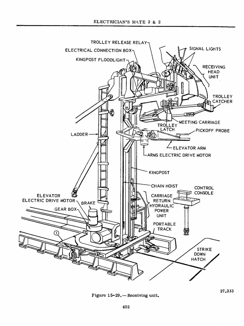
ELECTRICIAN’S NKTE 3 & 2
TROLLEY RELEASE RELAY-
ELECTRICAL CONNECTION BOX-
KINGPOST FLOODLIGHT-
SIGNAL LIGHTS
RECEIVING HEAD
UNIT
TROLLEY
CATCHER
PICKOFF PROBE
« MEETING CARRIAGE
TRQLLEY _ LATCH
LADDER
3 z *— ELEVATOR ARM
ARMS ELECTRIC DRIVE MOTOR
KINGPOST
CHAIN HO ST CONTROL
CONSOLE CARRIAGE
¥ RETURN
BRAKE HYDRAULIC
GEAR BOX ]| \ POWER
) UNIT
PORTABLE
/ TRACK □ » STRIKE DOWN
HATCH
X
ELEVATOR ELECTRIC DRIVE MOTOR
Figure 15-29. — Receiving unit. 27.333
402

Chapter 15—ELECTRICAL AUXILIARIES
unit from a remote control console (figs. 15-29 and 15-30). The control console is a portable aluminum box housing upon which the control switches and indicator lights are installed. Switches are grouped on the console by their control function.
The power switch is in the upper right-hand corner of the control console and connects and disconnects the 440 volts a-c ship power supply to all the electrical components of the receiving unit. The main electrical operations of the sys- tem are to (1) raise and lower the elevator, (2) open and close the elevator arms, (3) immobilize the meeting carriage when receiving the missile and when indexed-stowing the missile, (4) release
the trolley latch, and (5) operate the transfer signal holdup light.
An ultraviolet night light is installed above the console to illuminate the switch panel during night operation. When in use, the control console is installed on a pedestal near the receiving unit. When not in use, the control console is stowed within the console stowage box.
Elevator Drive Control System
The elevator drive control system raises and lowers the elevator. The elevator mechanism is supported by the kingpost. A chain hoist, located within the kingpost, is attached to the elevator
LAMP
■ «
«SN
-S 'S
© e s
9
Figure 15-30. — Control console on receiving ship 27.334
403

ELECTRICIAN’S MATE 3 & 2
and is driven by a bidirectional electric motor for elevator operation. The motor is mounted on the side of the kingpost near the base (fig. 15-29). The 5-hp motor operates on 440 volts a-c, 3- phase, 60-hertz at 1800 rpm. It is a watertight motor and drives the elevator through a worm- gear type speed reducer. A solenoid operated disc brake, installed on top of the elevator drive motor, performs fast action in stopping and starting the motor, thereby permitting the swift and accurate positioning required by the system. The operator at the console can stop the elevator at any position along the kingpost.
Electrical circuits provide the means to raise the elevator with the arms open and unloaded, or with the arms closed and loaded and to lower the elevator with the arms open and unloaded, or with the arm closed and loaded. Emergency circuits bypass the normal control switches to provide a built-in safety for emergency operation but should never by used unless an emergency arises.
Arms Rotation Control System
The arms rotation control system controls the opening and closing of the elevator arms for both normal and emergency operations. The arms system consists of an electric motor (fig. 15-29), a speed reduction gear box, and a cross-shaft, worm gear mechanism. The 1-1/2-hp electric motor is bidirectional and is watertight. It op- erates on 440 volts a-c, 3 phase, 60 hertz at
1800 rpm. The components, as a unit and with the necessary control circuitry, function to open and close the arms of the elevator.
Meeting Carriage Control System
The meeting carriage (fig. 15-29) receives and cushions the incoming missile, with the trolley catcher and jackknife units. The, meet- ing carriage is pushed back horizontally about 20 inches, moving from the fully extended RE- CEIVED position to the fully compressed IN- DEXED position. The carriage is- held in the indexed position by the trolley, which is re- tained by the trolley latch. When the trolley latch is released, the' trolley is pulled from the receiving head. Hydraulic pressure is auto- matically supplied to the carriagè return cyl- inder which extends the cylinder and moves the meeting carriage to the received position.
During operation when the trolley enters the receiving head, the jackknife folds back and mechanically operates an electrical limit switch. This action automatically energizes the carriage return solenoid valve (fig. 15-31B), and allows the hydraulic fluid within the carriage return cylinder to bleed off into the reservoir (fig. 15- 31A). AS the trolley moves all the way into the receiving head, the meeting carriage is, pushed back into the indexed position and the cylinder is collapsed. When the meeting carriage solenoid valve is deenergized, the supply port to the cylinder is open and hydraulic pressure pushes
ELECTRIC
MOTOR
PRESSURE RELIEF
BYPASS VALVE'
ACCUMULATOR
PRESSURE
GAGE CHECK VALVE
PRESSURE
SWITCH
RESERVOIR
SIGHTGAGE
I
SUPPLY HOSE
(TO CARRIAGE —
RETURN CYLINDER)
KINGPOST
LIGHT
SWITCH
CARRIAGE RETURN
SOLENOID VALVE
HYDRAULIC SJJPPLY
SHUT OFF VALVE
HYDRAULIC PUMP
MOTOR SWITCH
CONNECTION BOY
* \ DIMMER SIGNAL
LIGHTS
Figure 15-31. — Carriage return hydraulic power unit. 27.335
404

Chapter 15—ELECTRICAL AUXILIARIES
the meeting carriage into the received position. Upon trolley release, the jackknife and limit switch also return to their normal operating positions.
An electric motor mounted vertically on top of the reservoir (fig. 15-31A) operates a positive displacement gear type hydraulic pump located inside the reservoir. The motor is a 3 phase, 440 volt, a-c, 60-hertz, waterproof motor with a rating of 1-1/2 hp at 3600 rpm. Operation of the hydraulic pump motor is automatic and maintains the hydraulic fluid supply pressure at about 1000 psi. During operation whenever the supply pressure within the accumulator is below 950 psi the oil pressure switch (fig. 15- 31A) will close electrical contacts and start the pump motor operating. As the pressure inside the accumulator reaches 1000 psi the oil pressure switch electrical contacts will open and stop the motor.
The automatic controls can be overridden by the console operator.
Trolley Latch Release
The trolley latch (fig. 15-29) consists pri- marily of a latch pin and trunnion assembly, a locking arm, a solenoid, two limit switches, and a manually operated release lever. The latch will automatically fall into the latch hole in the side of the trolley when the trolley has been pulled into the receiving head sufficiently to push the meeting carriage into the indexed position.
The trolley latch release system has a blue signal light (not shown) located on the opposite side of the receiving head unit, and a blue indicator light located at the control console (fig. 15-30). The purpose of the electrical cir- cuit is to provide a visual indication for the winch operator on the supply ship and the con- sole operator on the receiving ship that the trolley is latched. When the trolley is latched, the blue trolley latched lights are illuminated and are extinguished when the trolley is re- leased.
The trolley latch signal light circuit receives 110 volt a-c power from the 450/120-volt trans- former. The 440 volt a-c power to the transformer is controlled by the power switch located on the control console.
The automatic trolley latch system can be manually controlled by releasing the latch either by the operator energizing the trolley release solenoid from the control console or by manually pulling the release handle on the side of the kingpost.
Transfer Signal Holdup Light
The transfer signal holdup light circuit has an amber signal (shown in fig. 15-29) located on the receiving head unit. An amber indication light is located on the control console. The purpose of the electrical circuit is to give a visual indication to the winch operator on the supply ship and console operator on the receiving ship when the ships are becoming too far off station. Whenever the receiving head trains more than 30 degrees off station, the lights are il- luminated. This light circuit also enables the console operator to signal the winch operator to temporarily stop operation.
The holdup transfer signal light circuit re- ceives 120-volt a-c power from the 440/120- volt transformer. The 440-volt a-c power to the transformer is controlled by the power switch located on the control console.
ELECTRIC FORK LIFT TRUCK
Electric fork lift trucks are primarily used for the handling, transporting, and warehousing of materials in confined areas where engine exhaust fumes cannot be tolerated (fig. 15-32). The larger vehicles we electric powered, front- wheel drive, rear wheel power-steering fork lift trucks (fig. 15-32A). A 36 or 24-volt storage battery is required to furnish power for the traveling, steering and lifting mechanism. The drive mechanism includes an electric drive (traction) motor, coupling, power axle assembly and control. Control of the travel circuit pro- vides one automatic accelerating speed plus four forward and four reverse controlled speeds.
The lifting mechanism includes an electric motor, hydraulic pump, hydraulic fluid reservoir, hoist, tilt, and side shift cylinders, directional control valve, forks, and controls.
The vehicle steering system consists of a steering motor, pump, steering gear assembly, power steering unit, trailing ajde, and controls.
405

5.58(77C)A

Chapter 15—ELECTRICAL AUXILIARIES
The brake system consists of a master cyl- inder, mechanical parking brake and hydraulic service brakes.
Truck speed control is accomplished by con- trolling the average power delivered to the drive motor over a given period of time. Most fork lifts have speed controls which are of INCRE- MENTAL TYPE, whereby a bank of resistors is inserted into or shorted out of the circuit, in order to obtain speed control. The STEPLESS TYPE in the newest forklift truck uses silicon controlled rectifiers (SCR) control circuitry. The incremental-type truck control is similar to a car with a standard shift, and the stepless type of control is similar to a car with an automatic transmission which will provide for smooth con- trol of the speed.
Many of today’s shipboard requirements for material handling operations necessitate very smooth acceleration of the electric truck. Smooth acceleration for a major portion of the speed range is highly desirable and permits accurate maneuvering of the truck for spotting loads in congested areas.
The electrical system (fig. 15-33) may be logically divided into a power circuit and a con- trol circuit. These two circuits comprise the circuitry for the hydraulic pump motor, the steer motor, and the drive motor.
PUMP MOTOR
The hydraulic lift pump motor power circuit consists of the pump motor and contacts of the pump relay coil (P). The pump motor control circuit consists of the pump relay coil(P), and lever valve switches that are actuated by a hy- draulic control valve.
To operate the truck’s lift system, the bat- tery switch must be closed and the key switch turned on. The movement of one of the lever valve switches, starts the hydraulic-lift pump motor. When the levers are returned to neutral, the pump motor stops.
STEER MOTOR
The steer motor power circuit consists of the steer motor and contacts of the steer relay coil (S). The steer motor control circuit has a
relay-coil (S) and, on the seated-type fork lifts, a steer switch that is closed when the operator is seated, therefore the motor is in continuous operation while the operator is seated. This permits power steering even though the truck is not moving.
DRIVE MOTOR AND CONTROLLER
The drive motor controller regulates the speed of the series drive motor by means of solid state control circuitry integrated with mag- netically operated devices. This circuitry en- ables heavy loads to be handled at low speeds with very little battery current, re suiting in extra hours of operation. For full speed cruising, the solid state system is removed from the control circuit thus connecting the drive motor across the battery supply.
The drive motor POWER circuit (fig. 15-33) consists of the drive motor with its seriesfields, the contacts of the speed changing relays (1A, 2A, 3A, 4A), and contacts of the forward and reversing relays (F, R).
In the drive motor CONTROL circuit, the accelerator pedal switches provide the four ac- celerating speeds by controlling the series fields of the drive motor. The control circuit also includes the speed changing power relay coils (IA, 2À, 3A, 4A); the directional relay coils (F, R) and the necessary interlocks which are mechanically operated by the respective contactors. For instance, when the “2A” con- tactor coil is energized, its normally-opened contacts close, and its normally-closed contacts open. Another component, the static timer, serves to provide an adjustable time delay between first and second speed and one between second and third speed, as well as a fixed time delay between third and fourth speed. The brake switch, op- erated by the brake pedal, interrupts the drive control circuit whenever the brake pedal is de- pressed and also provides power for starting up on a grade by means of the anti-rollback (ARB) connection of the static timer. The static timer also provides for controlled plugging. Control fuses (not shown) protect the drive motor and the static timer against electrical faults. Thermal switches (not shown) serve to open the drive and steer motor circuits in case motor frame tem- peratures reach 225°F.
The master accelerating switch used for con- trolling truck speed is a manually operated pilot
407

ELECTRICIAN’S MATE 3 & 2
BATTERY SWITCH
A/ -or^'o-
FUSE l|F
36 VOLTS
A1fAR^
■o-
■w FIELD
1A==
DRIVE MOTOR
FIELDS
=P3A
-W—"
5-4A
STEER MOTOR
POWER CIRCUITS (HEAVY LINED)
DIRECTION SWITCH
DRIVE MOTOR
1 KEY SWITCH
; BRAKE PEDAL SWITCH
-r> I o-
MS-1 12 3 4
HI—i x ÿ ÿ
MS-2
MS-3
X-+
FWD
^-0 X REV
2 A
INTERLOCKS
A 2 A^=
STATIC TIMER
I ARB I [PLUGI H
^ IZZjTDR-lf-
T/W M— RECTIFIERS
■VWR M—
I SS I
pÜDRl 1
-1 |SS- 2 I
MS-4 X=CLOSED I I I
ACCELERATOR PEDAL SWITCH
AUXILIARY T STATIC] TIMER
TDR-3
. J
n ULU-
I 4A
STEER SWITCH
4 A1
LEVER VALVE
o<o—
—0^0—
HOIST —cr^o—
<!> STEER RELAY COIL
<Z>! SWITCHES ATTACHMENT
PUMP RELAY COIL
— LEGEND -
1A TO 4A-SPEED CHANGING POWER RELAYS ARB-ANTI ROLL BACK
F-FORWARD RELAY L— LINE RELAY
MS-MASTER SWITCH CONTACT
P-PUMP RELAY R-REVERSE RELAY S-STEER RELAY
SS-STATIC SWITCH TDR-TIME DELAY RELAY
Figure 15-33. — Wiring diagram of an electric fork lift. 5.88(77C)B
408

Chapter 15—ELECTRICAL AUXILIARIES
device to control magnetic contactors, which in turn, control the' drive motor of the vehicle. An off position and four speeds are provided. The switch ¿is operated by an accelerator pedal.
Ther' directional master switch is the mechanism by which the operator can determine direction in operation of the vehicle. The switch is a three position, manually operated, two-circuit pilot device, designed for handling coil circuits of directional magnetic contactors, which must be energized to initiate movement of the truck.
The heart of a solid state speed control system is the silicon controlled rectifier. Essentially, the . SCR is nothing but a rectifier except that a control element commonly referred to as a gate has been introduced. As applied in stepless truck control systems, the silicon controlled rectifier is nothing but a switch.
Static Speed Control
Refer to elementary wiring diagram figure 15-33 and to the motor field connections table 15-1. In normal operation, when the directional control handle is moved to forward or reverse and the accelerator pedal is slowly depressed the following sequence takes place.
FIRST SPEED.—As the accelerator pedal is depressed to the first speed, master switch 1 (MS-1) is closed. If the direction handle is placed in forward position, the (F) contactor picks up and the drive motor is in first speed.
SECOND SPEED.—The pedal is depressed to the second speed point to close (MS-2) and a ositive voltage appears at Time Delay#!, SS 1 anode, and Time Delay #2, on the static timer.
Table 15-1. — Drive Motor Field Connections
The positive voltage appears at these points because of the low resistance path through the 1A coil. The very small currents needed to operate the time delay circuitry is about 1/100 of that needed to operate the coil and hence only a small voltage is dropped across the coil. Now Time Delay #1 cannot operate until a positive voltage also appears from either ARB (anti- rollback) or the plug. A positive voltage could only come from ARB when the brake pedal is de- pressed which is not likely when trying to go forward. However, a small positive voltage comes through the plugging section due to the voltage developed across the armature of the drive motor. Now Time Delay# 1 does operate, fires SS#1 and picks up 1A coil, whichprovides the second speed.
THIRD SPEED.—The pedal is depressed to third speed point to close (MS-3) and a positive voltage appears at Time Delay #2 and SS #2. Since 1A has already picked up, a negative volt- age is at the top input to Time Delay #2 and after a time delay, SS#2 operates and 2A coil picks up, which provides the third speed. Now 2A interlock leading to (MS-4) closes providing a positive voltage to the left of (MS-4) to ready the control of the fourth speed.
FOURTH SPEED.—The pedal is depressed to the fourth speed point to close (MS-4) and to open MS2 which deenergizes relay 1A. In a manner similar to the previous steps, the Auxiliary Static Timer gives a time delay to the pickup of (4A). After (4A) closes, both normally open (4A) inter- locks close. One shorts out the Auxiliary Static Timer and turns it off. The other interlock lets (3A) coil pick-up to shunt the field. However, relay ÍA has opened therefore a field is still present. The 4A coil picks up before the (3A) coil so that any arc that might be present when the normally closed (4A) contacts break will be extinguished before (3A) picks up. Otherwise, a direct short may occur. This provides the fourth speed.
Speeds Power Tips Motor Fields
Speed 1 Speed 2
Speed 3 Speed 4
All Open 1A Closed
IA, 2A Closed 1A, 2A, 3A
Closed
All Fields Energized Three Fields Ener-
gized Two Fields Energized One Field Energized
77.335
ELECTRIC GALLEY EQUIPMENT
Electric galley equipment comprises the heavy duty cooking and baking equipment installed aboard naval vessels and consists essentially of ranges, griddles, deep fat fryers, roasting ovens, and baking ovens (fig. 15-34). This equipment is supplemented by electric pantry equipment, which includes coffee urns, coffee makers, griddles, hot- plates and toasters. The number and capacity of the units comprising a galley installation depends
409

ELECTRICIAN’S MATE 3 & 2
ft* ••• •••
having two 3 kw enclosed heating units. A sim- plified wiring diagram of a type A range is illus- trated in figure 15-35.
OVENS
* 3
A - TYPE A RANGE B- TYPE 60 OVEN
C - TYPE 90 FRY KETTLE
48.8:11 Figure 15-34. — Electric galley equipment.
A type 60 roasting oven is pictured in figure 15-34B. Type 60 and type 125 ovens are sec- tional type ovens with each section constituting a separate oven that is thermally insulated and operated independently of the other sections. The roasting ovens are provided in either 2 or 3 sections mounted one above the other. These ovens are provided with a separately mounted switchbox which contains the fuses, contactors, and 3-heat switches for each section. The type number of these ovens denotes the capacity in pounds of raw meat per section.
The type 4 and type 6 baking ovens are the older type having baking decks (the type number denotes the number of decks) that are not ther- mally insulated from each other. The heating units are located at the top and bottom of the oven and between each deck. Each heating unit is con- trolled by individual 3-heat switches located in a switch box enclosure mounted on the right- hand side of the oven.
The type 12 and 18 baking ovens are sectional type ovens with each section constituting a separate oven that is thermally insulated and operated independently of the other sections. Each section of the type 12 or type 18 ovens has a capacity of six standard five-loaf bread pans. The type 12 oven consists of two sections mounted one above the other. The type numbërs denote the total bread pan capacity of the oven.
on the size and type of ship. Galley equipment is normally designed for operation on 115-volt or 230-volt, d-c power or 440-volt, 3 phase, 60 hertz, a-c power.
RANGES
Electric galley ranges are provided in type A (36-inch), type B (20-inch), and type C (30-inch). The ranges consist of a range-top section and an oven section assembled as a single unit, and a separate switchbox designed for overhead or bulkhead mounting. A type A range is illustrated in figure 15-34A. This range is provided with three 6 kw surface units and an oven section
DEEP FAT FRYERS
Electric deep fat fryers are normally pro- vided in the type 23, type 45, and type 90 sizes rated at 5 kw, 10 kw, and 18 kw, respectively. A type 90 deep fat fryer is shown in figure 15-34C.
The heating units, which are of the enclosed type, are immersed directly in the fat to ensure maximum efficiency. The fryer is equipped with an adjustable automatic temperature control to maintain the fat at the desired temperature. The thermostat control, located on a panel at the front of the fryer, is provided with an OFF position and the adjustable temperature range of 250° F to 400°F is graduated on the control knob.
410

Chapter 15—ELECTRICAL AUXILIARIES
RANGE CONTROL BOX
OVEN THERMOSTAT
< RIGHT PLATE THERMOSTAT
< CENTER PLATE THERMOSTAT
«y'
LEFT PLATE THERMOSTAT
LOWER OVEN
SWITCH
LOWER OVEN
O I RELAY
■ ■ >
UPPER OVEN SWITCH
UPPER OVEN
r\J RELAY RIGHT PLATE
CENTER RELAY PLATE
RELAY LEFT PLATE r\j
RANGE CIRCUITS
L2
L3
OFF HIGH MED
OVEN SWITCH CONNECTIONS
LOW
TO LINE
INNER ROD
77.191 Figure 15-35. —Schematic diagram of type A range.
411

ELECTRICIAN’S MATE 3 & 2
vwvwwvwwww
THERMOSTAT
AA/WVWWWWW wwwwwwwvw ywwwwwwww LINE DISCONNECT
SWITCH HEATING UNITS
CUTOUT i BLOCK
a > <
Y ÜL
L|—»A-r«
^ ^IIOV |-|-»0-rO 440 V
N F IrN t=
3 PHASE LOADING ÍKW PER PHASE) y
X-Y Y-Z X-Z
4.5 4.5 9.0
7 CONTACTORS
SHUNT TRIP COIL
450 VOLT
H-5 VOLT
Ov ON O
) ) ) CIRCUIT BREAKER
I o
HIGH TEMP
THERM SWITCH
AUXILIARY ON-OFF SWITCH
INPUT
440 VOLT 60 HERTZ 3-PHASF
Figure 15-36. —Wiring diagram of type 90 deep fat fryer
77.193
412

Chapter 15—ELECTRICAL AUXILIARIES
The thermostat operates contactors, which, in turn, control the circuits to the heating units. The later models of fryers are equipped with an upper temperature limit thermostat which op- erates in the event of failure of the main thermo- stat. The contacts of the upper limit thermostat are connected to the shunt trip coil of an ex- ternal disconnect breaker when the fryer is in- stalled. In the event the fat temperature reaches 460 degrees F., the thermostat contacts will close, thus tripping the breaker and deenergizing the fryer.
A rotary switch also located on the front panel is provided for disconnecting the fryer from the line. As a safety measure, the switch should be turned to the OFF position when the fryer is not in use.
A compartment located inside the fryer con- tains the contactors, thermostat, heating unit terminals, line terminal block, fuses, and line switch. The compartment is equipped with a removable panel for access to the control devices. Figure 15-36 is a simplified wiring diagram of the type 90 fryer.
MAINTENANCE
Before starting any servicé work on electric galley equipment be certain that the equipment is disconnected from the power supply.
Refer to the manufacturers’ manuals for in- structions concerning the servicing of the elec- tric galley equipment installed aboard your ship. These manuals also include the methods of re- moving and replacing the various heating units, thermostats, switches, contactors, and other components of electric cooking equipment.
Galley equipments are normally trouble-free. The largest single trouble with electric ranges, ovens, and deep fat fryers is burning contacts. As the operating temperature is met on the thermostat, the contactor will open under heavy load causing its contacts) to arc and burn. This problem is lessened to a certain extent by the use of high voltage capacitors connected in parallel with the contacts. Another common problem con- cerns corroded connections due to prolonged exposure to heat and grease. A concentrated effort must be made to follow prescribed planned main- tenance, and when necessary, corrective main- tenance procedures.
LAUNDRY EQUIPMENT
Laundry equipment aboard ship is comprised of washers, extractors, and dryers separately or in combinations. This equipment is designed to operate primarily on 3-phase, 440 VAC, 60-hertz power. The fully automatic washer-extrator with a card-o-matic programmer for controls is a representative piece of equipment. It has an automatic supply hopper, which is the main dif- ference between it and a semiautomatic unit. There is little electrical difference between the card and drum type programmers.
WASHER-EXTRACTOR
The cylinder of the washer-extractor (fig. 15-37 and 15-38) has a 100-pound dry weight capacity. A three-motor system drives the cyl- inder through its cycles by means of V-belts, speed reducers, and an air-operated clutch. Elec- tric solenoids control the supply of air for op- erating the clutch, brake, drain and steam valves, and detergent dispenser. Water level is controlled by three pressure-operated level switches; the water temperature by three adjustable ther- mostats. The machine may or may not have an automatic steam feature to help maintain water temperature throughout the wash cycle.
Though designed to operate automatically (formula mode), the washer-extractor can op- erate in the manual mode or in a combination of the two modes. The sequence and duration of the oper- ations in the formula mode are controlled by the card-o-matic programmer (fig. 15-39). In the manual mode, the machine operator controls the duration and sequence of the wash/extract cycle by positioning switches as desired. He also adds detergent supplies as desired.
Card-O-Matic Programmer
The programmed card that the operator selects should be determined by the type of washing to be done. He uses a different card when washing greasy dungarees than when washing T-shirts. The dungarees require a longer wash time, hotter water, and stronger detergent.
The formula card (fig. 15-40) has eleven tracks on each side. The tracks on the front side are numbered 1 through 11, and the tracks on the back side are numbered 12 through 22. These
413

ELECTRICIAN’S MATE 3 & 2
ik-
12
10
10
1. OPERATING CONTROLS 2. REMOVABLE SIDE PANEL 3. DOOR BUMPER 4. LIFTING BAR 5. DATA PLATE 6. SUPPLY HOPPER 7. DRAIN VALVE AIR CYLINDER 8. WATER LEVEL BELLS 9. DRAIN VALVE
10. BASE PLATE 11. SIGHT GLASS 12. FRONT PANEL 13. TUB DOOR LATCH
Figure 15-37. —Front right view. Class 2258 Cascadex Washer Extractor. 77.328
414

Chapter 15—ELECTRICAL AUXILIARIES
5 6 7 8 9 3 4
a On
14
15
0
7
19 O
20 n 2
22
23
23 25
1. VIBRATION SWITCH 2. HIGH BRAKE SOLENOID VALVE 3. SUPPLY TRIP SOLENOID VALVE 4. CLUTCH SOLENOID VALVE 5. DOOR INTERLOCK SOLENOID VALVE 6. DRAIN VALVE SOLENOID VALVE 7. STEAM VALVE SOLENOID VALVE 8. LOW BRAKE PRESSURE SWITCH 9. ELECTRICAL ENCLOSURE
10. SUPPLY FLOW CONTROL VALVE 11. LOW BRAKE PRESSURE REGULATOR 12. LOW BRAKE SOLENOID VALVE 13. ELECTRICAL DATA PLATE 14. LOW BRAKE PRESSURE GAGE
15. LIFTING BAR 16. SYSTEM AIR PRESSURE GAGE 17. SYSTEM AIR PRESSURE REGULATOR 18. AIR FILTER 19. MANUAL BRAKE RELEASE 20. SALT WATER INLET 21. VENT AND OVERFLOW 22. STEAM VALVE 23. BASE PLATE 24. MASTER CYLINDER 25. BRAKE ACTUATING CYLINDER 26. HOT WATER VALVE 27. COLD WATER VALVE
Figure 15-38. —Rear left view, Class 2258 Cascadex Washer Extractor, 77.329
415

ELECTRICIAN’S MATE 3 & 2
20
19
16
10 15 14
13 12
1. RUN INDICATOR 2. STOP INDICATOR 3. FORMULA CARD WINDOW 4. SIGNAL INDICATOR 5. SIGNAL SWITCH 6. LEVEL SWITCH 7. MASTER SWITCH 8. SAFE ON SWITCH 9. STOP INCH PUSHBUTTON
10. INTERIOR LAMP (NOT SHOWN)
11. THERMOMETER 12. INCH START SWITCH 13. STEAM SWITCH 14. EXTRACT SWITCH 15. CARD ADVANCE WHEEL 16. DISCONNECT SWITCH 17. OVERLOAD RESET BUTTON 18. COLD WATER SWITCH 19. HOT WATER SWITCH 20. DRAIN VALVE SWITCH
Figure 15-39. — Location of operating controls and indicators, 77.330

Chapter 15—ELECTRICAL AUXILIARIES
tracks identify the operation. The numbers and index marks on the program time columns (C in fig. 15-40) are graduated in one minute intervals and determine the duration of the op- eration, forming the wash/extract cycle.
Cards are programmed by removing a section from the track which cause a spring-loaded actuator to move as the formula card is ad- vanced by the programmer drive motor. This
I 2 3 6 7 8 9 tO II 12 13 14 15 16 17 18 19 20 21 22
83 — —
\T7 /
movement energizes and deenergizes the elec- trical circuit for the components (drain valve, water valve, level switch, supply dispenser, etc) related to the track.
Sequence of Operation
A sequence of operation is given here to aid the Electrician’s Mate in maintenance of the machine. With the master switch in the off- position, other applicable switches are placed in their formula positions (fig. 15-39 and 15-41). The correct formula card is inserted in the programmer and the cycle is started by placing the master switch in the formula position and momentarily pressing the start pushbutton.
After the machine starts the water tem- perature, water level, and addition of detergents are controlled by the programmed card. Incorrect programming of the formula card may cause the motor to stop.
The run indicator lamp lights and remains lit throughout the wash/extract cycle except when steam or water is being added or when the signal indicator is lit and the buzzer is sounding.
The SIGNAL indicator lights and the buzzer sounds at programmed times to signal the op- erator to return to the unit to add detergents or check the progress of the wash/extract cycle. The cylinder stops when the signal indicator is on. Momentarily pressing the signal switch to the OFF position puts out the signal indicator, stops the buzzer, and restarts the wash/extract cycle.
During the wash cycle, the cylinder is rotated at 35 rpm and reversed 4 times per minute. During the distribution operation the cylinder turns at 45 rpm in one direction only. After the last programmed wash operation, the drain valve opens and remains open. The extract oper- ation then starts.
A. TRACK NUMBERS ON FORMULA CARD FRONT SIDE (Tracks No. 1 thru No. 11)
B. TRACK NUMBERS ON FORMULA CARD BACK SIDE (Tracks No. 12 thru 22)
C. PROGRAM TIME COLUMN
77.293 Figure 15-40. — Front and back sides of a for-
mula card.
During the extract operation the clutch is disengaged and the cylinder is rotated at 650 rpm in the same direction as the distribution cycle. At the end of the extract operation, the cylinder decelerates to the wash speed (35 rpm) and re- establishes the wash cycle unless the formula card is programmed to stop or the operator presses the stop pushbutton. At this point, the operator places the master switch in the OFF position, opens the tub door, and removes the
417

ELECTRICIAN’S MATE 3 & 2
Table 15-2„ — Formula Card Track Number, Track Designation, and Related Function
TRACK NO. DESIGNATION RELATED FUNCTION
1* No. 1 thermostat Regulates the tub water temperature to no. 1 thermostat control point
2* No. 2 thermostat Regulates the tub water temperature to no. 2 thermostat control point
3* No. 3 thermostat Regulates the tub water temperature to no. 3 thermostat control point
Hot water Controls hot water valve operation
Cold water Controls cold water valve operation
Drain valve and no. 2 water level
Controls drain valve operation and no. 2 water level
No, 3 water level Controls no. 3 water level
No. 1 water level Controls no. 1 water level
9* Steam Controls the steam valve in conjunction with track no. 1, no. 2 or no. 3, or controls the steam valve if steam is to be injected for a pro- grammed time period
10 Signal Controls the SIGNAL indica- tor and buzzer
11 Stop Controls the STOP indicator and stops the unit and con- trol when all operations are finished
12 Extract Controls extract operation
13* Supply track Dispenses supplies from the automatic supply dispenser
14 thru 22 Not used
The maximum length a wash extract cvclecan be programmed for is 85 minutes.
*Used only if unit has steam option
77.333
418

Fig
ure
15-4
1. —
Sch
em
atic
dia
gra
m o
f wash
er-e
xtra
cto
r.
00 00
LI L2 L3
.w
LLIILL
VV\ EXTRACT TIMER TIME CHART
ILLS ILLI ILLS DRAIN DISTRIBUTION BRAKE F8R-0.L SWITCH
OC^ TIME IN SECONDS
0 10 20 30 AO 50 60 70 80 90 I0OMOI2O NO
W3 ET I
WASH FaR-0 L. MOTOR ET2
E T 3 D-0 L,
oo ET4 DI2
440V H2 513 DI3 117 oo ET 6 D-0 L. DISTRIBUTION
MOTOR
E2I .—.
rvw’vwN
ñ! E-0 L SOLID AREAS INDICATE
THAT N.O CONTACT HELD CLOSED
S2I OO
E22 S23
OO E-0 L EXTRACT
MOTOR
PS SET TO CLOSE ABOVE 40 PSI
EXTRACT TIMER MOTOR
ET 6 FaR-O-E O.L CR32 ft NO
ENERGIZE TO UNLOCK DOOR
Ÿ DOOR UNLOCK ’
NC° CR32 NOo
C R 31
HI BRAKE
SAFE ô NO-L ON
O NO-L NO-R STOP INCH DOOR SW VIB SW CR4
60 eo CR\RUN NO-L >—Q I Q- O I O CR3I
CR3I 84 CCW
NC-L ET2 CR 32 rfTc‘“1051—lh
CR3I CR2I 87
qp 1 _ NO? I CRB
o o NO-L
EXTRACT •LO P2-2
N0~ I RED BRAKE P2-3
P2- FORMÓ ORN I
CR3I EXTRACT CR3 TRACK 12 CR
ET3 CR3
-©* -ccw 96 ET 4 NC O
NCO 1 L _ _ J -CLUTCH
MASTER MAN Dl-I \0 CARD LIGHT MAN MASTER
0/ pi-6 DFFQ t>r>>. »— OFF P -4
102 P-5 STOP CR BRN BLK STOP
RED YEL STOP NCO
BUZZER ¿ L n ——, / \ SIGNAL
r ÑCO?.Q.RN L I
P -7 NO i_^r_ VIO *' SIGNAL
-SIGNAL PAUSE TRACK«f|l PINK
SIGNAL CANCEL
OFF
PI-6 SIGNAL
98 PJ;23GRN L NO TRACK# 10 - SIGNAL CANCEL DRAIN S
^2 LEVEL YEL
CR ADD JUMPER WHEN THERM STEAM IS NOT TO STOP CARD MOTOR NO RUN
MASTER SIGNAL SIGNAL
BRN OR 2 CRI ? &—
GND
TRACK# 6 ...
PI-9 CR3I CRB CR5 PI_|Q\UWMN / — \
ILUE L ?I E AM _ j25 BLU/Q ~ YEL¿ 7%. p
JUMPER WHEN LEVEL FORN »T TO STOP CARD MOTOR /7r-N
r~W rucor.nc Tn i
O MAN CARD MOTOR
VIO, I LEVEL BLK
FORM 6 yYELvx PI 'DRAIN
OPE
ENERGIZE TO CLOSE DRAIN
- DRAIN CLOSE DRAIN
-#■2 LEVEL ^ILtVEL Pl-35 ^NC 26 p|-'2 ORN CR 27/1
PI-36» NO COLD WATER LEVEL SPARE TRACKS
ORNI NCÇ| I L
TRACK#8 L
NO # I LEVEL
I FORM COLD WATER PI-34 TRACK#I4 p2_9 TRACKS 19 P2-30 VIO
L^fjPINK 7 PU14
TRACKS 5 °FFA5RÑ^~
COLD WATER SOLENOID
P2-I0 NOp^ > P2-3I NO NUQp- IORN ^ALEVE^L V3°y
r NO^J Xf 3 LEVEL P2-8 < PINK
vio I CR 7 RED NC° NC° L-l^ —'BRN L __ JYEL P2-29 BLK LO TEMP TRACK'S p2,(2 TRACK-3*20 N CO P2-33 CR 6 29/Vi^/
LEVEL PRESSURE SWITCHES NC OPENS WHEN
CR7 P2-I3 NOC*T ^ P2-34 NOo- ^ f—>^!BLUP2-Il
TRACK# 7
ORN I NO THERM VIO. LO TEMP LOFORM NC LNC_JBL HOT WATER L 1-_ JYEL
TR ACK # 16 . NO LEVEL REACHED TRACK#2 P2-I5
r' I FORM HOT WATER 1 NC° ToiTi °/ PI-15
NO HOT WATER SOLENOID
LEVEL OFF L-^cZTBLU y
ITRACK#4 0FF(^ > - — — ■ oN
P2-35 LOFORM SWITCH ORN BLU I NC RED
L ^9. JBLK
TRACK #■ 17 _
1 -IpiNK
TRACK#22
p2-39^
PI-30 PI-29 THERM# Pl‘32 ( THERM#2 P|-27r Ñ0!H
L3 # \ r NOOr-^
NO THERM P2-23 PI-26 P2-24.; N0O-i
OFF
I^IŸÊT^ p5 r°^ i P2-22 i
THERM# BLUE , P2-38 RED BLU I PI-33 NO RED PINKLNC_oj THERM SW
LNC_J PI-25 BRN PINK NCV TRACK# BLU| NCÇ» L»^BLK| 1
l_ _ JPINK BRN \ 7 p|-20 5 s~\#2 THERM SW
-» *-4o~¿F
TRACK# 2 TRACK # 3
YEL" v_y
6 3THERM SW -LO TEMP
IN 2404 Pl-31
e CR VÍ760MFD
±_dAilOV BLK B 450 it 7
12 W STEAM STEAM I 1 ON©/
1-16 32 PI-39 NOp /
>>~ r «YF,r^ p'-3^F3FtH o YF-|- Nroj KV^-ON I
CR2 CR 7 IN2484 — STEAM P -
450^.10 12 W
VIO LEVEL L - "ÜjRED^ FORM°
ON
LO TEMP
CR6
^ 1 .... " NO T!
EAM
JL SUP PLY
P2-7i NC ~| I O—
P2-4 CR
I P'NK P2-6 “LUI NOÖH
GND
^ACK^ie p2_27 P2-28| N°9- >
<or BLKP2-26 RED I ^ L NC IBRN7
ALL CARO-O-MATIC TRACKS RETURN TO N C POSITION WHEN TRACK I S CUT
SWITCH LEGEND
NO- HELD CLOSED
O NC- HELD OPEN
O NO - OPEN
NC-CLOSED
L___¡ VIO
TRACK#I3
STEAM
SOLENOID
"SUPPLY
SUPPLY TRIP
SUPPLY SPRAY


Chapter 15—ELECTRICAL AUXILIARIES
load and formula card. The formula card track numbers with designations and functions are given in table 15-2.
Safety
The dry weight cylinder capacity (100 pounds) should never be exceeded, but it is recommended that the cylinder be loaded to capacity. Lighter loads may fail to distribute clothes properly, causing the machine to vibrate excessively.
Safety features of the washer-extractor include a mercury vibration switch to stop the machine in case of excessive vibration and a tub-door interlock system to prevent the tub door from being opened while the machine is running. The tub-door interlock system also prevents the machine from starting when the door is open.
Be certain that the machine is disconnected before performing maintenance. Refer to the manufacturers’ manual and NAVSHIPS Technical Manual for instructions concerning the trouble- shooting and replacement of defective parts in the laundry equipment installed aboard your ship.
419

CHAPTER 16
SOUND MOTION PICTURE SYSTEMS
The sound motion picture system As designed for use as an aid in training, briefing, and entertaining naval personnel. The system As comprised of a motion picture projector, ampli- fier(s), and one or more loudspeakers. Navy equipment is readily portable and can be operated in any average size space, or topside, where 115-volt a-c power is available.
This chapter will not qualify you to operate a Navy projector. It will, however, give you the principles of motion picture projection; tell how films are prepared, inspected, and handled; and describe the paper work required for reports and records.
DEFINITION OF TERMS
Definitions of terms are included in this chapter so you can find the meanings of technical terms that are used in explaining the principles of motion picture projection and in telling you how to operate a projector, prepare film, and perform other tasks related to the showing of sound motion pictures. • Acoustics — A science that deals with the
production, control, transmission, reception, and effects of sound.
• Aperture — An opening in a film guiding plate that limits illumination to one frame at a time.
• Aperture Plate — A guide plate containing aperture, used also to prevent lateral film movement. • Cement — A solution used to join two pieces
of film together. • Condensing Lens — A lens that concentrates
the light of the projector lamp upon the aperture. • Damping System — A system used to smooth
the flow of film movement through the sound optic system.
• Emulsion—The film material composed of gelatin and silver-nitrate, that contains the image.
• Exciter Lamp —The lamp that furnishes light for the sound optical system.
• Film Base —The cellulose acetate material that supports the emulsion. It also contains the sprocket holes.
• Focusing—The act of adjusting the projector lens to obtain a sharp image on the screen. • Framing — An adjustment that centers the
frame to be projected over the aperture. • Image — The likeness obtained by photographic
means.
• Lens — A glass optical device used to transmit and control the light passing through a film. • Matte White — A cloth screen. • Motion Pictures — A series of still pictures
projected at a rate sufficient to produce the “illusion of motion.” • Pressure Plate — A device that provides a
constant and proper pressure on the film as it passes the aperture.
• Projector — An electromechanical device that reflects an image on a screen by the use of a light transmission path.
• Reel — A metal or plastic spool upon which film is wound prior to, and following projection. Standard sizes are 400, 800, 1200, 1600, and 2000 feet. • Shuttle — The electromechanical device which
advances the film to the aperture. • Sound Optic System — The system which con-
verts light variations, representing sound, into corresponding electrical variations.
• Sound Optical Lens — The portion of the sound optic system which focuses the exciter output on the sound track.
• Sound Track—The portion of film upon which sound is photographically recorded. • Splicing — The act of joining two pieces of
film together as one continuous film strip. • Sprocket Holes — The holes along one edge
of film which are engaged by the sprockets. • Sprockets — Toothed gears which advance the
film through the projector at a constant rate of speed.
420

Cnapter 16 —SOUND MOTION PICTURE SYSTEMS
LENS LIGHT PICTLINE
SCREEN
7.65(77C) Figure 16-1. —Simple Projection System,
• Threading—Proper placement of the film for projection.
SOUND MOTION PICTURE PROJECTION
Motion picture projection is the presentation on a screen, of a series of images taken in very rapid succession by a motion picture camera. Such a presentation produces an illusion of mov- ing images. As you look at the screen, what you are actually observing is a series of still
pictures projected in rapid succession. The illusion of motion is created by taking advantage of certain peculiarities of the eye.
At one time or another, as you have closed your eyes after having looked at a bright light, you may have noted that the light impression was retained for a brief period of time after you had shut it out. This is known as “per- sistence of vision” and makes motion pictures possible.
Persistence of vision is the ability of the eye to retain upon its retina, the impression of light after the light is removed from view. If a series of picture images, each one of which differs but slightly from the preceding one, is viewed in rapid succession, the brain retains an impression of the preceding image and blends it with the succeeding image to create the illusion of motion.
The projection of pictures is based upon the principle of formation of images by a convex lens. The image forming properties of a micro- scope or telescope are similar. A simple projection with no motion would contain a lamp., a lens, and a screen (fig. 16-1). Note in the illustration that the image would be inverted after the light rays pass through the convex lens.
A basic motion picture system (fig. 16-2) could be developed from this simple system by the addition of a reflector, an intermittent
REFLECTOR
/""N APERTURE I PROJECTION LENS
CONOENSINO LENSES 8 ✓ FILM
OPTICAL AXIS PROJECTION LAMP
SCREEN
77.265 Figure 16-2. —Motion Picture Projection System.
42l
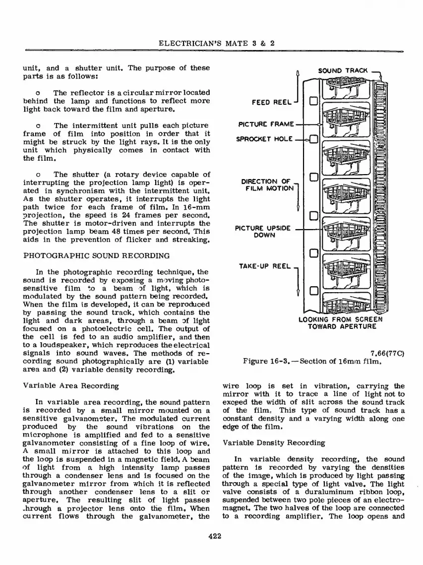
ELECTRICIAN’S MATE 3 & 2
unit, and a shutter unit. The purpose of these parts is as follows:
o The reflector is acircular mirror located behind the lamp and functions to reflect more light back toward the film and aperture.
o The intermittent unit pulls each picture frame of film into position in order that it might be struck by the light rays. It is the only unit which physically comes in contact with the film.
o The shutter (a rotary device capable of interrupting the projection lamp light) is oper- ated in synchronism with the intermittent unit. As the shutter operates, it interrupts the light path twice for each frame of film. In 16-mm projection, the speed is 24 frames per second. The shutter is motor-driven and interrupts the projection lamp beam 48 times per second. This aids in the prevention of flicker and streaking.
PHOTOGRAPHIC SOUND RECORDING
In the photographic recording technique, the sound is recorded by exposing a moving photo- sensitive film to a beam of light, which is modulated by the sound pattern being recorded. When the film is developed, it can be reproduced by passing the sound track, which contains the light and dark areas, through a beam of light focused on a photoelectric cell. The output of the cell is fed to an audio amplifier, and then to a loudspeaker, which reproduces the electrical signals into sound waves. The methods of re- cording sound photographically are (1) variable area and (2) variable density recording.
Variable Area Recording
In variable area recording, the sound pattern is recorded by a small mirror mounted on a sensitive galvanometer. The modulated current produced by the sound vibrations on the microphone is amplified and fed to a sensitive galvanometer consisting of a fine loop of wire. A small mirror is attached to this loop and the loop is suspended in a magnetic field. A beam of light from a high intensity lamp passes through a condenser lens and is focused on the galvanometer mirror from which it is reflected through another condenser lens to a slit or aperture. The resulting slit of light passes .hrough a projector lens onto the film. When current flows through the galvanometer, the
SOUND TRACK
FEED REEL-
PICTURE FRAME
SPROCKET HOLE
DIRECTION OF _ FILM MOTION
PICTURE UPSIDE DOWN
TAKE-UP REEL _
□
□
S3 □ a
□
□ LOOKING FROM SCREEN
TOWARD APERTURE
7„66(77C) Figure 16-3. — Section of 16mm film.
wire loop is set in vibration, carrying the mirror with it to trace a line of light not to exceed the width of slit across the sound track of the film. This type of sound track has a constant density and a varying width along one edge of the film.
Variable Density Recording
In variable density recording, the sound pattern is recorded by varying the densities of the image, which is produced by light passing through a special type of light valve. The light valve consists of a duraluminum ribbon loop, suspended between two pole pieces of an electro- magnet. The two halves of the loop are connected to a recording amplifier. The loop opens and
422

Chapter 16 —SOUND MOTION PICTURE SYSTEMS
RECORDING- REPRODUCING
MICROPHONE AMPLIFIER RECORDER
SOUND OPTICAL AMPLIFIER SYSTEM SPEAKER
m
SOUND WAVES
ELECTRIC CURRENT
PHOTOGRAPHIC IMAGE
ELECTRIC CURRENT
SOUND WAVES
Figure 16-4. — Sound recording and sound reproducing system.
closes to allow varying amounts of light to expose the film,
FILM CONSTRUCTION
As an Electrician’s Mate, you may be responsible for the handling, inspection, repair, projection, and stowage of sound motion picture film on board ship. A general knowledge of the construction, splicing, and handling of film is necessary in order to do the job.
Figure 16-3 is an exploded view of motion picture film. Its composition is a cellulose acetate base upon which has been bonded a gelatin and silver nitrate emulsion. The base is a transporter, while the emulsion is the component used for recording the image photo- graphically, The film in figure 16-3 is inverted as is the case in projection. The reinversion occurs in the projection lens, discussed later.
One edge of the film is perforated with sprocket holes used for transporting film through the projector, the other edge contains the sound recording (track).
Methods of recording are discussed in this chapter, however, figure 16-4 gives the basic components required in a recording-reproducing situation. Sound for motion pictures can be of the variable area or variable density type. Figure 16-5 gives examples of both area and density recordings.
FILM MAKEUP
SOUND
TRACK
VARIABLE AREA
RECORDING
VARIABLE DENSITY
RECORDING
A representative film makeup is described below so you may understand all of the parts Figure 16-5. — Film sound track,
423
77.266
PICTURE
FRAME
SPROCKET
HOLE
7.67

ELECTRICIAN’S MATE 3 & 2
and thereby enable yourself to conduct smooth uninterrupted showings.
PROTECTIVE LEADER—raw stock or trans- parent film used to protect the program on rewinding. It is normally five feet in length, and breakage is anticipated. This should be replaced when its length is reduced to less than three feet.
IDENTIFICATION L EADE R —consists of parts “A” and “B„” Part “A” is 15 frames long and contains the type and class of print, the title of the reel, and the word “HEAD” in capital letters. Part “B” contains 24 frames in which are printed in block letters the type print, reel number, and picture title. It is used to determine reel number without requiring reference to the film itself.
SYNCHRONIZING L E A D E R—contains 212 frames and has imprinted the start mark and indicator numerals. The start mark is located on the 21st frame and contains the word “START.” The frames between the start mark and the beginning of the picture section contain the indicator numèrals. The first numeral is 11 and is 16 frames from the start mark. The numerals are 16 frames apart and descend to 3, some 48 frames from the picture. The purpose of the numbers is to guide the operator when the synchronization of two projectors is desired during a continuous showing of one program.
PICTURE SECTION — the program body con- taining 40 frames per foot of entertainment to be projected on the screen. Specifications call for no more than 1600 feet of film per reel. The later portion of the picture section contains the “cue marks.”
because they aid in preventing the trailer from being projected.
Figure 16-6 shows a film equipped with proper cue marks. Both sets of cue marks are located in the same portion of their respective frames. As one looks at the film, he finds these “marks” inside the picture portion on the sound track side.
RUNOUT TRAILER—consists of 48 frames of opaque film which permits no light to pass through it onto the screen. It is designed to blacken the screen on negligent changeovers.
IDENTIFICATION TRAILER—containing 24 frames, upon which is printed “End of Reel,” the reel number, and picture title. The trailer is used for identification when the film is “tails up.”
PROTECTIVE TRAILER—identical to the protective leader.
FILM SPLICING
Motion picture film is spliced by overlapping the film and cementing the portions together. The action of the cément is such that it softens the acetate base, and when pressure is applied to the overlapping portions, they are welded together rather than cemented. It is important that all emulsion across the face of the film be scraped off, as the cement has no binding action on the emulsion, but binds only on the
CUE MARKS—rarely apparent to viewer, are designed to aid the operator when running a multiprojection continuous program. The motor cues are located in the later 198th through 195th frames of the picture section. They appear on the screen for l/6th of a second, at which time there is only five feet of film left on the reel. Upon seeing his cue mark, the operator should start his oncoming projector. The change- over cues appear in the later '22nd through 19th frames of the picture section. At this time there is but 1/2 of picture remaining to be shown. Upon sighting this second set of cues, the operator of a multiprojector continuous program should press his changeover switch and begin display on his next machine. Cue marks are also a benefit when using one projector
SPROCKET HOLES
SOUND TRACK
CUE a a MARKS
B B
77.267 Figure 16-6. — Cue mark location.
424

Chapter 16 —SOUND MOTION PICTURE SYSTEMS
7A
165.47 Figure 16-7. — Film splicer.
incline the scraper downward in the direction of travel and scrape the emulsion off the film from the center of the film to each edge. Be sure the scraper will go down only far enough to scrape the emulsion and that the film does not tear during the process. With the brush (attached to the scraper) remove particles of emulsion which may remain after the scraping.
Raise the left jaw of the clamp so that the film is about 1/4 inch above the lower shear blade. Thoroughly dry the scraped area before applying the cement. While the film is being held in this position, apply a small amount of fresh film cement with one stroke from tin applicator. Quickly bring down both film clamps and wipe off any excess cement with a dry cloth. Allow sufficient time for the cement to dry (15 seconds), then remove the film by opening both upper jaws.
acetate base. Splicing is generally done with a film splicer (fig. 16-7).
Beginning with the splicer empty and closed, swing the upper jaw of the right-hand clamp against the backstop. Similarly, swing the entire left film clamp (both upper and lower jaws) against‘the backstop. Place one end of the film to be spliced, emulsion side up, on the lower right jaw. Align the sprocket holes on the pins keeping the film firmly against the track guides. Let two or three frames of the broken end of the film extend beyond the edge of the left shear blade. Bring the upper right-hand jaw down on the film edge. One end of the film is now held firmly in place.
Bring the left film clamp down so as to cut the film held in the right jaw. Raise the right film clamp with the film in place. Swing the upper jaw of the left-hand clamp back against the stop. Place the other sectionof film, emulsion side up, on the lower left jaw. Again, to be sure that the sprocket holes and film are properly aligned. Let two or three frames of the edge of the film extend beyond the right shear blade. Bring the upper left jaw down on the film. Bring down the right clamp so as to cut the film, and swing the clamp back against the stop.
Moisten the emulsion of the film on that part of the film which is held by the left film clamp, and which overlaps the shear blade. With the brush end of a scraper downward.
Grasp the film with both hands and gently curve the film with the splice at the top of the film. Check to ensure that the complete splice is bonded together, and not just half of it. A good splice will be smooth and hard across its entirety. Further test by gently “popping” the film out to a straight line. A good splice will hold. If it separates, begin again with new frames.
FILM HANDLING
To facilitate in the maximum utilization of motion picture film, the Navy requires that several records and reports be maintained. The records are as much a part of the motion picture as the film itself, and should be maintained in an orderly and timely fashion.
Upon receipt of a new program, you should immediately check the contents of the container against the Inspection and Exhibition (I&E) Booklet that accompanies it. The program is next in- spected, preferably at the Motion Picture Exchange (MPX), and all necessary repairs should then be made. Worn sprocket holes, scratched film, torn film, oil and grease spots, acid from fingers, and other defects are care- fully noted at this time in the I&E booklet. Serious damage of such a nature as to prevent an adequate display of the film should immediately be brought to the attention of the MPX and appropriate corrective action taken.
425

ELECTRICIAN’S MATE 3 & 2
After a film is displayed by an operator, he has the responsibility to note in the I&E booklet any damage that occurred during his projection of the film» The booklet should be maintained with the program to prevent loss.
Inspection and Exhibition Booklet
The I&E booklet is designed to keep a record of the damage that occurs to a film during exhibition and to aid the MPX in determining when a given print should be removed from circulation.
Entries in the I&E book should be brief, legible, and specific. They should be made in ink and should include the damage noted prior to exhibit, as well as any damage that occurs during the display. After the entries have been made, the booklet should be signed by a commissioned officer.
Cards are now included in the rear of each I&E booklet to ensure an accurate accounting of all film prints at the end of each month. These cards are self-explanatory.
Notification of Motion Picture Transfer, NavPers 3042
When ships are underway for extended periods or they are in ports not serviced by MPXs, motion pictures should be exchanged as often as is practicable. When such exchanges are made, the notification of motion picture transfer form (fig. 16-8) is filled out in triplicate and the original and one copy are sent with the film. The original is signed by the recipient and is then sent back to the originating ship. This record is then maintained on file by the sending and receiving activities.
In other transactions, one copy will be mailed to Navy Motion Picture Service, Brooklyn, one copy will be sent with each bundle and one copy to the receiving activity. Each movie will be listed by program and print number. The method of shipment should be indicated as air parcel post, military aircraft, commercial rail, etc. The addressee shall acknowledge receipt by entering date and signature at the bottom of the form and promptly returning a copy to the originator. The form may be typed or printed.
During the transfer of film, care should be exercised to ensure the transfer of complete programs and the I&E book as well. Any discrepancy should be corrected as soon as possible. Failure to correct any loss should be reported to the nearest Motion Picture Exchange (MPX). Except where exception is made by higher authority, exchange should be on a print for print basis.
Motion Picture Inspection Record, NavPers 3043
Motion Picture Exchanges generally require the activity drawing a film to complete a record of inspection (fig. 16-9) prior to receipt of a print. The form contains a checkoff for each reel of film in a program, as well as space for additional comments by the inspector.
Activity Damage, Loss, and Destruction Report, NavPers 3041A
Upon the discovery of loss, damage, or destruction of a print, your ship will be required to complete a report (fig, 16-10). This report consists of the original and five copies. The ship retains one copy, sending the original and all others to the requesting authority. As- signment of responsibility and cost of repairs will be based in part on the completed report.
Exhibition, Transfer, and Inventory Record, NavPers 1710/12
This form, commonly called the movie log (fig, 16-11), is a running record of each film received by a ship. All films are entered regardless of whether they are exhibited or not. Film transfers are also recorded on this log.
The commanding officer signs this log at the beginning and end of each month. The man drawing film must present this log at the MPX prior to drawing film.
JAN PROJECTOR
Since the early 1950’s the Navy has purchased a series of standardized motion picture projectors (fig, 16-12) for shipboard use. These machines were manufactured by several different firms and, therefore, have minor part deviations. The basic components and the operational sequence, however, are similar. One of these projectors
426

Chapter 16 —SOUND MOTION PICTURE SYSTEMS
ROTIF (CATION OF MOTION PICTURE TRANSFER umc 1710/1 iii-u) [farmgtr WWBS 30W)
Mavy Hatton Picture Service, Naval Station, 136 Flushing Ave.. Brooklyn. W. Y. 11251 to
Officer in Charge. Wavy Motion Picture Exchange. Bavai Station. Pearl Harbor. Hawaii csmrro NO.
raOGOAM AND PMNT NUMBER
NUMBER OP REELS
PRODUCTION TITIE
* TCN #N001414112P013-XX
Í606-P15 3 THE WHISPERERS
2607- P15
2608- P15 2609- P15
3 OUR MAN FLINT 1 SPOTLIGHT ON TASMIHIA, TELESPORTS #728 3 ACT ORE 3 THE MAN FROM NOWHERE
NO ENTRY BELOW THIS LIME
1 BDLE - 71 LBS. - 1.6 CUFT.
PLEASE RECEIPT COPY & RETURN
DATE RECEIVED
4/10/71 /a/ L. M. CASSADY, CDR, USN
INSTRUCTIONS
Forward original and a copy loThe'receiving activity via Air Mail One copy shall accompany shipment artd one copy shall be mailed to the Navy Motion Picture Service, U.S Naval Station, 136 Flushing Avenue, Brooklyn, New York 11251. Originator shall enter all necessary shipping information in the spaces provided at the top of tins form. Listing for each film program shall include the. complete program numoer with print designator, number of reels in program and feature titTe of program Each listing is understood to be one case unless otherwise indicated. Receiver shall acknowledge receipt by entering dale of receipt and signature in the spaces provided at the bottom of this form and promptly return a copy to the originator. Receiver shall also clearly indicate any programs luted above but not received. 5/N 0105-VOT-8710 oro . INT or-lai-ltt
Figure 16-8.—Notification of motion picture transfer 77.268
427

ELECTRICIAN’S MATE 3 & 2
MOTION PICTURE INSPECTION RECORD NAVPERS 3043 (Rtv. 4-61)
INSTRUCTIONS ». Ft prtpmmthu by m»ri$ optr+tor prior to «xhibitinf of ootb
film—to bo rttMtuté o» boord. A- For »it by NMPX't to otskiop roMtimo iwtpottíomt.
PSOCSAM NUMKC
«ptfUiHUhíf COKDfTTON
E —EXCELLENT
G —GOOD
U —USABLE NU—NON-U SABLE
PROGRAM CONDITION CODE
SPCOnC MRCTS NOTED
B —BRITTLE
C —CRIMPS
LS—UGHT SCRATCH
HS—HEAVY SCUTCH
M —MISSING
N —NICKS
SP1—LIGHT SPROCKET DAMAGE SPH—HEAVY SPROCKET DAMAGE W —WATERMARKS
SHORT SUBJECTS
#1
#2
#3
INSPECTION FACTORS
(Us* »bon codr) SHORT SUBJECTS REELS OF FEATURE
PROTECTIVE LEADER
SYNCHRONIZING LEADER
TITLE AND CAST
PICTURE
SOUND TRACK
ALONGSIDE SOUND TRACK
SPROCKET HOLES
SPLICES
ENDING
GENERAL PUNT CONDITION (list Codr oho it)
SIGNATURE (lotpoctt)
SIGNATURE OP MOTION PICTURE OFFICER PRIOR TO EXHIBITION
U t «OVttNMMT PilNTIHQ OPPICI , IMI OP—M3MI
Figure 16-9. — Motion picture inspection record. 77.269
428
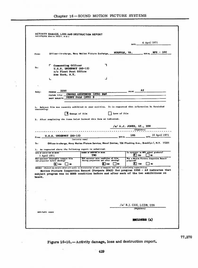
Chapter 16 —SOUND MOTION PICTURE SYSTEMS
ACTIVITY DAMAGE, LOSS AND DESTRUCTION REPORT N A VPERS 304 1 A (REV. 4*01)
DATE: 6 April 1971
Fren: OffIcer-ln-charge, Navy Motion Plctura Exchange, NORFOUC, VA,
SERIAL UPE 100
P Commanding Officer ~î U.S.S. UNDERWAY (AD-12) c/o Fleet Post Office Nev York, N.Y.
L -I
Subj : PROGRAM 2250
FEATURE TITLE
SHORT SUBJECTS
CROOKS ANONYMOUS (STD) B8.W PENNY PALS (STD) E
PRINT A2
1. Subject fila vea receatly exhibited at your activity* It ie reqoeetad tbet ioforaetioo be foroiehed ceoceroiaf:
(3 D* ■e(e of fila l~~l *■••• •* «*■
2. After eeapletiag the iteae beloe forward tbit fora aa indicated.
/s/ A.J. JONES, LT., USN (5(fnatare)
Froo: .
To:
U.S.S. UNDERWAY (AD-12) 185 10 April 1971 , DATE —
foctivity nas«>
Offlcer-ln-charge, Navy Motion Picture Service, Naval Station, 136 Flushing Ave., Brooklyn I, N.Y. 11251
1. Aa requested above tbe following report ia eobaitted:
OATI OF tEMItITION ON BOARD
1 April 1971 HLMMR OF IMOeiMt 0
TWO la operator an UPO eebool gradéate?
PH YES I I WO
Vas a Motion Pietnra Inapection Record prepared?
Did operator Thoroughly inspect fila and projector boforo shoeing?
[Xi YES I I NO
Did eporator noto condition of fila daring projection and tftor «bowing?
BYES □«O [X~| YES I I HO
ffarai«A aa, J«(a<l« •*(,* sill a«»!»« (a J,i«ra<aailaa a/ raa,« a/ rfaaat«/ar la** a«4 <• ««takKahlag r«tpaa*ItáKfpt
Motion Picture Inspection Record (Navpers 3043) for program 2250 - A2 Indicates that subject program was in GOOD condition before and after each of the two exhibitions on board.
9N0*P6PO 100(9
/s/ R.J. COX, LCDR, USN fJigneleraj
BKL03CRX (A)
Figure 16-10.—Activity damage, loss and destruction report, 77.270

430 UÄ NAVY MOTION PICTURE EXHIBITION. TRANSFER « INVENTORY RECORD NAVPERS 1710/12 1449) (Formerly NAVPERS 3048) SNOlOMSO-tsn
Not to be nibmltlod by NMPX'i
April 1971 1 OF 1 io NUMBER oß öO ACTIVITY
USS UNDERWAY (AD-12) NAMES ANO RATES OF QUALIFIED PROJECTIONISTS
Hi none ¡¡udiftä. là: Oiou tcmparahty mtharhcd referencing Bufen Authority)
A.R. Jones
J.D. Doe
R.B. King
RATC
EM2 NATE
MM3 RATE
EM3
A.S. Young
G.W. Smith
A.J. Brown
IC3 RATE
YN2 RATE
EM2
INSTRUCTIONS
This form b to be prepared In duplicate.
a. The original and the copy must be presented when returning or drawing fUm from
any Morion Picture Exchange
b. Submit original monthly to Officer in Charge, Nary Motion Picture Service, Brooklyn.
c. Retain copy as permanent ship or aetMty morion picture log.
PROGRAM NO
a DESIGNATOR
3601-A2
3613-A6
SWEET NOVEMBER
YOU ONLY LIVE TWICE
3618-A26 CATTLE KING
3608-AL
3622-A2
3624-A6
3625-AIi, THE PERILS OF PAULINE
7572-AK THE MAN FROM NOWHERE
730L-A6
7309-A8
3602-AK
3610-A21
36L8-A2
YOURS. MINE AND OURS
SWEET NOVEMBER
TO SIR WITH LOVE
7574-A2Á DRACULA HAS RISEN FROM THE
ROSEMARY'S BABY GRAVE
FOR LOVE OF IVY
HAWAII
AMBUSHERS
THE ODD COUPLE
EXODUS 2202-A16
3654-Alt; DIVORCE AMERICAN STYLE
RECEIVED FROM
NAME OF ACTIVITY
NMPX BKLYN
NMPX BKLYN
NMPX
NMPX
BKLYN
BKLYN
NMPX BKLYN
NMPX
NMPX
BKLYN
BKLYN
NMPX BKLYN
NMPX BKLYN
NMPX BKLYN
NMPX BKLYN
NMPX BKLYN
NMPX BKLYN
NMPX BKLYN
NMPX BKLYN
NMPX BKLYN
DATE
RECEIVED
4/2/71
4/3/71
-4/4/71
4/5/71
4/5/71
.4/5/71
4/5/71
.4/5/71
4/5/71
.4/5/71
4/5/71
4/5/71
4/5/71
-4/5/71
4/5/71
EXHIBITION DATA DATE
SHOWN
4/1/71 4/2/71
4bâÆL 4/4/7I 4/6/71
4/7/71
4/15/71
4/9/71
4/8/71
4/10/71
-4/13/71
4/16/71
4/5/71
4/I4/7I 2
NO. SHOWS
4/12/71
4A1/71
CONDITION OF FILM
AFTER SHOWING
GOOD
BXnq.T.TiMT
GOOD
EXCET.T.EHT
GOOD
GOOD
USABLE
GOOD
GOOD
USABLE
GOOD
USABLE
GOOD
GOOD
USABLE
GOOD
TRANSFERRED 1
NAME OF ACTIVITY
NMPX BKLYN
NMPX BKLYN
NMPX BKLYN
NMPX BKLYN
NMPX BKLYN
NMPX BKLYN
NMPX BKLYN
NMPX BKLYN
NMPX BKLYN
NMPX BKLYN
NMPX BKLYN
NMPX BKLYN
NMPX BKLYN
NMPX BKLYN
NMPX BKLYN
NMPX BKLYN
DATE
TRANSFERRED
4/2/71
4/3/71
4/4/71
4/5/71
4/12/71
4/12/71
4/2.4/71
4/12/71
4/12/71
4/12/71
4/24/71
4/24/71
4/12/71
4/24/71
4/24/71
4/12/71 (If more space is needed, continue on revene)
1 April 1971 (Date submitted)
/s/ R.J. COX, LCDR. USN (Signature)
F igure 16-11. — U. S. Navy motion picture exhibtion, transfer and inventory record. 77.271
EL
EC
TR
ICIA
N’S M
AT
E
3 &
2

Chapter 16 —SOUND MOTION PICTURE SYSTEMS
T>
k
77.272 Figure 16-12. —Motion picture projector,
AQ-3A8.
will be used for explanation; however, for a specific machine the applicable manufacturer’s technical manual should be used.
The projector consists of a sound motion picture projector, an internal amplifier, and an internal loudspeaker contained in a metal case. The operating switches and controls are located on a panel at the rear of the case. The projection parts located on the operating side of the projector are shown in figure 16-13.
Projectors are divided into three major subdivisions: transport system, light system, and sound system.
TRANSPORT SYSTEM
The transport system (fig. 16-14) of a rep- resentative projector begins with the forward or feed reel. This reel is mounted on a reel arm which is attached to a guide pin and a thumb screw to the projector top. The spindle of the arm contains a slip clutch, and during rewinding receives its motive force from a belt driven from within the projector case. The slip clutch is engaged during rewind operation,
and disengaged during projection. During pro- jection, the reel is turned by the film being pulled off of the reel by the feed sprocket.
Latches are provided to maintain the reel on its spindle under the adverse conditions of shipboard showing. These latches should be closed at all times when a reel is on the spindle.
The film in leaving the reel passes through two guide rollers and onto a feed sprocket. Leaving the feed sprocket, the film is looped to allow sufficient slack in order that the film may move intermittently (stop and start) past the aperture. Following the loop, the film passes between the aperture plate and the pressure plate. The film is drawn through the aperture assembly by an intermittent mechanism called a shuttle (fig. 16-15), the forward projection of which has three teeth. The shuttle mechanism moves its cam assembly in a rectangular fashion. The action of the shuttle is in synchronism with that of the shutter, which will be discussed under the light system. The teeth of the shuttle coming across the top of the motion rectangle engage the film sprocket holes and pull the film down in front of the aperture opening. The teeth then retract and the mechanism moves back across the bottom of the rectangle. Film is pulled across the face of the aperture assembly at a rate of 24 frames per second.
The film, upon leaving the aperture assembly, passes into another loop (fig. 16-14) whose purpose is to allow for the intermittent operation. Descending from the lower loop, the film is again given motion by the sound sprocket and passes under the upper idler roller to the sound drum where the action is mechanically dampened.
The film now enters the sound system, where it is guided by the film guide roller past the sound drum. Leaving the sound head, the film passes under another idler roller and onto a take-up sprocket where motive force is again restored. The film presently passes two additional idler rollers and through two roller guides and onto the take-up reel.
The take-up reel is belt-driven on its simple spindle. The take-up reel and spindle are sup- ported as was the feed reel.
The force to operate the entire transport system is derived from the drive motor and chain assembly (fig. 16-16). The drive motor currently being used by the Navy is of the synchronous type. Older projectors still remain, and these originally had auniversal series-wound governor-controlled motor, which is being replaced during routine overhaul as replacements become available.
431

ELECTRICIAN’S MATE 3 & 2
m 25
24
23 22 20
1. TAKE-UP REEL ARM LOCK LATCH 2. TAKE-UP REEL ARM
3. TAKE-UP BELT 4. LOOPSETTER PUSHBUTTON 5. REEL ARM THUMB SCREW 6. FEED REEL ARM 7. REWIND BELT 8. FEED REEL ARM LOCK LATCH 9. REWIND BELT ECCENTRIC BEARING 10. THREADING LAMP 11. LENS LOCKING SCREW 12. PROJECTION LENS 13. LENS HOLDER
14. PRESSURE PLATE CLOSING LEVER 15. FOCUSING CONTROL 16. LAMP COVER JEWEL 17 EXCITER LAMP COVER 18. SOUNDHEAD ASSEMBLY 19. SOUND DRUM 20. DOUSER SWITCH 21. SHUTTER COVER 22. THREADING CONTROL 23. FRAMING CONTROL 24. LAMPHOUSE COVER
25. TAKE-UP BELT ECCENTRIC BEARING
Figure 16-13.— Identification of projector parts on operating side of projector AQ-3A8 77.273
432

Chapter 16 —SOUND MOTION PICTURE SYSTEMS
O ) 16
oVo) 15
14
mi 7
10 12
13
1. FEED REEL
2. CASE GUIDE ROLLERS
3. FEED SPROCKET
4. APERTURE PLATE
5. PRESSURE PLATE
6. PROJECTION LENS 7. SOUND SPROCKET
8. IDLER ROLLER
9. FILM GUIDE ROLLER 10. SOUND DRUM 11. IDLER ROLLER
12. TAKE-UP SPROCKET
13. FLOATING IDLER ROLLER
14. LOWER GUIDE ROLLER
15. CASE GUIDE ROLLER
16. TAKE-UP REEL
Figure 16-14.—Transport system, 77.274
An additional motor, whose sole purpose is to cool all components associated with the light system is installed in the projector.
LIGHT OPTICAL SYSTEM
The light optical system (fig. 16-17) consists of the projection lamp, reflector, condensing lens, shutter, aperture, projection lens, and screen. Projection lamps are rated 300, 500, 750, 1000, and 1200 watts and are concentrated- filament type lamps. The lamp socket provides for horizontal movement both fore and aft and athwart, to facilitate uniform illumination of the film.
The reflector is mounted directly behind the projection lamp and serves to send back through the lamp, in the direction of the film, all light received. This component serves to increase light utilization.
The condensing lens functions to collect and concentrate the maximum amount of light for
SHUTTLE
PIVOT BUSHING
© ©
REAR CAM
FRONT CAM
SHUTTLE TOOTH
Figure 16-15.—Shuttle. 77.278
projection It is composed of two separate lenses which are removable in current machines to facilitate cleaning. The lens closest to the projection lamp is an aspheric lens designed to collect light, while the other is a plane-convex lens which converges and concentrates the light.
433

ELECTRICIAN’S MATE 3 & 2
I
o
^.1
1. DRIVE CHAIN
2. BLOWER MOTOR
3. AMPLIFIER POWER CABLE 4. EXCITER LAMP CABLE
5. DRIVE MOTOR
6. DRIVE GEAR ASSEMBLY
7. PHOTODIODE CABLE 8. CHAIN DRIVE
Figure 16-16. —Projector with amplifier-loudspeaker chassis removed. 77.276
The two-segment shutter is used to interrupt the light path and allow the full use of persistence of vision. Working in conjunction with the intermittent shuttle (fig. 16-18), the shutter operates at 24 r.p.s. and interrupts the light path 48 times each second.
The aperture plate and aperture are the channel through which the film is moved, one frame at a time, for projection. Shown removed from the projector in figure 16-19A, the rec- tangular opening or aperture is the precise size of one frame so as to limit the light to
the desired frame of film. Sapphire jewel inserts are used to furnish a low friction method of edge guiding the film past the aperture without scratching the base of emulsion. These inserts also aid in smoothing the operation and giving a steady picture. The film path is a highly polished surface and should be kept absolutely clean.
The pressure plate (fig. 16-19B), also part of the aperture assembly, is used to provide a constant and proper tension on the film, holding it flat against the aperture plate in a plane of
434

Chapter 16 —SOUND MOTION PICTURE SYSTEMS
=4
a
1. LAMP REFLECTOR 2. PROJECTION LAMP 3. LENS LOCK LEVER (HIDDEN) 4. CONDENSING LENS ASSEMBLY 5. LAMP SOCKET 6. PROJECTION LAMP ADJUSTMENT LEVER 1 7. PROJECTION LAMP ADJUSTMENT LEVER 2
77.277 Figure 16-17.—Projector lamphouse.
exact focus. The rectangular opening of the pressure plate is slightly larger than that of the aperture plate. The portion of the pressure plate which comes in contact with the film is also highly polished and must be kept devoid of foreign matter.
The projection lens forms on the screen the enlarged image of the illuminated film frame at the aperture. Generally, two lenses tire provided with each projector; the standard (with a two-inch focal length, figure 16-13) which
is used with regular motion picture film, and the anamorphic (fig. 16-20), which is used with Cinemascope film. Lenses of other focal lengths are available through normal supply channels.
Throughout the Navy many different types of screens are used with motion picture pro- jection. These vary from readily available retired mattress covers to expensive glass beaded screens. An assortment of screens is available through the stock system; beaded screens however, tend to lose their beads when subjected to a salt atmosphere, and therefore are not recommended for shipboard use.
SOUND SYSTEM
The sound system of a motion picture is as important as the transport or light system. The sound system (fig. 16-21) is composed of an exciter lamp, optical unit, optical light pipe prism (light pipe), photo cell, filter assembly, an internal or external amplifier, and associated loudspeakers. The components which come in contact with the film are. located so as to be 26 frames ahead of the display frame of the film. By having the sound located in this manner,
DOUSER
SHUTTER
Om
INTERMITTENT MECHANISM
Figure 16-18.—Shutter. 77.275
435

ELECTRICIAN’S MATE 3 & 2
©
<r 1. PICTURE APERTURE 2. SAPPHIRE JEWEL INSETS 3. FIXED FILM GUIDE RAIL 4. MOVABLE FILM GUIDE RAIL
A APERTURE PLATE
B PRESSURE PLATE
77.279 Figure 16-19. — Aperture.
VERTICAL/HORIZONTAL ADJUSTMENT LENS TO SCREEN
DISTANCE ADJUSTMENT
BARREL
/
SHOULDER SCALE FOR THROW ADJUSTMENT
77.280 Figure 16-20.—Anamorphic lens.
the picture and its corresponding sound may be reproduced together.
The exciter lamp furnishes the illumination to scan the soundtrack. It operates atfrequencies above the áudio range so as not to introduce any unwanted noise into the system. A jeweled cover is placed over the lamp to exclude outside light, yet allow an indication of lamp operation. The lamp is permanently focused in its socket so as to give maximum light to the optical lens.
The optical lens focuses the light on the film soundtrack in such a manner a.s to form a light line scanning beam. The depth of focus
FILM
PHOTO CELL
SCANNING BEAM
OBJECTIVE CONDENSER
\ SLIT
SOUND OPTICAL UNIT
1 EXCITER
LAMP
TO AMPLIFIER
Figure 16-21, — Sound optical system. 77.281
436

Chapter 16 —SOUND MOTION PICTURE SYSTEMS
1. LAMP, EXCITER
2. SOCKET, EXCITER LAMP 3. JEWEL, EXCITER LAMP COVER 4. COVER, EXCITER LAMP 5. LENS, SOUND OPTICAL 6. ROLLER,UPPER IDLER (GRAVITY) 7. ROLLER, LOWER IDLER ( GRAVITY) 8. DRUM, SOUND STABILIZER 9. PRISM, OPTICAL LIGHT PIPE
10. ARM, IDLER ROLLER 11. ROLLER ASSEMBLY, FILM GUIDE
77.282 Figure 16-22. — Sound drum.
of the lens is sufficient to attain the required response regardless of which side of the film the sound is recorded upon. This lens, although adjustable, should not be disturbed from its overhaul setting. As is apparent from figure 16-22, the film passes between the optical lens and the sound drum.
The light pipe is located in the sound head stabilizer connected to the sound drum. The light, after having scanned the soundtrack, is gathered, concentrated, and transmitted as a light beam by the light pipe to the photo cell. The peculiar shape of the pipe enables the concentration to accurately reflect the sound (now light) reproduction.
The photo cell (fig. 16-23) converts light variations to variations in electrical current of an amplifiable nature. Current design makes use of a highly sensitive, long life, efficient, germanium diode photo cell, while older units use a lead sulphide unit. In either design, the sound emerges as an electrical signal capable of amplification and reproduction.
Smooth, accurate sound reproduction, without flutter, is accomplished through the use of a gravity filter system. Combining the action of a flywheel (on the reverse end of the sound drum) and idler gravity rollers (fig. 16-22), the start-stop action of the intermittent and other variations introduced by the transport system are filtered from the film. From a stop, the flywheel comes up to speed and maintains motion in three seconds.
The internal amplifier (fig. 16-24), an internal part of some projectors, delivers 7.5 watts of power to an internal or external amplifier. On-off tone and volume controls are located in the amplifier housing, as is a speaker jack and control switch. Generated within the ampli- fier chasis are the high-frequency potential for the exciter lamp and the d-c required for photo cell operation.
OPERATION
Only qualified personnel are authorized to maintain and operate motion picture projection
DIODE
77.283 Figure 16-23. — Germanium diode photocell
assembly.
437

ELECTRICIAN’S MATE 3 & 2
ZJ
T
f
if "I.
1. I2AX7 TUBES (2) 2. 6005/6AQ5W TUBES (2) 3.6X4WA TUBES (2)
5. SPARE TUBES (ONE I2AX7, ONE 6005/6AQ5W, ONE 6X4WA)
6. 6005/6AQ5W TUBE 4. SLO-BLOW FUSE.0.8 AMP 7. LOUDSPEAKER
Figure 16-24. —Amplifier-loudspeaker chassis AQ-3A8 projector. 77.284
equipment. Before operating a movie projector, give the equipment a visual inspection to see that everything is in order. Clean the lens with lens tissue. Note, NEVER TOUCH THE LENS WITH THE BARE FINGER. An oily film collects dust and the heat will cause the lens surface to blister. If you are not acquainted with the type of pro- jector, or have not operated for a long time, then read the operating instructions on the equipment. Before threading the film, make sure the film is “headed” out (that is, the start of the film is at the beginning, not at the end). To connect the projection equipment for single equipment operation, turn the motor-lamp switch and the external or internal (whichever is being used) amplifier on-off switch to the OFF position. Turn the gain control and the tone control on
the amplifier to the NORMAL position. Plug the a-c power cable from the receptacle on the projector into the ship’s 115-volt 60 hertz power supply. Place the loudspeaker selector switch on the projector in the LOCAL or REMOTE position, depending on whether the internal loud- speaker or an external loudspeaker is to be used. Be certain that the douser switch is in the OPEN position, the rewind switch is in the OFF position, and the rewind knob on the feed reel arm is in the OUT position and properly engaged in the short slot.
To operate single projector equipment, turn the motor-lamp switch to the MOTOR position. When showing training films as soon as the end of the film leader passes the picture aperture,
438

Chapter 16 —SOUND MOTION PICTURE SYSTEMS
turn the switch to the LAMP position, and at the same time, increase the amplifier volume control to the required setting for proper sound volume. When showing 16-mm entertainment films, numbers starting at 12 and ending at 3 (at regular intervals) are on the film following the end of the film leader. When the last number passes the picture aperture, turn the switch to the LAMP position.
To operate dual projector equipment (fig. 16-25), place projector 1 in operation as explained for a single projector. While the film is running through (outgoing) projector 1, mount the second reel of film to the feed reel arm, and empty reel to the takeup arm of (incoming) projector 2. Thread projector 2 and set the douser switch in the CLOSED position.
As projector 1 nears the end of the reel, watch for the opaque dot (cue mark) which appears for an instant in the upper right-hand corner of the screen. When the dot appears, turn projector 2 switch to the LAMP position. Another opaque dot will appear in the same position on the screen approximately 6 seconds after the first one. When this dot appears, depress the changeover pushbutton on projector 2 and turn off projector 1 by placing the switch in the OFF position. The changeover button, when depressed on projector 2, opens the douser of (incoming) projector 2 and the picture is projected on the screen accompanied by sound. The picture and the sound are cut out from (outgoing) projector 1.
To stop the projector equipment, place the switch in the MOTOR position and turn the
A C. POWER CABLE
PROJECTOR SET NO. I
AC. POWER CABLE
PROJECTOR SET NO.2
CHANGE-OVER CABLE
EXTERNAL 1C/QDM LOUDSPEAKER
oeo 00-000
ooo oooo oo
OP
O oo oo
O O
LOUDSPEAKER CABLE
Y" LOUDSPEAKER CABLE
rtoi
z I
JZ03
JtOS
T20I
Figure 16-25.—Interconnection of duel projection equipments, 7.75

ELECTRICIAN’S MATE 3 & 2
Table 16=10—Daily inspection and servicing oí projectors
Item Operation Agent
Projection lens
Aperture plate and pres- sure shoe assemblies.
Sprocket shoe assemblies.
Sound drum
Take-up, rewind, and feed belts.
Projection lamp-
Reflector
Arc lamphouse ash pan.
Arc reflector, viewing filter glasses, and heat-resisting glass.
Wipe, inspect, and tighten elements if necessary.
Inspect and clean
Clean
Inspect and clean
Check and replace if necessary.
Inspect and clean. Replace if excep- tionally black or burned out.
Clean
Remove and clean
Inspect and clean
Lens tissue.
Brush or soft cloth, dry cleaning solvent, toothpick or other small piece of wood.
Same as above.
Soft cloth, dry cleaning sol- vent.
Soft cloth.
Lens tissue.
Brush or soft cloth.
Lens tissue.
77„334
volume control to the extreme counterclockwise position as soon as the sound or end title on the end of the reel has faded out„ Allow the remaining film to run through the projector and then turn the switch to the OFF position,,
The changeover mechanism is incorporated in each projector,, When two projectors are used, with one or more amplifiers and loudspeakers, they provide the capability of uninterrupted sound film programs. The changeover mechanism mounts to the inner surface of the shutter assembly, Sound changeover is affected by breaking the exciter lamp circuit, and picture changeover is effected by a light shield (douser), which drops between the condenser lens assembly and the picture aperture.
The changeover switch controls simultane- ously the sound and picture changeover from the outgoing projector to the incoming projector. However, to effect this changeover the hand-set douser switch must be preset once only, at the start of the program, to the OFEN position on the operating (outgoing) projector and to
the CLOSED position on the idle (incoming) projector. For single equipment operation, the douser switch must always be set in the OPEN position.
Interconnection of the electromagnetic changeover circuits between projectors is ac- complished by connecting the changeover cable into receptacles on each projector. The cable connections parallel the (OPEN) solenoid of projector 1 with the (CLOSE) solenoid of projector 2, Depressing the changeover push- button switch simultaneously energizes the (OPEN) solenoid of the desired operative pro- jector and the (CLOSE) solenoid of the other projector.
After operation, make the routine daily servic- ing check on the equipment. See table 16-1, Daily Inspection and Servicing of Projectors,
MAINTENANCE
The corrective maintenance of sound motion picture equipment is divided into the categories
440

Chapter 16 —SOUND MOTION PICTURE SYSTEMS
of emergency repair service, which is performed aboard ship or in the field, and major overhaul and repair which is performed by a repair ship or shore activity. Only emergency repairs which are accomplished aboard ship or in the field are discussed here.
PROJECTOR
The projector equipment is set up for sound operation with sound film properly threaded in the projector, the on-off amplifier toggle switch in the ON position, the loudspeaker selector switch in the LOCAL position (if external speaker is not used), the volume control in the MID position, and the motor-lamp switch in the LAMP position.
If no sound is present under these conditions, check the projector sound system consisting of the exciter lamp, photocell, and associated flight path elements. The motor-lamp switch, when placed in the LAMP position, should light the exciter lamp. If the lamp does not operate, replace it with one that is known to be good. If the new lamp does not operate, replace the exciter lamp oscillator tube in the internal amplifièr.' Be sure the circuit is deenergized any time a tube is removed.
If sound is not present after replacing the oscillator tube, and the exciter lamp is lit, then insert a piece of cardboard or heavy paper between thé sound lens to obstruct the optical light path. With no film in the projector and with the volume control at the MID position, this áction should produce a “plop” in the speaker. In no “plop” is heard, it may be the result of a bad photocell, an open or shorted photocell cable, misalignment of the light path, or an obstruction such as oil, dirt, or a piece of broken film. Do not attempt to remove or adjust the lens of the sound optical system because this requires special training and equip- ment. If sound is not obtained after the foregoing checks, then check the internal amplifier or loudspeaker.
INTERNAL AMPLIFIER
If the amplifier pilot lamp does not operate, the lamp is defective or no filament power is
present. If the tubes do not heat after allowing approximately 1 minute to warm up, no a-c power is being delivered to the amplifier. Check the fuse and replace if necessary. If the pilot lamp and tube filaments are operating normally but no sound is forthcoming, the tubes should be removed and tested on a tube tester. If no noise is heard after the tubes have been tested, then check the loudspeaker connections and speaker selector switch.
The performance of the internal amplifier, with respect to the audio signal, cannot be determined without a steady amplitude input signal. A 400-hertz test film can be used to supply the audio frequency signal for all amplifier emergency audio frequency measurements. If desired, the film can be used in the form of a loop about 3 feet in length.
The a-c signal voltages must be measured with a high-impedance vacuum-tube voltmeter, otherwise the readings will be in error. The amplifier should be terminated in a i6-ohm load resistor instead of the external loudspeaker, when taking output power measurements. A 20,000 ohm-per-volt type of meter must be used for the taking the d-c measurements.
INTERNAL LOUDSPEAKER
The internal loudspeaker is an integral part of the 16-mm projector. It is a 5-inch dynamic loudspeaker containing a permanent rhagnet and moving voice coil. To gain access to the loud- speaker, remove the speaker mounting panel from the projector case and place it on a bench. Check the loudspeaker cone for holes or cracks. Apply equal pressure to all sides of the cone and gently push the cone with the fingers to be certain that the voice coil is not rubbing in the air gap. Be careful not to damage the loudspeaker when making this inspection. Unsolder the con- nection from the terminals of the loudspeaker and check the resistance of the voice coil with an ohmmeter. The resistance should be approximately 8 ohms.
The procedures used to localize troubles and effect emergency repairs to the internal amplifier and loudspeaker are also followed when performing similar maintenance on the external amplifier and loudspeaker. The scope of this training manual does not permit a
441

ELECTRICIAN’S MATE 3 & 2
complete coverage of the operation, care, and maintenance of the sound motion picture
\ projection equipment. More detailed information is contained in chapter 9850 of Naval Ships Technical Manual, manufacturer’s instruction books furnished with the equipment, and don’t forget the 3-M system maintenance requirement cards for projector equipment.
TRAINING FILMS
When called on to show training films, make sure you prepare and take care of them as you would entertainment films. Never mix or store training films with entertainment films. In transferring films, see that each type is handled separately and accounted for as prescribed.
442

APPENDIX Vil
ELECTRONICS SYMBOLS
AMPLIFIER (2) ANTENNA (3) ATTENUATOR, VARIABLE (5) MULTICELL
GENERAL
WITH TWO INPUTS
WITH TWO OUTPUTS
WITH ADJUSTABLE GAIN
WITH ASSOCIATED POWER SUPPLY
I PS 1
WITH ASSOCIATED ATTENUA- TOR
S- WITH EXTERNAL FEEDBACK PATH
AMPLIFIER LETTER COMBINA- TIONS (ompl¡f¡er-use identifica- tion in symbol if required)
BOG BRIDGING BST BOOSTER CMP COMPRESSION DC DIRECT CURRENT EXP EXPANSION LIM LIMITING MON MONITORING PGM PROGRAM PRE PRELIMINARY PWR POWER TRQ TORQUE
GENERAL
y DIPOLE
If LOOP
=a COUNTERPOISE
-E ARRESTER, LIGHTNING (4)
GENERAL
CARBON BLOCK
-Q0- ELECTROLYTIC OR ALUMINUM CELL
HORN GAP
PROTECTIVE GAP
SPHERE GAP
VALVE OR FILM ELEMENT
—Ill— MULTIGAP
ATTENUATOR, FIXED (see PAD) (57)
(some symbol as variable attenuator, without vari- obi li ty)
BALANCED
UNBALANCED
AUDIBLE SIGNALING DEVICE (6)
BELL, ELECTRICAL; RINGER, TELEPHONE
=DO BUZZER
=CN HORN, ELECTRICAL; LOUD- SPEAKER; SIREN; UNDER- WATER SOUND HYDROPHONE, PROJECTOR OR TRANSDUCER
HORN, LETTER COMBINATIONS (if required)
*HN HORN. ELECTRICAL *HW HOWLER *LS LOUDSPEAKER *SN SIREN tEM ELECTROMAGNETIC
WITH MOVING COIL tEMN ELECTROMAGNETIC
WITH MOVING COIL AND NEUTRALIZING WINDING
tMG MAGNETIC ARMATURE tPM PERMANENT MAGNET
WITH MOVING COIL
(identification replaces (*) asterisk and (t) dagger)
SOUNDER, TELEGRAPH
BATTERY (7)
GENERALIZED DIRECT CUR- RENT SOURCE; ONE CELL
CAPACITOR (8)
GENERAL
POLARIZED .
_L±
ADJUSTABLE OR VARIABLE
CONTINOUSLY ADJUSTABLE OR VARIABLE DIFFERENTIAL
PHASE-SHIFTER
1 —I—
T SPLIT-STATOR
FEED-THROUGH
Q Q
CELL, PHOTOSENSITIVE (Semiconductor) (9)
ASYMMETRICAL PHOTOCON- DUCTI VE TRANSDUCER
W
& SYMMETRICAL PHOTOCON- DUCTI VE TRANSDUCER
\V ——
-NUMBER IN PARENTHESES INDICATES LOCATION OF SYMBOL IN MIL-STD PUBLICATION
Figure AI-1. — Electronics symbols 13.5(179) A

ELECTRICIAN'S MATE 3 & 2
PHOTOVOLTAIC TRANSDUCER; SOLAR CELL
XV
CIRCUIT BREAKER (11)
GENERAL
) WITH MAGNETIC OVERLOAD
DRAWOUT TYPE
CIRCUIT CLEMENT (12)
GENERAL
CIRCUIT ELEMENT LETTER COMBINATIONS (replaces (*). osferi sk)
EG EQUALIZER FAX FACSIMILE SET FL FILTER FL-BE FILTER, BAND
ELIMINATION FL-BP FILTER, BAND PASS FL-HP FILTER, HIGH PASS FL-LP FILTER, LOW PASS PS POWER SUPPLY RG RECORDING UNIT RU REPRODUCING UNIT DIAL TELEPHONE DIAL TEL TELEPHONE STATION TPR TELEPRINTER TTY TELETYPEWRITER
ADDITIONAL LETTER*COMBINA- TIONS (symbols preferred)
AR AMPLIFIER AT ATTENUATOR C CAPACITOR CB CIRCUIT BREAKER HS HANDSET I INDICATING OR SWITCH
BOARD LAMP L INDUCTOR J JACK LS LOUDSPEAKER MIC MICROPHONE OSC OSCILLATOR PAD PAD P PLUG HT RECEIVER, HEADSET K RELAY R RESISTOR S SWITCH OR KEY SWITCH T TRANSFORMER WR WALL RECEPTACLE
CLUTCH; BRAKE (14)
DISENGAGED WHEN OPERATING MEANS IS DE-ENERGIZED
OR 1 I
ENGAGED WHEN OPERATING MEANS IS DE-ENERGIZED
- - OR ' -
COIL, REPLAY and OPERATING (16)
-0-OR ft SEMICIRCULAR DOT INDICATES INNER END OF WIRING
“ö“ OR Qz
CONNECTOR (18)
ASSEMBLY, MOVABLE OR STA- TIONARY PORTION; JACK, PLUG, OR RECEPTACLE
* OR <
JACK OR RECEPTACLE
—< OR Q
PLUG
> OR Q
SEPARABLE CONNECTORS
CD TWO-CONDUCTOR SWITCHBOARD JACK
TWO-CONDUCTOR SWITCHBOARD PLUG
JACKS NORMALLED THROUGH ONE WAY
T'A
T'O JACKS NORMALLED THROUGH BOTH WAYS
roller- 0QvT>~
2-CONDUCTOR NONPOLARIZED, FEMALE CONTACTS
2-CONDUCTOR POLARIZED, MALE CONTACTS
WAVEGUIDE FLANGE
PLAIN, RECTANGULAR
-B» CHOKE, RECTANGULAR
-§< ENGAGED 4-CONDUCTOR, THE PLUG HAS 1 MALE AND 3 FE- MALE CONTACTS, INDIVIDUAL CONTACT DESIGNATIONS SHOWN
A -T->A>T-
B- 0R -r^Bi-r c—
COAXIAL, OUTSIDE CONDUCTOR SHOWN CARRIED THROUGH
Or *>-
t
COAXIAL, CENTER CONDUCTOR SHOWN CARRIED THROUGH, OUT- SIDE CONDUCTOR NOT CARRIED THROUGH
TT Q- x-»~
MATED CHOCK FLANGES IN REC- TANGULAR WAVEGUIDE
-B< >fr COUNTER, ELECTROMAGNETIC,
MESSAGE REGISTER (26)
GENERAL
WITH A MAKE CONTACT E CONTAC
4^ COUPLER, DIRECTIONAL (27)
(common eoaxiol/weveguide usage)
X
(common coaxlal/waveguide usage)
E-PLANE APERTURE-COUPLING, 30-DEOBEL TRANSMISSION LOSS
X © 300B
COUPLING (28)
BY LOOP FROM COAXIAL TO CIRCULAR WAVEGUIDE, DIRECT- CURRENT GROUNDS CONNECTED
CRYSTAL, PIEZO> ELECTRIC (62)
^Oi-
DELAY LINE (31)
GENERAL
*
TAPPED DELAY
*
* * *
BIFILAR SLOW-WAVE STRUCTURE (commonly used in traveling-wave tubes)
(length of delay indication replaces (*) asterisk)
DETECTOR, PRIMARY; MEASURING TRANSDUCER (30)
(see HALL GENERATOR and THERMAL CONVERTER)
DISCONTINUITY (33)
(common coaxial Waveguide usage)
EQUIVALENT SERIES ELEMENT, GENERAL
CAPACITIVE REACTANCE
INDUCTIVE REACTANCE
INDUCTANCE-CAPACITANCE CIR- CUIT, INFINITE REACTANCE AT RESONANCE
Figure AI-1.— Electronics symbols—continued, 13.5(179)B

APPENDIX I
INDUCTANCE-CAPACITANCE CIRCUIT, ZERO REACTANCE AT RESONANCE
“zûk-
RESISTANCE
EQUIVALENT SHUNT ELEMENT, GENERAL
CAPACITIVE SUSCEPTANCE
CONDUCTANCE
INDUCTIVE SUSCEPTANCE
INDUCTANCE-CAPACITANCE CIRCUIT, INFINITE SUSCEPT- ANCE AT RESONANCE
TWIN TRIODE, EOUI POTENTIAL CATHODE
REFLEX KLYSTRON, INTEGRAL CAVITY, APERTURE COUPLED
HIGH-VOLTAGE PRIMARY CUT- OUT, OIL
TYPICAL WIRING FIGURE TO SHOW TUBE SYMBOLS PLACED IN ANY CONVENIENT POSITION
TRANSMIT-RECEIVE (TR) TUBE GAS FILLED, TUNABLE INTEGRAL CAVITY, APERTURE COUPLED, WITH STARTER
RECTIFIER; VOLTAGE REGU- LATOR (see LAMP, GLOW)
PHOTOTUBE, SINGLE AND MULTI- PLIER
TRAVELING-WAVE TUBE (typical)
FORWARD-WAVE TRAVELING- WAVE-TUBE AMPLIFIER SHOWN WITH FOUR GRIDS, HAVING SLOW-WAVE STRUCTURE WITH ATTENUATION. MAGNETIC FOCUSING BY EXTERNAL PERMANENT MAGNET, rf IN- PUT AND rf OUTPUT COU- PLING EACH E-PLANE APER-
TURE TO EXTERNAL REC- TANGULAR
mi mi
OR
GOVERNOR (contact-making) (37)
CONTACTS SHOWN HERE AS CLOSED
HALL GENERATOR (39)
HANDSET (40)
RAL
OPERATOR'S SET WITH PUSH- TO TALK SWITCH
0=
HYBRID (41)
GENERAL
—I H|B1—
INDUCTANCE-CAPACITANCE CIRCUIT, ZERO SUSCEPTANCE AT RESONANCE
ELECTRON TUBE (34)
TRIODE
CATHODE-RAY TUBE, ELECTRO- STATIC AND MAGNETIC DE- FLECTION
MERCURY-POOL TUBE, IGNITOR AND CONTROL GRID (see RECTI- FIER)
PENTODE, ENVELOPE CONNECT ED TO BASE TERMINAL RESONANT MAGNETRON, CO-
AXIAL OUTPUT AND PERMA- NENT MAGNET
e PPM!
FERRITE DEVICES (100)
FIELD POLARIZATION ROTATOR
FIELD POLARIZATION AMPLI- TUDE MODULATOR
U*
FUSE (36)
HIGH-VOLTAGE PRIMARY CUT- OUT, DRY
_^L_ 0R
JUNCTION (common coaxial/waveguide usage)
|E
CIRCULAR
O (E, H or HE transverse field in- dicators replace (*) asterisk)
RECTANGULAR WAVEGUIDE AND COAXIAL COUPLING
CD -Q-
INDUCTOR (42)
GENERAL
'■VY-V* OR TRJIp
Figure AI-1. —Electronics symbols—continued. 13.5(179)C
445

ELECTRICIAN’S MATE 3 & 2
MAGNETIC CORE CONDITION INDICATORS FLIP-FLOP, LATCH LOGIC LETTER COMBINATIONS
/-V-VY-N
TAPPED
~TT ADJUSTABLE, CONTINUOUSLY ADJUSTABLE
T ^ KEY, TELEGRAPH (43)
LAMP (44)
BALLAST LAMP; BALLAST TUBE
LAMP, FLUORESCENT, 2 AND 4 TERMINAL
—(§23- • cfcz
LAMP, GLOW, NEON LAMP
A-C
-40 Of
U-L
LAMP, INCANDESCENT
=®
INDICATING LAMP; SWITCHBOARD LAMP (see VISUAL SIGNALING DEVICE)
LOGIC (see 806B end Y32-U) (including some duplicóte symbols, loft and right-hand symbols are not mixed)
AND function
*□ - ‘D OR function
’Q o, ’O EXCLUSIVE-OR function
((*) input side of logic symbols in general)
STATE (logic negation)
O A LOGIC NEGATION OUTPUT BE- COMES 1 -STATE IF AND ONLY IF THE INPUT IS NOT 1-STATE
AN AND FUNC. WHERE OUTPUT IS LOW IF AND ONLY IF ALL INPUTS ARE HIGH
3 ELECTRIC INVERTER
[H " O (elec, invtr. output becomes 1-stote if and only i f the input is 1 - state) (elec, invtr. output is more pos. if and only if input is less pos.)
LEVEL (relative)
1-STATE IS 1-STATE IS LESS + MORE ¥
(symbol is o rt. triangle pointing in direction of flow)
FL
0 I
REGISTER
S S S S
RG(4) C
10 10 10 10
(binary register denoting four flip- flops and bits)
AMPLIFIER (see AMPLIFIER)
□ - t> CHANNEL PATH(s) (see PATH, TRANSMISSION)
MAGNETIC HEADS (see PICK- UP HEAD)
OSCILLATOR (see OSCILLATOR)
AN AND PUNC. WITH INPUT 1-STATES AT MORE POS LEVEL AND OUTPUT 1-STATE AT LESS POS. LEVEL
OSC ” O 33'
RELAY, CONTACTS (see CON- TACT, ELECTRICAL) RELAY, ELECTROMAGNETIC (see RELAY COIL RECOGNITION
SINGLE SHOT (one output)
ss * *
SIGNAL FLOW (see DIRECTION OF FLOW)
TIME DELAY (see DELAY LINE)
(waveform dato replaces inside/out- side (*))
SCHMITT TRIGGER, WAVEFORM AND TWO OUTPUTS
ST
0
—I .5¿S“EC L + 13v -Ov
□ - CD TIME DELAY WITH TYPICAL DE- LAY TAPS:
> FLIP-FLOP, COMPLEMENTARY
S T C FF
J 0
FUNCTIONS NOT OTHERWISE SYM BOLIZED
*
(identification replaces (*})
S SET C CLEAR (reset) T TOGGLE (trigger) (N) NUMBER OF BITS BO BLOCKING OSCILLATOR CF CATHODE FOLLOWER EF EMITTER FOLLOWER FF FLIP-FLOP SS SINGLE SHOT ST SCHMITT TRIGGER
RG(N) REGISTER (N stages) SR SHIFT REGISTER
MACHINE, ROTATING (46)
GENERATOR
(GEN)
MOTOR
ÍMOT)
METER, INSTRUMENT (48)
O (identification replaces (*) asterisk)
METER LETTER COMBINATIONS
A AMMETER AH AMPERE-HOUR CM A CONTACT-MAKING (or
breaking) AMMETER CMC CONTACT-MAKING (or
breaking) CLOCK CMV CONTACT-MAKING (or
breaking) VOLTMETER
CRO OSCILLOSCOPE OR CATHODE-RAY OSCIL- LOGRAPH
DB DB (decibel) METER DBM DBM (decibels referred to
1 milliwatt) METER DM DEMAND METER DTR DEMAND-TOTALIZING
RELAY F FREQUENCY METER G GALVANOMETER GD GROUND DETECTOR I INDICATING INT INTEGRATING fLA or UA MICROAMMETER MA MILLIAMMETER NM NOISE METER OHM OHMMETER OP OIL PRESSURE
Figure AI-1. —Electronics symbols — continued. 13.5(179)D
446

APPENDIX I
MODE TRANSDUCER (53)
(common cooxiol/wovagui de usogo)
TRANSDUCER FROM RECTANGU- LAR WAVEGUIDE TO'COAXIAL WITH MODE SUPPRESSION, Dl- RECT-CURRENT GROUNDS CON- NECTED
'ÜF -/“V
MOTION, MECHANICAL (54)
ROTATION APPLIED TO A RE- SISTOR
cvj 0Rc-^|
(identification replace* (*) asterisk)
NUCLEAR-RADIATION DETECTOR, GAS PILLED; IONIZATION CHAM- BER; PROPORTIONAL COUNTER TUBE; GEIGER-MULLER COUNTER TUBE (50) (see RADIATION- SENSITIVITY INDICATOR)
PATH, TRANSMISSION (58)
CABLE; 2-CONDUCTOR, SHIELD GROUNDED AND 5-CONDUCTOR SHIELDED
-w- -H- t-t-
PICKUP HEAD (61)
GENERAL
> WRITING; RECORDING
READING; PLAYBACK
ERASING
*>
WRITING, READING, AND ERAS- ING
—
RECTIFIER (65)
SEMICONDUCTOR DIODE; METAL- LIC RECTIFIER; ELECTROLYTIC RECTIFIER; ASYMMETRICAL VARISTOR
MERCURY-POOL TUBE POWER RECTIFIER
FULLWAVE BRIDGE-TYPE
RESISTOR (66)
TAPPED
'ff
SYMMETRICAL VARISTOR RESIST- OR, VOLTAGE SENSITIVE (silicon carbide, etc.)
—PJÍV-0
(identification marks replace (*) asterisk)
WITH ADJUSTABLE CONTACT
—^—
ADJUSTABLE OR CONTINUOUSLY ADJUSTABLE (variable)
0R —i—
(identification replaces (*) asterisk)
RESONATOR, TUNED CAVITY (71)
(common coaxial/waveguide usage)
RESONATOR WITH MODE SUP- PRESSION COUPLED BY AN E- PLANE APERTURE TO A GUIDED TRANSMISSION PATH AND BY A LOOP TO A COAXIAL PATH
:Q>5" TUNABLE RESONATOR WITH DI- RECT-CURRENT GROUND CON- NECTED TO AN ELECTRON DE- VICE AND ADJUSTABLY COUPLED BY AN E-PLANE APERTURE TO A RECTANGULAR WAVEGUIDE
ROTARY JOINT, RF (COUPLER) (72)
GENERAL; WITH RECTANGULAR WAVEGUIDE
~0Ci) (transmission path recognition sym- bol replaces (*) asterisk)
COAXIAL TYPE IN RECTANGU- LAR WAVEGUIDE
CIRCULAR WAVEGUIDE TYPE IN RECTANGULAR WAVEGUIDE
SEMICONDUCTOR DEVICE (73) (Two Terminal, diode)
SEMICONDUCTOR DIODE; RECTI- FIER
—H—OR OR
CAPACITIVE DIODE (also Varicap, Varactor, reactance diode, parametric diode)
—1(-
BREAKDOWN, DIODE, UNIDIREC- TIONAL (also backward diode, avalanche diode, voltage regulator diode, Zener diode, voltage refer- diode)
J
BREAKDOWN DIODE, BIDIRECTION- AL AND BACKWARD DIODE (also bipolar voltage limiter)
t¡7 TUNNEL DIODE (also Esaki diode)
0, ^ TEMPERATURE-DEPENDENT DIODE
OR
PHOTODIODE (also solar cell)
-X XX
SEMICONDUCTOR DIODE. PNPN SWITCH (also Shockley diode, four- layer diode and SCR).
0 OR
Jt °R JF (Multi-Term!nal, transistor, etc.)
PNP TRANSISTOR
0 NPN TRANSISTOR
UNIJUNCTION TRANSISTOR, N- TYPE BASE
© Figure AI-1. —Electronics symbols—continued. 13.5(179)E
447

ELECTRICIAN’S MATE 3 & 2
UNIJUNCTION TRANSISTOR, P- TYPE BASE
© FIELD-EFFECT TRANSISTOR, N- TYPE BASE
($) o"(^) FIELD-EFFECT TRANSISTOR, P- TYPE BASE
SEMICONDUCTOR TRIODE, PNPN- TYPE SWITCH
SQUIB (75)
EXPLOSIVE
IGNITER
fr?- SENSING LINK; FUSIBLE LINK OPERATED
<T\^b
SWITCH (76)
PUSH BUTTON, CIRCUIT CLOS- ING (make)
SAFETY INTERLOCK, CIRCUIT OPENING AND CLOSING
V 2-POLE FIELD-DISCHARGE KNIFE, WITH TERMINALS AND DISCHARGE RESISTOR
13 (identification replaces (*) asterisk)
SYNCHRO (78)
THERMISTOR; THERMAL RESISTOR (84)
-0- WITH INTEGRAL HEATER
THERMOCOUPLE (85)
TEMPERATURE-MEASURING
U CURRENT-MEASURING, INTE ORAL HEATER CONNECTED
HEATER
SEMICONDUCTOR TRIODE, NPNP- TYPE SWITCH
■Q- NPN TRANSISTOR, TRANSVERSE- BIASED BASE
PNIP TRANSISTOR, OHMIC CON- NECTION TO THE INTRINSIC REGION
V NPIN TRANSISTOR, OHMIC CON- NECTION TO THE INTRINSIC REGION
PNIN TRANSISTOR, OHMIC CON- NECTION TO THE INTRINSIC REGION
NPIP TRANSISTOR, OHMIC CON- NECTION TO THE INTRINSIC REGION
o e
PUSH BUTTON, CIRCUIT OPEN- ING (break)
Q la
NONLOCKING, MOMENTARY CIR- CUIT CLOSING (make)
OR t
NONLOCKING; MOMENTARY CIR- CUIT OPENING (break)
v—i- OR
TRANSFER
o—i. OR SL- ♦
LOCKING, CIRCUIT CLOSING (make)
LOCKING, CIRCUIT OPENING (break)
° ^ OR o—v
TRANSFER, 3-POSITION
-OFF
SYNCHRO LETTER COMBINATIONS
CDX CONTROL-DIFFERENTIAL TRANSMITTER
CT CONTROL TRANSFORMER CX CONTROL TRANSMITTER TDR TORQUE-DIFFERENTIAL
RECEIVER TDX TORQUE-DIFFERENTIAL
TRANSMITTER TR TORQUE RECEIVER TX TORQUE TRANSMITTER RS RESOLVER B OUTER WINDING ROTATABLE
IN BEARINGS
CURRENT-MEASURING, INTE- GRAL HEATER INSULATED
TEMPERATURE-MEASURING, SEMICONbUCTOR
CURRENT-MEASURING, SEMI- CONDUCTOR
THERMAL ELEMENT (83)
ACTUATING DEVICE
THERMAL CUTOUT, FLASHER TRANSFORMER (86)
THERMAL RELAY
GENERAL
LJ m OR
1 »08 I pnnrj
OR OR MAGNETIC-CORE
THERMOSTAT (operates on rising temperature), CONTACT ONE WINDING WITH ADJUSTABLE
INDUCTANCE
WAFER
(example shown: 3-pole 3-circuit with 2 nonshorting and 1 shorting moving contacts)
S'
THERMOSTAT, MAKE CONTACT r THERMOSTAT, INTEGRAL HEATER AND TRANSFER CONTACTS
SEPARATELY ADJUSTABLE IN- DUCTANCE
ÏÏ
/ OR
ADJUSTABLE MUTUAL INDUC- TOR, CONSTANT-CURRENT
If Figure AI-1.—Electronics symbols—continued. 13.5(179)F
448

APPENDIX I
AUTOTRANSFORMER, 1-PHASE ADJUSTABLE
z£
WITH DIRECT-CURRENT CON- NECTIONS AND MODE SUPPRES- SION BETWEEN TWO RECTAN- GULAR WAVEGUIDES
(common cooxiol/wovoguide utogo)
CURRENT, WITH POLARITY MARK- ING
uy POTENTIAL, WITH POLARITY MARK
SHIELDED, WITH MAGNETIC CORE
71
.11
WITH A SHIELD BETWEEN WIND- INGS, CONNECTED TO THE FRAME
K IF i
VIBRATOR; INTERRUPTER (87)
TYPICAL SHUNT DRIVE (torminal • shown)
H
Ttjt TYPICAL SEPARATE DRIVE (terminals shown)
n
VISUAL SIGNALING DEVICE (88)
COMMUNICATION SWITCHBOARD- TYPE LAMP
—(D
INDICATING, PILOT, SIGNALING, OR SWITCHBOARD LIGHT (see LAMP)
[3 OR ^5) OR ©
(identification replaces (*) asterisk)
INDICATING LIGHT LETTER COMBINATIONS
A AMBER B BLUE C CLEAR G GREEN NE NEON 0 ORANGE OP OPALESCENT P PURPLE R RED W WHITE Y YELLOW
JEWELED SIGNAL LIGHT
(ID
Figure AI-1. —Electronics symbols—continued, 13.5(179)G

INDEX
A
A-c generator operation, 137-139 A-c power distribution systems, 112-150 A-c propulsion, 284-295
operation, 288-295 propulsion control panels, 286-288 propulsion exciters, 286 propulsion motors, 286
A-c rotors, 195 A-c solenoid brake, 171 A-c stator coils, 196 A-c torque motor brake, 172 Acid burn treatment, 368-370 Advancement qualifications for EM, 2 Aerosol dispensers, 11-13 Air coolers, motor and generator, 222 Amplifiers, 362 Analogies and symbols, logic, 359-363 Analysis control circuit, 178 Analysis power circuit, 177 AND circuits, 359 Antifriction bearings, 180-182 Application of logic circuitry, 363 Arcing contacts, 170 Armature testing and repairing, 197-210
handtools, 204-210 test procedures, 202-204 types of armature windings, 199-202
Armature windings, types of, 199-202 Armatures, 193-195 Audio signal generators, 51 Automatic degaussing systems, 268-273
AM-9A automatic degaussing system, 268-273 Autotransformer controllers, 165 Auxiliaries, electrical, 366-419
B
Balanced potentiometer circuit, 52-58 digital voltmeter, 53 feedback voltage linearity test, 57 front panel controls and indicators, 53-55
Balanced potentiometer circuit (continued) gain setting, 55 hum control adjustment, 55-57 power requirements, 53 range unit adjustment, 57 standardization adjustment, 57
Base lead current, 346 Basic electronic components and circuits, 321-357
Basic oscilloscope, 40-51 Battery charging systems, 377-380
Bearings, 180-186 antifriction bearings, 180-182 friction bearings, 184-186 grease-lubricated ball bearings, 183 oil-lubricated ball bearings, 182
Biasing methods, 342 cathode bias, 342 grid leak bias, 343
Biasing, single source, 347-349 Brakes, electric, 171-174 Bridge console, 309-311
Brushes, 186-189 care of, 187 correct brush type, 187 seating, 188
Brushless generators, 214 Burns, 24 Bus transfer switches, automatic, 227
C
Cable maintenance, 82-87 Cables, electrical, 59-87
Capacitor testing, 323-326 capacitor color coding, 325 fixed capacitors, 323-325
Career Challenges for the Electrician’s Mate, 1-6
Casualty power, 128 Casualty power cable, 76-79
450

INDEX
Casualty power distribution system, 140-143 damage control charts, 143 inspection and maintenance, 143 rigging casualty power, 141 unrigging casualty power, 142
Cathode bias, 342 Cathode heating, 330 Cathode leakage test, 351 Cathode-ray oscilloscope, 40-51
basic oscilloscope, 40-51 Cathodes, types of, 330
Central operations systems, 300-320 bridge console, 309-311 data scanner, 313-318 engineroom console, 301-309 general description, 300 power supplies, 320 sensors, 311-313 throttle control, 318-320
Characteristics of electron-tube materials, 330 Chassis wiring, identification, 328 Checking motor and generator speeds after rewinding, 2l2
Circuit breakers, 96-107 ACB, 96 ALB, 101 AQB, 97 AQB-A250, 98-100 AQB-LF250, 100 NLB, 101 NQB-A250, 101
Circuit testing, 326 Circuitry, 338
Circuitry application, logic, 363 logic diagrams, 363 signal tracing, 364
Circuitry and components, small craft, 366-380 Circuits, 359
AND, 359 NAND, 360 NOR, 360 OR, 359
Circuits, live, 16 Classification codes, Navy Enlisted, 1 Cleaning motors and generators, 179 Cleaning solvents, 13 Closely regulated power supplies, 130-135
static converter, 133-135 30-kw motor generator set, 130-133
Coils, 195 field, 195, 211 series and commutating, 2ll shunt, 211
Color codes, resistor, 322 Commutating coils, 2ll Commutators and collector rings, 189-193
restoring the commutator film, 192 truing the commutator, 190-192 undercutting mica, 193
Components and circuits, basic electronic, 321-357
Connection and through boxes, 261 Control devices, electrical, 87-93
electrically operated contacts, 88 float switches, 89 limit switches, 88 manually operated contacts, 87 pilot control device, 92 pressure and temperature switches, 89-92
Control equipment, 114 Controller troubleshooting, 174-178
control circuit analysis, 178 power circuit analysis, 177
Controllers autotransformer, 165 Controllers d-c, 165-167 Controls and electrical propulsion, 275-299 Corrective maintenance, equipment, 145-150 Coupling methods, 343-346
direct coupling, 345 impedance coupling, 344 RC coupling, 343 transformer coupling, 344
Cross plant operation, 136 Current, base lead, 346
D
Darken ship equipment, 250 Data scanner, 313-318 D-c contractor, 169 D-c controllers, 165-167
arcing contacts, 170 blowout coils, 170 d-c contractor, 169 one-stage acceleration, 167 reversing, 168 speed control, 168
D-c dynamic brake, 173 D-c generators, operation of, 155-157 D-c magnetic brake, 174 D-c power distribution systems, 151-157
D-c propulsion, 275-284 operation, 279-284 propulsion control equipment, 277-279 propulsion exciters, 276 propulsion generators, 276 propulsion motor, 276
451

ELECTRICIAN’S MATE 3 & 2
Deenergized and low voltage circuits, 15 Deep fat fryers, 410-413 Degaussing, 255-274 Degaussing coils, 259-261 Degaussing folder, 259 Degaussing installation, shipboard, 259-262 Degaussing maintenance, 273 Degaussing systems, automatic, 268-273 Degaussing systems, manual, 262-268 Delivery ship, 398-400 Destroyer anchor windlass, 386-389 Detector lamps, ground, 115 Diagrams, logic, 363 Digital voltmeter, model 481, 52
Diodes, 329 operation, 329 types of, 330
Diodes, gas, 332 Diodes, solid state, 334-336 Direct coupling, 345 Disassembly and reassembly of motors and generators, 196
Distribution system, casualty power, 140-143
Diversified lighting equipment, 250-254 darken ship equipment, 250 special lights, 251-254 three-way switch circuits, 254
DLG power distribution, 124-130 DOD Information Security Program Regulaton, 5 Drive motor and controller, 407-409 Drum and gypsy, 385
E
Earth’s magnetic field, 255 Electric brakes, 171-174
a-c solenoid brake, 171 a-c torque motor brake, 172 d-c dynamic brake, 173 d-c magnetic brake, 174
Electric fork lift truck, 405-409 drive motor and controller, 407-409 pump motor, 407 steer motor, 407
Electric galley equipment, 409-413 deep fat fryers, 410-413 maintenance, 413 ovens, 410 ranges, 410
Electric plant operation, 136-140 Electric plants, ship service, 124 Electric shock, 22-24 Electric soldering irons, 11 Electrical auxiliaries, 366-419
Electrical cables, 59-87 cable maintenance, 82-87 cable repair and installation, 62-74 cable type and size designations, 59-61 casualty power cable, 76-79 grounded receptacles, 74 nonflexing service, 61 plugs and cords, 75 repeated flexing service, 61 RF coaxial cables, 81 shore power cable, 79-81
Electrical control devices, 87-93
Electrical hazards and precautions, 7-2l aerosol dispensers, 11-13 cleaning solvents, 13 confined areas, 21 deenergized and low voltage circuits, 15 electric soldering irons, 11 electrical fires, 14 handtools, 7 isolated receptacle circuits, 19 leakage currents, 17-19 live circuits, 16 paints and varnishes, 14 portable electric power tools, 7-10 radioactive electron tubes, 13 rubber floor matting, 10 safety shorting probe, 11 shipboard lighting, 20 steel wool and emery, il switchboard meters and instrument transformers, 19
test equipment, 19 workbenches, 20
Electrical installations, 59-111 Electrical propulsion and controls, 275-299 Electrician, repair party, 21 Electrician’s Mate career challenges, 1-6 Electrohydraulic steering gear, 380-385
construction, 380-384 operation, 384
Electrolyte mixing, 368 Electron-tube materials physical characteristics, 330
Electron tube testing, 349-353 Electron tube triodes, 339-341
oscillators, 340 Electron tubes, multielement, 341 Electronic components and circuits, basic, 321-357
Electronics symbols, 453-459
Elevators, 389-397 electric (electromechanical), 389-392 electrohydraulic, 392 electronic controlled, 393-397
452

INDEX
Emergency electric plants, 124 Emergency power distribution, 119-124
automatic operation, 122 emergency switchboards, 119 feedback operation, 124 interconnections, 120-122 retransfer to ship’s service from emergency, 123
test operation, 124 Emergency switchboards, 119 Emission types, 331
secondary, 331 thermionic, 331
Engine starting system, 366 Engineering log, 299 Engineer’s bell book, 295-299 Engineroom console, 301-309 Equipment corrective maintenance, 145-150 Equipment preventative maintenance, 143-150 Equipment, test, 28-58
F
Feedback operation, 124 Field coils, 195, 2ll Filament activity test, 352 Film construction, 423 Film handling, 425 Film mak'eup, 423 Film splicing, 424 Fires, electrical, 14 First aid and rescue, 22-27 Fixed capacitors, 323-325 Fixtures, light, 234-236 Flip-flops, 361 Float switches, 89 Fluorescent lamps, 231-234 Fork lift truck, electric, 405-409 Frequency measurements, 38 Friction bearings, 184-186
G
Galley equipment, electric, 409-413 Gas diodes, 332 Gas-filled tubes, 331-336
conduction in gas tubes, 331 diode tubes, 333 gas diodes, 332 solid state diodes, 334-336
Gas test, 351 Generators, 143 Generators, audio signal, 51 Generators, brushless, 2i4 Generators and motors, cleaning of, 179
Generators and motors, maintenance and repair, 179-223
Glow lamps, 234 Grease-lubricated ball bearings, 183 Grid leak bias, 343 Ground detector lamps, 115 Gypsy and drum, 385
H
Handtools, 7 Hazards and precautions, electrical, 7-2l Heating the cathode, 330 Hertz power distribution (400), 128-130 High-potential test, 210
I .
ICO test, 355 Identification of chassis wiring, 328 Ignition systems, 370-377 Impedance coupling, 344 Incandescent lamps, 2‘27-231 Information sources of EM, 2-6 Inspecting armatures, rotors, and windings, 193-196
a-c rotors, 195 a-c stator coils, 196 armatures, 193-195 field coils, 195
Installations, electrical, 59-111 Interconnections, 120-122 Internal amplifier maintenance, 441 Internal loudspeaker maintenance, 44L
J
Jan projector, 426-440 light optical system, 433-435 operation, 437-440 sound system, 435-437 transport system, 431-433
L
Lamp maintenance, 236 Lamps, kinds of, 227-234
fluorescent, 231-234 glow, 234 incandescent, 227-231
Laundry equipment, 413-419 washer-extractor, 413-419
Lead current, base, 346 Leakage currents, 17-19
453

ELECTRICIAN’S MATE 3 & 2
Legal records, 295-299 engineering log, 299 engineer’s bell book, 295-299
Light fixtures, 234-236 classification, 234-236
Light optical system, 433-437 Light sources, 227-234
flourescent lamps, 231-234 glow lamps, 234 incandescent lamps, 227-231
Lighting distribution systems, 224-227 automatic bus transfer switches, 227
Lighting, shipboard, 224-254 Limit switches, 88 Line voltage adjustment and test, 350 Logic analogies and symbols, 359-363
amplifiers, 362 AND circuits, 359 flip-flops, 361 inhibit, 361 memory, 362 multivibrator, 361 NAND circuits, 360 NOR circuits, 360 OR circuits, 359 puiser, 362 Schmitt trigger, 361 stepper, 362
Logic circuitry application, 363 Logic diagrams, 363 Logic symbols, 358 Logic systems, 358-365
maintenance, 364 Low voltage protection, 162
M
Magnetic across-line controllers, 163 reversing, 163 speed control, 164
Magnetic fields, 255-258 earth’s, 255 ship’s, 256
Magnetic overload relay, 93-95, 160 Magnetic ranging, 258
degaussing folder, 259 ranging procedures, 258
Magnetization, 256-258 induced, 257 permanent, 256
Maintenance, degaussing, 273 Maintenance, equipment corrective, 145-150 Maintenance of lamps, 236 Maintenance of logic systems, 364
modules in a control cabinet, 365
Maintenance and repair of motors and generators, 179-223
Maintenance of sound motion picture systems, 440-442
internal amplifier, 441 internal loudspeaker, 441 projector, 441
Mandatory turn-in repairables, 223 Manual degaussing systems, 262-268
changing coil currents, 265-268 motor-generator control, 262 polarity, 263-265 rheostat control, 262 securing, 268
Marking system, 261 Measurements, frequency, 38 Memory, 362 Mica undercutting, 193 Motion picture systems, sound, 420-442 Motor controllers, 158-178 Motor and generator air coolers, 222 Motor-generator Mode 1 and 2, 136 Motor and generator speed checks after rewinding, 212
Motor repair, single phase, 219-222 Motors (d-c) direction reversing of rotation, 2l 2
Motors, electric fork lift truck, 405-409 drive, 407-409 pump, 407 steer, 407
Motors and generators cleaning, 179 Motors and generators maintenance and repair, 179-223
Multielement electron tubes, 341 pentodes, 341 tetrodes, 341
Multimeters, 32-38 multimeter AN/PSM-4 (series), 32-36 multimeter AN/USM-116, 36-38
Multivibrator, 361
N
NAND circuits, 360 Naval Education and Training Publications
(NAVEDTRAPUB), 2-5 Navigation and signal lights, 236-250
navigational lights, 236-241 signal lights (station or operational), 241-243 signal lights (visual communication), 243-250
Navy Enlisted Classification Codes, i No-break power supply system, 135
motor-generator Mode 1 and 2, i36 NOR circuits, 360
454

INDEX
O
Oil-lubricated ball bearings, 182 Operating records, 295 Operation of d-c generators, 155-157
parallel operational difficulties, 155-157 Operation of electric plants, 136-140
cross plant operation, 136 operating records, 139 operation of a-c generators, 137-139 parallel operational difficulties with a-c generators, 139
split plant operation, 136 Operation systems, central, 300-320 OR circuits, 359 Oscillators, 340 Oscilloscope, basic, 40-51 Oscilloscope, cathode-ray, 40-51 Ovens, 410 Overload relay resets, 160 Overload relays, 159-163 Overload relays, emergency run, 161
P
Paints and varnishes, 14 Pentodes, 341 Periodicals, 5 Phase-failure relay, 108-111 Phase sequence, 118 Photographic sound recording, 422 Polarity, 263-265 Polyphase stator troubles, 2l8 Portable electric power tools, 7-10 Potentiometer circuit, balanced, 52-58 Power distribution on a DLG, 124-130
casualty power, 128 emergency electric plants, 124 400-hertz power distribution, 128-130 ship service electric plants, 124 shore power connections, 128 system operation, 125-128
Power distribution, emergency, 119-124 Power distribution, ship service, 112-119 Power distribution system, a-c, 112-150 Power distribution system, casualty, 140-143 Power supplies, 320 Power supplies, closely regulated, 130-135 Power supply system, no-break, 135 Precautions and hazards, electrical, 7-2l Preventative maintenance, equipment, 143-150
corrective maintenance, 145-150 generators, 143 switchboards, 143-145
Projection, sound motion picture, 421-426 Projector, Jan, 426-440 Projector maintenance, 441 Propulsion, a-c, 284-295 Propulsion, d-c, 275-284
Protective devices, 93-111 circuit breakers, 96-107 magnetic overload relay, 93-95 phase-failure relay, 108-111 reverse-current relay. 111 reverse-power relay, 107 thermal overload relay, 95
Publications and posters, safety, 25-27 Puiser, 362 Pump motor, 407
O
Qualifications for Advancement of EM, 2 Quality test, 353
R
Radioactive electron tubes, 13 Ranges, 410 Ranging, magnetic, 258
Rate Training Manuals, 5 DOD Information Security Program Regulation, 5
periodicals, 5 technical manuals, 5
RC coupling, 343 Reassembly and disassembly of motors and generators, 196
Receiving ship, 400-405 Receptacle circuits, isolated, 19 Records,legal, 295-299 Records, operating, 295 Rectifier test, 353
Relays, 93-11 magnetic overload, 93-95 phase-failure, 108-111 reverse-current, 111 reverse-power, 107 thermal overload, 95
Repair and maintenanceof Motors and generators, 179-223
Repair party electrician, 2l Replenishment system, underway, 397-405 Rescue and first aid, 22-27
burns, 24 electric shock, 22-24
455

ELECTRICIAN'S MATE 3 & 2
Resistor testing, 321-323 resistor color codes, 322 resistor ratings, 321 resistor tolerances, 321 resistors with special characteristics, 322
Reverse-current relay, ill Reverse-power relay, 107 Reversing direction of rotation of d-c motors, 212 Rewinding field coils, 2il
series and commutating coils, 2ll shunt coils, 2il
RF coaxial cables, 81 Rheostat control, 262 Rigging casualty power, 141 Rubber floor matting, 10
S
Safety publications and posters, 25-27 Safety shorting probe, 11 Schmitt trigger, 36l Secondary emission, 331 Semiconductor testing, 353-355 Sensors, 311-313 Series coils', 2il Setting on neutral, 2l2-2l4 Ship service distribution system, 151-155
drive, types of, 155 Ship service electric plants, 124 Ship service power distribution, 112-119
control equipment, 114 ground detector lamps, 115 phase sequence, 118 shore power connection, 119 switchboards, 112-114 voltage regulators, 116-118
Shipboard degaussing installation, 259-262 connection and through boxes; 261 degaussing coils, 259-261 marking system, 261
Shipboard lighting, 20, 224-254 Ship’s magnetic field, 256
induced magnetization, 257 permanent magnetization, 256
Shore power cable, 79-81 Shore power connection, 119, 128 Short circuit and noise test, 350 Short circuit protection, 161 Shunt coils, 211 Signal generators, audio, 51 Signal lights and navigation, 236-250 Signal tracing, 364 Single phase motor repair, 219-222
reversing the direction of rotation of a single phase motor, 222
Single source biasing, 347-349 Small craft circuitry and components, 366-380
battery charging systems, 377-380 engine starting system, 366 ignition systems, 370-377 mixing electrolytes, 368 specific gravity, 366-368 treatment of acid burns, 368-370
Sound motion picture projection, 421-426 film construction, 423 film handling, 425 film makeup, 423 film splicing, 424 photographic sound recording, 422
Sound motion picture systems, 420-442 definition of turns, 420 maintenance, 440-442
Sources of information, 2-6 Naval Education and Training and Publications
(NAVEDTRAPUB), 2-5 Specific gravity, 366-368 Split plant operation, 136 Static converter, 133-135 Stator troubles, polyphase, 218 Steel wool and emery, il Steer motor, 407 Steering gear, electrohydraulic, 380-385 Stepper, 362 Stroboscopic tachometr, 30 Study basic rules, 6
Study, how to, 6 basic rules for study, 6 studying this rate training manual, 6
Supplies, closely regulated power, 130-135 Supply system, no-break power, 135 Switchboard meters and instrument transformers, 19
Switchboards, 112-114, 143-145 Switchboards, emergency, 119 Symbols and analogies, logic, 359-363 Symbols, electronics, 453-459 Symbols, logic, 358 System distribution, d-c power, 151-157 System distribution, ship service, 151-155 Systems, logic, 358-365
T
Tables, truth, 358 Tachometers, 29-32
stroboscopic tachometer, 30 Technical manuals, 5 Terms of sound motion picture systems, 420 Test equipment, 19, 28-58
456 3000021347

INDEX
Testing, 353-357 ICO test, 355 measurements in transistor circuits, 356 semiconductor testing, 353-355
Testing, capacitor, 323-326 Testing, circuit, 326
Testing electron tubes, 349-353 cathode leakage test, 351 filament activity test, 352 gas test, 351 line voltage adjustment and test, 350 quality test, 353 rectifier test, 353 short circuit and noise test, 350
Testing field coil, 2l2 Testing, resistor, 321-323 Tetrodes, 341 Thermal overload relay, 95 Thermionic emission, 331
Three phase stator testing and repair, 214-219 polyphase stator troubles, 2i8 reversing direction of. rotation of a three phase motor, 219
three phase stator rewinding, 2i5-2i8 Three-way switch circuits, 254 Throttle control, 318-320 Tolerances, resistor, 32i Tracing, signal, 364 Training films, 442 Transformer coupling, 344 Transformer testing, 327 Transistors, 336-339
circuitry, 338 transistor lead identification, 338
Transport system, 431-433 Trigger, Schmitt, 361 Triodes, electron tube, 339-341
Troubleshooting, 28, 254, 365 Troubleshooting controller, 174-178 Truth tables, 358 Turn-in repairables, mandatory, 223 Types of cathodes, 330 Types of emission, 331 Types of motor controllers, 158 Types of thermal overload relays, 160
full field protection, 162 low voltage protection, 162 magnetic overload relays, 160 overload reláy resets, 160 overload refays-emergency run, l6l thermal overload relays, 159 short circuit protection, 161
U
Underway replenishment system, 397-405- delivery ship, 398-400 receiving ship, 400-405
Unrigging casualty power, 142
V
Voltage regulators, 116-118 Voltmeter, digital, model 481, 52
W
Washer-extractor, 413-419 Wheatstone bridge, 38-40 Winches, 385-389
destroyer anchor windlass, 386-389 drum and gypsy, 385
Windings, rotors, and armature inspections, 193-19&
Workbenches, 20
*U.S. GOVERNMENT PRINTING OFFICE: 1975-640-704/51
457


s W r* a* 7z O n ^ o co m
n o cn> ?
a ~o^ ä s SS-'> m r- s « /-, rn m CO' o ^ ■>»
§8 °-o* I Ç?êo
' o m ^5
C/) kJ7 o S O r> •< Js> O y*
c*5 o ►-» rv i m -1 O Ü
m ZD n gâP-i Z*
f\>. 5 ~ m 53
30
Oo O
N) O
!» Ixl O Tr £» f» ri o -JC
O O-ä o vO <Ç m v
O o O U1 >co CD CO CO
cO .O SO o Lu mm Ln o oo O if
fNj xm m co > o x> So
09 = Oi Oi 0 = 01 10 = mml, > Oi é^l •NII
‘A
0
PE
NT
AG
ON
LIB
RA
RY