Embed Size (px)
Citation preview

EFD1000/500 MFDPilot’s Guide


EFD1000/500 MFD Pilot’s GuidePage PB 091-00006-001 REV B EFD1000/500 MFD Pilot’s Guide Page iii091-00006-001 REV B
EFD1000/500 MFDPilot’s Guide
EFD1000/500 MFD Pilot’s GuidePage iv 091-00006-001 REV B EFD1000/500 MFD Pilot’s Guide Page PB091-00006-001 REV B
Document Revisions Revision Description of Change
( ) Initial Release
A Added Index, updated terrain symbology
B Administrative Release
EFD1000/500 MFD Pilot’s GuidePage PB 091-00006-001 REV B EFD1000/500 MFD Pilot’s Guide Page v091-00006-001 REV B
Table of ContentsDocument Revisions .................................................................... ivCopyrights and Trademarks ......................................................xixApprovals .......................................................................................xxLIMITED WARRANTY Aspen Avionics, Inc. ..............................xxiWeather Data Warranty ...........................................................xxivXM WX Satellite Radio Service Agreement ...........................xxvConventions...............................................................................xxvii
Covered Functionality .............................................................................................. xxvii
Terminology ................................................................................................................... xxvii
Pilot Interface Modes ..................................................................................................xxix
Color Philosophy ............................................................................................................xxx
Warnings, Cautions, and Notes.............................................................................xxxi
Example Graphics ....................................................................................................... xxxii
Pilot Familiarity .............................................................................................................. xxxii
Map Orientation .......................................................................................................... xxxii
Chapter 1Welcome & Introduction ........................................................... 1-1
1.1. System Hardware ..................................................................................................1-41.1.1. EFD1000 Display ................................................................................. 1-51.1.2. EFD500 Display .................................................................................... 1-61.1.3. Remote Sensor Module (RSM) (EFD1000 MFD only) ..... 1-61.1.4. Configuration Module (CM) ......................................................... 1-7
1.1.5. Analog Converter Unit (ACU) - optional ............................... 1-71.1.6. Evolution Weather Receiver (EWR50) and Antenna - Optional ........................................................................... 1-81.1.7. microSDHC Card ................................................................................. 1-8
Chapter 2MFD Overview ............................................................................. 2-1
2.1. Navigation Map ......................................................................................................2-1
2.2. XM WX Satellite Weather ..................................................................................2-2
2.3. Terrain and Obstructions ..................................................................................2-2
2.4. Traffic .............................................................................................................................2-3
2.5. Stormscope® WX-500 .........................................................................................2-3
2.6. Manual Reversionary Mode (EFD1000 MFD only) ............................2-4
2.7. Secondary PFD Display......................................................................................2-52.7.1 Secondary Attitude Indicator ....................................................... 2-52.7.2 Secondary Horizontal Situation Indicator ............................. 2-5
Chapter 3Display & Controls ...................................................................... 3-1
3.1. Default Display ........................................................................................................3-43.1.1. Data Bar .................................................................................................... 3-7
3.2. Controls .......................................................................................................................3-83.2.1. Lower Controls ..................................................................................... 3-8
3.2.1.1. Left Knob .................................................................................. 3-83.2.1.2 Left Button ................................................................................ 3-9
EFD1000/500 MFD Pilot’s GuidePage vi 091-00006-001 REV B EFD1000/500 MFD Pilot’s Guide Page vii091-00006-001 REV B
3.2.1.3. Middle Button ....................................................................... 3-93.2.1.4. Right Button ........................................................................... 3-93.2.1.5. Right Knob.............................................................................3-10
3.2.2. Side Buttons ........................................................................................3-103.2.2.1. Reversion (REV) Button ..................................................3-103.2.2.2. Range +/- Button ...............................................................3-103.2.2.3. Menu Button ........................................................................3-113.2.2.4. Hot Keys/Menu Keys .......................................................3-11
Chapter 4Getting Started ........................................................................... 4-1
4.1. Startup .........................................................................................................................4-24.1.1. Select Different PAGE or WINDOW ........................................... 4-44.1.2. Change VIEW ......................................................................................... 4-64.1.3. Panning .................................................................................................... 4-74.1.4. Editing Airport Identifier Fields .................................................. 4-84.1.5. Scroll Bar .................................................................................................. 4-9
4.2. Main Menu .............................................................................................................4-104.2.1. Using the Menus ..............................................................................4-10
4.3. Display Lighting ..................................................................................................4-14
4.4. Backup Battery .....................................................................................................4-164.4.1. Power Override ..................................................................................4-18
4.5. Power Off/REV Button .....................................................................................4-19
4.6. Range Button ........................................................................................................4-20
4.7. Cleaning the Display Screen .......................................................................4-20
Chapter 5Reference Guide ......................................................................... 5-1
5.1. Navigation Map ......................................................................................................5-25.1.1. General Map Settings ...................................................................... 5-55.1.2. Map Symbols ........................................................................................ 5-65.1.3. Map Range ...........................................................................................5-115.1.4. Map Declutter ....................................................................................5-135.1.5. GPS Information ................................................................................5-13
5.1.5.1. Invalid GPS .............................................................................5-145.1.6. Airport/VOR Information .............................................................5-155.1.7. Flight Plan .............................................................................................5-185.1.8. Map Styles ............................................................................................5-195.1.9. Overlays..................................................................................................5-20
5.1.9.1. Airways Overlay ..................................................................5-205.1.9.2. Terrain Overlay.....................................................................5-215.1.9.3. Lightning Overlay ..............................................................5-225.1.9.4. Data Link Weather Overlay...........................................5-235.1.9.5. Traffic Overlay ......................................................................5-24
5.2. Data Link Weather (optional) ......................................................................5-265.2.1. Selecting Data Link Weather Products ................................5-285.2.2. Convective............................................................................................5-295.2.3. METAR .....................................................................................................5-335.2.4. Echo Tops ..............................................................................................5-375.2.5. Cloud Tops ............................................................................................5-395.2.6. AIRMET/SIGMET.................................................................................5-405.2.7. TFR .............................................................................................................5-44
EFD1000/500 MFD Pilot’s GuidePage vi 091-00006-001 REV B EFD1000/500 MFD Pilot’s Guide Page vii091-00006-001 REV B
5.2.8. Winds Aloft ...........................................................................................5-465.2.9. XM Status ..............................................................................................5-48
5.2.9.1. Signal Quality .......................................................................5-485.2.9.2. Status Message ...................................................................5-495.2.9.3. Control States ......................................................................5-505.2.9.4. Descriptive Messages .....................................................5-515.2.9.5. XM Product Page ...............................................................5-52
5.3. Dedicated Hazard Awareness Views ......................................................5-555.3.1. Terrain and Obstructions..............................................................5-565.3.2. Traffic (optional) ................................................................................5-59
5.3.2.1. Traffic Display .......................................................................5-605.3.2.1.1. Display of Traffic Symbols .........................................5-615.3.2.1.2. No Bearing Advisories .................................................5-625.3.2.1.3. Off Scale and Symbol Overlap ...............................5-625.3.2.1.4. Traffic Operational Modes ........................................5-635.3.2.1.5. Altitude Filter ....................................................................5-645.3.2.2. Traffic Advisories ................................................................5-65
5.3.3. WX-500 (optional) ............................................................................5-665.3.3.1. WX-500 Annunciations ..................................................5-68
5.4. Secondary Views (EFD1000 MFD only) .................................................5-695.4.1. Secondary Attitude Instrument (AI) ......................................5-69
5.4.1.1. Airspeed and Altitude .....................................................5-695.4.2. Secondary Horizontal Situation Indicator (HSI) ..............5-71
5.4.2.1. Vertical Deviation Indicator (VDI) .............................5-72
Chapter 6Expanded Emergency & Abnormal Procedures ................... 6-1
6.1. Pitot/Static System Blockage .........................................................................6-1
6.2. CROSS CHECK ATTITUDE Message .............................................................6-2
6.3. Abnormal Shutdown Procedure .................................................................6-3
6.4. MFD Reversionary Mode Operation (EFD1000 MFD only) ..........6-4
6.5. Loss of or Degraded Aircraft Power or ON BAT Annunciation ...........................................................................................................6-5
6.6. GPSS Operation, Annunciations, and Autopilot Modes ................6-6
6.7. EBB Disconnect (EFD1000 MFD only) .......................................................6-8
6.8. Power Override .......................................................................................................6-9
6.9. ADAHRS Attitude Disagreement ..............................................................6-10
6.10. In-Flight ADAHRS Reset ...............................................................................6-10
6.11. EFD1000/500 Intercommunications Failure ...................................6-12
6.12. Loss of GPS information ..............................................................................6-13
6.13. MFD Database Card .......................................................................................6-14
6.14. Warning, Caution, and Advisory Summary .....................................6-15
Chapter 7Appendices .................................................................................. 7-1
7.1. Jeppesen Data ........................................................................................................7-17.1.1. Jeppesen Technical Support ....................................................... 7-2
EFD1000/500 MFD Pilot’s GuidePage viii 091-00006-001 REV B EFD1000/500 MFD Pilot’s Guide Page ix091-00006-001 REV B
7.2. XM Weather Receiver Activation .................................................................7-3
7.3. Specifications ...........................................................................................................7-47.3.1. EFD Display Unit.................................................................................. 7-47.3.2. Remote Sensor Module (RSM) .................................................... 7-57.3.3. Analog Converter Unit (ACU) ...................................................... 7-57.3.4. Operational ............................................................................................ 7-57.3.5. Emergency Backup Battery .......................................................... 7-6
7.4. Warnings, Cautions, Notes ...............................................................................7-7
7.5. Symbology .............................................................................................................7-10
7.6. Glossary ....................................................................................................................7-13
7.7. Index ..........................................................................................................................7-17
EFD1000/500 MFD Pilot’s GuidePage viii 091-00006-001 REV B EFD1000/500 MFD Pilot’s Guide Page ix091-00006-001 REV B
Table of FiguresFigure 1 Full Screen LAYOUT ................................................................................ xxvii
Figure 3 Thumbnail LAYOUT ................................................................................ xxvii
Figure 2 Split Screen LAYOUT .............................................................................. xxvii
Figure 4 The Secondary Attitude Indicator has the FOCUS .............xxviii
Figure 5 Main Menu Keys ......................................................................................xxviii
Figure 6 Hot Keys .......................................................................................................xxviii
Chapter 1Figure 1-1 EFD1000 PFD and EFD500 MFD Display Units ....................1-1
Figure 1-2 Single Display EFD1000 PFD System .........................................1-2
Figure 1-3 Dual Display System: PFD & MFD .................................................1-2
Figure 1-4 Trio Display System: PFD & dual MFDs ......................................1-3
Figure 1-5 EFD1000/500 MFD Rear Connections ......................................1-5
Figure 1-6 Remote Sensor Module (RSM) .......................................................1-6
Figure 1-7 Configuration Module ........................................................................1-7
Figure 1-8 Analog Converter Unit (ACU) - optional ..................................1-7
Figure 1-9 Evolution Weather Receiver (EWR) and Antenna - optional ...............................................................................................1-8
Figure 1-10 Micro Secure Data (SD) Card ........................................................1-8
Chapter 2Figure 2-1 Navigation Map Showing VFR Style Map................................2-1
Figure 2-2 XM WX Satellite Weather Display on the EFD1000/500 MFD ...............................................................................................2-2
Figure 2-3 Dedicated Terrain Display on the EFD1000/500 MFD ...............................................................................................2-2
Figure 2-4 Dedicated Traffic Display on the EFD1000/500 MFD ...............................................................................................2-3
Figure 2-5 Stormscope® WX-500 Display on the EFD1000/500 MFD ...............................................................................................2-3
Figure 2-6 Revert the EFD1000/500 MFD to EFD1000 Pro PFD Operation ..........................................................................2-4
Figure 2-7 Switch Back to MFD Operating Mode ......................................2-4
Figure 2-8 MFD/PFD Communication Lost Annunciations .................2-5
Figure 2-9 Secondary Attitude Indicator VIEW on the EFD1000 MFD ..........................................................................................................2-5
Figure 2-10 Secondary HSI VIEW on the EFD1000 MFD ........................2-5
Chapter 3Figure 3-1 Actual view of EFD1000 MFD Display Unit ............................3-1
Figure 3-2 Full Screen LAYOUT ...............................................................................3-2
Figure 3-3 Split Screen LAYOUT ............................................................................3-2
Figure 3-4 Thumbnail Screen LAYOUT ..............................................................3-3
Figure 3-5 EFD1000/500 MFD PAGE 1/3 ..........................................................3-4
Figure 3-6 EFD1000/500 MFD Page 2/3 ...........................................................3-5
Figure 3-7 EFD1000/500 MFD PAGE 3/3 ..........................................................3-6
Figure 3-8 Data Bar ........................................................................................................3-7
Figure 3-9 Lower Controls, Knobs and Buttons ...........................................3-8
Figure 3-10 Right Side Display Controls ........................................................3-10
EFD1000/500 MFD Pilot’s GuidePage x 091-00006-001 REV B EFD1000/500 MFD Pilot’s Guide Page xi091-00006-001 REV B
Chapter 4Figure 4-1 EFD1000/500 MFD Initializing Screen .......................................4-2
Figure 4-2 EFD1000/500 MFD Database Confirmation Screen .........4-3
Figure 4-3 Database Expiration Dates ...............................................................4-3
Figure 4-4 PAGE Selection Mode – Split-Screen LAYOUT......................4-4
Figure 4-5 PAGE Selection Mode – Thumbnail LAYOUT ........................4-4
Figure 4-6 PAGE Selection Mode – Top Right WINDOW Selected ......................................................................................................................4-5
Figure 4-7 WINDOW Selection Mode – Bottom WINDOW Selected ......................................................................................................................4-5
Figure 4-8 Change VIEW – New VIEW Selected ...........................................4-6
Figure 4-9 PUSH TO PAN Displays Above the Left Knob ........................4-7
Figure 4-10 Panning Activated ..............................................................................4-7
Figure 4-11 Panning the Navigation Map .......................................................4-7
Figure 4-12 METAR Weather Product Screen ................................................4-8
Figure 4-13 Editing Airport Identifier .................................................................4-8
Figure 4-14 New Airport Identifier Entered ...................................................4-8
Figure 4-15 METAR with Information Viewable by Scrolling ...............4-9
Figure 4-16 Use the Scroll Feature to View a METAR ................................4-9
Figure 4-17 Main Menu Navigation Mode ..................................................4-11
Figure 4-18 Main Menu Edit Mode ..................................................................4-11
Figure 4-19 Main MENU ..........................................................................................4-11
Figure 4-20 Main Menu Text - Editable ..........................................................4-12
Figure 4-21 Main Menu Text - Enabled ..........................................................4-12
Figure 4-22 Main Menu Text – Status Only .................................................4-12
Figure 4-23 Main Menu Text - Disabled ........................................................4-12
Figure 4-24 Menu Display ......................................................................................4-12
Figure 4-25 EDIT VALUE Displays Above Right Knob ............................4-13
Figure 4-26 EFD1000/500 MFD photocell ...................................................4-14
Figure 4-27 Display Brightness in AUTO Mode .........................................4-15
Figure 4-28 Display Brightness in ADJUST Mode ....................................4-15
Figure 4-29 Internal Battery Annunciation ..................................................4-16
Figure 4-30 Main Menu, Power Settings, BATTERY and EXT PWR MENU Button ..................................................................................4-18
Figure 4-31 Main Menu, POWER SETTINGS page, EXT PWR Status MENU Button ...................................................................4-18
Figure 4-32 Main Menu, Power Settings, BAT MENU Button........................................................................................................................4-18
Figure 4-33 Main Menu, Power Settings, RESTART Menu Button........................................................................................................................4-19
Figure 4-34 EFD1000/500 MFD Powering Off ...........................................4-19
Chapter 5Figure 5-1 Navigation Map VIEW, IFR Style Map, Showing Hot Key Menu 1/2 .................................................................................................5-2
Figure 5-2 Navigation Map VIEW, VFR Style Map, Showing Hot Key Menu, Page 2/2 ...................................................................................5-2
Figure 5-3 Map General Settings Page .............................................................5-6
Figure 5-4 Editing OTHER APTS Feature Group ........................................5-10
Figure 5-5 OTHER APTS Feature Group Set to OFF ................................5-10
EFD1000/500 MFD Pilot’s GuidePage x 091-00006-001 REV B EFD1000/500 MFD Pilot’s Guide Page xi091-00006-001 REV B
Figure 5-6 Navigation Map VIEW at 15 nm Range .................................5-11
Figure 5-7 Navigation Map VIEW in Auto-Range mode ......................5-11
Figure 5-8 Map General Settings Page Editing Auto Range Setting .......................................................................................................................5-12
Figure 5-9 Map Declutter Settings ...................................................................5-13
Figure 5-10 Other Valid GPS Reversion Mode ...........................................5-14
Figure 5-11 RSM Reversion Mode .....................................................................5-14
Figure 5-12 Invalid or Failed GPS Annunciations.....................................5-14
Figure 5-13 Navigation Map INFO Selection..............................................5-15
Figure 5-14 VOR Information Page ...................................................................5-16
Figure 5-15 NBD Information Page ..................................................................5-16
Figure 5-16 Airport Basic Information Page................................................5-16
Figure 5-17 Airport Communication Information Page ......................5-17
Figure 5-18 Airport Runway Information Page .........................................5-17
Figure 5-19 Airport Weather Information Page ........................................5-17
Figure 5-20 Navigation Map VIEW Showing the Current Flight Plan ...............................................................................................................5-18
Figure 5-21 Navigation Map VIEW with IFR Map Style Selected ...................................................................................................................5-19
Figure 5-22 Navigation Map VIEW with VFR Map Style Selected ...................................................................................................................5-19
Figure 5-23 Navigation Map VIEW Overlay Hot Keys, All Overlays Disabled .......................................................................................5-20
Figure 5-24 LO Airways Overlay On .................................................................5-20
Figure 5-25 Terrain Overlay On ...........................................................................5-21
Figure 5-26 Lightning Overlay On Displaying WX-500 Cell Data ...................................................................................................................5-22
Figure 5-27 Data Link Weather Overlay On .................................................5-23
Figure 5-28 Traffic Overlay On .............................................................................5-24
Figure 5-29 Traffic Sensor Invalid .......................................................................5-25
Figure 5-30 Data Link Weather VIEW Showing Convective Weather Product Screen ................................................................................5-27
Figure 5-31 Data Link Weather VIEW Selected ..........................................5-28
Figure 5-32 Weather Product Selection Activated .................................5-28
Figure 5-33 Convective Screen ...........................................................................5-30
Figure 5-34 NEXRAD Precipitation Colors ....................................................5-31
Figure 5-35 Convective Legend .........................................................................5-32
Figure 5-36 NEXRAD Coverage On ..................................................................5-32
Figure 5-37 Lightning Coverage On ................................................................5-32
Figure 5-38 Convective SIGMET Coverage On ..........................................5-32
Figure 5-39 METAR Weather Product Page .................................................5-33
Figure 5-40 METAR Flag Legend ........................................................................5-34
Figure 5-41 Selecting a METAR to Display ...................................................5-35
Figure 5-42 METAR Pop-up for Reno Airport .............................................5-35
Figure 5-43 METAR Text Edit Pop-up Window ..........................................5-36
Figure 5-44 Selecting a Specific Airport with METAR Text Edit, First Character .................................................................................5-36
Figure 5-45 Selecting a Specific Airport with METAR Text Edit, Second Character .........................................................................5-36
Figure 5-46 Echo Tops Screen .............................................................................5-37
EFD1000/500 MFD Pilot’s GuidePage xii 091-00006-001 REV B EFD1000/500 MFD Pilot’s Guide Page xiii091-00006-001 REV B
Figure 5-47 Echo Tops Legend ...........................................................................5-37
Figure 5-48 Cloud Tops Screen ...........................................................................5-39
Figure 5-49 Cloud Tops Legend .........................................................................5-39
Figure 5-50 AIRMET/SIGMET ................................................................................5-40
Figure 5-51 AIRMET/SIGMET Legend ..............................................................5-42
Figure 5-52 METAR Product VIEW Showing Icing AIRMET .................5-42
Figure 5-53 METAR Product VIEW Showing Turbulence AIRMET ......................................................................................................................5-42
Figure 5-54 METAR Product VIEW Showing IFR and Mountain Obstructions ..................................................................................5-42
Figure 5-55 METAR Product VIEW Showing Convective SIGMET ......................................................................................................................5-42
Figure 5-56 METAR Product VIEW with MTOS Selected ......................5-43
Figure 5-57 METAR Product VIEW with IFR AIRMET Selected ..........5-43
Figure 5-58 Selected IFR AIRMET Information Pop-up ........................5-43
Figure 5-59 TFR .............................................................................................................5-44
Figure 5-60 TFR Selected ........................................................................................5-45
Figure 5-61 Selecting Another TFR...................................................................5-45
Figure 5-62 Selected TFR Information Pop-up ..........................................5-45
Figure 5-63 Winds Aloft Screen at 500 nm ..................................................5-46
Figure 5-64 Winds Aloft Screen Above 500 nm .......................................5-46
Figure 5-65 Winds Aloft Legend ........................................................................5-47
Figure 5-66 XM Status ..............................................................................................5-48
Figure 5-67 XM Status Product Ages Screen..............................................5-52
Figure 5-68 Dedicated Hazard Awareness – Terrain ..............................5-55
Figure 5-69 Terrain VIEW Showing an ARC Range Ring ......................5-56
Figure 5-70 Invalid or Failed GPS Annunciations.....................................5-58
Figure 5-71 Dedicated Hazard Awareness – Traffic................................5-59
Figure 5-72 Traffic VIEW Showing an ARC Range Ring ........................5-60
Figure 5-73 Traffic Symbols ...................................................................................5-61
Figure 5-74 Intruder Data Block .........................................................................5-61
Figure 5-75 Text-format Traffic Advisories ....................................................5-62
Figure 5-76 Traffic Advisory ...................................................................................5-65
Figure 5-77 Displaying a Traffic Advisory......................................................5-65
Figure 5-78 WX-500 VIEW in Strike Mode .....................................................5-66
Figure 5-79 WX-500 VIEW in Cell Mode .........................................................5-66
Figure 5-80 WX-500 Strike Symbol ...................................................................5-66
Figure 5-81 WX-500 Cell Symbol .......................................................................5-66
Figure 5-82 WX-500 Strike Mode and Rate .................................................5-66
Figure 5-83 WX-500 Invalid Rate ........................................................................5-66
Figure 5-84 WX-500 VIEW in Self-Test Mode ...............................................5-67
Figure 5-85 Secondary Attitude Instrument ..............................................5-69
Figure 5-86 ADAHRS FAIL .......................................................................................5-70
Figure 5-87 CHECK AHRS ........................................................................................5-70
Figure 5-88 Secondary HSI ....................................................................................5-71
Figure 5-89 Editing Course Value ......................................................................5-71
Figure 5-90 Secondary HSI Displaying the VDI .........................................5-72
EFD1000/500 MFD Pilot’s GuidePage xii 091-00006-001 REV B EFD1000/500 MFD Pilot’s Guide Page xiii091-00006-001 REV B
Chapter 6Figure 6-1 Powering Off the EFD1000/500 MFD ........................................6-3
Figure 6-2 The EFD1000 MFD is on the Right of a Three-Display Setup ............................................................................................6-4
Figure 6-3 Internal Battery Operational ............................................................6-5
Figure 6-4 Operating in GPSS Mode ..................................................................6-6
Figure 6-5 GPSS in Wings Level Mode ..............................................................6-6
Figure 6-6 GPSS Disabled ..........................................................................................6-7
Figure 6-7 External Power Voltage Status .......................................................6-9
Figure 6-8 Battery Status ...........................................................................................6-9
Figure 6-9 Attitude Degraded Performance ..............................................6-10
Figure 6-10 Attitude Failure ..................................................................................6-10
Figure 6-11 Main Menu GENERAL SETTINGS Page ................................6-11
Figure 6-12 AHRS Reset Menu Key ...................................................................6-11
Figure 6-13 Battery Countdown ........................................................................6-15
Figure 6-14 Battery Operational .........................................................................6-15
Figure 6-15 Attitude Fail ..........................................................................................6-15
Figure 6-16 Direction Indicator Fail ..................................................................6-15
Figure 6-17 Extreme Pitch Down ......................................................................6-16
Figure 6-18 Extreme Pitch Up ..............................................................................6-16
Figure 6-19 Cross Check Attitude .....................................................................6-17
Figure 6-20 ADAHRS FAIL .......................................................................................6-17
Figure 6-21 CROSS LINK FAILURE .......................................................................6-17
Figure 6-22 CHECK AHRS ......................................................................................6-17
Figure 6-23 Check Pitot Heat ...............................................................................6-18
Figure 6-24 GPS Invalid ............................................................................................6-18
Figure 6-25 RSM GPS .................................................................................................6-18
Figure 6-26 GPS Reversion ....................................................................................6-18
Figure 6-27 GPS Reversion Emergency Use Only ...................................6-18
Figure 6-28 GPS POS Failed ...................................................................................6-19
Figure 6-29 GPS Integrity Flag .............................................................................6-19
Figure 6-30 Minimums Caution .........................................................................6-19
Figure 6-31 Altitude Caution................................................................................6-20
Figure 6-32 Decision Height Caution .............................................................6-20
Figure 6-33 GPSS Source Lost/Changed ......................................................6-21
Figure 6-34 Terrain Fail .............................................................................................6-21
Figure 6-35 Traffic Advisory ...................................................................................6-22
Figure 6-36 TIS Traffic Unavailable ....................................................................6-23
Figure 6-37 TIS Traffic Unavailable ....................................................................6-23
Figure 6-38 Traffic Removed.................................................................................6-23
Figure 6-39 Traffic Sensor Failure .......................................................................6-23
Figure 6-40 Traffic Sensor Link Lost ..................................................................6-23
Figure 6-41 WX-500 Self Test Failure ................................................................6-24
Figure 6-42 WX-500 Self Test Failure ................................................................6-24
Figure 6-43 WX-500 Sensor Error .......................................................................6-24
Figure 6-44 WX-500 Antenna Error ..................................................................6-24
Figure 6-45 WX-500 Inhibit Line Error ............................................................6-25
Figure 6-46 WX-500 Antenna Jumped Error ..............................................6-25
EFD1000/500 MFD Pilot’s GuidePage xiv 091-00006-001 REV B EFD1000/500 MFD Pilot’s Guide Page xv091-00006-001 REV B
Figure 6-47 WX-500 Heading Invalid Error ..................................................6-25
Figure 6-48 WX-500 Link Error .............................................................................6-25
Figure 6-49 Datalink Weather Data Error ......................................................6-26
Figure 6-50 Free Gyro Mode .................................................................................6-26
Figure 6-51 Battery Failed ......................................................................................6-26
Figure 6-52 REV Button Off ...................................................................................6-27
Figure 6-53 REV Button Off ...................................................................................6-27
Figure 6-54 GPSS On .................................................................................................6-27
Figure 6-55 GPS Annunciations .........................................................................6-28
Figure 6-56 Traffic Enabled ....................................................................................6-28
Figure 6-57 Traffic Sensor Standby ...................................................................6-28
Figure 6-58 Traffic Sensor Self-Test ...................................................................6-28
Figure 6-59 Traffic Data Older Than Six Seconds .....................................6-29
Figure 6-60 WX-500 Strike Rate ..........................................................................6-29
Figure 6-61 WX-500 Cell Rate ..............................................................................6-29
Figure 6-62 WX-500 Self-Test ................................................................................6-29
Figure 6-63 WX-500 Self-Test ................................................................................6-29
Figure 6-64 Datalink Weather Product Data Age ....................................6-30
Figure 6-65 Data Invalid or Unavailable ........................................................6-30
Figure 6-66 Source Invalid or Unavailable ...................................................6-30
Figure 6-67 GPSS Off .................................................................................................6-30
Figure 6-68 Database Failure ................................................................................6-31
Figure 6-69 Loading Airways ...............................................................................6-31
Chapter 7Figure 7-1 XM RECIEVER Main Menu Page .....................................................7-3
Figure 7-2 NAVAID Symbols ..................................................................................7-10
Figure 7-3 Airport Symbols ...................................................................................7-10
Figure 7-4 Airway Symbols....................................................................................7-10
Figure 7-5 Declutter Symbols ..............................................................................7-10
Figure 7-6 NEXRAD Legend ..................................................................................7-11
Figure 7-7 METAR Legend......................................................................................7-11
Figure 7-8 Echo Tops Legend ..............................................................................7-11
Figure 7-9 Cloud Tops Legend ............................................................................7-11
Figure 7-10 Winds Aloft Legend ........................................................................7-11
Figure 7-11 AIRMET/SIGMET Symbology .....................................................7-12
Figure 7-12 Dedicated Terrain Colors .............................................................7-12
Figure 7-13 Terrain Overlay Colors ....................................................................7-12
Figure 7-14 Obstruction Symbols .....................................................................7-12
EFD1000/500 MFD Pilot’s GuidePage xiv 091-00006-001 REV B EFD1000/500 MFD Pilot’s Guide Page xv091-00006-001 REV B
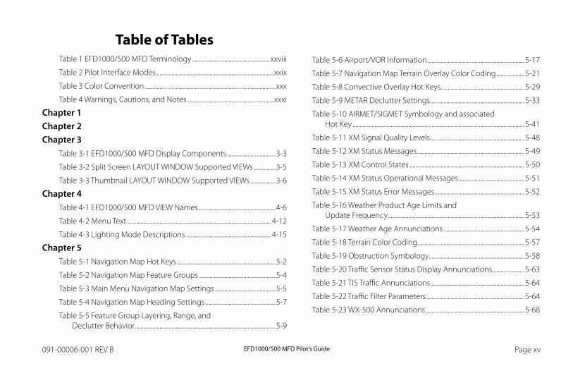
Table of TablesTable 1 EFD1000/500 MFD Terminology .....................................................xxviii
Table 2 Pilot Interface Modes ................................................................................xxix
Table 3 Color Convention .........................................................................................xxx
Table 4 Warnings, Cautions, and Notes ...........................................................xxxi
Chapter 1Chapter 2Chapter 3
Table 3-1 EFD1000/500 MFD Display Components .................................3-3
Table 3-2 Split Screen LAYOUT WINDOW Supported VIEWs ...............3-5
Table 3-3 Thumbnail LAYOUT WINDOW Supported VIEWs .................3-6
Chapter 4Table 4-1 EFD1000/500 MFD VIEW Names.....................................................4-6
Table 4-2 Menu Text ..................................................................................................4-12
Table 4-3 Lighting Mode Descriptions ..........................................................4-15
Chapter 5Table 5-1 Navigation Map Hot Keys ...................................................................5-2
Table 5-2 Navigation Map Feature Groups ....................................................5-4
Table 5-3 Main Menu Navigation Map Settings .........................................5-5
Table 5-4 Navigation Map Heading Settings ................................................5-7
Table 5-5 Feature Group Layering, Range, and Declutter Behavior ................................................................................................5-9
Table 5-6 Airport/VOR Information ..................................................................5-17
Table 5-7 Navigation Map Terrain Overlay Color Coding ...................5-21
Table 5-8 Convective Overlay Hot Keys.........................................................5-29
Table 5-9 METAR Declutter Settings ................................................................5-33
Table 5-10 AIRMET/SIGMET Symbology and associated Hot Key .....................................................................................................................5-41
Table 5-11 XM Signal Quality Levels ................................................................5-48
Table 5-12 XM Status Messages .........................................................................5-49
Table 5-13 XM Control States ..............................................................................5-50
Table 5-14 XM Status Operational Messages .............................................5-51
Table 5-15 XM Status Error Messages .............................................................5-52
Table 5-16 Weather Product Age Limits and Update Frequency .............................................................................................5-53
Table 5-17 Weather Age Annunciations .......................................................5-54
Table 5-18 Terrain Color Coding.........................................................................5-57
Table 5-19 Obstruction Symbology .................................................................5-58
Table 5-20 Traffic Sensor Status Display Annunciations......................5-63
Table 5-21 TIS Traffic Annunciations ................................................................5-64
Table 5-22 Traffic Filter Parameters ...................................................................5-64
Table 5-23 WX-500 Annunciations ...................................................................5-68
EFD1000/500 MFD Pilot’s GuidePage xvi 091-00006-001 REV B EFD1000/500 MFD Pilot’s Guide Page xvii091-00006-001 REV B
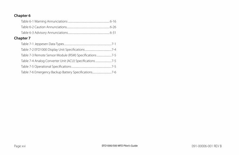
Chapter 6Table 6-1 Warning Annunciations ....................................................................6-16
Table 6-2 Caution Annunciations......................................................................6-26
Table 6-3 Advisory Annunciations ....................................................................6-31
Chapter 7Table 7-1 Jeppesen Data Types .............................................................................7-1
Table 7-2 EFD1000 Display Unit Specifications ...........................................7-4
Table 7-3 Remote Sensor Module (RSM) Specifications ........................7-5
Table 7-4 Analog Converter Unit (ACU) Specifications ..........................7-5
Table 7-5 Operational Specifications .................................................................7-5
Table 7-6 Emergency Backup Battery Specifications ...............................7-6
EFD1000/500 MFD Pilot’s GuidePage xvi 091-00006-001 REV B EFD1000/500 MFD Pilot’s Guide Page xvii091-00006-001 REV B
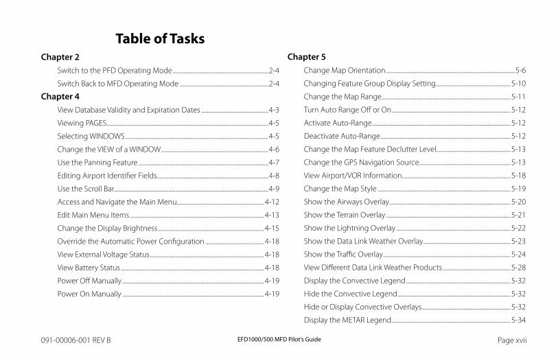
Table of TasksChapter 2
Switch to the PFD Operating Mode ...................................................................2-4
Switch Back to MFD Operating Mode ..............................................................2-4
Chapter 4View Database Validity and Expiration Dates ...............................................4-3
Viewing PAGES .................................................................................................................4-5
Selecting WINDOWS ....................................................................................................4-5
Change the VIEW of a WINDOW ...........................................................................4-6
Use the Panning Feature ...........................................................................................4-7
Editing Airport Identifier Fields ..............................................................................4-8
Use the Scroll Bar............................................................................................................4-9
Access and Navigate the Main Menu .............................................................4-12
Edit Main Menu Items ..............................................................................................4-13
Change the Display Brightness ..........................................................................4-15
Override the Automatic Power Configuration .........................................4-18
View External Voltage Status ................................................................................4-18
View Battery Status ....................................................................................................4-18
Power Off Manually ...................................................................................................4-19
Power On Manually ...................................................................................................4-19
Chapter 5Change Map Orientation ..........................................................................................5-6
Changing Feature Group Display Setting ....................................................5-10
Change the Map Range ..........................................................................................5-11
Turn Auto Range Off or On ...................................................................................5-12
Activate Auto-Range .................................................................................................5-12
Deactivate Auto-Range ...........................................................................................5-12
Change the Map Feature Declutter Level....................................................5-13
Change the GPS Navigation Source ................................................................5-13
View Airport/VOR Information ............................................................................5-18
Change the Map Style .............................................................................................5-19
Show the Airways Overlay.....................................................................................5-20
Show the Terrain Overlay .......................................................................................5-21
Show the Lightning Overlay ................................................................................5-22
Show the Data Link Weather Overlay .............................................................5-23
Show the Traffic Overlay .........................................................................................5-24
View Different Data Link Weather Products ...............................................5-28
Display the Convective Legend .........................................................................5-32
Hide the Convective Legend ...............................................................................5-32
Hide or Display Convective Overlays ..............................................................5-32
Display the METAR Legend ...................................................................................5-34
EFD1000/500 MFD Pilot’s GuidePage xviii 091-00006-001 REV B EFD1000/500 MFD Pilot’s Guide Page PB091-00006-001 REV B
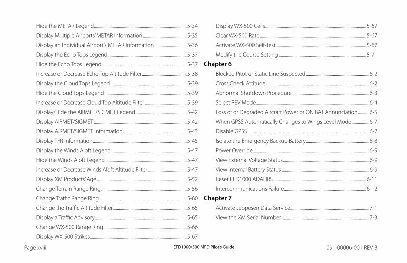
Hide the METAR Legend .........................................................................................5-34
Display Multiple Airports’ METAR Information ..........................................5-35
Display an Individual Airport’s METAR Information ...............................5-36
Display the Echo Tops Legend ............................................................................5-37
Hide the Echo Tops Legend .................................................................................5-37
Increase or Decrease Echo Top Altitude Filter ...........................................5-38
Display the Cloud Tops Legend .........................................................................5-39
Hide the Cloud Tops Legend ...............................................................................5-39
Increase or Decrease Cloud Top Altitude Filter ........................................5-39
Display/Hide the AIRMET/SIGMET Legend .................................................5-42
Display AIRMET/SIGMET .........................................................................................5-42
Display AIRMET/SIGMET Information .............................................................5-43
Display TFR Information ..........................................................................................5-45
Display the Winds Aloft Legend ........................................................................5-47
Hide the Winds Aloft Legend ..............................................................................5-47
Increase or Decrease Winds Aloft Altitude Filter .....................................5-47
Display XM Products’ Age ......................................................................................5-52
Change Terrain Range Ring ..................................................................................5-56
Change Traffic Range Ring ....................................................................................5-60
Change the Traffic Altitude Filter.......................................................................5-65
Display a Traffic Advisory ........................................................................................5-65
Change WX-500 Range Ring ................................................................................5-66
Display WX-500 Strikes.............................................................................................5-67
Display WX-500 Cells .................................................................................................5-67
Clear WX-500 Rate ......................................................................................................5-67
Activate WX-500 Self-Test .......................................................................................5-67
Modify the Course Setting ....................................................................................5-71
Chapter 6Blocked Pitot or Static Line Suspected .............................................................6-2
Cross Check Attitude ...................................................................................................6-2
Abnormal Shutdown Procedure .........................................................................6-3
Select REV Mode .............................................................................................................6-4
Loss of or Degraded Aircraft Power or ON BAT Annunciation ...........6-5
When GPSS Automatically Changes to Wings Level Mode .................6-7
Disable GPSS .....................................................................................................................6-7
Isolate the Emergency Backup Battery .............................................................6-8
Power Override ................................................................................................................6-9
View External Voltage Status ...................................................................................6-9
View Internal Battery Status ....................................................................................6-9
Reset EFD1000 ADAHRS .........................................................................................6-11
Intercommunications Failure ...............................................................................6-12
Chapter 7Activate Jeppesen Data Service............................................................................7-1
View the XM Serial Number ....................................................................................7-3

EFD1000/500 MFD Pilot’s GuidePage PB 091-00006-001 REV B EFD1000/500 MFD Pilot’s Guide Page xix091-00006-001 REV B
Copyrights and Trademarks Copyright 2007-2009.
Aspen Avionics® is a registered trademark of Aspen Avionics, Inc. Evolution™, EFD1000 Pro PFD™, EFD1000 MFD™, EFD500 MFD™, EFD1000™, EFD500™, and the Aspen Avionics logo are trademarks of Aspen Avionics, Inc. These trademarks may not be used without the express permission of Aspen Avionics, Inc. All rights reserved.
All other trademarks are the property of their respective companies. No part of the Pilot’s Guide may be reproduced, copied, stored, transmitted, or disseminated, for any reason, without the express written permission of Aspen Avionics, Inc. Aspen Avionics hereby grants permission to download a single copy, and any revision, of the Pilot’s Guide onto a hard drive or other electronic storage medium for personal use, provided that such electronic or printed copy of the Pilot’s Guide or revision must contain the complete text of this copyright notice and provided further that any unauthorized commercial distribution of the Pilot’s Guide or revision hereto is strictly prohibited.
The NavData® for the EFD1000/500 MFD is provided by Jeppesen Sanderson, Inc. and includes copyrighted data compilations owned by Jeppesen. Aspen Avionics has a limited, non-exclusive license to use this copyrighted data. The data is authorized for use only in connection with the ordinary and intended use of the EFD1000/500 MFD as described in this manual. Use for any other purpose, or reproduction or copying of any portion of said copyrighted subject matter, is strictly prohibited.
The Aspen Avionics EFD1000/500 MFD provides access to information from multiple sources. Aspen Avionics does not control, edit or review the content of said information and as such, is not responsible for information or the actions or conduct of any company that provides weather data used by the Aspen Avionics EFD1000/500 MFD. Therefore, although Aspen Avionics strives to provide the highest quality service, ALL SERVICES AND WEATHER DATA ARE PROVIDED AS-IS and neither Aspen Avionics nor its suppliers, subcontractors, information sources or developers (collectively called “Suppliers”) are responsible for: 1) the accuracy, completeness, timeliness, reliability, content, or availability of the Services or any information accessed; 2) loss or damage to your records or data; or 3) your use of, or results achieved from, the Services or any information accessed.
Avidyne® is a registered trademark of Avidyne Corporation; Bendix/King® is a registered trademark of Honeywell; Garmin GTX™is a trademark of Garmin International, Inc.; NavData® is a registered trademark of Jeppesen, Inc.; SkyWatch® is a registered trademark of L-3 Communications; Stormscope® WX-500 is a registered trademark of BFGoodrich Avionics Systems, Inc.; and XM is a registered trademark of XM Satellite Radio, Inc.

EFD1000/500 MFD Pilot’s GuidePage xx 091-00006-001 REV B EFD1000/500 MFD Pilot’s Guide Page xxi091-00006-001 REV B
ApprovalsThe EFD1000/500 MFD is approved under the following Technical Standard Orders (TSOs):
C2D, C3D, C4C, C6D, C8D, C10B, C106, C113
The following certification levels also apply to this product:
• Environmental Certification Level: RTCA DO-160E
• Software Certification Level: RTCA DO-178B Level C
This Pilot’s Guide provides information on the use and operation of the Evolution Flight Display 1000 Multifunction Flight Display (EFD1000 MFD) and Evolution Flight Display 500 Multifunction Flight Display (EFD500 MFD). This guide is current as of the Date Published. Specifications and operational details are subject to change without notice. Please visit the Aspen Avionics web site, aspenavionics.com, for the most up-to-date Pilot’s Guide.
Installation of the EFD1000/500 MFD in a type-certificated aircraft must be performed in accordance with the latest revision of the Aspen Avionics EFD1000/500 MFD Installation Manual, document number 900-00003-001.
Aspen Avionics, Inc. 5001 Indian School Road NE Albuquerque, NM 87110 Phone: (505) 856-5034 Fax: (505) 314-5440
www.aspenavionics.com
Date Published: September 18, 2009
EFD1000/500 MFD Pilot’s GuidePage xx 091-00006-001 REV B EFD1000/500 MFD Pilot’s Guide Page xxi091-00006-001 REV B
B. Furnish proof sufficient to establish that the item is a Nonconforming Product, and
C. Allow Aspen access to all relevant records in order to substantiate your warranty claim.
4. EXCLUSIONS. The following are not covered by (and are expressly excluded from) this warranty:
A. Normal wear and tear and the need for regular overhaul and maintenance,
B. Exposure of the Product to temperature, environmental, operating, or other conditions other than those prescribed in the owner’s manual,
C. Failure to install or operate the Product as prescribed in the owner’s manual or as Aspen otherwise directs,
D. Alterations or repairs made by anyone other than Aspen or its authorized service center,
E. Maintenance, repair, installation, handling, transportation, storage, operation (including, without limitation, operation of the product’s software or host medium), or use which is improper or otherwise does not comply with Aspen’s instructions as set forth in the owner’s manual.
LIMITED WARRANTY Aspen Avionics, Inc.
1. YOUR WARRANTY. Aspen Avionics, Inc. (“Aspen”) warrants to you, the original purchaser, that its Products (if purchased from an authorized dealer) will comply with applicable specifications (as set forth in the owner’s manual) in all material respects and will be free from material defects in workmanship or materials for a period of twenty-four (24) months beginning with the date that the aircraft in which the Product has been installed has been returned to service following installation by an Aspen authorized dealer (“Return to Service Date”). “Product” means new end equipment or hardware items, replaceable units and components of those units.
2. YOUR REMEDY. During the term of this warranty, Aspen will repair or replace, at its discretion, without charge (see Section 13 below for information on covered transportation costs), any Product that does not comply with the warranty of Section 1 above (a “Nonconforming Product”), so long as the warranty claim is timely submitted and the procedures in Section 14 (below) are followed. Aspen warrants repaired and/or replacement items only for the unexpired portion of the original warranty period, or, if the warranty has expired, for six months from Aspen’s shipment of the repaired or replacement Product.
3. CONDITIONS TO COVERAGE. Aspen’s obligation under this warranty is conditioned on your fulfillment of the obligation to:
A. Maintain records accurately reflecting operating time of and maintenance performed on the Product,
EFD1000/500 MFD Pilot’s GuidePage xxii 091-00006-001 REV B EFD1000/500 MFD Pilot’s Guide Page xxiii091-00006-001 REV B
F. Accident, contamination, damage from a foreign object or weather conditions, abuse, misuse, neglect, or negligence,
G. Exposure of the product or the product’s host medium to any computer virus or other intentionally disruptive, destructive, or disabling computer code, and
H. Any damage precipitated by failure of a product Aspen has supplied that is not under warranty or by any product supplied by someone else.
5. INVALIDATION OF WARRANTY. This warranty is void if the product is altered or repair is attempted or made by anyone other than Aspen or its authorized service center.
6. WARRANTY CARD. The Return to Service Date must be included in an accurately completed Aspen warranty application form submitted by the installing authorized dealer within 30 days of the Return to Service Date. The warranty application must be signed by the authorized repairman who certifies that the equipment has been safely and properly installed in accordance with all Aspen supplied technical information and in accordance with all applicable FAA procedures and requirements. The warranty application form must note the repairman’s FAA certificate number to be valid. FAILURE TO COMPLETE AND RETURN THE WARRANTY CARD MAY RESULT IN DENIAL OF WARRANTY CLAIMS. MAKING CERTAIN THAT THE WARRANTY CARD IS COMPLETED, SIGNED, AND RETURNED IS YOUR RESPONSIBILITY.
7. SOLE REMEDY. Aspen’s sole obligation, and your exclusive remedy under this warranty, is limited to either the repair or replacement, at Aspen’s option, of any Nonconforming Product as provided herein.
8. EXCLUSIVE WARRANTY. THIS WARRANTY IS EXCLUSIVE AND IN LIEU OF ALL OTHER WARRANTIES. THE IMPLIED WARRANTY OF MERCHANTABILITY AND IMPLIED WARRANTY OF FITNESS FOR A PARTICULAR PURPOSE, AS WELL AS ALL OTHER IMPLIED WARRANTIES (STATUTORY OR OTHERWISE) EXPIRE AT THE END OF THE WARRANTY PERIOD PRESCRIBED IN SECTION 1.
Some States do not allow limitations on how long an implied warranty lasts, so the above limitation may not apply to you.
9. INCIDENTAL DAMAGES. ASPEN SHALL NOT UNDER ANY CIRCUMSTANCES BE LIABLE FOR ANY SPECIAL, DIRECT, INDIRECT, INCIDENTAL OR CONSEQUENTIAL LOSS OR DAMAGES OF ANY KIND (INCLUDING WITHOUT LIMITATION: DAMAGES FOR LOSS OF PROFITS, LOSS OF REVENUES, OR LOSS OF USE OR BUSINESS INTERRUPTION), EVEN IF ASPEN HAS BEEN ADVISED OF THE POSSIBILITY OR CERTAINTY OF THOSE DAMAGES OR IF ASPEN COULD HAVE REASONABLY FORESEEN THOSE DAMAGES.
Some states do not allow the exclusion of incidental or consequential damages, so the preceding limitations may not apply to you.
10. LIMITATION OF LIAbILITY. ASPEN’S AGGREGATE LIABILITY HEREUNDER, WHETHER BASED UPON CONTRACT, TORT (INCLUDING NEGLIGENCE AND STRICT LIABILITY), INDEMNITY, OR OTHERWISE, WILL NOT EXCEED THE PRICE PAID BY YOU FOR THE WARRANTED PRODUCT. THE EXCLUSIONS OF TYPES OF DAMAGES CONTAINED HEREIN WILL BE DEEMED INDEPENDENT OF, AND WILL SURVIVE, ANY FAILURE OF THE ESSENTIAL PURPOSE OF ANY LIMITED REMEDY UNDER THE TERMS OF ANY AGREEMENT.

EFD1000/500 MFD Pilot’s GuidePage xxii 091-00006-001 REV B EFD1000/500 MFD Pilot’s Guide Page xxiii091-00006-001 REV B
11. EXTENSION OF WARRANTY. No extension of this warranty will be binding upon Aspen unless set forth in writing and signed by Aspen’s authorized representative.
12. DEALER WARRANTIES. Any express or implied warranty or remedy in addition to or different from those stated herein that is offered by a dealer (“Dealer Warranty”) will be the sole responsibility of the dealer, who will be solely responsible for all liability, loss, cost, damage, or expense arising out of or in connection with any such Dealer Warranty. Although Aspen provides training and assistance to dealers, it cannot control the installation of its Products by its dealers, which are independent businesses not owned or controlled by Aspen.
13. TRANSPORTATION COSTS. Aspen will assume round trip transportation costs for a Product determined by Aspen to be a Nonconforming Product in an amount not to exceed normal (non express) shipping charges within the continental United States. You are responsible for all import/export fees, taxes, duties, customs, documentation fees, clearance fees, and similar fees and charges. You may contact Aspen to obtain a freight courier account number for prepaid shipping of the return. If Aspen subsequently determines that the Product is not a Nonconforming Product, that this warranty is inapplicable, that the Product is out of warranty, that the defect or malfunction is excluded from coverage, or that the warranty is invalid, Aspen will invoice you for repair or replacement costs and the shipping costs. Risk of loss or damage for any Product in transit will be borne by the party initiating the transportation.
14. WARRANTY PROCEDURE. If you require warranty service, you may contact your local Aspen Authorized Dealer or you may contact Aspen directly as described below. An original or copy of the sales receipt from the original Aspen Authorized dealer will be required to obtain any warranty service. You may contact Aspen for warranty service directly by calling Aspen Customer Service at (505) 856-5034; by writing to Aspen Customer Service Department, Aspen Avionics, Inc., 5001 Indian School Road NE, Albuquerque, New Mexico, 87110; or by visiting the Aspen Website at http://www.aspenavionics.com.
This warranty gives you specific legal rights, and you may also have other rights which vary from State to State.
EFD1000/500 MFD Pilot’s GuidePage xxiv 091-00006-001 REV B EFD1000/500 MFD Pilot’s Guide Page xxv091-00006-001 REV B
Weather Data Warranty THE WEATHER DATA SOFTWARE PRODUCT IS PROVIDED “AS IS.” ALL OTHER WARRANTIES, EXPRESSED OR IMPLIED, INCLUDING ANY WARRANTY OF MERCHANTABILITY OR FITNESS FOR A PARTICULAR PURPOSE OR OF NON-INFRINGEMENT ARE HEREBY EXCLUDED.
PILOT SAFETY.
If you use XM Services it is your responsibility to exercise prudent discretion and observe all safety measures required by law and your own common sense. You assume the entire risk related to your use of the Services. XM and Aspen assume no responsibility for accidents resulting from or associated with use of the Services. Your Radio Service includes weather information, and you acknowledge that such information is not for “safety for life,” but is merely supplemental and advisory in nature, and therefore cannot be relied upon as safety-critical in connection with any aircraft. This information is provided “as is” and XM and Aspen disclaim any and all warranties, express and implied, with respect thereto or the transmission or reception thereof. XM and Aspen further do not warrant the accuracy, disclosed on the Radio Service. In no event will XM and Aspen, their data suppliers, service providers, marketing/distribution, software or Internet partners or hardware manufacturers be liable to you or to any third party for any direct, indirect, incidental, consequential, special, exemplary or punitive damages or lost profits resulting from use of or interruptions in the transmission or reception of the Services.
LIMITS ON OUR RESPONSIbILITY
A. DISCLAIMERS. EXCEPT AS EXPRESSLY PROVIDED HEREIN, WE MAKE NO WARRANTY OR REPRESENTATION, EITHER EXPRESS OR IMPLIED, REGARDING THE RADIO SERVICE. YOUR USE OF THE SERVICE IS AT YOUR SOLE RISK. THE CONTENT AND FUNCTIONALITY OF THE SERVICE IS PROVIDED “AS IS” WITHOUT ANY WARRANTY OF ANY KIND, EXPRESS OR IMPLIED. ALL SUCH WARRANTIES OR REPRESENTATIONS (INCLUDING, WITHOUT LIMITATION, THE IMPLIED WARRANTIES OF MERCHANTABILITY, FITNESS FOR A PARTICULAR PURPOSE, TITLE AND NON0INFRINGEMENT) ARE HEREBY DISCLAIMED.
B. LIMITATIONS OF LIAbILITY. WE ARE NOT RESPONSIBLE FOR ANY SPECIAL, INCIDENTAL, OR CONSEQUENTIAL DAMAGES OR LOSSES RELATING TO THE USE OF THE RADIO SERVICE, WHETHER BASED ON NEGLIGENCE OR OTHERWISE. OUR TOTAL LIABILITY TO YOU AND ANY OTHER PERSONS RECEIVING OUR SERVICES, REGARDLESS OF THE CAUSE, WILL IN NO EVENT EXCEED THE AMOUNTS THAT YOU HAVE PAID TO US FOR THE SERVICE THAT YOU RECEIVED DURING THE SIX (6) MONTH PERIOD IMMEDIATELY PRIOR TO THE SPECIFIC EVENT THAT GAVE RISE TO THE APPLICABLE DAMAGE OR LOSS. THIS ALLOCATION OF RISK IS REFLECTED IN OUR PRICES. YOU MAY HAVE GREATER RIGHTS THAN DESCRIBED ABOVE UNDER YOUR STATE’S LAWS.
EFD1000/500 MFD Pilot’s GuidePage xxiv 091-00006-001 REV B EFD1000/500 MFD Pilot’s Guide Page xxv091-00006-001 REV B
XM WX Satellite Radio Service Agreement
Hardware and required monthly subscription sold separately. Subscription fee is consumer only. Other fees and taxes, including a one-time activation fee may apply. All programming fees and weather data are subject to change. XM WX weather data displays and individual product availability vary by hardware equipment. Reception of the XM signal may vary depending on location. Subscriptions subject to Customer Agreement included with the XM Welcome Kit and available at xmradio.com and are available only in the 48 contiguous United States. XM WX is a trademark of XM WX Satellite Radio Inc.
Contact XM WX Satellite Radio by phone at 800.985.9200 to subscribe to XM WX Weather.

EFD1000/500 MFD Pilot’s GuidePage xxvi 091-00006-001 REV B EFD1000/500 MFD Pilot’s Guide Page PB091-00006-001 REV B
This Page Intentionally Left Blank
EFD1000/500 MFD Pilot’s GuidePage PB 091-00006-001 REV B EFD1000/500 MFD Pilot’s Guide Page xxvii091-00006-001 REV B
ConventionsThe following conventions, definitions, terminology and colors are used in this manual and the EFD1000 PFD.
Covered FunctionalityThis guide covers all the functionality available in the EFD1000 MFD and EFD500 MFD. The EFD500 MFD does not include an AHRS and ADC sensor, Secondary HSI, and does not support Reversionary mode. See Aspen Avionics document number 091-00005-001 EFD1000 PFD Pilot’s Guide for complete instructions on the EFD1000 PFD.
TerminologyThis guide uses the terminology listed in Table 1 when referring to specific parts of the EFD1000/500 MFD. Refer to Chapter 5, Reference Guide for an in-depth discussion and step-by-step instructions for all the available functionality of the EFD1000/500 MFD.
Term Definition
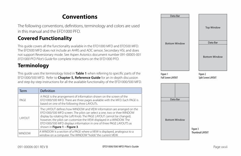
PAGEA PAGE is the arrangement of information shown on the screen of the EFD1000/500 MFD. There are three pages available with the MFD. Each PAGE is based on one of the following three LAYOUTs.
LAYOUT
The LAYOUT defines how WINDOW and VIEW information are arranged on the EFD1000/500 MFD screen. The pilot can select a one, two or thee WINDOW display by rotating the Left Knob. The PAGE LAYOUT cannot be changed; however, the pilot can customize the VIEW displayed in a WINDOW. The EFD1000/500 MFD displays information in one of three PAGE LAYOUTS as shown in Figure 1 – Figure 3.
WINDOW A WINDOW is a section of a PAGE where a VIEW is displayed, analogous to a window on a computer. The WINDOW “holds” the current VIEW.
Figure 1 Full Screen LAYOUT
Figure 2 Split Screen LAYOUT
Figure 3 Thumbnail LAYOUT
Data Bar
Data Bar
Data Bar
EFD1000/500 MFD Pilot’s GuidePage xxviii 091-00006-001 REV B EFD1000/500 MFD Pilot’s Guide Page xxix091-00006-001 REV B
Term Definition
VIEW
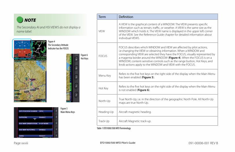
A VIEW is the graphical content of a WINDOW. The VIEW presents specific information such as terrain, traffic, or weather. A VIEW is the same size as the WINDOW which holds it. The VIEW name is displayed in the upper left corner of the VIEW. See the Reference Guide chapter for detailed information about individual VIEWS.
FOCUS
FOCUS describes which WINDOW and VIEW are affected by pilot actions, i.e changing the VIEW or obtaining information. When a WINDOW and corresponding VIEW are selected they have the FOCUS, visually represented by a magenta border around the WINDOW (Figure 4). When the FOCUS is on a WINDOW, content-sensitive controls such as the range button, Hot Keys, and knob actions apply to the WINDOW and VIEW with the FOCUS.
Menu Key Refers to the five hot keys on the right side of the display when the Main Menu has been enabled (Figure 5).
Hot Key Refers to the five hot keys on the right side of the display when the Main Menu is not enabled (Figure 6).
North-Up True North-Up, i.e. in the direction of the geographic North Pole. All North-Up maps are true North-Up.
Heading-Up Aircraft magnetic heading.
Track-Up Aircraft Magnetic track-up.
Table 1 EFD1000/500 MFD Terminology
NOTE The Secondary AI and HSI VIEWS do not display a name label.
Figure 4 The Secondary Attitude Indicator has the FOCUS
Figure 6 Hot Keys
Figure 5 Main Menu Keys
EFD1000/500 MFD Pilot’s GuidePage xxviii 091-00006-001 REV B EFD1000/500 MFD Pilot’s Guide Page xxix091-00006-001 REV B
Pilot Interface ModesThe EFD1000/500 MFD has several interface modes described in Table 2. The current mode determines the functionality of the content-sensitive pilot controls.
Term Definition
PAGE Selection
When the EFD1000/500 MFD first initializes it is in PAGE (and VIEW) Selection mode. Rotating the Left Knob selects different PAGES. When PAGE Selection mode is active the Pg #/3 label above the Left Knob is magenta in color (# indicates the current page number). PAGE and VIEW selection mode deactivates automatically after 10 seconds of inactivity.
Change WINDOW
Pressing the Right Knob activates WINDOW Select mode and moves the FOCUS to different WINDOWS on the currently displayed PAGE. When WINDOW Selection mode is active, the magenta border around the selected WINDOW becomes thicker and the VIEW label above the Right Knob is magenta in color. WINDOW selection mode deactivates automatically after 10 seconds of inactivity.
Change VIEW Rotating the Right Knob selects different VIEWS within the WINDOW with the FOCUS. VIEW selection mode deactivates automatically after 10 seconds of inactivity.
VIEW Control
When VIEW Control Mode is activated, the function of the Right and Left Knobs changes. VIEW Control Mode is available for those VIEWS that support additional functionality, such as map panning, data editing, product selection, and information scrolling. A button or knob is usually pressed to activate VIEW Control Mode and must be pressed to deactivate VIEW control mode. See the Navigation Map and Data Link Weather section in Chapter 5 for detailed information about different VIEW controls.
MENUPressing the MENU Button activates the Main Menu and displays a context-sensitive list of options, putting the MFD in MENU Mode. The five Hot Keys function as menu selection keys (Menu Keys). The pilot must press the MENU button to deactivate MENU mode. See Chapter 6, Customizing the EFD1000/500 MFD for complete Main Menu options.
Table 2 Pilot Interface Modes
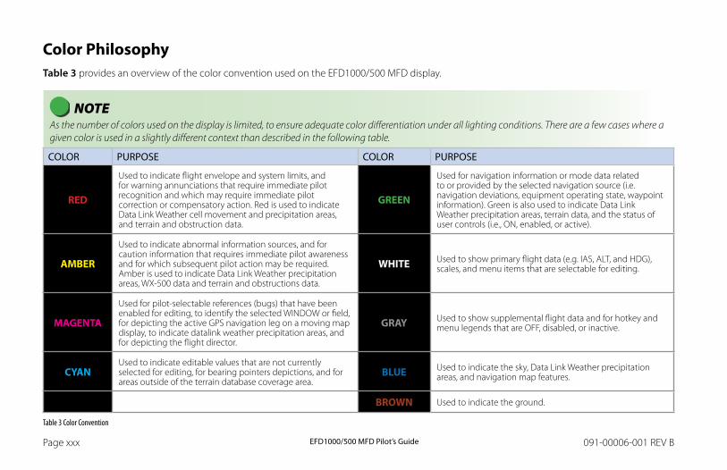
EFD1000/500 MFD Pilot’s GuidePage xxx 091-00006-001 REV B EFD1000/500 MFD Pilot’s Guide Page xxxi091-00006-001 REV B
Color PhilosophyTable 3 provides an overview of the color convention used on the EFD1000/500 MFD display.
NOTE As the number of colors used on the display is limited, to ensure adequate color differentiation under all lighting conditions. There are a few cases where a given color is used in a slightly different context than described in the following table.
COLOR PURPOSE COLOR PURPOSE
RED
Used to indicate flight envelope and system limits, and for warning annunciations that require immediate pilot recognition and which may require immediate pilot correction or compensatory action. Red is used to indicate Data Link Weather cell movement and precipitation areas, and terrain and obstruction data.
GREEN
Used for navigation information or mode data related to or provided by the selected navigation source (i.e. navigation deviations, equipment operating state, waypoint information). Green is also used to indicate Data Link Weather precipitation areas, terrain data, and the status of user controls (i.e., ON, enabled, or active).
AMBER
Used to indicate abnormal information sources, and for caution information that requires immediate pilot awareness and for which subsequent pilot action may be required. Amber is used to indicate Data Link Weather precipitation areas, WX-500 data and terrain and obstructions data.
WHITE Used to show primary flight data (e.g. IAS, ALT, and HDG), scales, and menu items that are selectable for editing.
MAGENTA
Used for pilot-selectable references (bugs) that have been enabled for editing, to identify the selected WINDOW or field, for depicting the active GPS navigation leg on a moving map display, to indicate datalink weather precipitation areas, and for depicting the flight director.
GRAY Used to show supplemental flight data and for hotkey and menu legends that are OFF, disabled, or inactive.
CYANUsed to indicate editable values that are not currently selected for editing, for bearing pointers depictions, and for areas outside of the terrain database coverage area.
BLUE Used to indicate the sky, Data Link Weather precipitation areas, and navigation map features.
BROWN Used to indicate the ground.
Table 3 Color Convention
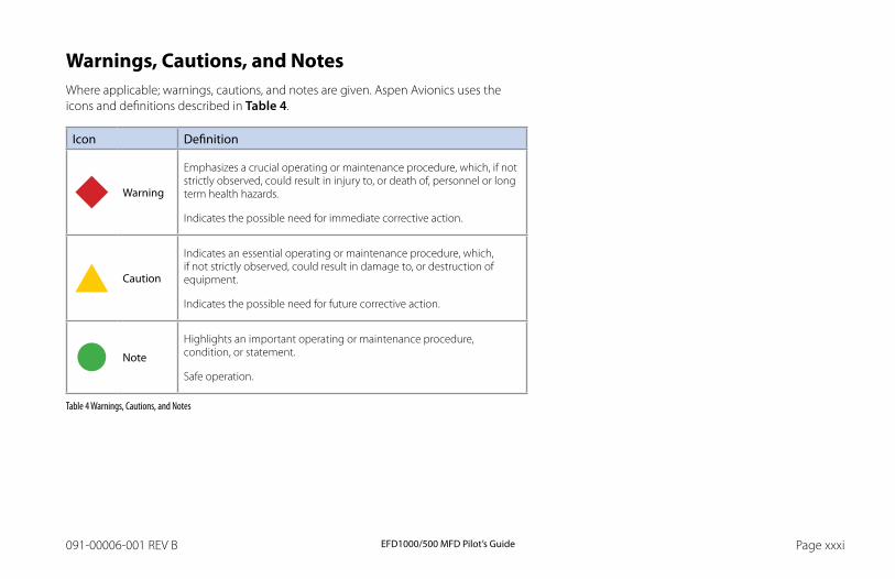
EFD1000/500 MFD Pilot’s GuidePage xxx 091-00006-001 REV B EFD1000/500 MFD Pilot’s Guide Page xxxi091-00006-001 REV B
Warnings, Cautions, and NotesWhere applicable; warnings, cautions, and notes are given. Aspen Avionics uses the icons and definitions described in Table 4.
Icon Definition
Warning
Emphasizes a crucial operating or maintenance procedure, which, if not strictly observed, could result in injury to, or death of, personnel or long term health hazards.
Indicates the possible need for immediate corrective action.
Caution
Indicates an essential operating or maintenance procedure, which, if not strictly observed, could result in damage to, or destruction of equipment.
Indicates the possible need for future corrective action.
Note
Highlights an important operating or maintenance procedure, condition, or statement.
Safe operation.
Table 4 Warnings, Cautions, and Notes
EFD1000/500 MFD Pilot’s GuidePage xxxii 091-00006-001 REV B EFD1000/500 MFD Pilot’s Guide Page PB091-00006-001 REV B
Example GraphicsThe example graphics and screen shots used throughout this Pilot’s Guide are provided for reference only and are taken from a simulated flight. They should not be used for actual flights.
Most of the example graphics and screen shots used throughout this Pilot’s Guide & Reference are based on flying the ILS 16R instrument approach into Reno/Tahoe International Airport (KRNO) in Reno, Nevada, USA. Those images with the airplane in a right bank show the airplane completing the procedure turn in-bound to intercept the Localizer, descending through 8,660 feet to the target altitude of 8,500 feet. The other main group of images, showing the airplane straight and level, are earlier in the approach, tracking outbound for the procedure turn.
Pilot FamiliarityWhile the EFD1000 is reasonably intuitive and easy to use, some familiarity with Electronic Flight Instrument Systems (EFIS) and Horizontal Situation Indicators (HSI) is required. Aspen Avionics strongly recommends that new users of the EFD1000 get some dual instruction from an experienced instrument CFI, and spend some time becoming familiar with the PFD in day VFR conditions with a safety pilot, before flying in actual instrument meteorological conditions (IMC). To reduce pilot workload, the use of autopilot (when available) is strongly encouraged.
Map OrientationAll references are magnetic except the orientation of the North Up navigation map. Track display on the navigation map shows the actual aircraft direction, displaying the magnetic track plus the magnetic variation.
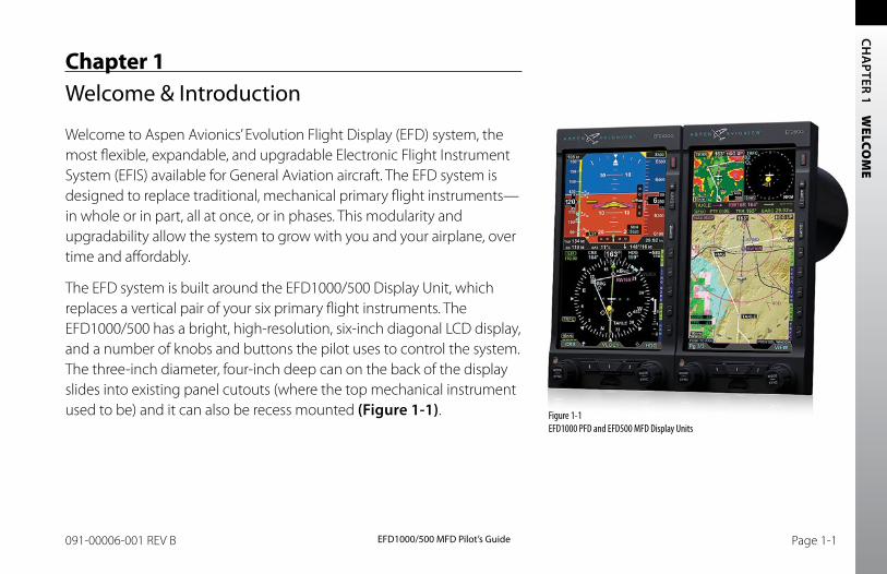
CH
APTER 1 W
ELCOM
E
EFD1000/500 MFD Pilot’s GuidePage PB 091-00006-001 REV B EFD1000/500 MFD Pilot’s Guide Page 1-1091-00006-001 REV B
Chapter 1Welcome & Introduction
Welcome to Aspen Avionics’ Evolution Flight Display (EFD) system, the most flexible, expandable, and upgradable Electronic Flight Instrument System (EFIS) available for General Aviation aircraft. The EFD system is designed to replace traditional, mechanical primary flight instruments—in whole or in part, all at once, or in phases. This modularity and upgradability allow the system to grow with you and your airplane, over time and affordably.
The EFD system is built around the EFD1000/500 Display Unit, which replaces a vertical pair of your six primary flight instruments. The EFD1000/500 has a bright, high-resolution, six-inch diagonal LCD display, and a number of knobs and buttons the pilot uses to control the system. The three-inch diameter, four-inch deep can on the back of the display slides into existing panel cutouts (where the top mechanical instrument used to be) and it can also be recess mounted (Figure 1-1). Figure 1-1
EFD1000 PFD and EFD500 MFD Display Units
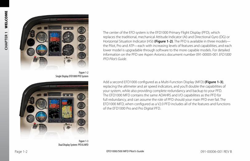
CH
APT
ER 1
W
ELCO
ME
EFD1000/500 MFD Pilot’s GuidePage 1-2 091-00006-001 REV B EFD1000/500 MFD Pilot’s Guide Page 1-3091-00006-001 REV B
Figure 1-3 Dual Display System: PFD & MFD
Figure 1-2 Single Display EFD1000 PFD System
The center of the EFD system is the EFD1000 Primary Flight Display (PFD), which replaces the traditional, mechanical Attitude Indicator (AI) and Directional Gyro (DG) or Horizontal Situation Indicator (HSI) (Figure 1-2). The PFD is available in three models—the Pilot, Pro and ATP—each with increasing levels of features and capabilities, and each lower model is upgradable through software to the more capable models. For detailed information on the PFD see Aspen Avionics document number 091-00005-001 EFD1000 PFD Pilot’s Guide.
Add a second EFD1000 configured as a Multi-Function Display (MFD) (Figure 1-3), replacing the altimeter and air speed indicators, and you’ll double the capabilities of your system, while also providing complete redundancy and backup to your PFD. The EFD1000 MFD contains the same ADAHRS and I/O capabilities as the PFD for full redundancy, and can assume the role of PFD should your main PFD ever fail. The EFD1000 MFD, when configured as a V2.0 PFD includes all of the features and functions of the EFD1000 Pro and Pro Digital PFD.

CH
APTER 1 W
ELCOM
E
EFD1000/500 MFD Pilot’s GuidePage 1-2 091-00006-001 REV B EFD1000/500 MFD Pilot’s Guide Page 1-3091-00006-001 REV B
You can even add another MFD, an EFD500 to round out a complete “six-pack” replacement and gain even more capability and flexibility (Figure 1-4). When you are ready to upgrade, simply contact an Aspen Avionics Authorized Dealer for more information.
Figure 1-4 Trio Display System: PFD & dual MFDs
NOTE Please spend some time with your avionics installer to understand exactly how your EFD system is installed and configured in your particular aircraft with your existing equipment. This will help you fully understand the features and capabilities available to you, and to understand how various aircraft system failures and abnormalities may affect your EFD.
CH
APT
ER 1
W
ELCO
ME
EFD1000/500 MFD Pilot’s GuidePage 1-4 091-00006-001 REV B EFD1000/500 MFD Pilot’s Guide Page 1-5091-00006-001 REV B
1.1. System HardwareDepending on the EFD configuration you have selected, you will have some, all or several of the following pieces of hardware installed in your aircraft. The EFD1000 MFD system typically consists of the following pieces of hardware:
• EFD1000 display unit
• Remote Sensor Module (RSM)
• Configuration Module (CM)
• Analog Converter Unit (ACU) – optional
• Evolution Weather Receiver (EWR) – optional
• Emergency Backup Battery – optional (required for certain configurations)
• microSDHC Card
The EFD500 MFD system is typically comprised of the following pieces of hardware:
• EFD500 display unit
• Configuration Module (CM)
• Analog Converter Unit (ACU) – optional
• Evolution Weather Receiver (EWR) – optional
• microSDHC Card
NOTE The EFD1000 MFD comes standard without emergency GPS. Emergency GPS may be orderd as an option.
NOTE Only one ACU and EWR are needed for all EFD1000/500 displays.
NOTE Each individual EFD1000 requires a CM and an RSM. Each EFD500 requires a CM.
NOTE Each MFD requires a microSDHC card.
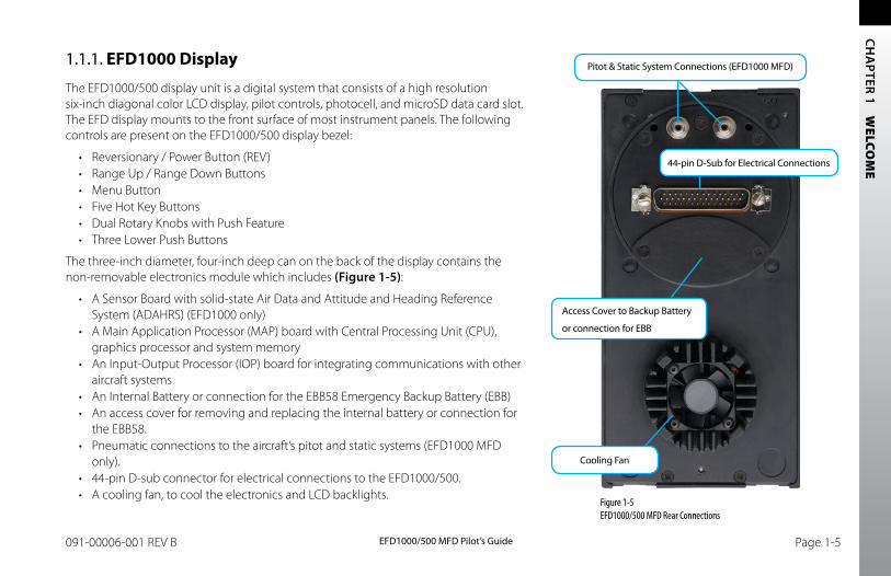
CH
APTER 1 W
ELCOM
E
EFD1000/500 MFD Pilot’s GuidePage 1-4 091-00006-001 REV B EFD1000/500 MFD Pilot’s Guide Page 1-5091-00006-001 REV B
1.1.1. EFD1000 Display
The EFD1000/500 display unit is a digital system that consists of a high resolution six-inch diagonal color LCD display, pilot controls, photocell, and microSD data card slot. The EFD display mounts to the front surface of most instrument panels. The following controls are present on the EFD1000/500 display bezel:
• Reversionary / Power Button (REV)• Range Up / Range Down Buttons• Menu Button• Five Hot Key Buttons• Dual Rotary Knobs with Push Feature• Three Lower Push Buttons
The three-inch diameter, four-inch deep can on the back of the display contains the non-removable electronics module which includes (Figure 1-5):
• A Sensor Board with solid-state Air Data and Attitude and Heading Reference System (ADAHRS) (EFD1000 only)
• A Main Application Processor (MAP) board with Central Processing Unit (CPU), graphics processor and system memory
• An Input-Output Processor (IOP) board for integrating communications with other aircraft systems
• An Internal Battery or connection for the EBB58 Emergency Backup Battery (EBB)• An access cover for removing and replacing the internal battery or connection for
the EBB58.• Pneumatic connections to the aircraft’s pitot and static systems (EFD1000 MFD
only).• 44-pin D-sub connector for electrical connections to the EFD1000/500.• A cooling fan, to cool the electronics and LCD backlights.
Figure 1-5 EFD1000/500 MFD Rear Connections
44-pin D-Sub for Electrical Connections
Access Cover to Backup Battery
or connection for EBB
Cooling Fan
Pitot & Static System Connections (EFD1000 MFD)
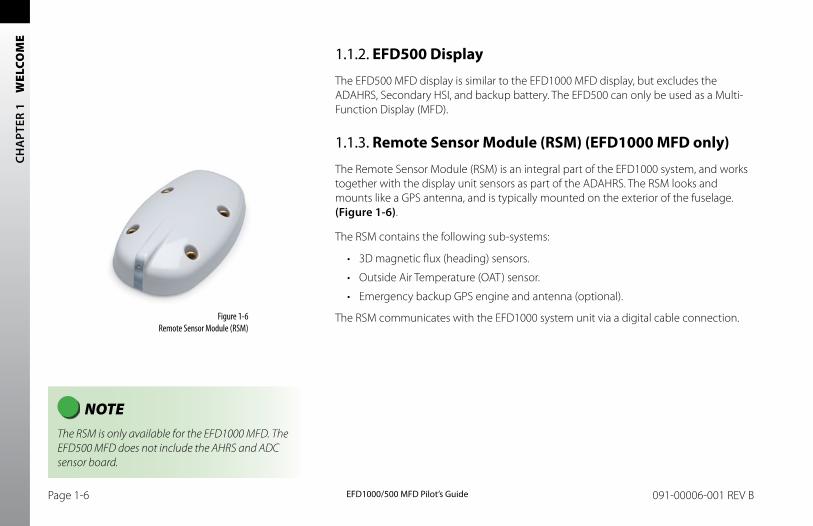
CH
APT
ER 1
W
ELCO
ME
EFD1000/500 MFD Pilot’s GuidePage 1-6 091-00006-001 REV B EFD1000/500 MFD Pilot’s Guide Page 1-7091-00006-001 REV B
NOTE The RSM is only available for the EFD1000 MFD. The EFD500 MFD does not include the AHRS and ADC sensor board.
1.1.2. EFD500 Display
The EFD500 MFD display is similar to the EFD1000 MFD display, but excludes the ADAHRS, Secondary HSI, and backup battery. The EFD500 can only be used as a Multi- Function Display (MFD).
1.1.3. Remote Sensor Module (RSM) (EFD1000 MFD only)
The Remote Sensor Module (RSM) is an integral part of the EFD1000 system, and works together with the display unit sensors as part of the ADAHRS. The RSM looks and mounts like a GPS antenna, and is typically mounted on the exterior of the fuselage. (Figure 1-6).
The RSM contains the following sub-systems:
• 3D magnetic flux (heading) sensors.
• Outside Air Temperature (OAT) sensor.
• Emergency backup GPS engine and antenna (optional).
The RSM communicates with the EFD1000 system unit via a digital cable connection.Figure 1-6 Remote Sensor Module (RSM)
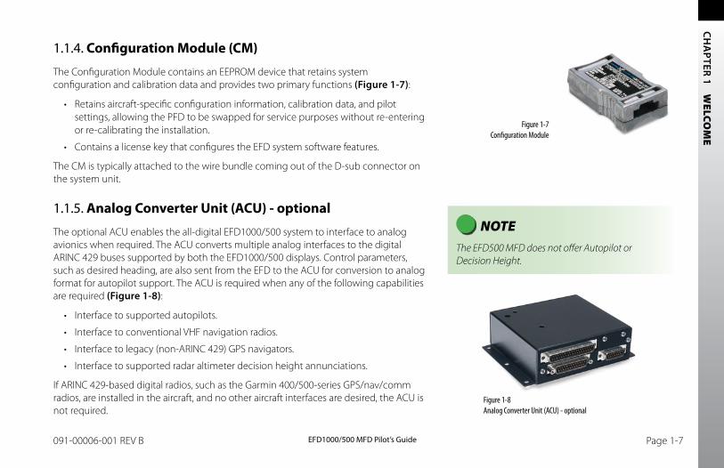
CH
APTER 1 W
ELCOM
E
EFD1000/500 MFD Pilot’s GuidePage 1-6 091-00006-001 REV B EFD1000/500 MFD Pilot’s Guide Page 1-7091-00006-001 REV B
NOTE The EFD500 MFD does not offer Autopilot or Decision Height.
1.1.4. Configuration Module (CM)
The Configuration Module contains an EEPROM device that retains system configuration and calibration data and provides two primary functions (Figure 1-7):
• Retains aircraft-specific configuration information, calibration data, and pilot settings, allowing the PFD to be swapped for service purposes without re-entering or re-calibrating the installation.
• Contains a license key that configures the EFD system software features.
The CM is typically attached to the wire bundle coming out of the D-sub connector on the system unit.
1.1.5. Analog Converter Unit (ACU) - optional
The optional ACU enables the all-digital EFD1000/500 system to interface to analog avionics when required. The ACU converts multiple analog interfaces to the digital ARINC 429 buses supported by both the EFD1000/500 displays. Control parameters, such as desired heading, are also sent from the EFD to the ACU for conversion to analog format for autopilot support. The ACU is required when any of the following capabilities are required (Figure 1-8):
• Interface to supported autopilots.
• Interface to conventional VHF navigation radios.
• Interface to legacy (non-ARINC 429) GPS navigators.
• Interface to supported radar altimeter decision height annunciations.
If ARINC 429-based digital radios, such as the Garmin 400/500-series GPS/nav/comm radios, are installed in the aircraft, and no other aircraft interfaces are desired, the ACU is not required.
Figure 1-7 Configuration Module
Figure 1-8 Analog Converter Unit (ACU) - optional
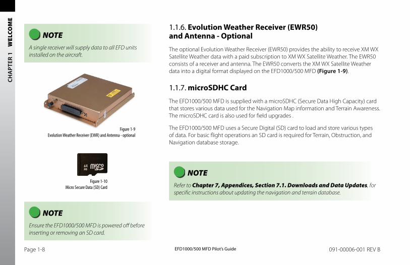
CH
APT
ER 1
W
ELCO
ME
EFD1000/500 MFD Pilot’s GuidePage 1-8 091-00006-001 REV B EFD1000/500 MFD Pilot’s Guide Page PB091-00006-001 REV B
NOTE Ensure the EFD1000/500 MFD is powered off before inserting or removing an SD card.
1.1.6. Evolution Weather Receiver (EWR50) and Antenna - Optional
The optional Evolution Weather Receiver (EWR50) provides the ability to receive XM WX Satellite Weather data with a paid subscription to XM WX Satellite Weather. The EWR50 consists of a receiver and antenna. The EWR50 converts the XM WX Satellite Weather data into a digital format displayed on the EFD1000/500 MFD (Figure 1-9).
1.1.7. microSDHC Card
The EFD1000/500 MFD is supplied with a microSDHC (Secure Data High Capacity) card that stores various data used for the Navigation Map information and Terrain Awareness. The microSDHC card is also used for field upgrades .
The EFD1000/500 MFD uses a Secure Digital (SD) card to load and store various types of data. For basic flight operations an SD card is required for Terrain, Obstruction, and Navigation database storage.
Figure 1-9 Evolution Weather Receiver (EWR) and Antenna - optional
Figure 1-10 Micro Secure Data (SD) Card
NOTE A single receiver will supply data to all EFD units installed on the aircraft.
NOTE Refer to Chapter 7, Appendices, Section 7.1. Downloads and Data Updates, for specific instructions about updating the navigation and terrain database.
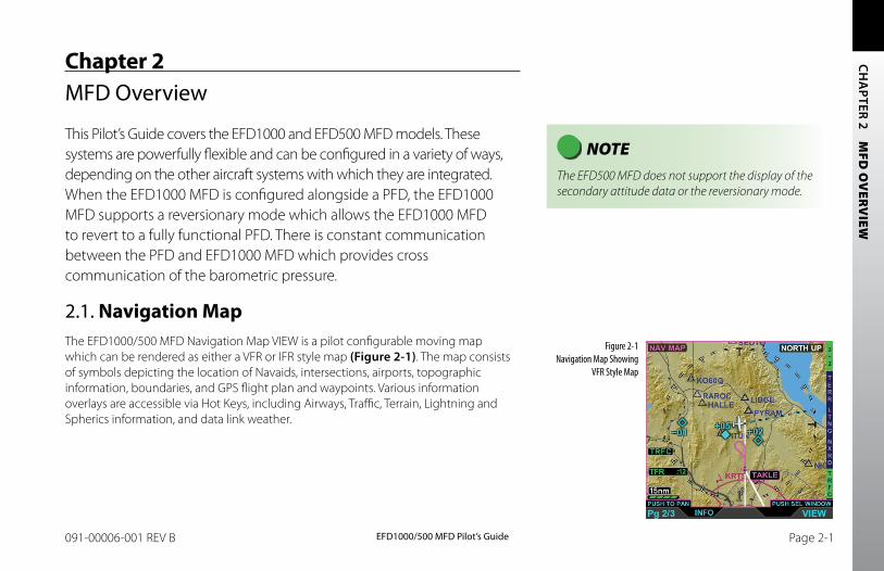
EFD1000/500 MFD Pilot’s GuidePage PB 091-00006-001 REV B EFD1000/500 MFD Pilot’s Guide Page 2-1091-00006-001 REV B
CH
APTER 2 M
FD O
VERV
IEW
Chapter 2MFD Overview
This Pilot’s Guide covers the EFD1000 and EFD500 MFD models. These systems are powerfully flexible and can be configured in a variety of ways, depending on the other aircraft systems with which they are integrated. When the EFD1000 MFD is configured alongside a PFD, the EFD1000 MFD supports a reversionary mode which allows the EFD1000 MFD to revert to a fully functional PFD. There is constant communication between the PFD and EFD1000 MFD which provides cross communication of the barometric pressure.
2.1. Navigation MapThe EFD1000/500 MFD Navigation Map VIEW is a pilot configurable moving map which can be rendered as either a VFR or IFR style map (Figure 2-1). The map consists of symbols depicting the location of Navaids, intersections, airports, topographic information, boundaries, and GPS flight plan and waypoints. Various information overlays are accessible via Hot Keys, including Airways, Traffic, Terrain, Lightning and Spherics information, and data link weather.
NOTE The EFD500 MFD does not support the display of the secondary attitude data or the reversionary mode.
Figure 2-1 Navigation Map Showing
VFR Style Map
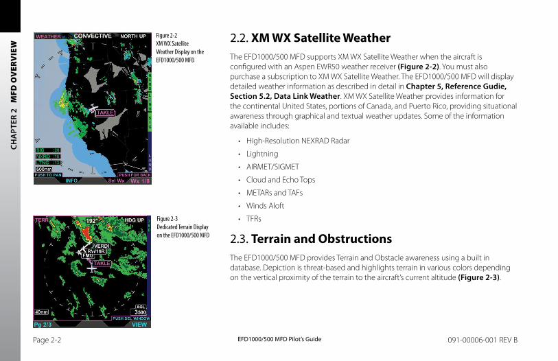
EFD1000/500 MFD Pilot’s GuidePage 2-2 091-00006-001 REV B
CH
APT
ER 2
M
FD O
VER
VIE
W
2.2. XM WX Satellite WeatherThe EFD1000/500 MFD supports XM WX Satellite Weather when the aircraft is configured with an Aspen EWR50 weather receiver (Figure 2-2). You must also purchase a subscription to XM WX Satellite Weather. The EFD1000/500 MFD will display detailed weather information as described in detail in Chapter 5, Reference Gudie, Section 5.2, Data Link Weather. XM WX Satellite Weather provides information for the continental United States, portions of Canada, and Puerto Rico, providing situational awareness through graphical and textual weather updates. Some of the information available includes:
• High-Resolution NEXRAD Radar
• Lightning
• AIRMET/SIGMET
• Cloud and Echo Tops
• METARs and TAFs
• Winds Aloft
• TFRs
2.3. Terrain and ObstructionsThe EFD1000/500 MFD provides Terrain and Obstacle awareness using a built in database. Depiction is threat-based and highlights terrain in various colors depending on the vertical proximity of the terrain to the aircraft’s current altitude (Figure 2-3).
Figure 2-3 Dedicated Terrain Display on the EFD1000/500 MFD
Figure 2-2 XM WX Satellite Weather Display on the EFD1000/500 MFD
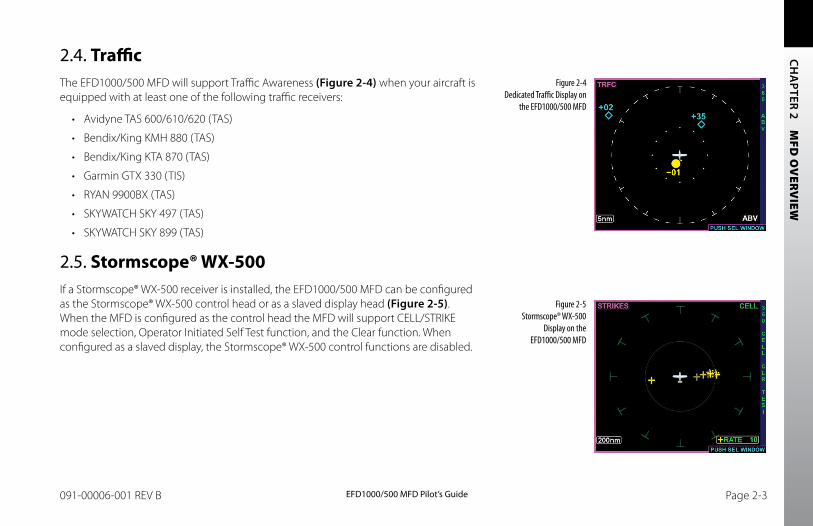
EFD1000/500 MFD Pilot’s GuidePage 2-2 091-00006-001 REV B EFD1000/500 MFD Pilot’s Guide Page 2-3091-00006-001 REV B
CH
APTER 2 M
FD O
VERV
IEW
Figure 2-5 Stormscope® WX-500
Display on the EFD1000/500 MFD
Figure 2-4 Dedicated Traffic Display on
the EFD1000/500 MFD
2.4. TrafficThe EFD1000/500 MFD will support Traffic Awareness (Figure 2-4) when your aircraft is equipped with at least one of the following traffic receivers:
• Avidyne TAS 600/610/620 (TAS)
• Bendix/King KMH 880 (TAS)
• Bendix/King KTA 870 (TAS)
• Garmin GTX 330 (TIS)
• RYAN 9900BX (TAS)
• SKYWATCH SKY 497 (TAS)
• SKYWATCH SKY 899 (TAS)
2.5. Stormscope® WX-500If a Stormscope® WX-500 receiver is installed, the EFD1000/500 MFD can be configured as the Stormscope® WX-500 control head or as a slaved display head (Figure 2-5). When the MFD is configured as the control head the MFD will support CELL/STRIKE mode selection, Operator Initiated Self Test function, and the Clear function. When configured as a slaved display, the Stormscope® WX-500 control functions are disabled.
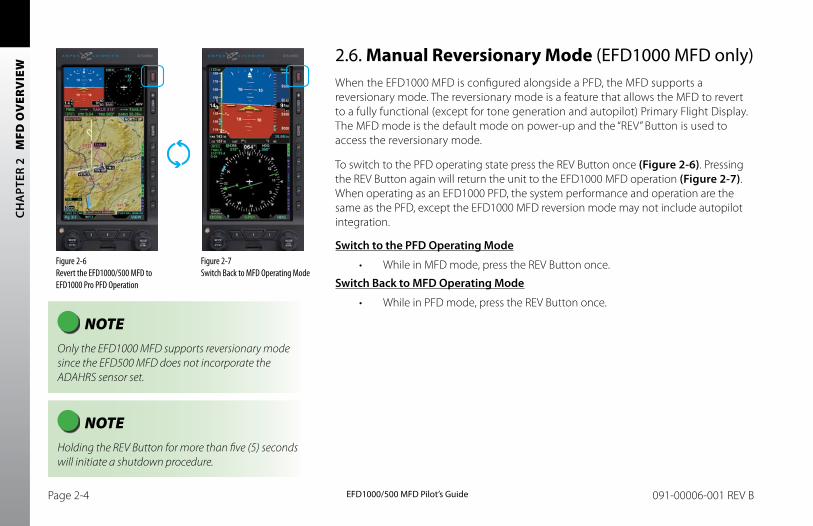
EFD1000/500 MFD Pilot’s GuidePage 2-4 091-00006-001 REV B
CH
APT
ER 2
M
FD O
VER
VIE
W
2.6. Manual Reversionary Mode (EFD1000 MFD only)When the EFD1000 MFD is configured alongside a PFD, the MFD supports a reversionary mode. The reversionary mode is a feature that allows the MFD to revert to a fully functional (except for tone generation and autopilot) Primary Flight Display. The MFD mode is the default mode on power-up and the “REV” Button is used to access the reversionary mode.
To switch to the PFD operating state press the REV Button once (Figure 2-6). Pressing the REV Button again will return the unit to the EFD1000 MFD operation (Figure 2-7). When operating as an EFD1000 PFD, the system performance and operation are the same as the PFD, except the EFD1000 MFD reversion mode may not include autopilot integration.
Switch to the PFD Operating Mode
• While in MFD mode, press the REV Button once.
Switch back to MFD Operating Mode
• While in PFD mode, press the REV Button once.
Figure 2-6 Revert the EFD1000/500 MFD to EFD1000 Pro PFD Operation
Figure 2-7 Switch Back to MFD Operating Mode
NOTE Holding the REV Button for more than five (5) seconds will initiate a shutdown procedure.
NOTE Only the EFD1000 MFD supports reversionary mode since the EFD500 MFD does not incorporate the ADAHRS sensor set.
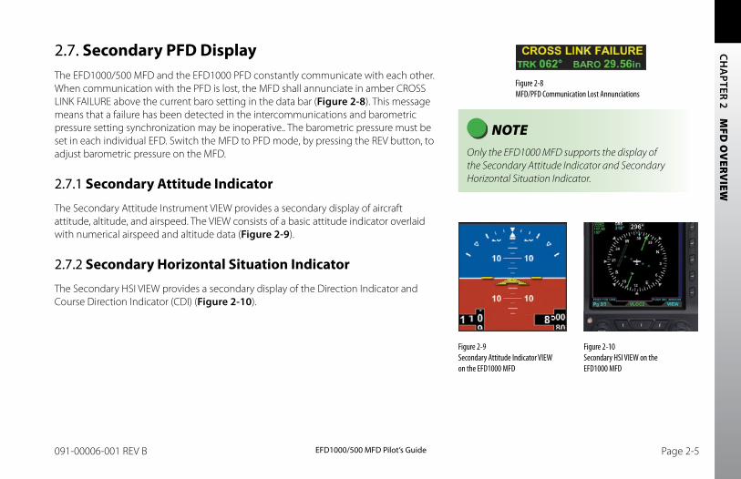
EFD1000/500 MFD Pilot’s GuidePage 2-4 091-00006-001 REV B EFD1000/500 MFD Pilot’s Guide Page 2-5091-00006-001 REV B
CH
APTER 2 M
FD O
VERV
IEW
Figure 2-8 MFD/PFD Communication Lost Annunciations
Figure 2-9 Secondary Attitude Indicator VIEW on the EFD1000 MFD
Figure 2-10 Secondary HSI VIEW on the EFD1000 MFD
NOTE Only the EFD1000 MFD supports the display of the Secondary Attitude Indicator and Secondary Horizontal Situation Indicator.
2.7. Secondary PFD DisplayThe EFD1000/500 MFD and the EFD1000 PFD constantly communicate with each other. When communication with the PFD is lost, the MFD shall annunciate in amber CROSS LINK FAILURE above the current baro setting in the data bar (Figure 2-8). This message means that a failure has been detected in the intercommunications and barometric pressure setting synchronization may be inoperative.. The barometric pressure must be set in each individual EFD. Switch the MFD to PFD mode, by pressing the REV button, to adjust barometric pressure on the MFD.
2.7.1 Secondary Attitude Indicator
The Secondary Attitude Instrument VIEW provides a secondary display of aircraft attitude, altitude, and airspeed. The VIEW consists of a basic attitude indicator overlaid with numerical airspeed and altitude data (Figure 2-9).
2.7.2 Secondary Horizontal Situation Indicator
The Secondary HSI VIEW provides a secondary display of the Direction Indicator and Course Direction Indicator (CDI) (Figure 2-10).

EFD1000/500 MFD Pilot’s GuidePage 2-6 091-00006-001 REV B
CH
APT
ER 2
M
FD O
VER
VIE
W
This Page Intentionally Left Blank
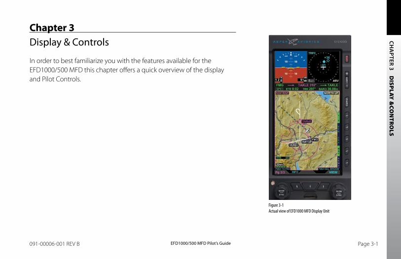
CH
APTER 3 D
ISPLAY &
CON
TRO
LS
EFD1000/500 MFD Pilot’s GuidePage PB 091-00006-001 REV B EFD1000/500 MFD Pilot’s Guide Page 3-1091-00006-001 REV B
Chapter 3Display & Controls
In order to best familiarize you with the features available for the EFD1000/500 MFD this chapter offers a quick overview of the display and Pilot Controls.
Figure 3-1 Actual view of EFD1000 MFD Display Unit
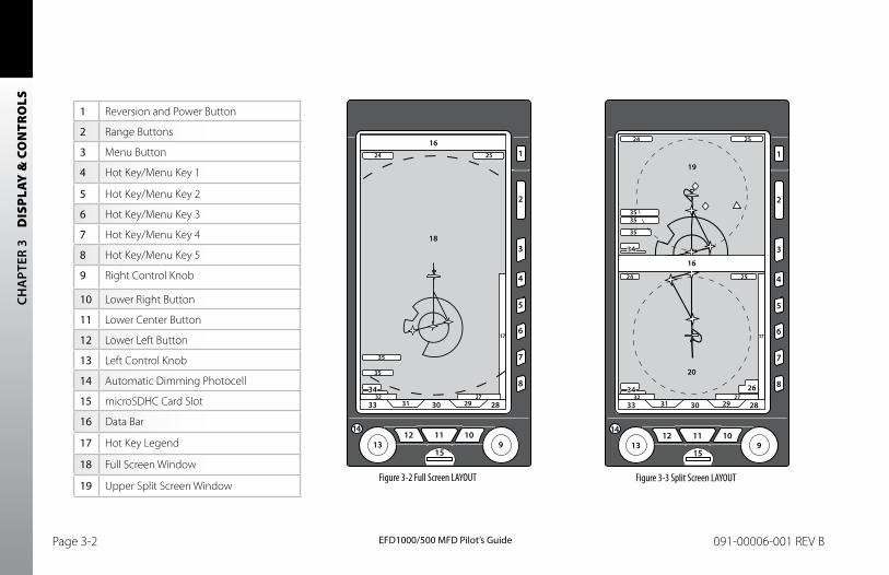
CH
APT
ER 3
D
ISPL
AY &
CO
NTR
OLS
EFD1000/500 MFD Pilot’s GuidePage 3-2 091-00006-001 REV B EFD1000/500 MFD Pilot’s Guide Page 3-3091-00006-001 REV B
1 Reversion and Power Button
2 Range Buttons
3 Menu Button
4 Hot Key/Menu Key 1
5 Hot Key/Menu Key 2
6 Hot Key/Menu Key 3
7 Hot Key/Menu Key 4
8 Hot Key/Menu Key 5
9 Right Control Knob
10 Lower Right Button
11 Lower Center Button
12 Lower Left Button
13 Left Control Knob
14 Automatic Dimming Photocell
15 microSDHC Card Slot
16 Data Bar
17 Hot Key Legend
18 Full Screen Window
19 Upper Split Screen WindowFigure 3-2 Full Screen LAYOUT Figure 3-3 Split Screen LAYOUT
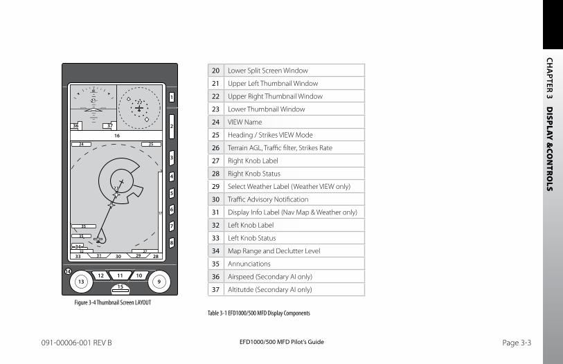
CH
APTER 3 D
ISPLAY &
CON
TRO
LS
EFD1000/500 MFD Pilot’s GuidePage 3-2 091-00006-001 REV B EFD1000/500 MFD Pilot’s Guide Page 3-3091-00006-001 REV B
Figure 3-4 Thumbnail Screen LAYOUT
20 Lower Split Screen Window
21 Upper Left Thumbnail Window
22 Upper Right Thumbnail Window
23 Lower Thumbnail Window
24 VIEW Name
25 Heading / Strikes VIEW Mode
26 Terrain AGL, Traffic filter, Strikes Rate
27 Right Knob Label
28 Right Knob Status
29 Select Weather Label (Weather VIEW only)
30 Traffic Advisory Notification
31 Display Info Label (Nav Map & Weather only)
32 Left Knob Label
33 Left Knob Status
34 Map Range and Declutter Level
35 Annunciations
36 Airspeed (Secondary AI only)
37 Altitutde (Secondary AI only)
Table 3-1 EFD1000/500 MFD Display Components
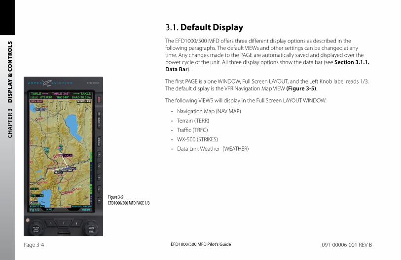
CH
APT
ER 3
D
ISPL
AY &
CO
NTR
OLS
EFD1000/500 MFD Pilot’s GuidePage 3-4 091-00006-001 REV B EFD1000/500 MFD Pilot’s Guide Page 3-5091-00006-001 REV B
3.1. Default DisplayThe EFD1000/500 MFD offers three different display options as described in the following paragraphs. The default VIEWs and other settings can be changed at any time. Any changes made to the PAGE are automatically saved and displayed over the power cycle of the unit. All three display options show the data bar (see Section 3.1.1. Data bar).
The first PAGE is a one WINDOW, Full Screen LAYOUT, and the Left Knob label reads 1/3. The default display is the VFR Navigation Map VIEW (Figure 3-5).
The following VIEWS will display in the Full Screen LAYOUT WINDOW:
• Navigation Map (NAV MAP)
• Terrain (TERR)
• Traffic (TRFC)
• WX-500 (STRIKES)
• Data Link Weather (WEATHER)
Figure 3-5 EFD1000/500 MFD PAGE 1/3
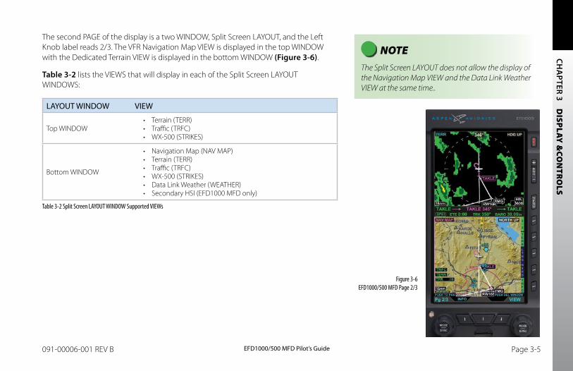
CH
APTER 3 D
ISPLAY &
CON
TRO
LS
EFD1000/500 MFD Pilot’s GuidePage 3-4 091-00006-001 REV B EFD1000/500 MFD Pilot’s Guide Page 3-5091-00006-001 REV B
Figure 3-6 EFD1000/500 MFD Page 2/3
NOTE The Split Screen LAYOUT does not allow the display of the Navigation Map VIEW and the Data Link Weather VIEW at the same time..
The second PAGE of the display is a two WINDOW, Split Screen LAYOUT, and the Left Knob label reads 2/3. The VFR Navigation Map VIEW is displayed in the top WINDOW with the Dedicated Terrain VIEW is displayed in the bottom WINDOW (Figure 3-6).
Table 3-2 lists the VIEWS that will display in each of the Split Screen LAYOUT WINDOWS:
LAYOUT WINDOW VIEW
Top WINDOW• Terrain (TERR)• Traffic (TRFC)• WX-500 (STRIKES)
Bottom WINDOW
• Navigation Map (NAV MAP)• Terrain (TERR)• Traffic (TRFC)• WX-500 (STRIKES)• Data Link Weather (WEATHER)• Secondary HSI (EFD1000 MFD only)
Table 3-2 Split Screen LAYOUT WINDOW Supported VIEWs
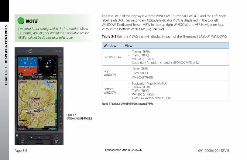
CH
APT
ER 3
D
ISPL
AY &
CO
NTR
OLS
EFD1000/500 MFD Pilot’s GuidePage 3-6 091-00006-001 REV B EFD1000/500 MFD Pilot’s Guide Page 3-7091-00006-001 REV B
The last PAGE of the display is a three WINDOW, Thumbnail LAYOUT, and the Left Knob label reads 3/3. The Secondary Attitude Indicator VIEW is displayed in the top left WINDOW, Dedicated Terrain VIEW in the top right WINDOW, and VFR Navigation Map VIEW in the bottom WINDOW (Figure 3-7).
Table 3-3 lists the VIEWS that will display in each of the Thumbnail LAYOUT WINDOWS:
Window View
Left WINDOW
• Terrain (TERR) • Traffic (TRFC)• WX-500 (STRIKES)• Secondary Attitude Instrument (EFD1000 MFD only)
Right WINDOW
• Terrain (TERR)• Traffic (TRFC)• WX-500 (STRIKES)
Bottom WINDOW
• Navigation Map (NAV MAP)• Terrain (TERR)• Traffic (TRFC)• WX-500 (STRIKES)• Data Link Weather (WEATHER)
Table 3-3 Thumbnail LAYOUT WINDOW Supported VIEWs
Figure 3-7 EFD1000/500 MFD PAGE 3/3
NOTE If a sensor is not configured in the Installation Menu (i.e., traffic, WX-500, or EWR50) the associated sensor VIEW shall not be displayed or selectable.
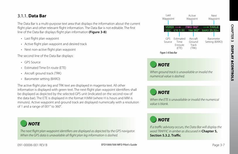
CH
APTER 3 D
ISPLAY &
CON
TRO
LS
EFD1000/500 MFD Pilot’s GuidePage 3-6 091-00006-001 REV B EFD1000/500 MFD Pilot’s Guide Page 3-7091-00006-001 REV B
3.1.1. Data Bar
The Data Bar is a multi-purpose text area that displays the information about the current flight plan and other relevant flight information. The Data Bar is not editable. The first line of the Data Bar displays flight plan information (Figure 3-8):
• Last flight plan waypoint
• Active flight plan waypoint and desired track
• Next non-active flight plan waypoint
The second line of the Data Bar displays:
• GPS Source
• Estimated Time En route (ETE)
• Aircraft ground track (TRK)
• Barometer setting (BARO)
The active flight plan leg and TRK text are displayed in magenta text. All other information is displayed with green text. The next flight plan waypoint identifiers shall be displayed as depicted by the selected GPS unit (indicated on the second row of the data bar). The ETE is displayed in the format H:MM (where H is hours and MM is minutes). Active waypoint and ground track are displayed numerically with a resolution of 1 and a range of 001° to 360°.
NOTE The next flight plan waypoint identifiers are displayed as depicted by the GPS navigator. When the GPS data is unavailable all flight plan leg information is dashed.
NOTE When ground track is unavailable or invalid the numerical value is dashed.
NOTE When the ETE is unavailable or invalid the numerical value is blank.
NOTE If a traffic advisory occurs, the Data Bar will display the word TRAFFIC in amber as discussed in Chapter 5, Section 5.3.2. Traffic.
Figure 3-8 Data Bar
GPS Source
Last Waypoint
Active Waypoint
Next Waypoint
Aircraft Ground
Track (TRK)
Barometer Setting (BARO)
Estimated Time
Enroute (ETE)
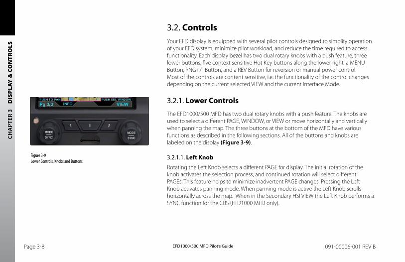
CH
APT
ER 3
D
ISPL
AY &
CO
NTR
OLS
EFD1000/500 MFD Pilot’s GuidePage 3-8 091-00006-001 REV B EFD1000/500 MFD Pilot’s Guide Page 3-9091-00006-001 REV B
3.2. ControlsYour EFD display is equipped with several pilot controls designed to simplify operation of your EFD system, minimize pilot workload, and reduce the time required to access functionality. Each display bezel has two dual rotary knobs with a push feature, three lower buttons, five context sensitive Hot Key buttons along the lower right, a MENU Button, RNG+/- Button, and a REV Button for reversion or manual power control. Most of the controls are content sensitive, i.e. the functionality of the control changes depending on the current selected VIEW and the current Interface Mode.
3.2.1. Lower Controls
The EFD1000/500 MFD has two dual rotary knobs with a push feature. The knobs are used to select a different PAGE, WINDOW, or VIEW or move horizontally and vertically when panning the map. The three buttons at the bottom of the MFD have various functions as described in the following sections. All of the buttons and knobs are labeled on the display (Figure 3-9).
3.2.1.1. Left KnobRotating the Left Knob selects a different PAGE for display. The initial rotation of the knob activates the selection process, and continued rotation will select different PAGEs. This feature helps to minimize inadvertent PAGE changes. Pressing the Left Knob activates panning mode. When panning mode is active the Left Knob scrolls horizontally across the map. When in the Secondary HSI VIEW the Left Knob performs a SYNC function for the CRS (EFD1000 MFD only).
Figure 3-9 Lower Controls, Knobs and Buttons
CH
APTER 3 D
ISPLAY &
CON
TRO
LS
EFD1000/500 MFD Pilot’s GuidePage 3-8 091-00006-001 REV B EFD1000/500 MFD Pilot’s Guide Page 3-9091-00006-001 REV B
When the INFO button is pressed rotating the Left Knob selects different objects on the Navigation Map (Airports/VORs) or METAR, AIRMET/SIGMET, and TFR weather pages. Pressing the Left Knob after the INFO button has been pressed will display the selected object’s textual information, when available.
3.2.1.2 Left ButtonThe Left Button displays the label Select when the AIRMET/SIGMET, METAR, or TFR Weather view is displayed. Pressing the Left Button activates alert selection, and then rotating the Left Knob selects individual alerts. See Section 5.2. Data Link Weather for more information.
3.2.1.3. Middle ButtonThe Middle Button is used to select a navigation source for the Secondary HSI when the HSI VIEW has the FOCUS (EFD1000 MFD only). A navigation source label (e.g. GPS1, VLOC1) will display directly above the button when its functionality is available. During a traffic alert, pressing the Middle Button will display the Traffic VIEW; and when pressed a second time the display returns to the previous VIEW. See Section 5.4.2. Secondary Horizontal Situation Indicator (HSI) and Section 5.3.2. Traffic for more information.
3.2.1.4. Right ButtonWhen the Data Link Weather VIEW is displayed and has the FOCUS, the Right Button displays the label Sel WX. Pressing the lower Right Button activates Weather Product Selection, and then rotating the Right Knob selects different Weather Products. See Section 5.2. Data Link Weather for more information.
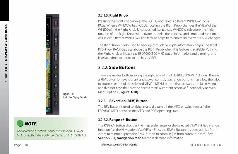
CH
APT
ER 3
D
ISPL
AY &
CO
NTR
OLS
EFD1000/500 MFD Pilot’s GuidePage 3-10 091-00006-001 REV B EFD1000/500 MFD Pilot’s Guide Page 3-11091-00006-001 REV B
3.2.1.5. Right KnobPressing the Right Knob moves the FOCUS and selects different WINDOWS on a PAGE. When a WINDOW has FOCUS, rotating the Right Knob changes the VIEW of the WINDOW. If the Right Knob is not pushed (to activate WINDOW selection) the initial rotation of the Right Knob will activate the selection process, and continued rotation will select different WINDOWs. This feature helps to minimize inadvertent PAGE changes.
The Right Knob is also used to back up through multiple information pages. The label PUSH FOR BACK displays above the Right Knob when this feature is available. Pushing the Right Knob will back the EFD1000/500 MFD out of information and panning, one level at a time, to return to the basic VIEW.
3.2.2. Side Buttons
There are several buttons along the right side of the EFD1000/500 MFD display. There is a REV button for reversionary and power control, two range buttons that allow the pilot to zoom in or out of the selected VIEW, a MENU button that activates the Main Menu, and five Hot Keys that provide access to VIEW content sensitive functionality or Main Menu options (Figure 3-10).
3.2.2.1. Reversion (REV) ButtonThe REV Button is used to either manually turn off the MFD or switch (revert) the EFD1000 MFD between the MFD and PFD operating state.
3.2.2.2. Range +/- ButtonThe RNG+/- Button changes the map scale range for the selected VIEW, if it has a range function (i.e. the Navigation Map VIEW). Press the RNG+ Button to zoom out (i.e. from 20nm to 30nm) or press the RNG- Button to zoom in (i.e. from 30nm to 20nm). See Section 5.1, Navigation Map for more detailed information.
NOTE The reversion function is only available on EFD1000 MFD units that are configured with an EFD1000 PFD.
Figure 3-10 Right Side Display Controls
CH
APTER 3 D
ISPLAY &
CON
TRO
LS
EFD1000/500 MFD Pilot’s GuidePage 3-10 091-00006-001 REV B EFD1000/500 MFD Pilot’s Guide Page 3-11091-00006-001 REV B
3.2.2.3. Menu ButtonThe MENU Button is used to activate or exit the Main Menu. The first time the Main Menu is accessed the GENERAL SETTINGS menu page displays; subsequently, the last viewed menu page will display.
3.2.2.4. Hot Keys/Menu KeysThe five buttons along the lower right side of the EFD1000/500 MFD display offer either Hot Key functionality, to rapidly select a common command, or to select a menu option when the Main Menu is activated.
The functionality of the Hot Key is content sensitive based on which WINDOW/VIEW has the current FOCUS. The label to the left of the Hot Key changes to reflect the current functionality available. See Chapter 5. Reference Guide for detailed information about individual VIEWs and the associated Hot Keys.
NOTE Not all Hot Keys are used in each VIEW. If a Hot Key does not have a label, it does not perform any function for that VIEW. The Navigation Map VIEW has two levels of Hot Keys; the first Hot Key is labeled 1/2 or 2/2 designating the Hot Key level currently displayed..

CH
APT
ER 3
D
ISPL
AY &
CO
NTR
OLS
EFD1000/500 MFD Pilot’s GuidePage 3-12 091-00006-001 REV B EFD1000/500 MFD Pilot’s Guide Page PB091-00006-001 REV B
This Page Intentionally Left Blank
CH
APTER 4 G
ETTING
STAR
TED
EFD1000/500 MFD Pilot’s GuidePage PB 091-00006-001 REV B EFD1000/500 MFD Pilot’s Guide Page 4-1091-00006-001 REV B
Chapter 4Getting Started
If you already have an EFD1000 PFD, you will probably find your new EFD1000/500 MFD fairly easy to use. However, because of all the information available to view, many of the controls on the EFD display unit have different functionality. You may want to familiarize yourself with the terminology and functionality of the EFD1000/500 MFD by reading Chapter 3; this will provide you with an understanding of the controls, operating logic, and display elements of your new EFD1000/500 MFD. Refer to Chapter 5 for more in-depth information and step-by-step instructions for each of the VIEWS on the EFD1000/500 MFD.
The EFD1000/500 MFD complements your current EFD1000 PFD and provides a fully functional Electronic Flight Instrument System (EFIS), offering the same capabilities and features found on larger glass cockpit systems in airliners, business jets, and newer general aviation aircraft. With the addition of an EFD1000/500 MFD, your EFD system is now capable of much more than the analog instruments it replaced.
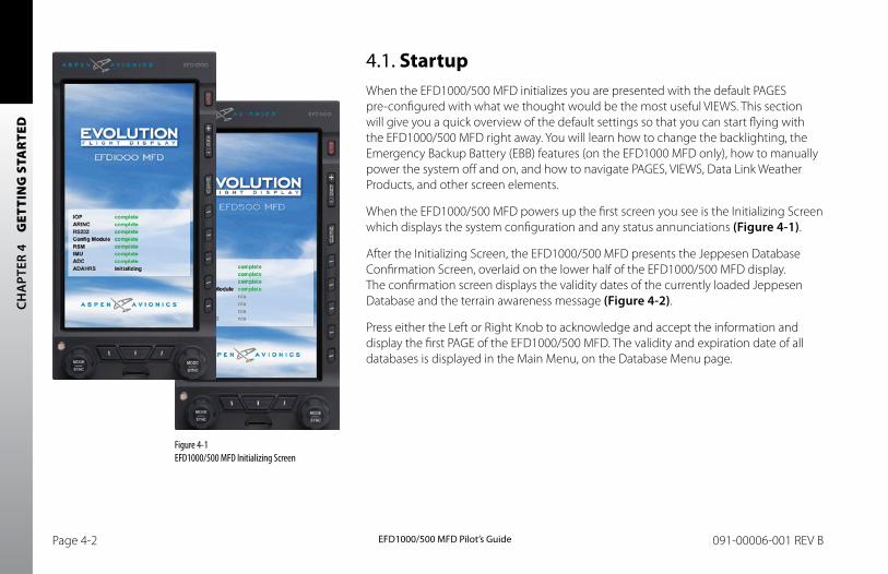
CH
APT
ER 4
G
ETTI
NG
STA
RTE
D
EFD1000/500 MFD Pilot’s GuidePage 4-2 091-00006-001 REV B EFD1000/500 MFD Pilot’s Guide Page 4-3091-00006-001 REV B
4.1. StartupWhen the EFD1000/500 MFD initializes you are presented with the default PAGES pre-configured with what we thought would be the most useful VIEWS. This section will give you a quick overview of the default settings so that you can start flying with the EFD1000/500 MFD right away. You will learn how to change the backlighting, the Emergency Backup Battery (EBB) features (on the EFD1000 MFD only), how to manually power the system off and on, and how to navigate PAGES, VIEWS, Data Link Weather Products, and other screen elements.
When the EFD1000/500 MFD powers up the first screen you see is the Initializing Screen which displays the system configuration and any status annunciations (Figure 4-1).
After the Initializing Screen, the EFD1000/500 MFD presents the Jeppesen Database Confirmation Screen, overlaid on the lower half of the EFD1000/500 MFD display. The confirmation screen displays the validity dates of the currently loaded Jeppesen Database and the terrain awareness message (Figure 4-2).
Press either the Left or Right Knob to acknowledge and accept the information and display the first PAGE of the EFD1000/500 MFD. The validity and expiration date of all databases is displayed in the Main Menu, on the Database Menu page.
Figure 4-1 EFD1000/500 MFD Initializing Screen
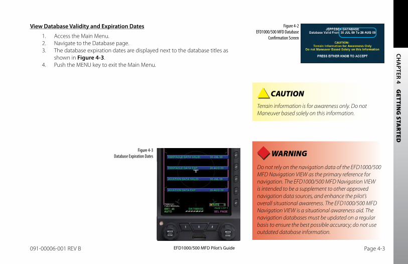
CH
APTER 4 G
ETTING
STAR
TED
EFD1000/500 MFD Pilot’s GuidePage 4-2 091-00006-001 REV B EFD1000/500 MFD Pilot’s Guide Page 4-3091-00006-001 REV B
View Database Validity and Expiration Dates
1. Access the Main Menu.2. Navigate to the Database page.3. The database expiration dates are displayed next to the database titles as
shown in Figure 4-3.4. Push the MENU key to exit the Main Menu.
Figure 4-2 EFD1000/500 MFD Database
Confirmation Screen
Figure 4-3 Database Expiration Dates
CAUTION Terrain information is for awareness only. Do not Maneuver based solely on this information.
WARNING Do not rely on the navigation data of the EFD1000/500 MFD Navigation VIEW as the primary reference for navigation. The EFD1000/500 MFD Navigation VIEW is intended to be a supplement to other approved navigation data sources, and enhance the pilot’s overall situational awareness. The EFD1000/500 MFD Navigation VIEW is a situational awareness aid. The navigation databases must be updated on a regular basis to ensure the best possible accuracy; do not use outdated database information.
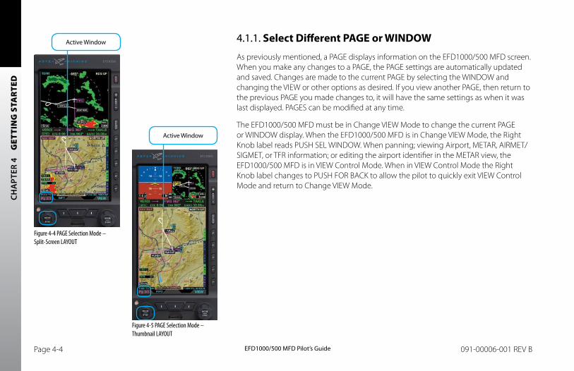
CH
APT
ER 4
G
ETTI
NG
STA
RTE
D
EFD1000/500 MFD Pilot’s GuidePage 4-4 091-00006-001 REV B EFD1000/500 MFD Pilot’s Guide Page 4-5091-00006-001 REV B
4.1.1. Select Different PAGE or WINDOW
As previously mentioned, a PAGE displays information on the EFD1000/500 MFD screen. When you make any changes to a PAGE, the PAGE settings are automatically updated and saved. Changes are made to the current PAGE by selecting the WINDOW and changing the VIEW or other options as desired. If you view another PAGE, then return to the previous PAGE you made changes to, it will have the same settings as when it was last displayed. PAGES can be modified at any time.
The EFD1000/500 MFD must be in Change VIEW Mode to change the current PAGE or WINDOW display. When the EFD1000/500 MFD is in Change VIEW Mode, the Right Knob label reads PUSH SEL WINDOW. When panning; viewing Airport, METAR, AIRMET/SIGMET, or TFR information; or editing the airport identifier in the METAR view, the EFD1000/500 MFD is in VIEW Control Mode. When in VIEW Control Mode the Right Knob label changes to PUSH FOR BACK to allow the pilot to quickly exit VIEW Control Mode and return to Change VIEW Mode.
Figure 4-4 PAGE Selection Mode – Split-Screen LAYOUT
Figure 4-5 PAGE Selection Mode – Thumbnail LAYOUT
Active Window
Active Window
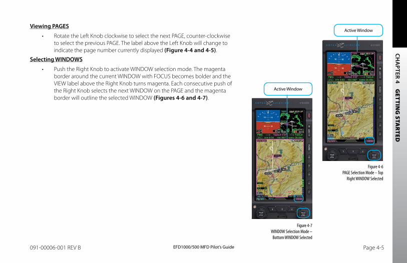
CH
APTER 4 G
ETTING
STAR
TED
EFD1000/500 MFD Pilot’s GuidePage 4-4 091-00006-001 REV B EFD1000/500 MFD Pilot’s Guide Page 4-5091-00006-001 REV B
Viewing PAGES
• Rotate the Left Knob clockwise to select the next PAGE, counter-clockwise to select the previous PAGE. The label above the Left Knob will change to indicate the page number currently displayed (Figure 4-4 and 4-5).
Selecting WINDOWS
• Push the Right Knob to activate WINDOW selection mode. The magenta border around the current WINDOW with FOCUS becomes bolder and the VIEW label above the Right Knob turns magenta. Each consecutive push of the Right Knob selects the next WINDOW on the PAGE and the magenta border will outline the selected WINDOW (Figures 4-6 and 4-7).
Figure 4-6 PAGE Selection Mode – Top
Right WINDOW Selected
Figure 4-7 WINDOW Selection Mode –
Bottom WINDOW Selected
Active Window
Active Window
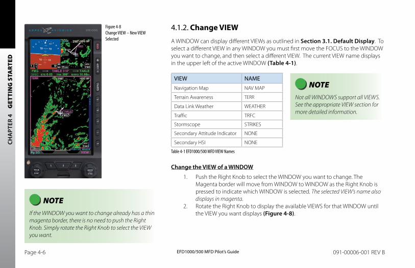
CH
APT
ER 4
G
ETTI
NG
STA
RTE
D
EFD1000/500 MFD Pilot’s GuidePage 4-6 091-00006-001 REV B EFD1000/500 MFD Pilot’s Guide Page 4-7091-00006-001 REV B
4.1.2. Change VIEW
A WINDOW can display different VIEWs as outlined in Section 3.1. Default Display. To select a different VIEW in any WINDOW you must first move the FOCUS to the WINDOW you want to change, and then select a different VIEW. The current VIEW name displays in the upper left of the active WINDOW (Table 4-1).
VIEW NAME
Navigation Map NAV MAP
Terrain Awareness TERR
Data Link Weather WEATHER
Traffic TRFC
Stormscope STRIKES
Secondary Attitude Indicator NONE
Secondary HSI NONE
Table 4-1 EFD1000/500 MFD VIEW Names
Change the VIEW of a WINDOW
1. Push the Right Knob to select the WINDOW you want to change. The Magenta border will move from WINDOW to WINDOW as the Right Knob is pressed to indicate which WINDOW is selected. The selected VIEW’s name also displays in magenta.
2. Rotate the Right Knob to display the available VIEWS for that WINDOW until the VIEW you want displays (Figure 4-8).
Figure 4-8 Change VIEW – New VIEW Selected
NOTE Not all WINDOWS support all VIEWS. See the appropriate VIEW section for more detailed information.
NOTE If the WINDOW you want to change already has a thin magenta border, there is no need to push the Right Knob. Simply rotate the Right Knob to select the VIEW you want.
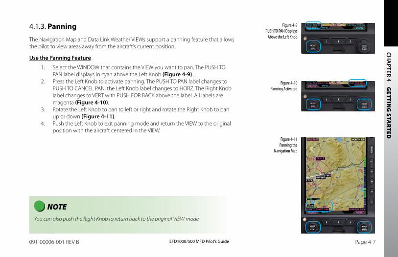
CH
APTER 4 G
ETTING
STAR
TED
EFD1000/500 MFD Pilot’s GuidePage 4-6 091-00006-001 REV B EFD1000/500 MFD Pilot’s Guide Page 4-7091-00006-001 REV B
4.1.3. Panning
The Navigation Map and Data Link Weather VIEWs support a panning feature that allows the pilot to view areas away from the aircraft’s current position.
Use the Panning Feature
1. Select the WINDOW that contains the VIEW you want to pan. The PUSH TO PAN label displays in cyan above the Left Knob (Figure 4-9).
2. Press the Left Knob to activate panning. The PUSH TO PAN label changes to PUSH TO CANCEL PAN, the Left Knob label changes to HORZ. The Right Knob label changes to VERT with PUSH FOR BACK above the label. All labels are magenta (Figure 4-10).
3. Rotate the Left Knob to pan to left or right and rotate the Right Knob to pan up or down (Figure 4-11).
4. Push the Left Knob to exit panning mode and return the VIEW to the original position with the aircraft centered in the VIEW.
NOTE You can also push the Right Knob to return back to the original VIEW mode.
Figure 4-9 PUSH TO PAN Displays
Above the Left Knob
Figure 4-10 Panning Activated
Figure 4-11 Panning the
Navigation Map
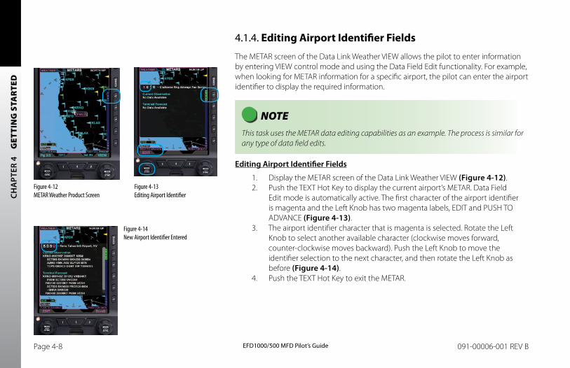
CH
APT
ER 4
G
ETTI
NG
STA
RTE
D
EFD1000/500 MFD Pilot’s GuidePage 4-8 091-00006-001 REV B EFD1000/500 MFD Pilot’s Guide Page 4-9091-00006-001 REV B
4.1.4. Editing Airport Identifier Fields
The METAR screen of the Data Link Weather VIEW allows the pilot to enter information by entering VIEW control mode and using the Data Field Edit functionality. For example, when looking for METAR information for a specific airport, the pilot can enter the airport identifier to display the required information.
NOTE This task uses the METAR data editing capabilities as an example. The process is similar for any type of data field edits.
Editing Airport Identifier Fields
1. Display the METAR screen of the Data Link Weather VIEW (Figure 4-12).2. Push the TEXT Hot Key to display the current airport’s METAR. Data Field
Edit mode is automatically active. The first character of the airport identifier is magenta and the Left Knob has two magenta labels, EDIT and PUSH TO ADVANCE (Figure 4-13).
3. The airport identifier character that is magenta is selected. Rotate the Left Knob to select another available character (clockwise moves forward, counter-clockwise moves backward). Push the Left Knob to move the identifier selection to the next character, and then rotate the Left Knob as before (Figure 4-14).
4. Push the TEXT Hot Key to exit the METAR.
Figure 4-12 METAR Weather Product Screen
Figure 4-13 Editing Airport Identifier
Figure 4-14 New Airport Identifier Entered
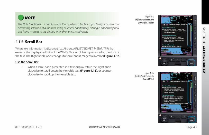
CH
APTER 4 G
ETTING
STAR
TED
EFD1000/500 MFD Pilot’s GuidePage 4-8 091-00006-001 REV B EFD1000/500 MFD Pilot’s Guide Page 4-9091-00006-001 REV B
NOTE The TEXT function is a smart function. It only selects a METAR capable airport rather than permitting selection of a random string of letters. Additionally, editing is done using only one hand — twist to the desired letter then press to advance.
4.1.5. Scroll Bar
When text information is displayed (i.e. Airport, AIRMET/SIGMET, METAR, TFR) that exceeds the displayable limits of the WINDOW, a scroll bar is presented to the right of the text. The Right Knob label changes to Scroll and is magenta in color (Figure 4-15).
Use the Scroll bar
• When a scroll bar is presented in a text display rotate the Right Knob clockwise to scroll down the viewable text (Figure 4.16), or counter-clockwise to scroll up the viewable text.
Figure 4-15 METAR with Information
Viewable by Scrolling
Figure 4-16 Use the Scroll Feature to
View a METAR
CH
APT
ER 4
G
ETTI
NG
STA
RTE
D
EFD1000/500 MFD Pilot’s GuidePage 4-10 091-00006-001 REV B EFD1000/500 MFD Pilot’s Guide Page 4-11091-00006-001 REV B
4.2. Main MenuThe MENU Button is used to access the EFD1000/500 MFD’s Menu system to change options and also to change the EFD1000’s LCD brightness controls.
4.2.1. Using the Menus
As previously discussed, you enter MENU mode by pressing the MENU Button. The Main MENU has several pages of information that allow the pilot to fully customize the EFD1000/500 MFD display. Pilot can view, manage, and change the settings of the EFD1000/500 MFD. Some EFD1000/500 MFD Main MENU options available are:
• Change VIEW settings
• Change declutter settings
• Check the battery status
• Check the database version
• Restart the system
• View the serial number of the unit
The first MENU page is the default page, following the power cycle of the MFD. Rotating the Right Knob navigates to different menu pages. When the EFD1000 MFD is operating in reversionary mode, pressing the MENU Button displays the PFD Main MENU.
The current Menu Page Name displays on the bottom center of the Display. Directly below the Menu Page Name is a segmented menu page bar, giving a graphical representation of the current page relative to the total number of menu pages. The current menu page number displays in the lower right of the Navigation Display.
The Menu system operates either in Navigation or Edit mode, as indicated by the label directly above the Right Knob. When the MENU Button is first pressed, the Menu system
NOTE If a traffic advisory occurs when the Main Menu is enabled, the Main Menu is removed from the display.
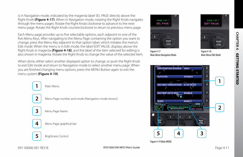
CH
APTER 4 G
ETTING
STAR
TED
EFD1000/500 MFD Pilot’s GuidePage 4-10 091-00006-001 REV B EFD1000/500 MFD Pilot’s Guide Page 4-11091-00006-001 REV B
is in Navigation mode, indicated by the magenta label SEL PAGE directly above the Right Knob (Figure 4-17). When in Navigation mode, rotating the Right Knob navigates through the menu pages. Rotate the Right Knob clockwise to advance to the next menu page. Rotate the Right Knob counterclockwise to return to previous menu page.
Each Menu page provides up to five selectable options, each adjacent to one of the five Menu Keys. After navigating to the Menu Page containing the option you want to change, press the Menu Key adjacent to that option label, which initiates the menu’s Edit mode. When the menu is in Edit mode, the label EDIT VALUE, displays above the Right Knob in magenta (Figure 4-18), and the label of the item selected for editing is also shown in magenta. Rotate the Right Knob to change the value of the selected item.
When done, either select another displayed option to change, or push the Right Knob to exit Edit mode and return to Navigation mode to select another menu page. When you are finished changing menu options, press the MENU Button again to exit the menu system (Figure 4-19).
Main Menu
Menu Page number and mode (Navigation mode shown)
Menu Page Name
Menu Page graphical bar
Brightness Control
Figure 4-17 Main Menu Navigation Mode
Figure 4-18 Main Menu Edit Mode
Figure 4-19 Main MENU
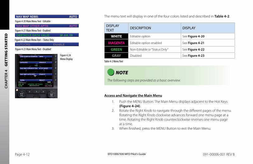
CH
APT
ER 4
G
ETTI
NG
STA
RTE
D
EFD1000/500 MFD Pilot’s GuidePage 4-12 091-00006-001 REV B EFD1000/500 MFD Pilot’s Guide Page 4-13091-00006-001 REV B
The menu text will display in one of the four colors listed and described in Table 4-2.
DISPLAY TEXT DESCRIPTION DISPLAY
WHITE Editable option See Figure 4-20
MAGENTA Editable option enabled See Figure 4-21
GREEN Non-Editable or “Status Only” See Figure 4-22
GRAY Disabled See Figure 4-23
Table 4-2 Menu Text
NOTE The following steps are provided as a basic overview.
Access and Navigate the Main Menu
1. Push the MENU Button. The Main Menu displays adjacent to the Hot Keys (Figure 4-24).
2. Rotate the Right Knob to navigate through the different pages of the menu. Rotating the Right Knob clockwise advances forward one menu page at a time. Rotating the Right Knob counterclockwise reverses one menu page at a time.
3. When finished, press the MENU Button to exit the Main Menu.
Figure 4-20 Main Menu Text - Editable
Figure 4-21 Main Menu Text - Enabled
Figure 4-22 Main Menu Text – Status Only
Figure 4-23 Main Menu Text - Disabled
Figure 4-24 Menu Display
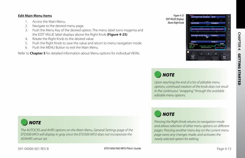
CH
APTER 4 G
ETTING
STAR
TED
EFD1000/500 MFD Pilot’s GuidePage 4-12 091-00006-001 REV B EFD1000/500 MFD Pilot’s Guide Page 4-13091-00006-001 REV B
Edit Main Menu Items
1. Access the Main Menu.2. Navigate to the desired menu page.3. Push the Menu Key of the desired option. The menu label turns magenta and
the EDIT VALUE label displays above the Right Knob (Figure 4-25).4. Rotate the Right Knob to the desired value.5. Push the Right Knob to save the value and return to menu navigation mode.6. Push the MENU Button to exit the Main Menu.
Refer to Chapter 5 for detailed information about Menu options for individual VIEWs.
NOTE Pressing the Right Knob returns to navigation mode and allows selection of other menu options on different pages. Pressing another menu key on the current menu page saves any changes made, and activates the newly selected option for editing.
NOTE Upon reaching the end of a list of editable menu options, continued rotation of the knob does not result in the continuous “wrapping” through the available editable menu options.
Figure 4-25 EDIT VALUE Displays
Above Right Knob
NOTE The AUTOCRS and AHRS options on the Main Menu, General Settings page of the EFD500 MFD will display in gray since the EFD500 MFD does not incorporate the ADAHRS sensor set.
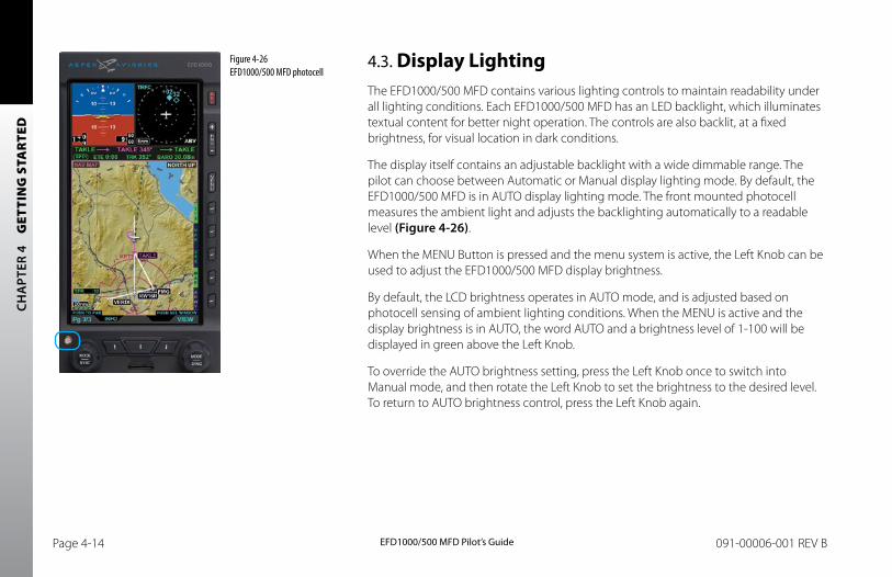
CH
APT
ER 4
G
ETTI
NG
STA
RTE
D
EFD1000/500 MFD Pilot’s GuidePage 4-14 091-00006-001 REV B EFD1000/500 MFD Pilot’s Guide Page 4-15091-00006-001 REV B
4.3. Display LightingThe EFD1000/500 MFD contains various lighting controls to maintain readability under all lighting conditions. Each EFD1000/500 MFD has an LED backlight, which illuminates textual content for better night operation. The controls are also backlit, at a fixed brightness, for visual location in dark conditions.
The display itself contains an adjustable backlight with a wide dimmable range. The pilot can choose between Automatic or Manual display lighting mode. By default, the EFD1000/500 MFD is in AUTO display lighting mode. The front mounted photocell measures the ambient light and adjusts the backlighting automatically to a readable level (Figure 4-26).
When the MENU Button is pressed and the menu system is active, the Left Knob can be used to adjust the EFD1000/500 MFD display brightness.
By default, the LCD brightness operates in AUTO mode, and is adjusted based on photocell sensing of ambient lighting conditions. When the MENU is active and the display brightness is in AUTO, the word AUTO and a brightness level of 1-100 will be displayed in green above the Left Knob.
To override the AUTO brightness setting, press the Left Knob once to switch into Manual mode, and then rotate the Left Knob to set the brightness to the desired level. To return to AUTO brightness control, press the Left Knob again.
Figure 4-26 EFD1000/500 MFD photocell
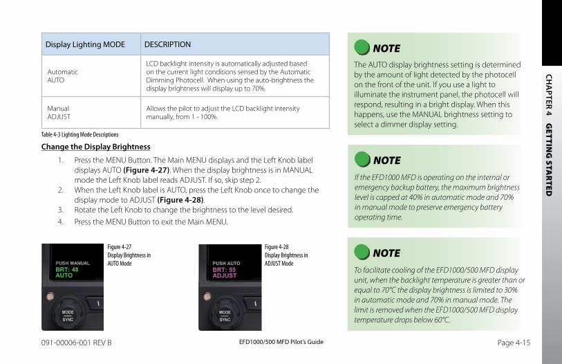
CH
APTER 4 G
ETTING
STAR
TED
EFD1000/500 MFD Pilot’s GuidePage 4-14 091-00006-001 REV B EFD1000/500 MFD Pilot’s Guide Page 4-15091-00006-001 REV B
Display Lighting MODE DESCRIPTION
Automatic AUTO
LCD backlight intensity is automatically adjusted based on the current light conditions sensed by the Automatic Dimming Photocell. When using the auto-brightness the display brightness will display up to 70%.
Manual ADJUST
Allows the pilot to adjust the LCD backlight intensity manually, from 1 - 100%.
Table 4-3 Lighting Mode Descriptions
Change the Display brightness
1. Press the MENU Button. The Main MENU displays and the Left Knob label displays AUTO (Figure 4-27). When the display brightness is in MANUAL mode the Left Knob label reads ADJUST. If so, skip step 2.
2. When the Left Knob label is AUTO, press the Left Knob once to change the display mode to ADJUST (Figure 4-28).
3. Rotate the Left Knob to change the brightness to the level desired.4. Press the MENU Button to exit the Main MENU.
NOTE The AUTO display brightness setting is determined by the amount of light detected by the photocell on the front of the unit. If you use a light to illuminate the instrument panel, the photocell will respond, resulting in a bright display. When this happens, use the MANUAL brightness setting to select a dimmer display setting.
Figure 4-27 Display Brightness in AUTO Mode
Figure 4-28 Display Brightness in ADJUST Mode
NOTE If the EFD1000 MFD is operating on the internal or emergency backup battery, the maximum brightness level is capped at 40% in automatic mode and 70% in manual mode to preserve emergency battery operating time.
NOTE To facilitate cooling of the EFD1000/500 MFD display unit, when the backlight temperature is greater than or equal to 70°C the display brightness is limited to 30% in automatic mode and 70% in manual mode. The limit is removed when the EFD1000/500 MFD display temperature drops below 60°C.
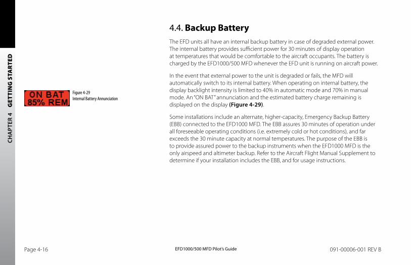
CH
APT
ER 4
G
ETTI
NG
STA
RTE
D
EFD1000/500 MFD Pilot’s GuidePage 4-16 091-00006-001 REV B EFD1000/500 MFD Pilot’s Guide Page 4-17091-00006-001 REV B
4.4. Backup BatteryThe EFD units all have an internal backup battery in case of degraded external power. The internal battery provides sufficient power for 30 minutes of display operation at temperatures that would be comfortable to the aircraft occupants. The battery is charged by the EFD1000/500 MFD whenever the EFD unit is running on aircraft power.
In the event that external power to the unit is degraded or fails, the MFD will automatically switch to its internal battery. When operating on internal battery, the display backlight intensity is limited to 40% in automatic mode and 70% in manual mode. An “ON BAT” annunciation and the estimated battery charge remaining is displayed on the display (Figure 4-29).
Some installations include an alternate, higher-capacity, Emergency Backup Battery (EBB) connected to the EFD1000 MFD. The EBB assures 30 minutes of operation under all foreseeable operating conditions (i.e. extremely cold or hot conditions), and far exceeds the 30 minute capacity at normal temperatures. The purpose of the EBB is to provide assured power to the backup instruments when the EFD1000 MFD is the only airspeed and altimeter backup. Refer to the Aircraft Flight Manual Supplement to determine if your installation includes the EBB, and for usage instructions.
Figure 4-29 Internal Battery Annunciation
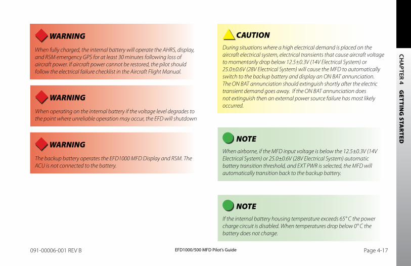
CH
APTER 4 G
ETTING
STAR
TED
EFD1000/500 MFD Pilot’s GuidePage 4-16 091-00006-001 REV B EFD1000/500 MFD Pilot’s Guide Page 4-17091-00006-001 REV B
WARNING When fully charged, the internal battery will operate the AHRS, display, and RSM emergency GPS for at least 30 minutes following loss of aircraft power. If aircraft power cannot be restored, the pilot should follow the electrical failure checklist in the Aircraft Flight Manual.
WARNING The backup battery operates the EFD1000 MFD Display and RSM. The ACU is not connected to the battery.
CAUTION During situations where a high electrical demand is placed on the aircraft electrical system, electrical transients that cause aircraft voltage to momentarily drop below 12.5±0.3V (14V Electrical System) or 25.0±0.6V (28V Electrical System) will cause the MFD to automatically switch to the backup battery and display an ON BAT annunciation. The ON BAT annunciation should extinguish shortly after the electric transient demand goes away. If the ON BAT annunciation does not extinguish then an external power source failure has most likely occurred.
NOTE When airborne, if the MFD input voltage is below the 12.5±0.3V (14V Electrical System) or 25.0±0.6V (28V Electrical System) automatic battery transition threshold, and EXT PWR is selected, the MFD will automatically transition back to the backup battery.
NOTE If the internal battery housing temperature exceeds 65° C the power charge circuit is disabled. When temperatures drop below 0° C the battery does not charge.
WARNING When operating on the internal battery if the voltage level degrades to the point where unreliable operation may occur, the EFD will shutdown
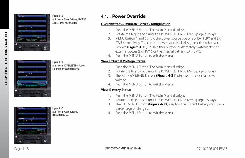
CH
APT
ER 4
G
ETTI
NG
STA
RTE
D
EFD1000/500 MFD Pilot’s GuidePage 4-18 091-00006-001 REV B EFD1000/500 MFD Pilot’s Guide Page 4-19091-00006-001 REV B
4.4.1. Power OverrideOverride the Automatic Power Configuration
1. Push the MENU Button. The Main Menu displays.2. Rotate the Right Knob until the POWER SETTINGS Menu page displays.3. MENU Button 1 and 2 show the power source options of BATTERY and EXT
PWR respectively. The current power source label is green; the other label is white (Figure 4-30). Push either button to alternately switch between external power (EXT PWR) or the internal battery (BATTERY).
4. Push the MENU Button to exit the Menu
View External Voltage Status
1. Push the MENU Button. The Main Menu displays.2. Rotate the Right Knob until the POWER SETTINGS Menu page displays.3. The EXT PWR MENU Button, (Figure 4-31) displays the external power
voltage.4. Push the MENU Button to exit the Menu.
View battery Status
1. Push the MENU Button. The Main Menu displays.2. Rotate the Right Knob until the POWER SETTINGS Menu page displays.3. The BAT MENU Button (Figure 4-32) displays the current battery status as a
percentage of charge .4. Push the MENU Button to exit the Menu.
Figure 4-32 Main Menu, Power Settings, BAT MENU Button
Figure 4-30 Main Menu, Power Settings, BATTERY and EXT PWR MENU Button
Figure 4-31 Main Menu, POWER SETTINGS page, EXT PWR Status MENU Button
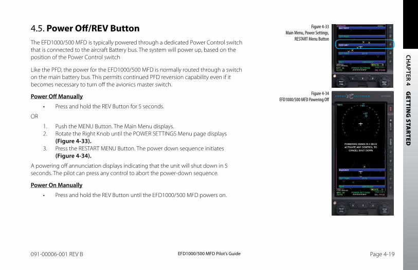
CH
APTER 4 G
ETTING
STAR
TED
EFD1000/500 MFD Pilot’s GuidePage 4-18 091-00006-001 REV B EFD1000/500 MFD Pilot’s Guide Page 4-19091-00006-001 REV B
4.5. Power Off/REV ButtonThe EFD1000/500 MFD is typically powered through a dedicated Power Control switch that is connected to the aircraft Battery bus. The system will power up, based on the position of the Power Control switch
Like the PFD, the power for the EFD1000/500 MFD is normally routed through a switch on the main battery bus. This permits continued PFD reversion capability even if it becomes necessary to turn off the avionics master switch.
Power Off Manually
• Press and hold the REV Button for 5 seconds.
OR
1. Push the MENU Button. The Main Menu displays.2. Rotate the Right Knob until the POWER SETTINGS Menu page displays
(Figure 4-33).3. Press the RESTART MENU Button. The power down sequence initiates
(Figure 4-34).
A powering off annunciation displays indicating that the unit will shut down in 5 seconds. The pilot can press any control to abort the power-down sequence.
Power On Manually
• Press and hold the REV Button until the EFD1000/500 MFD powers on.
Figure 4-33 Main Menu, Power Settings,
RESTART Menu Button
Figure 4-34 EFD1000/500 MFD Powering Off
CH
APT
ER 4
G
ETTI
NG
STA
RTE
D
EFD1000/500 MFD Pilot’s GuidePage 4-20 091-00006-001 REV B EFD1000/500 MFD Pilot’s Guide Page PB091-00006-001 REV B
4.6. Range ButtonWhen the MAP is enabled, the RNG (Range) button is used to zoom in or out in scale to display more or less of the map. The map range available depends on the VIEW. Press the top or (+) of the RNG key to increase map range. Press the bottom or (–) of the RNG key to decrease map range. Additionally an Auto Range feature is available.
Pressing and holding either the (+) or (-) of the RNG key will cause the map range to scale continuously to its maximum or minimum range, respectively. When the map range is at its maximum or minimum setting, pressing and holding the RNG key again will activate Auto Range mode (see Section 5.1.3. for complete details).
4.7. Cleaning the Display ScreenThe EFD1000/500 MFD display is an LCD screen that is prone to damage from scratches, smudging, and clouding caused by the use of improper cleaning agents and harsh cloths. Use care when cleaning, using the following tips:
• Only clean the display when the unit is off.
• Use a clean, soft, lint free cloth dampened with a 50/50 solution of isopropyl alcohol and water, a pre-moistened lens cleaning tissue like Bausch & Lomb Sight Savers®, or a cleaning solution made especially for LCD displays.
• Never spray any cleaning solutions directly onto the screen, spray it into the cleaning cloth.
• Gently wipe the screen in a circular motion. Do not press hard on the cloth.
• Remove all excess moisture to prevent damage of the EFD1000/500 MFD display.
• The EFD1000/500 MFD display should be dry before powering the unit on.
NOTE Use caution when using isopropyl alcohol as it is flammable. Using any other chemicals or materials voids the warranty.
CH
APTER 5 R
EFEREN
CE GU
IDE
EFD1000/500 MFD Pilot’s GuidePage PB 091-00006-001 REV B EFD1000/500 MFD Pilot’s Guide Page 5-1091-00006-001 REV B
Chapter 5Reference Guide
The EFD1000/500 MFD is a panel-mounted Electronic Flight Instrument System (EFIS) that presents the pilot with a full-color moving Navigation Map VIEW and a dedicated Terrain VIEW. Additionally there are three optional VIEWS that provide Traffic, Stormscope® WX-500, and Weather information (all require additional receivers and possible subscriptions, see the appropriate sections for detailed information).
The Navigation Map VIEW displays aviation data (e.g., Navaids, intersections, airports, etc.) topographic information, boundaries, and GPS flight plan information. The Data Link Weather VIEW provides graphical Convective, METAR, Echo Tops, Cloud Tops, AIRMET/SIGMET, TFR, and Winds Aloft data. Each VIEW is clearly labeled in the upper left corner of the window.
The MFD1000 MFD also has a Secondary Attitude Indicator and Secondary HSI VIEW which provide the safety and confidence of DuoSafe™ full PFD instrument redundancy. If for some reason your EFD1000 PFD should fail, simply press the REV button on your EFD1000 MFD and your full PFD display is right back in your primary instrument scan.
The Reference Guide offers detailed information about each of the available VIEWS and step-by-step instructions to guide the pilot in the use and operation of each VIEW. Sections 5.1. – 5.3.1. provide information for VIEWS that all EFD1000/500 MFDs have. Sections 5.3.2. – 5.3.3. provide information for the three VIEWS that require additional equipment and subscriptions to third-party vendors for data link information.
NOTE If the GPS becomes invalid an Invalid GPS annunciation displays. When the GPS position source is unavailable, map functions such as panning, info etc. will still be available. See Section 5.1.5.1. Invalid GPS for detailed invalid GPS information.
NOTE The MFD uses azimuthal projection for all maps and geo-referenced data. .
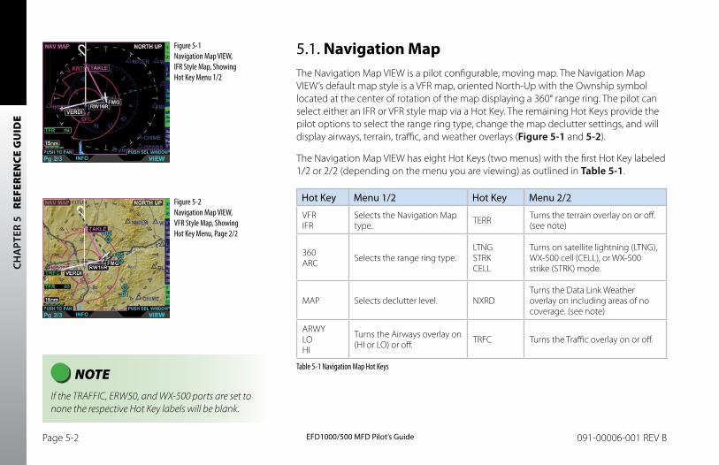
CH
APT
ER 5
R
EFER
ENCE
GU
IDE
EFD1000/500 MFD Pilot’s GuidePage 5-2 091-00006-001 REV B EFD1000/500 MFD Pilot’s Guide Page 5-3091-00006-001 REV B
Figure 5-2 Navigation Map VIEW, VFR Style Map, Showing Hot Key Menu, Page 2/2
5.1. Navigation MapThe Navigation Map VIEW is a pilot configurable, moving map. The Navigation Map VIEW’s default map style is a VFR map, oriented North-Up with the Ownship symbol located at the center of rotation of the map displaying a 360° range ring. The pilot can select either an IFR or VFR style map via a Hot Key. The remaining Hot Keys provide the pilot options to select the range ring type, change the map declutter settings, and will display airways, terrain, traffic, and weather overlays (Figure 5-1 and 5-2).
The Navigation Map VIEW has eight Hot Keys (two menus) with the first Hot Key labeled 1/2 or 2/2 (depending on the menu you are viewing) as outlined in Table 5-1.
Hot Key Menu 1/2 Hot Key Menu 2/2
VFR IFR
Selects the Navigation Map type. TERR Turns the terrain overlay on or off.
(see note)
360 ARC Selects the range ring type.
LTNG STRK CELL
Turns on satellite lightning (LTNG), WX-500 cell (CELL), or WX-500 strike (STRK) mode.
MAP Selects declutter level. NXRDTurns the Data Link Weather overlay on including areas of no coverage. (see note)
ARWY LO HI
Turns the Airways overlay on (HI or LO) or off. TRFC Turns the Traffic overlay on or off.
Table 5-1 Navigation Map Hot Keys
Figure 5-1 Navigation Map VIEW, IFR Style Map, Showing Hot Key Menu 1/2
NOTE If the TRAFFIC, ERW50, and WX-500 ports are set to none the respective Hot Key labels will be blank.
CH
APTER 5 R
EFEREN
CE GU
IDE
EFD1000/500 MFD Pilot’s GuidePage 5-2 091-00006-001 REV B EFD1000/500 MFD Pilot’s Guide Page 5-3091-00006-001 REV B
NOTE Terrain and NEXRAD are mutually exclusive. The Navigation map will only display one of these overlays at a time. Turning on the terrain overlay will remove NEXRAD information, and conversely turning on NEXRAD will remove Terrain information.
NOTE When the ARC compass mode is selected the Ownship symbol is located at the bottom 1/3 of the VIEW.
The Range +/- button and the Map Hot Key allow the pilot to control the map range1 and provide feature declutter. The current map range and declutter settings are shown in the lower left corner of the VIEW. Additionally, more detailed customization is available from the main menu, giving the pilot control over the symbols that can be shown on the map:
• Airports
• Hydrographic Features2
• Cultural Boundaries2
• Highways
• Airspace Boundaries2
1. The map range scale settings are 0.5, 1, 2, 3, 5, 10, 15, 20, 30, 40, 60, 80, 100, 200, 500, 1000 and 2000 nautical miles from the ownship position to the range ring.
2. Based on map range and declutter settings, see Table 5-6.
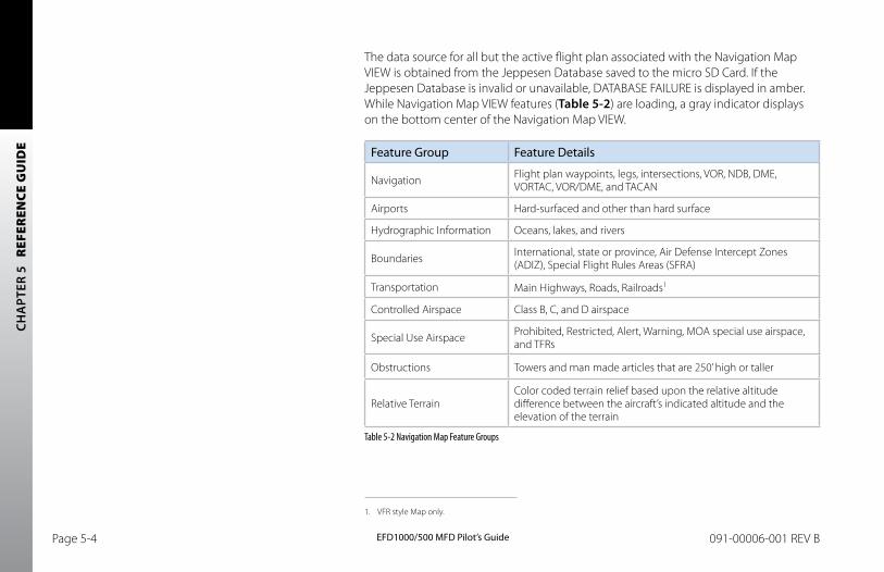
CH
APT
ER 5
R
EFER
ENCE
GU
IDE
EFD1000/500 MFD Pilot’s GuidePage 5-4 091-00006-001 REV B EFD1000/500 MFD Pilot’s Guide Page 5-5091-00006-001 REV B
The data source for all but the active flight plan associated with the Navigation Map VIEW is obtained from the Jeppesen Database saved to the micro SD Card. If the Jeppesen Database is invalid or unavailable, DATABASE FAILURE is displayed in amber. While Navigation Map VIEW features (Table 5-2) are loading, a gray indicator displays on the bottom center of the Navigation Map VIEW.
Feature Group Feature Details
Navigation Flight plan waypoints, legs, intersections, VOR, NDB, DME, VORTAC, VOR/DME, and TACAN
Airports Hard-surfaced and other than hard surface
Hydrographic Information Oceans, lakes, and rivers
Boundaries International, state or province, Air Defense Intercept Zones (ADIZ), Special Flight Rules Areas (SFRA)
Transportation Main Highways, Roads, Railroads1
Controlled Airspace Class B, C, and D airspace
Special Use Airspace Prohibited, Restricted, Alert, Warning, MOA special use airspace, and TFRs
Obstructions Towers and man made articles that are 250’ high or taller
Relative TerrainColor coded terrain relief based upon the relative altitude difference between the aircraft’s indicated altitude and the elevation of the terrain
Table 5-2 Navigation Map Feature Groups
1. VFR style Map only.
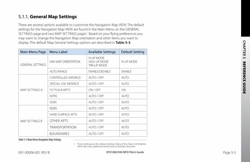
CH
APTER 5 R
EFEREN
CE GU
IDE
EFD1000/500 MFD Pilot’s GuidePage 5-4 091-00006-001 REV B EFD1000/500 MFD Pilot’s Guide Page 5-5091-00006-001 REV B
5.1.1. General Map Settings
There are several options available to customize the Navigation Map VIEW. The default settings for the Navigation Map VIEW are found in the Main Menu on the GENERAL SETTINGS page and two MAP SETTINGS pages1. Based on your flying preferences you may want to change the Navigation Map orientation and other items you want to display. The default Map General Settings options are described in Table 5-3.
Main Menu Page Menu Label Available Settings Default Setting
GENERAL SETTINGSNAV MAP ORIENTATION
N-UP MODE HDG-UP MODE TRK-UP MODE
N-UP MODE
AUTO RANGE ENABLE/DISABLE ENABLE
MAP SETTINGS A
CONTROLLED AIRSPACE AUTO / OFF AUTO
SPECIAL USE AIRSPACE AUTO / OFF AUTO
FLT PLN & WPTS ON / OFF ON
INTRS AUTO / OFF AUTO
VORS AUTO / OFF AUTO
MAP SETTINGS B
NDBS AUTO / OFF AUTO
HARD SURFACE APTS AUTO / OFF AUTO
OTHER APTS AUTO / OFF AUTO
TRANSPORTATION AUTO / OFF AUTO
BOUNDARIES AUTO / OFF AUTO
Table 5-3 Main Menu Navigation Map Settings1. These settings are the default settings. Many of the Data Link Weather
VIEW tabs have additional restrictions to facilitate declutter.
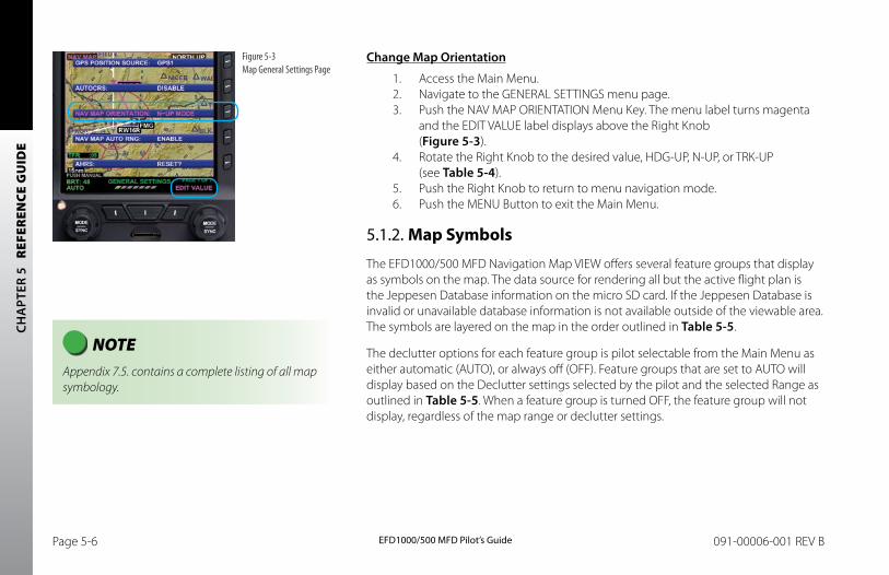
CH
APT
ER 5
R
EFER
ENCE
GU
IDE
EFD1000/500 MFD Pilot’s GuidePage 5-6 091-00006-001 REV B EFD1000/500 MFD Pilot’s Guide Page 5-7091-00006-001 REV B
Change Map Orientation
1. Access the Main Menu.2. Navigate to the GENERAL SETTINGS menu page.3. Push the NAV MAP ORIENTATION Menu Key. The menu label turns magenta
and the EDIT VALUE label displays above the Right Knob (Figure 5-3).
4. Rotate the Right Knob to the desired value, HDG-UP, N-UP, or TRK-UP (see Table 5-4).
5. Push the Right Knob to return to menu navigation mode.6. Push the MENU Button to exit the Main Menu.
5.1.2. Map Symbols
The EFD1000/500 MFD Navigation Map VIEW offers several feature groups that display as symbols on the map. The data source for rendering all but the active flight plan is the Jeppesen Database information on the micro SD card. If the Jeppesen Database is invalid or unavailable database information is not available outside of the viewable area. The symbols are layered on the map in the order outlined in Table 5-5.
The declutter options for each feature group is pilot selectable from the Main Menu as either automatic (AUTO), or always off (OFF). Feature groups that are set to AUTO will display based on the Declutter settings selected by the pilot and the selected Range as outlined in Table 5-5. When a feature group is turned OFF, the feature group will not display, regardless of the map range or declutter settings.
Figure 5-3 Map General Settings Page
NOTE Appendix 7.5. contains a complete listing of all map symbology.
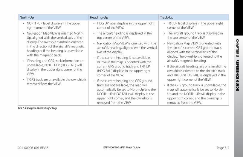
CH
APTER 5 R
EFEREN
CE GU
IDE
EFD1000/500 MFD Pilot’s GuidePage 5-6 091-00006-001 REV B EFD1000/500 MFD Pilot’s Guide Page 5-7091-00006-001 REV B
North-Up Heading-Up Track-Up
• NORTH-UP label displays in the upper right corner of the VIEW.
• Navigation Map VIEW is oriented North-Up, aligned with the vertical axis of the display. The ownship symbol is oriented in the direction of the aircraft’s magnetic heading or if the heading is unavailable with the magnetic track.
• If heading and GPS track information are unavailable, NORTH-UP (HDG FAIL) will display in the upper right corner of the VIEW.
• If GPS track are unavailable the ownship is removed from the VIEW.
• HDG UP label displays in the upper right corner of the VIEW.
• The aircraft heading is displayed in the top center of the VIEW.
• Navigation Map VIEW is oriented with the aircraft’s heading, aligned with the vertical axis of the display.
• If the current heading is not available or invalid the map is oriented with the current GPS ground track and TRK UP (HDG FAIL) displays in the upper right corner of the VIEW.
• If the current heading and GPS ground track are not available, the map will automatically be set to North-Up and the NORTH-UP (HDG FAIL) will display in the upper right corner, and the ownship is removed from the VIEW.
• TRK UP label displays in the upper right corner of the VIEW.
• The aircraft ground track is displayed in the top center of the VIEW.
• Navigation Map VIEW is oriented with the aircraft’s current GPS ground track, aligned with the vertical axis of the display. The ownship is oriented to the aircraft’s magnetic heading.
• If the aircraft heading fails or is invalid the ownship is oriented to the aircraft’s track and TRK UP (HDG FAIL) is displayed in the upper right corner of the VIEW.
• If the GPS ground track is unavailable, the map will automatically be set to North-Up and the NORTH-UP will display in the upper right corner, and the ownship is removed from the VIEW.
Table 5-4 Navigation Map Heading Settings
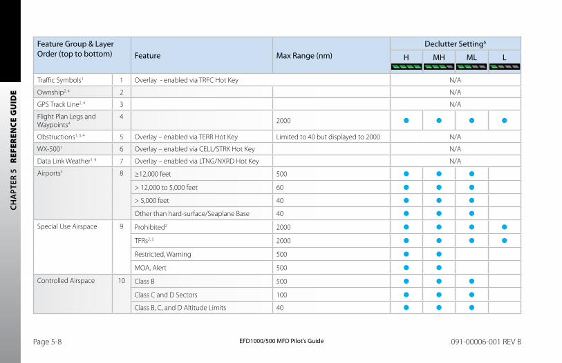
CH
APT
ER 5
R
EFER
ENCE
GU
IDE
EFD1000/500 MFD Pilot’s GuidePage 5-8 091-00006-001 REV B EFD1000/500 MFD Pilot’s Guide Page 5-9091-00006-001 REV B
Feature Group & Layer Order (top to bottom) Feature Max Range (nm)
Declutter Setting6
H MH ML L
Traffic Symbols1 1 Overlay - enabled via TRFC Hot Key N/A
Ownship2, 4 2 N/A
GPS Track Line2, 4 3 N/A
Flight Plan Legs and Waypoints4
4 2000
Obstructions1, 3, 4 5 Overlay – enabled via TERR Hot Key Limited to 40 but displayed to 2000 N/A
WX-5001 6 Overlay – enabled via CELL/STRK Hot Key N/A
Data Link Weather1, 4 7 Overlay – enabled via LTNG/NXRD Hot Key N/A
Airports4 8 ≥12,000 feet 500
> 12,000 to 5,000 feet 60
> 5,000 feet 40
Other than hard-surface/Seaplane Base 40
Special Use Airspace 9 Prohibited2 2000
TFRs2, 5 2000
Restricted, Warning 500
MOA, Alert 500
Controlled Airspace 10 Class B 500
Class C and D Sectors 100
Class B, C, and D Altitude Limits 40
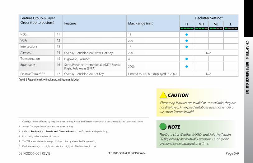
CH
APTER 5 R
EFEREN
CE GU
IDE
EFD1000/500 MFD Pilot’s GuidePage 5-8 091-00006-001 REV B EFD1000/500 MFD Pilot’s Guide Page 5-9091-00006-001 REV B
1. Overlays are not affected by map declutter setting. Airway and Terrain information is decluttered based upon map range.
2. Always ON regardless of range or declutter settings.
3. Refer to Section 5.3.1. Terrain and Obstructions for specific details and symbology.
4. Not configurable via the main menu.
5. The TFR annunciaiton is always displayed directly above the Range setting.
6. Declutter settings: H=High, MH=Medium High, ML=Medium Low, L=Low
CAUTION If basemap features are invalid or unavailable, they are not displayed. An expired database does not render a basemap feature invalid.
NOTE The Data Link Weather (NXRD) and Relative Terrain (TERR) overlay are mutually exclusive, i.e. only one overlay may be displayed at a time..
Feature Group & Layer Order (top to bottom) Feature Max Range (nm)
Declutter Setting6
H MH ML L
NDBs 11 15
VORs 12 200
Intersections 13 15
Airways1, 4 14 Overlay - enabled via ARWY Hot Key 200 N/A
Transportation 15 Highways, Railroads 40
Boundaries 16 State, Province, International, ADIZ4, Special Flight Rule Areas (SFRA)4 2000
Relative Terrain1, 3, 4 17 Overlay – enabled via Hot Key Limited to 100 but displayed to 2000 N/A
Table 5-5 Feature Group Layering, Range, and Declutter Behavior
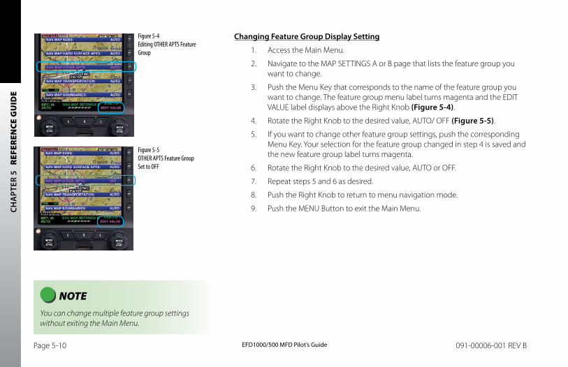
CH
APT
ER 5
R
EFER
ENCE
GU
IDE
EFD1000/500 MFD Pilot’s GuidePage 5-10 091-00006-001 REV B EFD1000/500 MFD Pilot’s Guide Page 5-11091-00006-001 REV B
NOTE You can change multiple feature group settings without exiting the Main Menu.
Changing Feature Group Display Setting
1. Access the Main Menu.
2. Navigate to the MAP SETTINGS A or B page that lists the feature group you want to change.
3. Push the Menu Key that corresponds to the name of the feature group you want to change. The feature group menu label turns magenta and the EDIT VALUE label displays above the Right Knob (Figure 5-4).
4. Rotate the Right Knob to the desired value, AUTO/ OFF (Figure 5-5).
5. If you want to change other feature group settings, push the corresponding Menu Key. Your selection for the feature group changed in step 4 is saved and the new feature group label turns magenta.
6. Rotate the Right Knob to the desired value, AUTO or OFF.
7. Repeat steps 5 and 6 as desired.
8. Push the Right Knob to return to menu navigation mode.
9. Push the MENU Button to exit the Main Menu.
Figure 5-4 Editing OTHER APTS Feature Group
Figure 5-5 OTHER APTS Feature Group Set to OFF
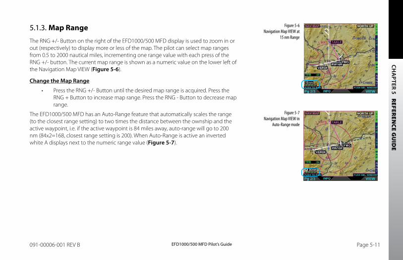
CH
APTER 5 R
EFEREN
CE GU
IDE
EFD1000/500 MFD Pilot’s GuidePage 5-10 091-00006-001 REV B EFD1000/500 MFD Pilot’s Guide Page 5-11091-00006-001 REV B
5.1.3. Map Range
The RNG +/- Button on the right of the EFD1000/500 MFD display is used to zoom in or out (respectively) to display more or less of the map. The pilot can select map ranges from 0.5 to 2000 nautical miles, incrementing one range value with each press of the RNG +/- button. The current map range is shown as a numeric value on the lower left of the Navigation Map VIEW (Figure 5-6).
Change the Map Range
• Press the RNG +/- Button until the desired map range is acquired. Press the RNG + Button to increase map range. Press the RNG - Button to decrease map range.
The EFD1000/500 MFD has an Auto-Range feature that automatically scales the range (to the closest range setting) to two times the distance between the ownship and the active waypoint, i.e. if the active waypoint is 84 miles away, auto-range will go to 200 nm (84x2=168, closest range setting is 200). When Auto-Range is active an inverted white A displays next to the numeric range value (Figure 5-7).
Figure 5-6 Navigation Map VIEW at
15 nm Range
Figure 5-7 Navigation Map VIEW in
Auto-Range mode
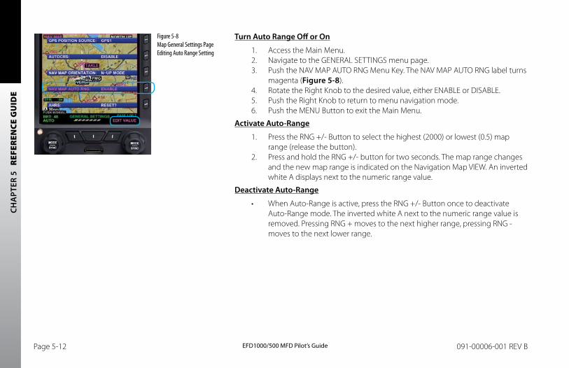
CH
APT
ER 5
R
EFER
ENCE
GU
IDE
EFD1000/500 MFD Pilot’s GuidePage 5-12 091-00006-001 REV B EFD1000/500 MFD Pilot’s Guide Page 5-13091-00006-001 REV B
Figure 5-8 Map General Settings Page Editing Auto Range Setting
Turn Auto Range Off or On
1. Access the Main Menu.2. Navigate to the GENERAL SETTINGS menu page.3. Push the NAV MAP AUTO RNG Menu Key. The NAV MAP AUTO RNG label turns
magenta (Figure 5-8).4. Rotate the Right Knob to the desired value, either ENABLE or DISABLE.5. Push the Right Knob to return to menu navigation mode.6. Push the MENU Button to exit the Main Menu.
Activate Auto-Range
1. Press the RNG +/- Button to select the highest (2000) or lowest (0.5) map range (release the button).
2. Press and hold the RNG +/- button for two seconds. The map range changes and the new map range is indicated on the Navigation Map VIEW. An inverted white A displays next to the numeric range value.
Deactivate Auto-Range
• When Auto-Range is active, press the RNG +/- Button once to deactivate Auto-Range mode. The inverted white A next to the numeric range value is removed. Pressing RNG + moves to the next higher range, pressing RNG - moves to the next lower range.
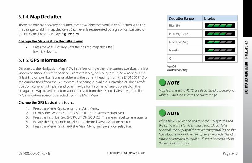
CH
APTER 5 R
EFEREN
CE GU
IDE
EFD1000/500 MFD Pilot’s GuidePage 5-12 091-00006-001 REV B EFD1000/500 MFD Pilot’s Guide Page 5-13091-00006-001 REV B
5.1.4. Map Declutter
There are four map feature declutter levels available that work in conjunction with the map range to aid in map declutter. Each level is represented by a graphical bar below the numerical range display (Figure 5-9).
Change the Map Feature Declutter Level
• Press the MAP Hot Key until the desired map declutter level is selected.
5.1.5. GPS Information
On startup, the Navigation Map VIEW initializes using either the current position, the last known position (if current position is not available), or Albuquerque, New Mexico, USA (if last known position is unavailable) and the current heading from the EFD1000 PFD or the current track from the GPS system (if heading is invalid or unavailable). The aircraft position, current flight plan, and other navigation information are displayed on the Navigation Map based on information received from the selected GPS navigator. The GPS navigation source is selected from the Main Menu.
Change the GPS Navigation Source
1. Press the Menu Key to enter the Main Menu.2. Display the General Settings page if it is not already displayed.3. Press the first Hot Key, GPS POSITION SOURCE. The menu label turns magenta.4. Rotate the Right Knob to select the desired GPS navigation source.5. Press the Menu Key to exit the Main Menu and save your selection.
NOTE Map features set to AUTO are decluttered according to Table 5-6 and the selected declutter range.
Declutter Range Display
High (H)
Med-High (MH)
Med-Low (ML)
Low (L)
Off
Figure 5-9 Map Declutter Settings
NOTE When the EFD is connected to some GPS systems and the active flight plan is changed (e.g. “Direct To” is selected), the display of the active (magenta) leg on the Nav Map may be delayed for up to 20 seconds. The CDI course pointer and autopilot will react immediately to the flight plan change.
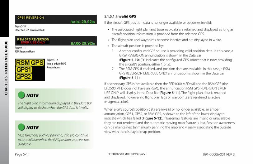
CH
APT
ER 5
R
EFER
ENCE
GU
IDE
EFD1000/500 MFD Pilot’s GuidePage 5-14 091-00006-001 REV B EFD1000/500 MFD Pilot’s Guide Page 5-15091-00006-001 REV B
5.1.5.1. Invalid GPSIf the aircraft GPS position data is no longer available or becomes invalid:
• The associated flight plan and basemap data are retained and displayed as long as aircraft position information is provided from the selected GPS.
• The flight plan and waypoints become inactive and are displayed in white.
• The aircraft position is provided by:1. Another configured GPS source is providing valid position data. In this case, a
GPS# REVERSION annunciation is shown in the Data Bar (Figure 5-10) (“#” indicates the configured GPS source that is now providing the aircraft’s position, either 1 or 2).
2. The RSM GPS, if enabled, and position data are available. In this case, a RSM GPS REVERSION EMER USE ONLY annunciation is shown in the Data Bar (Figure 5-11).
If a secondary GPS is not available then the EFD1000 MFD will use the RSM GPS (the EFD500 MFD does not have an RSM). The annunciation RSM GPS REVERSION EMER USE ONLY will display in the Data Bar (Figure 5-11). The flight plan data is retained and displayed, however no flight plan legs or waypoints are rendered as active (magenta color).
When a GPS source’s position data are invalid or no longer available, an amber annunciation, GPS1, GPS2, or RSM GPS, is shown to the left of the lower display to indicate which has failed (Figure 5-12). If Basemap features are invalid or unavailable they are not rendered and the automatic moving map feature is lost. Position awareness can be maintained by manually panning the map and visually associating the outside view with the displayed map position.
Figure 5-10 Other Valid GPS Reversion Mode
Figure 5-11 RSM Reversion Mode
Figure 5-12 Invalid or Failed GPS Annunciations
NOTE The flight plan information displayed in the Data Bar will display as dashes when the GPS data is invalid.
NOTE Map functions such as panning, info etc. continue to be available when the GPS position source is not available.
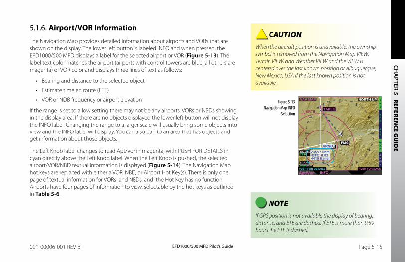
CH
APTER 5 R
EFEREN
CE GU
IDE
EFD1000/500 MFD Pilot’s GuidePage 5-14 091-00006-001 REV B EFD1000/500 MFD Pilot’s Guide Page 5-15091-00006-001 REV B
5.1.6. Airport/VOR Information
The Navigation Map provides detailed information about airports and VORs that are shown on the display. The lower left button is labeled INFO and when pressed, the EFD1000/500 MFD displays a label for the selected airport or VOR (Figure 5-13). The label text color matches the airport (airports with control towers are blue, all others are magenta) or VOR color and displays three lines of text as follows:
• Bearing and distance to the selected object
• Estimate time en route (ETE)
• VOR or NDB frequency or airport elevation
If the range is set to a low setting there may not be any airports, VORs or NBDs showing in the display area. If there are no objects displayed the lower left button will not display the INFO label. Changing the range to a larger scale will usually bring some objects into view and the INFO label will display. You can also pan to an area that has objects and get information about those objects.
The Left Knob label changes to read Apt/Vor in magenta, with PUSH FOR DETAILS in cyan directly above the Left Knob label. When the Left Knob is pushed, the selected airport/VOR/NBD textual information is displayed (Figure 5-14). The Navigation Map hot keys are replaced with either a VOR, NBD, or Airport Hot Key(s). There is only one page of textual information for VORs and NBDs, and the Hot Key has no function. Airports have four pages of information to view, selectable by the hot keys as outlined in Table 5-6.
Figure 5-13 Navigation Map INFO
Selection
NOTE If GPS position is not available the display of bearing, distance, and ETE are dashed. If ETE is more than 9:59 hours the ETE is dashed.
CAUTION When the aircraft position is unavailable, the ownship symbol is removed from the Navigation Map VIEW, Terrain VIEW, and Weather VIEW and the VIEW is centered over the last known position or Albuquerque, New Mexico, USA if the last known position is not available.
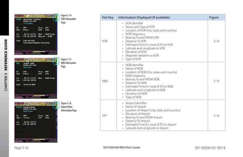
CH
APT
ER 5
R
EFER
ENCE
GU
IDE
EFD1000/500 MFD Pilot’s GuidePage 5-16 091-00006-001 REV B EFD1000/500 MFD Pilot’s Guide Page 5-17091-00006-001 REV B
Hot Key Information Displayed (if available) Figure
VOR
• VOR Identifier• Name and Type of VOR• Location of VOR (city, state, and country)• VOR Frequency• Bearing To and FROM VOR• Distance To VOR• Estimated Time En route (ETE) to VOR• Latitude and Longitude to VOR• Elevation of VOR• Magnetic Variation to VOR• Type of VOR
5-14
NBD
• NDB Identifier• Name of NDB• Location of NDB (city, state, and country)• NDB Frequency• Bearing To and FROM NDB• Distance To NDB• Estimated Time En route (ETE) to NDB• Latitude and Longitude to NDB• Elevation of NDB• Type of NDB
5-15
APT
• Airport Identifier• Name of Airport• Location of Airport (city, state, and country)• Elevation of Airport• Bearing To and FROM Airport• Distance To Airport• Estimated Time En route (ETE) to Airport• Latitude and Longitude to Airport
5-16
Figure 5-16 Airport Basic Information Page
Figure 5-14 VOR Information Page
Figure 5-15 NBD Information Page
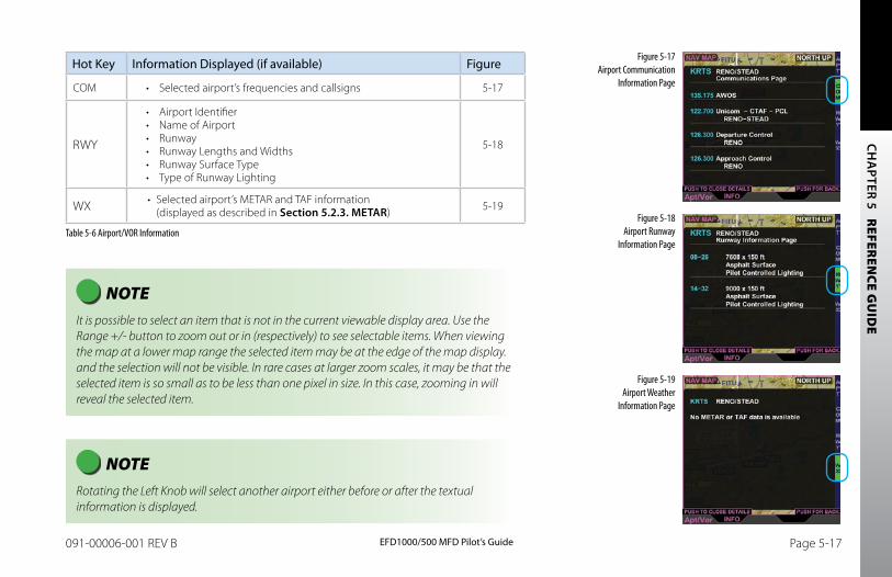
CH
APTER 5 R
EFEREN
CE GU
IDE
EFD1000/500 MFD Pilot’s GuidePage 5-16 091-00006-001 REV B EFD1000/500 MFD Pilot’s Guide Page 5-17091-00006-001 REV B
NOTE Rotating the Left Knob will select another airport either before or after the textual information is displayed.
Hot Key Information Displayed (if available) Figure
COM • Selected airport’s frequencies and callsigns 5-17
RWY
• Airport Identifier• Name of Airport• Runway• Runway Lengths and Widths• Runway Surface Type• Type of Runway Lighting
5-18
WX • Selected airport’s METAR and TAF information (displayed as described in Section 5.2.3. METAR) 5-19
Table 5-6 Airport/VOR Information
Figure 5-17 Airport Communication
Information Page
Figure 5-18 Airport Runway
Information Page
Figure 5-19 Airport Weather
Information Page
NOTE It is possible to select an item that is not in the current viewable display area. Use the Range +/- button to zoom out or in (respectively) to see selectable items. When viewing the map at a lower map range the selected item may be at the edge of the map display. and the selection will not be visible. In rare cases at larger zoom scales, it may be that the selected item is so small as to be less than one pixel in size. In this case, zooming in will reveal the selected item.
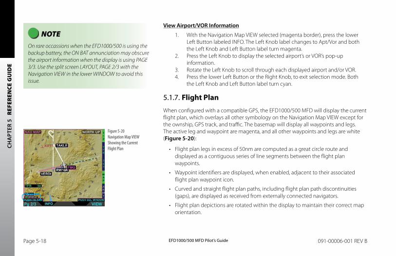
CH
APT
ER 5
R
EFER
ENCE
GU
IDE
EFD1000/500 MFD Pilot’s GuidePage 5-18 091-00006-001 REV B EFD1000/500 MFD Pilot’s Guide Page 5-19091-00006-001 REV B
View Airport/VOR Information
1. With the Navigation Map VIEW selected (magenta border), press the lower Left Button labeled INFO. The Left Knob label changes to Apt/Vor and both the Left Knob and Left Button label turn magenta.
2. Press the Left Knob to display the selected airport’s or VOR’s pop-up information.
3. Rotate the Left Knob to scroll through each displayed airport and/or VOR. 4. Press the lower Left Button or the Right Knob, to exit selection mode. Both
the Left Knob and Left Button label turn cyan.
5.1.7. Flight Plan
When configured with a compatible GPS, the EFD1000/500 MFD will display the current flight plan, which overlays all other symbology on the Navigation Map VIEW except for the ownship, GPS track, and traffic. The basemap will display all waypoints and legs. The active leg and waypoint are magenta, and all other waypoints and legs are white (Figure 5-20):
• Flight plan legs in excess of 50nm are computed as a great circle route and displayed as a contiguous series of line segments between the flight plan waypoints.
• Waypoint identifiers are displayed, when enabled, adjacent to their associated flight plan waypoint icon.
• Curved and straight flight plan paths, including flight plan path discontinuities (gaps), are displayed as received from externally connected navigators.
• Flight plan depictions are rotated within the display to maintain their correct map orientation.
Figure 5-20 Navigation Map VIEW Showing the Current Flight Plan
NOTE On rare occassions when the EFD1000/500 is using the backup battery, the ON BAT annunciation may obscure the airport information when the display is using PAGE 3/3. Use the split screen LAYOUT, PAGE 2/3 with the Navigation VIEW in the lower WINDOW to avoid this issue.
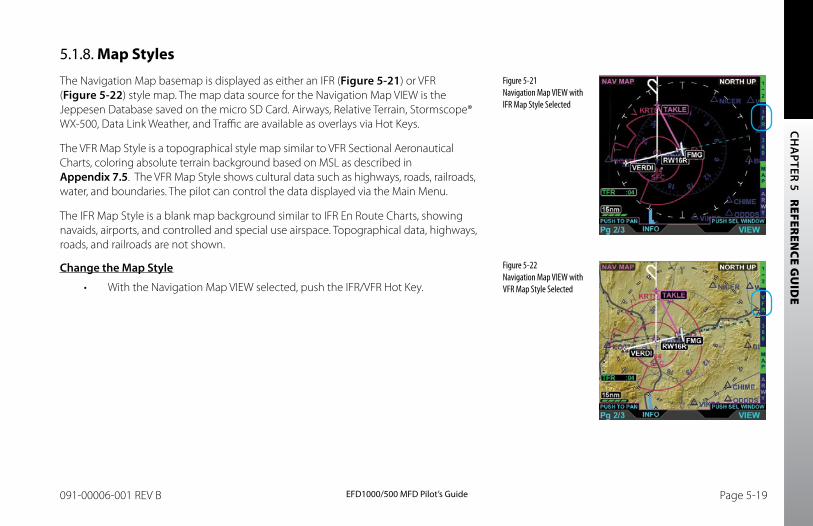
CH
APTER 5 R
EFEREN
CE GU
IDE
EFD1000/500 MFD Pilot’s GuidePage 5-18 091-00006-001 REV B EFD1000/500 MFD Pilot’s Guide Page 5-19091-00006-001 REV B
5.1.8. Map Styles
The Navigation Map basemap is displayed as either an IFR (Figure 5-21) or VFR (Figure 5-22) style map. The map data source for the Navigation Map VIEW is the Jeppesen Database saved on the micro SD Card. Airways, Relative Terrain, Stormscope® WX-500, Data Link Weather, and Traffic are available as overlays via Hot Keys.
The VFR Map Style is a topographical style map similar to VFR Sectional Aeronautical Charts, coloring absolute terrain background based on MSL as described in Appendix 7.5. The VFR Map Style shows cultural data such as highways, roads, railroads, water, and boundaries. The pilot can control the data displayed via the Main Menu.
The IFR Map Style is a blank map background similar to IFR En Route Charts, showing navaids, airports, and controlled and special use airspace. Topographical data, highways, roads, and railroads are not shown.
Change the Map Style
• With the Navigation Map VIEW selected, push the IFR/VFR Hot Key.
Figure 5-21 Navigation Map VIEW with IFR Map Style Selected
Figure 5-22 Navigation Map VIEW with VFR Map Style Selected
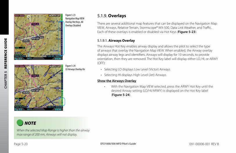
CH
APT
ER 5
R
EFER
ENCE
GU
IDE
EFD1000/500 MFD Pilot’s GuidePage 5-20 091-00006-001 REV B EFD1000/500 MFD Pilot’s Guide Page 5-21091-00006-001 REV B
5.1.9. Overlays
There are several additional map features that can be displayed on the Navigation Map VIEW, Airways, Relative Terrain, Stormscope® WX-500, Data Link Weather, and Traffic. Each of these overlays is enabled or disabled via Hot Keys (Figure 5-23).
5.1.9.1. Airways OverlayThe Airways Hot Key enables airway display and allows the pilot to select the type of airways that overlay the Navigation Map VIEW. When enabled, the Airway overlay displays airway legs and identifiers. Airways will display for 10 seconds, to provide orientation, then they are removed. The Hot Key label will display either LO, HI, or ARWY (OFF):
• Selecting LO displays Low Level (Victor) Airways
• Selecting HI displays High Level (Jet) Airways
Show the Airways Overlay
• With the Navigation Map VIEW selected, press the ARWY Hot Key until the desired Airway setting (LO/HI/ARWY) is displayed on the Hot Key label (Figure 5-24).
Figure 5-23 Navigation Map VIEW Overlay Hot Keys, All Overlays Disabled
NOTE When the selected Map Range is higher than the airway max range of 200 nm, Airways will not display.
Figure 5-24 LO Airways Overlay On
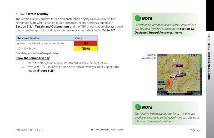
CH
APTER 5 R
EFEREN
CE GU
IDE
EFD1000/500 MFD Pilot’s GuidePage 5-20 091-00006-001 REV B EFD1000/500 MFD Pilot’s Guide Page 5-21091-00006-001 REV B
5.1.9.2. Terrain OverlayThe Terrain Hot Key enables terrain and obstruction display as an overlay on the Navigation Map. When enabled terrain and obstructions display as outlined in Section 5.3.1. Terrain and Obstructions and the TERR annunciation displays above the current Range. Color coding for the Terrain Overlay is depicted in Table 5-7.
Relative Elevation Color
greater than 100’ Below - all terrain Above RED
500’ - 100’ Below YELLOWTable 5-7 Navigation Map Terrain Overlay Color Coding
Show the Terrain Overlay
1. With the Navigation Map VIEW selected, display the 2/2 Hot Key.2. Press the TERR Hot Key to turn on the Terrain overlay (Hot Key label turns
green) (Figure 5-25).
NOTE For detailed information about Traffic, Stormscope® WX-500, and Terrain/Obstructions see Section 5.3. Dedicated Hazard Awareness Views.
Figure 5-25 Terrain Overlay On
NOTE The Relative Terrain overlay and Data Link Weather overlay are mutually exclusive. Only one can display at a time on the Navigation Map.
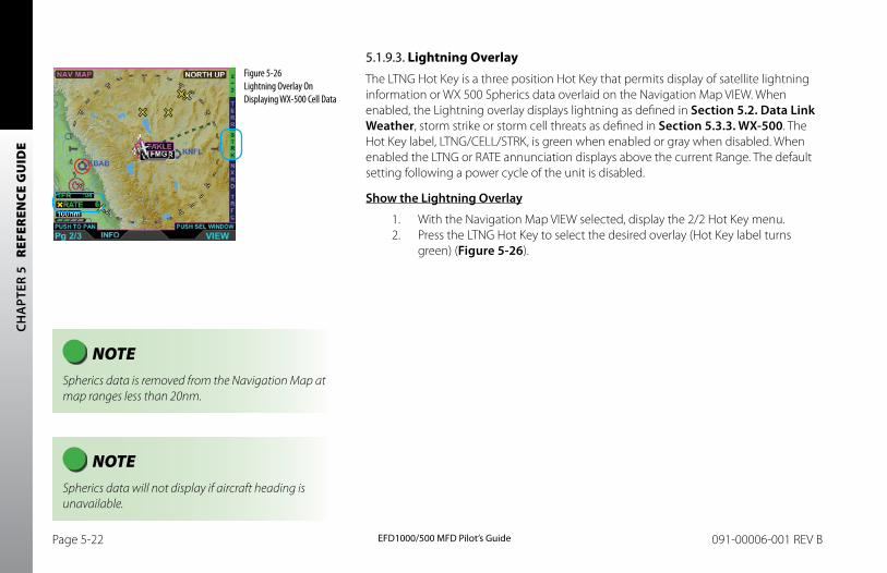
CH
APT
ER 5
R
EFER
ENCE
GU
IDE
EFD1000/500 MFD Pilot’s GuidePage 5-22 091-00006-001 REV B EFD1000/500 MFD Pilot’s Guide Page 5-23091-00006-001 REV B
5.1.9.3. Lightning OverlayThe LTNG Hot Key is a three position Hot Key that permits display of satellite lightning information or WX 500 Spherics data overlaid on the Navigation Map VIEW. When enabled, the Lightning overlay displays lightning as defined in Section 5.2. Data Link Weather, storm strike or storm cell threats as defined in Section 5.3.3. WX-500. The Hot Key label, LTNG/CELL/STRK, is green when enabled or gray when disabled. When enabled the LTNG or RATE annunciation displays above the current Range. The default setting following a power cycle of the unit is disabled.
Show the Lightning Overlay
1. With the Navigation Map VIEW selected, display the 2/2 Hot Key menu.2. Press the LTNG Hot Key to select the desired overlay (Hot Key label turns
green) (Figure 5-26).
Figure 5-26 Lightning Overlay On Displaying WX-500 Cell Data
NOTE Spherics data is removed from the Navigation Map at map ranges less than 20nm.
NOTE Spherics data will not display if aircraft heading is unavailable.
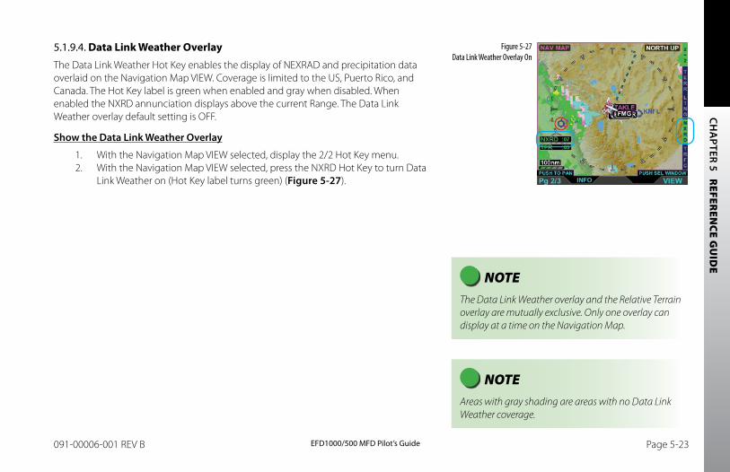
CH
APTER 5 R
EFEREN
CE GU
IDE
EFD1000/500 MFD Pilot’s GuidePage 5-22 091-00006-001 REV B EFD1000/500 MFD Pilot’s Guide Page 5-23091-00006-001 REV B
5.1.9.4. Data Link Weather OverlayThe Data Link Weather Hot Key enables the display of NEXRAD and precipitation data overlaid on the Navigation Map VIEW. Coverage is limited to the US, Puerto Rico, and Canada. The Hot Key label is green when enabled and gray when disabled. When enabled the NXRD annunciation displays above the current Range. The Data Link Weather overlay default setting is OFF.
Show the Data Link Weather Overlay
1. With the Navigation Map VIEW selected, display the 2/2 Hot Key menu.2. With the Navigation Map VIEW selected, press the NXRD Hot Key to turn Data
Link Weather on (Hot Key label turns green) (Figure 5-27).
NOTE The Data Link Weather overlay and the Relative Terrain overlay are mutually exclusive. Only one overlay can display at a time on the Navigation Map.
NOTE Areas with gray shading are areas with no Data Link Weather coverage.
Figure 5-27 Data Link Weather Overlay On
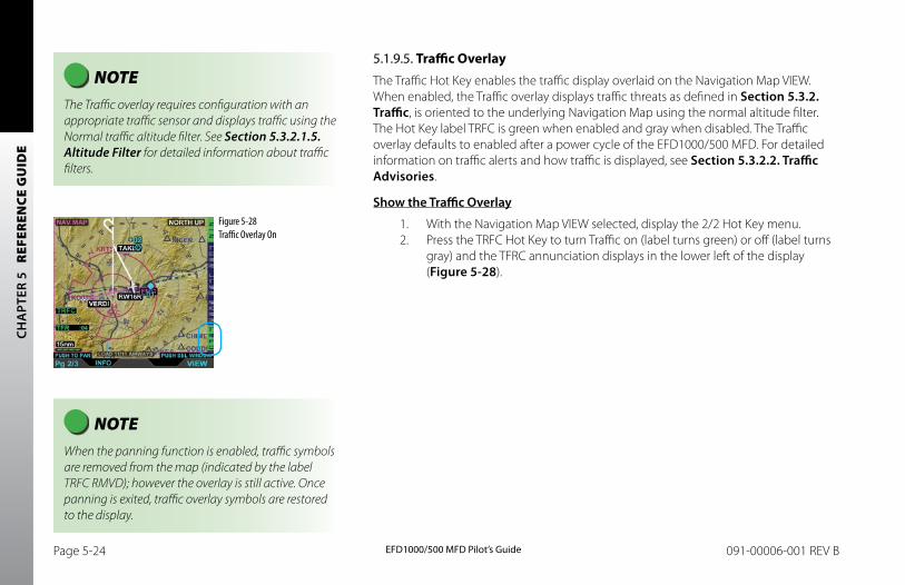
CH
APT
ER 5
R
EFER
ENCE
GU
IDE
EFD1000/500 MFD Pilot’s GuidePage 5-24 091-00006-001 REV B EFD1000/500 MFD Pilot’s Guide Page 5-25091-00006-001 REV B
5.1.9.5. Traffic OverlayThe Traffic Hot Key enables the traffic display overlaid on the Navigation Map VIEW. When enabled, the Traffic overlay displays traffic threats as defined in Section 5.3.2. Traffic, is oriented to the underlying Navigation Map using the normal altitude filter. The Hot Key label TRFC is green when enabled and gray when disabled. The Traffic overlay defaults to enabled after a power cycle of the EFD1000/500 MFD. For detailed information on traffic alerts and how traffic is displayed, see Section 5.3.2.2. Traffic Advisories.
Show the Traffic Overlay
1. With the Navigation Map VIEW selected, display the 2/2 Hot Key menu.2. Press the TRFC Hot Key to turn Traffic on (label turns green) or off (label turns
gray) and the TFRC annunciation displays in the lower left of the display (Figure 5-28).
Figure 5-28 Traffic Overlay On
NOTE The Traffic overlay requires configuration with an appropriate traffic sensor and displays traffic using the Normal traffic altitude filter. See Section 5.3.2.1.5. Altitude Filter for detailed information about traffic filters.
NOTE When the panning function is enabled, traffic symbols are removed from the map (indicated by the label TRFC RMVD); however the overlay is still active. Once panning is exited, traffic overlay symbols are restored to the display.
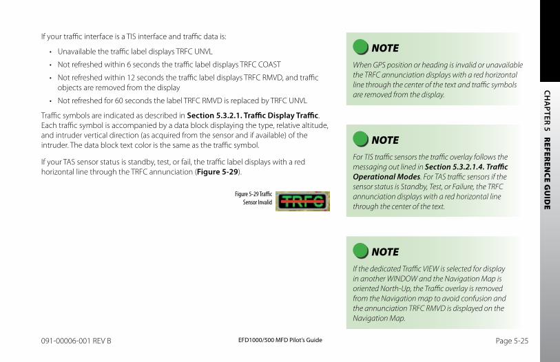
CH
APTER 5 R
EFEREN
CE GU
IDE
EFD1000/500 MFD Pilot’s GuidePage 5-24 091-00006-001 REV B EFD1000/500 MFD Pilot’s Guide Page 5-25091-00006-001 REV B
NOTE If the dedicated Traffic VIEW is selected for display in another WINDOW and the Navigation Map is oriented North-Up, the Traffic overlay is removed from the Navigation map to avoid confusion and the annunciation TRFC RMVD is displayed on the Navigation Map.
If your traffic interface is a TIS interface and traffic data is:
• Unavailable the traffic label displays TRFC UNVL
• Not refreshed within 6 seconds the traffic label displays TRFC COAST
• Not refreshed within 12 seconds the traffic label displays TRFC RMVD, and traffic objects are removed from the display
• Not refreshed for 60 seconds the label TRFC RMVD is replaced by TRFC UNVL
Traffic symbols are indicated as described in Section 5.3.2.1. Traffic Display Traffic. Each traffic symbol is accompanied by a data block displaying the type, relative altitude, and intruder vertical direction (as acquired from the sensor and if available) of the intruder. The data block text color is the same as the traffic symbol.
If your TAS sensor status is standby, test, or fail, the traffic label displays with a red horizontal line through the TRFC annunciation (Figure 5-29).
NOTE When GPS position or heading is invalid or unavailable the TRFC annunciation displays with a red horizontal line through the center of the text and traffic symbols are removed from the display.
Figure 5-29 Traffic Sensor Invalid
NOTE For TIS traffic sensors the traffic overlay follows the messaging out lined in Section 5.3.2.1.4. Traffic Operational Modes. For TAS traffic sensors if the sensor status is Standby, Test, or Failure, the TRFC annunciation displays with a red horizontal line through the center of the text.
CH
APT
ER 5
R
EFER
ENCE
GU
IDE
EFD1000/500 MFD Pilot’s GuidePage 5-26 091-00006-001 REV B EFD1000/500 MFD Pilot’s Guide Page 5-27091-00006-001 REV B
5.2. Data Link Weather (optional)Data Link Weather provides graphical and textual descriptions of weather-related information received from XM WX Satellite Weather through the Aspen satellite receiver (Model EWR50) for the continental United States, Puerto Rico, and parts of Canada and Mexico. This VIEW requires a weather receiver configured with the EFD1000/500 MFD and a subscription to XM WX Satellite Weather. There are two ways that the EFD1000/500 MFD displays weather:
• Data Link Weather VIEW
• Data Link Weather Navigation Map Overlay (see the Navigation Map Section 5.2. Data Link Weather)
Several weather products are available; each weather product is presented on a separate screen in the Data Link Weather VIEW. Each weather product is initially displayed at the default map range of 200 nm. To display a different product screen, set the FOCUS on the Data Link Weather VIEW by pressing the Right Knob, press the lower right button Sel Wx, then rotate the Right Knob to select and view a different product screen (see Section 5.2.1. Selecting Data Link Weather Products). The Data Link Weather VIEW contains the following product screens:
• Convective (Radar, NEXRAD, Lightning, and Convective SIGMETs)
• METARs
• Echo Tops
• Cloud Tops
• AIRMETs/SIGMETs
• TFRs
• Winds Aloft
• XM Status
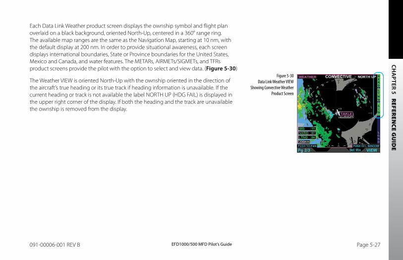
CH
APTER 5 R
EFEREN
CE GU
IDE
EFD1000/500 MFD Pilot’s GuidePage 5-26 091-00006-001 REV B EFD1000/500 MFD Pilot’s Guide Page 5-27091-00006-001 REV B
Each Data Link Weather product screen displays the ownship symbol and flight plan overlaid on a black background, oriented North-Up, centered in a 360° range ring. The available map ranges are the same as the Navigation Map, starting at 10 nm, with the default display at 200 nm. In order to provide situational awareness, each screen displays international boundaries, State or Province boundaries for the United States, Mexico and Canada, and water features. The METARs, AIRMETs/SIGMETs, and TFRs product screens provide the pilot with the option to select and view data. (Figure 5-30)
The Weather VIEW is oriented North-Up with the ownship oriented in the direction of the aircraft’s true heading or its true track if heading information is unavailable. If the current heading or track is not available the label NORTH UP (HDG FAIL) is displayed in the upper right corner of the display. If both the heading and the track are unavailable the ownship is removed from the display.
Figure 5-30 Data Link Weather VIEW
Showing Convective Weather Product Screen
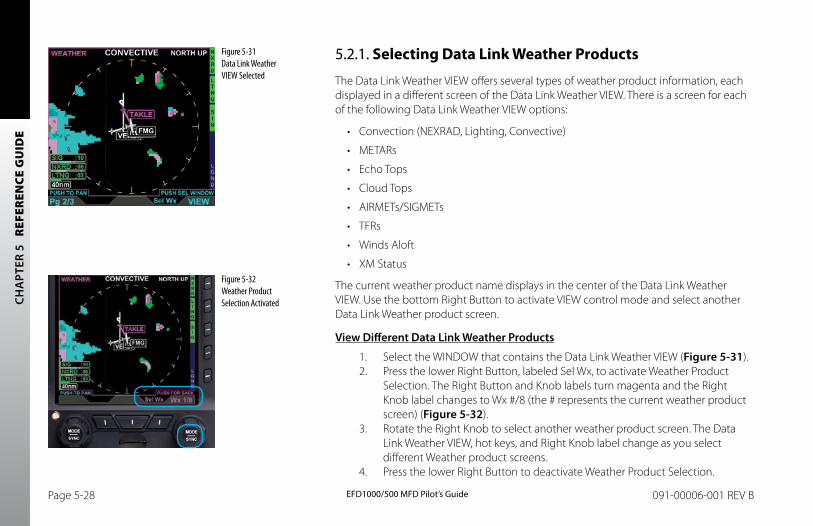
CH
APT
ER 5
R
EFER
ENCE
GU
IDE
EFD1000/500 MFD Pilot’s GuidePage 5-28 091-00006-001 REV B EFD1000/500 MFD Pilot’s Guide Page 5-29091-00006-001 REV B
5.2.1. Selecting Data Link Weather Products
The Data Link Weather VIEW offers several types of weather product information, each displayed in a different screen of the Data Link Weather VIEW. There is a screen for each of the following Data Link Weather VIEW options:
• Convection (NEXRAD, Lighting, Convective)
• METARs
• Echo Tops
• Cloud Tops
• AIRMETs/SIGMETs
• TFRs
• Winds Aloft
• XM Status
The current weather product name displays in the center of the Data Link Weather VIEW. Use the bottom Right Button to activate VIEW control mode and select another Data Link Weather product screen.
View Different Data Link Weather Products
1. Select the WINDOW that contains the Data Link Weather VIEW (Figure 5-31).2. Press the lower Right Button, labeled Sel Wx, to activate Weather Product
Selection. The Right Button and Knob labels turn magenta and the Right Knob label changes to Wx #/8 (the # represents the current weather product screen) (Figure 5-32).
3. Rotate the Right Knob to select another weather product screen. The Data Link Weather VIEW, hot keys, and Right Knob label change as you select different Weather product screens.
4. Press the lower Right Button to deactivate Weather Product Selection.
Figure 5-31 Data Link Weather VIEW Selected
Figure 5-32 Weather Product Selection Activated
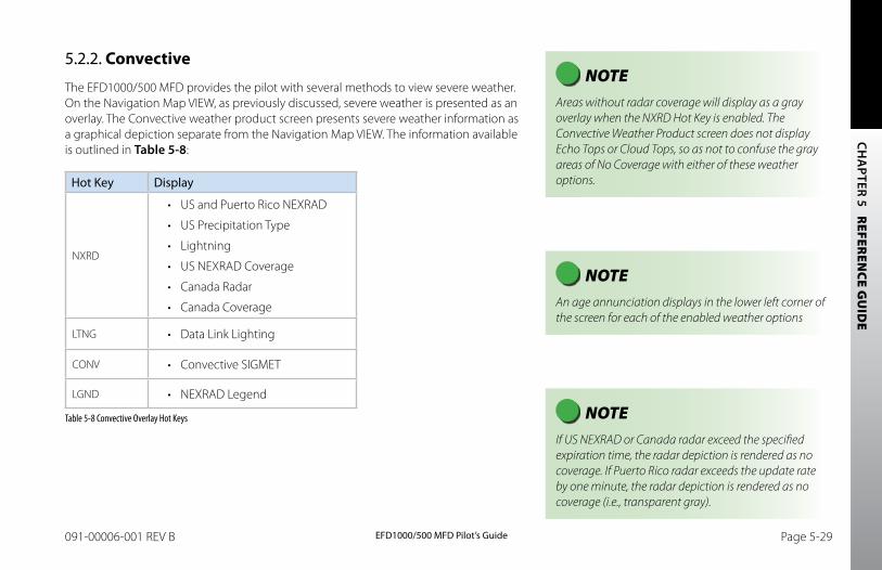
CH
APTER 5 R
EFEREN
CE GU
IDE
EFD1000/500 MFD Pilot’s GuidePage 5-28 091-00006-001 REV B EFD1000/500 MFD Pilot’s Guide Page 5-29091-00006-001 REV B
5.2.2. Convective
The EFD1000/500 MFD provides the pilot with several methods to view severe weather. On the Navigation Map VIEW, as previously discussed, severe weather is presented as an overlay. The Convective weather product screen presents severe weather information as a graphical depiction separate from the Navigation Map VIEW. The information available is outlined in Table 5-8:
Hot Key Display
NXRD
• US and Puerto Rico NEXRAD
• US Precipitation Type
• Lightning
• US NEXRAD Coverage
• Canada Radar
• Canada Coverage
LTNG • Data Link Lighting
CONV • Convective SIGMET
LGND • NEXRAD Legend
Table 5-8 Convective Overlay Hot Keys
NOTE Areas without radar coverage will display as a gray overlay when the NXRD Hot Key is enabled. The Convective Weather Product screen does not display Echo Tops or Cloud Tops, so as not to confuse the gray areas of No Coverage with either of these weather options.
NOTE An age annunciation displays in the lower left corner of the screen for each of the enabled weather options
NOTE If US NEXRAD or Canada radar exceed the specified expiration time, the radar depiction is rendered as no coverage. If Puerto Rico radar exceeds the update rate by one minute, the radar depiction is rendered as no coverage (i.e., transparent gray).
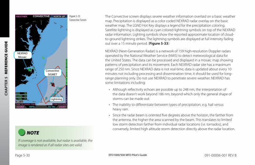
CH
APT
ER 5
R
EFER
ENCE
GU
IDE
EFD1000/500 MFD Pilot’s GuidePage 5-30 091-00006-001 REV B EFD1000/500 MFD Pilot’s Guide Page 5-31091-00006-001 REV B
The Convective screen displays severe weather information overlaid on a basic weather map. Precipitation is displayed as a color coded NEXRAD radar overlay on the basic weather map. The LGND Hot Key displays a legend for the precipitation coloring. Satellite lightning is displayed as cyan colored lightning symbols on top of the NEXRAD radar information. Lighting symbols show the reported approximate location of cloud-to-ground lightning strikes. The lightning symbols are displayed at full intensity fading out over a 15 minute period. (Figure 5-33)
NEXRAD (Next-Generation Radar) is a network of 159 high-resolution Doppler radars operated by the National Weather Service (NWS) to detect meteorological data for the United States. The data can be processed and displayed in a mosaic map showing patterns of precipitation and its movement. Each NEXRAD radar site has a maximum range of 250 nm. Since NEXRAD data is not real-time, data is updated about every 10 minutes not including processing and dissemination time, it should be used for long-range planning only. Do not use NEXRAD to penetrate severe weather. NEXRAD has some limitations including:
• Although reflectivity echoes are possible up to 248 nm, the interpretation of the data doesn’t work beyond 186 nm, beyond which only the general shape of storms can be made out.
• The inability to differentiate between types of precipitation, e.g. hail versus heavy rain.
• Since the radar beam is oriented five degrees above the horizon, the farther from the antenna, the higher the area scanned by the beam. This translates to limited low storm detection farther from individual radar locations (i.e. tornados), and conversely, limited high altitude storm detection directly above the radar location.
Figure 5-33 Convective Screen
NOTE If coverage is not available, but radar is available, the image is rendered as if all radar sites are valid.
Lightning
Convective SIGMET
NEXRAD Mosaic
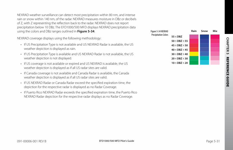
CH
APTER 5 R
EFEREN
CE GU
IDE
EFD1000/500 MFD Pilot’s GuidePage 5-30 091-00006-001 REV B EFD1000/500 MFD Pilot’s Guide Page 5-31091-00006-001 REV B
NEXRAD weather surveillance can detect most precipitation within 80 nm, and intense rain or snow within 140 nm, of the radar. NEXRAD measures moisture in DBz or decibels of Z, with Z representing the reflection back to the radar. NEXRAD does not report precipitation below 10 DBz. The EFD1000/500 MFD displays NEXRAD precipitation data using the colors and DBz ranges outlined in Figure 5-34.
NEXRAD coverage displays using the following methodology:
• If US Precipitation Type is not available and US NEXRAD Radar is available, the US weather depiction is displayed as rain.
• If US Precipitation Type is available and US NEXRAD Radar is not available, the US weather depiction is not displayed.
• If US coverage is not available or expired and US NEXRAD is available, the US weather depiction is displayed as if all US radar sites are valid.
• If Canada coverage is not available and Canada Radar is available, the Canada weather depiction is displayed as if all US radar sites are valid.
• If US NEXRAD Radar or Canada Radar exceed the specified expiration time, the depiction for the respective radar is displayed as no Radar Coverage.
• If Puerto Rico NEXRAD Radar exceeds the specified expiration time, the Puerto Rico NEXRAD Radar depiction for the respective radar displays as no Radar Coverage.
Figure 5-34 NEXRAD Precipitation Colors
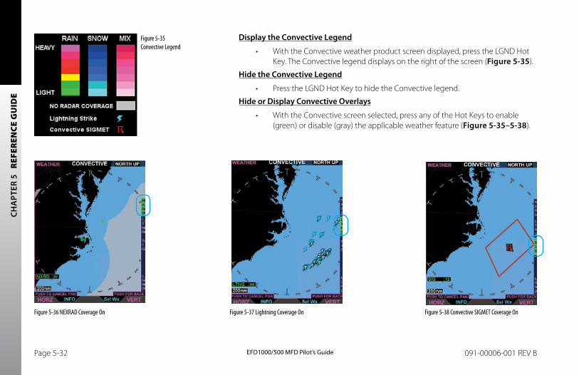
CH
APT
ER 5
R
EFER
ENCE
GU
IDE
EFD1000/500 MFD Pilot’s GuidePage 5-32 091-00006-001 REV B EFD1000/500 MFD Pilot’s Guide Page 5-33091-00006-001 REV B
Figure 5-35 Convective Legend
Display the Convective Legend
• With the Convective weather product screen displayed, press the LGND Hot Key. The Convective legend displays on the right of the screen (Figure 5-35).
Hide the Convective Legend
• Press the LGND Hot Key to hide the Convective legend.
Hide or Display Convective Overlays
• With the Convective screen selected, press any of the Hot Keys to enable (green) or disable (gray) the applicable weather feature (Figure 5-35–5-38).
Figure 5-36 NEXRAD Coverage On Figure 5-37 Lightning Coverage On Figure 5-38 Convective SIGMET Coverage On
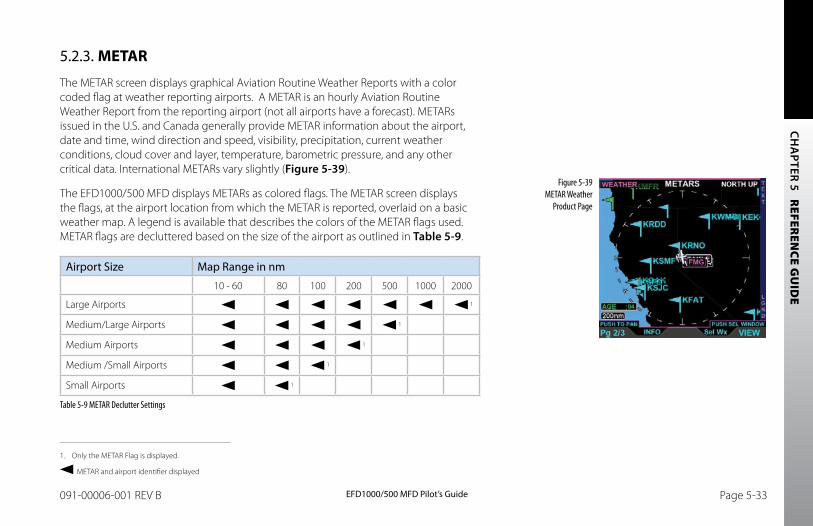
CH
APTER 5 R
EFEREN
CE GU
IDE
EFD1000/500 MFD Pilot’s GuidePage 5-32 091-00006-001 REV B EFD1000/500 MFD Pilot’s Guide Page 5-33091-00006-001 REV B
5.2.3. METAR
The METAR screen displays graphical Aviation Routine Weather Reports with a color coded flag at weather reporting airports. A METAR is an hourly Aviation Routine Weather Report from the reporting airport (not all airports have a forecast). METARs issued in the U.S. and Canada generally provide METAR information about the airport, date and time, wind direction and speed, visibility, precipitation, current weather conditions, cloud cover and layer, temperature, barometric pressure, and any other critical data. International METARs vary slightly (Figure 5-39).
The EFD1000/500 MFD displays METARs as colored flags. The METAR screen displays the flags, at the airport location from which the METAR is reported, overlaid on a basic weather map. A legend is available that describes the colors of the METAR flags used. METAR flags are decluttered based on the size of the airport as outlined in Table 5-9.
Airport Size Map Range in nm
10 - 60 80 100 200 500 1000 2000
Large Airports 1
Medium/Large Airports 1
Medium Airports 1
Medium /Small Airports 1
Small Airports 1
Table 5-9 METAR Declutter Settings
Figure 5-39 METAR Weather
Product Page
1. Only the METAR Flag is displayed.
METAR and airport identifier displayed
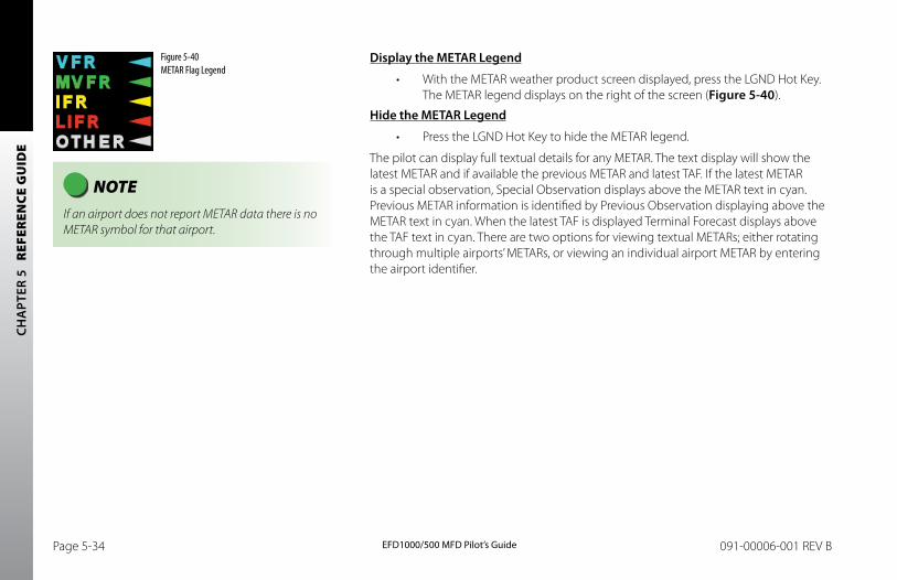
CH
APT
ER 5
R
EFER
ENCE
GU
IDE
EFD1000/500 MFD Pilot’s GuidePage 5-34 091-00006-001 REV B EFD1000/500 MFD Pilot’s Guide Page 5-35091-00006-001 REV B
Display the METAR Legend
• With the METAR weather product screen displayed, press the LGND Hot Key. The METAR legend displays on the right of the screen (Figure 5-40).
Hide the METAR Legend
• Press the LGND Hot Key to hide the METAR legend.
The pilot can display full textual details for any METAR. The text display will show the latest METAR and if available the previous METAR and latest TAF. If the latest METAR is a special observation, Special Observation displays above the METAR text in cyan. Previous METAR information is identified by Previous Observation displaying above the METAR text in cyan. When the latest TAF is displayed Terminal Forecast displays above the TAF text in cyan. There are two options for viewing textual METARs; either rotating through multiple airports’ METARs, or viewing an individual airport METAR by entering the airport identifier.
Figure 5-40 METAR Flag Legend
NOTE If an airport does not report METAR data there is no METAR symbol for that airport.
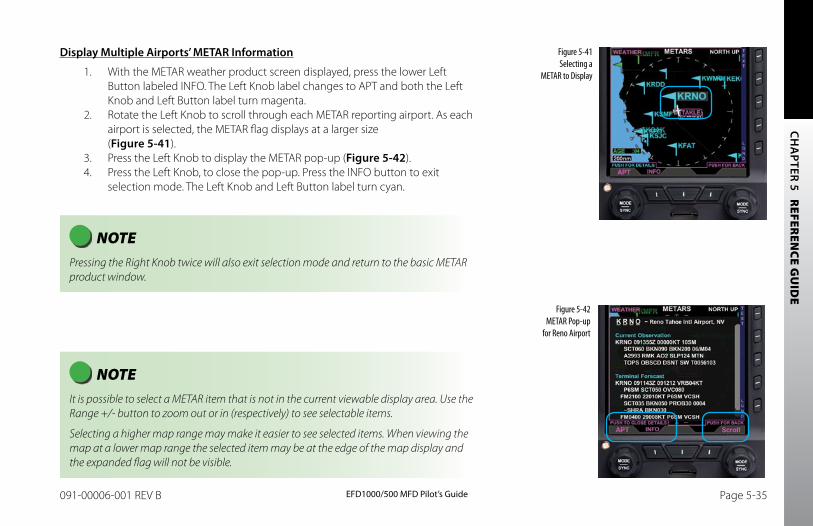
CH
APTER 5 R
EFEREN
CE GU
IDE
EFD1000/500 MFD Pilot’s GuidePage 5-34 091-00006-001 REV B EFD1000/500 MFD Pilot’s Guide Page 5-35091-00006-001 REV B
Display Multiple Airports’ METAR Information
1. With the METAR weather product screen displayed, press the lower Left Button labeled INFO. The Left Knob label changes to APT and both the Left Knob and Left Button label turn magenta.
2. Rotate the Left Knob to scroll through each METAR reporting airport. As each airport is selected, the METAR flag displays at a larger size (Figure 5-41).
3. Press the Left Knob to display the METAR pop-up (Figure 5-42).4. Press the Left Knob, to close the pop-up. Press the INFO button to exit
selection mode. The Left Knob and Left Button label turn cyan.
Figure 5-41 Selecting a
METAR to Display
Figure 5-42 METAR Pop-up
for Reno Airport
NOTE It is possible to select a METAR item that is not in the current viewable display area. Use the Range +/- button to zoom out or in (respectively) to see selectable items.
Selecting a higher map range may make it easier to see selected items. When viewing the map at a lower map range the selected item may be at the edge of the map display and the expanded flag will not be visible.
NOTE Pressing the Right Knob twice will also exit selection mode and return to the basic METAR product window.
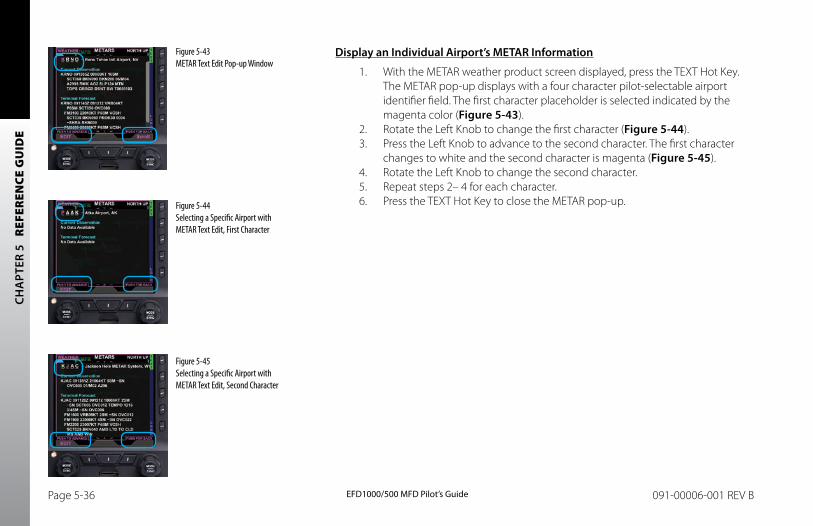
CH
APT
ER 5
R
EFER
ENCE
GU
IDE
EFD1000/500 MFD Pilot’s GuidePage 5-36 091-00006-001 REV B EFD1000/500 MFD Pilot’s Guide Page 5-37091-00006-001 REV B
Figure 5-45 Selecting a Specific Airport with METAR Text Edit, Second Character
Figure 5-44 Selecting a Specific Airport with METAR Text Edit, First Character
Figure 5-43 METAR Text Edit Pop-up Window
Display an Individual Airport’s METAR Information
1. With the METAR weather product screen displayed, press the TEXT Hot Key. The METAR pop-up displays with a four character pilot-selectable airport identifier field. The first character placeholder is selected indicated by the magenta color (Figure 5-43).
2. Rotate the Left Knob to change the first character (Figure 5-44).3. Press the Left Knob to advance to the second character. The first character
changes to white and the second character is magenta (Figure 5-45).4. Rotate the Left Knob to change the second character.5. Repeat steps 2– 4 for each character.6. Press the TEXT Hot Key to close the METAR pop-up.
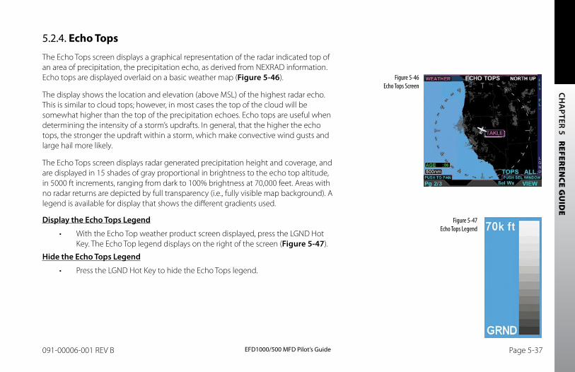
CH
APTER 5 R
EFEREN
CE GU
IDE
EFD1000/500 MFD Pilot’s GuidePage 5-36 091-00006-001 REV B EFD1000/500 MFD Pilot’s Guide Page 5-37091-00006-001 REV B
Figure 5-46 Echo Tops Screen
Figure 5-47 Echo Tops Legend
5.2.4. Echo Tops
The Echo Tops screen displays a graphical representation of the radar indicated top of an area of precipitation, the precipitation echo, as derived from NEXRAD information. Echo tops are displayed overlaid on a basic weather map (Figure 5-46).
The display shows the location and elevation (above MSL) of the highest radar echo. This is similar to cloud tops; however, in most cases the top of the cloud will be somewhat higher than the top of the precipitation echoes. Echo tops are useful when determining the intensity of a storm’s updrafts. In general, that the higher the echo tops, the stronger the updraft within a storm, which make convective wind gusts and large hail more likely.
The Echo Tops screen displays radar generated precipitation height and coverage, and are displayed in 15 shades of gray proportional in brightness to the echo top altitude, in 5000 ft increments, ranging from dark to 100% brightness at 70,000 feet. Areas with no radar returns are depicted by full transparency (i.e., fully visible map background). A legend is available for display that shows the different gradients used.
Display the Echo Tops Legend
• With the Echo Top weather product screen displayed, press the LGND Hot Key. The Echo Top legend displays on the right of the screen (Figure 5-47).
Hide the Echo Tops Legend
• Press the LGND Hot Key to hide the Echo Tops legend.

CH
APT
ER 5
R
EFER
ENCE
GU
IDE
EFD1000/500 MFD Pilot’s GuidePage 5-38 091-00006-001 REV B EFD1000/500 MFD Pilot’s Guide Page 5-39091-00006-001 REV B
The Echo Tops screen has an altitude filter, controlled by the Hot Keys, allowing the pilot to set the altitude for echo top display. Only echo tops at or above the selected altitude filter value will display. The pilot adjusts the altitude filter value by pressing either the FL + or the FL- Hot Key. The Echo Tops altitude filter increments up to 70,000 feet (displayed as TOPS >FL700). When the FL + Hot Key is pressed, the altitude filter advances to the next filter increment. When the FL- Hot Key is pressed, the altitude filter decreases to the next filter increment. The default setting is ALL or the previous setting.
Increase or Decrease Echo Top Altitude Filter
• Press the FL+ Hot Key to increase the altitude filter to the next altitude increment.
• Press the FL- Hot Key to decrease the altitude filter to the previous altitude increment.
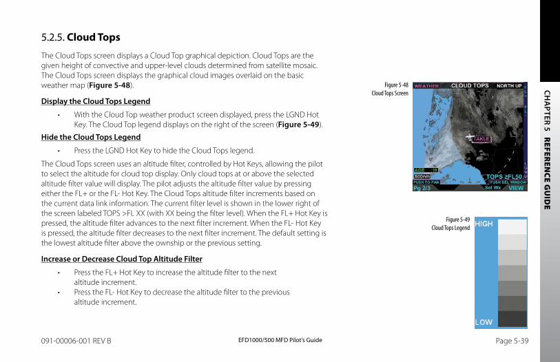
CH
APTER 5 R
EFEREN
CE GU
IDE
EFD1000/500 MFD Pilot’s GuidePage 5-38 091-00006-001 REV B EFD1000/500 MFD Pilot’s Guide Page 5-39091-00006-001 REV B
5.2.5. Cloud Tops
The Cloud Tops screen displays a Cloud Top graphical depiction. Cloud Tops are the given height of convective and upper-level clouds determined from satellite mosaic. The Cloud Tops screen displays the graphical cloud images overlaid on the basic weather map (Figure 5-48).
Display the Cloud Tops Legend
• With the Cloud Top weather product screen displayed, press the LGND Hot Key. The Cloud Top legend displays on the right of the screen (Figure 5-49).
Hide the Cloud Tops Legend
• Press the LGND Hot Key to hide the Cloud Tops legend.
The Cloud Tops screen uses an altitude filter, controlled by Hot Keys, allowing the pilot to select the altitude for cloud top display. Only cloud tops at or above the selected altitude filter value will display. The pilot adjusts the altitude filter value by pressing either the FL+ or the FL- Hot Key. The Cloud Tops altitude filter increments based on the current data link information. The current filter level is shown in the lower right of the screen labeled TOPS >FL XX (with XX being the filter level). When the FL+ Hot Key is pressed, the altitude filter advances to the next filter increment. When the FL- Hot Key is pressed, the altitude filter decreases to the next filter increment. The default setting is the lowest altitude filter above the ownship or the previous setting.
Increase or Decrease Cloud Top Altitude Filter
• Press the FL+ Hot Key to increase the altitude filter to the next altitude increment.
• Press the FL- Hot Key to decrease the altitude filter to the previous altitude increment.
Figure 5-48 Cloud Tops Screen
Figure 5-49 Cloud Tops Legend
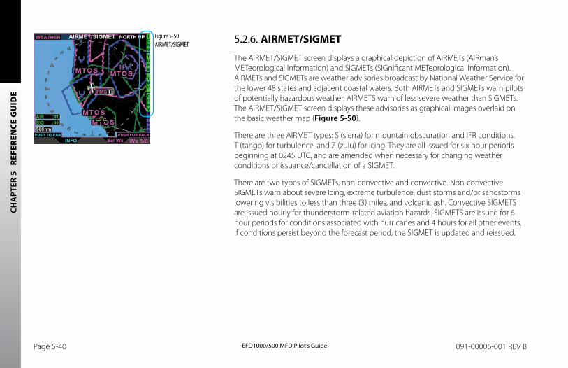
CH
APT
ER 5
R
EFER
ENCE
GU
IDE
EFD1000/500 MFD Pilot’s GuidePage 5-40 091-00006-001 REV B EFD1000/500 MFD Pilot’s Guide Page 5-41091-00006-001 REV B
5.2.6. AIRMET/SIGMET
The AIRMET/SIGMET screen displays a graphical depiction of AIRMETs (AIRman’s METeorological Information) and SIGMETs (SIGnificant METeorological Information). AIRMETs and SIGMETs are weather advisories broadcast by National Weather Service for the lower 48 states and adjacent coastal waters. Both AIRMETs and SIGMETs warn pilots of potentially hazardous weather. AIRMETS warn of less severe weather than SIGMETs. The AIRMET/SIGMET screen displays these advisories as graphical images overlaid on the basic weather map (Figure 5-50).
There are three AIRMET types: S (sierra) for mountain obscuration and IFR conditions, T (tango) for turbulence, and Z (zulu) for icing. They are all issued for six hour periods beginning at 0245 UTC, and are amended when necessary for changing weather conditions or issuance/cancellation of a SIGMET.
There are two types of SIGMETs, non-convective and convective. Non-convective SIGMETs warn about severe Icing, extreme turbulence, dust storms and/or sandstorms lowering visibilities to less than three (3) miles, and volcanic ash. Convective SIGMETS are issued hourly for thunderstorm-related aviation hazards. SIGMETS are issued for 6 hour periods for conditions associated with hurricanes and 4 hours for all other events. If conditions persist beyond the forecast period, the SIGMET is updated and reissued.
Figure 5-50 AIRMET/SIGMET
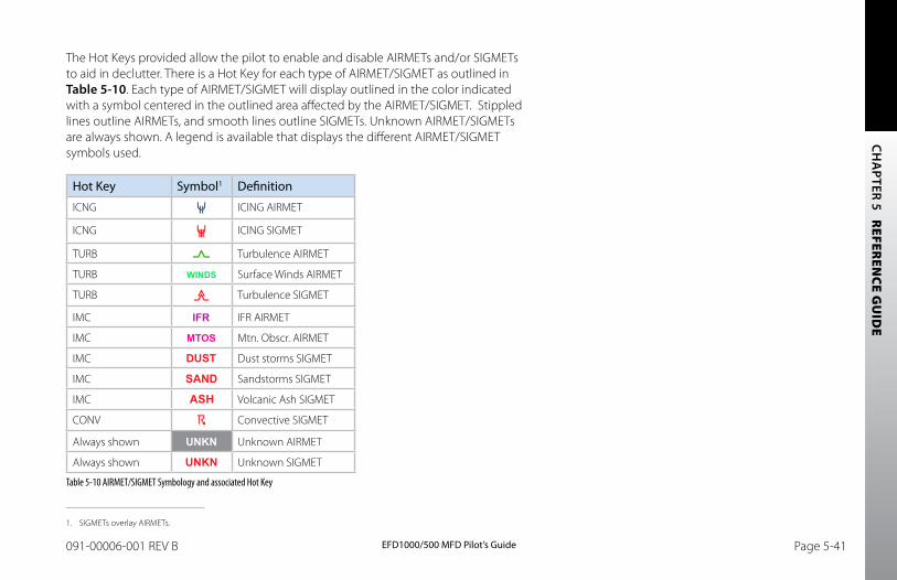
CH
APTER 5 R
EFEREN
CE GU
IDE
EFD1000/500 MFD Pilot’s GuidePage 5-40 091-00006-001 REV B EFD1000/500 MFD Pilot’s Guide Page 5-41091-00006-001 REV B
The Hot Keys provided allow the pilot to enable and disable AIRMETs and/or SIGMETs to aid in declutter. There is a Hot Key for each type of AIRMET/SIGMET as outlined in Table 5-10. Each type of AIRMET/SIGMET will display outlined in the color indicated with a symbol centered in the outlined area affected by the AIRMET/SIGMET. Stippled lines outline AIRMETs, and smooth lines outline SIGMETs. Unknown AIRMET/SIGMETs are always shown. A legend is available that displays the different AIRMET/SIGMET symbols used.
Hot Key Symbol1 Definition
ICNG ICING AIRMET
ICNG ICING SIGMET
TURB Turbulence AIRMET
TURB Surface Winds AIRMET
TURB Turbulence SIGMET
IMC IFR AIRMET
IMC Mtn. Obscr. AIRMET
IMC Dust storms SIGMET
IMC Sandstorms SIGMET
IMC Volcanic Ash SIGMET
CONV Convective SIGMET
Always shown Unknown AIRMET
Always shown Unknown SIGMET
Table 5-10 AIRMET/SIGMET Symbology and associated Hot Key
1. SIGMETs overlay AIRMETs.
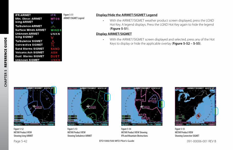
CH
APT
ER 5
R
EFER
ENCE
GU
IDE
EFD1000/500 MFD Pilot’s GuidePage 5-42 091-00006-001 REV B EFD1000/500 MFD Pilot’s Guide Page 5-43091-00006-001 REV B
Display/Hide the AIRMET/SIGMET Legend
• With the AIRMET/SIGMET weather product screen displayed, press the LGND Hot Key. A legend displays. Press the LGND Hot Key again to hide the legend (Figure 5-51).
Display AIRMET/SIGMET
• With the AIRMET/SIGMET screen displayed and selected, press any of the Hot Keys to display or hide the applicable overlay (Figure 5-52 – 5-55).
Figure 5-51 AIRMET/SIGMET Legend
Figure 5-52 METAR Product VIEW Showing Icing AIRMET
Figure 5-53 METAR Product VIEW Showing Turbulence AIRMET
Figure 5-54 METAR Product VIEW Showing IFR and Mountain Obstructions
Figure 5-55 METAR Product VIEW Showing Convective SIGMET
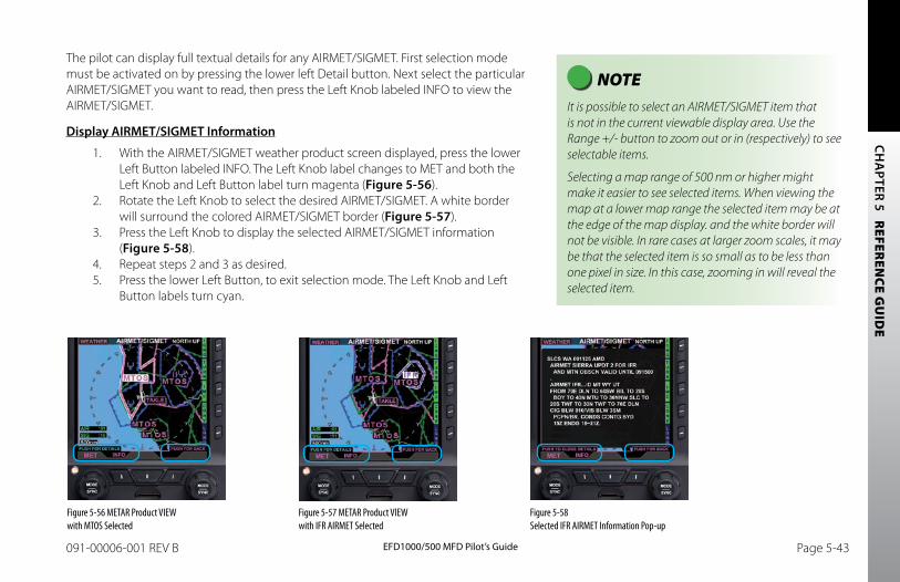
CH
APTER 5 R
EFEREN
CE GU
IDE
EFD1000/500 MFD Pilot’s GuidePage 5-42 091-00006-001 REV B EFD1000/500 MFD Pilot’s Guide Page 5-43091-00006-001 REV B
The pilot can display full textual details for any AIRMET/SIGMET. First selection mode must be activated on by pressing the lower left Detail button. Next select the particular AIRMET/SIGMET you want to read, then press the Left Knob labeled INFO to view the AIRMET/SIGMET.
Display AIRMET/SIGMET Information
1. With the AIRMET/SIGMET weather product screen displayed, press the lower Left Button labeled INFO. The Left Knob label changes to MET and both the Left Knob and Left Button label turn magenta (Figure 5-56).
2. Rotate the Left Knob to select the desired AIRMET/SIGMET. A white border will surround the colored AIRMET/SIGMET border (Figure 5-57).
3. Press the Left Knob to display the selected AIRMET/SIGMET information (Figure 5-58).
4. Repeat steps 2 and 3 as desired. 5. Press the lower Left Button, to exit selection mode. The Left Knob and Left
Button labels turn cyan.
NOTE It is possible to select an AIRMET/SIGMET item that is not in the current viewable display area. Use the Range +/- button to zoom out or in (respectively) to see selectable items.
Selecting a map range of 500 nm or higher might make it easier to see selected items. When viewing the map at a lower map range the selected item may be at the edge of the map display. and the white border will not be visible. In rare cases at larger zoom scales, it may be that the selected item is so small as to be less than one pixel in size. In this case, zooming in will reveal the selected item.
Figure 5-56 METAR Product VIEW with MTOS Selected
Figure 5-57 METAR Product VIEW with IFR AIRMET Selected
Figure 5-58 Selected IFR AIRMET Information Pop-up
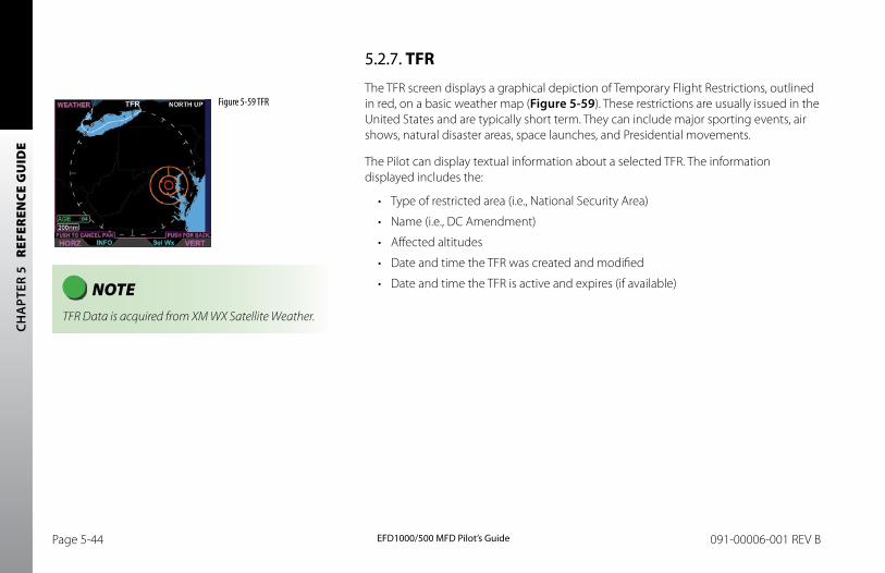
CH
APT
ER 5
R
EFER
ENCE
GU
IDE
EFD1000/500 MFD Pilot’s GuidePage 5-44 091-00006-001 REV B EFD1000/500 MFD Pilot’s Guide Page 5-45091-00006-001 REV B
5.2.7. TFR
The TFR screen displays a graphical depiction of Temporary Flight Restrictions, outlined in red, on a basic weather map (Figure 5-59). These restrictions are usually issued in the United States and are typically short term. They can include major sporting events, air shows, natural disaster areas, space launches, and Presidential movements.
The Pilot can display textual information about a selected TFR. The information displayed includes the:
• Type of restricted area (i.e., National Security Area)
• Name (i.e., DC Amendment)
• Affected altitudes
• Date and time the TFR was created and modified
• Date and time the TFR is active and expires (if available)
Figure 5-59 TFR
NOTE TFR Data is acquired from XM WX Satellite Weather.
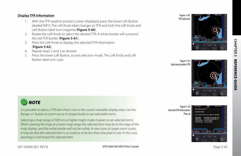
CH
APTER 5 R
EFEREN
CE GU
IDE
EFD1000/500 MFD Pilot’s GuidePage 5-44 091-00006-001 REV B EFD1000/500 MFD Pilot’s Guide Page 5-45091-00006-001 REV B
Display TFR Information
1. With the TFR weather product screen displayed, press the lower Left Button labeled INFO. The Left Knob label changes to TFR and both the Left Knob and Left Button label turn magenta (Figure 5-60).
2. Rotate the Left Knob to select the desired TFR. A white border will surround the red TFR border (Figure 5-61).
3. Press the Left Knob to display the selected TFR information (Figure 5-62).
4. Repeat steps 2 and 3 as desired. 5. Press the lower Left Button, to exit selection mode. The Left Knob and Left
Button label turn cyan.
NOTE It is possible to select a TFR item that is not in the current viewable display area. Use the Range +/- button to zoom out or in (respectively) to see selectable items.
Selecting a map range of 500 nm or higher might make it easier to see selected items. When viewing the map at a lower map range the selected item may be at the edge of the map display. and the white border will not be visible. In rare cases at larger zoom scales, it may be that the selected item is so small as to be less than one pixel in size. In this case, zooming in will reveal the selected item.
Figure 5-60 TFR Selected
Figure 5-61 Selecting Another TFR
Figure 5-62 Selected TFR Information
Pop-up
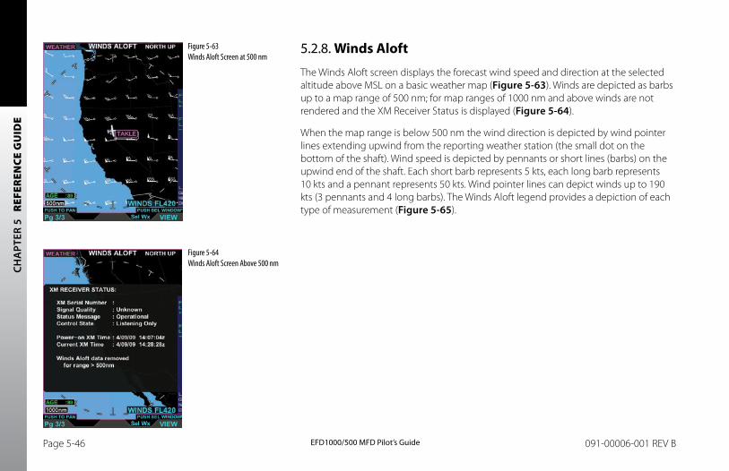
CH
APT
ER 5
R
EFER
ENCE
GU
IDE
EFD1000/500 MFD Pilot’s GuidePage 5-46 091-00006-001 REV B EFD1000/500 MFD Pilot’s Guide Page 5-47091-00006-001 REV B
5.2.8. Winds Aloft
The Winds Aloft screen displays the forecast wind speed and direction at the selected altitude above MSL on a basic weather map (Figure 5-63). Winds are depicted as barbs up to a map range of 500 nm; for map ranges of 1000 nm and above winds are not rendered and the XM Receiver Status is displayed (Figure 5-64).
When the map range is below 500 nm the wind direction is depicted by wind pointer lines extending upwind from the reporting weather station (the small dot on the bottom of the shaft). Wind speed is depicted by pennants or short lines (barbs) on the upwind end of the shaft. Each short barb represents 5 kts, each long barb represents 10 kts and a pennant represents 50 kts. Wind pointer lines can depict winds up to 190 kts (3 pennants and 4 long barbs). The Winds Aloft legend provides a depiction of each type of measurement (Figure 5-65).
Figure 5-63 Winds Aloft Screen at 500 nm
Figure 5-64 Winds Aloft Screen Above 500 nm
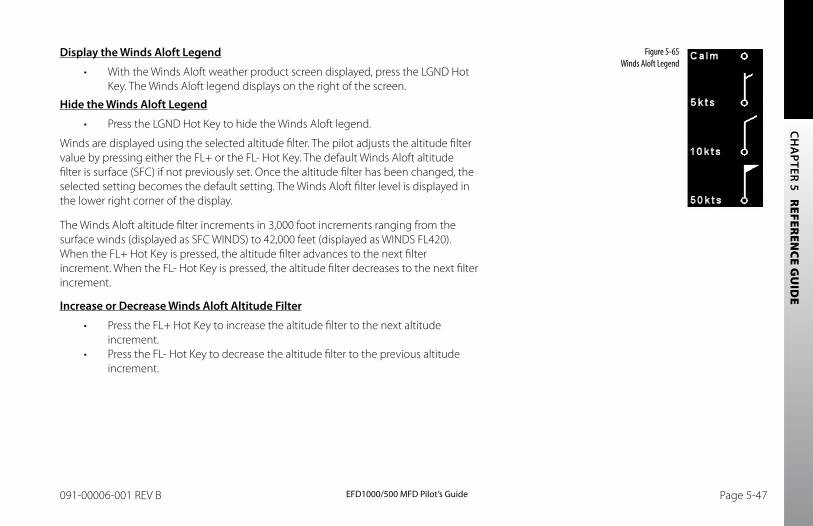
CH
APTER 5 R
EFEREN
CE GU
IDE
EFD1000/500 MFD Pilot’s GuidePage 5-46 091-00006-001 REV B EFD1000/500 MFD Pilot’s Guide Page 5-47091-00006-001 REV B
Display the Winds Aloft Legend
• With the Winds Aloft weather product screen displayed, press the LGND Hot Key. The Winds Aloft legend displays on the right of the screen.
Hide the Winds Aloft Legend
• Press the LGND Hot Key to hide the Winds Aloft legend.
Winds are displayed using the selected altitude filter. The pilot adjusts the altitude filter value by pressing either the FL+ or the FL- Hot Key. The default Winds Aloft altitude filter is surface (SFC) if not previously set. Once the altitude filter has been changed, the selected setting becomes the default setting. The Winds Aloft filter level is displayed in the lower right corner of the display.
The Winds Aloft altitude filter increments in 3,000 foot increments ranging from the surface winds (displayed as SFC WINDS) to 42,000 feet (displayed as WINDS FL420). When the FL+ Hot Key is pressed, the altitude filter advances to the next filter increment. When the FL- Hot Key is pressed, the altitude filter decreases to the next filter increment.
Increase or Decrease Winds Aloft Altitude Filter
• Press the FL+ Hot Key to increase the altitude filter to the next altitude increment.
• Press the FL- Hot Key to decrease the altitude filter to the previous altitude increment.
Figure 5-65 Winds Aloft Legend
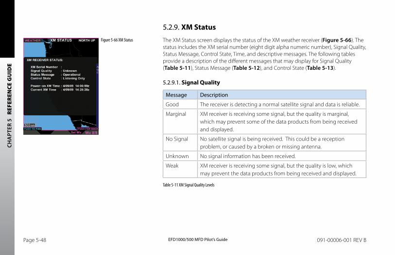
CH
APT
ER 5
R
EFER
ENCE
GU
IDE
EFD1000/500 MFD Pilot’s GuidePage 5-48 091-00006-001 REV B EFD1000/500 MFD Pilot’s Guide Page 5-49091-00006-001 REV B
5.2.9. XM Status
The XM Status screen displays the status of the XM weather receiver (Figure 5-66). The status includes the XM serial number (eight digit alpha numeric number), Signal Quality, Status Message, Control State, Time, and descriptive messages. The following tables provide a description of the different messages that may display for Signal Quality (Table 5-11), Status Message (Table 5-12), and Control State (Table 5-13).
5.2.9.1. Signal Quality
Message Description
Good The receiver is detecting a normal satellite signal and data is reliable.
Marginal XM receiver is receiving some signal, but the quality is marginal, which may prevent some of the data products from being received and displayed.
No Signal No satellite signal is being received. This could be a reception problem, or caused by a broken or missing antenna.
Unknown No signal information has been received.
Weak XM receiver is receiving some signal, but the quality is low, which may prevent the data products from being received and displayed.
Table 5-11 XM Signal Quality Levels
Figure 5-66 XM Status
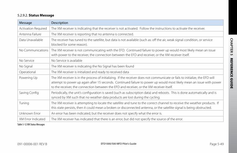
CH
APTER 5 R
EFEREN
CE GU
IDE
EFD1000/500 MFD Pilot’s GuidePage 5-48 091-00006-001 REV B EFD1000/500 MFD Pilot’s Guide Page 5-49091-00006-001 REV B
5.2.9.2. Status Message
Message Description
Activation Required The XM receiver is indicating that the receiver is not activated. Follow the instructions to activate the receiver.
Antenna Failure The XM receiver is reporting that no antenna is connected.
Data Unavailable The receiver has tuned to the satellite, but data is not available (such as: off the air, weak signal condition, or service blocked for some reason).
No Communications The XM receiver is not communicating with the EFD. Continued failure to power up would most likely mean an issue with power to the receiver, the connection between the EFD and receiver, or the XM receiver itself.
No Service No Service is available
No Signal The XM receiver is indicating the No Signal has been found
Operational The XM receiver is initialized and ready to received data
Powering Up The XM receiver is in the process of initializing. If the receiver does not communicate or fails to initialize, the EFD will attempt to power up again after 15 seconds. Continued failure to power up would most likely mean an issue with power to the receiver, the connection between the EFD and receiver, or the XM receiver itself.
Saving Config Periodically, the unit’s configuration is saved (such as subscription data) and reboots. This is done automatically and is synced by XM such that no weather data products are lost during the cycling.
Tuning The XM receiver is attempting to locate the satellite and tune to the correct channel to receive the weather products. If this state persists, then it could mean a broken or disconnected antenna, or the satellite signal is being obstructed.
Unknown Error An error has been indicated, but the receiver does not specify what the error is.
XM Error Indicated The XM receiver has indicated that there is an error, but did not specify the source of the error.Table 5-12 XM Status Messages
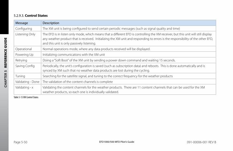
CH
APT
ER 5
R
EFER
ENCE
GU
IDE
EFD1000/500 MFD Pilot’s GuidePage 5-50 091-00006-001 REV B EFD1000/500 MFD Pilot’s Guide Page 5-51091-00006-001 REV B
5.2.9.3. Control States
Message Description
Configuring The XM unit is being configured to send certain periodic messages (such as signal quality and time)
Listening Only The EFD is in listen only mode, which means that a different EFD is controlling the XM receiver, but this unit will still display any weather product that is received. Initializing the XM unit and responding to errors is the responsibility of the other EFD, and this unit is only passively listening.
Operational Normal operations mode, where any data products received will be displayed.
Powering Up Initializing communications with the XM unit
Retrying Doing a “Soft Boot” of the XM unit by sending a power down command and waiting 15 seconds.
Saving Config Periodically, the unit’s configuration is saved (such as subscription data) and reboots. This is done automatically and is synced by XM such that no weather data products are lost during the cycling.
Tuning Searching for the satellite signal, and tuning to the correct frequency for the weather products
Validating - Done The validation of the content channels is complete
Validating - x Validating the content channels for the weather products. There are 11 content channels that can be used for the XM weather products, so each one is individually validated.
Table 5-13 XM Control States
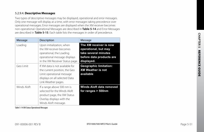
CH
APTER 5 R
EFEREN
CE GU
IDE
EFD1000/500 MFD Pilot’s GuidePage 5-50 091-00006-001 REV B EFD1000/500 MFD Pilot’s Guide Page 5-51091-00006-001 REV B
5.2.9.4. Descriptive MessagesTwo types of descriptive messages may be displayed, operational and error messages. Only one message will display at a time, with error messages taking precedence over operational messages. Error messages are displayed when the XM receiver becomes non-operational. Operational Messages are described in Table 5-14 and Error Messages are described in Table 5-15. Each table lists the messages in order of precedence.
Message Description Message
Loading Upon initialization, when the XM receiver becomes operational, the Loading operational message displays in the XM Receiver Status page.
The XM receiver is now operational, but may take several minutes before data products are displayed.
Geo Limit If XM data is not available for the current position, the Geo Limit operational message displays on all selected Data Link Weather pages.
Geographic limitation: XM Weather is not available
Winds Aloft If a range above 500 nm is selected for the Winds Aloft product page, the XM Status Overlay displays with the Winds Aloft message.
Winds Aloft data removed for ranges > 500nm
Table 5-14 XM Status Operational Messages
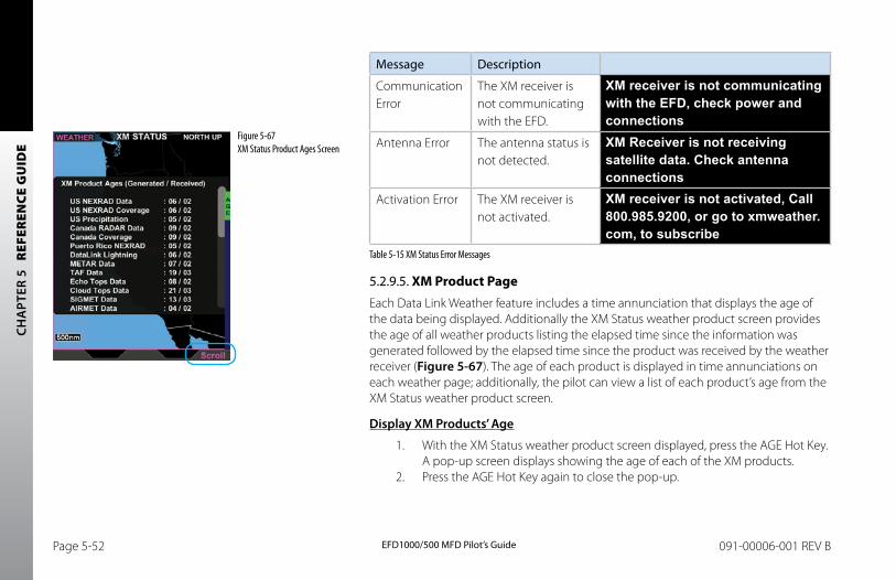
CH
APT
ER 5
R
EFER
ENCE
GU
IDE
EFD1000/500 MFD Pilot’s GuidePage 5-52 091-00006-001 REV B EFD1000/500 MFD Pilot’s Guide Page 5-53091-00006-001 REV B
Message Description
Communication Error
The XM receiver is not communicating with the EFD.
XM receiver is not communicating with the EFD, check power and connections
Antenna Error The antenna status is not detected.
XM Receiver is not receiving satellite data. Check antenna connections
Activation Error The XM receiver is not activated.
XM receiver is not activated, Call 800.985.9200, or go to xmweather.com, to subscribe
Table 5-15 XM Status Error Messages
5.2.9.5. XM Product PageEach Data Link Weather feature includes a time annunciation that displays the age of the data being displayed. Additionally the XM Status weather product screen provides the age of all weather products listing the elapsed time since the information was generated followed by the elapsed time since the product was received by the weather receiver (Figure 5-67). The age of each product is displayed in time annunciations on each weather page; additionally, the pilot can view a list of each product’s age from the XM Status weather product screen.
Display XM Products’ Age
1. With the XM Status weather product screen displayed, press the AGE Hot Key. A pop-up screen displays showing the age of each of the XM products.
2. Press the AGE Hot Key again to close the pop-up.
Figure 5-67 XM Status Product Ages Screen
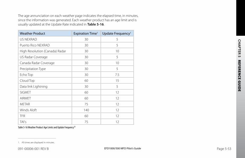
CH
APTER 5 R
EFEREN
CE GU
IDE
EFD1000/500 MFD Pilot’s GuidePage 5-52 091-00006-001 REV B EFD1000/500 MFD Pilot’s Guide Page 5-53091-00006-001 REV B
The age annunciation on each weather page indicates the elapsed time, in minutes, since the information was generated. Each weather product has an age limit and is usually updated at the Update Rate indicated in Table 5-16.
Weather Product Expiration Time1 Update Frequency1
US NEXRAD 30 5
Puerto Rico NEXRAD 30 5
High Resolution (Canada) Radar 30 10
US Radar Coverage 30 5
Canada Radar Coverage 30 10
Precipitation Type 30 5
Echo Top 30 7.5
Cloud Top 60 15
Data link Lightning 30 5
SIGMET 60 12
AIRMET 60 12
METAR 75 12
Winds Aloft 140 12
TFR 60 12
TAFs 75 12Table 5-16 Weather Product Age Limits and Update Frequency
1. All times are displayed in minutes.
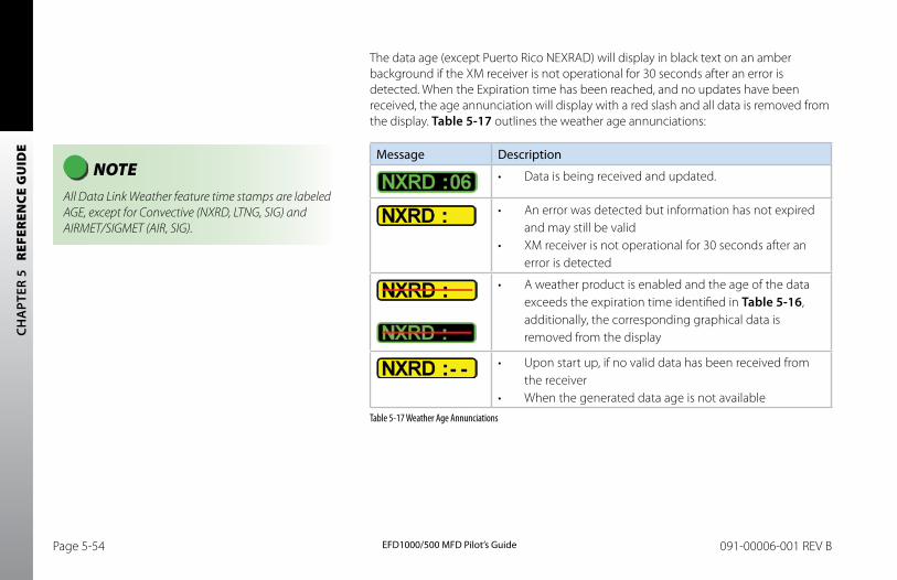
CH
APT
ER 5
R
EFER
ENCE
GU
IDE
EFD1000/500 MFD Pilot’s GuidePage 5-54 091-00006-001 REV B EFD1000/500 MFD Pilot’s Guide Page 5-55091-00006-001 REV B
The data age (except Puerto Rico NEXRAD) will display in black text on an amber background if the XM receiver is not operational for 30 seconds after an error is detected. When the Expiration time has been reached, and no updates have been received, the age annunciation will display with a red slash and all data is removed from the display. Table 5-17 outlines the weather age annunciations:
Message Description
• Data is being received and updated.
• An error was detected but information has not expired and may still be valid
• XM receiver is not operational for 30 seconds after an error is detected
• A weather product is enabled and the age of the data
exceeds the expiration time identified in Table 5-16, additionally, the corresponding graphical data is removed from the display
• Upon start up, if no valid data has been received from the receiver
• When the generated data age is not availableTable 5-17 Weather Age Annunciations
NOTE All Data Link Weather feature time stamps are labeled AGE, except for Convective (NXRD, LTNG, SIG) and AIRMET/SIGMET (AIR, SIG).
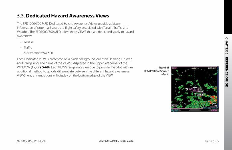
CH
APTER 5 R
EFEREN
CE GU
IDE
EFD1000/500 MFD Pilot’s GuidePage 5-54 091-00006-001 REV B EFD1000/500 MFD Pilot’s Guide Page 5-55091-00006-001 REV B
5.3. Dedicated Hazard Awareness ViewsThe EFD1000/500 MFD Dedicated Hazard Awareness Views provide advisory information of potential hazards to flight safety associated with Terrain, Traffic, and Weather. The EFD1000/500 MFD offers three VIEWS that are dedicated solely to hazard awareness:
• Terrain
• Traffic
• Stormscope® WX-500
Each Dedicated VIEW is presented on a black background, oriented Heading-Up with a full-range ring. The name of the VIEW is displayed in the upper left corner of the WINDOW (Figure 5-68). Each VIEW’s range ring is unique to provide the pilot with an additional method to quickly differentiate between the different hazard awareness VIEWS. Any annunciations will display on the bottom edge of the VIEW.
Figure 5-68 Dedicated Hazard Awareness
– Terrain
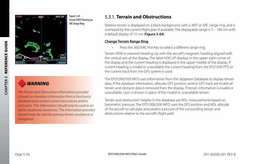
CH
APT
ER 5
R
EFER
ENCE
GU
IDE
EFD1000/500 MFD Pilot’s GuidePage 5-56 091-00006-001 REV B EFD1000/500 MFD Pilot’s Guide Page 5-57091-00006-001 REV B
5.3.1. Terrain and Obstructions
Relative terrain is displayed on a black background, with a 360° or ARC range ring, and is overlayed by the current flight plan if available. The displayable range is 5 – 100 nm with a default display of 15 nm (Figure 5-69).
Change Terrain Range Ring
• Press the 360/ARC Hot Key to select a different range ring.
Terrain VIEW is oriented Heading-Up with the aircraft’s magnetic heading aligned with the vertical axis of the display. The label HDG UP displays in the upper right corner of the display and the current heading is displayed in the upper middle of the display. If current heading is invalid or unavailable the current heading from the EFD1000 PFD or the current track from the GPS system is used.
The EFD1000/500 MFD uses information from the Jeppesen Database to display terrain data. If the database information, altitude, GPS position, and/or GPS track are invalid all terrain and obstacle data is removed from the display. If terrain information is invalid or unavailable, cyan is shown in place of the invalid or unavailable terrain
Terrain and obstruction heights in the database are MSL measurements based on barometric pressure. The EFD1000/500 MFD uses the GPS position and MSL altitude of the aircraft to calculate and predict a picture of the surrounding terrain and obstructions relative to the aircraft’s flight path.
Figure 5-69 Terrain VIEW Showing an ARC Range Ring
WARNING The Terrain and Obstruction information provided is based on elevation information from a third party database and contains some inaccuracies and/or omissions. This information should only be used as an aid to situational awareness. The information provided should never be used for primary terrain avoidance or navigation.
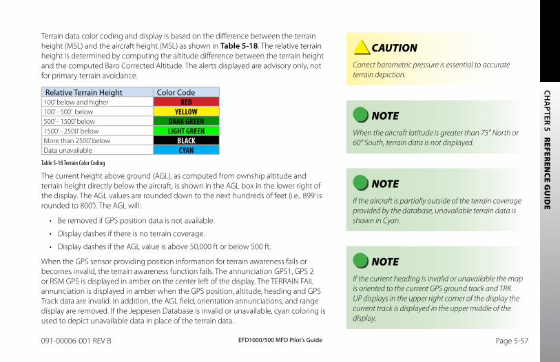
CH
APTER 5 R
EFEREN
CE GU
IDE
EFD1000/500 MFD Pilot’s GuidePage 5-56 091-00006-001 REV B EFD1000/500 MFD Pilot’s Guide Page 5-57091-00006-001 REV B
Terrain data color coding and display is based on the difference between the terrain height (MSL) and the aircraft height (MSL) as shown in Table 5-18. The relative terrain height is determined by computing the altitude difference between the terrain height and the computed Baro Corrected Altitude. The alerts displayed are advisory only, not for primary terrain avoidance.
Relative Terrain Height Color Code100’ below and higher RED100’ - 500’ below YELLOW500’ - 1500’ below DARK GREEN1500’ - 2500’ below LIGHT GREENMore than 2500’ below BLACKData unavailable CYAN
Table 5-18 Terrain Color Coding
The current height above ground (AGL), as computed from ownship altitude and terrain height directly below the aircraft, is shown in the AGL box in the lower right of the display. The AGL values are rounded down to the next hundreds of feet (i.e., 899’ is rounded to 800’). The AGL will:
• Be removed if GPS position data is not available.
• Display dashes if there is no terrain coverage.
• Display dashes if the AGL value is above 50,000 ft or below 500 ft.
When the GPS sensor providing position information for terrain awareness fails or becomes invalid, the terrain awareness function fails. The annunciation GPS1, GPS 2 or RSM GPS is displayed in amber on the center left of the display. The TERRAIN FAIL annunciation is displayed in amber when the GPS position, altitude, heading and GPS Track data are invalid. In addition, the AGL field, orientation annunciations, and range display are removed. If the Jeppesen Database is invalid or unavailable, cyan coloring is used to depict unavailable data in place of the terrain data.
NOTE When the aircraft latitude is greater than 75° North or 60° South, terrain data is not displayed.
NOTE If the aircraft is partially outside of the terrain coverage provided by the database, unavailable terrain data is shown in Cyan.
CAUTION Correct barometric pressure is essential to accurate terrain depiction.
NOTE If the current heading is invalid or unavailable the map is oriented to the current GPS ground track and TRK UP displays in the upper right corner of the display the current track is displayed in the upper middle of the display.
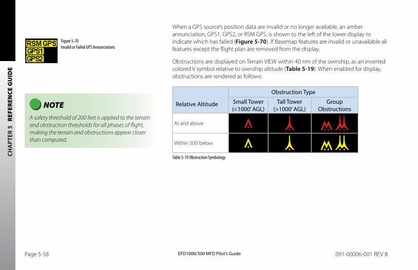
CH
APT
ER 5
R
EFER
ENCE
GU
IDE
EFD1000/500 MFD Pilot’s GuidePage 5-58 091-00006-001 REV B EFD1000/500 MFD Pilot’s Guide Page 5-59091-00006-001 REV B
When a GPS source’s position data are invalid or no longer available, an amber annunciation, GPS1, GPS2, or RSM GPS, is shown to the left of the lower display to indicate which has failed (Figure 5-70). If Basemap features are invalid or unavailable all features except the flight plan are removed from the display.
Obstructions are displayed on Terrain VIEW within 40 nm of the ownship, as an inverted colored V symbol relative to ownship altitude (Table 5-19). When enabled for display, obstructions are rendered as follows:
Relative Altitude
Obstruction Type
Small Tower (<1000’ AGL)
Tall Tower (>1000’ AGL)
Group Obstructions
At and above
Within 500’ below
Table 5-19 Obstruction Symbology
NOTE A safety threshold of 200 feet is applied to the terrain and obstruction thresholds for all phases of flight, making the terrain and obstructions appear closer than computed.
Figure 5-70 Invalid or Failed GPS Annunciations
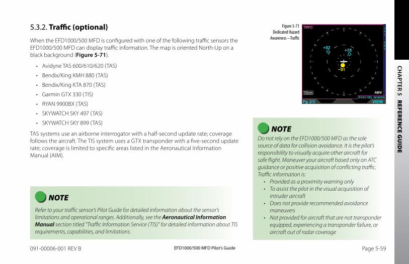
CH
APTER 5 R
EFEREN
CE GU
IDE
EFD1000/500 MFD Pilot’s GuidePage 5-58 091-00006-001 REV B EFD1000/500 MFD Pilot’s Guide Page 5-59091-00006-001 REV B
5.3.2. Traffic (optional)
When the EFD1000/500 MFD is configured with one of the following traffic sensors the EFD1000/500 MFD can display traffic information. The map is oriented North-Up on a black background (Figure 5-71).
• Avidyne TAS 600/610/620 (TAS)
• Bendix/King KMH 880 (TAS)
• Bendix/King KTA 870 (TAS)
• Garmin GTX 330 (TIS)
• RYAN 9900BX (TAS)
• SKYWATCH SKY 497 (TAS)
• SKYWATCH SKY 899 (TAS)
TAS systems use an airborne interrogator with a half-second update rate; coverage follows the aircraft. The TIS system uses a GTX transponder with a five-second update rate; coverage is limited to specific areas listed in the Aeronautical Information Manual (AIM).
Figure 5-71 Dedicated Hazard
Awareness – Traffic
NOTE Do not rely on the EFD1000/500 MFD as the sole source of data for collision avoidance. It is the pilot’s responsibility to visually acquire other aircraft for safe flight. Maneuver your aircraft based only on ATC guidance or positive acquisition of conflicting traffic. Traffic information is:• Provided as a proximity warning only• To assist the pilot in the visual acquisition of
intruder aircraft• Does not provide recommended avoidance
maneuvers • Not provided for aircraft that are not transponder
equipped, experiencing a transponder failure, or aircraft out of radar coverage
NOTE Refer to your traffic sensor’s Pilot Guide for detailed information about the sensor’s limitations and operational ranges. Additionally, see the Aeronautical Information Manual section titled “Traffic Information Service (TIS)” for detailed information about TIS requirements, capabilities, and limitations.
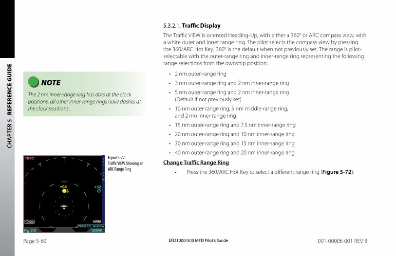
CH
APT
ER 5
R
EFER
ENCE
GU
IDE
EFD1000/500 MFD Pilot’s GuidePage 5-60 091-00006-001 REV B EFD1000/500 MFD Pilot’s Guide Page 5-61091-00006-001 REV B
5.3.2.1. Traffic DisplayThe Traffic VIEW is oriented Heading-Up, with either a 360° or ARC compass view, with a white outer and inner range ring. The pilot selects the compass view by pressing the 360/ARC Hot Key; 360° is the default when not previously set. The range is pilot-selectable with the outer-range ring and inner-range ring representing the following range selections from the ownship position:
• 2 nm outer-range ring
• 3 nm outer-range ring and 2 nm inner-range ring
• 5 nm outer-range ring and 2 nm inner-range ring (Default if not previously set)
• 10 nm outer-range ring, 5 nm middle-range ring, and 2 nm inner-range ring
• 15 nm outer-range ring and 7.5 nm inner-range ring
• 20 nm outer-range ring and 10 nm inner-range ring
• 30 nm outer-range ring and 15 nm inner-range ring
• 40 nm outer-range ring and 20 nm inner-range ring
Change Traffic Range Ring
• Press the 360/ARC Hot Key to select a different range ring (Figure 5-72).
NOTE The 2 nm inner-range ring has dots at the clock positions; all other inner-range rings have dashes at the clock positions. .
Figure 5-72 Traffic VIEW Showing an ARC Range Ring
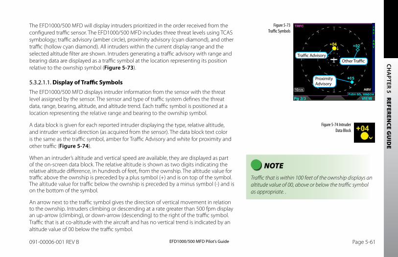
CH
APTER 5 R
EFEREN
CE GU
IDE
EFD1000/500 MFD Pilot’s GuidePage 5-60 091-00006-001 REV B EFD1000/500 MFD Pilot’s Guide Page 5-61091-00006-001 REV B
The EFD1000/500 MFD will display intruders prioritized in the order received from the configured traffic sensor. The EFD1000/500 MFD includes three threat levels using TCAS symbology; traffic advisory (amber circle), proximity advisory (cyan diamond), and other traffic (hollow cyan diamond). All intruders within the current display range and the selected altitude filter are shown. Intruders generating a traffic advisory with range and bearing data are displayed as a traffic symbol at the location representing its position relative to the ownship symbol (Figure 5-73).
5.3.2.1.1. Display of Traffic SymbolsThe EFD1000/500 MFD displays intruder information from the sensor with the threat level assigned by the sensor. The sensor and type of traffic system defines the threat data, range, bearing, altitude, and altitude trend. Each traffic symbol is positioned at a location representing the relative range and bearing to the ownship symbol.
A data block is given for each reported intruder displaying the type, relative altitude, and intruder vertical direction (as acquired from the sensor). The data block text color is the same as the traffic symbol, amber for Traffic Advisory and white for proximity and other traffic (Figure 5-74).
When an intruder’s altitude and vertical speed are available, they are displayed as part of the on-screen data block. The relative altitude is shown as two digits indicating the relative altitude difference, in hundreds of feet, from the ownship. The altitude value for traffic above the ownship is preceded by a plus symbol (+) and is on top of the symbol. The altitude value for traffic below the ownship is preceded by a minus symbol (-) and is on the bottom of the symbol.
An arrow next to the traffic symbol gives the direction of vertical movement in relation to the ownship. Intruders climbing or descending at a rate greater than 500 fpm display an up-arrow (climbing), or down-arrow (descending) to the right of the traffic symbol. Traffic that is at co-altitude with the aircraft and has no vertical trend is indicated by an altitude value of 00 below the traffic symbol.
Figure 5-73 Traffic Symbols
Figure 5-74 Intruder Data Block
Traffic Advisory
Proximity Advisory
Other Traffic
NOTE Traffic that is within 100 feet of the ownship displays an altitude value of 00, above or below the traffic symbol as appropriate. .
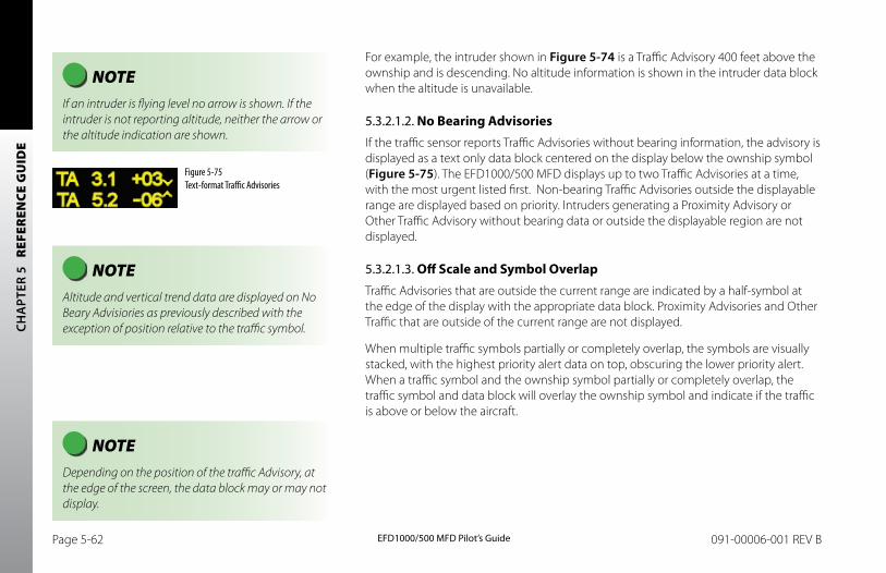
CH
APT
ER 5
R
EFER
ENCE
GU
IDE
EFD1000/500 MFD Pilot’s GuidePage 5-62 091-00006-001 REV B EFD1000/500 MFD Pilot’s Guide Page 5-63091-00006-001 REV B
For example, the intruder shown in Figure 5-74 is a Traffic Advisory 400 feet above the ownship and is descending. No altitude information is shown in the intruder data block when the altitude is unavailable.
5.3.2.1.2. No Bearing AdvisoriesIf the traffic sensor reports Traffic Advisories without bearing information, the advisory is displayed as a text only data block centered on the display below the ownship symbol (Figure 5-75). The EFD1000/500 MFD displays up to two Traffic Advisories at a time, with the most urgent listed first. Non-bearing Traffic Advisories outside the displayable range are displayed based on priority. Intruders generating a Proximity Advisory or Other Traffic Advisory without bearing data or outside the displayable region are not displayed.
5.3.2.1.3. Off Scale and Symbol OverlapTraffic Advisories that are outside the current range are indicated by a half-symbol at the edge of the display with the appropriate data block. Proximity Advisories and Other Traffic that are outside of the current range are not displayed.
When multiple traffic symbols partially or completely overlap, the symbols are visually stacked, with the highest priority alert data on top, obscuring the lower priority alert. When a traffic symbol and the ownship symbol partially or completely overlap, the traffic symbol and data block will overlay the ownship symbol and indicate if the traffic is above or below the aircraft.
NOTE If an intruder is flying level no arrow is shown. If the intruder is not reporting altitude, neither the arrow or the altitude indication are shown.
Figure 5-75 Text-format Traffic Advisories
NOTE Depending on the position of the traffic Advisory, at the edge of the screen, the data block may or may not display.
NOTE Altitude and vertical trend data are displayed on No Beary Advisiories as previously described with the exception of position relative to the traffic symbol.
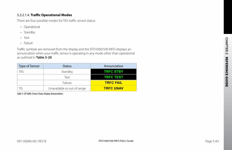
CH
APTER 5 R
EFEREN
CE GU
IDE
EFD1000/500 MFD Pilot’s GuidePage 5-62 091-00006-001 REV B EFD1000/500 MFD Pilot’s Guide Page 5-63091-00006-001 REV B
5.3.2.1.4. Traffic Operational ModesThere are four possible modes for TAS traffic sensor status:
• Operational
• Standby
• Test
• Failure
Traffic symbols are removed from the display and the EFD1000/500 MFD displays an annunciation when your traffic sensor is operating in any mode other than operational as outlined in Table 5-20.
Type of Sensor Status Annunciation
TAS Standby TRFC STBYTest TRFC TEST
Failure TRFC FAILTIS Unavailable or out of range TRFC UNAV
Table 5-20 Traffic Sensor Status Display Annunciations
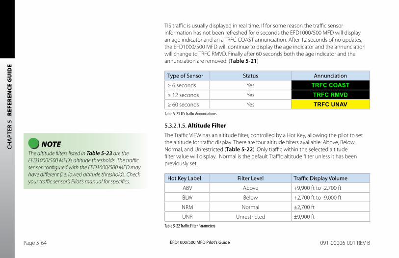
CH
APT
ER 5
R
EFER
ENCE
GU
IDE
EFD1000/500 MFD Pilot’s GuidePage 5-64 091-00006-001 REV B EFD1000/500 MFD Pilot’s Guide Page 5-65091-00006-001 REV B
TIS traffic is usually displayed in real time. If for some reason the traffic sensor information has not been refreshed for 6 seconds the EFD1000/500 MFD will display an age indicator and an a TRFC COAST annunciation. After 12 seconds of no updates, the EFD1000/500 MFD will continue to display the age indicator and the annunciation will change to TRFC RMVD. Finally after 60 seconds both the age indicator and the annunciation are removed. (Table 5-21)
Type of Sensor Status Annunciation
≥ 6 seconds Yes TRFC COAST≥ 12 seconds Yes TRFC RMVD≥ 60 seconds Yes TRFC UNAV
Table 5-21 TIS Traffic Annunciations
5.3.2.1.5. Altitude FilterThe Traffic VIEW has an altitude filter, controlled by a Hot Key, allowing the pilot to set the altitude for traffic display. There are four altitude filters available: Above, Below, Normal, and Unrestricted (Table 5-22). Only traffic within the selected altitude filter value will display. Normal is the default Traffic altitude filter unless it has been previously set.
Hot Key Label Filter Level Traffic Display Volume
ABV Above +9,900 ft to -2,700 ft
BLW Below +2,700 ft to -9,000 ft
NRM Normal ±2,700 ft
UNR Unrestricted ±9,900 ftTable 5-22 Traffic Filter Parameters
NOTE The altitude filters listed in Table 5-23 are the EFD1000/500 MFD’s altitude thresholds. The traffic sensor configured with the EFD1000/500 MFD may have different (i.e. lower) altitude thresholds. Check your traffic sensor’s Pilot’s manual for specifics.
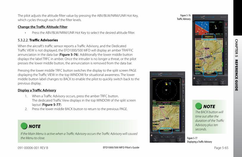
CH
APTER 5 R
EFEREN
CE GU
IDE
EFD1000/500 MFD Pilot’s GuidePage 5-64 091-00006-001 REV B EFD1000/500 MFD Pilot’s Guide Page 5-65091-00006-001 REV B
The pilot adjusts the altitude filter value by pressing the ABV/BLW/NRM/UNR Hot Key, which cycles through each of the filter levels.
Change the Traffic Altitude Filter
• Press the ABV/BLW/NRM/UNR Hot Key to select the desired altitude filter.
5.3.2.2. Traffic AdvisoriesWhen the aircraft’s traffic sensor reports a Traffic Advisory, and the Dedicated Traffic VIEW is not displayed, the EFD1000/500 MFD will display an amber TRAFFIC annunciation in the data bar (Figure 5-76). Additionally the lower middle button displays the label TRFC in amber. Once the intruder is no longer a threat, or the pilot presses the lower middle button, the annunciation is removed from the data bar.
Pressing the lower middle TRFC button switches the display to the split screen PAGE displaying the Traffic VIEW in the top WINDOW for situational awareness. The lower middle button label changes to BACK to enable the pilot to quickly switch back to the previous display.
Display a Traffic Advisory
1. When a Traffic Advisory occurs, press the amber TRFC button. The dedicated Traffic View displays in the top WINDOW of the split screen layout (Figure 5-77).
2. Press the lower middle BACK button to return to the previous PAGE.
Figure 5-76 Traffic Advisory
Figure 5-77 Displaying a Traffic Advisory
NOTE If the Main Menu is active when a Traffic Advisory occurs the Traffic Advisory will caused the Menu to close.
NOTE The BACK button will time out after the duration of the Traffic Advisory plus ten seconds.
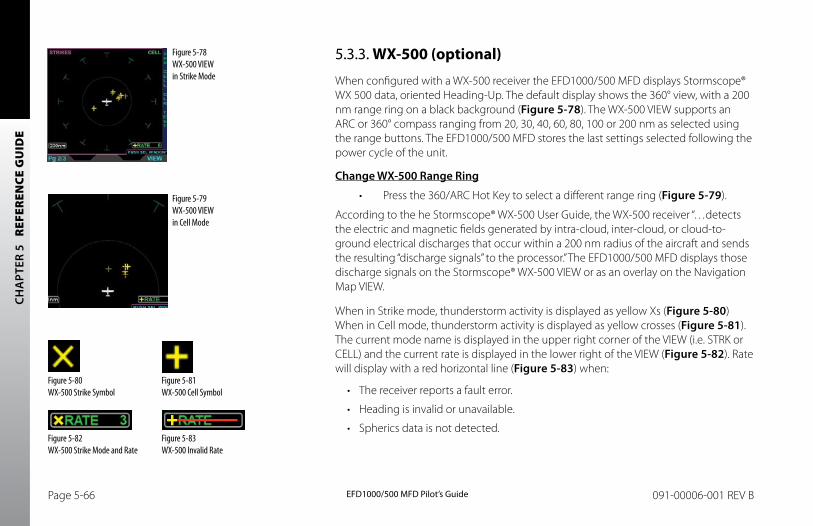
CH
APT
ER 5
R
EFER
ENCE
GU
IDE
EFD1000/500 MFD Pilot’s GuidePage 5-66 091-00006-001 REV B EFD1000/500 MFD Pilot’s Guide Page 5-67091-00006-001 REV B
5.3.3. WX-500 (optional)
When configured with a WX-500 receiver the EFD1000/500 MFD displays Stormscope® WX 500 data, oriented Heading-Up. The default display shows the 360° view, with a 200 nm range ring on a black background (Figure 5-78). The WX-500 VIEW supports an ARC or 360° compass ranging from 20, 30, 40, 60, 80, 100 or 200 nm as selected using the range buttons. The EFD1000/500 MFD stores the last settings selected following the power cycle of the unit.
Change WX-500 Range Ring
• Press the 360/ARC Hot Key to select a different range ring (Figure 5-79).
According to the he Stormscope® WX-500 User Guide, the WX-500 receiver “…detects the electric and magnetic fields generated by intra-cloud, inter-cloud, or cloud-to-ground electrical discharges that occur within a 200 nm radius of the aircraft and sends the resulting “discharge signals” to the processor.” The EFD1000/500 MFD displays those discharge signals on the Stormscope® WX-500 VIEW or as an overlay on the Navigation Map VIEW.
When in Strike mode, thunderstorm activity is displayed as yellow Xs (Figure 5-80)When in Cell mode, thunderstorm activity is displayed as yellow crosses (Figure 5-81). The current mode name is displayed in the upper right corner of the VIEW (i.e. STRK or CELL) and the current rate is displayed in the lower right of the VIEW (Figure 5-82). Rate will display with a red horizontal line (Figure 5-83) when:
• The receiver reports a fault error.
• Heading is invalid or unavailable.
• Spherics data is not detected.
Figure 5-78 WX-500 VIEW in Strike Mode
Figure 5-79 WX-500 VIEW in Cell Mode
Figure 5-80 WX-500 Strike Symbol
Figure 5-81 WX-500 Cell Symbol
Figure 5-82 WX-500 Strike Mode and Rate
Figure 5-83 WX-500 Invalid Rate
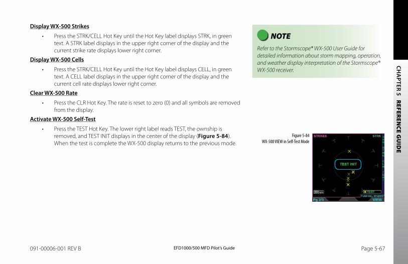
CH
APTER 5 R
EFEREN
CE GU
IDE
EFD1000/500 MFD Pilot’s GuidePage 5-66 091-00006-001 REV B EFD1000/500 MFD Pilot’s Guide Page 5-67091-00006-001 REV B
Display WX-500 Strikes
• Press the STRK/CELL Hot Key until the Hot Key label displays STRK, in green text. A STRK label displays in the upper right corner of the display and the current strike rate displays lower right corner.
Display WX-500 Cells
• Press the STRK/CELL Hot Key until the Hot Key label displays CELL, in green text. A CELL label displays in the upper right corner of the display and the current cell rate displays lower right corner.
Clear WX-500 Rate
• Press the CLR Hot Key. The rate is reset to zero (0) and all symbols are removed from the display.
Activate WX-500 Self-Test
• Press the TEST Hot Key. The lower right label reads TEST, the ownship is removed, and TEST INIT displays in the center of the display (Figure 5-84). When the test is complete the WX-500 display returns to the previous mode.
Figure 5-84 WX-500 VIEW in Self-Test Mode
NOTE Refer to the Stormscope® WX-500 User Guide for detailed information about storm mapping, operation, and weather display interpretation of the Stormscope® WX-500 receiver.
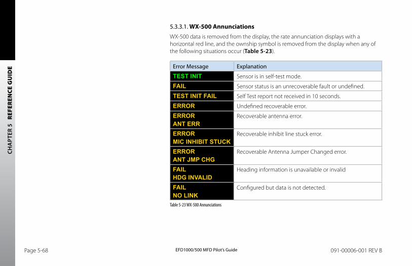
CH
APT
ER 5
R
EFER
ENCE
GU
IDE
EFD1000/500 MFD Pilot’s GuidePage 5-68 091-00006-001 REV B EFD1000/500 MFD Pilot’s Guide Page 5-69091-00006-001 REV B
5.3.3.1. WX-500 AnnunciationsWX-500 data is removed from the display, the rate annunciation displays with a horizontal red line, and the ownship symbol is removed from the display when any of the following situations occur (Table 5-23).
Error Message Explanation
TEST INIT Sensor is in self-test mode.
FAIL Sensor status is an unrecoverable fault or undefined.
TEST INIT FAIL Self Test report not received in 10 seconds.
ERROR Undefined recoverable error.
ERRORANT ERR
Recoverable antenna error.
ERROR MIC INHIBIT STUCK
Recoverable inhibit line stuck error.
ERROR ANT JMP CHG
Recoverable Antenna Jumper Changed error.
FAILHDG INVALID
Heading information is unavailable or invalid
FAILNO LINK
Configured but data is not detected.
Table 5-23 WX-500 Annunciations
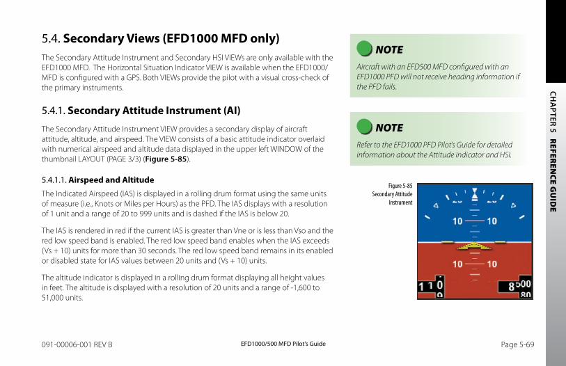
CH
APTER 5 R
EFEREN
CE GU
IDE
EFD1000/500 MFD Pilot’s GuidePage 5-68 091-00006-001 REV B EFD1000/500 MFD Pilot’s Guide Page 5-69091-00006-001 REV B
5.4. Secondary Views (EFD1000 MFD only)The Secondary Attitude Instrument and Secondary HSI VIEWs are only available with the EFD1000 MFD. The Horizontal Situation Indicator VIEW is available when the EFD1000/ MFD is configured with a GPS. Both VIEWs provide the pilot with a visual cross-check of the primary instruments.
5.4.1. Secondary Attitude Instrument (AI)
The Secondary Attitude Instrument VIEW provides a secondary display of aircraft attitude, altitude, and airspeed. The VIEW consists of a basic attitude indicator overlaid with numerical airspeed and altitude data displayed in the upper left WINDOW of the thumbnail LAYOUT (PAGE 3/3) (Figure 5-85).
5.4.1.1. Airspeed and AltitudeThe Indicated Airspeed (IAS) is displayed in a rolling drum format using the same units of measure (i.e., Knots or Miles per Hours) as the PFD. The IAS displays with a resolution of 1 unit and a range of 20 to 999 units and is dashed if the IAS is below 20.
The IAS is rendered in red if the current IAS is greater than Vne or is less than Vso and the red low speed band is enabled. The red low speed band enables when the IAS exceeds (Vs + 10) units for more than 30 seconds. The red low speed band remains in its enabled or disabled state for IAS values between 20 units and (Vs + 10) units.
The altitude indicator is displayed in a rolling drum format displaying all height values in feet. The altitude is displayed with a resolution of 20 units and a range of -1,600 to 51,000 units.
NOTE Aircraft with an EFD500 MFD configured with an EFD1000 PFD will not receive heading information if the PFD fails.
NOTE Refer to the EFD1000 PFD Pilot’s Guide for detailed information about the Attitude Indicator and HSI.
Figure 5-85 Secondary Attitude
Instrument
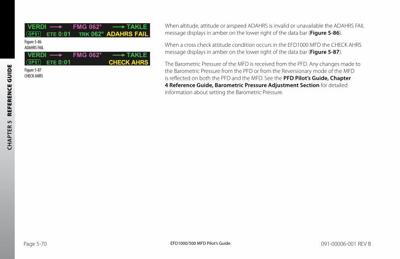
CH
APT
ER 5
R
EFER
ENCE
GU
IDE
EFD1000/500 MFD Pilot’s GuidePage 5-70 091-00006-001 REV B EFD1000/500 MFD Pilot’s Guide Page 5-71091-00006-001 REV B
When altitude, attitude or airspeed ADAHRS is invalid or unavailable the ADAHRS FAIL message displays in amber on the lower right of the data bar (Figure 5-86).
When a cross check attitude condition occurs in the EFD1000 MFD the CHECK AHRS message displays in amber on the lower right of the data bar (Figure 5-87).
The Barometric Pressure of the MFD is received from the PFD. Any changes made to the Barometric Pressure from the PFD or from the Reversionary mode of the MFD is reflected on both the PFD and the MFD. See the PFD Pilot’s Guide, Chapter 4 Reference Guide, barometric Pressure Adjustment Section for detailed information about setting the Barometric Pressure.
Figure 5-86 ADAHRS FAIL
Figure 5-87 CHECK AHRS
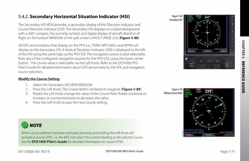
CH
APTER 5 R
EFEREN
CE GU
IDE
EFD1000/500 MFD Pilot’s GuidePage 5-70 091-00006-001 REV B EFD1000/500 MFD Pilot’s Guide Page 5-71091-00006-001 REV B
5.4.2. Secondary Horizontal Situation Indicator (HSI)
The Secondary HSI VIEW provides a secondary display of the Direction Indicator and Course Direction Indicator (CDI). The Secondary HSI displays on a black background with a 360° compass, the ownship symbol, and digital display of aircraft direction of flight on the bottom WINDOW of the split screen LAYOUT (PAGE 2/3) (Figure 5-88).
All GPS annunciations that display on the PFD (i.e., TERM, WPT, MSG, and APPR) will display on the Secondary HSI. A Vertical Deviation Indicator (VDI) is displayed to the left of the HSI using the same logic as the PFD VDI. The navigation source is pilot selectable, from any of the configured navigation sources for the PFD CDI, using the lower center button. The course value is selectable via the Left Knob. Refer to the EFD1000 PFD Pilot’s Guide for detailed information about GPS annunciations, the VDI, and navigation source selection.
Modify the Course Setting
1. Select the Secondary HSI VIEW WINDOW.2. Press the Left Knob. The Course field is rendered in magenta (Figure 5-89).3. Rotate the Left Knob change the value of the Course field. Rotate clockwise to
increase, or counterclockwise to decrease, the value.4. Press the Left Knob to save the new Course setting.
Figure 5-88 Secondary HSI
NOTE When course selection has been activated, pressing and holding the Left Knob will activate a course SYNC, i.e. the MFD will select the current heading as the selected course. See the EFD1000 Pilot’s Guide for detailed information on course SYNC.
Figure 5-89 Editing Course Value
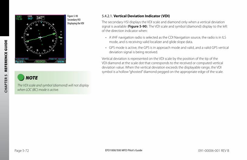
CH
APT
ER 5
R
EFER
ENCE
GU
IDE
EFD1000/500 MFD Pilot’s GuidePage 5-72 091-00006-001 REV B EFD1000/500 MFD Pilot’s Guide Page PB091-00006-001 REV B
5.4.2.1. Vertical Deviation Indicator (VDI)The secondary HSI displays the VDI scale and diamond only when a vertical deviation signal is available (Figure 5-90). The VDI scale and symbol (diamond) display to the left of the direction indicator when:
• A VHF navigation radio is selected as the CDI Navigation source, the radio is in ILS mode, and is receiving valid localizer and glide slope data.
• GPS mode is active, the GPS is in approach mode and valid, and a valid GPS vertical deviation signal is being received.
Vertical deviation is represented on the VDI scale by the position of the tip of the VDI diamond at the scale dot that corresponds to the received or computed vertical deviation value. When the vertical deviation exceeds the displayable range, the VDI symbol is a hollow “ghosted” diamond pegged on the appropriate edge of the scale.
Figure 5-90 Secondary HSI Displaying the VDI
NOTE The VDI scale and symbol (diamond) will not display when LOC (BC) mode is active.
CHA
PTER 6 EXPANDED EMERGENCY AND ABNORM
AL PROCEDURES
EFD1000/500 MFD Pilot’s GuidePage PB 091-00006-001 REV B EFD1000/500 MFD Pilot’s Guide Page 6-1091-00006-001 REV B
Chapter 6Expanded Emergency & Abnormal Procedures
This section supplements and provides an expanded description of the emergency and abnormal procedures included in the FAA approved Aircraft Flight Manual Supplement. The data provided here is intended to provide additional background information to enhance the pilot’s understanding of the emergency and abnormal conditions, and the associated procedures provided in the AFMS. This pilot guide is provided for supplementary purposes only. The approved cockpit reference for in-flight use is the AFMS, which must be immediately available to the pilot at all times in flight. In the event of any conflict between this document and the FAA approved AFMS, the AFMS instructions must be followed.
6.1. Pitot/Static System BlockageA pitot line blockage will result in the airspeed indicator behaving like an altimeter when the aircraft’s altitude changes and it will not respond to airspeed changes. A pitot line blockage can also affect the EFD1000’s attitude indication.
A static line blockage will result in altitude remaining fixed and a zero vertical speed despite aircraft pitch and/or power setting changes. In addition, IAS indications will be incorrect if the static line is blocked. Errors will typically be noticed during climbs or descents. When descending, ambient pressure increases which will result in the indicated airspeed reading less than the actual airspeed. The opposite effect will be observed in a climb. A static line blockage can also affect the EFD1000’s attitude indication.
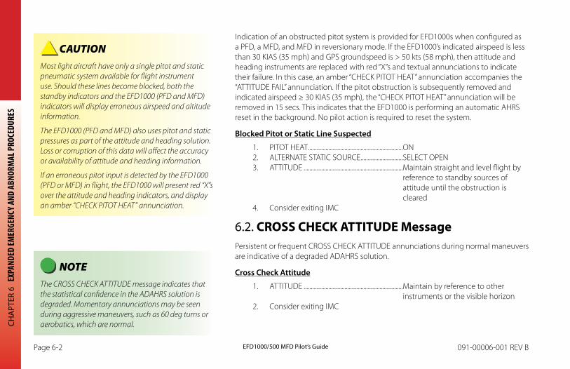
CHA
PTER
6 E
XPAN
DED
EMER
GENC
Y AND
ABN
ORM
AL P
ROCE
DURE
S
EFD1000/500 MFD Pilot’s GuidePage 6-2 091-00006-001 REV B EFD1000/500 MFD Pilot’s Guide Page 6-3091-00006-001 REV B
Indication of an obstructed pitot system is provided for EFD1000s when configured as a PFD, a MFD, and MFD in reversionary mode. If the EFD1000’s indicated airspeed is less than 30 KIAS (35 mph) and GPS groundspeed is > 50 kts (58 mph), then attitude and heading instruments are replaced with red “X”s and textual annunciations to indicate their failure. In this case, an amber “CHECK PITOT HEAT” annunciation accompanies the “ATTITUDE FAIL” annunciation. If the pitot obstruction is subsequently removed and indicated airspeed ≥ 30 KIAS (35 mph), the “CHECK PITOT HEAT” annunciation will be removed in 15 secs. This indicates that the EFD1000 is performing an automatic AHRS reset in the background. No pilot action is required to reset the system.
blocked Pitot or Static Line Suspected
1. PITOT HEAT .................................................................ON2. ALTERNATE STATIC SOURCE .............................SELECT OPEN3. ATTITUDE ....................................................................Maintain straight and level flight by
reference to standby sources of attitude until the obstruction is cleared
4. Consider exiting IMC
6.2. CROSS CHECK ATTITUDE MessagePersistent or frequent CROSS CHECK ATTITUDE annunciations during normal maneuvers are indicative of a degraded ADAHRS solution.
Cross Check Attitude
1. ATTITUDE ....................................................................Maintain by reference to other instruments or the visible horizon
2. Consider exiting IMC
CAUTION Most light aircraft have only a single pitot and static pneumatic system available for flight instrument use. Should these lines become blocked, both the standby indicators and the EFD1000 (PFD and MFD) indicators will display erroneous airspeed and altitude information.
The EFD1000 (PFD and MFD) also uses pitot and static pressures as part of the attitude and heading solution. Loss or corruption of this data will affect the accuracy or availability of attitude and heading information.
If an erroneous pitot input is detected by the EFD1000 (PFD or MFD) in flight, the EFD1000 will present red “X”s over the attitude and heading indicators, and display an amber “CHECK PITOT HEAT” annunciation.
NOTE The CROSS CHECK ATTITUDE message indicates that the statistical confidence in the ADAHRS solution is degraded. Momentary annunciations may be seen during aggressive maneuvers, such as 60 deg turns or aerobatics, which are normal.
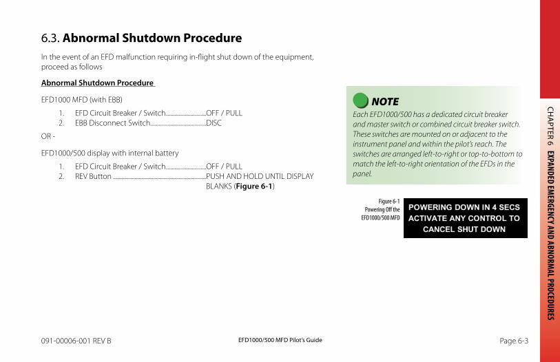
CHA
PTER 6 EXPANDED EMERGENCY AND ABNORM
AL PROCEDURES
EFD1000/500 MFD Pilot’s GuidePage 6-2 091-00006-001 REV B EFD1000/500 MFD Pilot’s Guide Page 6-3091-00006-001 REV B
6.3. Abnormal Shutdown ProcedureIn the event of an EFD malfunction requiring in-flight shut down of the equipment, proceed as follows
Abnormal Shutdown Procedure
EFD1000 MFD (with EBB)
1. EFD Circuit Breaker / Switch ............................OFF / PULL2. EBB Disconnect Switch.......................................DISC
OR -
EFD1000/500 display with internal battery
1. EFD Circuit Breaker / Switch ............................OFF / PULL2. REV Button .................................................................PUSH AND HOLD UNTIL DISPLAY
BLANKS (Figure 6-1)
Figure 6-1 Powering Off the
EFD1000/500 MFD
NOTE Each EFD1000/500 has a dedicated circuit breaker and master switch or combined circuit breaker switch. These switches are mounted on or adjacent to the instrument panel and within the pilot’s reach. The switches are arranged left-to-right or top-to-bottom to match the left-to-right orientation of the EFDs in the panel.
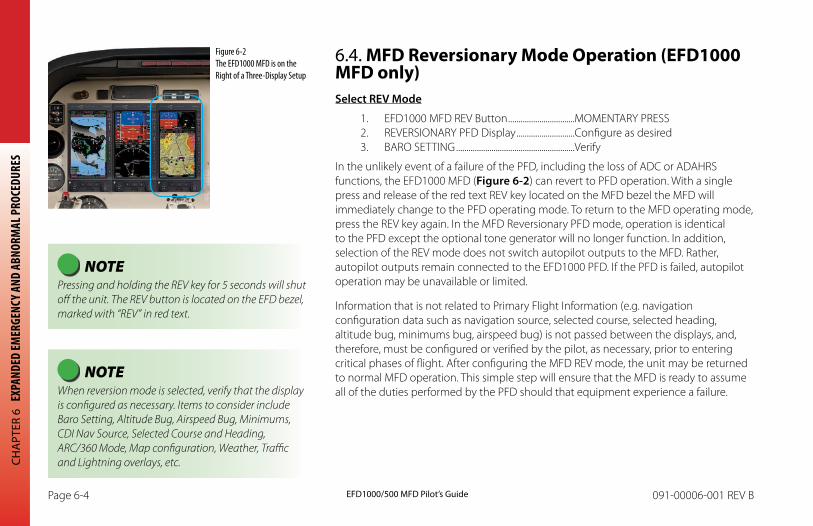
CHA
PTER
6 E
XPAN
DED
EMER
GENC
Y AND
ABN
ORM
AL P
ROCE
DURE
S
EFD1000/500 MFD Pilot’s GuidePage 6-4 091-00006-001 REV B EFD1000/500 MFD Pilot’s Guide Page 6-5091-00006-001 REV B
6.4. MFD Reversionary Mode Operation (EFD1000 MFD only)Select REV Mode
1. EFD1000 MFD REV Button ................................MOMENTARY PRESS2. REVERSIONARY PFD Display ............................Configure as desired3. BARO SETTING .........................................................Verify
In the unlikely event of a failure of the PFD, including the loss of ADC or ADAHRS functions, the EFD1000 MFD (Figure 6-2) can revert to PFD operation. With a single press and release of the red text REV key located on the MFD bezel the MFD will immediately change to the PFD operating mode. To return to the MFD operating mode, press the REV key again. In the MFD Reversionary PFD mode, operation is identical to the PFD except the optional tone generator will no longer function. In addition, selection of the REV mode does not switch autopilot outputs to the MFD. Rather, autopilot outputs remain connected to the EFD1000 PFD. If the PFD is failed, autopilot operation may be unavailable or limited.
Information that is not related to Primary Flight Information (e.g. navigation configuration data such as navigation source, selected course, selected heading, altitude bug, minimums bug, airspeed bug) is not passed between the displays, and, therefore, must be configured or verified by the pilot, as necessary, prior to entering critical phases of flight. After configuring the MFD REV mode, the unit may be returned to normal MFD operation. This simple step will ensure that the MFD is ready to assume all of the duties performed by the PFD should that equipment experience a failure.
NOTE Pressing and holding the REV key for 5 seconds will shut off the unit. The REV button is located on the EFD bezel, marked with “REV” in red text.
NOTE When reversion mode is selected, verify that the display is configured as necessary. Items to consider include Baro Setting, Altitude Bug, Airspeed Bug, Minimums, CDI Nav Source, Selected Course and Heading, ARC/360 Mode, Map configuration, Weather, Traffic and Lightning overlays, etc.
Figure 6-2 The EFD1000 MFD is on the Right of a Three-Display Setup
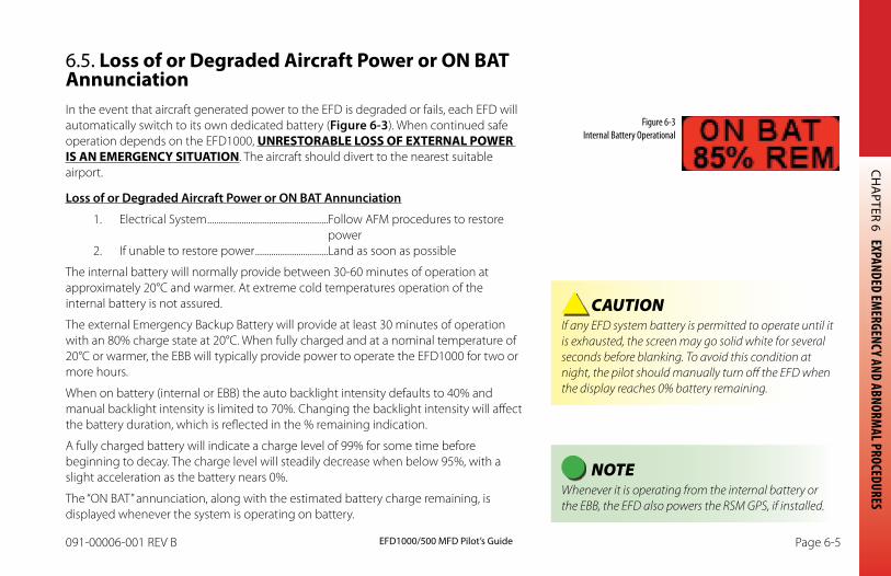
CHA
PTER 6 EXPANDED EMERGENCY AND ABNORM
AL PROCEDURES
EFD1000/500 MFD Pilot’s GuidePage 6-4 091-00006-001 REV B EFD1000/500 MFD Pilot’s Guide Page 6-5091-00006-001 REV B
6.5. Loss of or Degraded Aircraft Power or ON BAT AnnunciationIn the event that aircraft generated power to the EFD is degraded or fails, each EFD will automatically switch to its own dedicated battery (Figure 6-3). When continued safe operation depends on the EFD1000, UNRESTORABLE LOSS OF EXTERNAL POWER IS AN EMERGENCY SITUATION. The aircraft should divert to the nearest suitable airport.
Loss of or Degraded Aircraft Power or ON bAT Annunciation
1. Electrical System .....................................................Follow AFM procedures to restorepower
2. If unable to restore power ................................Land as soon as possible
The internal battery will normally provide between 30-60 minutes of operation at approximately 20°C and warmer. At extreme cold temperatures operation of the internal battery is not assured.
The external Emergency Backup Battery will provide at least 30 minutes of operation with an 80% charge state at 20°C. When fully charged and at a nominal temperature of 20°C or warmer, the EBB will typically provide power to operate the EFD1000 for two or more hours.
When on battery (internal or EBB) the auto backlight intensity defaults to 40% and manual backlight intensity is limited to 70%. Changing the backlight intensity will affect the battery duration, which is reflected in the % remaining indication.
A fully charged battery will indicate a charge level of 99% for some time before beginning to decay. The charge level will steadily decrease when below 95%, with a slight acceleration as the battery nears 0%.
The “ON BAT” annunciation, along with the estimated battery charge remaining, is displayed whenever the system is operating on battery.
Figure 6-3 Internal Battery Operational
CAUTION If any EFD system battery is permitted to operate until it is exhausted, the screen may go solid white for several seconds before blanking. To avoid this condition at night, the pilot should manually turn off the EFD when the display reaches 0% battery remaining.
NOTE Whenever it is operating from the internal battery or the EBB, the EFD also powers the RSM GPS, if installed.
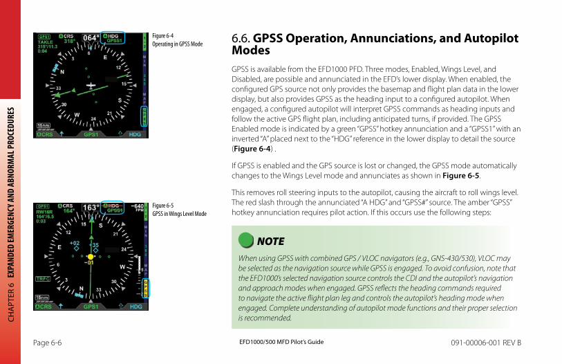
CHA
PTER
6 E
XPAN
DED
EMER
GENC
Y AND
ABN
ORM
AL P
ROCE
DURE
S
EFD1000/500 MFD Pilot’s GuidePage 6-6 091-00006-001 REV B EFD1000/500 MFD Pilot’s Guide Page 6-7091-00006-001 REV B
6.6. GPSS Operation, Annunciations, and Autopilot ModesGPSS is available from the EFD1000 PFD. Three modes, Enabled, Wings Level, and Disabled, are possible and annunciated in the EFD’s lower display. When enabled, the configured GPS source not only provides the basemap and flight plan data in the lower display, but also provides GPSS as the heading input to a configured autopilot. When engaged, a configured autopilot will interpret GPSS commands as heading inputs and follow the active GPS flight plan, including anticipated turns, if provided. The GPSS Enabled mode is indicated by a green “GPSS” hotkey annunciation and a “GPSS1” with an inverted “A” placed next to the “HDG” reference in the lower display to detail the source (Figure 6-4) .
If GPSS is enabled and the GPS source is lost or changed, the GPSS mode automatically changes to the Wings Level mode and annunciates as shown in Figure 6-5.
This removes roll steering inputs to the autopilot, causing the aircraft to roll wings level. The red slash through the annunciated “A HDG” and “GPSS#” source. The amber “GPSS” hotkey annunciation requires pilot action. If this occurs use the following steps:
NOTE When using GPSS with combined GPS / VLOC navigators (e.g., GNS-430/530), VLOC may be selected as the navigation source while GPSS is engaged. To avoid confusion, note that the EFD1000’s selected navigation source controls the CDI and the autopilot’s navigation and approach modes when engaged. GPSS reflects the heading commands required to navigate the active flight plan leg and controls the autopilot’s heading mode when engaged. Complete understanding of autopilot mode functions and their proper selection is recommended.
Figure 6-5 GPSS in Wings Level Mode
Figure 6-4 Operating in GPSS Mode
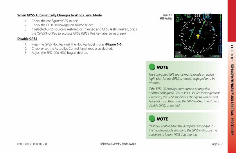
CHA
PTER 6 EXPANDED EMERGENCY AND ABNORM
AL PROCEDURES
EFD1000/500 MFD Pilot’s GuidePage 6-6 091-00006-001 REV B EFD1000/500 MFD Pilot’s Guide Page 6-7091-00006-001 REV B
When GPSS Automatically Changes to Wings Level Mode
1. Check the configured GPS source.2. Check the EFD1000 navigation source select.3. If selected GPSS source is restored or changed and GPSS is still desired, press
the “GPSS” Hot Key to activate GPSS (GPSS Hot Key label turns green).
Disable GPSS
1. Press the GPSS Hot Key until the Hot Key label is gray (Figure 6-6).2. Check or set the Autopilot Control Panel modes as desired.3. Adjust the EFD1000 HDG bug as desired.
Figure 6-6 GPSS Disabled
NOTE The configured GPS source must provide an active flight plan for the GPSS to remain engaged or to be restored.
If the EFD1000 navigation source is changed to another configured GPS or VLOC source for longer than 2 seconds, the GPSS mode will change to Wings Level. The pilot must then press the GPSS hotkey to restore or disable GPSS, as desired.
NOTE If GPSS is enabled and the autopilot is engaged in the heading mode, disabling the GPSS will cause the autopilot to follow HDG bug steering.
CHA
PTER
6 E
XPAN
DED
EMER
GENC
Y AND
ABN
ORM
AL P
ROCE
DURE
S
EFD1000/500 MFD Pilot’s GuidePage 6-8 091-00006-001 REV B EFD1000/500 MFD Pilot’s Guide Page 6-9091-00006-001 REV B
6.7. EBB Disconnect (EFD1000 MFD only)To isolate the EBB in the event of an EBB or EFD1000 MFD malfunction, proceed as follows:
Isolate the Emergency backup battery
1. EBB Switch ..................................................................Select DISC
The EBB is protected by thermal and short-circuit sensing circuitry to prevent battery overheating or damage. The battery is normally connected to its EFD1000 MFD. If it is desired to remove battery power from the EFD1000 MFD, or to otherwise isolate the EBB, the EBB includes an externally activated isolation relay integral to the EBB aluminum housing. This relay is activated by the EBB Disconnect Switch installed in the instrument panel.
The EBB Emergency Disconnect switch is either a guarded or lever-lock switch mounted on or adjacent to the instrument panel and within the pilot’s reach. The switch should be left in the NORM position at all times, including when away from the aircraft. When it is desired to disconnect the EBB from the EFD1000 MFD display, move the switch to the DISC position.
NOTE When in the “DISC” position, the EBB isolation relay is powered from the EBB. Thus, when the switch is in the disconnect position, the Emergency Backup Battery will gradually discharge.
NOTE Setting the disconnect to EMER. DISC. closes the relay to the EFD and therefore will drain the EBB battery. As such do not set the EBB to EMER. DISC. when garaging the aircraft.
If the EBB is inadvertently drained, apply auxillary power to the aircraft, turn on the EFD1000 MFD and allow the EBB to recharge. The EBB takes approximately three (3) hours to recharge when the temperature is at 25°C.
The EBB will not recharge at temperatures below 0°C or above 25°C.
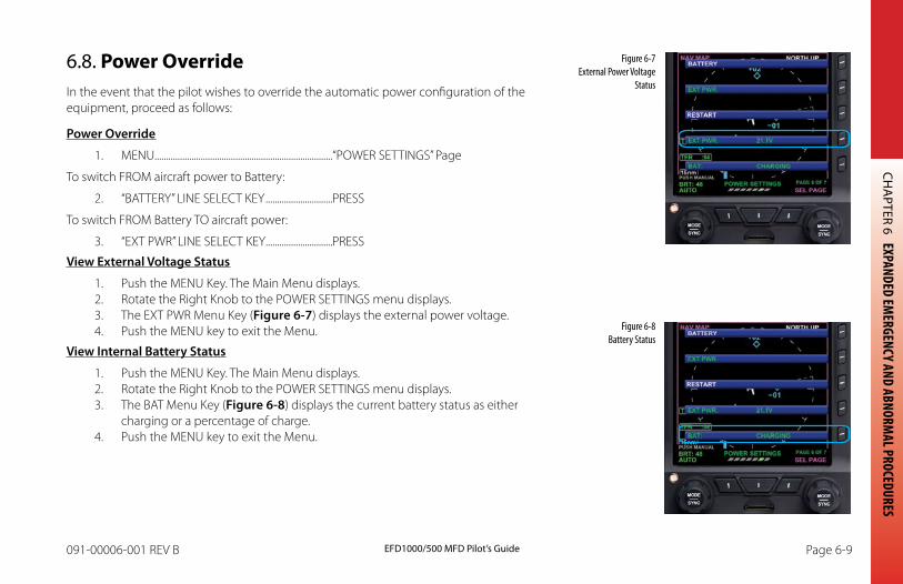
CHA
PTER 6 EXPANDED EMERGENCY AND ABNORM
AL PROCEDURES
EFD1000/500 MFD Pilot’s GuidePage 6-8 091-00006-001 REV B EFD1000/500 MFD Pilot’s Guide Page 6-9091-00006-001 REV B
6.8. Power OverrideIn the event that the pilot wishes to override the automatic power configuration of the equipment, proceed as follows:
Power Override
1. MENU.............................................................................“POWER SETTINGS” Page
To switch FROM aircraft power to Battery:
2. “BATTERY” LINE SELECT KEY .............................PRESS
To switch FROM Battery TO aircraft power:
3. “EXT PWR” LINE SELECT KEY .............................PRESS
View External Voltage Status
1. Push the MENU Key. The Main Menu displays.2. Rotate the Right Knob to the POWER SETTINGS menu displays.3. The EXT PWR Menu Key (Figure 6-7) displays the external power voltage.4. Push the MENU key to exit the Menu.
View Internal battery Status
1. Push the MENU Key. The Main Menu displays.2. Rotate the Right Knob to the POWER SETTINGS menu displays.3. The BAT Menu Key (Figure 6-8) displays the current battery status as either
charging or a percentage of charge.4. Push the MENU key to exit the Menu.
Figure 6-7 External Power Voltage
Status
Figure 6-8 Battery Status
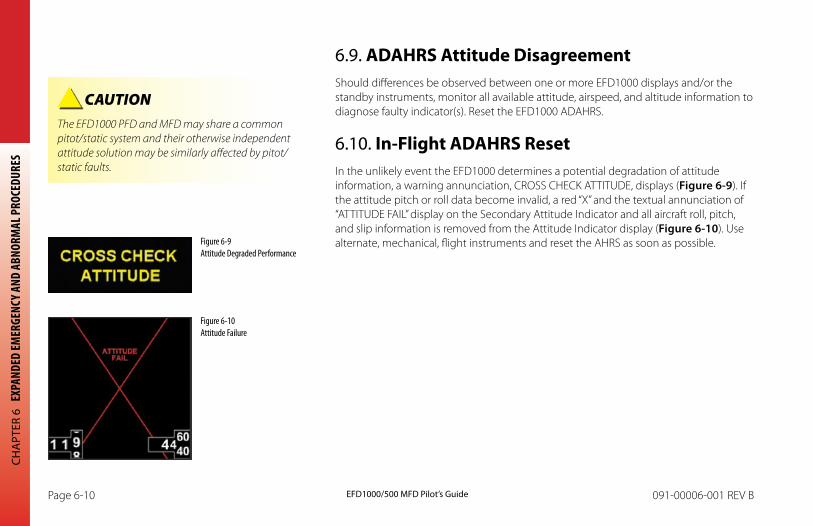
CHA
PTER
6 E
XPAN
DED
EMER
GENC
Y AND
ABN
ORM
AL P
ROCE
DURE
S
EFD1000/500 MFD Pilot’s GuidePage 6-10 091-00006-001 REV B EFD1000/500 MFD Pilot’s Guide Page 6-11091-00006-001 REV B
6.9. ADAHRS Attitude DisagreementShould differences be observed between one or more EFD1000 displays and/or the standby instruments, monitor all available attitude, airspeed, and altitude information to diagnose faulty indicator(s). Reset the EFD1000 ADAHRS.
6.10. In-Flight ADAHRS ResetIn the unlikely event the EFD1000 determines a potential degradation of attitude information, a warning annunciation, CROSS CHECK ATTITUDE, displays (Figure 6-9). If the attitude pitch or roll data become invalid, a red “X” and the textual annunciation of “ATTITUDE FAIL” display on the Secondary Attitude Indicator and all aircraft roll, pitch, and slip information is removed from the Attitude Indicator display (Figure 6-10). Use alternate, mechanical, flight instruments and reset the AHRS as soon as possible. Figure 6-9
Attitude Degraded Performance
CAUTION The EFD1000 PFD and MFD may share a common pitot/static system and their otherwise independent attitude solution may be similarly affected by pitot/static faults.
Figure 6-10 Attitude Failure
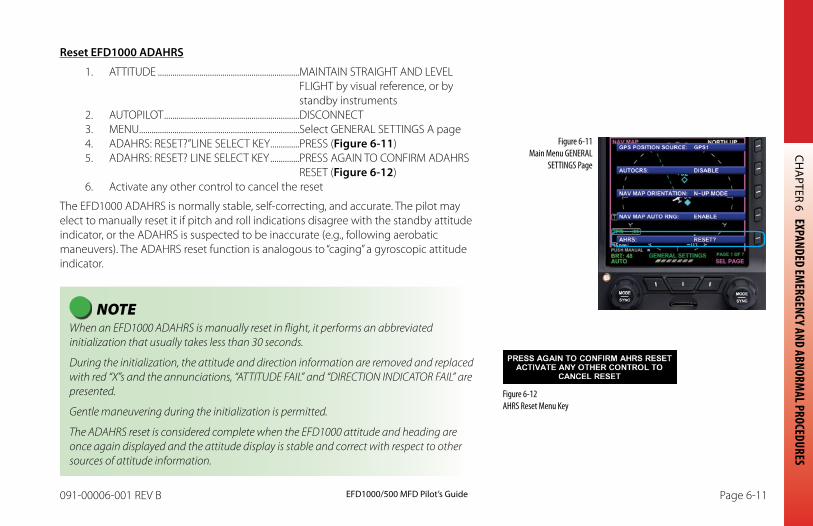
CHA
PTER 6 EXPANDED EMERGENCY AND ABNORM
AL PROCEDURES
EFD1000/500 MFD Pilot’s GuidePage 6-10 091-00006-001 REV B EFD1000/500 MFD Pilot’s Guide Page 6-11091-00006-001 REV B
Reset EFD1000 ADAHRS
1. ATTITUDE ....................................................................MAINTAIN STRAIGHT AND LEVEL FLIGHT by visual reference, or by standby instruments
2. AUTOPILOT .................................................................DISCONNECT 3. MENU.............................................................................Select GENERAL SETTINGS A page4. ADAHRS: RESET?”LINE SELECT KEY ..............PRESS (Figure 6-11)5. ADAHRS: RESET? LINE SELECT KEY ..............PRESS AGAIN TO CONFIRM ADAHRS
RESET (Figure 6-12)6. Activate any other control to cancel the reset
The EFD1000 ADAHRS is normally stable, self-correcting, and accurate. The pilot may elect to manually reset it if pitch and roll indications disagree with the standby attitude indicator, or the ADAHRS is suspected to be inaccurate (e.g., following aerobatic maneuvers). The ADAHRS reset function is analogous to “caging” a gyroscopic attitude indicator.
NOTE When an EFD1000 ADAHRS is manually reset in flight, it performs an abbreviated initialization that usually takes less than 30 seconds.
During the initialization, the attitude and direction information are removed and replaced with red “X”s and the annunciations, “ATTITUDE FAIL” and “DIRECTION INDICATOR FAIL” are presented.
Gentle maneuvering during the initialization is permitted.
The ADAHRS reset is considered complete when the EFD1000 attitude and heading are once again displayed and the attitude display is stable and correct with respect to other sources of attitude information.
Figure 6-11 Main Menu GENERAL
SETTINGS Page
Figure 6-12 AHRS Reset Menu Key
CHA
PTER
6 E
XPAN
DED
EMER
GENC
Y AND
ABN
ORM
AL P
ROCE
DURE
S
EFD1000/500 MFD Pilot’s GuidePage 6-12 091-00006-001 REV B EFD1000/500 MFD Pilot’s Guide Page 6-13091-00006-001 REV B
6.11. EFD1000/500 Intercommunications FailureIn the event of a “CROSS LINK FAILURE” message, verify that barometric altimeter setting information is correctly transferred between the displays. On the EFD1000 MFD, the barometric altimeter setting can only be set from the MFD REV mode.
Intercommunications Failure
1. BARO SETTING .........................................................VERIFY
If EFD1000 Baro Setting must be set
2. EFD1000 MFD REV Button ................................PRESS TO DISPLAY PFD3. BARO SETTING .........................................................SET
An intercommunications link exists between the EFD1000 PFD, EFD1000 MFD, and EFD500 MFD to share various information, including barometric setting, heading, airspeed and altitude information. The EFD1000 PFD and EFD1000 MFD both receive and transmit data to each other, and each also transmits data to the EFD500 MFD. The EFD500 MFD only receives data, but does so from each installed EFD1000 display.
In the event of an intercommunication failure between the EFD1000 PFD, EFD1000 MFD, or EFD500 MFD, a CROSS LINK FAILURE annunciation will be presented in the affected PFD/MFD’s data bar. When this occurs, the altimeter’s barometric pressure setting may not be communicated between EFDs. It will be necessary to confirm if the baro setting information is being transferred. If it is not, the pilot should manually adjust the BARO setting on the affected display. For the EFD1000 MFD, this is accomplished in the PFD Reversion Mode.
In a three display configuration it is possible for the EFD500 MFD to display this message, but still maintain synchronization. This indicates that only one of the intercommunications buses to the EFD500 has failed.
CAUTION Relative terrain is based on the barometric altitude from the EFD1000 displays. BARO setting may not be shared between the EFD1000 displays during this Cross Link Failure condition. It is necessary to set BARO individually on both EFD1000 displays to prevent the display of erroneous relative terrain.
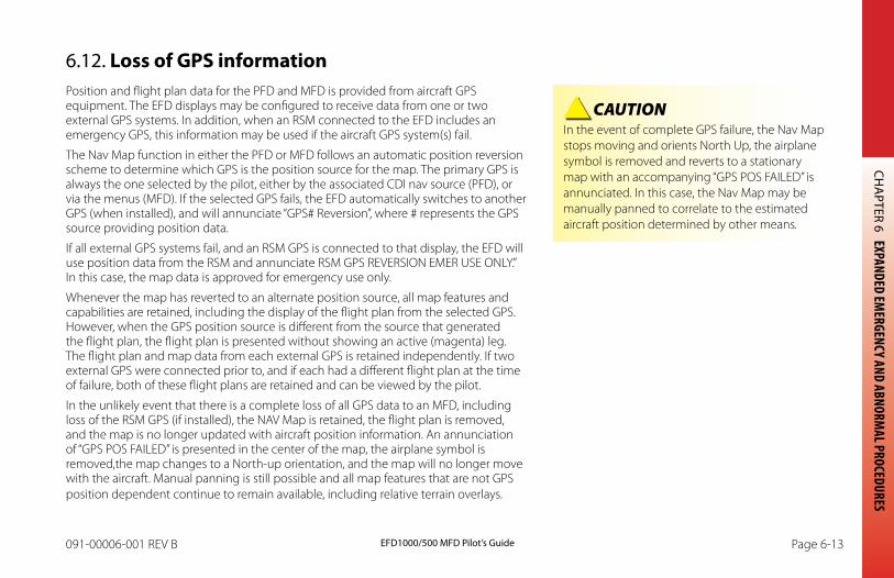
CHA
PTER 6 EXPANDED EMERGENCY AND ABNORM
AL PROCEDURES
EFD1000/500 MFD Pilot’s GuidePage 6-12 091-00006-001 REV B EFD1000/500 MFD Pilot’s Guide Page 6-13091-00006-001 REV B
6.12. Loss of GPS informationPosition and flight plan data for the PFD and MFD is provided from aircraft GPS equipment. The EFD displays may be configured to receive data from one or two external GPS systems. In addition, when an RSM connected to the EFD includes an emergency GPS, this information may be used if the aircraft GPS system(s) fail.
The Nav Map function in either the PFD or MFD follows an automatic position reversion scheme to determine which GPS is the position source for the map. The primary GPS is always the one selected by the pilot, either by the associated CDI nav source (PFD), or via the menus (MFD). If the selected GPS fails, the EFD automatically switches to another GPS (when installed), and will annunciate “GPS# Reversion”, where # represents the GPS source providing position data.
If all external GPS systems fail, and an RSM GPS is connected to that display, the EFD will use position data from the RSM and annunciate RSM GPS REVERSION EMER USE ONLY.” In this case, the map data is approved for emergency use only.
Whenever the map has reverted to an alternate position source, all map features and capabilities are retained, including the display of the flight plan from the selected GPS. However, when the GPS position source is different from the source that generated the flight plan, the flight plan is presented without showing an active (magenta) leg. The flight plan and map data from each external GPS is retained independently. If two external GPS were connected prior to, and if each had a different flight plan at the time of failure, both of these flight plans are retained and can be viewed by the pilot.
In the unlikely event that there is a complete loss of all GPS data to an MFD, including loss of the RSM GPS (if installed), the NAV Map is retained, the flight plan is removed, and the map is no longer updated with aircraft position information. An annunciation of “GPS POS FAILED” is presented in the center of the map, the airplane symbol is removed,the map changes to a North-up orientation, and the map will no longer move with the aircraft. Manual panning is still possible and all map features that are not GPS position dependent continue to remain available, including relative terrain overlays.
CAUTION In the event of complete GPS failure, the Nav Map stops moving and orients North Up, the airplane symbol is removed and reverts to a stationary map with an accompanying “GPS POS FAILED” is annunciated. In this case, the Nav Map may be manually panned to correlate to the estimated aircraft position determined by other means.
CHA
PTER
6 E
XPAN
DED
EMER
GENC
Y AND
ABN
ORM
AL P
ROCE
DURE
S
EFD1000/500 MFD Pilot’s GuidePage 6-14 091-00006-001 REV B EFD1000/500 MFD Pilot’s Guide Page 6-15091-00006-001 REV B
6.13. MFD Database CardEach EFD1000 MFD and EFD500 MFD includes a microSDHC (SD card, High Capacity) card slot into which a database card with terrain and Nav Map data may be inserted. The database card must remain in the EFD display as data is dynamically loaded from the microSDHC into the EFD memory during flight as the aircraft position changes.
In the event that the microSDHC database card is removed from the card slot, or communications with the card fails, the MFD will continue to operate using the last data that was loaded into memory. As the aircraft position changes, the software will attempt to access the data card to retrieve additional data for the new location. When this occurs, if the data card cannot be detected, an annunciation of “DATABASE FAILURE” is displayed at the bottom of the Nav Map. When this occurs the previously loaded data remains available, but new data information (such as roads, rivers, navaids, and detailed terrain data that has not yet been loaded into memory) will not be available to add to the navigation map.
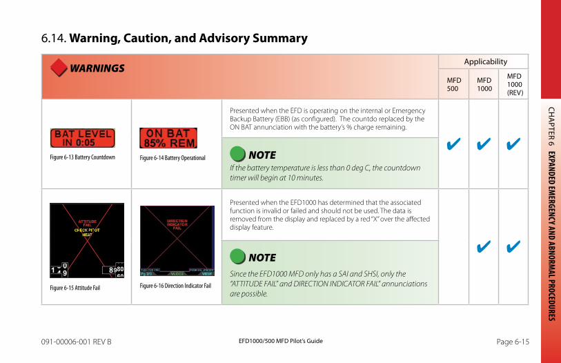
CHA
PTER 6 EXPANDED EMERGENCY AND ABNORM
AL PROCEDURES
EFD1000/500 MFD Pilot’s GuidePage 6-14 091-00006-001 REV B EFD1000/500 MFD Pilot’s Guide Page 6-15091-00006-001 REV B
6.14. Warning, Caution, and Advisory Summary
WARNINGSApplicability
MFD 500
MFD 1000
MFD 1000 (REV)
Figure 6-13 Battery Countdown Figure 6-14 Battery Operational
Presented when the EFD is operating on the internal or Emergency Backup Battery (EBB) (as configured). The countdo replaced by the ON BAT annunciation with the battery’s % charge remaining.
NOTE If the battery temperature is less than 0 deg C, the countdown timer will begin at 10 minutes.
Figure 6-15 Attitude Fail Figure 6-16 Direction Indicator Fail
Presented when the EFD1000 has determined that the associated function is invalid or failed and should not be used. The data is removed from the display and replaced by a red “X” over the affected display feature.
NOTE Since the EFD1000 MFD only has a SAI and SHSI, only the “ATTITUDE FAIL” and DIRECTION INDICATOR FAIL” annunciations are possible.
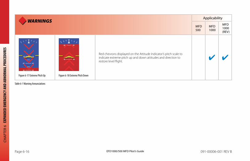
CHA
PTER
6 E
XPAN
DED
EMER
GENC
Y AND
ABN
ORM
AL P
ROCE
DURE
S
EFD1000/500 MFD Pilot’s GuidePage 6-16 091-00006-001 REV B EFD1000/500 MFD Pilot’s Guide Page 6-17091-00006-001 REV B
WARNINGSApplicability
MFD 500
MFD 1000
MFD 1000 (REV)
Figure 6-17 Extreme Pitch Up Figure 6-18 Extreme Pitch Down
Red chevrons displayed on the Attitude Indicator’s pitch scale to indicate extreme pitch up and down attitudes and direction to restore level flight.
Table 6-1 Warning Annunciations
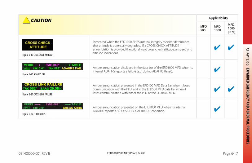
CHA
PTER 6 EXPANDED EMERGENCY AND ABNORM
AL PROCEDURES
EFD1000/500 MFD Pilot’s GuidePage 6-16 091-00006-001 REV B EFD1000/500 MFD Pilot’s Guide Page 6-17091-00006-001 REV B
CAUTION Applicability
MFD 500
MFD 1000
MFD 1000 (REV)
Figure 6-19 Cross Check Attitude
Presented when the EFD1000 AHRS internal integrity monitor determines that attitude is potentially degraded. If a CROSS CHECK ATTITUDE annunciation is provided the pilot should cross check attitude, airspeed and altitude indications.
Figure 6-20 ADAHRS FAIL
Amber annunciation displayed in the data bar of the EFD1000 MFD when its internal ADAHRS reports a failure (e.g. during ADAHRS Reset).
Figure 6-21 CROSS LINK FAILURE
Amber annunciation presented in the EFD100 MFD Data Bar when it loses communication with the PFD, and in the EFD500 MFD data bar when it loses communication with either the PFD or the EFD1000 MFD.
Figure 6-22 CHECK AHRS
Amber annunciation presented on the EFD1000 MFD when its internal ADAHRS reports a “CROSS CHECK ATTITUDE” condition.
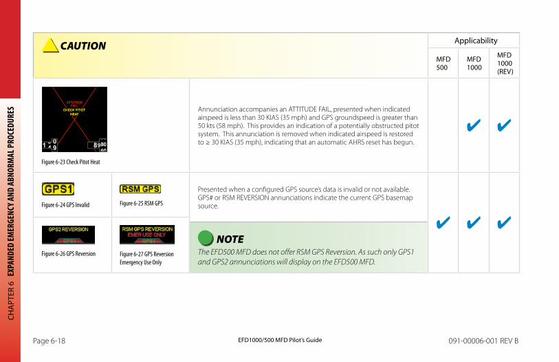
CHA
PTER
6 E
XPAN
DED
EMER
GENC
Y AND
ABN
ORM
AL P
ROCE
DURE
S
EFD1000/500 MFD Pilot’s GuidePage 6-18 091-00006-001 REV B EFD1000/500 MFD Pilot’s Guide Page 6-19091-00006-001 REV B
CAUTION Applicability
MFD 500
MFD 1000
MFD 1000 (REV)
Figure 6-23 Check Pitot Heat
Annunciation accompanies an ATTITUDE FAIL, presented when indicated airspeed is less than 30 KIAS (35 mph) and GPS groundspeed is greater than 50 kts (58 mph). This provides an indication of a potentially obstructed pitot system. This annunciation is removed when indicated airspeed is restored to ≥ 30 KIAS (35 mph), indicating that an automatic AHRS reset has begun.
Figure 6-24 GPS Invalid Figure 6-25 RSM GPS
Presented when a configured GPS source’s data is invalid or not available. GPS# or RSM REVERSION annunciations indicate the current GPS basemap source.
Figure 6-26 GPS Reversion Figure 6-27 GPS Reversion Emergency Use Only
NOTE The EFD500 MFD does not offer RSM GPS Reversion. As such only GPS1 and GPS2 annunciations will display on the EFD500 MFD.
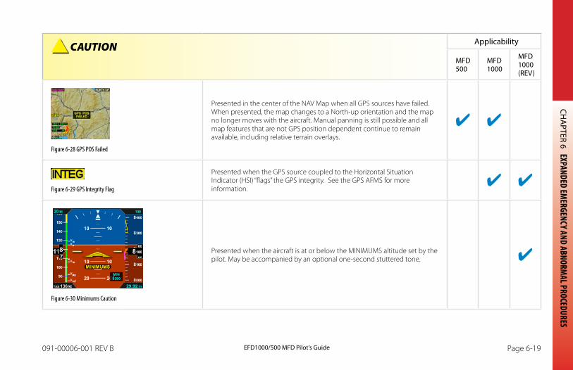
CHA
PTER 6 EXPANDED EMERGENCY AND ABNORM
AL PROCEDURES
EFD1000/500 MFD Pilot’s GuidePage 6-18 091-00006-001 REV B EFD1000/500 MFD Pilot’s Guide Page 6-19091-00006-001 REV B
CAUTION Applicability
MFD 500
MFD 1000
MFD 1000 (REV)
Figure 6-28 GPS POS Failed
Presented in the center of the NAV Map when all GPS sources have failed. When presented, the map changes to a North-up orientation and the map no longer moves with the aircraft. Manual panning is still possible and all map features that are not GPS position dependent continue to remain available, including relative terrain overlays.
Figure 6-29 GPS Integrity Flag
Presented when the GPS source coupled to the Horizontal Situation Indicator (HSI) “flags” the GPS integrity. See the GPS AFMS for more information.
Figure 6-30 Minimums Caution
Presented when the aircraft is at or below the MINIMUMS altitude set by the pilot. May be accompanied by an optional one-second stuttered tone.
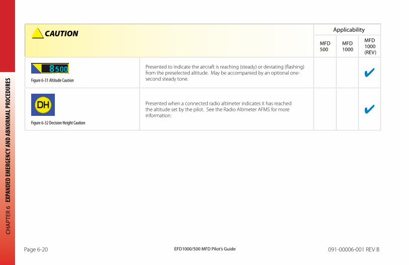
CHA
PTER
6 E
XPAN
DED
EMER
GENC
Y AND
ABN
ORM
AL P
ROCE
DURE
S
EFD1000/500 MFD Pilot’s GuidePage 6-20 091-00006-001 REV B EFD1000/500 MFD Pilot’s Guide Page 6-21091-00006-001 REV B
CAUTION Applicability
MFD 500
MFD 1000
MFD 1000 (REV)
Figure 6-31 Altitude Caution
Presented to indicate the aircraft is reaching (steady) or deviating (flashing) from the preselected altitude. May be accompanied by an optional one-second steady tone.
Figure 6-32 Decision Height Caution
Presented when a connected radio altimeter indicates it has reached the altitude set by the pilot. See the Radio Altimeter AFMS for more information.
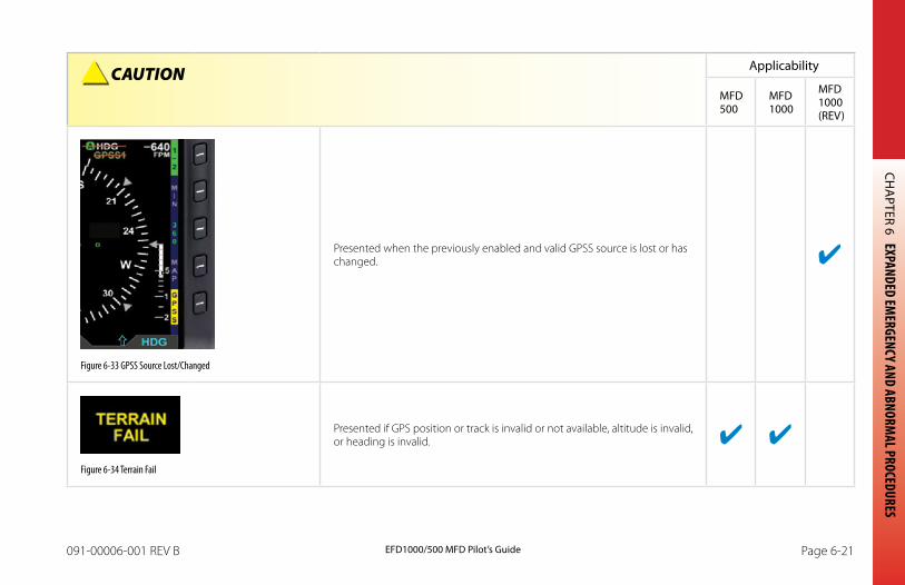
CHA
PTER 6 EXPANDED EMERGENCY AND ABNORM
AL PROCEDURES
EFD1000/500 MFD Pilot’s GuidePage 6-20 091-00006-001 REV B EFD1000/500 MFD Pilot’s Guide Page 6-21091-00006-001 REV B
CAUTION Applicability
MFD 500
MFD 1000
MFD 1000 (REV)
Figure 6-33 GPSS Source Lost/Changed
Presented when the previously enabled and valid GPSS source is lost or has changed.
Figure 6-34 Terrain Fail
Presented if GPS position or track is invalid or not available, altitude is invalid, or heading is invalid.
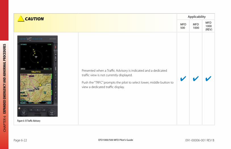
CHA
PTER
6 E
XPAN
DED
EMER
GENC
Y AND
ABN
ORM
AL P
ROCE
DURE
S
EFD1000/500 MFD Pilot’s GuidePage 6-22 091-00006-001 REV B EFD1000/500 MFD Pilot’s Guide Page 6-23091-00006-001 REV B
CAUTION Applicability
MFD 500
MFD 1000
MFD 1000 (REV)
Figure 6-35 Traffic Advisory
Presented when a Traffic Advisory is indicated and a dedicated traffic view is not currently displayed.
Push the “TRFC” prompts the pilot to select lower, middle button to view a dedicated traffic display.
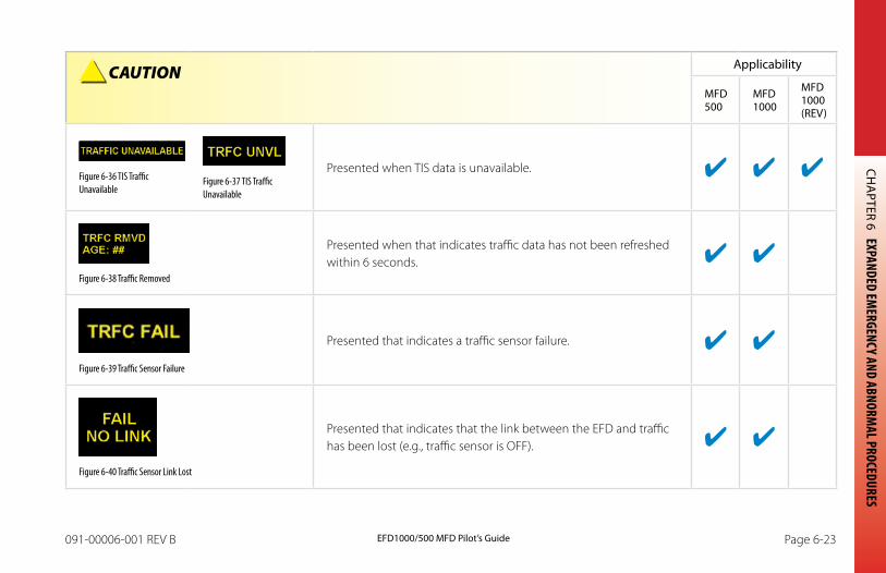
CHA
PTER 6 EXPANDED EMERGENCY AND ABNORM
AL PROCEDURES
EFD1000/500 MFD Pilot’s GuidePage 6-22 091-00006-001 REV B EFD1000/500 MFD Pilot’s Guide Page 6-23091-00006-001 REV B
CAUTION Applicability
MFD 500
MFD 1000
MFD 1000 (REV)
Figure 6-36 TIS Traffic Unavailable
Figure 6-37 TIS Traffic Unavailable
Presented when TIS data is unavailable.
Figure 6-38 Traffic Removed
Presented when that indicates traffic data has not been refreshed within 6 seconds.
Figure 6-39 Traffic Sensor Failure
Presented that indicates a traffic sensor failure.
Figure 6-40 Traffic Sensor Link Lost
Presented that indicates that the link between the EFD and traffic has been lost (e.g., traffic sensor is OFF).
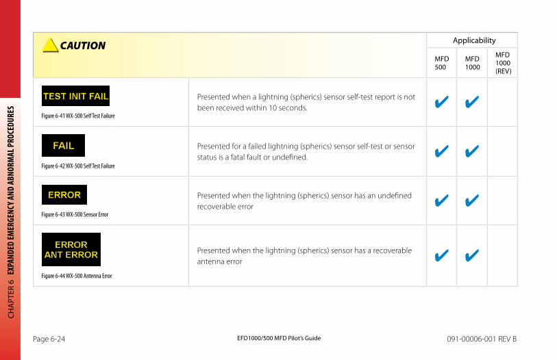
CHA
PTER
6 E
XPAN
DED
EMER
GENC
Y AND
ABN
ORM
AL P
ROCE
DURE
S
EFD1000/500 MFD Pilot’s GuidePage 6-24 091-00006-001 REV B EFD1000/500 MFD Pilot’s Guide Page 6-25091-00006-001 REV B
CAUTION Applicability
MFD 500
MFD 1000
MFD 1000 (REV)
Figure 6-41 WX-500 Self Test Failure
Presented when a lightning (spherics) sensor self-test report is not been received within 10 seconds.
Figure 6-42 WX-500 Self Test Failure
Presented for a failed lightning (spherics) sensor self-test or sensor status is a fatal fault or undefined.
Figure 6-43 WX-500 Sensor Error
Presented when the lightning (spherics) sensor has an undefined recoverable error
Figure 6-44 WX-500 Antenna Error
Presented when the lightning (spherics) sensor has a recoverable antenna error
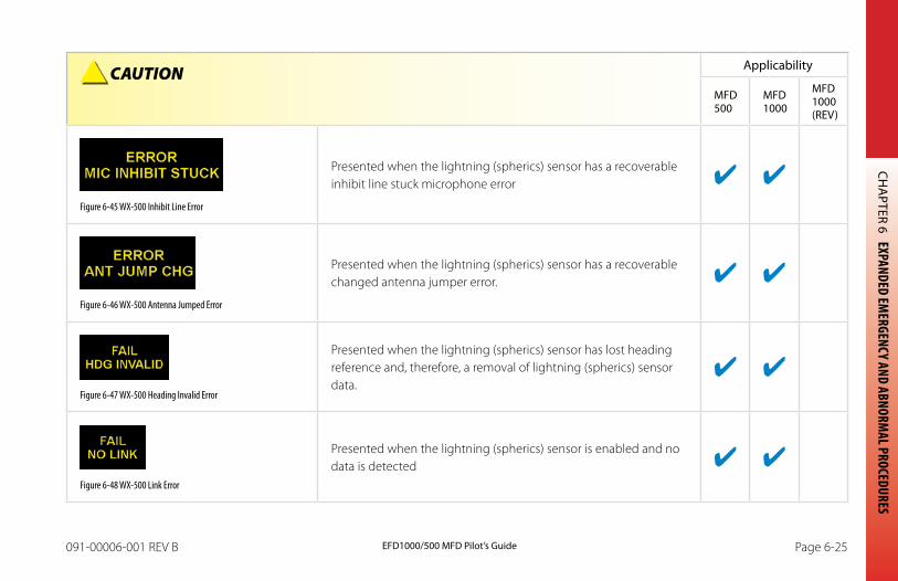
CHA
PTER 6 EXPANDED EMERGENCY AND ABNORM
AL PROCEDURES
EFD1000/500 MFD Pilot’s GuidePage 6-24 091-00006-001 REV B EFD1000/500 MFD Pilot’s Guide Page 6-25091-00006-001 REV B
CAUTION Applicability
MFD 500
MFD 1000
MFD 1000 (REV)
Figure 6-45 WX-500 Inhibit Line Error
Presented when the lightning (spherics) sensor has a recoverable inhibit line stuck microphone error
Figure 6-46 WX-500 Antenna Jumped Error
Presented when the lightning (spherics) sensor has a recoverable changed antenna jumper error.
Figure 6-47 WX-500 Heading Invalid Error
Presented when the lightning (spherics) sensor has lost heading reference and, therefore, a removal of lightning (spherics) sensor data.
Figure 6-48 WX-500 Link Error
Presented when the lightning (spherics) sensor is enabled and no data is detected
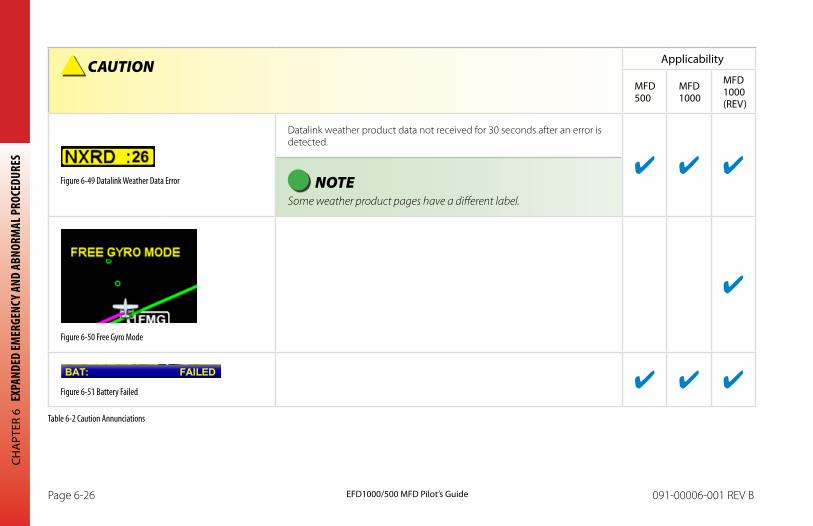
CHA
PTER
6 E
XPAN
DED
EMER
GENC
Y AND
ABN
ORM
AL P
ROCE
DURE
S
EFD1000/500 MFD Pilot’s GuidePage 6-26 091-00006-001 REV B EFD1000/500 MFD Pilot’s Guide Page 6-27091-00006-001 REV B
CAUTION Applicability
MFD 500
MFD 1000
MFD 1000 (REV)
Figure 6-49 Datalink Weather Data Error
Datalink weather product data not received for 30 seconds after an error is detected.
NOTE Some weather product pages have a different label.
Figure 6-50 Free Gyro Mode
Figure 6-51 Battery Failed
Table 6-2 Caution Annunciations
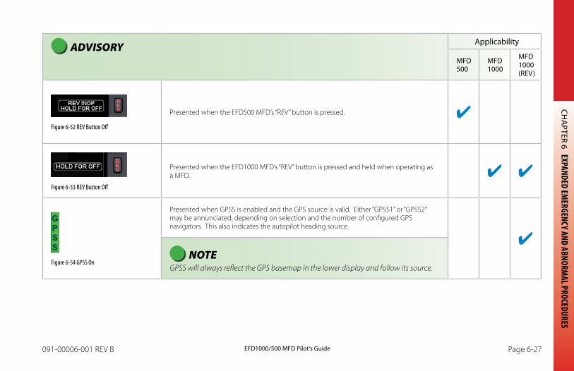
CHA
PTER 6 EXPANDED EMERGENCY AND ABNORM
AL PROCEDURES
EFD1000/500 MFD Pilot’s GuidePage 6-26 091-00006-001 REV B EFD1000/500 MFD Pilot’s Guide Page 6-27091-00006-001 REV B
ADVISORY Applicability
MFD 500
MFD 1000
MFD 1000 (REV)
Figure 6-52 REV Button Off
Presented when the EFD500 MFD’s “REV” button is pressed.
Figure 6-53 REV Button Off
Presented when the EFD1000 MFD’s “REV” button is pressed and held when operating as a MFD.
Figure 6-54 GPSS On
Presented when GPSS is enabled and the GPS source is valid. Either “GPSS1” or “GPSS2” may be annunciated, depending on selection and the number of configured GPS navigators. This also indicates the autopilot heading source.
NOTE GPSS will always reflect the GPS basemap in the lower display and follow its source.
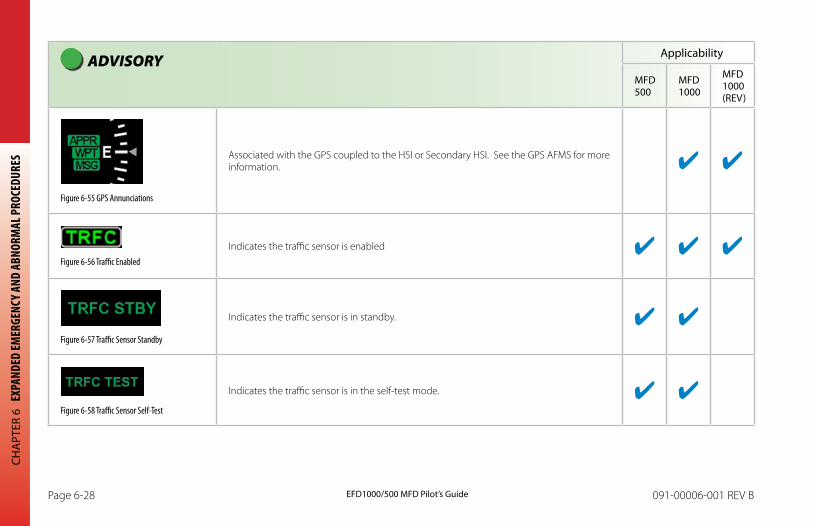
CHA
PTER
6 E
XPAN
DED
EMER
GENC
Y AND
ABN
ORM
AL P
ROCE
DURE
S
EFD1000/500 MFD Pilot’s GuidePage 6-28 091-00006-001 REV B EFD1000/500 MFD Pilot’s Guide Page 6-29091-00006-001 REV B
ADVISORY Applicability
MFD 500
MFD 1000
MFD 1000 (REV)
Figure 6-55 GPS Annunciations
Associated with the GPS coupled to the HSI or Secondary HSI. See the GPS AFMS for more information.
Figure 6-56 Traffic Enabled
Indicates the traffic sensor is enabled
Figure 6-57 Traffic Sensor Standby
Indicates the traffic sensor is in standby.
Figure 6-58 Traffic Sensor Self-Test
Indicates the traffic sensor is in the self-test mode.
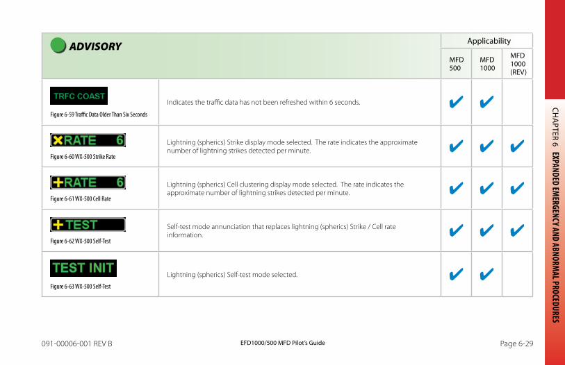
CHA
PTER 6 EXPANDED EMERGENCY AND ABNORM
AL PROCEDURES
EFD1000/500 MFD Pilot’s GuidePage 6-28 091-00006-001 REV B EFD1000/500 MFD Pilot’s Guide Page 6-29091-00006-001 REV B
ADVISORY Applicability
MFD 500
MFD 1000
MFD 1000 (REV)
Figure 6-59 Traffic Data Older Than Six Seconds
Indicates the traffic data has not been refreshed within 6 seconds.
Figure 6-60 WX-500 Strike Rate
Lightning (spherics) Strike display mode selected. The rate indicates the approximate number of lightning strikes detected per minute.
Figure 6-61 WX-500 Cell Rate
Lightning (spherics) Cell clustering display mode selected. The rate indicates the approximate number of lightning strikes detected per minute.
Figure 6-62 WX-500 Self-Test
Self-test mode annunciation that replaces lightning (spherics) Strike / Cell rate information.
Figure 6-63 WX-500 Self-Test
Lightning (spherics) Self-test mode selected.
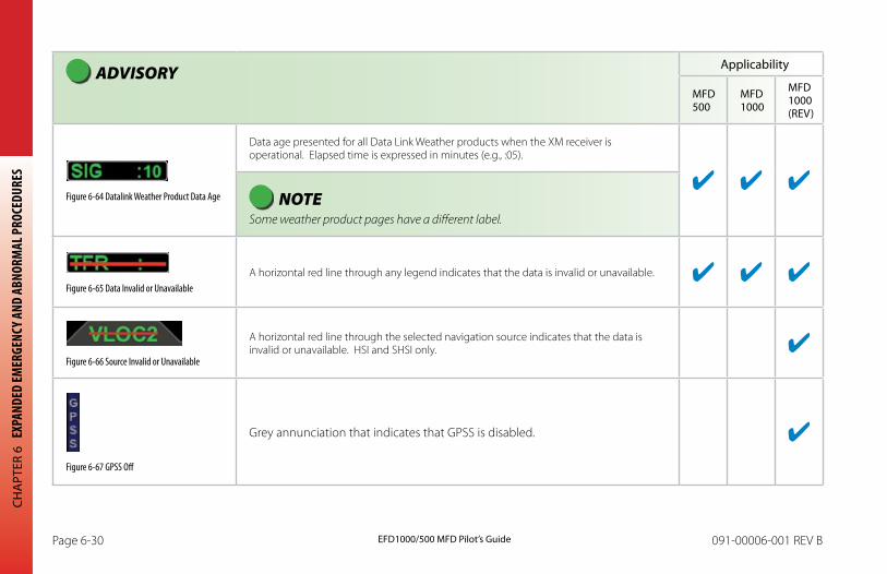
CHA
PTER
6 E
XPAN
DED
EMER
GENC
Y AND
ABN
ORM
AL P
ROCE
DURE
S
EFD1000/500 MFD Pilot’s GuidePage 6-30 091-00006-001 REV B EFD1000/500 MFD Pilot’s Guide Page 6-31091-00006-001 REV B
ADVISORY Applicability
MFD 500
MFD 1000
MFD 1000 (REV)
Figure 6-64 Datalink Weather Product Data Age
Data age presented for all Data Link Weather products when the XM receiver is operational. Elapsed time is expressed in minutes (e.g., :05).
NOTE Some weather product pages have a different label.
Figure 6-65 Data Invalid or UnavailableA horizontal red line through any legend indicates that the data is invalid or unavailable.
Figure 6-66 Source Invalid or Unavailable
A horizontal red line through the selected navigation source indicates that the data is invalid or unavailable. HSI and SHSI only.
Figure 6-67 GPSS Off
Grey annunciation that indicates that GPSS is disabled.
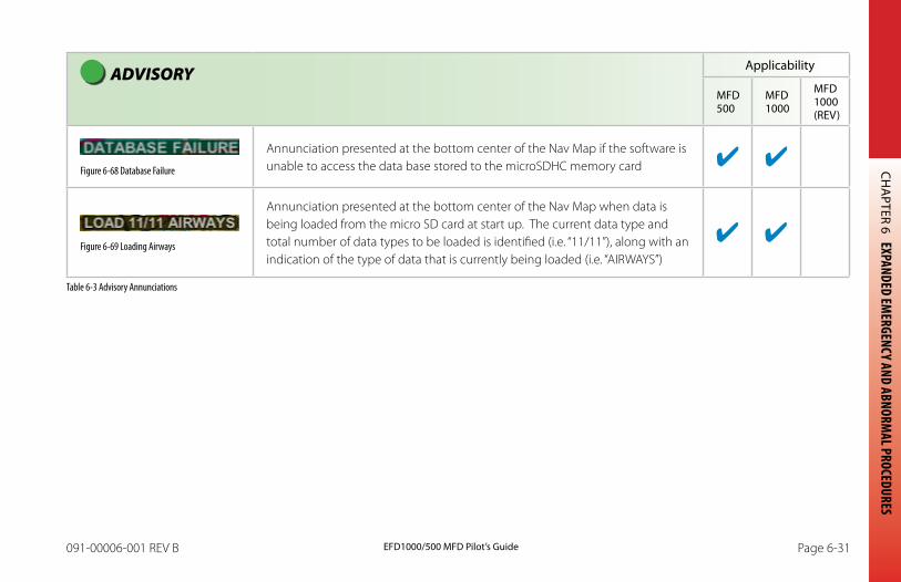
CHA
PTER 6 EXPANDED EMERGENCY AND ABNORM
AL PROCEDURES
EFD1000/500 MFD Pilot’s GuidePage 6-30 091-00006-001 REV B EFD1000/500 MFD Pilot’s Guide Page 6-31091-00006-001 REV B
ADVISORY Applicability
MFD 500
MFD 1000
MFD 1000 (REV)
Figure 6-68 Database Failure
Annunciation presented at the bottom center of the Nav Map if the software is unable to access the data base stored to the microSDHC memory card
Figure 6-69 Loading Airways
Annunciation presented at the bottom center of the Nav Map when data is being loaded from the micro SD card at start up. The current data type and total number of data types to be loaded is identified (i.e. “11/11”), along with an indication of the type of data that is currently being loaded (i.e. “AIRWAYS”)
Table 6-3 Advisory Annunciations

CHA
PTER
6 E
XPAN
DED
EMER
GENC
Y AND
ABN
ORM
AL P
ROCE
DURE
S
EFD1000/500 MFD Pilot’s GuidePage 6-32 091-00006-001 REV B EFD1000/500 MFD Pilot’s Guide Page PB091-00006-001 REV B
This Page Intentionally Left Blank
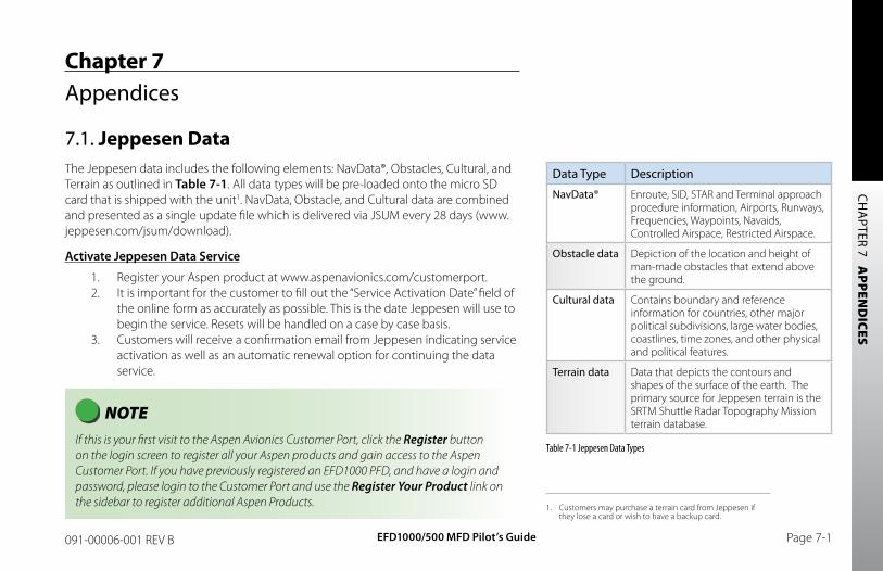
CH
APTER 7 A
PPEND
ICES
EFD1000/500 MFD Pilot’s Guide Page 7-1091-00006-001 REV B
Chapter 7Appendices
7.1. Jeppesen DataThe Jeppesen data includes the following elements: NavData®, Obstacles, Cultural, and Terrain as outlined in Table 7-1. All data types will be pre-loaded onto the micro SD card that is shipped with the unit1. NavData, Obstacle, and Cultural data are combined and presented as a single update file which is delivered via JSUM every 28 days (www.jeppesen.com/jsum/download).
Activate Jeppesen Data Service
1. Register your Aspen product at www.aspenavionics.com/customerport.2. It is important for the customer to fill out the “Service Activation Date” field of
the online form as accurately as possible. This is the date Jeppesen will use to begin the service. Resets will be handled on a case by case basis.
3. Customers will receive a confirmation email from Jeppesen indicating service activation as well as an automatic renewal option for continuing the data service.
Data Type Description
NavData® Enroute, SID, STAR and Terminal approach procedure information, Airports, Runways, Frequencies, Waypoints, Navaids, Controlled Airspace, Restricted Airspace.
Obstacle data Depiction of the location and height of man-made obstacles that extend above the ground.
Cultural data Contains boundary and reference information for countries, other major political subdivisions, large water bodies, coastlines, time zones, and other physical and political features.
Terrain data Data that depicts the contours and shapes of the surface of the earth. The primary source for Jeppesen terrain is the SRTM Shuttle Radar Topography Mission terrain database.
Table 7-1 Jeppesen Data Types
NOTE If this is your first visit to the Aspen Avionics Customer Port, click the Register button on the login screen to register all your Aspen products and gain access to the Aspen Customer Port. If you have previously registered an EFD1000 PFD, and have a login and password, please login to the Customer Port and use the Register Your Product link on the sidebar to register additional Aspen Products. 1. Customers may purchase a terrain card from Jeppesen if
they lose a card or wish to have a backup card.

CH
APT
ER 7
A
PPEN
DIC
ES
EFD1000/500 MFD Pilot’s GuidePage 7-2 091-00006-001 REV B
If you lose your microSDHC card or would like to have an extra one, contact Jeppesen directly to purchase an additional or replacement terrain card. Jeppesen Customer Service: 1-800-621-5377 or email [email protected]
7.1.1. Jeppesen Technical Support
For questions and troubleshooting on installing and/or using the JSUM application and loading data from JSUM to the micro SD card, contact Jeppesen Technical Support. This team can also direct your call if you have questions about the content of your Jeppesen data.
800-732-2800 or 303-328-4587 (24/7) [email protected] (24/7) Live Chat (Mon-Fri 8am-4pm MST) www.jeppesen.com > Support > Technical Support
For questions about Customer accounts, username/passwords, other Jeppesen products and services contact Jeppesen Customer Service.
800-621-5377 or 303-799-9090 [email protected]
For questions about Evolution Flight Display functionality, contact Aspen Avionics.
[email protected] 505-856-5034
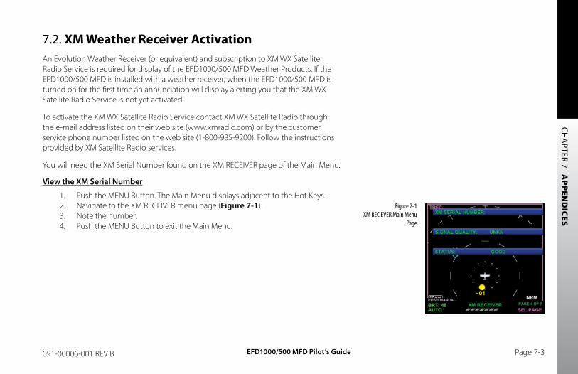
CH
APTER 7 A
PPEND
ICES
EFD1000/500 MFD Pilot’s Guide Page 7-3091-00006-001 REV B
7.2. XM Weather Receiver ActivationAn Evolution Weather Receiver (or equivalent) and subscription to XM WX Satellite Radio Service is required for display of the EFD1000/500 MFD Weather Products. If the EFD1000/500 MFD is installed with a weather receiver, when the EFD1000/500 MFD is turned on for the first time an annunciation will display alerting you that the XM WX Satellite Radio Service is not yet activated.
To activate the XM WX Satellite Radio Service contact XM WX Satellite Radio through the e-mail address listed on their web site (www.xmradio.com) or by the customer service phone number listed on the web site (1-800-985-9200). Follow the instructions provided by XM Satellite Radio services.
You will need the XM Serial Number found on the XM RECEIVER page of the Main Menu.
View the XM Serial Number
1. Push the MENU Button. The Main Menu displays adjacent to the Hot Keys.2. Navigate to the XM RECEIVER menu page (Figure 7-1).3. Note the number.4. Push the MENU Button to exit the Main Menu.
Figure 7-1 XM RECIEVER Main Menu
Page
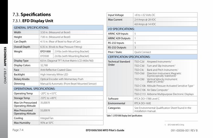
CH
APT
ER 7
A
PPEN
DIC
ES
EFD1000/500 MFD Pilot’s GuidePage 7-4 091-00006-001 REV B
Input Voltage +8 to +32 Volts DC
Max Current 2.4 Amps @ 28 VDC
4.8 Amps @ 14 VDC
I/O SPECIFICATIONS:ARINC 429 Inputs 5
ARINC 429 Outputs 1
RS-232 Inputs 5
RS-232 Outputs 3
Pitot / Static Quick Connect
CERTIFICATION SPECIFICATIONS:Technical Standard Order
TSO-C2d Airspeed Instruments 1
TSO-C3d Turn and Slip Instrument 1
TSO-C4c Bank and Pitch Instruments 1
TSO-C6d Direction Instrument Magnetic (Gyroscopically Stabilized) 1
TSO-C8d Vertical Velocity Instrument (Rate of Climb) 1
TSO-C10b Altitude Pressure Activated Sensitive Type 1
TSO-C106 Air Data Computer 1
TSO-C113 Airborne Multipurpose Electronic Displays
Software RTCA DO-178B Level C
Environmental RTCA DO-160E
Categories See Environmental Qualification Sheet found in the installation manual.
Table 7-2 EFD1000 Display Unit Specifications
7.3. Specifications7.3.1. EFD Display Unit
GENERAL SPECIFICATIONS:Width 3.50 in. (Measured at Bezel)
Height 7.00 in. (Measured at Bezel)
Can Depth 4.15 in. (Rear of Bezel to Rear of Can)
Overall Depth 6.35 in. (Knob to Rear Pressure Fitting)
Weight EFD1000 2.9 lbs (with Mounting Bracket)
EFD500 2.6 lbs (with Mounting Bracket)
Display Type 6.0 in. Diagonal TFT Active Matrix LCD (400x760)
Display Colors 32,768
Face Anti-Reflective Coated Glass
Backlight High Intensity White LED
Rotary Knobs Optical Encoder with Momentary Push
Dimming Manual & Automatic (Front Bezel Mounted Sensor)
OPERATIONAL SPECIFICATIONS:Operating Temp -20°C to +55°C
Storage Temp -55°C to +85°C
Max Un-Pressurized Operating Altitude
35,000 ft
Max Pressurized Operating Altitude
55,000 ft
Cooling Integral Fan
Max Humidity 95% at 50°C1. EFD1000 MFD Only.
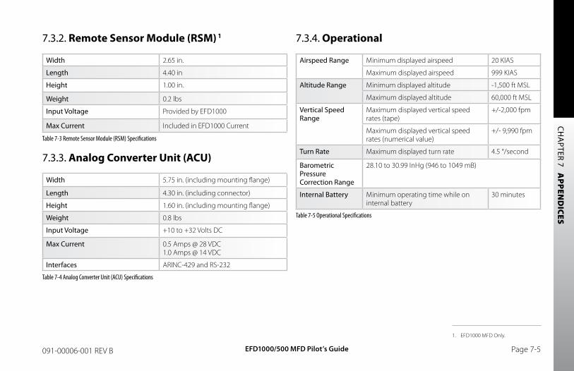
CH
APTER 7 A
PPEND
ICES
EFD1000/500 MFD Pilot’s Guide Page 7-5091-00006-001 REV B
7.3.2. Remote Sensor Module (RSM) 1
Width 2.65 in.
Length 4.40 in
Height 1.00 in.
Weight 0.2 lbs
Input Voltage Provided by EFD1000
Max Current Included in EFD1000 Current
Table 7-3 Remote Sensor Module (RSM) Specifications
7.3.3. Analog Converter Unit (ACU)
Width 5.75 in. (including mounting flange)
Length 4.30 in. (including connector)
Height 1.60 in. (including mounting flange)
Weight 0.8 lbs
Input Voltage +10 to +32 Volts DC
Max Current 0.5 Amps @ 28 VDC 1.0 Amps @ 14 VDC
Interfaces ARINC-429 and RS-232
Table 7-4 Analog Converter Unit (ACU) Specifications
7.3.4. Operational
Airspeed Range Minimum displayed airspeed 20 KIAS
Maximum displayed airspeed 999 KIAS
Altitude Range Minimum displayed altitude -1,500 ft MSL
Maximum displayed altitude 60,000 ft MSL
Vertical Speed Range
Maximum displayed vertical speed rates (tape)
+/-2,000 fpm
Maximum displayed vertical speed rates (numerical value)
+/- 9,990 fpm
Turn Rate Maximum displayed turn rate 4.5 °/second
Barometric Pressure Correction Range
28.10 to 30.99 InHg (946 to 1049 mB)
Internal Battery Minimum operating time while on internal battery
30 minutes
Table 7-5 Operational Specifications
1. EFD1000 MFD Only.
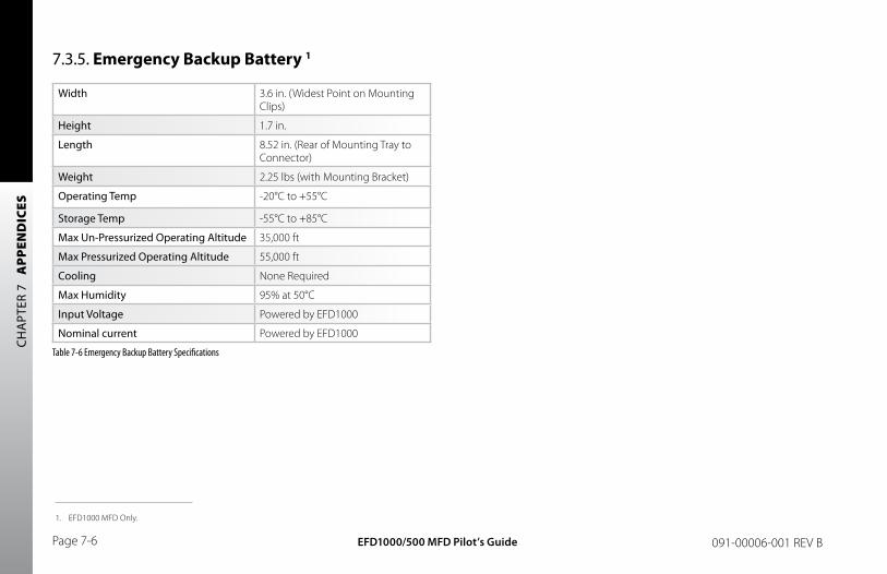
CH
APT
ER 7
A
PPEN
DIC
ES
EFD1000/500 MFD Pilot’s GuidePage 7-6 091-00006-001 REV B
7.3.5. Emergency Backup Battery 1
Width 3.6 in. (Widest Point on Mounting Clips)
Height 1.7 in.
Length 8.52 in. (Rear of Mounting Tray to Connector)
Weight 2.25 lbs (with Mounting Bracket)
Operating Temp -20°C to +55°C
Storage Temp -55°C to +85°C
Max Un-Pressurized Operating Altitude 35,000 ft
Max Pressurized Operating Altitude 55,000 ft
Cooling None Required
Max Humidity 95% at 50°C
Input Voltage Powered by EFD1000
Nominal current Powered by EFD1000
Table 7-6 Emergency Backup Battery Specifications
1. EFD1000 MFD Only.
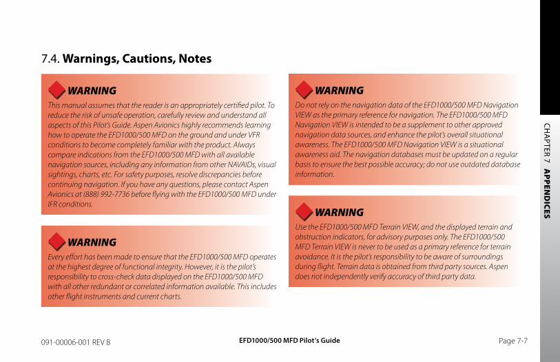
CH
APTER 7 A
PPEND
ICES
EFD1000/500 MFD Pilot’s Guide Page 7-7091-00006-001 REV B
7.4. Warnings, Cautions, Notes
WARNING This manual assumes that the reader is an appropriately certified pilot. To reduce the risk of unsafe operation, carefully review and understand all aspects of this Pilot’s Guide. Aspen Avionics highly recommends learning how to operate the EFD1000/500 MFD on the ground and under VFR conditions to become completely familiar with the product. Always compare indications from the EFD1000/500 MFD with all available navigation sources, including any information from other NAVAIDs, visual sightings, charts, etc. For safety purposes, resolve discrepancies before continuing navigation. If you have any questions, please contact Aspen Avionics at (888) 992-7736 before flying with the EFD1000/500 MFD under IFR conditions.
WARNING Every effort has been made to ensure that the EFD1000/500 MFD operates at the highest degree of functional integrity. However, it is the pilot’s responsibility to cross-check data displayed on the EFD1000/500 MFD with all other redundant or correlated information available. This includes other flight instruments and current charts.
WARNING Do not rely on the navigation data of the EFD1000/500 MFD Navigation VIEW as the primary reference for navigation. The EFD1000/500 MFD Navigation VIEW is intended to be a supplement to other approved navigation data sources, and enhance the pilot’s overall situational awareness. The EFD1000/500 MFD Navigation VIEW is a situational awareness aid. The navigation databases must be updated on a regular basis to ensure the best possible accuracy; do not use outdated database information.
WARNING Use the EFD1000/500 MFD Terrain VIEW, and the displayed terrain and obstruction indicators, for advisory purposes only. The EFD1000/500 MFD Terrain VIEW is never to be used as a primary reference for terrain avoidance. It is the pilot’s responsibility to be aware of surroundings during flight. Terrain data is obtained from third party sources. Aspen does not independently verify accuracy of third party data.
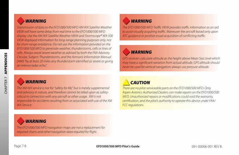
CH
APT
ER 7
A
PPEN
DIC
ES
EFD1000/500 MFD Pilot’s GuidePage 7-8 091-00006-001 REV B
WARNING Transmission of data to the EFD1000/500 MFD XM WX Satellite Weather VIEW will have some delay from real time to the EFD1000/500 MFD display. Use the XM WX Satellite Weather VIEW and Stormscope® WX-500 VIEW displayed information for long-range planning purposes only, not for short-range avoidance. Do not use the information provided on the EFD1000/500 MFD to penetrate weather, thunderstorms, cells or lines of cells. Always avoid severe weather as advised by both the FAA Advisory Circular, Subject: Thunderstorms, and the Airman’s Information Manual (AIM) “by at least 20 miles any thunderstorm identified as severe or giving an intense radar echo.”
WARNING The XM WX service is not for “safety for life,” but is merely supplemental and advisory in nature, and therefore cannot be relied upon as safety-critical in connection with any aircraft or other usage. XM is not responsible for accidents resulting from or associated with use of the XM WX Service.
WARNING The EFD1000/500 MFD navigation maps are not a replacement for required charts and other navigation data required for flight.
WARNING The EFD1000/500 MFD Traffic VIEW provides traffic information as an aid to assist visually acquiring traffic. Maneuver the aircraft based only upon ATC guidance or positive visual acquisition of conflicting traffic.
WARNING GPS receivers calculate altitude as the height above Mean Sea Level which may have a significant variation from actual altitude. GPS altitude should never be used for vertical navigation; always use pressure altitude.
CAUTION There are no pilot-serviceable parts on the EFD1000/500 MFD. Only Aspen Avionics Authorized Dealers can make repairs on the EFD1000/500 MFD. Unauthorized repairs or modifications could void the warranty, certification, and the pilot’s authority to operate this device under FAA/FCC regulations.
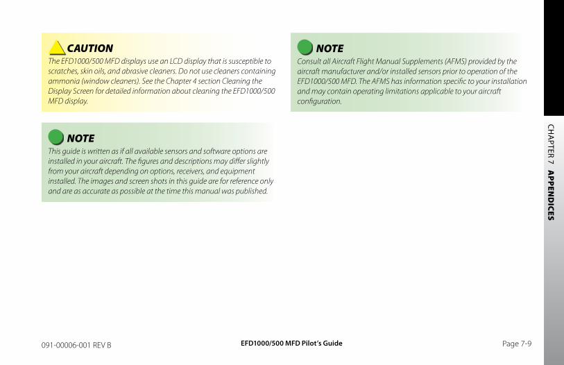
CH
APTER 7 A
PPEND
ICES
EFD1000/500 MFD Pilot’s Guide Page 7-9091-00006-001 REV B
CAUTION The EFD1000/500 MFD displays use an LCD display that is susceptible to scratches, skin oils, and abrasive cleaners. Do not use cleaners containing ammonia (window cleaners). See the Chapter 4 section Cleaning the Display Screen for detailed information about cleaning the EFD1000/500 MFD display.
NOTE This guide is written as if all available sensors and software options are installed in your aircraft. The figures and descriptions may differ slightly from your aircraft depending on options, receivers, and equipment installed. The images and screen shots in this guide are for reference only and are as accurate as possible at the time this manual was published.
NOTE Consult all Aircraft Flight Manual Supplements (AFMS) provided by the aircraft manufacturer and/or installed sensors prior to operation of the EFD1000/500 MFD. The AFMS has information specific to your installation and may contain operating limitations applicable to your aircraft configuration.
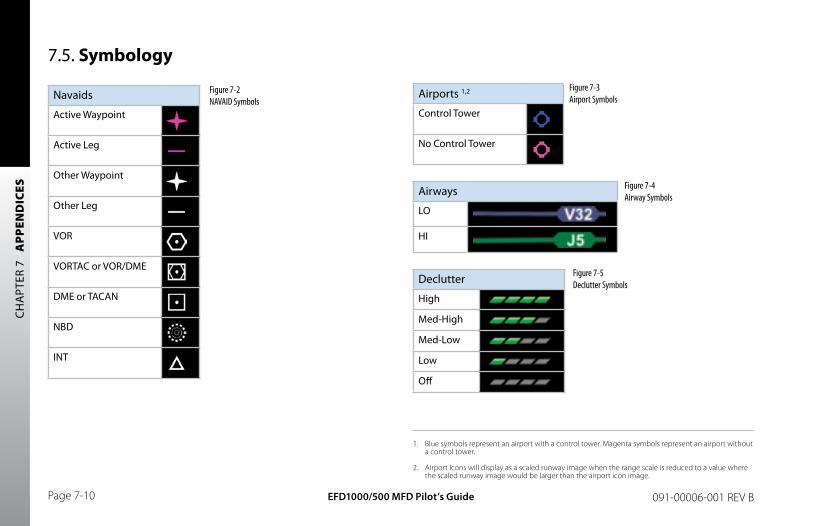
CH
APT
ER 7
A
PPEN
DIC
ES
EFD1000/500 MFD Pilot’s GuidePage 7-10 091-00006-001 REV B
7.5. Symbology
Navaids
Active Waypoint
Active Leg
Other Waypoint
Other Leg
VOR
VORTAC or VOR/DME
DME or TACAN
NBD
INT
Airports 1,2
Control Tower
No Control Tower
Airways
LO
HI
Declutter
High
Med-High
Med-Low
Low
Off
1. Blue symbols represent an airport with a control tower. Magenta symbols represent an airport without a control tower.
2. Airport Icons will display as a scaled runway image when the range scale is reduced to a value where the scaled runway image would be larger than the airport icon image.
Figure 7-2 NAVAID Symbols
Figure 7-3 Airport Symbols
Figure 7-5 Declutter Symbols
Figure 7-4 Airway Symbols
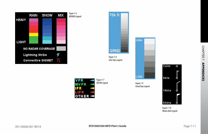
CH
APTER 7 A
PPEND
ICES
EFD1000/500 MFD Pilot’s Guide Page 7-11091-00006-001 REV B
Figure 7-6 NEXRAD Legend
Figure 7-7 METAR Legend
Figure 7-8 Echo Tops Legend
Figure 7-9 Cloud Tops Legend
Figure 7-10 Winds Aloft Legend
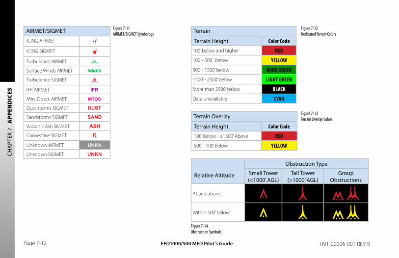
CH
APT
ER 7
A
PPEN
DIC
ES
EFD1000/500 MFD Pilot’s GuidePage 7-12 091-00006-001 REV B
AIRMET/SIGMET
ICING AIRMET
ICING SIGMET
Turbulence AIRMET
Surface Winds AIRMET
Turbulence SIGMET
IFR AIRMET
Mtn. Obscr. AIRMET
Dust storms SIGMET
Sandstorms SIGMET
Volcanic Ash SIGMET
Convective SIGMET
Unknown AIRMET
Unknown SIGMET
Terrain
Terrain Height Color Code
100’ below and higher RED
100’ - 500’ below YELLOW
500’ - 1500’ below DARK GREEN
1500’ - 2500’ below LIGHT GREEN
More than 2500’ below BLACK
Data unavailable CYAN
Terrain Overlay
Terrain Height Color Code
100’ Below - ≥1500’ Above RED
500’ - 100’ Below YELLOW
Relative Altitude
Obstruction Type
Small Tower (<1000’ AGL)
Tall Tower (>1000’ AGL)
Group Obstructions
At and above
Within 500’ below
Figure 7-11 AIRMET/SIGMET Symbology
Figure 7-12 Dedicated Terrain Colors
Figure 7-13 Terrain Overlay Colors
Figure 7-14 Obstruction Symbols
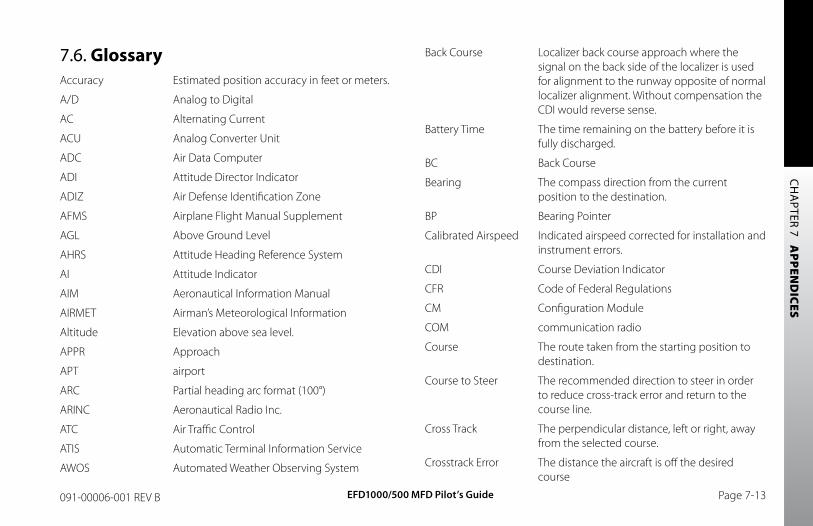
CH
APTER 7 A
PPEND
ICES
EFD1000/500 MFD Pilot’s Guide Page 7-13091-00006-001 REV B
7.6. GlossaryAccuracy Estimated position accuracy in feet or meters.
A/D Analog to Digital
AC Alternating Current
ACU Analog Converter Unit
ADC Air Data Computer
ADI Attitude Director Indicator
ADIZ Air Defense Identification Zone
AFMS Airplane Flight Manual Supplement
AGL Above Ground Level
AHRS Attitude Heading Reference System
AI Attitude Indicator
AIM Aeronautical Information Manual
AIRMET Airman’s Meteorological Information
Altitude Elevation above sea level.
APPR Approach
APT airport
ARC Partial heading arc format (100°)
ARINC Aeronautical Radio Inc.
ATC Air Traffic Control
ATIS Automatic Terminal Information Service
AWOS Automated Weather Observing System
Back Course Localizer back course approach where the signal on the back side of the localizer is used for alignment to the runway opposite of normal localizer alignment. Without compensation the CDI would reverse sense.
Battery Time The time remaining on the battery before it is fully discharged.
BC Back Course
Bearing The compass direction from the current position to the destination.
BP Bearing Pointer
Calibrated Airspeed Indicated airspeed corrected for installation and instrument errors.
CDI Course Deviation Indicator
CFR Code of Federal Regulations
CM Configuration Module
COM communication radio
Course The route taken from the starting position to destination.
Course to Steer The recommended direction to steer in order to reduce cross-track error and return to the course line.
Cross Track The perpendicular distance, left or right, away from the selected course.
Crosstrack Error The distance the aircraft is off the desired course
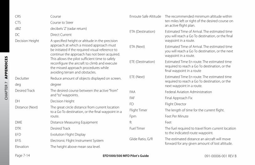
CH
APT
ER 7
A
PPEN
DIC
ES
EFD1000/500 MFD Pilot’s GuidePage 7-14 091-00006-001 REV B
CRS Course
CTS Course to Steer
dBZ decibels ‘Z’ (radar return)
DC Direct Current
Decision Height A specified height or altitude in the precision approach at which a missed approach must be initiated if the required visual reference to continue the approach has not been acquired. This allows the pilot sufficient time to safely reconfigure the aircraft to climb and execute the missed approach procedures while avoiding terrain and obstacles.
Declutter Reduce amount of objects displayed on screen.
deg degree
Desired Track The desired course between the active “from” and “to” waypoints.
DH Decision Height
Distance (Next) The great circle distance from current location to a Go To destination, or the final waypoint in a route.
DME Distance Measuring Equipment
DTK Desired Track
EFD Evolution Flight Display
EFIS Electronic Flight Instrument System
Elevation The height above mean sea level.
Enroute Safe Altitude The recommended minimum altitude within ten miles left or right of the desired course on an active flight plan.
ETA (Destination) Estimated Time of Arrival. The estimated time you will reach a Go To destination, or the final waypoint in a route.
ETA (Next) Estimated Time of Arrival. The estimated time you will reach a Go To destination, or the next waypoint in a route.
ETE (Destination) Estimated Time En route. The estimated time required to reach a Go To destination, or the final waypoint in a route
ETE (Next) Estimated Time En route. The estimated time required to reach a Go To destination, or the next waypoint in a route.
FAA Federal Aviation Administration
FAF Final Approach Fix
FD Flight Director
Flight Timer The length of time for the current flight.
Fpm Feet Per Minute
ft Feet
Fuel Timer The fuel required to travel from current location to the indicated route waypoint.
Glide Ratio, G/R The estimated distance an aircraft will move forward for any given amount of lost altitude.
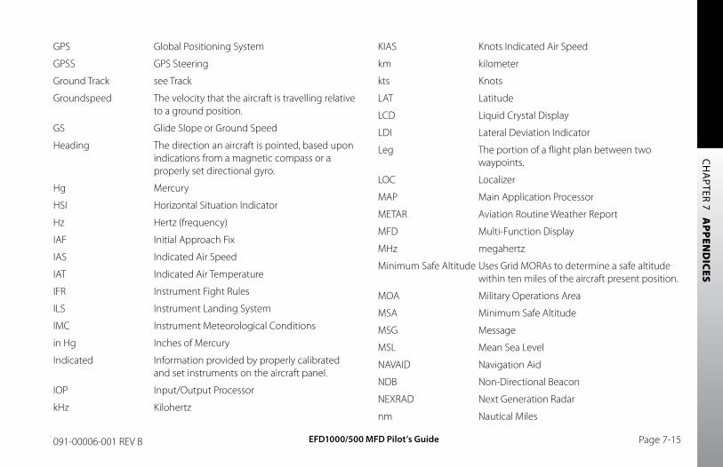
CH
APTER 7 A
PPEND
ICES
EFD1000/500 MFD Pilot’s Guide Page 7-15091-00006-001 REV B
GPS Global Positioning System
GPSS GPS Steering
Ground Track see Track
Groundspeed The velocity that the aircraft is travelling relative to a ground position.
GS Glide Slope or Ground Speed
Heading The direction an aircraft is pointed, based upon indications from a magnetic compass or a properly set directional gyro.
Hg Mercury
HSI Horizontal Situation Indicator
Hz Hertz (frequency)
IAF Initial Approach Fix
IAS Indicated Air Speed
IAT Indicated Air Temperature
IFR Instrument Fight Rules
ILS Instrument Landing System
IMC Instrument Meteorological Conditions
in Hg Inches of Mercury
Indicated Information provided by properly calibrated and set instruments on the aircraft panel.
IOP Input/Output Processor
kHz Kilohertz
KIAS Knots Indicated Air Speed
km kilometer
kts Knots
LAT Latitude
LCD Liquid Crystal Display
LDI Lateral Deviation Indicator
Leg The portion of a flight plan between two waypoints.
LOC Localizer
MAP Main Application Processor
METAR Aviation Routine Weather Report
MFD Multi-Function Display
MHz megahertz
Minimum Safe Altitude Uses Grid MORAs to determine a safe altitude within ten miles of the aircraft present position.
MOA Military Operations Area
MSA Minimum Safe Altitude
MSG Message
MSL Mean Sea Level
NAVAID Navigation Aid
NDB Non-Directional Beacon
NEXRAD Next Generation Radar
nm Nautical Miles
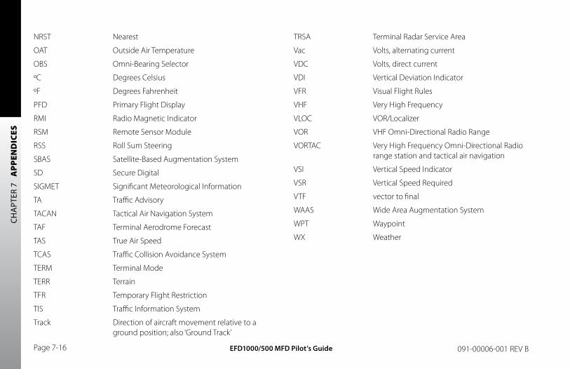
CH
APT
ER 7
A
PPEN
DIC
ES
EFD1000/500 MFD Pilot’s GuidePage 7-16 091-00006-001 REV B
NRST Nearest
OAT Outside Air Temperature
OBS Omni-Bearing Selector
ºC Degrees Celsius
ºF Degrees Fahrenheit
PFD Primary Flight Display
RMI Radio Magnetic Indicator
RSM Remote Sensor Module
RSS Roll Sum Steering
SBAS Satellite-Based Augmentation System
SD Secure Digital
SIGMET Significant Meteorological Information
TA Traffic Advisory
TACAN Tactical Air Navigation System
TAF Terminal Aerodrome Forecast
TAS True Air Speed
TCAS Traffic Collision Avoidance System
TERM Terminal Mode
TERR Terrain
TFR Temporary Flight Restriction
TIS Traffic Information System
Track Direction of aircraft movement relative to a ground position; also ‘Ground Track’
TRSA Terminal Radar Service Area
Vac Volts, alternating current
VDC Volts, direct current
VDI Vertical Deviation Indicator
VFR Visual Flight Rules
VHF Very High Frequency
VLOC VOR/Localizer
VOR VHF Omni-Directional Radio Range
VORTAC Very High Frequency Omni-Directional Radio range station and tactical air navigation
VSI Vertical Speed Indicator
VSR Vertical Speed Required
VTF vector to final
WAAS Wide Area Augmentation System
WPT Waypoint
WX Weather
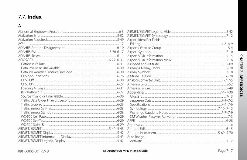
EFD1000/500 MFD Pilot’s Guide Page 7-17091-00006-001 REV B
CH
APTER 7 A
PPEND
ICES
7.7. IndexAAbnormal Shutdown Procedure ......................................................................................6-3Activation Error ........................................................................................................................5-52Activation Required ..............................................................................................................5-49ACU .............................................................................................................................................1-7ADAHRS Attitude Disagreement ..................................................................................6-10ADAHRS FAIL .................................................................................................................5-70, 6-17ADAHRS, Reset .........................................................................................................................6-11ADVISORY .......................................................................................................................6-27–6-31
Database Failure..................................................................................................................6-31Data Invalid or Unavailable ..........................................................................................6-30Datalink Weather Product Data Age ......................................................................6-30GPS Annunciations ...........................................................................................................6-28GPSS Off ...................................................................................................................................6-30GPSS On ...................................................................................................................................6-27Loading Airways .................................................................................................................6-31REV Button Off .....................................................................................................................6-27Source Invalid or Unavailable .....................................................................................6-30Traffic Data Older Than Six Seconds .......................................................................6-29Traffic Enabled .....................................................................................................................6-28Traffic Sensor Self-Test .....................................................................................................6-28Traffic Sensor Standby ....................................................................................................6-28WX-500 Cell Rate ................................................................................................................6-29WX-500 Self-Test .................................................................................................................6-29WX-500 Strike Rate ............................................................................................................6-29
AIRMET/SIGMET ..........................................................................................................5-40–5-43AIRMET/SIGMET, Display ....................................................................................................5-42AIRMET/SIGMET Information, Display ........................................................................5-43AIRMET/SIGMET Legend, Display .................................................................................5-42
AIRMET/SIGMET Legend, Hide .......................................................................................5-42AIRMET/SIGMET Symbology ...........................................................................................7-12Airport Identifier Fields
Editing ................................................................................................................................4-8–4-9Airports, Feature Group .........................................................................................................5-4Airport Symbols .......................................................................................................................7-10Airport/VOR Information ...................................................................................................5-15Airport/VOR Information, View ......................................................................................5-18Airspeed and Altitude ..........................................................................................................5-69Airways Overlay, Show ........................................................................................................5-20Airway Symbols .......................................................................................................................7-10Altitude Caution ......................................................................................................................6-20Analog Converter Unit ..................................................................................................1-7, 7-5Antenna Error ............................................................................................................................5-52Antenna Failure ........................................................................................................................5-49Appendices ......................................................................................................................7-1–7-30
Glossary ....................................................................................................................................7-13Jeppesen Data ..............................................................................................................7-1–7-2Specifications ................................................................................................................7-4–7-6Symbology ................................................................................................................7-10–7-12Warnings, Cautions, Notes .....................................................................................7-7–7-9XM Weather Receiver Activation .................................................................................7-3
APPR ..........................................................................................................................................6-28Approvals .......................................................................................................................................... xxAttitude Fail ................................................................................................................................6-15Attitude Instrument .................................................................................................5-69–5-70Auto Range
Activate ....................................................................................................................................5-12
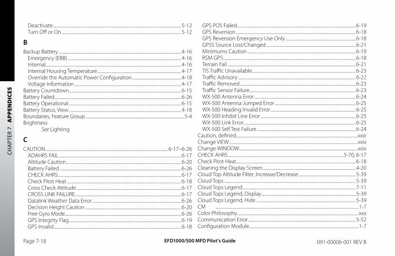
EFD1000/500 MFD Pilot’s GuidePage 7-18 091-00006-001 REV B
CH
APT
ER 7
A
PPEN
DIC
ES
Deactivate ...............................................................................................................................5-12Turn Off or On ......................................................................................................................5-12
bBackup Battery .........................................................................................................................4-16
Emergency (EBB) ................................................................................................................4-16Internal......................................................................................................................................4-16Internal Housing Temperature ...................................................................................4-17Override the Automatic Power Configuration ................................................4-18Voltage Information .........................................................................................................4-17
Battery Countdown...............................................................................................................6-15Battery Failed .............................................................................................................................6-26Battery Operational ...............................................................................................................6-15Battery Status, View ...............................................................................................................4-18Boundaries, Feature Group ..................................................................................................5-4Brightness
See Lighting
CCAUTION .........................................................................................................................6-17–6-26
ADAHRS FAIL .........................................................................................................................6-17Altitude Caution..................................................................................................................6-20Battery Failed ........................................................................................................................6-26CHECK AHRS ..........................................................................................................................6-17Check Pitot Heat .................................................................................................................6-18Cross Check Attitude .......................................................................................................6-17CROSS LINK FAILURE .........................................................................................................6-17Datalink Weather Data Error ........................................................................................6-26Decision Height Caution ...............................................................................................6-20Free Gyro Mode ...................................................................................................................6-26GPS Integrity Flag ...............................................................................................................6-19GPS Invalid ..............................................................................................................................6-18
GPS POS Failed .....................................................................................................................6-19GPS Reversion ......................................................................................................................6-18GPS Reversion Emergency Use Only .....................................................................6-18GPSS Source Lost/Changed ........................................................................................6-21Minimums Caution ...........................................................................................................6-19RSM GPS ...................................................................................................................................6-18Terrain Fail ...............................................................................................................................6-21TIS Traffic Unavailable ......................................................................................................6-23Traffic Advisory ....................................................................................................................6-22Traffic Removed ..................................................................................................................6-23Traffic Sensor Failure.........................................................................................................6-23WX-500 Antenna Error ....................................................................................................6-24WX-500 Antenna Jumped Error ................................................................................6-25WX-500 Heading Invalid Error ....................................................................................6-25WX-500 Inhibit Line Error ..............................................................................................6-25WX-500 Link Error ...............................................................................................................6-25WX-500 Self Test Failure ..................................................................................................6-24
Caution, defined ........................................................................................................................xxxiChange VIEW ...............................................................................................................................xxixChange WINDOW .....................................................................................................................xxixCHECK AHRS ..................................................................................................................5-70, 6-17Check Pitot Heat ......................................................................................................................6-18Cleaning the Display Screen ............................................................................................4-20Cloud Top Altitude Filter, Increase/Decrease ........................................................5-39Cloud Tops ..................................................................................................................................5-39Cloud Tops Legend................................................................................................................7-11Cloud Tops Legend, Display .............................................................................................5-39Cloud Tops Legend, Hide ..................................................................................................5-39CM .............................................................................................................................................1-7Color Philosophy ........................................................................................................................xxxCommunication Error ..........................................................................................................5-52Configuration Module ............................................................................................................1-7
EFD1000/500 MFD Pilot’s Guide Page 7-19091-00006-001 REV B
CH
APTER 7 A
PPEND
ICES
Configuring ................................................................................................................................5-50Controlled Airspace, Feature Group...............................................................................5-4Controls ..............................................................................................................................3-8–3-11
Hot Keys ...................................................................................................................................3-11Left Button .................................................................................................................................3-9Left Knob ....................................................................................................................................3-8Menu Button .........................................................................................................................3-11Menu Keys ..............................................................................................................................3-11Middle Button .........................................................................................................................3-9Range Button ........................................................................................................................3-10Reversion Button ................................................................................................................3-10Right Button .............................................................................................................................3-9Right Knob .............................................................................................................................3-10
Convective .....................................................................................................................5-29–5-32Convective Legend ...............................................................................................................5-32Convective Legend, Display.............................................................................................5-32Convective Legend, Hide ..................................................................................................5-32Convective Overlays, Display/Hide ..............................................................................5-32Conventions...................................................................................................................xxvii–xxxii
Covered Functionality ..................................................................................................... xxviiTerminology .......................................................................................................................... xxvii
Copyrights....................................................................................................................................... xixCourse Setting, Modify ........................................................................................................5-71Covered Functionality ......................................................................................................... xxviiCross Check Attitude ............................................................................................................6-17CROSS CHECK ATTITUDE Message .......................................................................6-2–6-3CROSS LINK FAILURE .............................................................................................................6-17
DData Bar ...........................................................................................................................................3-7Database
Confirmation Screen ...........................................................................................................4-3
Expiration Date ..............................................................................................................4-2, 4-3Validity ..........................................................................................................................................4-2Validity and Expiration Dates, View ............................................................................4-3
Database Failure ......................................................................................................................6-31DATABASE FAILURE ...................................................................................................................5-4Data Invalid or Unavailable ...............................................................................................6-30Data Link Weather .....................................................................................................5-26–5-55
AIRMET/SIGMET .....................................................................................................5-40–5-43Cloud Tops ..............................................................................................................................5-39Convective ................................................................................................................5-29–5-32
Convective Legend ......................................................................................................5-32Convective SIGMET ......................................................................................................5-32Lightning Coverage .....................................................................................................5-32NEXRAD Coverage ........................................................................................................5-32
Echo Tops ...................................................................................................................5-37–5-38METAR ..........................................................................................................................5-33–5-36
Declutter Settings .........................................................................................................5-33Pop-up ..................................................................................................................................5-35
TFR .............................................................................................................................5-44–5-45Winds Aloft ................................................................................................................5-46–5-47XM Status ...................................................................................................................5-48–5-54
Control States ...................................................................................................................5-50Descriptive Messages .................................................................................................5-51Error Messages ................................................................................................................5-52Operational Messages ................................................................................................5-51Product Age Limits .......................................................................................................5-53Product Page ....................................................................................................................5-52Signal Quality ...................................................................................................................5-48Status Message ...............................................................................................................5-49
Data Link Weather Age Annunciations .....................................................................5-54Datalink Weather Data Error.............................................................................................6-26Data Link Weather Overlay, Show ................................................................................5-23
EFD1000/500 MFD Pilot’s GuidePage 7-20 091-00006-001 REV B
CH
APT
ER 7
A
PPEN
DIC
ES
Datalink Weather Product Data Age ...........................................................................6-30Data Link Weather Products, Selecting .....................................................................5-28Data Link Weather Products, View Different ..........................................................5-28Data Unavailable .....................................................................................................................5-49Decision Height Caution ....................................................................................................6-20Declutter .............................................................................................................................5-3, 5-13Declutter Settings .....................................................................................................................5-8Declutter Symbols .................................................................................................................7-10Dedicated Terrain Colors ....................................................................................................7-12Default Display ............................................................................................................................3-4
Full Screen LAYOUT ..............................................................................................................3-4Split Screen LAYOUT ............................................................................................................3-5Thumbnail LAYOUT ..............................................................................................................3-6
Direction Indicator Fail ........................................................................................................6-15Disable GPSS .................................................................................................................................6-7Display Brightness, Change the .....................................................................................4-15Display Components .....................................................................................................3-2–3-3
Full Screen LAYOUT ..............................................................................................................3-2Split Screen LAYOUT ............................................................................................................3-2Thumbnail Screen LAYOUT .............................................................................................3-3
Display & Controls ........................................................................................................3-1–3-11Dual Display System: PFD & MFD ....................................................................................1-2
EEBB Disconnect ...........................................................................................................................6-8Echo Top Altitude Filter, Increase/Decrease ...........................................................5-38Echo Tops........................................................................................................................5-37–5-38Echo Tops Legend ..................................................................................................................7-11Echo Tops Legend, Display ...............................................................................................5-37Echo Tops Legend, Hide .....................................................................................................5-37EDIT VALUE ..................................................................................................................................4-11
See also Main Menu: Edit mode
EFD500 Display ...........................................................................................................................1-6EFD1000 Display ........................................................................................................................1-5EFD Display Unit .........................................................................................................................7-4Emergency Backup Battery .................................................................................................7-6Emergency Backup Battery, Isolate ................................................................................6-8Emergency GPS ..........................................................................................................................1-4Emergency Procedures
See Expanded Emergency & Abnormal ProceduresERROR ..........................................................................................................................................6-24ERROR ANT ERROR .................................................................................................................6-24ERROR ANT JUMP CHG .......................................................................................................6-25Error Messages
See Individual Error Message; See WARNING, CAUTION, or ADVISORY
ERROR MIC INHIBIT STUCK ................................................................................................6-25Evolution Flight Display ...............................................................................................1-1–1-3Evolution Weather Receiver ................................................................................................1-8EWR50 .............................................................................................................................................1-8Example Graphics ................................................................................................................... xxxiiExpanded Emergency & Abnormal Procedures ...............................6-1–6-32, 6-8
Abnormal Shutdown Procedure .................................................................................6-3ADAHRS Attitude Disagreement ..............................................................................6-10CAUTION .....................................................................................................................6-17–6-26CROSS CHECK ATTITUDE Message ...................................................................6-2–6-3Disable GPSS ............................................................................................................................6-7GPS Information, Loss of ................................................................................................6-13GPSS Operation, Annunciations, and Autopilot Modes......................6-6–6-7GPSS Wings Level Mode ...................................................................................................6-7In-Flight ADAHRS Reset.....................................................................................6-10–6-11Intercommunications Failure ......................................................................................6-12Loss of or Degraded Aircraft Power ...........................................................................6-5MFD Database Card ..........................................................................................................6-14
EFD1000/500 MFD Pilot’s Guide Page 7-21091-00006-001 REV B
CH
APTER 7 A
PPEND
ICES
MFD Reversionary Mode Operation .........................................................................6-4ON BAT Annunciation ........................................................................................................6-5Pitot/Static System Blockage ...............................................................................6-1–6-2Power Override .......................................................................................................................6-9WARNINGS ..............................................................................................................................6-15
External Voltage Status, View .................................................................................4-18, 6-9Extreme Pitch Down .............................................................................................................6-16
FFAIL 6-24FAIL HDG INVALID ..................................................................................................................6-25FAIL NO LINK ..................................................................................................................6-23, 6-25Feature Group Details .............................................................................................................5-4Feature Group Display Setting, Changing ..............................................................5-10Feature Group Layering, Range, and Declutter Behavior ....................5-8–5-13Flight Plan ....................................................................................................................................5-18FOCUS .........................................................................................................................................xxviiiFree Gyro Mode .......................................................................................................................6-26Full Screen LAYOUT ............................................................................................ xxvii, 3-2, 3-4
GGeo Limit .....................................................................................................................................5-51Glossary ........................................................................................................................................7-13Good ..........................................................................................................................................5-48GPS
Invalid GPS ..............................................................................................................................5-14Position Source Unavailable ...........................................................................................5-1
GPS Annunciations ................................................................................................................6-28GPS Information ......................................................................................................................5-13GPS Information, Loss of ....................................................................................................6-13GPS Integrity Flag ...................................................................................................................6-19GPS Invalid ..................................................................................................................................6-18
GPS Navigation Source, Change ...................................................................................5-13GPS POS Failed .........................................................................................................................6-19GPS Reversion ...........................................................................................................................6-18GPS# REVERSION .....................................................................................................................5-14GPS Reversion Emergency Use Only ..........................................................................6-18GPSS Off .......................................................................................................................................6-30GPSS On........................................................................................................................................6-27GPSS Operation, Annunciations, and Autopilot Modes ..........................6-6–6-7GPSS Source Lost/Changed .............................................................................................6-21GPSS Wings Level Mode ........................................................................................................6-7
HHazard Awareness Views.......................................................................................5-55–5-67
Terrain and Obstructions ..................................................................................5-56–5-58Obstruction Symbology ............................................................................................5-58Terrain Color Coding ....................................................................................................5-57
Traffic ............................................................................................................................5-59–5-65Advisories ...........................................................................................................................5-65Altitude Filter ....................................................................................................................5-64Annunciations .................................................................................................................5-64Display .....................................................................................................................5-60–5-65Display of Traffic Symbols .........................................................................................5-61Filter Parameters .............................................................................................................5-64Intruder Data Block .......................................................................................................5-61No Bearing Advisories .................................................................................................5-62Off Scale and Symbol Overlap ..............................................................................5-62Operational Modes .......................................................................................................5-63Sensor Status Display Annunciations................................................................5-63Text-format Traffic Advisories .................................................................................5-62
WX-500 ........................................................................................................................5-66–5-68Annunciations .................................................................................................................5-68
Heading-Up...............................................................................................................................xxviii
EFD1000/500 MFD Pilot’s GuidePage 7-22 091-00006-001 REV B
CH
APT
ER 7
A
PPEN
DIC
ES
HI Airways ....................................................................................................................................5-20Horizontal Situation Indicator ............................................................................5-71–5-72Hot Keys ..........................................................................................................................xxviii, 3-11
Navigation Map1/2 .............................................................................................................................................5-22/2 .............................................................................................................................................5-2360/ARC ..................................................................................................................................5-2APT ..........................................................................................................................................5-16ARWY/LO/HI.............................................................................................................5-2, 5-20COM .......................................................................................................................................5-17LTNG/CELL/STRK ...................................................................................................5-2, 5-22MAP ...........................................................................................................................................5-2NBD ........................................................................................................................................5-16NXRD ............................................................................................................................5-2, 5-23RWY ........................................................................................................................................5-17TERR ..............................................................................................................................5-2, 5-21TRFC ..............................................................................................................................5-2, 5-24VFR/IFR ....................................................................................................................................5-2VOR .........................................................................................................................................5-16WX ..........................................................................................................................................5-17
Terrain and Obstructions360/ARC ...............................................................................................................................5-56
TrafficABV .........................................................................................................................................5-64BLW .........................................................................................................................................5-64NRM ........................................................................................................................................5-64UNR ........................................................................................................................................5-64
Weather, AIRMET/SIGMETCONV .....................................................................................................................................5-41ICNG .......................................................................................................................................5-41IMC ..........................................................................................................................................5-41LGND .....................................................................................................................................5-42
TURB.......................................................................................................................................5-41Weather, Cloud Tops
FL- ..........................................................................................................................................5-39FL+ ..........................................................................................................................................5-39LGND .....................................................................................................................................5-39
Weather, ConvectiveCONV .....................................................................................................................................5-29LGND .....................................................................................................................................5-29LTNG .......................................................................................................................................5-29NXRD .....................................................................................................................................5-29
Weather, Echo TopsFL- ..........................................................................................................................................5-38FL+ ..........................................................................................................................................5-38LGND .....................................................................................................................................5-37
Weather, METARSLGND .....................................................................................................................................5-34TEXT .......................................................................................................................................5-36
See also Airport Identifier Fields: EditingWeather, Winds Aloft
FL- ..........................................................................................................................................5-47FL+ ..........................................................................................................................................5-47LGND .....................................................................................................................................5-47
Weather, XM StatusAGE .........................................................................................................................................5-52
Hydrographic Information, Feature Group ................................................................5-4
IIFR ..........................................................................................................................................5-19IFR Style Map ................................................................................................................................5-2Individual Airport’s METAR Information, Display.................................................5-36In-Flight ADAHRS Reset .........................................................................................6-10–6-11Initializing Screen ......................................................................................................................4-2
EFD1000/500 MFD Pilot’s Guide Page 7-23091-00006-001 REV B
CH
APTER 7 A
PPEND
ICES
Intercommunications Failure ..........................................................................................6-12Internal Battery Status, View ...............................................................................................6-9Invalid Navigation Map Features .....................................................................................5-9
JJeppesen Data ...................................................................................................................7-1–7-2
Technical Support .................................................................................................................7-2Jeppesen Database Confirmation Screen..................................................................4-2Jeppesen Data Service, Activate ......................................................................................7-1
LLayout
Full Screen .............................................................................................................................. xxviiSplit Screen ............................................................................................................................ xxviiThumbnail .............................................................................................................................. xxvii
LAYOUT ......................................................................................................................................... xxviiLeft Button .....................................................................................................................................3-9Left Knob ........................................................................................................................................3-8Lighting ........................................................................................................................................4-14Lightning Overlay, Show ....................................................................................................5-22Listening Only ...........................................................................................................................5-50Loading .........................................................................................................................................5-51Loading Airways ......................................................................................................................6-31LO Airways ..................................................................................................................................5-20Loss of or Degraded Aircraft Power ...............................................................................6-5Lower Controls ............................................................................................................................3-8
MMain Menu
Access and Navigate ........................................................................................................4-12AUTO RANGE ...........................................................................................................................5-5BOUNDARIES ............................................................................................................................5-5
Brightness Control .............................................................................................................4-11CONTROLLED AIRSPACE ...................................................................................................5-5Edit Items ................................................................................................................................4-13Edit mode ...............................................................................................................................4-11FLIGHT PLAN & WAYPOINTS ...........................................................................................5-5HARD SURFACE AIRPORTS ...............................................................................................5-5INTERSECTIONS ......................................................................................................................5-5Map Settings ............................................................................................................................5-5Navigation mode ...............................................................................................................4-11NAV MAP ORIENTATION ....................................................................................................5-5NDBS .............................................................................................................................................5-5OTHER AIRPORTS ...................................................................................................................5-5Page graphical bar .............................................................................................................4-11Page Name .............................................................................................................................4-11Page number and mode ...............................................................................................4-11SPECIAL USE AIRSPACE ......................................................................................................5-5TRANSPORTATION.................................................................................................................5-5Using .............................................................................................................................4-10–4-13VORS .............................................................................................................................................5-5
Main Menu TextDisabled ...................................................................................................................................4-12Editable.....................................................................................................................................4-12Enabled ....................................................................................................................................4-12Status Only .............................................................................................................................4-12
Manual Reversionary Mode ................................................................................................2-4Map
Declutter ..................................................................................................................................5-13Orientation ............................................................................................................................. xxxii
Change ..........................................................................................................................5-6–5-7Range................................................................................................................................5-3, 5-11
Change .................................................................................................................................5-11Settings........................................................................................................................................5-5
EFD1000/500 MFD Pilot’s GuidePage 7-24 091-00006-001 REV B
CH
APT
ER 7
A
PPEN
DIC
ES
Symbols ..........................................................................................................................5-6–5-10Map Feature Declutter Level, Change .......................................................................5-13Map Settings ................................................................................................................................5-5Map Style, Change .................................................................................................................5-19Map Styles ...................................................................................................................................5-19Marginal ........................................................................................................................................5-48Max Range .....................................................................................................................................5-8MENU ............................................................................................................................................xxixMenu Button .............................................................................................................................3-11Menu Key ....................................................................................................................................xxviiiMenu Keys ..................................................................................................................................3-11METAR .............................................................................................................................5-33–5-36
Declutter Settings ..............................................................................................................5-33Pop-up ......................................................................................................................................5-35
METAR Legend .........................................................................................................................7-11METAR Legend, Display ......................................................................................................5-34METAR Legend, Hide ............................................................................................................5-34MFD Database Card ..............................................................................................................6-14MFD Operating Mode, Switch Back to .........................................................................2-4MFD Reversionary Mode Operation ..............................................................................6-4microSDHC Card ........................................................................................................................1-8Middle Button ..............................................................................................................................3-9Minimums Caution ................................................................................................................6-19MSG ..........................................................................................................................................6-28Multiple Airports’ METAR Information, Display .....................................................5-35
NNAVAID Symbols .....................................................................................................................7-10Navigation Map ....................................................................................................2-1, 5-2–5-25
Airways .....................................................................................................................................5-20Auto Range ............................................................................................................................5-12Data Link Weather .............................................................................................................5-23
Declutter ............................................................................................................................5-3, 5-8Feature Group Details ........................................................................................................5-4Heading Settings ...................................................................................................................5-7Heading-Up ..............................................................................................................................5-7Lightning .................................................................................................................................5-22Map Orientation ..........................................................................................................5-6–5-7Map Range ....................................................................................................................5-3, 5-11Map Settings ..................................................................................................................5-5–5-6Map Symbols ..............................................................................................................5-6–5-10Max Range .................................................................................................................................5-8North-Up ....................................................................................................................................5-7Overlays .......................................................................................................................5-20–5-25Terrain ........................................................................................................................................5-21Track-Up ......................................................................................................................................5-7Traffic .........................................................................................................................................5-24
NEXRAD ...........................................................................................................................5-30–5-31Precipitation Colors ...........................................................................................................5-31
NEXRAD Legend .....................................................................................................................7-11No Communications ............................................................................................................5-49North-Up .....................................................................................................................................xxviiiNo Service ...................................................................................................................................5-49No Signal ..........................................................................................................................5-48, 5-49Note, defined ..............................................................................................................................xxxi
OObstructions
See Terrain and ObstructionsObstructions, Feature Group ..............................................................................................5-4Obstruction Symbols ...........................................................................................................7-12ON BAT ..........................................................................................................................................4-17ON BAT Annunciation .............................................................................................................6-5Operational............................................................................................................5-49, 5-50, 7-5
EFD1000/500 MFD Pilot’s Guide Page 7-25091-00006-001 REV B
CH
APTER 7 A
PPEND
ICES
Overlays ...........................................................................................................................5-20–5-25Airways .....................................................................................................................................5-20Data Link Weather .............................................................................................................5-23Lightning .................................................................................................................................5-22Terrain ........................................................................................................................................5-21Traffic .........................................................................................................................................5-24
OverviewManual Reversionary Mode ............................................................................................2-4Navigation Map ......................................................................................................................2-1Secondary PFD Display .....................................................................................................2-5
Secondary Attitude Indicator ....................................................................................2-5Secondary Horizontal Situation Indicator .........................................................2-5
Stormscope® WX-500 .........................................................................................................2-3Traffic ............................................................................................................................................2-3XM WX Satellite Weather ..................................................................................................2-2
PPAGE xxvii
Viewing Different ........................................................................................................4-4–4-5PAGE Selection ...........................................................................................................................xxixPanning ............................................................................................................................................4-7PFD Operating Mode, Swith to .........................................................................................2-4Pilot Familiarity ......................................................................................................................... xxxiiPilot Interface Modes .............................................................................................................xxix
Change VIEW ..........................................................................................................................xxixChange WINDOW ................................................................................................................xxixMENU ...........................................................................................................................................xxixPAGE Selection .......................................................................................................................xxixVIEW Control ...........................................................................................................................xxix
Pitot/Static System Blockage ...................................................................................6-1–6-2Powering Up ..................................................................................................................5-49, 5-50Power Off .....................................................................................................................................4-19
Power Override ...............................................................................................................4-18, 6-9PUSH FOR BACK..........................................................................................................................4-4
See also VIEW Mode: ControlPUSH SEL WINDOW ..................................................................................................................4-4
See also VIEW Mode: Change
RRange Button ................................................................................................................3-10, 4-20Reference Guide ............................................................................................................5-1–5-72Relative Terrain, Feature Group .........................................................................................5-4Remote Sensor Module ................................................................................................1-6, 7-5Retrying ........................................................................................................................................5-50REV Button ..................................................................................................................................4-19REV Button Off ..........................................................................................................................6-27Reversion Button ....................................................................................................................3-10Revisions ............................................................................................................................................ ivRight Button..................................................................................................................................3-9Right Knob ..................................................................................................................................3-10RSM .............................................................................................................................................1-6RSM GPS .......................................................................................................................................6-18RSM GPS REVERSION EMER USE ONLY ......................................................................5-14
SSaving Config ................................................................................................................5-49, 5-50Scroll Bar ..........................................................................................................................................4-9Secondary Attitude Instrument........................................................................5-69–5-70
Airspeed and Altitude .....................................................................................................5-69Secondary Horizontal Situation Indicator ..................................................5-71–5-72
Vertical Deviation Indicator .........................................................................................5-72Secondary Views ........................................................................................................5-69–5-72
Attitude InstrumentAirspeed and Altitude .................................................................................................5-69
EFD1000/500 MFD Pilot’s GuidePage 7-26 091-00006-001 REV B
CH
APT
ER 7
A
PPEN
DIC
ES
Horizontal Situation Indicator ....................................................................................5-71Vertical Deviation Indicator .....................................................................................5-72
Secondary Attitude Instrument ................................................................................5-69Selecting Data Link Weather Products ......................................................................5-28SEL PAGE ......................................................................................................................................4-11
See also Main Menu: Navigation modeService Agreement, XM WX Satellite Radio ...............................................................xxvSide Buttons ...............................................................................................................................3-10Single Display EFD1000 PFD System .............................................................................1-2Source Invalid or Unavailable..........................................................................................6-30Special Use Airspace, Feature Group .............................................................................5-4Specifications .....................................................................................................................7-4–7-6
Analog Converter Unit .......................................................................................................7-5EFD Display Unit ....................................................................................................................7-4Emergency Backup Battery .............................................................................................7-6Remote Sensor Module ....................................................................................................7-5
Split Screen LAYOUT .......................................................................................... xxvii, 3-2, 3-5Startup .............................................................................................................................................4-2
Initializing Screen ..................................................................................................................4-2Jeppesen Database Confirmation Screen .............................................................4-2
Stormscope® WX-500 ..............................................................................................................2-3Symbology.....................................................................................................................7-10–7-12
AIRMET/SIGMET Symbology .......................................................................................7-12Airport Symbols ..................................................................................................................7-10Airway Symbols ...................................................................................................................7-10Cloud Tops Legend ...........................................................................................................7-11Declutter Symbols .............................................................................................................7-10Dedicated Terrain Colors ...............................................................................................7-12Echo Tops Legend .............................................................................................................7-11METAR Legend .....................................................................................................................7-11NAVAID Symbols .................................................................................................................7-10NEXRAD Legend .................................................................................................................7-11
Obstruction Symbols .......................................................................................................7-12Terrain Overlay Colors .....................................................................................................7-12Winds Aloft Legend ..........................................................................................................7-11
System Hardware .......................................................................................................................1-4EFD500 MFD.............................................................................................................................1-4EFD1000 MFD ..........................................................................................................................1-4
TTAS traffic sensors ...................................................................................................................5-25Terminology
FOCUS ......................................................................................................................................xxviiiHeading-Up ..........................................................................................................................xxviiiHot Key ....................................................................................................................................xxviiiLAYOUT ..................................................................................................................................... xxviiMenu Key ...............................................................................................................................xxviiiNorth-Up ................................................................................................................................xxviiiPAGE .......................................................................................................................................... xxviiTrack-Up ..................................................................................................................................xxviiiVIEW .........................................................................................................................................xxviiiWINDOW ................................................................................................................................. xxvii
Terrain and Obstructions .............................................................................2-2, 5-56–5-58Obstruction Symbology ................................................................................................5-58Terrain Color Coding ........................................................................................................5-57
Terrain Fail....................................................................................................................................6-21Terrain Overlay Colors ..........................................................................................................7-12Terrain Overlay, Show...........................................................................................................5-21Terrain Range Ring, Change.............................................................................................5-56TEST INIT FAIL ............................................................................................................................6-24TFR .............................................................................................................................5-44–5-45TFR Information, Display ....................................................................................................5-45Thumbnail LAYOUT ............................................................................................ xxvii, 3-3, 3-6TIS traffic sensors ....................................................................................................................5-25
EFD1000/500 MFD Pilot’s Guide Page 7-27091-00006-001 REV B
CH
APTER 7 A
PPEND
ICES
TIS Traffic Unavailable ..........................................................................................................6-23Track-Up ......................................................................................................................................xxviiiTrademarks ..................................................................................................................................... xixTraffic ....................................................................................................................2-3, 5-59–5-65
Advisories ................................................................................................................................5-65Display..........................................................................................................................5-60–5-65
Altitude Filter ....................................................................................................................5-64Annunciations .................................................................................................................5-64Display of Traffic Symbols .........................................................................................5-61Filter Parameters .............................................................................................................5-64Intruder Data Block .......................................................................................................5-61No Bearing Advisories .................................................................................................5-62Off Scale and Symbol Overlap ..............................................................................5-62Operational Modes .......................................................................................................5-63Sensor Status Display Annunciations................................................................5-63Text-format Traffic Advisories .................................................................................5-62
Traffic Advisory .........................................................................................................................6-22Traffic Altitude Filter, Change ..........................................................................................5-65Traffic Data Older Than Six Seconds ...........................................................................6-29Traffic Enabled ..........................................................................................................................6-28Traffic Overlay, Show ............................................................................................................5-24Traffic Range Ring, Change ..............................................................................................5-60Traffic Receivers ..........................................................................................................................2-3Traffic Removed .......................................................................................................................6-23Traffic Sensor Failure .............................................................................................................6-23Traffic Sensor Link Lost ........................................................................................................6-23Traffic Sensor Self-Test .........................................................................................................6-28Traffic Sensor Standby .........................................................................................................6-28TRAFFIC UNAVAILABLE ........................................................................................................6-23Transportation, Feature Group ..........................................................................................5-4TRFC ..........................................................................................................................................6-28TRFC COAST ...............................................................................................................................6-29
TRFC FAIL .....................................................................................................................................6-23TRFC RMVD .................................................................................................................................6-23TRFC STBY ....................................................................................................................................6-28TRFC TEST ....................................................................................................................................6-28TRFC UNVL ..................................................................................................................................6-23Trio Display System: PFD & dual MFDs .........................................................................1-3Tuning ..............................................................................................................................5-49, 5-50
UUnknown .....................................................................................................................................5-48Unknown Error .........................................................................................................................5-49
VValidating - Done ....................................................................................................................5-50Validating - x ..............................................................................................................................5-50Vertical Deviation Indicator ..............................................................................................5-72VFR ..........................................................................................................................................5-19VFR Style Map ..............................................................................................................................5-2VIEW .........................................................................................................................................xxviii
Change ........................................................................................................................................4-6NAV MAP...............................................................................................................4-6, 5-2–5-25STRIKES ...............................................................................................................4-6, 5-66–5-68TERR ....................................................................................................................4-6, 5-56–5-58TRFC ....................................................................................................................4-6, 5-59–5-65WEATHER ...........................................................................................................4-6, 5-26–5-55
VIEW Control ................................................................................................................................xxixVIEW Mode
Change ........................................................................................................................................4-4Control .........................................................................................................................................4-4
VOR Information ......................................................................................................................5-15VOR Information, View ........................................................................................................5-18
EFD1000/500 MFD Pilot’s GuidePage 7-28 091-00006-001 REV B
CH
APT
ER 7
A
PPEN
DIC
ES
WWarning, defined ......................................................................................................................xxxiWARNINGS .....................................................................................................................6-15–6-16
Attitude Fail ............................................................................................................................6-15Battery Countdown ..........................................................................................................6-15Battery Operational...........................................................................................................6-15Direction Indicator Fail ....................................................................................................6-15Extreme Pitch Down ........................................................................................................6-16Extreme Pitch Up................................................................................................................6-16
Warnings, Cautions, and Notes ........................................................................................xxxiWarnings, Cautions, Notes .........................................................................................7-7–7-9Warranty ........................................................................................................................................... xxi
Card .............................................................................................................................................xxiiConditions .................................................................................................................................. xxiDealer ..........................................................................................................................................xxiiiExclusions.................................................................................................................................... xxiExclusive .....................................................................................................................................xxiiExtension of .............................................................................................................................xxiiiIncidental Damages ............................................................................................................xxiiInvalidation ...............................................................................................................................xxiiLimitation of Liability ..........................................................................................................xxiiProcedure ..................................................................................................................................xxiiiRemedy ........................................................................................................................................ xxiTransportation Costs ..........................................................................................................xxiiiWeather Data ..........................................................................................................................xxiv
Weak .............................................................................................................................................-48Weather
See Data Link WeatherWeather Data Warranty .........................................................................................................xxivWeather Product Age Limits ............................................................................................5-53Weather Product Update Frequency .........................................................................5-53WINDOW ...................................................................................................................................... xxvii
Active ..................................................................................................................................4-4–4-5Viewing Different ........................................................................................................4-4–4-5
Winds Aloft ........................................................................................................5-46–5-47, 5-51Winds Aloft Altitude Filter, Increase/Decrease .....................................................5-47Winds Aloft Legend ..............................................................................................................7-11Winds Aloft Legend, Display ............................................................................................5-47Winds Aloft Legend, Hide .................................................................................................5-47WPT ..........................................................................................................................................6-28WX-500 .............................................................................................................................5-66–5-68
Annunciations ......................................................................................................................5-68Cell Mode ................................................................................................................................5-66Cell Symbol ............................................................................................................................5-66Invalid Rate .............................................................................................................................5-66Strike Mode ............................................................................................................................5-66Strike Mode and Rate ......................................................................................................5-66Strike Symbol ........................................................................................................................5-66
WX-500 Antenna Error .........................................................................................................6-24WX-500 Antenna Jumped Error .....................................................................................6-25WX-500 Cell Rate .....................................................................................................................6-29WX-500 Cells, Display ...........................................................................................................5-67WX-500 Heading Invalid Error.........................................................................................6-25WX-500 Inhibit Line Error ...................................................................................................6-25WX-500 Link Error ...................................................................................................................6-25WX-500 Range Ring, Change ..........................................................................................5-66WX-500 Rate, Clear.................................................................................................................5-67WX-500 Self-Test ......................................................................................................................6-29WX-500 Self-Test, Activate .................................................................................................5-67WX-500 Self Test Failure ......................................................................................................6-24WX-500 Sensor Error .............................................................................................................6-24WX-500 Strike Rate ................................................................................................................6-29WX-500 Strikes, Display .......................................................................................................5-67
EFD1000/500 MFD Pilot’s Guide Page 7-29091-00006-001 REV B
CH
APTER 7 A
PPEND
ICES
XXM Error Indicated .................................................................................................................5-49XM Products’ Age, Display .................................................................................................5-52XM Serial Number, View ........................................................................................................7-3XM Status ........................................................................................................................5-48–5-54
Control States .......................................................................................................................5-50Descriptive Messages ......................................................................................................5-51Error Messages .....................................................................................................................5-52Operational Messages.....................................................................................................5-51Product Page .........................................................................................................................5-52Signal Quality ........................................................................................................................5-48Status Message ....................................................................................................................5-49
XM Weather Receiver Activation......................................................................................7-3XM WX Satellite Radio Service Agreement ................................................................xxvXM WX Satellite Weather ......................................................................................................2-2

EFD1000/500 MFD Pilot’s GuidePage 7-30 091-00006-001 REV B
CH
APT
ER 7
A
PPEN
DIC
ES
This Page Intentionally Left Blank


Aspen Avionics, Inc.
5001 Indian School Road NE
Albuquerque, NM 87110
Phone: 888-99ASPEN (888-992-7736)
Phone, International: (505) 856-5034
Fax: (505) 314-5440
www.aspenavionics.com
091-00006-001 REV B Printed in USA