Embed Size (px)
Citation preview
3D documentation pipeline of Cultural Heritage artifacts: a cross-disciplinary implementation
E. Athanasiou, M. Faka, S. Hermon, V. Vassallo, K. Yiakoupi The Cyprus Institute – Science and Technology in Archaeology Research Center
CyI - STARC Nicosia, Cyprus
Abstract—This paper focuses on the development of a
procedure for 3D documentation of Cultural Heritage assets and
describes all the steps from the 3D data acquisition of the real
object, the post processing the raw data and finally the digital
recording, documentation and virtual preservation of the 3D
data. It will also describe the experiences, carried out during the
digital process, of some virtual restoration cases.
Keywords—3D documentation, virtual restoration, digital
preservation, Cultural Heritage, museum collections, metadata
I. INTRODUCTION The scope of this paper is to describe a procedure for 3D
documentation of Cultural Heritage assets as well as to guarantee the virtual preservation of the digital data.
The paper will describe the step by step creation of a 3D model, including all the process that starts from the 3D data acquisition of the real object, the post processing the raw data and finally the digital recording, documentation and virtual preservation. During this workflow, some remarkable cases were encountered from the 3D documentation of small and medium dimensions’ museum objects, which will be presented in this paper. This contribution will also describe the experiences, carried out during the digital process, of some virtual restoration cases.
Through the digital restitution of some archaeological and ethnographic artifacts, it has been possible to test for example, beyond the 3D data acquisition, the performance properties of some materials or simulate the reconstruction of fragmented items with high level of reliability. Furthermore, other cases will be presented in which it was possible to detect and visualize features, elements and particulars otherwise not visible with a naked eye, and only revealed after the application and elaboration of the 3D modeling.
A. 3D documentation of Cultural Heritage assets
The research carried out at STARC focuses on the development of a pipeline in an approach to acquire and create knowledge, to document different kind of 3D outcomes (museum objects, architectures, archaeological sites and excavation areas) as well as to guarantee the virtual preservation of the digital data. Particularly, the paper focuses on the digital pipeline applied to the 3D documentation of
small and medium dimensions’ objects coming from different museums, archaeological and ethnographic: the Cyprus Museum, the Larnaka District Museum, and the Cyprus Folk Art Museum in Nicosia.
In the framework of the research project CARARE1, a best practice network funded by the European Commission’s ICT Policy Support Programme, a large number of artifacts of several museums in Cyprus had to be documented in order to be provided to Europeana, a web-portal that gives access to millions of books, paintings, films, museum objects and archival records that have been digitized throughout Europe. Within this project and during the documentation process, many research questions about the best approach to be adopted for the acquisition, the methodology and best practices to be chosen for the post processing, arose2.
The case studies presented in this paper will give practical examples of the decisions taken during all the processes and that helped us to develop a fluid methodology in the 3D documentation of Cultural Heritage artifacts, providing also interesting cases of virtual restoration.
II. 3D DOCUMENTATION OF CULTURAL HERITAGE: A PROCEDURE FOR INFORMATION DATA ACQUISITION
A. The acquisition procedure Considering the artifacts to be three-dimensionally
acquired, their sizes, materials, shapes, texture and surface characteristics by Cultural Heritage professionals’ point of view [1], the NextEngine 3D Desktop laser scanner based on multi-stripe laser triangulation (MLT) was selected to collect the point clouds that represent the several objects3 [2].
The device is a compact aluminium box of 22×28×9cm size, provided with twin arrays of four solid state lasers (red, 650nm) and twin 3.0 Megapixel CMOS image sensors. The acquisition speed is 50.000 processed points/sec throughputs and typically it takes 2/3 min per scan of each facet. For the
1 http://www.carare.eu/ 2 Important is to consider the accuracy, the cost of money and time, and so forth. 3 Differently from the usual laser scanner reviews and benchmarking, the NextEngine scanner was reviewed also by archaeologists [2].
978-1-4799-3169-9/13/$31.00 ©2013 IEEE 145
3D data acquisition of small objects, they are placed in a distance of 16.5 cm from the front side of the scanner (Macro Mode distance), with accuracy from the manufacturer of ±0.127 mm, and in case of bigger objects, they are placed in a distance of 43.2 cm (Wide Mode distance) with an accuracy of ±0.381 mm. The scanner resolution is 200DPI in Macro Mode and 75DPI in Wide Mode. Texture density on target surface is 400DPI in Macro Mode and 150DPI in Wide Mode. The Macro or Wide Mode distance choice is based mainly on the size of the object as well as the desired resolution. In the case of Macro distance, the scanner field size that is captured is 12.95 cm x 9.65 cm, whereas in the case of Wide distance, the scanner field size that is captured is 34.29 cm x 25.65 cm. Despite of the limitation of scanner field size, there is no size limitation for object acquisition; objects larger than the scanner field can be composite-captured. Dealing with these variables, several trials were made in order to achieve the best practice for data acquisition and data post-processing of archaeological artifacts [1].
During the scanning process of an object it is better to take as much overlaps as possible in order to assure the complete coverage of its entire surface. In order to achieve this, it was needed to reposition the same object on the rotating platform multiple times (the instrument is equipped with a rotary table which is used in the acquisition of small size objects). This scanner provides three choices of scans. The "360°" scan option, which acquires the object from every angle, with the help of the rotating platform. In this instance the number of divisions will control the degree of the rotation between scans, as well as the total number of scans. The most important thing is that the individual scans are grouped together as a family. This is achieved by the AutoAlignment that the scanner has by default. The second scan option is the "Bracket", which scans three consecutive angles of the object. The number of division controls the degree of rotation between the left and the right offset scans from the central scan. The three scans are also grouped as a family. The last option is the "Single" scan that captures the object from one angle. The procedure of collecting data through several “360°”, “Bracket“ and “Single“ scans, is useful for the stage of post–processing because of the lack of control points (targets). For that purpose, instead of targets, detail points are used from the scanning sets of the surface of the objects at the stage of the alignment of the several scan positions.
Considering the tests and the results carried out, an average number of scans that are needed to fully acquire objects of medium complexity are two sets of "360°" and one "Bracket". This number depends on the complexity of the size and the shape of the object. Table I shows, for the case studies described in this contribution, the information about the objects’ dimensions, the number of the scans needed, the time of the 3D data acquisition and the Distance Mode.
The software used for data acquisition is ScanStudio HD4. It allows defining all the scan parameters mentioned, aligning multiple scans (group of scans) and post-processing aligned scans data.
4 The proprietary software of NextEngine.
TABLE I.
Bounding box
(cm)
Numb
er of
scans
Time for
3D data
acquisition
Distance
Mode
Tray with
angel and
shields
40.5x40.5x6.5 58 170’ Wide
Tray with
Annunciati
on
39.5x39.5x7.9 46 135’ Wide
Knitting
woman
(part a)
22.3x17.1x18.5 15 45’ Wide
Knitting
woman
(part b)
10x10x6 14 42’ Macro
Stemmed
bowl (part
a)
11.6x9.4x10.4 14 42’ Wide
Stemmed
bowl (part
b)
7.3x4.1x7.3 7 21’ Macro
Bilateral
stone relief
icon
10.5x10.5x1.7 15 45’ Macro
Cruciform
figurine 9.3x16x2.6 24 45’ Macro
Birth scene 5.9x9.3x11.5 24 72’ Macro
a. 3D data acquisition of the case studies
During the procedure of the scanning a lot of unnecessary information is collected by the scanner that does not belong to the real object. Thus, the several scans have to be cleaned from that noise (e.g. rotating platform, support part gripper, etc.). It is better the cleaning is done at this stage since the trimming tools of the software are simple and ease. Once the several scans are completed the result is one file that includes all the different meshes of scan positions (.scn).
Although there is the opportunity for post-processing with ScanStudio HD, the necessity to work on different objects and with different operators at the same time, engaged both in the acquisition and in the post processing, the activities are carried out with the open source software MeshLab5.
At this stage the scans have to be exported in a form that can be compatible with the formats supported by Meshlab. There are a lot of export formats that can achieve the compatibility, e.g. .xyz, .obj, .vrml, .ply etc. (other export formats are: .stl and .u3d). Usually .ply is used, since the meshes keep the texture and at the same time the files are more manageable. For example, if the operator exports a file that consists of 17 scan positions (the .scan file), the result is 17 ply files. Each scan position corresponds to a range map .ply file.
NextEngine also acquires the texture of an object that is overlapped automatically on the models by a synchronous RGB color texture capture. After different tests on the results of these images, the best solution for a high and precise resolution image, it was that one to proceed with an external camera.
5 The open source software for mesh processing developed at the Visual Computing Lab of ISTI - CNR. http://meshlab.sourceforge.net/
146
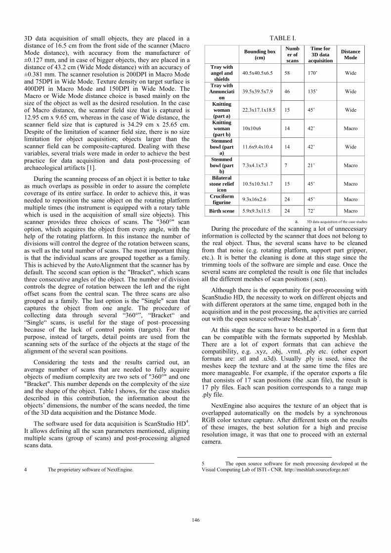
For this reason, a special apparatus has been set up for acquiring the digital images: it is composed of a DSLR camera, a light tent with white background, two extendable labs (CFL bulbs with natural day-light balanced color temperature of 5500 K) at each side of the tent and a tripod. The objects are placed in the photographic light tent. Light tent's photographic nylon fabric diffuses the external light sources, softening shadows and reducing glare, making it ideal for photographing shiny or reflective objects and helps to capture a better and more consistent color information of the objects in order to produce high quality 3D models The light should always be neutral and the depth of field should be wide, in order for the object area to be sharp. In addition the white background of the tent is used to provide the neutral color that will be used to correct the lighting of the photos. Depending on each object case, the camera parameters such as the focal length, aperture and shutter speed changed accordingly. The images taken are fully depicting all sides of the object.
This is a very important procedure because these pictures are going to be used for the texture mapping of the 3D model of the objects. Considering the tests and the results carried out, an average number of pictures that are needed for each object are about 8-10. A .jpg format is saved as well as the raw data. Fig. 1 shows the apparatus used to acquire the digital images.
B. The post-processing procedure After the 3D data acquisition, the post-processing of the
data follows. The pipeline for the post-processing of the range maps involves all the steps from the editing, cleaning, aligning of the range maps to the construction of a unique surface of a 3D model and texture mapping.
After importing in MeshLab all the range maps that had already been acquired at the previous stage, the remained noise has to be removed. Part of the cleaning and repairing of the meshes is to apply some filters to each range map. MeshLab has several filters, and the following were applied to our case studies: ‘Compact faces’, ‘Compact vertices’, ‘Merge Close Vertices’, ‘Remove Duplicate Faces’, ‘Remove Duplicated Vertex’, ‘Remove Faces from Non Manifold Edges’ and ‘Remove Unreferenced Vertex’.
The next stage is the alignment (“Rough alignment”) of the several range maps. The alignment tool puts the range maps into the same reference space and some common features between each pair of range maps are needed. That is the reason why it is important for the successive scans to have an overlap region. The desirable result of this procedure is achieved by considering one of the meshes as a reference mesh and then choosing a second one to glue it on the referenced one. Then the operator has to choose at least four corresponding pair of points on these two meshes and always has to check for the result and for any errors of this alignment process. The step of gluing meshes at the reference mesh continues until all the meshes have been overlapped correctly.
After the meshes have been aligned in the same reference system, the operator has to merge all of them into a single mesh in order to reconstruct the surface.
Fig. 1. The apparatus used to acquire the digital images.
The stage of the surface reconstruction is a necessary procedure, since the system has to generate a single surface by making an average between all the scans in order to obtain a unique surface. MeshLab has various types of filters for “Remeshing, Simplification and Reconstruction”: that one applied for the reconstruction of the surface is the “Poisson Reconstruction”. The model, which is created from the point clouds, is an accurate mesh without any holes. The next stage is the image alignment, in which process the 3D model acquires the texture. The alignment of the 3D model and the picture is achieved manually. The manually alignment is more precise and close to the real texture of the object. The procedure of the registration of an image on the 3D model is applied using the filter of “Mutual Information”, which is exploiting the illumination and the geometric properties of the pictures. At this point it is worth mentioning that the pictures before their import in MeshLab are modified in order to adjust the brightness and to make the color more natural. For the modification the open source Gimp 2 is used6. The same parameters are applied to all the photos to achieve uniformity between all the images of an object.
The deliverable product of the procedure is a 3D model with exactly the same shape, size, form and texture as the real artifact.
Based on the team’s experience in scanning and post-processing a large number of museums’ objects, the use of Meshlab has produced good quality results. A combination of the following parameters influences the performance of this open source software: the workstation used, the render mode of the visualization, the size of the active mesh and the filters in use. For example a very powerful workstation can easily manage large size files (up to 1GB) and create a high quality “Surface Reconstruction Poisson” if the render mode is as “points”. As a result, MeshLab demonstrated to be a suitable software for a successful completion of a post processing of a 3D model of an object as well as a viewer for visualisation,
6 http://www.gimp.org/downloads/
147
and the fact that is freely accessible, it makes it ideal for the use in the cultural heritage research.
III. THE DIGITAL OUTCOME: REMARKABLE CASE STUDIES During the acquisition and post processing procedures
many interesting cases have been treated: some are relative to the solution taken by the operators during the elaboration of the 3D models, others concern the solution of virtual restoration of fragmented or broken items. Furthermore during the steps of the 3D documentation procedure, it has been possible to detect important information on the objects digitally acquired.
The first case study concerns the “unorthodox” methods that the operator has to apply to achieve a 3D modeling and documentation of complex objects, otherwise not achievable with the usual processing procedures. Such methods were applied in the cases of ultrafine ecclesiastical trays coming from a temporary exhibition of the Cyprus Folk Art Museum. The second case study refers to the virtual reconstruction of fragments which constitute part of the same object. In these cases the task is to scan the several parts of the object, which will then be modeled in order to create its virtual reconstruction prior to its breaking. Such methods were applied in the case of the stone statuette from the Cyprus Folk Art Museum and of the stemmed bowl from the archaeological site of Hala Sultan Tekke, housed at the Larnaka District Museum. The third study case concerns the revealed ‘secret’ aspects after the application of the 3D modeling methodology. The objects that will be presented are: a bilateral stone relief icon from the Cyprus Folk Art Museum, the Cruciform figurine of Cyprus and a terracotta birth scene from the Cyprus Museum.
TABLE II. Tray A
Tray depicting angel and shields
Tray B
Holy bread tray depicting the Annunciation
Total Number of Scans 58 46 Size of scans (GB) 9.65 9.50 Number of frontal side of scans
34 23
Number of back side of scans
24 23
Size of Ply (GB) 0.85 0.78 Number of images 2 2
b. 3D data acquisition of the trays
A. First case study: complex cases
A temporal exhibition called “Cyprus–Germany 800 Years of History and Culture” took place at the Cyprus Folk Art Museum in December of 2012. At this exhibition, a large amount of ecclesiastical trays was exhibited among other objects and STARC was invited to digitize some of them. They are: a tray that belongs to the Leventis Municipal Museum of Nicosia and dated around 1500 – 1550 A.D., representing angel and shields surrounded by an embossed Late Gothic inscription; a Holy bread tray depicting the Annunciation found in the Holy church of Saint George in
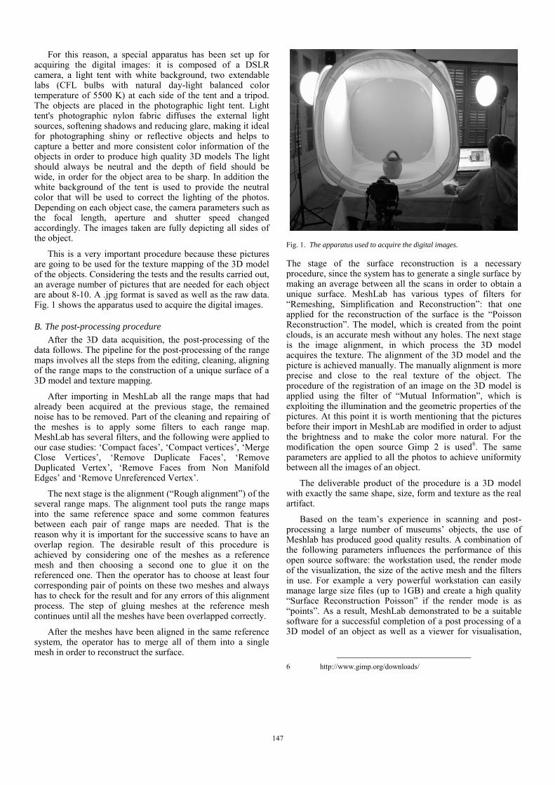
Fig. 2. The reconstruction of the ecclesiastical trays.
Arediou and dated at the end of 15th century [3].
For the digitization of those ecclesiastical trays a specific procedure had to be followed. Once the object was placed on the rotating platform of the NextEngine scanner, the user had to set some default parameters, such as the number of divisions which corresponded to the different sides of the object that had to be scanned. After the scanning process took place, the result was an aligned mesh composed of the data acquired at each division. The main problem that the team had to address was related to the thickness of the object. As a result, the automatically alignment of the scans failed and the frontal sides of the trays were projected to the back sides.
Due to the fact that the trays were remarkably thin, the automatic alignment of the front and back surface was not successful; the point clouds of the two surfaces were entangled. In other words, the trays were so thin that there was not even one scan in common which would have been used to connect the two surfaces together; more clearly, there was not even one scan to include the two facets together. Having this restriction, the operator had to act fast and proceed into decisions in order for the 3D model to be accomplished.
Thus, it was decided to collect both facets' point clouds and then assemble the two surfaces independently. To assemble the two surfaces of those trays, the “Manipulator Tool” was used for the placement of the object in the reference space. The “Manipulator Tool” provides three options: rotation, translation, scaling. Essentially, through the use of the rendering tools that MeshLab provides, namely the shaders, the point clouds were presented as xray.gdp; their assemblage was considerably easier since it was possible for both front and back surfaces to be visible. Processing the two surfaces through shaders resulted in the creation of a successful 3D model.
However, it should be noted that during the assemblage, a space of 0.15 cm was added between the two facets. Without having this space addition between them the assemblage
148
would not have been possible. The addition covers the tolerance of the acceptable error, according to the scale of
the 3D visualization.
The Table II gives information about the 3D data acquisition of the trays. Fig. 2 shows the case study of the 3D acquisition and reconstruction of the ecclesiastical trays.
B. Second case study: Virtual reconstruction
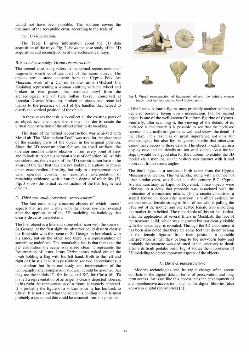
The second case study refers to the virtual reconstruction of fragments which constitute part of the same object. The objects are: a stone statuette from the Cyprus Folk Art Museum, work of a Cypriot famous artist (Michael Ch. Kasialos) representing a woman knitting with the wheel and broken in two pieces; the stemmed bowl from the archaeological site of Hala Sultan Tekke, (conserved at Larnaka District Museum), broken in pieces and reunified thanks to the presence of part of the handles that helped to clarify the vertical position of the object.
In these cases the task is to collect all the existing parts of an object, scan them, and then model in order to create the virtual reconstruction of the object prior to its breaking.
The stage of the virtual reconstruction was achieved with MeshLab. The “Manipulator Tool” was used for the placement of the existing parts of the object in the original position. Since the 3D reconstruction focuses on small artifacts, the operator must be able to observe it from every point of view and to look at its details without a loss of definition [4]. At this consideration, the viewers of the 3D reconstruction have to be aware of the fact that they are not looking at a photo or movie or an exact replica of reality, but only to a representation of what operator consider as reasonable interpretation of remaining evidence, with a variable degree of reliability [5]. Fig. 3 shows the virtual reconstruction of the two fragmented objects.
C. Third case study: revealed “secret aspects”
The last case study concerns objects of which ‘secret’ aspects that are not visible with the naked eye are revealed after the application of the 3D modeling methodology that clearly discerns their details.
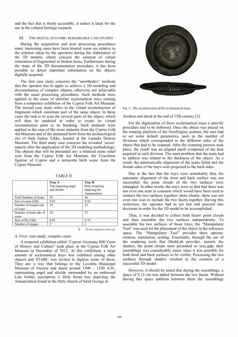
The first object is a bilateral stone relief icon with the scene of St. George: at the first sight the observer could discern clearly the front side with the scene of St. George on horseback with his lance, but on the other side there is a representation of something undefined. The remarkable fact is that thanks to the 3D elaboration the scene was made clear: it represents the Resurrection of Jesus. Jesus Christ comes naked out of the tomb holding a flag with his left hand. Both to the left and right of Christ’s head it is possible to see two abbreviations: it is not clear but from our study and interpretation of the iconography after comparison studies, it could be assumed that they are the initials IC, for Jesus, and XC, for Christ [6]. To his left a representation of an angel is clearly depicted whereas to his right the representation of a figure is vaguely depicted. It is probably the figure of a soldier since he has his back to Christ. It is not clear what the soldier is holding but it is most probably a spear, and this could be assumed from the position
Fig. 3. Virtual reconstruction of fragmented objects: the knitting woman (upper part) and the stemmed bowl (bottom part).
of the hands. A fourth figure, most probably another soldier, is depicted possibly laying down unconscious [7].The second object is one of the well-known Cruciform figurine of Cyprus. Similarly, after scanning it, the viewing of the details of its necklace is facilitated: it is possible to see that the necklace represents a cruciform figurine as well and shows the detail of the clasp. This result is of great importance not only for archaeologists but also for the general public that otherwise cannot have access to these details. The object is exhibited in a display case and the details are not well visible. As a further step, it would be a good idea for the museum to exhibit the 3D model via a monitor, so the visitors can interact with it and observe it from various angles.
The third object is a terracotta birth scene from the Cyprus Museum’s collection. This terracotta, along with a number of other similar ones, was found at a 6th century B.C. Cypro-Archaic sanctuary at Lapithos (Kyrenia). These objects were offerings to a deity that probably was associated with the protection of women and infants. This terracotta consists of a seated female in labor (the newborn is visible) assisted by another seated female sitting in front of her who is pulling the baby out of the mother and one seated female who is holding the mother from behind. The remarkable of this artifact is that, after the application of several filters in MeshLab, the face of the newborn child, which was engraved but not clearly visible with the naked eye, is revealed. Through the 3D elaboration it has been also noted that there are some feet that do not belong to the female figures: from their position, a possible interpretation is that they belong to the new-born baby and probably the statuette was dedicated to the sanctuary to thank after a difficult podalic birth. Fig. 4 shows the importance of 3D modeling to detect important aspects of the objects.
IV. DIGITAL PRESERVATION Modern technologies and its rapid change often create conflicts to the digital data in terms of preservation and long term access. An issue like this necessitates the development of a comprehensive access tool, such as the digital libraries (also known as digital repositories) [8].
149
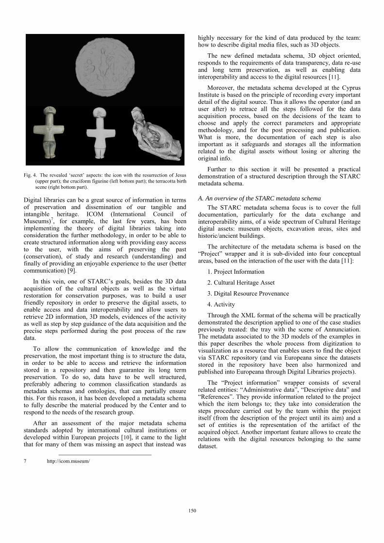
Fig. 4. The revealed ‘secret’ aspects: the icon with the resurrection of Jesus (upper part); the cruciform figurine (left bottom part); the terracotta birth scene (right bottom part).
Digital libraries can be a great source of information in terms of preservation and dissemination of our tangible and intangible heritage. ICOM (International Council of Museums)7, for example, the last few years, has been implementing the theory of digital libraries taking into consideration the further methodology, in order to be able to create structured information along with providing easy access to the user, with the aims of preserving the past (conservation), of study and research (understanding) and finally of providing an enjoyable experience to the user (better communication) [9].
In this vein, one of STARC’s goals, besides the 3D data acquisition of the cultural objects as well as the virtual restoration for conservation purposes, was to build a user friendly repository in order to preserve the digital assets, to enable access and data interoperability and allow users to retrieve 2D information, 3D models, evidences of the activity as well as step by step guidance of the data acquisition and the precise steps performed during the post process of the raw data.
To allow the communication of knowledge and the preservation, the most important thing is to structure the data, in order to be able to access and retrieve the information stored in a repository and then guarantee its long term preservation. To do so, data have to be well structured, preferably adhering to common classification standards as metadata schemas and ontologies, that can partially ensure this. For this reason, it has been developed a metadata schema to fully describe the material produced by the Center and to respond to the needs of the research group.
After an assessment of the major metadata schema standards adopted by international cultural institutions or developed within European projects [10], it came to the light that for many of them was missing an aspect that instead was
7 http://icom.museum/
highly necessary for the kind of data produced by the team: how to describe digital media files, such as 3D objects.
The new defined metadata schema, 3D object oriented, responds to the requirements of data transparency, data re-use and long term preservation, as well as enabling data interoperability and access to the digital resources [11].
Moreover, the metadata schema developed at the Cyprus Institute is based on the principle of recording every important detail of the digital source. Thus it allows the operator (and an user after) to retrace all the steps followed for the data acquisition process, based on the decisions of the team to choose and apply the correct parameters and appropriate methodology, and for the post processing and publication. What is more, the documentation of each step is also important as it safeguards and storages all the information related to the digital assets without losing or altering the original info.
Further to this section it will be presented a practical demonstration of a structured description through the STARC metadata schema.
A. An overview of the STARC metadata schema
The STARC metadata schema focus is to cover the full documentation, particularly for the data exchange and interoperability aims, of a wide spectrum of Cultural Heritage digital assets: museum objects, excavation areas, sites and historic/ancient buildings.
The architecture of the metadata schema is based on the “Project” wrapper and it is sub-divided into four conceptual areas, based on the interaction of the user with the data [11]:
1. Project Information
2. Cultural Heritage Asset
3. Digital Resource Provenance
4. Activity
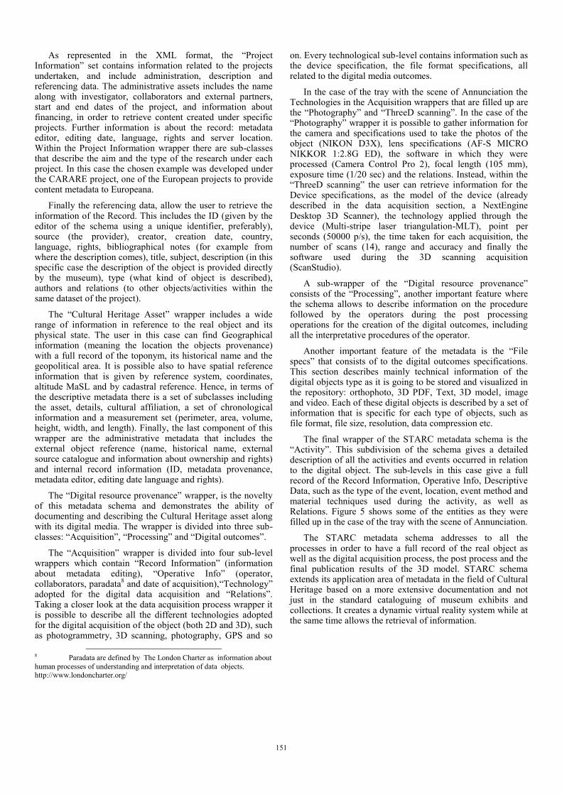
Through the XML format of the schema will be practically demonstrated the description applied to one of the case studies previously treated: the tray with the scene of Annunciation. The metadata associated to the 3D models of the examples in this paper describes the whole process from digitization to visualization as a resource that enables users to find the object via STARC repository (and via Europeana since the datasets stored in the repository have been also harmonized and published into Europeana through Digital Libraries projects).
The “Project information” wrapper consists of several related entities: “Administrative data”, “Descriptive data” and “References”. They provide information related to the project which the item belongs to; they take into consideration the steps procedure carried out by the team within the project itself (from the description of the project until its aim) and a set of entities is the representation of the artifact of the acquired object. Another important feature allows to create the relations with the digital resources belonging to the same dataset.
150
As represented in the XML format, the “Project Information” set contains information related to the projects undertaken, and include administration, description and referencing data. The administrative assets includes the name along with investigator, collaborators and external partners, start and end dates of the project, and information about financing, in order to retrieve content created under specific projects. Further information is about the record: metadata editor, editing date, language, rights and server location. Within the Project Information wrapper there are sub-classes that describe the aim and the type of the research under each project. In this case the chosen example was developed under the CARARE project, one of the European projects to provide content metadata to Europeana.
Finally the referencing data, allow the user to retrieve the information of the Record. This includes the ID (given by the editor of the schema using a unique identifier, preferably), source (the provider), creator, creation date, country, language, rights, bibliographical notes (for example from where the description comes), title, subject, description (in this specific case the description of the object is provided directly by the museum), type (what kind of object is described), authors and relations (to other objects/activities within the same dataset of the project).
The “Cultural Heritage Asset” wrapper includes a wide range of information in reference to the real object and its physical state. The user in this case can find Geographical information (meaning the location the objects provenance) with a full record of the toponym, its historical name and the geopolitical area. It is possible also to have spatial reference information that is given by reference system, coordinates, altitude MaSL and by cadastral reference. Hence, in terms of the descriptive metadata there is a set of subclasses including the asset, details, cultural affiliation, a set of chronological information and a measurement set (perimeter, area, volume, height, width, and length). Finally, the last component of this wrapper are the administrative metadata that includes the external object reference (name, historical name, external source catalogue and information about ownership and rights) and internal record information (ID, metadata provenance, metadata editor, editing date language and rights).
The “Digital resource provenance” wrapper, is the novelty of this metadata schema and demonstrates the ability of documenting and describing the Cultural Heritage asset along with its digital media. The wrapper is divided into three sub-classes: “Acquisition”, “Processing” and “Digital outcomes”.
The “Acquisition” wrapper is divided into four sub-level wrappers which contain “Record Information” (information about metadata editing), “Operative Info” (operator, collaborators, paradata8 and date of acquisition),“Technology” adopted for the digital data acquisition and “Relations”. Taking a closer look at the data acquisition process wrapper it is possible to describe all the different technologies adopted for the digital acquisition of the object (both 2D and 3D), such as photogrammetry, 3D scanning, photography, GPS and so
8 Paradata are defined by The London Charter as information about human processes of understanding and interpretation of data objects. http://www.londoncharter.org/
on. Every technological sub-level contains information such as the device specification, the file format specifications, all related to the digital media outcomes.
In the case of the tray with the scene of Annunciation the Technologies in the Acquisition wrappers that are filled up are the “Photography” and “ThreeD scanning”. In the case of the “Photography” wrapper it is possible to gather information for the camera and specifications used to take the photos of the object (NIKON D3X), lens specifications (AF-S MICRO NIKKOR 1:2.8G ED), the software in which they were processed (Camera Control Pro 2), focal length (105 mm), exposure time (1/20 sec) and the relations. Instead, within the “ThreeD scanning” the user can retrieve information for the Device specifications, as the model of the device (already described in the data acquisition section, a NextEngine Desktop 3D Scanner), the technology applied through the device (Multi-stripe laser triangulation-MLT), point per seconds (50000 p/s), the time taken for each acquisition, the number of scans (14), range and accuracy and finally the software used during the 3D scanning acquisition (ScanStudio).
A sub-wrapper of the “Digital resource provenance” consists of the “Processing”, another important feature where the schema allows to describe information on the procedure followed by the operators during the post processing operations for the creation of the digital outcomes, including all the interpretative procedures of the operator.
Another important feature of the metadata is the “File specs” that consists of to the digital outcomes specifications. This section describes mainly technical information of the digital objects type as it is going to be stored and visualized in the repository: orthophoto, 3D PDF, Text, 3D model, image and video. Each of these digital objects is described by a set of information that is specific for each type of objects, such as file format, file size, resolution, data compression etc.
The final wrapper of the STARC metadata schema is the “Activity”. This subdivision of the schema gives a detailed description of all the activities and events occurred in relation to the digital object. The sub-levels in this case give a full record of the Record Information, Operative Info, Descriptive Data, such as the type of the event, location, event method and material techniques used during the activity, as well as Relations. Figure 5 shows some of the entities as they were filled up in the case of the tray with the scene of Annunciation.
The STARC metadata schema addresses to all the processes in order to have a full record of the real object as well as the digital acquisition process, the post process and the final publication results of the 3D model. STARC schema extends its application area of metadata in the field of Cultural Heritage based on a more extensive documentation and not just in the standard cataloguing of museum exhibits and collections. It creates a dynamic virtual reality system while at the same time allows the retrieval of information.
151
Fig. 5. The metadata schema with the information of the specific 3D object.
V. CONCLUSIONS The procedure demonstrated the importance of the digital
3D documentation for archaeological, cultural heritage and research aims. The multidisciplinary of the research group gave the possibility to integrate different kind of knowledge and offered interesting solutions in the decision-making.
Through the workflow is possible to perform virtual restoration, adding a further level to the concept of digital museum curatorship, and to guarantee virtual preservation.
Consequently by building an easily accessible and manageable digital repository, it can benefit the historical documentation, the digital preservation and sustainability of the data. What is more, the standardization of data promotes the international collaboration and information sharing by all users.
This means that at anytime any user can have access and trace the previous tasks related to the 3D content and hence expand their knowledge within the study and analysis of the data materials related to their interests [12].
Finally, the systematic storage of the 3D data can support the creation of a new “understanding” derived from the retrieved information.
ACKNOWLEDGMENTS This research project would not have been possible
without the collaboration of many people. The authors want to thank those involved in the digital procedure and they wish to express their gratitude for the support for this work and thank for the availability to access and digitally acquire data for research aims from the Folk Art Museum (Cypriot Studies), the Cyprus Museum and Larnaca District Museum, Mediterranean Archaeological Research Institute. The results presented in this paper were supported by the grant from the EU funded project CARARE.
REFERENCES [1] N. Amico, P. Ronzino, G. Iannone, Developing an “Archaeological”
Benchmarking Procedure, Verhagen, Philip (ed.), Revive the past : proceedings of the 39th Annual Conference of Computer Applications and Quantitative Methods in Archaeology (CAA), Beijing, China, 12-16 April 2011, Amsterdam 2012.
[2] D. Abernathy, 2007. “Review: The NextEngine Desktop 3D Scanner.” CSA Newsletter 20:11.
[3] Society of Cypriot Studies - Zypriotische Kommission fuer Byzantinische Studien (2012). Κύπρος - Γερμανία: 800 Χρόνια Ιστορίας & Πολιτισμού/Zypern-Deutschland. 800 Jahren Geschichte und Kultur (ed. Ch. Chotzakoglou), Lefkosia. Nicosia: Ministry of Education and Culture – Cultural Services.
[4] P. Petridis, K. Mania , D. Pletinckx & M. White (2006, November). Usability evaluation of the epoch multimodal user interface: designing 3d tangible interactions. In Proceedings of the ACM symposium on Virtual reality software and technology (pp. 116-122). ACM.
[5] F. Niccolucci, & F. Cantone, (2002). Legend and virtual reconstruction: Porsenna’s mausoleum in x3d. In CAA (pp. 57-62).
[6] Ph Kontoglou. (1979). Έκφρασης της Ορθοδόξου Εικονογραφίας, Τόμος Πρώτος Τεχνολογικόν και Εικονογραφικόν [Expression of Orthodox Iconography, Book I Technologikon and Iconographicon]. ΑΣΤΗΡ.
[7] A. Tsitouridou (1986). Ο ζωγραφικός Διάκοσμος του Αγίου Νικολάου Ορφανού στη Θεσσαλονίκη, Συμβολή στη μελέτη της παλαιολογείας ζωγραφικής κατά τον πρώιμο 14ο αιώνα, Κέντρο Βυζαντινών Ερευνών [The paintings of the Church of St. Nicholas Orphanou in Thessaloniki, Contribution to the study of paleologian painting during the early 14th century, Centre for Byzantine Research].
[8] G.Crane, (2002). Cultural Heritage Digital Libraries: Needs and Components. Rome: European conference, ECDL .
[9] N. Mourkoussis, M. White, M. Patel, J. Chmielewski and K. Walczak (2003) AMS: metadata for cultural exhibitions using virtual reality. In: DC-2003, proceedings of the international DCMI metadata conference and workshop, September 28-October 2, 2003, Seattle, Washington USA. University of Washington
[10] P. Ronzino, N. Amico, F. Niccolucci, Assessment and comparison of metadata schemas for architectural heritage, Proceedings of CIPA 2011.
[11] P. Ronzino, S. Hermon, F. Niccolucci, 2012, A Metadata Schema for Cultural Heritage Documentation, in V. Capellini (ed.), Electronic Imaging & the Visual Arts: EVA 2012 Florence, Firenze University Press, pp. 36- 41
[12] F. Remondino, (2011). Heritage Recording and 3D Modeling with Photogrammetry and 3D Scanning. 3D Optical Metrology (3DOM) Research Unit, Bruno Kessler Foundation (FBK).
152